GETTING
STARTED
MOUNTING
INCLUDED IN THIS BOX
68-0239EF-09
APPENDICES
Tools needed to install Enhanced Air Cleaner
Standard screwdriver
Phillips screwdriver
Metal cutter
Drill
Duct Sealant
Replacement Air Filters
Filter Size (in.)
Part Number
F100 - MERV 11 F200 - MERV 13
12.5 x 20 FC100A1052 N/A
16 x 25 FC100A1029 FC200E1029
16 x 20 FC100A1003 FC200E1003
20 x 25 FC100A1037 FC200E1037
20 x 20 FC100A1011 FC200E1011
SPECIFICATIONS
Media Air
Cleaner Size (in.)
F100
Media Air Cleaner
w/ MERV 11 Filter
F200
Media Air Cleaner
w/ MERV 13 Filter
16 X 25
F100F1625 F200F1625
16 X 20
F100F1620 F200F1620
20 X 25
F100F2025 F200F2025
20 X 20
F100F2020 F200F2020
25 X 22 F100F2051 -
25 X 20 F100F2044 -
SPECIFICATIONS
•
PROFESSIONAL INSTALLATION GUIDE.
GUIDE D’INSTALLATION PROFESSIONNELLE.
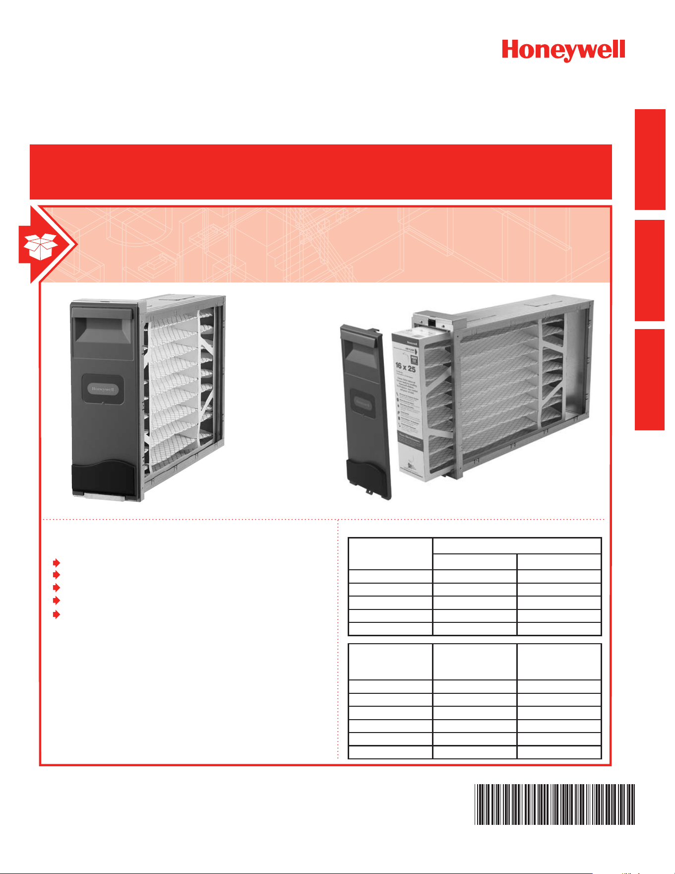
Honeywell Media Air Cleaners

GETTING
STARTED
MOUNTING
SPECIFICATIONS
Honeywell Media Air Cleaner
NEED HELP? For assistance with this product please visit http://yourhome.honeywell.com
or call Honeywell Customer Care toll-free at 1-800-468-1502.
Read and save these instructions.
® U.S. Registered Trademark. Patents pending. Copyright © 2013 Honeywell International Inc. All rights reserved.
?
Honeywell Media Air Cleaner 68-0239EF—09
What to Expect From Your Honeywell
Media Air Cleaner ......................................... 1
When Installing this Product... .......................................1
How it Works ................................................ 1
Application Considerations ........................... 2
Models ...........................................................................2
Air Conditioning .............................................................2
Humidiers ....................................................................2
UV Lights .......................................................................2
Transitions
.....................................................................3
Turning Vanes
................................................................3
Sheetmetal ....................................................................3
Offsets
...........................................................................3
Important Installation Requirements ............ 4
Personal Safety .............................................................4
Before Mounting ............................................................4
If Replacing an Old Air Cleaner .....................................4
Choosing a Mounting Position ...................... 5
Mounting the Honeywell Media Air Cleaner . 7
Checkout ...................................................... 8
Maintenance ................................................. 8
Specications ............................................... 8
Capacity And Pressure Drop .........................................9
Temperature Rating
.......................................................9
Dimensions .................................................................... 9
Approvals .......................................................................9
Replacement Filter Table ...............................................9

GETTING
STARTED
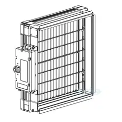
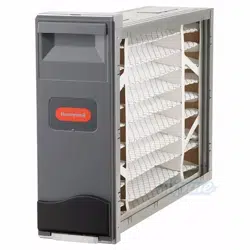
Congratulations for selecting the Honeywell Media Air Cleaner for your home comfort system! The Honeywell
MediaAirCleanercapturesandremovesasignicantamountoftheair-borneparticlesfromtheaircirculated
throughthehigh-efciencypleatedmedialter.TheMediaAirCleanereasilymountsinanypositionwithinthe
return air duct of any gas, oil, and electric forced warm air furnaces and to compressor cooling up to 5 tons.
Additionally,itrequiresnoelectricalconnectionsormaintainencebeyondperiodicmedialterreplacement.
When Installing this Product...
1. Read these instructions carefully. Failure to follow them could damage the product or cause a hazardous
condition.
2. Check the rating given in the instructions and on the product to make sure the product is suitable for your
application.
3. Installer must be a trained, experienced service technician.
4. After installation is complete, check out product operation as provided in these instructions.
How it Works
ThelterinyourHoneywellMediaAirCleanerismadeupofawebofbers.AsairpassesthroughtheMedia
AirCleaner,particulatessuchasdust,pollen,dander,mold,andbacteriacollidewiththebersinthelterand
become trapped. Meanwhile, the clean air is allowed to continue through your heating and cooling system and into
yourhome.TheparticleremovalefciencyoftheHoneywellMediaAirCleanercanbefoundintheSpecication
section of this manual.
What to Expect From Your Honeywell Media Air Cleaner
Honeywell Media Air Cleaner 68-0239EF—09 1
NEED HELP? For assistance with this product please visit http://yourhome.honeywell.com
or call Honeywell Customer Care toll-free at 1-800-468-1502.
Read and save these instructions.
® U.S. Registered Trademark. Patents pending. Copyright © 2013 Honeywell International Inc. All rights reserved.

GETTING
STARTED
Application Considerations
The Honeywell Media Air Cleaner is designed to work with gas, oil, and electric forced warm air furnaces and with
compressorcooling.Itcanalsobeusedwithheatpumpsifthelterischangedregularlytopreventexcessive
pressure drop. The Honeywell Media Air Cleaner is not recommended for applications where pressure drop may
be critical.
Models
F100FMediaAirCleanerincludescabinet,accessdoorandMERV11pleatedmedialter.
F200FMediaAirCleanerincludescabinet,accessdoorandMERV13pleatedmedialter.
F100B Media Air Cleaner Boot includes cabinet and access door. (No Filter)
Air Conditioning
Mountthemediaaircleanerupstreamoftheevaporatorcoilinacoolingsystem.Thelterwillhelptokeepthecoil
clean and reduce maintenance.
Humidiers
Themediaaircleaneriscompatiblewithhumidiers.Avoidapplicationswherewatermistwillreachthemedia.If
anatomizing(steam)humidierisused,theltermediawillrequirereplacementmoreoftenbecauseofminerals
in the water.
UV Lights
GermicidalUVlightscancausedegradationofthemedialter.TheUVlightshouldbelocatedoutoflineofsight
oraminimumof3feetfromthelter.Otherwisetheltermayneedtobereplacedmorefrequently.
Honeywell Media Air Cleaner 68-0239EF—09
2

GETTING
STARTED
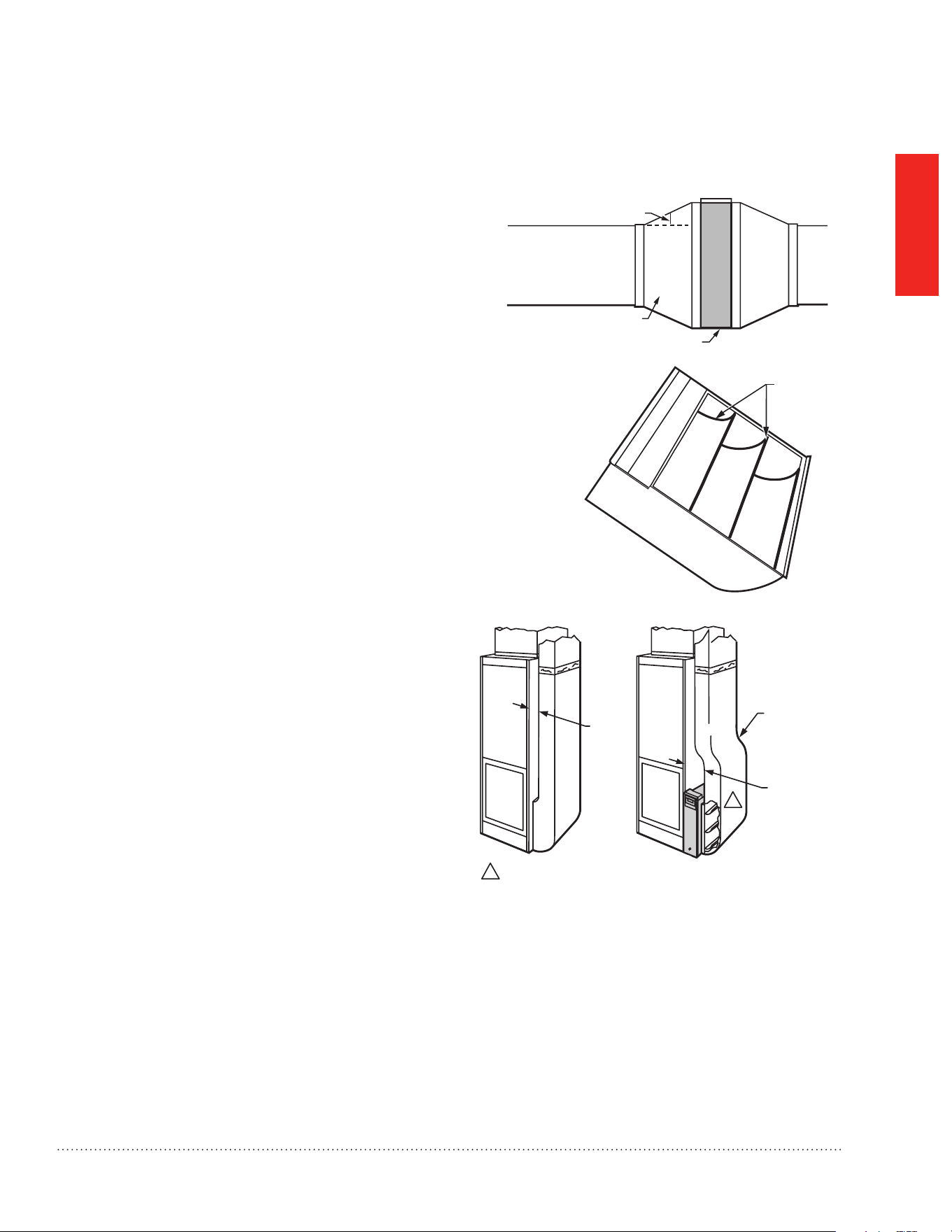
Transitions
Formostefcientaircleaning,spreadairowevenly
across the face of the media. If the duct is a different
sizethanthemediaairltercabinet,gradualtransitions
are required. Follow these guidelines when fabricating:
• Use gradual transitions to reduce air turbulence and
increaseefciency.
• Use no more than 20 degrees (about 4 in. per
running ft. (100 mm per 300 linear mm)) of
expansiononeachsideofatransitiontting.
Turning Vanes
If the media air cleaner is installed next to an elbow
orangletting,addturningvanesinsidetheangleto
distributeairowmoreevenlyacrossthefaceofthe
media.Seemiddlegure.
Sheetmetal
The media air cleaner is adaptable to all new or
existing forced air heating and cooling systems used
in residential applications. Transitions or turning vanes
may be required in some applications for effective
media air cleaner operation.
Offsets
If the duct connection to the furnace in a side
installation allows less than 7 in. (178 mm) for mounting
media air cleaner cabinet, attach an offset to the elbow.
Seebottomgureatright.
TURNING
VANES
M5651
M948B
LESS
THAN
7 in.
(178 mm)
OFFSET
AT LEAST
7 in.
(178 mm)
1
1 REQUIRED TURNING VANES HELP DISTRIBUTE AIRFLOW EVENLY.
20 DEGREE EXPANSION PER SIDE PER
FITTING (4 IN. PER RUNNING FOOT
[100 MM PER 300 LINEAR MM])
RETURN AIR
DUCT
TRANSITION FITTING
ELECTRONIC AIR CLEANER CABINET
M947B
DUCT SIZE CHANGED GRADUALLY TO PREVENT TURBULENCE.
Honeywell Media Air Cleaner 68-0239EF—09 3

GETTING
STARTED
Important Installation Requirements
Personal Safety
• Wear safety glasses while installing the unit.
• Do not cut into any air conditioning or electrical line.
• Follow professional safety standards and all local codes for plumbing, electrical, and mechanical
considerations.
Before Mounting
• Usingthegureonthecoverandthelistsontheinsidecover,makesurethatyouhaveallthecomponentsfor
your Honeywell Media Air Cleaner and the tools to install it.
• EnsureairowdirectionthroughtheHoneywellMediaAirCleanermatchesthearrowsontheltercartridge.
Thearrowsshouldpointinthedirectionoftheairow.
• Choosealocationthatisreadilyaccessibleforcheckingandreplacingthelter.Allowatleast26in.(660mm)
clearance in front of the unit for removal of the cartridge.
• InstallthemediaairlterwherethetemperaturewillnotexceedtheratingsintheSpecications.
• Do not mount in the supply air duct.
NOTE: Generally, the best location is in the return air duct next to the blower compartment so the media air
cleaner can help to keep the blower motor and evaporator coils clean.
If Replacing an Old Air Cleaner
If the Honeywell Media Air Cleaner is not identical in size and shape to the existing air cleaner, before performing
aretrotinstallation,youmightneedtoaddducttransitionstoensureasmoothairow.
Foroptimumsystemperformance,replacetheltereverysixmonths(beforeheatingseasonandbeforecooling
season).Adjustthescheduletoyourneeds,butreplacethelteratleastonceperyear.
Failure to comply with these requirements will result in voided warranty, improper installation, and
service callbacks.
Honeywell Media Air Cleaner 68-0239EF—09
4
MOUNTING
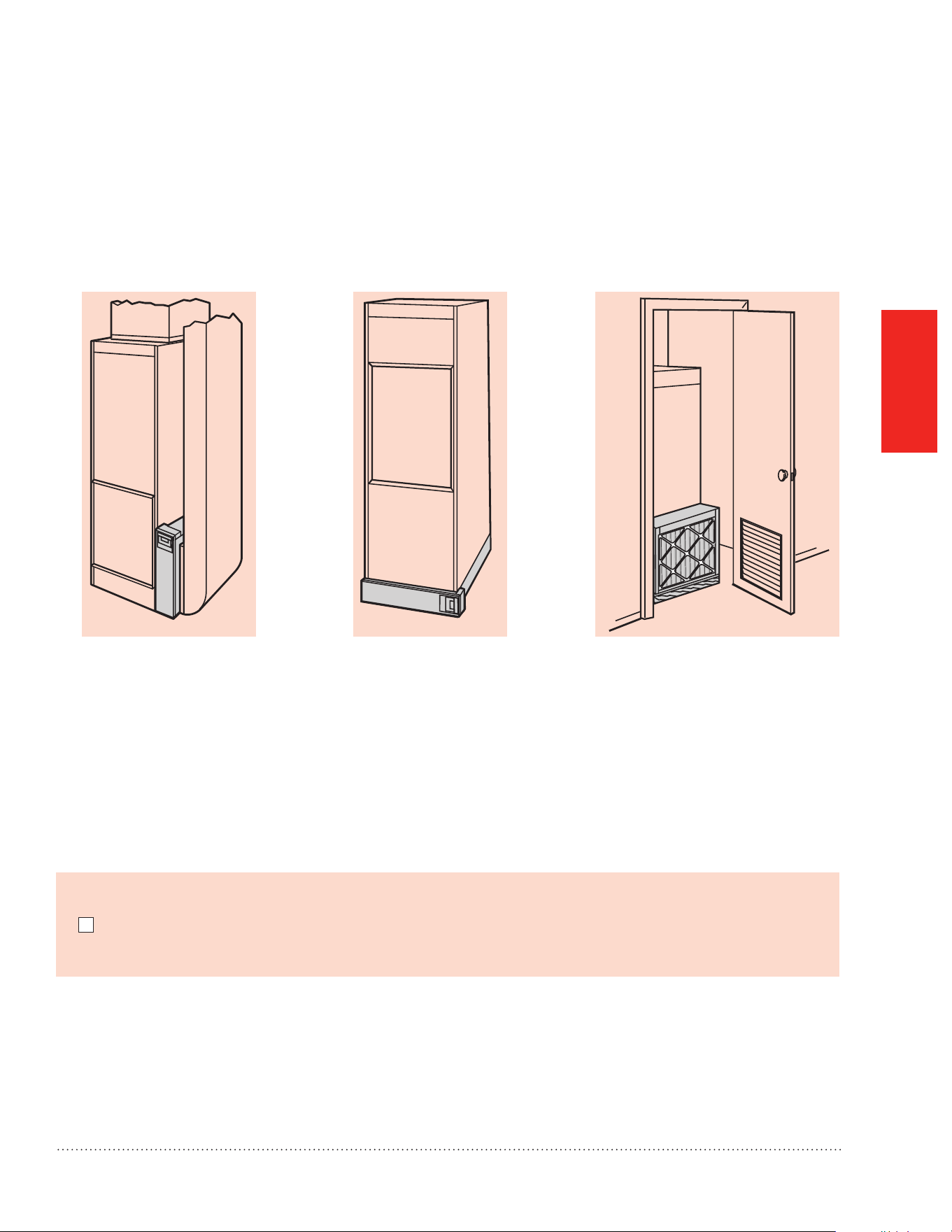
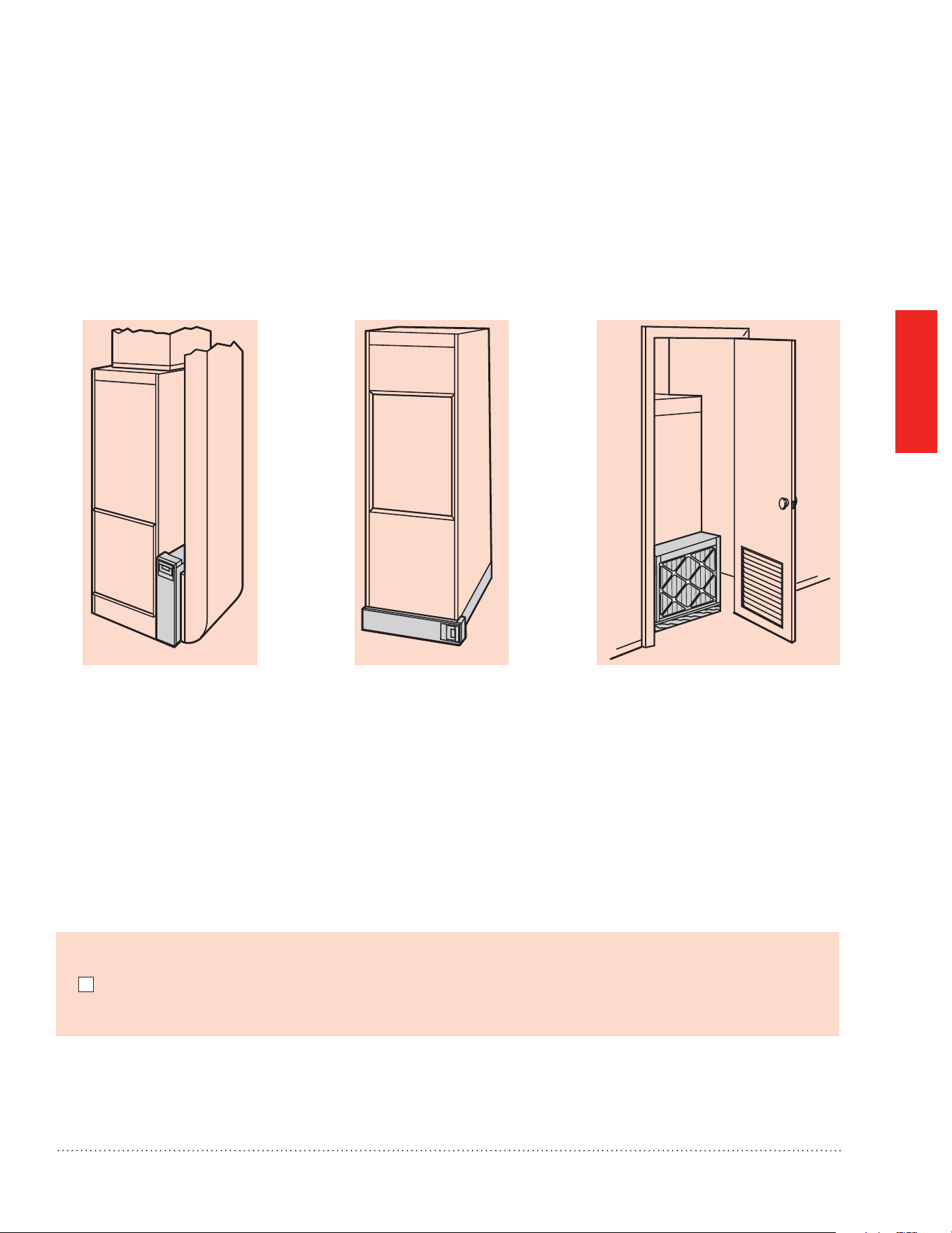
The Media Air Cleaner mounts in any position within the return air duct, usually next to the furnace blower
compartment,butthearrowonthecartridgemustpointinthesamedirectionastheairow.SeeFigs.1-8for
proper location of the media air cleaner for a variety of furnace installations.
NOTE: The media air cleaner cabinet is sturdy enough to easily support the weight of the furnace and evaporator
coil.
M939B
M940B
Choosing a Mounting Position
Before beginning Mounting:
I have chosen an installation location that meets the requirements on pages 5 through 6.
Fig. 1. Highboy furnace with side
installation.Mediaairlteris
mounted vertically where return
enters side inlet of furnace.
Fig 2. Highboy furnace, with
installation beneath furnace.
Media air cleaner is mounted
horizontally where return
enters from below.
M941A
Fig. 3. Highboy furnace, with closet
installation. Media air
cleaner is mounted vertically on
furnace between furnace and
louvered return air opening in closet
door.
Honeywell Media Air Cleaner 68-0239EF—09 5
MOUNTING
M942B
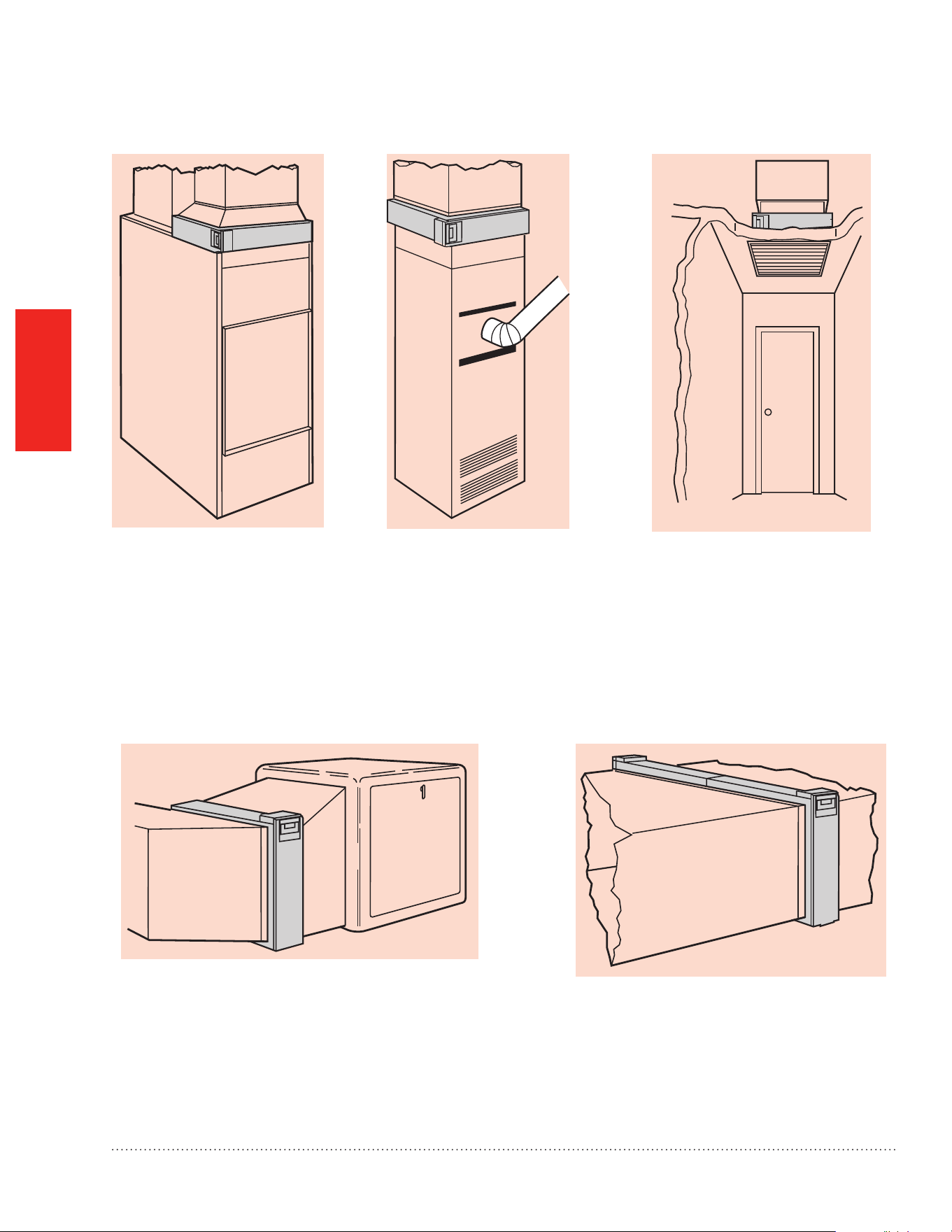
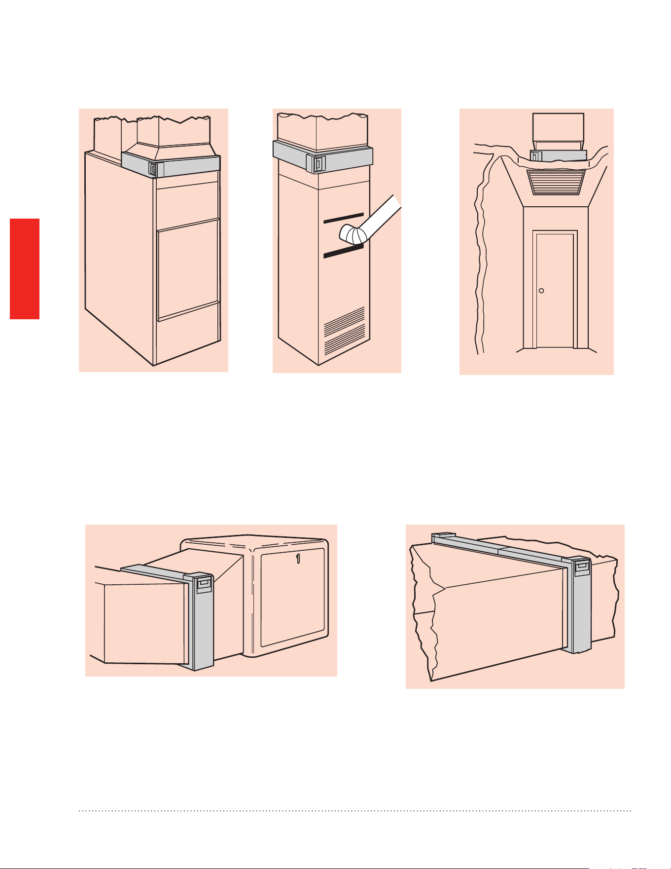
Fig. 4. Lowboy furnace, with
media air cleaner mounted
horizontally in return plenum
just above furnace and
opposite heating plenum.
M943B
M944B
Fig.5.Counterowfurnace,
with media air cleaner
mounted horizontally in
return duct or plenum just
above furnace.
Fig. 6. Central fan installation,
with media air cleaner mounted
horizontally in central return duct.
M945B
M946B
Fig.7.Horizontalfurnace,withmediaairlter
mounted vertically in return duct near furnace.
Fig. 8. Two or more media air cleaners used
in a high capacity system.
Honeywell Media Air Cleaner 68-0239EF—09
6

MOUNTING
The following procedure describes a typical side installation on an existing highboy furnace (Fig. 1). Alternate
procedures are noted as appropriate. Other changes in installation procedures may be necessary to complete
your installation.
NOTE: Beforestartingtheinstallation,removeanddiscardtheexistingfurnacelter(ifused).Thoroughlyclean
the blower compartment. If possible, power vacuum the ductwork to remove accumulated dust in an
occupied home or remove construction dirt in a new home. The media air cleaner cannot remove dirt that
has settled in the blower compartment and distribution ducts.
STEP ONE: Review the Installation Plan
Temporarilyplacethecabinetontheoor,orientedasitwillbewheninstalled.Insertandremovethecartridgeto
make sure the plan allows adequate clearance for easy removal and replacement of the cartridge.
STEP TWO: Fasten the Cabinet to the Furnace
a. Align the cabinet with the return air opening.
b. Place blocks under the cabinet, as necessary, to make sure the unit sits securely.
c. Create an opening in the furnace to match the cabinet opening.
d. Attachthecabinetsecurelytothefurnace.Attachtheunitdirectlyortastartingcollarinthefurnaceopening.
Either drill holes and fasten with sheetmetal screws or rivets, or use slip joints. If you are drilling holes, use a
locking pliers to help hold the unit in place during drilling.
STEP THREE: Install Turning Vanes
Install turning vanes to help distribute air equally over the full surface of the upstream side of the media. Install
them whenever an abrupt 90 degree elbow is installed directly against the media air cleaner cabinet.
STEP FOUR: Fasten Cabinet to Ductwork
Fasten side of cabinet to the ductwork using sheet-metal screws, rivets, or slip joints, as appropriate.
STEP FIVE: Connect Ductwork
a. Connect the vertical duct section to the elbow. If the vertical drop of the duct is less than 7 in. (178 mm) from
thesideofthefurnace,shortenthehorizontaltrunkorattachanoffsetttingtotheelbow.
b. When ductwork is properly aligned, connect the vertical duct to the horizontal trunk.
STEP SIX: Seal Joints
Sealalljointsinthereturnairsystembetweenthemediaairlterandthefurnacetopreventdustfromentering
the clean airstream.
STEP SEVEN: Install Filter Cartridge
Slidetheltercartridgeintothecabinet,makingsurethearrowonthecartridgepointsinthedirectionofairow.
Replace access door. Insert the tab on the bottom of the door into the slot in the cabinet. Swing the door closed
and press it into place.
Mounting the Honeywell Media Air Cleaner
Honeywell Media Air Cleaner 68-0239EF—09 7

MOUNTING
Visually check the installation and make sure that:
• Airflow is in the direction of the arrow on the media air filter cartridge.
• Turning vanes and transitions, if used, are properly installed.
• Joints in sheetmetal between media air filter and furnace are sealed.
• All sheetmetal connections are complete.
• Original furnace filter has been removed and blower compartment is cleaned.
Whenyouhaveveriedthatcheckouthasbeencompleted:
• Replace any access doors removed during the Installation or Checkout.
• Run the furnace or cooling system through one complete cycle to make sure the system operates as desired.
Themedialtermustbereplacedwhenpressuredropacrossthemedialterreaches0.5in.w.c.(0.1kPa),orat
leastannually.Ifthemediaaircleanerisinstalleddownstreamfromanatomizinghumidieroriftheinstallation
includes both heating and cooling, more frequent replacement may be necessary. Clogged media must be
replacedpromptlytoavoidrestrictingairowandreducingefciencyoftheheating/coolingsystem.Recordthe
replacementdateinthespaceprovidedonthereplacementmedialter.
Checkout
Maintenance
Specications
The specications in this publication do not include normal manufacturing tolerances; therefore, an individual
unit may not exactly match the listed specications. This product is tested and calibrated under closely
controlled conditions, and some minor differences in performance can be expected if those conditions are
changed.
Honeywell Media Air Cleaner 68-0239EF—09
8
SPECIFICATIONS
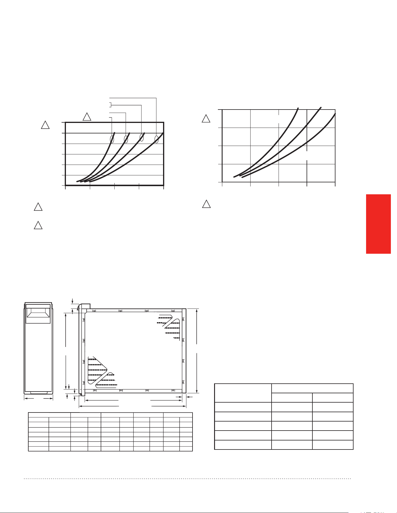
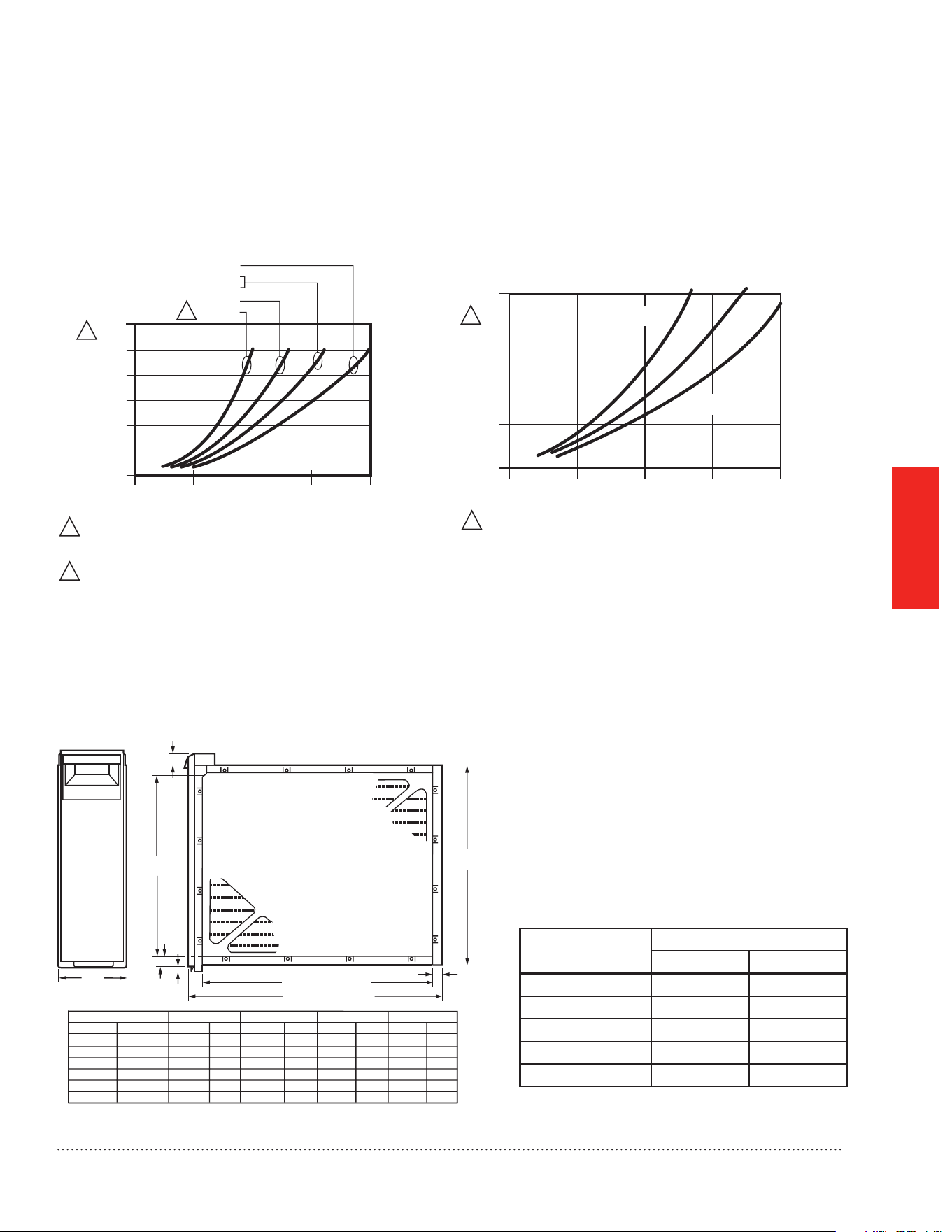
F100 Specications
MERV Rating*: MERV 11
Static Pressure Drop: 0.23 (in. w.c.) at 500 FPM
Efciency Denition*:
Small Particles: E1 = 0.3 to 1.0 microns = 32%
Medium Particles: E2 = 1.0 to 3.0 microns = 72%
Large Particles: E3 = 3.0 to 10.0 microns = 96%
0
500 1000 1500
2000
0.000
0.050
0.100
0.150
0.200
0.250
0.300
12.5 X 20
16 X 20
16 X 25
20 X 20
20 X 25
FILTER SIZE
PRESSURE DROP (IN. WC)
AIRFLOW (CFM)
M34911
WHEN FIRST INSTALLED. PRESSURE DROP INCREASES AS FILTER
BECOMES LOADED. REPLACE FILTER WHEN PRESSURE DROP
REACHES 0.5 IN. WC. (0.1 kPa).
AVAILABLE ONLY IN UNITED STATES.
2
1
1
2
F200 Specications
MERV Rating*: MERV 13
Static Pressure Drop: 0.3 (in. w.c.) at 500 FPM
Efciency Denition*:
Small Particles: E1 = 0.3 to 1.0 microns = 63%
Medium Particles: E2 = 1.0 to 3.0 microns = 91%
Large Particles: E3 = 3.0 to 10.0 microns = 99%
0
500 1000 1500
2000
0
0.1
0.2
0.3
0.4
PRESSURE DROP (IN. WC)
AIRFLOW (CFM)
M13662
WHEN FIRST INSTALLED. PRESSURE DROP INCREASES AS FILTER
BECOMES LOADED. REPLACE FILTER WHEN PRESSURE DROP
REACHES 0.5 IN. WC. (0.1 kPa).
1
1
20 x 25 in.
(508 x 635 mm)
20 x 20 in.
(508 x 508 mm)
16 x 25 in.
(406 x 635 mm)
16 x 20 in.
(406 x 508 mm)
M14710E
F100 SIZE
IN.
16 X 25
16 X 20
20 X 25
20 X 20
25 X 20
25 X 22
MM
406 X 635
406 X 508
508 X 635
508 X 508
635 X 508
635 X 559
DIM. A
14 7/16
14 7/16
18 7/16
18 7/16
23 5/16
23 5/16
367
367
468
468
592
592
DIM. B
16 3/16
16 3/16
20 3/16
20 3/16
25 1/8
25 1/8
411
411
513
513
638
638
23 1/4
18 1/4
23 1/4
18 1/4
18 3/8
20 1/4
DIM. C
591
457
591
457
467
514
DIM. D
25 1/2
20 1/2
25 1/2
20 1/2
20 5/8
22 1/2
648
521
648
521
524
572
DIM. C (SEE TABLE)
DIM. D (SEE TABLE)
DIM. B
(SEE T
ABLE)
DIM. A
(SEE TABLE)
1-1/8 (29)
7/8
(22)
5/8
(16)
6-3/4
(171)
7/8
(22)
IN. MM IN. MM
IN. MM IN. MM
Dimensions
Temperature Rating
-40° to +140°F (-40° to +60°C)
Approvals
Underwriters Laboratories, Inc.: Listed to UL
900, Class 2.
Replacement Filter Table
Filter Size (in.) Part Number
F100 F200
20 x 12-1/2 x 4-3/8 FC100A1052 N/A
16 x 24-7/8 x 4-3/8 FC100A1029 FC200E1029
16 x 19-3/4 x 4-3/8 FC100A1003 FC200E1003
20 x 24-7/8 x 4-3/8 FC100A1037 FC200E1037
20 x 19-3/4 x 4-3/8 FC100A1011 FC200E1011
* MinimumEfciencyReportingValue(MediaFiltersOnly)
* EfciencyratingsarebasedonAmericanSocietyofHeating,RefrigeratingandAir-ConditioningEngineers
Standard 52.2-1999.
Honeywell Media Air Cleaner 68-0239EF—09 9

Automation and Control Solutions
Honeywell International Inc.
1985 Douglas Drive North
Golden Valley, MN 55422
Honeywell Ltd
705 Montrichard Avenue
Saint-Jean-sur-Richelieu, Québec
J2X 5K8
http://yourhome.honeywell.com
® U.S. Registered Trademark.
© 2013 Honeywell International Inc.
68-0239EF—09 M.S. Rev. 11-13
Printed in U.S.A.
POUR
COMMENCER
MONTAGE
CARACTÉRISTIQUES
TECHNIQUES
INCLUS DANS LA BOÎTE
68-0239EF-09
Épurateurs d’air à fibres de Honeywell
•
PROFESSIONAL INSTALLATION GUIDE.
GUIDE D’INSTALLATION PROFESSIONNELLE.
Outils requis pour installer
l’épurateur d’air amélioré
Tournevis normal
Tournevis cruciforme
Cisailles à tôle
Perceuse
Produit d’étanchéité de gaine
Filtres à air de rechange
Dimension du
ltre (po)
Référence de pièce
F100 - MERV 11 F200 - MERV 13
12,5 x 20 FC100A1052 N/A
16 x 25 FC100A1029 FC200E1029
16 x 20 FC100A1003 FC200E1003
20 x 25 FC100A1037 FC200E1037
20 x 20 FC100A1011 FC200E1011
Dimension de
l’épurateur d’air
(po.)
Épurateur d’air
F100 avec ltre
MERV 11
Épurateur d’air
F200 avec ltre
MERV 13
16 X 25 F100F2002 F200F2002
16 X 20 F100F2028 F200F2028
20 X 25 F100F2010 F200F2010
20 X 20 F100F2036 F200F2036
25 X 22 F100F2051 -
25 X 20 F100F2044 -

CARACTÉRISTIQUES
TECHNIQUES
MONTAGE
POUR
COMMENCER
?
BESOIN D’AIDE? Pour obtenir de l’aide sur ce produit, prière de visiter le site
http://yourhome.honeywell.com
ou d’appeler le service d’assistance à la clientèle de Honeywell au 1-800-468-1502.
Lire et conserver ces instructions.
® Marque de commerce déposée américaine. Brevets en instance. Copyright © 2013 Honeywell International Inc. Tous droits réservés.
Épurateurd’airàbresdeHoneywell68-0239EF—09
Épurateurd’airàbresdeHoneywell
Àproposdel’épurateurd’airàbres
F100 de Honeywell ....................................... 1
Lors de l’installation du produit... ...................................1
Fonctionnement ............................................ 1
Considérations relatives à l’application ........ 2
Modèles .........................................................................2
Climatisation ..................................................................2
Humidicateurs .............................................................. 2
Lampes UV .................................................................... 2
Transitions .....................................................................3
Aubes directrices ...........................................................3
Tôle ................................................................................3
Déviations ......................................................................3
Exigences d’installation importantes ............ 4
Sécurité personnelle ...................................................... 4
Avant le montage ........................................................... 4
Pour le remplacement d’un ancien épurateur d’air ........4
Sélection de la position de montage ............ 5
Montage de l’épurateur d’air
àbresHoneywell ........................................ 7
Vérication .................................................... 8
Entretien ....................................................... 8
Caractéristiques techniques ......................... 8
Capacité et chute de pression .......................................9
Température nominale ...................................................9
Dimensions .................................................................... 9
Homologations ..............................................................9
Tableaudesltresderechange .....................................9

POUR
COMMENCER
Félicitationspourvotrechoixdel’Épurateurd’airàbresdeHoneywellpourvotresystèmedeconfortd’intérieur!
L’Épurateurd’airàbresdeHoneywellcaptureetretireunequantitéconsidérabledeparticulescontenuesdans
l’aircirculantparleltreàbresàplishauteefcacité.L’épurateurd’airàbressemontefacilementdanstoutes
les positions dans la gaine d’air de retour de tout appareil de chauffage à gaz, mazout, électrique et air pulsé et
les systèmes de refroidissement par compresseur jusqu’à 5 tonnes. En outre, il ne nécessite aucun branchement
électriquenientretienexceptéleremplacementpériodiquedultreàbres.
Lors de l’installation du produit...
1. Lire attentivement ces instructions. Le non-respect des instructions peut endommager le produit ou provoquer
une situation dangereuse.
2. Vérierlescaractéristiquesnominalesindiquéesdanslesinstructionsetsurleproduitpours’assurerquele
produit correspond bien à l’application prévue.
3. L’installateur doit être un technicien expérimenté ayant reçu la formation adéquate.
4. Unefoisl’installationterminée,vérierqueleproduitfonctionnecommeindiquédanscesinstructions.
Fonctionnement
Leltredel’Épurateurd’airàbresdeHoneywellestconstituéd’unréseaudebres.Lorsquel’airpassepar
l’épurateurd’airàbres,lesparticulescommelapoussière,lepollen,lessquamesanimales,lesmoisissures
etlesbactériesentrentencollisionaveclesbresdultreetsontpiégées.L’airpropreltréestacheminédans
lesystèmedechauffageetderefroidissementetaèrelamaison.L’efcacitédunettoyagedesparticulesde
l’Épurateurd’airàbresdeHoneywellestspéciéedanslasectionCaractéristiquestechniquesdecemanuel.
Àproposdel’épurateurd’airàbresdeHoneywell
Épurateurd’airàbresdeHoneywell68-0239EF—09 1
BESOIN D’AIDE? Pour obtenir de l’aide sur ce produit, prière de visiter le site
http://yourhome.honeywell.com
ou d’appeler le service d’assistance à la clientèle de Honeywell au 1-800-468-1502.
Lire et conserver ces instructions.
® Marque de commerce déposée américaine. Brevets en instance. Copyright © 2013 Honeywell International Inc. Tous droits réservés.

POUR
COMMENCER
Considérations relatives à l’application
L’Épurateurd’airàbresdeHoneywellestconçupourfonctionneraveclesappareilsdechauffageàgaz,mazout,
électrique et air pulsé et les systèmes de refroidissement par compresseur. Il peut aussi être utilisé avec des
thermopompesuniquementsileltreestremplacérégulièrementpouréviterleschutesdepressionexcessives.
L’Épurateurd’airàbresdeHoneywelln’estpasrecommandédanslesapplicationspourlesquellesunechutede
pression peut avoir de graves conséquences.
Modèles
L’épurateurd’airF100Fcomprendl’armoire,laported’accèsetleltreàbresMERV11.
L’épurateurd’airF200Fcomprendl’armoire,laported’accèsetleltreàbresMERV13.
L’épurateurd’airF100Bcomprendl’armoireetlaported’accès.(Aucunltre)
Climatisation
Monterl’épurateurd’airàbresenamontduserpentind’évaporationdusystèmederefroidissement.Leltre
permet de maintenir la propreté du serpentin et de réduire la maintenance.
Humidicateurs
L’épurateurd’airàbresestcompatibleavecleshumidicateurs.Éviterlesapplicationsdanslesquellesde
labrumed’eaupeutatteindreleltre.Siunhumidicateuràvapeurestutilisé,leltreàbresexigeraun
remplacement plus fréquent dû aux minéraux dans l’eau.
Lampes UV
LeslampesUVgermicidespeuventendommagerleltreàbres.Ellesdoiventêtresituéeshorsdel’axedirecte
ouàunminimumde3piedsdultre.Danslecascontraire,leltredoitêtreremplacéplusfréquemment.
Épurateurd’airàbresdeHoneywell68-0239EF—09
2
POUR
COMMENCER
Transitions
Pour un nettoyage de l’air optimal, le débit d’air doit
passeruniformémentsurlafacedultre.Silataille
delagaineestdifférentedel’armoiredultreàbres,
des transitions graduelles sont requises. Suivre ces
instructions lors de la fabrication :
• Utiliser des transitions graduelles pour réduire les
turbulencesdel’airetaugmenterl’efcacité.
• Utiliser des expansions de 20° maximum (environ
100 mm tous les 300 mm linéaires [4 po par pied de
longueur]) de chaque côté du raccord de transition.
Aubes directrices
Sil’épurateurd’airàbresestinstalléprèsd’uncoude
ou d’un raccord à angle, ajouter des aubes directrices
dans le coude pour distributeur le débit de façon plus
uniformesurlafacedultre.Voirgurecentrale.
Tôle
L’épurateurd’airàbrespeutêtreadaptéàtousles
systèmes de chauffage et de refroidissement à air
pulsé neufs ou existants utilisés dans les applications
résidentielles. Des transitions ou des aubes directrices
peuvent être requises dans certaines applications pour
uneépurationdel’airplusefcace.
Déviations
Si la connexion de la gaine à l’appareil de chauffage
dans une installation latérale alloue un espace inférieur
à 178 mm (7 po) pour le montage de l’armoire de
l’épurateurd’airàbres,attacherunedéviationau
coude.Voirgureenbasàdroite.
AUBES
DIRECTRICES
MF5651
MF948
MOINS
DE
178 mm
(7 po)
DÉVIATION
AU MOINS
178 mm (7 po)
1
1 AUBES DIRECTRICES REQUISES POUR UNE DISTRIBUTION
UNIFORME DU DÉBIT D'AIR.
EXPANSION DE 20° PAR CÔTÉ PAR RACCORD
(100 MM TOUS LES 300 MM LINÉAIRES
[4 PO PAR PIED DE LONGUEUR])
GAINE D’AIR DE RETOUR
RACCORD DE TRANSITION
ARMOIRE DE L’ÉPURATEUR D’AIR À FIBRES
MF947
DIMENSION DE GAINE MODIFI
É
E GRADUELLEMENT POUR
ÉVITER LES TURBULENCES.
Épurateurd’airàbresdeHoneywell68-0239EF—09 3

POUR
COMMENCER
Exigences d’installation importantes
Sécurité personnelle
• Porter des lunettes de protection lors de l’installation de l’unité.
• S’assurerdenepasentaillerleslsélectriquesoulesgainesdeclimatisation.
• Respecter les normes de sécurité professionnelles et les codes de plomberie et d’électricité et d’installations
mécaniques.
Avant le montage
• Enconsultantlaguresurlecouvercleetleslistesdanslecouvercleintérieur,s’assurerquetousles
composantsrequispourlemodèled’épurateurd’airàbresdeHoneywellettouslesoutilspourl’installation
sont présents.
• S’assurerqueladirectiondudébitd’airparl’épurateurd’airàbresdeHoneywellcorrespondauxèchessur
lafacedultre.Lesèchesdoiventpointerdansladirectiondudébitd’air.
• Choisirunemplacementfacilementaccessiblepourlavéricationetleremplacementdultre.Allouerun
dégagementd’aumoins660mm(26po)àl’avantdel’unitépourretirerleltre.
• Installerleltreàairàbresàunendroitoùlatempératurenedépassepaslesvaleursindiquéesdansla
section Caractéristiques techniques.
• Ne pas monter l’appareil dans la gaine d’air d’alimentation.
REMARQUE : De manière générale, le meilleur emplacement est dans la gaine d’air de retour près du
compartimentdelasoufantepourfavoriserlapropretédumoteurdelasoufanteetdes
serpentins d’évaporation.
Pour le remplacement d’un ancien épurateur d’air
Sil’épurateurd’airàbresdeHoneywelln’estpasidentiqueàl’épurateurexistantenmatièredetailleetdeforme,
avant d’effectuer une installation de modernisation, il peut être nécessaire d’ajouter des transitions de gaine pour
assurer un débit d’air régulier.
Pourassureruneperformanceoptimaledusystème,remplacerleltretouslessixmois(avantlasaisonde
chauffage et avant la saison de refroidissement). Régler le programme en fonction des besoins, mais remplacer le
ltreaumoinsunefoisparan.
Le non-respect de ces exigences annulera la garantie, nuira à l’installation et entraînera des appels
de service injustiés.
Épurateurd’airàbresdeHoneywell68-0239EF—09
4
MONTAGE
L’épurateurd’airàbressemontedansn’importequellepositiondanslagained’airderetour,engénéralprès
ducompartimentdelasoufantedel’appareildechauffage,maislaèchedultredoitpointerdansladirection
dudébitd’air.VoirlesFig.1-8pourl’emplacementdel’épurateurd’airàbrespourunevariétéd’installations
d’appareils de chauffage.
REMARQUE : L’armoiredel’épurateurd’airàbresestsufsammentrobustepouraisémentsoutenirlepoids
de l’appareil de chauffage et du serpentin d’évaporation.
Sélection de la position de montage
Avant de commencer le montage :
J’ai choisi un emplacement d’installation qui répond aux exigences des pages 5 à 6.
M939B
M940B
Fig. 1. Appareil de chauffage
superposé avec installation
latérale.Leltreàairàbresse
monte verticalement à l’endroit
oùl’airderetourpénètredans
l’entrée latérale de l’appareil de
chauffage.
Fig 2. Appareil de chauffage
superposé avec installation
sous l’appareil de chauffage.
L’épurateurd’airàbresse
monte horizontalement à
l’endroitoùl’airderetour
pénètre par en dessous.
M941A
Fig. 3. Appareil de chauffage
superposé avec installation dans un
placard.L’épurateurd’airàbresse
monter verticalement sur l’appareil
de chauffage entre ce dernier et
l’ouverture de l’air de retour à volets
de la porte du placard.
Épurateurd’airàbresdeHoneywell68-0239EF—09 5
MONTAGE
M942B
Fig. 4. Appareil de chauffage
juxtaposé avec épurateur
d’airàbresmonté
horizontalement dans le
plénum de retour juste au-
dessus de l’appareil de
chauffage et à l’opposé du
plénum de chauffage.
M943B
M944B
Fig. 5. Appareil de
chauffage à contrecourant
avecépurateurd’airàbres
monté horizontalement
dans la gaine de retour ou
le plénum juste au-dessus
de l’appareil de chauffage.
Fig. 6. Installation de ventilation
centrale avec épurateur d’air à
bresmontéhorizontalement
dans la gaine de retour centrale.
M945B
M946B
Fig.7.Appareildechauffagehorizontalavecltre
àairàbresmontéverticalementdanslagaine
de retour près de l’appareil de chauffage.
Fig.8.Deuxépurateursd’airàbresouplus
utilisés dans un système haute capacité.
Épurateurd’airàbresdeHoneywell68-0239EF—09
6

MONTAGE
La procédure suivante décrit une installation latérale typique sur un appareil de chauffage superposé existant (Fig.
1).Lesautresprocéduressontindiquéesselonlebesoin.D’autresmodicationsdesprocéduresd’installation
peuvent être nécessaires pour terminer l’installation.
REMARQUE : Avantdecommencerl’installation,retireretéliminerleltredel’appareildechauffageexistant
(lecaséchéant).Nettoyerintégralementlecompartimentdelasoufante.Sipossible,nettoyer
les gaines à l’aspirateur pour retirer la poussière accumulée dans une maison occupée ou la
poussièredeconstructiondansunemaisonnouvellementconstruite.L’épurateurd’airàbres
nepeutpasretirerlasaletéaccumuléedanslecompartimentdelasoufanteetdesgainesde
distribution.
ÉTAPE 1 : Révision du plan d’installation
Placerprovisoirementl’armoireausol,orientéedanslesensdel’installation.Inséreretretirerleltrepour
s’assurerqueleplanalloueundégagementsufsantpourunretraitetunremplacementfaciledultre.
ÉTAPE 2 : Fixation de l’armoire à l’appareil de chauffage
a. Aligner l’armoire sur l’ouverture de l’air de retour.
b. Placer des cales sous l’armoire selon le besoin pour s’assurer que l’unité est bien assise.
c. Créer une ouverture dans l’appareil de chauffage correspondant à l’ouverture de l’armoire.
d. Attacher fermement l’armoire à l’appareil de chauffage. Attacher l’unité directement ou insérer un collet de
départdansl’ouverturedel’appareildechauffage.Percerdestrousetxeravecdesvisàtôleoudesrivets,
ou utiliser des joints coulissants. Si des trous sont percés, utiliser des pinces de verrouillage pour maintenir
l’ouverture en place durant le perçage.
ÉTAPE 3 : Installation des aubes directrices
Installerlesaubesdirectricespourfavoriserunedistributionégaledel’airsurtoutelasurfacedultreenamont.
Lesinstallerlorsqu’uncoudeà90°abruptestinstallédirectementcontrel’armoiredel’épurateurd’airàbres.
ÉTAPE 4 : Fixation de l’armoire aux gaines
Attacher le côté de l’armoire aux gaines à l’aide de vis à tôle, de rivets ou de joints coulissants, selon le besoin.
ÉTAPE 5 : Connexion des gaines
a. Brancher la section de gaine verticale au coude. Si la section verticale est située à moins de 178 mm (7 po)
du côté de l’appareil de chauffage, raccourcir la section horizontale ou attacher un raccord de déviation au
coude.
b. Lorsque la gaine est bien alignée, brancher la gaine verticale à la section horizontale.
ÉTAPE 6 : Étanchéication des joints
Étanchéiertouslesjointsdusystèmed’airderetourentreleltreàairàbresetl’appareildechauffagepour
éviterlapoussièredepénétrerdansleuxd’airpropre.
ÉTAPE 7 : Installation du ltre
Insérerleltredansl’armoireens’assurantquelaèchedultrepointedansladirectiondudébitd’air.Replacer
la porte d’accès. Insérer la languette au bas de la porte dans la fente de l’armoire. Faire pivoter la porte pour la
fermer et appuyer dessus pour l’enclencher en position fermée.
Montagedel’Épurateurd’airàbresdeHoneywell
Épurateurd’airàbresdeHoneywell68-0239EF—09 7

MONTAGE
Vérication
Vérierl’installationvisuellementets’assurerque:
• Le débit d’air est dans la direction de la flèche du filtre à air à fibres.
• Les aubes directrices et les transitions, le cas échéant, sont correctement installées.
• Les joints dans la tôle entre le filtre à air à fibres et l’appareil de chauffage sont étanches.
• Les raccords de tôle sont bien en place.
• Le filtre de l’appareil de chauffage d’origine a été retiré et le compartiment de la soufflante est propre.
Unefoislesvéricationsterminées:
• Replacer toutes les portes d’accès retirées durant l’installation ou la vérification.
• Mettre l’appareil de chauffage ou le système de refroidissement en marche sur un cycle complet pour
s’assurer que le système fonctionne correctement.
Entretien
Leltreàbresdoitêtreremplacélorsquelachutedepressionsurleltreàbresatteint0,1kPa(0,5poc.e.)
ouunefoisparanauminimum.Sil’épurateurd’airàbresestinstalléenavald’unhumidicateuràpulvérisation
ousil’installationinclutchauffageetrefroidissement,unremplacementplusfréquentpeutêtrerequis.Unltre
obstruédoitêtrerapidementremplacépouréviterlesrestrictionsdudébitd’airetuneréductiondel’efcacitédu
systèmedechauffage/refroidissement.Noterladatederemplacementdansl’espacefournisurleltreàbresde
rechange.
Caractéristiques techniques
Les caractéristiques techniques de cette publication n’incluent pas les tolérances de fabrication normales.
En conséquence, une unité individuelle peut ne pas correspondre exactement aux caractéristiques
techniques indiquées. Ce produit est testé et étalonné dans des conditions strictement contrôlées, et des
différences de performance mineures peuvent avoir lieu si ces conditions sont différentes.
Épurateurd’airàbresdeHoneywell68-0239EF—09
8
CARACTÉRISTIQUES
TECHNIQUES
MF14710
DIMENSIONS DU F100
PO
16 X 25
16 X 20
20 X 25
20 X 20
25 X 20
25 X 22
MM
406 X 635
406 X 508
508 X 635
508 X 508
635 X 508
635 X 559
DIM. A
14 7/16
14 7/16
18 7/16
18 7/16
23 5/16
23 5/16
367
367
468
468
592
592
DIM. B
16 3/16
16 3/16
20 3/16
20 3/16
25 1/8
25 1/8
411
411
513
513
638
638
23 1/4
18 1/4
23 1/4
18 1/4
18 3/8
20 1/4
DIM. C
591
457
591
457
467
514
DIM. D
25 1/2
20 1/2
25 1/2
20 1/2
20 5/8
22 1/2
648
521
648
521
524
572
DIM. C (VOIR TABLEAU)
DIM. D (VOIR TABLEAU)
DIM. B
(VOIR TABLEAU)
DIM. A
(VOIR TABLEAU)
1-1/8 (29)
7/8
(22)
5/8
(16)
6-3/4
(171)
7/8
(22)
PO MM PO MM
PO MM PO MM
Caractéristiques du F100
Valeur MERV* : MERV 11
Chute de pression statique : 0,23 (PO C.E.) @
2,54 m/s
Cotes d’efcacité* :
Petites particules : E1 = 0,3 à 1,0 microns = 32%
Particules moyennes : E2 = 1,0 à 3,0 microns = 72%
Grosses particules : E3 = 3,0 à 10,0 microns = 96%
0
500 1000 1500
2000
0.000
0.050
0.100
0.150
0.200
0.250
0.300
12.5 X 20
16 X 20
16 X 25
20 X 20
20 X 25
TAILLE DU FILTRE
CHUTE DE PRESSION (PO C.E.)
DÉBIT D’AIR (EN pi3/min)
MF34911
LORS DE LA PREMIÈRE INSTALLATION. LA CHUTE DE PRESSION AUGMENTE
À MESURE QUE LE FILTRE SE REMPLISSE. REMPLACER LE FILTRE
LORSQUE LA CHUTE DE PRESSION ATTEINT 0,5 PO C.E. (0,1 kPa).
DISPONIBLE AUX ÉTATS UNIS SEULEMENT.
2
1
1
2
Caractéristiques du F200
Valeur MERV* : MERV 13
Chute de pression statique : 0,3 (PO C.E.) @
2,54 m/s
Cotes d’efcacité* :
Petites particules : E1 = 0,3 à 1,0 microns = 63%
Particules moyennes : E2 = 1,0 à 3,0 microns = 91%
Grosses particules : E3 = 3,0 à 10,0 microns = 99%
0
500 1000 1500
2000
0
0.1
0.2
0.3
0.4
CHUTE DE PRESSION (PO C.E.)
DÉBIT D’AIR (EN pi3/min)
MF13662
LORS DE LA PREMIÈRE INSTALLATION. LA CHUTE DE PRESSION AUGMENTE
À MESURE QUE LE FILTRE SE REMPLISSE. REMPLACER LE FILTRE
LORSQUE LA CHUTE DE PRESSION ATTEINT 0,5 PO C.E. (0,1 kPa).
1
1
20 x 25 po
(508 x 635 mm)
20 x 20 po
(508 x 508 mm)
16 x 25 po
(406 x 635 mm)
16 x 20 po
(406 x 508 mm)
Dimensions
Température nominale
-40 °C à 60 °C (-40 °F à 140 °F)
Homologations
Underwriters Laboratories Inc. : Répertorié
UL 900, Classe 2.
Tableau des ltres de rechange
Dimension du
ltre (po)
Référence de pièce
F100 F200
20 x 12-1/2 x 4-3/8 FC100A1052 N/A
16 x 24-7/8 x 4-3/8 FC100A1029 FC200E1029
16 x 19-3/4 x 4-3/8 FC100A1003 FC200E1003
20 x 24-7/8 x 4-3/8 FC100A1037 FC200E1037
20 x 19-3/4 x 4-3/8 FC100A1011 FC200E1011
* Valeurd’efcacitéminimaledéclarée(ltresàbresuniquement)
* Lescotesd’efcacitésontbaséessurlanormeASHRAE52.2-1999.
Épurateurd’airàbresdeHoneywell68-0239EF—09 9

Solutions de régulation et d'automatisation
Honeywell International Inc.
1985 Douglas Drive North
Golden Valley, MN 55422
Honeywell Ltd
705 Montrichard Avenue
Saint-Jean-sur-Richelieu, Québec
J2X 5K8
http://yourhome.honeywell.com
® Marque de commerce déposée aux États-Unis
© 2013 Honeywell International Inc.
68-0239EF—09 M.S. Rev. 11-13
Imprimé aux États-Unis