Important Safety Instructions
The following symbols and labels are used throughout this
manual to indicate immediate or potential safety hazards. It is
the owner’s and installer’s responsibility to read and comply
with all safety information and instructions accompanying these
symbols. Failure to heed safety information increases the risk
of personal injury, property damage, and/or product damage.
HIGH VOLTAGE!
Disconnect ALL power before servicing.
Multiple power sources may be present.
Failure to do so may cause property damage,
personal injury or death.
WARNING
Only personnel that have been trained to install,
adjust, service or repair (hereinafter, “service”) the
equipment specified in this manual should service
the equipment. The manufacturer will not be
responsible for any injury or property damage arising
from improper service or service procedures. If you
service this unit, you assume responsibility for any
injury or property damage which may result. In
addition, in jurisdictions that require one or more
licenses to service the equipment specified in this
manual, only licensed personnel should service the
equipment. Improper installation, adjustment,
servicing or repair of the equipment specified in this
manual, or attempting to install, adjust, service or
repair the equipment specified in this manual without
proper training may result in product damage,
property damage, personal injury or death.
Shipping Inspection
Upon receiving the product, inspect it for damage from ship-
ment. Shipping damage, and subsequent investigation is the
responsibility of the carrier. Verify the model number, specifi-
cations, electrical characteristics, and accessories are cor-
rect prior to installation. The distributor or manufacturer will not
accept claims from dealers for transportation damage or in-
stallation of incorrectly shipped units.
Codes & Regulations
This product is designed and manufactured to comply with
national codes. Installation in accordance with such codes and/
or prevailing local codes/regulations is the responsibility of the
installer. The manufacturer assumes no responsibility for equip-
ment installed in violation of any codes or regulations.
The United States Environmental Protection Agency (EPA)
has issued various regulations regarding the introduc-
HORIZONTAL TWO-WAY COIL
INSTALLATION INSTRUCTIONS
tion and disposal of refrigerants. Failure to follow these
regulations may harm the environment and can lead to
the imposition of substantial fines. Should you have any
questions please contact the local office of the EPA.
Replacement Parts
When reporting shortages or damages, or ordering repair parts,
give the complete product model and serial numbers as stamped
on the product. Replacement parts for this product are avail-
able through your contractor or local distributor. For the loca-
tion of your nearest distributor consult the white business
pages, the yellow page section of the local telephone book or
contact:
HOMEOWNER SUPPORT
GOODMAN MANUFACTURING COMPANY, L.P.
19001 KERMIER ROAD
WALLER, TEXAS 77484
877–254–4729
Pre-Installation Instructions
Carefully read all instructions for the installation prior to in-
stalling product. Make sure each step or procedure is under-
stood and any special considerations are taken into account
before starting installation. Assemble all tools, hardware and
supplies needed to complete the installation. Some items may
need to be purchased locally. Make sure everything needed to
install the product is on hand before starting.
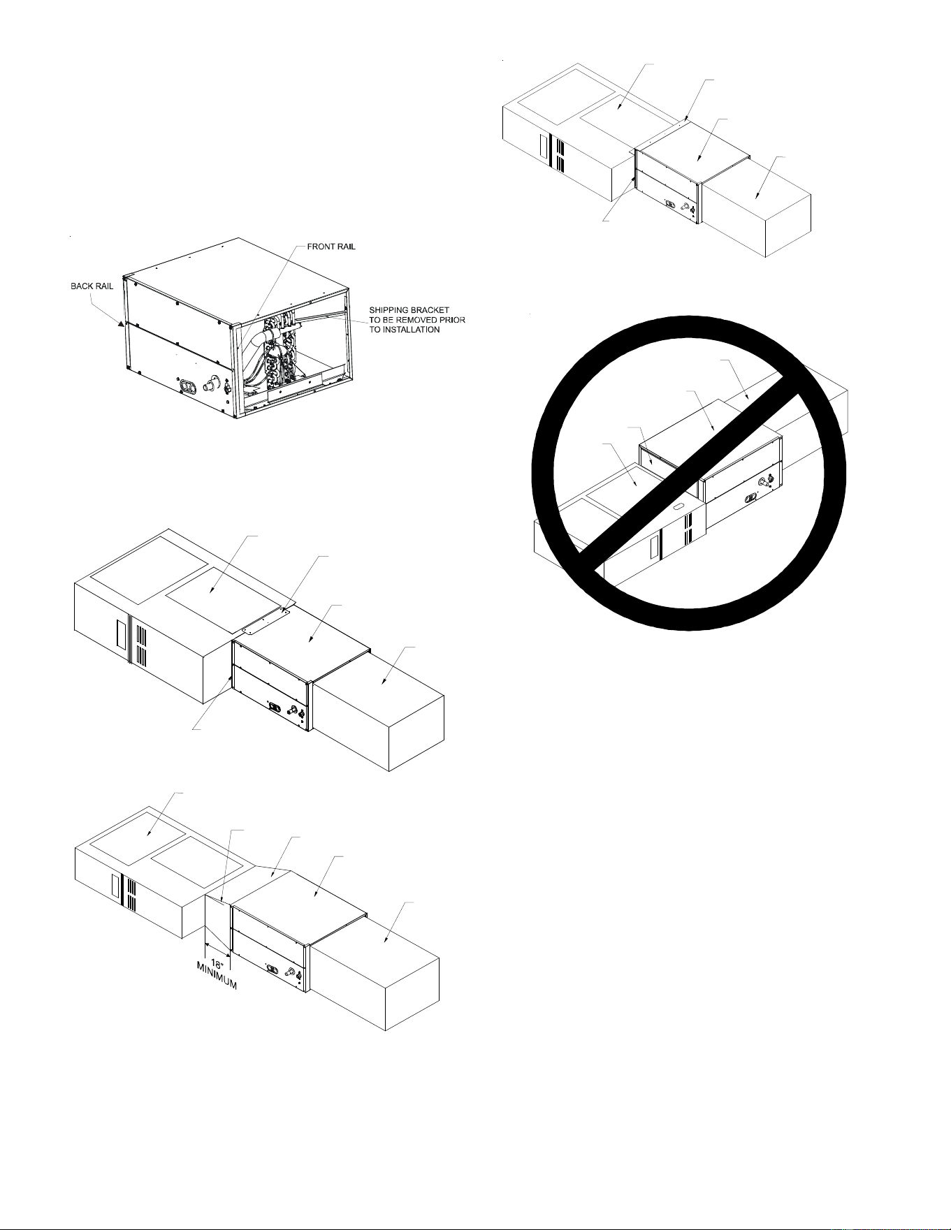
Application Information
Install this coil upstream (discharge air) of the furnace and
install downstream (return air) of the air handler. This coil is bi-
directional coil and can be installed in either the left or right
direction. Determine the coil direction by the side that allows
the best access.
RIGHT APPLICATION LEFT APPLICATION
Figure 1
Front View (for Right & Left Hand Application)
There is no conversion required to reverse from right to left
application. Attach the duct flanges to the discharge side of
the unit. If the coil and furnace combination are not similar in
depth and width, use a field-supplied transition to center the
furnace and coil openings (see figure 3). The supplied Z-bracket
attachment should be used to attach the coil to a narrower
furnace when the furnace is one size smaller than the coil (i.e.
coil height = 17.5-inches and furnace width = 14-inches) (See
figure 3). Figure 3a indicates incorrect coil/furnace attach-
ment method.
IO-285L
02/2018
2
Duct Flange Attachment
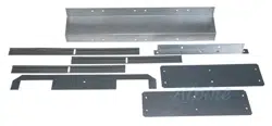
1. Remove the shipping bracket spanning the A-Coil apex
to the rear of the wrapper on all models prior to installa-
tion.
2. The bottom duct flange for the supply plenum side is
shipped unattached. Carefully insert the flange into bot-
tom rail and use a 5/16" screw to attach at the middle of
the flange.
Figure 2
Horizontal Right Application
3. Using the hardware and brackets provided, attach the coil
to the furnace then attach the plenum to the coil (Figure 3).
COIL
PLENUM
FRONT BRACKET
ACCESSORY
FURNACE
TOP & BACK
BRACKET
ACCESSORY
COIL
FURNACE
PLENUM
TRANSITION
MAX 10° ANGLE
ACCESSORY
TOP & BACK
ACCESSORY
FRONT BRACKET
COIL
FURNACE
BRACKET
PLENUM
(Z-BRACKET WITH NARROW FURNACE)
Figure 3
Furnace, Coil and Plenum Installation
COIL
FURNACE
PLENUM
DUCT BOARD, SHEET
METAL OR OTHER
FILLER MATERIAL
Figure 3a
Incorrrect Furnace, Coil and Plenum Installation
Using tape or mastic seal between the coil and furnace and
the coil and plenum.
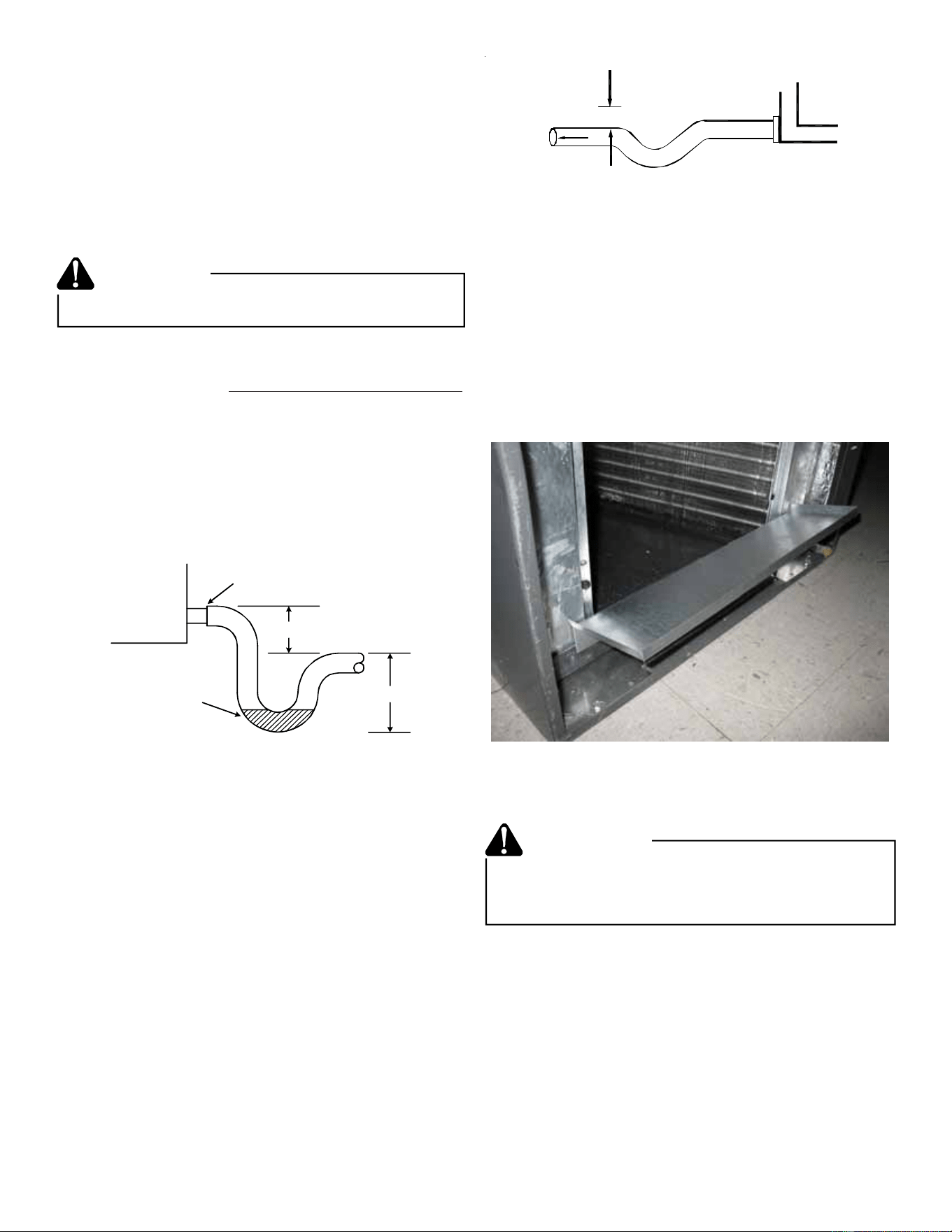
Condensate Drain Piping
When coils are installed above ceilings, or in other locations
where damage from condensate overflow may occur, it is MAN-
DATORY to install a field-fabricated auxiliary drain pan under
the coil cabinet enclosure. Drain lines from the auxiliary pan
must be installed and terminated so that the homeowner can
see water discharges.
The coil drain pan has a primary and an optional secondary
drain with 3/4" NPT female connections. The connectors re-
quired can be 3/4" NPT male either PVC or metal pipe and
should be hand tightened to a torque of no more than 37 in-lbs.
to prevent damage to the drain pan connection. An insertion
depth between .355 to .485 inches (3-5 turns) should be ex-
pected at this torque. If using a copper drain line, solder a
short piece of pipe to the connector before installing a drain
fitting. DO NOT over torque the 3/4” copper connector to the
plastic drain connection.
1. Ensure drain pan hole is NOT obstructed.
2. To prevent potential sweating and dripping on finished
space, it may be necessary to insulate the condensate
drain line located inside the building. Use Armaflex
®
or
similar material.
3
A Secondary Condensate Drain Connection has been pro-
vided for areas where the building codes require it. Pitch the
drain line 1/4" per foot to provide free drainage. Insulate
drain lines (primary and secondary) located inside the build-
ing to prevent sweating. Install a condensate trap in the pri-
mary drain line to ensure proper drainage. If the secondary
line is required, run the line separately from the primary drain
and end it where it can be easily seen.
NOTE: Water coming from this line means the coil primary
drain is plugged and needs clearing.
If secondary drain is not installed, the secondary access
must be plugged.
CAUTION
NOTE: Trapped lines are required by many local codes. In the
absence of any prevailing local codes, please refer to the
requirements listed in the Uniform Mechanical Building Code.
A drain trap in a draw-through application prevents air from
being drawn back through the drain line during fan operation
thus preventing condensate from draining, and if connected to
a sewer line to prevent sewer gases from being drawn into the
airstream during blower operation. In a blow-through applica-
tion the drain trap prevents conditioned air from escaping. It is
permissible in this application to use a shallow trap design
sometimes referred to as a running trap.
Cased Coil
3" MIN.
POSITIVE LIQUID SEAL
REQUIRED AT TRAP
Drain
Connection
2" MIN.
Figure 4
Condensate Drain Trap
The depth of a running trap (Figure 5) should be either 1" or a
depth that permits unrestricted condensate drainage without
excessive air discharge.
Field experience has shown condensate drain traps with an
open vertical Tee between the air handler and the condensate
drain trap can improve condensate drainage in some applica-
tions, but may cause excessive air discharge out of the open
Tee. The manufacturer does not prohibit this type of drain but
we also do not recommend it due to the resulting air leakage.
Regardless of the condensate drain design used, it is the
installer’s responsibility to ensure the condensate drain sys-
tem is of sufficient design to ensure proper condensate re-
moval from the coil drain pan.
PITCH
TOWARDS
DRAIN
1” MIN
TRAP
CONDENSATE
DRAIN CONN.
CONNECT DRAIN
SAME SIZE AS ON
UNIT OR LARGER
Figure 5
Running Trap
Horizontal Coil Water Blower-Off Bracket
CHPF4860 coils are shipped with an accessory kit containing
a sheet metal bracket. For horizontal-left applications where
the airflow may exceed 1600 CFM, this bracket must be
installed on the left side of the drain pan as shown in Figure 6.
Figure 6
Horizontal Blow-Off Bracket
Refrigerant Lines
A quenching cloth is strongly recommended to
prevent scorching or marring of the equipment
finish when welding close to the painted surfaces.
Use brazing alloy of 5% minimum silver content.
WARNING
All cut ends are to be round, burr free, and cleaned. Any other
condition increases the chance of a refrigerant leak. Use a
pipe cutter to remove the closed end of the spun closed suc-
tion line.
To avoid overheating after brazing, quench all welded joints
with water or a wet rag.
For the correct tubing size, follow the specification for the con-
denser/heat pump
4
The coil is shipped under pressure. Follow these
instructions to prevent injury.
WARNING
Applying too much heat to any tube can melt the tube. Torch
heat required to braze tubes of various sizes must be
proportional to the size of the tube. Service personnel must
use the appropriate heat level for the size of the tube being
brazed.
CAUTION
NOTE: Tubes of smaller size require less heat to bring the
tube to brazing temperature before adding brazing alloy. The
use of a heat shield when brazing is recommended to avoid
burning the serial plate or the finish on the unit.
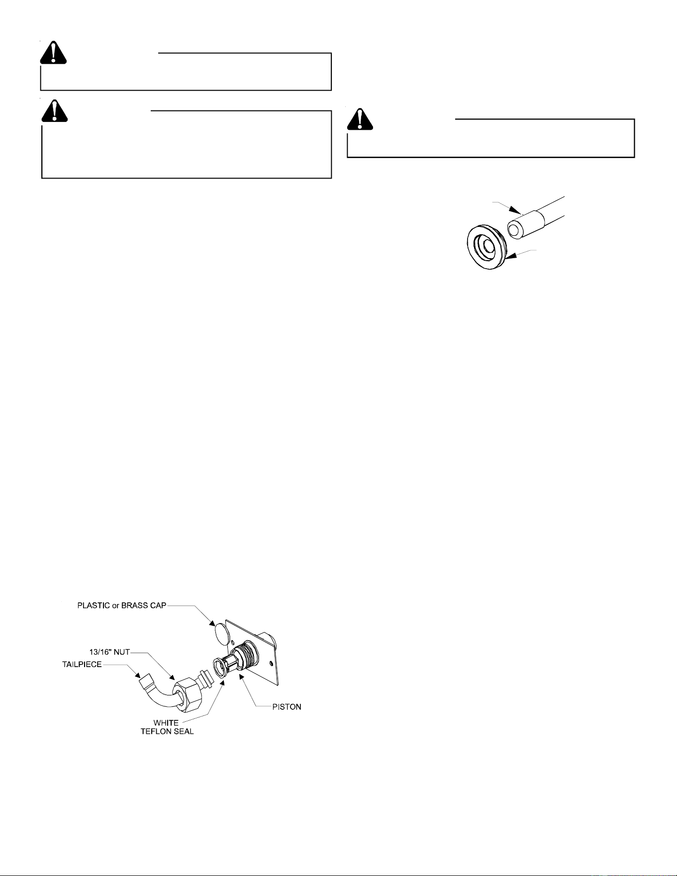
Special Instructions
This coil comes equipped with a check style flowrator for refrig-
erant management. For most installations with matching ap-
plications, no change to the flowrator orifice is required. How-
ever, in mix-matched applications, a flowrator change may be
required. See the Piston Kit Chart or consult your local dis-
tributor for details regarding mix-matched orifice sizing. If the
mix-match application requires a different piston size, change
the piston in the distributor on the indoor coil before installing
the coil and follow the procedure shown below.
1. Loosen the 13/16 nut 1 TURN ONLY to allow high pres-
sure tracer gas to escape. No gas indicates a possible
leak.
2. After the gas has escaped, remove the nut and discard
the plastic or brass cap.
3. Remove the check piston to verify it is correct and then
replace the piston. See piston kit chart in instructions.
4. Use a tube cutter to remove the spin closure on the suc-
tion line.
5. Slide the 13/16 nut into place on the tailpiece supplied in
the literature bag or with the unit.
6. Braze tailpiece to the line set liquid tube.
Figure 7
Flowrator
7. Insert the suction line into the connection, slide the insu-
lation and the rubber grommet at least 18" away from the
braze joint. Braze suction line.
8. AFTER THE TAILPIECE HAS COOLED, confirm posi-
tion of the white Teflon
®
seal and hand tighten the 13/16
nut.
9. Torque the 13/16 nut to 10-25 ft-lbs. or tighten 1/6 turn.
Excessive torque can cause orifices to stick. Use the proper
torque settings when tightening orifices.
CAUTION
10. Replace suction line grommet and insulation.
RUBBER
GROMMET
SUCTION LINE
WITH SPIN CLOSURE
Figure 8
Suction Line Grommet
11. Check fittings for leaks after complete installation. Evacu-
ate and charge on the low side.
NOTE: With the piston in the distributor, the seal end should
point inside the distributor body and should not be seen when
looking into the end of distributor. Make sure the piston is free
to rotate, and move up and down in the distributor body.
IMPORTANT: Note 2 in the Piston Kit Chart does not apply to
CH coils.
Aluminum Indoor Coil Cleaning
(Qualified Servicer Only)
This unit is equipped with an aluminum tube evaporator coil.
The safest way to clean the evaporator coil is to simply flush
the coil with water. This cleaning practice remains as the
recommended cleaning method for both copper tube and alu-
minum tube residential cooling coils.
An alternate cleaning method is to use one of the products
listed in the technical publication TP-109 (shipped in the lit-
erature bag with the unit) to clean the coils. The cleaners
listed are the only agents deemed safe and approved for use to
clean round tube aluminum coils. TP-109 is available on the
web site in Partner Link > Service Toolkit.
NOTE: Ensure coils are rinsed well after use of any chemical
cleaners.

5
THIS PAGE LEFT BLANK INTENTIONALLY

6
THIS PAGE LEFT BLANK INTENTIONALLY

7
THIS PAGE LEFT BLANK INTENTIONALLY
8
is a registered trademark of Maytag Corporation or its related companies and is used under license. All rights reserved.
NOTE: SPECIFICATIONS AND PERFORMANCE DATA LISTED HEREIN ARE SUBJECT TO CHANGE WITHOUT NOTICE
5151 San Felipe, Suite 500, Houston, TX 77056
© 2005-2006, 2009-2013, 2015, 2018
Goodman Manufacturing Company, L.P.
Visit our website at www.daikincomfort.com, www.goodmanmfg.com or www.amana-hac.com for information on:
• Products
• Warranties
• Customer Services
• Parts
• Contractor Program and Training
• Financing Options
CUSTOMER FEEDBACK
We are very interested in all product comments.
Please fill out the feedback form on one of the following links:
Daikin Products: (https://daikincomfort.com/contact-us)
Goodman® Brand Products: (http://www.goodmanmfg.com/about/contact-us).
Amana® Brand Products: (http://www.amana-hac.com/about-us/contact-us).
You can also scan the QR code on the right for the product brand you purchased
to be directed to the feedback page.
PRODUCT REGISTRATION
Thank you for your recent purchase. Though not required to get the protection of
the standard warranty, registering your product is a relatively short process, and
entitles you to additional warranty protection, except that failure by California
and Quebec residents to register their product does not diminish their warranty
rights.
For Product Registration, please register as follows:
Daikin Products:
(https://daikincomfort.com/owner-support/product-registration).
Goodman® Brand products: (https://www.goodmanmfg.com/product-registration).
Amana® Brand products: (http://www.amana-hac.com/product-registration).
You can also scan the QR code on the right for the product brand you purchased
to be directed to the Product Registration page.
DAIKIN
GOODMAN® BRAND
AMANA® BRAND
AMANA® BRAND
GOODMAN® BRAND
DAIKIN