1
Service Instructions
ANX, SSX, ASX, GSX, DSX
Condensing Units,
ANZ, SSZ, ASZ, GSZ, DSZ, VSX, VSZ
Split System Heat Pumps
with R-410A Refrigerant
Blowers, Coils, & Accessories
This manual is to be used by qualied, professionally trained HVAC technicians
only. The manufacturer does not assume any responsibility for property damage
or personal injury due to improper service procedures or services performed by
an unqualied person.
Copyright ©2006-2019 Goodman Manufacturing Company, L.P.
RS6200006r97
December 2019
2
IMPORTANT INFORMATION
Table of Contents
IMPORTANT INFORMATION.............................2
PRODUCT IDENTIFICATION - MODEL TREE..4
COILS.................................................................6
BLOWERS..........................................................8
AIR HANDLERS.................................................9
LIGHT COMMERCIAL......................................11
PRODUCT IDENTIFICATION - CHARTS........12
LIGHT COMMERCIAL......................................12
SPLIT SYSTEM HEAT PUMPS........................13
AIR HANDLERS................................................41
COILS................................................................49
ACCESSORIES - LIGHT COMMERCIAL.........53
MODELS TO kITS MATCHUP...........................54
ASSOCIATED KITS..........................................63
PRODUCT DESIGN..........................................75
SYSTEM OPERATION......................................78
TROUBLESHOOTING CHART.........................82
SERVICING TABLE OF CONTENTS................83
IMPORTANT INFORMATION
Pride and workmanship go into every product to provide our customers with quality products. It is possible, however, that during its
lifetime a product may require service. Products should be serviced only by a qualied service technician who is familiar with the safety
procedures required in the repair and who is equipped with the proper tools, parts, testing instruments and the appropriate service
manual. REVIEW ALL SERVICE INFORMATION IN THE APPROPRIATE SERVICE MANUAL BEFORE BEGINNING REPAIRS.
IMPORTANT NOTICES FOR CONSUMERS AND SERVICERS
RECOGNIZE SAFETY SYMBOLS, WORDS AND LABELS
T
HIS
UNIT
SHOULD
NOT
BE
CONNECTED
TO
.
OR
USED
IN
CONJUNCTION
WITH
,
ANY
DEVICES
THAT
ARE
NOT
DESIGN
CERTIFIED
FOR
USE
WITH
THIS
UNIT
OR
HAVE
NOT
BEEN
TESTED
AND
APPROVED
BY
THE
MANUFACTURER
.
S
ERIOUS
PROPERTY
DAMAGE
OR
PERSONAL
INJURY
,
REDUCED
UNIT
PERFORMANCE
AND
/
OR
HAZARDOUS
CONDITIONS
MAY
RESULT
FROM
THE
USE
OF
DEVICES
THAT
HAVE
NOT
BEEN
APPROVED
OR
CERTIFIED
BY
THE
MANUFACTURER
.
HIGH VOLTAGE
DISCONNECT ALL POWER BEFORE SERVICING OR INSTALLING THIS
UNIT. MULTIPLE POWER SOURCES MAY BE PRESENT.
FAILURE TO DO SO MAY CAUSE PROPERTY DAMAGE, PERSONAL INJURY
OR DEATH.
T
O
PREVENT
THE
RISK
OF
PROPERTY
DAMAGE
,
PERSONAL
INJURY
,
OR
DEATH
,
DO
NOT
STORE
COMBUSTIBLE
MATERIALS
OR
USE
GASOLINE
OR
OTHER
FLAMMABLE
LIQUIDS
OR
VAPORS
IN
THE
VICINITY
OF
THIS
APPLICANCE
.
O
NLY
PERSONNEL
THAT
HAVE
BEEN
TRAINED
TO
INSTALL
,
ADJUST
,
SERVICE
OR
REPAIR
(
HEREINAFTER
, “
SERVICE
”)
THE
EQUIPMENT
SPECIFIED
IN
THIS
MANUAL
SHOULD
SERVICE
THE
EQUIPMENT
. T
HE
MANUFACTURER
WILL
NOT
BE
RESPONSIBLE
FOR
ANY
INJURY
OR
PROPERTY
DAMAGE
ARISING
FROM
IMPROPER
SERVICE
OR
SERVICE
PROCEDURES
. I
F
YOU
SERVICE
THIS
UNIT
,
YOU
ASSUME
RESPONSIBILITY
FOR
ANY
INJURY
OR
PROPERTY
DAMAGE
WHICH
MAY
RESULT
. I
N
ADDITION
,
IN
JURISDICTIONS
THAT
REQUIRE
ONE
OR
MORE
LICENSES
TO
SERVICE
THE
EQUIPMENT
SPECIFIED
IN
THIS
MANUAL
,
ONLY
LICENSED
PERSONNEL
SHOULD
SERVICE
THE
EQUIPMENT
. I
MPROPER
INSTALLATION
,
ADJUSTMENT
,
SERVICING
OR
REPAIR
OF
THE
EQUIPMENT
SPECIFIED
IN
THIS
MANUAL
,
OR
ATTEMPTING
TO
INSTALL
,
ADJUST
,
SERVICE
OR
REPAIR
THE
EQUIPMENT
SPECIFIED
IN
THIS
MANUAL
WITHOUT
PROPER
TRAINING
MAY
RESULT
IN
PRODUCT
DAMAGE
,
PROPERTY
DAMAGE
,
PERSONAL
INJURY
OR
DEATH
.
To locate an authorized servicer, please consult your telephone book or the dealer from whom you purchased this
product. For further assistance, please contact:
CONSUMER INFORMATION LINE
GOODMAN® BRAND PRODUCTS
TOLL FREE
1-877-254-4729 (U.S. only)
email us at: [email protected]
fax us at: (713) 856-1821
(Not a technical assistance line for dealers.)
AMANA® BRAND PRODUCTS
TOLL FREE
1-877-254-4729 (U.S. only)
email us at: [email protected]
fax us at: (713) 856-1821
(Not a technical assistance line for dealers.)
Outside the U.S., call 1-713-861-2500.
(Not a technical assistance line for dealers.) Your telephone company will bill you for the call.
is a registered trademark of Maytag Corporation or its related companies and is used under license. All rights reserved.
3
IMPORTANT INFORMATION
SAFE REFRIGERANT HANDLING
While these items will not cover every conceivable situation, they should serve as a useful guide.
R
EFRIGERANTS
ARE
HEAVIER
THAN
AIR
. T
HEY
CAN
“
PUSH
OUT
”
THE
OXYGEN
IN
YOUR
LUNGS
OR
IN
ANY
ENCLOSED
SPACE
. T
O
AVOID
POSSIBLE
DIFFICULTY
IN
BREATHING
OR
DEATH
:
• N
EVER
PURGE
REFRIGERANT
INTO
AN
ENCLOSED
ROOM
OR
SPACE
. B
Y
LAW
,
ALL
REFRIGERANTS
MUST
BE
RECLAIMED
.
• I
F
AN
INDOOR
LEAK
IS
SUSPECTED
,
THOROUGHLY
VENTILATE
THE
ARA
BEFORE
BEGINNING
WORK
.
• L
IQUID
REFRIGERANT
CAN
BE
VERY
COLD
. T
O
AVOID
POSSIBLE
FROSTBITE
OR
BLINDNESS
,
AVOID
CONTACT
WITH
REFRIGERANT
AND
WAR
GLOVES
AND
GOGGLES
. I
F
LIQUID
REFRIGERANT
DOES
CONTACT
YOUR
SKIN
OR
EYES
,
SEEK
MEDICAL
HELP
IMMEDIATELY
.
• A
LWAYS
FOLLOW
EPA
REGULATIONS
. N
EVER
BURN
REFRIGERANT
,
AS
POISONOUS
GAS
WILL
BE
PRODUCED
.
T
O
AVOID
POSSIBLE
EXPLOSION
:
• N
EVER
APPLY
FLAME
OR
STEAM
TO
A
REFRIGERANT
CYLINDER
. I
F
YOU
MUST
HEAT
A
CYLINDER
FOR
FASTER
CHARGING
,
PARTIALLY
IMMERSE
IT
IN
WARM
WATER
.
• N
EVER
FILL
A
CYLINDER
MORE
THAN
80%
FULL
OF
LIQUID
REFRIGERANT
.
• N
EVER
ADD
ANYTHING
OTHER
THAN
R-22
TO
AN
R-22
CYLINDER
OR
R-
410A
TO
AN
R-410A
CYLINDER
. T
HE
SERVICE
EQUIPMENT
USED
MUST
BE
LISTED
OR
CERTIFIED
FOR
THE
TYPE
OF
REFRIGERANT
USED
.
• S
TORE
CYLINDERS
IN
A
COOL
,
DRY
PLACE
. N
EVER
USE
A
CYLINDER
AS
A
PLATFORM
OR
A
ROLLER
.
THE UNITED STATES ENVIRONMENTAL PROTECTION AGENCY ("EPA")
HAS ISSUED VARIOUS REGULATIONS REGARDING THE INTRODUCTION AND
DISPOSAL
OF REFRIGERANTS INTRODUCED INTO THIS UNIT. FAILURE TO
FOLLOW
THESE REGULATIONS
MAY HARM
THE ENVIRONMENT AND CAN
LEAD
TO THEH IMPOSITION OF SUBSTANTIAL FINES. THESE REGULATIONS
MAY
VARY BY JURISDICTION. SHOULD QUESTIONS ARISE, CONTACT YOUR
LOCAL
EPA OFFICE.
T
O
AVOID
POSSIBLE
EXPLOSION
,
USE
ONLY
RETURNABLE
(
NOT
DISPOSABLE
)
SERVICE
CYLINDERS
WHEN
REMOVING
REFRIGERANT
FROM
A
SYSTEM
.
• E
NSURE
THE
CYLINDER
IS
FREE
OF
DAMAGE
WHICH
COULD
LEAD
TO
A
LEAK
OR
EXPLOSION
.
• E
NSURE
THE
HYDROSTATIC
TEST
DATE
DOES
NOT
EXCEED
5
YEARS
.
• E
NSURE
THE
PRESSURE
RATING
MEETS
OR
EXCEEDS
400 PSIG.
W
HEN
IN
DOUBT
,
DO
NOT
USE
CYLINDER
.
T
O
AVOID
POSSIBLE
INJURY
,
EXPLOSION
OR
DEATH
,
PRACTICE
SAFE
HANDLING
OF
REFRIGERANTS
.
S
YSTEM
CONTAMINANTS
,
IMPROPER
SERVICE
PROCEDURE
AND
/
OR
PHYSICAL
ABUSE
AFFECTING
HERMETIC
COMPRESSOR
ELECTRICAL
TERMINALS
MAY
CAUSE
DANGEROUS
SYSTEM
VENTING
.
The successful development of hermetically sealed
refrigeration compressors has completely sealed the
compressor's moving parts and electric motor inside a
common housing, minimizing refrigerant leaks and the
hazards sometimes associated with moving belts, pulleys
or couplings.
Fundamental to the design of hermetic compressors is
a method whereby electrical current is transmitted to the
compressor motor through terminal conductors which pass
through the compressor housing wall. These terminals are
sealed in a dielectric material which insulates them from
the housing and maintains the pressure tight integrity of
the hermetic compressor. The terminals and their dielectric
embedment are strongly constructed, but are vulnerable
to careless compressor installation or maintenance
procedures and equally vulnerable to internal electrical
short circuits caused by excessive system contaminants.
In either of these instances, an electrical short between
the terminal and the compressor housing may result in
the loss of integrity between the terminal and its dielectric
embedment. This loss may cause the terminals to be
expelled, thereby venting the vaporous and liquid contents
of the compressor housing and system.
A venting compressor terminal normally presents no
danger to anyone, providing the terminal protective cover is
properly in place.
If, however, the terminal protective cover is not properly in
place, a venting terminal may discharge a combination of
(a) hot lubricating oil and refrigerant
(b) ammable mixture (if system is
contamnated with air)
in a stream of spray which may be dangerous to anyone in
the vicinity. Death or serious bodily injury could occur.
Under no circumstances is a hermetic compressor to be
electrically energized and/or operated without having the
terminal protective cover properly in place.
See Service Section S-17 for proper servicing.

4
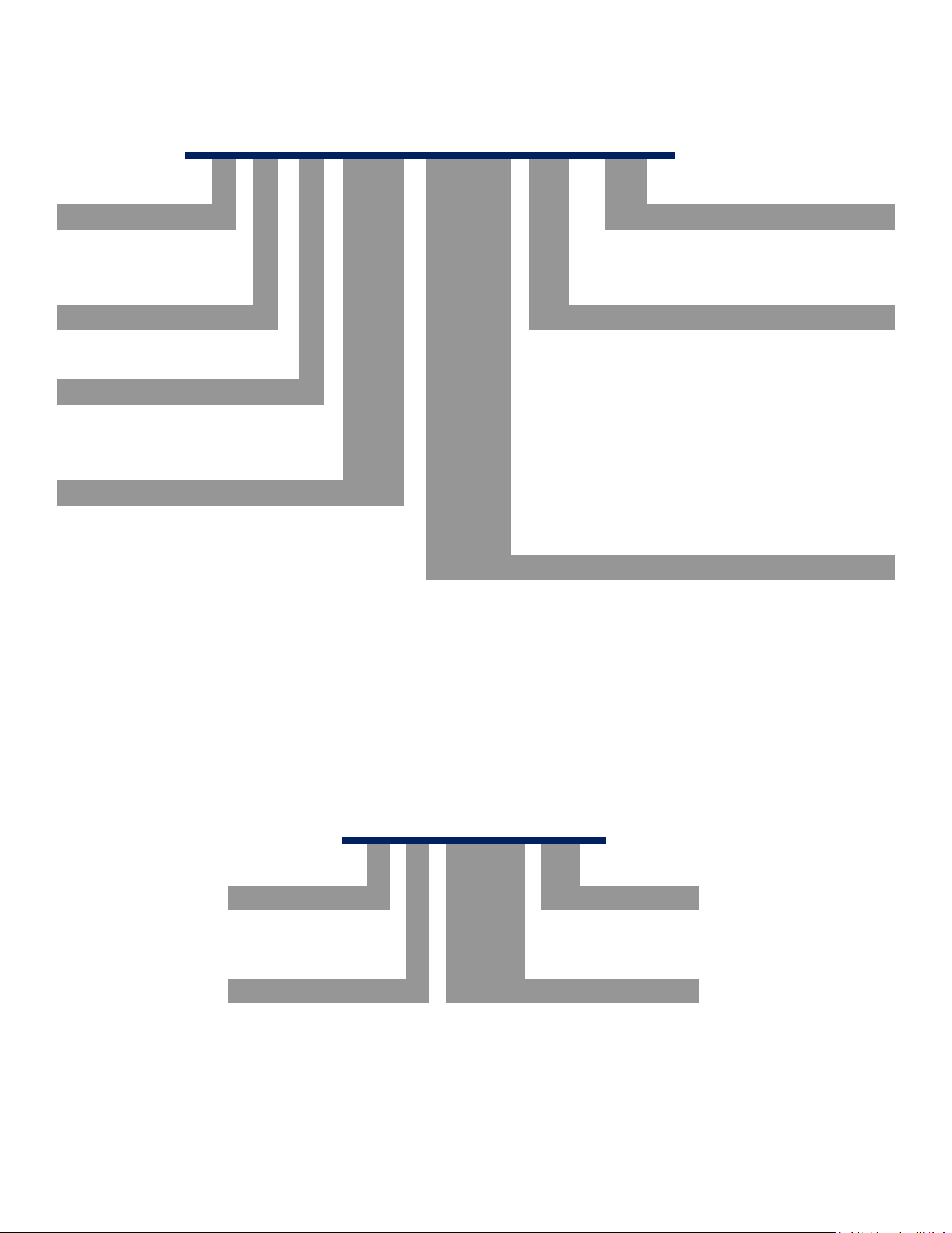
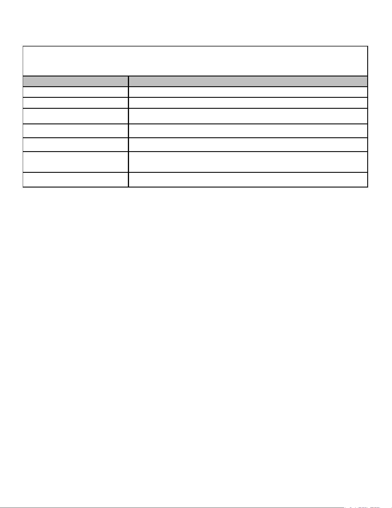
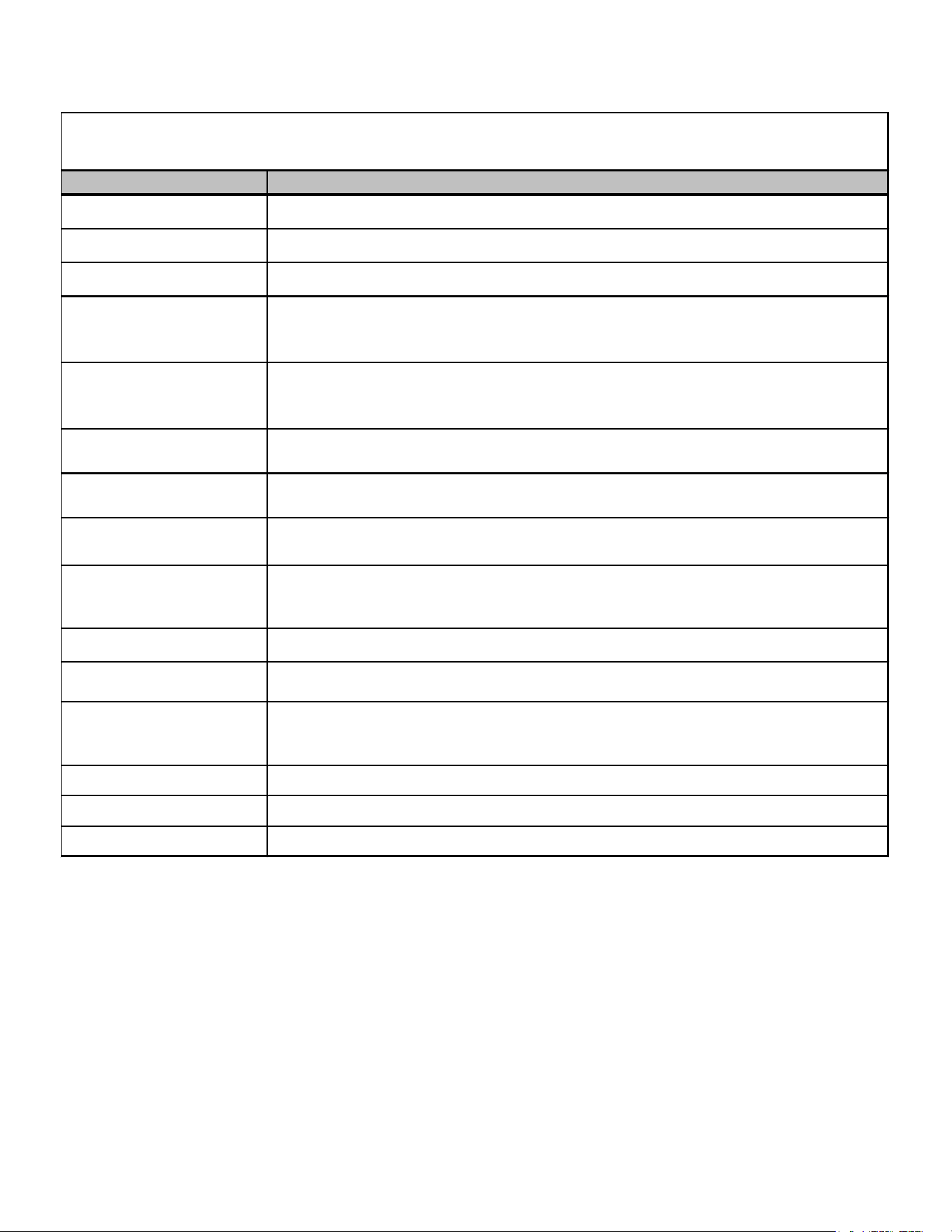
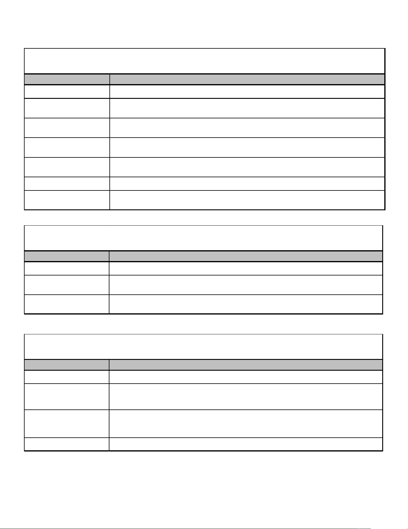
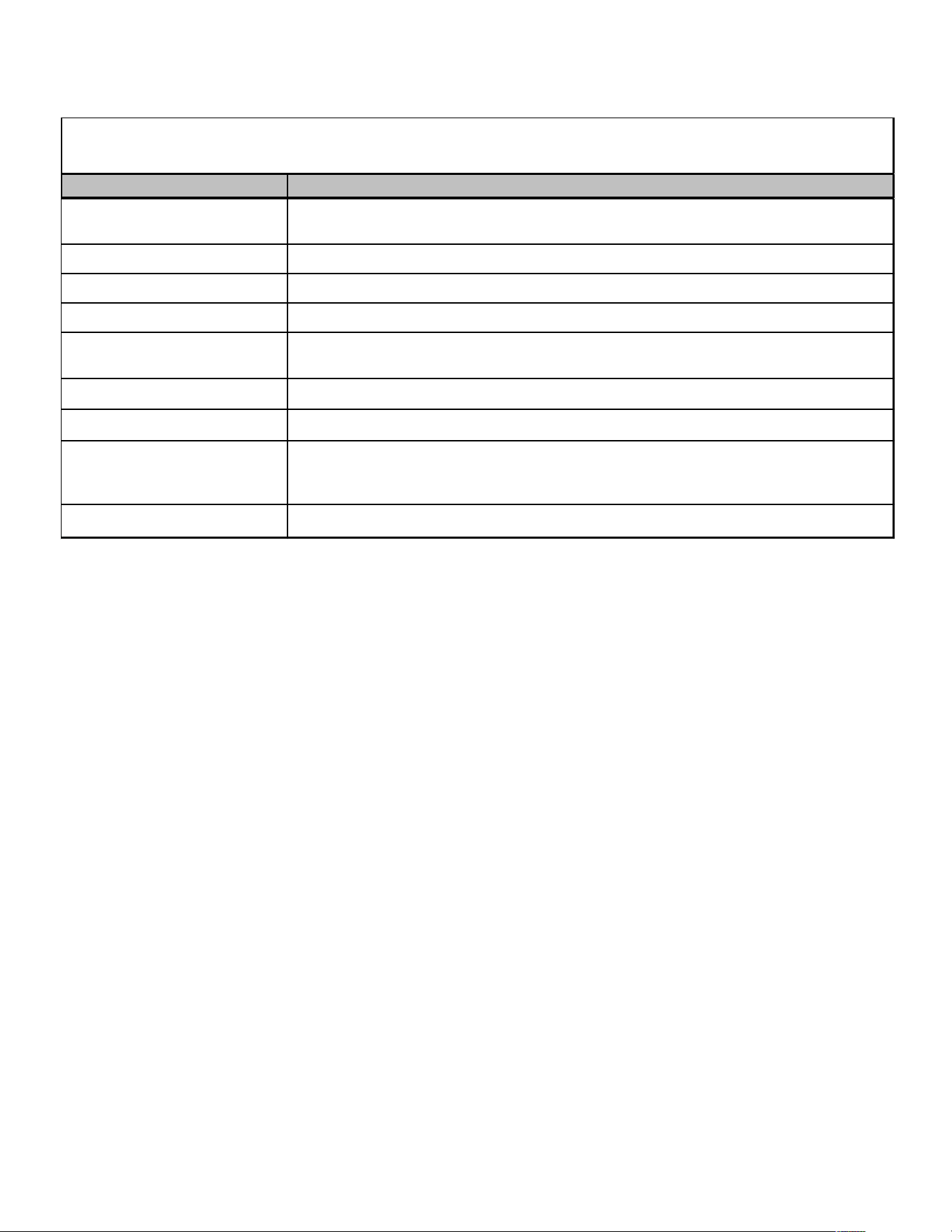
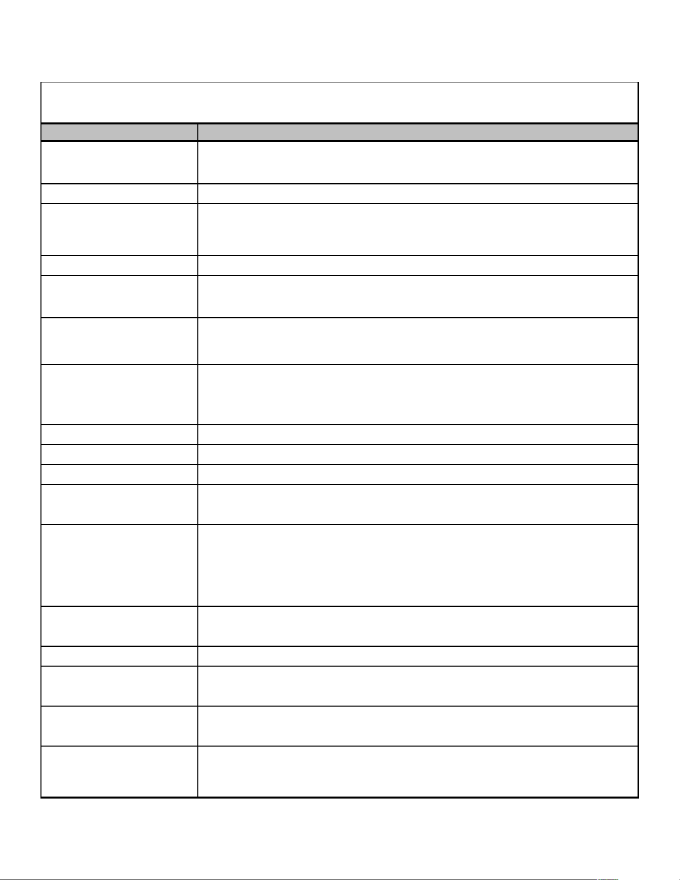
A N Z 13 018 1 AA
1 2 3 4,5 6,7,8 9
10,11
Brand
A -
Type
N 1 -
208/230V Single-Phase 60 Hz
2 -
220/240V Single-Phase 50 Hz
Type 3 - 208/230V Three-Phase 60 Hz
X: Condenser R-410A 4 - 460V Three-Phase 60 Hz
Z: Heat Pump R-410A 5 - 380/415V Three-Phase 50 Hz
SEER
11 - 11 SEER
13 - 13 SEER
14 - 14 SEER
16 - 16 SEER
18 = 1-1/2 Tons 42 = 3-1/2 Tons
24 = 2 Tons
48 = 4 Tons
30 = 2-1/2 Tons 59 = 5 Tons
36 = 3 Tons 60 = 5 Tons
61 = 5 Tons
Nominal Capacity
Amana® brand
Engineering
Major/Minor Revisions
Voltage
Del uxe Spl i t System
PRODUCT IDENTIFICATION - MODEL TREES
PRODUCT IDENTIFICATION

5
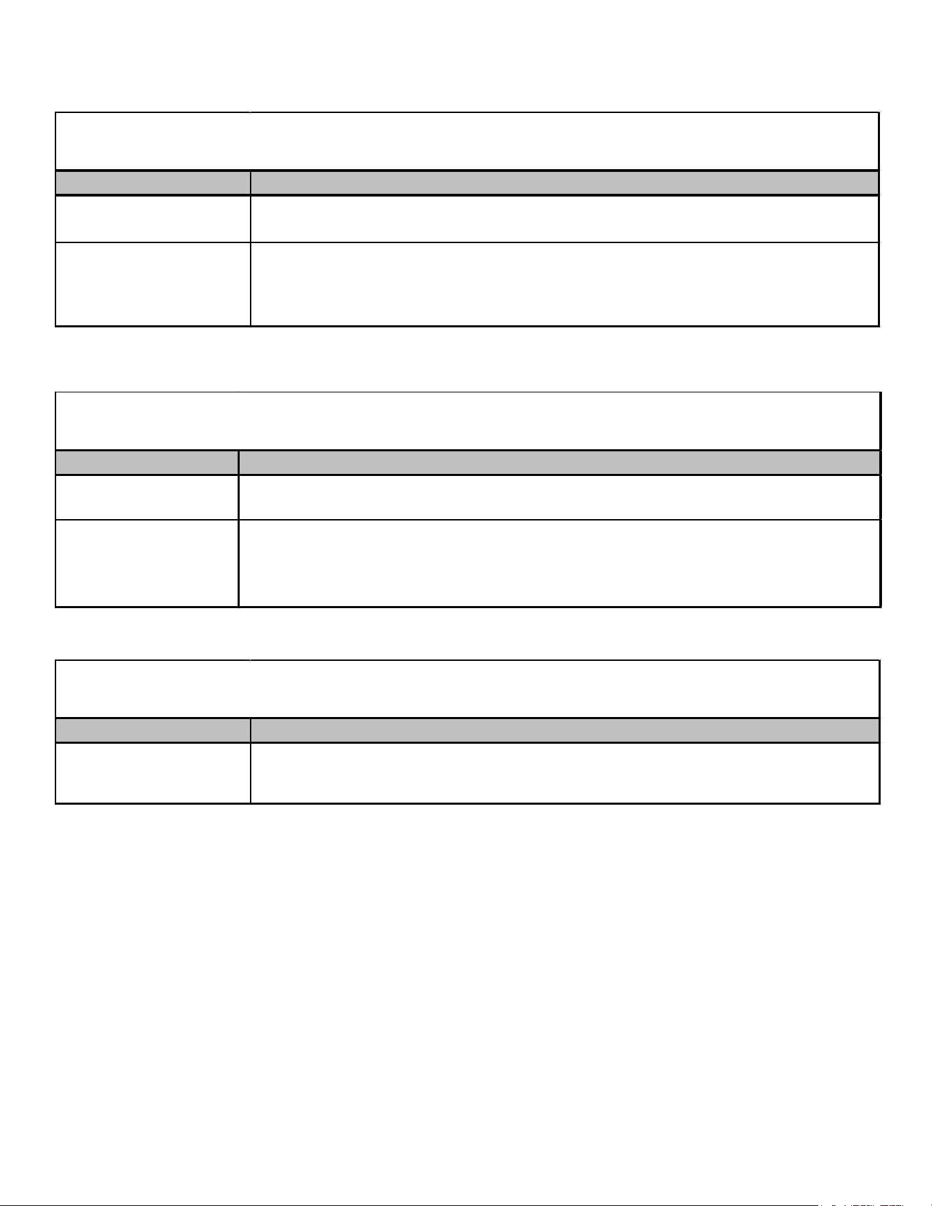
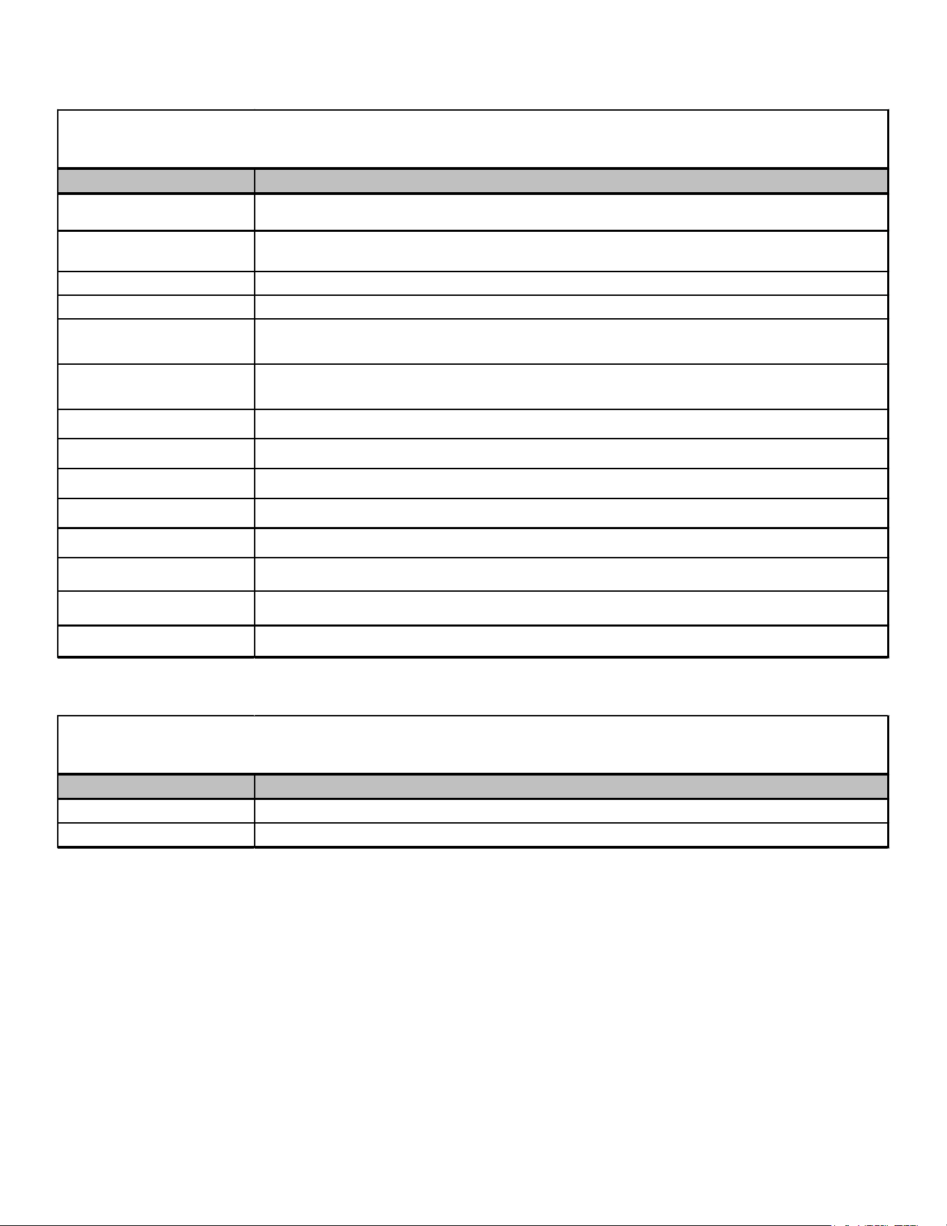
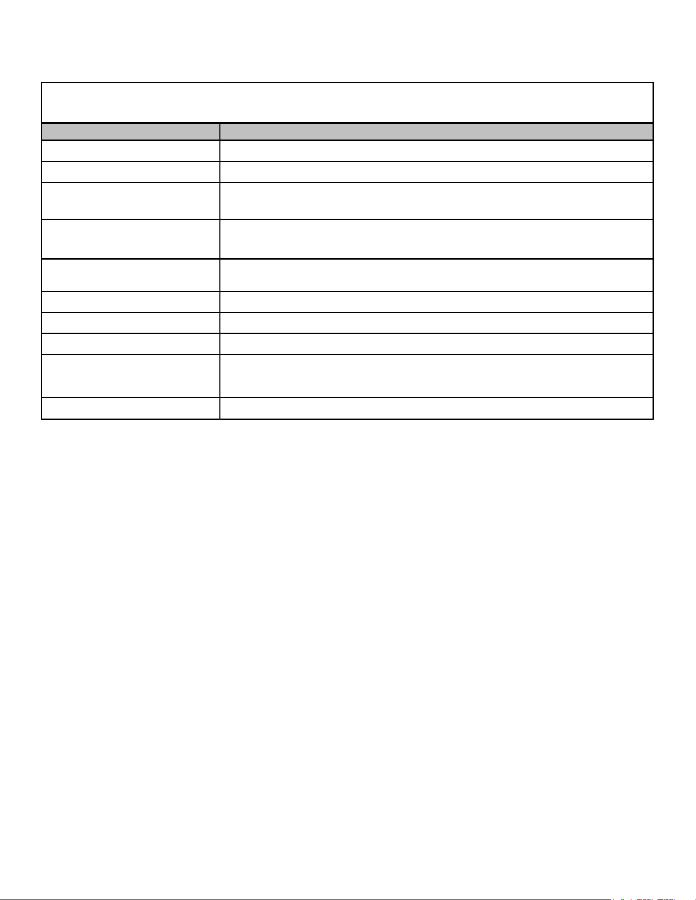
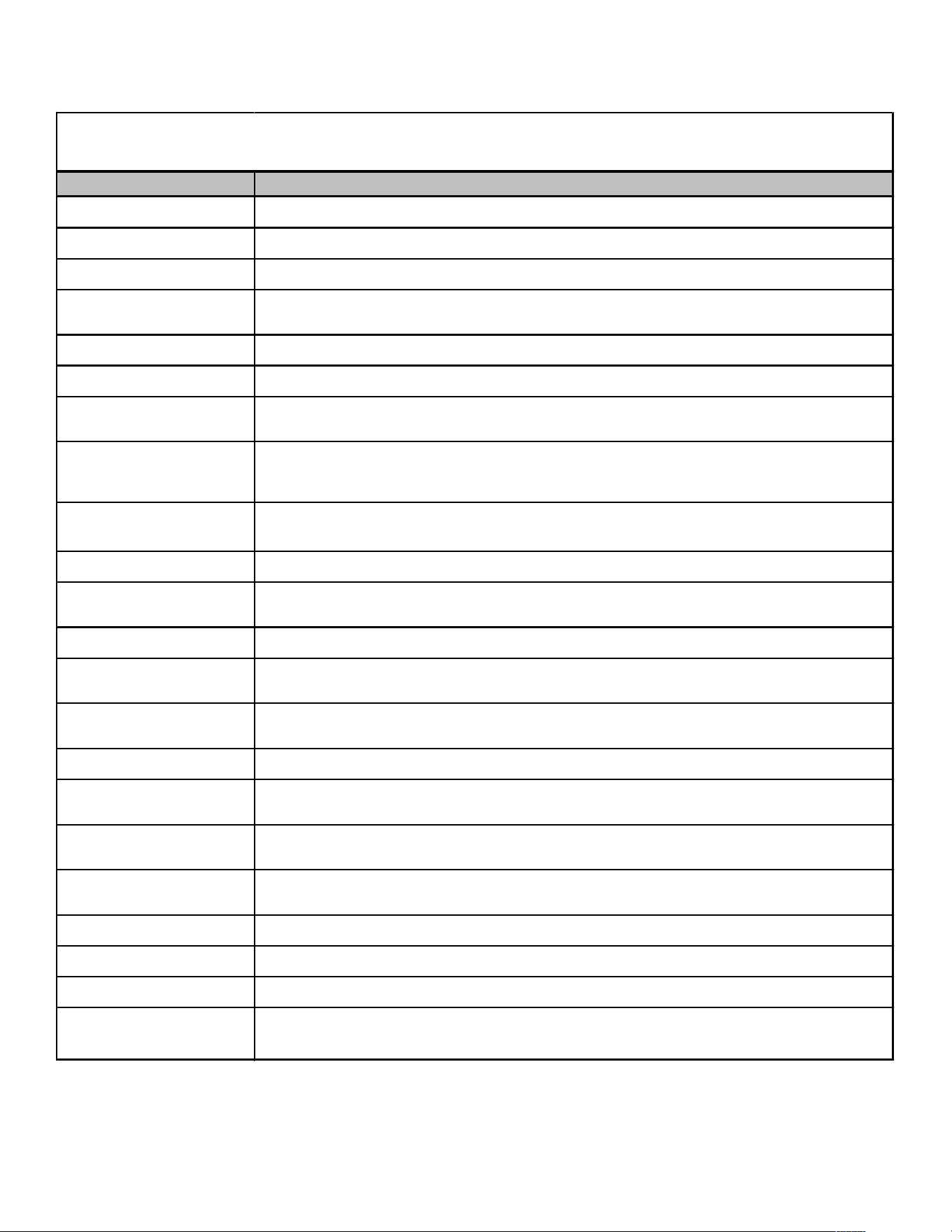
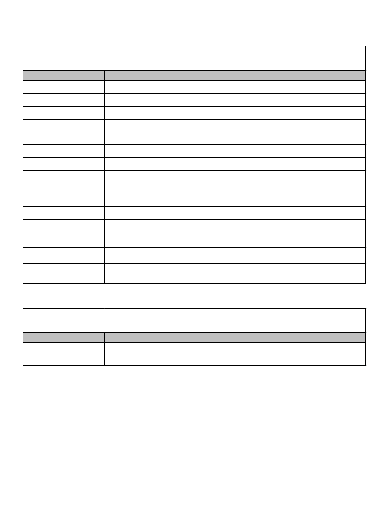
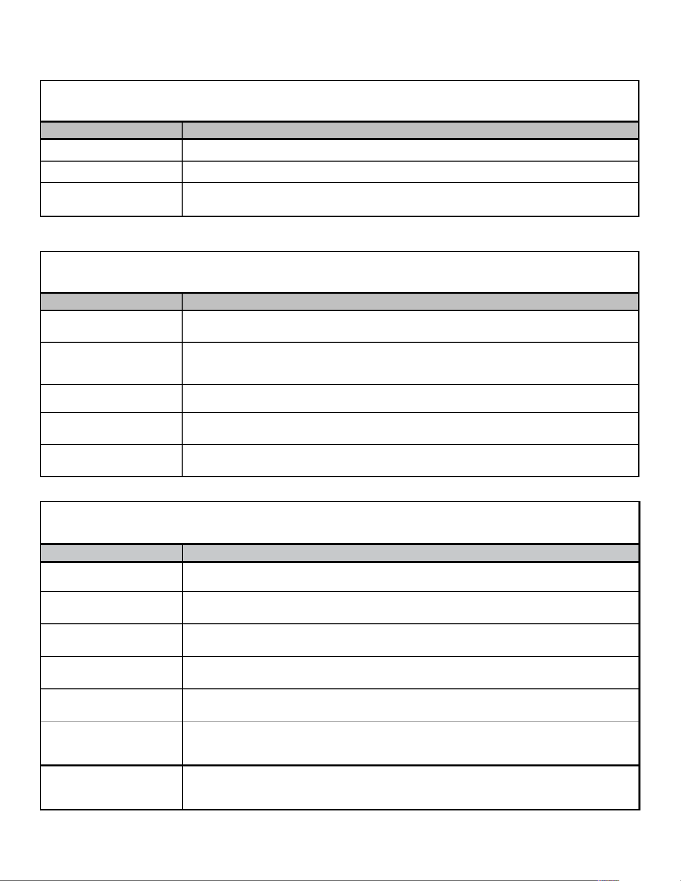
S S Z 14
0
1 AA
1 2 3 4,5
6
9
10,11
Brand
G
(Standard Feature Set)
S
(Hi gh Feature Set)
A
Del uxe
D
Del uxe
V
Type
S 1 - 208/230V Single-Phase 60 Hz
2 - 220/240V Single-Phase 50 Hz
Type 3 - 208/230V Three-Phase 60 Hz
X: Condenser R-410A 4 - 460V Three-Phase 60 Hz
Z: Heat Pump R-410A 5 - 380/415V Three-Phase 50 Hz
SEER
13 - 13 SEER 18 = 1-1/2 Tons 42 = 3-1/2 Tons
14 - 14 SEER 24 = 2 Tons 48 = 4 Tons
16 - 16 SEER 30 = 2-1/2 Tons 59 = 5 Tons
18 - 18 SEER 36 = 3 Tons 60 = 5 Tons
38 = 3 Tons
Engineering
Goodman® brand
Major/Minor Revisions
Goodman® brand
Amana® brand
Goodman® brand
Value Li ne
Voltage
0 = Legacy Pl aceholder
N = Sold in North Region
S = Sold in Southeast and North Regions
A = Sold in All Regions
36
7,8
Spl i t System
PRODUCT IDENTIFICATION

6
PRODUCT IDENTIFICATION
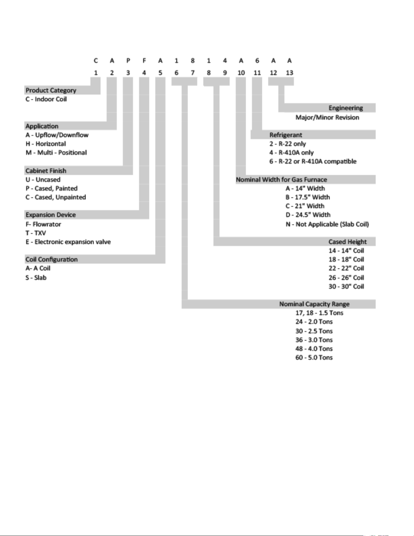
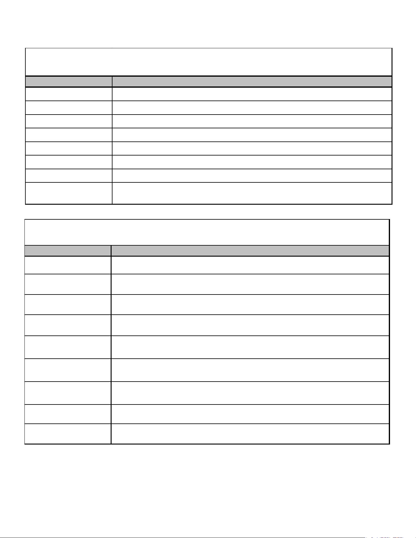
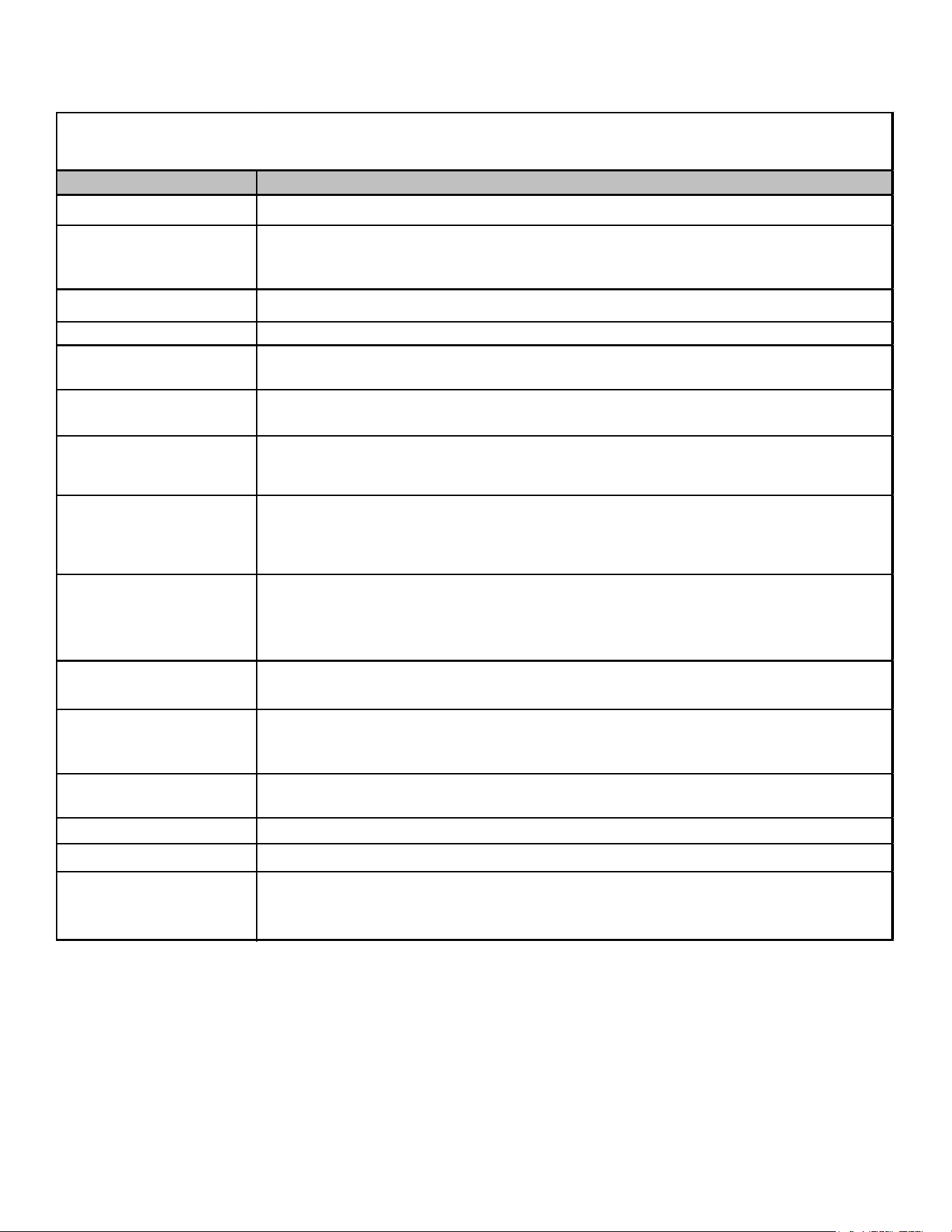
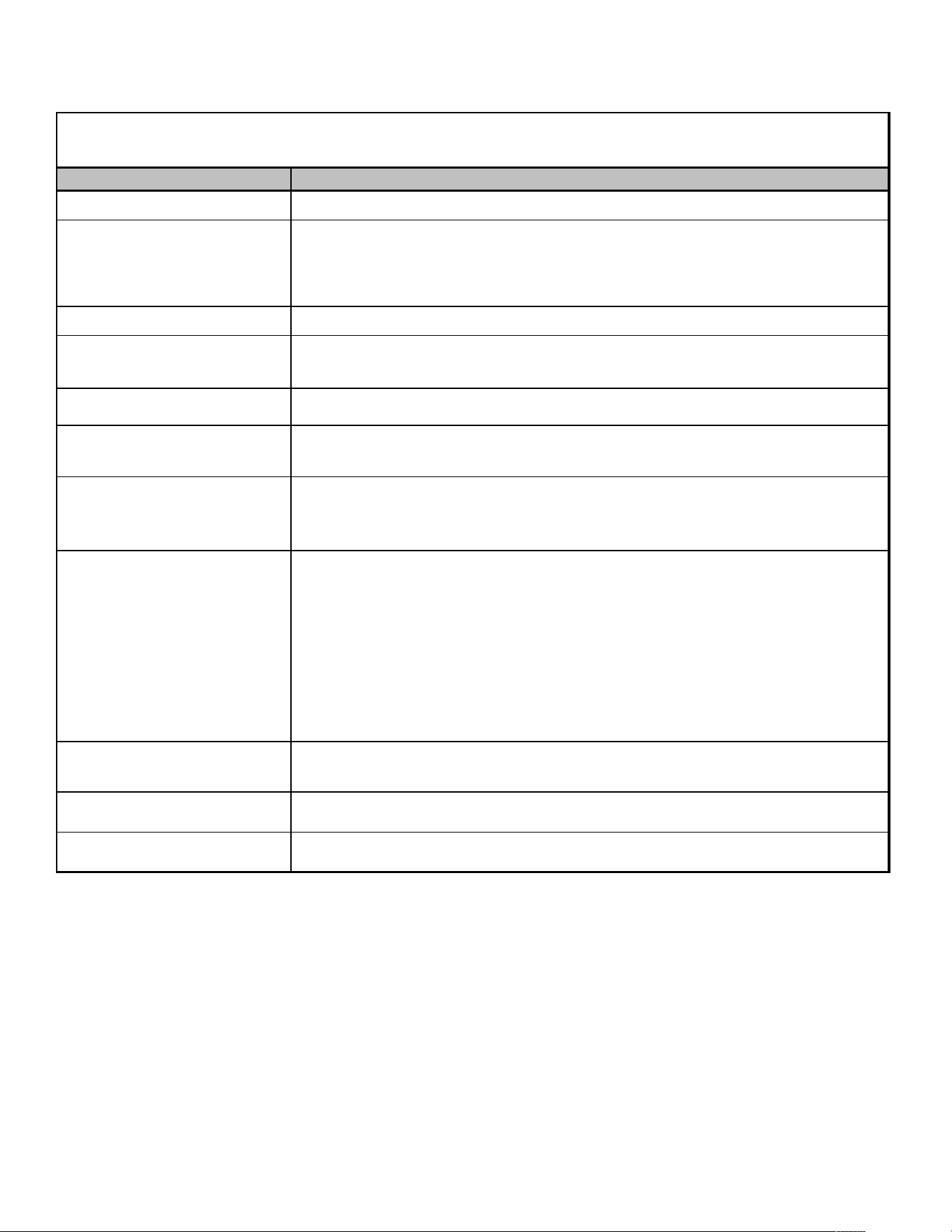
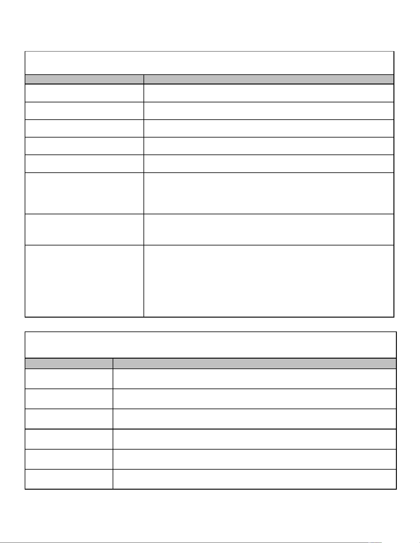
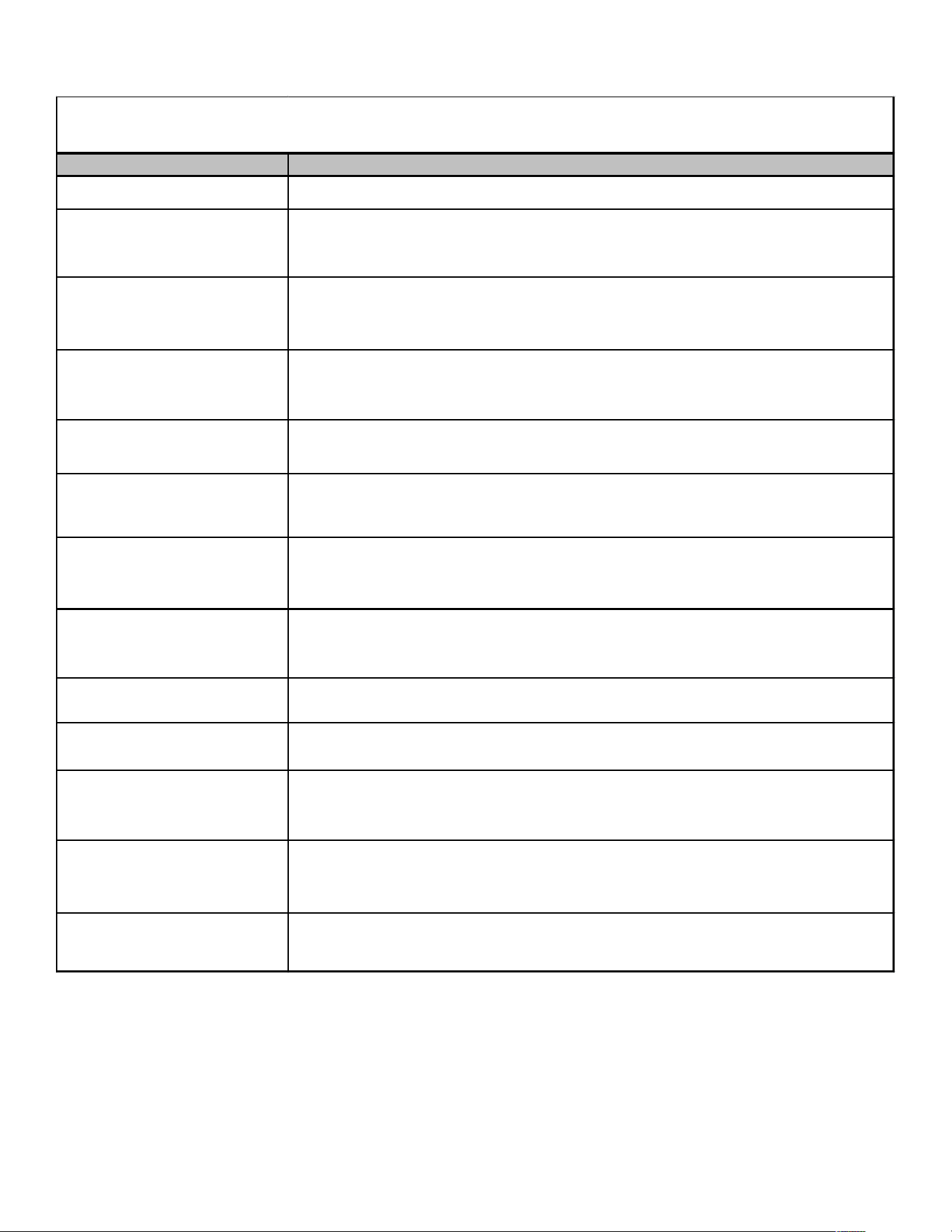
C A P
F
1824 A 6 AA
1 2 3 4 5,6,7,8 9 10
11,12
Brand Engineering*
C Indoor Coil
Refrigerant Charge
Unit Application 2 = R-22
A Upflow/Downflow Coil
4 = R-410A
H Horizontal A-Coil
6 = R-410A or R-22
S
T
Nominal Width for Gas Furnace
A = Fits 14" Furnace Cabinet
B = Fits 17-1/2" Furnace Cabinet
C =
Fits 21" Furnace Cabinet
D =
Fits 24-1/2" Furnace Cabinet
N =
Does Not Apply (Horizontal Slab Coils
Cabinet Finish
U Unpainted
1-1/2 - 2 Tons
P Pai nted
2-1/2 Tons
N Unpainted Case
2-1/2 Tons
3 Tons
Expansion Device
3 - 3-1/2 Tons
F Flowrator
3 - 3-1/2 Tons
T 4 - 5 Tons
Expansion Valve 4 - 5 Tons
3636 =
3642 =
3743 =
4860 =
Factory-Installed Non-Adjustable
Horizontal Slab Coil
Major/Minor Revisions
Coated Coils
Nominal Capacity @ 13 SEER
4961 =
1824 =
3030 =
3131 =
COILS
7
PRODUCT IDENTIFICATION
COILS

8
PRODUCT IDENTIFICATION
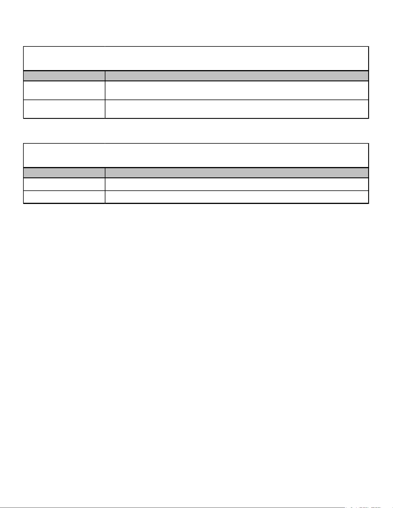
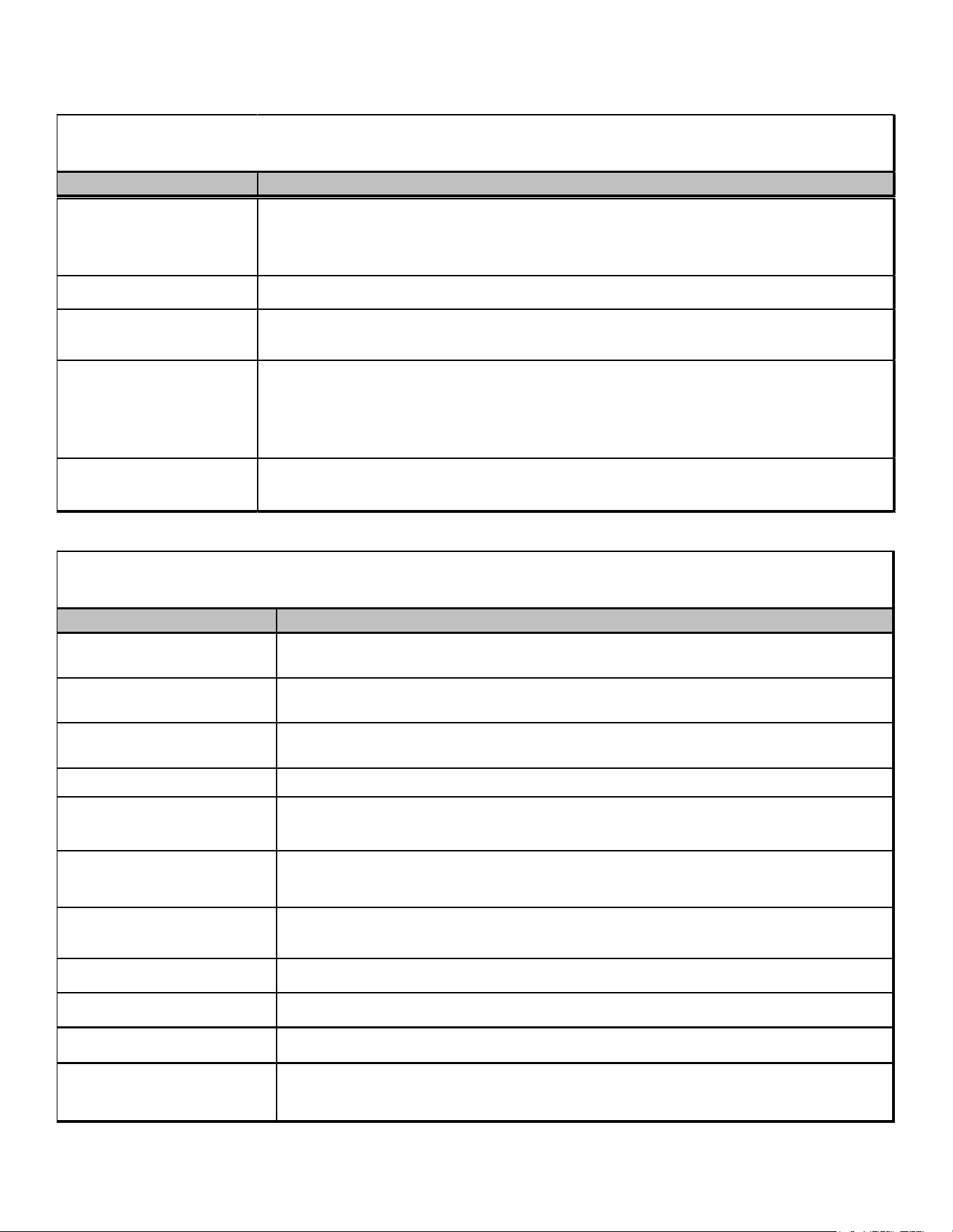
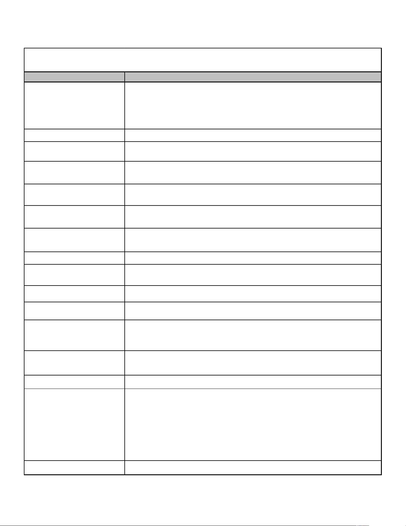
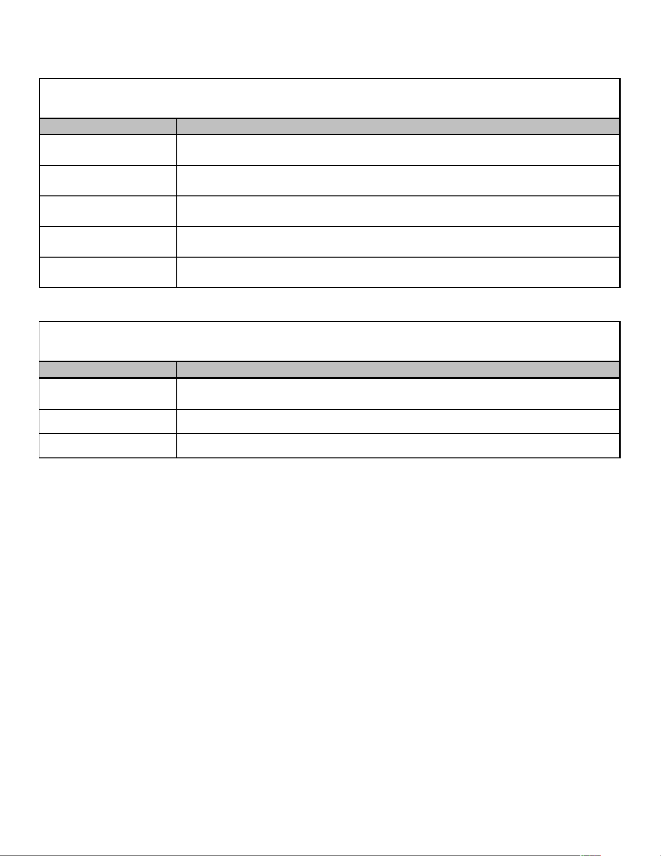
MB R 8 00 A A 1
1,2 3 4 5,6 7 8 9
Brand
MB - Modular Blower 1: 208-230V/60Hz/1 PH
Type A: First Seri es
R -
E -
Airflow A: No Circuit Breaker
8:
B: Ci rcui t Breaker
12:
16:
20:
00 No Heat
Electrical
Design Series
Circuit Breaker
Factory Heat
1200 CFM
1500 CFM
2000 CFM
Constant
Speed
Vari abl e Speed
800 CFM
BLOWERS
9
PRODUCT IDENTIFICATION
All Airhandlers use DIRECT DRIVE MOTORS. Power supply is AC 208-240v, 60 hz, 1 phase.
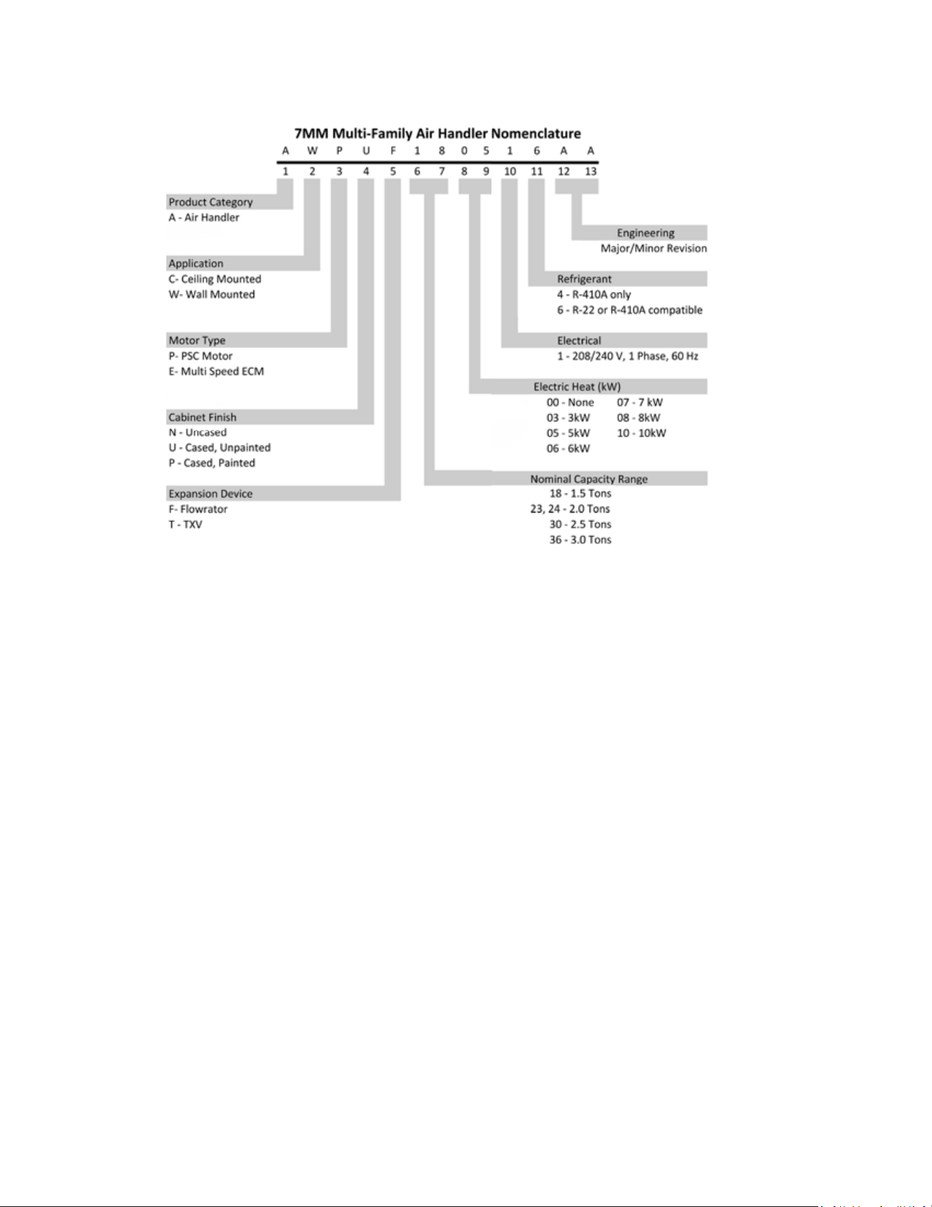
AIR HANDLERS
AR UF 18 B1 4A A
1234 5,67 81 01 1,12
Brand Engineering *
A - Single-piece Air Handler Major/ Minor Revisions
* Not used for order or
inventory management.
C - Ceiling Mount PSC Motor
Refrigerant Charge
4 - R-410A
Variable-Speed Motor
Electrical
1 - 208/240 V, 1 Phase, 60 Hz
W - Wall-Mount PSC Motor
Cabinet Width
Cabinet Finish B - 17½" C - 21"
U - Unpainted P - Painted D - 24½"
N - Uncased
Nominal Capacity Range @ 13 SEER
Expansion Device 18 - 1½ Tons 30 - 2½ Tons 42 - 3½ Tons
F - Flowrater 24 - 2 Tons 36 - 3 Tons 48 - 4 Tons
T - Expansion Valve 60 - 5 Tons
10
PRODUCT IDENTIFICATION
11
PRODUCT IDENTIFICATION
A R U
F
18 B 1 4 AA
1 2 3 4 5,6 7 8 9 10,11
Brand Engineering*
A Single-Piece
Airhandler
Unit Application Refrigerant Charge
C Ceiling Mount PSC Motor 4 = R-410a
R Multi Position PSC Motor
S Mul ti Posi ti on EEM Motor Electrical
W Wal l Mount PSC/EEM Motor 1 208/240V, 1 Phase, 60 Hz
Cabinet Finish
U Unpainted B =
17-
1/2" Wide
P Pai nted C = 21" Wide
N Uncas ed D = 24 -1/2" Wide
Expansion Device
F Flowrator 18 =
1-1/2 Tons
39 =
2-1/2 - 3 Tons
T Expansion Valve 24 = 2 Tons 42 =
3-1/2 Tons
25 = 2 Tons 47 =
3-1/2 Tons
29 =
2-1/2 - 3 Tons
48 = 4 Tons
30 =
2-1/2 Tons
49 = 4 Tons
33 = 1 1/2 - 2 Tons 59 = 5 Tons
36 = 3 Tons 60 = 5 Tons
37 =
2-1/2 - 3 Tons
61 = 5 Tons
Major/Minor Revisions
Cabinet Width
Nominal Capacity @ 13SEER
ADDED S: ENERGY EFFICIENT MOTOR FOR CAC-974 FOR ASPT MODELS
Airhandlers use DIRECT DRIVE MOTORS. Power supply is AC 208-230v, 60 hz, 1 phase.
12
PRODUCT IDENTIFICATION
G S X 11 090 1 AA
1 2 3 4,5 6,7,8 9
10,11
Brand
G - Goodman brand
A - Amana brand
Type
S 1 -
208/230V Single-Phase 60 Hz
2 -
220/240V Single-Phase 50 Hz
Type 3 - 208/230V Three-Phase 60 Hz
X: Condenser R-410A 4 - 460V Three-Phase 60 Hz
Z: Heat Pump R-410A 5 - 380/415V Three-Phase 50 Hz
SEER
11 - 11 SEER
13 - 13 SEER
14 - 14 SEER
16 - 16 SEER 036 - 3 Tons
048 - 4 Tons
060 - 5 Tons
090 - 7-1/2 Tons
120 - 10 Tons
Nominal Capacity
Engineering
Major/Minor Revisions
Voltage
Spl it System
A R 090 AA
1 2 3,4,5 6,7
Brand
A
Single Piece
Air Handler
Unit Application
R 090 7-1/2 Tons
120 10 Tons
Engineering
Major/Minor Revisions
Nominal Capacity
Multi Position
PSC Motor
For use with GSX/GSZ11 Light Commercial models only.
LIGHT COMMERCIAL
LIGHT COMMERCIAL
13
PRODUCT IDENTIFICATION
Model/Rev Description
GSX11090*AA
GSX11120*AA
Introduction of Goodman Light Commercial 11 SEER, R-410A Condensers.
GSX111203AB
GSX110903AB
GSX111204AB
GSX110904AB
208-230V and 460V 3 Phase condensing units with new ball valve/brackets, suction
tube/assembly and panel w/offset.
GSX11 LIGHT COMMERCIAL
GOODMAN® BRAND SPLIT X-R410A CONDENSERS 11 SEER
Model/Rev Description
GSZ11090*AA
GSZ11120*AA
Introduction of Goodman Light Commercial 11 SEER, R-410A Heat Pumps.
GSZ110903AB
GSZ111203AB
GSZ110904AB
GSZ111204AB
208-230V and 460V 3 Phase R410A heat pump units with new ball valve/brackets, suction
tube/assembly and panel w/offset.
GSZ11 LIGHT COMMERCIAL
GOODMAN SPLIT Z-R410A HEAT PUMP 11 SEER
Model/Rev Description
AR0904A
AR1204A
Introducation of new 7.5 & 10 Ton Air Handler Models, for use with GSX11 and GSZ11
Light Commercial Models.
AR LIGHT COMMERCIAL
A SINGLE PIECE R-MULTI-POSITION PSC MOTOR
LIGHT COMMERCIAL
PRODUCT IDENTIFICATION - CHARTS
LIGHT COMMERICAL
14
PRODUCT IDENTIFICATION Split System Heat Pumps
Model/Rev Description
ASZ130**1AA Initial release of Amana® Brand 13 SEER Heat Pump R410A.
ASZ130**1AB Introduces new revisions with improved circuiting for effective defrost.
ASZ130[18, 36-60]1AB
ASZ130[24-30]1AC
Introduces models containing crankcase heater, CCH switch and upgraded defrost
control.
ASZ130[18, 36-60]1AC
ASZ130[24-30]1AD
Relocation of low pressure switch from liquid line to suction line as a compressor
safeguard to prevent low pressure from entering.
ASZ130[18, 36-60]1AD
ASZ130[24-30]1AE
Initial release of models using single speed PSC motors; removal of low ambient
temperature switch.
ASZ130241BA Release of 2 Ton models, converting from 3/8" to 5mm condenser coils
ASZ130181AF
ASZ130[24-30]1AG
Current reversing valve change from Dunan to new SanHua reversing valve
ASZ130481AF
Current Ranco reversing valve 0151M00020 replaced by SanHua 0151R00070 reversing
val ve
ASZ130361AG
ASZ130421AH
Change from copper wound motor to aluminum wound motor.
ASZ130481AG
ASZ130601AF
Create new Motor 0131M00807 & Replace 0131M00061 with 0131M00807
ASZ130181AG
ASZ130[24,30]1AH
Replaced motor 0131M000266 with 0131M00811
ASZ130421AJ
Change from copper wound compressor motor to aluminum wound compressor motor.
ZP34K5EPFV130 and ZP36K5EPFV130.
ASZ13
AMANA® BRAND SPLIT Z-R410A HEAT PUMP 13 SEER
15
PRODUCT IDENTIFICATION Split System Heat Pumps
Model/Rev Description
ASZ140**1AA
Initial release of Amana® Brand 14 SEER Heat Pump R410A with sound blankets and
Coresense control.
ASZ140**1AB
Screw locations moved in the top panel, base pans, louvers, and control box covers.
ASZ140**1AC
Horizontal style louvers.
ASZ140[18, 42-48]1AD
ASZ140[24-36, 60]1AE
New steel muffler, and suction tubes w/shock loop.
ASZ140361AF
ASZ140421AD
ASZ140[48-60]1AE
TXV & compensator replaced with flowrator & accumulator.
ASZ140[18, 30,36]1AF
ASZ140241AG
ASZ14[42, 48, 60]1AE
Sanhua (RANCO) reversing valves.
ASZ140241AF
Smaller B1227315 reversing valve.
ASZ140[18,30,36]1AG
ASZ140241AH
ASZC160[42,48,60]1AF
Introduction of heat pumps with accumulators, crankcase heaters, and upgraded defrost
control.
ASZ140361BA
Chassis size reduction from large to medium.
ASZ140[18, 30]1AH
ASZ140241AJ
ASZ140[42-60]1AG
Relocation of low pressure switch from liquid line to suction line as a compressor
safeguard to prevent low pressure from entering.
ASZ140[18, 30]1AJ
ASZ140241AK
ASZ140[42-60]1AH
ASZ140361BB
2 speed PSC motors replaced with single speed PSC motors.
ASZ140181AL
ASZ140241AM
ASZ140301AL
ASZ140361BC
ASZ140381AB
ASZ140[42-60]1AK
Revision made for design improvement.
ASZ14
AMANA® BRAND SPLIT Z-R410A HEAT PUMP 14 SEER
*ASZ14 CONTINUED ON THE NEXT PAGE
16
PRODUCT IDENTIFICATION Split System Heat Pumps
Model/Rev Description
ASZ140381AA 35" chassis with 6-channel flowrator and ZP29K5 compressor.
ASZ140[18-30]1BA Updated ratings and agency information.
ASZ140[18-60]1KA
Introduction of ready 15, 14 SEER heat pumps to meet the 2015 energy efficiency
requirement.
ASZ140[42,49]1KB Motor change on 3 & 3.5T 14 SEER & 2 & 2.5T 16 SEER. Increase blade gap.
ASZ140181KC Change from copper wound motor to aluminum wound motor.
ASZ140[24,30,36,48,60]1KB
ASZ140[42,49]1 KC
Refrigerant Charge Reduction
ASZ140181KD Refrigerant Charge Reduction
ASZ14
AMANA® BRAND SPLIT Z-R410A HEAT PUMP 14 SEER
17
PRODUCT IDENTIFICATION Split System Heat Pumps
Model/Rev
Description
ASZ160**1AA Initial release of Amana® Brand 16 SEER Heat Pump R410A.
ASZ160**1AB
Introduces models with screw locations moved in the top panel, base pans, louvers, and
control box covers.
ASZ160**1AC Horizontal style louvers.
ASZ160**1AD Muffler and standardized TXV, Compensator using the ASZ18 Seer weldment.
ASZ160241AD
ASZ160[36-60]AE
Adds new steel muffler, and suction tubes w/shock loop.
ASZ160[24,36]1AF
ASZ160[48,60]1AF
Sanhua (RANCO) reversing valves.
ASZ160[24,36,48,60]1KA Initial release of Amana® Brand 16 SEER Heat Pump models
ASZ160[18-48]1LA Initial release of Amana® Brand 16 SEER Heat Pump models with 9.6+ HSPF
ASZ160601LA Initial release of Amana® Brand 5 Ton 16 SEER, 13 eer Heat Pump models.
ASZ160[24,30]1LB
Motor change on 3 & 3.5T 14 SEER & 2 & 2.5T 16 SEER. Increase blade gap.
ASZ160181LB 16SEER 1.5T Heat Pumps, Remove Hard Start Kit
ASZ160181LC Change from copper wound motor to aluminum wound motor.
ASZ160[36,48]1LB Create new Motor 0131M00807 & Replace 0131M00061 with 0131M00807
ASZ160421LB Replaced motor 0131M00018P with 0131M00813
ASZ16
AMANA
®
BRAND S
PLITS Z-R410A HEAT PUMP 16 SEER
Model/Rev Description
ASZ180**1AB Initial release of Amana® Brand 18 SEER Heat Pump R410A.
ASZ180[36,48,60]1AC Sanhua (RANCO) reversing valves.
ASZ18
AMANA® BRAND SPLIT Z-R410A HEAT PUMP 18 SEER
18
PRODUCT IDENTIFICATION Split System Heat Pumps
Model/Rev Description
ANZ130[18-60]1AA Initial release of Amana® Brand Split System Base Heat Pump, 13 Seer R-410A units.
ANZ130[18/24/30]1AB
Reversing valve change from Dunan to new SanHua reversing valve
ANZ130481AB Ranco 0151M00020 reversing valve changed to new SanHua 0151R00070 reversing valve
ANZ130241AC Create new Motor & Replace 0131M00294 with 0131M00800
ANZ130601AB Create new Motor 0131M00807 & Replace 0131M00061 with 0131M00807
ANZ130[18,30]1AC Replaced motor 0131M000266 with 0131M00811
ANZ130[36,42,48]1AC Replaced motor 0131M00018P with 0131M00813
ANZ130421AD
ANZ130421AE
Change from copper wound compressor motor to aluminum wound compressor motor.
ZP34K5EPFV130 and ZP36K5EPFV130.
ANZ13
AMANA® BRAND SPLIT SYSTEM N-BASE Z-R410A HEAT PUMP 13 SEER
Model/Rev
Description
ANZ140(18-60)1AA
Introduction of ready 15, 14 SEER heat pumps to meet the 2015 energy efficiency
requirement.
ANZ140(24-30)1AB Energy guide update.
ANZ140181AB
Minor revisions on OD units ZP14K6 compressors without hard start kit.
14S 1.5T HPs ONLY.
ANZ140421AB
ANZ140491AB
Motor change on 3 & 3.5T 14 SEER & 2 & 2.5T 16 SEER. Increase blade gap.
ANZ140[18,30]1AC
ANZ140361AB
Change from copper wound motor to aluminum wound motor.
ANZ140[42,49]1AC
ANZ140[48,60]1AB
Refrigerant Charge Reduction
ANZ140[18,30]1AD
ANZ140361AC
Refrigerant Charge Reduction
ANZ140241AD Equivalent motor with Aluminum Windings replacing Copper Windings.
ANZ140[48,60]1AC Create new Motor 0131M00807 & Replace 0131M00061 with 0131M00807
ANZ14
AMANA® BRAND SPLIT SYSTEM N-BASE Z-R410A HEAT PUMP 14 SEER
19
PRODUCT IDENTIFICATION Split System Heat Pumps
Model/Rev Description
DSZ160**1AA Initial release of Deluxe Goodman 2-stage 16 SEER heat pumps with R-410A.
DSZ160241AC
DSZ16036, 48, 60]1AB
Sanhua (RANCO) reversing valves.
DSZ16
DELUXE SPLIT Z-R410A HEAT PUMP 16 SEER
Model/Rev Description
DSZ180**1AA Initial release of Deluxe Goodman 2-stage 18 SEER heat pumps with R-410A.
DSZ180[36, 48, 60]1AB Sanhua (RANCO) reversing valves.
DSZ18
DELUXE SPLIT Z-R410A HEAT PUMP 18 SEER
20
PRODUCT IDENTIFICATION Split System Heat Pumps
Model/Rev Description
VSZ13**1AA Initial release of Value Line 13 SEER heat pumps with R-410A.
VSZ130[24 & 30]1AB Improved circuiting for effective defrost.
VSZ130[24 & 36]1BA Initial release of models with 5mm Smart Coil™.
VSZ130[18, 42, 48]1AB
VSZ130241BB
VSZ130301AC
Models containing crankcase heater, CCH switch and upgraded defrost control.
VSZ130[24 & 36]1BC
VSZ130301AE
VSZ130[18, 42 & 48]1AD
Release of single phase models with new 6 pole motor.
VSZ130[18, 42-60]1AC
VSZ130301AD
Relocation of low pressure switch from liquid line to suction line as a compressor
safeguard to prevent low pressure from entering.
VSZ130241CA
Release of 2 Ton models with a compressor change from ZP21K5EPFV130 to
ZP20K5EPFV130.
VSZ130181AE
VSZ130421AF
Changed from four-piece louver assembly to a two piece louver assembly. Added a corner
post on 26" and 29" chassis.
VSZ130361BD
VSZ130301AF
VSZ130481AE
Single phase models with new 6 pole motor.
Changed from four-piece louver assembly to a two piece louver assembly. Added a corner
post on 26" and 29" chassis.
VSZ130421AF Compressor change from ZP36K5EPFV130 to ZP34K5EPFV130.
VSZ130241CB
2 Ton models changing from the current four piece louver assembly, to a two piece louver
plus a corner post on Goodman and value series 26" and 29" chassis.
VSZ130181AF
VSZ130241BD
VSZ130301AG
Reversing valve change from Dunan to new SanHua.
VSZ130481AF Ranco 0151M00020 reversing valve replaced by SanHua 0151R00070 reversing valve
VSZ130241BE Create new Motor & Replace 0131M00294 with 0131M00800
VSZ130601AD Create new Motor 0131M00807 & Replace 0131M00061 with 0131M00807
VSZ13
VALUE SPLIT Z-R410A HEAT PUMP 13 SEER
21
PRODUCT IDENTIFICATION Split System Heat Pumps
Model/Rev Description
VSZ14[018-060]1AA Introduction of ready 15, 14 SEER heat pumps to meet the 2015 efficiency requirement.
VSZ140(18-30)1AB Energy guide update. PCBDM160 with new software.
VSZ140421AB
VSZ140491AB
Motor change on 3 & 3.5T 14 SEER & 2 & 2.5T 16 SEER. Increase blade gap.
VSZ140[18,30]1AC
VSZ140[36,48,60]1AB
Refrigerant charge reduction.
VSZ140[18, 30]1AD
VSZ140361AC
Change from copper wound motor to aluminum wound motor.
VSZ140[24, 42, 49]1AC
Refrigerant Charge Reduction
VSZ140241AD
Equivalent motor with Aluminum Windings replacing Copper Windings.
VSZ140[48,60]1AC
Create new Motor 0131M00807 & Replace 0131M00061 with 0131M00807
VSZ140[18,24,30]1AF
VSZ140[36,42,48,49,60]1AE
GMC product for outdoor splits is changing the paint color to match the new paint for
GMC indoor furnaces being released.
VSZ140181BA
Convert VSZ 14 SEER 1.5 Ton HP from Copeland to Rechi Compressor
VSZ14
VALUE SPLIT Z-R410A HEAT PUMP 14 SEER
22
PRODUCT IDENTIFICATION Split System Heat Pumps
Model/Rev Description
GSZ13**1AA
Initial release with Regal Beloit motor.
GSZ13**1AB
GSZ13**3AA
GSZ13**4AA
Initial release with Broad Ocean motor.
GSZ130[24 & 30]1AC Release of minor revision with improved circuiting for effective defrost.
GSZ130[24 & 36]1BA Initial release of models with 5mm Smart Coil™.
GSZ130241CA
Release of 2 Ton models with a compressor change from ZP21K5EPFV130 to
ZP20K5EPFV130.
GSZ130241CB
2 Ton models changing from the current four piece louver assembly, to a two piece louver
plus a corner post on Goodman and value series 26" and 29" chassis.
GSZ130[18, 42-60]1AC
GSZ130301AD
GSZ130361BB
Release of models containing crankcase heater, CCH switch and upgraded defrost control.
GSZ130[18,42,48,60]1AD
GSZ130301AE
GSZ130[36,48,60{3,4]AB
GSZ130[48,60{3,4]AB
Relocation of low pressure switch from liquid line to suction line as a compressor safeguard
to prevent low pressure from entering.
GSZ130[18,42,48]1AF
GSZ130301AG
GSZ130[36,48]3AD
GSZ130484AC
Changing from the current four piece louver assembly, to a two piece louver plus a corner
post on Goodman and value series 26" and 29" chassis.
GSZ130361BC
GSZ130[42,48]1AE
Release of models with new 6 pole motor/fan combination.
GSZ130361BD
Models with new 6 pole motor/fan combination. Changing from the current four piece louver
assembly, to a two piece louver plus a corner post on Goodman and value series 26" and
29" chassis.
GSZ130421AF
Release of two piece louver plus corner post on 26" and 29" chassis with compressor
changing from ZP36K5EPFV130 to ZP34K5EPFV130.
GSZ130[36, 48]3AC Release of 3 phase models with new 6 pole motor.
GSZ14**1AA Initial release of 14 SEER models.
GSZ130481AG
GSZ130483AE
GSZ130484AD
Replaced Ranco reversing valve 0151M00020 with SanHua 0151R00070 reversing valve .
GSZ13
GOODMAN SPLIT Z-R410A HEAT PUMP 13 SEER
*GSZ13 Continued on the next page
23
PRODUCT IDENTIFICATION Split System Heat Pumps
Model/Rev Description
GSZ13
GOODMAN SPLIT Z-R410A HEAT PUMP 13 SEER
GSZ130[19,31]1AD
GSZ130241BE
GSZ130251AC
Create new Motor & Replace 0131M00294 with 0131M00800
GSZ130601AE Create new Motor 0131M00807 & Replace 0131M00061 with 0131M00807
GSZ130181AH
GSZ130301AJ
Replaced motor 0131M000266 with 0131M00811
GSZ130361BF
GSZ130371AD
GSZ130421AJ
GSZ130481AH
Replaced motor 0131M00018P with 0131M00813
GSZ130421AK
GSZ130421AL
Change from copper wound compressor motor to aluminum wound compressor motor.
ZP34K5EPFV130 and ZP36K5EPFV130.
Model/Rev Description
GSZ140(18-60)1KA
GSZ140491AA
Introduction of ready 15 14 SEER heat pumps to meet the 2015 energy efficiency
requirement.
GSZ140(18-30)1KB Energy guide update. PCBDM160 with new software.
GSZ140301KC
GSZ140361KB
Migrating from copper to aluminum motors.
GSZ140[42,49]1KB Motor change on 3 & 3.5T 14 SEER & 2 & 2.5T 16 SEER. Increase blade gap.
GSZ140181KC
GSZ140361KC
Refrigerant charge reduction
GSZ140[24,30]1KD
GSZ140[48,60]1KB
New model revisions, GSZ140241KD, GSZ140301KD, GSZ140481KB and GSZ140601KB
will have the BOMs changed and have a lower refrigerant charge.
GSZ140[24,30]1KE
GSZ140[48,60]1KC
New model revisions to deplete current overstock of Ranco reversing valves
GSZ140181KD
Change from copper wound motor to aluminum wound motor.
GSZ140[42,49]1KC
Refrigerant charge reduction
GSZ140241KF Equivalent motor with Aluminum Windings replacing Copper Windings.
GSZ140371AB
GSZ140[48,60]1KD
Create new Motor 0131M00807 & Replace 0131M00061 with 0131M00807
GSZ14
GOODMAN SPLIT Z-R410A HEAT PUMP 14 SEER
24
PRODUCT IDENTIFICATION Split System Heat Pumps
Model/Rev Description
GSZ160[18-48]1BA Initial release of Goodman 16 SEER, 13 EER Heat Pumps with 9.0+ HSPF
GSZ1160601BA Initial release of Goodman 5 Ton 16 SEER, 13 EER Heat Pumps
GSZ160241BB
GSZ160301BB
Motor change on 3 & 3.5T 14 SEER & 2 & 2.5T 16 SEER. Increase blade gap.
GSZ160181BB
16 SEER 1.5T Heat Pumps, Remove Hard Start Kit
GSZ160181BC Equivalent motor with Aluminum Windings replacing Copper Windings.
GSZ160181BD
GSZ160[24,30]1BC
GSZ160[36,42,48,60]1BB
Switching current Goodman 16SEER condensers and heat pumps with grille tops to louver
tops to be consistent with other Goodman units having louver-style top panels.
GSZ160[36,48]1BC Create new Motor 0131M00807 & Replace 0131M00061 with 0131M00807
GSZ160421BC Replaced motor 0131M00018P with 0131M00813
GSZ16
GOODMAN SPLIT Z-R410A HEAT PUMP 16 SEER
25
PRODUCT IDENTIFICATION Split System Heat Pumps
Model/Rev
Description
SSZ140**1AA Initial release of Goodman 14 SEER Heat Pump R410A.
SSZ140**1AB Screw locations moved in the top panel, base pans, louvers, and control box covers.
SSZ140**1AC Broad Ocean Motors.
SSZ140181AC
SSZ140241AF
SSZ140301AD
Discharge line mufflers added.
SSZ140361AF
SSZ140[42-60]1AD
Added discharge line mufflers. Replaced TXV and compensator with flowrator and
accumulator.
SSZ140241AG
Smaller B1227315 reversing valve.
SSZ140[18, 30, 42-60]AE
SSZ140241AH
SSZ140361AG
Sanhua (RANCO) reversing valves.
SSZ140[18, 30, 42-60]AF
SSZ140241AJ
SSZ140361AH
Introduction of heat pumps with accumulators, crankcase heaters, and upgraded defrost
control.
SSZ140[18,30]1AH
SSZ140241AL
SSZ140361BB
Changed from four-piece louver assembly to a two piece louver assembly. Added a corner
post on Goodman 26" and 29" chassis.
SSZ140140[18, 30]1AJ
SSZ140[19, 25]1AC
SSZ140[31, 37]1AC
SSZ140241AM
SSZ140361BCC
SSZ140381AB
SSZ140140381AB
SSZ140[42-60]AH
Revision made for design improvement.
SSZ140[18-60]1AD
Relocation of low pressure switch from liquid line to suction line as a compressor
safeguard to prevent low pressure from entering.
SSZ140361AF
SSZ140[42-60]1AD
Chassis size reduction from large to medium.
SSZ140381AA Initial release of 35" chassis with 6-channel flowrator and ZP29K5 compressor.
SSZ140[18-30]1BA Updated ratings and agency information.
SSZ140241BB
SSZ140251AE
Change from copper wound motor to aluminum wound motor.
SSZ140361BE
SSZ140371AE
SSZ140[42,48,60]1AK
Create new Motor 0131M00807 & Replace 0131M00061 with 0131M00807
SSZ14
SPECIAL HIGH FEATURE SPLIT Z-R410A HEAT PUMP 14 SEER
26
PRODUCT IDENTIFICATION Split System Heat Pumps
Model/Rev Description
SSZ160**1AA Initial release of Goodman 16 SEER Heat Pump R410A.
SSZ160**1AB Screw locations moved in the top panel, base pans, louvers, and control box covers.
SSZ160**1AC
Broad Ocean Motor. Updated muffler and standardized TXV. Compensator using ASZ18
SEER weldment to the SSZ160601AC.
SSZ16[024-48]1AC
SSZ160601AD
Discharge line mufflers added.
SSZ160361AF
SSZ160[42-60]1AD
Added discharge line mufflers. Replaced TXV and compensator with flowrator and
accumulator.
SSZ160241AF
SSZ160[36, 48]1AD
SSZ160601AE
Sanhua (RANCO) reversing valves.
SSZ160241AF
SSZ160[36-48]1AE
SSZ160601BA
Introduction of heat pumps with accumulators, crankcase heaters, and upgraded defrost
control.
SSZ160241AH
Changed from four-piece louver assembly to a two piece louver assembly. Added a corner
post on Goodman 26" and 29" chassis.
SSZ160601BB Ultratech® compressor
SSZ160241AK Change from copper wound motor to aluminum wound motor.
SSZ16
SPECIAL HIGH FEATURE SPLIT Z-R410A HEAT PUMP 16 SEER
27
PRODUCT IDENTIFICATION Split System Condensers
Model/Rev Description
GSX130**1AA Initial release of Goodman 13 SEER R-410A Condensers with Regal Beloit motors
GSX13061[1/3/4]AA
Introduction of Goodman 13 SEER R-410A Condensers that supplement our current 5 ton
models.
GSX130363AB
GSX130484AB
GSX130603AB
GSX130604AB
Changed from the current four piece louver assembly, to a two piece louver plus a corner
post on Goodman and value series 26" and 29" chassis.
GSX130**1AB Broad Ocean motors.
GSX130483AB 3 Phase model with new 6 pole motor.
GSX130483AC
3 phase model changing from the current four piece louver assembly, to a two piece louver
plus a corner post on Goodman and value series 26" and 29" chassis.
GSX130181EA
GSX130181EB
Introduction of 1.5 ton condenser with Rechi Compressor.
GSX130**1BA
GSX130**3AA
GSX130**4AA
Introduction of Goodman 13 SEER R-410A Condensers using SmartCoil® coils. Units will
have new louvers because units are smaller. Piston size change. Other components
unchanged.
GSX130301BB Replaced fan motor to -294 and fan blade to -18 on GSX130301BA models.
GSX130[42, 48]1BC
GSX130301BC
GSX130601BB
Changed from the current four piece louver assembly, to a two piece louver plus a corner
post on Goodman and value series 26" and 29" chassis.
GSX130[42, 48]1BB New 6 pole motor/fan combination.
GSX130181CA Rotary compressor.
GSX130421CA
GSX130481CA
Introduction of Goodman 3.5 and 4 ton 13 SEER condensing units with reciprocating
compressor.
GSX130361CA Replaced current compressor with compressor ZP29K5EPFV130.
GSX130[18-36]1DA Condenser conversion to 23" chassis for the 1.5 - 3 ton models.
GSX130181ED
Changed from a 4 leg Rechi Compressor 50N382XV-ZAKM to 3 Leg Rechi Compressor
50N382XV-5AKM. Changed Suction line Assy from 0210R01608 to 0210R01406. This
minor
GSX13031DB
Improved coil circuit assembly for greater capacity/efficiency and a new discharge tubing
assembly.
GSX130361EA Introduction of Goodman 3 ton conversion from 29" chassis to 26".
GSX130361EB
Changed from the current four piece louver assembly, to a two piece louver plus a corner
post on Goodman and value series 26" and 29" chassis.
GSX130371AA Improved decibel ratings for Canadian market.
GSX130181EF Change from motor 0131M00276 to 0131M00593 on units GSX130181 & VSX130181
GSX130363AD Change from copper wound motor to aluminum wound motor.
GSX130241EC
GSX130301BF
Create new Motor & Replace 0131M00294 with 0131M00800
GSX13
GOODMAN BRAND SPLIT X-R410A CONDENSERS 13 SEER
*GSX13 Continued on the next page
28
PRODUCT IDENTIFICATION Split System Condensers
noitpircseDveR/ledoM
GSX13
G
OODMAN BRAND
S
PLIT
X-
R410A
C
ONDENSERS 13 SEER
GSX130611AC Create new Motor 0131M00807 & Replace 0131M00061 with 0131M00807
GSX130241ED
GSX130[30,60]1BG
GSX130361EE
GSX130[42,48]1BF
Factory Refrigerant Charge Optimization
GSX130181EH Changing Flat BOM structure to Indented BOM structure
GSX130181EG
Switching 3-legged and 4-legged compressors in 13SEER and 14SEER condensers to
those with improved overload protection (OLP).
MKA5-VY283N05 ot MKA5-VX283N05 morf rosserpmoc gnihctiwSJE181031XSG
GSX130301LA
13 SEER 2_5T Condenser Rechi Conversion - Switch from Copeland compressor to Rechi
compressor in 13 SEER 2.5 ton condensers (GSX, VSX, ANX)
GSX130361EF
GSX130[42,48]1BG
GSX130483AE
GSX130601BH
Replaced motor 0131M00018P with 0131M00813
GSX130421BH
GSX130421BJ
Change from copper wound motor to aluminum wound motor.
.rotom dnuow muni
mula ot rotom dnuow reppoc morf egnahCBL103031XSG
GSX130241FA Reduce chassis size to 23" base
29
PRODUCT IDENTIFICATION Split System Condensers
noitpircseDveR/ledoM
.sledom A014-R REES 41 namdooG fo noitcudortnIAA1**41XSG
GSX140[18-19]1KA
GSX140[24-25]1KA
GSX140[30-31]1KA
GSX140[36-37]1KA
GSX140[42, 48, 60]1KA
Goodman
S
plit
X
14 Seer Condensing units. Introducing the Goodman 14 SEER standard
condenser 5mm architecture with updated scroll compressors.
GSX140241KB Replaced 1/12hp fan motor with 1/8hp fan motor.
GSX140311AA Introduction of 12.2 EER air conditioning units.
GSX140[30-36,42]1KBMigrating from copper to aluminum motors.
GSX140251LA
Changed compressor from K5 to K6, Changed coil slab from 25" tall to 30" tall, Changed
louvers from 24" tall to 29" tall
GSX140241LB
Create minor revisions of the new Rechi 2.0T units to consume the excess inventory of
19P fan motor
GSX140191KB
Remove HS Kit from Control Panels of condenser units with updated
ZP14K6E scroll compressors.
GSX140361KC
GSX140371KB
GSX140421KC
GSX140 [43,48,60]1KB
Refrigerant charge reduction.
GSX140311KB
GSX140371KC
GSX140431KC
Change from copper wound motor to aluminum wound motor.
GSX140[4
8,60]1KCCreate new Motor 0131M00807 & Replace 0131M00061 with 0131M00807
GSX140301LA
Changing from Copeland to Rechi in 14 SEER 2.5T condenser units: Project involve s
moving to a larger coil, and added accessories for the Rechi application.
GSX140181LB
Switching 3-legged and 4-legged compressors in 13SEER and 14SEER condensers to
those with improved overload protection (OLP).
GSX140241LDCharge Optimization for 14 SEER 2T lineup
GSX140[36,42]1KECharge Optimization for 14 SEER 3T and 3.5T condenser units
GSX140181LC
GSX140191KC
GSX140251BB
Replaced motor 0131M000266 with 0131M00811
GSX140241LC
Replaced motor 0131M000266 with 0131M00811
Refrigerant Charge Change
GSX140[37,43]1KD Charge optimization for Southwest 14 SEER models
GSX140301KC Reinstatement and new minor revision
GSX140181MA Reduce chassis size to 23" base
GSX14
G
OODMAN BRAND
S
PLIT
X-
R410A
C
ONDENSERS
14 SEER
30
PRODUCT IDENTIFICATION Split System Condensers
Model/Rev Description
GSX160**1FA Initial release of the Goodman 16 SEER R410A Condensers.
GSX160611FA New high capacity 5 ton model that will supplement the current GSX160601 models.
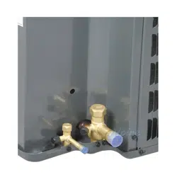
GSX160[18-61]1FB Minor revision for GSX16s to include ball valves 0151R00045 and 0151R00046.
GSX160601GA 7mm coils.
GSX160(48/60/61)1FB Ball valve change from 0151R00046 to 0151R00081
GSX160(18/24/30/36)1FC Migrating from copper to aluminum motors.
GSX160(18/24/30/36)1FC
GSX160(42/48/60/61)1FC
Ball Valve Re-work 0151R00045 & 0151R00046
GSX160311AA
GSX160371AA
Initial release creates and launches 2 new SKUs in the 16 SEER single-stage AC
product line.
GSX160[24, 30, 60]1FE
Refrigerant charge reduction.
GSX160[31,37]1AB
Equivalent motor with Aluminum Windings replacing Copper Windings.
GSX160[18,36,42,48,61]1FE
GSX160[24,30]1FF
GSX160[31,37]1AC
Switching current Goodman 16SEER condensers and heat pumps with grille tops to
louver tops to be consistent with other Goodman units having louver-style top
panels.
GSX160[48,61]1FF Create new Motor 0131M00807 & Replace 0131M00061 with 0131M00807
GSX160421FG
GSX160481FH
Change from copper wound compressor motor to aluminum wound compressor motor.
ZP34K5EPFV130 and ZP36K5EPFV130.
GSX16S[18-48]1AA
GSX16A[18-60]1AA
Releasing new top level nomenclature for the 16 SEER condenser family. The "0" that
previously followed the GSX16 family name (preceding the nominal capacity digits) will
now be used to designate the region the product can be sold in (A=All Regions, N=Nor
GSX16S301AB
QIP Factory Refrigerant Charge Optimization.
GSX16
GOODMAN BRAND SPLIT X-R410A CONDENSERS 15 AND 16 SEER
31
PRODUCT IDENTIFICATION Split System Condensers
Model/Rev Description
SSX140**1AA Initial release of Goodman 14 SEER AC 410A.
SSX140**1AB
Revisions have screw locations moved in the top panel, base pans, louvers, and control
box covers.
SSX14018, 241AC Revised condenser coils by removing [1] haripin.
SSX140301AC Model contains the Broad Ocean motor 0131M00060
SSX14036-601AC Models contain the Broad Ocean motor 0131M00061
SSX14030,361AD Revised condenser coils by removing [1] haripin.
SSX140421AD Introduces SSX140421A in 29" base pan
SSX140[18-24]1BA
SSX140[30-36]1BA
SSX140421CA
Converts 1.5 - 3.5 ton condenser coil tubes from 3/8" tube diameter to 5mm tube
diameter.
SSX140[18-36]1BC
SSX140421CC
Changing from the current four piece louver assembly, to a two piece louver plus a corner
post on Goodman and value series 26" and 29" chassis.
SSX140[18-36]1BD
SSX140421CD
SSX140481BB
SSX140601AG
Revision made for design improvement.
SSX140421BA
Revision for SSZ140421B* in 29 base pan and it will the reduce the unit charge from 180
oz. to 170 oz. and replace the 1/4 hp outdoor unit motor with 1/6 hp motor.
SSX14030-421AE Revised condenser coils by removing [1] haripin.
SSX140[18-48]1BA
SSX14042-481CA
Introduction of Goodman 14 SEER R-410A Condensers with SmartCoil® Coils.
SSX140[18-36]1BB
SSX140421CB
SSX140601AF
Relocation of low pressure switch from liquid line to suction line as a compressor
safeguard to prevent low pressure from entering.
SSX14
SPECIAL HIGH FEATURE SPLIT X-R410A CONDENSERS 14 SEER
32
PRODUCT IDENTIFICATION Split System Condensers
Model/Rev Description
SSX160**1AA Introduces Goodman 16 SEER AC 410A
SSX160**1AB
New revisions have screw locations moved in the top panel, base pans, louvers, and
control box covers.
SSX160**1AB
SSX160591AA
New revisions have screw locations moved in the top panel, base pans, louvers, and
control box covers.
SSX160[24, 36, 48]1BA
SSX160[30 & 42]1AA
SmartCoil® coils.
SSX160[24, 36]1BC
SSX160[30, 42]1AB
Changing from the current four piece louver assembly, to a two piece louver plus a corner
post on Goodman and value series 26" and 29" chassis.
SSX160601BA ZPS49K compressor.
SSX160[24,36,60]1BB
Relocation of low pressure switch from liquid line to suction line as a compressor
safeguard to prevent low pressure from entering.
SSX16
SPECIAL HIGH FEATURE SPLIT X-R410A CONDENSER 16 SEER
Model/Rev Description
DSX160**1AA Initial release of Goodman 2-stage, 16 SEER condensing units with R-410A.
DSX160[24, 36]1BA Conversion of 2 & 3 ton models to SmartCoil® Coils.
DSX160241BC Introduces Ultratech® 2.0 compressor changes.
DSX16
DELUXE SPLIT X-R410A HEAT PUMP 16 SEER
Model/Rev
Description
DSXC18**1AA Intial release of 2-stage condensing units with R-410A communicating models.
DSXC18036AB
DSXC18048AB
DSXC18060AB
Updated wiring diagram with notes for communicating condensing units.
DSXC18036AC
Replaced existing compressor ZPS20K4EPFV230 to ZPS20K5EPFV130 & existing
compressor ZPS30K4EPFV230 to ZPS30K5EPFV130 for communicating condensing
units.
DSXC180[48-60]AC Intial release of Ultratech 2.0 to communicating condensing units
DSX18
DELUXE SPLIT X-R410A HEAT PUMP 18 SEER
33
PRODUCT IDENTIFICATION Split System Condensers
Model/Rev Description
VSX130[18-48]1AA Introduces Value Line 13 SEER condensing units with R-410A.
VSX130611AA Supplements the 5 ton model GSX130611 to enhance performance.
VSX130301AB Replaced fan motor to -294 and fan blade to -18 on the VSX130301AA.
VSX130301AC
VSX130[42-48]1AC
Changed from current four piece louver assembly to a two piece louver assembly plus a
corner post on Goodman and value series 26" and 29" chassis.
VSX130[42-48]1AB Replaced with 6-pole motor and Copeland compressor.
VSX130181BA Rotary compressor.
VSX130181EA
VSX130181EB
Introduction of 1.5 ton condenser with Rechi Compressor.
VSX130181ED
Changed 4-leg Rechi Compressor 50N382XV-ZAKM to 3-Leg Rechi Compressor
50N382XV-5AKM. Changed Suction line Assy from 0210R01608 to 0210R01406.
VSX130241BA
2.0 ton condensing units with aluminum coils, aluminum manifolds w/existing scroll
compressor.
VSX130361BA Replaced current compressor with compressor ZP29K5EPFV130.
VSX130361EB
Changed from current four piece louver assembly, to a two piece louver plus a corner post
on Goodman and value series 26" and 29" chassis.
VSX130601BA Condensing units with SmartCoil® coils.
VSX130601BB
Changing from the current four piece louver assembly, to a two piece louver plus a corner
post on Goodman and value series 26" and 29" chassis.
VSX130421BA
VSX130481BA
3.5 and 4 ton 13 SEER condensing units with reciprocating compressor.
VSX130[18-36]1DA 3.5 and 4 ton 13 SEER Condensers conversion to 23" chassis for the 1.5 - 3 ton models.
VSX130301DB
2.5 13 SEER Condensers with improved coil circuit assembly for greater
capacity/efficiency and the creation of a new discharge tubing assembly.
VSX130301EA
3 Ton 13 SEER Condensers release of 3 ton models converting from 29" chassis to 26"
chassis.
VSX130241EA
2.0 Ton 13 SEER Condensers with Rechi Compressor, converting 23" chassis to 26"
chassis
VSX130371AA 2.5 13 SEER Condensers with improved decibel ratings for Canadian market.
VSX130241EB Compressor wires yellow, red and black changing from 40" to 45".
VSX130181EF Change from motor 0131M00276 to 0131M00593 on units GSX130181 & VSX130181
VSX130241ED
VSX130301AF
Create new Motor & Replace 0131M00294 with 0131M00800
VSX13
VALUE SPLIT X-R410A CONDENSER 13 SEER
*VSX13 Continued on the next page
34
PRODUCT IDENTIFICATION Split System Condensers
noitpircseDveR/ledoM
VSX13
V
ALUE
S
PLIT
X-
R410A CONDENSER 13 SEER
VSX130611AC Create new Motor 0131M00807 & Replace 0131M00061 with 0131M00807
VSX13[241,361]EE
VSX130301AG
VSX130[421,481]AF
VSX130601BE
Factory Refrigerant Charge Optimization
VSX130181EH Changing Flat BOM structure to Indented BOM structure
VSX130181EG
Switching 3-legged and 4-legged compressors in 13SEER and 14SEER condensers to
those with improved overload protection (OLP).
VSX130181EJSwitching compressor from 50N382XV-5AKM to 50N382YV-5AKM
VSX130301LA
13 SEER 2_5T Condenser Rechi Conversion - Switch from Copeland compressor to Rechi
compressor in 13 SEER 2.5 ton condensers (GSX, VSX, ANX)
VSX130361EF
VSX130[42,48]1AG
VSX130601BF
Replaced motor 0131M00018P with 0131M00813
VSX130181EL
VSX130241EG
VSX130301LB
VSX130361EH
VSX130421AM
VSX130421AL
VSX130481AJ
VSX130601BH
VSX130611AE
GMC product for outdoor splits is changing the paint color to match the new paint for
GMC indoor furnaces be
ing released.
VSX130421AJ
VSX130421AK
Change from copper wound motor to aluminum wound motor.
VSX130301LCChange from copper wound motor to aluminum wound motor.
VSX130241FAReduce chassis size to 23" base
35
PRODUCT IDENTIFICATION Split System Condensers
noitpircseDveR/ledoM
VSX140[18-19]1AA
VSX140[24-25]1AA
VSX140[30-31]1AA
VSX140[36-37]1AA
VSX140[42, 48, 60]1AA
Introducing the 14 SEER standard condenser 5mm architecture with updated scroll
compressors.
VSX140241AB Replaced 1/12hp fan motor with 1/8hp fan motor.
VSX140251BA
Changed compressor from K5 to K6, Changed coil slab from 25" tall to 30" tall, Changed
louvers from 24" tall to 29" tall
VSX140241BB
Create minor revisions of the new Rechi 2.0T units to consume the excess inventory of
19P fan motor
VSX140191KB
Remove HS Kit from Control Panels of condenser units with updated
ZP14K6E scroll compressors.
VSX140[30,31]1AB
VSX140[36-43]1AC
Change from copper wound motor to aluminum wound motor.
VSX140301BA
Copeland to Rechi 2.5 T update suct tube, fix liq line assy, fix wiring diagram, change
charge qty.
VSX140[48,60
]1AC Create new Motor 0131M00807 & Replace 0131M00061 with 0131M00807
VSX140181BB
Switching 3-legged and 4-legged compressors in 13SEER and 14SEER condensers to
those with improved overload protection (OLP).
VSX140241BDCharge Optimization for 14 SEER 2T lineup
VSX140[36,42]1AE Charge Optimization for 14 SEER 3T and 3.5T condenser units
VSX140181BC
VSX140191AC
VSX140251BB
Replaced motor 0131M000266 with 0131M00811
VSX140241BC
Replaced motor 0131M000266 with 0131M00811
Refrigerant Charge Change
VSX140[37,43]1AD Charge optimization for Southwest 14 SEER models
VSX140[18,24]1BF
VSX140[18,25]1BE
VSX140[19,36,42]1AF
VSX140[19,37,43,48,60]1AE
VSX140241BG
VSX140251BD
VSX140301BC
VSX140311AD
GMC product for outdoor splits is changing the paint color to match the new paint for
GMC indoor furnaces being released.
esab "32 ot ezis sissahc ecudeRAC181041X
SV
VSX14
V
ALUE
S
PLIT
X-
R410A CONDENSER 13 SEER
36
PRODUCT IDENTIFICATION Split System Condensers
Model/Rev
Description
ANX130[18-24]1AA
Launch of the Tier 1.5T & 2.0T models. Launched with 26" chasis to accommodate
horizontal style louvers.
ANX130[30-61]1AA Initial release.
ANX130241BA
Convert ANX13/14 1.5 and 2 ton models to Rechi compressors.
ANX130[30-60]1AD Refrigerant Charge Reduction
ANX130241BB
ANX130301AE
Create new Motor & Replace 0131M00294 with 0131M00800
ANX130611AD
Create new Motor 0131M00807 & Replace 0131M00061 with 0131M00807
ANX130241BC
ANX130301AF
ANX130[36,42,48,60]1AE
Factory Refrigerant Charge Optimization
ANX130181BA
New major revision of ANX130181 as a result of change to Rechi compressor. Rechi
compressor and associated parts (grommets, bolts, wires, associated tubing, etc.) will
replace the current compressor and associated parts.
ANX130301BA
13 SEER 2_5T Condenser Rechi Conversion - Switch from Copeland compressor to Rechi
compressor in 13 SEER 2.5 ton condensers (GSX, VSX, ANX)
ANX130181AC
ANX130181BB
Replaced motor 0131M000266 with 0131M00811
ANX130181BC
ANX130181BD
Replaced 50N382XV-ZAKM Rechi compressor with rechi 50N382YV-ZAKM compressor in
all models.
ANX130[36,42,48,60]1AF Replaced motor 0131M00018P with 0131M00813
ANX130421AG
ANX130421AH
Change from copper wound motor to aluminum wound motor.
ANX130301BB Change from copper wound motor to aluminum wound motor.
ANX13
AMANA® BRAND SPLIT SYSTEM N-BASE X-R410A CONDENSERS 13 SEER
37
PRODUCT IDENTIFICATION Split System Condensers
Model/Rev Description
ANX140[18-60]1AA
Introducing the Amana
®
Brand 14 SEER standard condenser 5mm architecture with
updated scroll compressors.
ANX140241AB Replaces 1/12hp fan motor with 1/8hp fan motor.
ANX140431AA Introduction of ready 15, 12.2 EER air conditioning units.
ANX140251BA
Changed compressor from K5 to K6, Changed coil slab from 25" tall to 30" tall, Changed
louvers from 24" tall to 29" tall
ANX140191AB
Remove HS Kit from Control Panels of condenser units with updated
ZP14K6E scroll compressors.
ANX140181BA
ANX140241BA
Convert ANX13/14 1.5 and 2 ton models to Rechi compressors.
ANX140[30-37]1AB
ANX140[42,43]1AB
Change from copper wound motor to aluminum wound motor.
ANX140481AB
ANX140601AB
Refrigerant Charge Reduction
ANX140[36,37]1AC
ANX140[42,43]1AC
Refrigerant Charge Reduction
ANX140[48,60]1AC Create new Motor 0131M00807 & Replace 0131M00061 with 0131M00807
ANX140301BA
Changing from Copeland to Rechi in 14 SEER 2.5T condenser units: Project involves
moving to a larger coil, and added accessories for the Rechi application.
ANX140181BB
Switching 3-legged and 4-legged compressors in 13SEER and 14SEER condensers to
those with improved overload protection (OLP).
ANX140241BC Charge Optimization for 14 SEER 2T lineup
ANX140[36,42]1AD Charge Optimization for 14 SEER 3T and 3.5T condenser units
ANX140181BC
ANX140191AC
ANX140251BB
Replaced motor 0131M000266 with 0131M00811
ANX140241BB
Replaced motor 0131M000266 with 0131M00811
Refrigerant Charge Change
ANX140[37,43]1AD Charge Optimization for Southwest 3T and 3.5T lineup
ANX14
AMANA® BRAND SPLIT SYSTEM N-BASE X-R410A CONDENSERS 14 SEER
38
PRODUCT IDENTIFICATION Split System Condensers
Model/Rev Description
ASX130**1AA
Initial release new models of Amana
®
Brand Deluxe 13 SEER AC R410A conditioners.
ASX130611AA
Initial release of new models of Amana® Brand Deluxe 13 SEER AC R410A conditioners;
replaced ASX130601* models.
ASX130611AA
Introduction of Amana
®
brand 13 SEER R-410A Condensers that supplement our current
5 ton models.
ASX130**1BA
Initial release of models using SmartCoil
®
coils. Smaller units with new louvers. Piston
size changed; other components unchanged.
ASX130**1CB
Relocation of low pressure switch from liquid line to suction line. Compressor safeguard to
prevent low pressure from entering.
ASX130181DA Initial release of models with new 266 fan motor; Low pressure switch removed.
ASX130181DB
ASX130[24-48]1CD
ASX130601CC
Low pressure switch 013M00082 added; updated wiring diagram.
ASX130[24-48]1CC
ASX130601CB
Initial release of models with single speed PSC motors; Does not contain a low pressure
switch, low ambient temperature switch and relay.
ASX130361DA Release of 3 ton models with a 26" chassis.
ASX130361DE Refrigerant Charge Reduction
ASX130[42,48]1CF
ASX130601CE
ASX130611AC
Create new Motor 0131M00807 & Replace 0131M00061 with 0131M00807
ASX130[24,30,60]1CF
ASX130361DF
ASX130[42,48]1CG
Factory Refrigerant Charge Optimization
ASX130181DD
ASX130[24,30]1CG
Replaced motor 0131M000266 with 0131M00811
ASX130361DG Replaced motor 0131M00018P with 0131M00813
ASX130421CH
Change from copper wound compressor motor to aluminum wound compressor motor.
ZP34K5EPFV130 and ZP36K5EPFV130.
ASX13
AMANA® BRAND SPLIT X-CONDENSERS 13 SEER
39
PRODUCT IDENTIFICATION Split System Condensers
Model/Rev Description
ASX140**1AA
Initial release of models of Amana
®
Brand Deluxe 14 SEER AC R410A conditioners.
ASX140**1AB Screw locations moved in the top panel, base pans, louvers, and control box covers.
ASX140**1AC Horizontal style louvers.
ASX14018-361AD Revised condenser coils by removing (1) hairpin. R410A quantity reduced by 6 ounces.
ASX140421AD Initial release of model ASX140421A in 29" base pan
ASX140421BA
29" platform. Unit charge reduced from 180 oz. to 170 oz. 1/4 hp outdoor unit motor
replaced with 1/6 hp motor.
ASX14018-361BA
ASX140[42-48]1CA
1.5 - 3.5 ton condenser coil tubes converted from 3/8" tube diameter to 5mm tube
diameter.
ASX140[18-30]1BA
ASX140[42-48]1CA
Initial release of models using SmartCoil® coils.
ASX140[18-36]1CB
ASX140421DB
ASX140601BB
Low pressure switch relocated from liquid line to suction line as a compressor safeguard
to prevent low pressure from entering.
ASX140[24-36]1CC
ASX140421DC
ASX140481CB
ASX140601BC
Initial release of models with single speed PSC motors; Does not contain a low pressure
switch, low ambient temperature switch and relay.
ASX140181DB
ASX140[24-36]1CD
ASX140421DD
ASX140481CC
ASX140601BD
Low pressure switch added.
ASX140181DD
ASX140[24-48]1CE
ASX140421DE
ASX140601BE
Design improvement.
ASX140181DA Initial release of models with new 266 fan motor; Low pressure switch removed.
ASX140[18-19, 24-25]1KA
ASX140[30-31, 36-37]1KA
ASX140[42, 48, 60]1KA
Initial release of 5mm architecture with updated scroll compressors.
ASX140241KB 1/8 hp fan motor replaced 1/12 hp fan motor.
ASX140241LA ASX140251LA
Changed compressor from K5 to K6, Changed coil slab from 25" tall to 30" tall, Changed
louvers from 24" tall to 29" tall
ASX14
AMANA® BRAND SPLIT X-CONDENSERS 14 SEER
*ASX14 Continued on the next page
40
PRODUCT IDENTIFICATION Split System Condensers
ASX140191KB
Remove HS Kit from Control Panels of condenser units with updated
ZP14K6E scroll compressors.
ASX140241LA
Change compressor from K6 to K5 on ASX140241 and DX14SA0241
ASX 140[30,43]1KB Change from copper wound motor to aluminum wound motor.
ASX 140[48,60]1KB Refrigerant Charge Reduction
ASX 140[36,37,42,43]1KC
ASX160[24,30]1FC
Refrigerant Charge Reduction
ASX140[48,60]1KC Create new Motor 0131M00807 & Replace 0131M00061 with 0131M00807
ASX140[36,42]1KD Charge Optimization for 14 SEER 3T and 3.5T condenser units
ASX140181KB
ASX140191KC
ASX140[24,25]1LB
Replaced motor 0131M000266 with 0131M00811
ASX140[37,43]1KD Charge Optimization for Southwest 3T and 3.5T lineup
Model/Rev Description
ASX14
AMANA® BRAND SPLIT X-CONDENSERS 14 SEER
41
PRODUCT IDENTIFICATION Split System Condensers
Model/Rev Description
ASX160**1AB Screw locations moved in the top panel, base pans, louvers, and control box covers.
ASX160**1AC Horizontal style louvers.
ASX160**1FA Single speed outdoor fan.
ASX160611FA High capacity 5 ton models that supplement the current ASX160601 models.
ASX160611GA 7mm coils.
ASX160[24-60]1BA Wiring diagram updated with notes.
ASX160[24/36]1CA
Initial release of Conversion of 2 & 3 ton models to SmartCoil
®
coils.
ASX160(48/60/61)1FB Ball valve change from 0151R00046 to 0151R00081
ASX160311AA
ASX160371AA
Initial release creates and launches 2 new SKUs in the 16 SEER single-stage AC product
line.
ASX160[18-42]1FB Change from copper wound motor to aluminum wound motor.
ASX160601FC Refrigerant charge reduction
ASX160[31,37]1AB Equivalent motor with Aluminum Windings replacing Copper Windings.
ASX160[48,61]1FC Create new Motor 0131M00807 & Replace 0131M00061 with 0131M00807
ASX160421FC
ASX160481FD
Change from copper wound compressor motor to aluminum wound compressor motor.
ZP34K5EPFV130 and ZP36K5EPFV130.
ASX16
AMANA® BRAND SPLIT X-CONDENSERS 16 SEER
Model/Rev Description
ASX180**1AB
Initial release new models of Amana
®
Brand Deluxe 18 SEER AC R410A conditioners.
ASX18
AMANA® BRAND SPLIT X-CONDENSERS 18 SEER
42
PRODUCT IDENTIFICATION Air Handlers
Model/Rev Description
ACNF****1AA Release of all models of 13 SEER Dayton uncased air handlers.
ACNF****16AA
Release of all models of 13 SEER Dayton uncased air handlers suitable for use with R-22
& R-410A.
ACNF****1AB Drain pan material change.
ACNF****1BA Current wavey fin design with replaced new louvered fin design
ACNF****16DA
Converted copper coils, manifolds, hairpins, flowrators, 90° flowrator stub to aluminum.
Conversion of copper 3/8" return bends to aluminum 5/16" return bends.
ACNF180[51-81]6DB
ACNF240[51-81]6DB
ACNF241016DB
ACNF300[51-81]6DB
ACNF301016DB
UL1995 heater change.
ACNF250[01/05/06/08/]16AA
ACNF251016AA
ACNF310[01/05/06/08/10]16AA
Change in the air handler design. The motor changed from an existing PSC to a constant
torque motor.
ACNF180016DC
ACNF18[0516,0616,0816]DD
ACNF240016DC
ACNF24[0516,0616,0816,1016]DD
ACNF25[0016,0516,0616,0816,1016]AB
ACNF300016DC
ACNF30[0516,0616,0816,1016]DD
ACNF31[0016,0516,0616,0816,1016]AB
Creation of new ACNF Minor Rev models to produce coils with non acid etched fins.
ACNF
A- SINGLE PIECE AIR HANDLER CEILING MOUNT N-UNCASED FLOW ATER
Model/Rev Description
ADPF****16AA Introduction of new 13 SEER Air Handler Models suitable for use with R-22 and R-410A.
ADPF364216AB
Replacement of the current spot welded blower housing with the same cinched or crimped
design used on the 80% furnace line.
ADPF486016AB
Replacement of the current spot welded blower housing with the same cinched or crimped
design used on the 80% furnace line.
ADPF304216AC
Replacement of the current spot welded blower housing with the same cinched or crimped
design used on the 80% furnace line.
ADPF****1BA Replacement of all ARPFcoils using wavy fin with louver enhanced fin.
ADPF182416CA
ADPF486016CA
Replacement of existing air handler copper coils and other associated parts with
aluminum components.
ADPF
A- SINGLE PIECE DOWNFLOW AIR HANDLER PSC MOTOR PAINTED FLOW ATER
43
PRODUCT IDENTIFICATION Air Handlers
Model/Rev Description
AEPF****16AA Introducation of new 13 SEER Air Handler Models suitable for use with R-22 and R-410A.
AEPF****16BA Introduction of new models adding lower kW hit kits on the S&R plate.
AEPF****16BB
Replacement of the current spot welded blower housing with the same cinched or crimped
design used on the 80% furnace line.
AEPF****16CA Replacement of all ARPFcoils using wavy fin with louver enhanced fin.
AEPF313716AA Introduction of 3-Ton Air Handler units with 3-row coil.
AEPF
A- SINGLE PIECE E-MULTI-POSITION VARIABLE SPEED PAINTED FLOW ATER
Model/Rev Description
ARPF364216AB
ARPF486016AB
Replacement of the current spot welded blower housing with the same cinched or crimped
design used on the 80% furnace line.
ARPF****16BA Wavy fin replaced with louver enhanced fin.
ARPF****16CA Replaced air handler copper coils and other associated parts with aluminum components.
ARPF
A- SINGLE PIECE AIR HANDLER R-MULTI-POSITION PSC MOTOR PAINTED FLOW RATER
44
PRODUCT IDENTIFICATION Air Handlers
Model/Rev Description
ARUF172916AA
A24-00-2RCA
Introduction of new Air Handler Models with all aluminum evaporator coils. Conversion
includes coils, manifold, hairpin, flowrators, 3/8" return bend to 5/16" aluminum return
bends.
ARUF****16AA
Introduction of new 13 SEER Air Handler Models suitable for use with R-22 and R-410A
ARUF364216AB
ARUF486016AB
ARUF364216AC
Replaced current spot welded blower housing with cinched/crimped design used on the
80% furnace line.
ARUF****16BA
Replaced wavy fin with louver enhanced fin.
ARUF****16CA
Replaced existing air handler copper coils and other associated parts with aluminum
components.
ARUF***14AA
ARUF***14AA
ARUF***14AB
Initial release of the redesigned air handlers manufactured at the Houston furnace facility.
ARUF18B14AB
ARUF24B14BA
ARUF36C14BA
ARUF42C14AB
R-410A only. 2 & 3 ton coil replacement. 2 ton replaced w/3 row/16" tall; 3 ton replaced
with 18" tall coil. 3.5 ton model blower motor changes from 10X8 to 10X10.
ARUF24B14BB Changed 16 Tall, 3 Row, 6 Cir Coil Assembly to 14 Tall, 3 Row , 6 Cir Coil Assembly.
ARUF24B14CA Initial release of model to meet AHRI requirements
ARUF30C14BA ARUF30B, 17.5 inch wide models converted to an ARUF30C, 21 inch wide model.
ARUF36C14BB
ARUF42C14AC
The aluminum models changes the RBs, COs, and coil slabs to 9mm braze joints.
ARUF36C14BC
ARUF30B14AC
ARUF30C14BB
ARUF42C14AD
ARUF[48-60]D14AC
Serial plate changes
ARUF[37,43,49]C14AA
Release ARUF series airhandlers for 7mm 14SEER HP's to meet 2015 DOE energy
efficiency level
ARUF[37,43,49]D14AA Initial Release. D53 Cabinet fir 7mm 14 SEER Heat Pumps.
ARUF[47,61]D14AA
Ready 2015 - Release ARUF series airhandlers for 7mm 14SEER HP's to meet 2015 DOE
energy efficiency level
ARUF[37,43,49]C14AB
ARUF[37,43,47,49,61]D14AB
Revisions because of New Heater kits released
ARUF[25,29,31,]B14AB
ARUF[37,43,49]C14AC
ARUF[37,43,47,49,61]D14AC
Air handler revisions due to using an upgraded (thicker with higher R value)
Quietflex wrapper insulation.
ARUF
A- SINGLE PIECE AIR HANDLER R-MULTI-POSITION PSC MOTOR UNPAINTED FLOWRATOR
45
PRODUCT IDENTIFICATION Air Handlers
Model/Rev Description
ARPT***14AA Initial release of the new air handlers.
ARPT***14AB Initial release of the air handlers manufactured at the Houston furnace facility.
ARPT[18-36]B14AC
ARPT[36-60]D14AC
Serial plate changes.
ARPT - R410A ONLY
A- SINGLE PIECE AIR HANDLER R-MULTI-POSITION PSC MOTOR PAINTED FLOWRATER TXV
Model/Rev Description
ASPF****16AA Introduction of new ASPF Air Handlers.
ASPF****16BA
Initial release of modified ASPF control scheme, to ensure blower operation during and
after call for heat on units with heat kits and replacing wavy fin with louver enhanced fin on
coil.
ASPF****16CA
Replaced existing air handler copper coils and other associate departs with aluminum
components.
ASPF****16DA
Initial release of models with Emerson SelecTech motor. Replaced Regal-Beloit X-13
motor.
ASPF****16EA
Replaced of existing air handler copper coils and other associated parts with aluminum
components and replaced Regal-Beloit X-13 motor with Emerson SelecTech motor.
ASPF
A- SINGLE PIECE AIR HANDLER S-MULTI-POSITION EEM MOTOR PAINTED FLOWRATOR
noitpircseDveR/ledoM
ASUF29B14AA
ASUF39C14AA
Initial release of models in the mid-range efficiency air handler. Incorporates smart frame
chassis with EEM (X-13) style motors and piston type flowrators.
ASUF49C14AA
ASUF59D14AA
Initial release of mid-range efficiency air handler with X-13 motor & fixed orifice flowrator.
ASUF49C14AB
ASUF59D14AB
9 mm return bend coil.
ASUF59D14ACF our row, piston, 9 mm return bend coil.
ASUF59D14ADN idec Pre-programmed Motor. Nidec motor can be programmed by the supplier.
ASUF29B14AB
ASUF39C14AB
ASUF49C14AC
Programmed Broad Ocean Motor. The supplier can program the motor.
ASUF29B14AC
ASUF39C14AC
ASUF49C14AD
Changed from X13 Motor IP to IGBT (Broad Ocean).
ASUF
A-
SINGLE PIECE AIR HANDLER
S-
ENERGY EFFICIENT MOTOR
U
NPAINTED
F
LOWRATOR
46
PRODUCT IDENTIFICATION Air Handlers
Model/Rev
Description
ASPT[24/36/48/60]*14 Introduction of new generation ASPT air handlers.
ASPT36C 14AB
ASPT[48/60]D14AB
ASPT48D 14AC
9mm return bend coil changes to new generation of ASPT air handlers.
ASPT24B 14AC
ASPT30C 14AB
ASPT36C 14AC
Programmed Broad Ocean Motor. The supplier can program the motor instead of furnace plant,
thus eliminating any programming installing issues. The programmed label will provide by
supplier.
ASPT[24, 36]B14AD
ASPT30C14AC
ASPT[42, 48] C14AB
X13 Motor IP changed to IGBT (Broad Ocean).
ASPT[42-48]C14AA
Initial release of models
with 2+2 coil slab assy. These models are required to meet higher
tonnage rating in Cabinet.
ASPT42D 14AB
ASPT48D 14AD
ASPT60D 14AC
Nidec Pre-programmed Motor. Nidec motor can be programmed by the supplier instead of
programming at the furnace plant, thus eliminating any programming installing issues.
ASPT[25,29,37] B14AA
ASPT[37,47, 59] C14AA
ASPT[47, 49, 61] D14AA
Initial release of models with a 2 slab, low airflow resistant coil with a fixed speed ECM 53"
cabinet size. ASPT42C and aspt48C 2+2 models discontinued.
ASPT33C14AA
ASPT39C14AA
ASPT49C14AA
Upgrade the current ASPT C-49 cabinets to include 1. quality improvements captured in
Ready15 design. 2.include redesigned drain pan, Morrison blower housing and Emerson NXT
Booster Charge AdjustableTXV.
ASPT35B14AA Introducing 2.5 and 3 Ton Air Handler product lines.
ASPT[33,37,39,47,49,59]C14AB
ASPT[47,49,61]D14AB
Revisions because of New Heater kits released
ASPT[25,29,37,]B14AB
ASPT[33,37,39,47,49,59]C14AC
ASPT[47,49,61]D14AC
Air handler revisions due to using an upgraded (thicker with higher R value)
Quietflex wrapper insulation.
ASPT[33,39,47]BA
Revision change on ASPT33C14/39C14/47C14 air handlers to change the amps in electrical
data which ends reducing the MOP size from 35 to 30 and thus increasing wire gauge size in
the field for the 5kW heater kit
ASPT35B14AB
The SR plate format is changing from SR075 to SR099 and in order to track this change a
minor revision is necessary.
ASPT
A- SINGLE PIECE AIR HANDLER S-MULTI-POSITION EEM MOTOR PAINTED TXV
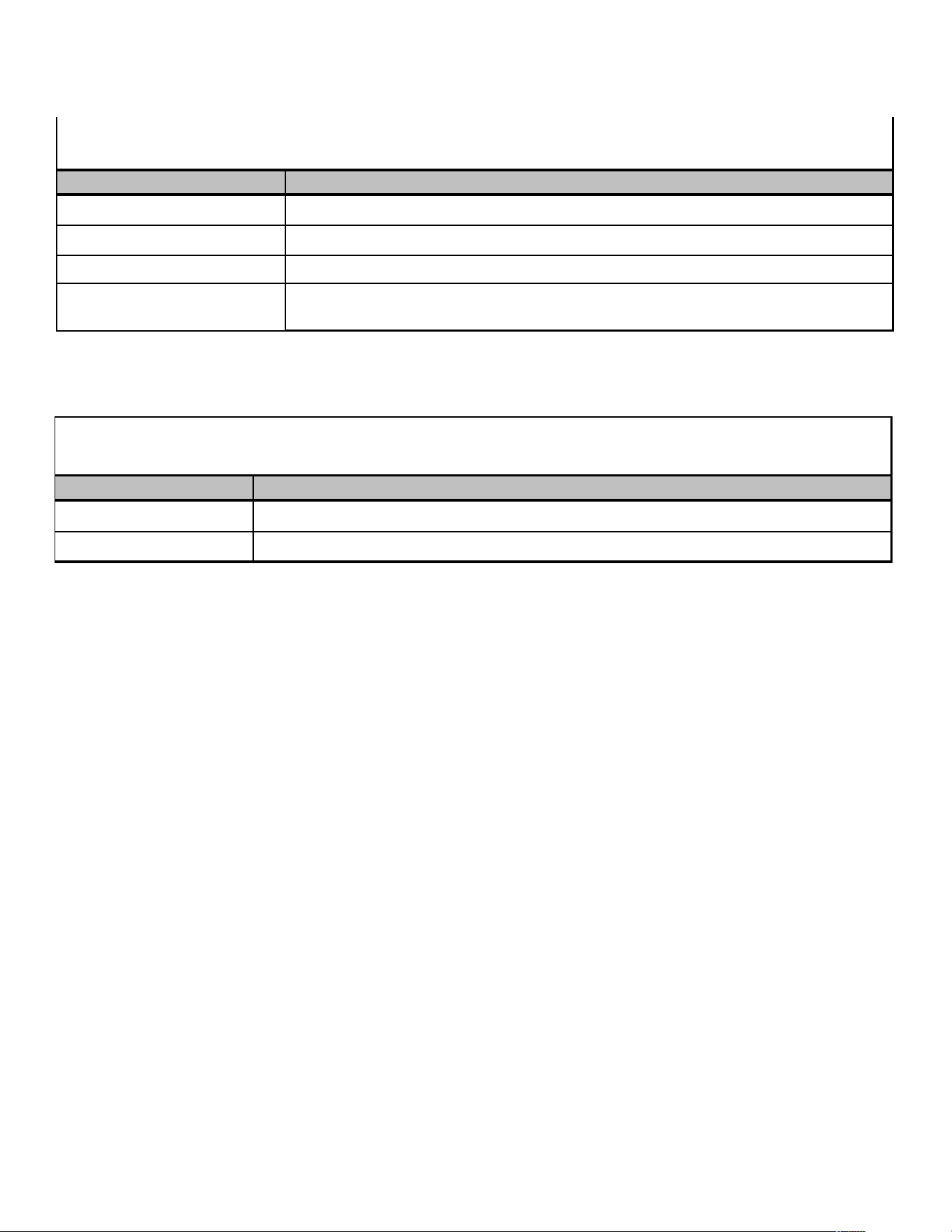
47
PRODUCT IDENTIFICATION Air Handlers
Model/Rev Description
MBR****AA-1AA Initial release of a module blower with PSC blower motor.
MBR****AA-1AB A quality improvement to use 0.75" Quiet Flex Insulation.
MBR****AA-1AC Release of MBR/MBVC Models(Minor Revisions) for 11th St Plant. Dayton to Houston
MBR****AA-1AD
Add permanent sealing/condensation-control upgrades to all MB units and remove high-
voltage knockouts
MBR
MODULAR BLOWER AIR HANDLER R-MULTI-POSITION PSC MOTOR
Model/Rev Description
MBE****AA-1AA Introduction of a module blower with variable speed blower motor.
MBE****AA-1BA Introduction of new models adding lower kW hit kits on the S&R plate.
MBE
MODULAR BLOWER AIR HANDLER E-MULTI-POSITION VARIABLE-SPEED
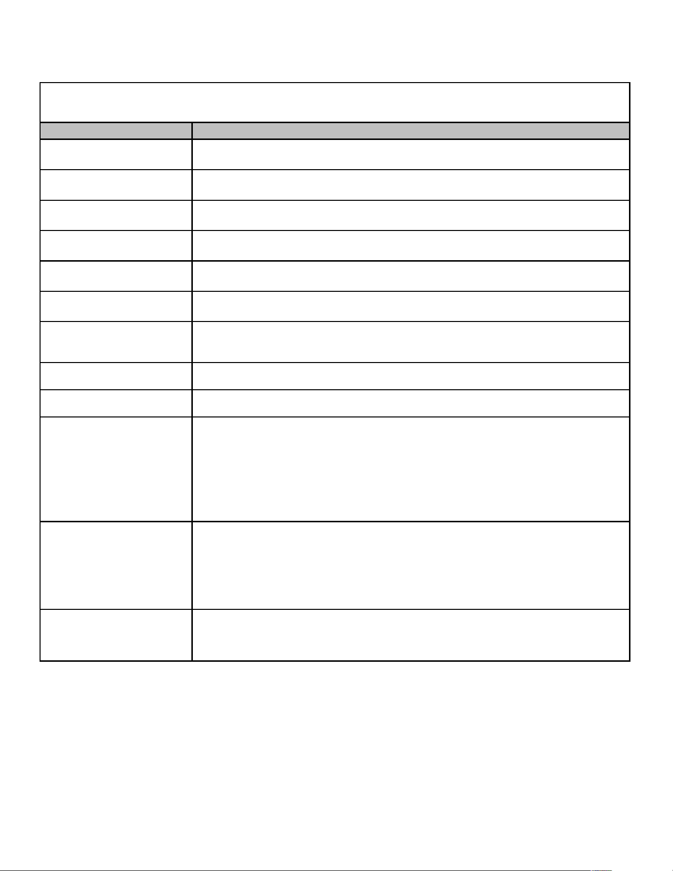
48
PRODUCT IDENTIFICATION Air Handlers
Model/Rev Description
AWUF****1AA Initial release of 13 SEER Dayton wall mount air handlers.
AWUF****16AA
Initial release 13 SEER Dayton wall mount air handlers suitable for use with R-22 and R-
410A refrigerant.
AWUF3005-101AA Introduces 13 SEER Dayton wall mount air handlers using a Burr Oak Louvered Fin coil.
AWUF****1BA Replaced wave fin design with new louvered fin design.
AWUF370**16AA Initial release of AWUF37 Air Handlers for use with R-22 and R410A.
AWUF****16BA
Replaced wave fin design with new louvered fin design. Replaced copper tube hairpins with
aluminum hairpins.
AWUF180316BA
AWUF240316BA
AWUF300316BA
Initial release of AWUF 3KW Heater air handlers.
AWUF310[5/8]16AA
AWUF321016AA
Initial release of higher 14 SEER AWUF series air-handlers
AWUF300[3-10]16BB
AWUF360[5-10]16BB
18 x 20 x 1 filter replaced the 16 x 20 x 1 filter.
AWUF18F[3-8]16AA
AWUF24F[1/8]16AA
AWUF30F*16AA
AWUF31F[5/8]16AA
AWUF32F116AA
AWUF36F*16AA
AWUF37F[1/5/8]16AA
Initial release of R-401A air handlers with factory-installed float switch and a drain pan water
sensor switch.
AWUF180[3-8]16BB
AWUF240[3-10]16BB
AWUF300[5-10]16BC
AWUF310[5-10]16AB
AWUF360[5-10]16BC
AWUF370[5-10]6BB
UL1995 heater change to remove sequencer and replace a contactor.
AWUF190*16AA
AWUF250*16AA
AWUF251*16AA
Matchup to meet the new 14 SEER min efficiency levels. Uses a 4 row coil and an EEM
Motor (X13 style) to achieve higher efficiency. Initial release.
AWUF
A SINGLE PIECE AIR HANDLER WALL MOUNT PSC MOTOR UNPAINTED FLOWRATOR
*AWUF Continued on the next page
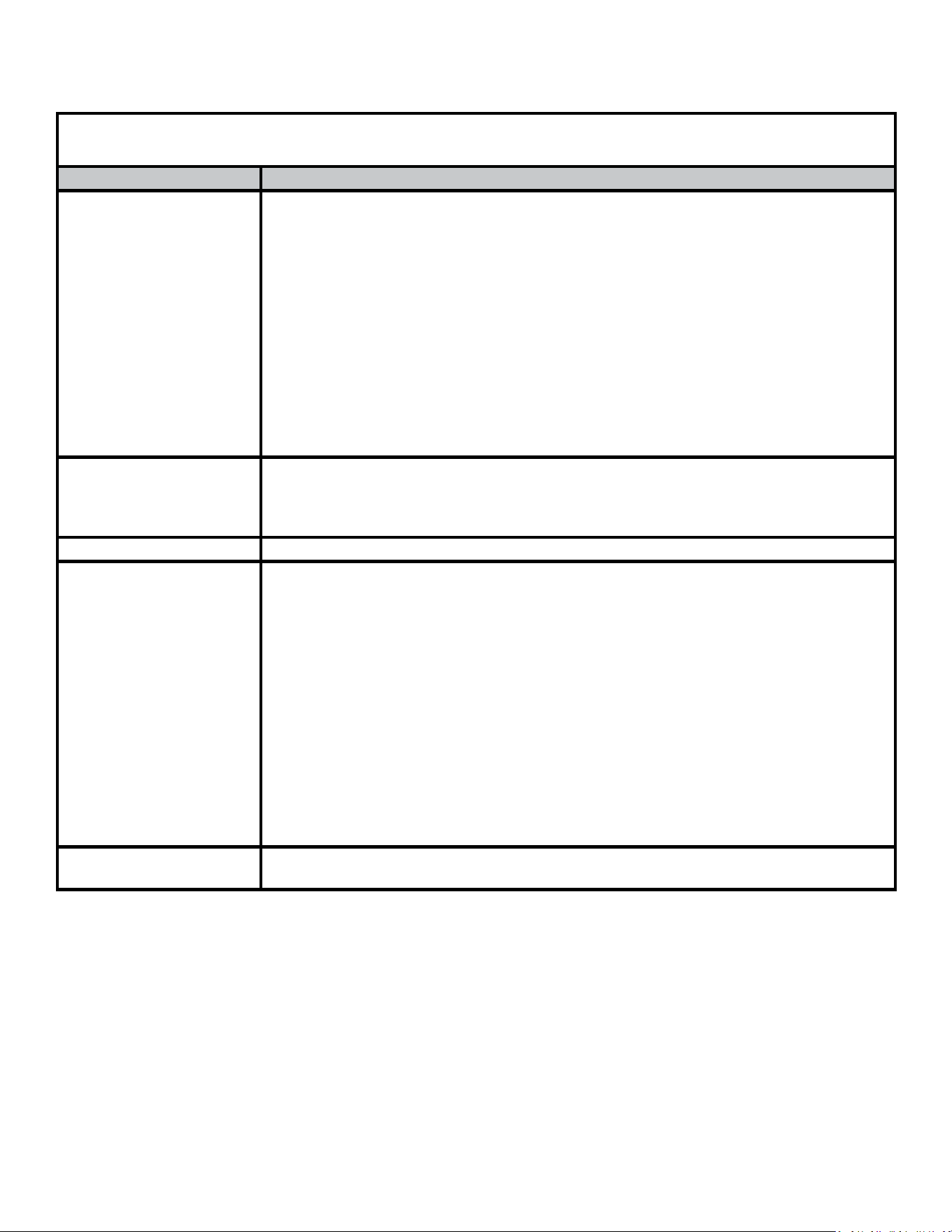
49
PRODUCT IDENTIFICATION Air Handlers
AWUF
A SINGLE PIECE AIR HANDLER WALL MOUNT PSC MOTOR UNPAINTED FLOWRATOR
Model/Rev Descripon
AWUF180[316,516,816]BC
AWUF190[316,516,816]AB
AWUF240[316,516,816]BC
AWUF241016BC
AWUF250[316,516,816]AB
AWUF251016AB
AWUF300[516,816]BD
AWUF301016BD
AWUF310[516,816]AC
AWUF321016AC
AWUF360[516,816]BD
AWUF361016BD
AWUF370[516,816]BC
AWUF371016BC
Release gasket and caps to seal leak. With this modicaon we will be able to meet 2% at 1 inch
stac leak and 1.4% leak rate at 0.5 inch stac. Modied all current AWUF units to pass current air
leak rate.
AWUT310[516,816]AA
AWUT321016AA
AWUT370[516,816]AA
AWUT371016AA
AWUT is a new lineup of the AWUF wall mounted Electric Heat Air Handlers with a factory installed
TXV. The lineup will be matched with a 5, 8 and 10KW heater, 208V/230V and single phase.
AWUF310516AD Design improvement - Update MOP
AWUF180[316,516,816]BD
AWUF190[316,516,816]AC
AWUF240[316,516,816]BD
AWUF241016BC
AWUF250[316,516,816]AC
AWUF251016AC
AWUF300[516,816]BC
AWUF301016DC
AWUF310516AE
AWUF310816AD
AWUF321016AD
AWUF360[516,816]BE
AWUF361016BE
AWUF[516,816]BD
AWUF371016BD
Redesigned the AWUF Control Box to make it larger to allow more room to access components for
serviceability in the eld.
AWUT24[05,08,10]14
AWUT is a new lineup of the AWUF with a 7mm coil and a factory installed TXV. The lineup will be
matched with a 5, 8 and 10KW heater, 208V/230V and single phase.
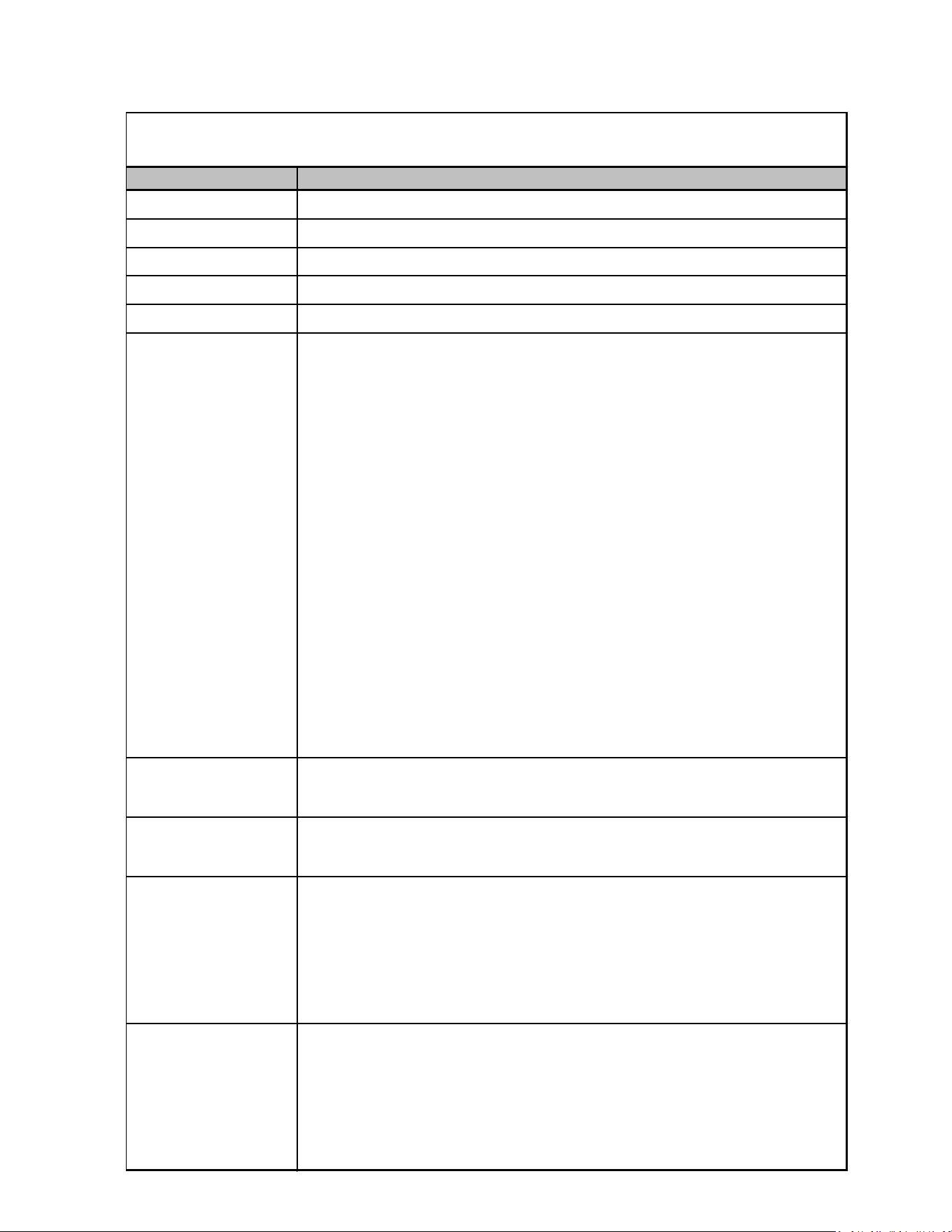
50
PRODUCT IDENTIFICATION Coils
Model/Rev Description
CAPF*****6AA Initial release of CAPF Dayton Upflow/Downflow coils.
CAPF*****6BA Burr Oak Louvered Fin released in place of the Wavy Fin.
CAPF36***CA Redesigned for performance improvement from 2 row to 3 row.
CAPF*****6DA Replaced existing copper coils and other associated parts with aluminum components.
CAPF*****6DB Drain pan material changed.
CAPF1824A6DC
CAPF1824B6DC
CAPF1824C6DC
CAPF3030A6DC
CAPF3030B6DC
CAPF3030C6DC
CAPF3030D6DC
CAPF3131B6DC
CAPF3131C6DC
CAPF3137B6AB
CAPF3636A6DC
CAPF3636B6DC
CAPF3636C6DC
CAPF3636D6DC
CAPF3642C6DC
CAPF3642D6DC
CAPF3743C6DC
CAPF3743D6DC
CAPF4860C6DC
CAPF4860
Redesign the wrapper for the CAPF to provide increased ease of installation.
CAPFA1818A6AA
CAPFA1818B6AA
Replaced 3/8 aluminum tubing in residential splits indoor coils with more efficient 7mm
aluminum tubing.
CAPFA1818A6BA
CAPFA1818B6BA
Redesigned drain pan, replace two piece access panels with single piece access panel.
CAPFA1818C6AA
CAPFA2418A6AA
CAPFA2418B6BA
CAPFA2418C6AA
CAPFA2422B6AA
CAPFA2422C6AA
Initial release of CAPFA Upflow/Downflow 7mm AL Coils.
CAPFA3022B6AA
CAPFA3022C6AA
CAPFA3022D6AA
CAPFA3626B6AA
CAPFA3626C6AA
CAPFA3626D6AA
Initial release of CAPFA Upflow/Downflow 7mm AL Coils.
CAPF
C-INDOOR COIL A- UPFLOW/DOWNFLOW PAINTED FLOWRATOR
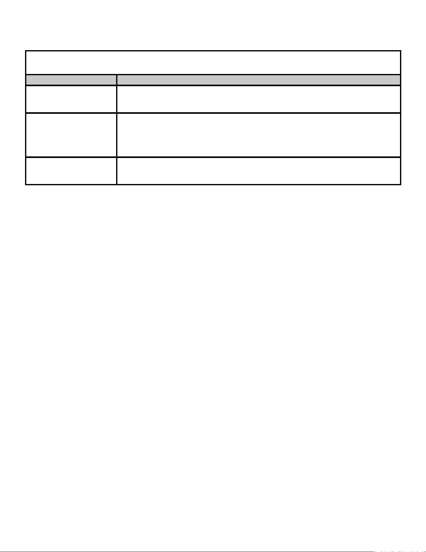
51
CAPF
C-INDOOR COIL A-UPFLOW/DOWNFLOW PAINTED FLOWRATOR
Model/Rev Descripon
CAPFA1714A6AA
CAPFA1714B6AA
CAPFA1818C6BA
Inial release of 7mm AL CAPFA Upow/Downow Coils.
CAPFA2318A6AA
CAPFA2318B6AA
CAPFA2318C6AA
CAPFA2422A6AA
CAPFA3022A6AA
Inial release of 7mm AL CAPFA Upow/Downow Coils.
CAPFA2922A6AA
CAPFA2922B6AA
CAPFA2922C6AA
Inial release of 7mm AL CAPFA Upow/Downow Coils.
PRODUCT IDENTIFICATION Coils
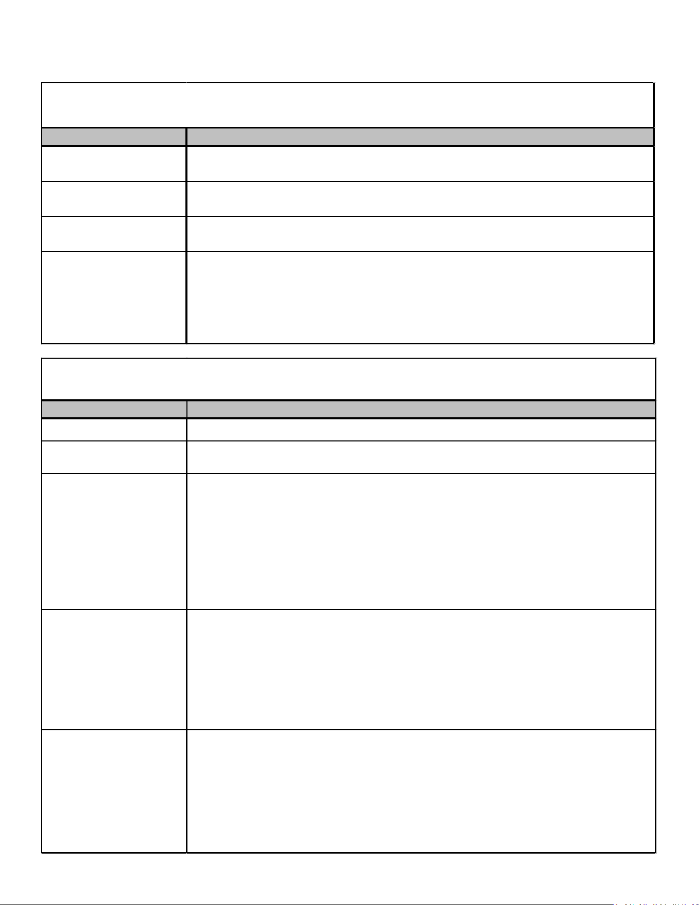
52
PRODUCT IDENTIFICATION Coils
Model/Rev Description
CAPT3131B4BA
CAPT3131C4BA
Initial release of coils with factory-installed, non-adjustable TXV. Single stage AHRI ratings
for CAPT3131 NTC combinations.
CAPT3743C4AA
CAPT3743D4AA
Initial release of single stage AHRI ratings for CAPT3743 NTC combinations.
CAPT4961C4AA
CAPT4961D4AA
Initial release of single stage AHRI ratings for CAPT4961C4 NTC combinations.
CAPT3131B4AB
CAPT3131C4AB
CAPT3743C4AB
CAPT3743D4AB
CAPT4961C4AB
CAPT4961D4AB
Redesign the wrapper for the CAPT to provide increased ease of installation.
CAPT
C-INDOOR
C
OIL A- UPFLOW/DOWNFLOW PAINTED CASED FLOWRATOR W/TXV
Model/Rev Description
CHPF*****6AA Intial release of 13 SEER CHPF horizontal A coil.
CHPF*****6BA
Released Burr Oak Louvered Fin in place of the Wavy Fin. The rows changed by one, (i.e.
4 row to 3 row; 3 row to 2 row) where applicable.
CHPF1824A6CA
CHPF2430B6CA
CHPF3636B6CA
CHPF3642C6CA
CHPF3642D6CA
CHPF3743C6BA
CHPF3743D6BA
CHPF4860D6DA
Louvered fins. Replaced copper tube hairpins with aluminum hairpins.
CHPF1824A6CB
CHPF2430B6CB
CHPF3636B6CB
CHPF3642C6CB
CHPF3642D6CB
CHPF3743C6BB
CHPF3743D6BB
CHPF4860D6DB
Drain pan material change to a Decabromodiphenyl Ether free resin.
CHPF1824A6CC
CHPF2430B6CC
CHPF3636B6CC
CHPF3642C6CC
CHPF3642D6CC
CHPF3743C6BC
CHPF3743D6BC
CHPF4860D6DC
Change to prepainted wrappers
CHPF
C-INDOOR COIL HORIZONTAL A-COIL PAINTED FLOWRATOR
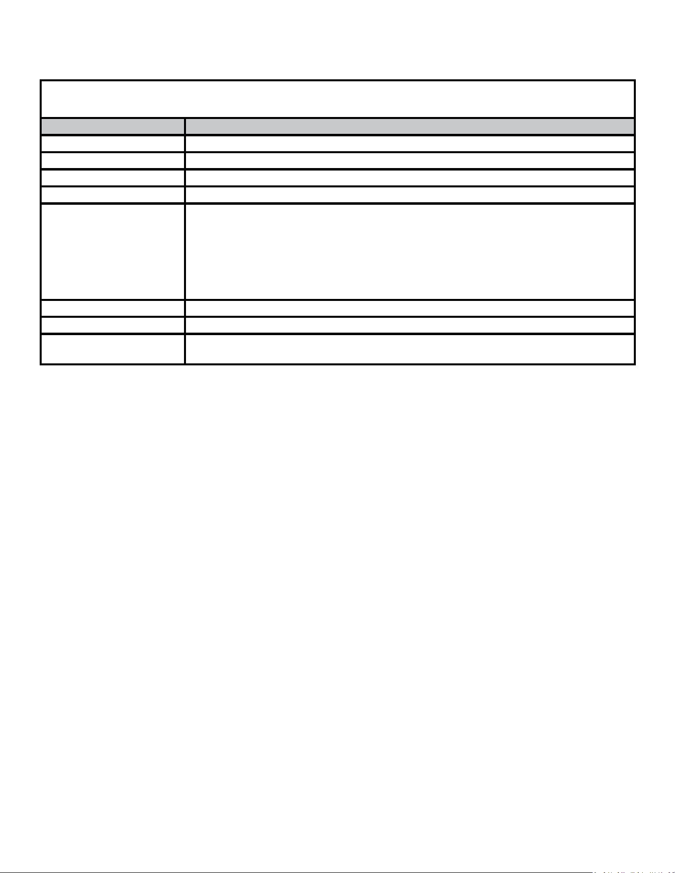
53
PRODUCT IDENTIFICATION Coils
CAPF
C-INDOOR COIL A-UPFLOW/DOWNFLOW UNCASED FLOWRATOR
Model/Rev Descripon
CAUF*****6AA Inial release of CAUF Dayton Upow/Downow coils.
CAUF*****6BA Burr Oak Louvered Fin released in place of the Wavy Fin.
CAUF****6*DA Replaced exisng copper coils and other associated parts with aluminum components.
CAUF*****6DB Drain pan material changed.
CAUF1824(A/B/C)6RDB
CAUF3636(A/B)6RDB
CAUF3636(C/D)6RDB
CAUF3642(C/D)6RDB
CAUF3743(C/D)6RDB
CAUF4860(C/D)6RDB
CAUF4961(C/D)6RDB
Manufacturing Locaon Change from Dayton to Houston. Designated by “R”.
CAUF3137B6RAA Manufacturing Locaon Change from Dayton to Houston. Designated by “R”.
CAUF36***CA Redesign from 2 row to 3 row for performance improvement.
CAUFA*****6AA
CAUFA*****6BA
Inial release of 7mm AL CAUFA Upow/Downow Coils.
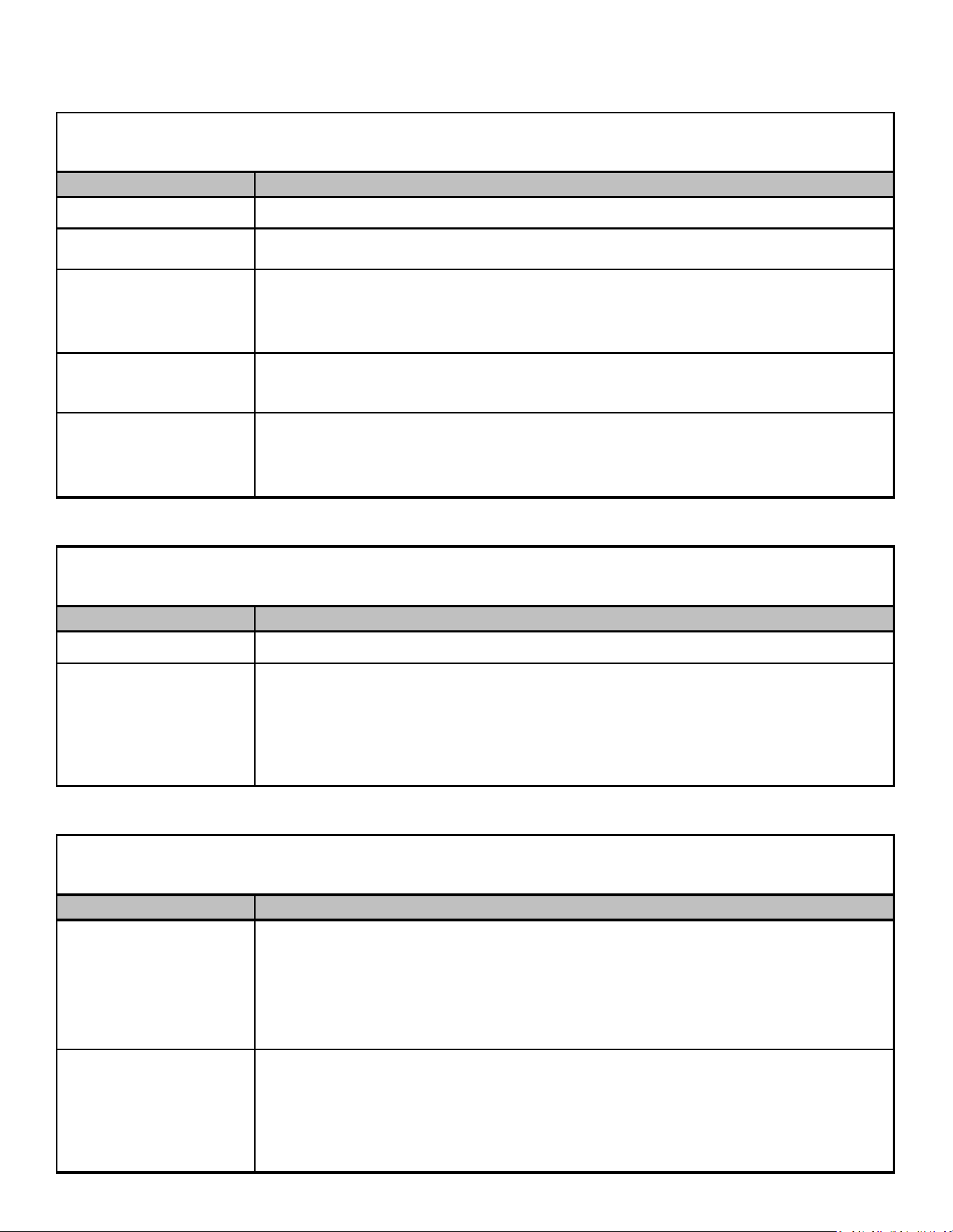
54
PRODUCT IDENTIFICATION Coils
Model/Rev
Description
CSCF*****6AA Release 13 SEER CSCF slab horizontal coil.
CSCF*****6BA
Burr Oak Louvered Fin released in place of the Wavy Fin. The rows change by one, (i.e.
4 row to 3 row; 3 row to 2 row) where applicable.
CSCF1824N6BB
CSCF3036N6BB
CSCF3642N6CB
CSCF4860N6CB
Drain pan material change.
CSCF3642N6CA
CSCF4860N6CA
Release 13 SEER CSCF slab horizontal coil. Louvered fin project.
CSCF1824N6DA
CSCF3036N6DA
CSCF3642N6DA
CSCF4860N6DA
Release 13 SEER CSCF slab horizontal coil. Converting copper coils, maifolds, haripins,
flowrators to aluminum coils.
Model/Rev
Description
CTPF*****6AA
Initial release of coated coils.
CTPF1824*6AB
CTPF3030*6AB
CTPF3131*6AB
CTPF3636*6AC
CTPF3642*6AB
CTPF4860*6AB
Drain pan material change.
Model/Rev Description
CTUF1824*6AA
CTUF3030*6AA
CTUF3131*6AA
CTUF3636*6AA
CTUF3642*6AA
CTUF4860*6AA
Initial release.
CTUF1824*6AB
CTUF3030*6AB
CTUF3131*6AB
CTUF3636*6AC
CTUF3642*6AB
CTUF4860*6AB
Initial release.
CTUF
C-INDOOR COIL T-COATED UNPAINTED FLOWRATOR
CSCF
C-INDOOR COIL S-HORIZONTAL SLAB COIL UNPAINTED FLOWRATOR
CTPF
C-INDOOR COIL T-COATED PAINTED FLOWRATOR
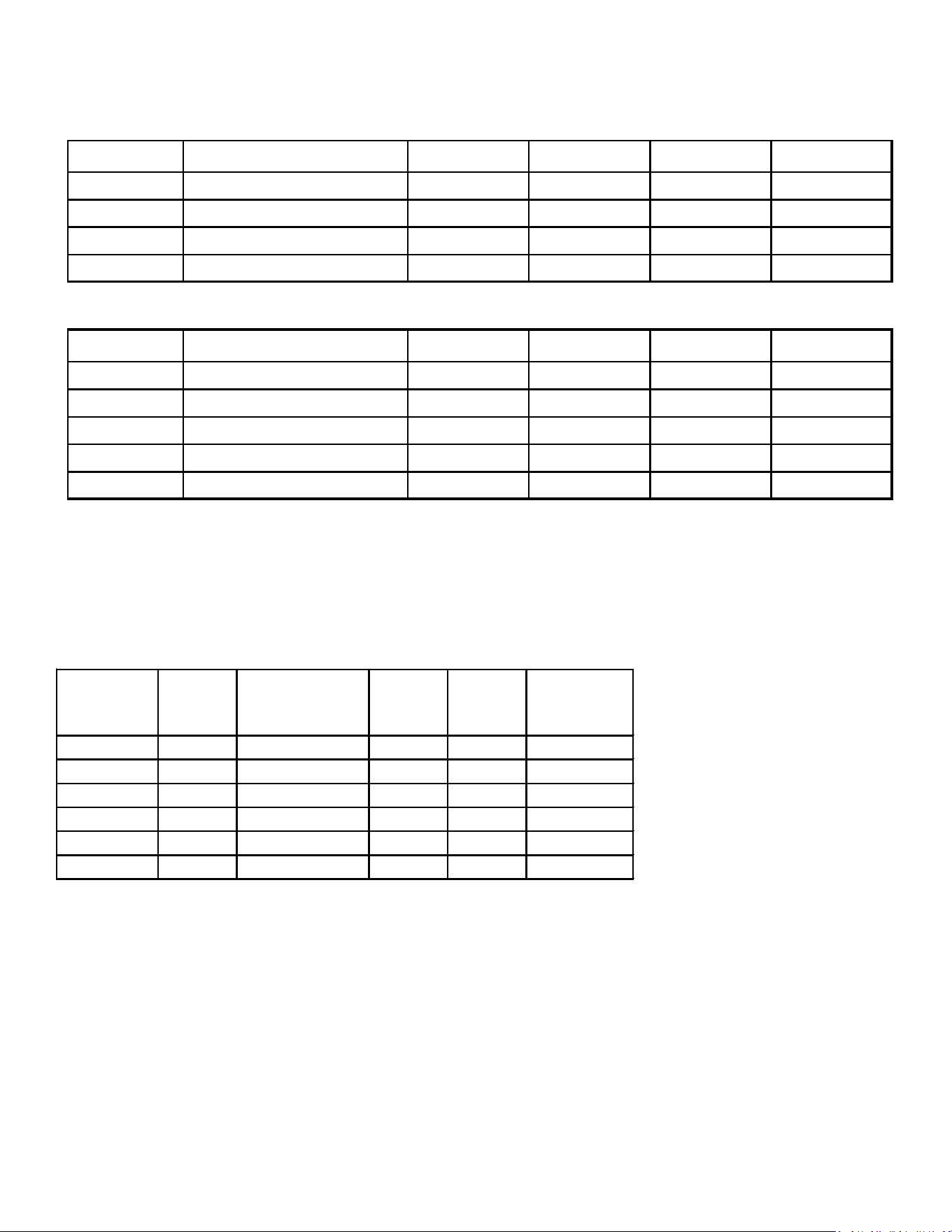
55
ACCESSORIES - LIGHT COMMERCIAL
ACCESSORIES LIGHT COMMERCIAL
Model Description GSX110903 GSX110904 GSX111203 GSX111204
FSK01A* Freeze Protection Kit x x x x
ASC01 Anti Short Cycle Kit x x x x
LAKT-01 Low Ambient Kit x x x x
LSK03*
Liquid Line Solenoid Kit
x x x x
Model Description GSZ110903 GSZ110904 GSZ111203 GSZ111204
FSK01A* Freeze Protection Kit x x x x
ASC01 Anti Short Cycle Kit x x x x
OT-EHR18-60 Emergency Heat Relay Kit --- --- --- ---
LAKT-01 Low Ambient Kit x x x x
LSK03* Liquid Line Solenoid Kit
x x x x
GSX11
GSZ11
AHKD
Model
Nominal
kW
Electrical
Characteristics
Stages
Weight
(lbs.)
Max.
Overcurrent
Protection
AHKD15-3 15 208-230/3/60 1 56 60
AHKD15-4 15 460/3/60 1 55 30
AHKD20-3 20 208-230/3/60 2 59 70
AHKD20-4 20 460/3/60 2 57 35
AHKD30-3 30 208-230/3/60 2 60 100
AHKD30-4 30 460/3/60 2 58 50
ELECTRIC HEATER KITS
NOTES:
• AR series Air Handlers do not have factory installed electric heat. Purchased as an accessory, these are the ONLY heater kits that can
be used with the AR Series.
• The electrical characteristics of the air handler, electric heater kits and building power supply must be compatible.
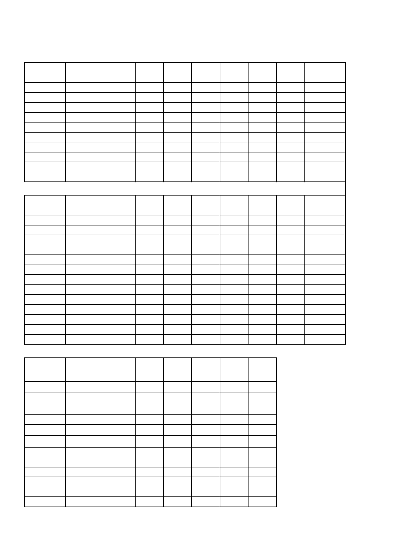
56
ACCESSORIES MODELS TO KITS MATCHUP
ASX13
Model Description
ASX13
018*
ASX13
024*
ASX13
030*
ASX13
036*
ASX13
042*
ASX13
048*
ASX13
060*/061*
ABK-20
1
Anchor Bracket Kit X X X X X X X
ASC0 1 Anti-Short Cycle Kit X X X X X X X
CSR-U-1 Hard-start Kit X X X X
CSR-U-2 Hard-start Kit X X
CSR-U-3 Hard-start Kit X X
FSK01A
2
Freeze Protection Kit X X X X X X X
LSK02* Liquid Line Solenoid Kit X X X X X X X
TX2 N 4 A³ TXV Kit X X
TX3 N 4
3
TXV Ki t X X
TX5 N 4
3
TXV Ki t X X X
G/VSX13
Model Description
G/VSX13
018*
G/VSX13
024*
G/VSX13
030*
G/VSX13
036*
G/VSX13
042*
G/VSX13
048*
G/VSX13060*
GSX13061*
ABK-20
1
Anchor Bracket Kit X X X X X X X
ABK-21
4
Anchor Bracket Kit X X X X
ASC0 1 Anti-Short Cycle Kit X X X X X X X
CSR-U-1 Hard-start Kit X X X X
CSR-U-2 Hard-start Kit X X
CSR-U-3 Hard-start Kit X X
FSK01A
2
Freeze Protection Kit X X X X X X X
LSK02* Liquid Line Solenoid Kit X X X X X X X
TX2 N 4 A³ TXV Kit X X
TX3 N 4
3
TXV Ki t X X
TX5 N 4
3
TXV Ki t X X X
CSB-15
Sound Blanket Kit X X X
CSB-16 Sound Blanket Kit X X X X
GSX13 Three-Phase models
Model Description
GSX13
0363*
GSX13
0483*
GSX13
0484*
GSX130
[60/61]3*
GSX130
[60/61]4*
ABK-20
1
Anchor Bracket Kit X X X X X
ASC01 Anti-Short Cyc le Kit X X X X X
FSK01A
2
Freeze Protection Kit X X X X X
LSK02*
Liquid Line Solenoid Kit X X X X X
TX3N4
3
TXV Kit X
TX5N4
3
TXV Kit X X X X
CSB-15 Sound Blanket Kit X X X X
CSB-16 Sound Blanket Kit X
LAKT01 Low Ambient Kit X X X X X
0163R00002 Crankc ase Heater Kit X
0163R00003 Crankc ase Heater Kit X X
0163R00004 Crankc ase Heater Kit X X
1) Contains 20 brackets; four brackets
needed to anchor unit to pad
2) Installed on indoor coil.
3) Field-installed, non-bleed, expansion
valve kit - Condensing units and heat
pumps with reciprocating or rotary
compressors require the use of start-
assist components when used in
conjuntion with an indoor coil using a
non-bleed thermal expansion valve
refrigerant.
4) For use on the 23" chassis only.
Contains 20 brackets; four brackets
needed to anchor unit to pad.
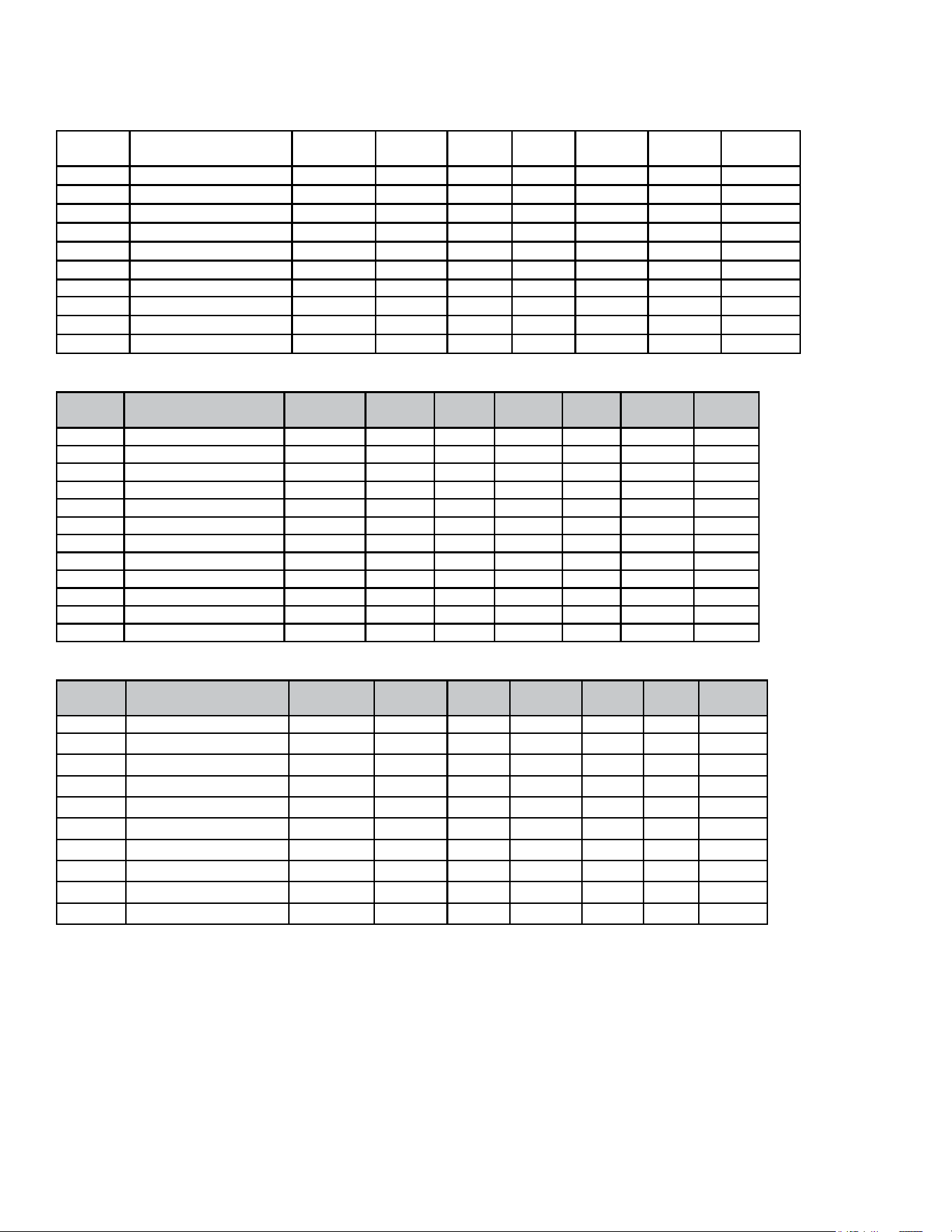
57
ACCESSORIES
ASX14
Model Description
ASX14
018
ASX14
024
ASX14
030
ASX14
036
ASX14
042
ASX14
048
ASX14
060
ABK-20
1
Anchor Bracket Kit X X X X X X X
ASC01 An-Short Cycle Kit X X X X X X X
CSR-U-1 Hard-start Kit X X X X
CSR-U-2 Hard-start Kit X X
CSR-U-3 Hard-Start Kit X X
FSK01A² Freeze Protecon Kit X X X X X X X
LSK02* Liquid Line Solenoid Kit X X X X X X X
TX2N4A³ TXV Kit X X
TX3N4³ TXV Kit X X
TX5N4³ TXV Kit X X X
GSX14
Model Description
GSX14
018*
GSX14
024*
GSX14
030*
GSX14
036*
GSX14
042*
GSX14
048*
GSX14
060*
ABK-20
1
Anchor Bracket Kit X X X X X X X
ABK-21⁴ Anchor Bracket Kit X
CSR-U-1 Hard-start Kit X X X X
CSR-U-2 Hard-start Kit X X
CSR-U-3 Hard-Start Kit X X
FSK01A² Freeze Protecon Kit X X X X X X X
LSK02* Liquid Line Solenoid Kit X X X X X X X
TX2N4A³ TXV Kit X X
TX3N4³ TXV Kit X X
TX5N4³ TXV Kit X X X
CSB-14 Sound Blanket Kit X X
CSB-16 Sound Blanket Kit X X X X X
SSX14
Model Description
SSX14
018
SSX14
024
SSX14
030
SSX14
036
SSX14
042
SSX14
048
SSX14
060
ABK-20
1
Anchor Bracket Kit X X X X X X X
ASC01 An-Short Cycle Kit X X X X X X X
CSR-U-1 Hard-start Kit X X X X
CSR-U-2 Hard-start Kit X X
CSR-U-3 Hard-Start Kit X X
FSK01A² Freeze Protecon Kit X X X X X X X
LSK02* Liquid Line Solenoid Kit X X X X X X X
TX2N4A³ TXV Kit X X
TX3N4³ TXV Kit X X
TX5N4³ TXV Kit X X X
1 Contains 20 brackets; four brackets needed to anchor unit to anchor unit to pad
2 Installed on Indoor coil
3 Field-installed, non-bleed, expansion valve kit - Condensing units and heat pumps with reciprocang or rotary compressors
require the use of start-assist components when used in conjuncon with an indoor coil using a non-bleed thermal expansion valve
refrigerant.
4 For use exclusively on 23” chassis models. Contains 20 brackets; four brackets needed to anchor unit to pad.
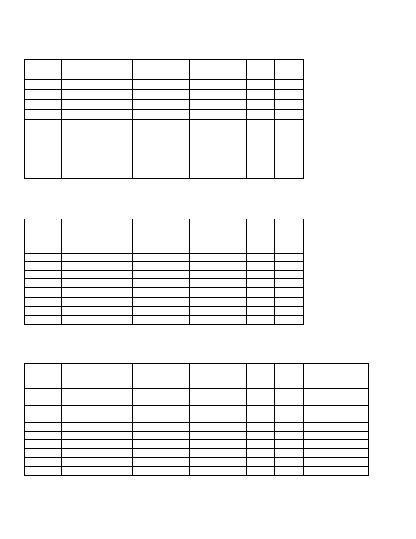
58
ACCESSORIES
SSX16
Model Description
SSX16
024*
SSX16
030*
SSX16
036*
SSX16
042*
SSX16
048*
SSX16
060*
ABK-20
1
Anchor Bracket Kit X X X X X X
ASC0 1 Anti-Short Cycle Kit X X X X X X
CSR-U-1 Hard-start Kit X X X
CSR-U-2 Hard-start Kit X X
CSR-U-3 Hard-start Kit X X
FSK01A
2
Freeze Protection Kit X X X X X X
LSK02* Liquid Line Solenoid Kit X X X X X X
TX2N4A
3
TXV Ki t X
TX3 N 4
3
TXV Ki t X X
TX5 N 4
3
TXV Ki t X X X
ASX16/DSX16
Model Description
A/DSX16
024*
A/DSX16
030*
A/DSX16
036*
A/DSX16
042*
A/DSX16
048*
A/DSX16
060*
ABK-20
1
Anchor Bracket Kit X X X X X X
ASC0 1 Anti-Short Cycle Kit X X X X X X
CSR-U-1 Hard-start Kit X X X
CSR-U-2 Hard-start Kit X X
CSR-U-3 Hard-start Kit X X
FSK01A
2
Freeze Protection Kit X X X X X X
LSK02* Liquid Line Solenoid Kit X X X X X X
TX2N4A
3
TXV Ki t X
TX3 N 4
3
TXV Ki t X X
TX5 N 4
3
TXV Ki t X X X
ASX/GSX16 (Rev F or Later)
Model Description
A/GSX16
018F*
A/GSX16
024F*
A/GSX16
030F*
A/GSX16
036F*
A/GSX16
042F*
A/GSX16
048F*
A/GSX16
060F*
A/GSX16
061F*
ABK-20 Anchor Bracket Kit X X X X X X X X
ASC0 1 Anti-Short Cycle Kit X X X X X X X X
CSR-U-1 Hard-start Kit X X X X
CSR-U-2 Hard-start Kit X X
CSR-U-3 Hard-start Kit X X X
FSK01A
2
Freeze Protection Kit X X X X X X X X
LSK02* Liquid Line Solenoid Kit X X X X X X X X
TXV-3 0
3
Fi xe d TXV Ki t X X X
TXV-4 2
3
Fi xe d TXV Ki t X X
TXV-4 8
3
Fi xe d TXV Ki t X
TXV-6 0
3
Fi xe d TXV Ki t X X
3
Field-installed, non-bleed, expansion valve kit - Condensing units and heat pumps w ith reciprocating or rotary compressors require the
use of start-assist components w hen used in conjunction w ith an indoor coil using a non-bleed thermal expansion valve refrigerant.
1
Contains 20 brackets; four brackets needed to anchor unit to pad.
2
Installed on indoor coil
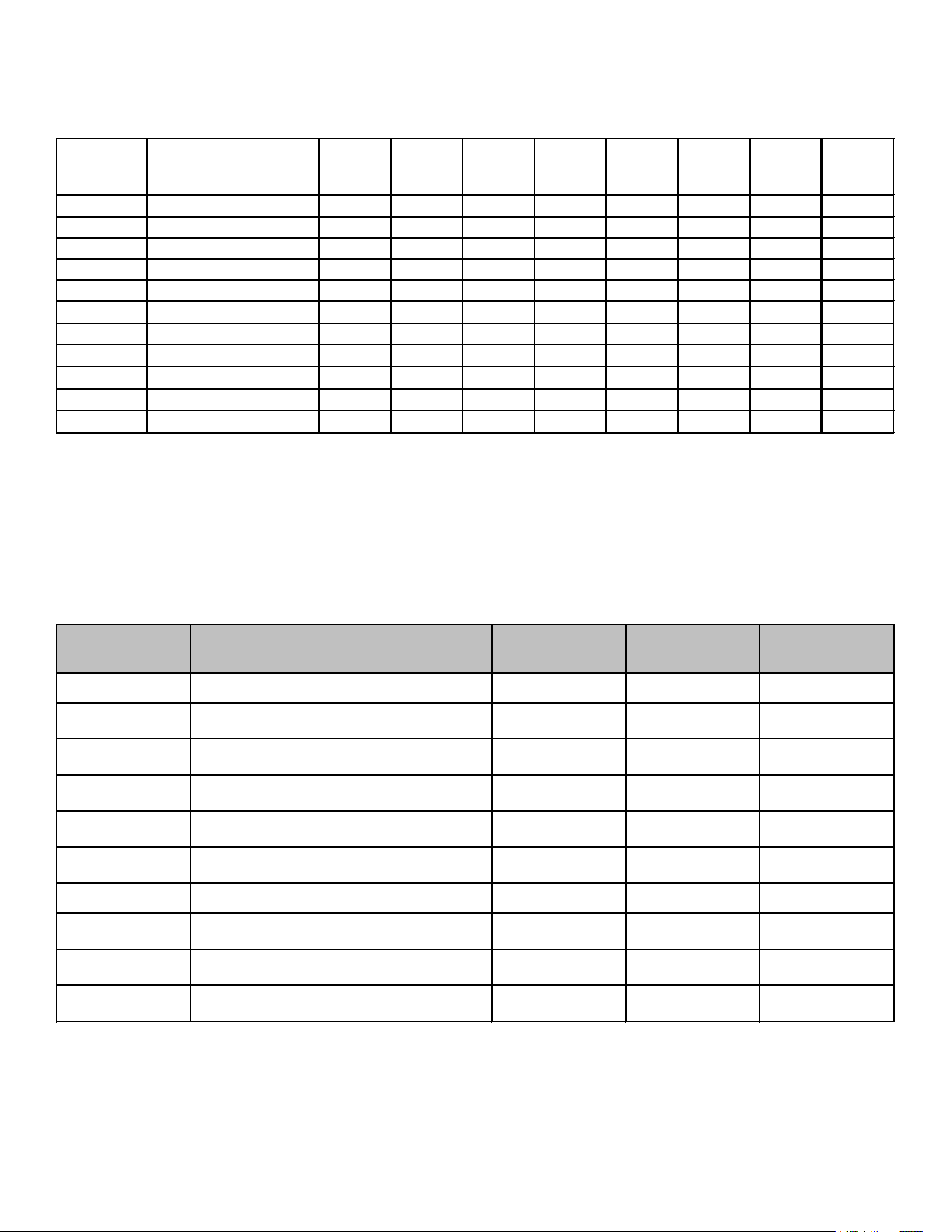
59
ACCESSORIES
GSX16S/GSX16A
Model Description
GSX16
S/A181A*
GSX16
S/A241A*
GSX16
S/A301A*
GSX16
S/A361A*
GSX16
S/A421A*
GSX16
S/A481A*
GSX16
A601A*
GSX16
A611A*
ABK-20
1
Anchor Bracket Kit X X X X X X X X
ASC 0 1 Anti-Short Cycle Kit X X X X X X X X
CSR-U-1 Hard-start Kit X X X X
CSR-U-2 Hard-start Kit X X
CSR-U-3 Hard-start Kit X X X
FSK01A
2
Freeze Protection Kit X X X X X X X X
LSK02* Liquid Line Solenoid Kit X X X X X X X X
TXV-3 0
3
Fi xe d TXV Kit X X X
TXV-4 2
3
Fi xe d TXV Kit X X
TXV-4 8
3
Fi xe d TXV Kit X
TXV-6 0
3
Fi xe d TXV Kit X X
1
Contains 20 brackets; four brackets needed to anchor unit to pad.
2
Installed on indoor coil
3
Field-installed, non-bleed, expansion valve kit - Condensing units and heat pumps w ith reciprocating or rotary compressors require the
use of start-assist components w hen used in conjunction w ith an indoor coil using a non-bleed thermal expansion valve refrigerant.
ASX/DSX18
Model Description
A/DSX18
036*
A/DSX18
048*
/DSX18
060*
ABK-20
1
Anchor Bracket Kit X X X
ASC0 1 Anti-Short Cycle Kit X X X
CSR-U-1 Hard-start Kit X
CSR-U-2 Hard-start Kit X
CSR-U-3 Hard-start Kit X X
FSK01A
1
Freeze Protection Kit X X X
LSK02* Liquid Line Solenoid Kit X X X
TX2N4A TXV Ki t
TX3N4 TXV Kit X
TX5N4 TXV Kit X X
1
Installed on indoor coil
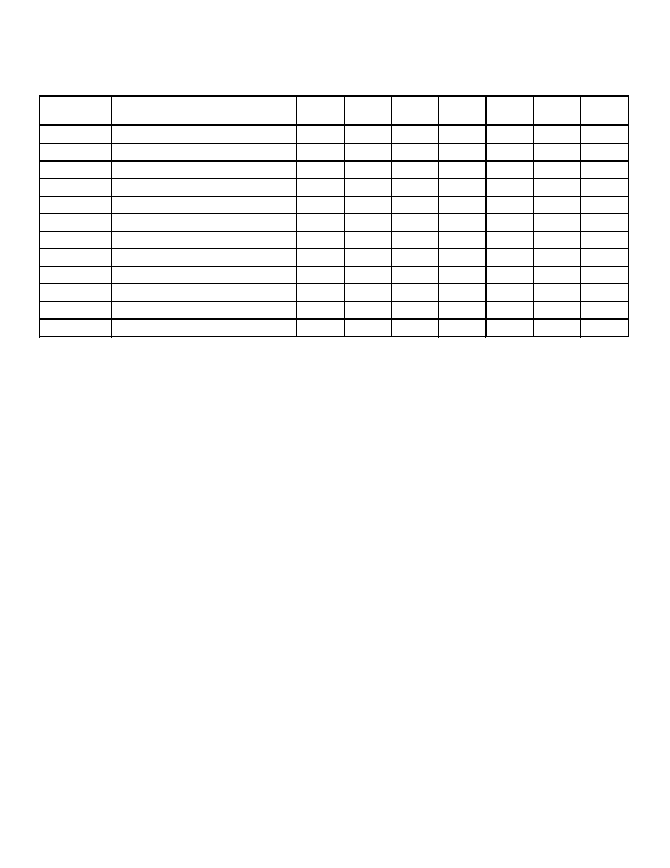
60
ACCESSORIES
ASZ13
Model Description
ASZ13
018
ASZ13
024
ASZ13
030
ASZ13
036
ASZ13
042
ASZ13
048
ASZ13
060
AFE18-60A All-Fuel Kit X X X X X X X
ASC 0 1 Anti-Short Cycle Kit X X X X X X X
CSR-U-1
4
Hard-start Kit X X X X
CSR-U-2
4
Hard-start Kit X X
CSR-U-3
4
Hard-start Kit X X
FSK01A
2
Freeze Protection Kit X X X X X X X
LSK02* Liquid Line Solenoid Kit X X X X X X X
OT/EHR18-60 Emergency Heat Relay kit X X X X X X X
OT18-60A
3
Outdoor Thermostat w/Lockout Stat X X X X X X X
TX2N4A
4
TXV Ki t X X
TX3 N 4
4
TXV Ki t X X
TX5 N 4
4
TXV Ki t X X X
1) Contains 20 brackets; four brackets needed to anchor unit to pad
2) Installed on indoor coil.
3) Required for heat pump applications where ambient temperatures fall below 0°F with 50% or higher relative humidity.
4) Condensing units & heat pumps with reciprocating compressors require the use of start-assist components when used in conjuntion with an indoor
coil using a non-bleed expansion valve refrigerant metering device.
5) Field-installed, non-bleed, expansion valve kit - Condensing units and heat pumps with reciprocating compressors require the use of start-assist
components when used in conjuntion with an indoor coil using a non-bleed thermal expansion valve refrigerant.
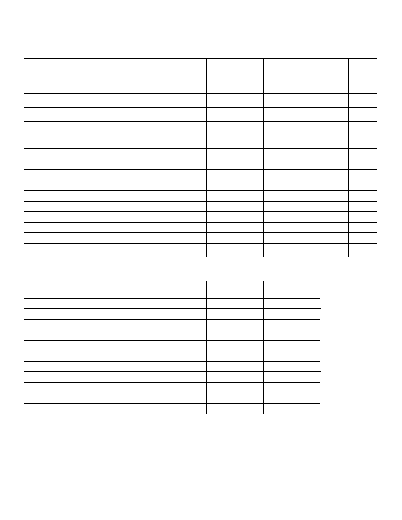
61
ACCESSORIES
GSZ13
Model Description
G/VSZ13
018
G/VSZ13
024
G/VSZ13
030
G/VSZ13
036
G/VSZ13
042
G/VSZ13
048
G/VSZ13
060
AFE18-60A
All-Fuel Kit
X X X X X X X
ASC 0 1
Anti-Short Cycle Kit
X X X X X X X
CSB-15
Sound Blanket
X X X
CSB-16
Sound Blanket
X X X X
CSR-U-1
4
Hard-start Kit X X X X
CSR-U-2
4
Hard-start Kit X X
CSR-U-3
4
Hard-start Kit X X
FSK01A
2
Freeze Protection Kit X X X X X X X
LSK02*
Liquid Line Solenoid Kit X X X X X X X
OT/EHR18-60 Emergency Heat Relay kit X X X X X X X
OT18-60A
3
Outdoor Thermostat w/Lockout Stat X X X X X X X
TX2N4A
5
TXV Ki t X X
TX3 N 4
5
TXV Ki t X X
TX5 N 4
5
TXV Ki t
X X X
GSZ13 Three-Phase
Model Description
GSZ1 3
036*
GSZ1 3
048*
GSZ1 3
048*
GSZ1 3
060*
GSZ1 3
060*
AFE18-60A All-Fuel Kit X X X X X
ASC 0 1 Anti-Short Cycle Kit X X X X X
FSK01A
2
Freeze Protection Kit X X X X X
LSK02* Liquid Line Solenoid Kit X X X X X
OT/EHR18-60 Emergency Heat Relay kit X X X X X
OT18-60A
3
Outdoor Thermostat w/Lockout Stat X X X X X
TX3 N 4
5
TXV Ki t X X
TX5 N 4
5
TXV Ki t X X X
CSB-15 Sound Blanket Kit X X X X
CSB-16 Sound Blanket Kit X
LAKT01 Low Ambient Kit X X X X X
1) Contains 20 brackets; four brackets needed to anchor unit to pad
2) Installed on indoor coil.
3) Required for heat pump applications where ambient temperatures fall below 0°F with 50% or higher relative humidity.
4) Condensing units & heat pumps with reciprocating compressors require the use of start-assist components when used in conjuntion with an indoor
coil using a non-bleed expansion valve refrigerant metering device.
5) Field-installed, non-bleed, expansion valve kit - Condensing units and heat pumps with reciprocating compressors require the use of start-assist
components when used in conjuntion with an indoor coil using a non-bleed thermal expansion valve refrigerant.
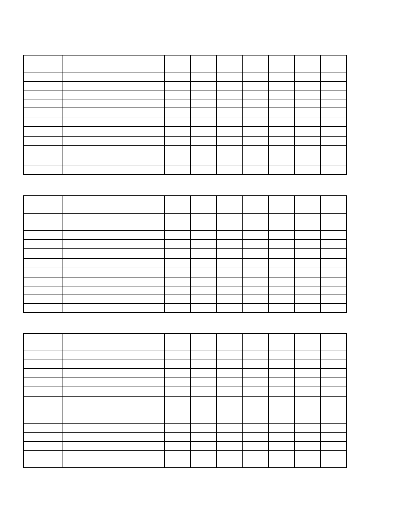
62
ACCESSORIES
SSZ14
Model Description
SSZ14
018*
SSZ14
024*
SSZ14
030*
SSZ14
036*
SSZ14
042*
SSZ14
048*
SSZ14
060*
AFE18-60A All-Fuel Kit X X X X X X X
CSR-U-1 Hard-start Kit X X X X
CSR-U-2 Hard-start Kit X X
CSR-U-3 Hard-start Kit X X
FSK01A
1
Freeze Protection Kit X X X X X X X
LSK02* Liquid Line Solenoid Kit X X X X X X X
OT18-60A
2
Outdoor Thermostat X X X X X X X
OT/EHR18-60 Emergency Heat Relat Kit X X X X X X X
TX2N4A³ TXV Kit X X
TX3N4³ TXV Kit X X
TX5N4³
TXV Kit X X X
ASZ14
Model Description
ASZ14
018*
ASZ14
024*
ASZ14
030*
ASZ14
036*
ASZ14
042*
ASZ14
048*
ASZ14
060*
AFE18-60A
All-Fuel Kit X X X X X X X
CSR-U-1 Hard-start Kit X X X X
CSR-U-2 Hard-start Kit X X
CSR-U-3 Hard-start Kit X X
FSK01A
1
Freeze Protection Kit X X X X X X X
LSK02*
Liquid Line Solenoid Kit X X X X X X X
OT18-60A
2
Outdoor Thermostat X X X X X X X
OT/EHR18-60
Emergency Heat Relat Kit X X X X X X X
TX2N4A³ TXV Kit X X
TX3N4³ TXV Kit X X
TX5N4³
TXV Kit X X X
GSZ14
Model Description
GSZ14
018*
GSZ14
024*
GSZ14
030*
GSZ14
036*
GSZ14
042*
GSZ14
048*
GSZ14
060*
AFE18-60A All-Fuel Kit X X X X X X X
CSR-U-1 Hard-start Kit X X X X
CSR-U-2 Hard-start Kit X X
CSR-U-3 Hard-start Kit X X
FSK01A
1
Freeze Protection Kit X X X X X X X
LSK02*
Liquid Line Solenoid Kit X X X X X X X
OT18-60A
2
Outdoor Thermostat X X X X X X X
OT/EHR18-60 Emergency Heat Relat Kit X X X X X X X
TX2N4A³ TXV Kit X X
TX3N4³ TXV Kit X X
TX5N4³
TXV Kit X X X
CSB-15 Sound Blanket Kit X X X
CSB-16 Sound Blanket Kit X X X X
1
Installed on indoor coil
2
Required for heat pump applications where ambient temperatures fall below 0°F with 50% or higher relative humidy.
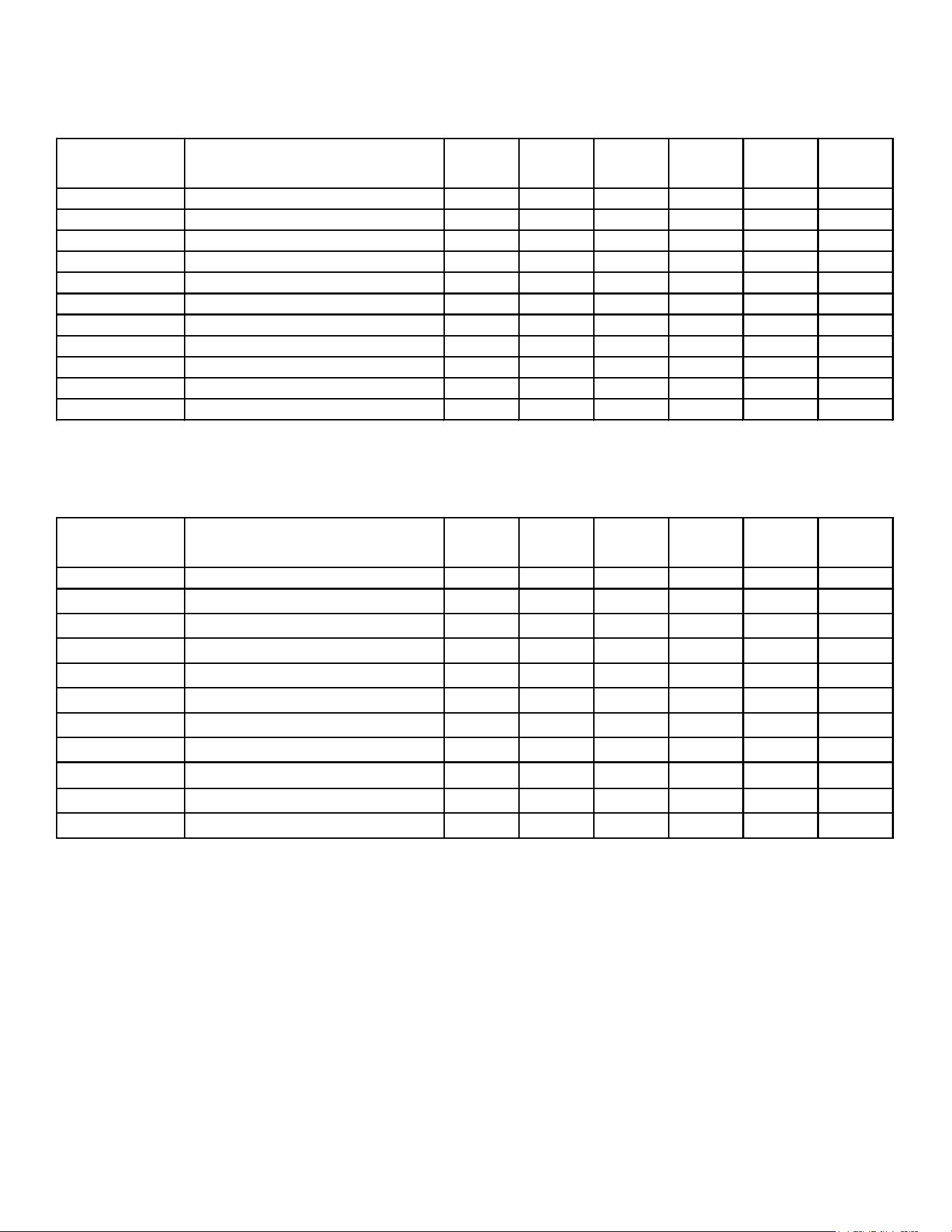
63
ACCESSORIES
ASZ16/DSZ16
Model Description
A/DSZ16
024*
A/DSZ16
030*
A/DSZ16
036*
A/DSZ16
042*
A/DSZ16
048*
A/DSZ16
060*
AFE18-60A All-Fuel Kit X X X X X X
CSR-U-1 Hard-start Kit X X X
CSR-U-2 Hard-start Kit X X
CSR-U-3 Hard-start Kit X X
FSK01A
1
Freeze Protection Kit X X X X X X
LSK02* Liquid Line Solenoid Kit X X X X X X
OT/EHR18-60 Emergency Heat Relay Kit X X X X X X
OT18-60A² Outdoor Thermostat w/ Lockout Stat X X X X X X
TX2N4A TXV Ki t X
TX3 N 4 TXV Ki t X X
TX5 N 4 TXV Ki t X X X
SSZ16
Model Description
SSZ16
024*
SSZ16
030*
SSZ16
036*
SSZ16
042*
SSZ16
048*
SSZ16
060*
AFE18-60A All-Fuel Kit X X X X X X
CSR-U-1 Hard-start Kit X X X
CSR-U-2 Hard-start Kit X X X X
CSR-U-3 Hard-start Kit X X
FSK01A
1
Freeze Protection Kit X X X X X X
LSK02* Liquid Line Solenoid Kit X X X X X X
OT/EHR18-60 Emergency Heat Relay Kit X X X X X X
OT18-60A² Outdoor Thermostat w/ Lockout Stat X X X X X X
TX2N4A TXV Ki t X
TX3 N 4 TXV Ki t X X
TX5 N 4 TXV Ki t X X X
1
Installed on indoor coil
2
Required for heat pump applications where ambient temperatures fall below 0°F with 50% or higher relative humidity.
1
Installed on indoor coil
2
Required for heat pump applications where ambient temperatures fall below 0°F with 50% or higher relative humidity.
64
ACCESSORIES
ASZ/DSZ18
Model Description
A/DSZ18
036*
A/DSZ18
048*
A/DSZ18
060*
AFE18-60A All-Fuel Kit X X X
CSR-U-1 Hard-start Kit X
CSR-U-2 Hard-start Kit X
CSR-U-3 Hard-start Kit X X
FSK01A
1
Freeze Protection Kit X X X
LSK02* Liquid Line Solenoid Kit X X X
OT/EHR18-60 Emergency Heat Relay Kit X X X
OT18-60A² Outdoor Thermostat w/ Lockout Stat X X X
TX2N 4 A³ TXV Ki t
TX3N4³ TXV Ki t X
TX5N4³ TXV Ki t X X
1
Installed on indoor coil
2
Require for heat pump applications where ambient temperatures fall below 0°F with 50% or higher relative humidy.
³ Field-installed, non-bleed, expansion valve kit — Condensing units and heat pumps with reciprocating compressors require the use of
start-assist components when used in conjunction with an indoor coil using a non-bleed thermal expansion valve
refrigerant metering device.
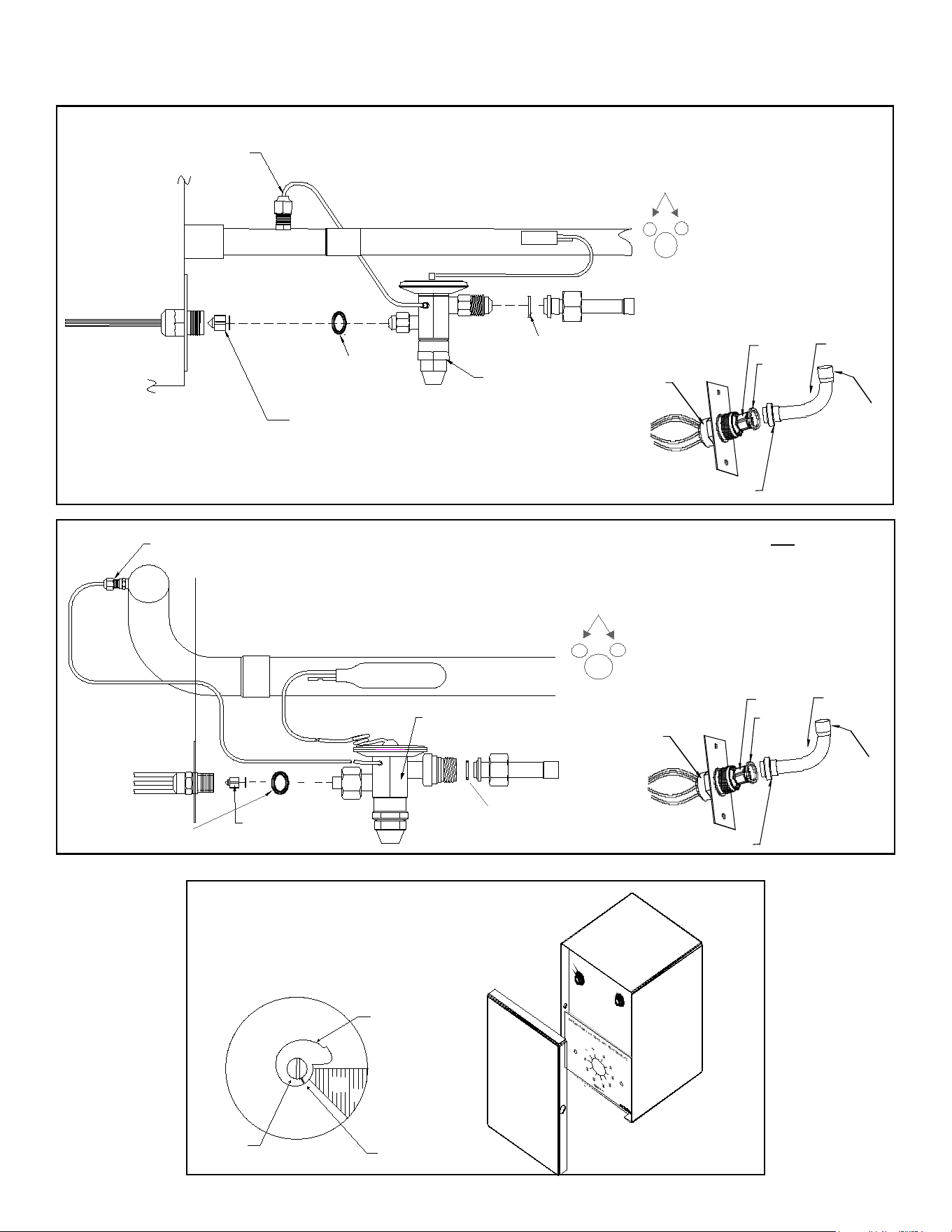
65
ACCESSORIES ASSOCIATED KITS
EXPANSION VALVE KITS
SUCTION LINE
BULB
1/4 FLARE CONNECTION
EXPANSION VALVE
EVAPORATOR COIL
REMOVE BEFORE INSTALLING EXPANSION VALVE
SEAL SUPPLIED W/ KIT
SEAL SUPPLIED W/ KIT
BULB TO BE LOCATED
AT 10 OR 2 O'CLOCK
TAILPIECE
3/8"-
SWEAT
7/8" NUT
DISTRIBUTOR
BODY
PISTON
SEAL
For Applications requiring
a eld installed access tting
EVAPORATOR COIL
1/4' FLARE
CONNECTION
BULB
SUCTION LINE
EXPANSION VALVE
REMOVE BEFORE
INSTALLING
EXPANSION VALVE
SEAL SUPPLIED W/ KIT
SEAL SUPPLIED W/ KIT
BULB TO BE LOCATED
AT 10 OR 2 O'CLOCK
TAILPIECE
3/8"-
SWEAT
7/8" NUT
DISTRIBUTOR
BODY
PISTON
SEAL
For Applications not requiring
a eld installed access tting
Set Point
Adjustment
Screw
Set Point
Indicator
Mark
(Shown @ Oº F)
Thermostat
Dial
DEAD
DIAL
315º
45º
COLD
(Turn Clockwise)
WARM
(Turn Counterclockwise)
OT18-60
OT/EHR18-60
OUTDOOR THERMOSTAT &
EMERGENCY HEAT RELAY
Not for use with
ComfortNet System
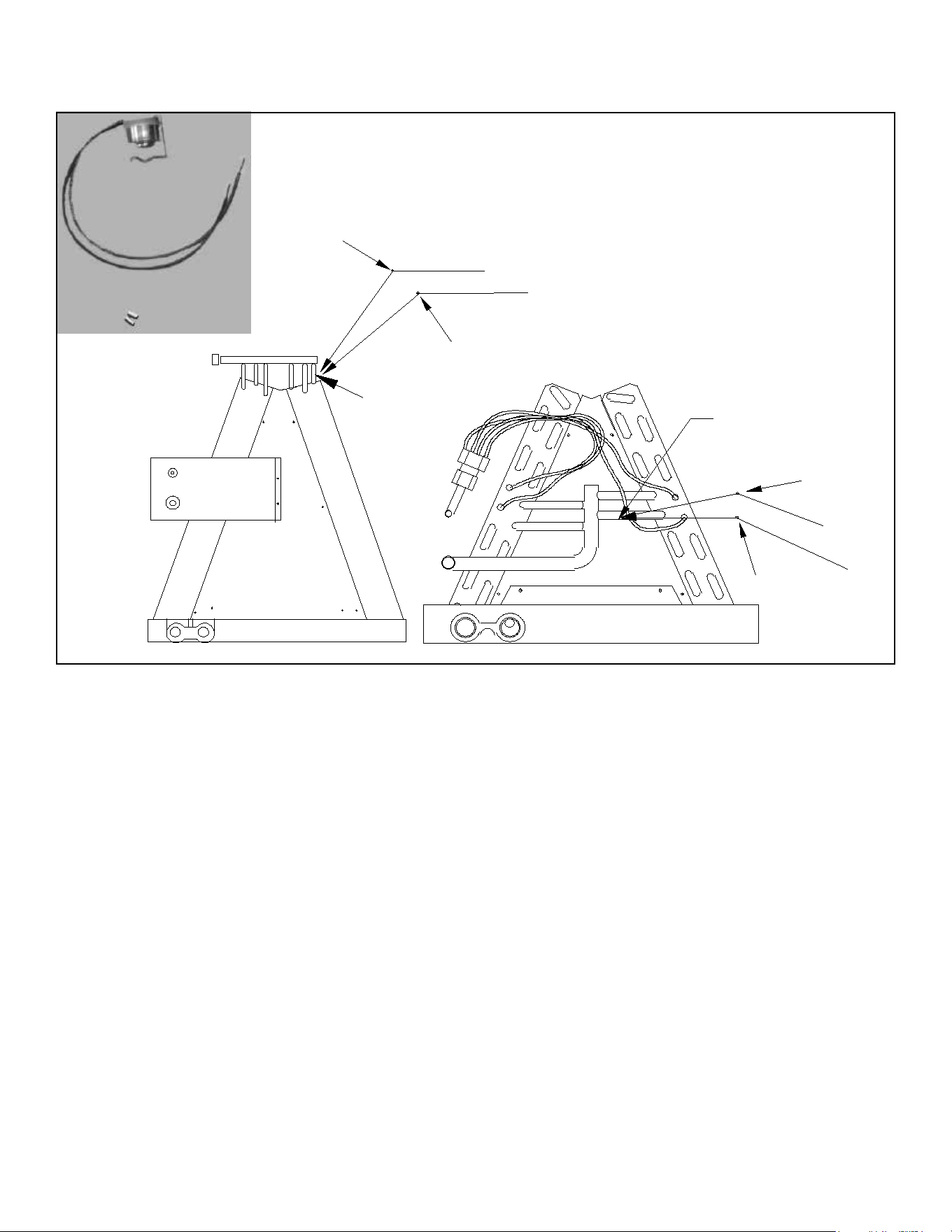
66
ACCESSORIES
Install Line
Thermostat
Here
Install Line
Thermostat
Here
Wire Nut
Wire Nut
Y
Y
Black
Black
Wire Nut
Y
Wire Nut
Y
Black
Black
FSK01A
Freeze Thermostat
Kit
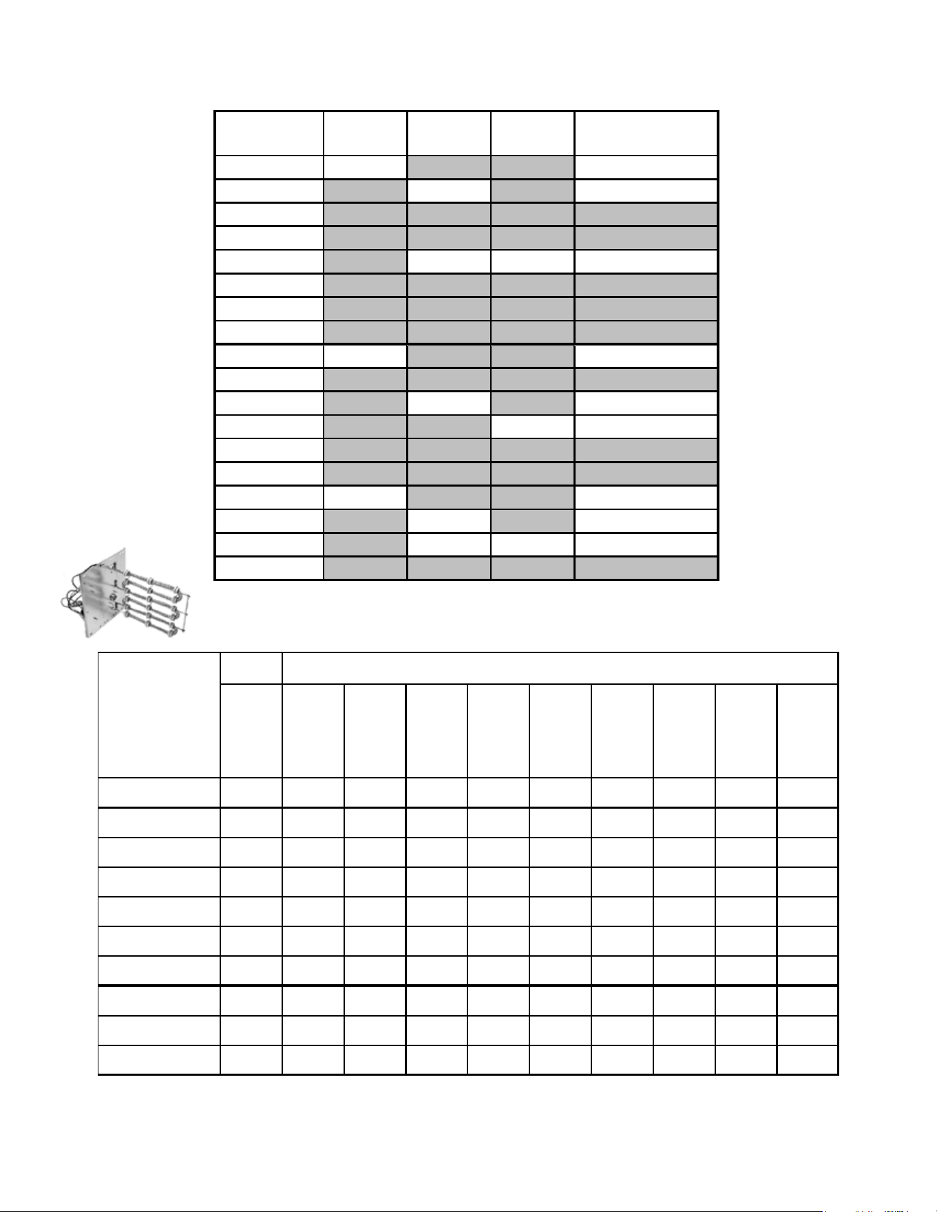
67
ACCESSORIES
COIL ACCESSORIES
COIL MODEL
TX2N4A
TXV KIT
TX3N4
TXV KIT
TX5N4
TXV KIT
FSK01A FREEZE
PROTECTION KIT
CA*F18246*
X
X
CA*F30306*
X
X
CA*F31316*
CA*F36366*
CA*F36426*
X
X
X
CA*F37436*
CA*F48606*
CA*F49616*
CHPF18246*
X X
CHPF24306*
CHPF36366*
X
X
CHPF36426*
X X
CHPF37436*
CHPF48606*
CSCF1824N6*
X X
CSCF3036N6*
X X
CSCF3642N6*
X X X
CSCF4860N6*
NO HEAT
HKR-03*
HKR05-(C)'
HKR-06*
HKR-08(C)*
HKR-10(C)*
HKA-15C*
HKA-20C*
^HKR3-15*
^HKR3-20A
MBR0800AA-1AA
- X X X X X - -
MBR1200AA-1AA
- X X X X X X X X X
MBR1600AA-1AA
- X X X X X X X X X
MBR2000AA-1AA
- X X X X X X X X X
MBE1200AA-1AA
- - - - X X - - - -
MBE1600AA-1AA
- - - - - X - - - -
MBE2000AA-1AA
- - - - - X - - - -
MBE1200AA-1BA
- X X X X X - - - -
MBE1600AA-1BA
- X X X X X - - - -
MBE2000AA-1AA
- X X X X X - - - -
X = Allowable combinations
^ = Circuit 1: Single Phase for Air Handler Motor
- = Restricted combinations
Circuit 2: 3-Phase for HKR3 Heater Kits
BLOW ER
ELECTRIC HEAT KIT
HK* SERIES ELECTRIC HEAT KITS -
ELECTRIC HEAT KIT APPLICATIONS - MBR, MBE
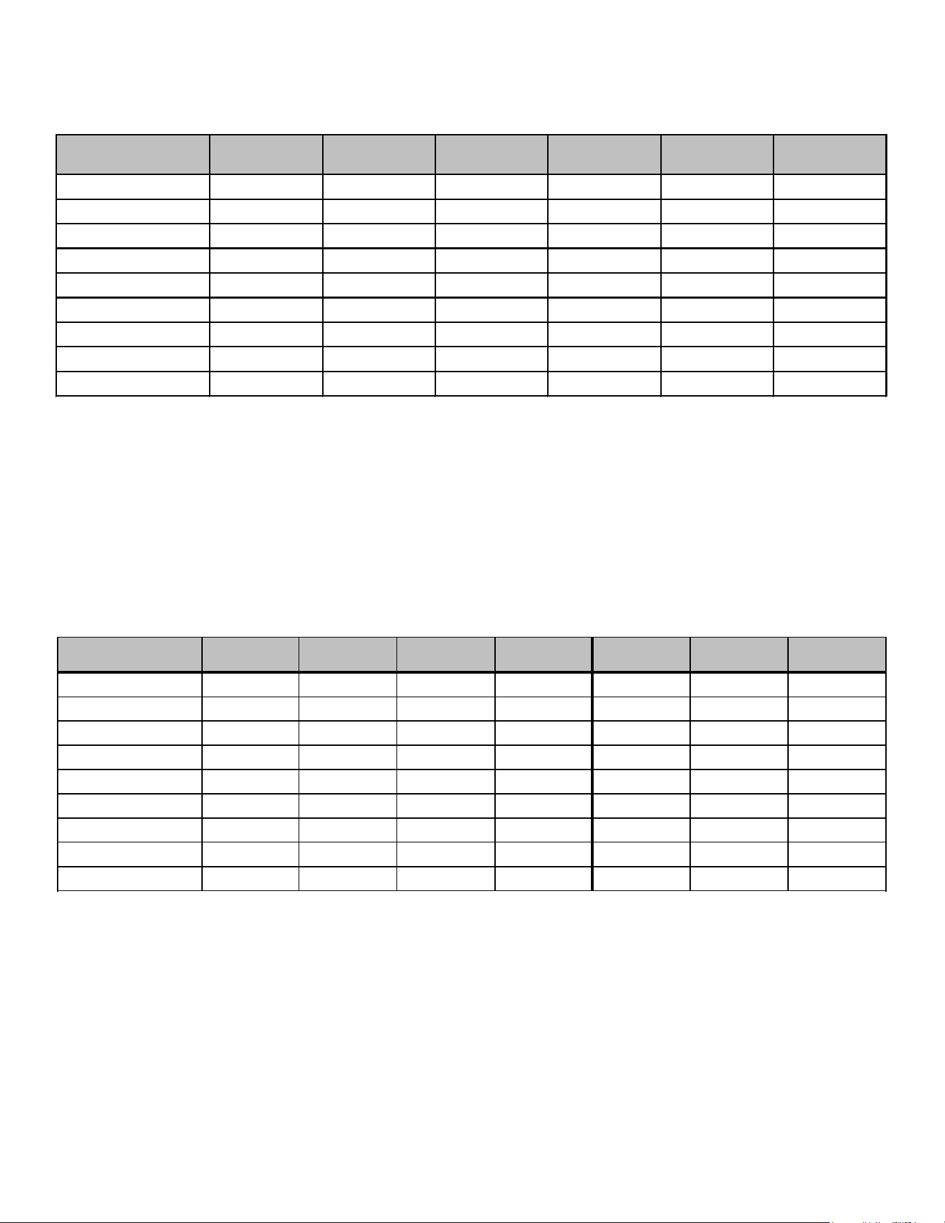
68
ACCESSORIES
ARPF1824
1/16
ARPF1931
1/16
ARPF3030
1/16
ARPF3642
1/16
ARPF3743
1/16
ARPF4860
1/16
HKR-03*
X X X X X X
HKR-05*, HKR-05C* X X X X X X
HKR-06* X X X X X X
HKR-08*, HKR-08C*
X
1
X
1
X X X X
HKR-10*, HKR-10C*
X
1
X
1
X
1
X X X
HKA-15C*
X
2
X
2
X
2
X
3
X
3
X
HKA-20C*
X
2
X
3
X
3
X
^ HKR3-15*
X
2
X
3
X
3
X
^ HKR3-20*
X
2
X
3
X
3
X
* Revision level that may or may not be designated
C Circuit breaker option
^ Heat kit required three-phase power supply
1
Air handler must either be on medium or high speed
2
Air handler must be on high speed
3
For static pressure of 0.6 or higher, air handler must be on medium or high speed.
ARUF1729
1/16
ARUF1824
1/16
ARUF1931
1/16
ARUF3030
1/16
ARUF3642
1/16
ARUF3743
1/16
ARUF4860
1/16
HKR-03* X X X X X X X
HKR-05*, HKR-05C* X X X X X X X
HKR-06* X X X X X X X
HKR-08*, HKR-08C* X
1
X
1
X
1
X X X X
HKR-10*, HKR-10C* X
1
X
1
X
1
X
1
X X X
HKA-15C* X
2
X
2
X
2
X
2
X
3
X
3
X
HKA-20C* X
2
X
3
X
3
X
^ HKR3-15* X
2
X
3
X
3
X
^ HKR3-20* X
2
X
3
X
3
X
* Revision level that may or may not be designated
C Circuit breaker option
^ Heat kit required three-phase power supply
1
Air handler must either be on medium or high speed
2
Air handler must be on high speed
3
For static pressure of 0.6 or higher, air handler must be on medium or high speed.
ELECTRIC HEAT KIT APPLICATIONS - ARPF
ELECTRIC HEAT KIT APPLICATIONS - ARUF
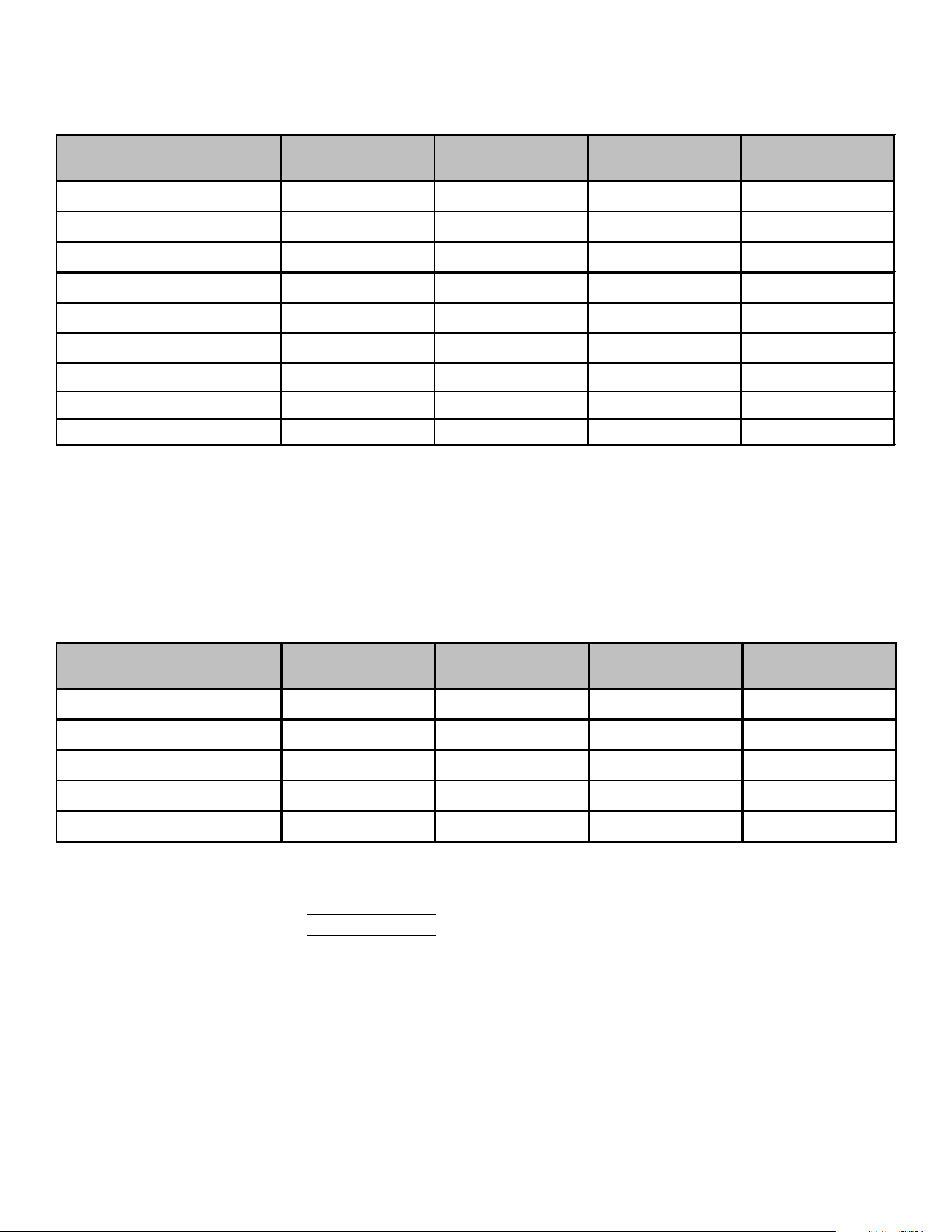
69
ACCESSORIES
ADPF182416
ADPF304216
ADPF486016
ADPF4486016
HKR-03*
X
X
X
X
HKR-05*, HKR-05C*
X
X
X
X
HKR-06*
X
X X X
HRK-08*, HKR-08C*
X
1
X
1
X
1
X
HKR-10*, HKR-10C*
X
1
X
1
X
1
X
HKA-15C*
X
X
X
2
X
1
HKA-20C*
-
X
X
2
X
1
^HKR3-15*
-
X
X
X
^HKR3-20*
-
X
X
X
*
Revision level that may or may not be designated
1
Air handler must be on speed tap 2, 3, 4 or 5
C Circuit Breaker option
2
Air handler must be on speed tap 4 or 5
^ Heat kit requires 3-phase power supply
3
Air handler must be on speed tap 3, 4 or 5
AEPF183016
AEPF303616
AEPF313716
AEPF426016
HKR-05*, HKR-05C*
X
X
HRK-08*, HKR-08C
X
X
X
HKR-10*, HKR-10C
X
1
X
X
X
HKA-15C*
X
1
X
1
X
HKA-20C*
X
2
*
Revision level that may or may not be designated
C Circuit Breaker option
1
This heater kit can be used ONLY for
1000 CFM or higher
applications
2
This heater kit can be used ONLY for
1200 CFM or higher
applications
ELECTRIC HEAT KIT APPLICATIONS - ADPF
ELECTRIC HEAT KIT APPLICATIONS - AEPF
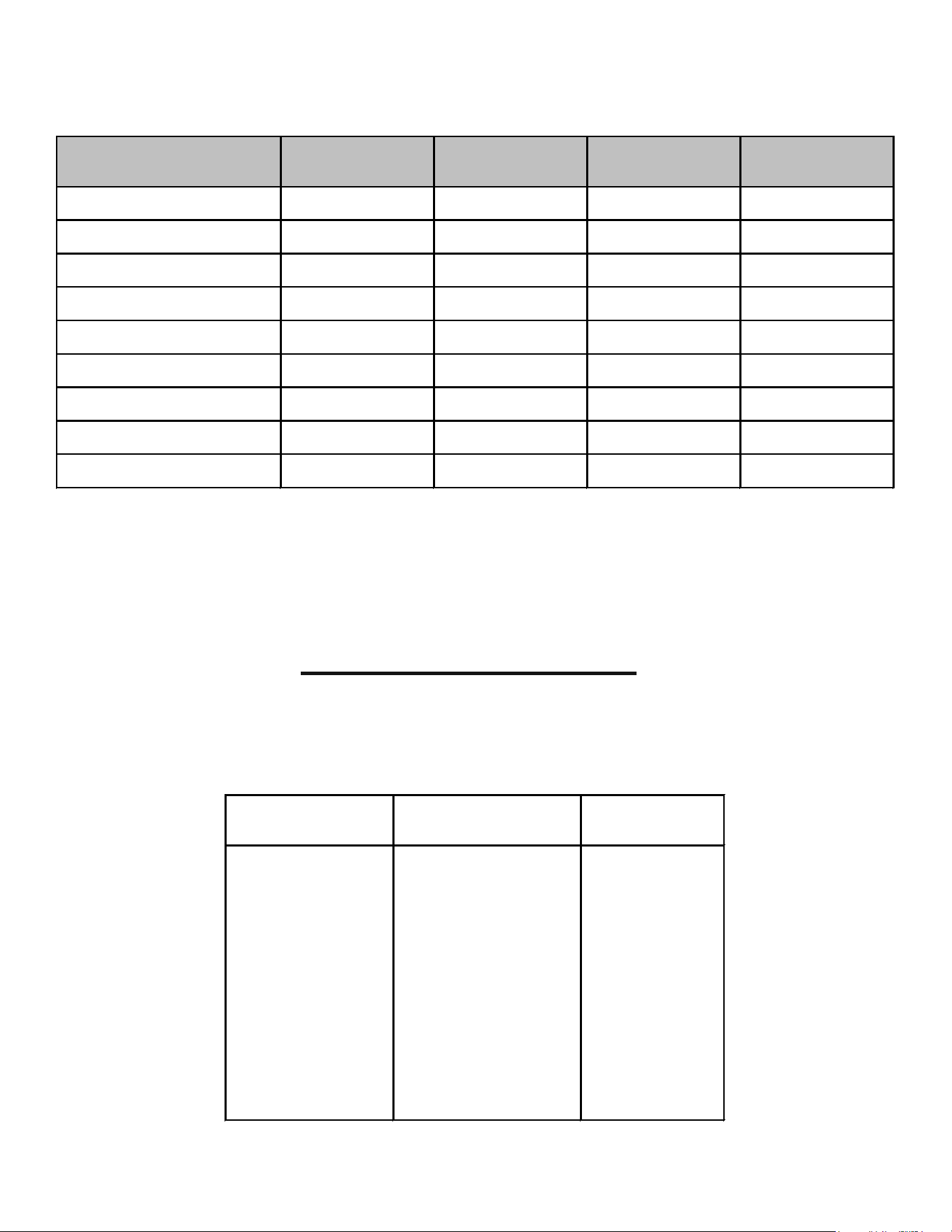
70
ACCESSORIES
ELECTRIC HEAT KIT APPLICATIONS - ASPF
ASPF183016
ASPF303616 ASPF313716 ASPF426016
HKR-03* X X X X
HKR-05*, HKR-05C* X X X X
HKR-06* X X X X
HRK-08*, HKR-08C*
X
1
X
1
X
1
X
HKR-10*, HKR-10C*
X
1
X
1
X
1
X
+HKR3-15*
X
2
X
2
X
2
X
1
+HKR3-20*
X
2
X
2
X
1
HKA-15C*
X
2
X
2
X
2
X
1
HKA-20C*
X
2
X
2
X
1
*
Revision level that may or may not be designated
C Circuit Breaker option
+ Heat kit requires 3-phase power supply
1
Air handler must be on speed tap 2, 3, 4 or 5
2
Air handler must be on speed tap 4 or 5
3
Air handler must be on speed tap 3, 4 or 5
DRAIN PAN INSULATION KITS
ARUF**14**, ARPT**14**, ASPT**14** & ASUF**14**
DFK-B
Downflow Kit
DFK-C
Downflow Kit
DFK-D
Downflow Kit
ARUF18B14** ARUF30C14** ARUF48D14**
ARUF24B14** ARUF36C14** ARUF60D14**
ARUF30B14** ARUF42C14** ARPT36D14**
ARPT18B14** ARPT36C14** ARPT42D14**
ARPT24B14** ASPT36C14** ARPT48D14**
ARPT30B14** ASPT42C14** ARPT60D14**
ASPT24B14** ASPT48C14** ASPT48D14**
ASUF49C14** ASPT60D14**
ASUF59D14**
MODEL LIST FOR DOWNFLOW KITS
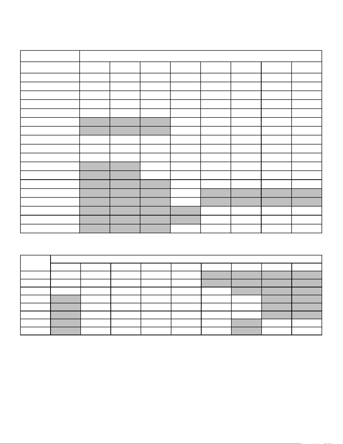
71
ACCESSORIES
Heat Kit Applications
Type / model 18B14-A* 24B14-A* 30B14-A* 36C14-A* 36D14-A* 42D14-A* 48D14-A* 60D14-A*
HK S X03XC* X X X X X X X X
HK S X05XC* X X X X X X X X
HK S X06XC* X X X X X X X X
HK S X08XC* X X X X X X X X
HK S X10XC* X X X X X X X X
HK S X15XF * X X X X X
HK S X20XF * X X X X X
HKSC05XC* X X X X X X X X
HKSC08XC* X X X X X X X X
HKSC10XC* X X X X X X X X
HKSC15XA* X X X X X X
HKSC15XB* X X X X X X
HKSC15XF* X X X X X
HKSC19CA* X
HKSC19CB* X
HKSC20DA* X X X X
HKSC20DB* X X X X
HKSC20XF* X X X X X
ARPT
ARPT**14**
3 5 6 8 10 15 19 20 25
18 715 715 715 715 950
24 715 715 715 715 950
30B 715 715 715 715 875 875
30C 1170 1170 1170 1170 1345 1345
36 1170 1170 1170 1170 1345 1345
42 1170 1170 1170 1170 1345 1345
48 1590 1590 1590 1590 1715 1715 1715
60 1590 1590 1590 1590 1715 1715 1715
Minimum CFM required for Heater Kits
*ARUF
ARPT
HEATER (kW)
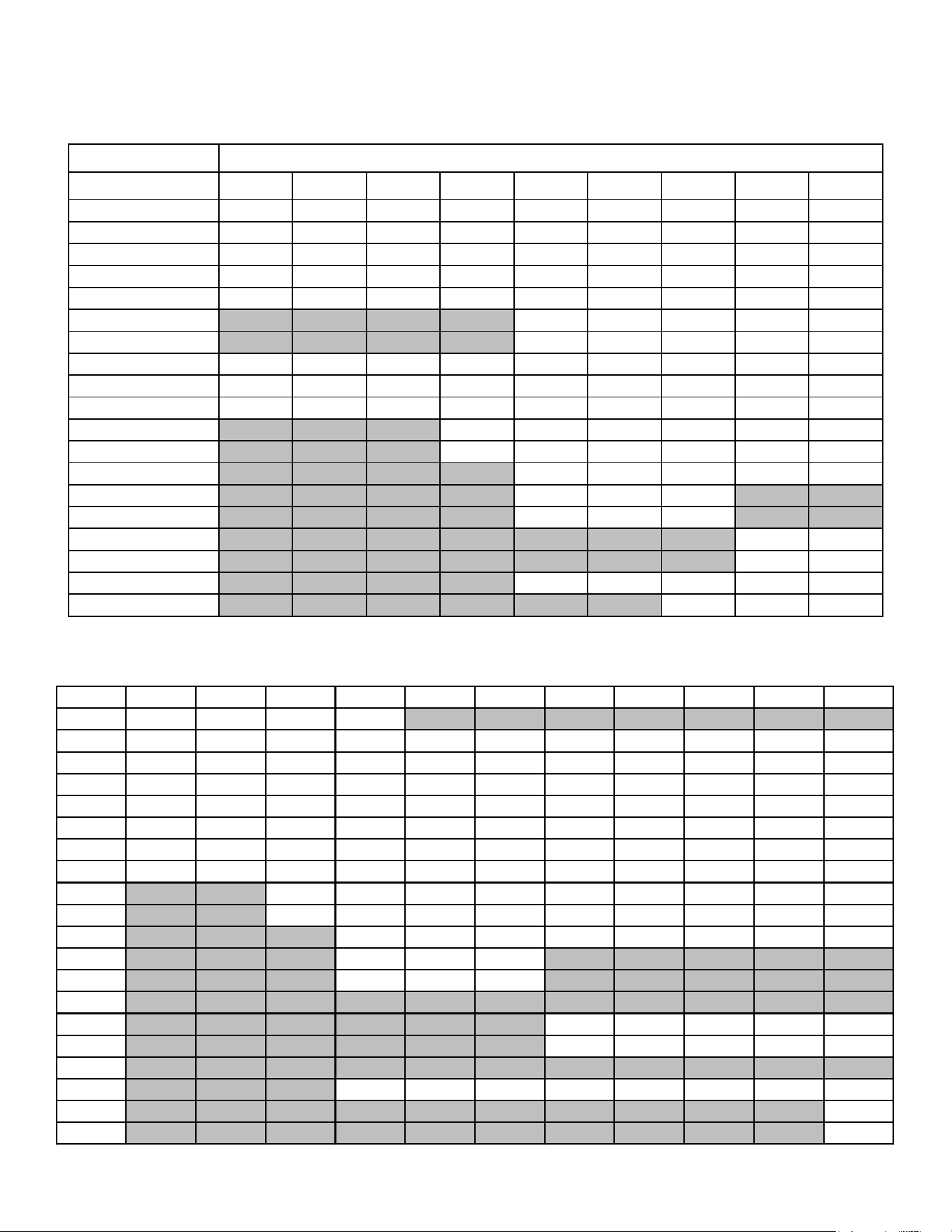
72
ACCESSORIES
ARUF**14**
Heat Kit Applications
TYPE/MODEL 18B14-A* 24B14-B* 24B14-C* 30B14-A* 30C14-B* 36C14-B* 42C14-A* 48D14-A* 60D14-A*
HKSX0 3XC * X X X X X X X X X
HKSX0 5XC * X X X X X X X X X
HKSX0 6XC * X X X X X X X X X
HKSX0 8XC * X X X X X X X X X
HKSX1 0XC * X X X X X X X X X
HKSX1 5XF* X X X X X
HKSX2 0XF* X X X X X
HKSC05XC* X X X X X X X X X
HKSC08XC* X X X X X X X X X
HKSC10XC* X X X X X X X X X
HKSC 15 XA* X X X X X X
HKSC15XB* X X X X X X
HKSC15XF*
X X X X X
HKSC19CA* X X X
HKSC19CB* X X X
HKSC20DA* X X
HKSC20DB* X X
HKSC20XF*
X X X X X
HKSC25DC*
X X X
* Revision level that may or may not be designated Refer to the minimum airflow requirements for each of the heat kits.
ARUF
Model
ARUF25B14 ARUF29B14 ARUF31B14 ARUF37C14 ARUF43C14 ARUF49C14 ARUF37D14 ARUF43D14 ARUF47D14 ARUF49D14 ARUF61D14
HKSX03XC X X X X
HKSX05XC X X X X X X X X X X X
HKSX06XC X X X X X X X X X X X
HKSX08XC X X X X X X X X X X X
HKSX10XC X X X X X X X X X X X
HKSC05XC X X X X X X X X X X X
HKSC08XC X X X X X X X X X X X
HKSC10XC X X X X X X X X X X X
HKSC15XA X X X X X X X X X
HKSC15XB X X X X X X X X X
HKSC15XF X X X X X X X X
HKSC19CA X X X
HKSC19CB X X X
HKSC19CH
HKSC20DA X X X X X
HKSC20DB X X X X X
HKSC20DH
HKSC20XF X X X X X X X X
HKSC25DA X
HKSC25DB X
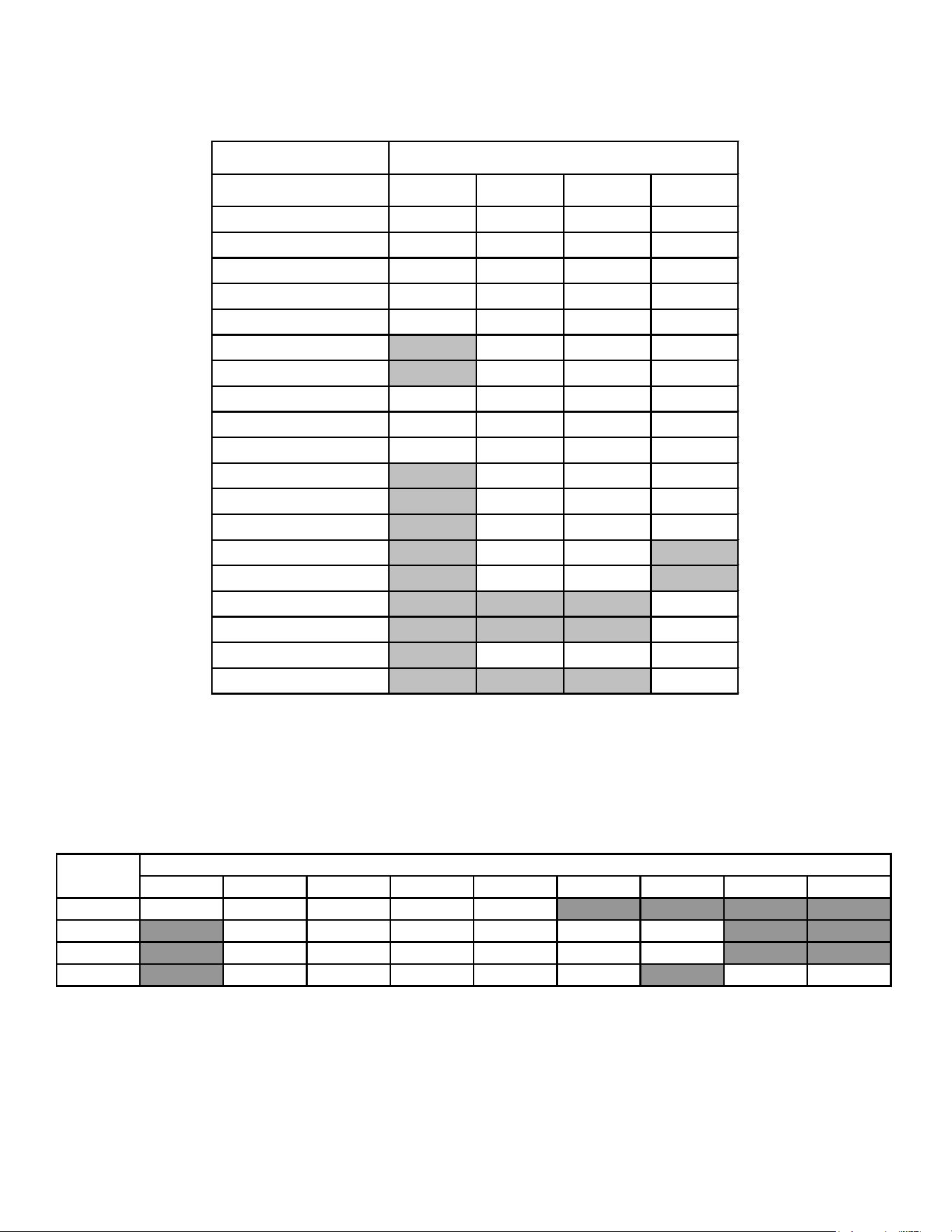
73
ACCESSORIES
ASUF**14**
Heat Kit Applications
TYPE/MODEL
29B14-A* 39C14-A* 49C14-A* 59D14-A*
HKSX0 3 XC* X X X X
HKSX0 5 XC* X X X X
HKSX0 6 XC* X X X X
HKSX0 8 XC* X X X X
HKSX1 0 XC* X X X X
HKSX1 5 XF* X X X
HKSX2 0 XF* X X X
HKSC05XC* X X X X
HKSC08XC* X X X X
HKSC10XC* X X X X
HKSC 1 5XA* X X X
HKSC15XB* X X X
HKSC15XF* X X X
HKSC19CA* X X
HKSC19CB* X X
HKSC20DA* X
HKSC20DB* X
HKSC20XF* X X X
HKSC25DC* X
* Revision level that may or may not be designated.
Refer to the minimum airflow requirements for each of the heat kits.
ASUF
3 5 6 8 10 15 19 20 25
29 715 715 715 715 875
39 1170 1170 1170 1170 1345 1345
49 1170 1170 1170 1170 1345 1345
59 1590 1590 1590 1590 1715 1715 1715
Minimum CFM required for Heater Kits
ASUF
HEATER (kW)
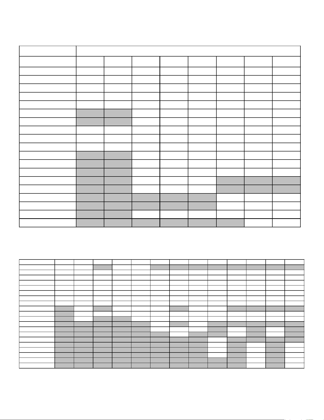
74
ACCESSORIES
ASPT**14**
Heat Kit Applications
TYPE/MODEL 24B14-A* 30C14-A* 36C14-A* 42C14-A* 48C14-A* 42D14-A* 48D14-A* 60D14-A*
HKSX0 3 XC * X X X X X X X X
HKSX0 5 XC * X X X X X X X X
HKSX0 6 XC * X X X X X X X X
HKSX0 8 XC * X X X X X X X X
HKSX1 0 XC * X X X X X X X X
HKSX1 5 XF* X X X X X X
HKSX2 0 XF* X X X X X X
HKSC05XC* X X X X X X X X
HKSC08XC* X X X X X X X X
HKSC10XC* X X X X X X X X
HKSC 1 5 XA* X X X X X X
HKSC15XB* X X X X X X
HKSC15XF* X X X X X X
HKSC19CA* X X X
HKSC19CB* X X X
HKSC20DA* X X X
HKSC20DB* X X X
HKSC20XF* X X X X X X
HKSC25DC* X X
* Revision level that may or may not be designated.
Refer to the minimum airflow requirements for each of the heat kits.
ASPT
Model ASPT25B14 ASPT29B14 ASPT33C14 ASPT35B14 ASPT37B14 ASPT37C14 ASPT39C14 ASPT47C14 ASPT47D14 ASPT49C14 ASPT49D14 ASPT59C14 ASPT61D14
HKSX03XC X X X X
HKSX05XC X X X X X X X X X X X X X
HKSX06XC X X X X X X X X X X X X X
HKSX08XC X X X X X X X X X X X X X
HKSX10XC X X X X X X X X X X X X X
HKSC05XC X X X X X X X X X X X X X
HKSC08XC X X X X X X X X X X X X X
HKSC10XC X X X X X X X X X X X X X
HKSC15XA X X X X X X
HKSC15XB X X X X X X X X X X X X
HKSC15XF X X X X X X X X X X
HKSC19CA X X
HKSC19CB X X X X X
HKSC19CH X X X
HKSC20DA X
HKSC20DB X X X
HKSC20DH X X
HKSC20XF X X X
HKSC25DA X X
HKSC25DB X X
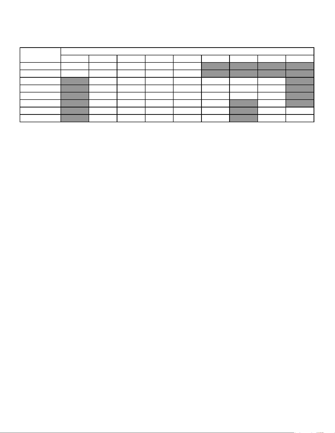
75
ACCESSORIES
ASPT**14**
3
5 6 8 10 15 19 20 25
ASPT24B14*
715 715 715 715 875
NR NR NR NR
ASPT30C14*
730 715 715 715 950 NR NR
NR NR
ASPT36C14* NR
1170 1170 1170 1170 1345 1345 1345
NR
ASPT42C14* NR
1170 1170 1170 1170 1345 1345 1345
NR
ASPT48C14* NR
1170 1170 1170 1170 1345 1345 1345 NR
ASPT42D14* NR
1590 1590 1590 1590 1715 NR 1715 NR
ASPT48D14* NR
1590 1590 1590 1590 1715 NR 1715 1715
ASPT60D14* NR
1590 1590 1590 1590 1715 NR 1715 1715
Minimum CFM required for Heater Kits
HEATER (kW)
ASPT
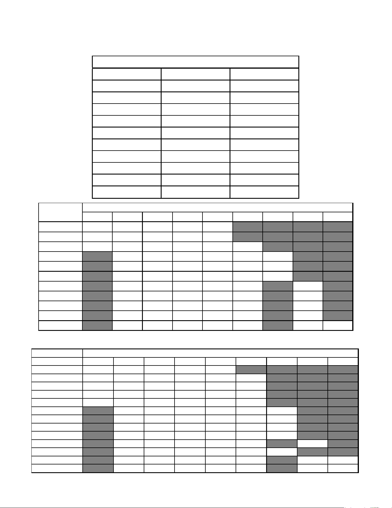
76
ACCESSORIES
ARUF & ASPT
DFK-B DFK-C DFK-D
DOWNFLOW KIT DOWNFLOW KIT DOWNFLOW KIT
ARUF25B14** ARUF37C14** ARUF37D14**
ARUF29B14** ARUF43C14** ARUF43D14**
ARUF31B14** ARUF49C14** ARUF47D14**
ASPT24B14** ASPT33C14** ARUF49D14**
ASPT29B14** ASPT37C14** ARUF61D14**
ASPT35B14** ASPT39C14** ASPT61D14**
ASPT37B14** ASPT47C14** ASPT47D14**
ASPT49C14** ASPT49D14**
ASPT59C14**
MODEL LIST FOR DOWNFLOW KIT
3 5 6 8 10 15 19 20 25
ARUF25B14 715 715 715 715 950
ARUF29B14 715 715 715 715 950
ARUF31B14 715 715 715 715 875 875
ARUF37C14 1170 1170 1170 1170 1345 1345
ARUF43C14 1170 1170 1170 1170 1345 1345
ARUF49C14 1170 1170 1170 1170 1340 1430
ARUF37D14 1170 1170 1170 1170 1345 1345
ARUF43D14 1170 1170 1170 1170 1345 1345
ARUF47D14 1170 1170 1170 1170 1345 1345
ARUF49D14 1240 1240 1240 1240 1520 1520
ARUF61D14 1590 1590 1590 1590 1715 1715 1715
MODEL
HEATER KIT (kW)
MODEL
3 5 6 8 10 15 19 20 25
ASPT25B14
715 715 715 715 850
ASPT29B14
715 715 715 715 875 1050
ASPT33C14
715 715 715 715 875 875
ASPT35B14
715 715 715 715 875 1050
ASPT37B14
715 715 715 715 875 1050
ASPT37C14
1170 1170 1170 1170 1345 1345
ASPT39C14
1170 1170 1170 1170 1345 1345
ASPT47C14
1170 1170 1170 1170 1345 1345
ASPT59C14
1170 1170 1170 1170 1345 1345
ASPT47D14
1240 1240 1240 1240 1520 1520
ASPT49C14
1170 1170 1170 1170 1345 1345
ASPT49D14
1590 1590 1590 1590 1715 1715 1715
ASPT61D14*
1590 1590 1590 1590 1715 1715 1715
MINIMUM CFM REQUIRED FOR HEATER KITS
HEATER (kW )

77
Product Design
Product Design
This secon gives a basic descripon of cooling unit operaon,
its various components and their basic operaon. Ensure your
system is properly sized for heat gain and loss according to
methods of the Air Condioning Contractors Associaon (ACCA)
or equivalent.
CONDENSING UNIT
The condenser air is pulled through the condenser coil by a
direct drive propeller fan. This condenser air is then discharged
out of the top of the cabinet. These units are designed for free
air discharge, so no addional resistance, like duct work, shall be
aached.
The sucon and liquid line connecons on present models are
of the sweat type for eld piping with refrigerant type copper.
Front seang valves are factory installed to accept the eld run
copper. The total refrigerant charge for a normal installaon is
factory installed in the condensing unit.
GSX, GSZ, ASX, ASZ, SSX, SSZ, DSX, DSZ, VSX, and VSZ models are
available in 1 1/2 through 5 ton sizes and use R-410A refrigerant.
They are designed for 208/230 volt single phase applicaons.
GSX/GSZ *****3 models are available in 3, 4, and 5 ton sizes
and use R-410A refrigerant. They are designed for 208/230 volt
3-phase applicaons.
ASX, ASZ, DSX and DSZ R-410A model units use the Copeland
Scroll "Ultratech" Series compressors which are specically
designed for R-410A refrigerant. These units also have
Copeland® ComfortAlert diagnoscs.
GSX, GSZ, SSX, SSZ, VSX, and VSZ R-410A model units,
except for GSX130181C*, GSX130241E*, GSX130301L* and
later, GSX140181L*, GSX140241L* and later, VSX130181B*,
VSX130241E*, VSX130301L*, VSX130421B*, VSX130481B* and
later, VSX140181B*, VSX140241B* and later, GSZ140181L*,
GSZ140241L* and later, VSZ140181B*, VSZ140241B* and later,
use the Copeland Scroll "Ultratech" Series compressors which
are specically designed for R-410A refrigerant.
There are a number of design characteriscs which are dierent
from the tradional reciprocang and/or scroll compressors.
"Ultractech" Series scroll compressors will not have a discharge
thermostat. Some of the early model scroll compressors
required discharge thermostat.
"Ultratech" Series scroll compressors use "POE" or polyolester
oil which is NOT compable with mineral oil based lubricants like
3GS. "POE" oil must be used if addional oil is required.
COILS AND BLOWER COILS
MBR/MBE blower cabinets are designed to be used as a two-
piece blower and coil combinaon. MBR/MBE/MBVC blower
secons can be aached to cased evaporator coil. This two-piece
arrangement allows for a variety of mix-matching possibilies
providing greater exibility. The MBE/MBVC blower cabinets use
a variable speed motor that maintains a constant airow with a
higher duct stac.
MBE blower cabinests are approved for applicaons with cooling
coils of up to 0.8 inches W.C. external stac pressure. The MBE
models includes a feature that allows airow to be changed by
+10% or -15%. The MBVC models allow airow trimming of +/-
10%.
The MBR blower cabinet uses a PSC motor. It is approved for
applicaons with cooling coils of up to 0.5 inches W.C. external
stac pressure.
The MBR/MBE blower cabinets with proper coil matches can be
posioned for upow, counterow, horizontal right or horizontal
le operaon. All units are constructed with R-4.2 insulaon.
In areas of extreme humidity (greater than 80% consistently),
insulate the exterior of the blower with insulaon having a vapor
barrier equivalent to ductwork insulaon, providing local codes
permit.
The CAUF, CAPF and CAPT coils are designed for upow and
counterow applicaons. The CACF and CHPF coils are designed
for horizontal applicaons.
AR*F, ASPF, ASUF, ASPT
Mul-Posion Air Handler
These one-piece mul-posion air handlers are used with
R-410A and are available in 2 to 5 ton sizes with oponal 3 kW to
25kW electric heat kits available for eld installaon. The AR*F
unit’s blower design includes a PSC motor and is compable
with heat pumps and cooling applicaons. ASUF and ASPT units
use an EEM blower motor and are compable with heat pumps
and cooling applicaons.
This appliance can be installed in the vercal or le horizontal
posion without modicaon. The horizontal right and
downow posions require product modicaon. This product
is designed for zero inches (0 inches) clearance; however,
adequate access for service or replacement must be considered
without removing permanent structure. This unit can be
installed on a plaorm when deemed necessary.
In an ac installaon a secondary drain pan must be provided
by the installer and placed under the enre unit with a separate
drain line properly sloped and terminated in an area visible to
the owner. This secondary drain pan is required in the event
that there is a leak or main drain blockage. Closed cell insulaon
should be applied to the drain lines in uncondioned spaces
where sweang may occur.
NOTE: Single piece air handlers are factory-sealed to achieve a
2% or less leakage rate at 1.0” water gauge external duct stac
pressure.
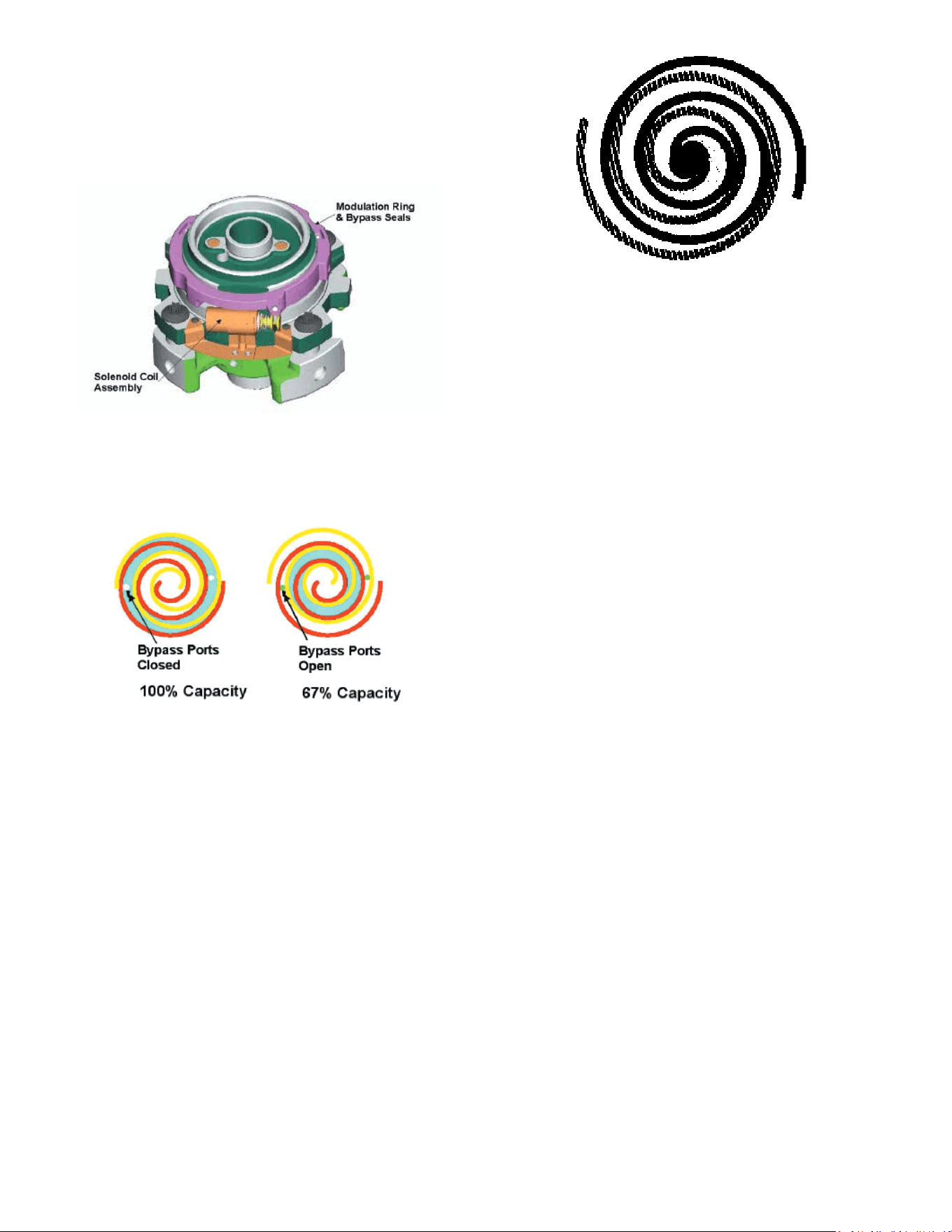
78
Product Design
The ASX [16 & 18], ASZ [16 & 18], DSX[16 & 18] and DSZ [16 &
18] series split system units use a two-stage scroll compressor.
The two-step modulator has an internal unloading mechanism
that opens a bypass port in the rst compression pocket,
eecvely reducing the displacement of the scroll. The opening
and closing of the bypass port is controlled by an internal
electrically operated solenoid.
The ZPS/ZRS two-step modulated scroll uses a single step
of unloading to go from full capacity to approximately 67%
capacity. A single speed, high eciency motor connues to run
while the scroll modulates between the two capacity steps.
FIGURE A
A scroll is an involute spiral which, when matched with a mang
scroll form as shown, generates a series of crescent shaped gas
pockets between the two members.
During compression, one scroll remains staonary (xed scroll)
while the other form (orbing scroll) is allowed to orbit (but not
rotate) around the rst form.
As this moon occurs, the pockets between the two forms
are slowly pushed to the center of the two scrolls while
simultaneously being reduced in volume. When the pocket
reaches the center of the scroll form, the gas, which is now at a
high pressure, is discharged out of a port located at the center.
During compression, several pockets are being compressed
simultaneously, resulng in a very smooth process. Both the
sucon process (outer poron of the scroll members) and the
discharge process (inner poron) are connuous.
Some design characteriscs of the Compliant Scroll compressor
are:
• Compliant Scroll compressors are more tolerant of
liquid refrigerant.
NOTE: Even though the compressor secon of a Scroll
compressor is more tolerant of liquid refrigerant, connued
oodback or ooded start condions may wash oil from the
bearing surfaces causing premature bearing failure.
• “Ultratech” Series scroll compressors use “POE” or polyo-
lester oil which is NOT compable with mineral oil based
lubricants like 3GS. “POE” oil must be used if addional oil is
required.
• Compliant scroll compressors perform “quiet” shutdowns
that allow the compressor to restart immediately without
the need for a me delay. This compressor will restart even
if the system has not equalized.
NOTE: Operang pressures and amp draws may dier from
standard reciprocang compressors. This informaon can be
found in the unit’s Technical Informaon Manual.
CAPACITY CONTROL - LEGACY MODELS
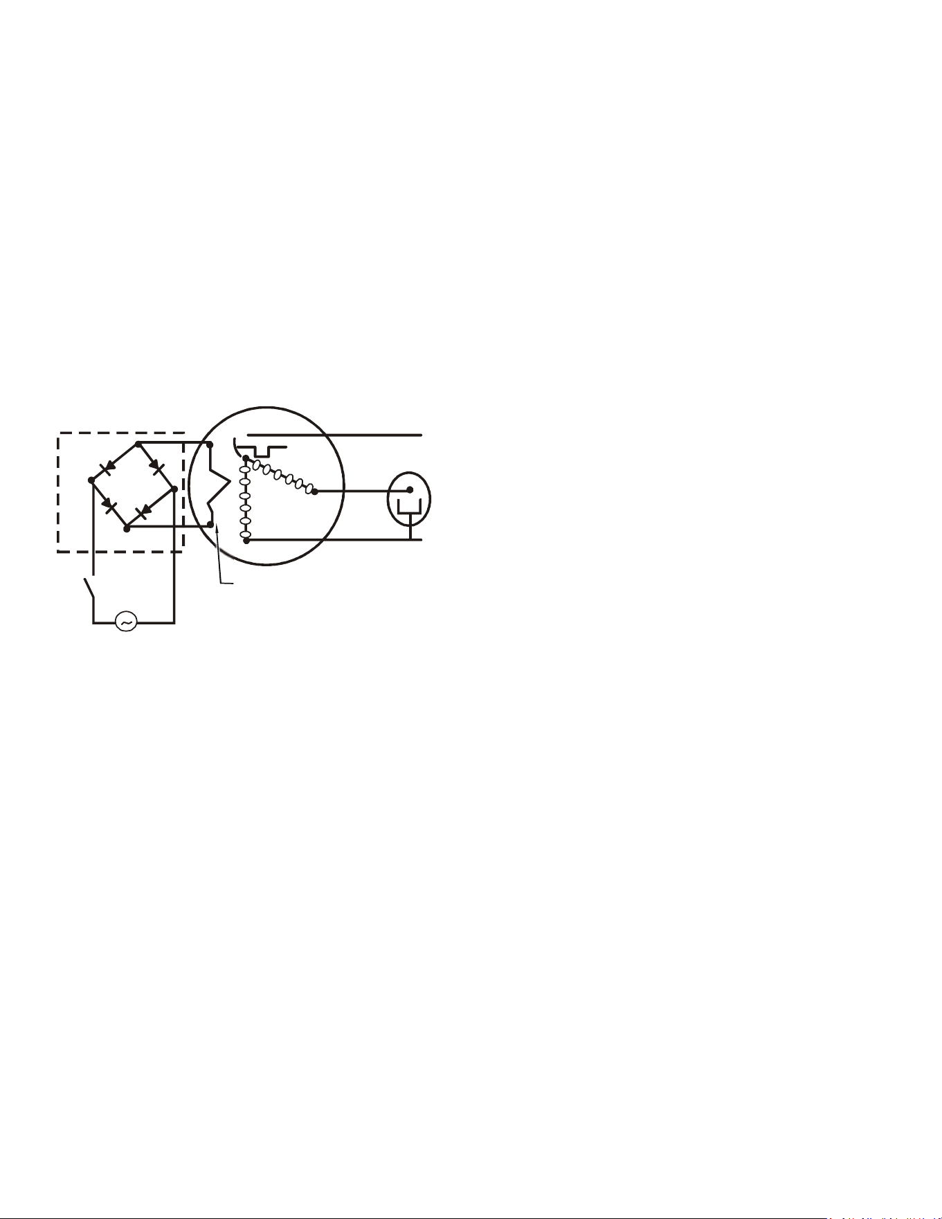
79
Product Design
During the compression process, there are several pockets
within the scroll that are compressing gas. Modulaon is
achieved by venng a poron of the gas in the rst sucon
pocket back to the low side of the compressor thereby
reducing the eecve displacement of the compressor.
See Figure A. Full capacity is achieved by blocking these
vents, increasing the displacement to 100%. A solenoid in
the compressor, controlled by an external 24-volt ac signal,
moves the slider ring that covers and uncovers these vents.
The vent covers are arranged in such a manner that the
compressor operates somewhere around 67% capacity when
the solenoid is not energized and 100% capacity when the
solenoid is energized. The loading and unloading of the two
step scroll is done “on the y” without shung o the mo-
tor between steps. See Figure B below. The unloaded mode
default was chosen for two reasons:
Molded Plug w/
Rectifier
24 Vac
Line
Line
Run Capacitor
C
R
S
Internal Unloader
Coil
FIGURE B
1. It is expected that the majority of run hours will be in the low
capacity, unloaded mode.
2. It allows a simple two-stage thermostat to control capacity
through the second stage in both cooling and possibly heang if
desired.
UNLOADER SOLENOID
A nominal 24-volt direct current coil acvates the internal
unloader solenoid. The input control circuit voltage must be 18
to 28 volt ac. The coil power requirement is 20 VA. The external
electrical connecon is made with a molded plug assembly. This
plug is connected to the Comfort Alert™ or CoreSense™ Module
(dependent upon which module you are using) which contains a
full wave recer to supply direct current to the unloader coil.
COOLING
The refrigerant used in the system is R-410A. It is a clear,
colorless, non-toxic and non-irritang liquid. R-410A is a 50:50
blend of R-32 and R-125. The boiling point at atmospheric
pressure is -62.9°F.
A few of the important principles that make the refrigeraon
cycle possible are: heat always ows from a warmer to a cooler
body. Under lower pressure, a refrigerant will absorb heat and
vaporize at a low temperature. The vapors may be drawn o
and condensed at a higher pressure and temperature to be used
again.
The indoor evaporator coil funcons to cool and dehumidify the
air condioned spaces through the evaporave process taking
place within the coil tubes.
NOTE: The pressures and temperatures shown in the refrigerant
cycle illustraons on the following pages are for demonstraon
purposes only. Actual temperatures and pressures are to be
obtained from the “Expanded Performance Chart”.
Liquid refrigerant at condensing pressure and temperatures,
(270 psig and 122°F), leaves the outdoor condensing coil
through the drier and is metered into the indoor coil through
the metering device. As the cool, low pressure, saturated
refrigerant enters the tubes of the indoor coil, a poron of the
liquid immediately vaporizes. It connues to soak up heat and
vaporizes as it proceeds through the coil, cooling the indoor coil
down to about 48°F.
Heat is connually being transferred to the cool ns and tubes of
the indoor evaporator coil by the warm system air. This warming
process causes the refrigerant to boil. The heat removed from
the air is carried o by the vapor.
As the vapor passes through the last tubes of the coil, it
becomes superheated. That is, it absorbs more heat than is
necessary to vaporize it. This is assurance that only dry gas
will reach the compressor. Liquid reaching the compressor can
weaken or break compressor valves.
The compressor increases the pressure of the gas, thus adding
more heat, and discharges hot, high pressure superheated gas
into the outdoor condenser coil.
In the condenser coil, the hot refrigerant gas, being warmer than
the outdoor air, rst loses its superheat by heat transferred from
the gas through the tubes and ns of the coil. The refrigerant
now becomes saturated, part liquid, part vapor and then
connues to give up heat unl it condenses to a liquid alone.
Once the vapor is fully liqueed, it connues to give up heat
which subcools the liquid, and it is ready to repeat the cycle.
HEATING
The heang poron of the refrigeraon cycle is similar to the

80
cooling cycle. By energizing the reversing valve solenoid coil,
the ow of the refrigerant is reversed. The indoor coil now
becomes the condenser coil, and the outdoor coil becomes the
evaporator coil.
The check valve at the indoor coil will open by the ow of
refrigerant leng the now condensed liquid refrigerant bypass
the indoor expansion device. The check valve at the outdoor coil
will be forced closed by the refrigerant ow, thereby ulizing the
outdoor expansion device.
The restrictor orice used with the CA*F, CHPF and CH**FCB
coils will be forced onto a seat when running in the cooling
cycle, only allowing liquid refrigerant to pass through the orice
opening. In the heang cycle, it will be forced o the seat
allowing liquid to ow around the restrictor. A check valve is not
required in this circuit.
COOLING CYCLE
For legacy room thermostat: When the room thermostat calls
for cool, the contacts of the room thermostat close making
terminals R to Y1 & G (if thermostat calls for low stage cool), or
R to Y1, Y2 & G (if thermostat calls for high stage cool), the low
voltage circuit of the transformer is completed. Current now
ows through the magnec holding coils of the compressor
contactor (CC) and fan relay (RFC). If thermostat calls for
high stage cool, the microprocessor on the UC board will
also energize the compressor high stage solenoid to run the
compressor at full capacity.
This draws in the normally open contact CC, starng the
compressor and condenser fan motors in either low or high
stage depending on the thermostat’s demand. At the same me,
contacts RFC close, starng the indoor fan motor.
When the thermostat is sased, it opens its contacts, breaking
the low voltage circuit, causing the compressor contactor and
indoor fan relay to open, shung down the system.
If the room thermostat fan selector switch should be set on the
“on” posion, then the indoor blower would run connuously
rather than cycling with the compressor.
GSZ, ASZ, SSZ, DSZ, and VSZ models energize the reversing valve
thorough the “O” circuit in the room thermostat. Therefore,
the reversing valve remains energized as long as the thermostat
subbase is in the cooling posion. The only excepon to this is
during defrost.
For heat pumps, during cooling cycle the reversing valve is
energized as the room thermostat closes “O” terminal to R
and the microprocessor on the UC board responds to such a
condion by energizing the solenoid coil on the reversing valve.
DEFROST CYCLE
The defrosng of the outdoor coil is jointly controlled by the
defrost control board and the defrost thermostat.
Solid State Defrost Control
During operaon the power to the circuit board is controlled
by a temperature sensor, which is clamped to a return bend
(3/8” coils) or a feeder tube (5 mm coils) entering the outdoor
coil. Defrost ming periods of 30, 60, or 90 minutes may be
selected by connecng the circuit board jumper to 30, 60, or 90
respecvely. Accumulaon of me for the ming period selected
starts when the sensor closes (approximately 31° F), and when
the room thermostat calls for heat. At the end of the ming
period, the unit’s defrost cycle will be iniated provided the
sensor remains closed. When the sensor opens (approximately
75° F), the defrost cycle is terminated and the ming period is
reset. If the defrost cycle is not terminated due to the sensor
temperature, a ten minute override interrupts the unit’s defrost
period. The new upgraded defrost control has a 12 minute
override interrupt.
HEATING CYCLE
The reversing valve on the gsz, SSZ, ASZ and DSZ models is
energized in the cooling cycle through the “O” terminal on the
room thermostat.
These models have a 24 volt reversing valve coil. When the
thermostat selector switch is set in the cooling posion, the “O”
terminal on the thermostat is energized all the me.
Care must be taken when selecng a room thermostat. Refer
to the installaon instrucons shipped with the product for
approved thermostats.
When the room thermostat calls for heat, the contacts of the
room thermostat close making terminals R to Y & G, the low
voltage circuit of the transformer is completed. Current now
ows through the magnec holding coils of the compressor
contactor (CC) and fan relay (RFC).
This draws in the normally open contact CC, starng the
compressor condenser fan motors. At the same me, contacts
RFC close, starng the indoor fan motor.
When the thermostat is sased, it opens its contacts, breaking
the low voltage circuit, causing the compressor contactor and
indoor fan relay to open, shung down the system.
If the room thermostat fan selector switch should be set to the
“on” posion, then the indoor blower would run connuously
rather than cycling with the compressor.
When the thermostat is sased, appropriate commands are
sent to the UC control. The compressor relay and outdoor
fan relay is de-energized. The compressor high stage solenoid
is de-energized if it was energized. The UC control sends an
appropriate command to the indoor unit to de-energize the
indoor blower motor.
SYSTEM OPERATION
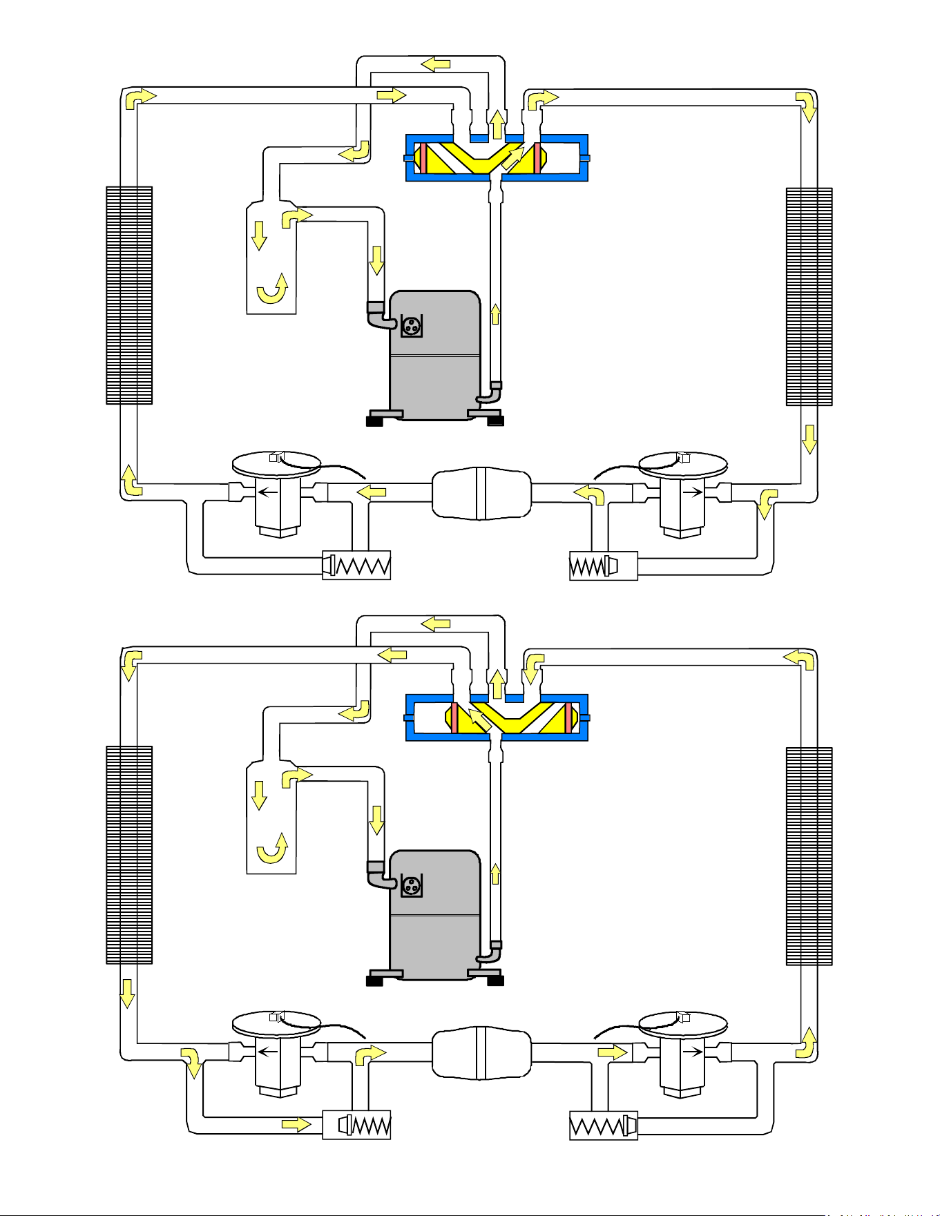
81
SYSTEM OPERATION
Indoor
Coil
Accumulator
Bi-Flow
Filter Dryer
Outdoor
Coil
Thermostatic
Expansion
Valve
Check Valve
Reversing Valve
(De-Energized)
Indoor
Coil
Accumulator
Bi-Flow
Filter Dryer
Outdoor
Coil
Thermostatic
Expansion
Valve
Check Valve
Reversing Valve
(Energized)
COOLING CYCLE
HEATING CYCLE
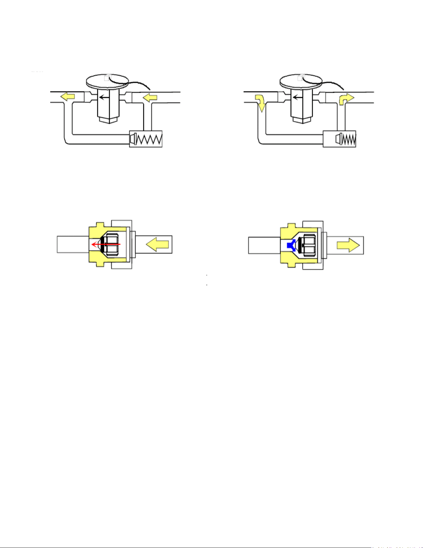
82
SYSTEM OPERATION
EXPANSION VALVE/CHECK VALVE ASSEMBLY IN
COOLING OPERATION
EXPANSION VALVE/CHECK VALVE ASSEMBLY IN
HEATING OPERATION
Most expansion valves used in current Amana Heat Pump products use an internally checked expansion valve. This type
of expansion valve does not require an external check valve as shown above.
Restrictor Orice Assy in Cooling Operation
Restrictor Orice Assy in Heating Operation
In the cooling mode, the orice is pushed into its seat,
forcing refrigerant to ow through the metered hole in the
center of the orice.
In the heating mode, the orice moves back o its seat,
allowing refrigerant to ow unmetered around the outside of
the orice.
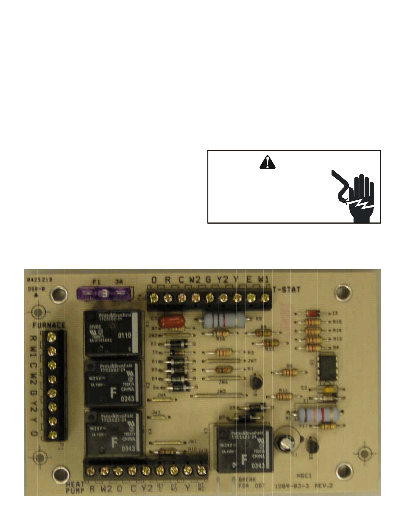
83
SYSTEM OPERATION
AFE18-60A Control Board
Descripon
The AFE18 control is designed for use in heat pump applicaons
where the indoor coil is located above/downstream of a gas or
fossil fuel furnace. It will operate with single and two stage heat
pumps and single and two stage furnaces. The AFE18 control
will turn the heat pump unit o when the furnace is turned on.
An an-short cycle feature is also incorporated which iniates
a 3 minute med o delay when the compressor goes o. On
inial power up or loss and restoraon of power, this 3 minute
med o delay will be iniated. The compressor won’t be
allowed to restart unl the 3 minute o delay has expired. Also
included is a 5 second de-bounce feature on the “Y, E, W1 and
O” thermostat inputs. These thermostat inputs must be present
for 5 seconds before the AFE18 control will respond to it.
An oponal outdoor thermostat, OT18-60A, can be used with
the AFE18 to switch from heat pump operaon to furnace
operaon below a specic ambient temperature seng, i.e.
break even temperature during heang. When used in this
manner, the “Y” heat demand is switched to the “W1” input to
the furnace by the outdoor thermostat and the furnace is used
to sasfy the rst stage “Y” heat demand.
On some controls, if the outdoor thermostat fails closed in this
posion during the heang season, it will turn on the furnace
during the cooling season on a “Y” cooling demand. In this
situaon, the furnace produces heat and increases the indoor
temperature thereby never sasfying the cooling demand.
The furnace will connue to operate and can only be stopped
by switching the thermostat to the o posion or removing
power to the unit and then replacing the outdoor thermostat.
When the AFE18 receives a “Y” and “O” input from the indoor
thermostat, it recognizes this as a cooling demand in the cooling
mode. If the outdoor thermostat is stuck in the closed posion
switching the “Y” demand to the “W1” furnace input during
the cooling mode as described above, the AFE18 won’t allow
the furnace to operate. The outdoor thermostat will have to be
replaced to restore the unit to normal operaon.
WARNING
HIGH VOLTAGE!
Disconnect ALL power before servicing
or installing. Multiple power sources
may be present. Failure to do so may
cause property damage, personal injury
or death.
84
Complaint
System
Operating
Pressures
POSSIBLE CAUSE
DOTS IN ANALYSIS
GUIDE INDICATE
"POSSIBLE CAUSE"
SYMPTOM
System will not start
Compressor will not start - fan runs
Comp. and Cond. Fan will not start
Evaporator fan will not start
Condenser fan will not start
Compressor runs - goes off on overload
Compressor cycles on overload
System runs continuously - little cooling/htg
Too cool and then too warm
Not cool enough on warm days
Certain areas too cool, others too warm
Compressor is noisy
System runs - blows cold air in heating
Unit will not terminate defrost
Unit will not defrost
Low suction pre ssure
Low head pressure
High suction pressure
High head pressure
Test Method
Remedy
See Service Procedure Ref.
Pow er Failure
•
Test Voltage S-1
Blow n Fuse
• • •
Inspect Fuse Size & Type S-1
Unbalanced Pow er, 3PH
• • •
Test Voltage S-1
Loose Connection
• • •
Inspect Connection - Tighten S-2, S-3
Shorted or Broken Wires
• • • • • •
Test Circuits With Ohmmeter S-2, S-3
Open Fan Overload
• •
Test Continuity of Overload S-17A
Faulty Thermostat
• • • •
Test Continuity of Thermostat & Wiring S-3
Faulty Transf ormer
• •
Check Control Circuit w ith Voltmeter S-4
Shorted or Open Capacitor
• • • • •
Test Capacitor S-15
Internal Compressor Overload Open
•
♦
Test Continuity of Overload S-17A
Shorted or Grounded Compressor
• •
Test Motor Windings S-17B
Compressor Stuck
• • •
♦
Use Test Cord S-17D
Faulty Compressor Contactor
• • •
Test Continuity of Coil & Contacts S-7, S-8
Faulty Fan Relay
•
Test Continuity of Coil And Contacts S-7
Open Control Circuit
•
Test Control Circuit w ith Voltmeter S-4
Low Voltage
• • •
Test Voltage S-1
Faulty Evap. Fan Motor
• •
♦
Repair or Replace S-16
Shorted or Grounded Fan Motor
• •
Test Motor Windings S-16
Improper Cooling Anticipator
• •
Check Resistance of Anticipator S-3B
Shortage of Ref rigerant
• •
♦
• •
Test For Leaks, Add Refrigerant S-101,103
Restricted Liquid Line
• • • • •
Remove Restriction, Replace Restricted Part S-112
Open Element or Limit on Elec. Heater
♦ ♦
Test Heater Element and Controls S-26,S-27
Dirty Air Filter
• • • •
♦
Inspect Filter-Clean or Replace
Dirty Indoor Coil
• • • •
♦
Inspect Coil - Clean
Not enough air across Indoor Coil
• • • •
♦
Check Blow er Speed, Duct Static Press, Filter S-200
Too much air across Indoor Coil
♦
•
Reduce Blow er Speed S-200
Overcharge of Ref rigerant
• • •
♦
• •
Recover Part of Charge S-113
Dirty Outdoor Coil
• • •
♦
•
Inspect Coil - Clean
Noncondensibles
• •
♦
•
Recover Charge, Evacuate, Recharge S-114
Recirculation of Condensing Air
• • •
Remove Obstruction to Air Flow
Infiltration of Outdoor Air
• • •
Check Window s, Doors, Vent Fans, Etc.
Improperly Located Thermostat
• •
Relocate Thermostat
Air Flow Unbalanced
• •
Readjust Air Volume Dampers
System Undersized
• •
Refigure Cooling Load
Broken Internal Parts
•
♦
Replace Compressor S-115
Broken Valves
• • • •
Test Compressor Efficiency S-104
Inefficient Compressor
•
♦
• •
Test Compressor Efficiency S-104
Wrong Type Expansion Valve
• • • • • •
♦
Replace Valve S-110
Expansion Device Restricted
• • • • • • •
Remove Restriction or Replace Expansion Device S-110
Oversized Expansion Valve
• •
Replace Valve
Undersized Expansion Valve
• • • • •
Replace Valve
Expansion Valve Bulb Loose
• •
Tighten Bulb Bracket S-105
Inoperative Expansion Valve
• • •
Check Valve Operation S-110
Loose Hold-dow n Bolts
•
Tighten Bolts
Faulty Reversing Valve
•
♦ ♦ ♦ ♦ ♦ ♦
Replace Valve or Solenoid S-21, 122
Faulty Defrost Control
•
♦ ♦ ♦ ♦ ♦ ♦
Test Control S-24
Faulty Defrost Thermostat
♦ ♦ ♦ ♦ ♦ ♦ ♦
Test Defrost Thermostat S-25
Flow rator Not Seating Properly
• • •
Check Flow rator & Seat or Replace Flow rator S-111
•
Cooling or Heating Cycle (Heat Pump)
♦
COOLING/HP ANALYSIS CHART
No Cooling
Unsatisfactory
Cooling/Heating
Heating Cycle Only (Heat Pum p)
TROUBLESHOOTING CHART
TROUBLESHOOTING CHART
85
HIGH VOLTAGE!
Disconnect ALL power before servicing or installing. Multiple power sources may be present. Failure to
do so may cause property damage, personal injury or death.
S-1 CHECKING VOLTAGE......................................................84
S-2 CHECKING WIRING........................................................84
S-3 CHECKING THERMOSTAT and WIRING .........................84
S-3A Thermostat Wiring........................................................84
S-4 Checking Transformer And Control Circuit...................85
S-7 CHECKING CONTACTOR AND/OR RELAYS.....................85
S-8 CHECKING CONTACTOR CONTACTS..............................85
S-9 CHECKING FAN RELAY CONTACTS.................................86
S-10 MBR/AR*F ELECTRONIC
BLOWER TIME DELAY RELAY..........................................87
S-11 CHECKING Loss OF Charge PROTECTOR .......................87
S-12 CHECKING HIGH PRESSURE CONTROL .........................87
S-13 CHECKING LOW PRESSURE CONTROL...........................87
S-10 Copeland Comfort Alert™.............................................88
S-10B Copeland CORESENSE™................................................88
S-15 CHECKING CAPACITOR..................................................94
S-15A Resistance Check using a digital mul-meter...............94
S-15B Capacitance Check using a digital
mul-meter (In capacitance mode)..............................94
S-16A CHECKING FAN AND BLOWER
MOTOR WINDINGS (PSC MOTORS)...............................95
S-16B CHECKING FAN AND BLOWER MOTOR
(ECM MOTORS).............................................................95
S-16C Checking ECM motor windings.....................................96
S-16D ECM CFM ADJUSTMENTS mbe / aepf...........................96
S-16E Blower Performance Data..........................................100
S-16F CHECKING High Eciency MOTORS ...........................100
S-16G eem BLOWER REPLACEMENT.....................................101
S-17 CHECKING COMPRESSOR............................................102
S-17A Resistance Test...........................................................103
S-17B Ground Test................................................................103
S-17C Unloader Test Procedure............................................103
S-17D Operaon Test............................................................104
S-17E Checking 3-phase scroll compressor
rotaon.......................................................................104
S-18 Tesng crankcase heater
(Oponal Item)...........................................................105
S-21 CHECKING REVERSING VALVE
AND SOLENOID...........................................................105
S-24 TESTING DEFROST CONTROL......................................105
S-25 TESTING DEFROST THERMOSTAT................................105
S-50 CHECKING HEATER LIMIT CONTROL(S).......................111
S-52 CHECKING HEATER ELEMENTS....................................111
S-60 ELECTRIC HEATER (OPTIONAL ITEM)..........................111
S-61A CHECKING HEATER LIMIT CONTROL(S).......................112
S-61B CHECKING HEATER FUSE LINK....................................112
(OPTIONAL ELECTRIC HEATERS)..................................112
S-62 CHECKING HEATER ELEMENTS....................................112
S-100 REFRIGERATION REPAIR PRACTICE.............................113
S-101 leak tesng
(nitrogen or nitrogen-traced).....................................113
S-102 EVACUATION...............................................................113
S-103 CHARGING..................................................................114
S-104 CHECKING COMPRESSOR EFFiCIENCY.........................115
S-106 OVERFEEDING.............................................................116
S-107 UNDERFEEDING..........................................................116
S-108 SUPERHEAT..................................................................116
S-109 CHECKING SUBCOOLING.............................................116
S-110 Checking expansion valve operaon...........................119
S-112 CHECKING RESTRICTED LIQUID LINE..........................119
S-113 OVERCHARGE OF REFRIGERANT.................................119
S-114 NON-CONDENSABLES.................................................119
S-115 COMPRESSOR BURNOUT............................................120
S-120 REFRIGERANT PIPING.................................................120
S-201 CLEANING ALUMINUM COILS.......................................120
S-202 DUCT STATIC PRESSURES
AND/OR STATIC PRESSURE DROP
ACROSS COILS.............................................................121
S-203 SINGLE PIECE AIR HANDLER
EXTERNAL STATIC........................................................121
S-203A Two Piece Air Handler
External Stac Pressure..............................................121
S-204 COIL STATIC PRESSURE DROP......................................121
TABLE OF CONTENTS
SERVICING
SERVICING
86
SERVICING
S-1 CHECKING VOLTAGE
1. Remove outer case, control panel cover, etc., from unit being
tested.
With power ON:
Line Voltage now present.
WARNING
2. Using a voltmeter, measure the voltage across terminals L1
and L2 of the contactor for the condensing unit or at the
eld connecons for the air handler or heaters.
3. No reading - indicates open wiring, open fuse(s) no power or
etc., from unit to fused disconnect service. Repair as
needed.
4. With ample voltage at line voltage connectors, energize the
unit.
5. Measure the voltage with the unit starng and operang,
and determine the unit Locked Rotor Voltage.
NOTE: If checking heaters, be sure all heang elements are
energized.
Locked Rotor Voltage is the actual voltage available at the
compressor during starng, locked rotor, or a stalled condion.
Measured voltage should be above minimum listed in chart
below.
To measure Locked Rotor Voltage aach a voltmeter to the run
"R" and common "C" terminals of the compressor, or to the T1
and T2 terminals of the contactor. Start the unit and allow the
compressor to run for several seconds, then shut down the unit.
Immediately aempt to restart the unit while measuring the
Locked Rotor Voltage.
6. Locked rotor voltage should read within the voltage tabula-
on as shown. If the voltage falls below the minimum volt-
age, check the line wire size. Long runs of undersized wire
can cause low voltage. If wire size is adequate, nofy the
local power company in regard to either low or high voltage.
Unit Supply Voltage
Voltage
Min. Max
208/230
197 253
460 414 506
NOTE: When operang electric heaters on voltages other than
240 volts, refer to the System Operaon secon on electric
heaters to calculate temperature rise and air ow. Low voltage
may cause insucient heang.
S-2 CHECKING WIRING
WARNING
HIGH VOLTAGE!
Disconnect ALL power before servicing
or installing. Multiple power sources
may be present. Failure to do so may
cause property damage, personal injury
or death.
1. Check wiring visually for signs of overheang, damaged insu-
laon and loose connecons.
2. Use an ohmmeter to check connuity of any suspected open
wires.
3. If any wires must be replaced, replace with comparable
gauge and insulaon thickness.
S-3 CHECKING THERMOSTAT and WIRING
Thermostat Wiring: The maximum wire length for 18 AWG
thermostat wire is 100 feet.
S-3A Thermostat Wiring
Line Voltage now present.
WARNING
With power ON, thermostat calling for cooling
1. Use a voltmeter to check for 24 volts at thermostat wires C
and Y in the condensing unit control panel.
2. No voltage indicates trouble in the thermostat, wiring or
external transformer source.
3. Check the connuity of the thermostat and wiring. Repair or
replace as necessary.
Indoor Blower Motor
With power ON:
Line Voltage now present.
WARNING
1. Set fan selector switch at thermostat to “ON” posion.
2. With voltmeter, check for 24 volts at wires C and G.
3. No voltage indicates the trouble is in the thermostat or wir-
ing.
4. Check the connuity of the thermostat and wiring. Repair or
replace as necessary.
Resistance Heaters
1. Set room thermostat to a higher seng than room tempera-
ture so both stages call for heat.
2. With voltmeter, check for 24 volts at each heater relay.
87
SERVICING
3. No voltage indicates the trouble is in the thermostat or wir-
ing.
4. Check the connuity of the thermostat and wiring. Repair or
replace as necessary.
NOTE: Consideraon must be given to how the heaters are
wired (O.D.T. and etc.). Also safety devices must be checked for
connuity.
S-4 Checking Transformer And Control Circuit
WARNING
HIGH VOLTAGE!
Disconnect ALL power before servicing
or installing. Multiple power sources
may be present. Failure to do so may
cause property damage, personal injury
or death.
A step-down transformer (208/240 volt primary to 24 volt
secondary) is provided with each indoor unit. This allows ample
capacity for use with resistance heaters. The outdoor secons
do not contain a transformer (see note below).
Disconnect ALL power before servicing.
WARNING
1. Remove control panel cover, or etc., to gain access to trans-
former.
With power ON:
Line Voltage now present.
WARNING
2. Using a voltmeter, check voltage across secondary voltage
side of transformer (R to C).
3. No voltage indicates faulty transformer, bad wiring, or bad
splices.
4. Check transformer primary voltage at incoming line voltage
connecons and/or splices.
5 If line voltage available at primary voltage side of transform-
er and wiring and splices good, transformer is inoperave.
Replace.
S-7 CHECKING CONTACTOR AND/OR RELAYS
WARNING
HIGH VOLTAGE!
Disconnect ALL power before servicing
or installing. Multiple power sources
may be present. Failure to do so may
cause property damage, personal injury
or death.
The compressor contactor and other relay holding coils are
wired into the low or line voltage circuits. When the control
circuit is energized, the coil pulls in the normally open contacts
or opens the normally closed contacts. When the coil is de-
energized, springs return the contacts to their normal posion.
NOTE: Most single phase contactors break only one side of the
line (L1), leaving 115 volts to ground present at most internal
components.
NOTE: The compressor contactor/relay in ComfortNetTM ready
equipment is fully integrated into the unitary (UC) control.
The compressor contactor/relay coil on the UC control is non-
serviceable.
1. Remove the leads from the holding coil.
2. Using an ohmmeter, test across the coil terminals.
If the coil does not test connuous, replace the relay or
contactor.
S-8 CHECKING CONTACTOR CONTACTS
Disconnect ALL power before servicing.
WARNING
SINGLE PHASE:
1. Disconnect the wire leads from the terminal (T) side of the
contactor.
2. With power ON, energize the contactor.
Line Voltage now present.
WARNING
3. Using a voltmeter, test across terminals.
A. L2 - T1 - No voltage indicates CC1 contacts open.
If a no voltage reading is obtained - replace the contactor.
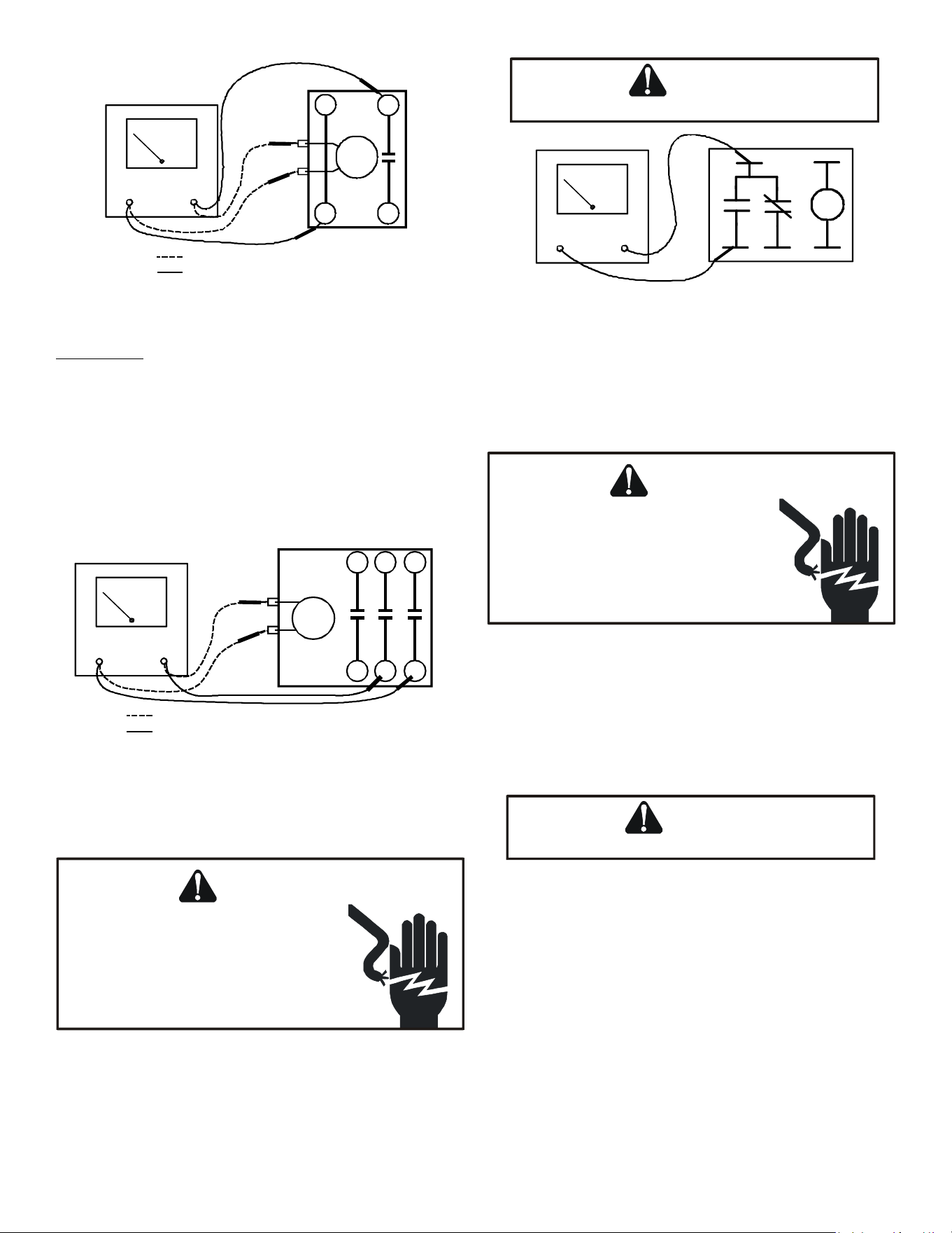
88
SERVICING
VOLT/OHM
METER
T1
T2
L1L2
CC
Ohmmeter for testing holding coil
Voltmeter for testing contacts
TESTING COMPRESSOR CONTACTOR
(Single Phase)
THREE PHASE
Using a voltmeter, test across terminals:
A. L1-L2, L1-L3, and L2-L3 - If voltage is present, proceed to B. If
voltage is not present, check breaker or fuses on main power
supply..
B. T1-T2, T1-T3, and T2-T3 - If voltage readings are not the
same as in “A”, replace contactor.
VOLT/OHM
METER
CC
Ohmmeter for testing holding coil
Voltmeter for testing contacts
T1
L1
T3
L3
T2
L2
TESTING COMPRESSOR CONTACTOR
(Three-Phase)
S-9 CHECKING FAN RELAY CONTACTS
WARNING
HIGH VOLTAGE!
Disconnect ALL power before servicing
or installing. Multiple power sources
may be present. Failure to do so may
cause property damage, personal injury
or death.
1. Disconnect wire leads from terminals 2 and 4 of Fan Relay
Cooling and 2 and 4, 5 and 6 of Fan Relay Heang.
2. Using an ohmmeter, test between 2 and 4 - should read
open. Test between 5 and 6 - should read connuous.
3. With power ON, energize the relays.
Line Voltage now present.
WARNING
1
2
3
4
5
OHMMETER
TESTING FAN RELAY
4. Using an ohmmeter, test between 2 and 4 - should read
connuous . Test between 5 and 6 - should read open.
5. If not as above, replace the relay.
Checking Relay Contacts - PSC Fan Motor
WARNING
HIGH VOLTAGE!
Disconnect ALL power before servicing
or installing. Multiple power sources
may be present. Failure to do so may
cause property damage, personal injury
or death.
1. Disconnect the motor leads from 6-circuit fan motor wire
harness.
2. Connect a voltmeter between circuit 3 and circuits 2 (low
speed) or 1 (high speed).
NOTE: Circuit 3 is connected directly to L2.
3. Energize the system at low or high stage.
Line Voltage now present.
WARNING
4. The measured voltage between circuit 3 and circuits 2 or 1
should be approximately 0VAC, which indicates the relay
contacts are closed. A voltage measurement of approx-
imately 115VAC indicates the relay is open. Replace the
control if the relay checks open when it should be closed.
See notes and cauons below.
NOTE: Ensure any ON delays have expired before making
voltage measurements
CAUTION: Prolonged operaon with the condenser fan motoR
disconnected will cause the high pressure switch to trip.
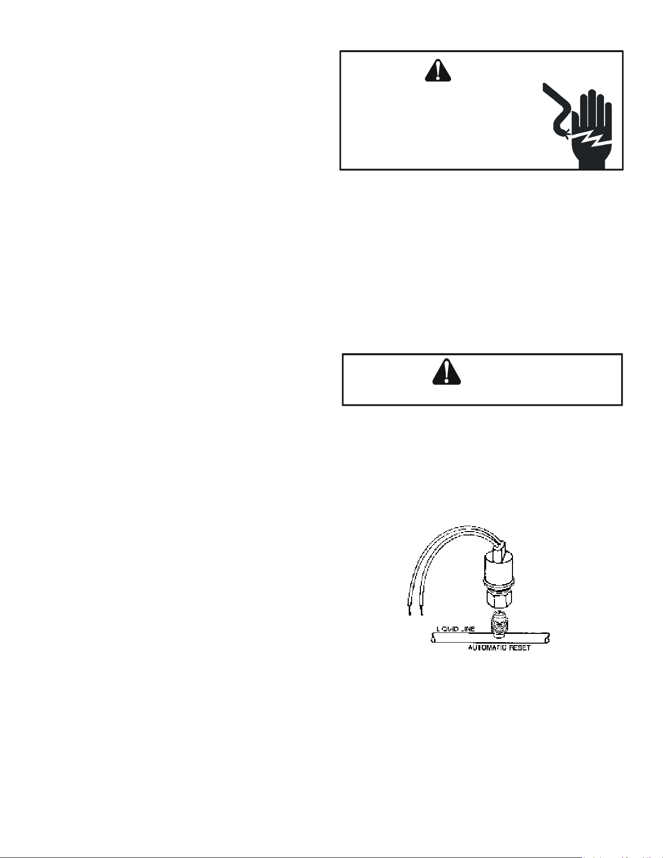
89
SERVICING
S-10 MBR/AR*F ELECTRONIC BLOWER TIME DELAY
RELAY
The MBR/AR*F contains an Electronic Blower Time Delay Relay
board, B1370735. This board provides on/o me delays for the
blower motor in cooling and heat pump heang demands when
“G” is energized.
During a cooling or heat pump heang demand, 24Vac is
supplied to terminal “G” of the EBTDR to turn on the blower
motor. The EBTDR iniates a 7 second delay on and then
energizes it’s onboard relay. The relay on the EBTDR board
closes it’s normally open contacts and supplies power to the
blower motor. When the “G” input is removed, the EBTDR
iniates a 65 second delay o. When the 65 seconds delay
expires the onboard relay is de-energized and it’s contacts open
and remove power from the blower motor.
During an electric heat only demand, “W1” is energized but “G”
is not. The blower motor is connected to the normally closed
contacts of the relay on the EBTDR board. The other side of this
set of contacts is connected to the heat sequencer on the heater
assembly that provides power to the rst heater element. When
“W1” is energized, the sequencer will close it’s contacts within
10 to 20 seconds to supply power to the rst heater element
and to the blower motor through the normally closed contacts
on the relay on the EBTDR. When the “W1” demand is removed,
the sequencer opens it contacts within 30 to 70 seconds and
removes power from the heater element and the blower motor.
The EBTDR also contains a speedup terminal to reduce the
delays during troubleshoong of the unit. When this terminal is
shorted to the common terminal, “C”, on the EBTDR board, the
delay ON me is reduced to 3 seconds and the delay OFF me is
reduced to 5 second.
Two addional terminals, M1 and M2, are on the EBTDR board.
These terminals are used to connect the unused leads from the
blower motor and have no aect on the board’s operaon.
S-11 CHECKING LOSS OF CHARGE PROTECTOR
(Heat Pump Models)
The loss of charge protectors senses the pressure in the liquid
line and will open its contacts on a drop in pressure. the low
pressure control will automacally reset itself with a rise in
pressure.
The low pressure control is designed to cut-out (open) at
approximately 21 PSIG. It will automacally cut-in (close) at
approximately 50 PSIG.Test for connuity using a VOM and if not
as above, replace the control.
S-12 CHECKING HIGH PRESSURE CONTROL
WARNING
HIGH VOLTAGE!
Disconnect ALL power before servicing
or installing. Multiple power sources
may be present. Failure to do so may
cause property damage, personal injury
or death.
The high pressure control capillary senses the pressure in the
compressor discharge line. If abnormally high condensing
pressures develop, the contacts of the control open, breaking
the control circuit before the compressor motor overloads. This
control is automacally reset.
1. Using an ohmmeter, check across terminals of high pressure
control, with wire removed. If not connuous, the contacts
are open.
2. Aach a gauge to the dill valve port on the base valve.
With power ON:
Line Voltage now present.
WARNING
3. Start the system and place a piece of cardboard in front of
the condenser coil, raising the condensing pressure.
4. Check pressure at which the high pressure control cuts-out.
If it cuts-out at 610 PSIG ± 10 PSIG, it is operang normally
(See causes for high head pressure in Service Problem Anal-
ysis Guide). If it cuts out below this pressure range, replace
the control.
S-13 CHECKING LOW PRESSURE CONTROL
The low pressure control senses the pressure in the sucon
line and will open its contacts on a drop in pressure. The low
pressure control will automacally reset itself with a rise in
pressure.
The low pressure control is designed to cut-out (open) at
approximately 21 PSIG for heat pumps and 55 PSIG for air
condioners.
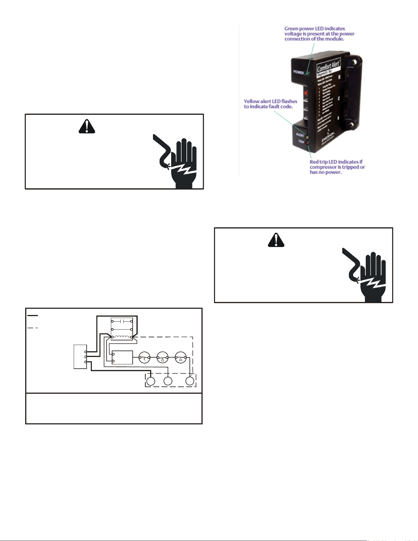
90
SERVICING
It will automacally cut-in (close) at approximately 50 PSIG for
heat pumps and 95 PSIG for air condioners.
Test for connuity using a VOM and if not as above, replace the
control.
S-10 Copeland Comfort Alert™
Diagnoscs - 3-Wire module
Applies to ASX /ASZ and DSX/DSZ units
WARNING
HIGH VOLTAGE!
Disconnect ALL power before servicing
or installing. Multiple power sources
may be present. Failure to do so may
cause property damage, personal injury
or death.
Comfort Alert™ is self-contained with no required external
sensors and is designed to install directly into the electrical box
of any residenal condensing unit that has a Copeland Scroll™
compressor inside.
Once aached, Comfort Alert provides around-the-clock
monitoring for common electrical problems, compressor defects
and broad system faults. If a glitch is detected, an LED indicator
ashes the proper alert codes to help you quickly pinpoint the
problem. (See Diagnosc Table: 3-Wire Comfort Alert Module on
previous page.)
Schematic Abbreviation Descriptions
HTCO High Temperature Cut Out Switch
HPCO High Pressure Cut Out Switch
LPCO Low Pressure Cut Out Switch
CC Compressor Contactor
ECB Electronic Control Board
(Defrost or Time Delay)
ECB
CC
HTCO
LPCO
HPCO
Comfort Alert
Diagnostics Module
Bold line shows field
installed wiring
Dashed line shows thermostat
demand wiring in system without
HTCO, HPCO, CPCO, and ECB
LOGIC
R
C
Y
Y1
R
C
Wiring Schemac - 3-Wire Comfort Alert Module
S-10B Copeland CORESENSE™
Diagnoscs - 3-Wire module
Applies to ASX /ASZ and DSX/DSZ units
WARNING
HIGH VOLTAGE!
Disconnect ALL power before servicing
or installing. Multiple power sources
may be present. Failure to do so may
cause property damage, personal injury
or death.
The CoreSense™ module is self-contained with no required
external sensors and works with any residenal condensing unit
that has a Copeland Scroll™ compressor inside.
Once aached, CoreSense™ provides around-the-clock
monitoring for common electrical problems, compressor defects
and broad system faults. If a glitch is detected, an LED indicator
ashes the proper alert codes to help you quickly pinpoint the
problem. See Diagnosc Table: 3-Wire CoreSense™ Module on
following pages.
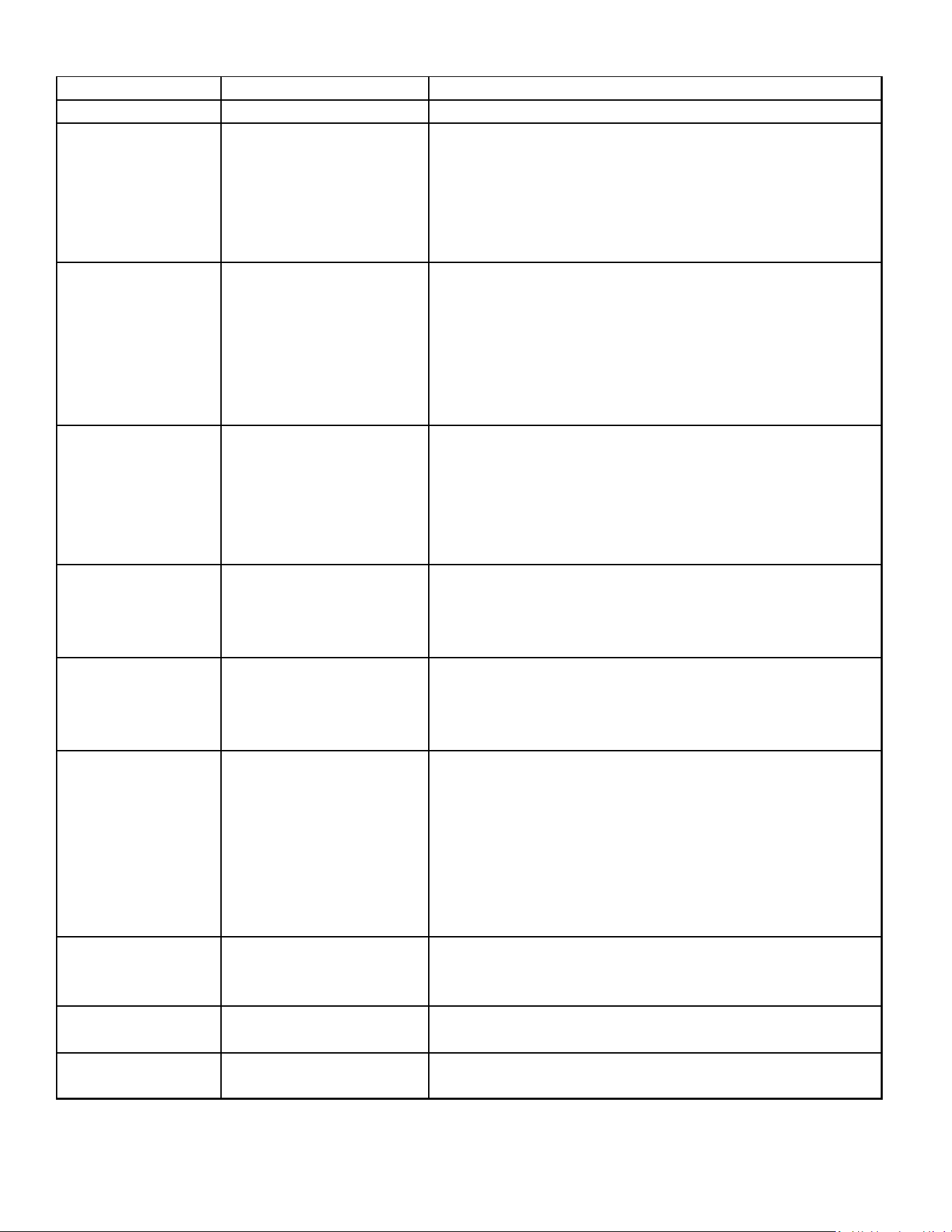
91
SERVICING
Status LED Status LED Description Status LED Troubleshooting Information
Green “POWER” Module has power Supply voltage is present at module terminals
Red “TRIP” Thermostat demand signal 1. Compressor protector is open
Y1 is present, but the 2. Outdoor unit power disconnect is open
compressor is not 3. Compressor circuit breaker or fuse(s) is open
running 4. Broken wire or connector is not making contact
5. Low pressure switch open if present in system
6. Compressor contactor has failed open
Yellow “ALERT” Long Run Time 1. Low refrigerant charge
Flash Code 1 Compressor is 2. Evaporator blower is not running
running extremely 3. Evaporator coil is frozen
long run cycles 4. Faulty metering device
5. Condenser coil is dirty
6. Liquid line restriction (filter drier blocked if present in system)
7. Thermostat is malfunctioning
Yellow “ALERT” S yste m P re ssure Tri p 1. High head pressure
Flash Code 2 Discharge or suction 2. Condenser coil poor air circulation (dirty, blocked, damaged)
pressure out of limits or 3. Condenser fan is not running
compressor overloaded 4. Return air duct has substantial leakage
5. If low pressure switch present in system,
check Flash Code 1 information
Yellow “ALERT” Short Cycling 1. Thermostat demand signal is intermittent
Flash Code 3 Compressor is running 2. Time delay relay or control board defective
only briefly 3. If high pressure switch present go to Flash Code 2 information
4. If low pressure switch present go to Flash Code 1 information
Yellow “ALERT” Locked Rotor 1. Run capacitor has failed
Flash Code 4 2. Low line voltage (contact utility if voltage at disconnect is low)
3. Excessive liquid refrigerant in compressor
4. Compressor bearings are seized
Yellow “ALERT” Open Circuit 1. Outdoor unit power disconnect is open
Flash Code 5 2. Compressor circuit breaker or fuse(s) is open
3. Compressor contactor has failed open
4. High pressure switch is open and requires manual reset
5. Open circuit in compressor supply wiring or connections
6. Unusually long compressor protector reset time
due to extreme ambient temperature
7. Compressor windings are damaged
Yellow “ALERT” Open Start Circuit 1. Run capacitor has failed
Flash Code 6 Current only in run circuit 2. Open circuit in compressor start wiring or connections
3. Compressor start winding is damaged
Yellow “ALERT” Open Run Circuit 1. Open circuit in compressor run wiring or connections
Flash Code 7 Current only in start circuit 2. Compressor run winding is damaged
Yellow “ALERT” Low Voltage 1. Control circuit transformer is overloaded
Flash Code 9 Control circuit < 17VAC 2. Low line voltage (contact utility if voltage at disconnect is low)
DIAGNOSTICS TABLE: 2-WIRE COMFORT ALERT™ MODULE
• FLASH CODE NUMBER CORRESPONDS TO A NUMBER OF LED FLASHES, FOLLOWED BY A PAUSE AND THEN REPEATED
• TRIP AND ALERT LEDS FLASHING AT SAME TIME MEANS CONTROL CIRCUIT VOLTAGE IS TOO LOW FOR OPERATION.
• LAST ALERT FLASH CODE IS DISPLAYED FOR 1 MINUTE AFTER MODULE IS POWERED ON.
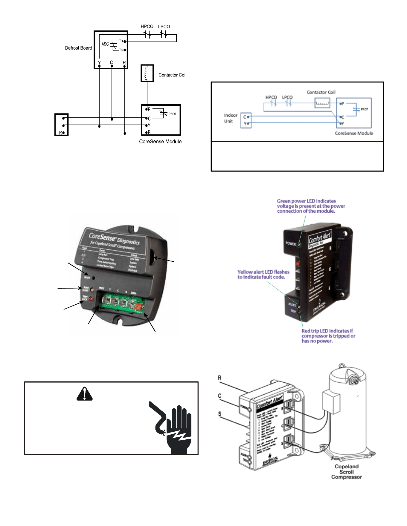
92
SERVICING
C
Y
Indoor
Unit
Schematic Abbreviation Descriptions
HTCO High Temperature Cut Out Switch
HPCO High Pressure Cut Out Switch
LPCO Low Pressure Cut Out Switch
CC Compressor Contactor
ECB Electronic Control Board
(Defrost or Time Delay)
WIRING SCHEMATIC - 3-WIRE CORESENSE™ ALERT MODULE
Reset
Switch
Run/Alert
LED
Trip/Lock-Out
Red LED
Protection
Output
Data Port
One
Current
Sensor
DIAGNOSTICS - 2-WIRE MODULE
APPLIES TO ASX130[18-60]CA, ASX140[18-36]1CA,
ASX140421DA, AND ASX140[48-60]1BA UNITS
WARNING
HIGH VOLTAGE!
Disconnect ALL power before servicing
or installing. Multiple power sources
may be present. Failure to do so may
cause property damage, personal injury
or death.
The CoreSense™ module is self-contained with no required
external sensors and works with any residenal condensing unit
that has a Copeland Scroll™ compressor inside.
Once aached, CoreSense™ provides around-the-clock
monitoring for common electrical problems, compressor defects
and broad system faults. If a glitch is detected, an LED indicator
ashes the proper alert codes to help you quickly pinpoint the
problem. See Diagnosc Table: 2-Wire Comfort Alert™ Module
on following pages.)
Schematic Abbreviation Descriptions
HTCO High Temperature Cut Out Switch
HPCO High Pressure Cut Out Switch
LPCO Low Pressure Cut Out Switch
CC Compressor Contactor
ECB Electronic Control Board
(Defrost or Time Delay)
WIRING SCHEMATIC - 2-WIRE CORESENSE™ MODULE
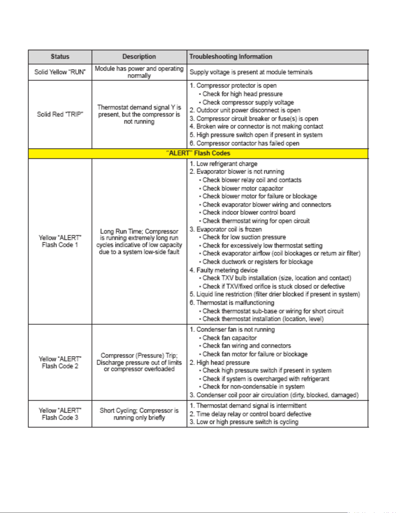
93
SERVICING
DIAGNOSTICS TABLE: CORESENSE™ MODULE
Flash code number corresponds to the number of LED ashes, followed by a pause and then repeated.
TRIP and ALERT LEDs ashing at the same time mean control circuit voltage is too low for operation.
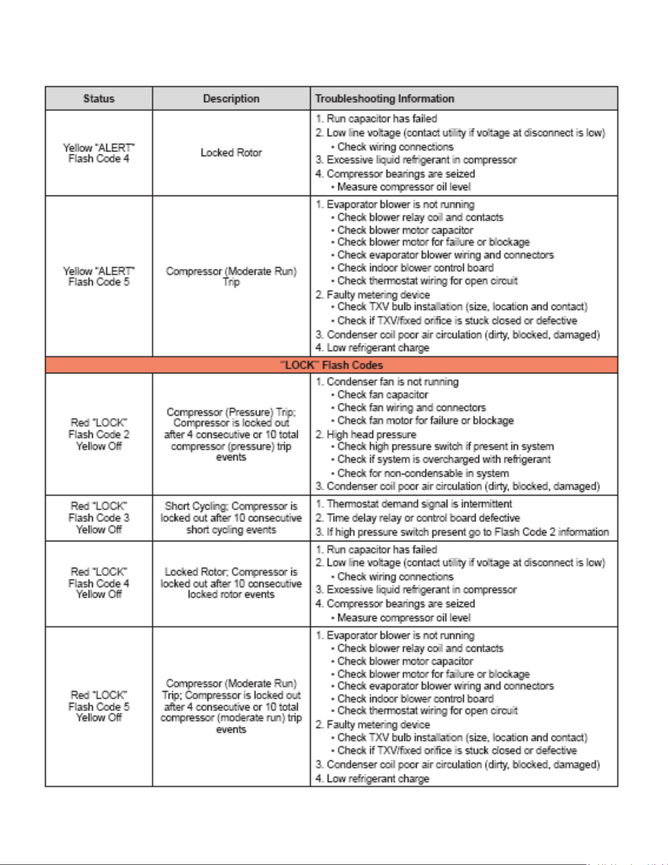
94
SERVICING
DIAGNOSTICS TABLE: CORESENSE™ MODULE (cont.)
Flash code number corresponds to the number of LED ashes, followed by a pause and then repeated.
TRIP and ALERT LEDs ashing at the same time mean control circuit voltage is too low for operation.
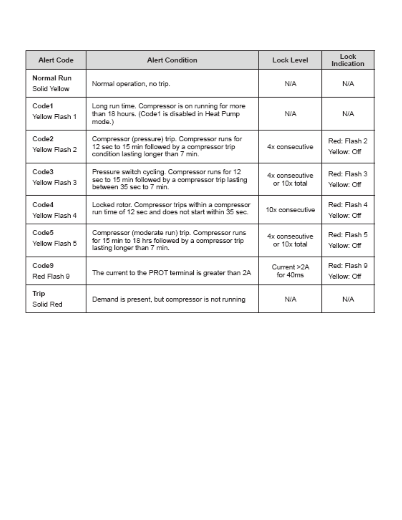
95
SERVICING
Table 1 - Quick Reference Table
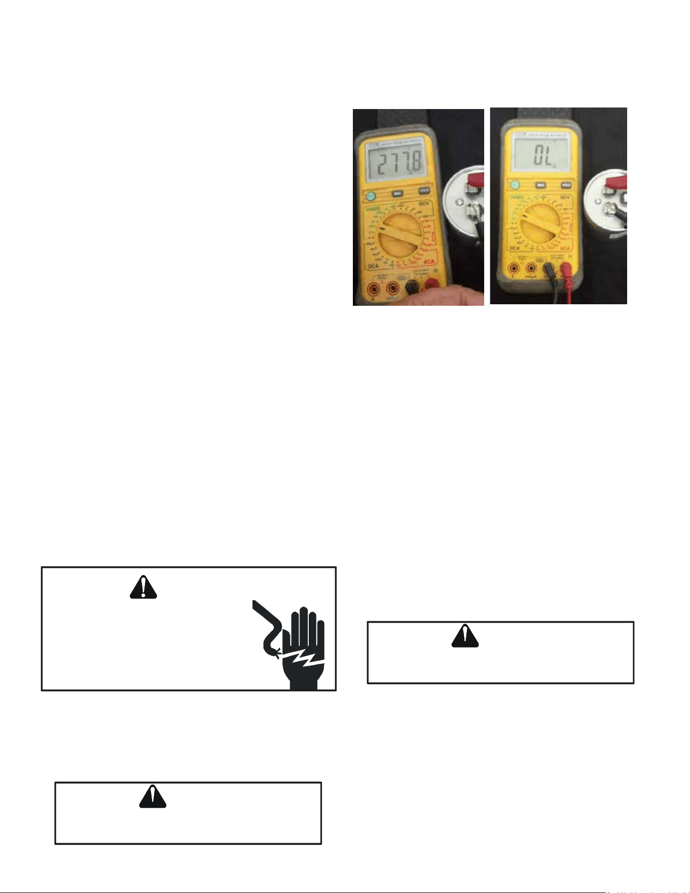
96
S-15 CHECKING CAPACITOR
CAPACITOR, RUN
A run capacitor is wired across the auxiliary and main windings
of a single phase permanent split capacitor motor. The
capacitors primary funcon is to reduce the line current while
greatly improving the torque characteriscs of a motor. This is
accomplished by using the 90° phase relaonship between the
capacitor current and voltage in conjuncon with the motor
windings, so that the motor will give two phase operaon when
connected to a single phase circuit. The capacitor also reduces
the line current to the motor by improving the power factor.
The line side of this capacitor is marked with “COM” and is wired
to the line side of the circuit.
CAPACITOR, START
SCROLL COMPRESSOR MODELS
In most cases hard start components are not required on Scroll
compressor equipped units due to a non-replaceable check
valve located in the discharge line of the compressor. However,
in installaons that encounter low lock rotor voltage, a hard
start kit can improve starng characteriscs and reduce light
dimming within the home. Only hard start kits approved by
Amana® brand or Copeland should be used. “Kick Start” and/or
“Super Boost” kits are not approved start assist devices.
The discharge check valve closes o high side pressure to the
compressor aer shut down allowing equalizaon through the
scroll anks. Equalizaon requires only about 1/2 second.
To prevent the compressor from short cycling, a Time Delay
Relay (Cycle Protector) has been added to the low voltabe
circuit.
S-15A RESISTANCE CHECK USING A DIGITAL
MULTI- METER
WARNING
HIGH VOLTAGE!
Disconnect ALL power before servicing
or installing. Multiple power sources
may be present. Failure to do so may
cause property damage, personal injury
or death.
Check for Digital Test
1. Set the meter on Ohm range (Set it at lease 1000 Ohm
=1k).
WARNING
Discharge capacitor through a 20 to 30 OHM
resistor before handling.
WARNING
SERVICING
SERVICING
2. Connect the Meter leads to the Capacitor terminals.
3. Digital meter will show a reading momentarily (Figure 1).
Note the reading.
Figure 1 Figure 2
4. Reading will immediately return to the OL = (Open Line)
(Figure 2). Every aempt of Step 2 will show the same result
as was in step 4 and Step 5. This indicates that the capacitor
is good.
5. If there is no Change, then capacitor is dead and must be
replaced.
Check for Analog Meter
A. Good Condion - indicator swings to zero and slowly
returns to innity. (Start capacitor with bleed resistor will
not return to innity. It will sll read the resistance of the
resistor).
B. Shorted - indicator swings to zero and stops there - re-
place.
C. Open - no reading - replace. (Start capacitor would read
resistor resistance.)
S-15B CAPACITANCE CHECK USING A DIGITAL
MULTI-METER (IN CAPACITANCE MODE)
WARNING
Discharge capacitor through a 20 to 30 OHM
resistor before handling.
WARNING
NOTE: You can do this test with a mul-meter if you have a
Capacitance meter on your mul-meter.
1. Remove the capacitor from the circuit.
2. Now Select “Capacitance” on your mul-meter.
3. Now connect the capacitor terminals to the mul-meter
leads.
4. If the reading is near to the actual value of the capacitor (i.e.
the printed value on the capacitor). The capacitor is good.
(Note that the reading may be less than the actual printed
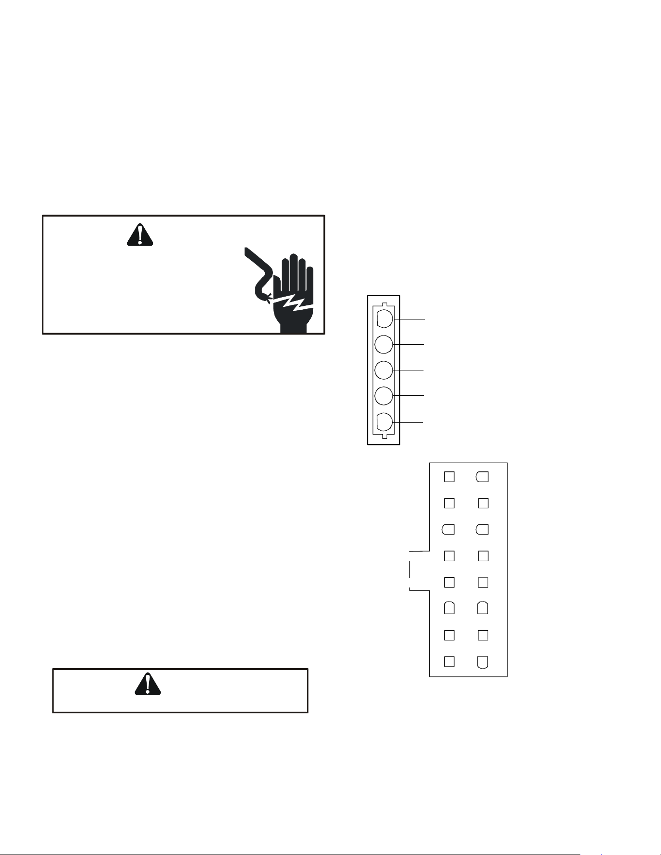
97
value of the capacitor).
5. If you read a signicantly lower capacitance or none at all,
then capacitor is dead and must be replaced.
S-16A CHECKING FAN AND BLOWER MOTOR
WINDINGS (PSC MOTORS)
The auto reset fan motor overload is designed to protect the
motor against high temperature and high amperage condions
by breaking the common circuit within the motor, similar to the
compressor internal overload. However, heat generated within
the motor is faster to dissipate than the compressor, allow at
least 45 minutes for the overload to reset, then retest.
WARNING
HIGH VOLTAGE!
Disconnect ALL power before servicing
or installing. Multiple power sources
may be present. Failure to do so may
cause property damage, personal injury
or death.
1. Remove the motor leads from its respecve connecon
points and capacitor (if applicable).
2. Check the connuity between each of the motor leads.
3. Touch one probe of the ohmmeter to the motor frame
(ground) and the other probe in turn to each lead.
If the windings do not test connuous or a reading is obtained
from lead to ground, replace the motor.
S-16B CHECKING FAN AND BLOWER MOTOR
(ECM MOTORS)
An ECM is an Electronically Commutated Motor which oers
many signicant advantages over PSC motors. The ECM has
near zero rotor loss, synchronous machine operaon, variable
speed, low noise, and programmable air ow. Because of
the sophiscated electronics within the ECM motor, some
technicians are inmated by the ECM motor; however, these
fears are unfounded. GE oers two ECM motor testers, and with
a VOM meter, one can easily perform basic troubleshoong on
ECM motors. An ECM motor requires power (line voltage) and
a signal (24 volts) to operate. The ECM motor stator contains
permanent magnet. As a result, the sha feels “rough” when
turned by hand. This is a characterisc of the motor, not an
indicaon of defecve bearings.
Line Voltage now present.
WARNING
1. Disconnect the 5-pin connector from the motor.
2. Using a volt meter, check for line voltage at terminals #4 &
#5 at the power connector. If no voltage is present:
3. Check the unit for incoming power See secon S-1.
4. Check the control board, See secon S-40.
5. If line voltage is present, reinsert the 5-pin connector and
remove the 16-pin connector.
6. Check for signal (24 volts) at the transformer.
7. Check for signal (24 volts) from the thermostat to the “G”
terminal at the 16-pin connector.
8. Using an ohmmeter, check for connuity from the #1 & #3
(common pins) to the transformer neutral or “C” thermostat
terminal. If you do not have connuity, the motor may func-
on erracally. Trace the common circuits, locate and repair
the open neutral.
9. Set the thermostat to “Fan-On”. Using a voltmeter, check for
24 volts between pin # 15 (G) and common.
10.Disconnect power to compressor. Set thermostat to call for
cooling. Using a voltmeter, check for 24 volts at pin # 6 and
or #14.
11.Set the thermostat to a call for heang. Using a voltmeter,
check for 24 volts at pin #2 and/or #11.
1
2
3
4
5
Lines 1 and 2 will be connected
for 12OVAC Power Connector
applications only
Gnd
AC Line Connection
AC Line Connection
}
11
1 9
2
3
4
5
6
7
8 16
15
14
13
12
10
OUT - OUT +
ADJUST +/-
G (FAN)
Y1 Y/Y2
COOL
EM Ht/W2
DELAY
24 Vac (R)
COMMON2
HEAT
W/W1
BK/PWM (SPEED)
COMMON1 O (REV VALVE)
16-PIN ECM HARNESS CONNECTOR
If you do not read voltage and connuity as described, the
problem is in the control or interface board, but not the motor.
If you register voltage as described , the ECM power head is
defecve and must be replaced.
S-15 CHECKING CAPACITOR
CAPACITOR, RUN
A run capacitor is wired across the auxiliary and main windings
of a single phase permanent split capacitor motor. The
capacitors primary funcon is to reduce the line current while
greatly improving the torque characteriscs of a motor. This is
accomplished by using the 90° phase relaonship between the
capacitor current and voltage in conjuncon with the motor
windings, so that the motor will give two phase operaon when
connected to a single phase circuit. The capacitor also reduces
the line current to the motor by improving the power factor.
The line side of this capacitor is marked with “COM” and is wired
to the line side of the circuit.
CAPACITOR, START
SCROLL COMPRESSOR MODELS
In most cases hard start components are not required on Scroll
compressor equipped units due to a non-replaceable check
valve located in the discharge line of the compressor. However,
in installaons that encounter low lock rotor voltage, a hard
start kit can improve starng characteriscs and reduce light
dimming within the home. Only hard start kits approved by
Amana® brand or Copeland should be used. “Kick Start” and/or
“Super Boost” kits are not approved start assist devices.
The discharge check valve closes o high side pressure to the
compressor aer shut down allowing equalizaon through the
scroll anks. Equalizaon requires only about 1/2 second.
To prevent the compressor from short cycling, a Time Delay
Relay (Cycle Protector) has been added to the low voltabe
circuit.
S-15A RESISTANCE CHECK USING A DIGITAL
MULTI- METER
WARNING
HIGH VOLTAGE!
Disconnect ALL power before servicing
or installing. Multiple power sources
may be present. Failure to do so may
cause property damage, personal injury
or death.
Check for Digital Test
1. Set the meter on Ohm range (Set it at lease 1000 Ohm
=1k).
WARNING
Discharge capacitor through a 20 to 30 OHM
resistor before handling.
WARNING
SERVICING
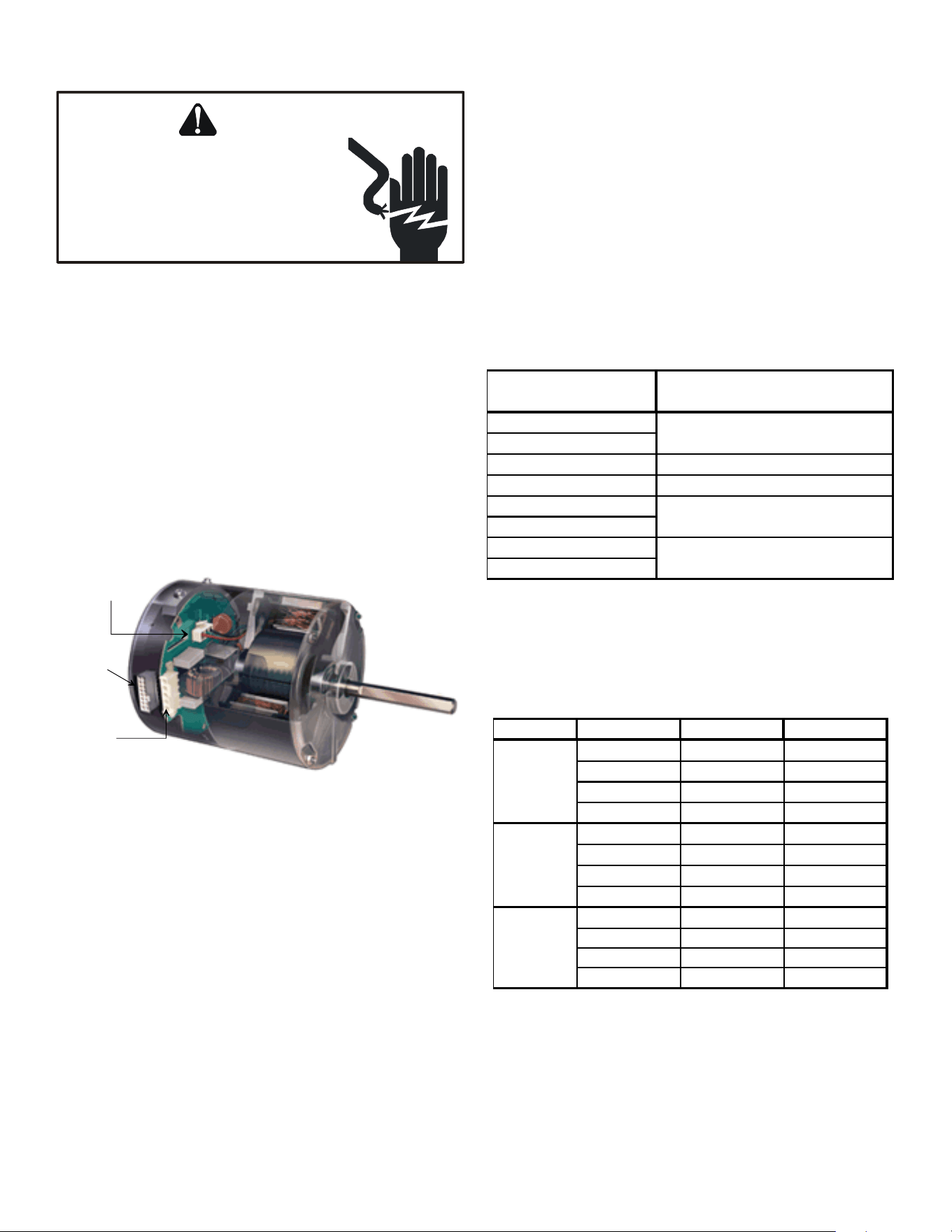
98
SERVICING
S-16C CHECKING ECM MOTOR WINDINGS
WARNING
HIGH VOLTAGE!
Disconnect ALL power before servicing
or installing. Multiple power sources
may be present. Failure to do so may
cause property damage, personal injury
or death.
1. Disconnect the 5-pin and the 16-pin connectors from the
ECM power head.
2. Remove the 2 screws securing the ECM power head and
separate it from the motor.
3. Disconnect the 3-pin motor connector from the power head
and lay it aside.
4. Using an ohmmeter, check the motor windings for connuity
to ground (pins to motor shell). If the ohmmeter indicates
connuity to ground, the motor is defecve and must be
replaced.
5. Using an ohmmeter, check the windings for connuity (pin
to pin). If no connuity is indicated, the thermal limit (over
load) device may be open. Allow motor to cool and retest.
16-pin
connector
5-pin
connector
3-pin motor
connector
S-16D ECM CFM ADJUSTMENTS MBE / AEPF
MBE MOTOR
This secon references the operaon characteriscs of the MBE/
AEPF models motor only. The ECM control board is factory
set with the dipswitch #4 in the “ON” posion and all other
dipswitches are factory set in the “OFF” posion. When MBE/
AEPF are used with 2-stage cooling units, dipswitch #4 should be
in the "OFF" posion.
For most applicaons, the sengs are to be changed according
to the electric heat size and the outdoor unit selecon.
The MBE/AEPF products use a General Electric ECMTM motor.
This motor provides many features not available on the
tradional PSC motor. These features include:
• Improved Eciency
• Constant CFM
• So Start and Stop
• Improved Humidity Control
MOTOR SPEED ADJUSTMENT
Each ECM™ blower motor has been preprogrammed for
operaon at 4 disnct airow levels when operang in Cooling/
Heat Pump mode or Electric Heat mode. These 4 disnct
levels may also be adjusted slightly lower or higher if desired.
The adjustment between levels and the trim adjustments are
made by changing the dipswitch(s) either to an “OFF” or “ON”
posion.
Dipswitch Funcons
The MBE / aepf air handler motors have an electronic control
that contains an eight (8) posion dip switch. The funcon of
these dipswitches are shown in Table 1.
Dipswitch
Number
1
2
3 N/A
4 Indoor Thermostat
5 Cooling & Heat
6 Pump CFM
7
8
Function
Electric Heat
CFM Trim Adjust
Dipswitch Functions
Table 1
CFM Delivery
Tables 2, 3, 5 and 6 show the CFM output for dipswitch
combinaons 1-2, and 5-6.
Model Switch 1 Switch 2 CFM
OFF
OFF
1,200
ON
OFF
1,000
OFF
ON
800
ON ON 600
OFF
OFF
1,600
ON
OFF
1,400
OFF
ON
1,200
ON ON 1,000
OFF
OFF
2,000
ON OFF 1,800
OFF ON 1,600
ON ON 1,200
MBE1200
MBE1600
MBE2000
Electric Heat Operation
Table 2
99
SERVICING
Model Switch 5 Switch 6 CFM
OFF
OFF
1,200
ON
OFF
1,000
OFF
ON
800
ON ON
600
OFF
OFF
1,600
ON
OFF
1,400
OFF
ON
1,200
ON ON
1,000
OFF
OFF
2,000
ON
OFF
1,800
OFF
ON
1,600
ON ON
1,200
MBE1200
MBE1600
MBE2000
Cooling/Heat Pump Operation
Table 3
Thermostat “Fan Only” Mode
During Fan Only Operaons, the CFM output is 30% of the
cooling seng.
Dipswitch Funcons
The AEPF air handler motor has an electronic control that
contains an eight (8) posion dip switch. The funcon of these
dipswitches are shown in Table 9.
Dipswitch Number Function
1
2
3 N/A
4 Indoor Thermostat
5
6
7
8
Electric Heat
Cooling & Heat Pump CFM
CFM Trim Adjust
Table 9
CFM Delivery
Tables 10-Electric Heat and 11-Cooling/Heat Pump show the
CFM output for dipswitch combinaons 1-2, and 5-6.
1
2 7 8
OFF OFF OFF OFF 1100 1210
ON OFF OFF OFF 890 935
OFF ON OFF OFF 700 770
OFF OFF OFF OFF 2050 2150
AEPF3036
ON OFF OFF OFF 1750 1835
AEPF3137
OFF ON OFF OFF 1600 1680
AEPF4260
ON ON OFF OFF 1200 1260
ON ON OFF ON 1020 1070
Model
Switch
Switch
Emergecny
(Electric)
Heat
Heat Pump
w/Backup
Heat
AEPF1830
Table 10
5 6 7 8
OFF OFF OFF OFF 2 ½ 1100
ON OFF OFF OFF 2 800
OFF ON OFF OFF 1 ½ 600
OFF OFF OFF OFF 5 1800
AEPF3036
ON OFF OFF OFF 4 1580
AEPF3137 OFF ON OFF OFF
3 ½ 1480
AEPF4260 ON ON OFF OFF
3 1200
ON ON OFF ON
2 ½ 1020
Model
Switch
Switch
Nominal
Cooling
Tonnage
CFM
AEPF183
0
Table 11
Thermostat “Fan Only Mode”
During “Fan Only Mode” operaon, the CFM output is 30% of
the cooling seng.
CFM Trim Adjust
Minor adjustments can be made through the dip switch
combinaon of 7-8. The following Table 12 shows the switch
posion for this feature.
CFM Switch 7 Switch 8
+10% ON OFF
-15% OFF ON
Humidity Control
When using a Humidistat (normally closed), cut jumper PJ6 on
the control board. The Humidistat will only aect cooling airow
by adjusng the Airow to 85%.
100
SERVICING
Symptom Fault Description(s)
Possible Causes Corrective Action
Cautions and Notes
- Motor rocks
slightly
w hen starting.
- This is normal start-up for
variable speed motor.
---- ---- ----
- No movement.
- Manual disconnect sw itch of f or
door sw itch open.
- Blow n f use or circuit breaker.
- 24 Vac w ires misw ired.
- Unseated pins in w iring
harness connectors.
- Bad motor/control module.
- Moisture present in motor or control module.
- Check 230 Vac pow er at motor.
- Check low voltage (24 Vac R to C) at motor.
- Check low voltage connections
(G, Y, W, R, C) at motor.
- Check for unseated pins in connectors
on motor harness.
- Test w ith a temporary jumper betw een R - G.
-
- Turn pow er OFF prior to repair.
Wait 5 minutes after
disconnecting pow er before
opening motor.
- Handle electronic motor/control w ith care.
- Motor rocks,
but w on't start.
- Loose motor mount.
- Blow er w heel not tight on motor shaft.
- Bad motor/control module.
- Check for loose motor mount.
- Make sure blow er w heel is tight on shaft.
- Perf orm motor/control replacement check,
ECM motors only.
- Turn pow er OFF prior to repair.
Wait 5 minutes after
disconnecting pow er before
opening motor.
- Handle electronic motor/control w ith care.
- Motor
oscillates up &
dow n w hile
being tested
off of blow er.
- It is normal for motor to
oscillate w ith
no load on shaf t.
---- ---- ----
- Varies up and dow n
or intermittent.
- Variation in 230 Vac to motor.
- Unseated pins in w iring harness
connectors.
- Erratic CFM command f rom
"BK" terminal.
- Improper thermostat connection or setting.
- Moisture present in motor/control module.
- Check line voltage for variation or "sag".
- Check low voltage connections
(G, Y, W, R, C) at
motor, unseated pins in motor
harness connectors.
- Check-out system controls - Thermostat.
- Perf orm Moisture Check.*
- Turn pow er OFF prior to repair.
- "Hunts" or "puffs" at
high CFM (speed).
- Incorrect or dirty filter(s).
- Incorrect supply or return ductw ork.
- Incorrect blow er speed setting.
- Does removing panel or filter
reduce "puffing"?
- Check/replace f ilter.
- Check/correct duct restrictions.
- Adjust to correct blow er speed setting.
- Turn pow er OFF prior to repair.
Troubleshooting Chart for GE/Regal-Beloit ECM Variable Speed Air Circulator Blower Motors
- Motor w on't
start.
- Motor starts,
but runs
erratically.
- Connectors are oriented "down" (or as recommended by equipment manufacturer). - Arrange harnesses with "drip loop" under motor.
- Is condensate drain plugged? - Check for low airflow (too much latent capacity).
- Check for undercharged condition. - Check and plug leaks in return ducts, cabinet.
*Moisture Check
Important Note: Using the wrong motor/control module voids all product warranties and may produce unexpected results.
Note: You must use the correct replacement control/motor module since they are factory programmed for specific operating modes. Even though they look alike, different modules may have completely different
functionality. The ECM variable speed motors are c
CHART CONTINUED ON NEXT PAGE
101
SERVICING
- Connectors are oriented "down" (or as recommended by equipment manufacturer). - Arrange harnesses with "drip loop" under motor.
- Is condensate drain plugged? - Check for low airflow (too much latent capacity).
- Check for undercharged condition. - Check and plug leaks in return ducts, cabinet.
*Moisture Check
Important Note: Using the wrong motor/control module voids all product warranties and may produce unexpected results.
Note: You must use the correct replacement control/motor module since they are factory programmed for specific operating modes. Even though they look alike, different modules may have completely different
functionality. The ECM variable speed motors are c
Symptom Fault Description(s) Possible Causes Corre ctive Action
Cautions and Notes
- Stays at low CFM despite
system call f or cool
or heat CFM.
- 24 Vac w ires misw ired or loose.
- "R" missing/not connected at motor.
- Fan in delay mode.
- Check low voltage (Thermostat)
w ires and connections.
- Verify f an is not in delay mode -
w ait until delay complete.
- Perform motor/control replacement
check, ECM motors only.
- Turn pow er OFF prior to repair.
Wait 5 minutes after
disconnecting pow er before
opening motor.
- Handle electronic motor/control
w ith care.
- Stays at high CFM.
- "R" missing/not connected at motor.
- Fan in delay mode.
- Is fan in delay mode? - w ait until delay time
complete.
- Perform motor/control replacement check, ECM
motors only.
- Turn pow er OFF prior to repair.
Wait 5 minutes after
disconnecting pow er before
opening motor.
- Handle electronic motor/control
w ith care.
- Blow er w on't shut of f .
- Current leakage f rom controls
into G, Y, or W.
- Check for Triac sw itched t'stat
or solid state relay.
- Turn pow er OFF prior to repair.
- Air noise.
- High static creating high blow er speed.
- Incorrect supply or return ductw ork.
- Incorrect or dirty filter(s).
- Incorrect blow er speed setting.
- Check/replace f ilter.
- Check/correct duct restrictions.
- Adjust to correct blow er speed setting.
- Turn pow er OFF prior to repair.
- Noisy blow er or cabinet.
- Loose blow er housing, panels, etc.
- High static creating high blow er
speed.
- Air leaks in ductw ork, cabinets,
or panels.
- Check for loose blow er housing,
panels, etc.
- Check for air w histling thru seams in
ducts, cabinets or panels.
- Check for cabinet/duct deformation.
- Turn pow er OFF prior to repair.
- "Hunts" or "puffs" at
high CFM (speed).
- High static creating high blow er speed.
- Incorrect or dirty filter(s).
- Incorrect supply or return ductw ork.
- Incorrect blow er speed setting.
- Does removing panel or filter
reduce "puffing"?
- Check/replace f ilter.
- Check/correct duct restrictions.
- Adjust to correct blow er speed setting.
- Turn pow er OFF prior to repair.
- Evidence of
Moisture.
- Motor failure or
malfunction has
occurred and moisture
is present.
- Moisture in motor/control module.
- Replace motor and perf orm
Moisture Check.*
- Turn pow er OFF prior to repair.
Wait 5 minutes after
disconnecting pow er before
opening motor.
- Handle electronic motor/control
w ith care.
- Excessive
noise.
Troubleshooting Chart for GE/Regal-Beloit ECM Variable Speed Air Circulator Blower Motors
- Motor starts,
but runs
erratically.
CHART CONTINUED FROM PREVIOUS PAGE.
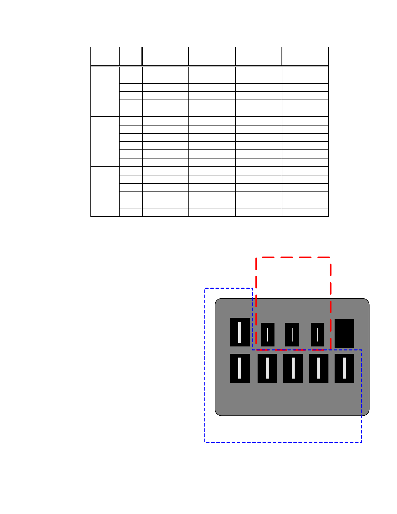
102
SERVICING
S-16E BLOWER PERFORMANCE DATA
S-16F CHECKING HIGH EFFICIENCY MOTORS
The motor is a one piece, fully encapsulated, 3 phase brushless
DC (single phase AC input) motor with ball bearing construcon.
1. Using a voltmeter, check for 230 volts to the motor connec-
ons L and N. If 230 volts is present, proceed to step 2. If
230 volts is not present, check the line voltage circuit to the
motor.
2. Using a voltmeter, check for 24 volts from terminal C to
either terminal 1, 2, 3, 4, or 5, depending on which tap is
being used, at the motor. If voltage present, proceed tostep
3. If no voltage, check 24 volt circuit to motor.
3. If voltage was present in steps 1 and 2, the motor has failed
and will need to be replaced.
NOTE: When replacing motor, ensure the belly band is between
the vents on the motor and the wiring has the proper drip loop
to prevent condensate from entering the motor.
SPEED STATIC
MBR800**-*
SCFM
MBR1200**-*
SCFM
MBR1600**-*
SCFM
MBR2000**-*
SCFM
0.1 1,240 1,500 1,800 2,160
0.2 1,170 1,460 1,740 2,080
0.3 1,120 1,360 1,680 1,990
0.4 1,060 1,280 1,610 1,890
0.5 980 1,200 1,520 1,790
0.6 900 1,110 1,430 1,690
0.1 900 1,380 1,540 1,730
0.2 850 1,320 1,490 1,670
0.3 790 1,270 1,450 1,590
0.4 740 1,200 1,400 1,520
0.5 680 1,140 13,560 1,420
0.6 605 1,040 1,280 1,320
0.1 650 1,170 1,130 1,520
0.2 590 1,130 1,100 1,450
0.3 540 1,080 1,070 1,360
0.4 500 1,020 1,030 1,290
0.5 430 950 990 1,200
0.6 330 830 930 1,090
HIGH
MEDIUM
LOW
C
L G N
1 2 3
4
5
High Voltage
Connections
3/16"
Low Voltage Connections
1/4”
MOTOR CONNECTIONS
NOTE: External stac is for blower @ 230 Volts. It does not include Coil, Air Filter or Electric Heaters.
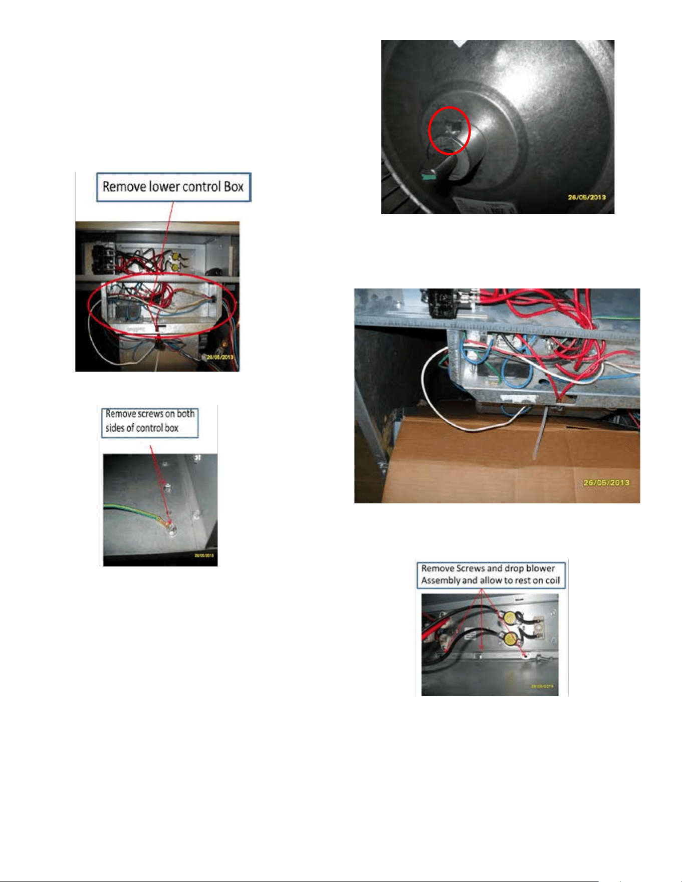
103
SERVICING
S-16G EEM BLOWER REPLACEMENT
For AWUF19-25, AWUF31-32, and AWUF37 Air Handlers.
1. Disconnect power at main electrical panel.
2. Remove front access panel.
3. Remove the two screws on each side holding the lower
control box and move out of the way to give access to the
blower assembly
5. Loosen or remove set screw on blower wheel hub and en-
sure the wheel slides freely on the sha of the motor.
6. Install cardboard or rug over coil to protect ns from dam-
age.
7. Remove the three 3/8” screws holding the blower in place.
8. Lower blower onto coil.
9. Slide blower assembly all the way to the le side of cabinet.
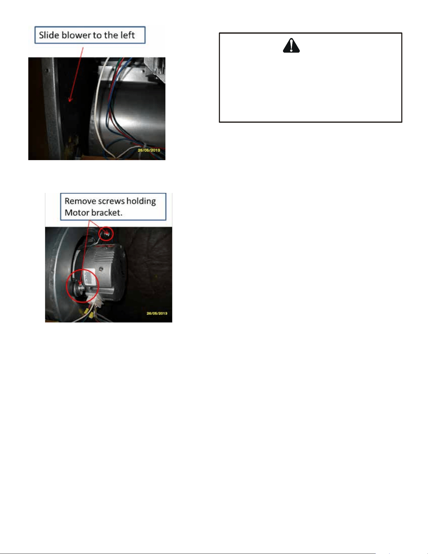
104
SERVICING
10.Remove the bolts holding the motor bracket to the
blower and slide out of blower shell.
11.Replace the motor and reinstall blower and control box.
12.Reconnect power and test operaon.
S-17 CHECKING COMPRESSOR
WARNING
Hermetic compressor electrical terminal venting can
be dangerous. When insulating material which
supports a hermetic compressor or electrical terminal
suddenly disintegrates due to physical abuse or as a
result of an electrical short between the terminal and
the compressor housing, the terminal may be
expelled, venting the vapor and liquid contents of the
compressor housing and system.
If the compressor terminal PROTECTIVE COVER and gasket
(if required) are not properly in place and secured, there is a
remote possibility if a terminal vents, that the vaporous and
liquid discharge can be ignited, spoung ames several feet,
causing potenally severe or fatal injury to anyone in its path.
This discharge can be ignited external to the compressor if
the terminal cover is not properly in place and if the discharge
impinges on a sucient heat source.
Ignion of the discharge can also occur at the venng terminal
or inside the compressor, if there is sucient contaminant air
present in the system and an electrical arc occurs as the terminal
vents.
Ignion cannot occur at the venng terminal without the
presence of contaminant air, and cannot occur externally
from the venng terminal without the presence of an external
ignion source.
Therefore, proper evacuaon of a hermec system is essenal
at the me of manufacture and during servicing.
To reduce the possibility of external ignion, all open ame,
electrical power, and other heat sources should be exnguished
or turned o prior to servicing a system.
S-17A Resistance Test
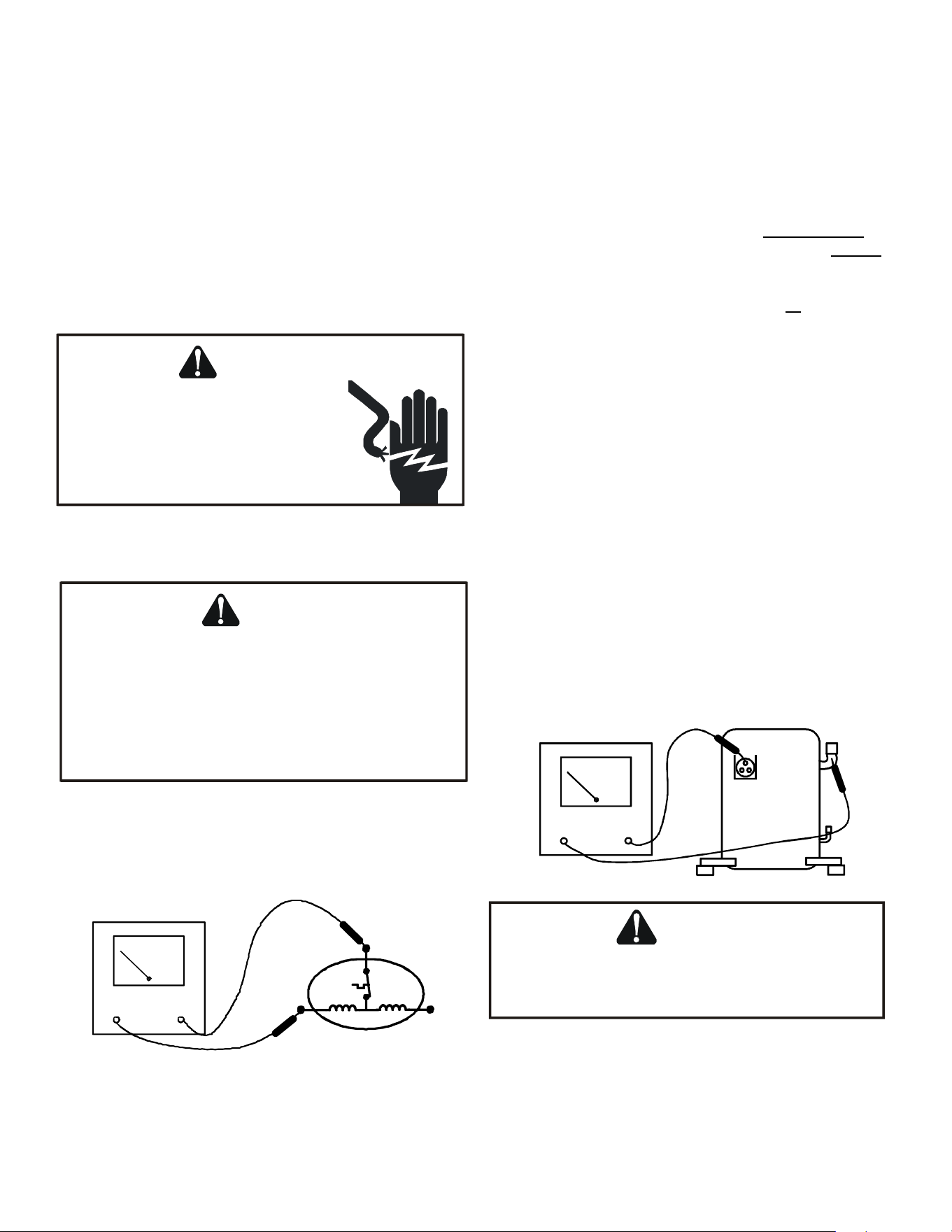
105
SERVICING
Each compressor is equipped with an internal overload.
The line break internal overload senses both motor amperage
and winding temperature. High motor temperature or
amperage heats the disc causing it to open, breaking the
common circuit within the compressor on single phase units.
Heat generated within the compressor shell, usually due to
recycling of the motor, high amperage or insucient gas to cool
the motor, is slow to dissipate. Allow at least three to four hours
for it to cool and reset, then retest.
Fuse, circuit breaker, ground fault protecve device, etc. has not
tripped -
WARNING
HIGH VOLTAGE!
Disconnect ALL power before servicing
or installing. Multiple power sources
may be present. Failure to do so may
cause property damage, personal injury
or death.
1. Remove the leads from the compressor terminals.
WARNING
Hermetic compressor electrical terminal venting can
be dangerous. When insulating material which
supports a hermetic compressor or electrical terminal
suddenly disintegrates due to physical abuse or as a
result of an electrical short between the terminal and
the compressor housing, the terminal may be
expelled, venting the vapor and liquid contents of the
compressor housing and system.
2. Using an ohmmeter, test connuity between terminals S-R,
C-R, and C-S, on single phase units or terminals T2, T2 and
T3, on 3 phase units.
S
R
C
COMP
OHMMETER
TESTING COMPRESSOR WINDINGS
If either winding does not test connuous, replace the
compressor.
NOTE: If an open compressor is indicated, allow ample me for
the internal overload to reset before replacing compressor.
S-17B Ground Test
If fuse, circuit breaker, ground fault protecve device, etc., has
tripped, this is a strong indicaon that an electrical problem
exists and must be found and corrected. The circuit protecve
device rang must be checked, and its maximum rang should
coincide with that marked on the equipment nameplate.
With the terminal protecve cover in place, it is acceptable to
replace the fuse or reset the circuit breaker ONE TIME ONLY to
see if it was just a nuisance opening. If it opens again, DO NOT
connue to reset.
Disconnect all power to unit, making sure that all power legs
are open.
1. DO NOT remove protecve terminal cover. Disconnect the
three leads going to the compressor terminals at the nearest
point to the compressor.
2. Idenfy the leads and using an ohmmeter on the R x 10,000
scale or the highest resistance scale on your ohmmeter
check the resistance between each of the three leads sepa-
rately to ground (such as an unpainted tube on the compres-
sor).
3. If a ground is indicated, then carefully remove the compres-
sor terminal protecve cover and inspect for loose leads or
insulaon breaks in the lead wires.
4. If no visual problems indicated, carefully remove the leads at
the compressor terminals.
5. Carefully retest for ground, directly between compressor
terminals and ground.
6. If ground is indicated, replace the compressor. The resistance
reading should be innity. If there is any reading on meter,
there is some connuity to ground and compressor should
be considered defecve.
OHMMETER
WARNING
Damage can occur to the glass embedded terminals if
the leads are not properly removed. This can result in
terminal and hot oil discharging.
S-17C Unloader Test Procedure
A nominal 24-volt direct current coil acvates the internal
unloader solenoid. The input control circuit voltage must be 18
to 28 volt ac. The coil power requirement is 20 VA. The external
electrical connecon is made with a molded plug assembly. This
plug contains a full wave recer to supply direct current to the
106
SERVICING
unloader coil.
UNLOADER SOLENOID
(Molded Plug)
Unloader Test Procedure
If it is suspected that the unloader is not working, the following
methods may be used to verify operaon.
1. Operate the system and measure compressor current. Cycle
the unloader ON and OFF at 10 second intervals. The com-
pressor amperage should go up or down at least 25 percent.
2. If step one does not give the expected results, shut unit o.
Apply 18 to 28 volt ac to the unloader molded plug leads and
listen for a click as the solenoid pulls in. Remove power and
listen for another click as the unloader returns to its original
posion.
3. If clicks can’t be heard, shut o power and remove the con-
trol circuit molded plug from the compressor and measure
the unloader coil resistance. The resistance should be 32 to
60 ohms, depending on compressor temperature.
4. Next check the molded plug.
A.Voltage check: Apply control voltage to the plug wires (18
to 28 volt ac). The measured dc voltage at the female con-
nectors in the plug should be around 15 to 27 vdc.
B.Resistance check: Measure the resistance from the end of
one molded plug lead to either of the two female connectors
in the plug. One of the connectors should read close to zero
ohms while the other should read innity. Repeat with other
wire. The same female connector as before should read
zero while the other connector again reads innity. Reverse
polarity on the ohmmeter leads and repeat. The female con-
nector that read innity previously should now read close to
zero ohms.
C.Replace plug if either of these test methods doesn’t show
the desired results.
S-17D OPERATION TEST
If the voltage, capacitor, overload and motor winding test fail to
show the cause for failure:
WARNING
HIGH VOLTAGE!
Disconnect ALL power before servicing
or installing. Multiple power sources
may be present. Failure to do so may
cause property damage, personal injury
or death.
1. Remove unit wiring from disconnect switch and wire a test
cord to the disconnect switch.
NOTE: The wire size of the test cord must equal the line wire
size and the fuse must be of the proper size and type.
2. With the protecve terminal cover in place, use the three
leads to the compressor terminals that were disconnected
at the nearest point to the compressor and connect the
common, start and run clips to the respecve leads.
3. Connect good capacitors of the right MFD and voltage rang
into the circuit as shown.
4. With power ON, close the switch.
Line Voltage now present.
WARNING
A. If the compressor starts and connues to run, the cause for
failure is somewhere else in the system.
B. If the compressor fails to start - replace.
COPELAND COMPRESSOR
03 A 12345 L
YEAR
MONTH
SERIAL
NUMBER
PLANT
S-17E CHECKING 3-PHASE SCROLL COMPRESSOR
ROTATION
Verify the proper rotaon of Copeland scroll compressors as
follows:
NOTE: The compressor may run backwards (noisy operaon) for
1 or 2 seconds at shutdown. This is normal and does not harm
the compressor.
1. Install gauges and verify that the sucon pressure drops
while the discharge pressure increases.
2. Listen for normal compressor sound levels. Reverse rotaon
results in elevated or unusual sound levels.
107
SERVICING
3. Reverse rotaon will result in substanally reduced amp
draw from tabulated values.
To correct improper rotaon, switch any two power supply leads
at the outdoor unit contactor.
The 3-phase scroll compressors are direcon of rotaon
sensive. They will rotate in either direcon depending on the
phasing of the power. There is no negave impact on durability
caused by operang 3-phase compressors in reversed rotaon.
The compressor’s internal protector will trip, de-energizing the
compressor. Connued operaon of 3-phase scroll compressors
with the rotaon reversed will contribute to compressor failure.
All 3-phase scroll compressors should be checked for correct
phase rotaon.
S-18 TESTING CRANKCASE HEATER (OPTIONAL ITEM)
The crankcase heater must be energized a minimum of four (4)
hours before the condensing unit is operated.
Crankcase heaters are used to prevent migraon or
accumulaon of refrigerant in the compressor crankcase during
the o cycles and prevents liquid slugging or oil pumping on
start up.
A crankcase heater will not prevent compressor damage due to a
oodback or over charge condion.
Disconnect ALL power before servicing.
WARNING
1. Disconnect the heater lead in wires.
2. Using an ohmmeter, check heater connuity - should test
connuous. If not, replace.
NOTE: The posive temperature coecient crankcase heater is
a 40 wa 265 voltage heater. The cool resistance of the heater
will be approximately 1800 ohms. The resistance will become
greater as the temperature of the compressor shell increases.
S-21 CHECKING REVERSING VALVE AND SOLENOID
Occasionally the reversing valve may sck in the heang or
cooling posion or in the mid-posion.
When stuck in the mid-posion, part of the discharge gas from
the compressor is directed back to the sucon side, resulng in
excessively high sucon pressure. An increase in the sucon line
temperature through the reversing valve can also be measured.
Check operaon of the valve by starng the system and
switching the operaon from COOLING to HEATING cycle.
If the valve fails to change its posion, test the voltage (24V)
at the valve coil terminals, while the system is on the COOLING
cycle.
If no voltage is registered at the coil terminals, check the
operaon of the thermostat and the connuity of the
connecng wiring from the “O” terminal of the thermostat to
the unit.
S-24 TESTING DEFROST CONTROL
To check the defrost control for proper sequencing, proceed as
follows: With power ON; unit not running.
1. Jumper defrost thermostat by placing a jumper wire across
the terminals “DFT” and “R”/”R-DFT” at defrost control
board.
2. Connect jumper across test pins on defrost control board.
3. Set thermostat to call for heang. System should go into
defrost within 21 seconds.
4. Immediately remove jumper from test pins.
5. Using VOM check for voltage across terminals “C & O”. Me-
ter should read 24 volts.
6. Using VOM check for voltage across fan terminals DF1 and
DF2 on the board. You should read line voltage (208-230
VAC) indicang the relay is open in the defrost mode.
7. Using VOM check for voltage across “W”/”W2” & “C” termi-
nals on the board. You should read 24 volts.
8. If not as above, replace control board.
9. Set thermostat to o posion and disconnect power before
removing any jumpers or wires.
NOTE: Remove jumper across defrost thermostat before
returning system to service.
S-25 TESTING DEFROST THERMOSTAT
1. Install a thermocouple type temperature test lead on the
tube adjacent to the defrost control. Insulate the lead point
of contact.
2. Check the temperature at which the control closes its
contacts by lowering the temperature of the control. Part #
0130M00009P which is used on 2 and 2.5 ton units should
close at 34°F ± 5°F. Part # 0130M00001P or B1370803 which
is used on 3 thru 5 ton units should close at 31°F ± 3°F.
3. Check the temperature at which the control closes its
contacts by lowering the temperature of the control. Part #
0130M00085, which is used onunits with 5 mm coils, should
close at 30°F ± 5°F.
4. Check the temperature at which the control opens its
contacts by raising the temperature of the control. Part
#0130M00009P which is used on 2 and 2.5 ton units should
open at 60°F ± 5°F. Part # 0130M00001P or B1370803 which
is used on 3 thru 5 ton units should open at 75°F ± 6°F.
5. Check the temperature at which the control opens its
contacts by raising the temperature of the control. Part #
0130M00085, which is used on units with 5 mm coils, should
open at 60°F ± 5°F.
6. If not as above, replace control.
SEQUENCE OF OPERATION
Refer to the installaon instrucons and wiring diagrams
provided with the MBR/AR*F for specic wiring connecons
and system conguraon.
MBR/AR*F WITH SINGLE STAGE CONDENSERS
1.0 Cooling Operaon
1.1 On a demand for cooling, the room thermostat energizes

108
SERVICING
“G” and “Y” and 24Vac is supplied to “Y” at the condensing
unit and the “G” terminal on the EBTDR board.
1.2 The compressor and condenser fan are turned on and aer
a 7 second on delay, the relay on the EBTDR board is ener-
gized and the blower motor starts.
1.3 When the cooling demand “Y” is sased, the room ther-
mostat removes the 24Vac from “G” and “Y”.
1.4 The compressor and condenser fan are turned o and aer
a 65 second delay o, the relay on the EBTDR board is de-en-
ergized and the blower is turned o.
2.0 Heang Operaon
2.1 On a demand for heat, the room thermostat energizes
“W1” and 24Vac is supplied to heat sequencer, HR1, on the
heater assembly.
2.2 The contacts M1 and M2 will close within 10 to 20 sec-
onds and turn on heater element #1. The normally closed
contacts on the EBTDR are also connected to terminal M1.
When M1 and M2 close, the blower motor will be energized
thru the normally closed contacts on the EBTDR board. At
the same me, if the heater assembly contains a second
heater element, HR1 will contain a second set of contacts,
M3 and M4, which will close to turn on heater element #2.
NOTE: If more than two heater elements are on the heater
assembly, it will contain a second heat sequencer, HR2,which
will control the 3rd and 4th heater elements if available. If the
rst stage heat demand, “W1” cannot be sased by the heat
pump, the temperature indoors will connue to drop. The room
thermostat will then energize “W2” and 24Vac will be supplied
to HR2 on the heater assembly. When the “W2” demand is
sased, the room thermostat will remove the 24Vac from HR2.
The contacts on HR2 will open between 30 to 70 seconds and
heater elements #3 and #4 will be turned o. On most digital/
electronic thermostats, “W2” will remain energized unl the
rst stage demand “W1” is sased and then the “W1” and
“W2” demands will be removed.
2.3 When the “W1” heat demand is sased, the room ther-
mostat will remove the 24Vac from HR1. Both set of con-
tacts on the relay opens within 30 to 70 seconds and turn o
the heater element(s) and the blower motor.
MBR/AR*F WITH SINGLE STAGE HEAT PUMPS
3.0 Cooling Operaon
On heat pump units, when the room thermostat set to the
cooling mode, 24Vac is supplied to “O” which energizes the
reversing valve. As long as the thermostat is set for cooling, the
reversing valve will be in the energized posion for cooling.
3.1 On a demand for cooling, the room thermostat energizes
“G” and “Y” and 24Vac is supplied to “Y” at the heat pump
and the “G” terminal on the EBTDR board.
3.2 The heat pump turned on in the cooling mode and aer a 7
second on delay, the relay on the EBTDR board is energized
and the blower motor starts.
3.3 When the cooling demand is sased, the room thermostat
removes the 24Vac from “G” and “Y”.
3.4 The heat pump is turned o and aer a 65 second delay o,
the relay on the EBTDR board is de-energized and the blower
motor is turned o.
4.0 Heang Operaon
On heat pump units, when the room thermostat set to the
heang mode, the reversing valve is not energized. As long
as the thermostat is set for heang, the reversing valve will
be in the de-energized posion for heang except during a
defrost cycle. Some installaons may use one or more outdoor
thermostats to restrict the amount of electric heat that is
available above a preset ambient temperature. Use of oponal
controls such as these can change the operaon of the electric
heaters during the heang mode. This sequenceof operaon
does not cover those applicaons.
4.1 On a demand for rst stage heat with heat pump units, the
room thermostat energizes “G” and “Y” and 24Vac is sup-
plied to “Y” at the heat pump unit and the “G” terminal on
the EBTDR board. The heat pump is turned on in the heang
mode and the blower motor starts aer a 7 second on delay.
4.2 If the rst stage heat demand cannot be sased by the
heat pump, the temperature indoors will connue to drop.
The room thermostat will then energize terminal “W2’ for
second stage heat and 24Vac will be supplied to heat se-
quencer HR1 on the heater assembly.
4.3 HR1 contacts M1 and M2 will close will close within 10 to
20 seconds and turn on heater element #1. At the same
me, if the heater assembly contains a second heater ele-
ment, HR1 will contain a second set of contacts, M3 and M4,
which will close and turn on heater element #2. The blower
motor is already on as a result of terminal “G” on the EBTDR
board being energized for the rst stage heat demand.
NOTE: If more than two heater elements are on the heater
assembly, it will contain a second heat sequencer, HR2, which
will control the 3rd and 4th heater elements if available. If the
second stage heat demand, “W2” cannot be sased by the heat
pump, the temperature indoors will connue to drop. The room
thermostat will then energize “W3” and 24Vac will be supplied
to HR2 on the heater assembly. When the “W3” demand is
sased, the room thermostat will remove the 24Vac from HR2.
The contacts on HR2 will open between 30 to 70 seconds and
heater elements #3 and #4 will be turned o. On most digital/
electronic thermostats, “W3” will remain energized unl the
rst stage heat demand “Y” is sased and then the “G”, “Y”,
“W2” and “W3” demands will be removed.
4.4 As the temperature indoors increase, it will reach a point
where the second stage heat demand, “W2”, is sased.
When this happens, the room thermostat will remove the
24Vac from the coil of HR1. The contacts on HR1 will open
between 30 to 70 seconds and turn o both heater ele-
ment(s). The heat pump remains on along with the blower
motor because the “Y” demand for rst stage heat will sll
be present.
4.5 When the rst stage heat demand “Y” is sased, the room
thermostat will remove the 24Vac from “G” and “Y”. The

109
SERVICING
heat pump is turned o and the blower motor turns o aer
a 65 second o delay.
5.0 Defrost Operaon
On heat pump units, when the room thermostat is set to the
heang mode, the reversing valve is not energized. As long as
the thermostat is set for heang, the reversing valve will be in
the de-energized posion for heang except during a defrost
cycle.
5.1 The heat pump will be on and operang in the heang
mode as described the Heang Operaon in secon 4.
5.2 The defrost control in the heat pump unit checks to seeif a
defrost is needed every 30, 60 or 90 minutes of heat pump
operaon depending on the selectable seng by monitoring
the state of the defrost thermostat aached to the outdoor
coil.
5.3 If the temperature of the outdoor coil is low enough to
cause the defrost thermostat to be closed when the defrost
board checks it, the board will iniate a defrost cycle.
5.4 When a defrost cycle is iniated, the contacts of the HVDR
relay on the defrost board open and turns o the outdoor
fan. The contacts of the LVDR relay on the defrost board
closes and supplies 24Vac to “O” and “W2”. The reversing
valve is energized and the contactson HR1 close and turns
on the electric heater(s). The unit will connue to run in this
mode unl the defrost cycle is completed.
a.For models with defrost control PCBDM133 or PCBDM160,
a 30 second compressor delay at defrost iniaon/termina-
on is oponal. As shipped from the factory, the control is
set for the delay (“DLY”), which will turn the compressor o
for 30 seconds while the reversing valve shis to/from the
cooling mode posion. To bypass the delay, which typically
reduces sound levels during defrost mode, change the pin
sengs from “DLY” to “NORM”.
5.5 When the temperature of the outdoor coil rises high
enough to causes the defrost thermostat to open, the
defrost cycle will be terminated. If at the end of the pro-
grammed 10 minute override me the defrost thermostat
is sll closed, the defrost board will automacally terminate
the defrost cycle.
5.6 When the defrost cycle is terminated, the contacts of the
HVDR relay will close to start the outdoor fan and the con-
tacts of the LVDR relay will open and turn o the reversing
valve and electric heater(s). The unit will now be back in a
normal heang mode with a heat pump demand for heang
as described in the Heang Operaon in secon 4. See
secon 5.4a.
MBE/AEPF WITH GSX, SSX, ASX, DSX, VSX
MBE ELECTRONIC BLOWER TIME DELAY RELAY
AEPF AIR HANDLER
SEQUENCE OF OPERATION
This document covers the basic sequence of operaon for a
typical applicaon with a mercury bulb thermostat. When a
digital/electronic thermostat is used, the on/o staging of the
auxiliary heat will vary. Refer to the installaon instrucons and
wiring diagrams provided with the MBE/AEPF for specic wiring
connecons, dip switch sengs and system conguraon.
MBE/AEPF WITH SINGLE STAGE GSX, ASX, SSX, and VSX CONDENSERS
When used with a single stage GSX, SSX, ASX, and VSX
condensers, dip switch #4 must be set to the on posion on the
VSTB inside the MBE/AEPF. The “Y” output from the indoor
thermostat must
be connected to the yellow wire labeled “Y/Y2” inside the wire
bundle marked “Thermostat” and the yellow wire labeled “Y/
Y2” inside the wire bundle marked “Outdoor Unit” must be
connected to “Y” at the condenser. The orange jumper wire
from terminal “Y1” to terminal“O” on the VSTB inside the MBE/
AEPF must remain connected.
1.0 Cooling Operaon
1.1 On a demand for cooling, the room thermostat energizes
“G” and “Y” and 24Vac is supplied to “G” and “Y/Y2” of the
MBE/AEPF unit. The VSTB inside the MBE/AEPF will turnon
the blower motor and the motor will ramp up to the speed
programmed in the motor based on the sengs for dip
switch 5 and 6. The VSTB will supply 24Vac to “Y” at the
condenser and the compressor and condenser are turned
on.
1.2 When the cooling demand is sased, the room thermo-
stat removes the 24Vac from “G” and “Y”. The MBE/AEPF
removes the 24Vac from “Y’ at the condenser and the com-
pressor and condenser fan are turned o. The blower motor
will ramp down to a complete stop based on the me and
rate programmed in the motor.
2.0 Heang Operaon
2.1 On a demand for heat, the room thermostat energizes
“W1” and 24Vac is supplied to terminal “E/W1” of the VSTB
inside the MBE/AEPF unit. The VSTB will turn on the blower
motor and the motor will ramp up to the speed programmed
in the motor based on the sengs for dip switch 1 and 2.
The VSTB will supply 24Vac to heat sequencer HR1 on the
electric heater assembly.
2.2 HR1 contacts M1 and M2 will close within 10 to 20 seconds
and turn on heater element #1. At the same me, if the
heater assembly contains a second heater element, HR1
will contain a second set of contacts, M3 and M4, which will
close and turn on heater element #2.
NOTE: If more than two heater elements are on the heater
assembly, it will contain a second heat sequencer, HR2, which
will control the 3rd and 4th heater elements if available. For
the 3rd and 4th heater elements to operate on a second stage
heat demand, the PJ4 jumper on the VSTB inside the MBE/
AEPF must be cut. With the PJ4 jumper cut, the VSTB will run
the blower motor on low speed on a “W1” only demand. If
the rst stage heat demand, “W1” cannot be sased by the
heat pump, the temperature indoors will connue to drop. The
room thermostat will then energize “W2” and 24Vac will be
supplied to HR2 on the heater assembly and the blower motor
will change to high speed. When the “W2” demand is sased,
the room thermostat will remove the 24Vac from “W2” and the
VSTB will remove the 24Vac from HR2. The contacts on HR2
will open between 30 to 70 seconds and heater elements #3
and #4 will be turned o and the blower motor will change to
low speed. On most digital/electronic thermostats, “W2” will
remain energized unl the rst stage demand “W1” is sased
and then the “W1” and “W2” demands will be removed.
2.3 When the “W1” heat demand is sased, the room ther-

110
SERVICING
mostat will remove the 24Vac from “E/W1” and the VSTB
rebetween 30 to 70 seconds and turn o the heater ele-
ment(s) and the blower motor ramps down to a complete
stop.
MBE/AEPF WITH SINGLE STAGE
GSZ, SSZ, ASZ, and VSZ HEAT PUMPS
When used with a single stage GSZ, SSZ, ASZ, or VSZ heat
pumps, dip switch #4 must be set to the ON posion on
the VSTB inside the MBE. The “Y” output from the indoor
thermostat must be connected to the yellow wire labeled “Y/
Y2” inside the wire bundle marked “Thermostat” and the yellow
wire labeled “Y/Y2” inside the wire bundle marked “Outdoor
Unit” must be connected to “Y” at the heat pump. The orange
jumper wire from terminal “Y1” to terminal “O” on the VSTB
inside the MBE/AEPF must be removed.
3.0 COOLING OPERATION
On heat pump units, when the room thermostat is set to the
cooling mode, 24Vac is supplied to terminal “O” of the VSTB
inside the MBE/AEPF unit. The VSTB will supply 24Vac to “O” at
the heat pump to energize the reversing valve. As long as the
thermostat is set for cooling, the reversing valve will be in the
energized posion for cooling.
3.1 On a demand for cooling, the room thermostat energizes
“G” and “Y” and 24Vac is supplied to terminals “G” and “Y/
Y2” of the MBE/AEPF unit. The VSTB will turn on the blower
motor and the motor will ramp up to the speed programmed
in the motor based on the sengs of dip switch 5 and 6.
The VSTB will supply 24Vac to “Y” at the heat pump.
3.2 The heat pump is turned on in the cooling mode.
3.3 When the cooling demand is sased, the room thermostat
removes the 24Vac from “G” and “Y/Y2” of the MBE/AEPF
and the VSTB removes the 24Vac from “Y” at the heat pump.
The heat pump is turned o and the blower motor will ramp
down to a complete stop based on the me and rate pro-
grammed in the motor.
4.0 Heang Operaon
On heat pump units, when the room thermostat is set to the
heang mode, the reversing valve is not energized. As long
as the thermostat is set for heang, the reversing valve will
be in the de-energized posion for heang except during a
defrost cycle. Some installaons may use one or more outdoor
thermostats to restrict the amount of electric heat that is
available above a preset ambient temperature. Use of oponal
controls such as these can change the operaon of the electric
heaters during the heang mode. This sequence of operaon
does not cover those applicaons.
4.1 On a demand for rst stage heat with heat pump units,
the room thermostat energizes “Y” and “G” and 24Vac is
supplied to “G” and “Y/Y2” of the MBE/AEPF. The VSTB will
turn on the blower motor and the motor will ramp up to the
speed programmed in the motor based on the sengs of
dip switch 1 and 2. The VSTB will supply 24Vac to “Y” at the
heat pump and the heat pump is turned on in the heang
mode.
4.2 If the rst stage heat demand cannot be sased by the
heat pump, the temperature indoors will connue to drop.
The room thermostat will then energize terminal “W2” for
second stage heat and 24Vac will be supplied to “E/W1” of
the MBE/
AEPF. The VSTB will supply 24Vac to heat sequencer, HR1, on
the electric heater assembly.
4.3 HR1 contacts M1 and M2 will close within 10 to 20 seconds
and turn on heater element #1. At the same me, if the
heater assembly contains a second heater element, HR1
will contain a second set of contacts, M3 and M4, which will
close to turn on heater element #2.
NOTE: If more than two heater elements are on the heater
assembly, it will contain a second heat sequencer, HR2, which
will control the 3rd and 4th heater elements if available. For the
3rd and 4th heater elements to operate on a third stage heat
demand, the PJ4 jumper on the VSTB inside the MBE/AEPF
must be cut. If the second stage heat demand, “W2”, cannot
be sased by the heat pump, the temperature indoors will
connue to drop. The room thermostat will then energize “W3”
and 24Vac will be supplied to “W/W2” of the MBE/AEPF. The
VSTB will supply 24Vac to HR2 on the electric heater assembly.
When the “W3” demand is sased, the room thermostat
will remove the 24Vac from “W/W2” of the MBE/AEPF. The
contacts on HR2 will open between 30 to 70 seconds and
heater elements #3 and #4 will be turned o. On most digital/
electronic thermostats, “W3” will remain energized unl the
rst stage demand “Y” is sased and then the “G”, “Y”, “W2”
and “W3” demands will be removed.
4.4 As the temperature indoors increase, it will reach a point
where the second stage heat demand, “W2”, is sased.
When this happens, the room thermostat will remove the
24Vac from “E/W1” of the MBE/AEPF. The contacts on HR1
will open between 30 to 70 seconds and turn o both heater
element(s). The heat pump remains on along with the
blower motor because the “Y” demand for rst stage heat
will sll be present.
4.5 When the rst stage heat demand “Y” is sased, the room
thermostat will remove the 24Vac from “G” and “Y/Y2” of
the MBE/AEPF. The VSTB removes the 24Vac from “Y” at
the heat pump and the heat pump is turned o. The blower
motor will ramp down to a complete stop based on the me
and rate programmed in the motor control.
5.0 DEFROST OPERATION
On heat pump units, when the room thermostat is set to the
heang mode, the reversing valve is not energized. As long as
the thermostat is set for heang, the reversing valve will be in
the de-energized posion for heang except during a defrost
cycle.
5.1 The heat pump will be on and operang in the heang
mode as described the Heang Operaon in secon 4.
5.2 The defrost control in the heat pump unit checks to see if a
defrost is needed every 30, 60 or 90 minutes of heat pump
operaon depending on the selectable seng by monitoring
the state of the defrost thermostat aached to the outdoor
coil.
5.3 If the temperature of the outdoor coil is low enough to
cause the defrost thermostat to be closed when the defrost
board checks it, the board will iniate a defrost cycle.
5.4 When a defrost cycle is iniated, the contacts of the HVDR

111
SERVICING
relay on the defrost board open and turns o the outdoor
fan.
The contacts of the LVDR relay on the defrost board closes
and supplies 24Vac to “O” and “W2”. The reversing valve is
energized and the contacts on HR1 close and turns on the
electric heater(s). The unit will connue to run in this mode
unl the defrost cycle is completed.
a. For models with defrost control PCBDM133 or PCBDM160,
a 30 second compressor delay at defrost iniaon/termina-
on is oponal. As shipped from the factory, the control is
set for the delay (“DLY”), which will turn the compressor o
for 30 seconds while the reversing valve shis to/from the
cooling mode posion. To bypass the delay, which typically
reduces sound levels during defrost mode, change the pin
sengs from “DLY” to “NORM”.
5.5 When the temperature of the outdoor coil rises high
enough to causes the defrost thermostat to open, the
defrost cycle will be terminated. If at the end of the pro-
grammed 10 minute override me the defrost thermostat
is sll closed, the defrost board will automacally terminate
the defrost cycle.
5.6 When the defrost cycle is terminated, the contacts of
the HVDR relay on the defrost board will close to start the
outdoor fan and the contacts of the LVDR relay will open
and turn o the reversing valve and electric heater(s). The
unit will now be back in a normal heang mode with a heat
pump demand for heang as described in the Heang Oper-
aon in secon 4. See secon 5.4a.
MBE/AEPF WITH TWO STAGE ASX & DSX CONDENSERS
1.0 COOLING OPERATION
When used with the ASX & DSX two stage condensers, dip
switch #4 must be set to the OFF posion on the VSTB inside
the MBE/AEPF. The “Y1” output from the indoor thermostat
must be connected to the purple wire labeled “Ylow/Y1” inside
the wire bundle marked “Thermostat” and the purple wire
labeled “Ylow/Y1” inside the wire bundle marked “Outdoor
Unit” must be connected to “Ylow/Y1” at the condenser. The
“Y2” output from the indoor thermostat must be connected to
the yellow wire labeled “Y/Y2” inside the wire bundle marked
“Thermostat” and the yellow wire labeled “Y/Y2” inside the wire
bundle marked “Outdoor Unit” must be connected to “Y/Y2” at
the condenser. The orange jumper wire from terminal “Y1” to
terminal “O” on the VSTB inside the MBE/AEPF must remain
connected.
1.1 On a demand for cooling, the room thermostat energizes
“G” and “Y1” and 24Vac is supplied to “G” and “Ylow/Y1” of
the MBE/AEPF unit. The VSTB inside the MBE/AEPF will turn
on the blower motor and the motor will ramp up to 60% of
the speed programmed in the motor based on the sengs
for dip switch 5 and 6. The VSTB will supply 24Vac to “Ylow/
Y1” at the condenser and the compressor and condenser fan
starts in low speed operaon.
1.2 If rst stage cooling cannot sasfy the demand, the room
thermostat will energize “Y2” and supply 24Vac to the MBE/
AEPF unit. The blower motor will change to the cfm for high
speed operaon and the VSTB will supply 24Vac to “Y/Y2” at
the condenser and the compressor and condenser fan will
change to high speed operaon. When the “Y2” demand is
sased, the thermostat will remove the “Y2” demand and
the VSTB will remove the 24Vac from “Y/Y2” at the
condenser.
The blower will drop to 60% of the programmed cfm and the
compressor and condenser fan will change to low speed. On
most digital/electronic thermostats, “Y2” will remain energized
unl the rst stage cooling demand “Y1” is sased and then
the “G”, “Y1” and “Y2” demands will be removed.
1.3 When the rst stage cooling demand, “Y1”, is sased,
the room thermostat removes the 24Vac from “G” and
“Y1”. The MBE/AEPF removes the 24Vac from “Ylow/Y1’ at
the condenser and the compressor and condenser fan are
turned o. The blower motor will ramp down to a complete
stop based on the me and rate programmed in the motor.
2.0 Heang Operaon
2.1 On a demand for heat, the room thermostat energizes
“W1” and 24Vac is supplied to terminal “E/W1” of the VSTB
inside the MBE/AEPF unit. The VSTB will turn on the blower
motor and the motor will ramp up to the speed programmed
in the motor based on the sengs for dip switch 1 and 2.
The VSTB will supply 24Vac to heat sequencer HR1 on the
electric heater assembly.
2.2 HR1 contacts M1 and M2 will close within 10 to 20 seconds
and turn on heater element #1. At the same me, if the
heater assembly contains a second heater element, HR1
will contain a second set of contacts, M3 and M4, which will
close and turn on heater element #2.
NOTE: If more than two heater elements are on the heater
assembly, it will contain a second heat sequencer, HR2, which
will control the 3rd and 4th heater elements if available. For
the 3rd and 4th heater elements to operate on a second stage
heat demand, the PJ4 jumper on the VSTB inside the MBE/
AEPF must be cut. With the PJ4 jumper cut, the VSTB will run
the blower motor on low speed on a “W1” only demand. If
the rst stage heat demand, “W1” cannot be sased by the
heat pump, the temperature indoors will connue to drop. The
room thermostat will then energize “W2” and 24Vac will be
supplied to HR2 on the heater assembly and the blower motor
will change to high speed. When the “W2” demand is sased,
the room thermostat will remove the 24Vac from “W2” and the
VSTB will remove the 24Vac from HR2. The contacts on HR2
will open between 30 to 70 seconds and heater elements #3
and #4 will be turned o and the blower motor will change to
low speed. On most digital/electronic thermostats, “W2” will
remain energized unl the rst stage demand “W1” is sased
and then the “W1” and “W2” demands will be removed.
2.3 When the “W1” heat demand is sased, the room
thermostat will remove the 24Vac from “E/W1” and the
VSTB removes the 24Vac from HR1. The contacts on HR1

112
SERVICING
will open between 30 to 70 seconds and turn o the heater
element(s) and the blower motor ramps down to a complete
stop.
MBE/AEPF WITH TWO STAGE ASZ & DSZ HEAT PUMP UNITS
3.0 Cooling Operaon
When used with the ASZ & DSZ two stage heat pumps, dip
switch #4 must be set to the OFF posion on the VSTB inside
the MBE/AEPF. The “Y1” output from the indoor thermostat
must be connected to the purple wire labeled “Ylow/Y1” inside
the wire bundle marked “Thermostat” and the purple wire
labeled “Ylow/Y1” inside the wire bundle marked “Outdoor
Unit” must be connected to “Y” at the heat pump. The “Y2”
output from the indoor thermostat must be connected to the
yellow wire labeled “Y/Y2” inside the wire bundle marked
“Thermostat” and the yellow wire labeled “Y/Y2” inside the
wire bundle marked “Outdoor Unit” must be connected to “Y/
Y2” at the heat pump. The orange jumper wire from terminal
“Y1” to terminal “O” on the VSTB inside the MBE/AEPF must
be removed.
On heat pump units, when the room thermostat is set to the
cooling mode, 24Vac is supplied to terminal “O” of the VSTB
inside the MBE unit. The VSTB will supply 24Vac to “O” at
the heat pump to energize the reversing valve. As long as the
thermostat is set for cooling, the reversing valve will be in the
energized posion for cooling.
3.1 On a demand for cooling, the room thermostat energizes
“G” and “Y1” and 24Vac is supplied to “G” and “Ylow/Y1”
of the MBE unit. The VSTB inside the MBE will turn on the
blower motor and the motor will ramp up to 60% of the
speed programmed in the motor based on the sengs for
dip switch 5 and 6. The VSTB will supply 24Vac to “Y” at the
heat pump and the compressor and outdoor fan starts in
low speed operaon.
3.2 If rst stage cooling cannot sasfy the demand, the room
thermostat will energize “Y2” and supply 24Vac to “Y/Y2”of
the MBE unit. The blower motor will change to the cfm for
high speed operaon and the VSTB will supply 24Vac to “Y2”
at the heat pump. The compressor and outdoor fan will
change to high speed operaon. When the “Y2” demand is
sased, the thermostat will remove the “Y2” demand and
the VSTB will remove the 24Vac from “Y2” at the heat pump.
The blower will drop to 60% of the programmed cfm and
the compressor and outdoor fan will change to low speed
operaon. On most digital/electronic thermostats, “Y2” will
remain energized unl the rst stage cooling demand “Y1”
is sased and then the “G”, “Y1” and “Y2” demands will
be removed.
3.3 When the rst stage cooling demand, “Y1”, is sased, the
room thermostat removes the 24Vac from “G” and “Y1”.
The VSTB removes the 24Vac from “Y’ at the heat pump and
the compressor and outdoor fan are turned o. The blower
motor will ramp down to a complete stop based on the me
and rate programmed in the motor.
4.0 Heang Operaon
On heat pump units, when the room thermostat is set to the
heang mode, the reversing valve is not energized. As long
as the thermostat is set for heang, the reversing valve will
be in the de-energized posion for heang except during a
defrost cycle. Some installaons may use one or more outdoor
thermostats to restrict the amount of electric heat
that is available above a preset ambient temperature. Use of
oponal controls such as these can change the operaon of
the electric heaters during the heang mode. This sequence of
operaon does not cover those applicaons.
4.1 On a demand for rst stage heat with heat pump units,
the room thermostat energizes “G” and “Y1” and 24Vac is
supplied to “G” and “Ylo/Y1” of the MBE/AEPF. The VSTB
will turn on the blower motor and the motor will ramp up
to 60% of the speed programmed in the motor based on
the sengs of dip switch 1 and 2. The VSTB will supply
24Vac to “Y” at the heat pump. The compressor will start
on low stage and outdoor fan will start on low speed on
a “Y1” heang demand but the blower motor will deliver
only 60% of the programmed cfm for high speed heang
operaon.
4.2 If a thermostat that provides a “Y2” demand in heang is
used and rst stage heang cannot sasfy the demand, the
room thermostat will energize “Y2” and supply 24Vac to “Y/
Y2” of the MBE unit. The blower motor will change to the
cfm for high speed heang operaon and the VSTB will sup-
ply 24Vac to “Y/Y2” at the heat pump. The outdoor fan will
change to high speed operaon and compressor will shi to
high stage. If the “Y2” demand is present and becomes sat-
ised, the thermostat will remove the “Y2” demand and the
VSTB will remove the 24Vac from “Y/Y2” at the heat pump.
The blower will drop to 60% of the programmed cfm and
the outdoor fan will change to low speed. On most digital/
electronic thermostats, “Y2” will remain energized unl the
rst stage heang demand “Y1” is sased and then the “G”,
“Y1” and “Y2” demands will be removed.
4.3 If the heat pump operaon cannot sasfy the demand, the
room thermostat energizes “W2/W3” and 24Vac is supplied
to terminal “E/W1” of the VSTB inside the MBE/AEPF unit.
The VSTB will supply 24Vac to heat sequencer HR1 on the
electric heater assembly.
4.4 HR1 contacts M1 and M2 will close within 10 to 20 seconds
and turn on heater element #1. At the same me, if the
heater assembly contains a second heater element, HR1
will contain a second set of contacts, M3and M4, which will
close and turn on heater element #2.
Note: If more than two heater elements are on the heater
assembly, it will contain a second heat sequencer, HR2, which
will control the 3rd and 4th heater elements if available. For the
3rd and 4th heater elements to operate on a second stage
auxiliary heat demand, the PJ4 jumper on the VSTB inside
the MBE/AEPF must be cut. If the “W2/W3” demand cannot
be sased by the heat pump, the temperature indoors will
connue to drop. The room thermostat will then energize “W3/
W4” and 24Vac will be supplied to “W/W2” of the MBE. The
VSTB will supply 24Vac to HR2 on the electric heater assembly.
When the “W3/W4” demand is sased, the room thermostat
will remove the 24Vac from “W/W2” of the MBE/AEPF. The
contacts on HR2 will open between 30 to 70 seconds and
113
SERVICING
heater elements #3 and #4 will be turned o. On most digital/
electronic thermostats, “W3/W4” will remain energized unl
the rst stage demand “Y1” is sased and then the “G”, “Y1”,
“Y2” “W2/W3” and “W3/W4” demands will be removed.
4.5 As the temperature indoors increase, it will reach a point
where the “W2/W3” demand is sased. When this hap-
pens, the room thermostat will remove the 24Vac from “E/
W1” of the MBE/AEPF. The contacts on HR1 will open be-
tween 30 to 70 seconds and turn o the 1st and 2nd heater
elements. If the “Y2” demand is present and becomes sas-
ed the room thermostat will remove the 24Vac from “Y/Y2”
of the MBE and the blower motor will change to 60% of the
programmed cfm. The VSTB will remove the 24Vac from “Y/
Y2” at the heat pump and the outdoor fan will change to low
speed operaon. The heat pump remains on along with the
blower motor because the “Y1” demand for rst stage heat
will sll be present.
4.6 When the rst stage heat demand “Y1” is sased, the
room thermostat will remove the 24Vac from “G” and “Ylo/
Y1” of the MBE/AEPF. The VSTB removes the 24Vac from
“Ylo/Y1” at the heat pump and the compressor and outdoor
fan are turned o. The blower motor will ramp down to a
complete stop based on the me and rate programmed in
the motor control.
5.0 Defrost Operaon
On heat pump units, when the room thermostat is set to the
heang mode, the reversing valve is not energized. As long as
the thermostat is set for heang, the reversing valve will be in
the de-energized posion for heang except during a defrost
cycle.
5.1 The heat pump will be on and operang in the heang
mode as described the Heang Operaon in secon 4.
5.2 The defrost control in the heat pump unit checks to see if a
defrost is needed every 30, 60 or 90 minutes of heat pump
operaon depending on the selectable seng by monitoring
the state of the defrost thermostat aached to the outdoor
coil.
5.3 If the temperature of the outdoor coil is low enough to
cause the defrost thermostat to be closed when the defrost
board checks it, the board will iniate a defrost cycle.
5.4 When a defrost cycle is iniated, the contacts of theHVDR
relay on the defrost board open and turns o the outdoor
fan. The contacts of the LVDR relay on the defrost board
closes and supplies 24Vac to “O” and “W2”. The reversing
valve is energized and the contacts on HR1 close and turns
on the electric heater(s). The unit will connue to run in this
mode unl the defrost cycle is completed.
a. For models with defrost control PCBDM133 or PCBDM160,
a 30 second compressor delay at defrost iniaon/termina-
on is oponal. As shipped from the factory, the control is
set for the delay (“DLY”), which will turn the compressor o
for 30 seconds while the reversing valve shis to/from the
cooling mode posion. To bypass the delay, which typically
reduces sound levels during defrost mode, change the pin
sengs from “DLY” to “NORM”.
5.5 When the temperature of the outdoor coil rises high
enough to causes the defrost thermostat to open, the
defrost cycle will be terminated. If at the end of the pro-
grammed 10 minute override me the defrost thermostat
is sll closed, the defrost board will automacally terminate
the defrost cycle.
S-50 CHECKING HEATER LIMIT CONTROL(S)
(OPTIONAL ELECTRIC HEATERS)
Each individual heater element is protected with an automac
rest limit control connected in series with each element to
prevent overheang of components in case of low airow. This
limit control will open its circuit at approximately 150°F. to 160°F
and close at approximately 110°F.
Disconnect ALL power before servicing.
WARNING
1. Remove the wiring from the control terminals.
2. Using an ohmmeter test for connuity across the normally
closed contacts. No reading indicates the control is open
- replace if necessary. Make sure the limits are cool before
tesng.
IF FOUND OPEN - REPLACE - DO NOT WIRE AROUND.
S-52 CHECKING HEATER ELEMENTS
Oponal electric heaters may be added, in the quanes
shown in the spec sheet for each model unit, to provide electric
resistance heang. Under no condion shall more heaters than
the quanty shown be installed.
WARNING
HIGH VOLTAGE!
Disconnect ALL power before servicing
or installing. Multiple power sources
may be present. Failure to do so may
cause property damage, personal injury
or death.
1. Disassemble and remove the heang element(s).
2. Visually inspect the heater assembly for any breaks in the
wire or broken insulators.
3. Using an ohmmeter, test the element for connuity - no
reading indicates the element is open. Replace as necessary.
S-60 ELECTRIC HEATER (OPTIONAL ITEM)
Oponal electric heaters may be added, in the quanes shown
in the specicaons secon, to provide electric resistance
heang. Under no condion shall more heaters than the
quanty shown be installed.
The low voltage circuit in the air handler is factory wired and
terminates at the locaon provided for the electric heater(s). A
minimum of eld wiring is required to complete the installaon.
114
SERVICING
Other components such as a Heang/Cooling Thermostat and
Outdoor Thermostats are available to complete the installaon.
The system CFM can be determined by measuring the stac
pressure external to the unit. The installaon manual supplied
with the blower coil, or the blower performance table in the
service manual, shows the CFM for the stac measured.
Alternately, the system CFM can be determined by operang
the electric heaters and indoor blower WITHOUT having the
compressor in operaon. Measure the temperature rise as close
to the blower inlet and outlet as possible.
If other than a 240V power supply is used, refer to the BTUH
CAPACITY CORRECTION FACTOR chart below.
BTUH CAPACITY CORRECTION FACTOR
SUPPLY VOLTAGE 250 230 220 208
MULTIPLICATION FACTOR 1.08 .92 .84 .75
EXAMPLE: Five (5) heaters provide 24.0 KW at the rated
240V. Our actual measured voltage is 220V, and our measured
temperature rise is 42°F. Find the actual CFM:
Answer: 24.0KW, 42°F Rise, 240 V = 1800 CFM from the
TEMPERATURE RISE chart on the right.
Heang output at 220 V = 24.0KW x 3.413 x .84 = 68.8 MBH.
Actual CFM = 1800 x .84 Corr. Factor = 1400 CFM.
NOTE: The temperature rise table is for sea level installaons.
The temperature rise at a parcular KW and CFM will be
greater at high altudes, while the external stac pressure at a
parcular CFM will be less.
CFM
3.0
kW
4.8
kW
7.2
kW
9.6
kW
14.4
kW
19.2
kW
24.0
kW
28.8
kW
600 16 25 38 51 - - - -
700 14 22 33 43 - - - -
800 12 19 29 38 57 - - -
900 11 17 26 34 51 - - -
1000 10 15 23 30 46 - - -
1100 9 14 21 27 41 55 - -
1200 8 13 19 25 38 50 - -
1300 7 12 18 23 35 46 - -
1400 7 11 16 22 32 43 54 65
1500 6 10 15 20 30 40 50 60
1600 6 9 14 19 28 38 47 57
1700 6 9 14 18 27 36 44 53
1800 5 8 13 17 25 34 42 50
1900 5 8 12 16 24 32 40 48
2000 5 8 12 15 23 30 38 45
2100 5 7 11 14 22 29 36 43
2200 4 7 11 14 21 27 34 41
2300 4 7 10 13 20 26 33 39
TEMPERATURE RISE (°F) @ 240V
HTR
KW
3.0
KW
4.7
KW
6.0
KW
7.0
KW
9.5
KW
14.2
KW
19.5
KW
21.0
KW
BTUH 10200 16200 20400 23800 32400 48600 66500 71600
ELECTRIC HEATER CAPACITY BTUH
FORMULAS:
Heang Output = KW x 3413 x Corr. Factor
Actual CFM = CFM (from table) x Corr. Factor
BTUH = KW x 3413
BTUH = CFM x 1.08 x Temperature Rise (T)
CFM = KW x 3413
1.08 x T
T = BTUH
CFM x 1.08
S-61A CHECKING HEATER LIMIT CONTROL(S)
Each individual heater element is protected with a limit control
device connected in series with each element to prevent
overheang of components in case of low airow. This limit
control will open its circuit at approximately 150°F.
115
SERVICING
WARNING
HIGH VOLTAGE!
Disconnect ALL power before servicing
or installing. Multiple power sources
may be present. Failure to do so may
cause property damage, personal injury
or death.
1. Remove the wiring from the control terminals.
2. Using an ohmmeter, test for connuity across the normally
closed contacts. No reading indicates the control is open -
replace if necessary.
IF FOUND OPEN - REPLACE - DO NOT WIRE AROUND.
S-61B CHECKING HEATER FUSE LINK
(OPTIONAL ELECTRIC HEATERS)
Each individual heater element is protected with a one me fuse
link which is connected in series with the element. The fuse link
will open at approximately 333°.
Disconnect ALL power before servicing.
WARNING
1. Remove heater element assembly so as to expose fuse link.
2. Using an ohmmeter, test across the fuse link for connuity -
no reading indicates the link is open. Replace as necessary.
NOTE: The link is designed to open at approximately 333°F. DO
NOT WIRE AROUND - determine reason for failure.
S-62 CHECKING HEATER ELEMENTS
Disconnect ALL power before servicing.
WARNING
1. Disassemble and remove the heang element.
2. Visually inspect the heater assembly for any breaks in the
wire or broken insulators.
3. Using an ohmmeter, test the element for connuity - no
reading indicates the element is open. Replace as necessary.
S-100 REFRIGERATION REPAIR PRACTICE
DANGER
Always remove the refrigerant charge in a proper
manner before applying heat to the system.
When repairing the refrigeraon system:
WARNING
HIGH VOLTAGE!
Disconnect ALL power before servicing
or installing. Multiple power sources
may be present. Failure to do so may
cause property damage, personal injury
or death.
1. Never open a system that is under vacuum. Air and mois-
ture will be drawn in.
2. Plug or cap all openings.
3. Remove all burrs and clean the brazing surfaces of the tub-
ing with sand cloth or paper. Brazing materials do not ow
well on oxidized or oily surfaces.
4. Clean the inside of all new tubing to remove oils and pipe
chips.
5. When brazing, sweep the tubing with dry nitrogen to pre-
vent the formaon of oxides on the inside surfaces.
6. Complete any repair by replacing the liquid line drier in the
system, evacuate and charge.
BRAZING MATERIALS
IMPORTANT NOTE: Torch heat required to braze tubes of
various sizes is proporonal to the size of the tube. Tubes
of smaller size require less heat to bring the tube to brazing
temperature before adding brazing alloy. Applying too much
heat to any tube can melt the tube. Service personnel must use
the appropriate heat level for the size of the tube being brazed.
NOTE: The use of a heat shield when brazing is recommended to
avoid burning the serial plate or the nish on the unit. Heat trap
or wet rags should be used to protect heat sensive components
such as service valves and TXV valves.
Copper to Copper Joints - Sil-Fos used without ux (alloy of 15%
silver, 80% copper, and 5% phosphorous). Recommended heat
1400°F.
Copper to Steel Joints - Silver Solder used without a ux (alloy
of 30% silver, 38% copper, 32% zinc). Recommended heat -
1200°F.
S-101 LEAK TESTING (NITROGEN OR NITROGEN-TRACED)
116
SERVICING
To avoid the risk of fire or explosion, never use
oxygen, high pressure air or flammable gases for leak
testing of a refrigeration system.
WARNING
WARNING
To avoid possible explosion, the line from the
nitrogen cylinder must include a pressure regulator
and a pressure relief valve. The pressure relief valve
must be set to open at no more than 150 psig.
Pressure test the system using dry nitrogen and soapy water
to locate leaks. If you wish to use a leak detector, charge the
system to 10 psi using the appropriate refrigerant then use
nitrogen to nish charging the system to working pressure, then
apply the detector to suspect areas. If leaks are found, repair
them. Aer repair, repeat the pressure test. If no leaks exist,
proceed to system evacuaon.
S-102 EVACUATION
REFRIGERANT UNDER PRESSURE!
Failure to follow proper procedures may cause
property damage, personal injury or death.
WARNING
Do not front seat the service valve(s) with the
Compressor open, with the suction line of the
comprssor closed or severely restricted.
WARNING
IMPORTANT NOTE: Because of the potenal damage to
compressors, do not allow sucon pressure at service valve to
drop below 20 PSIG when pumping unit system down for repair.
Outdoor secon, depending on line set length and amount of
charge in system, may not be able to hold the enre system
charge.
This is the most important part of the enre service procedure.
The life and eciency of the equipment is dependent upon the
thoroughness exercised by the serviceman when evacuang
air (non-condensables) and moisture from the system. Air in
a system causes high condensing temperature and pressure,
resulng in increased power input and reduced performance.
Moisture chemically reacts with the refrigerant oil to form
corrosive acids. These acids aack motor windings and parts,
causing breakdown. The equipment required to thoroughly
evacuate the system is a high vacuum pump, capable of
producing a vacuum equivalent to 250 microns or less and
a vacuum gauge to give a true reading of the vacuum in the
system.
NOTE: Never use the Scroll compressor as a vacuum pump or run
when under a high vacuum. Motor damage could occur.
Condensing unit liquid and sucon valves are closed to contain
the charge within the unit. The unit is shipped with the valve
stems closed and caps installed. Do not open valves unl the
system is evacuated.
1. Connect the vacuum pump with 250 micron capability to the
service valves.
2. Evacuate the system to 250 microns or less using sucon and
liquid service valves. Using both valves is necessary as some
compressors create a mechanical seal separang the sides of
the system.
3. Close pump valve and hold vacuum for 10 minutes. Typically
pressure will rise during this period.
4. If the pressure rises to 1000 microns or less and remains
steady the system is considered leak free; proceed to start-
up.
5. If pressure rises above 1000 microns but holds steady below
2000 microns, moisture and/or non-condensibles may be
present or the system may have a small leak.
6. Return to step 2: If the same result is encountered check for
leaks as previously indicated and repair as necessary then
repeat evacuaon.
7. If pressure rises above 2000 microns, a leak is present. Check
for leaks as previously indicated and repair as necessary
then repeat evacuaon.
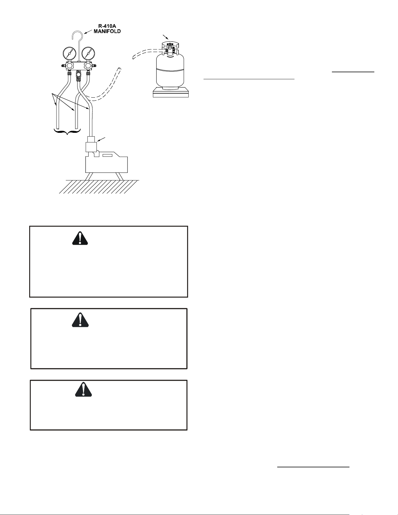
117
SERVICING
LOW SIDE
GAUGE
AND VALVE
HIGH SIDE
GAUGE
AND VALVE
TO
UNIT SERVICE
VALVE PORTS
VACUUM PUMP
VACUUM PUMP
ADAPTER
800 PSI
RATED
HOSES
CHARGING
CYLINDER
AND SCALE
S-103 CHARGING
* Do not overcharge system with refrigerant.
* Do not operate unit in a vacuum or at negative
pressure.
Failure to follow proper procedures may cause
property damage, personal injury or death.
WARNING
REFRIGERANT UNDER PRESSURE!
CAUTION
Use refrigerant certified to AHRI standards. Used
refrigerant may cause compressor damage and is
not covered under the warranty. Most portable
machines cannot clean used refrigerant to meet
AHRI standards.
CAUTION
with the suction valve closed is not covered under the
Damage to the unit caused by operating the compressor
warranty and may cause serious compressor damage.
Charge the system with the exact amount of refrigerant. Refer
to the specicaon secon or check the unit nameplates for the
correct refrigerant charge. An inaccurately charged system will
cause future problems.
NOTE: R410A should be drawn out of the storage container
or drum in liquid form due to its fraconaon properes, but
should be “Flashed” to its gas state before entering the system.
There is commercially available restricon devices that t into
the system charging hose set to accomplish this. DO NOT charge
liquid R410A into the compressor.
NOTE: Power must be supplied to the 18 SEER outdoor units
containing ECM motors before the power is applied to the
indoor unit. Sending a low voltage signal without high voltage
power present at the outdoor unit can cause malfuncon of the
control module on the ECM motor.
Adequate refrigerant charge for the matching evaporator
coil or air handler and 15 feet of line set is supplied with
the condensing unit. If using evaporator coils or air handlers
other than HSVTC coil it may be necessary to add or remove
refrigerant to aain proper charge. If line set exceeds 15 feet
in length, refrigerant should be added at .6 ounces per foot of
liquid line.
NOTE: The outdoor temperature should be 60°F or higher
when charging the unit.Charge should always be checked using
subcooling when using TXV equipped indoor coil to verify proper
charge. Open the sucon service valve rst! If the liquid service
valve is opened rst, oil from the compressor may be drawn
into the indoor coil TXV, restricng refrigerant ow and aecng
operaon of the system.
When opening valves with retainers, open each valve only unl
the top of the stem is 1/8” from the retainer. To avoid loss
of refrigerant, DO NOT apply pressure to the retainer. When
opening valves without a retainer remove service valve cap and
insert a hex wrench into the valve stem and back out the stem
by turning the hex wrench counterclockwise. Open the valve
unl it contacts the rolled lip of the valve body.
NOTE: These are not back-seang valves. It is not necessary to
force the stem ghtly against the rolled lip.
Aer the refrigerant charge has bled into the system, open the
liquid service valve. The service valve cap is the secondary seal
for the valve and must be properly ghtened to prevent leaks.
Make sure cap is clean and apply refrigerant oil to threads and
sealing surface on inside of cap. Tighten cap nger-ght and
then ghten addional 1/6 of a turn (1 wrench at) to properly
seat the sealing surfaces.
EXPANSION VALVE SYSTEM
NOTE: Units matched with indoor coils equipped with non-
adjustable TXV should be charged by subcooling only.
NOTE: The TXV should NOT be adjusted at light load condions
55º to 60ºF. Use the following guidelines and methods to check
unit operaon and ensure that the refrigerant charge is within
limits. Charge the unit on low stage.
Units Equipped with Adjustable Expansion Valves should be
charged by Subcooling and Superheat adjusted only if

118
SERVICING
necessary.
1. Purge gauge lines. Connect service gauge manifold to base-
valve service ports. Run the system in low stage at least 10
minutes to allow pressure to stabilize.
2. Temporarily install a thermometer on the liquid line at the
liquid line service valve and 4-6” from the compressor on
the sucon line. Ensure the thermometer makes adequate
contact and is insulated for best possible readings. Use liquid
line temperature to determine subcooling and vapor tem-
perature to determine superheat.
3. Check subcooling and superheat. Systems with TXV applica-
on should have a subcooling of 5 to 7°F and superheat of 7
to 9 °F.
a. If subcooling and superheat are low, adjust TXV to 7 to
9 ºF superheat, and then check subcooling.
NOTE: To adjust superheat, turn the valve stem clockwise to
increase and counter clockwise to decrease.
b. If subcooling is low and superheat is high, add charge to
raise subcooling to 5 to 7 °F then check superheat.
c. If subcooling and superheat are high, adjust TXV valve
to 7 to 9 ºF superheat, then check subcooling.
d. If subcooling is high and superheat is low, adjust TXV
valve to 7 to 9 ºF superheat and remove charge to
lower the subcooling to 5 to 7 ºF.
NOTE: Do NOT adjust the charge based on sucon pressure
unless there is a gross undercharge.
4. Disconnect manifold set, installaon is complete.
SUBCOOLING FORMULA = SATURATED LIQUID TEMP. - LIQUID
LINE TEMP.
NOTE: Check the Schrader ports for leaks and ghten valve cores
if necessary. Install caps nger-ght.
HEAT PUMP - HEATING CYCLE
The proper method of charging a heat pump in the heat mode
is by weight with the addional charge adjustments for line size,
line length, and other system components. For best results on
outdoor units with TXVs, superheat should be 2-5°F at 4-6” from
the compressor. Make nal charge adjustments in the cooling
cycle.
S-104 CHECKING COMPRESSOR EFFiCIENCY
The reason for compressor ineciency is broken or damaged
scroll anks on Scroll compressors, reducing the ability of the
compressor to pump refrigerant vapor.
The condion of the scroll anks is checked in the following
manner.
1. Aach gauges to the high and low side of the system.
2. Start the system and run a “Cooling Performance Test.
If the test shows:
a. Below normal high side pressure.
b. Above normal low side pressure.
c. Low temperature dierence across coil.
d. Low amp draw at compressor.
And the charge is correct. The compressor is faulty - replace the
compressor.
S-106 OVERFEEDING
Overfeeding by the expansion valve results in high sucon
pressure, cold sucon line, and possible liquid slugging of the
compressor.
If these symptoms are observed:
1. Check for an overcharged unit by referring to the cooling
performance charts in the servicing secon.
2. Check the operaon of the power element in the valve as
explained in S-110 Checking Expansion Valve Operaon.
3. Check for restricted or plugged equalizer tube.
S-107 UNDERFEEDING
Underfeeding by the expansion valve results in low system
capacity and low sucon pressures.
If these symptoms are observed:
1. Check for a restricted liquid line or drier. A restricon will be
indicated by a temperature drop across the drier.
2. Check the operaon of the power element of the valve as
described in S-110 Checking Expansion Valve Operaon.
S-108 SUPERHEAT
The expansion valves are factory adjusted to maintain 7 to 9
degrees superheat of the sucon gas. Before checking the
superheat or replacing the valve, perform all the procedures
outlined under Air Flow, Refrigerant Charge, Expansion Valve -
Overfeeding, Underfeeding. These are the most common causes
for evaporator malfuncon.
CHECKING SUPERHEAT
Refrigerant gas is considered superheated when its temperature
is higher than the saturaon temperature corresponding to
its pressure. The degree of superheat equals the degrees
of temperature increase above the saturaon temperature
at exisng pressure. See Temperature - Pressure Chart on
following pages.
119
CAUTION
To prevent personal injury, carefully connect and
disconnect manifold gauge hoses. Escaping liquid
refrigerant can cause burns. Do not vent refrigerant
to atmosphere. Recover during system repair
or final unit disposal.
1. Run system at least 10 minutes to allow pressure to stabilize.
2. For best results, temporarily install a thermometer on the
liquid line at the liquid line service valve and 4-6” from the
compressor on the sucon line. Ensure the thermometer
makes adequate contact and is insulated for best possible
readings. Use liquid line temperature to determine sub-cool-
ing and vapor temperature to determine superheat.
NOTE: An oponal method is to locate the thermometer
at the sucon line service valve. Ensure the thermometer
makes adequate contact and is insulated for best possible
readings.
3. Refer to the superheat table provided for proper system
superheat. Add charge to lower superheat or recover charge
to raise superheat.
Superheat Formula = Suct. Line Temp. - Sat. Suct. Temp.
EXAMPLE:
a. Sucon Pressure = 143
b. Corresponding Temp. °F. = 50
c. Thermometer on Sucon Line = 61°F.
To obtain the degrees temperature of superheat, subtract 50.0
from 61.0°F.
The dierence is 11° Superheat. The 11° Superheat would fall in
the ± range of allowable superheat.
S-109 CHECKING SUBCOOLING
Refrigerant liquid is considered subcooled when its temperature
is lower than the saturaon temperature corresponding to
its pressure. The degree of subcooling equals the degrees of
temperature decrease below the saturaon temperature at the
exisng pressure.
1. Aach an accurate thermometer or preferably a thermocou-
ple type temperature tester to the liquid line as it leaves the
condensing unit.
2. Install a high side pressure gauge on the high side (liquid)
service valve at the front of the unit.
3. Record the gauge pressure and the temperature of the line.
4. Review the technical informaon manual or specicaon
sheet for the model being serviced to obtain the design
subcooling.
5. Compare the hi-pressure reading to the "Required Liquid
Line Temperature" chart (page 108). Find the hi-pressure
value on the le column. Follow that line right to the column
under the design subcooling value. Where the two intersect
is the required liquid line temperature.
Alternately you can convert the liquid line pressure gauge
reading to temperature by nding the gauge reading in
Temperature - Pressure Chart and reading to the le, nd the
temperature in the °F. Column.
6. The dierence between the thermometer reading and pres-
sure to temperature conversion is the amount of subcooling.
Add charge to raise subcooling. Recover charge to lower
subcooling.
Subcooling Formula = Sat. Liquid Temp. - Liquid Line Temp.
EXAMPLE:
a. Liquid Line Pressure = 417
b. Corresponding Temp. °F. = 120°
c. Thermometer on Liquid line = 109°F.
To obtain the amount of subcooling subtract 109°F from 120°F.
The dierence is 11° subcooling. See the specicaon sheet or
technical informaon manual for the design subcooling range for
your unit.
S-110 CHECKING EXPANSION VALVE OPERATION
1. Remove the remote bulb of the expansion valve from the
sucon line.
2. Start the system and cool the bulb in a container of ice
water, closing the valve. As you cool the bulb, the sucon
pressure should fall and the sucon temperature will rise.
3. Next warm the bulb in your hand. As you warm the bulb,
the sucon pressure should rise and the sucon tempera-
ture will fall.
4. If a temperature or pressure change is noced, the expan-
sion valve is operang. If no change is noced, the valve is
restricted, the power element is faulty, or the equalizer tube
is plugged.
5. Capture the charge, replace the valve and drier, evacuate
and recharge.
S-112 CHECKING RESTRICTED LIQUID LINE
When the system is operang, the liquid line is warm to the
touch. If the liquid line is restricted, a denite temperature
drop will be noced at the point of restricon. In severe cases,
frost will form at the restricon and extend down the line in the
direcon of the ow.
Discharge and sucon pressures will be low, giving the
appearance of an undercharged unit. However, the unit will
have normal to high subcooling.
Locate the restricon, replace the restricted part, replace drier,
evacuate and recharge.
120
SERVICING
PSIG
°F
PSIG
°F
PSIG
°F
PSIG
°F
PSIG
°F
PSIG
°F
12
-37.7
114.0
37.8
216.0
74.3
318.0
100.2
420.0
120.7
522.0
137.6
14
-34.7
116.0
38.7
218.0
74.9
320.0
100.7
422.0
121.0
524.0
137.9
16
-32.0
118.0
39.5
220.0
75.5
322.0
101.1
424.0
121.4
526.0
138.3
18
-29.4
120.0
40.5
222.0
76.1
324.0
101.6
426.0
121.7
528.0
138.6
20
-36.9
122.0
41.3
224.0
76.7
326.0
102.0
428.0
122.1
530.0
138.9
22
-24.5
124.0
42.2
226.0
77.2
328.0
102.4
430.0
122.5
532.0
139.2
24
-22.2
126.0
43.0
228.0
77.8
330.0
102.9
432.0
122.8
534.0
139.5
26
-20.0
128.0
43.8
230.0
78.4
332.0
103.3
434.0
123.2
536.0
139.8
28
-17.9
130.0
44.7
232.0
78.9
334.0
103.7
436.0
123.5
538.0
140.1
30
-15.8
132.0
45.5
234.0
79.5
336.0
104.2
438.0
123.9
540.0
140.4
32
-13.8
134.0
46.3
236.0
80.0
338.0
104.6
440.0
124.2
544.0
141.0
34
-11.9
136.0
47.1
238.0
80.6
340.0
105.1
442.0
124.6
548.0
141.6
36
-10.1
138.0
47.9
240.0
81.1
342.0
105.4
444.0
124.9
552.0
142.1
38
-8.3
140.0
48.7
242.0
81.6
344.0
105.8
446.0
125.3
556.0
142.7
40
-6.5
142.0
49.5
244.0
82.2
346.0
106.3
448.0
125.6
560.0
143.3
42
-4.5
144.0
50.3
246.0
82.7
348.0
106.6
450.0
126.0
564.0
143.9
44
-3.2
146.0
51.1
248.0
83.3
350.0
107.1
452.0
126.3
568.0
144.5
46
-1.6
148.0
51.8
250.0
83.8
352.0
107.5
454.0
126.6
572.0
145.0
48
0.0
150.0
52.5
252.0
84.3
354.0
107.9
456.0
127.0
576.0
145.6
50
1.5
152.0
53.3
254.0
84.8
356.0
108.3
458.0
127.3
580.0
146.2
52
3.0
154.0
54.0
256.0
85.4
358.0
108.8
460.0
127.7
584.0
146.7
54
4.5
156.0
54.8
258.0
85.9
360.0
109.2
462.0
128.0
588.0
147.3
56
5.9
158.0
55.5
260.0
86.4
362.0
109.6
464.0
128.3
592.0
147.9
58
7.3
160.0
56.2
262.0
86.9
364.0
110.0
466.0
128.7
596.0
148.4
60
8.6
162.0
57.0
264.0
87.4
366.0
110.4
468.0
129.0
600.0
149.0
62
10.0
164.0
57.7
266.0
87.9
368.0
110.8
470.0
129.3
604.0
149.5
64
11.3
166.0
58.4
268.0
88.4
370.0
111.2
472.0
129.7
608.0
150.1
66
12.6
168.0
59.0
270.0
88.9
372.0
111.6
474.0
130.0
612.0
150.6
68
13.8
170.0
59.8
272.0
89.4
374.0
112.0
476.0
130.3
616.0
151.2
70
15.1
172.0
60.5
274.0
89.9
376.0
112.4
478.0
130.7
620.0
151.7
72
16.3
174.0
61.1
276.0
90.4
378.0
112.6
480.0
131.0
624.0
152.3
74
17.5
176.0
61.8
278.0
90.9
380.0
113.1
482.0
131.3
628.0
152.8
76
18.7
178.0
62.5
280.0
91.4
382.0
113.5
484.0
131.6
632.0
153.4
78
19.8
180.0
63.1
282.0
91.9
384.0
113.9
486.0
132.0
636.0
153.9
80
21.0
182.0
63.8
284.0
92.4
386.0
114.3
488.0
132.3
640.0
154.5
82
22.1
184.0
64.5
286.0
92.8
388.0
114.7
490.0
132.6
644.0
155.0
84
23.2
186.0
65.1
288.0
93.3
390.0
115.0
492.0
132.9
648.0
155.5
86
24.3
188.0
65.8
290.0
93.8
392.0
115.5
494.0
133.3
652.0
156.1
88
25.4
190.0
66.4
292.0
94.3
394.0
115.8
496.0
133.6
656.0
156.6
90
26.4
192.0
67.0
294.0
94.8
396.0
116.2
498.0
133.9
660.0
157.1
92
27.4
194.0
67.7
296.0
95.2
398.0
116.6
500.0
134.0
664.0
157.7
94
28.5
196.0
68.3
298.0
95.7
400.0
117.0
502.0
134.5
668.0
158.2
96
29.5
198.0
68.9
300.0
96.2
402.0
117.3
504.0
134.8
672.0
158.7
98
30.5
200.0
69.5
302.0
96.6
404.0
117.7
506.0
135.2
676.0
159.2
100
31.2
202.0
70.1
304.0
97.1
406.0
118.1
508.0
135.5
680.0
159.8
102
32.2
204.0
70.7
306.0
97.5
408.0
118.5
510.0
135.8
684.0
160.3
104
33.2
206.0
71.4
308.0
98.0
410.0
118.8
512.0
136.1
688.0
160.8
106
34.1
208.0
72.0
310.0
98.4
412.0
119.2
514.0
136.4
692.0
161.3
108
35.1
210.0
72.6
312.0
98.9
414.0
119.6
516.0
136.7
696.0
161.8
110
35.5
212.0
73.2
314.0
99.3
416.0
119.9
518.0
137.0
112
36.9
214.0
73.8
316.0
99.7
418.0
120.3
520.0
137.3
*Based on ALLIED SIGNAL Data
Pressure vs. Temperature Chart
R-410A
121
LIQUID PRESSURE
AT SERVICE VALVE (PSIG) 8 10 12 14 16 18
189
58 56 54 52 50 48
195
60
58
56
54
52
50
202 62 60 58 56 54 52
208 64 62 60 58 56 54
215 66 64 62 60 58 56
222 68 66 64 62 60 58
229 70 68 66 64 62 60
236 72 70 68 66 64 62
243 74 72 70 68 66 64
251 76 74 72 70 68 66
259 78 76 74 72 70 68
266 80 78 76 74 72 70
274 82 80 78 76 74 72
283 84 82 80 78 76 74
291 86 84 82 80 78 76
299 88 86 84 82 80 78
308 90 88 86 84 82 80
317 92 90 88 86 84 82
326 94 92 90 88 86 84
335 96 94 92 90 88 86
345 98 96 94 92 90 88
354 100 98 96 94 92 90
364 102 100 98 96 94 92
374 104 102 100 98 96 94
384 106 104 102 100 98 96
395 108 106 104 102 100 98
406 110 108 106 104 102 100
416 112 110 108 106 104 102
427 114 112 110 108 106 104
439 116 114 112 110 108 106
450 118 116 114 112 110 108
462 120 118 116 114 112 110
474 122 120 118 116 114 112
486 124 122 120 118 116 114
499 126 124 122 120 118 116
511 128 126 124 122 120 118
REQUIRED SUBCOOLING TEMPERATURE (°F)
REQUIRED LIQUID LINE TEMPERATURE
SERVICING
122
S-115 COMPRESSOR BURNOUT
When a compressor burns out, high temperature develops
causing the refrigerant, oil and motor insulaon to decompose
forming acids and sludge.
If a compressor is suspected of being burned-out, aach a
refrigerant hose to the liquid line dill valve and properly remove
and dispose of the refrigerant.
NOTICE
Violation of EPA regulations may result in fines
or other penalties.
Now determine if a burn out has actually occurred. Conrm by
analyzing an oil sample using a Sporlan Acid Test Kit, AK-3 or its
equivalent.
Remove the compressor and obtain an oil sample from the
sucon stub. If the oil is not acidic, either a burnout has not
occurred or the burnout is so mild that a complete clean-up is
not necessary.
If acid level is unacceptable, the system must be cleaned by
using the clean-up drier method.
Do not allow the sludge or oil to contact the skin.
Severe burns may result.
CAUTION
NOTE: The Flushing Method using R-11 refrigerant is no longer
approved by Amana® Brand Heang-Cooling.
Sucon Line Drier Clean-Up Method
The POE oils used with R410A refrigerant is an excellent solvent.
In the case of a burnout, the POE oils will remove any burnout
residue le in the system. If not captured by the refrigerant
lter, they will collect in the compressor or other system
components, causing a failure of the replacement compressor
and/or spread contaminants throughout the system, damaging
addional components.
Install a eld supplied sucon line drier. This drier should be
installed as close to the compressor sucon ng as possible.
The lter must be accessible and be rechecked for pressure drop
aer the system has operated for a me. It may be necessary to
use new tubing and form as required.
NOTE: At least twelve (12) inches of the sucon line
immediately out of the compressor stub must be discarded due
to burned residue and contaminates.
SERVICING
S-113 OVERCHARGE OF REFRIGERANT
An overcharge of refrigerant is normally indicated by an
excessively high head pressure.
An evaporator coil, using an expansion valve metering device,
will basically modulate and control a ooded evaporator and
prevent liquid return to the compressor.
An evaporator coil, using a capillary tube metering device, could
allow refrigerant to return to the compressor under extreme
overcharge condions. Also with a capillary tube metering
device, extreme cases of insucient indoor air can cause icing of
the indoor coil and liquid return to the compressor, but the head
pressure would be lower.
There are other causes for high head pressure which may be
found in the “Service Problem Analysis Guide.”
If other causes check out normal, an overcharge or a system
containing non-condensables would be indicated.
If this system is observed:
1. Start the system.
2. Remove and capture small quanes of gas from the sucon
line dill valve unl the head pressure is reduced to normal.
3. Observe the system while running a cooling performance
test. If a shortage of refrigerant is indicated, then the system
contains non-condensables.
S-114 NON-CONDENSABLES
If non-condensables are suspected, shut down the system
and allow the pressures to equalize. Wait at least 15 minutes.
Compare the pressure to the temperature of the coldest
coil since this is where most of the refrigerant will be. If the
pressure indicates a higher temperature than that of the coil
temperature, non-condensables are present.
Non-condensables are removed from the system by rst
removing the refrigerant charge, replacing and/or installing
liquid line drier, evacuang and recharging.
CHECKING COMPRESSOR EFFICIENCY
The reason for compressor ineciency is broken or damaged
scroll anks on Scroll compressors, reducing the ability of the
compressor to pump refrigerant vapor. The condion of the
scroll anks is checked in the following manner.
1. Aach gauges to the high and low side of the system.
2. Start the system and run a “Cooling Performance Test. If the
test shows:
a. Below normal high side pressure.
b. Above normal low side pressure.
c. Low temperature dierence across coil.
d. Low amp draw at compressor.
And the charge is correct. The compressor is faulty – replace
the compressor.
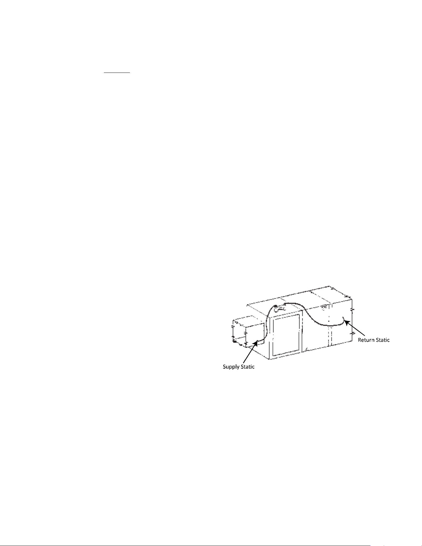
123
SERVICING
1. Remove compressor discharge line strainer.
2. Remove the liquid line drier and expansion valve.
3 Purge all remaining components with dry nitrogen or carbon
dioxide unl clean.
4. Install new components including liquid line drier.
5. Braze all joints, leak test, evacuate, and recharge system.
6. Start up the unit and record the pressure drop across the
drier.
7. Connue to run the system for a minimum of twelve (12)
hours and recheck the pressure drop across the drier. Pres-
sure drop should not exceed 6 PSIG.
8. Connue to run the system for several days, repeatedly
checking pressure drop across the sucon line drier. If
the pressure drop never exceeds the 6 PSIG, the drier has
trapped the contaminants. Remove the sucon line drier
from the system.
9. If the pressure drop becomes greater, then it must be
replaced and steps 5 through 9 repeated unl it does not
exceed 6 PSIG.
NOTICE: Regardless, the cause for burnout must be determined
and corrected before the new compressor is started.
S-120 REFRIGERANT PIPING
The piping of a refrigeraon system is very important in relaon
to system capacity, proper oil return to compressor, pumping
rate of compressor and cooling performance of the evaporator.
POE oils maintain a consistent viscosity over a large temperature
range which aids in the oil return to the compressor; however,
there will be some installaons which require oil return traps.
These installaons should be avoided whenever possGible,
as adding oil traps to the refrigerant lines also increases the
opportunity for debris and moisture to be introduced into the
system. Avoid long running traps in horizontal sucon line.
S-201 CLEANING ALUMINUM COILS
This unit is equipped with an aluminum tube evaporator
coil. The safest way to clean the evaporator coil is to simply
ush the coil with water. This cleaning pracce remains as
the recommended cleaning method for both copper tube and
aluminum tube residenal cooling coils.
An alternate cleaning method is to use one of the products listed
in the technical publicaon TP-109 (shipped in the literature
bag with the unit) to clean the coils. The cleaners listed are the
only agents deemed safe and approved for use to clean round
tube aluminum coils. TP-109 is available on the web site in
Partner Link > Service Toolkit.
NOTE: Ensure coils are rinsed well aer use of any chemical
cleaners.
S-202 DUCT STATIC PRESSURES AND/OR STATIC PRESSURE
DROP ACROSS COILS
This minimum and maximum allowable duct stac pressure for
the indoor secons are found in the specicaons secon.
Tables are also provided for each coil, lisng quanty of air
(CFM) versus stac pressure drop across the coil.
Too great an external stac pressure will result in insucient
air that can cause icing of the coil. Too much air can cause poor
humidity control and condensate to be pulled o the evaporator
coil causing condensate leakage. Too much air can also cause
motor overloading and in many cases this constutes a poorly
designed system.
S-203 SINGLE PIECE AIR HANDLER EXTERNAL STATIC
To determine proper airow, proceed as follows:
1. Using a Inclined Manometer or Magnehelic gauge , measure
the stac pressure of the return duct at the inlet of the air
handler, this will be a negave pressure (for example-.30”wc)
2. Measure the stac pressure of the supply duct at the outlet
of the air handler, this should be a posive pressure (for
example .20”wc).
3. Add the two readings together (for example -.30”wc +
.20”wc = .50”wc total external stac pressure.
NOTE: Both readings may be taken simultaneously and read
directly on the manometer if so desired.
4. Consult proper air handler airow chart for quanty of air
(CFM) at the measured external stac pressure.
+ .20” wc
- .30” wc
S-203A Two Piece Air Handler External Stac Pressure
To determine proper airow, proceed as follows:
1. Using a Inclined Manometer or Magnehelic gauge, measure
the stac pressure between the outlet of the evaporator
coil and the inlet of the air handler, this will be a negave
pressure ( for example -.30”wc)
2. Measure the stac pressure of the supply duct at the outlet
of the unit, this should be a posive pressure (for example
.20”wc).
3. Add the two readings together (for example -.30”wc +
.20”wc = .50”wc total stac pressure.
NOTE: Both readings may be taken simultaneously and read
directly on the manometer if so desired.
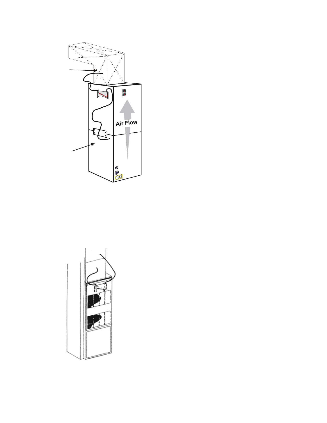
124
SERVICING
4. Consult proper air handler airow chart for quanty of air
(CFM) at the measured external stac pressure.
Supply Static
+ .20” wc
Return Static
- .30” wc
S-204 COIL STATIC PRESSURE DROP
1. Using a dra gauge (inclined manometer), connect the posi-
ve probe underneath the coil and the negave probe above
the coil.
2. A direct reading can be taken of the stac pressure drop
across the coil.
3. Consult proper table for quanty of air.
STATIC PRESSURE DROP
If the total external stac pressure and/or stac pressure drop
exceeds the maximum or minimum allowable stacs, check for
closed dampers, dirty lters, undersized or poorly laid out duct
work.
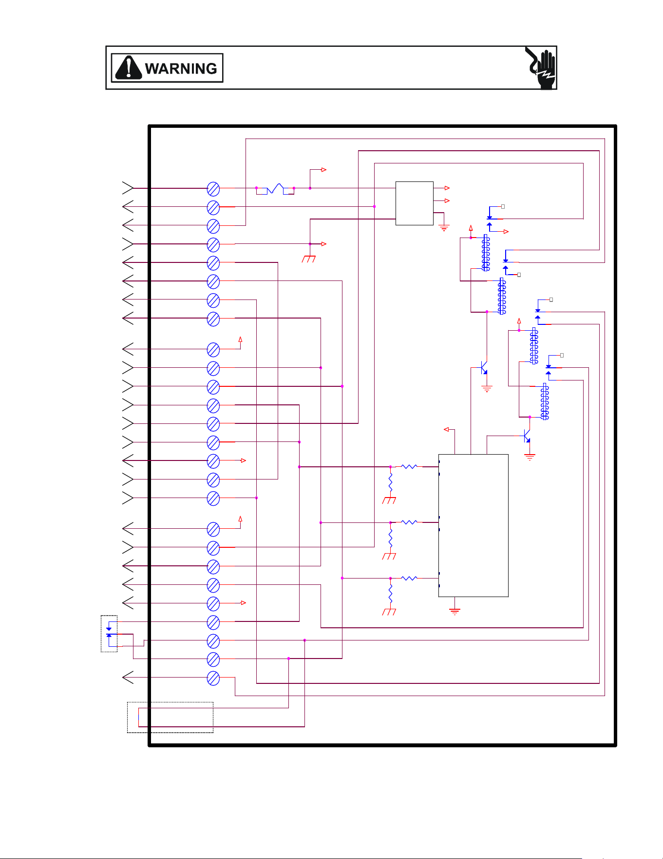
125
ACCESSORIES WIRING DIAGRAMS
ACCESSORIES WIRING DIAGRAMS
+5VDC
24 VAC
G
POWER SUPPLY
INPUT
POWER SUPPLY C OMMON
OUT TO HP CONTROL
P3-1
6.8K
P3-7
Y-HP
P1-6
P1-4
COMPRESSOR OUTPUT
P1-7
O
POWER SUPPLY OUT
TO THERMOSTAT
24 VAC
Q2
K3
W1
POWER SUPPLY I NPUT
(COMMON)
+VD C
E/W1
Y
P2-8
CAL L FOR
REVERSING VALVE
P3-5
C
C
BLOWER FAN DEMAND
OUTPUT
P3-3
P1-8
Y-STAT
Y-FURN
C
P3-2
P1-1
P3-8
REVERSING VALVE
OUTPUT
BREAK FOR OD T
FURNACE DEMAND
OUTPUT
P1-3
R
24 VAC
K4
HP CALL FOR FURNACE
(DURING DEFROST)
W2
Y2-STAT
Y2-FURN
CAL L FOR
COMPRESSOR
P2-7
P3-6
+VD C
Y2
O
REVERSING
VALVE OUTPUT
Q1
Y
P2-4
K1
OT-NO
Y
P2-9
CALL FOR 2ND STAGE
COMPRESSOR
Y2
1.0K
G-FURN
P2-1
C
OT-C
C
SECOND STAGE
COMPRESSOR OUTPUT
G
CAL L FOR
EMERGENC Y HEAT
W1-FURN
W2-HP
F1
3A
OT-NC
24 VAC
2ND STAGE COMPRESSOR
DEMAND OUTPUT
W1
CAL L FOR
FURNACE HEAT
6.8K
G-STAT
+VD C
P3-4
F
U
R
N
A
C
E
P2-6
K2
ODT (OUTDOOR
THERMOSTAT)
Y
R
SECOND STAGE FURNACE
DEMAND OUTPUT
MICROPROCESSOR
Y2-HP
P1-5
CALL FOR 2ND STAGE
FURNACE HEAT
O
W2
CAL L FOR
BLOWER FAN
T
H
E
R
M
O
S
T
A
T
P2-5
1 2
R
Y2
POWER
SUPPLY
COMPRESSOR
CONTACTOR OUTPUT
O
H
E
A
T
P
U
M
P
P2-3
+5VDC
W2
P3-9
P2-2
E
POWER SUPPLY C OMMON
OUT TO THERMOSTAT
POWER SUPPLY OUT
TO HP CONTROL
C
P1-2
ALL FUEL CONTROL BOARD - AFE18-60A
This wiring diagram is for reference only. Not all wiring is as shown above.
Refer to the appropriate wiring diagram for the unit being serviced.
(For use with Heat Pumps in conjuncon with 80% or 90% Single-Stage or Two-Stage Furnaces)
ALL FUEL SYSTEM AFE18-60A CONTROL BOARD
HIGH VOLTAGE!
DISCONNECT ALL POWER BEFORE SERVICING OR INSTALLING THIS
UNIT. MULTIPLE POWER SOURCES MAY BE PRESENT. FAILURE TO
DO SO MAY CAUSE PROPERTY DAMAGE, PERSONAL INJURY OR DEATH.
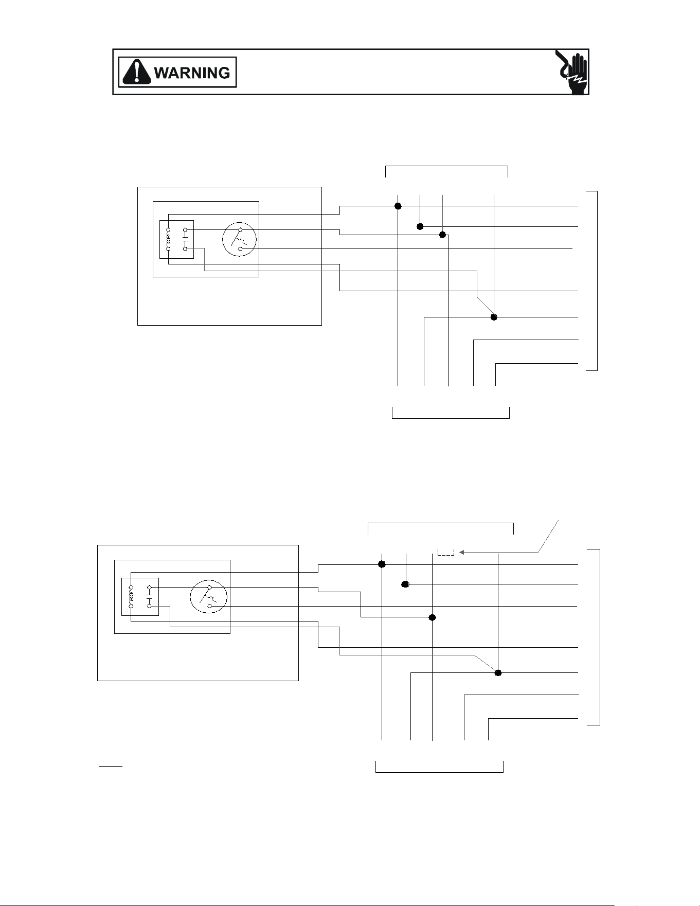
126
ACCESSORIES WIRING DIAGRAMS
HIGH VOLTAGE!
DISCONNECT ALL POWER BEFORE SERVICING OR INSTALLING THIS
UNIT. MULTIPLE POWER SOURCES MAY BE PRESENT. FAILURE TO
DO SO MAY CAUSE PROPERTY DAMAGE, PERSONAL INJURY OR DEATH.
EMERGENCY
HEAT
RELAY
1 3
4 2
BLUE
WHITE
BLACK
BROWN
THERMOSTAT
OT/EHR18-60
21
From Air Handler
C G W2 R
C R W2 O Y
From Outdoor Unit
C
G
W2
E
R
O
Y
Indoor Thermostat
BLUE
GREEN
WHITE
RED
BLUE
RED
WHITE
ORANGE
YELLOW
10kw and Below, One Stage Electric Heat
RED
EMERGENCY
HEAT
RELAY
1
4 2
BLUE
WHITE
BLACK
BROWN
THERMOSTAT
OT/EHR18-60
21
From Air Handler
C G W2 R
C R W2 O Y
From Outdoor Unit
C
G
W2
E
R
O
Y
Indoor Thermostat
W3
BLUE
GREEN
WHITE
RED
BROWN
BLUE
RED
WHITE
ORANGE
YELLOW
15kw and Above, Two Stage Electric Heat
3
RED
SEE NOTE
Note:
When using a Thermostat with only one
stage for electric heat (W2), tie white and
brown wires from air handler together.
Typical Wiring Schemacs for OT/EHR18-60 (Outdoor Thermostat & Emergency Heat Relay).
This wiring diagram is for reference only. Not all wiring is as shown above.
Refer to the appropriate wiring diagram for the unit being serviced.
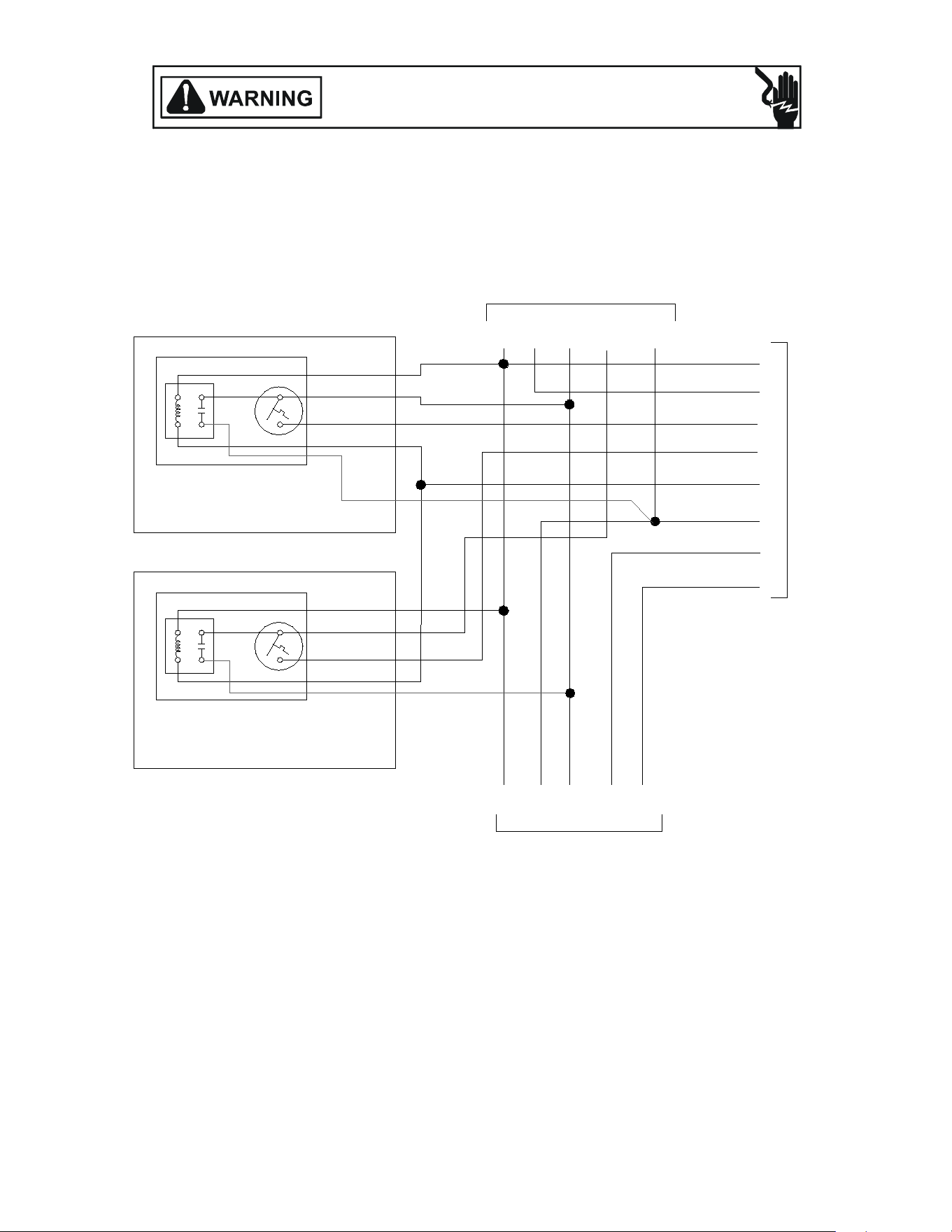
127
EMERGENCY
HEAT
RELAY
1 3
4 2
BLUE
WHITE
BLACK
BROWN
THERMOSTAT
OT/EHR18-60 #2
2
1
From Air Handler
C G W2 R
C R W2 O Y
From Outdoor Unit
C
G
W2
E
R
O
Y
Indoor Thermostat
W3
W3
BLUE
GREEN
WHITE
RED
BROWN
BLUE
RED
WHITE
ORANGE
YELLOW
15kw and Above with Two OT/EHR18-60's, Two Stage Electric Heat and Two Stage Thermostat
HEAT
RELAY
EMERGENCY
THERMOSTAT
1
4
3
2
1
2
BROWN
BLACK
WHITE
BLUE
OT/EHR18-60 #1
RED
RED
Typical Wiring Schemacs for OT/EHR18-60 (Outdoor Thermostat & Emergency Heat Relay).
This wiring diagram is for reference only. Not all wiring is as shown above.
Refer to the appropriate wiring diagram for the unit being serviced.
ACCESSORIES WIRING DIAGRAMS
HIGH VOLTAGE!
DISCONNECT ALL POWER BEFORE SERVICING OR INSTALLING THIS
UNIT. MULTIPLE POWER SOURCES MAY BE PRESENT. FAILURE TO
DO SO MAY CAUSE PROPERTY DAMAGE, PERSONAL INJURY OR DEATH.
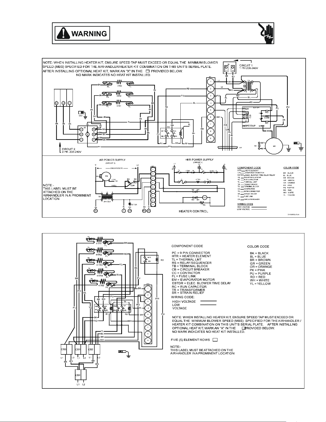
128
ACCESSORIES WIRING DIAGRAMS
HIGH VOLTAGE!
DISCONNECT ALL POWER BEFORE SERVICING OR INSTALLING THIS
UNIT. MULTIPLE POWER SOURCES MAY BE PRESENT. FAILURE TO
DO SO MAY CAUSE PROPERTY DAMAGE, PERSONAL INJURY OR DEATH.
Wiring is subject to change. Always refer to the wiring diagram on the unit for the most up-to-date wiring.
3-Phase Heat Kit
25kW Heat Kit

129
WIRING DIAGRAMS
AIRHANDLERS
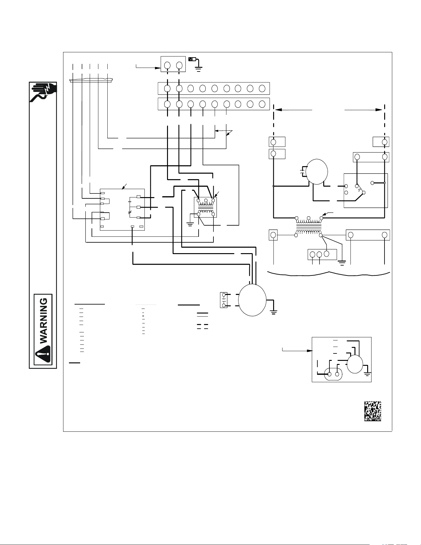
130
WIRING DIAGRAMS
HIGH VOLTAGE!
DISCONNECT ALL POWER BEFORE SERVICING OR INSTALLING THIS
UNIT. MULTIPLE POWER SOURCES MAY BE PRESENT. FAILURE TO
DO SO MAY CAUSE PROPERTY DAMAGE, PERSONAL INJURY OR DEATH.
Wiring is subject to change. Always refer to the wiring diagram on the unit for the most up-to-date wiring.
ADPF, ARPF, ARUF, ATUF
USECOPPE RWIRE
SPEEDUP
COPP ER POWER SUPPLY
(SEE RATI NG PLAT E)
EQ UIPMENTGROUND
BL
BL
SEE
NOTE 3
BK
M1
BR
BR
RC
EM
RD
BL
BK
RD
PU
WH
EBTDR
SR
BL
G
RD
XFMR-R
XFMR-C
C
R
RD
GR
SEENOTES 2 &6
BL RD GR WH BR
5
NO
COM
NC
K1
K1
PU
PU
RD
RD
C
BK
BR
PLF
BK
1
RD
PU
2
3
240
24V
4
1
2
3
TR
RD
SEE
NOTE 4
BL
BR
4 5
WH
6789
PLM
GRND
1
BK
23
RD
L2
L1
4 5 678 9
0140A00245-A
PLM
PLF
TR
FACTORYWIRING
FIELDWIRING
NOTE
S:
DELAY RELAY
STRAIN RELIEF
EVAPORATOR MOTOR
ELECTRONICBLOW ER TIME
RUN CAPA CITOR
SR
EM
EBTDR
RC
BK
RD
BL
YL
BLUE
BLACK
RED
YELLOW
COMPONENT CODE
BROWN
PURPLE
GREEN
PU
BR
GR
FEMALE PLUG CONNECTOR
MALE PLUG CONNECTOR
TRANSFORMER
HIGHVOLTAGE
LOW VOLTAGE
HIGHVOLTAGE
LOW VOLTAGE
PLF
3
2
COLOR CO DE
RD
TR
WH
6
BR
5
PLF
4
4
24V
5
SEE NOTE 1
1
2
3
RC
HI
EM
GR
WIRING CODE
BL
EBTDR
LO
COM
NC
M1
EBTDR
NO
208/240VOLTS
1
1
PLF
PLM
L1
PLM
2
L2
(M2)
PU
RC
(M1) BK
BL
MEDIUM
3 SPEED
BR
HIGH
EM
(COM)RDLOW
IF REPLACEMENTOFTHE ORIGINAL WIRES
SUPPLIED WITH THIS ASSEMBLY IS NECESSARY
USEWIR ETHATCONFORMSTOTHE
NATIONAL ELECTRIC CODE.
M2
PU
(TR 1)
M2
R G
C
EBTDR
SEENOTE1
FL FUSE LI NK
TL
THERMA L LIMIT
SEENOTE5
RRELAY
TERMINALBLOC K SHOW N
FOR50HZMODELS ONLY
THREE SP EED MO TORWIRING
(SELEC T MODELS ONLY)
SEE NOTE 3
WHIT E
WH
USE MIN.75˚C FIELDWIRE
1. REDWIRES TO BE ON TRANSFORMER TERMINAL "3" FOR240 VOLTSAND
ONTERMINAL "2" FOR208 VOLTS
2. SEE CO MPOSITEWIRING DIAGRAMS IN INSTALLATION INSTRUCTIONS FORPROPER
LOWVOLTAGE WIRING CONNECTIONS
3. CONFIRMSPEED TAPSELECTED IS APPROPRIATE FORAPPLICATION. IF SPEEDTAP
NEEDS TO BE CHANGED, CONNECTAPPROPR IATE MOTORWIRE (RED FOR LOW,
BLUE FOR MEDIUM,AND BLACK FORHIGHSPEED) ON "COM" CONNECTION OF THEEBTDR
INACTIVE MOTORWIRES MUST BE CONNECTED TO "M1 OR M2"ON EBTDR.
4. BROW NAND WHITEWIRES ARE USED WITH HEAT KITSONLY.
5. EBTDRHAS A 7SECONDON DELAYWHE N "G" IS EN ERGIZEDAND A65SECOND OFF
DELAYWHEN "G" IS DE-ENERGIZED.
6. LOWVOLTAGE FIELDWIRING TO BE N.E.C CLASS 2WIRES.
GRND GROUND
SEENOTES 2 & 6
Eecve 12/24/14
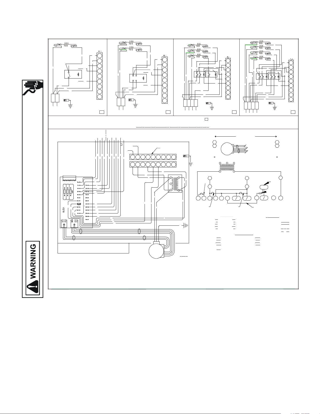
131
N
O
M
A
R
K
I
ND
I
CA
TE
S
N
O
H
E
A
T
K
I
T
I
N
S
T
A
L
L
E
D
AFTER INSTALLING OPTIONAL HEAT KIT, MARK AN "X" IN THE PROVIDED ABOVE.
MARK ACCORDING TO NUMBER OF HEATER ELEMENT ROWS INSTALLED
BK
BK
BL
IF REPLACEMENT OF THE ORIGINAL W IRES SUPPLIED WITH THIS ASSEMBLY IS NECESSARY, USE 105°C. W IRE. SIZE TO CONFORM TO T HE NATIONA L ELECTRI C CODE.
FIELD CONNECTION
* SEE N OTE 7
LOW VOLTAGE
DS 1
COPPER
(SEE RATING PLATE)
POW ER SUPPLY
CONTROLS SHOW N WITH UTILITIES IN "ON" POSITION AND THERMOSTAT IN "O FF" POSIT ION.
P N.
B
13 6827 0 RE V. A
J1
BOX
TH ERMOS TAT S
W2
HEAT ER
W
C R
J3
J2
BR
R
BL
Y/Y2
24 VAC
Y 1
R
PU
HUM ID IS TAT
HU M
R Y 1 G
Y
G
USE COPPER W IRE
EQUIPMENT GROUND
R
BL
W
BR
W1
THERMOSTAT
Y CO N
CONDE NSER
COM W 2O E D
W1
OUTD OOR
HEAT PUM P
W/W 2
R
W
BL
OTC O
T1 COT2OE
\W1
BR
BL
Y
BL
Y
YCO N
TO
CONDENSER
C
PL2
3
12
BR
BK
PL1
PUW
BL
BR
R
Y
G
Y1C
W2 R
TO
Y/Y2
G
1
R
23
BK
L1 L2
BK
BK
HTR1
TL
HTR2
R
9
8
7
R
W
BL
PU
TL
BK
5
6
3
4
BK
R
1
2
W
BK
L2L1
BK
R
R
R
BK
R
HTR1
TL
0140A00000P
EM
2
24 VOLT
O
SEE NOTE 2
C O LO R COD
E
PRO GRAM J U MPER
7. SEE COMPOSITE WIRING DIAGRAMS IN INSTALLATION INSTRUCTIONS FOR PROPER LOW VOLTAGE
CONNECTIONS AND DETAILS ON COMPATIBLE THERMOSTATS AND THEIR CONNECTIONS.
3. FOR OUTDOOR THERMOSTAT OPERATION OF SECOND STAGE HEAT, CUT PJ2 & ADD OT18-60 TO OTC & OT2.
2. FOR TWO STAGE ELECTRIC HEAT APPLICATIONS CUT PJ4. (USE ONLY ON 15 & 20 KW MODELS).
4. FOR SINGLE STAGE COOLING APPLICATION S CONNECT THERMOSTAT TO Y/Y2 ONLY,
TAPE OR REMOVE Y1 CONNECTION. C ONNECT CONDENSING UNIT TO YCON & C.
6. RED WIRES TO BE ON TRANSFORMER TERMINAL 3 FOR 240 VOLTS AND ON TERMINAL 2 FOR 208 VOLTS.
1. F OR HEAT PUM P AP P LICATIO N S RE MOVE ORANGE JUMP ER WI RE BET WEEN O & Y1.
EVAPORATOR MOTOR
5. W HEN H UMIDSTAT IS PROV IDED CUT PJ 6. THER MOSTAT OPEN S ON HUMIDITY RIS E.
N
OTE
S:
EM
BK
R
G
PJ2,PJ4,PJ6
SEE NOTE 3
BL AC KBK
PL
EM
Y
R
BL
PL UG
R ED
YELLOW
BL UE
W
W HITE
BL
456789
W
R
R
BL
COM
3
BL
5
TR
240
2
208
1
24V
4
R
4567
89
SEE NOTE 5
HUM
R
PJ6
2
OT
1
OT
PJ2
W2
OT
C
5
PL2
TR
4
PL2
2
1
PL1
2
FACTORY WIRING
W
IR
I
NG CO
DE
FIELD WIRING
HIGH VOLTAGE
LOW VO LTAGE
HIGH VOLTAGE
LOW VO LTAGE
TERMINAL BOARD
VARIABLE SPEED TRANSF ORMERVSTB TR
COMP
ONENT COD
E
PU PURPLE
PIN K
ORANGE
BROWNBR
PK
0
GR E ENG
SEE NOTE 1
NOTE DIODE
ON VSTB
*SEE NOTE 7
W1
W1
6
W2
W
E
PJ4
5
DIODE
IN4005
Y1
Y
Y2
YCO N
PL2
208/240 VOLTS
3
TO LOW VOLTAGE
TERMINAL BOARD
G
C
NOTE 4
SEE
4
PL2
1 PL2
1
PL1
L1
BK
6
8
9
7
2
R
PU
4
5
3
BK
R
1
BK
L2 L1
L2
R
Y
M1
M2
BK
R
Y
R
R1
M4
R
BK
M3
HTR3
TL
HTR2
HTR1
TL
TL
PU
M2
R2
Y
M1
BL
W
BR
BL
R
BK
R
BK
TL
HTR1
BK
HTR4
HTR3
HTR2
BK
R
9
7
8
L2
L1
L1
L2
2
5
6
3
4
1
R
M1
Y
BK
M2
BL
W
6
BL
R
BK
Y
8
9
7
M6
M5
M3
R1
M4
R
PU
M7
R2
M8
BL
TL
TL
TL
Y
BL
R
BK
R
BL
BR
4
5
3
2
BK
1
OT2
HUM
W1
OT1
W2
PJ2
PJ6
PJ4
SEE NOTE 8
8. DISCAR D ORIGINAL "PL1" PLUG CONNECTOR WHEN INSTALLING OPTIONAL H EAT KIT.
R EL AY
THERMAL LIMIT
R
HEAT ELEMENT
HTR
TL
ONE (1) ELEMENT ROWS
TWO (2) ELEMENT ROWS
THREE (3) ELEMENT ROWS FOUR (4) EL EMENT ROWS
O
W2
BR
O
O
BR
R
R
O
O
FL FUSE LINK
FL
M1
M2
FL
FL
M1
M2
M3
M4
FL
FL
FL
FL
FL
FL
FL
HIGH VOLTAGE!
DISCONNECT ALL POWER BEFORE SERVICING OR INSTALLING THIS
UNIT. MULTIPLE POWER SOURCES MAY BE PRESENT. FAILURE TO
DO SO MAY CAUSE PROPERTY DAMAGE, PERSONAL INJURY OR DEATH.
Wiring is subject to change. Always refer to the wiring diagram on the unit for the most up-to-date wiring.
WIRING DIAGRAMS AEPF
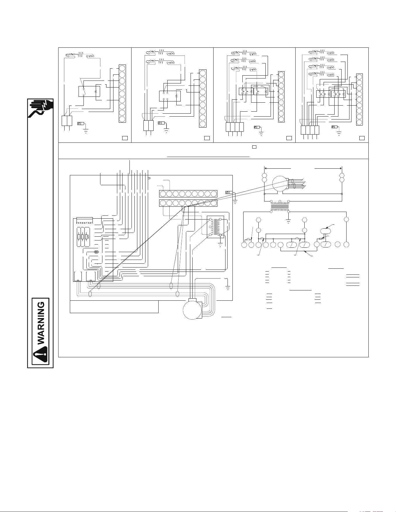
132
WIRING DIAGRAMS
Wiring is subject to change. Always refer to the wiring diagram on the unit for the most up-to-date wiring.
HIGH VOLTAGE!
DISCONNECT ALL POWER BEFORE SERVICING OR INSTALLING THIS
UNIT. MULTIPLE POWER SOURCES MAY BE PRESENT. FAILURE TO
DO SO MAY CAUSE PROPERTY DAMAGE, PERSONAL INJURY OR DEATH.
NO MARK INDICATES NO HEAT KIT INSTALLED
AFTER INSTALLING OPTIONAL HEAT KIT, MARK A "X" IN THE PROVIDED ABOVE.
MARK ACCORDING TO NUMBER OF HEATER ELEMENT ROWS INSTALLED
BK
RD
BL
FIELD CONNECTION
* SEE NOTE 7
LOW VOLTAGE
VSTB
DS1
COPPER
(SEE RATING PLATE)
POWER SUPPLY
CONTROLS SHOWN WITH UTILITIES IN "ON" POSITION AND THERMOSTAT IN "OFF" POSITION.
PN. B1368270 REV. A
J1
BOX
THERMOSTATS
W2
HEATER
WH
C R
J3J2
BR
RD
BL
Y/Y2
24 VAC
Y1
O
RD
PU
HUMIDISTAT
HUM
R Y1 G
YL
GR
RD
BL
WH
BR
W1
THERMOSTAT
YCON
CONDENS
ER
COM W2O ED
W1
OUTDOOR
HEATPUMP
W/W2
R
WH
BL
OTC OT1 COT2OE\W1
BR
BL
YL
BL
YL
YCON
TO
CONDENSER
C
PL2
3
1 2
BR
BK
PL1
PU
WH
BL
BR
RD
YL
GR
Y1C
W2
R
TO
Y/Y2
G
1
RD
2 3
BK
L1 L2
BK
BK
HTR 1
TL
HTR 1
RD
9
8
7
R
WH
BL
PU
TL
BK
5
6
3
4
PL 1
BK
RD
1
2
WH
RD
BK
BK
RD
BK
RD
R
HTR 2
TL
0140A00041-B
EM
2
24 VOLT
O
SEE NOTE 2
COLOR CODE
PROGRAM JUMPER
7. SEE COMPOSITE WIRING DIAGRAMS IN INSTALLATION INSTRUCTIONS FOR PROPER LOW VOLTAGE
CONNECTIONS AND DETAILS ON COMPATIBLE THERMOSTATS AND THEIR CONNECTIONS.
3. FOR OUTDOOR THERMOSTAT OPERATION OF SECOND STAGE HEAT, CUT PJ2 & ADD OT18-60 TO OTC & OT2.
2. FOR TWO STAGE ELECTRIC HEAT APPLICATIONS CUT PJ4. (USE ONLY ON 15 & 20 KW MODELS).
4. FOR SINGLE STAGE COOLING APPLICATIONS CONNECT THERMOSTAT TO Y/Y2 ONLY,
TAPE OR REMOVE Y1 CONNECTION. CONNECT CONDENSING UNIT TO YCON & C.
6. RED WIRES TO BE ON TRANSFORMER TERMINAL 3 FOR 240 VOLTS AND ON TERMINAL 2 FOR 208 VOLTS.
1. FOR HEAT PUMP APPLICATIONS REMOVE ORANGE JUMPER WIRE BETWEEN O & Y1.
EVAPORATOR MOTOR
5. WHEN HUMIDSTAT IS PROVIDED CUT PJ6. THERMOSTAT OPENS ON HUMIDITY RISE.
NOT ES :
EM
BK
RD
GR
PJ2,PJ4,PJ6
SEE NOTE 3
BLACKBK
PL
EM
YL
RD
BL
PLUG
RED
YELLOW
BLUE
WH WHITE
BL
4 5 6 7 8 9
WH
RD
RD
BL
COM
3
BL
5
TR
240
2
208
1
24V
4
RD
4 5 6 7 8 9
SEE NOTE 5
HUM
R
PJ6
2
OT
1
OT
PJ2
W2
OT
C
5
PL2
TR
4
PL2
2
1
PL1
2
FACTORY WIRING
WIRING CODE
FIELD WIRING
HIGH VOLTAGE
LOW VOLTAGE
HIGH VOLTAGE
LOW VOLTAGE
TERMINAL BOARD
VARIABLE SPEED TRANSFORMERVSTB TR
COMPONENT CODE
PU PURPLE
PINK
ORANGE
BROWNBR
PK
0R
GREENGR
SEE NOTE 1
NOTE DIODE
ON VSTB
*SEE NOTE 7
W1
W1
6
W2W E
PJ4
5
DIODE
IN4005
Y1
Y Y2
YCON
PL2
208/240 VOLTS
3
TO LOW VOLTAGE
TERMINAL BOARD
G
C
NOTE 4
SEE
4
PL2
1
PL2
1
PL1
BK
6
8
9
7
2
RD
PU
4
5
3
BK
BK
1
PL 1
BK
RD
YL
M1
M2
BK
RD
YL
RD
R1
M4
RD
BK
M3
HTR 3
TL
HTR 2
HTR 1
TL
TL
PU
M2
R2
YL
M1
BL
WH
BR
BL
RD
BK
RD
BK
TL
HTR 1
BK
HTR 4
HTR 3
HTR 2
BK
RD
9
7
8
2
5
6
3
4
PL 1
1
RD
M1
YL
BK
M2
BL
WH
6
BL
RD
BK
YL
8
9
7
M6
M5
M3
R1
M4
RD
PU
M7
R2
M8
BL
TL
TL
TL
YL
BL
RD
BK
RD
BL
BR
4
5
3
2
BK
PL 1
1
OT2
HUM
W1
OT1
W2
PJ2
PJ6
PJ4
SEE NOTE 8
8. DISCARD ORIGINAL "PL1" PLUG CONNECTOR WHEN INSTALLING OPTIONAL HEAT KIT.
RE LAY
THERMAL LIMIT
R
HEAT ELEMENTHTR
TL
ONE (1) ELEMENT ROWS TWO (2) ELEMENT ROWS THREE (3) ELEMENT ROWS FOUR (4) ELEMENT ROWS
O
W2
BR
OR
BR
RD
R
FL FUSE LINK
FL
M1
M2
FL
FL
M1
M2
M3
M4
FL
FL
FL
FL
FL
FL
FL
L1 L2
L1L1 L2 L2
L1 L2 L2L1
FOR HEAT
PUMPS ONLY
RD
OR
USE COPPER WIRE
EQUIPMENT GROUND
USE COPPER WIRE
EQUIPMENT GROUND
USE COPPER WIRE
EQUIPMENT GROUND
AEPF******CA
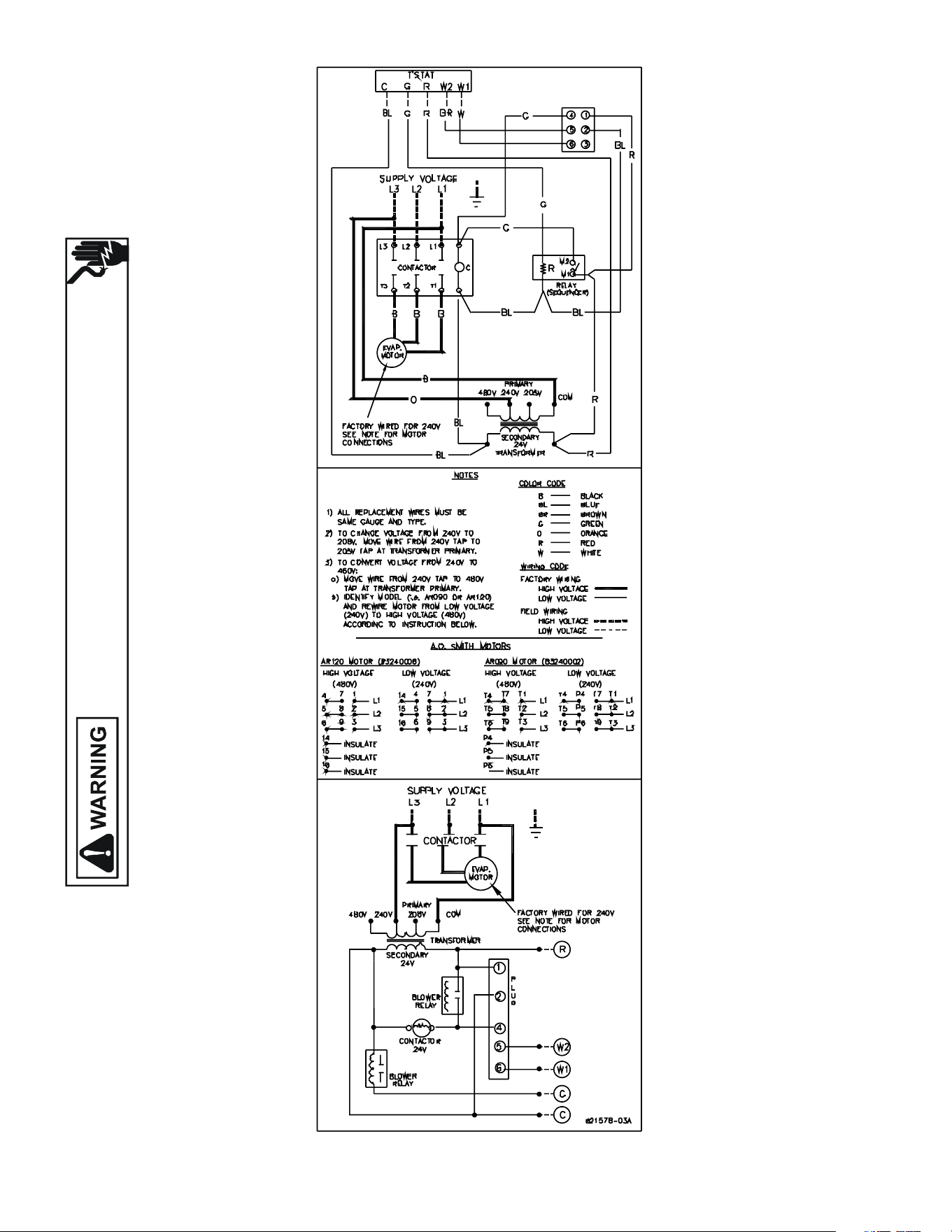
133
WIRING DIAGRAMS
Wiring is subject to change. Always refer to the wiring diagram on the unit for the most up-to-date wiring.
HIGH VOLTAGE!
DISCONNECT ALL POWER BEFORE SERVICING OR INSTALLING THIS
UNIT. MULTIPLE POWER SOURCES MAY BE PRESENT. FAILURE TO
DO SO MAY CAUSE PROPERTY DAMAGE, PERSONAL INJURY OR DEATH.
AR[090-120]4
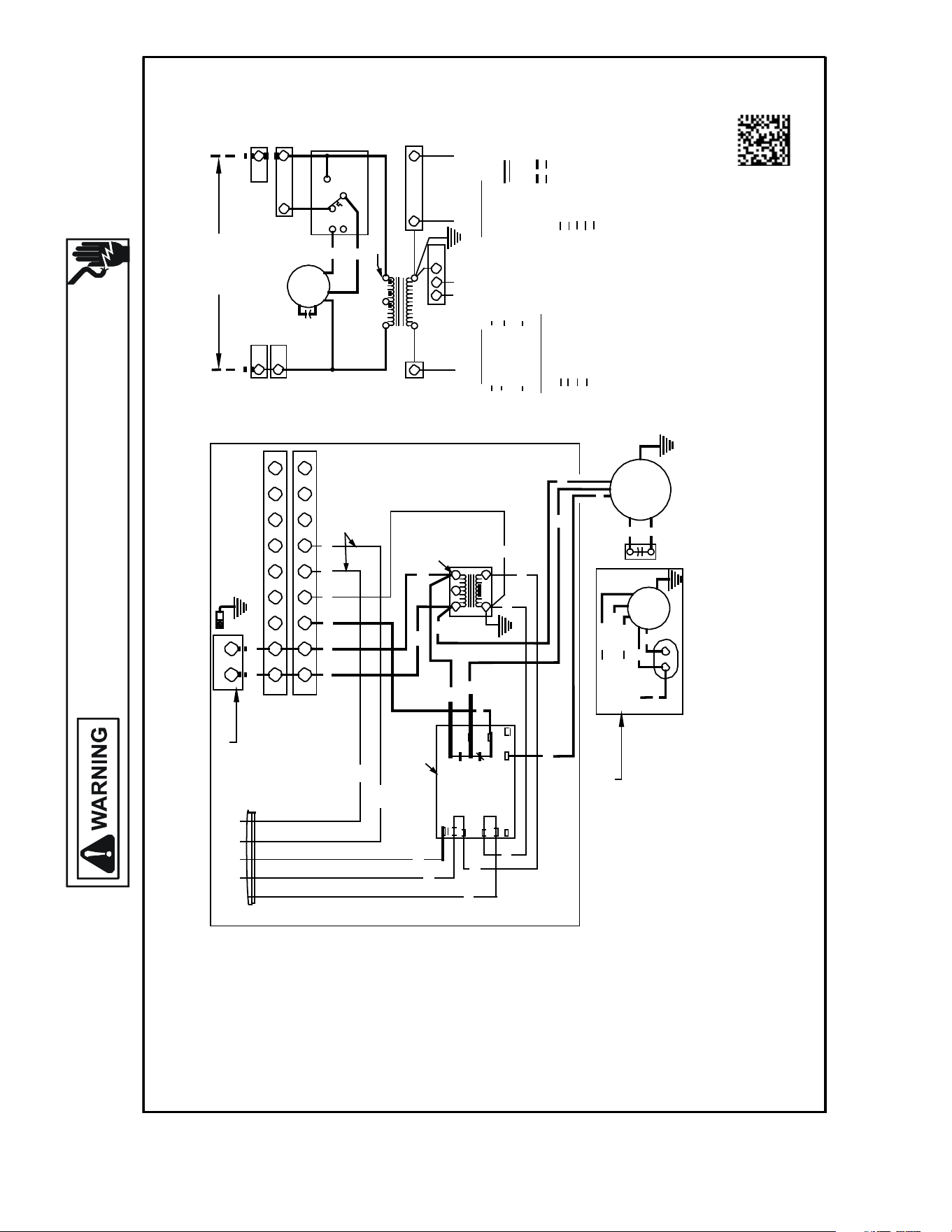
134
WIRING DIAGRAMS
Wiring is subject to change. Always refer to the wiring diagram on the unit for the most up-to-date wiring.
HIGH VOLTAGE!
DISCONNECT ALL POWER BEFORE SERVICING OR INSTALLING THIS
UNIT. MULTIPLE POWER SOURCES MAY BE PRESENT. FAILURE TO
DO SO MAY CAUSE PROPERTY DAMAGE, PERSONAL INJURY OR DEATH.
C EBTDR G
RD
SEE NOTES 2 & 6
BL RD GR
WH
BR
TERMINAL BLOCK SHOWN
FOR 50HZ MODELS ONLY
SR
BK RD
GRD
EQUIPMENT GROUND
USE COPPER WIRE
208/240
VOLTS
L1 L2
PLF
1
2 3
4 5 6 7 8 9
PLM
1 2 3 4 5
6 7 8 9
BK
RD
PU
BR
WH
BL
BR
WH
SEE
NOTE 4
GR
SEE NOTE 5
RD
G
EBTDR
RD
BK
RD
PU
SEE NOTE 1
EBTDR R
4
24V
5
6 5
4 PLF
R
BL
XFMR-R
XFMR-C
K1
NO
RD
C
1 2 3
240
RD
COLOR
CODE
WH BR
BL GR
WIRING
CODE
C
5
BK
NC
BLACK
GR GREEN
FACTORY WIRING
BL SPEEDUP
M1
M2
BL
BL
RD RED
PU PURPLE
HIGH VOLTAGE
YL YELLOW BR
BROWN
LOW VOLTAGE
RD
BL
BLUE
WH WHITE
FIELD WIRING
COMPONENT CODE
BK
EM
EVAPORATOR MOTOR
HIGH VOLTAGE
LOW VOLTAGE
COPPER POWER SUPPLY
(SEE RATING PLATE)
SEE
NOTE 3
RD
PU
RC
RUN CAPACITOR
SR
STRAIN RELIEF
TR
PLF
TRANSFORMER
FEMALE PLUG CONNECTOR
USE MIN. 75°C FIELD WIRE
R
RELAY
PLM
MALE PLUG CONNECTOR
THREE SPEED MOTOR
WIRING
(SELECT MODELS
ONLY)
(COM) RD LOW
EBTDR
BK
ELECTRONIC
BLOWER
TIME DELAY RELAY
FL
FUSE LINK
TL
THERMAL LIMIT
IF REPLACEMENT OF THE ORIGINAL WIRES
SEE NOTE 3
(M2)
BL
MEDIUM
SUPPLIED WITH THIS ASSEMBLY IS NECESSARY
USE WIRE THAT CONFORMS TO THE
NATIONAL ELECTRIC CODE.
(M1) BK
(TR 1)
PU
PU
RC
HIGH
RC
BR
BR
EM
EM
3 SPEED
BR
NOTES:
1) RED WIRES TO BE ON TRANSFORMER TERMINAL "3" FOR 240 VOLTS
AND ON TERMINAL "2" FOR 208 VOLTS.
2) SEE COMPOSITE WIRING DIAGRAMS IN INSTALLATION INSTRUCTIONS
FOR PROPER LOW VOLTAGE WIRING CONNECTIONS.
3) CONFIRM SPEED TAP SELECTED IS APPROPRIATE FOR APPLICATION.
IF SPEED TAP NEEDS TO BE CHANGED, CONNECT APPROPRIATE
MOTOR WIRE (RED FOR LOW, BLUE FOR MEDIUM, AND BLACK FOR
HIGH SPEED) ON "COM" CONNECTION OF THE EBTDR.
INACTIVE MOTOR WIRES MUST BE CONNECTED TO "M1 OR M2"
ON EBTDR.
4) BROWN AND WHITE WIRES ARE USED WITH HEAT KITS ONLY.
5) EBTDR HAS A 7 SECOND ON DELAY WHEN "G" IS ENERGIZED
AND A 65 SECOND OFF DELAY WHEN "G" IS DE-ENERGIZED.
6) LOW VOLTAGE FIELD WIRING TO BE N.E.C CLASS 2 WIRES.
0140A00242-A
PLF
2
1 PLF
1
PLM
3 PLM
2
RC
EM
M1
NC
NO
HI
LO
M2
EBTDR
COM
1
2 3
SEE NOTE 1
TR
L1
L2
ARPT**14**/ARUF**14**
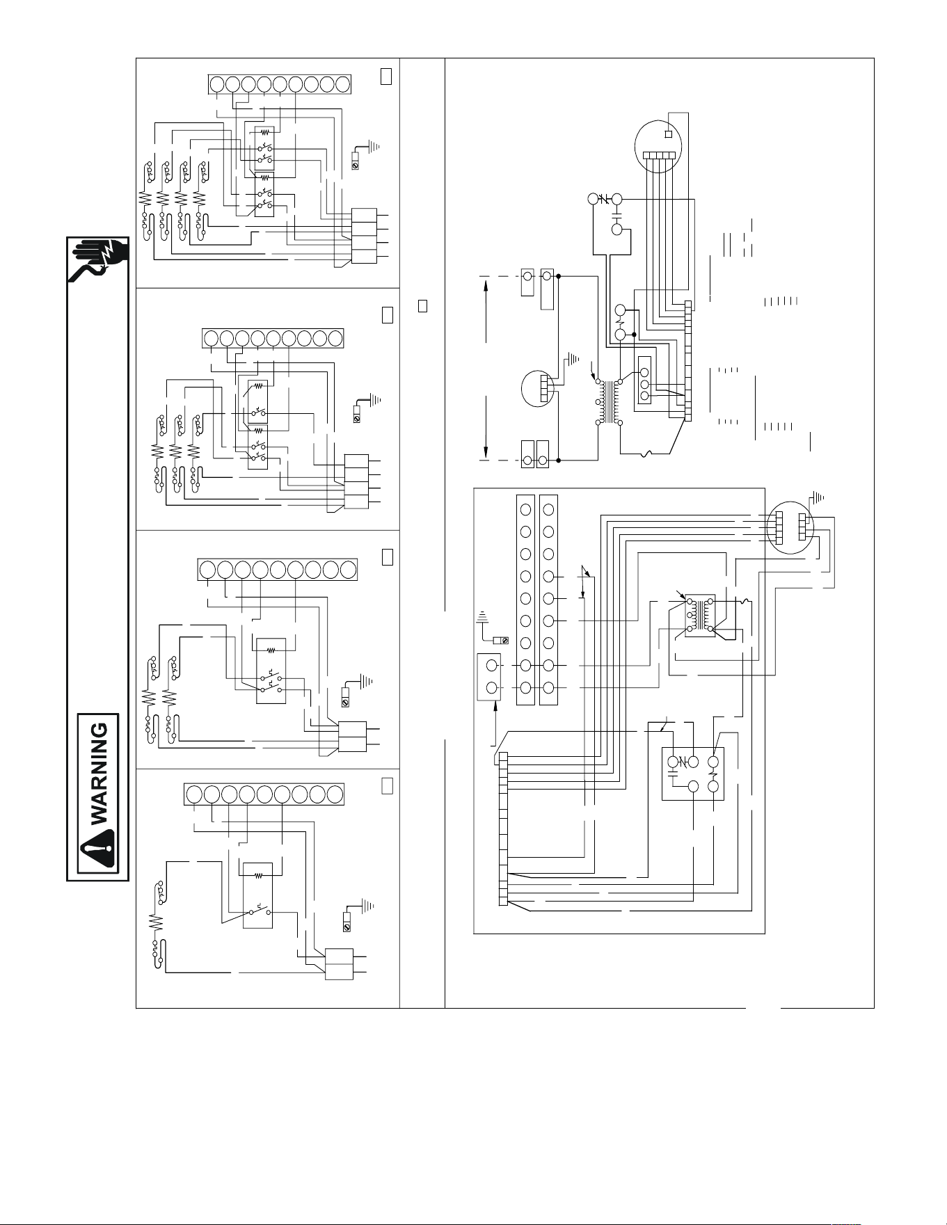
135
WIRING DIAGRAMS ASPF******BA
Wiring is subject to change. Always refer to the wiring diagram on the unit for the most up-to-date wiring.
HIGH VOLTAGE!
DISCONNECT ALL POWER BEFORE SERVICING OR INSTALLING THIS
UNIT. MULTIPLE POWER SOURCES MAY BE PRESENT. FAILURE TO
DO SO MAY CAUSE PROPERTY DAMAGE, PERSONAL INJURY OR DEATH.
BK
BL
BK
L1 L2
BK
BK
HTR1
TLHTR2
RD
R
WH
BL
PU
TL
BK
PL
BK
RD
WH
BK
L2L1
BK
RD
RD
RD
BK
R
HTR1 TL
L1
B
RD
PU
BK
RD
PL
B
L2 L1 L2
R
Y
M
M
B
R
Y
R
R1
M
R
B
M
HTR
TL
HTR
HTR
TL
TL
P
M
R2
Y
M
B
WH
B
B
R
B
R
B
TL
HTR
B
HTR
HTR
HTR
B
R
L2L1 L1 L2
PL
R
M
Y
B
M
B
WH
B
R
B
Y
M
M
M
R1
M
R
P
M
R2
M
B
TL
TL
TL
Y
B
R
B
R
B
B
B
PL
ONE (1) ELEMENT ROWS
TWO (2) ELEMENT ROWS
THREE (3) ELEMENT ROWS
FOUR (4) ELEMENT ROWS
FL
M1
M2
FL
FL
M1
M2
M3
M4
FL
FL
FL
FL
FL
FL
FL
USE COPPER OR ALUMINUM WIRE
COPPER OR ALUMINUM
POWER SUPPLY
(SEE RATING PLATE)
USE MIN. 75°C FIELD WIRE
EQUIPMENT GROUND
BL
EM
YL
BL
BK
C
BK
PLF
BK
1
RD
2
3
240
24V
TR
RD
SE
NOTE 4
BL
BR
4
5
WH
67
89
PLM
GRD
1
BK
23
RD
L2
L1
4 5 67
8 9
0140A00037
REV B
4) Brown and white wires are used with Heat Kits only.
PLM
PLF
TR
FACTORY WIRING
FIELD WIRING
1) Red wires to be on transforme r terminal "3" for 240 volts and on terminal "2" for 208 volts.
2) See composite wiring diagrams in installation instructions
for proper lo w volt age wiring connections.
Notes:
DELAY RELAY
RELAY
EVAPORATOR MOTOR
ELECTRONIC BLOWER TIME
TERMINAL BOARD
EM
EBTDR
TB
BK
RD
BL
YL
BLUE
BLACK
RED
YELLOW
COMPONE NT CODE
BROWN
PURPLE
GREEN
PU
BR
GR
FEMALE PLUG CONNECTOR
MALE PLUG CONNECTOR
TRANSFORMER
HIGH VOLTAGE
LOW VOLTAGE
HIGH VOLTAGE
LOW VOLTAGE
PLF
2
COLOR CODE
T
6
5
PL
4
4
24
5
SEE NOTE
1
2
3
E
W IRING CODE
208/240 VOLTS
1
1
PLF
PLM
L1
PLM
2
L2
IF REPLACEMENT OF THE ORIGINAL WIRES
SUPPLIED WITH THIS ASSEMBLY IS NECESSARY,
USE WIRE THAT CONFORMS TO THE
NATIONAL ELECTRIC CODE.
SEE NOTE
FL
FUSE LINK
TL
THERMAL LIMIT
HTRHEAT ELEMENTS
CR CONTROL RELAY
TERMINAL BLOCK SHOWN
FOR 50HZ MODELS ONLY
3) Conf irm speed tap selected is appropriate for application. If speed tap needs
to be changed, connect purple wire from terminal 4 of CR relay to appropriate tap
at TB
MARK ACCORDING TO NUMBER OF HEATER ELEMENT ROWS INSTALLED. NO MARK INDICATES NO HEAT KIT INSTALLED.
KIT COMBINATION ON THIS UNIT'S S&R PLATE. AFTER INSTALLING OPTIONAL HEAT KIT, MARK AN "X" IN THE PROVIDED ABOVE.
NOTE: WHEN INSTALLING HEATER KIT, ENSURE SPEED TAP DOES NOT EXCEED MINIMUM BLOWER SPEED (MBS) SPECIFIED FOR THE AIRHANDLER/HEAT ER
WHITE
WH
1 3
52
4
CR
SEE NOTE 2
2
1
43
5
NC
GL
RD
PU
BL
BR
WH
BL
RD
GR
RD
BL
RD
BK
RD
C LG
N
W2
R
W1C G 4Y1 OY2 1
DH
32
5
3
1
1
C
EM
2
4
3
5
2
4
CR
W2
R
W1C
G 4
Y1 OY2 1
DH 32
5
RD
PU
BR
WH
OR
WH
WH
BL
GR
SE
NOTE 3
RD
BL
FUS
HOLDER
FUS
HOLDER
5
COPPER POWER SUPPLY
(SEE RATING PLATE)
USE MIN. 75°C FIELD WIRE
EQUIPMENT GROUND
USE COPPER WIRE
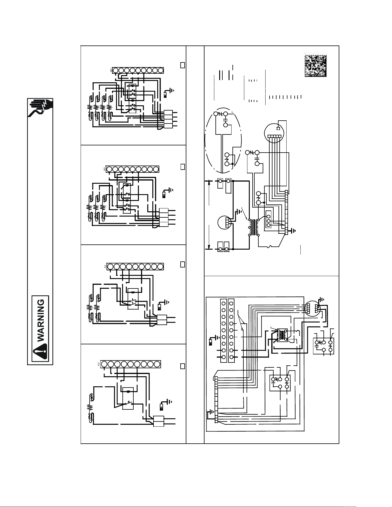
136
WIRING DIAGRAMS ASPF******C*
Wiring is subject to change. Always refer to the wiring diagram on the unit for the most up-to-date wiring.
HIGH VOLTAGE!
DISCONNECT ALL POWER BEFORE SERVICING OR INSTALLING THIS
UNIT. MULTIPLE POWER SOURCES MAY BE PRESENT. FAILURE TO
DO SO MAY CAUSE PROPERTY DAMAGE, PERSONAL INJURY OR DEATH.
BK
BL
BK
L1 L2
BK
BK
HTR 1
TL
HTR1
RD
9
8
7
R
WH
BL
PU
TL
BK
5
6
3
4
BK
RD
1
2
WH
RD
L2L1
BK
BK
RD
BK
RD
R
HTR2
TL
L1
BK
6
8
9
7
2
RD
PU
4
5
3
BK
RD
1
BK
L2 L1
L2
RD
YL
M1
M2
BK
RD
YL
RD
R1
M4
RD
BK
M3
HTR3
TL
HTR2
HTR1
TL
TL
PU
M2
R2
YL
M1
BL
WH
BR
BL
RD
BK
RD
BK
TL
HTR1
BK
HTR4
HTR3
HTR2
BK
RD
9
7
8
L2L1
L1 L2
2
5
6
3
4
1
RD
M1
YL
BK
M2
BL
WH
6
BL
RD
BK
YL
8
9
7
M6
M5
M3
R1
M4
RD
PU
M7
R2
M8
BL
TL
TL
TL
YL
BL
RD
BK
RD
BL
BR
4
5
3
2
BK
1
ONE (1) ELEMENT ROWS
TWO (2) ELEMENT ROWS
THREE (3) ELEMENT ROWS
FOUR (4) ELEMENT ROWS
FL
M1
M2
FL
FL
M1
M2
M3
M4
FL
FL
FL
FL
FL
FL
FL
COPPER POWER SUPPLY
(USE RATIN G PLATE)
USE MIN. 75° C FIELD WIRE
0140A00063-B
PLM
PLF
TR
FACTORY WIRING
FIELD WIRING
N
OTES:
1) RED WIRES TO BE ON TRANSFORMER TERMINAL "3" FOR 240 VOLTS AND ON
TERMINAL "2" FOR 208 VOLTS.
2) SEE COMPLETE WIRING DIAGRAMS IN INSTALLATION INSTRUCTIONS FOR
PROPER LOW VOLTAGE WIRING CONNECTIONS.
3) CONFIRM SPEED TAP SELECTION IS APPROPRIATE FOR APPLICATION. IF
SPEED TAP NEEDS TO BE CHANGED, CONNECT PURPLE WIRE FROM TERMINAL 4
OF CR RELAY TO APPROPRIATE TAP AT TB
4) BROWN AND WHITE WIRES ARE USED FOR HEAT KITS ONLY.
5) FUSE: 3A, 250V, 3AG CARTRIDGE FUSE.
RELAY
EVAPORATOR MOT OR
T ERMINAL B OAR D
R
EM
TB
BK
RD
BL
YL
BLUE
BLACK
RED
YELLOW
COMPONENT CODE
BROW N
PURPLE
GREE N
PU
BR
GR
FEMALE PLUG CONNECTOR
MALE PLUG CONNECTOR
TRANSFORM ER
HIGH VOLTAGE
LOW V OLTAGE
HIGH VOLTAGE
LOW V OLTAGE
PLF
2
COLOR CODE
TR
6
5
PLM4
4 2 4V
5
1
23
EM
WIRING CODE
208/240 VOLTS
1
1
PLF
PLM
L1
PLM
2
L2
IF REPLACEMENT OF THE ORIGINAL WIRES
SUPPLIED WITH THIS ASSEMBLY IS NECESSARY,
USE WIRE THAT CONFORMS TO THE NATIONAL
ELECTRIC CODE.
FL FUSE LINK
TL
THERMAL LIMIT
HTR HEAT ELEMENT S
CR CONTROL RELAY
NOTE: WHEN INSTALLING HEATER KIT, ENSURE SPEED TAP DOES NOT EXCEED MINIMUM BLOWER SPEED (MBS) SPECIFIED FOR THE AIRHANDLER/HEAT ER KIT COMBINATION ON THIS
UNIT'S S&R PLATE. AFTER INSTALLING OPTIONAL HEAT KIT, MARK A "X" IN THE BOX PROVIDED ABOVE. MARK ACCORDING TO NUMBER OF HEATER ELEMENT ROWS INSTALLED. NO MARK
INDICATES NO HEAT KIT INSTALLED.
WHITE
WH
LGN
W2R W1C G 4Y1 OY2 1DH 32 5
AB
1
C
EM
2
4
3
5
4
7
CR
FUSE
HOLDER
(OP T ION AL)
1
SEE NOTE 1
USE COPPER WIR
E
EQUIPMENT GROUND
BL
EM
YL
BL
5
BK
C
BK
P
L
F
BK
1
RD
2
3
240
2
4
V
4
1
2
3
T
R
RD
BL
BR
4
5
W
H
6
7
8
9
P
L
M
G
R
D
1
2
3
4
5
6
7
8
9
A
B
1
7
4
CR
SEE
NOTE 2
2
1
43 5
NC GL
RD
PU
BL
BR
WH
BL
RD
GR
RD or BK
BL
RD
BK
RD
W
2
R
W
1
C
G
4
Y
1
O
Y
2
1
D
H
3
2
5
RD or BK
PU
BR
WH
OR
WH
WH
BL
GR
RD or BK
BL
FUSE
HOLDER
(OPTIONAL)
L
2
L
1
SEE
NOTE 1
SEE
NO TE 4
1
3
5
4
2
ALTERNATE HEAT RELAY
BL
PU
RD
GR
WH
BL
13
2
4
CR
5
ALT ERNATE HEAT RELAY
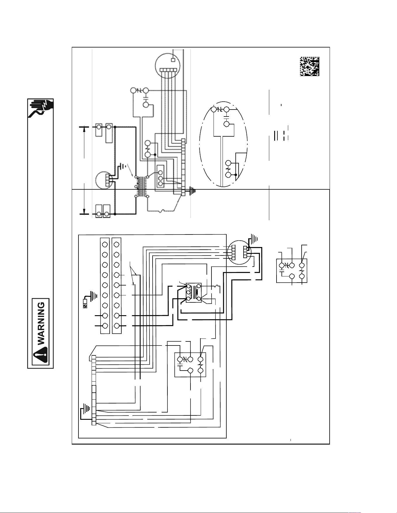
137
WIRING DIAGRAMS
HIGH VOLTAGE!
DISCONNECT ALL POWER BEFORE SERVICING OR INSTALLING THIS
UNIT. MULTIPLE POWER SOURCES MAY BE PRESENT. FAILURE TO
DO SO MAY CAUSE PROPERTY DAMAGE, PERSONAL INJURY OR DEATH.
Wiring is subject to change. Always refer to the wiring diagram on the unit for the most up-to-date wiring.
1 3
SEE NOTES 2 & 6
R C G W1 W2 Y1 Y2 O DH 1
2 3 4 5
GRD
L1 L2
EQUIPMENT GROUND
USE COPPER WIRE
L1
1
PLF
208/240 VOLTS
EM
L2
PLF
2
PLF
RD
1
2 3
4 5
6 7 8
9
1
PLM
LG N
PLM
2
PLM
1
2
3 4 5
6
7
8 9
GR
BL
RD or BK
WH
BK RD
BR
WH
PU
CR BK
7
BK
BL
BR
RD
WH
SEE
SEE
NOTE 4
FUSE
HOLDER
(OPTIONAL)
1
2 3
TR
4
24V 5
6 5
4 PLM
SEE NOTE 1
B
A
1
4
7
CR
1
2
EM
3
4
C
5
WH
RD
4 1
2
RD
C
5
NOTE 1
240
TR
R C G W1 W2 Y1 Y2 O DH 1 2 3 4 5
GR
A B
BL
RD or BK
BL
RD or BK
BL
FUSE
HOLDER
(OPTIONAL)
WH PU
OR BR YL
NOTES:
COPPER POWER SUPPLY
(USE RATING PLATE)
USE MIN. 75° C FIELD WIRE
IF REPLACEMENT OF THE ORIGINAL WIRES
SUPPLIED WITH THIS ASSEMBLY IS NECESSARY,
USE WIRE THAT CONFORMS TO THE NATIONAL
ELECTRIC CODE.
BL
RD
BK
4
RD
2 5
1 2 3 4 5
EM
C L G N
PU
WH
COMPONENT CODE
CR CONTROL RELAY
EM EVAPORATOR MOTOR
FL FUSE LINK
PLF FEMALE PLUG CONNECTOR
PLM MALE PLUG CONNECTOR
R RELAY
TB TERMINAL BOARD
ALTERNATE HEAT RELAY
WIRING CODE
FACTORY W IRING
HIGH VOLTAGE
LOW VOLTAGE
FIELD W IRING
HIGH VOLTAGE
LOW VOLTAGE
COLOR CODE
BK BLACK
RD RED
YL YELLOW
BL BLUE
GR GREEN
PU PURPLE
BR BROW N
WH WHITE
1. RED WIRES TO BE ON TRANSFORMER TERMINAL "3" FOR 240 VOLTS AND ON
TERMINAL "2" FOR 208 VOLTS.
2. SEE COMPLETE WIRING DIAGRAMS IN INSTALLATION INSTRUCTIONS FOR
PROPER LOW VOLTAGE WIRING CONNECTIONS.
3. CONFIRM SPEED TAP SELECTION IS
APPROPRIATE
FOR APPLICATION. IF
SPEED TAP NEEDS TO BE CHANGED, CONNECT PURPLE WIRE FROM TERMINAL
4 OF CR RELAY TO APPROPRIATE TAP AT TB
4. BROWN AND WHITE WIRES ARE USED FOR HEAT KITS ONLY.
5. FUSE: 3A, 250V, 3AG CARTRIDGE FUSE.
6. LOW VOLTAGE FIELD W IRING TO BE N.E.C CLASS 2 WIRES.
GR
1 3
BL
ALTERNATE HEAT RELAY
BL
TR TRANSFORMER
TL THERMAL LIMIT
0140A00243
-A
5
3
1
2
4
CR
ASPT**14**/ASUF**14**
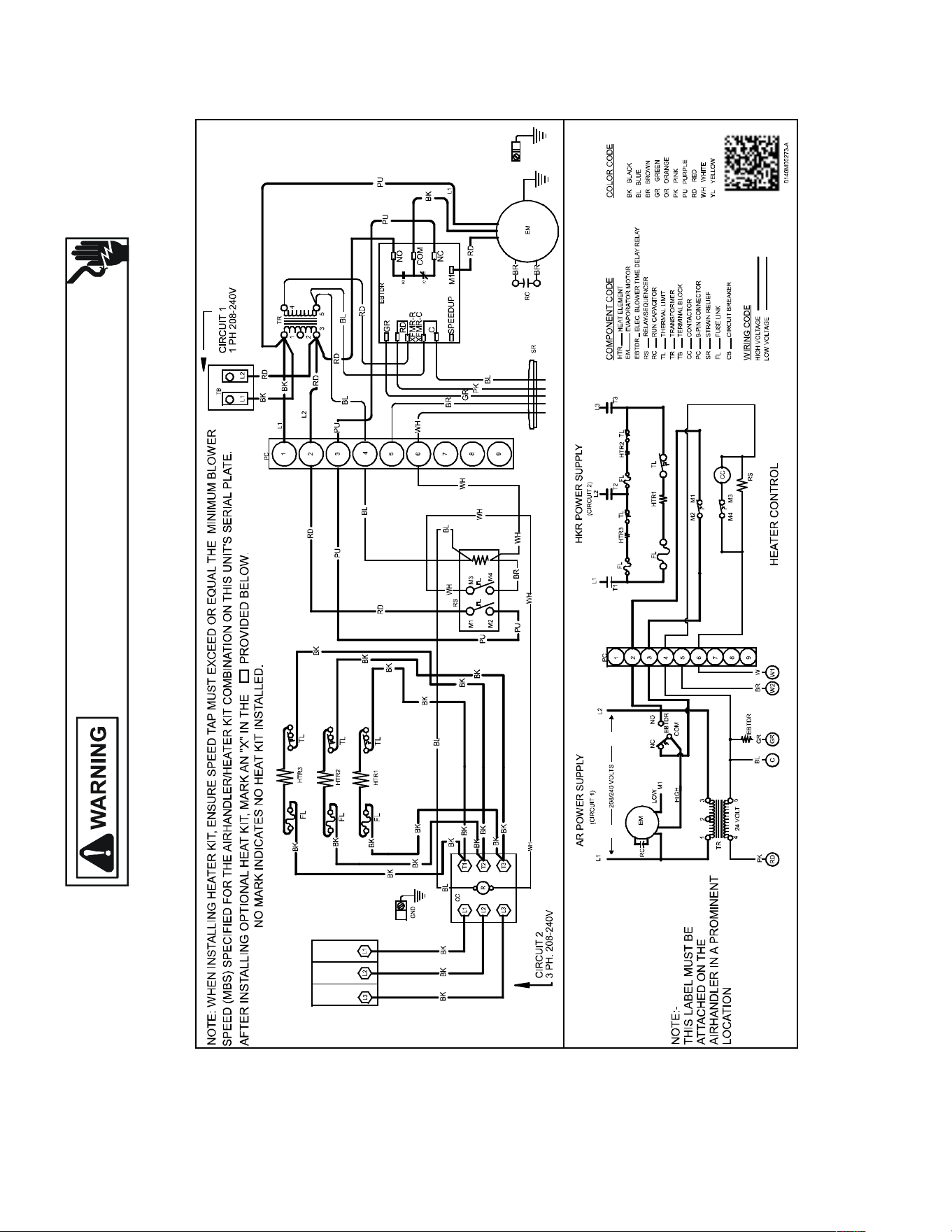
138
WIRING DIAGRAMS
HIGH VOLTAGE!
DISCONNECT ALL POWER BEFORE SERVICING OR INSTALLING THIS
UNIT. MULTIPLE POWER SOURCES MAY BE PRESENT. FAILURE TO
DO SO MAY CAUSE PROPERTY DAMAGE, PERSONAL INJURY OR DEATH.
Wiring is subject to change. Always refer to the wiring diagram on the unit for the most up-to-date wiring.
ASPT**14**/ASUF**14**
3-PHASE HEAT KIT
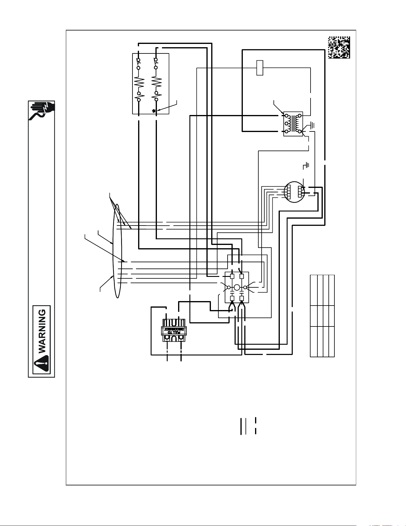
139
WIRING DIAGRAMS
Wiring is subject to change. Always refer to the wiring diagram on the unit for the most up-to-date wiring.
HIGH VOLTAGE!
DISCONNECT ALL POWER BEFORE SERVICING OR INSTALLING THIS
UNIT. MULTIPLE POWER SOURCES MAY BE PRESENT. FAILURE TO
DO SO MAY CAUSE PROPERTY DAMAGE, PERSONAL INJURY OR DEATH.
AWUF310516AE, AWUF310816AD, AWUF321016AD
BTUh NOMINALCFM
PURPLE 18 000600
PINK 24 000800
YELLOW30000 950
RD
PK
PK
GR
PU
PU
YL
WH
F
123
54
24V
12 34 5
CL GN
EM
YL
TABLE-1
WIRE COLOR
0140A00542-A
240V
TR
HTR1
HTR2*
TL1
TL2*
DISC
SEENOTE1
C
L1
L2
T1
T2
BL
BR
WH
BK
RD
BK
BL
WH
WH
RD
RD
BL
RD
BK
BR
BK
BK
BK
BK
RD
RD
RD
RD
GR/YL
BL
BL
BL
NOTES:
1. REDWIRETOBEON TRANSFORMER
TERMINAL "3"FOR 230 VOLTS ANDON
TERMINAL "2"FOR 208VOLTS.
2. CONFIRMSPEED TAPSELECTEDIS
APPROPRIATE FOR APPLICATION. IF SPEED
TAPS NEEDSTOBECHANGED,CONNECT
APPROPRIATE WIRE FROMMOTOR TO
"Y"FROM THERMOSTAT/CONDENSER(SEE TABLE-1).
3. ASTERISK (*)IND ICATES THATHEATING
ELEMENT, THERMAL LIMIT, RELAYAND
INTERCONNECTINGWIRES ANDJUMPERS
OF HEATER #2 AREDELETED WITH SINGLE
ELEMENTUNITS.
4. COLORCODES:
BK -BLACK
BL -BLUE
BR -BROWN
GR -GREEN
PU -PURPLE
RD -RED
WH -WHITE
YL -YELLOW
5. WIRING CODE:
FACTORYWIRING:
HIGH VOLTAGE
LOW VOLTAGE
FIELDWIRING:
HIGH VOLTAGE
6. COMPONENTCODE:
C-CONTACTOR
DISC -DISCONNECTSWITCH
EM -EVAPORATERMOTOR
F-FUSE
HTR-HEATER ELEMENT
R-RELAY
SEQ-SEQUENCER
TL -THERMAL LIMIT
TR -TRANSFORMER
BK
GR
RD
BK
BK
BK
BK
BK
RD
RD
RD
SEENOTE#3
MOTORCONNECTION
ONLY ONEWILLBECONNECTED
(SEE NOTE 2)
OPTIONAL
CONNECTION
UNUSED WIRESMUSTHAVETHEIR ENDS TAPEDOR
CAPPED
FIELDCONNECTIONS
SEE NOTE 2
USEN.E.C CLASS2WIRE
L2
RD
L1
BK
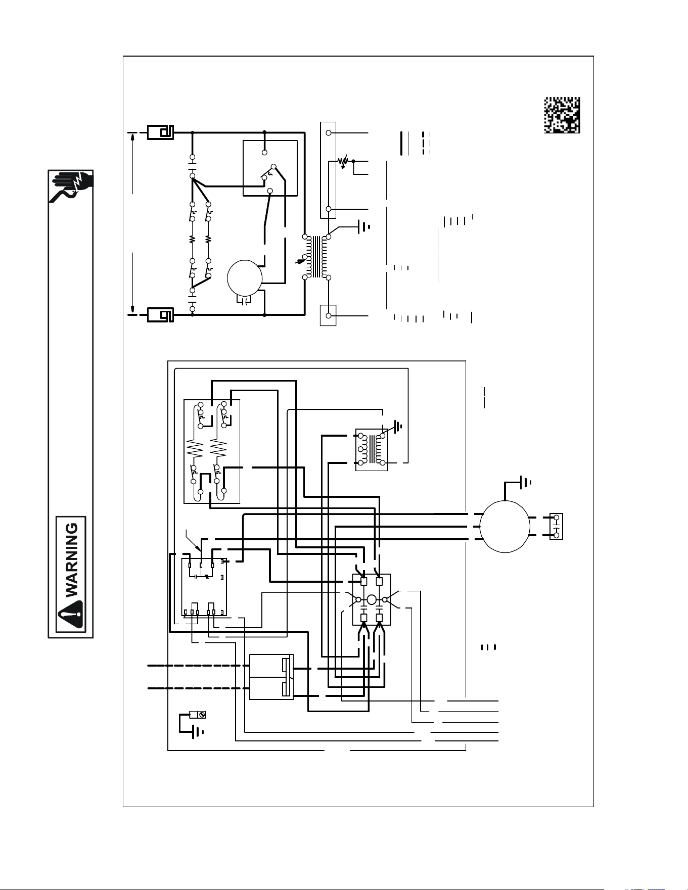
140
WIRING DIAGRAMS
Wiring is subject to change. Always refer to the wiring diagram on the unit for the most up-to-date wiring.
HIGH VOLTAGE!
DISCONNECT ALL POWER BEFORE SERVICING OR INSTALLING THIS
UNIT. MULTIPLE POWER SOURCES MAY BE PRESENT. FAILURE TO
DO SO MAY CAUSE PROPERTY DAMAGE, PERSONAL INJURY OR DEATH.
AWUF180[316,516,816]BD, AWUF240[316,516,816]BD, AWUF241016BD,
AWUF300[516,816]BE, AWUF301016BE, AWUF360[516,816]BE, AWUF361016BE,
AWUT24[05,08,10]14AA
NO TES:
1) REDWIRETOBEONTRANSFO RMER T ERMINAL 3FOR 230VOLTS AN DON
2) TO PLACEAIRHANDLERINHIG HSPEED,REMOVERED MOTORLEAD FRO M ELECTRONIC
3) SEE COMPOSITE WIRING DIAGRAMSININSTALLATIONINSTRUCTIONS FO RPROPER
4) ASTERISK (*) INDICATES THATHEA TING ELEMENT ,THERMAL LIMIT,
CONTROLS SHOWNWITHUTILITIES IN "ON" POSITION ANDTHERMOSTAT IN "OFF"POSITION.
COLORCOD
E WIRING CODE
0140 A00543-B
BLOW ER TIME DELAYRELAY (EBTDR )COM TERMINAL ANDREP LACEWITHBLACK
ANDINTERCO NNECTING WIRESAND JUMPERSOFHEATER#2
AREDELETED WITH SINGLE ELEMEN TUNITS.
MO TORLEAD. ALLUNITS WILL BE FACTOR YCONNECTEDAT LOW SPEE D.
TERMINAL 2FOR 208 VO LTS.
LOWVOLTAGE WIRING CONNECTIONS.
YELLOW
TIME DELAYRELAY
EVAPORATOR MOTOR
ELECTRONIC BLOWER
DISCONNECT SWITCH
EBTDR
DISC
EM
RD RED
BL
YL
BLUE
WH
BK
WHITE
BLACK
COM
PON EN
TCOD
E
TL
HTR
TR
R
FC
GREEN
BROWN
PURPLE
BR
GR
PU
RELAY
FANCAPACITOR
THERMALLIMIT
TRANSFORMER
HEATER ELEMENT
FACTORYWIRING
HIGH VOLTAGE
LOWVOLTAGE
FIELDWIRING
HIGH VOLTAGE
LOWVOLTAGE
TR
RD
24 VOLT45
2
SEENOTE1
1
3
LO
FC
EM
HI
TL1
TL1
HTR1
HTR2
COM
BL
BR
WH
R1
GR
NONC
TL2
TL2
208/230VOLTS
DISC
DISC
EBTDR
OFFDELAY WHEN "G"ISDE-ENERGIZED.
5) EBTDR HAS A7SECONDONDELAY WHEN "G"ISENERG IZED ANDA65SECOND
R
EBTDR
G
C
EBTDR
M2
IF REPLACEMENTOFTHE ORIGINAL WIRESSUPPLIEDWITHTHISASSEMBLY IS NECESSARY, USE105˚C .
WIRE SI ZE TO CONFORMTOTHE NATIONAL ELECTRIC CODE.
5
RD
BL
GR
EM
FC
BR
EVAPORATORMOTOR LEADS
BR
RD
NOTE
SEE
3
DISC
EQUIPMENT
GROUND
DISC
1
4
3
2
TR
HTR1
BK
BK
TL1
TL1
RD
RD
TL2
EBTDR
SEE
NOTE 5
COPPER
POWER SUPPLY
(SEE RATING PLATE)
USEMIN.75˚C FIELDWIRE
N.E.C. CLASS2WIRE
COM
R
NC
NO
UP
C
K1
SPEE D
K1
M1
XFMR-C
EBTDR
XFMR-R
G
M2
L2
RD
L1
BK
BL
BK
RD
GR
RD
BL
RD
BK
RD
PU
BK
N.E.C. CL
AS
S2WIRE
PU COMMON
BK HIGH
RD LOW
L2
T2
HC
HC HEATER CONTACTOR
T1
L1
HC
*
*
*
*
*
HTR2*
TL2*
*
C
L1
L2
T1
T2
BK
BL
BR
WH
RD
RD
BL
RD
PU
BK
BK
BK
RD
RD
BK
RD
BL
RD
RD
RD
RD
WH
BR
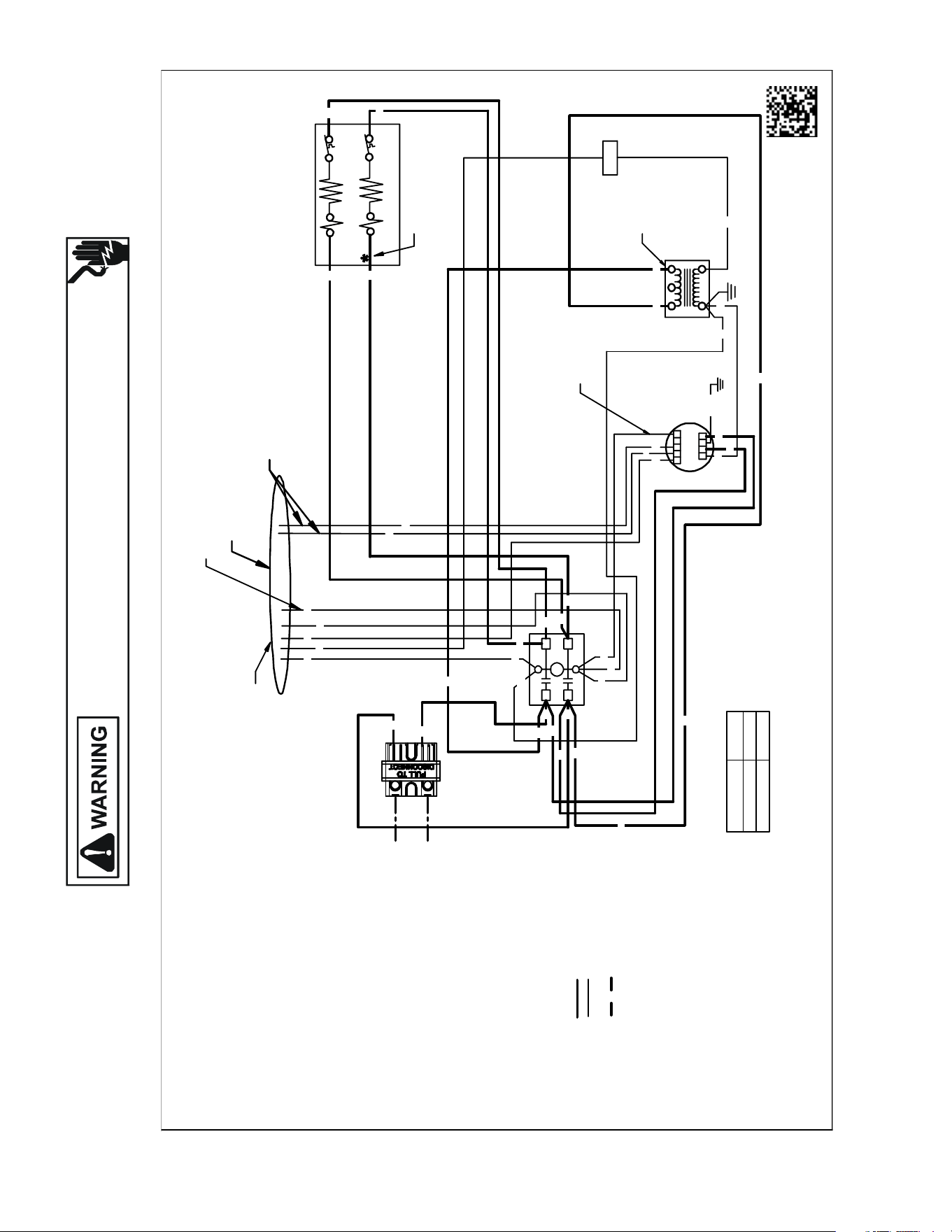
141
WIRING DIAGRAMS
Wiring is subject to change. Always refer to the wiring diagram on the unit for the most up-to-date wiring.
HIGH VOLTAGE!
DISCONNECT ALL POWER BEFORE SERVICING OR INSTALLING THIS
UNIT. MULTIPLE POWER SOURCES MAY BE PRESENT. FAILURE TO
DO SO MAY CAUSE PROPERTY DAMAGE, PERSONAL INJURY OR DEATH.
AWUF190[316,516,816]AC, AWUF250[316,516,816]AC
NOTES:
1. REDWIRETOBEONTRANSFORMER
TERMINAL "3"FOR 230VOLTS ANDON
TERMINAL "2"FOR 208VOLTS.
2. CONFIRMSPEED TAPSELECTEDIS
APPROPRIATEFOR APPLICATION. IF SPEED
TAPS NEEDSTOBECHANGED,CONNECT
APPROPRIATEWIRE FROMMOTOR TO
"Y"FROMTHERMOSTAT/CONDENSER(SEETABLE-1).
3. ASTERISK (*)INDICATES THAT HEATING
ELEMENT, THERMALLIMIT,RELAY AND
INTERCONNECTINGWIRES ANDJUMPERS
OF HEATER #2 AREDELETED WITH SINGLE
ELEMENTUNITS.
4. COLORCODES:
BK -BLACK
BL -BLUE
BR -BROWN
GR -GREEN
PU -PURPLE
RD -RED
WH -WHITE
YL-YELLOW
PK -PINK
5. WIRING CODE:
FACTORYWIRING:
HIGH VOLTAGE
LOWVOLTAGE
FIELDWIRING:
HIGH VOLTAGE
6. COMPONENTCODE:
C- CONTACTOR
DISC -DISCONNECTSWITCH
EM -EVAPORATERMOTOR
F- FUSE
HTR- HEATER ELEMENT
R- RELAY
SEQ- SEQUENCER
TL -THERMAL LIMIT
TR -TRANSFORMER
7. FORUNITS USING3KW AND5KW HEATERS,
WHITEWIREWILLBECONNECTED TO
TERMINAL 4.
BTUh
PURPLE 18 000
PINK 24 000
RD
PK
PK
GR
PU
PU
WH
F
123
54
24V
12345
CL GN
EM
TABLE-1
MOTORCONNECTIONS
ONLY ONEWILL BE CONNECTED
(SEENOTE2)
UNUSED WIRESMUSTHAVE THEIR ENDS TAPE DOR
CAPPED
WIRE COLOR
01 40A005 44-A
SEE NOTE #3
240V
TR
HTR1
HTR2*
TL1
TL2*
DISC
FIELD CONNECTIONS
SEE NOTE 2
USE N.E.C CLASS2WIRE
SEENOTE1
C
L1
L2
T1
T2
BL
BR
WH
BK
RD
BK
BL
WH
WH
RD
RD
BL
RD
BK
BR
BK
BK
BK
BK
RD
RD
RD
RD
GR/YL
BL
BL
BL
BK
GR
RD
BK
BK
BK
BK
BK
RD
RD
RD
OPTIONAL
CONNECTION
SEENOTE7
L2
RD
L1
BK
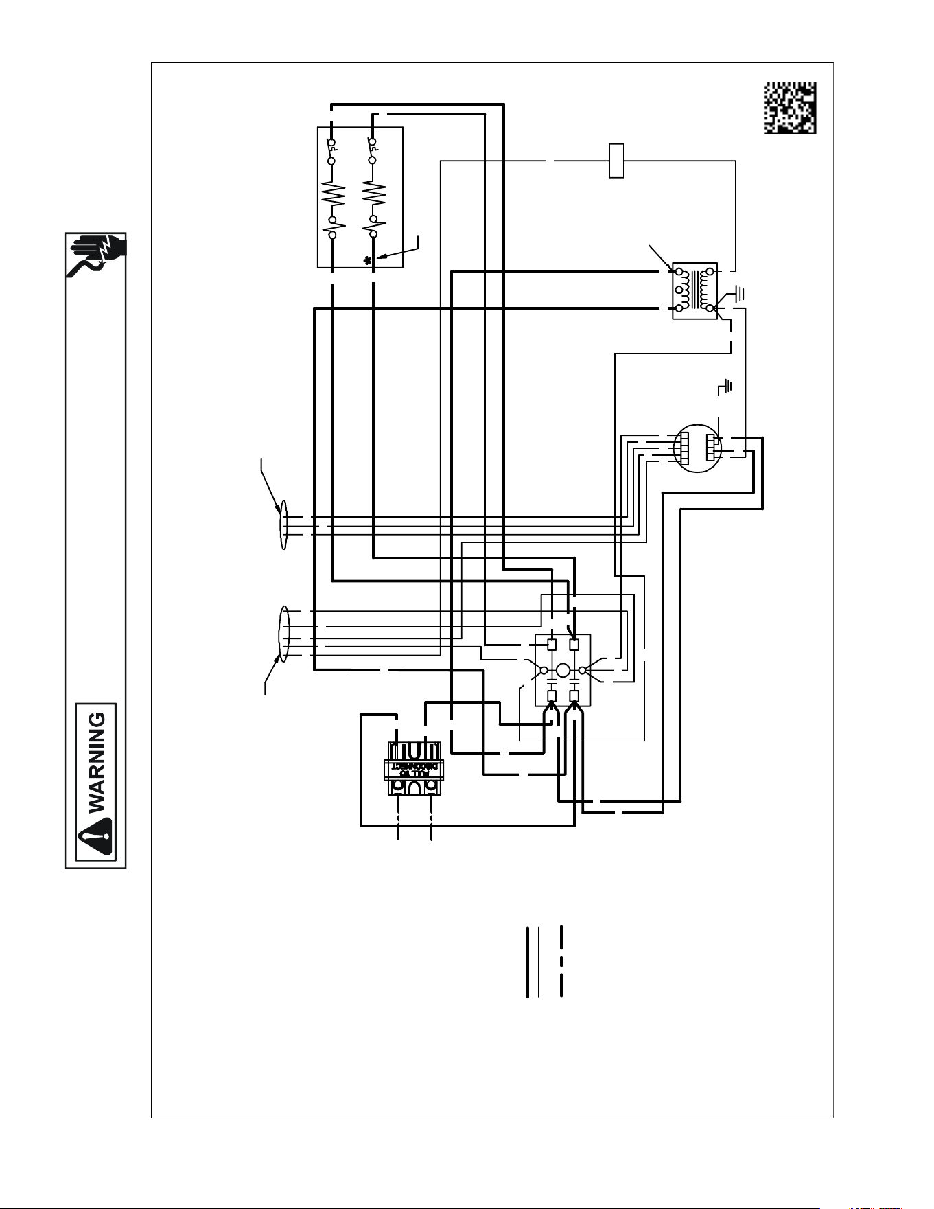
142
WIRING DIAGRAMS
Wiring is subject to change. Always refer to the wiring diagram on the unit for the most up-to-date wiring.
HIGH VOLTAGE!
DISCONNECT ALL POWER BEFORE SERVICING OR INSTALLING THIS
UNIT. MULTIPLE POWER SOURCES MAY BE PRESENT. FAILURE TO
DO SO MAY CAUSE PROPERTY DAMAGE, PERSONAL INJURY OR DEATH.
AWUF370[516,816]BD, AWUF371016BE
0140A005 45-A
F
123
54
24V
12 34 5
CL GN
EM
DISC
FIELDCONNECTIONS
SEE NOTE 3
USEN.E.C CLASS 2WIRE
SPEEDTAPS FROMMOTOR
SEE NOTE 2
SEE NOTE 3
HTR2*
HTR1
TL1
TL2*
240V
TR
NOTES:
1. REDWIRETOBEONTRANSFORMER
TERMINAL "3"FOR 230VOLTS ANDON
TERMINAL "2"FOR 208VOLTS.
2. SEE COMPOSITEWIRINGDIAGRAMSIN
INSTALLATION INSTRUCTIONS FORPROPER
LOWVOLTAGE WIRING CONNECTIONS.
3. ASTERISK (*)INDICATES THAT HEATING
ELEMENT, THERMALLIMIT,RELAY AND
INTERCONNECTINGWIRES ANDJUMPERS
OF HEATER #2 AREDELETED WITH SINGLE
ELEMENTUNITS.
4. COLORCODES:
BK -BLACK
BL -BLUE
BR -BROWN
GR -GREEN
PU -PURPLE
RD -RED
WH -WHITE
YL -YELLOW
5. WIRINGCODE:
FACTORYWIRING
HIGH VOLTAGE
LOWVOLTAGE
FIELD WIRING
HIGH VOLTAGE
LOWVOLTAGE SEE NOTE 2
6. COMPONENTCODE:
C- CONTACTOR
DISC -DISCONNECTSWITCH
EM - EVAPORATER MOTOR
F- FUSE
HTR- HEATER ELEMENT
R- RELAY
SEQ- SEQUENCER
TL - THERMAL LIMIT
TR -TRANSFORMER
SEE NOTE 1
C
L1
L2
T1
T2
RD
GR
BL
BR
PK
WH
PU YL
BK
BK
RD
BK
BK
BL
WH
WH
RD
RD
BL
RD
BK
BR
BK
BK
BK
RD
RD
RD
RD
RD
BK
GR/YL
BL
BL
PK
GR
PU
YL
WH
BL
BK
BK
RD
RD
RD
RD
RD
BL
L2
RD
L1
BK
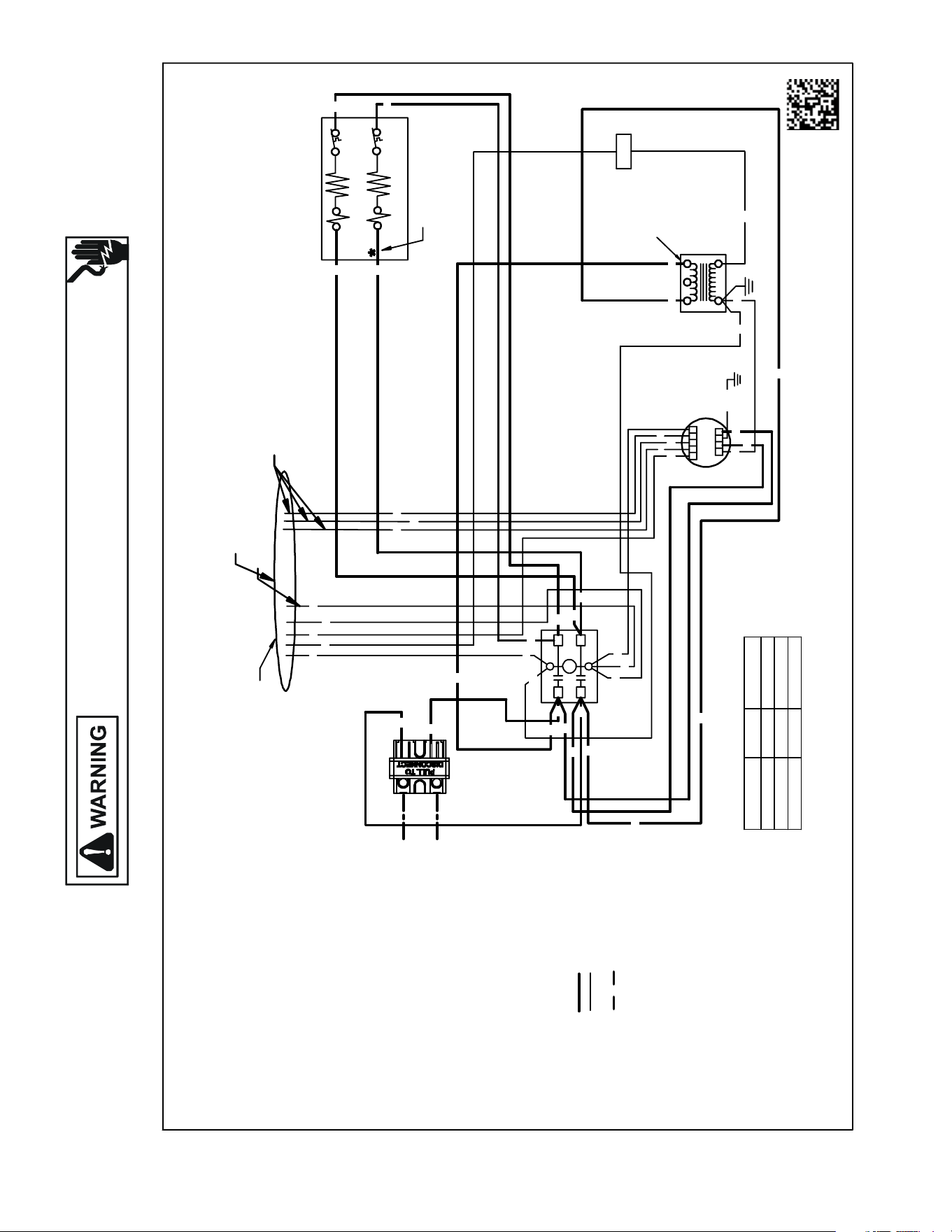
143
WIRING DIAGRAMS
Wiring is subject to change. Always refer to the wiring diagram on the unit for the most up-to-date wiring.
HIGH VOLTAGE!
DISCONNECT ALL POWER BEFORE SERVICING OR INSTALLING THIS
UNIT. MULTIPLE POWER SOURCES MAY BE PRESENT. FAILURE TO
DO SO MAY CAUSE PROPERTY DAMAGE, PERSONAL INJURY OR DEATH.
BT Uh NOMINALCFM
PURPLE 1800 0600
PI NK 2400 0800
YELL OW 3000 0950
RD
PK
PK
GR
PU
PU
YL
WH
F
123
54
24V
12345
CL GN
EM
YL
TABLE- 1
MOTOR CONNECTIONS
ONLY ONEWILL BE CONNECTED
(SEE NOTE 2)
UNU SED WIRESMUST HAVE THEIREND S TAPEDOR
CAPPED
WIRE COLOR
0140A00276 -A
SEE NOTE # 3
240V
TR
HTR 1
HTR 2*
TL1
TL2*
DISC
FIELD CONNECTIONS
SEE NOTE 2
USE N.E.C CLASS2WIRE
SEE NOTE 1
C
L1
L2
T1
T2
BL
BR
WH
BK
RD
BK
BL
WH
WH
RD
RD
BL
RD
BK
BR
BK
BK
BK
BK
RD
RD
RD
RD
GR/YL
BL
BL
BL
NOTES:
1. REDWIRETO BE ON TRANSFORMER
TERMINAL "3"FOR 230VOLTS AND ON
TERMINAL "2"FOR 208VOLTS.
2. CONFIRM SPEED TAPSELECTEDIS
APPROPRIATE FOR APPLICATION. IF SPEED
TAPS NEEDS TO BE CHANGED, CONNECT
APPROPRIATEWIRE FROM MOTOR TO
"Y" FROM THERMOSTAT/CONDENSER (SEE TABLE-1).
3. ASTERI SK (*) INDICATESTHAT HEATING
ELEMENT, THERMAL LIMIT, RELAY AND
INTERCONNECTING WIRESAND JUMPERS
OF HEATER #2 ARE DELETEDWITHSINGLE
ELEMENT UNITS.
4. COLOR CODES:
BK -BLACK
BL - BLUE
BR - BROWN
GR -GREEN
PU - PURPLE
RD -RED
WH -WHITE
YL -YELLOW
5. WIRING CODE:
FACTORYWIRING:
HIGH VOLTAGE
LOWVOLTAGE
FIELDWIRING:
HIGH VOLTAGE
6. COMPONENT CODE:
C - CONTACTOR
DISC -DISCONN ECTSWITCH
EM -EVAPORATER MOTOR
F - FUSE
HTR - HEATER ELEMENT
R -RELAY
SEQ -SEQUENCER
TL - THERMAL LIMIT
TR - TRANSFORMER
OPTIONAL
CONNECTION
BK
GR
RD
BK
BK
BK
BK
BK
RD
RD
RD
AWUF31[05/08]16AB, AWUF321016AB
AWUF[19,25]**
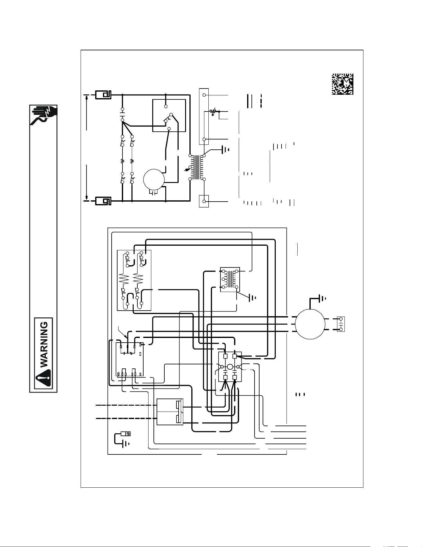
144
WIRING DIAGRAMS
Wiring is subject to change. Always refer to the wiring diagram on the unit for the most up-to-date wiring.
HIGH VOLTAGE!
DISCONNECT ALL POWER BEFORE SERVICING OR INSTALLING THIS
UNIT. MULTIPLE POWER SOURCES MAY BE PRESENT. FAILURE TO
DO SO MAY CAUSE PROPERTY DAMAGE, PERSONAL INJURY OR DEATH.
NOTES :
1) REDWIRETOBEONTRANSFORMER TERMINAL 3 FOR 23 0VOLTS ANDON
2) TO PLACEAIRHANDLERINHIGHSPE ED,REMOVERED MOTORLEADFROMELECTRONI C
3) SEECOMPOSITE WIRING DIAGRAMS IN INSTALLA TION INSTRUCT IONS FORPROPE R
4) ASTERISK (*)INDICATES TH AT HEATIN GELEMENT ,THERMAL LI MIT,
CONTROLS SHOWNWIT HUTILITIESIN "ON" POSITION ANDTHERMOSTAT IN "OFF"POSITIO N.
COLOR CO
DE WIR ING CODE
0140A002 82-A
BLOWER TIME DE LAYRELAY (EBTDR)COM TERMINAL ANDREPLACE WITH BLACK
RELAY(SEQUENCER) ANDINTERCONNEC TING WIRESAND JUMP ERSOFHEATER#2
AREDELETED WITH SINGLE ELEMENTUNITS .
MOTOR LE AD. ALL UNIT SWILL BE FACT ORY CONNECTED AT LOW SPEED.
TERMINAL 2FOR 208VOL TS.
LOWVOLTA GE WIRING CONNECTI ONS.
YELLOW
TIME DELAY RELAY
EVAPORATOR MOTOR
ELECTRONIC BLOWER
DISCONNECT SWITCH
EBTDR
DISC
EM
RD RED
BL
YL
BLUE
WH
BK
WHITE
BLACK
COMPO
NE NT CODE
TL
HTR
TR
R
FC
GREEN
BROWN
PURPLE
BR
GR
PU
NOTE 3
RELAY
FAN CAPACITOR
THERMAL LIMIT
TRANSFORMER
HEATER ELEM EN T
FACTOR Y WIRING
HIGH VO LTAGE
LOW VOLTAGE
FIELD WI RING
HIGH VO LTAGE
LOW VOLTAGE
TR
RD
24 VOLT45
2
SEENOTE 1
1
3
LO
FC
*
EM
HI
TL1
TL1
HTR 1
HTR 2
COM
BL BR
WH
R1
GR
NONC
TL2
TL2
208/230 VOLTS
DISC
* *
DISC
EBTDR
OFFDELAY WHEN "G"ISDE-ENERGIZED.
5) EBTDRHAS A7SECONDONDELAY WHEN "G"ISENERGIZEDAND A65SECOND
R
EBTDR
G
C
EBTDR
M2
IF REPL ACEMENTOFTHE ORIGINAL WIRESSUPPLIEDWIT HTHISASSEMBLY IS NECESSARY, USE 105˚ C.
WIRE SIZE TO CONFORMTOTHE NATIONAL ELECTRICCODE.
C
L2
L1
T2
T1
4
RD
WH
BR
RD
BL
GR
EM
FC
BR
EVAPORATOR MOTOR LEADS
BR
RD
RD
NOTE
SEE
3
DISC
EQUIPMENT
GROUND
DISC
3
5
BK
12
TR
RD
HTR2*
HTR1
*
BK
BK
TL1
TL1
RD
*
RD
TL2*
TL2
EBTDR
SEE
NOTE 5
COPPER
POWERSUPPLY
(SEE RATING PLATE)
USEMIN. 75˚C FIELDWIRE
N.E.C. CLASS2WIRE
COM
R
NC
NO
UP
C
K1
SPEED
K1
M1
XFMR-C
EBTDR
XFMR-R
G
M2
L2
L1
BL
BK
RD
RD
RD
BK
BL
WH
BR
RD
RD
BK
BK
BL
GR
RD
RD
RD
RD
RD
BK
RD
PU
BK
RD
CCONTACTOR
N
.E.C. CLASS 2 WIRE
PU COMMON
BK HIGH
RD LOW
RD
BK
2T2L
HC
HC HEATER CONTACTOR
AWUF18[03/05/08]16BB AWUF24[03/05/08/10]16BB AWUF30[05/08/10]16BC
AWUF36[05/08/10]16BC
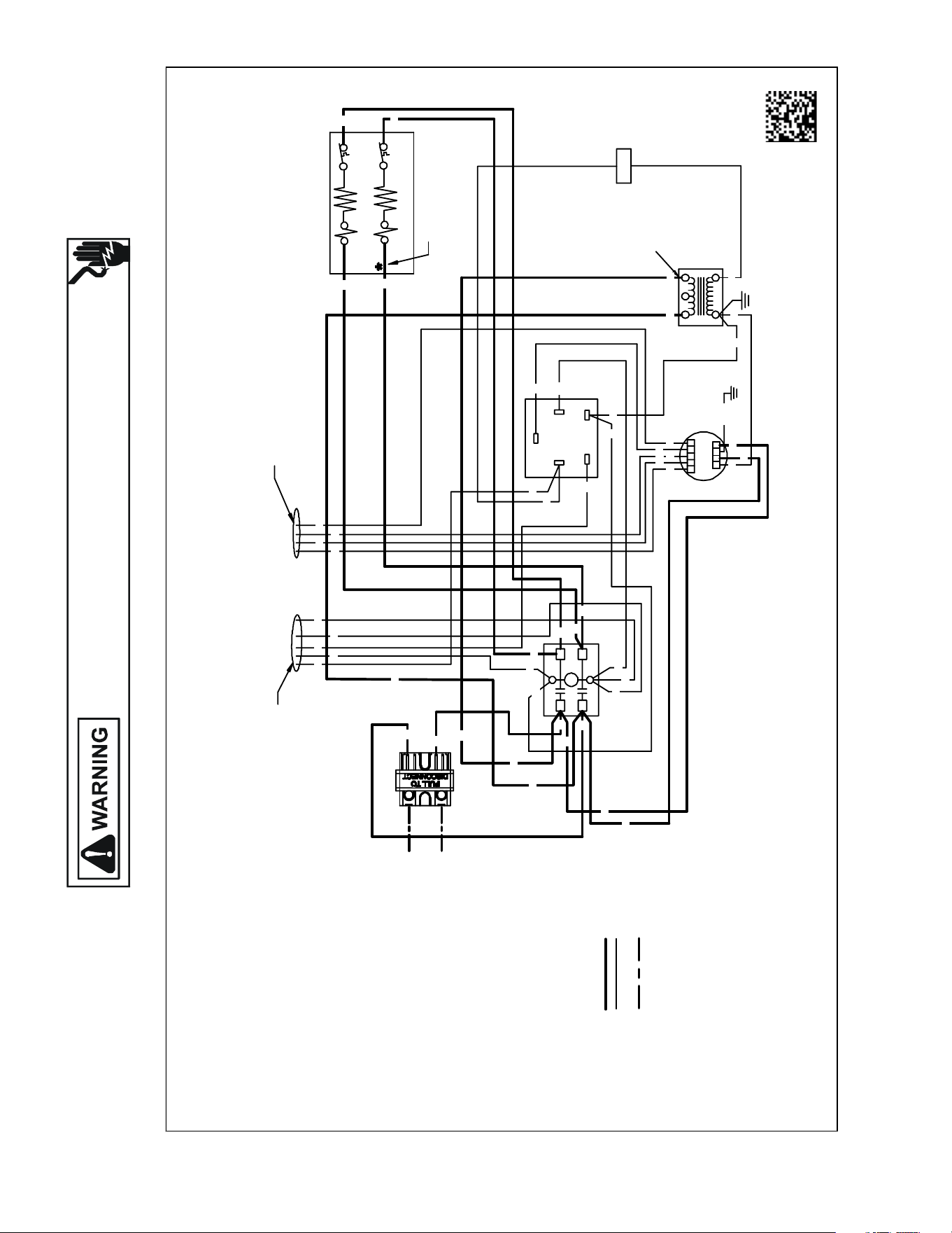
145
WIRING DIAGRAMS
Wiring is subject to change. Always refer to the wiring diagram on the unit for the most up-to-date wiring.
HIGH VOLTAGE!
DISCONNECT ALL POWER BEFORE SERVICING OR INSTALLING THIS
UNIT. MULTIPLE POWER SOURCES MAY BE PRESENT. FAILURE TO
DO SO MAY CAUSE PROPERTY DAMAGE, PERSONAL INJURY OR DEATH.
AWUF37[05/08/10]16BB
0140A00275-A
F
123
54
24V
12345
CL GN
EM
DISC
FIELD CONNECTIONS
SEE NOTE 3
USE N. E.C CLASS 2WIRE
SPEEDTAPS FROM MOTOR
SEE NOTE 2
SEE NOTE 4
HTR 2*
HTR 1
TL1
TL2*
240V
TR
NOTES:
1. RED WIRE TO BE ON TRANSF ORMER
TERMINAL "3" FOR 230 VOLTS AND ON
TERMINAL "2" FOR 208 VOLTS.
2. CONFIRM SPEEDTAP SELECTED IS
APPROPRIAT E FORAPPLICATION.IFSPEED
TAPS NEEDS TO BE CHANGED, CONNECT
APPROPRIAT EWIRE FROM MOTORTO
TERMINAL "4" ON RELAY.
3. SEE COMPOSITEWIRING DIAGRAMS IN
INSTALLATION INSTRUCTIONS FOR PROPER
LOWVOLTAGE WIRING CONNECTIONS.
4. ASTERISK (*) INDICATESTHAT HEATING
ELEMENT, THERMALLIMIT, RELAY AND
INTERCONNECTINGWIRES ANDJUMPERS
OF HEATER #2 ARE DELETEDWITHSINGLE
ELEMENT UNITS.
5. COLOR CODES:
BK -BLACK
BL - BLUE
BR - BROWN
GR -GREEN
PU - PURPLE
RD -RED
WH -WHITE
YL -YELLOW
6. WIRING CO DE:
FACTORYWIRING
HIGH VOLTAGE
LOWVOLTAGE
FIELDWIRING
HIGH VOLTAGE
LOWVOLTAGE SEE NOTE 3
7. COMPONENT CODE:
C - CONTACTOR
DISC -DISCO NNECT SWITCH
EM -EVAPORATER MOTOR
F-
FUSE
HTR - HEATER ELEMENT
R -RELAY
SEQ -SEQUE NCER
TL - THERMAL LI MIT
TR - TRANSFORMER
SEE NOTE 1
C
L1
L2
T1
T2
R
RD
GR
BL
BR
BR
OR
WH
WH YL
BK
BK
RD
BK
BK
BL
WH
WH
RD
RD
BL
RD
BK
BR
BK
BK
BK
RD
RD
RD
RD
RD
BK
GR
GR/YL
BL
BL
BL
BR
OR
WH
WH
PU
PU
YL
BL
RD
RD
BL
13
52
R
4
BK
BK
RD
RD
RD
RD
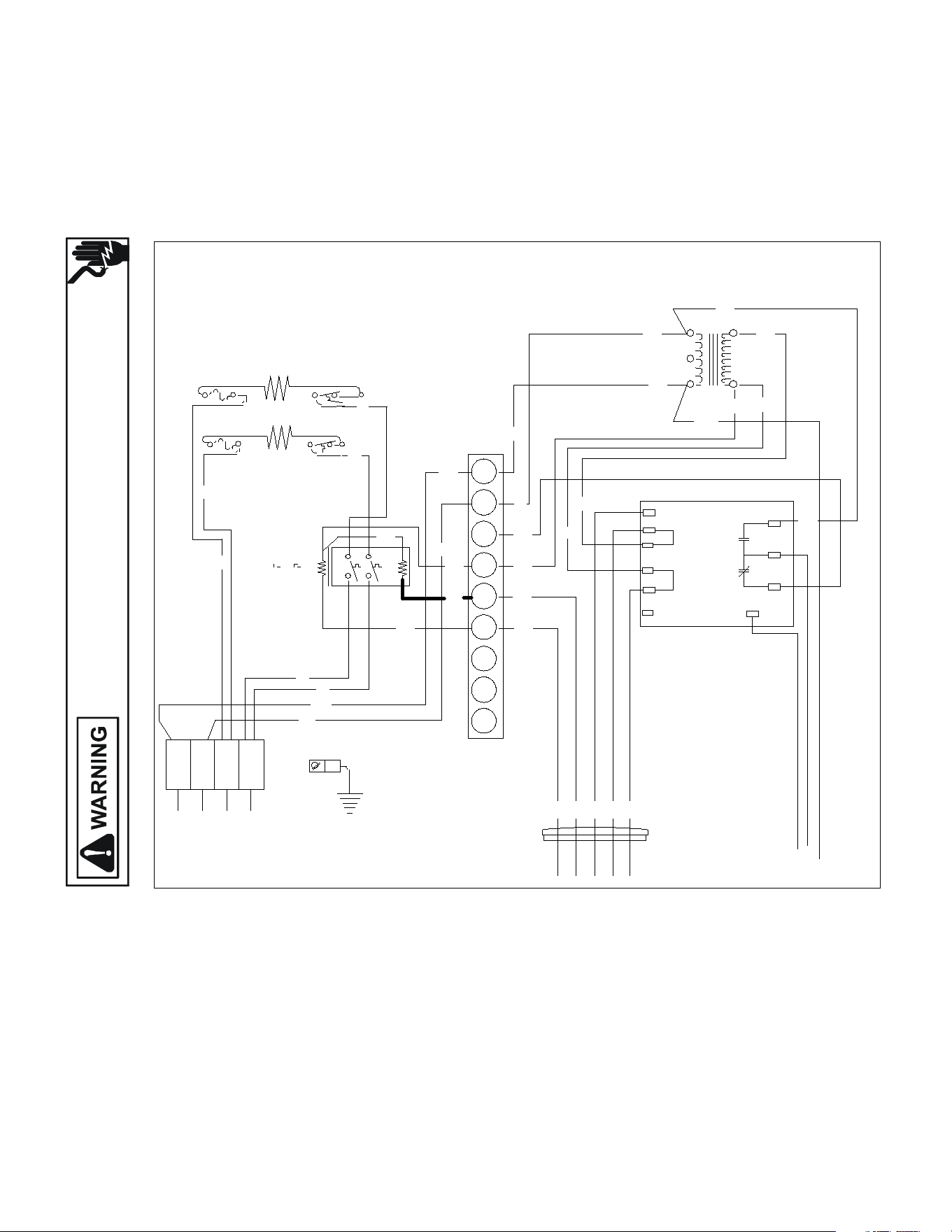
146
WIRING DIAGRAMS
Wiring is subject to change. Always refer to the wiring diagram on the unit for the most up-to-date wiring.
HIGH VOLTAGE!
DISCONNECT ALL POWER BEFORE SERVICING OR INSTALLING THIS
UNIT. MULTIPLE POWER SOURCES MAY BE PRESENT. FAILURE TO
DO SO MAY CAUSE PROPERTY DAMAGE, PERSONAL INJURY OR DEATH.
MBR
COM
XFMR-C
XFMR-R
SPEEDUP
C
NC
M1
K1
R
G
NO
K1
USE COPPER OR ALUMINUM WIRE
EQU IPMENT GRO UND
3 5
2
1 4
TR
PC
PU
L1 L2
BL
W
BR
SR
PK
G
W
BR
BL
PU
R
BK
R
R
R
BK
BL
BL
R
208/240
24V
BL
R
M6
M5
RS2
W
BR
BL
BL
L1 L2
BK
BK
R
R
Y
Y
Y
M8
M7
BL
BL
BL
EBTDR
HTR2
FL HTR3
TL
FL
HTR4 TL
8
9
7
6
5
4
3
1
2
Typical Wiring Schemac MBR Blower with Electric Heat.
This wiring diagram is for reference only. Not all wiring is as shown above.
Refer to the appropriate wiring diagram for the unit being serviced.
USE COPPER WIRE
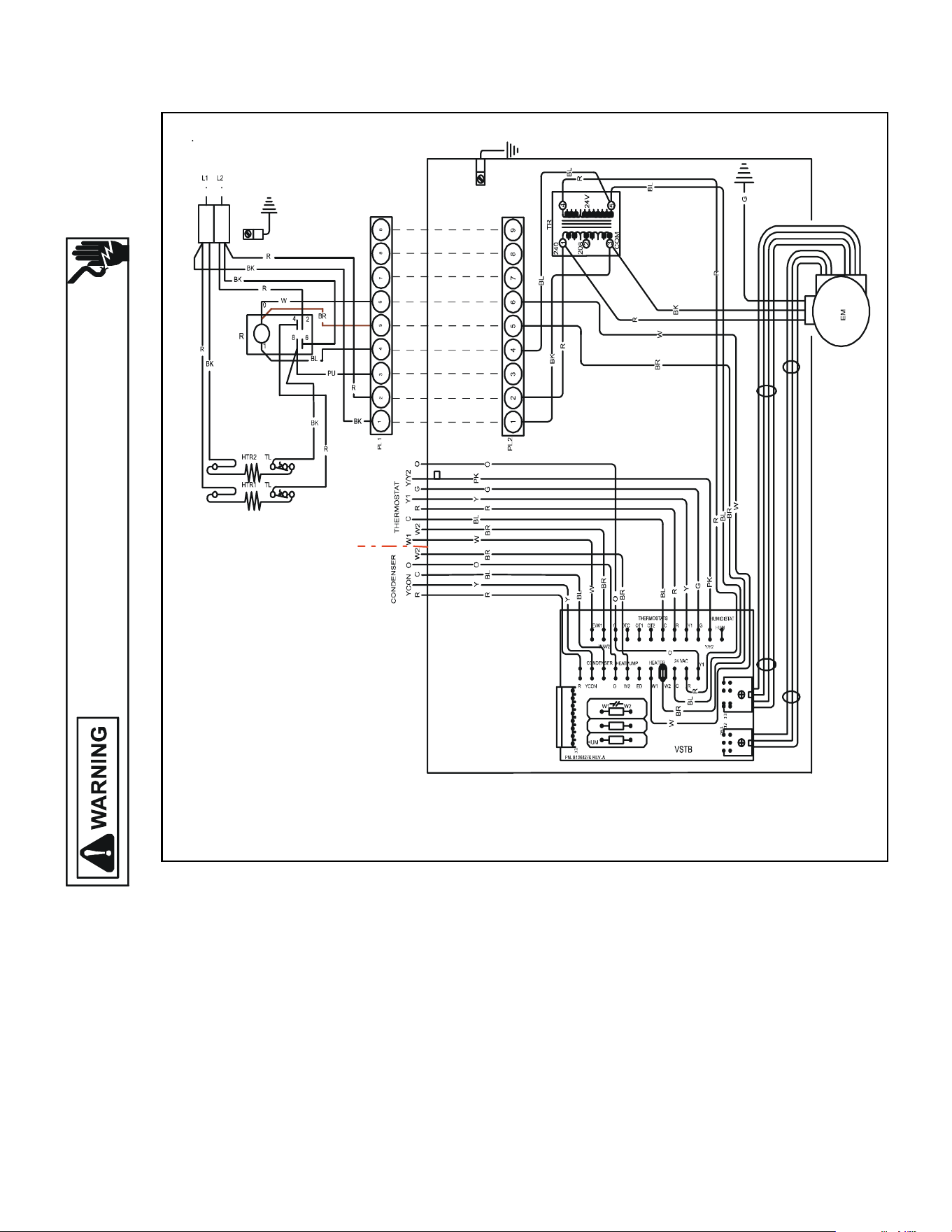
147
WIRING DIAGRAMS
Wiring is subject to change. Always refer to the wiring diagram on the unit for the most up-to-date wiring.
MBE
HIGH VOLTAGE!
DISCONNECT ALL POWER BEFORE SERVICING OR INSTALLING THIS
UNIT. MULTIPLE POWER SOURCES MAY BE PRESENT. FAILURE TO
DO SO MAY CAUSE PROPERTY DAMAGE, PERSONAL INJURY OR DEATH.
` lj
l rqal lo
ql
ql
l qO
l qN
mgO
mgS
mgQ
Blower Secon
HKR Heat Kit
Typical Wiring Schemac MBE Blower with Electric Heat.
This wiring diagram is for reference only.
Not all wiring is as shown above.
148
WIRING DIAGRAMS
Wiring is subject to change. Always refer to the wiring diagram on the unit for the most up-to-date wiring.
HIGH VOLTAGE!
DISCONNECT ALL POWER BEFORE SERVICING OR INSTALLING THIS
UNIT. MULTIPLE POWER SOURCES MAY BE PRESENT. FAILURE TO
DO SO MAY CAUSE PROPERTY DAMAGE, PERSONAL INJURY OR DEATH.
WIRING DIAGRAMS - REMOTE SPLITS A/C
REMOTE - SPLITS
A/C
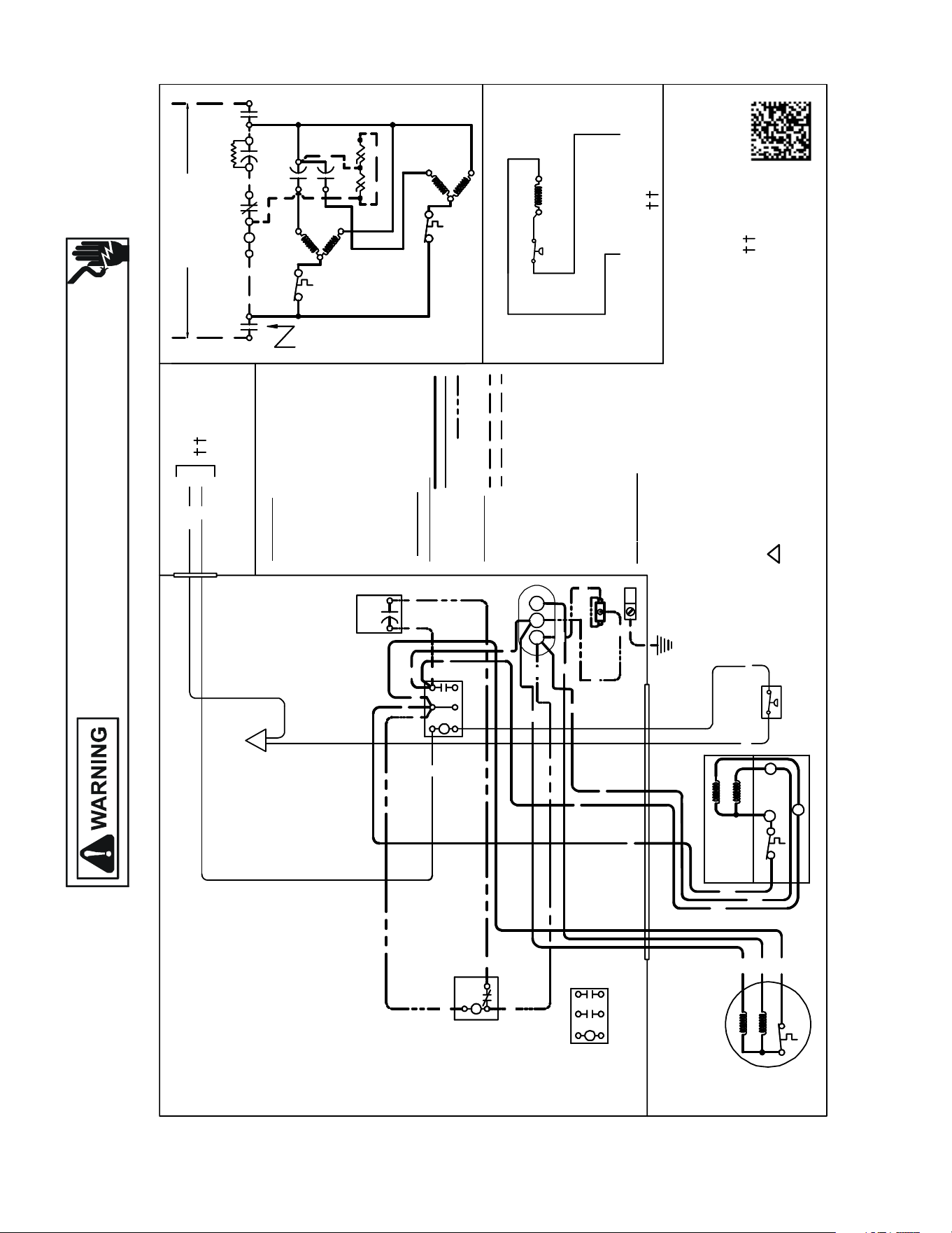
149
WIRING DIAGRAMS
Wiring is subject to change. Always refer to the wiring diagram on the unit for the most up-to-date wiring.
HIGH VOLTAGE!
DISCONNECT ALL POWER BEFORE SERVICING OR INSTALLING THIS
UNIT. MULTIPLE POWER SOURCES MAY BE PRESENT. FAILURE TO
DO SO MAY CAUSE PROPERTY DAMAGE, PERSONAL INJURY OR DEATH.
ANX130[18-24]1A*
COMP
ALTERNATEDOUBLE
POLE CONTACTOR ONLY
IO
T1
C
M
A
I
N
R
A
U
X
5
S
SR
SA
2
1
RC CF
SC
T2
C
L1
L2
(IF USED)
CH
C
F
M
A
I
N
A
U
X
IO
CM
C
Y
BL
YL
C
Y
LVJB
T1
L1
T2
L2
ALTERNATE DOUBLE
POLE CONTACTOR
OUTDOORPOWER SUPPLY
SEERATINGPLATE
WIR
I
N
G CODE
FACTORY WIR ING
HIGH VOLTAGE
LOWVOLTAGE
OPTIONAL HIGHVOLTAGE
FI
ELD W IR ING
HIGH VOLTAGE
LOWVOLTAGE
BK
SC
RD
BL
RD
RD
RD
BKBK
BK
C
T1
L1
T2
L2
RD
YL
RD
BK
MAIN
COMP
IO
CM
AUX
MAIN
BK
BR
PU
SR
5
2
1
BL
EQUIPMENT GROUND
COLO R
CO DE
BK --------------- BLACK
BL --------------- BLUE
BR --------------- BROWN
OR ---------------ORANGE
PU --------------- PURPLE
RD --------------- RED
WH -------------- WHITE
YL ---------------YELLOW
RD
SA
(IF USED)
NOTE2
C
IO
IO
R
S
AUX
USEN.E.C.
CLASS2WIRE
NOTES:
1) TO INDOOR UNIT LOWVOLTAGE
TERMINAL BLOCK& INDOOR
THERMOSTAT.
2) STARTASSIST FACTORY
EQUIPPEDWHENREQUIRED.
3) USECOPPE RCONDUCTORS
ONLY.
COMP
ALTERNATEDOUBLE
POLE CONTACTOR ONLY
IO
T1
C
M
A
I
N
R
A
U
X
5
S
SR
SA
2
1
RC CF
SC
T2
C
L1
L2
(IF USED)
CH
C
F
M
A
I
N
A
U
X
IO
CM
C
C
BL C
Y
LVJB
SEE NOTE 1
CO M
PO
N
E
NT CODE
C--------------- CONTACTOR
CSM -------- CORESENSEMODULE
CM ------------ OUTDOORFAN MOTOR
COMP--------COMPRESSOR
IO --------------INTERNALOVERLOAD
LVJB ---------- LOWVOLTAGE JUNCTION BOX
RCCF ---------RUN CAPACITORFOR COMPRESSOR &FAN
SA ------------- STARTASSIST
SC -------------STARTCAPACITORFOR COMPRESSOR (OPTIONAL)
SR -------------START RELAY FORCOMPRESSOR(OPTIONAL)
LPS------------LOW PRESSURE SWITCH
------------- CRIMPCAP
CONTROLSSHOWN WITH THERMOSTAT IN 'OFF'POSITION.
T1
L1
T2
L2
ALTERNATE DOUBLE
POLE CONTACTOR
WIR
I
N
G CODE
FACTORY WIR ING
HIGH VOLTAGE
LOWVOLTAGE
OPTIONAL HIGHVOLTAGE
FI
ELD W IR ING
HIGH VOLTAGE
LOWVOLTAGE
RD
BK
YL/PK
LVJB
CONTROL BOX
SC
RD
BL
RD
BL
RD
RD
BK
BK
BK
C
T1
L1
T2
L2
RC CF
BR
RD
YL
RD
BK
MAIN
COMP
IO
AUX
MAIN
BK
BR
PU
SR
5
2
1
BK
YL
BL
COLO R
CO DE
BK --------------- BLACK
BL --------------- BLUE
BR --------------- BROWN
OR ---------------ORANGE
PU --------------- PURPLE
RD --------------- RED
WH -------------- WHITE
YL ---------------YELLOW
YL/PK----------YELLOW/PINK STRIPE
SA
(IF USED)
NOTE2
SEE
NOTE 3
C
IO
IO
R
S
AUX
0140R00331-C
LPS
YL/PK
LPS
YL
SEENOTE1
PU
H
F
C
RD
YL
YL
YL
YL
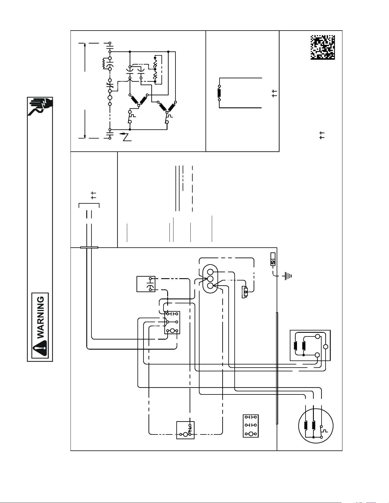
150
WIRING DIAGRAMS
Wiring is subject to change. Always refer to the wiring diagram on the unit for the most up-to-date wiring.
HIGH VOLTAGE!
DISCONNECT ALL POWER BEFORE SERVICING OR INSTALLING THIS
UNIT. MULTIPLE POWER SOURCES MAY BE PRESENT. FAILURE TO
DO SO MAY CAUSE PROPERTY DAMAGE, PERSONAL INJURY OR DEATH.
ANX130[30-61]1A*
ANX140[18-60]1A*
USEN.E.C.CLASS 2WIRE
COMP
ALTERNATE DOUBLE
POLE CONTACTORONLY
IO
T1
C
M
A
I
N
R
A
U
X
5
S
SR
SA
2
1
RCCF
SC
T2
C
L1 L2
(IFUSED)
CH
C
F
M
A
I
N
A
U
X
C
C
0140R00015P-C
BL
Y
C
LVJB
COL OR C O
DE
BK ---------------BLACK
BL ---------------BLUE
BR --------------- BROWN
OR --------------- ORANGE
PU --------------- PURPLE
RD --------------- RED
WH -------------- WHITE
YL ---------------- YELLOW
CONTROLBOX
COMP O
NE
NT CO
DE
C--------------- CONTACTOR
CM ------------ OUTDOOR FAN MOTOR
COMP-------- COMPRESSOR
IO --------------INTERNALOVERLOAD
LVJB ----------LOW VOLT AGEJUNCTION BOX
RCCF --------- RUN CAPACITORFOR COMPRESSOR &FAN
SA ------------- STARTASSIST
SC ------------- START CAPA CITORFOR COMPRESSOR (OPTIONAL)
SR ------------- START RELAYFOR COMPRESS OR (OPTIONAL)
CONTROLS SHOWN WITH THERMOSTAT IN 'OFF' POSITION.
OUTDOOR POWER SUPPLY
SEERATINGPLATE
WIRING CO DE
FACTOR Y WIRING
HIGH VOLTAGE
LOWVOLTAGE
OPTIONAL HIGH VOLTAGE
FI
E LD
WIRING
HIGH VOLTAGE
IO
CM
Y
YL
YL
C
R
S
RD
BK
AUX
MAIN
COMP
SEENOTE1
SC
RD
BL
RCCF
YL
PU
YL
SR
5
2
1
BK
YL
BL
RD
YL
BL
RD
RD
BK
BK
BK
C
T1
L1
T2
L2
SA
(IFUSE D)
NOTE 2
EQUIPMENTGROUN D
SEE NOTE 3
PU
BR
BK
MAIN
AUX
CM
IO
T1
L1
T2
L2
ALTERN ATE DOUBLE POLE
CONTACTOR
NOTES:
1) TO IND OOR UNIT LOWVOLTAGE TERMINAL BLOCK&
INDOOR THERMOSTAT.
2) STARTASSISTFACTORY EQUIPPED WHEN REQUIRED.
3) USE COPPER CONDUC TORS ONLY.
CFH
RD
RD
RD
BR
SEENOTE1
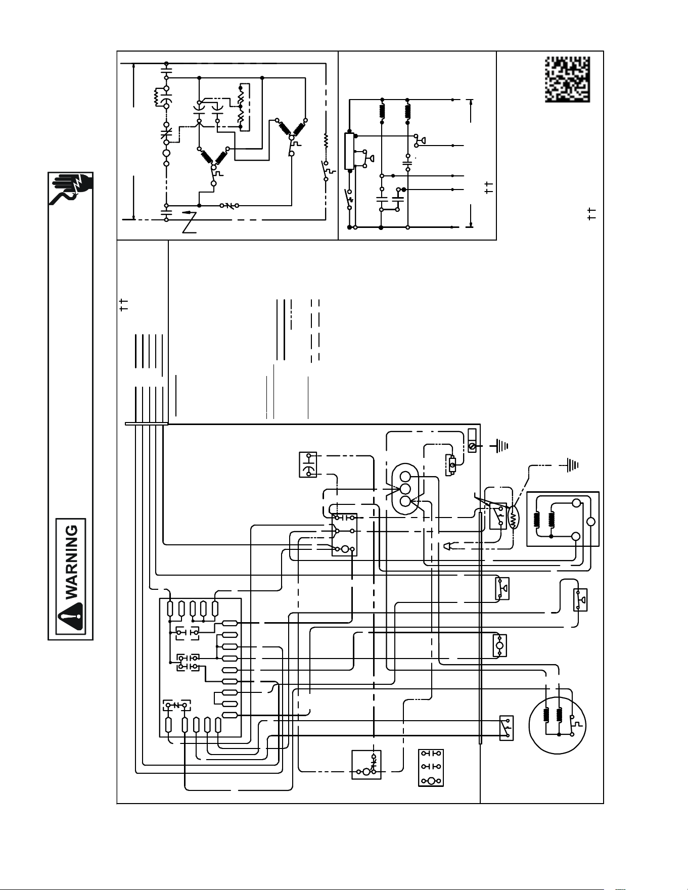
151
WIRING DIAGRAMS
Wiring is subject to change. Always refer to the wiring diagram on the unit for the most up-to-date wiring.
HIGH VOLTAGE!
DISCONNECT ALL POWER BEFORE SERVICING OR INSTALLING THIS
UNIT. MULTIPLE POWER SOURCES MAY BE PRESENT. FAILURE TO
DO SO MAY CAUSE PROPERTY DAMAGE, PERSONAL INJURY OR DEATH.
ANZ130[18-60]1A*
INDOOR PO WER SUPPLY
NOTES:
1. TO INDOOR UNIT LOWVOLTAGE TERMINAL BLOCK&INDOOR THERMOSTAT.
2. START ASSIST FACTORYEQUIPPED WHEN RE QUIRED.
3. USE COPPER CO NDUCTOR ONLY.
4. CRANKCASE HEATER & CR ANKCASE HEATER SWITCH ARE FACTORYINSTALLED OPTION.
CRANKCASE HEATER MA Y NOT HAVE ADDITIONAL GROUND WIRE
5. 40VA MINIMUM TRANSFORMER IS REQUIRED.
6. COMMON SIDE OF TRANSFORMER MUST BE GROUNDED.
COMP
ALTERNATE DOUBLE
POLE CONTACTORONLY
IO
T1
C
M
A
I
N
R
A
U
X
5
S
SR
SA
2
1
RCCF
SC
T2
C
L1
L2
(IFUSED)
NOTE 2
CH
C
F
M
A
I
N
A
U
X
IO
CM
0140R00171 -D
OR
BL/PK
BL
RD
O
Y
C
R
COL OR C
ODE
BK --------------- BLACK
BL/PK ---------- BLUE/PINKSTRIPE
BR --------------- BROWN
GR---------------- GREEN
OR --------------- ORANGE
PU --------------- PURPLE
RD --------------- RED
WH -------------- WHITE
YL ---------------YELLOW
YL/PK----------- YELLOW/PINK STRIPE
COMPONENT CODE
C------------ --- CONTACTOR
CADM -------- COMFORT ALERT DIAGNOSTIC MODULE
CCR----------- COMPRESSOR CONTACTOR RELAY
CH ------------- CRANKCASE HEATER
CHS----------- CRANKCASE HEATER SWITCH
CM ------------ OUTDOOR FAN MOTOR
CMR ---------- CONDENSER MOTOR RELAY
COMP -------- COMPRESSOR
CS ------------- COMPRESSOR SOLENOID
DC ------------- DEFROST CONTROL
DFT----------- DEFROST THERMOSTAT
DT ------------- DISCHARGE TH ERMOSTAT
HPS ----------- HIGH PRESSURE SWITCH
HVDR -------- HIGH VOLTAGE DEFROST RELAY
IO -------------- INTERNAL OVERLOAD
LPS ---------- LOW PRESSURE SWITCH
LVDR --------- LOWVOLTAGE DEFROST RELAY
LVJB ------ --- LOWVOLTAGE JUNCTION BOX
RCCF --------- RUNCAPACITOR FOR CO
MPRESSOR & FAN
RVC----------- REVERSING VALVE COIL
SA ------------- STARTASSIST
SC ------------- START CAPACITOR FOR COMPRESSOR (OPT IONAL)
SR ------------- START RELAY FOR COMPRESSOR (OPTIONAL)
CONTROLS SHOWNWITH THERMOSTAT IN 'OFF' POSITION.
OUTDOOR POWER SUPP LY
SEE RATINGPLATE
LVJB
CONTROL BOX
SC
RD
BL
L2
T2
L1
T1
C
BK
BK
BK
RD
RD
BL
RD
RCCF
YL
BR
PU
RD
SR
5
2
1
BK
YL
BL
IO
CM
AUX
MAIN
BR
PU
YL
RD
BK
YL/PK
LPS
DF1
DF2
CH
LVDR
R
CNT
DFT
C
Y
DC
DFT
WH
W2
DC
BL/PK
HPS
O
C
RVC
W2
R
HVDR
YL/PK
BK
BK
BL
BL
CHS
R-DFT
C-RV
LPS
PS2
O
W
C
HPS
CCR
}
FIELDLOW
VOLTAGE
CONNECTIONS
RD
BK
CH
SA
(IFUSED)
NOTE 2
DFT
RVC
RD
BK
BL/PK
BK
Y
T1
L1
T2
L2
R
DF1
DF2
0
0-RV
C-RV
W
LVDR
HVDR
CCR
CNT
0
DFT
R-DFT
R-PS 1
Y
Y
C
R
C
C
PS2
RD
RD
BK
BK
SEENOTE 4
SEE NO TE 5& 6
BK
BK
RD
SEE NOTE 1
EQUIPMENTGROUND
SEENOT E 3
ALTERNATE
DOUBLE POLE
CONTAC TOR
WH BK
BL/PK
YL/P K
YL/P K
OR
PU
PU
CHS
C
R
S
AUX
MAIN
COMP
HFC
RD
RD
YL
YL
GR
USE N.E.C. CLASS2WIRE
SEE NOTE 4
RD
R-PS1
O-RV
W
IRING CO
DE
FACTORY W
IRING
HIGH VOLTAGE
LOWVOLTAGE
OPTIONAL HIGH VOLTAGE
FIELD
W
IRING
HIGH VOLTAGE
LOWVOLTAGE
SEE NOTE 1
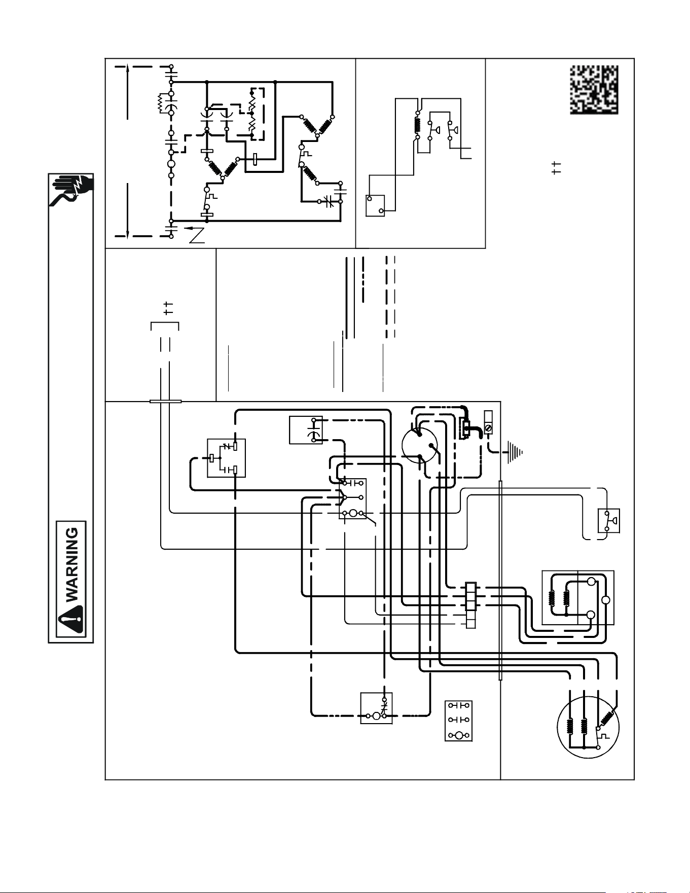
152
WIRING DIAGRAMS
Wiring is subject to change. Always refer to the wiring diagram on the unit for the most up-to-date wiring.
HIGH VOLTAGE!
DISCONNECT ALL POWER BEFORE SERVICING OR INSTALLING THIS
UNIT. MULTIPLE POWER SOURCES MAY BE PRESENT. FAILURE TO
DO SO MAY CAUSE PROPERTY DAMAGE, PERSONAL INJURY OR DEATH.
ASX130[18-48]1C[A/B]/ASX130601CA
USE N.E.C. CLASS 2 WIRE
COMP
ALTERNATE DOUBLE
POLE CONTACTOR ONLY
IO
T1
C
M
A
I
N
R
A
U
X
5
S
SR
CADM
SA
2
1
RCCF
SC
T2
C
L1
L2
(IF USED)
CH
C
C
A
D
M
CADM
F
C
A
D
M
M
A
I
N
A
UX
IO
CM
(
L
OW
)
3
2
(HIGH)
1
C
Y
C
LPS
Y
C
BL
YL/PK
C
Y
LVJB
NOTE 1
COMPONENT CODE
C --------------- CONTACTOR
CADM -------- COMFORT ALERT MODULE
CM ------------ OUTDOOR FAN MOTOR
COMP -------- COMPRESSOR
HPS ----------- HIGH PRESSURE SWITCH
IO -------------- INTERNAL OVERLOAD
LAT ------------ LOW AMBIENT THERMOSTAT
LPS ------------ LOW PRESSURE SWITCH
LVJB ---------- LOW VOLTAGE JUNCTION BOX
RCCF --------- RUN CAPA CITOR FOR COMPRESSOR & FAN
SA ------------- START ASSIST
SC ------------- START CAPA CITOR FOR COMPRESSOR (OPTIONAL)
SR ------------- START RELAY FOR COMPRESSOR (OPTIONAL)
CONTROLS SHOWN WITH THERMOSTAT IN 'OFF' POSITION.
T1
L1
T2
L2
ALTERNATE DOUBLE
POLE CONTACTOR
OUTDOOR POWER SUPPLY
SEE RATING PLATE
WIRING
CO DE
FA C
T
O RY WI
RI N
G
HIGH VOLTAGE
LOW VOLTAGE
OPTIONAL HIGH VOLTAGE
FIE
L
D
WI
RI
NG
HIGH VOLTAGE
LOW VOLTAGE
S
CR
BK
RD YL
Y
C
CADM
BL
YL
RD
BK
YL
LVJB
CONTROL BOX
RD
2
1
3
LAT
NOTE 3
BK
BK
SC
RD BL
RD
YL
YL/PK
BL
BL
RD
RD
BKBK
BK
C
T1
L1
T2
L2
RCCF
F
C
HERM
YL
YL
YL
BR
RD
PU
YL
RD
YL/PK
YL/PKLPS
YL
C
R
S
RD
BK
AUX
MAIN
COMP
IO
CM
AUX
MAIN
BK
(HIGH)
BR
PU
RD
(LOW)
SR
5
2
1
BK
YL
BL
EQUIPMENT GROUND
USE COPPER
CONDUCTORS ONLY
LAT
NOTE 3
YL/PK
COLO
R CO DE
BK --------------- BLACK
BL --------------- BLUE
BL/PK ------ ---- BLUE/PINK ST RIPE
BR --------------- BROW N
OR -- ------------- ORANGE
PU --------------- PURPLE
RD --------------- RED
WH -------------- WHITE
YL --------------- YELLOW
YL/PK ---------- YELLOW/PINK STRIPE
HPS
0140R00169 - B
NOTES:
1) TO INDOOR UNIT LO W VOLTAGE TERMINAL BLOCK
& INDOOR THERMOSTAT.
2) START ASSIST FACTORY EQUIPPED WHEN
REQUIR ED.
3) LAT POSITION SHOWN FOR HIGH AMBIENT
TEMPERAT URE.
RD
SA
(IF USED)
NOTE 2
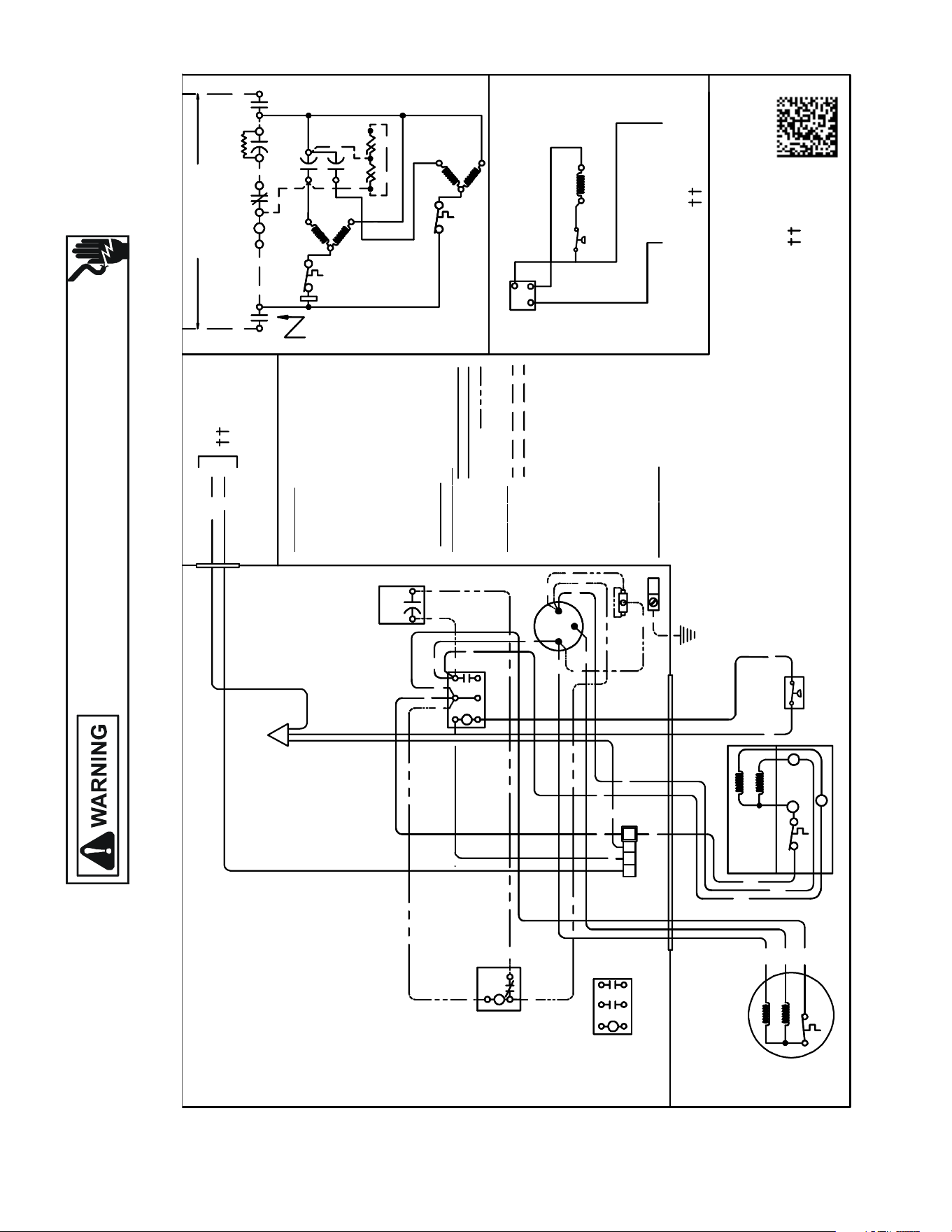
153
WIRING DIAGRAMS
ASX130181D*/ASX130[24,30,48]1CC-CE
ASX130361[CC,CD]/D*
Wiring is subject to change. Always refer to the wiring diagram on the unit for the most up-to-date wiring.
HIGH VOLTAGE!
DISCONNECT ALL POWER BEFORE SERVICING OR INSTALLING THIS
UNIT. MULTIPLE POWER SOURCES MAY BE PRESENT. FAILURE TO
DO SO MAY CAUSE PROPERTY DAMAGE, PERSONAL INJURY OR DEATH.
COMP
ALTERNATEDOUBLE
POLE CONTACTORONLY
IO
T1
C
M
A
I
N
R
A
U
X
5
S
SR
CSM
SA
2
1
RC CF
SC
T2
C
L1
L2
(IFUSED)
CH
C
C
S
M
F
M
A
I
N
A
U
X
IO
CM
C
Y
C
Y
BL
YL
C
Y
LVJB
T1
L1
T2
L2
ALTERNATE DOUBLE
POLE CONTACTOR
OUTDOOR POWER SUPPLY
SEERATINGPLATE
WIR
INGCODE
FACTORY
WIR
ING
HIGH VOLTAGE
LOW VOLTAGE
OPTIONALHIGH VOLTAGE
FI
ELD
WIR
ING
HIGH VOLTAGE
LOW VOLTAGE
CP
BK
Y
C
BK
SC
RD
BL
RD
RD
RD
BK
BK
BK
C
T1
L1
T2
L2
RC CF
F
C
HERM
YL
YL
YL
BR
RD
PU
YL
RD
YL
RD
BK
MAIN
COMP
IO
CM
AUX
MAIN
BK
BR
PU
SR
5
2
1
BK
YL
BL
EQUIPMENTGROUND
COLO R CO
DE
BK ---------------BLACK
BL --------------- BLUE
BR ---------------BROWN
OR --------------- ORANGE
PU ---------------PURPLE
RD --------------- RED
WH -------------- WHITE
YL --------------- YELLOW
RD
SA
(IF USED)
NOTE 2
C
IO
IO
R
S
AUX
USEN.E.C.
CLASS2WIRE
NOTES:
1) TO INDOOR UNIT LOWVOLTAGE
TERMINAL BLOCK&INDOOR
THERMOSTAT.
2) START ASSISTFACTORY
EQUIPPED WHEN REQUIRED.
3) USECOPPERCONDUCTORS
ONLY.
COMP
ALTERNATEDOUBLE
POLE CONTACTORONLY
IO
T1
C
M
A
I
N
R
A
U
X
5
S
SR
SA
2
1
RC CF
SC
T2
C
L1
L2
(IFUSED)
CH
C
F
M
A
I
N
A
U
X
IO
CM
C
Y
C
C
BL
YL
C
Y
LVJB
SEENOTE1
CO MPO NE N
T CODE
C ---------------CONTACTOR
CSM -------- CORESENSEMODULE
CM ------------OUTDOOR FANMOTOR
COMP--------COMPRESSOR
IO -------------- INTERNAL OVERLOAD
LVJB ----------LOW VOLTAGEJUN CTIONBOX
RCCF ---- ----- RUNCAPACITOR FORCOMPRESSOR&FAN
SA -------------START ASSIST
SC -------------START CAPACITORFOR COMPRESSOR (OPTIONAL)
SR -------------START RELAYFOR COMPRESSOR (OPTIONAL)
LPS ------------LOW PRESSURE SWITCH
CONTROLS SHOWNWITHTHERMOSTATIN'OFF' POSITION.
T1
L1
T2
L2
ALTERNATE DOUBLE
POLE CONTACTOR
WIR
INGCODE
FACTORY
WIR
ING
HIGH VOLTAGE
LOW VOLTAGE
OPTIONALHIGH VOLTAGE
FI
ELD
WIR
ING
HIGH VOLTAGE
LOW VOLTAGE
C
BK
RD
C
CSM
PU
BK
YL/PK
LVJB
CONTROLBOX
SC
RD
BL
RD
PU
RD
RD
BK
BK
BK
C
T1
L1
T2
L2
RC CF
F
C
HERM
YL
YL
YL
BR
RD
PU
YL
RD
YL
RD
BK
MAIN
COMP
IO
AUX
MAIN
BK
BR
PU
SR
5
2
1
BK
YL
BL
COLO R CO
DE
BK ---------------BLACK
BL --------------- BLUE
BR ---------------BROWN
OR --------------- ORANGE
PU ---------------PURPLE
RD --------------- RED
WH -------------- WHITE
YL --------------- YELLOW
YL/PK----------YELLOW/PINKSTRIPE
RD
SA
(IF USED)
NOTE 2
NOTE3
C
IO
IO
R
S
AUX
USEN.E.C.
CLASS2WIRE
0140R00274-B
LPS
YL/PK
LPS
YL
P
SEE NOTE1
YL
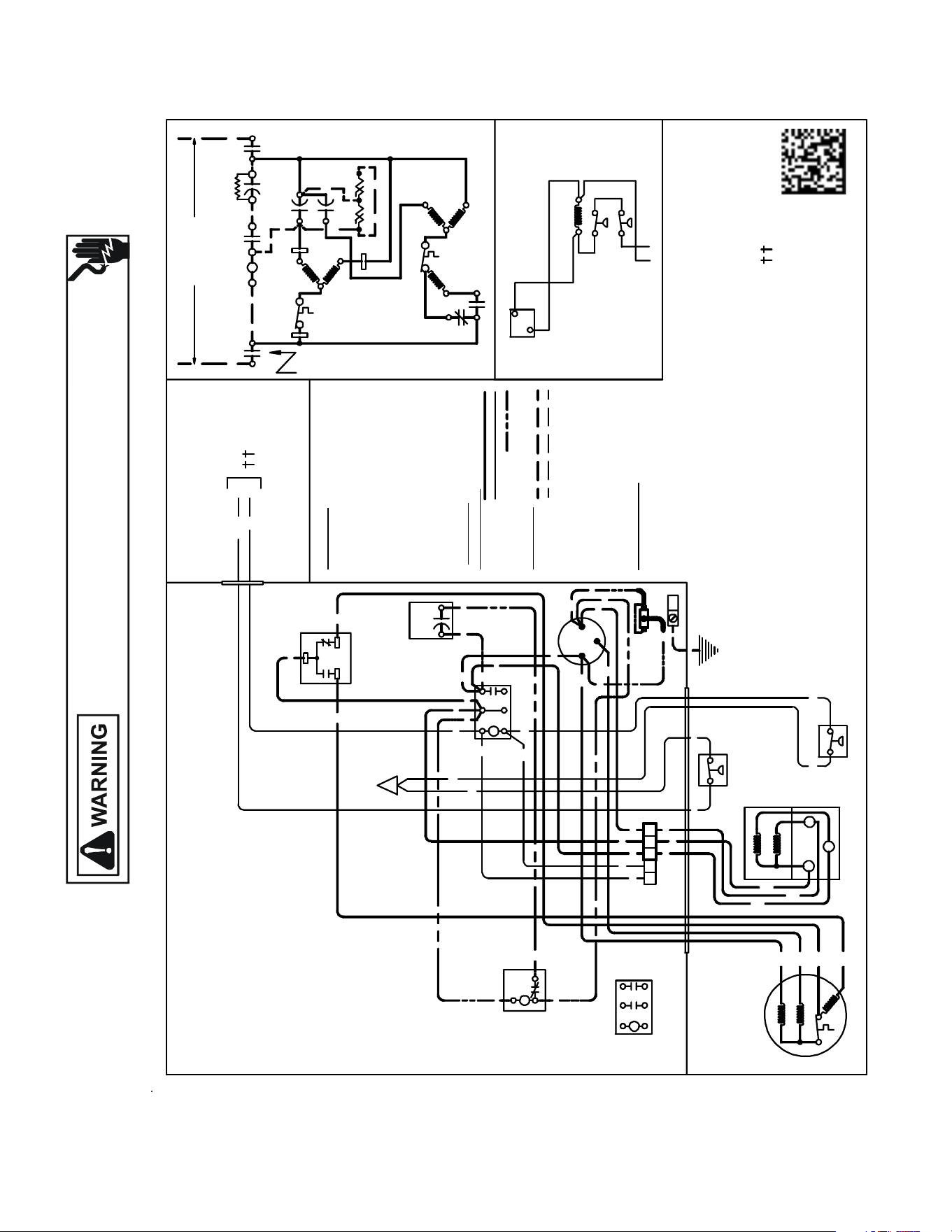
154
WIRING DIAGRAMS
ASX140[18-36/48]1C[A/B]
ASX140421D[A/B] / ASX140[48-60]1[BA/B]
Wiring is subject to change. Always refer to the wiring diagram on the unit for the most up-to-date wiring.
HIGH VOLTAGE!
DISCONNECT ALL POWER BEFORE SERVICING OR INSTALLING THIS
UNIT. MULTIPLE POWER SOURCES MAY BE PRESENT. FAILURE TO
DO SO MAY CAUSE PROPERTY DAMAGE, PERSONAL INJURY OR DEATH.
USE N.E.C. CLAS S 2 WIRE
COMP
ALTERNATE DOUBLE
POLE CONTACTOR ONLY
IO
T1
C
M
A
I
N
R
A
U
X
5
S
SR
CADM
SA
2
1
RCCF
SC
T2
C
L1
L2
(IF USED )
CH
C
C
A
D
M
CADM
F
C
A
D
M
M
A
I
N
A
U
X
IO
CM
(
L
O
W
)
3
2
(HIGH)
1
C
Y
C
LPS
YC
BL
BL/PK
C
Y
LVJB
NOTE 1
C
OMP
ONE NT C
O
DE
C --------------- CONTACTOR
CADM -------- COMFORT ALERT MODULE
CM ------------ OUTDOOR FAN MOTOR
COMP -------- COMPRESSOR
HPS
----------- HIGH PRESSURE SWITCH
IO -------------- INTERNAL OVERLOAD
LAT ------------ LOW AMBIENT THERMOSTAT
LPS
------------ LOW PRESSURE SWITCH
LVJB
---------- LOW VOLTAGE
JUNCTION BOX
RCCF
--------- RUN CAPACITOR FOR COMPRESSOR & FAN
SA ------------- START ASSIST
SC
------------- START CAPACITOR FOR COMPRESSOR (OPTIONAL)
S
R
-------------
START RELAY FOR COMPRESSOR (OPTIONAL)
CONTROLS SHOWN WITH THERMOSTAT IN 'OFF' POSITION.
T1
L1
T2
L2
ALTERNATE DOUBLE
POLE CONTACTOR
OUTDOOR POWER SUPPLY
SEE RATING PLATE
W
IR
IN
G
C
O
DE
FA
C
T
O
RY WI
R
I
N
G
HIGH VOLTAGE
LOW VOLTAGE
OPTIONAL HIGH VOLTAGE
FIEL
D
WI R
I
N
G
HIGH VOLTAGE
LOW VOLTAGE
S
C
R
BK
RD YL
Y
C
CADM
BL
YL
RD
BK
YL
LVJB
CONTROL BOX
RD
2
1
3
LAT
NOTE 3
BK
BK
SC
RD
BL
RD
YL
YL/PK
BL
BL
RD
RD
BKBK
BK
C
T1
L1
T2
L2
RCCF
F
C
HERM
YL
YL
YL
BR
RD
PU
YL
RD
YL/PK
YL/PK
LPS
YL
C
R
S
RD
BK
AUX
MAIN
COMP
IO
CM
AUX
MAIN
BK
(HIGH)
BR
PU
RD
(LOW)
SR
5
2
1
BK
YL
BL
EQUIPMENT GROUND
USE COPPER
CONDUCTORS ONLY
LAT
NOTE 3
BL/PK
HPS
BL/PK
BL/PK
YL/PK
CO
L
OR
CODE
BK --------------- BLACK
BL --------------- BLUE
BL/PK ---------- BLUE/PINK STRIPE
BR --------------- BROW N
OR --------------- ORANGE
PU --------------- PURPLE
RD --------------- RED
WH -------------- WHITE
YL --------------- YELLOW
YL/PK ---------- YELLOW/PINK STRIPE
HPS
0140R00168-B
NOTES:
1) TO INDOOR UNIT LOW VOLTAGE TERMIN AL BLOCK
& INDOOR THERMOSTAT.
2) START ASSIST FACTORY EQUI PPED WHEN
REQUIRED.
3) LAT POSITION SHOWN FOR HIGH AMBIENT
TEMPERATURE.
RD
SA
(IF USED)
NOTE 2
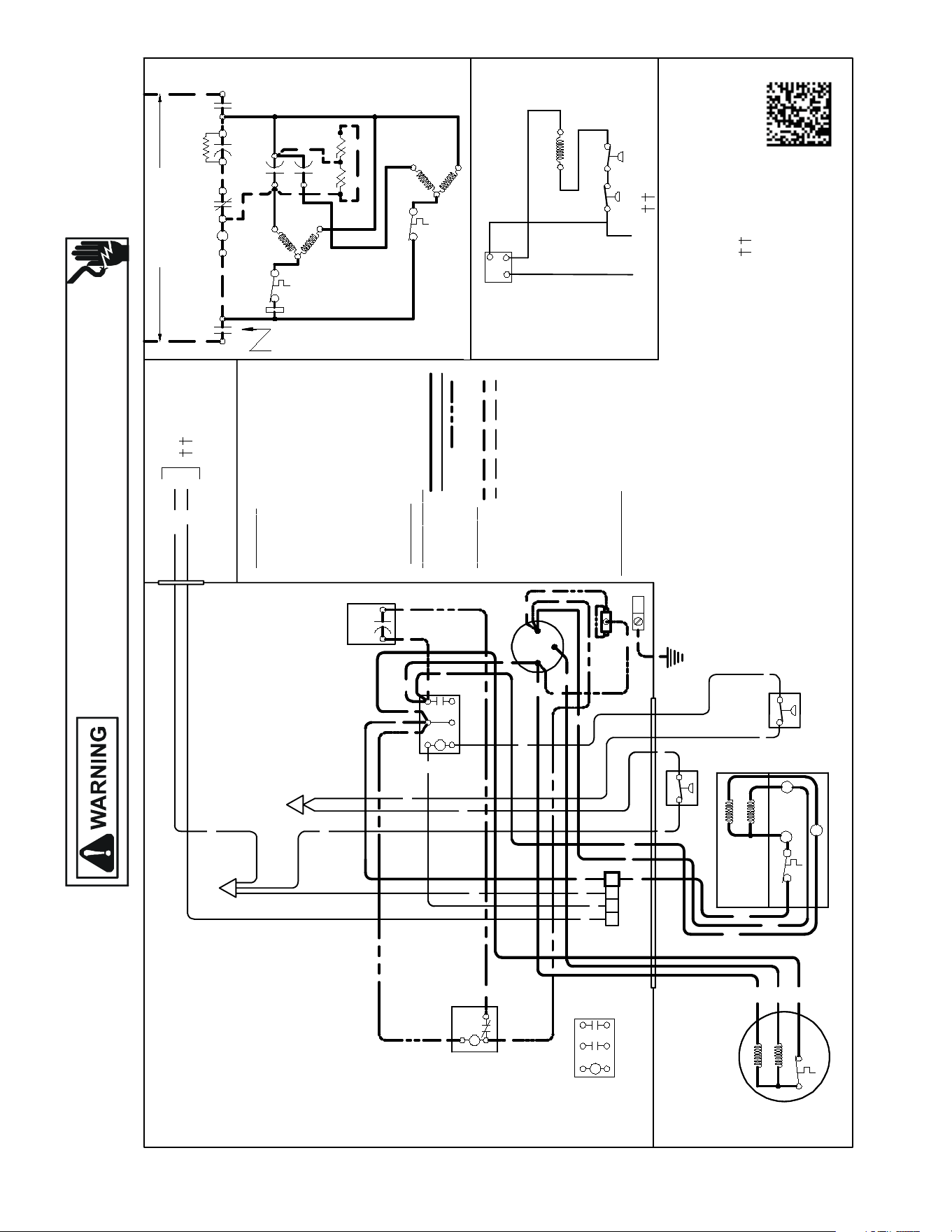
155
WIRING DIAGRAMS
Wiring is subject to change. Always refer to the wiring diagram on the unit for the most up-to-date wiring.
HIGH VOLTAGE!
DISCONNECT ALL POWER BEFORE SERVICING OR INSTALLING THIS
UNIT. MULTIPLE POWER SOURCES MAY BE PRESENT. FAILURE TO
DO SO MAY CAUSE PROPERTY DAMAGE, PERSONAL INJURY OR DEATH.
ASX140[24-36]1CD/ASX140421DD/ASX140481CC/
ASX140601BD/ ASX1401801DB/ ASX140241KB
COMP
ALTERNATEDOUBLE
POLE CONTACTORONLY
IO
T1
C
M
A
I
N
R
A
U
X
5
S
SR
SA
2
1
RCCF
SC
T2
C
L1
L2
(IFUSED)
CH
C
F
M
A
I
N
A
U
X
IO
CM
C
Y
C
BL
C
Y
LVJB
CO M
PONENT CODE
C---------------CONTACTOR
CSM-------- CORESENSEMODULE
CM ------------ OUTDOOR FANMOTOR
COMP --------COMPRESSOR
HPS ----------- HIGH PRESSURE SWITCH
IO -------------- INTERNAL OVERLOAD
LVJB ---------- LOWVOLTAGE JUNCTION BOX
RCCF --------- RUNCAPACITOR FORCOMPRESSOR&FAN
SA -------------START ASSIST
SC -------------START CAPACITORFOR COMPRESSOR (OPTIONAL)
SR ------------- STARTRELAY FORCOMPRESSOR(OPTIONAL)
LPS ------------ LOWPRESSURESWITCH
CONTROLS SHOWNWITH THERMOSTAT IN 'OFF'POSITION.
OUTDOORPOWER SUPPLY
SEERATING PLATE
WIR ING CODE
F
A
CTOR
Y W
I
R
I
NG
HIGH VOLTAGE
LOWVOLTAGE
OPTIONAL HIGH VOLTAGE
F
I
E
LD
W
I
R
I
NG
HIGH VOLTAGE
LOWVOLTAGE
CC
PU
YL
YL
SC
RD
BL
RD
YL
RD
RD
BK
BK
BK
C
T1
L1
T2
L2
RCCF
F
C
HERM
YL
YL
BR
RD
PU
YL
RD
YL
RD
BK
COMP
IO
CM
AUX
MAIN
BK
BR
PU
SR
5
2
1
BK
YL
BL
HPS
BL/PK
BL/PK
COLORCOD
E
BK ---------------BLACK
BL ---------------BLUE
BL/PK---------- BLUE/PINKSTRIPE
BR ---------------BROWN
OR ---------------ORANGE
PU ---------------PURPLE
RD ---------------RED
WH -------------- WHITE
YL --------------- YELLOW
YL/PK--------------- YELLOW /PINKSTRIPE
HPS
NOTES:
1) TO INDOOR UNIT LOWVOLTAGE
TERMINAL BLOCK&INDOOR THERMOSTAT.
2) STARTASSISTFACTORY EQUIPPED WHEN
REQUIRED.
3) USECOPPERCONDUCTORSONLY.
RD
SA
(IFUSED)
NOTE 2
MAIN
C
IO
R
S
AUX
COMP
IO
T1
C
M
A
I
N
R
A
U
X
5
S
SR
CSM
SA
2
1
RCCF
SC
T2
C
L1
L2
(IFUSED)
CH
C
C
S
M
F
M
A
I
N
A
U
X
IO
CM
C
Y
C
Y
C
BL
C
Y
LVJB
SEENOTE1
C
BK
P
C
CSM
BL
YL
RD
BK
LVJB
CONTROLBOX
SC
RD
BL
RD
PU
RD
RD
BK
BK
BK
C
T1
L1
T2
L2
RCCF
F
C
HERM
YL
YL
BR
RD
PU
YL
RD
YL
RD
BK
COMP
IO
CM
AUX
MAIN
BK
BR
PU
5
2
1
BK
YL
BL
EQUIPMENTGROUND
BL/PK
HPS
BL/PK
BL/PK
HPS
RD
SA
(IFUSED)
NOTE 2
NOTE 3
LPS
C
IO
R
S
AUX
0140R00275-C
YL/PK
YL/PK
LPS
Y
YL
P
YL
USE N.E.C. CLASS2WIRE
T1
L1
T2
L2
ALTERNATEDOUBLE
POLECONTACTOR
YL
BL/PK
YL/PK
YL/PK
SEENOTE1
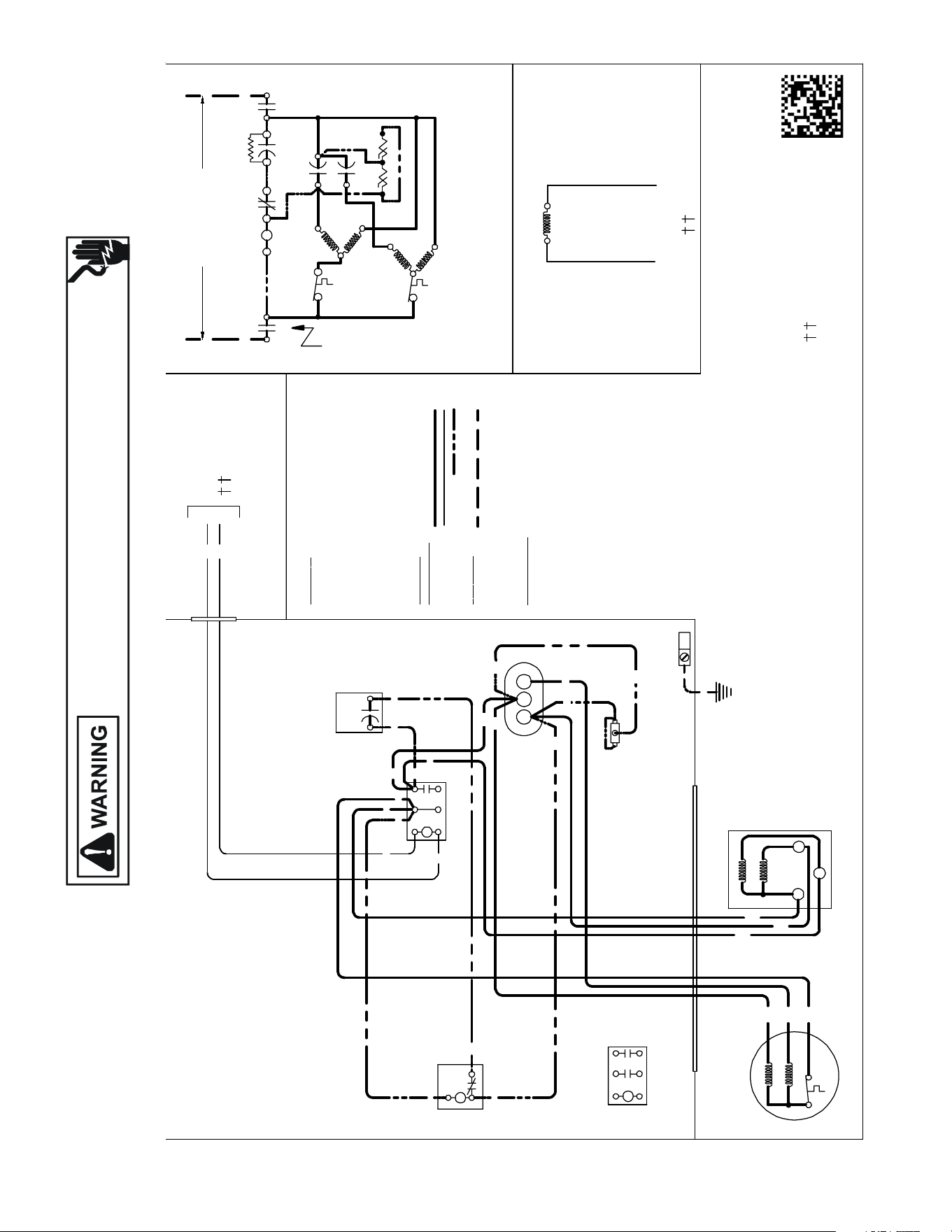
156
WIRING DIAGRAMS
Wiring is subject to change. Always refer to the wiring diagram on the unit for the most up-to-date wiring.
HIGH VOLTAGE!
DISCONNECT ALL POWER BEFORE SERVICING OR INSTALLING THIS
UNIT. MULTIPLE POWER SOURCES MAY BE PRESENT. FAILURE TO
DO SO MAY CAUSE PROPERTY DAMAGE, PERSONAL INJURY OR DEATH.
ASX140[18-60]1KA
USEN.E.C.CLASS 2WIRE
COMP
ALTERNATE DOUBLE
POLE CONTACTORONLY
IO
T1
C
M
A
I
N
R
A
U
X
5
S
SR
SA
2
1
RCCF
SC
T2
C
L1
L2
(IF USED)
CH
C
F
M
A
I
N
A
U
X
C
C
0140R00015P-C
BL
Y
C
LVJB
COL OR C
O
DE
BK ---------------BLACK
BL ---------------BLUE
BR ---------------BROWN
OR --------------- ORANGE
PU ---------------PURPLE
RD --------------- RED
WH -------------- WHITE
YL ---------------- YELLOW
CONTROL BOX
COMP
O
NE NT CO
DE
C--------------- CONTACTOR
CM ------------ OUTDOORFAN MOTOR
COMP -------- COMPRESSOR
IO -------------- INTERNAL OVERLOAD
LVJB ---------- LOWVOLTAGE JUNCTION BOX
RCCF --------- RUN CAPA CITORFOR COMPRESSOR &FAN
SA -------------START ASSIST
SC ------------- START CAPACITORFOR COMPRESSOR (OPTIONAL)
SR -------------START RELAYFOR COMPRESS OR (OPTIONAL)
CONTROLS SHOWNWITHTHERMOSTAT IN 'OFF'POSITION.
OUTDOORPOWER SUPPLY
SEERATINGPLATE
WIRING CO
DE
FACTOR
Y
WIRING
HIGH VOLTAGE
LOWVOLTAGE
OPTIONAL HI GH VOLTAGE
FI
E LD
WIRING
HIGH VOLTAGE
IO
CM
Y
YL
YL
C
R
S
RD
BK
AUX
MAIN
COMP
SEE NOTE 1
SC
RD
BL
RCCF
YL
PU
YL
SR
5
2
1
BK
YL
BL
RD
YL
BL
RD
RD
BKBK
BK
C
T1
L1
T2
L2
SA
(IF USED)
NOTE 2
EQUIPMENT GROUND
SEE NOTE 3
PU
BR
BK
MAIN
AUX
CM
IO
T1
L1
T2
L2
ALTERNATE DOUBLE POLE
CONTACTOR
NOTES:
1) TO INDOOR UNIT LOW VOLTAGE TERMINAL BLOCK &
INDOOR THERMOSTAT.
2) STARTASSISTFACTORY EQUIPPED WHEN REQUIRED.
3) USE COPPER CONDUCTORSONLY.
CFH
RD
RD
RD
BR
SEENOTE1
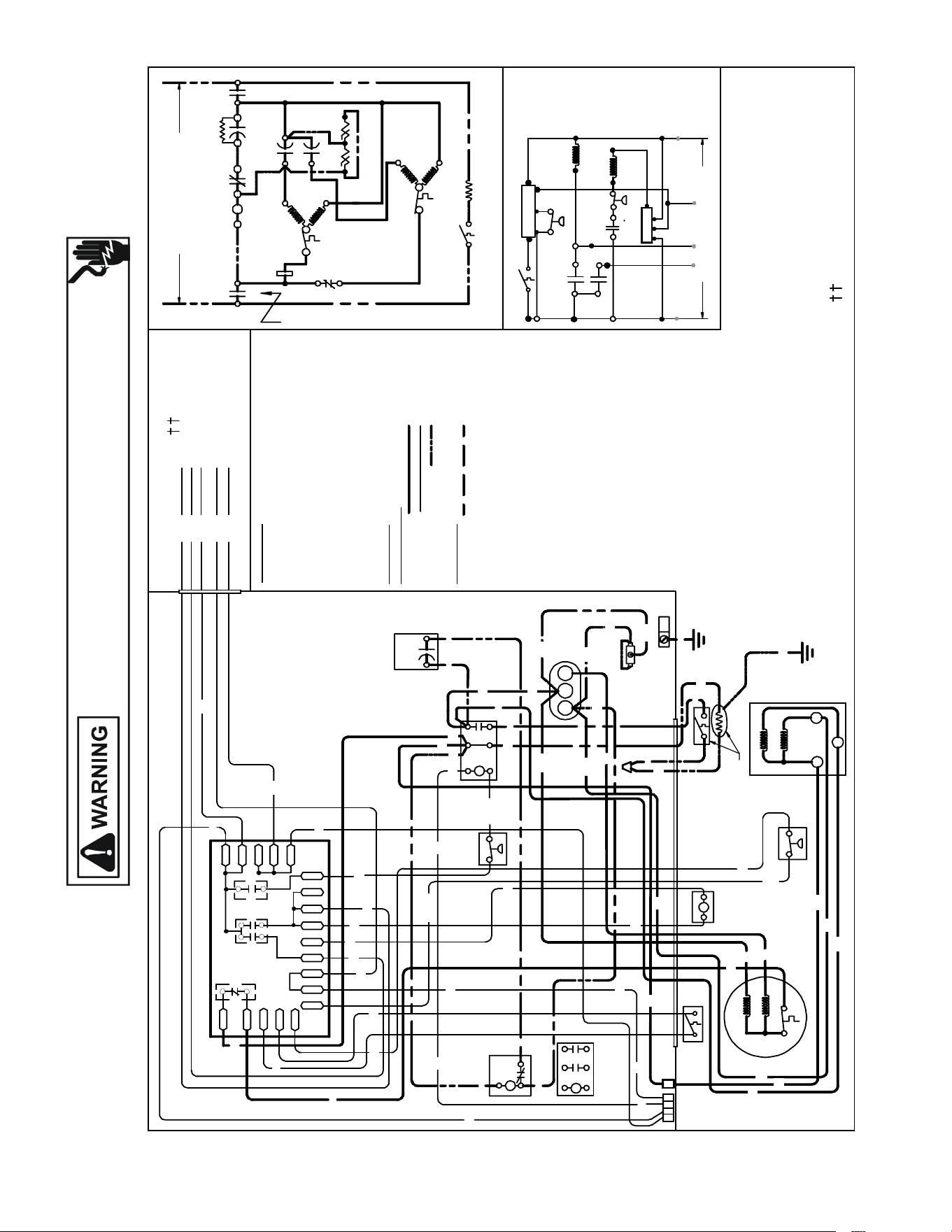
157
WIRING DIAGRAMS ASZ130[18-60]1*
Wiring is subject to change. Always refer to the wiring diagram on the unit for the most up-to-date wiring.
HIGH VOLTAGE!
DISCONNECT ALL POWER BEFORE SERVICING OR INSTALLING THIS
UNIT. MULTIPLE POWER SOURCES MAY BE PRESENT. FAILURE TO
DO SO MAY CAUSE PROPERTY DAMAGE, PERSONAL INJURY OR DEATH.
USE N.E.C. CLASS 2 WIRE
NOTES:
1) TO INDOOR UNIT LO W VOLTAGE TERMINAL BLOCK & INDOOR THERMOSTAT.
2) START ASSIST FA CTORY EQUIPPED WHEN REQUIRED .
3) USE COPPER CONDUCTOR ONLY.
4) CRANKCASE HEATER & CRANKCASE HEATER SWITCH ARE FACTORY
INSTALLE D OPTION
5) 40VA MINIMUM TRAN SFORMER IS REQUIRED.
6) COMMON SIDE OF TR ANSFORMER MUST BE GROUNDED.
COMP
ALTERNATE DOUBLE
POLE CONTACTOR ONLY
IO
T1
C
M
A
I
N
R
A
U
X
5
S
SR
SA
2
1
RCCF
SC
T2
C
L1
L2
(IF USED)
NOTE 2
CH
C
F
M
A
I
N
A
U
X
IO
CM
OR
BL
RD
O
Y
C
R
CO L
OR
C
ODE
BK --------------- BLACK
BL/PK ---------- BLUE/PINK STRIPE
BR --------------- BROWN
GR---------------- GREEN
OR --------------- ORANGE
PU --------------- PURPLE
RD --------------- RED
WH -------------- WHITE
YL --------------- YELLOW
YL/PK----------- YELLOW/PINK STRIPE
OUTDOOR POWER SUPPLY
SEE RATING PLATE
WIRIN G
C
ODE
FA CTO
RY W
IRI NG
HIGH VOLTAGE
LOW VOLTAGE
OPTIONAL HIGH VOLTAGE
FIELD WIRING
HIGH VOLTAGE
LVJB
CONTROL BOX
SC
RD
BL
L2
T2
L1
T1
C
RCCF
BR
SR
5
2
1
BK
YL
BL
IO
CM
AUX
MAIN
PU
YL/PK
LPS
EQUIPMENT
GROUND
DF1
DF2
CH
LVDR
R
CNT
INDOOR POWER SUPPLY
DFT
C
Y
DC
DFT
WH
W2
DC
HPS
O
C
RVC
W2
R
HVDR
YL/PK
RD
BK
BK
BL
CHS
R-DFT
O-RV
C-RV
LPS
PS2
R-PS1
O
W
C
HPS
CCR
}
RD
CH
CHS
SA
(IF USED)
NOTE 2
DFT
RVC
RD
BK
GR
Y
T1
L1
T2
L2
ALTERNAT E
DOUBLE POLE
CONTACTOR
R
DF1
DF2
0
0-RV
C-RV
W
LVDR
HVDR
CCR
CNT
0
DFT
R-DFT
R-PS1
Y
Y
C
R
C
C
PS2
YL/PK
YL/PK
RD
WH
OR
BK
SEE NOTE 3
BK
BK
RD
NOTE 1
CSM
YCR
CSM
YL
PU
0140R00273-A
Y
P
R C
RD
COMPONENT CODE
C --------------- CONTACTOR
CSM --------
---
CORESENSE MODULE
CCR ----------- CO MPRESSOR CONTACTOR RELAY
CH ------------- CRAN KCASE HEATER
CHS ----------- CRAN KC ASE HEAT ER SWITCH
CM ------------ OUTDOOR FAN MOTOR
COMP -------- COMPRESSOR
DC ------------- DEFROST CONTROL
DFT ----------- DEFROST THERMOSTAT
HPS ----------- HIGH PRESSURE SWITCH
HVDR -------- HIGH VOLTAGE DEFROST RELAY
IO -------------- INTERNAL OVERLOAD
LPS ---------- LOW PRESSURE SWITCH
LV DR --------- LOW VOLTAGE DEFROST RELAY
LV JB --------- LOW VOLTAGE JUNCTION BOX
RCCF --------- RUN CAPACITOR FO R COMPRESSOR & FAN
RVC ----------- REVERSING VALVE COIL
SA ------------- START ASSIS T
SC ------------- START CAPAC ITOR FOR COMPRESSOR
(OPTIONAL)
SR ------------- START RELAY FO R COMPRESSOR (OPTIONAL)
CONTROLS SHOWN WITH THERMOSTAT IN
'OFF' POSITION.
BK
C
R
AUX
MAIN
COMP
S
BK
YL
RD
H
F
C
RD
YL
YL
YL
PU
SEE NOTE 5 & 6
FIELD LO W
VOLTAG E
CONNECTIONS
SEE NOTE 4
SEE NOTE 4
YL
RD
BK
BK
BK
BK
RD
YL
RD
RD
RD
BK
BK
BK
BK
YL
RD
BL/PK
BL
BR
CSM
C
PU
PU
PU
RD
P
YL
YL
BL/PK
PU
PU
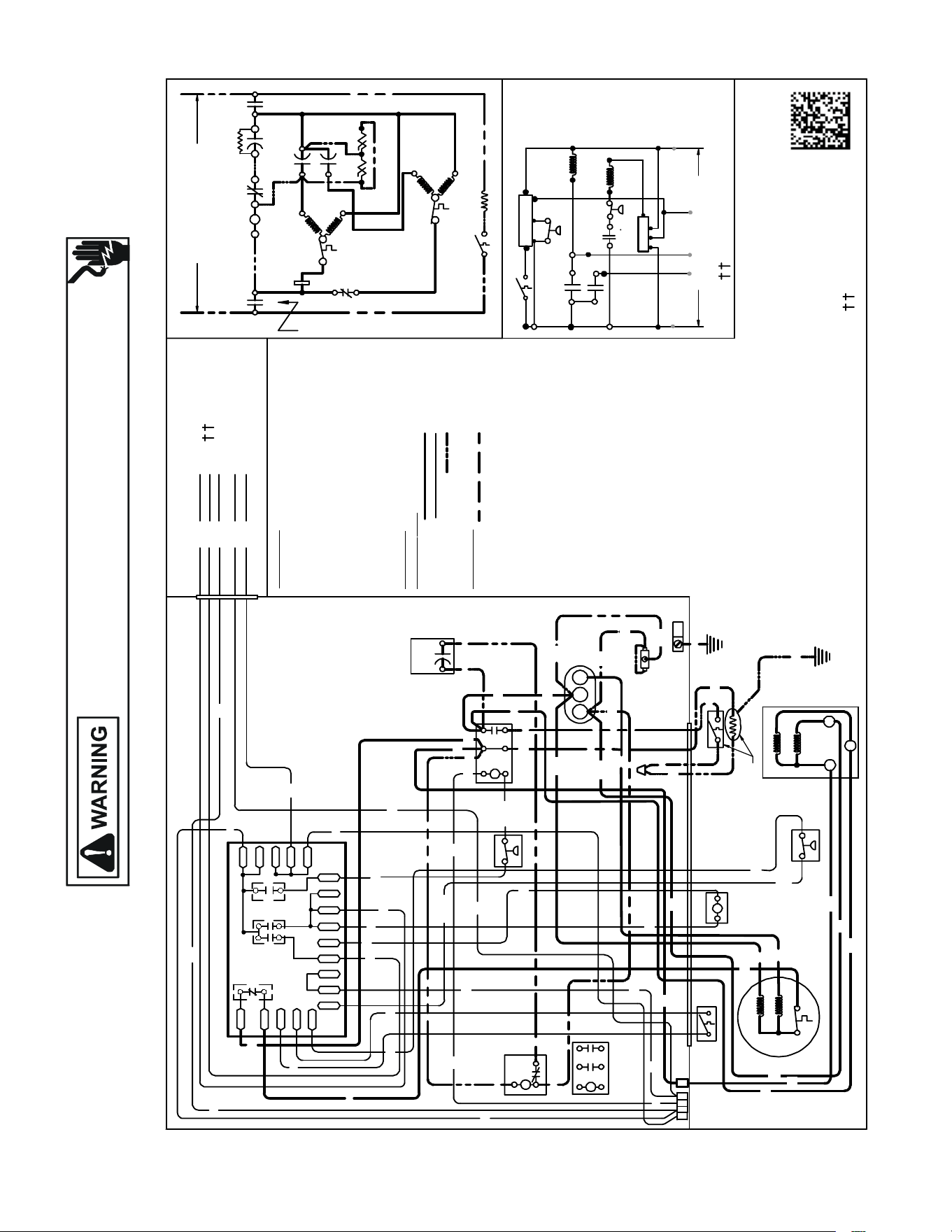
158
WIRING DIAGRAMS
ASZ140381A*; ASZ140[18,30]1*K; ASZ140241*L;
ASZ140301*K; ASZ140421*J
ASZ140[18-30]1B*
Wiring is subject to change. Always refer to the wiring diagram on the unit for the most up-to-date wiring.
HIGH VOLTAGE!
DISCONNECT ALL POWER BEFORE SERVICING OR INSTALLING THIS
UNIT. MULTIPLE POWER SOURCES MAY BE PRESENT. FAILURE TO
DO SO MAY CAUSE PROPERTY DAMAGE, PERSONAL INJURY OR DEATH.
USE N. E.C. CLASS2WIRE
NOTES:
1) TO INDOOR UNIT LOWVOLTAGE TERMINAL BLOC K& INDOOR THERMOSTAT.
2) STARTASSISTFACTORY EQUIPPED WHEN REQUIRED.
3) USE COPPER CONDUCTOR ONLY.
4) CRANKCASE HE ATER & CRAN KCASE HE ATER SWITCH ARE FACTORY
INSTALLEDOPTION
5) 40VA MINIMUMTRANSFORMER IS REQUIRED.
6) COMMON SIDE OF TRANSFORMER MUSTBE GROUNDED.
COMP
ALTERNATE DOUBLE
POLE CONTACTORONLY
IO
T1
C
M
A
I
N
R
A
U
X
5
S
SR
SA
2
1
RCCF
SC
T2
C
L1
L2
(IF USED)
NOTE 2
CH
C
F
M
A
I
N
A
U
X
IO
CM
OR
BL
RD
O
Y
C
R
COL
OR C
ODE
BK --------------- BLACK
BL/PK ---------- BLUE/PINKSTRIPE
BR --------------- BROWN
GR---------------- GREEN
OR --------------- ORANGE
PU --------------- PURPLE
RD ---------------RED
WH -------------- WHITE
YL --------------- YELLOW
YL/PK-----------YELLOW/PINK STRI PE
OUTDOOR POWER SUPP LY
SEE RATING PLATE
WIRING C ODE
FACTORY W
IRING
HIGH VOLTAGE
LOWVOLTAGE
OPTIONAL HIGH VOLTAGE
FIE
LD W IRING
HIGH VOLTAGE
LVJB
CONTROLBOX
SC
RD
BL
L2
T2
L1
T1
C
RCCF
BR
SR
5
2
1
BK
YL
BL
IO
CM
AUX
MAIN
PU
YL/PK
LPS
EQUI PMENT
GROUND
DF1
DF2
CH
LVDR
R
CNT
INDOOR POWER SUPPLY
DFT
C
Y
DC
DFT
WH
W2
DC
HPS
O
C
RVC
W2
R
HVDR
YL/PK
RD
BK
BK
BL
CHS
R-DFT
O-RV
C-RV
LPS
PS2
R-PS1
O
W
C
HPS
CCR
}
RD
CH
CHS
SA
(IF USED)
NOTE 2
DFT
RVC
RD
BK
GR
Y
T1
L1
T2
L2
ALTERNATE
DOUBLE POLE
CONTACTOR
R
DF1
DF2
0
0-RV
C-RV
W
LVDR
HVDR
CCR
CNT
0
DFT
R-DFT
R-PS1
Y
Y
C
R
C
C
PS2
YL/PK
YL/PK
RD
WH
OR
BK
SEE NOTE 3
BK
BK
RD
SEE NOTE 1
CSM
YCR
CSM
YL
PU
0140R00273-C
Y
P
R C
RD
COMPONENT CODE
C---------------CONTACTOR
CSM ----------- COR ESENSE MODULE
CCR -----------COMPRESSOR CONTACTOR RELAY
CH -------------CRANKC ASE HE ATER
CHS ----------- CRANKC ASE HE ATER SWITCH
CM ------------ OUTDOOR FANMOTOR
COMP -------- COMPRESSOR
DC ------------- DEFROST CONTROL
DFT ----------- DEFROST THERMOSTAT
HPS ----------- HIGH PRESSURE SWITCH
HVDR -------- HIGH VOLTAGE DEFROST RELAY
IO -------------- INTERNAL OVERLOAD
LPS ---------- LOW PRESSURE SWITCH
LVDR --------- LOWVOLTAGE DEFROST RELAY
LVJB --------- LOWVOLTAGE JUNCTION BOX
RCCF ---------RUN C APACITORFOR COMPRESSOR & FAN
RVC -----------REVERSING VALVE COIL
SA ------------- STARTASSIST
SC ------------- START C APACI TOR FOR COMPRESSOR
(OPTIONAL)
SR ------------- START RELAY FOR COMPRESSOR (OPTIONAL)
CONTROLS SHOWNWITHTHERMOSTATIN
'OFF'POSITION.
BK
C
R
AUX
MAIN
COMP
S
BK
YL
RD
H
F
C
RD
YL
YL
YL
PU
SEE NOTE 5&6
FIELDLOW
VOLTAGE
CONNECTIONS
SEE NOTE 4
SEE NOTE 4
YL
RD
BK
BK
BK
BK
RD
YL
RD
RD
RD
BK
BK
BK
BK
YL
RD
BL/PK
BL
BR
CSM
C
PU
PU
PU
RD
P
YL
YL
BL/PK
PU
RD
RD
PU
PU
SEE NOTE 1
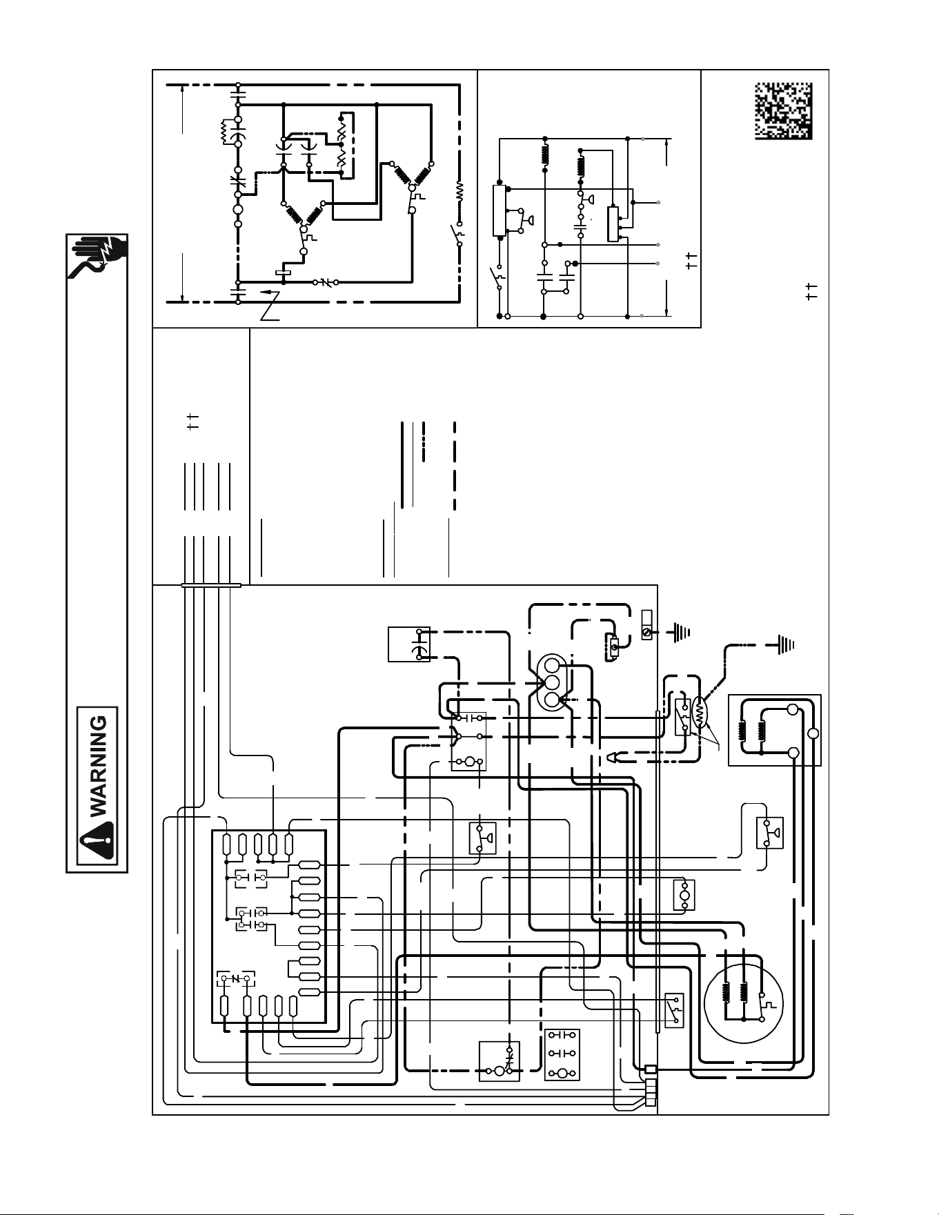
Wiring is subject to change. Always refer to the wiring diagram on the unit for the most up-to-date wiring.
HIGH VOLTAGE!
DISCONNECT ALL POWER BEFORE SERVICING OR INSTALLING THIS
UNIT. MULTIPLE POWER SOURCES MAY BE PRESENT. FAILURE TO
DO SO MAY CAUSE PROPERTY DAMAGE, PERSONAL INJURY OR DEATH.
159
WIRING DIAGRAMS ASZ160[18-48]1L*WIRING DIAGRAMS
USE N. E.C. CLASS2WIRE
NOTES:
1) TO INDOOR UNIT LOWVOLTAGE TERMINAL BLOCK& INDOOR THERMOSTAT.
2) STARTASSISTFACTORY EQUIPPED WHEN REQUIRED.
3) USE COPPER CONDUCTOR ONLY.
4) CRANKCASE HE ATER & CRAN KCASE HE ATER SWITCH ARE FACTORY
INSTALLEDOPTION
5) 40VA MINIMUMTRANSFORMER IS REQUIRED.
6) COMMON SIDE OF TRANSFORMER MUSTBE GROUNDED.
COMP
ALTERNATEDOUBLE
POLE CONTACTORONLY
IO
T1
C
M
A
I
N
R
A
U
X
5
S
SR
SA
2
1
RCCF
SC
T2
C
L1
L2
(IF USED)
NOTE 2
CH
C
F
M
A
I
N
A
U
X
IO
CM
OR
BL
RD
O
Y
C
R
COL
OR C
ODE
BK --------------- BLACK
BL/PK ---------- BLUE/PINKSTRIPE
BR --------------- BROWN
GR---------------- GREEN
OR --------------- ORANGE
PU --------------- PURPLE
RD ---------------RED
WH -------------- WHITE
YL --------------- YELLOW
YL/PK-----------YELLOW/PINK STRI PE
OUTDOOR PO WER SUPP LY
SEE RATING PLATE
WIRING C
ODE
FACTORY W IRING
HIGH VOLTAGE
LOWVOLTAGE
OPTIONAL HIGH VOLTAGE
FIE
LD W
IRING
HIGH VOLTAGE
LVJB
CONTROLBOX
SC
RD
BL
L2
T2
L1
T1
C
RCCF
BR
SR
5
2
1
BK
YL
BL
IO
CM
AUX
MAIN
PU
YL/PK
LPS
EQUIPMENT
GROUND
DF1
DF2
CH
LVDR
R
CNT
INDOOR POWER SUPP LY
DFT
C
Y
DC
DFT
WH
W2
DC
HPS
O
C
RVC
W2
R
HVDR
YL/PK
RD
BK
BK
BL
CHS
R-DFT
O-RV
C-RV
LPS
PS2
R-PS1
O
W
C
HPS
CCR
}
RD
CH
CHS
SA
(IF USED)
NOTE 2
DFT
RVC
RD
BK
GR
Y
T1
L1
T2
L2
ALTERNATE
DOUBLE POLE
CONTACTOR
R
DF1
DF2
0
0-RV
C-RV
W
LVDR
HVDR
CCR
CNT
0
DFT
R-DFT
R-PS1
Y
Y
C
R
C
C
PS2
YL/PK
YL/PK
RD
WH
OR
BK
SEE NOTE 3
BK
BK
RD
SEE NOTE 1
CSM
YCR
CSM
YL
PU
0140R00273-C
Y
P
R C
RD
COMPONENT CODE
C---------------CONTACTOR
CSM ----------- CORESENSE MODULE
CCR -----------COMPRESSOR CONTACTOR RELAY
CH -------------CRANKCASE HE ATER
CHS ----------- CRANKC ASE HE ATER SWITCH
CM ------------ OUTDOOR FANMOTOR
COMP -------- COMPRESSOR
DC ------------- DEFROST CONTROL
DFT ----------- DEFROST THERMOSTAT
HPS ----------- HIGH PRESSURE SWITCH
HVDR -------- HIGH VOLTAGE DEFROST RELAY
IO -------------- INTERNAL OVERLOAD
LPS ---------- LOW PRESSURE SWITCH
LVDR --------- LOWVOLTAGE DEFROST RELAY
LVJB --------- LOWVOLTAGE JUNCTION BOX
RCCF --------- RUN CAPACITORFOR COMPRESSOR & FAN
RVC -----------REVERSING VALVE COIL
SA ------------- STARTASSIST
SC ------------- START CAPACI TOR FOR COMPRESSOR
(OPTIONAL)
SR ------------- START RELAY FOR COMPRESSOR (OPTIONAL)
CONTROLS SHOWNWITHTHERMOS TATIN
'OFF' POSITION.
BK
C
R
AUX
MAIN
COMP
S
BK
YL
RD
H
F
C
RD
YL
YL
YL
PU
SEE NOTE 5&6
FIELDLOW
VOLTAGE
CONNECTIONS
SEE NOTE 4
SEE NOTE 4
YL
RD
BK
BK
BK
BK
RD
YL
RD
RD
RD
BK
BK
BK
BK
YL
RD
BL/PK
BL
BR
CSM
C
PU
PU
PU
RD
P
YL
YL
BL/PK
PU
RD
RD
PU
PU
SEE NOTE 1
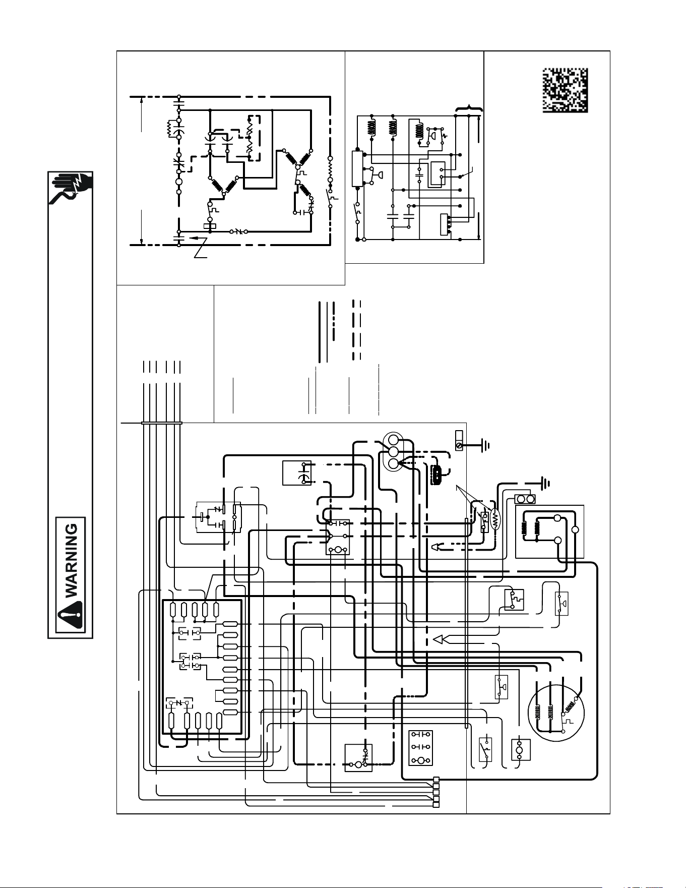
Wiring is subject to change. Always refer to the wiring diagram on the unit for the most up-to-date wiring.
HIGH VOLTAGE!
DISCONNECT ALL POWER BEFORE SERVICING OR INSTALLING THIS
UNIT. MULTIPLE POWER SOURCES MAY BE PRESENT. FAILURE TO
DO SO MAY CAUSE PROPERTY DAMAGE, PERSONAL INJURY OR DEATH.
160
WIRING DIAGRAMS ASZ160601-L*WIRING DIAGRAMS
COMP
ALTERNATEDOUBLE
POLE CONTACTOR ONLY
IO
T1
C
M
A
I
N
R
A
U
X
5
S
SR
SA
2
1
RCCF
SC
T2
C
L1
L2
(IFUSE D)
NOTE 2
CH
C
F
M
A
I
N
A
U
X
IO
CM
C
O
L
O
RC
O
D
E
BK -- ------------ -
BL/PK -- ------ --
BR ------------- --
OR ------- --------
PU ------------- --
RD ---- -----------
WH ------------ --
YL -- -------------
YL/PK-----------
C
O
MP O
N
E N
T C
O
D
E
C ------- --------
CCR------------
CH ---- -------- -
CHS -- ---------
CM ---- --------
CMR ---- ------
COMP ----- ---
CS -- ---------- -
CSM-----------
DC ------- ------
DFT -- ---------
DT -------- -----
HPS------------
HVDR ---- ----
IO ----------- ---
LPS ----- -------
LVDR ---------
LVJB -- ------ --
RCCF -------- -
RVC -----------
SA -------- -----
SC ---------- ---
SR ------- ------
CONTR OLS SHOW NWITHTHERMOSTA T IN 'OFF'POSITION.
OUTDOO RPOWER SUPP LY
SEERATING PLATE
WIR
I
N
GCO D
E
F
A C
T O
R
YW
I
R IN
G
HIGH VOLTAGE
LOWVOLTAGE
OPTIONAL HIGH VOLTAG E
F
I
E
L
DW
I
R
IN
G
HIGH VOLTAGE
LOWVOLTAGE
CONTROLBOX
SC
L2
T2
L1
T1
C
RCCF
SR
5
2
1
LPS
DF1
DF2
(HIG H)
CH
HPS
(
L
O
W
)
5
4
2
HVDR
CMR
CMR
1
3
4
2
5
CHS
SA
(IFUSE D)
NOTE 2
DFT
RVC
DT
CS
C
Y2
T1
L1
T2
L2
0140 R00377-C
DC
R
DF1
DF2
0
0-RV
C-RV
W
LVDR
HVDR
CCR
CNT
0
DFT
R-DFT
R-PS1
Y
Y
C
R
C
C
PS2
EQUIPMENT
GROUND
NOTE 4
NOTES:
1) TO INDOOR UNIT LOW VOLTAGE TERMINAL
BLOCKAND INDOOR THERMOSTAT.
USEN.E.C.CLASS2WIRE.
2) STARTASSISTFACTORY EQUIPPED WHEN
REQUIRED.
3) THECOMMONSIDEOFLOW VOLTAGE SHALL
NOTBEGROUNDED.
4) USECOPPERCON DUCTOR ONLY.
5) CRANKCASE HEAT ER MAYNOT
HAVE ADDITIONALGROUNDWIRE.
6) CRANKCASE HEAT ER &CRA NK CA SE
HEATER SWITCH AREFACTORY
INSTALLEDOPTION.
7) ENSURE BLACK COMPRESSOR WIRE IS
ROUTEDTHROUGH THEHOLEINTHE CSM.
SEENOTE6
YL
ALTERNATE
DOUBLE PO LE
CONTACTOR
CHS
CH
IO
AUX
MAIN
CM
CFH
AUX
MAIN
COMP
C
S
R
SEE NOTE6
CSM
O
W2
R
Y
C
Y2
LVJB
SEE NOTE 1
C
RPYC
R-DFT
DFTDFT
C
DC
Y
PS2
LPS
R-PS1
LVDR
CMR
RVC
3
C-RV
O-RV
1
W
O
R
C
HPS
DT
INDOOR POWERSUPPLY
CCR
CNT
Y2 C
CS
Y
2WO2Y
R
SEENOTE1
CSM
RYCP
FIELDLOW
VOLTAGE
CONNECTIONS
RD
RD
RD
BL
RDBK
RD BL
RD
BL
BL
BK
BL
RD
BK
RD
RD
RD
YL
YL
YL
PU
BR
GR
RD
BK
RD
BK
BL
BL/PK OR
BK
BKWHYLYL/PK
RD
RD
RD
RD
BK
BK
OR
WH
RD
PU
BL
YL
BK
BK
BK
BK
BL
BL
YL/PK
RD
PU
BL
YL/P K
BL/PK
PU
BK
BL
BK
RD
RD
BL/PK
CSM
BK
BL/PK
BK
BK
BK
YL/P K
YL/PK
RD
YL
PU
BR
BK
(HIGH)
RD
(LOW)
SEENOTE4
BLACK
BLUE/PINK STRIPE
BROW N
ORANGE
PURPLE
RED
WHITE
YELL OW
YELL OW /PINKSTR IPE
CONTACTO R
COMPRESSOR CONTACTORRELA Y
CRANKCASEHEATER
CRANKCASEHEATER SW ITCH
OUTDOOR FANMOTOR
CONDENSER MOTOR RELAY
COMPRESSOR
COMPRESSOR SOLE NOID
CORESENSEMODULE
DEFROSTCONTROL
DEFROSTTHERMOSTA T
DISCHARGETHER MOSTAT
HIGH PRESSURESWITCH
HIGH VOLTAGEDEFROST RELA Y
INTERNA LOVERLOAD
LOWPRESSURESWITC H
LOWVOLTAGE DEFROSTRELAY
LOWVOLTAGE JU NCTION BOX
RUNCAPAC ITOR FORCOMPRESS OR &FAN
REVERS INGVALVE COIL
STARTASSIST
STARTCAPAC ITOR FORCO MPRESSO R (OPTIONAL)
STARTRELA YFOR COMPRESSO R (OPT IONAL)
SEE NOTE 4
SEENOTE4
SEENOTE7
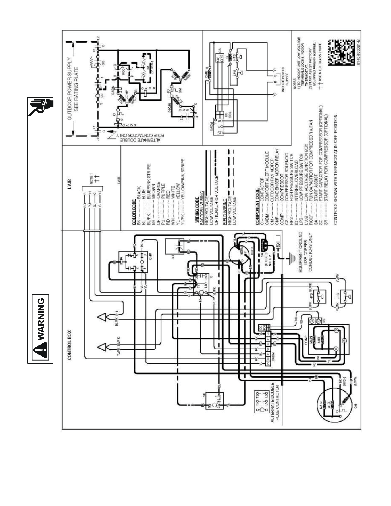
Wiring is subject to change. Always refer to the wiring diagram on the unit for the most up-to-date wiring.
HIGH VOLTAGE!
DISCONNECT ALL POWER BEFORE SERVICING OR INSTALLING THIS
UNIT. MULTIPLE POWER SOURCES MAY BE PRESENT. FAILURE TO
DO SO MAY CAUSE PROPERTY DAMAGE, PERSONAL INJURY OR DEATH.
161
WIRING DIAGRAMS *SX160[24-60]1**
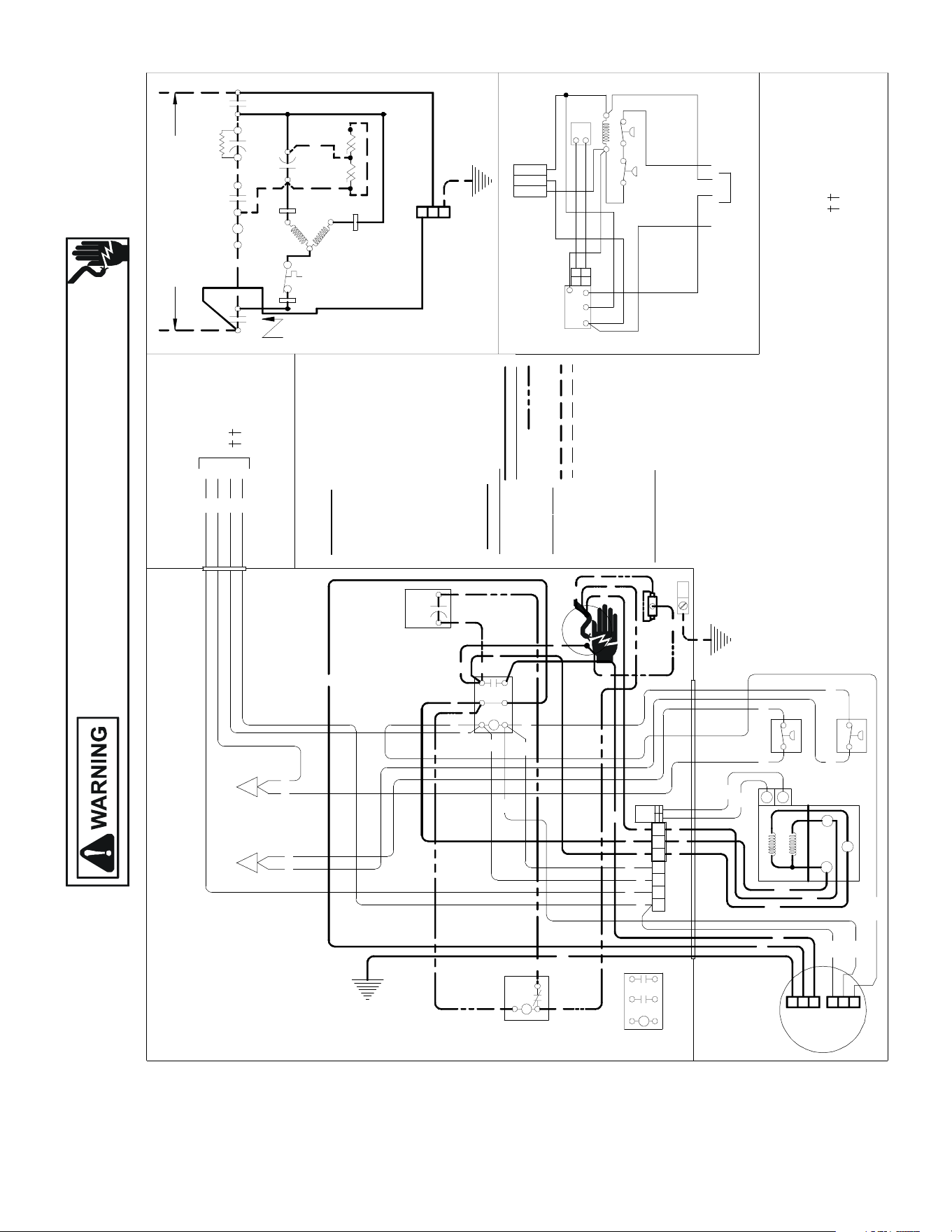
Wiring is subject to change. Always refer to the wiring diagram on the unit for the most up-to-date wiring.
HIGH VOLTAGE!
DISCONNECT ALL POWER BEFORE SERVICING OR INSTALLING THIS
UNIT. MULTIPLE POWER SOURCES MAY BE PRESENT. FAILURE TO
DO SO MAY CAUSE PROPERTY DAMAGE, PERSONAL INJURY OR DEATH.
162
WIRING DIAGRAMS *SX180[36-60]1A*
USE N.E.C. CLASS 2 WIRE
NOTES:
1) TO INDOOR UNIT LOW VOLTAGE
TERMINAL BLOCK & INDOOR
THERMOSTAT.
2) START ASSIST FA CTORY
EQUIPPED WHEN REQUIRED.
COMP
IO
T1
C
M
A
I
N
R
A
U
X
5
S
SR
CADM
SA
2
1
RC
SC
T2
C
L1
L2
(IF USED)
C
Y2
C
A
D
M
CADM
C
A
D
M
C
R
Y1
DC
SOL
CS
Y2
C
INDOOR POWER
SUPPLY
C
LPS
HPS
Y1Y2
CR
0140R00106
PU
YL
BL
RD
Y1
Y2
C
R
LVJB
NOTE 1
COL OR C OD E
BK --------------- BLACK
BL --------------- BLUE
BL/PK ---------- BLUE/PINK STRIPE
BR --------------- BROWN
GR --------------- GREEN
PU --------------- PURPLE
RD --------------- RED
WH -------------- WHITE
YL --------------- YELLOW
YL/PK ---------- YELLOW/PINK STRIPE
GR/YL ---------- GREEN/YELLOW STRIPE
COM P ON E NT C ODE
C --------------- CONTACTOR
CADM -------- COMFORT ALERT MODULE
CM ------------ OUTDOOR FAN MOTOR
COMP -------- COMPRESSOR
CS ------------- COMPRESSOR SOLENOID
HPS ----------- HIGH PRESSURE SWITCH
IO -------------- INTERNAL OVERLOAD
LPS ------------ LOW PR ESSURE SWITCH
LV JB ---------- LOW VOLTAGEJUNCTIO N BOX
RC ------------ COMPRESSOR RUN CAPACITOR
SA ------------- START ASSIST
SC ------------- START CAPA CITOR FOR COMPRESSOR (OPTIONAL)
SR -------------START RELAY FOR COMPRESSOR (OPTIONAL)
CONTROLS SHOWN WITH THERMOSTAT IN 'OFF' POSITION.
OUTDOOR POWER SUPPLY
SEE RATING PLATE
WIRI
NG C OD E
FA CTOR
Y W IRING
HIGH VOLTAGE
LOW VOLTAGE
OPTIONAL HIGH VOLTAGE
FIE
LD W IRING
HIGH VOLTAGE
LOW VOLTAGE
RD
SA
(IF USED)
NOTE 2
LV JB
CONTROL BOX
BK
SC
RD BL
L2
T2
L1
T1
C
BK
BK
RD
RD
BL
BL
YL/PK
PU
BL
RD
RC
YL
YL
YL
BR
RD
YL
RD
SR
5
2
1
BK
YL
BL
CM
WH
(HIGH)
BR
GR/YL
YL
(LOW)
YL
C
R
S
RD
BK
AUX
MAIN
COMP
CS
Y2
C
BK
RD
BL/PK
BL/PK
HPS
LPS
YL
BK
RD
DC
SOL
YL
PURD
BL
CADM
Y2 R C
Y1
YLRD
BK
R C
S
EQUIPMENT GROUND
USE COPPER
CONDUCTORS ONLY
ALTERNATE DOUBLE
POLE CONTACTOR ONLY
YL/PKYL/PK
YL/PK
BL/PK
BL/PK
PU
CM
CM
L1
L2
GND
L1
L2
GND
Y
L
W
H
B
L
BL
(COM)
ALTERNATE DOUBLE
POLE CONTACTOR
L1
T1 T2
L2
YL
BK
C
HERM
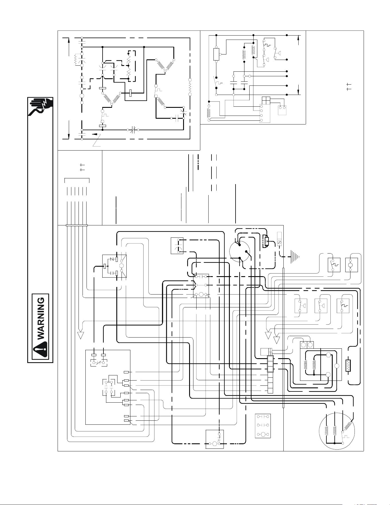
Wiring is subject to change. Always refer to the wiring diagram on the unit for the most up-to-date wiring.
HIGH VOLTAGE!
DISCONNECT ALL POWER BEFORE SERVICING OR INSTALLING THIS
UNIT. MULTIPLE POWER SOURCES MAY BE PRESENT. FAILURE TO
DO SO MAY CAUSE PROPERTY DAMAGE, PERSONAL INJURY OR DEATH.
163
WIRING DIAGRAMS *SZ160[24-60]1A*
USE N.E.C. CLASS 2 WIRE
NOTES:
1) TO INDOOR UNIT LOW VOLTAGE
TERMINAL BLOCK & INDOOR
THERMOSTAT.
2) START ASSIST FA CTORY
EQ UIPPED WHEN REQUIRED.
3) CRANKCASE HEATER MAY BE
FA CTORY OR FIELD INSTALLED.
0140R00082 REV B
C OMPO N E NT CO DE
C --------------- CONTACTOR
CADM --------
COMFORT ALERT DIAGNOSTIC MODULE
CH ------------- CRANKCASE HEATER
CM ------------ OUTDOOR FAN MOTOR
CMR ---------- CONDENSER MOTOR RELAY
COMP -------- COMPRESSOR
CS ------------- COMPRESSOR SOLENOID
DC ------------- DEFROST CONTROL
DFT ----------- DEFROST THERMOSTAT
DT ------------- DISCHARGE THERMOSTAT
HPS ----------- HIGH PRESSURE SWITCH
HVDR -------- HIGH VOLTAGE DEFROST RELAY
IO -------------- INTERNAL OVERLOAD
LPS ------------ LOW PRESSURE SWITCH
LVDR --------- LOW VOLTAGE DEFROST RELAY
LVJB ---------- LOW VOLTAGEJUNCTION BOX
RCCF --------- RUN CAPA CITOR FOR COMPRESSOR & FAN
RVC ----------- REVERSING VALVE COIL
SA ------------- START ASSIST(OPTIONAL)
SC ------------- START CAPACITOR FOR COMPRESSOR (OPTIONAL)
SR ------------- START RELAY FOR COMPRESSOR (OPTIONAL)
CONTROLS SHOWN WITH THERMOSTAT IN 'OFF' POSITION.
T1
L1
T2
L2
ALTERNATE DOUBLE
POLE CONTACTOR
WIRI NG CO D E
FACTO RY W IRING
HIGH VOLTAGE
LOW VOLTAGE
OPTIONAL HIGH VOLTAGE
FIELD W
IRING
HIGH VOLTAGE
LOW VOLTAGE
CONTROL BOX
EQUIPMENT GROUND
USE COPPER
CONDUCTORS ONLY
CADM
Y2
CRY1
DC
SOL
CS
Y2
C
CMR
3
1
HPS
COMP
ALTERNATE DOUBLE
POLE CONTACTOR ONLY
IO
T1
C
M
A
I
N
R
A
U
X
5
S
SR
SA
2
1
RCCF
SC
T2
C
L1
L2
(IF USED)
CH
C
F
LPS
OR
BL
RD
O
C
R
NOTE 1
OUTDOOR POWER SUPPLY
SEE RATING PLAT E
LVJB
DF1
DF2
HVDR
CH
(IF USED)
NOTE 3
W2
LVDR
O
R
O
O
Y1
C
RVC
W2
INDOOR POWER
SUPPLY
CR
DFT
C
Y
DC
R
DFT
WH
W2
CADM
C
A
D
M
M
A
I
N
A
U
X
IO
CM
(
L
O
W
)
2
4
(HIGH)
5
C
M
R
C
A
D
M
Y2
DT
C OLO
R
C O
D
E
BK --------------- BLACK
BL --------------- BLUE
BL/PK ---------- BLUE/PINK STRIPE
BR --------------- BROWN
OR --------------- ORANGE
PU --------------- PURPLE
RD --------------- RED
WH -------------- WHITE
YL --------------- YELLOW
YL/PK ---------- YELLOW/PINK STRIPE
YL
C
R
S
RD
BK
AUX
MAIN
COMP
BK
CH
(IF USED) NOTE 3
BK
IO
CM
AUX
MAIN
BK
(HIGH)
BR
PU
RD
(LOW)
RD
BK
DC
SOL
YL
PURD
BL
CADM
Y2
R C Y1
R
C S
CS
Y2
C
RD
BK
YL
BK
LPS
YL/
PK
YL/
PK
HPS
BL/
PK
DT
BK
BK
DFT
RVC
BK
RD RD
RD
SA
(IF USED)
NOTE 2
RCCF
F
C
HERM
YL
YL
YL
BR
RD
PU
YL
RD
SC
RD
BL
L2
T2
L1
T1
C
BK
BK
BK
RD
RD
BL
BL
YL/
PK
PU
BL
RD
BK BK
PU
SR
5
2
1
BK
YL
BL
DC
OR
C Y
O O
BL
PU BK
RD
R
R
LVDR
W2
WH
DFT
RD
H
V
D
R
DF2
DF1
BK
BK
BK
RD
BK
4
1
3
CMR
2
5
BK
BK
RD
RD
RD
YL
YL
BL
BL
YL
Y2
PU Y1
BL/
PK
NOTE 2
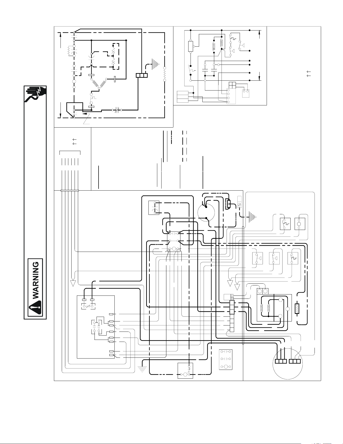
Wiring is subject to change. Always refer to the wiring diagram on the unit for the most up-to-date wiring.
HIGH VOLTAGE!
DISCONNECT ALL POWER BEFORE SERVICING OR INSTALLING THIS
UNIT. MULTIPLE POWER SOURCES MAY BE PRESENT. FAILURE TO
DO SO MAY CAUSE PROPERTY DAMAGE, PERSONAL INJURY OR DEATH.
164
WIRING DIAGRAMS *SZ180[36-60]1A*
USE N.E.C. CLASS 2 WIRE
NOTES:
1) TO INDOOR UNIT LOW VOLTAGE
TERMINAL BLOCK & INDOOR
THERMOSTAT.
2) START ASSIST FACTORY
EQUIPPED WHEN REQUIRED.
3) CRANKCASE HEAT ER MAY BE
FACTORY OR FIELD INSTALLED.
0140R00108
CO MPO NE NT CO DE
C --------------- CONTACTOR
CADM --------
COMFORT ALERT DIAGNOSTIC MODULE
CH ------------- CRANKCASE HEAT ER
CM ------------ OUTDOOR FAN MOTOR
COMP -------- COMPRESSOR
CS ------------- COMPRESSOR SOLENOID
DC ------------- DEFROST CONTROL
DFT ----------- DEFROST THERMOSTAT
DT ------------- DISCHARGE THERMOSTAT
HPS ----------- HIGH PRESSURE SWITCH
HVDR -------- HIGH VOLTAGE DEFROST RELAY
IO -------------- INTERNAL OVERLOAD
LPS ------------ LOW PRESSURE SWITCH
LVDR --------- LOW VOLTAGE DEFROST RELAY
LVJB ---------- LOW VOLTAGEJUNCTION BOX
RC--- --------- COMPRESSOR RUN CAPACITOR
RVC ----------- REVERSING VALVE COIL
SA ------------- START ASSIST (OPTIONAL)
SC ------------- START CAPA CITOR FOR COMPRESSOR (OPTIONAL)
SR ------------- START RELAY FOR COMPRESSOR (OPTIONAL)
CONTROLS SHOWN WITH THERMOSTAT IN 'OFF' POSITION.
W
IRING CO DE
FACT O R Y W IRI NG
HIGH VOLTAGE
LOW VOLTAGE
OPTIONAL HIGH VOLTAGE
FIE
LD W IRI NG
HIGH VOLTAGE
LOW VOLTAGE
CONTROL BOX
EQUIPMENT GROUND
USE COPPER
CONDUCTORS ONLY
CADM
Y2
C
RY1
DC
SOL
CS
Y2
C
HPS
COMP
ALTERNATE DOUBLE
POLE CONTACTOR ONLY
IO
T1
C
M
A
I
N
R
A
U
X
5
S
SR
SA
2
1
SC
T2
C
L1
L2
(IF USED)
C
LPS
OR
BL
RD
O
C
R
NOTE 1
OUTDOOR POWER SUPPLY
SEE RATING PLATE
LVJB
DF1
DF2
HVDR
CH
(IF USED)
NOTE 3
W2
LVDR
O
R
O
O
Y1
C
RVC
W2
INDOOR POWER
SUPPLY
R
C
DFT
C
Y
DC
R
DFT
WH
W2
CADM
C
A
D
M
C
A
D
M
Y2
DT
CO LO R CO DE
BK --------------- BLACK
BL --------------- BLUE
BL/PK ---------- BLUE/PINK STRIPE
BR --------------- BROWN
OR --------------- ORANGE
PU --------------- PURPLE
RD --------------- RED
WH -------------- WHITE
YL --------------- YELLOW
YL/PK ---------- YELLOW/PINK STRIPE
GR/YL-----------GREEN/YELLOW
STRIPE
YL
C
R
S
RD
BK
AUX
MAIN
COMP
BK
CH
(IF USED) NOTE 3
BK
CM
WH
(HIGH)
BR
BK
YL
(LOW)
RD
BK
DC
SOL
YL
PURD
BL
CADM
Y2
R C
Y1
R
C
S
CS
Y2
C
RD
BK
YL
BK
LPS
YL/
PK
YL/
PK
HPS
BL/
PK
DT
BK
BK
DFT
RVC
BK
RD RD
RD
SA
(IF USED)
NOTE 2
RC
C
YL
YL
YL
RD
YL
RD
SC
RD BL
L2
T2
L1
T1
C
BK
BK
RD
RDBL
YL/
PK
YL
BL
RD
BK BK
PU
SR
5
2
1
BK
YL
BL
DC
OR
C Y
O O
PU
BK
RD
R
R
LVDR
W2
WH
DFT
RD
H
V
D
R
DF2
DF1
BK
BK
BK
RD
BK
RD
RD
YL
Y2
PU Y1
BL/
PK
NOTE 2
Y
L
B
L
W
H
CM
CM
L1
L2
GND
CM
L1
L2
GND
BL
(COM)
GR/YL
T1
L1
T2
L2
ALTERNAT E DOUBLE
POLE CONTACTOR
PU
BL
BR
HERM
BL
BL
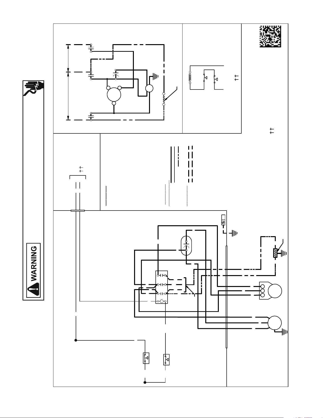
Wiring is subject to change. Always refer to the wiring diagram on the unit for the most up-to-date wiring.
HIGH VOLTAGE!
DISCONNECT ALL POWER BEFORE SERVICING OR INSTALLING THIS
UNIT. MULTIPLE POWER SOURCES MAY BE PRESENT. FAILURE TO
DO SO MAY CAUSE PROPERTY DAMAGE, PERSONAL INJURY OR DEATH.
165
WIRING DIAGRAMS GSX11[090-120]*A*
USEN.E.C.CLASS 2WIRE
T1
C
FC
T3
C
L1
L3
C
C
0140R00190-D
BL
Y
C
LVJB
COMPONENT CODE
C -------- ------- CONTACTOR
CM ----------OUT DOOR FAN MOTOR
COMP -------- COMPRESSOR
FC -------- ----- FAN CAPACITOR
IO -------- ------INTERNAL OVERLOAD
LVJB ---------- LOW VOLTAGE JUNCTION BOX
CH ------------CRANKCASE HEATER
CHS-------- --- CRANKCASEHEATERSWITCH
LPS -------- -- LOWPRESSURESWITCH
HPS-------- -- HIGHPRESSURESWITCH
CONTROLS SHOWNWITHTHERMOSTAT IN 'OFF' POSITION.
W
I
R I
NG
C OD E
F ACTOR Y W IR ING
HIGH VOLTAGE
LOWVOLTAGE
OPTIONAL HIGH VOLTAGE
F
IE LD W IR ING
HIGH VOLTAGE
LOWVOLTAGE
Y
YL
YL
L2
C
T2
OUTDOOR POWERSUPPLY
SEERATINGPLATE
BK
RD
BK
BL
BK
YL
C
YL/PK
RD
FC
PU
BR
LVJB
CONTROL BOX
SEE NOTE1
PU
BR
BK
CH
BK
CH
BK
BK
BK
BK
CO LOR
C OD E
BK ---------------BLACK
BL ---------------BLUE
BR --------------- BROW N
OR --------------- ORANGE
PU --------------- PURPLE
RD --------------- RED
WH --------------WHITE
YL --------------- YELLOW
YL/PK ---------- YELLOW w/PINK
HASH MARKS
BL/PK----------BLUEw/PINK
HASH MARKS
PK ---------------PINK
L1
L2 L3
SEE
NOTE 2
SEENOTE3
LPS
HPS
HPS
LPS
NOTES:
1) TO INDOOR UNITLOW VOLTAGETERMINALBLOCK &INDOOR
THERMOSTAT.
2) CRANKCASE HEATER FACTORYINSTALLED OPTION.
3) USECOPPERCONDUCTORSONLY
4) 40VA TRANSFORMERMINIMUMSYSTEMREQUIRED
5) TRANSFORMERCOMMONSIDEMUSTBEGROUNDED
COMP
L1
L2
L3
EQUIPMENT GROUND
CM
COMP
R
C
S
CM
SEENOTE2
T1
L1
T2
L2
T3
L3
YL
BL/PK
YL/PK
BL/PK
PU
PU
SEE NOTE 3
SEE NOTE1
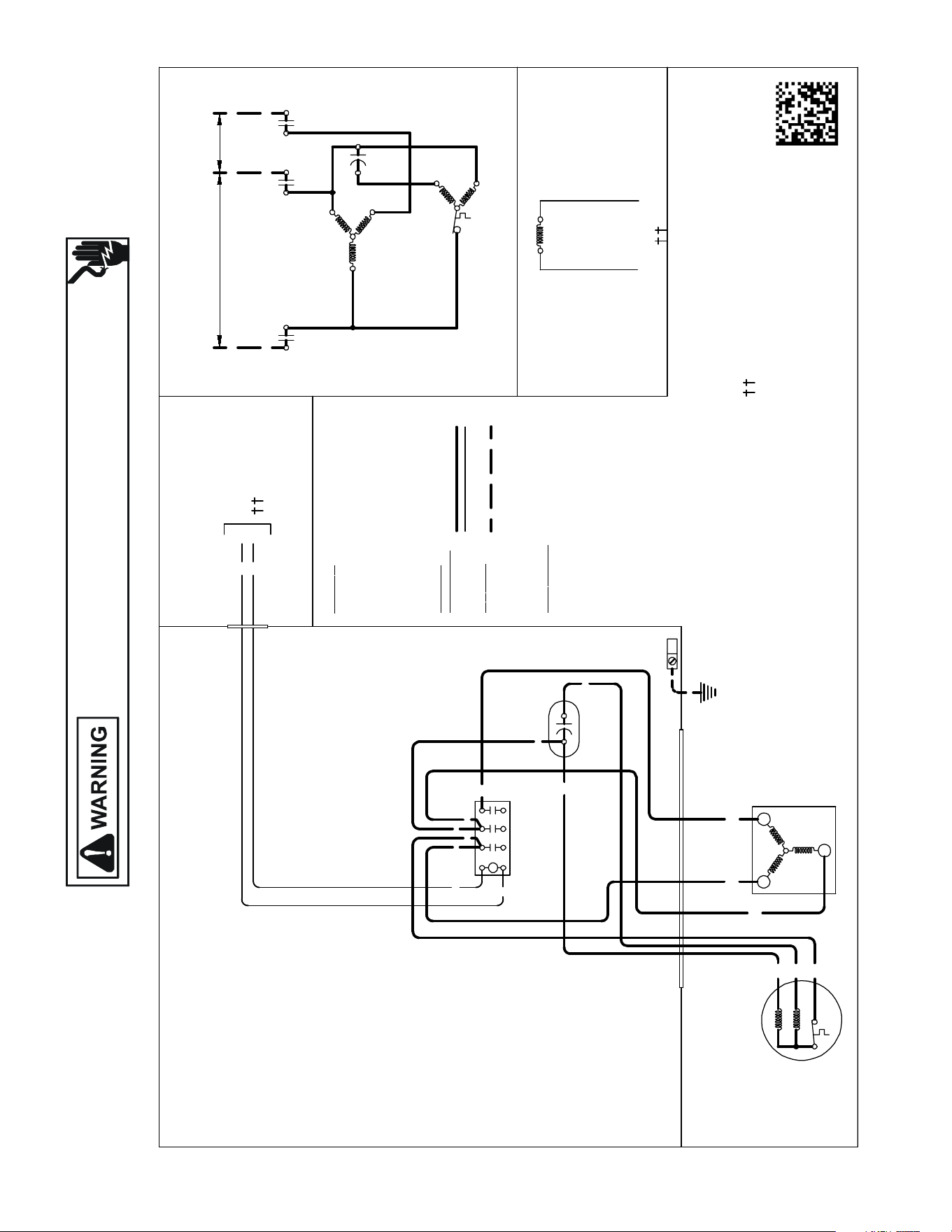
Wiring is subject to change. Always refer to the wiring diagram on the unit for the most up-to-date wiring.
HIGH VOLTAGE!
DISCONNECT ALL POWER BEFORE SERVICING OR INSTALLING THIS
UNIT. MULTIPLE POWER SOURCES MAY BE PRESENT. FAILURE TO
DO SO MAY CAUSE PROPERTY DAMAGE, PERSONAL INJURY OR DEATH.
166
WIRING DIAGRAMS GSX130[36-61][3,4]A*/3-Phase
USE N.E.C. CLASS2WIRE
NOTES:
1) TO INDOORUNITLOW VOLTAGE TERMINAL BLOCK &
INDOOR THERMOSTAT.
2) USECOPPERCONDUCTOR ONLY
COMP
T1
C
T3
T2
FC
T3
C
L1
L3
M
A
I
N
A
U
X
C
C
BL
Y
C
COL OR C O DE
BK --------------- BLACK
BL --------------- BLUE
BR ---------------BROWN
OR --------------- ORANGE
PU --------------- PURPLE
RD --------------- RED
WH -------------- WHITE
YL ---------------YELLOW
COMP
O
NE NT CO
DE
C --------------- CONTACTOR
CM ------------ OU TDOO RFAN MOTOR
COMP -------- COMPRESSOR
FC ------------- FAN CAPACITOR
IO -------------- INTERNAL OVERLOAD
LVJB ---------- LOWVOLTAGE JUNCTION BOX
CONTROLSSHOWN WITH THERMOSTAT IN 'OFF ' POSITION.
WIRING CO
DE
FACTOR Y WIRING
HIGH VOLTAGE
LOWVOLTAGE
FI
E LD WIRING
HIGH VOLTAGE
IO
CM
Y
YL
BK
T3
COMP
T1
L2
C
T2
OUTDOOR POWER SUPPLY
SEERATINGPLATE
T1
T2
RD
YL
RD
BL
BK
BK
C
T1
L1
T2
L2
T3
L3YL
YL
RD
FC
PU
BR
RD
LVJB
CONTROLBOX
SEENOTE1
PU
BR
BK
MAIN
AUX
CM
IO
EQUIPMENT GROUND
SEE NOTE 2
0140R00016P-D
SEE NOTE1
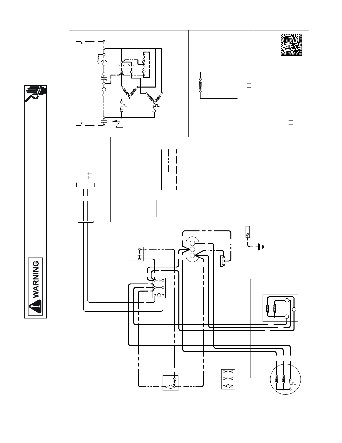
Wiring is subject to change. Always refer to the wiring diagram on the unit for the most up-to-date wiring.
HIGH VOLTAGE!
DISCONNECT ALL POWER BEFORE SERVICING OR INSTALLING THIS
UNIT. MULTIPLE POWER SOURCES MAY BE PRESENT. FAILURE TO
DO SO MAY CAUSE PROPERTY DAMAGE, PERSONAL INJURY OR DEATH.
167
WIRING DIAGRAMS
GSX140[18-60]1K*,
GSX160[18-48,611]1F*
USEN.E.C.CLASS2WIRE
COMP
ALTERNATE DOUBLE
POLE CONTACTORONLY
IO
T1
C
M
A
I
N
R
A
U
X
5
S
SR
SA
2
1
RCCF
SC
T2
C
L1 L2
(IFUSED)
CH
C
F
M
A
I
N
A
U
X
C
C
0140R00015P-C
BL
Y
C
LVJB
COL OR C O
DE
BK ---------------BLACK
BL --------------- BLUE
BR --------------- BROWN
OR --------------- ORANGE
PU --------------- PURPLE
RD --------------- RED
WH --------------WHITE
YL ----------------YELLOW
CONTROLBOX
COMP ONE NT CO
DE
C--------------- CONTACTOR
CM ------------ OUTDOORFAN MOTOR
COMP-------- COMPRESSOR
IO -------------- INTERNALOVERLOAD
LVJB ----------LOW VOLTAGE JUNC TION BOX
RCCF --------- RU N CAPACITORFOR COMPRESS OR &FAN
SA ------------- STARTASSIST
SC ------------- START CAPACITORFOR COMPRESSOR(OPTIONAL)
SR -------------START RELAY FOR COMPRESSOR (OPTIONAL)
CONTROLS SHOWN WITH THERMOSTAT IN 'OFF' POSITION.
OUTDOORPOWER SUPPLY
SEERATINGPLATE
WIRING CO
DE
FACTOR Y WIRING
HIGH VOLTAGE
LOWVOLTAGE
OPTIONAL HI GH VOLTAGE
FI
E LD WIRING
HIGH VOLTAGE
IO
CM
Y
YL
YL
C
R
S
RD
BK
AUX
MAIN
COMP
SEENOTE1
SC
RD
BL
RCCF
YL
PU
YL
SR
5
2
1
BK
YL
BL
RD
YL
BL
RD
RD
BKBK
BK
C
T1
L1
T2
L2
SA
(IFUSED)
NOTE 2
EQUIPMENT GROUND
SEE NOTE 3
PU
BR
BK
MAIN
AUX
CM
IO
T1
L1
T2
L2
ALTERNATE DOUBLE POLE
CONTACTOR
NOTES:
1) TO INDOOR UNIT LOWVOLTAGE TERMINAL BLOCK&
INDOOR THERMOSTAT.
2) STARTASSIST FACTORY EQUIPPEDWHEN REQUIRED.
3) USE COPPER CONDUC TORS ONLY.
CFH
RD
RD
RD
BR
SEE NOTE1
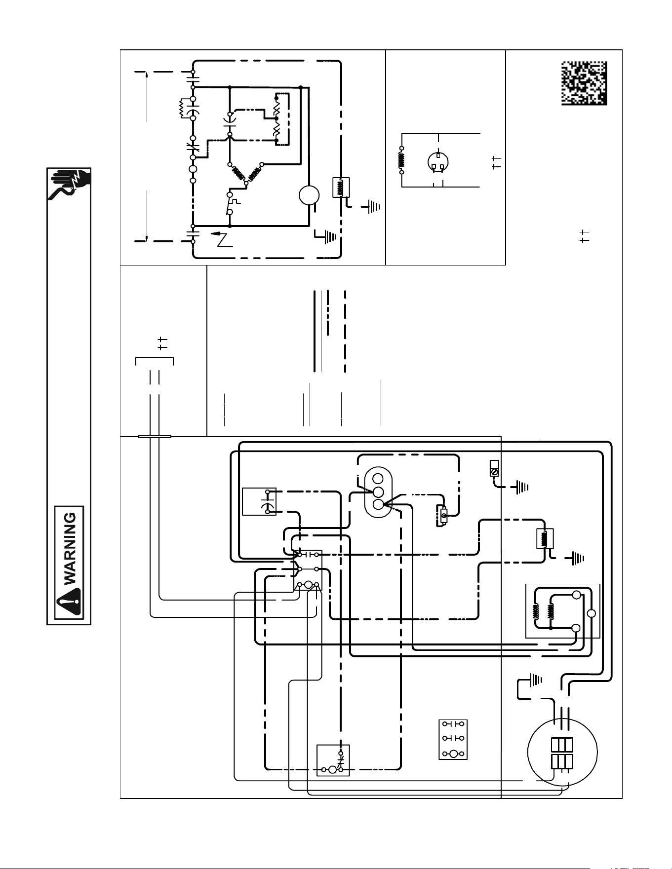
Wiring is subject to change. Always refer to the wiring diagram on the unit for the most up-to-date wiring.
HIGH VOLTAGE!
DISCONNECT ALL POWER BEFORE SERVICING OR INSTALLING THIS
UNIT. MULTIPLE POWER SOURCES MAY BE PRESENT. FAILURE TO
DO SO MAY CAUSE PROPERTY DAMAGE, PERSONAL INJURY OR DEATH.
168
WIRING DIAGRAMS GSX160601F*
USE N.E.C.CLASS 2WIRE
COMP
ALTERNATEDOUBLE
POLE CONTACTORONLY
IO
T1
C
M
A
I
N
R
A
U
X
5
S
SR
SA
2
1
RCCF
SC
T2
C
L1
L2
(IFUSED)
CH
C
C
C
0140R00287-B
BL
Y
C
LVJB
COL OR C
O
DE
BK --------------- BLACK
BL ---------------BLUE
BR --------------- BROWN
OR --------------- ORANGE
PU --------------- PURPLE
RD --------------- RED
WH -------------- WHITE
YL ---------------- YELLOW
GR/YL------------GREEN/YELLOW STRIPE
GR----------------GREEN
CONTROLBOX
COMP
O
NE
NT CO
DE
C --------------- CONTACTOR
CM ------------ OUTDOORFAN MOTOR
COMP -------- COMPRESSOR
IO --------------INTERNAL OVERLOAD
LVJB ----------LOW VOLT AGEJUNCTIONBOX
RCC--------- RUNC APACITOR FOR COMPRESS OR
SA ------------- STARTASSIST
SC ------------- STARTC APACITORFOR COMPRESSOR(OPTIONAL)
SR ------------- STARTRELAY FOR COMPRESSOR (OPTIONAL)
CH-------------- CRANKCASE HEATER
CONTROLSSHOWN WITH THERMOSTAT IN 'OFF'POSITION.
OUTDOOR POWER SUPPLY
SEERATINGPLATE
WIRING CO
DE
FACTOR
Y WIRING
HIGH VOLTAGE
LOWVOLTAGE
OPTIONAL HIGH VOLTAGE
FI
E LD WIRING
HIGH VOLTAGE
Y
YL
YL
C
R
S
RD
BK
AUX
MAIN
COMP
SC
RD
BL
RCC
YL
YL
SR
5
2
1
BK
YL
BL
RD
YL
BL
RD
RD
BK
BK
BK
C
T1
L1
T2
L2
SA
(IFUSED)
NOTE2
EQUIPMENT GROUND
SEE NOTE 3
BR
BK
YL
T1
L1
T2
L2
ALTERNAT E DOUBLE POLE
CONTACTOR
NOTES :
1) TO INDOOR UNIT LOWVOLTAGE TERMINAL BLOCK&
INDOOR THERMOSTAT.
2) STARTASSISTFACTORY EQUIPPE DWHEN REQUIRED.
3) USE COPPER CONDUC TORS ONLY.
H
C
RD
RD
RD
WH
BL
GND
L1
L2
CM
C
F
GR/YL
GR
BK
BK
GR
BK
BK
CH
CH
CM
L2
L1
CM
BL
WH
YL
GR/YL
SEE NOTE 1
SEE NOTE 1
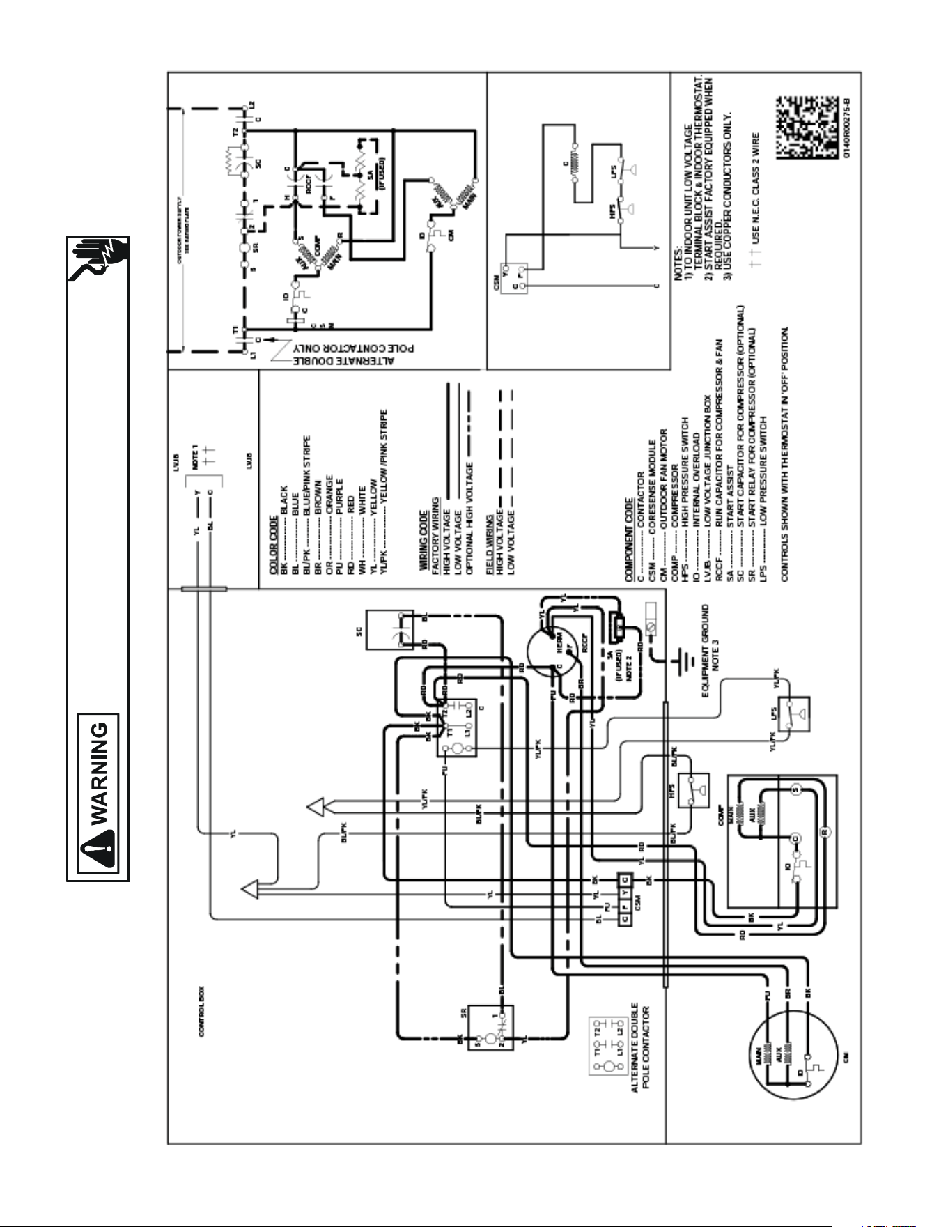
Wiring is subject to change. Always refer to the wiring diagram on the unit for the most up-to-date wiring.
HIGH VOLTAGE!
DISCONNECT ALL POWER BEFORE SERVICING OR INSTALLING THIS
UNIT. MULTIPLE POWER SOURCES MAY BE PRESENT. FAILURE TO
DO SO MAY CAUSE PROPERTY DAMAGE, PERSONAL INJURY OR DEATH.
169
WIRING DIAGRAMS GSX160611F*
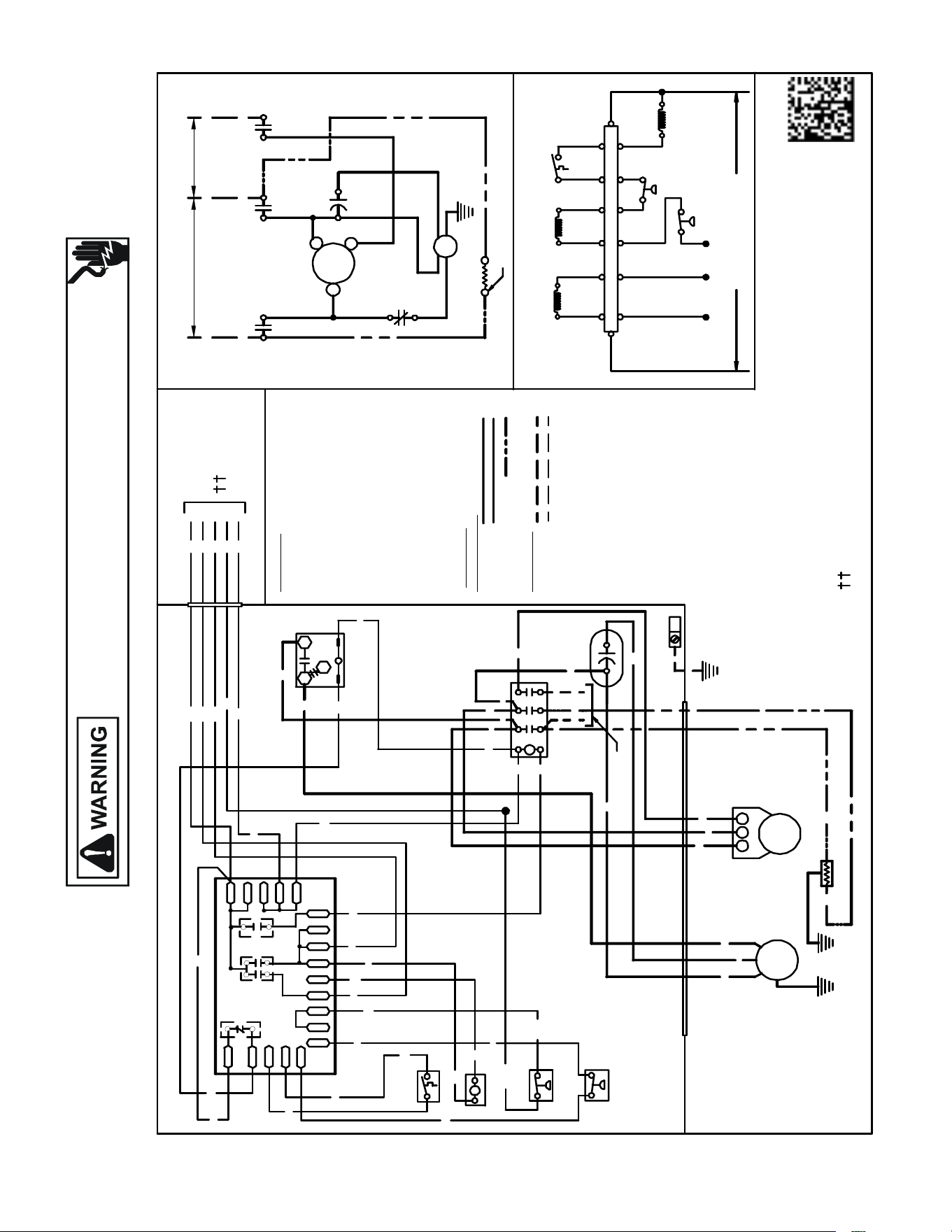
Wiring is subject to change. Always refer to the wiring diagram on the unit for the most up-to-date wiring.
HIGH VOLTAGE!
DISCONNECT ALL POWER BEFORE SERVICING OR INSTALLING THIS
UNIT. MULTIPLE POWER SOURCES MAY BE PRESENT. FAILURE TO
DO SO MAY CAUSE PROPERTY DAMAGE, PERSONAL INJURY OR DEATH.
170
WIRING DIAGRAMS GSZ11[090-120]3A*
USE N.E.C. CLASS 2 WIRE
NOTES:
1) TO INDOOR UNIT LOW VOLTAGE TERMINAL BLOCK & INDOOR THERMOSTAT.
2) CRANKCASE HEAT ER FACTORY INSTALLED OPTION.
3) USE COPPER CONDUC TORS ONLY
4) 40VA MI NIMUM TRANSFORMER IS REQUIRED
5) COMMON SIDE OF TRANSFORMER MUST BE GROUNDED
0140R00186 - C
OR
YL
BL
RD
O
Y
C
R
SEE NOTE # 1
YL/PK ---------- YELLOW W/ PINK
HASH MARKS
COMPONENT CODE
C --------------- CONTACTOR
CH ------------- CR ANKC ASE HE ATER
CM ------------ OUTDOOR FAN MOTO R
COMP -------- COMPR ESSOR
DC ------------- DEFROST CO NTROL
DFT ----------- DEFROST THERMOSTAT
FC ------------- FAN CAPA CITOR
HVDR -------- HIGH VOLTAGE DEFROST RELAY
IO -------------- IN TERNAL OVERLO AD
LPS ------------ LO W PRESSURE SWIT CH
LVDR --------- LO W VOLTAG E DEFROST RELA Y
LVJB ---------- LOW VOLTAGE JUNCTION BOX
RVC ----------- REVERSING VALVE CO IL
CMR ----------- CONDENSER MOTOR RELAY
HPS ------ ----- HI GH PR ESSURE SWITCH
CHS ----------- CRANKC ASE HEATER SWITCH
CONTROLS SH OWN WITH THER MOSTAT IN 'OFF' PO SITI ON.
W IRIN G C ODE
FA CTO
RY W
IRI NG
HIGH VOLTAGE
LOW VOLTAGE
OPTIONAL HIGH VOLTAGE
FIELD WI RI NG
HIGH VOLTAGE
LOW VOLTAGE
LVJB
CONTROL BOX
BK
BR
PU
BK
DFT
YL/PK
LPS
EQUIPMENT
GROUND
DFT
W
O-RV
DC
RVC
BK
BK
CH
BK
WH
W2
YL
BK
RD
BK
BK
YL
C
T1
L1
T2
L2
T3
L3PU
PU
RD
FC
PU
BR
PU
3
1
CMR
BL
BL
BK
BL/P K
BL/PK
HPS
RD
BK
BK
CMR
C OL OR C ODE
BK --------------- BLAC K
BL --------------- BLUE
BR --------------- BROWN
OR --------------- ORANGE
PK ---------------- PINK
PU --------------- PURPLE
RD ------- -------- RED
WH -------------- WHITE
YL --------------- YELLOW
BL/PK ---------- BLUE W/PINK
HASH MARKS
L1 L2 L3
DC
RD
BK
BK
BL
RD
PU
OR
BL/PK
WH
T1
C
FC
T3
C
L1
L3
L2
C
T2
CH
Y
PS1PS2 CN T
DFTR-DFT
C-RV
DF1DF2
O
LPS
HPS
W2 YO
C
CMR
RVC
R
C
OUTDOOR POWER SUPPLY
SEE RATING PLATE
2
1 3
COMP
L1 L2 L3
CM
COMP
S
C
R
CM
YL
YL/PK
YL/PK
OR
WH
RD
BL
BK
BL
BL
R
DF1
DF2
0
0-RV
C-RV
W
LVDR
HVDR
CCR
CNT
0
DFT
R-DF T
R-PS1
Y
Y
C
R
C
C
PS2
RD
RD
RD
RD
SEE NOTE 2
SEE NOTE 4 & 5
(IF USED)
NOTE 2
SEE NOTE 3
SEE NOTE 3
INDOOR POWER SUPPLY

Wiring is subject to change. Always refer to the wiring diagram on the unit for the most up-to-date wiring.
HIGH VOLTAGE!
DISCONNECT ALL POWER BEFORE SERVICING OR INSTALLING THIS
UNIT. MULTIPLE POWER SOURCES MAY BE PRESENT. FAILURE TO
DO SO MAY CAUSE PROPERTY DAMAGE, PERSONAL INJURY OR DEATH.
171
WIRING DIAGRAMS
GSZ130181A[D/F/G], GSZ130241[B*/C*], GSZ130421A[G/H]
GSZ130301A[E/F/G/H], GSZ130361B*, GSZ140[18-30/48-60]1AA
GSZ140[36-42]1AB, GSZ130181AC, GSZ130241BB, GSZ130301AD
GSZ130361B*, GSZ130421A*, GSZ130481AC, GSZ130601AC
USE N.E.C. CLASS 2 WIRE
NOTES:
1) TO INDOOR UNIT LOW VOLTAG E TERMINAL BLOCK & INDOOR THERMO STAT.
2) START ASSIST FA CTORY EQUIPPED WH EN REQUIRED.
3) USE COPPER CO ND UCTOR ON LY.
4) CRANKCASE HEATER & CRANKCAS E HEAT ER SWITCH ARE FACTORY INSTALLED OP TION
5) 40VA MINIMUM TRANSFOR MER IS REQUIRED.
6) COMM ON SIDE OF TR ANSFORMER MUST BE GROUNDED.
COMP
ALTERNAT E DOUB LE
POLE CONTACTOR ONLY
IO
T1
C
M
A
I
N
R
A
U
X
5
S
SR
SA
2
1
RCCF
SC
T2
C
L1
L2
(IF USED)
NOTE 2
CH
C
F
M
A
I
N
A
U
X
IO
CM
01 40R00171 - B
OR
BL/PK
BL
RD
O
Y
C
R
C
O
LO
R
C ODE
BK ----------- -- -- BLACK
BL/PK ---------- BL UE/PINK STRIPE
BR --------------- BROWN
GR---------------- GREEN
OR --------------- ORANGE
PU --------------- PURPLE
RD --------------- RED
WH -------------- WHITE
YL --------------- YELLOW
YL/PK----------- YELL OW/PINK STRIPE
COMPONEN T CODE
C --------------- CONTACTOR
CADM -------- COMFORT ALERT DIAGNOSTIC MODULE
CCR ----------- COMPRESSOR CONTACTOR RELAY
CH ------------- CRANKCASE HEAT ER
CHS ----------- CRANKCASE HEATER SWITCH
CM ------------ OUTDOOR FA N MOTOR
CMR ---------- CONDENSE R MOTOR RELAY
COMP ------ -- COMPRESSOR
CS ------------- COMP RESSOR SOLENOID
DC ---- --------- DEFROST CONTROL
DFT ----------- DEFROST THERMOSTAT
DT ------------- DISCHARGE THERMOSTAT
HPS -------- --- HI GH PRESSURE SW ITCH
HVDR -------- HIGH VOLTAGE DEFROST RELAY
IO ---------- ---- INTERNAL OVERLOAD
LPS ---- ------
LOW PRESSURE SWITCH
LV DR --------- LOW VOLTAGE DEFROST RELAY
LV JB --------- LOW VOLT AG E JU NCTION BOX
RCCF -------- - RUN CAPACI TOR FOR COMPRESS OR & FAN
RVC ----------- REVERSING VALV E COIL
SA ------------- START ASSIST
SC ------------- START CA PACITOR FOR COMPRESSOR (OPTIONAL)
SR ------------- START RELAY FOR COMPRESS OR (OPTIONAL)
CONTROLS SHOWN WITH THERM OSTAT IN 'OFF' POSITION.
OUTDOOR POWER SUPPLY
SEE RATING PLATE
WIRI NG CODE
FA CT
O RY WI
RI N
G
HI GH VOLTAGE
LOW VOLTAGE
OPTIONAL HIGH VOLT AGE
FIE
L D WI RI
N
G
HI GH VOLTAGE
LOW VOLTAGE
LVJB
CONTROL BOX
SC
RD BL
L2
T2
L1
T1
C
BK
BK
BK
RD
RD
BL
RD
RCCF
F
C
HERM
YL
YL
YL
BR
RD
PU
YL
RD
SR
5
2
1
BK
YL
BL
IO
CM
AUX
MAIN
BR
PU
YL
C
R
S
RD
BK
AUX
MAIN
COMP
YL/PK
LPS
EQUIPMENT
GROUND
DF1
DF2
CH
LV DR
R
CNT
INDOOR POWE R SUPPLY
DFT
C
Y
DC
DFT
WH W2
DC
BL/PK
HPS
O
C
RV C
W2
R
HVDR
YL/PK
BK
RD
BK
PU
BK
BL
BL
PU
CHS
R-DFT
O-RV
C-RV
LPS
PS2
R-PS1
O
W
C
HPS
CCR
}
FIELD LOW
VO LTAG E
CONNECTIONS
RD
BK
CH
CH S
RD
SA
(IF USED)
NOTE 2
DFT
RVC
RD
BK
BL/PK
BK
GR
Y
T1
L1
T2
L2
ALT ERNATE
DOUBLE POLE
CONTACTOR
R
DF1
DF2
0
0- RV
C-RV
W
LV DR
HVDR
CCR
CN T
0
DFT
R-DF T
R-PS1
Y
Y
C
R
C
C
PS 2
YL/PK
YL/PK
RD
RD
BL/PK
WH
OR
BK
BK
SEE NOTE 4
SEE NOTE 5 & 6
SEE NOTE 4
SEE NOTE 3
BK
BK
RD
NOTE 1
IO
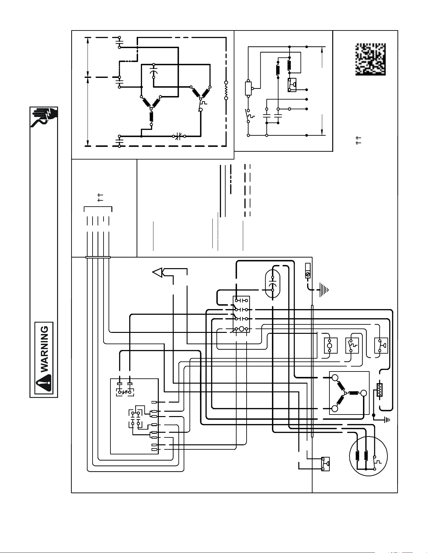
Wiring is subject to change. Always refer to the wiring diagram on the unit for the most up-to-date wiring.
HIGH VOLTAGE!
DISCONNECT ALL POWER BEFORE SERVICING OR INSTALLING THIS
UNIT. MULTIPLE POWER SOURCES MAY BE PRESENT. FAILURE TO
DO SO MAY CAUSE PROPERTY DAMAGE, PERSONAL INJURY OR DEATH.
172
WIRING DIAGRAMS GSZ130[36-60][3,4]A*
USE N.E.C. CLAS S 2 WIRE
NOTES:
1) TO INDOOR UNIT LOW VOLTAGE
TERMINAL BLOCK & INDOOR
THERMOSTAT.
LPS
0140R00162-C
OR
BL
RD
O
BL/PK
C
R
NOTE 1
C
O
L O
R
C
ODE
BK --------------- BLACK
BL/PK ---------- BLUE/ PINK STRIPE
BR --------------- BROWN
OR --------------- ORANGE
PU --------------- PURPLE
RD --------------- RED
WH -------------- WHITE
YL -------- ------- YELLOW
YL/PK------------YELLOW/PINK STRIPE
COMPONENT CODE
C --------------- CONTACTOR
CH -- ----------- CRANKCASE HEATER
CM -- ---------- OUTDOOR FAN MOTOR
COMP -- ------ COMPRESSOR
DC -- ----------- DEFROST CONTROL
DFT ----------- DEFROST THERMOSTAT
HPS-------------HIGH PRESSURE SWITCH
FC ------------- FA N CAPACITOR
HVDR -------- HIGH VOLTAGE DEFROST RELAY
IO -------- ------ INTERNAL OVERLOAD
LPS --------- --- LOW PR ESSURE SWITCH
LVDR --------- LO W VOLTAGE DEFROST RELAY
LVJB ---------- LOW VOLTAGE JUNCTION BOX
RVC ----------- REVERSING VA LVE COIL
CONTROLS SHOWN WITH THERMOSTAT IN 'OFF' POSITION.
WIRIN
G
COD
E
FA C
T O RY WI
RI
NG
HIGH VOLTAGE
LOW VOLTAGE
OPTIONAL HIGH VOLTAGE
FIE
L D WI RI NG
HIGH VOLTAGE
LOW VOLTAGE
LVJB
CONTROL BOX
IO
CM
AUX
MAIN
BK
BR
PU
BK
DFT
YL/PK
YL/PK
LPS
EQUIPMENT GROUND
USE COPPER
CONDUCTORS ONLY
CH
(IF USED)
W2
LV DR
O
R
O
O
C
RVC
W2
INDOOR POWER
SUPPLY
R
C
DFT
C
Y
DC
R
DFT
RVC
BK
RD
RD
BK
CH
(IF USED)
BK
WH W2
DC
OR
C
Y
O
O
BL
YL BK
RD
R
R
RD
LV DR
W2
WH
DFT
RD
H
V
D
R
DF2
DF1
BK
BK
COMP
T1
C
T3
T2
FC
T3
C
L1
L3
M
A
I
N
A
U
X
IO
CM
BK
T3
COMP
T1
L2
C
T2
OUTDOOR POWER SUPPLY
SEE RATING PLATE
T1
T2
RD
YL
RD
BK
BK
C
T1
L1
T2
L2
T3
L3YL
RD
YL
FC
PU
BR
RD
DF1
DF2
HVDR
BK
BL
YL/PK
BL
BK BK
HPS
HPS
BL/PK
BL/PK
YL/PK
BL/PK
Y
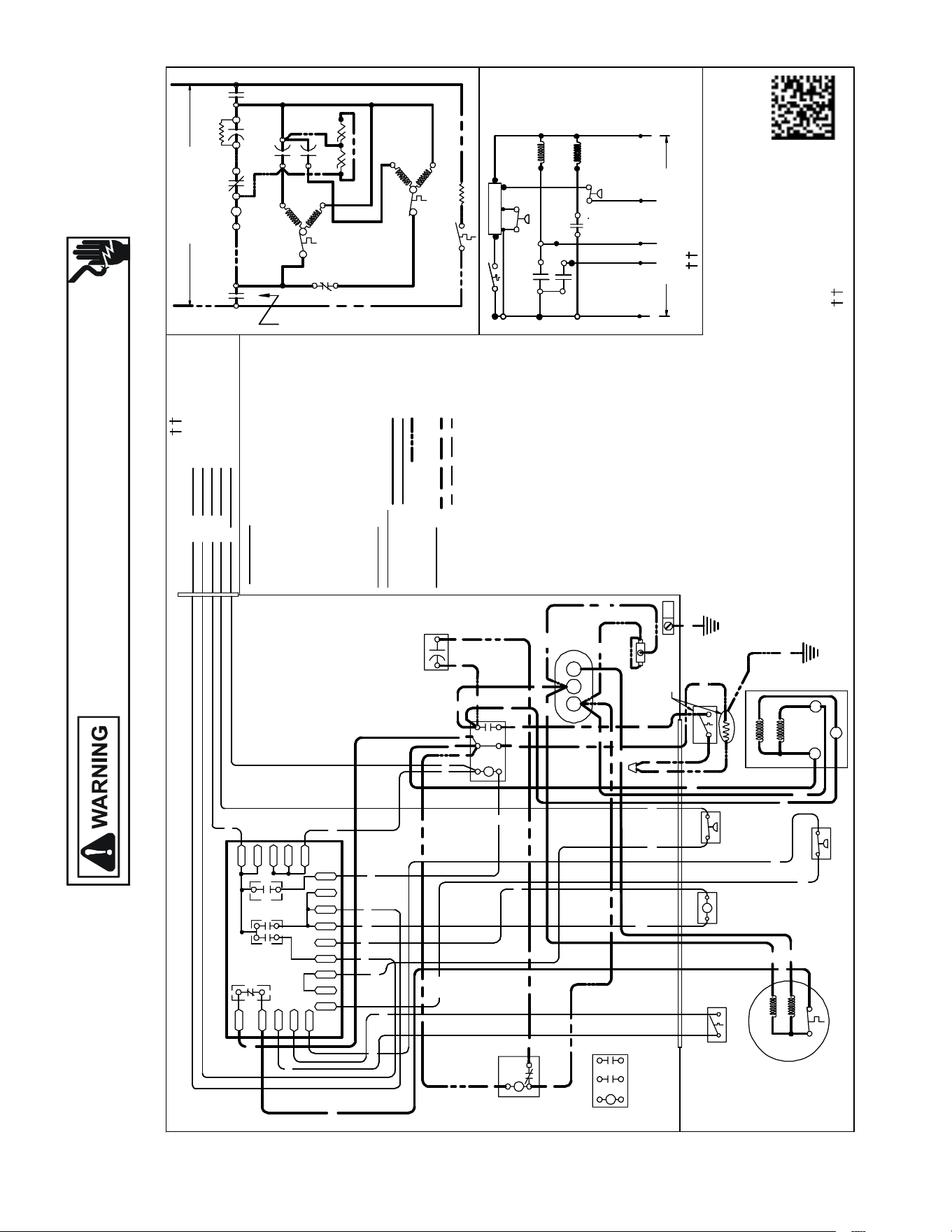
Wiring is subject to change. Always refer to the wiring diagram on the unit for the most up-to-date wiring.
HIGH VOLTAGE!
DISCONNECT ALL POWER BEFORE SERVICING OR INSTALLING THIS
UNIT. MULTIPLE POWER SOURCES MAY BE PRESENT. FAILURE TO
DO SO MAY CAUSE PROPERTY DAMAGE, PERSONAL INJURY OR DEATH.
173
WIRING DIAGRAMS GSZ160[18-48]1B*
INDOOR POWER SUPPLY
NOTES:
1. TO INDOOR UNIT LOWVOLTAGE TERMINAL BLOCK&INDOOR THERMOSTAT.
2. START ASSIST FACTOR YEQUIPPED WHEN RE QUIRED.
3. USE COPPER CO NDUCTOR ONLY.
4. CRANKCASE HEATER & CR ANKCASE HEATER SWITCH ARE FACTORYINSTALLED OPTION.
CRANKCASE HEATER MA Y NOT HAVE ADDITIONAL GROUND WIRE
5. 40VA MINIMUM TRANSFORM ER IS REQUIRED.
6. COMMON SI DE OF TRANSFORMER MUST BE GROUNDED.
COMP
ALTERNATE DOUBLE
POLE CONTACTORONLY
IO
T1
C
M
A
I
N
R
A
U
X
5
S
SR
SA
2
1
RCCF
SC
T2
C
L1
L2
(IF USED)
NOTE 2
CH
C
F
M
A
I
N
A
U
X
IO
CM
0140R00171-D
OR
BL/P K
BL
RD
O
Y
C
R
COL
OR
C ODE
BK --------------- BLACK
BL/PK ---------- BLUE/PINKSTRIPE
BR --------------- BROWN
GR---------------- GREEN
OR --------------- ORANGE
PU --------------- PURPLE
RD --------------- RED
WH -------------- WHITE
YL --------------- YELLOW
YL/PK----------- YELLOW/PINK STRIPE
COMPONENT CODE
C --------------- CONTACTOR
CADM -------- COMFORT ALERT DIAGNOSTIC MODULE
CCR----------- COMPRESSOR CONTACTOR RELAY
CH -------------CRANKCASE HEATER
CHS----------- CRANKC ASE HEATER SWITCH
CM ------------ OUTDOOR FAN MOTOR
CMR ---------- CONDENSER MOTOR RELAY
COMP -------- COMPR ESSOR
CS ------------- COMPRESSOR SOLENOID
DC ------------- DEFROST CONTROL
DFT ----------- DEFROST THERMOSTAT
DT ------------- DISCHARGE TH ERMOSTAT
HPS ----------- HIGH PRESSURE SWITCH
HVDR -------- HIGH VOLTAGE DEFROST RELAY
IO -------------- INTERNAL OVERLOAD
LPS ---------- LOW PR ESSURE SWITCH
LVDR --------- LOWVOLTAGE DEFROST RELAY
LV
JB --------- LOWVOLTAGE JUNCTION BOX
RCCF --------- RUNC APACITOR FOR COMPRESSOR & FAN
RVC----------- REVERSING VALVE COIL
SA ------------- STARTASSIST
SC ------------- START CAPACITOR FOR COMPRESSOR (OPT IONAL)
SR ------------- START RELAY FOR COMPR ESSOR (OPTIONAL)
CONTROLS SHOWNWITH THERMOSTAT IN 'OFF' POSITION.
OUTDOOR POWER SUPPLY
SEE RATING PLATE
LVJB
CONTROLBOX
SC
RD
BL
L2
T2
L1
T1
C
BK
BK
BK
RD
RD
BL
RD
RCCF
YL
BR
PU
RD
SR
5
2
1
BK
YL
BL
IO
CM
AUX
MAIN
BR
PU
YL
RD
BK
YL/PK
LPS
DF1
DF2
CH
LVDR
R
CNT
DFT
C
Y
DC
DFT
WH
W2
DC
BL/PK
HPS
O
C
RVC
W2
R
HVDR
YL/PK
BK
BK
BL
BL
CHS
R-DFT
C-RV
LPS
PS2
O
W
C
HPS
CCR
}
FIELDLOW
VOLTAGE
CONNECTIONS
RD
BK
CH
SA
(IF USED)
NOTE 2
DFT
RVC
RD
BK
BL/PK
BK
Y
T1
L1
T2
L2
R
DF1
DF2
0
0-RV
C-RV
W
LVDR
HVDR
CCR
CNT
0
DFT
R-DFT
R-PS1
Y
Y
C
R
C
C
PS2
RD
RD
BK
BK
SEENOTE 4
SEE NOTE 5& 6
BK
BK
RD
SEE NOTE 1
EQUIPMENTGROUND
SEENOTE 3
ALTERNATE
DOUBLE POLE
CONTACTOR
WH BK
BL/PK
YL/PK
YL/PK
OR
PU
PU
CHS
C
R
S
AUX
MAIN
COMP
H
FC
RD
RD
YL
YL
GR
USE N.E.C. CLASS2WIRE
SEE NOTE 4
RD
R-PS1
O-RV
W
IRING CO DE
FACTORY W IRING
HIGH VOLTAGE
LOWVOLTAGE
OPTIONAL HIGH VOLTAGE
FIELD
W
IRING
HIGH VOLTAGE
LOWVOLTAGE
SEE NOTE 1
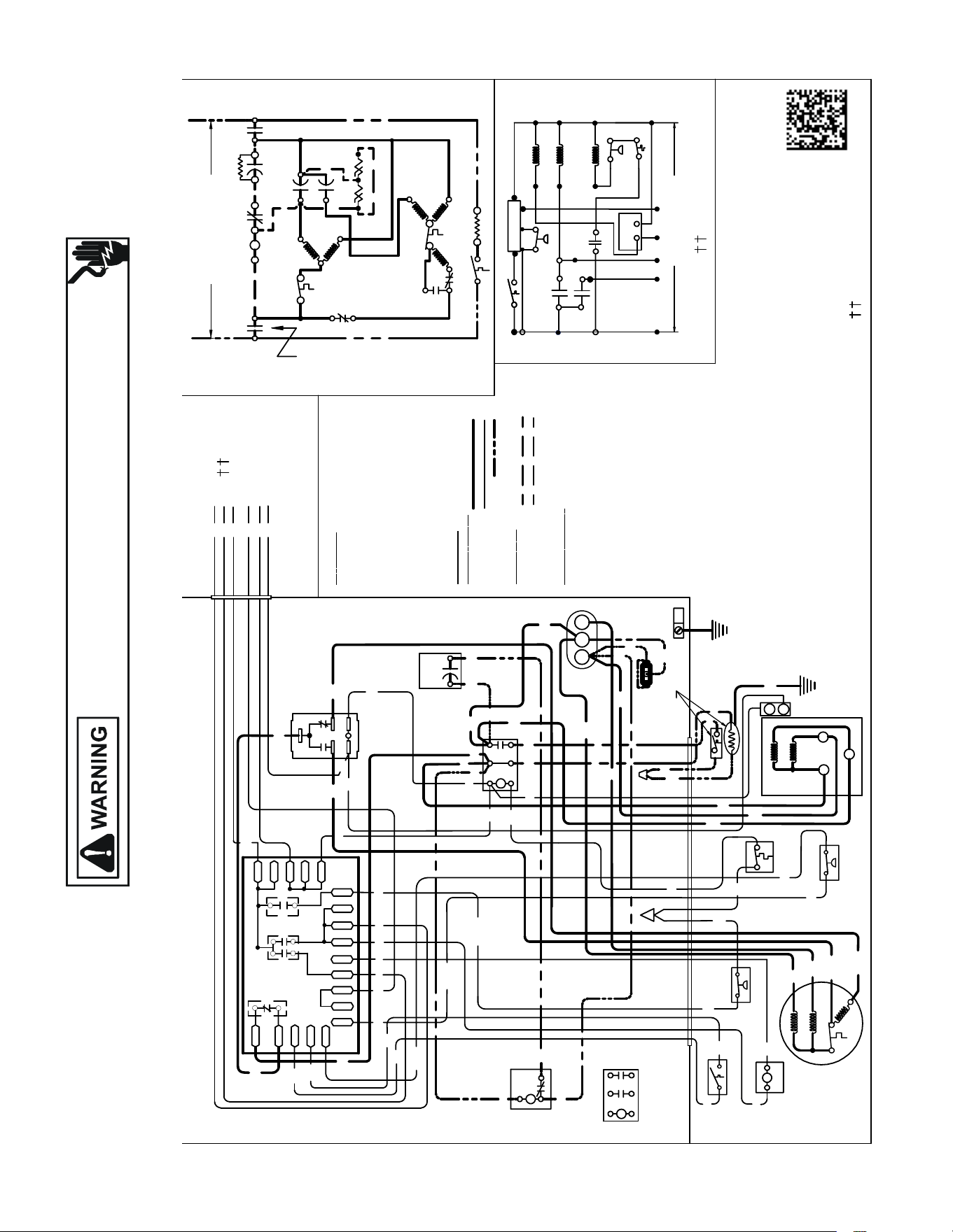
Wiring is subject to change. Always refer to the wiring diagram on the unit for the most up-to-date wiring.
HIGH VOLTAGE!
DISCONNECT ALL POWER BEFORE SERVICING OR INSTALLING THIS
UNIT. MULTIPLE POWER SOURCES MAY BE PRESENT. FAILURE TO
DO SO MAY CAUSE PROPERTY DAMAGE, PERSONAL INJURY OR DEATH.
174
WIRING DIAGRAMS GSZ160601B*
USE N.E.C. CLASS 2 WIRE
COMP
ALTERNATE DOUBLE
POLE CONTACTOR ONLY
IO
T1
C
M
A
I
N
R
A
U
X
5
S
SR
SA
2
1
RCCF
SC
T2
C
L1
L2
(IF USED)
NOTE 2
CH
C
F
M
A
I
N
A
U
X
IO
CM
CO
L
OR
CODE
BK --------------- BLACK
BL/PK ---------- BLUE/PINK STRIPE
BR --------------- BROWN
OR --------------- ORANGE
PU --------------- PURPLE
RD --------------- RED
WH -------------- WHITE
YL --------------- YELLOW
YL/PK----------- YELLOW/PINK STRIPE
COMPON
ENT
CODE
C --------------- CONTACTOR
CCR------------ COMPRESSOR CONTACTOR RELAY
CH ------------- CRANKCASE HEATER
CHS ----------- CRANKCASE HEATER SWITCH
CM ------------ OUTDOOR FAN MOTOR
CMR ---------- CONDENSER MOTOR RELAY
COMP -------- COMPRESSOR
CS ------------- COMPRESSOR SOLENOID
DC ------------- DEFROST CONTROL
DFT ----------- DEFROST THERMOSTAT
DT ------------- DISCHARGE THERMOSTAT
HPS------------ HIGH PRESSURE SWITCH
HVDR -------- HIGH VOLTAGE DEFROST RELAY
IO -------------- INTERNAL OVERLOAD
LPS ------------ LOW PRESSURE SWITCH
LVDR --------- LOW VOLTAGE DEFROST RELAY
LVJB ---------- LOW VOLTAGE JUNCTION BOX
RCCF --------- RUN CAPACITOR FOR COMPRESSOR & FAN
RVC ----------- REVERSING VALVE COIL
SA ------------- START ASSIST
SC ------------- START CAPACITOR FOR COMPRESSOR (OPTIONAL)
SR ------------- START RELAY FOR COMPRESSOR (OPTIONAL)
CONTROLS SHOWN WITH THERMOSTAT IN ’OFF’ POSITION.
OUTDOOR POWER SUPPLY
SEE RATING PLATE
WI
RIN
G
CODE
FACTORY
WI
R
I
NG
HIGH VOLTAGE
LOW VOLTAGE
OPTIONAL HIGH VOLTAGE
F
IELD W
IRING
HIGH VOLTAGE
LOW VOLTAGE
CONTROL BOX
SC
RD
BL
L2
T2
L1
T1
C
BK
BK
BK
RD
BL
RD
RCCF
BR
SR
5
2
1
BK
YL
BL
BK
BR
PU
BK
YL/PK
LPS
DF1
DF2
(HIGH)
CH
LVDR
R
Y
HPS
O
W2
R
(
L
O
W
)
5
4
2
HVDR
CMR
(HIGH)
(LOW)
RD
BK
YL/PK
CMR
BL
RD
BK
1
3
4
2
5
RD
RD
RD
BKBK
BL
YL/PK
BL
BK
CHS
LPS
PS2
R-PS1
O
W
CCR
Y
Y2
C
Y2
CS
FIELD LOW VOLTAGE CONNECTIONS
BK
BK
RD
SA
(IF USED)
NOTE 2
BL/PK
DFT
BK
RVC
BK
RD
BK
DT
RD
RD
BL
BK
GR
BL/PK
BK
DT
HPS
CS
C
Y2
T1
L1
T2
L2
CNT
DFT
C
DC
DFT
C
RVC
1
3
R-DFT
O-RV
CMR
C-RV
C
0140R00172-E
DC
R
DF1
DF2
0
0-RV
C-RV
W
LVDR
HVDR
CCR
CNT
0
DFT
R-DFT
R-PS1
Y
Y
C
R
C
C
PS2
RD
RD
EQUIPMENT
GROUND
NOTE 4
NOTES:
1) TO INDOOR UNIT LOW VOLTAGE TERMINAL
BLOCK AND INDOOR THERMOSTAT.
2) START ASSIST FACTORY EQUIPPED WHEN
REQUIRED.
3) THE COMMON SIDE OF LOW VOLTAGE SHALL
NOT BE GROUNDED.
4) USE COPPER CONDUCTOR ONLY.
5) CRANKCASE HEATER MAY NOT
HAVE ADDITIONAL GROUND WIRE.
6) CRANKCASE HEATER & CRANKCASE
HEATER SWITCH ARE FACTORY
INSTALLED OPTION.
SEE NOTE 6
YL
YL/PK
BL/PK
OR
RD
BL
YL
O
R
C
Y2
ALTERNATE
DOUBLE POLE
CONTACTOR
CHS
CH
SEE NOTE 1
BL
BK
IO
AUX
MAIN
CM
H
AUX
MAIN
COMP
C
S
R
SEE NOTE 6
SEE NOTE 1
WH
W2
PU
Y
LVJB
RD
RD
PU
YL
YL
YL
RD
RD
BKRD
YL
BL/PK
YL/PK
OR
WH
PU
INDOOR POWER SUPPLY
CF
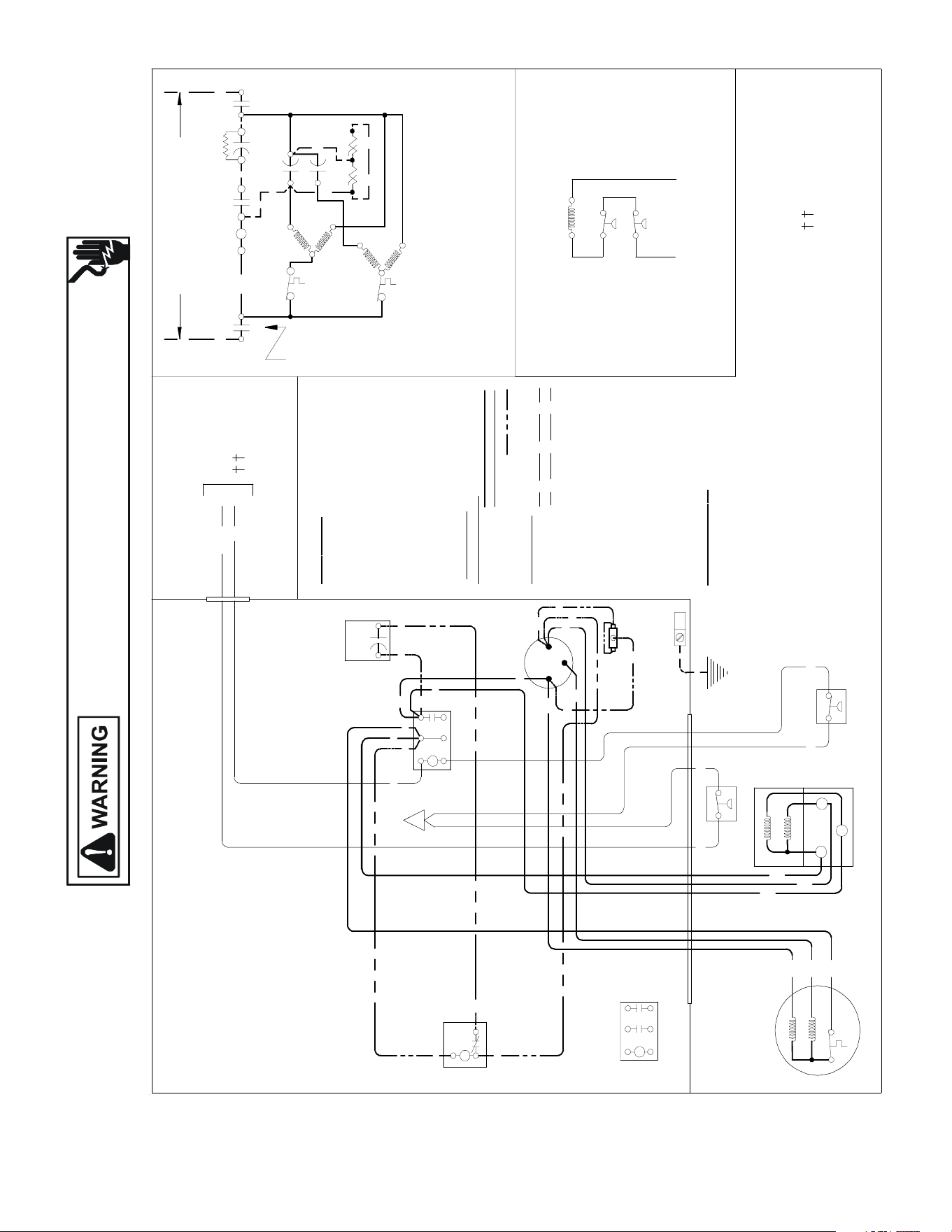
Wiring is subject to change. Always refer to the wiring diagram on the unit for the most up-to-date wiring.
HIGH VOLTAGE!
DISCONNECT ALL POWER BEFORE SERVICING OR INSTALLING THIS
UNIT. MULTIPLE POWER SOURCES MAY BE PRESENT. FAILURE TO
DO SO MAY CAUSE PROPERTY DAMAGE, PERSONAL INJURY OR DEATH.
175
WIRING DIAGRAMS SSX140[18-60]1A*/B*/C*
USE N.E.C. CLASS 2 WIRE
NOTES:
1) TO INDOOR UNIT LOW VOLTAGE
TERMINAL BLOCK & INDOOR
THERMOSTAT.
2) START ASSIST FA CTORY
EQUIPPED WHEN REQUIRED.
COMP
ALTERNATE DOUBLE
POLE CONTACTOR ONLY
IO
T1
C
M
A
I
N
R
A
U
X
5
S
SR
SA
2
1
RCCF
SC
T2
C
L1
L2
(IF USED)
CH
C
F
M
A
I
N
A
U
X
C
C
0140R00046
BL
Y
C
LVJB
C OLO
R
C O DE
BK --------------- BLACK
BL --------------- BLUE
BL/PK ---------- BLUE/PINK STRIPE
BR --------------- BROWN
OR --------------- ORANGE
PU --------------- PURPLE
RD --------------- RED
WH -------------- WHITE
YL --------------- YELLOW
YL/PK ---------- YELLOW/PINK STRIPE
CONTROL BOX
C
OMPO
N
E N
T CO DE
C --------------- CONTACTOR
CM ------------ OUTDOOR FAN MOTOR
COMP -------- COMPRESSOR
HPS ----------- HIGH PRESSURE SWITCH
IO -------------- INTERNAL OVERLOAD
LPS ------------ LOW PRESSURE SWIT CH
LVJB
---------- LOW VOLTAGE
JUNCTION BOX
RCCF
--------- RUN CAPACITOR FOR COMPRESSOR & FAN
SA ------------- START ASSIST
SC
------------- START CAPACITOR FOR COMPRESSOR (OPTIONAL)
S
R
-------------
START RELAY FOR COMPRESSOR (OPTIONAL)
CONTROLS SHOWN WITH THERMOSTAT IN 'OFF' POSITION.
T1
L1
T2
L2
ALTERNATE DOUBLE
POLE CONTACTOR
OUTDOOR POWER SUPPLY
SEE RATING PLAT E
WIRI
N
G CO
D
E
FACTO RY W
IRING
HIGH VOLTAGE
LOW VOLTAGE
OPTIONAL HIGH VOLTAGE
FIELD W
IRING
HIGH VOLTAGE
LOW VOLTAGE
IO
CM
Y
PU
BR
BK
MAIN
AUX
CM
IO
BL/PK
YL
C
R
S
RD
BK
AUX
MAIN
COMP
NOTE 1
SC
RD
BL
RCCF
F
C
HERM
YL
YL
YL
BR
RD
PU
YL
RD
SR
5
2
1
BK
YL
BL
RD
BL
RD
RD
BKBK
BK
C
T1
L1
T2
L2
RD
SA
(IF USED)
NOTE 2
EQUIPMENT GROUND
USE COPPER
CONDUCTORS ONLY
YL/PK
LPS
BL/PK
HPS
BL/PK
YL/PK
LPS
HPS
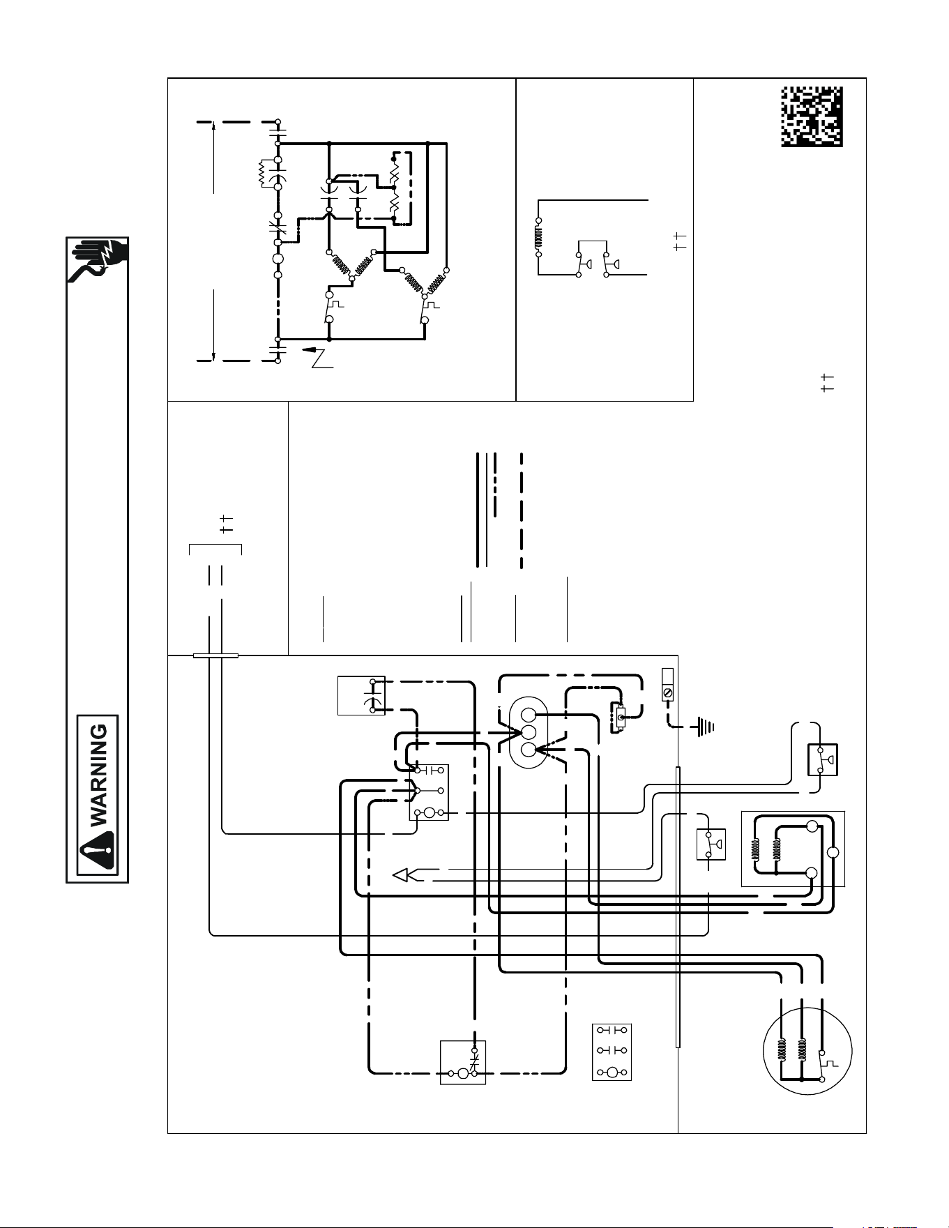
Wiring is subject to change. Always refer to the wiring diagram on the unit for the most up-to-date wiring.
HIGH VOLTAGE!
DISCONNECT ALL POWER BEFORE SERVICING OR INSTALLING THIS
UNIT. MULTIPLE POWER SOURCES MAY BE PRESENT. FAILURE TO
DO SO MAY CAUSE PROPERTY DAMAGE, PERSONAL INJURY OR DEATH.
176
WIRING DIAGRAMS SSX160[24-48]1A*/B*;SSX160591AA
USEN.E.C.CLASS 2WIRE
NOTES:
1. TO INDOOR UNIT LOWVOLTAGE TERMINAL BLOCK&
INDOORTHERMOSTAT.
2. STARTASSIST FACTORY EQUIPPEDWHEN REQUIRED.
3. USECOPPERCONDUCTORS ONLY.
COMP
ALTERNATE DOUBLE
POLE CONTACTORONLY
IO
T1
C
M
A
I
N
R
A
U
X
5
S
SR
SA
2
1
RCCF
SC
T2
C
L1 L2
(IFUSED)
CH
C
F
M
A
I
N
A
U
X
C
C
0140R00046-C
LVJB
COL OR C
O
DE
BK --------------- BLACK
BL --------------- BLUE
BL/PK---------- BLUE/PINKSTRIP
BR --------------- BROWN
OR --------------- ORANGE
PU ---------------PUR PLE
RD --------------- RED
WH --------------WHITE
YL --------------- YE LLOW
YL/PK----------YELLOW/PINK STRIP
CONTROLBOX
COMP ONE NT CO
DE
C--------------- CONTACTOR
CM ------------ OUTDOORFAN MOTOR
COMP -------- COMPRESSOR
HPS----------- HIGH PRESSURE SWITCH
IO -------------- INTERNAL OVERLOAD
LPS ----------- LOWPRESSURESWITCH
LVJB ---------- LOWVOLTAGE JUNCTIONBOX
RCCF --------- RUN CAPA CITORFOR COMPRESSOR &FAN
SA ------------- STARTASSIST
SC -------------START CAPACITOR FOR COMPRESSOR(OPTIONAL)
SR -------------START RELAYFOR COMPRESSOR (OPTIONAL)
CONTROLS SHOWNWITHTHERMOSTAT IN 'OFF'POSITION.
OUTDOORPOWER SUPPLY
SEERATINGPLATE
WIRING CO
DE
FACTOR
Y
WIRING
HIGH VOLTAGE
LOWVOLTAGE
OPTIONAL HIGH VOLT AGE
FI
E LD
WIRING
HIGH VOLTAGE
IO
CM
Y
YL
C
R
S
RD
BK
AUX
MAIN
COMP
SEE NOTE1
SC
RD
BL
RCCF
YL
BR
RD
SR
5
2
1
BK
YL
BL
RD
BL
RD
RD
BKBK
BK
C
T1
L1
T2
L2
SA
(IFUSED)
NOTE 2
EQUIPMENT GROUND
SEE NOTE 3
PU
BR
BK
MAIN
AUX
CM
IO
T1
L1
T2
L2
ALTERN ATE DOUBLE POLE
CONTACTOR
HPS
LPS
YL/PK
LPS
YL/PK
BL/PK
HPS
BL/PK
YL/PK
BL/PK
BL/PK
BL C
Y
H
FC
PU
YL
YL
RD
YL/PK
RD
SEE NOTE1
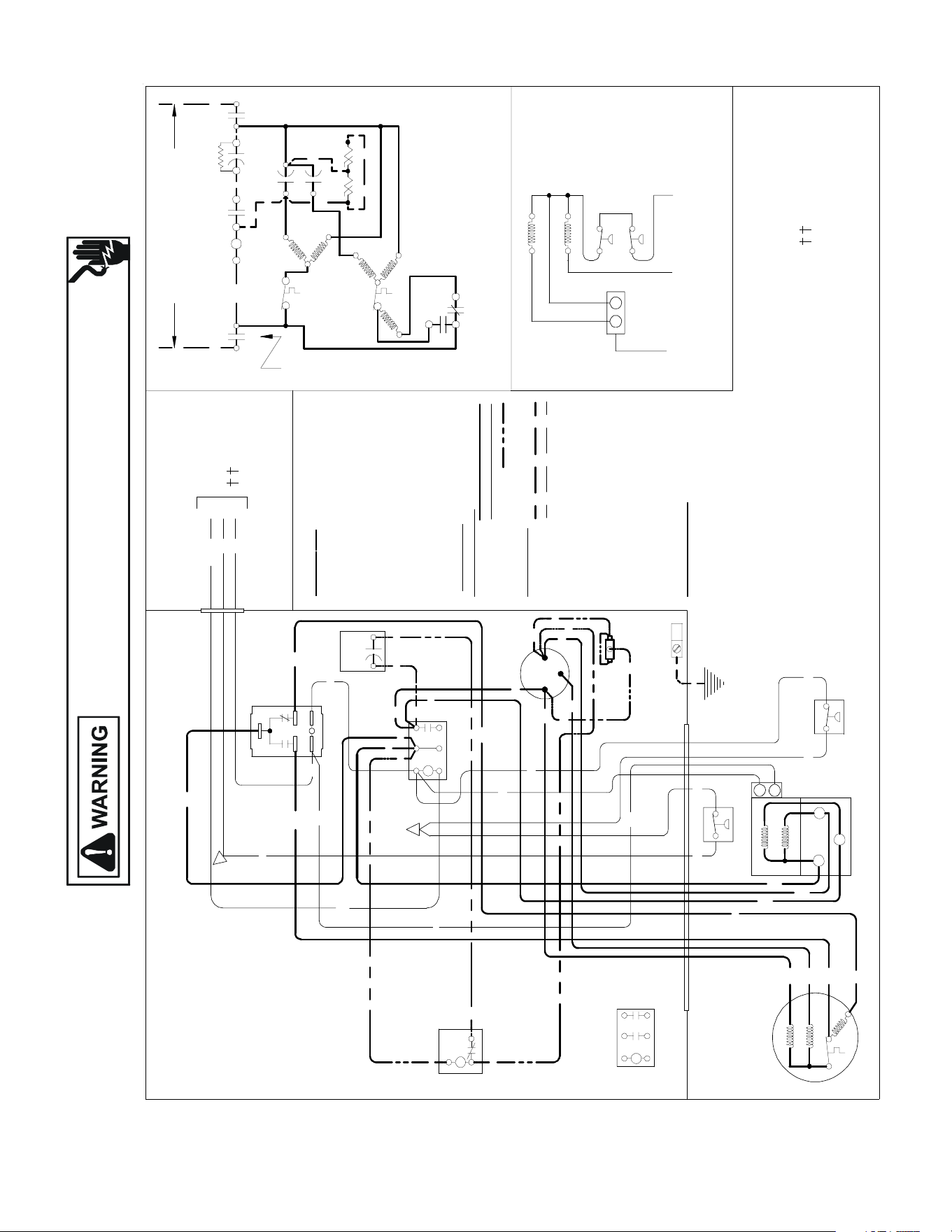
Wiring is subject to change. Always refer to the wiring diagram on the unit for the most up-to-date wiring.
HIGH VOLTAGE!
DISCONNECT ALL POWER BEFORE SERVICING OR INSTALLING THIS
UNIT. MULTIPLE POWER SOURCES MAY BE PRESENT. FAILURE TO
DO SO MAY CAUSE PROPERTY DAMAGE, PERSONAL INJURY OR DEATH.
177
WIRING DIAGRAMS SSX160601A*/BA
USE N.E.C. CLASS 2 WIRE
NOTES:
1) TO INDO OR UNIT LOW VOLTAGE
TERMINAL BLOCK & INDOOR
THERMOSTAT.
2) START ASSIST FA CTORY
EQUIPPED WHEN REQUIRED.
COMP
ALTERNATE DOUBLE
POLE CONTACTOR ONLY
IO
T1
C
M
A
I
N
R
A
U
X
5
S
SR
SA
2
1
RCCF
SC
T2
C
L1
L2
(I F US ED)
CH
C
F
M
A
I
N
A
U
X
C
C
0140R00115-A
BL
Y
C
LVJB
C
OLO
R C ODE
BK --------------- BLACK
BL --------------- BLUE
BL/PK ---------- BLUE/PINK STRIPE
BR --------------- BROWN
OR --------------- ORANGE
PU --------------- PURPLE
RD --------------- RED
WH -------------- WHITE
YL --------------- YELLOW
YL/PK ---------- YELLOW/PINK STRIPE
CONTROL BOX
COMPO
N
E N
T CO
D
E
C --------------- CONTACTOR
CM ------------ OUTDOOR FAN MOTOR
CMR ---------- CONDENSER MOTOR RELAY
COMP ------ -- COMPRESSOR
CS ---------- --- COMPRESSOR SOLENOID
HPS ----------- HIGH PRESSURE SWITCH
IO -------------- INTERNAL OVERLOAD
LPS ------------ LOW PRESSURE SWITCH
LV JB ---------- LOW VOLTAGEJUNCTION BOX
RCCF --------- RUN CAPACITOR FOR COMPRESSOR & FAN
SA ------------- START ASSI ST
SC ------------- START CAPA CITOR FOR COMPRESSOR (OPTIONAL)
SR ------------- START RELAY FOR COMPRESSOR (OPTIONAL)
CONTROLS SHOWN WITH THERMOSTAT IN 'OFF' POSITION.
T1
L1
T2
L2
ALTERNATE DOUBLE
POLE CONTACTOR
OUTDOOR POWER SUPPLY
SEE RATING PLATE
WIRI
N
G CO DE
FACTO RY W
IRING
HIGH VOLTAGE
LOW VOLTAGE
OPTIONAL HIGH VOLTAGE
FIELD W
IRING
HIGH VOLTAGE
LOW VOLTAGE
IO
CM
Y
PU
BR
BK
MAIN
AUX
CM
IO
PU
YL
C
R
S
RD
BK
AUX
MAIN
COMP
NOTE 1
SC
RD
BL
RCCF
F
C
HERM
YL
YL
YL
BR
RD
PU
YL
RD
SR
5
2
1
BK
YL
BL
RD
RD
RD
BK
BK
BK
C
T1
L1
T2
L2
RD
SA
(IF USED)
NOTE 2
EQUIPMENT GROUND
USE COPPER
CONDUCTORS ONLY
YL/PKLPS
BL/PK
HPS
BL/PK
YL/PK
LPS
HPS
CMR
1
3
Y2 C
Y2
(
L
O
W
)
(HIGH)
2
4 5
CMR
(HIGH)
(LOW)
RD
1
3
4
BL
25
Y2
C
YL Y2
YL
CS
BL/PK
RD
RD
RD
BL
BL
BK
BL
BL
YL/PK
YL/PK
BL/PK
BK
CMR
CS
PU
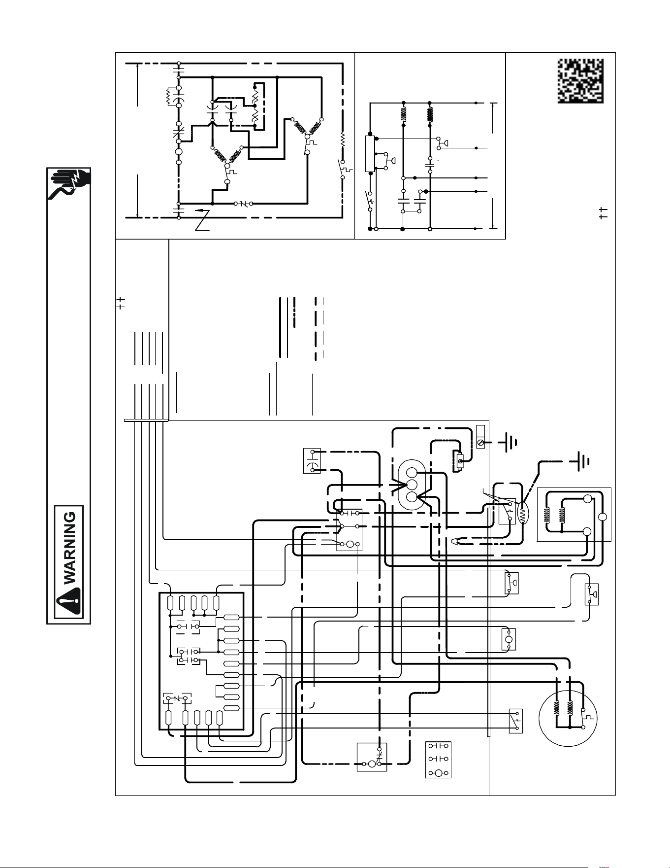
Wiring is subject to change. Always refer to the wiring diagram on the unit for the most up-to-date wiring.
HIGH VOLTAGE!
DISCONNECT ALL POWER BEFORE SERVICING OR INSTALLING THIS
UNIT. MULTIPLE POWER SOURCES MAY BE PRESENT. FAILURE TO
DO SO MAY CAUSE PROPERTY DAMAGE, PERSONAL INJURY OR DEATH.
178
WIRING DIAGRAMS
SSZ140381AA, SSZ140[18,30,42-60]1A*, 241A*, 361A*
SSZ140[18-36]1B*, SSZ140[19-37]1A*
SSZ140[18,30,42-60]1A*, 241A*, 361A*, SSZ140361B*
INDOOR POWER SUPPLY
NOTES:
1. TO INDOOR UNIT LOW VOLTAGE TERMINAL BLOCK & INDOOR THERMOSTAT.
2. START ASSIST FACTORY EQUIPPED WHEN REQUIRED.
3. USE COPPER CONDUCTOR ONLY.
4. CRANKCASE HEAT ER & CRANKCASE HEATER SWITCH ARE FACTORY INSTALLED OPTION.
CRANKCASE HEAT ER MAY NO T HAVE ADDITIONAL GROUND WIRE
5. 40VA MINIMUM TRANSFORMER IS REQUIRED.
6. COMMON SIDE OF TRANSFORMER MUST BE GROUNDED.
COMP
ALTERNATE DOUBLE
POLE CONTACTOR ONLY
IO
T1
C
M
A
I
N
R
A
U
X
5
S
SR
SA
2
1
RCCF
SC
T2
C
L1
L2
(IF USED)
NOTE 2
CH
C
F
M
A
I
N
A
U
X
IO
CM
0140R00171 - C
OR
BL/PK
BL
RD
O
Y
C
R
CO L
OR
C OD
E
BK --------------- BLACK
BL/PK ---------- BLUE/PINK STRIPE
BR --------------- BROWN
GR---------------- GREEN
OR ------------- -- ORANGE
PU --------------- PURPLE
RD --------------- RED
WH -------------- WHITE
YL --------------- YELLOW
YL/PK----------- YELLOW/PIN K STRIPE
COMPONENT CODE
C --------------- CONTACTOR
CADM -------- COMFORT ALERT DIAGNOSTIC MODULE
CCR ----------- COMP RESSOR CONTACTOR RELAY
CH ------------- CRANK CASE HEATER
CHS ----------- CRANKC ASE HEAT ER SWITCH
CM ------------ OUTDOOR FAN MOTOR
CMR ---------- CONDENSER MOTOR RELAY
COMP -------- COMPRESSOR
CS ------------- COMP RESSOR SOLENOID
DC ------------- DEFROST CONTROL
DFT ----------- DEFROST THERMOSTAT
DT ------------- DISCHARGE THERMOSTAT
HPS ----------- HIGH PRESSURE SWITCH
HVDR -------- HIGH VOLTAGE DEFROST RELAY
IO -------------- INTERNAL OVERLOAD
LPS ---------- LOW PRESSURE SWITCH
LVDR --------- LOW VOLTAGE DEFROST RELAY
LVJB --------- LOW VOLTAGE JUNCTION BOX
RCCF --------- RUN CAPACITOR FO R COMPRESSOR & FAN
RVC ----------- REVERSING VALVE COIL
SA ------------- START ASSIST
SC ------------- START CAPACITOR FOR COMPRESSOR (OPTIONAL)
SR ------------- START RELAY FO R COMPRESSOR (OPTIONAL)
CONTROLS SHOW N WITH THERMOSTAT IN 'OFF' POSI
TION.
OUTDOOR POWER SUPPLY
SEE RATING PLATE
LVJB
CONTROL BOX
SC
RD
BL
L2
T2
L1
T1
C
BK
BK
BK
RD
RD
BL
RD
RCCF
YL
BR
PU
RD
SR
5
2
1
BK
YL
BL
IO
CM
AUX
MAIN
BR
PU
YL
RD
BK
YL/PK
LPS
DF1
DF2
CH
LVDR
R
CNT
DFT
C
Y
DC
DFT
WH
W2
DC
BL/PK
HPS
O
C
RVC
W2
R
HVDR
YL/PK
BK
BK
BL
BL
CHS
R-DFT
C-RV
LPS
PS2
O
W
C
HPS
CCR
}
FIELD LOW
VOLTAGE
CONNECTIONS
RD
BK
CH
SA
(IF USED)
NOTE 2
DFT
RVC
RD
BK
BL/PK
BK
Y
T1
L1
T2
L2
R
DF1
DF2
0
0-RV
C-RV
W
LVDR
HVDR
CCR
CNT
0
DFT
R-DF T
R-PS1
Y
Y
C
R
C
C
PS2
RD
RD
BK
BK
SEE NOTE 4
SEE NOTE 5 & 6
BK
BK
RD
SEE NOTE 1
EQUIPMENT GROUND
SEE NOTE 3
ALTERNATE
DOUBLE POLE
CONTACTOR
WH
BK
BL/PK
YL/PK
YL/PK
OR
PU
PU
CHS
C
R
S
AUX
MAIN
COMP
HFC
RD
RD
YL
YL
GR
USE N.E.C. CLASS 2 WIRE
SEE NOTE 4
RD
R-PS1
O-RV
WIRING CO
DE
FA CTO
RY W
IRI NG
HIGH VOLTAGE
LOW VOLTAGE
OPTIONAL HIGH VOLTAGE
FIELD WIRING
HIGH VOLTAGE
LOW VOLTAGE
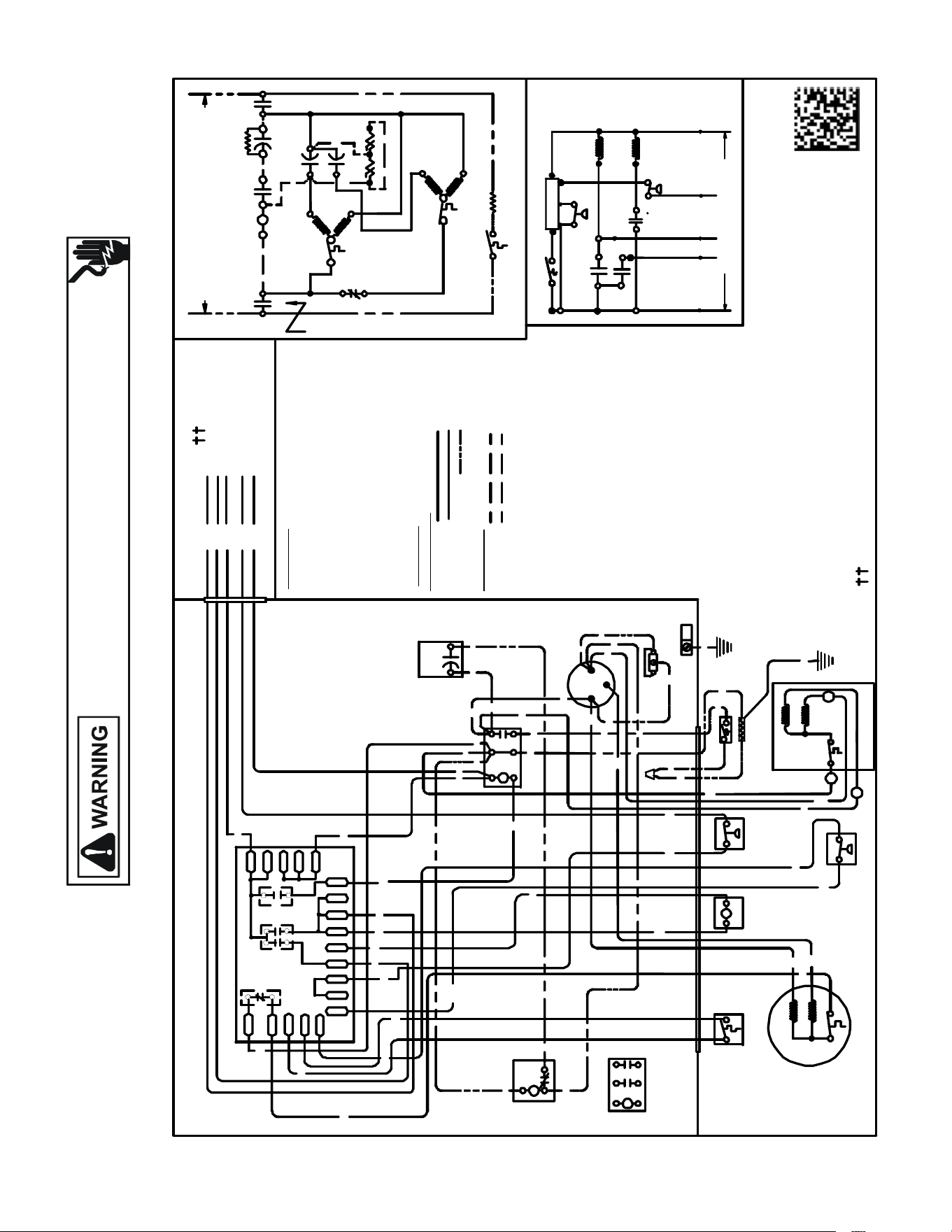
Wiring is subject to change. Always refer to the wiring diagram on the unit for the most up-to-date wiring.
HIGH VOLTAGE!
DISCONNECT ALL POWER BEFORE SERVICING OR INSTALLING THIS
UNIT. MULTIPLE POWER SOURCES MAY BE PRESENT. FAILURE TO
DO SO MAY CAUSE PROPERTY DAMAGE, PERSONAL INJURY OR DEATH.
179
WIRING DIAGRAMS
SSZ160[24]1AG, SSZ160[36-48]1AE,
SSZ160[24]1AA-AF, SSZ160[36-48]1AA-AD
USE N.E.C. CLASS 2 WIRE
NOTES:
1) TO INDOOR UNIT LOW VO LTAG E TERMINAL BLOCK & INDOOR THER MO STAT.
2) START ASSI ST FA CTORY EQUIPPED WH EN REQUIRED.
3) USE COPPER CO NDUCTOR ONLY.
4) CRANKCASE HEATER & CRANKCASE HEAT ER SW ITCH ARE FACTOR Y INSTALLED OPTION
5) 40VA MINIMUM TRANSFORMER IS REQUIRED.
6) COMMON SIDE OF TR ANSF ORMER MUST BE GROUNDED.
COMP
ALTERNAT E DOUBLE
POLE CONTACTOR ONLY
IO
T1
C
M
A
I
N
R
A
U
X
5
S
SR
SA
2
1
RCCF
SC
T2
C
L1
L2
(IF USED)
NOTE 2
CH
C
F
M
A
I
N
A
U
X
IO
CM
0140R00171 - B
OR
BL/PK
BL
RD
O
Y
C
R
COL
O
R C
O
D
E
BK --------------- BLACK
BL/PK ---------- BL UE/PINK STRIPE
BR --------------- BROWN
GR---------------- GREE N
OR --------------- ORANGE
PU --------------- PURPLE
RD --------------- RED
WH -------------- WHITE
YL --------------- YELLOW
YL/PK----------- YE LL OW/PINK STRIPE
COMPONENT CODE
C -------------- - CONTACTOR
CADM ------- - COMFORT ALERT DIAGNOSTIC MODULE
CCR ----------- COMPRESSOR CONTACTOR RELAY
CH ------------- CRANKCASE HEAT ER
CHS ----------- CRANKCASE HEATER SWITCH
CM -- ---------- OUTDOOR FA N MOTOR
CMR ---------- CONDEN SE R MOTOR RELAY
COMP -- ------ COMPRESSOR
CS ------ ------- COMPRESS OR SOLENOID
DC ------------- DEFROST CONTROL
DFT ----------- DEFROST THERMOSTAT
DT ------------- DISCHARGE THERMOSTAT
HPS ---- ------- HIGH PRESSURE SWITCH
HVDR -------- HIGH VOLTAGE DEFROST RELAY
IO ------- ------ - INTERNAL OVERLOAD
LPS ---------- LOW PRESSURE SWITCH
LV
DR --------- LOW VOLTAGE DEFROST RELAY
LV JB -------- - LOW VOLTAGE JU NCTION BOX
RCCF --------- RUN CAPACI TOR FOR COMPRESSOR & FAN
RVC ----------- REVERSING VALV E COIL
SA --------- ---- START ASSIST
SC ------ ------- START CAPACITO R FOR COMPRESSOR (OPTIONAL)
SR ------------- START RELAY FOR COMPRESS OR (OPTIONAL)
CONTROLS SHOWN WITH THERMOSTAT IN 'OFF' POSITION.
OUTDOOR POWER SUPPLY
SEE RATING PLATE
W
IR ING
CO
DE
FA
C T
O
RY
WI
RI N
G
HIGH VOLTAGE
LOW VOLTAGE
OPTIONAL HIGH VOLTAGE
FIE
L
D
WI
RI N
G
HIGH VOLTAGE
LOW VOLTAGE
LVJB
CONTROL BOX
SC
RD BL
L2
T2
L1
T1
C
BK
BK
BK
RD
RD
BL
RD
RCCF
F
C
HERM
YL
YL
YL
BR
RD
PU
YL
RD
SR
5
2
1
BK
YL
BL
IO
CM
AUX
MAIN
BR
PU
YL
C
R
S
RD
BK
AUX
MAIN
COMP
YL/PK
LPS
EQUIPMENT
GROUND
DF1
DF2
CH
LV DR
R
CNT
INDOOR POWER SUPPLY
DFT
C
Y
DC
DFT
WH
W2
DC
BL/PK
HPS
O
C
RV C
W2
R
HVDR
YL/PK
BK
RD
BK
PU
BK
BL
BL
PU
CHS
R-DFT
O-RV
C-RV
LPS
PS2
R-PS1
O
W
C
HPS
CCR
}
FIELD LOW
VO LTAG E
CONNECTIONS
RD
BK
CH
CH S
RD
SA
(IF USED)
NOTE 2
DFT
RVC
RD
BK
BL/PK
BK
GR
Y
T1
L1
T2
L2
ALTERNATE
DOUBLE POLE
CONTACTOR
R
DF1
DF2
0
0- RV
C-RV
W
LVDR
HVDR
CCR
CNT
0
DFT
R-DF T
R-PS1
Y
Y
C
R
C
C
PS2
YL/PK
YL/PK
RD
RD
BL/PK
WH
OR
BK
BK
SEE NOTE 4
SEE NOTE 5 & 6
SEE NOTE 4
SEE NOTE 3
BK
BK
RD
NOTE 1
IO
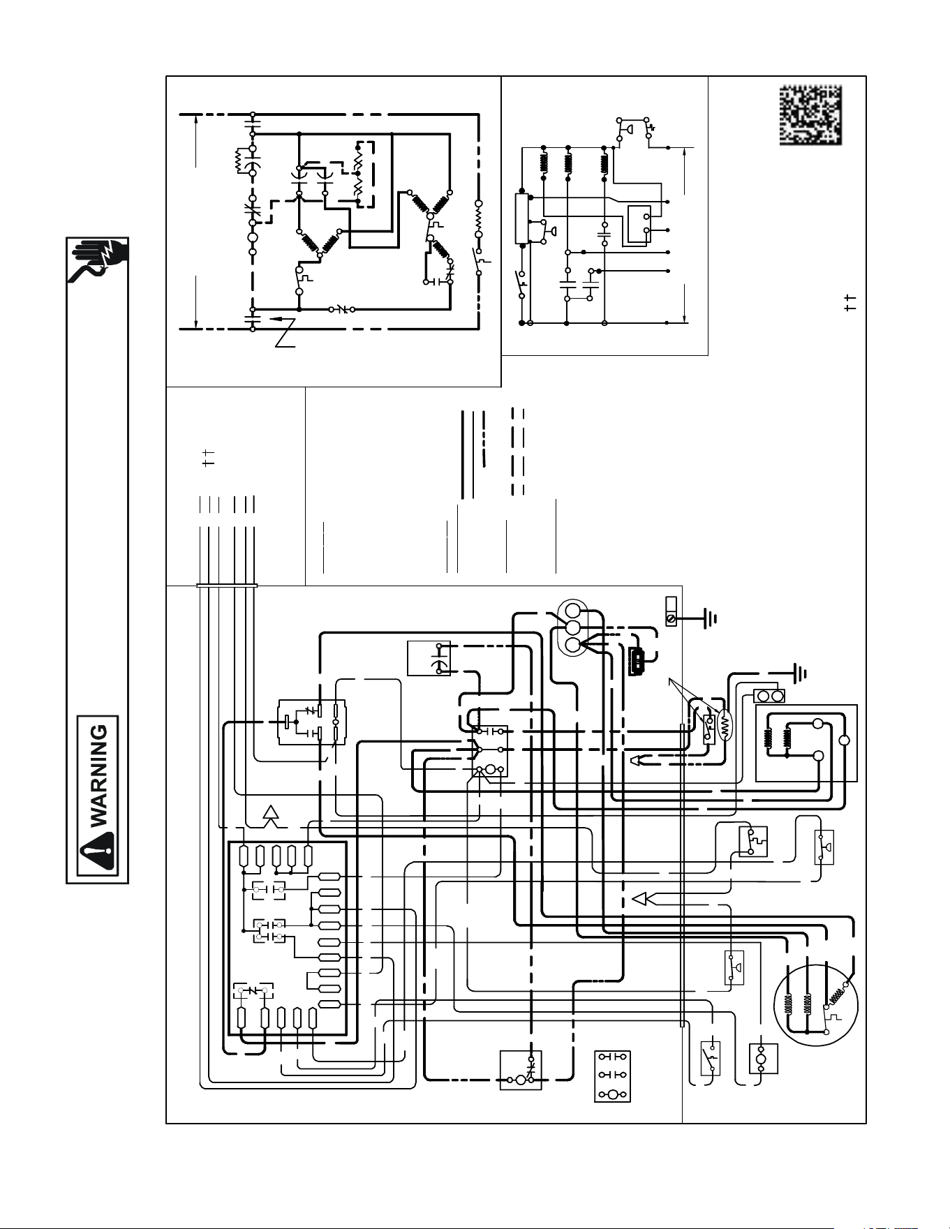
Wiring is subject to change. Always refer to the wiring diagram on the unit for the most up-to-date wiring.
HIGH VOLTAGE!
DISCONNECT ALL POWER BEFORE SERVICING OR INSTALLING THIS
UNIT. MULTIPLE POWER SOURCES MAY BE PRESENT. FAILURE TO
DO SO MAY CAUSE PROPERTY DAMAGE, PERSONAL INJURY OR DEATH.
180
WIRING DIAGRAMS
SSZ160[60]1BA,
SSZ160[60]1AB/AC/AD/AE
USE N.E.C. CLASS 2 WIRE
COMP
ALTERNAT E DOUBLE
POLE CONTACTOR ONLY
IO
T1
C
M
A
I
N
R
A
U
X
5
S
SR
SA
2
1
RCCF
SC
T2
C
L1
L2
(IF USED)
NOTE 2
CH
C
F
M
A
I
N
A
U
X
IO
CM
C
O
L
O
R C
O D
E
BK -------- ------- BL ACK
BL/P K ---------- BLUE/PINK STRIPE
BR --------------- BROW N
OR --------------- OR ANGE
PU --------------- PURPLE
RD --------------- RED
WH -------------- WHITE
YL --------------- YELLOW
YL/P K----------- YELLOW/PINK STRIPE
C
O
M
PO NE
N
T C
O DE
C --------------- CONTACTOR
CCR----- ------- COMPRESSOR CONTACTOR RELAY
CH ------------- CRANKC ASE HEATER
CHS ---- ------- CRANKCASE HEATER SWITCH
CM ------------ OUTDOOR FAN MOTOR
CMR ---------- CONDENSER MOTOR RELAY
COMP -------- COMPRESSOR
CS ------------- COMPRESSOR SO LENOID
DC ------------- DEFR OST CONTROL
DFT ----------- DEFROST THERMOSTAT
DT ------------- DISCHA RG E THERMOST AT
HPS------------ HIGH PRESSU RE SWIT CH
HVDR -------- HIGH VOLTAGE DE FROST RELAY
IO -------------- INTE RNAL OVERLOAD
LPS ------------ LO W PRESSURE SWITCH
LVDR --------- LOW VOLTAGE DEFROST REL AY
LVJB ---------- LOW VOLTAGE JUNCTION BOX
RCCF --------- RUN CAPACITOR FOR COMPRESSOR & FAN
RVC ----------- REVE RSING VALV E COIL
SA -------- ----- START ASSIST
SC ------------- START CAPACITOR FOR COMPRESSOR (OPTIONAL)
SR ------------- START RELAY FOR COMPRESS OR (OPTION AL)
CONTROLS SHOWN WITH THERMOST AT IN 'OFF' POSITION.
OUTDOOR POWER SUPPLY
SEE RATING PL AT E
WIR
I
N
G C
O
D
E
FA
C
TO
RY WI
RI
N G
HIGH VOLT AGE
LOW VOLTAGE
OPTIONAL HIGH VOLT AGE
FIEL
D WI RI N
G
HIGH VOLTAGE
LOW VOLTAGE
CONTRO L BOX
SC
RD BL
L2
T2
L1
T1
C
BK
BK
BK
RD
RD
BL
RD
RCCF
BR
PU
SR
5
2
1
BK
YL
BL
BK
BR
PU
BK
YL/PK
LPS
DF1
DF2
(HIGH)
CH
LVDR
R
INDOOR POWER SUPPLY
Y
HPS
O
W2
R
(
L
O
W
)
5
4
2
HVDR
CMR
(HIGH)
(LOW)
RD
BK
YL/PK
CMR
BL
RD
BK
1
3
4
2
5
RD
RD
RD
BK
BK
BL
YL/PK
BL
PU
CHS
LPS
PS2
R-PS1
O
W
CCR
Y
Y2 C
Y2
CS
}
FIELD LOW
VOLT AGE
CONNECTIONS
BK
BK
RD
SA
(IF US ED)
NOTE 2
BL/PK
DFT
BK
RVC
BK
RD
BK
DT
RD
RD
BL
BK
GR
BL/PK
BK
BK
DT
HPS
CS
C
Y2
T1
L1
T2
L2
CN
T
DFT
C
DC
DFT
C
RVC
1
3
R-DFT
O-RV
CMR
C-RV
C
0140R00172-B
DC
R
DF 1
DF2
0
0-RV
C-RV
W
LVDR
HV DR
CCR
CNT
0
DFT
R-DFT
R-PS1
Y
Y
C
R
C
C
PS2
RD
RD
EQUIPMENT
GROUND
NOTE 4
NOTES:
1) TO INDOOR UNIT LOW VOLT AGE TERMIN AL
BLOCK AND INDOOR THERMOST AT.
2) START ASSIST FACTORY EQUIPPED WHEN
REQUIRED.
3) THE COMM ON SIDE OF LOW VOLT AGE SH ALL
NOT BE GROUNDED.
4) USE COPPER CONDUCTOR ONLY.
5) CRANKC ASE HE ATER MAY NOT
HAVE ADDITION AL GROUND WI RE.
6) CRANKC ASE HE ATER & CR ANKC ASE
HEATER SWITCH ARE FACTORY
INSTALLED OPTION.
SEE NOTE 6
YL
BL/PK
YL/PK
PU
WH
PUOR
OR
WH
RD
PU
BL
YL
O
W2
R
Y
C
Y2
LVJB
ALTERNATE
DOUBLE POLE
CONTACTOR
CHS
CH
RD
BK
SEE NOTE 1
BL
BK
IO
AUX
MAIN
RD
YL
CM
H
F
C
YL
YL
YL
YL/PK
RD
RD
AUX
MAIN
COMP
C
S
R
SEE NOTE 6

Wiring is subject to change. Always refer to the wiring diagram on the unit for the most up-to-date wiring.
HIGH VOLTAGE!
DISCONNECT ALL POWER BEFORE SERVICING OR INSTALLING THIS
UNIT. MULTIPLE POWER SOURCES MAY BE PRESENT. FAILURE TO
DO SO MAY CAUSE PROPERTY DAMAGE, PERSONAL INJURY OR DEATH.
181
WIRING DIAGRAMS
VSX130[18-48/61]1A* / VSX130{24/36/42-60]1B*/1D*
VSX130[30]1D*/VSX130[36]1E*/ VSX140[18-60]1A*/ VSX130[18-48/61]1A*
VSX130[24/36/42-60]1B*/1D*/VSX130[30]1D*/ VSX130[36]1E*
USEN.E.C. CLASS2WIRE
COMP
ALTERN ATE DOUBLE
POLE CONTACTORONLY
IO
T1
C
M
A
I
N
R
A
U
X
5
S
SR
SA
2
1
RCCF
SC
T2
C
L1
L2
(IFUSED)
CH
C
F
M
A
I
N
A
U
X
C
C
0140R00015P-C
BL
Y
C
LVJB
COL
OR C
O
DE
BK ---------------BLACK
BL ---------------BLUE
BR --------------- BROWN
OR --------------- ORANGE
PU --------------- PURPLE
RD --------------- RED
WH -------------- WHITE
YL ---------------- YELLOW
CONTROLBOX
COMP
O
NE NT CO DE
C--------------- CONTACTOR
CM ------------ OUTDOORFAN MOTOR
COMP-------- COMPRESSOR
IO --------------INTERNALOVERLOAD
LVJB ----------LOW VOLTAGEJUNCTION BOX
RCCF --------- RUN CAPACITOR FOR COMPRESS OR &FAN
SA ------------- STARTASS IST
SC ------------- START CAPACI TOR FOR COMPRESSOR (OPTIONAL)
SR ------------- START RELAYFOR COMPRESS OR (OPTIONAL)
CONTROLSSHOWN WITH THERMOSTAT IN 'OFF' POSITION.
OUTDOORPOWER SUPPLY
SEERATINGPLATE
WIRING CO
DE
FACTOR
Y WIRING
HIGH VOLTAGE
LOWVOLTAGE
OPTIONAL HIGH VOLTAGE
FI
E
LD
WIRING
HIGH VOLTAGE
IO
CM
Y
YL
YL
C
R
S
RD
BK
AUX
MAIN
COMP
SEENOTE1
SC
RD
BL
RCCF
YL
PU
YL
SR
5
2
1
BK
YL
BL
RD
YL
BL
RD
RD
BK
BK
BK
C
T1
L1
T2
L2
SA
(IFUSED)
NOTE 2
EQUIPMENT GROUND
SEE NOTE 3
PU
BR
BK
MAIN
AUX
CM
IO
T1
L1
T2
L2
ALTERN ATE DOUBLE POLE
CONTACTOR
NOTES:
1) TO INDOOR UNIT LOWVOLTAGE TERMIN AL BLOCK&
INDOOR THERMOSTAT.
2) STARTASSISTFACTORY EQUIPPED WHEN REQUIRED.
3) USE COPPER CONDUC TORS ONLY.
CFH
RD
RD
RD
BR
SEENOTE1
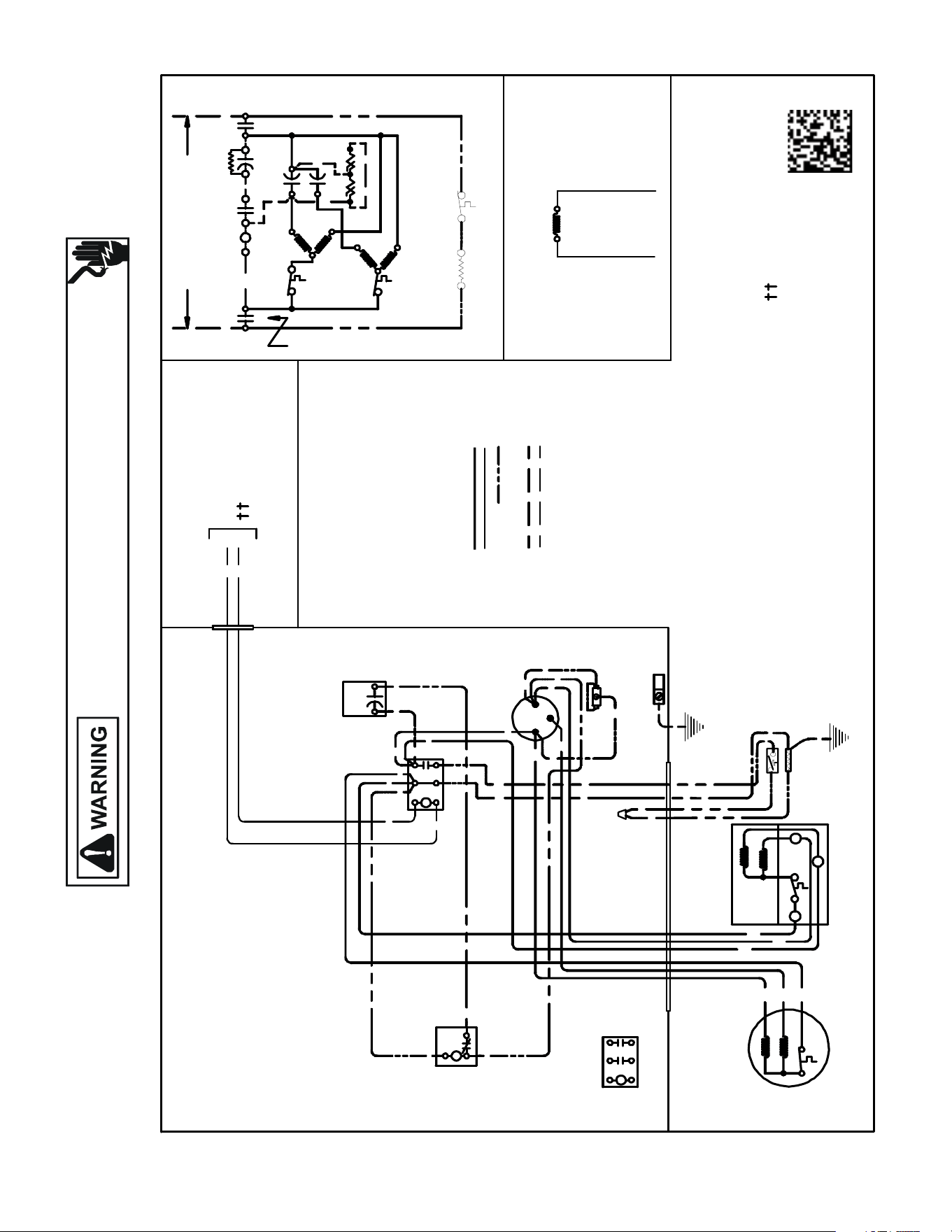
Wiring is subject to change. Always refer to the wiring diagram on the unit for the most up-to-date wiring.
HIGH VOLTAGE!
DISCONNECT ALL POWER BEFORE SERVICING OR INSTALLING THIS
UNIT. MULTIPLE POWER SOURCES MAY BE PRESENT. FAILURE TO
DO SO MAY CAUSE PROPERTY DAMAGE, PERSONAL INJURY OR DEATH.
182
WIRING DIAGRAMS
VSX130181B*/D*
COMP
IO
T1
C
M
A
I
N
R
A
U
X
5
S
SR
SA
2
1
RCCF
SC
T2
C
L1
L2
(IF USED)
CH
C
F
M
A
I
N
A
U
X
C
C
BL
Y
C
LVJB
COLOR CODE
BK --------------- BLACK
BL --------------- BLUE
BR --------------- BROWN
PU --------------- PURPLE
RD --------------- RED
YL --------------- YELLOW
CONTROL BOX
COMPONENT CODE
C --------------- CONTACTOR
CM ------------ OUTDOOR FAN MOTOR
COMP -------- COMPRESSOR
IO -------------- INTERNAL OVERLOAD
XOB NOITCNUJBJVL
RCCF
------ --- RUN CAPACITOR FOR COMPRESSOR & FAN
SC
------------- START CAPACITOR FOR COMPRESSOR (OPTIONAL)
S
R
-------------
IO
CM
Y
YL
YL
C
R
S
RD
BK
AUX
MAIN
COMP
SC
RD BL
RCCF
F
C
HERM
YL
YL
YL
BR
RD
PU
YL
RD
SR
5
2
1
BK
YL
BL
RD
YL
BL
RD
RD
BKBK
BK
C
T1
L1
T2
L2
RD
(IF USED)
EQUIPMEN T GROUND
T1
L1
T2
L2
PU
BR
BK
MAIN
AUX
CM
IO
GR/YL------------- GREEN / YELLOW
OT ------------- OUTDOOR THERMOSTAT
CH ------------- CRANKCASE HEATER
NOTE 1
WH -------------- WHITE
WIRING CODE
FACTORYWIRING
HIGH VOLTAGE
LOWVOLTAGE
OPTIONAL HIGH VOLTAGE
FIELDWIRING
LOWVOLTAGE
HIGH VOLTAGE
---------- LOW
VOLTAGE
SA ------------- START ASSIST
CONTROLS SHOWN WI TH THERMOSTAT IN 'OFF'POSITION.
START RELAY FOR COMPRESSOR
(OPTIONAL)
0140R00165-B
USE N.E.C. CL ASS 2 WIRE
ALTERNATE DOUBLE
POLE CONTACTOR
OUTD OOR POWERSUPPLY
SEE RATING PLATE
POLE CONTACTORONLY
ALTERNATEDOUBLE
SA
NOTE 2
NOTE 4
CHS
CH
NOTE 3
NOTES:
1) TO INDOOR UNIT LOW VOLTAGE
TERMINAL BLOCK & INDOOR THERMOSTAT.
2) START ASSIST FACTORY
EQUIPPED WHEN REQUIRED.
3) CRANKCASE HEAT ER & CRANKCASE HEAT ER
SWITCH ARE FACTORY INSTALLED OPTION.
4) USE COPPER CO NDUCTOR ONLY.
GR
RD
BK
RD
BK
CHS ----------- CRANKCASE HEATER SWITCH
IO
BK
RD
CHS
CH
NOTE 3
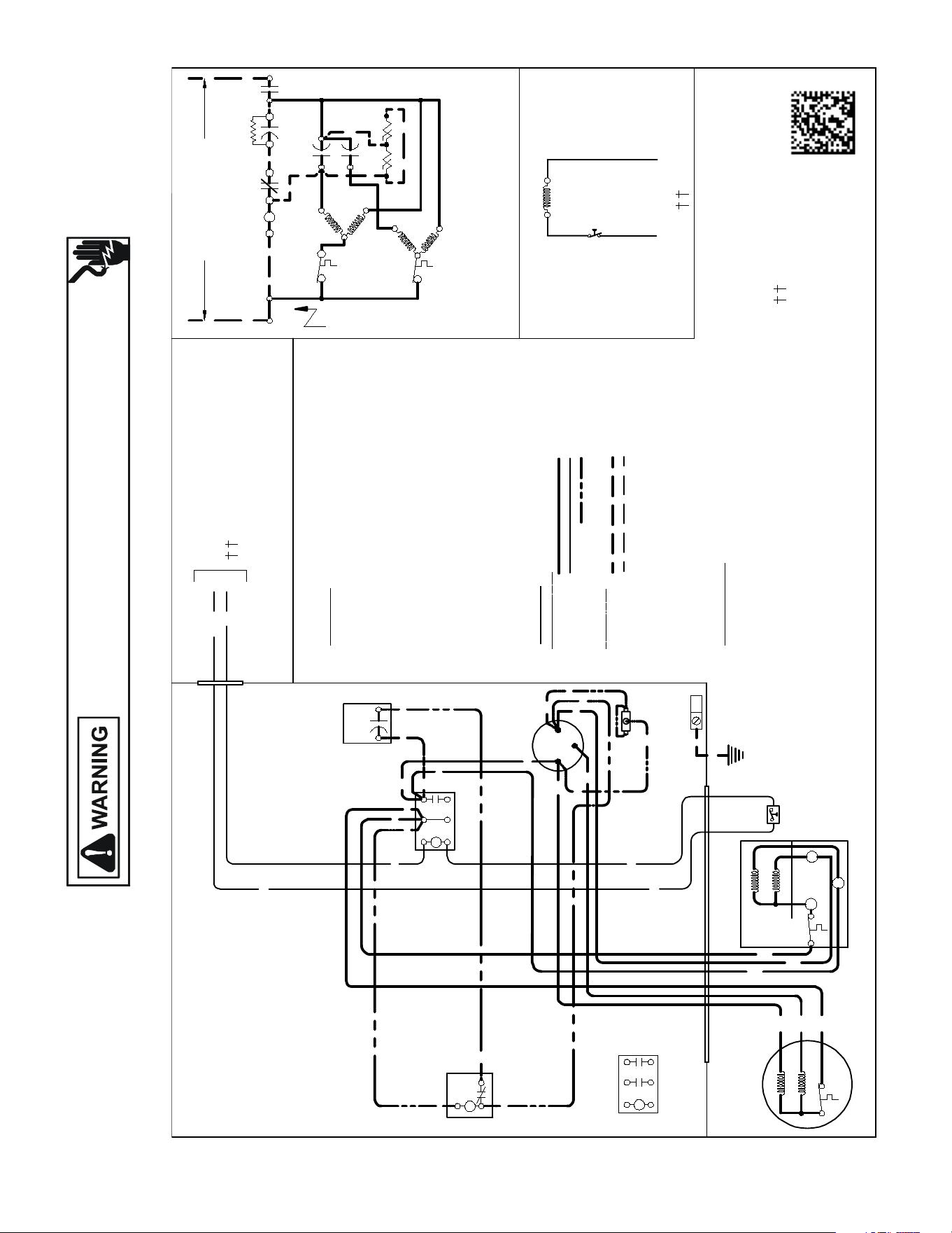
Wiring is subject to change. Always refer to the wiring diagram on the unit for the most up-to-date wiring.
HIGH VOLTAGE!
DISCONNECT ALL POWER BEFORE SERVICING OR INSTALLING THIS
UNIT. MULTIPLE POWER SOURCES MAY BE PRESENT. FAILURE TO
DO SO MAY CAUSE PROPERTY DAMAGE, PERSONAL INJURY OR DEATH.
183
WIRING DIAGRAMS
VSX130[18-24]1E*
USEN.E.C.CLASS 2WIRE
COMP
ALTERNATEDOUBLE
POLE CONTACTORONLY
IO
T1
M
A
I
N
R
A
U
X
5
S
SR
SA
2
1
RCCF
SC
T2
C
L1
L2
(IFUSED)
CH
C
F
M
A
I
N
A
U
X
C
C
0140R00258-C
BL
Y
C
LVJB
COLORCODE
BK ---------------BLACK
BL ---------------BLUE
BL/PK ---- ------BLUE/PINK STRIPE
BR ---------------BROWN
OR --------------- ORANGE
PU ---------------PURPLE
RD ---------------RED
WH ---- ----------WHITE
YL ---------------- YELLOW
CONTROLBOX
CO
MPONENT CODE
C ---- ----------- CONTACTOR
CM ------------ OUTDOORFAN MOTOR
COMP -------- COMPRESSOR
HPS -----------HIGHPRESSURESWITCH
IO -------------- INTERNAL OVERLOAD
LVJB ----------LOW VOLTAGEJUNCTIONBOX
RCCF--------- RUNCAPACITOR FORCOMPRESSOR & FAN
SA -------------START ASSIST
SC ------------- STARTCAPACITOR FORCOMPRESSOR(OPTIONAL)
SR ------------- STARTRELAY FORCOMPRESSOR(OPTI ONAL)
CONTROLS SHOWNWITHTHERMOSTAT IN 'OFF'POSITION.
OUTDOORPOWER SUPPLY
SEERATINGPLATE
WIR
I
NG CODE
FA
CTOR
Y W I
R
I
NG
HIGH VOLTAGE
LOWVOLTAGE
OPTIONAL HIGH VOLTAGE
F
I
E
LD W
I
R
I
NG
HIGH VOLTAGE
LOWVOLTAGE
IO
CM
Y
BL/PK
YL
C
R
S
RD
BK
AUX
MAIN
COMP
SEENOTE1
SC
RD
BL
RCCF
F
C
HERM
YL
YL
YL
BR
RD
PU
YL
RD
SR
5
2
1
BK
YL
BL
RD
BL
RD
RD
BKBK
BK
C
T1
L1
T2
L2
RD
SA
(IFUSED)
NOTE 2
EQUIPMENTGROUND
PU
BR
BK
MAIN
AUX
CM
IO
T1
L1
T2
L2
ALTERNATEDOUBLE
POLE CONTACTOR
NOTES:
1) TO INDOOR UNIT LOWVOLTAGE
TERMINAL BLOCKAND INDOOR
THERMOSTAT
2) STARTASS ISTFACTORY
EQUIPPED WHEN REQUIRED.
3) USECOPPERCONDUCTORSONLY.
BL/PK
HPS
BL/PK
HPS
BL/PK
IO
SEENOTE1
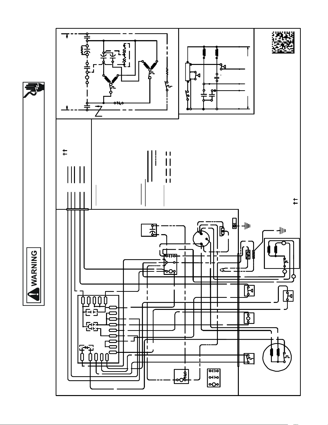
Wiring is subject to change. Always refer to the wiring diagram on the unit for the most up-to-date wiring.
HIGH VOLTAGE!
DISCONNECT ALL POWER BEFORE SERVICING OR INSTALLING THIS
UNIT. MULTIPLE POWER SOURCES MAY BE PRESENT. FAILURE TO
DO SO MAY CAUSE PROPERTY DAMAGE, PERSONAL INJURY OR DEATH.
184
WIRING DIAGRAMS
VSZ130181A[C/D/E/F], VSZ130241B[B/C/D], VSZ130301A[D/E/F/G]
VSZ130361B[B/C/D], VSZ130421A[C/D/E/F/G], VSZ130481A[C/D],
VSZ130601AC
USE N. E.C. CLASS 2 WIRE
NOTES:
1) TO INDOOR UNIT LOW VO LTAG E TERMINAL BLOCK & INDOOR THERMO STAT.
2) START ASSIST FA CTORY EQUIPPED WH EN REQUIRED.
3) USE COPPER CO NDUCTOR ONLY.
4) CRANK CASE HEATER & CRANKCAS E HEAT ER SWITCH ARE FA CTOR Y INSTALLED OPTION
5) 40VA MINIMUM TRANSFORMER IS REQUIRED.
6) COMM ON SIDE OF TRANSFORMER MUST BE GROUNDED.
COMP
ALTERNAT E DOUBLE
POLE CONTACTOR ONLY
IO
T1
C
M
A
I
N
R
A
U
X
5
S
SR
SA
2
1
RCCF
SC
T2
C
L1
L2
(IF USED)
NOTE 2
CH
C
F
M
A
I
N
A
U
X
IO
CM
0140R0 0171 - B
OR
BL/PK
BL
RD
O
Y
C
R
CO
L
OR C
O
D
E
BK --------------- BLACK
BL/PK ---------- BLUE/PINK STRIPE
BR --------------- BROWN
GR---------------- GREEN
OR --------------- ORANGE
PU --------------- PURPLE
RD --------------- RED
WH -------------- WHITE
YL --------------- YELLOW
YL/PK----------- YELL OW/PINK STRIPE
COMPONENT CODE
C --------------- CONTACTOR
CADM -------- COMFORT ALERT DIAGNOSTIC MODULE
CCR ----------- COMPRESS OR CONTACTOR RELAY
CH ------------- CRANKCASE HEAT ER
CHS ----------- CRANKCASE HEATER SWITCH
CM ------------ OUTDOOR FA N MOTOR
CMR ---------- CONDEN SE R MOTOR RELAY
COMP -- ------ COMPRESSOR
CS ------------- COMPRESS OR SOLENOID
DC ------------- DEFROST CONTROL
DFT ----------- DEFROST THERMOSTAT
DT ---------- --- DISCHARGE THERMOSTAT
HPS ---- ------- HIGH PRESSURE SWITCH
HVDR -------- HIGH VOLTAGE DEFROST RELAY
IO ----
------ ---- INTERNAL OVERLOAD
LPS ------ ---- LOW PRESSURE SWITCH
LV DR --------- LOW VOLTAGE DEFROST RELAY
LV JB --------- LOW VOLTAGE JUNCTION BOX
RCCF -------- - RUN CAPACITOR FOR COMPRE SSOR & FAN
RVC ----------- REVERSING VALV E COIL
SA ------------- START ASSIST
SC ------------- START CAPACITOR FOR COMPRE SSOR (OPTIONAL)
SR ------------- START RELAY FOR COMPRESSOR (OPTIONAL)
CONTROLS SHOWN WITH THERMOSTAT IN 'OFF' PO SITION.
OUTDOOR POWER SUPPLY
SEE RATING PLATE
W
I
R
ING
C
O
D
E
FA C T O
RY
WI
RI
N
G
HIGH VOLTAGE
LOW VOLTAGE
OPTIONAL HIGH VOLTAGE
FIE
L
D WI RI N
G
HIGH VOLTAGE
LOW VOLTAGE
LVJB
CONTROL BOX
SC
RD
BL
L2
T2
L1
T1
C
BK
BK
BK
RD
RD
BL
RD
RCCF
F
C
HERM
YL
YL
YL
BR
RD
PU
YL
RD
SR
5
2
1
BK
YL
BL
IO
CM
AUX
MAIN
BR
PU
YL
C
R
S
RD
BK
AUX
MAIN
COMP
YL/PK
LPS
EQUIPMENT
GROUND
DF1
DF2
CH
LV DR
R
CNT
INDOOR POWE R SUPPLY
DFT
C
Y
DC
DFT
WH
W2
DC
BL/PK
HPS
O
C
RV C
W2
R
HVDR
YL/PK
BK
RD
BK
PU
BK
BL
BL
PU
CHS
R-DFT
O-RV
C-RV
LPS
PS2
R-PS1
O
W
C
HPS
CCR
}
FIELD LOW
VO LT AGE
CONNEC TIONS
RD
BK
CH
CH S
RD
SA
(IF USED)
NOTE 2
DFT
RVC
RD
BK
BL/PK
BK
GR
Y
T1
L1
T2
L2
ALTERNATE
DOUBLE POLE
CONTACTOR
R
DF1
DF2
0
0- RV
C-RV
W
LVDR
HVDR
CCR
CN T
0
DFT
R-DF T
R-PS1
Y
Y
C
R
C
C
PS 2
YL/PK
YL/PK
RD
RD
BL/PK
WH
OR
BK
BK
SEE NOTE 4
SEE NOTE 5 & 6
SEE NO TE 4
SEE NOTE 3
BK
BK
RD
NOTE 1
IO