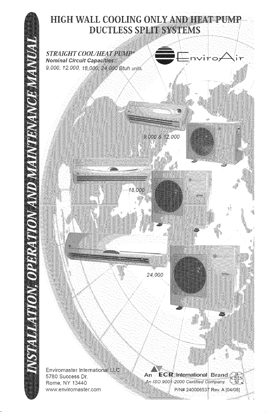
HIGH WALL COOLING
DUCTLESS
9,000, 12,000, 18(
24,000
...... :ii!¸I:::,I_(:
Enviromaster Internati(
5780 Success Dr,
Rome, NY 13440
www,enviromaster, com
mNSTALLATION, OPERATION AND MAINTENANCE MANUAL
P/N 240006537, Rev. 1.0 [01/07]
This manual is intended as an aid to a qualified service personnel for proper installation,
operation, and maintenance of EMI EnviroAir high efficiency R-410A Ductless Split
Systems. Carefully read these instructions before attempting installation or operation.
Failure to follow these instructions may result in improper installation, operation, or
maintenance, possibly resulting in fire, electrical shock, property damage, personal
injury, or death.
(1) Retain this manual for future reference.
(2) Before leaving the premises, review this
manual to be sure the unit has been
installed correctly and run the unit for
one complete cycle to make sure it
functions properly.
To obtain technical service or warranty
assistance during or after the installation
d this unit, check our website @ www.
enviromaster.com or call your installing
contractor or distributor. Our technical
service department may be contacted at
1-800-228-9364.
When calling for assistance, please have
the following information ready:
Indoor Unit
Model Number
Indoor Unit
Serial Number
Outdoor Unit
Model Number
Outdoor Unit
Serial Number
Date of installation
Read all instructions before using
the EMI EnviroAir high efficiency
system. Install or locate this sys-
tem only in accordance with these
instructions. Use this system only
for its intended use as described in
this manual.
Check rating plate for correct system
voltage before installing. Installa-
tion and operation of a system with
the incorrect voltage may result in
malfunction or other issues and will
void _he warranty.
The EMI EnviroAir system must
be connected only to a properly
grounded electrical supply. Do not
fail to properly ground this unit.
Turn off the electrical supply be-
fore servicing the EMI EnviroAir
system.
Do not use the EMI EnviroAir
system if it has damaged wiring, is
not working properly, or has been
damaged or dropped.
[Save These/nstrucdons]
X,_ j
This symbol is an indication of ,_"_
Important Safety Information.
TheEnviroAirsystemisanefficientduct-
lesssplitairconditioningsystemwithcooF
ingcapacitiesfrom9,000-24,000Btuhand
heatpumpcapacityof9,000-24,000Btuh.
Designedforquietoperationandboasting
compactdimensions,theEnviroAirsys-
temincludesadvancedfeatureslikeauto-
restart,fullfeatureremotecontrol.
oMain System Breaker: Sized per unit
requirements, to be mounted adjacent
to outdoor unit.
o Mounting Hardware: Wall anchors,
condenser pad.
o Vacuum Pump
oGauge Set: R-410 specific.
o High Vo#age interconnect Wiling:
14 AWG wiring from outdoor unit to in-
door unit for power and control. *
o Refrigerant : R-410A required for addi-
tional line sets beyond 16 ft=
• Can be purchased through the factory as an
accessory, (part of the Tube Set Kit below)
Comprised of three standard components
the indoor high wall evaporator, the out
door condensing unit, and an infrared
handheld remote contro!. The EnviroAir
system is engineered to the highest per-
formance and reliability standards. The
evaporator is equipped with permanent
washable air filters as well as motorized
air sweep for enhanced air circulation, and
the condensing unit is equipped as stan-
dard with a high efficiency rotary compres-
sor.
Tube-Set Kit consisting of:
o Refrigerant Line Set - 25 feet of
suction and liquid line, both fully in-
sulated, and flare fittings supplied
on both ends.
ointerconnecting High Vo#age Wiring
- 25 feet supplied.
oAdd#ional Condensate Tubing - 6 feet
extra supplied.
EMI recommends the EnviroAir system
for residential and light commercial cool-
ing applications. The EnviroAir system will
operate in standard cooling mode down to
60°F outdoor temperature.
o Matched System Consisting Of:
Evaporator section and condenser sec-
tion with remote control.
The EnviroAir system is backed with the
standard limited warranty that applies
to all EMI equipment. For a copy of this
limited warranty, please contact EMI cus-
tomer service or refer to the website at
_,_Nw.enviromaster, com.
Application:
Check the application of the unit prior to
installation, certain applications require
additional components or installation pa-
rameters, such as the need for external
condensate pump or if the system will
need to perform low ambient cooling at
outdoor temperatures below 6O°F.
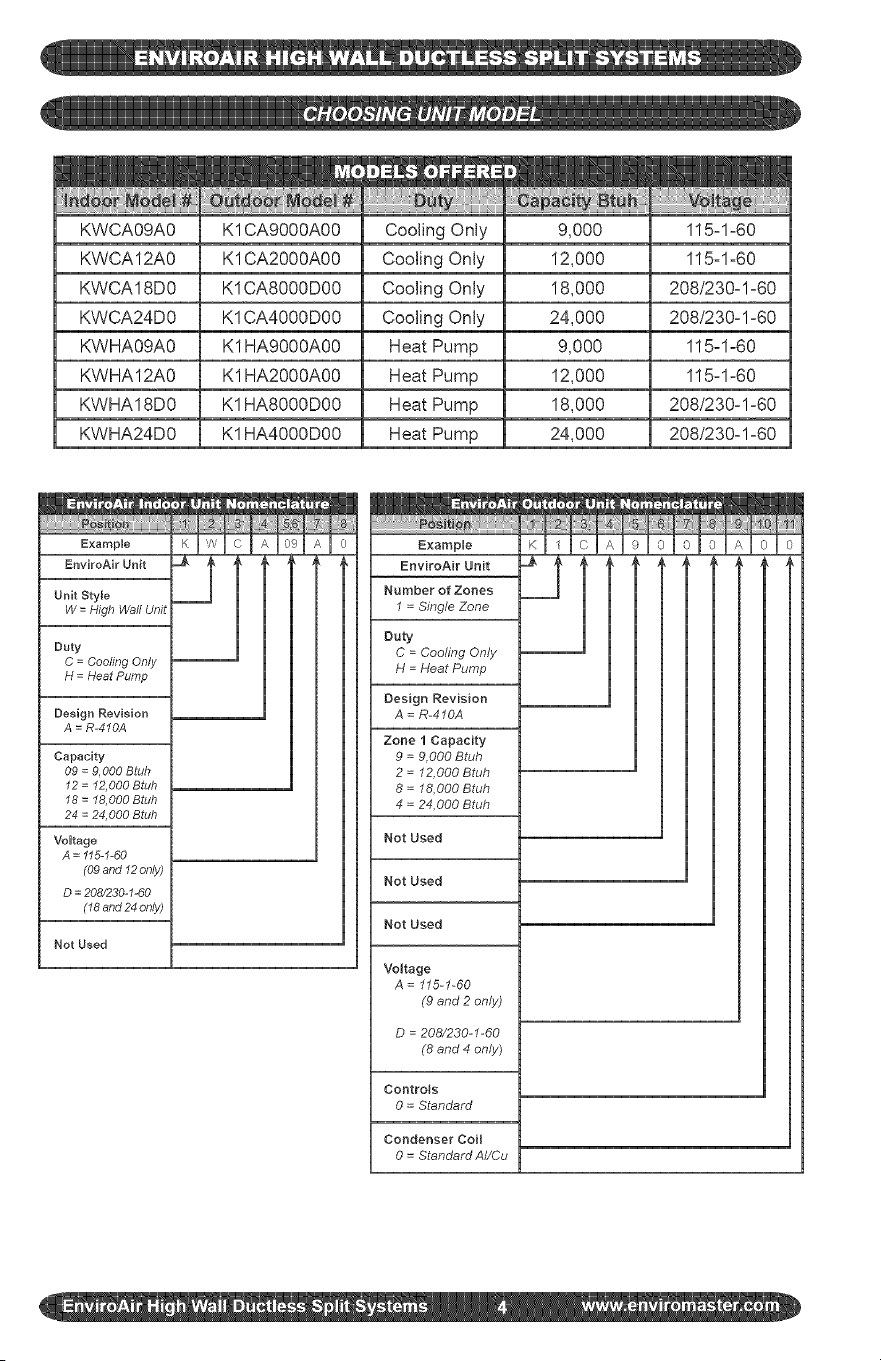
KWCA09A0
KWCA12A0
KWCA18D0
KWCA24D0
KWHA09A0
KWHA12A0
KWHA18D0
KWHA24D0
K1CA9000A00
K1CA2000A00
K1CA8000D00
K1CA4000D00
K1 HA9000A00
K1 HA2000A00
K1HA8000D00
K1HA4000D00
Cooling Only
Cooling Only
Cooling Only
Cooling Only
Heat Pump
Heat Pump
Heat Pump
Heat Pump
9,000
12,000
18,000
24,000
9,000
12,000
18,000
24,000
115zlz60
115zl-60
208/230-1-60
208/230-1z60
115-1-60
115-1-60
208/230zl-60
208/230-1-60
Example
EnviroAir Unit
Unit Style
W = High Waft Unit
Duty
C = Cooling Only
H = Heat Pump
Design Revision
A = R-4'10A
Capacity
09 = 9,000 Btuh
12 = 12,000 Btuh
18 = I8,000 Btuh
24 = 24,000 Btuh
Voltage
A = "115-I-60
(09 and "12only)
D = 208/230-"1-60
(18 and 24 only)
Not Used
Example
EnviroAir Unit
Number of Zones
I = Single Zone
Duty
C = Cooling Only
H = Heat Pump
Design Revision
A = R-410A
Zone I Capacity
9 = 9,000 Btuh
2 = 12,000 Btuh
8 = 18,000 Btuh
4 = 24,000 Btuh
Not Used
Not Used
Not Used
Voltage
A = 115-1-60
(9 and 2 only)
D = 208/230-I-60
(8 and 4 only)
Controls
0 = Standard
Condenser Coil
0 = StandardAI/Cu
Determine the best location for mounting
the indoor unit, it must be located a mini-
mum of 4 ft (6 ft or more recomended) from
the floor and no less than 6" from ceiling.
Pay attention to the air circulation in the
room, 9,000 & 12,000 Btuh units throw air
15ft, 18,000 & 24,000 Btuh units throw air
25ft, ensure no obstacles to airflow exist.
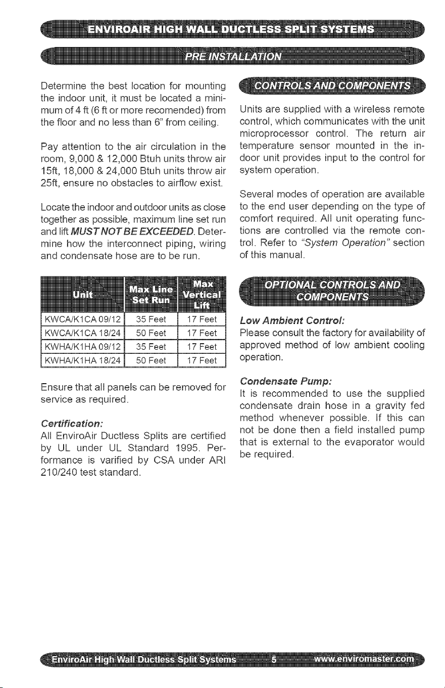
Locate the indoor and outdoor units as close
together as possible, maximum line set run
and lift MUST NOT BE EXCEEDED. Deter-
mine how the interconnect piping, wiring
and condensate hose are to be run.
Units are supplied with a wireless remote
control, which communicates with the unit
microprocessor control. The return air
temperature sensor mounted in the in-
door unit provides input to the control for
system operation.
Several modes of operation are available
to the end user depending on the type of
comfort required. All unit operating func-
tions are controlled via the remote con-
trol. Refer to "_System Operation" section
of this manual.
KWCA/K 1CA 09/12
KWCA/K1 CA 18/24
KWHA/K1HA 09/12
KWHA/K1 HA 18/24
35 Feet
50 Feet
35 Feet
50 Feet
17 Feet
17 Feet
17 Feet
17 Feet
Ensure that all panels can be removed for
service as required.
Cerdffeadon:
All EnviroAir Ductless Splits are certified
by UL under UL Standard 1995. Per-
formance is varified by CSA under ARI
210/240 test standard.
Low Ambient Contro#
Please consult the factory for availability of
approved method of low ambient cooling
operation.
Condensate Pump:
It is recommended to use the supplied
condensate drain hose in a gravity fed
method whenever possible. If this can
not be done then a field installed pump
that is external to the evaporator would
be required.
structions,failureto followI
s maycausepossiblemat=I
ndvoidanywarranty. J
J
Remove indoor and outdoor units from
the carton/box, indoor unit carton con-
tains, remote controt and batteries, en-
sure these are kept in a safe place during
installation.
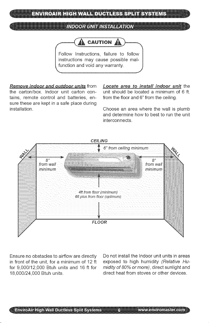
Locate area to install indoor unit the
unit should be located a minimum of 6 ft.
from the floor and 6" from the ceiling.
Choose an area where the watt is plumb
and determine how to best to run the unit
interconnects.
CEIMNG
ceiling minimum
6" from
from wall
minimum
4R from floor (minimum)
6R plus from floor (optimum)
FLOOR
Ensure no obstacles to airflow are directly
in front of the unit, for a minimum of 12 ft
for 9,000/12,000 Btuh units and 16 ft for
18,000t24,000 Btuh units.
Do not install the Indoor unit units in areas
exposed to high humidity (Relative Hu=
midity of 80% or more), direct sunlight and
direct heat from stoves or other devices.
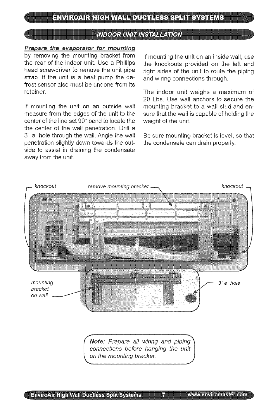
Prepare the evaporator for moundng
by removing the mounting bracket from
the rear of the indoor unit. Use a Phillips
head screwdriver to remove the unit pipe
strap. If the unit is a heat pump the de-
frost sensor also must be undone from its
retainer.
If mounting the unit on an outside wall
measure from the edges of the unit to the
center of the line set 90 ° bend to locate the
the center of the wall penetration. Drill a
3" e hole through the wall. Angle the wall
penetration slightly down towards the out-
side to assist in draining the condensate
away from the unit.
If mounting the unit on an inside walt, use
the knockouts provided on the left and
right sides d the unit to route the piping
and wiring connections through.
The indoor unit weighs a maximum of
20 Lbs. Use watt anchors to secure the
mounting bracket to a watt stud and en-
sure that the wall is capable of holding the
weight of the unit.
Be sure mounting bracket is level, so that
the condensate can drain properly.
knockout remove mounting
knockout
mounting
bracket
on wall
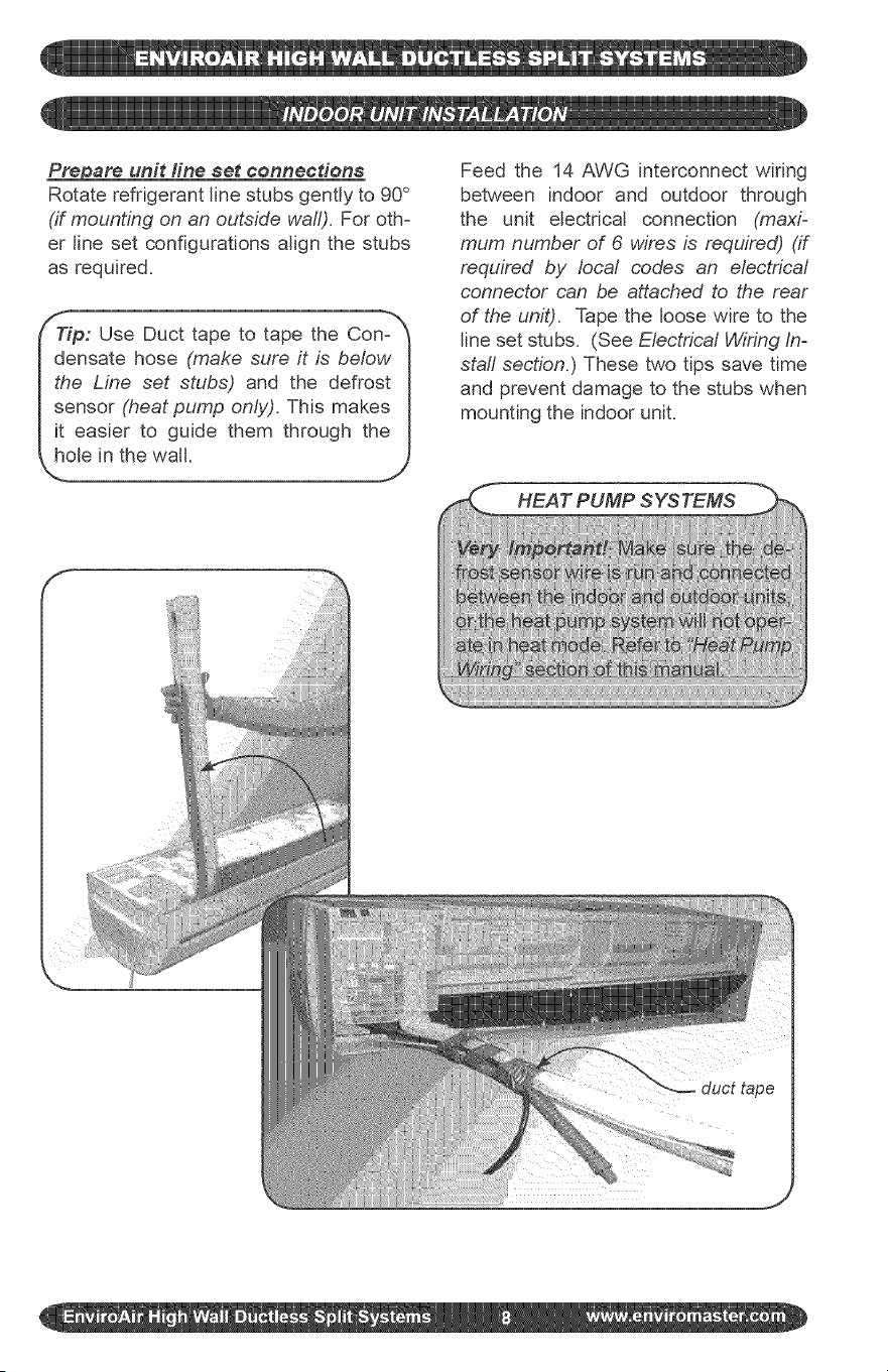
_are unit fine set connections
Rotate refrigerant line stubs gently to 90 °
(if mounting on an outside wall). For oth-
er line set configurations align the stubs
as required.
ieP: Use Duct tape to tape the Con-_
nsate hose (make sure it is below I
I the Line set stubs) and the defrost I
I sensor (heat pump only). This makes I
I it easier to guide them through the I
f
i !!!
Feed the 14 AWG interconnect wiring
between indoor and outdoor through
the unit electrical connection (maxi-
mum number of 6 wires is required) (if
required by local codes an electrica/
connector can be attached to the rear
of the unit). Tape the loose wire to the
line set stubs. (See Electrica/Wiring In-
staff section.) These two tips save time
and prevent damage to the stubs when
mounting the indoor unit.
HEAT PUMP SYSTEMS
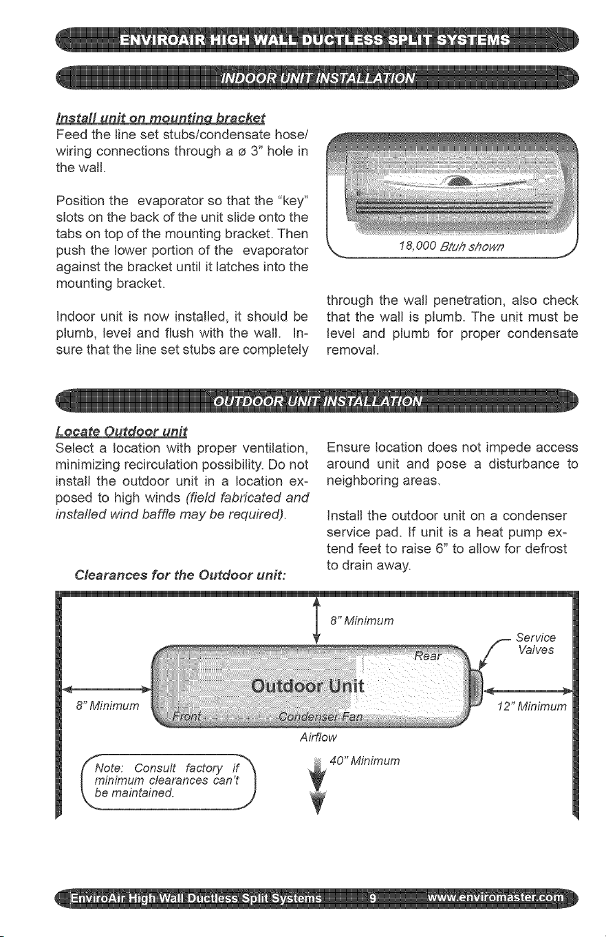
Install unit on mounting bracket
Feed the line set stubs/condensate hose/
wiring connections through a o 3" hole in
the walt.
Position the evaporator so that the "key"
slots on the back of the unit slide onto the
tabs on top of the mounting bracket. Then
push the lower portion of the evaporator
against the bracket until it latches into the
mounting bracket.
indoor unit is now installed, it should be
ptumb, level and flush with the wait. in-
sure that the line set stubs are completely
through the watt penetration, also check
that the watt is plumb. The unit must be
level and plumb for proper condensate
removal.
Locate Outdoor unit
Select a location with proper ventilation,
minimizing recircutation possibility. Do not
install the outdoor unit in a location ex-
posed to high winds (field fabricated and
installed wind baffle may be required).
Clearances for the Outdoor unit:
Ensure location does not impede access
around unit and pose a disturbance to
neighboring areas.
Install the outdoor unit on a condenser
service pad. If unit is a heat pump ex-
tend feet to raise 6" to allow for defrost
to drain away.
8" Minimum
Ote: Consult factory if"_
inimum clearances can't I
maintained. )
Airflow
40" Minimum
12" Minimum
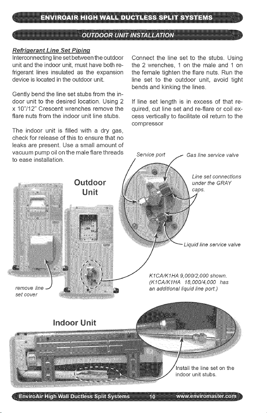
Re_nt Line Set Pi in
interconnectingline set between the outdoor
unit and the indoor unit, must have both re-
frigerant lines insulated as the expansion
device is located in the outdoor unit.
Gently bend the tine set stubs from the in-
door unit to the desired location. Using 2
x 10"/12" Crescent wrenches remove the
flare nuts from the indoor unit tine stubs.
The indoor unit is filled with a dry gas,
check for retease of this to ensure that no
leaks are present. Use a smatt amount of
vacuum pump oil on the male flare threads
to ease installation.
Outdoor
Unit
Connect the line set to the stubs. Using
the 2 wrenches, 1 on the male and 1 on
the female tighten the flare nuts. Run the
tine set to the outdoor unit, avoid tight
bends and kinking the lines.
If line set length is in excess of that re-
quired, cut line set and re-flare or coil ex-
cess vertically to facilitate oit return to the
compressor
Service port
Gas line service vahe
Line set connections
under the GRAY
caps.
set cover
Indoor Unit
Install the line set on the
indoor unit stubs.
Evacuation
Gauges can now be attached to the service
ports - SERVICE PORTS HAVE A 5/16"
CONNECTION TO GAUGES, which is dif-
ferent from the norm for R-22. You will need
specific hoses or an adaptor for the 5/16"
connection.
Once the gauges are attached the line
set can be leak checked using Nitrogen
at 300 psig. Evacuate the unit and inter-
connect down to a minimum of 400-500
Microns, break vacuum with Nitrogen to
further leak check.
Re-evacuate the system down to 300-400
Microns or lower for a period of one hour.
This is an R-410A System it is essential
that a deep vacuum be pulled on the sys-
tem to remove all traces of moisture. See
"System Start-Up" section to fine-tune the
refrigerant charge.
Main Power Wirin_
Electrical wiring should be done in ac-
cordance with all National Electrical Code
(NEC) and local state!city building codes.
_Note: A small screwdriver is required_
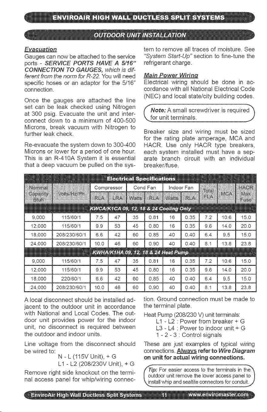
Breaker size and wiring must be sized
for the rating plate amperage, MCA and
HACR. Use only HACR type breakers,
each system installed must have a sep-
arate branch circuit with an individual
breaker/fuse.
9,000
2,000
8,000
!4,000
9,000
2,000
8,000
!4,000
115/80/1
115/80/1
220/60/!
208/230/80/!
7,2
9,6
6,4
8,1
7,2
9,6
6,4
8,1
A local disconnect should be installed ad-
jacent to the outdoor unit in accordance
with National and Local Codes. The out-
door unit provides power for the indoor
unit, no disconnect is required between
the outdoor and indoor units.
Line voltage from the disconnect should
be wired to:
N - L (115V Unit), + G
LI - L2 (208/230V Unit), + G
Remove right side knockout on the termi-
nal access panel for whip/wiring connec-
tion. Ground connection must be made to
the terminal plate.
Heat Pump (208,/230 V) unit terminals:
LI - L2 : Power from breaker + G
L3 - L4 : Power to indoor unit + G
1 - 2 - 3 : Control signals
These are just examples of typical wiring
connections. Alway_ refer to Wire Diagram
on unit for actuamwiring connections.
: For easier accessto the terminalsin the_
oor unitremovethe loweraccess paneltoJ
Electrical Wifin_ installation
Electrical Wiring should be done by a
certified electrician in accordance with
aft National ElectdcaICode (NEC) and
local state!city building codes.
ALL CONTROLS WIRING BETWEEN IN-
DOOR AND OUTDOOR UNIT IS HIGH
VOLTAGE MINIMUM 14 AWG WIRE MUST
BE USED.
outdoor unit must be a point to point i.e.
the terminal that the wire is attached to on
the outdoor unit must be the same termi-
nal it is wired to in on the indoor unit.
Remove terminal covers from indoor unit
and wire to the terminals, (small screw-
driver required). Control wiring from the
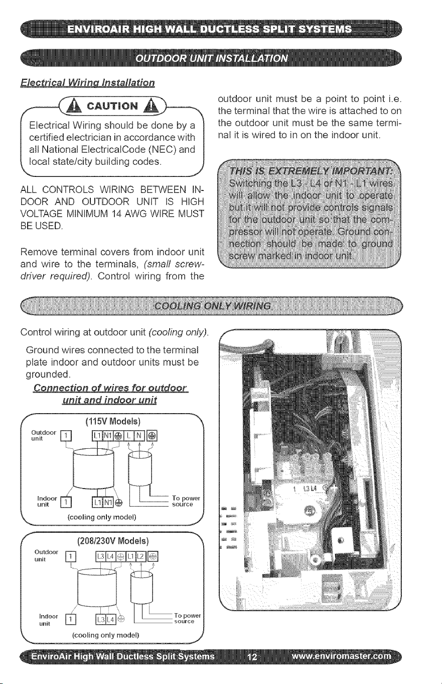
Control wiring at outdoor unit (cooling only).
Ground wires connected to the terminal
plate indoor and outdoor units must be
grounded.
Connection of wires for outdoor
unit and indoor unit
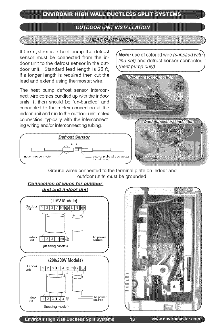
If the system is a heat pump the defrost
sensor must be connected from the in-
door unit to the defrost sensor in the out-
door unit. Standard lead length is 25 ft,
if a longer length is required then cut the
lead and extend using thermostat wire.
The heat pump defrost sensor intercon-
nect wire comes bundled up with the indoor
units. It then should be "un-bundled" and
connected to the molex connection at the
indoor unit and run to the outdoor unit motex
connection, typically with the interconnect-
ing wiring andlor interconnecting tubing.
ote: use of colored wire (supplied with_
Illne set) and defrost sensor connected I
(_eatpump only). ....
I_ Defrost Sensor "_
I I
Joor wire connector for deJrostirl"x_ outdoor prob_ wire cor/rlel_
Ground wires connected to the terminal plate on indoor and
outdoor units must be grounded.
Connection of wires for outdoor
unit and indoor unit
f
(115V Node[s)
(heating mode0
f- (208/230VNode[s) -_x
unit
Indoor To power
unit , _ _ L_ L_ _/ source
(heating model) j
12) Condensate Hose:
The unit is provided with approximately
18" of condensate hose connected. Hose
connection is sized to accept a 3/4" OD or
5/8" ID clear plastic hose to then extend to
building drain.
There is approximately 6' of additional
drain hose supplied with the (accessory)
line set.
All condensate hose extensions should be
in accordance with local building codes.
Remember water only flows downhill to
ensure positive draining from the unit.
Check using water for a positive flow of
condensate.
The basic system installation is now com-
plete. The unit is now ready for start up.
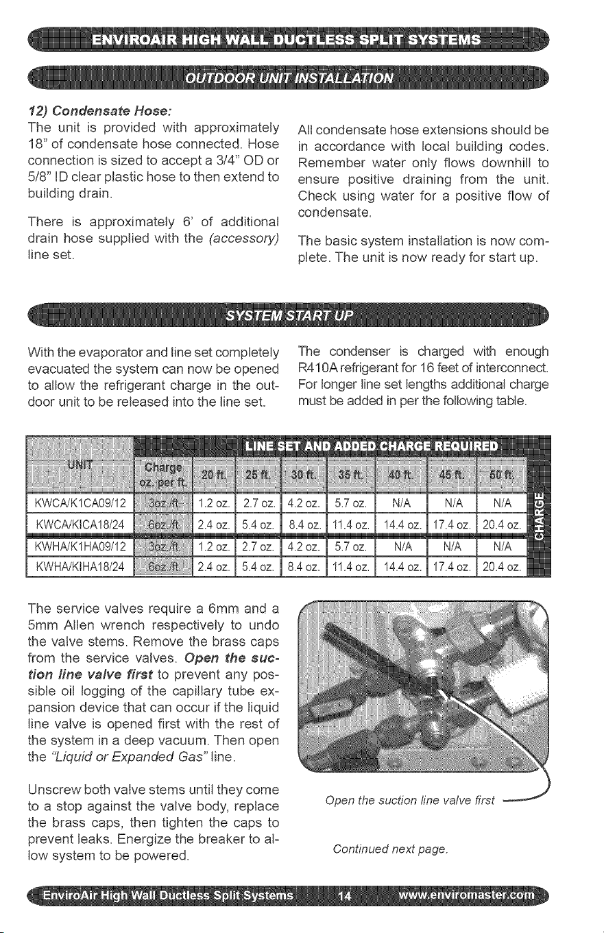
With the evaporator and line set completely
evacuated the system can now be opened
to allow the refrigerant charge in the out-
door unit to be released into the line set.
The condenser is charged with enough
R410A refrigerant for 16 feet of interconnect.
For longer line set lengths additional charge
must be added in per the following table.
KWHA/K1HA09/12
KWHA/KIHA18/24
_!i!i!i!i!_!_!_iiiii;i,ii_ii,X,ii_iiiiiiiiiii
1.2oz.
2.4oz.
1.2oz.
2.4oz.
The service valves require a 6mm and a
5mm Allen wrench respectively to undo
the valve stems. Remove the brass caps
from the service valves. Open the suc-
tion fine valve first to prevent any pos-
sible oil logging of the capillary tube ex-
pansion device that can occur if the liquid
line valve is opened first with the rest of
the system in a deep vacuum. Then open
the %_quid or Expanded Gas" line.
Unscrew both valve stems until they come
to a stop against the valve body, replace
the brass caps, then tighten the caps to
prevent leaks. Energize the breaker to aF
low system to be powered.
Open the suction fine valve first
Continued next page.
ote: tf interconnect is less then 12_
eta small amount of refrigerant may I
ed to be reclaimed to achieve the I
oper charge for optimal operation. I
viroAir recommends fine tuning us= I
yng the _Superheat" method, j)
Start the indoor unit, cooling mode is
only allowed when the outside ambient
temperature is above 60 ° F to prevent
damage to the compressor. Unit has a 3
minute time delay before the compressor
start up operation.
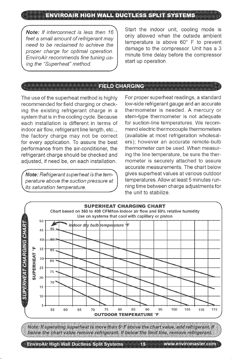
The use of the superheat method is highly
recommended for field charging or check-
ing the existing refrigerant charge in a
system that is in the cooling cycle. Because
each installation is different in terms of
indoor airflow, refrigerant line length, etc..,
the factory charge may not be correct
for every application. To assure the best
performance from the air-conditioner, the
refrigerant charge should be checked and
adjusted, if need be, on each installation.
For proper superheat readings, a standard
low=side refrigerant gauge and an accurate
thermometer is needed. A mercury or
stem=type thermometer is not adequate
for suction=line temperatures. We recom=
mend electric thermocouple thermometers
(available at most refrigeration wholesaF
ers); however an accurate remote=bulb
thermometer can be used. When measur=
ing the line temperature, be sure the theF
mometer is securely attached to assure
accurate measurements. The chart below
gives superheat values at various outdoor
temperatures. Allow at least 5 minutes run=
ning time between charge adjustments for
the unit to stabilize.
S
$UPIERHEAT CHARGmhlG CHART
Chart based on 360 to 400 CFM/ton indoor air flow and 66% relative humidity
Use on systems that cool with capillary or piston
5,0
'_ In :loot d, y bulb tempe, ature
450 95_ _ _ _._.
55 60 65 70 75 80 85 90 95 100 105 110 115
',-. OUTDOOR TEMPERATURE °F j
Instrucdons:
1. Measure suction pressure and deter-
mine evaporator-refrigerant temperature
on R410A scale of low-side gauge.
2. Measure suctionqine temperature on
suction line of the unit.
3. Measure outdoor and indoor tempera-
tures.
4. Determine from the table what the
superheat should be for the indoor and
outdoor temperatures.
5. Adjust charge if needed. Be sure unit is
running at stabilized condition.
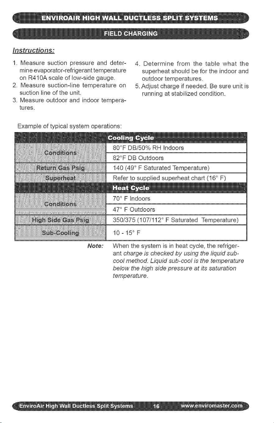
Example of typical system operations:
80°F DBi50% RH Indoors
82°F DB Outdoors
140 (49 ° F Saturated Temperature)
Refer to supplied superheat chart (16 ° F)
70 ° F Indoors
Note:
47 ° F Outdoors
350/375 (107/112 ° F Saturated Temperature)
10-15° F
When the system is in heat cycle, the refriger-
ant charge is checked by using the liquid sub-
cool method. Liquid sub-cool is the temperature
below the high side pressure at its saturation
temperature.
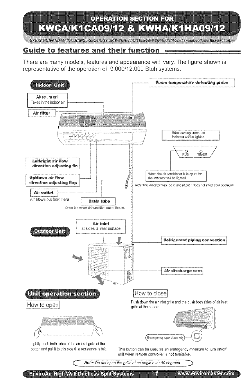
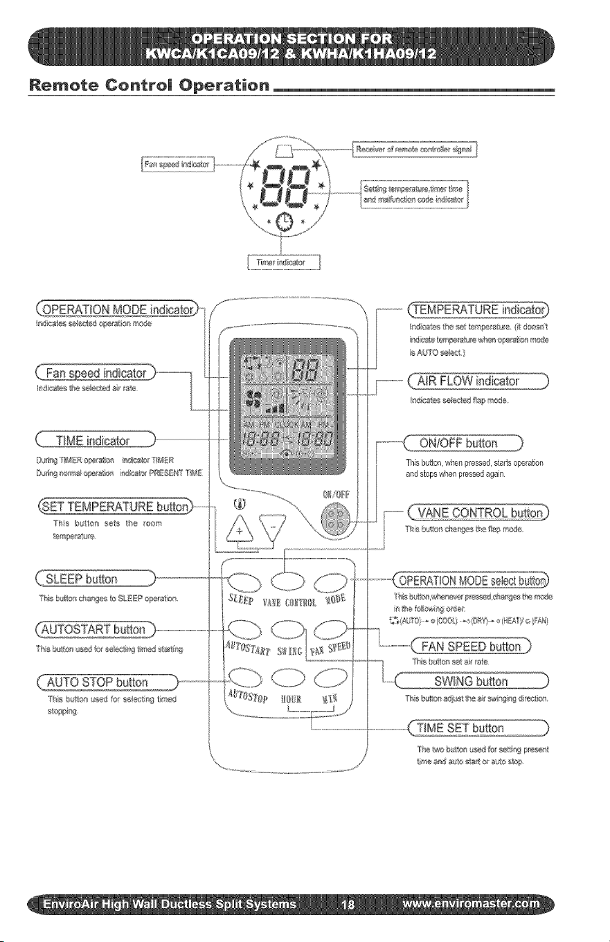
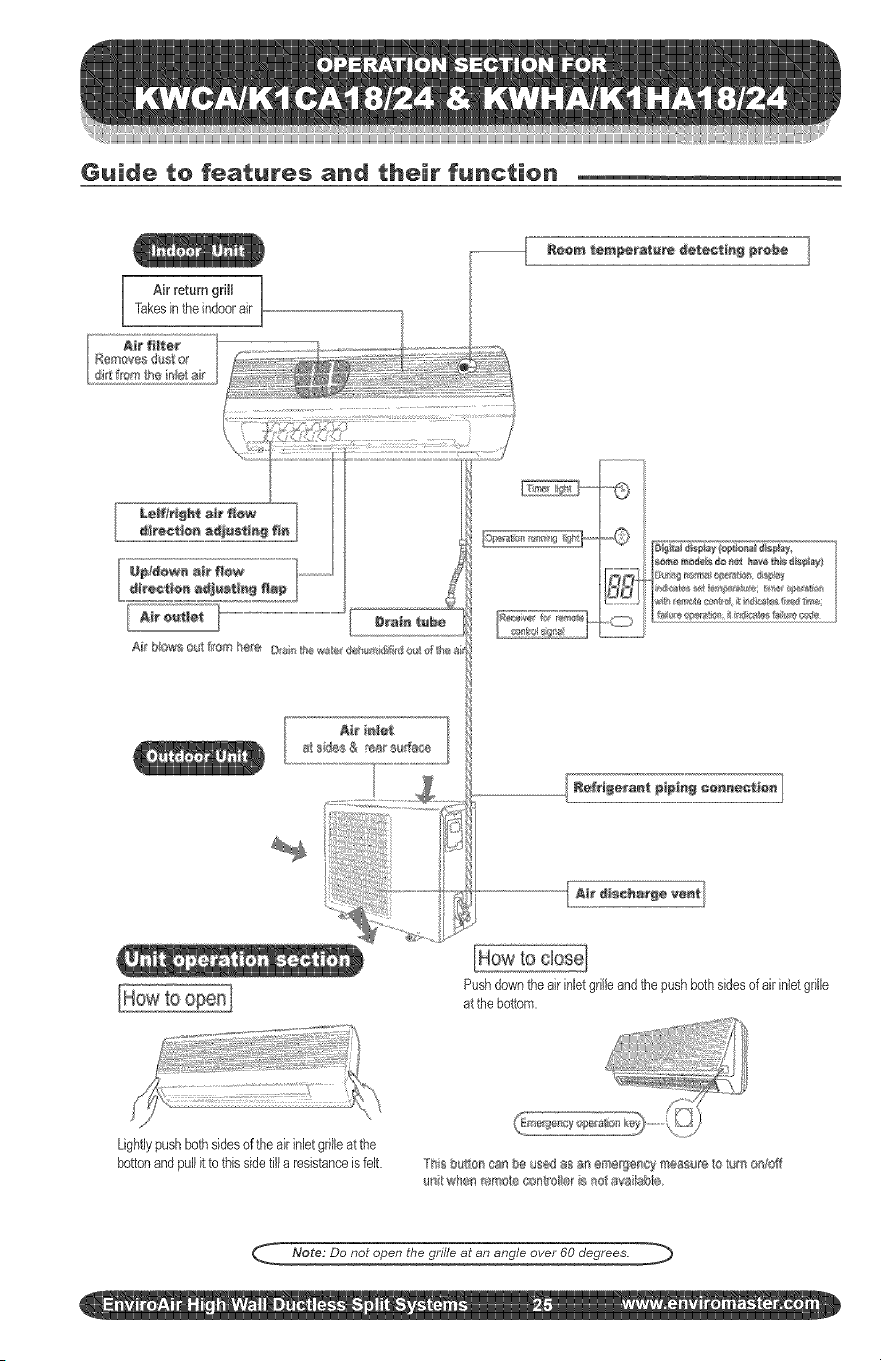
Guide to features and their function
There are many models, features and appearance will vary. The figure shown is
representative of the operation of 9,000/12,000 Btuh systems.
Ak return grill ]
Takesinthe indoorair
A_e tnl÷t
a__de_ & ea_ su_a_e
Pushdowntheair inletgrilleandthe pushbothsides ofak inlet
grilleat thebottom.
Lightlypushbothsidesof the airinletgr!lieat the
bottonand pullit to this sidetilla resistanceis felt ]'i_s b $u/'_cs_ be $_d as a_ ;me_f}e[_cy meas re,to _tm oni_b_
_¢_ whe_ _ote co_'o,l_eris _oi avai_sbk_
_ Note; Do not open the grille at an angle over 60 degrees.
Remote Contro| Operation
(:SETTEMPERATUREbutto_
/o
ON!OFF button )
Thisbutton,when pressed,starts operation
and stops whenpressedagain
FAN
SWING button
Remote Centre| Operation
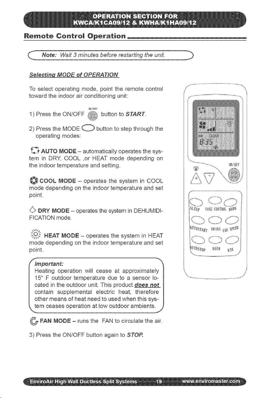
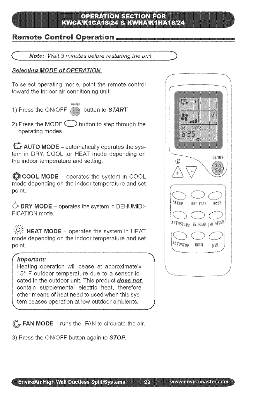
_._. Note: Wait 3 minutes before restarting the unit. b
Selecting MODE of OPERATION
To select operating mode, point the remote control
toward the indoor air conditioning unit:
1) Press the ON/OFF @ button to START.
2) Press the MODE O button to step through the
operating modes:
_' AUTO MODE - automatically operates the sys-
tem in DRY, COOL ,or HEAT mode depending on
the indoor temperature and setting.
COOL MODE - operates the system in COOL
mode depending on the indoor temperature and set
point.
(,/,_>DRY MODE - operates the system in DEHUMIDF
FICATION mode.
s2,, HEAT MODE - operates the system in HEAT
mode depending on the indoor temperature and set
point.
/_lmportant:
Heating operation will cease at approximately I
15 F outdoor temperature due to a sensor Io- I
cated in the outdoor unit. This product does not I
contain supplemental electric heat, therefore I
other means of heat need to used when this sys- I
Jem ceases operation at low outdoor ambients.J
_FAN MODE - runs the FAN to circulate the air.
3) Press the ON/OFF button again to STOR
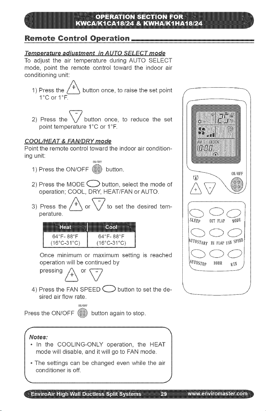
Remote Centre| Operation
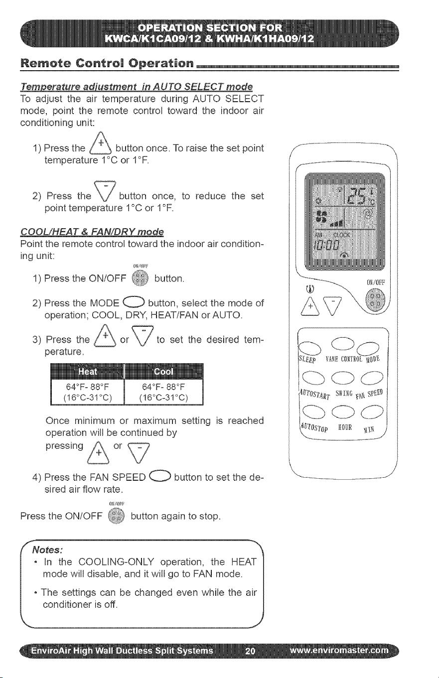
_erature _'uetment in AUTO SELECT mode
To adjust the air temperature during AUTO SELECT
mode, point the remote control toward the indoor air
conditioning unit:
1) Press the _ button once. To raise the set point
temperature 1°C or 1°F.
2) Press the button once, to reduce the set
point temperature 1°C or 1°F.
COOL/HEAT & FAN/DRY mode
Point the remote control toward the indoor air condition-
ing unit:
1) Press the ON/OFF @ button.
2) Press the MODE O button, select the mode of
operation; COOL, DRY, HEAT/FAN or AUTO.
3) Press the
perature.
I 64OF° 88OF
(!6°Co31°C)
set the desired tem-
64OFo88OF
(!6°Co3!°C)
Once minimum or maximum setting is reached
operation will be continued by
pressing or
4) Press the FAN SPEED O button to set the de-
sired air flow rate.
Press the ON/OFF 4&_ button again to stop.
SNores:
_ in the COOLING-ONLY operation, the HEAT I
mode wifl disable, and it will go to FAN mode. |
|
|o The settings can be changed even while the air I
Remote Centre| Operation
Up/down air flow direction adiustment
The up/down air flow direction can be adjusted by pressing the VANE CONTROL button
on the remote control, each time this button is pressed, the vane angle changes in the
following sequence: J i
(1) _ (2) !_ _ (3) T (4) (5)
, (1) through (5) are fixed positions.
, AUTO oscillates up and down automatically.
Air flow veleeit_iustment
To change the vane control velocity press the FAN SPEED button.
Each time the button is pressed, fan speed is changed in sequence,
[LO] 41 [MID] dr1 [HI]
To cool the whole room, use the dJ_ [HI] setting in COOL MODE. If the sound of the
air conditioner operating disturbs your sleep, use the SLEEP mode. (See next page)
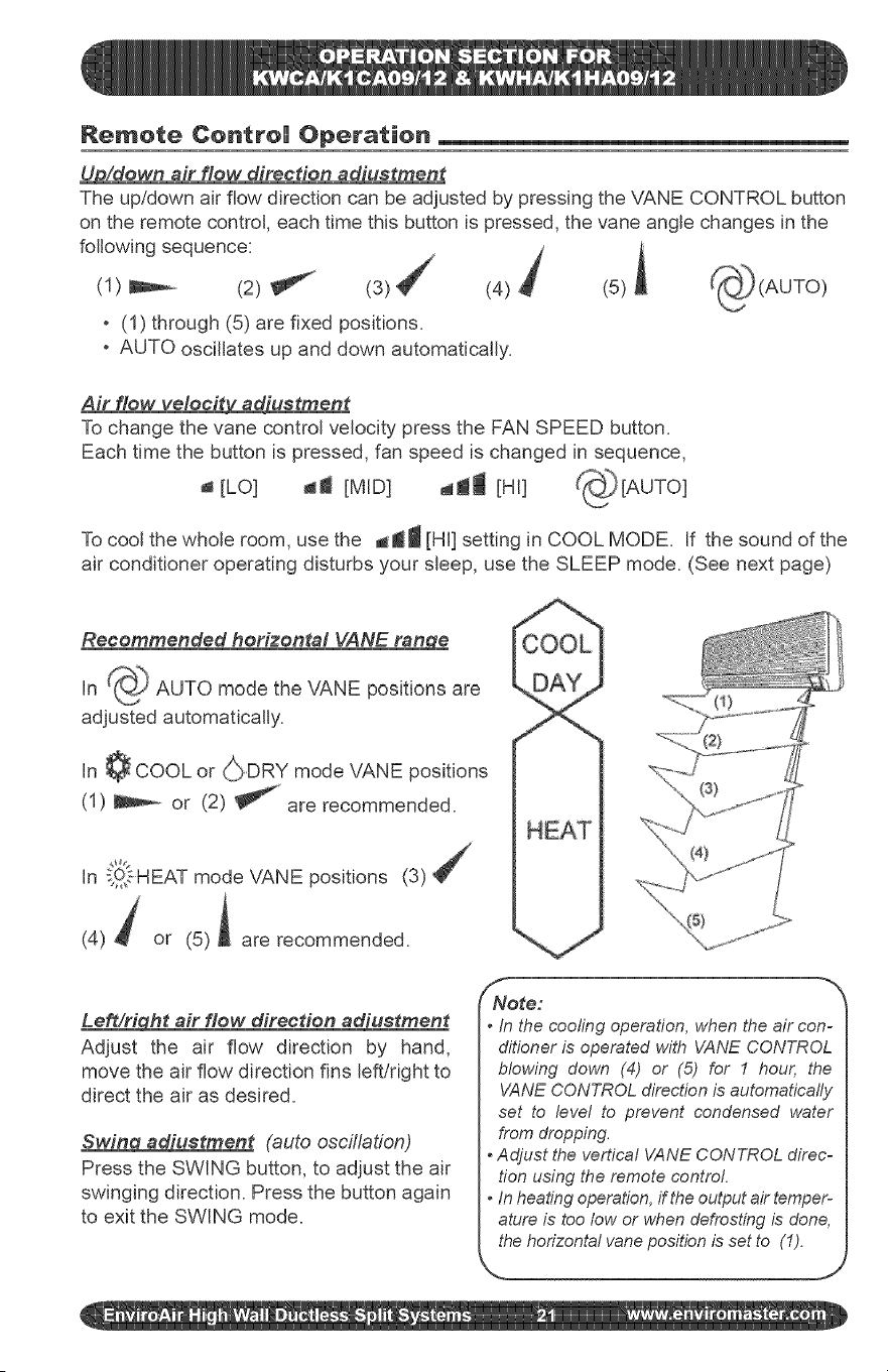
Recommended horizontal VANE ran_qe
in _ AUTO mode the VANE positions are
adjusted automatically.
In ¢ COOL or _DRY mode VANE positions
(1) _ or (2) _ are recommended.
In _31sHEAT mode VANE positions (3)
(4) t or (5)A are recommended.
Lea/right air flow direction adiustment
Adjust the air flow direction by hand,
move the air flow direction fins left/right to
direct the air as desired.
Swing adiustment (auto oscillation)
Press the SWING button, to adjust the air
swinging direction. Press the button again
to exit the SWING mode.
H
/ NNote: _'_
• In the cooling operation, when the air con-
ditioner is operated with VANE CONTROL
blowing down (4) or (5) for I hour, the
VANE CONTROLdirection is automatically
set to level to prevent condensed water
from dropping.
• Adjust the vertical VANE CONTROL direc-
tion using the remote control.
• In heatingoperation,if theoutput air temper-
ature is too low or whendefrosting is done,
thehorizontal vaneposition is set to (1).
N.. __ j
Remote Centre| Operation
(
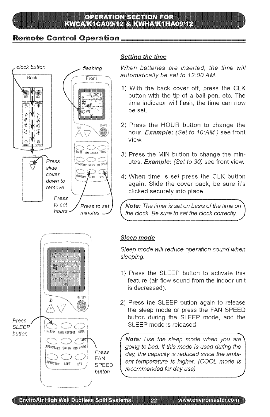
Setting the time
When batteries are inserted, the time will
automaticafly be set to 12.00 AM.
1) With the back cover off, press the CLK
button with the tip of a ball pen, etc. The
time indicator win flash, the time can now
be set.
2) Press the HOUR button to change the
hour. Example: (Set to IO:AM ) see front
view.
3) Press the MIN button to change the min=
utes. Example: (Set to 30) see front view.
4) When time is set press the CLK button
again. Slide the cover back, be sure it's
clicked securely into place.
Nore: The timer is set on basis of the time on_
We clock. Be sure to set the clock correctly.)
Press /i
SLEEP
button
Sleep mode
Sleep mode will reduce operation sound when
sleeping.
1) Press the SLEEP button to activate this
feature (air flow sound from the indoor unit
is decreased).
2) Press the SLEEP button again to release
the sleep mode or press the FAN SPEED
button during the SLEEP mode, and the
SLEEP mode is released
Nore: Use the sleep mode when you are_
\ I going to bed. If thb mode is used during the I
Press I day, the capacity is reduced since the ambF I
FAN lent temperature is higher. (COOL mode is I
SPEED _ecommended for day use) J
button
<, i
Remote Centre| Operation
Press
AUTO
START
Press
to set
hours
X
>X ................................../
Press to set
minutes
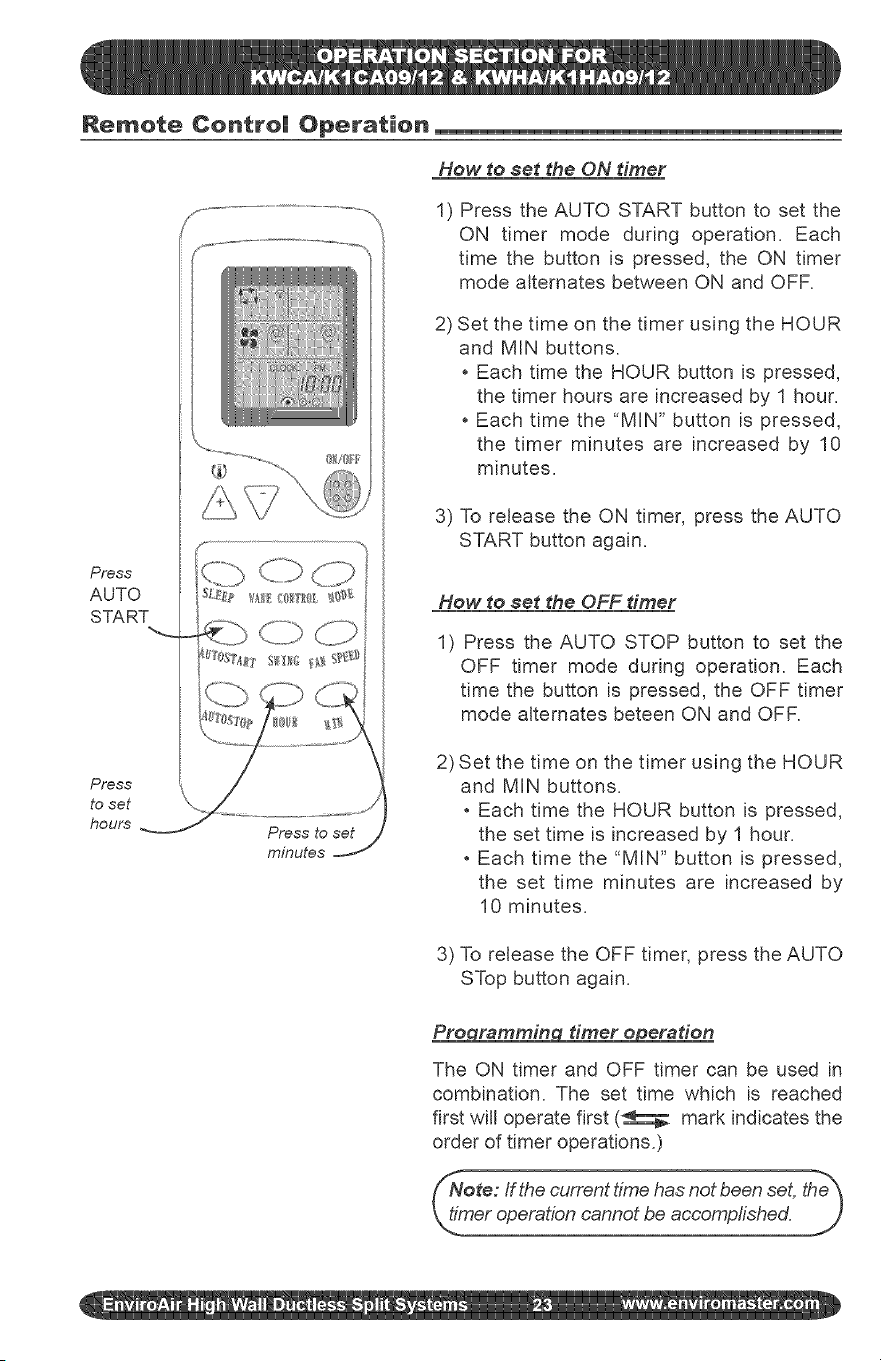
How to set _he ON diner
1) Press the AUTO START button to set the
ON timer mode during operation. Each
time the button is pressed, the ON timer
mode alternates between ON and OFR
2) Set the time on the timer using the HOUR
and MIN buttons.
Each time the HOUR button is pressed,
the timer hours are increased by 1 hour.
Each time the "MIN" button is pressed,
the timer minutes are increased by 10
minutes.
3) To release the ON timer, press the AUTO
START button again.
How to set the OFF timer
1) Press the AUTO STOP button to set the
OFF timer mode during operation. Each
time the button is pressed, the OFF timer
mode alternates beteen ON and OFF.
2) Set the time on the timer using the HOUR
and MIN buttons.
Each time the HOUR button is pressed,
the set time is increased by 1 hour.
Each time the "MIN" button is pressed,
the set time minutes are increased by
10 minutes.
3) To release the OFF timer, press the AUTO
STop button again.
Pro rammin dmer o eradon
The ON timer and OFF timer can be used in
combination. The set time which is reached
first will operate first (_ mark indicates the
order of timer operations.)
/Note: If the current time has not been set, the_
__o_shed.
Features of Heating Operations
Heating operation will cease at ap=
proximately 15° F outdoor tempera=
ture due to a sensor located in the
outdoor unit. This product does not
contain supplemental electric heat,
therefore other means of heat need to
used when this system ceases opera=
tion at low outdoor ambients.
Defros dnA
When the outdoor air temperature is very
low and humidity is very high, frosting will
occur in the heat exchanger of the outdoor
unit, which has negative impacts upon the
efficiency of the heating performance. In
this case, the automatic defrosting function
will come into play. The heating operation
will be stopped for 5=10 minutes to do the
defrosting.
Basic _les and #erformances
The Heat Pumps absorb heat from the
outdoor air and transfers it indoors to
heat the indoor air. The heating capa=
bilities through this principle go up/down
with the increase/decrease of the tem-
perature of the outdoor air.
When the outdoor air temperature is very
low, the system can be used together
with other heating device& Good ven=
tilation should be maintained to ensure
safety and prevent accidents.
The fans of both the outdoor and indoor
units are stopped. During the defrosting
operation, the run light wifl flash slowly.
Dudng defrosting, the outdoor unit might
generate some steam. It is caused by
fast defrosting, which is not a perfor=
mance failure.
Upon the completion of the defrosting pro=
cess, the heating operation is resumed.
Guide to features and their function
Air return grHI ,,
Takesintheindoorair
Pushdownthe airinletgrilleand thepushbothsidesof air inletgrille
at thebottom.
Lightlypush bothsidesof the airinlet grilleat the
bottonandpullit to this sidetill a resistanceis felt. TiI _ tl¢#_8aI bI ussd as 8_ ett_t[j_f_¢_ ¢SIIS_=IIt to tutI OI[01ff
US _,v!en _x_s_'_o_e_,xx¢o le_b _e av,a lable
Note: Do not open the grille at an angle over 60 degrees. ._
Remote Centre| Operation
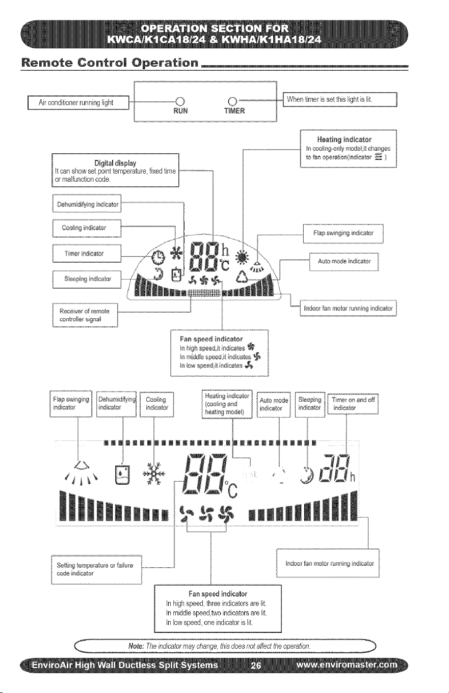
I Airconditionerrunninglight
setthislightis ft [
Digital display /
it canshowset pointtemperature,fixedtime
[or mafuncton code. J
II C081ill@IIy rllolel_ll llllIe
111t_1abestio_(indics'l_¢_ )
Fa_ s#*e# indieaio_
._______...... In2="j__E=_=.JL__]...............L.............[L.........,,.
f¢ o.:•o.......4...t.
, _ ' Q DDh
$_i_l%temp{{rata_eo_fT_i;l_e_...............................................
¢J_@ ]rllctt tf
Fanspeed indicator
In highspeed,threeindicatorsare lit.
in middlespeed,twoindicatorsarelit
in low speed,oneindicatoris lit.
Note: Theindicatormaychange,thisdoesnotaffecttheoperation.
Remote Centre| Operation
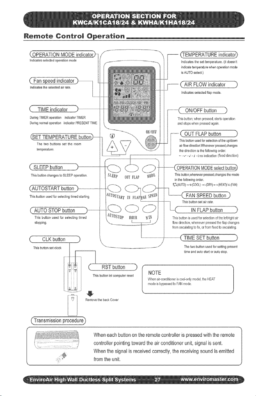
MODE
SLEEP bu_bn
_0 STOP huron
CLK butbn
I_l¢_Wos_eb_bv3flapr_,_de
ONIOFFbutton
Thisbuttoc whenpressed,sta4s operation
and stops whenpressedagain
FAN SPEEDbutton]
IN FLAP bu{bn
Thisbufbn is usedfor selectionof the leffkightair
flow direction,wheneverpressedthe flap changes
from osculatingto fix, or fromfixedto osculating
NOTE
When air-conditioneriscool-onlymodel,the HEAT
modeis bypassedto FANmode
When ea@ huron on the remote _ntroiler is p_'essedwi{h the iemote
controller pointing toward the air _ndifioner unR signa! is sent,
Whe_ the signai is received correctly' _he receMng seun_ is emitted
from the unR
Remote Control Operation
_- Note: Wait 3 minutes before restarting the unit.
Selecti_a MODE of OPERATION
To select operating mode, point the remote control
toward the indoor air conditioning unit:
1) Press the ON/OFF
('D button to START.
2) Press the MODE O button to step through the
operating modes:
AUTO MODE - automatically operates the sys-
tem in DRY, COOL ,or HEAT mode depending on
the indoor temperature and setting.
_COOL MODE - operates the system in COOL
mode depending on the indoor temperature and set
point.
_ DRY MODE - operates the system in DEHUMIDI-
FICATION mode.
gO_ HEAT MODE - operates the system in HEAT
mode depending on the indoor temperature and set
point.
f-
Important:
Heating operation will cease at approximately
15 ° F outdoor temperature due to a sensor Io=
cated in the outdoor unit= This product does not
contain supplemental electric heat, therefore
other means of heat need to used when this sys-
tem ceases operation at low outdoor ambients.
'_ ,rJ'
_FAN MODE the FAN to circulate the air.
runs
3) Press the ON/OFF button again to STOP.
f ...........
Remote Centre| Operation
Tem#erature adiuetment in AUTO SELECT mode
To adjust the air temperature during AUTO SELECT
mode, point the remote control toward the indoor air
conditioning unit:
1) Press the
1°C or 1°F.
button once, to raise the set point
2) Press the \./button once, to reduce the set
point temperature 1°C or 1°F.
COOL/HEAT & FAN/DRY mode
Point the remote control toward the indoor air condition-
ing unit:
1) Press the ON/OFF ,_ button.
2) Press the MODE O button, select the mode of
operation; COOL, DRY, HEAT/FAN or AUTO.
A
3) Press the _ or to set the desired tem-
perature.
Once minimum or maximum setting is reached
operation will be continued by
pressing or
4) Press the FAN SPEED O button to set the de-
sired air flow rate.
Press the ON/OFF _i_ button again to stop.
F" ",,
SL_E_ OUTFLf_P _{3_
( Lb dZb
_'TOST4_t I_ FLAP_,_ gf_t,*_
J
Notes:
* In the COOLING-ONLY operation, the HEAT
mode will disable, and it will go to FAN mode.
* The settings can be changed even while the air
conditioner is off.
Remote Centre| Operation
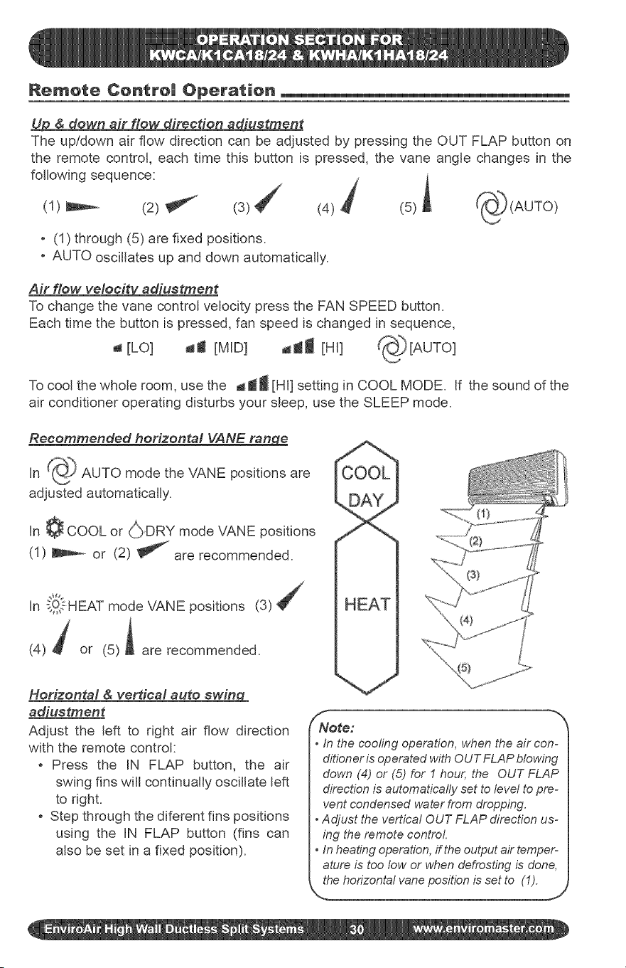
U_ & down air flow direction adiuetment
The up/down air flow direction can be adjusted by pressing the OUT FLAP button on
the remote control, each time this button is pressed, the vane angle changes in the
following sequence: j
(1) _ (2) _ (4) _ (5) ,
. (1) through (5) are fixed positions.
, AUTO oscillates up and down automatically.
Air flow veleeit_uetment
To change the vane control velocity press the FAN SPEED button.
Each time the button is pressed, fan speed is changed in sequence,
a [LO] da [MID] _l [HI] _[AUTO]
To cool the whole room, use the _ti [HI] setting in COOL MODE. if the sound of the
air conditioner operating disturbs your sleep, use the SLEEP mode.
Recommended horizontal VANE range
in _ AUTO mode the VANE positions are
adjusted automatically.
in ¢ COOL or (_}DRY mode VANE positions
(1) _ or (2) _ are recommended.
In _!,_.1-HEATmode VANE positions (3)
(4) _ or (5)i are recommended.
Horizontal & verdcal auto swin_CL
_uetment
Adjust the left to right air flow direction
with the remote control:
, Press the IN FLAP button, the air
swing fins will continually oscillate left
to right.
, Step through the diferent fins positions
using the iN FLAP button (fins can
also be set in a fixed position).
f
Note:
• in the cooling operation, when the air con-
ditioneris operatedwith OUTFLAP blowing
down (4) or (5) for 1 hour, the OUT FLAP
directionis automatically set to level to pre-
vent condensed water from dropping.
Adjust the vertical OUT FLAP direction us-
ing the remote control.
In heatingoperation,if theoutputair temper-
ature is too fow or whendefrosting is done,
thehorizontal vaneposition is set to (1).
J
Remote Centre| Operation
r clock button flashing
---'gack ...................... Front
tess "">
I Irem°ve
/L.... _ Press
to set j Press to set
hours minutes
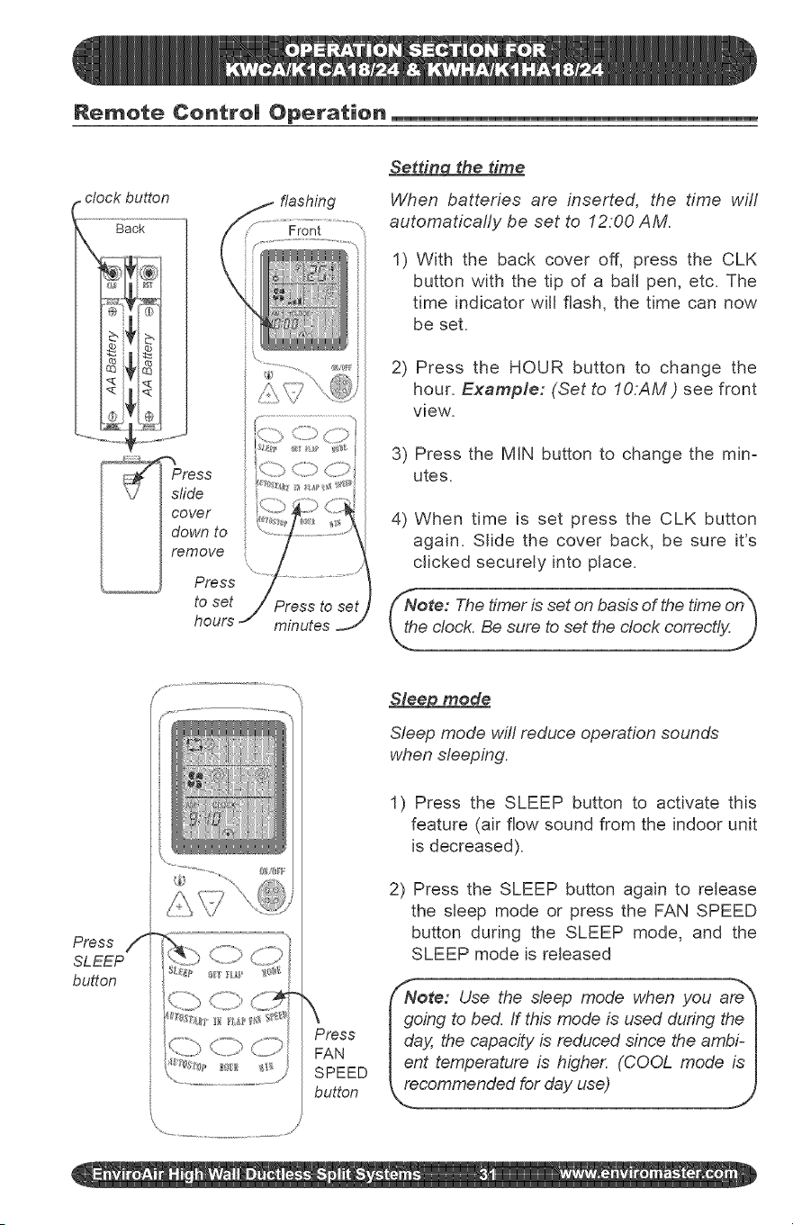
Setdn¢_ the time
When batteries are inserted, the time wifl
automaticafly be set to 12:00 AM.
1) With the back cover off, press the CLK
button with the tip of a ball pen, etc. The
time indicator will flash, the time can now
be set.
2) Press the HOUR button to change the
hour. Example: (Set to IO:AM ) see front
view.
3) Press the MIN button to change the mira
utes.
4) When time is set press the CLK button
again. Slide the cover back, be sure it's
clicked securely into place.
/
\
Press
FAN
SPEED
button
Sleep mode
Sleep mode will reduce operation sounds
when sleeping.
1) Press the SLEEP button to activate this
feature (air flow sound from the indoor unit
is decreased).
2) Press the SLEEP button again to release
the sleep mode or press the FAN SPEED
button during the SLEEP mode, and the
SLEEP mode is released
{/Note: Use the sleep mode when you are _
I going to bed. If this mode is used during the I
I day, the capacity is reduced since the ambi- I
Ient temperature is higher. (COOL mode is I
_oded for day use)
Remote Centre| Operation
Press
AUTO
START
Press
to set
hours
minutes
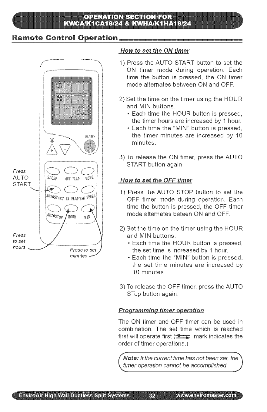
How to $et the ON timer
1) Press the AUTO START button to set the
ON timer mode during operation. Each
time the button is pressed, the ON timer
mode alternates between ON and OFR
2) Set the time on the timer using the HOUR
and MIN buttons.
Each time the HOUR button is pressed,
the timer hours are increased by 1 hour.
Each time the "MIN" button is pressed,
the timer minutes are increased by 10
minutes=
3) To release the ON timer, press the AUTO
START button again=
How to set the OFF diner
1) Press the AUTO STOP button to set the
OFF timer mode during operation= Each
time the button is pressed, the OFF timer
mode alternates beteen ON and OFR
2) Set the time on the timer using the HOUR
and MIN buttons=
Each time the HOUR button is pressed,
the set time is increased by 1 hour.
Each time the "MIN" button is pressed,
the set time minutes are increased by
10 minutes.
3) To release the OFF timer, press the AUTO
STop button again.
Pre_a diner e#eraden
The ON timer and OFF timer can be used in
combination. The set time which is reached
first will operate first (_ mark indicates the
order of timer operations.)
Note: ffthe current time has not been set, the_
_h_.meroperation cannot be accomplished.
J
Features of Heating Operations
portant: Heating operation will cease
proximately !5 ° F outdoor temperature
e to a sensor located in the outdoor unit.
is product does not contain supplemen-
I tal electric heat, therefore other means of
I heat need to used when this system ceas-
_,,_soperation at low outdoor ambients.
_ei lee and erformaneee
, The Heat Pumps absorb heat from the
outdoor air and transfers it indoors to
heat the indoor air. The heating capa=
bilJties through this principle go up/down
with the increase/decrease of the tem=
perature of the outdoor air.
, When the outdoor air temperature is very
low, the system can be used together
with other heating devices. Good ven=
tilation should be maintained to ensure
safety and prevent accidents.
Maintenance
Defroedn_
When the outdoor air temperature is very
low and humidity is very high, frosting will
occur in the heat exchanger of the outdoor
unit, which has negative impacts upon the
efficiency of the heating performance, in
this case, the automatic defrosting function
wifl come into play. The heating operation
wifl be stopped for 5=10 minutes to do the
defrosting.
, The fans of both the outdoor and indoor
units are stopped= During the defrosting
operation, the run light will flash slowly.
, During defrosting, the outdoor unit might
generate some steam= it is caused by
fast defrosting, which is not a perfor-
mance failure.
, Upon the completion of the defrosting pro=
cess, the heating operation is resumed=
The air conditioner must be turned off before the maintenance is to be carried out.
Before the o eratinN season
1) Check if there are any materials block-
ing the intake and outlet vents of the
indoor and outdoor units,
2) Check if the installation stand is cor-
roded or rusty.
3) Check if the unit is properly grounded.
4) Check if the air filter is clean.
5) Connect to the power source=
6) Put batteries in the remote controller.
Durin¢l the ooeradn_ season
Check the air filter periodicafly during the
season and clean it if it is dirty.
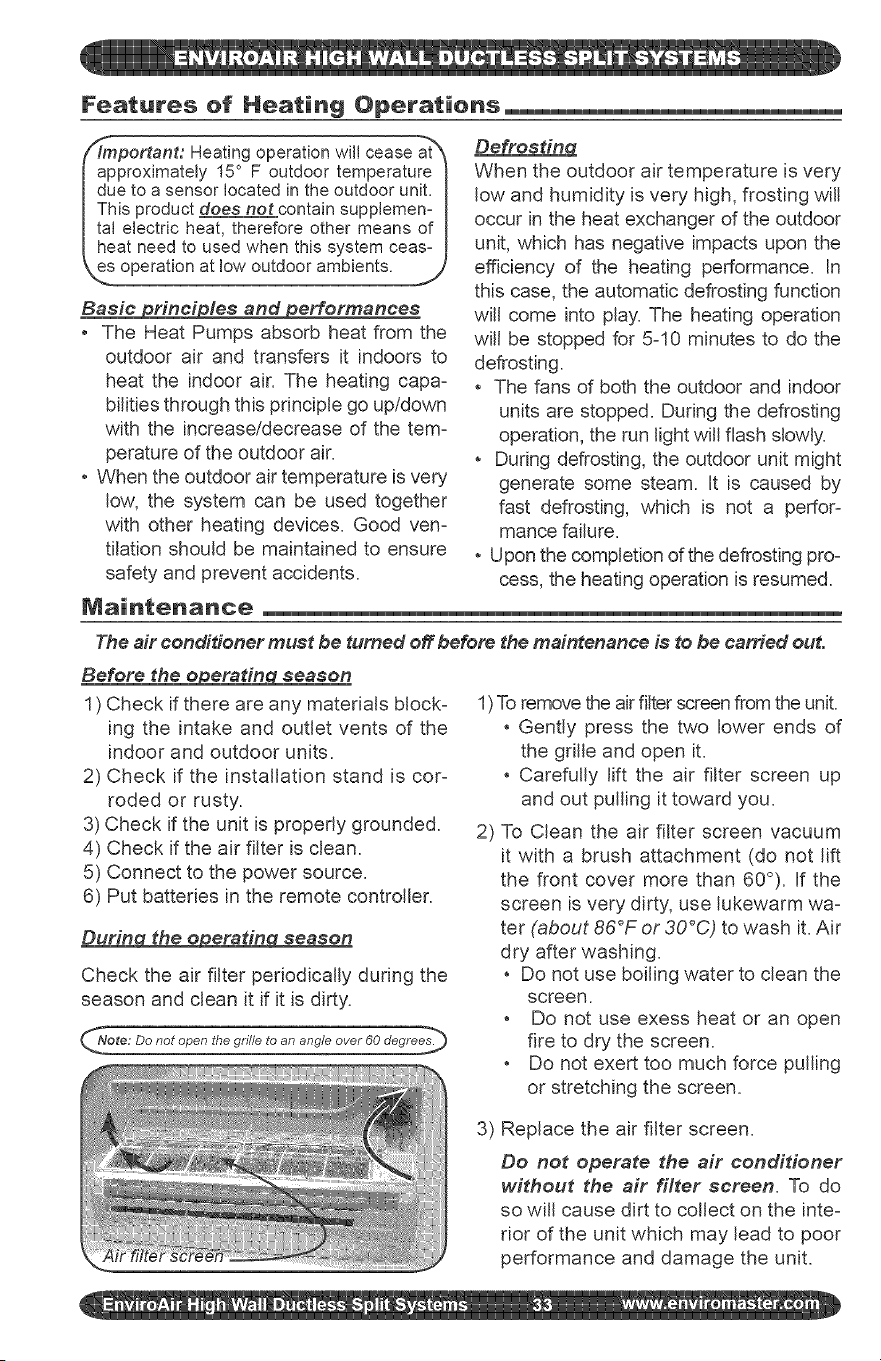
ote: Do not open the grille to an angle over 60 degrees._
1)To remove the air fitter screen from the unit.
Gently press the two lower ends of
the grille and open it.
Carefully lift the air filter screen up
and out pulling it toward you.
2) To Clean the air filter screen vacuum
it with a brush attachment (do not lift
the front cover more than 60°). If the
screen is very dirty, use lukewarm wa=
ter (about 86°F or 30°C) to wash it. Air
dry after washing.
Do not use boiling water to clean the
screen.
Do not use exess heat or an open
fire to dry the screen.
Do not exert too much force pulling
or stretching the screen.
3) Replace the air filter screen.
Do not operate the air conditioner
without the air filter screen. To do
so will cause dirt to collect on the inte-
rior of the unit which may lead to poor
performance and damage the unit.
Maintenance
To clean the surface of the air conditioner:
Use a soft and dry cloth to wipe the
air conditioner off, or use a vacuum
cleaner to clean it.
, if the air conditioner is very dirty, use a
damp soft cloth with a neutral house-
hold detergent to clean the surface of
the unit.
f"NNote: If the air filter screen is blocked_
by dust or dirt, the performance of 1
cooling and heating will be affected, 1
and the operation noise and power 1
consumption will increased. There- 1
fore, the air filter screen should be 1
_,,_eaned regularly. J
A_er the o eratin season
1) Set the temperature at 86°F or 30°C and
operate in the fan status for about half a
day, to dry out the interior of the units.
2) Stop the operation of the system
and turn OFF the power switch. The
air conditioner will consume about
5W of electric power after the unit
is turned off. For energy saving and
safety, it is advisable to disconnect
the power in the off season.
3) Clean and reinstall the air filter screen.
4) Clean the surface of both the indoor
and outdoor units.
5) Take the batteries out of the remote
control.
Troub|eshooting
Check the following before requesting a_erosale service from your dealer.
ff the air conditioner does not operate at all
, Check if the main power is on.
, Is the time set to "ON" position?
(If using the timer function.)
, Check for a blown fuse or a power failure.
, Check the batteries in the remote control.
Poor eooling or heating performance
, Room temperature can't be controlled
(Too cotd or too hot). Check if the room
temperature setting too low or too high.
, Are the air filters clean (Not dogged)?
, Are the window (s) and door (s) opened?
Peer cooling performance
, Check if direct sunlight isentering the room.
, Check if there is a heat source in the
room (i.e. = hot plate, oven, stove, etc).
, Are there too many people in the room?
if the air conditioner does not operate
properly ever after conducting the above
checks, if there is still doubt even after
consulting the Baeie Operation Charae-
terisdee section on following page of this
manual, or in case of such phenomena as
described below, turn off the power and
contact your distributor.
Disconnect the power immediately, inform your installer in the following situations.
Fuse or breaker often trips off (re-
peatedly).
Remote does not initiate operation.
, Abnormal noise is heard during op-
if faulty operation is observed when
the RUN button is pressed and even
after restarting the operation after 3
minutes, faulty operation does not
disappear.
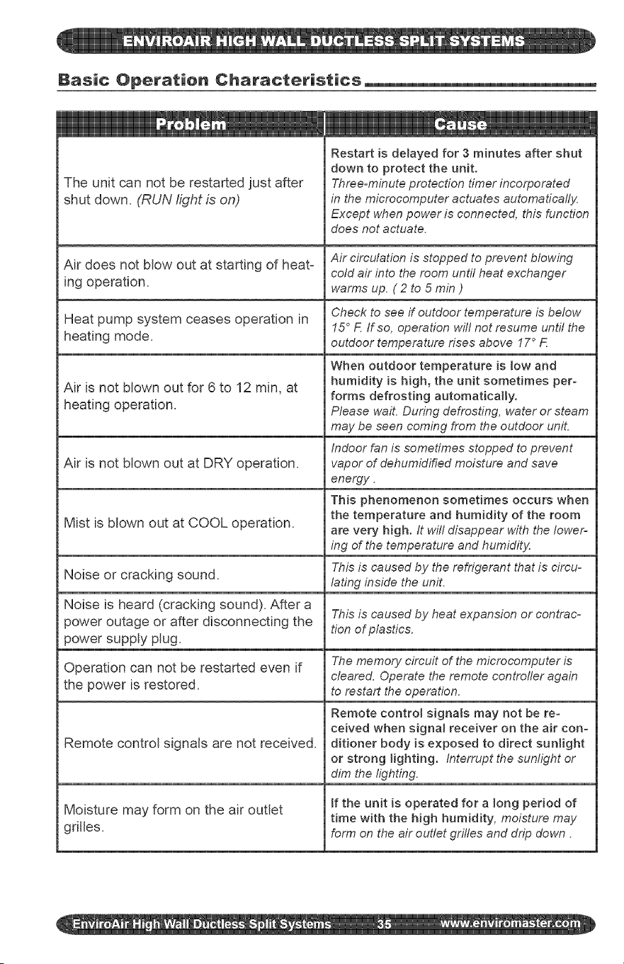
Basic Operation Characteristics_
The unit can not be restarted just after
shut down. (RUN light is on)
Air does not blow out at starting of heat=
ing operation.
Heat pump system ceases operation in
heating mode.
Air is not blown out for 6 to 12 min, at
heating operation.
Air is not blown out at DRY operation.
Mist is blown out at COOL operation.
Noise or cracking sound.
Noise is heard (cracking sound). After a
power outage or after disconnecting the
power supply plug.
Operation can not be restarted even if
the power is restored.
Remote control signals are not received.
Moisture may form on the air outlet
gdlles.
Restart is detayed for 3 minutes after shut
down to protect the unit.
Three=minute protection timer incorporated
in the microcomputer actuates automatically
Except when power is connected, this function
does not actuate.
Air circulation is stopped to prevent blowing
cold air into the room until heat exchanger
warms up. ( 2 to 5 min )
Check to see if outdoor temperature is below
15 ° F If so, operation witl not resume until the
outdoor temperature rises above 17 ° F
When outdoor temperature is low and
humidity is high, the unit sometimes per-
forms defrosting automatically,
Please wail During defrosting, water or steam
may be seen coming from the outdoor uniL
Indoor fan is sometimes stopped to prevent
vapor of dehumidified moisture and save
energy.
This phenomenon sometimes occurs when
the temperature and humidity of the room
are very high. It wil! disappear with the lower-
ing of the temperature and humidity
This is caused by the refrigerant that is circu-
lating inside the unit.
This is caused by heat expansion or contrac-
tion of plastics.
The memory circuit of the microcomputer is
cleared. Operate the remote controfler again
to restart the operation.
Remote control signats may not be re=
ceived when signal receiver on the air con-
ditioner body is exposed to direct sunlight
or strong lighting. Interrupt the sunlight or
dim the lighting.
tf the unit is operated for a long period of
time with the high humidity, moisture may
form on the air outlet grifles and drip down.

Phone: 1-800-228-9364 5780 Success Drive,
Fax: 1-800-232-9364 O_',_#_"__2' _ ,_(_',' _ Rome, NY 13440