
20V MAX BRAD NAILER
AND CROWN STAPLER
Instruction Manual
IMPORTANT: Your new tool has been engineered and manufactured to WEN’s highest standards for dependability,
ease of operation, and operator safety. When properly cared for, this product will supply you years of rugged,
trouble-free performance. Pay close attention to the rules for safe operation, warnings, and cautions. If you use
your tool properly and for its intended purpose, you will enjoy years of safe, reliable service.
NEED HELP? CONTACT US!
Have product questions? Need technical support? Please feel free to contact us:
TECHSUPPOR[email protected]1-847-429-9263 (M-F 8AM-5PM CST)
For replacement parts and the most up-to-date instruction manuals, visit WENPRODUCTS.COM
MODEL 20538, 20538BT

CONTENTS
WELCOME 3
Introduction ......................................................................................................3
Specifications ....................................................................................................3
SAFETY 4
General Safety Rules .........................................................................................4
Brad Nailer & Stapler Safety Warnings..............................................................6
Electrical Information (Charger) ........................................................................7
Battery & Charger Safety Warnings ..................................................................8
BEFORE OPERATING 9
Unpacking & Packing List .................................................................................9
Know Your Brad Nailer & Stapler ......................................................................9
Assembly & Adjustments ................................................................................10
OPERATION & MAINTENANCE 13
Operation ........................................................................................................13
Maintenance ....................................................................................................14
Exploded View & Parts List .............................................................................15
Warranty Statement ........................................................................................17
2
WEN plans to continue to add more items to our 20V line. For an up-to-date list of the 20V cordless tools compatible
with the included battery and charger, visit wenproducts.com.
To purchase accessories and replacement parts for your tool, visit WENPRODUCTS.COM
20V 4.0Ah Max Battery (Model 20204, 20204B)
20V 2A Charger (Model 20200C)
20V 5.0Ah Max Battery (Model 20205)
20V 5A Quick Charger (Model 20201Q)
20V 2.0Ah Max Battery (Model 20202, 20202B)
20V 2A Dual Port Charger (Model 20200D)
20V 8.0Ah Max Battery (Model 20208)

SPECIFICATIONS
INTRODUCTION
Thanks for purchasing the WEN Brad Nailer and Stapler. We know you are excited to put your tool to work, but first,
please take a moment to read through the manual. Safe operation of this tool requires that you read and understand
this operator’s manual and all the labels affixed to the tool. This manual provides information regarding potential
safety concerns, as well as helpful assembly and operating instructions for your tool.
NOTE: The following safety information is not meant to cover all possible conditions and situations that may occur.
WEN reserves the right to change this product and specifications at any time without prior notice.
At WEN, we are continuously improving our products. If you find that your tool does not exactly match this manual,
please visit wenproducts.com for the most up-to-date manual or contact our customer service at 1-847-429-9263.
Keep this manual available to all users during the entire life of the tool and review it frequently to maximize
safety for both yourself and others.
Indicates danger, warning, or caution. The safety symbols and the explanations with them deserve your
careful attention and understanding. Always follow the safety precautions to reduce the risk of fire, electric shock
or personal injury. However, please note that these instructions and warnings are not substitutes for proper ac-
cident prevention measures.
Model Number 20538, 20538BT
Included Battery* 2.0Ah Battery (Model 20202)*
Included Charger* 20V, 2A DC (Model 20200C)*
Magazine Capacity
Nails: 50 pcs
Staples: 100 pcs
Rated Firing Speed 60 Pcs / Minute
Staple Type Length: 1/4 in. - 9/16 in. Type: T50 Crown Staples
Nail Type Length: 5/8 in. Type: 18-Gauge Brad Nails
Product Weight 2.4 lbs
Product Dimensions 7.0 in. x 7.8 in. x 2.7 in.
Battery Models All WEN 20V MAX Batteries**
Charger Models All WEN 20V MAX Chargers
**NOTE: Some tools may not be compatible with WEN 20V MAX 1.5Ah Batteries, model 49120B. Contact
WEN customer service at 1-847-429-9263, M-F with questions.
*NOTE: Battery and charger only included with model 20538. Model 20538BT does not include a battery
or charger.
3

GENERAL SAFETY RULES
WORK AREA SAFETY
1. Keep work area clean and well lit. Cluttered or dark
areas invite accidents.
2. Do not operate power tools in explosive atmo-
spheres, such as in the presence of flammable liquids,
gases or dust. Power tools create sparks which may ig-
nite the dust or fumes.
3. Keep children and bystanders away while operating
a power tool. Distractions can cause you to lose control.
ELECTRICAL SAFETY
1. Power tool plugs must match the outlet. Never mod-
ify the plug in any way. Do not use any adapter plugs
with earthed (grounded) power tools. Unmodified plugs
and matching outlets will reduce risk of electric shock.
2. Avoid body contact with earthed or grounded surfac-
es such as pipes, radiators, ranges and refrigerators.
There is an increased risk of electric shock if your body
is earthed or grounded.
3. Do not expose power tools to rain or wet conditions.
Water entering a power tool will increase the risk of elec-
tric shock.
4. Do not abuse the cord. Never use the cord for car-
rying, pulling or unplugging the power tool. Keep cord
away from heat, oil, sharp edges or moving parts.
Damaged or entangled cords increase the risk of electric
shock.
5. When operating a power tool outdoors, use an ex-
tension cord suitable for outdoor use. Use of a cord
suitable for outdoor use reduces the risk of electric
shock.
6. If operating a power tool in a damp location is un-
avoidable, use a ground fault circuit interrupter (GFCI)
protected supply. Use of a GFCI reduces the risk of elec-
tric shock.
PERSONAL SAFETY
1. Stay alert, watch what you are doing and use com-
mon sense when operating a power tool. Do not use a
power tool while you are tired or under the influence
of drugs, alcohol or medication. A moment of inatten-
tion while operating power tools may result in serious
personal injury.
2. Use personal protective equipment. Always wear
eye protection. Protective equipment such as a respira-
tory mask, non-skid safety shoes and hearing protection
used for appropriate conditions will reduce the risk of
personal injury.
3. Prevent unintentional starting. Ensure the switch is
in the off-position before connecting to power source
and/or battery pack, picking up or carrying the tool.
Carrying power tools with your finger on the switch or
energizing power tools that have the switch on invites
accidents.
4. Remove any adjusting key or wrench before turning
the power tool on. A wrench or a key left attached to a
rotating part of the power tool may result in personal
injury.
5. Do not overreach. Keep proper footing and balance
at all times. This enables better control of the power
tool in unexpected situations.
6. Dress properly. Do not wear loose clothing or jew-
elry. Keep your hair and clothing away from moving
parts. Loose clothes, jewelry or long hair can be caught
in moving parts.
Safety is a combination of common sense, staying alert and knowing how your item works. The term “power tool”
in the warnings refers to your mains-operated (corded) power tool or battery-operated (cordless) power tool.
SAVE THESE SAFETY INSTRUCTIONS.
WARNING! Read all safety warnings and all instructions. Failure to follow the warnings and instructions may
result in electric shock, fire and/or serious injury.
4

GENERAL SAFETY RULES
7. If devices are provided for the connection of dust
extraction and collection facilities, ensure these are
connected and properly used. Use of dust collection
can reduce dust-related hazards.
POWER TOOL USE AND CARE
1. Do not force the power tool. Use the correct power
tool for your application. The correct power tool will
do the job better and safer at the rate for which it was
designed.
2. Do not use the power tool if the switch does not turn
it on and off. Any power tool that cannot be controlled
with the switch is dangerous and must be repaired.
3. Disconnect the plug from the power source and/or
the battery pack from the power tool before making
any adjustments, changing accessories, or storing
power tools. Such preventive safety measures reduce
the risk of starting the power tool accidentally.
4. Store idle power tools out of the reach of children
and do not allow persons unfamiliar with the power
tool or these instructions to operate the power tool.
Power tools are dangerous in the hands of untrained us-
ers.
5. Maintain power tools. Check for misalignment or
binding of moving parts, breakage of parts and any
other condition that may affect the power tool’s opera-
tion. If damaged, have the power tool repaired before
use. Many accidents are caused by poorly maintained
power tools.
6. Keep cutting tools sharp and clean. Properly main-
tained cutting tools with sharp cutting edges are less
likely to bind and are easier to control.
7. Use the power tool, accessories and tool bits, etc.
in accordance with these instructions, taking into ac-
count the working conditions and the work to be per-
formed. Use of the power tool for operations different
from those intended could result in a hazardous situa-
tion.
8. Use clamps to secure your workpiece to a stable
surface. Holding a workpiece by hand or using your
body to support it may lead to loss of control.
9. KEEP GUARDS IN PLACE and in working order.
SERVICE
1. Have your power tool serviced by a qualified repair
person using only identical replacement parts. This
will ensure that the safety of the power tool is main-
tained.
CALIFORNIA PROPOSITION 65 WARNING
Some dust created by power sanding, sawing, grinding,
drilling, and other construction activities may contain
chemicals, including lead, known to the State of Califor-
nia to cause cancer, birth defects, or other reproductive
harm. Wash hands after handling. Some examples of
these chemicals are:
• Lead from lead-based paints.
• Crystalline silica from bricks, cement, and other
masonry products.
• Arsenic and chromium from chemically treated
lumber.
Your risk from these exposures varies depending on
how often you do this type of work. To reduce your ex-
posure to these chemicals, work in a well-ventilated area
with approved safety equipment such as dust masks
specially designed to filter out microscopic particles.
Safety is a combination of common sense, staying alert and knowing how your item works. The term “power tool”
in the warnings refers to your mains-operated (corded) power tool or battery-operated (cordless) power tool.
SAVE THESE SAFETY INSTRUCTIONS.
WARNING! Read all safety warnings and all instructions. Failure to follow the warnings and instructions may
result in electric shock, fire and/or serious injury.
5

BRAD NAILER & STAPLER SAFETY WARNINGS
BRAD NAILER & STAPLER SAFETY
1. THIS TOOL IS DESIGNED for household use only, not
for industrial or professional purposes. Do not force the
tool to do a job for which it was not designed.
2. INSPECT TOOL BEFORE USE. Do not operate if any
portion of the tool, trigger, or safety bracket is damaged,
inoperable, disconnected, or altered. Damaged or
missing parts should be repaired or replaced.
3. GRIP THE TOOL FIRMLY with both hands to maintain
control while still allowing it to recoil away from the work
surface as the fastener is driven.
4. KEEP FACE AND BODY PARTS AWAY from the back
of the tool cap when working in restricted areas. Sudden
recoil can result in impact to the body, especially when
nailing into hard or dense material.
5. DO NOT DISCHARGE fasteners into open air, concrete,
stone, extremely hard woods, knots, or any material too
hard for the fastener to penetrate.
6. DO NOT DRIVE FASTENERS near the edge of your work
material. The workpiece may split, causing the fastener
to ricochet, injuring you or a bystander. Be aware that
the fastener may follow the grain of the wood, causing
it to protrude unexpectedly from the side of the work
material. Drive the fastener perpendicular to the grain to
reduce risk of injury.
7. DO NOT DRIVE FASTENERS onto the heads of other
fasteners. Do not use the tool at too steep of an angle.
Personal injury from strong recoil, jammed fasteners, or
ricochetted nails may result.
8. BE AWARE of material thickness when using the nailer.
A protruding nail may cause injury.
9. WHEN THE TOOL IS BEING UTILIZED AT SPEEDS
ON THE HIGH END of its operating range, fasteners
can be driven completely through thin or very soft work
material. Make sure the speed is set so that fasteners are
set into the material and not pushed completely through.
10. REMOVE FINGER FROM TRIGGER when not driving
fasteners. Never carry the tool with your finger on the
trigger.
11. IF THE FASTENERS ARE JAMMED, turn the tool OFF
and remove the battery from the tool before removing
the jammed fasteners.
12. TURN THE TOOL OFF AND REMOVE THE BATTERY
FROM THE TOOL WHEN NOT IN USE. Remove fasteners
from magazine before leaving the area or passing the
tool to another operator. Do not climb ladders, stairs,
scaffoldings, etc. with the tool ON. Do not carry the
tool when it is ON to another work area. Do not make
adjustments, remove magazine, perform maintenance
or clear jammed fasteners while the tool is ON.
13. DO NOT REMOVE, tamper with, or otherwise cause
the tool, trigger, or safety bracket to become inoperable.
Do not tape or tie the trigger or safety bracket in the ON
position. Do not remove springs from the safety bracket.
Make daily inspections for free movement of the trigger
and safety bracket. Do not alter or modify the tool in any
way.
14. MAINTAIN TOOLS PROPERLY. Always keep tools
clean and in good working order. Follow instructions for
lubricating, changing accessories, and storage.
WARNING! Do not let comfort or familiarity with the product replace strict adherence to product safety rules.
Failure to follow the safety instructions may result in serious personal injury.
6

7
ELECTRICAL INFORMATION (CHARGER)
AMPERAGE
REQUIRED GAUGE FOR EXTENSION CORDS
25 ft. 50 ft. 100 ft. 150 ft.
2A 18 gauge 16 gauge 16 gauge 14 gauge
IMPORTANT: Servicing a double-insulated product requires extreme care and knowledge of the system, and
should be done only by qualified service personnel using identical replacement parts. Always use original factory
replacement parts when servicing.
1. Polarized Plugs. To reduce the risk of electric shock, this equipment has a polarized plug (one blade is wider
than the other). This plug will fit in a polarized outlet only one way. If the plug does not fit fully in the outlet, reverse
the plug. If it still does not fit, contact a qualified electrician to install a proper outlet. Do not modify the machine
plug or the extension cord in any way.
2. Ground fault circuit interrupter protection (GFCI) should be provided on the circuit or outlet used for this power
tool to reduce the risk of electric shock.
3. Service and repair. To avoid danger, electrical appliances must only be repaired by a qualified service technician
using original replacement parts.
GUIDELINES AND RECOMMENDATIONS FOR EXTENSION CORDS
When using an extension cord, be sure to use one heavy enough to carry the current your product will draw. An
undersized cord will cause a drop in line voltage, resulting in loss of power and overheating. The table below shows
the correct size to be used according to cord length and ampere rating. When in doubt, use a heavier cord. The
smaller the gauge number, the heavier the cord.
DOUBLE-INSULATED CHARGER
The charger’s electrical system is double-insulated where two systems of insulation are provided. This
eliminates the need for the usual three-wire grounded power cord. Double-insulated tools do not need
to be grounded, nor should a means for grounding be added to the product. All exposed metal parts are
isolated from the internal metal components with protecting insulation.
1. Examine extension cord before use. Make sure your extension cord is properly wired and in good condition.
Always replace a damaged extension cord or have it repaired by a qualified person before using it.
2. Do not abuse extension cord. Do not pull on cord to disconnect from receptacle; always disconnect by pulling on
plug. Disconnect the extension cord from the receptacle before disconnecting the product from the extension cord.
Protect your extension cords from sharp objects, excessive heat and damp/wet areas.
3. Use a separate electrical circuit for your tool. This circuit must not be less than a 12-gauge wire and should be
protected with a 15A time-delayed fuse. Before connecting the motor to the power line, make sure the switch is in
the OFF position and the electric current is rated the same as the current stamped on the motor nameplate. Running
at a lower voltage will damage the motor.

BATTERY & CHARGER SAFETY WARNINGS
ABOUT THE BATTERY
1. The battery pack has to be charged completely before you use the tool for the first time.
2. For optimum battery performance, avoid low discharge cycles by charging the battery pack frequently.
3. Lithium-ion batteries are subject to a natural aging process. The battery pack must be replaced at the latest when
its capacity falls to just 80% of its capacity when new. Weakened cells in an aged battery pack are no longer capable
of meeting the high power requirements needed for the proper operation of your tool, and therefore pose a safety
risk.
4. Do not throw battery packs into an open fire as this poses a risk of explosion. Do not ignite the battery pack or
expose it to fire.
5. Do not exhaustively discharge batteries. Exhaustive discharge will damage the battery cells. The most common
cause of exhaustive discharge is lengthy storage or non-use of partially discharged batteries. Stop working as soon
as the performance of the battery falls noticeably or the electronic protection system triggers. Place the battery pack
in storage only after it has been fully charged.
6. Protect batteries and the tool from overloads. Overloads will quickly result in overheating and cell damage inside
the battery housing even if this overheating is not apparent externally.
7. Avoid damage and shocks. Immediately replace batteries that have been dropped from a height of more than
one meter or those that have been exposed to violent shocks, even if the housing of the battery pack appears to be
undamaged. The battery cells inside the battery may have suffered serious damage. In such instances, please read
the waste disposal information for proper battery disposal.
8. If the battery pack suffers overloading and overheating, the integrated protective cutoff will switch off the equip-
ment for safety reasons.
9. Use only original battery packs. The use of other batteries poses a fire risk and may result in injuries or an explo-
sion.
ABOUT THE CHARGER
Protect battery charger and cord from damage. Keep the charger and its cord away from heat, oil and sharp edges.
Electrical plugs must match the outlet. Never modify the plug in any way. Do not use any adapter plugs with ground-
ed appliances. Unmodified plugs and matching outlets will reduce the risk of electric shock.
Keep the battery charger, battery pack(s), and the cordless tool out of the reach of children.
Do not use the supplied battery charger to charge other cordless tools.
During periods of heavy use, the battery pack will become warm. Allow the battery pack to cool to room temperature
before inserting it into the charger to recharge.
Do not overcharge batteries. Do not exceed the maximum charging times. These charging times only apply to dis-
charged batteries. Frequent insertion of a charged or partially charged battery pack will result in overcharging and
cell damage. Do not leave battery in the charger for days on end.
Never use or charge a battery if you suspect that it has been more than 12 months since last time they were charged.
There is a high probability that the battery pack has already suffered dangerous damage (exhaustive discharge).
Do not use batteries that have been exposed to heat during the charging process, as the battery cells may have suf-
fered dangerous damage.
Do not use batteries that have suffered curvature or deformation during the charging process or those that exhibit
other atypical symptoms (gassing, hissing, cracking, etc.)
8
UNPACKING
Carefully remove the brad nailer and stapler from the packaging and place it on a sturdy, flat surface. Make sure to
take out all contents and accessories. Do not discard the packaging until everything is removed. Check the packing
list below to make sure you have all of the parts and accessories. If any part is missing or broken, please contact
customer service at 1-847-429-9263 (M-F 8-5 CST), or email [email protected].
UNPACKING & PACKING LIST
PACKING LIST
TOOL PURPOSE
Install trim, build birdhouses, and more with the help of your handy-dandy newfangled WEN Brad Nailer & Stapler.
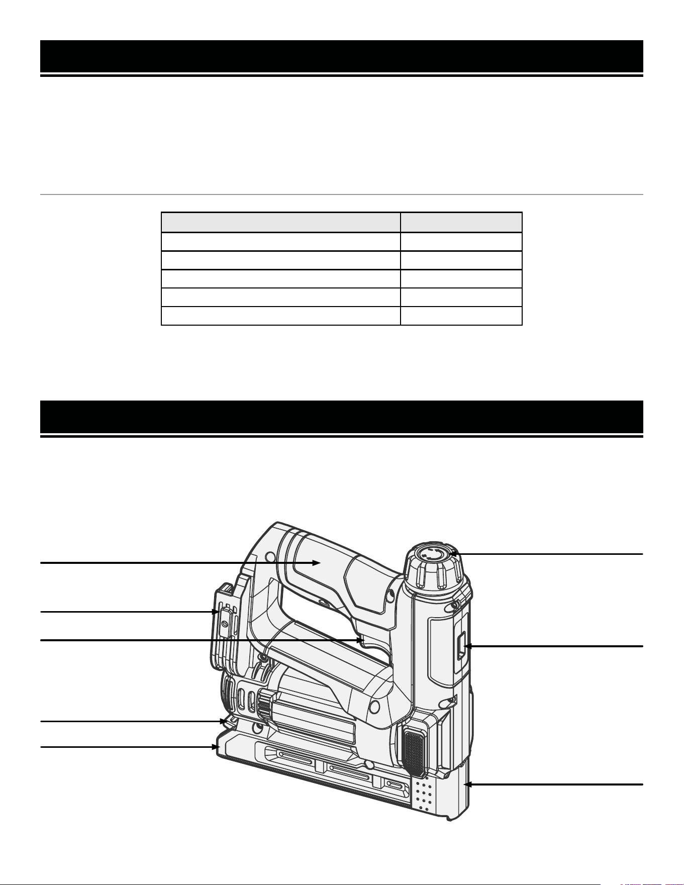
Refer to the following diagram to become familiarized with all the parts and controls of your tool. The components
will be referred to later in the manual for assembly and operation instructions.
KNOW YOUR BRAD NAILER & STAPLER
Description Quantity
Nailer and Stapler 1
18-Gauge Brad Nails 100
T50 Crown Staples 400
*20V 2.0Ah Battery 1
*20V 2A Charger 1
*Only included with model number 20538.
Power Trigger
9
Battery Port
Depth Adjustment Knob
Magazine
Magazine Latch
Wiring Guide
Handle
Depth Indicator

10
WARNING! To avoid injury from accidental startups, be sure that the tool is switched OFF and the battery is
removed from the tool before inspecting the unit, making adjustments, or changing accessories.
ASSEMBLY & ADJUSTMENTS
CHARGING THE BATTERY PACK
The 20V battery pack for this tool is supplied in a low charge condition to prevent possible problems, and must be
charged completely before you use the tool for the first time.
1. Connect charger to a 120V, 60Hz AC outlet. The green lights on the charger will illuminate, indicating that the
charger is powered.
2. Slide the battery all the way into the charger port until it clicks. The red light on the corresponding charger port
will illuminate, indicating that the battery is charging.
Charging Indication:
• Solid Green: Ready to Charge
• Solid Red: Charging
• Solid Green: Charged
3. When the battery is charged, the red light will turn off and the green light will turn on. Remove the battery from
the charger and unplug the charger from the power supply.
NOTE: Battery will not reach full charge the first time it is charged. Allow several cycles for the battery to fully
charge. The battery pack may become warm while charging; this is normal. If the battery is hot after continuous use
in the tool, allow it to cool to room temperature before charging. This will prolong the life of your battery.
The battery pack is equipped with three LED battery life indication lights. Press and hold the power button on the
front or rear of the battery to check the battery’s charge status.
Battery Life Indication:
• Three Lights: The battery is fully charged.
• Two Lights: The battery is about 60% charged.
• One Light: The battery is almost out of power and needs to be charged.
INSERTING AND REMOVING THE BATTERY
1. To install the battery, slide the battery pack into the battery port. Make sure the release latch on the rear side of
the battery pack snaps into place and the battery is secure before beginning operation.
2. To remove the battery pack, press the battery release latch on the front of the battery and pull the battery pack out.
ASSEMBLY & ADJUSTMENTS
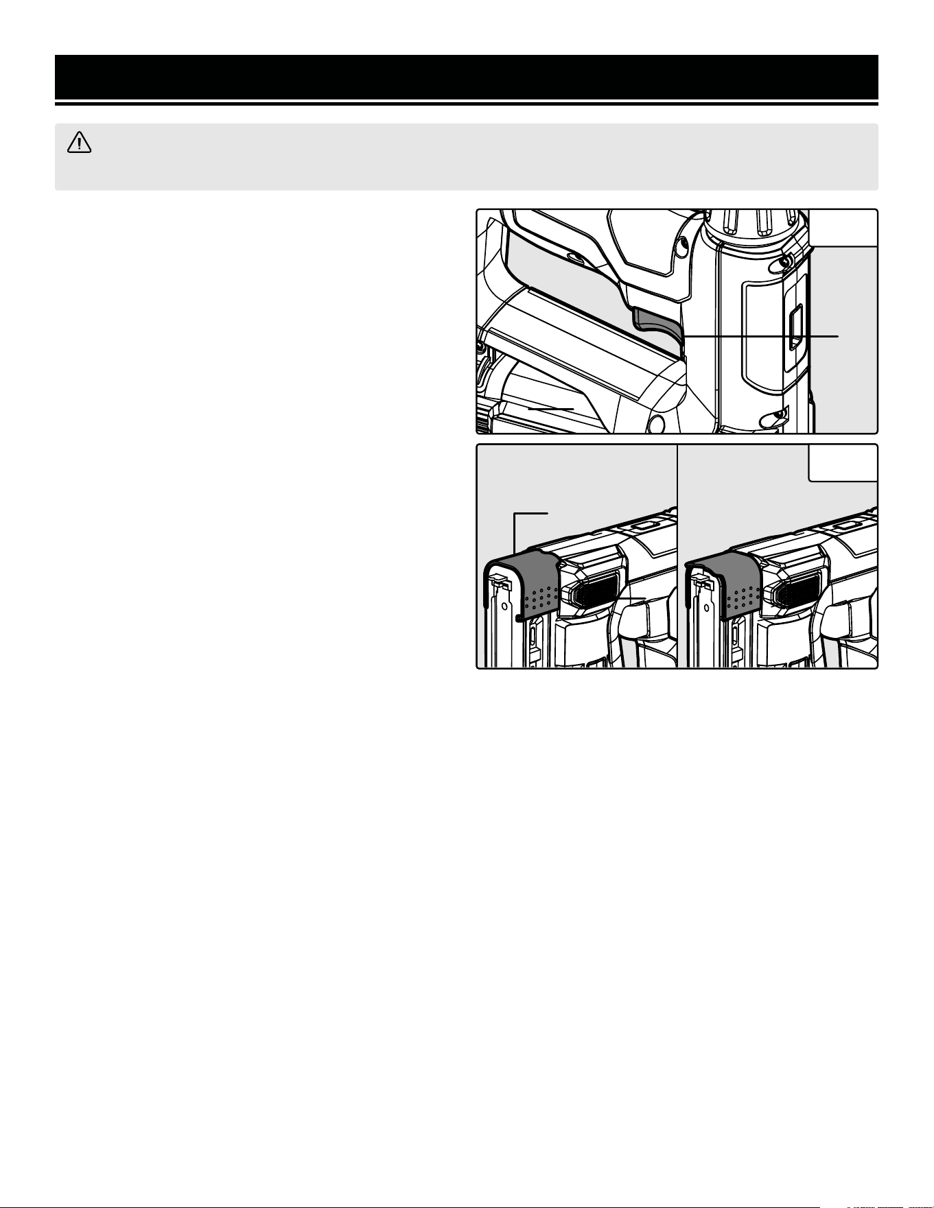
Fig. 1
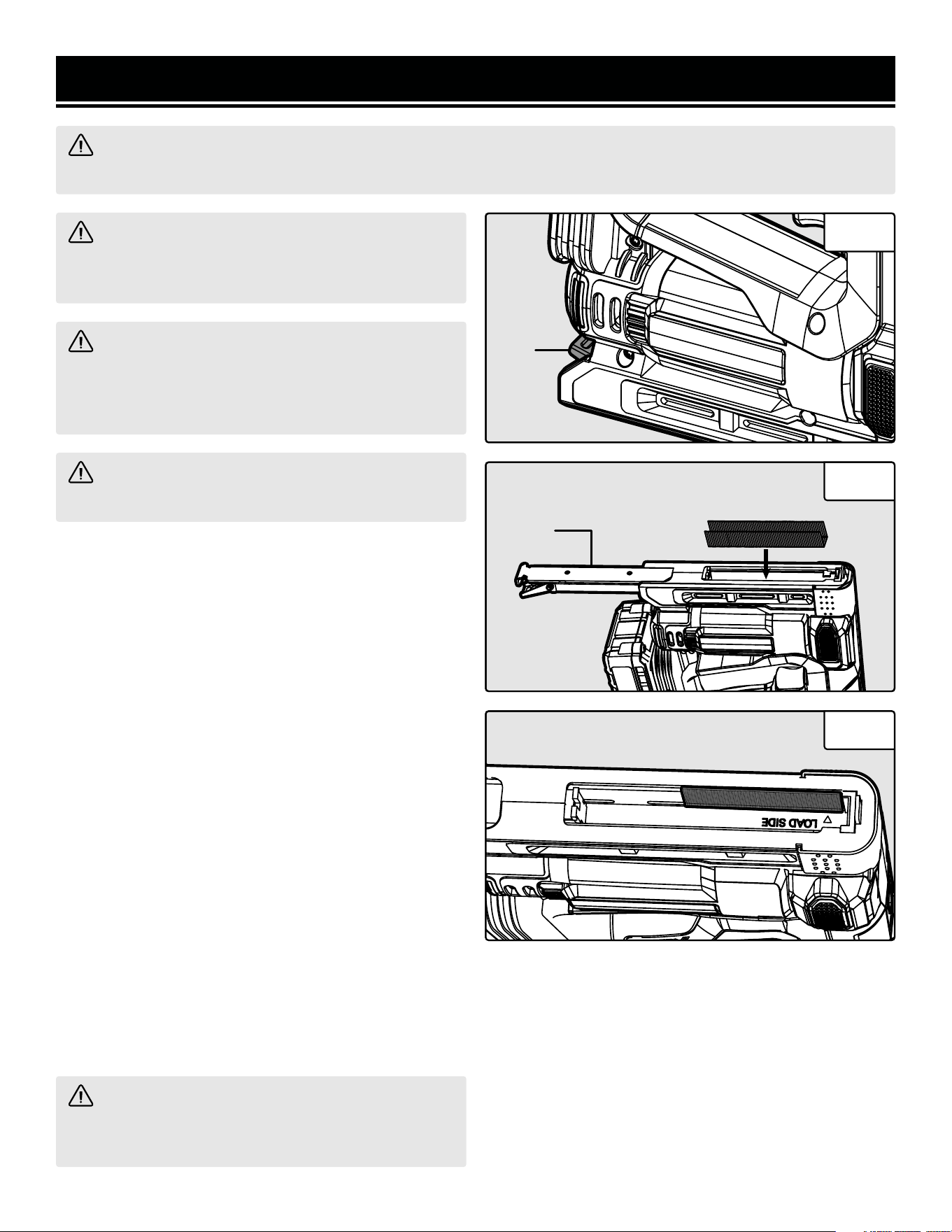
LOADING & UNLOADING STAPLES
This tool accepts T50 crown staples with a length of 1/4
in. to 9/16 in.
1. Unlock the magazine latch (Fig. 1 - 1) and pull back on
the magazine cover (Fig. 2 - 1).
2. Insert a row of staples into the opening behind the
nose as shown in Fig. 2.
4. Push the loaded magazine back into the unit until it
clicks into place.
LOADING & UNLOADING NAILS
This tool accepts 18-gauge brad nails with a length of
5/8 in.
1. Unlock the magazine latch (Fig. 1 - 1) and pull back on
the magazine cover (Fig. 2 - 1).
2. Insert a row of nails into the opening behind the nose
as shown in Fig. 3. Be sure to place the nails on the side
marked “LOAD SIDE”. The nail heads should sit perfectly
against the internal groove.
3. Push the loaded magazine back into the unit until it
clicks into place.
WARNING! To avoid injury from accidental startups, make sure that the tool is OFF and the battery is re-
moved when assembling the tool or when making any adjustments.
WARNING! To avoid injury from accidental start-
ups, make sure that the tool is OFF and the battery is
removed from the nailer when loading fasteners.
WARNING! Only use fasteners that are recom-
mended for the tool. Using fasteners that do not
match the specifications of the tool can result in per-
sonal injury or damage to the tool.
WARNING! Hold the nailer with the magazine at
your side. NEVER point the tip at yourself or others.
Fig. 2
Fig. 3
WARNING! Always unload the fasteners once
you’ve completed operation. The tool should not be
loaded when it is not in use.
11
1
1
ASSEMBLY & ADJUSTMENTS
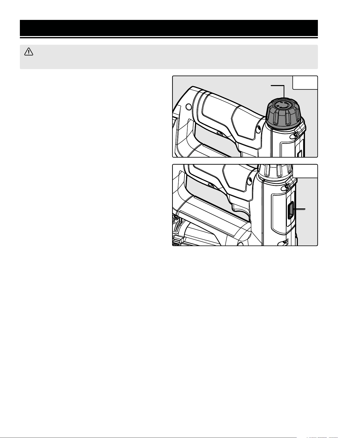
DEPTH ADJUSTMENT
Increase or decrease the drive force and the depth of the
fastener based on your specific operation.
• To increase the drive force and depth: Rotate the
depth adjustment knob (Fig. 4 - 1) clockwise.
• To decrease the drive force and depth: Rotate the
depth adjustment knob counterclockwise.
The line on the depth indicator (Fig. 5 - 1) will move
when the depth adjustment knob is rotated. The maxi-
mum drive force will show the line closer to the nose
of the nailer and stapler. The minimum drive force will
show the line closer to the depth adjustment knob.
WARNING! To avoid injury from accidental startups, make sure that the tool is OFF and the battery is re-
moved when assembling the tool or when making any adjustments.
12
Fig. 4
Fig. 5
1
1
1
OPERATION
FIRING FASTENERS
1. Check that the fasteners have been loaded into the
magazine and that the magazine is securely locked in
place.
2. Attach the battery to the battery terminal.
3. Test the driving depth on a scrap piece of wood. If
the fasteners penetrate too deeply, decrease the firing
depth. If the fasteners penetrate too shallowly, increase
the firing depth.
4. Hold the nailer upright on the workpiece and position
the nose where the fastener will be driven.
5. Carefully press down and pull the power trigger (Fig.
6 - 1) to drive a fastener.
6. Release the trigger, lift the tool off the workpiece and
reposition it where the next fastener will be driven. Re-
peat step 5 to drive another fastener.
7. After the operation has been completed, turn the tool
OFF and remove the battery. Remove all the fasteners
from the nailer. Store the nailer in a safe and secure loca-
tion, out of reach from children.
USING THE WIRING GUIDE
Your tool comes with a wiring guide (Fig. 7 - 1) that helps
with attaching wire to a wooden frame or workpiece.
Always use a scrap piece that is the same material as the
workpiece to test the drive force of the fastener.
When not in use, the wiring guide may be stored on the
tool with the notched edge facing away from the nose of
the nailer and stapler.
To install the accessory:
1. Make sure that the tool is OFF and the battery is re-
moved from the battery port.
2. Install the wiring guide so that the notched edge is
pointed downward towards the nose of the nailer and
stapler as shown in Fig. 7.
3. Align the wire between the notch in the wiring guide
and press the power trigger to fasten the wire to the
workpiece.
Fig. 6
WARNING! Using this type of tool can be dangerous. To reduce the risk of injury, always wear proper eye
and hearing protection when operating this tool. Stay alert and keep proper balance at all times.
Fig. 7
1
1
1
1
13
Wiring Guide
In Use
Wiring Guide
Not In Use

MAINTENANCE
CLEANING
Keep tools clean for better and safer performance. Wipe the tool clean with a damp towel and mild soap. Blow the
tool clean using compressed air, then use non-flammable cleaning solutions to wipe exterior of the tool as neces-
sary. Do not soak tool with cleaning solutions. Such solutions can damage internal parts.
INSPECTION
1. Inspect trigger and safety mechanism to assure system is complete and functional (no loose or missing parts, no
binding or sticking parts). Do not operate if any portion of the tool, trigger, or nose is damaged, inoperable, discon-
nected, or altered. Damaged or missing parts should be repaired or replaced before use.
2. Keep all screws tight. Loose screws can cause personal injury or damage the tool.
STORAGE
Store the unit and accessories in a dark, dry, frost-free and well ventilated place, out of the reach of children. The
ideal storage temperature is between 50 to 86 °F (10 and 30 °C).
WARNING! To avoid injury from accidental startups, make sure that the tool is OFF and the battery is re-
moved when performing any maintenance.
OPERATION
REMOVING A JAMMED STAPLE
If the tool becomes jammed, you must remove the jammed fastened before continuing operation.
1. Make sure that tool is OFF and the battery is removed from the battery port.
2. Position the tool upside down and open the magazine.
3. Remove all unused staples from the magazine.
4. Locate the jam and remove the fastener with needle-nose pliers (not included).
14
15
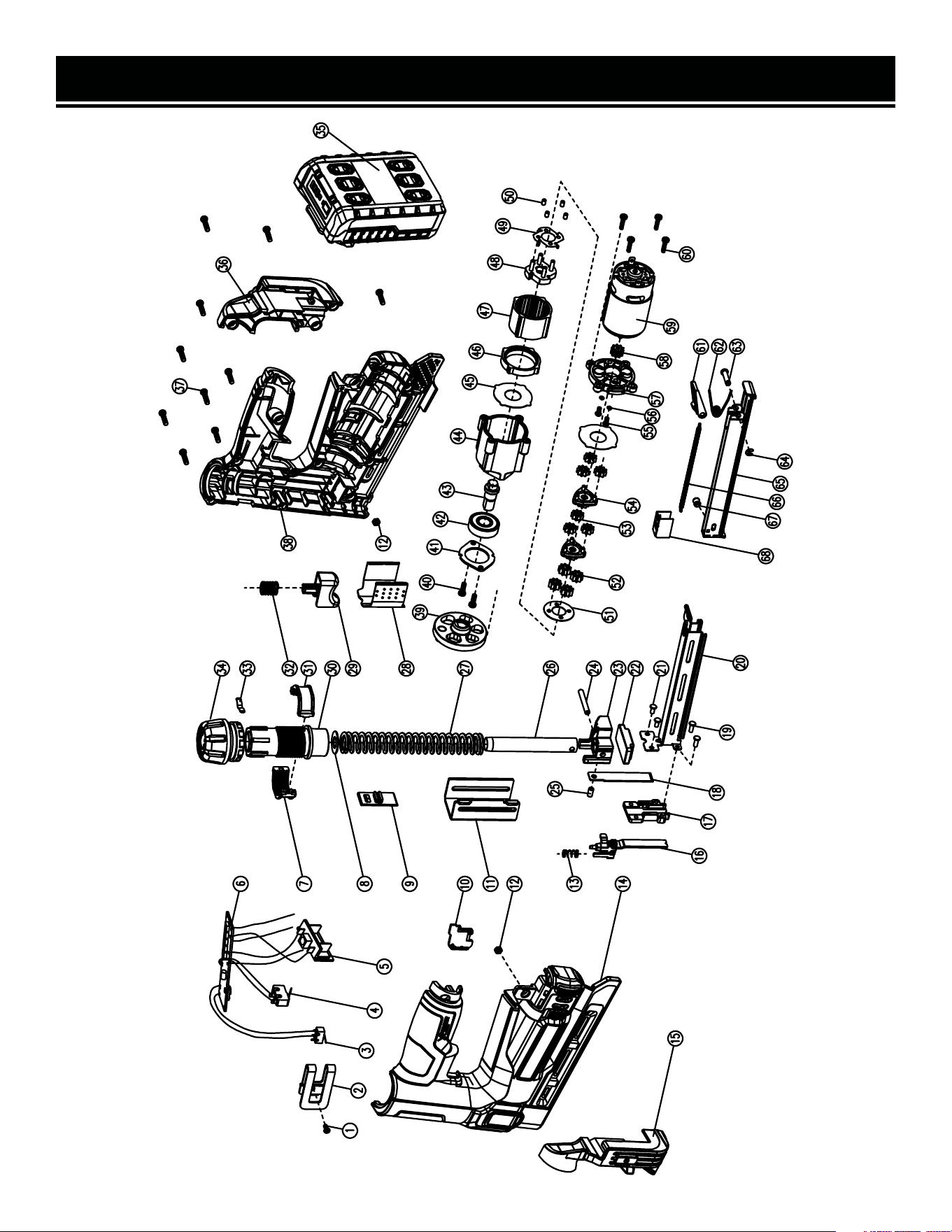
EXPLODED VIEW & PARTS LIST

16
EXPLODED VIEW & PARTS LIST
NOTE: Not all parts may be available for purchase. Parts and accessories that wear down over the course of
normal use are not covered under the warranty.
NO. PART NO. DESCRIPTION QTY.
1 20538-001 Phillips Head Screw 1
2 20538-002 Couple 1
3 20538-003 Trigger Switch 1
4 20538-004 Power Switch 1
5 20538-005 Battery Pin 1
6 20538-006 Circuit Board 1
7 20538-007 Left Threaded Collar 1
8 20538-008 Impact Gasket 1
9 20538-009 Depth Indicator 1
10 20538-010
Safety Switch Cover
Plate
1
11 20538-011 Chute 1
12 20538-012 Hexagon nuts, Grade C 2
13 20538-013
Safety Mechanism
Spring
1
14 20538-014 Left Housing 1
15 20538-015 Left Foot Board 1
16 20538-016 Safety Switch Assembly 1
17 20538-017 Muzzle 1
18 20538-018 Fastening Clip 1
19 20538-019
Flat Rivet ф3 x 8
2
20 20538-020 Outer Nail Magazine 1
21 20538-021
Flat Rivet ф3 x 6
2
22 20538-022
Vibration Dampening
Pad
1
23 20538-023 Impact Block 1
24 20538-024
Pin ф4x30
1
25 20538-025
Pin ф4x8
1
26 20538-026 Impact Guide 1
27 20538-027 Impact Spring 1
28 20538-028 Nose Guard 1
29 20538-029 Trigger 1
30 20538-030 Regulating Barrel 1
31 20538-031 Right Threaded Collar 1
32 20538-032 Trigger Spring 1
33 20538-033 Gear Locking Clip 1
34 20538-034 Depth Adjustment Knob 1
35 20538-035 20V Battery 1
NO. PART NO. DESCRIPTION QTY.
36 20538-036 Right Battery Housing 1
37 20538-037 Tapping Screw ST3.5x14 10
38 20538-038 Right Housing 1
39 20538-039 Flywheel Assembly 1
40 20538-040 Tapping Screw ST3.5x10 2
41 20538-041 Bearing Bracket 1
42 20538-042 Ball Bearing 1
43 20538-043 Output Shaft 1
44 20538-044 Gearbox Housing 1
45 20538-045 Gear Box Gasket 2
46 20538-046 Ratchet Cover 1
47 20538-047 Inner Gear Ring 1
48 20538-048 Ratchet Mechanism 1
49 20538-049 Self-Locking Clip 1
50 20538-050
Cylinder Pin ф3 x 5
4
51 20538-051 Ratchet Gasket 1
52 20538-052
Three-Stage Planetary
Gear
4
53 20538-053
First Stage Planetary
Gear
6
54 20538-054
Planetary Gear Disk
Assembly
2
55 20538-055
Phillips Head Screw
M3x8
2
56 20538-056
Washer ф3
2
57 20538-057 Motor Cover 1
58 20538-058 Motor Gear 1
59 20538-059 Motor 1
60 20538-060 Tapping Screw ST2.9x12 4
61 20538-061 Nail Slot Clip 1
62 20538-062 Torsion Spring 1
63 20538-063 Grooved Fastening Pins 1
64 20538-064
E-Type Circlip ф3
1
65 20538-065 Inner Nail Magazine 1
66 20538-066 Nail Magazine Spring 1
67 20538-067 Pin Guide Roller 1
68 20538-068 Nail Feeder 1

17
WARRANTY STATEMENT
WEN Products is committed to building tools that are dependable for years. Our warranties are consistent with this
commitment and our dedication to qualit
y.
LIMITED WARRANTY OF WEN PRODUCTS FOR HOME USE
GRE
AT LAKES TECHNOLOGIES, LLC (“Seller”) warrants to the original purchaser only, that all WEN
consumer
power tools will be free from defects in material or workmanship during personal use for a period of two (2) years
used
for professional or commercial use. Purchaser has 30 days from the date of purchase to report missing or
damaged parts.
SELLER’S
SOLE OBLIGATION AND YOUR EXCLUSIVE REMEDY under this Limited Warranty and, to the extent per-
mitted
by law, any warranty or condition implied by law, shall be the replacement of parts, without charge, which a
re
defective
in material or workmanship and which have not been subjected to misuse, alteration, careless handling,
misrepair
, abuse, neglect, normal wear and tear,
improper maintenance, or other conditions adversely affecting the
Product
or the component of the Product, whether by accident or intentionally, by persons other than Seller. To
make
a claim under this Limited Warranty, you must make sure to keep a copy of your proof of purchase that
clearly
-
dor
of Great Lakes Technologies, LLC. Purchasing through third party vendors, including but not limited to garage
sales,
pawn shops, resale shops, or any other secondhand merchant, voids the warranty included with this
product.
Contact [email protected] or 1-847-429-9263 with the following information to make arrangements:
your
shipping address, phone number, serial number, required part numbers, and proof of purchase. Damaged
or
defective parts and products may need to be sent to WEN before the replacements can be shipped out.
-
turning
a product for warranty service, the shipping charges must be prepaid by the purchaser. The product
must
be
shipped in its original container (or an equivalent), properly packed to withstand the hazards of shipment. The
product
must be fully insured with a copy of the proof of purchase enclosed. There must also be a description of
the
will be returned and shipped back to the pur
chaser at no charge for addresses within the contiguous United States.
THIS
LIMITED WARRANTY DOES NOT APPLY TO ITEMS THAT WEAR OUT FROM REGULAR USAGE OVER TIME,
INCLUDING
BELTS, BRUSHES, BLADES, BATTERIES, ETC. ANY IMPLIED WARRANTIES SHALL BE LIMITED IN
DUR
ATION TO TWO (2) YEARS FROM DATE OF PURCHASE. SOME STATES IN THE U.S. AND SOME CANADIAN
PROVINCES
DO NOT ALLOW LIMITATIONS ON HOW LONG AN IMPLIED WARRANTY LASTS, SO THE ABOVE LIMI-
TAT
ION MAY NOT APPLY TO YOU.
IN
NO EVENT SHALL SELLER BE LIABLE FOR ANY INCIDENTAL OR CONSEQUENTIAL DAMAGES (INCLUDING
BUT
NOT LIMITED TO LIABILITY FOR LOSS OF PROFITS) ARISING FROM THE SALE OR USE OF THIS PRODUCT.
SOME ST
ATES IN THE U.S. AND SOME CANADIAN PROVINCES DO NOT ALLOW THE EXCLUSION OR LIMITAT
ION
OF
INCIDENTAL OR CONSEQUENTIAL DAMAGES, SO THE ABOVE LIMITATION OR EXCLUSION MAY NOT APPLY
TO YOU.
THIS
LIMITED WARRANTY GIVES YOU SPECIFIC LEGAL RIGHTS, AND YOU MAY ALSO HAVE OTHER RIGHTS
WHICH
VARY FROM STATE TO STATE IN THE U.S., PROVINCE TO PROVINCE IN CANADA AND FROM COUNTRY
TO COUNT
RY.
THIS
LIMITED WARRANTY APPLIES ONLY TO ITEMS SOLD WITHIN THE UNITED STATES OF AMERICA, CANA-
DA
AND THE COMMONWEALTH OF PUERTO RICO. FOR WARRANTY COVERAGE WITHIN OTHER COUNTRIES,
CONT
ACT THE WEN CUSTOMER SUPPORT LINE. FOR WARRANTY PARTS OR PRODUCTS REPAIRED UNDER
W
ARRANTY SHIPPING TO ADDRESSES OUTSIDE OF THE CONTIGUOUS UNITED STATES, ADDITIONAL S
HIPPING
CHARGES MAY APPLY.

18
NOTES

19
NOTES

V. 2024.08.29
THANKS FOR
REMEMBERING