3 - 1
Cub Cadet 3000
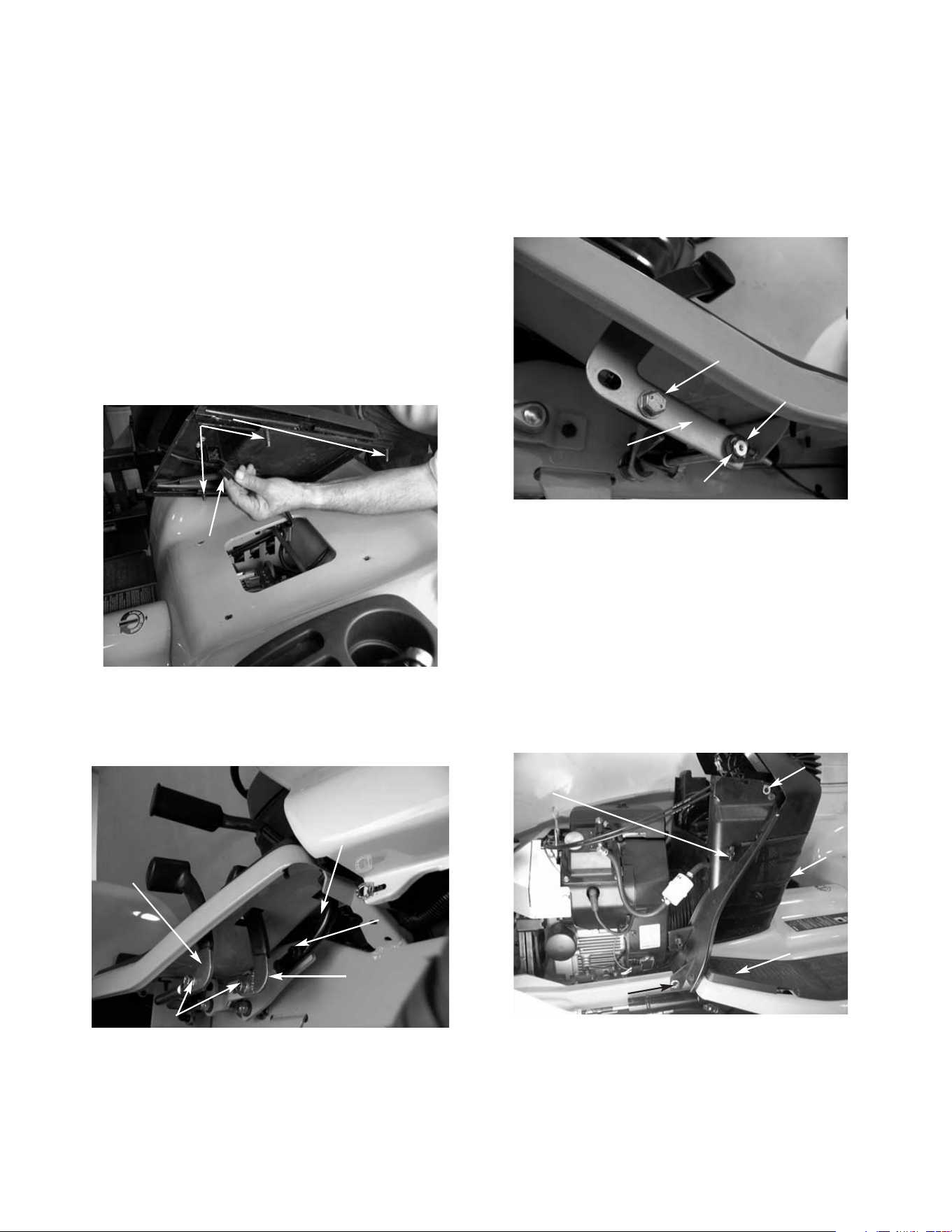
1. Slide the seat back and remove the front two pan
torx head screws using a T30 torx.
2. Slide the seat forward and remove the rear two
pan torx head screws using a T30 torx.
3. Pivot the seat assembly to the side and
disconnect the seat safety switch. See figure 1.
NOTE: Be careful not to scratch the fender with
the seat support brackets. It is advisable to use a
towel or cloth under the seat when pivoting the
seat.
4. Remove the seat from the tractor. See figure 1.
5. Remove all the hex bolts securing the three foot
pedals to the right side of the unit using a 9/16
socket. See figure 2.
Fender Assembly Removal and Reinstallation
FIGURE 1.
Torx Screws
Seat Safety
Switch
FIGURE 2.
Hex Bolts
Hex
Bolts
Reverse
Pedal
Forward
Pedal
Brake
Pedal
FIGURE 3.
Hex Bolt
Differential Lock
Out Pedal
Nylon Flange
Bearing
E-Clip
6. Remove the hex bolt securing the differential lock
out pedal on the left side of the unit using a 9/16
socket. Remove the “E” clip and the nylon flange
bearing from the pivot shaft.
FIGURE 4.
Wing
Nut
Side Panel Latch
Dash
Screen
Side Panel Latch
Rubber Foot Pads
7. Remove both rubber floor pads from the running
boards. See figure 4.
8. Lift the hood and remove the battery cover.
9. Remove both side panels from the tractor by
raising the latches horizontally and turning the
latches 1/4 turn. See figure 4.
10. Loosen all four plastic wing nuts holding the dash
panel screen in place. See figure 4.
11. Pull the dash screen towards the rear of the unit
and out of the dash panel. See figure 4.
3 - 2
Cub Cadet 3000
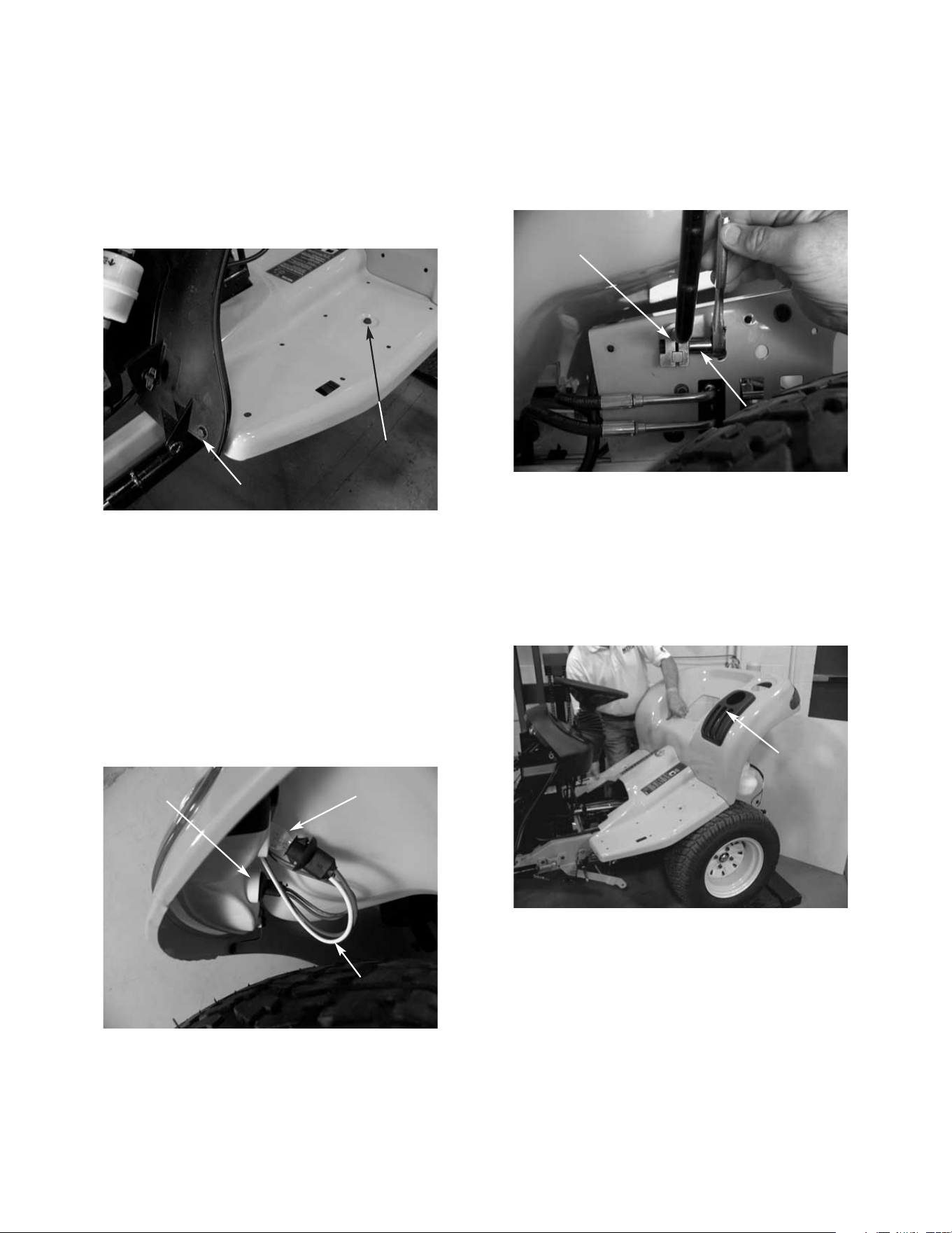
12. Remove all four running board hex bolts from the
tractor using a 1/2” socket. See figure 5.
NOTE: There are two bolts fastening the running
boards to the frame where the foot pads connect
and there are two bolts fastening the running
boards to the dash panel.
FIGURE 5.
Hex Bolt
Hex Bolt
FIGURE 6.
Tail
Light
Reverse
Light
White Wire
for Reverse
13. Remove the fuel cap.
14. Remove the tail light sockets from the tail light
assemblies by pushing in on the sockets gently
and twisting a 1/4 turn. See figure 6.
NOTE: When pulling the sockets out of the tail
light assemblies, it is very important to make sure
the light bulbs come straight out, or the light bulbs
will fall into the tail light assemblies. Also, note
the color of the wires for reinstallation. The white
wires go to the reverse lights. See figure 6.
FIGURE 7.
Hydraulic Lift
Handle Clamp
1/2" Socket
17. Remove the lift handle from the tractor through
the slot in the flap. See figure 8.
NOTE: If the lever is not removed at this time,
damage may occur to the lift knob.
18. Raise and remove the fender assembly.
FIGURE 8.
Slot for
Lift Handle
15. Raise the rear fender high enough to access the
hydraulic lift handle clamp. See figure 7.
16. Loosen the clamp connecting the hydraulic lift
handle to the center lift valve using a 1/2” socket.
19. Reinstall the fuel cap.