INSTALLATION AND OPERATING INSTRUCTIONS
WARNING: If the information in this manual is not followed exactly, a re or
explosion may result causing property damage, personal injury, or loss of life.
Do not store or use gasoline or other ammable vapors and liquids or other
combustible materials in the vicinity of this or any other appliance.
WHAT TO DO IF YOU SMELL GAS:
• Do not try to light any appliance.
• Do not touch any electrical switch; do not use any phone in your building.
• Immediately call your gas supplier from a neighbor’s phone. Follow the gas
supplier’s instructions.
• If you cannot reach your gas supplier, call the re department.
Installation and service must be performed by a qualied licensed installer,
service agency or the gas supplier.
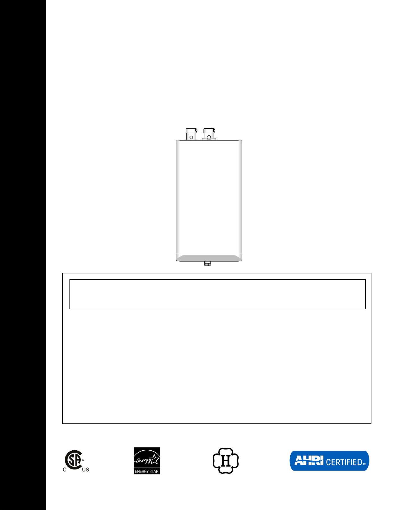
HIGH EFFICIENCY CONDENSING
HEATING BOILER
99,000 & 120,000 Btu/hr Models
(Natural Gas or Propane)

INSTALLATION AND OPERATION INSTRUCTIONS
2
HEATING BOILERS 99 & 120
WARNING
If the information in this
manual is not followed
exactly, a re or explosion
may result causing property
damage, personal injury, or
loss of life.
SAFETY CONSIDERATIONS
Installation, start-up and servicing of the unit must be done with due
care and attention, and must only be performed by competent, qualied,
licensed and trained heating technicians. Failure to read and comply with
all instructions and applicable National and local codes may result in
hazardous conditions that could result in property damage and injury to
occupants which in extreme cases might result in death.
HAZARDS & PRECAUTIONS
Supplied with the unit - The unit is shipped with an accessory parts kit
consisting of the following items:
• 1 x Wall Mounting Bracket Kit - Part # P-081344
• 1 x Condensate Trap Assembly
• 1 x Pressure Relief valve, 3/4" NPT, 30psi
• 1 x Outdoor Temperature Sensor
• 1 x Documentation set
• 1 x Propane Conversion Kit Part # P-081034 (99,000 Btu/hr) or
Part # P-081054 (120,000 Btu/hr)
WARNING
Points out a potentially
hazardous situation which
must be avoided to prevent
serious injury or death.
CAUTION
Points out a potentially
hazardous situation which
must be avoided to prevent
possible moderate injury and/
or property damage
NOTE
Points out installation,
maintenance and operation
details that will result in
enhanced eciency, longevity
and proper operation of your
unit.
DANGER
Points out an imminently
hazardous situation which
must be avoided in order to
prevent serious injury or
death.
BEST PRACTICES
Points out recommendations
for better installation.
3
INSTALLATION AND OPERATING INSTRUCTIONS
HEATING BOILERS 99 & 120
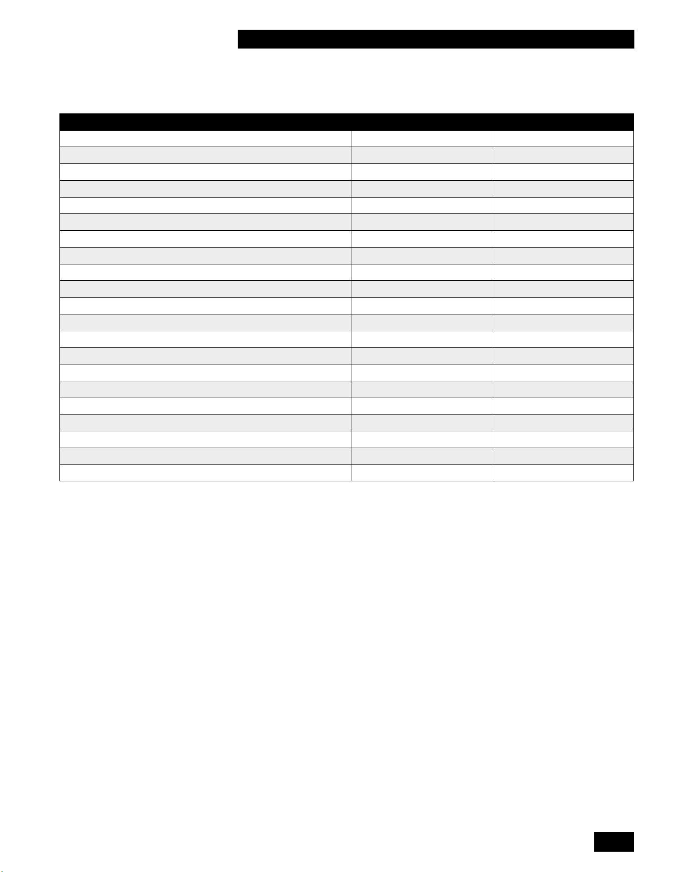
SPECIFICATIONS
SPECIFICATION 99,000 BTU 120,000 BTU
CSA Input (Natural Gas or Propane*) – MBH 15.5 - 99 13.65 - 120
CSA Input (Natural Gas or Propane*) – KW 4.5 - 29.0 4.0 - 35.2
CSA Output – MBH 14.8 - 89 13.0 - 108
CSA Output - KW 4.3 - 26.1 3.8 - 31.7
A.F.U.E 96% 95%
Min Gas Pressure (Nat. Gas or Propane*) – inch w.c. 4 4
Max Gas Pressure (Nat. Gas or Propane*) – inch w.c. 14 14
Power (120Vac/60Hz) - Watts @ full re with internal pump 126 126
Weight (empty) – lbs/Kg 85 / 39 85 / 39
Pressure Vessel water content – USG/Liters 0.5 / 1.9 0.5 / 1.9
Max boiler ow rate - GPM (LPM) 10 (37.8) 11 (41.6)
Min boiler ow rate - GPM (LPM) 2 (7.6) 2 (7.6)
Max Operating Pressure – Space Heating Coil - (psig)
† 43.5 43.5
Approved installation altitude - ASL (ft) 10.000 10.000
Ambient Temperature – Low (°F/°C) 32 / 0 32 / 0
Ambient Temperature – High (°F/°C) 122 / 50 122 / 50
Max relative humidity (non-condensing) 90% 90%
Min water Temperature (°F/°C) 51 / 10 51 / 10
Max water Temperature (°F/°C) 194 / 90 194 / 90
Max equivalent vent length 3" (each side) 120' 120'
Max equivalent vent length 2" (each side) 65'
ǂ 65''ǂ
* Natural Gas units require a Propane conversion kit included with unit (see page #3-2, Table 9). Propane (LP) units require a Natural Gas conversion kit (see page
#3-2, Table 9) to be ordered separately if converting a Propane unit to Natural Gas.
† units are shipped with 30 psig pressure relief valve
ǂ The input rate will derate as vent length increases. Reference Table 3: Maximum Exhaust Venting Length in section 1.4.3 for details.

INSTALLATION AND OPERATION INSTRUCTIONS
4
HEATING BOILERS 99 & 120
CONTENTS
1.0 INSTALLATION ..........................................1-1
1.1 GENERAL........................................................1-1
1.2 CODE REQUIREMENTS ............................................1-3
1.3 LOCATION .......................................................1-3
1.3.1 Removing/installing the front panel .................................1-5
1.4 EXHAUST VENTING AND AIR INTAKE .................................1-6
1.4.1 Applications ...................................................1-9
1.4.2 Exhaust Vent Material ...........................................1-9
1.4.3 Vent Travel ...................................................1-10
1.4.4 Venting Passage Through Ceiling and Floor .........................1-12
1.4.5 Rooftop Vent Termination........................................1-12
1.4.6 Sidewall Vent Termination .......................................1-14
1.4.7 “Direct Vent” Combustion Air Intake Piping .........................1-18
1.4.8 “Indoor Air” Combustion Air Intake .................................1-19
1.4.9 Closet Installations .............................................1-19
1.5 CONDENSATE REMOVAL..........................................1-20
1.5.1 Condensate Trap ..............................................1-20
1.5.2 Installing the Condensate Trap....................................1-20
1.5.3 Further Installation Details . . . . . . . . . . . . . . . . . . . . . . . . . . . . . . . . . . . . . . . 1-21
1.6 WATER PIPING - SPACE HEATING ..................................1-23
1.6.1 General Piping Considerations....................................1-23
1.6.2 Basic Heating Piping Arrangements................................1-27
1.7 GAS PIPING .....................................................1-32
1.8 ELECTRICAL CONNECTIONS ......................................1-33
1.8.1 120VAC Line Voltage Hook-up....................................1-33
1.8.2 Accessing Controller Terminal Strip ................................1-33
1.8.3 External probe type low water cuto device..........................1-35
1.8.4 Power Quality and Electrical Protection .............................1-35
1.8.5 Zone Valve and Zone Pump Connections ...........................1-36
1.8.6 Thermostat / Sensor Wiring ......................................1-36
2.0
UNIT SYSTEM OPERATION .....................................2-1
2.1 GENERAL........................................................2-1
2.2 CONTROL .......................................................2-2
2.3 INSTALLER INTERFACE ............................................2-2
2.3.1 Turning Appliance ON/OFF .......................................2-2
2.3.2 Programming Mode.............................................2-3
2.4 DOMESTIC HOT WATER............................................2-5
2.4.1 Domestic Hot Water with an Indirect Water Heater .....................2-5
2.5 SPACE HEATING ..................................................2-5
2.5.1 Overview .....................................................2-5
2.6 SEQUENCE OF OPERATION ........................................2-6
2.7 ACCESSING THE INFORMATION MENU ...............................2-7
2.8 RESETTING THE MAINTENANCE COUNTER ...........................2-9
3.0 STARTUP & COMMISSIONING ..............................3-1
3.1 LIGHTING & SHUTTING DOWN THE UNIT .............................3-1
3.2 PRIOR TO START-UP ..............................................3-2
3.2.1 Pre-Ignition Checks .............................................3-2

5
INSTALLATION AND OPERATING INSTRUCTIONS
HEATING BOILERS 99 & 120
3.2.2 Test Ignition Safety Shuto .......................................3-2
3.3 COMMISSIONING .................................................3-2
3.4 FUEL CONVERSION ...............................................3-4
3.4.1 Gaining access to combustion chamber, burner removal instructions .......3-5
4.0 MAINTENANCE..........................................4-1
4.1 UNIT MAINTENANCE ..............................................4-1
4.1.1 General Care ..................................................4-1
4.1.2 Inspection.....................................................4-1
4.1.3 Venting .......................................................4-1
4.1.4 Condensate Trap ...............................................4-1
4.1.5 Burner . . . . . . . . . . . . . . . . . . . . . . . . . . . . . . . . . . . . . . . . . . . . . . . . . . . . . . . 4-1
4.1.6 Heat Exchanger . . . . . . . . . . . . . . . . . . . . . . . . . . . . . . . . . . . . . . . . . . . . . . . . 4-2
4.1.7 Pump ........................................................4-2
4.1.8 Gas Piping ....................................................4-2
4.1.9 Control Module.................................................4-2
4.1.10 Water Heating System ..........................................4-2
4.1.11 Freeze Protection ..............................................4-2
4.1.12 System Treatment .............................................4-3
4.1.13 Relief Valve - Maintenance and Testing .............................4-3
4.1.14 Fan removal instructions ........................................4-3
4.1.15 Fan installation instructions ......................................4-4
4.1.16 Cleaning the Condensate Trap....................................4-4
4.1.17 Reset the Maintenance Counter...................................4-6
4.1.18 Winterization..................................................4-6
5.0 TROUBLESHOOTING .....................................5-1
5.1 PRELIMINARY CHECKS ............................................5-1
5.2 ELECTRONIC COMPONENTS .......................................5-2
5.2.1 Temperature Sensors............................................5-2
5.2.2 Fan/Blower ....................................................5-2
5.2.3 Cabinet Sensors................................................5-3
5.2.4 Thermostat Connections .........................................5-3
5.2.5 Water Pressure Sensor-Type Low Water Cut O (LWCO)................5-3
5.2.6 Flue Gas Temperature Sensor .....................................5-4
5.2.7 Outdoor Sensor ................................................5-4
5.2.8 DHW Tank Sensor ..............................................5-4
5.3 FAULTS AND NOTIFICATIONS .......................................5-5
5.3.1 Fault Codes ...................................................5-5
5.3.2 Notication Codes ..............................................5-9
5.4 OTHER FAULTS ..................................................5-11
5.4.1 No heat (space heating).........................................5-11
5.4.2 Space heating does not reach the correct temperature .................5-11
5.4.3 Space heating system remains too warm ...........................5-12
5.4.4 Burner ignites loudly............................................5-12
5.4.5 Burner resonates ..............................................5-12
6.0 REPLACEMENT KITS .....................................6-1
7.0 WIRING DIAGRAMS ......................................6-3
INSTALLATION & COMMISSIONING REPORT..............................6-5
SERVICE RECORD ...................................................6-6
NOTES ............................................................6-8

INSTALLATION AND OPERATION INSTRUCTIONS
6
HEATING BOILERS 99 & 120
PRE-INSTALLATION CHECK
Carefully consider clearances and access, vent travel and termination, gas
supply, condensate removal and combustion air supply.
Consider the following:
• Install the unit in areas where the combustion air source is free of
contamination. Exposure to corrosive chemical fumes such as chlorinated
and/or uorinated hydrocarbons can reduce the life of a unit. Cleaners,
bleaches, air fresheners, refrigerants, aerosol propellants, dry-cleaning uids,
de-greasers and paint-removers all contain vapors that can form corrosive
acid compounds when burned in a gas ame. Avoid airborne chlorides such
as those released with the use of laundry detergents.
• Locate the unit where water leakage will not result in damage to the area (for
example, do not install above carpeting). If you cannot nd a suitable location,
install a drain pan with an adequate drain under the appliance.
• At a new construction site, or during renovations, protect the unit from drywall
dust or other construction related contaminants.
○ Ensure combustion air is drawn from a CLEAN source (e.g. outdoors).
○ Isolate the unit from interior dust sources.
• When the unit is in operation, assess the impact of the steam plume normally
experienced at the exhaust terminal of a condensing unit. Generally, intake
and exhaust pipes should terminate at a rooftop or wall location free of
obstructions. Unit condensate is corrosive. Protective measures must be
taken to prevent corrosion damage to metal roofs or other metal building
components in contact with the condensate. Keep exhaust plumes well
away from all building air intakes including those of neighboring properties
by following all requirements of the jurisdiction having authority and this
installation manual.
• Place the exhaust outlet so it reaches 12" minimum above the down-turned
intake, to avoid ue gas contamination of the combustion air.
• For sidewall venting options: Both the inlet and exhaust terminations must
be located on the same side of the building. You can elevate both pipes
in “periscope style” after passing them through the wall to gain required
clearance above grade and snow level.
• Examine the condensate outlet to ensure proper disposal of condensate
will occur during operation. A condensate neutralizer must be installed if the
condensate will ow into a drain subject to corrosion.
• Ensure that the pressure relief valve is installed with no valves or other
means of isolation between its inlet and the unit. Pipe the relief valve with
unobstructed piping (minimum 3/4" diameter) to a safe discharge location.
• In locations where power supply quality varies or is unstable, consider
installing surge protection and power conditioners (up to and including battery
back-up uninterrupted power supply devices).
CAUTION
Care must be taken to
properly size the unit for
its intended use. Prolonged
full-re run time, over-
sizing or under-sizing,
and incorrect ow rates
through the unit can lead
to increased maintenance
costs, equipment stress and
premature failure.
WARNING
Do not use this unit if any
part has been under water.
Immediately call a qualied
service technician to inspect
the unit and to replace any
part of the control system and
any gas control that has been
under water.
DANGER
Should overheating occur
or the gas supply fails to
shut o, do not turn o or
disconnect the electrical
supply to the pump. Instead
shut o the gas supply at
a location external to the
appliance.
1-1
INSTALLATION
HEATING BOILERS 99 & 120
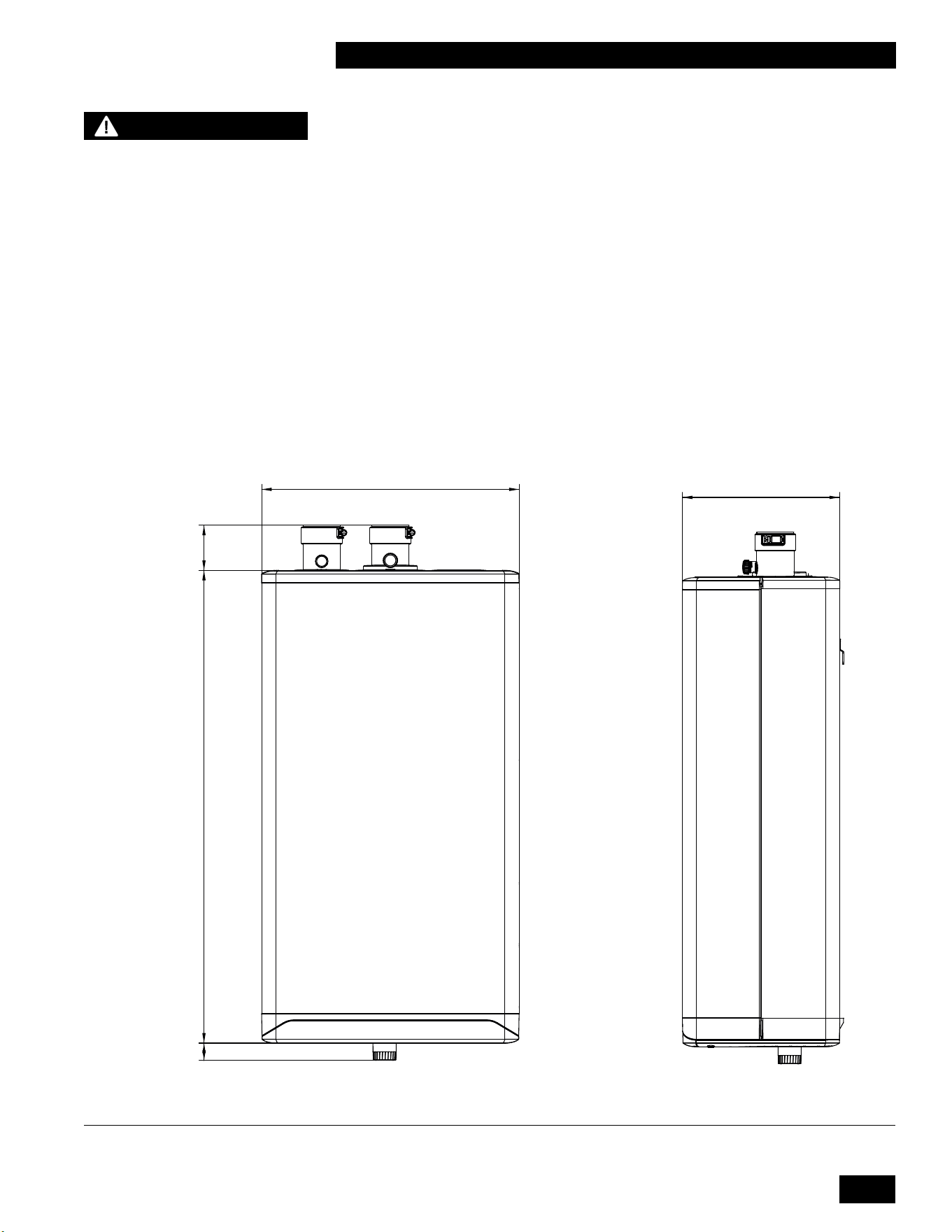
FRONT
17.7in
[450mm]
3.1in
[79mm]
32.5in
[826mm]
1.2in
[30mm]
1.0 INSTALLATION
1.1 GENERAL
This High Eciency Condensing Heating Boiler with variable input ranges (see
specication chart - page 3) is designed to be used for domestic (residential)
purposes. Domestic use is considered to be an average annual gas usage of less
than 140,000ft³ (4000 m³) for natural gas or 1,500 gallons (5,680 L) for propane.
The units are approved as “Category IV” vented appliances using Direct Vent
(sealed combustion).
Figures 1a and 1b show outer case dimensions and piping. Use this diagram to
nd a suitable location for the unit. See also Section 1.3 Location.
Figure 1a: Dimensions / Connections for Heating Boilers
NOTE
When using the unit for
non-domestic purposes,
the warranty conditions
and maintenance periods
described in this document
are no longer valid. Consult
the included warranty
documentation for details.
SIDE
10.9in
[278mm]
INSTALLATION AND OPERATION INSTRUCTIONS
1-2
HEATING BOILERS 99 & 120
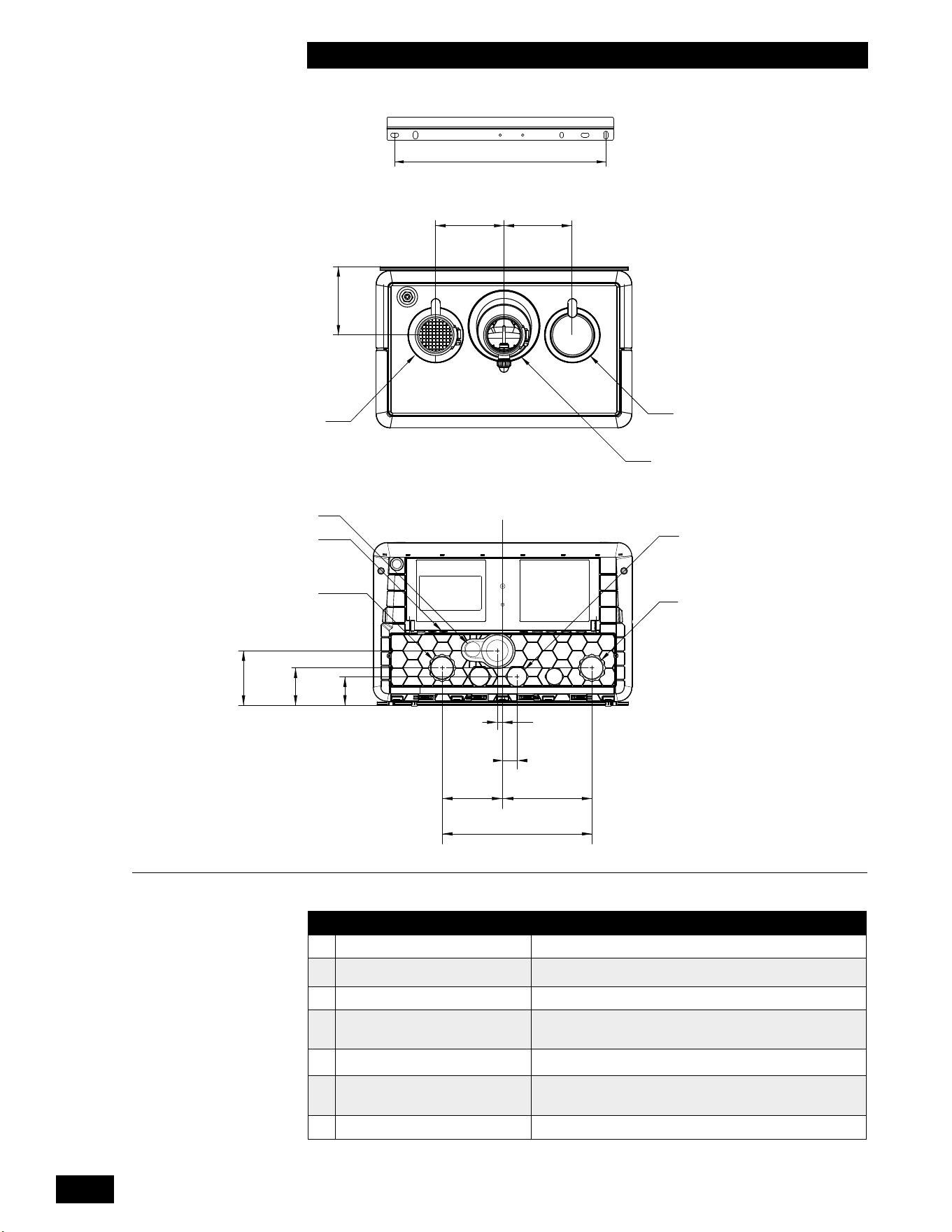
4.7in
[120mm]
4.7in
[120mm]
TOP
B (ALTERNATE)
A
B
4.7in
[120mm]
B (ALTERNATE)
B
Figure 1b: Dimensions / Connections for Heating Boilers
BOTTOM
10.2in
[260mm]
1.0in
[25mm]
2.0in
[50mm]
2.6in
[65mm]
3.7in
[95mm]
C
L
E
C
0.4in
[9mm]
F
D
G
6.1in
[155mm]
4.1in
[105mm]
16in
[406mm]
DESCRIPTION DIMENSION
A Exhaust Outlet 2" Schedule 40 PVC
B Combustion Air inlet 2" Schedule 40 PVC
C Heating Water Inlet (Return) 1" Male NPT
D
Heating Water Outlet
(Supply)
1" Male NPT
E Gas Inlet 3/4" Male NPT
F Condensate Outlet 3/4" Hose
G Control Wiring Entrance 7/16" Rubber Plug
Table 1: Connections
BRACKET

1-3
INSTALLATION
HEATING BOILERS 99 & 120
1.2 CODE REQUIREMENTS
The Heating Boiler is certied under CSA 4.9 / ANSI Z21.13.
The installation must conform to the requirements of the authority having
jurisdiction or, in the absence of such requirements, to the National Fuel
Gas Code, ANSI Z223.1/NFPA 54, (latest edition) in the US or Natural Gas
and Propane Installation Code, CSA B149.1 (latest edition) in Canada. The
installation must also conform to the Canadian Electrical Code Part 1 in Canada
or the National Electrical Code ANSI/NFPA 70 (latest edition) in the US. Where
required by the authority having jurisdiction, the installation must conform to the
Standard for Controls and Safety Devices for Automatically Fired Boilers, ANSI/
ASME CSD-1. If there is any conict, then the more stringent will apply.
1.3 LOCATION
All Heating Boiler models are designed and approved for indoor installation. Its
venting options provide exibility of location; for example, placement in an alcove,
basement, utility room or closet. The unit is approved for installation in a closet
(see Table 2 for clearances to combustibles).
Conditions for safe installations
Ensure that the surrounding conditions are between 32°F [0°C] and 122°F [50°C]
and less than 90% relative humidity.
Install the unit in areas where the combustion air source is free of
contamination.
Exposure to corrosive chemical fumes such as chlorinated and/or
uorinated hydrocarbons can reduce the life of a unit. Cleaners, bleaches,
air fresheners, refrigerants, aerosol propellants, dry-cleaning uids, de-greasers
and paint-removers contain vapors that can form corrosive acid compounds
when burned in a gas ame. Also avoid airborne chlorides such as those
released with the use of laundry detergents.
This unit must not be installed in an area where water leakage will result in
damage to the areas adjacent or below the unit. When such areas cannot be
avoided, a suitable drain pan with adequate drain must be installed under the
unit.
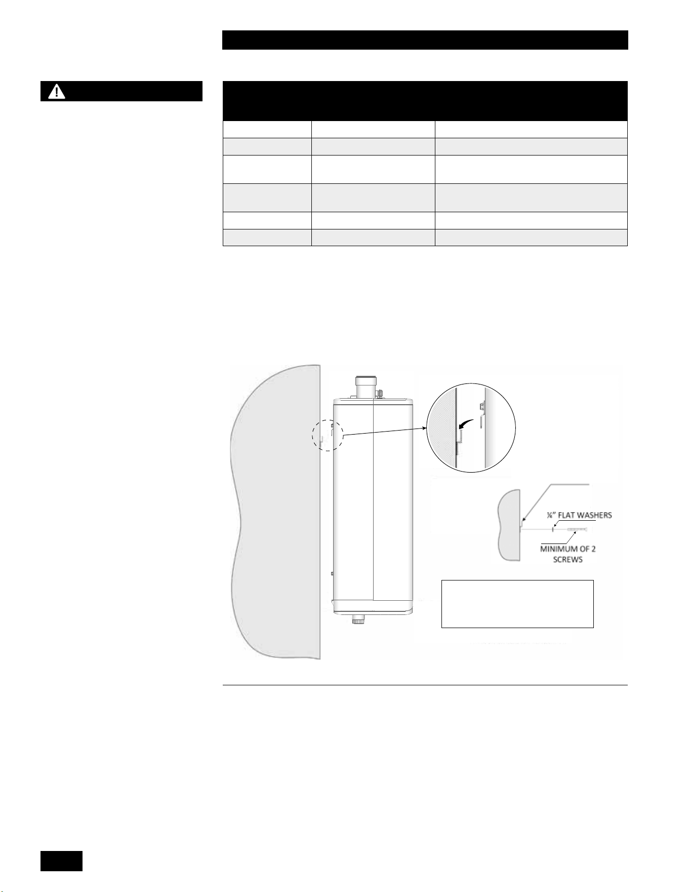
Unit fastening
Approximate weight for the unit
is
85 lbs / 39 kg. For support fasteners, use at
least two of the four supplied ¼" x 1¾" long lag screws. Installers must supply 1/4"
bolts if metal mounting systems are used. Attach the wall mounting bracket to a
structurally sound wall that is capable of supporting the combined weight of the unit
and piping components which can exceed 150 lbs. (68kg).
Unit clearance
Other factors aecting potential mounting sites:
• Ensure minimum clearance requirements for combustible materials (see
Table 2) are satised.
• For ease of access, we recommend a minimum 24" clearance at the front and
24" above. Check local codes for additional access and service clearance
requirements.
•
At a new construction site, or during renovations, protect the unit from
drywall dust or other construction related contaminants. Combustion air
must be drawn from a CLEAN source (e.g. outdoors) and the unit must be
isolated from interior dust sources.
WARNING
- Keep the unit area free
and clear of combustible
materials, gasoline, and other
ammable vapors and liquids.
- C
ombustion air must not be
drawn from areas containing
corrosive air from swimming
pools or spas, including air
directly next to outdoor pools
and spas.
- T
he unit must not be
exposed to water leaks from
piping or components located
overhead. This includes
condensation dropping from
un-insulated cold water lines
overhead.
-
Ensure the gas ignition
system components are
protected from water (dripping,
spraying, rain, etc.) during
appliance operation and when
servicing (pump replacement,
condensate trap servicing,
control replacement, etc.)
- California Proposition 65
This product contains
chemicals known to the
state of California to cause
cancer, birth defects, or other
reproductive harm.
INSTALLATION AND OPERATION INSTRUCTIONS
1-4
HEATING BOILERS 99 & 120
SURFACE
DISTANCE FROM
COMBUSTIBLE
SURFACES
RECOMMENDED DISTANCE
FOR INSTALLATION AND
SERVICE
Front 2" 24"
Rear 0" 0"
Left Side 1.5"
6" (labels may be dicult to read with
reduced clearance)
Right Side 4"
6" (labels may be dicult to read with
reduced clearance)
Top 2" 24"
Bottom 8" 24"
Table 2: Clearance from the unit cabinet
You must provide a minimum distance below the unit of 8" to allow
clearance for the supplied condensation trap assembly. More clearance will
typically be required to accommodate associated water and gas piping.
MOUNT BRACKET TO WALL,
HOOK UNIT OVER TOP.
FOR BRACKET USE TWO ¼” X 1¾” LAG
SCREWS WITH FLAT WASHERS INTO
STUDS. FOR METAL MOUNTING SYSTEM
USE ¼” BOLTS WITH FLAT WASHERS.
Figure 2: Wall mounting of unit
WARNING
- Exposed water piping and
associated components
(relief valves, circulators, etc.)
must not be in contact with
combustible materials. Check
local codes for required
clearances and/or provide
adequate insulation.
- DO NOT MOUNT THIS UNIT
TO A HOLLOW SHEET ROCK
WALL USING ANCHORS. The
wall mounting bracket must
be bolted to wall studs or a
solid wall structure to support
the combined weight of the
unit which can exceed 150
lbs. (68kg) once installed.
- Take precautions to avoid
injury during the installation
of this unit.
1-5
INSTALLATION
HEATING BOILERS 99 & 120
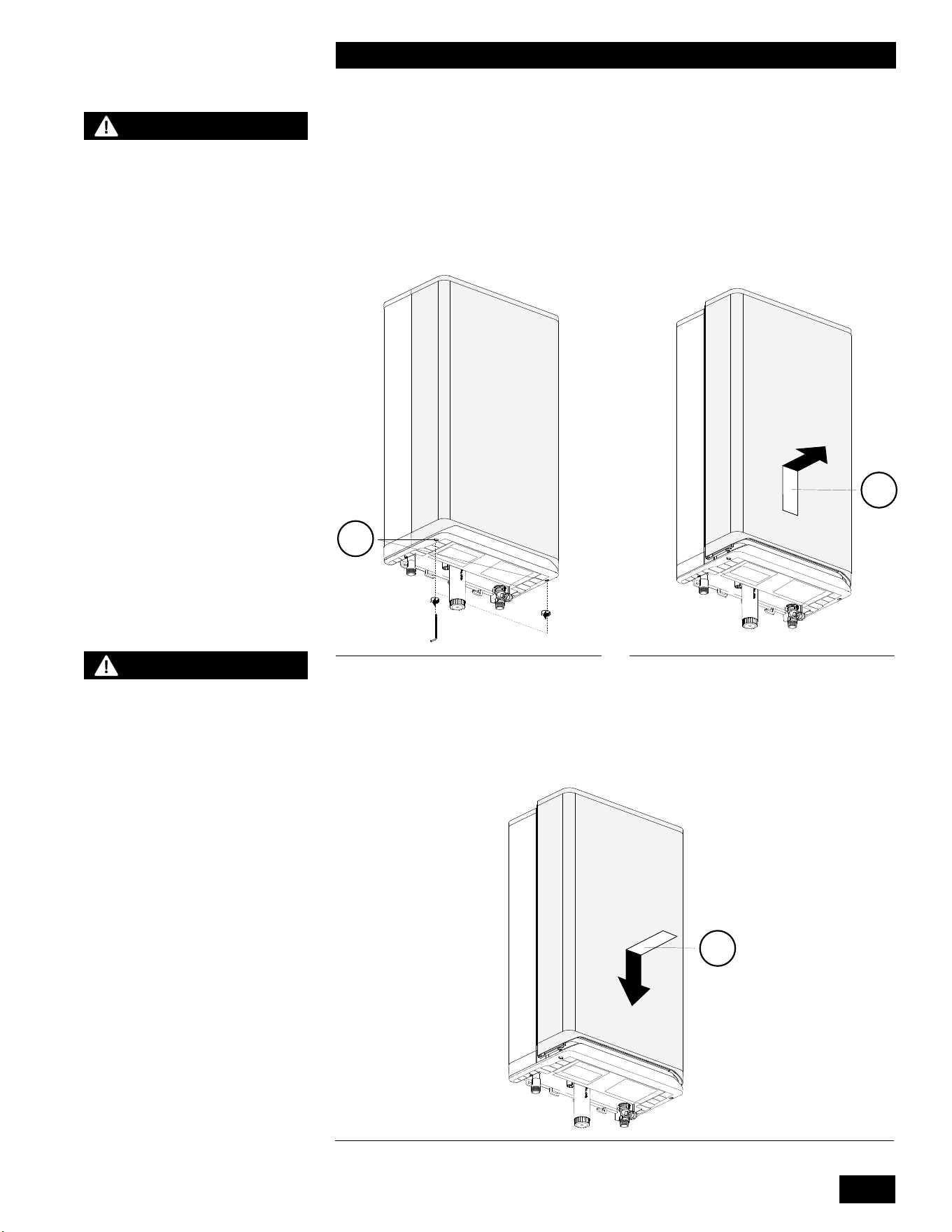
1.3.1 Removing/installing the front panel
•
The front panel of the unit must be removed to perform various maintenance
activities.
•
Loosen both screws (1) under the unit by using a 5 mm allen key. (They are
captive and therefore will not drop out of the lower housing).
•
Slide the front panel (2) upward and then remove it by pulling it towards you.
To replace the front panel, proceed as follows:
• Position the front panel (3) against the unit and slide it downwards until it is
correctly connected to the lower fascia panel.
• Hand tighten screws under the unit using a 5 mm allen key (do not over
tighten)
Figure 3: Loosen screws Figure 4: Frontpanel upward
Figure 5: Positioning the frontpanel
2
3
1
CAUTION
The front panel has a rubber
seal around the inner edge
sometimes making it very sti
to slide o so please ensure
the unit is secured to the wall
correctly before attempting
this procedure!
WARNING
This is a room sealed cover
and therefor extremely
important that it is tted
correctly, failure to do so can
result in ue gas spillage and
carbon monoxide emissions,
causing severe personal
injury or death.
INSTALLATION AND OPERATION INSTRUCTIONS
1-6
HEATING BOILERS 99 & 120
1.4 EXHAUST VENTING AND AIR INTAKE
When you plan the installation, ensure that you consider appropriate venting
materials, travel and termination decisions.
Consider the following when selecting a vent termination location:
• Select a location where the units exhaust will not damage nearby plants,
shrubs, air conditioning equipment or be objectionable to the homeowner.
• Exhaust gases will form a visible plume during cold weather. Avoid areas
where the plume could obstruct window views.
• Prevailing winds could cause water/ice buildup on nearby objects including
building surfaces.
• Avoid locations where people or pets could come in contact with exhaust
gases.
• Avoid locations such as inside building corners, near adjacent buildings or
surfaces, window wells, stairwells, alcoves, courtyards, or other recessed
areas where wind could aect the unit’s performance or cause exhaust gas
recirculation.
• Select a location where the termination is not likely to be damaged by foreign
objects such as stones or balls, or is subject to buildup of debris such as
leaves.
FLUE GAS
EXHAUST TO
OUTDOORS
Heating Boiler
Install venting in accordance with the requirements of the jurisdiction having
authority: in Canada, Part 8, Venting Systems of the B149.1-10 Code and any
other local building codes are to be followed. In the USA the National Fuel Gas
Code, ANSI 223.1, latest edition, prevails. Where there is a discrepancy between
the installation instructions below, and the code requirements, you must apply the
more stringent of the two requirements
Provisions for combustion and ventilation air in accordance with the section “Air
for Combustion and Ventilation”, of the National Fuel Gas Code, ANSI Z223.1/
NFPA 54 (latest edition) in the US or Clause 8.2, 8.3 or 8.4 of Natural Gas and
Propane Installation Code, CAN/CSA B149.1 (latest edition) in Canada. or
applicable provisions of the local building codes.
WARNING
- Venting, condensate
drainage, and combustion
air systems for all units
must comply with applicable
codes and the instructions of
their respective Installation
manuals.
- Inspect nished vent and air
piping thoroughly to ensure
all are airtight and comply
with the instructions provided
and with all requirements of
applicable codes.
- Failure to follow all
instructions can result in
ue gas spillage and carbon
monoxide emissions, causing
severe personal injury or
death. Failure to comply will
result in severe personal
injury or death.
Figure 6: Basic exhaust vent assembly
DANGER
Failure to properly vent
the unit to the outdoors
as outlined in this Venting
section will result in death
or serious personal injury.
To avoid the risk of re,
explosion, or asphyxiation
from carbon monoxide,
NEVER operate the unit
unless it is properly vented
and has adequate air supply
for proper operation as
outlined in this Venting
section. This unit must have
air supply connected and
terminated to the outdoors.
DANGER
Do not common vent this
Heating Boiler with any other
existing or new appliance.

1-7
INSTALLATION
HEATING BOILERS 99 & 120
In the Commonwealth of Massachusetts
The Commonwealth of Massachusetts requires compliance with regulation 248
CMR 4.00 and 5.00 for installation of through-the-wall vented gas appliances as
follows:
(a) For all side-wall, horizontally vented, gas-fueled equipment installed in every
dwelling, building, or structure used in whole or part for residential purposes,
including those owned or operated by the Commonwealth and where the side-
wall exhaust vent termination is less than seven (7) feet above nished grade
in the area of the venting, including but not limited to decks and porches, the
following requirements shall be satised.
1. INSTALLATION OF CARBON MONOXIDE DETECTORS. At the time of
installation of the side-wall, horizontally vented, gas-fueled equipment, the
installing plumber or gas tter shall observe that a hard-wired carbon monoxide
detector with an alarm and battery backup is installed on the oor level where the
gas equipment is to be installed. In addition, the installing plumber or gas tter
shall observe that a battery-operated or hard-wired carbon monoxide detector
with an alarm is installed on each additional level of the dwelling, building, or
structure served by the side-wall, horizontally vented, gas-fueled equipment.
It shall be the responsibility of the property owner to secure the services of
qualied licensed professionals for the installation of hard-wired carbon monoxide
detectors.
a. In the event that the side-wall, horizontally vented, gas-fueled equipment is
installed in a crawl space or an attic, the hard-wired carbon monoxide detector
with alarm and battery backup may be installed on the next adjacent oor level.
b. In the event that the requirements of this subdivision cannot be met at the time
of completion of installation, the owner shall have a period of thirty (30) days to
comply with the above requirements, provided, however, that during said thirty
(30) day period, a battery-operated carbon monoxide detector with an alarm shall
be installed.
2. APPROVED CARBON MONOXIDE DETECTORS. Each carbon monoxide
detector as required in accordance with the above provisions shall comply with
NFPA 720 and be ANSI/UL 2034-listed and IAS-certied.
3. SIGNAGE. A metal or plastic identication plate shall be permanently mounted
to the exterior of the building at a minimum height of eight (8) feet above grade
directly in line with the exhaust vent terminal for the horizontally vented, gas-
fueled heating appliance or equipment. The sign shall read, in print size no less
than one-half (1/2) inch in size, “GAS VENT DIRECTLY BELOW. KEEP CLEAR
OF ALL OBSTRUCTIONS.”
4. INSPECTION. The state or local gas inspector of the side-wall, horizontally
vented, gas-fueled equipment shall not approve the installation unless, upon
inspection, the inspector observes carbon monoxide detectors and signage
installed in accordance with the provisions of 248 CMR 5.08 (2)(a)(1 through 4).
(b) EXEMPTIONS: The following equipment is exempt from 248 CMR 5.08 (2)(a)
(1 through 4):
1. The equipment listed in Chapter 10 entitled “Equipment Not Required To Be
Vented” in the most current edition of NFPA 54 as adopted by the Board, and
2. Product-approved side-wall, horizontally vented, gas-fueled equipment
installed in a room or structure separate from the dwelling, building, or structure
used in whole or in part for residential purposes.
NOTE
For the State of
Massachusetts, use only
plastic piping, ttings
and vent terminations as
specied in this manual
which are approved by the
Massachusetts Board of State
Examiners of Plumbers and
Gas for venting of appliances
(see hyperlink below):
https://licensing.reg.state.
ma.us/pubLic/pl_products/
pb_pre_form.asp

INSTALLATION AND OPERATION INSTRUCTIONS
1-8
HEATING BOILERS 99 & 120
(c) MANUFACTURER REQUIREMENTS – GAS EQUIPMENT VENTING
SYSTEM PROVIDED. When the manufacturer of product-approved side-wall,
horizontally vented, gas-fueled equipment provides a venting system design or
venting system components with the equipment, the instructions provided by
the manufacturer for installation of the equipment and the venting system shall
include:
1. Detailed instructions for the installation of the venting system design or the
venting system components; and
2. A complete parts list for the venting system design or venting system.
(d) MANUFACTURER REQUIREMENTS – GAS EQUIPMENT VENTING
SYSTEM NOT PROVIDED. When the manufacturer of product-approved side-
wall, horizontally vented, gas-fueled equipment does not provide the parts for
venting the ue gases, but identies “special venting systems,” the following
requirements shall be satised by the manufacturer:
1. The referenced “special venting systems” instructions shall be included with
the appliance or equipment installation instructions, and
2. The “special venting systems” shall be product-approved by the Board, and
the instructions for that system shall include a parts list and detailed installation
instructions.
(e) A copy of all installation instructions for all product-approved side-wall,
horizontally vented, gas-fueled equipment, all venting instructions, all parts lists
for venting instructions, and/or all venting design instructions shall remain with
the appliance or equipment at the completion of the installation.

1-9
INSTALLATION
HEATING BOILERS 99 & 120
Removal of Existing Unit from Common Venting
When an existing unit is removed from a common venting system, the common
venting system is likely to be too large for proper venting of the appliances
remaining connected to it.
At the time of removal of an existing unit, the following steps must be followed
with each appliance remaining connected to the common venting system placed
in operation, while the other appliances remaining connected to the common
venting system are not in operation.
• Seal any unused openings in the common venting system.
• Visually inspect the venting system for proper size and horizontal pitch, and
determine that there is no blockage or restriction, leakage, corrosion and
other deciencies that could cause an unsafe condition.
• Insofar as is practical, close all building doors and windows and all doors
between the space in which the appliances remaining connected to the
common venting system are located and other spaces of the building. Turn
on clothes dryers and any appliance not connected to the common venting
system. Turn on any exhaust fans, such as range hoods and bathroom
exhausts, so they will operate at maximum speed. Do not operate a summer
exhaust fan. Close replace dampers.
• Place in operation the appliance being inspected. Follow the lighting
instructions. Adjust the thermostat, so that the appliance operates
continuously.
• Test for spillage at the draft hood relief opening after 5 minutes of main
burner operation. Use the ame of a match or candle, or smoke from a
cigarette, cigar, or pipe.
• After it has been determined that each appliance remaining connected to
the common venting system properly vents when tested as outlined above,
return doors, windows, exhaust fans, replace dampers and any other gas-
burning appliance to their previous conditions of use.
• Any improper operation of the common venting system must be corrected
so the installation conforms with the National Fuel Gas Code, ANSI
Z223.1/NFPA 54 (latest edition) in the US or the Natural Gas and Propane
Installation Code, CSA B149.1 (latest edition) in Canada. When resizing any
portion of the common venting system, the common venting system must be
resized to approach the minimum size as determined using the appropriate
tables in the National Fuel Gas Code, ANSI Z223.1/NFPA 54 (latest edition)
in the US or the Natural Gas and Propane Installation Code, CSA B149.1 in
Canada.
1.4.1 Applications
All Heating Boiler models must be installed as a Direct Vent venting system.
The combustion air must be piped in from the outdoors and connected directly
to the unit’s combustion air connection. See section 1.4.7 for air intake piping
requirements.
1.4.2 Exhaust Vent Material
Use of ABS, cellular core PVC (ASTM F891), cellular core CPVC, or Radel®
(polyphenolsulfone) in venting systems is prohibited.
Exhaust Vent Material – CANADA
Use only PVC, CPVC, Polypropylene (PPS), or stainless steel* vent components.
NOTE
The ue gas temperature
sensor reports the current
ue gas exhaust temperature
to the unit’s controller. If
necessary, the controller will
reduce the input of the boiler
to meet the ue gas exhaust
temperature requirements of
PVC material. The controller
locks out the unit if this
temperature is exceeded, and
displays F003.
CAUTION
- The minimum wall thickness
for venting is 1" and the
maximum wall thickness for
venting is 14".
- Do not connect this Heating
Boiler to a chimney ue
serving a separate appliance
designed to burn solid fuel.
- The air intake tting can be
moved to the left or to the
right of the exhaust tting.
INSTALLATION AND OPERATION INSTRUCTIONS
1-10
HEATING BOILERS 99 & 120
Venting components must be approved for use with a Category IV appliance,
listed under ULC S636 and must comply with CSA B149.1 (latest edition).
• PVC (ULC-S636)
• CPVC (ULC-S636)
• Polypropylene (ULC-S636)
• Stainless steel* (ULC-S636)
Exhaust Vent Material – USA
Use only PVC, CPVC, Polypropylene (PPS), or Stainless Steel* vent
components. Venting components must be approved by the authority having
jurisdiction and as follows:
• PVC (Schedule 40 ASTM D1785)
• CPVC (Schedule 40 ASTM F441)
• Polypropylene (UL1738 / ULC-S636)
• Stainless Steel* (Type BH)
DuraVent FasNSeal
HeatFab Saf-T Vent
Z-Flex Z-Vent
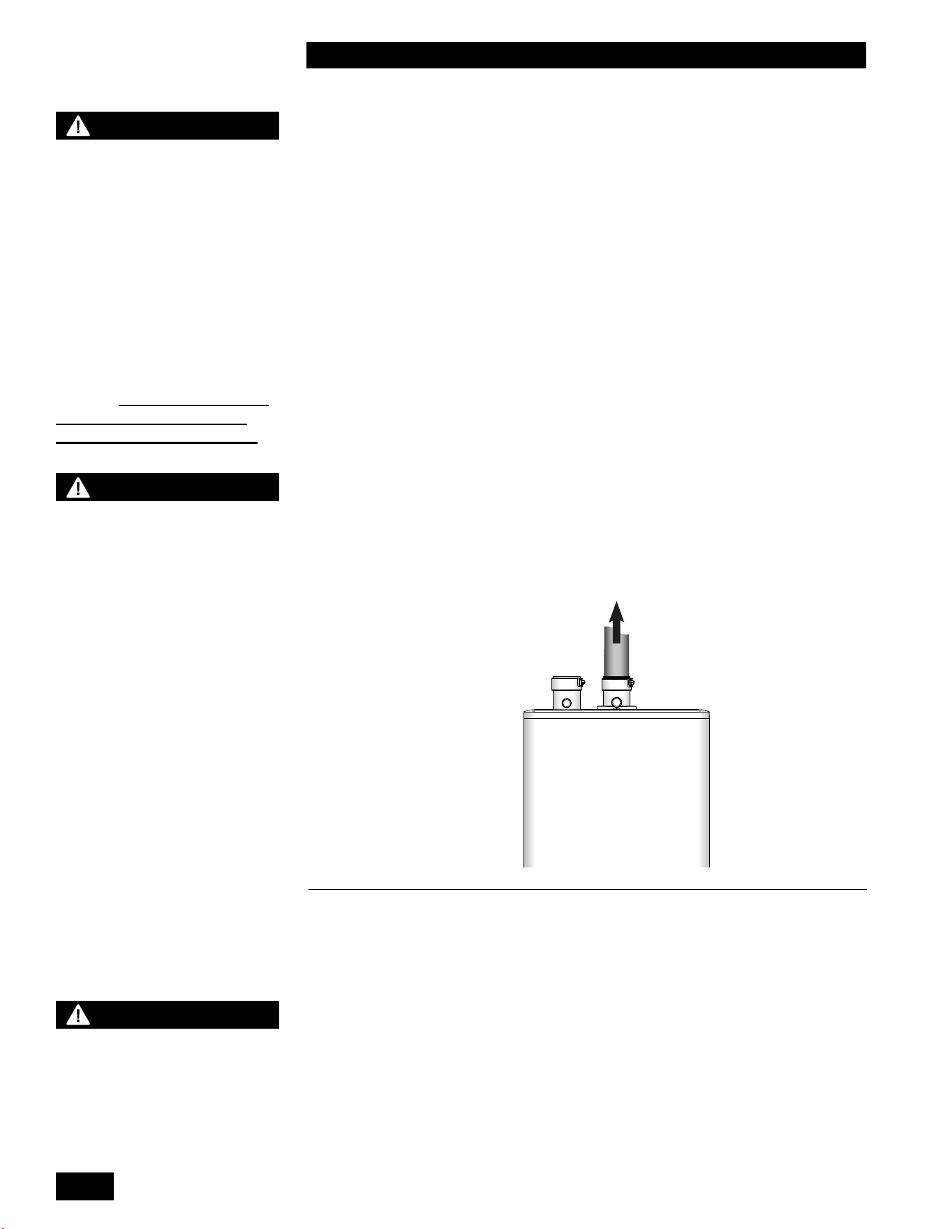
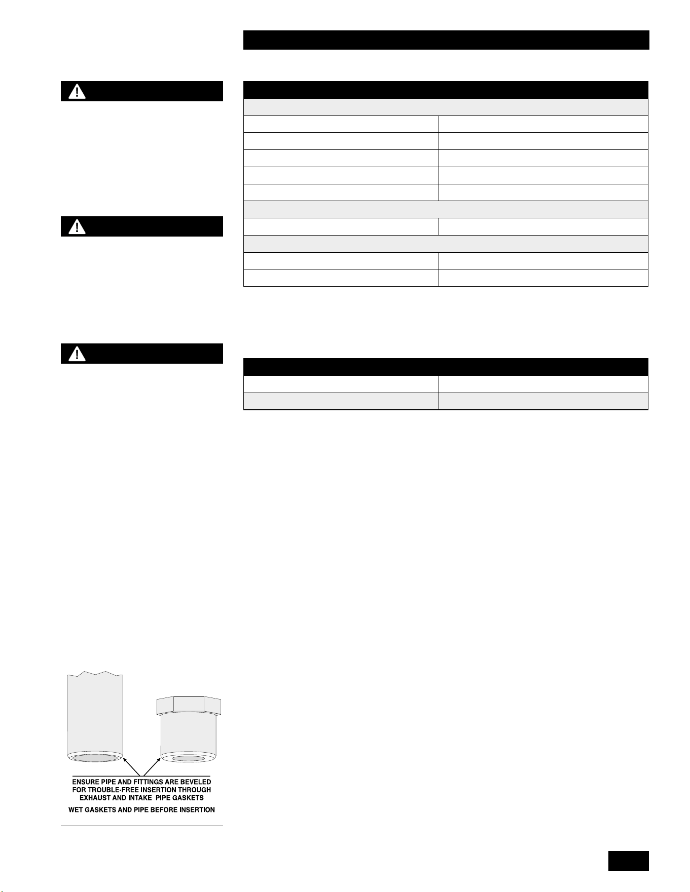
This unit is equipped with a top mounted 2" vent connection. Wet the vent
connection gasket and pipe with clean water prior to assembly. Insert 2" PVC or
CPVC directly into the units vent connection and secure the pipe by tightening
the clamp.
Polypropylene venting will require an adapter from the venting manufacturer
to transition from the 2" vent connection to the venting system. Centrotherm
InnoFlue polypropylene venting requires adapter part number ISAAL0202.
Wet the vent connection gasket and adapter with clean water prior to assembly.
Insert the polypropylene adapter into the units vent connection and secure by
tightening the clamp.
*Manufacturers of stainless steel Type BH venting systems must submit
their approved transition tting to us for evaluation and written approval.
1.4.3 Vent Travel
The maximum exhaust venting length is dependent upon the vent pipe size (2"
or 3") and the venting material (PVC, CPVC, PPs). See Table 3 for maximum
exhaust venting lengths and the required venting length reduction for each tting
in the venting system.
Example: When using 6 x 90º CPVC elbows, the maximum lineal measure of
pipe allowed using 3" pipe is 72 feet (120' – (6 x 8' = 48') = 72').
For 3" Flexible PPs, up to 35 actual lineal feet are allowed in a nominally vertical
orientation (>45°). The equivalent length of 3" Flexible PPs is calculated using
a multiple of 1.4:1, e.g. 35' x 1.4 = 49' equivalent. The balance of the venting
allowance is still available for use with rigid PPs piping material.
2" Flexible PPs is not allowed.
WARNING
- Do not mix venting materials
from dierent venting
manufacturers.
These venting materials are
designed to be installed as
part of a complete system.
Failure to comply may result
in severe personal injury or
death.
- Fully insert the approved
venting material into the
unit’s exhaust outlet and
tighten clamp to ensure the
venting connection is locked
in place.
Figure 7 Inlet and outlet vent
connections. Note the ue
exhaust test port.
NOTE
For the State of
Massachusetts, use only
plastic piping, ttings
and vent terminations as
specied in this manual
which are approved by the
Massachusetts Board of State
Examiners of Plumbers and
Gas for venting of appliances
(see hyperlink below):
https://licensing.reg.state.
ma.us/pubLic/pl_products/
pb_pre_form.asp
1-11
INSTALLATION
HEATING BOILERS 99 & 120
EXHAUST PIPE SIZE/FITTINGS MAXIMUM EQUIVALENT LENGTH
Schedule 40 PVC, CPVC or PPs – Allowances are for each side separately.
2" 65'*
3" 120'
2" or 3" 90° Long Sweep Vent Elbow Allow 5 equivalent feet
2" or 3" 90° Short Sweep Vent Elbow Allow 8 equivalent feet
2" or 3" 45° Vent Elbow Allow 3 equivalent feet
PPS
PPs 87-90° Elbow Allow 8 equivalent feet
Flex PPS
2" PPs Flex Not Allowed
3" PPs Flex 35' Actual (Equivalent = Actual x 1.4)
Table 3: Maximum Exhaust Venting Length
* The input rate will derate as vent length increases. See table below for
approximate derate at 2” maximum vent length.
MAXIMUM FIRING RATE APPROXIMATE DERATE
99,000
5 - 8%5 - 8%
120,000
10 - 16%10 - 16%
Follow all installation instructions supplied by the pipe and tting
manufacturer. Prior to assembly, ensure all venting components are clean of
burrs/debris which could clog the fan, burner, and heat exchanger.
General Venting/Piping Requirements
If the vent length requires increasing the vent pipe size to 3", the transition from
the 2" vent connector to 3" venting must occur within the rst 18" of the top of the
unit and must be done in a vertical section to avoid pooling of condensate. Slope
exhaust venting back towards the unit with a pitch of at least 1/4" per foot. Follow
venting manufacturer pitch requirements, so condensate runs back towards the
trap. Support air intake and vent piping per local code and vent manufacturers
requirements. In the absence of support requirements, support the air intake and
vent piping at every vertical and horizontal transition as well as every 5' of run.
Begin the vent system installation at the unit and work towards the outdoor
termination. We recommend using a bird screen of 1/4" stainless steel or plastic
mesh (e.g., IPEX System 636 drain grate for CPVC systems) to guard against
foreign objects.
BEST PRACTICES
To reduce the possibility of
expansion noise, allow a 1/4"
gap around the exhaust and
air intake piping.
NOTE
The bird screen is optional
for exhaust piping in cold
weather climates.
WARNING
C
ombustion air must not be
drawn from areas containing
corrosive air from swimming
pools or spas, including air
directly next to outdoor pools
and spas.
Figure 8
INSTALLATION AND OPERATION INSTRUCTIONS
1-12
HEATING BOILERS 99 & 120
Secure joints using appropriate solvent cement to bond the respective pipe
material (Canada: PVC/CPVC cement approved under ULC-S636, in accordance
with its manufacturer instructions; USA: PVC (ASTM D2564), or CPVC (ASTM
F493) Use transition cement anywhere that PVC and CPVC are joined. Follow
the cement manufacturer’s instructions closely when joining various components.
For PPs, connections must be secured using approved retainer clips supplied by
the respective PPs manufacturer.
Ensure that all vent connections are liquid and pressure tight. Prior to ring the
unit, and before any of the venting run is concealed by the building construction,
you must test the exhaust joints with a soap/water solution. You must ll the
condensate trap before testing.
1.4.4 Venting Passage Through Ceiling and Floor
• Conrm material meets local codes including re stopping requirements.
Some local jurisdictions require that a minimum initial length of pipe be
exposed or accessible for inspection.
•
Pipe clearances - best practice allows a minimum 1/4" gap around the pipe to
prevent binding and expansion noise. Follow local codes.
• All piping must be liquid and pressure tight.
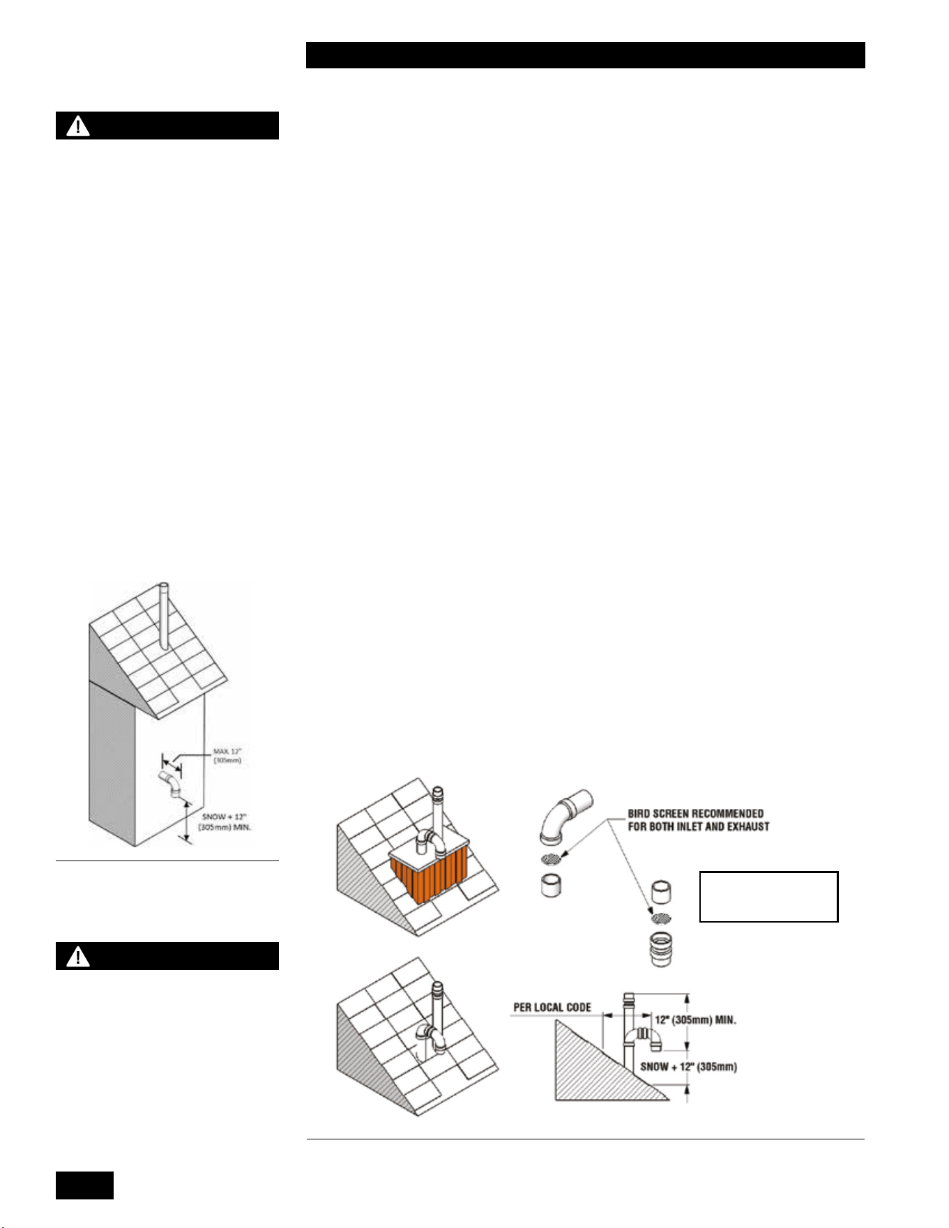
1.4.5 Rooftop Vent Termination
Direct Vent - Two Pipe
Rooftop vents must terminate as follows:
•
The exhaust pipe can terminate in an open vertical orientation without concern
about rain inltration; rain will drain away through the condensate trap.
•
The intake air pipe is not typically drained, so it must be terminated with a down-
turned elbow (see Figure 10). The intake pipe does not need to penetrate the
roof at the same elevation as the exhaust (as shown); lower down the roof is
OK.
• The air intake pipe may terminate on the side wall of the building as long as
WARNING
Condensate can cause
corrosion of metal roong
components and other
roong materials. Check
with the builder or roong
contractor to ensure that
materials are resistant to
acidic condensate. pH levels
can be as low as 3.0
[18" (457 mm) Canada] MIN.
NOTE: THE BIRD SCREEN
IS OPTIONAL IN COLD
WEATHER CLIMATES
CAUTION
Vent termination clearances
in this section are code
minimum, or recommended
minimum requirements,
and may be inadequate for
your installation. You must
examine building envelope
details, and take measures to
avoid admission of moisture
into building structures.
Serious structural damage
may occur if adequate
precautions and clearances
are not allowed for.
These precautions are to be
observed for neighboring
structures as well as for
the structure the unit(s) are
installed in.
Figure 10: Rooftop vent terminal congurations
Figure 9: Rooftop vent terminal
congurations
1-13
INSTALLATION
HEATING BOILERS 99 & 120
the air intake terminal is turned down and the side wall of the building is not
exposed to large wind loads i.e.,: prevailing wind (see Figure 9).
• Optional bird screen may be placed in a termination tting. Leave unglued,
and hold in place with a short nipple to allow easy access for cleaning.
• For roof top venting of multiple unit sets, group all intake terminals together
for a common penetration through a custom cap. Alternatively, place in
the closest proximity achievable using commonly available pipe ashing.
Similarly, group the exhaust pipes and place the 2 separate groups of pipes
at least 3' apart (the closest intake and exhaust pipes must be 36" - or more -
apart). Use the same 12" (minimum) vertical separation for 2 pipe option.
• DO NOT exhaust vent into a common venting system.
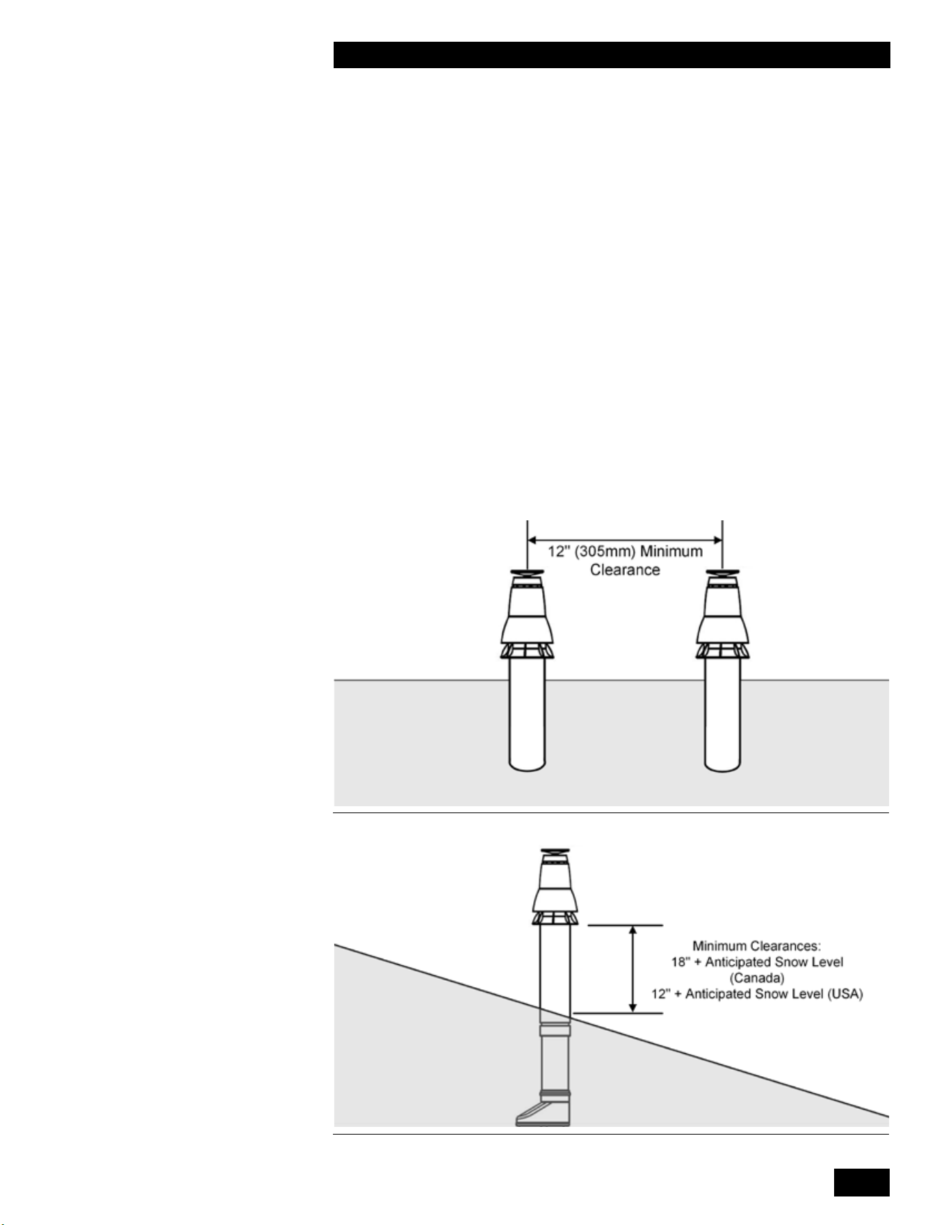
DIRECT VENT CONCENTRIC ROOF TOP TERMINATION
Roof Top Concentric Termination kits are approved for use with this unit.
For vertical roof top concentric terminations, you must follow the installation
instructions supplied by the manufacturer. Care must be taken to install the
termination kit a minimum horizontal distance of 10" (305 cm) away from any
portion of the building and a minimum of 12" (305 mm) [18" (457 mm) Canada]
above the roof line plus the anticipated snow line (see Figures 11 and 12).
Figure 11: Vertical Concentric Termination - Two Kits
Figure 12: Vertical Concentric Termination - Single Kit
INSTALLATION AND OPERATION INSTRUCTIONS
1-14
HEATING BOILERS 99 & 120
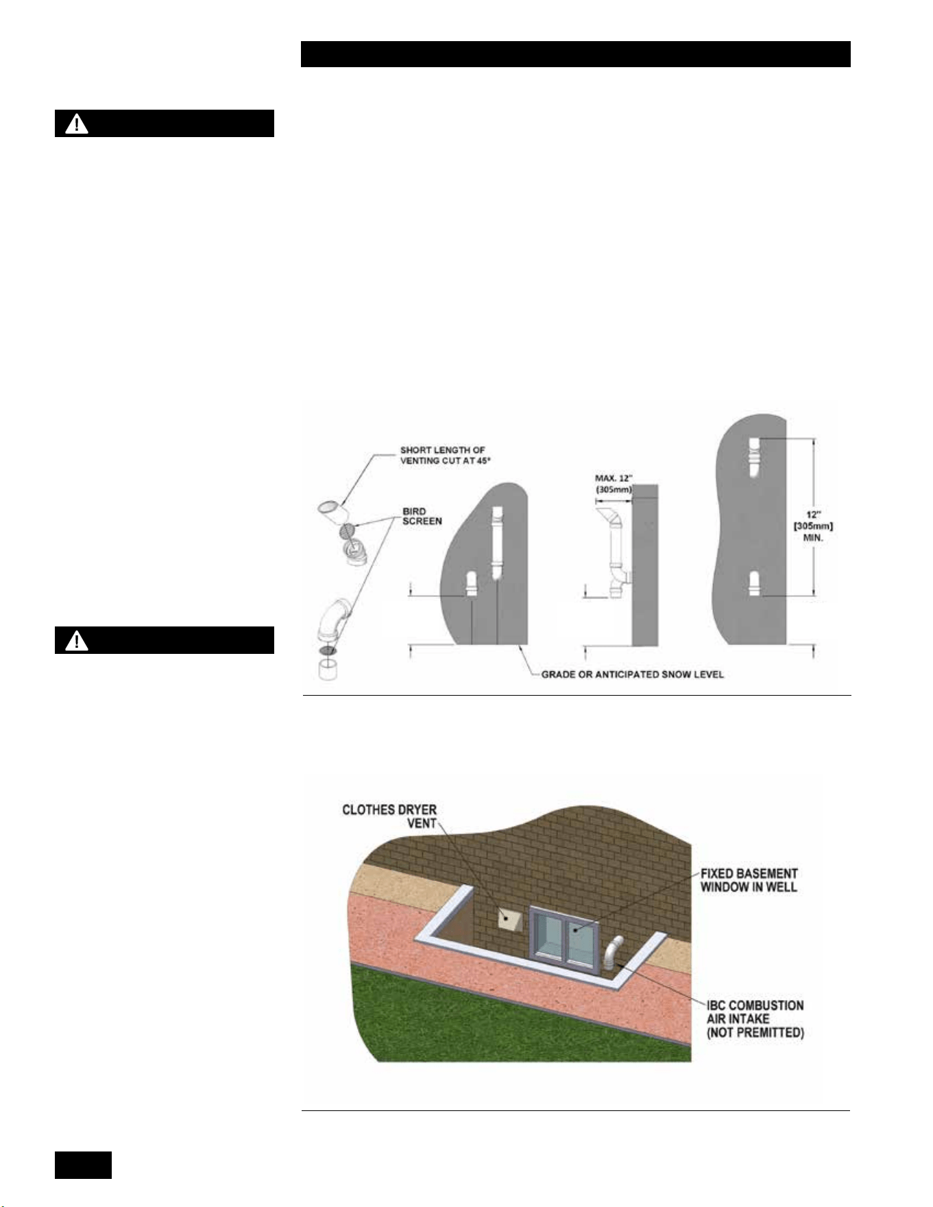
1.4.6 Sidewall Vent Termination
Direct Vent - Two Pipe
Sidewall direct vent applications must be vented as follows:
• Both the inlet and exhaust terminations must be located on the same plane
(side) of the building.
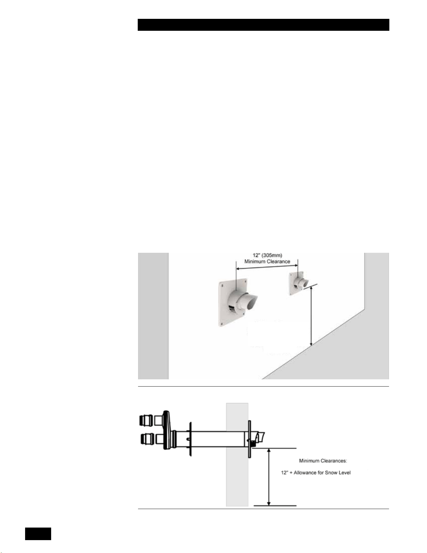
• The exhaust outlet is to be placed so as to reach 12" minimum above the
down-turned intake - to avoid intake re-ingestion of exhaust gases.
• The elevation of both pipes can be raised in “periscope style” after passing
through the wall, then congured as in Figure 13, to gain required clearance.
• Use a 45° elbow on the exhaust termination to launch the plume up and o
the sidewall, for protection of wall.
• Optional bird screen may be placed in a termination tting. Leave unglued,
and hold in place with a short nipple to allow easy access for cleaning.
SNOW + 12"
[305mm]
MIN.
SNOW + 12"
[305mm]
MIN.
SNOW + 12"
[305mm]
MIN.
Figure 13: Sidewall vent termination - piping conguration
WARNING
- You must maintain at least
the minimum separation of
exhaust vent termination from
unit’s intake air as illustrated
in gures 9, 10, 13 and 15.
Failure to do so can result
in a dangerous situation
where exhaust gases are
pulled in with combustion air.
Damage to the unit can result
from a failure to maintain
these separations. Improper
installation will void the
warranty.
- You must not cover non-
metallic vent pipe and ttings
with thermal insulation.
- In areas of high snowfall,
users must be advised to
check side wall vent and
air intake terminations on
a regular basis to ensure
blockage does not occur.
WARNING
The vent for this appliance
must not terminate:
1. Over public walkways in
the US. In Canada 7’ above
public walkways.
2. Near sot vents or crawl
space vents or other areas
where condensate or vapor
could create a nuisance or
hazard or cause property
damage.
3. Wherever condensate
vapor could cause damage
or could be detrimental to the
operation of regulators, relief
valves, or to other equipment..
Figure 14: Prohibited installation
1-15
INSTALLATION
HEATING BOILERS 99 & 120
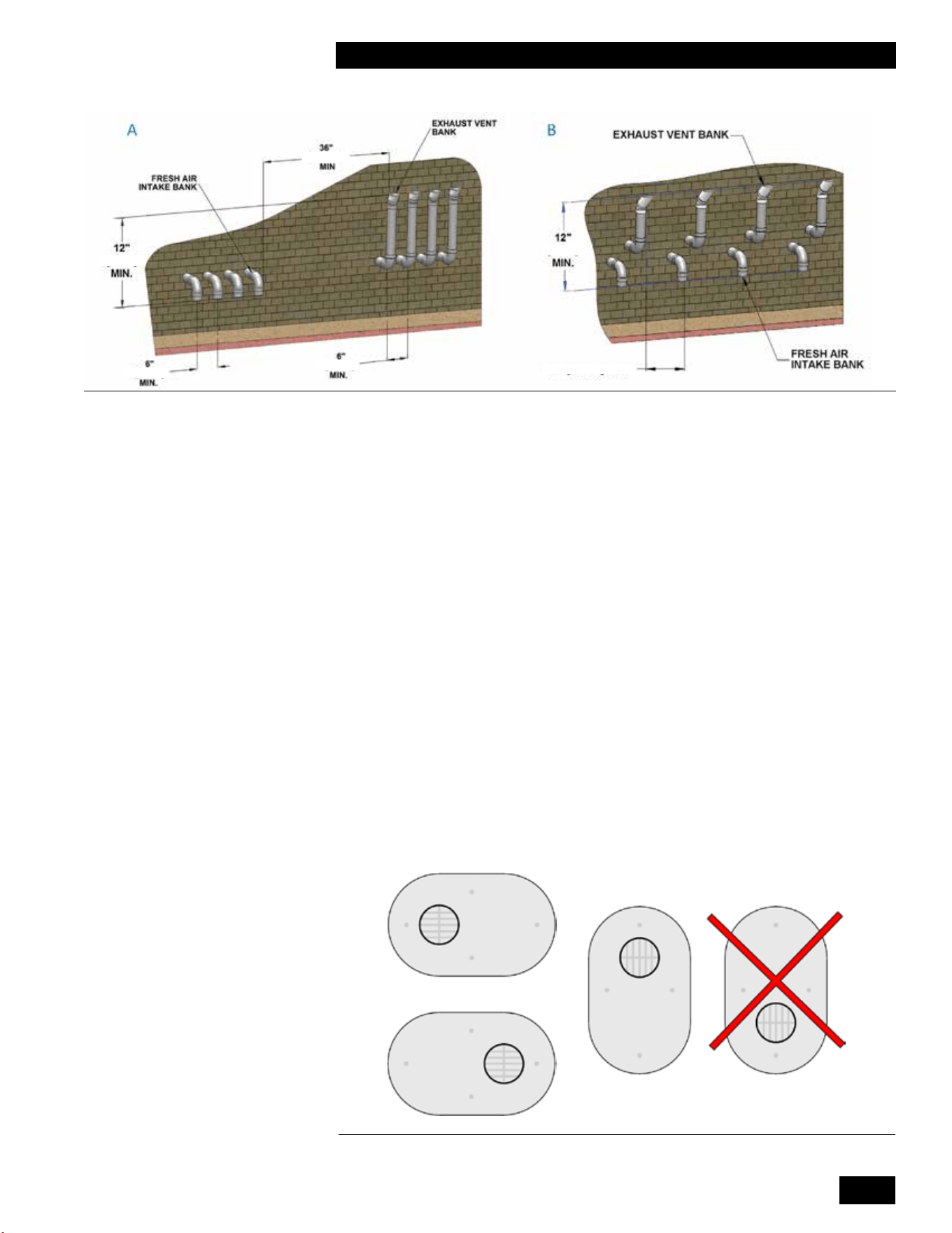
For sidewall venting of multiple units, group all intake terminals together with 6"
(minimum) lateral spacing, and similarly group the exhaust pipes. Place the 2
groups on the same plane of the building (e.g., north facing wall). Place the 2
groups of pipes at least 3' apart (the closest intake and exhaust pipes must be
36" - or more – apart). Use same 12" (minimum) vertical separation (see A in
Figure 15). Alternatively, as long as the units are identical models - intake and
exhaust terminals can maintain a minimum of 12" of separation horizontally from
any exhaust or inlet termination of an adjacent unit (see B in Figure 15).
DIRECT VENT SIDE WALL TERMINATION KITS
The Side Wall Termination kits approved for use with the Heating Boilers are
subject to restrictions. NOTE: Some jurisdictions may not allow this type of side
wall termination due to close proximity to the neighboring properties. See Figures
16, 17 and 18 on page 1-15, 1-16
You must follow the installation instructions, clearances and wall thickness
requirements of the approved vent termination manufacturer.
Approved Side Wall Termination Kits are listed below:
• 2" PVC low prole termination kit - Part #P-741
• 3" PVC low prole termination kit - Part #P-742
Vent on Left or Right Side
[305mm]
[305mm]
[152mm]
[152mm]
12" [305mm] MIN.
[915mm]
Figure 15: Sidewall vent termination - multiple vent piping conguration
Figure 16 PVC low prole termination acceptable orientations
INSTALLATION AND OPERATION INSTRUCTIONS
1-16
HEATING BOILERS 99 & 120
Concentric SideWall Termination Kits
Concentric Sidewall Termination kits approved for use with the Heating boiler
are subject to restrictions. NOTE: Some jurisdictions may not allow this type of
sidewall termination due to close proximity to the neighboring properties.
You must follow the installation instructions, clearances, and wall thickness
requirements of the approved vent termination manufacturer.
Approved Concentric Sidewall Termination kits are:
• 3" PVC (UL 1738) – Ipex #397006
• 3" PVC (ULC-S636) – Ipex #196006
• 3" CPVC (ULC-S636) – Ipex #197009
• 2" Centrotherm Innoue PPs - #ICWT242 (Termination)
#ICTCR24 (2 Pipe Adapter)
• 3" Centrotherm Innoue PPs - #ICWT352 (Termination)
#ICCT3503 (2 Pipe Adapter)
Installation of multiple Concentric Side Wall Termination kits must be:
• On the same horizontal line (not stacked)
• With a minimum horizontal separation of 12" center to center.
12" + Allowance
for Snow Level
Figure 17: Horizontal Polypropylene Concentric Termination - Two Kits
Figure 18: Horizontal Polypropylene Concentric Termination - Single Kit
1-17
INSTALLATION
HEATING BOILERS 99 & 120
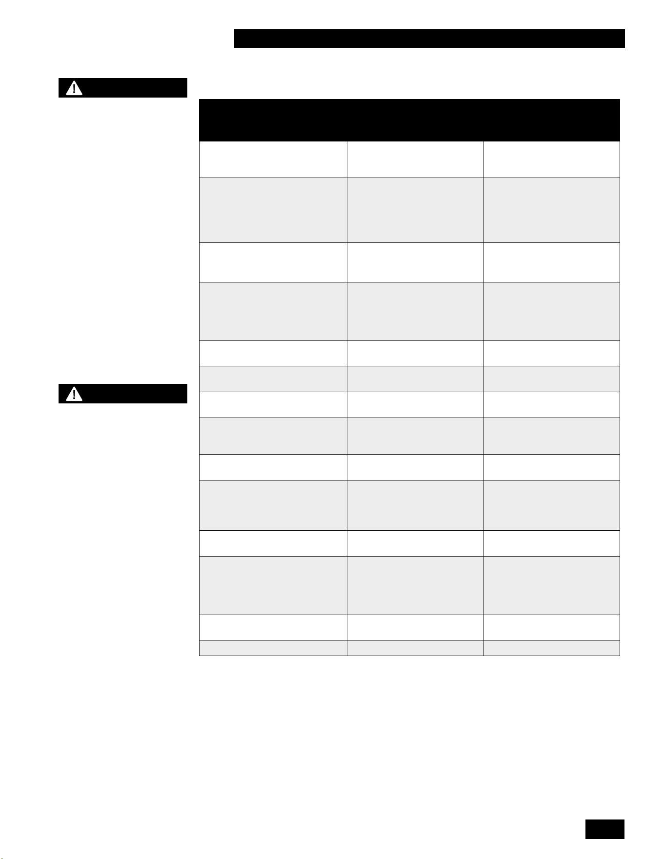
Vent terminal clearance minimums are as follows:
VENT TERMINAL MINIMUM CLEARANCES
CANADIAN
INSTALLATIONS
1, 3
US INSTALLATIONS
2, 3
A= Clearance above grade,
veranda, porch, deck, or
balcony
12 in (30 cm) 12 in (30 cm)
B= Clearance to window or door
that may be opened
12 in (30cm) for appliances
below 100,000 Btuh (30 kW)
36 in (91 cm) for appliances
over 100,000 Btuh (30 kW)
12 in (30 cm)
C= Clearance to permanently
closed window
* (Recommend minimum 1 ft
(30 cm))
* (Recommend minimum 1 ft
(30 cm))
D= Vertical clearance to
ventilated sot located above
the terminal within a horizontal
distance of 2 ft (61 cm) from the
center line of the terminal.
* (Recommend minimum 2 ft
(61 cm))
* (Recommend minimum 2 ft
(61 cm))
E= Clearance to unventilated
sot
* (Recommend minimum 1 ft
(30 cm))
* (Recommend minimum 1 ft
(30 cm))
F= Clearance to outside corner * (Recommend minimum 4 ft
(122 cm))
* (Recommend minimum 4 ft
(122 cm))
G= Clearance to inside corner * (Recommend minimum 4 ft
(122 cm))
* (Recommend minimum 4 ft
(122 cm))
H= Clearance to each side of
center line extended above
meter/regulator assembly
3 ft (91 cm) within a height of
15 ft (4.6m)
*
I= Clearance to service
regulator vent outlet
3 ft (91 cm) *
J= Clearance to nonmechanical
air supply inlet to building or the
combustion air inlet to any other
appliance
12 in (30cm) for appliances
below 100,000 Btuh (30 kW)
36 in (91 cm) for appliances
over 100,000 Btuh (30 kW)
12 in (30 cm)
K= Clearance to a mechanical
air supply inlet
6 ft(1.83 m) 3 ft (91 cm) above if within 10
ft (3 m) horizontally
L= Clearance above paved
sidewalk or paved driveway
located on public property
7 ft (2.13 m) † Vents cannot be located
above public walkways
or other areas where
condensate or vapor can
cause a nuisance or hazard.
M= Clearance under veranda,
porch, deck, or balcony
12 in (30 cm) ‡ *
Clearance to adjacent wall 6 ft (1.83 m) 6 ft (1.83 m)
1 In accordance with the current CSA B149.1 Natural Gas and Propane Installation Code
2 In accordance with the current ANSI Z223.1 / NFPA 54 National Fuel Gas Code
3 If locally adopted installation codes specify clearances dierent than those illustrated, then the most stringent shall apply.
† A vent shall not terminate directly above a sidewalk or paved driveway that is located between two single family dwellings
and serves both dwellings.
‡ Permitted only if veranda, porch, deck, or balcony is fully open on a minimum of two sides beneath the oor.
* Clearance in accordance with local installation codes and the requirements of the gas supplier. The minimum distance from
adjacent public walkways, adjacent buildings, openable windows, and building openings shall not be less than those values
specied in the National Fuel Gas Code, ANSI Z223.1/NFPA 54, and/or the Natural Gas and Propane Installation Code,
CSA B149.1
WARNING
- In addition to
preventing ingestion of
chemical contaminants,
care must be taken
to ensure air intake
terminals are not
installed in locations
where contamination
might occur due to
ingestion of particulate
foreign material (dust,
dirt and debris).
- Intake air openings
must be congured such
that rain or other forms
of moisture cannot enter
the air intake piping
system. Otherwise
serious damage to the
unit may result.
NOTE
Care must be taken
when installing air intake
piping to ensure that a
“trap” is not formed in
the piping so as to allow
a build-up of water,
and blockage of intake
air. Such blockage will
result in a unit’s safety
shutdown.
INSTALLATION AND OPERATION INSTRUCTIONS
1-18
HEATING BOILERS 99 & 120
1.4.7 “Direct Vent” Combustion Air Intake Piping
The unit must always be installed as a Direct Vent venting system with the
combustion air piped directly from the outdoors to the unit’s combustion air
connection. Provisions for combustion and ventilation air are in accordance with
the section “Air for Combustion and Ventilation”, of the National Fuel Gas Code,
ANSI Z223.1/NFPA 54 (latest edition) in the US or Clause 8.2, 8.3 or 8.4 of
Natural Gas and Propane Installation Code, CAN/CSA B149.1 (latest edition) in
Canada, or applicable provisions of the local building codes.
FLUE GAS
EXHAUST TO
OUTDOORS
COMBUSTION
AIR FROM
OUTDOORS
ALTERNATIVE
COMBUSTION AIR
CONNECTION
“DIRECT VENT”
INSTALLATION
CHECK AIR INTAKE
OUTSIDE TO MAKE SURE
IT IS CLEAR OF
OBSTRUCTIONS
Heating Boiler
Figure 20: Direct vent combustion air intake
Intake Pipe Sizing
For 3" Flexible PPs, you can use up to 35 actual linear feet in a nominally vertical
orientation (>45°). The equivalent length of 3" Flexible PPs must be calculated
using a multiple of 1.4:1, e.g. 35' x 1.4 = 49' equivalent.
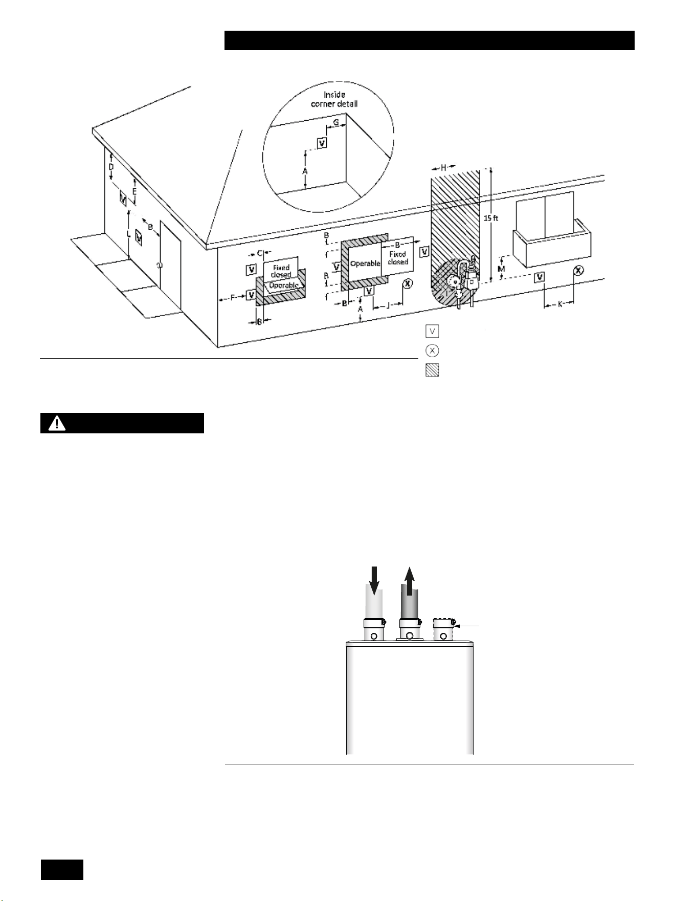
Figure 19: Vent Terminal Clearance
Vent terminal
Air supply inlet
Area where terminal is not permitted
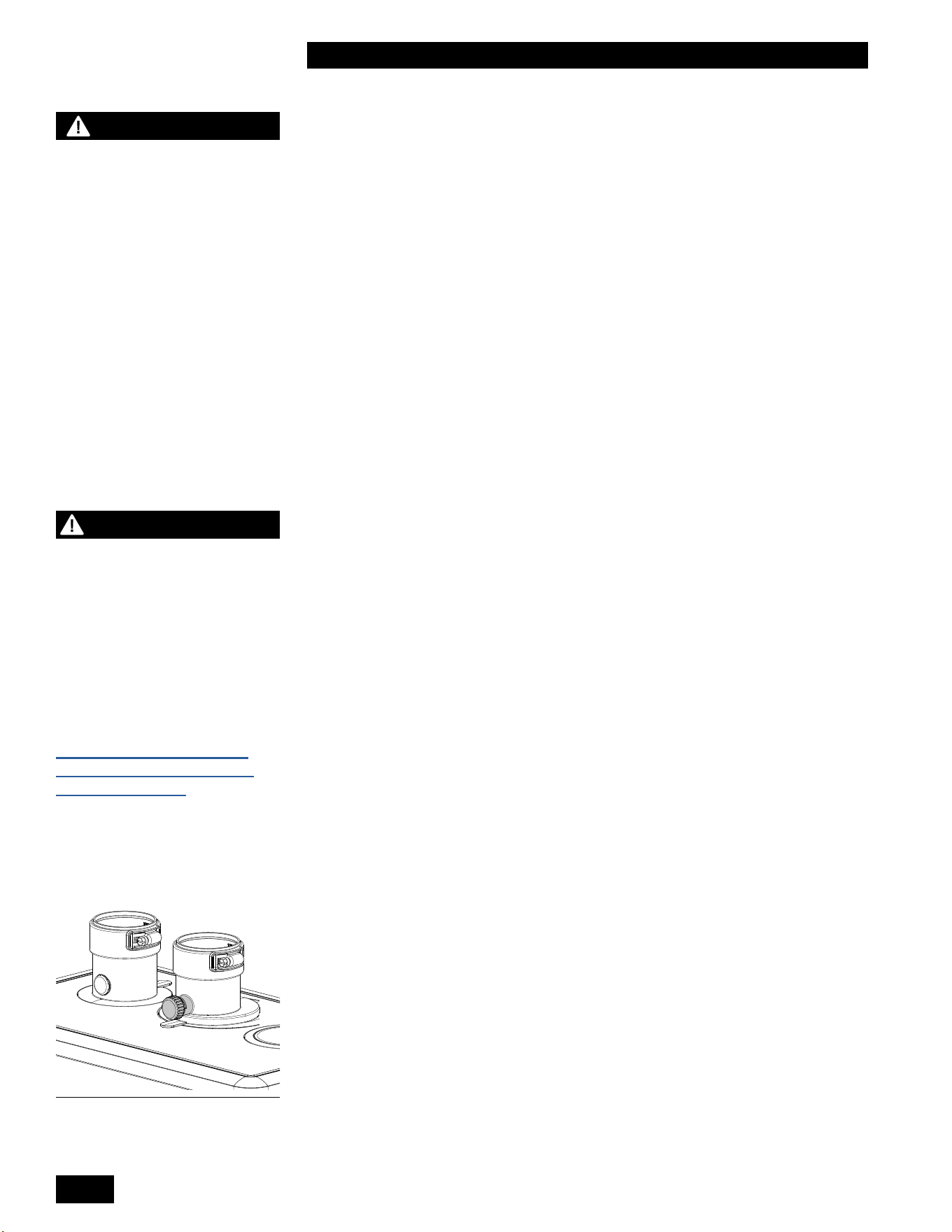
NOTE
Combustion air connection
may be moved from one side
to the other:
- Remove the retaining clip
screws then lift tab at back of
plug and rotate 1/8th of a turn
counter-clockwise to remove
from top of cabinet.
- Remove the retaining clip by
removing both screws then
lift tab at back of combustion
air connection and rotate
1/8th of a turn counter-
clockwise to remove from top
of cabinet.
- Reinstall plug and
combustion air connection
in the desired locations
then rotate 1/8th of a turn
clockwise until tab latches
into the top of the cabinet.
- Reinstall the retaining clip
over the combustion air
connection tab and secure
with two screws. Reinstall
two screws in the top of the
cabinet near the plug.
1-19
INSTALLATION
HEATING BOILERS 99 & 120
The balance of the venting allowance is still available for use with rigid PPs
piping material.
2" Flexible PPs is not allowed.
INTAKE PIPE SIZE/FITTINGS MAXIMUM EQUIVALENT LENGTH
Schedule 40 PVC, ABS, CPVC or PPs – Allowances are for each side separately.
2" 65'*
3" 120'
2" or 3" 90° Long Sweep Vent Elbow Allow 5 equivalent feet
2" or 3" 90° Short Sweep Vent Elbow Allow 8 equivalent feet
2" or 3" 45° Vent Elbow Allow 3 equivalent feet
PPS
PPs 87-90° Elbow Allow 8 equivalent feet
Flex PPS
3" PPs Flex 35' Actual (Equivalent = Actual x 1.4)
Table 4: Maximum intake piping length.
* The input rate will derate as intake length increases. See table below for
approximate derate at 2" maximum intake length.
MAXIMUM FIRING RATE APPROXIMATE DERATE
99,000 5 - 8%
120,000 10 - 16%
For inlet air, you can use Schedule 40 PVC, CPVC, ABS or PPs piping of any
type. Use the same diameter as vent piping.
Insert combustion air piping directly into the 2" female plastic tting on the top of
the unit, and run it horizontally or vertically to the outdoors. We recommend using
a bird screen of 1/4" stainless steel or plastic mesh (eg. IPEX System 636 drain
grate for CPVC systems) to guard against foreign objects.
Care must be taken to ensure adequate separation is maintained between the air
intake inlet and the vent termination. Refer to the vent termination conguration
drawings in the “Vent Termination” section above.
Support air intake and vent piping per local code and vent manufacturers
requirements. In the absence of support requirements, support the air intake and
vent piping at every vertical and horizontal transition as well as every 5ʹ of run.
1.4.8 “Indoor Air” Combustion Air Intake
The use of indoor air for combustion is prohibited. Combustion air must be
piped in from the outdoors and connected directly to the unit’s combustion air
connection
1.4.9 Closet Installations
For installations in a conned space (such as a closet), ventilation openings may
be needed through a door or wall to prevent build-up of excessive heat from
inside the space.
The unit must not be exposed to surrounding conditions above 122°F (50°C) or
below 32°F (0°C).
INSTALLATION AND OPERATION INSTRUCTIONS
1-20
HEATING BOILERS 99 & 120
1.5 CONDENSATE REMOVAL
The specied vent conguration promotes the safe drainage of moisture from
the unit and exhaust venting without owing liquids back through the heat
exchanger.
Reliable system operation requires (1) proper design and installation of
exhaust venting to allow condensate to run back to the drain/trap; (2) acid pH
neutralization as appropriate. To achieve these:
1. Allow for a 1/4" per foot slope back to the vent connection, with appropriate
hangers to maintain that gradient.
2. Ensure the supplied trap is correctly installed and lled with water.
3. When required, add (and maintain in good condition) a neutralization tank.
1.5.1 Condensate Trap
The condensate trap cup must be installed on the bottom of the condensate trap
at the base of the unit.
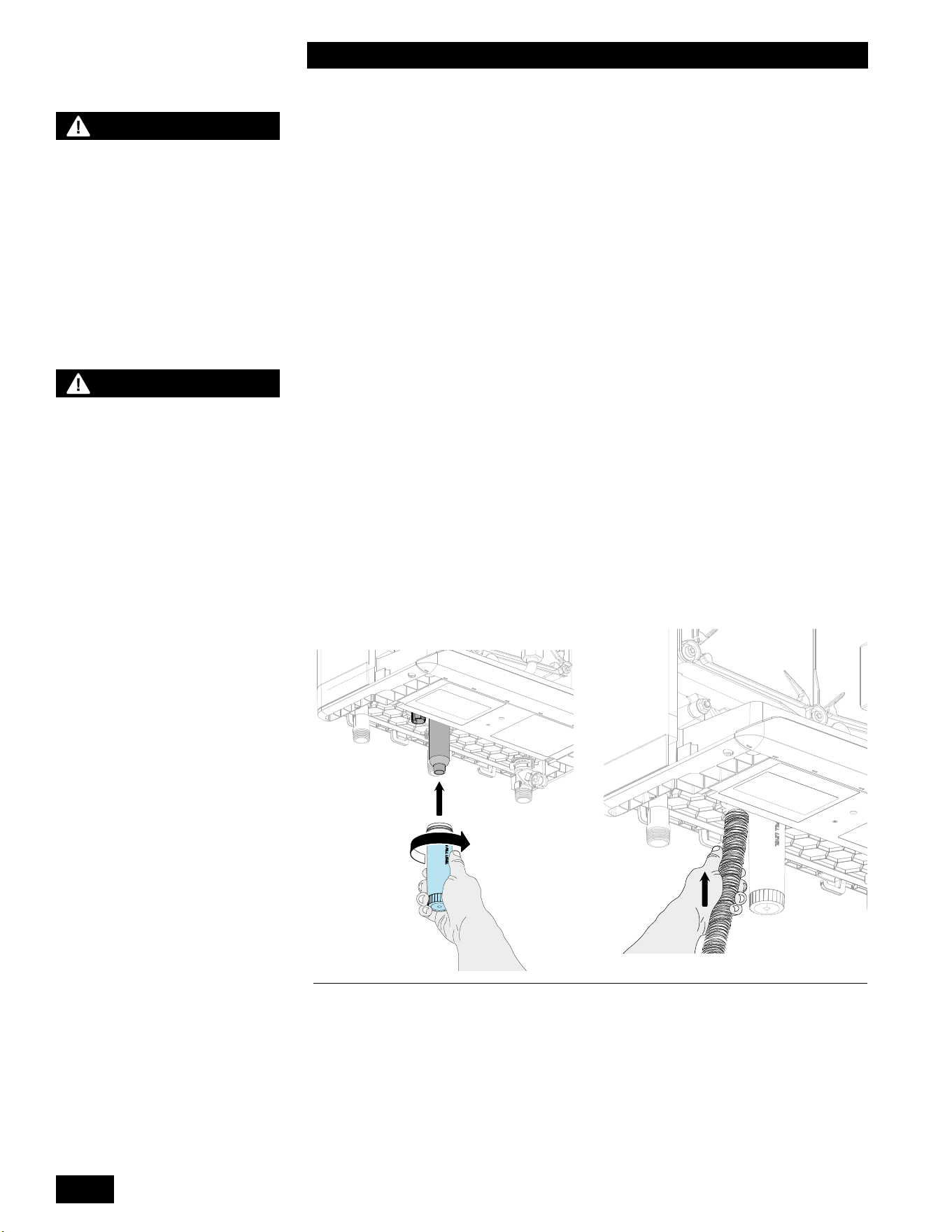
1.5.2 Installing the Condensate Trap
1. Fill the condensate trap cup with water.
2. Install the condensate trap cup on the condensate trap base and twist toward
the right.
3. Attach the drain hose to the condensate trap outlet located to the left of the
condensate trap cup.
Figure 21: Condensate trap installation
WARNING
Fill the trap with water before
initial startup of the unit to
prevent exhaust fumes from
entering the room. Never
operate the unit unless the
trap is lled with water.
Failure to comply will result
in severe personal injury or
death.
NOTE
It is the responsibility of
the installing and/or service
Contractor to advise and
instruct the end user on how
to perform the Trap cleaning
procedure, and to advise
that the trap be checked at
least every two months and
cleaned as required.
1-21
INSTALLATION
HEATING BOILERS 99 & 120
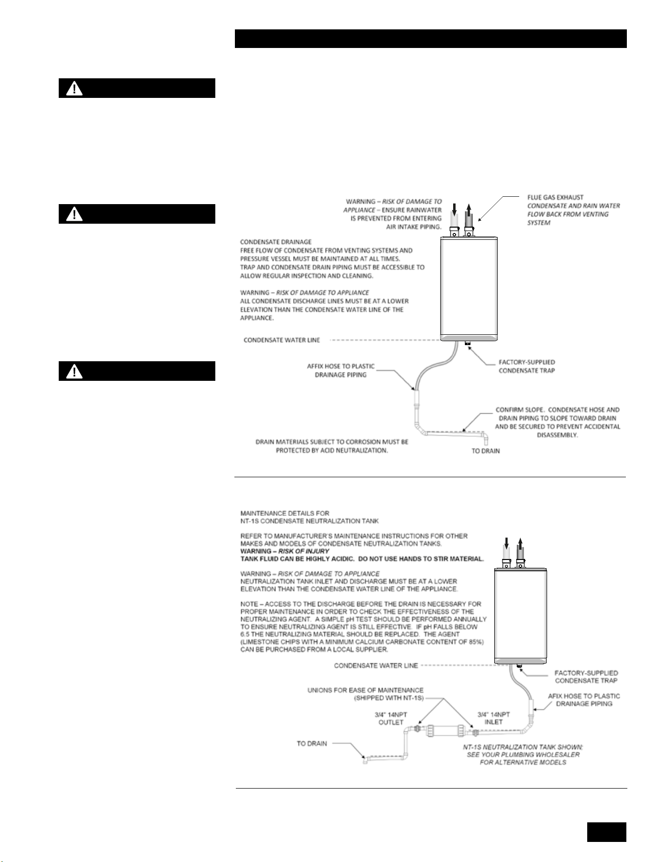
1.5.3 Further Installation Details
•
Pipe the condensate drain tube to within 1" of a drain, or connect it to a
condensate pump.
• Slope the drainage line down to the drain at a pitch of 1/4" per foot, so that the
condensate runs towards the drain.
• Check the condensate trap every 2 months, and clean and rell as necessary.
Figure 22: Condensate trap drainage
Figure 23: Condensate neutralization tank
Heating Boiler
Heating Boiler
WARNING
If discharging condensates into
building drain piping materials
that are subject to corrosion,
you must use a neutralization
package.
CAUTION
When a condensate
neutralization package
is installed, the pH of the
condensate discharge must
be measured on a regular
schedule to ensure the
neutralizing agent is active
and eective.
DANGER
The water in the condensate
neutralizer can cause severe
burns to the skin. Use extreme
caution when servicing the
condensate neutralizer. Wear
protective gloves and eyewear.

INSTALLATION AND OPERATION INSTRUCTIONS
1-22
HEATING BOILERS 99 & 120
PAGE INTENTIONALLY LEFT EMPTY
1-23
INSTALLATION
HEATING BOILERS 99 & 120
1.6 WATER PIPING - SPACE HEATING
1.6.1 General Piping Considerations
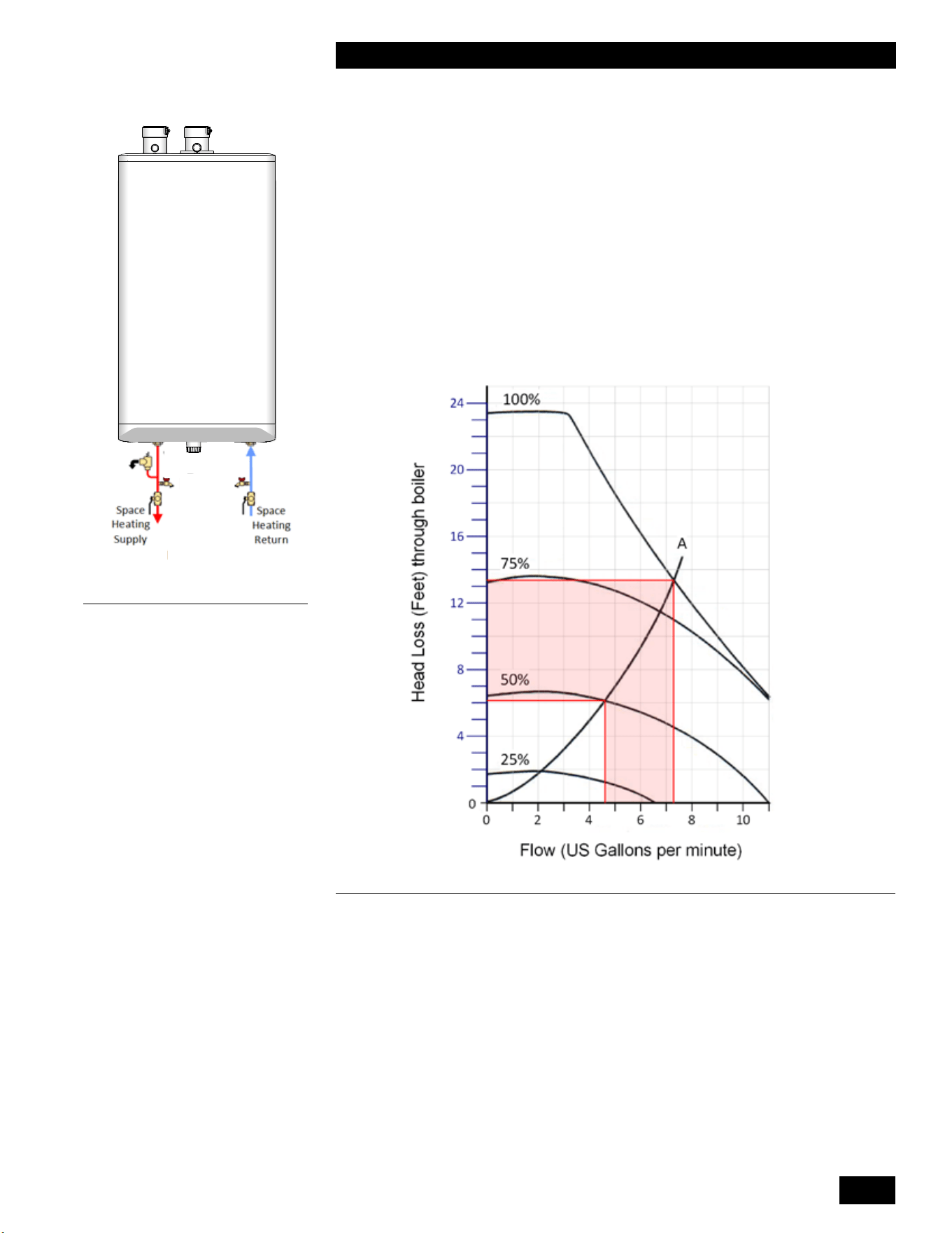
The Heating Boiler includes a factory installed, integral heating pump. The pump
is designed to provide adequate ow through the unit and near unit piping.
Primary/secondary piping or the use of a buer tank/hydraulic separator is
recommended for maximum exibility in multi zone/load applications. Piping
loads in parallel is only acceptable in systems where the minimum ow rate is
guaranteed to be higher than the minimum for the unit and where the unit’s pump
is adequate to provide the required ow rate and pump head for the system.
Graph 1: Boiler pressure drop - Pump runs between 50% to 100% capacity to establish
pressure dierence across boiler circuit
A=boiler pressure drop
This unit is designed for use within a closed loop, forced circulation, low pressure
system. A 30 PSI pressure relief valve (3/4" NPT) is supplied.
Heating Boiler
Figure 24: Overview of piping
connections
INSTALLATION AND OPERATION INSTRUCTIONS
1-24
HEATING BOILERS 99 & 120
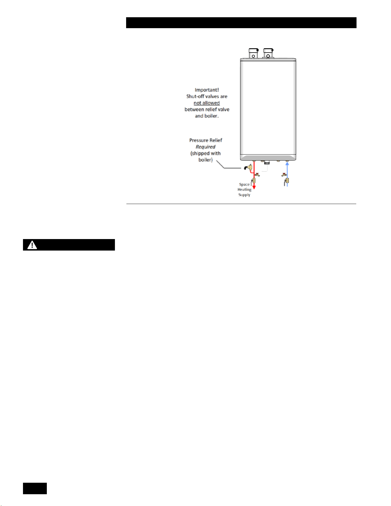
Heating Boiler
Figure 25: Relief Piping
System Piping
System piping is connected to the unit using the 1" NPT Male threaded ttings located
on the bottom of the unit. Use two wrenches when tightening eld piping onto the boiler.
Use one wrench to hold the boiler tting still while tightening with another wrench. We
recommend using unions and gate or ball valves at the unit’s supply and return water
connections to simplify servicing. Un-insulated hot water pipes require a minimum 1/4"
clearance from combustible materials.
Fluid ll is most often accomplished by using a regulator & ll valve set at 12 psig or more,
with appropriate backow prevention device as required by local code. This is acceptable
in areas where municipal water or well water has been treated and ltered to remove
excessive minerals and sediment, and water chemistry is known to be suitable for closed-
loop hydronic systems. When water quality is unknown, or when chemical treatment or
glycol is required, you should consider other options. Follow applicable Codes and good
piping practice.
Other feed and pressurization devices on the market today may be a better choice than a
raw water ll from the mains. When regular maintenance requires relief valve blow-o, the
discharge may be directed back into the pressurization unit for recycling of unit uid and
chemicals back into the system. In buildings that may be unoccupied for long periods of
time, pressurization units are useful to prevent ood damage should leakage occur from
any component in the system. An additional benet is that backow prevention devices
are not required when using these devices.
Do not place any water connections above the unit. Leaks can damage the fan and
controls. If needed, create a shield over the top of the cover, but allow clearance for
airow and service access.
WARNING
Failure to support the boiler
tting with a second wrench
while tightening eld piping
may lead to boiler damage.
1-25
INSTALLATION
HEATING BOILERS 99 & 120
Combi Boiler
Heating Boiler
Figure 26: Boiler trim basic options – concept drawing is only a simple schematic guide
For best results, use a primary/secondary piping system, with a boiler’s loop
using 1" piping (see section 1.6.2). The unit comes with the primary pump
installed and generally provides adequate ow for the unit and primary loop
piping only.
Combi Boiler
Combi Boiler
Combi Boiler
Combi Boiler
Heating Boiler
Heating Boiler Heating Boiler
Heating Boiler
Figure 27: Permitted and prohibited space heating boiler piping
WARNING
During operation, the relief
valve may discharge large
amounts of steam and/or hot
water. To reduce the potential
for bodily injury and property
damage, a discharge line
MUST be installed that:
1. Is connected from the
valve outlet with no
intervening valve and
directed downward to a
safe point of discharge.
2. Allows complete drainage
of both the valve and the
discharge line.
3.
Is independently supported
and securely anchored to
avoid applied stress on the
valve.
4. Is as short and straight as
possible
5. Terminates freely to
atmosphere where any
discharge is clearly
visible and is at no risk of
freezing.
6. Terminates with a plain
end which is not threaded.
7. Is constructed of a material
suitable for exposure to
temperatures of 375°F
(190°C) or greater.
8. Is, over its entire length,
of a pipe size equal to or
greater than that of the
valve outlet.
DO NOT CAP, PLUG OR
OTHERWISE OBSTRUCT THE
DISCHARGE PIPE OUTLET!
CAUTION
Installers should inquire of
local water purveyors as to the
suitability of their supply for use
in hydronic heating systems. If
water quality is questionable,
a local water treatment expert
must be consulted for testing,
assessment and, if required,
treatment.
Alternatively, water or hydronic
uid of known quality can be
brought to the site.
INSTALLATION AND OPERATION INSTRUCTIONS
1-26
HEATING BOILERS 99 & 120
WARNING
- Close ll valve after any
addition of water to the
system, to reduce risk of
water escapement.
- Ensure the gas ignition
system components are
protected from water (dripping,
spraying, rain, etc.) during
appliance operation and when
servicing (pump replacement,
condensate trap servicing,
control replacement, etc.)
NOTE
- The piping system of a
hot water unit connected
to heating coils located in
air handling units where
they may be exposed to
refrigerated air circulation
must be equipped with
ow control valves or
other automatic means to
prevent gravity circulation
of the unit’s water during the
cooling cycle.
- The unit, when used
in connection with a
refrigeration system, must
be installed so the chilled
medium is piped in parallel
with the unit with appropriate
valves to prevent the chilled
medium from entering the
unit.
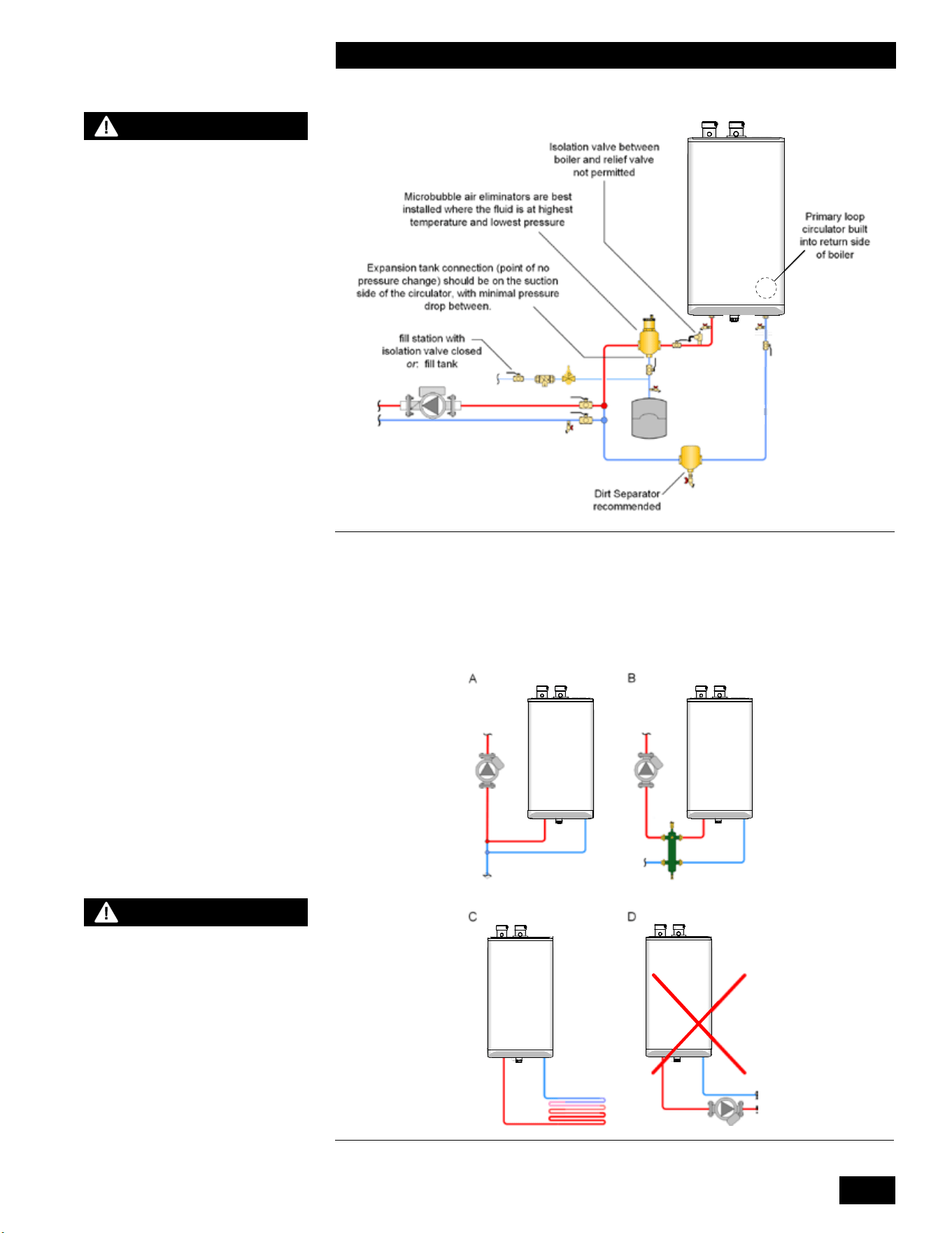
Figure 27 illustrates that the integral space heating pump can be hydraulically
separated from the distribution pump by (A) closely-spaced tees, or by (B) a
low-loss header. Although best practice is primary/secondary, in some cases
(C) the integral pump will be adequate to provide ow through the building heat
emitters. The installer / designer must ensure that if the integral pump is used for
the space-heating emitters it is powerful enough for system distribution. Avoid
(D) where an external pump is placed in series with the integral pump because
the external pump runs when the Heating Boiler is serving DHW. It will strongly
compromise DHW response.
The unit is designed to supply the heating load with temperatures within the
range of 86°F to 194°F (30° to 90°C). Use closely-spaced tees to connect
each pumped space heating load to the primary loop. As an option, a hydraulic
separator or buer tank can be used to separate the heating loads from the unit.
Ensure that the pump is rated for the design circulating water temperatures.
Some pumps have a minimum water temperature rating above the low
temperature potential of the unit. Following installation, conrm the performance
by measuring ΔT (under high and low ow conditions) after establishing the
correct ring rate.
We recommend water ow after burner shutdown to use legacy heat – this is
signicant due to the mass of the heat exchanger. The pump is under the control
of the unit to allow pump purge after burner shut-down. Default software values
will run the unit’s pump for 1 minute after the burner shuts down.
18po minimum
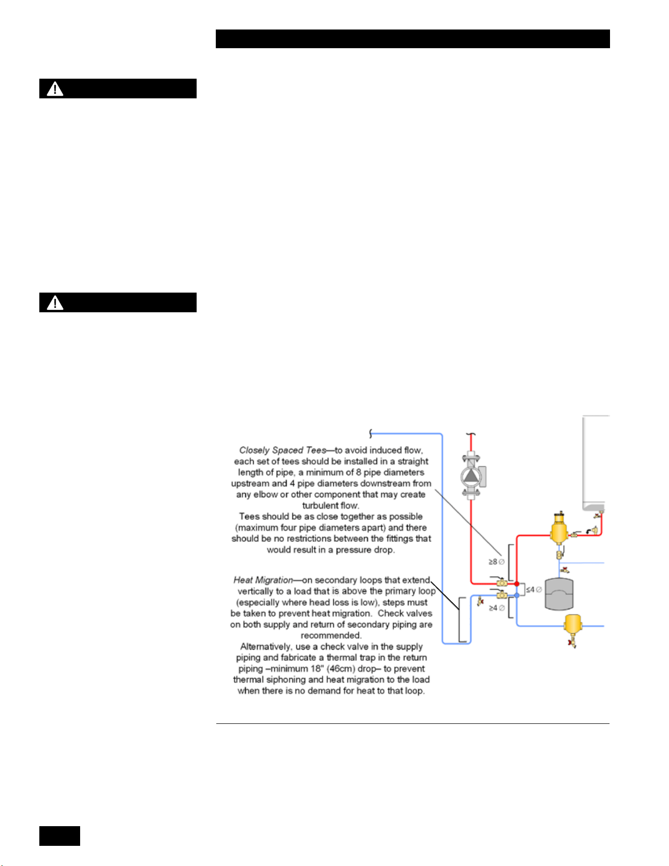
Figure 28: Basic Primary/Secondary piping with closely-spaced tees concept – concept
drawing. This drawing is only a simple schematic guide.

1-27
INSTALLATION
HEATING BOILERS 99 & 120
Schematics for several piping layouts are provided herein. You must conform
the piping design to one of the provided congurations to simplify the control
application, promote good loads and ow management.
This units ring rate modulation oers exceptional matching of heat generation to
radiation. The low minimum ring is better suited to low thermal loads presented
in a typical multi-zoned radiation system. However, where individual zones in
a heating system have loads under 10,000 Btu/hr, the system will still benet
through the use of a buer tank to ensure a controlled supply temperature, and to
prevent short-cycling. Buering should be added on the secondary piping of the
relevant load, to avoid bulking up the thermal mass of the primary piping circuit
(and potentially lengthen the duration of the transition from hot to cool loads).
Propylene glycol solution is commonly used in a closed loop where freeze
protection is required. Its density is lower than that of water, resulting in lower
thermal performance at a given ow and pressure. A solution of propylene glycol
and water will require an increased system circulation rate and system head to
provide performance equivalent to straight water.
1.6.2 Basic Heating Piping Arrangements
Primary/Secondary Piping - Benets and installation rules
The primary/secondary conguration:
• Ensures good circulating water ow through the unit irrespective of load or
radiation system head.
• Allows exible ΔT° control in secondary loops.
• Adds to the system’s thermal buering, to assist in handling small loads and
temperature transition.
A primary/secondary piping conguration requires an extra pump, independent
of any secondary load pumps. The Heating Boiler includes a pre-wired integral
Primary Pump.
For optimal performance, place pumps on the supply side of secondary loops
to facilitate air evacuation. Use pumps with internal check valves to avoid ghost
ows and thermal siphoning.
The unit is designed to be piped in a primary/secondary piping arrangement. In
some cases the unit can be piped in series with the heating load if the pump is
capable of providing the ow and head the system requires. For example, this
unit and an air handler can be installed together without the use of an additional
pump if the air handler is installed within close proximity of the unit and with
properly sized supply and return piping (see Figure 33).
If the installation involves small loads, as in typical zoned baseboard heating
applications, we recommend using a buer tank.
To aid in temperature transition from hot to cool loads, place a 3-way mixing
valve at the entrance to the cool load (this will also provide oor protection). This
type of installation allows immediate circulation of mixed ow into the cool loop.
WARNING
Water quality has a signicant
impact on the lifetime and
performance of the unit’s heat
exchanger.
Improperly prepared water in
a heating circuit may cause
damage to the heat exchanger
through corrosion or fouling.
Repeated or uncontrolled
water lls will increase the
potential for damage.
High levels of dissolved
solids or minerals may
precipitate out of the uid
onto the hottest part of the
heat exchanger, impairing
heat transfer and resulting in
overheating and premature
failure. The amount of solids
that may form on the heat
exchanger will depend on
the degree of hardness and
the total water volume in
the system. A high water
volume system with a low
hardness count may cause
as much damage as a system
with less volume and higher
hardness. We recommend
treating water to remove all
dissolved solids. Other water
chemistry allowable limits are
as follows:
• Acidity pH is to be between
6.5 and 8.5
• Chloride is to be less than
125 mg/l
• Iron is to be less than 0.3
mg/l
• Cu less than 0.1 mg/l
• Conductivity is to be less
than 400μS/cm (at 25°C)
• Hardness is to be 7 Grains
or less
IMPORTANT: Ensure that
these limits are acceptable
for the other water-side
components in the system.
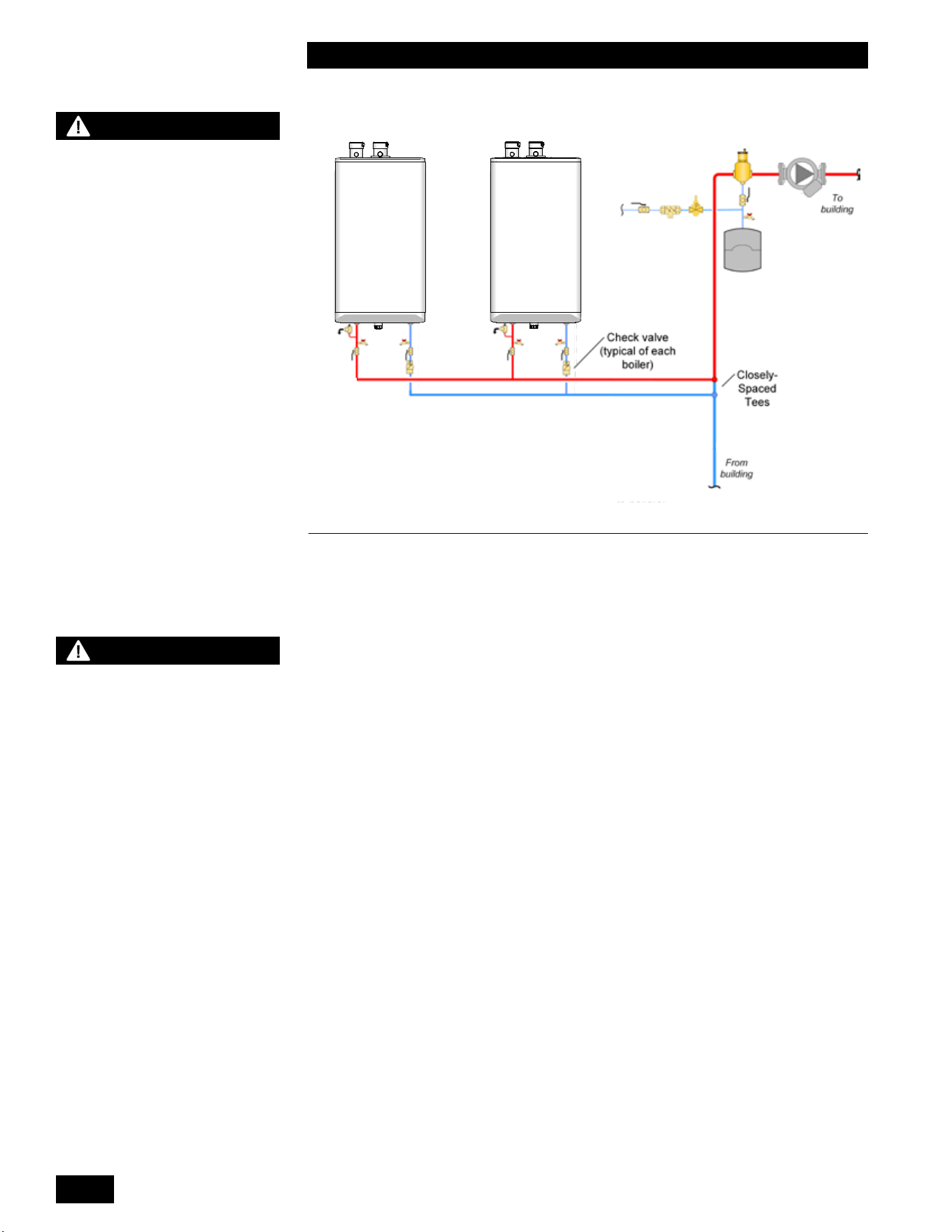
INSTALLATION AND OPERATION INSTRUCTIONS
1-28
HEATING BOILERS 99 & 120
T
T
Heating Boiler
Heating Boiler
Figure 29: Multiple boiler piping concept – concept drawing. This drawing is only a simple
schematic guide.
Multiple unit piping - Benets and installation rules
Multiple Heating Boilers can be installed in a single heating system to provide
redundancy, increased output, and greater heating plant turn-down capabilities.
Primary/Secondary piping must be used. This approach provides constant head
and ow at each unit, regardless of ow variations in the main building loop.
Each unit controls its own pump, turning it o or on when heat is required. This
approach saves electricity by reducing the pumping power required as load
conditions are reduced.
The Heating Boilers controller includes a cascade function which allows up to
8 Heating Boilers or Combi Boilers to operate together to satisfy a common
demand. See included Controller Manual for details.
Use check valves in each unit’s piping to prevent reverse ow when the unit is
o.
WARNING
Do not use automotive-type
ethylene or other types of
automotive glycol antifreeze,
or undiluted antifreeze of
any kind. This may result
in severe unit damage. It
is the responsibility of the
Installer to ensure that glycol
solutions are formulated to
inhibit corrosion in hydronic
heating systems of mixed
materials. Improper mixtures
and chemical additives may
cause damage to ferrous and
non-ferrous components as
well as non-metallic, wetted
components, normally found
in hydronic systems. Ethylene
glycol is toxic, and may be
prohibited for use by codes
applicable to your installation
location. For environmental
and toxicity reasons, we
require only using non-toxic
propylene glycol.
NOTE
- The piping drawings in this
manual are simple schematic
guides to a successful
installation.
- There are many necessary
components not shown, and
details such as thermal traps
are left out so the drawings
have greater clarity.
- We require that our units
be installed by licensed and
experienced trades people
who are familiar with the
applicable local and national
codes.
- System design is to be
completed by an experienced
hydronic designer or
Engineer. It is necessary to
carefully read and follow
these installation instructions
along with the application
drawing that ts your system.
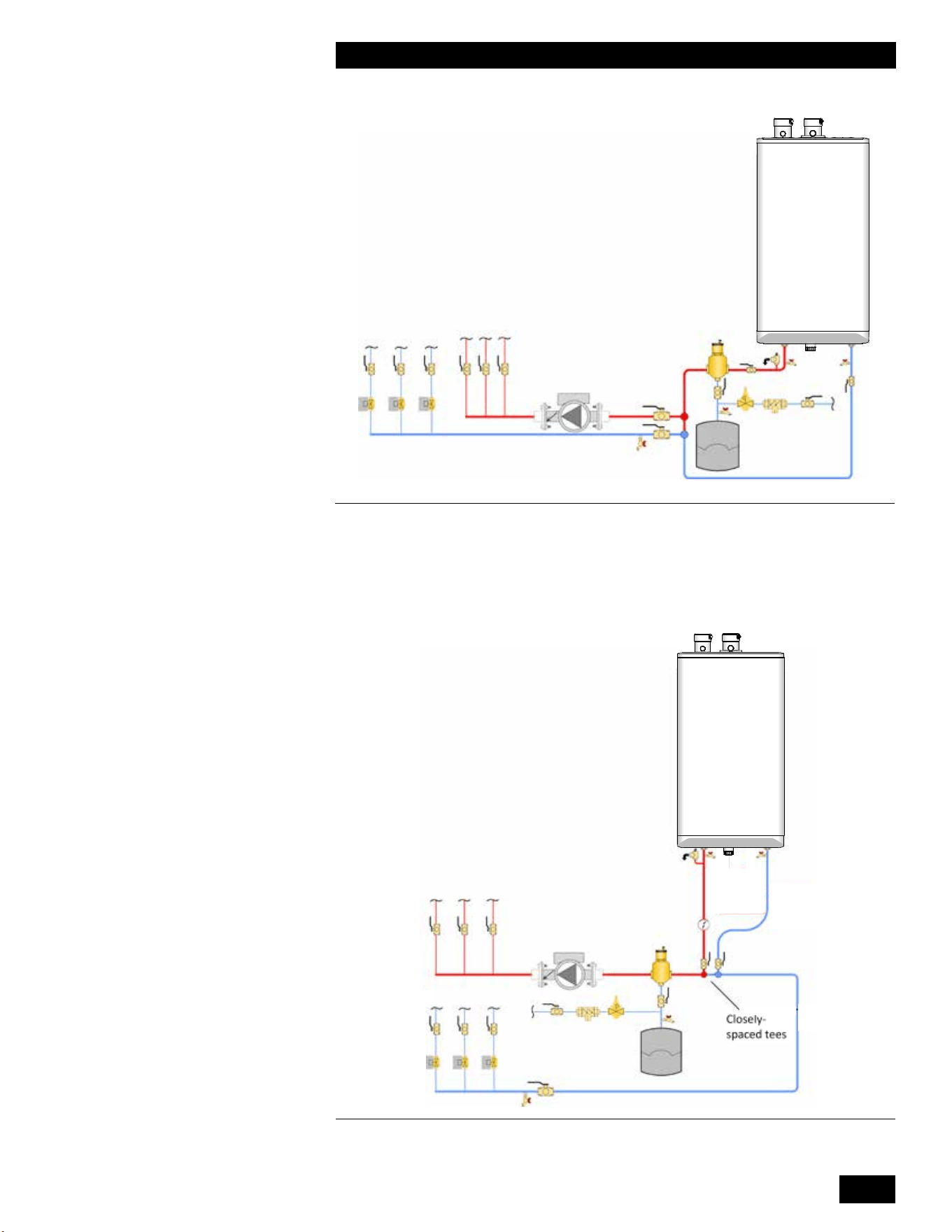
1-29
INSTALLATION
HEATING BOILERS 99 & 120
T
Boiler
B
Heating Boiler
Heating Boiler
Figure 31: Space heating piping concept with closely-spaced tees on secondary loop.
T
Heating Boiler
Figure 30: Typical one temperature space heating piping concept. This drawing is only a
simple schematic guide.
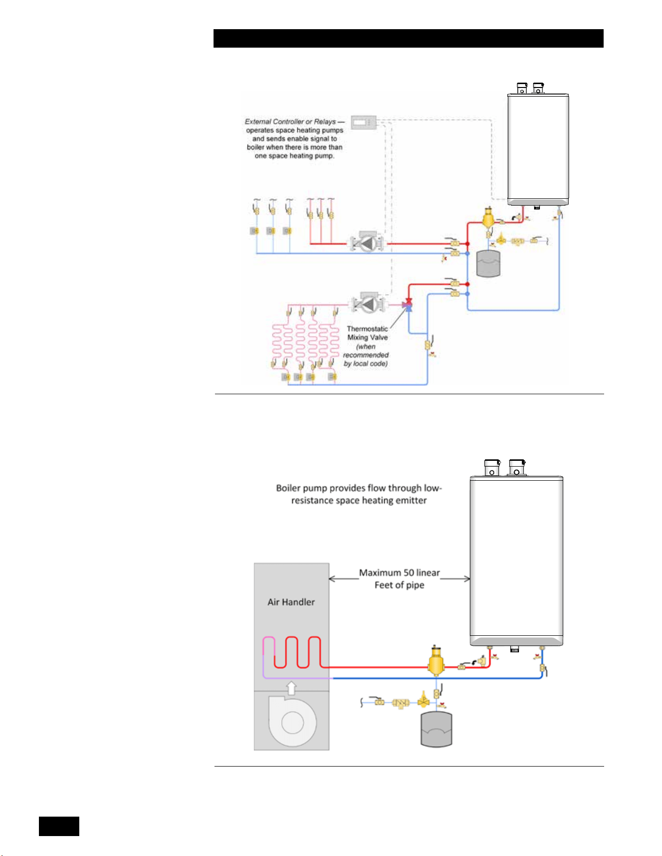
INSTALLATION AND OPERATION INSTRUCTIONS
1-30
HEATING BOILERS 99 & 120
T
Heating Boiler
Figure 32: Typical two temperature space heating piping concept. This drawing is only a
simple schematic guide.
T
Heating Boiler
Figure 33: Air handler – parallel piping for low loss heat emitter concept drawing. This
drawing is only a simple schematic guide.

1-31
INSTALLATION
HEATING BOILERS 99 & 120
T
Heating Boiler
Figure 34: Air handler – primary/secondary concept drawing. This drawing is only a simple
schematic guide.
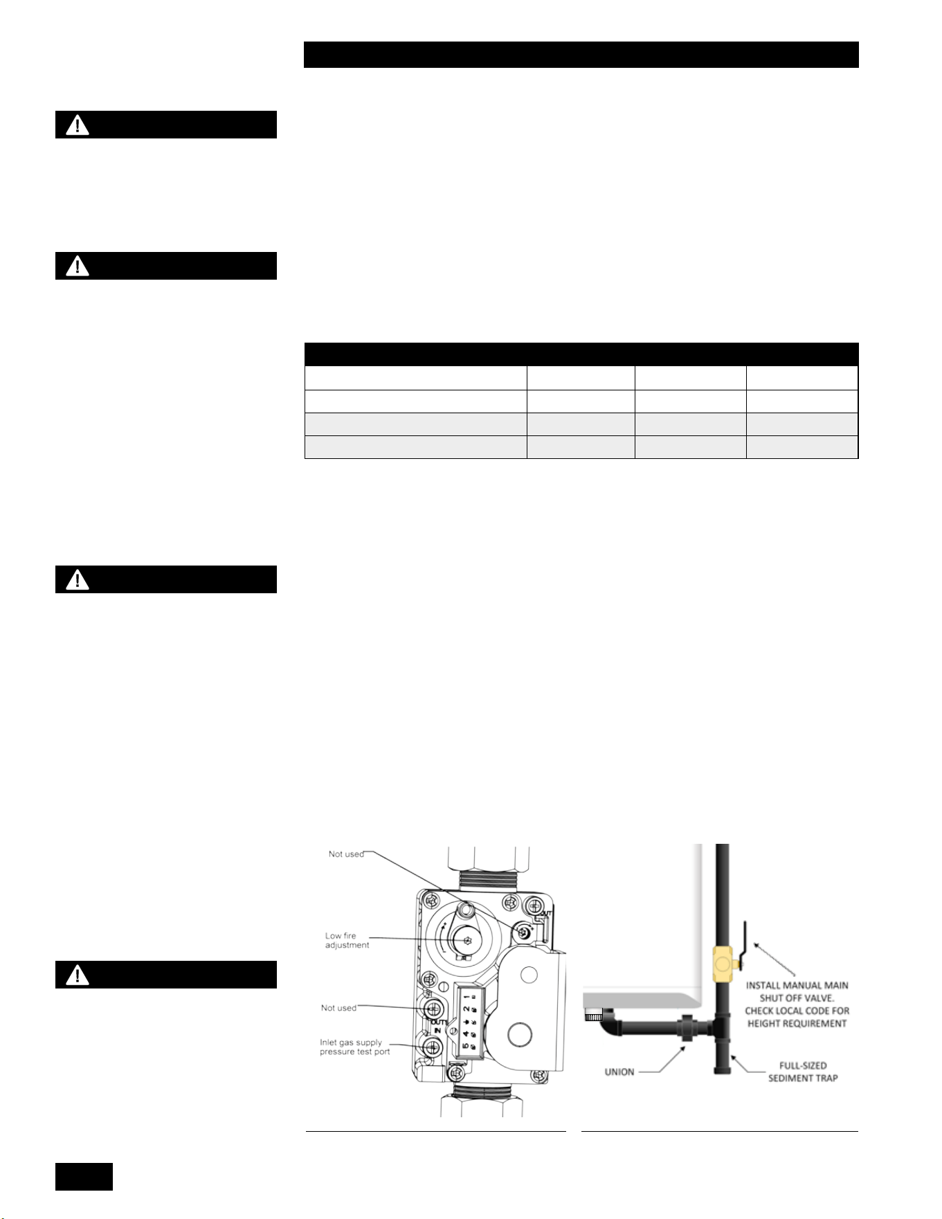
INSTALLATION AND OPERATION INSTRUCTIONS
1-32
HEATING BOILERS 99 & 120
1.7 GAS PIPING
The unit must have an inlet gas pressure of at least 4.0" w.c. for natural gas and
propane. For either fuel, the inlet pressure shall be no greater than 14.0" w.c.
Conrm this pressure range is available with your local gas supplier.
The inlet gas connection of the unit’s gas valve is 3/4" NPT (male). Use two
wrenches when tightening eld piping onto the boiler. Use one wrench to hold the
boiler tting still while tightening with another wrench.
Adequate gas supply piping must be provided with no smaller than 1/2" Iron Pipe
Size (IPS) and a 1" w.c. pressure drop, in accordance with the following chart:
MODEL 1/2" IPS 3/4" IPS 1" IPS
99,000 Btu/hr (Natural Gas) 40' 175' 500'
120,000 Btu/hr (Natural Gas) 30' 100' 350'
99,000 Btu/hr (Propane) 100' 450' 1,400'
120,000 Btu/hr (Propane) 80' 300’ 1,000'
Table 5: Maximum Pipe Length (ft)
Gas piping must have a sediment trap ahead of the unit’s gas valve (see Figure
36). A manual shuto valve must be located outside the unit, in accordance with
local codes/standards. All threaded joints in gas piping must be made with an
approved piping compound resistant to the action of natural gas/propane. Use
proper hangers to support gas supply piping as per applicable codes.
Before placing the boiler into operation, the boiler and all gas connections must
be checked for leaks.
• Close the gas shuto valve during any pressure testing equal to or less than
½ psi (3.5 kPa).
• Disconnect the boiler and gas shuto valve from the gas supply during any
pressure testing greater than ½ psi (3.5 kPa).
The gas valve is provided with pressure taps to measure gas pressure upstream
(supply pressure) and downstream (manifold pressure) of the gas valve (see
Figure 35). Note that manifold pressure varies slightly in accordance with ring
rates with the modulating series units, but will always be close to 0" w.c.
CHECK LOCAL CODE FOR
SIZE REQUIREMENTS
WARNING
This boiler model can burn
either natural gas or propane.
Refer to section 3.3 for further
instruction. If converting a
unit from one fuel to another,
you must order a conversion
kit prior to the conversion.
Install the conversion kit
according to the detailed
instructions supplied with
the kit. Failure to perform
the required fuel conversion
correctly can result in serious
injury or death.
NOTE
It is essential to check gas
supply pressure to each
unit with a manometer or
other high-quality precision
measuring device. Pressure
should be monitored before
ring the unit, when the
regulator is in a “lock-
up” condition and during
operation, throughout the
unit’s full modulation range.
Pay special attention to
retrot situations where
existing regulators may have
an over-sized orice and/or
worn seats, causing pressure
“creep” and high lock up
pressures.
Figure 35: Gas Valve
WARNING
Failure to support the boiler
tting with a second wrench
while tightening eld piping
may lead to boiler damage.
WARNING
Do not check for gas leaks
with an open ame, use the
bubble test. Failure to use
the bubble test or check
for gas leaks can cause
substantial property damage,
serious injury, or death.
Figure 36: Gas Piping
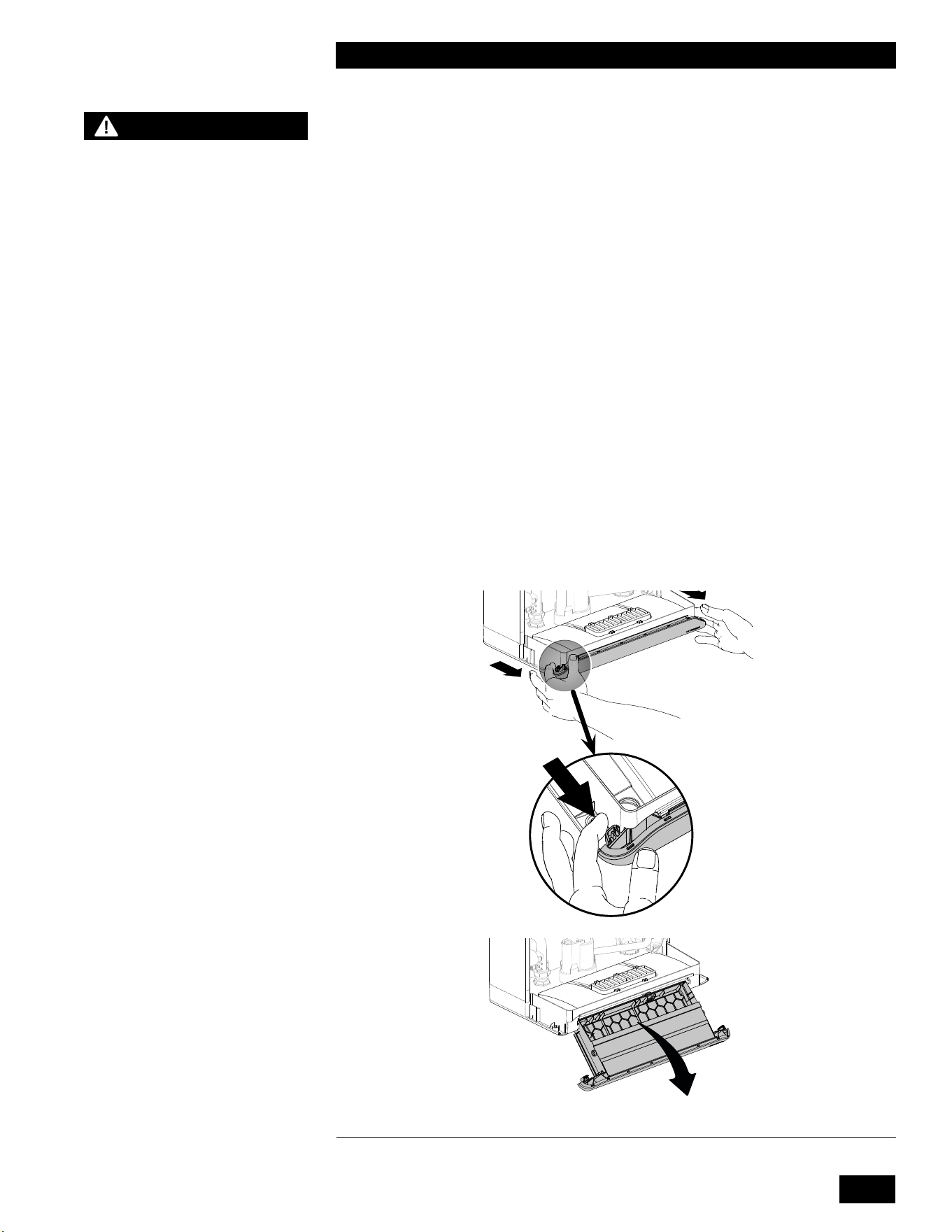
1-33
INSTALLATION
HEATING BOILERS 99 & 120
1.8 ELECTRICAL CONNECTIONS
Electrical wiring to the unit (including grounding) must conform to local electrical
codes and/or National Electrical Code, ANSI/NFPA No. 70 – latest edition in the
US or The Canadian Electrical Code, C22.1 - Part 1 in Canada.
1.8.1 120VAC Line Voltage Hook-up
(Refer to Section 6.2.Wiring Diagram on page 6-5). Connect the unit to the grid
power, using the supplied appliance plug in a separate non GFCI fused circuit and
on/o switch within sight of the unit.
The unit is equipped with 3 x 1/2" electrical knock-outs for control wiring located
behind the power supply terminal strip.
The unit includes a factory installed and pre-wired pump. The pump may not be
able to supply adequate ow for the heat emitter circuits. A system heating pump
switched through a separate relay or control box may be needed.
1.8.2 Accessing Controller Terminal Strip
Pull out on the two control module retaining tabs then ip down the control to
access the terminal strip.
Figure 37: Pullling out the tray
WARNING
Do not apply power to any
connection point on the
controllers terminal strips.
A hazardous situation could
occur resulting in possible
serious injury or death.
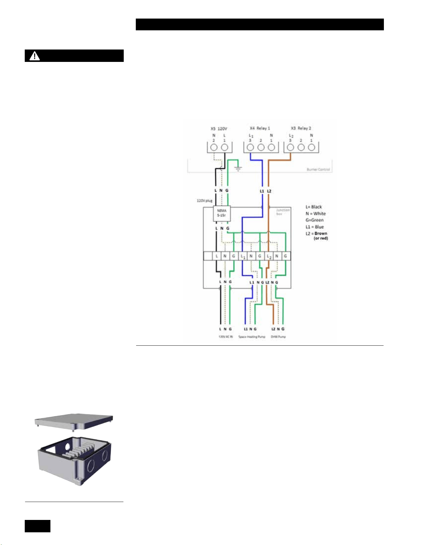
INSTALLATION AND OPERATION INSTRUCTIONS
1-34
HEATING BOILERS 99 & 120
Field Wiring Junction box
The unit ships with an optional eld-wiring junction box. This box provides wiring
connections for a space-heating pump, a DHW pump, and an outlet for unit
power. A certied harness from the wiring box connects to the movable controller
tray. You do not require a junction box if:
1. External pumps do not need to be controlled for space heating
2. There are no DHW indirect or storage tanks.
Figure 39 Junction box schematic
To install an external junction box to supply power and access the two pump
relays:
1. Pull out the controller as shown in Figure 37.
2. At the back of the tray, knock out the hole nearest to the power cord using a
athead screwdriver.
3. Feed the junction box cable through the hole and secure to the tray with the
connector nut.
4. Connect the blue wire to the X4 terminal, position 3.
5. Connect the brown (or red) wire to the X3 terminal, position 3.
6. Screw the junction box to the wall within six feet of the tray.
• Allow clearance for plug use.
• Allow wire enough slack for easy removal of the tray.
7. Drill out both holes in the junction box.
8. Connect 120VAC power to terminals labelled Power Inlet.
NOTE
- This unit (like any modern
appliance that contains
electronic equipment), must
have a “clean” power supply,
and can be disabled by power
surges and spikes, lightning
strikes and other forms of
severe electrical “noise”.
Power conditioning equipment
(surge protectors, APC or UPS
devices) may be required in
areas where power quality is
suspect.
- The control typically uses a
true dry contact closure as a
call for heat. A signal from an
Open Therm device can also
be used. Thermostats and
other devices that use a “Triac”
output cannot be used as a call
for heat without the installation
of an intervening relay with
dry contacts to connect to the
terminal strip.
- A Heating Boiler installed
above radiation level or as
required by the Authority
Having Jurisdiction, must
be provided with a low water
cut-o device at the time of
unit installation. Refer to 1.8.3
External probe type low water
cuto device for installation
instructions.
Figure 38: Junction Box
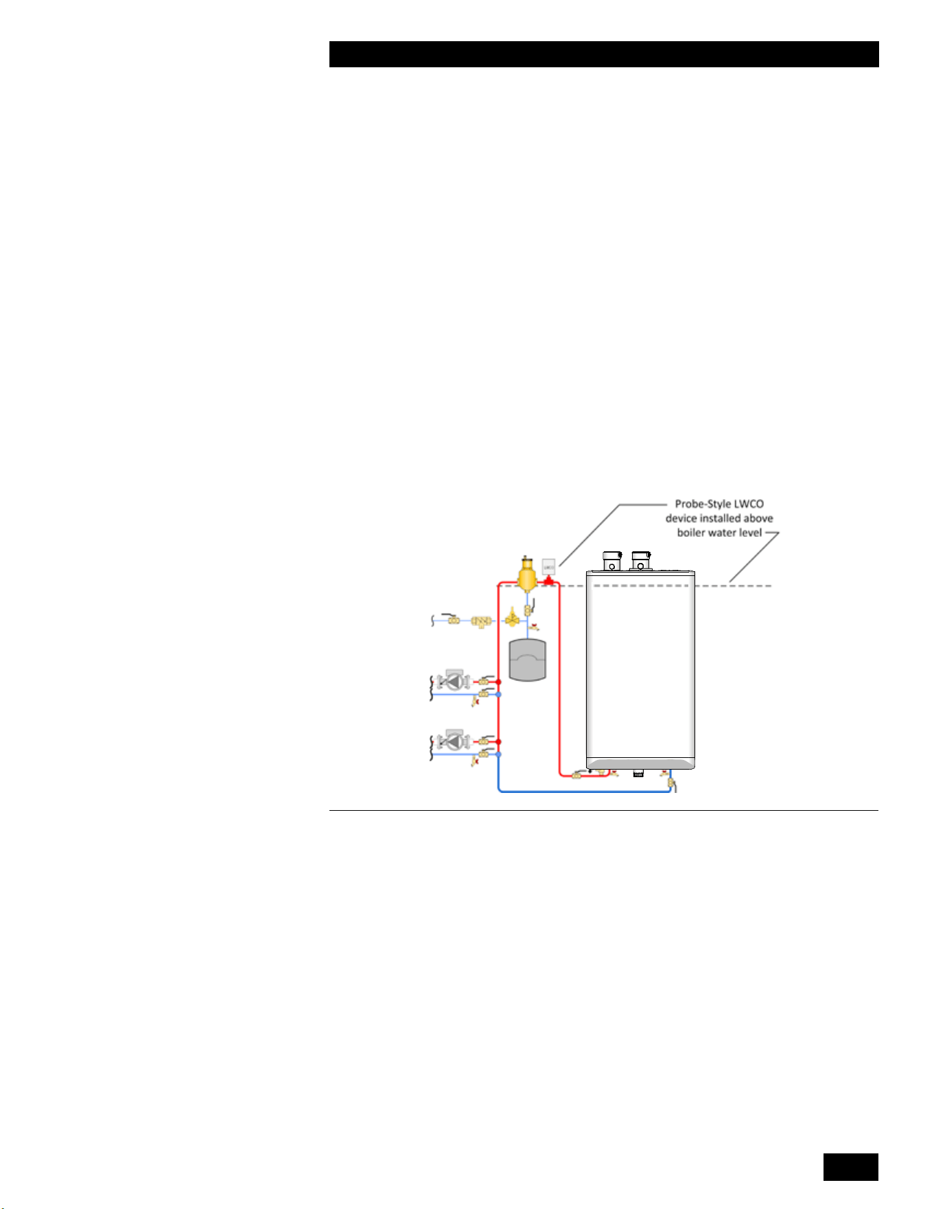
1-35
INSTALLATION
HEATING BOILERS 99 & 120
9. Wire the pump(s) to the junction box.
• Wire the space heating pump to terminals labeled Relay 1.
• Wire the DHW pump to terminals labeled Relay 2.
If using both relays, wire the pumps to the box with a duplex connector.
10. Install the junction box cover.
Note: If the junction box is installed, 120VAC power must be supplied to the
Heating Boiler through the junction box. Do not plug the unit in elsewhere.
1.8.3 External probe type low water cutoff device
You can link a eld-supplied, external safety device to the unit by connecting the
safety device in series with the unit’s 120V main power supply.
We recommend using an electronic probe style device:
• Install the probe type low water cut-o device with a Tee connection at a level
above the top of the unit.
• Wire the probe type low water cut-o device in series with the 120VAC power
supply, so that when the device trips on a low water condition the power
supply to the unit is interrupted.
T
Heating Boiler
Heating Boiler
Figure 40: External Probe Type Low Water Cuto Device
1.8.4 Power Quality and Electrical Protection
In areas of unreliable power, appropriate surge protectors and / or power
conditioning equipment should be installed to protect the unit.
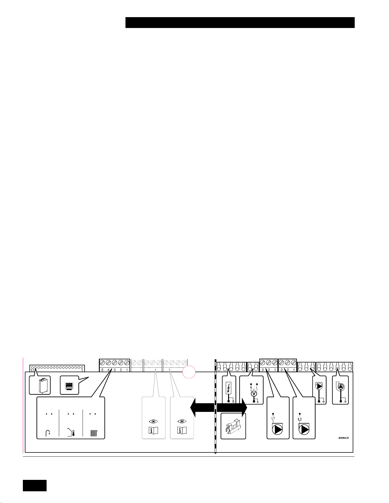
INSTALLATION AND OPERATION INSTRUCTIONS
1-36
HEATING BOILERS 99 & 120
1.8.5 Zone Valve and Zone Pump Connections
Zoning can be accomplished with either zone pumps or zone valves. If zoning by
multiple pumps, we recommend using an external pump module.
Zone valve end switches can be wired together in parallel, and connected to X13
terminals 1 and 2. Do not apply power to the X13 terminal strip. Alternatively, you
can connect the zone valves and thermostats to a zoning panel control system
(available from your local heating wholesaler).
You can connect zone pumps to the unit with a zone pump control, available from
your local heating wholesaler.
1.8.6 Thermostat / Sensor Wiring
A thermostat from a single zone heating system can be connected directly to the
controller’s X13 terminals 1 and 2. Do not apply power to the X13 terminal strip.
An outdoor sensor is not required for the unit to operate. If an outdoor sensor is
not connected, the unit will operate as a set point unit and operate at its design
supply temperature.
If outdoor reset functionality is desired connect the supplied Outdoor sensor to
X13 terminals 3 and 4. The outdoor sensor is a 12KΩ thermistor type sensor.
The sensor should be installed:
• On the exterior of the building on the north side.
• Ensure the outdoor sensor is shielded from direct sunlight and not near any
building exhausts which could aect its temperature reading.
DHW Aquastat or 10KΩ sensor can be connected to the controller’s X13
terminals 4 and 5. Do not apply power to the X13 terminal strip.
3 2 1
5 4 3 2 1
1
17
4 3 2
3 2 1
2 1
X15
X8
Fuse inside
X5
X2 X1
X14
X11
X10
X4 (120 V ~ )
120 V ~ , 60 Hz
24 V =
120 V ~
1
3
2
2 1
L1
F1 (5 AT)
junction box
859904.01
N L
3 2 1
X3 (120 V ~ )
3
L2
junction box
X13
DHW Aquastat
or Sensor
10kΩ
Outdoor Sensor
12kΩ
Space Heating
Demand
(dry contact)
5
4
4
3
2
1
Figure 41: Terminal strip for connection of the DHW Aquastat (optional), thermostat or end switch(es) (mandatory), outdoor sensor
(optional)

2-1
UNIT SYSTEM OPERATION
HEATING BOILERS 99 &120
2.0
UNIT SYSTEM OPERATION
2.1 GENERAL
The Heating Boiler is designed to heat your indoor space. The Heating Boiler
units can also generate domestic hot water with an indirect water heater.
With the installation of the provided outdoor sensor, the unit’s controller can
provide outdoor reset control for the space heating load. Installing the outdoor
sensor is optional, but recommended for higher eciency.
Alternatively, the controller can provide a set-point water temperature for the
space heating load.
The unit is equipped with a factory-installed pump. The pump is pre-wired and
will operate with any call for space heating or when heating an indirect water
heater.
The Heating boiler pump operates for 10 seconds every 24 hours to prevent
it from seizing. The pump is energized 24 hours after the last call for heat and
every 24 hours after that until the next call for heat.
The unit is equipped with an electronic unit controller that ignites the burner and
continuously monitors the ame throughout each call for heat. The control also
displays the current operating conditions of the unit and any error messages
should a problem occur.
The unit’s controller also provides frost protection. When the unit’s heat
exchanger temperature becomes too low the burner switches on to keep the heat
exchanger warm. Ensure that the condensate trap is protected from freezing. The
unit must be installed indoors.
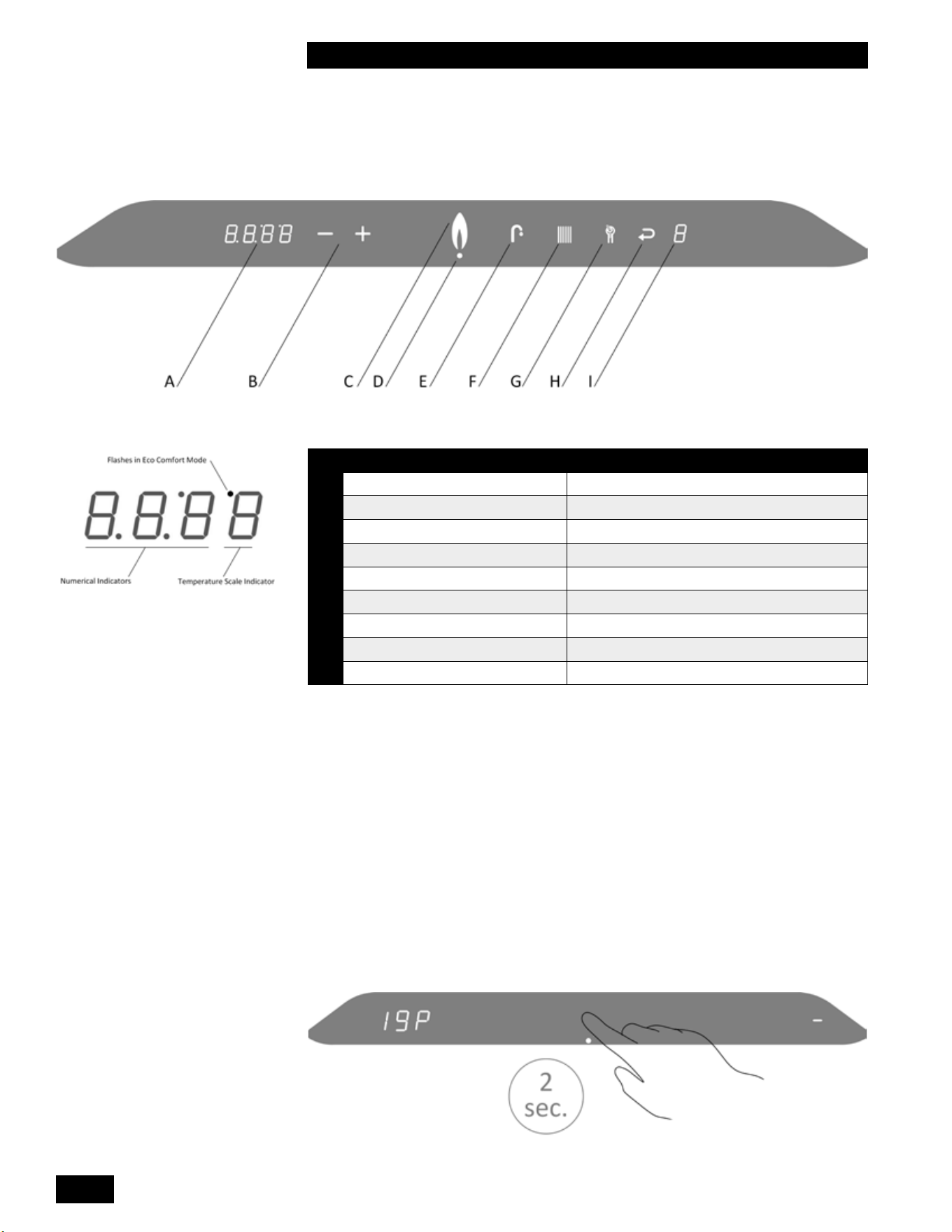
INSTALLATION AND OPERATION INSTRUCTIONS
2-2
HEATING BOILERS 99 & 120
2.2 CONTROL
ICON FUNCTION
A
Numerical Display Main Display
B
Plus & Minus Temperature Adjustment
C
Flame Burner ON Indicator
D
Dot Power ON Indicator
E
Faucet DHW Indicator
F
Radiator Heating Indicator
G
Wrench Service / Reset
H
Return Arrow Enter / Save
I
Numerical Display Service Display
Table 6: Controller Indicators and Touch Pad
2.3 INSTALLER INTERFACE
2.3.1 Turning Appliance ON/OFF
To turn on the unit, touch the area above the dot for 2 seconds. Now only the dot is
illuminated.
To turn o the unit, touch the area above the dot for 2 seconds. A dash appears to
the right and the space heating water pressure displays to the left.
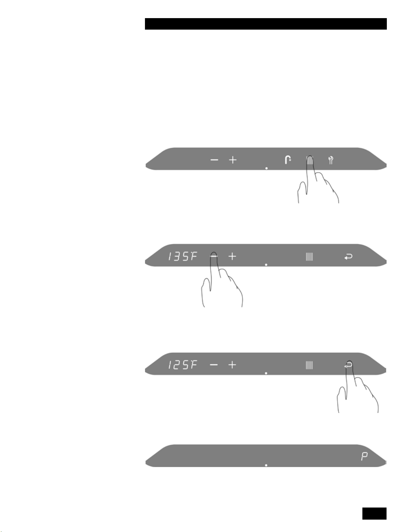
2-3
UNIT SYSTEM OPERATION
HEATING BOILERS 99 &120
2.3.2 Programming Mode
There are two parameters available in the User Setup Menu.
The controller has ve levels: User Menu, Installer Menu (code 15), a Master
Installer Menu (code 20), RF Menu (code 30) and Cascade Menu (code 35). See
included Controller Manual for details.
Adjusting the space heating water temperature
To access the main menu:
1. Touch the area above the dot.
2. Touch the Radiator button.
3. To change the space heating target temperature, touch the Plus or Minus
buttons.
4.
• To save the changes, touch the Return button.
• To exit without saving the changes, touch the area above the dot.
“P” to the right of the screen indicates that the changes have been saved.
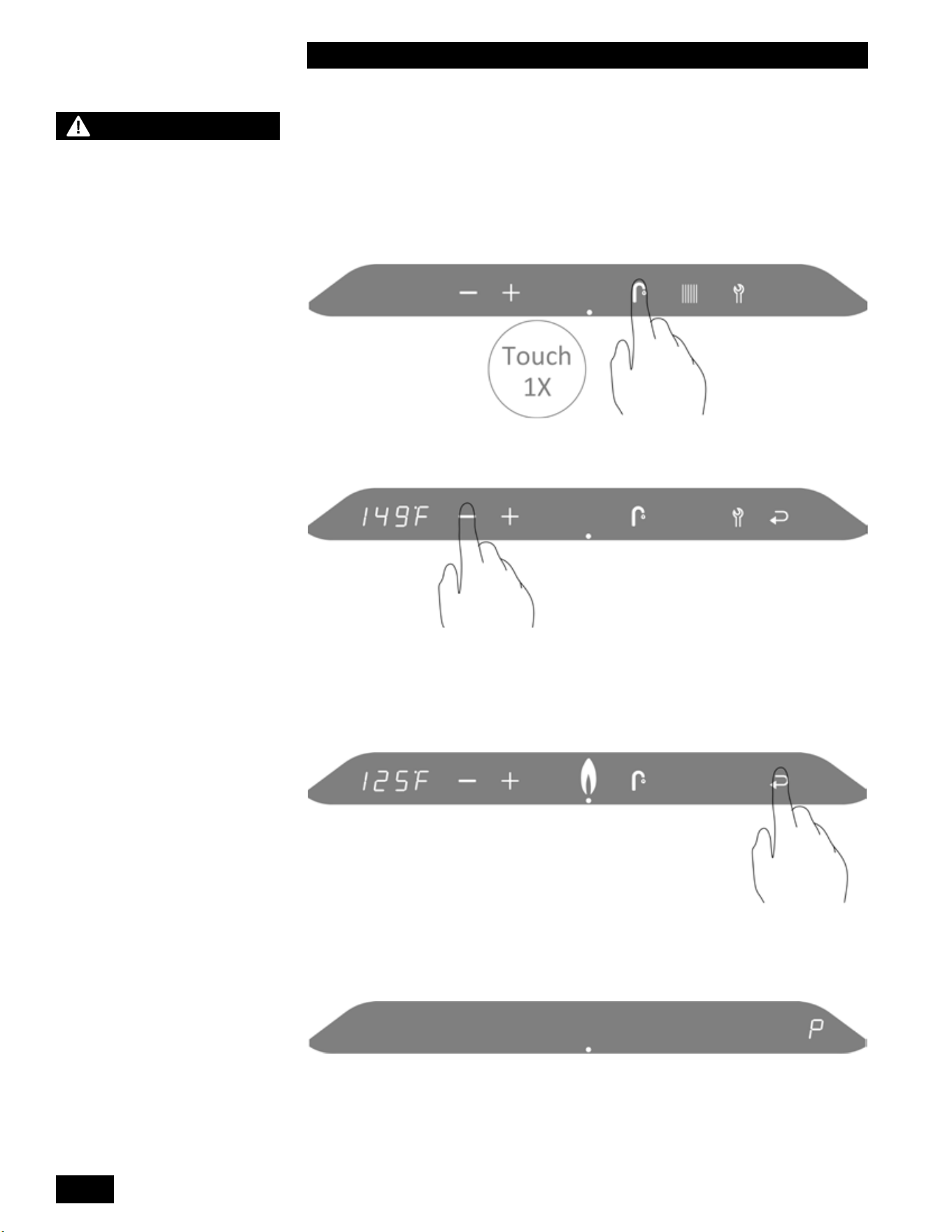
INSTALLATION AND OPERATION INSTRUCTIONS
2-4
HEATING BOILERS 99 & 120
Adjusting the Domestic Hot Water Temperature
This setting takes eect only when the temperature of an indirect domestic hot
water heater is sensed by a 10KΩ DHW sensor.
To access the main menu:
1. Touch the area above the dot.
2. Touch the Faucet button.
3. To change the DHW target temperature, touch the Plus or Minus buttons.
2. To alter this value, touch the Plus or Minus buttons.
4.
• To save the changes, touch the Return button.
• To exit without saving the changes, touch the area above the dot.
“P” to the right of the screen indicates that the changes have been saved.
WARNING
The correct 10KΩ temperature
sensor (or aquastat) must be
used to operate the indirect
water heater properly. If the
incorrect sensor is used
the domestic hot water may
overheat causing serious
injury or death.

2-5
UNIT SYSTEM OPERATION
HEATING BOILERS 99 &120
2.4 DOMESTIC HOT WATER
2.4.1 Domestic Hot Water with an Indirect Water
Heater
You can connect the Heating Boiler to an indirect water heater. Connect the
indirect water heater’s supply and return connections to the unit’s primary loop
using a hydraulic separator or closely-spaced tees. Properly sized piping must
be installed. A properly sized pump must also be installed between the unit and
the indirect water heater. The pump can be wired to the included junction box to
provide DHW priority.
2.5 SPACE HEATING
2.5.1 Overview
The Heating Boiler is designed to be installed in a primary/secondary type
piping system. The unit comes complete with a factory-installed pump, which is
designed to circulate heating system water through the unit’s heat exchanger and
primary loop piping only. The building’s distribution piping system may require a
dedicated pump or pumps to circulate space heating water through the heating
system. The unit can operate a separate building pump (120V 1.0 AMP max).
There are various ways to zone a space heating system. Local wholesalers sell
control packages that oer easy methods to connect the zoning system to the
unit.
The unit supplies heat to the space using an outdoor reset function. With an
outdoor sensor installed, the unit automatically adjusts its space heating water
temperature based on the parameters programmed into the unit. See separate
controller manual for parameter information. If the Outdoor sensor is not installed,
the unit uses the temperature set in the “User Set Up” menu “Boiler Supply
Temperature” to supply hot water to the space heating system.
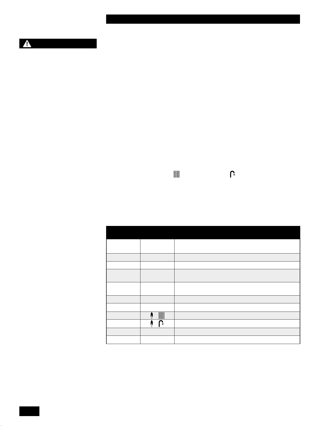
INSTALLATION AND OPERATION INSTRUCTIONS
2-6
HEATING BOILERS 99 & 120
2.6 SEQUENCE OF OPERATION
The unit operates in a similar way for both a space heating and a domestic hot
water call for heat. When the unit is powered up the controller enters a self-
diagnostic mode, and displays the controller software version in the main display.
The sequence of operation is as follows:
1. The unit receives a call for heat from a dry contact closure on terminals
X13.1 and X13.2 (24 volts section). The unit can also receive a call forfor
domestic hot water heating from a 10KΩ sensor or aquastat wired to
terminals X13.4 and X13.5 (24 volts section).
2. The unit performs a safety check and energizes the fan for a pre-purge
(Service Display = 3).
3. Once the 5-second pre-purge is complete, the unit enters a 5-second trial for
ignition (Service Display = 4). If the unit fails to ignite, the unit will complete
another 5-second pre-purge then 5-second trial for ignition. This is repeated
4 times before a hard lock-out occurs. The Return button must be pressed to
reset the controller and begin another trial for ignition.
4. Once the burner is lit and ame has been proven the unit operates as it is
programmed (Display = for space heating or for domestic hot water).
5. If the unit exceeds its target temperature and there is still a call for heat or hot
water the burner will turn o (integral pump runs) (Service Display = 1).
6. After call for heat is satised, the unit’s pump will operate for an adjustable
amount of time (Service Display = 0).
7. If the burner is on for frost protection (Service Display = 9).
MAIN
DISPLAY
SERVICE
DISPLAY
DESCRIPTION
[pressure] P - The unit is OFF. Press the space above the dot for 2
seconds to turn on the unit
.
(blank) (blank) No Call for Heat - Standby
XXX 0 Unit pump running – pump post purge
XXX 1 Unit water temperature exceeds target – unit pump is
energized, call still present
XXX 2 Self-test – When power is applied to the unit the
controller enters a self diagnostic mode for 5 seconds
XXX 3 Fan Pre-purge and Post-purge
XXX 4 Trial for Ignition and Flame Proving
XXX + Heating – Space Heating
XXX + Heating – DHW
XXX 7 Burner on for DHW Comfort mode
XXX
9
Freeze Protection mode
Table 7: Operating Display and Service Display Codes.
NOTE
The unit is equipped with
a frost protection feature.
This feature operates the
unit’s built-in pump and the
burner to help protect the
unit from freezing. If the
unit is in a hard lock-out
condition the burner will not
operate, but the unit’s built-
in pump will operate. We are
not responsible for damages
to the unit, and/or related
components, nor property
damages that may result from
freezing conditions.
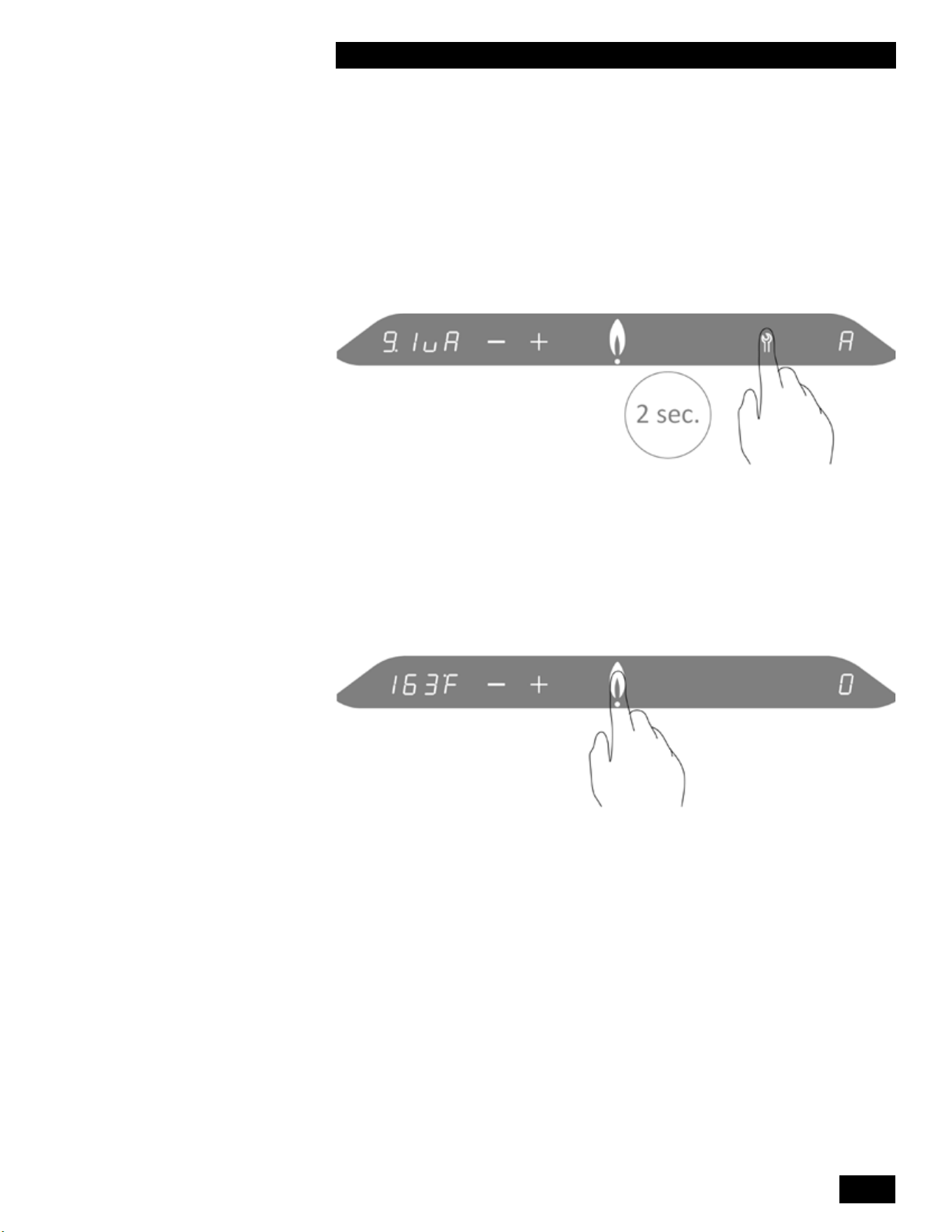
2-7
UNIT SYSTEM OPERATION
HEATING BOILERS 99 &120
2.7 ACCESSING THE INFORMATION MENU
The Information menu provides real time operating information to assist with
troubleshooting.
To access the Information menu:
1. Touch the area above the Dot.
2. Touch and hold the Wrench button for two seconds, let go when the minus,
plus, and wrench are displayed.
3. Again, touch and hold the Wrench button for two seconds to enter the
information menu.
See table 8 for a list of codes and corresponding description.
4. To scroll through the list of codes, use the Minus or Plus button.
5. To exit the information menu and return to the Service menu, press the area
above the Dot.
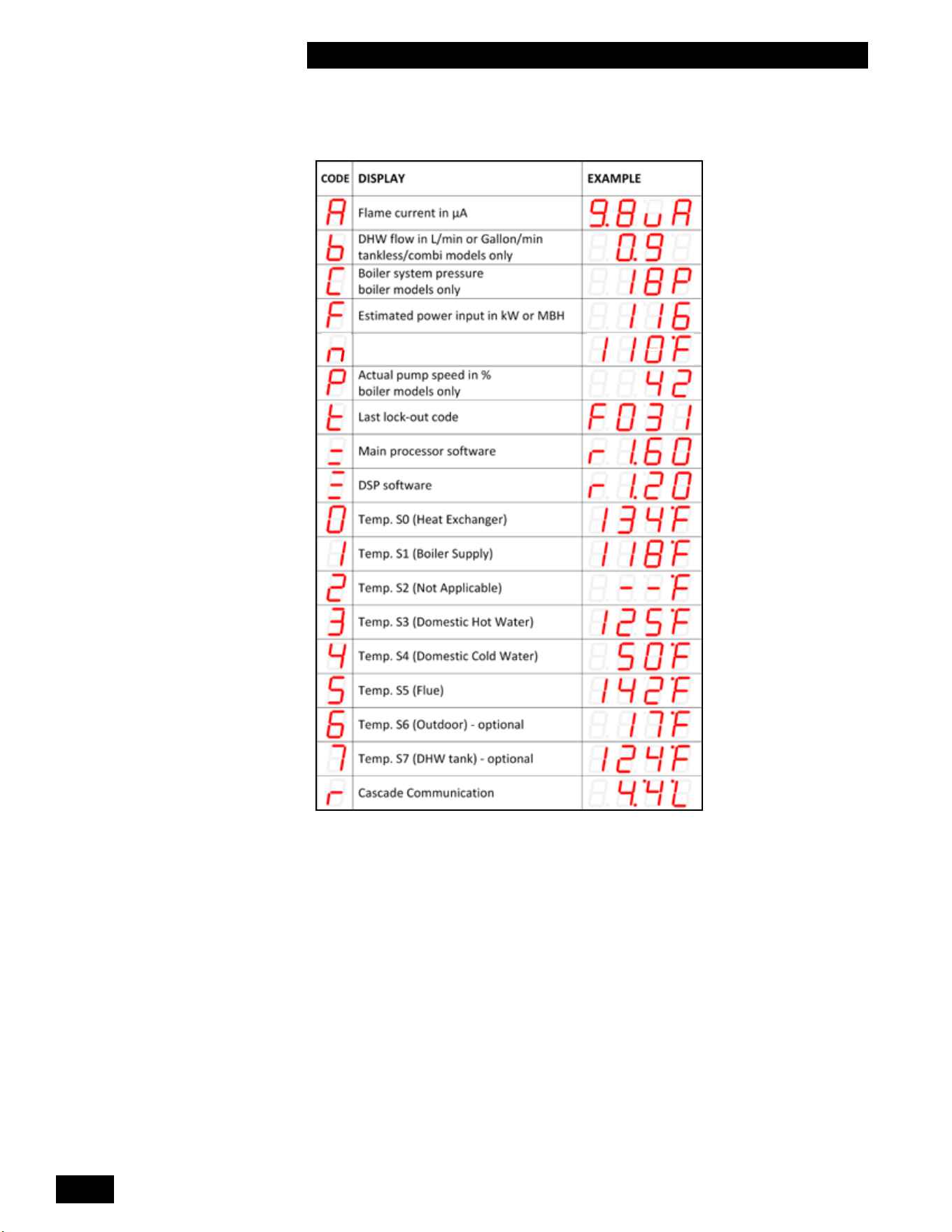
INSTALLATION AND OPERATION INSTRUCTIONS
2-8
HEATING BOILERS 99 & 120
INSTALLATION AND OPERATION INSTRUCTIONS
2-8
HEATING BOILERS 99 & 120
See below for a description of the codes:
Space heating setpoint
Table 8: Information Menu
Note that display parameters may dier depending on the conguration. Where
there is no DHW sensor, the display reading can be ignored.
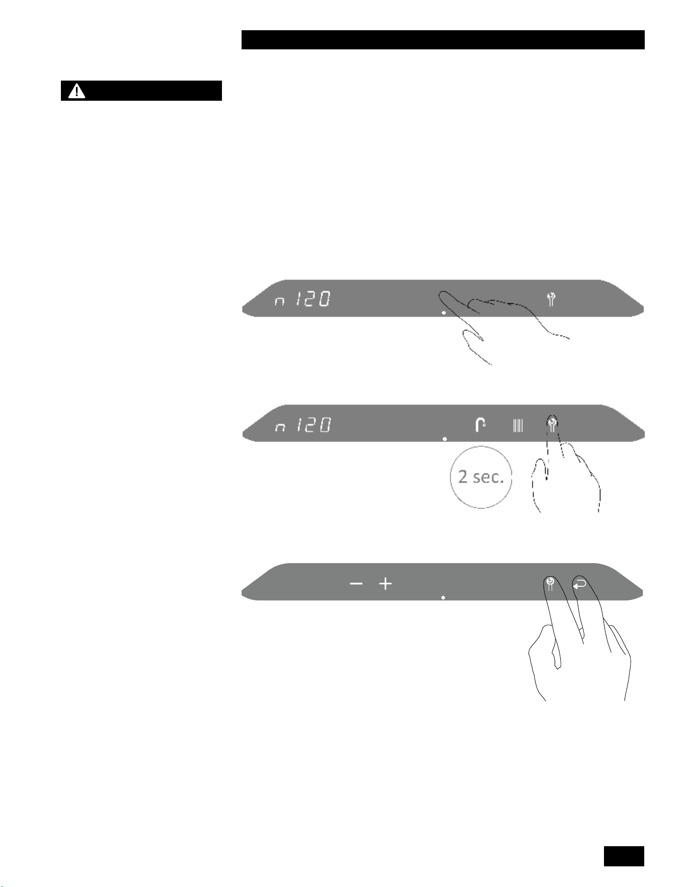
2-9
UNIT SYSTEM OPERATION
HEATING BOILERS 99 &120
2.8 RESETTING THE MAINTENANCE
COUNTER
Inspection of the unit must be performed annually by a qualied service
technician. This unit includes a maintenance counter which tracks the amount of
fuel burned within a two year period to ensure maintenance is performed if usage
exceeds typical residential usage. When above average usage occurs within a
two year period, a notication code will be displayed.
To reset the maintenance counter and clear a maintenance notication code:
1. Touch the area above the dot.
2. Touch the wrench for two seconds until the return button appears.
3. Touch wrench and return buttons together.
CAUTION
The maintenance counter
must only be reset after
performing the maintenance
procedures in Section
4.0 Maintenance of this
manual. Failure to perform
maintenance can result in a
hazardous condition.
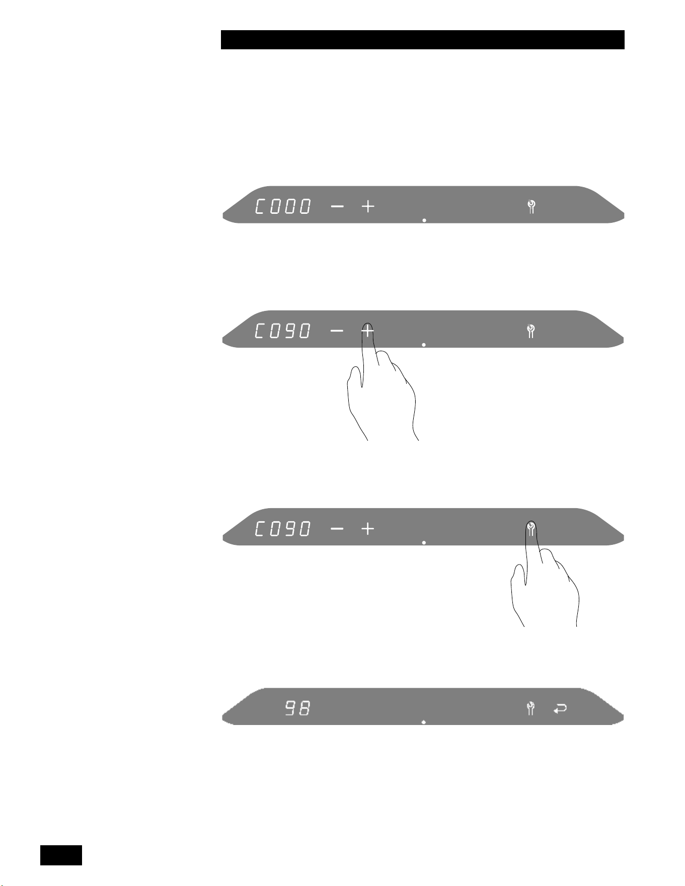
INSTALLATION AND OPERATION INSTRUCTIONS
2-10
HEATING BOILERS 99 & 120
INSTALLATION AND OPERATION INSTRUCTIONS
2-10
HEATING BOILERS 99 & 120
The code numbers are displayed in the left numerical display.
4. Change C000 to C090 by touching the + button.
5. Touch wrench to enter the maintenance menu.
The current maintenance counter value is displayed in the left numerical display.
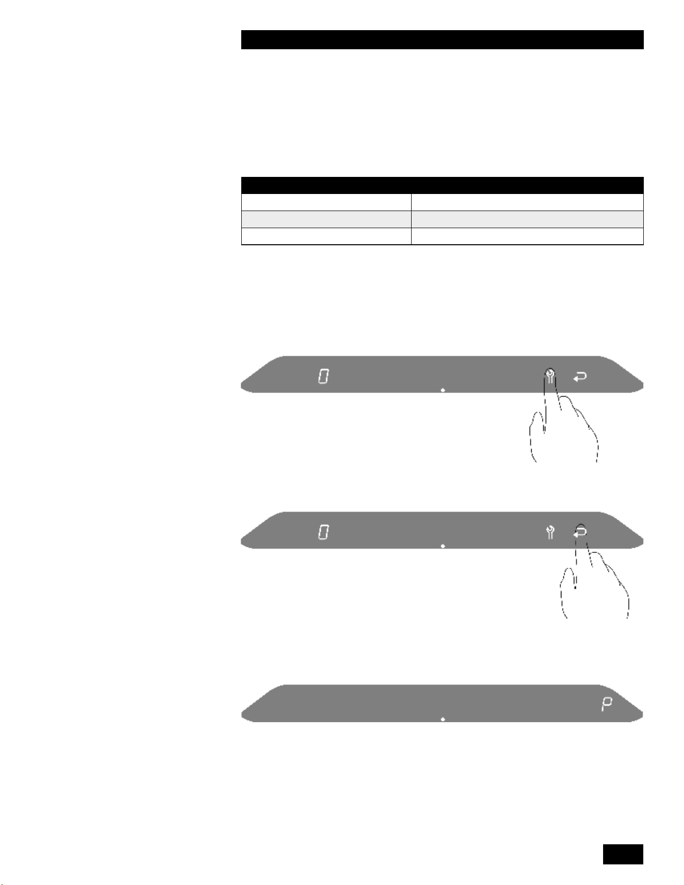
2-11
UNIT SYSTEM OPERATION
HEATING BOILERS 99 &120
The following notications will be displayed as the time for maintenance
approaches.
MAINTENANCE COUNTER NOTIFICATION CODE
80 n120 - Maintenance recommended
100 n121 - Maintenance required, limited DHW output
120 n122 - Maintenance required, no DHW output
The notication code will be displayed for 30 seconds and the wrench will ash.
Press the wrench button to see the notication code again after 30 seconds.
6. Touch the wrench to reset the maintenance counter to “0”.
7. Touch return to resume normal operation.
“P” will be briey displayed on the right screen to indicate the change has been
stored.

INSTALLATION AND OPERATION INSTRUCTIONS
2-12
HEATING BOILERS 99 & 120
INSTALLATION AND OPERATION INSTRUCTIONS
2-12
HEATING BOILERS 99 & 120
This page is intentionally left blank.
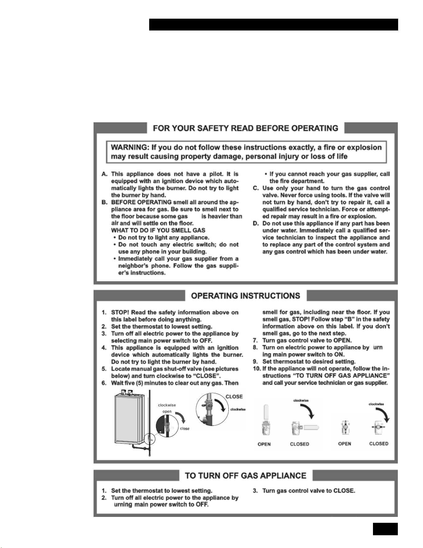
3-1
STARTUP AND COMMISSIONING
HEATING BOILERS 99 & 120
3.0 STARTUP & COMMISSIONING
3.1 LIGHTING & SHUTTING DOWN THE
UNIT
(LP)
t
-
t
t

INSTALLATION AND OPERATION INSTRUCTIONS
3-2
HEATING BOILERS 99 & 120
INSTALLATION AND OPERATION INSTRUCTIONS
3-2
HEATING BOILERS 99 & 120
3.2 PRIOR TO START-UP
3.2.1 Pre-Ignition Checks
1. Fill the condensation trap. Ensure the venting system is complete and seal-
tested. Conrm that any common venting system at the installation site is
isolated and independent of the unit, that any holes left from removal of a
previous unit have been sealed, and that any resizing of the old ue has
been done.
2.
Check that the water piping system is fully ushed and lled, and that all
air has been discharged. Use a minimum water pressure of 12 psig and
conrm that the pressure relief valve is installed and discharge line is directed
downward to a safe point of discharge.
3. Check to see that adequate gas pressure is present at the inlet gas supply
test port. With the unit gas valve shut o, using a Torx 15 screwdriver, open
the test port by turning 1 full turn counterclockwise. Connect a manometer
and open the manual gas valve. Requirements are minimum 4" w.c. and
maximum 14" w.c. Check that there are no gas leaks.
4. Perform a nal check of electrical wiring and provide power to the unit to
initialize operation.
5. The installer must verify that at least one carbon monoxide alarm has
been installed within a residential living space or home following the alarm
manufacturer’s instructions and applicable local codes before putting the
appliance into operation.
3.2.2 Test Ignition Safety Shutoff
With the unit in operation, test the ignition system safety shuto device by
shutting o the manual gas valve immediately outside the unit case. Ensure that
the unit has shut o and that the appropriate error information is displayed on the
main display screen. To restart the unit, press the reset button.
3.3 COMMISSIONING
The Heating Boiler is factory calibrated to operate with natural gas at sea level.
High Fire combustion is set by the orice installed and is not eld adjustable.
A low caloric value natural gas orice (See Table 9) is available for locations
where the natural gas caloric value falls below the expected range of 950-
1100 BTU/Ft³. Consult your local fuel provider for your fuel’s caloric value. Low
re is eld adjustable via the low re adjustment on the gas valve but must be
done with caution. No mixture adjustment may be performed unless done by
a qualied technician using a properly functioning and calibrated combustion
analyzer.
This unit can burn either natural gas or propane if equipped with the
correct specied orice. Examine the rating plate of the unit to ensure it
is congured for the fuel you are using. If the unit is to be converted from
natural gas to propane or from propane to natural gas a fuel conversion kit
must be installed. For the correct fuel conversion kit part number, see the
table on the next page:
DANGER
- Fill trap with water before
unit is rst red to prevent
exhaust fumes from entering
room. Never operate the unit
unless the trap is lled with
water.
Failure to comply will result
in severe personal injury or
death.
- It is forbidden to make
adjustments to the gas
valve except with a properly
calibrated gas combustion
analyzer by persons who
are trained and experienced
in its use. Failure to use an
analyzer can result in an
immediate hazard.
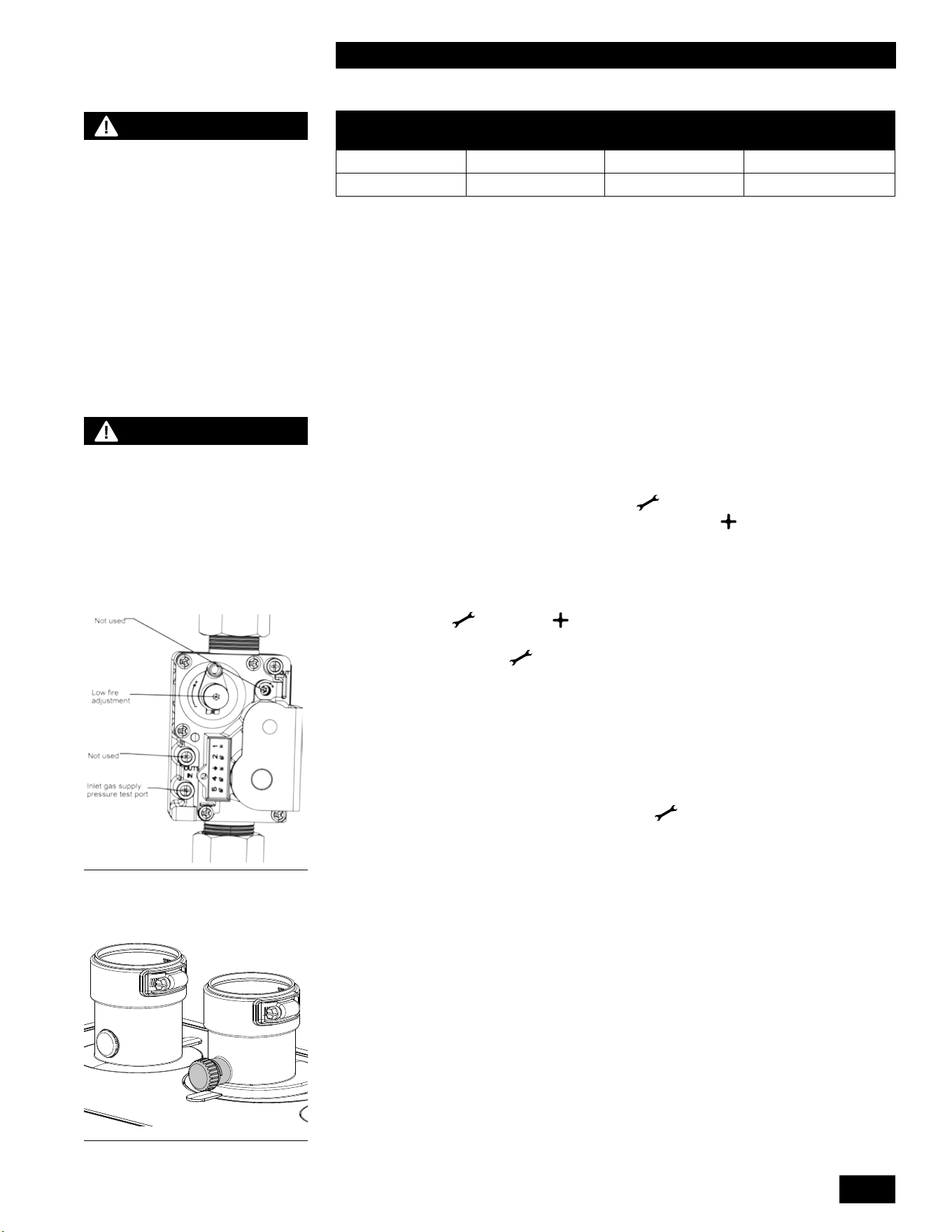
3-3
STARTUP AND COMMISSIONING
HEATING BOILERS 99 & 120
MODEL NATURAL GAS
TO PROPANE
PROPANE TO
NATURAL GAS
LOW CALORIFIC
NATURAL GAS
99,000 Btu/hr P-081034 P-081044 P-081364
120,000 Btu/hr P-081054 P-081064 P-081374
Table 9: Fuel conversion kits
The gas valve will automatically de-rate the maximum input by approximately 2%
per 1,000' above sea level. The gas valve’s zero governor will ensure that the
gas-air mixture is not aected at altitude.
To verify the proper operation of the gas valve in the eld, the following procedure
can be carried out by a qualied technician (see diagrams on this page).
1. Turn o the unit’s manual gas valve. With a Torx 15 screwdriver, open
the inlet gas supply pressure test port by turning its screw 1 full turn
counterclockwise. Attach a manometer to the pressure test port. Turn on
gas to the appliance. Static manometer reading should be ideally 7" w.c.,
for natural gas and 11" w.c. for propane. Minimum and maximum static
pressure must be between 4" and 14" w.c. Monitor pressure throughout the
commissioning procedure. Pressure may droop up to 1" at high re.
2. Allow the unit to ignite / run against a large load. To maintain high re, press
the ame icon, then press and hold the
Wrench icon for two seconds.
Then while holding the Wrench icon press the Plus button twice. “H” will
show in the service display as the unit enters high re.
NOTE: Allow the unit to operate at high re for 3 minutes to stabilize.
(The unit operates in manual mode for 10 minutes then switches back
to the normal operating mode. To extend manual mode operation, press
the Wrench and Plus together twice while the unit is operating
in manual mode to reset the timer for 10 more minutes.) Do not take
measurements if the Service display shows an “h”.
3. Clock the natural gas meter to conrm full maximum rating plate input. With
a combustion analyzer probe in the ue gas test port, check the measured
results against Table 10 - High Fire. If the results are outside the permitted
range, check the inlet pressure, and conrm that the correct orice and
venturi are installed. High Fire CO
2
is set by the orice installed and is not
eld adjustable. For areas of lower caloric value natural gas, install the
alternative orice listed in Table 9.
4. Switch the unit to low re by pressing the
Wrench button and Minus
-
buttons at the same time. The unit will drop to low re. “L” will show on the
service display. Compare the readings with Table 10 - Low Fire. If adjustment
is necessary, remove the low re adjustment cap to reveal a Torx head screw.
Make minimal adjustments, typically less than 1/8th of a turn at a time. Turn
the screw clockwise to increase CO
2
and counter-clockwise to reduce CO
2
.
If the target cannot be met, even after a full turn, contact the factory. When
nished, replace the low re cap, and leave the manual mode by pressing +
AND - simultaneously.
5. Switch o the unit by pressing the space above the dot for two seconds. Turn
o the gas at the unit’s manual gas valve. Remove the ue gas analyzer
from the test port and reinstall the test port cap. Remove the gas pressure
manometer from the gas valve and fully close the test port. Turn on the gas
at the gas shut o valve. Ensure that there are no gas leaks and reinstall
the front cover. Turn on the unit by pressing the space above the dot for two
seconds.
Figure 42 Gas Valve Adjust
Figure 43 Flue gas test port plug
WARNING
Check the rating plate of the
unit to ensure it is congured
for the fuel you are using. If
the fuel is incorrect for the
appliance, a conversion kit
must be installed as listed
in table 9, and the gas valve
adjusted accordingly.
Failure to perform the
required fuel conversion can
result in an immediate hazard.
DANGER
Attempting to change high
re combustion by adjusting
the low re combustion
adjustment could lead to
unstable operation, failed
ignitions, or dangerous
operating conditions.
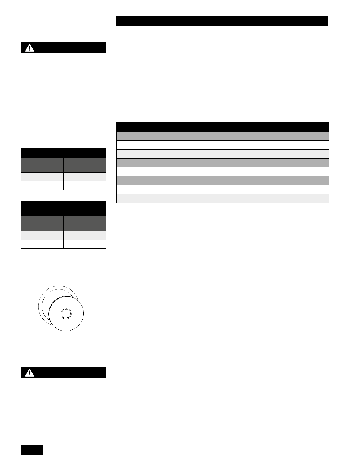
INSTALLATION AND OPERATION INSTRUCTIONS
3-4
HEATING BOILERS 99 & 120
INSTALLATION AND OPERATION INSTRUCTIONS
3-4
HEATING BOILERS 99 & 120
3.4 FUEL CONVERSION
The unit is factory re-tested to operate with natural gas as shown on the rating
plate. Firing a unit with a fuel other than what is listed on the rating plate is
prohibited unless the following conversion procedure is completed by a qualied
technician.
Fuel conversion requires hardware adjustments (orice replacement) as well as
measurement and possible tuning of the low re mixture. Detailed instructions
including parts and labeling are found in Fuel Conversion kits. Refer to Table 9
for the correct kit number.
NATURAL GAS PROPANE
CO
2
VALUE
(
%
)
AT HIGH FIRE WITH THE FRONT COVER OPEN¹
Max. CO
2
value 10.3% 11.0%
Min. CO
2
value 8.7% 9.8%
CO LIMIT
(
PPM
)
AT HIGH FIRE WITH THE FRONT COVER OPEN²
Max. CO limit < 150ppm <250ppm
CO
2
VALUE
(
%
)
AT LOW FIRE WITH THE FRONT COVER OPEN
Max. CO
2
value = value at High = value at High – 0.3%
Min. CO
2
value 8.7% 9.5%
Table 10: Acceptable High and Low Fire Combustion Values
¹ High Fire CO2 is set by the orice installed and is not eld adjustable.
² If the CO reading exceeds the limit in this table, the unit must be shut down until
the cause of excessive CO readings is corrected. - The following procedure must be
carried out by a qualied technician.
1. Ensure that the gas supply is turned o at the manual gas valve.
2. Disconnect the electrical power.
3. Disconnect the nut at the gas valve outlet (top of the gas valve) and remove
the orice and O-ring.
4. Insert the correct orice into the O-ring, and re-install into the nut at the gas
valve outlet (top of the gas valve) and then tighten the nut.
5. Restore the gas supply by opening the manual gas valve.
6. Test for leaks by using an approved leak detection solution on all joints.
7. Carefully follow the “Prior to Start-Up” – Section 3.2 and “Commissioning” –
Section 3.3 procedures on the preceeding page 3-2.
DANGER
Operating any unit using
a fuel other than the fuel
listed on its rating plate is
prohibited. If the information
in this section related to
conversion to alternative
fuels is not followed exactly,
a dangerous situation can
result, leading to re or
explosion, which may cause
property damage, personal
injury, or loss of life.
Figure 44: Orice and O-ring
PROPANE ORIFICE CHART
MODEL
ORIFICE
SIZE
99,000 Btu/hr 327
120,000 Btu/hr 392
NATURAL GAS ORIFICE
CHART
MODEL
ORIFICE
SIZE
99,000 Btu/hr 415
120,000 Btu/hr 480
WARNING
Ensure the part kit and
orice are correct for the
appliance model and fuel type
prior to performing the fuel
conversion.
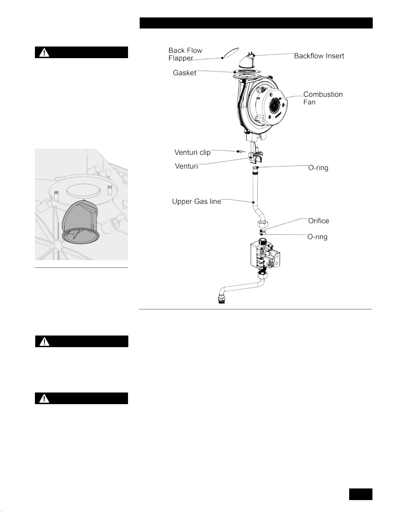
3-5
STARTUP AND COMMISSIONING
HEATING BOILERS 99 & 120
Figure 45: Back Flow Valve
Figure 46: Blower and Gas Valve Assembly
WARNING
Each unit is equipped with
a back ow valve installed
at the outlet of the fan.
Inspect the back ow apper
annually.
3.4.1 Gaining access to combustion chamber, burner
removal instructions
DISASSEMBLY
1. Turn o the main power switch to the unit.
2. Turn o the gas supply valve to the unit.
There is no need to drain the unit unless the unit will be exposed to freezing
conditions while o.
3. Remove the front cover, and allow the unit to cool.
4. Unplug the electrical connector at the gas valve and fan.
5. Loosen the lower gas valve connection nut.
NOTE: There is an O-ring in the lower gas connection. Cover the gas piping
connections to prevent debris from entering the gas piping.
6. Remove all 6mm Allen bolts from the heat exchanger cover and carefully
remove the front cover complete with the fan and the gas valve attached.
7. Place the heat exchanger cover in a safe location.
CAUTION
When removing the heat
exchanger cover in step 6,
be careful not to damage the
burner and refractory material
located on the opposite side
of the heat exchanger cover.
Use caution when handling
refractory materials. See
Caution on page 4-2.
NOTE
The Caution regarding burner
refractory on page 4-2 of this
manual must be observed.
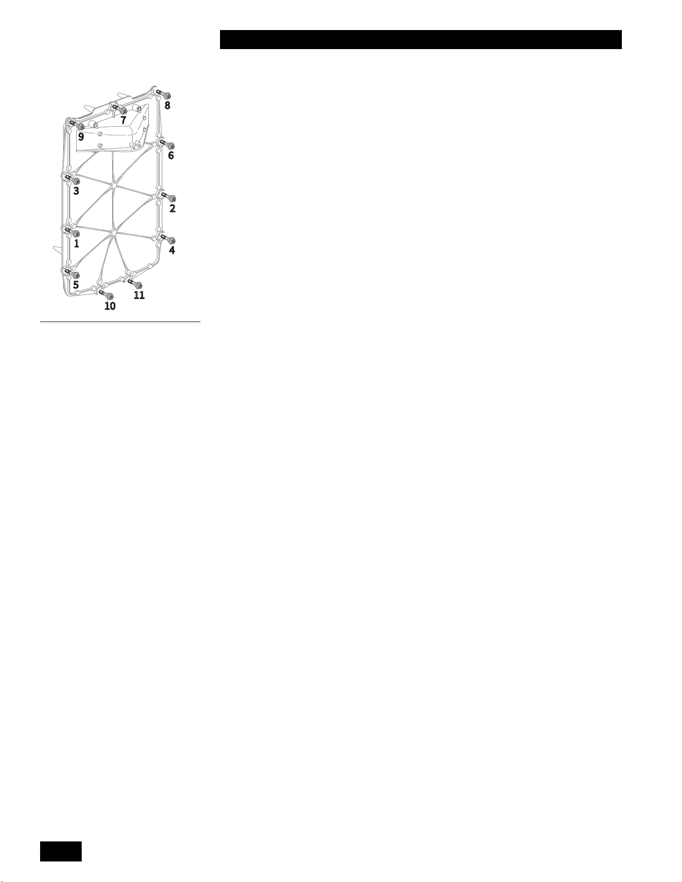
INSTALLATION AND OPERATION INSTRUCTIONS
3-6
HEATING BOILERS 99 & 120
INSTALLATION AND OPERATION INSTRUCTIONS
3-6
HEATING BOILERS 99 & 120
1
7
6
5
4
3
8
9
10
11
2
REASSEMBLY
1. Replace the heat exchanger gasket. Inspect, and when needed change other
gaskets. If necessary, inspect and clean the gasket mating surface.
2. Place the heat exchanger cover onto the heat exchanger and loosely install
the 6mm Allen bolts removed in step 6. Tighten the 6mm Allen bolts in a
cross pattern as shown in the Figure 47.
3. Connect the gas line to the gas valve ensuring the O-ring is in place. Tighten
the gas valve nut. Ensure the upper gas valve connection is tight. Re-connect
the gas valve electrical connection.
4. Re-connect the electrical connection to the fan.
5. Inspect the condensate trap for debris. Remove and clean if necessary. Fill
the condensate trap with water.
6. Turn on the gas supply valve to the unit and inspect for gas leaks. Use an
approved leak detection solution. Soap test all joints.
7. Ensure the unit is full of water and purged of air if the unit was drained during
disassembly.
8. Turn on the power to the unit and create a call for heat or for domestic hot
water.
9. Inspect the gasket around the unit cover.
10. Check ue gases for proper combustion. See Section 3.3 Commissioning for
proper adjustments.
11. Re-install the unit’s cover and set the unit into normal operation.
Figure 47: Tighten Allen bolts in
cross pattern direction.
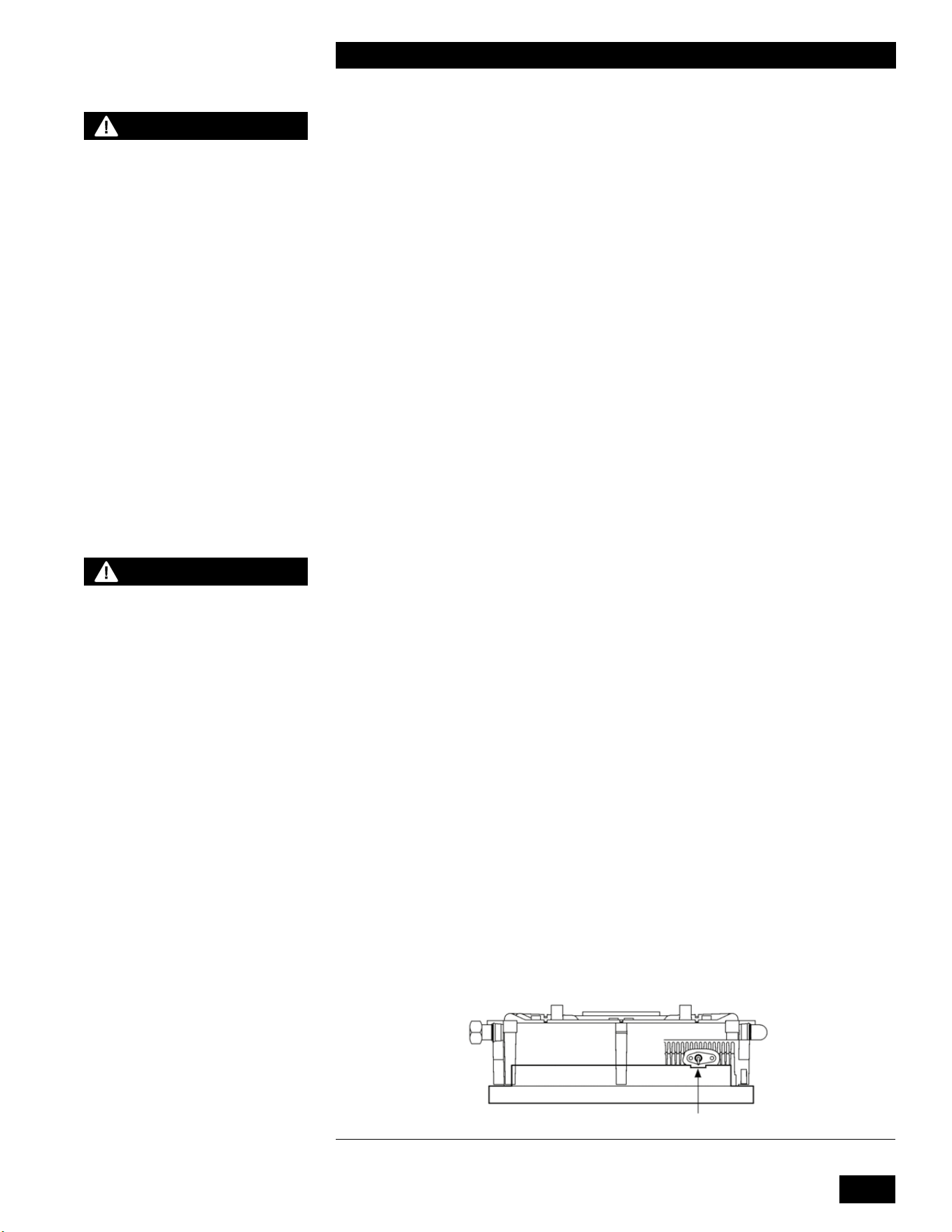
4-1
MAINTENANCE
HEATING BOILERS 99 & 120
4.0 MAINTENANCE
4.1 UNIT MAINTENANCE
4.1.1 General Care
•
Keep combustible materials and ammable liquids and vapors away from the unit.
• Keep vent terminals clear of obstructions (snow, dirt, etc.).
4.1.2 Inspection
Inspection of the unit must be performed annually by a qualied service
technician.
4.1.3 Venting
•
Check vent terminals for any obstructions (e.g. leaves, dust, other debris).
• Check and clean or replace intake or screens as required.
• Check for holes or leaks in venting. Replace venting as needed.
• Examine for any signs of moisture caused by sweating intake air pipes.
Insulate as required.
• Ensure proper resealing or reinstallation of venting at each servicing.
4.1.4 Condensate Trap
•
Examine the condensate trap every two months to see if cleaning is
necessary (refer to trap cleaning instructions, section 4.1.16 of this manual).
Ensure that the trap has been re-lled completely before ring the unit.
• Check the pH level of the condensate discharge if using condensate
neutralization.
4.1.5 Burner
•
At the rst annual service, remove the burner to inspect the extent of fouling
(refer to burner removal and reassembly instructions, section 3.4.1 of this
manual). Blow clear using compressed air. Evaluate the magnitude of
cleaning required, and establish a reasonable burner inspection schedule.
Some installations may call for annual service, others showing clean burners
will only need attention every 2 years. In alternate years, visually inspect
burner through the sight glass. Ensure the ame is stable and without
excessive uttering. Normal ame pattern is evenly distributed over the burner
surface.
• If the burner is operating improperly, remove and clean or replace. Use a
combustion analyzer to determine proper combustion. See Table 10 for
correct values.
3/16" / 4.5MM
Figure 48: Checking igniter gap using 251-001 Ignitor Gapping Tool
CAUTION
- The owner is responsible
for general care of the unit.
Improper maintenance of the
unit may result in a hazardous
condition.
- Periodic inspection of the
low water cut-o device,
including ushing of oat
types, is required, if installed
as an accessory to the unit.
- When servicing controls,
label all wires prior to
disconnection. Wiring errors
can cause improper and
dangerous operation.
- When removing a burner,a
new burner gasket is
required.
WARNING
- Fill the trap with water
before the unit is rst red to
prevent exhaust fumes from
entering the room. Never
operate the unit unless the
trap is lled with water.
Failure to comply will result in
severe personal injury or death.
-
Whenever the burner is
removed for inspection or
unit servicing, examine the
sealing gaskets and replace if
damaged.

INSTALLATION AND OPERATION INSTRUCTIONS
4-2
HEATING BOILERS 99 & 120
4.1.6 Heat Exchanger
During annual inspection (with the heat exchanger cover removed), examine
the heat exchanger for signs of contamination and clean if necessary. In areas
of poor gas quality or contaminated combustion air, there may be a build-up of
black plaque (typically sulfur). Other fouling agents are airborne dust, debris and
volatiles. Clean the heat exchanger surface with a sti plastic bristle brush only.
During maintenance, the heat exchanger gasket must be replaced. Inspect other
gaskets, and change when needed. Refer to the heat exchanger cover removal
instructions in Section 3.4.1 for access to the combustion chamber and heat
exchanger. Observe the safety warning regarding the burner refractory on
this page.
4.1.7 Pump
Check that the pump is on in normal space heating operation, and that the water
ΔT is reasonable for the heating application.
4.1.8 Gas Piping
Check for damage or leaks, and repair as needed.
4.1.9 Control Module
•
Check that unit operation is consistent with the steps in Section 2.6
Sequence of Operation.
• Check that water temperature targets and setpoint are satisfactory, and have
not been adversely adjusted.
4.1.10 Water Heating System
• Check water pressure and temperature. There should be no noticeable
change if the unit and system components are functioning normally. Check for
any noise in the system.
• Check heating system water piping for damage or leaks, and repair as
needed.
• Check for 12-15 psig in normal operation, and look to ensure pressure does
not run up toward 30 psig at high temperature. If pressure rises sharply,
consider replacement of the expansion tank. Check also for noise at high re
that may signal water quality problems.
• Water chemistry must be of a quality generally accepted as suitable for
hydronic applications. See Section 1.6 for details.
• Ensure that any direct “city ll” water connections are left in the closed
position to minimize exposure to leaks and ooding.
4.1.11 Freeze Protection
The unit’s controller operates the unit as needed to protect it from freezing. If the
unit and system components are vulnerable to freezing we recommend using a
freeze protection solution. Use antifreeze made specically for hydronic systems.
We recommend inhibited propylene glycol.
Antifreeze concentration must be between 25% and 50% of the total volume of
water in the system.
CAUTION
The heat exchanger has a
small amount of combustion
chamber insulation
(refractory), that contains
ceramic bers.
When exposed to extremely
high temperatures, the
ceramic bers, which contain
crystalline silica, can be
converted into cristobalite,
classied as a possible
human carcinogen.
Avoid disturbing or damaging
the refractory. If damage
occurs, contact the factory for
directions.
Avoid breathing in fumes and
contact with skin and eyes.
Follow these precautions:
1. For conditions of frequent
use or heavy exposure,
you need a respirator.
For respirators certied
by NIOSH, refer to the
“NIOSH Guide to the
Selection and Use of
Particulate Respirators
Certied under 42 CFR
84".
For current information,
contact NIOSH on 1-800-
356-4676 or on the web at
www.cdc.gov/niosh.
2. Wear long sleeved, loose
tting clothing, gloves
and eyes protection.
3. Assure adequate
ventilation.
4. Wash with soap and water
after contact.
5. Wash potentially
contaminated clothes
separately from other
laundry, and rinse clothes
thoroughly.
6. Discard used insulation in
an air tight plastic bag.
NIOSH rst aid guidelines:
• Eye contact - Irrigate and
wash immediately.
• Breathing in fumes -
Provide fresh air.

4-3
MAINTENANCE
HEATING BOILERS 99 & 120
4.1.12 System Treatment
•
Check consistency of any system treatment used, for appropriate mixture.
Chemical inhibitors are consumed over time, lowering their density.
• Verify proper operation after servicing.
4.1.13 Relief Valve - Maintenance and Testing
The relief valve manufacturer requires that under normal operating conditions a
“try lever test” must be performed quarterly. Under severe service conditions, or
if corrosion and/or deposits are noticed within the valve body, you must test more
often. Also perform a “try lever test” at the end of any non-service period.
Test at or near maximum operating pressure by holding the test lever fully open
for at least 5 seconds to ush the valve seat free of sediment and debris. Then
release the lever and permit the valve to snap shut.
If the lever does not activate, or there is no evidence of discharge, discontinue
use of equipment immediately, and contact a licensed contractor or qualied
service personnel.
If the relief valve does not completely seal, and uid continues to leak from
the discharge pipe, perform the test again to try and ush any debris that may
be lodged in the valve. If repeated attempts fail to stop the leakage, contact a
licensed contractor or qualied service personnel to replace the valve.
While performing a “try lever test”, a quantity of heat transfer uid will be
discharged from the piping system, and the system pressure will drop. This uid
must be replaced. We highly recommend using a system pressurization unit
such as an Axiom Industries model MF200 to rell and pressurize your system.
Capture the discharged uid in a container and recycle it by returning it to the
system feeder unit. This is particularly important when your system contains
treatment chemicals or glycol solutions. If the system employs plain water, turn
on the unit’s auto ll valve to recharge the lost uid.
4.1.14 Fan removal instructions
1. Turn o the power and the gas supply to the unit.
2. Remove the front cover, and allow the unit to cool down.
3. Disconnect the electrical plug attached to the fan.
4. Loosen the union nut at the top of the gas valve. Carefully remove the orice
and O-ring, and keep in a safe place for re-installation later. Ensure you
protect the gas valve outlet from dust and debris.
5.
Remove the 2 hex nuts connecting the fan to the burner housing, and
carefully remove the fan. You will nd a gasket attached to the fan outlet as
well as an internal check valve. Keep these items in a safe place for re-
installation.
6. If the removed fan is to be re-installed, ensure the fan and venturi are clean
and dust free. If the fan is being replaced, move the venturi over to the new
fan. Note that the t is tight.
CAUTION
Before testing the relief valve,
make certain the discharge
pipe is properly connected to
the valve outlet, and arranged
to contain and safely dispose
of equipment discharge.
NOTE
Installers should contact the
local water supplier about
the suitability of their water
for use in hydronic heating
systems.
If water quality is questionable,
a local water treatment expert
must be consulted for testing,
assessment and, if required,
treatment.
Alternatively, water or hydronic
uid of known quality can be
brought to the site.
WARNING
Do not use automotive-type
ethylene or other types of
automotive glycol antifreeze,
or undiluted antifreeze of
any kind. This may result
in severe unit damage. The
installer is responsible
in ensuring that glycol
solutions are formulated to
inhibit corrosion in hydronic
heating systems of mixed
materials. Improper mixtures
and chemical additives may
cause damage to ferrous and
non-ferrous components as
well as non-metallic, wetted
components, normally found
in hydronic systems. Ethylene
glycol is toxic, and may be
prohibited for use by codes
applicable to your installation
location. For environmental
and toxicity reasons, we
require only using non-toxic
propylene glycol.
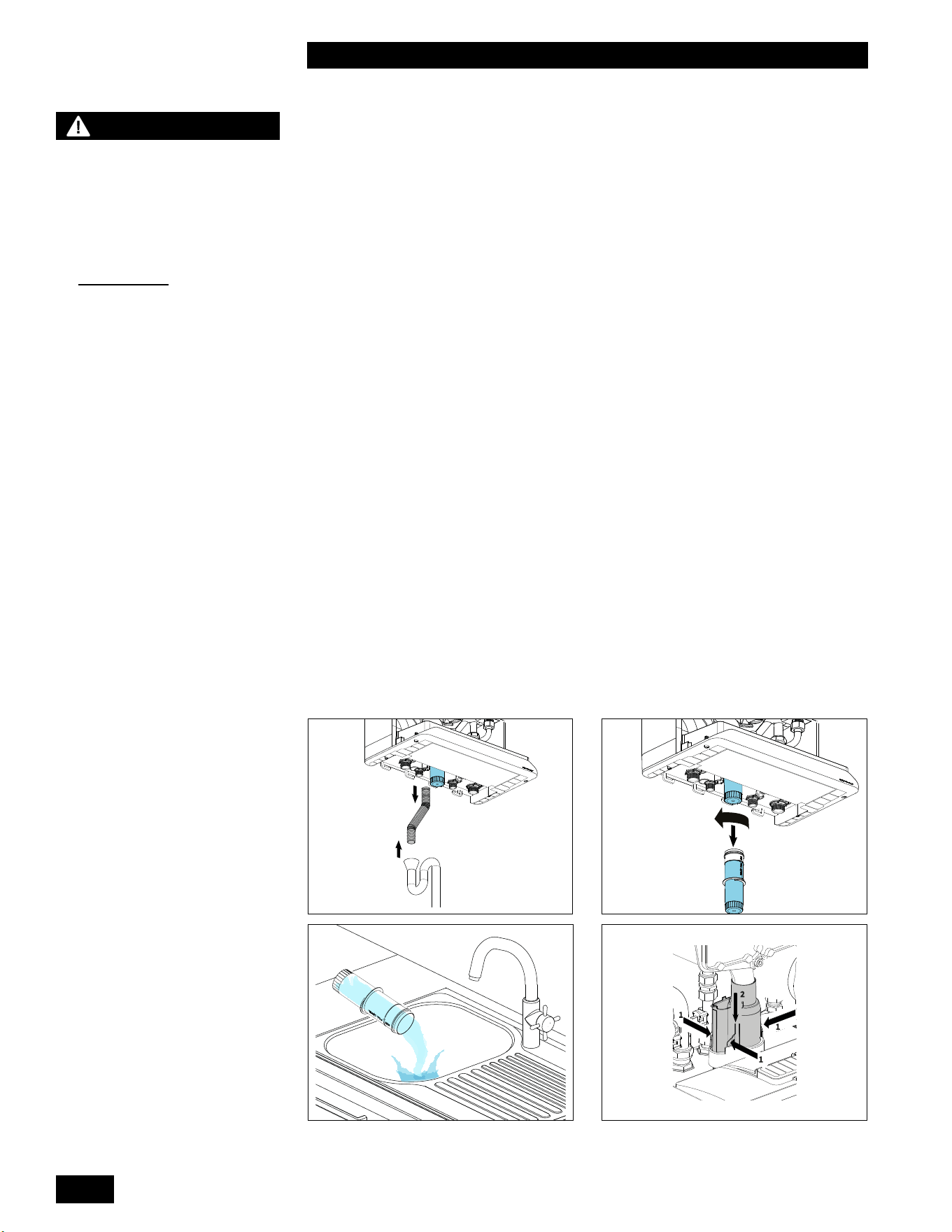
INSTALLATION AND OPERATION INSTRUCTIONS
4-4
HEATING BOILERS 99 & 120
DANGER
When servicing or replacing
the fan, you must transfer the
venturi from the old fan to the
new fan.
Failure to relocate the venturi
to the new fan may cause
an immediately hazardous
situation which must be
avoided in order to prevent
serious injury or death.
4.1.15 Fan installation instructions
1. Place the fan gasket on the outlet of the fan housing. The gasket has 2
locator pins to ensure the gasket does not move during installation.
2. Reinstall the check valve in the burner housing and attach the fan to the
burner housing with the 2 hex nuts. Tighten the 2 hex nuts with a wrench.
3. Insert the orice and O-ring between the gas valve outlet and the gas line to
the fan. Tighten the gas valve union nut with a wrench. Ensure that the gas
valve inlet (lower) nut is tight.
4. Connect the electrical plug to the fan.
5. Restore the gas supply to the unit, and test the gas valve inlet for gas leaks.
6. Restore the power to the unit, and create a call for heat or hot water.
7. Check for leaks at the gas valve outlet and the connection between the fan
and the burner housing.
8. Install the cover to the unit.
9. Return the unit to normal operation.
4.1.16 Cleaning the Condensate Trap
1. Turn o the power and the gas supply to the unit.
2. Remove the front cover, and allow the unit to cool down.
3. Remove the exible hose (1) from the condensate trap and drain.
4. Detach the condensate trap cup (2) by rotating it to the left (counter-
clockwise) and then pulling it downwards.
5. Empty the condensate trap cup (3).
6. Detach the condensate trap base (4) by pressing the three securing clips in,
while simultaneously pushing the condensate trap base downwards (4).
7. Remove the circlip and the plastic ball from the condensate trap base (5).
1
1
1
2
1 2
3 4
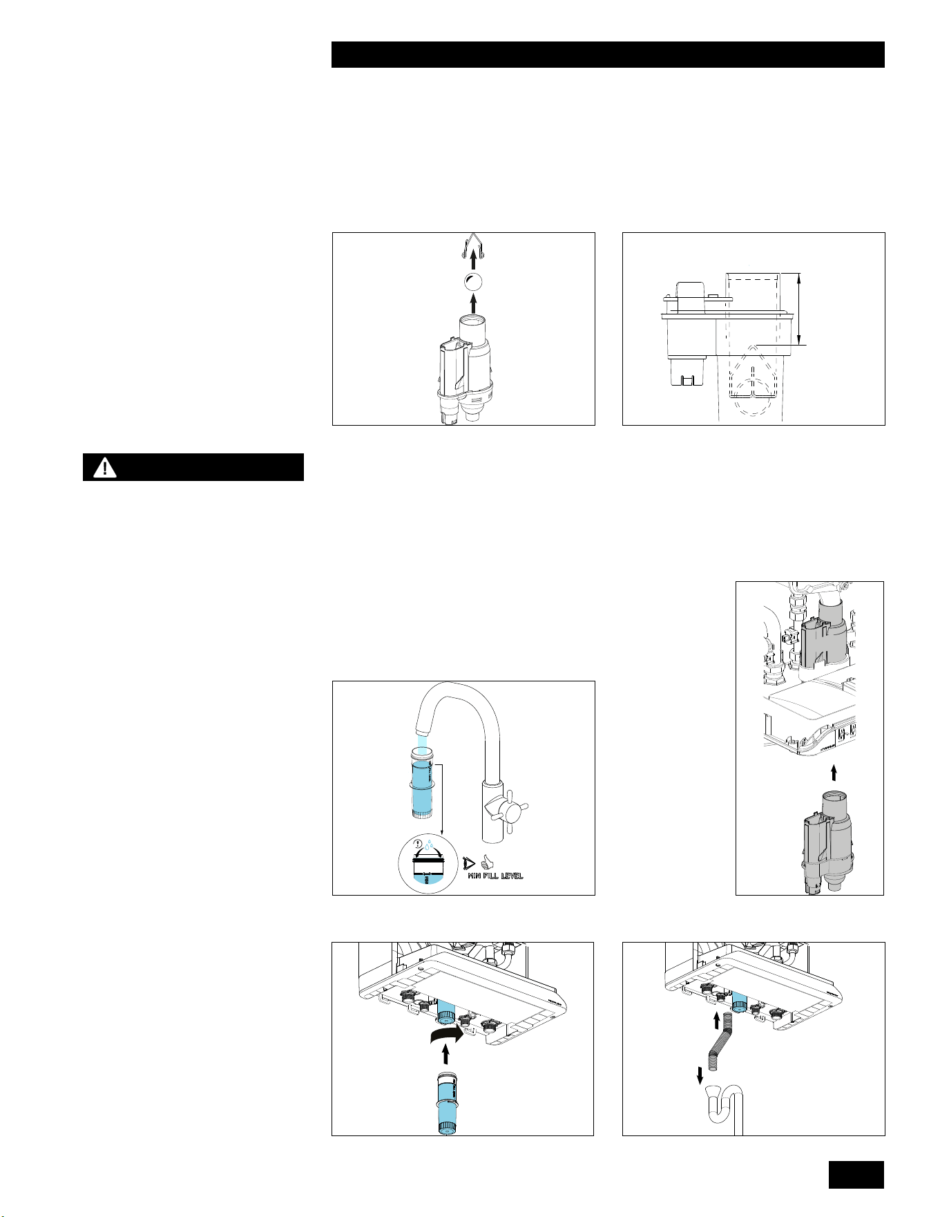
4-5
MAINTENANCE
HEATING BOILERS 99 & 120
8. Clean the following components with water:
● the inside of condensate trap base
● plastic ball
● circlip
● condensate trap cup
● opening of the ue pipe
9. Return the plastic ball to the condensate trap base and attach the circlip.
10. Check that the ball and circlip have been installed correctly (6). Make sure
that the top of the circlip is about 2 1/4” (60 mm) below the edge of the
condensate trap base.
11. Replace the O-ring (part #150-367) at the bottom of the ue pipe.
12. Attach the condensate trap base to the bottom by pushing it high enough so
that the securing clips click over the lip (8).
13. Make sure the condensate trap cup is ¾ lled
with water (7) before installation, slide it into the
condensate trap base and rotate it to the right
(clockwise) until it is correctly secured (9).
2 ¼"
(60 mm)
–
C
L
I
C
K
!
–
14. Slide the exible hose onto the condensate trap base and into the drain (10)
5 6
7
8
9 10
DANGER
Make sure that the
condensate trap base is
returned to its original
position, rmly locked into
the bottom with no gaps.
Incorrectly attaching the
condensate trap base (or not
attaching it at all) will result
in products of combustion
leaking into the room creating
a dangerous situation.

INSTALLATION AND OPERATION INSTRUCTIONS
4-6
HEATING BOILERS 99 & 120
CAUTION
The maintenance counter
must only be reset after
performing the maintenance
procedures in Section
4.0 Maintenance of this
manual. Failure to perform
maintenance can result in a
hazardous condition.
4.1.17 Reset the Maintenance Counter
The maintenance counter should be reset after all maintenance items in this
section have been completed. Refer to Resetting the Maintenance Counter,
section 2.8 of this manual.
4.1.18 Winterization
The Heating Boiler must be winterized along with the rest of the heating system
when the system will be shut down for an extended period of time and be subject
to freezing conditions.
1. Turn o the power and the gas supply to the unit.
2. If the heating system does not contain the proper level of propylene glycol to
prevent freezing, drain the units space heating coil along with the rest of the
heating system.
3. Remove the condensate trap cup and empty.
4. If present, empty condensate pump.
NOTE
Damage to the Heating Boiler
caused by freezing water is
not covered by the warranty.

5-1
TROUBLESHOOTING
HEATING BOILERS 99 & 120
5.0 TROUBLESHOOTING
The troubleshooting section is divided into four sections:
5.1 Preliminary Checks
5.2 Electronic Components
5.3 Faults and Notications
5.4 Other Faults
Often, you can identify and solve a problem through simple checks of the basics:
conrming the electrical power supply, gas ow and resetting the thermostat
control. To help with preliminary checks, the unit’s control module oers a clear
visual display of the status of the various control circuit components.
Should a problem remain unsolved after applying the preliminary checks,
proceed to the detailed system review in this guide. The Troubleshooting chapter
covers potential error conditions, grouped into the following categories:
5.3.1 Faults Codes
5.3.2 Notication Codes
5.4.1 No heat (space heating)
5.4.2 Space heating does not reach the correct temperature
5.4.3 Space heating system remains too warm
5.4.4 Burner ignites loudly
5.4.5 Burner resonates
Below each section is a list of symptoms, diagnoses, and solutions.
Some diagrams (see Section 6.0) are included for use with troubleshooting
including:
• Electrical Wiring Diagrams
• Unit Component Layout Diagrams
5.1 PRELIMINARY CHECKS
As a rst step in troubleshooting, you should review the controller’s display
screen. Diagnostic features evaluate system integrity, display error conditions,
and indicate initial troubleshooting action.
In addition to checking the controller’s display, try these troubleshooting steps:
1. Conrm power to the unit: check that control module display is on (e.g.,
display is lit).
2. Check that unit is not in a safety lockout.
3. Ensure that wiring is secure and properly terminated.
4. Check that gas is reaching the unit.
5.
Conrm that the water system is properly pressurized to 12 psig and that the
pump is operating.
NOTE
This unit is equipped with a
blocked vent shut-o system
that closes the gas supply
when it detects an irregular
venting condition.
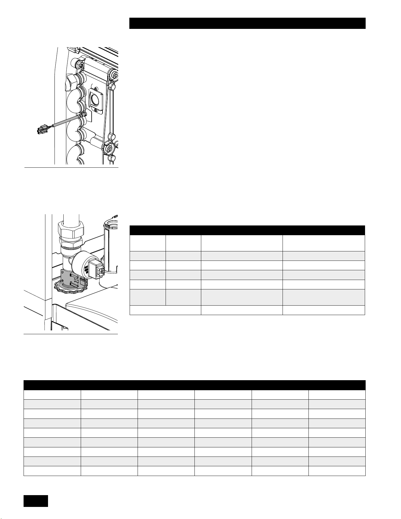
INSTALLATION AND OPERATION INSTRUCTIONS
5-2
HEATING BOILERS 99 & 120
5.2 ELECTRONIC COMPONENTS
This section details the method for troubleshooting the non-standard electronic
components on the unit, including the electronic water pressure sensor-type
LWCO and the temperature sensors.
5.2.1 Temperature Sensors
The resistance of the temperature sensors varies inversely with temperature. To
test, measure the temperature of the sensed environment and compare with the
value derived from the measurement of the resistance (obtained by connecting a
good quality test meter capable of measuring up to 5,000 KΩ (5,000,000Ω) at the
controller end of the sensor lead).
To obtain a resistance reading, remove power to the unit. For the supply water
and return water temperature sensors, remove the wire leads by disconnecting
their respective Molex connectors. Place multi-meter probes into the sensor’s
male Molex connector socket. Do not apply voltage to the sensor as damage
may result.
12KΩ temperature sensors are supplied with the unit. See Table 12 for resistance
values.
SENSOR TYPE PURPOSE LOCATION
S0 NTC 12KΩ Heat Exchanger
Temperature
Left Side of Heat Exchanger
S1 NTC 12KΩ Heating Supply Temperature Heating Supply Pipe
S5 NTC 12KΩ Flue Gas Temperature Top of rear Flue passage
S6 NTC 12KΩ Outdoor Sensor Outdoors (North side)
S7 NTC 10KΩ Hot Water Tank External Water Heater
PTC1
PTC2
PTC
Cabinet Temperature
Left and right Side top of
inner cabinet
Water Pressure Heating Supply Pipe
Table 11: Temperature and Pressure Sensors
5.2.2 Fan/Blower
Control and power to the fan is provided via a single wiring harness to the
controller.
Figure 50: Heating Supply
temperature sensor S1
TEMPERATURE RESISTANCE TEMPERATURE RESISTANCE TEMPERATURE RESISTANCE
F / C Ω - ohm F / C Ω - ohm F / C Ω - ohm
5F / -15C 76,020 77F / 25C 12,000 149F / 65C 2,752
14F / -10C 58,880 86F / 30C 9,805 158F / 70C 2,337
23F / -5C 45,950 95F / 35C 8,055 167F / 75C 1,994
32F / 0C 36,130 104F / 40C 6,653 176F / 80C 1,707
41F / 5C 28,600 113F / 45C 5,522 185F / 85C 1,467
50F / 10C 22,800 122F / 50C 4,609 194F / 90C 1,266
59F / 15C 18,300 131F / 55C 3,863 203F / 95C 1,096
68F / 20C 14,770 140F / 60C 3,253 212F / 100C 952
Table 12: Temperature Sensor Resistance Values – 12KΩ sensors.
Figure 49: Heat exchanger
temperature sensor S0
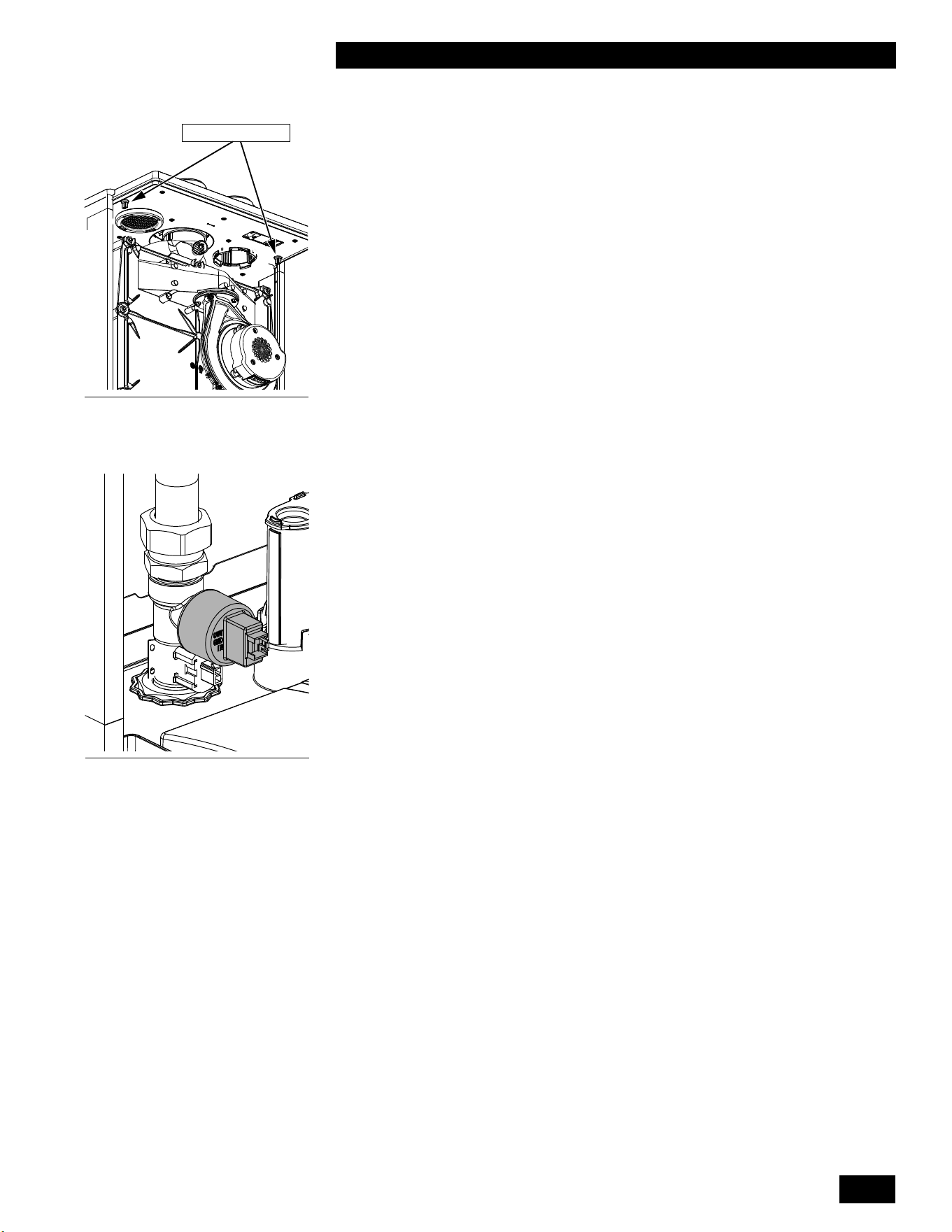
5-3
TROUBLESHOOTING
HEATING BOILERS 99 & 120
5.2.3 Cabinet Sensors
The Cabinet temperature sensors ensure that the unit shuts down if the
temperature inside the cabinet is above normal.
The Cabinet temperature sensors are located on the left and right side at the top
of the cabinet. To remove the sensors, unclip the wiring harness and unscrew
from the top cabinet.
5.2.4 Thermostat Connections
The unit’s controller is designed to heat a single space heating load. The load can
consist of a single zone or several zones. In either method, the ‘Call for Heat’ must
be from a device providing a dry contact and connected to X13.1 and X13.2. The
use of power-robbing thermostats directly will cause the unit to operate erratically.
If using a power-robbing thermostat, you will need to isolate it through a relay. An
Open Therm device can also be used across X13.1 and X13.2.
5.2.5 Water Pressure Sensor-Type Low Water Cut Off
(LWCO)
The unit is equipped with a pressure sensor that serves as a low-water cut-o.
The water pressure is displayed in the main display when the pressure is low. For
example, a system water pressure of 4.6psi would be displayed as 4.6P. If the
pressure is too low the controller ashes an error message in the main display by
toggling between the actual pressure and LO. To correct this error, increase the
system pressure. The water pressure in the heating system must be higher than
8psi for the unit to reach maximum ring rate. When the water pressure is less
than 8psi, the unit restricts its ring rate. If the pressure is less than 4psi then the
unit will not re at all.
To test the operation of the pressure sensor – type LWCO
1. Turn o the unit at the controller by pressing the area above the dot. The
current system pressure is displayed.
2.
Isolate the space heating circuit, and reduce the water pressure. The
displayed water pressure should drop as the system water is being removed
(expansion tank isolated). If the pressure remains steady the pressure sensor
may be blocked or faulty. If it remains “xed”, drain the unit and replace the
sensor, or dislodge any blocking debris from the sensor inlet channel and
reinsert.
3. If the pressure sensor is OK rell the unit and open the closed valves. Ensure
the system pressure is adequate for the heating system.
Pressure sensor lwco replacement
1. Turn o the power to the unit.
2. Isolate and drain the unit.
3. Disconnect the electrical connection to the sensor.
4. Carefully remove the pressure sensor by loosening it, turn the nut counter
clockwise until it can be removed. If there is some water leakage, ensure the
water does not spill into the controller.
5. Push the new sensor into the socket while twisting slightly. Take care to avoid
damage to the O-ring.
6. Connect the electrical connector to the sensor.
7. Restore water pressure to the unit.
8. Restore power to the unit.
Figure 52: Water Pressure Sensor
Type LWCO
Cabinet sensors
Figure 51: PTC Cabinet
Temperature Sensors
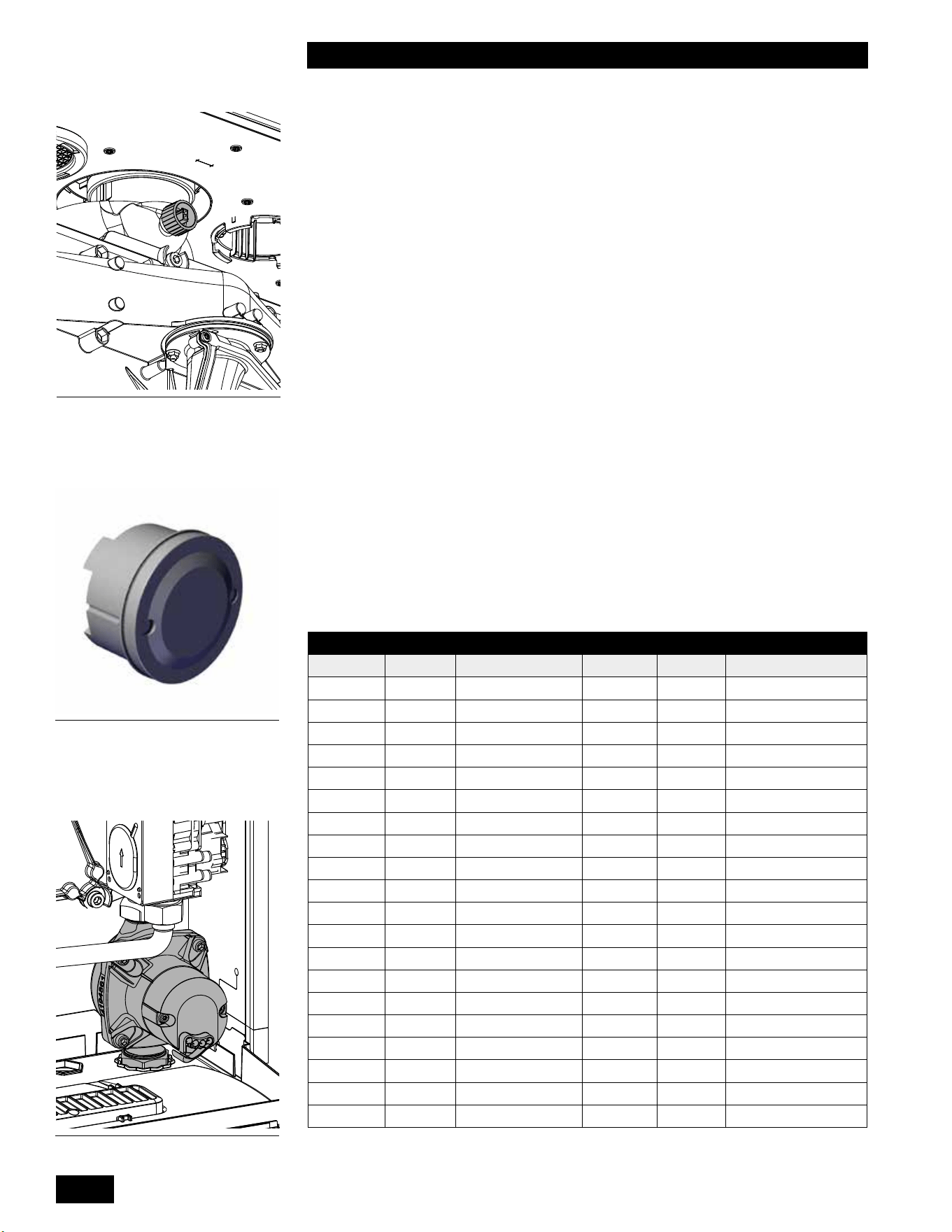
INSTALLATION AND OPERATION INSTRUCTIONS
5-4
HEATING BOILERS 99 & 120
5.2.6 Flue Gas Temperature Sensor
This sensor ensures that the unit shuts down safely if the ue temperature
is above normal. High ue temperatures can be an indication that the heat
exchanger requires cleaning.
The ue gas temperature sensor is located at the top of the rear ue passage,
below the top panel. To remove the sensor, unclip from the wiring harness and
unscrew from the rear ue passage.
5.2.7 Outdoor Sensor
An outdoor sensor is supplied with each unit. The sensor should be mounted
on the north side of the building away from any direct sunlight. Keep the
sensor away from any heat sources such as exhaust fan outlets, dryer outlets,
mechanical room ventilation grills etc.
The Outdoor sensor is a 12KΩ sensor with resistance values as listed in Table
12. If the sensor is not connected to the unit, the unit operates at the unit’s supply
temperature set in the User Setup menu, and operates as a set point load.
5.2.8 DHW Tank Sensor
The Heating Boiler allows the use of a tank sensor for controlling the domestic
hot water tank temperature. A 10KΩ sensor or an aquastat can be used to
operate the Heating Boiler.
If a eld supplied domestic hot water sensor is used, it must be a 10KΩ sensor
matching the following table.
TEMPERATURE RESISTANCE TEMPERATURE RESISTANCE
°F °C Ω °F °C Ω
0 -18 85,362 100 38 5,828
5 -15 72,918 105 41 5,210
10 -12 62,465 110 43 4,665
15 -9 53,658 115 46 4,184
20 -7 42,218 120 49 3,760
25 -4 39,913 125 52 3,383
30 -1 34,558 130 54 3,050
35 2 29,996 135 57 2,754
40 4 26,099 140 60 2,490
45 7 22,763 145 63 2,255
50 10 19,900 150 66 2,045
55 13 17,436 155 68 1,857
60 16 15,311 160 71 1,689
65 18 13,474 165 74 1,538
70 21 11,883 170 77 1,403
75 24 10,501 175 79 1,281
80 27 9,299 180 82 1,172
85 29 8,250 185 85 1,073
90 32 7,334 190 88 983
95 35 6,532 195 91 903
Table 13: Temperature Sensor resistance values – 10KΩ sensor
Figure 55: Pump
Figure 54: Outdoor air Temperature
Sensor
Figure 53: Flue gas Temperature
Sensor S5

5-5
TROUBLESHOOTING
HEATING BOILERS 99 & 120
5.3 FAULTS AND NOTIFICATIONS
5.3.1 Fault Codes
During operation the controller can detect unusual situations and can take action to avoid damage to the heat
exchanger or other unsafe operations. During these situations, the controller limits the temperature and power output
of the burner, or temporarily disables operation entirely.
These faults are shown ashing and visible on the main display, and displayed only when an unusual reading is
currently detected. Fault Codes can be reset by touching the wrench for 2 seconds after the cause of the fault has
been resolved.
FAULT CODE DESCRIPTION POSSIBLE CAUSE / SOLUTION
F000 Heat exchanger temperature sensor
fault.
• Verify wire harness connections at heat exchanger
temperature sensor and control module are tight.
• Replace heat exchanger temperature sensor.
F001 High heat exchanger temperature during
central heating demand.
• Verify all air has been bled/purged from the heat
exchanger central heating coil
• Replace internal pump if it is not operating during a
central heating demand.
• Verify the unit has been converted to propane if
operating on propane.
• Verify combustion readings at low and high re are
within specications.
• Clean heat exchanger central heating coil.
• Clean re side of heat exchanger.
F002 High heat exchanger temperature during
DHW demand
• Verify the unit has been converted to propane if
operating on propane
• Verify combustion readings at low and high re are
within specications.
• Clean heat exchanger DHW coil.
• Clean re side of heat exchanger.
F003 High ue temperature.
• Verify the unit has been converted to propane if
operating on propane.
• Verify combustion readings at low and high re are
within specications.
• Clean re side of heat exchanger.
• Clean heat exchanger central heating and DHW coils.
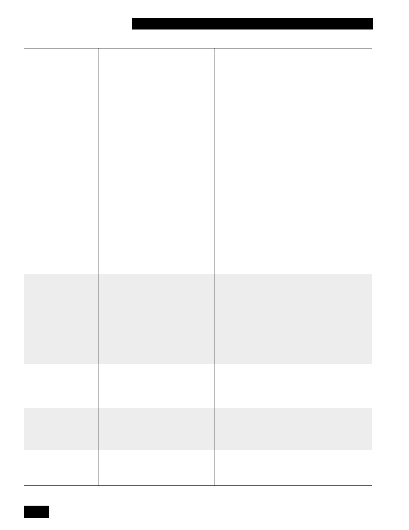
INSTALLATION AND OPERATION INSTRUCTIONS
5-6
HEATING BOILERS 99 & 120
F004 No ame detected during four ignition
trials.
• Verify external gas shuto valve is open.
• Verify gas inlet pressure is at least 4” during igntion
trial.
• Verify condensate drain is not blocked.
• Check vent and combustion air piping for blockage.
• Verify internal and power supply grounding.
• Verify ground spring is in contact with burner head
screw.
• Verify ignitor to ignition module connection is tight.
• Check ignitor condition and clean/replace as
necessary.
• Verify operation of the backow apper in the fan
outlet.
• Verify ignitor is not in contact with burner and gap is
correct.
• Replace ignition module if unit lights but ame icon
doesn’t illuminate.
• Replace ignition module if spark is not present and
110VAC is present on ignition module black and gray
wires.
• Replace control module if spark is not present and
110VAC is not present on ignition module black and
gray wires.
• Replace gas valve if gas inlet pressure does not drop
during trial for ignition and 24VDC is present at gas
valve harness.
• Replace control module if gas inlet pressure does not
drop during trial for ignition and 24 VDC is not present
at gas valve harness.
F005 No ame detected during operation.
• Verify condensate drain is not blocked.
• Check vent and combustion air piping for blockage.
• Check for ue gas recirculation.
• If vent termination is subject to high winds,
recongure/relocate as necessary.
• Verify gas inlet pressure is at least 4” at both low and
high re.
• Verify low and high re combustion readings are within
specications.
• Check ignitor condition and clean/replace as
necessary.
F006 Flame detected when burner is o.
• Verify good internal and power supply grounding.
• Verify ame goes out at conclusion of demand, if not
replace gas valve.
• Replace ignition module.
• Replace control module.
F007 Low ame signal.
• Verify ignitor to ignition module connection is tight.
• Check ignitor condition and clean/replace as
necessary.
• Verify low and high re combustion readings are within
specications.
F008 Incorrect fan speed
• Verify wire harness connections at fan and control
module are tight.
• Replace fan.
• Replace control module.
5-7
TROUBLESHOOTING
HEATING BOILERS 99 & 120
F009 Control module internal fault.
• Remove all eld wiring from unit then reset fault.
• Check eld wiring for voltage backfeed if F009 fault
does not return.
• Replace control module if F009 fault code returns.
F010 Heat exchanger temperature sensor
open.
• Verify wire harness connections at heat exchanger
temperature sensor and control module are tight.
• Check resistance of each heat exchanger temperature
sensor (center pin is common), replace sensor if open
circuit is found.
• Check resistance of each heat exchanger temperature
sensor (center pin is common) at control module
harness connector, repair wire harness if open circuit
is found.
F011 Heat exchanger temperature sensor
short
.
•
Check resistance of each heat exchanger temperature
sensor (center pin is common), replace sensor if short
circuit is found.
• Check resistance of each heat exchanger temperature
sensor (center pin is common) at control module
harness connector, repair wire harness if short circuit
is found.
F012 Flue temperature sensor open.
• Verify wire harness connections at ue temperature
sensor and control module are tight.
• Check resistance of ue temperature sensor, replace
sensor if open circuit is found.
• Check resistance of ue temperature sensor at control
module harness connector, repair wire harness if open
circuit is found.
F013 DHW inlet temperature sensor open/
short
• Verify wire harness connections at DHW inlet
temperature sensor and control module are tight.
• Check resistance of DHW inlet temperature sensor,
replace sensor if open/short circuit is found
• Check resistance of DHW inlet temperature sensor at
control module harness connector, repair wire harness
if open/short circuit is found
F014 Heat exchanger temperature sensor
mounting fault.
• Heat exchanger temperature is not changing while unit
is red.
• Verify heat exchanger temperature sensor is properly
mounted on the heat exchanger.
F015 High cabinet temperature
• Check heat exchanger for ue gas leakage
• Check vent pipe for ue gas leakage
F016 DHW outlet temperature sensor
mounting fault
• DHW outlet temperature is not changing while unit is
red
• Verify DHW outlet temperature sensor is properly
mounted on the DHW outlet pipe

INSTALLATION AND OPERATION INSTRUCTIONS
5-8
HEATING BOILERS 99 & 120
F017 DHW bypass valve fault
• Verify wire harness connections at DHW bypass valve
and control module are tight.
• Check resistance of DHW bypass valve at control
module harness connector:
Green - Purple = 30 to 40 Ω
Green - Blue = 30 to 40 Ω
Green - Yellow = 30 to 40 Ω
Green - Orange = 30 to 40 Ω
Red - Black = 5.5 to 6.5 MΩ
Red - Brown = 17 to 21 MΩ
If any resistance value is outside of these ranges,
check and repair any wire harness open/short circuit
before replacing DHW bypass valve.
F018 Flue/Combustion Air blockage.
• Check the vent and combustion air pipes for blockage.
• Verify operation of the backow apper in the fan
outlet.
F019 Boiler Memory Module (BMM) fault.
• Verify wire harness connections at boiler memory
module and control module are tight.
• Verify wire harness continuity between boiler memory
module and control module .
• Replace boiler memory module.
F021 Critical parameter changed
• Factory reset required.
F027 Outdoor temperature sensor short.
• Check resistance of outdoor temperature sensor,
replace sensor if short circuit is found.
• Check resistance of outdoor temperature sensor at
control module harness connector, repair outdoor
sensor eld wiring if short circuit is found.
F028 Reset button fault.
• Check the reset button for unintentional operation
such as during cleaning.
• Replace control module.
F029 Gas valve fault.
• Verify wire harness connections at gas valve and
control module are tight.
• Replace gas valve if upper coil resistance is not 35 to
45 Ω.
• Replace gas valve if lower coil resistance is not 20 to
30 Ω.
• Check resistance of gas valve at control module
harness connector, repair wire harness if open/short
circuit is found or if resistance is not within 60 to 70 Ω.
• Replace control module.
F031 Supply temperature sensor open/short.
• Verify wire harness connections at supply temperature
sensor and control module are tight.
• Check resistance of supply temperature sensor,
replace sensor if open/short circuit is found.
• Check resistance of supply temperature sensor at
control module harness connector, repair wire harness
if open/short circuit is found.
F040 Cabinet temperature sensor open.
• Verify wire harness connections at cabinet
temperature sensors and control module are tight.
• Check resistance of cabinet temperature sensors,
replace sensor if open circuit is found.
• Check resistance of cabinet temperature sensors at
control module harness connector, repair wire harness
if open circuit is found.

5-9
TROUBLESHOOTING
HEATING BOILERS 99 & 120
F041 Cabinet temperature sensor short.
• Check resistance of cabinet temperature sensors,
replace sensor if short circuit is found.
• Check resistance of cabinet temperature sensors at
control module harness connector, repair wire harness
if short circuit is found.
F042 Cascade DHW not available
• Resolve any other lockouts in the cascade system.
• Verify Leader cascade parameter settings are correct.
• Verify Follower(s) cascade parameter settings are
correct.
• Check cascade communication status in the
information menu of both Leader and Follower.
-- (Blinking) Water presssure sensor fault.
• Verify wire harness connections at water pressure
sensor and control module are tight.
• Check resistance of water pressure sensor at control
module harness connector:
Black - Orange = 7.5 to 9.5 KΩ
Black - Yellow = 7.5 to 9.5 KΩ
• If any resistance value is outside of these ranges,
check and repair wire harness open/short circuit
before replacing water pressure sensor.
5.3.2 Notication Codes
During operation the controller can also detect unusual situations and display a notication, usually without signicant
interruption of the normal operation of the appliance.
These notications are shown on the main display, and display only when an unusual reading is currently detected.
Once the error has been resolved, the operation will be restored
Note that these notications only appear on controllers installed with software versions after 1.80. The software
version of the controller will appear upon the controller’s initial start up.
NOTIFICATION
CODE
DESCRIPTION POSSIBLE CAUSE / SOLUTION
n030 DHW outlet temperature sensor
open/short
• Verify wire harness connections at DHW outlet temperature
sensor and control module are tight.
• Check resistance of DHW outlet temperature sensor, replace
sensor if open/short circuit is found.
• Check resistance of DHW outlet temperature sensor at control
module harness connector, repair wire harness if open/short
circuit is found.
n040 Cascade communication lost
• Verify Leader is powered on and cascade parameter settings are
correct
.
• Verify Follower(s) cascade parameter settings are correct.
• Check cascade communication status in the information menu of
both Leader and Follower.
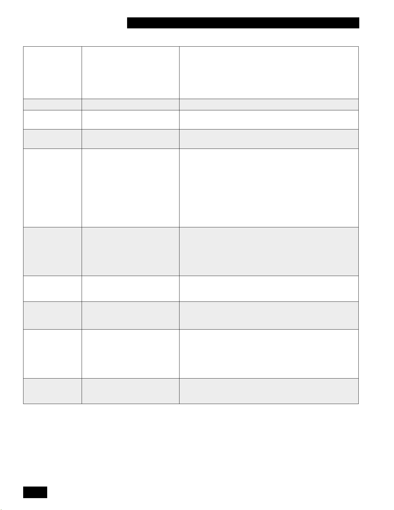
INSTALLATION AND OPERATION INSTRUCTIONS
5-10
HEATING BOILERS 99 & 120
n041 Cascade system sensor open
• Verify system sensor eld wiring is terminated at the choosen
input (X13-3&4 or X13-4&5).
• Check resistance of system temperature sensor, replace sensor if
open circuit is found.
• Check resistance of system temperature sensor at control
module harness connector, repair system sensor eld wiring if
open circuit is found.
n120 Maintenance recommended
• Maintenance is recommended based on hours of use.
n121 Maintenance required, limited DHW
output
• Maintenance is required based on hours of use.
• DHW output will be limited until maintenance is performed.
n122 Maintenance required, no DHW
output
• Maintenance is required based on hours of use.
• DHW output is disabled until maintenance is performed.
n150 High heat exchanger temperature,
limited output
• Verify all air has been bled/purged from the heat exchanger
central heating coil.
• Replace internal pump if it is not operating during a central
heating demand.
• Verify the unit has been converted to propane if operating on
propane.
• Verify combustion readings at low and high re are within
specications.
• Clean re side of heat exchanger.
• Clean heat exchanger central heating and DHW coils.
n151 High ue temperature, limited
output
• Verify the unit has been converted to propane if operating on
propane.
• Verify combustion readings at low and high re are within
specications.
• Clean re side of heat exchanger.
• Clean heat exchanger central heating and DHW coils.
n152 Flue temperature sensor mounting
fault
• Flue temperature is not changing while unit is red.
• Verify ue temperature sensor is properly mounted on the vent
pipe.
n201 Heat exchanger air purge function
activated
• Air trapped in the heat exchanger
• Closed boiler isolation valve
• Defective boiler pump
n202 High ue temperature, burner
disabled
• Verify the unit has been converted to propane if operating on
propane.
• Verify combustion readings at low and high re are within
specications.
• Clean re side of heat exchanger
• Clean heat exchanger central heating and DHW coils.
n245 Flue gas back ow, fan on low
speed
• Verify vent and combustion air piping and terminations are
installed according to this manual.
• Verify operation of the backow apper in the fan outlet.
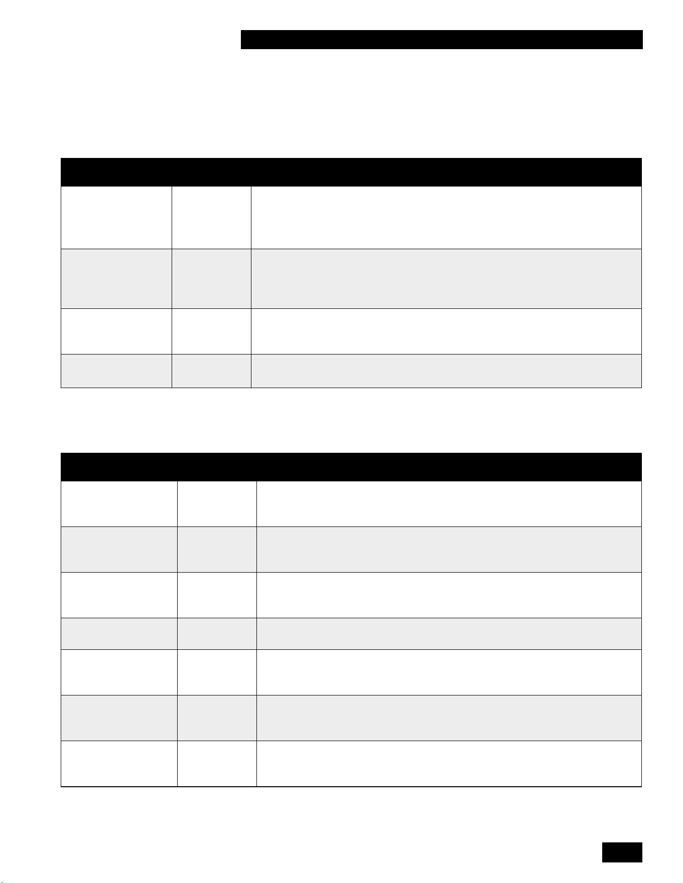
5-11
TROUBLESHOOTING
HEATING BOILERS 99 & 120
5.4 OTHER FAULTS
5.4.1 No heat (space heating)
POSSIBLE
CAUSES
ANALYSIS POSSIBLE SOLUTION
The power LED is not
shown.
→ Yes
↓No
• Check the power supply.
• Check the fuse (see Electrical schematic).
• Check wiring for breaks.
The right display
shows a line (–).
The unit is o.
→ Yes
↓No
• Switch on the unit by touching just above the power LED and
holding for 2 seconds.
Room thermostat
/ zone control not
enabling unit.
→ Yes
↓No
• Check the wiring.
Verify room thermostat / zone control is providing dry contact to enable unit for
space heating.
No electricity (24V). → Yes
• Check the wiring according to the schematic.
• Check Connector X13.
5.4.2 Space heating does not reach the correct temperature
POSSIBLE
CAUSES
ANALYSIS POSSIBLE SOLUTION
Water pressure in the
system is too
low.
→ Yes
↓No
Top up the system.
Room thermostat is not
calling for heat.
→ Yes
↓No
Check the setting and adjust it if necessary.
Temperature is set too
low.
→ Yes
↓No
Increase the space heating temperature (see 2.3.2). If an outdoor sensor is present.
Check the outdoor sensor.
No ow in the system. → Yes
↓No
Check the ΔT ±36°F / ±20°C between the central heating supply and the
return. Ensure a correct ow in the system.
The unit’s capacity is
not correctly
set.
→ Yes
↓No
Adjust the unit’s capacity.
No heat transfer due to
contamination in the
unit/system.
→ Yes
↓No
Flush the unit/system.
Flue and/or air supply
duct is blocked.
→ Yes Check and (if necessary) clean the ue and the air supply duct.
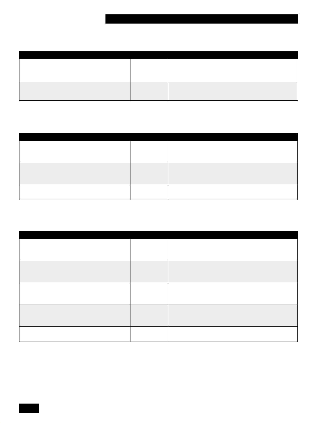
INSTALLATION AND OPERATION INSTRUCTIONS
5-12
HEATING BOILERS 99 & 120
5.4.3 Space heating system remains too warm
POSSIBLE CAUSES ANALYSIS POSSIBLE SOLUTION
Room thermostat / zone
control is defective or has
a short circuit.
→ Yes
↓No
• Check the wiring.
Check room thermostat / zone control for a short circuit.
There is thermo-siphon in the central
heating circuit.
→ Yes Place a check valve (in the case of thermo-siphon) or a
two-way valve (if there is a second pump in the central
heating circuit).
5.4.4 Burner ignites loudly
POSSIBLE CAUSES ANALYSIS SOLUTION
Inlet pressure is too high. → Yes
↓No
The gas pressure regulator may be defective. In that case,
contact the energy company.
Ignition distance is incorrect. → Yes
↓No
Replace the ignitor including the ignition cable.
Gas-air control is not correctly
adjusted.
→ Yes Check and/or adjust combustion with a calibrated
combustion analyzer.
5.4.5 Burner resonates
POSSIBLE CAUSES ANALYSIS SOLUTION
Gas inlet pressure lower than 4“ w.c.
or sometimes disappears.
→ Yes
↓No
The gas pressure regulator may be defective. Contact the
energy company.
There is recirculation of ue gases. → Yes
↓No
Check the ue and air supply duct.
Gas-air control is not correctly adjusted. → Yes
↓No
Check and/or adjust combustion with a calibrated
combustion analyzer.
Burner seal is defective. → Yes
↓No
Replace the burner seal.
Burner is defective. → Yes Replace the burner.
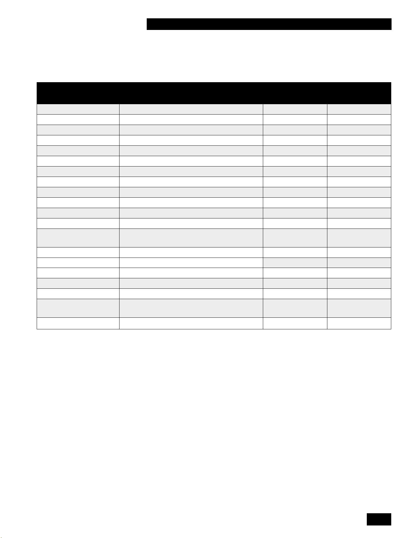
6-1
REPLACEMENT KITS
HEATING BOILERS 99 & 120
6.0 REPLACEMENT KITS
Replacement Kit
Numbers
Replacement Kit Description
99,000 120,000
P-081034 Conversion To Propane - Venturi 528
x
P-081044 Conversion To Natural Gas - Venturi 528
x
P-081054 Conversion To Propane - Venturi 500
x
P-081064 Conversion To Natural Gas - Venturi 500
x
P-081364 Conversion To Low Caloric Gas - Venturi 528
x
P-081374 Conversion To Low Caloric Gas - Venturi 500
x
P-081134 Replacement kit: Flue Temperature Sensor
x x
P-081144 Replacement kit: Ignitor
x x
P-081154 Replacement kit: Burner 99 - 125
x x
P-081174 Replacement kit: EBM Fan
x x
P-081224 Replacement kit: Boiler Pump
x x
P-081234 Replacement kit: Gas Valve
x x
P-081294 Replacement kit: Temperature Sensor Heat
Exchanger
x x
P-081314 Replacement kit: Pressure Sensor
x x
P-081334 Replacement kit: Controller Box White
x x
P-081504 Replacement kit: Ignition Wiring
x x
P-081574 Replacement kit: Ignition Line Complete
x x
P-081654 Replacement kit: Condensate Trap Boiler
x x
P-081694 Replacement kit: Temperature Sensor Supply
(Clip 22mm)
x x
P-081794 Replacement kit: Controller Box Black
x x

INSTALLATION AND OPERATION INSTRUCTIONS
6-2
HEATING BOILERS 99 & 120
This page is intentionally left blank.
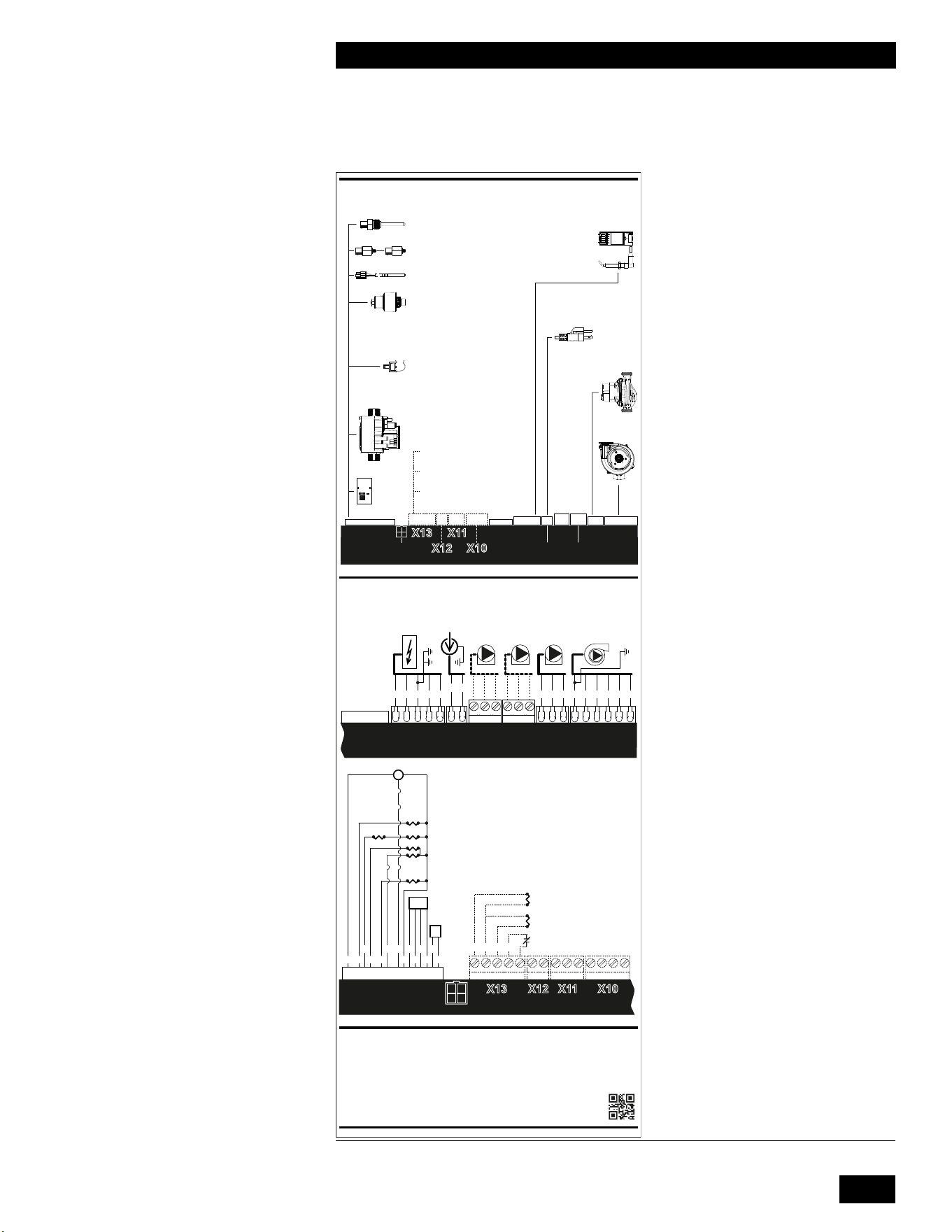
6-3
WIRING DIAGRAMS
HEATING BOILERS 99 & 120
7.0 WIRING DIAGRAMS
Diagram 6.2-1: Schematic wiring diagram
X2 X1
X3
X4
X5
X9 X8
X14
X15
X1
X2X8
X5
X4
X3
X9
2
1
3 24
5
1
8
7
6
5 4 3 2 1
5
4 3 2
6
13
2
1
X14
X15
17
16 15
14 13
12 11
10
9
8 7 6
5
4
3
2 1
Aquastat or
DHW Sensor
Outdoor Sensor
Thermostat
(by others)
Ignition
Power Plug
120V
Blower
Motor
Flue Sensor
Heat ex. Sensor
Space Heating
Presure Sensor
CH Supply NTC
Gas valve
BMM
G/Y GY
BL R O BK
Motor
Blower
snoitpO snoitpOIgnition
R O G/Y GY BK
BMM
R
GY
BK
BL
Gas valve
R
GY
CH Supply NTC
Space Heating
Pressure Sensor
Heatex. Sensor
Flue Sensor
V
859874.02
Heating Boiler 99, 120 Ladder Wiring Diagram
Control Module
Notes:
Wire Color Code Key:
BK - Black
Heating Boiler 99, 120 Schematic Wiring Diagram
- Original wiring as supplied with the appliance must be replaced with type T wire or
its equivalent.
- The wiring for the 120V field connections to the appliance shall have a minimum
size of 14 AWG and a temperature rating of at least 194 °F (90°C).
W - White
G - Green
BL - Blue
R - Red
O- Orange
V - Violet
Y - Yellow
BR - Brown
GY - Gray
Control Module
Low Voltage
High Voltage
Control Module
Y G W
BL O
BK
R
Boiler
Pump
Power Plug
W BK
R O BK
Pump
Boiler
Aquastat or
DWH Sensor
Outdoor Sensor
Thermostat
(by others)
Cabinet Sensor
Cabinet Sensor
5 4 3 2 1
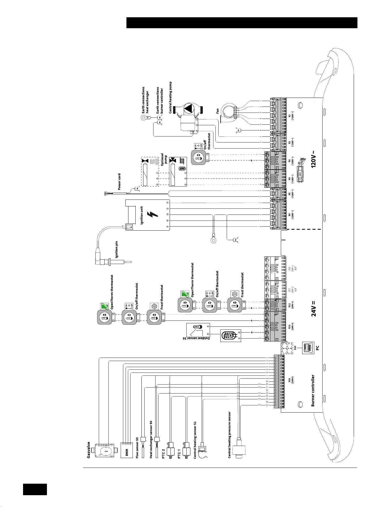
INSTALLATION AND OPERATION INSTRUCTIONS
6-4
HEATING BOILERS 99 & 120
120V~ / 60Hz
DHW Sensor / Aquastat
Diagram 6.2-2: Electrical wiring diagram
6-5
INSTALLATION AND OPERATING INSTRUCTIONS
HEATING BOILERS 99 & 120
INSTALLATION & COMMISSIONING REPORT
Unit Details:
Model Number _____________________ Serial Number ______________________________________________
Date of Installation ______________ Address of installation __________________________________________
_____________________________________________________________________________________________
User contact information _______________________________________________________________________
Installer Information Company ___________________________________________________________________
Address ______________________________________________________________________________________
Phone/Fax/E mail ____________________________________________________________________________
__
Fuel
Natural Gas
Propane
Gas Supply Pressure (high re) _______ Inches w.c. Measured Rate of Input (high re) ____________ Btu/hr
Installation instructions have been followed and completed (Section 1 of Installation and Operating Instructions).
Check-out procedures have been followed and completed (Section 3 of Installation and Operating Instructions).
Leak testing completed
gas piping
venting system
Fan and combustion components
System Cleaned and Flushed (type of cleaner used) ________________________________________________
System Filled (type/concentration of any glycol/chemicals used) _______________________________________
Air purge completed
Relief Valve correctly installed and piped
Relief valve “try lever” test performed
Condensate trap lled
Condensate drain clear and free owing
Condensate Neutralization? Yes/No
Ignition Safety Shuto test completed. Flame current reading - High re _______ µA - Low re _______ µA
Owner advised and instructed in the safe operation and maintenance of the unit and system.
Information regarding the unit and installation received and left with owner
Combustion Readings - recommended, but optional (required for fuel
conversion):
CO
2
_____________ % O
2
______________ % CO ____________ ppm
Flue temperature _________ Return water temperature (measure simultaneously with ue temp.) _______________
Commissioning has been completed as listed on this report - Installer Signature _____________________________
This installation & commissioning report should remain with the Heating boiler for future reference during
maintenance and repair.
INSTALLATION AND OPERATION INSTRUCTIONS
6-6
HEATING BOILERS 99 & 120
SERVICE RECORD
DATE LICENSED CONTRACTOR DESCRIPTION OF WORK DONE
6-7
INSTALLATION AND OPERATING INSTRUCTIONS
HEATING BOILERS 99 & 120
IMPORTANT
This unit is equipped with a feature that saves energy by reducing the unit’s water
temperature as the heating load decreases. This feature is equipped with an override
which is provided primarily to permit the use of an external energy management system
that serves the same function. THIS OVERRIDE MUST NOT BE USED UNLESS AT
LEAST ONE OF THE FOLLOWING CONDITIONS IS TRUE:
• An external energy management system is installed that reduces the unit’s water
temperature as the heating load decreases.
• This unit is not used for any space heating.
• This unit is part of a modular or multiple unit system having a total input
of
300,000 BTU/hr or greater.
• This unit is equipped with a tankless coil.

INSTALLATION AND OPERATION INSTRUCTIONS
6-8
HEATING BOILERS 99 & 120
NOTES

6-9
INSTALLATION AND OPERATING INSTRUCTIONS
HEATING BOILERS 99 & 120
This page is intentionally left blank.

Rheem Sales Co.
Montgomery, AL.
(833) 212-9276
IBC Technologies Inc.
8015 North Fraser Way
Burnaby, BC Canada V5J 5M8
(844) HEAT-IBC / (844) 432-8422
IBC Technologies USA Inc.
121 Walter A Gaines Way
Lawnside, NJ 08045
(856) 887-0544
84154404
May 2023 ©