SCAN this code
to download manual
Please ll in the following information for your NEW unit, carefully
read the instructions in this manual and le it for future reference.
MODEL NO.
SERIAL NO.
PURCHASED FROM
INSTALL DATE
1-800-523-7138
Continental Refrigerator
A Division of National Refrigeration
& Air Conditioning Products, Inc.
539 Dunksferry Road
Bensalem, PA 19020-5908
P 215-244-1400
F 215-244-9579
www.continentalrefrigerator.com
INCLUDES
R290
MODELS
INSTALLATION AND OPERATIONS MANUAL
Reach-Ins & Roll-Ins
(Including Pass-Thru & Roll-Thru Models)
Refrigerators, Freezers & Warmers
Some models utilize R-290 refrigerant, which is flammable.
Refer to data tag to see what refrigerant is used on your product of choice.
-
WARNING: Do not damage the refrigerant circuit. Do not store explosive substances, such as aerosol cans
with ammable propellant, in this appliance. Component parts shall be replaced with like components and
servicing shall be done by authorized service personnel to reduce the risk of possible ignition.
FOR FLAMMABLE (R-290) REFRIGERANT ONLY:
WARNING: KEEP CLEAR OF OBSTRUCTION ALL VENTILATION OPENINGS IN THE APPLIANCE ENCLOSURE OR IN THE STRUCTURE FOR
BUILDING-IN.
WARNING: DO NOT USE MECHANICAL DEVICES OR OTHER MEANS TO ACCELERATE THE DEFROSTING PROCESS, OTHER THAN THOSE
RECOMMENDED BY THE MANUFACTURER.
WARNING: DO NOT USE ELECTRICAL APPLIANCES INSIDE THE FOOD/ICE STOAGE COMPARTMENTS UNLESS THEY ARE OF THE TYPE REC-
OMMENDED BY THE MANUFACTURER.
DANGER: RISK OF FIRE OR EXPLOSION. FLAMMABLE REFRIGERANT USED. TO BE REPAIRED ONLY BY TRAINED SERVICE PERSONNEL. DO
NOT PUNCTURE REFRIGERANT TUBING.
CAUTION: RISK OF FIRE OR EXPLOSION. FLAMMABLE REFRIGERANT USED. CONSULT REPAIR MANUAL, OWNERS GUIDE BEFORE AT-
TEMPTING TO SERVICE THIS PRODUCT. ALL SAFETY PRECAUTIONS MUST BE FOLLOWED.
CAUTION: RISK OF FIRE OR EXPLOSION. DISPOSE OF PROPERLY IN ACCORDANCE WITH FEDERAL OR LOCAL REGULATIONS. FLAMMABLE
REFRIGERANT USED.
CAUTION: RISK OF FIRE OR EXPLOSION DUE TO PUNCTURE OF REFRIGERANT TUBING; FOLLOW HANDLING INSTRUCTIONS CAREFULLY.
FLAMMABLE REFRIGERANT USED.
CAUTION: THIS APPLIANCE IS NOT INTENDED FOR USE BY PERSONS (INCLUDING CHILDREN) WITH REDUCED PHYSICAL, SENSORY, OR
MENTAL CAPABILITIES, OR LACK OF EXPERIENCE AND KNOWLEDGE, UNLESS THEY HAVE BEEN GIVEN SUPERVISION OR INSTRUCTION
CONCERNING THE USE OF THE APPLIANCE BY A PERSON RESPONSIBLE FOR THEIR SAFETY.
CAUTION: CHILDREN SHOULD BE SUPERVISED TO ENSURE THEY DO NOT PLAY WITH THE APPLIANCE
REFER HERE
FOR REFRIG-
ERANT TYPE.
IF R-290, SEE
BELOW.

Page
Receiving Your New Model ............................................................................................................................... 5
General Information and Important Operating Facts .................................................................................................. 5
Uncrating Your New Model................................................................................................................................ 5
Model Components ......................................................................................................................................................................6
Installation and Location .................................................................................................................................. 7
Ventilation ....................................................................................................................................................................................7
Floor Loads ..................................................................................................................................................................................8
Installing Casters and Leveling ....................................................................................................................................................8
Installing Legs and Leveling ........................................................................................................................................................9
Installing Roll-In and Roll-Thru Models .......................................................................................................................................9
Condensate Removal (Interior Coil Models) ...............................................................................................................................11
Condensate Removal (Top Mount Coil Models) .........................................................................................................................11
Door Removal and Adjustment ...................................................................................................................................................12
Hinge Removal and Replacement ...............................................................................................................................................12
Re-Hinging Doors (Reach-Ins) ...................................................................................................................................................12
Removing Grill ..............................................................................................................................................................................................13
Initial Cleaning Procedure ............................................................................................................................... 13
Start-Up Procedure ........................................................................................................................................ 13
Electrical Connections .................................................................................................................................................................13
Start-Up Checklist .......................................................................................................................................................................14
Operation.................................................................................................................................................... 15
Refrigeration System and Adjustment ........................................................................................................................................15
Freezer System and Adjustment .................................................................................................................................................15
Warmer System and Adjustment ................................................................................................................................................16
Standard Reach-In Refrigeration System (Ceiling-Mount Evaporator) .......................................................................................16
Top-Mount Plug Box Refrigeration System (Evaporator Housing on Top of Cabinet) ................................................................16
Warmer with Axial Fans ..............................................................................................................................................................17
Roll-In Warmer with Blower .......................................................................................................................................................18
Electronic Control Display and Buttons.......................................................................................................................................18
Initial Sequence of Operation ......................................................................................................................................................18
How to Calibrate the Electronic Control ......................................................................................................................................19
How to Change the Set-Point ......................................................................................................................................................19
How to Switch Controller Off/On ................................................................................................................................................19
Anti-Condensate Control (On) .....................................................................................................................................................19
How to Initiate a Manual Defrost ................................................................................................................................................19
How to Change the Defrost Interval ............................................................................................................................................20
Electronic Control Error Codes ...................................................................................................................................................20
Warmers - Electronic Control Operation ............................................................................................................... 20
Electronic Control Display and Buttons.......................................................................................................................................20
How to Turn Off/On Warming Cabinet ........................................................................................................................................20
How to Change the Set-Point ......................................................................................................................................................21
How to Calibrate the Electronic Control ......................................................................................................................................21
Interior Accessories .....................................................................................................................................................................................21
Shelving Installation ....................................................................................................................................................................21
Product Loading .........................................................................................................................................................................22
Maintenance ................................................................................................................................................ 23
Periodic Cleaning Procedure .......................................................................................................................................................23
General Preventative Maintenance ..............................................................................................................................................23
Care and Cleaning of Stainless Steel...........................................................................................................................................24
Parts and Service .......................................................................................................................................... 25
Placing a Service Call ..................................................................................................................................................................25
Obtaining Replacement Parts Under Warranty ...........................................................................................................................25
Obtaining Replacement Compressor Under Warranty ................................................................................................................25
End-of-Life Disposal of Refrigerated Equipment .........................................................................................................................27
Optional Accessories ...................................................................................................................................... 28
Pan Slide Assemblies ..................................................................................................................................................................28
Hinged Glass Door Removal and Adjustment .............................................................................................................................30
Sliding Glass Door Removal and Adjustment .............................................................................................................................30
Digital Thermometer and Alarm ..................................................................................................................................................31
Mounting Caster Support Plates .................................................................................................................................................32
Installation of Tie-In Straps (Roll-Thru Cabinets) ........................................................................................................................33
Remote Set-Up and Installation Guidelines .................................................................................................................................34
Fish File Models ........................................................................................................................................... 35
Installation and Location .............................................................................................................................................................35
Loading and Storing Product ......................................................................................................................................................35
Cleaning and Maintenance ..........................................................................................................................................................36
Troubleshooting and Servicing Guide .................................................................................................................. 37
Limited Extended Protection Warranty ................................................................................................................. 40
TABLE OF CONTENTS
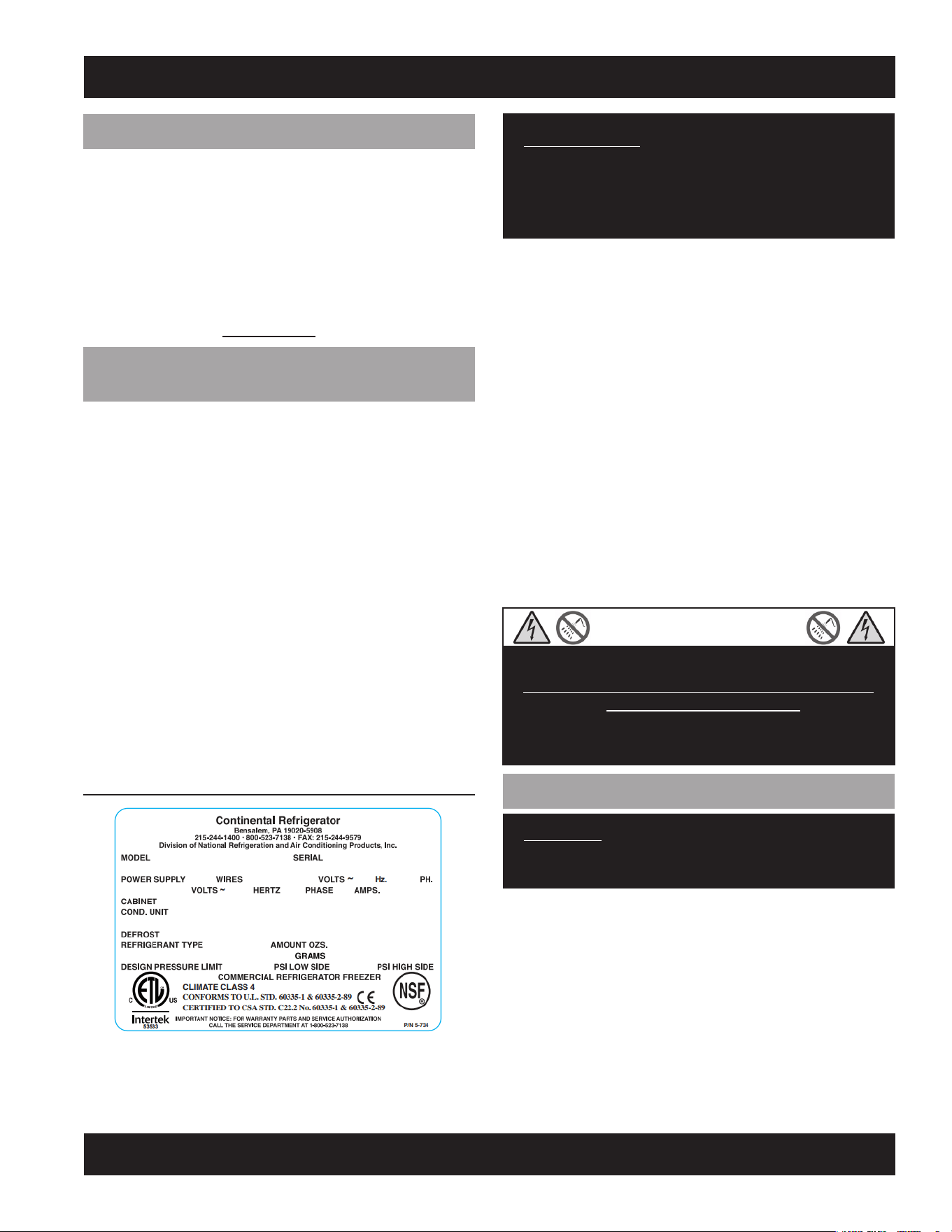
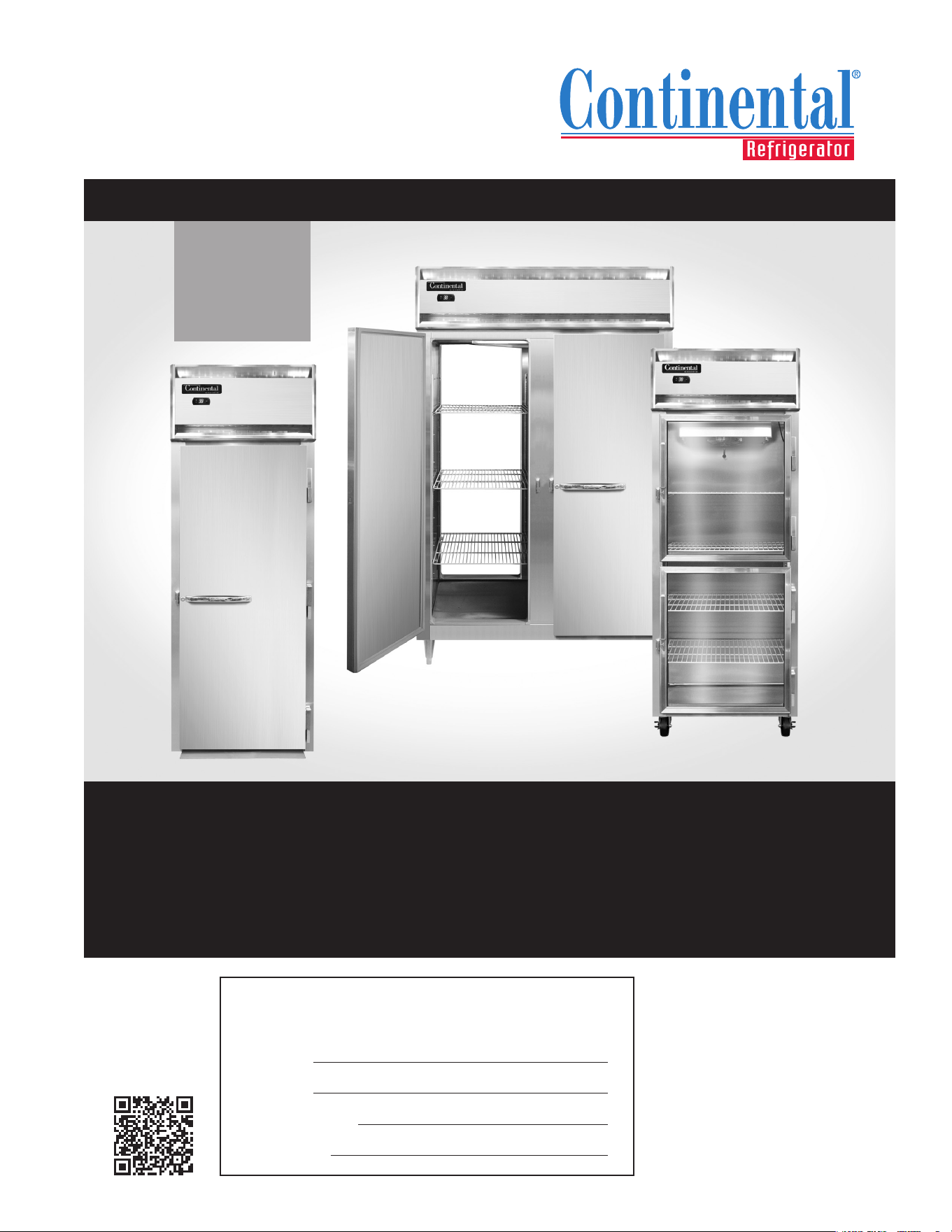
FIGURE 1: Data Tag
IMPORTANT NOTE: The model and serial number should
be noted on the front cover of this manual, in the spaces
provided. If parts or service are ever needed for your unit,
this information will be required to verify warranty status
and to properly identify any parts that may be needed.
All cabinets must be given sufficient time to reach normal oper-
ating temperature before placing any food inside cabinet or pans
(if equipped). For refrigerators, approximately 1 hour of opera-
tion is required to lower the cabinet and pan temperature to 40°F
(4°C). Freezers require approximately 2 hours of operation to
lower the cabinet temperature to 0°F (-18°C) (see “Operation”
section for further information).
Prior to factory shipping, all products are performance-run
tested for a minimum of 12 hours providing a highly sophis-
ticated temperature recording exclusive to each individual
cabinet. This recording is supplied within this manual packet. A
final evaluation, including analysis of cabinet performance, leak
check, vibration, noise level and visual examination is made by
a qualified quality control team to assure a superior product.
The carrier signs to this effect when they accept the product for
shipping. To insure the maximum in safety and sanitation, all
models are listed under applicable Underwriters Laboratories
and National Sanitation Foundation standards.
CAUTION
RISK OF ELECTRICAL SHOCK
KEEP ELECTRICAL COMPONENTS AND CONTROLS DRY
- DO NOT SPRAY WITH WATER!
FAILURE TO FOLLOW THESE INSTRUCTIONS CAN
CAUSE A HAZARD & VOID FACTORY WARRANTY.
UNCRATING YOUR NEW MODEL
IMPORTANT: Your equipment should never be transport-
ed on legs/casters unless the cabinet bottom is properly
supported. Consult the factory for more information.
The protective packaging should remain on your cabinet to avoid
dents or scratches while transporting to the actual set-up loca-
tion. All shelving, accessories and legs or casters are carefully
packaged and secured inside your cabinet to prevent damage.
All doors are locked and the keys are conveniently attached to
the door handle. After moving unit to its final location, remove
plastic and protective corner guards and any accessories or
boxes on the skid. Dispose of all packaging materials properly.
RECEIVING YOUR NEW MODEL
Congratulations on your purchase of Continental Refrigerator
superior foodservice equipment! When your shipment arrives,
thoroughly examine the packaging for any punctures, dents or
signs of rough handling. It is in your best interest to partially
remove or open the shipping container to examine the contents
for any missing accessories or concealed damage which may
have occurred during shipment. If the cabinet is damaged, it
must be noted on the carrier’s delivery slip or bill of lading
and a Freight Claim must be filed with the shipping company.
FREIGHT DAMAGE IS NOT COVERED UNDER WARRANTY.
GENERAL INFORMATION AND
IMPORTANT OPERATING FACTS
This manual has been compiled to aid in the installation, opera-
tion and maintenance of your equipment. Please read it and
familiarize yourself with your equipment, its operation and avail-
able accessories, to enjoy optimum performance.
This equipment is prohibited from use in California with
any refrigerants on the “List of Prohibited Substances” for
that specific end-use, in accordance with California Code of
Regulations, title 17, section 95374. This disclosure statement
has been reviewed and approved by NRAC, Inc. and NRAC, Inc.
attests, under penalty of perjury, that these statements are true
and accurate.
SERIAL DATA TAG
A serialized data tag is permanently attached to the inside right-
hand wall of your unit. (see Figure 1). In addition to identifying
the specific product, this label provides important information
regarding electrical requirements and refrigeration charge, as
well as agency listings and factory contacts.
6
REACH-INS & ROLL-INS
OPERATIONS MANUAL
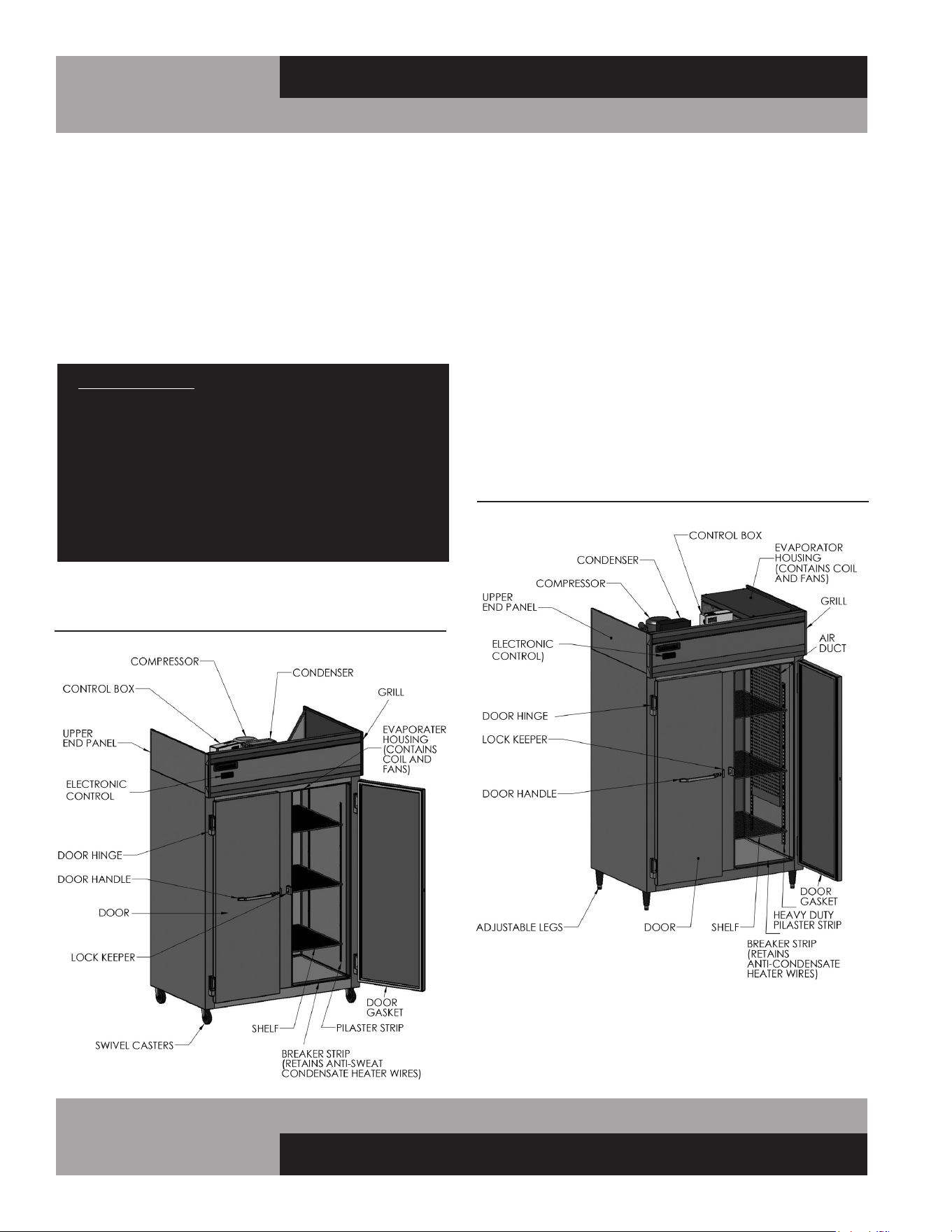
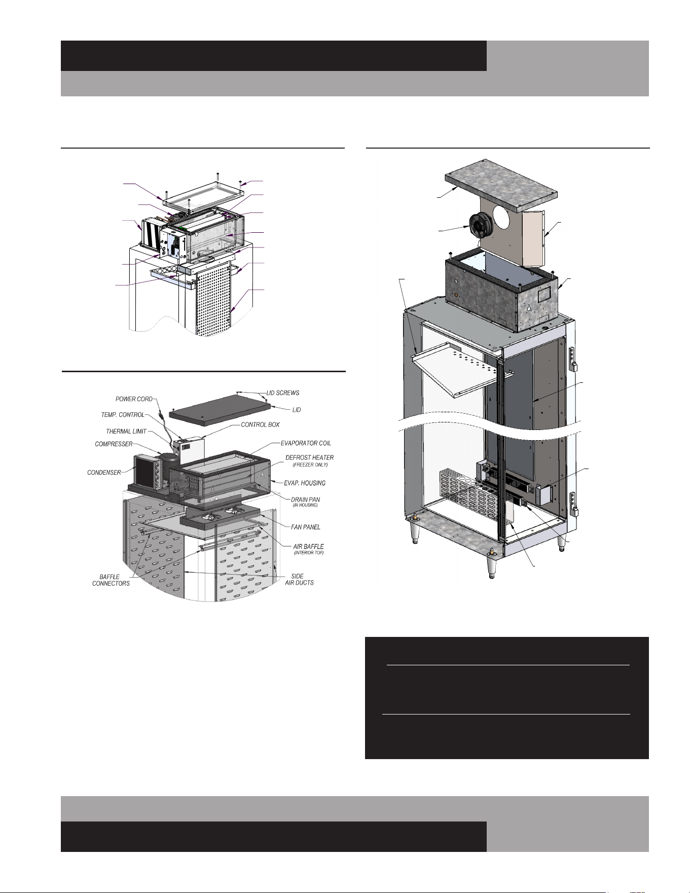
Standard Reach-In refrigerators and freezers have an internal
evaporator coil located behind the fan panel on the inside ceil-
ing of the refrigerated compartment (see Figure 2). Designer
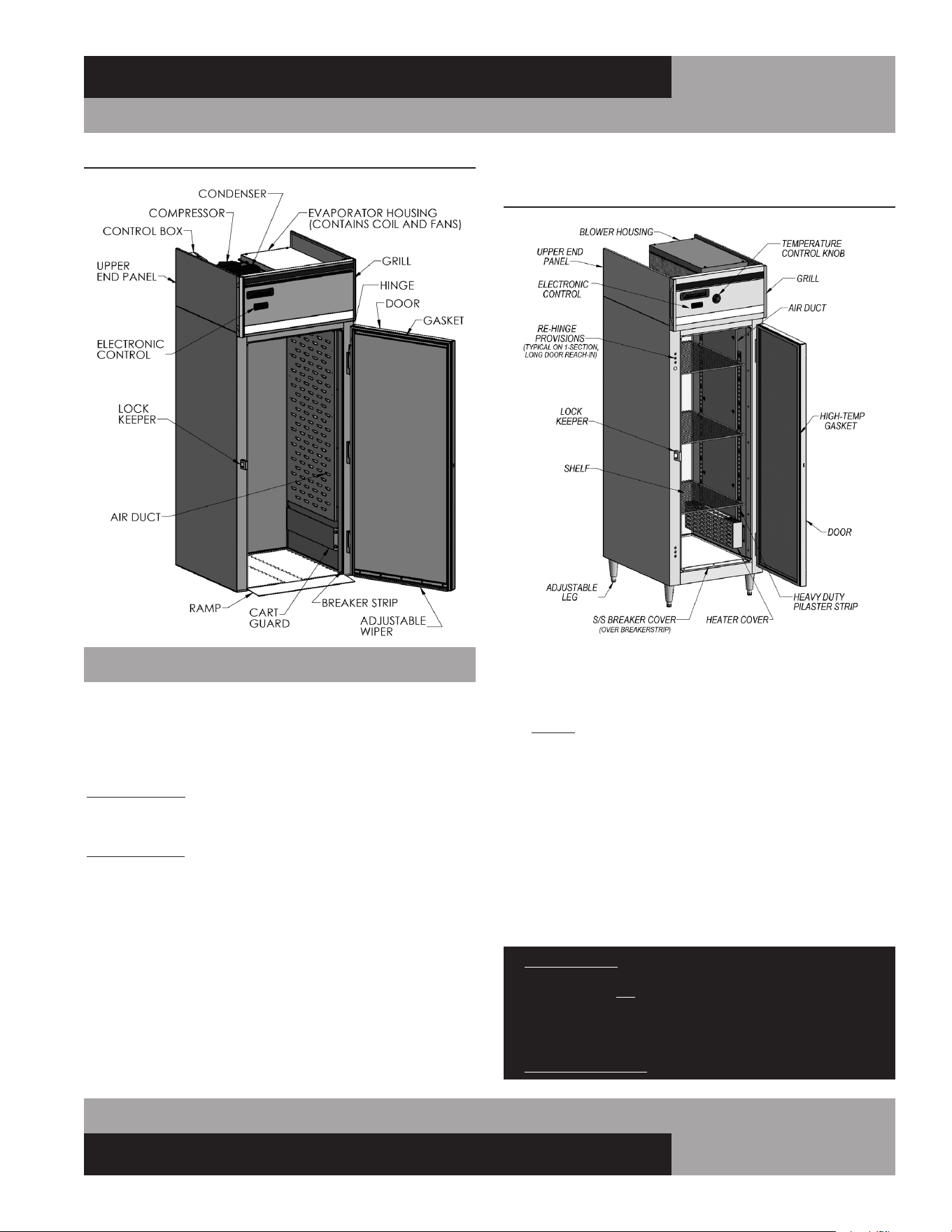
Line Reach-In, as well as all Pass-Thru, Roll-In and Roll-Thru
refrigerators and freezers have an insulated housing located on
top of the cabinet, that contains the evaporator coil, out of the
refrigerated storage area (see Figure 2A & 2B).
All warmers have an insulated housing located on top of the
unit, that contains a blower fan to circulate warm air inside the
cabinet (see Figure 2C). On most models, the high-wattage,
finned electric heating elements are located inside the cabinet,
at the bottom of the interior side walls. On single-section Roll-In
and Roll-Thru models, the heating elements are located in the
housing on top of the unit, to optimize space for carts inside
the cabinet.
FIGURE 2A: Designer Line Reach-In or Pass-Thru
Refrigerator or Freezer
FIGURE 2: Standard Reach-In Refrigerator or Freezer
Four (4) bolts secure the cabinet to the wooden skid. The bolts
are located at each end on the underside of the skid. In order to
remove these bolts, tilt the cabinet backwards and place wood-
en blocks at each end in order to hold it in its tilted position.
Using a ¾” socket or open end wrench, remove the bolts and
carefully slide the cabinet off of the skid. If caster support plates
are to be installed, save the bolts and washers (see “Mounting
Caster Support Plates” under “Optional Accessories”).
After skid removal, the cabinet should never be moved without
dollies or rollers to avoid damage to the cabinet bottom or floor.
IMPORTANT NOTE: Do not under any circumstances, lay
your new model on its front or sides. For a brief period
of time, you may lay the cabinet on its back, but only
when it’s properly blocked so as not to crush the back
or end panels and also to allow provision for your hands,
in order to set it in its upright position without damaging
the cabinet. Do not plug in and operate model for at
least three (3) hours after cabinet is set upright from
being on its back as this can damage the compressor.
MODEL COMPONENTS
7
OPERATIONS MANUAL
REACH-INS & ROLL-INS
Before moving the cabinet to its final point of installation, mea-
sure all doorways or passages to assure clearance. If additional
clearance is needed, you can remove the cabinet doors and grill
(see “Door Removal and Adjustment” and “Grill Removal”).
IMPORTANT NOTE: COMPONENT PARTS SHALL BE REPLACED WITH LIKE
COMPONENTS AND SERVICING SHALL BE DONE BY AUTHORIZED SERVICE
PERSONNEL TO REDUCE THE POSSIBLE RISK OF IGNITION.
IMPORTANT NOTE: THE APPLIANCE IS TO BE INSTALLED IN ACCORDANCE
WITH THE SAFETY STANDARD FOR REFRIGERATION SYSTEMS, ANSI/
ASHRAE 15. REFER TO THE DATA TAG FOR REFRIGERANT AMOUNT. IF THE
APPLIANCE HAS A REFRIGERANT CHARGE OF MORE THAN 114 GRAMS, THE
APPLIANCE SHALL NOT BE INSTALLED IN PUBLIC CORRIDORS OR LOBBIES
VENTILATION
The final location site of your air cooled refrigerator or freezer
must provide a sufficient quantity of cool, clean air. All refrigera-
tion systems operate more efficiently and trouble-free with cool,
dry air circulation. Avoid locations near heat and moisture gen-
erating equipment including ovens, fryers, dishwashers, steam
kettles, etc. Do not install in direct sunlight (where temperatures
FIGURE 2B: Roll-In or Roll-Thru Refrigerator or Freezer
INSTALLATION AND LOCATION
FIGURE 2C: Reach-In or Pass-Thru Warmer
may exceed 100°F) or in an unheated area (where temperatures
may drop below 55°F).
Air supply to the condensing unit is critical. Restricting airflow
places excessive heat load on the unit, adversely affecting its
operation and may cause premature failure. The condenser coil
must be kept clean and free from obstruction. Condenser air fil-
ters are not recommended, since they hinder airflow, especially
if they are not replaced frequently. Contact our factory Service
Department for more information.
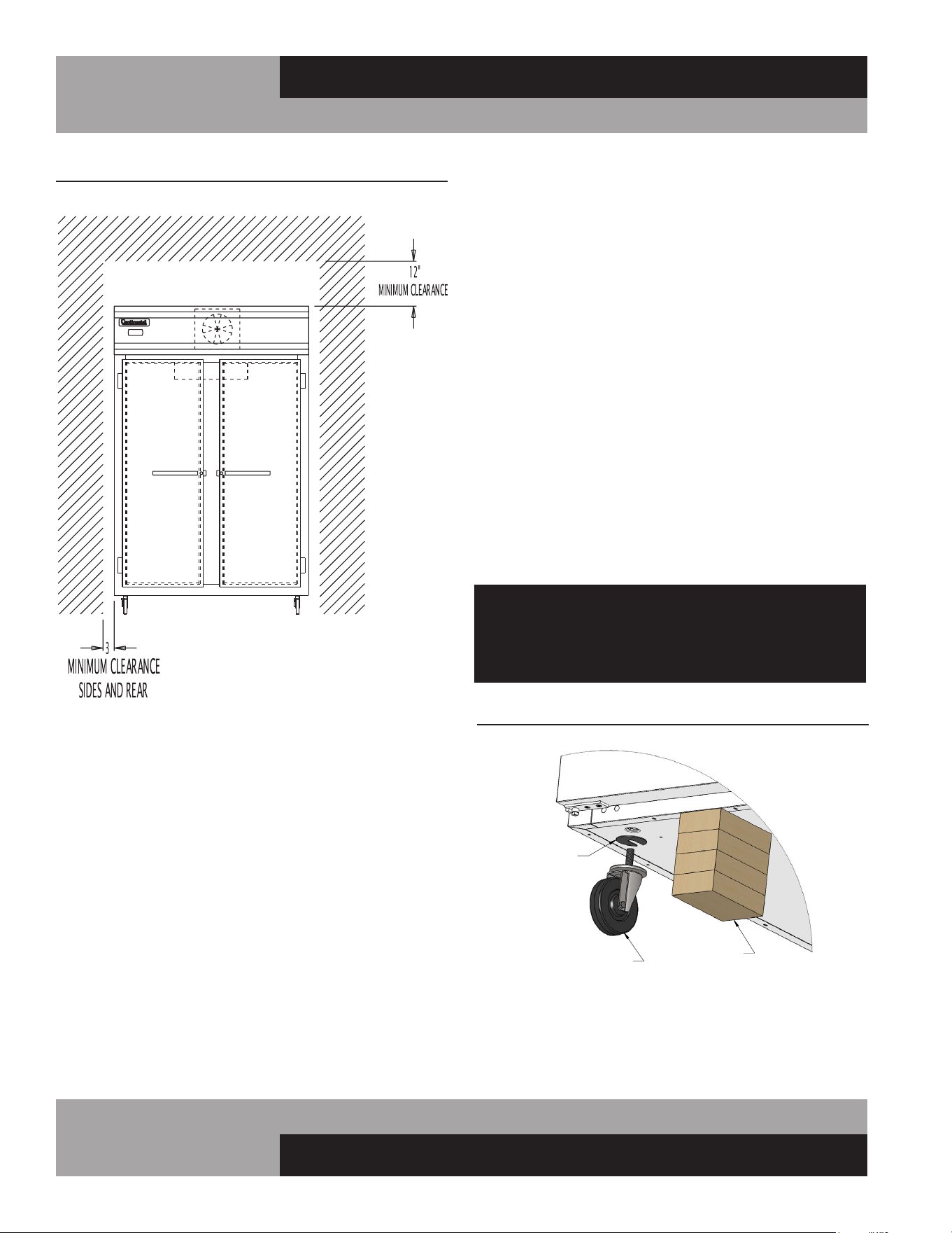
For optimum performance, all models should be installed on
casters or legs (see “Installing Casters” or “Legs”) with a
minimum 12” above the grill and 3” on each side and back of
cabinet (see Figure 3). This spacing will provide sufficient room
for proper air circulation and clearance to access components
for cleaning and maintenance. If any of the these conditions
cannot be met, the installer should provide special venting or air
ducts, as required.
IMPORTANT NOTE: For maximum efficiency, your new cabinet must be
lcated where an unrestricted air supply
can circulate aove and behind it. Never obstruct the face
of the condenser or the grill area in the front of the cabinet
and never place or store anything on the condenser or on
top of the cabinet machine compartment. These rules are
essential for long life. FAILURE TO FOLLOW THESE GUIDELINES MAY
VOID YOUR WARRANTY.
8
REACH-INS & ROLL-INS
OPERATIONS MANUAL
FLOOR LOADS
The floor at the final location site must be level, free of vibration
and strong enough to support the total combined weights of
your new model plus the maximum product load which might
be placed into it. Keep in mind that all the weight is concentrated
at the caster or leg locations. To estimate the possible product
weight, assume that each cubic foot of storage space weighs
approximately 35 pounds. Multiply 35 pounds by the amount of
cubic feet in the cabinet to obtain the product load weight.
For example, a 20 cubic foot refrigerator can hold approximately
700 pounds of product (35 x 20). Assuming the cabinet itself
weighs 300 pounds, the total combined weight of cabinet and
product is approximately 1000 pounds. Therefore, the floor in
this example must be able to support up to 1000 pounds.
A
OPTIONAL
CASTER SHIM
(CM1-2476)
CASTER
CASTER INSTALLATION
BLOCKS
FIGURE 4: Installing Casters
FIGURE 3: Minimum Clearance
(Typical Reach-In Model Shown)
INSTALLING CASTERS AND LEVELING
If your new unit is supplied with swivel casters, they will be
packed in the accessory box that came with your cabinet.
Casters should be installed only when the cabinet is close to
its final installation site. To install casters on your new model,
place wooden blocks along the back, at each end. Tilt the cabi-
net back, using the wood blocks to help hold the cabinet in its
tilted position. Locate the large threaded holes on the bottom
of the cabinet and screw the threaded caster studs into the
mounting holes, closest to the front of the unit. Repeat this
procedure by tilting the cabinet in the opposite direction and
installing the remaining casters. Make sure the casters are
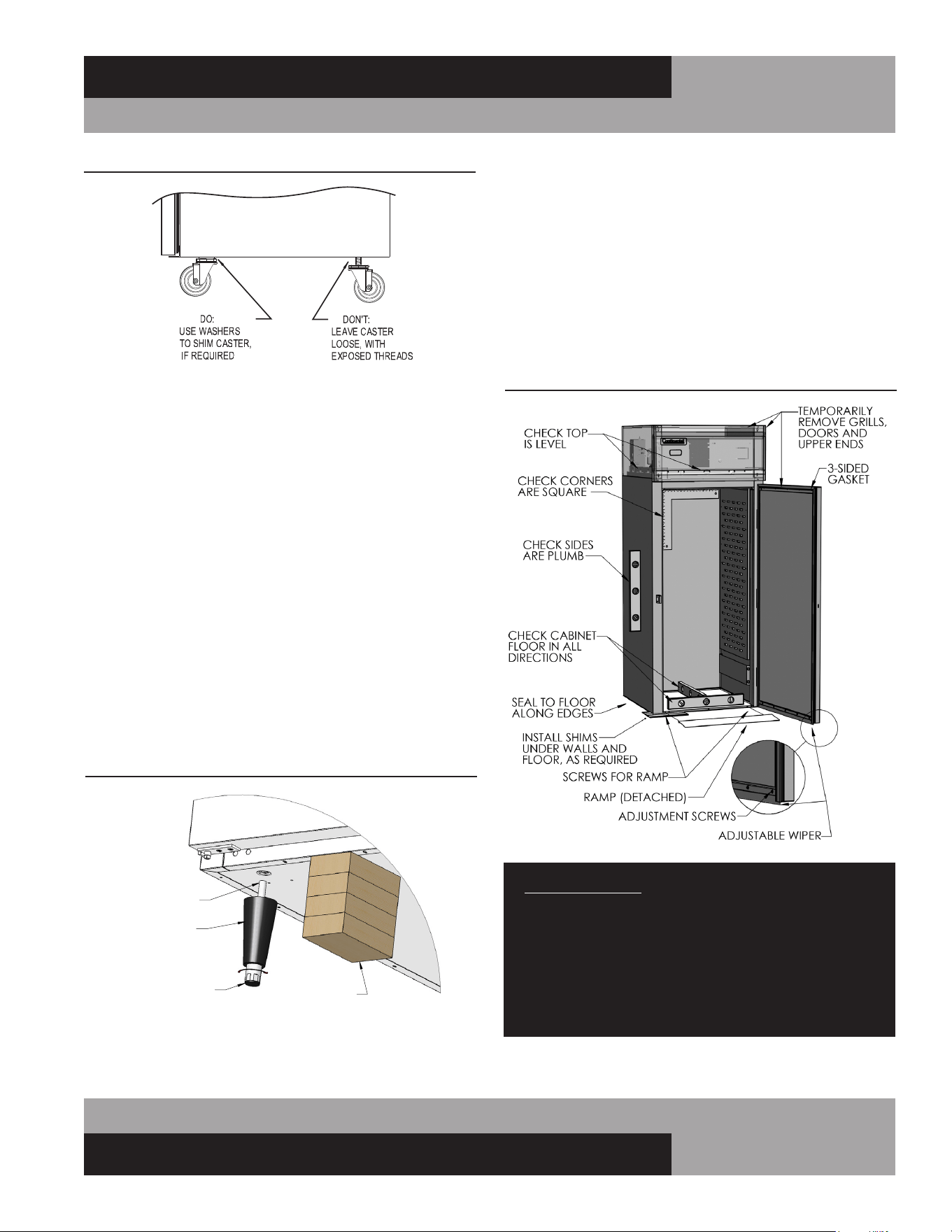
tightened extremely well (see Figure 4 & 4A). If the casters are
not installed tightly, the cabinet will be unstable and may sway
or rock, which can damage the cabinet.
If the height of a caster needs to be raised, shims must be
installed under the casters which need leveling. Extra large
washers, available at most hardware or furniture stores, can
be used to shim casters, or contact the factory for caster
shims. For maximum stability under extreme conditions, caster
plate assemblies are available from the factory (see “Optional
Accessories” section of this manual).
Do not attempt to level casters by unscrewing them
from the cabinet and leaving them loose, as this will
cause damage to the cabinet and leg hole threads,
voiding all warranties.
9
OPERATIONS MANUAL
REACH-INS & ROLL-INS
INSTALLING LEGS AND LEVELING
If your new unit is supplied with adjustable legs, they will be
packed in the accessory carton in the cabinet. Your cabinet will
have either four (4) or (6) threaded mounting holes on the bot-
tom of the cabinet (see Figure 5). In order to install the legs,
carefully tip the cabinet back, adding four (4) 2” wood blocks
underneath, and simply screw the threaded leg studs into the
case bottom front leg holes. Repeat this procedure by tilting
the cabinet in the opposite direction and install the remaining
legs. Make sure the legs are tightened extremely well or the
entire model will sway or rock with each opening or closing of
the doors, possibly causing damage to the case bottom. This
procedure should be performed close to the final installation
site and allow access to the rear of the cabinet.
To assure your cabinet is level, all legs are equipped with bullet-
type leveling bolts. These bolts can be turned by hand or by
wrench, clockwise or counterclockwise to level the cabinet.
FIGURE 4A: Casters Must Be Tight to Cabinet Bottom
04/29/10
FIGURE 5: Leg Installation
A
LEG
LEG INSTALLATION
BLOCKS
THREADED
END
TURN FOOT CLOCKWISE
TO REDUCE HEIGHT, OR
COUNTERCLOCKWISE
TO INCREASE HEIGHT.
FIGURE 6: Roll-In and Roll-Thru Installation
INSTALLING ROLL-IN AND ROLL-THRU MODELS
Roll-In and Roll-Thru models are designed to be mounted
directly (without legs or casters) on a flat floor surface in your
building (see Figure 6). The bottom off the cabinet is only
about ½” thick, to make it easy to roll carts up and into the
storage area. Roll-Ins and Roll-Thrus must be installed plumb
(vertically straight), level (horizontally even) and square for
proper operation of doors and refrigeration system. Proper
installation is similar to Walk-Ins and should only be done by a
qualified technician.
IMPORTANT NOTE: Proper installation and maintenance
is the responsibility of the customer. ANY DAMAGE OR
SERVICE REQUIRED, AS A RESULT OF INCOMPLETE
OR IMPROPER INSTALLATION, WILL NOT BE COVERED
UNDER WARRANTY. FAILURE TO PROPERLY INSTALL
AND LEVEL YOUR EQUIPMENT, INCLUDING, BUT NOT
LIMITED TO, THE INSTRUCTIONS PROVIDED IN THIS
MANUAL. MAY VOID YOUR WARRANTY.

10
REACH-INS & ROLL-INS
OPERATIONS MANUAL
length and width of the floor to provide enough support for the
cabinet and its contents.
NOTE: Shims and sealant are provided with all new roll-thru
models, to aide proper installation. Any shim material used
must be high density plastic, metal or other solid that will not
deteriorate due to moisture. Wedge shaped or flat shims 1/16”,
1/8” and 1/4” thick, and at least 3” wide to match thickness of
the cabinet walls, may be used. Failure to properly shim under
the entire floor of the cabinet will cause it to bend.
IMPORTANT NOTE: It is extremely important that your cabinet is
perfectly level for proper operation. If not level, the following adverse
conditions may occur:
1. The door(s) will not be properly aligned and consequently will not
provide a good seal.
2. Your unit may run excessively.
3. An excessive amount of ice will accumulate inside the cabinet,
around the door opening(s) and on the evaporator coil. If allowed
to continue, ice will eventually block the coil and the unit will fail.
This can result in the loss of all food stored in the cabinet.
4. Defrost water will fail to drain properly and will overflow the
evaporator coil drain pan and into the cabinet of both refrigerator
and freezer models.
CABINET AND DOOR ADJUSTMENT
After the unit is completely level, reinstall all grills, upper end
panels and ramps. Check alignment and adjust as required.
Caulk around the perimeter with NSF-approved sealant to
secure the cabinet in place and comply with sanitation require-
ments.
Reinstall all doors and verify gaskets seal properly. Adjust hing-
es as required (see “Door Removal and Adjusment”). Make
sure the adjustable flexible wiper on the bottom of each Roll-In
door gently contacts the ramp when the door is closed. Any
gaps must be eliminated, to avoid air leaks which will adversely
effect the performance of the refrigeration system. To check for
gaps, place a flashlight inside the cabinet, close the door(s) and
look under the door for visible light. Adjust the door wiper as
needed, by loosening the attachment screws slightly, then repo-
sition the wiper, recheck alignment, and retighten the screws.
NOTE: If your cabinet is adjacent to another Roll-Thru,
Tie-In Strips (see “Optional Accessories”) may be
installed for additional stability. Contact the factory for
more information and to order part kits.
SITE PREPARATION
IMPORTANT: The floor where any roll-in or roll-thru unit
is to be located must be level and flat. If not, it must be
made level prior to attempting to install the cabinet. THIS
IS CRITICAL FOR ROLL-THRU MODELS.
The best way to ensure a trouble-free installation is to have a
flat, level surface where the unit will be located, prior to setting
the cabinet in place. If the building floor is sloped or uneven,
due to floor drains or other conditions, a leveling bed should be
constructed. Otherwise it will be necessary to shim and anchor
the cabinet thoroughly, to ensure it remains stable and the doors
operate correctly. Make sure flooring is fully cured before mov-
ing the cabinet into position. Grout and concrete can release
chemicals while curing, which may corrode stainless steel.
CABINET INSTALLATION
Your cabinet should remain on the skid, with the protective
packaging in place, until transported to the final location. After
the cabinet is in the proper area, remove the door(s) by lifting
them off the hinges and setting in a safe location. Remove cart
ramp(s) at each opening by lifting off the fasteners attached to
the bottom face of the cabinet. The cabinet can be moved a short
distance, into its final position, by carefully pushing on the lower
half of the sides.
NOTE: Use care when handling the doors, as they are
large and heavy. Do not to damage the flexible wipers at
bottom of the doors. To avoid damaging or racking your
cabinet, only push on the sides at a height between 24”
and 48” from the floor.
CABINET LEVELING AND SHIMMING
After the cabinet is in its final location, remove the grills and
upper end panels. Place a 2 foot (or longer) carpenter’s along
the top edges and floor of the cabinet to check level. Use the
level to check if the sides of the cabinet are plumb (vertically).
Use a framing square to check the corners of the cabinet. If the
cabinet is not level, plumb and square, use a level to check the
cabinet floor in all directions and determine the highest area.
The cabinet must be shimmed to level the unit up to this point.
Determine the starting point for leveling, by identifying where
the cabinet is most plumb, straight and square. Insert a tapered
wedge under the adjacent walls, as needed, to raise them up to
a level position. Place shims under the side walls, on 12” cen-
ters or less, for adequate support along the entire length. After
the walls are level and plumb, place additional shims under the
11
OPERATIONS MANUAL
REACH-INS & ROLL-INS
CONDENSATE REMOVAL (Interior Coil Models)
No floor drains or plumbing connections are required since all
models use an automatic condensate water evaporating system.
Standard Reach-In models feature an evaporator housing,
located on the inside ceiling of the refrigerated storage area (see
Figure 2) and an electric condensate vaporizer pan with a mount-
ing bracket packed in the accessory carton.
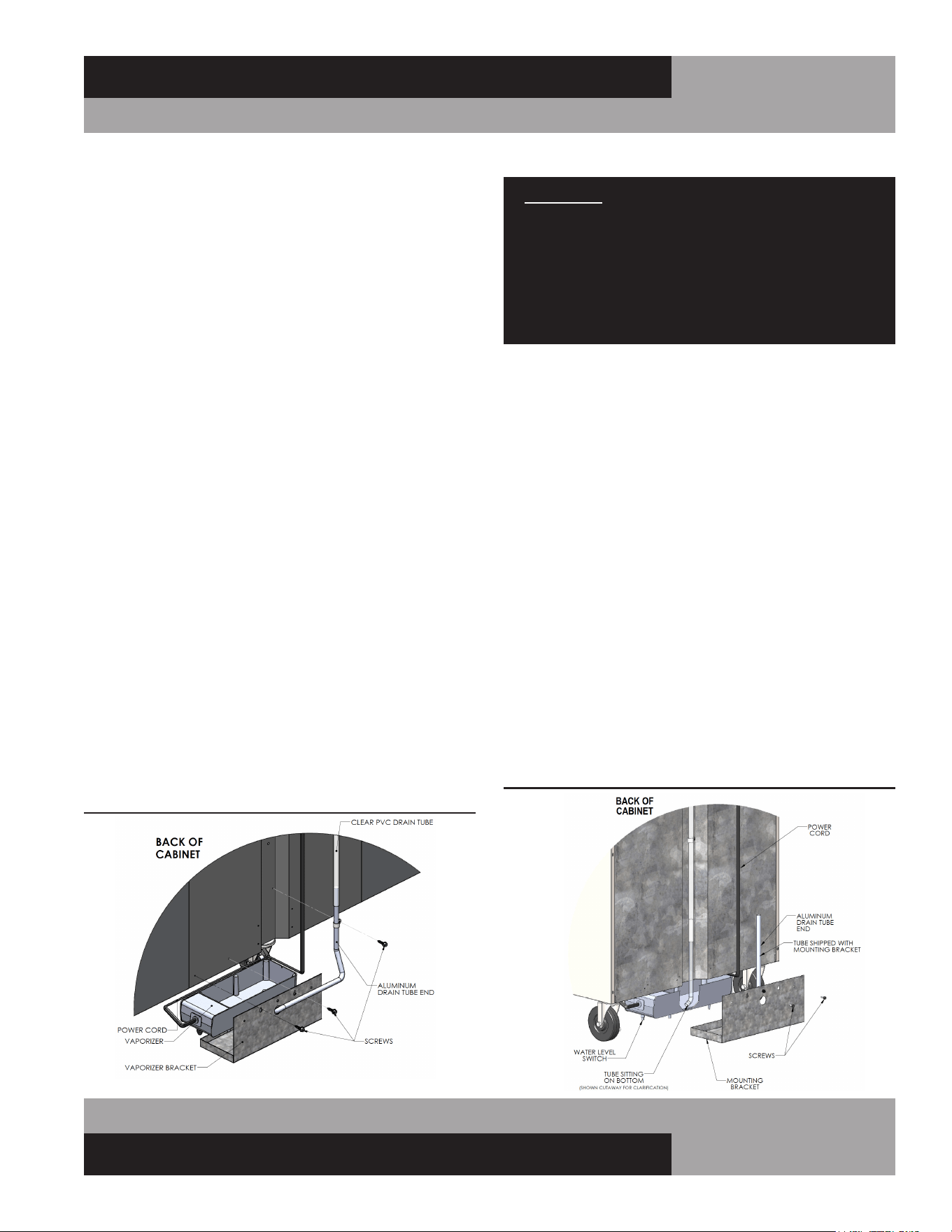
To install the vaporizer, remove the pan, power cord, cord
clamp, aluminum drain tube, and screw from the carton (see
Figure 7A & 7B). Connect the cord to the vaporizer as shown.
Route the cord around the outside of the pan and through the
clamp as illustrated. Secure the cord and clip to the pan by
fastening the mounting screw into the threaded hole on the side
of the vaporizer. Position the bracket as shown and place the
vaporizer in the bracket, making sure the power cord is routed
as illustrated. Locate the drain tube that is zip tied to the vapor-
izer bracket and position the aluminum drain tube end vertically.
Slide the bracket onto the existing rear cabinet screws and con-
nect the aluminum drain tube end to the plastic tubing. Slide the
aluminum drain tube end down into the Pan, ensuring the plastic
tubing is not blocked or kinked, and the aluminum tube is not
pushing on the bottom of the vaporizer pan. For the alternative
drain tube (see Figure 7A), simply remove from carton, insert
the tube into the hole on the bracket and connect the other end
to the plastic tubing. Check that the water level switch is operat-
ing correctly by lightly pressing down on the top of the vapor-
izer, at the end where the cord is attached. You will hear
a “click”as pressure is applied and another “click”when pressure
is removed. If you do not hear the switch “click”, ensure
the vaporizer is seated in the bracket correctly and the cord is
routed correctly and secured in the clamp. Plug the power cord
into the receptacle labeled “VAPORIZER”on top of the cabinet.
IMPORTANT: It is extremely important that water level
switch operates correctly. Vaporizer should be plugged
into outlet on top of cabinet labeled “VAPORIZER”. If a
duplex receptacle is provided on the cabinet, compres-
sor must be securely plugged into receptacle labeled
“CONDENSING UNIT”. Improper installation may cause
cabinet or vaporizer to operate erratically. This can result
in water overflowing the pan and onto the floor.
CONDENSATE REMOVAL(Top Mount Coil Models)
Designer Line Reach-Ins, as well as all Pass-Thrus, Roll-Ins
and Roll-Thrus feature an insulated evaporator housing, located
on the top of the cabinet, out of the food zone (see Figure 2A
& 2B). These models utilize a unique self-contained hot air
evaporating system to automatically eliminate condensate water.
No floor drains or plumbing connections are required and the
system is completely self-contained, so no further assembly
or maintenance is required. In some adverse conditions such
as high ambient temperature, high humidity, extremely heavy
usage, frequent loading for prolonged periods of time, or heavy
pan loading, the amount of condensate water generated could
overflow the pan. If this occurs, the plastic drain tube from the
cabinet can be diverted directly to a floor drain, bypassing the
condensate pan. Alternatively, an optional electric condensate
vaporizer may be purchased as an accessory. An electric con-
densate vaporizer is also supplied with all remote reach-in and
pass-thru models. To install the optional condensate vaporizer,
follow the steps for “Interior Coil Models” in the previous sec-
tion. Remote roll-in and roll-thru models are supplied with an
electric heater in the condensate pan on top of the cabinet, which
must be connected to a power supply by the installer.
FIGURE 7A: Alternative Drain Tube
FIGURE 7B: Vaporizer w/ Water Level Switch
12
REACH-INS & ROLL-INS
OPERATIONS MANUAL
DOOR REMOVAL AND ADJUSTMENT
During installation, it may become necessary to remove the
cabinet doors to facilitate passage through narrow doorways or
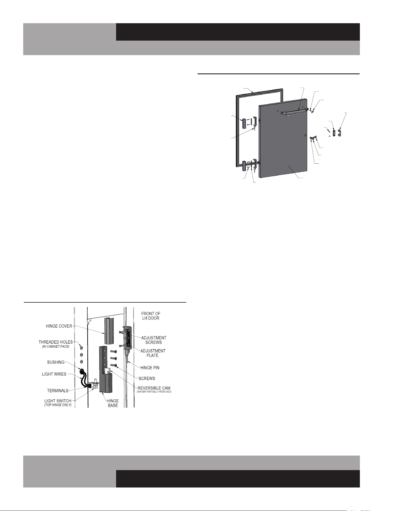
hallways. To remove a door, carefully pry off all hinge covers
using a sharp tool or plastic putty knife (see Figure 8). Swing
the door open 90° and carefully lift the door up, so the hinge
pins attached to the door clear the hinge bases mounted to
the cabinet. If it is necessary to remove the hinges, follow the
instructions below. To reinstall the door, reverse the above pro-
cedure. (For glass doors, see “Optional Accessories”).
All doors are aligned at the factory, however vibration during
transit may cause doors to shift and adjustment may be nec-
essary. If the door(s) require realignment, carefully pry off all
hinge covers (see Figure 8A) using a sharp tool or plastic putty
knife. Loosen the screws securing the hinge bases to the face
of the cabinet and slide the door into alignment. Hold the door
firmly in place and tighten all screws securely.
If the door gasket(s) do not seal properly to the cabinet face
or there are gaps between the gasket and the face on the hinge
side, adjust the door seal by removing the hinge covers and
loosening the adjustment screws securing the hinge pin to the
door. Push the face of the door towards the face of the cabinet,
so the gasket firmly contacts the cabinet. Do not press the door
too tight against the cabinet, or the gasket will pinch along the
hinge side and the door will not close and seal properly. Hold
the door firmly in place and tighten all screws securely. Open
and close the door several times to check that the gasket seals
properly all the way around the door. Re-adjust if necessary.
HINGE REMOVAL AND REPLACEMENT
Before attempting any work on your refrigerator or freezer,
always disconnect power by unplugging the cabinet, or
switching off the circuit breaker. It is strongly recommended
that you also remove all contents and store them in a walk-in
or other refrigerated space. The following tools are needed to
remove the hinge: plastic putty knife and philips screwdriver
with large (#3) tip.
To remove the hinge pin from the door (see Figure 8A) loosen
the adjustment screws and remove the adjustment plate and pin.
To remove the hinge base from the face of the cabinet loosen
the (3) flat-head machine screws. Use caution when removing
the top hinge base, as it contains the light switch. To remove the
lock keeper from the cabinet, remove the 2 screws on the inside
edge of the keeper (see Figure 8) and slide it off the base. If the
white, nylon cam needs to be removed from the hinge base, a
plastic putty knife may be used to carefully pry the cam out of
the body. Be careful not to damage the cam, as the nylon mate-
rial is soft.
RE-HINGING DOORS (Reach-Ins)
Single section, solid long door models are rehingeable in the
field, without the need to modify the cabinet. A plastic putty
knife, a philips screwdriver and wire crimpers will be needed.
Before attempting to rehinge your unit, unload all contents and
store in walk-in or other refrigerated space. Disconnect power
to the cabinet. Open the door 90° and lift it off the hinge bases.
Remove the hinge pins from the door (see instructions above).
Reverse each pin by rotating it 180° and reattaching to the door.
Remove the hinge bases and lock keeper(s) from the front of the
cabinet (see above). Use caution when removing the top hinge
base, as it contains the light switch. Remove the white, nylon
cam from each hinge base and reverse it by rotating 180° and
FIGURE 8: Reach-In/Roll-In Door Components
HINGE
COVER
MOUNTING
SCREW
ADJUSTMENT
PLATE
HINGE
PIN
HANDLE
SCREW
SCREW COVER
TONGUE
TUMBLER
LOCK HOUSING
GASKET
DOOR
SCREW
KEEPER
BASE
LOCK
KEEPER
REACH-IN/ROLL-IN DOOR COMPONENTS
HALF DOOR SHOWN
(COMPONENTS TYPICAL)
FIGURE 8A: Reach-In/Roll-In Hinge Adjustment

13
OPERATIONS MANUAL
REACH-INS & ROLL-INS
pressing firmly back in place. (A plastic putty knife may be used
to carefully pry the cam out of the base without damaging it).
Remove the filler screws and plug button from the face of the
cabinet, on the opposite side (new hinge locations). Wires for
connecting the light switch will be coiled up in the insulation,
behind the plug button. Carefully pull the wires out and install
female push-on connectors. Remove the old light switch from
the original top hinge location by disconnecting the push-on wire
terminals. Cap each lead wire separately, push the wires into the
insulation and insert the plug button into the hole. Connect the
light switch to the wire terminals at the new top hinge location.
To finish the cabinet wiring modifications, remove the cover
from the control box, on top of the cabinet. There will be a black
lamp cord, with a tag identifying it as the light switch wire. Install
(2) female wire connectors on the black lamp cord. There will
be (2) brown lamp cord leads on the terminal block. Disconnect
them and replace with the wires from the black lamp cord. Cut
off the old leads on the brown ripcord and secure them out of
the way, so they will not contact any live wiring. Check that all
wires are properly connected and secured. Replace the control
box cover.
Remount the hinge bases to the face of the cabinet. Install the
light switch into the top hinge base by sliding the flanged edge
into the slot on the back side of the base. Remount the lock
keeper and door. Adjust the doors as needed and reconnect
power to the cabinet.
NOTE: All wiring and connections should only be made by
a qualified electrician.
REMOVING GRILL
To remove the grill, loosen, but do not remove, the (4) mounting
screws located on the back side of the grill at the ends. Simply
lift grill up off of its mounting screws and out. To replace the
grill, line up the grill mounting screws with the keyhole slots
located on the cabinet body, push in and down on the grill.
IMPORTANT NOTE: The wiring to the anti-condensate
switch and the thin copper tubing or cable for the ther-
mometer are provided with leads long enough to allow
the grill to be laid across the top of the cabinet after it
has been removed. Take care not to damage the wires or
copper tubing when handling the grill.
If you need to completely remove the grill from the cabinet,
disconnect the power supply to the cabinet. Remove the wires
on the back of the anti-condensate switch on the grill. Locate the
thermometer sensing bulb and cover, located inside the cabinet.
On Standard Reach-In models, the thermometer bulb cover
is under a small cover channel on the interior top left corner
towards the front of the cabinet. On Designer Line, Pass-Thru,
Roll-In and Roll-Thru models, the thermometer bulb is located
on the interior top, under the air duct. Remove the cover, care-
fully grasp the bulb and push it back through the cabinet hole.
The thermometer bulb and grill can now be removed from the
cabinet. When reinstalling the thermometer bulb, be sure to
replace the sealant putty around the hole into the insulation.
Reattach the leads for the anti-condensate heater switch and
reconnect the cabinet’s power supply.
INITIAL CLEANING PROCEDURE
Prior to start-up and before placing any product inside of your
new model, the interior of the cabinet should be thoroughly
cleaned. Remove the protective film (which is clear on some
models) from all interior sides, bottom and other internal metal
panels, by working the corner loose and slowly pulling the film
back. Washing with a mild soap and warm water solution is
recommended for cleaning the aluminum and stainless steel
surfaces of your cabinet. This should be followed by cleaning
with a baking soda solution (three (3) tablespoons of baking
soda to each quart of warm water). Wipe down thoroughly with
a damp cloth or sponge that has been soaked in clean water and
wrung out thoroughly, and dry with a clean, soft cloth.
IMPORTANT NOTE: Never use harsh detergents, clean-
ers, scouring powders or chemicals when cleaning your
model. Failure to dry the interior surfaces after cleaning
may result in a streaking or staining of the metal.
Complete cleaning procedures and precautions are listed in the
(“Periodic Cleaning Procedure” under “Maintenance”).
START-UP PROCEDURE
ELECTRICAL CONNECTIONS
To insure proper operation, your new model must be connected
to an individual circuit that can supply the full voltage as stated
on the cabinet serial data plate. For correct voltage, power draw,
and wire accommodations, check the data on the serial data
plate located on the inner right wall of your new model. Verify
that this information exactly matches the electrical character-
istics at the installation location. An electrical wiring diagram,
located on the inside compressor compartment rear, next to
the electrical console box, should also be consulted during

14
REACH-INS & ROLL-INS
OPERATIONS MANUAL
connection. For reference, a copy of each electrical wiring dia-
gram is located towards the back of this manual (see “Wiring
Diagrams” section).
Refrigeration compressors are designed to operate within
+/-10% of the rated voltage indicated on the cabinet serial
plate. Excessively high or low supply power can burnout the
compressor. This can be easily detected and will void the fac-
tory warranty. Full voltage at the correct rating, on a separate,
designated circuit, not affected by the operation of other electri-
cal appliances, must be available to the refrigeration unit at all
times. Extension cords should never be used on commercial
equipment, as they can overheat and/or result in low voltage.
GFI/GFCI RECEPTACLES
Ground-Fault Circuit Interrupter (GFCI or GFI) devices are not
recommended for most commercial refrigerators and freezers,
since nuisance trips may occur, typically due to moisture. This
can cause temporary loss of power, which may result in high
storage temperatures and potentially unsafe food product.
Building codes in some areas may require certain 115 volt
receptacles to be protected by a GFI. If you need to connect your
equipment to a protected circuit, a properly sized, commercial
grade GFI circuit breaker should be used on a separate, isolated
power supply. Or a qualified electrician may be able to hard wire
your equipment, eliminating the need for a GFI device. Contact
Continental’s Service Department before making any modifica-
tions to your cabinet, to avoid loss of warranty.
NOTE: GFI RECEPTACLES ARE NOT RECOMMENDED,
PRODUCT LOSS OR SERVICE PROBLEMS RESULTING
FROM NUISANCE TRIPS, CONNECTION TO A DEFECTIVE
OR IMPROPER POWER SUPPLY, AND UNAUTHORIZED
MODIFICATIONS TO YOUR EQUIPMENT CAN CAUSE A
HAZARD AND WILL VOID FACTORY WARRANTY.
115 VOLT, 60 HZ, 1 PHASE CONNECTION
All 115 volt models are provided with a
factory installed, UL approved 15-amp
power cord and NEMA 5-15P plug, or a
20-amp power cord and NEMA 5-20P plug.
To insure proper operation, this
equipment must be plugged into a
NEMA compatible, grounded receptacle
that can supply the full voltage and amperage
stated on the serial plate (see Figure 1).
09/03/10
IMPORTANT NOTE: A SEPARATE, ISOLATED, PROPERLY
SIZED POWER SUPPLY MUST BE PROVIDED. GFCI
DEVICES AND/OR EXTENSION CORDS SHOULD NOT
BE USED. PRODUCT LOSS, AS WELL AS PROBLEMS
RESULTING FROM NUISANCE TRIPS OR HIGH/LOW
VOLTAGE, ARE NOT COVERED UNDER WARRANTY.
CAUTION: IF UNIT IS UNPLUGGED OR DISCONNECTED
FOR ANY REASON, ALLOW 5-6 MINUTES BEFORE
TURNING THE UNIT BACK ON TO ALLOW THE SYSTEM
TO EQUALIZE. DISREGARDING THIS PROCEDURE
COULD CAUSE AN OVERLOAD AND PREVENT THE UNIT
FROM OPERATING.
115/208-230 VOLT, 60 HZ, 1 PHASE CONNECTION
All 115/208-230 volt models are provided with three (3) sup-
ply wires, which exit the electrical box located in the machine
compartment rear, next to the compressor. The cabinet circuitry
is 115 volts and the condensing unit operates on 208-230 volts.
A permanently connected, 3-wire (plus ground) power supply is
required, consisting of (2) hot conductors and (1) neutral wire,
plus (1) ground wire. The supply leads must be connected to
the appropriate leads from the cabinet and the supply ground
wire must be attached to the electrical box with a ground lug
to provide proper grounding of the metal cabinet and chassis.
All wiring and connections should only be made by a qualified
electrician and must conform to all local electrical codes.
IMPORTANT NOTE: IF THE SUPPLY CORD IS DAMAGED, IT
MUST BE REPLACED BY THE MANUFACTURER, ITS SERVICE
AGENT, OR SIMILARLY QUALIFIED PERSONS IN ORDER TO
AVOID A HAZARD.
SPECIAL VOLTAGE CONNECTIONS
When models are ordered from the factory with special voltages,
connections should be made as required on the electrical wiring
diagram provided next to the electrical control box.
START-UP CHECKLIST
After your unit has been installed and electrically connected in
accordance with this manual, please take time to check the fol-
lowing before loading product, to assure trouble-free operation:
q Sufficient clearance and ventilation provided around
cabinet (see “Ventilation”)
q Unit connected to separate power supply at correct
voltage (see “Electrical Connections”)

15
OPERATIONS MANUAL
REACH-INS & ROLL-INS
q Cabinet is level and casters/legs are tight
(see “Installation and Location”)
q Doors close and seal properly
(see “Door Removal and Adjustment”)
q Cabinet operating at correct temperature
(see “System and Adjustment”)
q Thermometer properly calibrated
(see “Thermometer and Calibration”)
q Condensate vaporizer installed correctly
(see “Condensate Removal”)
q All refrigeration lines free of kinks and excess vibration
(see “Refrigeration System”)
q Condenser and evaporator fans rotate freely
(see “Refrigeration System”)
q Freezers only: defrost time clock set correctly
(see “Freezer System and Adjustment”)
q All pilaster clips installed securely and shelves are level
(see “Shelving Installation”)
q All packing materials discarded and cabinet properly
cleaned (see “Periodic Cleaning”)
The system should run smooth and quietly in accordance
with generally accepted commercial standards. If any unusual
noises are heard, turn the unit off immediately and check for any
obstructions of the condenser or evaporator fans. Fan motors,
fan blades, or fan housings can be jarred out of position through
rough handling in transit or during installation.
OPERATION
All cabinets must be given sufficient time to reach normal oper-
ating temperature before placing any product inside cabinet.
Refrigerators are designed to maintain an ideal cabinet tem-
perature of 38° to 40°F (3.3° to 4.4°C). Approximately 1 hour
of operation is required to reach this temperature. Freezers are
designed to maintain an ideal cabinet temperature of -4° to 0°F
(-20° to -18°C). Approximately 2 hours of operation are required
to reach this temperature.
REFRIGERATION SYSTEM AND ADJUSTMENT
All self-contained refrigerators are designed and factory set to
maintain an average cabinet temperature of 38° to 40°F (3.3° to
4.4°C). The temperature control is accessible from the top of the
electrical console box located on the cabinet top behind the front
grill (see Figure 9, 9A & 9B).
IMPORTANT NOTE: All refrigerators are designed with
automatic, “off-cycle” defrost system meaning defrosting
occurs automatically when compressor is not operat-
ing during an off-cycle. Do not set electronic control
too cold where cabinet temperature will fall below 35°F.
Evaporator will become blocked by ice since compressor
off-cycle will be considerably shortened. This will result
in loss of food stored within cabinet and require service.
FREEZER SYSTEM AND ADJUSTMENT
All self-contained freezers are factory set to maintain an average
cabinet temperature of -4° to 0°F (-20° to -18°C). These prod-
ucts are designed to hold pre-frozen food and although they are
capable of freezing small quantities of fresh food, they are not to
be used as fast or blast freezers. DO NOT ATTEMPT TO FREEZE
BULK QUANTITIES OF FRESH FOODS.
The temperature control is accessible from the top of the electri-
cal console box located on the cabinet top behind the front grill
(see Figure 9, 9A & 9B).
DEFROST OPERATION
All freezer models are equipped with an automatic, electric
defrost system, consisting of evaporator coil defrost and drain
pan heater(s). During each defrost period, the condensing unit
and evaporator fans go off, while the defrost heater(s) are ener-
gized. After termination of a defrost cycle, the heaters go off and
the condensing unit turns on. The evaporator fans remain off
(for about 20 minutes) until the coil cools down to a preset tem-
perature (typically 32°F). This defrost drip time, which allows
any remaining water to clear off the evaporator coil, also ensures
that only cold air is circulated throughout the storage compart-
ment. t for the correct time after power is restored, to maintain
the same time of day for defrost.
In some extreme applications, where there is very heavy usage,
excessively high humidity and/or constant door openings, addi-
tional defrost period(s) may be desired to ensure your evapora-
tor remains free of any frost accumulation.
16
REACH-INS & ROLL-INS
OPERATIONS MANUAL
All standard reach-in refrigerators and freezers built after June,
2009 have a unique, modular refrigeration system. The com-
plete, fully charged refrigeration unit can be easily removed from
the cabinet for locations with restricted access for installation,
servicing, conversion from a refrigerator to freezer (or vice
versa) or other needs. Contact the service department for more
information.
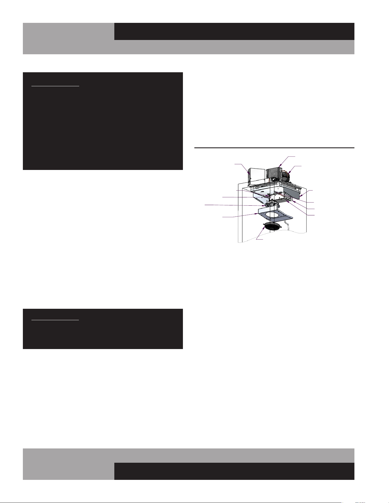
TOP-MOUNT PLUG BOX REFRIGERATION SYSTEM
(Evaporator Housing on Top of Cabinet)
The plug-type evaporator system is a unique system in which
the evaporator coil and air circulating fans are contained within
a concealed plug-type insulated housing, readily accessible on
the top of the cabinet and separate from the food storage zone
(see Figure 9A & 9B). The entire plug system is fully charged
with refrigerant and mounted on a steel rail type base which can
be removed from the cabinet for locations with restricted access
for installations, or if a field conversion (refrigerator to freezer or
vice versa) is desired. Before attempting to remove plug assem-
bly, consult factory.
FIGURE 9: Ceiling-Mount Evaporator Refrigeration System
CONTROL BOX
COMPRESSOR
CONDENSER
COIL COVER
DRAIN PAN
FAN GUARD
FAN
COIL
DEFROST HEATER
FREEZERS ONLY
HOUSING END
TXV VALVE
RETURN AIR PROBE
COIL PROBE
IMPORTANT NOTE: After defrost the automatic fan delay
prevents evaporator fans from operating until the coil has
reached a preset temperature, minimizing warm air circu-
lation in cabinet. During start-up and after a defrost cycle,
fans will not turn on immediately. Settings should only be
adjusted as noted, to minimize electrical cosumption and
provide efficient heating cycle. Contact the factory before
making modifications to any settings not described
above. Improper adjustments can cause problems with
unit, including loss of product and evaporator freeze ups,
which are not covered under warranty.
WARMER SYSTEM AND ADJUSTMENT
All Designer Line warming cabinets are designed with an operat-
ing range of 60°F to 180°F and factory performance run tested
to maintain an average cabinet temperature of 150°F. Always
preheat your new warming cabinet to the desired temperature
before placing any food into it. When the desired temperature
is reached and displayed on the electronic control, preheating is
complete and the cabinet is ready to be loaded. Please note that
setting the electronic control higher than the desired tempera-
ture will not provide quicker preheat warm-ups.
Warming cabinets are not designed to cook food. All foods
placed in the warming cabinet should be precooked and at, or
above the desired holding temperature. Never place cold or
uncooked foods in the cabinet. It is recommended that hot
foods be kept above 140°F to retard bacterial growth. Foods that
are steaming should always be covered.
IMPORTANT NOTE: Operating range of warmer tempera-
ture control is 60°F to 180°F. Never allow cabinet tem-
perature to exceed 200°F. Serious damage could result to
warming cabinet and warranty will become null and void.
STANDARD REACH-IN REFRIGERATION SYSTEM
(Ceiling-Mount Evaporator)
The low-profile evaporator system is comprised of a gener-
ous sized, evenly matched evaporator and air circulating fans
contained within an easily accessible, low silhouette, interior
ceiling mounted housing (see Figure 9). A control box, located
on top of the cabinet, contains the temperature control, thermal
limit switch, defrost time clock (for freezers) and other electrical
components.
17
OPERATIONS MANUAL
REACH-INS & ROLL-INS
IMPORTANT WARNING FOR HEATED CABINETS:
Heating Element Cover Hot!
Do Not Touch or place food next to or on heater cover.
Never store combustible material inside the cabinet.
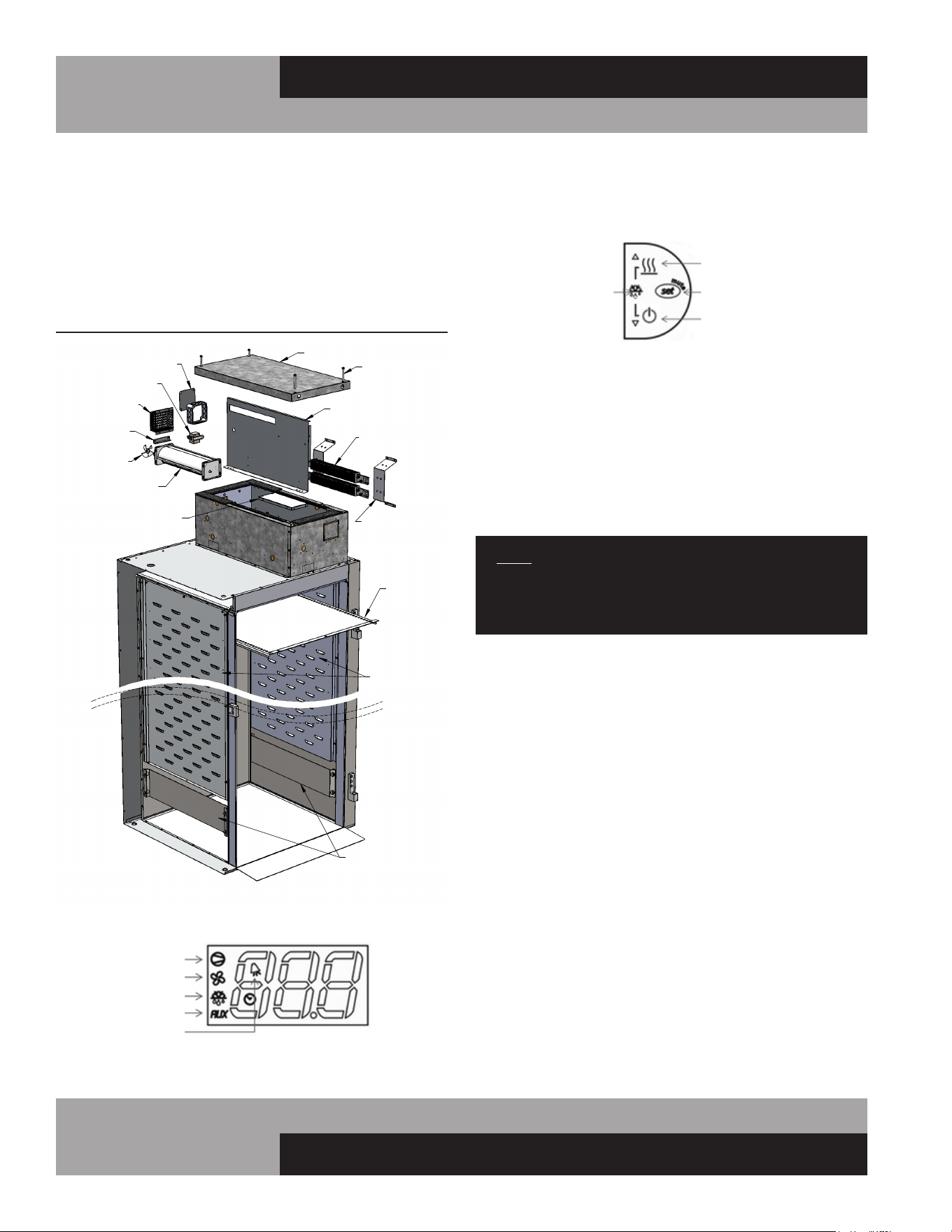
WARMER WITH AXIAL FANS
(Heaters Inside Cabinet; Fan in Housing on Top of Cabinet)
The unique plug-type heating system used on most warmer
models have heating elements located inside the cabinet storage
area (see Figure 9C). An axial fan is contained within a plug-type
insulated housing, readily accessible on the top of the cabinet,
for even temperature distribution. The insulated housing on all
models can easily be removed from the cabinet for locations
with restricted access for installation. Before attempting to
remove any housing assembly, consult the factory.
FIGURE 9A: Top-Mount Evaporator Housing Refrig. System
AIR BAFFLE
INTERIOR TOP
FAN PANEL
DRAIN PAN
CONDENSER
COMPRESSOR
CONTROL BOX
EVAPORATOR COIL
DEFROST HEATER
FREEZER ONLY
LID
LID SCREWS
INTERIOR
SIDE DUCT
AIR DIVIDERS
LID
FIGURE 9B: Roll-In Refrigeration System
FIGURE 9C: Warmer Heating System with Axial Fans
WARMER SYSTEM W/AXIAL FAN
BAFFLE
AIR DUCT
HEATER COVER
FINNED STRIP
HEATER
HOUSING
LID
FAN
FAN PANEL
FAN
TOP
MOUNTING
BRACKET
18
REACH-INS & ROLL-INS
OPERATIONS MANUAL
ROLL-IN WARMER WITH BLOWER
(Heaters and Blower in Housing on Top of Cabinet)
For maximum storage on single-section Roll-In and Roll-Thru
models, the heating elements are contained within the insulated
plug-type housing on top of the cabinet, along with a cross-flow
blower, for even air circulation (see Figure 9D).
ELECTRONIC CONTROL DISPLAY AND BUTTONS
FAN GUARD
BLOWER
COOLING
FAN
1-SEC ROLL-IN WARMER COMPONENTS
BRACKET
HEATER
LID
ELECTRICAL
BOX & COVER
BAFFLE
BRACKET
HEATER
AIR BLOCK
CART GUARD
TOP
DUCT
SIDE DUCTS
TRANSFORMER
LID
SCREWS
FIGURE 9D: Warmer with Top-Mount Heaters and Blower
a. The display will illuminate with the current cabinet
temperature.
b. The compressor icon, fan icon, and the aux heater icon
may flash for a period of time, indicating normal
delayed start-up.
c. After the start-up delay, the compressor and evaporator
fan(s) will start if the control is calling for cooling.
a. The SET-POINT is the preprogrammed temperature which
shuts off the compressor.
b. The DIFFERENTIAL is the preprogrammed temperature that
is added to the SET POINT temperature that will start the
compressor.
EXAMPLE: Set-Point 36°F and the differential is 4°F the com-
pressor will cycle off at 36°F and back on at 40°F.
COMPRESSOR
EVAP FAN
DEFROST
AUX HTRS
ALARM
AUX HTRS
(UP)
SET
(MUTE)
POWER
(DOWN)
DEFROST
2 BUTTONS
The control icons shown above will be illuminated when the
associated function is active. If an icon is flashing, it means the
function will be activated after the controller delays are finished.
• The “AUX HTRS/UP” button is used for activation or
deactivation of the auxiliary anti-condensate heaters or for
increasing values.
• The “SET/MUTE” button is used to lock in a new value or
to silence the alarm beeper.
• The “POWER/DOWN” button is used to turn the unit on/off
or for decreasing values.
• Press the “UP” and “DOWN” buttons simultaneously for 3
seconds to put into manual defrost.
NOTE: The electronic control has 2 or 3 probes. There is
the regulation probe in the return air stream, there is an
evaporator probe located in the evaporator coil, and if the
unit has fascia heaters, there will be an ambient probe.
INITIAL SEQUENCE OF OPERATION
1. Cabinet is plugged in.
2. The control will cycle the compressor on and off determined
by the SET-POINT and DIFFERENTIAL.

19
OPERATIONS MANUAL
REACH-INS & ROLL-INS
a. During defrost, the defrost icon will appear in the display
and the compressor will turn off until a preprogrammed
temperature or time is reached. During this time for freez-
ers only, the evaporator fan(s) will also turn off and the
defrost heater will be energized.
b. After a preprogrammed evaporator temperature has been
reached, there may be a short delay for both the compres-
sor and evaporator fan(s) to restart.
c. After the defrost cycle is completed, the control will
resume normal operation.
3. The control may be preprogrammed to initiate a defrost by
time interval.
HOW TO CALIBRATE THE ELECTRONIC CONTROL
The controller temperature display can be calibrated if required.
Before attempting to calibrate the temperature display, check the
display by placing a pre-calibrated temperature sensing device in
the center of the refrigerated compartment and keep the doors
closed for at least 15 minutes. The temperature display should
read the same temperature as the sensing device, within +/-2°F.
If not, follow these instructions to calibrate.
1. Press and HOLD the “SET” button until “PS” appears flash-
ing in the display. Release the “SET” button.
2. Press the “UP” button until “/C1” appears in the display.
Release the “UP” button.
3. Press and release the “SET” button. The current value of the
offset will appear in the display.
4. Press the “UP” button to increase or the “DOWN” button to
decrease the offset value.
5. Press and HOLD the “SET” button for 5 seconds to confirm
and save the new value. When complete, the current tem-
perature will be displayed. RELEASE the “SET” button.
EXAMPLE: If a sensing device in the cabinet reads 38°F and the
control display shows 41°F, follow steps above and decrease the
current offset by 3°F. If the current offset was 0, change to -3.
HOW TO CHANGE THE SET-POINT
Refrigerators are factory set to maintain an average temperature
of 38°F. Freezers are factory set to maintain an average tempera-
ture of 0°F. To change set-point:
1. Press and HOLD the “SET” button until the current set-point
begins flashing. Release the “SET” button.
2. Press the “UP” or “DOWN” but-
ton to adjust to the new set-point value.
3. Press and release the “SET” button to lock in the new set-
point. The control will now resume normal operation with
the new set-point.
HOW TO SWITCH THE CONTROLLER OFF/ON
The controller can be switched OFF. The display will still be
active but all systems operated by the control will be OFF.
1. To turn the controller OFF, press and HOLD “POWER” but-
ton for 5 seconds. When in the OFF mode, “OFF” will alter-
nate in the display with the current appliance temperature.
2. To turn the controller back “ON”, press and HOLD “POWER”
button for 5 seconds. The controller will resume normal
operation.
ANTI-CONDENSATE CONTROL (ON)
1. To see the current state of the aux heaters (anti-conden-
sate), press and HOLD “AUX HTR” button for 1 second.
RELEASE “AUX HTR” button. The display will show the cur-
rent state of the heater when the button is pressed.
2. To change the current state of the AUX Heaters, press and
HOLD “AUX HTR” button. The display will show the current
state of heater operation. After 5 seconds, the heater will
switch to the opposite state and the display will return to
displaying the cabinet temperature. RELEASE the button.
The control has a built in energy saving feature for the AUX (anti-
condensate) heaters. When in the ON position, the AUX icon
may not illuminate indicating the AUX heaters are not currently
energized. The control will automatically energize the AUX heat-
ers when the conditions require these heaters to be activated.
HOW TO INITIATE A MANUAL DEFROST
This is used when a one-time additional defrost may be neces-
sary to clear accumulated ice from the evaporator coil.
1. Press and HOLD “UP” and “DOWN” buttons simultaneously
for 5 seconds.
2. After 5 seconds, the defrost icon will illuminate. RELEASE
“UP” and “DOWN” buttons.
20
REACH-INS & ROLL-INS
OPERATIONS MANUAL
HEATER
FAN
POWER / UP
SET
(MUTE)
DOWN
HOW TO CHANGE THE DEFROST INTERVAL
This is used to increase or decrease the frequency of defrosts.
If the interval is set at “8”, a defrost will occur every 8 hours. If
you need more defrosts, lower this value.
1. Press and HOLD “SET” button until “PS” appears flashing
in the display. Release “SET” button.
2. Press “UP” button until “DI” (defrost interval) appears in
the display. Release “UP” button.
3. Press and RELEASE “SET” button. The current defrost inter-
val will appear in the display.
4. Press “UP” or “DOWN” button to adjust to the new defrost
interval.
5. Press and HOLD “SET” button to lock in this new value.
When the display returns back to cabinet temperature,
release “SET” button
NOTE: Defrost cycles are time initiated and temperature
terminated with a maximum time cut-off.
HIGH AND LOW TEMPERATURE ALARMS
The controller has high and low alarm set-points. These values
can be modified per the end user requirements. There is a pre-
programmed time delay for the alarm to activate to eliminate
nuisance alarms. To change the alarm threshold values:
1. Press and HOLD “SET” button until “PS” appears flashing
in the display. Release “SET” button.
2. Press “UP” button until “AL” (Low Alarm Setting) or “AH”
(High Alarm Setting) appears in the display. Release “UP”
button.
3. Press and RELEASE “SET” button. The current alarm setting
will be shown.
4. Press “UP” or “DOWN” button to get the desired alarm
set-point.
5. Press and HOLD “SET” button for 5 seconds to confirm and
save the new value. When complete, the current tempera-
ture will be displayed. Release “SET” button.
NOTE: When in an alarm condition, the display will alter-
nate between the cabinet temperature and alarm code.
“AL” when in a low temperature alarm condition and “AH”
when in a high temperature alarm condition. The control
will also beep and the alarm icon will activate when in an
alarm condition. To silence the alarm beeper for the active
alarm just press and release the “SET/MUTE” button.
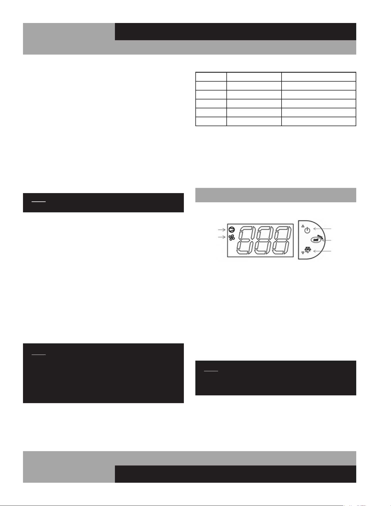
ELECTRONIC CONTROL ERROR CODES
If there is a regulation probe error, the display will just show
alarm code “E0” and not flash the cabinet temperature. If there
is a probe error, you must contact your service provider
immediately.
Alarm Code Alarm Description Notes
E0 Regulation Probe Error Located in return air stream
E1 Evaporator Probe Error Located in evaporator coil
E2 Ambient Probe Error Located on side of electrical box
LO Low Temperature Alarm Reference “AL” parameter
HI High Temperature Alarm Reference “AH” parameter
• If there is an error code “E0”, the control will operate the
appliance in a preprogrammed ON/OFF cycle based on time,
not temperature.
• If there is an error code “E1”, the control will still go into a
defrost but will terminate on time, not temperature.
• If there is an error code “E2”, the aux heaters will not oper-
ate.
W
WARMERS - ELECTRONIC CONTROL OPERATION
ELECTRONIC CONTROL DISPLAY AND BUTTONS
The control has a 3 button interface.
• The “POWER/UP” button is used to turn off the warming
cabinet or for increasing values.
• The “SET/MUTE” button is used to lock in a new value or to
access the set point.
• The “DOWN” button is used for decreasing values.
The control icons shown above will be illuminated when the
associated function is active. When the “HEATER” icon is illumi-
nated, the heaters are ON. When the “FAN” icon is illuminated,
the fan is ON..
NOTE: The electronic control has 1 probe. This probe is
used for regulation of the warming cabinet temperature
and is located in the return air stream.
HOW TO TURN OFF/ON WARMING CABINET
The warming cabinet is shipped with the control in the “ON”
position. When in the “ON” position, the current cabinet tem-
perature will be displayed along with the icons that are active:
fan and/or heater icon.

21
OPERATIONS MANUAL
REACH-INS & ROLL-INS
When the warming cabinet is in the “OFF” position, the current
cabinet temperature will alternate with “OFF” in the display. The
heaters and the fan(s) will remain off.
1. To turn “OFF” the warming cabinet:
2. To turn “ON” the warming cabinet:
HOW TO CHANGE THE SET-POINT
Warmers are factory set to maintain an average temperature of
180°F. The set-point is the temperature that the warming cabinet
heaters will shut off. There is a negative 2 degree differential. So
if the set-point is 184°F, the warmer cabinet heaters will turn off
at 184°F and turn back on at 182°F.
To change set-point:
1. Press and HOLD the “SET” button until the current set-point
begins flashing. Release the “SET” button.
2. Press the “UP” or “DOWN” button to adjust to the new set-
point value.
3. Press and release the “SET” button to lock in the new set-
point. The control will now resume normal operation with
the new set-point.
HOW TO CALIBRATE THE ELECTRONIC CONTROL
The controller temperature display can be calibrated if required.
Before attempting to calibrate the temperature display, check the
display by placing a pre-calibrated temperature sensing device
in the center of the warmer compartment and keep the doors
closed for at least 15 minutes. The temperature display should
read the same temperature as the sensing device, within +/-3°F.
If not, follow these instructions to calibrate.
1. Press and HOLD the “SET” button until “PS” appears flash-
ing in the display. Release the “SET” button.
2. Press the “UP” button until “/C1” appears in the display.
Release the “UP” button.
3. Press and release the “SET” button. The cur-
rent value of the offset will appear in the display.
a. Press and HOLD the “POWER” button for 5 seconds.
b. Release the “POWER” button. The display will alternate
between “OFF” and the cabinet temperature.
a. Press and HOLD the “POWER” button for 5 seconds.
b. Release the “POWER” button. The display will show cur-
rent cabinet temperature, the fan icon will illuminate and the
heater icon will illuminate if the cabinet is below the cut-in
temperature.
4. Press the “UP” button to increase or the “DOWN” button to
decrease the offset value.
5. Press and HOLD the “SET” button for 5 seconds to confirm
and save the new value. When complete, the current tem-
perature will be displayed. RELEASE the “SET” button.
EXAMPLE: If a sensing device in the cabinet reads 170°F and
the control display shows 175°F, follow the steps above and
decrease the current offset by 5°F. If the current offset is 0,
change to -5. The display will now read 170°F.
INTERIOR ACCESSORIES
Your new cabinet comes with (3) shelves per section for stan-
dard solid door models, or (4) shelves per section for glass door
models, and (4) support clips per shelf.
SHELVING INSTALLATION
Pilaster strips for mounting the shelves are secured to the cabi-
net walls with special screws which allow the strips to be readily
removed for cleaning without the use of tools. To install the
shelving, determine the desired location for the shelves in each
section of your cabinet. For proper airflow, the bottom shelf in
each section should be installed with the clips at the lowest posi-
tion on the pilaster strip, to provide space for sufficient airflow
under and around the product.
IMPORTANT NOTE: When locating your shelves, allow
space between each row of product. A minimum clear-
ance of 2” is recommended below the bottom product
for air circulation.
Shelf clips are easily installed by inserting them into the pilasters
at the desired shelf locations. To install a shelf, simply place it
on the (4) clips, making sure that the clips are located properly,
so the shelf is level and supported at each corner. Standard and
optional heavy duty pilasters and clips are shown in Figure 10.
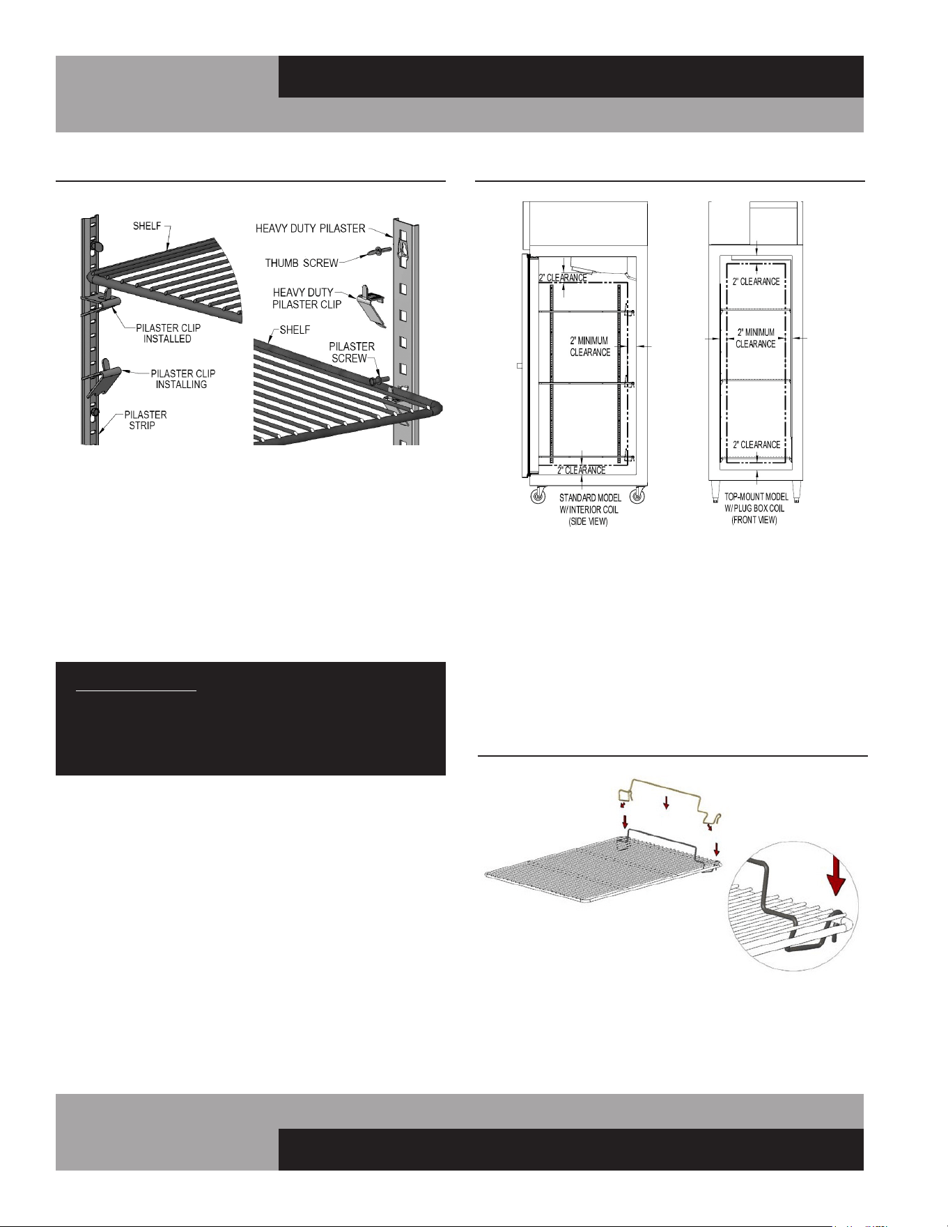
22
REACH-INS & ROLL-INS
OPERATIONS MANUAL
To ensure proper air flow inside wall your cabinet, some interior
standard models are provided with product stops that snap onto
the shelves (see Figure 10B). To install the product stop, place
it over the shelf as shown and press it down onto the shelf. If
necessary, carefully pull out on the ends of the product stop,
so the bottom of the rod snaps over the shelf wire. Press down
on the hooks at ends of the product stop, so they snap over the
back of the shelf frame. Repeat for remaining shelves. Make sure
all shelves are installed with the product stops positioned at the
back of your cabinet.
MAINTENANCE
PRODUCT LOADING
Product load should be evenly distributed over each shelf and
through the cabinet. Standard shelving will hold up to 125 lbs
and heavy duty shelves will hold up to 225 lbs, evenly distrib-
uted. For proper performance on standard ceiling-mount coil
models, maintain at least a 2” air space from product to the back
wall and to the coil housing. For top-mount plug box models, a
minimum 2” clearance should be maintained from the face of the
top and side walls (see Figure 10A).
IMPORTANT NOTE: LOADING PRODUCT TOO CLOSE
TO THE WALLS OR PANELS WILL RESTRICT AIRFLOW,
RESULTING IN POOR PERFORMANCE AND SERVICE
ISSUES, SUCH AS COIL FREEZE-UP, WHICH WILL NOT
BE COVERED BY WARRANTY.
FIGURE 10: Standard and Heavy Duty Shelf Supports
FIGURE 10A: Product Loading Limits
FIGURE 10B: Product Stop Installation

23
OPERATIONS MANUAL
REACH-INS & ROLL-INS
SAFETY PRECAUTIONS
DISCONNECT POWER BEFORE ATTEMPTING TO WORK
ON OR CLEAN EQUIPMENT. DO NOT ATTEMPT TO
REMOVE ANY COVERS OR PARTS YOURSELF, AS
THIS CAN EXPOSE DANGEROUS, HIGH VOLTAGE
WIRING. SERVICE SHOULD ONLY BE PERFORMED BY
A QUALIFIED TECHNICIAN.
ALWAYS ROUTE POWER CORDS AWAY FROM AREAS
WHERE THEY CAN BE WALKED ON OR DAMAGED BY
OTHER EQUIPMENT. YOUR APPLIANCE IS EQUIPPED
WITH A POLARIZED, GROUNDED POWER PLUG. NEVER
ATTEMPT TO REMOVE THE GROUND POST OR USE
A NON-POLARIZED ADAPTER, WITHOUT PROPERLY
GROUNDING THE EQUIPMENT.
CONDENSER FINS ARE MADE FROM THIN METAL AND
HAVE SHARP EDGES. ALWAYS WEAR GLOVES AND
USE CAUTION WHEN WORKING ON OR AROUND THE
CONDENSING UNIT TO PREVENT CUTS AND AVOID
DAMAGING FINS, TUBING AND OTHER COMPONENTS.
KEEP ELECTRICAL COMPONENTS AND CONTROLS DRY.
DO NOT SPRAY WITH WATER! FAILURE TO FOLLOW
THESE INSTRUCTIONS CAN CAUSE A SAFETY HAZARD
AND VOID FACTORY WARRANTY.
PERIODIC CLEANING PROCEDURE
It is always best to clean your refrigerator or freezer when the
product load in your cabinet is as its lowest level. To clean the
interior or exterior cabinet surfaces, follow these procedures:
1. Disconnect your cabinet from its power supply and remove
all product from inside.
2. Open all doors and allow the cabinet to reach room temp-
erature. Remove all accessories (shelves, pilasters, clips,
etc.) from inside and wash them with a baking soda
and warm water solution, wipe thoroughly with clean water.
Dry all accessories completely with a soft clean cloth.
3. Once the cabinet has reached room temperature, wash the
inside and outside surfaces with a solution of warm water
and baking soda. Pay particular attention to the face of the
cabinet, as any residue or debris can impair the door seal.
For slightly more difficult cleanups, ammonia or vinegar in
warm water can be used. Wipe down thoroughly with a
damp cloth or sponge that has been soaked in clean water
and wrung out thoroughly, and dry with a clean, soft cloth.
Carefully wash all of the vinyl door gaskets with clean
water, dry them and check for any damage, which may
affect the seal. Failure to dry all surfaces completely may
cause water stains or streaking on the aluminum or stain-
less steel finish.
4. Return all accessories to their original locations, reconnect
the power. Wait at least 1 hour before reloading product.
CLEANING PRECAUTIONS
NEVER USE HARSH DETERGENTS, ABRASIVE
CLEANERS, OR CHEMICALS CONTAINING HALOGENS
(CHLORINE, FLUORINE, IODINE, ETC.) WHEN
CLEANING YOUR UNIT. CONCENTRATED CHEMICALS
CAN CAUSE DISCOLORING, ALWAYS WIPE THEM OFF
IMMEDIATELY IF CONTACT OCCURS. SEE “CLEANING
OF STAINLESS STEEL” FOR MORE INFORMATION.
AVOID SPLASHING THE CABINET WITH WATER AND
CHEMICALS WHEN MOPPING FLOORS OR CLEANING
OTHER EQUIPMENT AROUND IT.
GENERAL PREVENTATIVE MAINTENANCE
The most important thing you can do to maintain any refrigera-
tor or freezer and extend its life, is to keep the condenser clean.
Performance of the air-cooled condensing unit, located on top of
the cabinet, depends exclusively upon the amount of air passing
through the condenser fins. Your refrigerator or freezer will run
more efficiently, consume less energy, and provide a maximum
of trouble-free service throughout its lifetime if the condenser
coil is kept clean and an adequate supply of clean, cool air is
provided at all times. Periodically (at least once a month) it is
important to inspect the condenser coil for any debris or block-
age that may have accumulated.
If the condenser coil is dirty or dusty, disconnect the cabinet
power supply and use a stiff brush to wipe away any dirt and
debris from the condenser fins. Using a vacuum cleaner with a
brush attachment may aid in this process. After cleaning, restore
electrical service to your cabinet.
IMPORTANT!
AFTER-MARKET CONDENSER FILTERS ARE NOT
PERMITTED BECAUSE THEY HINDER AIRFLOW.
FAILURE TO KEEP THE CONDENSER CLEAN AND
FREE FROM OBSTRUCTIONS WILL CAUSE EXCESSIVE
COMPRESSOR LOAD, REDUCING THE PERFORMANCE
OF YOUR UNIT. THIS CAN RESULT IN PREMATURE
FAILURE AND WILL VOID YOUR WARRANTY.
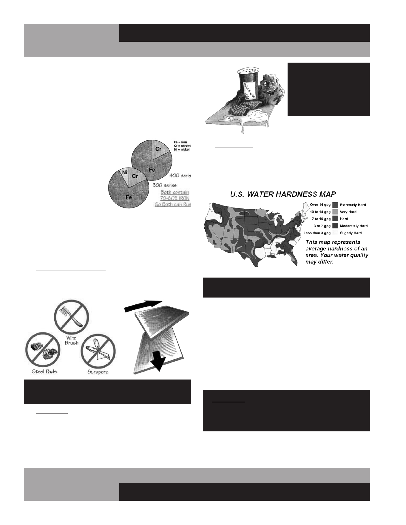
24
REACH-INS & ROLL-INS
OPERATIONS MANUAL
DO NOT USE: abrasive
cleaners, chemicals with
chlorides or muriatic
acid to clean your
equipment.
3. HARD WATER causes spots and stains on stainless steel
surfaces, particularly when it is heated. Find out the hard-
ness of your water and treat it properly, if needed. Use a
water filter and softeners if you have hard water. Club soda
can be used to remove streaks or spots.
DO NOT USE: hot or hard water to clean stainless steel.
CLEAN YOUR STAINLESS STEEL REGULARLY using the proper
tools and cleaners. After cleaning, always wipe, wipe, wipe
thoroughly with cool, clean, clear water.
CHECK ALL OF YOUR EQUIPMENT PERIODICALLY. If you see
any signs of rust, clean the area immediately, with a plastic
scrubbing pad. If surface rust is removed promptly, permanent
corrosion, pits and cracks may be avoided. Special stainless
steel polishes, that can help restore the protective coating on
your equipment, are available from a variety of retailers.
IMPORTANT: If these recommendations are not followed,
the protective film on your stainless steel can break down
and your equipment may begin the long walk down the
dark road of corrosion.
CARE AND CLEANING OF STAINLESS STEEL*
*Some information and graphics for this section were obtained from “Stainless
Steel Equipment Care and Cleaning” brochure, published by the North American
Association of Food Equipment Manufacturers (NAFEM).
Contrary to popular beliefs, stainless steel can rust, if not prop-
erly cared for and maintained (That’s why it’s called stain-LESS
steel, not stain-PROOF steel.)
All steel is primarily made of
iron. Stainless steels contain
other metals, such as chromi-
um and nickel, that provide an
invisible film on the surface of
the steel that acts as a shield
against corrosion. As long as
this invisible layer is intact and
not broken or contaminated,
the metal will retain its cor-
rosion protection and remain
stain-less.
There are 3 basic things that can break down the protective
layer on your stainless steel, which must be avoided:
1. MECHANICAL ABRASION is caused by things that
scratch the surface of the metal. Only use soft cloths or
plastic scouring pads to clean and always scrub in the
same directions as the metal grain.
DO NOT USE: abrasive cleaners, steel pads, wire
brushes, scrapers or knives to clean your equipment.
2. CHLORIDES are found in water, salt, food and worst
of all, many cleaners. Only use chloride-free, alkaline-
based, non-abrasive cleaners. Always wipe thoroughly
with cool, clean water and dry with a soft towel. A solu-
tion of 1 tablespoon baking soda mixed with 1 pint water
can be used to remove tough stains.

25
OPERATIONS MANUAL
REACH-INS & ROLL-INS
following business day, during normal business hours, to verify
the status of your call.
OBTAINING REPLACEMENT
PARTS UNDER WARRANTY
If replacement parts are required for a unit under warranty,
contact Continental’s Service Department. New parts will be
sent from the factory and, when applicable, a Return Goods
Authorization (RGA) will be issued to return old parts. The RGA
number must appear on the packaging of any parts returned, or
they will not be accepted. If a service agent uses a part from their
stock, Continental will replace it with a factory part.
OBTAINING REPLACEMENT
COMPRESSOR UNDER WARRANTY
If the compressor should fail within the first twelve (12) months
of use, or within twenty (20) months from the date code on the
compressor, an “over-the-counter” exchange must be made
at an authorized Copeland, Danfoss, Embraco, or Tecumseh
wholesaler.
After the first year, the compressor motor is covered under an
extended “parts only” warranty. The customer is responsible for
any labor charges and any additional parts that may be required.
Contact the Service Department to obtain a replacement com-
pressor through one of the following methods:
• Continental will supply a replacement compressor at
no charge and pay for regular freight. (If expedited
freight is requested, the end user, dealer or service
agent is responsible for additional charges and must
provide credit card information.
• A compressor can be purchased locally and
Continental will either replace the stock unit with
a new factory compressor, or offer an allowance
towards the purchase of a replacement compressor,
up to: $100 for 1/5hp to 1/3hp; $250 for 1/2hp to
3/4hp; $350 for 1hp to 2hp.
The data tag from the defective compressor (or compres-
sor model, serial number and date code, if the tag cannot be
removed) must be included with any reimbursement request.
INFORMATION FOR SERVICING TECHNICIAN
1. Checks to the area
Prior to beginning work on systems containing flammable
refrigerants, safety checks are necessary to ensure that the risk
of ignition is minimized. For repair to the refrigerating system,
PARTS AND SERVICE
Continental is committed to providing the best customer service
in the industry. All new units come with a Limited Extended
Protection Warranty (see “Warranty” section of this manual for
details). If a problem arises with your equipment, please contact
our Service Department at 1-800-523-7138. One of our Service
Specialists will do everything possible to solve the problem as
quickly as possible.
NOTICE: Servicing shall be performed only as recommended by
Continental.
ITEMS NOT COVERED UNDER WARRANTY INCLUDE, BUT ARE
NOT LIMITED TO:
• Preventative maintenance: cleaning condenser
coils and other components.
• Consumables: light bulbs, door gaskets, batteries.
General hardware adjustments: cabinet leveling,
casters/legs, doors/hinges.
• Problems due to: inadequate installation or supply
power; improper maintenance, operation, or abuse.
• Compressor failure due to: dirty condenser, insuffi-
cient clearance/ventilation, excessive temperatures.
• System adjustments and calibrations, including:
controls, thermometer and expansion valves.
Consult the Table of Contents in the front of this man-
ual for detailed information on the items listed above.
Contact Continental’s Service Department with any
additional questions.
PLACING A SERVICE CALL
In order to receive prompt service, always be prepared to pro-
vide your: cabinet model and serial number; cabinet location
name and date installed; contact name and phone number; plus
a description of the problem.
During normal business hours (Monday to Friday, 8am to 5pm
Eastern) contact the Service Department at: 800-523-7138, prior
to any warranty service work being performed.
After normal business hours, or on weekends you can notify our
Service Department by sending an email to:
leaving a message in the general mail box. Be sure to provide the
information listed above. Contact Continental Refrigerator the

26
REACH-INS & ROLL-INS
OPERATIONS MANUAL
the following shall be completed prior to conducting work on
the system.
a. Work procedure
Work shall be undertaken under a controlled procedure
so as to minimize the risk of a flammable gas or vapor being
present while the work is being performed.
b. General work area
All maintenance staff and others working in the local
area shall be instructed on the nature of work being carried out.
Work in confined spaces shall be avoided.
c. Checking for presence of refrigerant
The area shall be checked with an appropriate refriger-
ant detector prior to and during work, to ensure the techni-
cian is aware of potentially toxic or flammable atmospheres.
Ensure that the leak detection equipment being used is suit-
able for use with all applicable refrigerants, i.e., nonsparking,
adequately sealed, or intrinsically safe.
d. Presence of fire extinguisher
If any hot work is to be conducted on the refrigerating
equipment or any associated parts, appropriate fire extinguish-
ing equipment shall be available on hand. A dry chemical or CO2
fire extinguisher should be adjacent to the charging area.
e. No ignition sources
No person carrying out work in relation to a refrigerat-
ing system which involves exposing any pipe work shall use any
sources of ignition in such a manner that it may lead to the risk
of fire or explosion. All possible ignition sources, including ciga-
rette smoking, should be kept sufficiently far away from the site
of installation, repairing, removing and disposal, during which
refrigerant can possibly be released to the surrounding space.
Prior to work taking place, the area around the e q u i p -
ment shall be surveyed to make sure that there are no flammable
hazards or ignition risks. “No Smoking” signs shall be displayed.
2. Ventilated area
Ensure that the area is in the open or that it is adequately ven-
tilated before breaking into the system or conducting any hot
work. A degree of ventilation shall continue during the period
that the work is carried out. The ventilation should safely dis-
perse any released refrigerant and preferably expel it externally
into the atmosphere.
3. Checks to the refrigerating equipment
Where electrical components are being changed, they shall be
fit for the purpose and to the correct specification. At all times,
the manufacturer’s maintenance and service guidelines shall
be followed. If in doubt, consult the manufacturer’s technical
department for assistance. The following checks shall be applied
to installations using flammable refrigerants:
a. the actual refrigerant charge is in accordance with
the room size within which the refrigerant containing parts are
installed;
b. the ventilation machinery and outlets are operating
adequately and are not obstructed;
c. if an indirect refrigerating circuit is being used, the
secondary circuit shall be checked for the presence of refriger-
ant;
d. marking to the equipment continues to be visible and
legible. Markings and signs that are illegible shall be corrected;
e. refrigerating pipe or components are installed in a
position where they are unlikely to be exposed to any substance
which may corrode refrigerant containing components, unless
the components are constructed of materials which are inher-
ently resistant to being corroded or are suitably protected
against being so corroded.
4. Checks to electrical devices
Repair and maintenance to electrical components shall include
initial safety checks and component inspection procedures. If a
fault exists that could compromise safety, then no electrical sup-
ply shall be connected to the circuit until it is satisfactorily dealt
with. If the fault cannot be corrected immediately but it is neces-
sary to continue operation, an adequate temporary solution shall
be used. This shall be reported to the owner of the equipment,
so all parties are advised. Initial safety checks shall include:
a. that capacitors are discharged: this shall be done in
a safe manner to avoid possibility of sparking;
b. that no live electrical components and wiring are
exposed while charging, recovering or purging the system;
c. that there is continuity of earth bonding.
REPAIRS TO SEALED COMPONENTS
1. During repairs to sealed components, all electrical supplies
shall be disconnected from the equipment being worked upon
prior to any removal of sealed covers, etc. If it is absolutely
necessary to have an electrical supply to equipment during
servicing, then a permanently operating form of leak detection
shall be located at the most critical point to warn of a potentially
hazardous situation.
2. Particular attention shall be paid to the following to ensure
that by working on electrical components, the casing is not
altered in such a way that the level of protection is affected. This
shall include damage to cables, excessive number of connec-
tions, terminals not made to original specification, damage to
seals, incorrect fitting of glands, etc. Ensure that the apparatus
is mounted securely. Ensure that seals or sealing materials
have not degraded to the point that they no longer serve the
purpose of preventing the ingress of flammable atmospheres.
Replacement parts shall be in accordance with the manufac-
turer’s specifications.

27
OPERATIONS MANUAL
REACH-INS & ROLL-INS
REPAIR TO INTRINSICALLY SAFE COMPONENTS
Do not apply any permanent inductive or capacitance loads
to the circuit without ensuring that this will not exceed the
permissible voltage and current permitted for the equipment
in use. Intrinsically safe components are the only types that
can be worked on while live in the presence of a flammable
atmosphere. The test apparatus shall be at the correct rating.
Replace components only with parts specified by the manufac-
turer. Other parts can result in the ignition of refrigerant in the
atmosphere from a leak. NOTE The use of silicon sealant can
inhibit the effectiveness of some types of leak detection equip-
ment. Intrinsically safe components do not have to be isolated
prior to working on them.
CABLING
Check that all cabling will not be subject to wear, corros-
ing, excessive pressure, vibration, sharp edges, or any other
adverse environmental effects. The check shall also take into
account the effects of again or continual vibrationfrom sources
such as compressors or fans.
END-OF-LIFE DISPOSAL
OF REFRIGERATED EQUIPMENT
Your unit is designed and built to provide many years of reli-
able service. At the end of its useful life, please follow the steps
below for safe disposal, to help avoid accidents and to protect
the environment.
1. Remove all doors to eliminate any potential for accidental
child entrapment.
2. All refrigerant should be removed from the system by a
qualified technician and disposed of properly, or reclaimed.
(Intentional venting of many refrigerants into the air is
harmful and prohibited; violators are subject to fines). All
refrigerant oil should be drained from the compressor and
discarded appropriately.
3. Properly dispose of the cabinet and refrigeration system
components. The majority of the metal in your unit (stain-
less steel or aluminum cabinet shell and doors, steel shelv-
ing and compressor, copper refrigerant lines, etc.) can be
recycled. Many recycling facilities will dispose of the unit
free of charge, or pay you for scrap value of the material
content.
OPTIONAL ACCESSORIES
GUIDELINES FOR TECHNICIAN
Decommissioning
Before carrying out this procedure, it is essential that the techni-
cian is completely familiar with the equipment and all its detail. It
is recommended good practice that all refrigerants are recovered
safely. Prior to the task being carried out, an oil and refrigerant
sample shall be taken in case analysis is required prior to re-use
of recovered refrigerant. It is essential that electrical power is
available before the task is commenced.
1. Become familiar with the equipment and its operation.
2. Isolate the system electrically.
3. Before attempting the procedure, ensure that:
a. mechanical handling equipment is available, if
required, for handling refrigerant cylinders;
b. all personal protective equipment is available and
being used correctly;
c. the recovery process is supervised at all times by a
competent person;
d. recovery equipment and cylinders conform to the
appropriate standards.
4. Pump down refrigerant system, if possible.
5. If a vacuum is not possible, make a manifold so that refriger-
ant can be removed from various parts of the system.
6. Make sure that cylinder is situated on the scales before recov-
ery takes place.
7. Start the recovery machine and operate in accordance with
instructions.
8. Do not overfill cylinders (no more than 80 % volume liquid
charge).
9. Do not exceed the maximum working pressure of the cylinder,
even temporarily.
10. When the cylinders have been filled correctly and the pro-
cess completed, make sure that the cylinders and the equipment
are removed from site promptly and all isolation valves on the
equipment are closed off.
11. Recovered refrigerant shall not be charged into another
refrigerating system unless it has been cleaned and checked.
Labelling
Equipment shall be labelled stating that it has been de-com-
missioned and emptied of refrigerant. The label shall be dated
and signed. For appliances containing flammable refrigerants,
ensure that there are labels on the equipment stating the equip-
ment contains FLAMMABLE REFRIGERANT.
RECOVERY
When removing refrigerant from a system, either for servicing
or decommissioning, it is recommended good practice that all
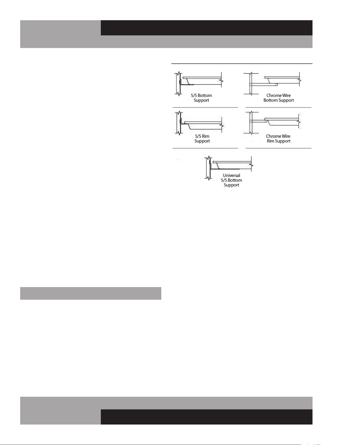
28
REACH-INS & ROLL-INS
OPERATIONS MANUAL
refrigerants are removed safely. When transferring refrigerant
into cylinders, ensure that only appropriate refrigerant recov-
ery cylinders are employed. Ensure that the correct number of
cylinders for holding the total system charge is available. All
cylinders to be used are designated for the recovered refriger-
ant and labelled for that refrigerant (i.e., special cylinders for
the recovery of refrigerant). Cylinders shall be complete with
pressure-relief valve and associated shut-off valves in good
working order. Empty recovery cylinders are evacuated and, if
possible, cooled before recovery occurs. The recovery equip-
ment shall be in good working order with a set of instructions
concerning the equipment that is at hand and shall be suit-
able for the recovery of all appropriate refrigerants including,
when applicable, flammable refrigerants. In addition, a set of
calibrated weighing scales shall be available and in good work-
ing order. Hoses shall be complete with leak-free disconnect
couplings and in good condition. Before using the recovery
machine, check that it is in satisfactory working order, has
been properly maintained and that any associated electrical
components are sealed to prevent ignition in the event of
a refrigerant release. Consult manufacturer if in doubt. The
recovered refrigerant shall be returned to the refrigerant sup-
plier in the correct recovery cylinder, and the relevant waste
transfer note arranged. Do not mix refrigerants in recovery
units and especially not in cylinders. If compressors or
compressor oils are to be removed, ensure that they have
been evacuated to an acceptable level to make certain that
flammable refrigerant does not remain within the lubricant.
The evacuation process shall be carried out prior to return-
ing the compressor to the suppliers. Only electric heating to
the compressor body shall be employed to accelerate this
process. When oil is drained from a system, it shall be carried
out safely.
PAN SLIDE ASSEMBLIES
Pan slide assemblies are available in a variety of configurations
(see Figure 11). The unique design of the vertical supports
allow the pan slides to be mounted on 1” centers and be read-
ily removed for cleaning, without the use of tools or additional
hardware. If your new unit was ordered from the factory with
pan slides, the vertical supports will be pre-installed directly on
the outer walls of the cabinet. On 2- and 3-section cabinets, the
vertical pan supports in the middle of the cabinet are mounted
to center supports as shown (see Figure 11A). The pan slides
are wrapped up in the accessory package, inside the cabinet.
FIGURE 11: Pan Slide Assembly Configurations
PAN SLIDE INSTALLATION
Pan slides should be installed in pairs, to ensure each set is
level at the same height. Before installing the slides, determine
the spacing desired between each pan that will be placed in the
cabinet. Align one of the pan slides against the vertical support
(see Figure 11A). Simultaneously insert the (2) studs on the
slide into the upper end of the slot on the vertical supports at the
desired height and the pan slide will simply drop down and lock
into place. Install another slide into opposite vertical supports,
using the same method. Check that the pair of slides are level
and at the proper height. Repeat this procedure for the remain-
ing sets of pan slides.
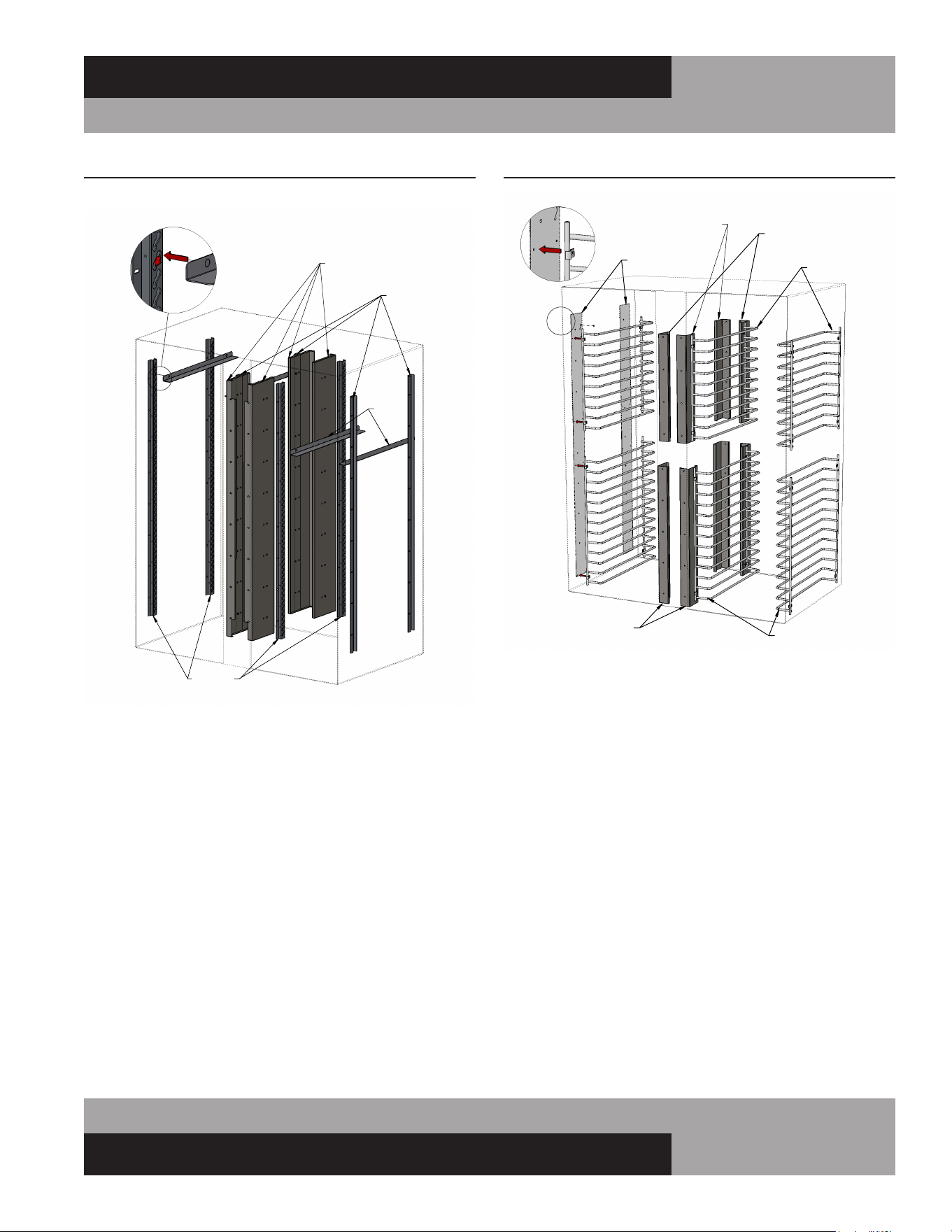
29
OPERATIONS MANUAL
REACH-INS & ROLL-INS
LH SLIDE
SUPPORT
CENTER
VERTICAL
SUPPORT
RH SLIDE
SUPPORT
PAN
SLIDES
PAN SLIDE
INSTALLATION
PAN SLIDES MOUNTED IN 2 SECTION INTERIOR
FIGURE 11A: Pan Slide Assembly Components
WIRE PAN SLIDE RACKS
Reach-In & Pass-Thru Models
Wire rod pan slide racks are attached directly to the left and
right walls in the cabinet and to vertical mounting brackets in
the center sections, between the doors, on 2 & 3-section mod-
els (see Figure 11B). To install Wire Pan Racks in a unit that
previously had shelves or metal pan slides, mounting holes will
need to be drilled in the side walls of the cabinet. Contact the
service department for detailed instructions and a template for
locating the mounting holes.
FIGURE 11B: Wire Rod Pan Slides
TOP WIRE RACKS
TEMPLATE
TOP MOUNTING BRACKETS
(FRONT RH / REAR LH)
TOP MOUNTING BRACKETS
(FRONT LH / REAR RH)
BOTTOM WIRE RACKS
BOTTOM
MOUNTING BRACKETS
DETAIL
VIEW
WIRE RACKS IN 2 SECTION INTERIOR
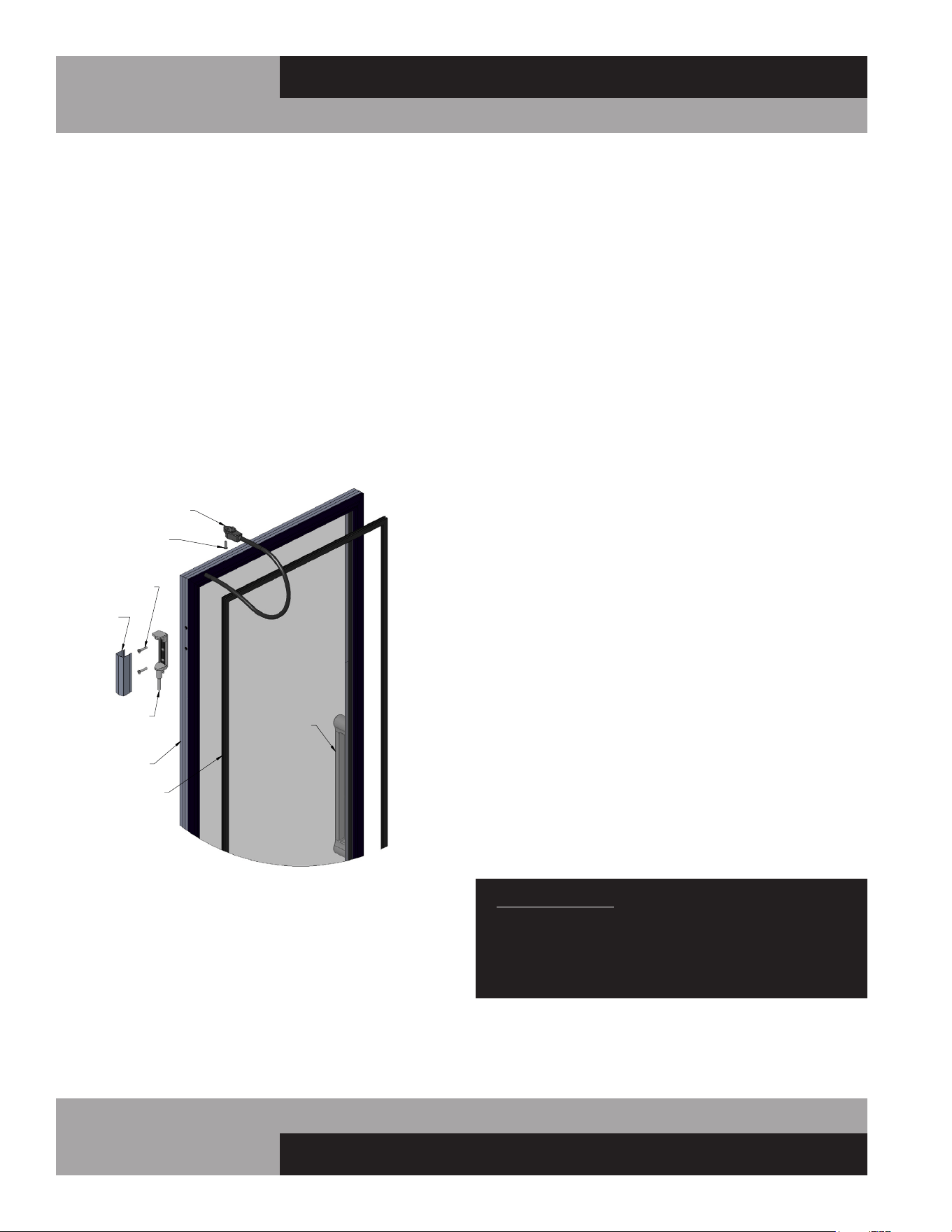
30
REACH-INS & ROLL-INS
OPERATIONS MANUAL
A
DETAIL A
SCALE 1 : 4
HINGE GLASS DOOR COMPONENTS
HINGE
COVER
HINGE
SCREWS
HINGE PIN
POWER CORD
WITH PLUG
ATTACHMENT
SCREW
DOOR
HANDLE
GASKET
DOOR
FRAME
HINGED GLASS DOOR REMOVAL
AND ADJUSTMENT
Removal and adjustment of hinged glass doors are similar to
solid doors except that heated glass doors have an electrical
cord attached to the cabinet. Before attempting to remove a
glass door, disconnect the cabinet from the power supply. Using
a phillips screwdriver, loosen the retaining screw from the mold-
ed plug and gently pull the plug out of the molded receptacle.
Carefully pry off all hinge covers using a sharp tool or knife (see
Figure 12). Swing the door to the open position (90°) and care-
fully lift the door upward, so the hinge pin (attached to the door)
clears the hinge body (mounted to the cabinet). If it is necessary
to remove the hinge bodies from the cabinet, use caution when
loosening the top hinge body, as they contain the light switch
actuator (see Figure 8A).
SLIDING GLASS DOOR REMOVAL
AND ADJUSTMENT
All sliding glass doors are easily removable for thorough clean-
ing. To remove the doors, slide the outer door (see Figure
13) open about half way, grasp the door on both sides and lift
straight up, off roller track, which will remain in the mounting
frame. Tilt the bottom of the door out, so it clears the locating
studs on the roller track and the bottom of the mounting frame.
Gently set the door down, being careful not to over-stretch the
self-closing spring and power cord that are attached to the top of
the door. Move the door towards its closed position, to release
any tension on the spring and power cord. The roller track will
simply lift out of the channel in the bottom of the mounting
frame. Repeat this procedure for the inner door.
To replace the doors, reverse the steps above, making sure the
door seats properly over the locating studs on the roller track.
If your sliding door does not close firmly, remove the doors,
starting with the outer door, as described above. Check the bot-
tom of the door, mounting frame channel, and rollers to make
sure they are clean and free of debris. If the rollers are damaged
or do not turn freely, contact the factory to order replacement
parts. The tension on the self-closing spring is adjustable, to
provide quicker and firmer closing, or to provide slower and
more gentle movement. Remove the screw attaching the end
of the self-closing spring to the top of the door. Note that there
are (3) threaded holes provided in the top of the door. To adjust
the door so it closes slower, reattach the spring at a position
closer to the handle side of the door. For a faster, firmer closing,
relocate the spring at a position further away from the handle
side of the door.
If the door does not seal evenly along the handle side when
in the closed position, the tilt of the door is adjustable. A flat
washer can be placed over the locating stud on the top of the
roller track, between the track and the underside of the door, to
level the door. For example: if the door contacts the mounting
frame at the top when it is closed, but there is a gap at the lower
half of the side edge, remove the door as described above. After
lifting the door off the roller track, place a flat washer over the
stud located closest to the handle side of the door. Replace the
door, recheck the seal, and readjust if needed. (To close a gap at
the upper half of the door, place a washer over the locating stud
farthest from the handle side of the door.)
IMPORTANT NOTE: The glass used in sliding or hinged
glass doors is of special, sealed pane design and can
not be replaced with ordinary window or plate glass.
If it becomes necessary to replace the glass, it can be
obtained directly from the factory.
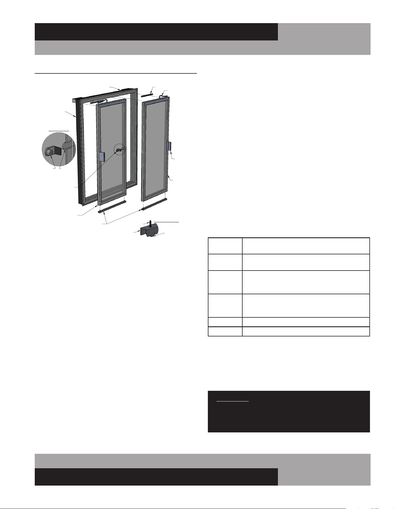
31
OPERATIONS MANUAL
REACH-INS & ROLL-INS
DIGITAL THERMOMETER W/ALARM
AND BATTERY BACKUP
The optional NSF-approved digital thermometer with alarm and
battery backup is prominently located on the front grill. Precise
temperature indication is provided from a remote sensing
bulb, located inside the cabinet. (Note: A separate electronic
temperature control unit is located behind the grill. Refer to the
Operation section on Electronic Control, for temperature set-
tings adjustments.) A 9-volt alkaline battery must be connected
to the back of the display, for temperature indication during a
power outage. Additional features include:
• Large, easy to read LED display (24-Volt AC)
• Data logging highest and lowest temp
• Flashing display visual alarm
• Battery backup (9-volt battery not included)
• Adjustable alarm set points (2)
• Alarm reset switch (manual, automatic)
• NO/NC alarm relay contacts (1 amp)
• Switchable alarm delay (0 or 45 minutes)
• 24VAC output for audible alarm (by others)
• Switchable audible silencing (none, 5 or 45min)
FIGURE 13: Sliding Glass Door Components
LEFT HAND
(INNER)
DOOR
RIGHT HAND
(OUTER)
DOOR
MOUNTING
FRAME
ELECTRICAL RACEWAY
HANDLE
POWER CORD
SPRING
DOOR LOCK
ROLLER DETAIL
LOCATING
STUD
ROLLER
TRACK
RECEIVER
PLATE
LOCK DETAIL
(WHEN PROVIDED)
LOCK
WITH STOP
SLIDING GLASS DOOR COMPONENTS
ROLLER TRACK
While in transit, your cabinet is subjected to more jarring and
vibration than at any other time, and the display may require
some adjustment at start-up. Refrigerators are designed to
maintain 38° to 40°F (3.3° to 4.4°C) and Freezers -2° to 0°F
(-19° to -18°C). During periods of heavy use, when doors
are opened repeatedly or remain open for extended period,
or if warm product is loaded in the cabinet, the temperature
displayed may temporarily exceed the “normal” range. This is
common, as warm air outside the cabinet mixes with cold air
inside. If your thermometer continues to display temperature
above “normal” range, close the doors, make sure they seal
tight and keep them closed for at least 30 minutes. If a high
temperature is still displayed, check the thermometer by plac-
ing a pre-calibrated temperature sensing device in the center
of the refrigerated compartment and keep the doors closed for
at least 15 minutes. The thermometer should display the same
temperature as the sensing device, within +/-2°F (+/-1°C). If
it does not, follow instructions below for calibration mode to
adjust the offset.
ADJUSTING PROGRAM SETTINGS
Press ‘SET’ on front to display settings in this order:
HSP
-40 to 199
= High Alarm Set Point
= High Set Point value*
LSP
-40 to 199
= Low Alarm Set Point
= Low Set Point value*
HI
-40 to 199
= High temperature log
= Highest temperature recorded since reset last
pressed (Press Reset to clear value)
LO
-40 to 199
= Low temperature log
= Lowest temperature recorded since Reset last
pressed (Press Reset to clear value.)
CAL
= Calibration Mode
-30 to 30 = Calibration temperature display offset value*
Calibration example: If sensing device in cabinet reads 38° and thermometer
displays 41°, press ‘SET’ 10 times, to display temperature offset value. Then
press down arrow three times, to decrease offset by 3°. (If original offset value
displayed was “0”, then “-3” will appear).
*To adjust value, press up or down arrow until desired setting is
displayed. Then press ‘SET’ to save.
IMPORTANT: If sequence is interrupted for more than 15
seconds, or not completed to where the display flashes
once, unit will automatically revert back to temperature
mode, WITHOUT saving new values (tamper resistant).
If you need additional help, please contact the factory.
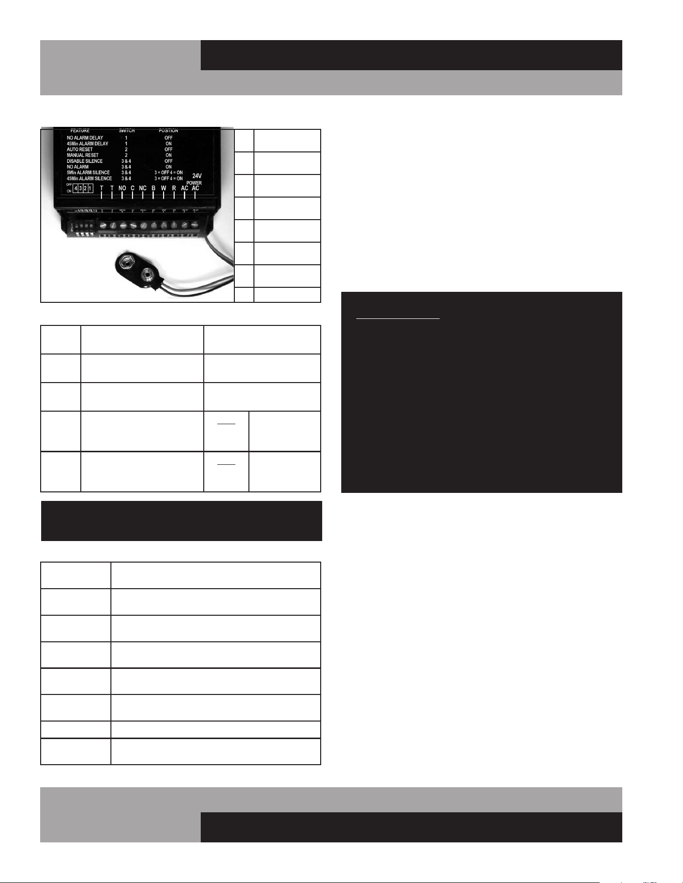
32
REACH-INS & ROLL-INS
OPERATIONS MANUAL
WIRE CONNECTIONS
T
= Output voltage
(for audible alarm)
NO
= Normally open
relay contact
C
= Common
relay contact
NC
= Normally closed
relay contact
B
= Black sensor
wire (ground)
W
= White sensor
wire (signal)
R
= Red sensor
wire (+5)
AC = Power supply
DIP SWITCH SETTINGS
Switch
1
OFF =
No alarm delay
ON = 45 minute
alarm delay
Switch
2
OFF =
Automatic alarm reset
ON = Manual alarm
reset required
Switch
3 & 4
OFF =
No alarm silencing
ON = No alarm
Switch
3 OFF
AND
Switch 4
ON = Alarm
silenced after
5 minutes
Switch
4 OFF
AND
Switch 3
ON = Alarm
silenced after
45 minutes
IMPORTANT: All dip switch functions should be set
before powering the unit on.
DEFINITIONS
Alarm
Delay
Alarm activates immediately, or after time
interval, when temp. exceeds set point
Alarm Silencer
Press “Reset” switch to silence
the audible alarm
Alarm Silence
Time
Number of minutes that will elapse until
audible alarm automatically silences
Automatic
Reset
Alarm will automatically stop after
temperature returns within normal settings
Battery
Indicator
Three dots light up on bottom of front
display when battery is low or not installed
Manual Reset
“Reset” must be pressed to stop audible/
visual alarm, even if temp returns to normal
No Alarm
Audio and visual alarm functions disabled
Power out
display
If power is lost, press “Reset” to display
temperature and sound audible alarm
MOUNTING CASTER SUPPORT PLATES
If casters on a cabinet are not properly maintained and tight-
ened, or if the unit is excessively overloaded and moved around,
the threaded inserts in the bottom of the cabinet can become
stripped, twisted or collapsed. If this occurs and the stem cast-
ers cannot be mounted securely, rigid caster support plates can
be fitted to provide the strength needed to safely use your cabi-
net. Each caster support plate assembly is made of heavy gauge
galvanized steel, with (2) casters permanently welded to it, for
maximum rigidity. The plate has a series of holes that will allow
you to fasten the plate assembly to the bottom of the cabinet
with sheet metal screws and bolts. Contact the factory to obtain
the correct parts for your model.
IMPORTANT NOTE: Always wear proper work gloves and
use appropriate safety equipment. You may CAREFULLY
lay the cabinet on its back, but only FOR A BRIEF PERIOD
OF TIME. Caution must be taken to ensure you DO NOT
DAMAGE the back or side panels, as well as the copper
tubing and refrigeration components located on top of
your cabinet. The cabinet must be properly blocked, to
allow room to get your hands in to lift without damaging
the cabinet or crushing the end panels. DO NOT PLUG-IN
OR OPERATE THE REFRIGERATION SYSTEM FOR AT
LEAST THREE (3) HOURS AFTER THE UNIT HAS BEEN
RETURNED TO AN UPRIGHT POSITION, AS THIS CAN
DAMAGE THE COMPRESSOR.
To install caster support plate assemblies, you will need a 3/4”
open end wrench (or a large adjustable wrench), a drill with a
1/8” bit and a Phillips bit (or a Phillips-Head screwdriver) plus
work gloves. A 1/2-13 thread tap is also recommended, to repair
any damage to the threaded inserts in the cabinet. Unload all
product and carefully lay the cabinet on its back. Remove the old
stem casters by unscrewing them from the cabinet. If a caster or
threaded insert has been stripped or cross-threaded, it may be
necessary to use a wrench to loosen the caster.
Hold one of the support plate assemblies under the cabinet as
shown (see Figure 14). Position it so the slotted holes at the end
of the plate line up with the threaded inserts in the bottom of the
cabinet (where the stem casters were attached). Attach the plate
assembly to the cabinet by putting a 1/2” x 1-3/4” long bolts and
flat washer through the slot in the support plate and screwing
into each of the threaded inserts in the bottom of the cabinet.
Snug the bolts down, but do not tighten them completely. If
one of the threaded inserts is stripped or damaged, a thread tap
should be used to clean the threads.
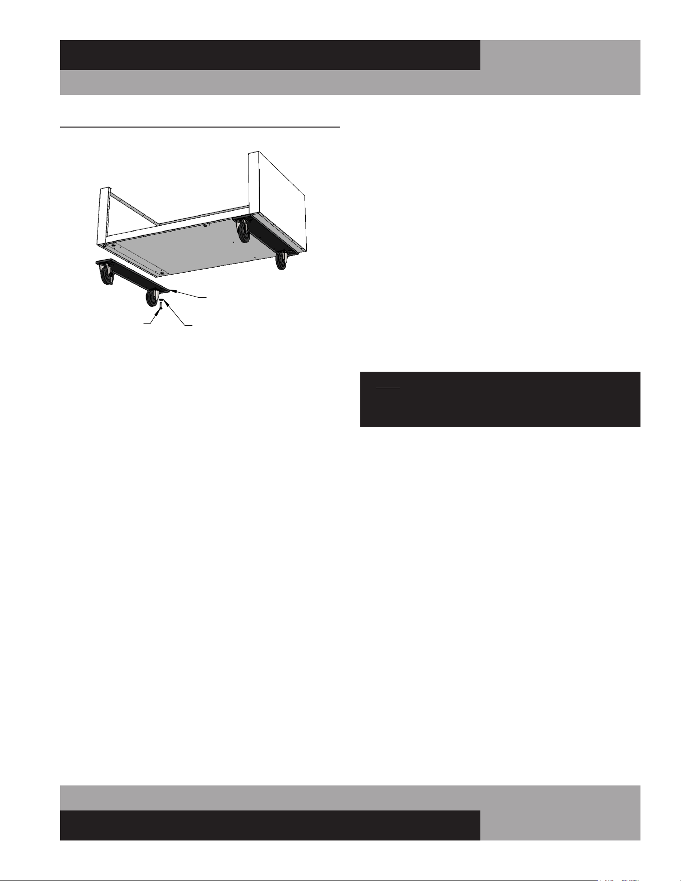
33
OPERATIONS MANUAL
REACH-INS & ROLL-INS
Using the small holes in the plate as a template, drill 1/8 pilot
holes in the bottom of the cabinet. (Note: drill only until you
penetrate the metal bottom of the cabinet. Do not continue
to drill into the insulation, or you may damage the cabinet.)
Secure the caster support plate assembly to the cabinet with a
sheet metal screw in each of the drilled holes. Tighten the 1/2”
bolts. Repeat these steps to attach the other plate assembly to
the opposite end of the cabinet.
Check that both plates are secure and that the casters turn
and swivel freely. Carefully lift the cabinet upright and double
check that the caster support plates are secure and the cabinet
is stable. Wait at least 3 hours before turning the refrigeration
system back on, and at least another 30 minutes for the cabinet
to come down to temperature and stabilize, before reloading
with product.
INSTALLATION OF TIE-IN STRAPS
Roll-Thru Cabinets
If two cabinets are installed side-by-side, a Tie-In Kit with straps
and notched upper end panels is available to attach to the cabi-
nets for rigidity. Before installing Tie-In Strips, make sure the
cabinets are close together and each unit is properly leveled (see
Installing Roll-In and Roll-Thru Models).
Remove the front and rear grill from each cabinet, by lifting off
mounting screws on the back side at each end (screws may
need to be loosened, before grill will lift up). Remove upper end
panel on the side of each cabinet located next to an adjacent
FIGURE 14: Caster Support Plates
1/2-13 BOLT
(2 PER PLATE)
FLAT WASHER
(2 PER PLATE)
SUPPORT ASSEMBY
CASTER SUPPORT PLATES
cabinet, by loosening the mounting screws along the bottom.
Make sure the cabinets are pushed tightly together. Gap between
the cabinets must be no more ¼” wide. Position Tie-In Strap
as shown in Figure 15 across the top of the gap between the
cabinets. Re-check that the cabinets are aligned properly and
secure the Tie-In Strap to the top of each cabinet with self-
drilling screws. Position one of the notched upper end panels
as shown on the first cabinet, with the notch at the bottom, and
attach to the cabinet with sheetmetal screws at front and back
corners. Position the other notched upper end panel as shown
on the second cabinet, with the notch at bottom, and attach to
the cabinet with sheetmetal screws at front and back corners.
Reinstall the front and rear grills on each cabinet by inserting
mounting screws on the back side at each end into the keyhole
slots on the end panels. Check that the grills and doors are
straight and properly aligned. Adjust if necessary. Apply a bead
of silicone in the vertical seems between the cabinets at front
and back side.
NOTE: This is necessary to comply with sanitation
requirements and also makes it apparent that the cabinets
have been attached together.
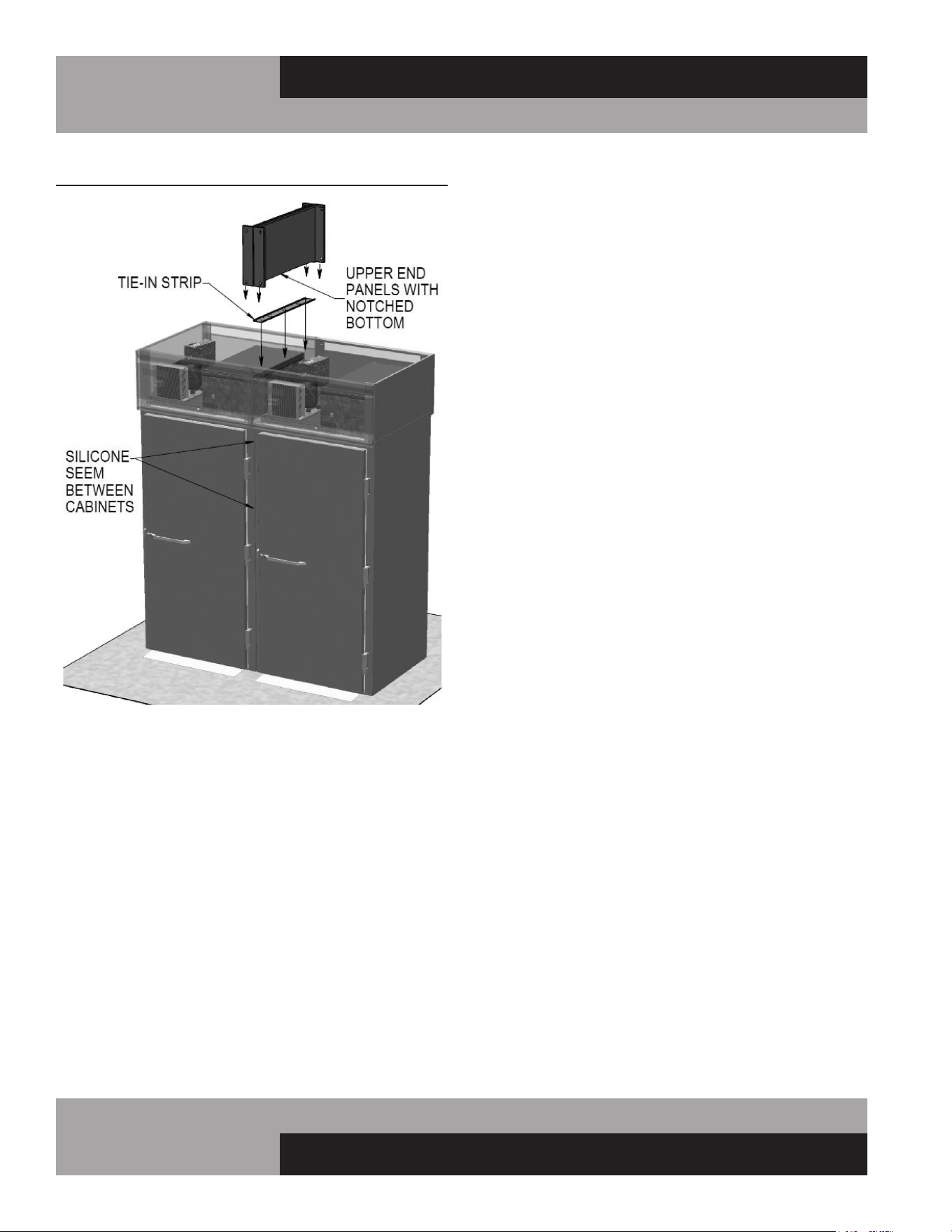
34
REACH-INS & ROLL-INS
OPERATIONS MANUAL
REMOTE SET-UP AND INSTALLATION GUIDELINES
All remote refrigerators and freezers are shipped with an expan-
sion valve, thermostat and defrost timer (freezer only), installed
from the factory. The installer is responsible for connecting all
refrigerant lines, liquid line drier, sight glass, solenoid, head
pressure control, hi/low pressure safety, crankcase heater, con-
densing unit and any other accessories as well as wiring. The
evaporator section has been factory leak checked with helium,
however; due to vibration in transit, the entire system must be
thoroughly leak checked after installation and prior to start-up.
The final leak inspection of the entire completed refrigeration
system and all of its components as well as start-up and the
operation of the refrigeration system is the sole responsibility
of the installer.
The CFC-Free refrigerant used in standard remote and self-
contained models is R-134a for refrigerators and R-404a for
freezers. All compressors and systems designed for these
FIGURE 15: Installation of Tie Straps for Roll-Thru Cabinets
refrigerants utilize polyolester oil as their main lubricant, which
absorbs moisture from the ambient surroundings extremely fast
and in much greater quantity than conventional mineral oils.
Since moisture levels greater than 100 PPM will result in system
corrosion and ultimate failure, it is imperative that the compres-
sor, components and entire system be kept sealed.
1. Piping material, pipe routing, and installation shall include
protection from physical damage in operation and service, and
be in compliance with national and local codes and standards,
such as ANSI/ASHRAE 15, IAPMO Uniform Mechanical Code,
ICC International Mechanical Code, or CSA B52. All field joints
shall be accessible for inspection prior to being covered or
enclosed.
2. The installation of pipe-work shall be kept to a minimum.
3. Mechanical connections shall be accessible for maintenance
purposes.
4. Provision shall be made for expansion and contraction of
long runs of piping.
5. Protection devices, piping, and fittings shall be protected
as far as possible against adverse environmental effects, for
example, the danger of water collecting and freezing in relief
pipes or the accumulation of dirt and debris.
6. Piping in refrigeration systems shall be so designed and
installed to minimize the likelihood of hydraulic shock damaging
the system.
7. Steel pipes and components shall be protected against cor-
rosion with a rustproof coating before applying any insulation.
8. Flexible pipe elements shall be protected against mechanical
damage, excessive stress by torsion, or other forces, and that
they should be checked for mechanical damage annually.
9. Precautions shall be taken to avoid excessive vibration or
pulsation
10. All refrigerant lines and components must be clean, free
of burrs and purged with nitrogen prior to and during brazing
or soldering connections. Nitrogen purging during brazing or
soldering will eliminate carbon or foreign matter contamination.
Any system restrictions or contamination is the responsibility of
the installer.
11. Condensing unit or compressor shall not be left open to the
atmosphere for more than five (5) minutes.
12. No refrigeration component, tubing or fitting shall be left
open to the atmosphere for more than ½ hour without being
soldered, capped or plugged.
13. Each completed refrigeration system shall be purged with
150psi of dry nitrogen for at least six (6) seconds, then pressur-
ized with at least 165psi of nitrogen for pressure check (making
sure to energize any solenoid valves to assure access). Leak-
check all joints, flare fittings and valves and make sure there is
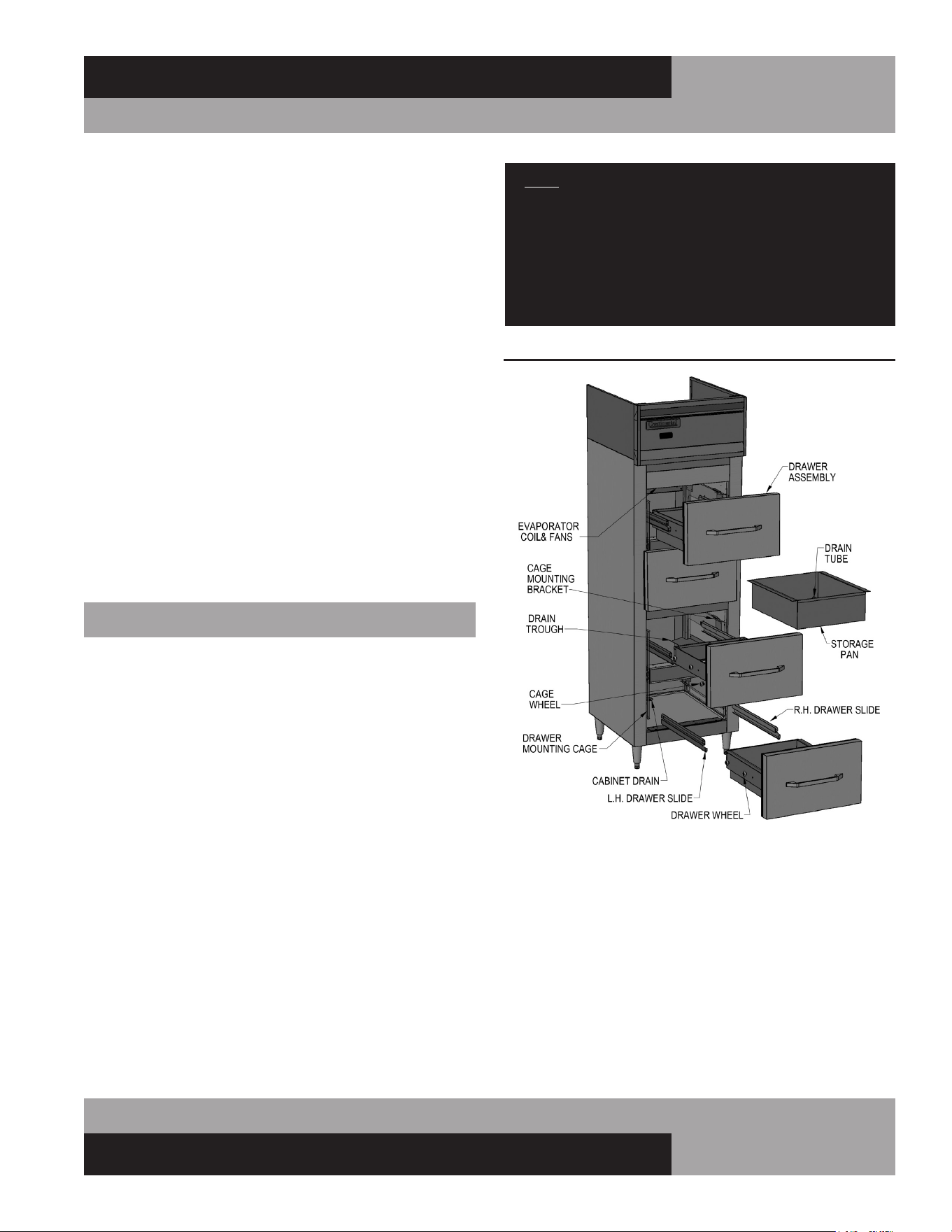
35
OPERATIONS MANUAL
REACH-INS & ROLL-INS
no pressure drop within the system.
14. System evacuation is of the utmost importance with NON-
CFC refrigerant systems. System must be evacuated to a
minimum of 200 microns. In addition, a vacuum decay test is
strongly recommended to assure there is not a large pressure
differential between the system and the vacuum pump. System
must be evacuated from both high and low sides of the system
using heavy duty vacuum hoses.
15. Each system should be charged with the refrigerant type as
specified on the cabinet data tag. This refrigerant type should
match the type listed on the condensing unit being used. The
refrigerant charge should be held to the minimum required
for the satisfactory pull down and operation. For an accurate
indication of refrigerant charge, the sight glass will show a full
column of liquid.
16. The superheat reading taken 6” from the compressor suction
valve should be 30° +/- 5°. Expansion valve adjustment may be
necessary to achieve this superheat.
17. Installation of the electric condensate vaporizer is also
the responsibility of the installer (see “Installing Electric
Condensate Vaporizer” under “optional Accessories”).
FISH FILE MODELS
Fish File models are provided with drawers specially designed
for the storage of fresh fish, or similar product, packed in
crushed ice. Each drawer has a removable pan, with a drain
tube at the back corner (see Figure 16). Water from melting ice
in the pan, along with moisture from the product, drains out of
the storage pan through the tube, along a trough on the interior
cabinet wall, down to the sloped interior bottom, and out of the
cabinet through a 1” drain tube.
INSTALLATION AND LOCATION
In addition to normal considerations (see Installation and
Location), Fish File units should be installed directly over a
building floor drain, to rapidly dispose of water from melted ice
that drains out of the cabinet. It is also highly recommended that
your Fish File is located near a water source that can be used to
thoroughly wash down your cabinet regularly.
NOTE: If a building floor drain is not immediately avail-
able, a waste line, with consistent downward slope, must
be supplied and connected to the 1” NPS drain tube
located under the cabinet. An electric condensate vapor-
izer cannot be used to dispose of water from melted ice,
as the liquid waste contains food residue that can cause
unpleasant odors and potentially unsanitary conditions.
LOADING AND STORING PRODUCT
When loading your cabinet, place a layer of ice in the drawer
pan first, then add a layer of food product, and then add another
layer of ice. Repeat this pattern until product is at least 1” from
the top of the pan, and then add a final layer of ice to cover
the product. Throughout the day, fresh ice should be added to
always keep the product covered. Periodically check the drain
tube at the back of the drawer pan and remove any debris, which
could allow excess water to accumulate in the pan. Cabinet tem-
perature can be adjusted to approximately 36°F (2°C), to prevent
the ice from melting too quickly.
FIGURE 16: Fish File Components

36
REACH-INS & ROLL-INS
OPERATIONS MANUAL
Fish should be stored at temperatures as close to 32°F (0°C) as
possible and should never exceed 39°F (4°C). Food product that
has been packed in ice must not be kept in the drawers over-
night, as this can allow for elevated temperatures and excessive
thawing, which will quickly degrade product quality. Always fol-
low proper procedures for handling, storing, thawing and cook-
ing any type of food, to eliminate potential for any contamination
or bacteria growth.
CLEANING AND MAINTENANCE
In addition to normal cleaning, (see Periodic Cleaning
Procedure) the entire interior of your Fish File, including the
drawers and storage pans, must be thoroughly cleaned and
sanitized daily, to prevent excessive build-up of food residue,
which can cause unpleasant odors and potentially unsanitary
conditions. At the end of each day, remove any remaining food
product from the drawers and move it to suitable refrigerated
storage, or discard it.
Lift each food pan up and out of the drawer frame, being careful
not to damage the drain tube. Run the pans through a dishwash-
er, or properly clean and sanitize them manually. Remove each
drawer assembly by pulling it out of the cabinet, until the front
roller wheels stop against the front of the slides. Lift up the front
of the drawer, so the wheels come up and out of the slide tracks.
Pull the drawer further out, until the rear wheels stop against
the front of the slides. Lift the drawer again, so the back wheels
clear the drawer slides. Thoroughly wash the drawer frame
and components properly (see Care and Cleaning of Stainless
Steel). Carefully wash the drawer gaskets thoroughly with clean
water, dry them and check for any damage. To re-install the
drawers and pans, reverse the above procedure.
NOTE: On 2-section Fish Files, pans must be installed
with drain toward the outside cabinet wall, so the drain
tube is directly aver the drain trough.

37
OPERATIONS MANUAL
REACH-INS & ROLL-INS
TROUBLESHOOTING GUIDE
NOTICE: GUIDE TO SERVICE TECHNICIANS, REFER TO PARTS AND SERVICE ON PLACING A SERVICE CALL
PROBLEM PROBABLE CAUSE CORRECTION
Condensing unit will not
start - no hum.
1. Line disconnected, switch open.
2. Fuse removed or blown.
3. Overload protector blown.
4. Control “Off” due to cold location.
5. Control stuck in open position.
6. Wiring improper or loose.
1. Close start or disconnect switch.
2. Replace Fuse.
3. Determine reason and correct/replace.
4. Relocate control.
5. Repair or replace control.
6. Check wiring against diagram.
Condensing unit will not
start - hums but trips on
overload protector.
1. Improperly wired.
2. Low voltage to unit.
3. Starting capacitor defective.
4. Relay failing to close.
5. Compressor motor has a shorted or open
winding.
6. Internal mechanical trouble in compressor.
7. Insufcient air supply.
1. Check wiring against diagram.
2. Determine reason and correct.
3. Determine reason and replace.
4. Determine reason and replace.
5. Replace compressor.
6. Replace compressor.
7. Clear condenser and allow compressor
to cool down.
Condensing unit starts
and runs, but short
cycles on overload
protector.
1. Additional current passing through overload
protector.
2. Low voltage unit.
3. Overload protector defective.
4. Run capacitor defective.
5. Excessive discharge pressure.
6. Excessive suction pressure.
7. Insufcient air supply.
1. Check wire diagram. Check for added
components connected to wrong side of
overload protector.
2. Determine reason and correct.
3. Check current, replace protector.
4. Determine reason and replace.
5. Check ventilation, restrictions in cooling
medium or refrig. system.
6. Check for misapplication.
7. Clear condenser and allow compressor
to cool down.
Condensing unit starts,
but fails to switch off of
“start” winding.
1. Improperly wired.
2. Low voltage to unit.
3. Relay failing to open.
4. Run capacitor defective.
5. Excessively high discharge pressure.
6. Compressor motor has a shorted or open
winding.
7. Internal mechanical trouble in compressor.
1. Check wiring against diagram.
2. Determine reason and correct.
3. Determine reason and replace.
4. Determine reason and replace.
5. Check discharge shut-off valve, possible
overcharge.
6. Replace compressor.
7. Replace compressor.
Condensing unit runs,
but short cycles on:
1. Overload protector.
2. Thermostat.
3. High pressure cut-out due to:
(a) Insufcient air supply.
(b) Overcharge.
(c) Air in system.
4. Low pressure cut-out due to:
(a) Valve leak.
(b) Undercharge.
(c) Restriction in expansion device.
1. Check current, replace protector.
2. Differential setting must be widened.
3.
(a) Check air supply to condenser.
(b) Evacuate and re-charge.
(c) Evacuate and re-charge.
4.
(a) Replace, evecuate and re-charge.
(b) Evacuate and re-charge.
(c) Replace expansion device.
Condensing unit runs,
but for prolonged peri-
ods or continuous.
1. Shortage of refrigerant.
2. Control contacts stuck closed.
3. Excessive heat load placed into cabinet.
4. Prolonged or too frequent door openings.
5. Evaporator coil iced.
6. Restriction in refrigeration system.
7. Dirty condenser.
8. Filter drier clogged.
1. Fix leak, evacuate and re-charge.
2. Clean contacts or replace control.
3. Allow unit sufcient time for removal of latent
heat.
4. Plan or organize schedule to correct condition.
5. Defrost evaporator coil.
6. Determine location and remove.
7. Clean condenser coil.
8. Replace, evacuate and re-charge.

38
REACH-INS & ROLL-INS
OPERATIONS MANUAL
TROUBLESHOOTING GUIDE
PROBLEM PROBABLE CAUSE CORRECTION
Start capacitor open,
shorted or blown.
1. Relay contact not opening properly.
2. Prolonged operation on start cycle:
(a) Low voltage to unit.
(b) Improper relay.
(c) Starting load too high.
3. Excessive short cycling.
4. Improper capacitor.
1. Clean contacts or replace relay.
2.
(a) Determine reason and correct.
(b) Replace with correct relay.
(c) Correct by using pump down.
3. See “Condensing Unit Short Cycles” above.
4. Determine correct size and replace.
Run capacitor open,
shorted or blown.
1. Improper capacitor.
2. Excessively high line voltage, over 110%
of rated maximum.
1. Check size and replace.
2. Determine reason and correct.
Relay defective or blown
out.
1. Incorrect Relay.
2. Incorrect mounting angle.
3. Voltage too low or too high.
4. Excessive short cycling.
5. Loose or vibrating mounting position.
6. Incorrect run capacitor.
7. Loose wiring on relay or overload.
1. Check relay and replace.
2. Remount relay in correct position.
3. Determine reason and correct.
4. See “Condensing Unit Short Cycles” above.
5. Remount rigidly.
6. Replace with proper capacitor.
7. Tighten all wiring screws.
Product zone
temperature too high.
1. Control setting too high.
2. Inadequate air circulation.
3. Dirty condenser.
1. Adjust T-stat.
2. Rearrange product load to improve air
circulation.
3. Clean condenser coil.
Suction line frosted or
sweating.
1. Overcharge of refrigerant.
2. Evaporator fan not running.
3. Expansion valve stuck open.
4. Expansion valve superheat too low.
1. Evacuate and re-charge.
2. Determine reason and correct.
3. Clean valve, evacuate and re-charge.
4. Adjust superheat to required setting.
Liquid line frosted, cold
or sweating.
1. Restriction in drier strainer.
2. Liquid line service valve partially closed.
1. Replace drier, evacuate and re-charge.
2. Open valve fully or replace if necessary.
Noisy condensing unit. 1. Loose parts or mounting.
2. Tubing rattle or vibration.
3. Bent fan blade causing excessive vibration.
4. Fan bearings worn.
1. Tighten all mounting parts and shroud cover.
2. Reform tubing to be free of contact.
3. Replace fan blade.
4. Replace fan motor.
Thermometer reads
different than actual
temperature.
1. Calibration.
2. Defective.
1. Consult Operations Manual and calibrate.
2. Replace.
Water leak inside unit. 1. Condensate drain pan not installed properly.
2. Unit not level.
3. Drain pan misaligned.
4. Defective drain pan.
1. Consult Operations Manual for install
instructions.
2. Make sure unit is level or pitched back slightly.
3. Make sure drain pan is aligned properly.
4. Replace.
Doors misaligned. 1. Shifted during shipping. 1. Refer to Operation Manual for hinge
adjustment.

39
OPERATIONS MANUAL
REACH-INS & ROLL-INS
Detection of ammable refrigerants
Under no circumstances shall any potential sources of ignition
be used in the searching for or detection of refrigerant leaks. A
halide torch (or any other detector using a naked ame) shall not
be used.
The following leak detection methods are deemed acceptable for
all refrigerant systems:
Electronic leak detectors may be used to detect refrigerant leaks
but, in the case of ammable refrigerants, the sensitivity might
not be adequate, or might need recalibration. (Detection equip-
ment shall be calibrated in a refrigerant-free area.)
Ensure that the detector is not a potential source of ignition and is
suitable for the refrigerant used. Leak detection equipment shall
be set at a percentage of the LFL of the refrigerant and shall be
calibrated to the refrigerant employed, and the appropriate per-
centage of gas (25 % maximum) is conrmed.
Leak detection uids are also suitable for use with most refriger-
ants but the use of detergents containing chlorine shall be avoid-
ed as the chlorine can react with the refrigerant and corrode the
copper pipe-work. NOTE Examples of leak detection uids are
– bubble method, – uorescent method agents.
If a leak is suspected, all naked ames shall be removed/extin-
guished. If a leakage of refrigerant is found which requires braz-
ing, all of the refrigerant shall be recovered from the system, or
isolated (by means of shut off valves) in a part of the system
remote from the leak. Removal of refrigerant shall be according
to Removal and evacuation below.
Removal and evacuation
When breaking into the refrigerant circuit to make repairs – or
for any other purpose – conventional procedures shall be used.
However, for ammable refrigerants it is important that best
practice be followed, since ammability is a consideration. The
following procedure shall be adhered to:
1. safely remove refrigerant following local and national regula-
tions;
2. purge the circuit with inert gas;
3. evacuate (optional for A2L);
4. purge with inert gas (optional for A2L);
5. open the circuit by cutting or brazing.
The refrigerant charge shall be recovered into the correct recov-
ery cylinders if venting is not allowed by local and national codes.
For appliances containing ammable refrigerants the system
shall be purged with oxygen-free nitrogen to render the appliance
safe for ammable refrigerants. This process might need to be
repeated several times. Compressed air or oxygen shall not be
used for purging refrigerant systems.
For appliances containing ammable refrigerants, refrigerants
purging shall be achieved by breaking the vacuum in the sys-
tem with oxygen-free nitrogen and continuing to ll until the
working pressure is achieved, then venting to atmosphere, and
nally pulling down to a vacuum (optional for A2L). This pro-
cess shall be repeated until no refrigerant is within the system
(optional for A2L). When the nal oxygen-free nitrogen charge
is used, the system shall be vented down to atmospheric pres-
sure to enable work to take place.
Ensure that the outlet for the vacuum pump is not close to any
potential ignition sources and that ventilation is available.
Charging procedures
In addition to conventional charging procedures, the following
requirements shall be followed.
1. Ensure that contamination of different refrigerants does not
occur when using charging equipment. Hoses or lines shall be
as short as possible to minimize the amount of refrigerant con-
tained in them.
2. Cylinders shall be kept in an appropriate position according
to the instructions.
3. Ensure that the refrigerating system is earthed prior to charg-
ing the system with refrigerant.
4. Label the system when charging is complete (if not already).
5. Extreme care shall be taken not to overll the refrigerating
system.
Prior to recharging the system, it shall be pressure-tested with
the appropriate purging gas. The system shall be leak-tested on
completion of charging but prior to commissioning. A follow up
leak test shall be carried out prior to leaving the site.

40
REACH-INS & ROLL-INS
OPERATIONS MANUAL
WARRANTY (all models utilizing R-290 refrigerant) United States of America & Canada
SEVEN (7) YEAR PARTS, LABOR AND COMPRESSOR WARRANTY
National Refrigeration & Air Conditioning Products, Inc., d/b/a Continental Refrigerator, warrants to the original purchaser of every new Continental
Refrigerator self-contained unit that all parts and equipment, including the R-290 compressor, are free from defects in material and workmanship,
under normal use, proper maintenance and service for a period of seven (7) years from the date of installation, or eighty-seven (87) months from
the date of shipment from Continental Refrigerator, whichever comes first. Normal use, proper maintenance and service refers specifically to the
actions and descriptions detailed in the Continental Refrigerator Installation and Operations Manual. This warranty does not cover normal wear parts
such as light bulbs and gaskets.
Improper operation due to incorrect installation, negligent or improper cleaning and maintenance, out-of-tolerance voltage conditions, inadequate
wiring, and accidental damage are not manufacturing defects and not covered under this warranty. Purchasers must clean condenser coils regularly
to avoid warranty voidance. The manual recommends monthly cleaning.
This warranty excludes adjustments such as cabinet leveling, hinge modifications, caster or leg adjustments, and control settings. This warranty
excludes damage caused by water and/or moisture from other appliances, or damage due to improper cleaning. This warranty excludes equipment
failure resulting from unauthorized modifications to the unit.
Continental Refrigerator will repair or replace, including labor, any defective part of the product. We reserve the right to inspect any claimed defect,
and the warranty applies only if our examination finds the parts, equipment, or compressor defective. The use of non-authorized services or non-
OEM parts voids the validity of this warranty. Defective parts must be returned to us within thirty (30) days. The return should include the cabinet
model, serial number, and a return material authorization number provided by the manufacturer. This warranty does not cover any shipping costs.
The labor warranty covers self-contained units only, during standard working hours, and excludes overtime rates. Before employing labor, the
purchaser must contact the factory for service authorization by calling directly or requesting service through our website. To be covered, purchasers
must supply a labor invoice along with the service authorization number within thirty (30) days of the date of completion. In any event, all work must
be completed within ninety (90) days of the service authorization date. This warranty does not cover special installations or applications, including
those in remote locations. Any installation that requires additional work or travel to access the unit for service is the responsibility of the purchaser.
THIS WARRANTY REPLACES ALL OTHER EXPRESS, IMPLIED, OR STATUTORY WARRANTIES, INCLUDING IMPLIED WARRANTIES OF
MERCHANTABILITY AND FITNESS FOR A PARTICULAR PURPOSE, WHICH ARE HEREBY DISCLAIMED. WE DO NOT ASSUME, NOR AUTHORIZE
OTHERS TO ASSUME, ANY OBLIGATION OR LIABILITY RELATED TO THE SALE OF THESE PRODUCTS.
This warranty is valid only for the original purchaser and cannot be assigned.
This warranty is void outside the USA and Canada and does not cover misuse, neglect, alteration, accidents, or damage from transportation, flood,
fire, acts of terrorism, acts of God, or natural disasters, as determined solely by Continental Refrigerator.
CONTINENTAL REFRIGERATOR SHALL IN NO EVENT BE LIABLE FOR CONSEQUENTIAL OR SPECIAL DAMAGES, INCLUDING INDIRECT, PUNITIVE,
LOSS OF USE, PRODUCT LOSS, DOWNTIME, OR LOST PROFITS, RELATED TO THE PRODUCT OR ITS USE. THE PURCHASER’S REMEDIES ARE
EXCLUSIVE. CONTINENTAL REFRIGERATOR’S TOTAL LIABILITY WILL NOT EXCEED THE PURCHASE PRICE OF THE COMPONENT IN QUESTION,
REGARDLESS OF CONTRACT, WARRANTY, NEGLIGENCE, INDEMNIFICATION, STRICT LIABILITY, TORT, OR OTHER GROUNDS.
See our Service Guideline at http://www.continentalrefrigerator.com/service-parts/
for additional information regarding service and warranty coverage.

41
OPERATIONS MANUAL
REACH-INS & ROLL-INS
MODEL # __________________________________________SERIAL # _______________
Notes: ______________________________________________________________
___________________________________________________________________
___________________________________________________________________
___________________________________________________________________
___________________________________________________________________
___________________________________________________________________
___________________________________________________________________
___________________________________________________________________
___________________________________________________________________
___________________________________________________________________
___________________________________________________________________
___________________________________________________________________
___________________________________________________________________
___________________________________________________________________
___________________________________________________________________
___________________________________________________________________
___________________________________________________________________
___________________________________________________________________
___________________________________________________________________
___________________________________________________________________
___________________________________________________________________
___________________________________________________________________
___________________________________________________________________
___________________________________________________________________
___________________________________________________________________
___________________________________________________________________
___________________________________________________________________
___________________________________________________________________
___________________________________________________________________
___________________________________________________________________
___________________________________________________________________
___________________________________________________________________
___________________________________________________________________
___________________________________________________________________
___________________________________________________________________
___________________________________________________________________
___________________________________________________________________

42
REACH-INS & ROLL-INS
OPERATIONS MANUAL
MODEL # __________________________________________SERIAL # _______________
Notes: ______________________________________________________________
___________________________________________________________________
___________________________________________________________________
___________________________________________________________________
___________________________________________________________________
___________________________________________________________________
___________________________________________________________________
___________________________________________________________________
___________________________________________________________________
___________________________________________________________________
___________________________________________________________________
___________________________________________________________________
___________________________________________________________________
___________________________________________________________________
___________________________________________________________________
___________________________________________________________________
___________________________________________________________________
___________________________________________________________________
___________________________________________________________________
___________________________________________________________________
___________________________________________________________________
___________________________________________________________________
___________________________________________________________________
___________________________________________________________________
___________________________________________________________________
___________________________________________________________________
___________________________________________________________________
___________________________________________________________________
___________________________________________________________________
___________________________________________________________________
___________________________________________________________________
___________________________________________________________________
___________________________________________________________________
___________________________________________________________________
___________________________________________________________________
___________________________________________________________________
___________________________________________________________________


A Division of National Refrigeration & Air Conditioning Products, Inc.
539 Dunksferry Road • Bensalem, PA 19020-5908
P 215-244-1400 • 1-800-523-7138 • F 215-244-9579
www.continentalrefrigerator.com
IM-RI-Black-50187-20250401
®
®
