
BULLETIN NO.
SERVICE PARTS LIST
54-26-2732
Aug. 2019
REVISED BULLETIN
DATE
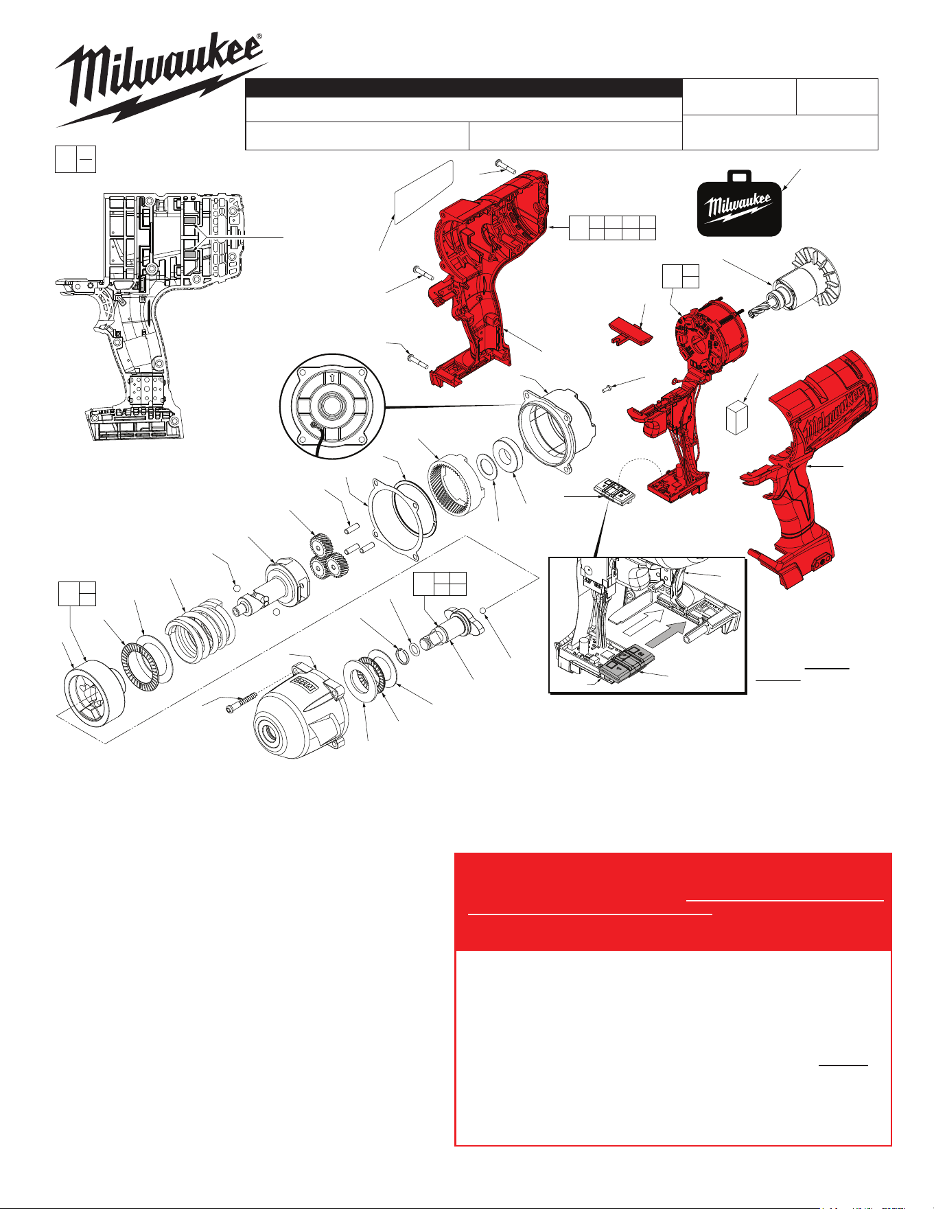
WIRING INSTRUCTION
FIG. PART NO. DESCRIPTION OF PART NO. REQ.
1 ---------------
Handle Support (Housing Halve-Left) w/ metal pin
1
6 45-30-0255 Rubber Slug 4
12 44-66-0417 Rear Case 1
13 02-04-0375 Ball Bearing 1
14 45-88-1655 Thrust Washer 1
15 32-65-0025 Ring Gear 1
16 44-60-1960 Planet Pin 3
17 32-62-0500 Planet Gear 3
18 30-40-0052 Retaining Ring 1
19 43-44-0065 Gasket 1
20 --------------- Camshaft 1
21 02-02-0251 1/4" Steel Ball 2
22 40-50-0995 Hammer Spring 1
23 45-88-1006 Thrust Washer 1
24 02-80-0200 Hammer Thrust Bearing 1
25 --------------- Hammer 1
26 02-02-7010 7/32" Steel Ball 1
27 --------------- 1/2" Square Anvil 1
28 45-88-1875 Thrust Washer 1
29 02-80-3256 Thrust Bearing 1
30 45-88-0032 Thrust Washer 1
33 14-30-0110 Front Housing Assembly with Bushing 1
34 06-82-2210 50 x 40mm Pan Hd. PT T-20 Screw 4
35 06-82-0995 M4 x 16mm Pan Hd. Plastite T-20 Screw 8
36 06-82-2230 M4 x 22mm Pan Hd. Plastite T-20 Screw 1
37 --------------- Handle Cover (Housing Halve Right) 1
39 40-50-1135 Shuttle Spring (for 45-24-0130, not shown) 1
51 34-40-0900 O-Ring 1
52 44-90-4530 Friction Ring 1
See Page 2
F42C or F42D
STARTING
SERIAL NO.
2763-20
CATALOG NO.
M18 FUEL™ 1/2" SQUARE IMPACT WRENCH with friction ring
SPECIFY CATALOG NO. AND SERIAL NO. WHEN ORDERING PARTS
FIG. PART NO. DESCRIPTION OF PART NO. REQ.
56 06-81-5383 M4 x 35mm Pan Hd. Plastite T-20 Screw 1
58 44-52-0025 Foam Pad 1
59 06-82-0165 High Voltage Screw 1
60 12-20-2626 Service Nameplate 1
65 42-55-2762 Carrying Case 1
71 16-01-0105 Rotor Assembly 1
72 45-24-0110 Speed Switch Assembly 1
74 42-06-0047 1/2" Square Anvil Assembly w/ friction ring 1
85 14-46-6025 Camshaft/Hammer Kit 1
0
EXAMPLE:
Component Parts (Small #) Are Included
When Ordering The Assembly (Large #).
00
72
1
25
24
23
22
21
(2x)
20
15
14
13
12
37
38
71
60
36
(1x)
56
(1x)
35
(8x)
58
59
58
59
70
73
1 6 35 36
37 56 60
20
25
85
6
Rubber Slugs
are (2x) per
handle halve
(4 total)
65
As an aid for servicing,
the Speed Switch
Assembly #72 should
be mounted onto the
PCBA first and than
carefully installed
together into the Left
Housing Halve #1.
PCBA
72
1
19
18
17
(3x)
16
(3x)
See page two for details
that aid in identifing the
proper Electronic
Assembly to be
serviced.
Back View of Rear Case #12
showing the orientation
of the Rear Case
(arrow facing
upward) and
showing the
location of the
High Voltage
Screw #59 and
ground wire.
34
(4x)
52
51
30
29
28
27
33
26
27 51
52
74
54-26-2731
= Part number change
from previous service
parts list.
MILWAUKEE TOOL
l
www.milwaukeetool.com
13135 W. Lisbon Road, Brookeld, WI 53005
Drwg. 2
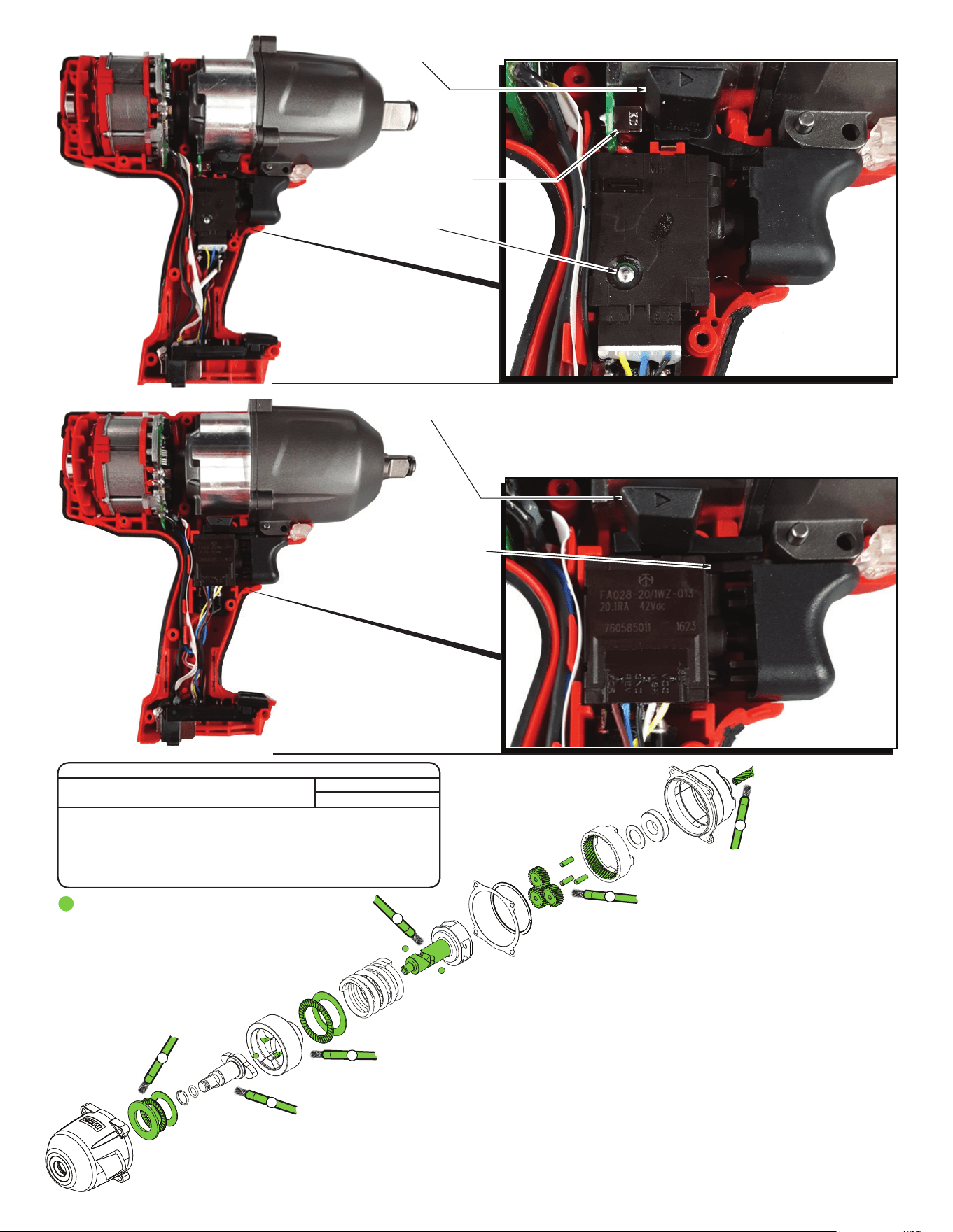
IMPORTANT! There are two dierent Electronic Assemblies available
for servicing this tool. It is important to identify which Electronic
Assembly is in your tool because the Housing Assembly and Fwd./Rev.
Shuttle are UNIQUE to each switch design. To identify at a glance, one
assembly is built with a switch that has a silver rivet on the side of the
switch body, the other switch has none (see page two).
Electronic Assembly No. 14-20-0255 can be identied by a silver rivet
on the side of the switch body, order the following parts:
FIG. PART NO. DESCRIPTION OF PART NO. REQ.
38 45-24-0130 Forward / Reverse Shuttle 1
70 14-20-0255 Electronics Assembly (Switch with rivet) 1
73 31-44-0869 Housing Assembly 1
Electronic Assembly No. 14-20-0257 can be identied by the absence
of a silver rivet on the side of switch body, order the following parts:
FIG. PART NO. DESCRIPTION OF PART NO. REQ.
38 45-24-0022 Forward / Reverse Shuttle 1
70 14-20-0257 Electronics Assembly (Switch without rivet) 1
73 31-44-0879 Housing Assembly 1
2
Electronic Assy. No. 14-20-0257 w/o rivet on switch
toggle switch
Electronics package
has toggle switch
mounted on pcba
Silver rivet
Electronic Assy. No. 14-20-0255 with riveted switch
Shuttle for fwd./rev.
Shuttle for fwd./rev. toggle
No. 14-20-0257
Electronic Assembly
has a switch with
the fwd./rev. feature
integrated in the
switch body. There
is no pcba in this
electronics package.
The switch in the
14-20-0257 has no
silver rivet on the
switch body.
1
3
4
5
6
LUBRICATION NOTES:
Type ‘J’ Grease No. 49-08-4220, 1 lb. can
A total of approx. 11 grams (.4 oz) will be used.
Prior to reinstalling, clean gear assemblies
with a clean, dry cloth. Lightly coat all parts
highlighted here with ‘J’ grease. Apply a
greater amount of grease to all internal
and external gear teeth.
1). Coat both sides of the Thrust Bearing and the two Thrust Washers with grease.
2). Lightly coat the Steel Ball with grease.
3). Place grease in both ball grooves of the Hammer. Coat both sides of the Thrust
Bearing and Thrust Washer with grease.
4). Coat shaft surface of the Camshaft with grease, being sure to place approx.
1 gram of grease in each ball groove. Lightly coat the two Steel Balls.
5). Coat the three Planet Pins with grease. Place a generous amount of grease to the
exterior teeth of the three Planet Gears and the interior teeth of the Ring Gear.
6). Place a generous amount of grease to the pinion teeth of the Rotor Assembly.
SCREW TORQUE SPECIFICATIONS
SEAT TORQUE
FIG. PART NO. WHERE USED (KG/CM) (IN/LBS)
34 06-82-2210 Front Housing Assy. 36 31
35 06-82-0995 Housing Assembly 12.5 11
36 06-82-2230 Housing Assembly 8.5 7
56 06-82-2240 Housing Assembly 12.5 11
59 06-82-0165 High Voltage Screw 13 11