Visit our website at: http://www.harborfreight.com
email our technical support at: [email protected]
23142E-B
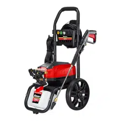
3000 PSI
1.1 GPM ELECTRIC
PRESSURE WASHER
70138
Owner’s Manual & Safety Instructions
Save This Manual Keep this manual for the safety warnings and precautions, assembly,
operating, inspection, maintenance and cleaning procedures. Write the product’s serial number in the
back of the manual near the assembly diagram (or month and year of purchase if product has no number).
Keep this manual and the receipt in a safe and dry place for future reference. 24b
When unpacking, make sure that the product is intact
and undamaged. If any parts are missing or broken,
please call 1-888-866-5797 as soon as possible.
Copyright
©
2024 by Harbor Freight Tools
®
. All rights reserved.
No portion of this manual or any artwork contained herein may be reproduced in
any shape or form without the express written consent of Harbor Freight Tools.
Diagrams within this manual may not be drawn proportionally. Due to continuing
improvements, actual product may differ slightly from the product described herein.
Tools required for assembly and service may not be included.
Read this material before using this product.
Failure to do so can result in serious injury.
SAVE THIS MANUAL.
Page 2 For technical questions, please call 1-888-866-5797. Item 70138
SaFety OperatiOn MaintenanceSetup
table of contents
Safety ......................................................... 3
Specifications ............................................. 6
Setup – Before Use: ................................... 7
Operation .................................................... 9
Maintenance .............................................. 13
Parts List and Assembly Diagram.............. 15
Warranty .................................................... 20
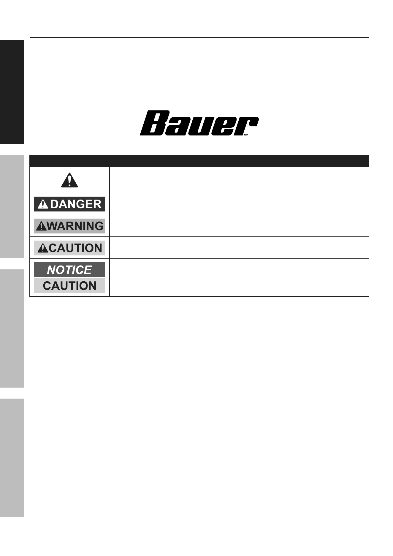
WarninG SyMBOLS anD DeFinitiOnS
This is the safety alert symbol. It is used to alert you to potential
personal injury hazards. Obey all safety messages that
follow this symbol to avoid possible injury or death.
Indicates a hazardous situation which, if not avoided,
will result in death or serious injury.
Indicates a hazardous situation which, if not avoided,
could result in death or serious injury.
Indicates a hazardous situation which, if not avoided,
could result in minor or moderate injury.
Addresses practices not related to personal injury.

Page 3For technical questions, please call 1-888-866-5797.Item 70138
SaFetyOperatiOnMaintenance Setup
iMpOrtant SaFety inStructiOnS
WarninG - When using this product basic precautions should
always be followed, including the following:
Safety Warnings
1. Read all the instructions before using the product.
2. To reduce the risk of injury, close supervision is
necessary when a product is used near children.
3. Know how to stop the product and bleed pressures
quickly. Be thoroughly familiar with the controls.
4. Stay alert – watch what you are doing.
5. Do not operate the product when fatigued or under
the influence of medication, alcohol or drugs.
6. Keep operating area clear of all persons.
7. Do not overreach or stand on unstable support.
Keep good footing and balance at all times.
8. Follow the maintenance instructions
specified in the manual.
9. This product is provided with a ground fault
circuit interrupter (GFCI) built into the power
cord plug. If replacement of the plug or cord is
needed, use only identical replacement parts.
10. WARNING – Risk of injection or injury–
do not direct discharge stream at persons.
11. Connect to individual branch circuit only.
12. WARNING – To reduce the risk of electrocution,
keep all connections dry and off the ground.
Do not touch plug with wet hands.
13. Do not abuse the cord. Never use the cord for
carrying, pulling or unplugging the pressure
washer. Keep cord away from heat, oil, sharp
edges or moving parts. Damaged or entangled
cords increase the risk of electric shock.
14. to allow GFci unit to function properly,
eXtenSiOn cOrDS MuSt nOt Be
uSeD with this pressure washer.
Set up precautions
1. The work area should have adequate
drainage to reduce the possibility of a fall
or electric shock due to wet surfaces.
2. Wear ANSI-approved safety goggles
during set up and use.
3. Only feed cold, clean water through this tool.
Pressure washer detergent may be used in
the Detergent Tank only. Do not use caustic
materials, solvents, flammable materials, or
detergents not designed for pressure washers.
Use of any such material can cause injury,
or damage this tool or personal property.
4. Prior to starting the Pressure Washer in
cold weather, check all of the parts of the
unit to make sure ice has not formed. Do
not store the unit anywhere that the
temperature will fall near 32° F (0° C).

Page 4 For technical questions, please call 1-888-866-5797. Item 70138
SaFety OperatiOn MaintenanceSetup
Operating precautions
1. Disconnect the plug from the power source
before making any adjustments, changing
accessories, or storing pressure washers. Such
preventive safety measures reduce the risk of
starting the pressure washer accidentally.
2. Do not leave the equipment unattended
when it is running. Turn off the equipment
before leaving the work area.
3. Wear ANSI-approved safety goggles and heavy-
duty nonslip rubber work boots during use.
4. Use only accessories that are recommended by
Harbor Freight Tools for your model. Accessories
that may be suitable for one piece of equipment may
become hazardous when used on another one.
5. This product must continuously run with
cold water only. Never use hot water. Do
not dry run this product. Dry running will
cause serious damage to the seals.
6. To avoid electrical shock, never start and run the
Pressure Washer in the rain. Never allow water
to leak into the Body of the Pressure Washer.
Do not direct discharge stream at the Pressure
Washer itself or at other live electrical equipment.
7. Do not allow the GFCI Plug to become wet.
Always place the GFCI Plug in a dry location and as
far away as possible from the object being sprayed.
8. DO NOT use an extension cord with this product.
9. When using the Pressure Washer, always maintain
a firm grip on the Spray Gun. Squeezing the
Trigger of the Spray Gun causes a kickback force.
10. Do not feed already-pressurized water (such as that
from another pressure washer) into this washer.
11. People with pacemakers should consult their
physician(s) before use. Electromagnetic fields in
close proximity to heart pacemaker could cause
pacemaker interference or pacemaker failure.
12. Use the correct equipment for the application.
Do not modify the equipment and do not use the
equipment for a purpose for which it is not intended.
13. If water is leaking out of the Pressure Washer
immediately turn off the unit. Unplug the
Pressure Washer, and discharge all pressure
before tightening fittings or having repair
work done by a qualified technician.
14. The high pressure water flow can damage
the work surface if not used properly.
Always test the spray in an open area first.
15. Injection Hazard. The high pressure
water jet produced by this tool can cut
skin or cause injury to hands or eyes.
Do not allow spray to strike you and do
not spray toward people or animals.
Do not spray the tool itself or any electrical source.
16. This Pressure Washer is intended for
outdoor residential use only.
17. in case of an emergency during use,
immediately release the trigger on the spray
handle, turn the power switch off and then
unplug the unit. Do not set the spray handle
down without turning off the power switch.
Page 5For technical questions, please call 1-888-866-5797.Item 70138
SaFetyOperatiOnMaintenance Setup
Vibration Hazard:
This tool vibrates during use. Repeated or long-term exposure to vibration may cause temporary or permanent
physical injury, particularly to the hands, arms and shoulders. To reduce the risk of vibration-related injury:
1. Anyone using vibrating tools regularly or for an
extended period should first be examined by a
doctor and then have regular medical check-
ups to ensure medical problems are not being
caused or worsened from use. Pregnant women
or people who have impaired blood circulation
to the hand, past hand injuries, nervous system
disorders, diabetes, or Raynaud’s Disease should
not use this tool. If you feel any medical or
physical symptoms related to vibration (such as
tingling, numbness, and white or blue fingers),
seek medical advice as soon as possible.
2. Do not smoke during use. Nicotine reduces
the blood supply to the hands and fingers,
increasing the risk of vibration-related injury.
3. Wear suitable gloves to reduce the
vibration effects on the user.
4. Use tools with the lowest vibration when there
is a choice between different processes.
5. Include vibration-free periods each day of work.
6. To reduce vibration, maintain the tool as
explained in this manual. If any abnormal
vibration occurs, stop use immediately.
Service precautions
Ground Fault circuit interrupter protection
This pressure washer is provided with a ground-fault circuit-interrupter (GFCI) built into the plug of the
power-supply cord. This device provides additional protection from the risk of electric shock. Should replacement
of the plug or cord become necessary, use only identical replacement parts that include GFCI protection.
SaVe tHeSe inStructiOnS.
Page 6 For technical questions, please call 1-888-866-5797. Item 70138
SaFety OperatiOn MaintenanceSetup
Symbology
Vac
Volts Alternating Current
a
Amperes
On position
Off position
WARNING marking concerning Risk
of Eye Injury. Wear ANSI-approved
safety goggles with side shields.
Read the manual before
set-up and/or use.
WARNING marking
concerning Risk of Fire.
Do not cover ventilation ducts.
Keep flammable objects away.
WARNING marking concerning
Risk of Electric Shock.
Properly connect power cord
to appropriate outlet.
Specifications
Electrical Rating 120VAC / 60Hz / 14.5A
Maximum Pressure 3000 PSI
Maximum Flow Rate 1.1 GPM
Maximum Water Temperature 104ºF
Maximum Inlet Water Pressure 101.5 PSI
High-Pressure Hose 25 ft
Power Cord 35 ft
Page 7For technical questions, please call 1-888-866-5797.Item 70138
SaFetyOperatiOnMaintenance Setup
Setup – Before use:
read the entire iMpOrtant SaFety inFOrMatiOn section at the beginning of this
manual including all text under subheadings therein before set up or use of this product.
tO preVent SeriOuS inJury FrOM acciDentaL OperatiOn:
turn the power Switch of the tool off, unplug the tool from its electrical outlet,
shut off the water supply and safely discharge all residual water pressure from
the unit before assembling or making any adjustments to the tool.
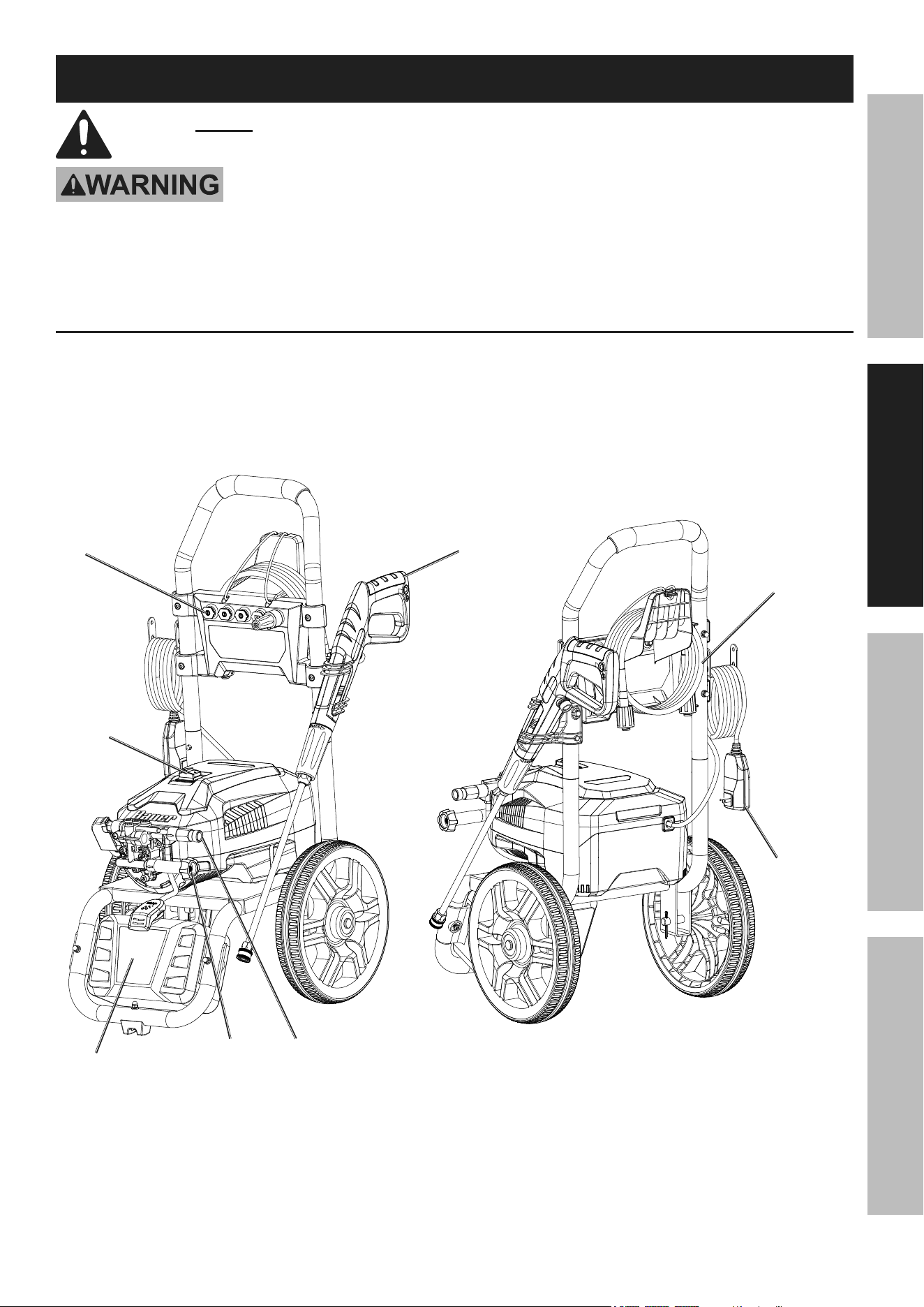
Functions
High-pressure
Hose
Water
Outlet
Detergent
tank
Spray
Gun
power cord
with GFci
power
Switch
Water
inlet
nozzle
Page 8 For technical questions, please call 1-888-866-5797. Item 70138
SaFety OperatiOn MaintenanceSetup
assembly
note: For additional information regarding the parts listed in the following pages,
refer to Parts List and Assembly Diagram on page 15.
Remove shipping caps from Water Inlet/Outlet.
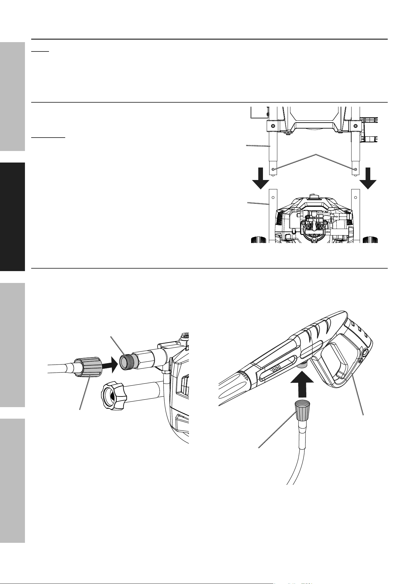
attach Handle
1. Hold the Spring Button near each end of the Handle
in while inserting the ends into the Lower Frame.
cautiOn! Be careful to avoid pinching your hands.
2. Slide the Handle into the Lower Frame until
both Spring Buttons pop out into place.
Handle
Spring
Buttons
Lower
Frame
connect High-pressure Hose
1. Connect High Pressure Hose to Water Outlet on
front of Pressure Washer by pushing Hose in as
far as it will go, then threading coupler on tightly.
Water
Outlet
High pressure
Hose
2. Connect High-Pressure Hose to connection
under Spray Gun by pushing Hose in as far as
it will go, then threading coupler on tightly.
High pressure
Hose
Spray
Gun

Page 9For technical questions, please call 1-888-866-5797.Item 70138
SaFetyOperatiOnMaintenance Setup
Operating instructions
read the entire iMpOrtant SaFety inFOrMatiOn section at the beginning of this
manual including all text under subheadings therein before set up or use of this product.
Work piece and Work area Set up
1. Designate a work area that is clean and well-lit.
The work area must not allow access by children
or pets to prevent distraction and injury.
2. CHECK THE WATER SUPPLY. Prior to using
the Pressure Washer for the first time, it is
ESSENTIAL to verify that the water supply is
adequate. The Pressure Washer needs TWICE the
water supply (or volume) of the listed water output
(1.1 GPM). This Pressure Washer will need about
2.2-3 GPM to operate correctly and efficiently. If
the water is being supplied by a well/pump, make
certain that the well/pump produces enough
water to keep up with the Pressure Washer’s
water demands. Water supply hoses should be
heavy-duty. The flow rate of the water supply must
never be allowed to fall below 2.2 GPM.
To determine the water supply’s flow rate:
Run the water at full for 30 seconds into a
5 gallon container, then measure the amount
of water in the container and multiply by 2.
cautiOn! If the Pressure Washer is run
with an inadequate water supply, the pump
may cavitate. Cavitation causes the pump
to operate loudly and will damage it.
3. USE PROPER ELECTRICAL SUPPLY.
This unit uses a large amount of current, especially
during start-up. Turn off power switch, then
connect this unit only to a dedicated household
circuit with no additional loads (running devices)
connected to it. For best results, use the outlet
that is nearest to the circuit breaker panel.
4. PLAN OUT THE JOB Plan out areas to be
cleaned, how many sessions will be necessary,
and how long the individual sessions will need
to be. Plan to clean the higher areas first.
Plan a safe direction for runoff, and plan
on working your way in that direction.
5. Clear the area of all objects that are not being
cleaned. If any water-sensitive or delicate items
cannot be moved, cover them. If detergent is to
be used, cover or remove any plants or animals.
Disconnect power to and protect any nearby
electrical wiring. Close windows and doors.
6. Place the Pressure Washer in a location
which is protected from runoff. The location
should be close enough so that the water
supply hose will reach every portion of the
area with some slack for movement.
7. Route the power cord along a safe route
to reach the work area without creating a
tripping hazard or exposing the power cord
to possible damage. The power cord must
reach the work area with enough extra length
to allow free movement while working.
Page 10 For technical questions, please call 1-888-866-5797. Item 70138
SaFety OperatiOn MaintenanceSetup
tool Set up
tO preVent SeriOuS inJury FrOM acciDentaL OperatiOn:
turn the power Switch off, unplug it from its electrical outlet, and relieve all
pressure before making adjustments or installing accessories.
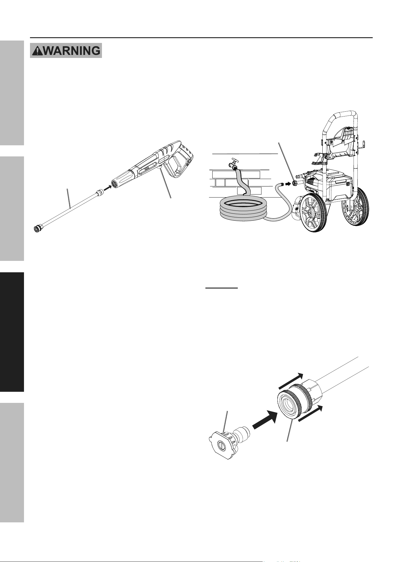
1. MAKE SURE THE WATER INLET STRAINER
ON SPRAY GUN AND WAND ARE FREE
OF MINERAL BUILDUP OR DEBRIS.
2. Insert Wand into end of Spray Gun, press in and
twist Wand clockwise until it locks into place.
Water
inlet
Wand
3. Run water through water supply hose (not
included) to remove any debris. Turn off water.
4. Connect water supply hose to Water Inlet on
front of Pressure Washer. Tighten securely.
Water
inlet
5. Nozzle Selection:
• This Pressure Washer includes several
Nozzles with different spray patterns. Select
the Nozzle that suits your requirements.
cautiOn! tO preVent inJury anD
prOperty DaMaGe, uSe HiGH-iMpact
Spray WitH cautiOn.
• The Black Nozzle is used specifically for
dispensing detergent at lower pressure.
• Pull back on the collar at the end of the Wand,
insert the Nozzle, and release the collar so
that it holds the Nozzle securely in place.
collar
nozzle
Page 11For technical questions, please call 1-888-866-5797.Item 70138
SaFetyOperatiOnMaintenance Setup
General Operating instructions
tO preVent eLectric SHOcK anD DeatH: test Ground Fault circuit
interrupter (GFci) before each use. the GFci does not protect against electrical
shock due to contact with both circuit conductors or a fault in any wiring supplying in this device. Do not
alter or disable the GFci. Do not use an extension cord.
This unit is intended for light to moderate cleaning. It is not intended for paint stripping or deep concrete cleaning.
1. Uncoil High-Pressure Hose completely. Do not use
pressure Washer if Hose is kinked or looped.
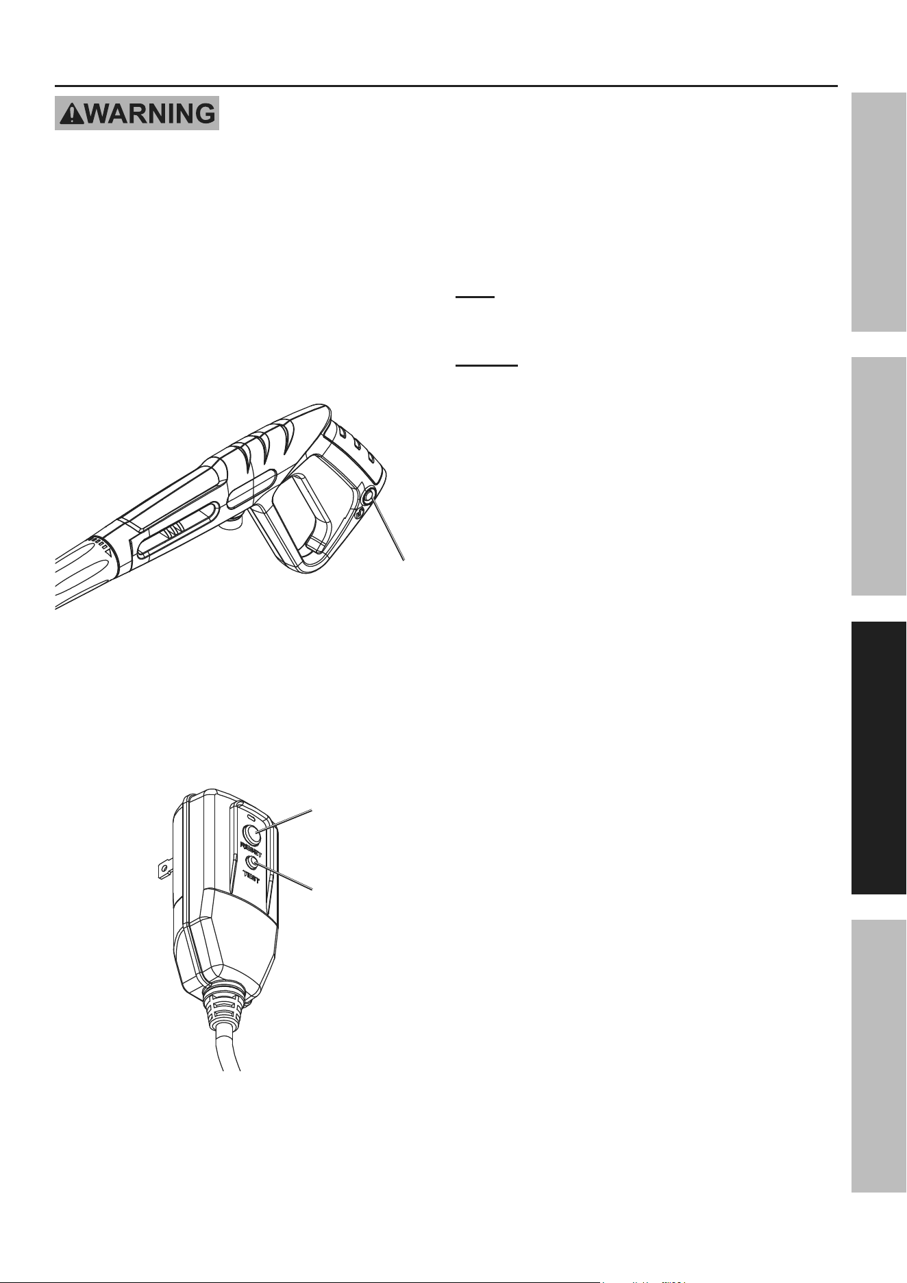
2. The Spray Gun includes a Trigger
Safety Lock that locks the Trigger.
• Push Trigger Safety Lock in from
the left side to lock the Trigger.
• Push Trigger Safety Lock in from
the right side to unlock Trigger.
trigger
Safety
Lock
3. Point Spray Gun in safe direction, press Trigger
to release all pressure, then release Trigger.
4. Plug GFCI into dedicated, grounded
120V outlet, then press the reSet
button to ensure proper operation.
reset
test
5. Turn on water supply.
6. Turn Power Switch to ON position.
note: If the unit does not turn on or turns
off suddenly, turn Power Switch to OFF
position, then check and reset the GFCI.
nOtice: Pressure Washer will run only while
Trigger is pressed. When trigger is released,
Pump will turn off. Do not leave idle for more
than one minute without spraying.
7. test spray an inconspicuous area:
a. Set Nozzle to low-impact fan spray.
b. Point Spray Gun at 45° angle to test area.
Unlock Trigger Safety Lock, then press
Trigger. Be aware of kick back.
c. Spray test area, adjusting pressure,
as needed, by changing distance from
surface and/or adjusting Nozzle.
d. If using detergent:
• Turn off unit, fill Detergent Tank,
then attach Black Nozzle.
• Turn on unit, then spray area with detergent
according to detergent manufacturer's
instructions. Scrub surface as necessary.
• Turn off unit, then switch to another Nozzle.
• Turn on unit, then spray area to rinse off
detergent, adjusting pressure as needed
by changing distance from surface and/
or changing to a different Nozzle.
e. Inspect test area for damage or discoloration.

Page 12 For technical questions, please call 1-888-866-5797. Item 70138
SaFety OperatiOn MaintenanceSetup
cleaning Windows
a. Inspect caulking and/or glazing. Inspect trim.
DO nOt preSSure WaSH WinDOWS iF
cauLKinG/GLaZinG/triM iS nOt intact.
b. If needed, apply detergent according
to manufacturer's instructions.
c. Set Nozzle to low-impact fan spray.
DO nOt uSe HiGH-iMpact Spray,
FOrce May BreaK GLaSS.
d. Point Spray Gun at 45° angle to, and 4 feet
away from, window. Spray window.
cleaning Wood
DO nOt cLean WOOD tHat iS
HOt Or in Direct SunLiGHt.
a. If needed, apply wood cleaning
detergent according to manufacturer's
instructions. For vertical surfaces,
apply detergent from bottom to top.
b. Scrub stained areas as needed.
c. Set Nozzle to low-impact fan spray.
d. Point Spray Gun at 45°. Spray surface,
working with the grain of the wood.
e. Let surface dry completely, then apply
stain or sealer, as needed, according
to manufacturer's instructions.
cleaning Brick and Mortar
a. Inspect mortar, patching as needed. Let mortar
cure according to manufacturer's instructions.
b. Soak surface prior to applying detergent.
c. If needed, apply brick cleaning
detergent according to manufacturer's
instructions. For vertical surfaces,
apply detergent from bottom to top.
d. Scrub stained areas as needed.
e. Set Nozzle to low-impact fan spray.
tO preVent DaMaGe, OnLy
uSe LOW-iMpact SettinG.
f. Point Spray Gun at 45°. Spray surface.
g. Let surface dry completely, then
apply sealer, as needed, according to
manufacturer's instructions as needed.
8. When finished:
• Release Trigger, then Lock Trigger Safety Lock.
• Turn off Power Switch.
• Turn off water supply.
• Unplug the unit.
• Point Nozzle in safe direction, unlock
Trigger Safety Lock, press Trigger to
release all pressure, release Trigger,
then Lock Trigger Safety Lock.
• Disconnect water supply hose.
• Disconnect High-Pressure Hose from unit.
• Disconnect High-Pressure
Hose from Spray Gun.
9. iMpOrtant: cLean tHe nOZZLeS aFter
eVery uSe tO Maintain SprayinG
pOWer anD preVent puMp DaMaGe.
• Remove Wand from Spray Gun.
• Pull back on the collar at the end of
the Wand and remove the Nozzle.
• Push Nozzle Tip Cleaner (included) into
tip to push out debris and buildup.
• Remove Nozzle Tip Cleaner and
back-flush water through Nozzle.
• Reattach Nozzle to Wand.
• Clean and store according to
user-Maintenance instructions on page 13.

Page 13For technical questions, please call 1-888-866-5797.Item 70138
SaFetyOperatiOnMaintenance Setup
user-Maintenance instructions
tO preVent SeriOuS inJury FrOM acciDentaL OperatiOn:
turn the power Switch of the tool off, unplug the tool from its electrical outlet,
shut off the water supply and safely discharge all residual water pressure from
the unit before performing any inspection, maintenance, or cleaning procedures.
tO preVent SeriOuS inJury FrOM tOOL FaiLure:
Do not use damaged equipment. if abnormal noise or vibration
occurs, have the problem corrected before further use.
cleaning, Maintenance, and Lubrication
1. BeFOre eacH uSe, inspect the general
condition of the tool. Check for:
• loose hardware,
• misalignment or binding of moving parts,
• damaged cord/electrical wiring,
• damaged high-pressure hose/accessories,
• cracked or broken parts, and
• any other condition that may
affect its safe operation.
2. aFter uSe:
• Drain water by tipping the unit.
Frost will damage the unit if it contains water.
• Flush Detergent Tank with water.
• Use only a clean cloth and mild detergent
to clean the body of the Pressure
Washer. Do not use solvents.
• Do not immerse any part of the tool in liquid.
• Dry off any remaining water
on all parts and fittings.
• Remove mineral deposits from the nozzle
using a thin, stiff wire brush (sold separately).
3. periODicaLLy, remove mineral buildup. Unplug
the unit and lay it face down. Fill Water Inlet
with de-mineralizing solution (sold separately),
following solution manufacturer's instructions.
Drain de-mineralizing solution out of Water Inlet
and rinse out inlet thoroughly before use.
4. WarninG! tO preVent SeriOuS
inJury: if the supply cord or GFci unit of this
power tool is damaged, it must be replaced
only by a qualified service technician.
Storage
1. Place accessories, High-Pressure Hose and
Power Cord in their storage locations.
2. Store in a dry, frost-free room. Flush the unit with
automotive antifreeze prior to long-term storage.
Dispose of antifreeze according to local ordinances.
Page 14 For technical questions, please call 1-888-866-5797. Item 70138
SaFety OperatiOn MaintenanceSetup
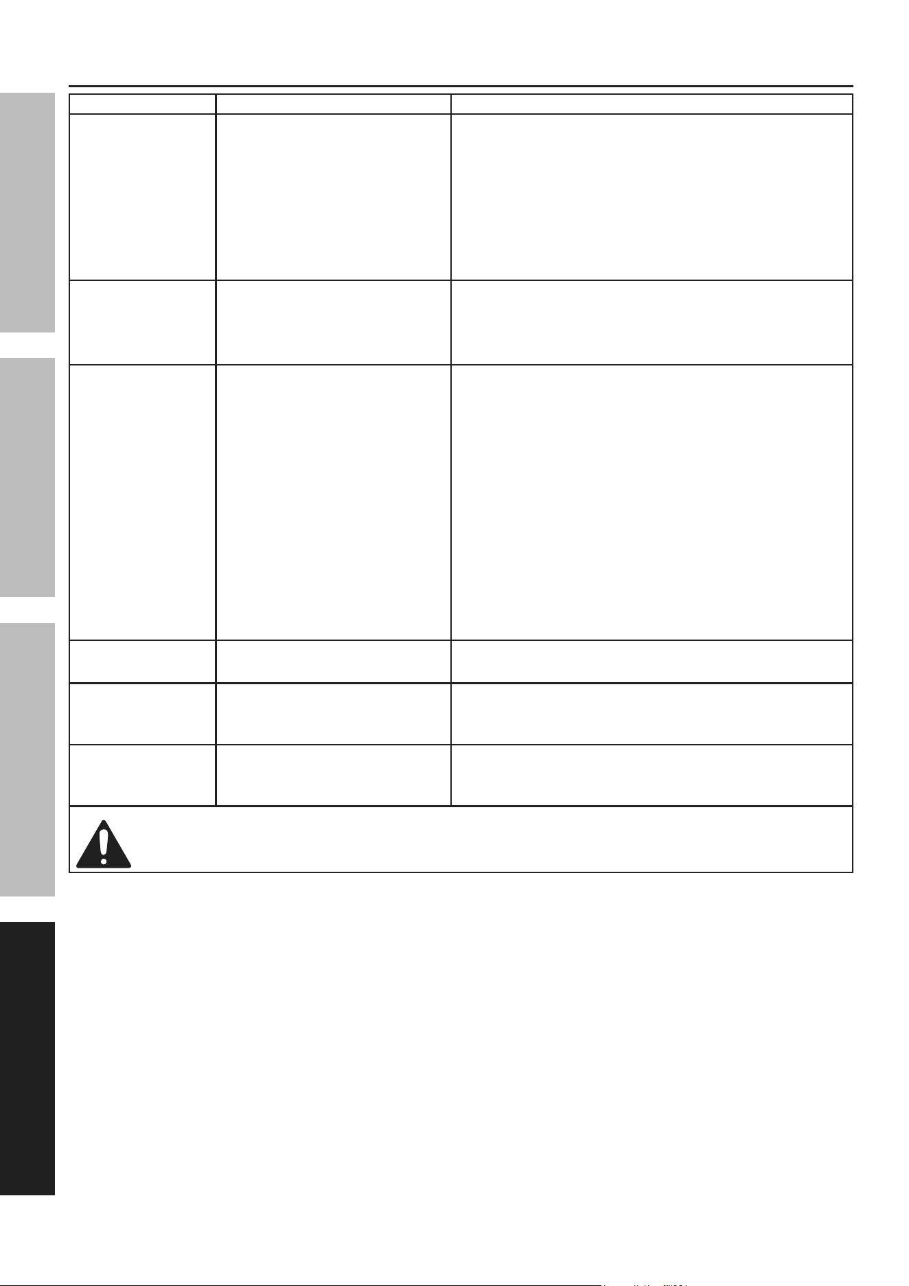
troubleshooting
problem possible causes Likely Solutions
Pressure Washer
will not start
1. Cord not connected.
2. No power at outlet.
3. GFCI circuit breaker tripped.
4. Internal damage or wear.
(switch, for example.)
1. Check that cord is plugged in.
2. Check power at outlet. If outlet is unpowered,
turn off tool and check circuit breaker. If breaker
is tripped, make sure circuit is right capacity
for tool and circuit has no other loads.
3. Press reset button on GFCI unit on cord.
4. Have a qualified technician service tool.
Pressure Washer
stops suddenly
1. GFCI circuit breaker tripped.
2. Water leaking from housing.
1. Press reset button on GFCI unit on cord.
2. SHOCK HAZARD! IMMEDIATELY discontinue use.
Have the unit repaired by a qualified
technician before further use.
Output pressure
varies
1. Not enough water supply.
2. Air in water supply.
3. Water Inlet Filter is clogged.
4. Nozzle not attached
to Spray Gun.
5. Nozzle is clogged.
6. Nozzle has mineral build up.
7. Water supply hose is
too long or narrow.
8. Internal valves or seals
may be worn or sticking.
1. Check water supply hose for kinks, leaks,
or blockage. Open faucet all the way.
2. Check that all connections are tight.
3. Remove Filter and clean.
4. Pressure is created by the Nozzle, not the
Spray Gun. Attach Nozzle to Spray Gun.
5. Remove Nozzle and clean with Nozzle Tip Cleaner.
6. Remove Nozzle and clean with
de-mineralizing solution.
7. Shorten the length of the water supply
hose if needed to increase pressure.
8. Have a qualified technician service tool.
Trigger does
not depress
Trigger Safety Lock
is still engaged.
Unlock Safety Lock.
Detergent will
not dispense
Incorrect detergent type. Check that the detergent is the recommended
type of detergent. Clean out dispenser and
replace with correct type if needed.
Performance
decreases
over time
Clogged with mineral deposits. Clean unit with de-mineralizing solution.
Follow all safety precautions whenever diagnosing or servicing the tool. Disconnect power
supply before service.

Page 15For technical questions, please call 1-888-866-5797.Item 70138
SaFetyOperatiOnMaintenance Setup
parts List and assembly Diagram
pLeaSe reaD tHe FOLLOWinG careFuLLy
THE MANUFACTURER AND/OR DISTRIBUTOR HAS PROVIDED THE PARTS LIST AND ASSEMBLY DIAGRAM
IN THIS MANUAL AS A REFERENCE TOOL ONLY. NEITHER THE MANUFACTURER OR DISTRIBUTOR
MAKES ANY REPRESENTATION OR WARRANTY OF ANY KIND TO THE BUYER THAT HE OR SHE IS
QUALIFIED TO MAKE ANY REPAIRS TO THE PRODUCT, OR THAT HE OR SHE IS QUALIFIED TO REPLACE
ANY PARTS OF THE PRODUCT. IN FACT, THE MANUFACTURER AND/OR DISTRIBUTOR EXPRESSLY
STATES THAT ALL REPAIRS AND PARTS REPLACEMENTS SHOULD BE UNDERTAKEN BY CERTIFIED AND
LICENSED TECHNICIANS, AND NOT BY THE BUYER. THE BUYER ASSUMES ALL RISK AND LIABILITY
ARISING OUT OF HIS OR HER REPAIRS TO THE ORIGINAL PRODUCT OR REPLACEMENT PARTS
THERETO, OR ARISING OUT OF HIS OR HER INSTALLATION OF REPLACEMENT PARTS THERETO.
record product’s Serial number Here:
note: If product has no serial number, record month and year of purchase instead.
note: Some parts are listed and shown for illustration purposes only, and are not available
individually as replacement parts. Specify UPC 193175490490 when ordering parts.

Page 16 For technical questions, please call 1-888-866-5797. Item 70138
SaFety OperatiOn MaintenanceSetup
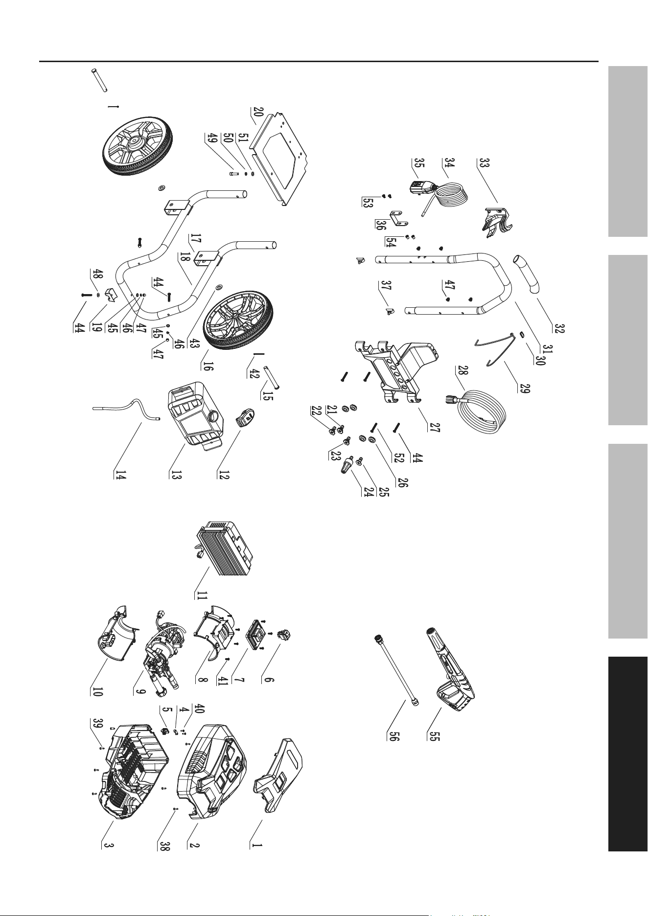
parts List - Washer
part Description Qty
1 Upper Housing Panel 1
2 Upper Housing 1
3 Lower Housing 1
4 Outlet Wire Strain Plate 2
5 Outlet Strain Plate Grommet 1
6 Power Switch 1
7 Switch Box Cover 1
8 Motor Upper Housing 1
9 Motor & Pump Assembly 1
10 Motor Lower Housing 1
11 Controller Assembly 1
12 Detergent Tank Cap 1
13 Detergent Tank 1
14 Suction Tube 1
15 Wheel Axle 2
16 Wheel 2
17 Wheel Bracket 1
18 Lower Frame 1
19 Frame Rubber foot 1
20 Frame Plate 1
21 15 Degree Spray Nozzle 1
22 25 Degree Spray Nozzle 1
23 40 Degree Spray Nozzle 1
24 Turbo Nozzle 1
25 Detergent Nozzle 1
26 Nozzle Holder 5
27 Upper Panel 1
28 High Pressure Hose 1
part Description Qty
29 Black Elastic Band 1
30 Clip 1
31 Handle 1
32 Foam Rubber Sleeve 1
33 Wand Mount 1
34 Power Cord 1
35 GFCI Plug 1
36 Power Cord Hanger 1
37 Spring Button 2
38 Cross Recessed Tapping Screw 4
39 Cross Recessed Tapping Screw 8
40 Cross Recessed Tapping Screw 4
41 Cross Recessed Tapping Screw 10
42 Split Pin 2
43 Flat Gasket 2
44 Hex Round Head Screw 6
45 Flat Gasket 7
46 Spring Gasket 7
47 Cap Nut 7
48 Large Gasket 1
49 Hex Round Head Screw 1
50 Spring Gasket 1
51 Flat Gasket 1
52 Hex Round Head Screw 1
53 Hex Round Head Screw 2
54 Flat Head Rivet Nut 2
55 Spray Gun 1
56 Wand 1
Page 17For technical questions, please call 1-888-866-5797.Item 70138
SaFetyOperatiOnMaintenance Setup
assembly Diagram - Washer

Page 18 For technical questions, please call 1-888-866-5797. Item 70138
SaFety OperatiOn MaintenanceSetup
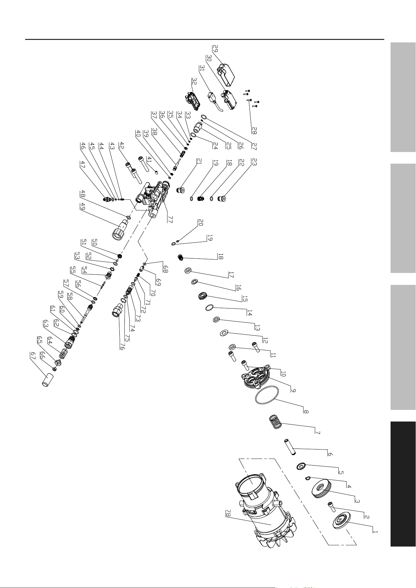
parts List - Motor
part Description Qty
A1 Bearing Seat 1
A2 Screw/Spring Gasket/Large Gasket 1
A3 Thrust Ball Bearing 1
A4 Axial Circlip 3
A5 Plunger Cup 3
A6 Plunger 3
A7 Plunger Spring 3
A8 O-Ring 1
A9 Pump Body 1
A10 Hex Cap Screw & Spring Gasket 3
A11 Reciprocating Oil Seal 3
A12 Auxiliary Water Seal Retaining Ring 3
A13 Auxiliary Water Seal 3
A14 O-Ring 3
A15 Middle Sleeve Set 3
A16 Main Water Seal Retaining Ring 3
A17 Main Water Seal 3
A18 Inlet & Outlet Valve Assembly 6
A19 O-Ring 6
A20 O-Ring 1
A21 Inlet & Outlet Valve Cap 1
A22 O-Ring 3
A23 Inlet & Outlet Valve Cap 3
A24 O-Ring 1
A25 Switch Top Rod Nut 1
A26 O-Ring 1
A27 O-Ring 1
A28 Self Tapping Screw 5
A29 Micro Switch Waterproof Cover 1
A30 Micro Switch Left Housing 1
A31 Micro Switch Lead Assembly 1
A32 Micro Switch Right Housing 1
A33 Closed Retaining Ring 1
A34 O-Ring 1
A35 Closed Retaining Ring 1
A36 Rod Spring Seat 1
A37 Rod Spring 1
A38 Switch Top Rod 1
A39 Open Retaining Ring 1
part Description Qty
A40 O-Ring 1
A41 Hex Set Screw 1
A42 Hex Cap Screw & Spring Gasket 3
A43 Suction Spring 1
A44 Stainless Steel Ball 1
A45 O-Ring 1
A46 O-Ring 1
A47 Suction Connector 1
A48 O-Ring 1
A49 Water Inlet Connector 1
A50 Steel Ball Seat 1
A51 Stainless Steel Ball 1
A52 O-Ring 1
A53 Open Retaining Ring 1
A54 Pressure Regulating Seat 1
A55 Ejector Pin 1
A56 Open Retaining Ring 1
A57 O-Ring 1
A58 Pressure Regulating Valve Stem 1
A59 O-Ring 1
A60 Closed Retaining Ring 1
A61 O-Ring 1
A62 O-Ring 1
A63 Pressure Regulating Valve Body 1
A64 Pressure Regulating Spring 1
A65 Pressure Regulating Nut 1
A66 Nut 1
A67 Pressure Regulating Sheath 1
A68 O-Ring 1
A69 Pressure Retaining Valve Core 1
A70 Pressure Retaining Valve Spring 1
A71 Suction Core 1
A72 O-Ring 1
A73 Suction Body 1
A74 O-Ring 1
A75 O-Ring 1
A76 Water Outlet Connector 1
A77 Pump Head 1
A78 Motor Assembly 1
When ordering replacement parts from this list, the “A” prefix must be included in order to get the correct part.
Page 19For technical questions, please call 1-888-866-5797.Item 70138
SaFetyOperatiOnMaintenance Setup
assembly Diagram - Motor

Limited 90 Day Warranty
Harbor Freight Tools Co. makes every effort to assure that its products meet high quality and durability standards,
and warrants to the original purchaser that this product is free from defects in materials and workmanship for the
period of 90 days from the date of purchase. This warranty does not apply to damage due directly or indirectly,
to misuse, abuse, negligence or accidents, repairs or alterations outside our facilities, criminal activity, improper
installation, normal wear and tear, or to lack of maintenance. We shall in no event be liable for death, injuries
to persons or property, or for incidental, contingent, special or consequential damages arising from the use of
our product. Some states do not allow the exclusion or limitation of incidental or consequential damages, so the
above limitation of exclusion may not apply to you. THIS WARRANTY IS EXPRESSLY IN LIEU OF ALL OTHER
WARRANTIES, EXPRESS OR IMPLIED, INCLUDING THE WARRANTIES OF MERCHANTABILITY AND FITNESS.
To take advantage of this warranty, the product or part must be returned to us with transportation charges
prepaid. Proof of purchase date and an explanation of the complaint must accompany the merchandise.
If our inspection verifies the defect, we will either repair or replace the product at our election or we may
elect to refund the purchase price if we cannot readily and quickly provide you with a replacement. We will
return repaired products at our expense, but if we determine there is no defect, or that the defect resulted
from causes not within the scope of our warranty, then you must bear the cost of returning the product.
This warranty gives you specific legal rights and you may also have other rights which vary from state to state.
26677 agoura road • calabasas, ca 91302 • 1-888-866-5797
