MBVC***1
BLOWER CABINET
INSTALLATION INSTRUCTIONS
Contents
is a registered trademark of Maytag Corporaon or its related companies and is used under license. All rights reserved.
Introduction............................................................................ 2
Electrostatic Discharge (ESD) Precautions ............................ 2
Checking Product Received ...................................................... 2
Replacement Parts ................................................................... 2
Ordering Parts ........................................................................ 2
Important Safety Instructions .............................................. 2
Recognize Safety Symbols, Words, and Labels ....................... 2
General Information ............................................................... 3
Features.................................................................................... 3
Achieving Less Air Leakage ....................................................... 3
Clearances And Accessibility ................................................... 3
Insulation ................................................................................ 3
Installation Instructions ........................................................ 4
Blower with Cased Evaporator Coil Installation ................... 4
Upflow Installation ................................................................ 4
Counterflow Installation ....................................................... 4
Horizontal Installation .......................................................... 4
Counterflow and Horizontal Applications ............................ 5
Electrical Connections ............................................................ 5
208/230 Volt Line Connections ................................................ 5
Low Voltage Wiring ................................................................. 5
Operation on 208 Volt Supply .................................................. 6
24 Volt Thermostat Wiring ..................................................... 6
CoolCloud HVAC Phone Application ........................................ 6
Quick Start Guide for Communicating Outdoor Units .......... 6
Charging .................................................................................. 7
Electric Heat Kit Testing .......................................................... 8
Quick Start Guide for Non-Communicating Outdoor Units .. 8
Charging .................................................................................. 9
Electric Heat Kit Testing .......................................................... 9
Dehumidification ..................................................................... 9
Auxiliary Alarm Switch ........................................................ 10
7-Segment Display and Push Buttons .................................... 10
Accessory Control ................................................................. 10
Dehumidification Control Options .................................... 11
Ramping Profiles ................................................................... 12
Electric Air Cleaner ............................................................... 13
Troubleshooting ................................................................... 13
Troubleshooting Matrix ....................................................... 14
Push Button Menus ............................................................... 16
System Status Display ............................................................. 18
Airflow Label
...................................................................... 19
Wiring Diagram
................................................................... 20
Homeowners Routine Maintenance Recommendations .... 21
Start Up CHecklist ............................................................... 22
THIS PRODUCT CONTAINS ELECTRONIC COMPONENTS WHICH REQUIRE A DEFINITE
GROUND. PROVISIONS ARE MADE FOR CONNECTION OF THE GROUND. A DEDICATED
GROUND FROM THE MAIN POWER SUPPLY OR AN EARTH GROUND MUST BE
© 2019 - 2021 Goodman Manufacturing Company, L.P.
19001 Kermier Rd., Waller, TX 77484
www.goodmanmfg.com - www.amana-hac.com
P/N: IO-456C Date: June 2021
O
NLY
PERSONNEL
THAT
HAVE
BEEN
TRAINED
TO
INSTALL
,
ADJUST
,
SERVICE
OR
REPAIR
(
HEREINAFTER
, “
SERVICE
”)
THE
EQUIPMENT
SPECIFIED
IN
THIS
MANUAL
SHOULD
SERVICE
THE
EQUIPMENT
. T
HE
MANUFACTURER
WILL
NOT
BE
RESPONSIBLE
FOR
ANY
INJURY
OR
PROPERTY
DAMAGE
ARISING
FROM
IMPROPER
SERVICE
OR
SERVICE
PROCEDURES
. I
F
YOU
SERVICE
THIS
UNIT
,
YOU
ASSUME
RESPONSIBILITY
FOR
ANY
INJURY
OR
PROPERTY
DAMAGE
WHICH
MAY
RESULT
. I
N
ADDITION
,
IN
JURISDICTIONS
THAT
REQUIRE
ONE
OR
MORE
LICENSES
TO
SERVICE
THE
EQUIPMENT
SPECIFIED
IN
THIS
MANUAL
,
ONLY
LICENSED
PERSONNEL
SHOULD
SERVICE
THE
EQUIPMENT
. I
MPROPER
INSTALLATION
,
ADJUSTMENT
,
SERVICING
OR
REPAIR
OF
THE
EQUIPMENT
SPECIFIED
IN
THIS
MANUAL
,
OR
ATTEMPTING
TO
INSTALL
,
ADJUST
,
SERVICE
OR
REPAIR
THE
EQUIPMENT
SPECIFIED
IN
THIS
MANUAL
WITHOUT
PROPER
TRAINING
MAY
RESULT
IN
PRODUCT
DAMAGE
,
PROPERTY
DAMAGE
,
PERSONAL
INJURY
OR
DEATH
.
This device, which was assembled by Goodman Manufacturing
Company, L.P., contains a component that is classied as an intentional
radiator. This intentional radiator has been certied by the FCC: FCC ID
QOQBGM111. And this international radiator has an Industry Canada
ID: IC 5123A-BGM111.
This device complies with Part 15 of the FCC’s Rules. Operation of this
device is subject to two conditions:
(1) This device may not cause harmful interference; and
(2) This device must accept any interference received, including
interference that may cause undesirable operation.
And this device meets the applicable Industry Canada technical
specications.
The manufacturer of the intentional radiator (model no. BGM111) is
Silicon Laboratories Finland Oy, which can be contacted by calling 617-
951-0200. (www.silabs.com)
The FCC responsible party is Goodman Manufacturing Company, L.P.,
and may be contacted by calling (713)-816-2500, or at 19001 Kermier
RD., Waller TX 77484. (www.GoodmanMFG.com)
This equipment complies with FCC radiation exposure limits. To ensure
compliance, human proximity to the antenna shall not be less the 20cm
during normal operations.
Changes or modications not expressly approved by the party
responsible for compliance could void the user’s authority to operate the
equipment.
2
PROVIDED.
Introduction
This booklet contains the installaon and operang instrucons for
your modular blower cabinet. All warnings and precauons within
this booklet must be observed. Improper installaon can result in
problems ranging from noisy operaon to property or equipment
damages, dangerous condions that could result in injury or per-
sonal property damage and that are not covered by the warranty.
Read this booklet and any instrucons packaged with accessories
prior to installaon. Give this booklet to the user and explain its
provisions. The user should retain this booklet for future reference.
Electrostatic Discharge (ESD) Precautions
NOTE: Discharge body’s stac electricity before touching unit. An
electrostac discharge can adversely aect electrical components.
Use the following precauons during modular blower installaon
and servicing to protect the integrated control module from dam-
age. By pung the modular blower, the control, and the person
at the same electrostac potenal, these steps will help avoid
exposing the integrated control module to electrostac discharge.
This procedure is applicable to both installed and uninstalled (un-
grounded) blowers.
1. Disconnect all power to the blower. Do not touch the
integrated control module or any wire connected to the
control prior to discharging your body’s electrostac charge
to ground.
2. Firmly touch a clean, unpainted, metal surface of the
modular blower near the control. Any tools held in a
person’s hand during grounding will be discharged.
3. Service integrated control module or connecng wiring
following the discharge process in step 2. Use cauon not
to recharge your body with stac electricity; (i.e., do not
move or shue your feet, do not touch ungrounded objects,
etc.). If you come in contact with an ungrounded object,
repeat step 2 before touching control or wires.
4. Discharge your body to ground before removing a new
control from its container. Follow steps 1 through 3 if
installing the control on a blower. Return any old or new
controls to their containers before touching any ungrounded
object.
Checking Product Received
Upon receiving the unit, inspect it for damage from shipment.
Claims for damage, either shipping or concealed, should be led
immediately with the shipping company. Check the unit model
number, specicaons, electrical characteriscs and accessories
to determine if they are correct. In the event an incorrect unit is
shipped, it must be returned to the supplier and must NOT be in-
stalled. The manufacturer assumes no responsibility for installaon
of incorrectly shipped units.
Replacement Parts
Ordering Parts
When reporng shortages or damages, or ordering repair parts,
give the complete unit model and serial numbers as stamped on
the unit’s nameplate.
Replacement parts for this appliance are available through your
contractor or local distributor. For the locaon of your nearest dis-
tributor, consult the white business pages, the yellow page secon
of the local telephone book or contact:
HOMEOWNER SUPPORT
GOODMAN MANUFACTURING COMPANY, L.P.
19001 KERMIER ROAD
WALLER, TEXAS 77484
(877) 254-4729
Important Safety Instructions
Recognize Safety Symbols, Words, and Labels
The following symbols and labels are used throughout this man-
ual to indicate immediate or potenal hazards. It is the owner’s
responsibility to read and comply with all safety informaon and
instrucons accompanying these symbols. Failure to heed safety
informaon increases the risk of property damage, product dam-
age, personal injury or death.
HIGH VOLTAGE!
D
ISCONNECT
ALL
POWER
BEFORE
SERVICING
.
M
ULTIPLE
POWER
SOURCES
MAY
BE
PRESENT
. F
AILURE
TO
DO
SO
MAY
CAUSE
PROPERTY
DAMAGE
,
PERSONAL
INJURY
OR
DEATH
.
WARNING
3
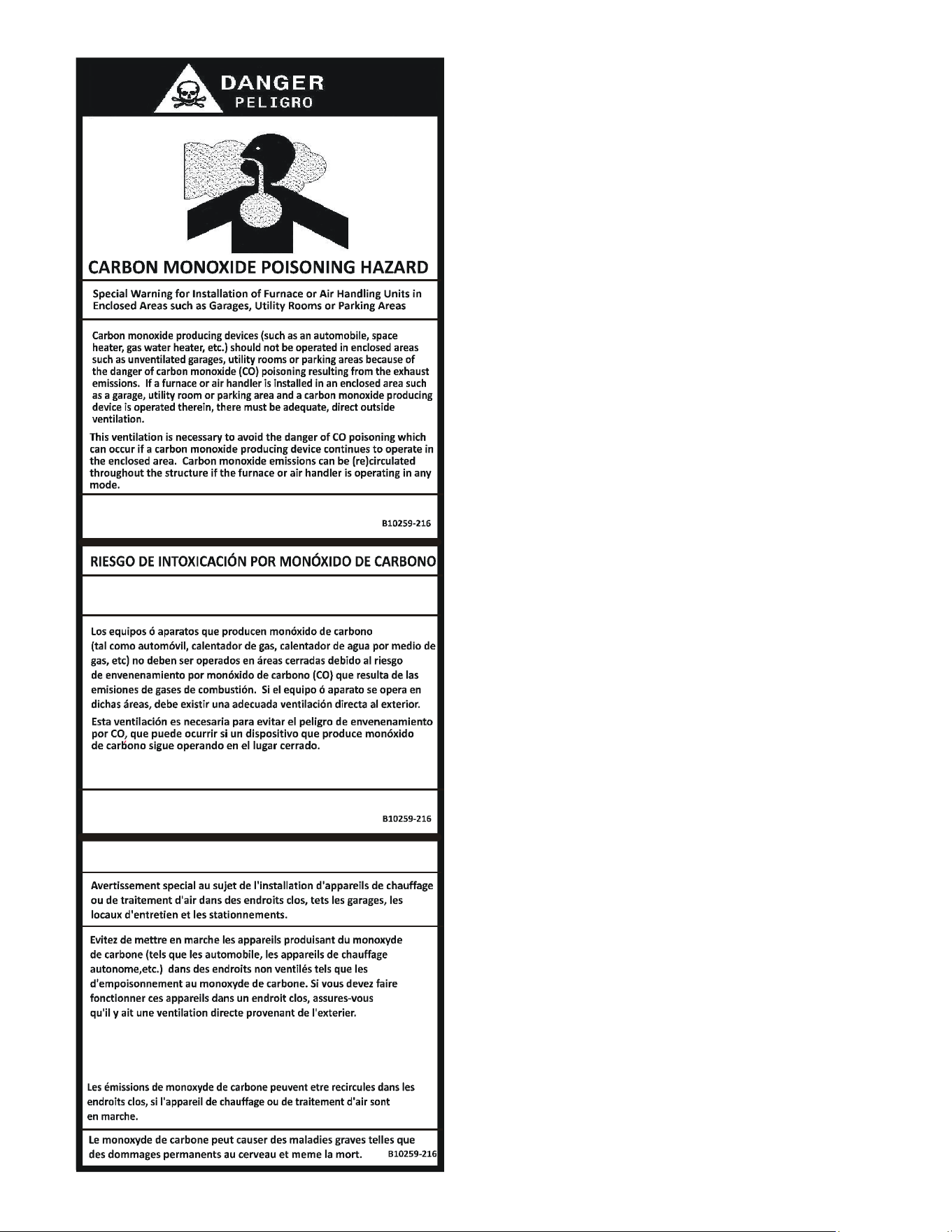
CO can cause serious illness including permanent brain
damage or death.
Advertencia especial para la instalación de calentadores ó manejadoras
de aire en áreas cerradas como estacionamientos ó cuartos de servicio.
El monóxido de carbono puede causar enfermedades severas
como daño cerebral permanente ó muerte.
Las emisiones de monóxido de carbono pueden circular a través
del aparato cuando se opera en cualquier modo.
RISQUE D'EMPOISONNEMENT AU
MONOXYDE DE CARBONE
Cette ventilation est nécessaire pour éviter le danger d'intoxication
au CO pouvant survenir si un appareil produisant du monoxyde
de carbone continue de fonctionner au sein de la zone confinée.
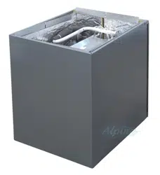
General Information
The MBVC Blower Cabinets are used in combinaon with a cased
evaporator coil. This combinaon of blower and coil funcons
as the indoor part of a split air-condioning system, and may be
matched with a remote condensing or heat pump unit. The blower
cabinet can also funcon as an electric furnace when used with an
electric heater.
NOTE: The electric heating elements for electric furnace
installaon are not shipped with the cabinet and are eld-installed.
Systems should be properly sized by heat gain and loss calculaons
made according to methods of the Air Condioning Contractors
Associaon (ACCA) or equivalent. It is the contractor’s responsi-
bility to ensure the system has adequate capacity to heat or cool
the condioned space.
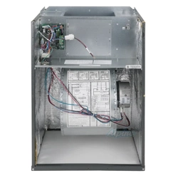
Features
This modular blower is a part of the ComfortBridge™ Technology
family of products. The Modular Blower can operate as a digitally
communicang system requiring only simple 24VAC thermostat in-
puts to funcon (Y for cooling, W for heang, G for fan operaons).
Internal algorithms will provide 2 stage or inverter Air Condioner
or Heat Pump funconality based on these simple inputs. With
built-in Bluetooth operaon, the CoolCloud™ HVAC phone appli-
caon is available for commissioning, soware and shared data
updates and troubleshoong. The Modular Blower can support
non-communicang outdoor unit installaons as well. See wiring
secons for more details. The ComfortBridge™ Technology system
simplies wiring, provides enhanced setup features and elevates
diagnoscs capabilies.
Achieving Less Air Leakage:
Ensure all the gaskets remain intact on surfaces as shipped with the
unit. Ensure upon installaon that the plasc breaker cover is ush
on with the access panel and access panel is ush with the cabinet.
With these requirements sased, the unit achieves less airow
leakage when tested in accordance with ASHRE Standard 193.
• Cabinet air leakage less than 2.0% at 1.0 inch H
2
O when
tested in accordance with ASHRAE standard 193.
• Cabinet air leakage less than 1.4% at 0.5 inch H
2
O when
tested in accordance with ASHRAE standard 193.
Clearances And Accessibility
The unit can be posioned for upow, counterow, horizontal right
or horizontal le operaon. Zero clearance is allowed on all sides
for combusble materials. Thirty-six inches should be alloed on
the door side for maintenance and service.
To reduce risk of rusng, do not install the unit directly on the
ground or on a oor that is likely to be wet. In such environments,
the unit must be elevated by use of a sturdy, nonporous material.
Insulation
To ensure ecient operaon, review the following precauons.
• If the unit is located in an area with high ambient
temperature and/or high humidity, the air handler may
be subject to nuisance sweang of the casing. On these
installaons, a wrap of 2” berglass insulaon with a vapor
barrier is recommended.
4
• The factory recommends insulang the duct running
through any uncondioned spaces.
To reduce operang sound and vibraon transmission use exible
canvas duct connecons at the cabinet.
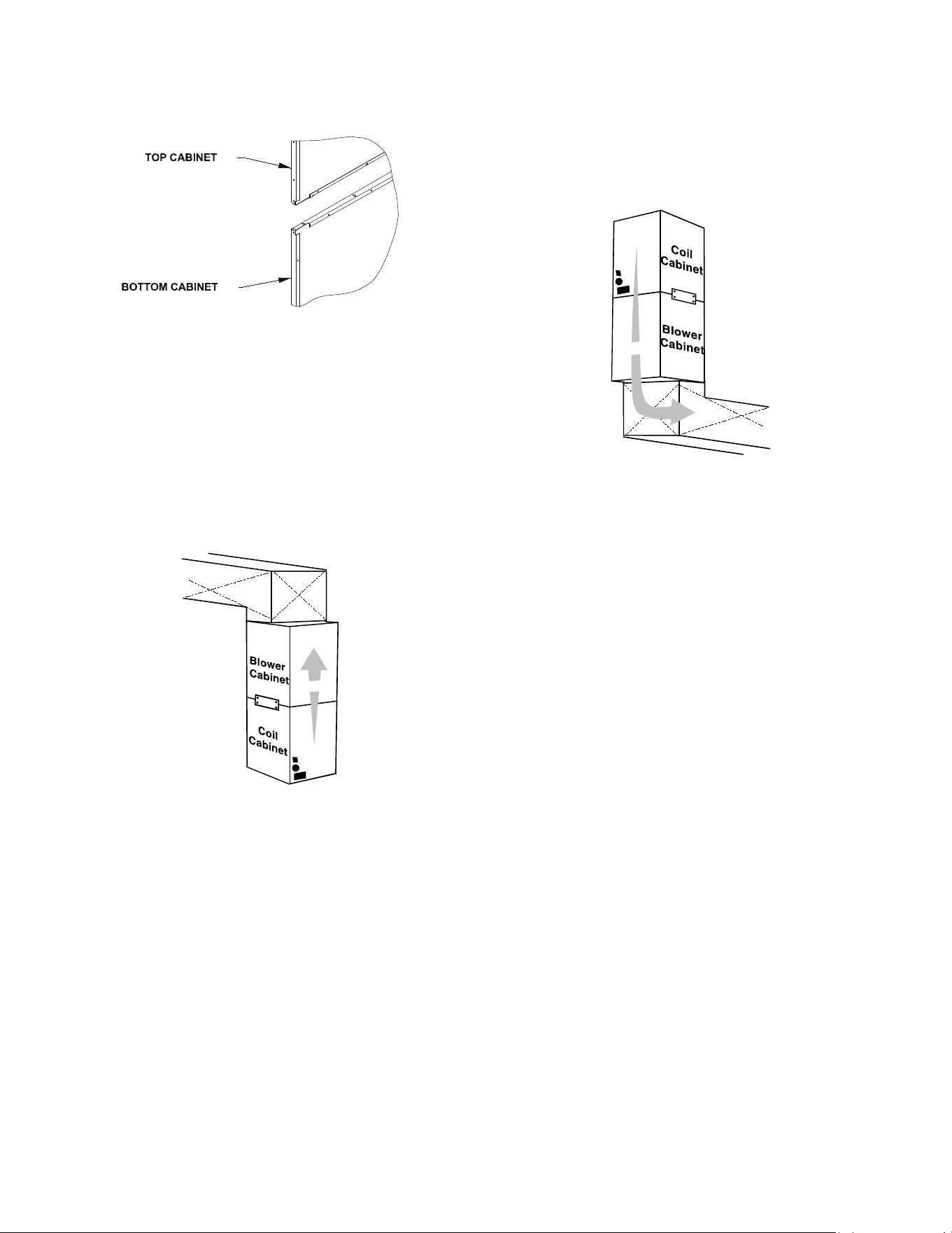
Figure 1 - Coil and Blower Connecon
Installation Instructions
Blower with Cased Evaporator Coil Installation
Secure the coil and blower together with the two connector plates
and screws supplied in the blower bag assembly. Use one connec-
tor plate and six screws on each side of the unit.
If accessory electric heat is to be added, install now per the instruc-
ons shipped with the heater kit.
Air Flow
Figure 2 - Upow Applicaon
Upflow Installation
For upow installaons, the blower cabinet must sit on top of the
coil cabinet (Figure 2).
NOTE: All panels should be in place before installing the cabinet.
1. Place the blower and coil cabinet assembly upright on the
return duct or duct opening. Ensure that there is ample
support for the cabinet assembly and all aached ductwork.
2. Connect refrigerant and condensate drain connecons
per the evaporator coil installaon instrucons. Ensure
refrigerant and drain lines do not interfere with service
access to the unit.
3. Aach supply ductwork. Seal connecons between unit and
ductwork as required to reduce/eliminate air leakage.
4. Make electrical connections as specified in Electrical
Connecons secon of this manual.
Figure 3 - Counterow Applicaon
Counterflow Installation
For counterow installaons, the evaporator coil cabinet must sit
on top of the blower cabinet (Figure 3). NOTE: All panels should
be in place when installing the unit.
NOTE: Supply ductwork for counterow applicaons, must be Class I.
However, if combusble ductwork is used, sheet metal protecon
is required.
Air Flow
1. Place the blower and coil cabinet assembly supply outlet
on the supply duct or duct opening. Ensure there is ample
support for the unit and all aached ductwork.
2. Connect refrigerant and condensate drain connecons
per the evaporator coil installaon instrucons. Ensure
refrigerant and drain lines do not interfere with service
access to the unit.
3. Aach return ductwork. Seal connecons between unit and
ductwork as required to reduce/eliminate air leakage.
4. Make electrical connections as specified in Electrical
Connecons secon of this manual.
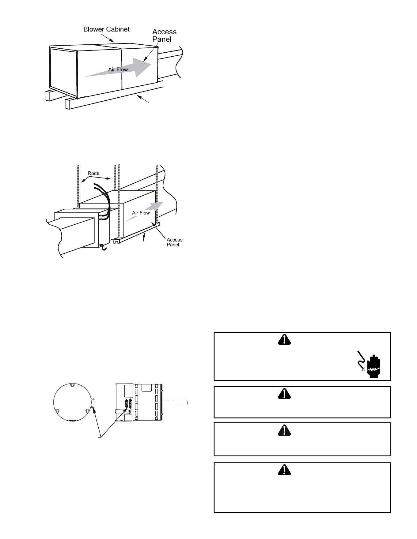
Horizontal Installation
For horizontal installaons, the coil cabinet must be upstream of
the blower cabinet (Figures 4 and 5). NOTE: All panels should be
in place when installing the unit.
1. Set the unit near its nal installaon place. The unit must
be supported along the enre length of the unit. Rubber
isolaon pads may be used to reduce sound and vibraon
transmission. Ensure there is ample support for the unit
and all aached ductwork.
NOTE: Unit must be mounted with access panel facing the front
as shown in following diagrams.
2. If installed above a nished ceiling or living space, be sure
to put a secondary drain pan under the enre unit, and pipe
the drain separately from the main condensate drain.
3. Connect refrigerant and condensate drain connecons per the
coil secon installaon instrucons. Ensure refrigerant and
drain lines do not interfere with service access to the unit.
5
Figure 4 - Ac Installaon
Figure 5 - Hanging Installaon
Figure 6 - MBVC Motor Orientaon
Support
4. Aach return and supply ductwork. Seal connecons.
5. Make electrical connections as specified in Electrical
Connecons secon of this manual.
Support
Counterflow and Horizontal Applications
Loosen motor mount and rotate motor (See Figure 6). Be sure mo-
tor is oriented with the female connecons on the casing poinng
down. If the motor is not oriented with the connecons poinng
down, water could collect in the motor and cause premature failure.
NOTE: Aer rotang motor, ghten motor mount to secure motor.
Be sure that the gap between the motor and the insulaon is the
same as it was before loosening the motor mount. This will ensure
that the blower wheel is properly spaced inside the blower housing.
FEMALE CONNECTIONS
SIDE VIEW
WARNING
SOFTW
ARE VER.
TOP
FRONT VIEW
Electrical Connections
Consult the local power company and local codes before installing
this unit. All wiring must be in accordance with the Naonal Elec-
trical Code as well as all local codes. Knockouts have been provided
on side and top of the cabinet for the installaon of the electrical
conduit. If the knockouts on the cabinet sides are used for electrical
conduit, an adapter ring must be used in order to meet UL1995
safety requirements. Use Minimum Circuit Ampacity and type of
wire to determine proper wire size. The unit MUST be properly
grounded. A ground lug is provided in the unit.
Check all factory connecons before connecng electrical power
to unit to ensure none were loosened or disconnected during
shipping and handling.
208/230 Volt Line Connections
If heater kits will not be installed, remove the proper size knockout
for the electrical conduit connecon. Connect electrical conduit to
the unit using two washers to make an approved connecon. If the
high voltage knockout is removed, please use the provided foam
tape to seal the opening with the conduit.
The power supply wires must be connected to the red and black
power wiring. Two wire nuts are provided in the bag assembly for
this connecon. Wrap the wire nuts with electrical tape. (Insulat-
ed crimp type connectors, eld supplied, may be substuted for
the wire nuts and electrical tape provided proper size connectors
are used.) A ground wire MUST be connected to the ground lug
inside the unit.
Low Voltage Wiring
A 24V-control voltage connects the air handler to the room thermo-
stat and condenser and must use low voltage wiring with copper
conductors. A minimum 18 AWG wire must be used for installaons
up to 150 feet. Low voltage wiring must be connected through
the top of the cabinet or either side. If the low voltage opening is
being used, please replace the pre-installed cap with the bushing
provided in the literature kit.
HIGH VOLTAGE!
T
O
PREVENT
PERSONAL
INJURY
OR
DEATH
DUE
TO
ELECTRICAL
SHOCK
,
DISCONNECT
THE
ELECTRICAL
POWER
BEFORE
ELECTRICALLY
CONNECTING
THE
UNIT
.
WARNING
T
O
AVOID
THE
RISK
OF
FIRE
OR
EQUIPMENT
DAMAGE
,
USE
COPPER
CONDUCTORS
.
WARNING
T
O
AVOID
THE
RISK
OF
PERSONAL
INJURY
,
WIRING
TO
THE
UNIT
MUST
BE
PROPERLY
POLARIZED
AND
GROUNDED
.
CAUTION
A
LL
WIRING
MUST
COMPLY
WITH
APPLICABLE
LOCAL
AND
NATIONAL
CODES
. T
YPE
AND
LOCATION
OF
FUSED
DISCONNECT
SWITCH
(
ES
)
MUST
COMPLY
WITH
ALL
APPLICABLE
CODES
AND
PROVIDE
OVERCURRENT
PROTECTION
AS
SHOWN
ON
THE
NAMEPLATE
.
WARNING
6
Operation on 208 Volt Supply
The unit transformer is factory connected for 230 V operaon. If
unit is to operate on 208 V, disconnect the red wire from terminal
3 of the unit transformer and connect them to terminal 2 of the
unit transformer.
24 Volt Thermostat Wiring
NOTE: Removable connectors are provided with the control
to make thermostat wire connecons. The connectors may be
removed, wire connecons made and the connector replaced. It is
STRONGLY recommended that you do not connect mulple wires
into a single terminal. Wire nuts are recommended to ensure one
wire is used for each terminal. Typical 18 AWG thermostat wire may
be used to wire the system components. 150 feet is the maximum
recommended length of wire recommended between indoor and
outdoor unit, or between indoor unit and thermostat.
NOTE: Wire roung must not interfere with the circulator blower
operaon or roune maintenance.
CoolCloud™ HVAC Phone Application
NOTE: This equipment has been tested and found to comply with
the limits for a Class B digital device, pursuant to part 15 of the FCC
Rules. These limits are designed to provide reasonable protecon
against harmful interference in a residenal installaon. This equip-
ment generates, uses and can radiate radio frequency energy and,
if not installed and used in accordance with the instrucons, may
cause harmful interference to radio communicaons. However,
there is no guarantee that interference will not occur in a parcular
installaon. If this equipment does cause harmful interference to
radio or television recepon, which can be determined by turning
the equipment o and on, the user is encouraged to try to correct
the interference by one or more of the following measures:
—Reorient or relocate the receiving antenna.
—Increase the separaon between the equipment and receiver.
—Connect the equipment into an outlet on a circuit dierent
from that to which the receiver is connected.
—Consult the dealer or an experienced radio/ TV technician
for help.
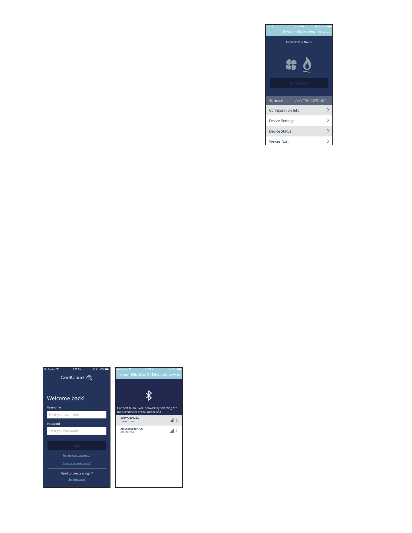
Actual screens may look dierent based on the mobile device
being used.
Figure 7
This air handler is Bluetooth ready and funcons with the Cool
Cloud HVAC phone applicaon designed to improve the contrac-
tor’s setup / diagnosc experience. Users can see specic model
informaon, review acve diagnosc error codes, observe system
menu tesng of all operaonal modes (heat / cool / fan) directly
from the phone. The phone applicaon is also capable of directly
updang the air handler soware anyme updates are available.
The applicaon will automacally nofy the user.
NOTE: The soware update may take up to 20 minutes to complete.
Quick Start Guide for Communicating Outdoor Units
EXTREMELY IMPORTANT: For all cooling calls the system only re-
quires a single Y input from the thermostat. For all heang calls
(including applicaons with backup electric heater kits) the system
only requires a single W input from the thermostat. Internal algo-
rithms will control all available cooling and heang stages based
on these inputs. Any single-stage 24VAC thermostat can be used.
For proper operaon, the thermostat must be setup to control a
single stage AC outdoor unit and to control single stage electric
heat operaon. The control board does not accommodate an O
wire thermostat input (reversing valve signal). If a heat pump is
installed, the thermostat should be setup as stated above. Seng
the thermostat for the heat pump control or mulstage control
may result in incorrect performance.
1. Connect all necessary thermostat wires to the thermostat
connector on the air handler control as instructed by the
applicable wiring diagrams shown in this secon.
2. Connect the 1 & 2 wires between the indoor and outdoor
unit for communicang operaon.
Note: Verify two stage outdoor units include a 24VAC
transformer (for outdoor control board power). Two stage
outdoor units may not behave properly without this 24 VAC
transformer.
7
Communicang Two Stage Air Condioner or Heat Pump
Figure 8
Communicang Inverter Air Condioner or Heat Pump
Figure 9
3. Download the CoolCloud HVAC phone applicaon for
charging and to congure /test system.
NOTE: When new versions of Bluetooth Communicaon Soware
and Air Handler Control Soware are available, the phone appli-
caon noes the user. Soware updates are classied as either
oponal or mandatory and installed by using the phone applica-
on. Ensure all mandatory soware updates have been installed.
Review notes for oponal soware updates and install if necessary.
NOTE: If an E11 code exists for the inverter system immediately
aer line voltage is applied (code displayed on the outdoor inverter
control), the System Vericaon Test needs to be completed before
any other operaon. See the following procedure.
1. Provide Line Voltage to the Inverter and MBVC systems
2. Allow the system to remain idle for 5 minutes
3. Apply a G call (FAN CALL) to the MBVC control. Do not
provide any other 24VAC thermostat call. Conrm the
blower starts running. This step is crical. The MBVC blower
must be running before connuing to step 4.
NOTE: The following steps must be completed on the outdoor
inverter control board. Not on the MBVC control.
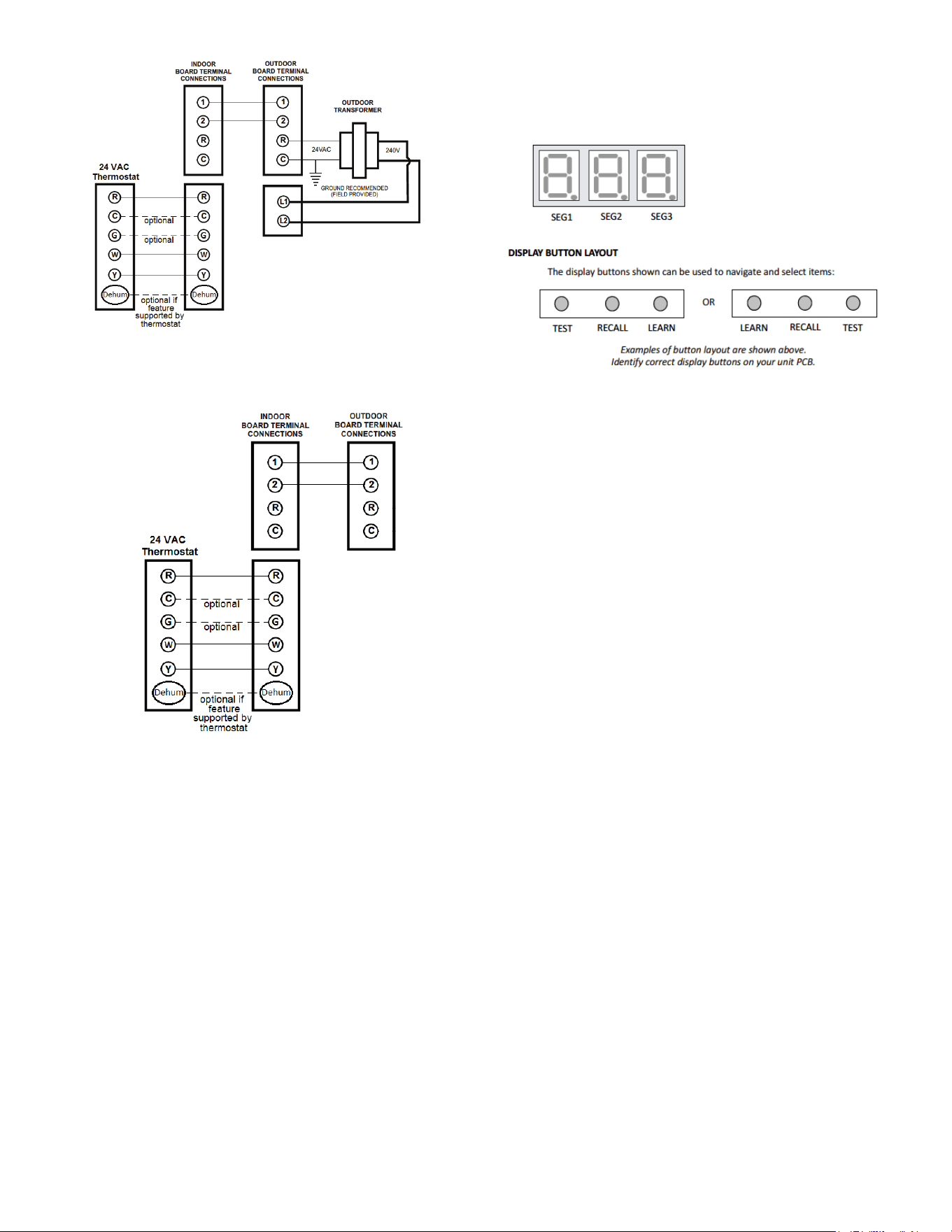
4. Locate the 3 push buons under the 3 seven segment
displays.
5. The 7 Segment display should be showing .
6. Press and hold the RECALL buon for 5 seconds. The 7
Segment display should show .. Release the RECALL
buon.
7. Press and hold the RECALL buon again for another 5
seconds. The 7 Segment display should show .. Release
the RECALL buon.
8. Press and hold BOTH the RECALL AND TEST buons for 5
seconds. The 7 Segment display should show .. Release
the RECALL AND TEST buons. Note, if you only hold the
RECALL buon during this step the display will show ..
You will then need to press the LEARN buon and then start
over from step 5.
9. Press and release the RECALL buon (do not hold it down)
3 mes unl the 7 Segment display shows ..
10. Press and Release the TEST buon. The 7 Segment display
will show ..
11. Press and release the RECALL buon. The 7 Segment display
will show .. Note: the display will be ashing at this me.
12. Press and release the TEST buon to stop the ashing.
13. Press and release the TEST buon again to exit this menu.
14. Step 13 successfully enable the mandatory system test.
Press the LEARN buon to return to the main screen. The
7 Segment display will show . The outdoor Inverter will
start up momentarily. Once the system test has completed,
any errors seen during the test will be displayed. If the test
passed, will clear, the system will shut down by itself
and you can proceed to charging.
Charging Instructions for an Inverter Outdoor Unit
1. Apply a G call (FAN CALL) to the MBVC control. Do not
provide any other 24VAC thermostat call. Confirm the
blower starts running. This step is crical. The MBVC blower
must be running before connuing on.
NOTE: The following steps must be completed on the outdoor
inverter control board. Not on the MBVC control.
2. Locate the three push buons under the three 7 Segment
displays.
8
3. The 7 Segment display should not be displaying anything at
this point
4. Press and hold the RECALL buon for 5 seconds. The 7
Segment display should show .. Release the RECALL
buon.
5. Press and hold the RECALL buon again for another 5
seconds. The 7 Segment display should show .. Release
the RECALL buon.
6. Press and hold BOTH the RECALL AND TEST buons for 5
seconds. The 7 Segment display should show .. Release
the RECALL AND TEST buons. Note, if you only hold the
RECALL buon during the step the display will show ..
You will then need to press the LEARN buon and then start
over from step 5.
7. Press and release the RECALL buon (do not hold it down)
unl the 7 Segment display shows ..
8. Press and release the TEST buon. The 7 Segment display
will show ..
9. Press and release the RECALL buon. The 7 Segment display
will show .. Note: The display will be ashing at this me.
10. Press and release the TEST buon to stop the ashing
11. Press and release the TEST buon again to exit this menu
12. Step 12 successfully enabled charge mode. Press the
LEARN buon to return to the main screen. The 7 Segment
display will be blank again. The Outdoor Inverter will start
up momentarily in charge mode and will remain in charge
mode for 1 hour.
NOTE: the installer must manually shut o charge mode once
complete. To do so, follow the same push buon procedures as
shown above (steps 2-7). Aer pressing the RECALL buon at step
8, if the 7 Segment display shows . it means the system has
already terminated charge mode. Pressing the LEARN buon will
exit the menus. If aer pressing the RECALL buon at step 8, the
7 Segment displays sll show ., press RECALL to change the
display to . then press the TEST buon two mes and nally
the LEARN buon to exit the menus. The system will shut down
aer a couple of minutes meaning charge mode is o.
Charging Instructions for a Two-Stage Outdoor Unit
1. Two-stage outdoor units using the CoolCloud HVAC
applicaon:
a. Using the cooling icon aer entering the outdoor
unit menus, energize the outdoor unit to 49%
capacity or lower.
b. Charge the outdoor unit as required using the
charging informaon provided with the outdoor
equipment.
Quick Start Guide for Non-Communicating
Outdoor Units
When setting up a ComfortBridge air handler for use with a
Non-Communicang outdoor unit you must set airow in the “ton”
menu on the PCB or in the CoolCloud HVAC APP. Failure to do so
will result in the air handler PCB displaying “IdL” and the blower
will not operate with a call for cooling. The Board does not need
to be replaced, you MUST set the airow rst.
EXTREMELY IMPORTANT: For two stage electric heat kit control
the system only needs a single W input. Internal algorithms will
control staging automacally based on the single W input. For
non-communicang outdoor unit wiring, see instrucons below:
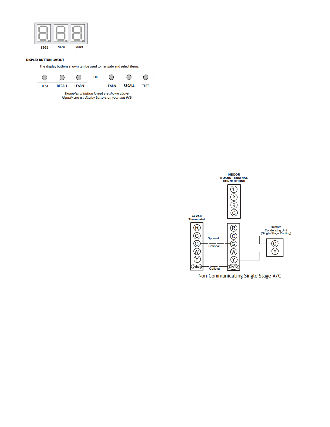
1. Use the wiring diagrams on the next page to connect low
voltage thermostat wires.
NOTE: When installing the air handler with a non-communicang
heat pump, wire directly to the “O” terminal on the non-commu-
nicang heat pump. See the following gures.
Non-Communicang Single Stage A/C
Figure 10
9
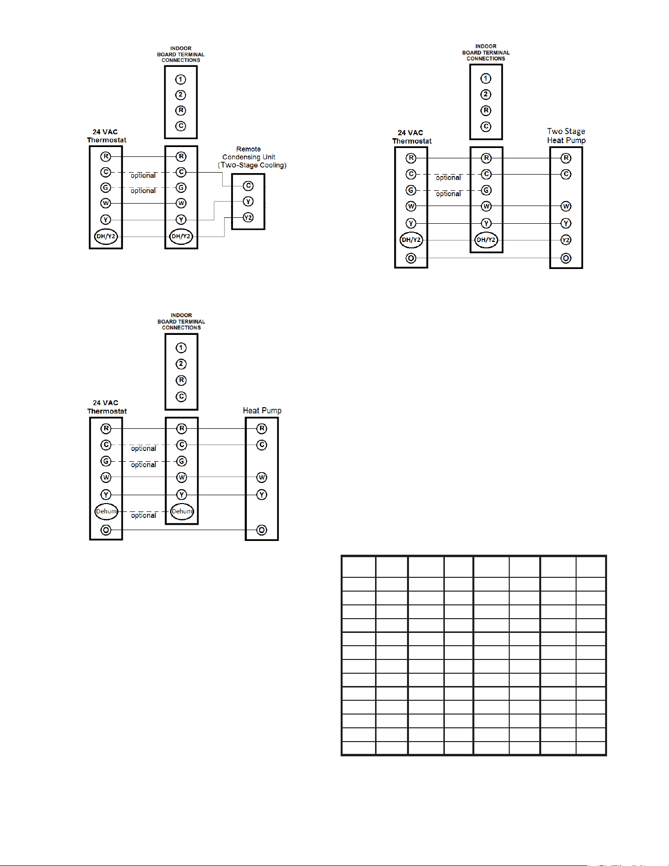
Non-Communicang Two Stage A/C
Figure 11
Non-Communicang SIngle Stage Heat Pump
Figure 12
Non-Communicang Two Stage Heat Pump
Figure 13
2. Download the CoolCloud HVAC phone applicaon.
Note: When new versions of Bluetooth Communicaon Soware
and Air Handler Control Soware are available, the phone appli-
caon noes the user. Soware updates are classied as either
oponal or mandatory and installed by using the phone applicaon.
Ensure all mandatory soware updates have been installed. Review
notes for oponal soware updates and install if necessary.
3. Go to the Non-Comm Outdoor Seng Menu (d) using
the on board push buons or the CoolCloud HVAC phone
applicaon. Select “” for single stage Air Condioners,
“” for single stage Heat Pumps, “” for two stage Air
Condioners and “” for 2 stage Heat Pumps.
4. Go to the Tonnage Units Menu () and select the tonnage
value that corresponds to the desired airow for the outdoor
unit. See the following table.
NOTE: For the two stage non-communicang outdoor units, system
will stage airow automacally for low stage operaon.
Tonnage
Selecon
Airow
Tonnage
Selecon
Airow
Tonnage
Selecon
Airow
Tonnage
Selecon
Airow
1 400 2.3 920 3.6 1440 4.9 1960
1.1 440 2.4 960 3.7 1480 5 2000
1.2 480 2.5 1000 3.8 1520 5.1 2040
1.3 520 2.6 1040 3.9 1560 5.2 2080
1.4 560 2.7 1080 4 1600 5.3 2120
1.5 600 2.8 1120 4.1 1640 5.4 2160
1.6 640 2.9 1160 4.2 1680 5.5 2200
1.7 680 3 1200 4.3 1720 5.6 2240
1.8 720 3.1 1240 4.4 1760 5.7 2280
1.9 760 3.2 1280 4.5 1800 5.8 2320
2 800 3.3 1320 4.6 1840 5.9 2360
2.1 840 3.4 1360 4.7 1880 6 2400
2.2 880 3.5 1440 4.8 1920
NOTE: The system will not provide airows above the max Airow
Value.

10
Model MAX CFM
MBVC1201AA-1 1200
MBVC1601AA-1 1600
MBVC2001AA-1 2000
5. Use the CoolCloud HVAC phone applicaon to congure/
test air handler operaons.
NOTE: The phone applicaon cannot test a non-communicang
outdoor unit. The thermostat will be required for outdoor unit
tesng.
Charging
1. Two-stage outdoor units:
a. Provide a low stage cooling call from the
thermostat and charge accordingly.
2. Single-stage outdoor units:
a. Provide a cooling call from the thermostat and
charge accordingly.
Electric Heat Kit Testing
1. Select the electric heat icon aer entering the air handler
menus in the CoolCloud HVAC phone applicaon.
2. Select any value less than 50% for low stage operaon and
any value greater than 50% for high stage operaon.
Conrm thermostat heang and cooling calls funcon properly
with equipment.
Dehumidification
Dehumidicaon allows the air handler’s circulator blower to
operate at a reduced speed during a combined thermostat call
for cooling and a dehumidicaon call from the thermostat or
humidistat. This lower blower speed increases dehumidicaon
of the condioned air as it passes through the indoor coil. The
control board is equipped with a 24 volt dehumidicaon input
(DH) located on the thermostat wiring connector. The terminal
can be congured to enable dehumidicaon when the input is
energized or de-energized. When using an external dehumidistat,
connect it between the R and DH terminals. If the humidistat
closes on humidity rise or the thermostat energizes this terminal
when dehumidicaon is required, set the control board Dehum
Logic Menu (dL) to “I” using the push buons or CoolCloud
HVAC phone applicaon. If the humidistat opens on humidity or
the thermostat de-energizes this terminal when dehumidicaon
is required, set the Dehum Logic Menu to “L” using the push
buons or CoolCloud HVAC phone applicaon.
11
Key Mitigations:
1. Full featured TS (dehum & overcool)
2. Connect G and dehum wire correctly
3. Dehumidistat
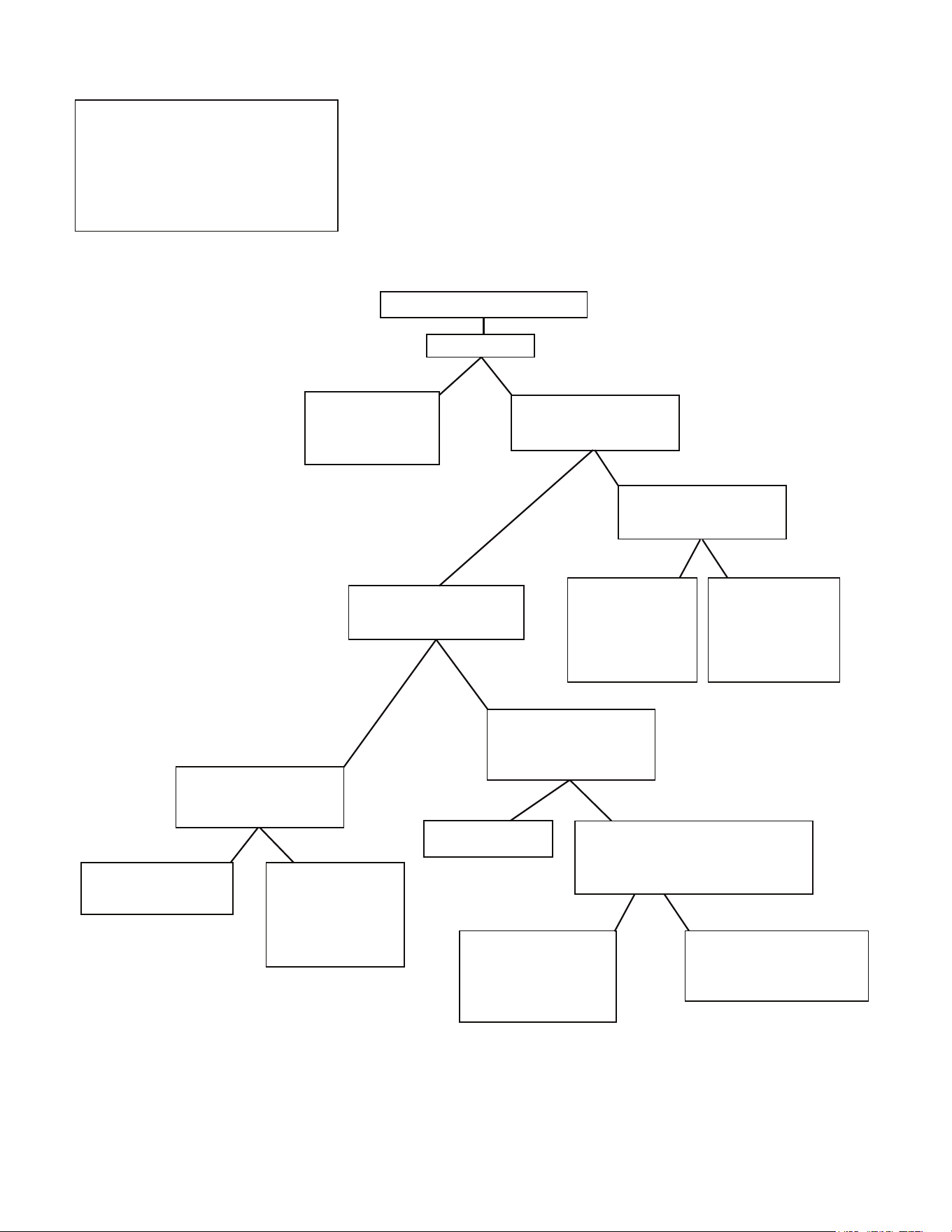
Dehumidification Control Options
1) Install Dehum wire
and DO NOT install G
Wire
2) Install Dehumidistat
in living space or
return duct
Is there a setting in the
thermostat to enable
Dehum without fan? (G)
Yes
No
During a call for Dehum,
does the thermostat
provide 24V to Dehum, Y,
and G?
Yes
No
Choose that setting
Wire the system and test
functionality
Yes
No
Wire the system and
test functionality
Dehumidification Control Options
Dry Environment
Yes
No
Install any 24VAC
thermostat on the
market - Use Y, W, G
signals
Thermostat has a Dehum or
Configurable terminal with
Dehum option
Yes
No
Does your thermostat have a
whole house Dehumidifier
setting?
Install Dehumidistat in
living space or return
duct
If the Dehumidistat
opens on a rise on
humidity, then you
will set Dehum logic
to Low via Coolcloud
app or push buttons
If the Dehumidistat
closes on a rise in
humidity, then you
will set Dehum logic
to High via Coolcloud
app or push buttons
Thermostat only sends Dehum + G on a
call for Dehum
A Dehumidistat needs to be installed in
the living space or return duct
If the Dehumidistat opens
on a rise on humidity,
then you will set Dehum
logic to Low via Coolcloud
app or push buttons
If the Dehumidistat closes on
a rise in humidity, then you will
set Dehum logic to High via
Coolcloud app or push buttons
12
Auxiliary Alarm Switch
The control is equipped with a 24VAC Aux Alarm to be used for
a condensate switch install (designated by CONDENSATE IN/OUT
on the control). By default, the connected AUX switch is normally
closed and opens when the water level in the evaporator coil base
pan reaches an undesirable level. The control responds by display-
ing a “” error code and turning o the outdoor condensing
unit. If the AUX switch is detected to be in the closed posion for
30 seconds, normal operaon resumes and the error message is
no longer displayed.
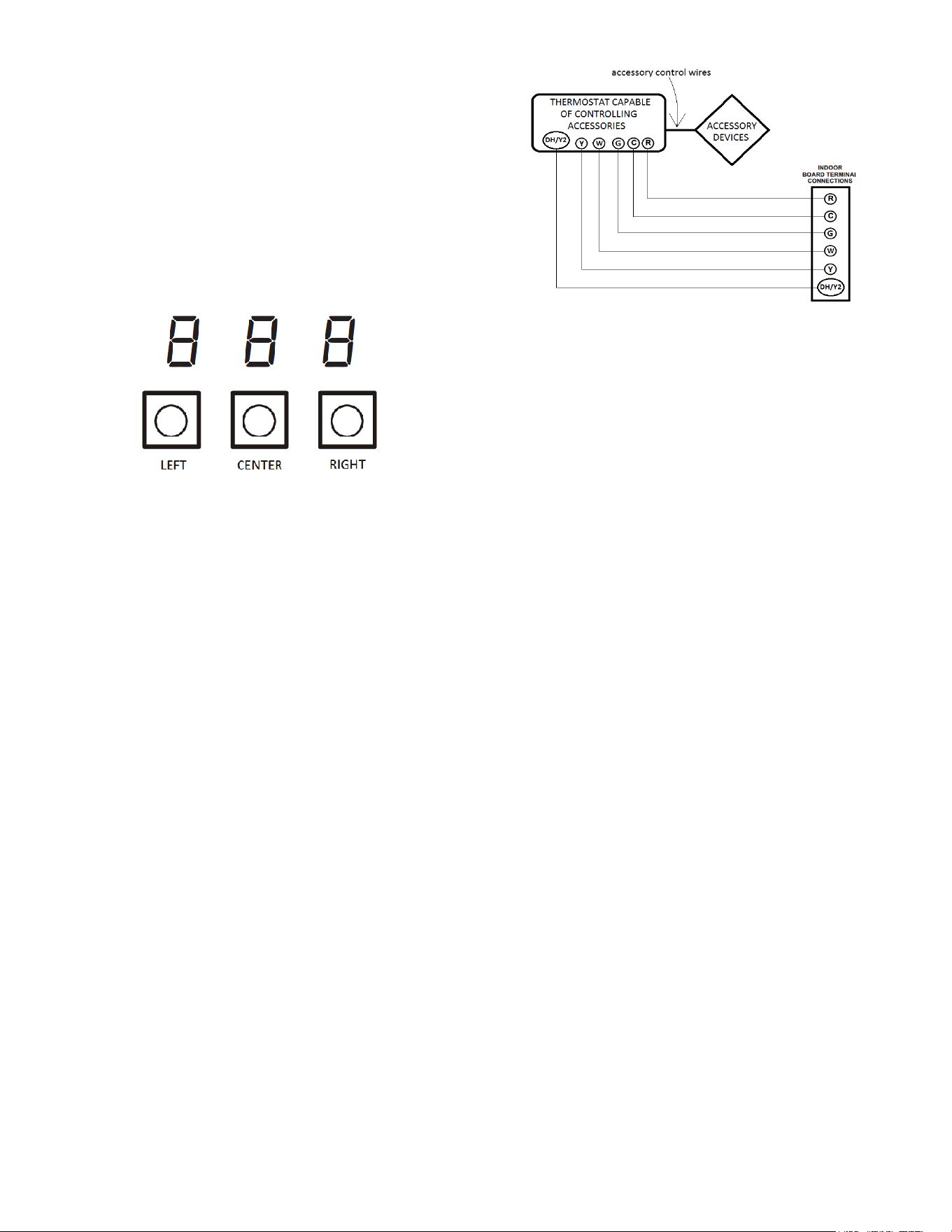
7-Segment Display and Push Buttons
Figure 14
The air handler includes three on-board push buons allowing
users to navigate indoor and outdoor system menus. The Right
and Le buons allow the user to scroll through the main menus
and to then scroll through available opons within specic menus.
The Center buon is used to enter into a main menu and to then
permanently select opons within those menus.
NOTE: Aer scrolling to the desired opon within a menu, that
opon may be ashing on the 7-segment displays. This indicates
the opon has not been ocially selected. Pressing the Center
buon two mes will select that opon. The rst press will stop
the ashing. The second will make the selecon ocial and return
you to the main menu.
Accessory Control (Humidifiers, Dehumidifiers,
Ventilators)
If an external humidier, dehumidier or venlator is installed, it
may require airow from the HVAC system to funcon properly.
1. Make sure the installed 24 VAC thermostat is capable of
controlling the accessory or accessories.
2. Connect the appropriate accessory control wires to the
accessory devices from the thermostat (see thermostat
manual for connecon and setup instrucons).
3. If the thermostat is capable of providing a connuous fan
call (G signal) during accessory operaon: Make sure to
connect the thermostat G terminal to the G terminal on the
indoor unit. Setup thermostat to ensure G signal is energized
during accessory operaon.
Figure 15
4. Select the appropriate fan only airow for the accessory
using the indoor unit push buon menus or the CoolCloud
HVAC phone applicaon.
5. Using the thermostat, independently test each accessory in
addion to the independently tesng connuous fan mode.
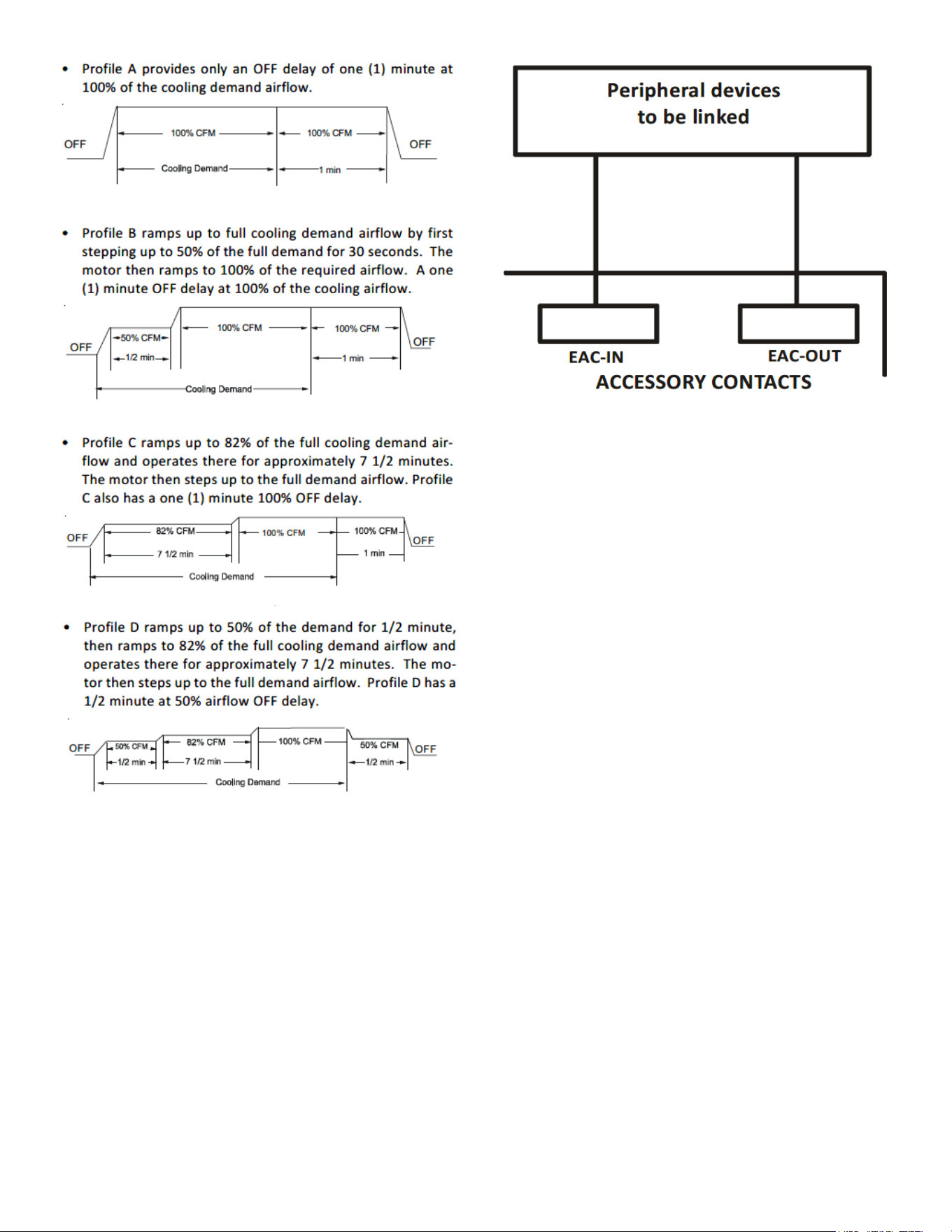
Ramping Profiles
The variable-speed circulator oers four dierent ramping proles.
These proles may be used to enhance cooling performance and
increase comfort level. Select the desired ramping prole using the
CoolCloud phone applicaon or the push buon menus.
When used with communicang outdoor units the cooling prole
must be selected in the outdoor unit menus.
When used with non-communicang outdoor units the cooling
proles must be selected in the indoor unit menus.
13
Troubleshooting
Electrostatic Discharge (ESD) Precautions
NOTE: Discharge body’s stac electricity before touching unit. An
electrostac discharge can adversely aect electrical components.
Use the following precauons during modular blower installaon
and servicing to protect the integrated control module from dam-
age. By pung the modular blower, the control, and the person
at the same electrostac potenal, these steps will help avoid
exposing the integrated control module to electrostac discharge.
This procedure is applicable to both installed and uninstalled (un-
grounded) blowers.
1. Disconnect all power to the blower. Do not touch the
integrated control module or any wire connected to the
control prior to discharging your body’s electrostac charge
to ground.
2. Firmly touch a clean, unpainted, metal surface of the
modular blower near the control. Any tools held in a
person’s hand during grounding will be discharged.
3. Service integrated control module or connecng wiring
following the discharge process in step 2. Use cauon not
to recharge your body with stac electricity; (i.e., do not
move or shue your feet, do not touch ungrounded objects,
etc.). If you come in contact with an ungrounded object,
repeat step 2 before touching control or wires.
4. Discharge your body to ground before removing a new
control from its container. Follow steps 1 through 3 if
installing the control on a blower. Return any old or new
controls to their containers before touching any ungrounded
object.
Figure 16
Electric Air Cleaner
The control is equipped with an Accessory Relay and a pair of ¼ inch
accessory terminals which is normally open, labeled EAC-IN and
EAC-OUT (see accessory contacts graphic). The Accessory Relay is
congured to close anyme the blower is running. A closed relay
means the two terminals will have connuity between them (the
control does not energize these contacts). It is recommended to
ulize 24VAC with these terminals and limit the current to 1A.
Figure 17
14
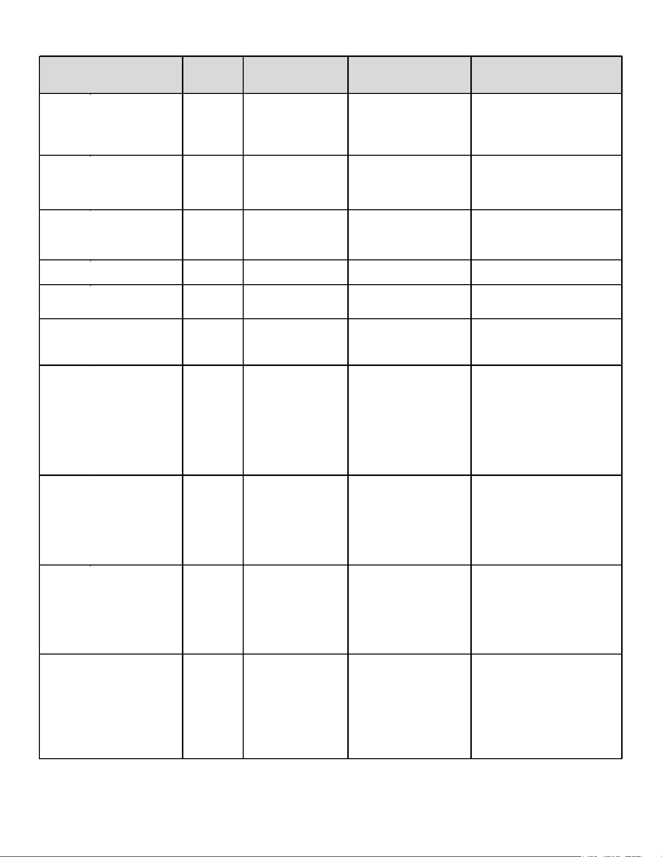
TROUBLESHOOTING MATRIX
Symptoms of Abnormal
Operation
Diagnostic
/ Status
LED Codes
Fault Description
Possible Causes
Corrective Actions
No outdoor unit operations
Communication error
with outdoor unit
Improper low voltage wiring
between the indoor and
outdoor unit
Outdoor control board lost
power duirng operation
Locate and correct improper low
voltage wiring issue
Identify reason outdoor control
board lost power during operation
No Air Handler operation
Open fuse
Short in low voltage wiring
Locate and correct short in low
voltage wiring
Replace fuse with 3-amp automotive
type
No Air Handler operation
Auxiliary switch
(condensate switch)
open or open fuse
High water level in the
evaporation coil or short in
low voltage wiring
Check evaporator drain pan, trap,
piping
Replace fuse with 3-amp automotive
type
No Air Handler operation d
Data not yet on network No network data
Populate shared data set using
memory card
No Air Handler operation d
Invalid memory card data
Air Handler blower does not
contain an appropriate shared
data set
Populate correct shared data using
memory card
Operation different than expected
or no operation
d
Invalid memory card data
Shared data set on memory
card has been rejected by
integrated control module
Verify shared data set is correct for
the specifc model. Re-populate data
using correct memory card if required
No Air Handler operation
Circulator blower motor
not running with demand
present
Loose or disconnected wiring
connection at circulator
motor power leads
Open circuit in inductor or
loose wiring connection at
inductor (3/4 Hp and 1 Hp
models only)
Failed circulator blower motor
Tighten or correct wiring connection
Verify continuous circuit through
inductor.
Replace if open or short circuit
Check circulator blower motor
No Air Handler operation
Integrated control
module has lost
communications with
circulator blower motor
Loose wiring connection at
circulator motor control leads
Failed circulator blower motor
Failed integrated control
module
Tighten or correct wiring connection
Check circulator blower motor,
replace if necessary
Check integrated control module,
replace if necessary
No Air Handler operation
Circulator blower motor
horse power in shared
data set does not match
circulator blower motor
horse power
Incorrect circulator blower
motor in Air Handler
Incorrect shared data set in
integrated control module
Verify circulator blower if motor
horse power is the same specifed for
the specifc Air Handler model,
replace if necessary
Verify shared data set is correct for
the specifc model, re-populate data
using correct memory card if required
Air Handler operates at reduced
performance
Airfow delivered is less than
expected
Circulator blower motor
is operating in a power,
temperature, or speed
limiting condition
Blocked flters
Restrictive or undersized
ductwork
High ambient temperatures
Check filters for blockage, clean
flters or remove obstruction
Check ductwork for blockage,
remove obstruction and verify all
registers are fully open
Verify ductwork is appropriately sized
for system and resize/replace ass
needed

15
TROUBLESHOOTING MATRIX (CONTINUED)
Symptoms of Abnormal Operation
Diagnostic /
Status LED
Codes
Fault Description Possible Causes Corrective Actions
No Air Handler operation
Circulator blower motor
senses a loss of rotor control
Circulator blower motor
senses high current
Abnormal motor loading, sudden
change in speed or torque, sudden
blockage of air handler air inlet or
outlet
Check filters, filter grills/registers, duct
system and air handler inlet/outlet for
blockages
No
Air Handler operation
Circulator blower motor fails to
start 10 consecutive times
Obstruction in circulator blower
housing
Seized Circulator blower motor
bearings
Failed circulator blower motor
Check circulator blower for obstructions
Remove and repair/replace wheel/motor if
necessary
Check circulator blower motor shaft rotation
and motor, replace motor if necessary
No Air Handler operation
Circulator blower motor sh
uts
down for over or under voltage
condition
Circulator blower motor shuts
down due to over temperature
condition on power module
High or low AC line voltage to air
handler
High ambient temperatures
Check power to air handler
Verify line voltage is within the range
specified on the rating plate
No Air Handler operation
Circulator blower motor does
not have enough information
to operate properly
Motor fails to start 40
c
onsecutive times
Error with integrated control module
shared data
Verify control is populated with the correct
shared data
Air Handler operates at reduced
performance or operates on low stage
when high stage is expected
Airflow is lower than
demanded
Blocked filters or restrictive
ductwork
Undersized ductwork
Check filters for blockage, clean filters or
remove obstruction
Check ductwork for blockage, remove
obst
ruction and verify all registers are fully
open
Verify ductwork is appropriately sized for
system, resize/replace ductwork if necessary

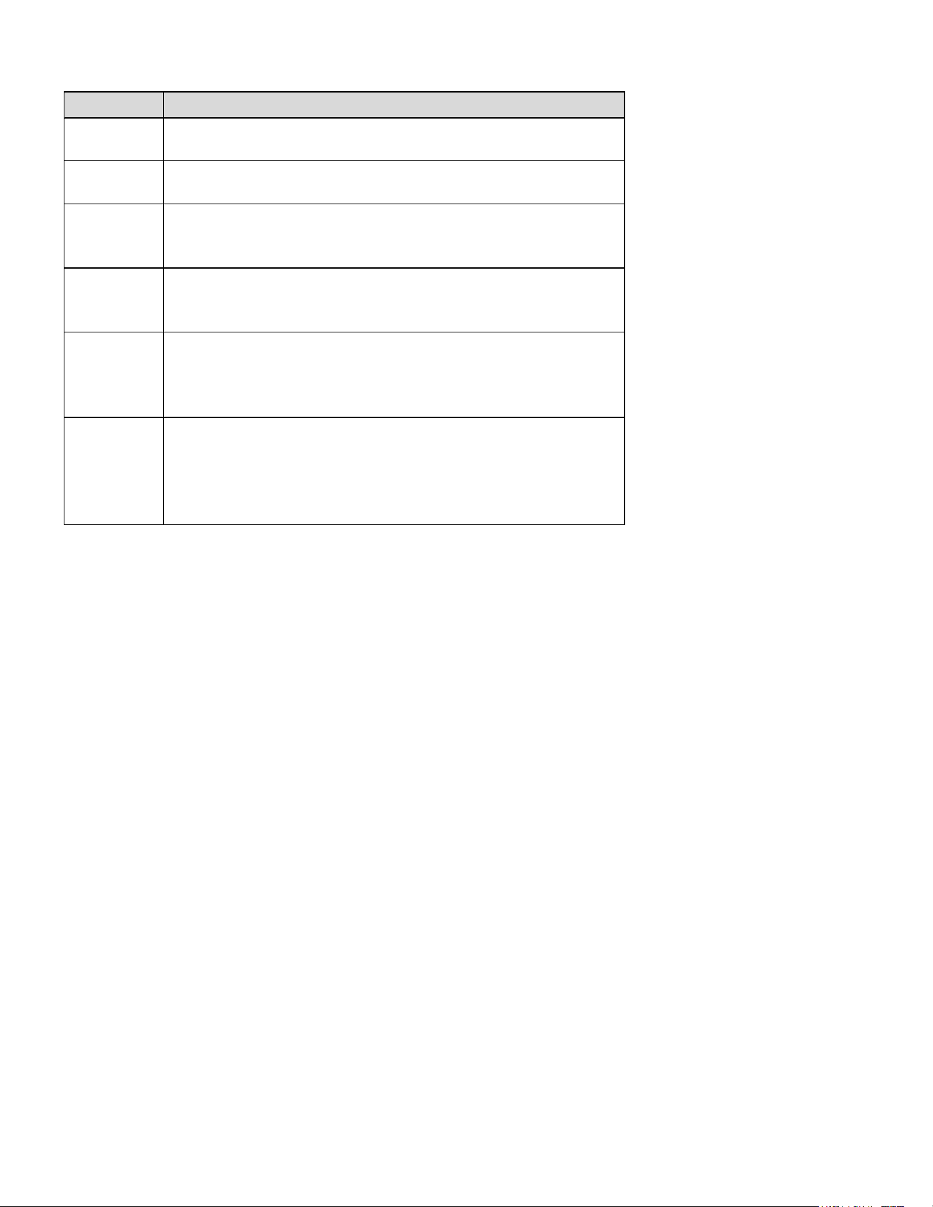
16
PUSH BUTTON MENUS
LED Display Menu Descrip�on
View 6 most recent fault codes and Clear Fault Codes if desired
(furnace)
Restart communications between the indoor and outdoor unit.
Control Firmware Revision Number
Control Shared Data Revision Number
Constant Fan Speed as percent of maximum airflow. Default = 30%
Electric Heater Kit Wattage (kW)
Electric Heat Off Delay (seconds)
Electric Heat On Delay (seconds)
Electric Heat Airflow Trim (percentage)
Percentage of high stage electric heating airflow to run duirng low
stage electric heat operation
1 = system will try to satisfy the thermostat quickly.
5 (default) = system will try to satsify the thermostat more slowly.
Select "" to enable dehumidification when the thermostat DH
terminal is energized. Select "" to enable dehumidification when
the thermostat DH terminal is de-energized. (default = )
Select number of stages for the non-communicating outdoor unit.
( for single-stage Air
Conditioners, for single stage Heat
Pumps, for two stage Air Conditioners or for two stage heat
pumps)
Indoor Airflow for non-communicating outdoor units. (values based
on 400CFM per ton) (default = 3.0 Ton)
Cooling Airflow Trim (default 0%)
Cooling Airflow Profile setting (default = profile D shown as 4)
Cooling Airflow On Delay Time (default = 5 seconds)
Cooling Airflow Off Delay Time. (default = 60 seconds)
Percentage of high stage cooling airflow to run during low stage
operation. (default = 70%)
Electric heat operation during defrost. 1 = low stage 2 (default) =
high stage
Heat Pump Indoor Airflow Trim (default = 0%)
Heat Pump Heating Airflow Off Delay Time (default = 60 seconds)
Heat Pump Heating Airflow On Delay Time (default = 5 seconds)
Percentage of high stage heat pump heating airflow to run during
low stage operation. (defaullt = 70%)
When heat pump heating and electric heat are running at the same
time, this perc
entage is used for additional airflow trim
Enables or disables dehumidification feature in the outdoor unit.
(default = Enabled)
Balance point temperature. The Compressor will not operate below
temperature. (Default = 0
°
F)
Backup Heat Balance Points
Compressor run time between defrost cycles. (default = 30 minutes)
(2 stage units)
Compressor off delay at the beginning and end of a defrost cycle.
(default = 30 seconds)
Note: When installed with an inverter outdoor unit, any change made to the inverter default sengs must be made using the push
buon on the outdoor unit control board. See inverter unit installaon manual for push buon menu instrucons.
17
PUSH BUTTON MENUS (CONTINUED)
LED Display Menu Descrip�on
View 6 most recent fault codes and Clear Fault Codes if desired
(outdoor communicating units)
Menu is enabled if the
menu is set to 6. Select the target time
the system will attempt to satisfy the thermostat.
Menu is enabled if the
menu is set to 6. Select the percentage
past the target time when the system will enable electric heat
operation during heat mode.
Menu is enabled if the
is set to 6. (Electric heat will run during
the next heat call if the heat pump fails to satisfy the custom target
time fo
r this number of consecutive cycles) (default = 20 cycles)
Menu is enabled if the
menu is set to 6. (if the addition of low
stage electric heat is able to consecutively satisfy the thermostat
under the set target time for this number of cycles, the system will
transition to the heat pump for primary heating)
Menu is enabled if the
menu is set to 6. (this percentage will
help determine when switching back to heat pump only operation is
appropriate. Default = 20%. If target time = 20 minutes, the addtion
of low stage electric heat must staisf
y the thermostat by less than 16
minutes. (target time - 20% default = 16 minutes).
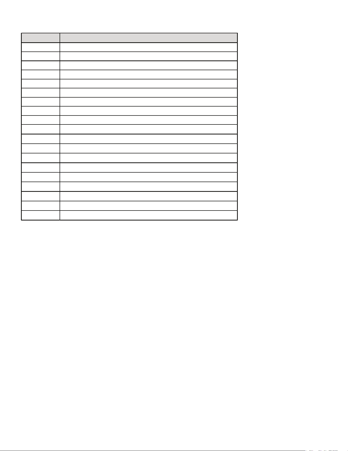
18
SYSTEM STATUS DISPLAY
LED Display Descrip�on of System Status
Idle
Constant Fan
Compressor Cooling, Single-Stage (non-comm units)
Compressor Cooling, Low Stage (non-comm units)
Compressor Cooling, High Stage (non-comm units)
Compressor Cooling, Low Stage (comm units)
Compressor Cooling, High Stage (comm units)
Compressor Heat, Single-Stage (non-comm. units)
Compressor Heat, Low Stage (non-comm units)
Compressor Heat, High Stage (non-comm units)
Compressor Heat, Low Stage (Comm Units)
Compressor Heat, High Stage (Comm Units)
Electric Heat, Single Stage
Electric Heat, Low Stage
Electric Heat, High Stage
*
Defrost, Single Stage Electric Heat (non-comm units)
Defrost, Low Stage Electric Heat
Defrost, High Stage Electric Heat
Dehumidification
* If a system is a heat pump connected legacy, then a DFT will show on the
board in 2 instances.
1. If the heat pump calls for a defrost, Y and a W will be energized resulting
in a DFT code on the air-handler display.
2. If the heat pump calls for auxiliary heat, Y and a W will be energized
resulting in a DFT code on the air-handler display.
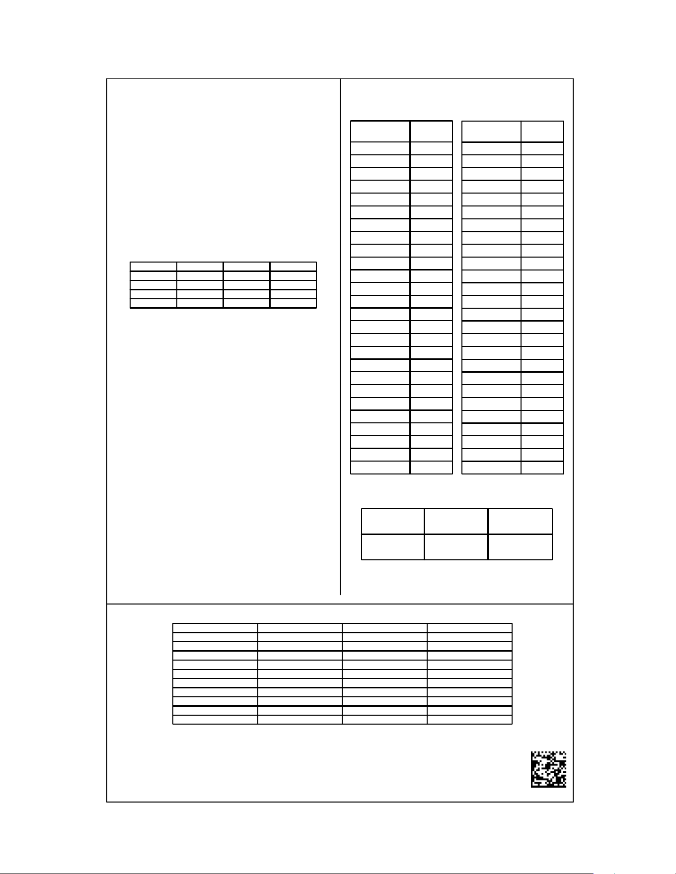
19
AIRFLOW LABEL
0140A00706-A
Airflow Settings Instructions
1) For non-communicating installations, select the type of unit installed
in the OdS menu (1AC = single-stage air conditioner,
1HP = single-stage heat pump, 2AC = 2 stage air conditioner,
2HP = 2 stage heat pump) Default = OFF (no outdoor unit).
2) Use the Tonnage Menu (ton) to select Cooling/Heat Pump Airflow
(non-communicating installation). Tonnage selection options and
corresponding airflow CFM can be found to the right.
[Airflow = Tonnage Selection x 400] Default selection is 6.0 tons.
3) [Optional] Use the Cooling Trim Menu (CtF
) to adjust the cooling
airflow from -10% to +10% (2% increments). This applies for 2
stage communicating outdoor units and single or 2 stage
non-communicating outdoor units. For inverter outdoor units use
Cooling Trim Factor High, Intermediate and Low menus (CtH, CtI,
and CtL) for trim adjustment.
4) [Optional] Use the Heating Trim Menu (HtF
to adjust the heat pump
airflow from -10% to +10% (2% increments). This applies for 2
stage communicating outdoor units and single or 2 stage
non-communicating outdoor units. For inverter outdoor units use
Heating Trim Factor High,
Intermediate and Low menus (HtH, HtI,
and HtL) for trim adjustment.
5) [Optional] Use the Constant Fan Menu (FSD) to select the
percentage of maximum airflow for continuous fan
6) [Optional] Use the Cooling Airflow Profile Menu (CAP) to select
between 4 cooling airflow profiles. Profile options 1-4 are listed above.
See installation manual for further details
Profiles
Pre-Run Short-Run OFF Delay
1 -------- -------- 60 sec/100%
2 -------- 30 sec/50% 60 sec/100%
3 -------- 7.5 min/82% 60 sec/100%
4 30 sec/50% 7.5 min/82% 60 sec/100%
Selecting Heater Kit: Use the Electric Heating Wattage Menu (EHt) to select heater kit size. See "Menu Navigation and Selection
Instructions" above. Default selection is 0 (No Heat Kit). Select installed heater kit for heater kit operation.
NR - Not Rated
Electric Heat Airflow Table
Menu Navigation and Selection Instructions
Using Phone Application over Bluetooth Network:
1) Connect to the air handler (instructions provided by phone during
connection process).
2) Select desired settings menu
3) Select item that requires adjustment and make necessary selection
4) Submit Changes
Using On-Board Push Buttons:
1) Use the Right and Left Buttons to scroll between menus
2) Use the Center Button to select desired menu when menu code is
shown on 7-segment displays
3) Use the Left and Right Buttons to scroll through options within the
desired menu (the display will flash while scrolling through opt
ions for
selection)
4) Use the Center Button to select the displayed option (when selected
the display will stop flashing)
5) Use the Center Button to finalize selection and return to the main
menu
*If airflow is set above the model's maximum value, the output will be the
maximum value
Maximum Airflow Output
Tonnage
Selection
Airflow
1.0 400
1.1 440
1.2 480
1.3 520
1.4 560
1.5 600
1.6 640
1.7 680
1.8 720
1.9 760
2.0 800
2.1 840
2.2 880
2.3 920
2.4 960
2.5 1000
2.6 1040
2.7 1080
2.8 1120
2.9 1160
3.0 1200
3.1 1240
3.2 1280
3.3 1320
3.4 1360
3.5 1400
Tonnage Menu (t o n)
Tonnage
Selection
Airflow
3.5 1400
3.6 1440
3.7 1480
3.8 1520
3.9 1560
4.0 1600
4.1 1640
4.2 1680
4.3 1720
4.4 1760
4.5 1800
4.6 1840
4.7 1880
4.8 1920
4.9 1960
5.0 2000
5.1 2040
5.2 2080
5.3 2120
5.4 2160
5.5 2200
5.6 2240
5.7 2280
5.8 2320
5.9 2360
6.0 2400
MBVC1201AA-1 MBVC1601AA-1 MBVC2001AA-1
1400 2000 2000
Htr Kw MBVC1201AA-1 MBVC1601AA-1 MBVC2001AA-1
3 600 800 800
5 600 800 800
6 635 800 800
8 740 1000 1000
10 1000 1000 1200
15 1400 1500 1500
19 NR NR NR
20 NR NR NR
21 NR NR NR
25 NR NR NR
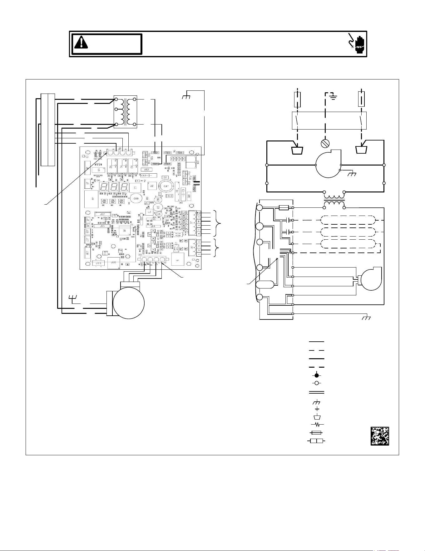
20
Wiring is subject to change, always refer to the wiring diagram on the unit for the most up-to-date wiring.
HIGH VOLTAGE!
DISCONNECT ALL POWER BEFORE SERVICING.
MULTIPLE POWER SOURCES MAY BE PRESENT. FAILURE TO DO SO
MAY CAUSE PROPERTY DAMAGE, PERSONAL INJURY OR DEATH.
WARNING
Wiring Diagram
CIRCULATOR BLOWER
1
1
CIRCULATOR
CIRCULATOR
RD
WH
TO
MICRO
AUX IN
AIR
230 VAC
PL1
SEE
NOTE 7
DEHUM
24 VAC
RD
4
BLWR
5
AIR
40 VA
8
40 VA TRANSFORMER, SEE NOTE 1
L1
9
INDOOR
7
24 VAC
4
BK
1
5
BL
PL2
FUSE 3 A
208/230 VAC
GRND
ECM MOTOR
HARNESS
GRND
6
L2
6
L1
COM
BR
G
INTEGRATED CONTROL MODULE
W
BK
3
24V THERMOSTAT CONNECTIONS
COM
L2
DISCONNECT
BL
BK
TR2
C
3
GRND (4)
2
2
INDOOR
9
RD
TH2
+VDC (1)
Y
208 VAC
BK
RX (2)
RD
GRND
GRND
4
GN
R
8
5
EH1
RD
TX (3)
BL
3
GRND
ELECTRIC STAGE 2
RD
TRANSFORMER
ELECTRIC HEAT STAGE 1
GN
7
2
BLWR
EQUIPMENT GRND
TERMINAL
PLUG CONNECTION
LOW VOLTAGE FIELD
HI VOLTAGE FIELD
JUNCTION
HI VOLTAGE (230V)
PROT. DEVICE
INTEGRATED CONTROL
LOW VOLTAGE (24V)
FIELD SPLICE
INTERNAL TO
FIELD GRND
OVERCURRENT
BK ---- BLACK
OR ---- ORANGE
BL ---- BLUE
PK ---- PINK
GY ---- GRAY
RD ---- RED
WH ----WHITE
PU ---- PURPLE
YL ---- YELLOW
BR ---- BROWN
COLOR CODES:
GN ---- GREEN
NOTES:
1. PLACE RED WIRES ON TRANSFORMER TERMINAL 2 FOR 208 VAC OPERATION.
2. MANUFACTURER'S SPECIFIED REPLACEMENT PARTS MUST BE USED WHEN SERVICING.
3. IF ANY OF THE ORIGINAL WIRES AS SUPPLIED WITH THIS UNIT MUST BE REPLACED, IT MUST BE REPLACED WITH WIRING MATERIAL
HAVING A TEMPERATURE RATING OF AT LEAST 105°C. USE COPPER CONDUCTORS
ONLY.
4. UNIT MUST BE PERMANENTLY GROUNDED AND CONFORM TO N.E.C AND LOCAL CODES.
5. TO RECALL THE LAST 6 FAULTS, DEPRESS THE RIGHT PUSH BUTTON FROM STATUS MENU ONCE AND THEN
USE THE LEFT OR RIGHT BUTTON TO REVIEW ALL THE FAULTS HISTORY.
6. 2 GREEN LEDS INDICATES CLIMATE TALK AND DATAAC NETWORK TRAFFIC STATUS. USE LEARN MENU FOR CLIMATE TALK NETWORK RESET.
7. DISCARD CONNECTOR PL1 WHEN INSTALLING OPTIONAL HEAT KIT.
8. THE CONDENSATE ALARM
SWITCH (AUX) TERMINALS CAN ONLY BE UTILIZED WITH COMMUNICATING MODE SETUPS AND MUST BE ENABLED WITH
COMMUNICATING THERMOSTAT. THIS FEATURE IS NOT OPERATIONAL WITH NON COMMUNICATING SYSTEMS.
9. USE N.E.C CLASS 2 WIRE.
10. SEE MANUAL FOR PUSH BUTTON OPERATION
11.
SEE MANUAL FOR 7-SEGMENT DISPLAY DIAGNOSTIC CODES AND MENU CODES
12. SEE MANUAL FOR LEDS FUNCTIONALITY
13. R AND C TERMINALS (USED FOR 24VAC OUTDOOR CONTROL VOLTAGE) ARE OPTIONAL FOR 2 STAGE COMMUNICATING
AIR CONDITIONERS. R AND C TERMINALSARE NOT TO BE USED FOR 2 STAGE COMMUNICATING HEAT PUMP APPLICATIONS.
FOR COMMUNICATING HEAT PUMP OR IF ONLY TWO THERMOSTAT WIRES ARE AVAILABLE, A SEPARATE TRANSFORMER
MUST BE INSTALLED IN THE OUTDOOR UNIT FOR CONTROL BOARD POWER.
1 AND 2 WIRES ARE REQUIRED FOR ALL APPLICATIONS. SEE INSTALLATION MANUAL FOR FULL SYSTEM WIRING EXAMPLES.
0140A00705-A
1
2
3
CONDENSATE SWITCH
AUX OUT
EH2
RESISTOR
4 3
2
1
SEE NOTE 9
4 - GND
NC
SEE NOTE 6
THERMOSTAT
OUTDOOR UNIT
(SEE NOTE 13)
21
AIR HANDLER
AIR HANDLER HOMEOWNER’S ROUTINE MAINTENANCE RECOMMENDATIONS
We strongly recommend a bi-annual maintenance checkup be performed
before the heang and cooling seasons begin by a qualied servicer.
REPLACE OR CLEAN FILTER
IMPORTANT NOTE: Never operate unit without a lter installed
as dust and lint will build up on internal parts resulng in loss of
eciency, equipment damage and possible re.
An indoor air lter must be used with your comfort system. A
properly maintained lter will keep the indoor coil of your comfort
system clean. A dirty coil could cause poor operaon and/or severe
equipment damage.
Your air lter or lters could be located in your furnace, in a blower
unit, or in “lter grilles” in your ceiling or walls. The installer of your
air condioner or heat pump can tell you where your lter(s) are,
and how to clean or replace them.
Check your lter(s) at least once a month. When they are dirty,
replace or clean as required. Disposable type lters should be
replaced. Reusable type lters may be cleaned.
You may want to ask your dealer about high eciency lters. High
eciency lters are available in both electronic and non-electronic
types. These lters can do a beer job of catching small airborne
parcles.
MOTORS
Indoor and outdoor fan motors are permanently lubricated and do
not require addional oiling.
ALUMINUM INDOOR COIL CLEANING
(QUALIFIED SERVICER ONLY)
This unit is equipped with an aluminum tube evaporator coil. The
safest way to clean the evaporator coil is to simply ush the coil
with water. This cleaning pracce remains as the recommended
cleaning method for both copper tube and aluminum tube resi-
denal evaporator coils.
It has been determined that many coil cleaners and drain pan tab-
lets contain corrosive chemicals that can be harmful to aluminum
tube and n evaporator coils. Even a one-me applicaon of these
corrosive chemicals can cause premature aluminum evaporator coil
failure. Any cleaners that contain corrosive chemicals including,
but not limited to, chlorine and hydroxides, should not be used.
An alternate cleaning method is to use one of the products listed in
TP-109* to clean the coils. The cleaners listed are the only agents
deemed safe and approved for use to clean round tube aluminum
coils. TP-109 is also available on the web site in Partner Link >
Service Toolkit.
NOTE: Ensure coils are rinsed well aer use of any chemical cleaners.
BEFORE YOU CALL YOUR SERVICER
• Check the thermostat to conrm that it is properly set.
• Wait 15 minutes. Some devices in the outdoor unit or
in programmable thermostats will prevent compressor
operaon for awhile, and then reset automacally. Also,
some power companies will install devices which shut o
air condioners for several minutes on hot days. If you wait
several minutes, the unit may begin operaon on its own.
• Check the electrical panel for tripped circuit breakers or
failed fuses. Reset the circuit breakers or replace fuses as
necessary.
• Check the disconnect switch near the indoor furnace or
blower to conrm that it is closed.
• Check for obstrucons on the outdoor unit . Conrm that
it has not been covered on the sides or the top. Remove
any obstrucon that can be safely removed. If the unit is
covered with dirt or debris, call a qualied servicer to clean
it.
• Check for blockage of the indoor air inlets and outlets.
Conrm that they are open and have not been blocked by
objects (rugs, curtains or furniture).
• Check the lter. If it is dirty, clean or replace it.
• Listen for any unusual noise(s), other than normal operang
noise, that might be coming from the outdoor unit. If you
hear unusual noise(s) coming from the unit, call a qualied
servicer.
22
Air Handler / Coil
ELECTRICAL
Line Voltage (Measure L1 and L2 Voltage) L1 - L2
Secondary Voltage (Measure Transformer Output Voltage) R - C
Blower Amps
Heat Strip 1 - Amps
Heat Strip 2 - Amps
BLOWER EXTERNAL STATIC PRESSURE
Return Air Static Pressure IN. W.C.
Supply Air Static Pressure IN. W.C.
Total External Static Pressure (Ignoring +/- from the reading above, add total here) IN. W.C.
TEMPERATURES
Return Air Temperature (Dry bulb / Wet bulb) DB °F WB °F
DB °F WB °F
Heating Supply Air Temperature DB °F
Temperature Rise DB °F
Delta T (Difference between Supply and Return Temperatures) DB °F
Air Handler / Coil - (Inverter Matched)
INVERTER AH / COIL ONLY
Check EEV and EEV wiring is secure (no adjustment required)
Additional Checks
Check wire routings for any rubbing
Check product for proper draining
Check screw tightness on blower wheel
Check factory wiring and wire connections
Check product for proper clearances as noted by installtion instructions
°F to °C formula: (°F - 32) divided by 1.8 = °C °C to °F formula: (°C multiplied by 1.8) + 32 = °F
Model Number
Serial Number
Cooling Supply Air Temperature (Dry bulb / Wet bulb)

23
THIS PAGE INTENTIONALLY LEFT BLANK
24
NOTE: SPECIFICATIONS AND PERFORMANCE DATE LISTED HEREIN ARE SUBJECT TO CHANGE WITHOUT NOTICE.
Visit our website at www.goodmanmfg.com or www.amana-hac.com for informaon on:
• Products • Parts
• Warranes • Contractor Programs and Training
• Customer Services • Financing Opons
Goodman Manufacturing Company, L.P.
19001 Kermier Rd. • Waller, TX 77484
©2019 - 2021
is a registered trademark of Maytag or its related companies and is used under license. All rights reserved.
CUSTOMER FEEDBACK
We are very interested in all product comments.
Please ll out the feedback form on one of the following links:
Goodman
®
Brand Products: (http://www.goodmanmfg.com/about/contact-us).
Amana
®
Brand Products: (http://www.amana-hac.com/about-us/contact-us).
You can also scan the QR code on the right for the product brand
you purchased to be directed to the feedback page.
GOODMAN
®
BRAND
AMANA
®
BRAND
GOODMAN
®
BRAND
AMANA
®
BRAND
PRODUCT REGISTRATION
Thank you for your recent purchase. Though not required to get the protection of
the standard warranty, registering your product is a relatively short process, and
entitles you to additional warranty protection, except that failure by California and
Quebec residents to register their product does not diminish their warranty rights.
For Product Registration, please register as follows:
Goodman
®
Brand products: (https://www.goodmanmfg.com/product-registration).
Amana
®
Brand products: (http://www.amana-hac.com/product-registration).
You can also scan the QR code on the right for the product brand
you purchased to be directed to the Product Registration page.