Café Models
This video provides an overview of what is needed to install a Café
Dishwasher Drawer.
It is intended as an overview only of the installation process and is not
intended to be used as a guide on how to install the Café Dishwasher
Drawer yourself.
If you have questions about your Café Dishwasher Drawer, visit our website at
cafeappliances.com.
Profile Models
This video provides an overview of what is needed to install a Profile
Dishwasher Drawer.
It is intended as an overview only of the installation process and is not
intended to be used as a guide on how to install the Profile Dishwasher
Drawer yourself.
If you have questions about your Profile Dishwasher Drawer, visit our website at
GEAppliances.com, or call GE Appliances at 833-4BODEWELL (833-426-3393).
WARNING
CAUTION
FOR YOUR SAFETY
Read and observe all WARNINGS and CAUTIONS shown throughout these instructions.
IMPORTANT – Observe all governing codes and ordinances.
ŶNote to Installer – Be sure to leave these instructions for the consumer’s and
local inspector’s use.
ŶNote to Consumer – Keep these instructions with your Owner’s Manual for
future reference.
ŶSkill Level – Installation of this dishwasher requires basic mechanical, electrical
and plumbing skills. Proper installation is the responsibility of the installer.
Product failure due to improper installation is not covered under the
GE Appliances Warranty. See Warranty information.
ŶCompletion Time – 1 to 3 Hours. New installations require more time than
replacement installations.
IMPORTANT – The dishwasher MUST be installed to allow for future removal from
the enclosure if service is required.
Care should be exercised when the appliance is installed or removed, to reduce the
likelihood of damage to the power supply cord.
If you received a damaged dishwasher, immediately contact your dealer or builder.
Your dishwasher is a water heating appliance.
BEFORE YOU BEGIN - Read these instructions completely and carefully.
Ŷ
To reduce the risk of electric shock, fire, or injury to persons, the installer must
ensure that the dishwasher is completely enclosed at the time of installation.
Ŷ
FOR PERSONAL SAFETY: Remove house fuse or open circuit breaker before
beginning installation. Do not use an extension cord or adapter plug with this
appliance.
Ŷ
The improper connection of the equipment grounding conductor can result in a
risk of electric shock. Check with a qualified electrician or service representative
if you are in doubt that the appliance is properly grounded.
Ŷ
If house wiring is not 2-wire with ground, a ground must be provided by the installer.
When house wiring is aluminum, be sure to use UL-Listed anti-oxidant
compound and aluminum-to-copper connectors.
Ŷ
To reduce the risk of electric shock, fire, or injury to persons, the installer should
check to ensure that wires
are not pinched or damaged, the house wiring is attached
to the dishwasher through a strain relief, and
all electrical connections made at
the time of install
are contained inside of the terminal block cover.
Ŷ
For models equipped with power cord: Do not modify the plug provided
with the appliance; if it will not fit the outlet, have a proper outlet installed by a
qualified technician.
While performing installations described in this booklet, gloves, safety glasses
or goggles should be worn.
Installation Instructions Dishwasher Drawer
Opening a drawer will cause the dishwasher to tip
forward when it is not fully installed. When opening
a drawer prior to the dishwasher being fully installed, hold the drawer
handle securely with one hand and the top of the dishwasher with the
other hand. Gloves should be worn.
CAUTION
READ CAREFULLY - KEEP THESE INSTRUCTIONS
2
Precauciones en Español
PARA SU SEGURIDAD
Lea y cumpla con todas las ADVERTENCIAS y PRECAUCIONES que figuran
en estas instrucciones.
IMPORTANTE – Cumpla con todos los códigos y ordenanzas gubernamentales.
ŶNota para el Instalador – Asegúrese de entregar estas instrucciones al consumidor
y al inspector local.
ŶNota para el Consumidor – Guarde estas instrucciones con su Manual del
Propietario para referencia futura.
Ŷ Nivel de habilidad – La instalación de este lavavajillas requiere un nivel básico
de habilidades mecánicas, eléctricas y de plomería. La correcta instalación
del producto es responsabilidad del instalador. Si se producen fallas en el
producto debido a una instalación inadecuada, la Garantía del Producto de
GE Appliances no cubrirá las mismas. Consulte la información de la Garantía.
ŶTiempo de instalación – 1 y 3 Horas. Las instalaciones nuevas requieren más
tiempo que las instalaciones de reemplazo.
IMPORTANTE – El lavavajillas DEBE ser instalado para permitir el retiro futuro de
su ubicación, si se requiere realizar el servicio técnico.
Se deberá tener cuidado cuando el electrodoméstico sea instalado o retirado, a fin
de reducir la posibilidad de daños sobre el cable de suministro eléctrico.
Si el lavavajillas que recibió está dañado, se debería comunicar de inmediato con
su vendedor o fabricante.
Su lavavajillas es un electrodoméstico donde se calienta agua.
ANTES DE COMENZAR - Lea estas instrucciones en su totalidad y atentamente.
Ŷ
Para reducir el riesgo de descarga eléctrica, incendio o lesiones a personas, el
instalador debe asegurarse de que el lavaplatos esté completamente cerrado en el
momento de la instalación.
Ŷ
PARA SEGURIDAD PERSONAL: Quite el fusible o abra el interruptor de
circuitos antes de comenzar la instalación. No utilice un cable de extensión o un
enchufe adaptador con este artefacto.
Ŷ
La conexión inadecuada del conductor de conexión a tierra del equipamiento
puede provocar un riesgo de descarga eléctrica. Consulte a un electricista
FDOL¿FDGRRUHSUHVHQWDQWHGHVHUYLFLRWpFQLFRVLWLHQHGXGDVVREUHODFRUUHFWD
conexión a tierra del aparato.
Ŷ
Si el cableado doméstico no cuenta con un cable de 2 hilos con conexión a
tierra, un instalador debe realizar una conexión a tierra. Cuando el cableado
doméstico es de aluminio, asegúrese de usar un compuesto antioxidante y
conectores de aluminio a cobre aprobados por UL.
Ŷ
Para reducir el riesgo de descarga eléctrica, incendio o
lesiones a personas,
el instalador deberá realizar un
control para asegurar que los cables no estén
pellizcados
ni dañados, que el cableado del hogar esté conectado a la ficha de la caja
de empalmes a través de un amortiguador
de refuerzo, y que todas las conexiones
eléctricas
realizadas en el momento de la instalación (tuercas para
cables) estén
dentro de la tapa de la caja de empalmes.
While performing installations described in this booklet, gloves, safety glasses
or goggles should be worn.
ADVERTENCIA
PRECAUCIÓN
Abrir un cajón hará que el lavavajillas se incline hacia adelante
cuando no esté completamente instalado. Cuando abra un
cajón antes de que el lavavajillas esté completamente instalado,
sostenga la manija del cajón firmemente con una mano y la parte
superior del lavavajillas con la otra mano. Deben usarse guantes.
PRECAUCIÓN
LEA DETENIDAMENTE
CONSERVE ESTAS INSTRUCCIONES
3
Installation Preparation
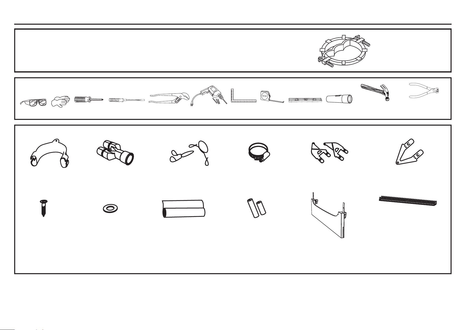
PARTS SUPPLIED IN INSTALLATION PACKAGE
If the drain hoses supplied are not long enough to reach your services, you must use a Drain Hose Extension Kit WD24X30798 which will extend the drain hoses by 11’ 10” (3.6m).
The kit is available from bodewell.com/schedule-repair-service or by phone at 833-4BODEWELL (833-426-3393) during normal business hours.
Clamp (1)
(for securing
Drain hose joiner)
Wire clip (2)
(for securing
Drain hose joiner)
Phillips
»´PP
screws (9)
Drain hose
support (1)
Moisture protection
tape (1)
(to prevent moisture
damage to cabinetry)
Drain hose
joiner (1)
Top
mounting
brackets (2)
OPTIONAL
Prefinished
toekick (1)
Edge Protector (1)
(If the services hole is through a
metal partition, the hole must be
protected with the Edge Protector
supplied to prevent damage to the
power cord or hoses.)
Rubber washer
for inlet hose (1)
(comes already
fitted)
Hexagonal
socket for feet
adjustment (2)
(long & short)
Side mounting
bracket kit
(A and B) (2)
OPTIONAL
NOTE: Consider recycling options for your appliance packaging material.
TOOLS YOU WILL NEED
Measuring
Tape
Phillips-Head
Screwdriver
Flashlight
GlovesSafety Glasses
Flat Head
Screwdriver
Carpenter’s
Square
Hammer
(For Hardwired
Installations Only)
USA
Flush Edge Wire Cutters
(For Hardwired
Installations Only)
Level
PART YOU WILL NEED - Strain Relief Clamp (For Hardwired Installations Only)
Drill and Bits
Pliers
(Channel Lock)
4
Installation Preparation
FOR PERSONAL SAFETY: Remove house fuse or open circuit breaker before
beginning installation.
Do not use an extension cord or adapter plug with this appliance.
WARNING
The improper connection of the equipment grounding conductor can result in a risk
of electric shock. Check with a qualified electrician or service representative if you
are in doubt that the appliance is properly grounded.
WARNING
PREPARE ELECTRICAL WIRING
ELECTRICAL REQUIREMENTS
Be sure that the electrical connection and wire size are adequate and in conformance
with the National Electric Code, ANSI/NFPA 70 – latest edition, and all local codes
and ordinances.
This appliance must have:
• 120V, 60Hz, AC-only, 15-ampere or 20-ampere, fused electrical supply.
• Wiring must be 2 wire with ground and rated for 75°C (167°F).
• If the electrical supply does not meet the above requirements, call a licensed
electrician before proceeding.
It is recommended to have:
• A circuit breaker or time-delay fuse.
• A properly grounded individual branch circuit.
Grounding Instructions–Permanent Connection
This appliance must be connected to a grounded metal, permanent wiring system,
or an equipment-grounding conductor must be run with the circuit conductors and be
connected to the equipment-grounding terminal or lead on the appliance.
Grounding Instructions–Power Cord Models
This appliance must be grounded. In the event of a malfunction or breakdown,
grounding will reduce the risk of electric shock by providing a path of least resistance
for electric current. This appliance is equipped with a cord having an equipment-
grounding conductor and a grounding plug. The plug must be plugged into an
appropriate outlet that is installed and grounded in accordance with all local codes
and ordinances.
For models equipped with power cord: Do not modify the plug provided with
the appliance; if it will not fit the outlet, have a proper outlet installed by a qualified
technician.
WARNING
La conexión inadecuada del conductor de conexión a tierra del equipamiento puede
SURYRFDUXQULHVJRGHGHVFDUJDHOpFWULFD&RQVXOWHDXQHOHFWULFLVWDFDOL¿FDGRR
representante de servicio técnico si tiene dudas sobre la correcta conexión a tierra
del aparato.
ADVERTENCIA
Con los modelos equipados con cable de corriente: No modifique el enchufe
provisto con el electrodoméstico; si no coincide con el tomacorriente, solicite la
instalación de un tomacorriente apropiado a un electricista calificado.
ADVERTENCIA
PARA SEGURIDAD PERSONAL: Quite el fusible o abra el interruptor de circuitos
antes de comenzar la instalación. No utilice un cable de extensión o un enchufe
adaptador con este artefacto.
ADVERTENCIA
5
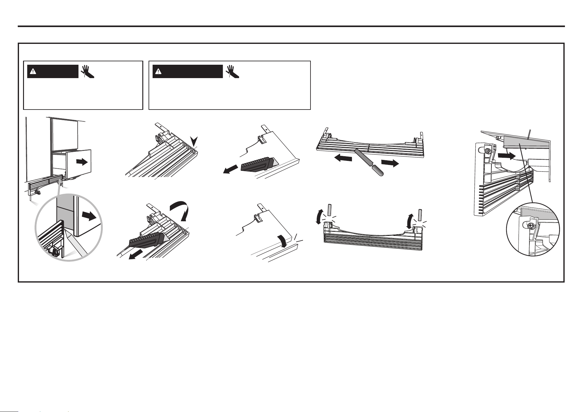
2
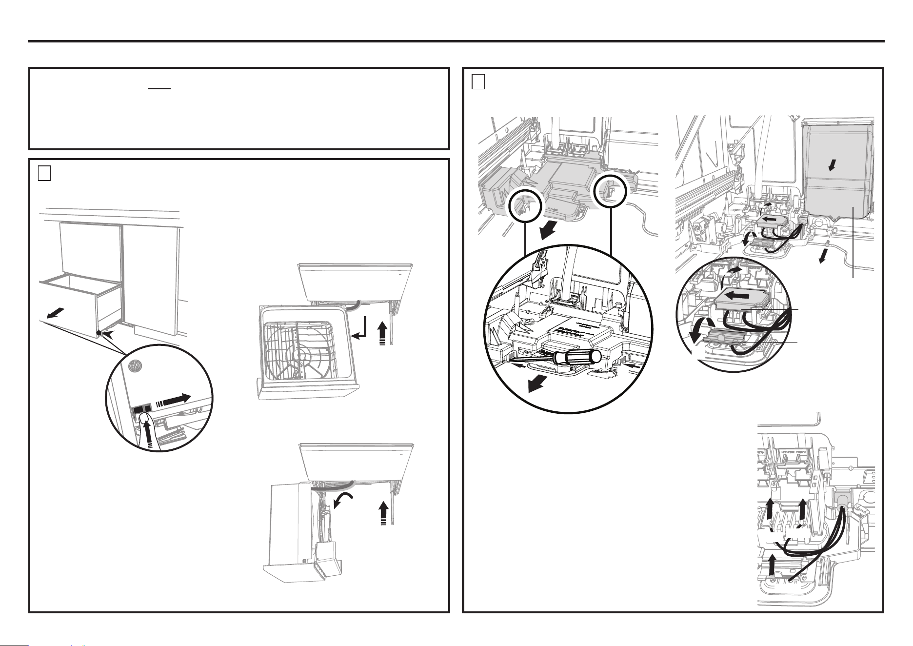
REMOVE THE ACCESS COVERS
(
Skip step if using the power cord.
)
Installation Preparation
OPTIONAL - HARDWIRING PRIOR TO INSTALLATION
To prevent kinked hoses
Either set the drawer down on the left hand
side (recommended) or rotate the drawer
counter-clockwise, resting it on its side after
removal.
1
REMOVE THE LOWER DRAWER
(
Skip step if using the power cord.
)
4” (100 mm)
Electronics
module
Terminal
block cover
2
3
4
5
Harness cover
4
4
3
3
Push drawer
runners back
in on either
side.
Push drawer
runners back
in on either
side.
Set the drawer down
Rotate the drawer counter-clockwise
(max. 90
o
) and rest on side.
OR
Press the release tabs
in on either side and
push back to release
drawer from runners.
Lift drawer off runners.
1
2
POWER CORD OR HARDWIRED OPTION
We recommend the use of the power cord. If using the power cord option, skip steps 1-5 and
proceed to the PRODUCT DIMENSIONS section of this Installation Instructions.
If however you elect to hardwire the dishwasher drawer, follow steps 1-5 and then continue
with the rest of the Installation Instructions.
1
1
1
1
1
1
1 With a flat-bladed screwdriver, press in both clips and
pull to slide out the access cover.
2 Unscrew the electronics module cover.
3 Carefully pull out the electronics module and rest on the
chassis base out of the way.
4 With a screwdriver, unclip the plastic harness cover and
hinge open.
5 Slide the terminal block cover sideways to unlock and
hinge open to access the terminal block.
NOTE: Only unscrew the white and black terminals
two turns. They are fork terminals and do not
require the screws to be removed. The green wire
requires the screw be removed. It is a ring terminal.
Remove the center Ground screw.
6 Unscrew the black, white and green wires.
6
White
Green
Black
6
Installation Preparation
OPTIONAL - HARDWIRING PRIOR TO INSTALLATION - CONTINUED
3
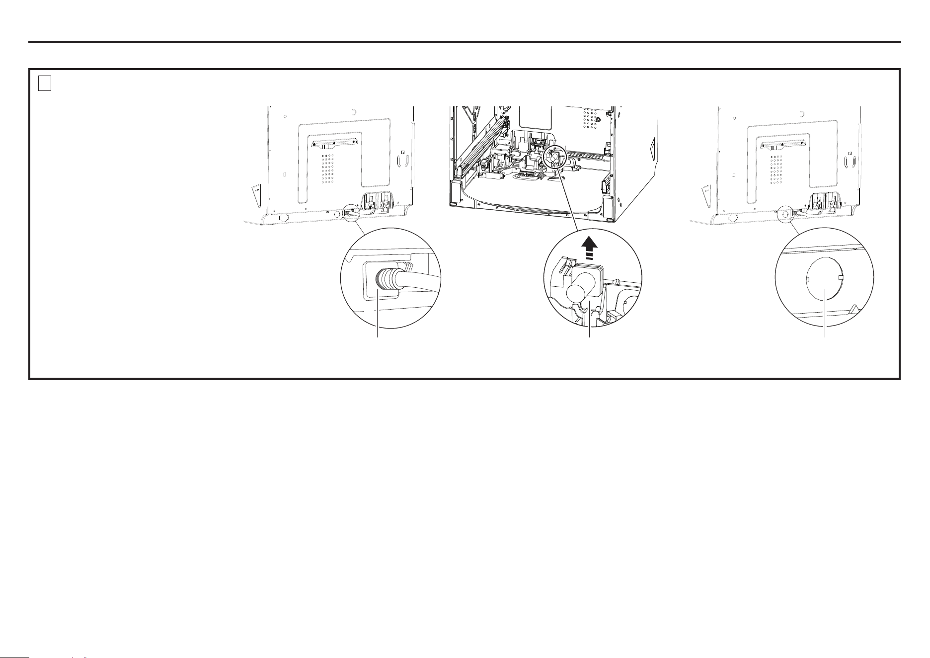
REMOVE THE POWER CORD AND EXTERNAL KNOCKOUT
(
Skip step if using the power cord.
)
1 From the outside, cut the power cord
collar off flush at its base using wire
cutters. Discard the exterior power
cord.
2 From the inside, remove the power
cord/strain relief from its U-shaped
retainer slot in the base pan. Discard
the interior power cord/strain relief.
3 From the outside, knock out the
external knockout in the base pan
using a hammer and screwdriver.
1
Cut power cord
collar off flush
at its base
2
Remove
power cord/
strain relief
3
Remove
Knockout
7
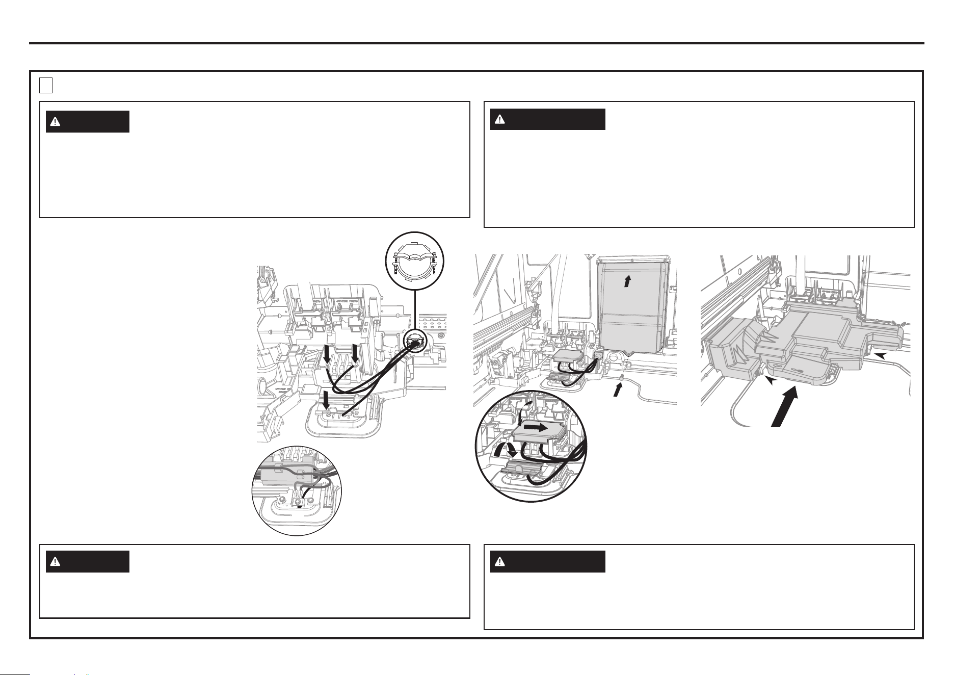
4
TERMINATE HOUSE WIRING AS SHOWN AND REPLACE MODULE AND COVERS
(
Skip step if using the power cord.
)
Installation Preparation
OPTIONAL - HARDWIRING PRIOR TO INSTALLATION - CONTINUED
IMPORTANT: Ensure
house wires are routed
UNDERNEATH all other
harness wiring from the
electronics module.
3
4
5
6
7
1 Fit a suitable strain relief cable
clamp for the conduit through the
metal knockout.
Ensure wiring is routed through or
under housing ribs.
2 Screw down the black, white and
green wires correctly.
3 Push the plastic harness cover back
over. It should clip back into place.
4 Fold down and slide back the
terminal block cover.
5 Refit the electronics module back
into position, being careful of wiring.
6 Replace the screw securing the
electronics module.
7 Slide the access cover back,
ensuring the 2 clips shown are fully
locked in place.
NOTE: Use copper conductors only.
2
The improper connection of the equipment grounding conductor can result in a risk
RIHOHFWULFVKRFN&KHFNZLWKDTXDOL¿HGHOHFWULFLDQRUVHUYLFHUHSUHVHQWDWLYHLI\RX
are in doubt that the appliance is properly grounded.
If house wiring is not 2-wire with ground, a ground must be provided by the
installer. When house wiring is aluminum, be sure to use UL-Listed anti-oxidant
compound and aluminum-to-copper connectors.
WARNING
La conexión incorrecta del conductor de conexión a tierra del equipo puede provocar un
ULHVJRGHGHVFDUJDHOpFWULFD&RQVXOWHDXQHOHFWULFLVWDFDOL¿FDGRRDXQUHSUHVHQWDQWHGH
servicio si tiene dudas sobre si el dispositivo está correctamente conectado a tierra.
Si el cableado doméstico no cuenta con un cable de 2 hilos con conexión a tierra,
un instalador debe realizar una conexión a tierra. Cuando el cableado doméstico
es de aluminio, asegúrese de usar un compuesto antioxidante y conectores de
aluminio a cobre aprobados or UL.
ADVERTENCIA
7
1
2
Install strain relief and
secure house wiring
to the dishwasher
The improper connection of the grounding conductors can result in a risk of electric
shock. Both ring terminals must be replaced and the Ground (green or bare) wire
clamped under the Green Ground Screw.
WARNING
La conexión incorrecta del conductor de conexión a tierra del equipo puede provocar
un riesgo de descarga eléctrica. Ambas terminales de anillo deben reemplazarse y
el cable de tierra (verde o descubierto) debe quedar sujetado debajo del tornillo de
conexión a tierra verde.
ADVERTENCIA
8
Installation Preparation
OPTIONAL - HARDWIRING PRIOR TO INSTALLATION - CONTINUED
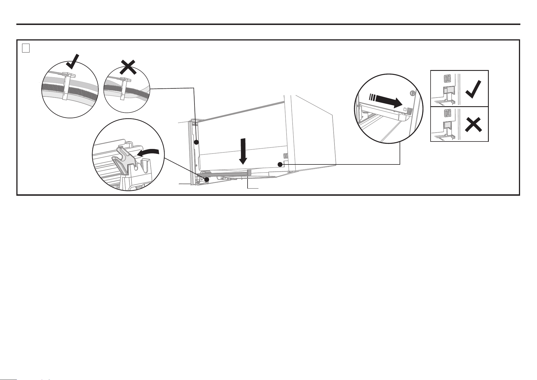
4” (100 mm)
Pull the release tabs forward on both
sides 4” (100 mm). Ensure the tabs are
fully pulled forward and click into place.
Before refitting the drawer,
ensure the hoses are not
twisted and the latches at
the rear of each drawer
runner are facing
forward.
Lift or rotate counter-clockwise the
drawer back onto the drawer runners
on either side.
Release tab
5
REFIT THE DRAWER ONTO THE RUNNERS AND CLOSE
(
Skip step if using the power cord.
)
1
2
3
4

9
Notes
10
B
D
O
E
N
F
A
C
M
L
G
J
I
H
K
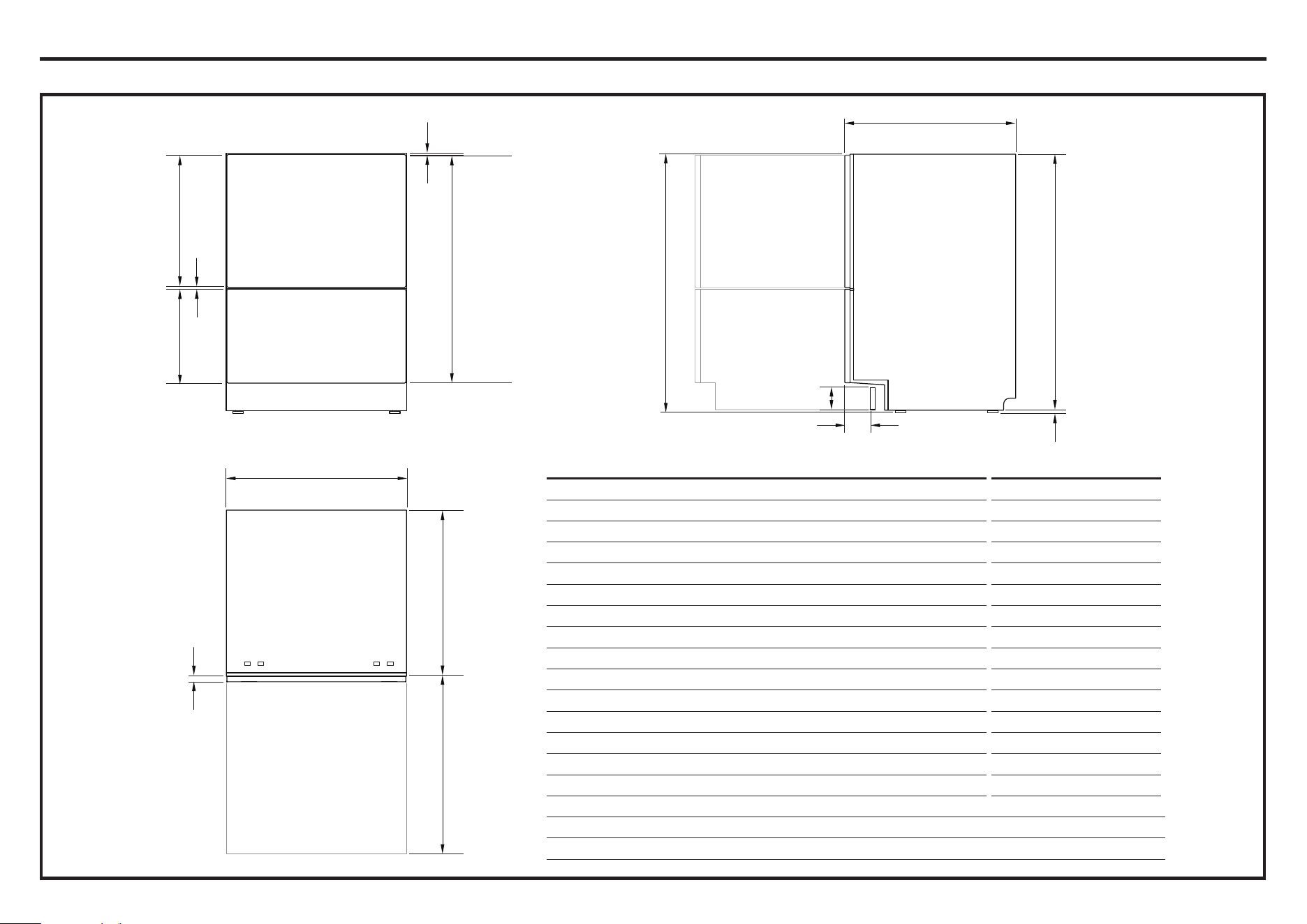
PLAN
SIDEFRONT
PRODUCT DIMENSIONS INCHES (MM)
A Overall height of product
1
34 - 36 3/8” (864-924)
2
B Overall width of product 23 9/16” (599)
C Overall depth of product (excl. handle) 22 9/16” (573)
D Depth of chassis (to back of front drawer panel) 21 3/4” (553)
E Depth of drawer front panel (excl. handle) 13/16” (20)
F Height of chassis
1
33 11/16” (855)
G Height of drawer front panels 30” (762)
H Height of upper drawer front panel 17 3/8” (442)
I Height of lower drawer front panel 12 1/4” (312)
J Height from top of drawer front panel to top of chassis 1/16” (2)
K Ventilation gap between drawer front panels 5/16” (8)
L Height of toekick (customizable) 2 13/16 - 5” (72-127)
M Depth from front of drawer panel to front of toekick (adjustable)
3
1 1/2 - 4” (38-102)
N Height of leveling feet (adjustable) 3/8 - 2 3/4” (9-69)
2
O Maximum extension of drawer 21 9/16” (547)
1
includes 1/16” (2mm) high bracket slots
2
depending on adjustment of leveling feet
3
adjustable to match toekick recess on adjoining cabinetry
PRODUCT DIMENSIONS
Installation Preparation
11
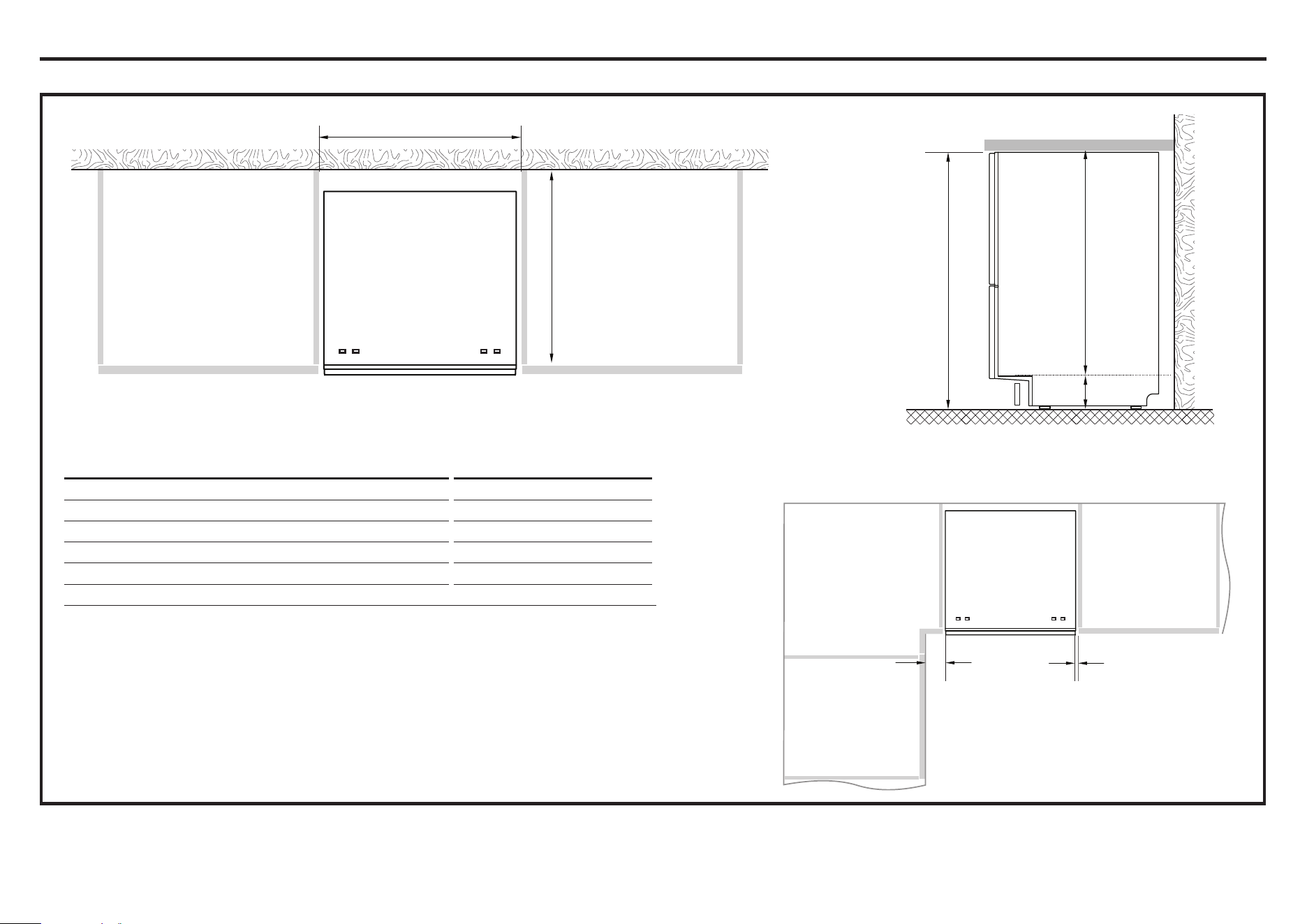
Minimum clearances from adjacent cabinetry
Bracket slots
R
Q
P
S
T
SIDE
PLAN
min. 1/2” (13 mm)
clearance from a
corner cabinet
min. 1/16” (2 mm)
clearance to adjacent
cabinet door
Installation Preparation
CABINETRY DIMENSIONS
CABINETRY DIMENSIONS INCHES (MM)
P Inside height of cavity* min. 34” (864)
Q Inside width of cavity 23 5/8” (600)
R Inside depth of cavity min. 22 1/16” (560)
S Recommended height of adjacent cabinet space 30” (762)
T Height of toekic K space* 3 15/16” - 6 5/16” (100-160)
* depending on adjustment of leveling feet
12
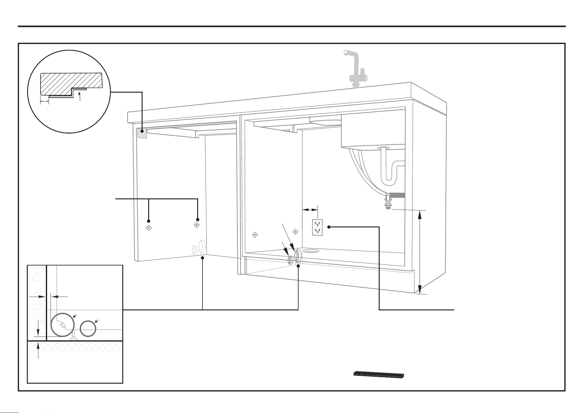
Water Connection
Recommended HOT
(Maximum 140°F/60°C).
Supplied hose to
VXLW»´PPPDOH
compression fitting.
Kosher requirements
Drains will need to be
separated to satisfy
kosher requirements.
We suggest you confirm
acceptability with your
local rabbi in respect to
kosher installations.
Water Pressure
Max. 1 MPa (145 psi)
Min. 0.03 MPa (4.3 psi)
IMPORTANT
The power outlet must be
located in a cabinet adjacent
to the dishwasher cavity.
110-120 VAC max. 15 A
Service Holes
Can be located either side of dishwasher, close to the rear face and the
floor, as illustrated, for access to the water supply, drain and power outlet.
The small hole is for the power cord only.
Ŷ
If the hole is through wood, make sure its edges are smooth and rounded.
Ŷ
If the hole is through metal, ensure you fit the supplied Edge Protector to
prevent damage to the power cord.
These marks indicate formed
bracket screw locations, if
securing by drawer removal.
If there is no side partition, you
can construct timber bracing as
something to secure into.
Moisture
protection
tape must be
applied.
3/8”
(10 mm)
COUNTERTOP
IMPORTANT
Incorrect placement of the
hole will result in damage to
hoses.
Ø 2 1/4”
(57 mm)
Max 1/2” (10mm)
Max distance between
hole edge and floor
Max 1/4” (5mm)
Max distance between
hole edge and rear
inner face
max. 17 11/16”
(450 mm)
min. 7 7/8” (200mm)
Hoses
Power
cord
Ø max. 1 1/2”
(38 mm)
Installation Preparation
CAVITY PREPARATION
13
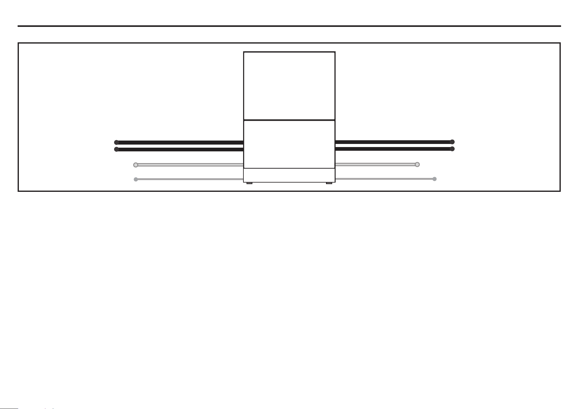
LEFT HAND SIDE RIGHT HAND SIDE
Drain hoses - 78 1/2” (2000mm)
Drain hoses - 70 1/2” (1800mm)
Inlet hose - 64 3/4” (1650mm)
Inlet hose - 49” (1250mm)
Power cord (excl.plug) - 29 1/2” (750mm)
Power cord (excl.plug) - 27 1/2” (700mm)
Installation Preparation
MAXIMUM DISTANCE OF HOSES AND CORD FROM CHASSIS EDGE
14
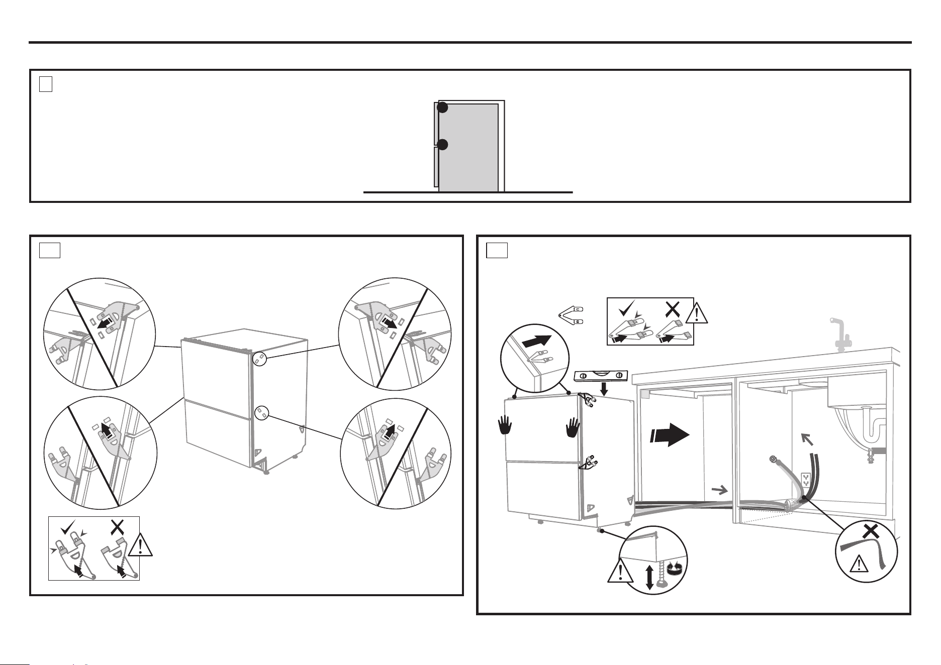
Clip all four side mounting brackets
into their slots using a flat-bladed
screwdriver. Ensure they’re securely
fitted before sliding product into cavity.
The mounting slots are in pairs, one on
each side diagonally across the product. A
bracket must match A slot and B bracket
must match B slot.
When fitting brackets, ensure the
ends are not pushed down into the
chassis.
A
A
A
B
B
B
AB
(x2)
As you push product
in, pull through hoses
and cord, ensuring
they don’t get kinked
or twisted.
Optional - Attach the
two top mounting
brackets
Initially level the product
When fitting brackets,
ensure the ends are not
pushed down into the
chassis.
You can raise or lower the
product by twisting the
feet. Then take care when
pushing the product into
the cavity that you do not
bend the feet.
Installation Instructions
A2
PULL HOSES THROUGH AND PUSH UNIT INTO THE
CAVITY
A1
ATTACH SIDE MOUNTING BRACKETS
CHOOSE WHICH INSTALLATION METHOD (A) OR (B) IS MOST SUITABLE FOR YOUR CABINETRY
A
ALTERNATE METHOD (A) - SECURE WITHOUT DRAWER REMOVAL (FRAMELESS CABINETRY ONLY)
OPTION A - ALTERNATE
15
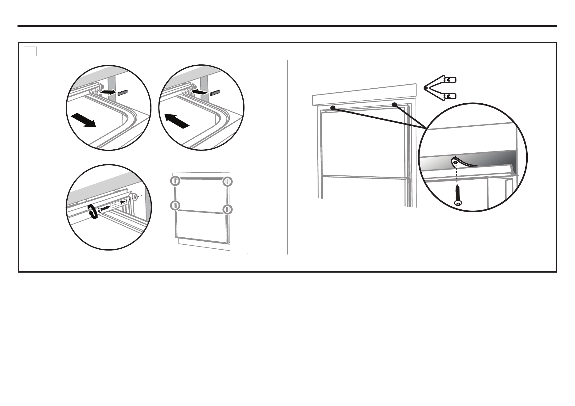
(x2)
Open the
drawer
halfway.
Using a
flat bladed
screwdriver,
pry the
grey rubber
plug out
of the trim
moulding.
Replace the
grey rubber
plug back
into the trim
moulding
and ensure
the trim seal
is facing
forward.
Drill pilot holes
and use a small
Phillips
screwdriver
to drive screws
through the
trim moulding,
securing the
side mounting
bracket to the
cabinetry.
Do not damage
the rubber trim seal.
The top mounting
brackets will only
bend upwards a
maximum of 10 mm.
Installation Instructions
OPTION A - ALTERNATE
(
CONTINUED
)
A3
SECURE TO THE SIDE CABINETRY - OPTION
SECURE TO THE ABOVE CABINETRY - OPTION
AFTER SECURING, REFER TO THE, “FIT THE SUPPLIED TOEKICK PANEL” STEP
2
1
3
4
Repeat for all
four brackets.
16
1
2
Installation Instructions
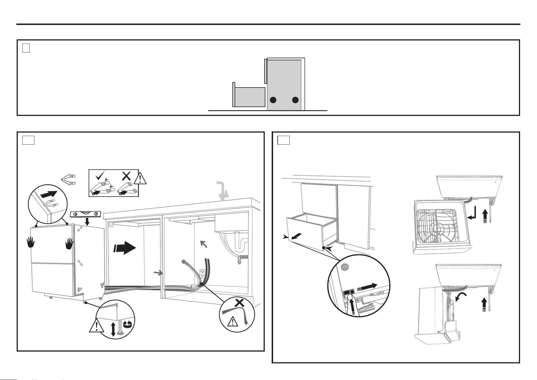
B2
REMOVE THE LOWER DRAWER
B1
PULL HOSES THROUGH AND PUSH UNIT INTO THE
CAVITY
CHOOSE WHICH INSTALLATION METHOD (A) OR (B) IS MOST SUITABLE FOR YOUR CABINETRY
B
RECOMMENDED METHOD (B) - SECURE BY REMOVING THE LOWER DRAWER
OPTION B - RECOMMENDED METHOD
(x2)
4
4
3
3
To prevent kinked hoses
Either set the drawer down on the left hand
side (recommended) or rotate the drawer
clockwise, resting it on its side after removal.
Press the release tabs
in on either side and
push back to release
drawer from runners.
Lift drawer off runners.
Push drawer
runners back in
on either side.
Set the drawer down
Rotate the drawer counter-clockwise
(max. 90
o
) and rest on side.
4” (100mm)
As you push product
in, pull through hoses
and cord, ensuring
they don’t get kinked
or twisted.
Optional - Attach the
two top mounting
brackets
Initially level the product
When fitting brackets,
ensure the ends are not
pushed down into the
chassis.
You can raise or lower the
product by twisting the
feet. Then take care when
pushing the product into
the cavity that you do not
bend the feet.
Push drawer
runners back in
on either side.
17
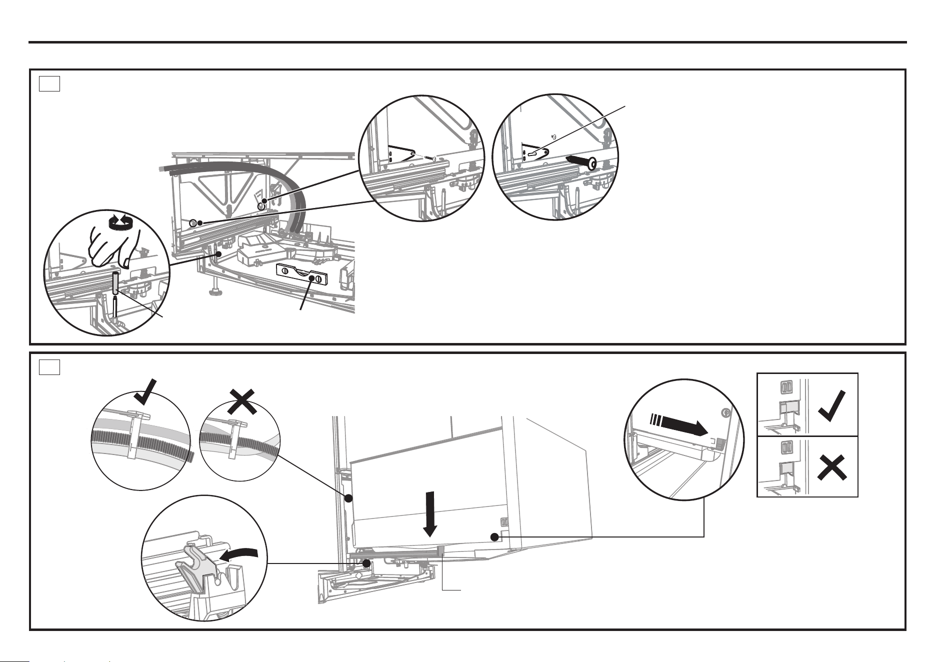
1
2
3
4
x4
Secure using two pairs
of formed brackets.
Repeat on the other
side of the chassis.
For further adjustment,
using the most appropriate
length Hexagonal socket
supplied, fully extend
levelling feet up to
required distance by hand.
Ensure product is level
and aligning with cabinetry.
Hexagonal
socket
Before refitting the
drawer, ensure
the hoses are not
twisted and the
latches at the rear
of each drawer
runner are facing
forward.
Lift or rotate counterclockwise the
drawer back onto the drawer runners
on either side.
Slip your finger under the slide and pull
the release tabs forward 4” (100mm)
on both sides. Ensure the tabs are fully
pulled forward and click into place.
Release tab
4” (100mm)
Installation Instructions
OPTION B - RECOMMENDED METHOD
(
CONTINUED
)
B3
SECURE TO THE SIDE CABINETRY - OPTION
B4
REFIT THE DRAWER ONTO THE RUNNERS
If your unit has this front mounting tab with the slot, it is
beneficial to use a screw in the slot on each side first.
Loosely screw the unit into place, replace the drawer
and check the alignment. Correct any alignment issues,
remove the drawer again, tighten the screws in the
slots and then mount with screws in the rear tabs.
Slot (on
some
models)
18
IMPORTANT
Do not overtighten screw.
Where the toekick
meets the bottom
of the tub is the
cut-off point
Mark this point on the
toekick with a pencil
Lay the toekick face down on
a chopping board or similiar
Smooth the edges with a file.
Be careful of sharp edges.
Snap off the two end tabs
Slide the toekick onto
the mounting rails on
either side and screw
the toekick onto the
bottom of tub on either
side.
Mounting rail
Score along the marked
cutoff line with a knife
Turn the toekick over and
score along the same line
Gently snap off the excess
Installation Instructions
FIT THE SUPPLIED TOEKICK PANEL
INSTALL TOEKICK
- Cut Hazard
WARNING
Take care - Panel edges are sharp.
Failure to use caution could result in
injury or cuts.
19
1
3
5
7
8
9
2
6
4
19
- Peligro de corte
Tenga cuidado - Los bordes del panel son afilados.
No tener cuidado podría resultar en heridas o
cortes.
ADVERTENCIA
19
1
2
min. R 8”
(200 mm)
29 1/2”-34 3/4”
(750-883 mm)
1 1/2”
(38 mm)
29 1/2 - 34 3/4” (750-883 mm)
max.
4 3/4”
(120
mm)
min. 19 11/16” (500 mm)
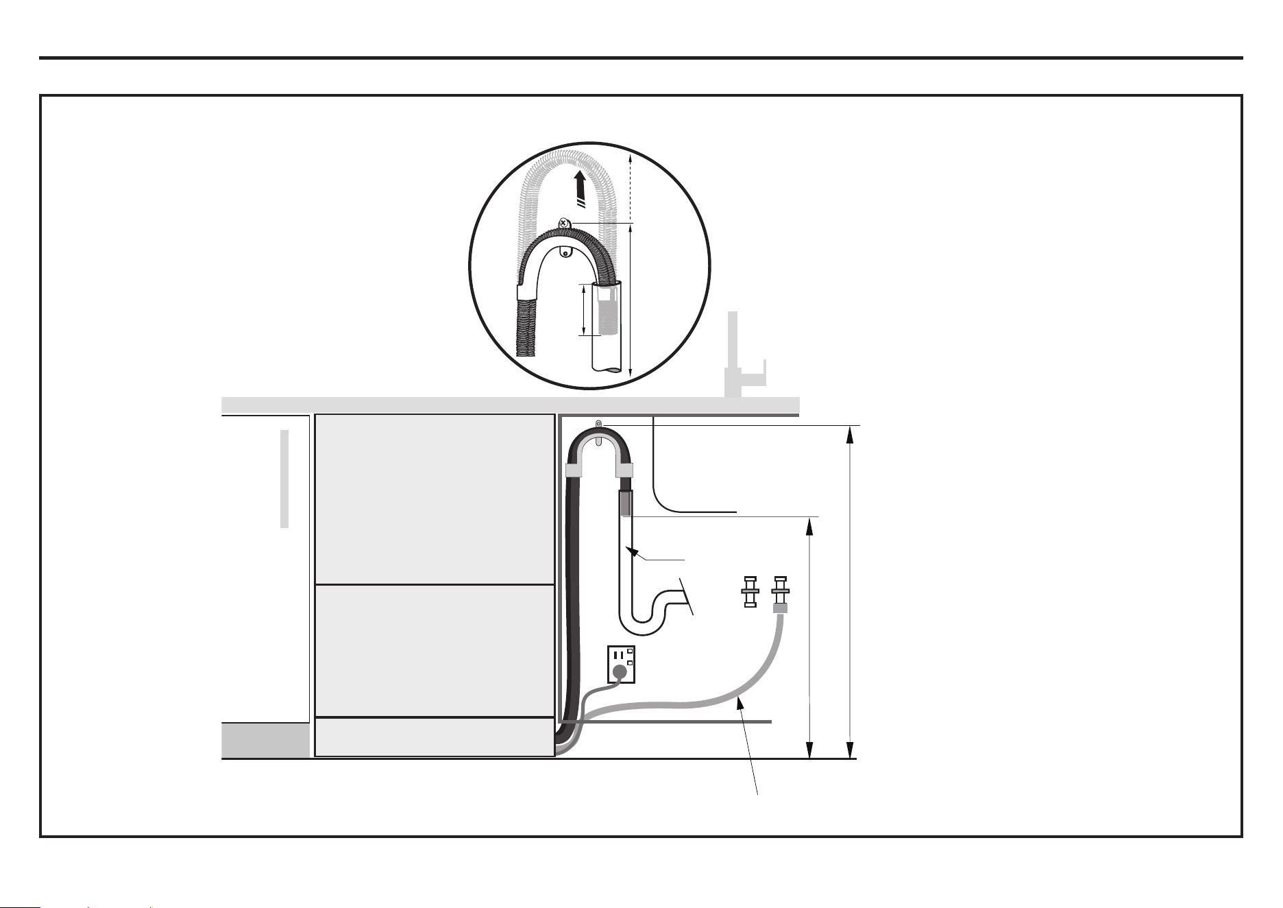
Screw Drain hose
support to back wall at
correct height.
If space is limited
for fixing, push
hose through drain
hose support
to required height.
IMPORTANT
Ensure that drain hose is installed
as close to the underside of the
countertop as possible. This will
ensure no waste re-enters the drain
hose in the event of poor flow or a
blockage in the plumbing.
Ensure the drain hose does not extend
into water retained in the trap; an air gap
is required to prevent waste water from
siphoning back into the tub.
IMPORTANT
Ensure that drain connection
will comply with local plumbing
regulations.
Installation Instructions
THERE ARE THREE DIFFERENT PLUMBING AND DRAINAGE OPTIONS - CHOOSE WHICH IS MOST SUITABLE
DRAINAGE OPTION 1 - Dishwasher and Ø 1 1/2” (38 mm) Standpipe
NOTE: See,
the “CONNECT
INLET HOSE TO
HOT WATER”
step.
20
1
2
min. R 8”
(200 mm)
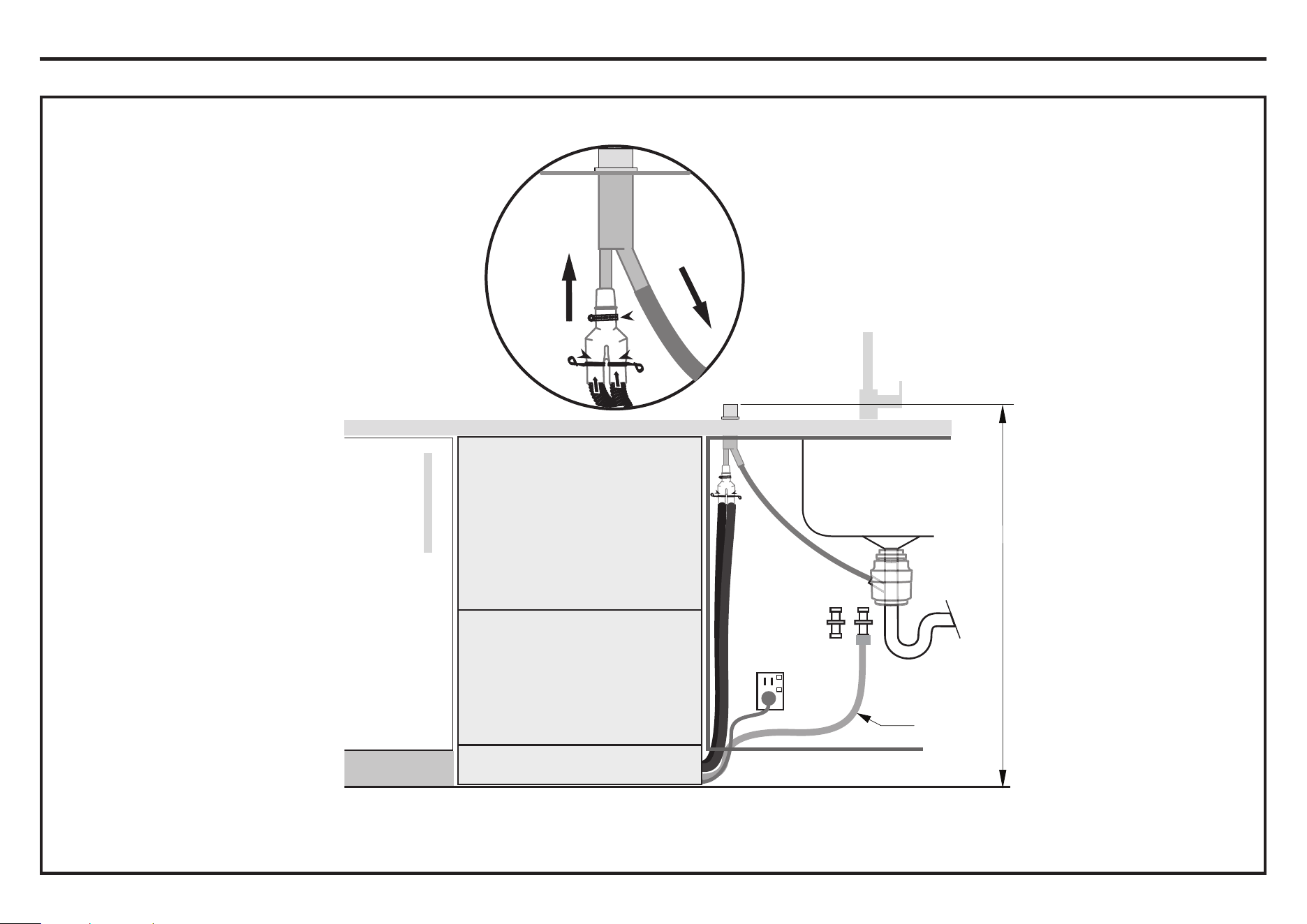
IMPORTANT
Ensure that drain connection
will comply with local
plumbing regulations.
IMPORTANT
We recommend the use of a
commercially available Dual (Double) Air
Gap/Break Kit.
This provides totally separate draining
for each drawer and eliminates possible
“cross draining” problems
37 3/8” (950 mm)
Max. height to top
of Air Break
(countertop or
wall mounted)
NOTE:
See, the
“CONNECT
INLET HOSE
TO HOT
WATER” step.
Drain hose
Drain hose
Secure both drain hoses
to a Dual Air Gap/Break
Installation Instructions
THERE ARE THREE DIFFERENT PLUMBING AND DRAINAGE OPTIONS - CHOOSE WHICH IS MOST SUITABLE
DRAINAGE OPTION 2 - Dishwasher using Dual Air Gap/Break with Drain Hose Joiner
21
1
2
3
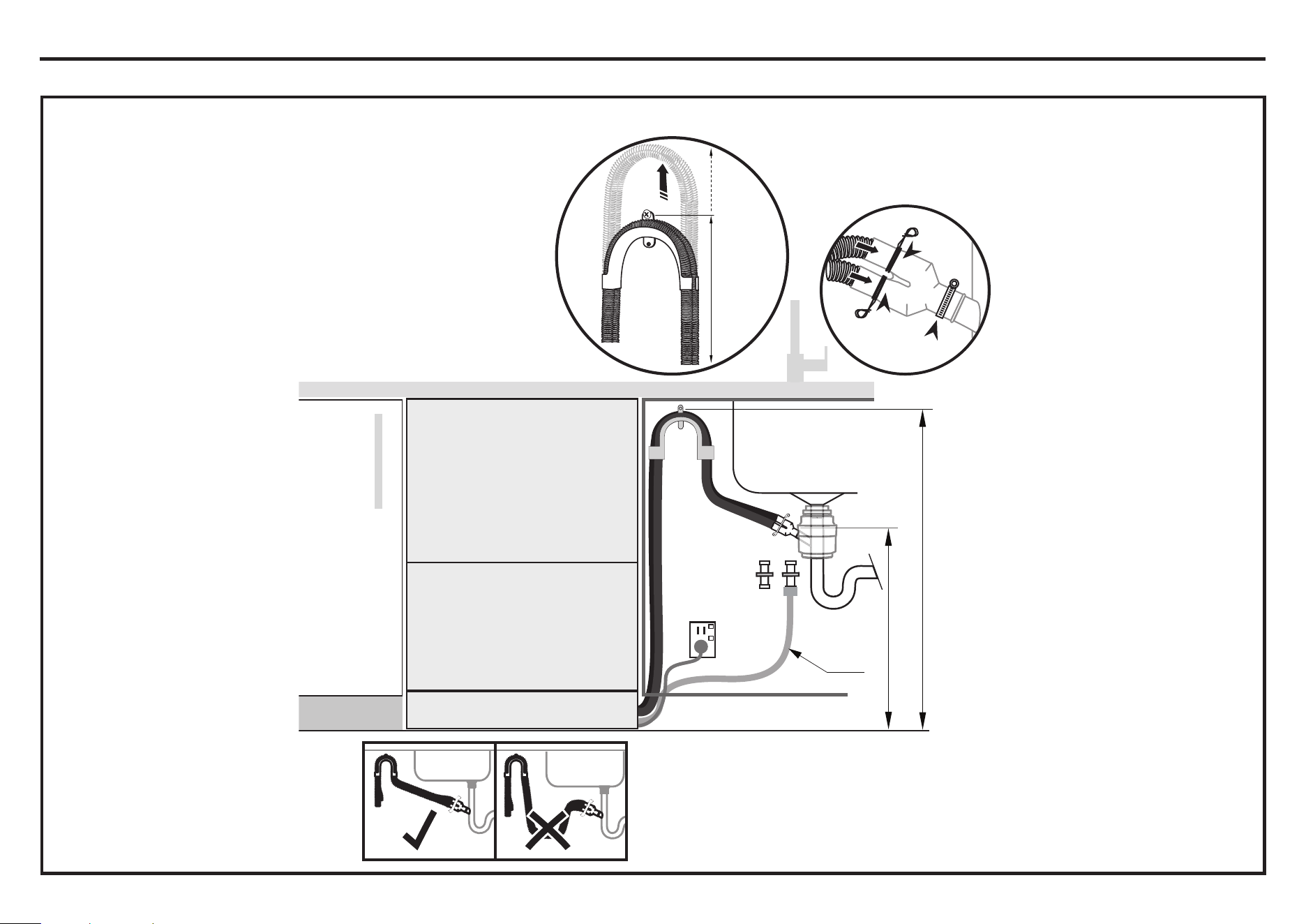
Ensure drain hose is routed straight to the joiner
so that waste water does not accumulate in the
hose. Remove excess drain hose material if
necessary. Do not shorten the inlet hose.
min. R 8”
(200 mm)
IMPORTANT
Ensure that drain connection
will comply with local
plumbing regulations.
29 1/2 - 34 3/4” (750-883 mm)
Supplied drain hose joiner to suit
Ø 3/4” (19 mm) waste tee
29 1/2”-34 3/4”
(750-883 mm)
max.
4 3/4 “
(120 mm)
min. 19 11/16” (500 mm)
Screw Drain hose
support to back wall at
correct height.
If space is limited
for fixing, push
hose through drain
hose support
to required height.
Installation Instructions
THERE ARE THREE DIFFERENT PLUMBING AND DRAINAGE OPTIONS - CHOOSE WHICH IS MOST SUITABLE
DRAINAGE OPTION 3 - Dishwasher using drain hose joiner onto sink trap/waste tee
NOTE: See, the
“CONNECT
INLET HOSE
TO HOT
WATER” step.
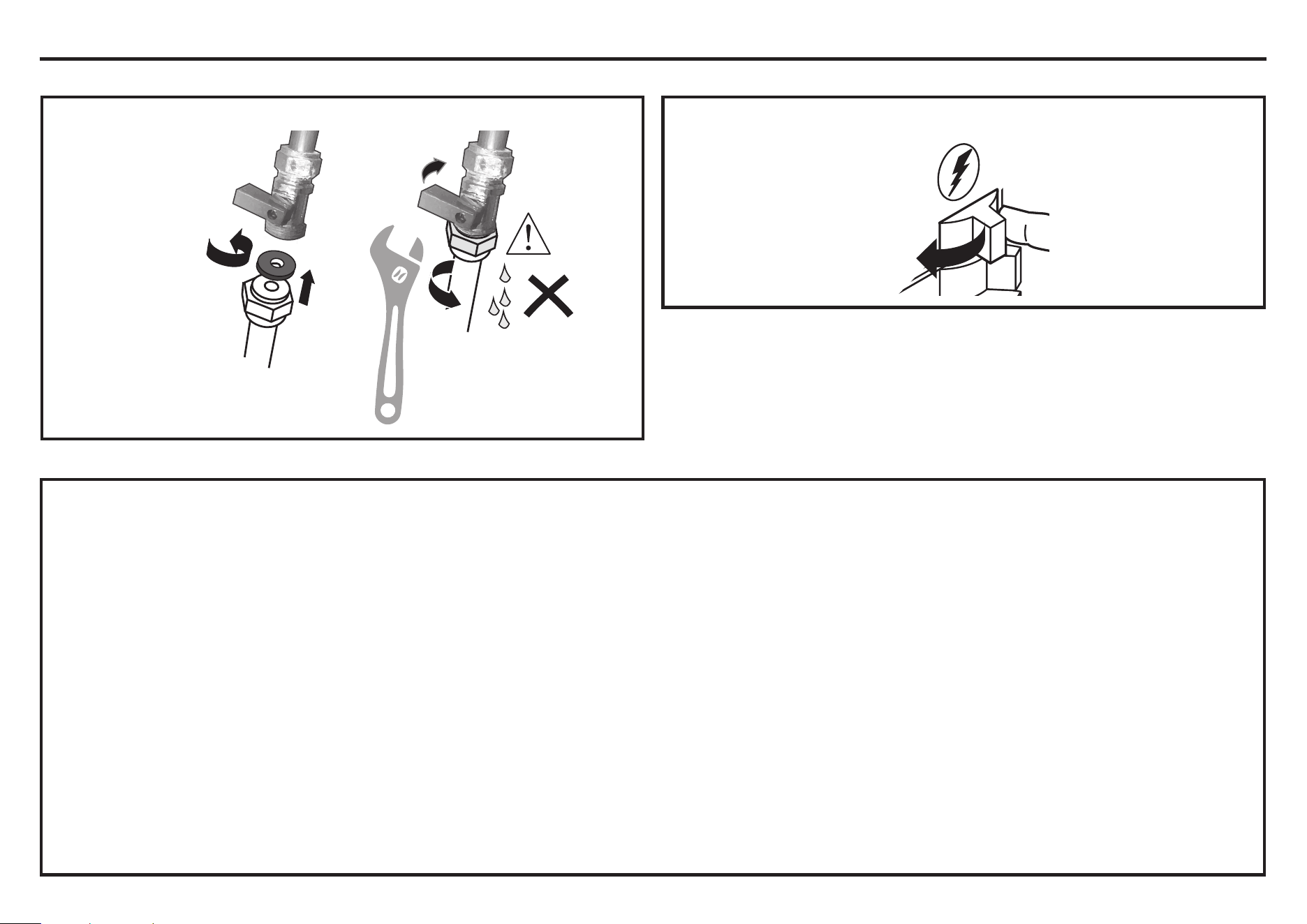
22
Ensure the
supplied rubber
washer is fitted
inside the coupling.
Tighten coupling
with spanner.
180
o
No leaks!
1
2
Installation Instructions
CONNECT WATER AND SWITCH DISHWASHER ON
SWITCH PRODUCT ON
CONNECT INLET HOSE TO HOT WATER
TROUBLESHOOTING
Ŷ
Excessive water remaining above the filter plate, after the rinse cycle. (This is displayed as an A3 fault. See Owner’s Manual, “How to attend to a fault”.)
Check for a kinked drain hose, blocked or incorrectly drilled out waste connection, highloop not properly installed, drain hose not routed correctly or spray arms not in place.
Ŷ
No water supply. (This is displayed as an A1 fault. See Owner’s Manual, “How to attend to a fault”.)
Check water is connected and turned on.
Ŷ
The dishwasher is beeping continuously
There is a fault. See section ‘How to attend to a fault’ in the User guide for further information and instructions.
Ŷ
No program indicator lights up when the drawer is opened
Ensure power is connected and is switched on. If it is and still no indicator ligths up, see the ‘Preference Options’ section of the Quick Start Guide.
An option called ‘Open drawer auto power-on’ may need to be turned on.
Ŷ
Water around water supply and drainage connections
Check connections, existing plumbing and hoses for leaks. Check rubber washer and hose clamp are correctly fitted.
Ŷ
If product is tipping
Ensure the product is secured to the cabinetry.
Ŷ
If front panels are misaligned
Check and relevel product. Check the cabinetry is square. For Integrated models, check and adjust front panel alignment if necessary.
Ŷ
Drawer doesn’t close properly
Ensure nothing is obstructing the drawer from closing properly eg hoses or drawer latches.
Ŷ
If a problem occurs, consult the ‘Troubleshooting’ section of the User guide.
Ŷ
If after checking these points you still need assistance, please refer to the Owner’s Manual for warranty details and your nearest Authorized Service Center, or
contact us through our website, listed below.
23
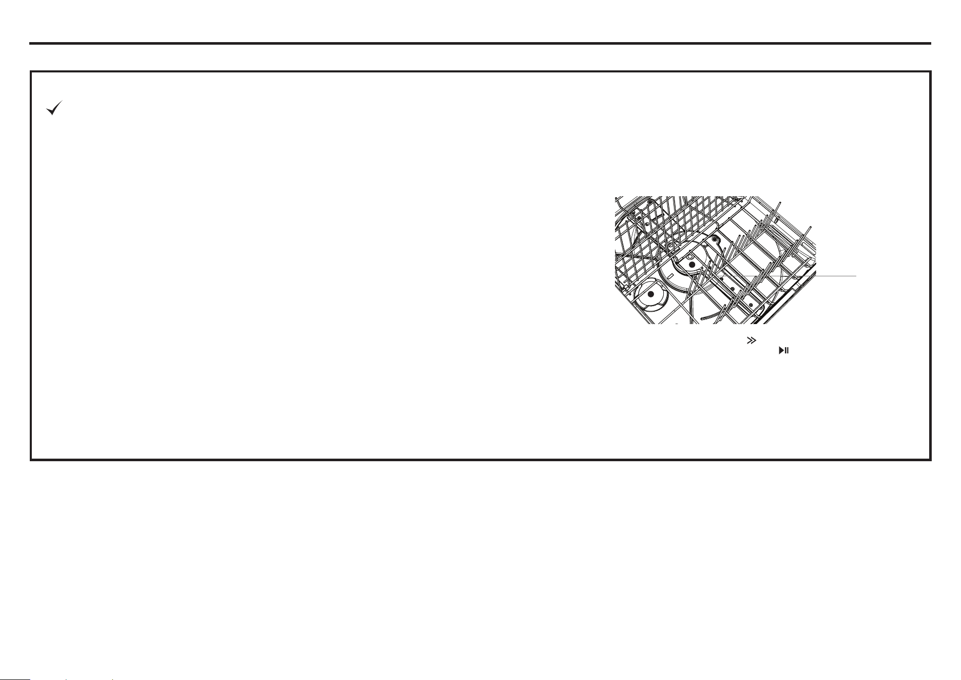
Spray
arm
Installation Instructions
FINAL CHECKLIST
TO BE COMPLETED BY THE INSTALLER
Ŷ
Check all parts are installed.
Ŷ
Ensure that all panels and parts thereof are secure and final electrical tests
have been conducted in accordance with local electrical regulations.
Ŷ
Ensure product is level, securely fastened to the cabinetry and opens and
closes freely. The drawers must be free to fully close with no resistance from
the cabinetry.
Ŷ
Ensure inlet hose to water supply has supplied rubber washer fitted, and that
it’s tightened a further half turn after seal contact.
Ŷ
Ensure any knockouts or plugs in drain connection have been drilled out and
drain connection has been made.
Ŷ
The drain hose joiner must not support the weight of excess hose material.
Keep drain hose as fully extended as possible to prevent sagging. Any excess
length of drain hose should be kept on the dishwasher side of the highloop.
Ŷ
If connecting the drain hose to the sink trap, ensure the Highloop is a minimum
150 mm higher than the drain hose joiner.
Ŷ
Ensure any packaging or tape securing the racks or spray arms is removed
from the drawers.
Ŷ
Water softener models only: adjust the water softener setting from the default
setting to suit the water hardness of the area. See the Quick Start Guide and
section ‘Water softener’ in the User guide.
Ŷ
Turn on the power and water supplies, then open the drawers. You should hear a
beep and see a program indicator light up on the internal control panel.
Ŷ
Check the spray arms are in place, mounted correctly and free to rotate, by
physically rotating by hand.
Ŷ
Add three cups of water into the drawer. Press until the indicator of the
‘Rinse’ program lights up. Close the drawer and press
to start the program.
Repeat for the other drawer.
Ŷ
After the Rinse program has finished, ensure the dishwasher has run and
drained correctly.
Ŷ
Check the water supply has correctly shut off and drainage connection for
leakage.

24
Printed in Thailand
31-4000257 Rev 5 06-25
520112