WARNING: To reduce the
risk of injury, the user must read and
understand the operator’s manual
before using this product.
ADVERTENCIA: Para reducir
el riesgo de lesiones, el usuario debe
leer y comprender el manual del
operador antes de usar este producto.
AVERTISSEMENT :
Pour réduire les risques de blessures,
l’utilisateur doit lire et veiller à bien
comprendre le manuel d’utilisation avant
d’employer ce produit.
General Power Tool
Safety Warnings ..............................2-3
Mixer Safety Instructions ....................3
Symbols ..............................................4
Electrical ............................................. 5
Features ..............................................6
Assembly ............................................ 7
Operation .......................................7-10
Maintenance ..................................... 11
Figures (Illustrations) ...................12-13
Parts Ordering
and Service .........................Back page
Règles de sécurité générales
relatives aux outils électriques ........2-3
Instructions de sécurité
du mélangeur .....................................3
Symboles ............................................4
Caractéristiques électriques ...............5
Caractéristiques .................................6
Assemblage ........................................7
Utilisation ......................................7-10
Entretien ...........................................11
Figures (illustrations) ....................12-13
Commande de pièces
et dépannage ....................Page arrière
Advertencias de seguridad
para herramientas eléctrica ........... 2-3
Instrucciones de seguridad de la
mezcladora ........................................3
Símbolos ............................................4
Aspectos eléctricos ...........................5
Características ...................................6
Armado ..............................................7
Funcionamiento ........................... 7-10
Mantenimiento .................................11
Figuras (illustraciones) ............... 12-13
Pedidos de
piezas y servicio ...........Pág. posterior
OPERATOR’S MANUAL
MANUEL D’UTILISATION
MANUAL DEL OPERADOR
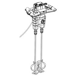
MUD MIXER
MÉLANGEUR DE BOUE
MEZCLADORA DE LODO
R7131
To register your RIDGID
product, please visit:
http://register.RIDGID.com
Pour enregistrer votre
produit de RIDGID,
s’il vous plaît la visite:
http://register.RIDGID.com
Para registrar su producto
de RIDGID, por favor visita:
http://register.RIDGID.com
SAVE THIS MANUAL FOR
FUTURE REFERENCE
CONSERVER CE MANUEL
POUR FUTURE RÉFÉRENCE
GUARDE ESTE MANUAL
PARA FUTURAS CONSULTAS
INCLUDES: Mud Mixer, Mixing
Paddle (2),Bucket Guard Assembly,
Operator’s Manual
****************
TABLE OF CONTENTS
INCLUT : Mélangeur de boue, lame de
mélange (2), assemblage du protecteur de
seau, manuel d’utilisation
****************
TABLE DES MATIÈRES
INCLUYE: Mezcladora de lodo, paleta de
mezcla (2), ensamblaje de protección de
cubeta, manual del operador
****************
ÍNDICE DE CONTENIDO

2 - English
GENERAL POWER TOOL SAFETY WARNINGS
WARNING
Read all safety warnings, instructions,
illustrations and specifications provided with
this power tool. Failure to follow all instructions
listed below may result in electric shock, fire and/
or serious injury.
Save all warnings and instructions for future reference.The
term “power tool” in the warnings refers to your mains-operated
(corded) power tool or battery-operated (cordless) power tool.
WORK AREA SAFETY
Keep work area clean and well lit. Cluttered or dark
areas invite accidents.
Do not operate power tools in explosive atmospheres,
such as in the presence of flammable liquids, gases
or dust. Power tools create sparks which may ignite the
dust or fumes.
Keep children and bystanders away while operating a
power tool. Distractions can cause you to lose control.
ELECTRICAL SAFETY
Power tool plugs must match the outlet. Never modify
the plug in any way. Do not use any adapter plugs with
earthed (grounded) power tools. Unmodified plugs and
matching outlets will reduce risk of electric shock.
Avoid body contact with earthed or grounded surfaces,
such as pipes, radiators, ranges and refrigerators.
There is an increased risk of electric shock if your body
is earthed or grounded.
Do not expose power tools to rain or wet conditions.
Water entering a power tool will increase the risk of
electric shock.
Do not abuse the cord. Never use the cord for carrying,
pulling or unplugging the power tool. Keep cord away
from heat, oil, sharp edges or moving parts. Damaged
or entangled cords increase the risk of electric shock.
When operating a power tool outdoors, use an
extension cord suitable for outdoor use. Use of a cord
suitable for outdoor use reduces the risk of electric shock.
If operating a power tool in a damp location is unavoidable,
use a ground fault circuit interrupter (GFCI) protected
supply. Use of a GFCI reduces the risk of electric shock.
PERSONAL SAFETY
Stay alert, watch what you are doing and use common
sense when operating a power tool. Do not use a
power tool while you are tired or under the influence
of drugs, alcohol or medication. A moment of inattention
while operating power tools may result in serious personal
injury.
Use personal protective equipment. Always wear eye
protection. Protective equipment such as dust mask, non-
skid safety shoes, hard hat, or hearing protection used for
appropriate conditions will reduce personal injuries.
Prevent unintentional starting. Ensure the switch is in
the off-position before connecting to power source
and/or battery pack, picking up or carrying the tool.
Carrying power tools with your finger on the switch or
energising power tools that have the switch on invites
accidents.
Remove any adjusting key or wrench before turning
the power tool on. A wrench or a key left attached to a
rotating part of the power tool may result in personal injury.
Do not overreach. Keep proper footing and balance at
all times. This enables better control of the power tool in
unexpected situations.
Dress properly. Do not wear loose clothing or jewellery.
Keep your hair, clothing and gloves away from moving
parts. Loose clothes, jewellery or long hair can be caught
in moving parts.
If devices are provided for the connection of dust
extraction and collection facilities, ensure these are
connected and properly used. Use of dust collection
can reduce dust-related hazards.
Do not let familiarity gained from frequent use of tools
allow you to become complacent and ignore tool
safety principles. A careless action can cause severe
injury within a fraction of a second.
Do not wear loose clothing or jewelry. Contain long hair.
Loose clothes, jewelry, or long hair can be drawn into air
vents.
Do not use on a ladder or unstable support. Stable
footing on a solid surface enables better control of the
power tool in unexpected situations.
POWER TOOL USE AND CARE
Do not force the power tool. Use the correct power
tool for your application. The correct power tool will
do the job better and safer at the rate for which it was
designed.
Do not use the power tool if the switch does not turn
it on and off. Any power tool that cannot be controlled
with the switch is dangerous and must be repaired.
Disconnect the plug from the power source and/
or remove the battery pack, if detachable, from the
power tool before making any adjustments, changing
accessories, or storing power tools. Such preventive
safety measures reduce the risk of starting the power tool
accidentally.
Store idle power tools out of the reach of children and
do not allow persons unfamiliar with the power tool
or these instructions to operate the power tool. Power
tools are dangerous in the hands of untrained users.
Maintain power tools and accessories. Check
for misalignment or binding of moving parts,
breakage of parts and any other condition that
may affect the power tool’s operation. If damaged,
have the power tool repaired before use. Many
accidents are caused by poorly maintained power tools.

3 - English
GENERAL POWER TOOL SAFETY WARNINGS
MIXER SAFETY INSTRUCTIONS
Hold the tool with both hands at the intended handles.
Loss of control can cause personal injury.
Ensure sufficient ventilation when mixing flammable
materials to avoid a hazardous atmosphere. Developing
vapour may be inhaled or be ignited by the sparks the
power tool produces.
Do not mix food. Power tools and their accessories are
not designed for processing food.
Keep the cord away from the working area. The cord
may be entangled by the mixing paddle.
Ensure that the mixing container is placed in a firm
and secure position. A container that is not properly
secured may move unexpectedly.
Ensure that no liquid splashes against the housing of
the power tool. Liquid that has penetrated the power tool
can cause damage and lead to electric shock.
Follow the instructions and warnings for the material
to be mixed. Material to be mixed may be harmful.
If the power tool falls into the material to be mixed,
unplug the tool immediately and have the power tool
checked by a qualified repair person. Reaching into the
container with the tool still plugged in can lead to electric
shock.
Do not reach into the mixing container with your hands
or insert any other objects into it while mixing. Contact
with the paddle may lead to serious personal injury.
Start up and run down the tool in the mixing container
only. The paddle may bend or spin in an uncontrolled
manner.
Know your power tool. Read operator’s manual
carefully. Learn its applications and limitations, as well
as the specific potential hazards related to this tool.
Following this rule will reduce the risk of electric shock,
fire, or serious injury.
Always wear eye protection with side shields marked
to comply with ANSI Z87.1. Following this rule will
reduce the risk of serious personal injury.
Protect your lungs. Wear a face or dust mask if the
operation is dusty. Following this rule will reduce the risk
of serious personal injury.
Protect your hearing. Wear hearing protectors during
extended periods of operation. Following this rule will
reduce the risk of serious personal injury.
Inspect tool cords periodically and, if damaged, have
repaired at your nearest authorized service center.
Constantly stay aware of cord location. Following this
rule will reduce the risk of electric shock or fire.
Check damaged parts. Before further use of the
tool, a guard or other part that is damaged should
be carefully checked to determine that it will operate
properly and perform its intended function. Check for
alignment of moving parts, binding of moving parts,
breakage of parts, mounting, and any other conditions
that may affect its operation. A guard or other part that
is damaged should be properly repaired or replaced
by an authorized service center. Following this rule will
reduce the risk of shock, fire, or serious injury.
Make sure your extension cord is in good condition.
When using an extension cord, be sure to use one
heavy enough to carry the current your product will
draw. A wire gauge size (A.W.G.) of at least 14 is
recommended for an extension cord 50 feet or less in
length. A cord exceeding 100 feet is not recommended.
If in doubt, use the next heavier gauge. The smaller
the gauge number, the heavier the cord. An undersized
cord will cause a drop in line voltage resulting in loss of
power and overheating.
If the power supply cord is damaged, it must be replaced
only by the manufacturer or by an authorized service
center to avoid risk.
Never leave mud mixer running unattended. Unplug
mixer when leaving work area or when mixer is out of
your line of sight.
Save these instructions. Refer to them frequently and
use them to instruct others who may use this tool. If you
loan someone this tool, loan them these instructions also.
Keep cutting tools sharp and clean. Properly maintained
cutting tools with sharp cutting edges are less likely to
bind and are easier to control.
Use the power tool, accessories and tool bits etc.
in accordance with these instructions, taking into
account the working conditions and the work to be
performed. Use of the power tool for operations different
from those intended could result in a hazardous situation.
Keep handles and grasping surfaces dry, clean and
free from oil and grease. Slippery handles and grasping
surfaces do not allow for safe handling and control of the
tool in unexpected situations.
SERVICE
Have your power tool serviced by a qualified repair
person using only identical replacement parts. This
will ensure that the safety of the power tool is maintained.
4 - English
SYMBOLS
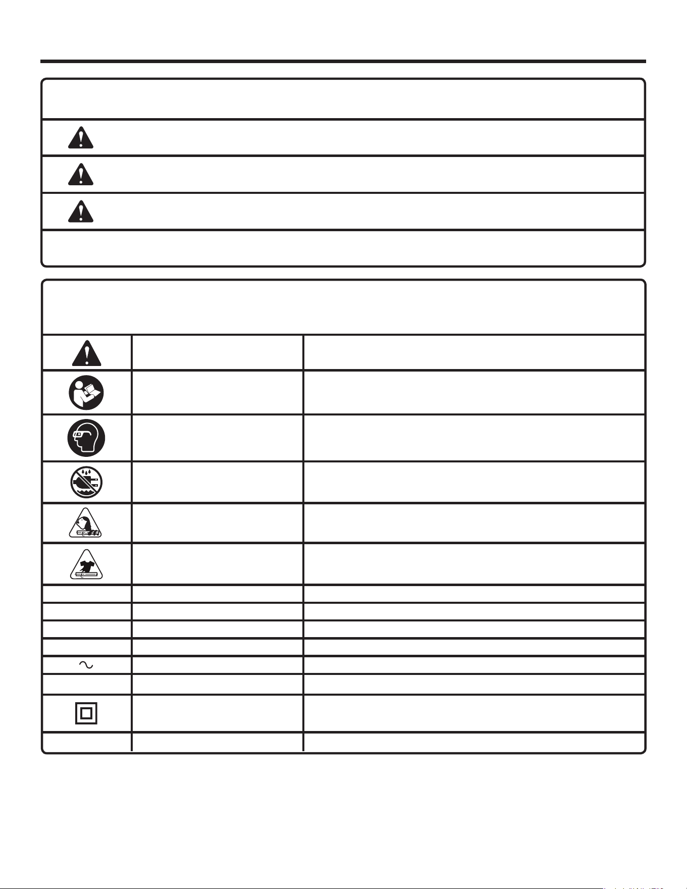
Some of the following symbols may be used on this product. Please study them and learn their meaning. Proper
interpretation of these symbols will allow you to operate the product better and safer.
SYMBOL NAME DESIGNATION/EXPLANATION
Safety Alert Indicates a potential personal injury hazard.
Read Operator’s Manual
To reduce the risk of injury, user must read and understand
operator’s manual before using this product.
Wear Eye Protection
Always wear eye protection with side shields marked to comply
with ANSI Z87.1.
Wet Conditions Alert Do not expose to rain or use in damp locations.
Long Hair Risk of long hair being drawn into rotating paddles.
Loose Clothing Risk of loose clothing being drawn into rotating paddles.
V Volts Voltage
A Amperes Current
Hz Hertz Frequency (cycles per second)
min Minutes Time
Alternating Current Type of current
n
o
No Load Speed Rotational speed, at no load
Class II Construction Double-insulated construction
.../min Per Minute Revolutions, strokes, surface speed, orbits etc., per minute
The following signal words and meanings are intended to explain the levels of risk associated with this product.
SYMBOL SIGNAL MEANING
DANGER:
Indicates a hazardous situation, which, if not avoided, will result in death or
serious injury.
WARNING:
Indicates a hazardous situation, which, if not avoided, could result in death or
serious injury.
CAUTION:
Indicates a hazardous situation, that, if not avoided, may result in minor or
moderate injury.
NOTICE:
(Without Safety Alert Symbol) Indicates information considered important, but
not related to a potential injury (e.g. messages relating to property damage).
5 - English
ELECTRICAL
DOUBLE INSULATION
Double insulation is a concept in safety in electric power tools,
which eliminates the need for the usual three-wire grounded
power cord. All exposed metal parts are isolated from the
internal metal motor components with protecting insulation.
Double insulated tools do not need to be grounded.
WARNING:
The double insulated system is intended to protect
the user from shock resulting from a break in the
tool’s internal insulation. Observe all normal safety
precautions to avoid electrical shock.
NOTE: Servicing of a product with double insulation requires
extreme care and knowledge of the system and should
be performed only by a qualified service technician. For
service, we suggest you return the product to your nearest
authorized service center for repair. Always use original
factory replacement parts when servicing.
ELECTRICAL CONNECTION
This product has a precision-built electric motor. It should be
connected to a power supply that is 120 V, AC only (normal
household current), 60 Hz. Do not operate this product on
direct current (DC). A substantial voltage drop will cause a
loss of power and the motor will overheat. If the product
does not operate when plugged into an outlet, double-check
the power supply.
EXTENSION CORDS
When using a power tool at a considerable distance from
a power source, be sure to use an extension cord that has
the capacity to handle the current the product will draw. An
undersized cord will cause a drop in line voltage, resulting in
overheating and loss of power. Use the chart to determine
the minimum wire size required in an extension cord. Only
round jacketed cords listed by Underwriter’s Laboratories
(UL) should be used.
When working outdoors with a product , use an extension
cord that is designed for outside use. This type of cord is
designated with “WA” or “W” on the cord’s jacket.
Before using any extension cord, inspect it for loose or
exposed wires and cut or worn insulation.
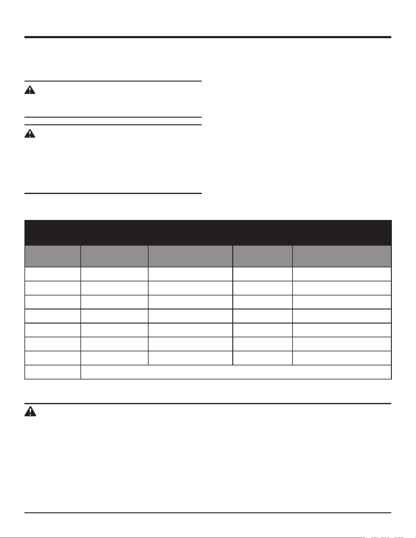
**Ampere rating (on tool faceplate)
0-2.0 2.1-3.4 3.5-5.0 5.1-7.0 7.1-12.0 12.1-16.0
Cord Length Wire Size (A.W.G.)
25' 16 16 16 16 14 14
50' 16 16 16 14 14 12
100' 16 16 14 12 10 —
**Used on 12 gauge - 20 amp circuit
NOTE: AWG = American Wire Gauge
WARNING:
Keep the extension cord clear of the working area.
Position the cord so that it will not get caught on
lumber, tools, or other obstructions while you are
working with a power tool. Failure to do so can
result in serious personal injury.
WARNING:
Check extension cords before each use. If
damaged replace immediately. Never use the
product with a damaged cord since touching
the damaged area could cause electrical shock
resulting in serious injury.

6 - English
FEATURES
KNOW YOUR MUD MIXER
The safe use of this product requires an understanding of
the information on the product and in this operator's manual
as well as a knowledge of the project you are attempting.
Before use of this product, familiarize yourself with all
operating functions.
BUCKET GUARD
The bucket guard provided secures the mixing paddles
and prevents the material being mixed from splashing onto
the mixer and prevents the tool from falling into the mixing
container.
CUSTOM MODE
The mixer can be programmed to turn on and off at custom
intervals. The unit can store up to 10 custom mix sets.
NOTE: The bucket guard should be properly seated on the
bucket before attempting any custom or preset operation.
If the bucket guard is not seated properly, the mud mixer
may not perform these operations correctly.
DIGITAL DISPLAY
The digital display shows the current mode and mixing
options selected on the tool.
HANDLE
This mixer has an ergonomic handle design for ease of
operation and to prevent loss of control.
LOCK-ON BUTTON
This tool is equipped with a lock-on feature for continuous
mixing.
MANUAL MODE
The mixer can be manually operated using the switch trigger.
NOTE: If the mixer is performing a custom or preset
operation, squeezing the trigger will cancel the operation
and return the unit to manual mode.
MIXING PADDLES
The mixing paddles are designed to mix thick and heavy
materials.
PRESET MODE
The mud mixer has eight preset mixing sets for some of the
most commonly mixed materials including paint, thinset,
and mortar.
NOTE: The bucket guard should be properly seated on the
bucket before attempting any custom or preset operation.
If the bucket guard is not seated properly, the mud mixer
may not perform these operations correctly.
PROGRAM BUTTON
The program button allows the user to choose between
different modes and select preset and custom mix sets.
STAND COMPATIBLE
The mud mixer can be mounted to the R7133 stand (not
included).
WARNING:
To reduce the risk of the tool falling into the material
being mixed, ensure that the mud mixer is secured
to the stand (not included) and the bucket guard
is in place prior to begining operations. Failure
to comply could result in a hazardous condition
leading to possible serious personal injury.
TWO SPEED GEAR TRAIN
The mud mixer has a two-speed gear train designed for
mixing at LO (1) or HI (2) speeds. A dial is located in the
center of the tool to select either LO (1) or HI (2) speed.
QUICK-CONNECT COUPLERS
The quick-connect couplers allow you to easily add/remove
paddles.
VARIABLE SPEED SELECTOR
The mixer speed can be adjusted with the variable speed
selector. This allows you to adjust the mixing rate to suit
your particular application.
NOTE: The speed cannot be adjusted during preset
operation.
PRODUCT SPECIFICATIONS
Coupler ....................................................................13 mm
Input .......................... 120 Volts, AC only, 60 Hz, 10 Amps
No Load Speed ...................................Low 180-460 r/min.
High 240-620 r/min.
7 - English
OPERATION
WARNING:
Do not allow familiarity with products to make you
careless. Remember that a careless fraction of a
second is sufficient to inflict severe injury.
WARNING:
Always wear eye protection with side shields
marked to comply with ANSI Z87.1. Failure to do
so could result in objects being thrown into your
eyes, resulting in possible serious injury.
WARNING:
Do not use any attachments or accessories not
recommended by the manufacturer of this product.
The use of attachments or accessories not
recommended can result in serious personal injury.
APPLICATIONS
You may use the product for the purposes listed below:
Mixing thinset, grout, mortar, paint, drywall, concrete, and
leveling compounds
SWITCH TRIGGER
See Figure 1, page 12.
To manually turn the tool ON, depress the switch trigger. To
turn it OFF, release the switch trigger and allow the couplers
to come to a complete stop.
NOTE: A whistling or ringing noise coming from the switch
during use is a normal part of the switch function.
NOTE: During use, the left and right couplers rotate in
opposite directions.
LOCK-ON BUTTON
See Figure 1, page 12.
This mixer is equipped with a lock-on feature, which is
convenient for continuous manual use over extended periods
of time.
To lock-on:
Depress the switch trigger.
Push in and hold the lock-on button, located above the
trigger.
Release the switch trigger.
Release the lock-on button and the mixer will continue
running.
To release the lock, depress and release the switch trigger.
If the lock-on feature is engaged during use and the mixer
becomes disconnected from the power supply, disengage
the lock-on feature immediately.
TWO-SPEED GEAR TRAIN (HI-LO SWITCH)
See Figure 2, page 12.
To determine the appropriate gear setting for the material
being mixed, refer to material manufacturer's instructions or
the Preset Mix Chart on page 10.
Select LO (1) speed for applications requiring higher
torque.
Select HI (2) speed for fast mixing applications.
NOTE: Running at low speeds under constant usage may
cause the mixer to become overheated. If this occurs, cool
the mixer by running it without a load and at full speed.
NOTICE:
Never change gears while the tool is running.
Failure to obey this caution could result in serious
damage to the mixer.
ASSEMBLY
WARNING:
Do not use this product if it is not completely
assembled or if any parts appear to be missing or
damaged. Use of a product that is not properly and
completely assembled or with damaged or missing
parts could result in serious personal injury.
WARNING:
Do not attempt to modify this product or create
accessories or attachments not recommended
for use with this product. Any such alteration
or modification is misuse and could result in a
hazardous condition leading to possible serious
personal injury.
If any parts are damaged or missing, please call 1-866-539-1710 for assistance.

8 - English
OPERATION
VARIABLE SPEED SELECTOR
See Figure 3, page 12.
To determine the appropriate speed setting for the material
being mixed, refer to material manufacturer's instructions or
the Preset Mix Chart on page 10.
Rotate the speed selector counter-clockwise to increase
speed and clockwise to decrease speed.
NOTE: When the gear train is set to LO (1), the tools
maximum speed is 460 RPMs. When the gear train is set
to HI (2), the maximum speed is 620 RPMs.
INSTALLING/REMOVING PADDLES
See Figures 4 and 5, page 12.
To install paddles:
Unplug the mixer.
Pull back and hold the quick-connect coupler.
Push the mixing paddle into the opening in the coupler.
Push the coupler forward so that the paddle is secured
properly. Check to see that the paddle is secure.
Repeat these steps to install the second paddle.
NOTE: If necessary, rotate the second paddle in either
direction to ensure its blades do not contact or interfere
with the blades on the first paddle.
To remove paddles:
Unplug the mixer.
Pull back and hold the quick-connect coupler.
Remove the mixing paddle by pulling it from the quick-
connect coupler. Clean the paddle and store in a dry
location.
Repeat these steps to remove the second paddle.
OPERATING THE MIXER
See Figures 6 - 15, pages 12 - 14.
Plug the mixer into a power source.
NOTE: When the mixer is connected to a power supply,
it defaults to Manual Mode.
Lift the display cover on the top of the tool to view the
digital display. The digital display shows the current mode
and mixing option you have selected for the mixer.
NOTE: The current mode or option will have a selection
icon (
>
) beside it (i.e.
>
Custom Mode). Certain options
will have a selection icon on either side (i.e.
>
START
<
).
Rotate the program button clockwise to navigate to the
next available mode or option and counterclockwise to
navigate to the previous one.
To select a mode or option, push the program button.
To return to Manual Mode, squeeze and release the
switch trigger.
Manual Mode (see figure 7):
Squeeze and release the switch trigger or select Manual
Mode in the digital display.
Use the two speed gear train and variable speed selector
to adjust the mixing speed.
Use the switch trigger to start and stop the mixer in this
mode.
Preset Mode (see figures 8 - 9):
Certain materials require periods of mixing and periods of
rest to allow them to absorb moisture. For your convenience,
the mixer has several presets that include appropriate rest
and mix times for items such as drywall, concrete, and paint.
Squeeze and release the switch trigger to return to
Manual Mode.
Select Preset Mode in the digital display.
Use the program button to cycle through and select one
of the following preset mix sets: Thinset, Grout, Leveler,
Mortar, Paint, Drywall, Concrete, or Maintain (see Preset
Mix Chart on page 10 for details).
NOTE: Select Back to return to the previous menu.
Use the two speed gear selector to choose the preset's
recommended gear setting.
NOTE: During preset operations, the mixing speed can
not be adjusted with the variable speed selector.
To start mixing, choose a preset mix set and select
START.
NOTE: Select BACK to choose another preset mix set.
NOTE: If the preset mode you selected has a rest time, a
chime will sound and the lights behind the clear LED cover
will flash prior to the unit begining the final mix cycle.
Custom Mode (see figures 10 - 14):
You can create and save up to 10 custom mix sets. Each
mix set includes an initial mixing period, a rest period, and
a final mixing period.
Squeeze and release the switch trigger to return to
Manual Mode.
Select Custom Mode in the digital display.
Use the program button to cycle through and select a
custom mix set.
NOTE: Select Back to return to the previous menu.
To edit the mix set, select EDIT in the digital display.
• Use the program button to choose the duration of your
first mixing time, rest time, and final mixing time (up
to ten minutes each).
• Save changes to your custom mix set by selecting
Save Settings in the digital display. Saved custom
sets are identified by their initial mix, rest, and final
mix times. For example, a custom set with an initial
mix time of four minutes, a rest time of one minute,
and a final mix time of two minutes will be identified
as "M04-R01-M02".

9 - English
OPERATION
Use the two speed gear selector to choose your desired
gear setting.
NOTE: During custom operations, the mixing speed can
not be adjusted with the variable speed selector.
To start mixing, choose a custom mix set and select
START.
NOTE: Select Back to return to the previous menu.
NOTE: If the custom mode you selected has a rest time,
a chime will sound and the lights behind the clear LED
cover will flash prior to the unit begining the final mix
cycle.
Setup Mode (see figure 15):
Squeeze and release the switch trigger to return to
Manual Mode.
Select Setup Mode in the digital display.
Use the program button to cycle through and select
English, Spanish, or French. After you make your
selection, the display text will appear in your desired
language.
NOTE: The default language for the mixer is English.
NOTE: Select Back to return to the previous menu.
USING THE MIXER IN MANUAL MODE
See Figure 16, page 15.
WARNING:
Mix and prepare materials according to the
material manufacturer's instructions.
WARNING:
To reduce the risk of electric shock or tool failure,
use caution to prevent liquid material from entering
the tool. If the tool falls into the material being
mixed, unplug the tool immediately and have it
checked by a qualified repair person.
Pour materials to be mixed into a suitable container.
Do not fill the container. There should be enough room
in the container to prevent spillage and reduce the risk
of the material splashing back on you or the tool during
operation.
Secure the container to keep it from turning as the paddles
rotate.
Select the appropriate gear and speed setting for the
materials you are mixing (see Preset Mix Chart on page 10
or refer to material manufacturer's instructions for details).
Plug the mixer into a power source.
Hold the mixer firmly with both hands and lower the
paddles into the container.
Squeeze and release the switch trigger to ensure the
mixer is in Manual Mode.
Depress the switch trigger to start mixing. Do not lock
the switch ON for jobs where the mixer may need to be
stopped suddenly.
NOTE: If the mixer is sluggish or if the unit struggles to mix
the material, lower the speed or adjust the gear setting.
Depending on the material being mixed, a rest time (slake)
may be required, refer to the manufacturer's instructions.
When mixing is complete, stop the tool and remove the
paddles. Clean the paddles and store for later use.
USING THE MIXER IN PRESET AND CUSTOM
MODES
See Figures 17 - 19, page 15.
WARNING:
Mix and prepare materials according to the
material manufacturer's instructions.
NOTE: The bucket guard should be properly seated on the
bucket before attempting any custom or preset operation.
If the bucket guard is not seated properly, the mud mixer
may not perform these operations correctly.
Pour materials to be mixed into a suitable container.
Leave two to three inches of space to allow the material
to move and expand as it mixes.
Secure the container to keep it from turning as the paddles
rotate.
Rotate the lever on the bucket guard away from the slot.
Hold the mixer firmly with both hands and lower the
paddles into the container.
With someone's assistance, place the bucket guard over
the bucket with the shafts of the paddles inside the slot.
Rotate the lever onto the paddles and press down on the
guard to make sure it is secured.
Connect the sensor cable on the bucket guard to the
input jack on the mixer.
Plug the mixer into a power source.
Lift the display cover on the top of the tool to view the
digital display.
Select a custom or preset operation, as described earlier
in this section.
Select the appropriate gear setting for the materials you
are mixing (see Preset Mix Chart on page 10 or refer to
material manufacturer's instructions for details).
Hold the mixer firmly with both hands.
Start the mixer.
When mixing is complete and the tool has stopped,
remove the guard and paddles. Clean the paddles and
bucket guard and store for later use.
10 - English
OPERATION
Assemble the stand (not included) and mount the mixer
as described in the R7133 operator's manual.
Once the mixer is mounted, it can be operated in manual,
custom, or preset mode as described earlier.
NOTE: Never leave mud mixer running unattended.
Unplug mixer when leaving work area or when mixer
is out of your line of sight.
When mixing is complete and the tool has stopped,
remove the guard and paddles. Clean the paddles and
bucket guard and store for later use.
USING THE MIXER WITH A STAND (NOT
INCLUDED)
See Figure 20, page 15.
WARNING:
Mix and prepare materials according to the
material manufacturer's instructions.
WARNING:
To reduce the risk of the tool falling into the material
being mixed, ensure that the mud mixer is secured
to the stand (not included) and the bucket guard
is in place prior to begining operations. Failure
to comply could result in a hazardous condition
leading to possible serious personal injury.
PRESET MIX CHART
PRESET
NAME
GEAR SETTING FIRST MIX TIME REST TIME FINAL MIX TIME
THINSET LO (1)
5 MINUTES 5 MINUTES 2 MINUTES
GROUT LO (1)
5 MINUTES 7 MINUTES 2 MINUTES
LEVELER HI (2)
2 MINUTES
-- --
MORTAR LO (1)
5 MINUTES 3 MINUTES 2 MINUTES
PAINT LO (1)
2 MINUTES
-- --
DRYWALL LO (1)
2 MINUTES 2 MINUTES 2 MINUTES
CONCRETE LO (1)
5 MINUTES 5 MINUTES 2 MINUTES
MAINTAIN
15 SECONDS MIX / 30 SECONDS REST (REPEAT FOR 6 CYCLES)
CALIFORNIA PROPOSITION 65
WARNING:
This product and some dust created by power sanding, sawing, grinding, drilling, and other construction activities
may contain chemicals, including lead, known to the State of California to cause cancer, birth defects, or other
reproductive harm. Wash hands after handling.
Some examples of these chemicals are:
• lead from lead-based paints,
• crystalline silica from bricks and cement and other masonry products and,
• arsenic and chromium from chemically treated lumber.
Your risk from exposure to these chemicals varies, depending on how often you do this type of work. To reduce
your exposure, work in a well-ventilated area and with approved safety equipment, such as dust masks that are
specially designed to filter out microscopic particles.

11 - English
MAINTENANCE
WARNING:
When servicing use only identical RIDGID
replacement parts. Use of any other parts may
create a hazard or cause product damage.
WARNING:
Always wear eye protection with side shields
marked to comply with ANSI Z87.1. Failure to do
so could result in objects being thrown into your
eyes, resulting in possible serious injury.
GENERAL MAINTENANCE
Avoid using solvents when cleaning plastic parts. Most
plastics are susceptible to damage from various types of
commercial solvents and may be damaged by their use.
Use clean cloths to remove dirt, carbon dust, etc.
WARNING:
Do not at any time let brake fluids, gasoline,
petroleum-based products, penetrating oils, etc.
come in contact with plastic parts. They contain
chemicals that can damage, weaken, or destroy
plastic.
Electric tools used on fiberglass material, wallboard,
spackling compounds, or plaster are subject to accelerated
wear and possible premature failure because the fiberglass
chips and grindings are highly abrasive to bearings, brushes,
commutators, etc. Consequently, we do not recommended
using this tool for extended work on these types of materials.
However, if you do work with any of these materials, it is
extremely important to clean the tool using compressed air.
LUBRICATION
All of the bearings in this tool are lubricated with a sufficient
amount of high grade lubricant for the life of the tool under
normal operating conditions. Therefore, no further lubrication
is required.
POWER SUPPLY CORD REPLACEMENT
If replacement of the power supply cord is necessary, this
must be done by the manufacturer or an authorized service
center in order to avoid a safety hazard.
BRUSH REPLACEMENT
See Figure 21, page 15.
This product has externally accessible brush assemblies
that should be periodically checked for wear.
Unplug the tool.
With a flat head screwdriver, remove the brush caps. The
brush assembly is spring loaded and will pop out when
you remove the brush cap.
Remove the brush assembly (brush and spring). Check
for wear. Replace both brushes when either has less than
1/4 in. length of carbon remaining. Do not replace one
side without replacing the other.
NOTE: When the brushes wear down to a predetermined
level, the tool automatically switches off, ruling out the
possibility of damage to the armature.
Reassemble using new brush assemblies. Make sure
curvature of brush matches curvature of motor and that
brush moves freely in brush tube.
Replace brush cap and tighten securely. Do not
overtighten.
NOTE: ILLUSTRATIONS START ON PAGE 12
AFTER FRENCH AND SPANISH LANGUAGE SECTIONS.
This product has a 90-Day Satisfaction Guarantee Policy,
as well as a Three-year Limited Warranty. For Warranty and Policy details,
please go to www.RIDGID.com or call (toll free) 1-866-539-1710.
