

ASSEMBLY OPERATION MAINTENANCE
MANUAL PART#: Q0506 Rev 1
POWER ASSIST TWIN BAG
DESIGNED
TO FIT:
OPERATOR’S MANUAL
PRO-X
59A30046150
COLLECTION SYSTEM
21120902
2016-NEWER
PRO Z 100 L & S
- 48”,54” & 60” DECKS
MODEL #
MODEL YEAR:
ALTERNATE
MODEL #
Series:
FOR SERIAL RANGE:
2E226XP0001
& UP

2
RESIDENTIAL BAGGING SYSTEM
TABLE OF CONTENTS
1. Read the operator’s manual carefully and familiarize yourself with the proper use of your attachment. Do not allow
anyone who is not acquainted with the Safety Instructions to use your attachment.
2. Know the controls and how to stop quickly. READ THE OPERATOR’S MANUAL!
3. Do not allow children to operate the vehicle. Do not allow adults to operate it without proper instruction.
4. Be especially watchful of children and pets darting into the area while operating.
5. Keep your eyes and mind on your unit while mowing or operating your attachment. Don’t let others distract you.
6. Do not attempt to operate your unit or mower when not in the driver’s seat.
7. Always stop unit when emptying the container.
8. Stop unit, shut off deck attachment, set parking brake, shut off mower engine and remove spark plug wire before
removing clogs, removing or replacing hose, boot, blower cone, or performing any maintenance.
9. Mow across the face of slopes (not steeper than 10 degrees); never up and down the face.
10. It is recommended that the container be kept only half full when negotiating any slopes. Start mowing on slopes
when the container is empty.
11. Inspect your lawn and remove any foreign objects before mowing. Never deliberately run the mower across any
foreign object.
12. Wear hearing protection.
13. Wear eye protection to prevent debris from damaging your eyes.
SECTION PAGE
Safety - - - - - - - - - - - - - - - - - - - - - - - - - - - - - - 2
Safety Alert Symbols- - - - - - - - - - - - - - - - - - - - - - 3
Warranty - - - - - - - - - - - - - - - - - - - - - - - - - - - - - 4
I INTRODUCTION AND DESCRIPTION - - - - - - - - - - - - 5
1-1 Introduction - - - - - - - - - - - - - - - - - - - - - - - - - 5
1-2 Description - - - - - - - - - - - - - - - - - - - - - - - - - 5
II INSTALLATION FOR USE - - - - - - - - - - - - - - - - - - - - - 5
2-1 Preparation Of Mower - - - - - - - - - - - - - - - - - - 5
2-2 Mount Arm Preparation and Installation- - - - - - - 6
2-3 PTO Drive Assembly - - - - - - - - - - - - - - - - - - -7-8
2-4 Drive Assembly and Belt Installation - - - - - - - - - 9
2-5 Lower Mount Tube Installation - - - - - - - - - - - - - 10
2-6 Upper Frame Assembly Installation- - - - - - - - - - 10
2-7 Top Assembly to Upper Frame
Assembly Installation - - - - - - - - - - - - - - - - - - 10
2-8 Inlet Installation - - - - - - - - - - - - - - - - - - - - - - 10
2-9 Hinge Kit Installation - - - - - - - - - - - - - - - - - - - 10
2-10 Blower Cone Installation - - - - - - - - - - - - - - - - 11
2-11 Boot To Mower Deck Installation - - - - - - - - - - - 12
2-12 Length of Hose Adjustment - - - - - - - - - - - - - - 13
2-13 Upper Hose Installation - - - - - - - - - - - - - - - - 13
SECTION PAGE
2-14 Lower Hose To Blower Cone Installation- - - - - - 13
2-15 Lower Hose To Boot Installation - - - - - - - - - - - 13
2-16 Installation/Removal Of Collection Bags - - - - - - 14
2-17 Weight Kit Installation- - - - - - - - - - - - - - - - - - 15
2-18 Safety Interlock Harness Installation - - - - - - 16-18
Safety Interlock Harness Wiring Diagram - - - - - - - - 19
2-19 Impeller Blade Removal/Replacement - - - - - - - 20
2-20 Even Bag Fill Adjustment - - - - - - - - - - - - - - - 21
Exploded Views & Parts List - - - - - - - - - - - - - - - 22-30
Pack Drawing - - - - - - - - - - - - - - - - - - - - - - - - - - 31
Safety Decals - - - - - - - - - - - - - - - - - - - - - - - - - - 32
III OPERATING INSTRUCTIONS - - - - - - - - - - - - - - - - - - 33
3-1 General Safety - - - - - - - - - - - - - - - - - - - - - - - 33
3-2 Operation & Tips On Mowing - - - - - - - - - - - - - - 33
3-3 Disengagement Of The PTO Assembly - - - - - - - 33
3-4 Unloading The Collection System - - - - - - - - - - - 33
IV MAINTENANCE- - - - - - - - - - - - - - - - - - - - - - - - - - 33-34
4-1 Maintenance Checklist - - - - - - - - - - - - - - - - - - 33
4-2 Lubrication- - - - - - - - - - - - - - - - - - - - - - - - - - 34
V PARTS AND SERVICE - - - - - - - - - - - - - - - - - - - - - - - 34
5-1 Parts And Service Information - - - - - - - - - - - - - 34
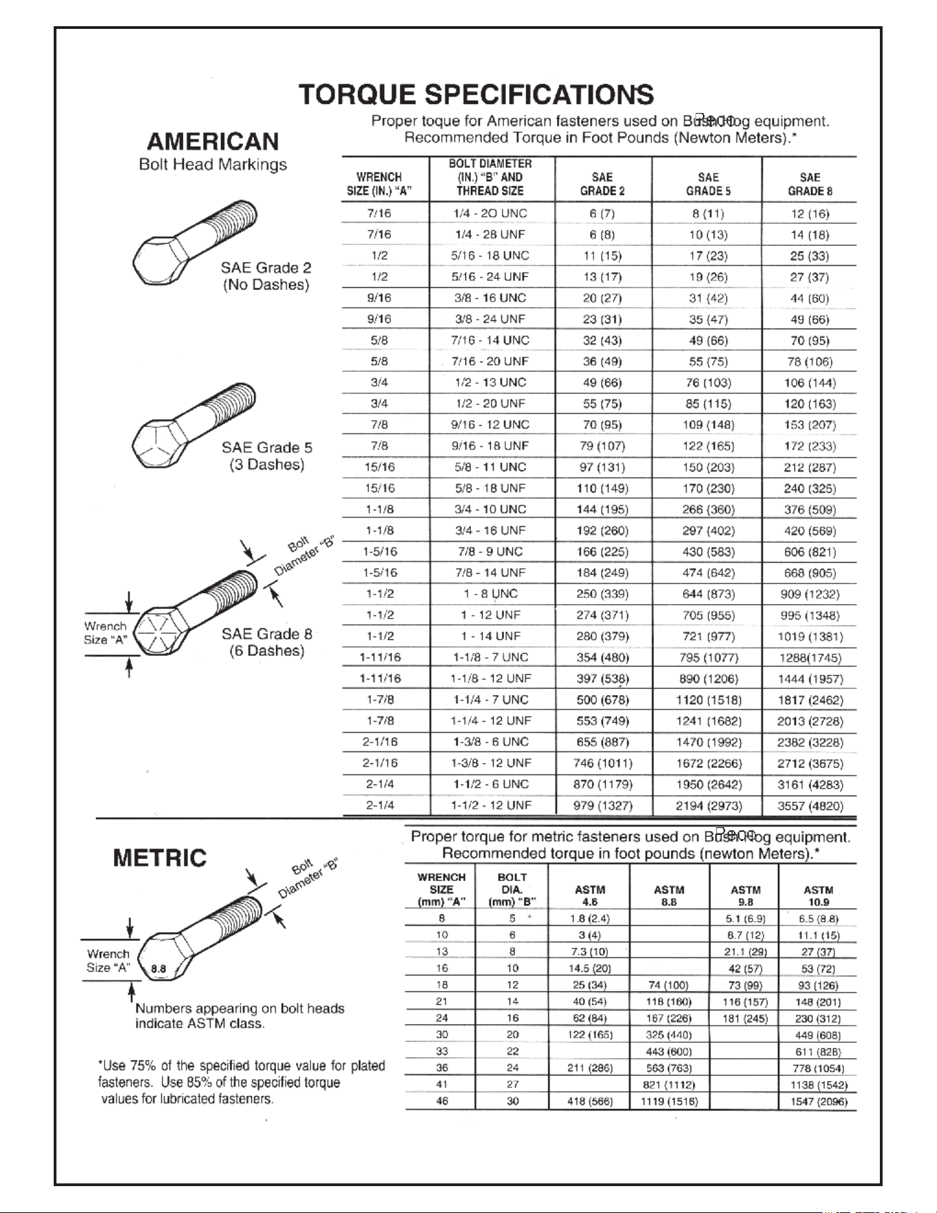
Torque Specifications - - - - - - - - - - - - - - - - - - - - - 35
Troubleshooting - - - - - - - - - - - - - - - - - - - - - - - - - 36
Notes- - - - - - - - - - - - - - - - - - - - - - - - - - - - - - - - 37
SAFETY

SAFETY
WARNING! NEVER operate the mower unless the discharge guard and either the deflector assembly or
the vacuum collector adapter are fastened securely in place.
WARNING! Do not work around the mower deck boot or the blower area until you are certain that the mower
blades and the blower impeller have stopped rotating.
WARNING! To avoid serious injury, perform maintenance on the vacuum collector; ONLY AFTER
STOPPING THE MOWER’S ENGINE AND WAITING FOR ALL MOVING PARTS TO COME TO A
COMPLETE STOP. Set the parking brake. Always remove the ignition key before beginning maintenance.
WARNING! For your own personal safety, ALWAYS mow ACROSS the face of slopes and NEVER UP
and DOWN the face. NEVER attempt to mow excessively steep slopes, and use caution when turning on any slope.
Safety Alert Symbol
This Safety Alert Symbol means: “ATTENTION! BECOME
ALERT! YOUR SAFETY IS INVOLVED!”
This symbol is used to call attention to safety precautions that
should be followed by the operator to avoid accidents. When
you see this symbol, carefully read the message that follows
and heed its advice. Failure to comply with safety precautions
could result in death or serious bodily injury.
Safety Signs
The signal words DANGER, WARNING, and CAUTION are used on the equipment safety signs. These words
are intended to alert the viewer to the existence and the degree of hazard seriousness.
!
This signal word indicates a potentially hazardous situation which, if not
avoided, will result in death or serious injury.
This signal word indicates a potentially hazardous situation which, if not
avoided, could result in death or serious injury.
It may also be used to alert against unsafe practices.
This signal word indicates a potentially hazardous situation exist which, if
not avoided, will result in minor or moderate injury.
It may also be used to alert against unsafe practices.
DANGER
!
WARNING
!
CAUTION
!
White letters on RED
Black letters on ORANGE
Black letters on YELLOW

4
PECO LIMITED WARRANTY FOR NEW PRODUCTS
A. WHAT IS UNDER WARRANTY?
PECO extends the following warranties to the original purchaser of each new PECO consumer product subject
to the following limitations.
1. PRODUCT WARRANTY: Any part of any consumer product, which is defective in material or workmanship as
delivered to the purchaser will be repaired or replaced, as PECO elects, without charge for parts or labor, if the
defect appears within 12 months from the date of delivery of the product to the original purchaser.
ALL DEFECTIVE PARTS MUST BE RETURNED TO PECO FOR INSPECTION TO
DETERMINE VALIDITY OF WARRANTY CLAIMS. Freight and mailing will be borne by the customer.
2. PARTS REPLACED DURING WARRANTY: Any new PECO part which is furnished in performance of this
warranty and is defective in material or workmanship as delivered to the purchaser will be repaired or replaced,
as PECO elects, without charge if the defect appears within 90 days from the date of installation of such part or
before the expiration of the original warranty period, whichever is later.
B. SECURING WARRANTY ADJUSTMENTS.
Call PECO for Return Authorization. Damaged or broken parts other than engines or batteries, must be
returned to New PECO, Inc. 10 Walden Dr., Arden, NC 28704 before any warranty adjustment can be
authorized. At the time of requesting warranty adjustment, the purchaser must present evidence of the date of
delivery of the product. The purchaser shall pay any charge for the product to and from Arden, NC.
C. ITEMS NOT COVERED BY PECO WARRANTY.
Engines and batteries attached to PECO products are covered under a separate warranty by the respective
manufacturer.
D. UNAPPROVED ALTERATION OR MODIFICATION.
All obligations of New PECO, Inc. under this warranty shall be terminated if products are altered or modified in
ways not approved by New PECO, Inc.
E. ACCIDENTS AND NORMAL MAINTENANCE.
The warranty covers only defective material and workmanship. It does not cover depreciation or damage
caused by normal wear, accident, improper use or abuse of products. The cost of normal maintenance and
normal replacement of service items such as belts, cutting blades, hoses, etc., which are not defective shall be
paid for by the purchaser.
F. NO REPRESENTATIONS ADDITIONAL WARRANTIES, DISCLAIMER.
Neither New PECO, Inc. nor any company affiliated with it makes any warranties, representations or promises
as to the quality of performance of its products other than those set forth herein. Except as described above,
New PECO, Inc. makes no other warranties AND SPECIFICALLY DISCLAIMS ANY AND ALL
IMPLIED WARRANTIES OF FITNESS AND MERCHANTABILITY.
G. ANY MACHINE USED FOR RENTAL PURPOSES ARE GUARANTEED FOR 45 DAYS FROM
DATE OF ORIGINAL SALE ONLY.
H. REMEDIED EXCLUSIVE.
The only remedies the purchaser has in connection with the breach or performance of any warranty on New
PECO, Inc. consumer products are set forth above. In no event will PECO be liable for special incidental or
consequential damages.
1. NO SERVICE CENTER WARRANTY.
The selling Service Center makes no warranty on his own on any item warranted by New PECO, Inc. unless he
delivers to purchaser a separate written warranty certificate specifically warranting the item. The dealer has no
authority to make any representation or promise on behalf of PECO or to modify the terms of this warranty in
any way.
Rev 2 (8/15)
Section I - INTRODUCTION &
DESCRIPTION
1-1 Introduction
Your grass collection system has been designed to give
you a low maintenance, simple, and effective way to
collect the grass clippings from your mower. This manual
is provided to give you the necessary instructions to
properly mount and operate the collection system on
your mower. Please read this manual thoroughly.
Understand what each control is for and how to use it.
Observe all safety decal precautions on the machine and
noted throughout the manual.
NOTE: All references made to right, left, front, rear, top
or bottom are as viewed from the normal operator’s
position on the mower.
1-2 Description
The grass collection system is designed for turf
maintenance where there is a need to collect the grass
clippings as the mower cuts the turf. It is also used for
picking up leaves in pre-season and post-season clean-
up. The blower, mounted on the right side of the unit,
uses a belt and gearbox system from the engine PTO
shaft. Drive train protection comes through belt slippage.
The blower draws grass clippings from the discharge
area of the cutting deck back to the (2) - 4 cubic foot
collection bags P#(G0013-L) at the rear portion of the
mower frame. The operator can engage the blower with
a toggle switch mounted on the control panel to the right
of the operator. Once the bags are full with clippings,
they can be easily released for dumping.
Section II - INSTALLATION FOR USE
Collection System May Require
Dealer Installation!
Please refer to Page 17 for further details.
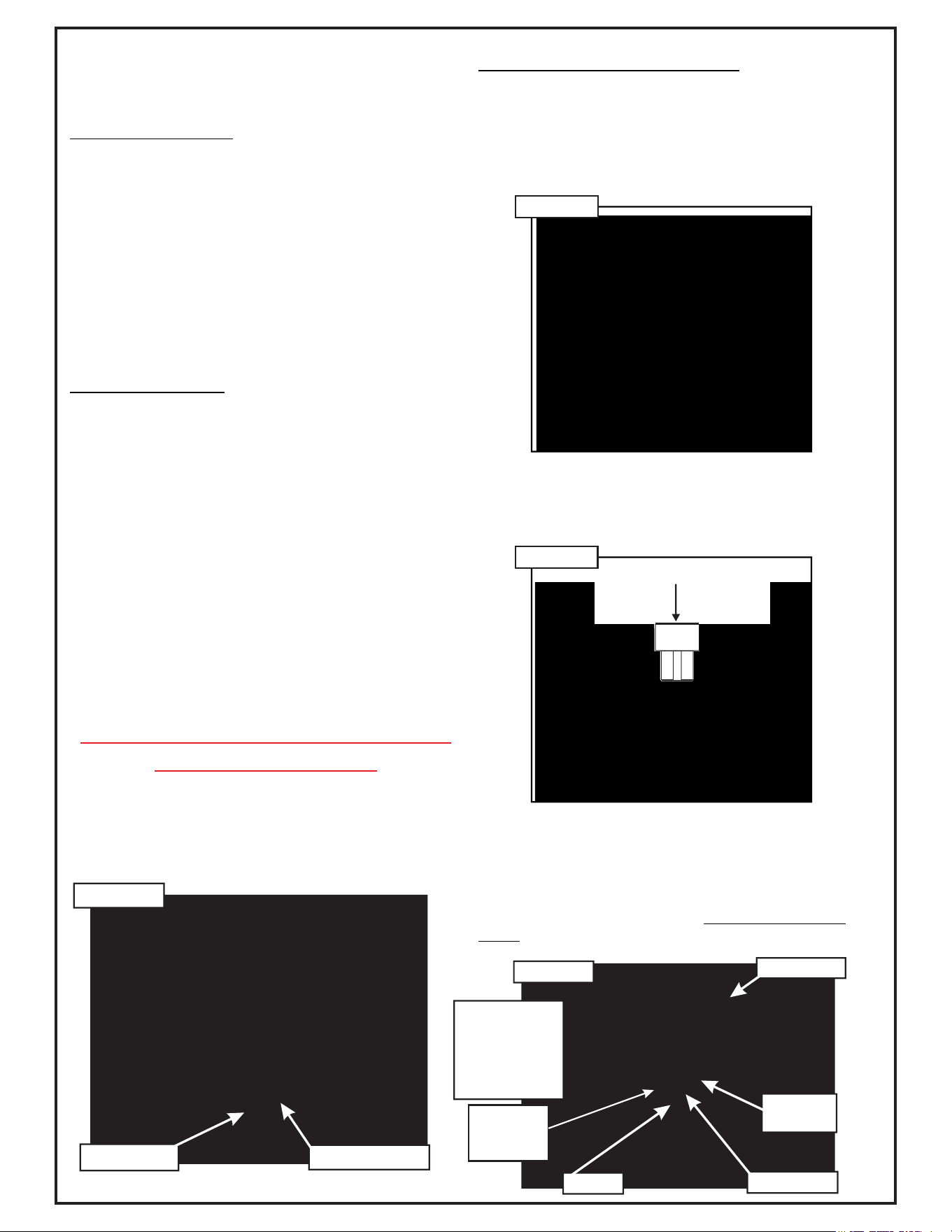
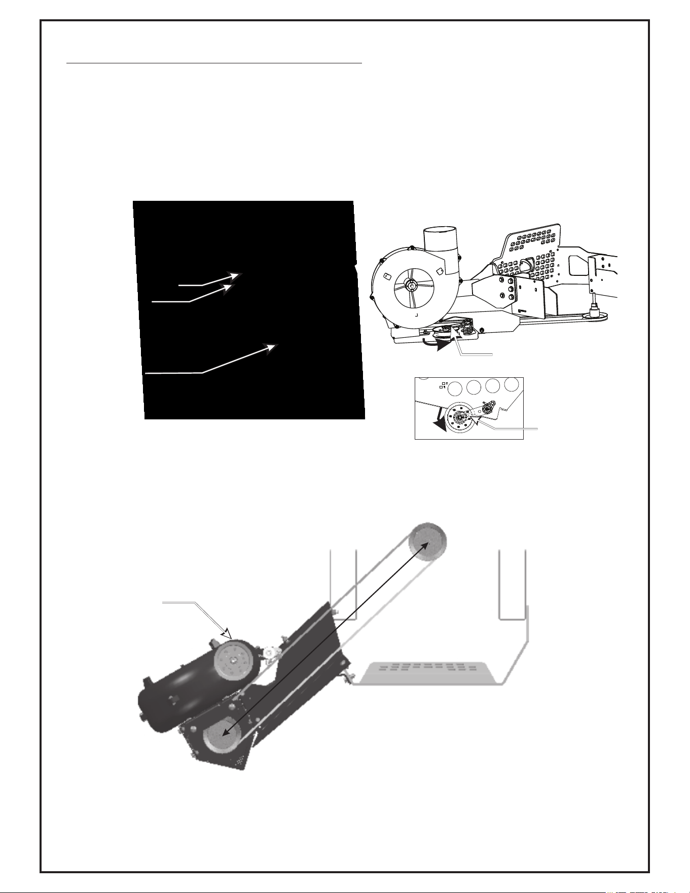
2-1 Preparation Of Mower
From the underside of the engine, disconnect the wiring
harness attached to the electric clutch. Remove the bolt
and electric clutch from the mower. Refer to Figure 2-1a.
Remove the D-drive spacer using an arbor press or
equivalent. On removal, adjacent bearing OUTER race
must be supported or bearing damage may occur. Refer
to Figure 2-1b.
The engine pulley bushing #31 P#(S0220) may need to
be installed using an arbor press or equivalent. If
pressed, opposite bearing inner race must be supported
or bearing damage may occur. Refer to Figure 2-1c.
Fasten the A-Section Pulley P#(M0309) to the pulley
bushing and electric clutch assembly using (1) 7/16”
Double Indented Washer P#(K0278), (1) 7/16” hi-collar
lock washer P#( ) and (1) 7/16”-20 x 5” HHCS K0140
P#(K0018) as shown in Figure 2-1d. The added pulley
will power the collection system. Torque the bolt to 55
ft./lbs. Re-connect the wiring harness to the electric
clutch.
Figure 2-1a
Remove Bolt
D-Drive Spacer
PRESS
Figure 2-1b
PRESS
Engine Pulley Installation
Figure 2-1c
Electric Clutch
A-Section
Pulley
Hex Bolt
Lock Washer
Engine Pulley
Number Is
Stamped On
The Pulley
Bushing
Figure 2-1d
Double
Indented
Washer
6
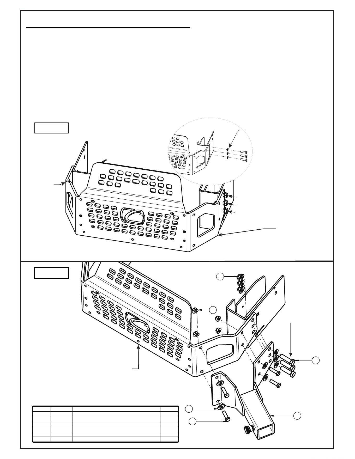
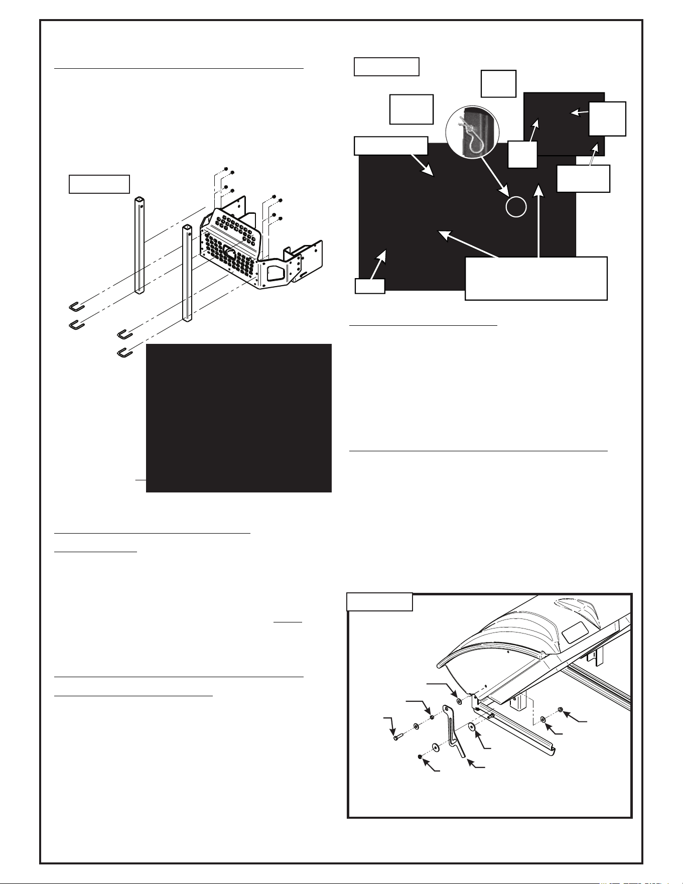
2-2 Mount Arm Preparation and Installation
Remove the (3) 1/2”-13 x 1-1/4” existing HHCS, (3) 1/2” washers and (3) 1/2”-13 Ny-Flange locknuts from the right-
rear of the mower and save the 1/2” Flat Washers for the next step. Next, loosen bolts on opposite side of mower
for rear bumper alignment in the next step. Refer to figure 2-2a.
Secure the Mount Arm Assembly P#(A2063_01) to the rear guard of the mower, using (3) 1/2”-13 x 1-3/4” HHCS
GR5 P#(K1301), (3) 1/2” Flat Washers (retained previously), (3) 1/2”-13 Ny-Flange Lock Nuts P#(K2012), (4) 3/8”-
16 x 1-1/4” HHCS GR5 P#(K1192), (4) 3/8” Flat Washers P#(K0047), and (4) 3/8”-16 Ny-Flange Lock Nuts
P#(2038). Refer to figure 2-2b.
Important: Before tightening bolts (A) (Figure2-2b), on both sides, make certain that the bumper is rotated fully in
the upward position. Once drive is installed, Section 2-4, the correct distance from the center of the engine pulley to
the center of the drive pulley is 34.84”(inches). If the dimension is within + or - .06, no further adjustment is
necessary.
Figure 2-2a
Figure 2-2b
1
2
3
4
5
6
Item # Part # Desc. Qty.
1 A2063 Mount Arm Assy 1
2 K0047 Flat Washer 3/8" / 1.00 OD x .446 ID x .075 T 4
3 K1192 HHCS 3/8"-16 x 1-1/4" GR5 4
4 K1301 HHCS / 1/2"-13 x 1-3/4" 3
5 K2012 1/2"-13 Ny-Flange Lock Nut 3
6 K2038 Ny-Flange Lock Nut 3/8"-16 4
Remove
Save
A
Rotate
Bumper
Upwards
Before
Tightening
Loosen
Bolts
Rear Bumper
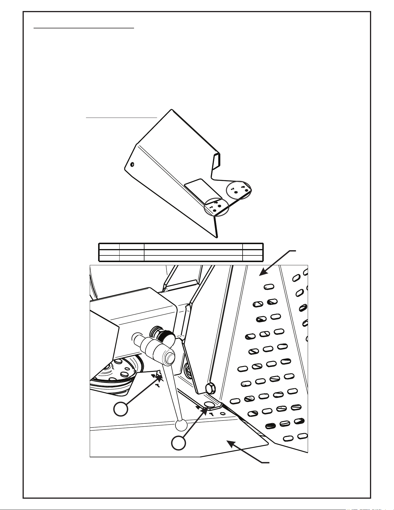
2-3 PTO Drive Assembly
Once the Mount Arm Assembly P#(A2063_01) is installed and
secured to the mower, assemble the Drive Assembly P#(A2061_01),
Belt Guard Assembly P#(A2069_01), and the Idler Mount Assembly
P#(A2067_01).
First, attach the Belt Guard Assembly P#(A2069_01) to the Drive
Assembly P#(A2061_01) using (2) 1/4”-20 x 5/8” Carriage Bolts
P#(K1010) and (2) 1/4”-20 Ny-Flange Lock Nuts P#(K2014).
Leave Bolts Loose.
1
1
Belt Guard
Drive Assembly
Item # Part # Desc. Qty.
1 K1010 1/4"-20 x 5/8" Carriage Bolt 2
2 K2014 1/4"-20 Ny-Flange Lock Nut 2
Notice Marked Holes Below;
(Use corresponding holes with type of
mower that is being fitted up)
T = Tank Mounting Hole
P = Pro Z Mounting Hole
BELT GUARD ASSY.
8
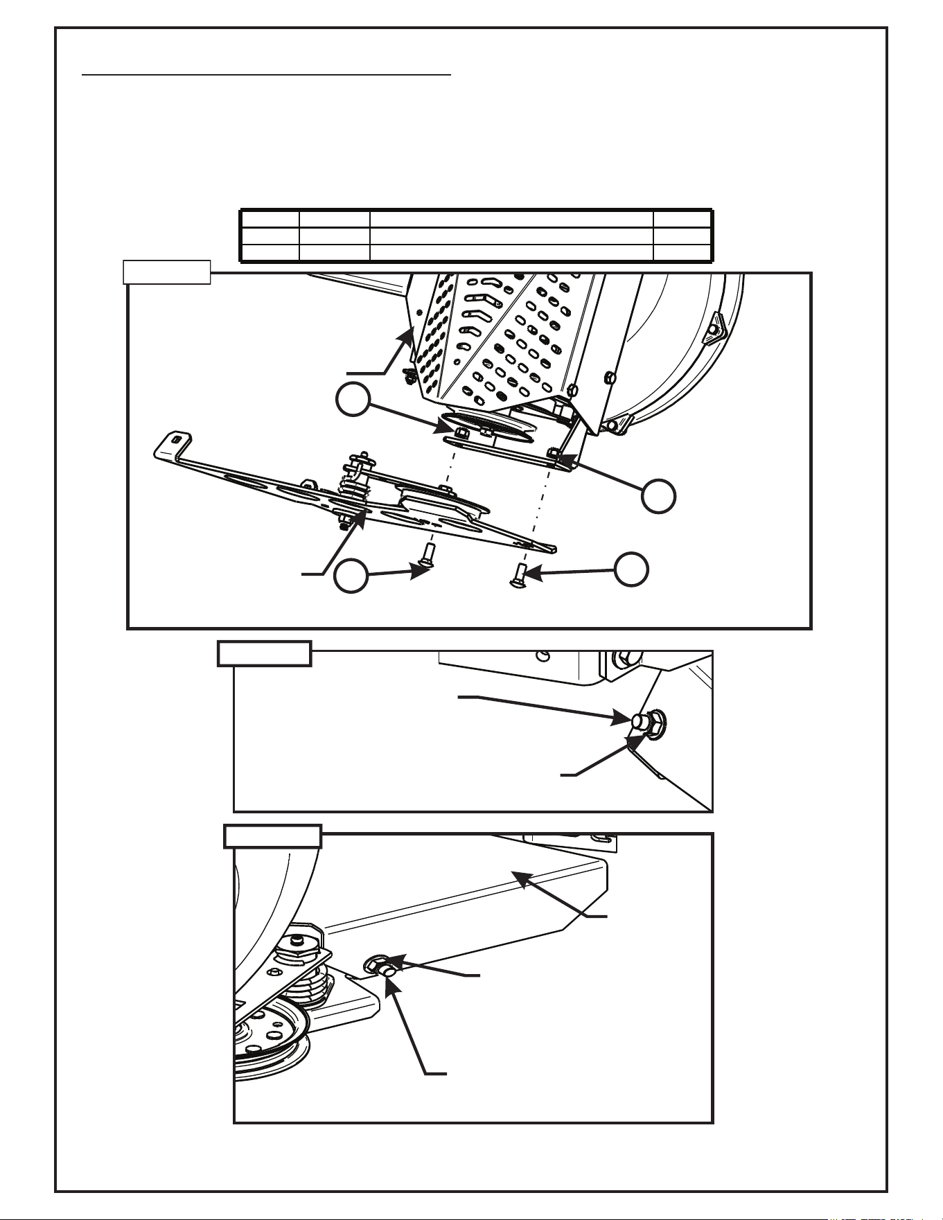
2-3 PTO Drive Assembly (Continued)
Attach the Idler Mount Assembly P#(A2067_01) to the Drive Assembly using (2) 3/8”-16 x 1” Carriage Bolts
P#(K1182) and (2) 3/8”-16 Ny-Flange Lock Nuts P#(2038). Refer to Figure 2-3a. Leave Bolts Loose
Next, secure the Idler Mount Assembly P#(A2067_01) to the Belt Guard Assembly P#(A2069_01) using (2) 3/8”-
16 x 1” Carriage Bolts P#(K1182) and (2) 38”-16 Ny-Flange Lock Nuts P#(K2038). Refer to Figure 2-3b & c.
Tighten All Bolts.
(1) K1182 - 3/8”-16
x 1” Carriage Bolt
(1) K2038 - 3/8” NyFlange
Lock Nut
(1) K1182 - 3/8”-16
x 1” Carriage Bolt
(1) K2038 - 3/8”
NyFlange
Lock Nut
Belt
Guard
Item # Part # Desc. Qty.
1 K1182 3/8"-16 x 1" Carriage Bolt 2
2 K2038 Ny-Flange Lock Nut 3/8"-16 2
1
2
1
2
Idler Mount
Assembly
Drive Assembly
Figure 2-3a
Figure 2-3b
Figure 2-4c
Figure 2-3c
2-4 Drive Assembly and Belt Installation
(Note: It is recommended that assistance be available during this step.)
Insert the drive assembly into the receiver tube on the Mount Arm Assembly until the Knob Plunger Pin engages.
Next, feed the AK82 Belt P#(M0311) between the belt guard and the Idler Mount Assembly. Place belt around the
PTO pulley on the underside of the mower. While one person inserts a 1/2” drive tool (socket handle) into the
Idler Mount Assembly and rotates lever arm counter-clockwise, enough to relieve all tension from belt, place belt
around the drive pulley. Once belt is in position, carefully release the tension to tighten belt.
Drive Assembly
Knob Plunger Pin
Mount Arm Assembly
Insert 1/2” Drive Tool
here
When belt is properly installed, the Idler Arm Pulley should remain on the outside of the belt. When the idler arm
is released the Idler pulley should make contact with the flat side of the belt.
Idler pulley
Insert Drive Tool
Here
34.84”
10
2-5 Lower Mount Tube Installation
Secure the (2) lower mount tubes P#(B0752) to the rear
frame using (2) 5/16”-18 u-bolts P#(K1098) and (4)
5/16”-18 nylon flange locknuts P#(K2516) PER TUBE.
Refer to Figure 2-5. Note: Bottom of Tubes should rest
on the top edge of the Trailer Hitch Plate.
2-6 Upper Frame Assembly
Installation
Lift the upper frame assembly P#(A1114) into position,
and slide onto the lower mount tubes as shown in Figure
2-7 and secure with (2) 1/2” x 2-1/4” clevis pins
P#(K0133) and (2) hair pin clips P#(K0088). Note: It is
recommended that someone assist you when installing
the upper frame assembly.
2-7 Top Assembly To Upper Frame
Assembly Installation
Position the top assembly P#(A2062) above the upper
frame assembly with the Rubber Dust Guard positioned
towards the seat as shown in Figure 2-7. Fasten the top
assembly to the upper frame assembly using (2) 5/16”-
18 x 2-1/2” HHCS P#(K0125) and (2) 5/16”-18 nylon
flange locknuts P#(K2516). Leave the locknuts slightly
loose, to allow the top assembly to open and close
easily. Refer to Figure 2-7 for hardware location.
2-8 Inlet Installation
Insert the Inlet P#(A2019) into the hole on the top
assembly from the inside and then snap the inlet into
place. The inlet should pivot freely about the hole.
2-9 Hinge Kit Assembly Installation
Assemble the hinge kit as shown in Figure 2-9, using (1)
Latch Plate P#(B0884), (1) 5/16”-18 x 1-1/4” HHCS
P#(K1156), (1) 5/16”-18 Ny-Flange locknut P#(K2516),
(3) 5/16” Flat Washers P#(K0042), (1) Latch Spacer
P#(S0006), (2) Extra Heavy 5/16” Fender Washers
P#(K0505) and (1) 5/16”-18 Lock Nut P#(K0506). Leave
the nuts loose enough to allow fluid movement of the top
when opening and closing. When opened, the top should
rest in the Latch Plate Slot.
(2) 5/16”-18 x 2-1/2” HHCS
(2) 5/16”-18 Locknuts
Top Assembly
Figure 2-7
Nylon
Flange
Locknut
Hex
Bolt
Inlet
Hair Pin
Clip
Clevis
Pin
K0506
B0884
K2516
K0042
S0006
K0505
K0042
K1156
Figure 2-9
Figure 2-5
Trailer Hitch
Plate
Rubber
Dust Guard
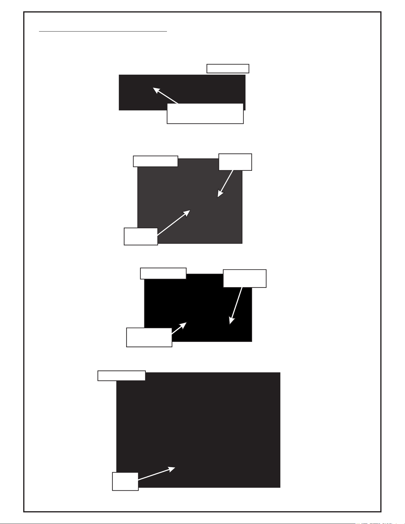
2-10 Blower Cone Installation
Thread (1) 5/16”-18 jam nut P#(K0120) onto each end of (2) 5/16”-18 x 2-1/2” HHCS P#(K0125) as
shown in Figure 2-10a.
Now partially thread (1) bolt into each of the two threaded bosses located on the blower housing. Place
8” Blower Cone P#(E6009) so the two tabs line up with the bolts and tighten completely as shown in
Figure 2-10b.
Once the (2) bolts are tight, tighten the jam nuts against the threaded boss as shown in Figure 2-10c.
Refer to Figure 2-10d for proper blower cone installation reference.
Figure 2-10b
Threaded
Boss
Blower
Cone Tab
Figure 2-10c
(1st) Tighten
Bolt
(2nd) Tighten
Jam Nut
Figure 2-10d
Blower
Cone
Figure 2-10a
Thread (1) Jam Nut
Onto Each 5/16”-18 Bolt
12
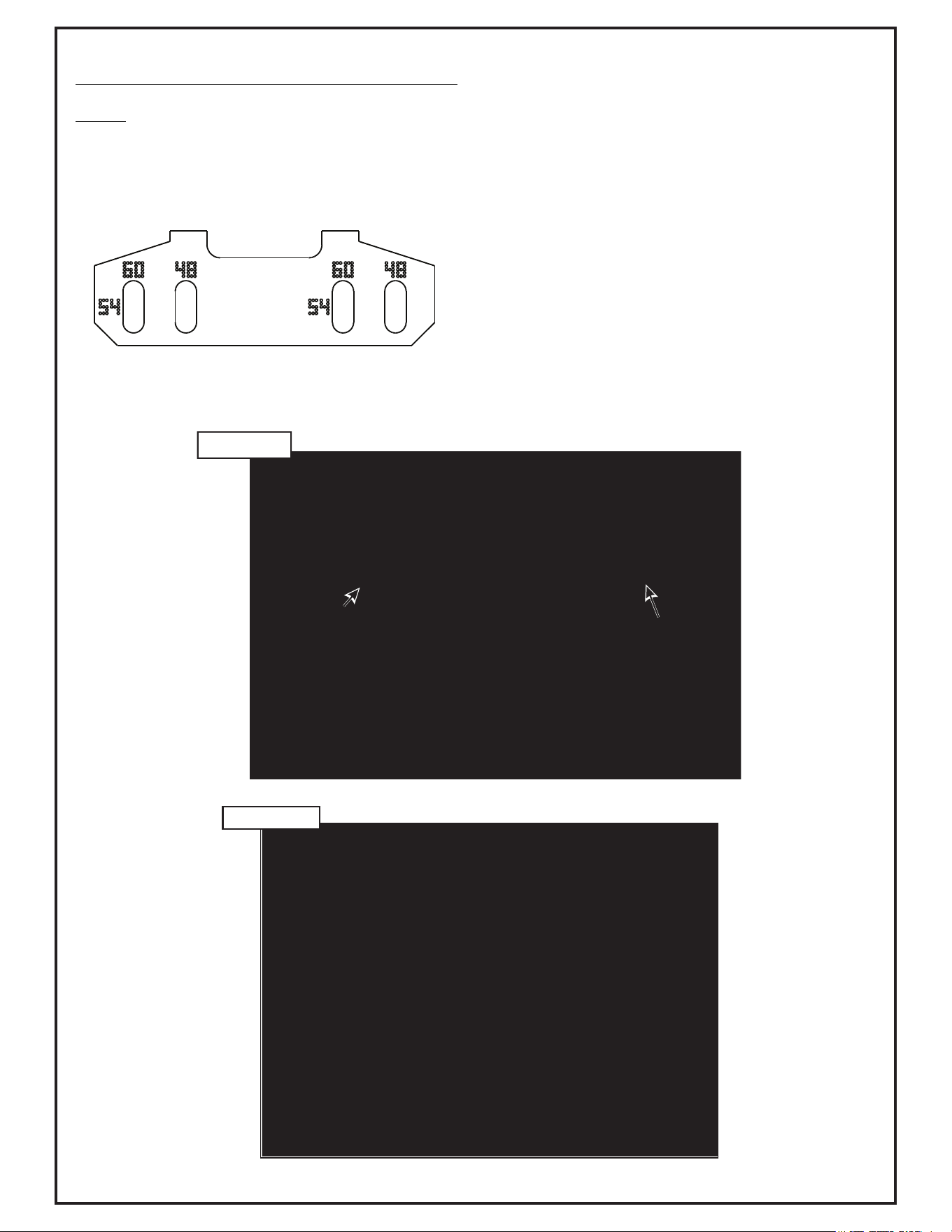
2-11 Boot To Mower Deck Installation
NOTE: The boot kit assembly is designed to fit the 48”,
54” and 60” deck. To ensure a snug fit between the boot
and the mower deck, follow the instructions in this step
thoroughly, and remove and tighten all hardware in the
sequence specified.
According to deck size, align marked holes and Boot holes.
Secure the boot mounting assembly P#(A2045) to the
aluminum boot P#(E0028A) using (2) 3/8”-16 x 1” carriage
bolts P#(K1182) and (2) 3/8”-16 nylon flange locknuts
P#(K2038). Insert the carriage bolts from the inside of the
boot so the threads are on the outside of the boot (Figure
2-11a). This will prevent grass clippings from collecting on
the bolt threads. Leave bolts loose for alignment once
installed on mower.
After removing only the wing knobs align the threaded
mount posts, on the boot mounting assembly, with the
mounting holes located above the mowers discharge chute
and insert the into the mounting holes. Secure with the (2)
Wing Knobs P#(J0018). Press Boot against discharge
chute, to ensure a snug fit and tighten the two nuts on top
of the boot. Refer to Figure 2-11b.
Figure 2-11b
Note: Deflector not shown for clarity but must be installed during normal operation.
Figure 2-11a
2-12 Length Of Hose Adjustment
The hoses in steps 2-13 and 2-14 must be cut to fit your
machine. Follow steps 2-13 and 2-14. do not cut the
hoses until you have tried to fit them on your machine.
Remember that the hoses have to be long enough to
adjust for the blower assembly’s movement as well as
allow for enough clamping surface between the inlet,
blower assembly, and the deck boot.
2-13 Upper Hose Installation
Fasten the inlet to the plastic top by sliding the inlet from
the inside of the top to the outside and lock into place.
Slide a hose clamp P#(J0060) onto one end of the 6”
upper hose (Figure 2-13). Next, slide opposite
end of the 6” hose onto the inlet. Make sure that the
hose is in position to be secured by the Snap Fastener
P#(K0508). Proceed to slide the opposite end of the 6”
hose onto the outlet of the blower assembly. Make sure
both ends of the hose are clearly attached to the inlet
and the blower assembly inlet. Tighten the hose clamp.
2-14 Lower Hose To Blower Cone
Installation
Slide a clamp P#(J0080) over both ends of the lower
hose. Then proceed to slide the lower hose onto the
blower cone. Tighten the hose clamp. The
assembly should look like Figure 2-13.
2-15 Lower Hose To Boot Installation
Take the unattached end of the lower hose and slide it
over the circular end of the boot. Use the lower hose
clamp to secure the hose to the boot (Figure 2-13). Tip:
Before securing clamp rotate hose counter-clockwise
(away from yourself) approximately 1” to aid in retaining
boot to mower deck.
Figure 2-13
Inlet
Upper
Hose
Lower
Hose
Hose
Clamps
Blower
Cone
Blower
Outlet
Boot
Hose
Clamps
Snap
Fastener
14
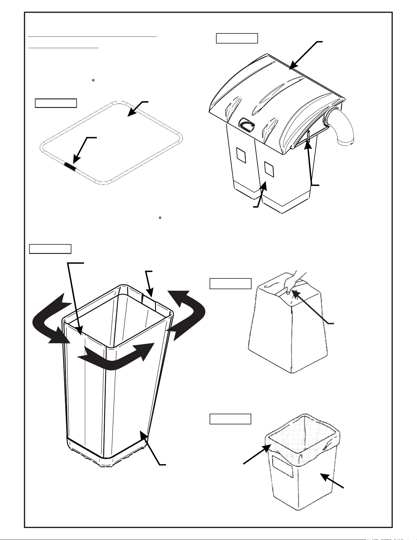
2-16 Installation/Removal Of
Collection Bags
IMPORTANT!
To prevent bag wear, install (1) black rubber end cap
P#(F0010), as shown in Figure 2-16a, on each bag ring
after rotating bag 360.
To complete the bag installation, place the seam
openings of the bag and the bag ring openings together.
Place the rubber bag ring connector on both ends of the
bag ring and turn the bag one half turn (180 ) so the
rubber end cap is located opposite to the opening in the
bag (Figure 2-16b). Do this for each bag.
Install the completed assemblies onto the support frame
and close the plastic top. Fasten the draw-latches to
hold the plastic top closed (Figure 2-16c).
Figure 2-16e
Grasp Bag
Here
Figure 2-19c
Black Rubber
Connector
Bag Ring
Bag
Bag Opening
Bag Ring Rubber End
Cap Opposite
of Bag Opening
Figure 2-16a
Figure 2-16b
Figure 2-16d
Plastic Bag
Cloth Bag
To empty the bag, first unlatch and lift top, next remove
the bag and bag ring by sliding rearward, then grasp the
handle on the bottom of the bag, and last turn it upside
down to empty the collected debris (Figure 2-16d).
Repeat for the other bag. Reinstall both bags, line with
plastic bags if desired, close the plastic top and reattach
the draw latches.
Plastic lawn and leaf bags, 33 gallon size, may be used
inside the cloth bags. Be sure to leave enough plastic
bag hanging over the frame so the plastic bags can be
twist tied before emptying (Figure 2-16e).
Plastic Top
Fasten Draw-
Latch Here &
Opposite Side
For Proper Unit
Transportation
Completed Bag
Installed
Figure 16-c
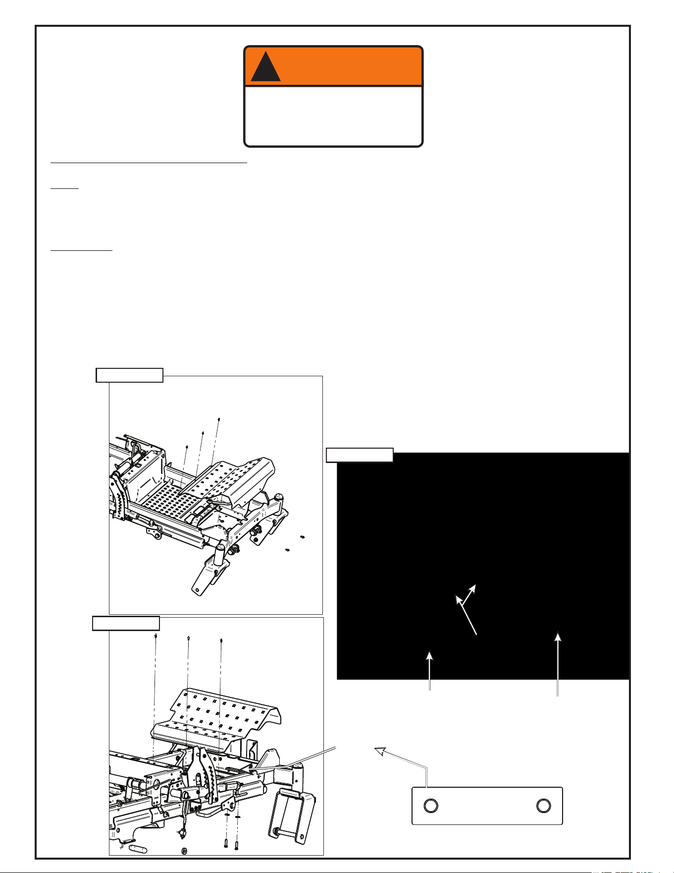
2-17 Weight Kit Installation
Note:
— Installing a weight kit is mandatory for safe operation of the collection system.
— When installing the weight bar, you should have another person to help position the weight.
— If removing PTO assembly for side-discharge mowing, please also remove the weight kit.
Installation:
To install weight kit, first remove screws on foot rest panel and retain. Next, remove and discard the HHCS on the
under side of the front of the mower. Lift the foot rest panel to access the front frame compartment. Refer to Figure
2-17a. Place Weight Bar Clamp P#(B0943), as shown in Figure 2-17b and loosely attach both the Left Mount Plate
P#(B0879) and Right Mount Plate P#(B0877) with (1) 3/8”-16 x 1-1/4” HHCS P#(K1192) and (1) 3/8” Flat Washer
P#(K0047) each. Lower the foot rest panel and loosely attach the front of both of the mount plates with the torx screws
removed earlier. Replace the remaining foot rest screws and tighten all bolts installed. Attach the (2) 1/2”-13 x 4.312”
x 4.25” U-Bolts P#(K0331) to the Mount Plates with (4) 1/2”-13 Ny-Flange Lock Nuts P#(K2012) loosely. From either
side of the mower, slide each weight bar into place and center. Once centered, tighten U-Bolts to hold weights
WARNING
!
To Prevent Serious Injury-
Weight Kit Must Be Installed
At All Times While Grass
Collection System Is In Use.
Figure 2-17a
Figure 2-17c
Figure 2-17b
Weight
Bar
Clamp
P#(B0943)
3/8”-16 x1-1/4”
HHCS P#(1192)
1/2”-13 x 4.312” x 4.25”
U-bolts
P#(K0331)
Torx Screws
16
A
B
C
D
P#(P0270)
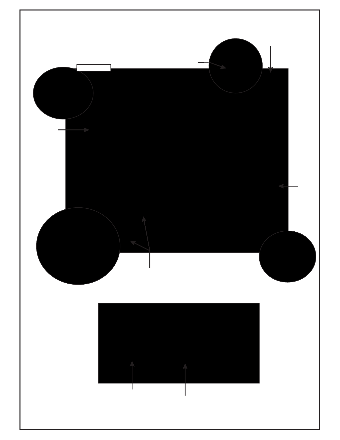
2-18 Safety Interlock Wiring Harness Installation
Note: orientation
P#(P0073)
Figure2-18a
WARNING
!
To Prevent Serious Injury-
Proper Installation Of Safety Interlock Harness
Is Mandatory. Please Check That All Interlock
Points Work Correctly Once Installed.
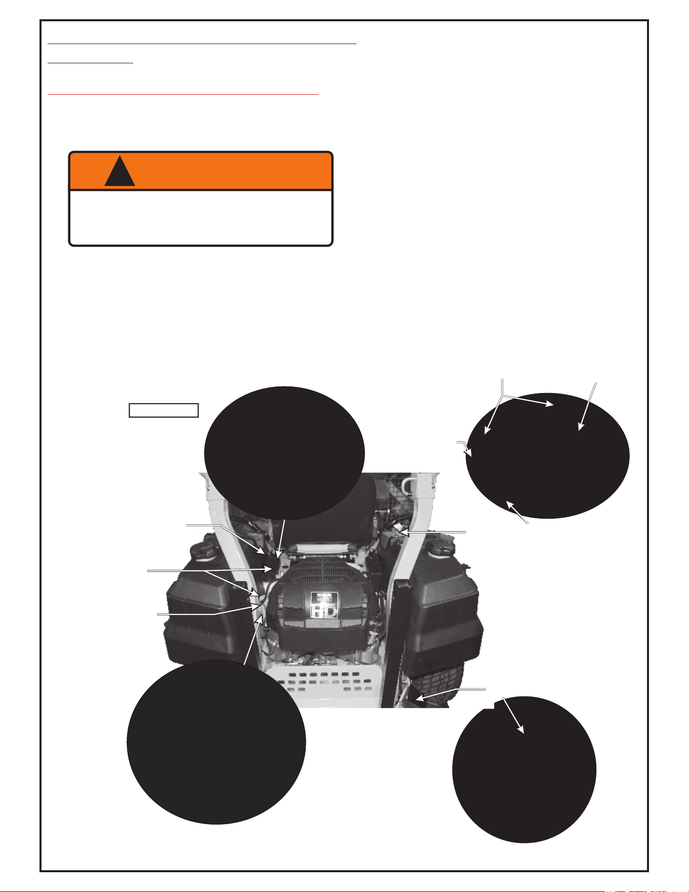
2-18 Safety Interlock Harness Installation
(Continued)
Collection System May Require Dealer Installation!
Before installing, please verify the presence of an auxiliary 5-
way female connector in the mower’s electrical harness. The
connector is located underneath the operator’s seat, near the (+)
side of the battery.
Connect (A) the Delphi 5-way Male connector, on the harness,
to the connection point under the seat near the (+) side of the
battery. Next, on the left side of the engine locate and separate
the engine harness from the main harness and connect the
Safety Interlock Harness (B) to each side of the motor harness
and the mowers main harness. Refer to Figure 2-18a & b.
Connection
Points
A
B
C
D
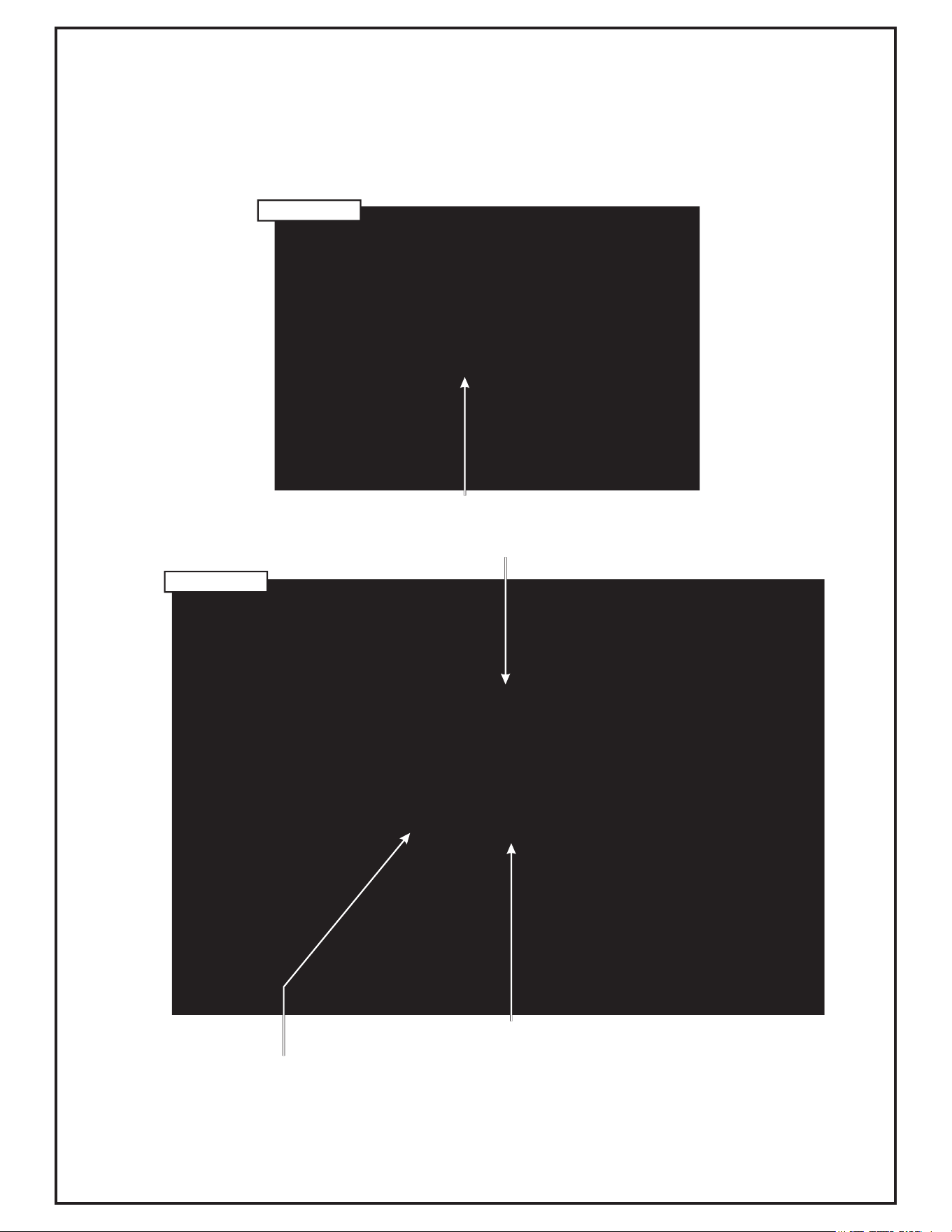
Route the PTO connector (C) around front side of
engine, between the ROPS and gas tank and
through the opening in the rear bumper connecting
to the quick connect plug located on the PTO Drive.
Before routing the switch (D), remove safety cover
from the top of the switch, locate and remove knock
out on control panel. The control panel is easily
removed by pulling the inner pin up on the
fasteners. Lift the back section and pull towards the
rear of the mower. Route harness (D) through the
frame and up to the underside of the control panel.
Insert switch into the knock-out hole, reattach safety
cover and orientate the switch with the groove side
forward.
Note: Switch must be oriented correctly, to the
harness connector, or mower will not start with
switch in the off position.
Knock Out
For Switch
Panel Fasteners
Lift
Slide
Connection
Points
A
B
C
D
Figure2-18b
18
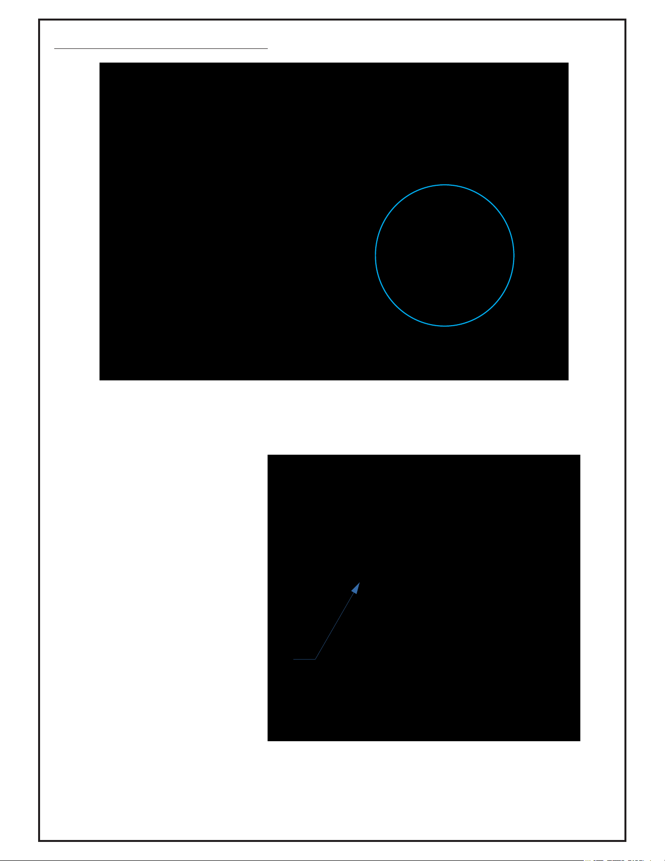
Once the safety interlock wiring harness is installed use the connectors provided to secure in place. Insert the
rosebud clips in the 1/4” holes on the engine shield as shown. Zip straps are also included to aid in securing the
harness. Refer to Figure 2-18c & d
1/2” Rosebud Conduit Clip
P#(P0273)
1” Rosebud Conduit Clip
P#(0272)
Battery
2-18 Safety Interlock Harness Installation (Continued)
Figure 2-18c
Figure 2-18d
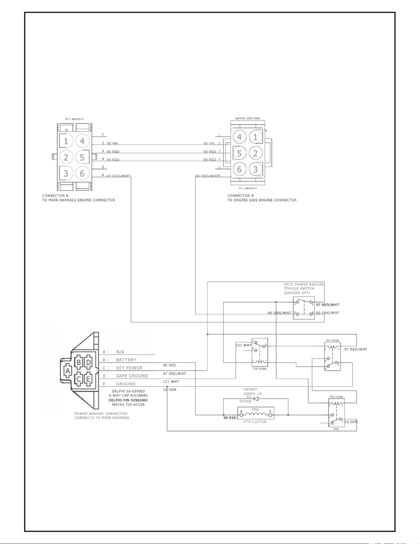
2-18 Safety Interlock Harness Installation (Continued)
Wiring Schematic

20
3
1
2
4
5
Figure 2-19
2-19 Impeller Blade Removal/Replacement
To Remove: First remove the 5/16”-24 x 1” HHCS P#(K0428) (#1), taper lock bushing washer P#(K0284) (#3), (2)
5/16 Flat Wahers P#(K0042) and spacer bushing P#(S0159) (#4) from the taper-lock bushing P#(S0157) (#5). See
Figure 2-19. Next remove the (2) 1/4”-20 x 1” HHCS (#2) and place them into the threaded holes of the taper-lock
bushing (#5). Gradually thread each bolt evenly into the taper-lock bushing, forcing the blade to break-away from
the taper-lock bushing. If the impeller will not move, carefully hit the base of the impeller, between each vein, with
a hammer, then try again.
To Replace: Place impeller blade over the engine shaft. Slide the taper-lock bushing (#5) on to the engine shaft
and into the impeller blade, aligning the non-threaded holes of the taper-lock bushing to the threaded holes of the
impeller blade. Fasten by using (2) 1/4”-20 x 1” HHCS (#2), (1) spacer bushing (#4) (1) taper lock bushing washer
(#3), and (1) 5/16”-24 x 1” HHCS (#1). Torque to the proper specifications in the torque chart on the back of this
manual. Next, rotate the impeller blade to ensure that the blade is clear of contact on all sides of the blower
housing.
Flap Can Be Adjusted Up/Down
Depending On Mowing Conditions.
Adjust Flap Up To Allow More Dense
Material To Reach Left Bag. Adjust
Flap Down To Allow Less Dense
Material To Reach The Right Bag.
Once Adjusted Properly, Both Bags
Should Fill Evenly, But May Require
Further Adjusting When Mowing
Conditions Change.
2-20 Even Bag Fill Adjustment
22
1
2
4
3
2
5
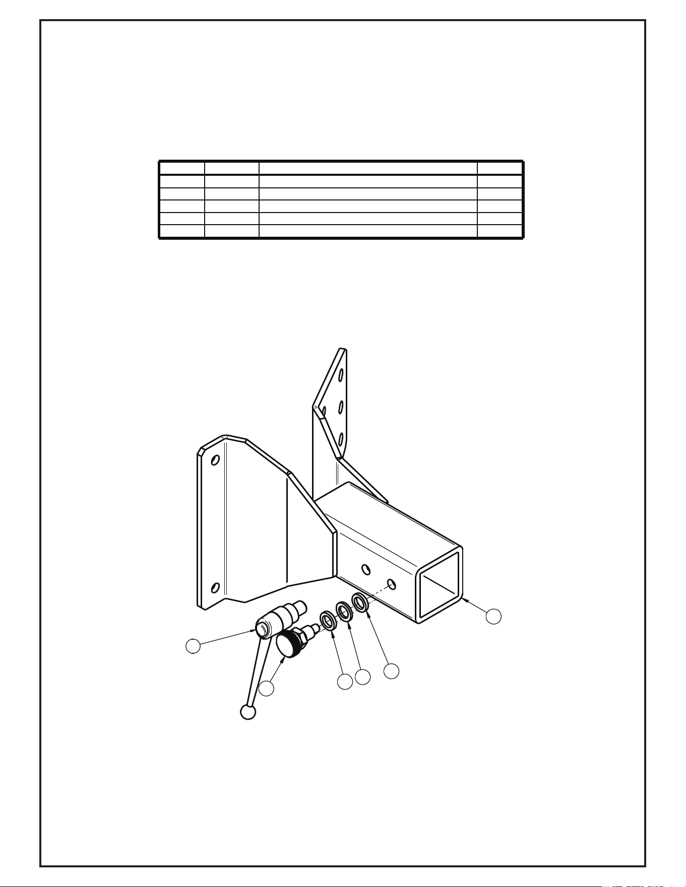
A2063_01 Mount Arm Assembly
Item # Part # Desc. Qty.
1 A2033_01 Mount Arm Sub-Assy 1
2 J0013 Nylon Flat Washer 1/2" x .750" OD Grade 6/6 2
3 K0027 Flat Washer 1/2" / .787 OD x .512 ID x .090 T 1
4 J0020 Knob Plunger Pin 1/2"-13 1
5 J0009 Adjustable Handle 1/2"-13 x .59 Male 1
2
1
6
9
4
7
3
5
8
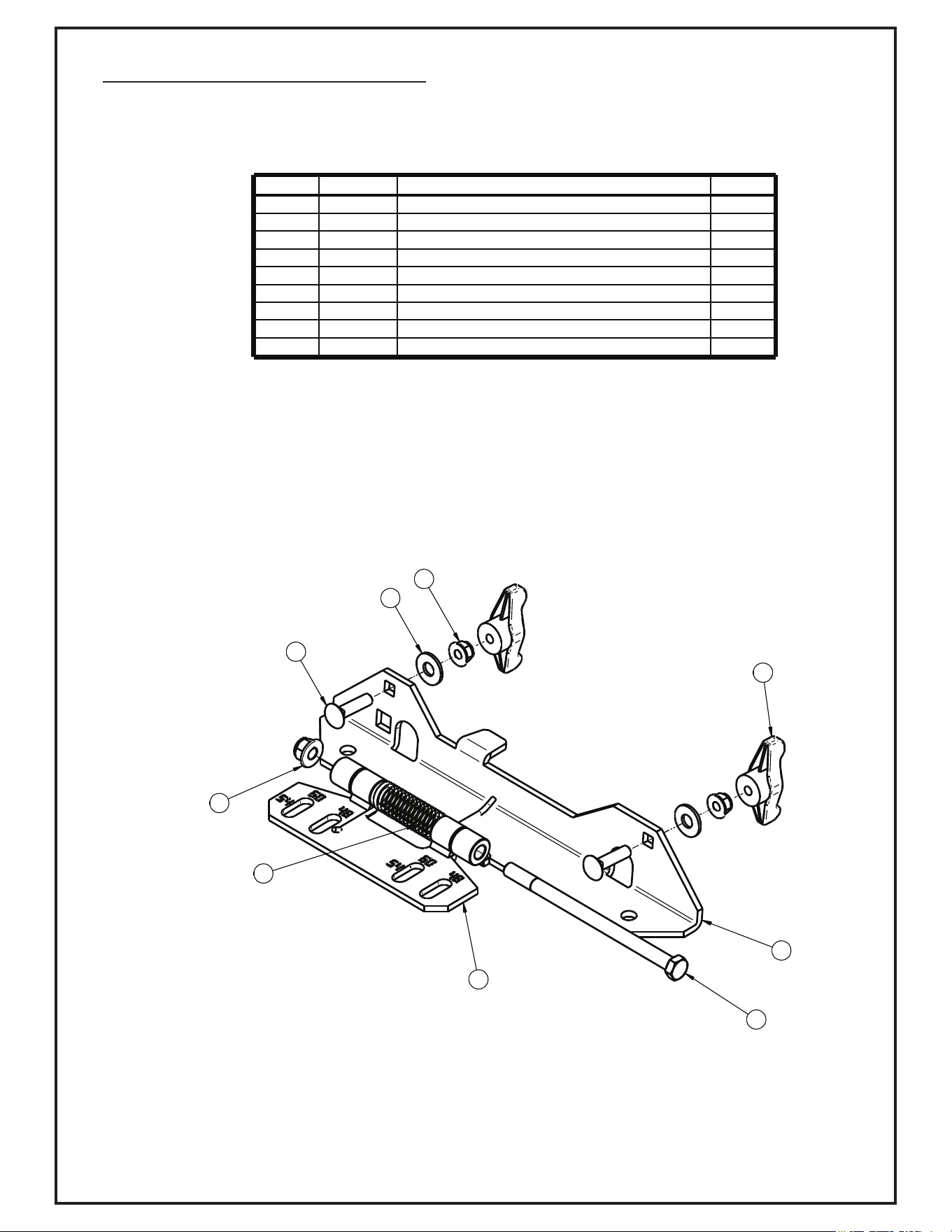
Item # Part # Desc. Qty.
1 A2044 Deck Plate Assy 1
2 A2043 Boot Plate Assy 1
3 K1429 3/8"-16 x 6" HHCS GR5 1
4 K0042 Flat Washer 5/16" / .875 OD x .380 ID x .075 T 2
5 K2038 Ny-Flange Lock Nut 3/8"-16 1
6 J0017_1 Torsion Spring 1
7 K1146 5/16"-18 x 1-1/4" Carriage Bolt 2
8 K2516 Ny-Flange Lock Nut 5/16"-18 2
9 J0018 Wing Knob / 5/16-18 Thru Nut 2
A2045 Boot Mounting Assembly
24
A2067_01 Idler Mount Assembly
1
12
11
6
8
10
2
7
9
13
14
5
4
3
2
Item # Part # Desc. Qty.
1 B0958_01 Idler Mnt Pl 1
2 K2038 Ny-Flange Lock Nut 3/8"-16 2
3 K1463 Flat Washer .720 ID x 1.500 OD x .250 T 1
4 K1219 Jam Nut 3/8"-16 1
5 K1192 HHCS 3/8"-16 x 1-1/4" GR5 1
6 K0329 Nylock Nut 7/16"-14 GR8 1
7 M0003 Idler Pulley 1
8 K1462 HHCS 3/8"-16 x 1-3/4" GR8 1
9 M0004 Cap / Idler Pulley 1
10 K1464 Shoulder Bolt 7/16"-14 / Idler 1
11 J0022 Grease Fitting 3/16" 1
12 J0021 Idler Torsion Spring 1
13 A2070 Idler Arm Assy. 1
14 B0974 Idler Base Plate 1
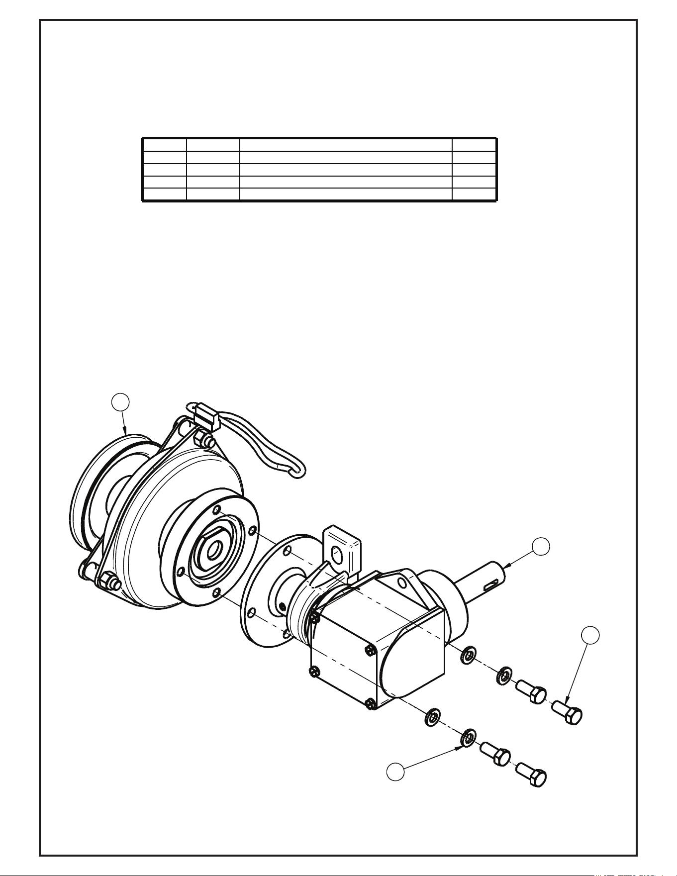
7
6
5
3
2
1
4
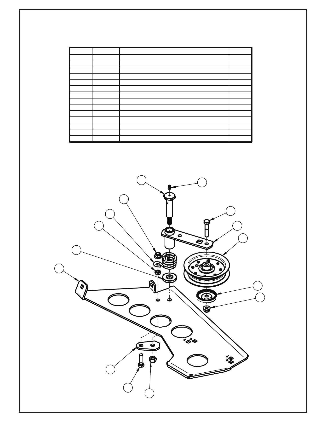
Item # Part # Desc. Qty.
1 M0002 Gearbox 1
2 K0428 HHCS 5/16"-24 x 1" GR8 1
3 K0043 Lock Washer 5/16" 1
4 N0002 Pillow Block Bearing 7/8" 1
5 K0035 Set Screw 5/16"-18 x 1/4" Cup Point 1
6 J0272 Woodruff Key #9 1
7 A2048 Clutch Flange Assy 1
A2058 Gearbox Sub-Assembly
26
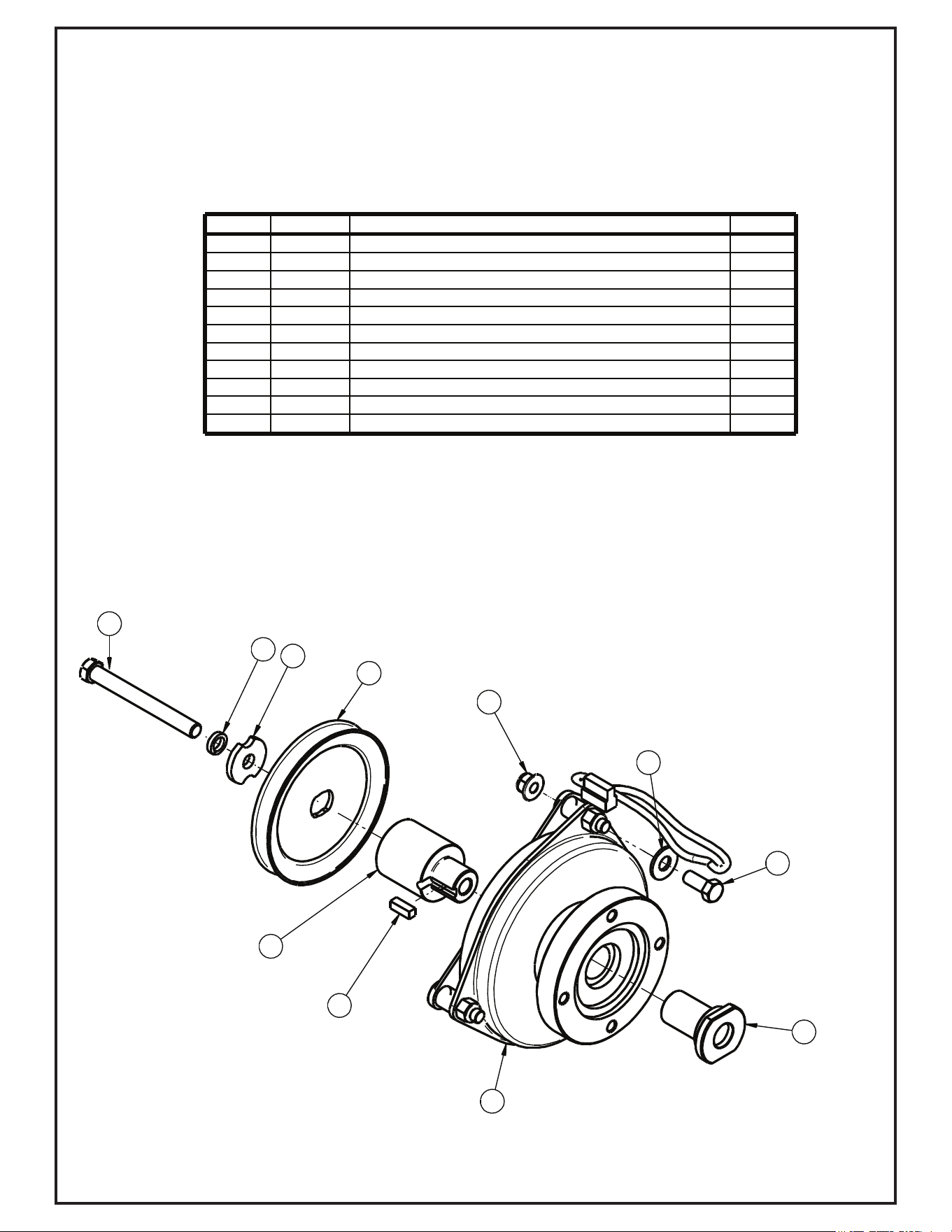
A2059_01 Clutch Sub-Assembly
10
8
11
4
3
6
5
7
1
9
2
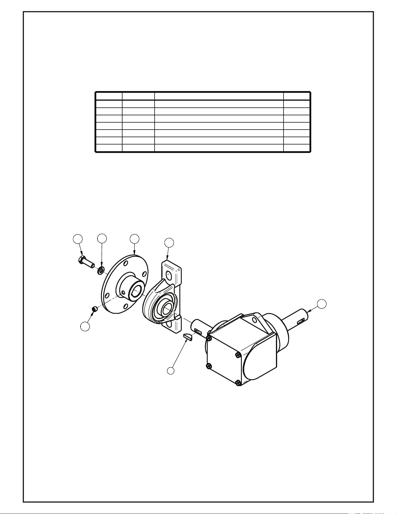
Item # Part # Desc. Qty.
1 M0001 Electric Clutch 1
2 S0007 Clutch Shaft 1
3 K0278 Double Indented Washer 7/16" / 1.375 OD x .440 ID x .179 T 1
4 K0140 Lock Washer 7/16" / High-Collar Helical Spring 1
5 K0359 HHCS / 7/16"-20 x 4.00" w/ Patch 1
6 K0343 HHCS 3/8"-16 x 7/8" GR8 1
7 K2038 Ny-Flange Lock Nut 3/8"-16 1
8 K0047 Flat Washer 3/8" / 1.00 OD x .446 ID x .075 T 1
9 M0309 A-Section Pulley / 4.75 OD 1
10 S0221 Eng. Pulley Bushing #27 1
11 K0076 Key 1/4" x 3/4" Long 1
(Ogura 110 Ft-Lb Clutch/Brake)
A2057_01 Drive Assembly Exploded Parts View
4
3
1
2
Item # Part # Desc. Qty.
1 K0048 Lock Washer 3/8" 4
2 K0343 HHCS 3/8"-16 x 7/8" GR8 4
3 A2059_01 Clutch Sub-Assy 1
4 A2058 Gearbox Sub-Assy 1
(See Page 25)
(See Page 26)
28
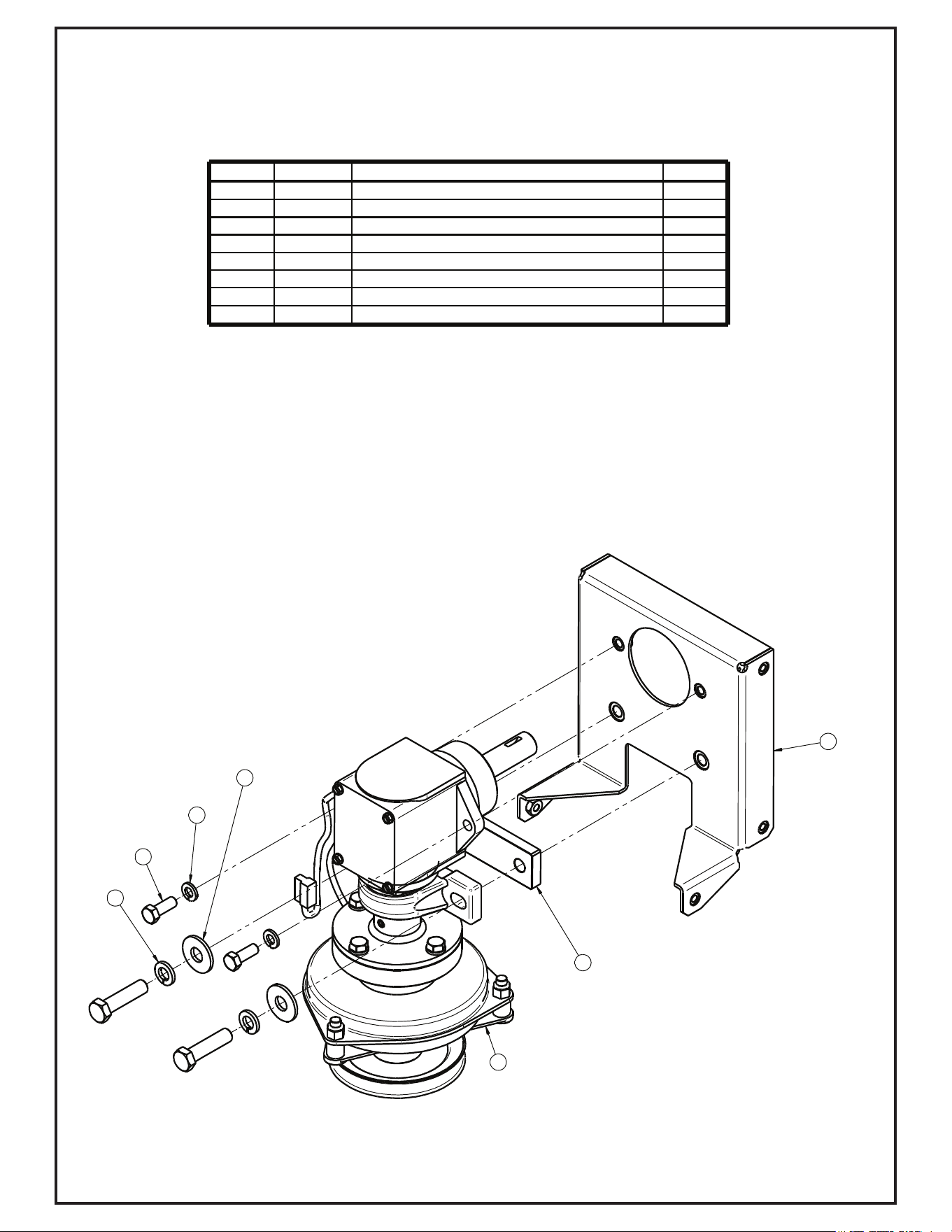
A2060_01 Mounted Drive Assembly
2
8
1
4
5
6
3
Item # Part # Desc. Qty.
1 B0940 Spacer Plate 1
2 A2034 Drive Mnt Assy 1
3 K1191 HHCS 3/8"-16 x 1" GR5 2
4 K0048 Lock Washer 3/8" 2
5 K0055 Flat Washer 1/2" / 1.383 OD x .560 ID x .120 T 2
6 K0056 Lock Washer 1/2" 2
7 K1234 HHCS 1/2"-13 x 2" 2
8 A2057_01 Drive Assy 1
(See page 27)
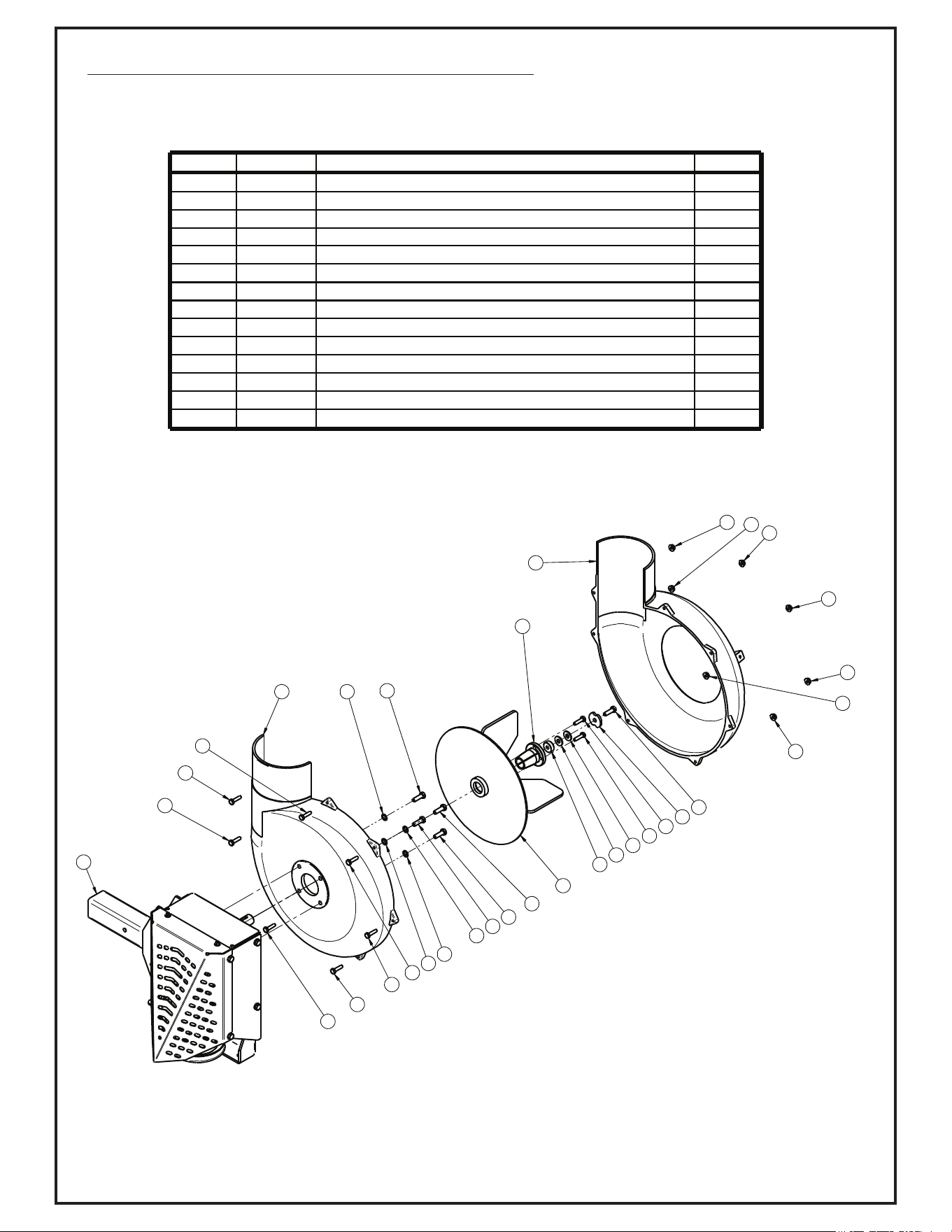
A2061_01 Drive Assembly / 4 Blade Impeller
1
8
12
11
6
6
6
6
2
3
13
13
13
13
13
13
13
14
14
14
14
14
14
14
7
7
7
7
4
4
9
5
10
10
Item # Part # Desc. Qty.
1 A0645 4-Blade Impeller Assy 1
2 K0284 Double Indented Washer 3/8" / 1.375 OD x .380 ID x .179 T 1
3 K0428 HHCS 5/16"-24 x 1" GR8 1
4 K1225 HHCS 1/4"-20 X 1" GR8 2
5 S0159 Spacer Bushing .938 OD x .325 ID x .375 T 1
6 K0044 I/T Tooth Lock Washer 5/16" 4
7 K1154 HHCS 5/16"-18 x 1" 4
8 A2039_01 Drive Assy / Base 1
9 S0157 Taperlock Bushing 7/8" 1
10 K0042 Flat Washer 5/16" / .875 OD x .380 ID x .075 T 2
11 E4052F Blower Hsg Front 1
12 E4052B Blower Hsg Back 1
13 K1125 HHCS 1/4"-20 X 1" GR2 7
14 K1126 Flange Nut 1/4"-20 7
30
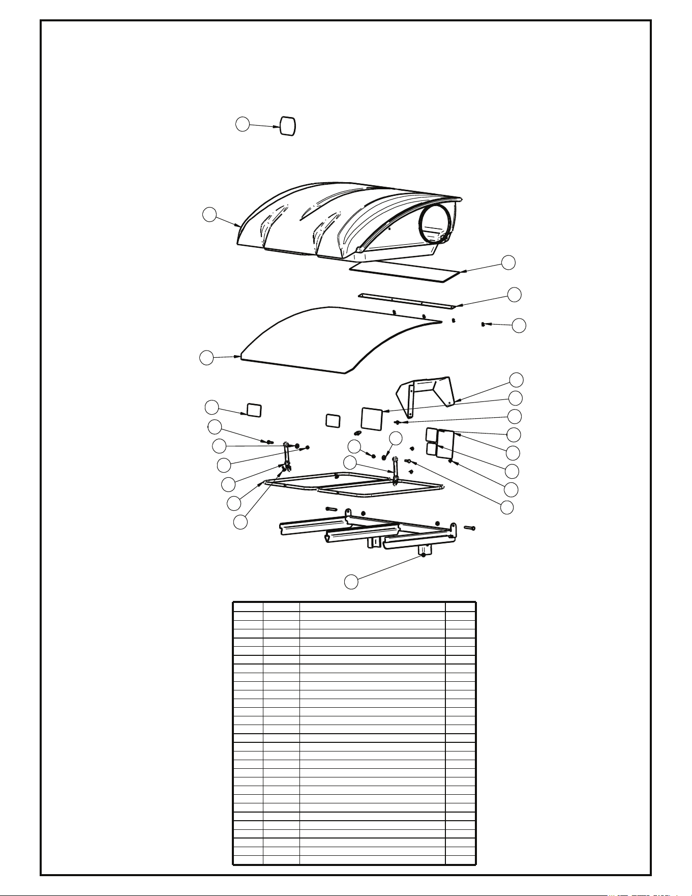
A2062 Top Assembly
A1114 Upper Frame Assembly
Exploded Parts View
6
7
24
3
18
11
13
15
16
12
14
17
20
21
22
23
9
10
19
12
13
14
11
2
25
Item # Part # Desc. Qty.
1 P2B Layout 1
2* A1114 Upper Frame Assy P2B+ Generic Gen 1 1
3 b0227 BAG RING 2
4 A2062 Top Assy / P2B+ / Cub Cadet (2016) 1
5 A1938 Top Assy / P2B+ / No Logo 1
6 C0026 Grass Deflector 1
7 K0114 Black Plastic Rivet 3
8 A1201 Top Assy. / Excel / Base Model 1
9 V0017 Pro 2 Bagger Top 1
10 V0018 Black Plastic Screen 1
11 J4009 Short Rubber Strap w/ S-Hook 1
12 K1030 1/4"-20 x 1-1/4" Carriage Bolt 1
13 K0037 Flat Washer / 1/4" (.75 OD x .312 ID x .060 T) 1
14 k1128 1/4"-20 Nyloc Nut 1
15 K0062 3/16" x 1-1/2" Fender Washer, Z 2
16 K0114 Black Plastic Rivet 6
17 K1265 Black Panel Retainer 2
18 C0067 Dust Guard Mnt. Brkt. 1
19 V1117 Dust Guard 1
20 R1051 Warning - Use Hearing Protection Decal 1
21 R1054 Important Check Hoses Decal 1
22 R1065 Made In America Decal 1
23 R1069 Warning - Turn Off Blower Decal 1
24 R1057 2" x 4" Red Reflector Label 2
11 J4009 Short Rubber Strap w/ S-Hook 1
12 K1030 1/4"-20 x 1-1/4" Carriage Bolt 1
13 K0037 Flat Washer / 1/4" (.75 OD x .312 ID x .060 T) 1
14 k1128 1/4"-20 Nyloc Nut 1
25 R0023 Decal / Cub Cadet 'C' 1


32
SAFETY DECALS
To promote safe operation, New PECO, Inc. supplies safety decals on all products manufactured. Damage can occur to
safety decals either through shipment, use or reconditioning. Contact your local Service Center for replacement decals.
Part #: R1054
Important Label
Part #: R1051
Warning: Hearing Protection Label
Part #: R1069
Warning: Turn Off Blower Label
Part #: R1065
Made In America Label
MADE INMADE IN
AMERICAAMERICA
MADE IN
AMERICA
DANGERDANGERDANGER
R2007R2007R2007
!
NUNCA USE MANOS
PARA LINPIAR BASURA CON LA
HOJA EN MARCHA!
PELIGROPELIGROPELIGRO
!
NEVER USE HANDS
TO CLEAR DEBRIS WITH BLOWER
RUNNING!
Part #: R2007
Never Use Hands Label
DANGERDANGERDANGER
R2008R2008R2008
!
HOJA ROTANTE!
DEDOS, MANOS Y PARTES DEL
CUERPO PUEDAN SER CORTADOS!
PELIGROPELIGROPELIGRO
!
ROTATING BLADES!
FINGERS, HANDS, & BODY PARTS
CAN BE SEVERED!
Part #: R2008
Rotating Blades Label
R1100
ENGAGEENGAGEENGAGE
DISENGAGEDISENGAGEDISENGAGE
PULL HANDLE
PUSH HANDLE
Part #: R1100
Engage-Disengage Label
Part #: R4037
Warning: Hot Surface Label
Part #: R1052
Small Warning: Turn Off Blower Label
Part #: R1057 - (2)
Part# R0023
Cub Cadet
Logo
Part # R0024
Danger Keep Hands
Clear
Part # R0025
Danger Rotating
Blades

SECTION III
OPERATING INSTRUCTIONS
3-1 General Safety
Only qualified people familiar with this operator’s manual
and the mower’s operator’s manual should operate this
machine.
3-2 Operation And Tips On Mowing
A. Perform BEFORE EACH USE the maintenance list
in paragraph 4-1.
B. Start mower.
C. With the mower at high idle speed, engage the mower
deck.
D. While seated in the operator’s seat, pull the
engagement handle of the PTO assembly towards
the operator’s seat until the handle slides into
position in the retaining slot. With the PTO assembly
engaged, you can proceed to operate the control
levers of the mower.
NOTE: If the collection system does not appear to be
collecting the grass clippings, disengage the deck
and PTO assembly (Section 3-3), then, engage the
parking brake and turn the mower off. Check upper and
lower hoses for any clogs.
To obtain the maximum effectiveness from your
collection system, the tips listed below should be
followed:
* Watch your speed- Normal conditions will allow a
speed of up to approximately 4 mph, but thick, heavy
damp conditions will require reduced ground speed.
* Mow with sharp blades- A sharp blade cuts cleaner.
* Wet grass and leaves will decrease effectiveness and
will increase horsepower requirements.
* Mow at higher cutting heights- Remove and mulch no
more than 2” of grass length with each mowing.
(Experts recommend not cutting off more than 1/3 of
the grass blade length at any given time.)
* Mow twice, at different height settings, (high, then low),
if grass is extra tall.
* Remember that horsepower requirements will vary with
the mowing conditions such as type and height of turf
grass, moisture content, amount of leaves, whether the
terrain is flat or hilly, etc.
3-3 Disengagement Of The PTO
Assembly
A. To disengage the PTO assembly, move switch to the
off position.
WARNING: The PTO assembly blades will continue to
spin. DO NOT TOUCH the PTO assembly, pulleys, or
the belt until the tractor is turned off. DO NOT adjust the
belt tension until the mower is turned off. Refer to
section 2-4 of the manual.
3-4 Unloading The Collection System
NOTE: To determine when the collection bags are full,
follow the following steps:
A. Stop the forward movement of the mower.
B. Disengage the mower deck.
C. Disengage the PTO assembly.
D. Engage the parking brake.
E. Once the parking brake has been engaged, then and
only then, walk behind the mower and check the
collection bags by first unhooking the rubber strap
with S-hook that secures the plastic top, then lift the
plastic hood. Load in bags should not exceed the
height of the installed bag.
F. To remove the bags from the frame, slide bags out
and turn bags over to deposit clippings.
G. Slide empty bags back onto the frame and secure
plastic top with the rubber strap with S-hook.
NOTE: Do not allow collection bags to become over-
filled as potential damage may occur to your
equipment. Also, be sure to clean the hood screen as
needed.
SECTION IV
MAINTENANCE
4-1 Maintenance Checklist
Before each use:
1. Check blades and spindles to be sure that no foreign
objects, such as wire or steel strapping bands, are
wrapped around them.
2. Inspect blades for wear. Replace if necessary. If it is
necessary to sharpen the blades, remove the blades
from the spindles before sharpening. DO NOT
sharpen blades while still attached to the mower.

34
3. Make sure all shields are in place and in good
condition. Repair or replace any missing or damaged
shields.
4. Perform lubrication per paragraph 4-2.
5. Listen for abnormal sounds, which might indicate
loose parts, damaged bearings, or other damage.
Correct any deficiency before continuing operation.
6. With the engine off check the belt tension and inspect
the pulley belt for cracks or tears.
7. Check for wear or deterioration of the upper or lower
hoses. If there are any portions of the hose that have
been torn or worn through, replace immediately.
After Each Use:
1. Clean all debris from machine especially from the
container, underneath the belt shields, and safety
decals. Replace any missing or illegible decals.
2. Inspect the unit for worn or damaged components.
Repair or replace before the next use. Any
replacement component installed during repair shall
include the component’s current safety decal specified
by the manufacturers to be affixed to the component.
3. Check belt for proper tension.
WRITE THE MODEL AND
SERIAL NUMBER IN THE
BOX TO THE LEFT
FOR FUTURE REFERENCE.
Blower Assembly:
1. Every 100 hours grease idler arm grease fitting with
white lithium grease.
SECTION V
PARTS AND SERVICE
5-1 Parts And Service Information
Collection system owners should record the name and
telephone number of their Service Center. Your Service
Center will be happy to supply replacement parts,
accessories, and do any service or repairs to your
collection system. If for any reason your Service Center
is unable to service your collection system or supply
replacement parts, contact New PECO, Inc. and include
the following information on the chart below.
THE SERIAL NUMBER PLATE
IS LOCATED ON THE TOP
ASSEMBLY
Unit Model Number: _____________________________
Unit Engine Size: _____________________________
Unit Serial Number: _____________________________
Date of purchase: _____/_____/_________
Dealer/Distributor Name: ________________________________________
Address: _____________________________________ State: __________ Zip:__________
Phone Number: ____________________________
59A30046150
2_____XP______
4-2 Lubrication
Gearbox:
1. Every 20 hours of use: Check oil levels in gearbox.
2. First 60 hours of use: Change oil.
3. Every 100 hours of use: Change oil.
NOTE: Oil in gearbox should cover the gears. If not,
drain the gearbox and fill using an 80W-90 gear oil.
The gearbox ships with 6.0 oz. of oil, but we
recommend replacing with a measured 5.5 oz. to fill
the gearbox. DO NOT OVERFILL!

36
Problem
Possible Cause
Corrective Action
Abnormal Vibration
— Cutting blades are bent or
unbalanced
— Loose blower pulley or pulley
assembly
— Impeller blade out of balance
— Install new cutting blade
— Tighten the pulley
— Contact dealer to replace
Reduced collection system
performance
— Low engine speed
— Plugged screen
— Loose belt
— Full collection bags
— Always operate collection
system at full throttle
— Remove debris, leaves, or
grass clippings from the
screen
— Replace belt
Blower and hoses plugging too
frequently
— Collection bags are too full
— Low engine speed
— Grass is too wet
— Grass is too long
— Ground speed is too fast
— Worn belt
— Loose belt
— Dump more frequently
— Always operate collection
system at full throttle
— Cut grass when it is dry
— Cut the grass several times
— Drive slower at full throttle
— Replace belt
Debris blowout
— Collection bags are too full
— Plug/clog in the collection
system
— Ground speed is too fast
— Dump more frequently
— Clean the collection system
— Drive more slowly at full
Impeller doesn’t rotate freely
— Plug in the blower housing
— Worn impeller blade
— Shaft bearings bad/failing
— Clean the blower housing
— Contact dealer to replace
— Contact dealer to replace
Troubleshooting
Collection System Performance

NOTES:

Cub Cadet LLC
P.O. Box 361131
Cleveland, Ohio 44136-0019
Phone: 1-877-282-8684
MTD Products Limited
Kitchener, ON N2G 4J1
1-800-668-1238