
October 2019 Rev. 1, 2/20
© 2019-2020 Fluke Corporation. All rights reserved. Specifications are subject to change without notice.
All product names are trademarks of their respective companies.
87V MAX
Digital Multimeter
Users Manual

Lifetime Limited Warranty
Each Fluke 20, 70, 80, 170, 180 and 280 Series DMM will be free from defects in material and workmanship for its lifetime. As used herein,
“lifetime” is defined as seven years after Fluke discontinues manufacturing the product, but the warranty period shall be at least ten years from
the date of purchase. This warranty does not cover fuses, disposable batteries, damage from neglect, misuse, contamination, alteration,
accident or abnormal conditions of operation or handling, including failures caused by use outside of the product’s specifications, or normal
wear and tear of mechanical components. This warranty covers the original purchaser only and is not transferable.
For ten years from the date of purchase, this warranty also covers the LCD. Thereafter, for the lifetime of the DMM, Fluke will replace the LCD
for a fee based on then current component acquisition costs.
To establish original ownership and prove date of purchase, please complete and return the registration card accompanying the product, or
register your product on http://www.fluke.com. Fluke will, at its option, repair at no charge, replace or refund the purchase price of a
defective product purchased through a Fluke authorized sales outlet and at the applicable international price. Fluke reserves the right to
charge for importation costs of repair/replacement parts if the product purchased in one country is sent for repair elsewhere.
If the product is defective, contact your nearest Fluke authorized service center to obtain return authorization information, then send the
product to that service center, with a description of the difficulty, postage and insurance prepaid (FOB Destination). Fluke assumes no risk
for damage in transit. Fluke will pay return transportation for product repaired or replaced in-warranty. Before making any non-warranty
repair, Fluke will estimate cost and obtain authorization, then invoice you for repair and return transportation.
THIS WARRANTY IS YOUR ONLY REMEDY. NO OTHER WARRANTIES, SUCH AS FITNESS FOR A PARTICULAR PURPOSE, ARE
EXPRESSED OR IMPLIED. FLUKE SHALL NOT BE LIABLE FOR ANY SPECIAL, INDIRECT, INCIDENTAL OR CONSEQUENTIAL
DAMAGES OR LOSSES, INCLUDING LOSS OF DATA, ARISING FROM ANY CAUSE OR THEORY. AUTHORIZED RESELLERS ARE
NOT AUTHORIZED TO EXTEND ANY DIFFERENT WARRANTY ON FLUKE’S BEHALF. Since some states do not allow the exclusion or
limitation of an implied warranty or of incidental or consequential damages, this limitation of liability may not apply to you. If any provision of
this warranty is held invalid or unenforceable by a court or other decision-maker of competent jurisdiction, such holding will not affect the
validity or enforceability of any other provision.
Fluke Corporation
P.O. Box 9090
Everett, WA 98206-9090
U.S.A.
Fluke Europe B.V.
P.O. Box 1186
5602 BD Eindhoven
The Netherlands
ООО «Флюк СИАЙЭС»
125167, г. Москва, Ленинградский
проспект дом 37,
корпус 9, подъезд 4, 1 этаж
5/07

i
Table of Contents
Title Page
Introduction .................................................................................................................... 1
How to Contact Fluke ..................................................................................................... 1
Safety Information .......................................................................................................... 1
Features ......................................................................................................................... 2
Automatic Power-Off ................................................................................................. 8
Input Alert™ Feature ................................................................................................. 8
Power-Up Options ..................................................................................................... 8
How to Make Measurements .......................................................................................... 10
AC and DC Voltage Measurements ........................................................................... 10
Zero Input Behavior of True-rms Meter ..................................................................... 11
Low-Pass Filter .......................................................................................................... 11
Temperature Measurements ..................................................................................... 12
Continuity Tests ......................................................................................................... 13
Resistance Measurements ........................................................................................ 15

87V MAX
Users Manual
ii
How to Use Conductance for High Resistance or Leakage Tests ............................ 17
Capacitance Measurements ..................................................................................... 18
Diode Tests ............................................................................................................... 19
AC or DC Current Measurements ............................................................................. 21
Frequency Measurements ........................................................................................ 24
Duty Cycle Measurements ........................................................................................ 26
How to Determine Pulse Width ................................................................................. 27
Bargraph ........................................................................................................................ 27
Zoom Mode (Power Up Option Only) ........................................................................ 28
Uses for the Zoom Mode .......................................................................................... 28
HiRes Mode ................................................................................................................... 28
MIN MAX Recording Mode ............................................................................................ 29
Smooth Feature (Power Up Option Only) ...................................................................... 29
AutoHOLD
Mode ........................................................................................................... 31
Relative Mode ................................................................................................................ 31
Maintenance .................................................................................................................. 32
General Maintenance ................................................................................................ 32
Fuse Test .................................................................................................................. 32
How to Replace the Batteries.................................................................................... 33
How to Replace the Fuses ........................................................................................ 34
Service and Parts .......................................................................................................... 34
General Specifications ................................................................................................... 38
Detailed Specifications .................................................................................................. 40
AC Voltage ................................................................................................................ 40
DC Voltage, Conductance, and Resistance .............................................................. 41
Temperature ............................................................................................................. 42
AC Current ................................................................................................................ 42
DC Current ................................................................................................................ 43
Capacitance .............................................................................................................. 43

Contents (continued)
iii
Diode ......................................................................................................................... 44
Frequency ................................................................................................................. 44
Frequency Counter Sensitivity and Trigger Levels .................................................... 44
Duty Cycle (Vdc and mVdc) ...................................................................................... 45
Input Characteristics .................................................................................................. 45
MIN MAX Recording .................................................................................................. 46

87V MAX
Users Manual
iv

1
Introduction
XW Warning
Read “Safety Information” before using the
Meter.
The 87V MAX (the Product or Meter) is a True-rms Digital
Multimeter. In addition, the 87V MAX measures
temperature using a type-K thermocouple.
How to Contact Fluke
To contact Fluke, call one of the following telephone
numbers:
• Technical Support USA: 1-800-44-FLUKE
(1-800-443-5853)
• Calibration/Repair USA: 1-888-99-FLUKE
(1-888-993-5853)
• Canada: 1-800-36-FLUKE (1-800-363-5853)
• Europe: +31 402-675-200
• Japan: +81-3-6714-3114
• Singapore: +65-6799-5566
• China: +86-400-921-0835
• Brazil: +55-11-3530-8901
• Anywhere in the world: +1-425-446-5500
Or, visit Fluke's website at www.fluke.com.
To register your product, visit http://register.fluke.com.
To view, print, or download the latest manual supplement,
visit http://us.fluke.com/usen/support/manuals.
Safety Information
General Safety Information is in the printed Safety
Information document that ships with the Product and at
www.fluke.com. More specific safety information is listed
where applicable.
87V MAX
Users Manual
2
Features
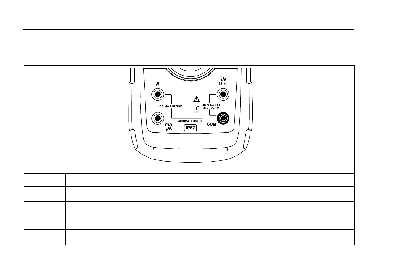
Tables 1 through 4 briefly describe the features of the Meter.
Table 1. Inputs
gaq112.emf
Terminal Description
A
Input for 0 A to 10.00 A current (10 - 20 A overload for 30 seconds maximum), current frequency, and duty
cycle measurements.
Input for 0
μ
A to 400 mA current measurements (600 mA for 18 hrs) and current frequency and duty cycle.
COM
Return terminal for all measurements.
Input for voltage, continuity, resistance, diode, capacitance, frequency, temperature, and duty cycle
measurements.

Digital Multimeter
Features
3
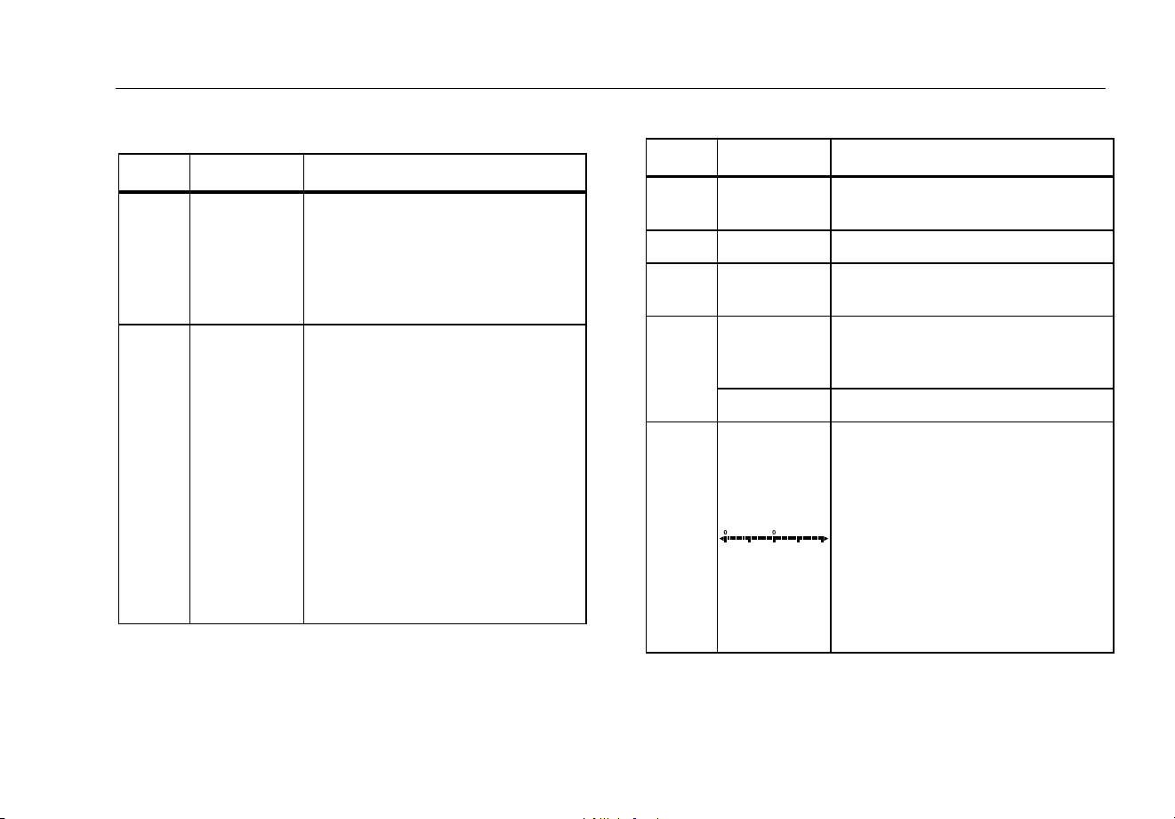
Table 2. Rotary Switch Positions
Switch Position Function
Any Position When the Meter is turned on, the Meter model number briefly appears on the display.
AC voltage measurement
Press
(yellow) for low-pass filter ()
DC voltage measurement
600 mV dc voltage range
Press (yellow) for temperature ()
Press for continuity test.
e Resistance measurement
Press (yellow) for capacitance measurement.
Diode test
AC current measurements from 0 mA to 10.00 A
Press
(yellow) for dc current measurements, from 0 mA to 10.00 A.
AC current measurements from 0 μA to 6000 μA
Press
(yellow) for dc current measurements from 0 μA to 6000 μA.

87V MAX
Users Manual
4
Table 3. Pushbuttons
Button
Switch
Position
Function
(Yellow)
Selects capacitance
Selects temperature
Selects ac low-pass filter function
Switches between dc and ac current
Switches between dc and ac current
Any switch
position
Switches between the ranges available for the selected function. To return to autoranging, hold
the button down for 1 second.
Switches between °C and °F.
Any switch
position
MIN MAX
recording
Frequency
counter
AutoHOLD (formerly TouchHold) captures the present reading on the display. When a new,
stable reading is detected, the Meter beeps and displays the new reading.
Stops and starts recording without erasing recorded values.
Stops and starts the frequency counter.

Digital Multimeter
Features
5
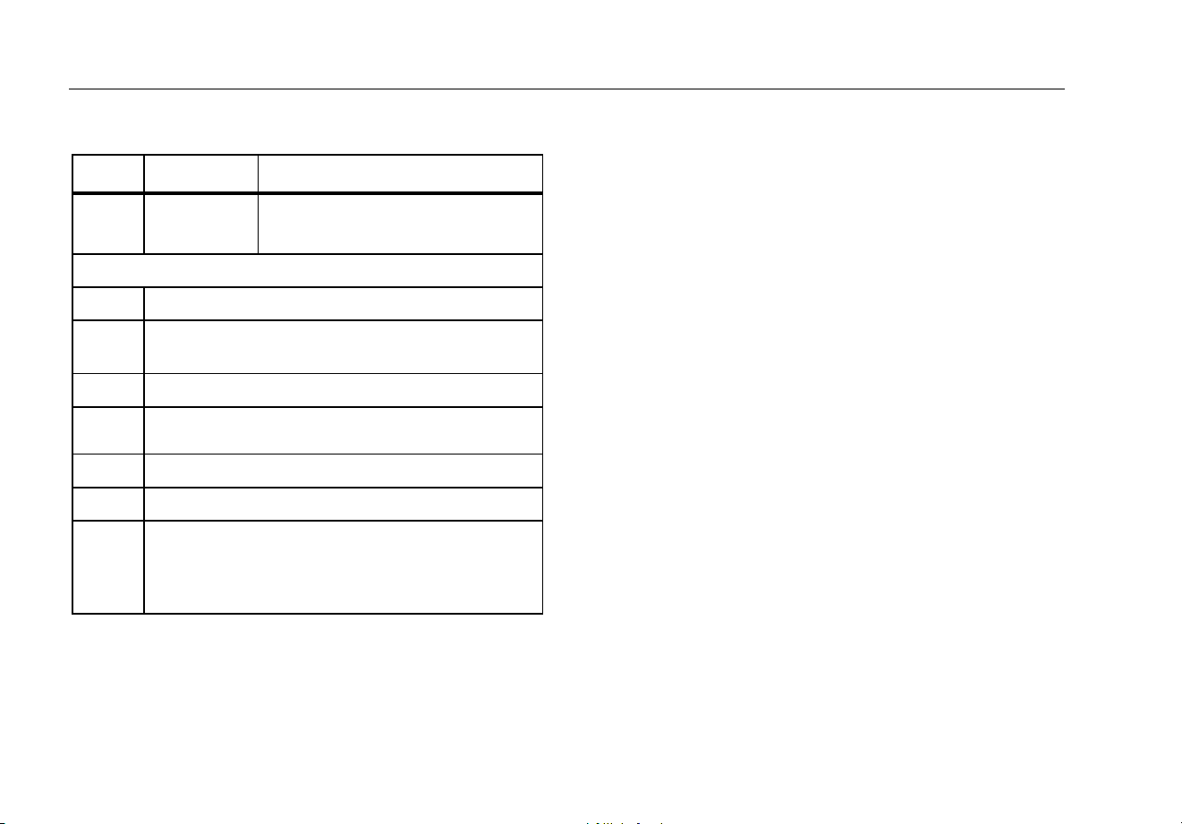
Table 3. Pushbuttons (cont.)
Button Switch Position Function
Continuity
MIN MAX
recording
Hz, Duty Cycle
Turns the continuity beeper on and off
Switches between Peak (250 μs) and Normal (100 ms) response times.
Toggles the meter to trigger on positive or negative slope.
Any switch
position
Turns the button backlight and display backlight on, makes them brighter, and turns them
off.
Hold down for one second to enter the HiRes digit mode. The “HiRes” icon appears
on the display. To return to the 3-1/2 digit mode, hold
down for one second.
HiRes=19,999
Any switch
position
Starts recording of minimum and maximum values. Steps the display through MAX,
MIN, AVG (average), and present readings. Cancels MIN MAX (hold for 1 second)
(Relative
mode)
Any switch
position
Stores the present reading as a reference for subsequent readings. The display is
zeroed, and the stored reading is subtracted from all subsequent readings.
Any switch
position except
diode test
Press for frequency measurements.
Starts the frequency counter.
Press again to enter duty cycle mode.
87V MAX
Users Manual
6
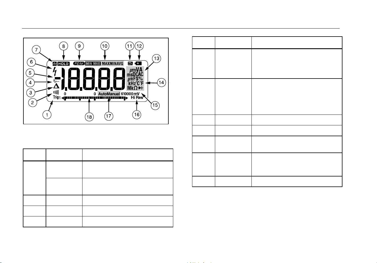
gaq101.emf
Figure 1. Display Features
Table 4. Display Features
Number Feature Indication
Polarity indicator for the analog
bargraph.
Trig±
Positive or negative slope indicator
for Hz/duty cycle triggering.
The continuity beeper is on.
Relative (REL) mode is active.
Smoothing is active.
Number Feature Indication
-
Negative readings, In relative mode,
this sign indicates that the present
input is less than the stored
reference.
High voltage present at the input.
Appears if the input voltage is 30 V
or greater (ac or dc), Also appears in
low-pass filter mode. Also appears in
cal, Hz, and duty cycle modes.
AutoHOLD is active.
Display HOLD is active.
Peak Min Max modes and the
response time is 250 μs.
MAX MIN
AVG
Minimum-maximum recording mode.
See Low-pass Filter.
Digital Multimeter
Features
7
Table 4. Display Features (cont.)
Number Feature Indication
Low battery. XW Warning: To
prevent false readings, which
could lead to possible electric
shock or personal injury,
replace the battery as soon as
the battery indicator appears.
A, μA, mA amperes (amps), microamp, milliamp
V, mV volts, millivolts
μF, nF
microfarad, nanofarad
nS nanosiemens
%
Percent. Used for duty cycle
measurements.
Ω, MΩ, kΩ ohm, megohm, kilohm
Hz, kHz hertz, kilohertz
Diode test mode.
AC DC Alternating current, direct current
Number Feature Indication
°C, °F
Degrees Celsius, Degrees
Fahrenheit
610000 mV Displays selected range
HiRes
High resolution (Hi Res) mode.
HiRes=19,999
Auto
Autorange mode. Automatically
selects the range with the best
resolution
Manual Manual range mode
The number of segments is relative
to the full-scale value of the selected
range. In normal operation 0 (zero) is
on the left. The polarity indicator at
the left of the graph indicates the
polarity of the input. The graph does
not operate with the capacitance, or
frequency counter functions. For
more information, see Bargraph. The
bargraph also has a zoom function,
as described under "Zoom Mode".
87V MAX
Users Manual
8
Table 4. Display Features (cont.)
Number Feature Indication
--
Overload condition is detected.
Error Messages
Replace the battery immediately.
In the capacitance function, too much electrical
charge is present on the capacitor being tested.
Invalid calibration data. Calibrate Meter.
Invalid EEPROM data. Have the Meter serviced.
Open thermocouple detected.
Invalid model. Have the Meter serviced.
W Test lead alert. Displayed when the test leads are
in the
A or mA/μA terminal and the selected rotary
switch position does not correspond to the terminal
being used.
Automatic Power-Off
The Meter automatically turns off if you do not turn the
rotary switch or press a button for 30 minutes. If MIN
MAX Recording is enabled, the Meter will not power off.
Refer to Table 5 to disable automatic power-off.
Input Alert™ Feature
If a test lead is plugged into the mA/μA or A terminal, but
the rotary switch is not set to the correct current position,
the beeper warns you by making a chirping sound and
the display flashes “”, This warning is intended to
stop you from attempting to measure voltage, continuity,
resistance, capacitance, or diode values with the leads
are plugged into a current terminal.
W Caution
Placing the probes across (in parallel with) a
powered circuit when a lead is plugged into a
current terminal can damage the circuit you
are testing and blow the Meter’s fuse. This
can happen because the resistance through
the Meter’s current terminals is very low, so
the Meter acts like a short circuit.
Power-Up Options
Holding a button down while turning the Meter on
activates a power-up option. Table 5 describes power-up
options.

Digital Multimeter
Features
9
Table 5. Power-Up Options
Button Power-Up Option
(Yellow)
Disables automatic power-off feature (Meter normally powers off in 30 minutes).
The Meter reads “” until is released.
Enables the Meter’s calibration mode and prompts for a password.
The Meter reads “” and enters calibration mode. See 87V MAX Calibration Information.
Enables the Meter’s smoothing feature. The Meter reads “” until is released.
Turns on all LCD segments.
Disables the beeper for all functions. The Meter reads “” until is released.
Disables auto backlight off (backlight normally disables after 2 minutes). The Meter reads “” until is
released.
(Relative mode)
Enables zoom mode for the bargraph. The Meter reads “” until is released.
Enables the Meter’s high impedance mode when the mV dc function is used.
The Meter reads “” until is released.
87V MAX
Users Manual
10
How to Make Measurements
The following sections describe how to make
measurements with the Meter.
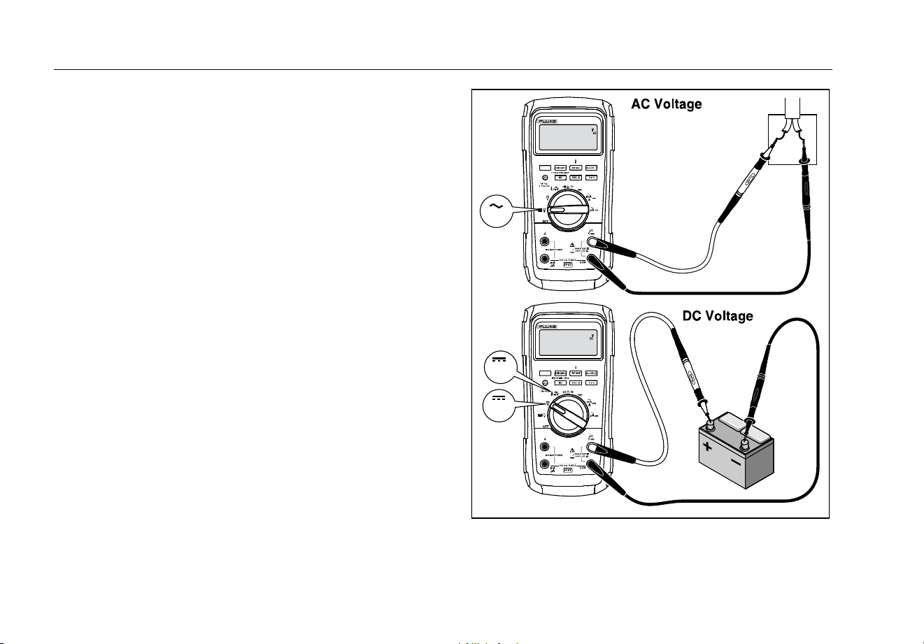
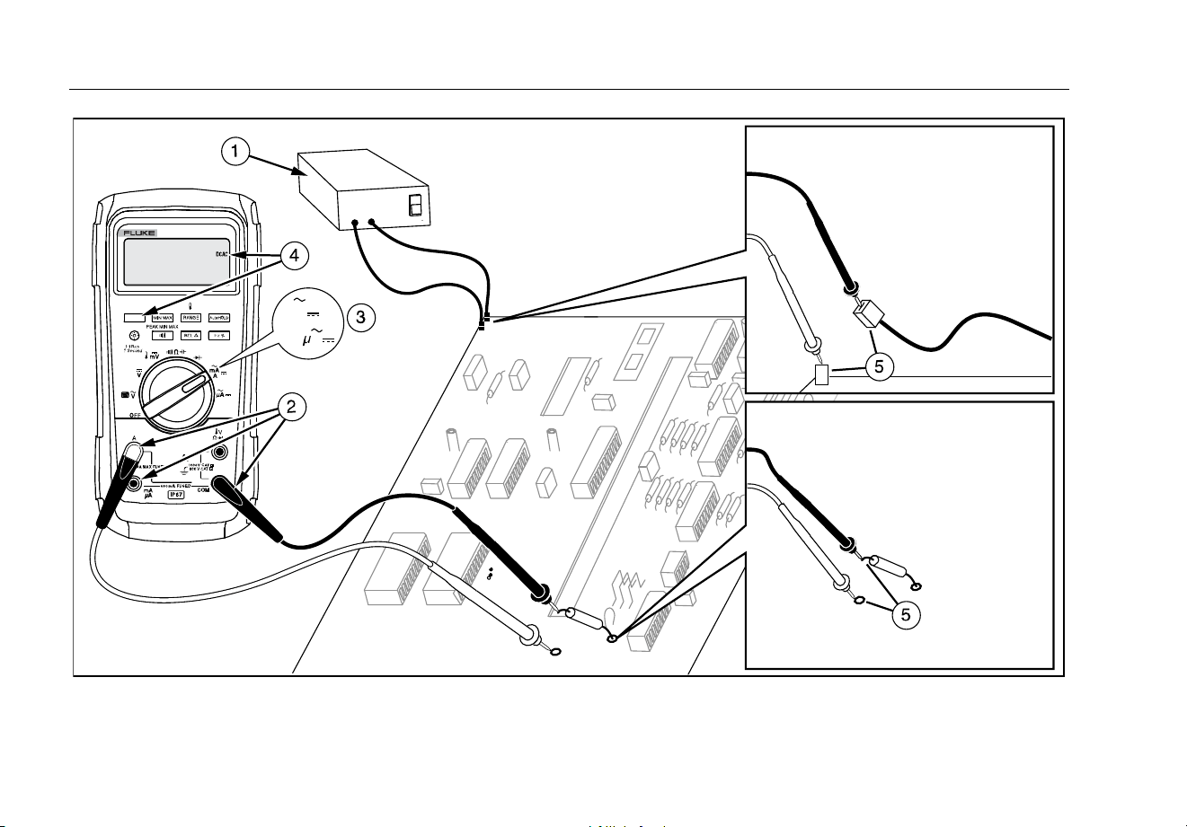
AC and DC Voltage Measurements
The Meter features true-rms readings, which are accurate
for distorted sine waves and other waveforms (with no dc
offset) such as square waves, triangle waves, and
staircase waves.
The Meter’s voltage ranges are 600.0 mV, 6.000 V,
60.00 V, 600.0 V, and 1000 V. The select the 600.0 mV
dc range, turn the rotary switch to mV.
Refer to Figure 2 to measure ac or dc voltage.
Switch Box
V
V
mV
gaq102.emf
Figure 2. AC and DC Voltage Measurements

Digital Multimeter
How to Make Measurements
11
When measuring voltage, the Meter acts approximately
like a 10-MΩ (10,000,000 Ω) impedance in parallel with
the circuit. This loading effect can cause measurement
errors in high-impedance circuits. In most cases, the error
is negligible (0.1 % or less) if the circuit impedance is
10 kΩ (10,000 Ω) or less.
For better accuracy when measuring the dc offset of an
ac voltage, measure the ac voltage first. Note the ac
voltage range, then manually select a dc voltage range
equal to or higher than the ac range. This procedure
improves the accuracy of the dc measurement by
ensuring that the input protection circuits are not
activated.
Zero Input Behavior of True-rms Meter
True-rms meters accurately measure distorted
waveforms, but when the input leads are shorted together
in the ac functions, the Meter displays a residual reading
between 1 and 30 counts. When the test leads are open,
the display readings may fluctuate due to interference.
These offset readings are normal. They do not affect the
Meter’s ac measurement accuracy over the specified
measurement ranges.
Unspecified input levels are:
• AC voltage: below 3 % of 600 mV ac, or 18 mV ac
• AC current: below 3 % of 60 mA ac, or 1.8 mA ac
• AC current: below 3 % of 600 μA ac, or 18 μA ac
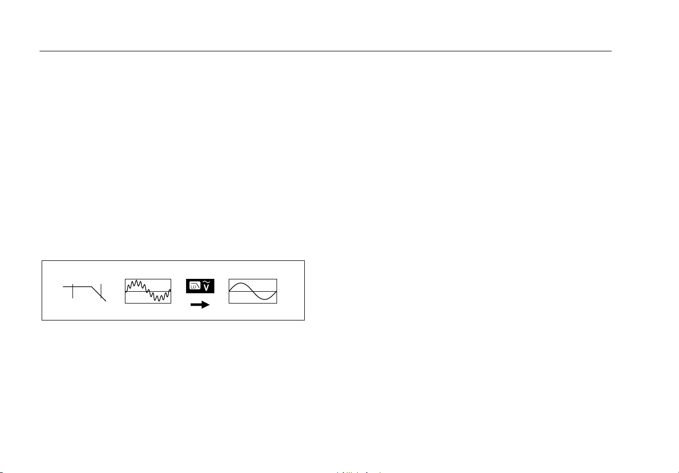
Low-Pass Filter
The Meter is equipped with an ac low-pass filter. When
measuring ac voltage or ac frequency, press to
activate the low-pass filter mode (). The Meter
continues measuring in the chosen mode, but now the
signal diverts through a filter that blocks unwanted
voltages above 1 kHz, refer to Figure 3. The lower
frequency voltages pass with reduced accuracy to the
measurement below 1 kHz. The low-pass filter can
improve measurement performance on composite sine
waves that are typically generated by inverters and
variable frequency motor drives.
87V MAX
Users Manual
12
XW Warning
To prevent possible electric shock or
personal injury, do not use the low-pass filter
to verify the presence of hazardous voltages.
Voltages greater than what is indicated may
be present. First, make a voltage
measurement without the filter to detect the
possible presence of hazardous voltage.
Then, select the filter.
Note
When the low-pass filter is selected, the Meter
goes to manual ranging mode. Select ranges by
pressing . Autoranging is not available with
the low-pass filter.
1 kHz
100 Hz
aom11f.emf
Figure 3. Low-Pass Filter
Temperature Measurements
The Meter measures the temperature of a type-K
thermocouple (included). Choose between degrees
Celsius (°C) or degrees Fahrenheit (°F) by pushing
.
W Caution
To prevent possible damage to the Meter or
other equipment, remember that while the
Meter is rated for -200.0 °C to +1090.0 °C and
-328.0 °F to 1994 °F, the included type-K
thermocouple is rated to 260 °C. For
temperatures out of that range, use a higher
rated thermocouple.
Display ranges are -200.0 °C to +1090 °C and -328.0 °F
to 1994 °F. Readings outside of these ranges show on
the Meter display. When there is no thermocouple
connected, the display also reads .
To measure temperature, do the following:
1. Connect a type-K thermocouple to the Meter’s COM
and terminals.
2. Turn the rotary switch to .
3. Push to enter temperature mode.
4. Push to choose Celsius or Fahrenheit.

Digital Multimeter
How to Make Measurements
13
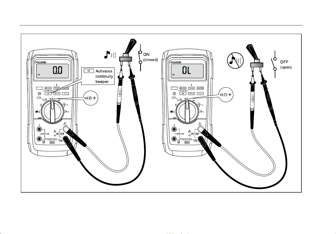
Continuity Tests
XW Warning
To prevent possible electrical shock, fire, or
personal injury, disconnect power and
discharge all high-voltage capacitors before
you measure resistance, continuity,
capacitance, or a diode junction.
The continuity test features a beeper that sounds as long
as a circuit is complete. The beeper allows you to perform
quick continuity tests without having to watch the display.
To test for continuity, set up the Meter as shown in
Figure 4.
Press to turn the continuity beeper on or off.
The continuity function detects intermittent opens and
shorts lasting as little as 1 ms. A brief short causes the
Meter to emit a short beep.
87V MAX
Users Manual
14
For in-circuit tests, turn circuit power off.
gaq103.emf
Figure 4. Continuity Tests

Digital Multimeter
How to Make Measurements
15
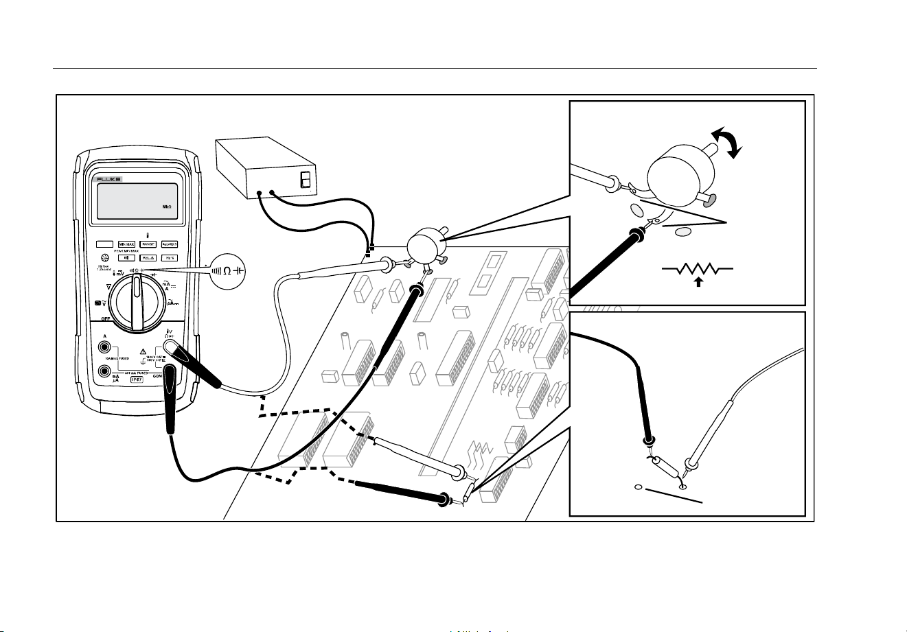
Resistance Measurements
XW Warning
To prevent possible electrical shock, fire, or
personal injury, disconnect power and
discharge all high-voltage capacitors before
you measure resistance, continuity,
capacitance, or a diode junction.
The Meter measures resistance by sending a small
current through the circuit. Because this current flows
through all possible paths between the probes, the
resistance reading represents the total resistance of all
paths between the probes.
The Meter's resistance ranges are 600.0 Ω, 6.000 kΩ,
60.00 kΩ, 600.0 kΩ, 6.000 MΩ, and 50.00 MΩ.
Set up the Meter as shown in Figure 5 to measure
resistance.
The following are some tips for measuring resistance:
• The measured value of a resistor in a circuit is often
different from the resistor's rated value.
• The test leads can add 0.1 Ω to 0.2 Ω of error to
resistance measurements. To test the leads, touch
the probe tips together and read the resistance of the
leads. If necessary, you can use the relative (REL)
mode to automatically subtract this value.
• The resistance function can produce enough voltage
to forward-bias silicon diode or transistor junctions,
causing them to conduct. If this is suspected, press
to apply a lower current in the next higher
range. If the value is higher, use the higher value.
Refer to the Input Characteristics table in the
specifications section for typical short-circuit currents.
87V MAX
Users Manual
16
1
2
3
1
3
2
Circuit Power
OFF
In-Circuit Resistance Measurements
Disconnect
Isolating a Potentiometer
Disconnect
Isolating a Resistor
gaq106.emf
Figure 5. Resistance Measurements

Digital Multimeter
How to Make Measurements
17
How to Use Conductance for High Resistance or
Leakage Tests
Conductance, the inverse of resistance, is the ability of a
circuit to pass current. High values of conductance
correspond to low values of resistance.
The Meter's 60-nS range measures conductance in
nanosiemens (1 nS = 0.000000001 siemens). Because
such small amounts of conductance correspond to
extremely high resistance, the nS range lets you
determine the resistance of components up to
100,000 MΩ, 1/1 nS = 1,000 MΩ.
To measure conductance, set up the Meter for measuring
resistance as shown in Figure 5, then press until
the nS indicator appears on the display.
The following are some tips for measuring conductance:
• High-resistance readings are susceptible to
electrical noise. To smooth out most noisy readings,
enter the MIN MAX recording mode; then step to the
average (AVG) reading.
• There is normally a residual conductance reading
with the test leads open. To ensure accurate
readings, use the relative (REL) mode to subtract
the residual value.
87V MAX
Users Manual
18
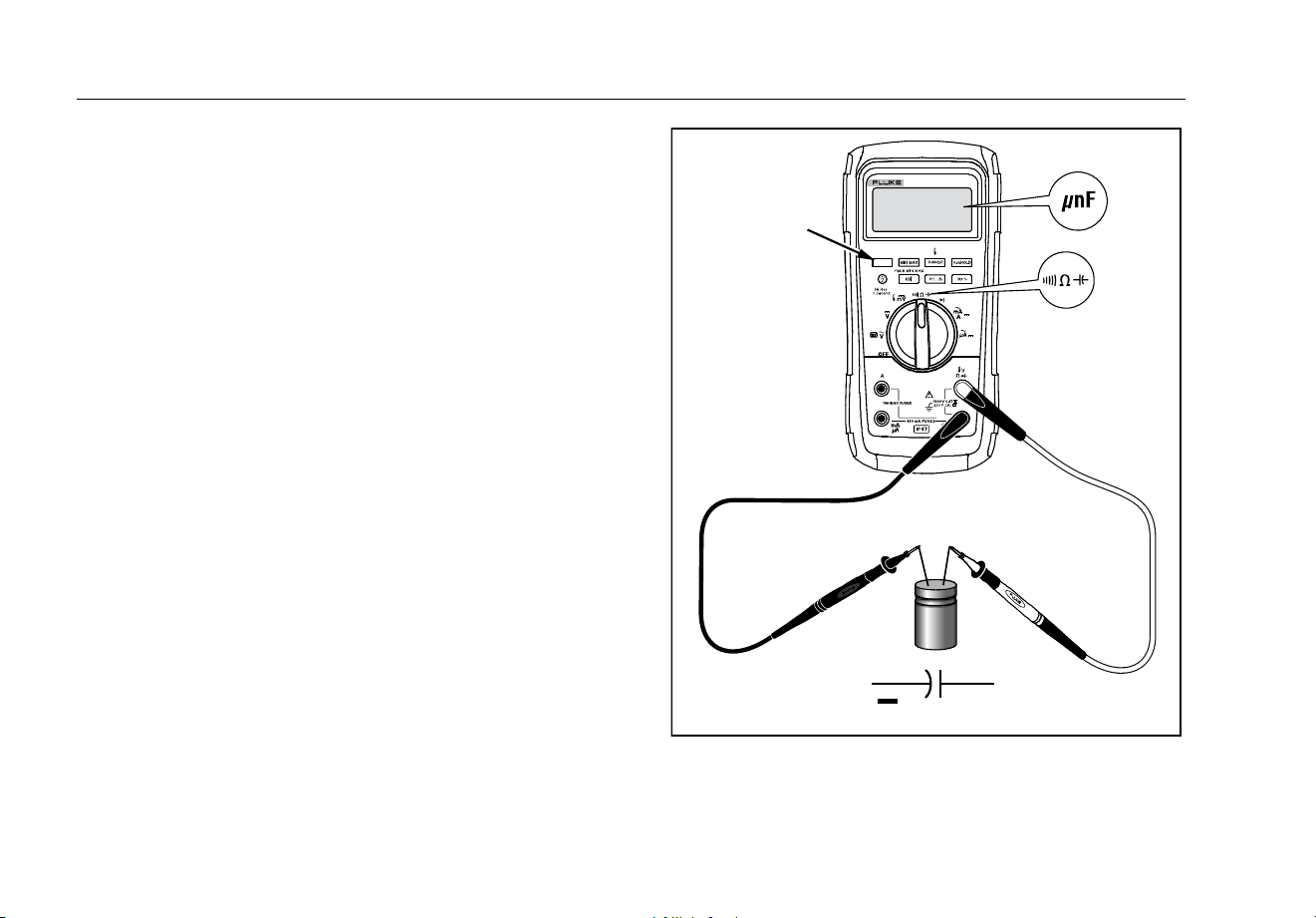
Capacitance Measurements
XW Warning
To prevent possible electrical shock, fire, or
personal injury, disconnect power and
discharge all high-voltage capacitors before
you measure resistance, continuity,
capacitance, or a diode junction.
The Meter's capacitance ranges are 10.00 nF, 100.0 nF,
1.000 μF, 10.00 μF, 100.0 μF, and 9999 μF.
To measure capacitance, set up the Meter as shown in
Figure 6.
To improve the accuracy of measurements less than
1000 nF, use the relative (REL) mode to subtract the
residual capacitance of the Meter and leads.
Note
If too much electrical charge is present on the
capacitor being tested, the display shows
“diSC“.
+
+
+
+
+
+
+
+
+
Select
Capacitance
gaq104.emf
Figure 6. Capacitance Measurements

Digital Multimeter
How to Make Measurements
19
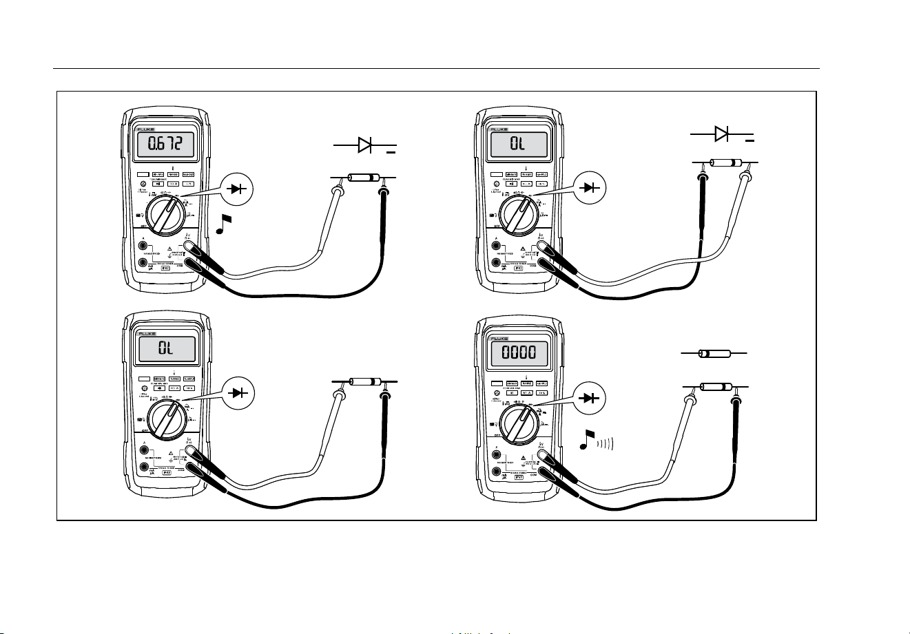
Diode Tests
XW Warning
To prevent possible electrical shock, fire, or
personal injury, disconnect power and
discharge all high-voltage capacitors before
you measure resistance, continuity,
capacitance, or a diode junction.
Use the diode test to check diodes, transistors, silicon
controlled rectifiers (SCRs), and other semiconductor
devices. This function tests a semiconductor junction by
sending a current through the junction, then measuring
the junction's voltage drop. A good silicon junction drops
between 0.5 V and 0.8 V.
To test a diode out of a circuit, set up the Meter as shown
in Figure 7. For forward-bias readings on any
semiconductor component, place the red test lead on the
component's positive terminal and place the black lead on
the component's negative terminal.
In a circuit, a good diode should still produce a forward-
bias reading of 0.5 V to 0.8 V; however, the reverse-bias
reading can vary depending on the resistance of other
pathways between the probe tips.
A short beep sounds if the diode is good (<0.85 V). A
continuous beep sounds if the reading is ≤0.100 V. This
reading would indicate a short circuit. The display shows
“OL” if the diode is open.
87V MAX
Users Manual
20
Bad Diode
+
+
Typical
Reading
Forward Bias
Reverse Bias
Bad Diode
Open
Shorted
Single Beep
or
gaq109.emf
Figure 7. Diode Tests

Digital Multimeter
How to Make Measurements
21
AC or DC Current Measurements
XWWarning
To prevent possible electrical shock, fire, or
personal injury, remove circuit power before
you connect the Product in the circuit when
you measure current. Connect the Product in
series with the circuit.
WCaution
To prevent damage to the Meter or to the
equipment under test:
• Check the Meter's fuses before
measuring current.
• Use the proper terminals, function, and
range for all measurements.
• Never place the probes across (in
parallel with) any circuit or component
when the leads are plugged into the
current terminals.
To measure current, you must break the circuit under
test, then place the Meter in series with the circuit.
The Meter's current ranges are 600.0 μA, 6000 μA,
60.00 mA, 400.0 mA, 6.000 A, and 10.00 A.
To measure current, refer to Figure 8 and proceed as
follows:
1. Turn off power to the circuit. Discharge all high-
voltage capacitors.
2. Insert the black lead into the COM terminal. For
currents between 0 mA and 400 mA, insert the red
lead into the mA/μA terminal. For currents above
400 mA, insert the red lead into the A terminal.
Note
To avoid blowing the Meter's 400-mA fuse, use
the mA/
μ
A terminal only if you are sure the
current is less than 400 mA continuously or less
than 600 mA for 18 hours or less.
87V MAX
Users Manual
22
Circuit Power:
OFF to connect meter.
ON for measurement.
OFF to disconnect meter.
Current Through One Component
Total Current to Circuit
mA
A
A
gaq107.emf
Figure 8. Current Measurements

Digital Multimeter
How to Make Measurements
23
3. If you are using the A terminal, set the rotary switch
to mA/A. If you are using the mA/μA terminal, set the
rotary switch to
for currents below 6000 μA
(6 mA), or for currents above 6000 μA.
4. To measure dc current, press .
5. Break the circuit path to be tested. Touch the black
probe to the more negative side of the break; touch
the red probe to the more positive side of the break.
Reversing the leads will produce a negative reading,
but will not damage the Meter.
6. Turn on power to the circuit; then read the display.
Be sure to note the unit given at the right side of the
display (μA, mA, or A).
7. Turn off power to the circuit and discharge all high-
voltage capacitors. Remove the Meter and restore
the circuit to normal operation.
The following are some tips for measuring current:
• If the current reading is 0 and you are sure the Meter
is set up correctly, test the Meter's fuses as
described under "Testing the Fuses".
• A current meter drops a small voltage across itself,
which might affect circuit operation. You can
calculate this burden voltage using the values listed
in the specifications in the Input Characteristics table.

87V MAX
Users Manual
24
Frequency Measurements
The Meter measures the frequency of a voltage or current
signal by counting the number of times the signal crosses
a threshold level each second.
Table 6 summarizes the trigger levels and applications for
measuring frequency using the various ranges of the
Meter's voltage and current functions.
To measure frequency, connect the Meter to the signal
source; then press
. Pressing switches the
trigger slope between + and -, as indicated by the symbol
at the left side of the display (refer to Figure 9 under
"Duty Cycle"). Pressing stops and starts the
counter.
The Meter autoranges to one of five frequency ranges:
199.99 Hz, 1999.9 Hz, 19.999 kHz, 199.99 kHz, and
greater than 200 kHz. For frequencies below 10 Hz, the
display is updated at the frequency of the input. Below
0.5 Hz, the display may be unstable.
The following are some tips for measuring frequency:
• If a reading shows as 0 Hz or is unstable, the input
signal may be below or near the trigger level. You
can usually correct these problems by selecting a
lower range, which increases the sensitivity of the
Meter. In the function, the lower ranges also have
lower trigger levels.
If a reading seems to be a multiple of what you expect,
the input signal may be distorted. Distortion can cause
multiple triggerings of the frequency counter. Selecting a
higher voltage range might solve this problem by
decreasing the sensitivity of the Meter. You can also try
selecting a dc range, which raises the trigger level. In
general, the lowest frequency displayed is the correct
one.
Digital Multimeter
How to Make Measurements
25
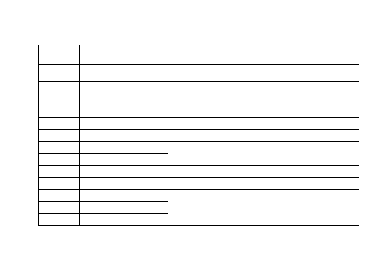
Table 6. Functions and Trigger Levels for Frequency Measurements
Function Range
Approximate
Trigger Level
Typical Application
6 V, 60 V,
600 V, 1000 V
±5 % of scale Most signals.
600 mV ±30 mV High-frequency 5 V logic signals. (The dc-coupling of the function can
attenuate high-frequency logic signals, reducing their amplitude enough to
interfere with triggering.)
m
600 mV 40 mV Refer to the measurement tips given before this table.
6 V 1.7 V 5 V logic signals (TTL).
60 V 4 V Automotive switching signals.
600 V 40 V Refer to the measurement tips given before this table.
1000 V 100 V
R e
Frequency counter characteristics are not available or specified for these functions.
All ranges ±5 % of scale AC current signals.
μA
600 μA, 6000 μA 30 μA , 300 μA Refer to the measurement tips given before this table.
60 mA, 400 mA 3.0 mA , 30 mA
A 6 A, 10 A 0.30 A, 3.0 A
87V MAX
Users Manual
26
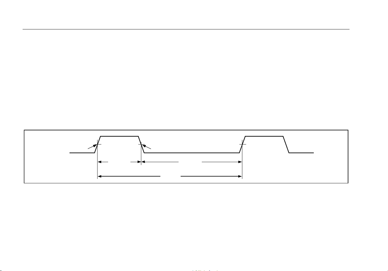
Duty Cycle Measurements
Duty cycle (or duty factor) is the percentage of time a
signal is above or below a trigger level during one cycle
(Figure 9). The duty cycle mode is optimized for
measuring the on or off time of logic and switching
signals. Systems such as electronic fuel injection systems
and switching power supplies are controlled by pulses of
varying width, which can be checked by measuring duty
cycle.
To measure duty cycle, set up the Meter to measure
frequency; then press Hz a second time. As with the
frequency function, you can change the slope for the
Meter's counter by pressing .
For 5-V logic signals, use the 6-V dc range. For 12-V
switching signals in automobiles, use the 60 V dc range.
For sine waves, use the lowest range that does not result
in multiple triggering. (Normally, a distortion-free signal
can be up to ten times the amplitude of the selected
voltage range.)
If a duty cycle reading is unstable, press MIN MAX; then
scroll to the AVG (average) display.
-Slope
Trigger Point
+Slope
Trigger Point
30% Above
+Slope
70% Below
-Slope
100%
iyf.emf
Figure 9. Components of Duty Cycle Measurements

Digital Multimeter
Bargraph
27
How to Determine Pulse Width
For a periodic waveform (its pattern repeats at equal time
intervals), you can determine the amount of time that the
signal is high or low as follows:
1. Measure the signal's frequency.
2. Push a second time to measure the signal's
duty cycle. Push to select a measurement of
the signal's positive or negative pulse, refer to
Figure 9.
3. Use the following formula to determine the pulse
width:
Pulse Width =
% Duty Cycle ÷ 100
(in seconds) Frequency
Bargraph
The analog bargraph functions like the needle on an
analog meter, but without the overshoot. The bargraph
updates 40 times per second. Because the graph
responds 10 times faster than the digital display, it is
useful for making peak and null adjustments and
observing rapidly changing inputs. The graph is not
shown for capacitance, frequency counter functions,
temperature, or peak min max.
The number of lit segments indicates the measured value
and is relative to the full-scale value of the selected
range.
In the 60-V range, for example, the major divisions on the
scale represent 0, 15, 30, 45, and 60 V. An input of -30 V
lights the negative sign and the segments up to the
middle of the scale.
The bargraph also has a zoom function, as described
under "Zoom Mode".

87V MAX
Users Manual
28
Zoom Mode (Power Up Option Only)
To use the Rel Zoom Bargraph:
1. Hold down while turning the Meter on. The
display reads “”.
2. Select the relative mode by pressing
again.
3. The center of the bargraph now represents zero and
the sensitivity of the bargraph increases by a factor
of 10. Measured values more negative than the
stored reference activate segments to the left of
center; values more positive activate segments to the
right of center.
Uses for the Zoom Mode
The relative mode, combined with the increased
sensitivity of the bargraph's zoom mode, helps you make
fast and accurate zero and peak adjustments.
For zero adjustments, set the Meter to the desired
function, short the test leads together, press
; then
connect the leads to the circuit under test. Adjust the
circuit's variable component until the display reads zero.
Only the center segment on the zoom bargraph is lit.
For peak adjustments, set the Meter to the desired
function, connect the leads to the circuit under test; then
press
. The display reads zero. As you adjust for a
positive or negative peak, the bargraph length increases
to the right or left of zero. If an overange symbol ( )
lights, press
twice to set a new reference; then
continue with the adjustment.
HiRes Mode
Push for one second to enter the high-resolution
(HiRes) 4-1/2 digit mode. Readings are displayed at 10
times the normal resolution with a maximum display of
19,999 counts. The HiRes mode works in all modes
except capacitance, frequency counter functions,
temperature, and the 250 μs (peak) MIN MAX modes.
To return to the 3-1/2 digit mode, push for one second.

Digital Multimeter
MIN MAX Recording Mode
29
MIN MAX Recording Mode
The MIN MAX mode records minimum and maximum
input values. When the inputs go below the recorded
minimum value or above the recorded maximum value,
the Meter beeps and records the new value. This mode
can be used to capture intermittent readings, record
maximum readings while you are away or record readings
while you are operating the equipment under test and
cannot watch the Meter. MIN MAX mode can also
calculate an average of all readings taken since the MIN
MAX mode was activated. To use MIN MAX mode, refer
to the functions in Table 7.
Response time is the length of time an input must stay at
a new value to be recorded. A shorter response time
captures shorter events, but with decreased accuracy.
Changing the response time erases all recorded
readings. The Meter has 100 millisecond and 250 μs
(peak) response times. The 250 μs response time is
indicated by “” on the display.
The 100 millisecond response time is best for recording
power supply surges, inrush currents, and finding
intermittent failures.
The true average value (AVG) displayed is the
mathematical integral of all readings taken since the start
of recording (overloads are discarded). The average
reading is useful for smoothing out unstable inputs,
calculating power consumption, or estimating the
percentage of time a circuit is active.
Min Max records the signal extremes lasting longer than
100 ms.
Peak records the signal extremes lasting longer than
250 μs.
Smooth Feature (Power Up Option Only)
When the input signal changes rapidly, “smoothing”
provides a steadier reading on the display.
To use the smooth feature:
1. Hold down while turning the Meter on. The
display will read “” until is released.
2. The smooth icon () will appear on the left side of
the display to let you know that smoothing is active.

87V MAX
Users Manual
30
Table 7. MIN MAX Functions
Button MIN MAX Function
Enter MIN MAX recording mode. The Meter is locked in the range displayed before you
entered MIN MAX mode. (Select the desired measurement function and range before
entering MIN MAX.) The Meter beeps each time a new minimum or maximum value is
recorded.
(while in MIN MAX mode)
Step through maximum (MAX), minimum (MIN), average (AVG) and present values.
PEAK MIN MAX
Select 100 ms or 250 μs response time. (The 250 μs response time is indicated by
on the display.) Stored values are erased. The present and AVG (average) values are not
available when 250 μs is selected.
Stop recording without erasing stored values. Press again to resume recording.
(hold for 1 second)
Exit MIN MAX mode. Stored values are erased. The Meter stays in the selected range.

Digital Multimeter
AutoHOLD Mode
31
AutoHOLD
Mode
XWWarning
To prevent possible electric shock, fire, or
personal injury:
• Do not use AutoHOLD mode to
determine that circuits are without
power. The AutoHOLD mode will not
capture unstable or noisy readings.
• Do not use the HOLD function to
measure unknown potentials. When
HOLD is turned on, the display does not
change when a different potential is
measured.
The AutoHOLD mode captures the present reading on
the display. When a new, stable reading is detected, the
Meter beeps and displays the new reading. To enter or
exit AutoHOLD mode, press
.
Relative Mode
Selecting relative mode () causes the Meter to zero
the display and store the present reading as the reference
for subsequent measurements. The Meter is locked into
the range selected when you pressed . Press
again to exit this mode.
In relative mode, the reading shown is always the
difference between the present reading and the stored
reference value. For example, if the stored reference
value is 15.00 V and the present reading is 14.10 V, the
display shows -0.90 V.

87V MAX
Users Manual
32
Maintenance
XWWarning
To prevent possible electrical shock, fire, or
personal injury:
• Remove the input signals before you
clean the Product.
• Do not operate the Product with covers
removed or the case open. Hazardous
voltage exposure is possible.
• Use only specified replacement parts.
• Have an approved technician repair the
Product.
General Maintenance
Periodically wipe the case with a damp cloth and mild
detergent. Do not use abrasives or solvents.
Dirt or moisture in the terminals can affect readings and
can falsely activate the Input Alert feature. Clean the
terminals as follows:
1. Turn the Meter off and remove all test leads.
2. Shake out any dirt that may be in the terminals.
3. Soak a clean swab with mild detergent and water.
Work the swab around in each terminal. Dry each
terminal using canned air to force the water and
detergent out of the terminals.
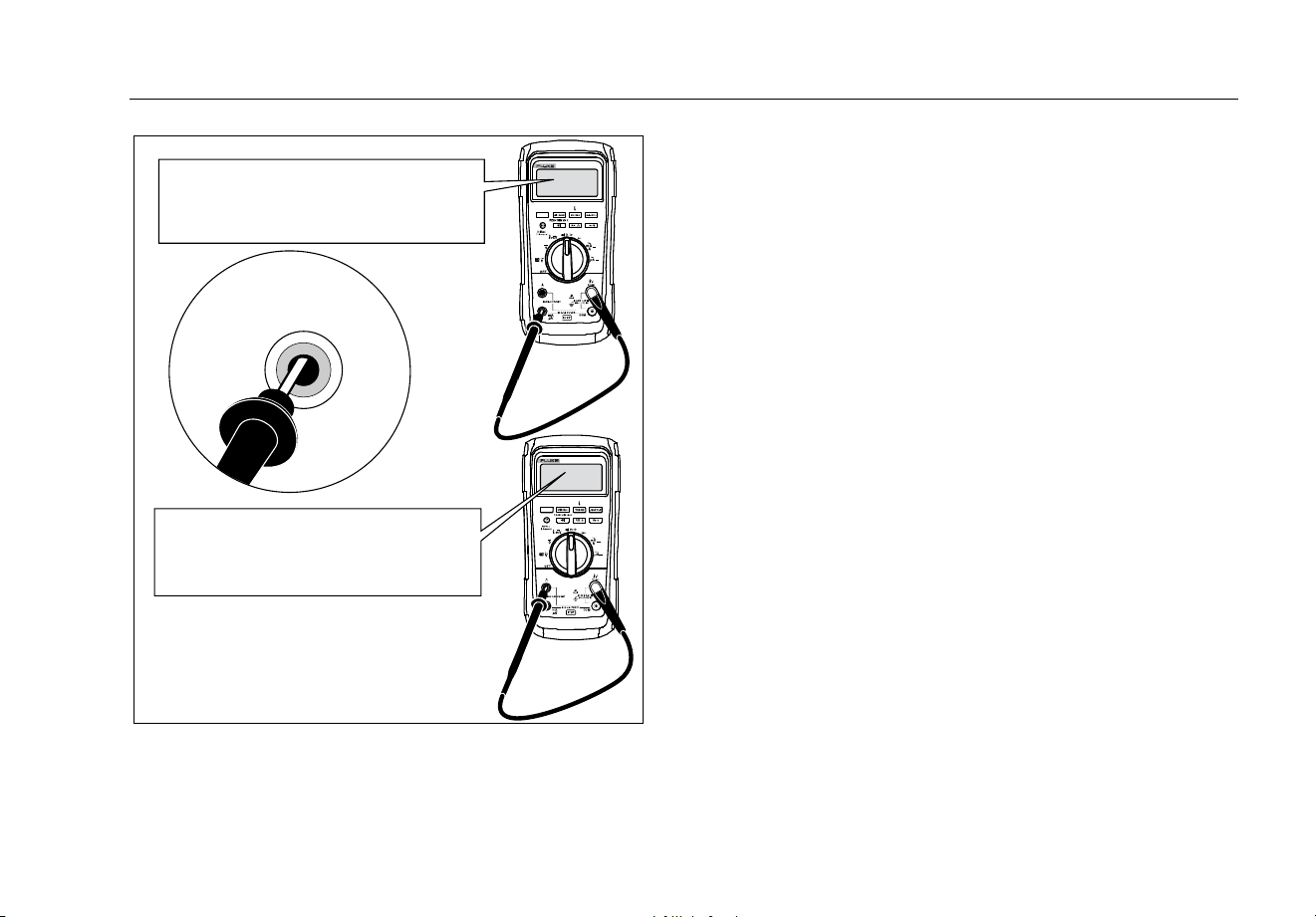
Fuse Test
As shown in Figure 10, with the Meter in the
function, insert a test lead into the jack and place the
probe tip on the other end of the test lead against the
metal of the current input jack. If “” appears in the
display, the probe tip has been inserted too far into the
amps input jack. Back the lead out a bit until the message
disappears and either OL or a resistance reading appears
in the display. The resistance value should be as shown
in Figure 10. If the tests give readings other than those
shown, have the Meter serviced.
XWWarning
To prevent possible electrical shock, fire, or
personal injury:
• Replace a blown fuse with exact
replacement only for continued
protection against arc flash.
• Use only specified replacement fuses.
Digital Multimeter
Maintenance
33
Touch top half
of input contacts
Good 11 A fuse: 00.0 Ω to
00.5 Ω
Replace fuse: OL
Good 0.44 A fuse: 0.995 kΩ to
1.005 kΩ
Replace fuse: OL
gaq105.emf
Figure 10. Current Fuse Test
How to Replace the Batteries
Replace the batteries with three AA batteries
(IEC LR6).
XWWarning
To prevent possible electrical shock, fire, or
personal injury:
• Batteries contain hazardous chemicals
that can cause burns or explode. If
exposure to chemicals occurs, clean
with water and get medical aid.
• Repair the Product before use if the
battery leaks. Battery leakage may create
a shock hazard or damage the Product.
• Do not put battery cells and battery
packs near heat or fire. Do not put in
sunlight.
• MSHA approved for use with three
Energizer P/N E91 or three Duracell P/N
MN1500 1.5 volt, “AA” alkaline batteries
only. All cells are to be replaced at the
same time with identical part number
cells in fresh air locations only.
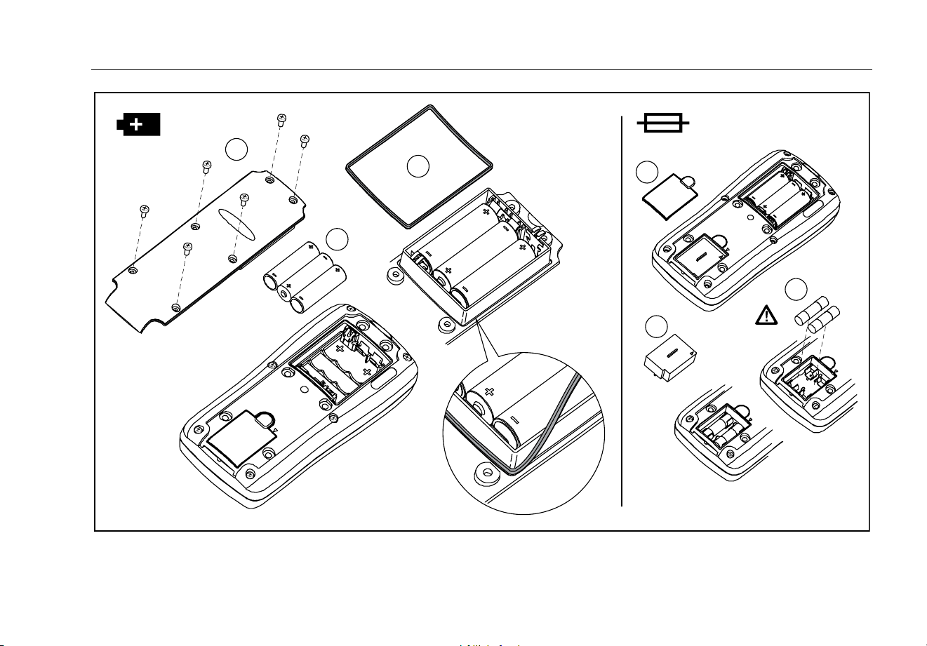
Replace the battery as follows, refer to Figure 11:
1. Turn the rotary switch to OFF and remove the test
leads from the terminals.
2. Remove the six Phillips-head screws from the case
bottom and remove the battery door ().

87V MAX
Users Manual
34
Note
While lifting the battery door, ensure the rubber
gasket stays attached to the battery
compartment barrier.
3. Remove the three batteries and replace all three with
AA Alkaline batteries ().
4. Ensure the battery compartment gasket () is
properly installed around the outside edge of the
battery compartment barrier.
5. Replace the battery door by aligning the battery
compartment barrier with battery compartment.
6. Secure the door with the six Phillips-head screws.
How to Replace the Fuses
Referring to Figure 11, examine or replace the Meter's
fuses as follows:
1. Turn the rotary switch to OFF and remove the test
leads from the terminals
2. Refer to step 2 under the How to Replace the
Batteries section above to remove the battery door.
3. Remove the fuse compartment seal () from the
fuse compartment.
4. Gently lift out the fuse compartment door () from
the fuse compartment.
5. Remove the fuse by gently prying one end loose,
then sliding the fuse out of its bracket ().
6. Install ONLY specified replacement fuses with the
amperage, voltage, and speed ratings shown in
Table 8. The 440-mA fuse is shorter than the 10-A
fuse. For correct placement of each fuse, note the
marking on the printed circuit board under each fuse.
7. Replace the fuse compartment door by aligning the
arrow on the fuse door with the arrow on the case
bottom and lowering the door into the fuse
compartment.
8. Replace the fuse compartment seal by aligning the
tab on the seal with the outline on the case bottom.
Ensure the seal () is properly seated.
9. Refer to steps four through six under the Replacing
the Batteries section above to reinstall the battery
door.
Service and Parts
If the Meter fails, check the battery and fuses. Review this
manual to verify proper use of the Meter.
Replacement parts and accessories are shown in Table 8
and Figure 12.
To order parts and accessories, refer to “How to Contact
Fluke”.
Digital Multimeter
Service and Parts
35
1
4
5
6
2
3
gaq10.emf
Figure 11. Battery and Fuse Replacement
87V MAX
Users Manual
36
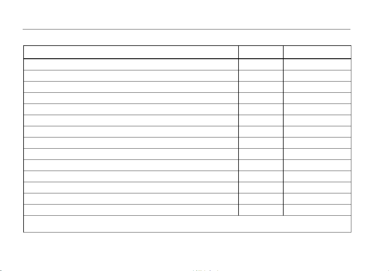
Table 8. Replacement Parts
Description Qty.
Fluke Part or Model
Numbe
r
Battery, AA 1.5 V 3 376756
Fuse, 0.440 A, 1000 V, FAST 1 943121
Fuse, 11 A, 1000 V, FAST 1 803293
Fuse Access Door 1 3400480
Screw 6 3861068
Gasket, Battery Door 1 3439087
Fuse Cap 1 3440546
Holster 1 3321048
Battery Door 1 3321030
Alligator Clips 1 (set of 2) variable
[1]
Test Leads 1 (set of 2) variable
[1]
Integrated DMM Temperature Probe 1 80BK-A
Quick Reference Guide 1 5160944
Safety Information 1 5160959
W To ensure safety, use exact replacement only.
[1] See www.fluke.com for more information about test leads and alligator clips available for your region.
Digital Multimeter
Service and Parts
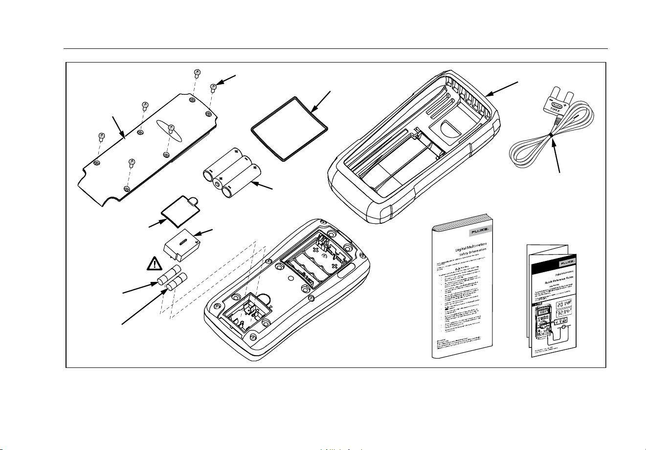
37
Holster
Battery Door
Gasket
Screw
Battery
AA 1.5 V
Fuse Cap
Fuse
Access Door
Battery
Door
Fuse
0.440 A,
1000 V, Fast
Fuse
11 A,
1000 V, Fast
80BK-A Integrated DMM
Temperature Probe
Quick Reference Guide
Safety
Information
gaq111.emf
Figure 12. Replacement Parts

87V MAX
Users Manual
38
General Specifications
Maximum voltage between any
terminal and earth ground ............................................ 1000 V rms
Fuse Protection for mA or μA inputs .......................... 0.44 A, 1000V, IR 10kA
Fuse Protection for A inputs ........................................ 11 A, 1000 V, IR 17 kA
Display
Digital .......................................................................... 6000 counts, updates 4/sec / 19,999 counts in high-resolution mode
Bargraph ..................................................................... 33 segments; updates 40/sec
Altitude
Operating .................................................................... 2000 meters
Storage ....................................................................... 10 000 meters
Temperature
Operating .................................................................... -15 °C to 55 °C, to -40 °C for 20 minutes when taken from 20 °C
Storage ....................................................................... -55 °C to 85 °C (without battery)
-55 °C to 60 °C (with battery)
Temperature coefficient ............................................... 0.05 X (specified accuracy) / °C (<18 °C or >28 °C)
Safety ............................................................................. IEC 61010-1: Pollution Degree 2
IEC 61010-2-033: CAT III 1000 V, CAT IV 600 V
Electromagnetic Compatibility (EMC) ......................... In an RF field of 3 V/m, accuracy = specified accuracy +20 counts, except 600 μA dc
range total accuracy = specified accuracy +60 counts. Temperature not specified.
International ................................................................ IEC 61326-1: Portable Electromagnetic Environment
CISPR 11: Group 1, Class A
Group 1: Equipment has intentionally generated and/or uses conductively coupled radio frequency energy that is necessary for
the internal function of the equipment itself.
Class A: Equipment is suitable for use in all establishments other than domestic and those directly connected to a low-voltage
power supply network that supplies buildings used for domestic purposes. There may be potential difficulties in ensuring
electromagnetic compatibility in other environments due to conducted and radiated disturbances.

Digital Multimeter
General Specifications
39
Caution: This equipment is not intended for use in residential environments and may not provide adequate protection to radio
reception in such environments.
Emissions that exceed the levels required by CISPR 11 can occur when the equipment is connected to a test object.
Korea (KCC) ................................................................ Class A Equipment (Industrial Broadcasting & Communication Equipment)
Class A: Equipment meets requirements for industrial electromagnetic wave equipment and the seller or user should take notice
of it. This equipment is intended for use in business environments and not to be used in homes.
USA (FCC) .................................................................. 47 CFR 15 subpart B. This product is considered an exempt device per clause
15.103. In an RF field of 3 V/M, accuracy = specified accuracy +20 counts, except
600 μA dc range total accuracy = specified accuracy +60 counts. Temperature not
specified
Relative Humidity .......................................................... 0 % to 95 % (0 °C to 35 °C)
0 % to 70 % (35 °C to 55 °C)
Battery Type ................................................................... 3 AA Alkaline batteries, IEC LR6, MSHA approved for use with three Energizer P/N
E91 or three Duracell P/N MN1500 1.5 Volt, AA alkaline batteries only.
Battery Life ..................................................................... 800 hr typical without backlight (Alkaline)
Vibration ......................................................................... Per MIL-PRF-28800 for a Class 2 instrument
Size (H x W x L) .............................................................. 1.8 in x 3.7 in x 7.7 in (4.6 cm x 9.4 cm x 19.7 cm)
Size with Holster ............................................................ 2.4 in x 4.3 in x 8.5 in (6.0 cm x 10.1 cm x 21.5 cm)
Weight ............................................................................ 1.14 lb (517.1 g)
Weight with Holster and Flex-Stand ............................ 1.54 lb (698.5 g)
Intrusion Protection (IP) Rating ................................... IEC 60529: IP67
MSHA Approval No ....................................................... 18-A100015-0
87V MAX
Users Manual
40
Detailed Specifications
For all detailed specifications:
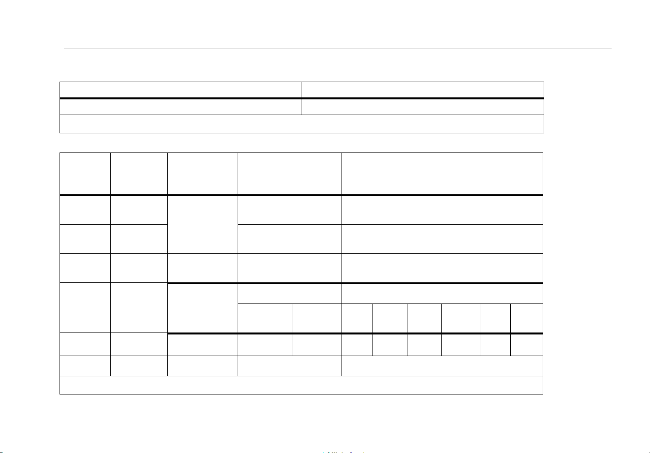
Accuracy is specified for 2 years after calibration, at operating temperatures of 18 °C to 28 °C, with relative humidity at 0 % to 95 %.
Accuracy specifications take the form of ±([% of Reading] + [Number of least-significant digits]). For the 4 ½-digit mode, multiply the number
of least-significant digits (counts) by 10.
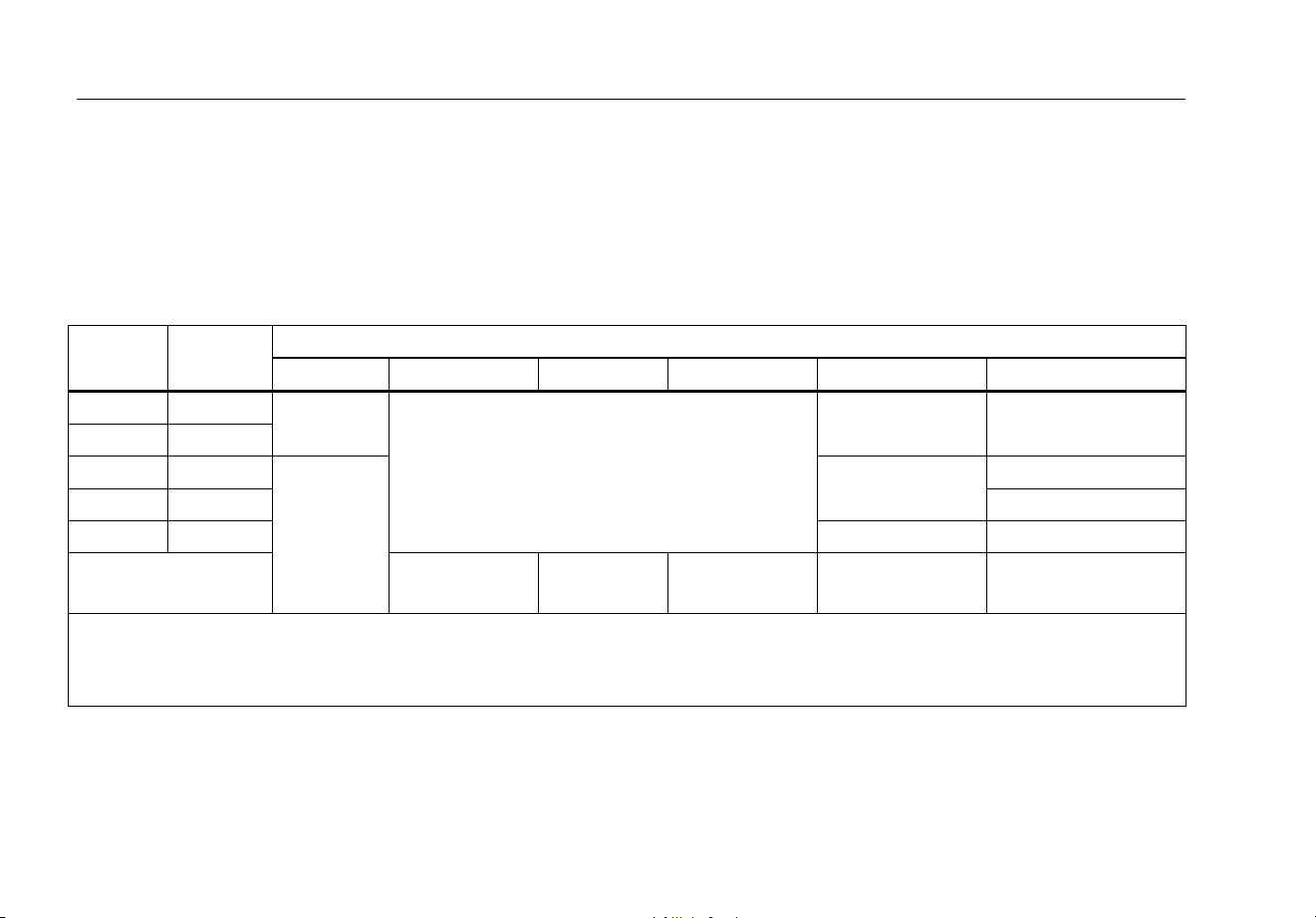
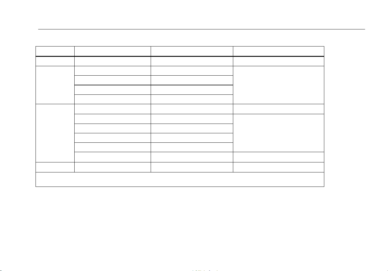
AC Voltage
AC conversions are ac-coupled and valid from 3 % to 100 % of range.
Range Resolution
Accuracy
45 – 65 Hz 15 – 200 Hz 200 – 440 Hz 440 Hz – 1 kHz 1 – 5 kHz 5 – 20 kHz
600.0 mV 0.1 mV
±(0.7 % + 4)
±(1.0 % + 4)
[1]
±(2 % + 4)
±(2 % + 20)
[2]
6.000 V 0.001 V
60.00 V 0.01 V
±(0.7 % + 2)
±(2 % + 4)
[3]
Unspecified
600.0 V 0.1 V Unspecified
1000 V 1 V Unspecified Unspecified
Low-Pass Filter
±(1.0 % + 4)
[1]
+1.0 % + 4
-6.0 % - 4
[4]
Unspecified Unspecified Unspecified
[1] Below 30 Hz, use smoothing function. Below 20 Hz add 0.6 %.
[2] Below 10 % of range, add 12 counts.
[3] Frequency range: 1 to 2.5 kHz
[4] Specification increases from -1 % to -6 % at 440 Hz when filter is used.
Digital Multimeter
Detailed Specifications
41
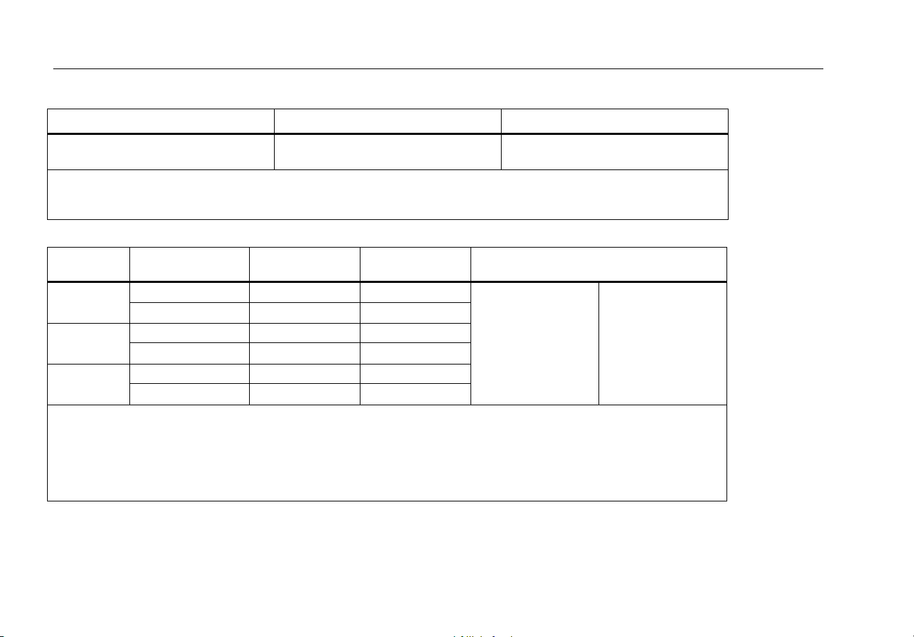
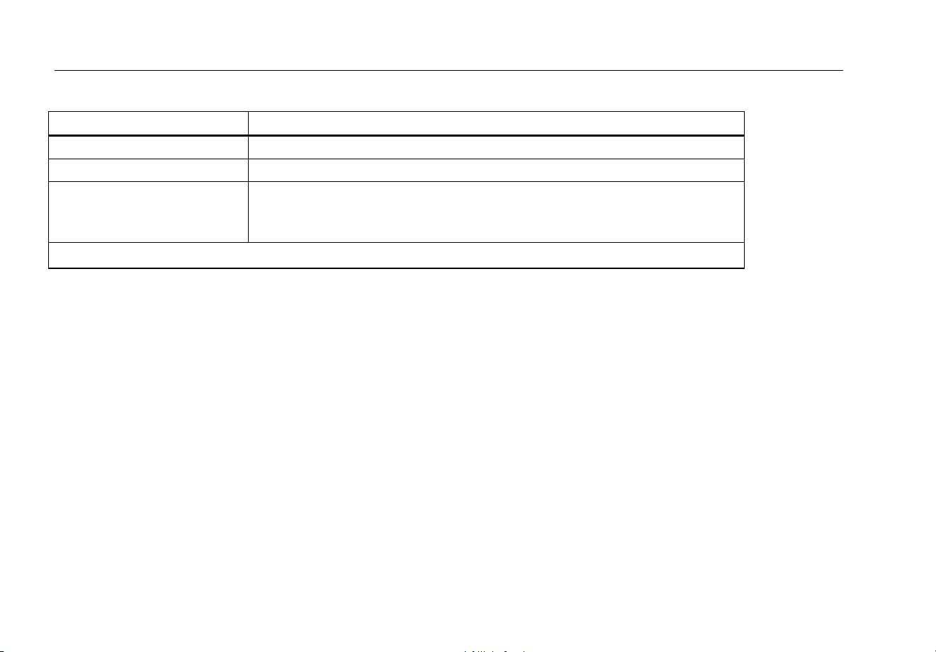
DC Voltage, Conductance, and Resistance
Function Range Resolution Accuracy
mV dc 600.0 mV 0.1 mV
±(0.1 % + 1)
V dc
6.000 V 0.001 V
±(0.05 % + 1)
60.00 V 0.01 V
600.0 V 0.1 V
1000 V 1 V
Ω
600.0 Ω 0.1 Ω
±(0.2 % + 2)
[2]
6.000 kΩ 0.001 kΩ
±(0.2 % + 1)
60.00 kΩ 0.01 kΩ
600.0 kΩ 0.1 kΩ
6.000 MΩ 0.001 MΩ
50.00 MΩ 0.01 MΩ
±(1.0 % + 1)
[1]
nS
60.00 nS 0.01 nS
±(1.0 % + 10)
[1,2]
[1] Add 0.5 % of reading when measuring above 30 MΩ in the 50 MΩ range, and 20 counts below 33 nS in the 60 nS range.
[2] When using the rel function to compensate for offsets.
87V MAX
Users Manual
42
Temperature
Range Resolution
Accuracy
[1,2]
-200 °C to +1090 °C
-328 °F to +1994 °F
0.1 °C
0.1 °F
±(1.0 % + 10)
±(1.0 % + 18)
[1] Does not include error of the thermocouple probe.
[2] Accuracy specification assumes ambient temperature stable to ± 1 °C. For ambient temperature changes of ± 5 °C, rated accuracy
applies after 2 hours.
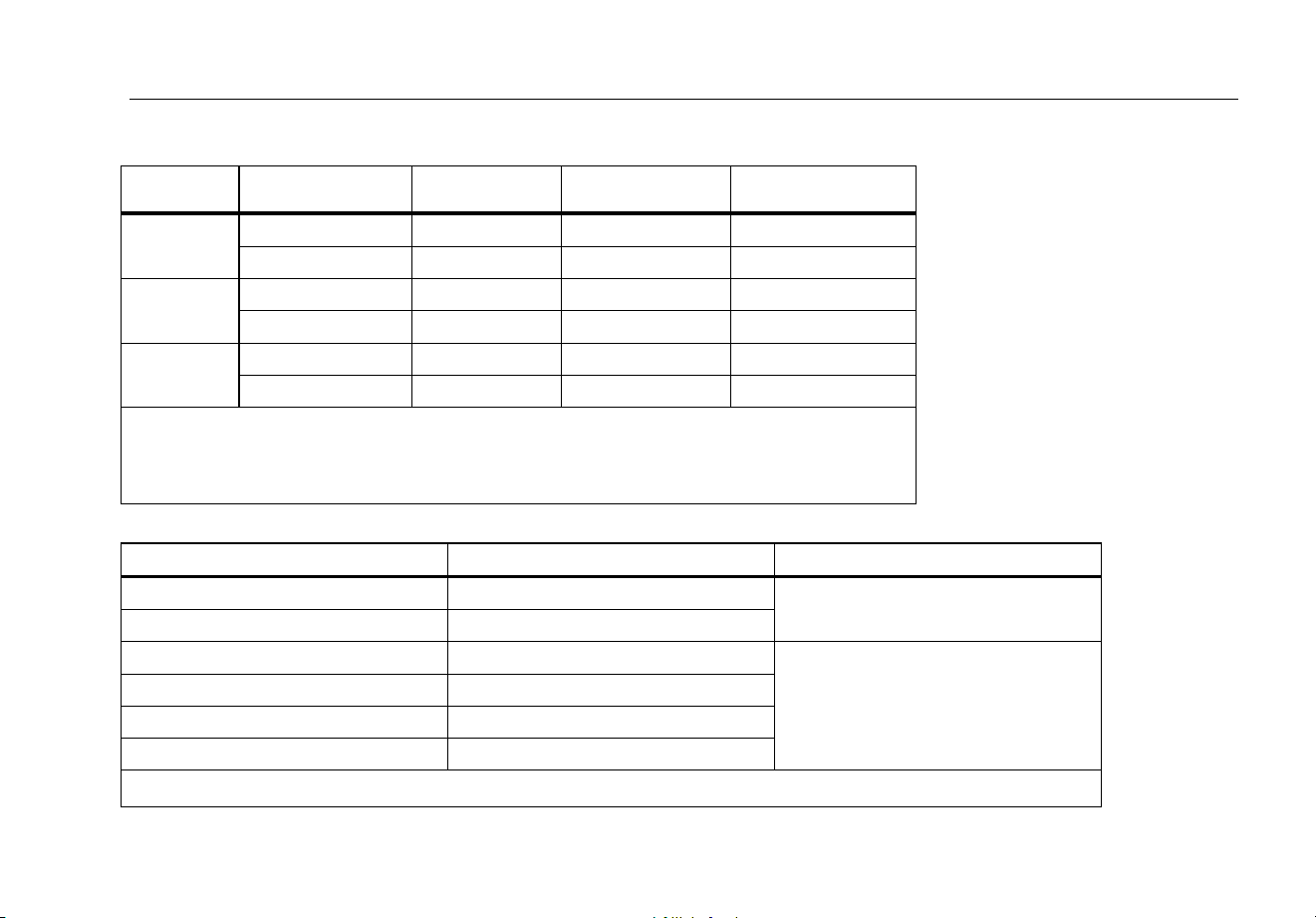
AC Current
Function Range Resolution Burden Voltage
Accuracy
[1]
(45 Hz to 2 kHz)
μA ac
600.0 μA 0.1 μA 100 μV/μA
±(1.5 % + 2) ±(1.0 % + 2)
6000 μA 1 μA 100 μV/μA
mA ac
60.00 mA 0.01 mA 1.8 mV/mA
400.0 mA
[2]
0.1 mA 1.8 mV/mA
A ac
6.000 A 0.001 A 0.03 V/A
10.00 A
[3,4]
0.01 A 0.03 V/A
[1] AC conversions are ac coupled, true rms responding, and valid from 3 % to 100 % of range, except 400 mA range. (5 % to 100 % of
range) and 10 A range (15 % to 100 % or range).
[2] 400 mA continuous. 600 mA for 18 hr maximum.
[3] W 10 A continuous up to 35 °C. <20 minutes on, 5 minutes off at 35 °C to 55 °C. >10 A to 20 A for 30 seconds maximum, 5 minutes
off.
[4] >10 A accuracy unspecified.
Digital Multimeter
Detailed Specifications
43
DC Current
Function Range Resolution Burden Voltage Accuracy
μA dc
600.0 μA 0.1 μA 100 μV/μA ±(0.2 % + 4)
6000 μA 1 μA 100 μV/μA ±(0.2 % + 2)
mA dc
60.00 mA 0.01 mA 1.8 mV/mA
±(0.2 % + 4)
400.0 mA
[1]
0.1 mA 1.8 mV/mA
±(0.2 % + 2)
A dc
6.000 A 0.001 A 0.03 V/A
±(0.2 % + 4)
10.00 A
[2,3]
0.01 A 0.03 V/A
±(0.2 % + 2)
[1] 400 mA continuous. 600 mA for 18 hr maximum.
[2] W 10 A continuous up to 35 °C. <20 minutes on, 5 minutes off at 35 °C to 55 °C. >10 A to 20 A for 30
seconds maximum, 5 minutes off.
[3] >10 A accuracy unspecified.
Capacitance
Range Resolution Accuracy
10.00 nF 0.01 nF
±(1.0 % + 2)
[1]
100.0 nF 0.1 nF
1.000 μF 0.001 μF
±(1.0 % + 2)
10.00 μF 0.01 μF
100.0 μF 0.1 μF
9999 μF 1 μF
[1] With a film capacitor or better, using the rel mode to zero residual.
87V MAX
Users Manual
44
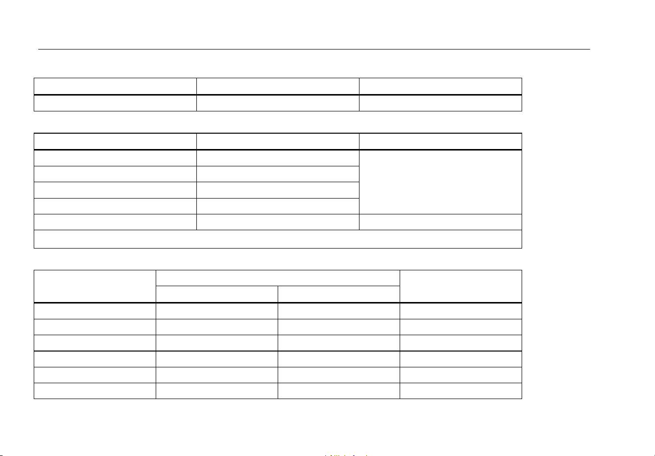
Diode
Range Resolution Accuracy
2.000 V 0.001 V
±(1.0 % + 1)
Frequency
Range Resolution Accuracy
199.99 Hz 0.01 Hz
±(0.005 % + 1)
[1]
1999.9 Hz 0.1 Hz
19.999 kHz 0.001 kHz
199.99 kHz 0.01 kHz
>200 kHz 0.1 kHz Unspecified
[1] From 0.5 Hz to 200 kHz and for pulse widths >2 μs.
Frequency Counter Sensitivity and Trigger Levels
Input Range
Minimum Sensitivity (RMS Sine Wave)
Approximate Trigger Level
(DC Voltage Function)
5 Hz – 20 kHz 0.5 Hz – 200 kHz
600 mV dc 70 mV (to 400 Hz) 70 mV (to 400 Hz) 40 mV
600 mV ac 150 mV 150 mV -
6 V 0.3 V 0.7 V 1.7 V
60 V 3 V
7 V (≤140 kHz)
4 V
600 V 30 V
70 V (≤14.0 kHz)
40 V
1000 V 100 V
200 V (≤1.4 kHz)
100 V
Digital Multimeter
Detailed Specifications
45
Duty Cycle (Vdc and mVdc)
Range Accuracy
0.0 % to 99.9 %
[1]
Within ± (0.2 % per kHz + 0.1 %) for rise times < 1 μs.
[1] 0.5 Hz to 200 kHz, pulse width >2 μs. Pulse width range is determined by the frequency by the frequency of the signal.
Input Characteristics
Function
Overload
Protection
[1]
Input
Impedance
(nominal)
Common Mode
Rejection Ratio
(1 kΩ unbalance)
Normal Mode Rejection
1000 V rms
10 MΩ <100 pF
> 120 dB at dc, 50 Hz
or 60 Hz
> 60 dB at 50 Hz or 60 Hz
1000 V rms
> 120 dB at dc, 50 Hz
or 60 Hz
> 60 dB at 50 Hz or 60 Hz
1000 V rms
10 MΩ < 100 pF
(ac-coupled)
> 60 dB, dc to 60 Hz
Open Circuit
Test Voltage
Full Scale Voltage Typical Short Circuit Current
To 6 MΩ
50 MΩ or
60 nS
600 Ω 6 kΩ 60 kΩ 600 kΩ 6 MΩ 50 MΩ
Ω
1000 V rms <2.8 V dc <850 mV dc <1.3 V dc
500 μA 100 μA 10 μA 1 μA 0.2 μA 0.1 μA
1000 V rms <2.8 V dc 2.200 V dc 1.0 mA typical
[1] 10
6
V Hz Max
87V MAX
Users Manual
46
MIN MAX Recording
Nominal Response Accuracy
100 ms to 80 % (dc functions)
Specified accuracy ±12 counts for changes >200 ms in duration
120 ms to 80 % (ac functions)
Specified accuracy ±40 counts for changes >350 ms and inputs >25 % of range
250 μs (peak)
[1]
Specified accuracy ±100 counts for changes >250 μs in duration
(add ±100 counts for readings over 6000 counts)
(add ±100 counts for readings in Low Pass mode)
[1] For repetitive peaks: 1 ms for single events.