


English
EN
Français
FR
Deutsch DE
Italiano IT
Español
ES
日本語 JA
中文 ZH

4
Read this first
Read through this installation guide carefully before
you install the product. Keep the installation guide for
future reference.
Legal considerations
Video and audio surveillance can be regulated by laws
that vary from country to country. Check the laws in
your local region before using this product for
surveillance purposes.
Liability
Every care has been taken in the preparation of this
document. Please inform your local Axis office of any
inaccuracies or omissions. Axis Communications AB
cannot be held responsible for any technical or
typographical errors and reserves the right to make
changes to the product and manuals without prior
notice. Axis Communications AB makes no warranty
of any kind with regard to the material contained
within this document, including, but not limited to,
the implied warranties of merchantability and fitness
for a particular purpose. Axis Communications AB
shall not be liable nor responsible for incidental or
consequential damages in connection with the
furnishing, performance or use of this material. This
product is only to be used for its intended purpose.
Intellectual property rights
Axis AB has intellectual property rights relating to
technology embodied in the product described in this
document. In particular, and without limitation, these
intellectual property rights may include one or more
of the patents listed at axis. com/patent and one or
more additional patents or pending patent
applications in the US and other countries.
Equipment modifications
This equipment must be installed and used in strict
accordance with the instructions given in the user
documentation. This equipment contains no user-
serviceable components. Unauthorized equipment
changes or modifications will invalidate all applicable
regulatory certifications and approvals.
Trademark acknowledgements
AXIS COMMUNICATIONS, AXIS, ARTPEC and VAPIX are
registered trademarks of Axis AB in various
jurisdictions. All other trademarks are the property of
their respective owners.
Regulatory information
Europe
This product complies with the applicable CE marking
directives and harmonized standards:
• Restriction of Hazardous Substances (RoHS)
Directive 2011/65/EU and 2015/863, including
any amendments, updates or replacements.
See Disposal and recycling, on page 5.
A copy of the original declaration of conformity may
be obtained from Axis Communications AB. See
Contact information, on page 6.
Electromagnetic compatibility (EMC)
This equipment has been designed and tested to fulfill
applicable standards for:
• Radio frequency emission when installed
according to the instructions and used in its
intended environment.
• Immunity to electrical and electromagnetic
phenomena when installed according to the
instructions and used in its intended
environment.
USA
This device complies with part 15 of the FCC Rules.
Operation is subject to the following two conditions:
1. This device may not cause harmful
interference, and
2. this device must accept any interference
received, including interference that may cause
undesired operation.
This equipment has been tested using an unshielded
network cable (UTP) and found to comply with the
limits for a Class A digital device, pursuant to part 15
of the FCC rules. This equipment has also been tested
using a shielded network cable (STP) and found to
comply with the limits for a Class A digital device,
pursuant to part 15 of the FCC rules. These limits are
designed to provide reasonable protection against
harmful interference when the equipment is operated
in a commercial environment. This equipment
generates, uses, and can radiate radio frequency
energy and, if not installed and used in accordance
with the instruction manual, may cause harmful
interference to radio communications. Operation of
this equipment in a residential area is likely to cause
harmful interference in which case the user will be
required to correct the interference at his own
expense.
Contact information
Axis Communications Inc.
300 Apollo Drive
Chelmsford, MA 01824
United States of America
Tel: +1 978 614 2000
Canada
This digital apparatus complies with CAN ICES-3
(Class A). The product shall be connected using a
shielded network cable (STP) that is properly
grounded. Cet appareil numérique est conforme à la
norme CAN NMB-3 (classe A). Le produit doit être
connecté à l'aide d'un câble réseau blindé (STP) qui est
correctement mis à la terre.
Europe
This digital equipment fulfills the requirements for RF
emission according to the Class A limit of EN 55032.
The product shall be connected using a shielded
5
network cable (STP) that is properly grounded. Notice!
This is a Class A product. In a domestic environment
this product may cause RF interference, in which case
the user may be required to take adequate measures.
Australia/New Zealand
This digital equipment fulfills the requirements for RF
emission according to the Class A limit of
AS/NZS CISPR 32. The product shall be connected
using a shielded network cable (STP) that is properly
grounded. Notice! This is a Class A product. In a
domestic environment this product may cause RF
interference, in which case the user may be required
to take adequate measures.
Japan
この装置は、クラスA機器です。この装置を住
宅環境で使用すると電波妨害を引き起こすこと
があります。この場合には使用者が適切な対策
を講ずるよう要求されることがあります。 VCCI
‒ A
本製品は、シールドネットワークケーブル(STP)
を使用して接続してください。また適切に接地
してください。
本製品は電気通信事業者(移動通信会社、固定
通信会社、インターネットプロバイダ等)の通
信回線(公衆無線 LAN を含む)に直接接続す
ることができません。本製品をインターネット
に接続する場合は、必ずルータ等を経由し接続
してください。
Korea
이 기기는 업무용 환경에서 사용할 목적으로 적
합성평가를 받은 기기로서 가정용 환경에서 사용
하는 경우 전파간섭의 우려가 있습니다. 적절히
접지된 STP (shielded twisted pair) 케이블을 사
용하여 제품을 연결 하십시오.
Safety
The product complies with IEC/EN/UL 62368-1 ed. 3,
safety of audio/video and IT equipment for outdoor
use.
The product shall be grounded via a grounding cable
with a minimum of 18 AWG.
The power supply used with this product shall have a
rated output voltage within range of 52-58 VDC.
The power supply used with this product shall fulfill
following requirements:
• Certified according to UL/IEC 62368-1 with
rated ES1 output.
• Have the country approval for the installation.
• Output cable shall have minimum 18 AWG and
comply with UL/CSA C22.2 No. 2556.
• Be aware to follow mounting and installation
requirements of the power supply.
• Have the ambient temperature rating
applicable for the installation.
We recommend the use of Axis power supply DIN
PS56 480 W and AXIS Cable 24 V DC/24-240 V AC 22
m.
Disposal and recycling
When this product has reached the end of its useful
life, dispose of it according to local laws and
regulations. For information about your nearest
designated collection point, contact your local
authority responsible for waste disposal. In
accordance with local legislation, penalties may be
applicable for incorrect disposal of this waste.
Europe
This symbol means that the product shall not be
disposed of together with household or commercial
waste. Directive 2012/19/EU on waste electrical and
electronic equipment (WEEE) is applicable in the
European Union member states. To prevent potential
harm to human health and the environment, the
product must be disposed of in an approved and
environmentally safe recycling process. For
information about your nearest designated collection
point, contact your local authority responsible for
waste disposal. Businesses should contact the product
supplier for information about how to dispose of this
product correctly.
This product complies with the requirements of
Directive 2011/65/EU and 2015/863 on the restriction
of the use of certain hazardous substances in
electrical and electronic equipment (RoHS).
China
This product complies with the requirements of
SJ/T 11364-2014, Marking for the restriction of
hazardous substances in electrical and electronic
products.
有毒有害物质或元素
部
件
名
称
铅
(Pb)
汞
(Hg)
镉
(Cd)
六
价
铬
(Cr
(VI))
多
溴
联
苯
(PB-
B)
多
溴
二
苯
醚
(PB-
DE)
6
电
气
实
装
部
分
X 0 0 0 0 0
0: 表示该有毒有害物质在该部件均质材料中的
含量均在GB/T 26572标准 规定的 限量要求以
下。
X: 表示该有毒有害物质至少在该部件的某一均
质材料中的含量超出GB/T 26572标准规定的限
量要求。
Contact information
Axis Communications AB
Gränden 1
223 69 Lund
Sweden
Tel: +46 46 272 18 00
axis.com
Warranty information
For information about Axis’ product warranty and
thereto related information, go to axis.com/warranty.
Support
Should you require any technical assistance, please
contact your Axis reseller. If your questions cannot be
answered immediately, your reseller will forward your
queries through the appropriate channels to ensure a
rapid response. If you are connected to the Internet,
you can:
• find answers to resolved problems in the FAQ
database, search by product, category, or
phrase
• report problems to Axis support staff by
logging in to your private support area
• chat with Axis support staff
• visit Axis Support at axis.com/support
Learn more!
Visit Axis learning center axis.com/learning for useful
trainings, webinars, tutorials and guides.
7
English
Safety information
Hazard levels
DANGER
Indicates a hazardous situation which, if not
avoided, will result in death or serious injury.
WARNING
Indicates a hazardous situation which, if not
avoided, could result in death or serious injury.
CAUTION
Indicates a hazardous situation which, if not
avoided, could result in minor or moderate injury.
NNOOTTIICCEE
Indicates a situation which, if not avoided, could
result in damage to property.
Other message levels
Important
Indicates significant information which is
essential for the product to function correctly.
Note
Indicates useful information which helps in
getting the most out of the product.
Safety instructions
DANGER
Risk of electric shock. All cables shall be de-
energized before installing or performing
maintenance on the product.
CAUTION
Moving parts. Risk of injury. Keep your body
parts away from the product when it's in
operation. Disconnect from power supply before
installing or performing maintenance on the
product.
CAUTION
Hot surface. Risk of injury. Don't touch the
product when it's in operation. Disconnect from
power supply and allow the surfaces to cool
before performing maintenance on the product.
NNOOTTIICCEE
• The Axis product shall be used in compliance
with local laws and regulations.
• This product is for professional use.
• Install this product at a safe distance from
children.
• Store the Axis product in a dry and ventilated
environment.
• Avoid exposing the Axis product to shocks or
heavy pressure.
• Do not install the product on unstable poles,
brackets, surfaces or walls.
• Use only applicable tools when installing the
Axis product. Using excessive force with power
tools could cause damage to the product.
• Use a soft cloth dampened with pure lukewarm
water to clean the device.
• Don’t use chemicals such as window cleaner or
acetone to clean your device.
• Use only accessories that comply with the
technical specification of your product. These
can be provided by Axis or a third party. Axis
recommends using Axis power source
equipment compatible with your product.
• Use only spare parts provided by or
recommended by Axis.
• Do not attempt to repair the product yourself.
Contact Axis support or your Axis reseller for
service matters.
• Use a yellow/green colored grounding cable of
at least 0.5 mm
2
or 20 AWG.
Transportation
NNOOTTIICCEE
• When transporting the Axis product, use the
original packaging or equivalent to prevent
damage to the product.
Français
Informations sur la sécurité
Niveaux de risques
DANGER
Indique une situation dangereuse qui, si elle n'est
pas évitée, entraînera le décès ou des blessures
graves.
AVERTISSEMENT
Indique une situation dangereuse qui, si elle n'est
pas évitée, pourrait entraîner le décès ou des
blessures graves.
ATTENTION
Indique une situation dangereuse qui, si elle n'est
pas évitée, pourrait entraîner des blessures
légères ou modérées.
8
RREEMMAARRQQUUEE
Indique une situation qui, si elle n'est pas évitée,
pourrait endommager l'appareil.
Autres niveaux de message
Important
Indique les informations importantes, nécessaires
pour assurer le bon fonctionnement de l’appareil.
Remarque
Indique les informations utiles qui permettront
d’obtenir le fonctionnement optimal de l’appareil.
Consignes de sécurité
DANGER
Risque de choc électrique. Tous les câbles doivent
être mis hors tension avant l'installation ou une
intervention de maintenance sur le produit.
ATTENTION
Pièces mobiles. Risque de blessure. Restez à
l'écart du produit lorsqu'il est en fonctionnement.
Débranchez l'alimentation électrique avant
d'installer le produit ou d'effectuer son entretien.
ATTENTION
Surfaces chaudes. Risque de blessure. Ne
touchez pas le produit lorsqu'il est en
fonctionnement. Débranchez l'alimentation
électrique et laissez les surfaces refroidir avant
d'effectuer l'entretien du produit.
RREEMMAARRQQUUEE
• Le produit Axis doit être utilisé conformément
aux lois et règlements locaux.
• Ce produit est destiné à un usage
professionnel.
• Installez ce produit à une distance sûre des
enfants.
• Conserver ce produit Axis dans un
environnement sec et ventilé.
• Ne pas exposer ce produit Axis aux chocs ou
aux fortes pressions.
• Ne pas installer ce produit sur des poteaux,
supports, surfaces ou murs instables.
• Utiliser uniquement des outils recommandés
pour l'installation de l'appareil Axis.
L'application d'une force excessive sur
l'appareil avec des outils puissants pourrait
l'endommager.
• Pour nettoyer le dispositif, utilisez un chiffon
doux humide à l'eau tiède pure.
• N'utilisez pas de produits chimiques tels que le
nettoyant pour vitres ou l'acétone pour
nettoyer votre dispositif.
• Utiliser uniquement des accessoires conformes
aux caractéristiques techniques de votre
produit. Ils peuvent être fournis par Axis ou un
tiers. Axis recommande d'utiliser un
équipement d'alimentation Axis compatible
avec votre produit.
• Utiliser uniquement les pièces de rechange
fournies ou recommandées par Axis.
• Ne pas essayer de réparer vous-même ce
produit. Contacter l'assistance technique d'Axis
ou votre revendeur Axis pour des problèmes
liés à l'entretien.
• Utilisez un câble de mise à la terre de couleur
jaune/vert d'au moins 0,5 mm
2
ou 20 AWG.
Transport
RREEMMAARRQQUUEE
• Lors du transport du produit Axis, utilisez
l'emballage d'origine ou un équivalent pour
éviter d'endommager le produit.
Deutsch
Sicherheitsinformationen
Gefährdungsstufen
GEFAHR
Weist auf eine gefährliche Situation hin, welche,
wenn sie nicht vermieden wird, zum Tod oder zu
schweren Verletzungen führen wird.
WARNUNG
Weist auf eine gefährliche Situation hin, welche,
wenn sie nicht vermieden wird, zum Tod oder zu
schweren Verletzungen führen könnte.
VORSICHT
Weist auf eine gefährliche Situation hin, welche,
wenn sie nicht vermieden wird, zu leichteren oder
mäßig schweren Verletzungen führen könnte.
HHIINNWWEEIISS
Weist auf eine Situation hin, welche, wenn sie
nicht vermieden wird, zu Sachschäden führen
könnte.
Andere Meldeebenen
Wichtig
Weist auf wichtige Informationen hin, die den
richtigen Betrieb des Produkts gewährleisten.
Hinweis
Weist auf nützliche Informationen hin, die die
optimale Verwendung des Produkts unterstützen.
Sicherheitsanweisungen
GEFAHR
Stromschlaggefahr Vor der Installation oder
Wartung des Produkts muss sichergestellt
werden, dass an keinem der Kabel Spannung
anliegt.
9
VORSICHT
Bewegliche Teile Verletzungsgefahr
Körperteile während des Betriebs vom Produkt
fernhalten. Vor der Installation oder Wartung des
Produkts alle Kabel von der Stromversorgung
abklemmen.
VORSICHT
Heiße Oberfläche. Verletzungsgefahr Das
Produkt während des Betriebs nicht berühren.
Trennen Sie vor Wartungsarbeiten die
Stromversorgung und lassen Sie die Oberflächen
des Produkts abkühlen.
HHIINNWWEEIISS
• Das Axis Produkt muss unter Beachtung der
geltenden Gesetze und Bestimmungen
betrieben werden.
• Dieses Produkt ist für den professionellen
Gebrauch bestimmt.
• Installieren Sie dieses Produkt in sicherer
Entfernung von Kindern.
• Lagern Sie das Axis Produkt in einer trockenen
und belüfteten Umgebung.
• Das Axis Produkt weder Stößen noch starkem
Druck aussetzen.
• Installieren Sie das Produkt nicht an instabilen
Masten, Halterungen, Oberflächen oder
Wänden.
• Verwenden Sie bei der Installation des Axis
Produkts ausschließlich passende Werkzeuge.
Ein zu großer Kraftaufwand mit elektrischen
Werkzeugen kann das Produkt beschädigen.
• Verwenden Sie zur Reinigung des Geräts ein
weiches, mit lauwarmem reinen Wasser
befeuchtetes Tuch.
• Verwenden Sie zur Reinigung Ihres Geräts
keine chemischen Substanzen wie
Fensterreiniger oder Aceton.
• Verwenden Sie nur Zubehör, das den
technischen Vorgaben Ihres Produkts
entspricht. Dieses ist von Axis oder
Drittanbietern erhältlich. Axis empfiehlt die
mit Ihrem Produkt kompatible
Stromversorgung von Axis.
• Verwenden Sie ausschließlich Ersatzteile die
von Axis angeboten oder empfohlen werden.
• Versuchen Sie nicht, dieses Produkt selbsttätig
zu reparieren. Wenden Sie sich bezüglich
Reparatur und Wartung an den Axis Support
oder Ihren Axis Händler.
• Verwenden Sie ein gelb/grün gekennzeichnetes
Erdungskabel mit einem Querschnitt von
mindestens 0,5 mm
2
.
Transport
HHIINNWWEEIISS
• Bei Bedarf transportieren Sie das Axis Produkt
in der Originalverpackung oder einer
entsprechenden Verpackung, so dass Schäden
vermieden werden.
Italiano
Informazioni di sicurezza
Livelli di pericolo
PERICOLO
Indica una situazione pericolosa che, se non
evitata, provoca morte o lesioni gravi.
PREAVVISO
Indica una situazione pericolosa che, se non
evitata, potrebbe provocare la morte o lesioni
gravi.
ATTENZIONE
Indica una situazione pericolosa che, se non
evitata, potrebbe provocare lesioni medie o
minori.
AAVVVVIISSOO
Indica una situazione che, se non evitata,
potrebbe danneggiare la proprietà.
Altri livelli di messaggio
Importante
Indica informazioni importanti, essenziali per il
corretto funzionamento del dispositivo.
Nota
Indica informazioni utili che aiutano a ottenere il
massimo dal dispositivo.
Istruzioni per la sicurezza
PERICOLO
Rischio di scosse elettriche. Tutti i cavi devono
essere diseccitati prima di installare o eseguire la
manutenzione sul dispositivo.
ATTENZIONE
Parti in movimento. Rischio di lesioni. Tenere
il corpo distante dal dispositivo durante il
funzionamento. Scollegare dall'alimentazione
prima di installare o eseguire la manutenzione sul
dispositivo.
ATTENZIONE
Superficie calda. Rischio di lesioni. Non
toccare il dispositivo durante il funzionamento.
Scollegare dall'alimentazione e lasciar raffreddare
le superfici prima di eseguire la manutenzione sul
dispositivo.
AAVVVVIISSOO
10
• Il dispositivo Axis deve essere utilizzato in
conformità alle leggi e alle normative locali.
• Questo prodotto è destinato all'uso
professionale.
• Installare il prodotto a una distanza di
sicurezza dai bambini.
• Conservare il dispositivo Axis in un ambiente
asciutto e ventilato.
• Evitare di esporre il dispositivo Axis a urti o
pressioni eccessive.
• Non installare il dispositivo su supporti,
superfici, pareti o pali instabili.
• Utilizzare solo strumenti applicabili quando si
installa il prodotto Axis. Se si utilizza una forza
eccessiva con strumenti non adatti è possibile
causare danni al dispositivo.
• Usare un panno morbido inumidito con acqua
pura tiepida per pulire il dispositivo.
• Non utilizzare sostanze chimiche come
detergenti per vetri o acetone per pulire il
dispositivo.
• Utilizzare solo accessori compatibili con le
specifiche tecniche del dispositivo. Questi
possono essere forniti da Axis o da terze parti.
Axis consiglia l'uso dell'apparecchiatura di
alimentazione Axis compatibile con il
dispositivo.
• Utilizzare solo parti di ricambio fornite o
consigliate da Axis.
• Non tentare di riparare il dispositivo da soli.
Contattare l'assistenza o il rivenditore Axis per
questioni relative alla manutenzione.
• Utilizzare un cavo di messa a terra giallo o
verde di almeno 0,5 mm
2
o 20 AWG.
Trasporto
AAVVVVIISSOO
• Durante il trasporto del dispositivo Axis,
utilizzare l'imballaggio originale o equivalente
per evitare danni al dispositivo.
Español
Información de seguridad
Niveles de peligro
PELIGRO
Indica una situación peligrosa que, si no se evita,
provocará lesiones graves o la muerte.
ADVERTENCIA
Indica una situación peligrosa que, si no se evita,
puede provocar lesiones graves o la muerte.
PRECAUCIÓN
Indica una situación peligrosa que, si no se evita,
puede provocar lesiones moderadas o leves.
AAVVIISSOO
Indica una situación peligrosa que, si no se evita,
puede provocar daños materiales.
Otros niveles de mensaje
Importante
Indica información importante que es
fundamental para que el producto funcione
correctamente.
Nota
Indica información útil que ayuda a aprovechar el
producto al máximo.
Instrucciones de seguridad
PELIGRO
Riesgo de descarga eléctrica. Todos los cables
deberán estar sin energía antes de realizar
trabajos de instalación o mantenimiento en el
producto.
PRECAUCIÓN
Piezas móviles. Riesgo de lesiones. No
acerque ninguna parte del cuerpo al producto
cuando esté funcionando. Desconecte la fuente
de alimentación antes de realizar trabajos de
instalación o mantenimiento en el producto.
PRECAUCIÓN
Superficie caliente. Riesgo de lesiones. No
toque el producto cuando esté funcionando.
Desconecte la fuente de alimentación y deje que
se enfríen las superficies antes de realizar
trabajos de mantenimiento en el producto.
AAVVIISSOO
• Este producto de Axis debe utilizarse de
acuerdo con las leyes y normativas locales.
• Este producto es para uso profesional.
• Instale este producto a una distancia segura de
los niños.
• Almacene el producto de Axis en un entorno
seco y ventilado.
• Evite exponer el producto Axis a golpes o
presiones excesivas.
• No instale el producto en postes, soportes,
superficies o paredes inestables.
• Use solo las herramientas adecuadas al instalar
el producto Axis. La aplicación de una fuerza

11
excesiva con herramientas eléctricas puede
provocar daños en el producto.
• Utilice un paño suave humedecido con agua
pura y tibia para limpiar el dispositivo.
• No utilice productos químicos como un
limpiacristales o acetona para limpiar el
dispositivo.
• Utilice solo accesorios que cumplan con las
especificaciones técnicas de su producto.
Puede obtenerlos de Axis o de un tercero. Axis
recomienda utilizar un equipo de suministro de
alimentación de Axis compatible con su
producto.
• Utilice solo piezas de recambio suministradas o
recomendadas por Axis.
• No intente reparar el producto usted mismo.
Contacte son el servicio de asistencia de Axis o
a su distribuidor de Axis para cualquier tema
relacionado con el mantenimiento.
• Utilice un cable de tierra de color amarillo/
verde de al menos 0,5 mm
2
o 20 AWG.
Transporte
AAVVIISSOO
• Cuando transporte el producto de Axis, utilice
el embalaje original o un equivalente para
evitar daños en el producto.
日本語
安全情報
危危険険レレベベルル
危険
回避しない場合、死亡または重傷につなが
る危険な状態を示します。
警告
回避しない場合、死亡または重傷につなが
るおそれのある危険な状態を示します。
注意
回避しない場合、軽傷または中程度の怪我
につながるおそれのある危険な状態を示し
ます。
注意
回避しない場合、器物の破損につながるお
それのある状態を示します。
そそのの他他ののメメッッセセーージジレレベベルル
重要
製品を正しく機能させるために不可欠な重
要情報を示します。
注
製品を最大限に活用するために役立つ有用
な情報を示します。
安全に関する指示
危険
感電の危険があります。製品の設置やメン
テナンスを行う前にすべてのケーブルの通
電を切ってください。
注意
可動部分。損傷の危険があります。動
作中は、身体の一部を本製品に近づけない
でください。製品の設置やメンテナンスを
行う前には電源を切ってください。
注意
表面が熱くなります。損傷の危険があ
ります。動作中は、本製品に触れないでく
ださい。製品のメンテナンスを実行する前
には電源を切り、表面が冷えるまで待って
ください。
注意
• 本製品は、お使いになる地域の法律や規
制に準拠して使用してください。
• 本製品は業務用です。
• 本製品はお子様の手の届かない場所に設
置してください。
• 本製品は乾燥した換気のよい環境に保管
してください。
• 本製品に衝撃または強い圧力を加えない
でください。
• 本製品を不安定なポール、ブラケット、
表面、または壁に設置しないでくださ
い。
• 本製品を設置する際には、適切な工具の
みを使用してください。電動工具を使用
して過剰な力をかけると、製品が損傷す
ることがあります。
• 装置のクリーニングには、ぬるま湯で湿
らせた柔らかい布を使用してください。
• 窓ガラス用洗剤やアセトンなどの化学薬
品を使用して装置をクリーニングしない
でください。
• 製品の技術仕様に準拠したアクセサリー
のみを使用してください。これらのアク
セサリーは、Axisまたはサードパーティ
から入手できます。Axisは、ご使用の製
品と互換性のあるAxis給電ネットワーク
スイッチの使用を推奨します。
• Axisが提供または推奨する交換部品のみ
を使用してください。
• 製品を自分で修理しないでください。修
理については、Axisサポートまたは販売
代理店にお問い合わせください。
• 最低0.5 mm
2
または20 AWGの黄/緑色の
ケーブルを使用してください。
輸輸送送
注意
12
• 本製品を運搬する際は、製品が損傷しな
いよう、元の梱包か同等の梱包を使用し
てください。
中文
安安全全信信息息
危危险险等等级级
危险
表示如果不避免则会导致死亡或严重伤害的
危险情况。
警告
表示如果不避免则可能导致死亡或严重伤害
的危险情况。
警示
表示如果不避免则可能导致轻微或中度伤害
的危险情况。
注注意意
表示如果不避免则可能导致财产损失的情
况。
其其他他消消息息等等级级
重要
表示产品正常工作所必需的重要信息。
注
表示有助于充分利用产品的有用信息。
安安全全说说明明
危险
触点危险。在安装或执行产品维护之前,电
缆应断电。
警示
活动部件。受伤风险。产品操作期间,
请保持身体部位远离产品。安装或维护产品
时,请断开电源。
警示
表面灼热。受伤风险。请勿在产品运作
期间触摸该产品。执行产品维护时,请断开
电源并让表面冷却。
注注意意
• 使用安讯士产品时应遵守当地法律和法
规。
• 本产品供专业人士使用。
• 安装本产品时,请与儿童保持安全距离。
• 在干燥通风的环境中存放安讯士产品。
• 避免将安讯士产品暴露在冲击或重压下。
• 请勿将本产品安装在不稳定的立杆、支
架、表面或墙壁上。
• 安装安讯士产品时,仅使用适用的工具。
使用电动工具过度施力可能导致产品损
坏。
• 使用蘸有温水的软布清洁设备。
• 请勿使用窗户清洁剂或丙酮等化学品来清
洁设备。
• 仅使用符合产品技术规格的附件。这些附
件可由安讯士或第三方提供。安讯士推荐
使用与产品兼容的安讯士电源设备。
• 仅使用安讯士提供或推荐的备件。
• 请勿尝试自行维修产品。有关服务事项,
请联系安讯士支持部门或安讯士经销商。
• 使用一根至少为 0.5 mm
2
或 20 AWG 的黄
色/绿色接地电缆。
运运输输
注注意意
• 安讯士产品运输途中,应使用其原包装或
等效包装,以防对产品造成损坏。

EN
Package contents
• Positioning unit
• Power connector
• I/O connector
• Torx® bit T20 (long)
• Cable gland
• RJ45 installation tool
• Ring cable lug
13
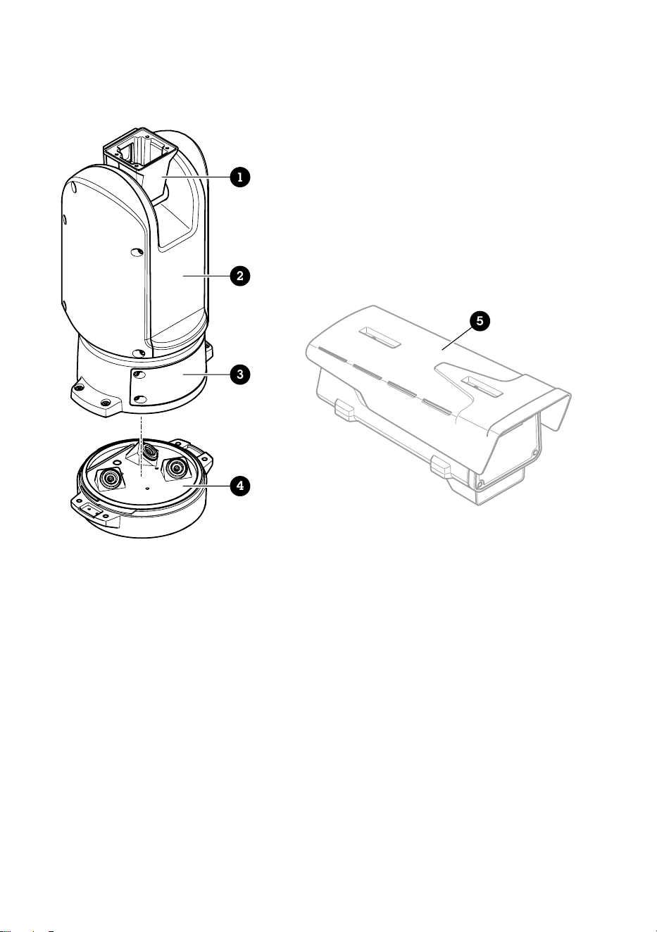
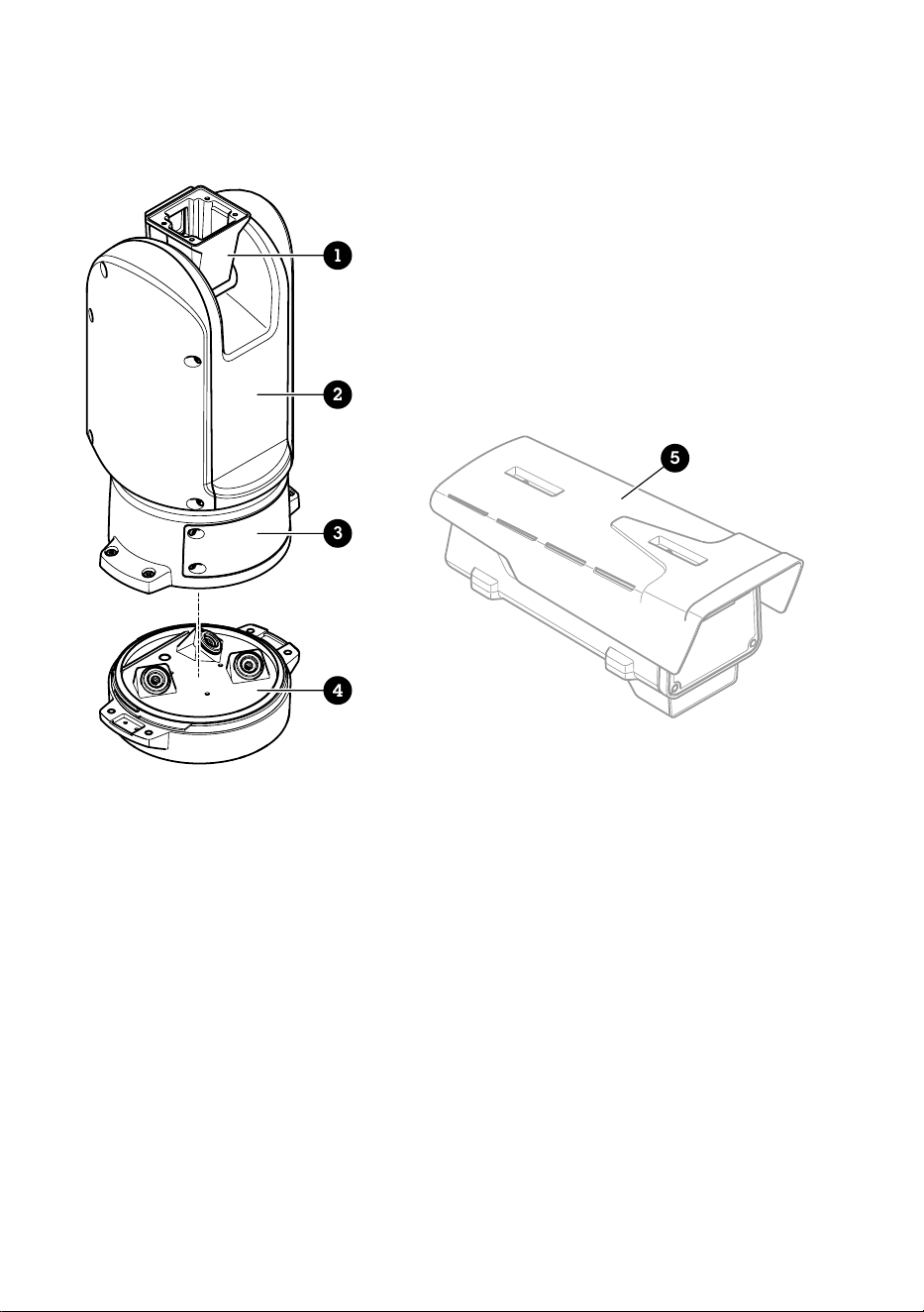
Product overview
1
2
3
4
5
1 Positioning unit (tilt)
2 Positioning unit (pan)
3 Lid
4 Base unit
5 Camera (not included)
14

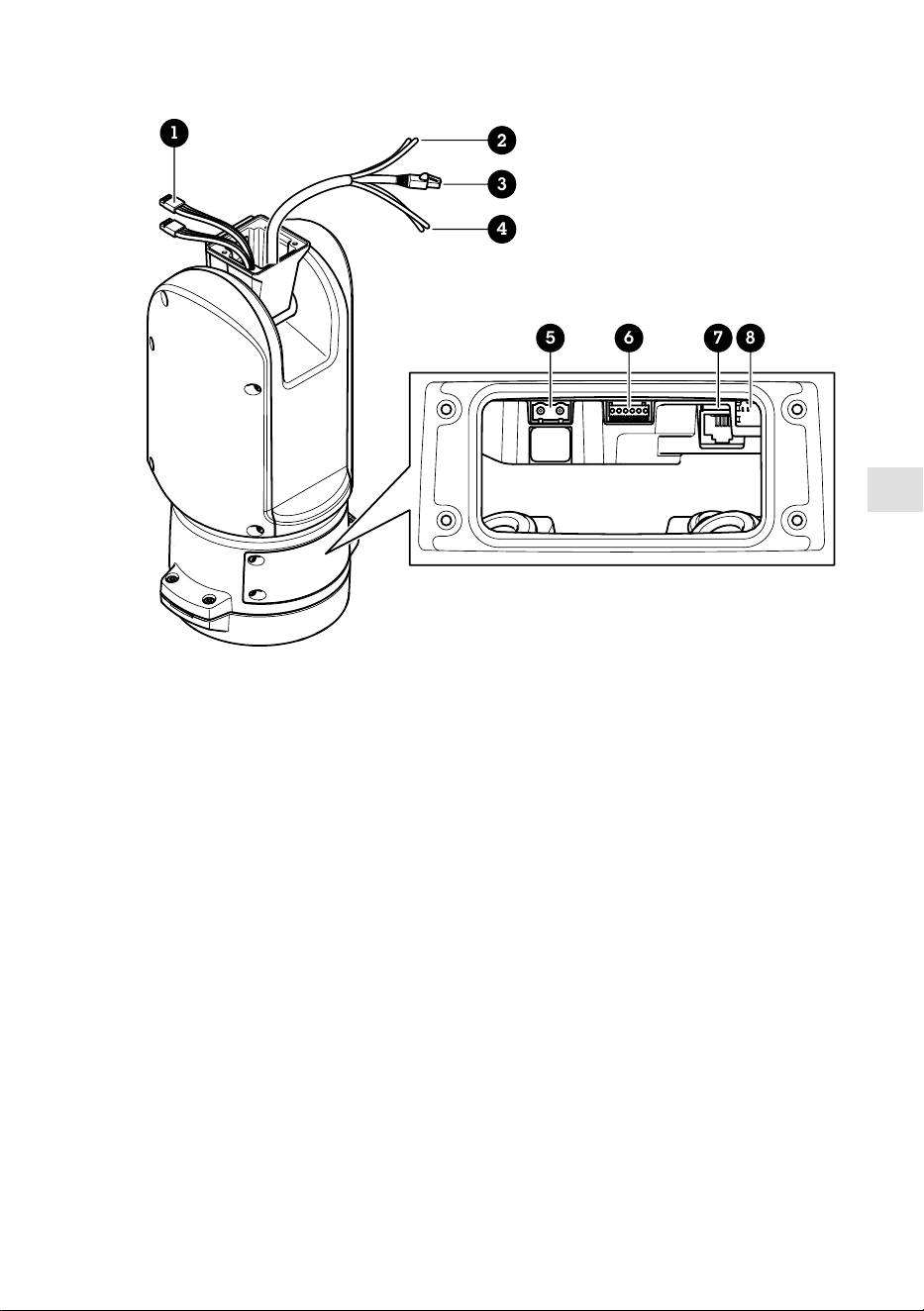
EN
1
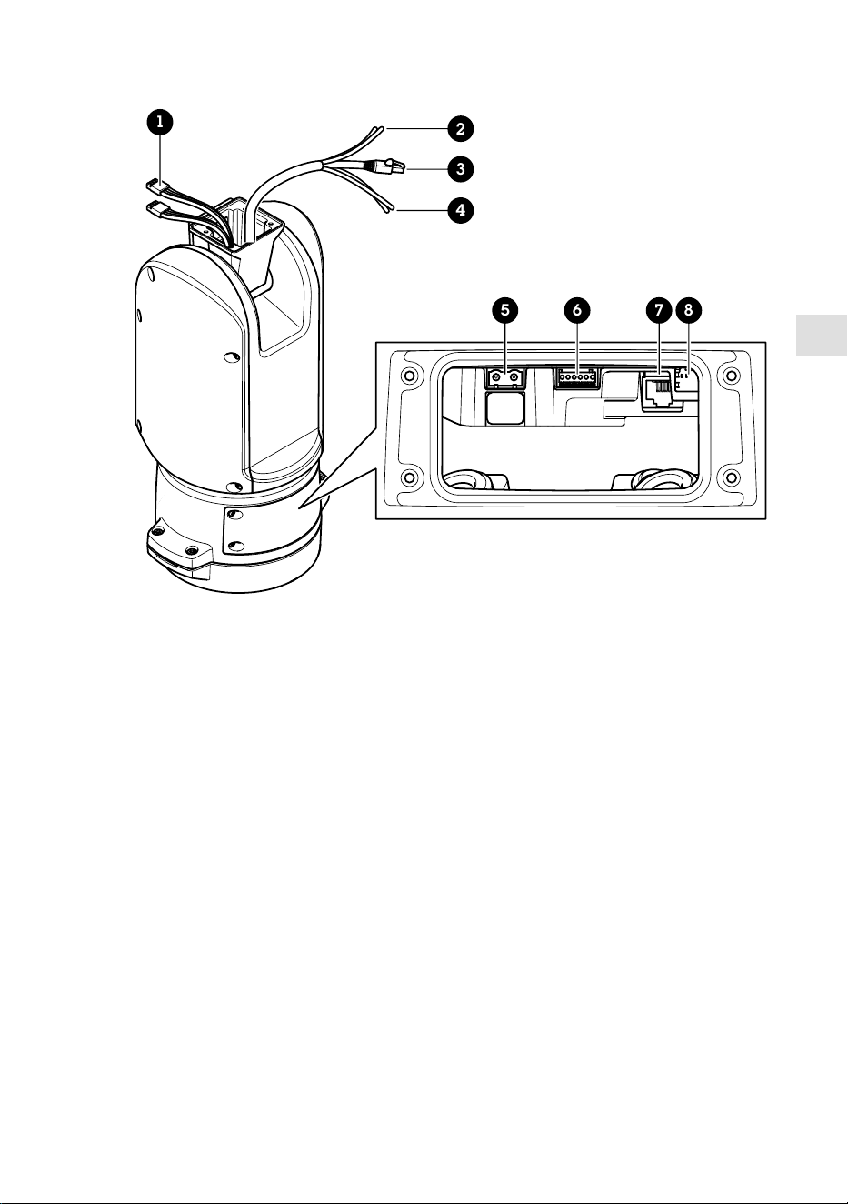
5 6 7 8
2
3
4
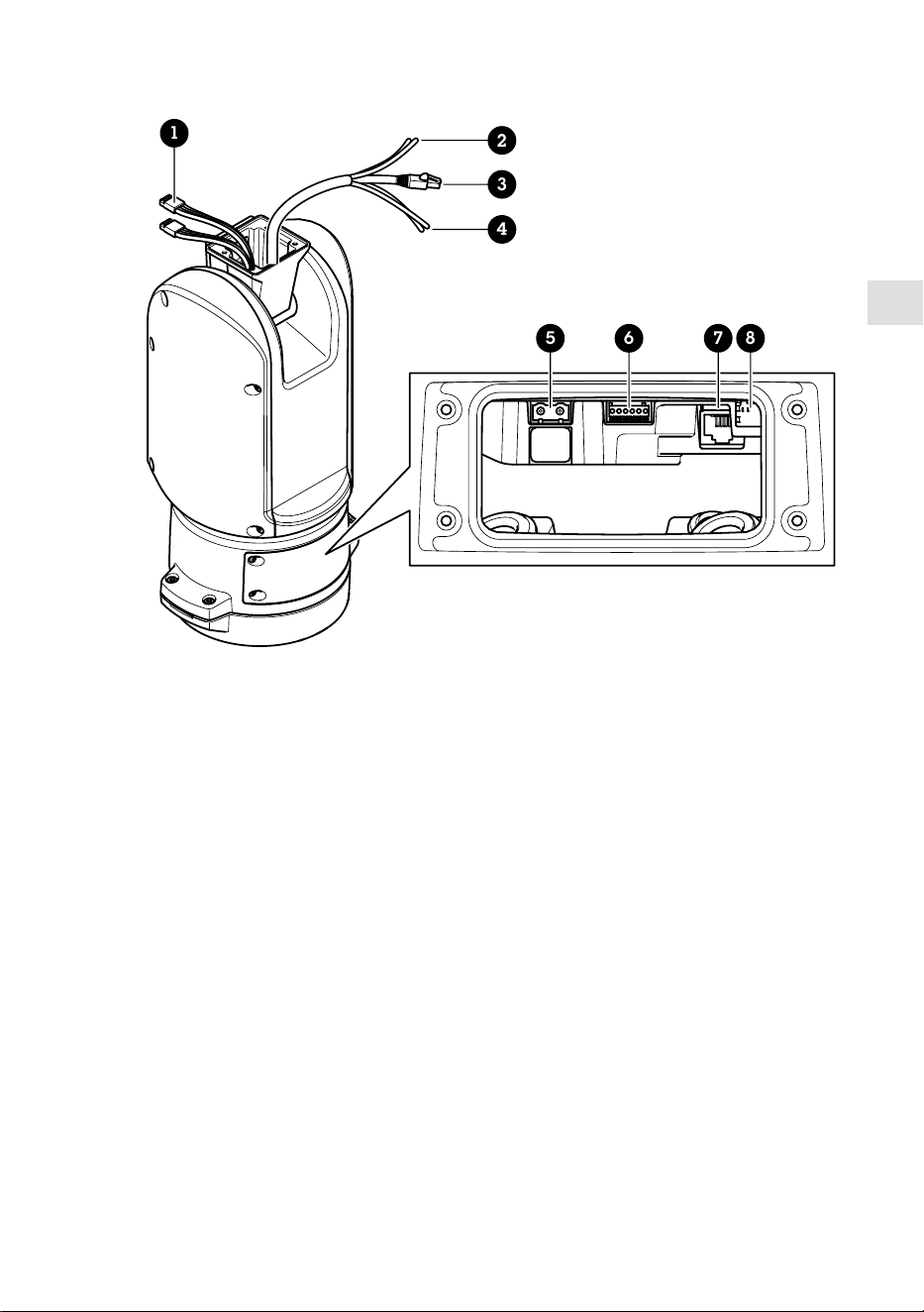
1 Illuminator cables (not to be used)
2 Camera power cable
3 Camera network cable
4 Camera serial interface cable
5 Input power connector
6 I/O connector
7 RJ45 connector
8 SFP slot for SFP module (SFP module not included)
15
How to install the product
DANGER
Risk of electric shock. All cables shall be de-energized before installing the product.
CAUTION
The electrical connections and conduit installations shall be made by a certified electrician and
in compliance with local regulations.
CAUTION
Risk of injury. Moving parts. Keep your body parts away from the product when in
operation. Disconnect from power supply before installing or performing maintenance on the
product.
CAUTION
Risk of injury. Hot surface. Do not touch the product when in operation. Disconnect from
power supply and allow the surfaces to cool before performing maintenance on the product.
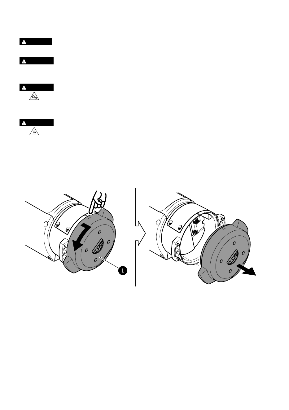
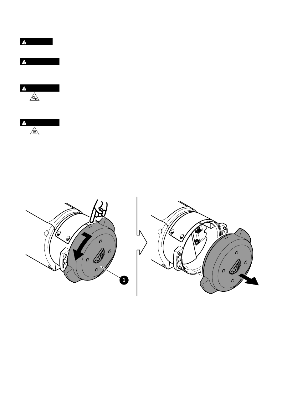
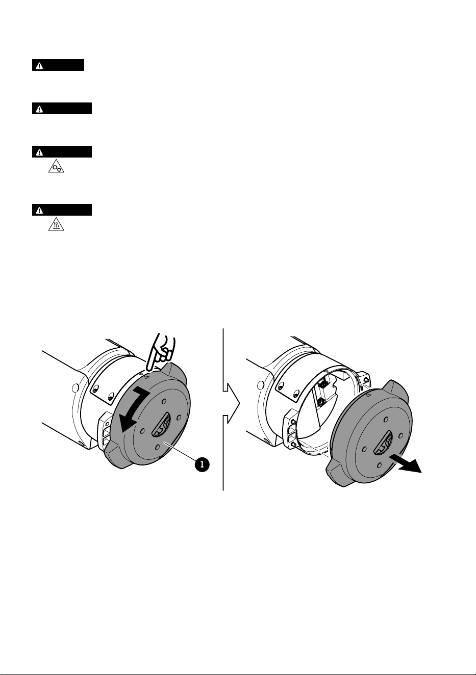
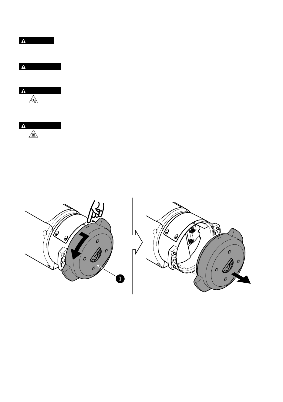
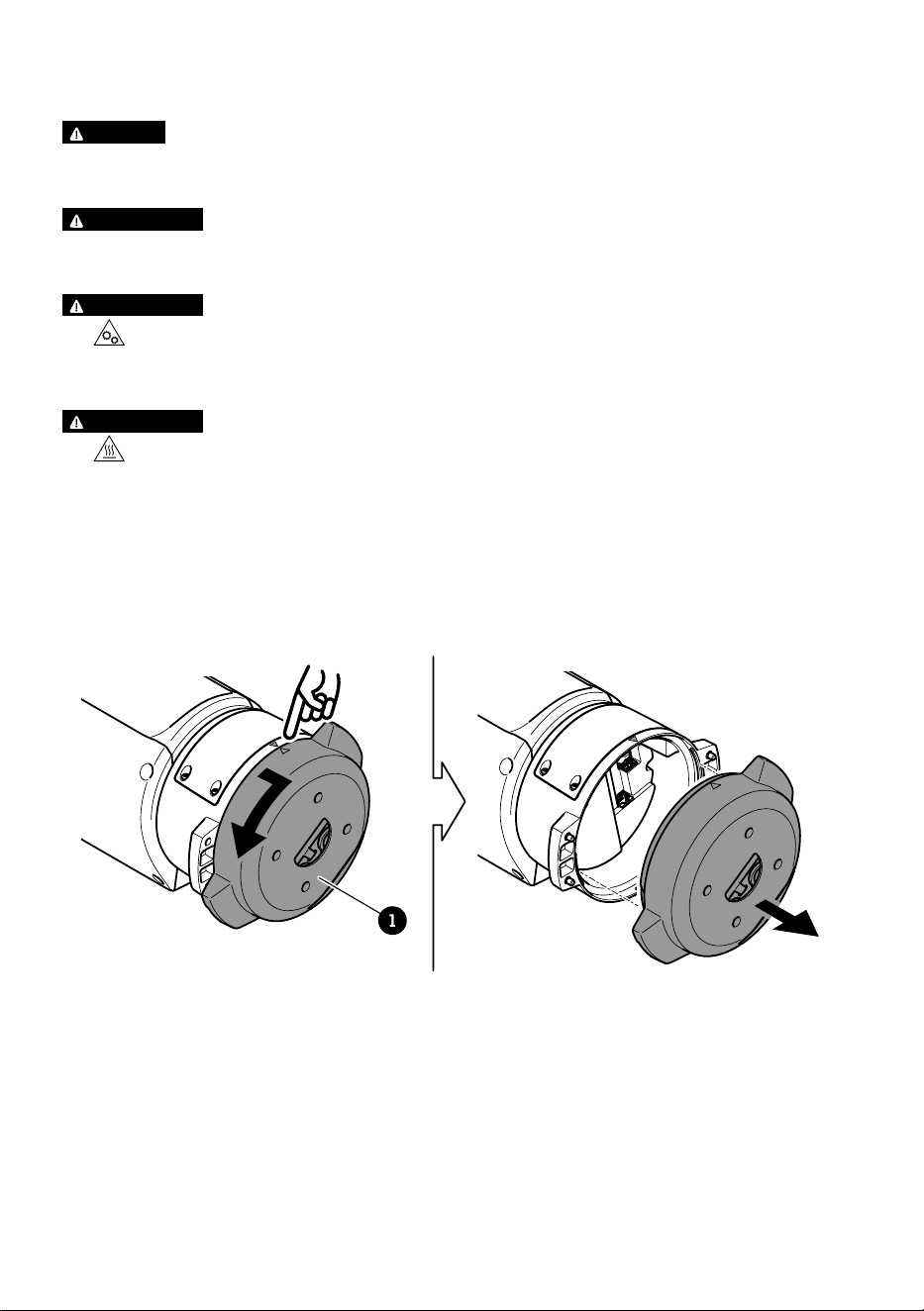
Mount the base unit
1
1 Base unit
1. Remove the four base unit screws (T30).
2. Simultaneously pull and turn the base unit counterclockwise until the arrows on the base
unit and the rest of the positioning unit align.
3. Remove the base unit.
16
EN
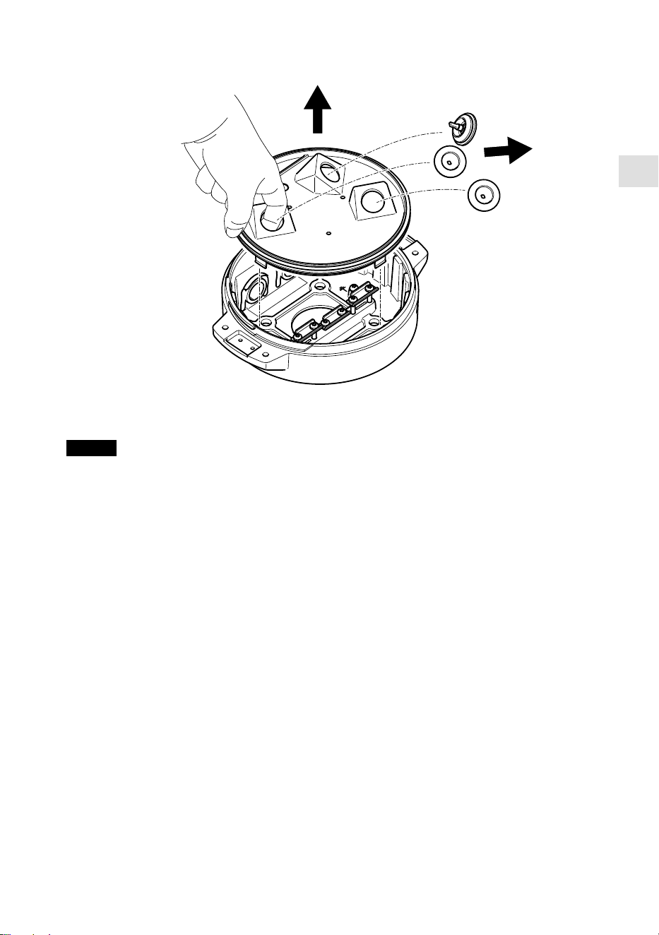
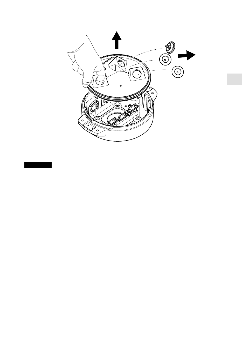
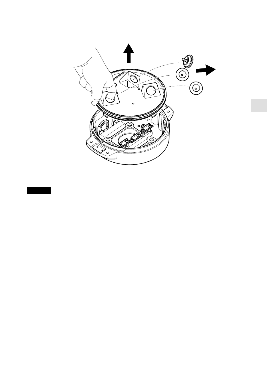
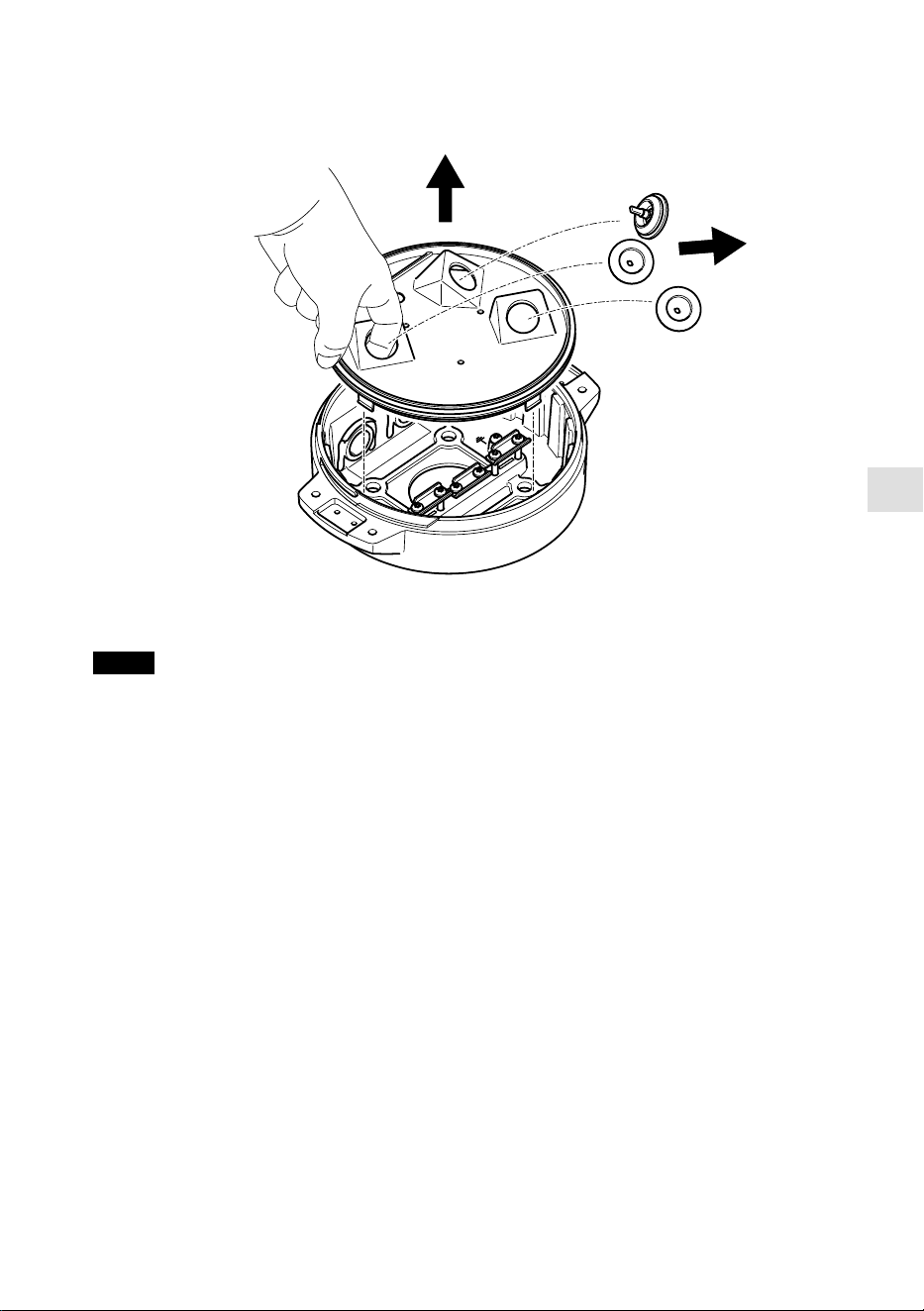
NOTICE
Do not use sharp tools when you remove the transparent base unit cover.
4. Remove the transparent base unit cover.
17
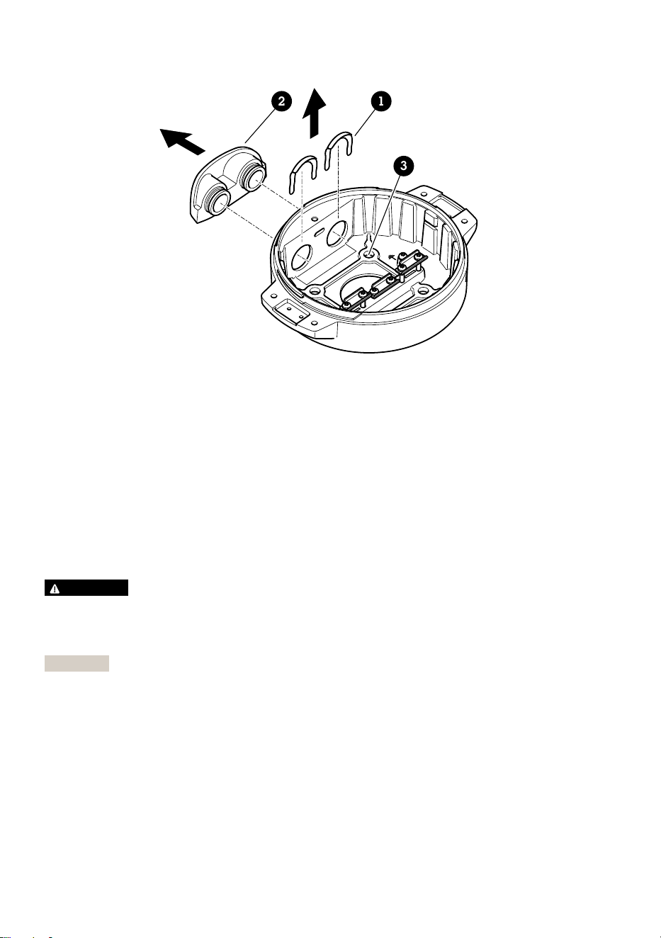
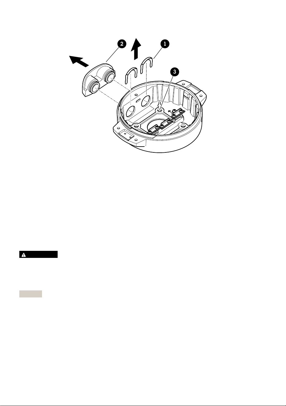
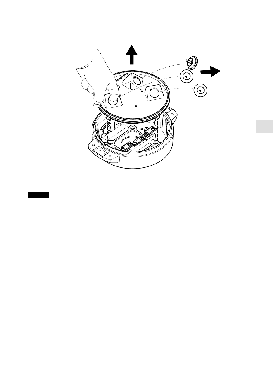
12
3
1 Conduit cover clip
2 Conduit cover
3 Screw hole (x4)
5. For conduit installations only: remove the two conduit cover clips followed by the conduit
cover.
6. Attach the base unit to the mounting surface with appropriate fasteners in the four screw
holes.
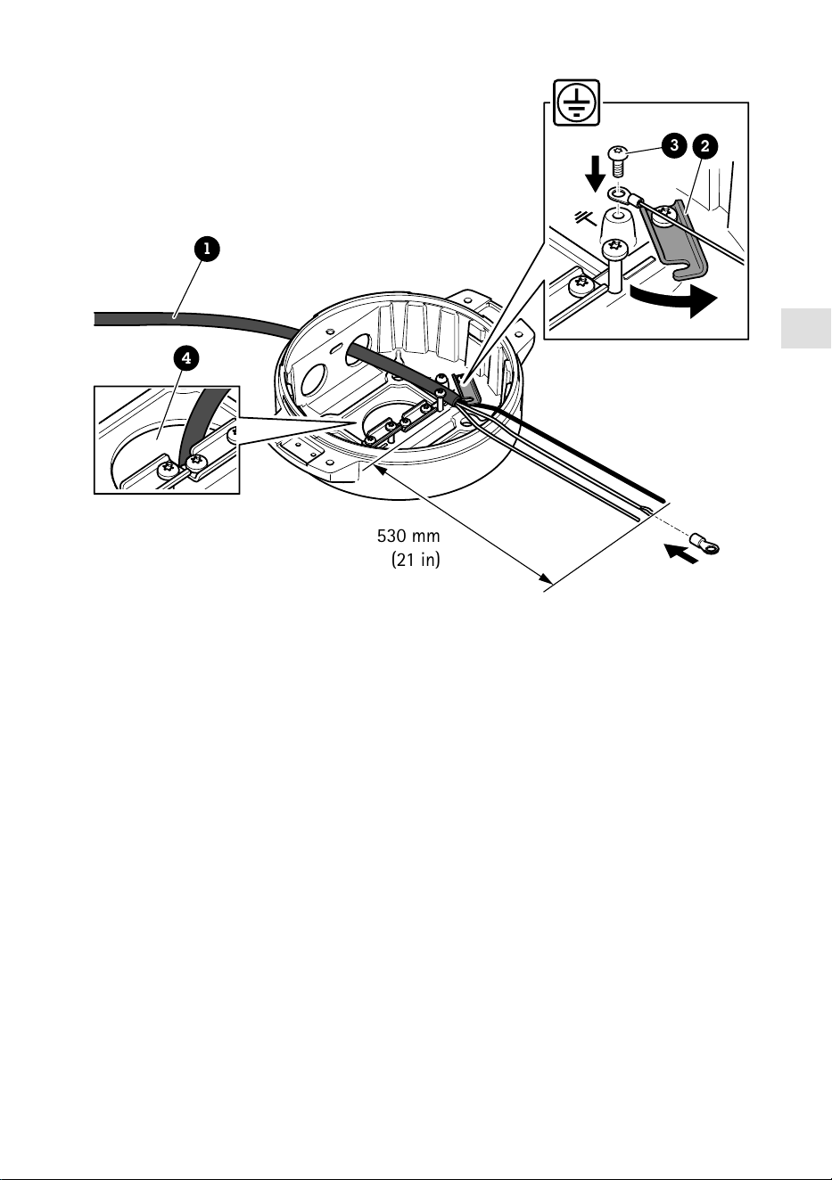
Route the cables
WARNING
Risk of electric shock. The product shall be grounded using both the protective grounding wire
in the power cable and the grounding braid. Make sure both ends of the protective grounding
wire and the grounding braid are in contact with their respective grounding surfaces.
Important
Use only cables that comply with the specified cable area. For more information, see Cable
thickness, on page 30.
18

EN
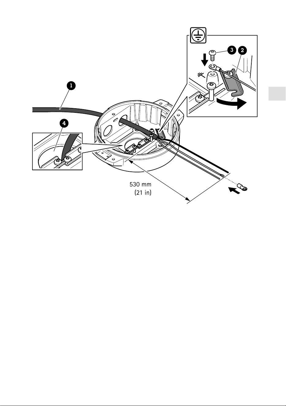
530 mm
(21 in)
1
4
3
2
1 Power cable (not included)
2 Strain relief
3 Grounding screw
4 Bottom cable hole
1. Install the optional conduit adapters (not included).
2. Insert the power cable through the hole in the base unit as shown in the illustration above.
Alternatively, insert it through the bottom cable hole.
3. Pull back the power cable sleeve by 530 mm (21 in), and then insert the power cable through
the strain relief.
4. Fasten the green/yellow wire to the included ring cable lug and connect it to the grounding
screw. The minimum required cable cross-sectional area is 18 AWG (0.82 mm²).
19

580 mm
(23 in)
420 mm
(16.5 in)
1 2
1 I/O cable (optional, not included)
2 Network cable (not included)
5. Insert the I/O cable (optional) and network cable through the hole in the base unit as shown
in the illustration above. Alternatively, insert them through the bottom cable hole.
6. Insert the I/O cable through the strain relief with a distance of 420 mm (16.5 in) from the
strain relief to the end of the cable.
7. Insert the network cable (optical fiber cable and/or RJ45 cable) through the strain relief with
a distance of 580 mm (23 in) from the strain relief to the end of the connector. For more
information on different network connectivity options, see Install the network link, on page
24.
8. Close and tighten the three strain reliefs.
20

EN
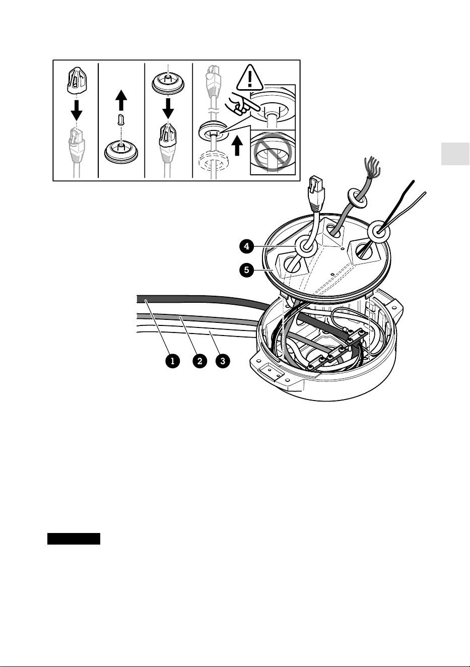
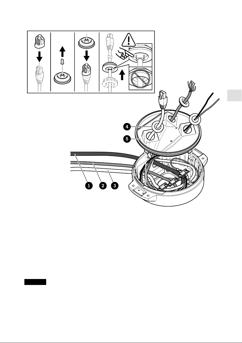
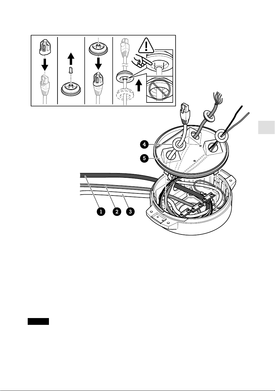
1 2 3
4
5
1 Power cable (not included)
2 I/O cable (optional, not included)
3 Network cable (not included)
4 Cable gasket
5 Transparent base unit cover
9. Fit cable gaskets on the cables. See Cable thickness, on page 30.
10. Insert the power, I/O and network cables including the cable gaskets through the holes in the
transparent base unit cover and arrange the cables as shown in the illustration above.
NOTICE
If you use both an optical fibre cable and an RJ45 cable for network connectivity, route the
optical fibre cable through the same cable gasket as the I/O cable. Apply a sealant between the
cables and the cable gasket to prevent leakage. For more information on different network
connectivity options, see Install the network link, on page 24.
21
11. Place the transparent base unit cover on the base unit and fit the cable gaskets inside the
holes.
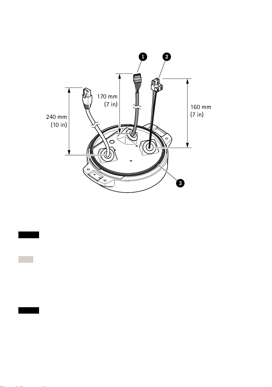
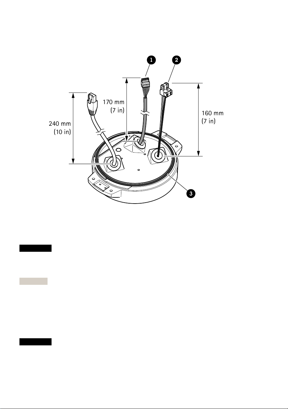
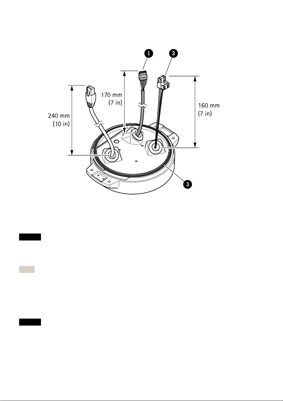
240 mm
(10 in)
170 mm
(7 in)
160 mm
(7 in)
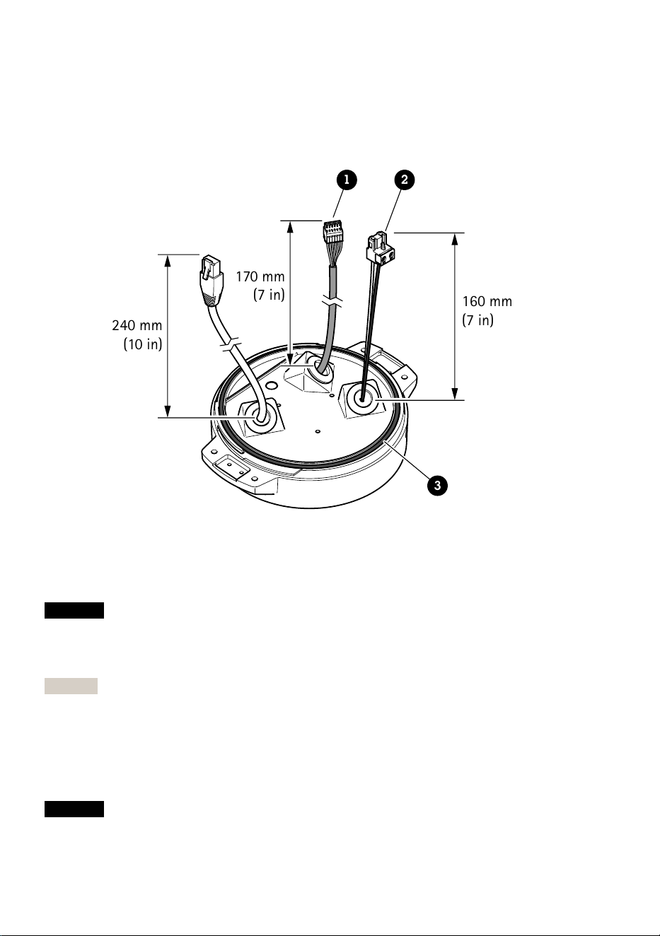
1 2
3
1 I/O connector
2 Power connector
3 O-ring
NOTICE
To not accidentally disconnect the unit from power if the cable is pulled, let the protective
grounding wire be about 10 mm (0.4 in) longer than the other two wires (in the power cable).
Note
To make the installation as easy as possible, we recommend you to strip approximately 90 mm
(3.5 in) of the power cable jacket and 70 mm (2.8 in) of the I/O cable jacket.
12. Install the power and I/O connectors.
13. Adjust the network, I/O and power cables so that the distance from the cable gasket to the
end of the connector is 240 mm (10 in), 170 mm (7 in), and 160 mm (7 in) respectively.
NOTICE
Make sure that the O-ring is fitted correctly around the transparent base unit cover.
22
EN
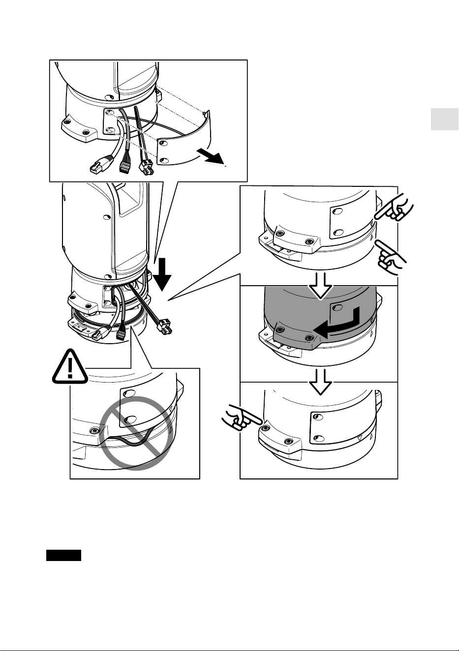
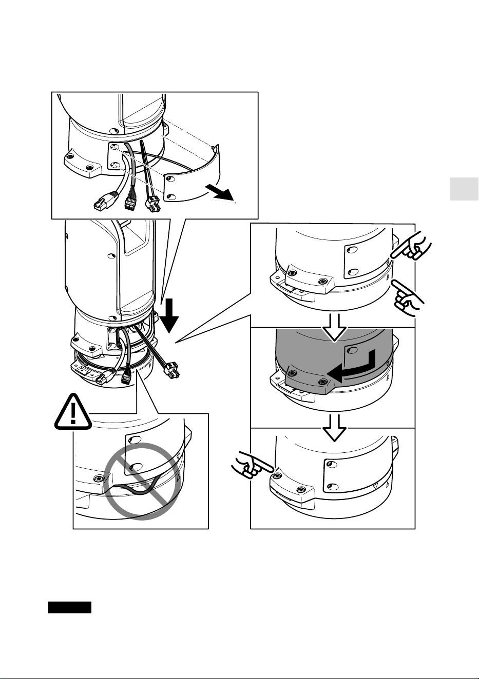
14. Place the positioning unit on the base unit. Make sure that the arrows on the two units are
aligned.
15. Turn the positioning unit clockwise back to its original position and tighten the four base
unit screws ( T30, torque 3.0 Nm).
NOTICE
Make sure that the cables don’t get pinched when you assemble the two units.
23
Install the network link
You can choose between different options when you install the network link:
• A: via an optical fiber or RJ45 cable connected to the SFP module (with a respective
connector) in the SFP slot.
• B: via an RJ45 cable connected to the fixed RJ45 connector.
• C: via both of the above, in which case the SFP module connection functions as the primary
network link, and the fixed RJ45 connection functions as the fail-over link.
For more information on network connector locations, see Product overview, on page 14.
Note
• SFP module is not included. For more information on available SFP modules, see axis.com
• If you install a network link only via the optical fiber cable using the respective SFP module,
it works as a stand-alone solution for long range cabling installations.
Install the camera
NOTICE
• This product supports several camera models. For a complete list of supported cameras, see
the product page at axis.com.
• For instructions on how to open the camera cover, see the camera’s installation guide.
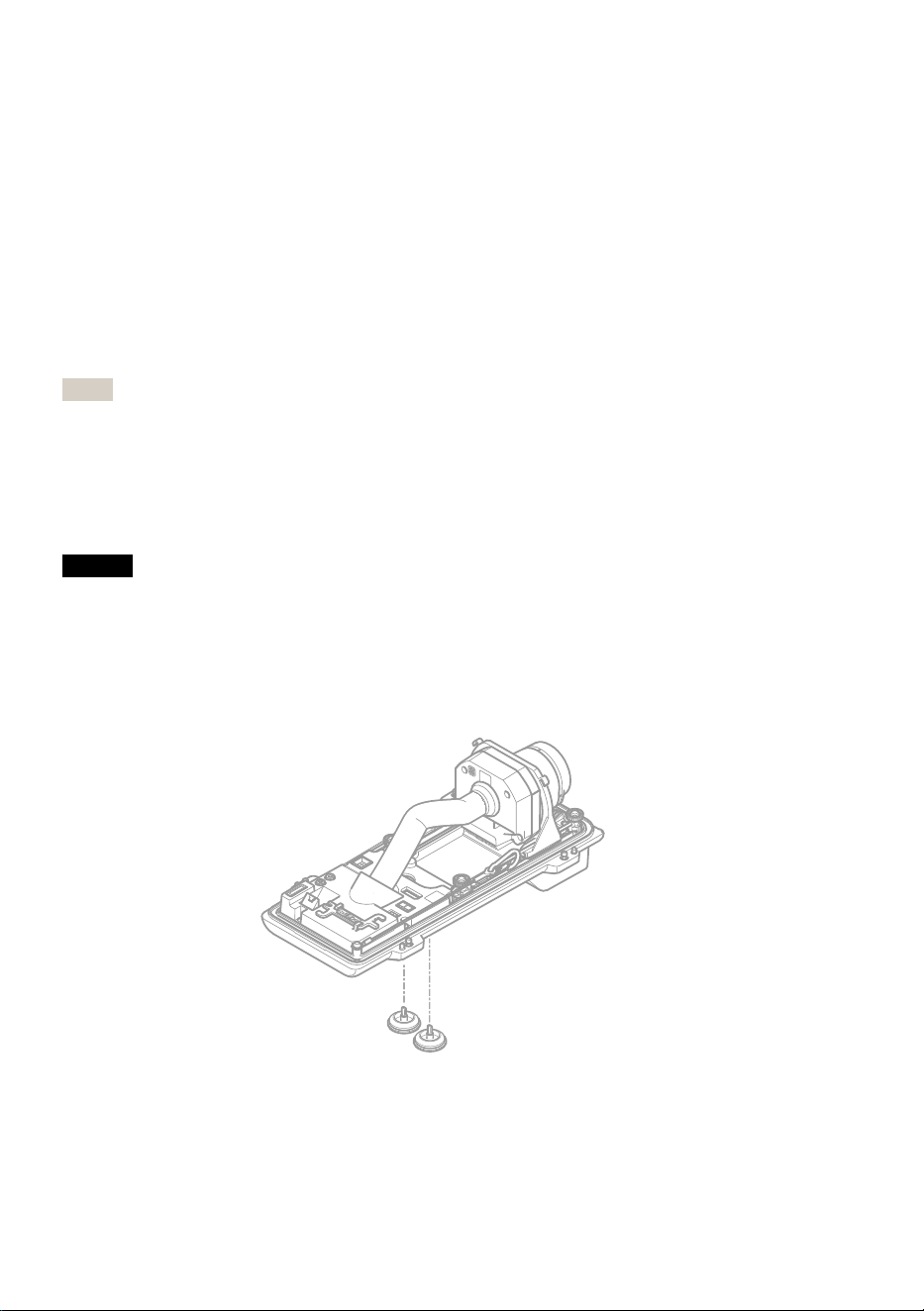
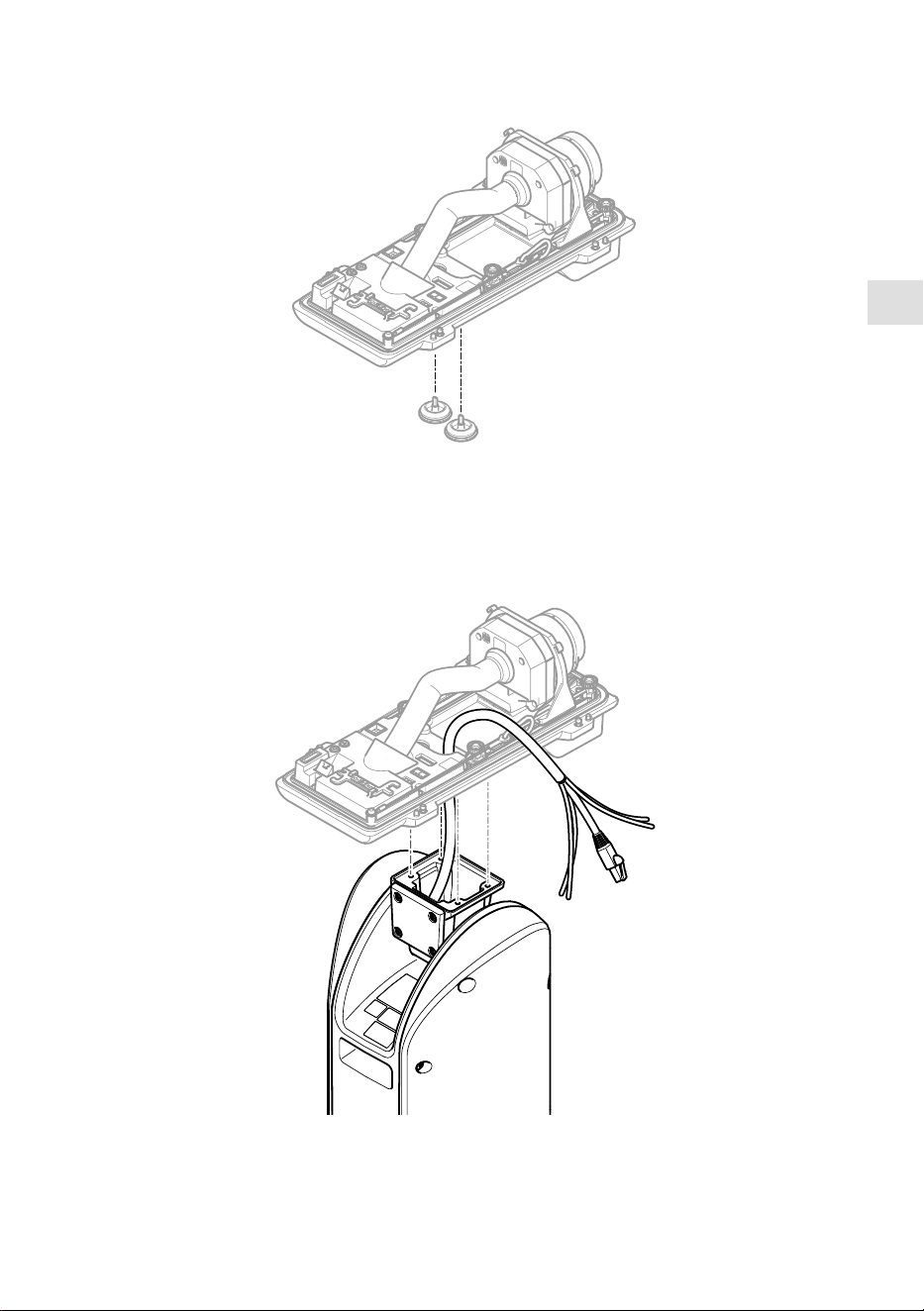
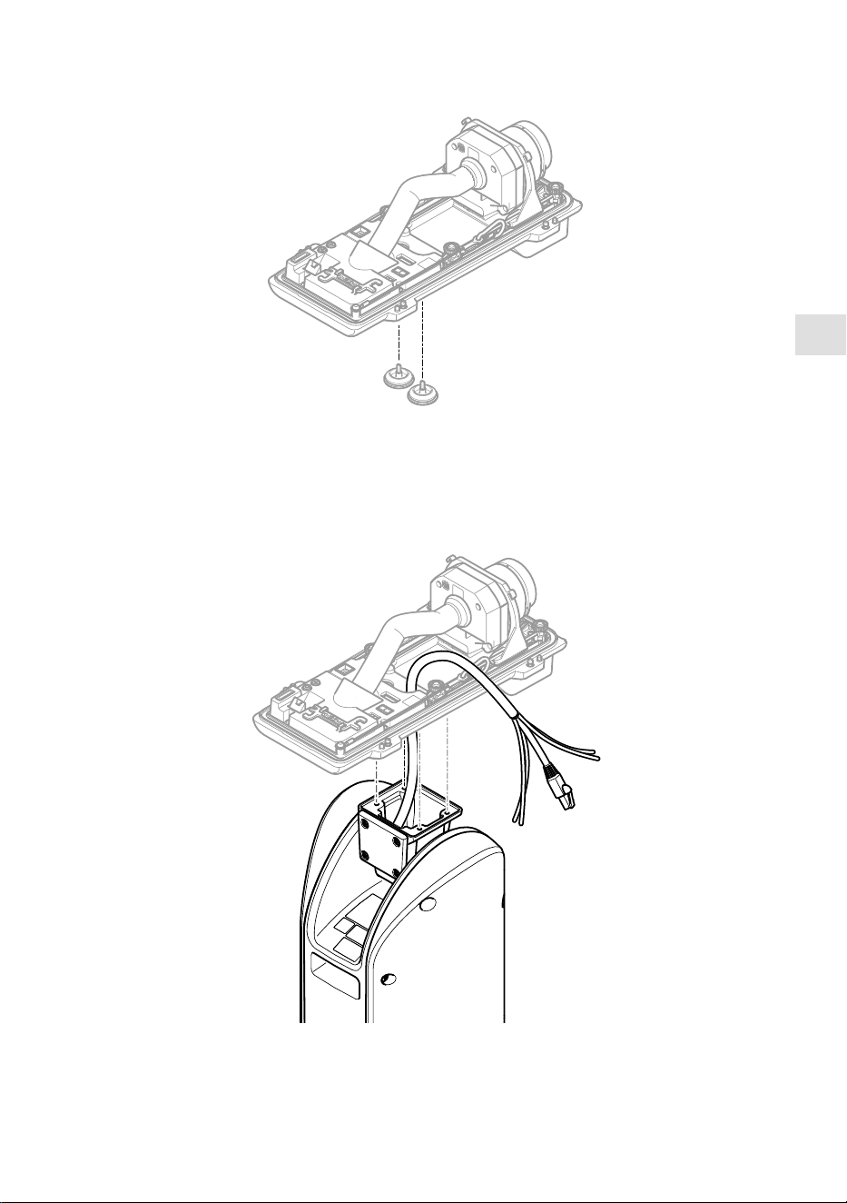
1. Remove the cable gaskets from the camera’s bottom cover.
24
EN
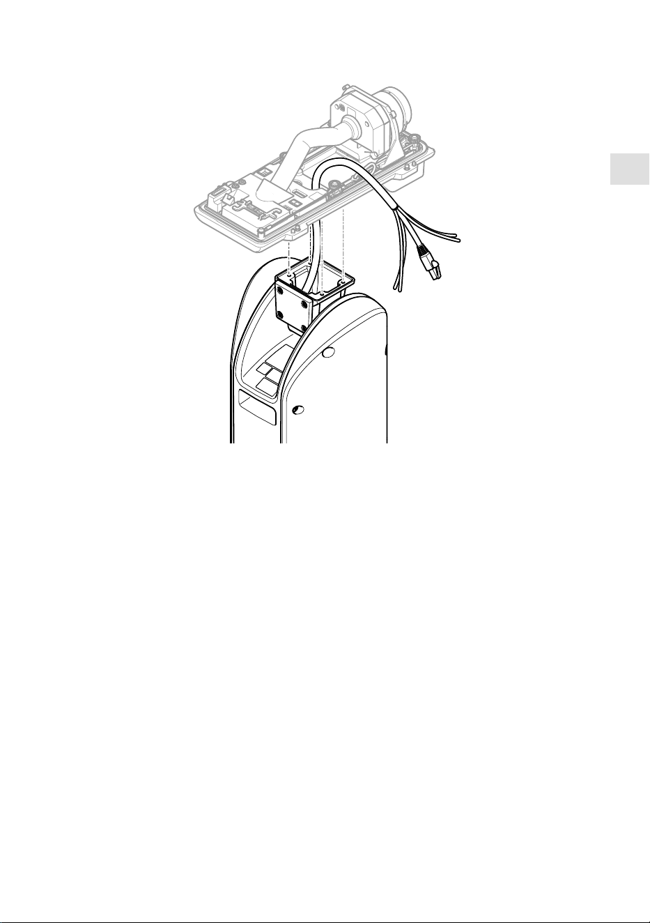
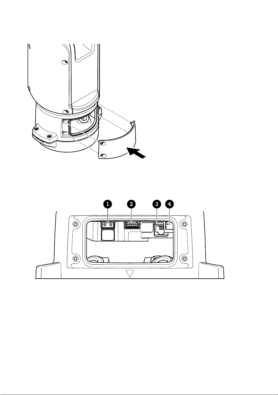
2. Insert the network/power/serial interface cable trough the holes in the bottom cover.
3. Fit the bottom cover on the positioning unit.
25

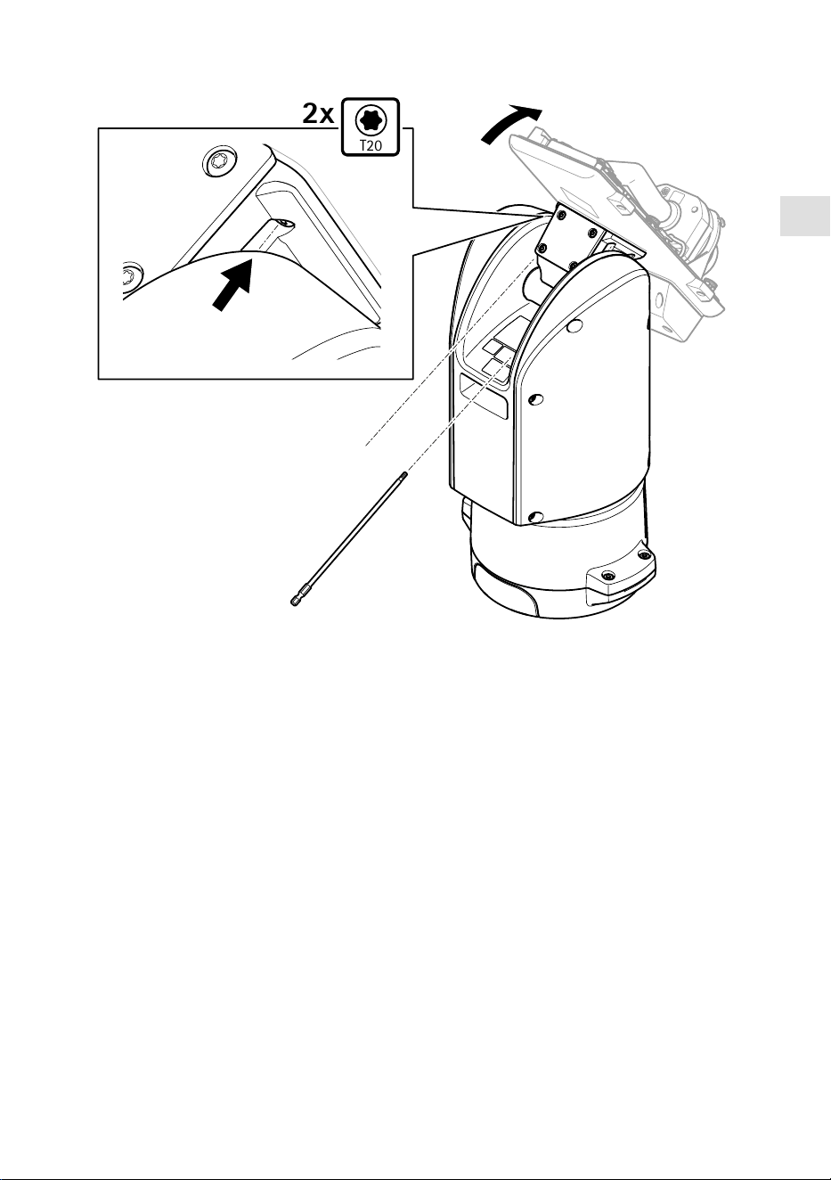
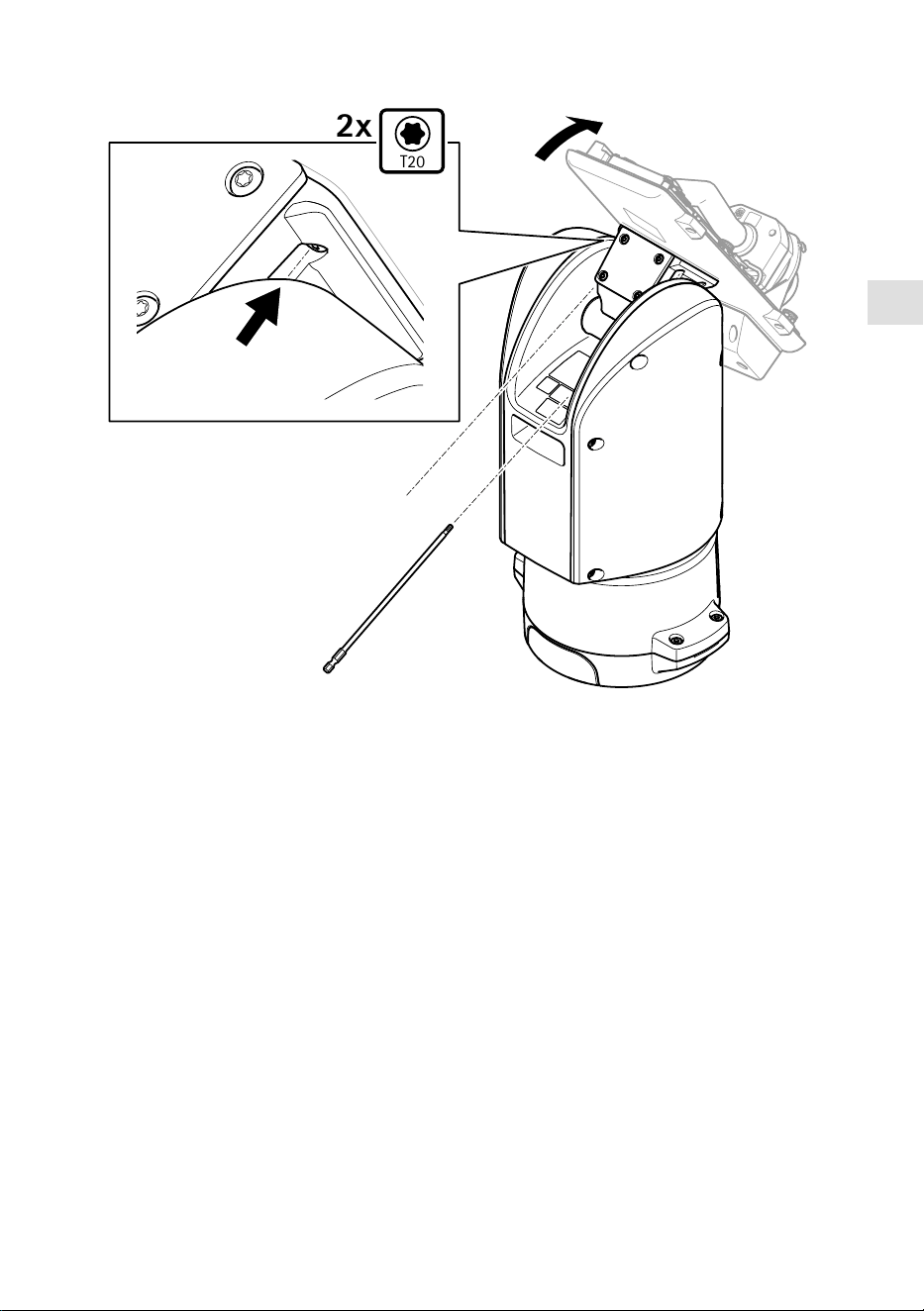
T20
2x
4. Tilt the bottom cover backward to its end position and tighten the two front screws of the
positioning unit (T20, torque 3.0 Nm).
26
EN
T20
2x
5. Tilt the bottom cover forward to its end position and tighten the two rear screws of the
positioning unit (T20, torque 3.0 Nm).
6. Connect the camera network, serial interface and power cables according to the camera’s
installation guide. For more information on cable specifications, see Camera power cable, on
page and Camera serial interface cable, on page 30.
7. Finalize the camera installation according to the camera’s installation guide.
27

Connect the cables
1. Loosen the four lid screws (T20) and remove the lid.
1 2 3 4
1 Input power connector
2 I/O connector
3 RJ45 connector
4 SFP slot for SFP module (SFP module not included)
2. Connect the network (optical fibre and/or RJ45), I/O and power cables. For more information
on different network connectivity options, see Install the network link, on page 24.
3. Return the lid to its position and tighten the four lid screws (torque 3.0 Nm).
4. Remove the protective cover.
28

EN
5. Apply power to the product.
Select the PTZ driver
1. Go to the camera’s webpage.
2. Go to System > Accessories > PTZ.
3. If your camera supports both PTZ drivers and digital PTZ, select PTZ mode Mechanical.
4. Select the driver APTP and click Save.
5. Go to the PTZ tab and check that the pan-tilt settings are available.
29

Specifications
Cables
Cable thickness
The cable diameter, when using cable gaskets provided with the product, should be in the range of
5 to 11 mm (0.2 to 0.4 in).
NOTICE
• Use cables that keep within the specified cable area
• Select cables in compliance with your local regulations
• Make sure all cable holes are properly sealed
• Use cable gaskets or cable glands that match both the cable hole and the cable area
For information about accessories, such as cable gaskets and cable glands that allow for other
cable areas, see www.axis.com
Camera serial interface cable
Cable color Specification
White RS485 RX/TX A
Green RS485 RX/TX B
Camera power cable
Cable color Specification
Red + 56 V DC
Black 0 V
30

FR
Contenu de l’emballage
• Unité de positionnement
• Connecteur d'alimentation
• Connecteur E/S
• Torx® bit T20 (long)
• Presse-étoupe
• Outil d'installation RJ45
• Cosses à anneau
31

Vue d'ensemble du produit
1
2
3
4
5
1 Unité de positionnement (inclinaison)
2 Unité de positionnement (panoramique)
3 Couvercle
4 Unité de base
5 Caméra (non incluse)
32
FR
1
5 6 7 8
2
3
4
1 Câbles de projecteur (ne doivent pas être utilisés)
2 Câble électrique de la caméra
3 Câble réseau de la caméra
4 Câble interface série de la caméra
5 Connecteur d'alimentation d'entrée
6 Connecteur E/S
7 Connecteur RJ45
8 Emplacement SFP pour module SFP (module SFP non inclus)
33
Comment installer le produit
DANGER
Risque de choc électrique. Tous les câbles doivent être hors tension avant d'installer le produit.
ATTENTION
Les connexions électriques et les installations de conduites doivent être effectuées par un
électricien certifié et conformément aux réglementations locales.
ATTENTION
Risques de blessures. Pièces mobiles. Restez à l'écart du produit lorsqu'il est en cours de
fonctionnement. Débranchez l'alimentation électrique avant d'installer le produit ou d'effectuer
son entretien.
ATTENTION
Risques de blessures. Surfaces chaudes. Ne touchez pas le produit lorsqu'il est en cours de
fonctionnement. Débranchez l'alimentation électrique et laissez les surfaces refroidir avant
d'effectuer l'entretien du produit.
Montage de l'unité de base
1
1 Unité de base
1. Déposer les quatre vis de l'unité (T30).
2. Tirez et tournez simultanément l'unité de base dans le sens anti-horaire jusqu'à ce que les
flèches sur l'unité de base et le reste de l'unité de positionnement s'alignent.
3. Déposez l'unité de base.
34
FR
REMARQUE
N'utilisez pas d'outils tranchants lorsque vous déposez le couvercle transparent de l'unité de
base.
4. Déposez le couvercle transparent de l'unité de base.
35

12
3
1 Clip du cache de conduit
2 Cache de conduit
3 Trou de vis (x4)
5. Pour les installations de conduits uniquement : supprimer les deux clips du couvercle du
conduit, puis le cache du conduit.
6. Fixez l'unité de base à la surface de montage avec les éléments de fixation appropriés dans
les quatre trous de vis.
Acheminement des câbles
AVERTISSEMENT
Risque de choc électrique. Le produit doit être mis à la terre à l'aide du câble de mise à la terre
de protection du câble d'alimentation et de la tresse de terre. Assurez-vous que les deux
extrémités du câble de mise à la terre de protection et la tresse de terre sont en contact avec
les surfaces de mise à la terre correspondantes.
Important
Utilisez uniquement des câbles conformes à la zone spécifiée. Pour en savoir plus, consultez
Épaisseur du câble, à la page 48.
36
FR
530 mm
(21 in)
1
4
3
2
1 Câble d'alimentation (non inclus)
2 Réducteur de tension
3 Vis de mise à la terre
4 Orifice du câble inférieur
1. Installez les adaptateurs de conduit en option (non fournis).
2. Insérez le câble d'alimentation dans l'orifice de l'unité de base, comme indiqué dans
l'illustration ci-dessus. Vous pouvez aussi l'insérer dans l'orifice du câble inférieur.
3. Tirez la gaine du câble d'alimentation vers l'arrière sur 530 mm (21 po), puis insérez le câble
d'alimentation à travers le réducteur de tension.
4. Fixez le câble vert/jaune à la cosse à anneaux fournie et connectez-le à la vis de mise à la
terre. La section minimale requise du câble est de 18 AWG (0,82 mm²).
37

580 mm
(23 in)
420 mm
(16.5 in)
1 2
1 Câble E/S (en option, non fourni)
2 Câble réseau (non inclus)
5. Insérez le câble d'E/S (optionnel) et le câble réseau à travers l'orifice de l'unité de base
comme illustré ci-dessus. Vous pouvez aussi les insérer dans l'orifice du câble inférieur.
6. Insérez le câble d'E/S à travers le réducteur de tension avec une distance de 420 mm
(16,5 po) depuis le réducteur de tension jusqu'à l'extrémité du câble.
7. Insérez le câble réseau (câble fibre optique et/ou câble RJ45) à travers le réducteur de
tension avec une distance de 580 mm (23 po) depuis le réducteur de tension jusqu'à
l'extrémité du connecteur. Pour plus d'informations sur les différentes options de
connectivité réseau, consultez Installation de la liaison réseau, à la page 42.
8. Fermez et serrez les trois reliefs de traction.
38
FR
1 2 3
4
5
1 Câble d'alimentation (non inclus)
2 Câble E/S (en option, non fourni)
3 Câble réseau (non inclus)
4 Joint de câble
5 Couvercle transparent de l'unité de base
9. Placez les joints sur les câbles. Consultez la section Épaisseur du câble, à la page 48.
10. Insérez les câbles d'alimentation, d'E/S et réseau y compris les joints à travers les orifices du
couvercle transparent de l'unité de base et disposez les câbles comme illustré ci-dessus.
REMARQUE
Si vous utilisez un câble à fibre optique et un câble RJ45 pour la connectivité réseau,
acheminez le câble à fibre optique à travers le même joint que le câble d'E/S. Appliquez un joint
entre les câbles et le joint de câble pour empêcher toute fuite. Pour plus d'informations sur les
différentes options de connectivité réseau, consultez Installation de la liaison réseau, à la page
42.
39
11. Placez le couvercle transparent de l'unité de base sur celle-ci et placez les joints dans les
orifices.
240 mm
(10 in)
170 mm
(7 in)
160 mm
(7 in)
1 2
3
1 Connecteur E/S
2 Connecteur d'alimentation
3 Joint torique
REMARQUE
Pour ne pas débrancher accidentellement l'unité de l'alimentation électrique si le câble est tiré,
le câble de mise à la terre de protection doit être plus long d'environ 10 mm (0,4 po) que les
deux autres fils (dans le câble d'alimentation).
Remarque
Pour faciliter l'installation, nous vous recommandons de dénuder environ 90 mm (3,5 po) de la
gaine du câble d'alimentation et 70 mm (2,8 po) de la gaine de câble d'E/S.
12. Installez les connecteurs d'alimentation et d'E/S.
13. Réglez les câbles réseau, d'E/S et d'alimentation de sorte que la distance depuis le joint du
câble jusqu'à l'extrémité du connecteur soit respectivement de 240 mm (10 po), 170 mm
(7 po) et 160 mm (7 po).
REMARQUE
Assurez-vous que les joints toriques sont correctement fixés autour du couvercle transparent
de l'unité de base.
40

FR
14. Placez l'unité de positionnement sur l'unité de base. Assurez-vous que les flèches des deux
unités sont alignées.
15. Tournez l'unité de positionnement dans le sens des aiguilles d'une montre jusqu'à sa position
d'origine et serrez les quatre vis de l'unité de base (T30, couple de 3,0 Nm).
REMARQUE
Assurez-vous de ne pas pincer les câbles lors de l'assemblage des deux unités.
41

Installation de la liaison réseau
Vous pouvez choisir entre plusieurs options lorsque vous installez la liaison réseau :
• A : via un câble à fibre optique ou un câble RJ45 raccordé au module SFP (avec connecteur
correspondant) sur l'emplacement SFP.
• B : via un câble RJ45 raccordé au connecteur RJ45 fixe.
• C : via les deux solutions ci-dessus, auquel cas la connexion du module SFP fonctionne
comme la liaison réseau primaire et la connexion RJ45 fixe fonctionne comme la liaison de
secours.
Pour plus d'informations sur les emplacements des connecteurs réseau, voir Vue d'ensemble du
produit, à la page 32.
Remarque
• Le module SFP n'est pas fourni. Pour plus d’informations sur les modules SFP, consultez le
site axis.com
• Si vous installez une liaison réseau uniquement via le câble à fibre optique à l'aide du
module SFP respectif, elle fonctionne comme une solution autonome pour les installations de
câblage longue distance.
Installation de la caméra
REMARQUE
• Ce produit Axis est compatible avec plusieurs modèles de caméras. Rendez-vous sur la page
produits sur axis.com pour consulter la liste complète des caméras prises en charge.
• Pour savoir comment ouvrir le couvercle de la caméra, reportez-vous au guide d'installation
de la caméra.
42
FR
1. Retirez les joints de câble du couvercle inférieur de la caméra.
2. Insérez le câble d'interface réseau/alimentation/série à travers les trous du couvercle
inférieur.
43

3. Montez le couvercle inférieur sur l'unité de positionnement.
T20
2x
4. Inclinez le couvercle inférieur vers l'arrière jusqu'à sa position finale et serrez les deux vis
avant de l'unité de positionnement (T20, couple 3 Nm).
44
FR
T20
2x
5. Inclinez le couvercle inférieur vers sa position finale et serrez les deux vis arrière de l'unité de
positionnement (T20, couple 3 Nm).
6. Branchez les câbles réseau, interface série et d'alimentation de la caméra conformément au
guide d'installation de la caméra. Pour plus d'informations concernant les caractéristiques
techniques des câbles, consultez Câble électrique de la caméra, à la page et Câble
interface série de la caméra, à la page 48.
7. Finalisez l'installation de la caméra conformément au guide d'installation de la caméra.
45
Branchement des câbles
1. Desserrez les quatre vis du couvercle (T20) et retirez le couvercle.
1 2 3 4
1 Connecteur d'alimentation d'entrée
2 Connecteur E/S
3 Connecteur RJ45
4 Emplacement SFP pour module SFP (module SFP non inclus)
2. Branchez le câble réseau (fibre optique et/ou RJ45), E/S et d'alimentation. Pour plus
d'informations sur les différentes options de connectivité réseau, consultez Installation de la
liaison réseau, à la page 42.
3. Remettez le couvercle en place et serrez les quatre vis du couvercle (couple de serrage
3,0 Nm).
46

FR
4. Retirez le couvercle de protection.
5. Mettez le produit sous tension.
Sélectionner le pilote PTZ
1. Allez à la page Web de la caméra.
2. Allez à Système > Accessoires > PTZ.
3. Si votre caméra prend en charge à la fois les pilotes PTZ et la fonction PTZ numérique,
sélectionnez le mode PTZ Mécanique.
4. Sélectionnez le pilote APTP et cliquez sur Sauvegarder.
5. Allez à l'onglet PTZ et vérifiez que les paramètres panoramique-inclinaison sont disponibles.
47
Specifications
Câbles
Épaisseur du câble
Le diamètre du câble, lors de l'utilisation de joints de câble fournis avec le produit, doit être
comprise entre 5 et 11 mm (0,2 à 0,4 po).
REMARQUE
• Utilisez des câbles adaptés à la zone spécifiée
• Sélectionnez des câbles conformes à la législation locale
• Assurez-vous que les passges de câbles sont correctement scellés
• Utilisez des joints de câble et des presse-étoupes adaptés aux passages de câbles et à la zone
de câble
Pour plus d'informations sur les accessoires, tels que les joints de câble et les presse-étoupes
adaptés à d'autres zones de câble, consultez www.axis.com
Câble interface série de la caméra
Couleur du câble Caractéristiques techniques
Blanc RS485 RX/TX A
Vert RS485 RX/TX B
Câble électrique de la caméra
Couleur du câble Caractéristiques techniques
Rouge + 56 V CC
Noir 0 V
48

DE
Lieferumfang
• Positionierungseinheit
• Stromanschluss
• E/A-Anschluss
• Torx® Bit T20 (lang)
• Kabelverschraubung
• RJ45-Installationswerkzeug
• Ringkabelschuh
49

Produktübersicht
1
2
3
4
5
1 Positionierungseinheit (Neigen)
2 Positionierungseinheit (Schwenken)
3 Deckel
4 Basiseinheit
5 Kamera (nicht im Lieferumfang enthalten)
50
DE
1
5 6 7 8
2
3
4
1 Strahlerkabel (nicht zu verwenden)
2 Stromversorgungskabel der Kamera
3 Netzwerk-Kabel der Kamera
4 Serielles Schnittstellenkabel der Kamera
5 Stromanschluss Eingang
6 E/A-Anschluss
7 RJ-45-Anschluss
8 SFP-Einschub für SFP-Module (SFP-Modul nicht enthalten)
51
Installieren des Produkts
GEFAHR
Stromschlaggefahr Vor der Installation oder Wartung des Produkts müssen alle Kabel von der
Stromversorgung abgeklemmt werden.
VORSICHT
Die Installation der elektrischen Anschlüsse und Kabelkanäle darf nur von einem zugelassenen
Elektriker in Übereinstimmung mit den geltenden Bestimmungen vorgenommen werden.
VORSICHT
Verletzungsgefahr Gefahr durch bewegliche Teile Körperteile während des Betriebs vom
Produkt fernhalten. Vor der Installation oder Wartung des Produkts alle Kabel von der
Stromversorgung abklemmen.
VORSICHT
Verletzungsgefahr Heiße Oberfläche Das Produkt während des Betriebs nicht berühren.
Trennen Sie vor Wartungsarbeiten die Stromversorgung und lassen Sie die Oberflächen des
Produkts abkühlen.
Montieren der Gerätebasis
1
1 Basiseinheit
1. Die vier Schrauben (T30) der Gerätebasis entfernen.
2. Die Gerätebasis gleichzeitig ziehen und gegen den Uhrzeigersinn drehen, bis die Pfeile auf
der Gerätebasis und dem Rest des Geräts in einer Linie stehen.
52
DE
3. Die Gerätebasis entfernen.
HINWEIS
Beim Entfernen der transparenten Abdeckung der Gerätebasis keine spitzen Werkzeuge
verwenden.
4. Die transparente Abdeckung der Gerätebasis entfernen.
53
12
3
1 Klammer der Kabelführung
2 Abdeckung der Kabelführung
3 Schraubenbohrung (4 x)
5. Nur für Installationen mit Kabelkanälen: Beide Klammern der Kabelkanalabdeckung und
anschließend die Kabelkanalabdeckung entfernen.
6. Die Gerätebasis mit geeigneten Befestigungselementen für die vier Schraubenbohrungen an
der Befestigungsfläche anbringen.
Führen der Kabel
WARNUNG
Stromschlaggefahr Das Produkt muss geerdet werden. Dazu müssen sowohl der Schutzleiter im
Stromversorgungskabel als auch das Erdungsband verwendet werden. Sicherstellen, dass beide
Enden des Schutzleiters und des Erdungsbandes Kontakt mit den entsprechenden
Erdungsflächen haben.
Wichtig
Nur Kabel mit dem vorgegebenen Kabelquerschnitt verwenden. Weitere Informationen finden
Sie unter Kabelstärke, auf Seite 66.
54
DE
530 mm
(21 in)
1
4
3
2
1 Stromversorgungskabel (nicht im Lieferumfang enthalten)
2 Zugentlastung
3 Erdungsschraube
4 Kabelöffnung unten
1. Die optionalen Kabelführungsadapter installieren (nicht im Lieferumfang enthalten).
2. Das Stromversorgungskabel wie in der Abbildung oben gezeigt durch die Öffnung in der
Grundeinheit führen. Alternativ das Kabel durch die untere Kabelöffnung einführen.
3. Die Muffe des Netzkabels um 530 mm zurückziehen und das Netzkabel durch die
Zugentlastung führen.
4. Das grün/gelbe Kabel an dem mitgelieferten Ringkabelschuh befestigen und an das
Schraubenloch für die Erdungsschraube anschließen. Die Mindestquerschnittsfläche des
Kabels beträgt 18 AWG (0,82 mm²).
55

580 mm
(23 in)
420 mm
(16.5 in)
1 2
1 E/A-Kabel (optional, nicht im Lieferumfang enthalten)
2 Netzwerkkabel (nicht im Lieferumfang enthalten)
5. Das E/A-Kabel (optional) einschließlich der Kabelverschraubungen wie in der Abbildung oben
durch die Öffnung des Basisgeräts führen. Alternativ die Kabel durch die untere
Kabelöffnung einführen.
6. Das E/A-Kabel durch die Zugentlastung führen. Dabei eine Länge von 420 mm zwischen
Zugentlastung und Kabelende einhalten.
7. Das Netzwerk-Kabel (Glasfaser oder Kabeltyp RJ-45) durch die Zugentlastung führen. Dabei
eine Länge von 580 mm zwischen Zugentlastung und Anschlussende einhalten. Weitere
Informationen zu den verschiedenen Anschlussoptionen an das Netzwerk, siehe Einrichten
der Netzwerkverbindung, auf Seite 60.
8. Die drei Zugentlastungen schließen und anziehen.
56
DE
1 2 3
4
5
1 Stromversorgungskabel (nicht im Lieferumfang enthalten)
2 E/A-Kabel (optional, nicht im Lieferumfang enthalten)
3 Netzwerkkabel (nicht im Lieferumfang enthalten)
4 Kabeldichtung
5 Transparente Abdeckung der Gerätebasis
9. Die Kabeldichtungen auf die Kabel schieben. Siehe Kabelstärke, auf Seite 66.
10. Die Kabel für Stromversorgung, Netzwerk und E/A einschließlich der Kabeldichtungen durch
die Öffnungen der transparenten Abdeckung der Gerätebasis führen und die Kabel wie in der
Abbildung oben dargestellt ausrichten.
HINWEIS
Wird sowohl ein Glasfaserkabel als auch ein Kabel des Typs RJ-45 verwendet, das
Glasfaserkabel durch dieselbe Kabeldichtung führen wie das E/A-Kabel. Gegen das Eindringen
von Feuchtigkeit zwischen Kabeln und Kabeldichtung ein Dichtmittel verwenden. Weitere
57
Informationen zu den verschiedenen Anschlussoptionen an das Netzwerk, siehe Einrichten der
Netzwerkverbindung, auf Seite 60.
11. Die transparente Abdeckung der Gerätebasis aufsetzen und die Kabeldichtungen in die
Öffnungen schieben.
240 mm
(10 in)
170 mm
(7 in)
160 mm
(7 in)
1 2
3
1 E/A-Anschluss
2 Stromanschluss
3 O-Ring
HINWEIS
Um das Gerät nicht versehentlich von der Stromversorgung zu trennen, wenn das Kabel
gezogen wird, lassen Sie den Schutz-Erdungsdraht um 10 0,4 mm länger als die beiden anderen
Kabel (im Stromversorgungskabel).
Hinweis
Um die Installation so einfach wie möglich zu machen, wird empfohlen, ca. 90 mm der
Stromkabelhülle und 70 mm der E/A-Kabelhülle zu entfernen.
12. Einbau der Stromversorgungs- und E/A-Anschlüsse
13. Die Kabel für Netzwerk, E/A und Stromversorgung so ausrichten, dass die Länge zwischen
Kabeldichtung und Ende des Anschlusses jeweils 240 mm, 170 mm und 160 mm beträgt.
HINWEIS
58
DE
Sicherstellen, dass der O-Ring richtig um die transparente Abdeckung der Gerätebasis herum
eingepasst ist.
14. Positionieren Sie die Positionierungseinheit auf der Basiseinheit. Stellen Sie sicher, dass die
Pfeile an den beiden Geräten ausgerichtet sind.
15. Die Positionierungseinheit im Uhrzeigersinn in ihre Ausgangsstellung drehen und die vier
Schrauben der Grundeinheit anziehen (T30, Drehmoment 3,0 Nm).
HINWEIS
59

Sicherstellen, dass die Kabel beim Zusammenbauen der beiden Geräte nicht gequetscht werden.
Einrichten der Netzwerkverbindung
Bei der Installation der Netzwerkverbindung stehen verschiedene Optionen zur Verfügung:
• A: Mithilfe eines Glasfaserkabels oder eines Kabels des Typs RJ-45, das (mit einem
entsprechenden Anschluss) an das SFP-Modul im SFP-Einschub angeschlossen wird.
• B: Mithilfe eines Anschlusses des Typs RJ-45 an den festen Anschluss des Typs RJ-45.
• C: Mithilfe beider oben angeführten Möglichkeiten. In diesem Fall agiert der Anschluss über
das SFP-Modul als die primäre Netzwerk-Verbindung und die Verbindung über den festen
Anschluss des Typs RJ-45 als Fail-Over-Anschluss.
Weitere Informationen zur Lage der Netzwerk-Steckverbindungen, siehe Produktübersicht, auf
Seite 50.
Hinweis
• SFP-Modul nicht im Lieferumfang enthalten. Weitere Informationen zu lieferbaren SFP-
Modulen, siehe axis.com.
• Die Installation einer Netzwerk-Verbindung ausschließlich über das Glasfaserkabel mittels
des entsprechenden SFP-Moduls dient als eigenständige Lösung für Kabelinstallationen mit
großer Reichweite.
Installieren der Kamera
HINWEIS
• Dieses Produkt unterstützt mehrere Kameramodelle. Eine vollständige Liste unterstützter
Kameras finden Sie auf der Produktseite von axis.com.
• Anweisungen dazu, wie sich die Abdeckung der Kamera öffnen lässt, finden Sie in der
Installationsanleitung der Kamera.
60
DE
1. Entfernen Sie die Kabeldichtungen von der unteren Abdeckung der Kamera.
2. Führen Sie das Kabel für Netzwerk / Stromversorgung / serielle Schnittstelle durch die
Öffnungen in der unteren Abdeckung ein.
61

3. Bringen Sie die untere Abdeckung an der Positionierungseinheit an.
T20
2x
4. Neigen Sie die untere Abdeckung nach hinten in Endlage und ziehen Sie die beiden vorderen
Schrauben (T20) der Positionierungseinheit an (Drehmoment 3,0 Nm).
62

DE
T20
2x
5. Neigen Sie die untere Abdeckung nach vorn in Endlage und ziehen Sie die beiden hinteren
Schrauben (T20) der Positionierungseinheit an (Drehmoment 3,0 Nm).
6. Schließen Sie die Kabel der Kamera für Netzwerk, serielle Schnittstelle und Stromversorgung
gemäß der Installationsanleitung der Kamera an. Weitere Informationen zu technischen
Kenndaten der Kabel finden Sie unter Stromversorgungskabel der Kamera, auf Seite und
Serielles Schnittstellenkabel der Kamera, auf Seite 66.
7. Schließen Sie die Installation der Kamera wie in der Installationsanleitung der Kamera
beschrieben ab.
63

Anschließen der Kabel
1. Die vier Deckelschrauben (T20) lösen und den Deckel abnehmen.
1 2 3 4
1 Stromanschluss Eingang
2 E/A-Anschluss
3 RJ-45-Anschluss
4 SFP-Einschub für SFP-Module (SFP-Modul nicht enthalten)
2. Das Netzwerk (Glasfaser und/oder RJ-45), E/A und die Stromversorgung anschließen Weitere
Informationen zu den verschiedenen Anschlussoptionen an das Netzwerk, siehe Einrichten
der Netzwerkverbindung, auf Seite 60.
3. Bringen Sie den Deckel an seine Position und ziehen Sie die vier Deckelschrauben an
(Drehmoment 3,0 Nm).
64

DE
4. Entfernen Sie die Schutzabdeckung.
5. Das Produkt an die Stromversorgung anschließen.
Den PTZ-Treiber wählen
1. Gehen Sie auf die Webseite der Kamera.
2. Gehen Sie zu System > Zubehör > PTZ.
3. Wenn Ihre Kamera sowohl PTZ-Treiber als auch digitales PTZ unterstützt, wählen Sie den
PTZ-Modus Mechanisch.
4. Wählen Sie den Treiber APTP und klicken Sie auf Speichern.
5. Gehen Sie zur Registerkarte PTZ und überprüfen Sie, ob die Einstellungen zu Schwenken/
Neigen verfügbar sind.
65
Technische Daten
Kabel
Kabelstärke
Wenn die dem Produkt beiliegenden Kabeldichtungen verwendet werden, muss der
Kabeldurchmesser zwischen 5 und 11 mm liegen.
HINWEIS
• Kabel verwenden, die der Querschnittsvorgabe entsprechen.
• Kabel verwenden, die den örtlichen Vorschriften entsprechen.
• Sicherstellen, dass alle Kabeldurchführungen ordnungsgemäß abgedichtet sind.
• Kabeldichtungen oder Kabelverschraubungen verwenden, die sowohl der Kabeldurchführung
als auch dem Kabelquerschnitt entsprechen.
Für Informationen zu Zubehör wie Kabeldichtungen und Kabelverschraubungen für andere
Kabelquerschnitte, siehe <1>www.axis.com.
Serielles Schnittstellenkabel der Kamera
Farbmarkierung des Kabels Technische Daten
Weiß RS485 RX/TX A
Grün RS485 RX/TX B
Stromversorgungskabel der Kamera
Farbmarkierung des Kabels Technische Daten
Rot + 56 V Gleichstrom
Schwarz 0 V
66

IT
Contenuto della confezione
• Unità di posizionamento
• Connettore di alimentazione
• Connettore I/O
• Punta Torx® T20 (lunga)
• Pressacavo
• Strumento di installazione RJ45
• Capocorda ad anello
67

Panoramica del dispositivo
1
2
3
4
5
1 Unità di posizionamento (inclinazione)
2 Unità di posizionamento (panoramica)
3 Coperchio
4 Unità base
5 Telecamera (non inclusa)
68

IT
1
5 6 7 8
2
3
4
1 Cavi illuminatore (da non usare)
2 Cavo di alimentazione della telecamera
3 Cavo di rete della telecamera
4 Cavo dell'interfaccia seriale della telecamera
5 Connettore ingresso alimentazione
6 Connettore I/O
7 Connettore RJ45
8 Slot SFP per modulo SFP (modulo SFP non incluso)
69
Come installare il dispositivo
PERICOLO
Rischio di scosse elettriche. Tutti i cavi non saranno sotto tensione prima di installare il
dispositivo.
ATTENZIONE
Le connessioni elettriche e l'installazione dei tubi protettivi devono essere effettuate da un
elettricista certificato e in conformità alle normative locali.
ATTENZIONE
Rischio di lesioni. Parti in movimento. Tenere il corpo a distanza dal dispositivo durante il
funzionamento. Scollegare dall'alimentazione prima di installare o eseguire la manutenzione
sul dispositivo.
ATTENZIONE
Rischio di lesioni. Superficie calda. Non toccare il dispositivo durante il funzionamento.
Scollegare dall'alimentazione e lasciar raffreddare le superfici prima di eseguire la
manutenzione sul dispositivo.
Montaggio dell'unità base
1
1 Unità base
1. Rimuovere le quattro viti (T30) dell'unità base.
2. Estrarre e ruotare simultaneamente l'unità base in senso antiorario finché le frecce sull'unità
base e sul resto dell'unità di posizionamento non si allineano.
70
IT
3. Rimuovere l'unità base.
AVVISO
Non utilizzare strumenti appuntiti quando si rimuove il coperchio trasparente dell'unità base.
4. Rimuovere il coperchio trasparente dell'unità base.
71

12
3
1 Clip del coperchio del tubo protettivo
2 Coperchio del tubo protettivo
3 Foro per vite (x4)
5. Solo per le installazioni con tubo protettivo: rimuovere le due clip del coperchio del tubo
protettivo e poi il coperchio del tubo protettivo.
6. Fissare l'unità base alla superficie di montaggio con i fissaggi appropriati nei quattro fori
delle viti.
Instradamento dei cavi
PREAVVISO
Rischio di scosse elettriche. Questo dispositivo deve essere collegato a terra utilizzando il cavo
di messa a terra di protezione nel cavo di alimentazione e la treccia di messa a terra.
Assicurarsi che entrambe le estremità del cavo di messa a terra di protezione e della treccia di
messa a terra siano in contatto con le rispettive superfici di messa a terra.
Importante
Utilizzare solo cavi conformi all'area dei cavi specificata. Per ulteriori informazioni, consultare
Spessore del cavo, alla pagina 84.
72

IT
530 mm
(21 in)
1
4
3
2
1 Cavo di alimentazione (non incluso)
2 Dispositivo antistrappo
3 Vite di messa a terra
4 Foro per cavo inferiore
1. Installare gli adattatori dei tubi protettivi opzionali (non inclusi).
2. Inserire il cavo di alimentazione nel foro dell'unità base come indicato nell'illustrazione sopra
riportata. In alternativa, inserirlo nel foro del cavo inferiore.
3. Tirare il manicotto del cavo di alimentazione di 530 mm, quindi inserire il cavo di
alimentazione attraverso il dispositivo antistrappo.
4. Fissare il cavo verde/giallo al capocorda ad anello in dotazione e collegarlo alla vite di messa
a terra. L'area minima richiesta della sezione del cavo è di 18 AWG (0,82 mm²).
73

580 mm
(23 in)
420 mm
(16.5 in)
1 2
1 Cavo I/O (opzionale, non incluso)
2 Cavo di rete (non incluso)
5. Inserire, il cavo di rete e il cavo I/O (opzionale) attraverso il foro nell'unità base come
mostrato nell'illustrazione sopra riportata. In alternativa, inserirli nel foro del cavo inferiore.
6. Inserire il cavo I/O nel dispositivo antistrappo con una distanza di 420 mm tra il dispositivo
antistrappo e l'estremità del cavo.
7. Inserire il cavo di rete (cavo in fibra ottica e/o cavo RJ45) nel dispositivo antistrappo ad una
distanza di 580 mm dal dispositivo antistrappo all'estremità del connettore. Per ulteriori
informazioni sulle differenti opzioni di connettività di rete, vedere Installazione del
collegamento di rete, alla pagina 78.
8. Chiudere e avvitare i tre dispositivi antistrappo.
74
IT
1 2 3
4
5
1 Cavo di alimentazione (non incluso)
2 Cavo I/O (opzionale, non incluso)
3 Cavo di rete (non incluso)
4 Guarnizione per cavi
5 Coperchio trasparente dell'unità base
9. Inserire le guarnizioni sui cavi. Vedere Spessore del cavo, alla pagina 84.
10. Inserire il cavo di alimentazione, di rete e I/O comprese le guarnizioni attraverso i fori nel
coperchio trasparente dell'unità base e sistemare i cavi come mostrato nell'illustrazione
sopra riportata.
AVVISO
Se si utilizzano un cavo in fibra ottica e un cavo RJ45 per la connettività di rete, instradare il
cavo in fibra ottica attraverso la stessa guarnizione del cavo I/O. Applicare un sigillante tra i
cavi e la guarnizione per evitare dispersioni. Per ulteriori informazioni sulle differenti opzioni di
connettività di rete, vedere Installazione del collegamento di rete, alla pagina 78.
75
11. Posizionare il coperchio trasparente sull'unità base e inserire le guarnizioni dei cavi nei fori.
240 mm
(10 in)
170 mm
(7 in)
160 mm
(7 in)
1 2
3
1 Connettore I/O
2 Connettore di alimentazione
3 Anello di tenuta
AVVISO
Per non scollegare accidentalmente l'unità dall'alimentazione se il cavo viene tirato, fare in
modo che il cavo di messa a terra di protezione sia più lungo degli altri due cavi (nel cavo di
alimentazione) di circa 10 mm.
Nota
Per rendere l'installazione il più semplice possibile, si consiglia di togliere circa 90 mm del
rivestimento del cavo di alimentazione e 70 mm del rivestimento del cavo I/O.
12. Installare i connettori di alimentazione e I/O.
13. Regolare i cavi di rete, I/O e di alimentazione in modo che la distanza dalla guarnizione del
cavo all'estremità del connettore sia rispettivamente di 240 mm, 170 mm e 160 mm.
AVVISO
Assicurarsi che l'anello di tenuta sia correttamente fissato al coperchio trasparente dell'unità
base.
76

IT
14. Collocare l'unità di posizionamento sull'unità base. Assicurarsi che le frecce sulle due unità
siano allineate.
15. Ruotare l'unità di posizionamento in senso orario facendola tornare alla posizione originale e
serrare le quattro viti dell'unità base (T30, coppia 3,0 Nm).
AVVISO
Accertarsi che i cavi non vengano schiacciati durante l'assemblamento delle due unità.
77

Installazione del collegamento di rete
È possibile scegliere tra diverse opzioni quando si installa il collegamento di rete:
• A: tramite un cavo in fibra ottica o un cavo RJ45 collegato al modulo SFP (con un rispettivo
connettore) nello slot SFP.
• B: tramite un cavo RJ45 collegato al connettore RJ45 fisso.
• C: tramite entrambe le opzioni precedenti. In tal caso la connessione tramite il modulo SFP
funge da primo collegamento di rete e la connessione tramite RJ45 fisso funziona come
collegamento di failover.
Per ulteriori informazioni sulle posizioni dei connettori di rete, vedere Panoramica del dispositivo,
alla pagina 68.
Nota
• Il modulo SFP non è incluso. Per ulteriori informazioni sui moduli SFP disponibili, vedere axis.
com
• Se si installa un collegamento di rete solo tramite cavo in fibra ottica utilizzando il rispettivo
modulo SFP, funziona come soluzione indipendente per le installazioni di cablaggi a lungo
raggio.
Installazione della telecamera
AVVISO
• Questo prodotto supporta diversi modelli di telecamera. Per un elenco completo delle
telecamere supportate, consultare la pagina del prodotto all'indirizzo axis.com.
• Per istruzioni su come aprire il coperchio della telecamera, consultare la guida
all'installazione della telecamera.
78

IT
1. Rimuovere le guarnizioni dei cavi dal coperchio inferiore della telecamera.
2. Inserire il cavo di rete/di alimentazione/dell'interfaccia seriale attraverso i fori nel coperchio
inferiore.
79

3. Inserire il coperchio inferiore nell'unità di posizionamento.
T20
2x
4. Inclinare il coperchio inferiore all'indietro nella posizione finale e serrare le due viti anteriori
sull'unità di posizionamento (T20, serraggio 3,0 Nm).
80

IT
T20
2x
5. Inclinare il coperchio inferiore in avanti nella posizione finale e serrare le due viti posteriori
dell'unità di posizionamento (T20, serraggio 3,0 Nm).
6. Eseguire il collegamento dei cavi di rete, dell'interfaccia seriale e di alimentazione della
telecamera basandosi sulla guida all'installazione della telecamera. Per ulteriori informazioni
sulle specifiche dei cavi, vedere Cavo di alimentazione della telecamera, alla pagina e
Cavo dell'interfaccia seriale della telecamera, alla pagina 84.
7. Eseguire la finalizzazione dell'installazione della telecamera basandosi sulla guida
all'installazione della telecamera.
81

Collegamento dei cavi
1. Allentare le quattro viti (T20) del coperchio e rimuoverlo.
1 2 3 4
1 Connettore ingresso alimentazione
2 Connettore I/O
3 Connettore RJ45
4 Slot SFP per modulo SFP (modulo SFP non incluso)
2. Collegare la rete (fibra ottica e/o RJ45), I/O e i cavi di alimentazione. Per ulteriori
informazioni sulle differenti opzioni di connettività di rete, vedere Installazione del
collegamento di rete, alla pagina 78.
3. Riportare il coperchio alla sua posizione e serrare le quattro viti del coperchio (coppia 3 Nm).
82

IT
4. Rimuovere la copertura protettiva.
5. Applicare l'alimentazione al dispositivo.
Selezionare il driver PTZ
1. Accedere alla pagina Web della telecamera.
2. Andare a System > Accessories > PTZ (Sistema > Accessori > PTZ).
3. Se la telecamera supporta sia i driver PTZ sia i PTZ digitali, selezionare la modalità PTZ
Mechanical (Meccanico).
4. Selezionare il driver APTP e fare clic su Save (Salva).
5. Andare alla scheda PTZ e controllare che le impostazioni di panoramica e inclinazione siano
disponibili.
83

Specifiche
Cavi
Spessore del cavo
Quando si utilizzano le guarnizioni per cavo fornite con il dispositivo, il diametro del cavo deve
essere compreso nell'intervallo tra 5 e 11 mm.
AVVISO
• Utilizzare cavi di lunghezza adeguata all'area specificata
• Selezionare i cavi nel rispetto delle normative locali
• Verificare che tutti i fori dei cavi siano correttamente sigillati
• Utilizzare guarnizioni per cavi o pressacavi corrispondenti al foro e all'area dei cavi
Per informazioni sugli accessori disponibili, come ad esempio guarnizioni per cavi e pressacavi
adatti per altre aree dei cavi, visitare il sito Web www.axis.com.
Cavo dell'interfaccia seriale della telecamera
Colore del cavo Specifiche
White RS485 RX/TX A
Verde RS485 RX/TX B
Cavo di alimentazione della telecamera
Colore del cavo Specifiche
Rosso + 56 V CC
Nero 0 V
84

ES
Contenido del paquete
• Unidad de posicionamiento
• Conector de alimentación
• Conector de E/S
• Torx® bit T20 (largo)
• Prensaestopas
• Herramienta de instalación de RJ45
• Terminal de cable anular
85
Información general del producto
1
2
3
4
5
1 Unidad de posicionamiento (movimiento horizontal/vertical)
2 Unidad de posicionamiento (movimiento horizontal)
3 Tapa
4 Unidad base
5 Cámara (no incluida)
86
ES
1
5 6 7 8
2
3
4
1 Cables del iluminador (no se deben utilizar)
2 Cable de alimentación de la cámara
3 Cable de red a la cámara
4 Cable de interfaz serie de la cámara
5 Conector de entrada de corriente
6 Conector de E/S
7 Conector RJ45
8 Ranura SFP para módulo SFP (módulo SFP no incluido)
87
Cómo instalar el producto
PELIGRO
Riesgo de descarga eléctrica. Todos los cables deben estar sin energía antes de instalar el
producto.
PRECAUCIÓN
Las conexiones eléctricas y las instalaciones de los conductos debe realizarlas un electricista
cualificado, de conformidad con la normativa local.
PRECAUCIÓN
Riesgo de lesiones. Piezas móviles. No acerque ninguna parte del cuerpo al producto
mientras esté funcionando. Desconecte la fuente de alimentación antes de realizar trabajos de
instalación o mantenimiento en el producto.
PRECAUCIÓN
Riesgo de lesiones. Superficie caliente. No toque el producto durante su funcionamiento.
Desconecte la fuente de alimentación y deje que se enfríen las superficies antes de realizar
trabajos de mantenimiento en el producto.
Montaje de la unidad base
1
1 Unidad base
1. Quite los cuatro tornillos (T30) de la unidad base.
2. Tire de la base a la vez que la gira en sentido contrario a las agujas del reloj hasta alinear las
flechas de la unidad base con el resto de la unidad de posicionamiento.
88
ES
3. Extraiga la unidad base.
AVISO
No utilice herramientas afiladas al retirar la cubierta transparente de la unidad base.
4. Extraiga la cubierta transparente de la unidad base.
89
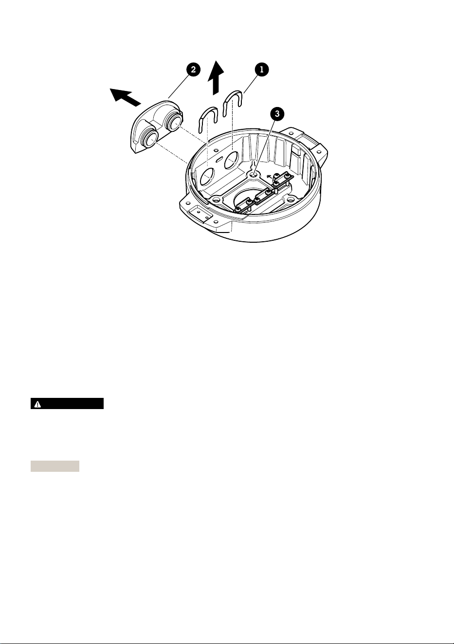
12
3
1 Clip de cubierta de conducto
2 Cubierta de conducto
3 Orificio para tornillo (4)
5. Solo para instalaciones de conductos: retire las dos pinzas de la tapa del conducto y, a
continuación, la tapa del conducto.
6. Fije la unidad base a la superficie de montaje mediante los fijadores adecuados en los cuatro
orificios para tornillos.
Guía de los cables
ADVERTENCIA
Riesgo de descarga eléctrica. El producto debe conectarse a tierra mediante el cable de tierra
protector en el cable de alimentación y el cable trenzado de tierra. Asegúrese de que los dos
extremos del cable de tierra protector y el cable trenzado de tierra estén en contacto con sus
respectivas superficies de toma de tierra.
Importante
Utilice solo los cables que cumplan los requisitos del área de cableado especificada. Para
obtener más información, consulte Grosor del cable, en la página 102.
90
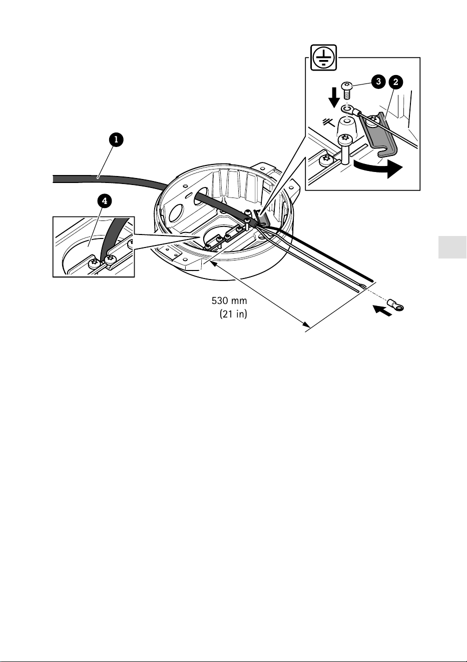
ES
530 mm
(21 in)
1
4
3
2
1 Cable de alimentación (no incluido)
2 Descarga de tracción
3 Tornillo de toma de tierra
4 Orificio inferior para cable
1. Instale los adaptadores de conducto opcionales (no incluidos).
2. Pase el cable de alimentación a través del orificio de la unidad base como se muestra en la
ilustración anterior. También puede pasarlo por el orificio del cable inferior.
3. Tire de la funda del cable de alimentación 530 mm hacia atrás y, a continuación, introduzca
el cable de alimentación a través del aliviador de tensión.
4. Fije el cable verde/amarillo al terminal de cable anular incluido y conéctelo al tornillo de
toma de tierra. El área mínima requerida de la sección del cable es de 18 AWG (0,82 mm²).
91
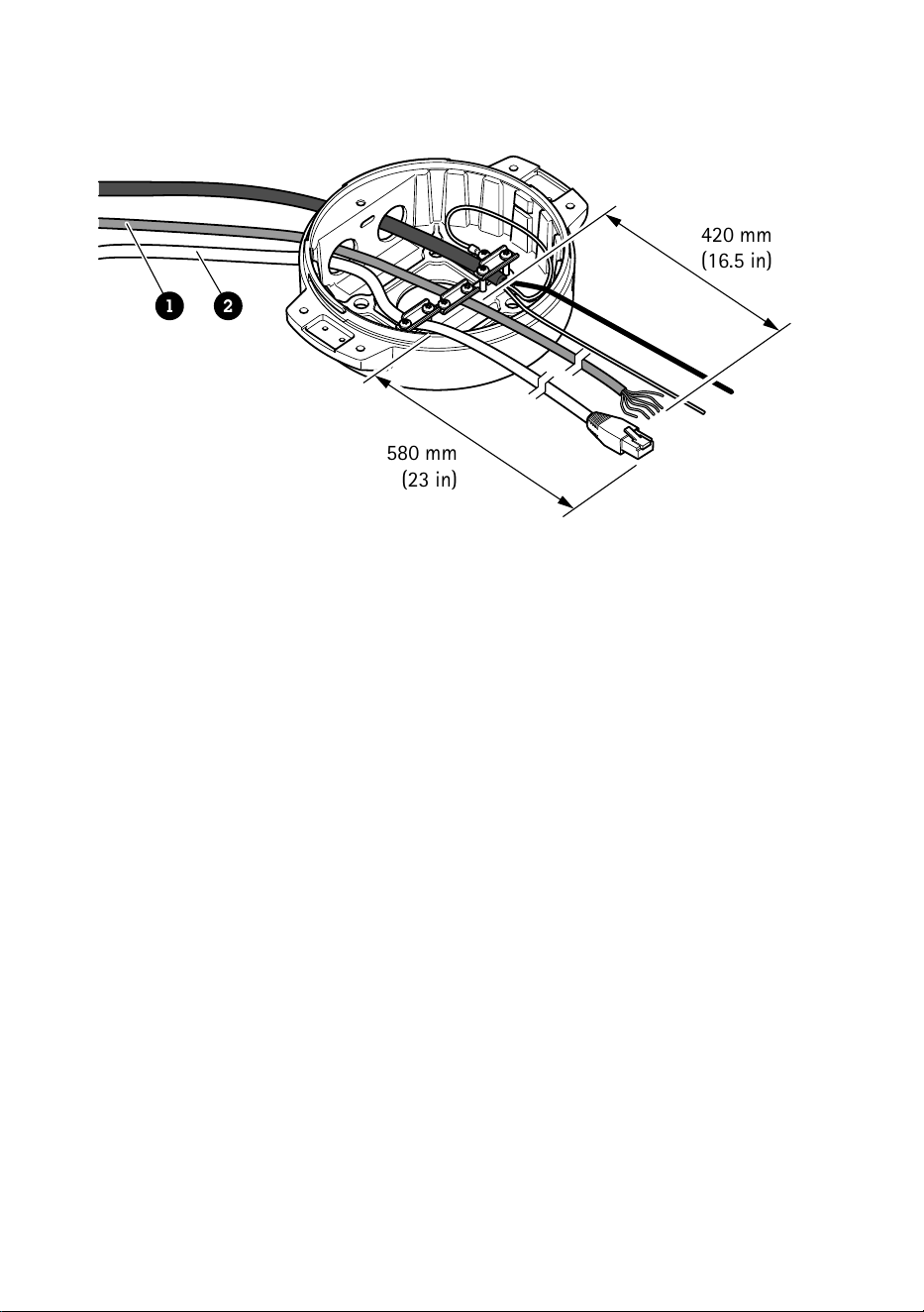
580 mm
(23 in)
420 mm
(16.5 in)
1 2
1 Cable de E/S (opcional, no incluido)
2 Cable de red (no incluido)
5. Pase el cable de E/S (opcional) y el cable de red a través del orificio de la unidad base como
se muestra en la ilustración anterior. También puede pasarlos por el orificio del cable inferior.
6. Introduzca el cable de E/S a través de la descarga de tracción con una distancia de 420 mm
entre esta y el extremo del cable.
7. Introduzca el cable de red (cable de fibra óptica o cable RJ45) con una distancia de 580 mm
entre la descarga de tracción y el extremo del conector. Para obtener más información sobre
las opciones de conectividad de la red, consulte Instalación del enlace de red, en la página
96.
8. Cierre y apriete las tres descargas de tracción.
92

ES
1 2 3
4
5
1 Cable de alimentación (no incluido)
2 Cable de E/S (opcional, no incluido)
3 Cable de red (no incluido)
4 Junta de cable
5 Cubierta transparente de la unidad base
9. Ponga juntas en los cables. Consulte Grosor del cable, en la página 102.
10. Pase los cables de alimentación, E/S y red con las juntas por los orificios de la cubierta
transparente de la unidad base y dispóngalos como se muestra en la ilustración anterior.
AVISO
Si usa un cable de fibra óptica y un cable RJ45 para la conexión de red, pase el cable de fibra
óptica por la misma junta que el cable de E/S. Aplique un sellador entre los cables y la junta de
cable para que no haya fugas. Para obtener más información sobre las opciones de
conectividad de la red, consulte Instalación del enlace de red, en la página 96.
93
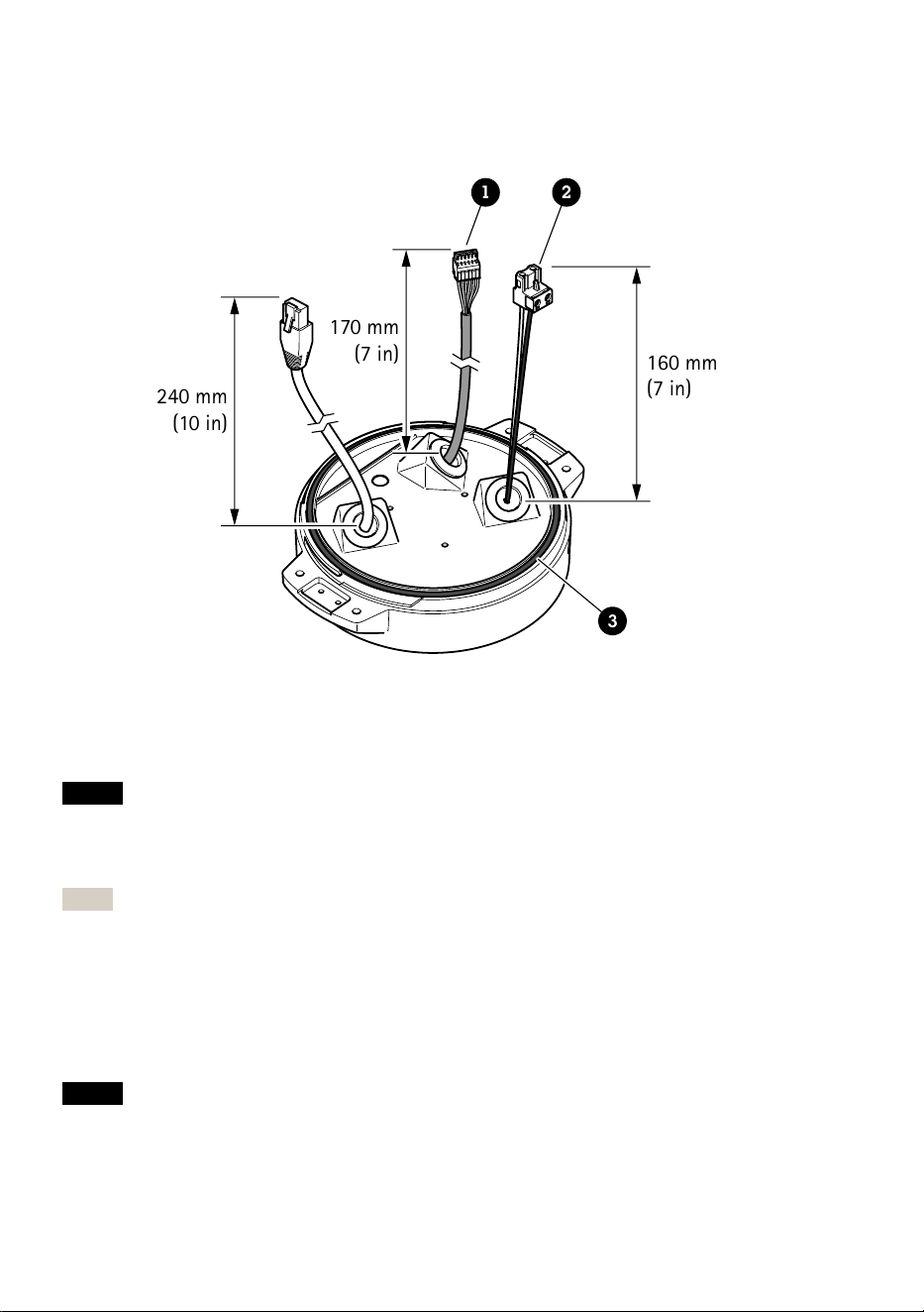
11. Coloque la cubierta transparente de la unidad base en la unidad y ponga las juntas de cable
en los orificios.
240 mm
(10 in)
170 mm
(7 in)
160 mm
(7 in)
1 2
3
1 Conector de E/S
2 Conector de alimentación
3 Junta tórica
AVISO
A fin de evitar desconectar accidentalmente la unidad de la alimentación si se tira del cable,
deje el cable protector de tierra unos 10 mm más largo que los otros dos cables (en el cable de
alimentación).
Nota
Para que la instalación resulte lo más sencilla posible, le recomendamos retirar
aproximadamente 90 mm de la camisa del cable de alimentación y 70 mm de la camisa del
cable de E/S.
12. Instale los conectores de alimentación y E/S.
13. Ajuste los cables de red, E/S y alimentación de forma que la distancia entre la junta de cable
y el extremo del conector sea de 240 mm, 170 mm y 160 mm respectivamente.
AVISO
Compruebe que la junta tórica está bien puesta en torno a la cubierta transparente de la
unidad base.
94

ES
14. Coloque la unidad de posicionamiento en la unidad base. Asegúrese de que las flechas de las
dos unidades estén alineadas.
15. Gire la unidad de posicionamiento en sentido horario hasta su posición original y apriete los
cuatro tornillos de la base (T30, par de 3,0 Nm).
AVISO
Compruebe que los cables no quedan presionados al montar las dos unidades.
95

Instalación del enlace de red
Puede elegir entre diferentes opciones para instalar el enlace de red:
• A: a través de un cable de fibra óptica o RJ45 conectado al módulo SFP (con el
correspondiente conector) en la ranura SFP.
• B: con un cable RJ45 unido al conector RJ45 fijado.
• C: mediante las dos opciones anteriores, en cuyo caso la conexión del módulo SFP funciona
como enlace de red principal y la conexión a través del conector RJ45 fijado funciona como
enlace para casos de error.
Para obtener más información sobre las ubicaciones de los conectores de red, consulte Información
general del producto, en la página 86.
Nota
• El módulo SFP no se incluye. Para obtener información sobre los módulos SFP disponibles,
consulte axis.com.
• Si instala un enlace de red únicamente con el cable de fibra óptica a través del
correspondiente módulo SFP, funcionará como solución independiente en instalaciones con
cables de largo alcance.
Instalación de la cámara
AVISO
• Este producto admite distintos modelos de cámara. Para obtener un listado completo de
cámaras compatibles, acceda a la página de productos en axis.com.
• Para obtener instrucciones sobre cómo abrir la cubierta de la cámara, consulte la guía de
instalación de la cámara.
96
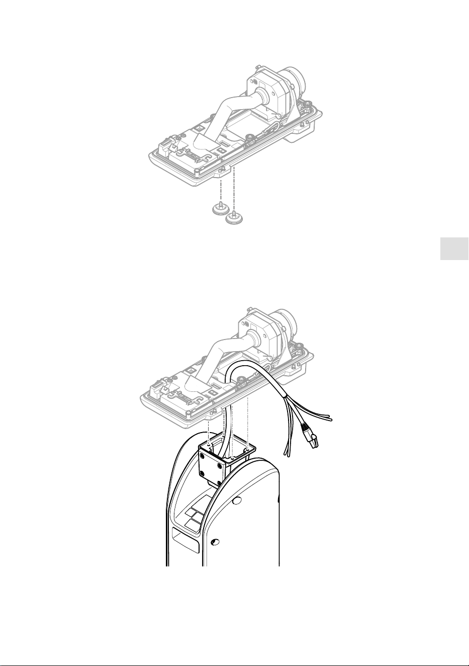
ES
1. Retire las juntas de cable de la cubierta inferior de la cámara.
2. Pase el cable de red/alimentación/interfaz serie por los orificios de la cubierta inferior.
97

3. Ponga la cubierta inferior en la unidad de posicionamiento.
T20
2x
4. Incline la cubierta inferior hacia atrás al máximo y apriete los dos tornillos delanteros de la
unidad de posicionamiento (T20, par 3,0 Nm).
98
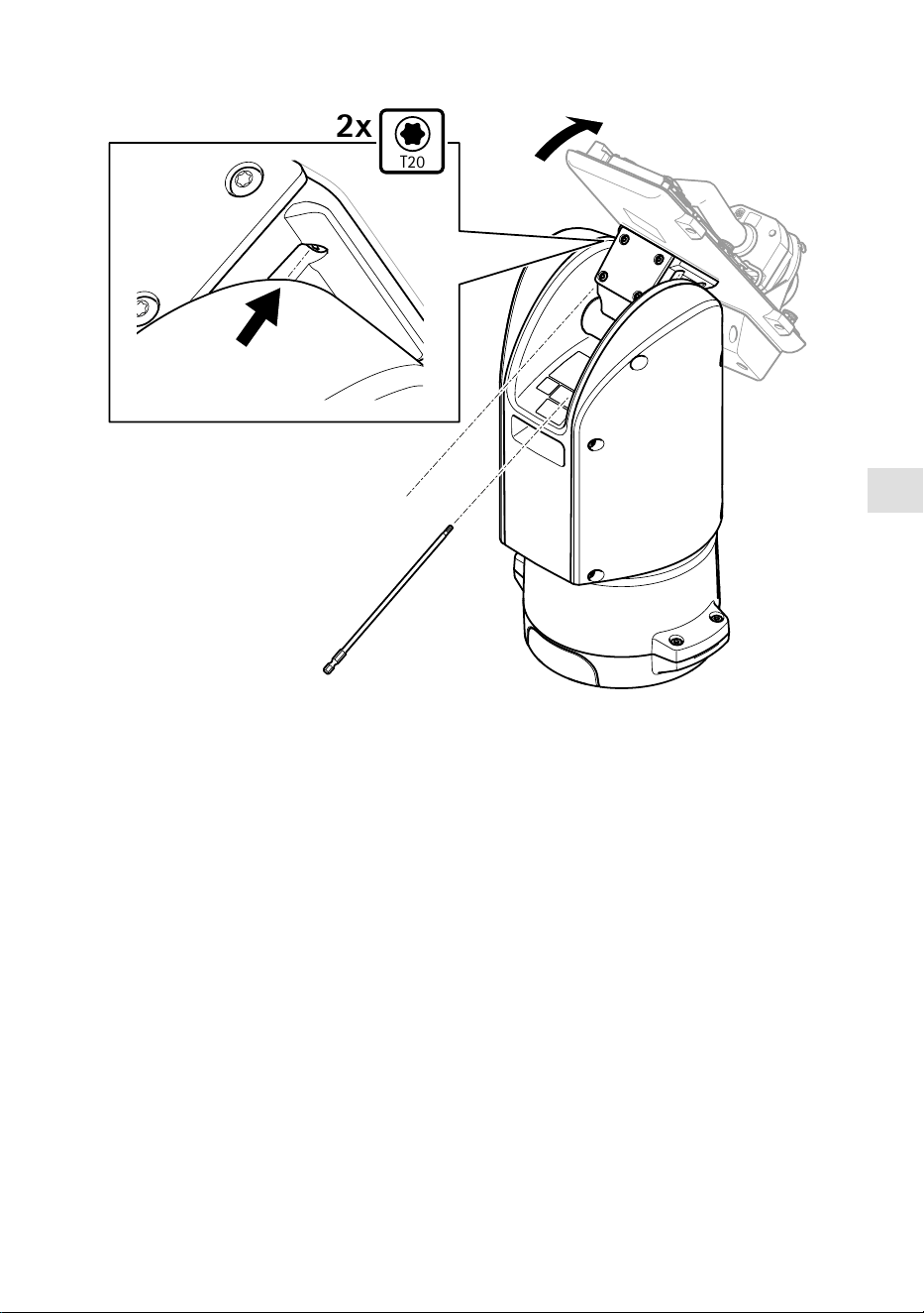
ES
T20
2x
5. Incline la cubierta inferior hacia delante al máximo y apriete los dos tornillos traseros de la
unidad de posicionamiento (T20, par 3,0 Nm).
6. Conecte los cables de red, de interfaz serie y de alimentación de la cámara según la guía de
instalación de la cámara. Para obtener más información sobre las especificaciones de los
cables, consulte Cable de alimentación de la cámara, en la página y Cable de interfaz
serie de la cámara, en la página 102.
7. Finalice la instalación de la cámara según la guía de instalación de la cámara.
99

Conexión de los cables
1. Afloje los cuatro tornillos (T20) de la tapa de la base y retírela.
1 2 3 4
1 Conector de entrada de corriente
2 Conector de E/S
3 Conector RJ45
4 Ranura SFP para módulo SFP (módulo SFP no incluido)
2. Conecte la red (fibra óptica o RJ45), la E/S y los cables de alimentación. Para obtener más
información sobre las opciones de conectividad de la red, consulte Instalación del enlace de
red, en la página 96.
3. Vuelva a colocar la tapa en su posición y apriete los cuatro tornillos de la tapa (par 3,0 Nm).
100

ES
4. Extraiga la cubierta protectora.
5. Conecte la alimentación del producto.
Selección de controlador PTZ
1. Vaya a la página web de la cámara.
2. Vaya a System > Accessories > PTZ (Sistema > Accesorios > PTZ).
3. Si la cámara admite controladores PTZ y digitales, seleccione el modo de PTZ Mechanical
(Mecánico).
4. Seleccione el controlador APTP y haga clic en Save (Guardar).
5. Vaya a la pestaña PTZ y compruebe que los ajustes de panorámica e inclinación están
disponibles.
101
Especificaciones
Cables
Grosor del cable
El diámetro del cable, si se usan las juntas para cables suministradas con este producto, debe ser de
entre 5 y 11 mm.
AVISO
• Utilice cables que puedan permanecer dentro del área de cableado especificada.
• Elija cables que cumplan la normativa local aplicable.
• Asegúrese de que todos los orificios para cables estén debidamente sellados.
• Utilice juntas de cable o prensaestopas que se ajusten tanto al orificio para cable como al
área de cableado.
Para obtener información acerca de los accesorios, como juntas de cable y prensaestopas
permitidos para otras áreas de cableado, visite www.axis.com.
Cable de interfaz serie de la cámara
Color del cable Especificaciones
Blanco RS485 RX/TX A
Verde RS485 RX/TX B
Cable de alimentación de la cámara
Color del cable Especificaciones
Rojo + 56 V CC
Negro 0 V
102

JA
パッケージの内容
• ポジショニングユニット
• 電源コネクター
• I/Oコネクター
• Torx®ビットT20(ロング)
• ケーブルグランド
• RJ45設置ツール
• リングケーブルラグ
103
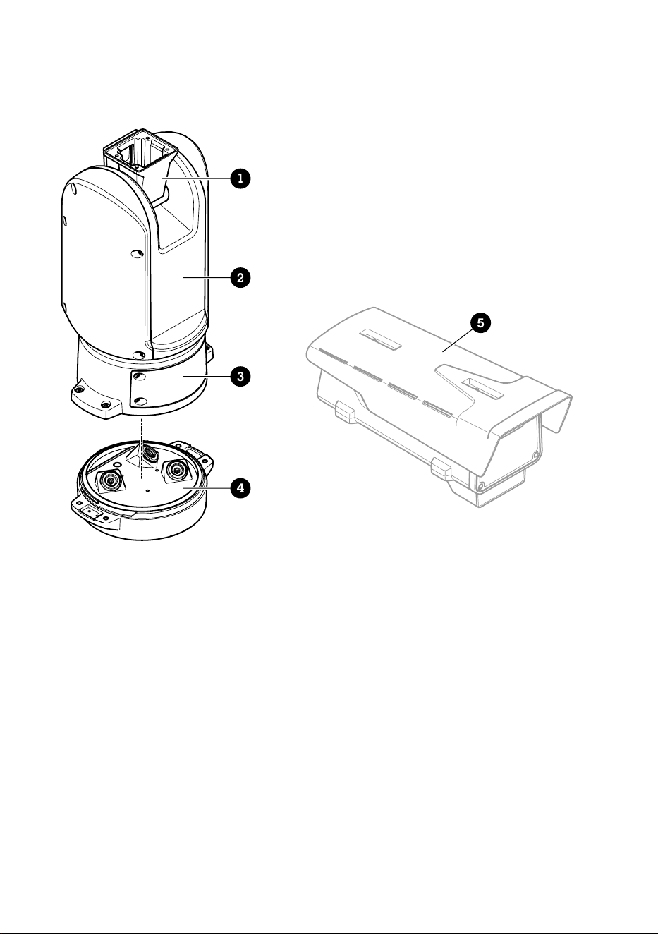
製品の概要
1
2
3
4
5
1
ポジショニングユニット(チルト)
2
ポジショニングユニット(パン)
3
蓋
4
ベースユニット
5
カメラ (別売り)
104
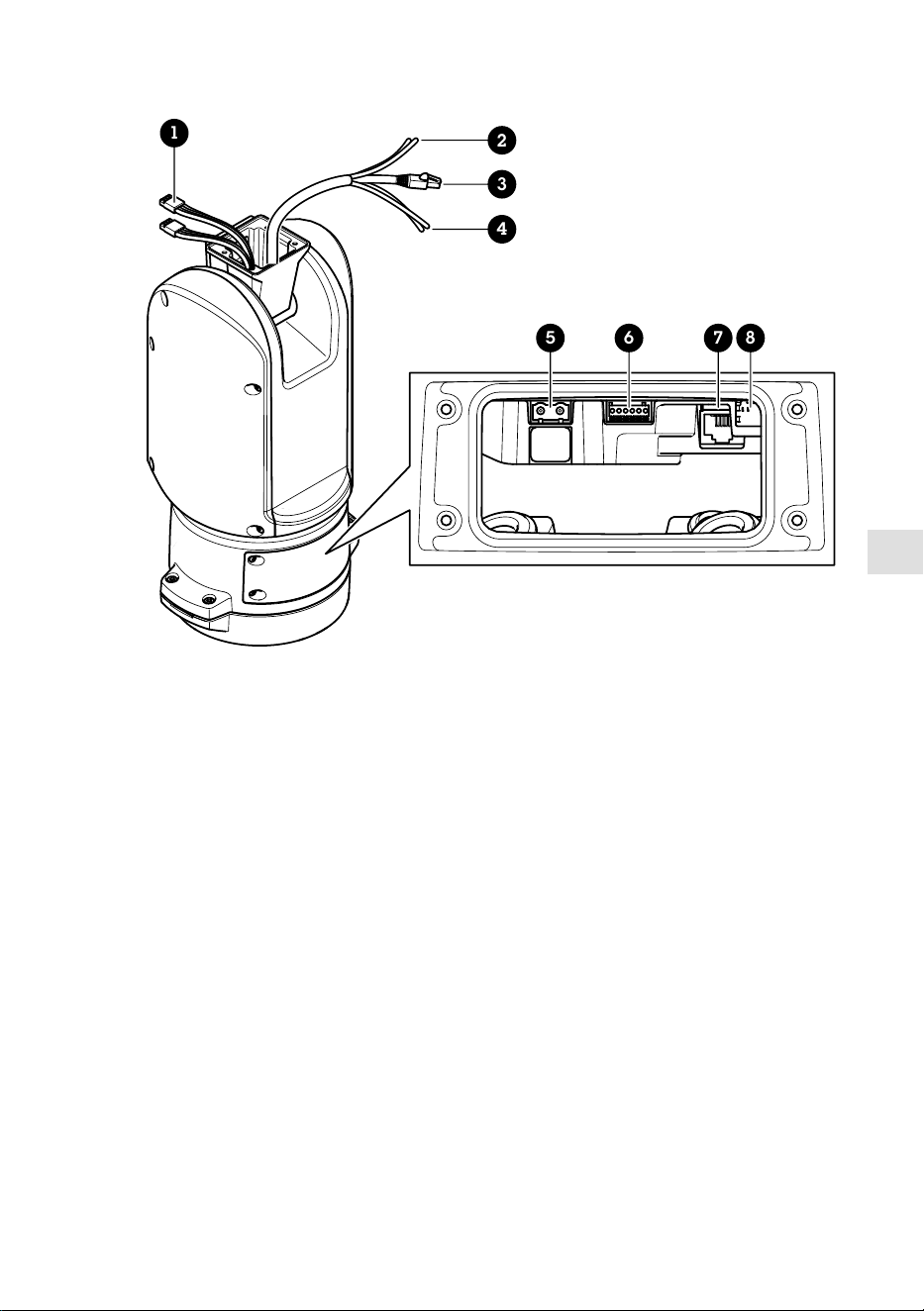
JA
1
5 6 7 8
2
3
4
1
イルミネーターケーブル (使用しない)
2
カメラの電源ケーブル
3
カメラのネットワークケーブル
4
カメラのシリアルインターフェースケーブル
5
入力電源コネクター
6
I/Oコネクター
7
RJ45コネクター
8
SFPモジュール用SFPスロット (SFPモジュールは付属していま
せん)
105
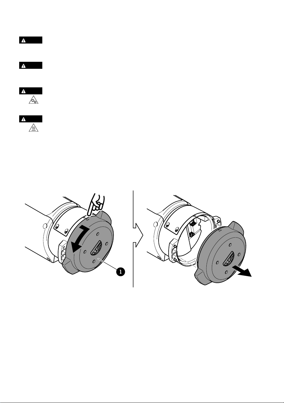
製品の取り付け方法
危危険険
感電の危険があります。 製品を設置する前に、すべてのケーブルの通電を切ってく
ださい。
注注意意
電気接続およびコンジットの取り付けは、必ず資格のある電気技師が地域の規制に
従って行ってください。
注注意意
損傷の危険があります。 可動部分。 動作中は、体を製品に近づけないでくださ
い。 製品の設置やメンテナンスを行う前には電源を切ってください。
注注意意
損傷の危険があります。 表面が熱くなります。 動作中は、本製品に触れないで
ください。 製品のメンテナンスを行う前に、電源を切り、表面が冷えるまで待って
ください。
ベースユニットの取り付け
1
1
ベースユニット
1. ベースユニットのネジ4本 (T30) を外します。
2. ベースユニットと残りの位置決めユニットの矢印が揃うまで、ベースユニットを
同時に反時計回りに引いて回します。
3. ベースユニットを取り外します。
106
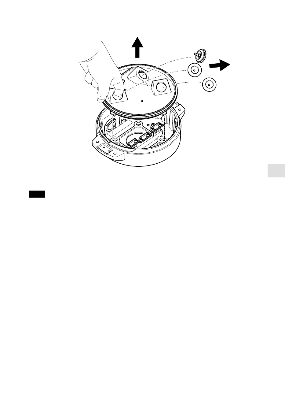
JA
注意
透明ベースユニットカバーの取り外しの際には、鋭利な工具を使用しないでくださ
い。
4. 透明ベースユニットカバーを取り外します。
107
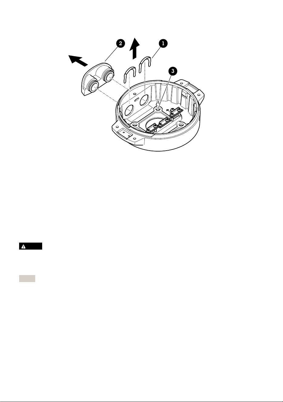
12
3
1
コンジットカバークリップ
2
コンジットカバー
3
ネジ穴 (x4)
5. コンジットを取り付ける場合のみ: 2つのコンジットカバークリップを取り外し、
コンジットカバーを取り外します。
6. 4つのネジ穴に適したファスナーで、ベースユニットを取付面に取り付けます。
ケーブルの配線
警警告告
感電の危険があります。本製品は、電源ケーブルおよび接地編組の両方に保護アー
ス線を使用して接地するものとします。保護アース線と接地編組のそれぞれの両端
がいずれもアース面と接触していることを確認してください。
重要
指定のケーブルエリアでの仕様に準拠したケーブルのみ使用してください。詳細に
ついては、
ケーブルの太さ, ページ 120
ご覧ください。
108

JA
530 mm
(21 in)
1
4
3
2
1
電源ケーブル (付属していません)
2
ストレインリリーフ
3
アース端子ネジ
4
底部ケーブル孔
1. オプションのコンジットアダプター (付属していません) を取り付けます。
2. 上図に示すように、電源ケーブルをベースユニットの穴に挿入します。あるい
は、底部ケーブル孔に挿入してください。
3. 電源ケーブルのスリーブを530 mm (21 in) 引き戻し、電源ケーブルをストレイン
リリーフに通します。
4. グリーン/イエローのワイヤーを付属のリングケーブルラグに固定し、接地用ネ
ジに接続してください。ケーブルの最小断面積は18AWG(0.82mm²)です。
109

580 mm
(23 in)
420 mm
(16.5 in)
1 2
1
I/Oケーブル (オプション、付属していません)
2
ネットワークケーブル (付属していません)
5. 上図に示すように、ベースユニットの穴にI/Oケーブル (オプション) とネット
ワークケーブルを通します。あるいは、それらを底部ケーブル孔から挿入しま
す。
6. ストレインリリーフからケーブルの先端までの距離が420 mm (16.5 in) になるよ
うに、ストレインリリーフにI/Oケーブルを通します。
7. ストレインリリーフからコネクタの先端までの距離が580 mmになるように、ス
トレインリリーフを通じてネットワークケーブル (光ファイバーケーブルやRJ45
ケーブル) を挿入します。さまざまなネットワーク接続オプションの詳細につい
ては、
ネットワークリンクのインストール, ページ 114
を参照してください。
8. 3つのストレインリリーフを閉じて締めます。
110

JA
1 2 3
4
5
1
電源ケーブル (付属していません)
2
I/Oケーブル (オプション、付属していません)
3
ネットワークケーブル (付属していません)
4
ケーブルガスケット
5
透明ベースユニットカバー
9. ケーブルに合ったケーブルガスケットを取り付けます。
ケーブルの太さ, ページ
120
を参照してください。
10. 上図に示すように、ケーブルガスケットを含めて、電源ケーブル、I/Oケーブ
ル、ネットワークケーブルを透明ベースユニットのカバー孔から挿入し、ケーブ
ルの配置を調整します。
注意
光ファイバーとRJ45ケーブルの両方をネットワーク接続に使用している場合、光
ケーブルはI/Oケーブルと同じケーブルガスケットを通します。漏電防止のため
に、シーラントをケーブルとケーブルガスケットの間に貼り付けます。さまざまな
111
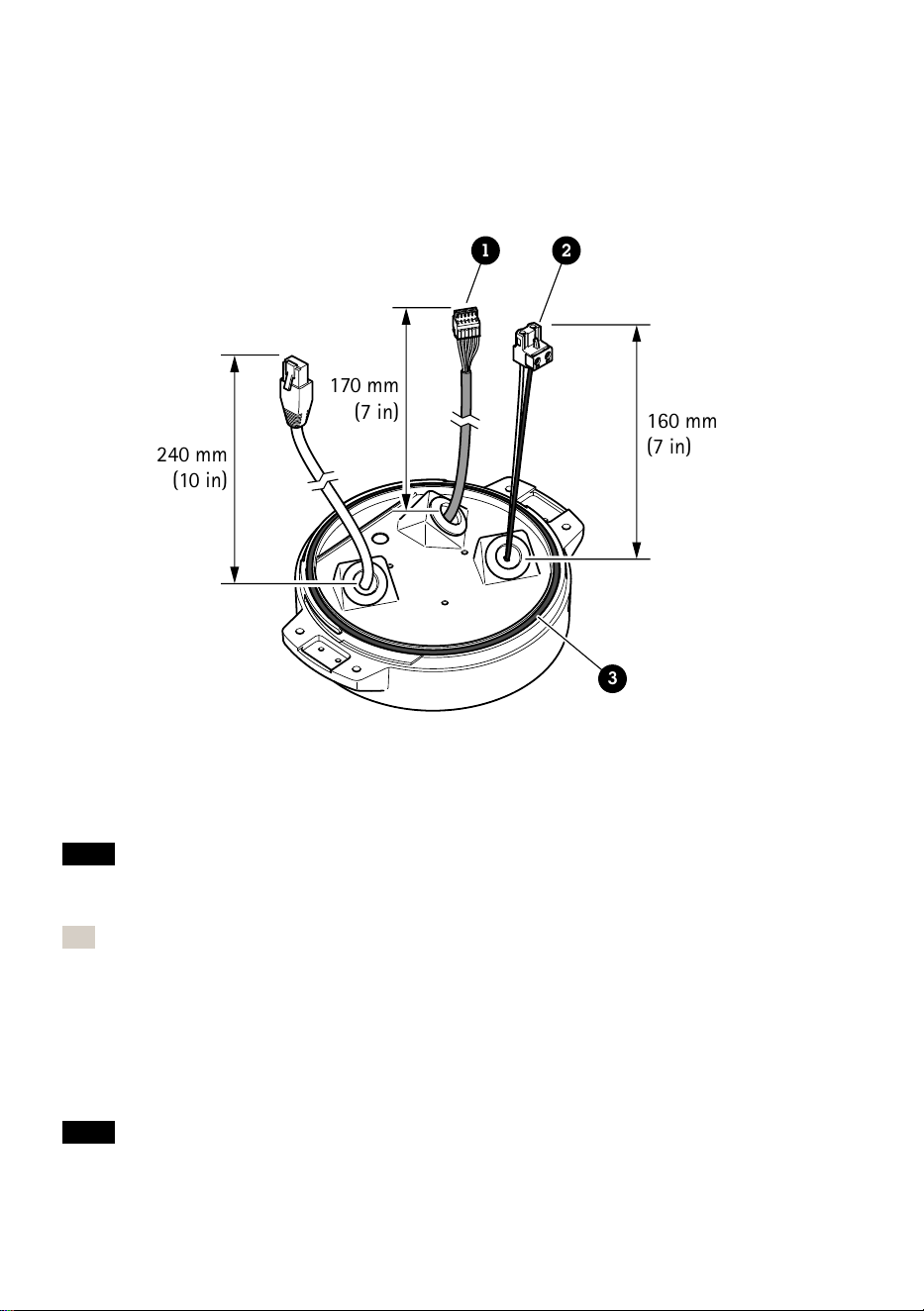
ネットワーク接続オプションの詳細については、
ネットワークリンクのインストー
ル, ページ 114
を参照してください。
11. ベースユニットの上に透明ベースユニットカバーを置き、穴の内側にケーブルガ
スケットをはめ込みます。
240 mm
(10 in)
170 mm
(7 in)
160 mm
(7 in)
1 2
3
1
I/Oコネクター
2
電源コネクター
3
O-リング
注意
ケーブルが引っ張られた場合に誤って装置を電源から切断しないように、保護接地
線は他の2本の線 (電源ケーブル内) よりも約10 mm 長くしてください。
注
設置をできるだけ簡単にするために、電源ケーブルジャケットの約90 mmとI/O
ケーブルジャケットの70 mmを取り除くことをお勧めします。
12. 電源およびI/Oコネクタを取り付けます。
13. ネットワークケーブル、I/Oケーブル、および電源ケーブルのケーブルガスケッ
トからコネクタの端までの距離が、それぞれ240 mm、170 mm、160 mmになる
ように調整します。
注意
112
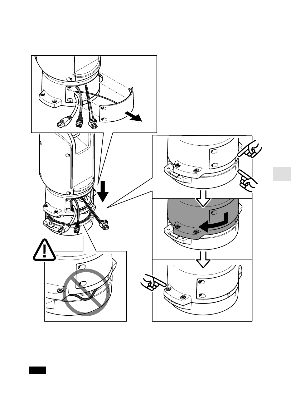
JA
O-リングが透明ベースユニットカバーに正しく取り付けられていることを確認しま
す。
14. ポジショニングユニットをベースユニットに配置します。2つのユニット上の矢
印が一直線上になっていることを確認してください。
15. ポジショニングユニットを元の位置に戻るまで時計回りに回し、ベースユニット
のネジ4本を締めます (T30、トルク3.0 Nm)。
注意
113

2つのユニットを組み立てるときにケーブルが締め付けられないように注意してく
ださい。
ネットワークリンクのインストール
次のいずれかの方法で、ネットワーク リンクをインストールすることができます:
• A: SFPポートで (それぞれのコネクタを使用して) SFPモジュールに接続された光
ファイバーまたはRJ45ケーブルを介して接続。
• B: 固定RJ45コネクタに接続されたRJ45ケーブルを介して接続。
• C: 上記の両方を使用して接続。この場合、SFPモジュール接続はプライマリネッ
トワークリンクとして機能し、固定のRJ45接続はフェイルオーバーリンクとして
機能します。
ネットワークコネクタの位置の詳細については、
製品の概要, ページ 104
を参照してく
ださい。
注
• SFPモジュールは付属していません。 利用可能なSFPモジュールについては、
axis.
com
を参照してください。
• 当該SFPモジュールを使用する光ファイバーケーブルのみを介してネットワーク
リンクをインストールする方法は、ケーブルを長距離に設置するスタンドアロン
のソリューションとして有効です。
カメラの設置
注意
• 本製品は、複数のカメラモデルに対応しています。対応しているカメラの全リス
トについては、
axis.com
にある製品ページを参照してください。
• カメラの蓋を開く方法については、カメラのインストールガイドを参照してくだ
さい。
114
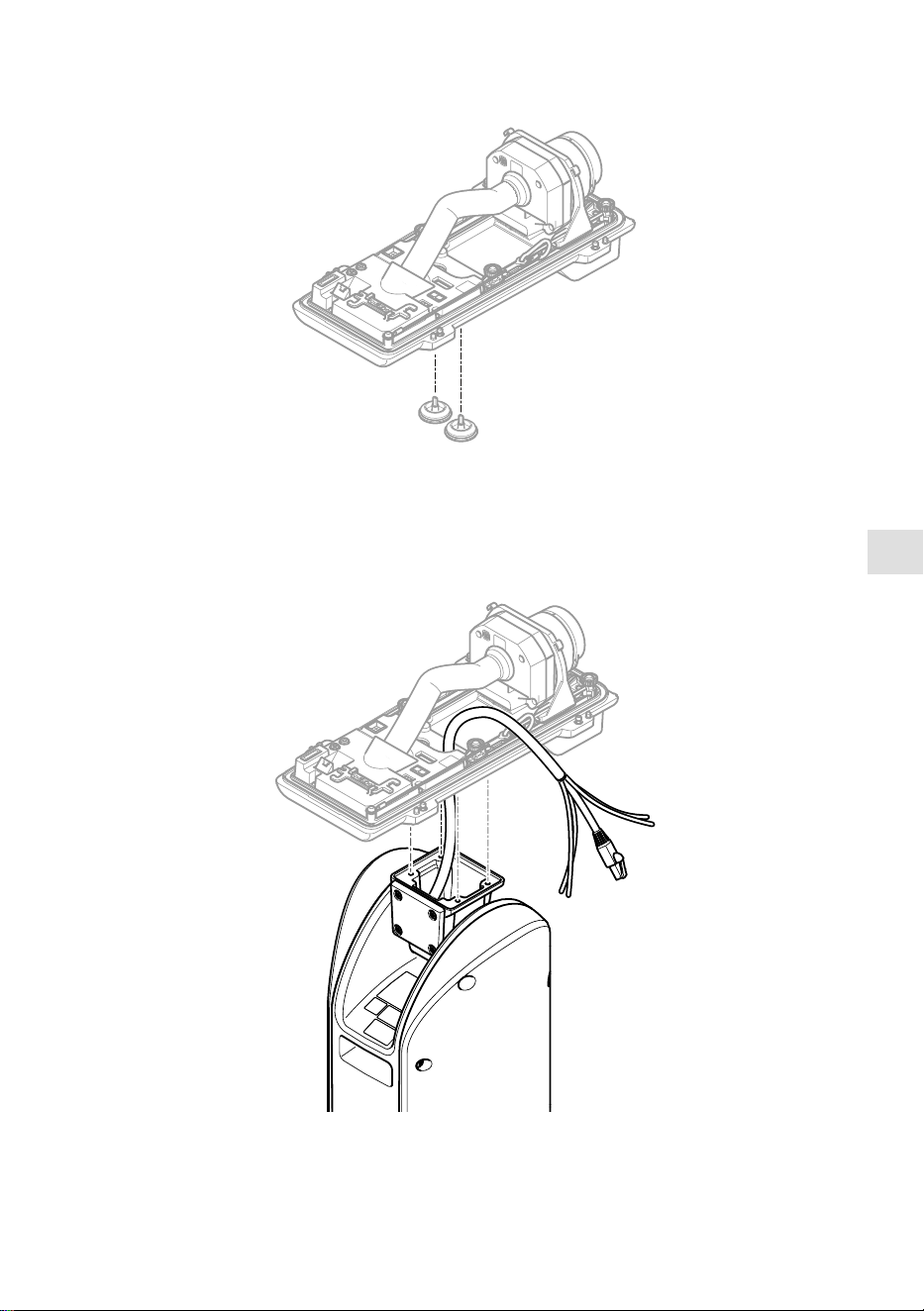
JA
1. カメラの裏蓋からケーブルガスケットを取り外します。
2. 裏蓋の穴にネットワーク/電源/シリアルインターフェースケーブルを通します。
115
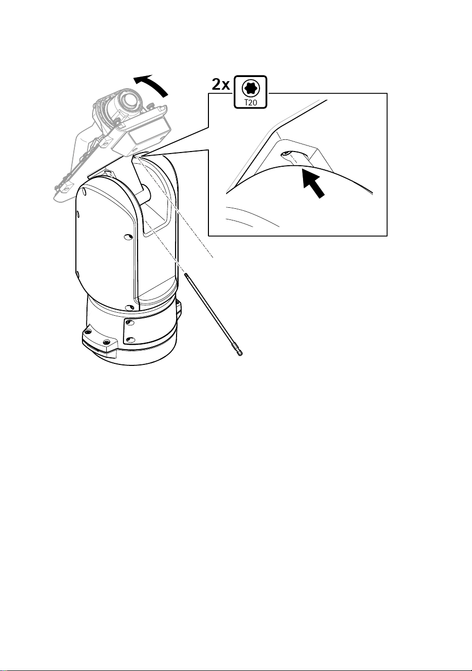
3. ポジショニングユニットに裏蓋をはめ込みます。
T20
2x
4. 裏蓋を端まで後方に傾け、ポジショニングユニットの正面ネジ (T20、トルク
3.0 Nm) 2本を締めます。
116
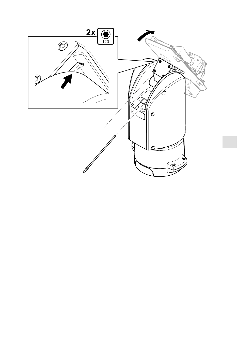


JA
4. 保護カバーを取り外します。
5. 製品の電源を入れます。
PTZドライバーの選択
1. カメラのWebページに移動します。
2. [SSyysstteemm >> AAcccceessssoorriieess >> PPTTZZ ((シシスステテムム >> アアククセセササリリーー >> PPTTZZ))] に移動しま
す。
3. カメラがPTZドライバーとデジタルPTZの両方に対応している場合は、PTZモード
に [MMeecchhaanniiccaall ((メメカカニニカカルル))] を選択します。
4. ドライバーに [AAPPTTPP] を選択し、[SSaavvee ((保保存存))] をクリックします。
5. [PPTTZZ] タブに移動し、パン/チルトの設定が利用可能であることを確認します。
119
仕様
ケーブル
ケケーーブブルルのの太太ささ
本製品に付属のケーブルガスケットを使用する際、ケーブルは直径が5〜11 mmのもの
を使用する必要があります。
注意
• 指定のケーブルエリアに収まるケーブルを使用してください
• 地域の規制に適合したケーブルを選択してください
• すべてのケーブル孔が適切に密封されていることを確認してください
• ケーブル孔とケーブルエリアの両方に適合するケーブルガスケットまたはケーブ
ルグランドを使用してください
他のケーブルエリアに対応するケーブルガスケット、ケーブルグランドなどのアクセ
サリーについては、
www.axis.com
を参照してください。
カカメメララののシシリリアアルルイインンタターーフフェェーーススケケーーブブルル
ケケーーブブルルのの色色
仕仕様様
白
RS485 RX/TX A
緑 RS485 RX/TX B
カカメメララのの電電源源ケケーーブブルル
ケケーーブブルルのの色色
仕仕様様
赤
+ 56 V DC
黒 0 V
120

ZH
包包装装内内容容
• 定位单元
• 电源连接器
• I/O 连接器
• Torx®钻头 T20(长)
• 线缆密封套
• RJ45 安装工具
• 环形电缆接线片
121
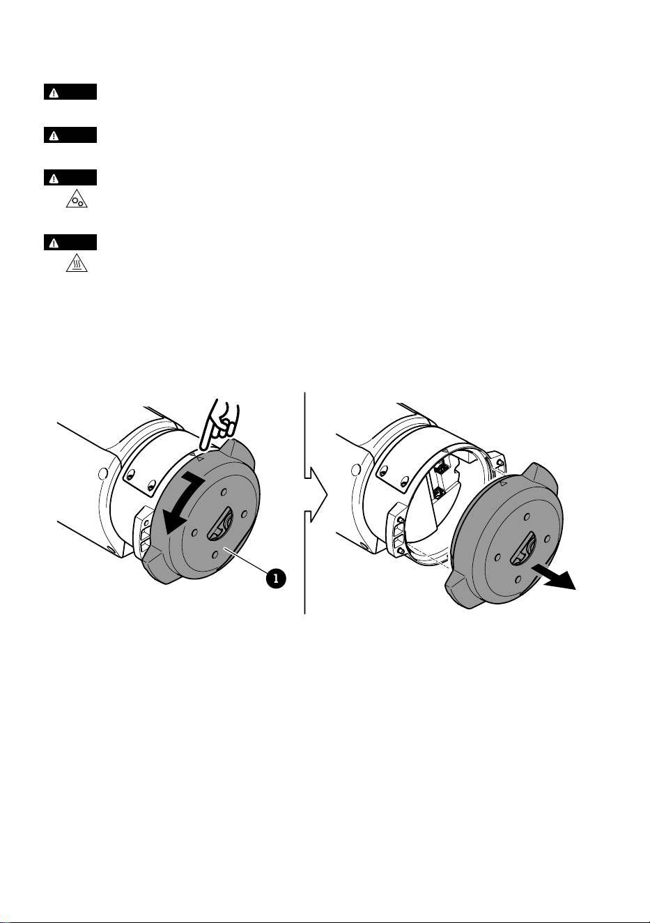
如如何何安安装装产产品品
危危险险
电击风险。 安装产品之前,电缆都应断电。
警警示示
电气连接和导线管安装应由经过认证的电工执行,并遵守当地法规。
警警示示
伤害风险。 活动部件。 操作期间,请保持身体部位远离产品。 安装或维护产品
时,请断开电源。
警警示示
伤害风险。 灼热的表面。 请勿在操作期间触摸该产品。 执行产品维护时,请断
开电源并让表面冷却。
安安装装底底座座单单元元
1
1
底座装置
1. 移除四颗底座单元螺丝 (T30)。
2. 同时逆时针拉转底座单元,直到底座单元和定位单元其余部分的箭头对齐。
3. 移除底座单元。
122

ZH
注意
移除透明底座单元盖板时,请勿使用尖锐工具。
4. 移除透明底座单元盖板。
123
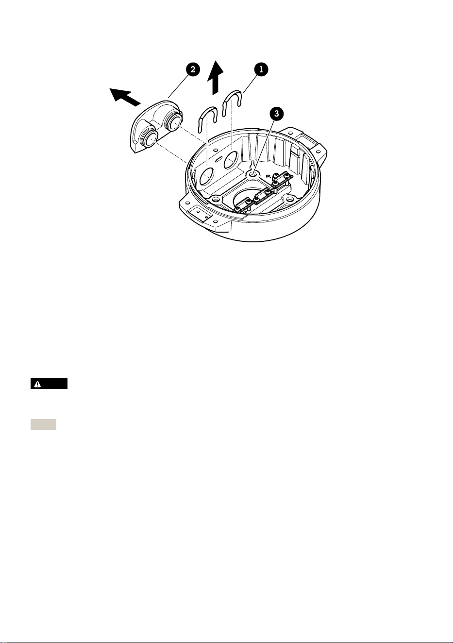
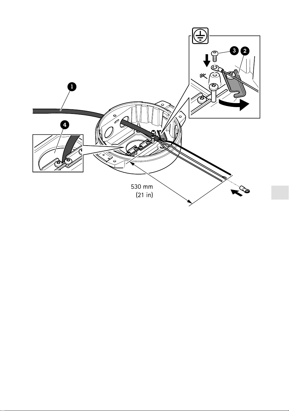
ZH
530 mm
(21 in)
1
4
3
2
1
电源线(不包括)
2
应力消除器
3
接地螺丝
4
底部电缆孔
1. 安装可选的导线管适配器(不包括)。
2. 将电源线穿过底座单元上的孔(如上图所示)。或者,将其穿过底部电缆孔。
3. 将电源线套管向后拉 530 毫米(21 英寸),然后将电源线穿过应力消除器。
4. 将绿色/黄色的电线固定在随附的环形电缆夹上,并连接到接地螺丝。电缆的最小截
面积为18AWG(0.82mm²)。
125


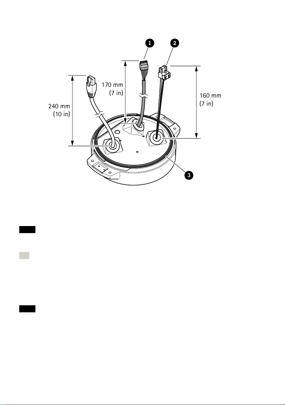
240 mm
(10 in)
170 mm
(7 in)
160 mm
(7 in)
1 2
3
1
I/O 连接器
2
电源连接器
3
O 形环
注意
为避免电缆被拉扯时单元电源意外断开,保护接地线应该比他两条电线(电源线内)
长约 10 毫米(0.4 英寸)。
注
为了让安装尽可能简单,我们建议您将电源线护套剥去约 90 毫米(3.5 英寸),并将
I/O 电缆护套剥去 70 毫米(2.8 英寸)。
12. 安装电源连接器和 I/O 连接器。
13. 调整网络、I/O 和电源线,以使电缆垫片与连接器末端的距离分别为 240 毫米(10
英寸)、170 毫米(7 英寸)及 160 毫米(7 英寸)。
注意
确保 O 型环正确安装在透明底座单元盖板周围。
128

ZH
14. 将定位单元放在底座单元上。确保两个单元上的箭头对齐。
15. 按顺时针方向将定位单元转回至其初始位置并拧紧四个底座单元螺丝(T30,扭矩
3.0 牛米)。
注意
在安装两个单元时,请确保电缆未被夹扁。
129
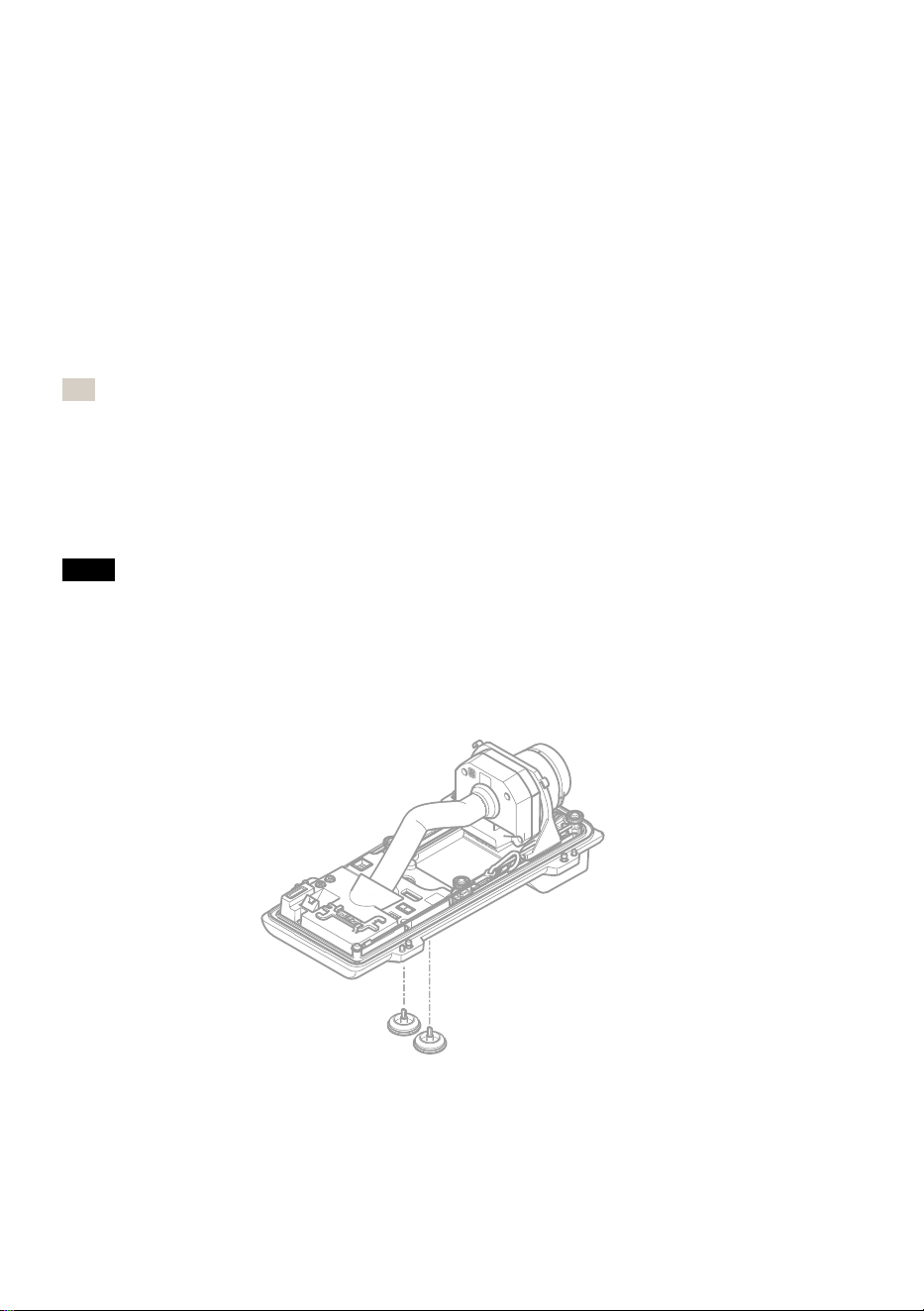
安安装装网网络络链链路路
安装网络链路时,有几个选项可以选择:
• A: 通过光纤电缆或与 SFP 插槽中的 SFP 模块(带有相应的连接器)连接的 RJ45
电缆。
• B: 通过与固定式 RJ45 连接器连接的 RJ45 电缆。
• C: 同时连接上述两种电缆,在此情况下,SFP 模块连接用作主网络链路,固定的
RJ45 连接用作故障转移链路。
有关网络连接器位置的详细信息,请参见
产品概述, 页面上
。
注
• 不包括 SFP 模块。 有关可用 SFP 模块的详细信息,请参见
axis.com
• 如果您仅通过使用相应 SFP 模块的光纤电缆安装网络链路,它可以用作远程布线安
装的独立解决方案。
安安装装摄摄像像机机
注意
• 本产品支持多种摄像机型号。有关支持的摄像机的完整列表,请参阅产品页面:
axis.com
。
• 有关如何打开摄像机外壳的说明,请参见摄像机的安装指南。
1. 从摄像机底盖上取下线缆垫圈。
130
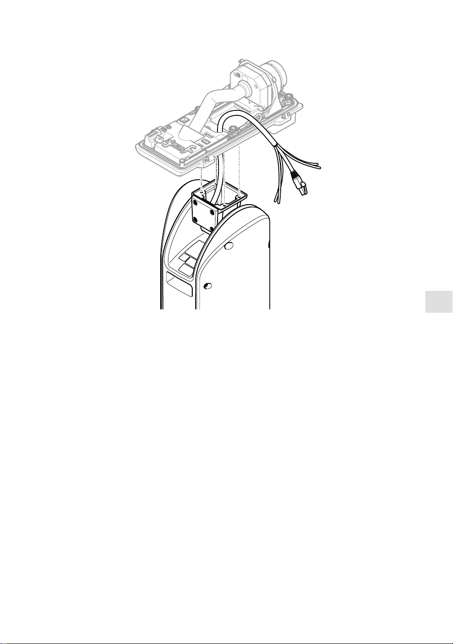
ZH
2. 将网络电缆/电源线/串行接口线穿过底盖上的孔。
3. 将底盖安装在定位单元上。
131
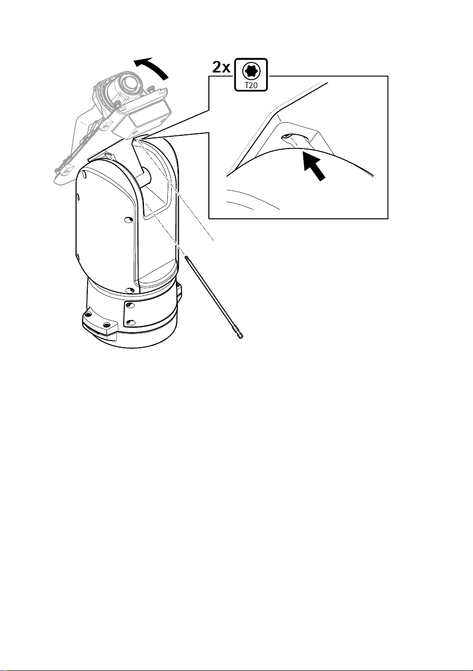
T20
2x
4. 将底盖向后倾斜至其终端位置,然后拧紧定位单元前面的两颗螺丝(T20,扭矩
3.0 Nm)。
132
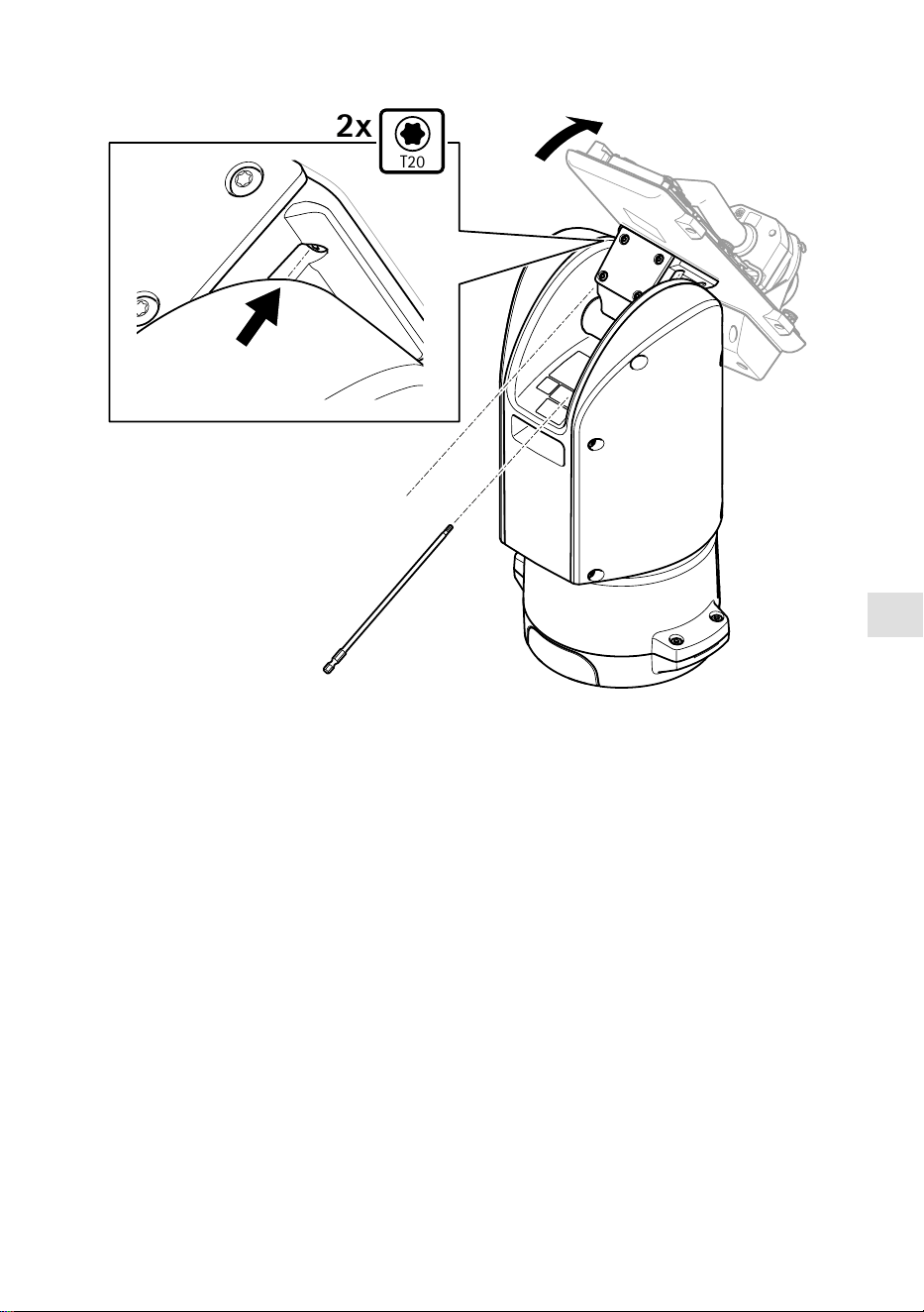
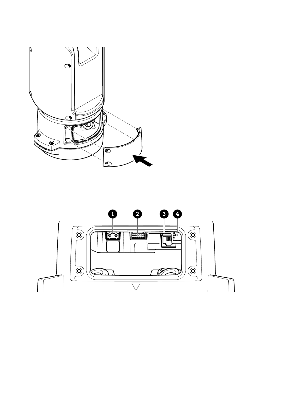

ZH
5. 接通产品电源。
选选择择 PPTTZZ 驱驱动动
1. 转到摄像机的网页。
2. 转到系系统统 >> 附附件件 >> PPTTZZ。
3. 如果您的摄像机同时支持 PTZ 驱动和数字 PTZ,请选择 PTZ 模式机机械械。
4. 选择驱动程序 AAPPTTPP,然后单击保保存存。
5. 转到 PPTTZZ 选项卡,检查水平转动-垂直转动设置是否可用。
135
规规格格
电电缆缆
电缆厚度
使用本产品随附的电缆垫片时,电缆直径应在 5 至 11 毫米(0.2 至 0.4 英寸)的范围
内。
注意
• 使用保持在指定电缆区域内的电缆
• 选择符合当地法规的电缆
• 确保电缆孔都已正确密封
• 使用与电缆孔和电缆区域相匹配的电缆垫圈或电缆套管
有关附件(如适合其他电缆区域的电缆垫圈和电缆套管)的信息,请参见
www.axis.com
摄像机串行接口线
电电缆缆颜颜色色 规规格格
白色款 RS485 RX/TX A
绿色 RS485 RX/TX B
摄像机电源线
电电缆缆颜颜色色 规规格格
红色 + 56 V DC
黑色 0 V
136

ZH
137

.
3178873
2025-01 (M2.2)
© 2025 Axis Communications AB
