USER GUIDE &
INSTALLATION INSTRUCTIONS
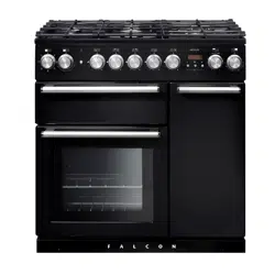
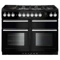
Professional + FXP 90 Dual Fuel
Australia
U111316 - 05

i
Contents
1. Before You Start... 1
Personal Safety 1
Electrical Connection Safety 2
If You Smell Gas 2
Peculiar Smells 2
Cooling Fan 2
Ventilation 3
Maintenance 3
Cooker Care 5
2. Overview 7
Hotplate burners 7
Wok burner 8
The wok cradle 8
Griddle 9
Multifunction oven 10
Energy saving panel 12
Operating the oven 12
Accessories 13
Storage 14
3. 6 Button clock 15
4. Cooking tips 17
6. Cooking Table 18
7. Cleaning your cooker 19
8. Troubleshooting 24
9. Service and Spares 26
10. Installation 27
Safety Requirements and Regulations 27
Provision of Ventilation 27
Location of Cooker 27
Conversion 27
Positioning the Cooker 29
Moving the Cooker 30
Removing the Oven Door 30
Lowering the Two Rear Rollers 30
Completing the Move 30
Levelling 31
Fitting the Stability Bracket and Chain 31
Fitting a Stability Bracket 31
Fitting the Restraining Chain 31
Gas Connection 32
Pressure Testing 32
Electrical Connection 33
Fixed Wiring 33
Final Checks 34
Final Fitting 34
Customer Care 34
Fitting the drawer 35
Removing the drawer 35
11. Servicing 36
1. Panels 36
2. Hotplate 37
3. Controls 37
4. Ovens 38
5. Door 41
12. Circuit Diagram 43
13. Technical Data 44

ii

1
Your cooker should give you many years of
trouble-free cooking if installed and operated
correctly. It is important that you read this
section before you start.
Personal Safety
This appliance is for cooking purposes only.
It must not be used for other purposes, for
example heating a room. Using it for any other
purpose could invalidate any warranty or
liability claim. Besides invalidating claims this
wastes fuel and may overheat the control knobs.
This cooker must be installed in accordance
with the relevant instructions in this booklet
and with the national and local regulations
as well as the local gas and electricity supply
companies’ requirements.
• This appliance can be used by children
aged from 8years and above and persons
with reduced physical, sensory or mental
capabilities or lack of experience and
knowledge if they have been given
supervision or instruction concerning
use of the appliance in a safe way and
understand the hazards involved.
• WARNING: Children less than 8 years
of age should be kept away unless
continuously supervised. Children shall not
play with the appliance. Cleaning and user
maintenance shall not be made by children
without supervision.
• Suitable only for indoor installation.
• DO NOT operate this appliance before
reading the instruction booklet.
• DO NOT place articles on or against this
appliance.
• DO NOT operate with panels, covers or
guards removed from this appliance.
• The cooker should not be placed on a base.
• This appliance is designed for domestic
cooking only. Use for any other purpose
could invalidate any warranty or liability
claim.
• Before operating the ovens please refer
to the oven shelf installation, in the
Accessories section.
• WARNING: The appliance and its
accessible parts become hot during use
and will retain heat even after you have
stopped cooking. Care should be taken to
avoid touching heating elements. Children
less than 8 years of age shall be kept away
unless continuously supervised.
• CAUTION: A long term cooking process
has to be supervised from time to time.
A short term cooking process has to be
supervised continuously.
• At the risk of fire DO NOT store items on
the cooking surfaces.
• DO NOT install an aftermarket lid or cover
over this appliance.
• DO NOT install combustible bench top
lids or covers within 200 mm (7
7
/8”) of the
nearest burner.
• To avoid overheating, DO NOT install the
cooker behind a decorative door.
• WARNING: Accessible parts will become
hot during use and will retain heat even
after you have stopped cooking. Keep
babies and children away from the cooker
and never wear loose-fitting or hanging
clothes when using the appliance.
• DO NOT use a steam cleaner on your
cooker.
• Always keep combustible materials, e.g.
curtains, and flammable liquids a safe
distance away from the cooker.
1. Before You Start...

2
• DO NOT spray aerosols in the vicinity of
the cooker while it is on.
Electrical Connection Safety
n
WARNING: THE APPLIANCE MUST BE
EARTHED.
The cooker is preset for a single-phase earthed
electrical connection. It is essential to install
a multi-pole circuit breaker that completely
disconnects the appliance from the mains, with
a minimum contact break distance of 3 mm.
The total electrical load of the appliance is
approximately 3.6 kW. The cable size used
should be suitable for this load and comply
with all local requirements (i.e. PVC Insulated
cable IEC 60227 – code 53 for ordinary cables).
Minimum temperature rating T105.
Read the instructions before installing or using
this appliance.
Gas Connection Safety
• This cooker is a Class 2 Subclass 1
appliance.
• This appliance can be converted for use on
another gas.
• Before installation, make sure that the
cooker is suitable for your gas type and
supply voltage. See the data badge.
• DO NOT use reconditioned or
unauthorised gas controls.
• Disconnect from the electricity and gas
supply before servicing.
• When servicing or replacing gas-carrying
components disconnect from the
gas supply before starting operation.
Check the appliance is gas sound after
completion.
• Make sure that the gas supply is turned
on and that the cooker is wired in and
switched on.
• In your own interest and that of safety, it is
law that all gas appliances be installed by a
qualified person(s).
• An appliance for use on LPG must not be
installed in a room or internal space below
ground level, e.g. in a basement.
If You Smell Gas
• DO NOT turn electric switches on or off
• DO NOT smoke
• DO NOT use naked flames
• Turn off the gas at the meter or cylinder
• Open doors and windows to get rid of the
gas
• Keep people away from the area affected
• Call your gas supplier
Peculiar Smells
When you rst use your cooker it may give o
an odour. This should stop after use.
Before using for the rst time, make sure that
all packing materials have been removed and
then, to dispel manufacturing odours, turn the
ovens to 200 °C and run for at least an hour.
Before using the grill for the rst time you
should also turn on the grill and run for 30
minutes with the grill pan in position, pushed
fully back and the grill door open.
Make sure the room is well ventilated to the
outside air (see ‘Ventilation’ below). People with
respiratory or allergy problems should vacate
the area for this brief period.
Cooling Fan
This appliance may have a cooling fan. When
the grill or ovens are in operation the fan will
run to cool the fascia and control knobs.

3
Ventilation
The use of a cooking appliance results in the
production of heat and moisture in the room
in which it is installed. Therefore, make sure
that the kitchen is well ventilated: keep natural
ventilation holes open or install a powered
cookerhood that vents outside. If you have
several hotplates/burners on, or use the cooker
for a long time, open a window or turn on an
extractor fan
Maintenance
• It is recommended that this appliance is
serviced annually.
• WARNING: Before replacing the oven
lamp, turn o the power supply and make
sure that the oven is cool.
• DO NOT use cooking vessels on the
hotplate that overlap the edges.
• Unless specified otherwise in this guide,
always allow the cooker to cool and then
switch it off at the mains before cleaning or
carrying out any maintenance work.
• DO NOT use the control knobs to
manoeuvre the cooker.
• NEVER operate the cooker with wet hands.
• DO NOT use a towel or other bulky cloth
in place of a glove – it might catch fire if
brought into contact with a hot surface.
• DO NOT use hotplate protectors, foil or
hotplate covers of any description. These
may affect the safe use of your hotplate
burners and are potentially hazardous to
health.
• NEVER heat unopened food containers.
Pressure build up may make the containers
burst and cause injury.
• DO NOT use unstable saucepans. Always
make sure that you position the handles
away from the edge of the hotplate.
• NEVER leave the hotplate unattended
at high heat settings. Pans boiling over
can cause smoking, and greasy spills may
catch on fire. Use a deep fat thermometer
whenever possible to prevent fat
overheating beyond the smoking point.
n
WARNING: Unattended cooking on a
hob with fat or oil can be dangerous and
may result in re.
n
NEVER try to extinguish a fire with water,
but switch off the appliance and then
cover the flame e.g. with a lid or a fire
blanket.
• NEVER leave a chip pan unattended.
Always heat fat slowly, and watch as it
heats. Deep fry pans should be only one
third full of fat.
• WARNING: Danger of re: do not store
items on the cooking surfaces.
• NEVER try to move a pan of hot fat,
especially a deep fat fryer. Wait until the
fat is cool. Filling the pan too full of fat can
cause spill over when food is added. If you
use a combination of oils or fats in frying,
stir them together before heating, or as the
fats melt.
• Foods for frying should be as dry as
possible. Frost on frozen foods or moisture
on fresh foods can cause hot fat to bubble
up and over the sides of the pan. Carefully
watch for spills or overheating of foods
when frying at high or medium high
temperatures.
• DO NOT use the top of the flue (the slot
along the back of the cooker) for warming
plates, dishes, drying tea towels or
softening butter.
4
• DO NOT use water on grease fires and
never pick up a flaming pan. Turn the
controls off and then smother a flaming
pan on a surface unit by covering the pan
completely with a well fitting lid or baking
tray. If available, use a multi-purpose dry
chemical or foam-type fire extinguisher.
• DO NOT modify this appliance. This
appliance is not intended to be operated
by means of external timer or separated
remote-control system.
• If flammable materials are stored in the
drawer, oven(s) or grill(s) it may explode
and result in fire or property damage.
Oven Care
• When the oven is not in use and before
attempting to clean the cooker always be
certain that the control knobs are in the
OFF position.
• Use oven gloves to protect your hand from
potential burns.
• Cooking high moisture content foods can
create a ‘steam burst’ when the oven door
is opened (Fig. 1.1). When opening the
oven, stand well back and allow any steam
to disperse.
• The inside door face is constructed with
toughened safety glass. Take care NOT
to scratch the surface when cleaning the
glass panel.
• Accidental damage may cause the door
glass panel to fracture.
• Keep oven vent ducts unobstructed.
• DO NOT use harsh abrasive cleaners or
sharp metal scrapers to clean the oven
door glass since they can scratch the
surface, which may result in shattering of
the glass.
• Make sure the shelves are pushed firmly
to the back of the oven. DO NOT close the
door against the oven shelves.
Fig. 1.1
ArtNo.062-0003 - 90SC - Prof+ steam burst

5
• DO NOT use aluminium foil to cover
shelves, linings or the oven roof.
• When the oven is on, DO NOT leave the
oven door open for longer than necessary,
otherwise the control knobs may become
very hot.
• DO NOT use the timed oven if the
adjoining oven is already warm.
• DO NOT place warm food in the oven to be
timed.
• DO NOT use a timed oven that is already
warm.
• Use dry oven gloves when applicable –
using damp gloves might result in steam
burns when you touch a hot surface.
Oven Shelves (dependant on model)
To t a shelf to the telescopic runners, slide
the telescopic runners forward, until they stop.
Holding the shelf above the runners, tilt the
front downward and locate into the front of the
runners. Lay the shelf at. Press on the rear of
the shelf to secure in place.
See “Accessories” section for details.
Standard oven shelves can be tted by lining
up the shelf with a groove in the oven ladders.
Push the shelf back until the ends hit the shelf
stop. Lift the front so the shelf clears the stops,
then lower the front so the shelf is level and
push it fully back.
Cooker Care
As steam can condense to water droplets
on the cool outer trim of the oven, it may be
necessary during cooking to wipe away any
moisture with a soft cloth. This will also help to
prevent soiling and discolouration of the oven
exterior by cooking vapours.
Self-Clean Oven
• WARNING: Remove all cookware,
shelves, and the shelf supports from the
oven before using the self-clean function.
• WARNING: Using the self-cleaning
function results in higher temperatures
than those for normal cooking. Under such
conditions the surfaces may get hotter than
usual so children should be kept away.
• Pre-clean any areas that are not reached
by the self-clean cycle, such as the outer
edges of the oven door. Wipe up any
excess fat or liquids.
Cleaning
• Isolate the electricity supply before
carrying out any thorough cleaning. Allow
the cooker to cool.
• In the interests of hygiene and safety, the
cooker should be kept clean at all times as
a build up in fats and other food stuff could
result in a fire.
• Clean only the parts listed in this guide.
• Clean with caution. If a wet sponge or
cloth is used to wipe spills on a hot surface,
be careful to avoid steam burns. Some
cleaners can produce noxious fumes if
applied to a hot surface.
• NEVER use paint solvents, washing soda,
caustic cleaners, biological powders,
bleach, chlorine based bleach cleaners,
coarse abrasives or salt.
• DO NOT mix different cleaning products
– they may react together with hazardous
results.
• All parts of the cooker can be cleaned with
hot soapy water.
• Take care that no water seeps into the
appliance.

6
• Before you remove any of the grill parts for
cleaning, make sure that they are cool or
use oven gloves.
• DO NOT use any abrasive substances on
the grill and grill parts.
• DO NOT put the side runners in a
dishwasher.
• DO NOT put the burner heads in a
dishwasher.
• NEVER use caustic or abrasive cleaners as
these will damage the surface.
• DO NOT use steel wool, oven cleaning
pads or any other materials that will
scratch the surface.
• NEVER store flammable materials in the
drawer. This includes paper, plastic and
cloth items, such as cookbooks, plastic
ware and towels, as well as flammable
liquids.
• DO NOT store explosives, such as aerosol
cans, on or near the appliance.
• DO NOT use steel wool, oven cleaning
pads, or any other materials that will
scratch the surface.
• DO NOT attempt to disassemble or clean
around any burner while another burner
is on, otherwise an electric shock could
result.
7
ArtNo.270-0001
Proplus control to high
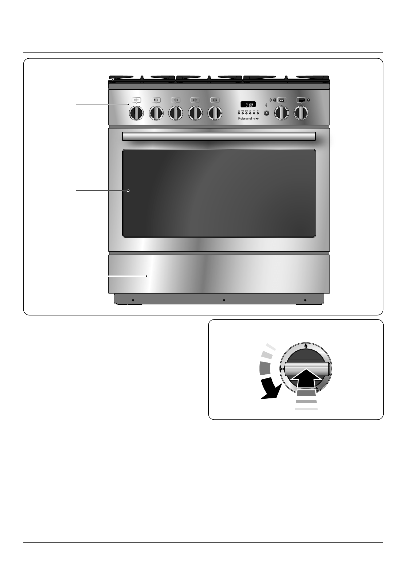
The dual fuel single cavity cooker (Fig. 2.1) has the following
features:
A. 5 hotplate burners including a wok burner
B. Control panel incorporating a timer
C. Multifunction oven
D. Storage drawer
Hotplate burners
The drawing by each of the control knobs indicates which
burner that knob controls.
Each burner has a special Flame Supervision Device (FSD) that
prevents the ow of gas if the ame goes out.
When a hotplate control knob is pressed in, sparks will be
made at every burner – this is normal. DO NOT attempt to
disassemble or clean around any burner while another burner
is on, otherwise an electric shock could result.
To light a burner, push in and turn the associated control
knob to the high position as indicated by the large ame
symbol (
), (Fig. 2.2).
The igniter should spark and light the gas. Keep holding the
knob pressed in to let the gas through to the burner for about
ten seconds.
ArtNo.273-0001 - 90 Pro+ FXP annotated
OFF
A
B
C
D
2. Overview
Fig. 2.1
Fig. 2.2
8
ArtNo.311-0005 Wok burner & pan support
ArtNo.311-0006 Correct wok sizes
ArtNo.311-0002 Pan with rim
If, when you let go of the control knob, the burner goes out,
then the FSD has not been bypassed. Turn the control knob
to the OFF position and wait for one minute before you try
again, this time making sure to hold in the control knob for
slightly longer.
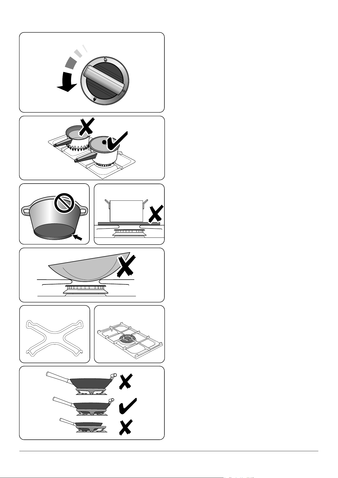
Adjust the ame height to suit by turning the knob counter-
clockwise (Fig. 2.3).
If a burner ame goes out, turn o the control knob and leave
it for one minute before relighting it.
Make sure that the ames are under the pans. For safety
reasons, adjust the ames so that they do not extend beyond
the edge of the cooking utensil. Using a lid will help the
contents boil more quickly (Fig. 2.4).
Large pans should be spaced well apart.
Pans and kettles with concave bases or down-turned base
rims should not be used (Fig. 2.5).
Simmering aids, such as asbestos or mesh mats, are
NOT recommended (Fig. 2.6). They will reduce burner
performance and could damage the pan supports.
You should also avoid using unstable and misshapen pans
that may tilt easily, and pans with a very small base diameter,
e.g. milk pans, single egg poachers (Fig. 2.7).
The minimum recommended pan diameter is 120 mm. The
maximum allowable pan base diameter is 260 mm. For a pan
diameter of 120 mm, or less, use the additional pan support
trivet supplied (Fig. 2.8).
DO NOT use cooking vessels on the hotplate that overlap the
edges.
Wok burner
The wok burner is designed to provide even heat over a large
area. It is ideal for large pans and stir-frying (Fig. 2.9).
For heating smaller pans, the aforementioned hotplate
burners may be more ecient.
You should wipe the enamel top surface of the cooker around
the hotplate burners as soon as possible after spills occur. Try
to wipe them o while the enamel is still warm.
NOTE: The use of aluminium pans may cause metallic
marking of the pan supports. This does not aect the
durability of the enamel and may be cleaned o with an
appropriate metal cleaner.
The wok cradle
The wok cradle is designed to t a 35 cm wok. If you use a
dierent wok, make sure that it ts the cradle. Woks vary
very widely in size and shape. It is important that the wok
sits down on the pan support – however, if it is too small, the
cradle will not support it properly (Fig. 2.10).
The cradle should be used on the wok burner only. When you
t the cradle, check that it is supported properly on a pan
support and the wok is sitting level in the cradle (Fig. 2.11).
The cradle will get very hot in use – allow plenty of time for it
to cool before you pick it up.
ArtNo.311-0001 Right pans gas
ArtNo.270-0003
Proplus control to low
ArtNo.311-0004 Tipping wok
Art No. 311-0003 Simmer aids
Fig. 2.3
Fig. 2.4
Fig. 2.5 Fig. 2.6
Fig. 2.7
Fig. 2.8 Fig. 2.9
Fig. 2.10
9
ArtNo.311-0007 Wok stand close-up
ArtNo.311-0044 - Positioning the griddle 09
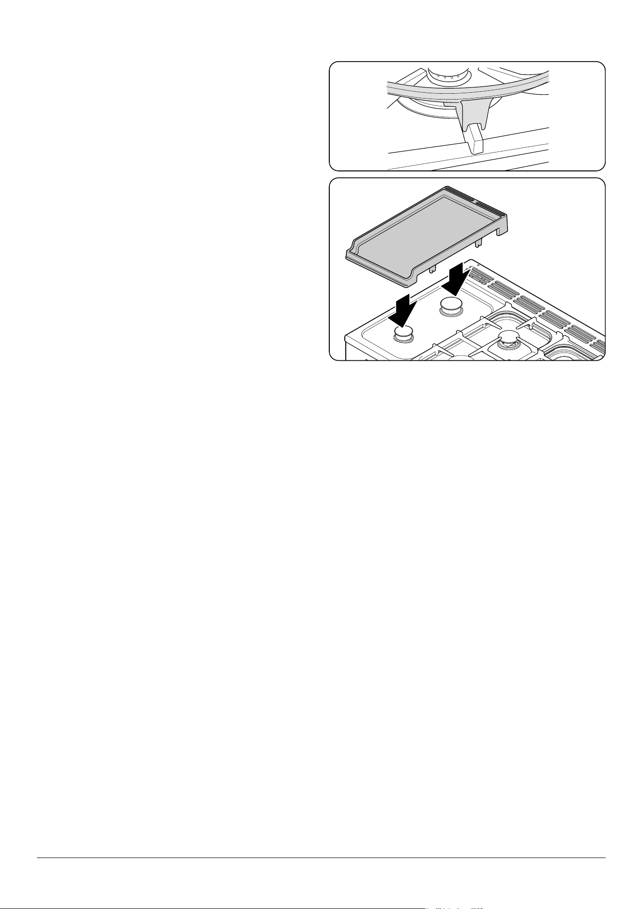
Griddle
The griddle ts the left-hand well, front to back (Fig. 2.12). It
is designed for cooking food on directly. DO NOT use pans
of any kind on it. The griddle surface is non-stick and metal
cooking utensils (e.g. spatulas) will damage the surface. Use
heat resistant plastic or wooden utensils.
n
DO NOT put it crossways – it will not t properly and
will be unstable.
n
DO NOT put it on any other burner – it is not
designed to t in any of the other cooker wells.
Remove the left-hand pan support. Position the griddle over
the well. Check that it is securely located.
The griddle can be lightly brushed with cooking oil before
use. Light the hotplate burners. Adjust the ame heights to
suit.
Preheat the griddle for a maximum of 5 minutes before
adding food. Leaving it longer may cause damage. Turn the
control knobs towards the low position, marked with the
small ame symbol, to reduce the burner ames.
Always leave space around the griddle for the gases to
escape.
After cooking, allow the griddle to cool before cleaning.
If the griddle is washed in a dishwasher then some
dishwasher residue may appear on the back. This is normal
and will not aect the performance of your griddle.
Fig. 2.11
Fig. 2.12
10
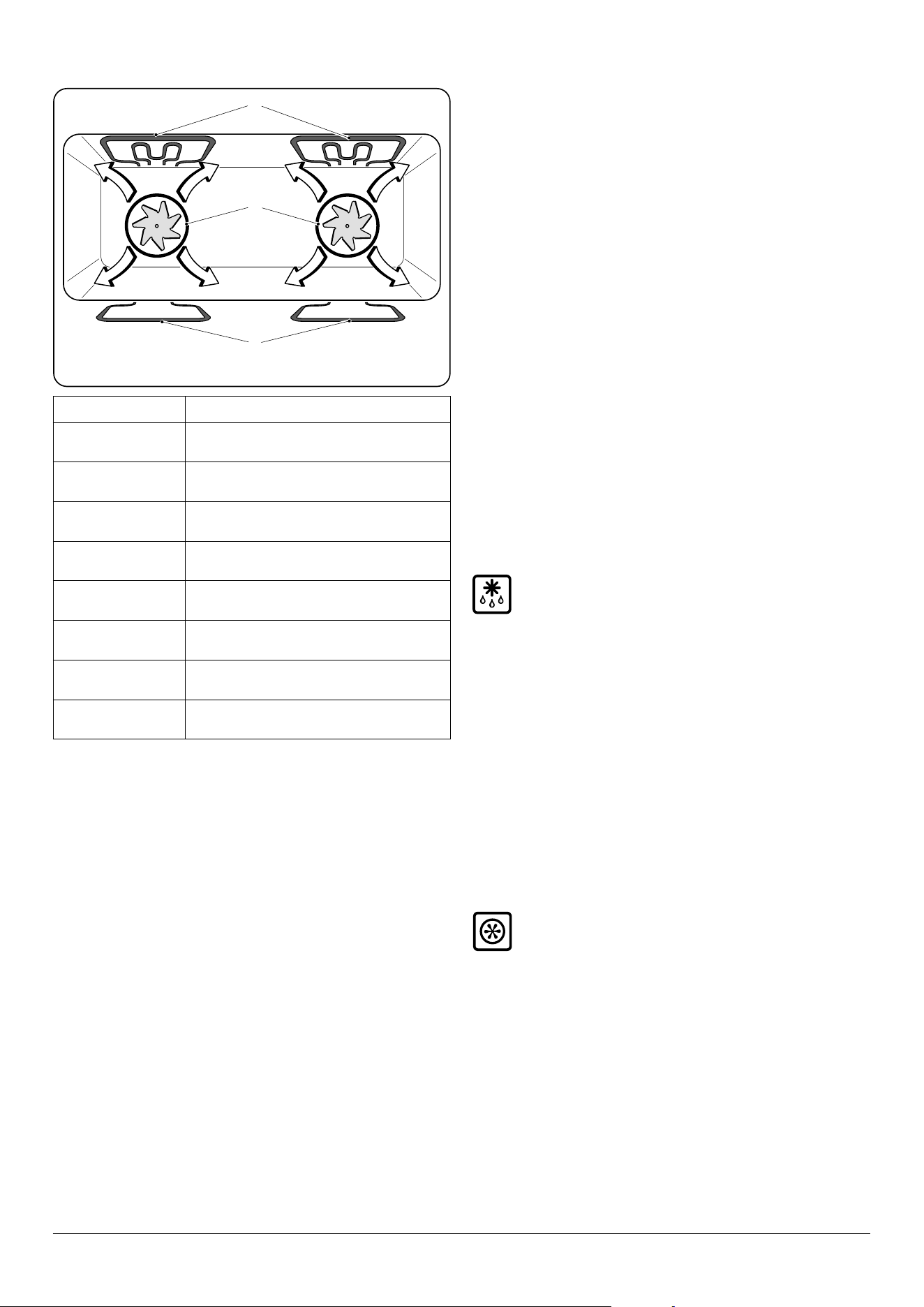
Multifunction oven
The oven is a multifunction oven (Fig. 2.13). In addition to
convection elements around the fans, it is tted with extra
heating elements, in the top of the oven and under the oven
base. Take care to avoid touching the top elements when
placing or removing items from the oven.
The multi-function oven has 3 main cooking functions: fan,
fan assisted and conventional cooking. These functions
should be used to complete most of your cooking.
The browning element and base heat can be used in the
latter part of the cooking process to ne tune the results to
your particular requirements.
Use fanned grilling for all your grilling needs and defrost to
safely thaw small items of frozen food.
Table 2.1 gives a summary of the multi-function modes. The
multi-function oven has many varied uses. We suggest you
keep a careful eye on your cooking until you are familiar with
each function. Remember, not all functions will be suitable
for all food types.
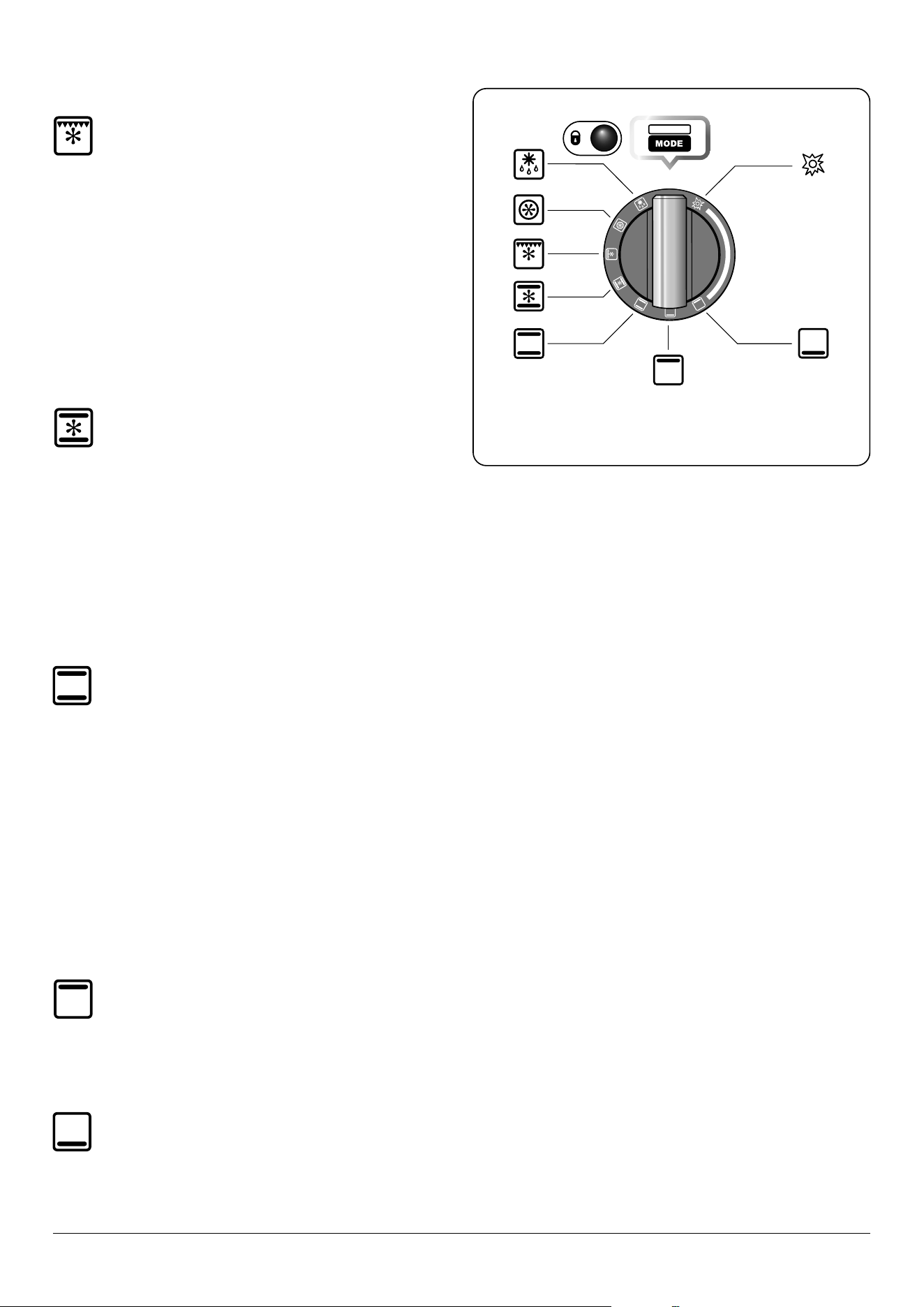
Multifunction oven modes (Fig. 2.14)
Defrost
This function operates the fan(s) to circulate cold air
only. Make sure the temperature control is at 0°C and
that no heat is applied. This enables small items such
as desserts, cream cakes and pieces of meat, sh and poultry
to be defrosted.
Defrosting in this way speeds up the process and protects
the food from contamination. Pieces of meat, sh and poultry
should be placed on a shelf, over a tray to catch any drips. Be
sure to wash the shelf and tray after defrosting.
Defrost with the oven door closed. Defrosting should not
be carried out in a warm oven. Large items, such as whole
chickens and meat roasts should not be defrosted in this way.
We recommend this be carried out in a refrigerator. Make sure
that dairy foods, meat and poultry are completely defrosted
before cooking.
Fan oven
This function operates the fans and the heating
element around them. An even heat is produced
throughout the oven, allowing you to cook large
amounts quickly.
Fan oven cooking is particularly suitable for multi-shelf
cooking and is a good ‘all-round’ function. It may be
necessary to reduce the temperature by approximately 10 °C
for recipes previously cooked in a conventional oven.
If you wish to preheat the oven, wait until the indicator light
has gone out before inserting the food.
ArtNo.326-0009 - Albertine SC - MF oven elements EU
C
A
B
A – Grill elements, B – Convection element, C – Base heat elements
Function Use
Defrost
To thaw small items in the oven without heat
Fan oven
A full cooking function, even heat throughout,
great for baking
Fanned grilling
Grilling meat and sh with the door closed
Fan assisted
A full cooking function good for roasting and
baking
Conventional
oven
A full cooking function for roasting and baking in
the lower half of the oven
Browning
element
To brown and crisp cheese topped dishes
Base heat
To crisp up the bases of quiche, pizza or pastry
Self-Cleaning
To burn any cooking residue to ash
Table 2.1
Fig. 2.13
11
Fanned grilling
This function operates the fan while the top element
is on. It produces a more even, less erce heat than a
conventional grill. For best results place the food to
be grilled on the pan provided. Thick pieces of meat or sh
are ideal for cooking in this way, as the circulated air reduces
the erceness of the heat from the grill. The oven door should
be kept closed while cooking is in progress, so saving energy.
You will also nd that the food needs to be watched and
turned less than for normal grilling. Preheat this function
before cooking.
NOTE: When grilling full width, to allow sucient access
for tending foods we recommend placing the grill pan tray
support on the second from top level.
Fan assisted oven
This function operates the fans, circulating air heated
by the elements at the top and the base of the oven.
The combination of fan and conventional cooking
(Top and Base Heat) makes this function ideal for cooking
large items that need thorough cooking, such as a large meat
roast. It is also possible to bake on two shelves at one time,
although they will need to be changed over during the
cooking time, as the heat at the top of the oven is greater
than at the base, when using this function.
This is a fast intensive form of cooking; keep an eye on the
food cooking until you are familiar with this function.
Conventional oven (Top and Base Heat)
This function combines the heat from the top and
base elements. It is particularly suitable for roasting
and baking pastry, cakes and biscuits.
Food cooked on the top shelf will brown and crisp faster than
on the lower shelf, because the heat is greater at the top of
the oven than at the base, as in ‘Fan Assisted Oven’ function.
Similar items being cooked will need to be swapped around
for even cooking. This means that foods requiring dierent
temperatures can be cooked together, using the cooler zone
in the lower half of the oven and hotter area to the top.
The exposed top element may cook some foods too quickly,
so we recommend that the food be positioned in the lower
half of the oven to cook. The oven temperature may also need
to be lowered.
Browning element
This function uses the element in the top of the oven
only. It is a useful function for the browning or
nishing of pasta dishes, vegetables in sauce and
lasagne, the item to be browned being already hot before
switching to the top element.
Base heat
This function uses the base element only. It will crisp
up your pizza or quiche base or nish o cooking the
base of a pastry case on a lower shelf. It is also a
gentle heat, good for slow cooking of casseroles in the
middle of the oven or for plate warming.
ArtNo.272-0006
Prof+ pyro - MF oven annotated
OFF
C
B
A
F
E
H
D
G
A – Defrost, B – Fan oven, C – Fanned grilling, D – Fan assisted oven, E –
Conventional oven, F – Browning element, G – Base heat,
H – Self cleaning
Fig. 2.14
12
ArtNo.062-0005 - Removing the divider (wrong)
ArtNo.062-0004 - Removing the divider (right)
ArtNo.270-0030
Pro+ FXP oven
set to conventional
OFF
ArtNo.270-0028
Proplus MF temp control
indicator light
140
100
180
220
0
The Browning and Base Heat functions are useful additions
to your oven, giving you exibility to nish o items to
perfection. With use, you will soon realize how these
functions can combine to extend your cooking skills.
Self-cleaning
The oven has a self-cleaning function. The oven will
run at a high temperature cycle to burn any cooking
residue to ash that is easily cleaned away with a
damp cloth. For safety, the oven will lock during the
cleaning cycle.
See the ‘Cleaning’ section for further details on the self-
cleaning operation.
Energy saving panel
The oven has a divider feature (Fig. 2.15). With this in place
only one half of the oven is heated and only the right-hand
side elements are used. This saves energy and is ideal for
cooking most foods. When using the divider, condensation
may appear in the left-hand oven – this is normal.
For very large loads, or large dishes for special occasions then
the divider can be removed. This brings into use the elements
on the left-hand side as well as those on the right when a
function is selected.
All oven functions are available in full and divided forms and
shelves are provided for use in both forms.
n
WARNING: Take great care when removing the
divider not to scratch the inner glass door surface.
Scratches in the glass can cause stress and may
cause the door to fail.
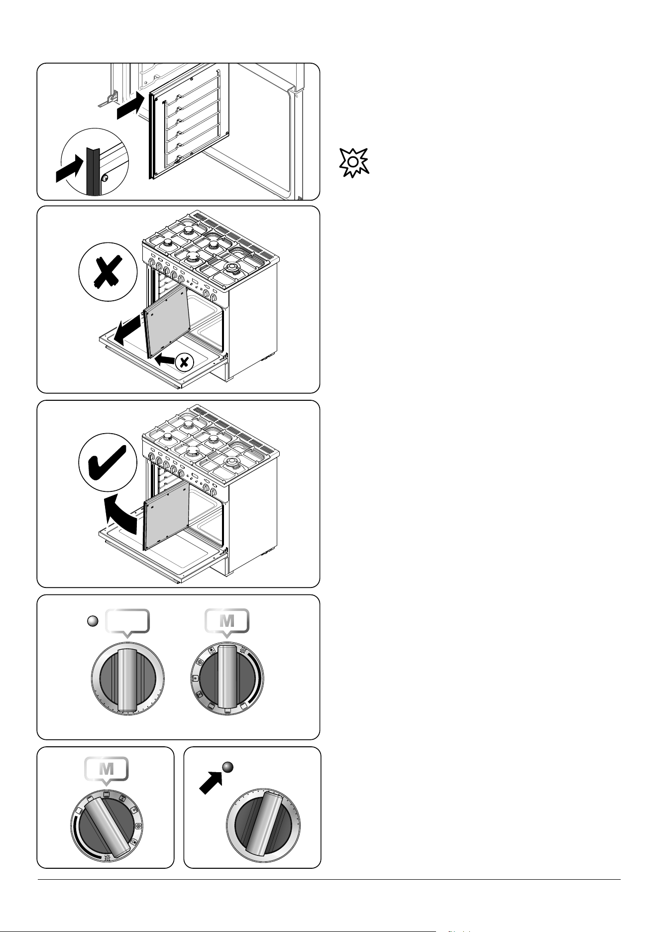
Removing the divider
n
Make sure the cooker is cool before attempting to
remove the divider.
Fully open the door and remove the oven shelves. When
removing the divider, tilt it slightly upwards and grip the
underside to prevent the metal base making contact with the
door glass (Fig. 2.16 and Fig. 2.17).
We recommend that you place a tea towel or similar on the
door glass before removing the divider. This should prevent
the door inner from scratching.
DO NOT place or slide metallic objects on the door glass as
this may cause scratching and subsequent failure to occur.
Operating the oven
The multi-function oven has two controls: a function selector
and a temperature setting knob (Fig. 2.18).
Turn the function selector control to a cooking function.
Fig. 2.19 shows the control set for convectional oven cooking.
Turn the oven temperature knob to the temperature you
need. The oven heating light will glow until the oven has
reached the temperature you selected. It will then cycle on
and o during cooking as the oven maintains the selected
temperature (Fig. 2.20).
ArtNo.281-0150 - Oven Divider
ArtNo.270-0029
Pro+ FXP MF oven controls
OFF
140
100
180
220
0
Temperature selector Function selector
Fig. 2.15
Fig. 2.16
Fig. 2.17
Fig. 2.18
Fig. 2.19
Fig. 2.20
13
ArtNo.326-0015 - Energy saving shelf (Falcon)
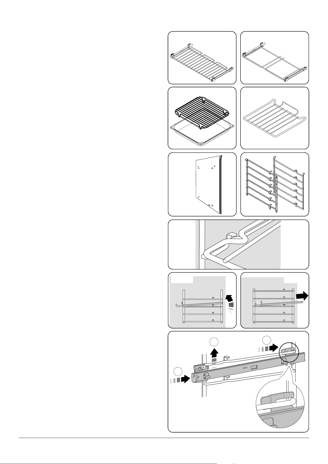
Accessories
The oven is supplied with:
• 2 x full capacity shelves with telescopic runners
(Fig. 2.21)
• 1 x full capacity grill pan shelf with telescopic runners
(Fig. 2.22)
• 2 x grill pan and trivet (Fig. 2.23)
• 3 x energy saving shelves (Fig. 2.24)
• 1 x divider (Fig. 2.25)
• 2 left hand and 2 right hand ladder side supports
(Fig. 2.26)
Any shelf can be tted in any of the positions. The oven
shelves are retained when pulled forward but can be easily
removed and retted.
To Remove and Ret a Shelf to the Side Supports
The shelf has a small kink on either side. To remove the shelf,
line these up with the stops in the shelf support (Fig. 2.27).
Lift the rear of the shelf upward so that it will pass over the
shelf stop and then pull it forward (Fig. 2.28 and Fig. 2.29).
Ret in the reverse order, making sure to push it fully back.
To Fit the Telescopic Shelf Runners
With the runner arm in the closed position locate the opening
of the upper rear slot onto the side support (Fig. 2.30). DO
NOT locate any further than the opening at this point.
Lift the front of the runner arm to locate the front slot against
the side support (Fig. 2.30).
Push the runner arm towards the rear of the oven. The catch
at the front will lift and drop to secure the runner arm in place
(Fig. 2.30).
Fig. 2.21 Fig. 2.22
Fig. 2.23 Fig. 2.24
Fig. 2.25 Fig. 2.26
Fig. 2.27
Fig. 2.28 Fig. 2.29
ArtNo.281-0028 - Albertine divider
1
2
3
Fig. 2.30
14
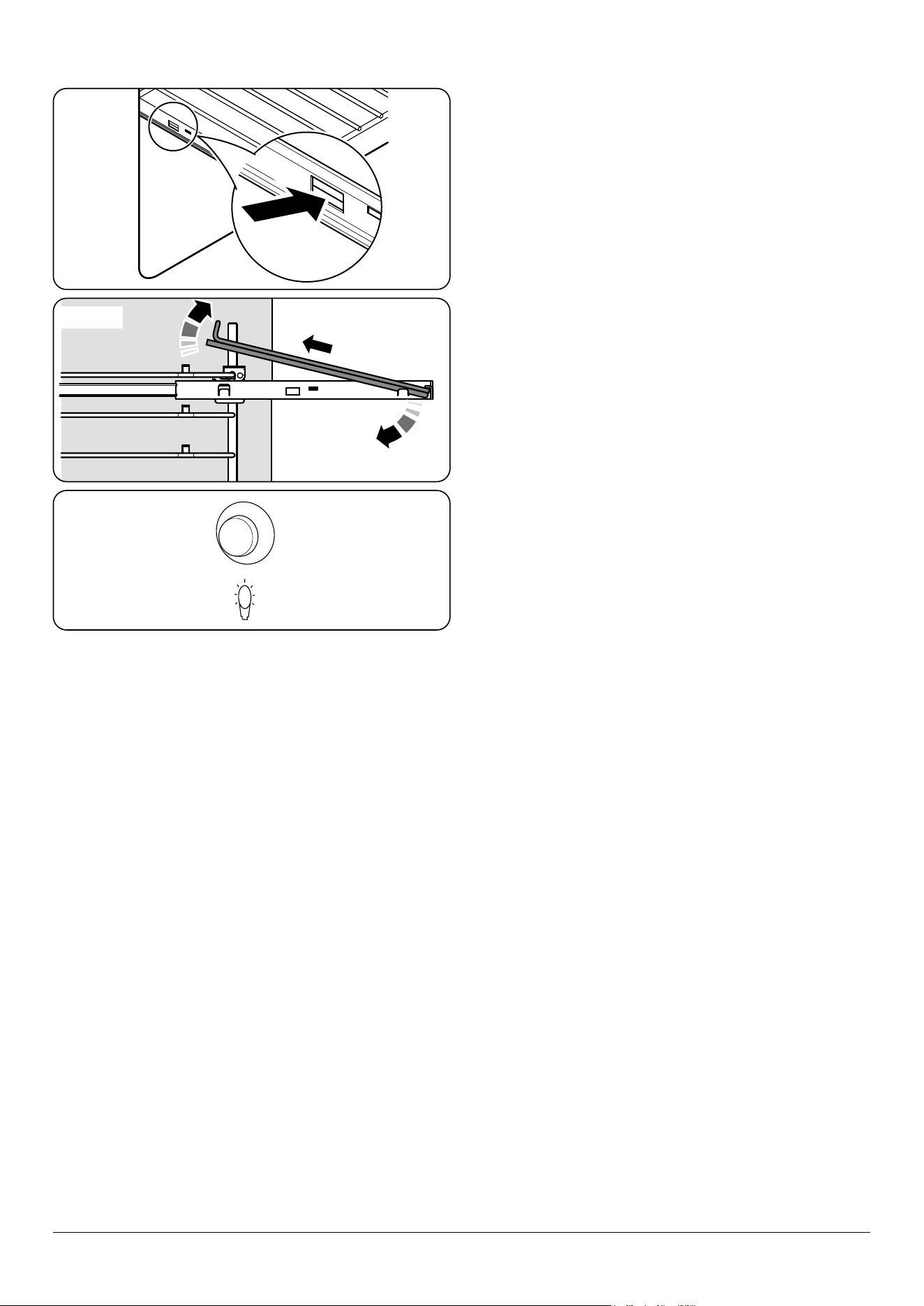
To Fit a Shelf to the Telescopic Shelf Runners
Slide the telescopic runners forward until they stop. Holding
the shelf above the runners, tilt the front downward and
locate into the front of the runners. Lay the shelf at. Press on
the rear of the shelf to secure in place.
To Remove a Shelf from the Telescopic Shelf Runners
Slide the shelf out on the runners. While holding one of the
runners securely, carefully lift the rear of the shelf upwards:
the shelf will spring clear of the central restraining tab. Repeat
for the opposite side of the shelf.
NOTE: To aid the removal of the shelf you can insert a suitable
at tool through the opening in the side of the runners and
lever the shelf clear (Fig. 2.31).
Tilt the front of the shelf downwards and then lift clear of the
runners (Fig. 2.32).
To Remove the Telescopic Shelf Runners
Firstly, remove the shelf as in the ‘To Remove a Shelf from the
Telescopic Shelf Runners’ section.
Place a nger on the underside of the telescopic runner and
lift.
Open the catch on top of the runner and pull the runner
forward and down to remove.
Oven Light
Press the appropriate button to turn on the oven lights
(Fig. 2.33).
If one of the oven lights fail, turn o the cooker circuit breaker
before you change the bulb. See the ‘Troubleshooting’ section
for details on how to change an oven light bulb.
Storage
The bottom drawer is for storing oven trays and other
cooking utensils. The drawer can be removed completely for
cleaning, etc.
n
It can get very warm, so do not store anything in it,
which may melt or catch re.
n
Never store ammable materials in the drawer.
This includes paper, plastic and cloth items, such
as cookbooks, plastic ware and towels, as well as
ammable liquids.
n
Do not store explosives, such as aerosol cans, on or
near the appliance.
n
Flammable materials may explode and result in re
or property damage.
ArtNo.320-0023
Oven light USA
Fig. 2.31
Fig. 2.32
Fig. 2.33
ArtNo.302-0002 - 6BC annotated
15
3. 6 Button clock
ArtNo.302-0002 - 6BC annotated
ArtNo.302-0002 - 6BC annotated
ArtNo.302-0002 - 6BC annotated
ArtNo.302-0002 - 6BC annotated
ArtNo.302-0002 - 6BC annotated
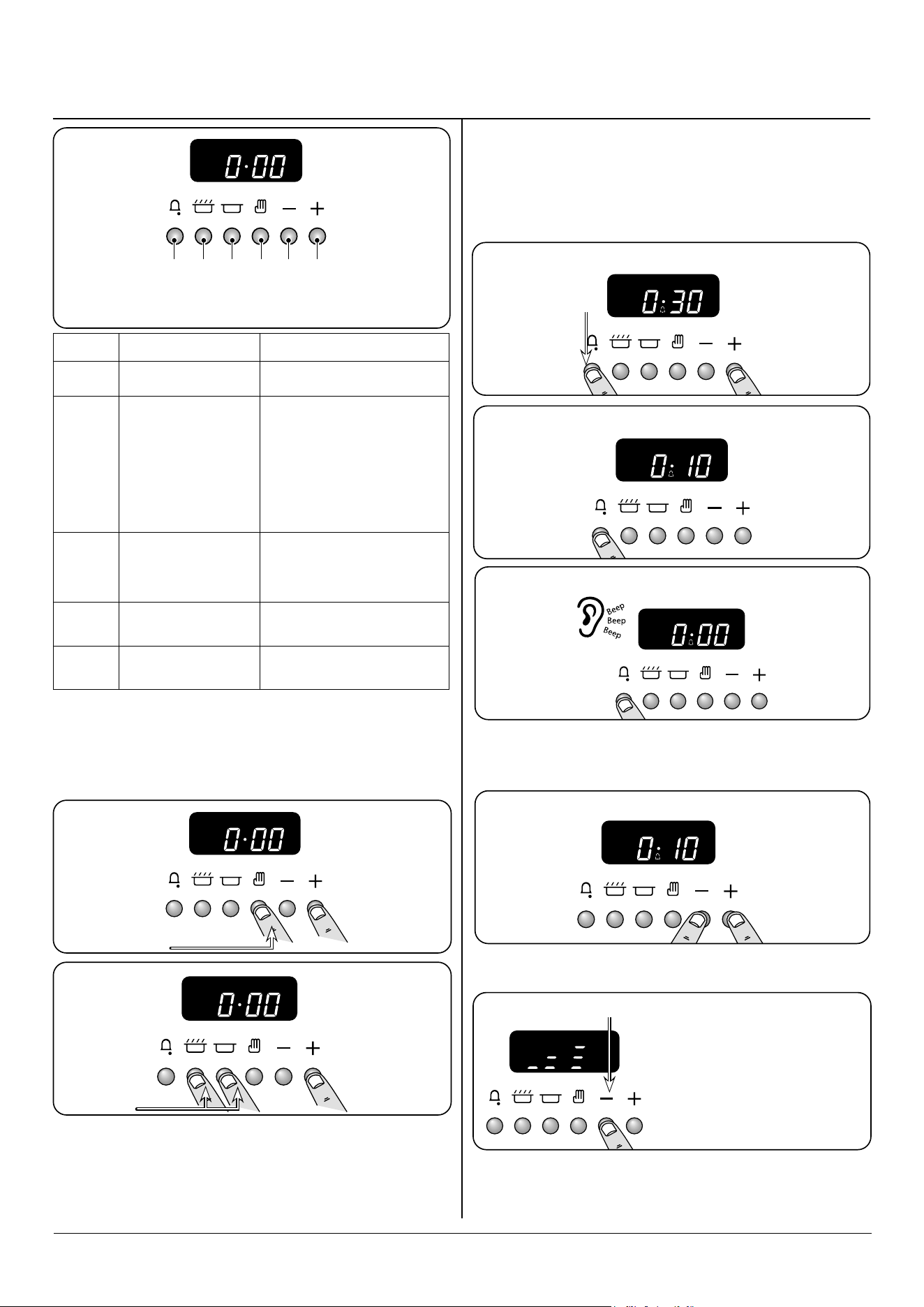
A B C D E F
A – Minute minder, B – ‘Cook’ time, C – ‘Stop’ time, D – Manual,
E & F – Time setting buttons
Symbol Function Notes
[
]
Minute Minder is active
[
]
Oven(s) can be operated
If the ‘cook’ [
] symbol is not
displayed the program has either:
ended and the oven(s) are non-
operational
the oven(s) are being controlled
by an automatic program that has
not started
[AUTO]
Oven(s) are being
controlled in semi-
automatic or automatic
mode
[P]
Self clean (pyrolytic)
mode has been enabled
Your cooker may not have this
pyrolytic function
[dot]
Flashes during setting
the time of day
Table 3.1 overview of the functions
ArtNo.302-0002 - 6BC annotated
ArtNo.302-0002 - 6BC annotated
1.
2.
Press either
[+] or [-]
buttons
Press either
[+] or [-]
buttons
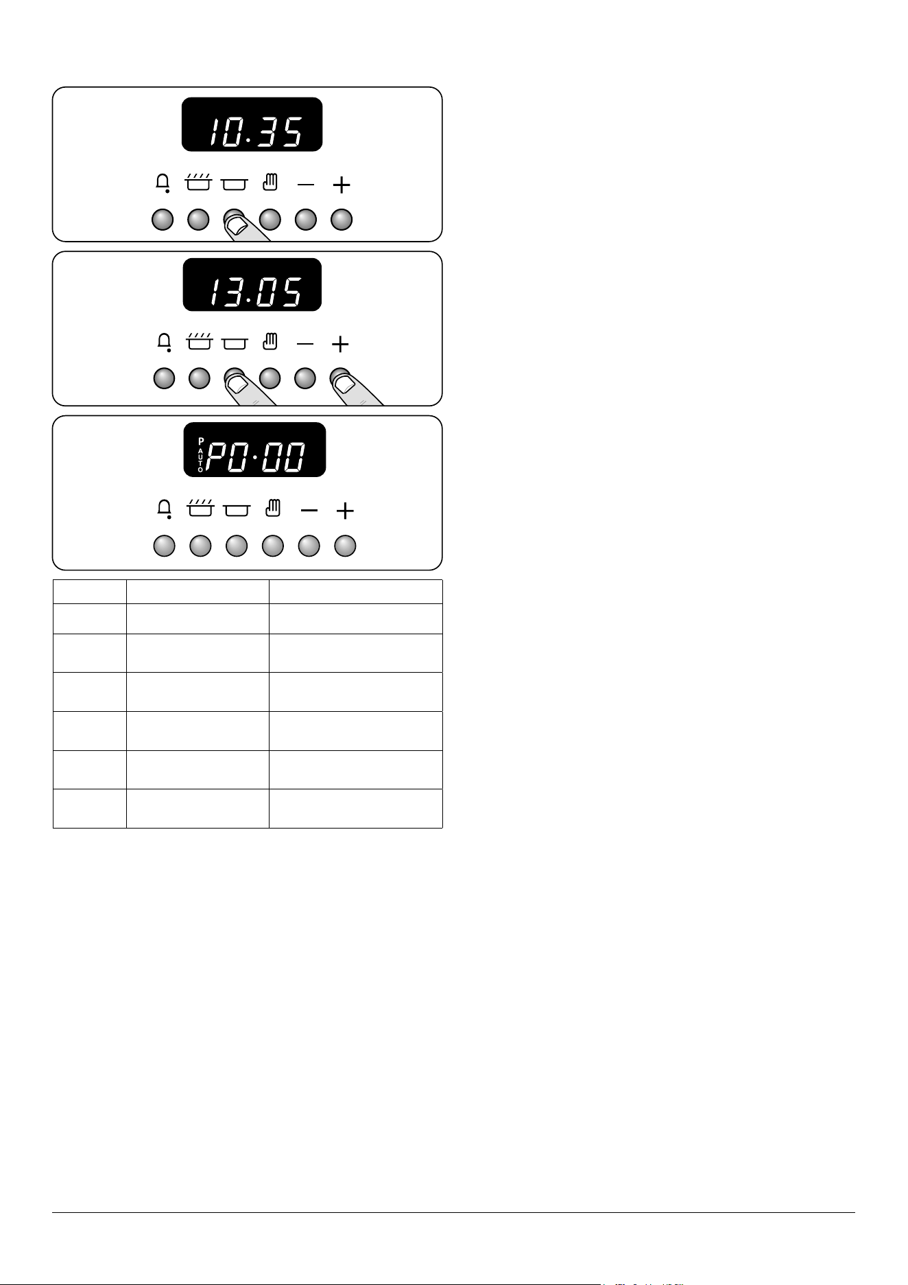
Setting the time
The clock must be set to the time of day before the oven will
work. The time of day can be set in two ways:
Press either
[+] or [-]
buttons.
DO NOT forget that it is a 24-hour clock.
If you need to reset the clock/cooker, turn o the power and
wait several minutes, then start again.
Automatic dimming
Providing there are no automatic programs set, and the
minute minder is not active, your clock will automatically dim
during the hours between 22:00 and 06:00.
Step. 1
Minute Minder
Reset minute minder and
automatic programs
Press and hold the [
] button
Step. 2
hold
Press [
] button to check how long left
To stop the alarm press any button.
Step. 3
hold
hold
Beeper tone adjustment.
hold
Release the [-] button and
immediately press again,
this will adjust the tone
down by a bar.
16
ArtNo.302-0002 - 6BC annotated
ArtNo.302-0002 - 6BC annotated
ArtNo.302-0002 - 6BC annotated
ArtNo.302-0002 - 6BC annotated
ArtNo.302-0002 - 6BC annotated
Step. 1 Step. 2
ArtNo.302-0002 - 6BC annotated
ArtNo.302-0002 - 6BC annotated
Step. 1
Step. 1
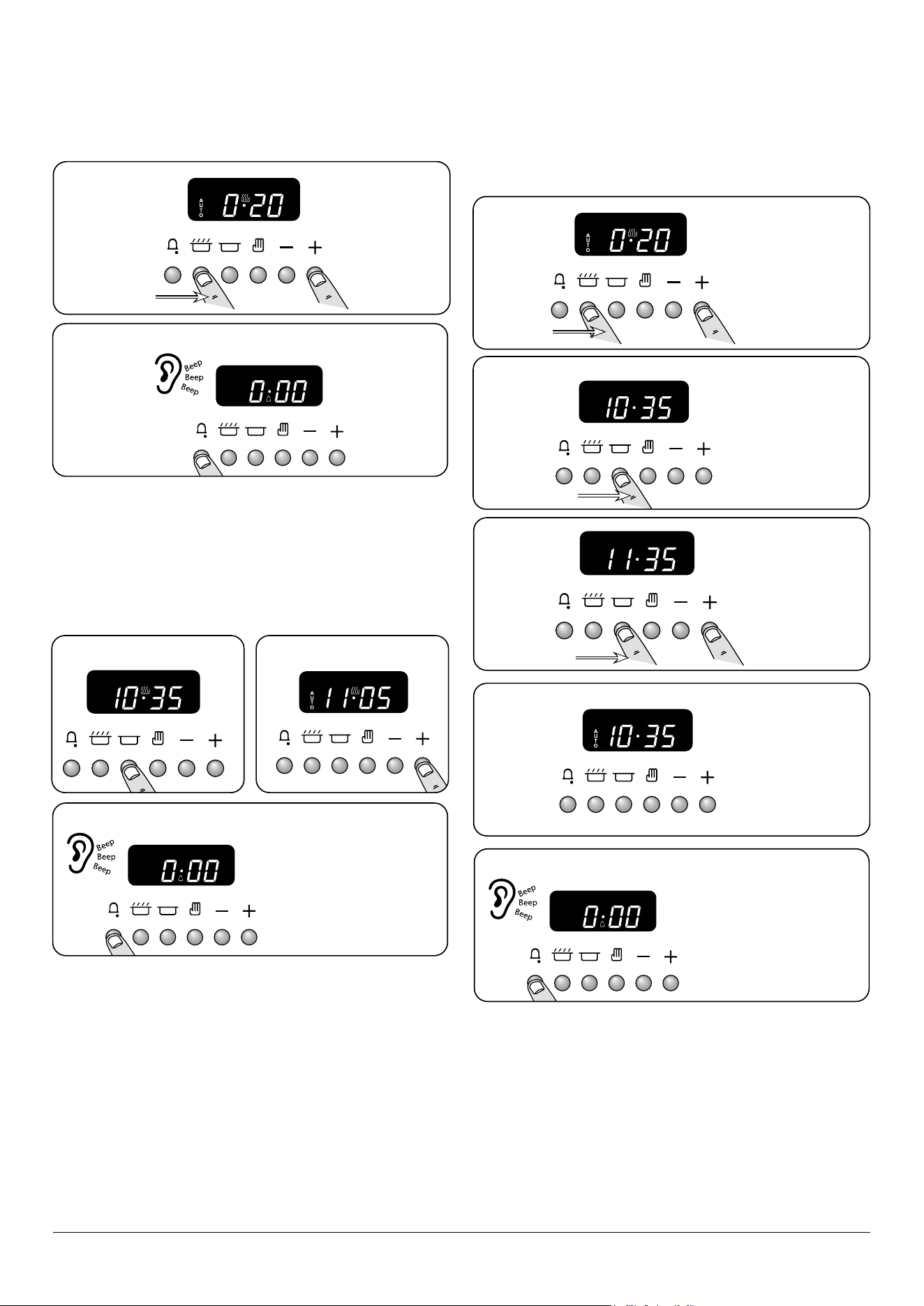
Setting a cook duration (main oven only)
You have set the required temperature and function mode
and you would like the oven to automatically stop.
Setting a cook end time (main oven only)
You have set the required temperature and function mode
and you would like the oven to automatically stop.
To start and stop the ovens
automatically (main oven only)
You have set the required temperature and function mode
and you would like the oven to automatically stop.
ArtNo.302-0002 - 6BC annotated
ArtNo.302-0002 - 6BC annotated
ArtNo.302-0002 - 6BC annotated
To stop the alarm press any button.
To stop the alarm press any button.
To stop the alarm press any button.
Step. 2
Step. 3
hold
hold
hold
hold
Press either
[+] or [-]
buttons.
Press either [+]
or [-] buttons
to set cooking
duration.
Press either [+]
or [-] buttons to
set stop time.
Release buttons.
The current time
and the AUTO
symbol will show
on the display.
Display will
show the
current time.
n
REMEMBER Turn the oven control knob to 0.
n
REMEMBER
Turn the oven
control knob(s) to 0.
n
REMEMBER
Turn the oven
control knob(s) to 0.
Step. 2
Step. 3
Step. 4
Step. 5

17
Cooking with a multi-function oven
Remember: Not all modes are suitable for all food types. The
oven cooking times given are intended for a guide only.
Tips on cooking with the timer
If you want to cook more than one dish, choose dishes that
require approximately the same cooking time. However,
dishes can be ‘slowed down’ slightly by using small containers
and covering them with aluminium foil, or ‘speeded up’
slightly by cooking smaller quantities or placing them in
larger containers.
Very perishable foods such as pork or sh should be avoided
if a long delay period is planned, especially in hot weather.
n
DO NOT place warm food in the oven to be timed.
n
DO NOT use a timed oven that is already warm.
Whole poultry must be thoroughly defrosted before being
placed in the oven. Check that meat and poultry are fully
cooked before serving.
4. Cooking tips
General oven tips
The wire shelves should always be pushed rmly to the back
of the oven.
Baking trays with food cooking on them should be placed
level with the front edge of the oven’s wire shelves. Other
containers should be placed centrally. Keep all trays and
containers away from the back of the oven, as overbrowning
of the food may occur.
When the oven is on, do not leave the door open for
longer than necessary, otherwise the knobs may get very
hot.
• Always leave a ‘‘finger’s width’’ between dishes on
the same shelf. This allows the heat to circulate freely
around them.
• To reduce fat splashing when you add vegetables to hot
fat around a roast, dry them thoroughly or brush lightly
with cooking oil.
• Where dishes may boil and spill over during cooking,
place them on a baking tray.
• Sufficient heat rises out of the oven while cooking to
warm plates in the grill compartment.
• If you want to brown the base of a pastry dish, preheat
the baking tray for 15 minutes before placing the dish in
the centre of the tray.
18
6. Cooking Table
Oven Shelf Positions
Top (T)
Centre (C)
Base (B)
ArtNo.050-0007
Oven shelf positions
The oven control settings and cooking times given in the table below are intended to be used as a
guide only. Individual tastes may require the temperature to be altered to provide a preferred result.
Food is cooked at lower temperature in a fan oven than in a conventional oven. When using recipes,
reduce the fan oven temperature by 10 °C and the cooking time by 5-10 minutes. The temperature in
the fan oven does not vary with height in the oven so you can use any shelf.
Food
Conventional Oven
°C (Shelf Position)
Fan Oven
Temperature
Approximate Cooking Time
Meat
Beef (no bone)
Lamb
Pork
160 (C)
200 (C)
160 (C)
200 (C)
160 (C)
200 (C)
150 °C
190 °C
150 °C
190 °C
150 °C
190 °C
30-35 minutes per 500g +30-35 minutes.
20-25 minutes per 500g +20-25 minutes.
30-35 minutes per 500g +30-35 minutes.
25-30 minutes per 500g +25-30 minutes.
35-40 minutes per 500g +35-40 minutes.
25-30 minutes per 500g +25-30 minutes.
Thoroughly thaw frozen joints
before cooking. Meat may be
roasted at 220°C (210°C for
fan oven) and the cooking
time adjusted accordingly. For
stued and rolled meats, add
approximately 10 minutes per
500g, or cook at 200°C (190°C)
for 20 minutes then 160°C
(150°C) for the remainder.
Poultry
Chicken
Turkey
Duck
160 (C)
200 (C)
160 (C)
200 (C)
160 (C)
200 (C)
150 °C
190 °C
150 °C
190 °C
150 °C
190 °C
20-25 minutes per 500g +20-25 minutes.
15-20 minutes per 500g +15-20 minutes.
20 minutes per 500g +20 minutes.
15 minutes per 500g +15 minutes.
25-30 minutes per 500g.
20 minutes per 500g.
For stued poultry, you could
cook at 200°C (190°C) for 20
minutes then 160°C (150°C)
for remainder. Do not forget
to include the weight of the
stung. For fresh or frozen
pre-packed poultry, follow
instructions on the pack.
Thoroughly thaw frozen
poultry before cooking.
Casserole 140-150 (C) 130 °C-140 °C 2-4 hours according to recipe.
Yorkshire Pudding 220 (C) 210 °C Large tins 30-35 minutes; individual 10-20 minutes.
Cake
Very rich fruit - Christmas, wedding, etc.
Fruit 180 mm tin
Fruit 230 mm tin
Madeira 180 mm
Queen cakes
Scones
Victoria sandwich
180 mm tin
210 mm tin
140 (C/B)
150 (C/B)
150 (C/B)
160 (C/B)
190 (C/B)
220 (C/B)
180 (C/B)
180 (C/B)
130 °C
140 °C
140 °C
150 °C
180 °C
210 °C
170 °C
170 °C
45-50 minutes per 500g of mixture.
2-2½ hours.
Up to 3½ hours.
80-90 minutes.
15-25 minutes.
10-15 minutes.
20-30 minutes.
30-40 minutes.
Using the conventional oven:
When two tier cooking leave
at least one runner space
between shelves. Position
the baking tray with the front
edge along the front of the
oven shelf.
Up to three tiers can be
cooked on, in a fan oven, at
the same time. But make sure
to leave at least one runner
space between each shelf
being cooked on.
Desserts
Shortcrust tarts
Fruit pies
Tartlets
Pu pastry
Meringues
Baked egg custard
Baked sponge pudding
Milk pudding
200 (C/B)
200 (C/B)
200 (C/B)
210 (C/B)
100 (C/B)
160 (C/B)
180 (C/B)
140-150 (C/B)
190 °C
190 °C
190 °C
200 °C
90 °C
150 °C
170 °C
130 °C-140 °C
20-30 minutes on a preheated tray.
35-45 minutes.
10-20 minutes according to size.
20-40 minutes according to size.
2-3 hours.
45-60 minutes.
40-45 minutes.
2 to 3 hours.
Up to three tiers can be
cooked on, in a fan oven, at
the same time. But make sure
to leave at least one runner
space between each shelf
being cooked on.
Bread 210 (C) 200 °C 20-30 minutes.
Fish Fanned Grilling
Fillet
Whole
Steak
190 (C/B)
190 (C/B)
190 (C/B)
190 °C (C/B)
190 °C (C/B)
190 °C (C/B)
15-20 minutes
15-20 minutes per 500g.
Steaks according to thickness.
19
ArtNo.311-0032 Burner layout FSD
A
B
C
D
E
Isolate the electricity supply before carrying out any major
cleaning. Allow the cooker to cool.
n
NEVER use paint solvents, washing soda, caustic
cleaners, biological powders, bleach, chlorine based
bleach cleaners, coarse abrasives or salt.
n
DO NOT mix dierent cleaning products – they may
react together with hazardous results.
All parts of the cooker can be cleaned with hot soapy water
– but take care that no surplus water seeps into the
appliance.
Remember to switch the electricity supply back on and reset
the clock before reusing the cooker.
Daily care
Cleaning the cooker is not a welcomed chore, but it has to be
done to maintain eciency and appearance. Remember it
is better to wipe up any spills as they occur, this will prevent
them burning on and becoming more dicult to remove
later.
n
Make sure the ow of combustion and ventilation
air to the cooker is unobstructed – for example by
build-up of fats or grease.
On Natural gas the hotplate burner ames should be a bluish
colour with, at most, a slight yellowish fringe.
On LP gas the ames may be “softer”. The hotplate burner
ames may have a slight yellowish tip.
If the ame burns with a long white tip you should call for
service.
Cleaning for spills
For spills and boil-overs that occur while cooking, turn o the
burner as soon as possible and allow it to cool. Do not clean
until the area is completely cooled down. Wipe up spills as
soon as possible.
DO NOT allow surplus water to seep into the cooker.
Hotplate burners
The burner heads and caps can be removed for cleaning.
n
DO NOT put the burner heads in a dishwasher.
Make sure they are absolutely dry before replacing.
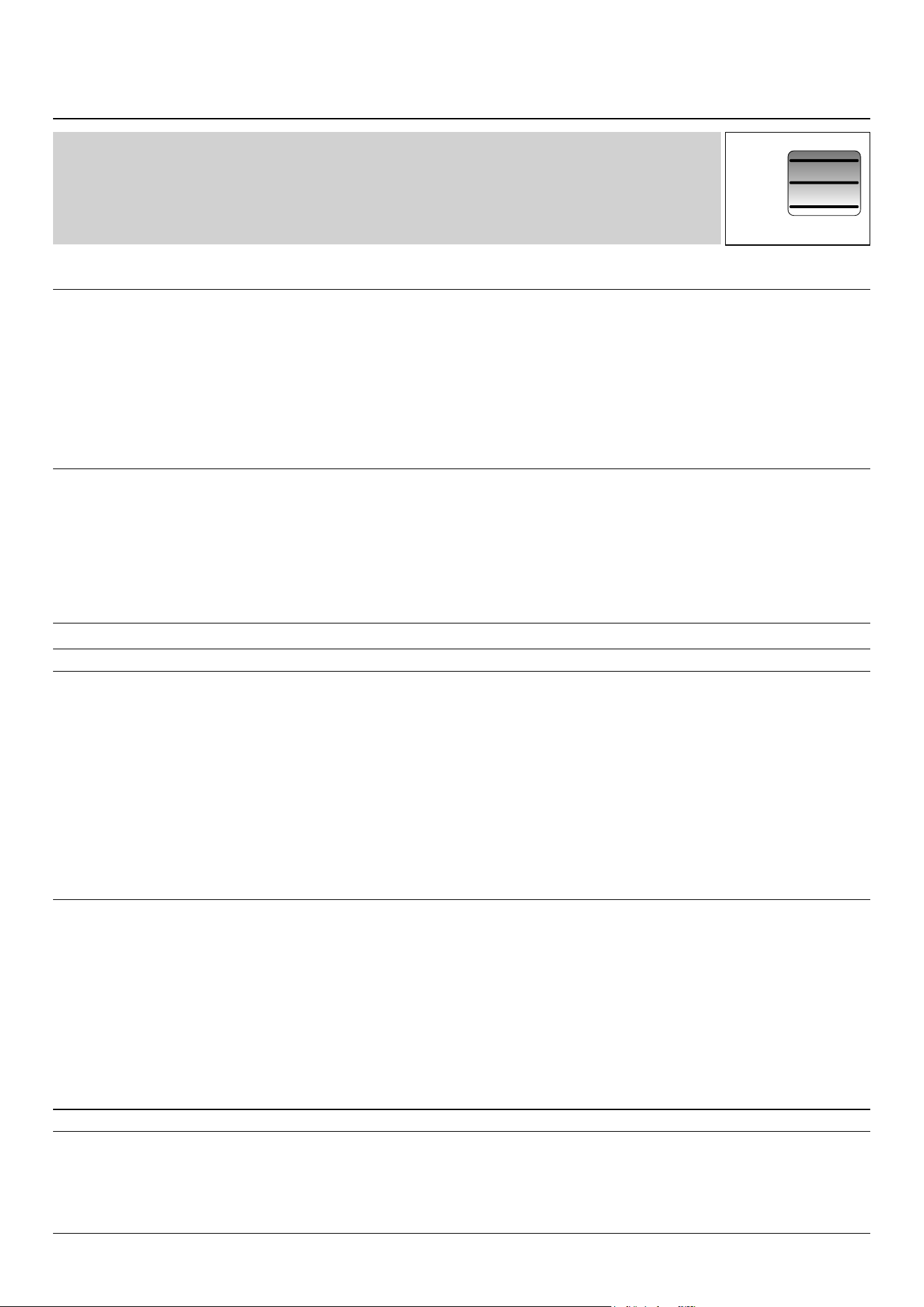
Single ring burners
When retting the burner head, make sure that the notch
lines up with the electrode or hole in the base. Check that the
burner head is level and that the cap is tted centrally on the
burner head (Fig. 7.1).
7. Cleaning your cooker
A – Cap, B – Head, C – Notch, D – Base, E – Electrode
Fig. 7.1
20
A
B
C
D
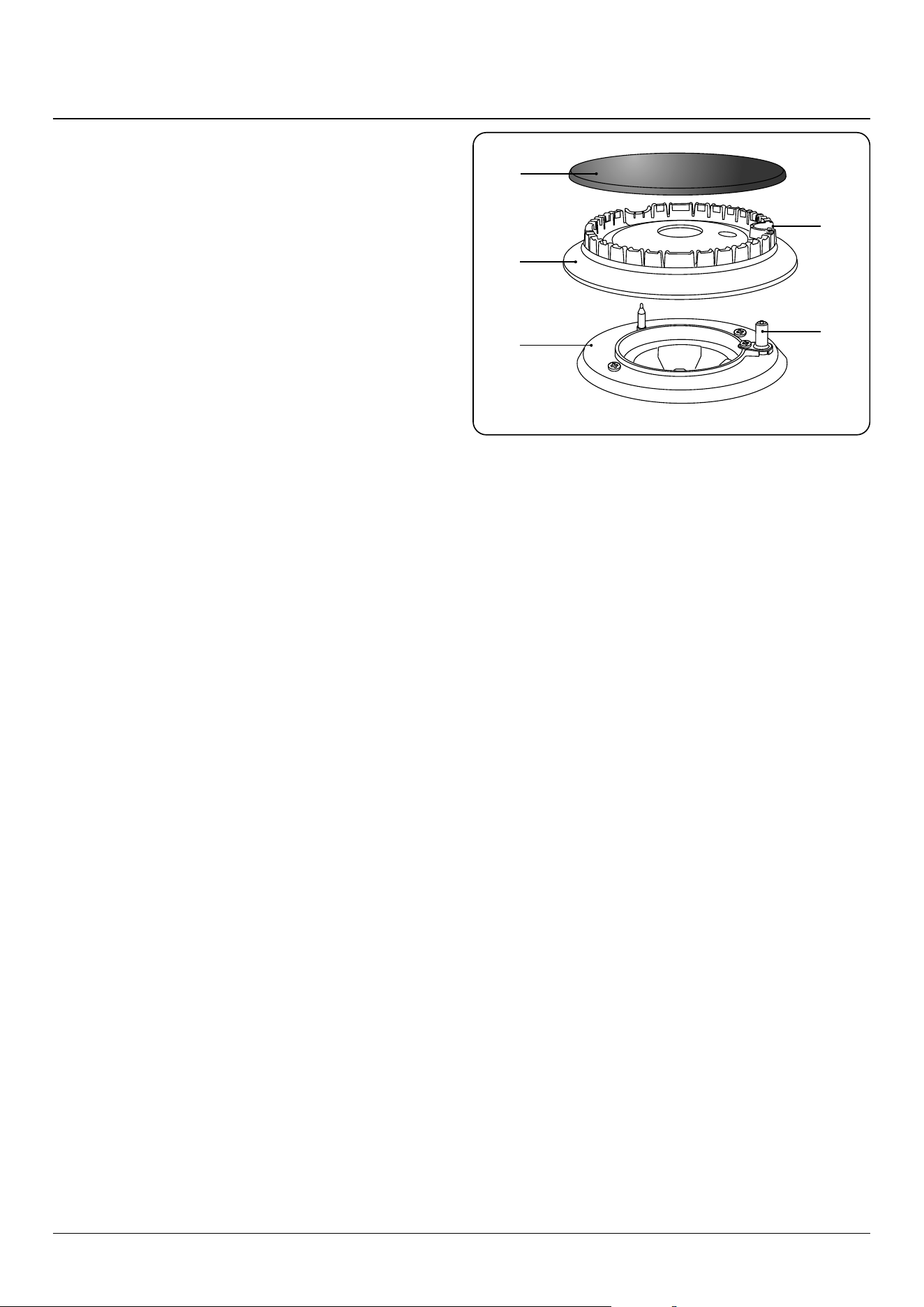
A – inner burner cap, B – outer burner cap,
C – burner head, D – wok burner base
Wok Burner
When reassembling the wok burner (Fig. 7.2) turn over the
large base ring and nd the ‘D’ shaped area (Fig. 7.3). Turn
the head until the ‘D’ matches the one on the burner base.
Flip the burner over once again and place it on the burner
base.
Check the burner slots are not blocked. If a blockage occurs,
remove stubborn particles using a toothbrush (Fig. 7.4).
Now t the two burner caps, making sure that they are seated
properly.
Check the burner ports are not blocked. If a blockage occurs,
remove stubborn particles using a piece of fuse wire.
Griddle
Always clean the griddle after use. Allow it to cool completely
before removing. Immerse the griddle plate in hot soapy
water. Use a soft cloth or, for stubborn stains, a nylon washing
up brush.
Wok Cradle
Recommended cleaning materials are hot soapy water, a
moistened soap pad, cream cleaner or nylon scourer.
Control panel and oven doors
The control panel and control knobs should only be cleaned
with a soft cloth wrung out in clean hot soapy water – but
take care that no surplus water seeps into the appliance. Wipe
with a clean dampened cloth then polish with a dry cloth. The
oven doors should only be cleaned with a soft cloth wrung
out in clean hot soapy water.
Removing the oven door outer panel
The outer door panel can be removed so that the inside of
the glass can be cleaned. Undo the 4 screws (2 each side) in
the door (Fig. 7.5).
Open the door slightly and, using the handle, carefully lift the
door outer upwards.
Ret in reverse.
ArtNo.272-0015 - 90DF - Pro+ - Removing the outer door panel
Fig. 7.2
Fig. 7.3
Fig. 7.4
Fig. 7.5
21
Self-clean oven
n
WARNING: Remove all cookware, shelves,
and the shelf supports from the oven before using
the self-clean function. If the shelves and supports
are left in the oven they will discolour and become
rough.
n
WARNING: Using the self-cleaning function
results in higher temperatures than those for normal
cooking. Under such conditions the surfaces may get
hotter than usual so children should be kept away.
n
WARNING: Remove the divider before using
the self-clean function. See “Energy saving panel”
page 12’.
n
DO NOT clean the door gasket: the door gasket is
essential for a good seal. Care should be taken not to
rub, damage or move the gasket.
n
DO NOT use oven cleaners: no commercial oven
cleaner or oven liner protective coating of any kind
should be used in or around any part of the oven.
n
Clean only parts listed in this User Guide.
n
DO NOT use the oven light while in self-cleaning
mode.
Before using the self-clean function
Pre-clean any areas that are not reached by the self-clean
cycle, such as the outer edges of the oven door. Wipe up any
excess fat or liquids.
Before operating the self-clean cycle, use hot water and
detergent or a paste of water and baking soda to remove any
dicult spots. Rinse o all residue with vinegar water. This
will prevent this soil from being baked on by the high heat of
the self-cleaning cycle.
Self-clean operation
NOTE: The minute minder can still be used when the clock is
controlling the pyrolytic cycle.
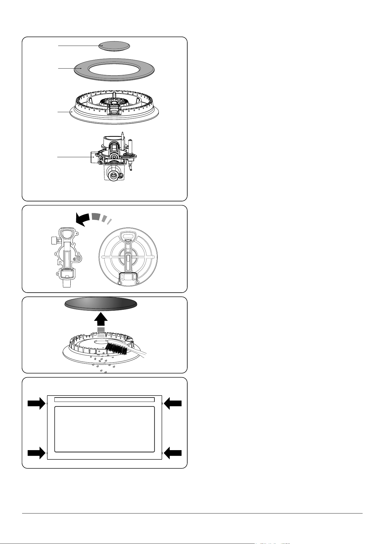
Set the oven function control to self-clean (Fig. 7.6). The
timer display will now show a ‘P’ (Fig. 7.7).
Press the [
] button once (Fig. 7.8) to set the default
cleaning time (3hours). The cleaning cycle will start
immediately.
To adjust the cleaning cycle duration, press and hold the [
]
button. The ‘P’ will no longer be displayed and [AUTO] will
ash. Press either the [–] or [+] buttons and set the required
duration; see Table 7.1. Release the [
] button once the
duration is set.
Note that the maximum time for the self-cleaning operation
is 4 hours. The minimum time is 1 hour.
The cooling fan will switch to high speed and as soon as a
certain temperature is reached the oven door will lock as
indicated by the illuminated interlock neon (Fig. 7.9).
ArtNo.272-0007
Prof+ pyro US - MF oven -
Self clean setting
OFF
ArtNo.302-0002 - 6BC annotated
ArtNo.302-0002 - 6BC annotated
ArtNo.272-0008
Prof+ pyro US - MF oven -
Self clean light on
OFF
Hours Soiling
2 hours Normal clean
3 hours Heavy soiling
4 hours Very heavy soiling
Table 7.1
Fig. 7.6
Fig. 7.7
Fig. 7.8
Fig. 7.9
22
NOTE: Because of the high temperatures generated
during the self-cleaning, the door will remain locked for a
period after the cleaning cycle has nished. When the oven
temperature has fallen suciently the interlock neon will go
out and the door will unlock.
When the door has unlocked turn the oven function control
back to OFF.
n
WARNING: The oven will still be hot!
When the door has unlocked and the oven has cooled, use a
damp cloth to clean the debris and ash.
To start the self-cleaning cycle automatically
By using the clock, the self-clean cycle can be programmed to
turn on and o automatically.
NOTE: You cannot set the start time directly – this is set
automatically by setting the ‘Cleaning period’ and the ‘stop
time’. This is the same method as used for normal automatic
cooking.
Set the oven function control to self-clean (Fig. 7.6). Press the
[
] button once to set the default cleaning time (Fig. 7.8).
To adjust the cleaning cycle duration, press the [
] button
and press either the [–] or [+] button and set the time as
required.
Now press the [
E
] button once to bring up the minimum
‘Stop time’ (Fig. 7.10) on the display. Press the [+] button
until the required ‘Stop time’ shows (Fig. 7.11). Release the
buttons.The symbols [AUTO] and [ P] are displayed. When
the self-clean start time is reached the [
] symbol will be
displayed and the self-clean cycle will start automatically.
At the end of the self clean [AUTO] will ash and the clock will
return to (
0.00 ) (Fig. 7.12). Turn the self-clean function switch
o to return to manual cooking.
To cancel the self-cleaning cycle
To cancel the self-clean function, hold down the [+] & [-]
buttons. The cycle time is re-set back to (
0.00 ), the heating
part of the cycle will end and the cooling part of the cycle will
start. When the oven temperature has fallen suciently the
interlock neon will go out and the door will unlock.
When the door has unlocked turn the oven function control
back to OFF.
n
WARNING: DO NOT attempt to stop the self-
clean cycle by turning the oven function control
to OFF. While this will stop the heating part of the
cleaning cycle it will also stop the ventilation fans
from running and cause the oven thermal cut-out to
trip.
For an overview of the functions refer to Table 7.2.
ArtNo.302-0002 - 6BC annotated
ArtNo.302-0005 -
6BC Stopping the oven 1
ArtNo.302-0005a -
6BC Stopping the oven 1a
Fig. 7.10
Fig. 7.11
Fig. 7.12
Symbol Function Notes
[
]
Sets the Minute Minder Used with the [+] and [-] buttons
[
]
Sets the Pyrolytic duration Used with the [+] and [-] buttons
[
E
]
Sets the Pyrolytic end time Used with the [+] and [-] buttons
[ - ]
Decreases time interval
Holding this button down
allows a quick set
[ + ]
Increases time interval
Holding this button down
allows a quick set
[ + ] & [ - ]
Clears the Pyrolytic
duration to zero
Table 7.2
23
Cleaning table
Cleaners listed are available from supermarkets or electrical
retailers as stated (Table 7.3).
For enamelled surfaces use a cleaner that is approved for use
on vitreous enamel.
Regular cleaning is recommended. For easier cleaning, wipe
up any spillages immediately.
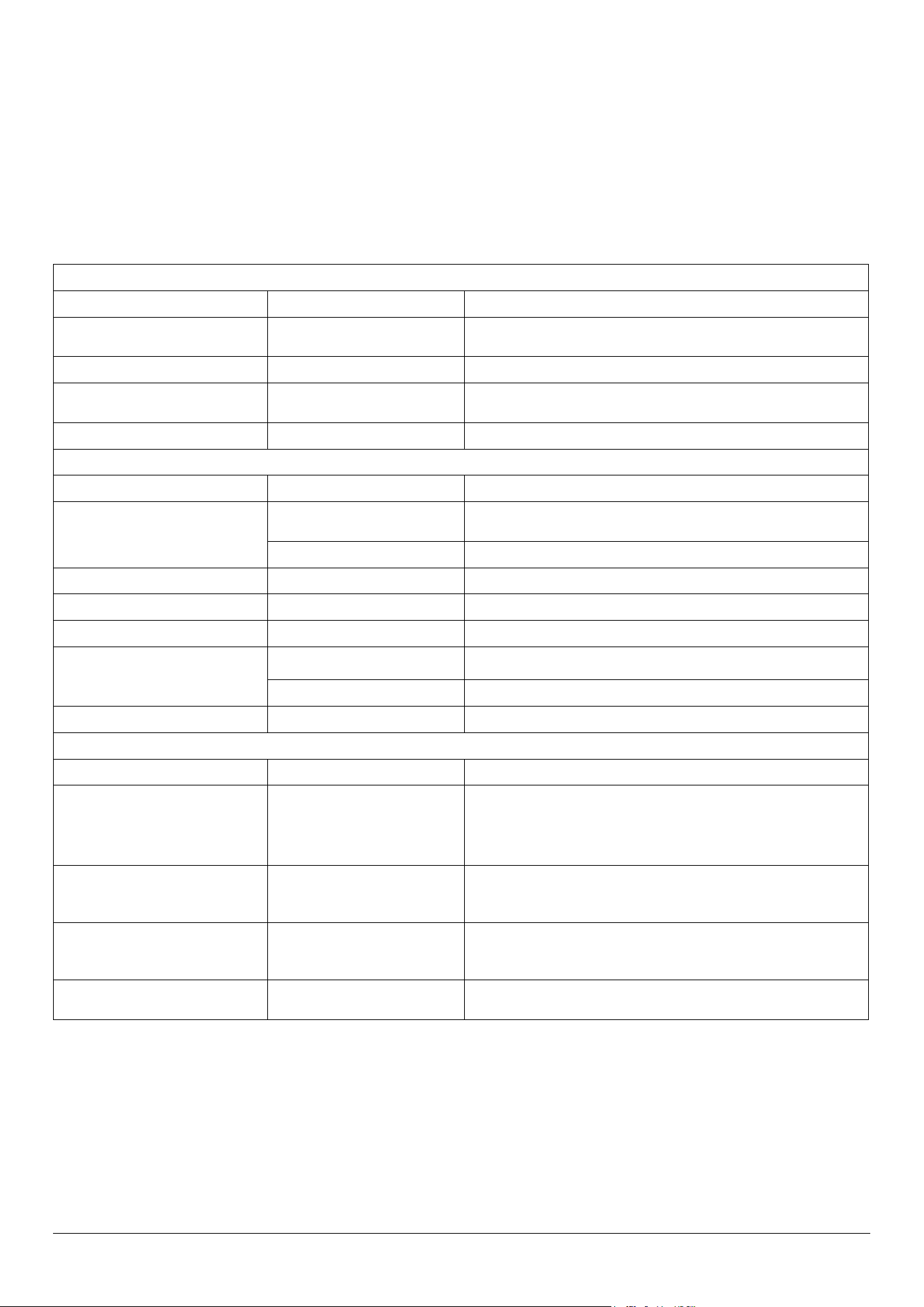
Hotplate
Part Finish Recommended Cleaning Method
Hob top (including burner heads and
caps)
Enamel, stainless steel, aluminium
Hot soapy water, soft cloth. Any stubborn stains remove gently with a nylon
scourer.
Ceramic/induction hob Toughened glass Hot soapy water; cream cleaner/scourer if necessary.
Griddle plate (some models only) Non-stick surface
Allow to cool. Wash in hot soapy water. Do not use abrasive cleaners/
scourers. Dishwasher.
Warming zone (some models only) Toughened glass Hot soapy water, cream cleaner/scourer if necessary.
Outside of Cooker
Part Finish Recommended Cleaning Method
Door, door surround and Storage
drawer exterior
Enamel or paint
Hot soapy water, soft cloth.
Any stubborn stains, remove gently with a liquid detergent.
Stainless steel E-cloth (electrical retailers) or microbre all-purpose cloth (supermarket).
Sides and plinth Painted surface Hot soapy water, soft cloth.
Splashback/rear grille Enamel or stainless steel Hot soapy water, soft cloth. Cream cleaner, with care, if necessary.
Control panel Paint, enamel or stainless steel Warm soapy water. Do not use abrasive cleaners on lettering.
Control knobs/handles & trims
Plastic/chrome, copper or lacquered
brass
Warm soapy water, soft cloth.
Brass Brass polish.
Oven door glass/glass lid Toughened glass Hot soapy water, cream cleaner/scourer if necessary.
Oven and Grill
Part Finish Recommended Cleaning Method
Sides, oor & roof of oven NOT ‘COOK &
CLEAN’ OVEN PANELS (see below)
Enamel
Any proprietary oven cleaner that is suitable for enamel.
CAUTION: CORROSIVE/CAUSTIC OVEN CLEANERS: FOLLOW
MANUFACTURER’S INSTRUCTIONS.
Do not allow contact with the oven elements.
‘Cook & Clean’ oven panels (some
models only)
Special enamel that partly cleans
itself
This surface cleans itself at 200 °C and above, or the panels can be removed
and washed with hot soapy water and a nylon brush.
Oven shelves, Handyrack, grill trivet,
Handygrill rack (some models only)
Chrome
An oven interior cleaner that is suitable for chrome. Soap lled pad.
Dishwasher.
Grill pan/meat tin (some models only) Enamel Hot soapy water. Soap lled pad. Dishwasher.
Table 7.3

24
Hotplate ignition or hotplate burners faulty
Is the power on? Is the clock illuminated?
If not, there maybe something wrong with the power supply.
Are the sparker (ignition electrode) or burner slots blocked by
debris?
Are the burner trim and caps correctly located? See the
section on ‘Cleaning’?
Hotplate burners will not light
Make sure that the burner parts have been replaced correctly
after wiping or removing for cleaning.
Check that there is not a problem with your gas supply. You
can do this by making sure that other gas appliances you may
have are working.
Do the burners spark when you push the control?
If not, verify that the power is on by checking that the clock is
illuminated.
Steam is coming from the oven
When cooking foods with high water content (e.g. oven
chips) there may be some steam visible at the rear grille.
Take care when opening the oven door, as there may be a
momentary pu of steam when the oven door is opened.
Stand well back and allow any steam to disperse.
What cleaning materials are recommended for the
cooker?
See the ‘Cleaning’ section for recommended cleaning
materials.
n
Never use caustic or abrasive cleaners as these will
damage the surface.
An oven fan is noisy
The note of the oven fan may change as the oven heats up –
this is perfectly normal.
The knobs get hot when I use the oven. Can I avoid this?
Yes, this is caused by heat rising from the oven and heating
them up. Do not leave the oven door open.
The fascia gets hot when I use the oven
The cooker is cooled by a fan. If the fascia becomes
excessively hot when the cooker is in use then the cooling
fan may have failed. Should this occur please contact your
installer, a qualied repair engineer or Customer Service to
arrange for its repair.
If there is an installation problem and I don’t get my
original installer to come back to x it who pays?
You do. Service organisations will charge for their call outs if
they are correcting work carried out by your original installer.
It is in your interest to track down your original installer.
Power failure
In the event of a failure in the electrical supply, remember to
reset the clock to make sure that the timed oven continues to
operate.
Poor performance
In the unlikely event that, after installation, the appliance
does not perform correctly please contact your distributor
(see “Service and Spares” on page 26).
Food is cooking too slowly, too quickly, or burning
Cooking times may dier from your previous oven.
Check that you are using the recommended temperatures,
shelf positions and tray sizes – see the oven cooking guide.
The oven control settings and cooking times are intended to
be used only as a guide.
Individual tastes may require the temperature to be altered
either way, to get the results you want.
The oven is not cooking evenly
Do not use a baking tray with dimensions larger than those
specied in the section on ‘General Oven Tips’.
If you are cooking a large item, be prepared to turn it round
during cooking.
If two shelves are used, check that space has been left for
the heat to circulate. When a baking tray is put into the oven,
make sure that it is placed centrally on the shelf.
Check that the door seal is not damaged and that the door
catch is adjusted so that the door is held rmly against the
seal.
A dish of water when placed on the shelf should be the
same depth all over. (For example, if it is deeper at the back,
then the back of the cooker should be raised up or the front
lowered.) If the cooker is not level arrange for your supplier to
level it for you.
Oven not coming on
Is the power on? Is the clock illuminated? If not, there may be
something wrong with the power supply.
Is the cooker supply on at the isolator switch?
Has the time of day been set?
The timed oven is not coming on when automatic cooking
Has the oven knob been left in the OFF position by mistake?
Is the oven locked (see above)?
8. Troubleshooting
25
Oven temperature getting hotter as the cooker gets older
If turning the temperature down using the oven control knob
has not worked, or has only worked for a short time, then you
may need a new thermostat. This should be tted by a service
person.
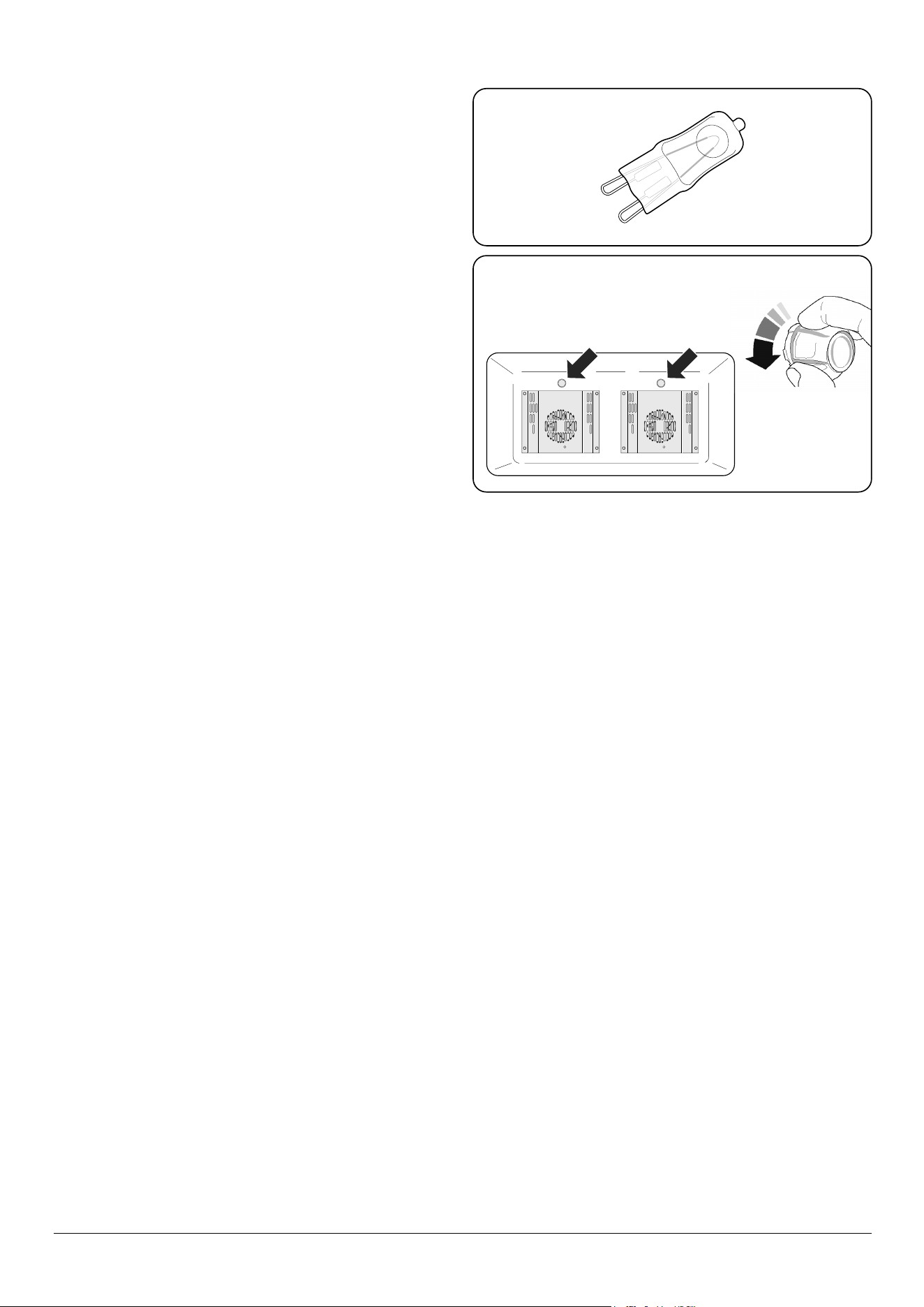
Oven lights are not working
The bulb has probably burnt out. You can buy a replacement
bulb (which is not covered under the warranty) from a good
electrical shop.
Ask for a 40 W - 230 V halogen lamp (G9) (Fig. 8.1).
Turn o the power at the circuit breaker.
Before removing the existing bulb, turn o the power supply
and make sure that the oven is cool. Open the oven door and
remove the oven shelves.
Remove the bulb cover by turning it a quarter turn, counter-
clockwise. It may be very sti (Fig. 8.2).
Pull the existing bulb to remove it. When handling the
replacement bulb, avoid touching the glass with your ngers,
as oils from your hands can cause premature failure. Push,
click in the replacement bulb.
Screw back the bulb cover. Turn on the circuit breaker and
check that the bulb now lights.
Fig. 8.1
Fig. 8.2
INSTALLATION
Check the appliance is electrically safe when you have nished.
26
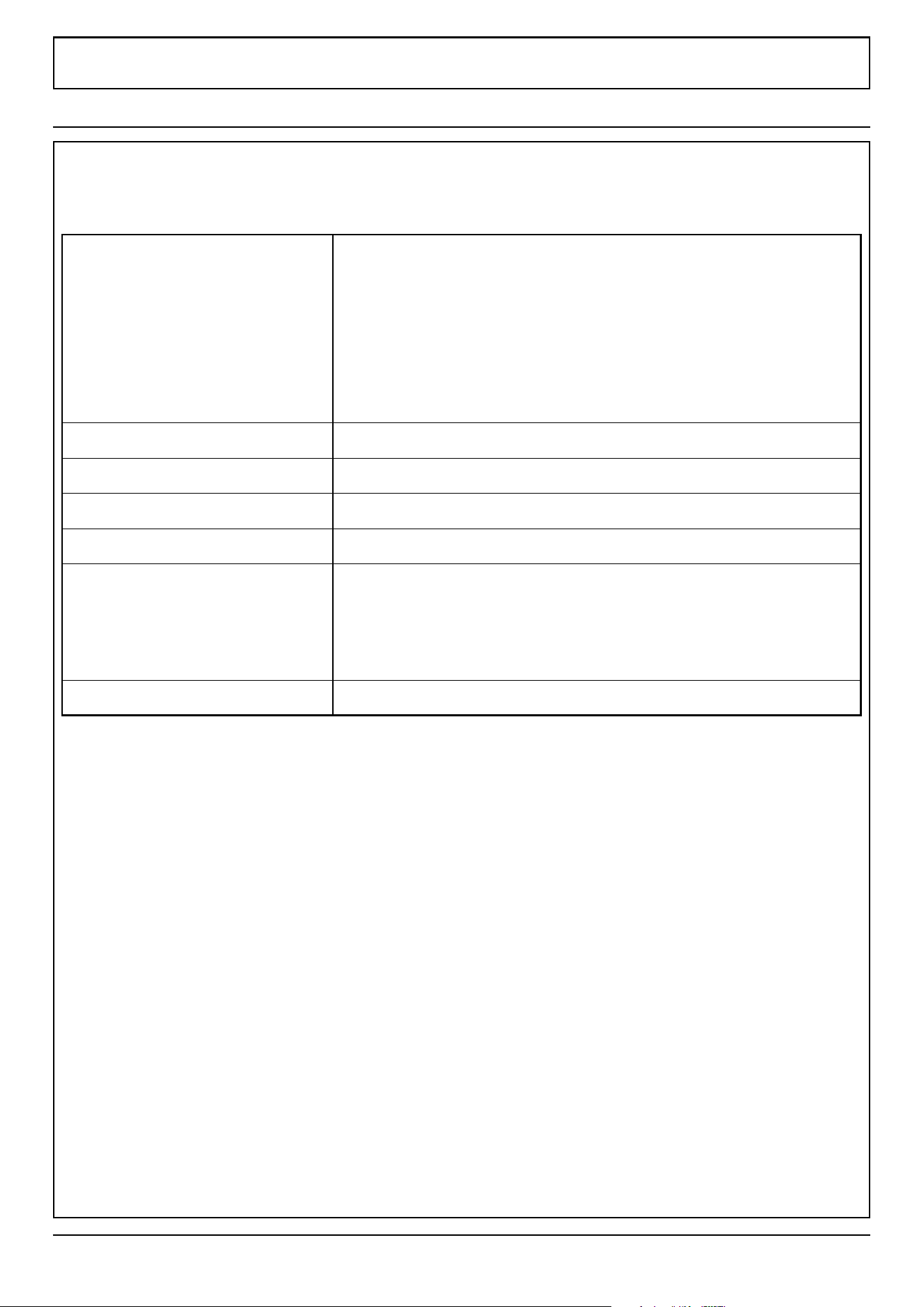
Firstly, please complete the appliance details below and keep them safe for future reference – this information will enable us
to accurately identify the particular appliance and help us to help you. Filling this in now will save time and inconvenience
if you later have a problem with the appliance. It may also be of benet to keep your purchase receipt with this leaet. You
may be required to produce the receipt to validate a warranty eld visit.
Distributor’s Name and Address Andi-Co Australia Pty Ltd.
1 Stamford Road,
Oakleigh, VIC 3166
Customer Care
Tel: 1300 650 020
Email: [email protected]
Name of Appliance
Appliance Serial Number*
Fuel Type
Date of Purchase
Installer’s Name, Address and
Telephone No.
Date of Installation
* This information is on the appliance data badge.
If You Have a Problem
In the unlikely event that you have a problem with your appliance, please refer to rest of this booklet, especially the problem
solving section, rst to check that you are using the appliance correctly.
If you are still having diculty, contact Customer Care on 1300 650 020 or email [email protected]om.au.
Please Note
For warranty information and how to request a remedy, please refer to the Warranty Statement at
https://www.andico.com.au/warranty/ or contact Customer Care.
Out of Warranty
We recommend that our appliances are serviced regularly throughout their life to maintain the best performance and
eciency. The frequency of service will depend on usage – for normal usage once a year should suce.
Service work should only be carried out by a suitably Authorised Person.
Spare Parts
To maintain optimum and safe performance, we recommend that only genuine spare parts are used. Do not use re-
conditioned or unauthorised controls. Contact Spare Parts on (03) 9569 7744 or email [email protected]om.au
9. Service and Spares

INSTALLATION
Check the appliance is electrically safe and gas sound when you have nished.
27
10. Installation
Safety Requirements and
Regulations
n
Please read the Before you start... chapter, before
you begin any installation and maintenance work on
this appliance.
You must be aware of the following safety requirements &
regulations.
n
Prior to installation, make sure that the local
distribution conditions (nature of the gas and gas
pressure) and the adjustment of the appliance are
compatible.
n
The appliance must be installed in accordance with
the regulations in force and only in a well ventilated
space.
n
Read the instructions before installing or using this
appliance.
The regulations and standards are as follows:
• AS/NZS 5601 – ‘Gas Installations’
• AS/NZS 3000 - ‘Wiring Rules’
In your own interest and that of safety, it is law that all gas
appliances be installed by competent persons.
n
Failure to install the appliance correctly could
invalidate any warranty or liability claims and lead
to prosecution.
The cooker must be installed in accordance with all local gas
tting regulations, municipal building codes, electrical wiring
regulations and any other relevant statutory regulations.
n
WARNING!
This appliance should not be used in marine craft,
caravans or mobile homes.
Provision of Ventilation
This appliance is not connected to a combustion products
evacuation device. Particular attention shall be given to the
relevant requirements regarding ventilation.
The room containing the cooker should have an adequate air
supply.
Install the cooker in a location to allow the complete
combustion of gas, proper ueing and to maintain ambient
temperature of the immediate surroundings at safe limits,
under normal condition.
Location of Cooker
The cooker may be installed in a kitchen/kitchen diner but
NOT in a room containing a bath or shower.
NOTE: An appliance for use on Propane must not be installed
in a room or internal space below ground level, e.g. in a
basement.
Conversion
All models are supplied set for use on Natural gas. A
conversion kit for Propane gas is included with the appliance.
See the instructions that are supplied with the conversion kit.
n
We recommend an overpressure shut-o device or
pressure relief valve be used in any LPG installation
to prevent exposure of downstream ttings /
appliances to excessive pressure (over 7.5kPa) in
event of regulator failure.
After converting the appliance, please attach the Gas
Conversion sticker over the appropriate area of the data
badge – this will identify the gas type for which the appliance
is now set.
INSTALLATION
Check the appliance is electrically safe and gas sound when you have nished.
28
Checking the Parts:You will need the following equipment to complete the
cooker installation satisfactorily:
• Flexible gas hose.
• Gas pressure tester/manometer.
• Multimeter: For electrical checks.
You will also need the following tools:
1. Electric drill
2. Masonry drill bit (only required if tting the cooker on a
stone or concrete oor)
3. Wall plugs (only required if tting the cooker on a stone
or concrete oor)
4. Steel tape measure
5. Cross head screwdriver
6. Flat head screwdriver
7. 4 mm & 3 mm Allen keys
8. Spirit level
9. Pencil
10. Adjustable spanner
11. 13 mm spanner or socket wrench
12. Screws for tting the restraining chain and stability
bracket
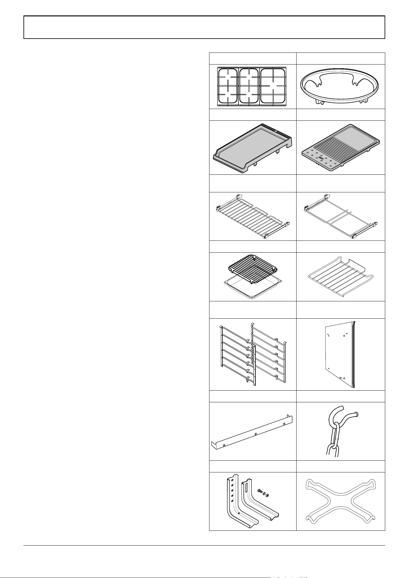
Pan supports Wok cradle
ArtNo.000-0001 90 Pan supports
ArtNo.000-0009 Wok ring, cast
Teppanyaki (supplied) Griddle (optional)
ArtNo.311-0043 - Griddle 09
2 x full capacity shelves with
telescopic runners
1 x full capacity grill pan shelf with
telescopic runners
2 grill pans & trivets 3 energy saving shelves
ArtNo.326-0015 - Energy saving shelf (Falcon)
2 left hand and 2 right hand
ladder side supports
Divider
ArtNo.281-0028 - Albertine divider
Plinth Restraining chain & hook
ArtNo.350-0008 - 90 SC plinth
ArtNo.020-0021 - Restraining
chain & hook
Stability bracket Small pan trivet
INSTALLATION
Check the appliance is electrically safe and gas sound when you have nished.
29
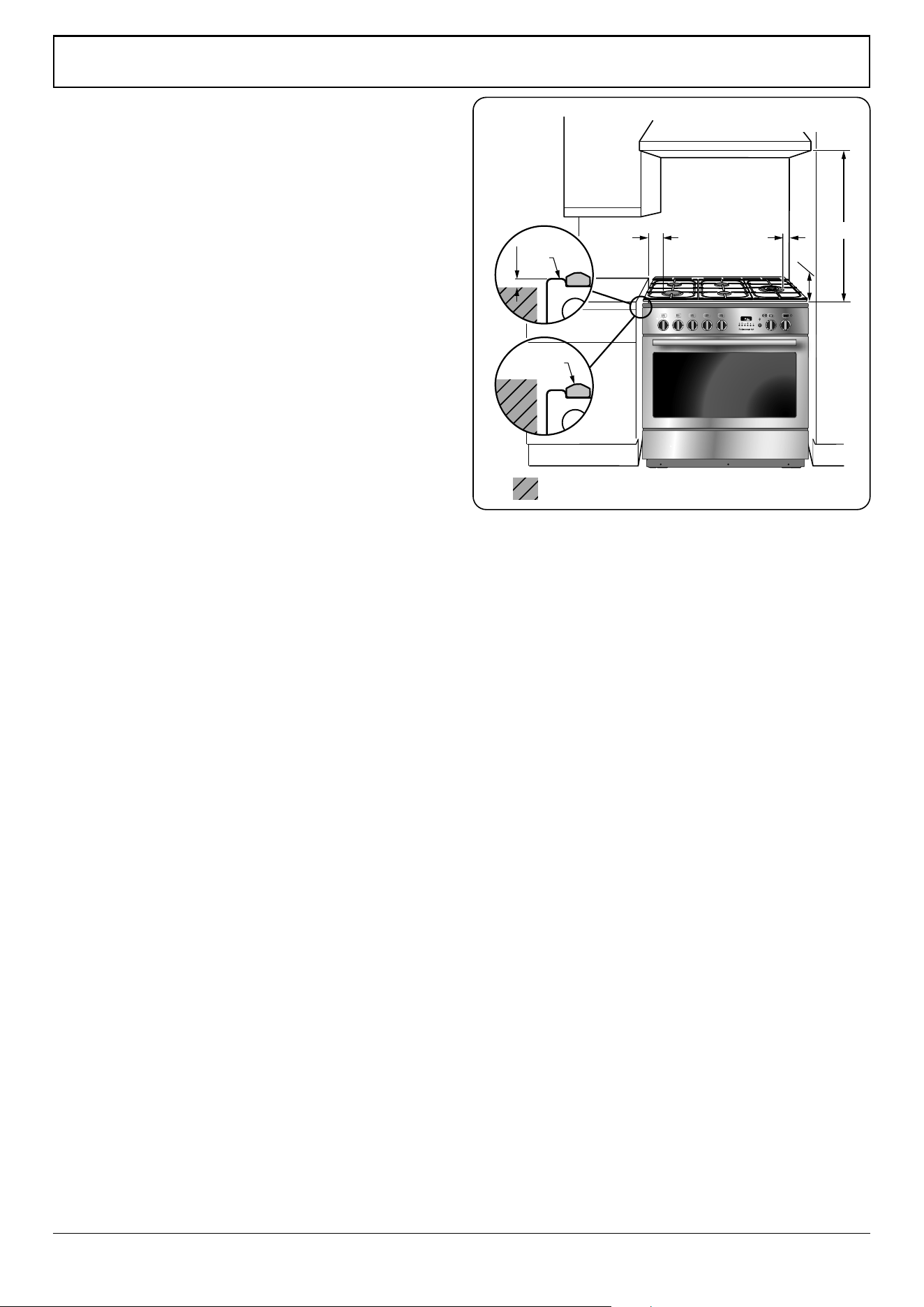
Positioning the Cooker
The diagram (Fig. 10.1) shows the minimum recommended
distance from the cooker to nearby surfaces as given in
AS/NZS 5601.
Where the appliance is installed next to cabinetry, the
cabinet material must be capable of withstanding 70°C. If
this appliance is installed near vinyl wrapped surfaces, use an
installation kit available from the vinyl-wrap supplier. Falcon
cannot accept any responsibility for damage caused due to
installation into cabinets with low temperature tolerances.
*Any splashback must be tted in accordance with the
manufacturers instructions. Allowance should be made for
the additional height of the ue trim, which is tted to the
cooker hob.
1. Overhead - Measurement A
The minimum height of any surface above the top of the pan
supports of the cooker is 650mm, for the full width and depth
of the hob.
Cookerhoods and exhaust fans shall be installed in
accordance with the manufacturer’s instructions. However, in
no case shall the clearance between between the top of the
pan supports of the cooking appliance and a cookerhood be
less than 650 mm or, for an overhead exhaust fan, 750 mm.
2. Side Clearances - Measurements B & C
Where B, measured from the periphery of the nearest burner
to any vertical combustible surface, or vertical combustible
surface covered with toughened glass or sheet metal, is less
than 200 mm, the surface shall be protected to make sure
that the combustible surface does not exceed 65 °C above
ambient*. Even with the surface protected, the dimension B
should not be less than 135 mm above hotplate level.
*The xing of 5mm thick ceramic tiles to the surface, or
attaching re resistant material to the surface and covering
with sheet metal with a minimum thickness of 0.4 mm to a
height C of not less than 150 mm above the hotplate, should
satisfy this requirement.
3. Side Clearances - Measurement D & E
Where D, the distance from the periphery of the nearest
burner to a horizontal combustible surface is less than
200 mm, then E shall be 10 mm or more, or the horizontal
surface shall be above the pan supports. See insets above.
DO NOT place the cooker on a base.
For safety reasons, curtains, must not be tted immediately
behind the cooker.
Surfaces of furniture and walls at the sides and rear of the
appliance should be heat, splash and steam resistant. Certain
types of vinyl or laminate kitchen furniture are particularly
prone to heat damage and discolouration. We cannot accept
responsibility for damage caused by normal use of the
cooker to any material that de-laminates or discolours at
temperatures less than 70 °C above room temperature (as
measured by EN30 / EN60335).
ArtNo.110-0023 - 110 - cooker clearances (AUS)
OFF
Hob
Pan
support
Horizontal combustible surface
B
C
D
E
A
*
or
Fig. 10.1
INSTALLATION
Check the appliance is electrically safe and gas sound when you have nished.
30
We recommend a gap of 910 mm between units to allow for
moving of the cooker. DO NOT box the cooker in – it must
still be possible to move the cooker in and out for cleaning
and servicing.
Moving the Cooker
n
On no account try and move the cooker while it is
plugged into the electricity supply.
n
The cooker is very heavy, so take great care.
We recommend that two people manoeuvre the cooker.
Make sure that the oor covering is rmly xed, or removed,
to prevent it being disturbed when moving the cooker
around.
To help you, there are two levelling rollers at the back, and
two screw-down levelling feet at the front.
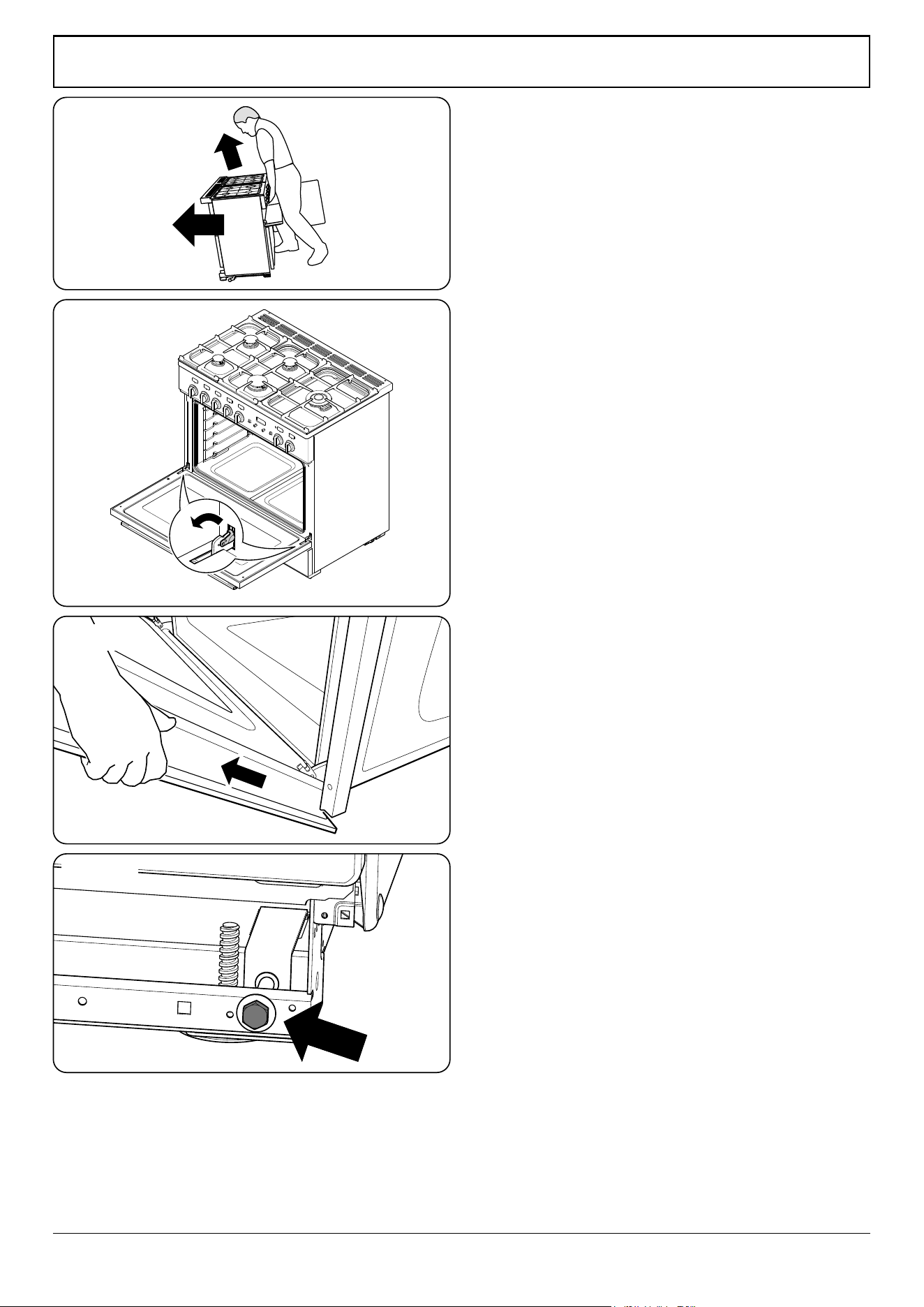
Remove the polystyrene base pack. From the front, tilt
the cooker backwards and remove the front half of the
polystyrene base (Fig. 10.2). Repeat from the back and
remove the rear half of the polystyrene base.
Removing the Oven Door
To remove the oven door, open the door fully. Swivel the
locking ‘U’ clips forward to the locking position (Fig. 10.3).
Grip the sides of the door, lift upwards and then slide the
door forwards (Fig. 10.4).
Lowering the Two Rear Rollers
To adjust the height of the rear of the cooker, rst t a 13 mm
spanner or socket wrench onto the hexagonal adjusting nut
(Fig. 10.5).
Rotate the nut – clockwise to raise – counter-clockwise to
lower. Make 10 complete (360°) turns clockwise.
Make sure you lower BOTH REAR ROLLERS.
Completing the Move
Unfold the rear edge of the pack base tray. Grip the fascia
panel and lift the front of the cooker slightly.
Carefully push the cooker backwards o the pack base.
Remove the pack base. Position the cooker close to its nal
position, leaving just enough space to get behind it.
n
DO NOT use the control knobs to manoeuvre the
cooker.
ArtNo.062-0001 - 90 Prof+ FX - Removing the door
Fig. 10.2
Fig. 10.3
Fig. 10.4
Fig. 10.5
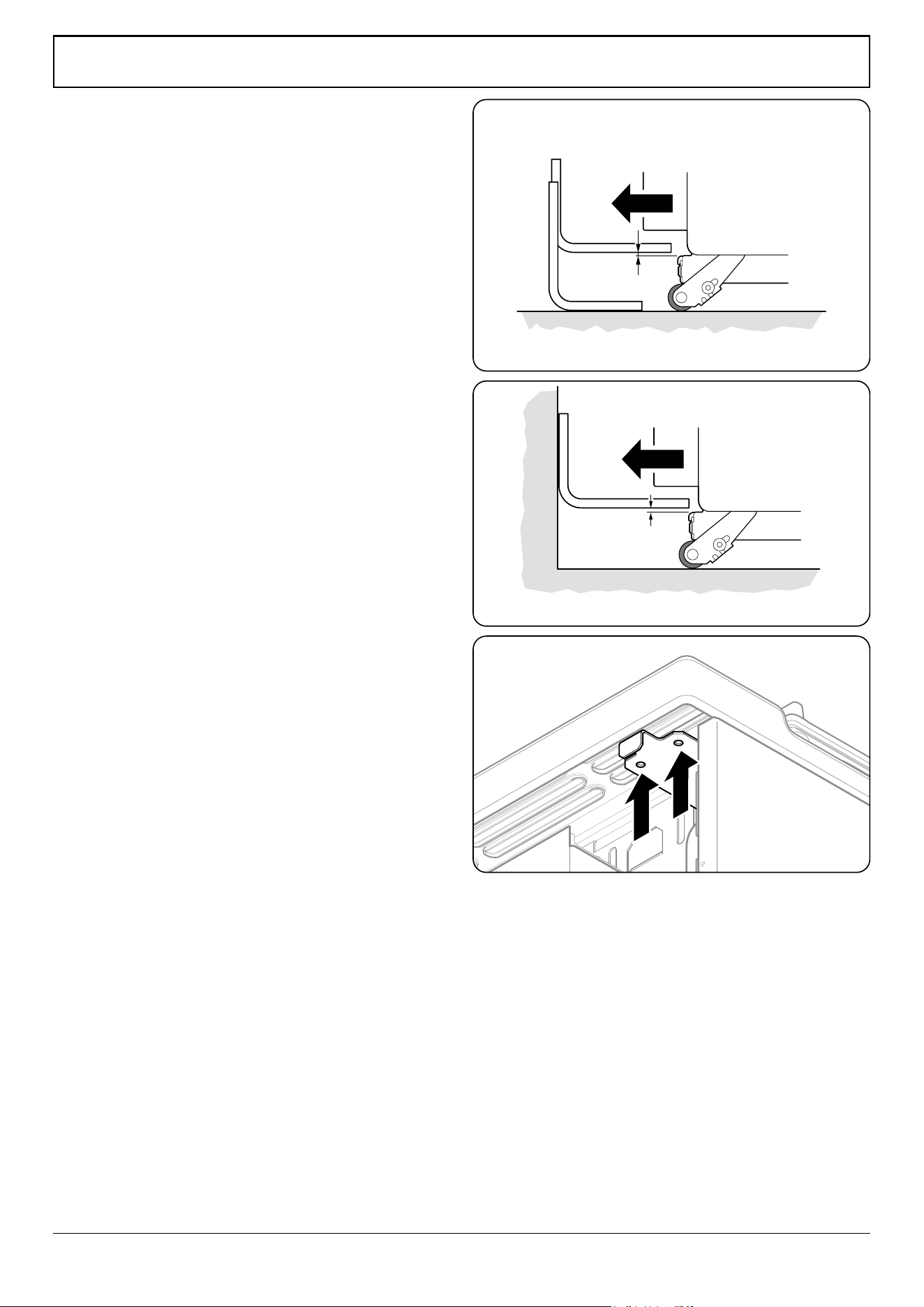
INSTALLATION
Check the appliance is electrically safe and gas sound when you have nished.
31
Levelling
You are recommended to use a spirit level on a shelf in one of
the ovens to check for level.
Place the cooker in its intended position, taking care not to
twist it within the gap between the kitchen units as damage
may occur to the cooker or the units.
The front feet and rear rollers can be adjusted to level the
cooker. To adjust the height of the rear of the cooker, turn the
adjusting nuts at the front bottom corners of the cooker. To
set the front feet turn the bases to raise or lower.
Fitting the Stability Bracket and
Chain
n
A stability bracket and chain MUST be tted when
the cooker is connected to a exible gas supply.
Unless properly installed, the cooker could be tipped by
leaning on the door. Injury might result from spilled hot
liquids or from the cooker itself.
n
IMPORTANT: The cooker MUST be set to the correct
height and levelled before the stability bracket is
installed.
Fitting a Stability Bracket
When tting a stability bracket please refer to the instructions
supplied with the bracket for further details on tting.
When tting a stability bracket (Fig. 10.6 and Fig. 10.7)
adjust the bracket to give the smallest practicable clearance
between the bracket and the engagement slot in the rear of
the cooker.
Fit the bracket so that it engages as far as possible over the
chassis of the cooker.
Fitting the Restraining Chain
The restraining chain MUST be tted.
The length of chain between the appliance and the wall xing
should prevent strain on the gas and electricity connections,
but still allow access to unhook the chain when the cooker is
pull forward.
Measure the length of chain required. Use the hexagon-
headed screw, washers and bolt supplied in the restraining
chain kit to x the chain to one of the holes at the top of the
ue trim bracket (Fig. 10.8).
Hook the other end of the chain to the wall xing.
ArtNo.070-0014 - Stability bracket - Wall fitting
Cooker
Stability bracket
Floor
3 mm min
Typical oor mounting
Cooker
Outer stability
bracket
Floor
Wall
3 mm min
Typical wall mounting
ArtNo.070-0001 - Fitting the restaining chain
Fig. 10.6
Fig. 10.7
Fig. 10.8
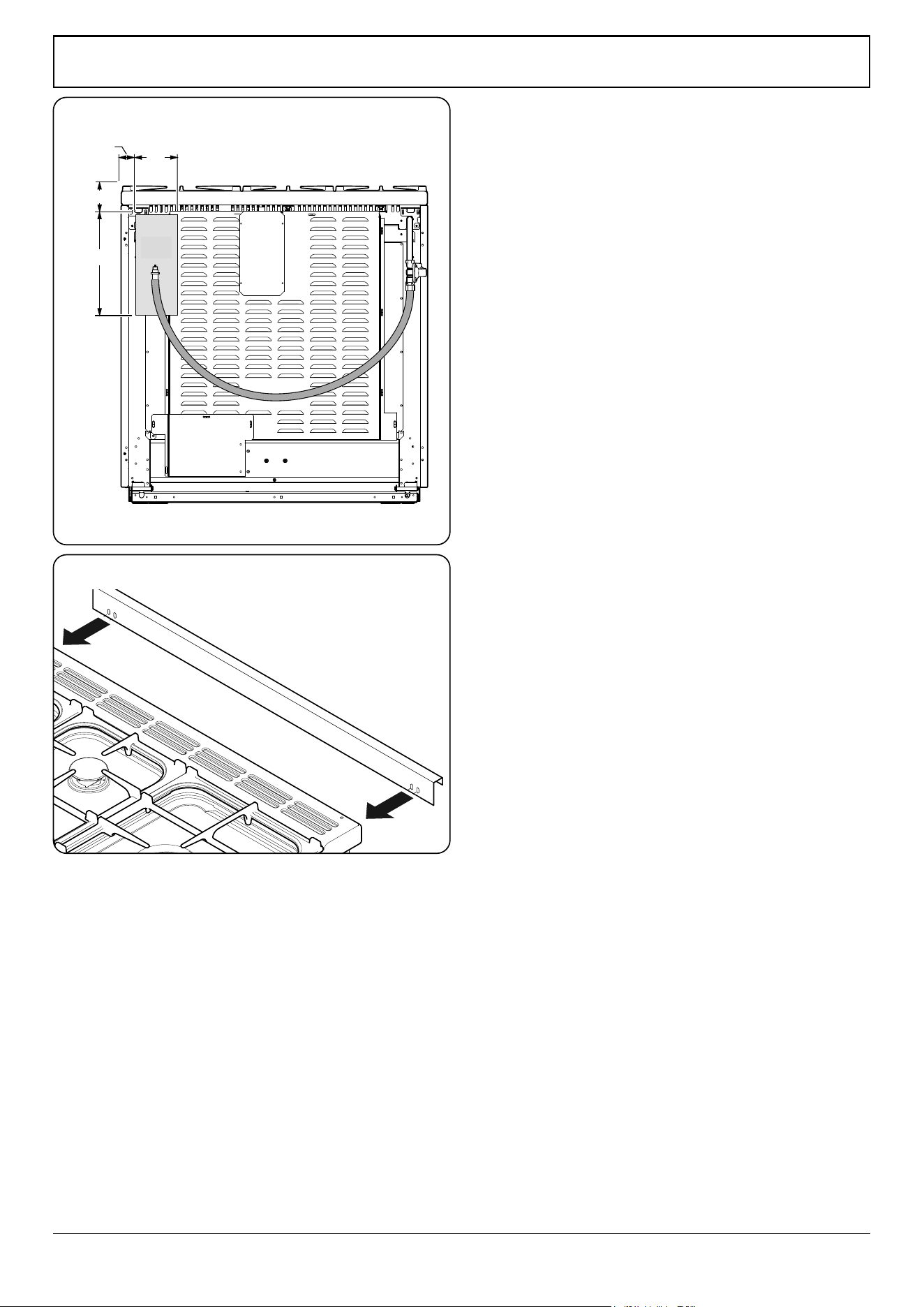
INSTALLATION
Check the appliance is electrically safe and gas sound when you have nished.
32
ArtAUS.062-0002 - 90SC - Prof+ - Gas connection
40
80
‘A’
330
140
All dimensions in millimetres
Gas Connection
Must be in accordance with the relevant standards.
The gas supply needs to terminate with a threaded tting ½”.
The inlet connector is located just below the hotplate level at
the rear of the cooker.
Because the height of the cooker can be adjusted and
each connection is dierent it is dicult to give precise
dimensions. Ideally, the house supply connection should be
in the shaded area (Fig. 10.9).
Means of isolation must be provided at the supply point by
either an approved quick-connect device or a Type 1 manual
shut-o valve.
The hose should be tted so that both inlet and outlet
connections are vertical so that the hose hangs downwards in
a ‘U’ shape (Fig. 10.9).
A exible connection is supplied with the cooker. If it is
necessary to use another hose it must be to AS 1869 Class B
and be suitable for your gas type.
If in doubt contact your supplier. Screw connect the threaded
end of the hose into the gas inlet.
After completing the gas connection, check the cooker is gas
sound with a pressure test. When checking for gas leaks do
not use washing up liquid – this can corrode. Use a product
specically manufactured for leak detection.
Natural Gas
The adjustable spring loaded gas pressure regulator is preset
to give a nominal pressure of 1 kPa on Natural gas. Connect to
the Rp½ inlet on the underside of the pressure regulator.
Propane
This cooker is supplied ready for use on Natural gas. A
conversion kit for Propane gas is supplied with the cooker –
see the ‘Conversion to Propane Gas’ section.
NOTE: If space behind the cooker is limited, t the spacer
provided to give a greater chance of clearance (Fig. 10.10).
Screw connect the threaded end of the hose into the gas
inlet.
After completing the gas connection, make sure that the
cooker is gas sound with a pressure test.
Pressure Testing
The pressure test point is accessible on the inlet pipe at the
rear. Remove the test nipple screw and t a pressure gauge to
the test point. Turn on and light two of the hotplate burners.
For Natural Gas cookers the pressure should be between
0.95kPa and 1.0kPa.
For Propane X cookers the pressure should be 2.54 kPa.
Fig. 10.9
ArtNo.062-0001 - 90 Prof+ FX - Removing the door
Fig. 10.10
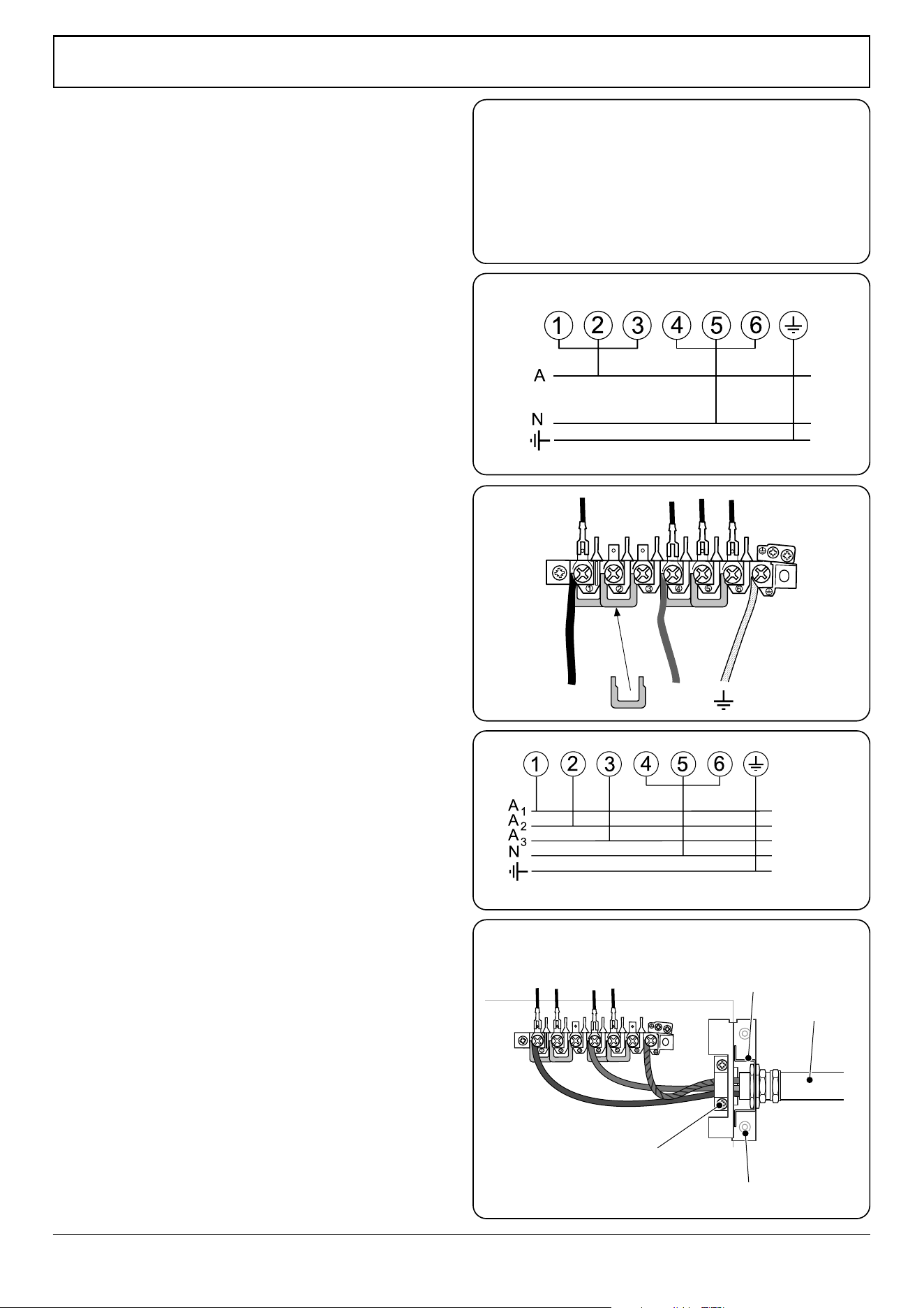
INSTALLATION
Check the appliance is electrically safe and gas sound when you have nished.
33
ArtNo.132-0001 - 1 phase 240Vac 50Hz
1-phase 230 V
AC
50 Hz
ArtNo.132-0003 - Single-phase connections (AUS)
A N
ArtNo.132-0002 - 3 phase 240/415Vac 50Hz
3-phase 400 V
AC
50 Hz
ArtNo.132-0004 - Fixed wiring connection (AUS)
Mains
terminal
Fixing bracket for
conduit connection
Conduit
Cable clamp
Strain relief
bracket
Electrical Connection
This appliance must be installed by a qualied electrician
to comply with with current AS/NZS 3000 Wiring Rules
and regulations in force.
Make sure that the mains characteristics (voltage, nominal,
power, etc.) match the ratings indicated on the cooker data
plate.
The cooker is preset for a single-phase earthed electrical
connection. It is essential to install a multi-pole circuit breaker
that completely disconnects the appliance from the mains,
with a minimum contact break distance of 3 mm.
n
WARNING: THIS APPLIANCE MUST BE EARTHED.
The appliance must be connected to an ecient earthing
circuit. If the electricity network is not equipped with an
earth connection, then it must be installed separately in
compliance with local regulations.
Earthing is a safety measure required by law, and must be
performed with particular care by a qualied technician, who
must also check that the electricity supply characteristics are
correct.
The total electrical load of the appliance is approximately
3.6 kW. The cable size used should be suitable for this load
and comply with all local requirements.
Access to the mains terminal is gained by removing the
electrical terminal cover box on the back panel. Connect the
mains cable to the correct terminals for your electrical supply
type (Fig. 10.11 and Fig. 10.12). Check that the links are
correctly tted and that the terminal screws are tight. Secure
the mains cable using the cable clamp.
An isolation switch shall be provided and mounted near
the cooker, in a readily accessible position, in compliance
with AS/NZS 3000 and/or AS/NZS 5601 as applicable for the
appliance conguration.
Fixed Wiring
For connection to xed wiring, i.e. exible conduit, remove
the electrical terminal cover box on the back panel. Using the
two screws, x the strain relief bracket in position.
Fix the conduit-to-conduit mounting bracket onto the
strain relief bracket. Connect the mains cable to the correct
terminals for your electrical supply type (Fig. 10.13 and
Fig. 10.14). Check that the links are correctly tted and that
the terminal screws are tight.
Replace the electric terminal cover box; make sure that the
conduit is clear of the bottom ange.
Fig. 10.11
Fig. 10.12
Fig. 10.13
Fig. 10.14
Current Operated Earth Leakage Breakers
The combined use of your cooker and other domestic
appliances may cause nuisance tripping, so we recommend
that the cooker is protected on an individual RCD (Residual
Current Device) or RCBO (Residual Current Breaker with
Overload).
IF IN DOUBT, PLEASE CONSULT A SUITABLY QUALIFIED
ELECTRICIAN.
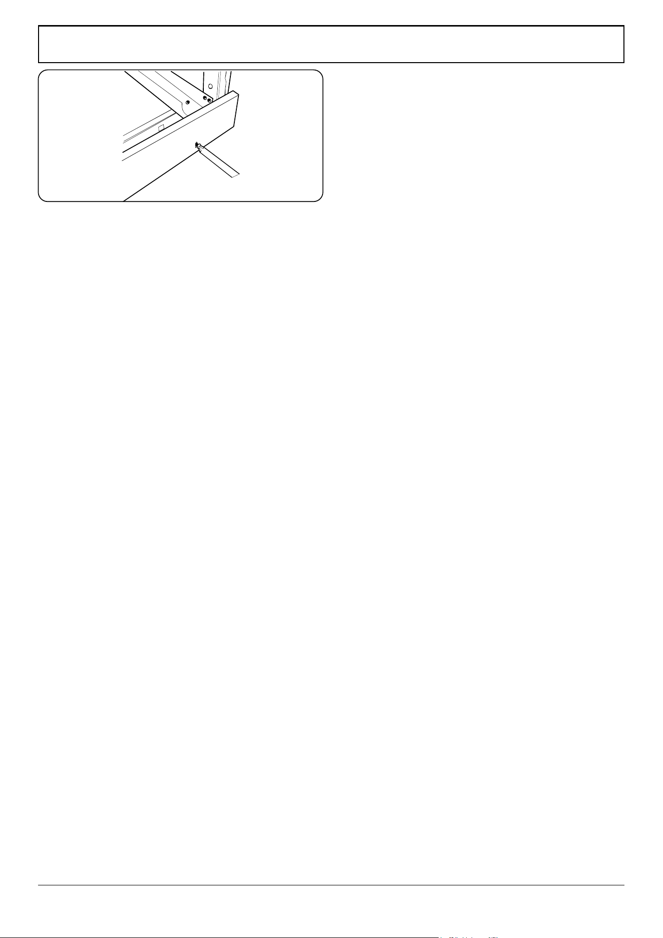
INSTALLATION
Check the appliance is electrically safe and gas sound when you have nished.
34
Final Checks
Hotplate Check
Check each burner in turn. There is a Flame Supervision
Device (FSD) that stops the ow of gas to the burner if the
ame goes out. For each burner, turn the control knob to the
solid ame symbol. Press in the control knob. This lets gas
through to the burner. Keep holding the knob pressed in and
press the igniter button or light with a match. Keep holding
the control knob pressed in for about 10 seconds.
If, when you let go of the control knob the burner goes out,
the safety device has not held in. Wait one minute then try
again this time holding the control pressed in for slightly
longer.
Oven Check
Turn on the oven and check that it starts to heat up. Check
that the oven lights are working.
NOTE: The oven light bulb is not included in the guarantee.
Turn o the oven.
Final Fitting
Fitting the Plinth
Remove the 3 screws for the plinth mounts along the front
bottom edge of the range (Fig. 10.15). Fasten the plinth
using these screws.
Retting the Oven Door
To ret the door, slide the hinges back into their slots. Rotate
the locking ‘U’ clips back to t onto the hinges.
Customer Care
INSTALLER: Please complete your details in this guide,
inform the user how to operate the cooker and hand over the
instructions.
ArtNo.281-0026 - Front plinth
Fig. 10.15
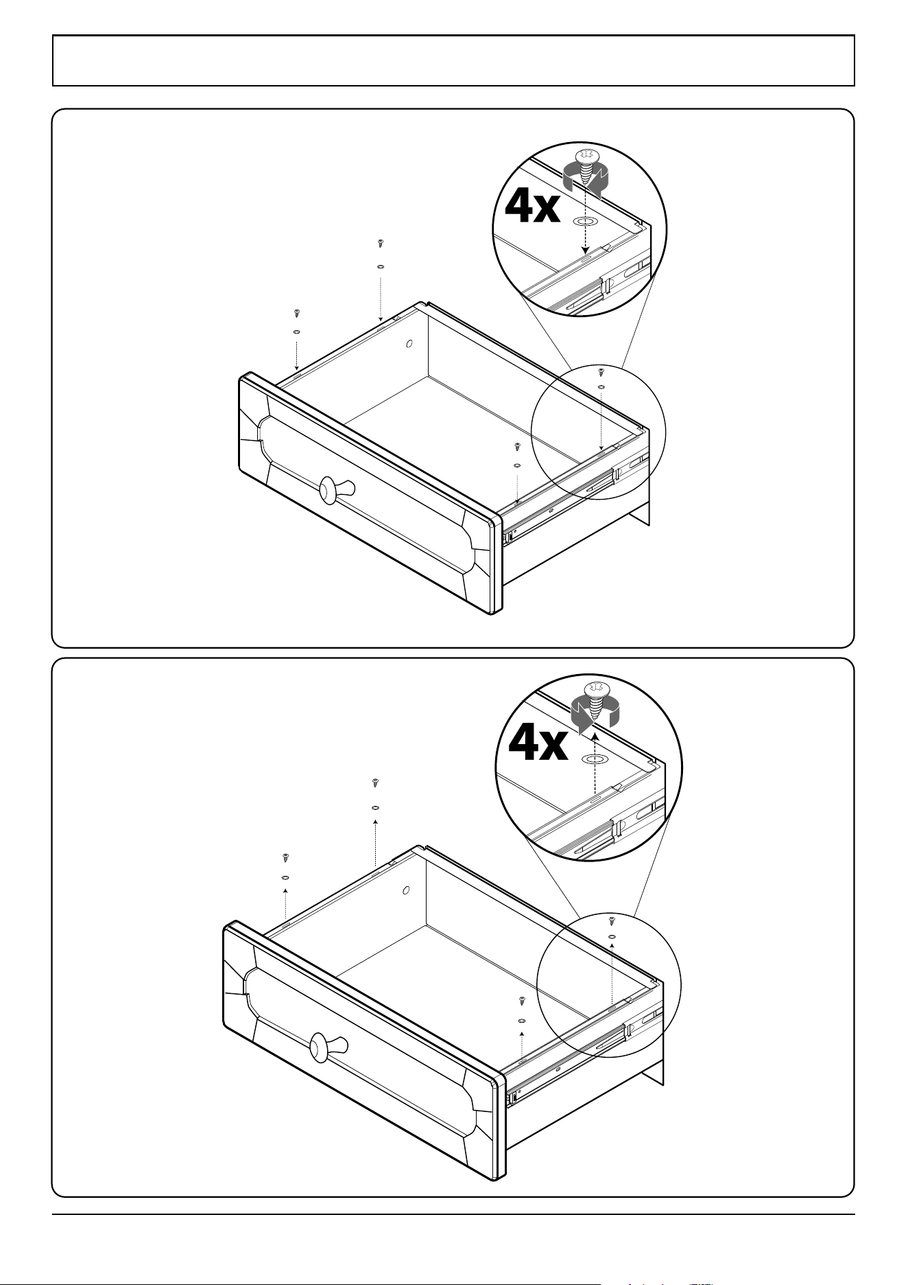
INSTALLATION
Check the appliance is electrically safe and gas sound when you have nished.
35
Removing the drawer
Fitting the drawer
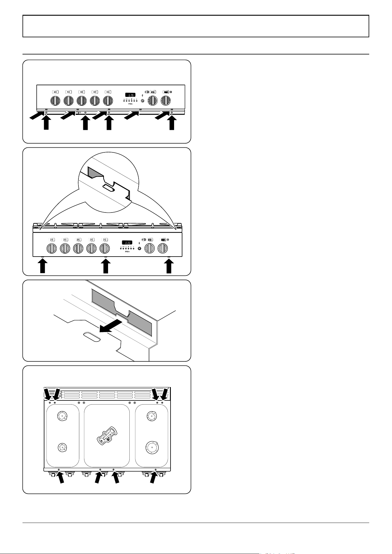
WARNING – SERVICING TO BE CARRIED OUT ONLY BY AN AUTHORISED PERSON
Disconnect from electricity and gas before servicing. Check appliance is safe when you have nished.
36
OFF
n
BEFORE SERVICING ANY GAS CARRYING
COMPONENTS TURN OFF THE GAS SUPPLY
n
Check the appliance is gas sound after completion
of service. When checking for gas leaks do not use
washing up liquid – this can corrode. Use a product
specically manufactured for leak detection.
n
DO NOT use reconditioned or unauthorised gas
controls.
n
Disconnect from the electricity supply before
servicing, particularly before removing any of the
following: control panel, side panels, hotplate tray
or any electrical components or covers.
n
Before electrical reconnection, check that the
appliance is electrically safe.
1. Panels
1. To Remove the Control Panel
DISCONNECT FROM THE ELECTRICITY SUPPLY.
Remove the control knobs. Open the oven door. Undo the
screws holding the oven beak to the cooker and remove (Fig.
11.1).
Remove the xing screws on the underside of the control. The
control panel should drop down slightly. It is held at each end
by 2 holes in the top edge (Fig. 11.2) that locate on the tags
on the inner panel.
Lift up the control panel so that it is clear of the tags and pull
the control panel forwards (Fig. 11.3).
Disconnect the wiring from the rear. Lift the panel clear of the
cooker.
Replace all parts in reverse order. When replacing any
electrical connections refer to the wiring diagram.
2. To Remove the Side Panels
DISCONNECT FROM THE ELECTRICITY SUPPLY.
Remove the control panel (see 1. To Remove the Control
Panel). Undo the 3 screws securing the plinth to the cooker
and remove.
Situated below the edge at the panel front corner is the lower
retaining screw. Remove this screw.
Remove the side panel retaining screw on the upper front
edge, and undo the 2 xings on the rear of the side panel.
Remove the panel by pulling it away from the cooker.
ArtNo.272-0014 - 90 Pro+ pyro- Removing the control panel
OFF
ArtNo.270-0019 - Proplus tags 2
Fig. 11.1
Fig. 11.2
Fig. 11.3
Fig. 11.4
11. Servicing

WARNING – SERVICING TO BE CARRIED OUT ONLY BY AN AUTHORISED PERSON
Disconnect from electricity and gas before servicing. Check appliance is safe when you have nished.
37
2. Hotplate
1. To Remove the Hotplate
DISCONNECT FROM THE ELECTRICITY SUPPLY.
Remove the pan supports and burner heads.
Remove the 10 screws (2 per burner) holding the hotplate
burners to the hotplate. Remove the 8 screws holding the
hotplate tray to the cooker (Fig. 11.4).
Taking care not to damage the burner heads, lift the hotplate
clear of the cooker.
Reassemble in reverse order, making sure that the leads are
reconnected correctly. Check the operation of each burner.
2. To Replace the Hotplate Control Taps
DISCONNECT FROM THE ELECTRICITY SUPPLY.
Remove the control panel (see 1. To Remove the Control
Panel) and hotplate (see 1. To Remove the Hotplate).
Unplug the FSD lead from the rear of the tap. Undo
compression tting at the rear of the tap. Remove the xings
that secure the tap to the gas rail.
Disconnect the ignition switch wiring. Remove the tap, then
remove and discard the gasket seal.
Fit the new gasket seal to the replacement tap.
Reassemble in reverse order. Check the cooker is gas sound.
Check the hotplate ignition.
3. To Change a Hotplate Burner Injector
DISCONNECT FROM THE ELECTRICITY SUPPLY.
Remove the pan supports, burner cap and head. Remove the
old jet. Fit the new injector.
Reassemble in reverse order. Check the cooker is gas sound.
4. To Replace a Hotplate Burner Electrode
DISCONNECT FROM THE ELECTRICITY SUPPLY.
Lift o the pan supports and remove the burner cap. Remove
the screw holding the electrode. Pull the electrode vertically
up suciently to grip the lead between thumb and forenger.
Pull o the electrode but keep hold of the lead.
Fit the new electrode to the lead and x the electrode to the
burner. Replace the burner cap. Check the burner ignition.
5. To Replace a Hotplate Burner
DISCONNECT FROM THE ELECTRICITY SUPPLY.
Remove the hotplate (see 1. To Remove the Hotplate).
All of the burners (except the wok burner) are mounted
on support struts. Disconnect the burner feed pipes at the
burner. Remove the screws at the front and rear holding the
support struts. Lift the strut and burners clear. The burners are
xed to the support struts with 2screws.
Remove the appropriate burner and t the new one.
Reassemble in reverse order. Check that the burner operation
is satisfactory.
Wok Burner
Disconnect the burner feed pipes at the burner. Fit the new
one and reassemble in reverse order. Check that the burner
operation is satisfactory.
1. To Replace a Hotplate Burner Thermocouple
DISCONNECT FROM THE ELECTRICITY SUPPLY.
Remove the hotplate (see 1. To Remove the Hotplate).
Identify the thermocouple to be removed. Pull o the
connection at the tap end and lift the thermocouple away at
the burner end.
Fit the new thermocouple in the reverse order.
Replace the hotplate. Check the thermocouple for correct
operation at full rate and turndown.
3. Controls
1. To Replace the Ignition or light Switch
DISCONNECT FROM THE ELECTRICITY SUPPLY.
Remove the control panel (see 1. To Remove the Control ).
NOTE: The old switch may be destroyed during removal.
Remove the switch button and old switch from its bezel
by gripping the switch body behind the control panel and
twisting sharply. Remove the switch bezel by folding back the
locking wings and pushing forwards.
Fit the new bezel to the control panel by rst lining up the
raised key on its body with the cut-out in the control panel
and pushing it in from the front. Assemble the new switch to
the bezel by lining up the key sections and pushing home.
Fit the new button by pushing in from the front.
Replace control panel in reverse order and test for correct
operation.
2. To Replace the Clock
DISCONNECT FROM THE ELECTRICITY SUPPLY.
Remove the control panel (see 1. To Remove the Control
Panel ). Pull o the timer control buttons.
Undo the timer/mounting bracket assembly xing screws and
remove the assembly from the control panel.
Remove the timer from its mounting bracket by depressing
the plastic lugs on the timer case, while at the same time
pulling the unit forward.
Reassemble in reverse order. When replacing the leads, refer
to the wiring diagram.
Check the operation of the timer.
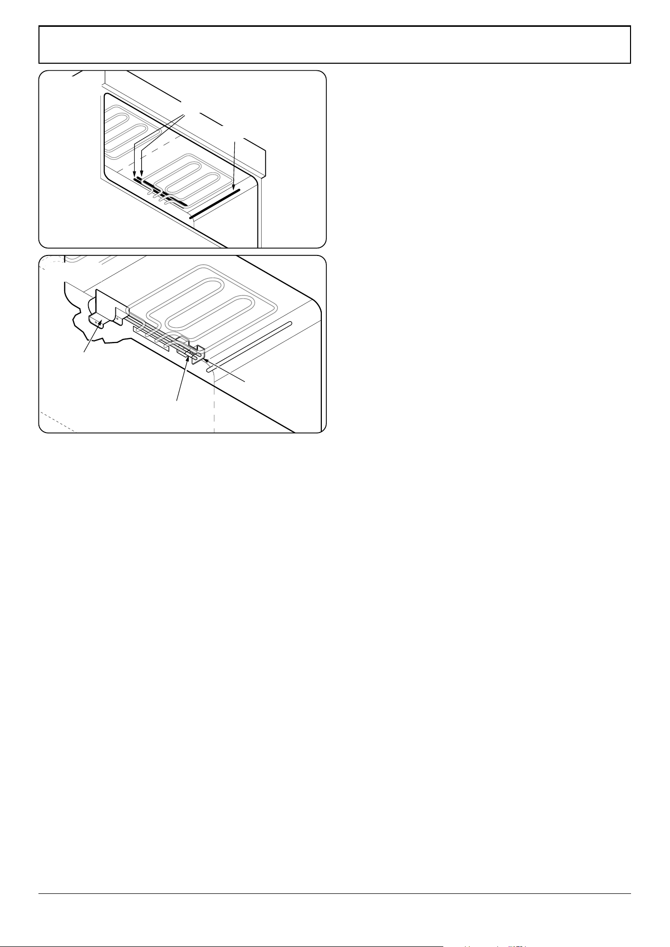
WARNING – SERVICING TO BE CARRIED OUT ONLY BY AN AUTHORISED PERSON
Disconnect from electricity and gas before servicing. Check appliance is safe when you have nished.
38
Catalytic lter cover
Bracket
Phial retaining
clamp
Protection & primary phials
Pyrolytic phial
3. To Replace the Ignition Spark Generator
DISCONNECT FROM THE ELECTRICITY SUPPLY.
Remove the hotplate (see 1. To Remove the Hotplate).
Disconnect all the leads from the generator, taking note of
their positions. Unclip the generator from the cooker.
Fit the new generator and reconnect the leads. Check for
correct ignition.
4. Ovens
1. To Change an Oven Thermostat
DISCONNECT FROM THE ELECTRICITY SUPPLY.
Situated at the back of the oven, behind the right-hand upper
elements, are the primary and protection thermostats phials.
One the right-hand side of the same element is the pyrolytic
phial (Fig. 11.5).
To Change the Primary Thermostat
Remove the control panel (see 1. To Remove the Control ) and
hotplate (see 1. To Remove the Hotplate).
Remove the oven shelves, shelf supports and divider.
Undo the cooker rear cover screws and remove the covers.
Undo the screw holding the phial retaining clamp to the
bracket. Undo the 2screws securing the catalytic lter cover
(Fig. 11.6).
Track the route of the thermostat capillary from the rear of
the control on the fascia to where it disappears into the oven.
By moving the capillary it will become obvious which of the
2 phials in the oven it is connected to. The phial can then be
removed.
Feed the thermostat capillary out and clear of the oven,
noting the routing.
Remove the 2 screws xing the thermostat to the inner
control panel and disconnect the wiring from the thermostat.
Fit the replacement in reverse order.
To Change the Protection Thermostat
Follow the same procedure as above except that the control
is situated on the rear cover.
Fit the replacement in reverse order.
To Change the Pyrolytic Thermostat
Remove the control panel (see 1. To Remove the Control ) and
hotplate (see 1. To Remove the Hotplate).
Remove the oven shelves, shelf supports and divider.
Undo the cooker rear cover screws and remove the covers.
Remove the 2 screws holding the small retaining plate on the
back of the cooker and remove the plate.
Remove the pyrolytic phial.
Fit the replacement in reverse order.
Fig. 11.5
Fig. 11.6
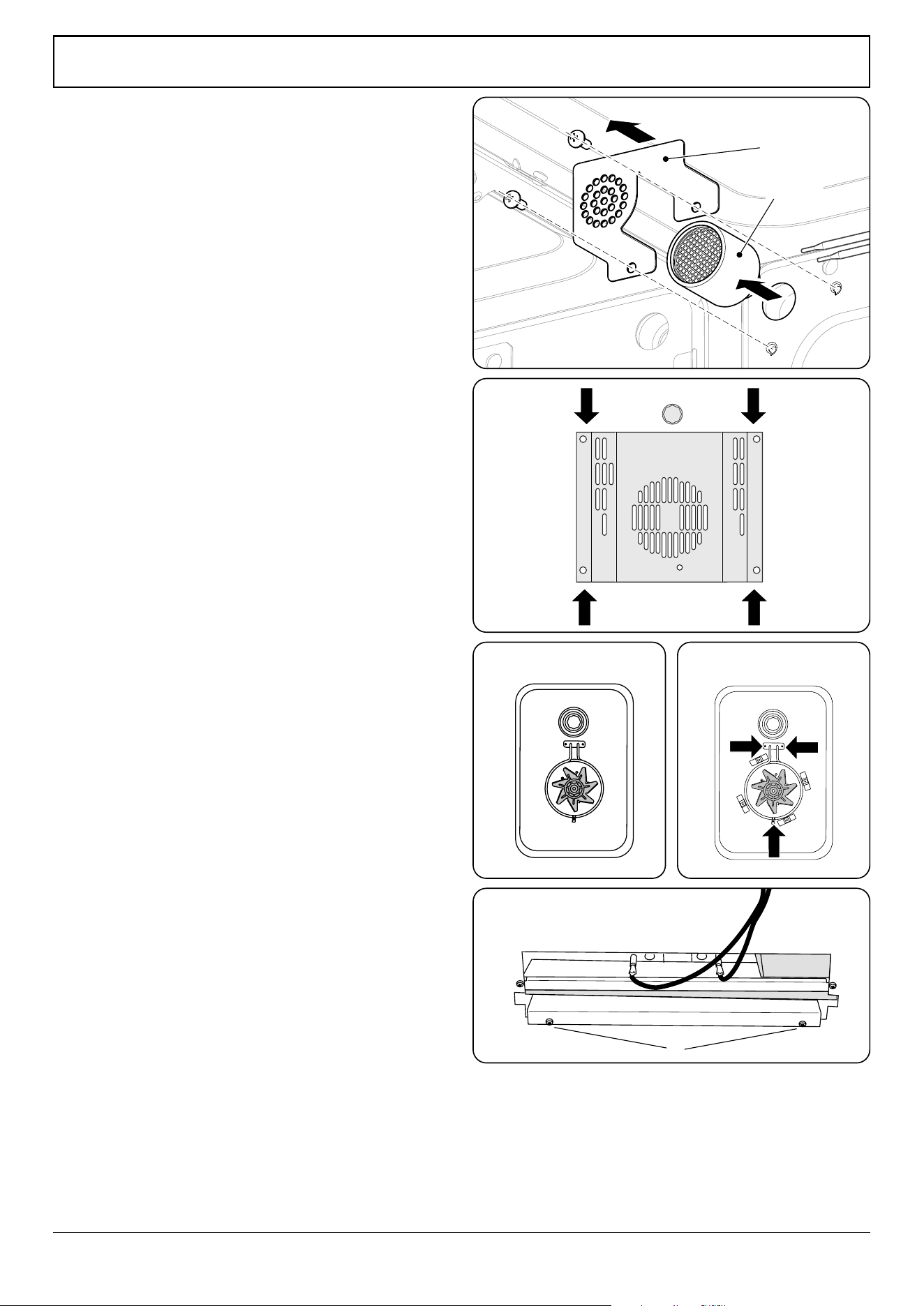
WARNING – SERVICING TO BE CARRIED OUT ONLY BY AN AUTHORISED PERSON
Disconnect from electricity and gas before servicing. Check appliance is safe when you have nished.
39
ArtNo.322-0002 Oven bottom element access
A
B B
2. To Replace the Oven Multi-function Switch
DISCONNECT FROM THE ELECTRICITY SUPPLY.
Move the cooker away from the wall to allow access to the
rear.
Remove the control panel (see 1. To Remove the Control
Panel) and hotplate (see 1. To Remove the Hotplate).
Remove the xing screws from the front of the oven multi-
function switch. Disconnect the leads and remove the switch.
Fit the new switch.
3. To Replace the Oven Catalytic Converter
DISCONNECT FROM THE ELECTRICITY SUPPLY.
Undo the 2 screws holding the catalytic lter cover in place
(Fig. 11.7) and remove.
Pull out the catalytic assembly.
Replace the catalyst and t in reverse, making sure that the
cover ts over the ends of the thermostat phials.
4. To Remove an Oven Inner Back Panel
DISCONNECT FROM THE ELECTRICITY SUPPLY.
Open the oven door. For the right-hand side unscrew the 4
thermostat phial xing screws.
Remove the xings that secure the inner back to the oven
rear (Fig. 11.8). Lift the removable panels away.
Reassemble in reverse order. Make sure that the retaining
xings are fully tightened.
5. Replacing an Oven Fan
DISCONNECT FROM THE ELECTRICITY SUPPLY.
Pull the cooker forward to access the cover boxes at the rear
of the cooker.
Remove the inner back panel (see 4. To Remove an Oven
Inner Back Panel).
Hold the fan blades and undo the centre nut (Left-hand
thread), brass washers, fan blade and circlip (Fig. 11.9). Undo
the screws that retain the fan and remove it from the cavity
rear.
Fit the replacement and reassemble the parts in reverse order.
Check that the oven operates satisfactorily.
6. Replacing an Oven Fan Element
DISCONNECT FROM THE ELECTRICITY SUPPLY.
Remove the inner back panel (see 4. To Remove an Oven
Inner Back Panel).
Remove the screws that secure the element within the oven
and carefully lift the element away (Fig. 11.10).
Disconnect the leads and connect to the replacement
element and reassemble the parts in reverse order.
ArtNo.281-0148
- USA Oven Fan
ArtNo281-0148 USA Oven Fan
ArtNo.281-0149 - Fan oven inner
ArtNo.281-0149 - Fan oven inner
Catalytic
assembly
Filter cover
Fig. 11.7
Fig. 11.8
Fig. 11.9 Fig. 11.10
Fig. 11.11
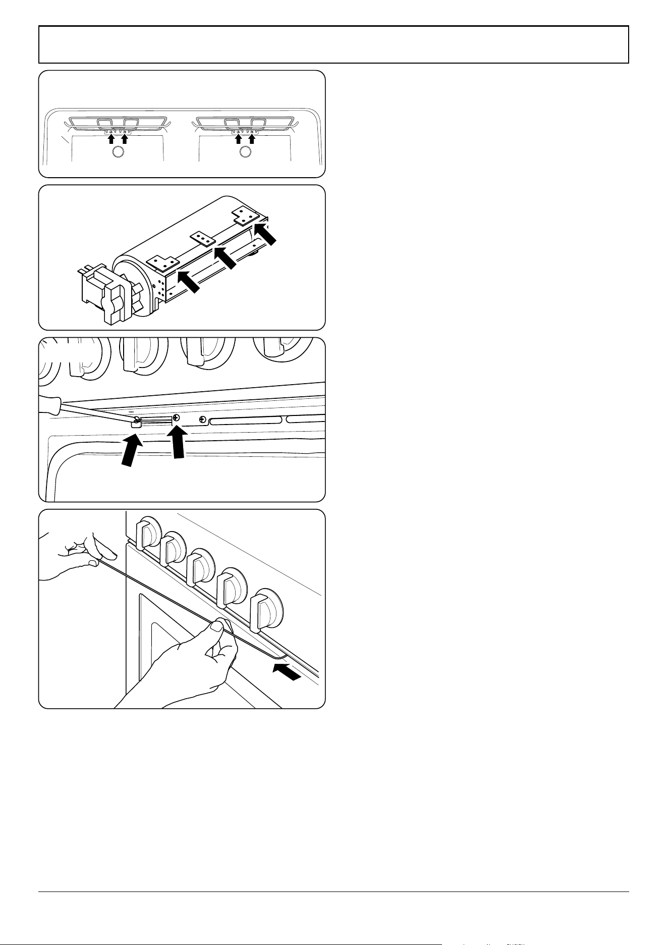
WARNING – SERVICING TO BE CARRIED OUT ONLY BY AN AUTHORISED PERSON
Disconnect from electricity and gas before servicing. Check appliance is safe when you have nished.
40
7. To Replace the Top and Bottom Elements
DISCONNECT FROM THE ELECTRICITY SUPPLY.
Bottom Element
Pull the cooker forward to allow access to the cover boxes at
the rear. Remove the xings that secure the cover and lift it
clear.
Remove the 2 screws ‘A’ and allow the plate to drop down.
Remove the 2 screws ‘B’, and then lower the upper plate and
remove it through the slot in the cooker back (Fig. 11.11).
Undo the terminal connections, noting their positions.
Remove the element xings and withdraw the element.
Replace the element and reassemble the parts in reverse
order.
Top Element
Remove the top element bracket xings and withdraw the
elements carefully, lifting to clear the clips on the support bar
(Fig. 11.12).
Replace the element and reassemble the parts in reverse
order.
Check that the oven operates satisfactorily.
8. To Replace the Cooling Fan
Remove the hotplate (see 1. To Remove the Hotplate).
Remove the access plate.
Remove the screws that hold the cooling fan to the duct (Fig.
11.13), and then lift out the fan.
Reassemble in reverse order.
9. To Replace the Oven Latch Motor
Remove the packing and accessories from the appliance
except the base pack that can be left in place.
Remove the hotplate (see see 1. To Remove the Hotplate).
Disconnect the thermal cut-out. Disconnect the motor leads
from the terminal block.
Undo the 3 cover plate screws and remove the plate.
Open the oven door and undo the 2 latch assembly retaining
screws (Fig. 11.14).
Remove the black, orange and purple wires connected to the
latch motor. Remove the latch motor assembly.
NOTE: The access to the assembly is very tight; it is suggested
that the assembly is slid into the cooker so that the latch can
be turned sideways and then lifted out front rst.
Replace the motor and ret in reverse order.
Fig. 11.12
Fig. 11.13
Fig. 11.14
Fig. 11.15
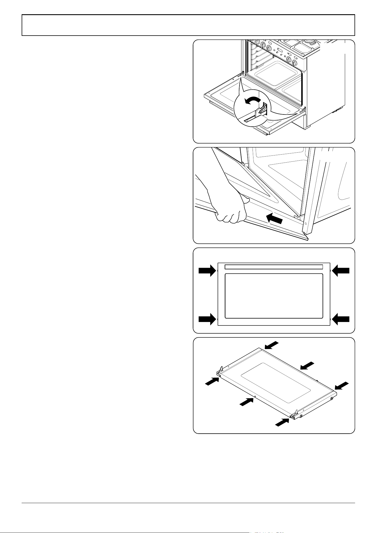
WARNING – SERVICING TO BE CARRIED OUT ONLY BY AN AUTHORISED PERSON
Disconnect from electricity and gas before servicing. Check appliance is safe when you have nished.
41
(x2)
(x2)
10. To Override a Locked Oven
Switch on the cooker. Set the oven function control to self-
clean – do not set the timer. This should switch the lock back
to the open position.
If this fails, then get a wire hook and slide in through the side
to pull the latch back (Fig. 11.15).
5. Door
1. To Remove the Oven Door
CAUTION! The door is very heavy. Take care when removing.
To remove the door, open the door fully.
Swivel the locking ‘U’ clips forward to the locking position
(Fig. 11.16). Grip the sides of the door, lift upwards and then
slide the door forwards (Fig. 11.17) and remove.
2. To Remove the Outer Panel
Undo the 4 screws (2 each side) in the door (Fig. 11.18). Open
the door slightly and, using the handle, lift the door outer
away.
To ret the door, rst close the door inner. Lift the door outer
panel onto the door inner, – make sure the top of the door
outer panel ts over the locking mechanism before locating
the sides. Secure in position.
ArtNo.272-0015 - 90DF - Pro+ - Removing the outer door panel
ArtNo.062-0001 - 90 Prof+ FX - Removing the door
Fig. 11.16
Fig. 11.17
Fig. 11.18
Fig. 11.19
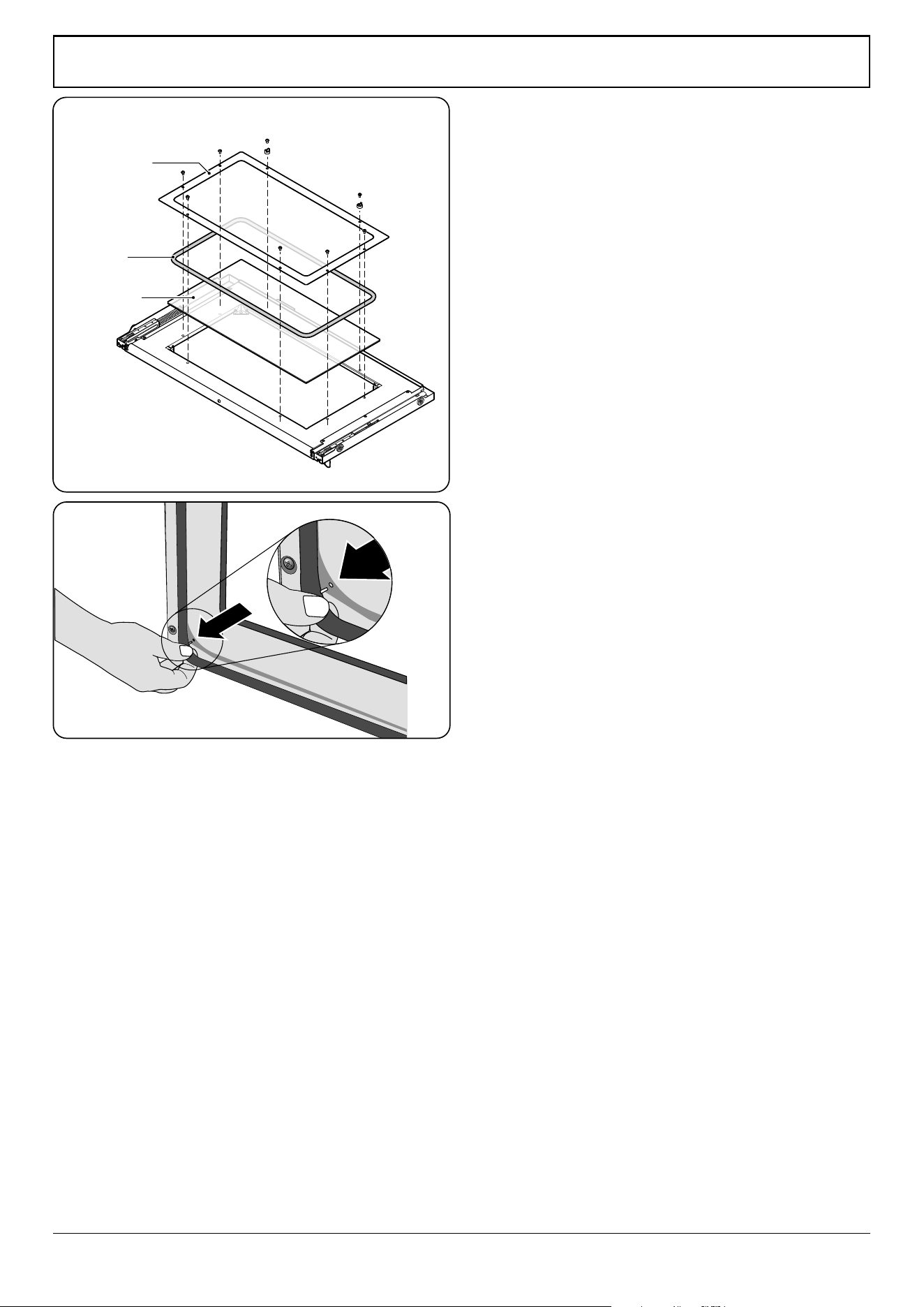
WARNING – SERVICING TO BE CARRIED OUT ONLY BY AN AUTHORISED PERSON
Disconnect from electricity and gas before servicing. Check appliance is safe when you have nished.
42
3. To Replace the Door Glass Panel
Remove the oven door (see 1. To Remove the Oven Door).
To remove the inner door glass panel, carefully place the
door, outer side up, on a clean level surface. Undo the 3
retaining screws in the top of the door and remove the trim.
Undo the 5 retaining screws from the lower edge of the door
and remove the bottom trim (Fig. 11.19). Lift out the glass
panel.
To remove the centre glass, carefully place the door, inner
side up, on a clean level surface. Remove the outer door panel
(see 2. To Remove the Outer Panel).
Undo the 8 screws holding the centre glass panel assembly
in place (Fig. 11.20). Lift out the centre glass panel assembly,
gasket and inner centre glass panel.
Reassemble in reverse order.
4. To Replace the Oven Door Hinge
Remove the oven door (see 1. To Remove the Oven Door).
Lift out the inner panel and place it, outer side up, on a clean
level surface. Undo the screws securing the hinge in place.
Remove the hinge.
Replace the hinge and rebuild the door in reverse order.
5. To Replace the Oven Door Seal
Open the oven door. The seal is held in place by small spring
clips to the cooker front. At the corner, squeeze the clip and
pull the seal diagonally away from the door centre until that
clip is released (Fig. 11.21).
Proceed to the next clip and release it in a similar way, and
so on. Use force if the clips are sti, as the old seal will be
discarded.
When tting the new seal, position the seal join at the
bottom. Clip the new seal in one of the corner holes of the
door, and proceed round the door snapping in each spring
clip in turn.
ArtNo.320-0005 Oven door rubber seal
Gasket
Centre glass
panel assembly
Inner centre
glass panel
Fig. 11.20
Fig. 11.21
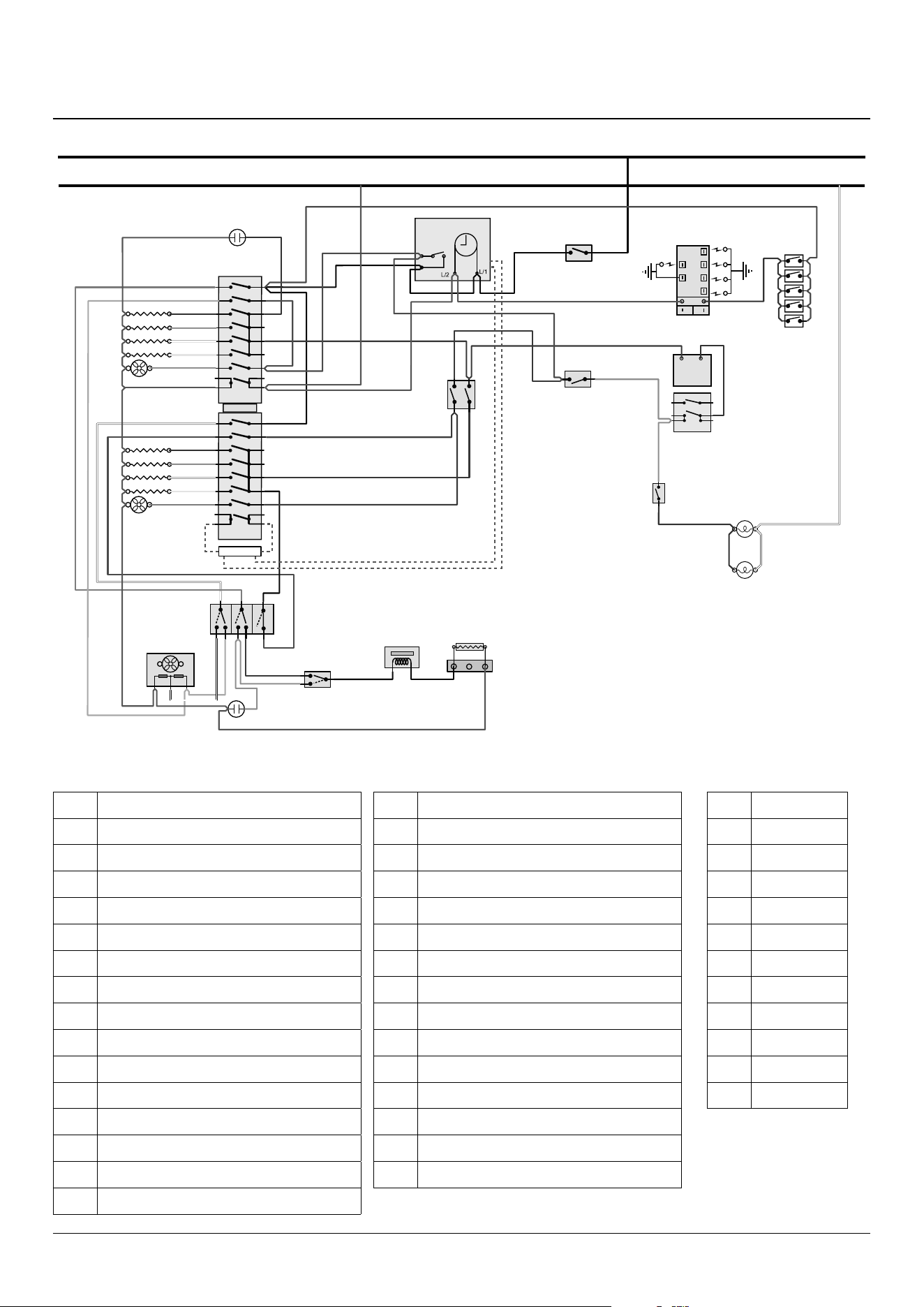
43
12. Circuit Diagram
6
P6
5 P5
4
P4
7 P7
8 P8
2
P2
1
P1
3 P3
a
b
e
f
c
d
1
2
v
32
31
21
22
24
14
12
1 2
1
2
P2
P1
A1
A2/B1
B2
6
P6
5 P5
4
P4
7 P7
8 P8
2
P2
1
P1
3 P3
11
235°C
235°C
470°C
or
gr
b
gr
w
y
or
r
br
w
b
gr
w
y
or
r
r
r
br
br
b
v
bk
b
r
bk
v
br
v
bk
r
r
or
w
bk
brw or vgr
grwr
r
or
or
v
r
v
br
br
v
br
or
or
or
v
v
v
b
w
w
r v
r
br
bk
bk
r
bk bk
bk
b
bk bk
br
v
br
br
br
N
A
A1
A2
B1
B2
K
G
H3
H2
J
M
O
P
D
Q2
R
I
Q1
H1
Q3
C1
C2
C3
C4
C5
F1
F2
F3
F4
F5
Code Description
A1
Multi-function oven master switch
A2
Multi-function oven drone switch
B1
Oven thermostat
B2
Oven front switch
C1
Right-hand oven base element
C2
Right-hand oven top outer element
C3
Right-hand oven top inner element
C4
Right-hand oven fan element
C5
Right-hand oven fan
D
Cooling fan (2 speed)
F1
Left-hand oven base element
F2
Left-hand oven top outer element
F3
Left-hand oven top inner element
F4
Left-hand oven fan element
F5
Left-hand oven fan
Code Colour
b
Blue
br
Brown
bk
Black
or
Orange
r
Red
v
Violet
w
White
y
Yellow
g/y
Green/yellow
gr
Grey
r(f)
Red (ag)
Code Description
G
Oven protect thermostat
H1
Oven neon
H2
Oven light
H3
Oven light switch
I
Door lock neon
J
Ignition spark generator
K
Oven divider switch (In)
M
Ignition switches
O
Cooling fan fail cut-out
P
Pyrolytic thermostat
Q1
Lock cam switch
Q2
Lock motor
Q3
Lock motor resistor
R
Clock / oven timer
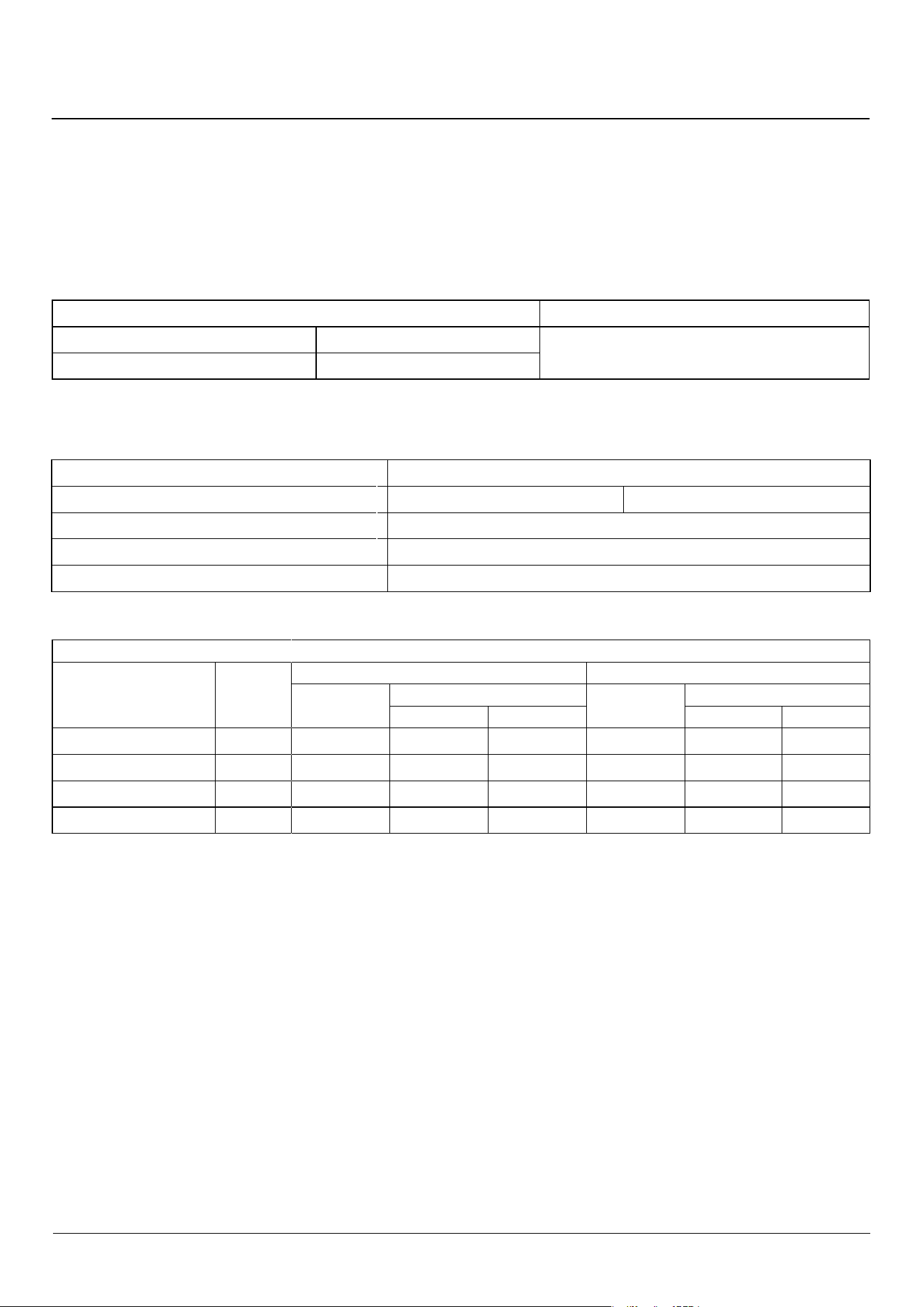
44
13. Technical Data
This cooker is designed for use on Natural gas, although a conversion for LP (LPG X Propane (2.54 kPa)) gas is packed with the
cooker.
INSTALLER: Please leave these instructions with the user.
DATA BADGE LOCATION: Inside base drawer of cavity and on rear of the appliance.
COUNTRY OF DESTINATION: Australia.
Connections
Gas (Rp ½ at rear right-hand side) Electric
Natural Gas
1.0 kPa
230 V 50 Hz
Propane 2.54 kPa
See the appliance badge for test pressures.
Dimensions
Model Professional+ FXP 90 Dual Fuel
Overall height top of hob | top of pan supports
minimum: 905 mm | 935 mm
maximum
: 930 mm | 960 mm
Overall width 900 mm
Overall depth
617 mm excluding handles, 662 mm including handles
Minimum height above top of pan supports
650 mm
Hotplate Ratings
BSI Evo 1 Type Burners Australia
Burner Type
Bypass
Screw*
Natural Gas 1.0 kPa Propane 2.54 kPa
Input
Injector
Input
Injector
Marking Size Ø Marking Size Ø
Wok 75 15.2 MJ/h-
1
198 1.93 mm 15.0 MJ/h-
1
111 1.07 mm
Rapide / Large 41 12.3 MJ/h-
1
165 1.65 mm 12.0 MJ/h-
1
89 0.96 mm
Semi Rapide / Medium 33 6.2 MJ/h-
1
115 1.15 mm 6.2 MJ/h-
1
67 0.68 mm
Auxillary / Small 25 3.7 MJ/h-
1
92 0.92 mm 3.3 MJ/h-
1
48 0.50 mm
* The valves in this cooker are tted with adjustable bypass screws. The cooker is supplied with the bypass screws set for Natural gas. For LPG conversion the
bypass screws must be screwed all the way down.
Hotplate energy saving tips Oven energy saving tips
Use cookware with a at base. Cook meals together, if possible.
Use the correct size cookware. Keep the pre-heating time short.
Use cookware with a lid. Do not lengthen cooking time.
Minimise the amount of liquid or fat. Do not open the oven door during the cooking period.
When liquid starts boiling, reduce the setting. Do not forget to turn the appliance o at the end of cooking.
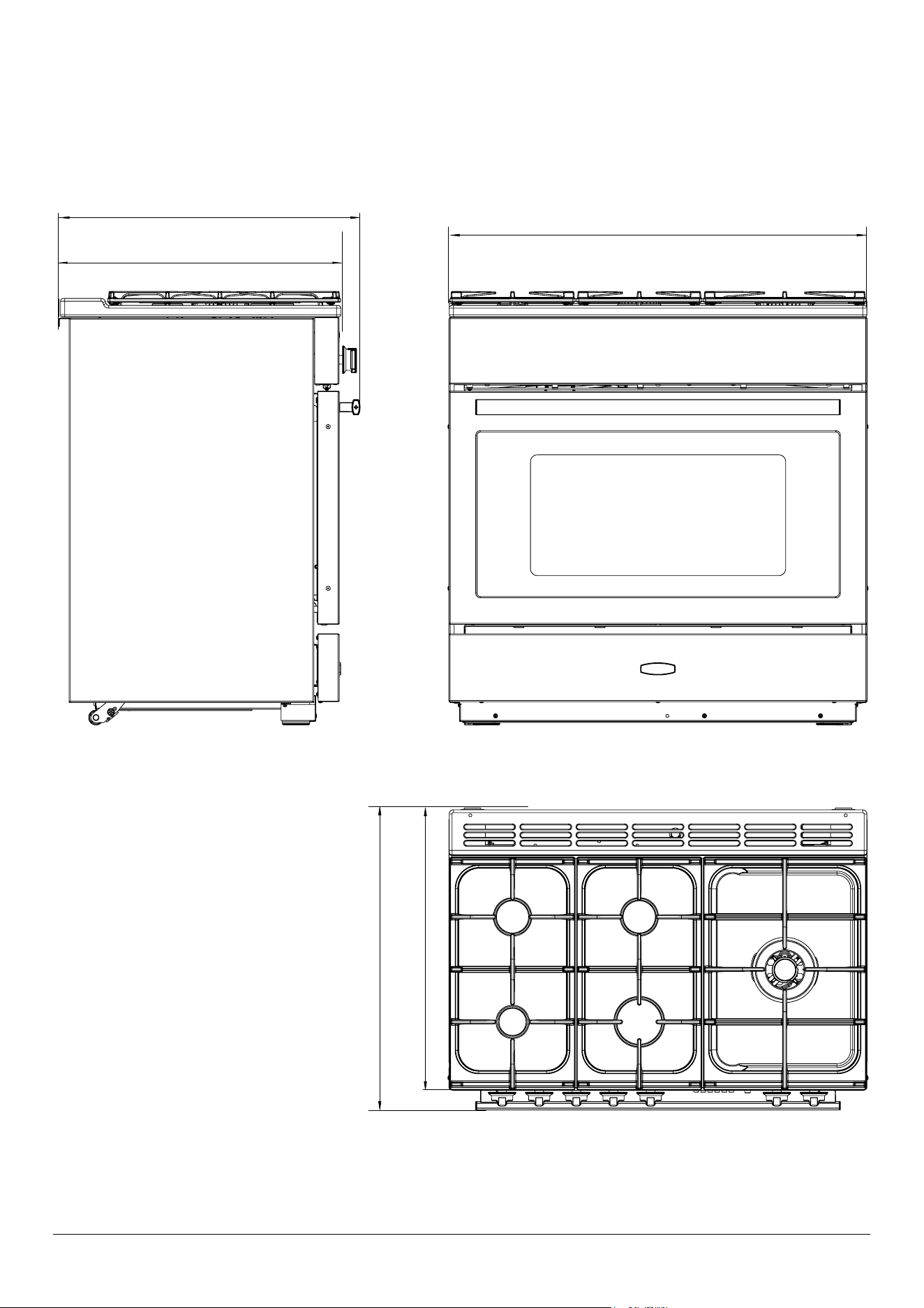
45
617 DEPTH EXCLUDING HANDLES
662 DEPTH INCLUDING HANDLES
900
617 DEPTH EXCLUDING HANDLES
662 DEPTH INCLUDING HANDLES
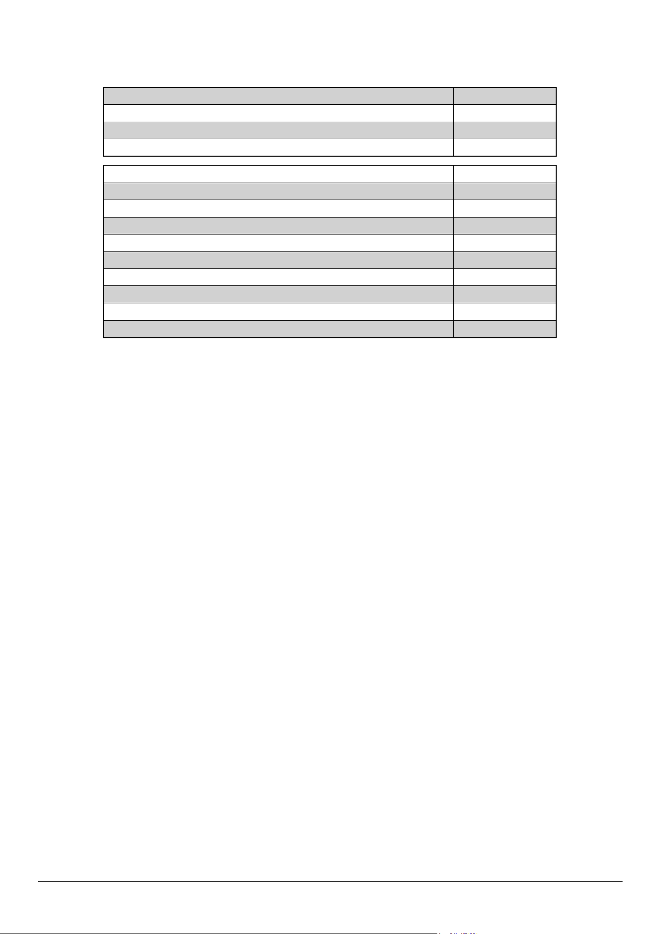
46
Hotplate Efficiency
Brand Falcon
Model Identication Professional+ FXP
Size 90 Single Cavity
Type Dual Fuel
Type of Hob GAS
Number of gas burners 5
Auxiliary / Small Burner (EE gas burner) -
Semi Rapide / Medium Burner (EE gas burner) 58%
Semi Rapide / Medium Burner (EE gas burner) 58%
Rapide / Large Burner (EE gas burner) 56%
Rapide / Large Burner (EE gas burner) -
Wok (EE gas burner) 54%
Wok (EE gas burner) -
Hotplate EE gas hob (*) 56%
Information marked thus (*) is not required with mixed fuel hobs
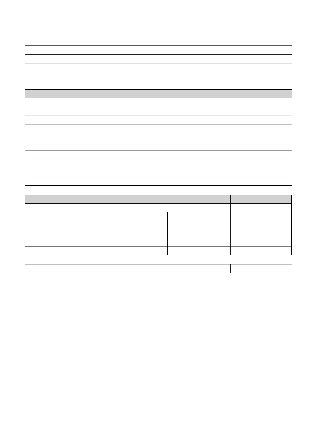
47
Oven Data
Brand Falcon
Model identication Professional+ FXP
Type of oven Electric
Mass kg 133
Number of cavities 1
Single Cavity
Fuel type Electric
Cavity type
*Drop Down Door Multifunction*
Power - conventional 2.75
Power - forced air convection 3.30
Volume Litres 114
Energy consumption (electricity) - conventional kWh / cycle 1.22
Energy consumption (electricity) - forced air convection kWh / cycle 1.05
Energy eciency index - conventional 118.6
Energy eciency index - forced air convection 102.1
Energy class A
Additional Information
The oven complies with EN 60350-1
Maximum output @ 230V 50Hz Full Divided
Fan element 3.31 kW 1.65 kW
Top element 3.49 kW 1.75 kW
Browning element 2.11 kW 1.06 kW
Bottom element 1.38 kW 0.69 kW
Maximum total electrical load at 230 V (approximate total including hob, oven lights, oven fan, etc.) 3.65 kW


Clarence Street, Royal Leamington Spa,
Warwickshire, CV31 2AD, England.
www.falconworld.com