January 2024
Installation and Operation Manual
Blackmagic
URSA
Broadcast G2
Blackmagic URSA Broadcast G2

Welcome
Thank you for purchasing Blackmagic URSA Broadcast G2!
Blackmagic URSA Broadcast G2 is an incredibly powerful camera designed for both
traditional and online broadcasters. The camera’s versatile design allows it to work as
a 4Kproduction camera, a 4K studio camera or a 6K digital film camera!
Built from strong, lightweight magnesium alloy, your Blackmagic URSA Broadcast G2 is
perfectly balanced and comfortable to use all day with physical controls at your fingertips.
This means you can change ND filters, shutter speed, white balance, ISO and more without
looking away from the viewfinder.
Your URSA Broadcast G2 is compatible with B4 broadcast lenses and records to common
file types such as Blackmagic RAW and Apple ProRes, plus highly efficient 10-bit broadcast
quality H.264 and H.265. Dual native gain provides fantastic low light performance and
is optimized to reduce grain and noise at higher ISOs while maintaining the full dynamic
range of the sensor!
We hope you use your URSA Broadcast G2 to produce some of the world’s most exciting
television programming, documentaries and live studio content. We are extremely excited
to see what creative work you produce and would love your feedback on new features you
would like to see us add to URSA!
Grant Petty
CEO Blackmagic Design

Contents
Getting Started 7
Attaching a Lens 7
Powering your Camera 8
Using Servo Zoom Lenses 10
Setting the Back Focus on B4 Lenses 16
Storage Media 20
CFast Cards 20
SD Cards 21
Recording to USB-C flash disks 23
SSDs 24
Preparing Media for Recording 26
Preparing Media on Blackmagic
URSA Broadcast G2 26
Preparing Media on Mac 28
Preparing Media on Windows 29
Recording 30
Recording Clips 30
Choosing the Codec, Resolution
and Sensor Area 31
Blackmagic RAW 32
Recording to Blackmagic RAW 32
Choosing Frame Rates 35
Triggering Record on External
Equipment 38
Record Duration Table 38
Playback 40
Media Pool 41
Controls 42
Playback 42
Group Select 44
Media Filter 44
Storage 44
Uploading Clips to Blackmagic Cloud 45
Logging into Blackmagic Cloud 45
Blackmagic Cloud Projects Panel 47
Uploading Clips to a Blackmagic
Cloud Project 47
Selectively Uploading Clips to Projects 49
Upload Original 50
Uploading to Your Blackmagic
Cloud Storage 50
Clip Upload Status Indicators 51
Closing the Media Pool 52
URSA Broadcast G2 Connectors
andFeatures 53
Camera Front 53
Left Side 54
Left Side Controls 54
Right Side 56
Rear Panel 57
Top Panel 59
Underside 59
URSA Broadcast G2 Controls 60
Forward Control Panel 60
Ergonomic Control Panel 63
Internal Control Panel 68
Camera Video Outputs 70
HD Monitoring Output 70
12G-SDI Output 70
Touchscreen Controls 72
Upper Toolbar 72
Lower Toolbar 89
Looping playback 95
Settings 96
Dashboard 96
Record Settings 96
File Naming Convention 103
Monitor Settings 103
Audio Settings 110
Setup Settings 112
Presets 130
LUTS 133
Entering Metadata 136
4Blackmagic URSA Broadcast G2

Gyro Stabilization 141
Streaming Video 143
Smartphone Setup 144
Settings 144
Setting the ATEM Camera ID 145
Creating the XML File 145
Exporting the XML File 145
Loading the XML File 146
URSA Mini Shoulder Kit 147
Blackmagic URSA Viewfinder 150
Mounting and Connecting to
Blackmagic URSA Broadcast G2 150
Adjusting the Eyepiece 151
Button Features 151
Menu Settings 152
Blackmagic URSA Studio Viewfinder 156
Mounting and Connecting to
Blackmagic URSA Broadcast G2 157
Adjusting the Blackmagic
URSAStudio Viewfinder 159
Button Features 162
Menu Settings 164
Blackmagic Zoom and Focus Demands 169
Connecting and Attaching to your
Camera 169
Using Blackmagic Focus Demand 171
Using Blackmagic Zoom Demand 172
Mounting Batteries 173
Mounting V-mount or GoldMount
Batteries 173
Using your own Battery Plate 175
URSA Broadcast ENG Kit 177
Product Assembly 177
Accessories Attachment 178
Blackmagic Fiber Converters 179
Getting Started with
BlackmagicFiberConverters 180
About SMPTE Fiber 180
Connecting SMPTE Fiber 182
Why Connections on the Front? 186
Plugging in Camera SDI 187
Plugging in Return SDI Outputs 187
Mounting BlackmagicCamera
Fiber Converter 187
Attaching the URSA Studio Viewfinder 190
Plugging in a Talkback Headset 190
Operating the Camera Fiber Converter 191
Selecting a Return Feed 191
Using the Call Button 192
Using Talkback 192
Using Tally 193
Status Indicators 193
Audio Inputs 194
IP Video 195
Power Specifications 195
Additional Camera Controls 196
Operating the Studio Fiber Converter 197
Using the Menu 198
Rack Mounting the Studio Unit 201
Camera Unit Connections 205
Camera Power Connection 205
PTZ Interface 205
Talkback Connection 206
Tracker Interface 207
DC Connection 207
D-Tap Output 208
Reference Output and Operation 208
Studio Unit Connections 209
12G-SDI Output 209
Return SDI Inputs 209
Reference Input and Output 210
Talkback Interface 210
PTZ Interface 211
Audio Outputs 212
Updating Internal Software 213
Updating Blackmagic Camera
Fiber Converter 213
Updating Blackmagic Studio Fiber
Converter 213
5Blackmagic URSA Broadcast G2

Interchangeable Lens Mount 214
Removing the B4 Mount 215
Blackmagic URSA Mini Pro EF Mount 215
Blackmagic URSA Mini Pro F Mount 217
Blackmagic URSA Mini Pro PL Mount 221
Blackmagic URSA Broadcast G2
B4 Mount 224
Shimming Lens Mounts 225
Blackmagic URSA Mini Pro Shim Kit 225
Shimming mounts 226
URSA Mini Recorder 227
Mounting and connecting
URSAMini Recorder 228
Using URSA Mini Recorder 230
Updating URSA Mini Recorder’s
internal software 231
Understanding Studio Camera Control 232
Using Camera Control 233
DaVinci Resolve Primary
ColorCorrector 238
Using DaVinci Resolve 242
Project Manager 242
Editing with the Cut Page 243
Adding Clips to the Timeline 246
Trimming Clips on the Timeline 247
Audio Trim View 247
Adding Titles 248
Working with Blackmagic RAW Files 249
Color Correcting your Clips with
the Color Page 253
Adding a Power Window 256
Using Plugins 258
Mixing Your Audio 259
Adding VFX and Compositing on
the Fusion Page 264
Mastering Your Edit 273
Quick Export 273
The Deliver Page 274
Blackmagic Camera Setup 275
Using Blackmagic Camera Setup 276
Transferring Files over a Network 283
Working with Third Party Software 286
Working with Files from CFast2.0
and SD cards 286
Working with Files from SSDs 287
Using Final Cut Pro X 287
Using Avid Media Composer 2018 288
Using Adobe Premiere Pro CC 289
Developer Information 290
Camera Control REST API 290
Event Control API 291
System Control API 291
Transport Control API 296
Timeline Control API 299
Media Control API 300
Preset Control API 302
Audio Control API 304
Lens Control API 309
Video Control API 311
Color Correction Control API 315
Blackmagic Bluetooth Camera Control 319
Blackmagic SDI and Bluetooth
Camera Control Protocol 321
Example Protocol Packets 329
Blackmagic TallyControl Protocol 330
Help 332
Regulatory Notices 333
Safety Information 334
Warranty 335
6Blackmagic URSA Broadcast G2
Getting Started
Getting started with your Blackmagic URSA Broadcast G2 is as simple as mounting a lens
andpowering your camera.
Attaching a Lens
Your URSA Broadcast G2 comes fitted with a B4 lens mount for HD and Ultra HD broadcast
lenses. An additional EF mount is included so you can also use stills lenses, other compact-
zoom or EF cine lenses. For instructions on switching lens mount types, refer to the
‘Interchangeable lens mount’ section later in this manual.
URSA Broadcast G2’s B4 mount features optics specifically designed to work with your
camera’s sensor to produce the same field of view and depth of field as traditional broadcast
cameras with 2/3" sensors. This means that if you already have a broadcast background,
you can be comfortable mounting your existing B4 lenses to URSA Broadcast G2 and shoot
confidently.
To remove the protective dust cap from the camera, rotate the outer locking ring
counterclockwise and pull the dust cap away from the mount.
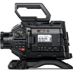
To attach a B4 mount lens:
Rotate the locking ring clockwise to secure the lens to the camera
1 Turn the B4 lens locking ring counterclockwise to reveal the alignment slot inside the top of
the mount. Align the B4 lens to your URSA Broadcast G2’s B4 mount so the alignment pin
on the lens matches the position of the alignment slot.
2 Hold the lens against the B4 mount so the mount plates are against each other and make
sure the alignment pin is secured inside the alignment slot.
3 Turn the locking ring clockwise to tighten the lens against the mount and lock it into position.
4 To power the lens and provide lens control, simply plug the lens cable into the connector
marked ‘Lens’ on the front of your URSA Broadcast G2’s turret. Most B4 lenses will have
the 12 pin lens connector and cable built in. This will provide power and control signals from
your URSA Broadcast G2 to the lens.
7Getting Started
For information on the types of B4 lenses and how to use them with your camera, refer to the
‘Using Servo Zoom Lenses’ section in this manual.
NOTE When no lens is attached to the camera, the optical element of URSA
Broadcast G2’s B4 mount isexposed to dust and other debris. Ensure that you
keepthe dust cap on whenever possible.
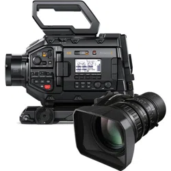
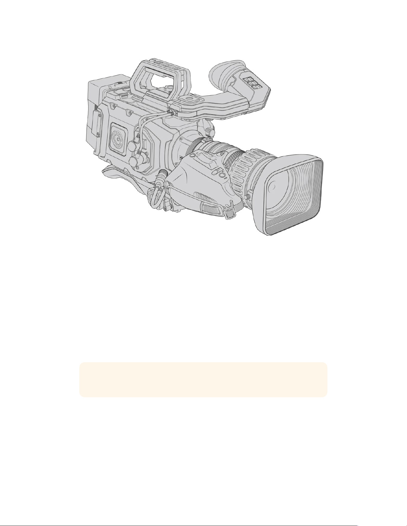
Many B4 lenses can be quite long due to their extreme zoom range. When using URSA
Broadcast G2 with B4 lenses, your camera’s center of gravity will move forward. The URSA
Mini shoulder pad included with your camera can be adjusted accordingly.
Center of gravity
When mounting URSA Broadcast G2 on the URSA Mini shoulder pad, it’s a good idea to mount
the camera towards the rear of the shoulder pad base when using longer zoom lenses. This
moves your camera rig’s center of gravity back over the middle of the pad, making it easier to
balance on your shoulder and rest steadily when sitting on a desk or flat surface. Refer to the
‘URSA Mini Shoulder Kit’ section later in this manual for more information on fitting the
shoulder pad.
Powering your Camera
Now that you’ve attached a lens, you will need to supply power. The quickest way to power
your camera is to connect external power using the supplied AC to 12V DC adapter.
To plug in external power:
1 Connect the AC to 12V DC adapter plug to your mains power socket.
2 Connect the AC to 12V DC adapter’s 4 pin XLR connector to the 12-18V DC power
connector on the camera.
If you have both external and battery power connected, only external power will be used. If you
remove external power while a charged battery is connected, your camera will switch to battery
power without interruption.
8Getting Started
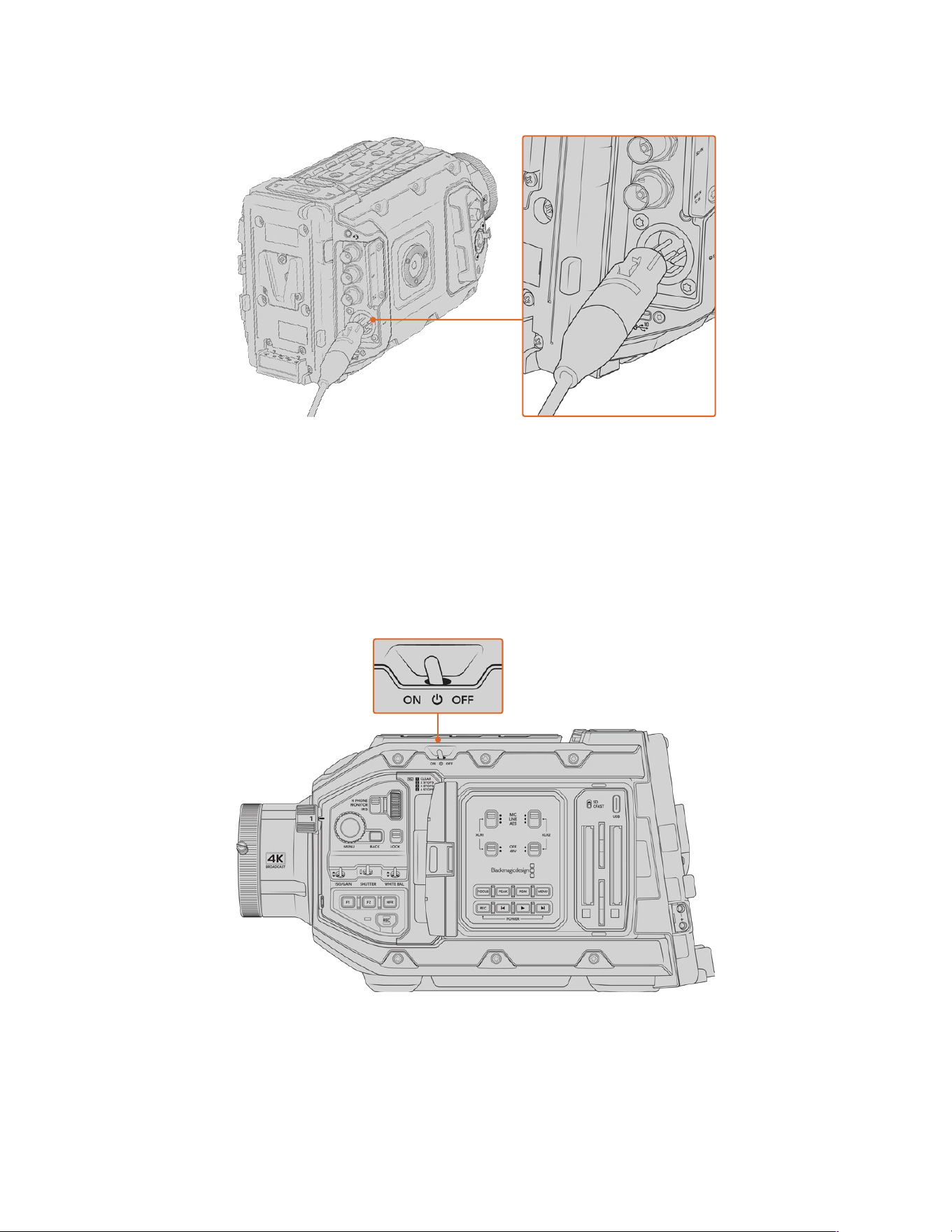
Use the supplied AC to 12V DC adapter to power your Blackmagic URSA Broadcast G2
Blackmagic URSA Broadcast G2 comes fitted with an URSA VLock Battery Plate. This lets you use
industry standard V mount batteries with your camera. Refer to the ‘mounting batteries’ section for
more information about mounting different types of battery plates to support different batteries.
To turn on URSA Broadcast G2:
1 Move the power switch, located above the fold out LCD, to the ‘on’ position.
2 To turn the camera off, move the switch to the ‘off’ position.
You are now ready to insert your media and start recording!
Move the power switch to ‘on’ to power your camera
URSA Broadcast G2 also features a redundant power switch, which allows the camera to be turned
on and off by holding down the ‘rec’ and ‘forward skip’ buttons on the inside control panel. While
you wouldn’t normally power your camera using this method, it is provided as a helpful alternative
if the power switch along the top edge is obscured, for example when mounted on a custom rig.
9Getting Started
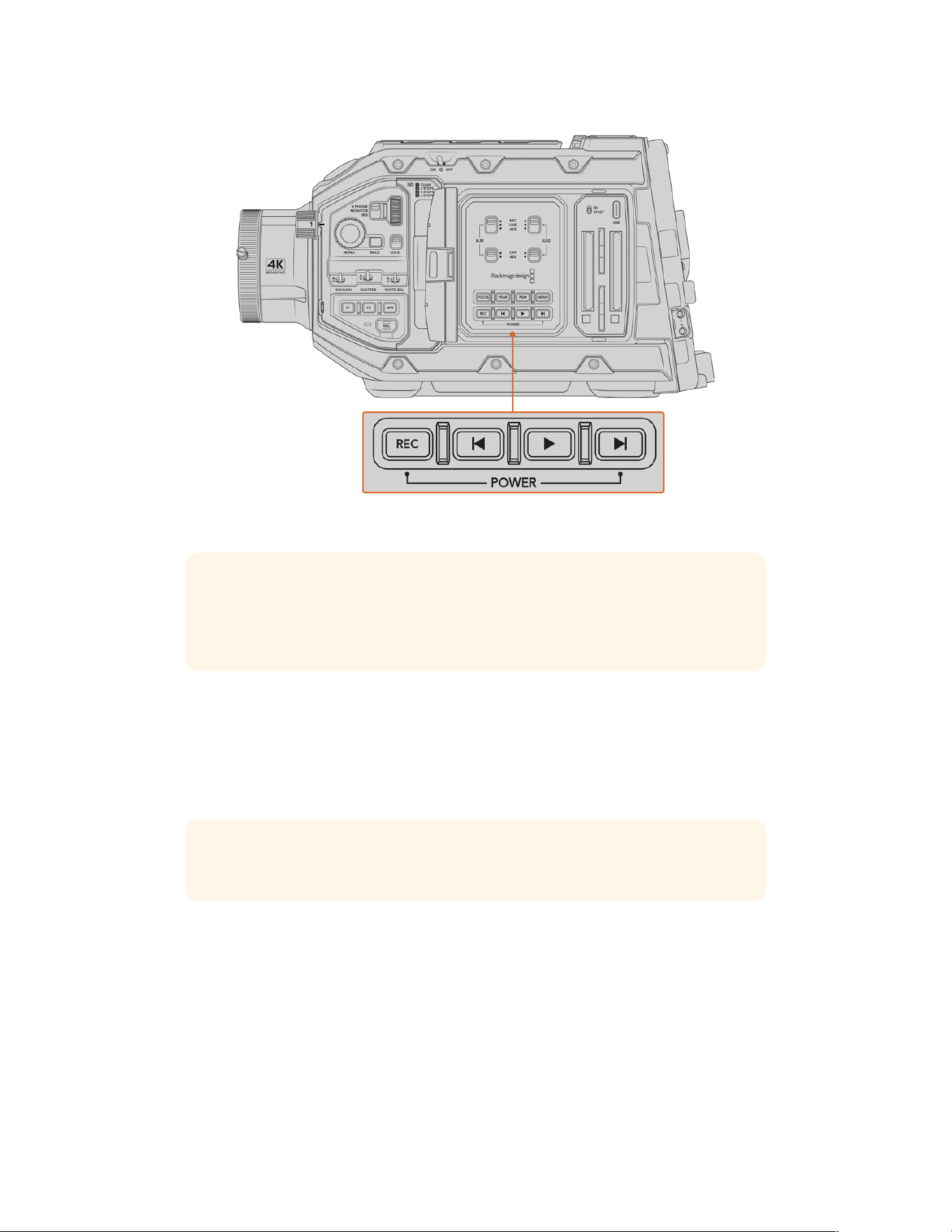
If you need to, you can also hold down the record and forward skip buttons
on the control panel behind the LCD to power your camera on or off
TIP If your URSA Broadcast G2 is turned off when the power switch is set to ‘on’, your
camera may have been powered down via Bluetooth® control or by holding down the
record and forward skip control panel buttons. Simply toggle the power switch ‘off’
and‘on,’ or hold down the relevant control panel buttons to power the camera on.
Using Servo Zoom Lenses
Your URSA Broadcast G2 natively supports servo driven B4 broadcast lenses. For information
on fitting a B4 lens to your camera, refer to the ‘attaching a lens’ section at the start of
this manual.
TIP With the optional URSA Mini Pro PL mount fitted, your URSA Broadcast G2 is also
compatible with servo driven PL cine lenses.
B4 broadcast lenses offer several features that aren’t typically present in still photography and
cinema lenses. In addition to the ability to hold focus through a large zoom range, these lenses
are distinguished by handgrip controls and servo driven iris and zoom functions. Some lenses
also feature servo driven focus. With the lens connector fitted, iris and zoom can be controlled
from the handgrip, from your camera or by using an optional Blackmagic Zoom Demand. You
can even control your lens remotely via an ATEM switcher.
Lenses which have a focus servo can accept auto focus commands from the camera,
continuously track focus using an optional Blackmagic Focus Demand or receive focus
commands from an ATEM switcher.
10Using Servo Zoom Lenses
B4 Lenses with iris and zoom control include:
Fujinon B4 lens models with HA, ZA, XA, UA and LA prefixes in their model name
and RM in their suffix. For example, Fujinon XA20sxBRM.
Canon B4 lens models with HJ, KJ and CJ prefixes and RSE or RSD in their suffix.
For example Canon KJ20x8.2B IRSD.
B4 Lenses with full servo control for focus, iris and zoom include:
Fujinon B4 lens models with HA, ZA and UA prefixes in their name and the letters
RD or ZD in the suffix. For example, Fujinon HA22x7.8 BERD.
Fujinon box lenses with XA and UA prefix in their name.
Canon B4 lens models with HJ, KJ..ex and CJ prefixes in their name and the letters
ASE or ASD in the suffix. For example, Canon HJ24ex7.5B IASE.
Canon box lenses with XJ and UJ prefix in their name.
TIP Box lens models mentioned above support both zoom and focus servos. Please
check with your lens supplier to confirm the servo motors are installed.
Your Blackmagic URSA Broadcast G2 is shipped ready to record to Blackmagic RAW Ultra HD.
Toconfirm your record settings simply press the menu button to open the menu settings on
the LCD. The first menu item is the ‘record’ tab and you can check your codec and resolution
settings here. More information on how to use the menu settings is provided later in the manual.
11Using Servo Zoom Lenses
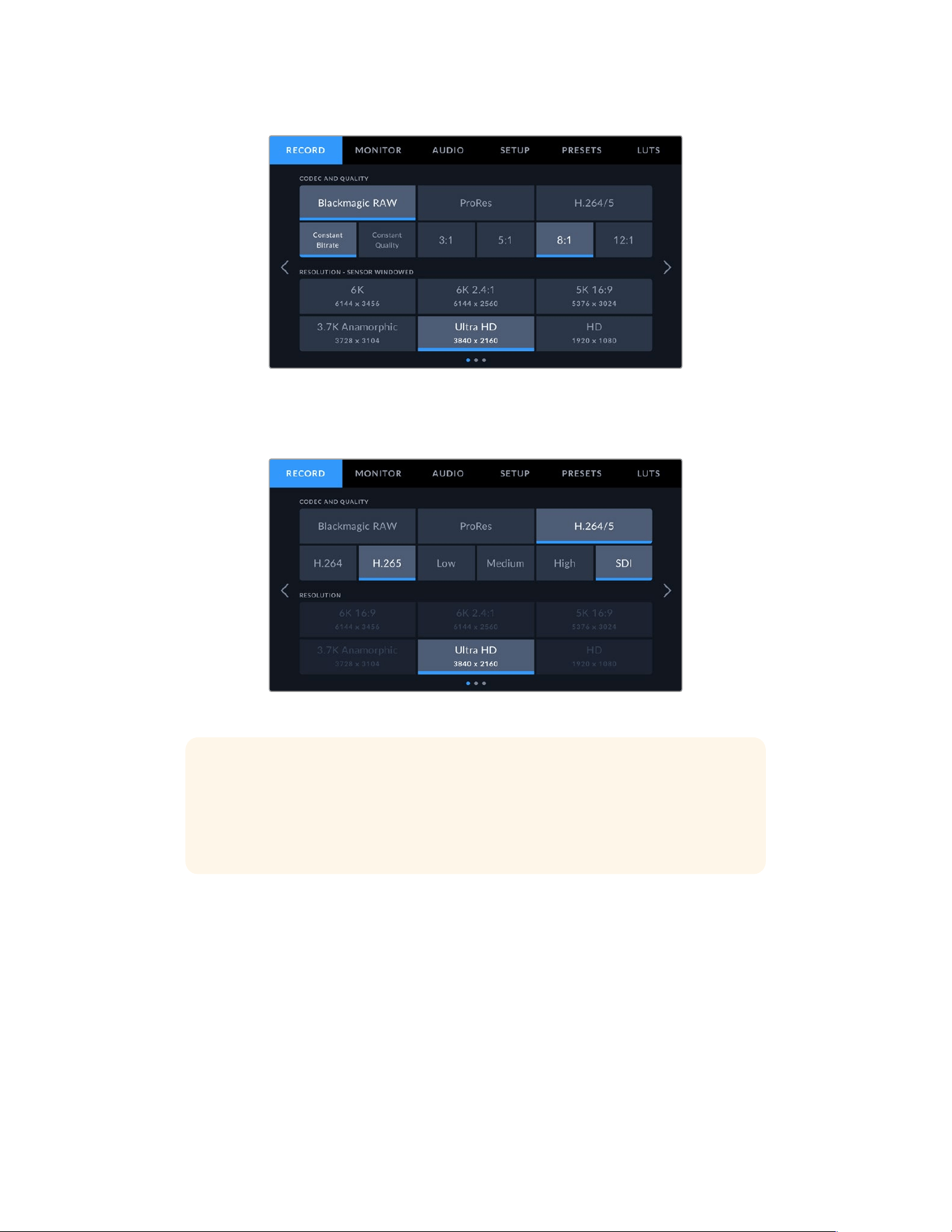
The default Blackmagic RAW settings in the ‘record’ tab
Ultra HD is also the default resolution for both ProRes and H.265 codecs. If you’d like to shoot
in HD that is also available in ProRes or H.264.
The record tab in the menu settings
TIP If you notice any vignetting in your images when using a B4 lens check that your
resolution is set to Ultra HD when set to Blackmagic RAW. If you are recording ProRes
or H.264/5, adjusting your camera’s ‘sensor area’ to 4K will suit the optical area that
the B4 mount covers. For more information, refer to the ‘record settings’ section later
in the manual.
12Using Servo Zoom Lenses
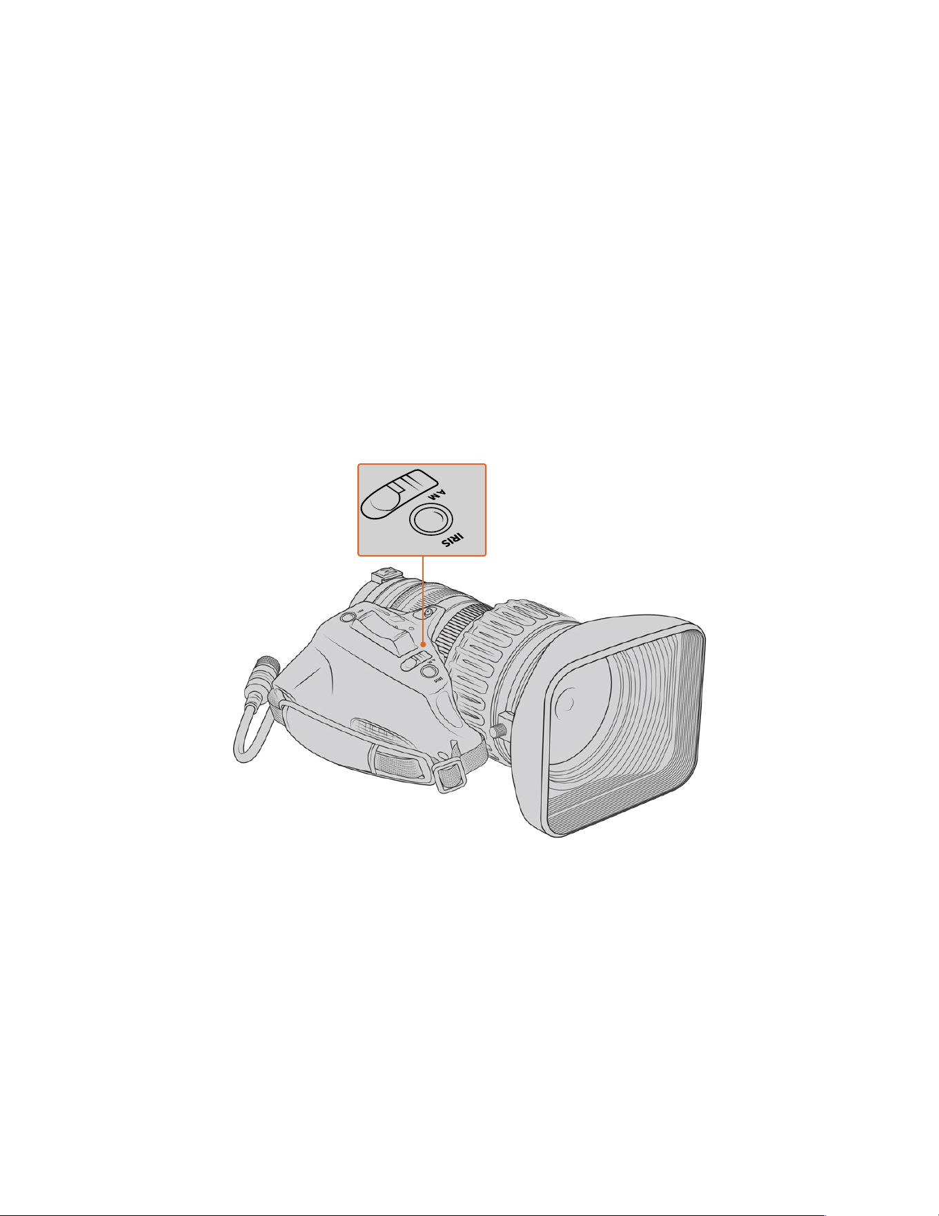
B4 lens controls
Iris
On the top of most B4 handgrips, you’ll find an ‘auto/manual’ or ‘A/M’ switch, and a ‘push auto’
or ‘iris’ switch. These control your lenses’ aperture ring.
Auto
Set this switch to ‘auto’ or ‘a’ to adjust your lens aperture via your URSA Broadcast G2,
Blackmagic Zoom Demand or an ATEM switcher. You can adjust lens aperture from URSA
Broadcast G2 using the iris wheel, internal control panel buttons, touchscreen controls,
or iris based auto exposure modes. See the ‘URSA Broadcast G2 controls’ and ‘touchscreen
controls’ sections in this manual for more details. While in ‘auto’ mode, the aperture ring on
your B4 lens cannot be moved manually.
Manual
Set this switch to ‘manual’ or ‘m’ to adjust your lens aperture by turning the iris ring on the lens
barrel. In this mode, your lens will not accept aperture commands from your URSA Broadcast
G2 or ATEM switcher.
Push Auto/Iris
Use this button to momentarily activate ‘auto’ aperture control while in ‘manual’ mode. This can
be combined with iris controls on your camera or ATEM switcher to great effect.
For example, with your camera set to an iris based auto exposure mode and your lens aperture
set to ‘manual,’ you can freely adjust your lens iris by using the aperture ring on the lens barrel,
however tapping the ‘push auto’/‘iris’ button will momentarily activate auto exposure, adjusting
your iris for the current lighting conditions.
Alternatively, you can set an iris value using the controls on your URSA Broadcast G2’s
LCDtouchscreen. While in ‘manual’ mode, you are free to adjust lens aperture using the
aperture ring on the lens barrel, but tapping the ‘push auto’/‘iris’ button will return the lens
to the preset value on your touchscreen.
13Using Servo Zoom Lenses
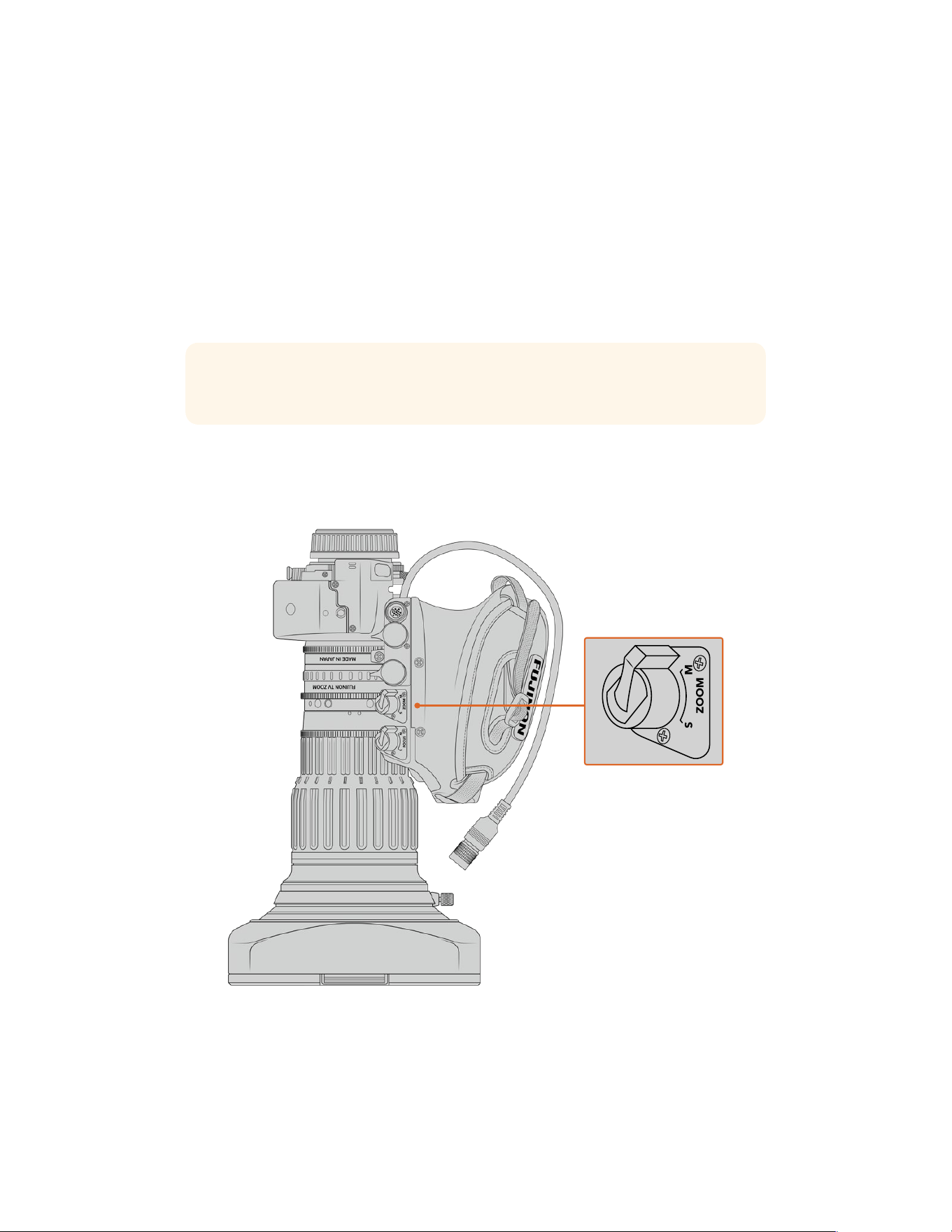
Zoom
On the underside of most B4 handgrips, you’ll find a ‘zoom’ switch that can be set to ‘servo’
or‘manual.’ This controls zoom behavior.
Servo
Set this switch to ‘servo’ or ‘s’ to enable servo zoom control. In this mode, the rocker switch on
your handgrip can be used to zoom your lens in and out, as well as any other zoom related
controls, such as zoom speed and quickzoom. Your lens will also accept zoom commands from
URSA Broadcast G2, Blackmagic Zoom Demand and ATEM switchers, so long as it is connected
to the camera via the lens connector. In this mode, you typically can’t adjust your lens’s manual
zoom ring.
TIP Handgrip zoom rockers are typically linked to zoom speed. Push the rocker down
gently to zoom slowly, push down harder to zoom more rapidly.
Manual
Set this switch to ‘manual’ or ‘m’ to disable servo control and adjust zoom using the zoom ring
on your lens barrel. In this mode, your lens will not accept zoom commands from the handgrip,
URSA Broadcast G2, or ATEM switchers.
14Using Servo Zoom Lenses
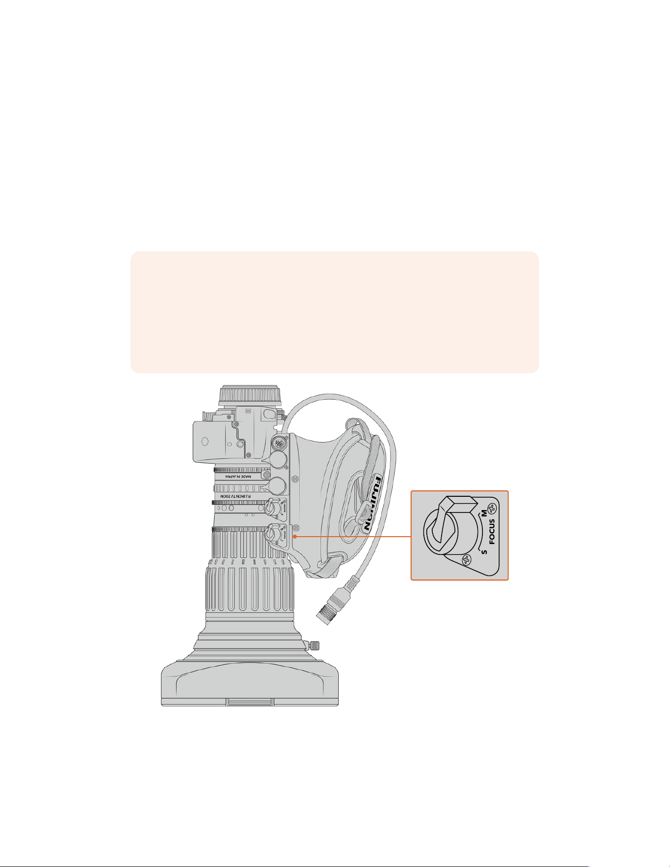
Focus
Some B4 lenses also have focus servo controls. If this control is present on your lens, you’ll
seea ‘focus’ switch on the underside of the handgrip with two settings, ‘servo’ and ‘manual.’
Servo
Set this switch to ‘servo’ or ‘s’ to enable servo focus control. In this mode, your lens canaccept
focus commands from URSA Broadcast G2, Blackmagic Focus Demand
or an ATEM switcher via the lensconnector.
Manual
Set this switch to ‘manual’ to use the focus ring on the lens barrel to control focus. B4lenses
tend to autofocus quite slowly, so using manual control is more common.
NOTE Analog B4 lenses with servos are also supported although the camera will only
power the zoom servo and support electronic iris control. Many of them are standard
definition and may not have the standard 12 pin broadcast connector. If you are going
to use an analog B4 lens, it’s important to make sure it is compatible with your camera
first as some have limited feature sets. It is also worth testing them for their image
circle coverage as some of them may reveal resolution and light fall off towards the
edge of the frame.
15Using Servo Zoom Lenses
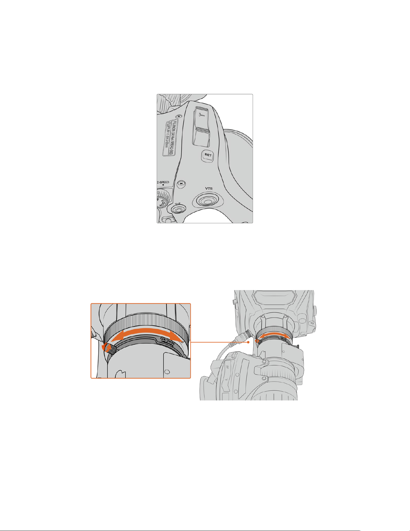
Ret and VTR
On a B4 lens, the ‘vtr’ button toggles recording and the ‘ret’ button is for ‘program return’.
For information on how you can configure the ‘vtr’ and ‘ret’ button as function buttons,
see the ‘set function button’ section in ‘setup settings’ later in this manual.
The ‘ret’ and ‘vtr’ buttons on a B4 lens
Setting the Back Focus on B4 Lenses
One of the huge advantages of B4 lenses is that they are designed to be ‘parfocal’ which
means they hold focus all the way through the zoom range. This means you can zoom in,
getfocus on an object and then when you zoom out it will remain in focus.
The back focus ring is typically located at the rear of the lens, close to the mount
Back focus is critical in ensuring that your HD or 4K B4 lenses retain focus right through the
zoom range. When you first mount a B4 lens on your camera you should check that the back
focus is correct. Back focus should also be checked when you swap lenses, and it’s a good
idea to periodically check back focus at the start of major projects.
16Using Servo Zoom Lenses

To check the back focus of a B4 lens:
1 Place a focus test chart, or a flat white item with good high contrast detail, approximately
seventy feet, or as far away as possible, from the camera.
2 Set the iris on the lens wide open and compensate for exposure by using the built in NDs
if you need to. You’ll want a shallow depth of field so you can exaggerate any focus issues.
3 Zoom into the chart and set focus.
4 Now zoom out. If you reach maximum wide and the focus remains sharp, then your back
focus is correct and you don’t need to make any adjustments.
However, if you zoomed out and the chart drifted out of focus, the back focus is incorrect.
Zoom all the way out and adjust the back focus ring on the rear of the lens close to the
mount. The back focus ring typically has a twist knob used to loosen and tighten. Simply
loosen the twist knob and rotate the ring until your chart is in focus.
5 Now zoom in and out slowly and check if your chart remains in focus all the way
through the zoom.
6 Repeat steps 4 and 5, zooming in and out and making adjustments to the back focus ring.
If your lens holds focus all the way through the zoom range your back focus is now set correctly.
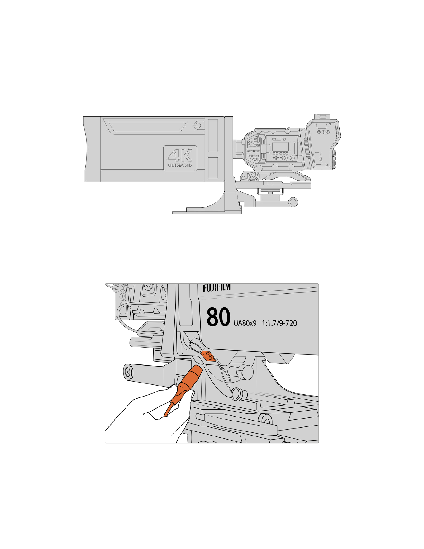
Setting back focus on Fuji LA16x8 BRM lenses
The process of setting back focus on a Fuji LA16x8 BRM lens is slightly different. Instead of an external
back focus ring this lens sets back focus electronically using a button underneath the hand grip.
To set back focus on a Fuji LA16x8 BRM lens:
1 Place a focus test chart, or a flat white item with good high contrast detail, approximately
seventy feet, or as far away as possible, from the camera.
2 Set the zoom switch underneath the lens handgrip to ‘servo’.
3 Locate the ‘F.f.’ button next to the zoom switch. Press and hold the ‘F.f.’ button
for 5seconds. The indicator LED on top of the zoom rocker will flash red.
4 The lens will automatically zoom in. Set focus using the focus ring. It’s important to note
that if you have Blackmagic Focus Demand attached you will need to unplug it from your
camera to adjust the physical focus ring or adjust the focus using the focus demand for
this step and step 5.
5 Press the ‘F.f.’ button again and the lens will automatically zoom out. Set focus using
the focus ring.
6 Press the ‘F.f.’ button to confirm the settings. The top indicator LED will flash red.
The electronic back focus on your Fuji LA16x8 BRM lens is now set.
7 Now zoom in and out slowly and check if your chart remains in focus all the way
through the zoom.
8 If your lens holds focus all the way through the zoom range your back focus is now
set correctly. If you need to make further adjustments, repeat steps 3 to 6.
TIP As temperature changes and wear over time can have subtle effects on the back
focus, it’s worth regularly checking the back focus on B4 lenses to ensure it stays accurate.
17Using Servo Zoom Lenses
Using Box Lenses
Large studio box lenses like Fujinon’s UA27x6.5 and UA125x8 and Canon’s UHD Digisuper
series lenses can also be used with URSA Broadcast G2’s B4 mount. These types of box lenses
allow horizontal and vertical image stabilization on studio style 27x lenses, as well as extreme
zoom ranges with 80x and even 125x magnification which are incredible for broadcasting sports
and outdoor events.
The large size of box lenses means that you will need to setup your camera correctly
on a heavy duty tripod or pedestal, with adequate spacing. This is possible with
URSA Mini Shoulder Kit, a VCT-14 plate and a box lens adapter.
Box lenses have a high power draw, and need to be powered separately. You can add additional
power to the lens by using an URSA 12 volt power supply, or if you are using Blackmagic
Camera Fiber Converter, you can run additional power from the 12 volt D-tap output on the side
of the unit. Plug the lens connector from the lens support bracket into URSA Broadcast G2.
Add additional power to your box lens by plugging in a 4 pin XLR cable
Once additional power is connected, you can power up your camera and control the lens with
your URSA Broadcast G2.
18Using Servo Zoom Lenses

PL Servo Zoom Lenses
PL zoom lenses used for motion pictures can also be used with your URSA Broadcast G2.
When using servo driven PL or EF lenses, the full 6K sensor area of URSA Broadcast G2 can
be used to get the most out of these lenses. For more information on setting the sensor area
on your URSA Broadcast G2, refer to the ‘record settings’ section later in this manual.
Super 35mm PL lenses with full servo control of focus, iris and zoom include:
Brand Series Model Range Max. Aperture
Fujinon Cabrio ZK2.5x14-SAF 14-35mm T2.9
Fujinon Cabrio ZK4.7x19-SAFB 19-90mm T2.9
Fujinon Cabrio ZK12x25 with ESM-15A-SA 25-300mm T3.5-3.85
Fujinon Cabrio ZK3.5x85-SAF 85-300mm T2.9-T4
Fujinon Cabrio XK6x20 20-120mm T3.5
Canon Cine-servo CN7x17KAS S 17-120mm T2.9-3.9
Canon Cine-servo CN10x25 IAS S/P1 25-250mm T2.95-3.95
Canon Cine-servo CN20x50 50-1000mm T5-8.9
Focus and zoom controls can also be used to drive focus and zoom from the pan handles in
astudio environment on all of the servo zoom lenses listed above.
Hybrid Compact Servo Zoom Lenses
Recently, a new category of lenses known as ‘compact-servo’ zoom lenses have been
introduced. These have some of the functionality of B4 and PL servo zoom lenses but use
an EF mount. The zoom rocker for these lenses can be powered through the lens mount from
URSA Broadcast G2 and information such as lens name, iris, focus and zoom position values
are allable to be read and recorded by URSA Broadcast G2’s lens metadata system.
Electronic control of the focus, iris and zoom is available with these lenses. When connected
toa switcher, these can also be controlled remotely via ATEMSoftware Control. If you are
operating in a live broadcast or studio environment, use of these lenses with Blackmagic Zoom
and Focus Demands is possible provided the iris switch on the barrel of the lens is set to ‘A’,
the focus switch is set to ‘AF’, and the zoom servo switch is set to ‘servo’.
Lenses in this range include:
Canon CN-E 18-80mm T4.4 Compact-servo
Canon CN-E 70-200mm T4.4 Compact-servo
19Using Servo Zoom Lenses

Storage Media
Your Blackmagic URSA Broadcast G2 uses standard SD cards, faster UHS-II SD cards or
CFast2.0 cards to record video.
Using the rear USB-C 3.2 Gen 2x1 port, you can connect high speed flash disks or high
capacity solid state drives. You can also record to SSDs using the optional Blackmagic
URSA Mini Recorder. For more information on connecting URSA Mini Recorder to your camera,
refer to the ‘URSA Mini Recorder’ section later in this manual.
Important Notes About Media Speeds
Write and read speeds published by recording media manufacturers are often based
on peak speeds for small files such as still images, and may not accurately reflect write
speeds for a continuous stream of high speed video.
Forreliable recording with your chosen frame rates, use only the cards recommended
by Blackmagic Design.
CFast Cards
CFast 2.0 cards are capable of supporting very high data rates, so are perfect for recording
HDand 4K video at high frame rates. Refer to the record duration table in the ‘recording’
section for details on the maximum frame rates that can be recorded in each format.
It’s important to note that while CFast 2.0 cards are generally high speed cards, some cards
have slower write speeds compared to read speeds, and maximum data rates can differ
between models. For reliable recording with your chosen frame rates, use only the cards
recommended by Blackmagic Design.
Inserting a CFast Card
To record using CFastcards you need to set your camera accordingly. To do this, set the
storage mediaswitch above the media slots to the ‘CFAST’ position.
To insert a CFast card.
1 Open the fold out monitor to access the CFast slots.
2 With the label of the CFast card facing towards the touchscreen, insert the card into the
CFast card slot until you feel it lock in place. The card should insert easily without the need
for excessive force. Push the CFast card ejector button underneath the CFast card slot to
eject the card.
The storage information at the bottom of the LCD touchscreen will show the name and
record time remaining of the detected CFast cards.
20Storage Media
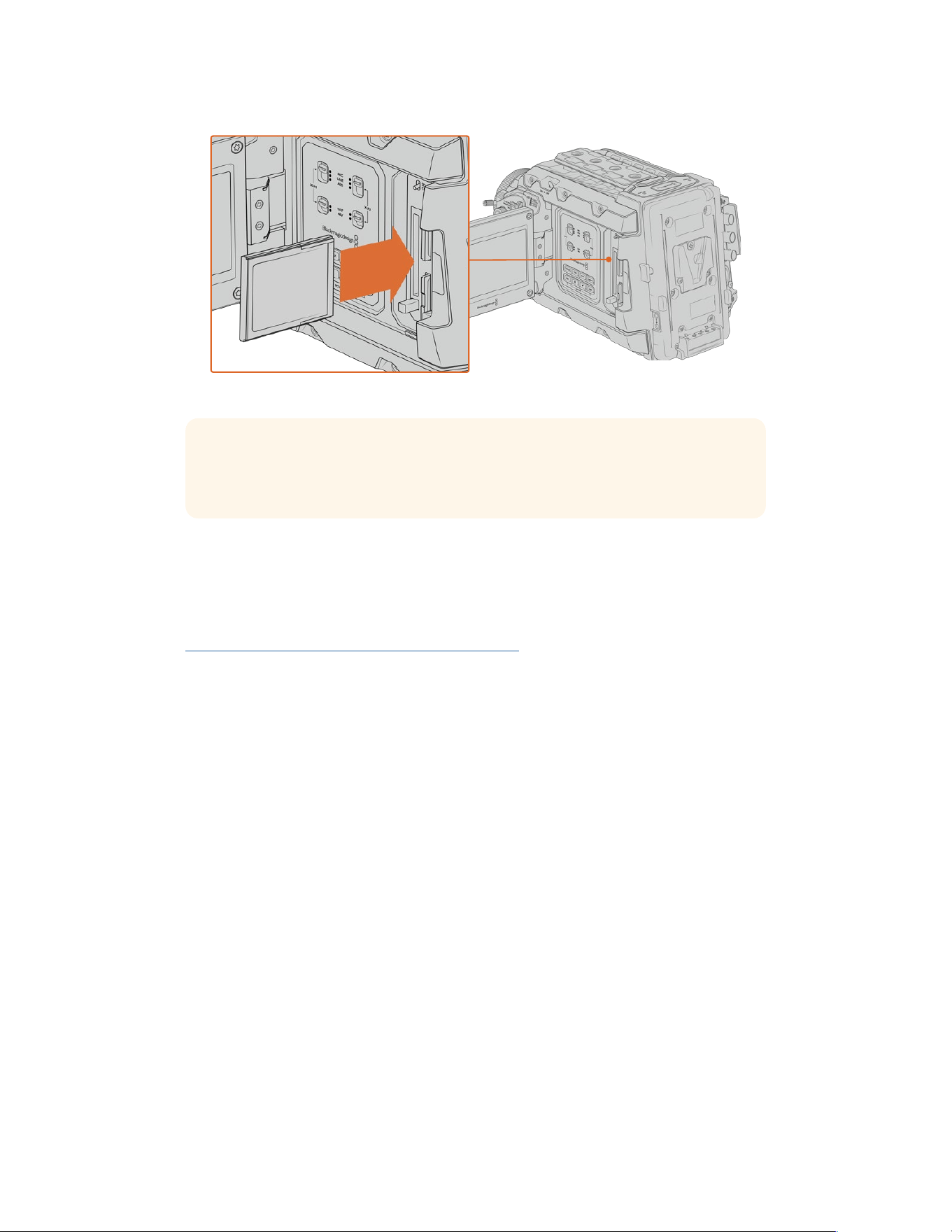
Blackmagic URSA Broadcast G2 has two CFast slots for continuous recording
TIP If you have CFast cards inserted but can not access them on the camera, check
you have CFast selected on the storage media selection switch located above the
media slots.
Choosing a CFast 2.0 Card
When working with high data rate video it’s important to carefully check the CFast card
you would like to use. This is because CFast 2.0 cards have different read and write speeds.
For the most up to date information on supported CFast cards on Blackmagic URSA
Broadcast G2, please refer to the Blackmagic Design support center at
https://www.blackmagicdesign.com/support/faq/59037.
SD Cards
In addition to CFast 2.0 cards, Blackmagic URSA Broadcast G2 can record on high speed
UHS-I and UHS-II type SD cards. Using high end SDXC UHS-II cards, you can record ProRes
HQ footage in Ultra HD or even 6K in Blackmagic RAW!
With SD cards, you can use more affordable storage media when shooting compressed video
formats in HD. SDXC and SDHC are a very common media storage format for consumer still and
video cameras.
If you’ve ever shot video using a DSLR, or use a Blackmagic Micro Cinema Camera, Pocket Cinema
Camera or Blackmagic Video Assist, you probably already have compatible SD cards to use.
For projects that don’t require the highest resolution Blackmagic RAW files, or for when long
recording durations are needed, using SD cards can be very economical. Lower capacity and
lower speed SD cards can also be used for storing and loading LUTs and Presets.
Inserting an SD Card
To insert an SD Card.
1 Open the fold out monitor to access the SD card slots. These are the smaller slots located
between the CFast slots.
2 Set the storage media toggle switch above the slots to ‘SD’.
3 With the label on the SD card facing away from the touchscreen, insert the card until you
feel it lock into place. To remove an SD card, push the SD card in to eject it.
21Storage Media
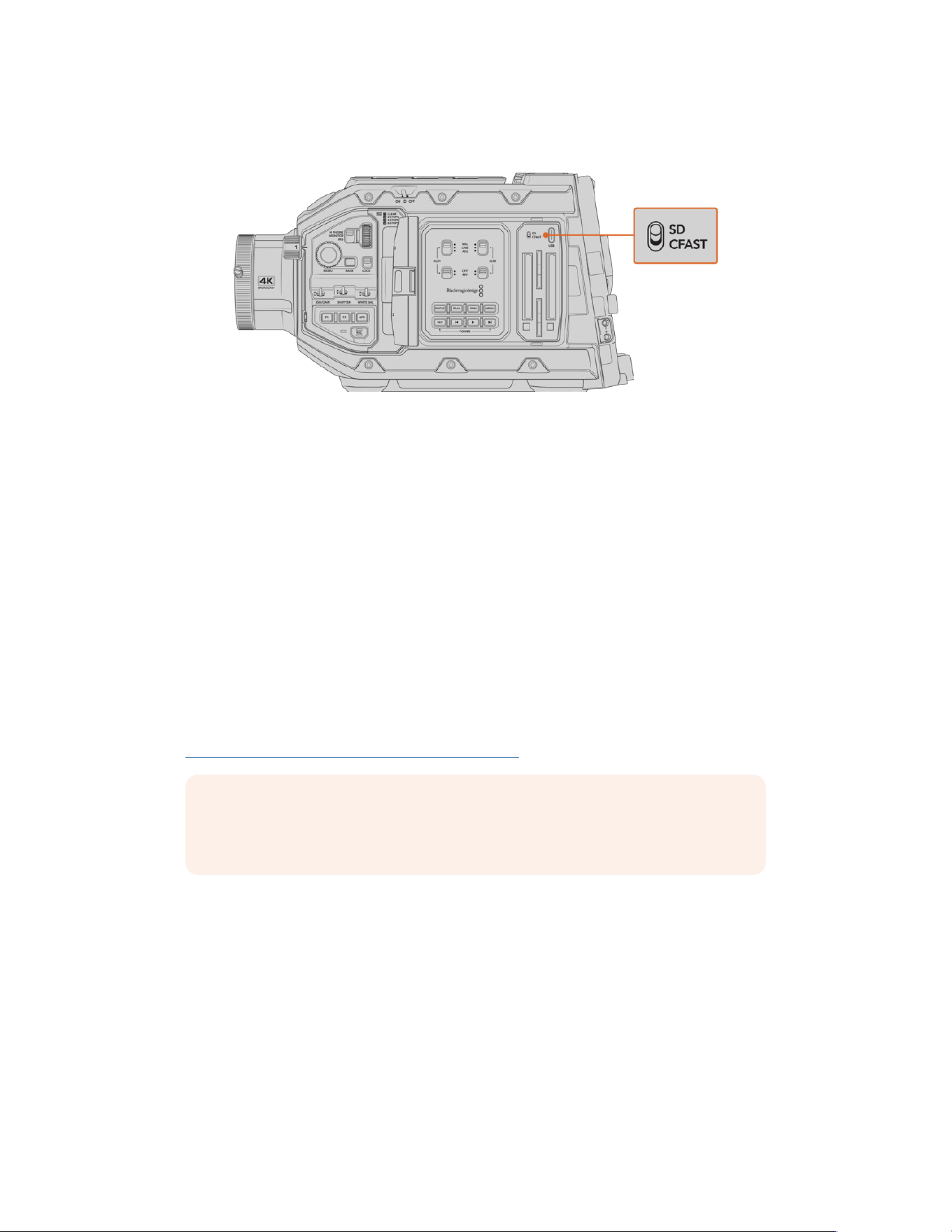
4 The storage indicator at the bottom of the LCD touchscreen will show the name and record
time remaining of detected cards.
When recording to SD cards on URSA Broadcast G2 make sure
the storage media selection switch is set to ‘SD’
Choosing a fast SD Card
If you are recording Ultra HD, then we recommend using the fastest high speed UHS-II type
SDcards available. It’s important to use high speed UHS-II SDcards for Ultra HD and HD
recording, or UHS-1 cards for HD recording. These cards are rated for fast data speeds and
support larger storage sizes. Generally the faster the cards, thebetter.
Before using your cards, you will need to format them to either HFS+ or exFAT formats.
You can format your media with the storage manager or your computer. For more information,
see the ‘preparing media for recording’ section.
If you want to, you can format your cards using a Mac or Windows computer. When using
your media on Mac, you can use HFS+ which is the Mac disk format. If you are using
Windows then you should use exFAT format, which is the Windows disk format that Mac
computers can also read.
For the most up to date information on supported SD cards on Blackmagic
URSA Broadcast G2, please refer to the Blackmagic Design support center at
https://www.blackmagicdesign.com/support/faq/59037.
NOTE When filming high frame rate or Ultra HD footage on your URSA Broadcast G2,
werecommend CFast 2.0 or SD UHS-II recording media, which are typically faster
andavailable in higher storage capacities than SD UHS-I media.
Locking and Unlocking SD Cards
SD cards can be write protected, or ‘locked’, to prevent data from being overwritten.
When inserting an SD card, make sure the card is not write protected. Write protection is
disabled by moving the plastic switch on the left side of the card to the position closest to
theconnectors. After recording, you can then write protect the card by sliding the switch
backdown to the bottom position.
22Storage Media
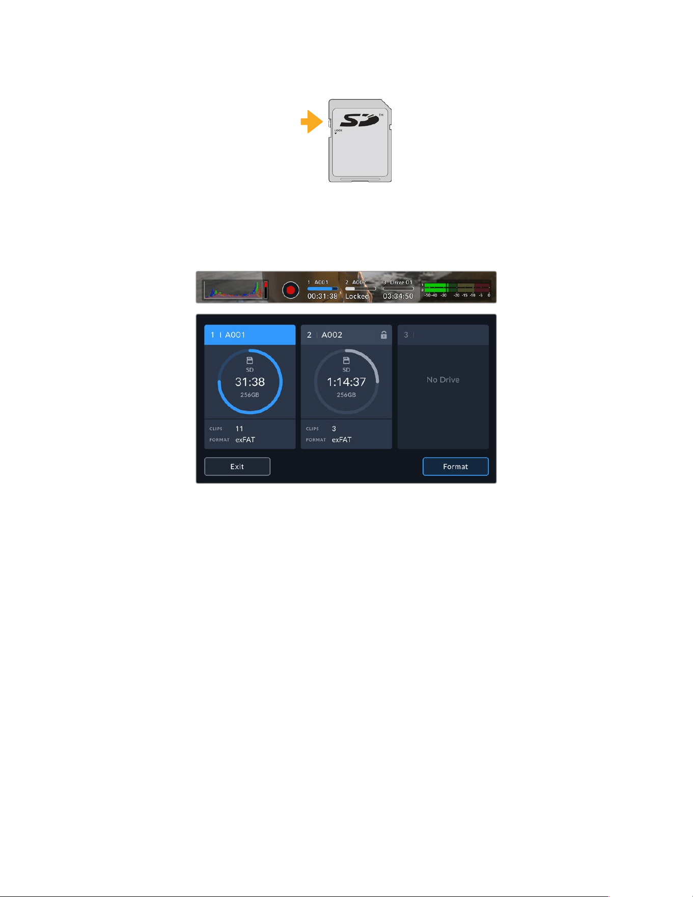
Move the lock tab up or down
to lock or unlock an SD card
Your URSA Broadcast G2 will let you know if you’ve inserted a locked SD card by displaying
a ‘locked’ icon on the LCD touchscreen and storage menu. If the card is locked, you won’t be
able to record video, capture stills, or export LUTs and presets until it is unlocked.
Your URSA Broadcast G2 will indicate when locked SD storage media is inserted
Recording to USB-C flash disks
Blackmagic URSA Broadcast G2 features two USB-C ports. The USB-C 3.1 Gen 1 port on the
side near the CFast card slots is for software updates. The port on the rear panel near the SDI
connectors is for recording to high speed SSDs and USB-C flash disks via USB-C 3.2 Gen 2x1.
These fast, high capacity drives allow you to record video for longer periods, which can be
important when filming events with long durations.
When a USB-C flash disk is connected to your camera, it occupies the third media slot in your
camera’s operating system. Tapping the drive name in the storage menu sets it as the active
drive. This means that recording, playback and storage management is exactly the same for
USB-C flash disks as it is for CFast, SD cards and SSDs.
Once you have finished recording you can connect the same drive directly to your computer
for editing and post production without having to copy media across.
To connect a USB-C flash disk:
1 Connect one end of a USB type-C cable to your USB-C flash disk.
2 On your URSA Broadcast G2, plug the USB-C cable into the USB-C port on the back panel
below the SDI ports.
3 The USB-C flash disk will occupy the third media slot on your camera’s LCD touchscreen.
23Storage Media

4 To switch recording to the USB-C flash disk, press and hold the drive name in the lower
toolbar of your camera’s LCD display. The media bar will turn blue to indicate that the
camera will now be recording to the USB-C flash disk. When recording the media bar
will turn red.
Choosing a fast USB-C flash disk
USB-C flash disks are designed to offer fast, affordable storage for a wide range of devices and
are readily available from a variety of consumer electronics outlets. It’s important to note that
film making is only one part of the USB-C flash disk market, so choosing the best drive is vital
to making sure you have enough speed to record Blackmagic RAW and Ultra HD footage.
Many USB-C flash disks are designed for home computing and aren’t fast enough to
record Ultra HD.
For the most up to date list of recommended USB-C flash disks please go to
https://www.blackmagicdesign.com/support/faq/59037.
Use Blackmagic Disk Speed Test to accurately measure whether your USB-C flash disk will be
able to handle high data rate video capture and playback. Blackmagic Disk Speed Test uses
data to simulate the storage of video so you get results similar to what you’ll see when capturing
video to a disk. During Blackmagic testing, we have found newer, larger models of USB-C flash
disk and larger capacity USB-C flash disks are generally faster.
Blackmagic Disk Speed Test is available from the Mac app store. Windows and Mac versions
are also included in Blackmagic Desktop Video, which you can download from the ‘capture and
playback’ section of the Blackmagic Design support center at www.blackmagicdesign.com/support.
SSDs
With the optional Blackmagic URSA Mini Recorder, URSA Broadcast G2 can record video
directly to solid state drives, or ‘SSDs’. These fast, high capacity drives are readily available
from a variety of consumer electronics outlets.
URSA Mini Recorder features a USB-C port enabling high speeds to work with standard 2.5" SATA
SSDs as well as 7mm U.2 SSDs. M.2 solid state drives will work when using an M.2to U.2 adapter.
To reach the proper speeds available, a certified USB 3.1 Gen 2 cable is required. The supplied
USB-C cable features locking connectors at each end to maintain a secure connection during use.
NOTE See the section ‘Blackmagic URSA Mini Recorder’ in this manual forinformation
on installing Blackmagic URSA Mini Recorder.
Inserting an SSD
To insert an SSD:
1 Hold your SSD with the connection pins facing towards the front of your camera.
2 Open the spring loaded cover on Blackmagic URSA Mini Recorder and gently insert the
SSDintothe slot.
TIP Blackmagic URSA Mini Recorder has a pressure plate to keep different sized SSDs
in place, so there’s no need to use spacers to fit your drive.
24Storage Media

3 Once your SSD is all the way into the slot gently push it home until you feel it register, then
lower URSA Mini Recorder’s cover.
4 The SSD will occupy the third media slot on your camera.
5 To switch recording to the SSD, press and hold the drive name in the lower toolbar of your
camera’s LCD display. The media bar will turn blue to indicate that the camera will now be
recording to the SSD. When recording the media bar will turn red.
To remove an SSD:
Open URSA Mini Recorder’s cover and gently grasp the drive between your thumb and
forefinger. There’s a small recess in the top of the bay to let you get a grip on the drive.
Simply pull the drive out and close the cover.
Choosing a fast SSD for URSA Mini Recorder
SSDs are designed to offer fast, affordable storage for a wide range of devices. It’s important
to note that film making is only one part of the SSD market, so choosing the right drive is vital
to ensuring that you have enough bandwidth to record Blackmagic RAW or Ultra HD footage.
ManySSDs are designed for home computing and aren’t fast enough to record Ultra HD video.
We highly recommend using only the SSDs from our recommended list, which have been tested
with Blackmagic URSA Broadcast G2 to ensure support for continuous filming at the specified
resolutions. For the most up to date list of recommended SSDs please go to
https://www.blackmagicdesign.com/support/faq/59031.
Important Notes About SSD Speed
Some models of SSD can’t save video data at the speed the manufacturer claims.
Thisis due to the disk using hidden data compression to attain higher write speeds.
This data compression can only save data at the manufacturer’s claimed speed when
storing data such as blank data or simple files. Video data includes video noise and
pixels which are more random so compression will not help, therefore revealing the
true speed of the disk.
Some SSDs can have up to 50% lower write speed than the manufacturer’s claimed speed.
Even though the disk specifications claim an SSD has speeds fast enough to handle video,
in reality the disk isn’t fast enough when used to store video data for real time capture.
Use Blackmagic Disk Speed Test to accurately measure whether your SSD will be able
to handle high data rate video capture and playback. Blackmagic Disk Speed Test
uses data to simulate the storage of video so you get results similar to what you’ll see
when capturing video to a disk. During Blackmagic’s rigorous testing, we have found
newer, larger models of SSD and larger capacity SSDs are generally faster.
25Storage Media
Preparing Media for Recording
You can format your recording media using Blackmagic URSA Broadcast G2’s storage manager,
or via a Mac or Windows computer. We recommend formatting storage media using URSA
Broadcast G2 for best performance.
HFS+ is also known as OS X Extended and is the recommended format as it supports
‘journaling’. Data on journaled media is more likely to be recovered in the rare event that your
media becomes corrupted. HFS+ is natively supported by Mac OS. ExFAT is supported natively
by Mac and Windows without needing to purchase any additional software. However, exFAT
does not support journaling.
NOTE Before formatting your media, it’s important to make sure the media storage
switch has been set correctly to either SD card or CFast card. Always check the
settings carefully before formatting.
Preparing Media on Blackmagic URSA Broadcast G2
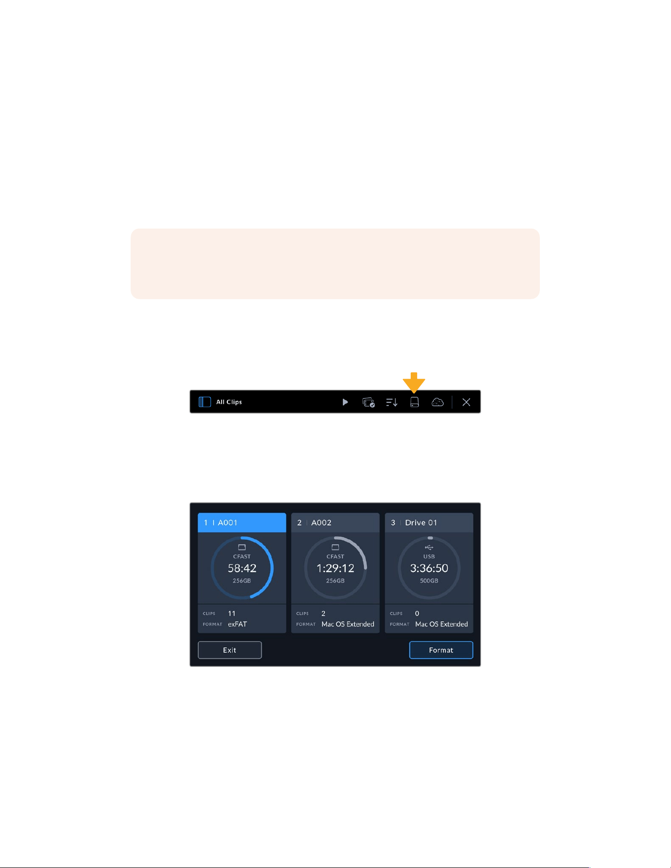
1 Tap any storage indicator at the bottom of the LCD touchscreen to open the media pool,
then tap the media storage icon at the top of the touchscreen to enter the storage manager.
Tap the media storage icon to open the storage manager
2 Tap a format button at the bottom of the touchscreen to format the card in slot 1 or 2,
respectively. If you have a USB-C flash disk or SSD connected to the rear USB-C port of
your URSA Broadcast G2, tap the ‘Drive List’ button. Then select the drive you want to
format and tap ‘Format Drive’.
Use your URSA Broadcast G2’s storage manager to format your camera’s storage media
3 If you want to change the reel number, tap on the pencil icon to open the keyboard.
Type the new reel number and tap ‘update’.
4 Choose OS X Extended or exFAT format and tap the ‘format’ button.
26Storage Media
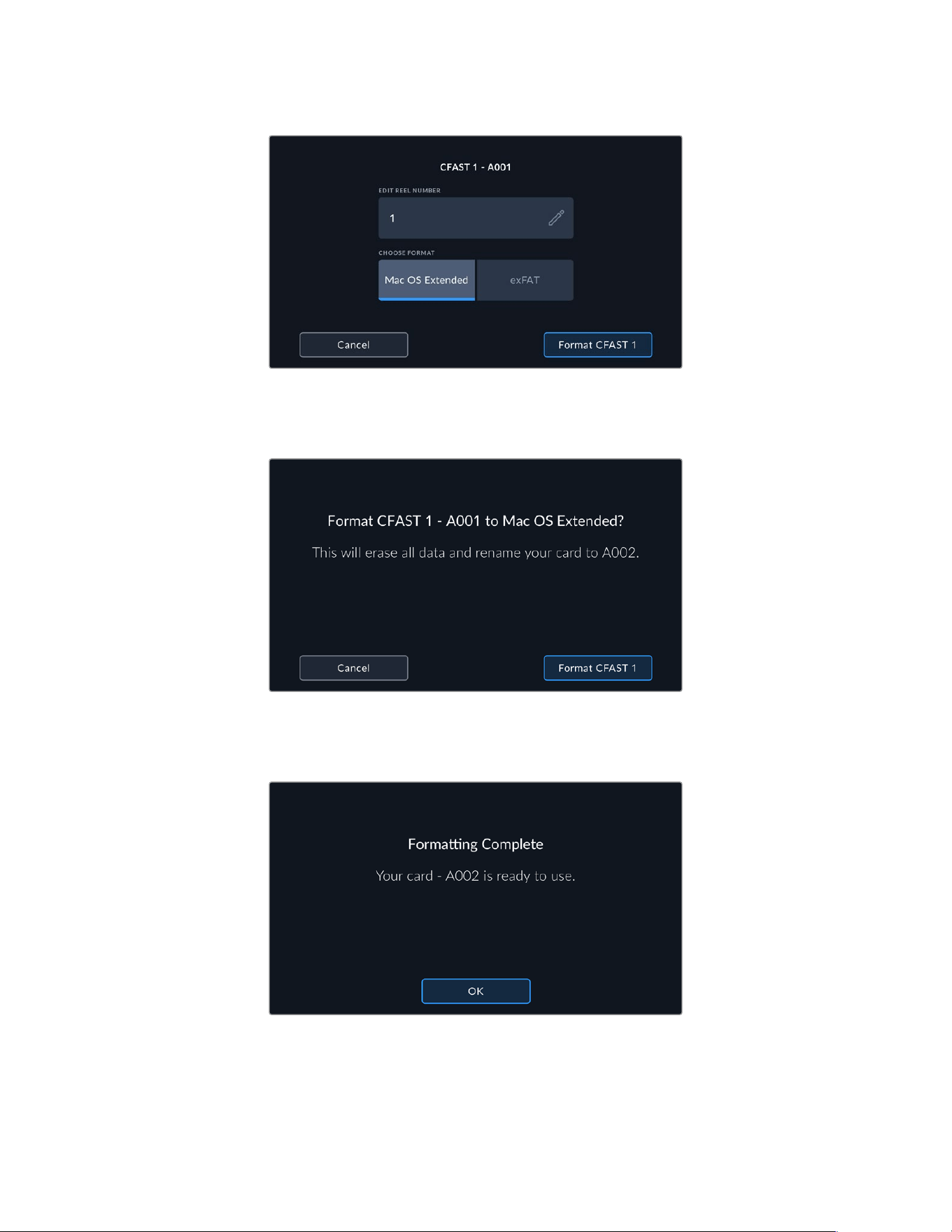
Tap the pencil icon to manually edit the reel number
5 You will be asked to confirm your selection. Tap the format button again to continue
or‘cancel’ to cancel the format.
Check that you have selected the correct card before formatting
6 You will be prompted to press and hold the ‘format’ button for 3 seconds. The camera will
notify you once formatting is complete.
When formatting is complete your card is ready to use
7 Tap ‘ok’ to return to the storage manager.
8 Tap ‘exit’ to leave the storage manager.
27Storage Media
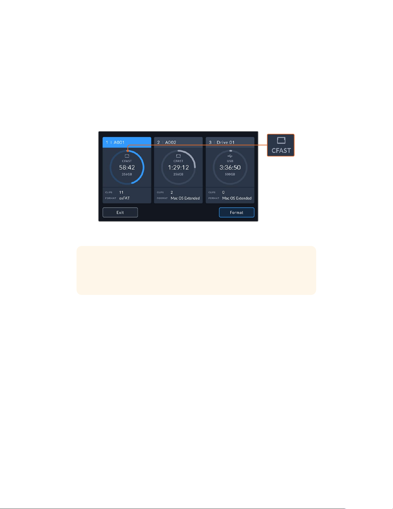
When formatting recording media using the storage manager, your URSA Broadcast G2 will
use the Camera ID from the slate and reel number to name the card. Your camera automatically
increments reel numbers each time you format. If you need to manually enter a specific reel
number, tap the ‘pencil icon’ and enter the number you want to format the card as.
When you start a new project, reel numbering will reset to 1 when you tap on ‘reset data’ in the
‘project’ tab of the slate.
It’s worth mentioning that if your camera’s media storage switch is set to SD or CFast, only the
selected card type will be formatted when you tap ‘format card’. For information on switching
between CFast and SD storage see the ‘SD Cards’ section earlier in this manual.
The storage manager on your URSA Broadcast G2 will indicate whether
you are currently managing CFast, SD, USB or SSD media
TIP If your URSA Broadcast G2 is set to record to SD cards and you have inserted
alocked card, you will be unable to format that card. A padlock icon will appear next to
the card’s name in the storage manager. Simply unlock thecard to format and record.
For more information on locking SD cards, see the ‘SDcards’ section of this manual.
Preparing Media on Mac
The Disk Utility application included with Mac can format your CFast card, SD card,
or SSD in the HFS+ or exFAT formats.
Make sure you back up anything important from your media as all data will be lost when
it is formatted.
1 Connect the storage media to your computer using a card reader, dock or adapter,
and dismiss any message offering to use your media for Time Machine backups.
2 Go to applications/utilities and launch Disk Utility.
3 Click on the disk icon for your camera’s storage media and then click the ‘erase’ tab.
4 Set the ‘format’ to ‘Mac OS extended (journaled)’ or ‘exFAT’.
5 Type a ‘name’ for the new volume and then click ‘erase’. Your camera’s storage media
will quickly be formatted and made ready for use.
28Storage Media
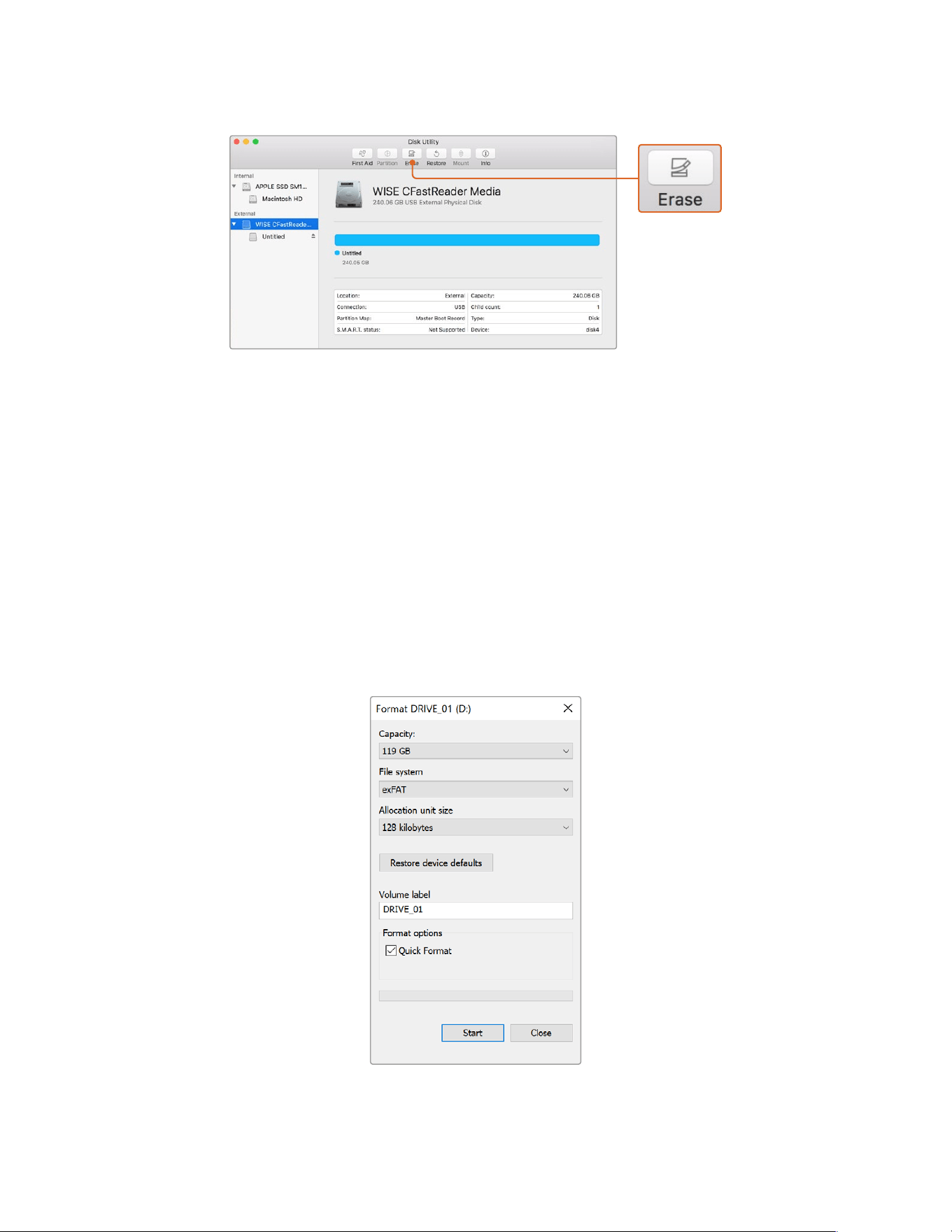
Use Disk Utility on Mac OS to erase your CFast card in the
MacOS extended (journaled) or exFAT format
Preparing Media on Windows
The ‘format’ dialog box can format a drive in the exFAT format on a Windows PC. Remember
to back up anything important from your media as all data will be lost when it is formatted.
1 Connect your camera’s storage media to your computer using an external reader/writer
orSSD dock or adapter.
2 Open the ‘start’ menu or ‘start’ screen and choose ‘computer’. Right click on your
camera’s storage media.
3 From the contextual menu, choose ‘format’.
4 Set the file system to ‘exFAT’ and the allocation unit size to 128 kilobytes.
5 Type a volume label, select ‘quick format’ and click ‘start’.
6 Your storage media will quickly be formatted and made ready for use.
Use the ‘format’ dialog box feature
in Windows to format your CFast, SD
card or SSD in the exFAT format
29Storage Media

NOTE If your recordings are dropping frames, check that your card is on our list
of recommended media for the codec and frame size you are using. For lower data
rates try lowering your frame rate, resolution, or try a compressed codec such as
ProRes. Check the Blackmagic Design website for the latest information at
www.blackmagicdesign.com
Recording
Recording Clips
B4 broadcast lenses typically have a record button positioned on the lens handle where your
thumb would be when shooting from the shoulder. Simply press the record button on the
handle to start recording. Press again to stop recording.
Your camera has record buttons built into the camera itself. A record button is located on the
inside control panel, and on the forward control panel for convenient access when shooting
from the shoulder.
Triggering Record from External Sources
Using the ‘Blackmagic Camera Control’ app you can trigger recording remotely and adjust
various camera settings via Bluetooth from your iPad. For more information on setting up and
using the ‘Blackmagic Camera Control’ app refer to the ‘Bluetooth’ section later in this manual.
If you are using an iPhone or Android smart phone there are also third party apps available that
let you trigger recording on your URSA Broadcast G2 via Bluetooth.
If you are using an optional Blackmagic Zoom Demand with your URSA Broadcast G2, you can
trigger record using the function button. The function button on Blackmagic Zoom Demand sits
under your thumb like the VTR button on a B4 lens. For more information on Blackmagic Zoom
Demand, refer to the ‘using Blackmagic Zoom Demand’ section later in this manual.
When your Blackmagic URSA Broadcast G2 is connected to an ATEM Mini Pro or Extreme
model switcher via a Blackmagic Micro Converter BiDirectional SDI/HDMI 3G, you can trigger
recording from the ATEM switcher.
For example, the ‘record stream’ palette in ATEM Software Control has a checkbox labeled ‘record
in all cameras’. When this checkbox is enabled and you click or press record, all connected
cameras will start recording as well. This means you only have to click or press one button to start
recording on all cameras simultaneously. Refer to the ATEM Mini manual for more information.
Another option for starting and stopping record is to attach an external LANC controller to your
URSA Broadcast G2’s LANC input and trigger the record externally. For example, you may want
to attach a LANC controller to your tripod so you can trigger the recording without taking your
hands off the focus ring and tripod handle.
You can also trigger record on one or more URSA Broadcast G2 cameras using a Blackmagic 3G-SDI
Shield for Arduino and the Blackmagic SDI Camera Control protocol. Formore information, see
the ‘Developer Information’ section of this manual or visit
www.blackmagicdesign.com/developer
and download the manual for Blackmagic 3G-SDIShield for Arduino.
30Recording
You can create your own hardware controller and plug it into your Blackmagic
3G-SDI Shield for Arduino for more interactive and refined control.
NOTE If you toggle the ‘storage media selection’ switch mid-recording, the camera
will complete the current recording before switching to the other type of media. This
ensures that you can not damage your recording if the switch is adjusted during a take.
Choosing the Codec, Resolution and Sensor Area
Your Blackmagic URSA Broadcast G2 can record using Blackmagic RAW with either a constant
quality or constant bitrate setting. You can also use Apple ProRes, H.264 or H.265 compressed
video codecs for recording in Ultra HD and HD resolutions. Sensor frame rate options will vary
depending on the codec and resolution you choose.
Blackmagic RAW lets you use either a constant quality or constant bitrate compression.
Blackmagic RAW 8:1, 12:1, Q3 or Q5 compression is recommended for ENG style shooting as
its high compression offers long recording times with minimal visual reduction of image quality.
For shots that contain a large amount of fine detail you can choose Blackmagic RAW 3:1 or Q0
for the highest level of image quality.
It’s worth noting that clips recorded using Blackmagic RAW are compatible with DaVinci
Resolve, Blackmagic RAW Player and other applications that support Blackmagic RAW SDK.
Blackmagic RAW has already been adopted by many post production platforms. It may not
be supported natively in all editing software but most work with the plugins provided in our
Camera Update and Blackmagic RAW installer. For more information, see the ‘Working with
Third Party Software’ section.
31Recording

Blackmagic RAW
Blackmagic URSA Broadcast G2 supports the new Blackmagic RAW file format. This format
offers superior image quality, wide dynamic range and a broad selection of compression ratios.
Blackmagic RAW features all the user benefits of RAW recording, but the files are very fast
because most of the processing is performed in the camera where it can be hardware
accelerated by the camera itself.
Blackmagic RAW also includes powerful metadata support so the software reading the files
knows your camera settings. If you like shooting in video gamma because you need to turn
around edits quickly and you don’t have time for color correction, then this metadata feature
means you can select video gamma, shoot in video gamma, and the file will display with video
gamma applied when you open it in software. However underneath, the file is actually film
gamma and the metadata in the file is what’s telling the software to apply the video gamma.
So what all this means is if you want to color grade your images at some point, then you have
allthat film dynamic range preserved in the file. You don’t have your images hard clipped in the
whites or the blacks, so you retain detail and you can color grade to make all your images look
cinematic. However, if you don’t have time for color grading, that’s fine because your images
will have the video gamma applied and look like normal video camera images. You are not
locked in on the shoot and you can change your mind later during post production.
Blackmagic RAW files are extremely fast and the codec is optimized for your computer’s
CPU and GPU. This means it has fast smooth playback and eliminates the need for hardware
decoder boards, which is important for laptop use. Software that reads Blackmagic RAW also
gets the advantage of processing via Apple Metal, Nvidia CUDA and OpenCL.
This means that Blackmagic RAW plays back at normal speed like a video file on most
computers, without needing to cache it first or lower the resolution.
It’s also worth mentioning that lens information is recorded in the metadata on a frame by frame
basis. For example, when using compatible lenses, any zoom or focus changes performed over
the length of a clip will be saved, frame by frame, to the metadata in the Blackmagic RAW file.
Recording to Blackmagic RAW
Blackmagic RAW works in two different ways. You have a choice to use either the constant
bitrate codec, or the constant quality codec.
The constant bitrate codec works in a similar way to most codecs. It tries to keep the data rate
at a consistent level and won’t let the data rate go too high. This means even if you are shooting
a complex image that might need a bit more data to store the image, a constant bitrate codec
will just compress the image harder to make sure the images fit within the space allocated.
This can be fine for video codecs, however when shooting RAW you really want to ensure the
quality is predictable. What would happen if the images you were shooting needed more data,
but the codec just compresses harder to make a specified data rate? It’s possible you could
lose quality, but not be sure it’s happening until you return from a shoot.
To solve this problem, Blackmagic RAW also has an alternative codec choice called constant
quality. This codec is technically called a variable bitrate codec, but what it’s really doing is
allowing the size of the file to grow if your images need extra data. There is no upper limit on
the file size if you need to encode an image but maintain quality.
So Blackmagic RAW set to the constant quality setting will just let the file grow as big as it
needs to be to encode your images. It also means the files could be larger or smaller
depending on what you are shooting. I guess if you leave your lens cap on the lens, you won’t
waste space on your media!
32Recording

It is also worth noting that the quality settings for Blackmagic RAW are not obscure names,
butare more meaningful as they are derived from what’s happening technically. So for example
when you have selected the constant bitrate codec, you will see quality settings of 3:1, 5:1, 8:1
and 12:1. These are the ratios of the uncompressed RAW file size vs the file sizes you should
expect when shooting in Blackmagic RAW. 3:1 is better quality as the file is larger, while 12:1 is
the smallest file size with the lowest quality. Many users of Blackmagic RAW find that 12:1 has
been perfectly ok and they have not seen any quality limitations. However it’s best to
experiment and try various settings for yourself.
When using Blackmagic RAW in constant quality you will see the settings are Q0, Q1, Q3 and
Q5. Theseare the compression parameters passed to the codec and they are setting how
much compression is applied in a more technical way. This setting is different because the
codec operates differently between constant bitrate vs constant quality. In this constant quality
setting, you really cannot tell what the file size ratio will become as it varies a lot based on
what you areshooting. So in this case the setting is different and the file will become the size
needed tostore your media.
Constant Bitrate Settings
The names for 3:1, 5:1, 8:1 and 12:1 represent the compression ratio. For example, 12:1
compression produces a file size roughly 12 times smaller than uncompressed RAW.
Constant Quality Settings
Q0, Q1, Q3 and Q5 refer to different levels of quantization. Q5 has a greater level of
quantization but offers a greatly improved data rate. As mentioned above, the constant quality
setting can result in files that grow and shrink quite a lot, depending on what you are shooting.
This also means it’s possible to shoot something and see the file size increase to beyond what
your media card can keep up with. It could result in dropped frames. However the benefit is that
you can instantly see if this happens on a shoot and then investigate your settings vs quality.
Blackmagic RAW Player
The Blackmagic RAW player included in your Blackmagic camera’s software installer is a
streamlined application for reviewing clips. Simply double click on a Blackmagic RAW file to
open it, and you can quickly play and scroll through the file with its full resolution and bit depth.
When decoding frames, the CPU acceleration in the SDK library supports all main architectures,
and also supports GPU acceleration via Apple Metal, Nvidia CUDA and OpenCL. It also works
with the Blackmagic eGPU for extra performance. Blackmagic RAW player is available for Mac,
Windows and Linux.
Sidecar Files
Blackmagic RAW sidecar files let you override metadata in a file without overwriting embedded
metadata in the original file. This metadata includes the RAW settings as well as information on
iris, focus, focal length, while balance, tint, color space, project name, take number and more.
Metadata is encoded frame by frame over the duration of the clip, which is important for lens
data if the lens is adjusted during a shot. You can add or edit metadata in sidecar files with
DaVinci Resolve or even a text editor because it’s a human readable format.
Sidecar files can be used to automatically add new RAW settings to a playback simply by
moving the sidecar file into the same folder as the corresponding RAW file. If you move the
sidecar file out of the folder and reopen the Blackmagic RAW file, the RAW settings are not
applied and you see the file as it was originally shot. Any software that uses the
BlackmagicRAW SDK can access these settings. Changes made are saved in the sidecar file
and can then be seen by Blackmagic RAW Player or any other software capable of reading
Blackmagic RAW files.
33Recording
When shooting video gamma, the file stays in film gamma, and the metadata tells the
Blackmagic RAW processing to display using video gamma. Video gamma is great when you
don’t want to grade the image and want to deliver content quickly, however if you want to pull
up the black parts of the image, or pull down the white areas, all the detail is retained.
Younever clip the video and all the detail is still there if you want to access it at any time.
Blackmagic RAW in DaVinci Resolve
Settings can be adjusted for each Blackmagic RAW file, and then saved as a new sidecar file
from the RAW tab in DaVinci Resolve for creative effect or optimized viewing. This also means
you can copy your media for another DaVinci Resolve artist and they will have access to your
modified gamma settings automatically on import. In addition to the other metadata your
camera files contain, DaVinci Resolve can read your selected dynamic range, so your clips will
automatically display in DaVinci Resolve with ‘film’, ‘extended video’ or ‘video’ dynamic range.
You can then customize these settings by adjusting the saturation, contrast and midpoint,
aswell as the highlight and shadow rolloff. Any adjustments can then be saved as a sidecar file,
sothe changes can be seen by anyone else working with the files in post. You can always
return to the original camera metadata at any time.
You can also export a single Blackmagic RAW frame from the RAW tab in DaVinci Resolve,
which contains all adjustments, metadata, full resolution and color information so it is easy to
share a single frame grab or reference file with others.
For more information on how to use Blackmagic RAW in DaVinci Resolve, see the ‘Using
DaVinci Resolve’ chapter in this manual.
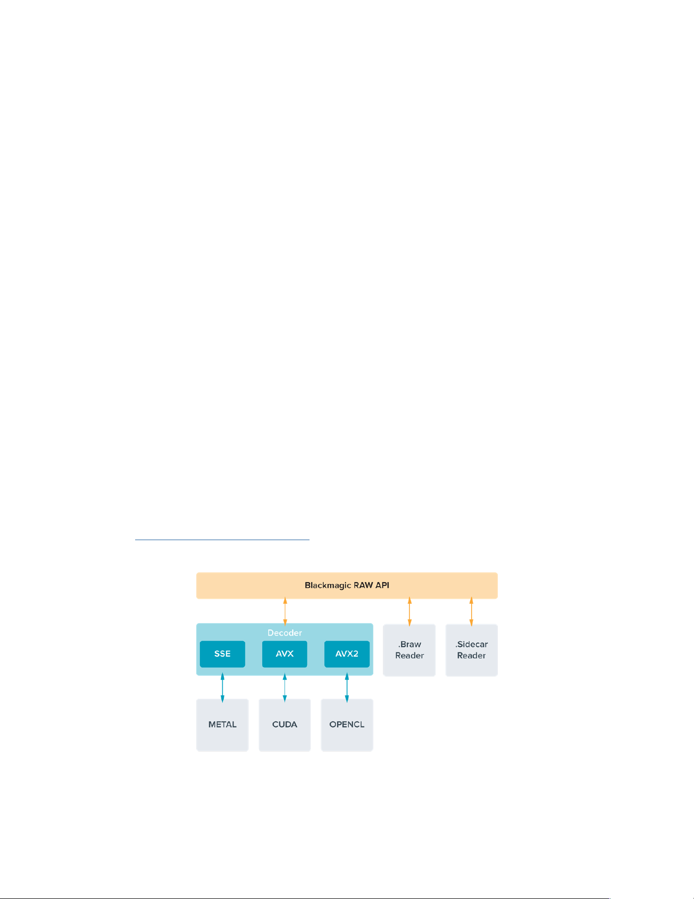
Blackmagic RAW SoftwareDevelopment Kit
The Blackmagic RAW Software Development Kit is an API developed by Blackmagic Design.
You can use the Blackmagic RAW SDK to write your own applications to use the Blackmagic
RAW format. This SDK library can be used by any developer to add support for reading, editing,
and saving Blackmagic RAW files. The Blackmagic RAW SDK includes all the generation 4 and
generation 5 color science so you can achieve organic cinematic images across any app that
supports it. The Blackmagic RAW SDK supports Mac, Windows and Linux, and is available as
a free download from the developer page of the Blackmagic website at
www.blackmagicdesign.com/developer
The following diagram illustrates the components of the Blackmagic RAW API:
34Recording

Choosing Frame Rates
Your camera is able to shoot video using many different frame rates and you may be wondering
which is the best one to use. Your camera’s sensor frame rate can also have a big impact on the
‘look’ of footage. Generally, when selecting a sensor frame rate, there are some common items
to consider. For many years, there have been presentation standards for film and television.
These have set frame rates that differ between countries, but all share the same purpose;
todisplay an efficient number of frames every second that portrays pleasing and
convincing motion.
Cinema, for example, uses a standard 24 frames per second and while there have been
recent experiments with faster frame rates, 24 frames per second remains widely accepted
for international audiences. Television frame rates have generally conformed to technical
broadcast standards for each country. For example, if you were making television content
you would typically record using 29.97 frames per second for North American distribution,
and 25frames per second for Europe.
However, as technology has improved, today we have more choices and broadcast standards
are changing. It is now common for sporting events to be recorded and broadcasted at higher
frame rates. For example, some sporting events are recorded and broadcasted at up to 59.94
frames per second in North America, and 50 frames per second in Europe. This provides
smoother motion on fast action and appears more lifelike. Alternatively, streaming and online
broadcasters normally use frame rates similar to television, however there is more freedom to
experiment due to user selectable viewing formats, and being limited only to what the
audience’s screens are capable of displaying.
Generally, when choosing a frame rate for a project, let your delivery format guide your choice.
This means your clips will play back at the same speed the event happened in real life. To achieve
this, you will need to turn off the ‘off speed’ option on your camera.
If you are looking to create an interesting effect, for example slow motion, then you can set the
sensor frame rate to a higher setting. The higher the sensor frame rate compared to the project
frame rate, the slower the playback speed.
For more information on using off speed sensor frame rates to achieve creative effects,
refer to the ‘touchscreen controls’ section.
Shooting at High Frame Rates
When shooting at high frame rates, your camera captures an increased number of frames per
second when compared with the traditional sync speed frame rates of 24, 25 and 30 frames
per second. This means that the image sensor has less time to collect light for each frame it
captures and the resulting image from your camera will be darker.
So for example, if you switch from 25 to 50 frames per second, the amount of light reaching
the sensor will be halved. To maintain your exposure you need to compensate for this change
by opening up your lens an extra stop, by opening up your shutter angle from 180º to 360º or
by adding some extra lighting to the scene that you are shooting.
When shooting at 60 frames per second you have 2.5 times less light than 24 frames per
second so you may need to adjust multiple things such as lens aperture, shutter angle and
lighting to achieve the same level of exposure.
Another thing to be mindful of when shooting at higher frame rates, is the fact that electronic
light sources can add flicker to your recorded image. Artificial light sources such as tungsten,
fluorescent and LED may introduce some flicker to your images. You may not see these flicker
issues when previewing the scene on your LCD and SDI feed or while recording, so it’s
important to perform a test shoot with the lights you plan to use and to play the clip back to
check for flicker.
35Recording

Your shutter setting can also affect the visibility of flicker when shooting under lights, so your
URSA Broadcast G2 can automatically calculate and display flicker free shutter options for your
current frame rate. Note that the characteristics of individual light sources may still cause flicker
even when using flicker free values. For more information, refer to the ‘touchscreen
controls’ section.
If you have opened up your shutter to the slowest shutter speed or widest shutter angle
possible and are still seeing flicker in recorded footage, you may need to consider using
different light sources for your scene or look into using a faster lens.
Maximum Sensor Frame Rates and Data Rates
The table below contains available codecs and resolutions with their maximum sensor frame
rates and data rates. It should be noted that the references to Blackmagic RAW, ProRes 444
and ProRes 422 are references to all of the supported variants within each particular codec.
Because of the data rates required for recording high resolutions in slow motion you will need
to choose a fast CFast card, USB-C flash disk or SSD. Refer to the ‘storage media’ section for
more information.
TIP You can test the speed your card can sustain by switching on the ‘stop recording’
option from the ‘if card drops frame’ settings menu and recording a test clip. This will
allow you to test how long you can shoot at a particular frame rate in any given
resolution. If the card stops recording too quickly, moving to the next available
compression setting or resolution will lower the data rate and make it easier for the
card to maintain.
Maximum Frame Rates for URSA Broadcast G2
Resolution Codec Max Frame Rate Max Data Rate
Ultra HD
3840x2160 Blackmagic RAW 3:1 60 254 MB/s
3840x2160 Blackmagic RAW 5:1 60 152 MB/s
3840x2160 Blackmagic RAW 8:1 60 96 MB/s
3840x2160 Blackmagic RAW 12:1 60 64 MB/s
3840x2160 Blackmagic RAW Q0 60 48.7 - 96.8 MB/s
3840x2160 Blackmagic RAW Q1 60 32.6 - 77.6 MB/s
3840x2160 Blackmagic RAW Q3 60 21.9 - 55.6 MB/s
3840x2160 Blackmagic RAW Q5 60 13.4 - 32.6 MB/s
3840x2160 ProRes HQ 60 220 MB/s
3840x2160 ProRes 422 60 148 MB/s
3840x2160 H.265 SDI 60 24.6 MB/s
3840x2160 H.265 High 60 21.6 MB/s
3840x2160 H.265 Medium 60 15.6 MB/s
3840x2160 H.265 Low 60 6.4 MB/s
36Recording

Resolution Codec Max Frame Rate Max Data Rate
HD
1920x1080 Blackmagic RAW 3:1 150 161.4 MB/s
1920x1080 Blackmagic RAW 5:1 150 97.2 MB/s
1920x1080 Blackmagic RAW 8:1 150 61.1 MB/s
1920x1080 Blackmagic RAW 12:1 150 41 MB/s
1920x1080 Blackmagic RAW Q0 150 121.2 - 241.6 MB/s
1920x1080 Blackmagic RAW Q1 150 81.8 - 193.4 MB/s
1920x1080 Blackmagic RAW Q3 150 54.4 - 138.4 MB/s
1920x1080 Blackmagic RAW Q5 150 33 - 81.1 MB/s
1920x1080 ProRes HQ 120 110 MB/s
1920x1080 ProRes 422 120 74 MB/s
1920x1080 H.264 SDI 60 14 MB/s
1920x1080 H.264 High 60 11.2 MB/s
1920x1080 H.264 Medium 60 6.4 MB/s
1920x1080 H.264 Low 60 3.6 MB/s
It’s important to note that Blackmagic RAW Q0, Q1, Q3 and Q5 use variable bit rate compression
to achieve constant quality. Q0, Q1, Q3 and Q5 data rates depend on the complexity of the
image subject matter and can vary considerably throughout a clip.
To select your desired codec and resolution:
1 Press the ‘menu’ button on the control panel.
2 Navigate to the first page of the ‘record’ tab.
3 Tap your desired combination of codec, quality, and resolution.
4 Press ‘menu’ to exit.
Recording Formats and Project Frame Rates
After setting your codec and resolution, you should set your ‘project’ and ‘sensor’ frame rates.
Refer to the ‘recording’ section in this manual for more information about frame rates.
The project frame rates available are:
23.98, 24, 25, 29.97, 30, 50, 59.94, and 60 frames per second.
When using Blackmagic RAW and ProRes codecs up to ProRes 422 HQ, the maximum project
frame rate is 60 frames per second at all resolutions.
37Recording
Triggering Record on External Equipment
Your URSA Broadcast G2 automatically sends a signal via the SDI outputs that will
trigger recording when connected to equipment that supports the SDI trigger record
feature, such as Blackmagic Video Assist. This means when you press record on your
camera, your external SDI equipment will also start recording, and will stop recording
when you press record again.
You will also need to set your equipment to enable SDI trigger recording to make sure it
responds to the trigger signal from your URSA Broadcast G2. If your SDI equipment supports
SDI trigger recording, it can usually be enabled using your SDI equipment’s settings menu.
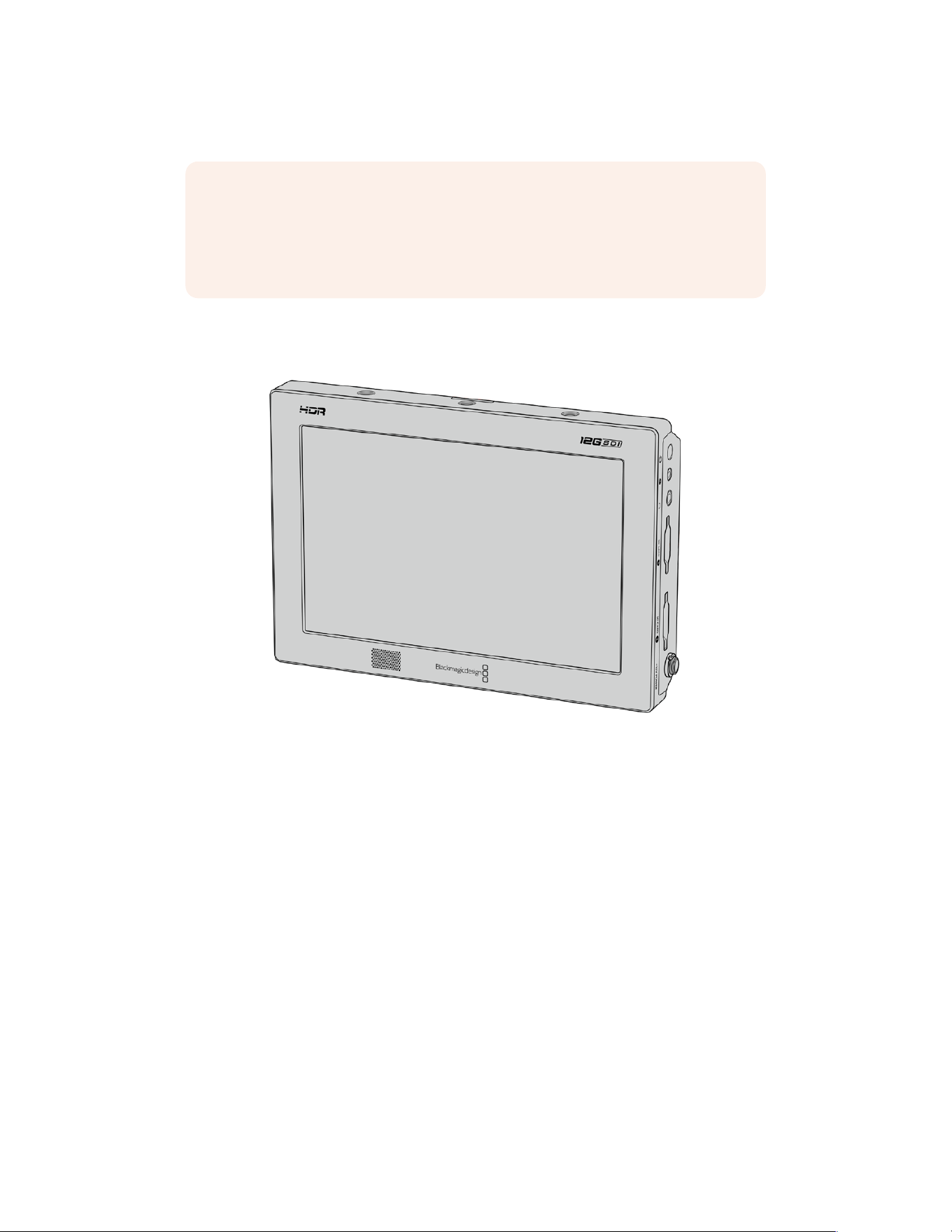
You can trigger recording on other SDI video equipment, for example
BlackmagicVideoAssist 12G HDR, using the trigger record feature on your camera
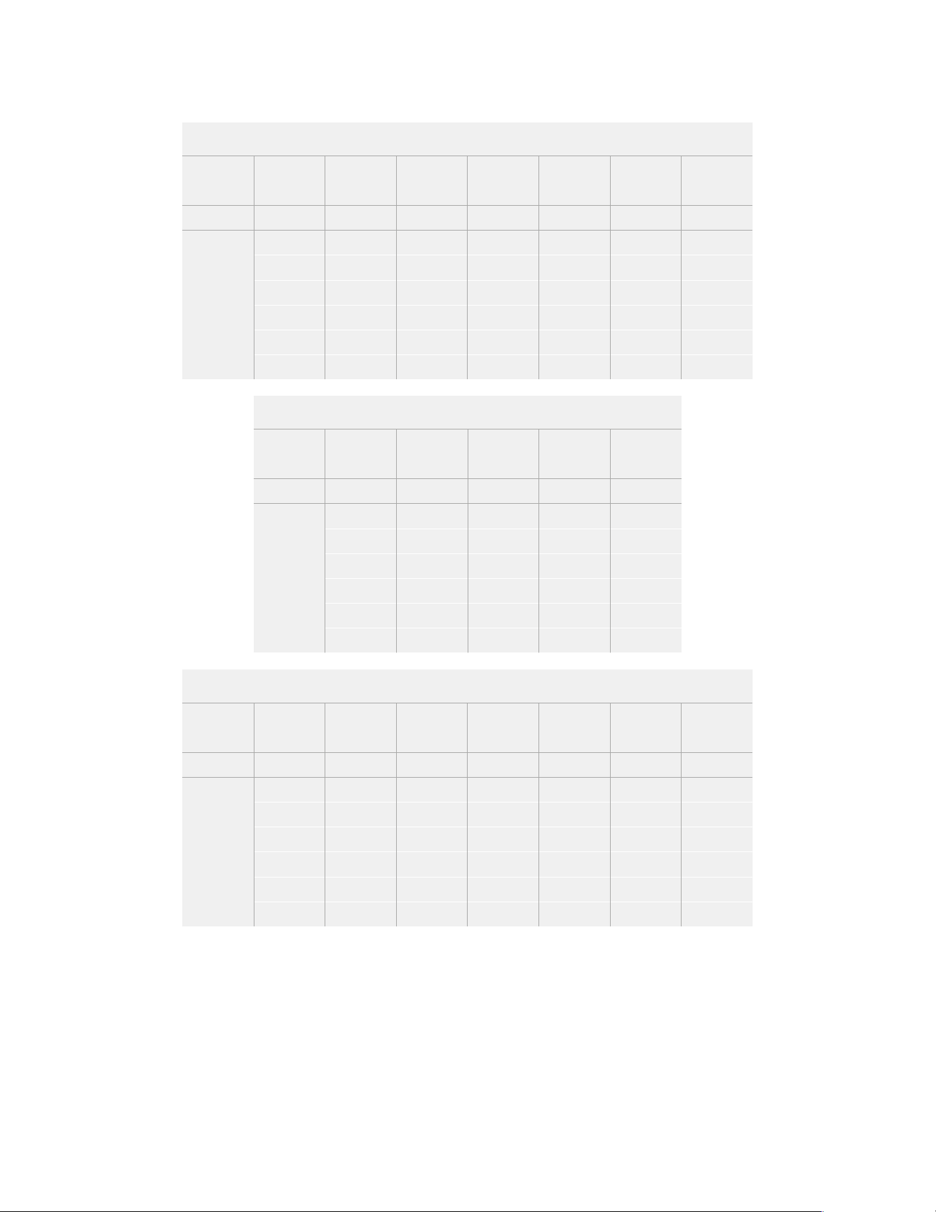
Record Duration Table
Tables are provided showing approximate record duration in minutes and seconds compared
toformat, project frame rate and media size. The maximum recording duration for your storage
media depends on its capacity, the recording format and the frame rate. For example, the
storage rate for Apple ProRes 422 HQ at 3840x2160 is approximately 880 Mbps. At 24 frames
per second, you can record approximately 47minutes ofvideo on a 256GB CFast 2.0 or SD
card. At the same settings youcan record approximately 23minutes of video on a 128GB CFast
2.0 or SD card, which is approximately half the record duration of the 256GB card.
It should be noted that record duration on CFast 2.0 and SD cards can also vary slightly
between cards from different manufacturers. It can also vary depending on whether the storage
media is formatted as ExFat or Mac OS Extended.
Simple scenes containing less detail tend to require less data than more dense compositions.
The values in these tables assume shots with a high complexity, which means you may get
slightly longer record times depending on the nature of your shoot.
38Recording
HD
CFast
Card
Frame
Rate
ProRes
422 HQ
ProRes
422
H.264
SDI
H.264
High
H.264
Medium
H.264
Low
Duration Duration Duration Duration Duration Duration
256GB
23.98 189 mins 283 mins 635 mins 782 mins 1395 mins 2456 mins
24 189 mins 283 mins 635 mins 782 mins 1395 mins 2456 mins
25 182 mins 271 mins 602 mins 748 mins 1339 mins 2321 mins
30 152 mins 227 mins 496 mins 612 mins 1118 mins 2079 mins
50 91 mins 137 mins 371 mins 462 mins 841 mins 1852 mins
60 76 mins 114 mins 331 mins 411 mins 716 mins 1520 mins
ULTRA HD
CFast
Card
Frame
Rate
Blackmagic
RAW 3:1
Blackmagic
RAW 5:1
Blackmagic
RAW 8:1
Blackmagic
RAW 12:1
Duration Duration Duration Duration
256GB
23.98 41 mins 68 mins 110 mins 164 mins
24 41 mins 68 mins 109 mins 164 mins
25 39 mins 66 mins 105 mins 157 mins
30 33 mins 55 mins 88 mins 131 mins
50 19 mins 33 mins 52 mins 79 mins
60 16 mins 27 mins 44 mins 66 mins
ULTRA HD
CFast
Card
Frame
Rate
ProRes
422 HQ
ProRes
422
H.265
SDI
H.265
High
H.265
Medium
H.265
Low
Duration Duration Duration Duration Duration Duration
256GB
23.98 47 mins 71 mins 353 mins 404 mins 571 mins 1499 mins
24 47 mins 71 mins 353 mins 404 mins 571 mins 1499 mins
25 45 mins 68 mins 339 mins 389 mins 550 mins 1442 mins
30 38 mins 57 mins 286 mins 325 mins 461 mins 1223 mins
50 22 mins 34 mins 242 mins 280 mins 389 mins 960 mins
60 18 mins 28 mins 241 mins 277 mins 325 mins 809 mins
Recording Motion Sensor Data
Your Blackmagic URSA Broadcast G2 Camera automatically records gyro data from the internal
motion sensor. DaVinci Resolve can then use this data to stabilize clips. For more information
refer to the ‘gyro stabilization’ section in this manual.
39Recording
Playback
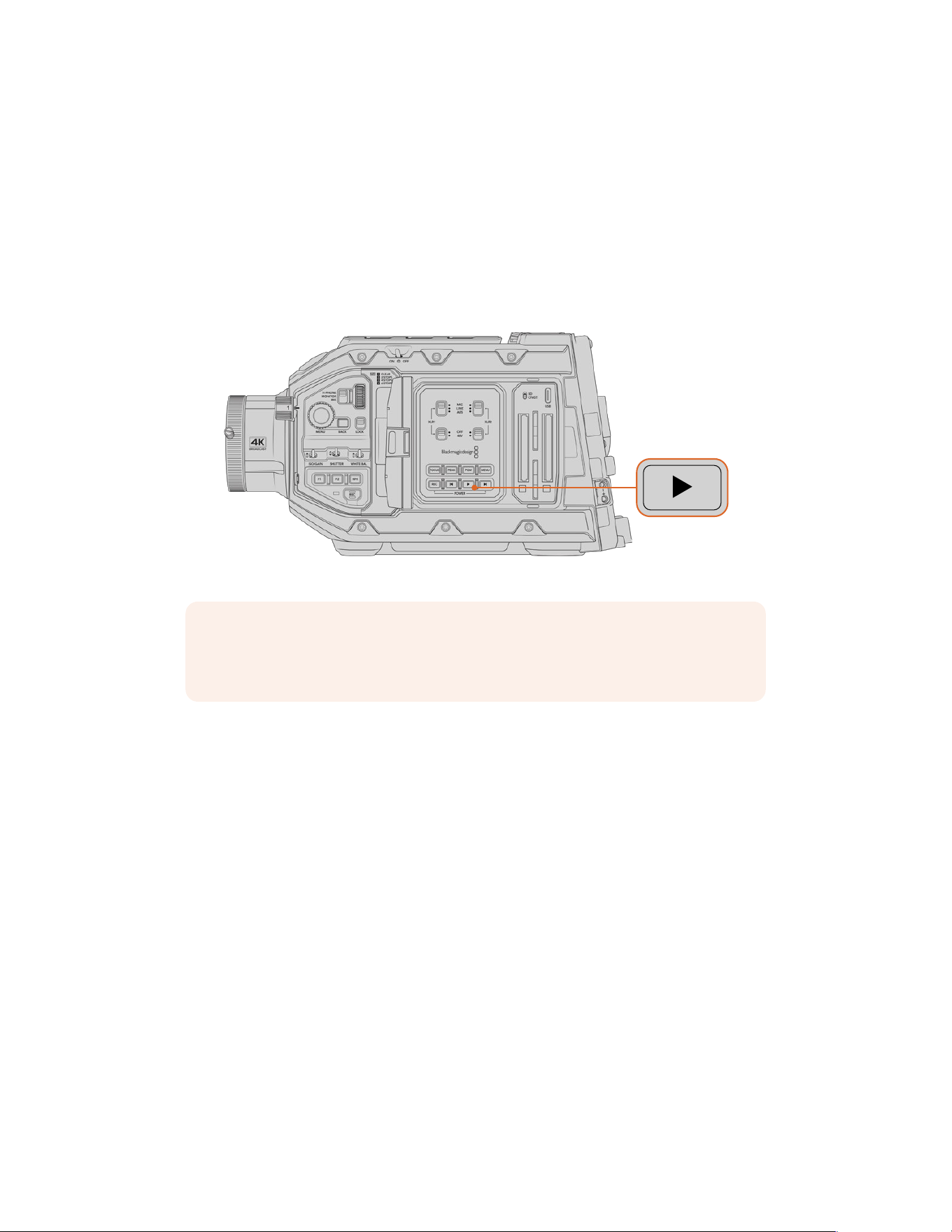
Playing Back Clips
Once you have recorded your video, you can use the transport control buttons to play back your clips.
Press the ‘play’ button once for instant playback and you’ll see your recorded video on
URSABroadcast G2’s LCD touchscreen. Your clips can also be viewed on any display
connected toyourURSABroadcast G2’s SDI outputs. Your URSA Broadcast G2 has playback
and transport controls buttons on both the internal and ergonomic control panels.
URSA Broadcast G2
NOTE You can also play back your clips using your camera’s media pool and sync
them to a Blackmagic Cloud project. For more information about the media pool, refer
to the next section of this manual.
The controls of your camera work just like a CD player, so pressing the ‘forward skip’ button
willskip to the start of the next clip. Press the ‘reverse skip’ button once to go to the start of the
current clip or press twice to skip back to the start of the previous clip. Hold the ‘forward’ or
‘reverse skip’ button to play or reverse at 2x speed. Once shuttling forward or backwards, press
the ‘fast forward’ or ‘reverse skip’ buttons twice for 4x, three times for x8 and four times for x16.
You can also use the forward and reverse skip buttons to open or close the iris on compatible
lenses while recording clips.
When recording a clip using a sensor frame rate that differs from your project frame rate, your
clip’s playback speed will also differ. For example, imagine you have set your camera’s project
frame rate to match your post production timeline of 24 frames per second. If you record a clip
with your sensor frame rate set to 60 frames per second, your clips will play back in slow motion
on both the camera and on your post production timeline. Refer to the ‘recording’ section of this
manual for more information about frame rates.
40Playback
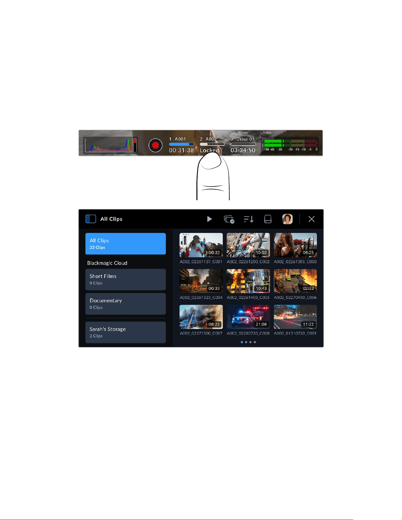
Media Pool
Your Blackmagic URSA Broadcast G2 features a media pool that lets you play back, search and
sort your recorded clips using a browser interface. You can also delete clips and sync clips to
Blackmagic Cloud via the Internet. For example, uploading clips to DaVinci Resolve projects or
directly to your own private Blackmagic Cloud storage.
To open the media pool, tap one of the storage indicators at the bottom of your camera’s
touchscreen display.
Tap a storage indicator to open the media pool
The browser is the main page of the media pool
The main page browser displays thumbnails of all the recorded clips on all media connected to
your camera. For example, CFast cards, SD cards and external flash disks via USB. There are
three rows of thumbnails and as more clips are added, you can swipe to the next page of
thumbnails using the touchscreen. Page indicators at the bottom of the display show how many
pages of clips are available.
Sidebar
The sidebar icon at the top left corner opens or closes the media pool side bar. Here, you can
select which Blackmagic Cloud projects you want to upload clips to, or to upload clips directly
to your personal Blackmagic Cloud storage. More information about uploading clips to
Blackmagic Cloud projects and storage is provided later in this section.
41Media Pool
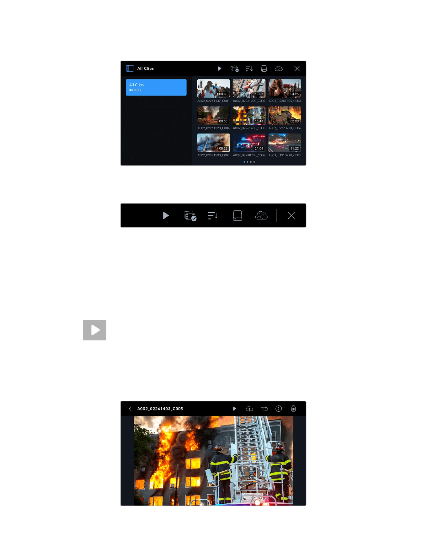
Tap the sidebar icon to open or close the media pool sidebar
Controls
The control menu icons in the browser page of the media pool
The control menu icons at the top of the media pool browser page feature playback, group
selection, media filter, media storage and Blackmagic Cloud log in status. When you select a
single clip, multiple clips or a filtered clip list the control menu icons will change to display the
relevant control options.
The next section describes how to use each control.
Playback
The playback control lets you play back clips recorded on your camera’s media
storage. You can play back a single clip, a sequence of selected clips, a list of clips
filtered by a particular parameter or even play back all the clips on your connected
media in one complete sequence.
Playing a Single Clip
Tap on a clip’s thumbnail to enter the clip viewer. This displays the clip thumbnail larger on the
LCD, lists the clip’s file name and provides playback, upload, priority tagging, clip info and deletion
controls. Swiping left and right on your camera’s touchscreen lets you select a different clip.
42Media Pool
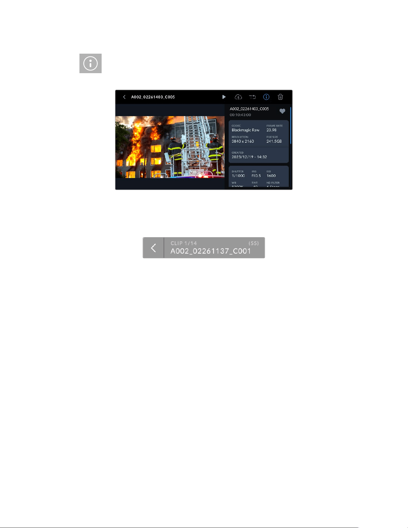
If you want to view the clip’s metadata, tap on the information icon. This opens
metadata that you can scroll through by dragging up and down. The heart icon lets
you add a ‘good take’ tag to the clip’s metadata, similar to marking a good take using
your camera’s slate feature.
Tap the ‘play’ icon to play your chosen clip.
When your clip begins playing, you can then use the transport touch controls to scroll the play
head backwards and forwards, skip to a different clip, or press ‘stop’ to return the LCD to the
live recording view.
Above the clip name, the clip indicator lets you know the current clip number from the total clips
that are cued. For example, clip number one from a total of fourteen clips recorded. If you have
any media filters set, the total number of clips will reflect that. The bracketed number represents
the total number of clips recorded on allmedia cards and external disks connected to
your camera.
To return to the browser, tap on the ‘back’ arrow ahead of the clip name.
Playing All Clips
Tapping the play icon in the controls menu when in the browser will construct a timeline of all
playable clips. The last clip recorded will be cued first so you can check it, or you can play
through the entire timeline. If all of the clips in the browser were recorded using the same
format and frame rate then everything recorded will play.
Playing a Sequence of Clips
To play back a sequence of clips, tap on the group select icon in the browser. With this icon
enabled, tap on a clip. A small ‘play’ icon will appear in the top right hand corner of all the clips
that share the same format and are available to play back together. You can now selectively tap
on the clips you want to play back in a sequence.
Tap the ‘play’ icon, your camera will now play the sequence of clips and stop when the
sequence ends.
43Media Pool
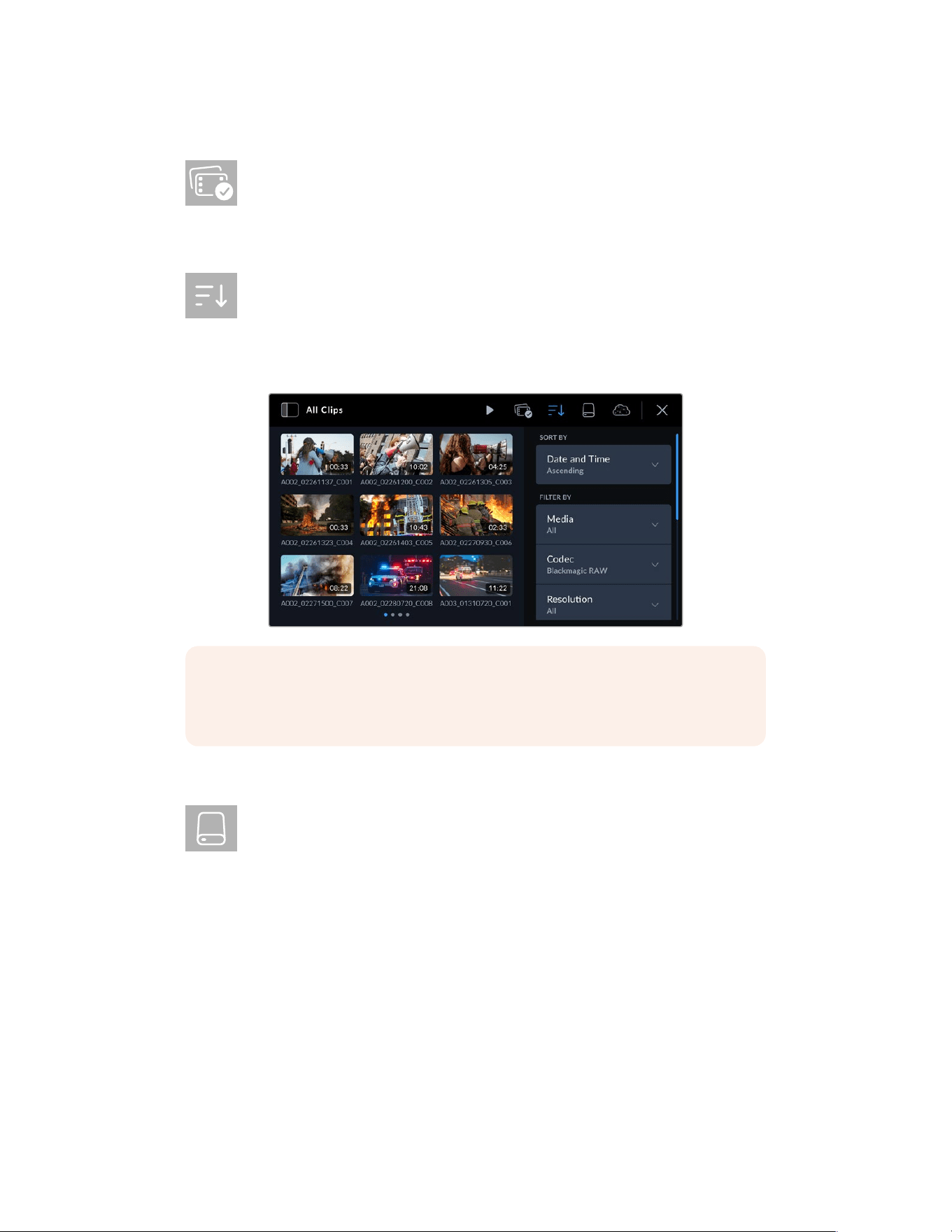
Group Select
Tap on the group select icon to select a sequence of clips to play back, or to choose
clips to upload to a Blackmagic Cloud project or storage. You can also select a group
of clips to delete.
Media Filter
Tap on the media filter icon in the media library to open the filter editor. Here, you
can tell your camera how to arrange the clips by preference. For example, you can
choose to display clips from a specific media drive, or select ‘upload status’ as a
quick way of checking which clips have been uploaded to Blackmagic Cloud. Use the filter
touchscreen menu to scroll up and down and select the filter options you want. When you have
made your selection, tap the clip filter icon again to close the menu.
NOTE If you only ever want to play back or review one clip at a time then you can go
to the eighth page of your camera’s ‘setup’ menu and select ‘single clip’ for your
playback preference.
Storage
Tap the media storage icon in the media library to enter the storage format page.
This page lets you format CFast cards, SD cards and any flash disks and SSDs
connected to your camera. For information on how to format media, refer to the
‘storage media’ section earlier in this manual.
44Media Pool
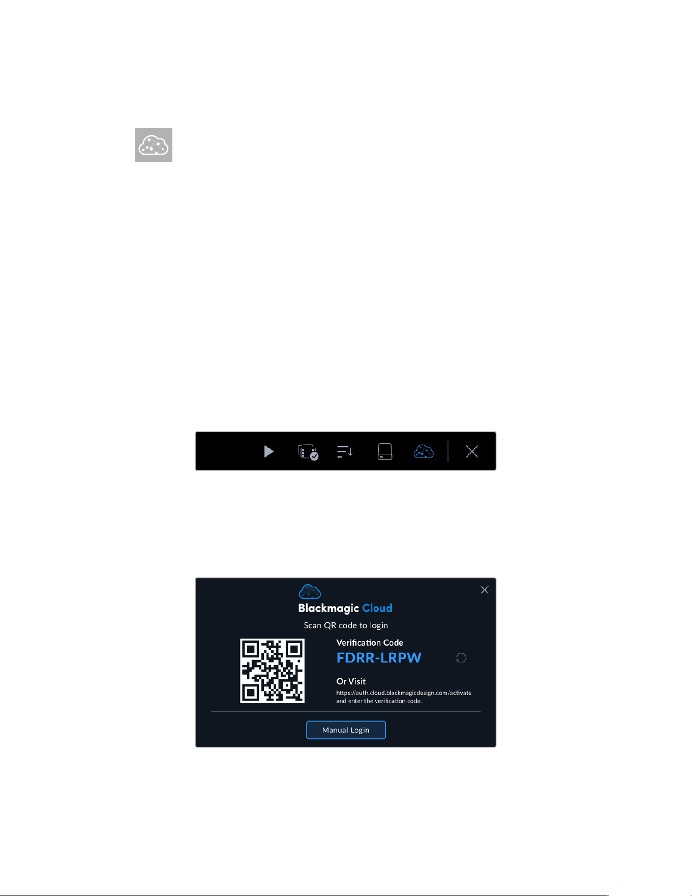
Uploading Clips to Blackmagic Cloud
Blackmagic Cloud is a collaboration platform that lets you work together as a team
and share DaVinci Resolve projects worldwide.
When you sign into Blackmagic Cloud on your URSA Broadcast G2 you can choose
to upload clips directly to a DaVinci Resolve Cloud project or to manually select the clips you
want to upload from your camera’s media pool. Alternatively clips can also be uploaded straight
to your own private Blackmagic Cloud storage directly without syncing to a Resolve
Cloud project.
You can choose to upload proxy files or both proxy and original files in your camera’s setup
settings on page 2 of the setup menu. Refer to the ‘setup settings’ section for more information.
Logging into Blackmagic Cloud
Before logging into Blackmagic Cloud on your URSA Broadcast G2, you will need to connect
your camera to the Internet.
Connect an Ethernet to USB-C adapter or your smartphone to your URSA Broadcast G2’s
USB-C port. When connecting using your smartphone, enable your phone’s tethering or
hotspot feature. Once connected to the Internet, the Blackmagic Cloud icon at the top of your
camera’s touchscreen will turn blue.
To log into your Blackmagic Cloud account:
1 Tap the Blackmagic Cloud icon in the controls menu.
2 Use your smartphone’s camera to scan the QR code on your URSA Broadcast G2’s
touchscreen and follow the prompts on your phone to sign your camera into your
Blackmagic Cloud account. Alternatively, you can visit the web address displayed on your
camera’s touchscreen display and enter the six digit code.
To enter your login details manually, tap ‘manual login’ and use the touchscreen keyboard
to enter your email address and password.
45Uploading Clips to Blackmagic Cloud
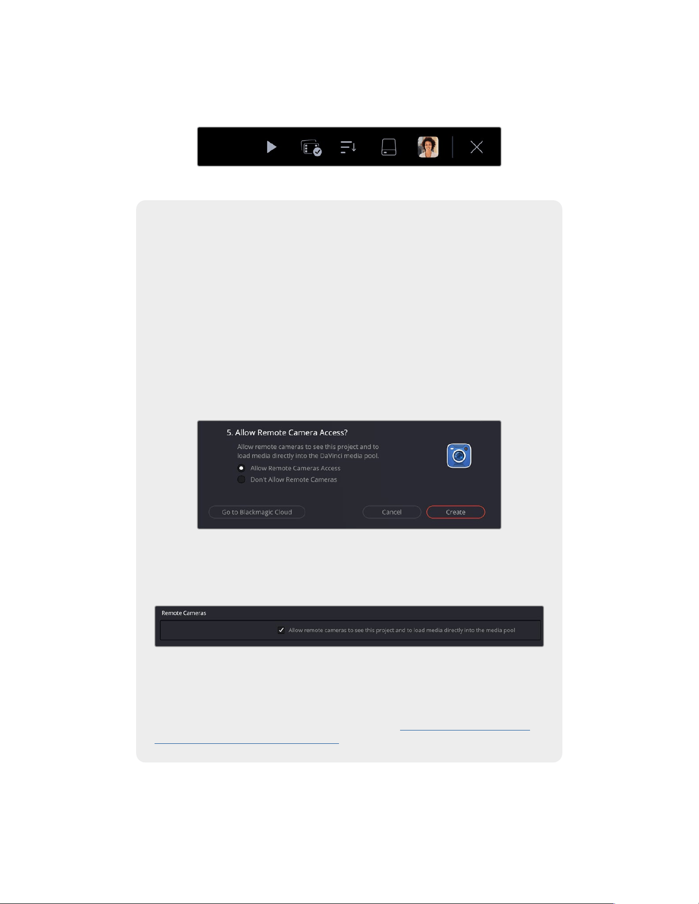
Once logged in, your Blackmagic Cloud avatar will be displayed in the controls menu. You can
tap your avatar to view your account details or to log out of your account.
Your account avatar is displayed in the controls menu
Allowing Remote Camera Access in DaVinci Resolve
You can upload clips to both new and existing Blackmagic Cloud projects from your
URSA Broadcast G2 by allowing remote camera access in DaVinci Resolve’s settings.
Once remote access has been enabled for a project, it will appear in your camera’s
Blackmagic Cloud projects panel.
Allowing access to a new project:
1 Open DaVinci Resolve. In the ‘project manager’ window, select the ‘cloud’ tab and
enter your Blackmagic Cloud login details.
2 Select a Blackmagic Cloud project library from the project library list and click
‘new project’.
3 With the new project window open, enter the project details. Enable ‘allow remote
camera access’ in the new cloud project window.
If you want to upload clips to an existing DaVinci Resolve Cloud project, open the
project settings and select ‘Blackmagic Cloud’. Enable the ‘allow remote cameras to
see this project to load media directly into the media pool’ option in the ‘remote
cameras’ settings.
The Blackmagic Cloud project will appear in your Blackmagic URSA Broadcast G2’s
media pool sidebar when your camera is connected to the internet and signed into
your Blackmagic Cloud account.
For more information about DaVinci Resolve Cloud projects, refer to the DaVinci
Resolve user manual. You can download the manual at www.blackmagicdesign.com/
support/family/ davinciresolve-and-fusion
46Uploading Clips to Blackmagic Cloud
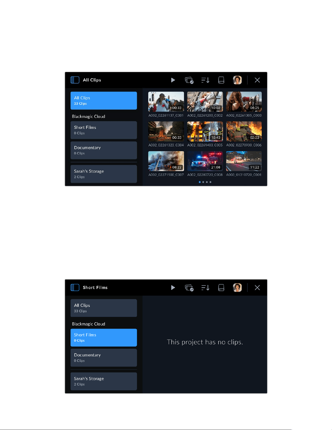
Blackmagic Cloud Projects Panel
Tap the sidebar icon at the top left of the touchscreen to open the Blackmagic Cloud
projects panel.
When you are signed into your Blackmagic Cloud account, projects that you can upload clips to
are listed in the ‘Blackmagic Cloud’ section of the viewer.
Uploading Clips to a Blackmagic Cloud Project
Selecting a Blackmagic Cloud project lets you upload proxy files, or both proxies and originals,
as you record clips to your camera’s media. When a project is selected in the projects panel,
aclip will be immediately uploaded as soon as you stop recording on your camera. This will
happen in the background as you continue recording clips for as long as your camera is
connected to the Internet and logged into your Blackmagic Cloud account.
To upload to a Blackmagic Cloud project:
1 Tap on a Blackmagic Cloud Project to select it.
47Uploading Clips to Blackmagic Cloud
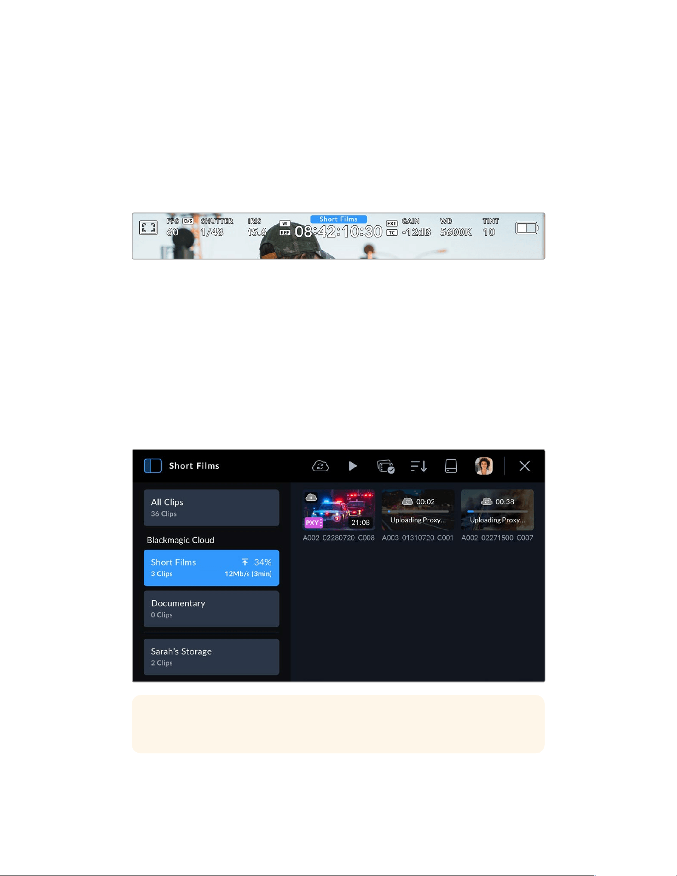
2 Tap the ‘x’ at the top right of your camera’s touchscreen or press the camera’s ‘record’
button to close the media pool and return to the HUD.
3 The name of the selected Blackmagic Cloud project will appear above the timecode display
on your camera’s HUD. The next time you record a clip, your camera will automatically start
uploading media to the selected cloud project.
If your camera’s internet connection is interrupted, the name of the cloud project will be
grayed out and uploads paused. Your camera will automatically restart the uploading
process when the internet connection is restored.
When you have finished recording, tap on your camera’s storage indicator to open the media
pool and view the upload status of your clips.
Your Blackmagic Cloud avatar will remain visible in the controls menu and you will stay logged
in even if you have disconnected your phone or Ethernet adapter. This ensures that any
recordings you have in your project upload queue will resume as soon as possible after
plugging in your phone or network again. Your camera will immediately try to reestablish your
internet connection and resume any uploads it has in its queue.
This also means when you choose to record directly into a project, you can operate in areas
with patchy cellular coverage and not worry about reconnecting to upload as the process
happens automatically. For example, you could record clips in locations where there is no
Internet connection or cellular signal at all and then simply plug in when you are in range or
have a wired Internet connection and quickly upload your proxies then.
TIP For information on how to set your camera to upload proxy files or both proxy and
original files, refer to the ‘settings’ section.
48Uploading Clips to Blackmagic Cloud
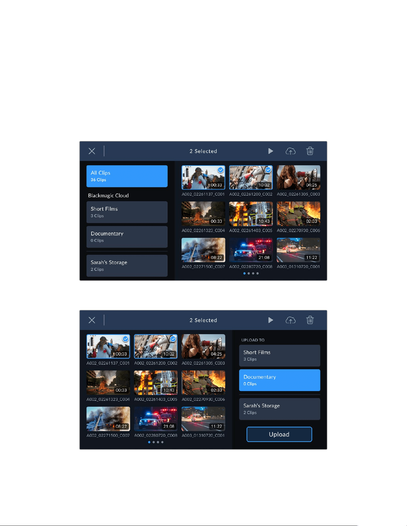
Selectively Uploading Clips to Projects
If you prefer, you can choose not to upload to a project until after your shoot and then upload a
single clip to a project, more than one project, or even your private storage all at once. You can
also use the group select tool to select multiple clips to upload at once to one or many locations.
To upload recorded clips to a Blackmagic Cloud project:
1 Log in to your Blackmagic Cloud account.
2 Tap the sidebar icon and select ‘all clips’.
3 Tap the ‘group select’ icon in the controls menu and select the clips that you want to upload.
4 Tap the ‘cloud upload’ icon. Select the Blackmagic Cloud projects that you want to upload
your clips to by tapping the project names.
5 Tap ‘upload’.
49Uploading Clips to Blackmagic Cloud
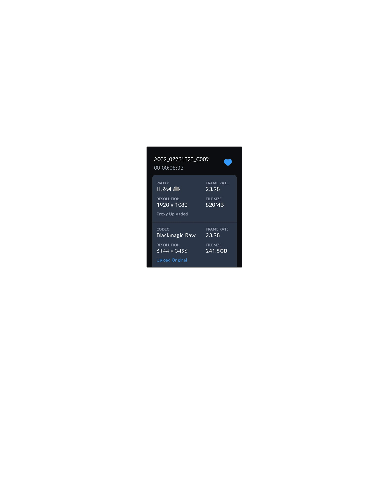
Upload Original
When uploading clips to Blackmagic Cloud projects with ‘proxies only’ selected in your
camera’s ‘setup’ settings, you can still choose to upload an original clip using the clip’s
metadata viewer. For example, this can be helpful when you are shooting using 6K Blackmagic
RAW with low compression as the files can get very large. To save cellular upload data you may
choose to upload proxies only and then upload specific original clips later as required.
To upload an original clip:
1 Select the Blackmagic Cloud project from the projects panel and tap the clip to open it in
the playback viewer.
2 Tap the ‘information’ icon in the controls menu to display the clip’s metadata.
3 In the metadata window, scroll to the section that displays metadata information for your
clip’s original file. Tap the ‘upload original’ button.
Uploading to Your Blackmagic Cloud Storage
You can also choose to upload clips directly to your own private Blackmagic Cloud storage.
This can be useful if you want to upload and back up clips but not into a specific DaVinci
Resolve project. Access your cloud storage by logging into your Blackmagic Cloud account on
your computer and selecting ‘cloud storage’ from the menu.
To upload clips to your Blackmagic Cloud storage:
1 Tap the sidebar icon at the top left of the Blackmagic Cloud project panel.
2 Scroll to the bottom of the project list and select your cloud storage, this will be named with
your Blackmagic Cloud user name, followed by ‘storage’.
50Uploading Clips to Blackmagic Cloud
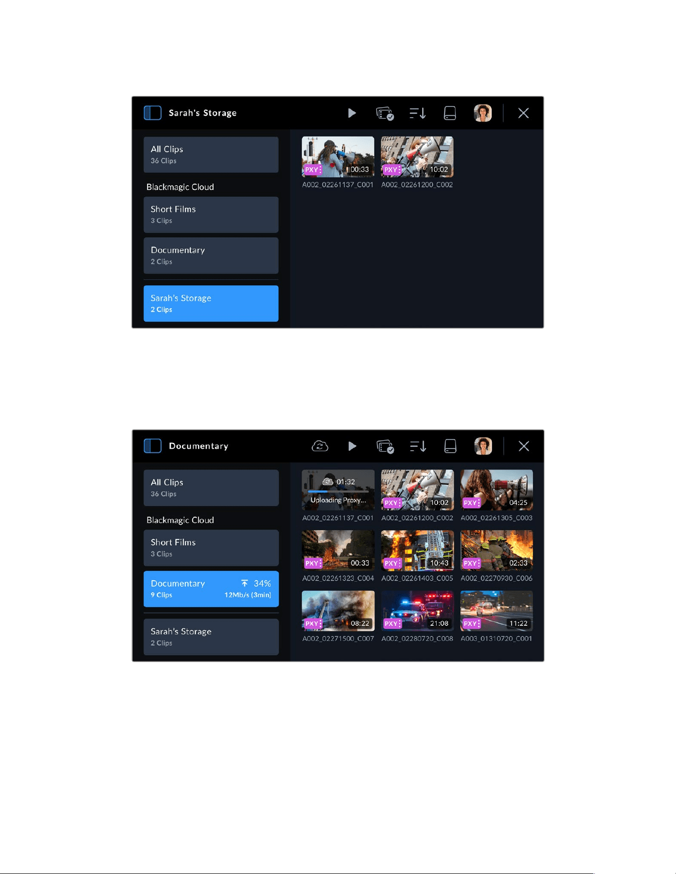
3 Tap your private Blackmagic Cloud storage to select it.
Clip Upload Status Indicators
When you have chosen to upload clips to a Blackmagic Cloud project, you can check the
upload status by selecting the project from the Blackmagic Cloud projects panel.
Next to the cloud project name the overall upload status is displayed including number of clips,
completed percentage, upload speed and estimated time remaining.
51Uploading Clips to Blackmagic Cloud
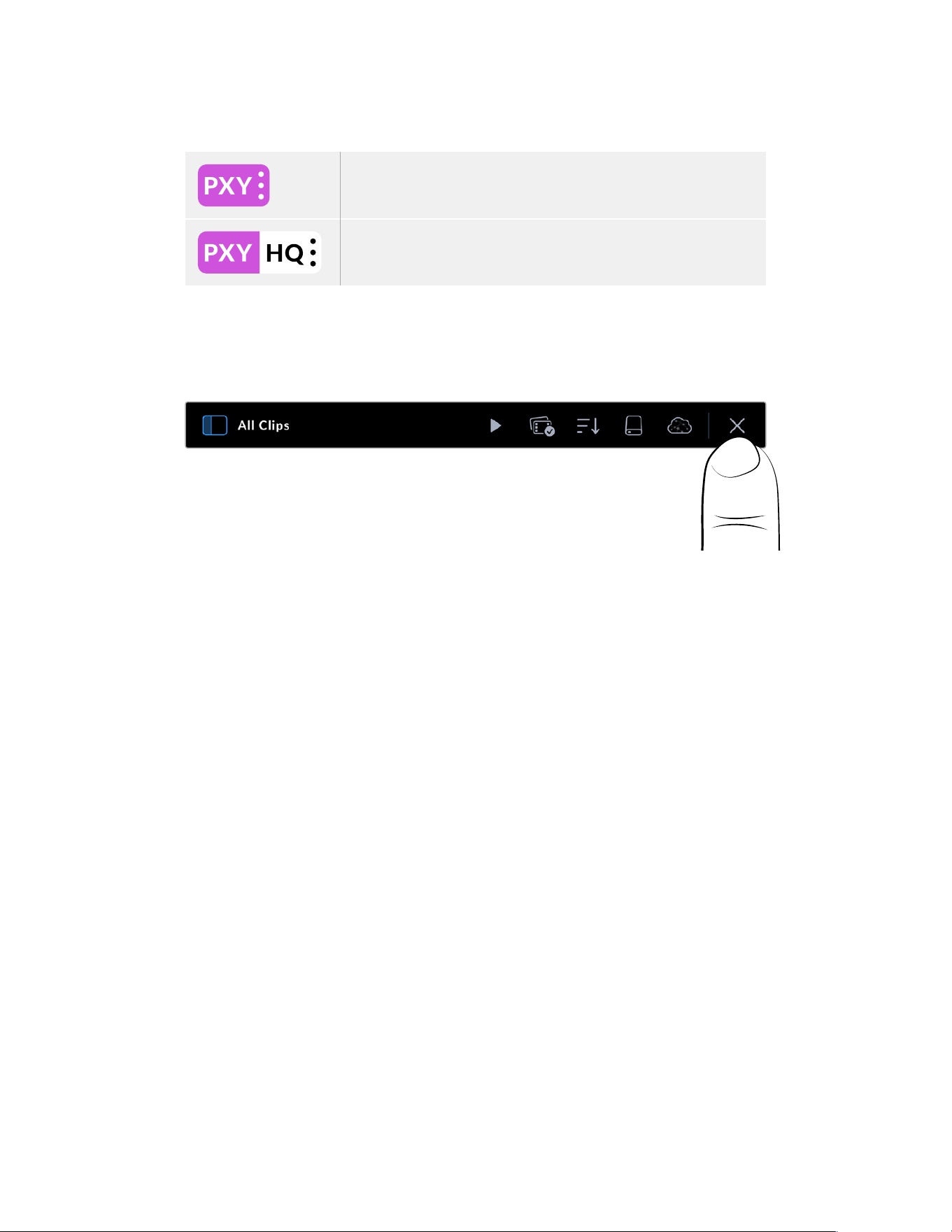
The upload status for each clip is displayed on the clip thumbnail:
Displayed when the clip’s proxy file has been successfully uploaded.
Displayed when both the proxy and original files have been uploaded.
Closing the Media Pool
When you have finished using the medial pool and want to return to the live recording view on
your camera’s LCD, tap the ‘X’ icon at the top right corner of the menu controls.
52Uploading Clips to Blackmagic Cloud
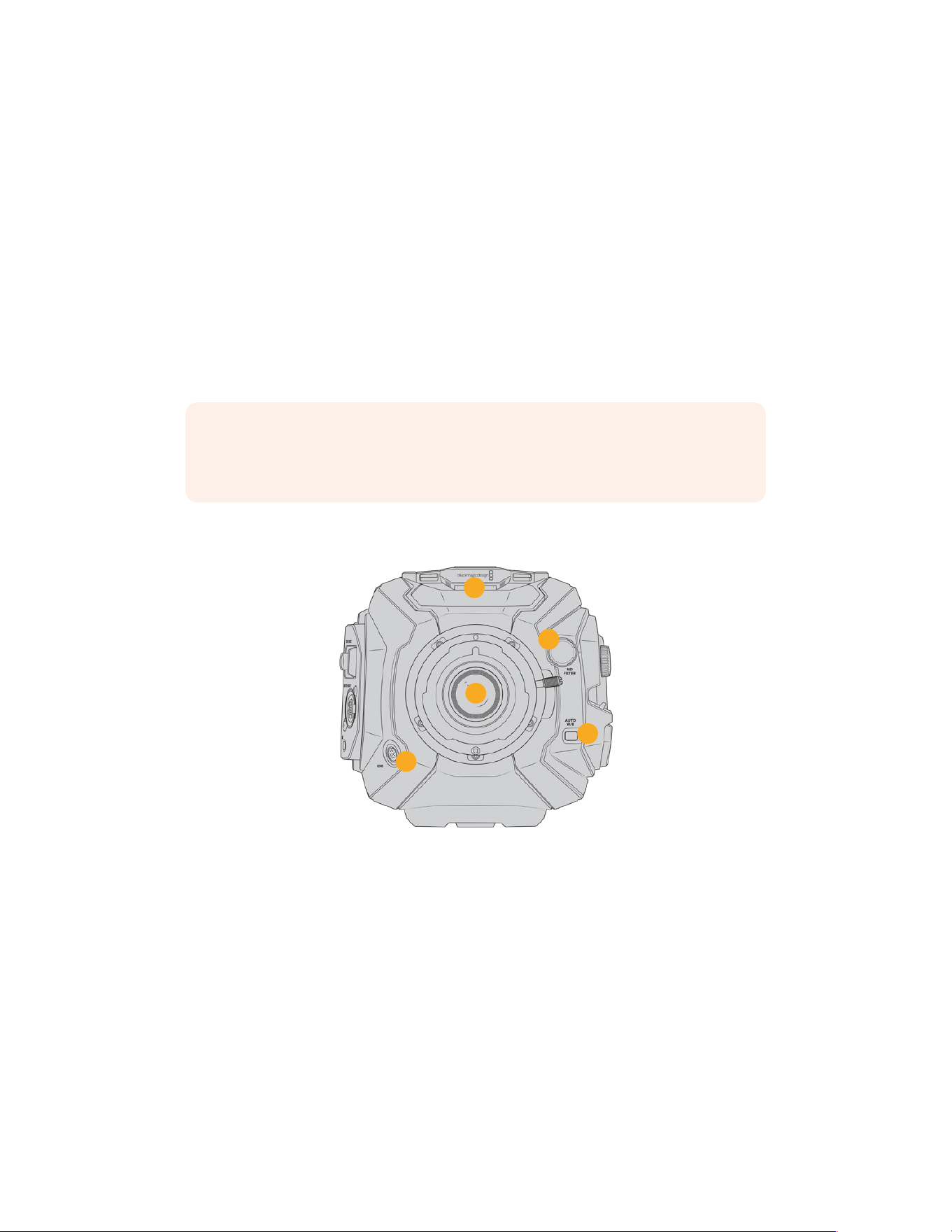
URSA Broadcast G2 Connectors
andFeatures
Industry standard BNC connectors are located on the right and rear panel of your URSA
Broadcast G2 for SDI connections. There is also a LANC input on the right panel for the
optional Blackmagic URSA Handgrip.
XLR inputs are on the top panel behind the mounting points for professional balanced analog
audio and AES digital audio. A 4 pin XLR connector is provided on the rear panel for external
power input, and an output is available on the right side for powering accessories such as
Blackmagic URSAViewfinder.
The USB port above the storage media slots is for connecting to a computerwhen updating
your camera’s internal software.
NOTE Your camera has additional ergonomic controls that make it easy to quickly
access the camera’s essential settings and functions without opening the
foldouttouchscreen.
Camera Front
4
5
3
1
2
URSA Broadcast G2 with B4 mount
1 Stereo Microphone
Built in high quality stereo microphone. Refer to the ‘settings’ section for information
on microphone audio settings.
2 Lens Mount
URSA Broadcast G2 is supplied fitted with a B4 mount. However, it’s interchangeable
with the included EF mount and compatible with URSA Mini Pro PL and F mounts.
Refer to the ‘Interchangeable lens mount’ section for more information.
3 Broadcast Lens Connector
This 12 pin connector provides power and control to compatible broadcast servo zoom
lenses. Refer to the ‘using servo zoom lenses’ section in this manual for details on
functionality available with these B4 and PL lenses.
53URSA Broadcast G2 Connectors andFeatures
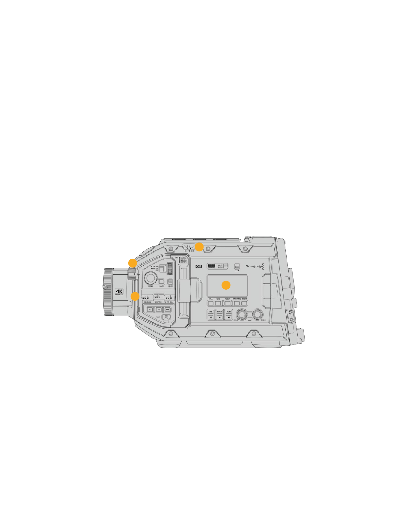
4 ND Filters
Use this wheel to cycle through three built in neutral density filters, as well as a clear
setting. See the section ‘URSA Broadcast G2 Controls’ for more information.
5 Auto White Balance
The auto white balance button is marked ‘Auto W/B’ and is used when you want to set
the white balance based on what is currently in the center of the screen. Forexample,
setting auto white balance on a gray card placed in front of the lens. Seethe section
‘URSA Broadcast G2 Controls’ for more information.
Left Side
URSA Broadcast G2’s left side panel lets you insert CFast 2.0 cards, SDXC or SDHC cards,
access the control panel and change settings. The USB-C port is located just above the CFast
slots so you can easily plug into a computer when updating your URSA Broadcast G2’s
internal software.
Left Side Controls
The left side panel features additional controls for easy access to all of your camera’s essential
functions. These controls are split between the forward control panel, the ergonomic control
panel located on the outside of the foldout touchscreen monitor, and a control panel on the
inside of the foldout monitor.
7
6
8
9
URSA Broadcast G2 with touchscreen closed
6 Power Switch
Power switch for turning on the camera. There is also a backup power switch inside the fold
out monitor that allows the camera to be powered on by pressing both the record and
forward skip buttons at the same time.
7 ND Filters
Your URSA Broadcast G2 has three internal neutral density filters to adjust the amount of
light reaching the sensor. Four settings are available, ranging from clear to six stops of light
reduction. Simply turn this wheel to move through the available settings. The filter will click
into place for each setting. For more information see the section ‘URSABroadcast G2
Controls’ in this manual.
54URSA Broadcast G2 Connectors andFeatures
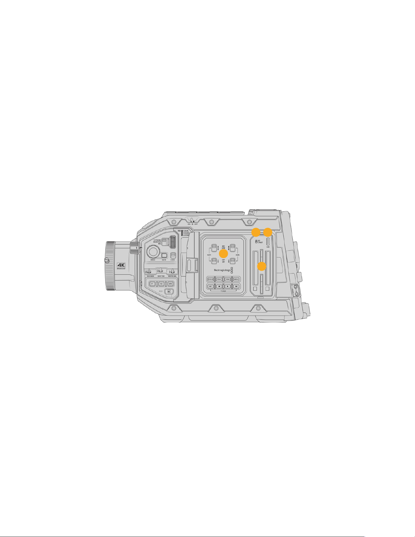
8 Forward Control Panel
The forward control panel provides quick access to all of your URSA Broadcast G2’s
essential functions. These controls are located for easy access when shooting on a tripod
or on the shoulder, and you can use them to adjust settings such as ISO, shutter speed, iris,
white balance, frame rate, and more. See the section ‘URSA Broadcast G2 Controls’ for
more information.
9 Ergonomic Control Panel
On the outside of your URSA Broadcast G2’s foldout touchscreen monitor, you’ll find an
LCD status monitor and a variety of controls for fast, powerful monitoring control. Here you
can see all of your camera’s status information at a glance, as well as controlling a variety
of powerful monitoring functions. See the section ‘URSA Broadcast G2 Controls’ formore
information.
10 Storage Media Selection Switch
Use this switch to choose between CFast and SD storage media.
11 USB Port
USB-C port for updating internal software. See the section ‘Blackmagic Camera Setup
Utility’ for more information.
1110
13
12
URSA Broadcast G2 with touchscreen open
12 Internal Control Panel
When your URSA Broadcast G2’s foldout monitor is open, you have access to the internal
control panel. Use the controls here to set your audio inputs as well as phantom power
settings. You can also access iris, focus, menu and playback controls and more. See the
section ‘URSA Broadcast G2 Controls’ for more information.
13 Memory Card Slots
Insert CFast 2.0 cards, SDXC or SDHC cards for record and playback. Please note that you
should check the list of certified cards on our website. See the section ‘storage media’ for
more information.
55URSA Broadcast G2 Connectors andFeatures
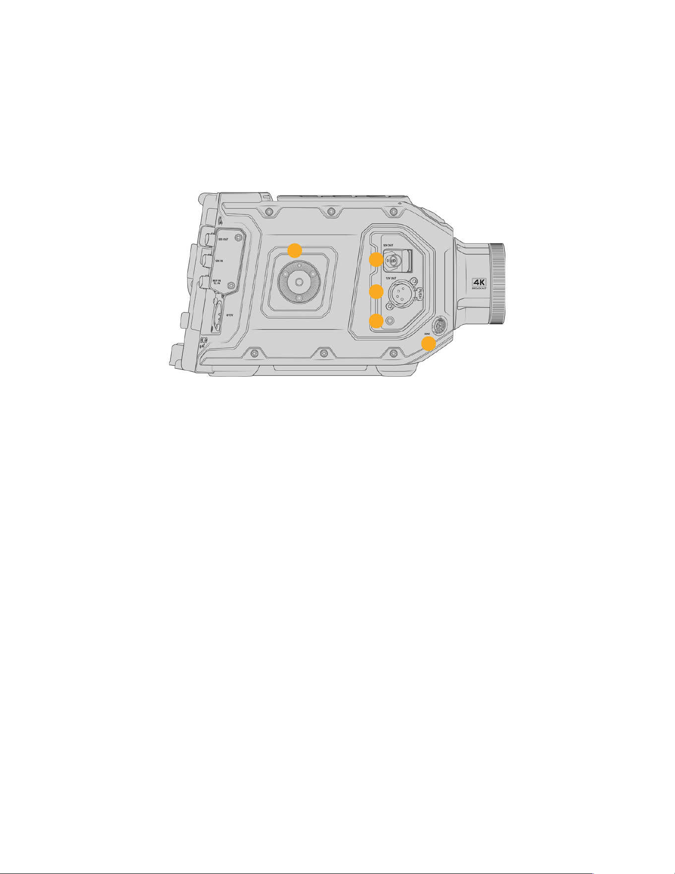
Right Side
URSA Broadcast G2’s right side panel gives you access to all the video, audio and power
connectors plus the side handle rosette mount.
14 Side Rosette Mount
Standard rosette mount for the side handle. Refer to the ‘Getting Started’ and
‘BlackmagicURSA Mini Shoulder Kit’ sections.
14
15
16
17
18
URSA Broadcast G2 has a rosette mount built into the right side if you need to attach
an optional URSA Mini side handle
15 HD Monitoring Output
3G-SDI connector for down converted 1080HD output. Use with Blackmagic URSA
Viewfinder or external monitors. Refer to the ‘camera video output’ and ‘Blackmagic
URSA Viewfinder’ sections for more information.
16 +12V Power Output
4 pin XLR connector for powering Blackmagic URSA Viewfinder, Blackmagic URSA
Studio Viewfinder or external monitors and accessories. Refer to the ‘Blackmagic
URSAViewfinder’ and ‘Blackmagic URSA Studio Viewfinder’ sections for more information.
This output combined with the Broadcast Lens Connector supplies 12 Volts at up to
2Amps in total.
17 LANC Input
Dedicated 2.5mm TRS LANC connector for Blackmagic URSA Handgrip.
18 Broadcast Lens Control Connector
Provides power and control to compatible PL and B4 mount lenses with 12pin connections.
This output combined with the +12V Power Output supplies 12 Volts at up to 2 Amps in total.
56URSA Broadcast G2 Connectors andFeatures
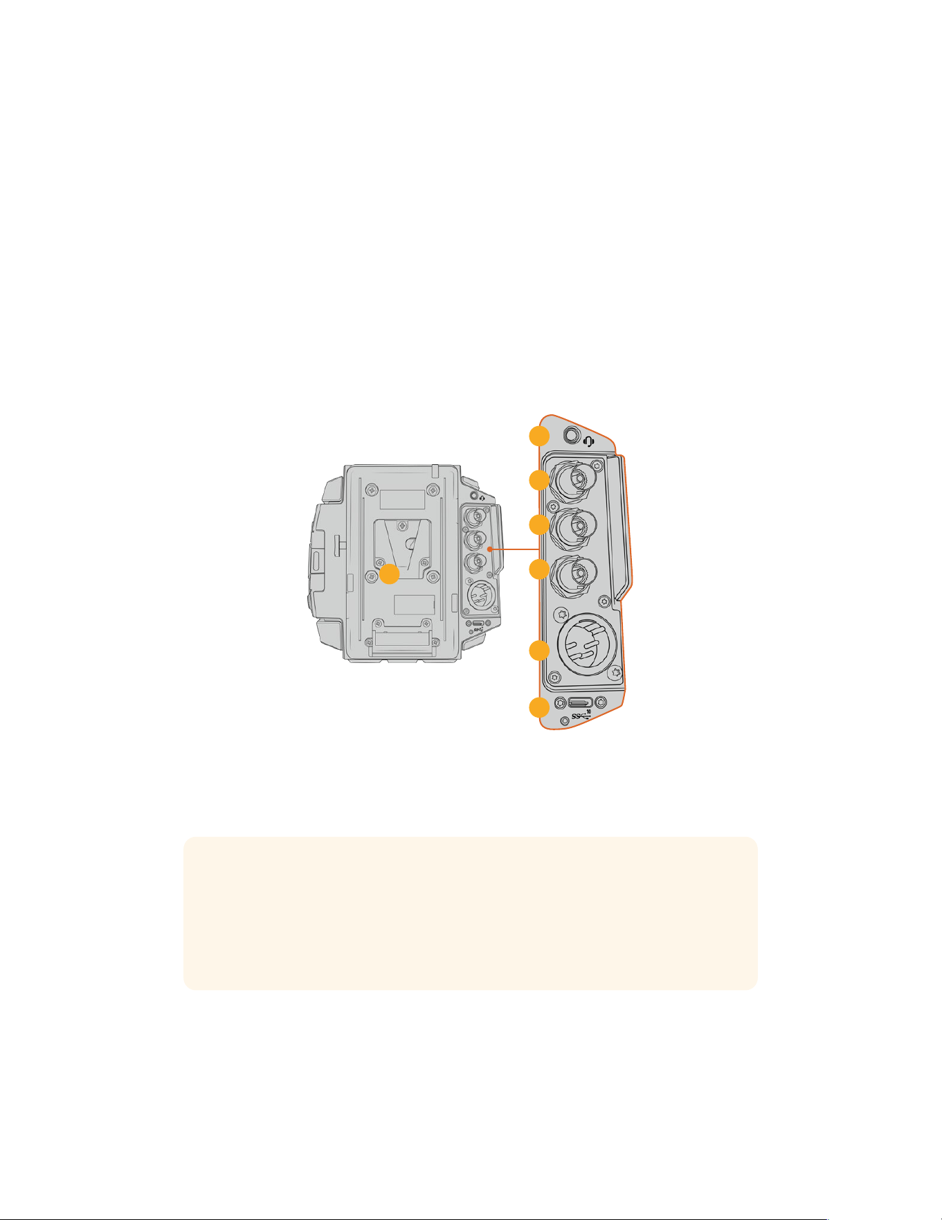
Rear Panel
19 Battery Mount Plate
Your Blackmagic URSA Broadcast G2 comes fitted with Blackmagic URSA VLock Battery
Plate for attaching VLock batteries to your camera. URSA VLock Battery Plate features a
D-Tap port for powering accessories. The D-tap port can output a regulated 12 Volts at up
to 1.5 Amps.
URSA VLock Battery Plate can be replaced with an optional Blackmagic URSA Gold
Battery Plate or a third party battery plate. The battery plate can be removed to access
a recessed Molex connector and to attach optional accessories such as Blackmagic
Camera Fiber Converter or Blackmagic URSA Mini Recorder onto the back of the camera.
If your connected accessory has a D-tap power output then the Molex connector will
supply a pass through output of 12 Volts at up to 1.5 Amps. For more information, refer to
the chapter for ‘Mounting Batteries’, ‘Getting Started with Blackmagic Fiber Converters’
and ‘URSA Mini Recorder’.
1
9
2
0
21
2
2
23
2
4
2
5
20 Headphone/Headset
The 3.5mm jack output is used for headphone monitoring and talkback. You can plug in
iPhone and Android compatible headsets that have a built in microphone for quick and
easy talkback. Talkback audio is embedded in channels 15 and 16 of the SDI output.
TIP When using URSA Broadcast G2’s 3.5mm jack for talkback, a very affordable option
is using an iPhone or Android compatible headset. These typically feature an inline
button that can be used to mute and unmute their microphone. If you would like to use
a broadcast headset without this inline switch you can configure your URSA Broadcast
G2’s function buttons to offer the same functionality. See the ‘setup settings’ section of
this manual for moreinformation.
21 12G-SDI Out
Blackmagic URSA Broadcast G2’s 12G-SDI output is used to send HD and Ultra HD video
to SDIequipment such as routers, monitors, SDI capture devices, and broadcast switchers.
You can also connect the 12G-SDI output to an external recorder such as theBlackmagic
Video Assist for backup recording.
57URSA Broadcast G2 Connectors andFeatures

22 12G-SDI In
The 12G-SDI input is used for connecting to a switcher or external recorder. This means if
you’re using URSABroadcast G2 in a live broadcast, you can plug in the switcher’s program
output and monitor it during the shoot, or check playback from an external recorder. Press
and hold the program button to see your program feed.
For more information, refer to the ‘Ergonomic Control Panel’ section in this manual.
You can also use an ATEM switcher’s ‘camera control’ feature to remotely adjust many
URSABroadcastG2 functions. See the section ‘Understanding Studio Camera Control’
for moreinformation. Blackmagic 3G-SDI Shield for Arduino can also be used to provide
custom control of the camera over SDI.
To receive tally and talkback via the SDI input, make sure you have set your ATEM Camera ID in
the camera’s setup menu. If you want to use the SDI input to receive an external reference signal,
you will need to select ‘program’ as your reference source in the setup settings. ‘REF’ will appear
next to the timecode display on your camera’s LCDscreen when the external reference is
locked. Refer to the ‘setup settings’ in the manual for more information.
On URSA Broadcast G2 the SDI Input can be used for feeding external timecode to the
camera as well. This will lock to the incoming timecode automatically if the frame rate ofthe
incoming SDI signal matches and has valid timecode. The ‘EXT’ logo will appear on URSA
Broadcast G2’s LCD when external timecode is locked. If you unplug the cable timecode
will remain jammed and the logo will switch to ‘INT’ to let you know it is now running from
URSA Broadcast G2’s internal timecode clock.
23 Reference and Timecode In
This input automatically recognizes and switches between timecode and reference input
signals. Synchronize Blackmagic URSA Broadcast G2 to a common reference signal, such
as tri-level sync, by connecting to the ‘reference’ BNC input marked ‘REF In’. It’s worth
noting that to use a reference signal through this input, you must set your reference source
to ‘external’ in your URSA Broadcast G2’s setup menu.
Alternatively you can use this connector to match an external timecode source to sync up
multiple cameras, or audio and picture when shooting dual-system. This ensures audio and
picture, or video from multiple cameras, can be easily synchronized during post production.
When external timecode with a matching frame rate is plugged into this connector the
camera will lock to the incoming timecode automatically. The ‘EXT’ logo will appear on
URSA Broadcast G2’s LCD when external timecode is locked. If you unplug the cable,
timecode will remain jammed and the logo will switch to ‘INT’ to let you know it is now
running from URSA Broadcast G2’s internal timecode clock.
You can also set your camera to use the reference signal from an ATEM switcher via
the Program SDI Input. This is helpful when working with ATEM switchers because all
cameras can receive program return, camera control and be referenced together using
a single SDI signal. See the ‘setup settings’ section in this manual for more information.
24 12V+ Power Input
Use the 4 pin 12-18 Volt DC XLR connector to plug in power from external sources such as
the supplied power adapter, or portable batteries.
25 USB Port
USB-C 3.2 Gen 2x1 port for recording to an external flash disk or to an SSD using
Blackmagic URSA Mini Recorder. Also used for connecting Blackmagic Zoom and Focus
Demand to your camera for focus and zoom control with compatible lenses.
The threaded connector under the USB-C port works with the locking USB cable supplied
with URSA Mini Recorder to maintain a secure connection during use. Formore information
refer to the ‘URSA Mini Recorder’ section in this manual.
58URSA Broadcast G2 Connectors andFeatures
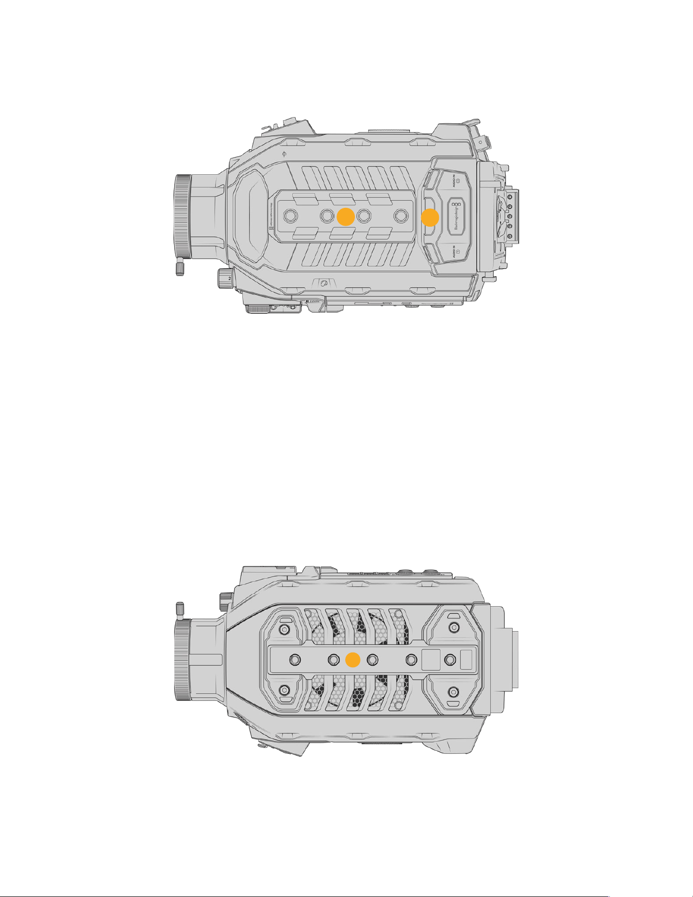
Top Panel
27
26
External analog audio can be plugged into the balanced XLR connectors on the top panel
26 1/4 Inch Mounting Points
Your camera’s top panel contains 4 strong mounting points for attaching the top
handleandaccessories.
27 XLR Audio In
Use the balanced XLR inputs to plug in external analog audio from professional equipment
such as audio mixers, PA systems or external microphones. The XLR connectors supply
48V phantom power so you can use microphones that aren’t self powered. Refer to the
‘URSA Broadcast G2 controls/internal control panel’ section for more information on
phantom power.
Underside
28 1/4 Inch Mounting Points
The 5 mounting points on the underside are used for attaching tripod heads, the URSAMini
Shoulder Kit and other accessories.
28
59URSA Broadcast G2 Connectors andFeatures
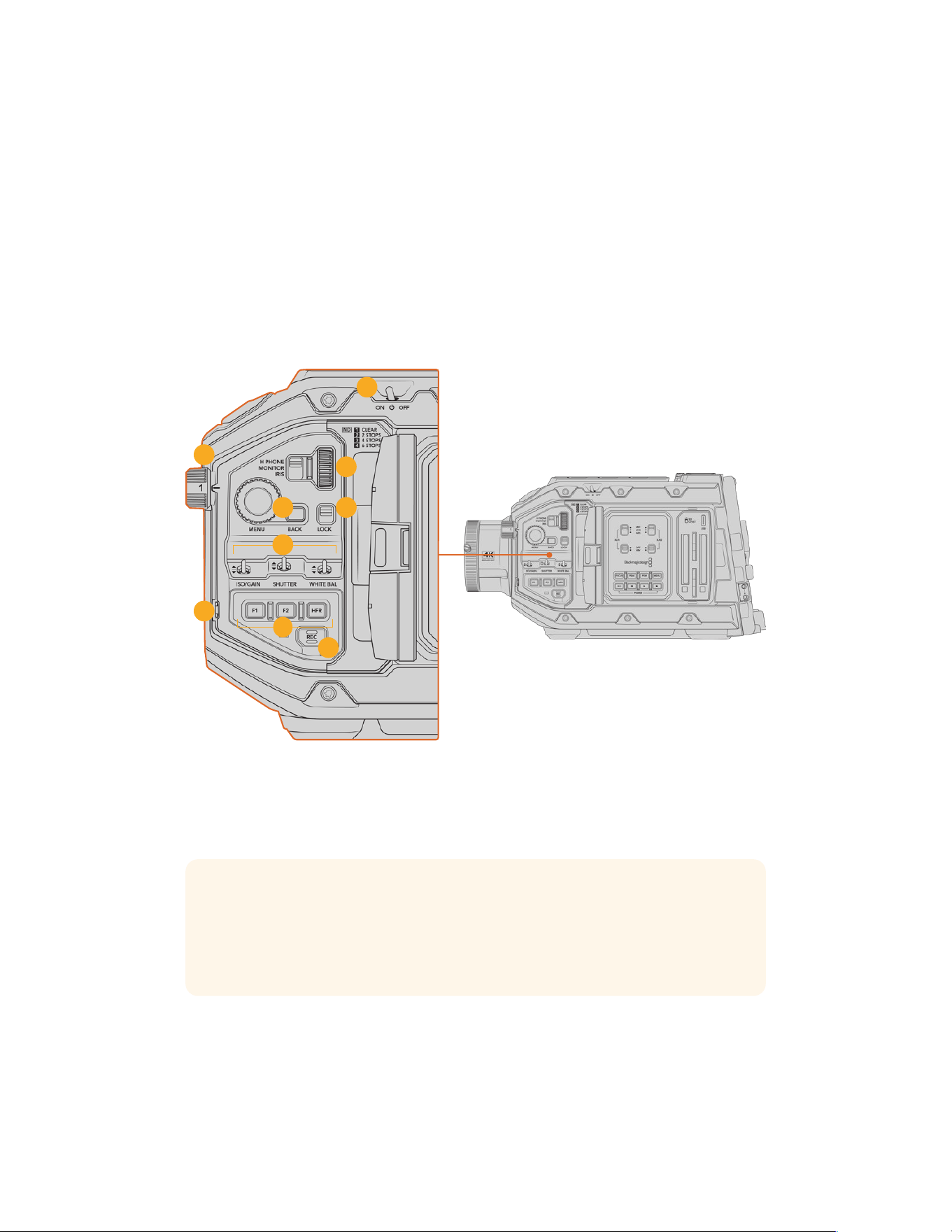
URSA Broadcast G2 Controls
Blackmagic URSA Broadcast G2 has control panels on the chassis, outside and inside of the
foldout touchscreen monitor to give you quick, easy access to all of its essential functions as
well as powerful monitoring tools. These panels are designed to be close to hand whether
shooting from a tripod, handheld or with the URSA Mini Shoulder Kit.
Forward Control Panel
Your camera’s forward control panel groups together all of the controls you might need to
adjust when setting up a shot and recording. These are all designed for easy access while
shooting with the foldout monitor closed, such as when using the shoulder kit.
6
8
1
4 5
9
7
3
2
URSA Broadcast G2 forward control panel
1 Power Switch
Power your URSA Broadcast G2 by moving this switch to the ‘on’ position. Power off by
moving the switch to the ‘off’ position.
TIP You can also power your URSA Broadcast G2 on or off via a combination
ofcontrol panel switches. Holding the ‘rec’ and ‘forward skip’ buttons will power upthe
camera if it is turned off, or power it off if it is turned on. If your camera’s power switch
is set to ‘on’ but your camera is powered down, it may have been powered down via
the control panel. Toggle the power switch to return it to normaloperation.
2 ND Filters
Your URSA Broadcast G2 has three internal neutral density filters. Together with a clear
filter, the available settings are 1/4, 1/16th and 1/64th. These filters allow you to reduce the
amount of light reaching your URSA Broadcast G2’s sensor by a preset fraction. By
reducing the exposure, you can continue shooting at wide apertures in bright conditions
such as outdoors on sunny days.
60URSA Broadcast G2 Controls
To adjust your neutral density setting, rotate the wheel upwards or downwards. The‘clear’
setting means there is no ND filter being used. From settings 1/4 to 1/64th, the NDfilters
gradually increase in density so you can decrease light if you need to.
Because different people prefer to use different terms for each ND filter, the measurement
of your ND settings can be customized in the LCD menu. You can identify the ND filter
number, amount of stops in light reduction, or the fraction representing the amount of light
reduced for the filters to suit your preference.
Neutral Density Filter Settings
Wheel position ND number Stops Fraction
1 clear 0 1
2 0.6 2 1/4
3 1.2 4 1/16
4 1.8 6 1/64
3 Settings Wheel
Set this wheel’s function by adjusting the adjacent three position switch next to the wheel.
The options are ‘headphone,’ ‘monitor’ and ‘iris’.
Headphone
When set to ‘headphone’, the settings wheel will adjust headphone audio levels. Rotatethe
wheel upwards to increase volume, and downwards to decrease.
Monitor
When set to ‘monitor’, the settings wheel adjusts audio levels on your camera’s built in
monitor speaker. The speaker is located on the outside of the LCDmonitor door and can be
used to monitor audio without headphones. Rotate the wheel upwards to increase volume,
and downwards to decrease. This function is disabled while recording from the camera’s
internal microphone to prevent unwanted feedback.
Iris
When set to ‘iris’, the settings wheel is used to adjust the aperture of compatible lenses
mounted to your URSA Broadcast G2. Rotating the wheel downwards opens the iris, and
turning the wheel upwards closes the iris. These directions mimic the operation of aperture
on adjustable still and cinema lenses.
TIP To change aperture settings via the settings wheel, URSA Broadcast G2 must be
fitted with a lens that supports changing aperture via the camera. Ifyou are using a B4
or PL lens connected via the broadcast 12 pin connector, make sure that the lens iris
switch on the handgrip is set to ‘A’ or ‘auto’.
4 Menu Wheel and Back Button
When ‘status text’ is turned on for your camera’s front SDI output, you can use the
menu wheel to navigate many of the head up display features usually accessed via
the LCD touchscreen.
61URSA Broadcast G2 Controls

Simply press the menu wheel as you would a button to access your URSABroadcastG2’s
head up display on an external monitor such as Blackmagic SmartView, Video Assist or
URSA Viewfinder. While the menu wheel is active, turn the wheel to select features such as
LCDmonitor options, frame rate, ISO, white balance and tint. Press the wheel to confirm
selections and make additional changes, and use the ‘back’ button next to the wheel to
cancel. You can also use the back button to move up a menu level, or exit the menu
completely if you’re at the top level. The menu will automatically close after one minute
of inactivity.
For more information on setting status text and the controls available, see the ‘touchscreen
controls’ and ‘monitor settings’ sections of this manual.
5 Lock
Toggle this switch to lock all of the controls on the forward control panel to prevent them
from being accidentally adjusted while shooting. Move this switch to the lower position to
lock, and the upper position to unlock.
TIP When shooting in busy or uncontrolled environments, you can lock your URSA
Broadcast G2’s forward control panel when you leave your camera unattended.
Thisensures that your settings are not changed unintentionally byothers.
6 ISO, Shutter and White Balance Switches
These small switches are used to adjust your ISO/Gain, white balance, and shutter settings.
They are helpful when you want to make fast adjustments without taking your eyes off the
shot. Gently push the switches up or down to make setting adjustments. Theswitches are
spring loaded so they always return to a neutral position.
ISO/Gain
Push this switch up or down to adjust your camera’s gain setting. Pushing up will increase
the setting by 1/3 stop, and pushing down will decrease by 1/3 stop. Theavailable settings
range from -12 to 36dB.
Shutter
Use this switch to adjust the camera’s shutter speed. Pushing up will increase the shutter
speed to the next available preset, and pushing down will decrease to the next available
preset. Holding the switch up or down will move more quickly through available values.
There are twelve shutter speed presets between 1/24and 1/2000.
TIP Your URSA Broadcast G2 can also suggest flicker free shutter speeds based on
the power frequency in your region. These must be selected through the
LCDtouchscreen menu. For more information see the ‘touchscreencontrols’ section in
this manual.
White Balance
This switch is used to adjust the camera’s white balance. Pushing up will increase the color
temperature by 50K, and pushing down will decrease it by 50K. Holding the switch up or
down will move more quickly through available values.
7 Auto White Balance
Pressing this button will reveal a white ‘auto white balance’ box in the center of the LCDfor
five seconds. This box will also appear on any SDI output that has ‘status text’ enabled in
the menu settings. The white box indicates the specific area of your image where the white
62URSA Broadcast G2 Controls
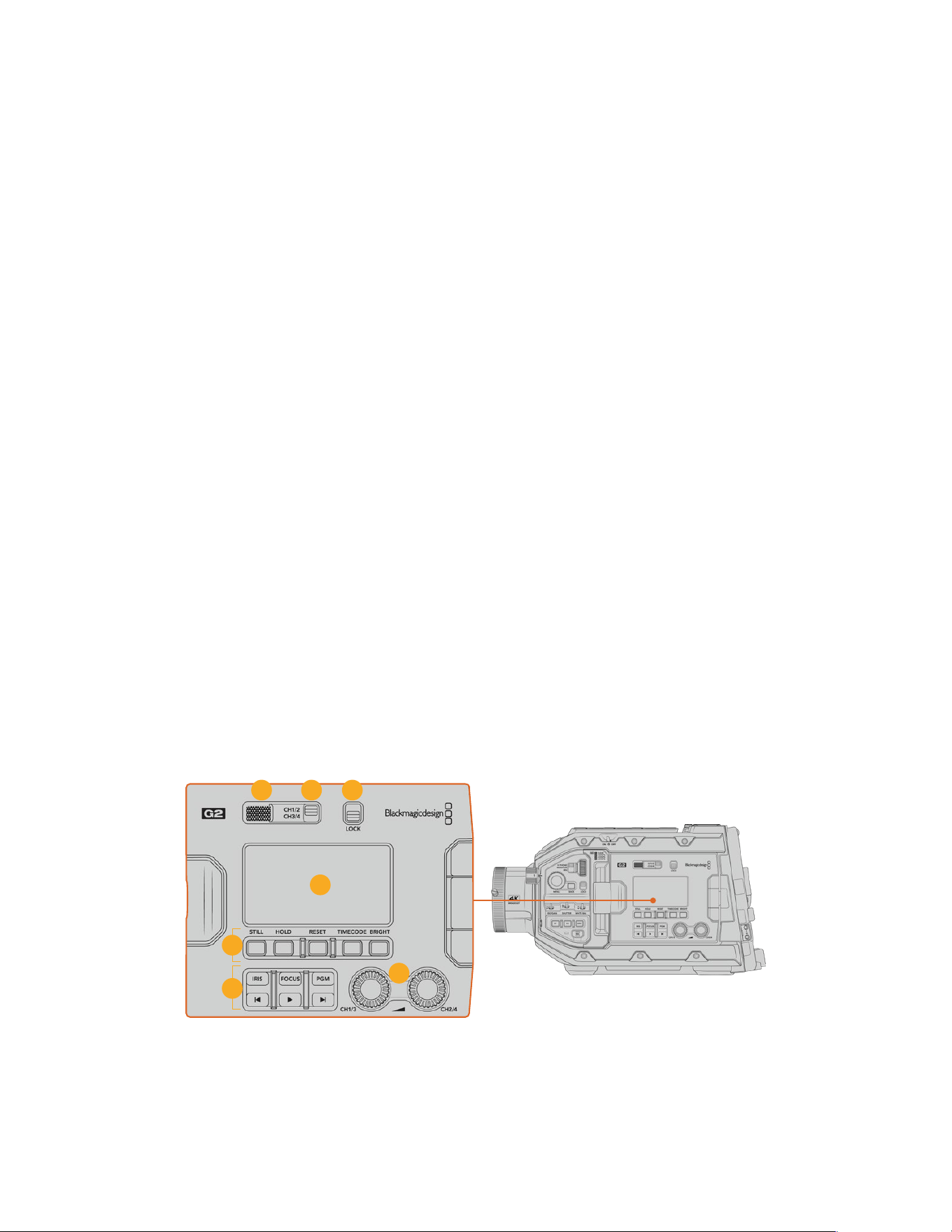
balance will be calculated from, so your gray card should be positioned within this box.
Pressing and holding the ‘Auto W/B’ button for three seconds will perform an ‘auto white
balance’, and the square will change from white to green to confirm that this has been
performed successfully.
For more information on enabling status text for your URSA Broadcast G2’s front or main
SDIoutputs, see the ‘monitor settings’ section in this manual.
8 F1 and F2
The F1 and F2 keys are ‘function’ keys that can be programmed to a variety of commonly
used functions using your URSA Broadcast G2’s ‘setup’ menu. By default, F1 is set to
toggle ‘focus zoom’ on the LCD and front SDI output, while F2 is set to toggle ‘false color’
on the LCD.
For more information, see the ‘touchscreen controls’ section of this manual.
HFR
Use the HFR or high frame rate button to toggle off speed frame rates. To use this button,
simply set the off speed frame rate you’d like to use in your URSA Broadcast G2’s ‘frame rate’
menu. Pressing this button will toggle between your chosen off speed frame rate and
project frame rate. It’s worth mentioning that this setting can only be adjusted when the
recording is stopped. The HFR button can also operate as a function button that you can
program to a variety of commonly used functions, or can be disabled.
For more information on project and off speed frame rates, see the ‘touchscreen controls’
section in this manual.
9 Record
The ‘record’ button is marked REC on your Blackmagic URSA Broadcast G2’s left side.
Pressthe record button to start and stop recording. Refer to the ‘recording’ section for
more information.
Ergonomic Control Panel
On the outside of your URSA Broadcast G2’s touchscreen monitor, you’ll find an LCD status
monitor and a variety of monitoring controls. This panel lets you see all of your camera’s status
information at a glance, as well as monitoring and adjusting audio levels. Automatic focus can
be set using compatible lenses and the transport controls let you playback clips.
15
14
10 11
13
16
12
URSA Broadcast G2 ergonomic control panel
63URSA Broadcast G2 Controls
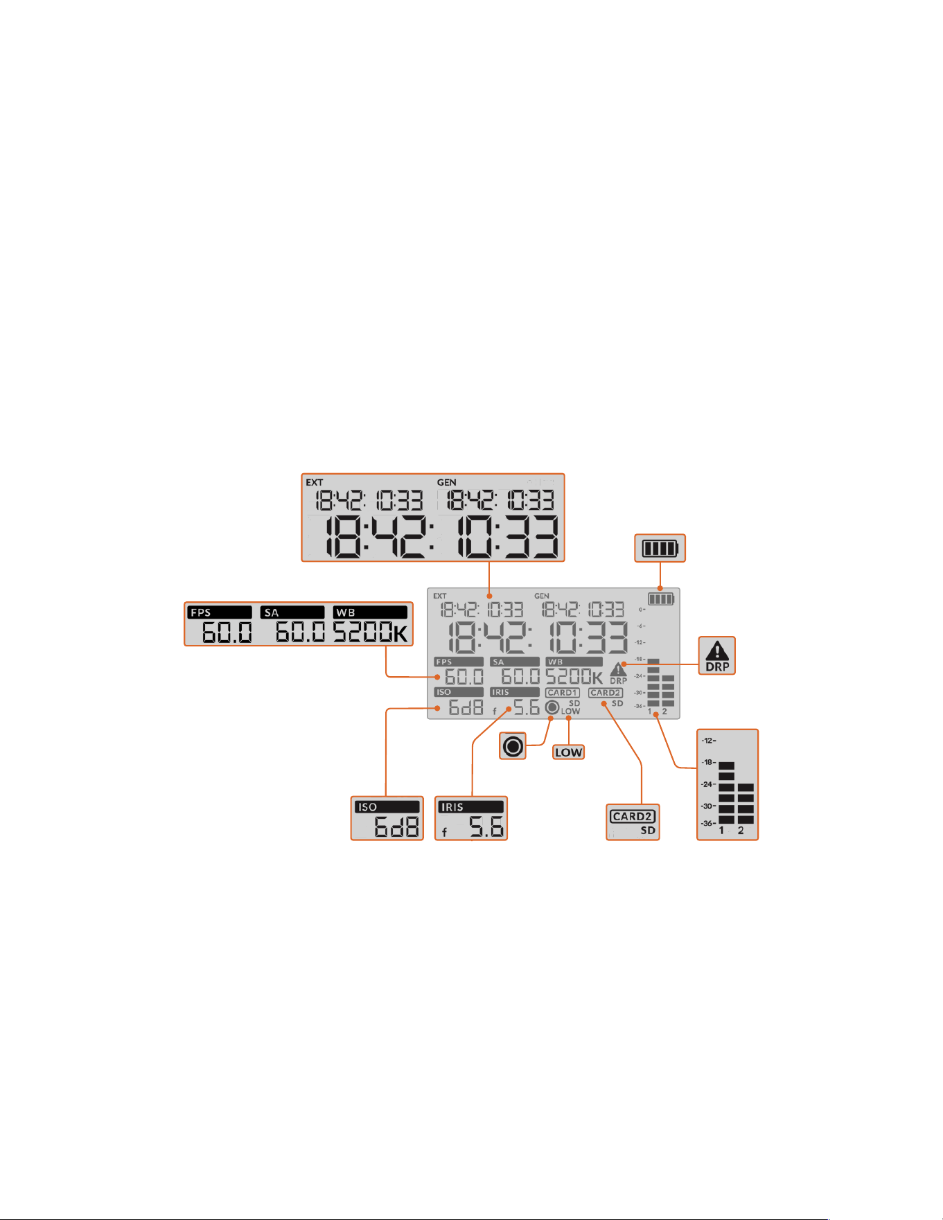
10 Monitor Speaker
The small speaker built into the outside control panel lets you monitor audio when in
playback. It is located where your ear would normally be when shooting with the camera
on your shoulder.
To adjust the volume of the speaker, simply rotate the settings wheel as described in the
‘URSA Broadcast G2 Controls’ section.
11 Monitor Channel Select
Your URSA Broadcast G2 supports two channels of audio.
12 Lock
Use this switch to lock all of the settings on your URSA Broadcast G2’s ergonomic control
panel. The only controls that will remain active while the lock switch is ‘on’ arethe monitor
channel select switches.
13 Status LCD
This display shows you your URSA Broadcast G2’s essential settings at a glance, without
needing to open the internal touchscreen. This screen is designed to be visibleeven
inbright daylight. The following information is available:
Timecodes
Your URSA Broadcast G2 displays three timecodes. If you have an external timecode
connected, this will be shown under the ‘ext’ indicator in the top left of the status LCD. Your
camera’s internally generated timecode is shown next to this under the ‘gen’ indicator. Both
the external and generated timecodes are shown in hours, minutes, seconds and frames.
The larger, main timecode indicator displays your current timecode as either clip duration
or timecode. You can switch between these two display modes by pressing the ‘timecode’
button underneath the status LCD.
Battery indicator
If your URSA Broadcast G2 is running on battery power, this indicator displays remaining
battery life in 25% increments. Each of the battery indicator’s four bars corresponds to 25%
battery life remaining. When your battery drops below 20% charge, the color of the status
Battery indicator
Audio metersCard indicatorIris
Low record
time remaining
FPS, Shutter Angle, White Balance
Record
indicator
Timecodes
ISO/Gain
Dropped
frame
indicator
64URSA Broadcast G2 Controls

LED, near the record button begins to flash. It will alternate slowly between red and orange
during recording and alternate between white and orange during standby mode.
If the mains power connector is plugged into your camera, the battery indicator
shows as full.
FPS, Shutter Angle, White Balance
The ‘FPS,’ ‘SA,’ and ‘WB’ indicators display your camera’s current frame rate, shutter angle
and white balance. The ‘fps’ indicator shows the current sensor frame rate.
Formore information on sensor and project frame rates, see the ‘touchscreen controls’
section in this manual.
ISO/Gain
Displays your camera’s currently set gain.
Iris
Displays your current lens aperture. Depending on your lens type, this will be displayedas
an ‘f’ or ‘T’ stop.
Card Information
The ‘card 1’ and ‘card 2’ indicators will appear on your URSA Broadcast G2’s status
LCDwhen these slots are occupied.
The ‘SD’ indicator appears if you are recording on SD cards, and disappears if you are
recording on CFast cards.
Record Indicator
While recording, a circular indicator will appear under the card or cards being currently
written to.
Low Time Remaining
A ‘low’ indicator will appear under the relevant card when you have approximately
5minutes of record time remaining.
Audio Meters
The peak audio meters display audio levels when using the internal microphone, or
viaexternal audio when connected. The display is calibrated to dBFS units and features
peak hold indicators which stay visible for a short time so you can clearly see the maximum
levels reached.
To achieve optimum audio quality, ensure your audio levels do not reach 0 dBFS. This is the
maximum level that your camera can record, meaning that any audio that exceeds this level
will be clipped, resulting in distortion.
Dropped Frame Indicator
This indicator will flash when your camera detects dropped frames. Once you stop
recording, the indicator will remain on the screen to let you know that the previous clip
detected dropped frames. This warning disappears the next time you start recording, or if
you power cycle the camera. For more information on avoiding dropped frames, see the
‘storage media’ section in this manual.
NOTE You can set your URSA Broadcast G2 to stop recording if dropped frames are
detected. See the ‘recordsettings’ section in this manual for more information. This
feature is user selectable as you may be able to get away with brief periods of ‘burst’
recording at higher frame rates or resolutions when shooting to slower media.
65URSA Broadcast G2 Controls
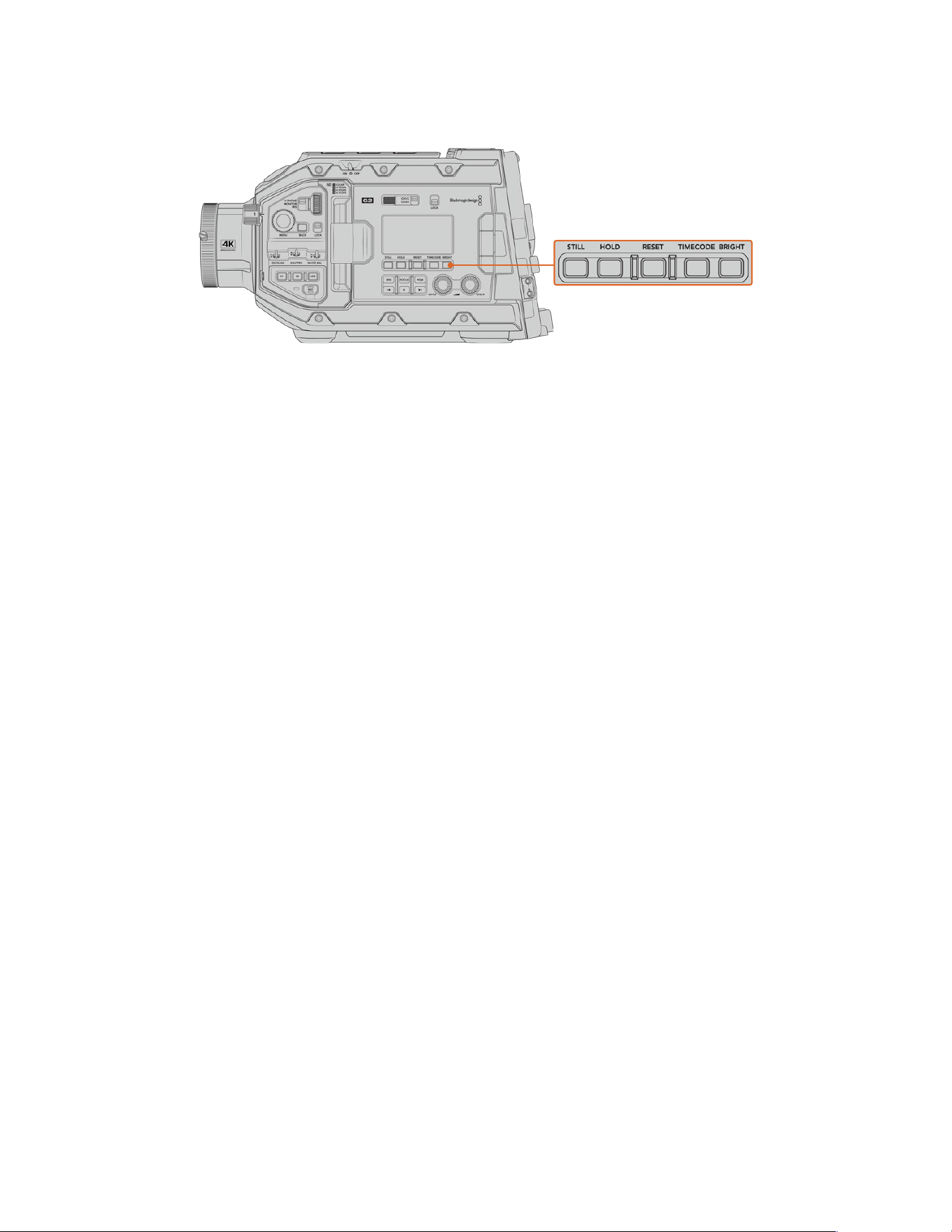
14 Status LCD Controls
URSA Broadcast G2 status LCD controls
Still
Press this button to capture a still image as a single uncompressed DNG frame. Image files
will be saved to the ‘stills’ folder in the root directory of the media you are currently
recording to. These will follow the file naming convention for video clips but the filename
will have an ‘S001’ representing the ‘still number’ as the last four digits of the filename.
To confirm you have successfully saved a still, an image of a camera will show in the top
right corner of the URSA Broadcast G2 touchscreen, and the record indicator on the status
LCD will flash three times.
Hold
Use this button to temporarily hold the main status LCD timecode when the timecode is in
free running time of day code. The timecode will continue to run in the background and
return to its actual position when you release the ‘hold’ button. While holding you can take
note of the timecode for a particular event. This can be useful in electronic news gathering
or documentary situations for noting key timecode points.
Reset
The reset button allows you to reset the timecode to 00:00:00:00 when you are setting
your preset timecode.
Timecode
Press the ‘timecode’ button to toggle the main timecode display’s format between clip
duration and timecode. By default the timecode will be free running time of day code
as this is the most frequently used. If you press and hold the ‘timecode’ button for five
seconds it will switch the camera into record run timecode and the timecode generator will
flash as well as the first two digits of the large timecode display. This indicates that you are
now editing your preset timecode and allows you to set a specific timecode number for
your preset timecode.
Pressing ‘reset’ at this stage will zero the timecode and then you can turn and press
themenu wheel to set the desired value starting with hours, minutes, seconds and then
frames. When you are happy with the timecode, press and hold the ‘timecode’ button
again for three seconds to set this as your preset timecode point. You will notice that the
timecode generator now shows this value and will only increment when the camera is
recording giving you continuous ascending timecode values. To switch your timecode
back to free running time of day code, press the ‘timecode’ and ‘hold’ buttons
simultaneously for three seconds.
Bright
Press the ‘bright’ button to cycle through four brightness settings for your URSA Broadcast
G2’s LCD status display. The settings are ‘off,’ ‘low,’ ‘medium’ and ‘high.’
66URSA Broadcast G2 Controls
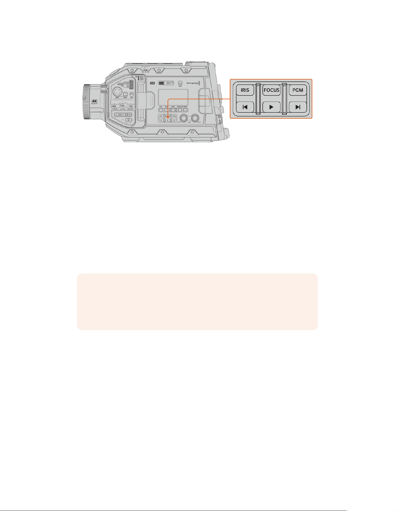
15 Control and Playback Buttons
URSA Broadcast G2 control and playback buttons
Iris
The ‘iris’ button activates the automatic aperture setting on compatible lenses. When using
video dynamic range settings, a single press of the iris button will set an average exposure
based on the highlights or shadows in your shot. When using film dynamic range settings,
pressing the iris button sets your exposure to the brightest highlight in your shot. This
button works with compatible EF lenses and PLlenses connected with acompatible
broadcast lens controller.
To set your aperture manually, press the forward and reverse skip transport buttons.
Focus
When using a B4 or EF lens that supports electronic focus adjustments, press the ‘focus’
button to activate auto focus. A white focus square will appear on any viewfinder or monitor
connected to your URSA Broadcast G2. Anything within the square will be correctly
focused. When the lens is focused, the square will disappear.
NOTE To use the ‘focus’ button, your B4 lens must have servo focus control, with the
servo activated. See the ‘getting started’ section for more information. Some EF lenses
have both manual and auto focus modes. If using the optional EF lens mount, in order
for URSA Broadcast G2 to be able to auto focus with your lens, you need to ensure
that your lens is set to auto focus mode.
Program
The program button is marked PGM and lets you switch the LCD and front SDI output
between the camera view and any signal plugged into the 12G-SDI input on the rear panel.
This means if you’re using the camera in a live broadcast, you can plug in the switcher’s
program output and monitor it during the shoot. Press and hold the program button to see
your program feed. The program feed will continue to display whilst the program button is
being held.
If you want to lock the LCD and front SDI output to display the program input feed, then
double press the program button to lock to the program feed. Pressing the program button
again will exit the program feed and return to the camera view.
Playback Control Buttons
The playback buttons let you start and stop playback, plus skip to the next or previous clip.
When using an EF lens, the forward and reverse skip buttons can also be used to open or
close the iris when using compatible lenses. Refer to the ‘playback’ section for more
information on how to use the playback buttons.
67URSA Broadcast G2 Controls
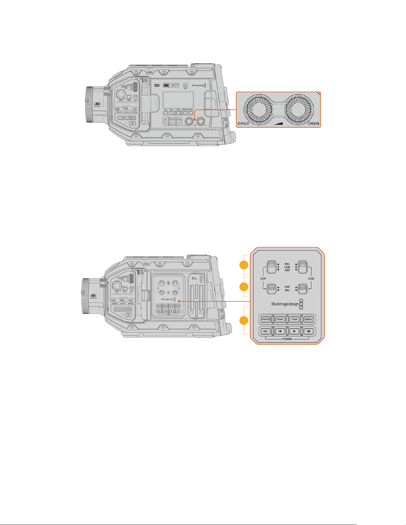
16 Audio Level Adjustment Knobs
URSA Broadcast G2 audio adjustment knobs
Use the built in adjustment knobs to set the recording levels for audio channels 1 and 2.
Turn each knob clockwise or counterclockwise to increase or decrease the recording level
for each channel of audio. Monitor the corresponding on screen audio meters as you adjust
each knob so you can see the best level to set it to.
Internal Control Panel
With your URSA Broadcast G2’s foldout monitor open, you can access the internal control
panel. Use the controls here to set your audio inputs as well as phantom power settings, iris,
focus, menu and playback controls and more.
17
18
19
URSA Broadcast G2 internal control panel
17 XLR1/XLR2
Use these switches to set how your URSA Broadcast G2’s XLR inputs behave when
selected as an input source. The options available are mic audio, line level audio and AES
digital audio.
18 Phantom Power
The camera’s XLR inputs can provide 48V phantom power so you can use microphones
that aren’t self powered. Move this switch to ‘48V’ to enable phantom power for any
microphone connected to the XLR above, or ‘off’ to disable phantom power.
It is standard practice to plug in your XLR cable before switching phantom power on.
It is also important to switch phantom power to ‘off’ when you no longer have a phantom
powered microphone connected. Connecting devices that don’t have phantom power
protection built into their AES XLR outputs whilst still sending phantom power from the
camera’s XLR audio inputs may damage your equipment. Always ensure that the +48V
switch is turned ‘off’ when you disconnect your microphone.
68URSA Broadcast G2 Controls

19 Control and Playback Buttons
Focus
When using a B4 or EF lens that supports electronic focus adjustments, press the ‘focus’
button to activate auto focus. A white focus square will appear on the fold out monitor.
Anything within the square will be correctly focused. When the lens is focused, the square
will disappear.
To use the ‘focus’ button, your B4 lens must have servo focus control, with the servo
activated. See the ‘getting started’ section for more information. Some EF lenses also have
both manual and auto focus modes. In order for URSA Broadcast G2 to be able to auto
focus with your lens, you need to ensure that your lens is set to auto focus mode.
Peak
Press the ‘Peak’ button to activate focus peaking. Your camera has two focus peaking
modes, traditional focus peaking, which artificially sharpens areas of the image that are
in focus, and ‘colored lines’ with overlays the sharp areas of your image with black, white,
red, green or blue colored lines. See the ‘monitor settings’ section of this manual for
more information.
TIP If you are recording your video output to a Blackmagic Video Assist or HyperDeck
Studio HD Mini, you may want to ensure that you don’t have peaking switched on for
that output. This can be done by using our ‘clean feed’ feature on your front SDI or
main SDI.
For more information on outputting a ‘clean feed’ see the ‘monitor settings’ section in
this manual.
Program
The program button is marked PGM and lets you switch the LCD and front SDI output
between the camera view and any signal plugged into the camera’s 12G-SDI input on the
rear panel. This means if you’re using your camera in a live broadcast, you can plug in
the switcher’s program output and monitor it during the shoot. Press and hold the program
button to see your program feed. Double press the button to lock the program feed on.
Press again to turn the program feed off.
To display a switcher’s program output, your camera and switcher must be set to the same
resolution and frame rate.
Menu
Press the ‘menu’ button to open the dashboard. Refer to the ‘settings’ section for more
information about the dashboard feature and how to adjust settings.
Record
Press any of the record buttons marked REC to start and stop recording. Refer to the
‘recording’ section for more information.
Playback Control Buttons
The playback buttons let you start and stop playback, plus skip to the next or previous clip.
When using the EF mount, the forward and reverse skip buttons can also be used to open
or close the iris when using compatible lenses. Refer to the ‘playback’ section for more
information on how to use the playback buttons.
69URSA Broadcast G2 Controls
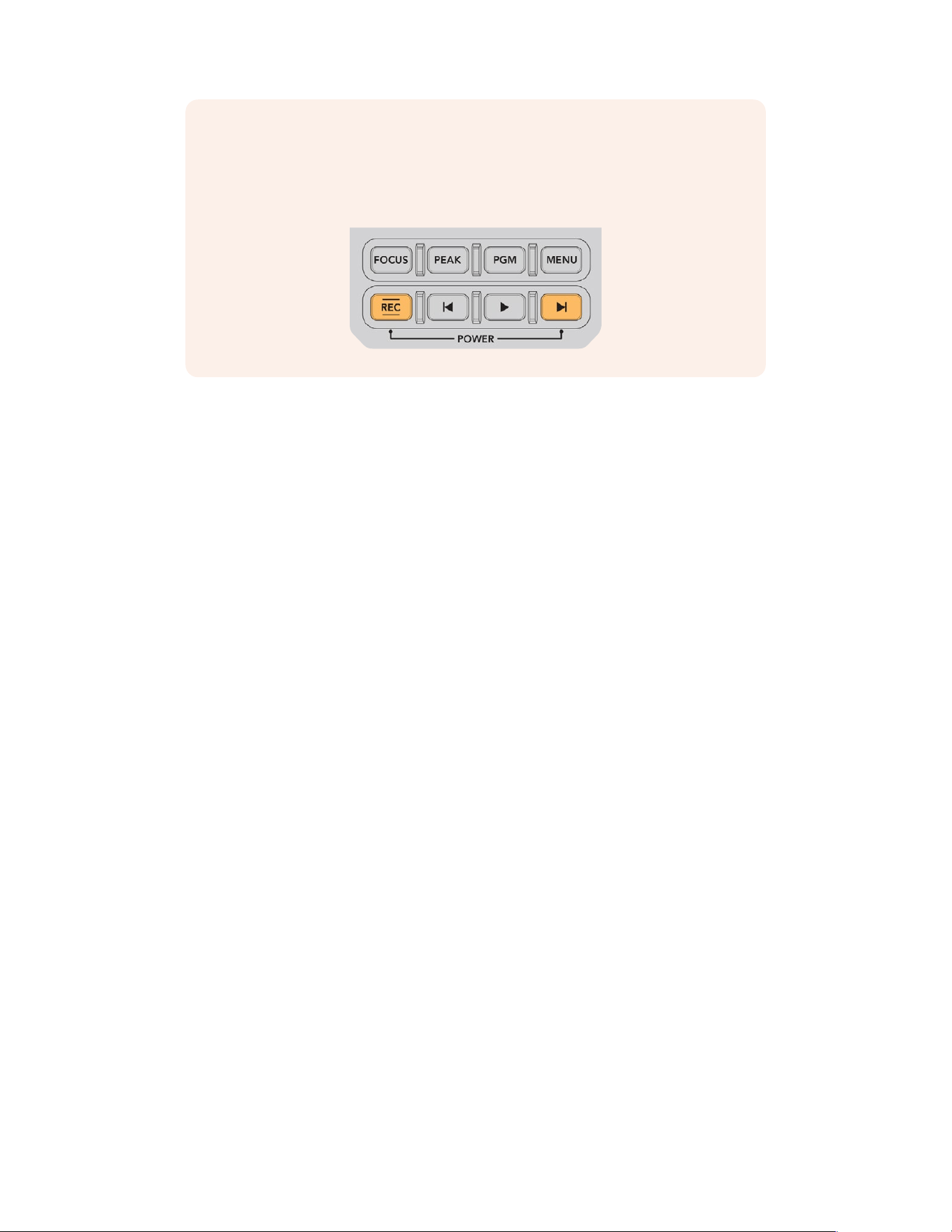
NOTE You can power your URSA Broadcast G2 on or off via a combination of internal
control panel buttons. Holding the ‘rec’ and ‘forward skip’ buttons will power up the
camera if it is turned off, or power it off if it is turned on. If your camera’s power switch
is set to ‘on’ but your camera is powered down, it may have been powered down via
the control panel. Toggle the power switch to return it to normal operation.
Camera Video Outputs
HD Monitoring Output
Blackmagic URSA Broadcast G2’s down converted 3G-SDI out connector always outputs
1080HD video so you can easily connect to routers, monitors, SDI capture devices, broadcast
switchers and other SDI devices. This output is labeled ‘front SDI’ in the touchscreen
settings menu.
12G-SDI Output
The 12G-SDI out connector on the rear panel supports HD and Ultra HD video including high
frame rate progressiveformats such as 2160p50, 59.94 and 60 on a single SDI cable. Interlaced
HD formats are also supported including 1080i50, 59.94 and 60. You can use the 12G-SDI
output to connect to anySDI monitor as well as Ultra HD switchers such as ATEM Production
Studio 4K. This output can be switched between HD and Ultra HD by selecting 1080p or 2160p
in the ‘SDI output’ setting for the ‘main SDI’ on the ‘monitor’ tab on the touchscreen. For more
information please refer to the ‘monitor settings’ section later in this manual.
Connecting to Video Switchers
The SDI outputs allow you to use your camera for live television production. You can connect
the rear panel SDI output directly to production switchers for live production work, or to
ATEMCamera Converters to convert your signal to optical so you can send it hundreds of
meters to a broadcast truck on location.
When connected to a switcher, you can easily view the switcher’s program output on your
Blackmagic URSA Broadcast G2. To do this, first connect the switcher to your camera’s rear
12G-SDI input. Now press the ‘program’ button marked PGM on your camera’s fold out monitor.
To switch back to the camera image, simply press the PGM button again.
70Camera Video Outputs
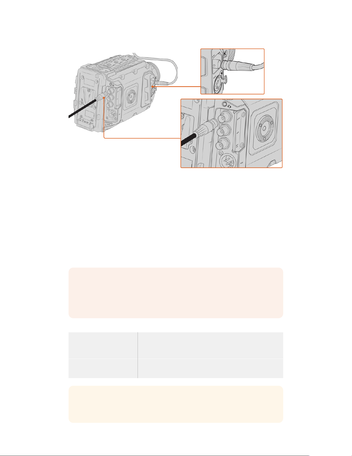
You can connect the 12G-SDI output to any 1080 HD or Ultra HD live production switcher or monitor. The HD
monitoring output can be plugged into an external viewfinder, such as the Blackmagic URSA Viewfinder, or
plugged into an external monitor when mounted to production equipment. For example a jib arm or crane
Connecting to Monitors
SDI monitoring can be really helpful when accessing the fold out monitor is impractical, such as
when secured high on a jib arm, on a crane, or mounted on a vehicle.
Monitoring information is displayed via your HD-SDI monitoring out connector by adjusting the
settings for the ‘front SDI’ on the ‘monitor’ tab on the touchscreen. These settings enable frame
guides and information such as recording details and camera settings. If you simply want to
monitor your shots, you can always turn overlays off for a clean SDI output.
Connect the camera’s SDI output to SDI monitors or to a Blackmagic SmartScope Duo 4K for
live waveform monitoring.
NOTE The rear SDI output and 3G-SDI monitoring output automatically flag HDR
video with ancillary metadata when you are working in ‘Film’ dynamic range and use
the Gen 5 Film to Rec 2020 Hybrid Log Gamma or Gen 5 Film to Rec 2020 PQ Gamma
LUT on the SDI output. This means you can display stunning HDR images on HDR
enabled screens from either SDI output.
SDI Output Formats
Rear SDI Output 2160p23.98, 24, 25, 29.97, 30, 50, 59.94, 60.
1080p23.98, 24, 25, 29.97, 30, 50, 59.94, 60.
1080i50, 59.94, 60.
3G-SDI Monitoring Output 1080p23.98, 24, 25, 29.97, 30, 50, 59.94, 60.
1080i50, 59.94, 60.
TIP To make a live recording with two codecs at once or a simultaneous backup,
youcan feed the rear SDI out from URSA Broadcast G2 to a Blackmagic Video Assist
orHyperDeck.
71Camera Video Outputs
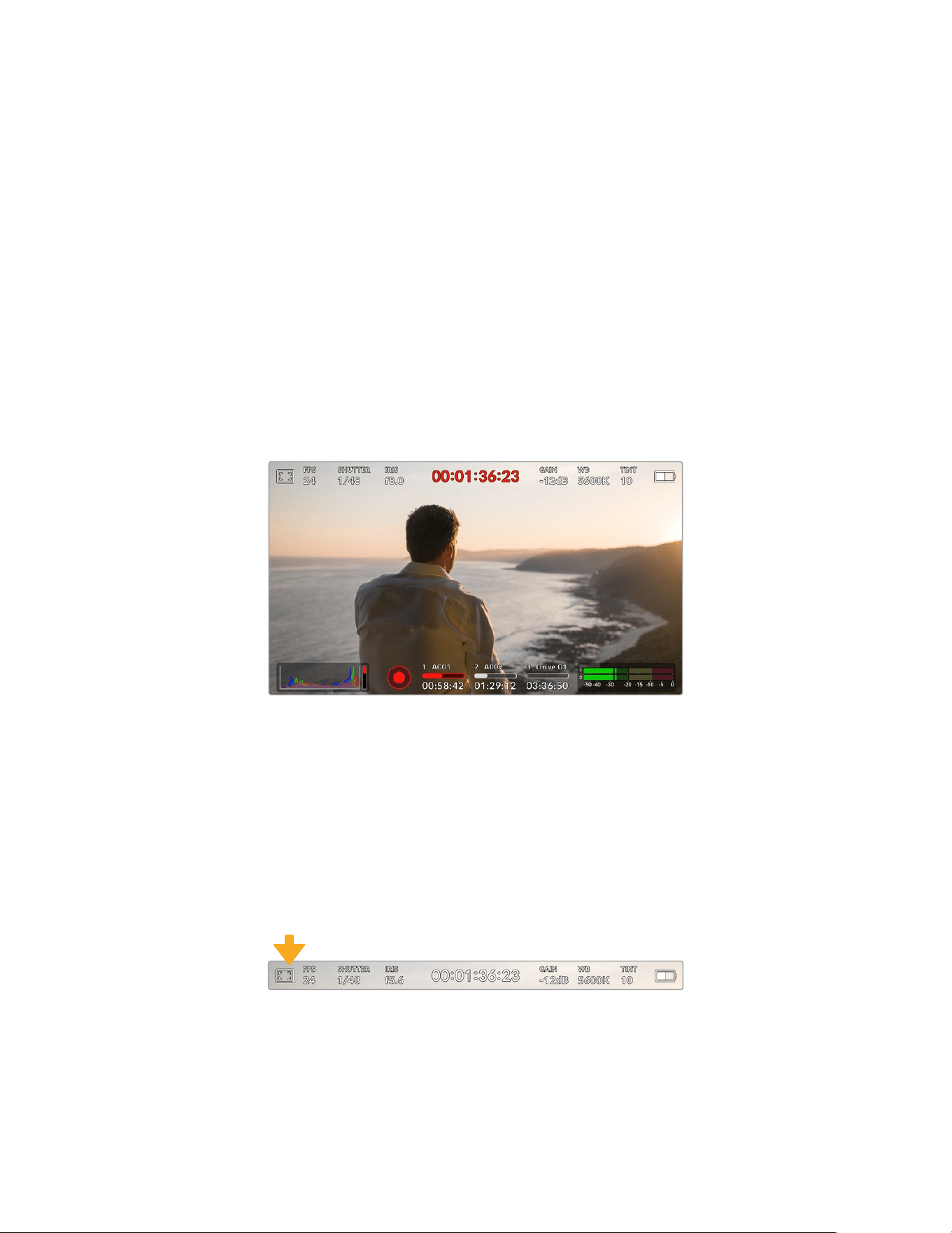
Touchscreen Controls
Touchscreen
Your Blackmagic URSA Broadcast G2’s fold out LCD touchscreen pivots for shooting high and
low angles. Buttons on the outside of the LCD panel let you control your URSA Broadcast G2
when mounted on your shoulder using the URSA Viewfinder and the LCD closed.
Touchscreen Features
The LCD touchscreen features a touch and gesture based interface that is specifically designed
for fast and intuitive user operation. By touching and swiping on different areas of URSA
Broadcast G2’s LCD touchscreen, you can quickly access the camera’s functions while shooting.
The touchscreen display features upper and lower toolbars. The upper toolbar provides access
to commonly used settings such as shutter speed, iris and gain controls. The lower toolbar
includes storage indicators, audio meters, transport controls and a histogram.
Your URSA Broadcast G2’s LCD touchscreen has a comprehensive head up
displayand gives you easy access to your camera’s most used settings
Upper Toolbar
LCD Monitor Options
Tap the ‘monitor’ icon at the top left of your URSA Broadcast G2’s LCD touchscreen to access
the LCDmonitor settings. These settings let you toggle and adjust the appearance of your
URSA Broadcast G2’s monitoring features, including zebra, focus assist, frame guide, and grids.
When accessing LCDmonitor options, the controls for these features appear in a tabbed menu
along the bottom edge of the LCD touchscreen.
Tap the icon at the top left of your URSA Broadcast G2’s
LCDtouchscreen to access LCD monitor options
72Touchscreen Controls
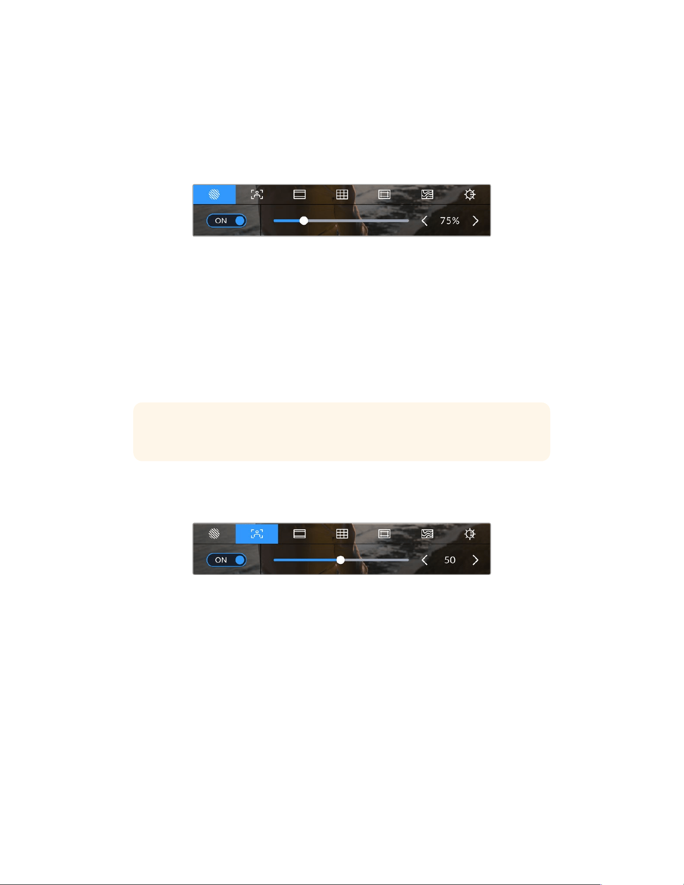
Zebra
The ‘zebra’ setting toggles the appearance of zebra on the LCD touchscreen, as well as setting
the zebra level for all URSA Broadcast G2’s outputs.
Zebra displays diagonal lines over areas of your image that exceed a set exposure level.
Forexample, setting zebra to 100% shows which areas are completely overexposed. This is
useful for achieving optimum exposure in fixed lighting conditions.
Tap the ‘zebra’ icon while accessing ‘LCD monitor options’
to access your URSA Broadcast G2’s zebra settings
To toggle zebra for the LCD touchscreen, tap the switch icon in the bottom left of the screen
while in the ‘zebra’ tab.
Set the exposure level that zebra appears at by dragging the slider left and right, or tapping
thearrow buttons next to the zebra level indicator. There are eight zebra presets available
including middle gray and middle gray plus one stop, then in five percent increments from
75 to 100 percent exposure.
For information on enabling zebra on your camera’s front and main SDIoutputs, see the
‘monitor settings’ section in this manual.
TIP If you’re shooting in variable light such as outdoors on a partly overcast day,
setting your zebra level lower than 100 can warn you of potential overexposure.
Focus Assist
The ‘focus assist’ setting toggles the appearance of focus assist on the LCD touchscreen,
aswell as setting the level of focus assistance for all outputs on your URSA Broadcast G2.
Tap the ‘focus assist’ icon while accessing ‘LCD monitor options’
toaccess your URSA Broadcast G2’s focus assist settings
To toggle focus assistance for the LCD touchscreen, tap the switch icon in the bottom left of
thescreen while in the ‘focus assist’ tab.
To set the level of focus assistance for all outputs on your URSA Broadcast G2, drag the slider
left and right along the bottom of your touchscreen, or tap the arrow buttons next to the focus
assist level.
The optimum level of focus assistance varies shot by shot. When focusing on actors, for
example, a higher level of focus assistance can help resolve edge detail in faces. A shot of
foliage or brickwork, on the other hand, may show distracting amounts of focus information
athigher settings.
For information on enabling focus assist on your camera’s front and main SDI outputs, see the
‘monitor settings’ section in this manual.
73Touchscreen Controls
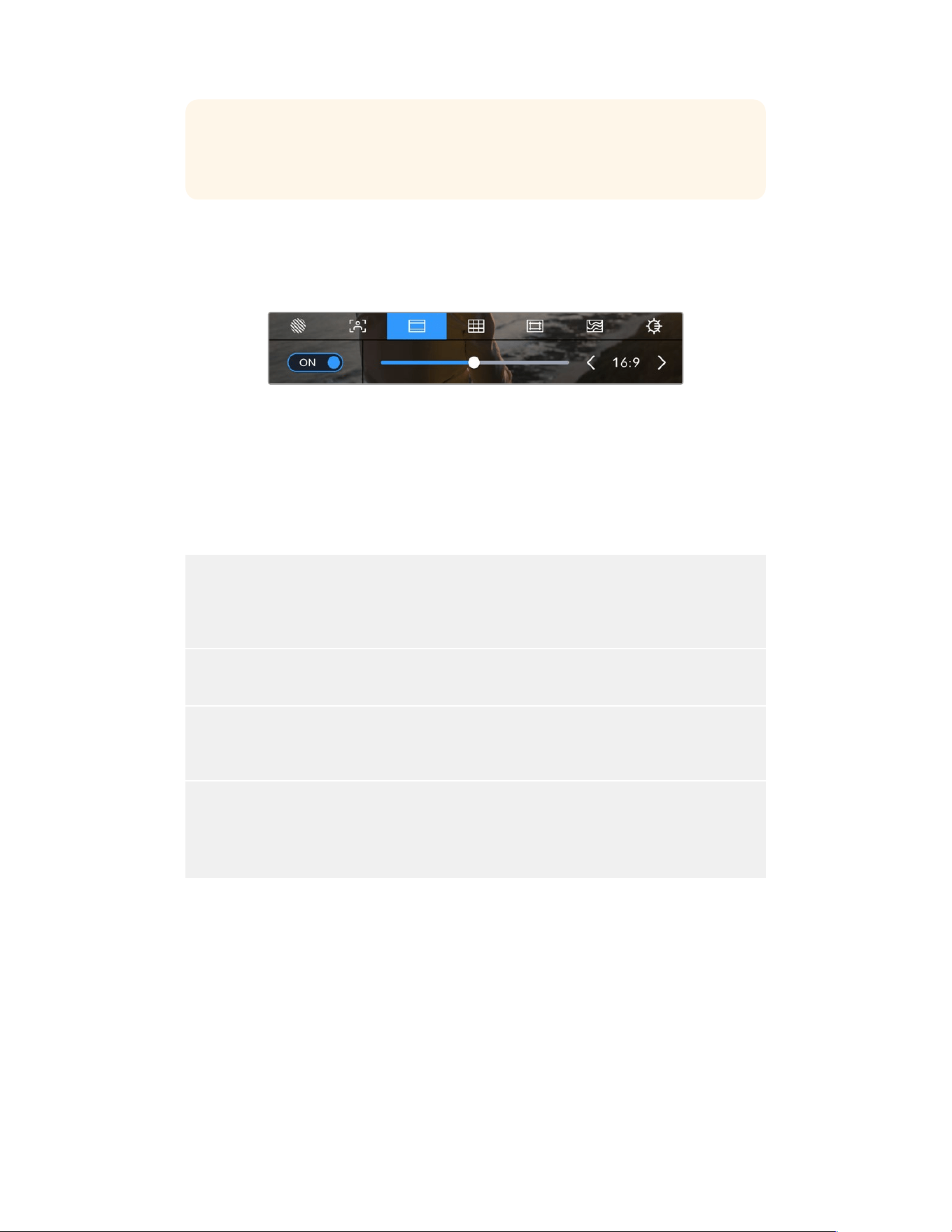
TIP Your URSA Broadcast G2 has two focus assist modes. You can switch between
‘peaking’ and ‘colored lines’ focus assistance in the ‘monitor’ settings menu. Formore
information, see the ‘monitor settings’ section and the ‘focus assist’ section.
Frame Guides
The ‘frame guide’ setting toggles the appearance of frame guides on the LCD touchscreen.
Youcan also choose from frame guide options for all outputs on your URSA Broadcast G2.
Frame guides include aspect ratios for various cinema, television and online standards.
Tap the ‘frame guides’ icon while accessing ‘LCD monitor options’ to
access your URSA Broadcast G2’s frame guide settings
To toggle the appearance of frame guides on your URSA Broadcast G2’s LCD touchscreen,
tap the switch icon in the bottom left of the screen.
Choose the frame guide you want to use by dragging the slider left and right, or tapping the
arrow buttons on either side of the currently selected aspect ratio.
The available guides are:
2.35:1, 2.39:1 and 2.4:1
Displays the broad widescreen aspect ratio compatible with anamorphic or flat widescreen cinema
presentation. The three widescreen settings differ slightly based on the changing cinema standards
over time. 2.39:1 is one of the most prominent cinema widescreen standards in use today.
2:1
Displays a ratio slightly wider than 16:9 but not as wide as 2.35:1.
1.85:1
Displays another common flat widescreen cinema aspect ratio. This ratio is slightly wider than HDTV
1.78:1 but not as wide as 2.39:1.
16:9
Displays a 1.78:1 aspect ratio compatible with 16:9 HD television and computer screens.
This ratio is most commonly used for HD broadcasting and online videos. The same aspect ratio has
also been adopted for Ultra HD broadcasting.
74Touchscreen Controls
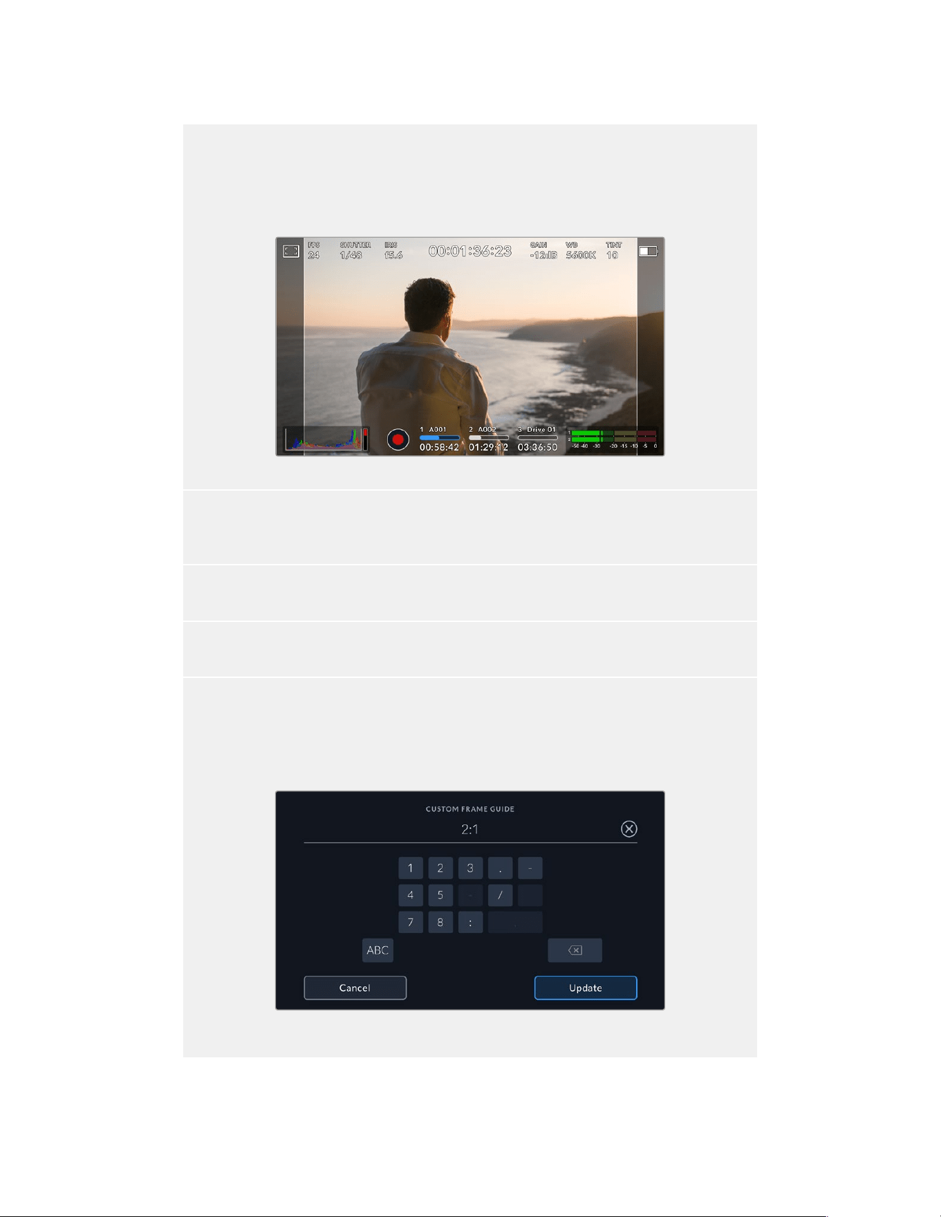
14:9
Displays a 14:9 aspect ratio used by some television broadcasters as a compromise between 16:9
and 4:3 television sets. Ideally, both 16:9 and 4:3 footage remains legible when center cropped to
fit 14:9. You can use this as a compositional guide if you know your project may be broadcast by a
television station that uses 14:9 cropping.
URSA Broadcast G2 LCD touchscreen with 14:9 frame guides enabled
4:3
Displays the 4:3 aspect ratio compatible with SD television screens, or to help with framing when
using 2x anamorphic adapters.
1:1
Displays a 1:1 ratio slightly narrower than 4:3. This square ratio is growing in popularity on social media.
4:5
Displays a 4:5 aspect ratio. This vertical aspect ratio is ideal for portraits and viewing on smartphones.
Custom Frame Guide Ratio
To create your own frame guide ratio for a unique appearance, tap on the ratio displayed between
the arrow buttons. On the ‘custom frameguide’ screen tap the backspace button to delete the
current ratio, then use the numeric keypad to specify a new ratio. Tap ‘update’ to apply your custom
frame guide ratio and return to shooting.
Use the numeric keypad on the ‘custom frame guide’
screen to enter a new frame guide ratio
75Touchscreen Controls
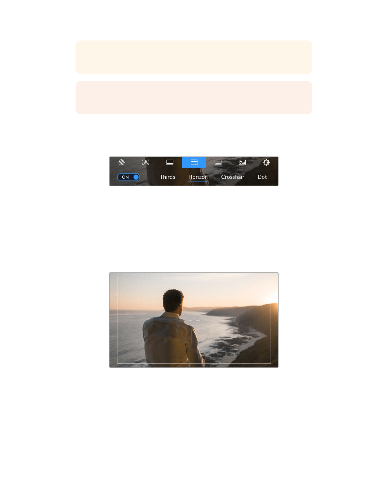
TIP You can change the opacity of frame guide overlays. For more information see the
‘monitor settings’ section of this manual.
NOTE For information on enabling frame guides on your camera’s front and main
SDIoutputs, see the ‘monitor settings’ section in this manual.
Grids
The ‘grids’ setting toggles the appearance of a rule of thirds grid, crosshair or center dot on
theLCD touchscreen, as well as setting the overlay that will be visible on all URSA Broadcast
G2’s outputs.
Tap the ‘grids’ icon while accessing ‘LCD monitor options’
toaccess your URSA Broadcast G2’s grid settings
Grids and crosshairs are overlays that can help with image composition. When ‘grids’ are
enabled, your URSA Broadcast G2 can show a rule of thirds grid, crosshairs, or center dot.
To toggle the appearance of grids on your URSA Broadcast G2 touchscreen, tap the switch icon
inthe bottom left of the screen while in the ‘frame guides’ tab.
When your URSA Broadcast G2 is set up and connected to an ATEM switcher as the current
program source, and ‘grids’ are set to ‘on’, the red ‘program’ tally outline will automatically
illuminate on the LCD.
When connected to an ATEM switcher sending a tally signal, a red border will
appear around your camera’s image preview when grids are set to ‘on’
To set which overlay you want to display on all URSA Broadcast G2 outputs, tap the ‘thirds,’
‘crosshairs,’ or ‘center dot’ options.
76Touchscreen Controls
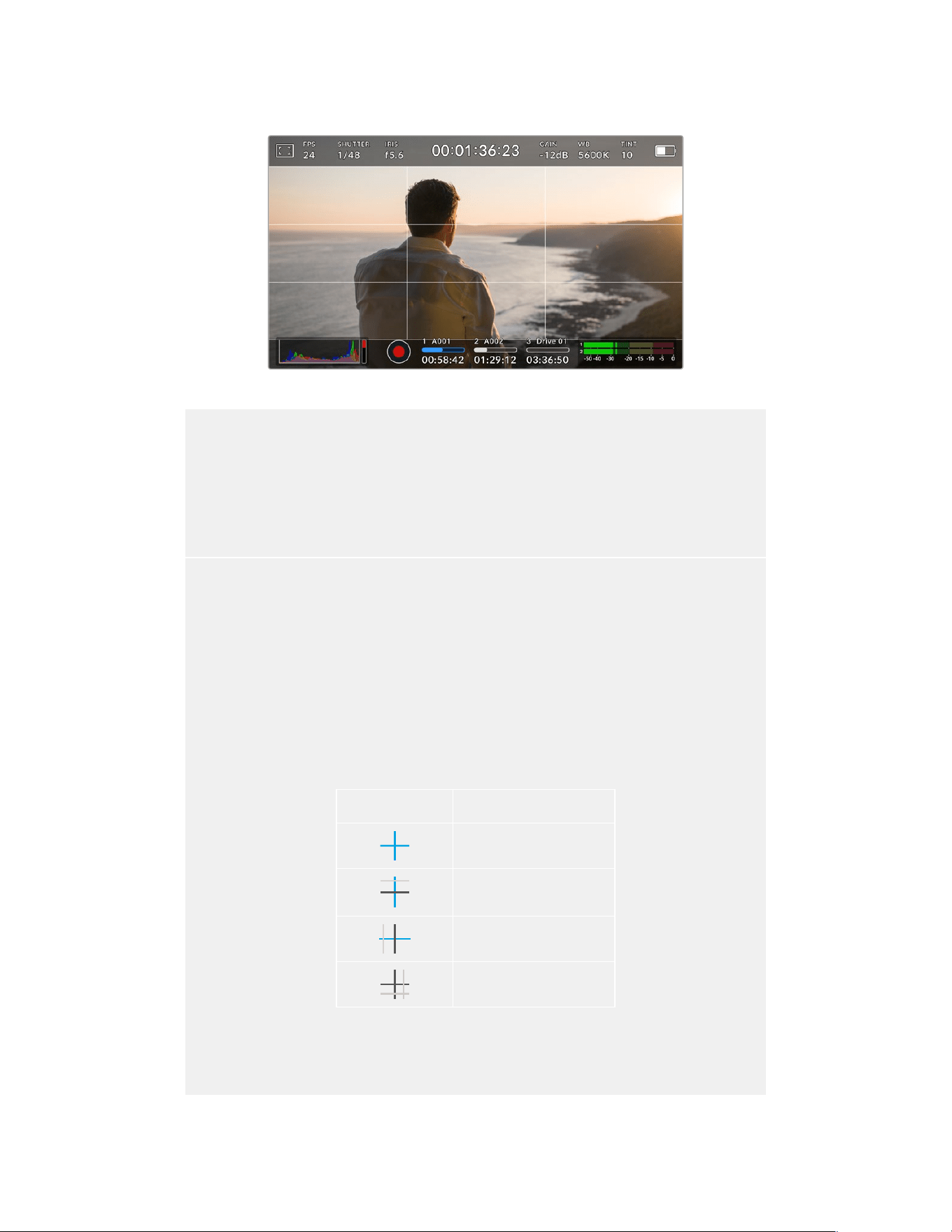
The rule of thirds grid automatically scales to any on screen frame guides
Thirds
The ‘thirds’ setting displays a grid with two vertical and horizontal lines placed in each third of the
image. Thirds are an extremely powerful tool to help compose your shots. For example, the human
eye typically looks for action near the points where the lines intersect, so it’s helpful to frame key
points of interest in these zones. An actor’s eyeline is commonly framed along the top third of
the screen, so you can use the top horizontal third to guide your framing. Thirds are also useful to
maintain framing consistency between shots.
Horizon
The ‘horizon’ meter indicates when your camera is rolled left or right and tilted up or down. This can
help you keep the horizon level during handheld shots and balance the camera tilt on a gimbal.
The gray vertical and horizontal indicators move away from the center as the camera is rolled and
tilted. The distance the lines move away from the central crosshair is proportional to the amount of
roll or tilt. After you calibrate the camera’s motion sensor, the motion indicators will illuminate blue
when the camera’s roll and tilt become level.
Note that if the camera is tilted straight down for an overhead shot or straight up, the horizon meter
takes this into account. If you roll the camera to shoot in portrait orientation, the horizon meter
rotates its axes 90 degrees.
This table shows examples of the horizon meter indicating tilt and roll of the camera.
Horizon meter Description
Straight and level
Tilted down and level
Straight and rolled left
Tilted up and rolled right
For normal use, calibrate the horizon meter for straight and level operation. If you want to use the
horizon meter to help maintain a consistent ‘dutch angle’ or a consistent tilt for a low or high shot,
you can calibrate the horizon meter at an incline. For information on how to calibrate the horizon
meter, see the ‘motion sensor calibration’ section.
77Touchscreen Controls
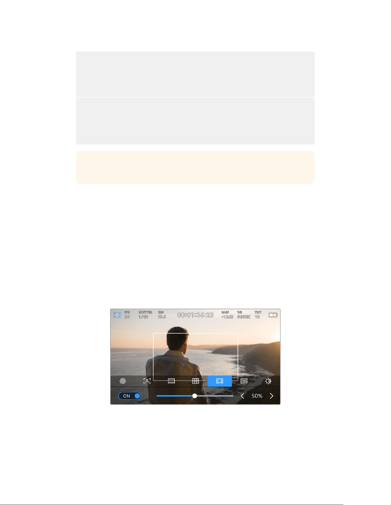
Crosshairs
The ‘crosshair’ setting places a crosshair in the center of the frame. Like thirds, the crosshair is a
very useful compositional tool, making it easy to frame the subject of a shot in the very center of
a frame. This is sometimes used when filming scenes that will be assembled using very fast cuts.
Keeping viewers’ eyes focused on the center of a frame can make rapid editing easier to follow.
Center Dot
The ‘center dot’ setting places a dot in the center of the frame. This works in exactly the same way
as the ‘crosshair’ setting, albeit with a smaller overlay that you may find lessintrusive.
You can enable a combination of ‘thirds’ and ‘crosshairs’ or ‘thirds’ and ‘center dot’ bytapping both
options in the ‘grids’ menu. ‘Crosshairs’ and ‘center dot’ cannot be selected together.
TIP For information on enabling grids on your URSA Broadcast G2’s front and main
SDIoutputs, see the ‘monitor settings’ section in this manual.
Safe Area Guides
The ‘safe area guides’ setting toggles the safe area guides on or off the LCDtouchscreen,
aswell as setting the size of safe area guides for all outputs on your URSA Broadcast G2.
Safe areas can be used in broadcast production to ensure that the most important parts of
a shotcan be seen by viewers. By keeping the most important parts of your shot within a
central ‘safearea,’ you can avoid cropping on some televisions, as well as leaving space for
abroadcaster to add bugs, news tickers and other overlays along the edges of the screen.
Manybroadcasters require footage to be submitted within a 90% safe area.
Safe area guides can also be used to assist with framing your shot where you know that the
shot will be stabilized in post production, which can crop the edges of the image. They can also
be used to indicate a specific crop. For example by setting it to 50% whilst recording at Ultra
HD 3840x2160 you can see what a 1920x1080 crop of the frame would look like. The safe area
guides also scale to your frame guides, so they will adjust to indicate the chosen percentage of
your target frame.
The ‘safe area’ indicator set to 50%
To toggle safe area guides for the LCD touchscreen, tap the switch icon in the bottom left of the
screen while in the ‘safe area guides’ tab. To set the level of safe area guides for all outputs on
your URSA Broadcast G2, tap the left or right arrows on either side of the current numerical
value at the bottom of your touchscreen. Alternatively, you can drag the slider left or right.
78Touchscreen Controls
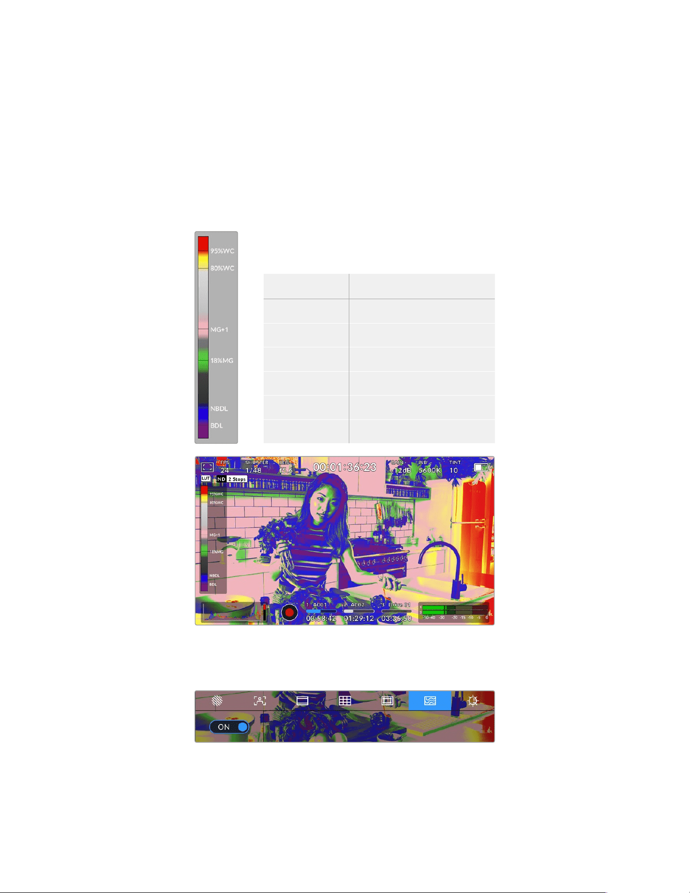
False Color
The ‘false color’ setting toggles the appearance of false color exposure assistance on the
LCDtouchscreen.
False color overlays different colors onto your image that represent exposure values for
different elements in your image. For example, pink represents optimum exposure for lighter
skin tones, while green is a good match to darker skin tones. By monitoring the pink or green
false color when recording people, you can maintain consistent exposure for their skin tones.
Similarly, when elements in your image change from yellow to red, that means they are now
over exposed.
The IRE false color chart on the left side of your
camera’s display shows you how to interpret the
different false colors.
False Color Meaning
95%WC White clipping
80%WC Near white clipping
MG+1 One stop over middle gray
18%MG Middle gray
NBDL Near black detail loss
BDL Black detail loss
In a well exposed image, skin tones are represented by green and pink false colors
To toggle false color for the LCD touchscreen, tap the switch icon in the bottom left of the
screen while in the ‘false color’ tab.
The ‘false color’ exposure assistance tab
79Touchscreen Controls
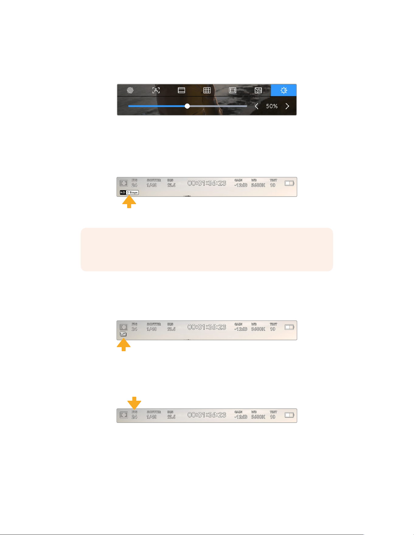
Screen Brightness
Tap the ‘screen brightness’ icon and drag the slider to the left or right to adjust the brightness
of your URSA Broadcast G2’s touchscreen.
The ‘screen brightness’ setting set to 50%.
ND Filter indicator
Your URSA Broadcast G2 has an ND filter indicator in the top left of the LCD touchscreen and
any SDI outputs set to show status text. The indicator uses the format you’ve selected in the
‘setup’ menu.
ND filter setting indicator on your URSA Broadcast G2
NOTE You can adjust the terminology used by the ND filter indicator to reflect the
conventions you’re used to. The options are ND number, stops and fractions. You can
set your preferred format in your URSA Broadcast G2’s ‘setup’ menu.
LUT indicator
A white icon will be visible on the LCD, front SDI or main SDI when ‘status text’ is switched on
and you have a LUT applied to that output. If you are recording to Blackmagic RAW and have
‘Apply LUT in File’ switched on in the ‘Record’ settings the LUT icon will be blue.
The LUT icon lets you know that you have a LUT applied to the image
Frames Per Second
The ‘FPS’ indicator displays your currently selected frames per second.
URSA Broadcast G2’s frames per second indicator. Tap this to access frame rate settings
Tapping the ‘FPS’ indicator lets you change your camera’s sensor and project frame rates via
amenu at the bottom of your LCD touchscreen.
80Touchscreen Controls
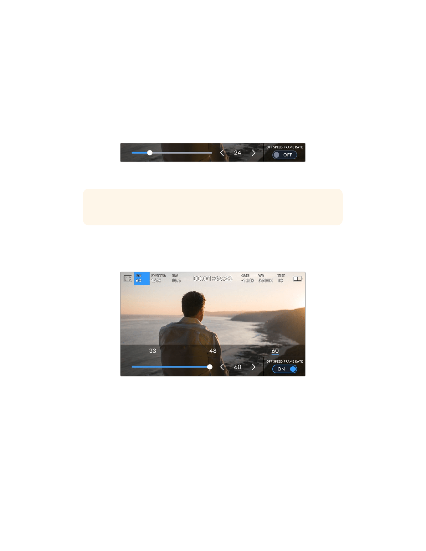
Project frame rate
The project frame rate is URSA Broadcast G2’s recording format frame rate and provides
aselection of common frame rates used in the film and television industry. This frame rate
is normally set to match your playback speed used in your post production workflow.
Your Blackmagic URSA Broadcast G2 has 8 project frame rate settings including 23.98, 24, 25,
29.97, 30, 50, 59.94 and 60 frames per second.
To adjust your URSA Broadcast G2’s project frame rate while in the ‘FPS’ menu, tap the left or
right arrows next to the current frame rate at the bottom left of your touchscreen. Alternatively,
you can drag the slider left or right.
Tap the arrows on either side of the project frame rate
or move the slider to make adjustments
TIP Your URSA Broadcast G2’s project frame rate also sets the frame rate of the front
and main SDI outputs.
Sensor frame rate
The sensor frame rate sets how many actual frames from the sensor are recorded every
second. This frame rate will affect how fast or slow your video will play back at your set project
frame rate.
With ‘off speed frame rate’ enabled, tap a preset or the arrows on either side
of the sensor frame rate or move the slider to make adjustments
By default, your URSA Broadcast G2’s project and sensor frame rates are matched for a natural
playback speed. However, by tapping the ‘off speed frame rate’ switch icon in the bottom right
hand side of your URSA Broadcast G2’s ‘FPS’ menu, you can independently set your sensor
frame rate. It’s worth mentioning that the ‘off speed frame rate’ option is only available when
recording to Blackmagic RAW or ProRes codecs.
To change your sensor frame rate, tap the arrows next to the sensor frame rate indicator in the
lower left of your touchscreen. You can also drag the slider left or right to increase or decrease
the frame rate. Once you release the slider, the sensor frame rate will be selected. Above the
slider, you can tap on a common off speed frame rate. These are based on your current project
frame rate.
81Touchscreen Controls
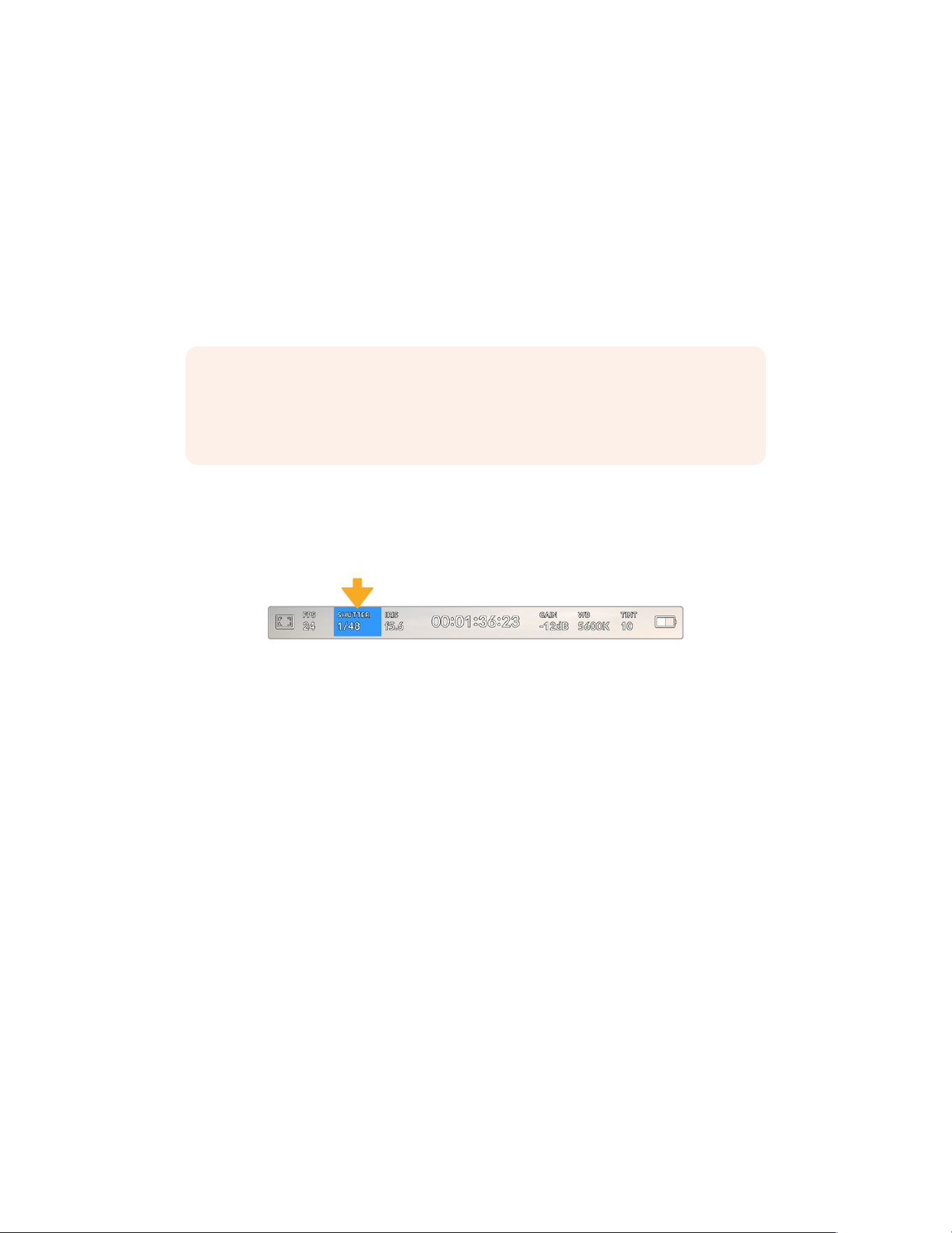
You can create dynamic and interesting speed effects in your clips by varying the sensor frame
rate. Setting the sensor frame rate higher than your project frame rate willcreate slow motion
during playback. For example, shooting with a 60 FPS sensor frame rate and playing back
at a 24 FPS project frame rate creates slow motion at less than half the real speed of action.
Alternatively, the lower your sensor frame rate, the faster your clips will appear. The principle is
similar to overcranking and undercranking a film camera. Overcranking speeds up the sensor
frame rate so you can stretch out moments in time during playback to enhance emotion.
Undercranking slows down the sensor frame rate so you can increase the action in fast moving
scenes. The creative possibilities are endless and entirely up to you!
For information on the maximum frame rates available for each recording format and codec,
refer to the table in the ‘recording’ section of this manual.
NOTE When ‘off speed frame rate’ is selected your URSA Broadcast G2’s audio and
video are no longer synced. This is true even if you set the same project and sensor
frame rate. For this reason, ‘off speed frame rate’ should never be selected if you want
to guarantee audio syncing.
Shutter
The ‘Shutter’ indicator displays your shutter speed. By tapping this indicator, you can manually
change your URSA Broadcast G2’s shutter speed or configure shutter priority auto
exposure modes.
URSA Broadcast G2’s shutter indicator. Tap this to access shutter settings
Shutter speed defines the level of motion blur in your video, and can be used to compensate
for varying light conditions. The shutter speed setting for natural motion blur, and the settings
available, depend on the frame rate you are using. For example, when shooting at 30p, a 1/60
of a second shutter speed is the equivalent of a 180 degree shutter angle, a very common
setting for film projects. However if you are shooting at 25p, you will need to set the shutter to
1/50 for the same look.
For natural motion blur you can calculate the shutter speed by doubling your frame rate.
Soat30p, set your shutter speed to 1/60 of a second for natural motion blur.
If you need more light on the sensor, you can set the shutter at the slowest setting
corresponding with your frame rate. For example, 1/25 for 25p, or 1/30 for 30p. At the slowest
shutter speed, your motion blur will appear slightly exaggerated.
If you want to reduce the motion blur so action appears sharper and more defined, set the
shutter to a faster speed, such as 1/120 of a second for 30p, or 1/100 of a second for 25p.
Ifyouare familiar with shutter angles, this equates to a shutter angle of 90 degrees.
It’s worth experimenting with different shutter speeds to see how this setting can provide
different levels of motion blur to your image.
When shooting under lights, your shutter speed can affect the visibility offlicker. Your URSA
Broadcast G2 will automatically calculate flicker free shutter speeds for your current frame rate.
These speeds are affected by mains power frequency in your region. You can set your local
power frequency to 50Hzor60Hz in your URSA Broadcast G2’s setup menu. See the ‘setup
settings’ section in thismanual for moreinformation.
82Touchscreen Controls
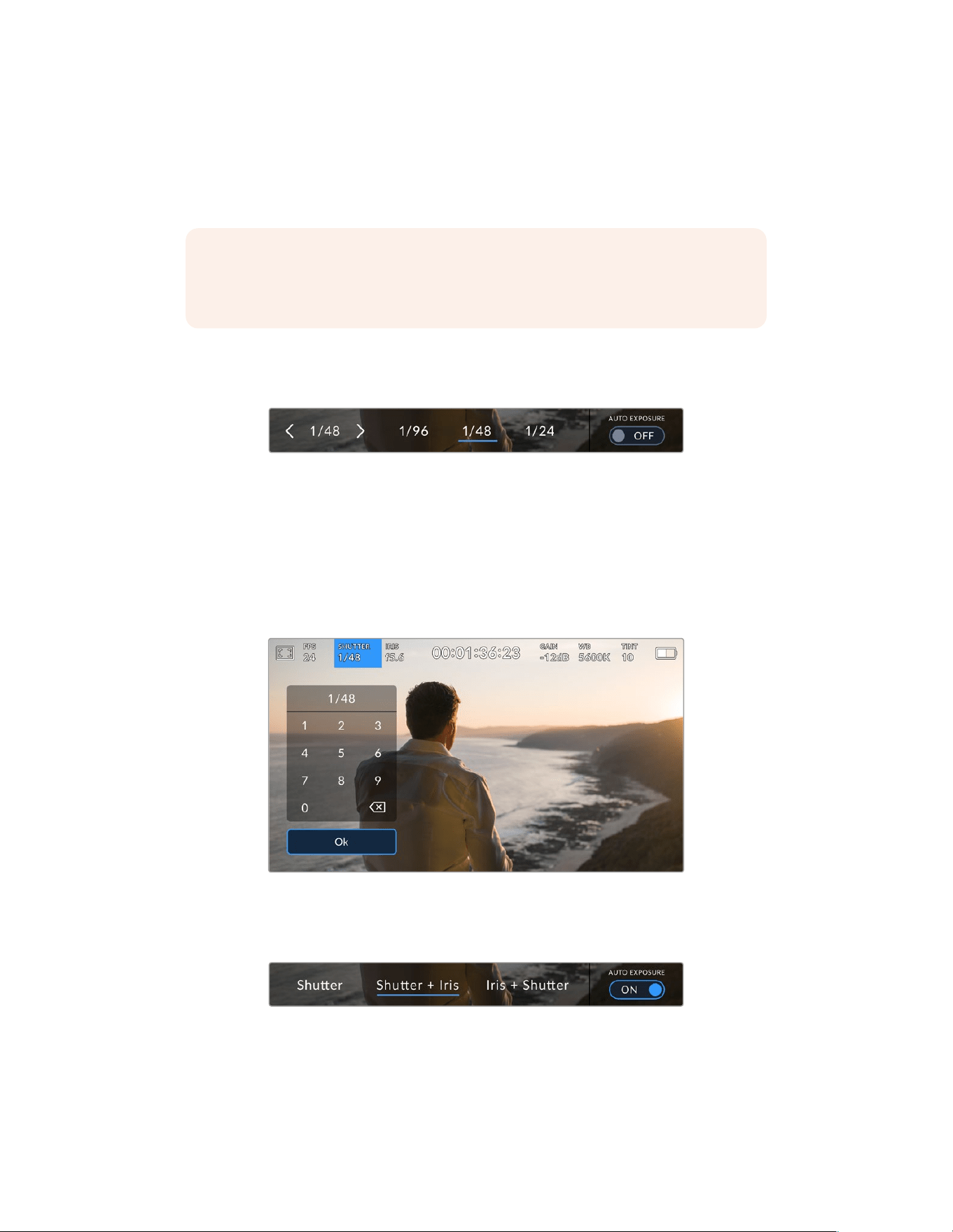
Tapping the ‘shutter’ indicator brings up the shutter speed menu along the bottom of your
URSA Broadcast G2’s touch screen. If you have auto exposure set to ‘off,’ this screen will show
youyour currently selected shutter speed, as well as the available flicker free shutter speeds,
based on the mains power frequency you have selected in your URSA Broadcast G2’s ‘setup’
menu. Formore information, see the ‘setup settings’ section in this manual.
NOTE The characteristics of different light sources may still cause flicker even when
using flicker free shutter speeds. We recommend always performing a test shoot when
not using continuous lights.
To select one of the flicker free shutter speeds, simply tap on one of the displayed shutter
values. Using the arrows on either side of the current shutter value indicator will cycle through
some of the most commonly used values.
Your URSA Broadcast G2 will suggest flicker free shutter speeds based
on the mains power frequency you choose in the ‘setup’ menu
If you would like to choose a specific shutter value, you can do so by double tapping the current
shutter indicator at the bottom left of your screen. This will bring up a keypad that allows you to
type in any shutter value you wish.
If you type in a shutter value that is less than your current frame rate, for example 1/25th when
shooting at 29.97 frames per second, the nearest achievable shutter value will be used.
Thenearest shutter speed in this example would be 1/30th.
The manual shutter keypad allows you to type in any shutter value you wish
Your URSA Broadcast G2 has three shutter based auto exposure modes. To select one of
these, tapthe ‘auto exposure’ button in the far right of the shutter menu.
Tap ‘auto exposure’ to access shutter based auto exposure modes
83Touchscreen Controls
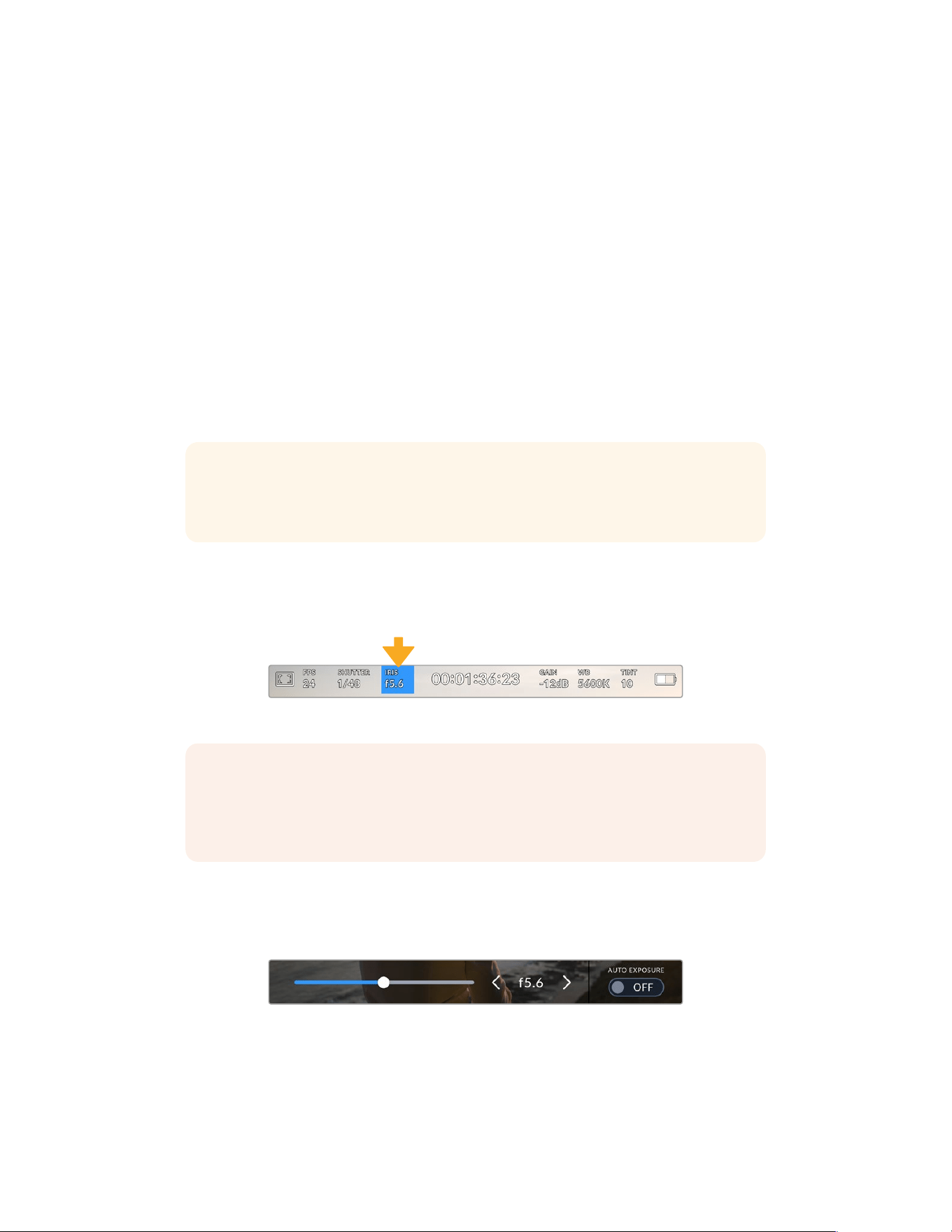
Shutter
This setting automatically adjusts shutter speed to maintain a constant exposure while keeping
iris aperture constant. If you want to maintain a fixed depth of field, this is the setting to choose.
It’s worth mentioning that the subtle automatic adjustments of the shutter may have an effect
on motion blur. It’s also worth keeping an eye out for any flicker that may be introduced from
various light fixtures on indoor shoots. URSABroadcast G2’s auto iris feature is not available
when the ‘shutter’ auto exposure mode is selected.
Shutter + Iris
Maintains the correct exposure levels by adjusting the shutter, then the aperture. If the
maximum or minimum available shutter speed is reached and exposure still cannot be
maintained, URSA Broadcast G2 will begin adjusting the aperture to keep exposure constant.
Iris + Shutter
Maintains the correct exposure levels by adjusting the aperture, then the shutter speed. If the
maximum or minimum available aperture is reached and exposure still cannot be maintained,
URSA Broadcast G2 will begin adjusting the shutter speed to keep exposure constant.
TIP When an auto exposure mode that effects the shutter is enabled, a small “A”
willappear next to the shutter speed indicator at the top of your URSA Broadcast G2
touchscreen.
Iris
The ‘Iris’ indicator displays your current lens aperture. By tapping this indicator, you can change
the aperture of compatible lenses and configure iris based auto exposure modes.
Your URSA Broadcast G2’s iris indicator. Tap this to access iris settings
NOTE To adjust your iris from the LCD touchscreen, your URSA Broadcast G2 must
befitted with a lens that supports changing aperture via the camera. If you are using
a B4 or PL lens connected via the broadcast 12 pin connector, make sure that the lens
iris switch on the handgrip is set to ‘A’ or ‘auto.’
Tapping the ‘iris’ indicator once brings up the iris menu along the bottom of your
URSABroadcast G2 touchscreen. You’ll see your current lens aperture at the far left of this
menu. You can change the aperture by tapping the left and right arrows on either side of
the current aperture, or moving the slider left or right.
While in the ‘iris’ menu, tap the arrows on either side of the iris indicator or use
the slider to adjust iris settings
84Touchscreen Controls
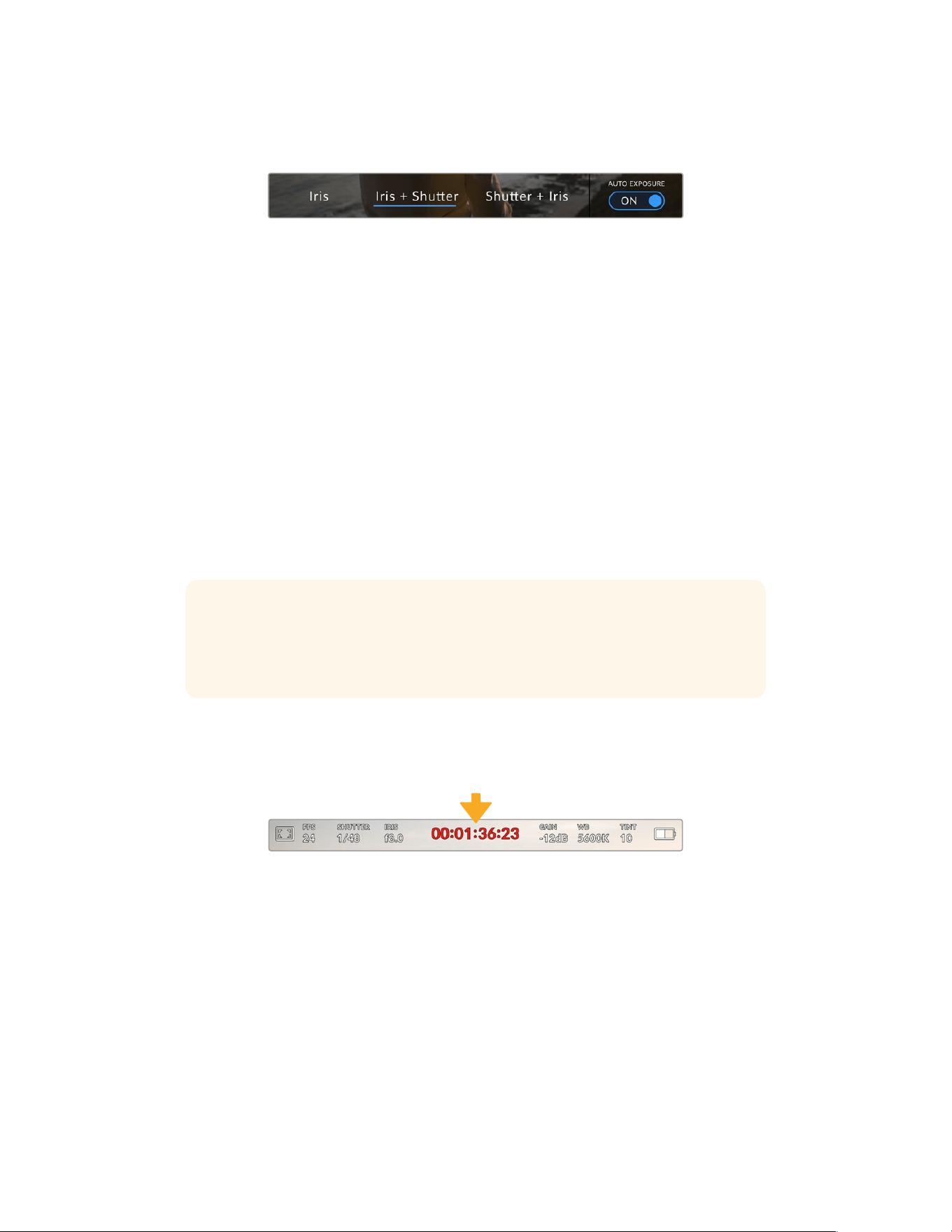
Tapping the ‘auto exposure’ switch icon at the far right of the iris menu opens the iris auto
exposure menu.
While in the iris menu, tap ‘auto exposure’ to access iris based auto exposure modes
This gives you the following auto exposure options.
Iris
This setting automatically adjusts the aperture to maintain a constant exposure, while keeping
shutter speed constant. This will keep motion blur constant, but may affect your depth of field.
Iris + Shutter
Maintains the correct exposure levels by adjusting the aperture, then the shutter speed. If the
maximum or minimum available aperture is reached and exposure still cannot be maintained,
URSA Broadcast G2 will begin adjusting the shutter speed to keep exposure constant.
Shutter + Iris
Maintains the correct exposure levels by adjusting the shutter, then the aperture. If the
maximum or minimum available shutter speed is reached and exposure still cannot be
maintained, URSA Broadcast G2 will begin adjusting the aperture to keep exposure constant.
When an auto exposure mode that effects the iris is enabled, a small “A” will appear next to the
iris indicator at the top of your URSA Broadcast G2 touchscreen.
TIP Automatic exposure works smoothly with compatible B4 or PL lenses which are
designed for video or film production. EF lenses may produce noticeable ‘steps’ in
exposure when changing aperture. For this reason, werecommend using only ‘shutter’
auto exposure mode if shooting with EF lenses.
Duration Display
At the top of your URSA Broadcast G2 LCD touchscreen, you’ll see your camera’s
duration display.
Your URSA Broadcast G2’s duration display. This will turn red while recording
The duration display provides a timecode counter for checking the duration of your clips and
monitoring timecode during recording and playback. The counter displays a time sequence
showing Hours:Minutes:Seconds:Frames and will progress through the sequence as you record
or play back clips. The timecode will turn red during recording.
The displayed duration of each clip starts from 00:00:00:00 for each clip. The clip duration
ofthe current, or last recorded, clip is displayed on the touchscreen. Time of day timecode is
embedded into clips for easier post production.
To see the timecode, simply tap the duration display. Tap the duration display again to return
toclip duration.
85Touchscreen Controls
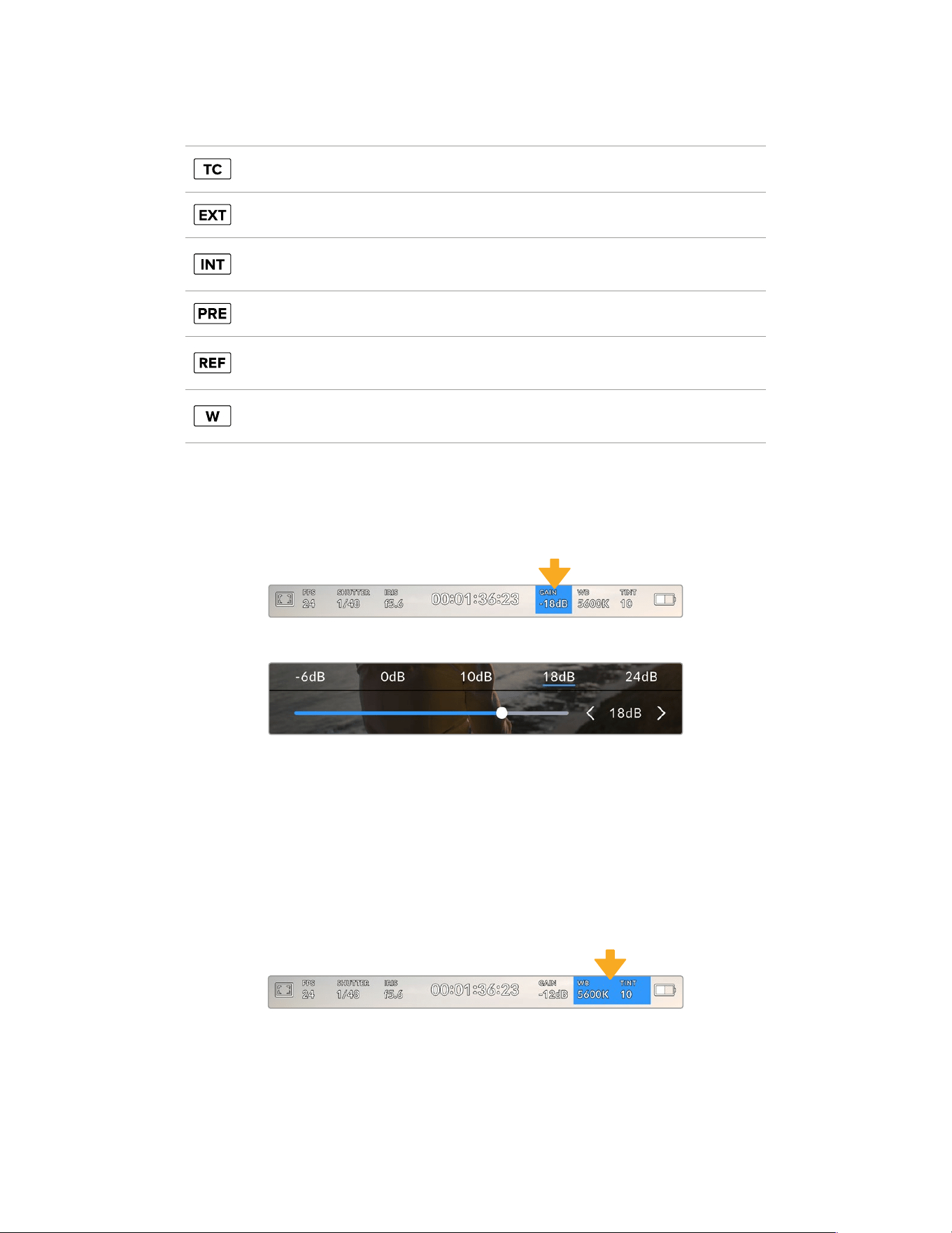
Additional status indicators may appear around the duration display:
Appears to the right of the duration display when showing timecode.
Appears to the right of the duration display if an external timecode is connected and valid.
Appears to the right of the duration display if the camera is running off an internal timecode
after being ‘jam synced’ anddisconnected.
Appears to the right of the duration display when you are viewing preset record run timecode.
Appears when a valid reference source is connected andlocked, based on the reference
input settings.
Appears to the left of the duration display when your Blackmagic URSA Broadcast G2 is
using a windowed sensor mode.
Gain
The ‘Gain’ indicator displays your URSA Broadcast G2’s current gain setting, or light sensitivity.
Tapping this indicator lets you adjust your gain to suit varying lighting conditions.
The optimum setting for URSA Broadcast G2 is 0dB.
Your URSA Broadcast G2’s gain indicator. Tap the indicator to access gain settings
While in the ‘gain’ menu, your URSA Broadcast G2’s gain settings
appear along the bottom of the LCD touchscreen. The slider and arrows
below the presets let you adjust the gain in 1/3 stop increments.
Depending on your situation, you may choose a lower or higher gain setting. For example,
inlowlight conditions +18dB can be suitable but may introduce some visible noise. In bright
conditions -6dB can provide richer colors.
White Balance
The ‘WB’ and ‘TINT’ indicators display your camera’s current white balance and tint. Tapping these
indicators lets you adjust your camera’s white balance and tint to suit varying lighting conditions.
Tap the white balance and tint indicators to access white balance and tint settings
Every light source emits a color. For example, a candle flame emits a warm color, and an
overcast sky emits a cool color. White balance settings are used to color balance your image
so white stays white by adjusting the mix of orange and blue in your image. For example, when
shooting under tungsten lamps which emit a warm, orange light, selecting 3200K adds some
blue to the image. This balances the color so white is accurately recorded.
86Touchscreen Controls
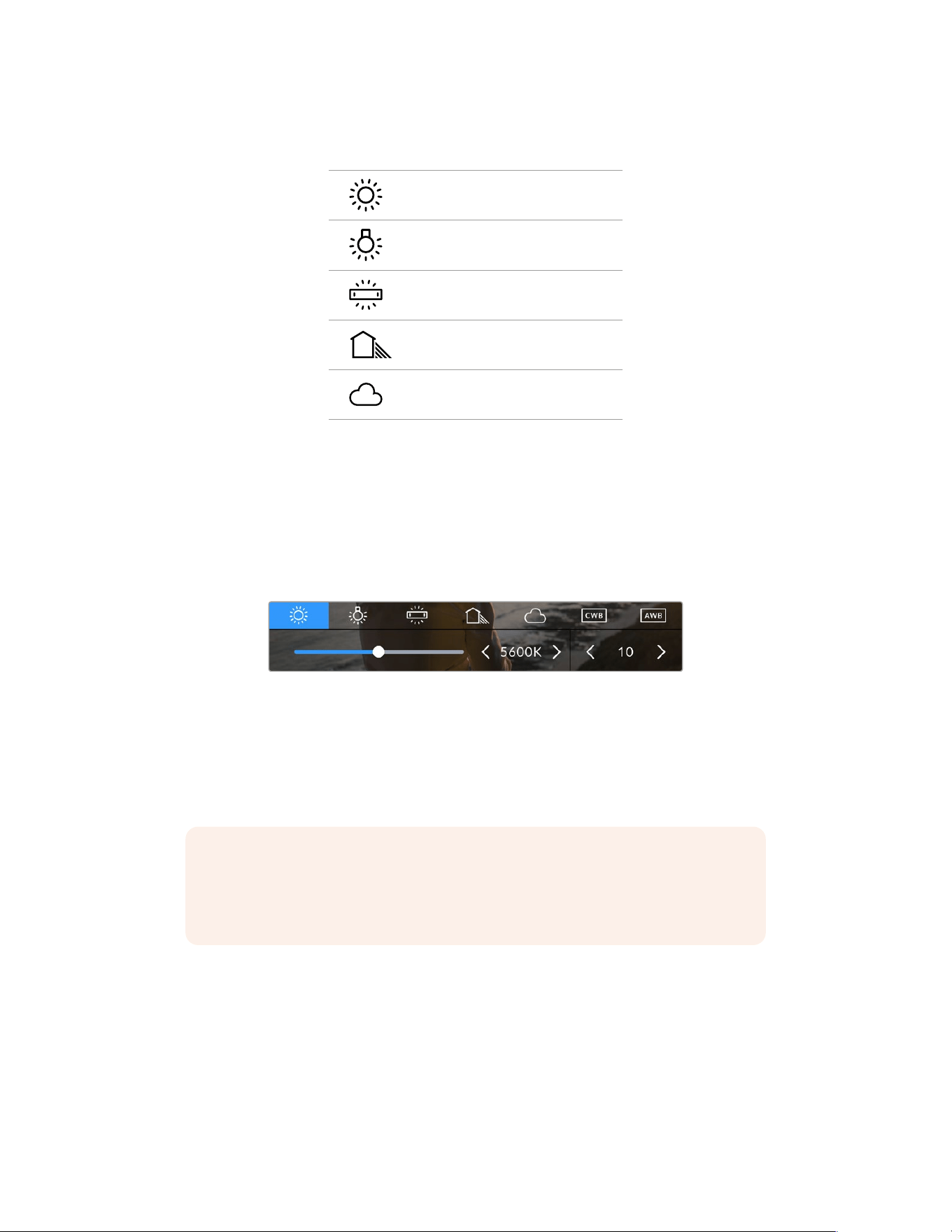
Your URSA Broadcast G2 comes with white balance presets for a variety of color temperature
conditions. These are:
Bright sunlight (5600K)
Incandescent bulbs (3200K)
Fluorescent bulbs (4000K)
Mixed light (4500K)
Cloud (6500K)
You can customize any of these presets by tapping or holding the arrow icons to the left and
right of the temperature indicator in the bottom left of the ‘white balance’ menu. Each tap moves
the color temperature up or down 50K, but holding the arrow icons down will increase these
increments for faster changes. Alternatively, you can move the temperature slider in the middle
of the ‘white balance’ menu.
To further dial in your image, you can adjust the ‘tint.’ This adjusts the mix of green and magenta
inyour image. For example, adding some magenta can compensate for the green cast of many
fluorescent lights. Many of your URSA Broadcast G2’s white balance presets include some tint.
Tapping the white balance and tint indicator on your URSA Broadcast G2 gives you access
to fivepresets, as well as a white balance indicator and slider on the left, and a tint indicator
on the right. Adjust thesetoset a custom white balance for your lighting conditions
While in the ‘white balance’ menu, your camera’s current tint setting is shown at the bottom right
of the screen. To adjust the tint, simply tap or hold the arrows to the left and right of the tint
indicator. The available range is -50 to +50 in one unit increments. Holding down on the arrows
speeds up adjustment.
NOTE Customizing the white balance or tint will change your preset to‘CWB,’ or
custom white balance. Custom white balances are persistent; your CWB settings will
stay configured between power cycles, and when switching to a preset and back to
CWB. This makes iteasy to compare a custom white balance to the last preset used.
Auto White Balance
Your URSA Broadcast G2 can set white balance automatically. Tapping ‘AWB’ will bring up the
white balance screen.
When setting white balance automatically, a square will be overlaid on the center of your image.
Fill this square with a neutral surface such as a white or gray card and tap ‘update.’ Your URSA
Broadcast G2 will automatically adjust its white balance and tint values to ensure that the
average of the white or gray within the white balance square is as neutral as possible. Once
updated, this will be set as your camera’s custom white balance.
87Touchscreen Controls
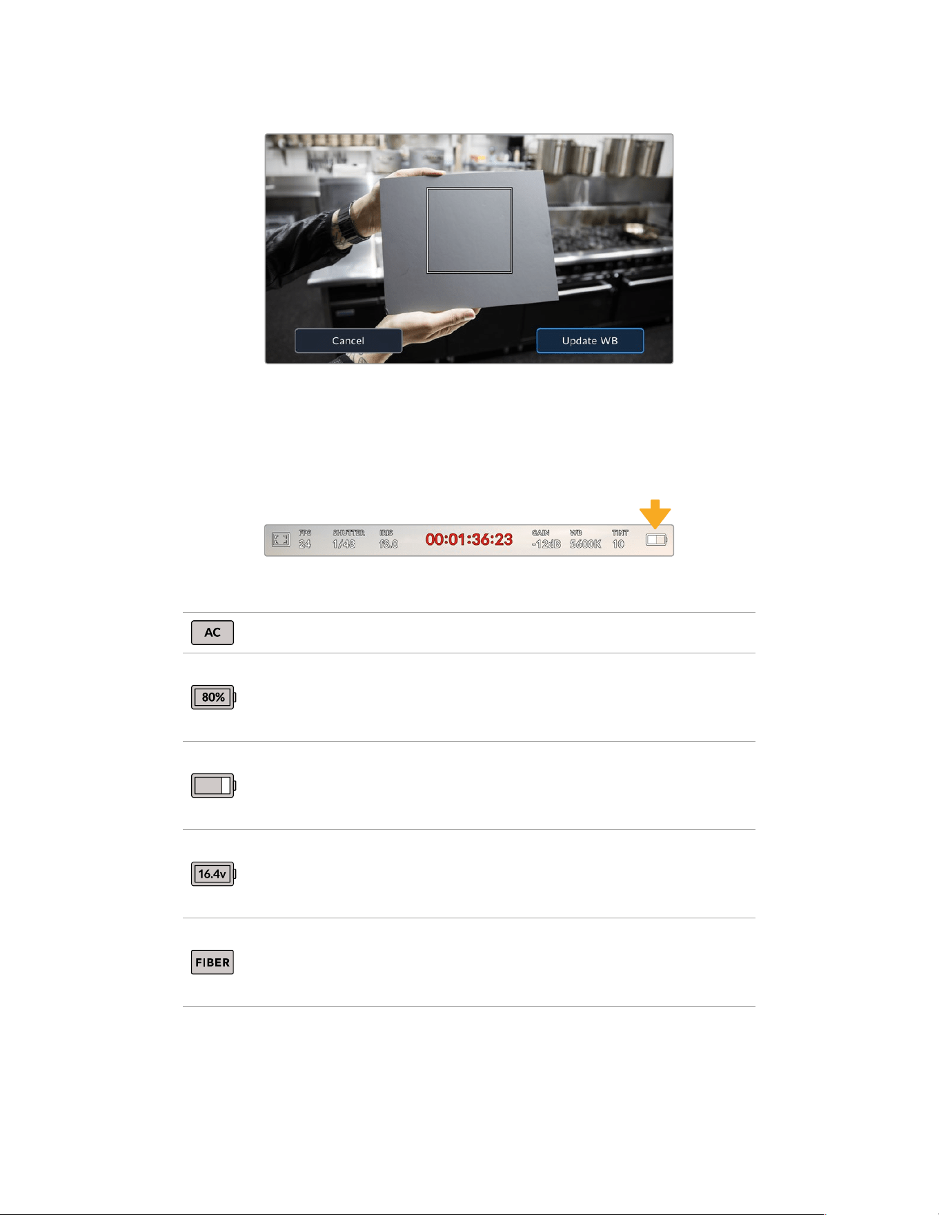
Tapping the ‘AWB’ icon in the white balance menu will bring up theauto white balance screen.
Use this with a white or neutralgray surface to automatically set a neutral white balance
Power
Your URSA Broadcast G2’s power status is displayed in the top right of the LCD screen.
There are five possible indicators:
Your URSA Broadcast G2’s power indicator is at the top right of the LCD touchscreen.
Whileusingbattery power, tapping this toggles between ‘voltage’ and ‘percentage’ displays
AC Displayed when your URSA Broadcast G2 is plugged into mainspower.
Percentage
If you are using a percentage accurate battery and plate combination
and have your battery display set to ‘percentage,’ theindicator will
display your battery level as a percentage. At20% charge remaining,
the indicator will turn red.
Battery bars
If your battery display is set to ‘percentage’ but your battery plate
andbattery combination does not support percentage accurate battery
information, your URSABroadcast G2 will display abattery icon that drains
in 25% increments. At 20% charge remaining, the battery bar will turn red.
Voltage
When your battery display is set to ‘voltage,’ this indicator will display your
battery’s remaining voltage. When your battery drops below 12.5 volts,
this indicator will turn red. Your URSA Broadcast G2 will automatically shut
down once the battery reaches 11.9 volts.
Fiber
Displayed when you have Blackmagic Camera Fiber Converter attached to
your camera and are powering thecamera through theSMPTE fiber cable.
If you have an XLR power cable plugged into URSABroadcast G2 whilst
the converter is attached, the AC icon will be displayed instead.
When using battery power, you can switch between ‘voltage’ and ‘percentage’ or ‘battery bars’
power indicators by tapping the power indicator.
88Touchscreen Controls
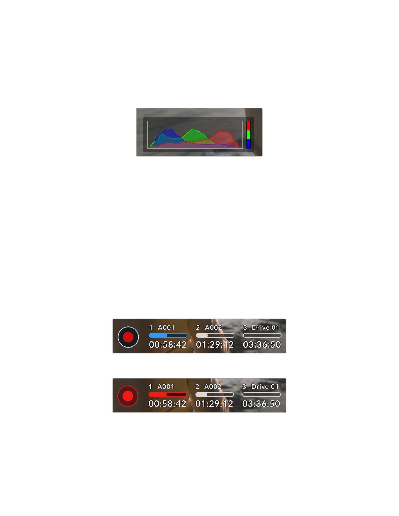
Lower Toolbar
Histogram
At the bottom left of your URSA Broadcast G2 touchscreen, you’ll see the histogram. The RGB
histogram shows the tonal distribution of the image separated into individual red, green and
blue channels.
The histogram gives you an indication of the tonal rangebetween
shadows and highlights in your clip. Itis also a helpful tool for checking
thebalance of your exposure and to prevent your highlights from clipping
The left edge of the histogram displays shadows, or blacks, and the far right displays highlights,
or whites. When you close or open the lens aperture, you’ll notice the information in the
histogram moves to the left or right accordingly. You can use this to check ‘clipping’ in your
image shadows and highlights. When clipping occurs in the red, green or blue channel, the
respective indicator on the right side of the histogram lights up. If the left and right of your
edges of the histogram come to an abrupt stop rather than falling off gradually, you may be
losing highlight or shadow detail.
If you don’t see a histogram in the bottom left of your touchscreen, your LCDmonitor settings
may be set to display ‘codec and resolution.’ See the ‘monitor settings’ section in this manual
for more information.
Record button
Next to the histogram at the bottom of your URSA Broadcast G2’s touchscreen, you’ll see a
round button with a red center. This is the ‘record’ button. Tap this once to begin recording,
andtap it again to stop. While recording, button, media bar icon and the timecode at the top
of your URSABroadcast G2 touchscreen will turn red.
Your URSA Broadcast G2’s ‘record’ button, next to the storage
indicatorsat the bottom of the LCD touchscreen
The ‘record’ button turns red when recording
89Touchscreen Controls
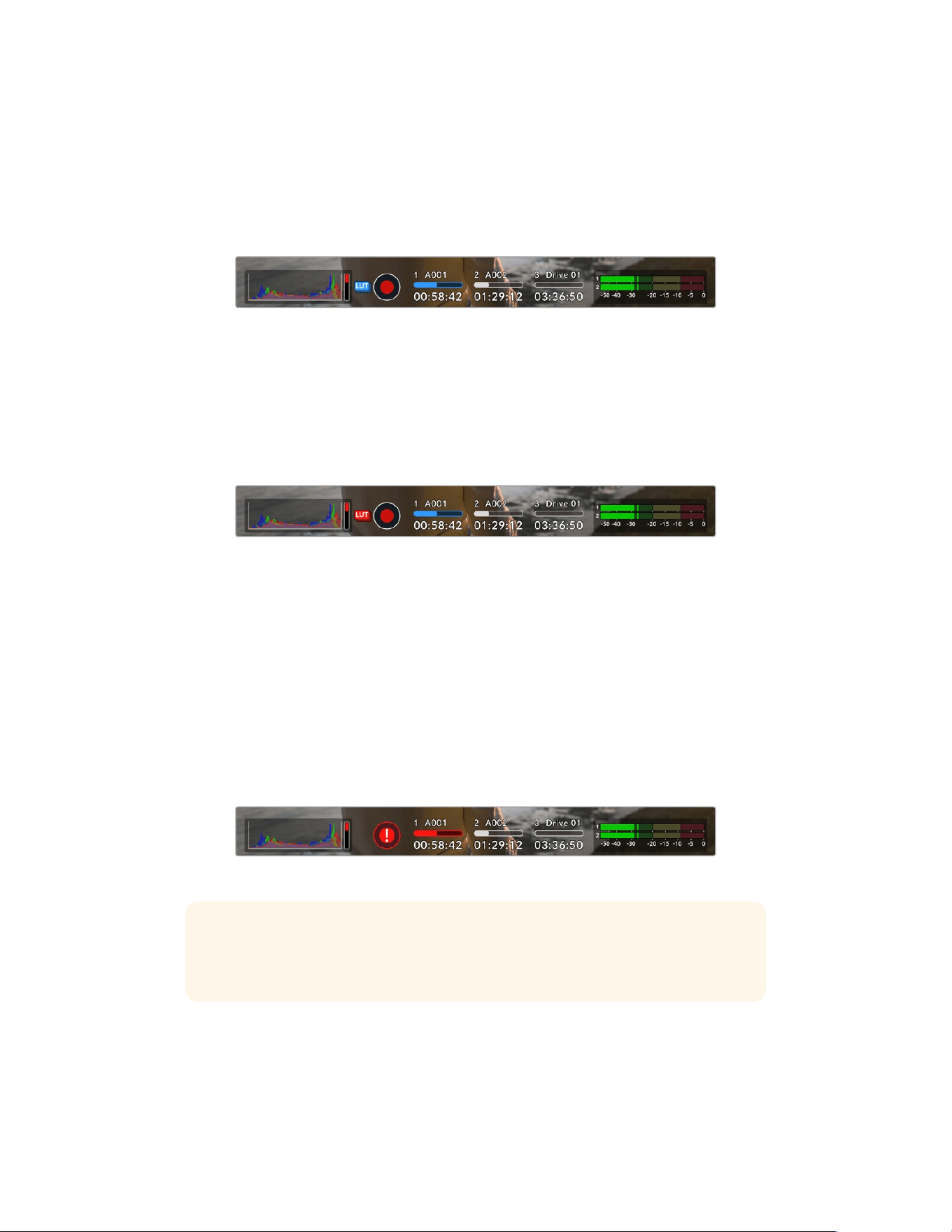
Apply LUT in File
If you are recording to Blackmagic RAW and have chosen to apply a LUT to your recorded clips
in the ‘record’ settings tab, a blue ‘LUT’ icon is displayed next to the ‘record’ button. The LUT
indicator is displayed in both standby and record mode.
For more information on recording LUTs with Blackmagic RAW, refer to the ‘Record Settings’
section later in this manual.
A blue ‘LUT’ icon is displayed when recording to Blackmagic RAW
Record LUT to Clip
If you are recording to ProRes, H.264 or H.265 and have chosen to record a LUT to your
recorded clips, a red ‘LUT’ icon is displayed next to the ‘record’ button. The LUT indicator
is displayed in both standby and record mode.
For more information on recording LUTs with ProRes, H.265 or H.264 video codecs, refer
to the ‘Record Settings’ section later in this manual.
A red ‘LUT’ icon is displayed when recording to ProRes, H.265 or H.264
Dropped Frame Indicator
The ‘record’ button will be overlaid with a flashing ‘!’ indicator if your URSA Broadcast G2
begins dropping frames while recording. The time remaining indicator for the affected card
or cards will also turn red. For example, if you are recording in dual card mode and card 1 is
dropping frames, the ‘!’ indicator will appear over the ‘record’ button, and the time remaining
indicator on card 1 will turn red. This lets you know if a particular card is too slow for your
currently selected codec and resolution. The ‘dropped frame indicator’ will also display if you
have dropped a frame on the previously recorded clip. This indicator will continue to display
until another clip is recorded, or the camera is power cycled. Refer to the ‘Choosing a CFast
2.0 card’ ‘Choosing a fast SD Card’ and ‘Choosing a fast SSD’ sections in this manual,
for more information on how to avoid dropping frames.
Dropped frame indicator for CFast card 1 dropping frames
TIP If you have your URSA Broadcast G2’s status LED enabled, this will rapidly flash
red when dropped frames are detected. For more information, see the ‘setup settings’
section in this manual.
90Touchscreen Controls
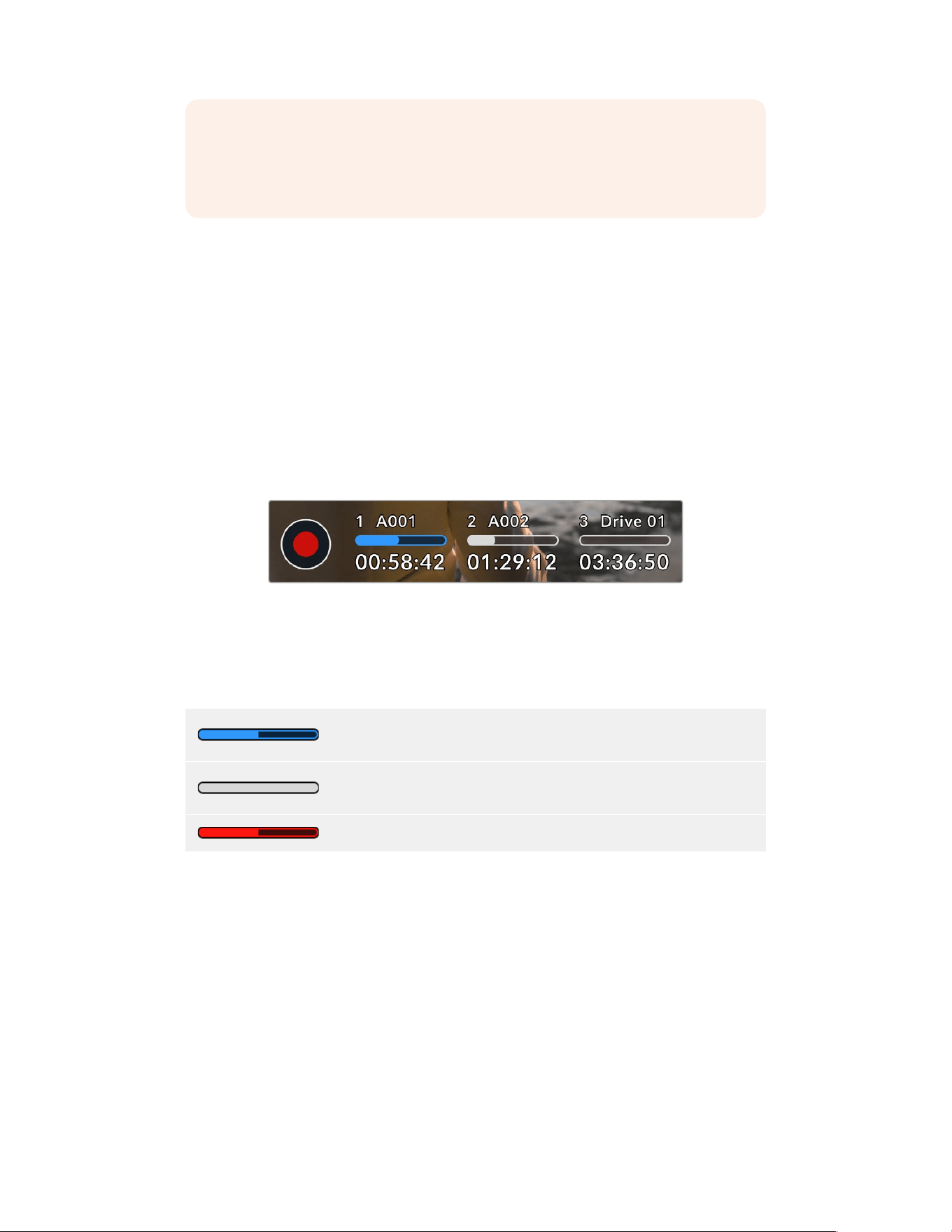
NOTE You can set your URSA Broadcast G2 to stop recording if dropped frames are
detected toprevent a situation where you waste time shooting unusable footage if
youdon’t notice the dropped frame indicator. See the ‘record settings’ section in this
manual for more information.
Storage Indicators
At the bottom of your URSA Broadcast G2 touchscreen next to the ‘record’ button, you’ll see
the storage indicators.
Recording Time Remaining
When a CFast or SD card is inserted, or a USB-C flash disk or SSD is attached to your camera,
the storage indicators show how much recording time is left on each card or drive. The
recording time is displayed in hours:minutes:seconds based on your chosen frame rate and
codec and is automatically recalculated if you change either of these settings.
When there is approximately 5 minutes remaining on your card or drive, the indicator text
will turn red. If you are recording to a single card or drive or have filled any additional storage
attached to your camera, the indicator will blink slowly when there is 3 minutes remaining and
blink quickly when there is less than 30 seconds of recording time remaining.
Your URSA Broadcast G2’s storage indicator will display the name of your
CFastcard, SD card, SSD or USB flash disk and the remaining record time
Media Bar
The media bar icon above the recording time will be either blue, white or red depending
onitscurrent status and will display the used space on the card or drive.
The blue drive icon indicates the active drive. This is the drive that
will be used for recording.
A white drive icon indicates there is media present, but not active.
A solid white icon indicates the media is full.
The bar will illuminate red during recording.
To switch recording to a different card or drive, press and hold the name or media bar of the
card, USB-C flash disk or SSD that you wish to record to.
Tapping the storage indicators will open the media pool, tap the media storage icon at the top
of the touchscreen to bring up the storage and formatting menu.
91Touchscreen Controls
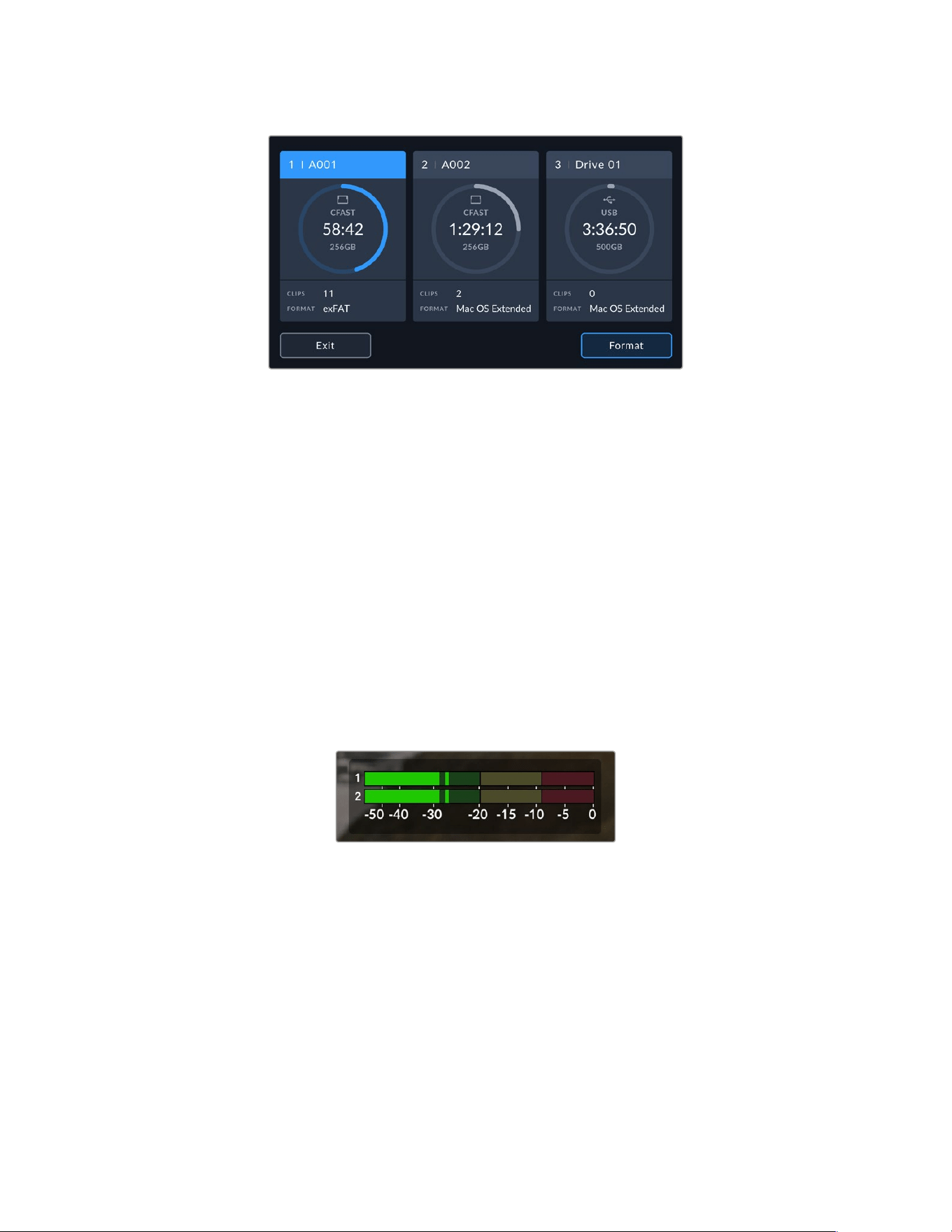
Tap the storage indicators to open the media pool and then tap
the storage icon to enter the storage and formatting menu
This menu displays the amount of free space on each CFast card, SD card, USB-C flash disk or
SSD currently connected to your URSA Broadcast G2, as well as the name of the card or drive,
remaining record time, total number of clips, and the file format for each card or drive. Tapping
the card or drive name in the storage menu sets it as the active card or drive. Your URSA
Broadcast G2 will fill this card first.
You can format your media from this menu. For more information on formatting media using
URSA Broadcast G2, see the ‘preparing media on Blackmagic URSA Broadcast G2’ section
ofthis manual.
Audio Meter
The peak audio meters display audio levels for channels 1 and 2 when using the internal
microphone, or via external audio when connected. You can display PPM or VU meters.
To change the meter type, see the ‘setup’ settings later in this manual.
To achieve optimum audio quality, ensure your audio levels do not reach 0 dBFS. This is the
maximum level that your camera can record, meaning that any audio that exceeds this level
will be clipped, resulting in distortion.
The colored bars on the audio meter represent peak audio
levels. Ideally your peak audio levels should fall in the upper
end of the green zone. If your peaks enter into the yellow
or red zones your audio is in danger of clipping.
You can tap the audio meter to bring up volume controls for audio input channels 1 and 2,
aswell as headset or speaker volume.
92Touchscreen Controls
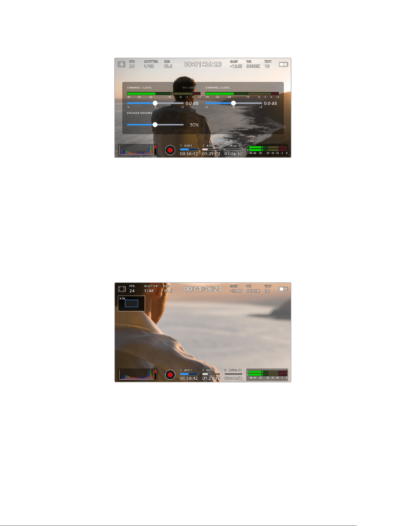
Tap the audio meters on your URSA Broadcast G2 LCD touchscreen
toeasily access volume and headset or speaker settings
Focus Zoom
You can magnify any part of your URSA Broadcast G2’s preview image by double tapping the
LCD touchscreen in the location you would like to zoom. You can move the magnified image
by dragging your finger around the touchscreen. This is very helpful when checking focus.
To return to the standard magnification, double tap on the touchscreen again.
When you have ‘focus zoom’ enabled you can also make a pinch to zoom multitouch gesture
to adjust the zoom level on the touchscreen. The ‘setup’ menu on your URSA Broadcast G2 lets
you configure a function button as a ‘focus zoom’ toggle that behaves like a double tap on the
touchscreen. This can be configured to show on the LCD or the front or main SDI to outputs.
For information on how to configure a function button as ‘focus zoom’, see the ‘Function Button
Behaves as Preset or Toggle’ section.
While zoomed in, an indicator in the top left of your LCD touchscreen will show
which part of the image you are viewing. You can move around the image
using the menu wheel or by dragging your finger around the screen.
93Touchscreen Controls
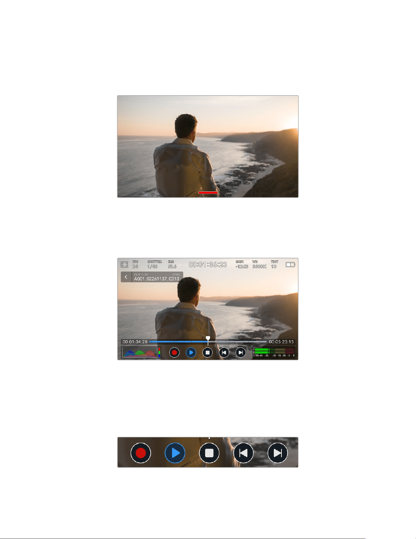
Full Screen Mode
It can be useful when framing or focusing a shot to temporarily hide your touchscreen’s
statustext and meters. Simply swipe up or down on URSA Broadcast G2’s LCD touchscreen to
hide these. Therecord indicator, frame guides, grids, focus assist and zebra will remain visible.
Swipe up or down to hide all status indicators on
your URSA Broadcast G2 LCD touchscreen
Playback Menu
Press the ‘play’ control button to access the playback menu. You can control previously
recorded clips with your camera’s control buttons or the LCD touchscreen.
The LCD touchscreen displays a timeline of segments representing all the recorded clips.
Each segment in the timeline represents an individual clip. The current clip name and number
is shown at the top left of the display and the total number of clips on the card or drive is shown
in brackets.
The counter ahead of the timeline displays the current location of the playhead and the counter
after the timeline displays the total duration of all the clips.
The playback controls below the timeline let you navigate through the clips.
94Touchscreen Controls
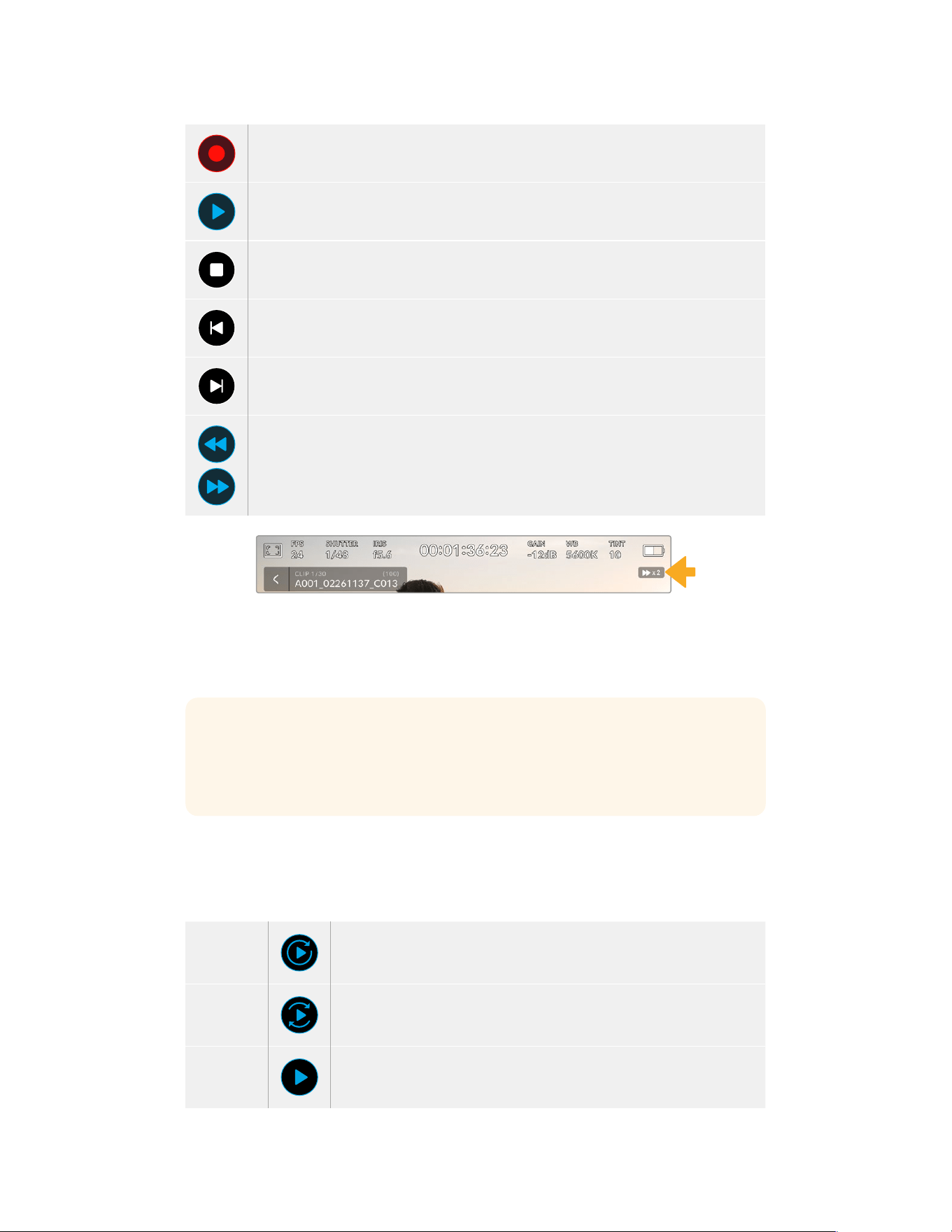
Tap the ‘record’ button in playback mode to return your camera to standby mode,
ready to record.
Tap the ‘play’ button to view your clips. You are now in ‘playback’ mode.
Press the ‘stop’ button to stop playback. Pressing the ‘stop’ button a second time will
return your camera to standby mode.
Tap the ‘skip’ back button once to move the playhead to the first frame of the current clip. If
the playhead is already on the start of a clip, it will jump to the first frame of the previous clip.
Tap the ‘skip’ forward button once to move the playhead to the last frame of the current clip.
If the playhead is already at the end of a clip, it will jump to the first frame of the next clip.
Press and hold the ‘skip’ back and ‘skip’ forward buttons to change them to ‘rewind’
and ‘forward’ shuttle buttons. Now you can use them to change the shuttle speed to
2x, 4x, 8x or 16x.
To reduce the shuttle speed, simply tap the button in the opposite direction.
The shuttle speed indicator displays the speed and direction of footage
being fast forwarded or reversed
You can change the playback mode from ‘all clips’ to ‘single clip’ in the ‘setup’ menu. In ‘single
clip’ mode the last recorded clip is displayed when you press ‘play’.
TIP Swipe up or down on your URSA Broadcast G2’s touchscreen to hide status text
while playing back footage. Entering the slate in playback mode will allow you to mark
the current clip ‘good take’ in metadata. For more information, see the ‘entering
metadata’ section in this manual.
Looping playback
Tapping the play button more than once enables the ‘loop’ feature. Looping can be useful if you
want to continue looping the same clip, or loop all clips on the timeline.
Loop
Once your clip is playing, press the ‘play’ button again to set your camera
to play the current clip on a continuous loop.
Loop all
Tap ‘play’ again to play all your recorded clips on a continuous loop.
Play
Tap again to return to real time playback.
95Touchscreen Controls
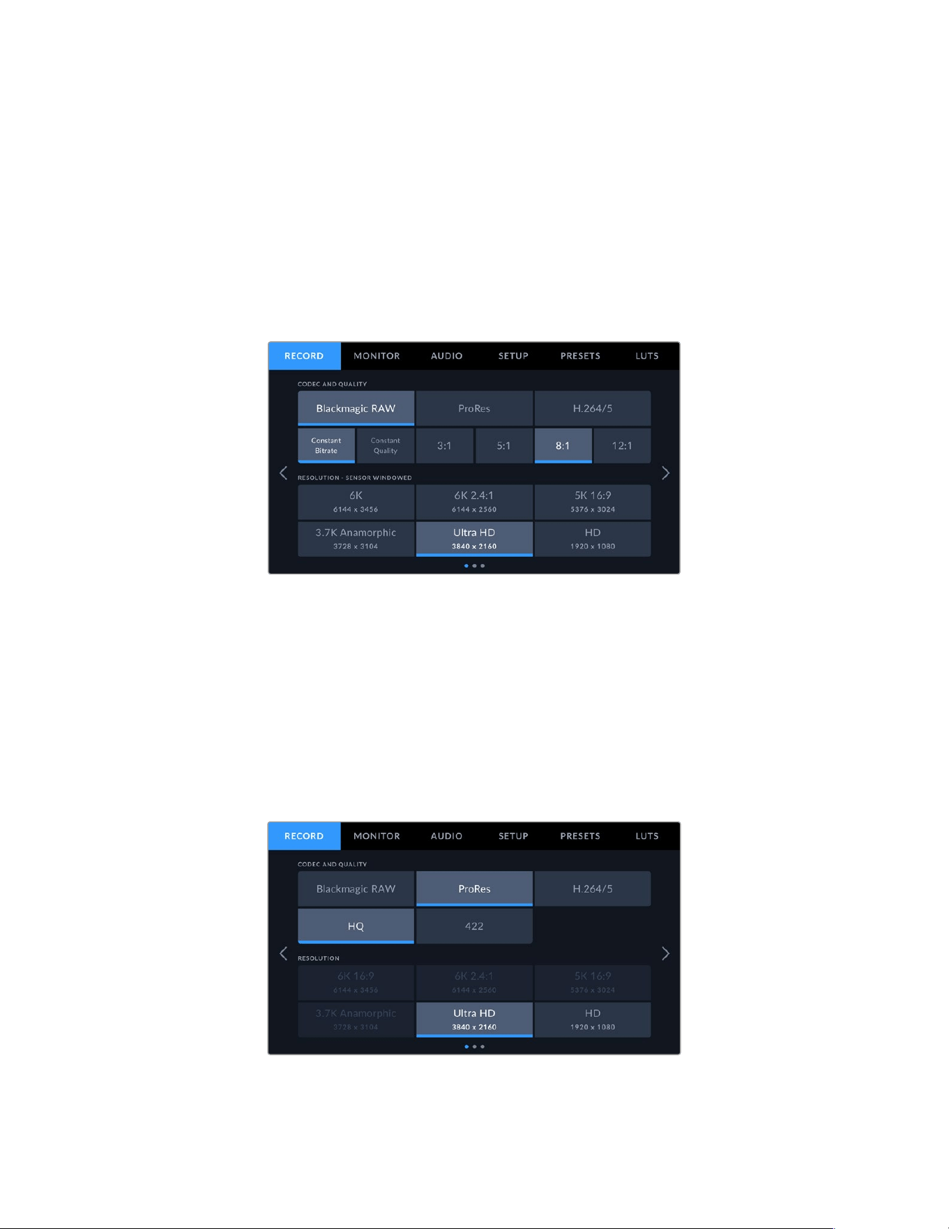
Settings
Dashboard
Pressing the ‘menu’ control button on your URSA Broadcast G2 will bring up your camera’s
dashboard. This is a tabbed menu containing the settings not available from your URSA
Broadcast G2’s head up display. Settings are divided by function into ‘record,’ ‘monitor,’ ‘audio,’
‘setup,’ ‘presets,’ and ‘LUTS’ tabs. Some tabs, such as ‘record,’ ‘monitor,’ and ‘setup’ contain
multiple pages. You can cycle between these pages by tapping the arrows on the left and right
of the settings screen, orswiping left or right as you would on a smartphone or tablet.
Tap the ‘record,’ ‘monitor,’ ‘audio,’ ‘setup,’ ‘presets,’ and ‘LUTS’ headings
to move between your URSA Broadcast G2’s dashboard tabs
Record Settings
The ‘record’ tab allows you to set your video format, codec, and resolution, as well as other
settings which affect the footage saved by your URSA Broadcast G2, such as preferred card
and detail sharpening. This menu has three pages, which you can cycle through by tapping
the arrows at the edge of your camera’s touchscreen, or swiping left or right.
Record Settings 1
The first page of the ‘record’ settings tab contains the following settings.
96Settings
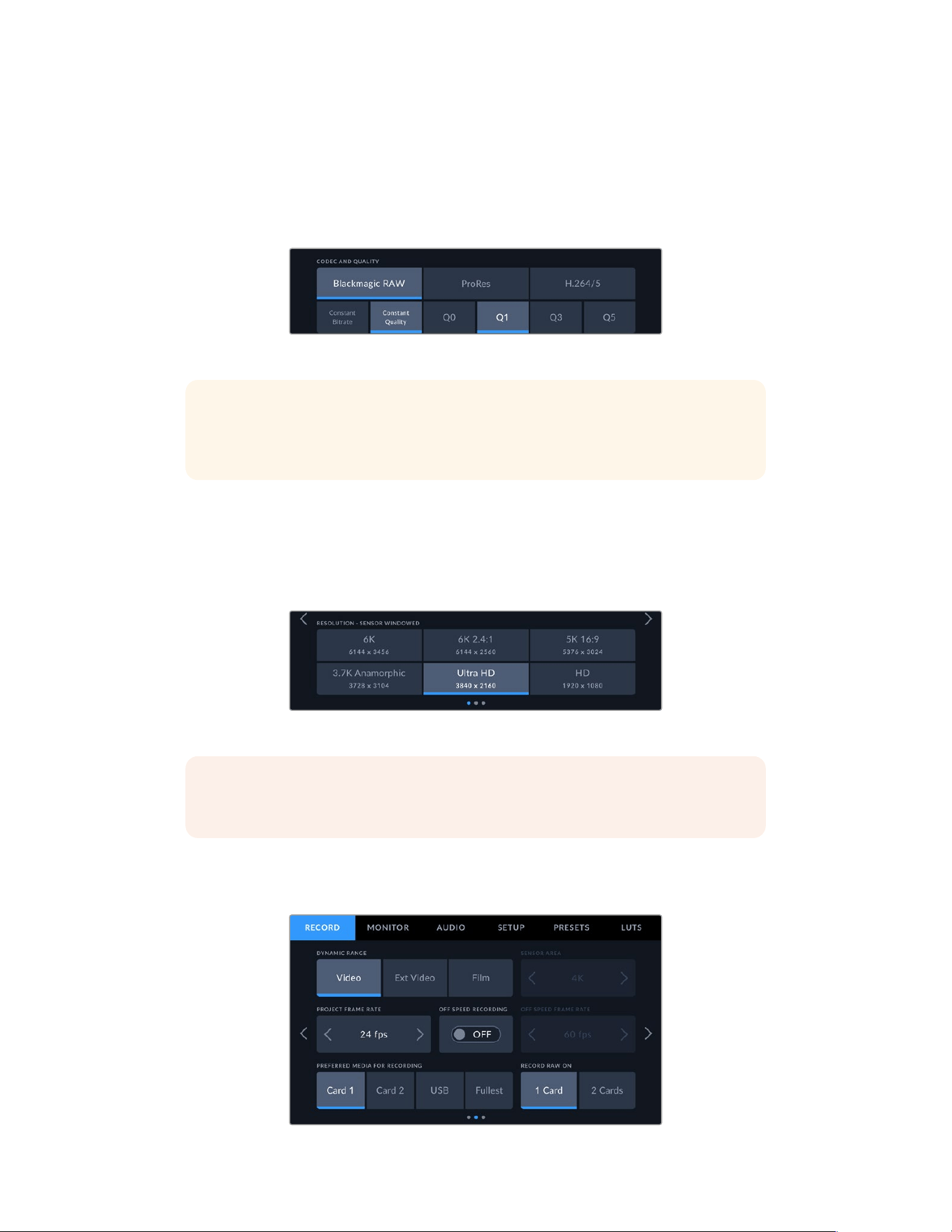
Codec and Quality
The ‘codec and quality’ menu is split into two rows. The top row lets you choose between three
codec families, Blackmagic RAW, Apple ProRes and H.264/5, while the bottom row offers
quality options in those families. For example, the quality options available in the ProRes codec
family are ProRes HQ and ProRes 422. Blackmagic RAW options are divided between four
‘constant bitrate’ and four ‘constant quality’ settings.
Blackmagic RAW ‘constant bitrate’ and ‘constant quality’ options
TIP The amount of video you can record on your storage media on URSA Broadcast
G2 will increase when choosingcodecs that utilize higher compression. Refer to the
‘record duration table’ inthe ‘recording’ section for more information.
Resolution
This setting works in combination with the ‘codec’ setting. Use it to select the resolution for your
desired recording format.
For example, if you want to record Ultra HD clips using ProRes HQ, select ‘ProRes’ and ‘HQ’ in
the ‘codec and quality’ menu. Now choose ‘Ultra HD’ in the resolution menu.
Blackmagic RAW ‘resolution’ options
NOTE Blackmagic URSA Broadcast G2 supports Blackmagic RAW in all resolutions,
Apple ProRes in Ultra HD and HD, H.265 in Ultra HD and H.264 in HD.
Record Settings 2
The second page of the ‘record’ settings tab contains the following settings.
97Settings

Dynamic Range
Adjust the ‘dynamic range’ setting by tapping the dynamic range icons. Blackmagic URSA
Broadcast G2 has three dynamic range settings:
Video The ‘video’ setting is the best choice for recording to a high contrast,
saturated look suitable for direct delivery or minimal post processing.
Video uses Rec.709 primaries with a pleasing roll off in the highlights.
This is a good option if you want an accurate starting point that still has
a pleasing gamma curve with room for grading if needed.
Ext Video The ‘extended video’ setting is based on Blackmagic Wide Gamut with
contrast and saturation applied. The most notable differences to the video
mode come from the magenta/green axis having less saturation which is
more typical of print film.
Film The ‘film’ setting shoots video using a log curve that allows you to maintain
the greatest dynamic range and maximizes the information in your video
signal to help you get the most out of color grading software, such as
DaVinci Resolve.
If you are using ‘video’ or ‘extended video’ dynamic range, make sure that display LUT is not
enabled on any of the monitor outputs, LCD, Front SDI or Main SDI.
If the display LUT is enabled, the LUT indicator will be visible on the HUD and the image
appears to have more saturation and contrast than intended. To check your display LUTs
setting, see the ‘monitor’ settings later in this manual.
Sensor Area
This setting is available when shooting in ProRes, H.265 and H.264 video codecs. It lets you
choose between scaling from the full ‘6K’ sensor area, or using a smaller ‘window’ of the sensor
area. Choosing a larger sensor area like 5.3K or 6K gives you a wider field of view whereas
choosing a smaller sensor area like 2.7K gives you higher frame rate options. It’s important to
mention that windowing to a smaller area only uses the center of the camera’s sensor, the field
of view of any given lens will be narrower due to the crop involved.
When using broadcast lenses on URSA Broadcast G2’s B4 mount you should ensure that your
sensor area is set to 4K as this is the area of the frame that these lenses will cover. The 5.3K and 6K
sensor area is roughly Super 35 size and so is compatible with most EF, F mount and PL lenses.
For more information on ‘full’ and ‘window’ formats, see the ‘maximum sensor frame rates’ section.
Project Frame Rate
The project frame rate is URSA Broadcast G2’s recording format frame rate and provides a
selection of common frame rates used in the film and television industry. For example, Ultra HD at
29.97 frames per second using ProRes HQ. This frame rate is normally set to match your playback
speed and audio sync used in your post production workflow and delivery requirements.
Your Blackmagic URSA Broadcast G2 has 8 project frame rate settings including 23.98, 24, 25,
29.97, 30, 50, 59.94 and 60 frames per second.
98Settings

NOTE Your camera’s project frame rate has a large impact on the ‘look’ of footage.
Inbroadcast environments, frame rates are typically set to 50, 59.94, or 60 frames per
second. These relatively high frame rates are great for capturing smooth motion and
eliminate or minimize stutter while panning.
Lower frame rates, such as 24 or 25 frames per second, are typically used for cinema
production. These have a distinct filmic ‘look,’ but require much slower camera
movement to avoid stutter.
Off Speed Recording
By default, your URSA Broadcast G2’s project and sensor frame rates are matched for a natural
playback speed. However, by tapping the ‘off speed recording’ switch icon you can set your
sensor frame rate independently. This option is only available when recording to Blackmagic
RAW or ProRes codecs.
Off Speed Frame Rate
With ‘off speed frame rate’ enabled, tap the arrows next to the ‘off speed frame rate’ indicator
toset your URSA Broadcast G2’s sensor frame rate.
The sensor frame rate sets how many actual frames from the sensor are recorded every second.
This frame rate will affect how fast or slow your video will play back at your set project frame rate.
For more information on off speed frame rates, see the ‘frames per second’ section in the
‘touchscreen features’ section of this manual.
NOTE For information on the maximum frame rates available for each recording format
and codec, refer to the ‘maximum sensor frame rates’ table in the ‘recording’ section of
this manual.
Preferred Media for Recording
Use this setting to select which storage card, SSD or flash disk your URSA Broadcast G2 will
record to first when more than one storage slot is in use. The options are ‘card 1’, ‘card 2’, ‘USB’
and ‘fullest’. Picking either ‘card 1’ or ‘card 2,’ isa matter of personal preference, but using either
consistently will let you know which card to swap out first as your storage fills up. ‘Fullest card’
can help group files chronologically when shooting a single camera project. The ‘fullest card’
setting is based on the percentage that your storage cards are filled, rather than their sizes or
the amount of data used.
The setting you choose is applied when a CFast card, SD card or SSD is inserted or when a
USB flash disk is connected. You can override this setting at any time by entering the storage
manager and setting a different card as ‘active.’ It’s important to note, however, that ejecting
and reinserting cards will revert to the current ‘preferred media for recording’ setting.
Record RAW on
Recording Blackmagic RAW on two cards lets you record extremely high resolution clips at high
frame rates with lower levels of compression. Insert a pair of CFast or SD Cards and choose the
‘2 cards’ option. Since this relies on striping across both cards sequentially, the data rate of the
slowest card will be the limiting factor, so you are advised to use two cards of the same or
similar specification.
You can also stripe between a CFast card in storage slot 1 or 2 and a USB-C flash disk in
storage slot 3. When you use the ‘2 cards’ option, the speed limit is twice the data rate of
the slowest card in the striped array.
99Settings
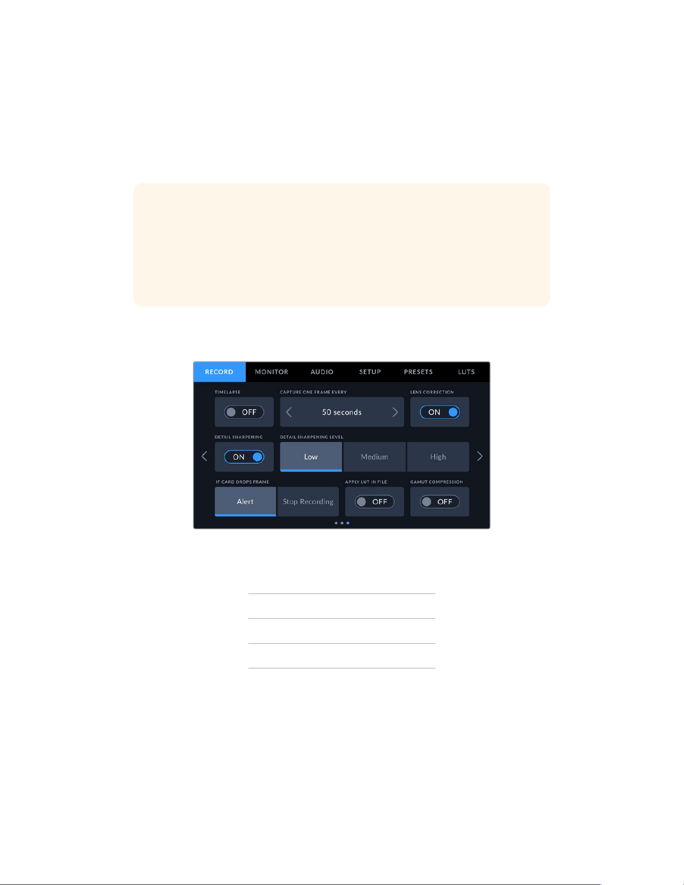
Merging files for Editing
Copy the .BRAW and .BRAW2 files from both memory cards into the same folder on your
computer, and DaVinci Resolve will bring them in as a single, merged clip when you import
them into your media pool. If the .BRAW and .BRAW2 files are separated, the clips can play
independently at half the frame rate. To play back a .BRAW2 file independently, change the
file extension from .BRAW2 to .BRAW.
TIP You can use the Media Management tool in DaVinci Resolve to combine a .BRAW
and .BRAW2 file into a single, independent clip.
Combining .BRAW files heps to make sure they can’t be separated. This can be useful
for media management or if you are sending files to another editor.
For more information, refer to the ‘Using Media management’ section in the DaVinci
Resolve manual.
Record Settings 3
The third page of the ‘record’ settings tab contains the following settings.
Timelapse
This setting activates the time lapse feature to automatically record a still frame at the
following intervals:
Frames 2 – 10
Seconds 1 – 10, 20, 30, 40, 50
Minutes 1 – 10
For example, you can set the camera to record a still frame every 10 frames, 5 seconds,
30seconds, 5 minutes etc.
The time lapse feature offers many creative options. For example, setting a 2 frame time lapse
interval will give your recorded video a high speed effect when played back.
The format of each still frame is based on your recording format, so if you set the camera to
record Ultra HD using ProRes HQ, the time lapse setting will maintain this format. The frame
rate will be based on your project frame rate. This is so your time lapse footage can be easily
incorporated into your post production workflow.
100Settings

When you record footage in timelapse mode, the timecode counter updates when a frame of
video is recorded.
Your URSA Broadcast G2 will indicate it is in time
lapse mode with an icon over the ‘record’ button
Lens Correction
Broadcast zoom lenses can often suffer from color fringing at the edge of frame or near the
corners of the image. This is more prominent in high contrast image areas on more affordable
B4 lenses, particularly those with more extreme zoom ranges. The Lens Correction feature
allows you to correct for this in-camera on URSA Broadcast G2 with broadcast B4 and
broadcast PL lenses. It is switched on by default when the camera detects necessary
information from the broadcast lens.
Detail Sharpening
Use this setting to sharpen your URSA Broadcast G2’s image. When sharpening is enabled,
decrease or increase the level of sharpening by selecting ‘low’, ‘medium’ or ‘high’.
When sharpening is enabled, it will be applied to ProRes video recorded on camera as well as
your URSA Broadcast G2’s SDI output.
This setting is intended for live studio production where there is no time for post production
and you want to output the image live to air. If you are doing extensive image manipulation
and color correction in post production then we recommend leaving detail sharpening ‘off’.
For this reason sharpening is not applied to Blackmagic RAW files that are intended for
significant post processing.
TIP When post processing your Blackmagic RAW files, you can achieve a comparable
level of sharpening to these settings by using the blur/sharpening tool in DaVinci
Resolve’s ‘color’ page.
Set the tool to a radius of 0.48 and adjust the scaling to 0.6, 0.3 or 0.15 for comparable
sharpening to ‘high,’ ‘medium,’ or ‘low.’
For detailed information on sharpening in post production, see the ‘motion effects and
blur palettes’ section in the full DaVinci Resolve manual.
If Card Drops Frame
Use this setting to configure your URSA Broadcast G2’s behavior when dropped frames
are detected. When set to ‘alert’ the dropped frame indicator will be displayed on the LCD
touchscreen, and recording will continue with dropped frames. When set to ‘stop recording’
your camera will stop recording when dropped frames are detected. This can prevent you
wasting time shooting unusable footage if you don’t spot the dropped frames indicator.
Refer to the ‘Choosing a CFast 2.0 card’, ‘Choosing a fast SD card’, ‘Choosing a fast SSD’ and
‘Choosing a fast USB-C flash disk’ sections for more information on how to avoid dropping frames.
101Settings

Apply LUT in File
If you are applying a LUT to any of the outputs from your URSA Broadcast G2, the selected LUT
will be embedded into the Blackmagic RAW file you are recording.
This means that the LUT will be saved in the header of the file and can easily be applied to the
clip in post production without needing to handle a separate file. When the ‘Apply LUT in file’
switch is set to ‘on’ in URSA Broadcast G2’s record menu, this clip will open in Blackmagic RAW
Player and DaVinci Resolve with the chosen LUT already applied to it. The LUT can then be
easily toggled ‘on’ or ‘off’ but will always travel with the Blackmagic RAW file as it is written into
the clip itself.
DaVinci Resolve also has an ‘Apply LUT’ switch in the RAW settings palette for enabling or
disabling the 3D LUT in the Blackmagic RAW file. The ‘Apply LUT’ setting in DaVinci Resolve is
the same setting as in the camera. This means that when shooting you can direct the colorist to
use the LUT by setting it in the camera, but they can switch it off easily in DaVinci Resolve by
setting ‘Apply LUT’ to ‘off’.
Record LUT to Clip
The ‘record LUT to clip’ option is available when shooting with ProRes, H.265 or H.264 video
codecs. YourBlackmagic URSA Broadcast G2 does not apply, or ‘bake in,’ LUTs by default to
recorded footage, however you can choose to ‘bake in’ the LUT to your footage by tapping the
‘record LUT to clip’ switch icon.
This can be a useful option for situations where you do not have the time to grade your footage
in post-production, or where you need to give the footage directly to a client or an editor. For
more information, refer to the ‘3D LUTs’ and ‘touchscreen controls’ sections.
Gamut Compression
The ‘gamut compression’ setting on your URSA Broadcast G2 is enabled by default and allows
you to choose whether you want to compress and desaturate extreme colored highlights to
stay within the display color space as they approach clipping.
This setting will affect the image sent from SDI outputs, sent in your stream and also your
recorded files. When shooting using Apple ProRes or H.264 and H.265 codecs, the ‘gamut
compression’ setting will be permanently recorded into the image. When shooting Blackmagic
RAW the ‘gamut compression’ setting is able to be adjusted in the RAW decode tab in the
color page of DaVinci Resolve.
Turning this setting ‘off’ will allow colors to clip in a more saturated manner but can cause
some color fringing from strong saturated monochromatic light sources like LEDs in some
extreme cases.
102Settings
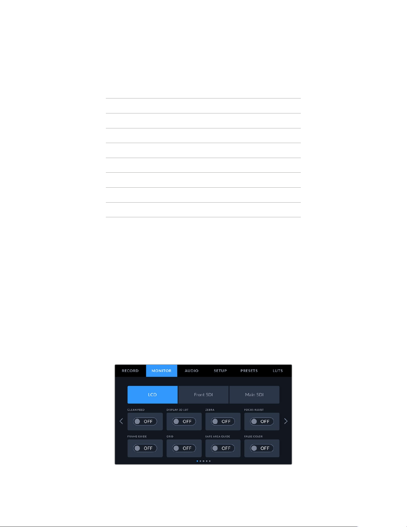
File Naming Convention
Clips are recorded in the Blackmagic RAW format, Apple ProRes and MP4 formats, depending
upon which recording format you have chosen.
The table below shows an example of the file naming convention:
A001_08151512_C001.mov QuickTime Movie Filename
A001_08151512_C001.mov Camera index
A001_08151512_C001.mov Reel Number
A001_08151512_C001.mov Month
A001_08151512_C001.mov Day
A001_08151512_C001.mov Hour
A001_08151512_C001.mov Minute
A001_08151512_C001.mov Clip Number
Still image files captured in DNG format using the still button will follow the file naming
convention for video clips, however the filename will have an ‘S001’ representing the ‘still
number’ as the last four digits of the filename in place of the clip number. For more information,
refer to the ‘Status LCDControls’ section in this manual.
Monitor Settings
The ‘monitor’ tab lets you adjust status text, overlays, and other monitoring options for your
URSA Broadcast G2’s LCD touchscreen, front and main SDI outputs. Options are arranged by
output between ‘LCD’, ‘front SDI’ and ‘main SDI’. Each of these menus have five pages of
options, which you can cycle through by tapping the arrows at the edge of your camera’s touch
screen, or swiping left or right.
Monitor Settings 1
The first page of the ‘LCD,’ ‘front SDI,’ and ‘main SDI,’ monitor tab contains identical settings for
each output. Forexample, you can set ‘zebra’ on for the LCD touchscreen, but off for the front
or main SDI outputs.
103Settings

Clean Feed
Tap the ‘clean feed’ switch in the ‘LCD,’ ‘front SDI’ and ‘main SDI’ menus to disable allstatus text
and overlays for that output, except the record tally indicator.
Your URSA Broadcast G2 LCD touchscreen will still display a record tally in
clean feed mode
NOTE LUTs will still be applied to outputs with ‘clean feed’ enabled. Todisable LUTs,
disable the ‘display LUT’ switch in the ‘Monitor’ menu for thatoutput.
Display 3D LUT
Your URSA Broadcast G2 can apply 3D LUTs to any output to approximate the look of color
graded footage. This is especially useful when shooting with ‘film’ dynamic range as it can
produce an intentionally ‘flat’ low contrast image.
If your URSA Broadcast G2 has a 3D LUT active, use this setting to independently apply that
LUTto your LCD touchscreen, front or main SDI output.
NOTE For more information on loading and using 3D LUTs, see the ‘LUTS’ section of
this manual.
Zebra
Tap the ‘zebra’ switch in the ‘LCD,’ ‘front SDI’ and ‘main SDI’ menus to enable zebra guides
for those outputs. For more information on zebra guides and setting zebra levels, see the
‘touchscreen features’ section in this manual.
Focus Assist
Tap the ‘focus assist’ switch in the ‘LCD,’ ‘front SDI’ and ‘main SDI’ menus to enable focus assist
for those outputs. For more information on focus assist and setting focus assist levels, see the
‘touchscreen features’ section in this manual.
Frame Guide
Tap the ‘frame guide’ switch in the ‘LCD,’ ‘front SDI’ and ‘main SDI’ menus to enable frame
guides for those outputs. For more information on frame guides and choosing different guides,
see the ‘touchscreen features’ section in this manual.
104Settings
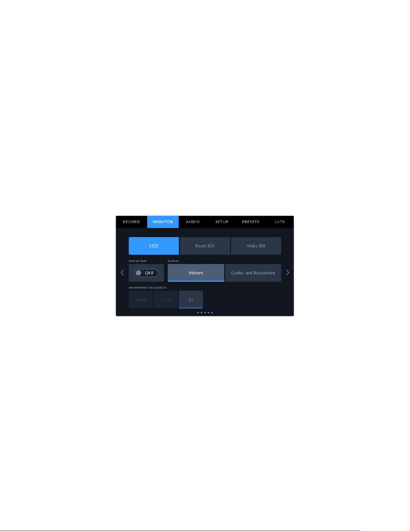
Grid
Tap the ‘grid’ switch in the ‘LCD,’ ‘front SDI’ and ‘main SDI’ menus to enable a rule of thirds grid
for those outputs. For more information on the rule of thirds grid, see the ‘touchscreen features’
section in this manual.
Safe Area Guide
Tap the ‘safe area’ switch in the ‘LCD,’ ‘front SDI’ and ‘main SDI’ menus to enable safe area
overlay for those outputs.
For more information on safe area guides, and setting the level of safe area guides, seethe
‘touchscreen features’ section in this manual.
False Color
Tap the ‘false color’ switch in the ‘LCD,’ ‘front SDI’ and ‘main SDI’ menus to enable false color
exposure assistance for those outputs.
For more information on false color, see the ‘touchscreen features’ section in this manual.
Monitor Settings 2
The second page of your URSA Broadcast G2’s ‘LCD’ monitor tab contains some settings that
vary depending on the selected output.
LCD, Front SDI and Main SDI
Status Text
It can be useful to hide the status text and meters on your LCD, front SDI or main SDI
output, leaving only the information necessary to compose or direct a shot. Tap the
‘status text’ switch icon in the LCD, ‘front SDI’ or ‘main SDI’ monitor menus to toggle
the appearance of status text and meters for that output. Overlays such as frame guides,
grids, focus assist and zebra will remain visible, if enabled.
Swiping up or down on your URSA Broadcast G2’s LCD touchscreen has the same effect
for the touchscreen.
Anamorphic Desqueeze
When shooting with anamorphic lenses, the image will appear horizontally ‘squeezed’ on
your URSA Broadcast G2’s preview outputs and in recorded files. Enabling ‘anamorphic
desqueeze’ will correct the preview image on your URSA Broadcast G2 as well as recording
the desqueeze amount used in the clip metadata for easy correction in post.
The desqueeze amount you choose will vary depending on what you’ve set your
URSA Broadcast G2 resolution to, but the resulting image will always be in the cinematic
widescreen 2.4:1 aspect ratio.
105Settings
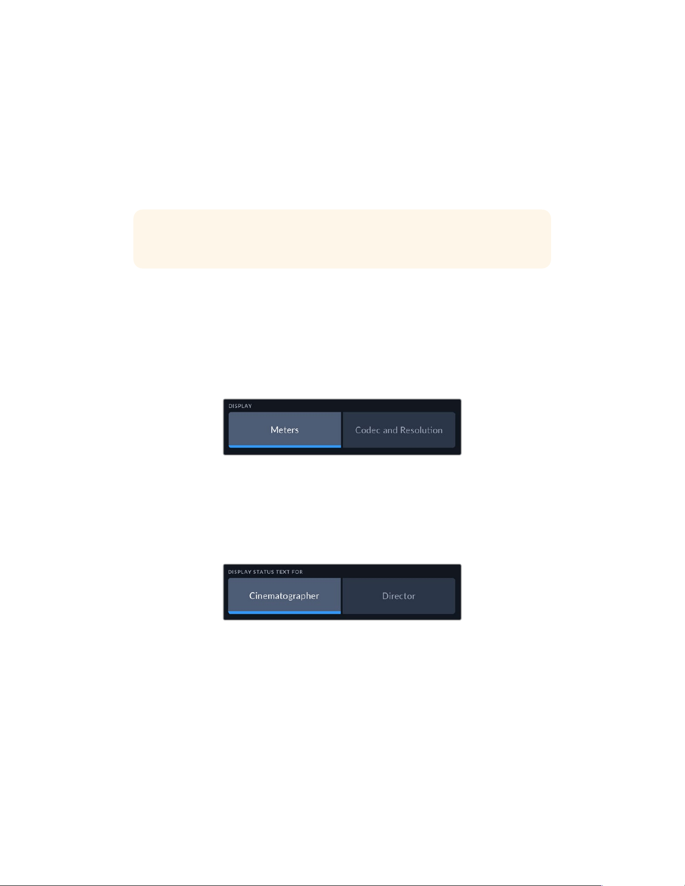
Anamorphic lenses designed for film typically have a 2x squeeze factor. Your URSA
Broadcast G2’s ‘3.7K anamorphic’ resolution is designed for use with these lenses and
will perform a 2x desqueeze when set to this resolution with ‘anamorphic desqueeze’
set to ‘2x’.
Anamorphic lenses designed for 16:9 digital image sensors often use a 1.33x squeeze
factor to produce 2.4:1 cinematic widescreen images from the entire 16:9 sensor. Therefore,
when your URSA Broadcast G2 is set to 16:9 resolutions such as ’4K 16:9’ and ‘HD 16:9,’
‘anamorphic desqueeze’ should be set to ‘1.33x’.
TIP If your image appears horizontally stretched when shooting with a standard
spherical lens, make sure you don’t have ‘anamorphic desqueeze’ enabled.
LCD Only
Display
Instead of a histogram and audio meters, your URSA Broadcast G2 can display codec and
resolution information at the left and right bottom edges of the LCD touchscreen. This can
be useful if you prefer to use false color for dialing in exposure, or are recording audio
separately and want to display additional information in the space normally used by the
histogram and audio meter. Simply tap ‘meters’ or ‘codec and resolution’ in the ‘LCD’ menu
to select your preferred view.
Front SDI and Main SDI
Display Status Text For Cinematographer or Director
The LCD touchscreen displays information such as ISO, white balance, and aperture that is
useful to a camera operator or cinematographer setting up individual shots on that camera.
Your camera’s SDI output, however, can also show information useful to a director or script
supervisor who is keeping track of multiple shots or cameras.
Setting the status text to ‘director’ in your URSA Broadcast G2’s ‘front SDI’ or ‘main SDI’
monitor settings changes the status text for that output to show the following information.
FPS
Displays the currently selected frames per second. If off speed frame rate is disabled, only
the project frame rate will be shown. If an off speed frame rate is being used, the sensor
frame rate will be shown, followed by the project frame rate.
CAM
Displays the camera index as set in your URSA Broadcast G2’s Slate. See the ‘slate’ section
in this manual for more information.
106Settings
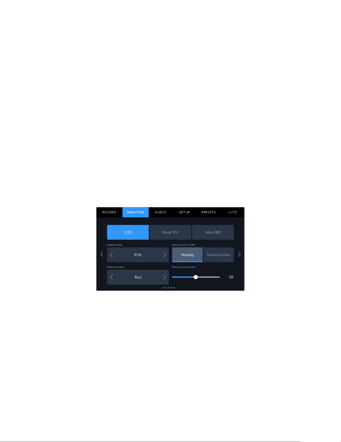
OPERATOR
Identifies the camera operator as set in your URSA Broadcast G2’s Slate. See the ‘slate’
section in this manual for more information.
DURATION DISPLAY
Displays the duration of the current clip, while recording, or the last recorded clip in the
following format: hours:minutes:seconds
REEL, SCENE, TAKE
Displays the current reel, scene and take. For more information on reels, scenes,
takes and their labelling conventions, refer to the ‘slate’ section in this manual.
DYNAMIC RANGE
The bottom left hand corner of the monitor displays your URSA Broadcast G2’s currently
applied LUT, if applied to that output. If no LUT is applied, ‘film’ or ‘video’ dynamic range
will be displayed.
TIMECODE
The bottom right of the monitor displays your URSA Broadcast G2’s timecode, in the
following format: hours:minutes:seconds:frames.
Monitor Settings 3
The third page of the ‘LCD’, ‘front SDI’ and ‘main SDI’ monitor tab contains identical settings
for each output. These settings act globally across all three monitoring outputs. For example,
if focus assist is enabled on your Blackmagic URSA G2’s LCD, Front SDI and Main SDI outputs
changing the ‘focus assist type’ from ‘peaking’ to ‘colored lines’ will effect all three outputs.
Zebra Level
Set the exposure level that zebra appears at by tapping the arrow icons on either side of this setting.
There are eight zebra level presets available, from middle gray through to 100 percent exposure.
For more information, see the ‘zebra’ guide in the ‘touchscreen features’ section of this manual.
Focus Assist Type
Your URSA Broadcast G2 camera has two focus assist modes, ‘peaking’ and ‘colored lines.’
Peaking
When ‘peaking’ style focus assist is selected, areas of the shot that are in focus are heavily
sharpened on your LCD touchscreen or SDI outputs, but not in the recorded image itself.
This causes focused parts of your shot to ‘pop’ out of the softer background on screen. As
no additional overlays are used, this can be a very intuitive way to tell when focus is dialed
in, especially when the subject you’re focusing on is physically well separated from other
elements in shot.
107Settings
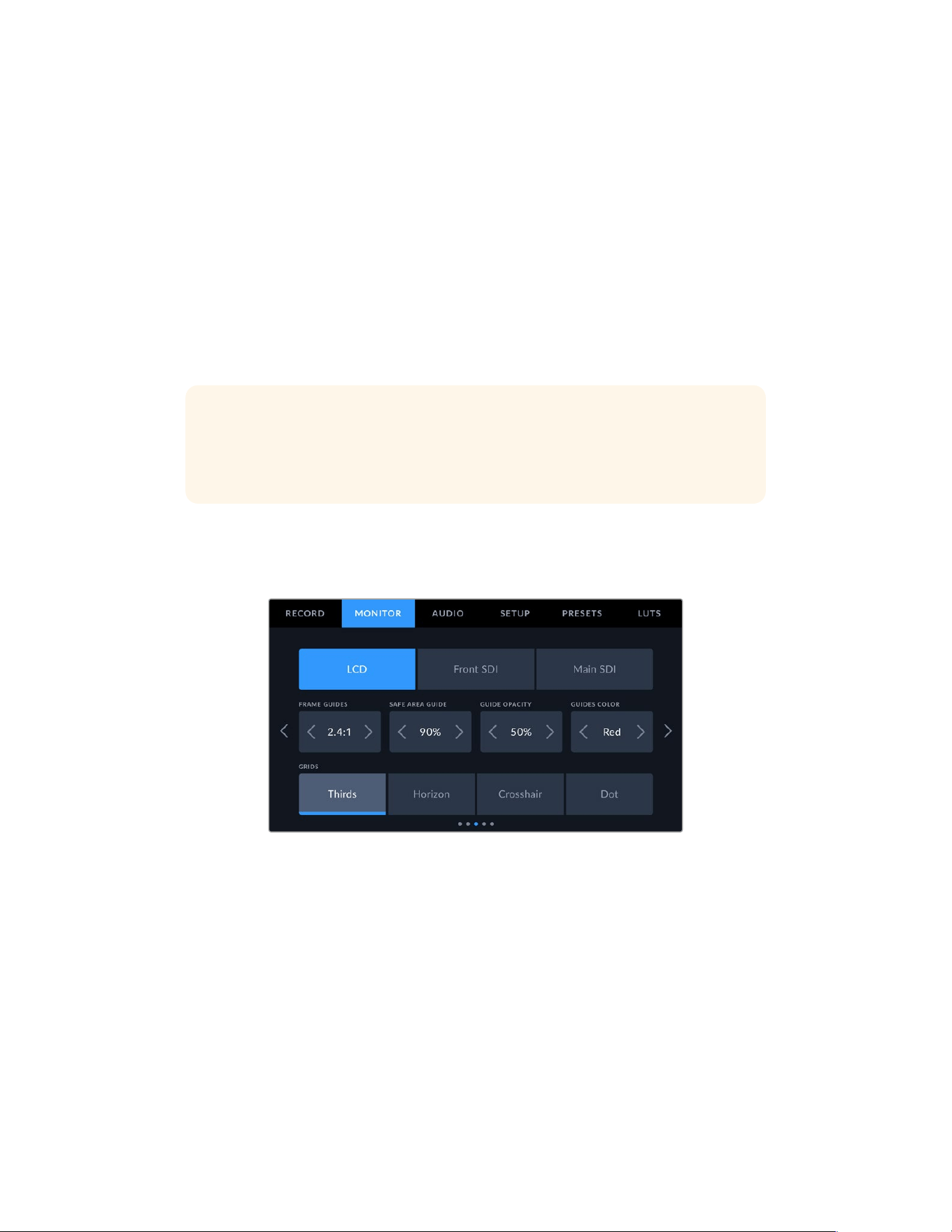
Colored Lines
When ‘colored lines’ style focus assist is selected, a colored line is superimposed around
the parts of the image that are in focus. This can be a little more intrusive than ‘peaking’
style focus assistance as the lines are drawn over your image, but especially in busy shots
with a lot of visible elements, it can be a precise focus aid.
Focus Color
Use this setting to change the color of focus line overlays when using ‘colored lines’ style focus
assistance. Changing the focus line color can make it easier to tell focus assistance lines apart
from your image. The available options are ‘white,’ ‘red,’ ‘green,’ ‘blue’ and ‘black.’
Focus Assist Level
To set the level of focus assistance for your LCD touchscreen, front SDI or main SDI, move the
slider from left to right.
TIP The optimum level of focus assistance varies shot by shot. When focusing on
actors, for example, a higher level of focus assistance can help resolve edge detail in
faces. A shot of foliage or brickwork, on the other hand, may show distracting amounts
focus information at higher settings.
Monitor Settings 4
The fourth page of the ‘LCD’, ‘front SDI’ and ‘main SDI’ monitor tab contains identical settings
for each output. These settings act globally across all three of your camera’s monitor outputs.
Frame Guides
Tap the left or right arrows in the ‘frame guides’ menu setting to cycle through frame guide
options for all outputs on your URSA Broadcast G2, including EVFs such as Blackmagic URSA
Viewfinder. The options are detailed in the ‘touchscreen features’ section of this manual, and
are also accessible from the LCD monitoring menu in your LCD touchscreen head up display.
Safe Area Guide
To adjust the size of the safe area overlay on your URSA Mini’s LCD touchscreen, front SDI and
main SDI outputs, tap the arrows to the left and right of the percentage displayed in this setting.
This percentage indicates the size of the safe area in relation to the image frame. Most
broadcasters require a 90% safe area.
108Settings
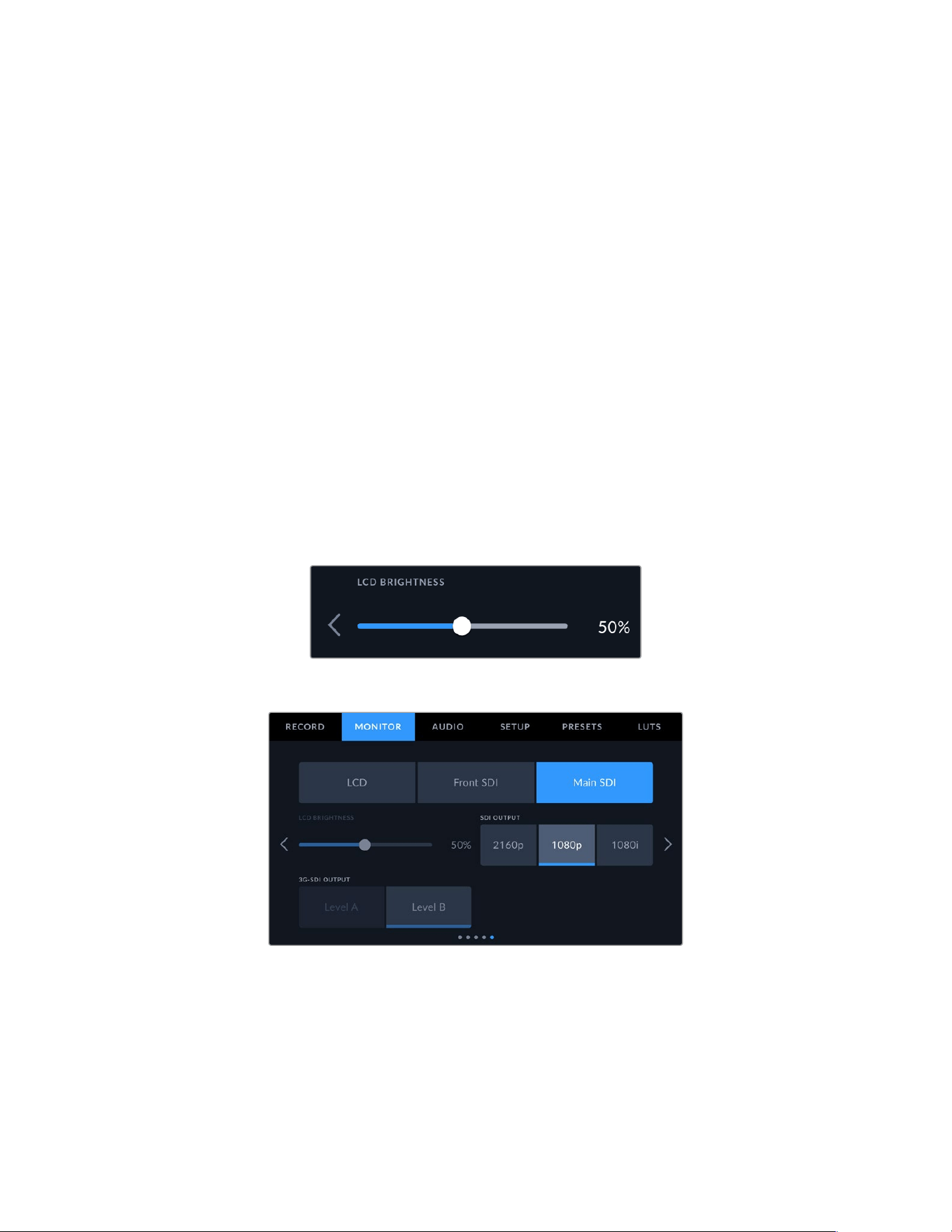
Guide Opacity
Tap the left or right arrows in the ‘guide opacity’ menu setting to choose the opacity of the
areas blocked out by frame guides on your LCD touchscreen, front and main SDI outputs.
The options are 25%, 50%, 75% and 100%.
Guides Color
Tap the left or right arrows in the ‘guides color’ menu setting to choose a color for the guides.
Grids
To set which combination of grids and crosshairs you want to display on your URSA Broadcast
G2’s LCD touchscreen, front and main SDI outputs, tap the ‘thirds’, ‘horizon’ ‘crosshairs,’ or ‘dot’
options in this setting.
For more information, see the ‘grids’ guide in the ‘touchscreen features’ section earlier in
this manual.
Monitor Settings 5
The fifth page of your URSA Broadcast G2’s ‘LCD’ monitor tab contains some settings that vary
depending on the selected output.
LCD only
LCD Brightness
Drag the ‘LCD brightness’ slider left or right to adjust the brightness of your URSA
Broadcast G2’s LCD touchscreen.
Front SDI and Main SDI
SDI Output
Both outputs allow you to choose between progressive and interlaced HD output or
progressive Ultra HD. The options available in this setting depend on your camera’s
resolution and frame rate settings. Progressive HD, or ‘1080p’ is always available regardless
of your recording resolution and frame rate, while interlaced HD, or ‘1080i’ is available when
your project frame rate is set to 50, 59.94 or 60. Ultra HD SDI output, or ‘2160p’ is available
when shooting at Ultra HD resolutions.
109Settings
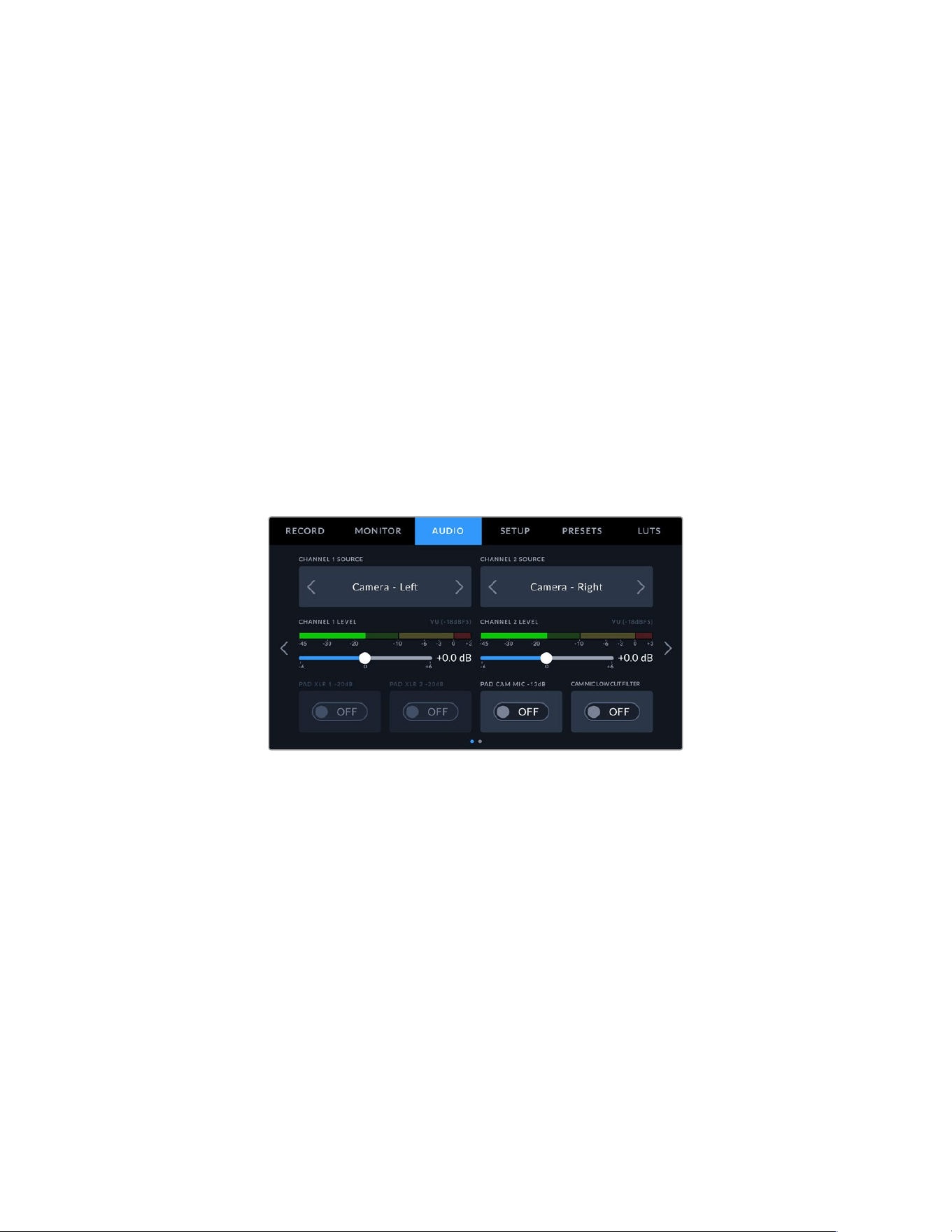
3G-SDI Output
You can change the 3G-SDI output standard to maintain compatibility with equipment that
can only receive level A or level B 3G-SDI video. This option will only appear when you are
operating in 50, 59.94 or 60 frames per second and outputting 1080p. Tap the ‘Level A’ or
‘Level B’ icon to select each standard.
Audio Settings
The ‘audio’ tab lets you adjust the audio input and monitoring settings on your URSABroadcast G2.
The settings are spread over two pages and divided between channels 1 and 2, while an
upcoming software update will add two additional channels.
You can map each audio channel to a different source, as well as adjusting various settings
such as padding and low cut filters.
These settings work together with the switches on your URSA Broadcast G2’s internal control panel.
So after you’ve set your audio source for a particular channel, you can use the internal control
panel switches to set the signal type and whether phantom power is enabled for that channel.
Audio Settings 1
The first page of your URSA Broadcast G2’s ‘audio’ tab contains the following settings.
Channel Source
Use the ‘channel 1 source’ and ‘channel 2 source’ buttons to select your audio source for each
audio channel. The options are:
Camera Left or Right
Use this setting to record from your camera’s internal microphones.
Camera Mono
Use this setting to record audio from your URSA Broadcast G2’s built in microphone’s left
and right channels onto a single audio channel.
XLR 1 or 2
Use this setting to record from your camera’s XLR inputs. Depending on which audio signal
you’ve set on your URSA Broadcast G2’s internal control panel switches, your XLRinput
may be listed as ‘mic,’ ‘line,’ or ‘AES.’ If phantom power is enabled and you have your XLR
input set to ‘mic’ you’ll also see a ‘+48V’ indicator here. It it is important to ensure that the
+48V switch gets turned ‘off’ when you disconnect your phantom powered microphone.
110Settings
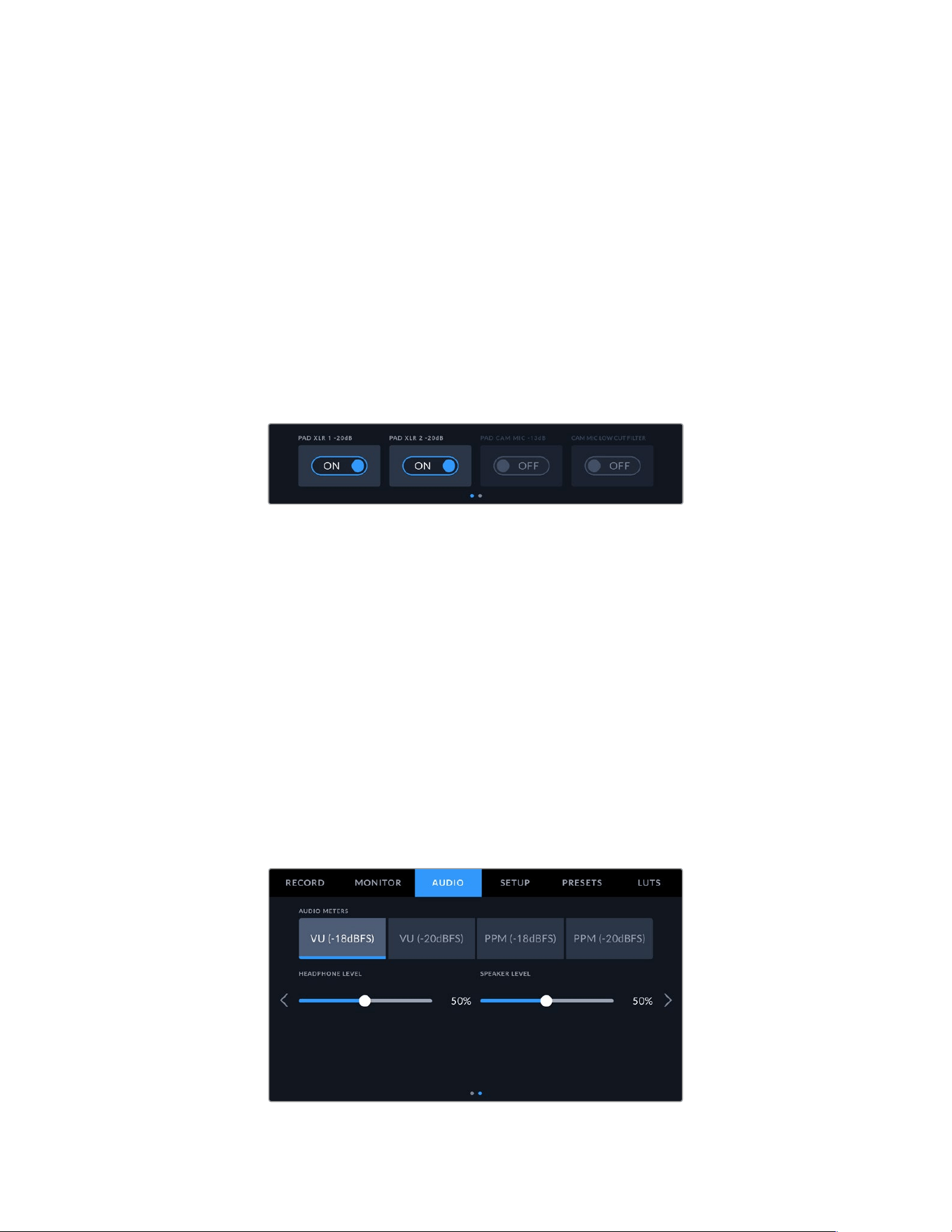
XLR 1 or 2 - Mic Backup
Use this setting to record audio from a microphone plugged into your URSA Broadcast G2
XLR 1 or 2 input at a lower level than the standard ‘mic’ recording. This can be used to avoid
audio clipping in the event of an unexpected increase in loudness. This feature will only be
available as a selectable item if the XLR 1 or 2 input switch is set to ‘mic’.
None
Use this setting to disable your audio channel.
Channel 1/2 Level
Use these sliders to adjust the recording levels of your chosen channel 1 and 2 sources.
Audiometers are included with each slider to help you set the correct audio level. These levels
will also update when you adjust the audio using the audio knobs on the ergonomic control panel.
To achieve optimum audio quality, ensure your audio levels do not reach 0 dBFS. This is the
maximum level that your camera can record, meaning that any audio that exceeds this level will
be clipped, resulting in distortion.
Pad XLR -20dB
The -20dB pad option gives you added control to further reduce the input gain levels on your
URSA Broadcast G2’s XLR audio inputs when shooting in a loud environment even after your
input levels are already turned down.
Pad Cam Mic -13dB
The -13dB pad option gives you added control to further reduce the microphone input gain
levels on your URSA Broadcast G2’s internal microphone when shooting in a loud environment
even after your input levels are already turned down.
Cam Mic Low Cut Filter
Tap this switch icon to enable the low cut filter for your camera’s internal microphones. This filter
helps to reduce potential wind noise or low frequency rumbling that may occur in exterior
shooting conditions. Note that the ‘pad cam mic -13dB’ selector must be switched off for this
function to work.
Audio Settings 2
The second page of your URSA Broadcast G2’s ‘Audio’ tab contains the following settings.
111Settings
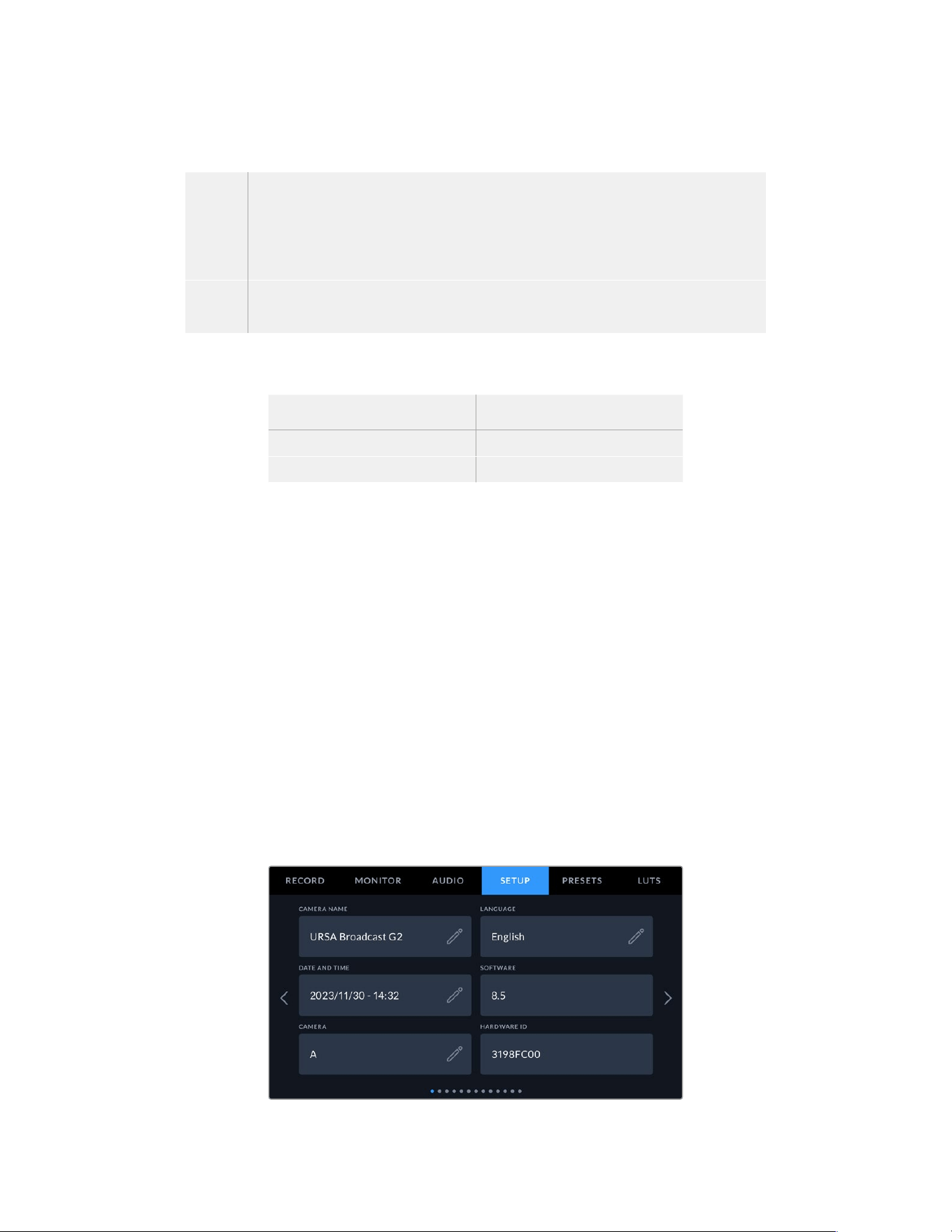
Audio Meters
You can choose from two different audio meter display types.
VU The VU meter, or ‘volume units’ meter, averages out short peaks and troughs in your
audio signal. If you are using VU metering, adjust the input levels on you Blackmagic
URSA Broadcast G2 so that the meter peaks at the 0db indicator on the audio meter.
This maximizes the signal to noise ratio and ensures your audio is at the highest quality.
If your audio peaks beyond the 0dB indicator there is a high risk of sound distortion.
PPM PPM meters, or ‘peak program meters’ displays a ‘peak hold’ feature that momentarily holds
the signal peaks and a slow fall back so you can easily see where your audio is peaking.
Both VU and PPM meters are available at reference levels of -18dBFS or -20dBFS so you can
monitor your audio to suit different international broadcasting standards.
Audio meter setting Standard
PPM (-20 dBFS) SMPTE RP.0155
PPM (-18 dBFS) EBU R.68
Headphone Level
This slider adjusts the output levels for headphones attached to URSA Broadcast G2’s 3.5mm
headphone jack. Move the audio slider left or right to adjust levels. These levels will also update
when you adjust the headphone volume using the settings wheel on the forward control panel.
Speaker Level
This slider adjusts the output levels for your URSA Broadcast G2’s built in speaker. Move the
audio slider left or right to adjust levels. These levels will also update when you adjust the
speaker volume using the settings wheel on the forward control panel.
Setup Settings
The ‘setup’ tab contains your URSA Broadcast G2’s identification settings, software version,
function button settings and other camera settings not directly linked to recording or
monitoring. This menu has twelve pages, which you can cycle through by tapping the arrows
at the edge of the LCD touchscreen, or swiping left or right.
Setup Settings Page 1
The first page of your URSA Broadcast G2’s ‘setup’ tab contains the following settings.
Setup menu on URSA Broadcast G2
112Settings
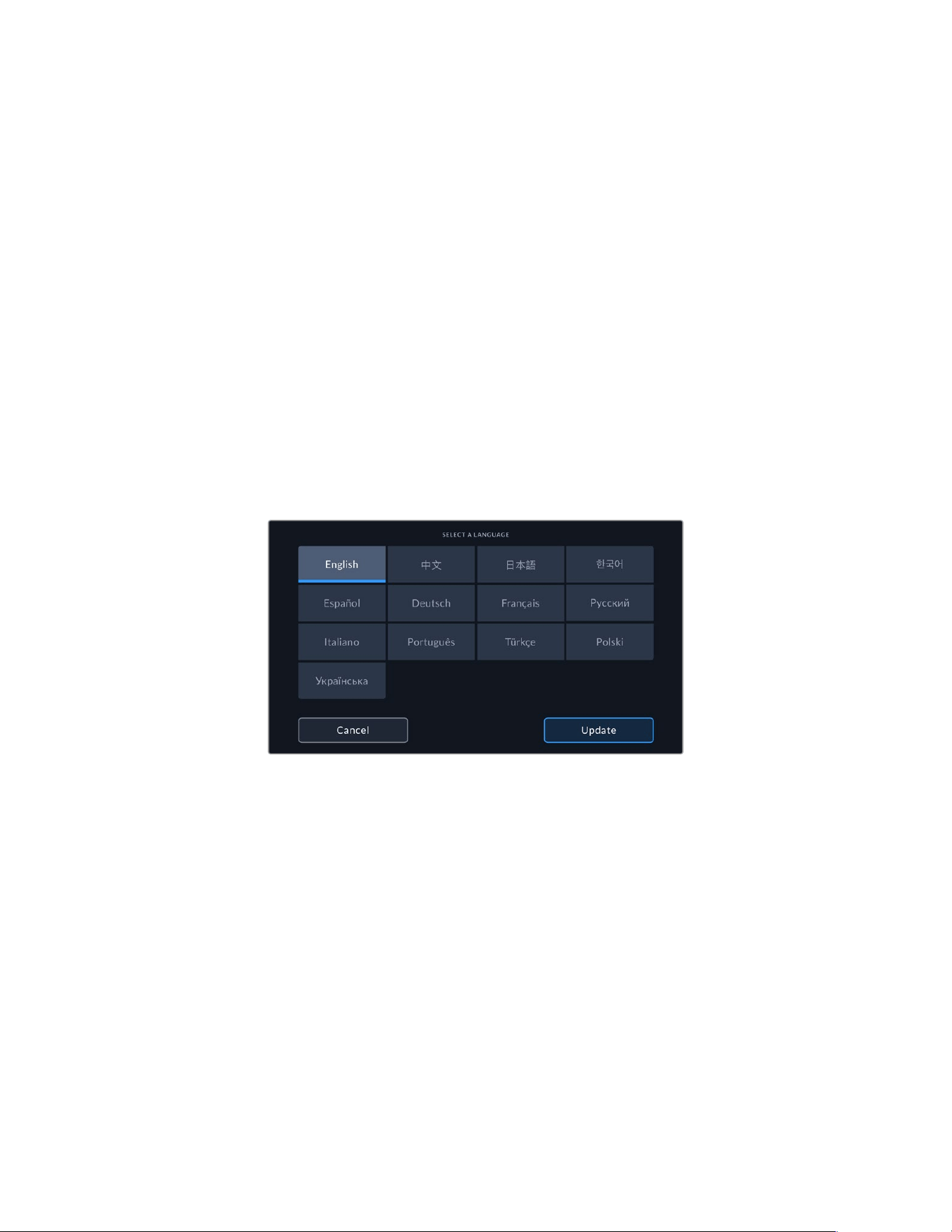
Name
When you first set up your URSA Broadcast G2 it’s important to give your camera a unique
name. If you are using more than one camera, this lets you easily identify it on a network and
when changing settings using the Blackmagic Camera Setup utility.
To change the name:
1 Tap on the edit icon to open the text editor.
2 Tap the circled cross to delete the current name and type in a new name using the alpha
numeric keyboard.
3 Tap ‘update’ to save the new name.
Language
URSA Broadcast G2 supports 13 popular languages including English, Chinese, Japanese,
Korean, Spanish, German, French, Russian, Italian, Portuguese, Turkish, Polish and Ukrainian.
The language page will also appear on initial start up.
To select your language:
1 Tap the pencil icon and select your language from the list.
2 Select ‘update’ to return to the setup menu.
Date and Time
Set your camera’s date and time by tapping the ‘date and time’ setting. The date format is year,
month, day and the time format is 24 hour. Date and time are also used for time of day timecode
if an external timecode source is not connected. The date and time can be set manually by
entering your own date, time and time zone, or you can set your camera to set it automatically.
When setting manually, tap on each field to enter the time and date and tap ‘update’ to confirm.
When set to ‘automatically’, your URSA Broadcast G2 will update the date and time when
connected to a network via Ethernet, or the next time you update your camera. The camera’s
default network time protocol server is time.cloudflare.com but you can set it yourself by
tapping the ‘time protocol’ edit icon and entering your own NTP server. After entering the NTP
server tap ‘update’ to confirm.
Setting the date and time correctly ensures your recorded clips have the same time and date
information as your network and also prevents conflicts that can occur with some network
storage systems.
113Settings
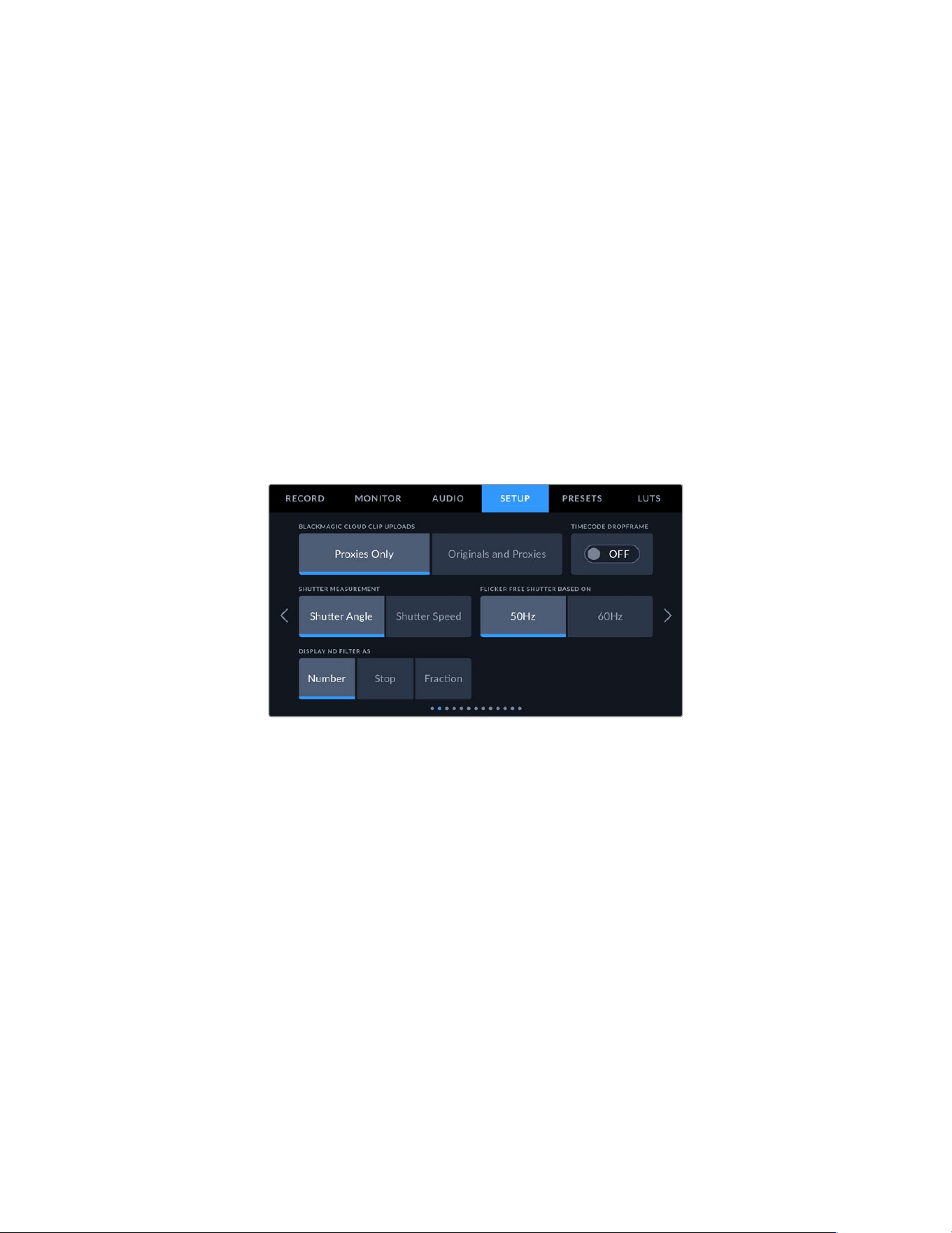
Software
Displays the version number of the currently installed software. See the ‘Blackmagic Camera
Setup Utility’ section for more information on updating software.
Camera
The camera setting sets the alpha numeric prefix at the start of a clip’s filename when recording
to external media. To edit the prefix, tap on the edit icon and replace it with a new one. Tap
‘update’ to apply. When your camera is connected to ATEM Mini via HDMI, the prefix is set
automatically to ensure all clips share the same prefix and each camera is uniquely identified in
a multi camera setup.
Hardware ID
The ‘hardware ID’ indicator displays an 8 character identifier for your Blackmagic URSA
Broadcast G2. This is unique to each camera. A longer, 32 character version of this ID is also
included in the metadata for Blackmagic RAW. This can be useful for identifying which footage
came from a particular camera.
Setup Settings Page 2
The second page of your URSA Broadcast G2’s ‘setup’ tab contains the following settings.
Blackmagic Cloud Clip Uploads
These settings let you choose which files are uploaded to Blackmagic Cloud when you are
signed into your account. When ‘proxies only’ is selected, only the proxy files from your camera
are uploaded, when ‘originals and proxies’ is selected both original camera files and proxy files
are uploaded.
Drop Frame Timecode
Use the ‘drop frame timecode’ option to use drop frame timecode when using NTSC project
frame rates of 29.97 and 59.94. Drop frame timecode drops a small number of frames from the
timecode at set intervals. This keeps your project timecode accurate despite each second not
containing a whole number of frames at NTSC frame rates.
Shutter Measurement
Use this setting to select whether to display shutter information as ‘shutter angle’ or ‘shutter
speed’. It’s important to note that both shutter measurements effect motion blur, but work in
slightly different ways. See the ‘touchscreen controls’ section of this manual for a full
explanation of shutter measurement.
114Settings
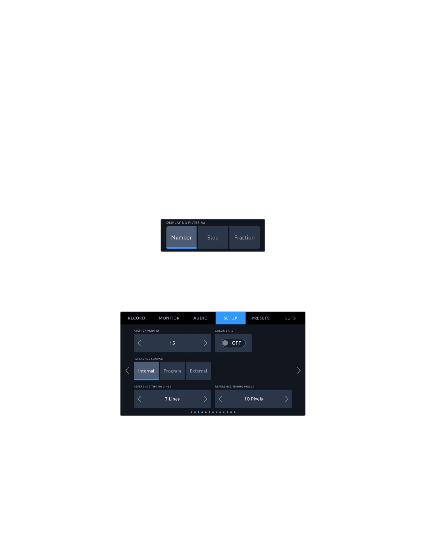
Flicker Free Shutter Based On
Use this setting to change the mains power frequency your URSA Broadcast G2 uses to
calculate flicker free shutter settings.
When shooting under lights, your shutter speed can effect the visibility of flicker. Your
URSABroadcast G2 will automatically calculate flicker free shutter speeds for your current
frame rate and display suggestions in the ‘shutter speed’ menu. These speeds are effected by
the frequency of the local mains power supply used to drive those lights. In most PAL countries,
this frequency is 50Hz, while NTSC countries typically use 60Hz power. Simply tap ‘50Hz’ or
‘60Hz’ to set the right frequency for your region.
Characteristics of various light sources may still cause flicker even when using flicker free
shutter values. We recommend performing a test shoot when not using continuous lights.
Display ND Filter As
Use this setting to adjust how the ND filter indicator on your URSA Broadcast G2 displays your
NDfilter setting. Each setting corresponds to a different camera convention. Cinematographers
typically use ND.number notation, while those familiar with DSLRs or broadcast cameras may
prefer this information in f-stop format, or as a fraction of available light.
These options are available here as ‘number,’ ‘stop,’ and ‘fraction,’ respectively.
Setup menu in URSA Broadcast G2 with
the option to customize how the ND filter
information is displayed
Setup Settings Page 3
The third page of your URSA Broadcast G2’s ‘setup’ tab contains the following settings.
ATEM Camera ID
If you’re using URSA Broadcast G2 with an ATEM Switcher and want your camera to receive
tally signals from the switcher, you’ll need to set the camera number on your camera. This
ensures the switcher sends the tally signal to the correct camera. The camera number can
be set to a value of 1-99 by tapping the left or right buttons. The default setting is 1.
115Settings
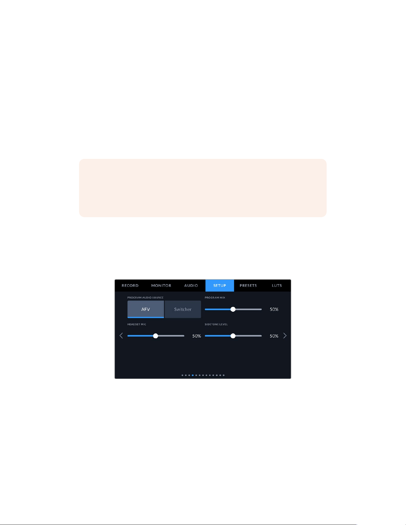
Color Bars
Outputting color bars rather than a preview image can be useful when connecting your
URSABroadcast G2 to a switcher or external monitor. The appearance of your URSA Broadcast
G2’s color bars onyour switcher or monitor confirms the connection, and you can perform basic
monitorcalibration based on the colors of the bars. To turn on color bars for all outputs on
yourURSABroadcast G2, including the LCD touchscreen, simply tap the ‘color bars’ switch icon.
Reference Source
This setting is used to select the reference source. Your URSA Broadcast G2 can lock to an
internal or external reference source, or to the reference signal in the program input from an
ATEM switcher. Ifyou are using your URSA Broadcast G2 with an ATEM Switcher’s camera
control function, you should always set your reference source to ‘program’ unless the switcher
itself and all connected cameras are set to an external reference.
NOTE When you are setting your reference source for URSA Broadcast G2, you may
experience a small dropout on your camera’s outputs when switching between your
reference sources. This is because the camera is adjusting its referencing timing to
match that of the external source. For this reason it is important not to change this
setting during a production and only while setting up.
Reference Timing
These settings allow you to manually adjust the reference timing on a line or pixel basis. Simply
tap the arrow icons on either side of the “lines” and “pixels” settings to make adjustments.
Setup Settings Page 4
The fourth page of your URSA Broadcast G2’s ‘setup’ tab contains the following settings.
Program Audio Source
When connected to an ATEM switcher, setting ‘program audio source’ to ‘switcher’ prioritizes
the program return audio as your input source to be mixed with talkback when monitoring using
headphones or a headset. This is useful when you are not feeding the switcher audio from your
camera but you still want to listen to the program feed from the switcher via the ‘SDI in’ port.
Setting ‘program audio source’ to ‘AFV’ prioritizes audio from your camera’s internal mics or
‘audio in’ XLR ports, and is the default setting.
116Settings
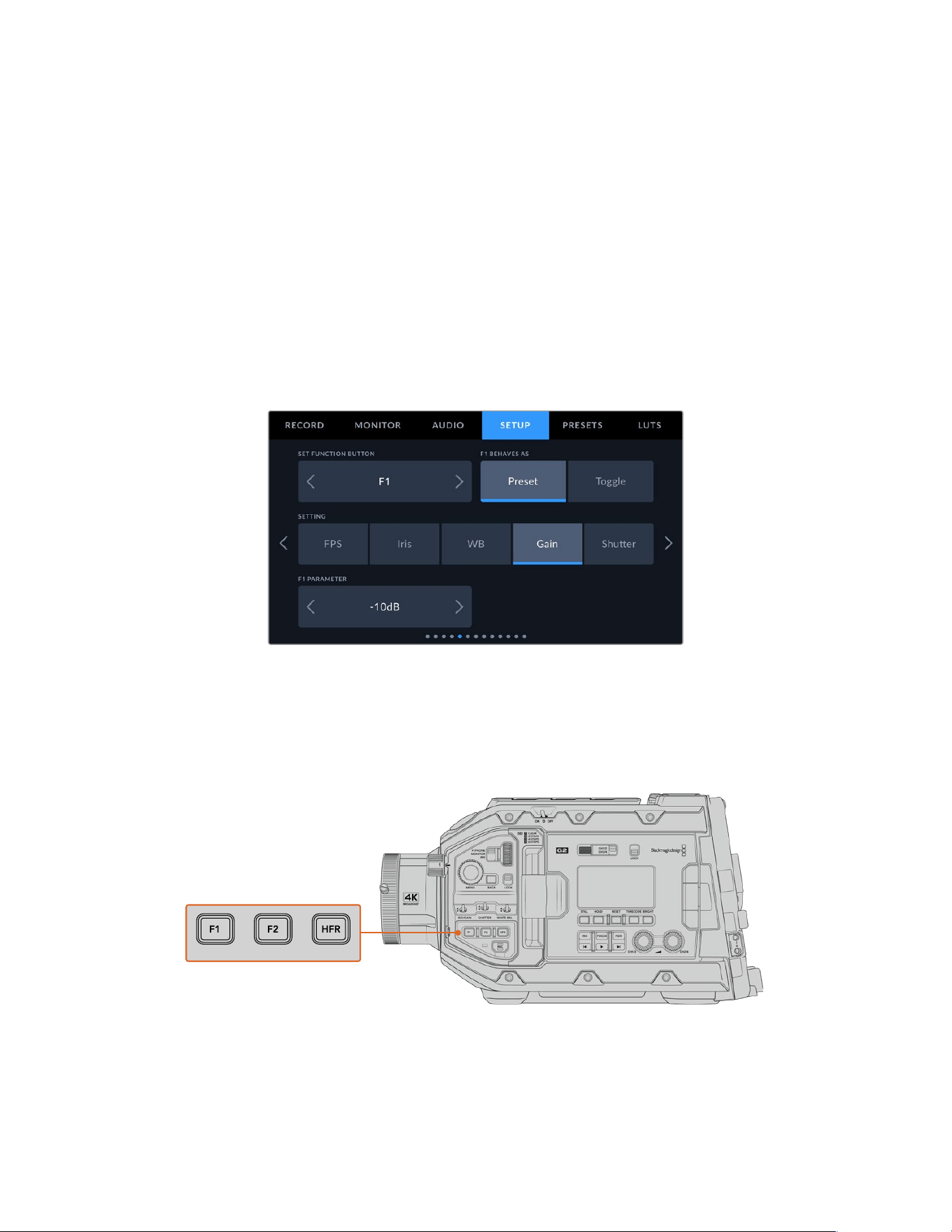
Program Mix
This setting changes the balance of camera sound to talkback sound. The headphones will
output audio following what is displayed on the LCD. For instance, if you are in camera view,
camera audio is heard. If you are in program view, program audio is heard. The default
setting is 100%.
Headset Mic
Move this volume slider left or right to increase or decrease audio microphone input levels.
Thedefault setting is 50%.
Sidetone Level
Adjust this slider to set the volume of your own voice mic in your headset.
Setup Settings Page 5
The fifth page of your URSA Broadcast G2’s ‘setup’ tab contains the following settings.
Set Function Button
On the outside of your URSA Broadcast G2’s LCD touchscreen, you’ll notice two function
buttons, ‘F1’ and ‘F2.’ These are mappable to frequently used features and are quickly
accessible whenusing your camera with the LCD touchscreen closed, such as when you are
using URSAViewfinder. The default setting for the ‘HFR’ button is ‘off speed rec’, though you
can assign other functions to it.
Your URSA Broadcast G2’s ‘F1’, ‘F2’ and ‘HFR’ buttons are located on the forward control panel
117Settings
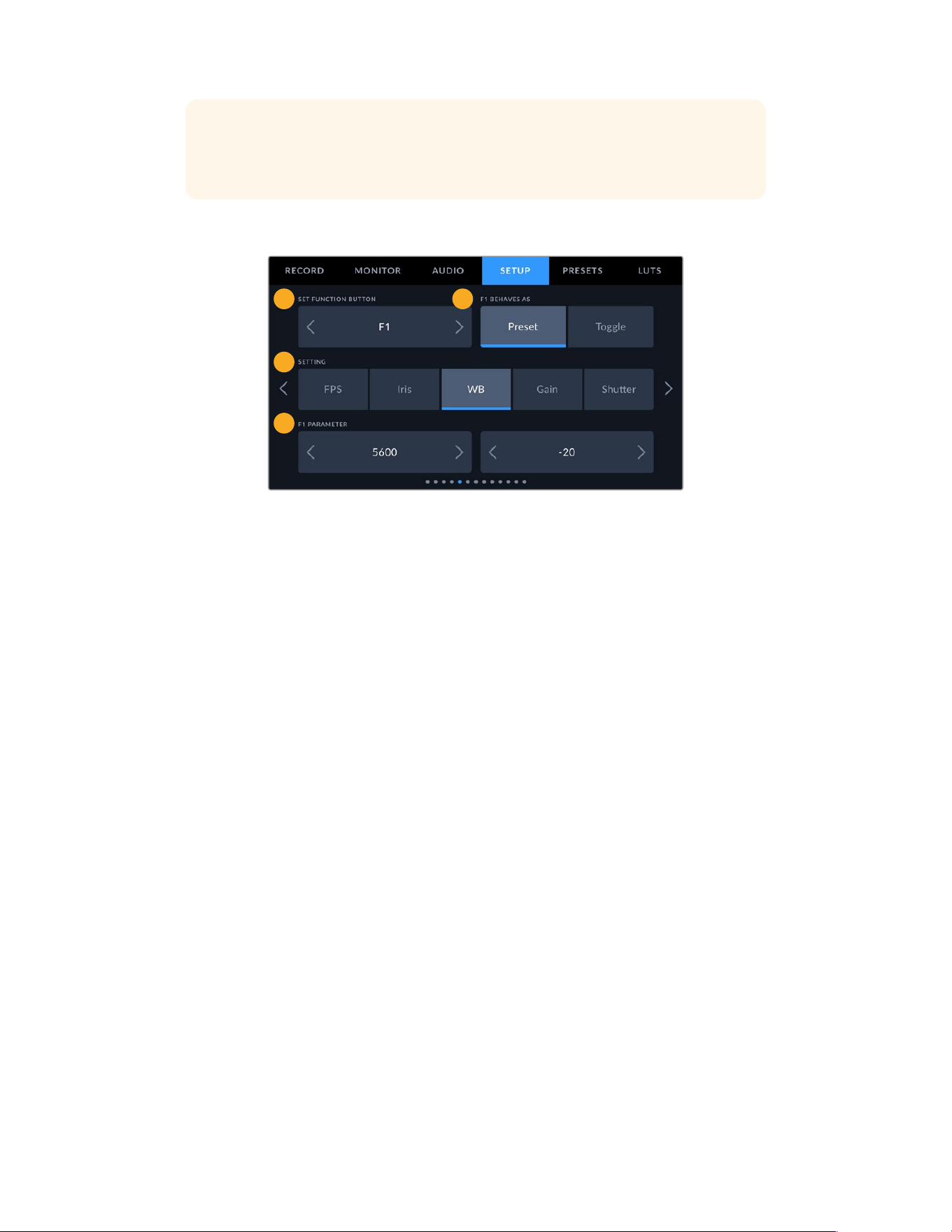
TIP If your URSA Broadcast G2 has a B4 lens with a lens connector, youcan configure
the ‘vtr’ and ‘ret’ buttons as function buttons and assign preset or toggle functions in
addition to the ‘F1’, ‘F2’ and ‘HFR’ buttons.
To set these buttons, use the arrows to select a function button and then its behavior, asetting,
and aparameterfor that setting.
3
4
1 2
1 Button 2 Behavior 3 Setting 4 Parameter
Function Button Behaves as Preset or Toggle
Once you have selected the function button you want to map, you can select a behavior.
Theavailable options are:
Preset
When set to this behavior, pressing a function button will recall a combination of a setting
and a parameter.
To set a preset, select the setting you want to use from the ‘setting’ menu, and adjust that
setting by tapping the arrow icons on either side of the ‘parameter’ menu.
For example, to set the F1 button to recall a preset white balance, use the ‘set function
button’ arrows to select ‘F1’, select the ‘preset’ behavior, tap the ‘WB’ setting, and tap the
arrows on either side of the ‘parameter’ menu until you get to WB ‘5600K’ and Tint ‘-20’.
Toggle
When set to this behavior, pressing a function button will toggle a particular setting on or
off. The ‘setting’ menu is grayed out in this mode. Instead, tap the left or right arrows in the
parameter menu to scroll through the available options. These are ‘clean feed’, ‘display
LUT’, ‘frame guides’, ‘focus assist’, ‘false color’, ‘zebra’, ‘grid’, ‘safe area guide’, ‘off speed
recording’, ‘record’, ‘program return’, ‘color bars’, ‘push to talk’, ‘focus zoom’ and ‘none’.
When ‘focus zoom’ is enabled, you can use the menu wheel on the forward control
panel to move the region of zoom and adjust the magnification level. Pressing the menu
wheel toggles between zoom and magnification adjustment. For information on how to
use ‘focus zoom’ when it is enabled on the LCD, see the ‘focus zoom’ section.
Using the ‘toggle’ behavior also lets you select the output this setting applies to.
Simply tap any combination of ‘LCD,’ ‘front SDI’ and ‘main SDI’ to select. If the output
for an option is not available, such as ‘color bars’ which always applies to all outputs,
the ‘LCD,’ ‘front SDI’, and ‘main SDI’ settings are disabled.
For example, you can configure URSA Broadcast G2 to use the ‘ret’ and ‘vtr’ buttons
on a B4 lens as function buttons. If ISO recording is happening with a HyperDeck,
a popular option is to set ‘vtr’ to act as a ‘push to talk’ button.
118Settings
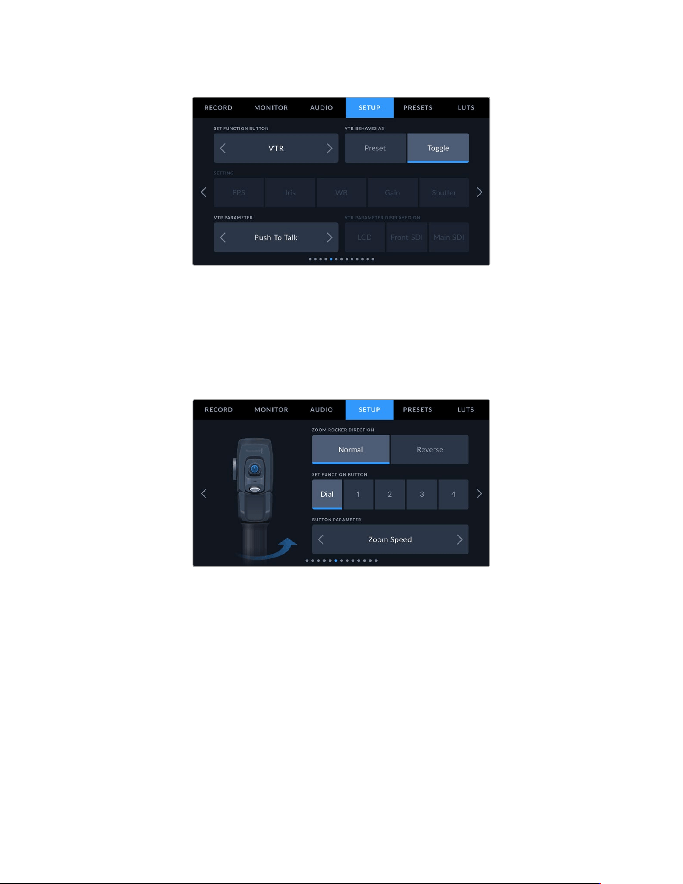
Configuring the ‘vtr’ button on a B4 lens to function as a ‘push to talk’ button
Setup Settings Page 6
The sixth page of your URSA Broadcast G2’s ‘setup’ tab contains settings to configure the
optional Blackmagic Zoom Demand. These settings are only active when you have Blackmagic
Zoom Demand attached to your URSA Broadcast G2.
For more information on attaching and using Blackmagic Zoom Demand with your URSA
Broadcast G2, refer to the ‘Blackmagic Zoom and Focus Demand’ section later in this manual.
Zoom Rocker Direction
Normal
The default zoom rocker direction. Push the zoom rocker to the right to zoom in and tothe
left to zoom out.
Reverse
When the zoom rocker direction is set to ‘reverse’ push the zoom rocker to the left tozoom
in and to the right to zoom out.
119Settings
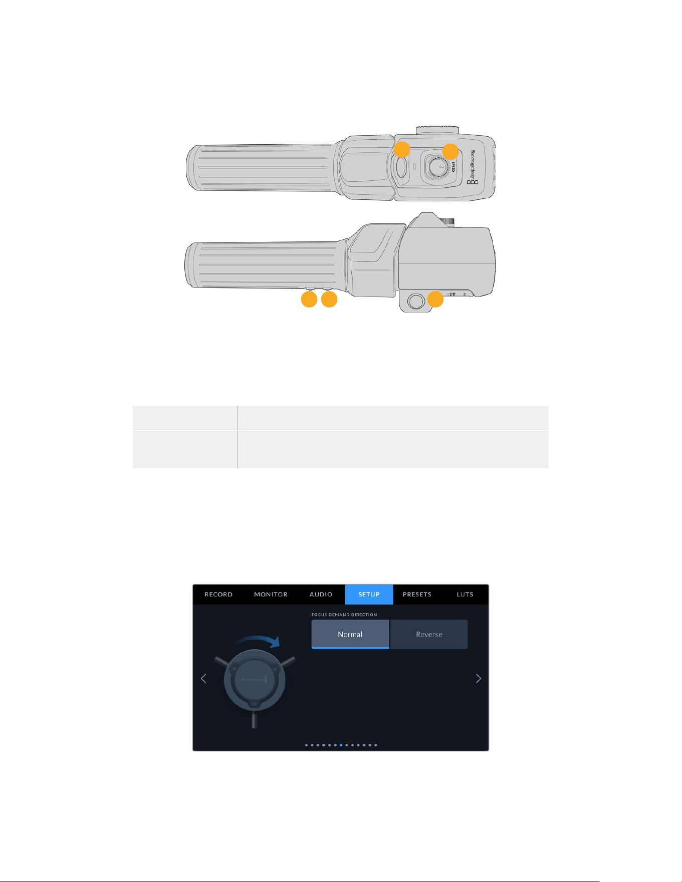
Blackmagic Zoom Demand has four zoom function buttons and a speed dial that you can map
to different functions.
2
3
4
5
1
1 Zoom F1 2 Zoom F2 3 Zoom F3 4 Zoom F4 5 Speed Dial
To assign a different function to the speed dial or one of the zoom buttons choose ‘dial’
or a button number from the ‘set function button’ menu. Next, choose a function by tapping
the arrow icons on either side of the ‘button parameter’ menu.
Dial and function button parameter options:
Speed Dial Zoom speed, headphone level, iris adjustment, focus adjustment.
Zoom buttons 1 – 4 Record, push to talk, program return, focus zoom, frame guides, status
text, auto focus, auto iris, auto white balance, playback.
Setup Settings Page 7
The seventh page of your URSA Broadcast G2’s ‘setup’ tab contains settings to configure the
optional Blackmagic Focus Demand. These settings are only active when you have Blackmagic
Focus Demand attached to your URSA Broadcast G2.
For more information on attaching and using Blackmagic Focus Demand with your URSA
Broadcast G2, refer to the ‘Blackmagic Zoom and Focus Demand’ section later in this manual.
120Settings
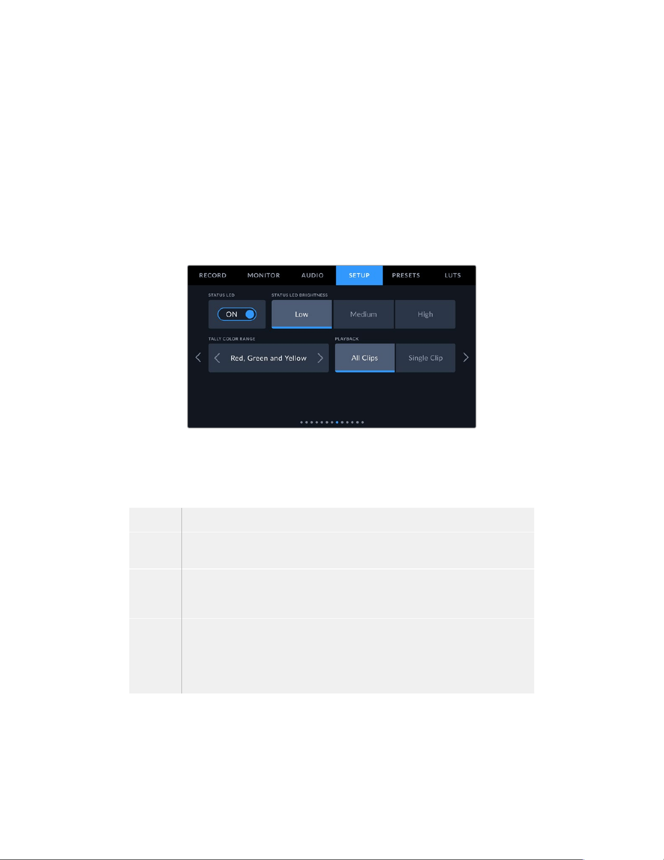
Focus Demand Direction
You can change the direction of the focus wheel on focus demand by selection either ‘normal’
or ‘reverse’.
Normal
Turn the focus wheel clockwise to focus on subjects closer to the lens and
counterclockwise for subjects further away.
Reverse
Turn the focus wheel counterclockwise to focus on subjects closer to the lens and
clockwise for subjects further away.
Setup Settings Page 8
The eighth page of your URSA Broadcast G2’s ‘setup’ tab contains the following settings.
Status LED
Your URSA Broadcast G2 has a small LED on the front panel that provides tally and status
information. You can enable or disable it by tapping the ‘Status LED’ switch icon.
The LED will provide the following status indicators:
White The camera is powered on and in standby mode.
Red The camera is recording. Slow flashing indicates that your card space is low, while
rapid flashing indicates dropped frames.
Green The camera is in playback mode. The LED alternates slowly between green and off
while a clip is playing. When inserted media is recognized, the status LED blinks green
and white three times.
Orange If your camera’s battery is low, the LED will flash orange and your other current status
color. For example, if currently recording, the LED indicator will slowly alternate between
orange and red. If your camera is in standby mode, the LED will alternate between white
and orange. The threshold for ‘low’ battery is 20 percent for batteries that support
percentage accurate charge information, or 12.5 volts for batteries that don’t.
121Settings
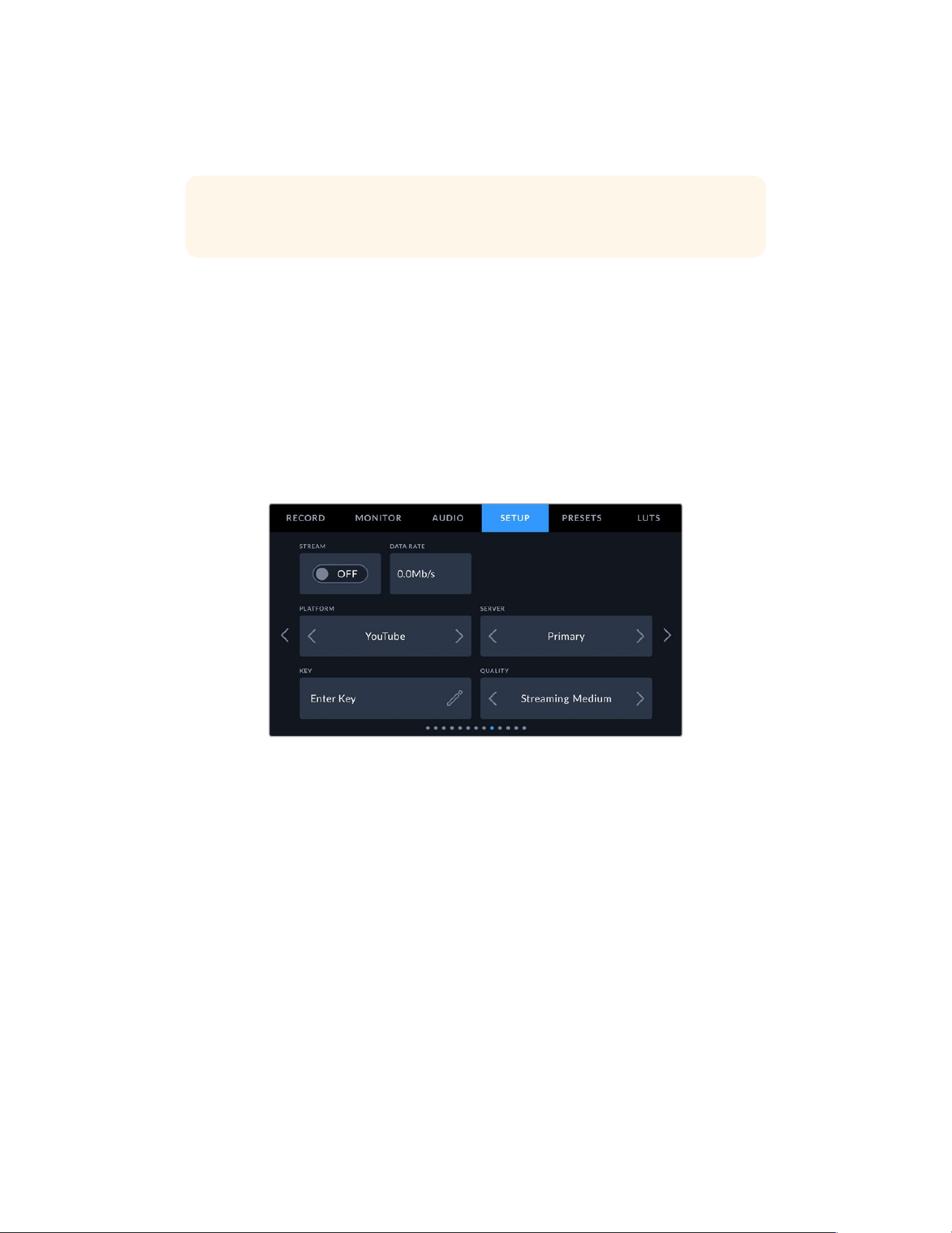
Status LED Brightness
To set the brightness of your URSA Broadcast G2’s status LED, simply tap ‘low,’ ‘medium,’ or ‘high.’
TIP The status LED settings on your Blackmagic URSA Broadcast G2 also control the status
LEDs on URSA Mini Recorder, Blackmagic Zoom Demand and Blackmagic Focus Demand.
Playback
This setting allows you to select whether to play back a ‘Single Clip’ or ‘All Clips’ during playback.
‘All Clips’ will play back through all matching media sequentially, and ‘Single Clip’ will play one
clip at a time. This also applies for the loop function. Selecting loop on ‘All Clips’ will play through
all of the clips on your media and then loop. Selecting ‘Single Clip’ will loop one clip at a time.
Setup Settings Page 9
The ninth page of your URSA Broadcast G2’s ‘setup’ tab contains settings that allow you to set
your camera’s streaming options.
For more information on setting up steaming from your URSA Broadcast G2, refer to the
‘streaming video’ section later in this manual.
Stream
Use the stream switch to toggle your stream on or off.
Data Rate
Displays the data rate of the stream during streaming.
Platform
Select your desired streaming platform. Options include YouTube, Twitter and Twitch.
Server
Use the arrow buttons to choose a server, these options will change depending on your
streaming platform.
Key
Tap the pencil icon to enter a stream key for your streaming platform.
Quality
Use the arrow buttons to select a streaming quality.
122Settings
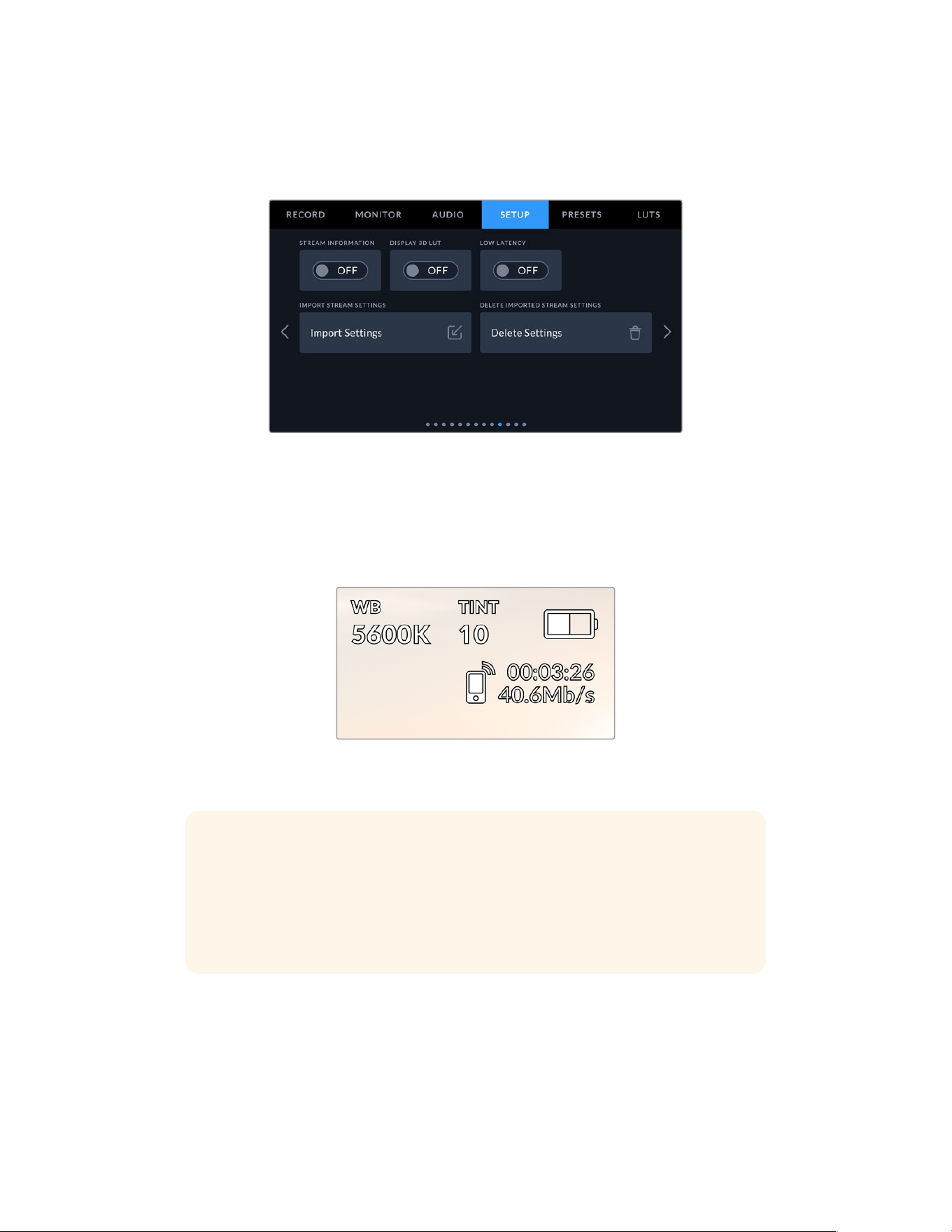
Setup Settings Page 10
The tenth page of your URSA Broadcast G2’s ‘setup’ tab contains settings that relate to your
camera’s streaming options.
Stream Information
Toggle the ‘stream information’ switch to ‘on’ to display information on your camera’s status
display. This will be viewable on the LCD, front SDI or main SDI output.
The information includes the connection being used for streaming, for example Ethernet or a
smartphone, a duration counter that shows the duration of your stream and a data rate using
megabits per second.
Display 3D LUT
Toggle this setting to ‘on’ if you want to apply a 3D LUT to your stream.
TIP Switching the ‘display 3D LUT’ setting to ‘on’ will only apply a LUT to the direct
stream output.
If you are simultaneously recording to Blackmagic RAW or ProRes video codecs while
streaming, you can use the LUT options in the record menu to add a LUT to your files,
or the monitor settings to add a LUT on the LCD or SDI outputs. Refer to the ‘record
settings’ section for more information.
Low Latency
Setting low latency to ‘on’ will ensure that there is minimum delay between what is happening
live and what is being viewed by the audience. Setting it to ‘off’ gives you more buffering so is
amore stable stream if you have an Internet connection that may be subject to dropouts or
poor connection.
123Settings
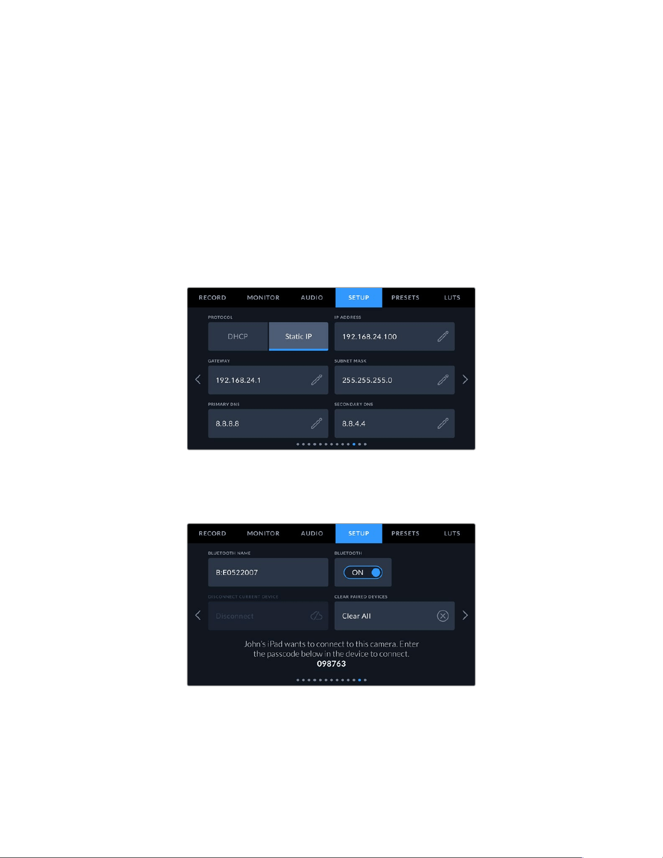
Import Stream Settings
Tap the ‘import stream settings’ button to import an XML setup file that has been created so
your camera can find an ATEM Streaming Bridge on the Internet.
For more information on importing an XML setup file, refer to the ‘streaming video’ section later
in this manual.
Delete Stream Settings
Press this button to delete your camera’s imported streaming settings. You will be asked to
confirm your selection.
Setup Settings Page 11
The eleventh page of the ‘setup’ tab contains your camera’s network settings.
These settings allow you to configure options such as choosing between connecting to a
network using DHCP or a static IP address.
You can connect to a network using a DHCP or a static IP address
Setup Settings Page 12
The twelfth page of your URSA Broadcast G2’s ‘setup’ tab contains the following settings.
The camera Bluetooth name will be the letter of your camera as selected in the
slate, followed by the 8 character hardware ID for your URSA Broadcast G2
124Settings
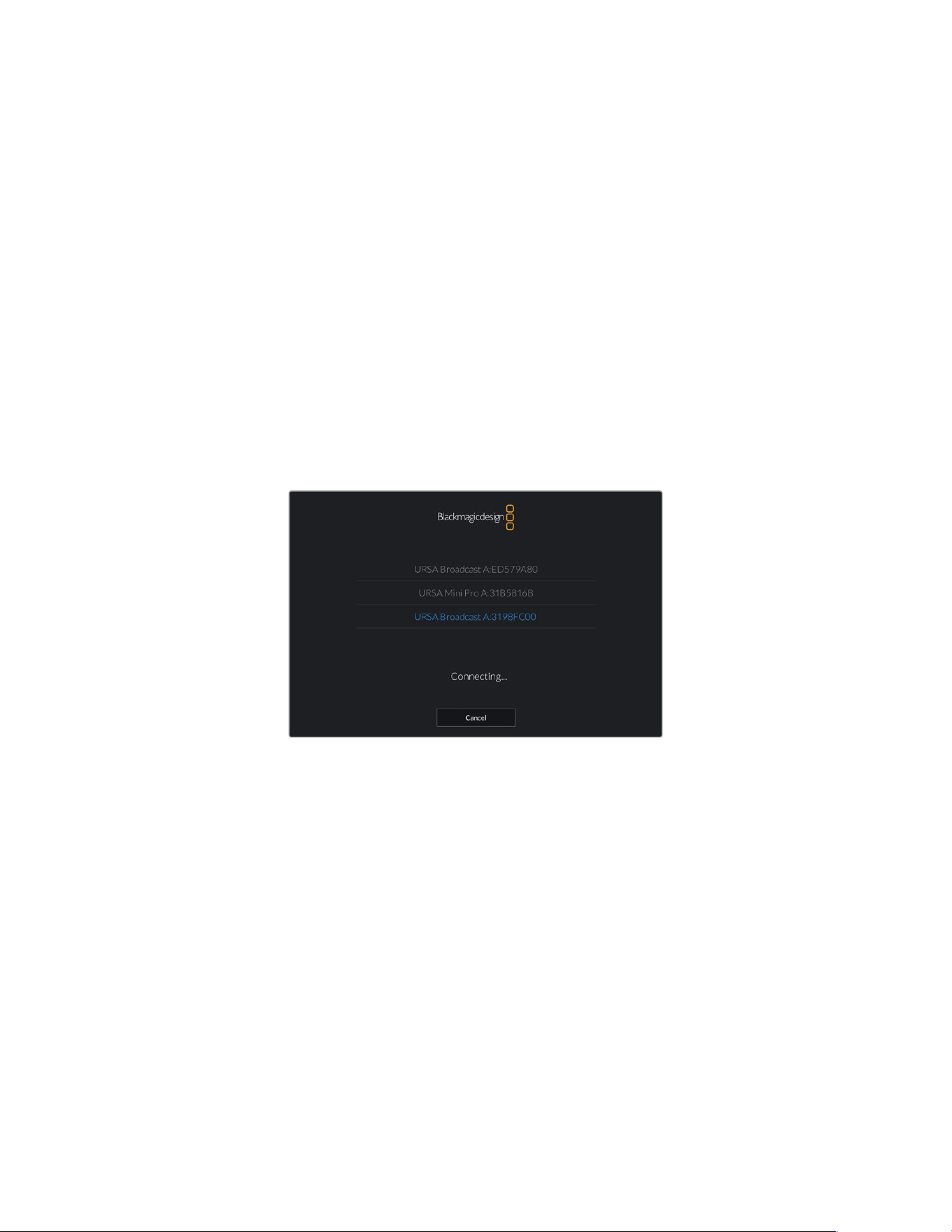
Bluetooth®
Bluetooth control allows you to control your camera wirelessly from portable devices. Using the
‘Blackmagic Camera Control App’ you can power the camera on or off, change settings, adjust
metadata and trigger record remotely from an iPad. You can enable or disable Bluetooth by
tapping the ‘Bluetooth’ switch icon in the ‘setup’ menu. WhenBluetooth is enabled, the camera
can be detected by Bluetooth devices up to 30feet away.
Because URSA Broadcast G2 uses the same set of commands for Bluetooth control as it does
for ‘Blackmagic SDI Camera Control Protocol’, you can write your own applications to control
almost every setting in the camera remotely, from monitoring to audio settings, the camera’s
inbuilt DaVinci Resolve color corrector or lens control.
For more information see the ‘Blackmagic SDI Camera Control Protocol’ section in this manual.
To pair your camera with an IPad for the first time:
1 Enable Bluetooth by tapping the ‘Bluetooth’ switch icon in the ‘setup’ menu on your URSA
Broadcast G2.
2 Open the ‘Blackmagic Camera Control App’ and select the URSA Broadcast G2 you would
like to pair with. Available cameras will be listed by their camera letter, followed by their
unique hardware ID. For example A:3198FC00.
Select the URSA Broadcast G2 you would like to pair with
When you install the Blackmagic Camera Control App and run it for the first time, you will be
asked if you want to ‘allow location access.’ If you select ‘while using the app,’ GPS readings
from your iPad will be included in the metadata of the files you shoot, allowing you to
geotag footage. This information can be viewed in Blackmagic DaVinci Resolve versions 14
or higher.
If you do not want to using this information, select ‘never.’
To change settings, go to settings, privacy, location services, camera control on youriPad.
3 When you try to connect for the first time the Blackmagic Camera Control App will request
a six digit code to pair with the camera. This code will be displayed on the camera’s LCD
screen. Type this code into the iPad.
125Settings
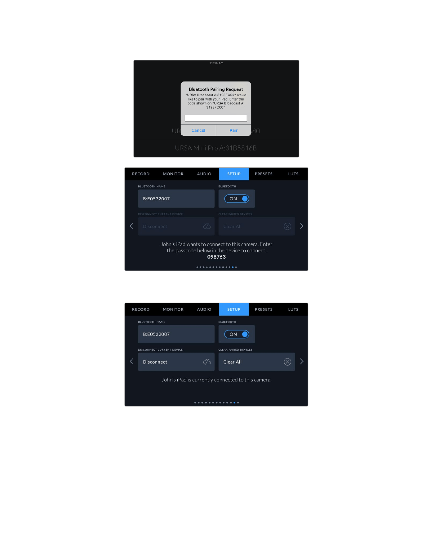
4 The information on the screen will confirm that your URSA Broadcast G2 is now paired
withyour iPad.
126Settings
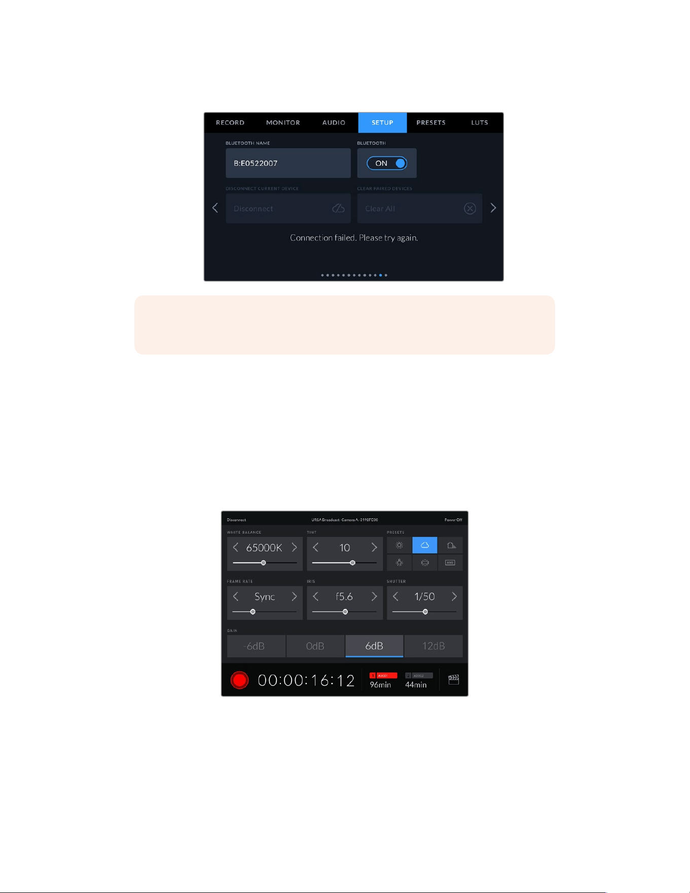
5 If there is a problem pairing the camera to your iPad you will see the following error message:
NOTE If you are not using Bluetooth to control your URSA Broadcast G2, it is a good
idea to turn Bluetooth off for the purpose of security.
Disconnect Current Device
Use this setting to disconnect your URSA Broadcast G2 from the iPad it is currently paired with.
Clear Paired Devices
Use this setting to clear the list of devices that your URSA Broadcast G2 has been paired with.
Controlling Your Camera with the Blackmagic Camera Control App
Once you have successfully paired your URSA Broadcast G2 to your iPad, you can power the
camera on or off, change settings, adjust metadata and trigger record remotely using
the iPad app.
Once paired, the Blackmagic Camera Control app will display this
screen, allowing you to adjust your settings and start recording
127Settings
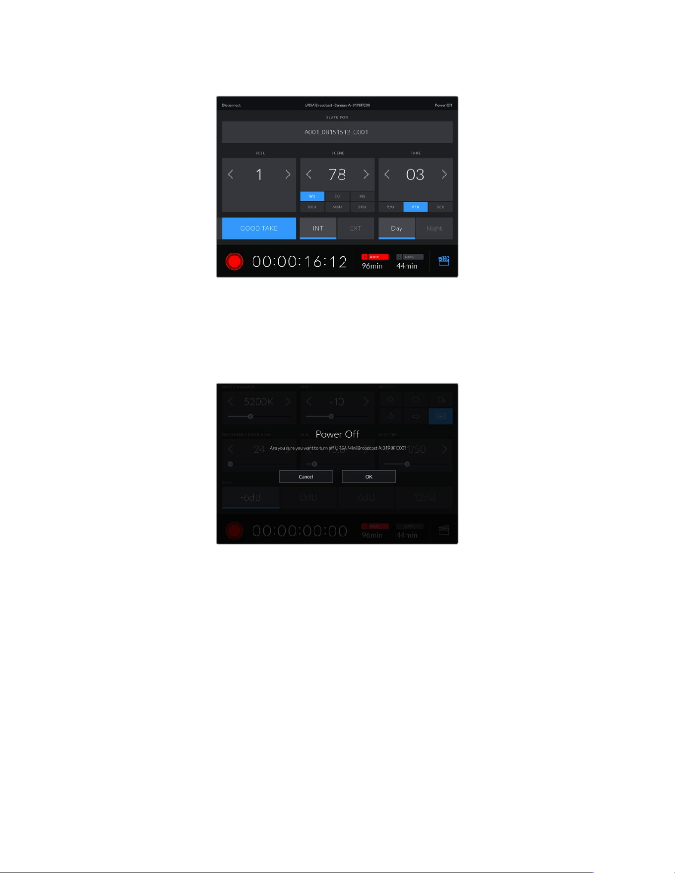
Tap the slate icon in the lower right corner
to access and update the slate
URSA Broadcast G2 uses Bluetooth LE to communicate with devices for wireless control.
Asthisisthe same type of protocol used in portable devices, it only uses a minimal amount
ofbattery power.
You can power off your URSA Broadcast G2 by tapping ‘power off’ in the top right corner.
You will be prompted to confirm your selection
before your camera is powered off
When Bluetooth is enabled and URSA Broadcast G2 is powered off, the name of your camera
will still show up on the list of available devices in the Blackmagic Camera Control App. Since
you have already paired with your camera, you can now switch it on remotely by selecting your
camera name and tapping ‘Connect’. Your camera will not show up in this list if Bluetooth
is disabled.
128Settings
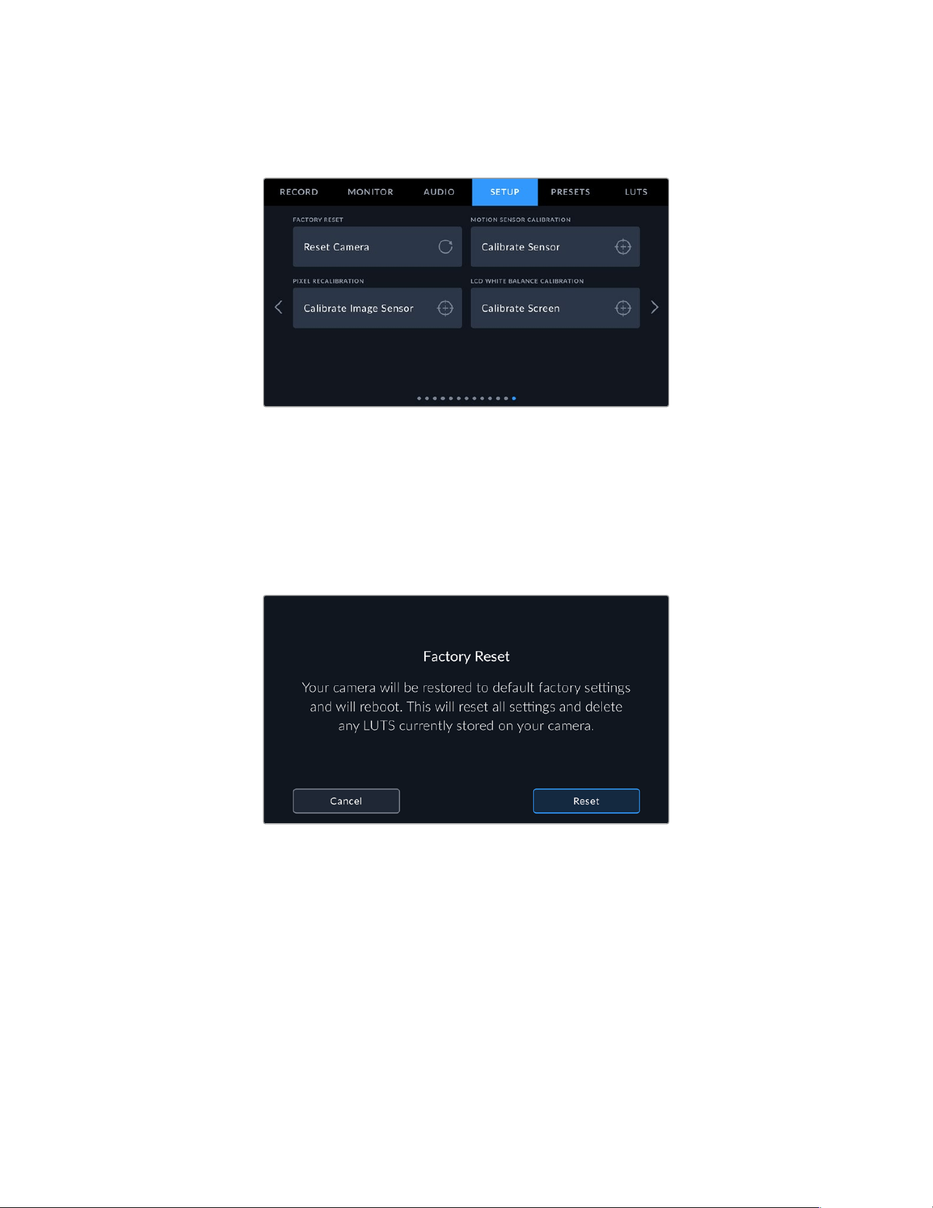
Setup Settings Page 13
The thirteenth page of your URSA Broadcast G2’s ‘setup’ tab contains the following settings.
Factory Reset
To reset the camera to its default factory settings, tap the ‘reset camera’ button. You will be
asked to confirm this action as it will erase any LUTs and presets currently stored on the
camera. Tap ‘reset’ on the confirmation page to reset your camera settings.
It’s important to note that a factory reset erases any presets and custom LUTs, and resets all
settings. It is a good practice to export them to a memory card as a backup before performing
a factory reset. After a factory reset, you can restore your presets and LUTs quickly by
importing them from the memory card.
When selecting ‘factory reset’ you will be prompted to confirm your action
Motion Sensor Calibration
To calibrate the horizon meter on URSA Broadcast G2, place your camera on a surface you
know is level and tap the ‘calibrate motion sensor’ button. It is essential that you keep the
camera stable during calibration. This is to ensure that the recorded motion sensor metadata
in the Blackmagic RAW files during filming is accurate. The process takes approximately five
seconds to complete.
The horizon can be set off center if needed. For example, if you want to set the tilt at
a consistent angle, calibrate the motion sensor with the camera at the angle you want,
then use the horizon meter to maintain the same angle.
The motion sensor data can be used in DaVinci Resolve to stabilize clips. Refer to the
‘gyro stabilization’ section for more information.
129Settings
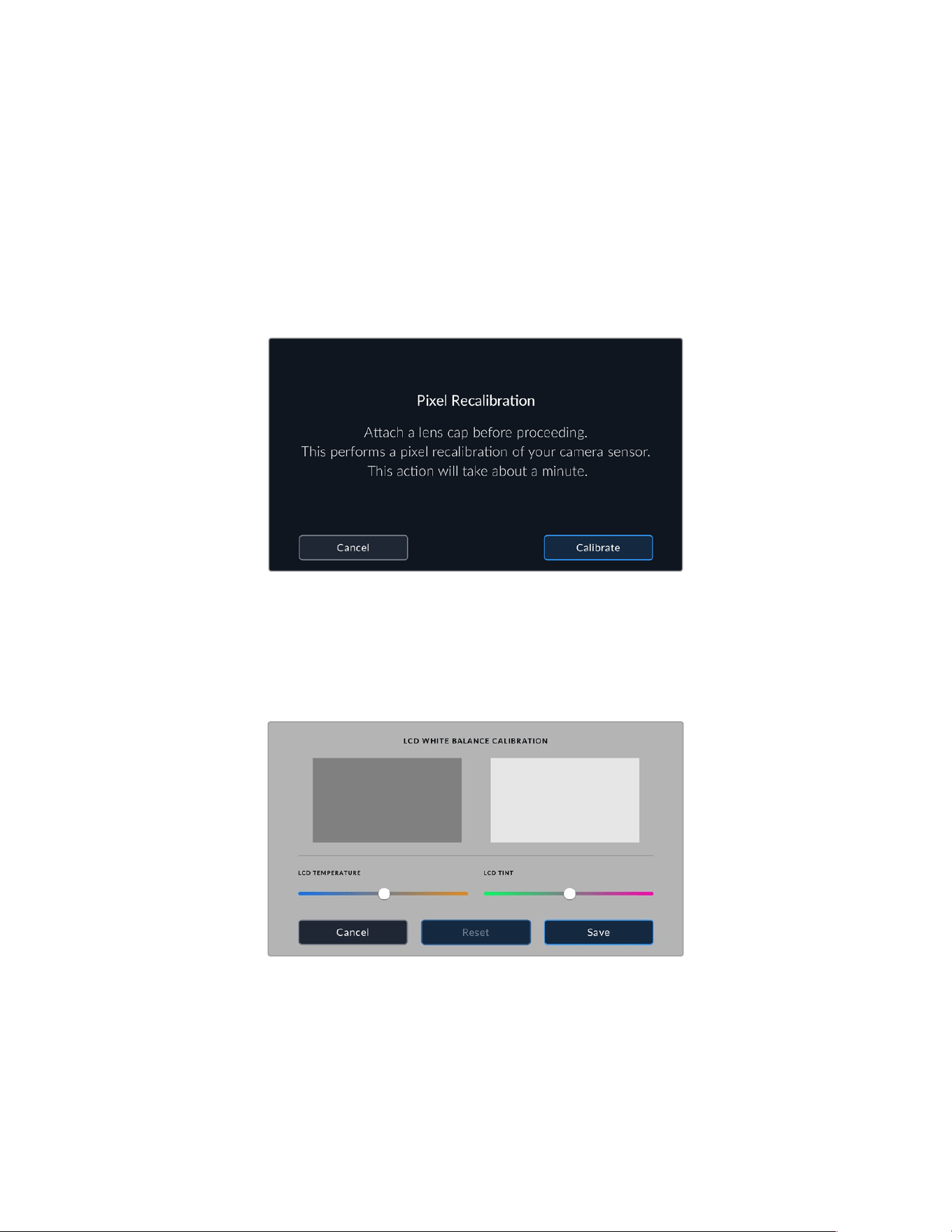
Pixel Recalibration
The CMOS sensor used in your URSA Broadcast G2 is made up of millions of pixels that
respond to light. As a result, they become more visible and become what is known commonly
as hot pixels. All camera sensors, regardless of manufacturer, will develop this variation in pixel
brightness over time.
To solve this, URSA Broadcast G2 has a built in recalibration feature that you can run if you see
any pixels that are brighter than others.
To begin this process, simply put on the lens cap and run the pixel recalibration feature by
tapping the ‘calibrate image sensor’ button, then tap ‘calibrate’ to confirm your choice. The
process takes approximately one minute to complete.
LCD White Balance Calibration
To perform LCD white balance calibration, adjust the ‘LCD temperature’ and ‘LCD tint’ controls
so that the two reference patches look neutral. After you change the settings, you can use the
‘reset’ button to return the controls to the factory calibration. The ‘restore’ button brings back
your new settings, which helps you compare the appearance before and after calibration.
Whenthe LCD shows an accurate white balance, save your settings.
Presets
The ‘presets’ tab lets you save and recall a complete collection of settings for your URSA
Broadcast G2. This is very useful when one camera is used for multiple projects. For example,
you may use your URSA Broadcast G2 for a variety of different shoots, from documentaries to
music videos, with very different settings between types of projects. Your URSA Broadcast G2’s
‘presets’ function lets you save the setup for a particular project or type of shoot and come
back to it quickly and easily when required.
130Settings
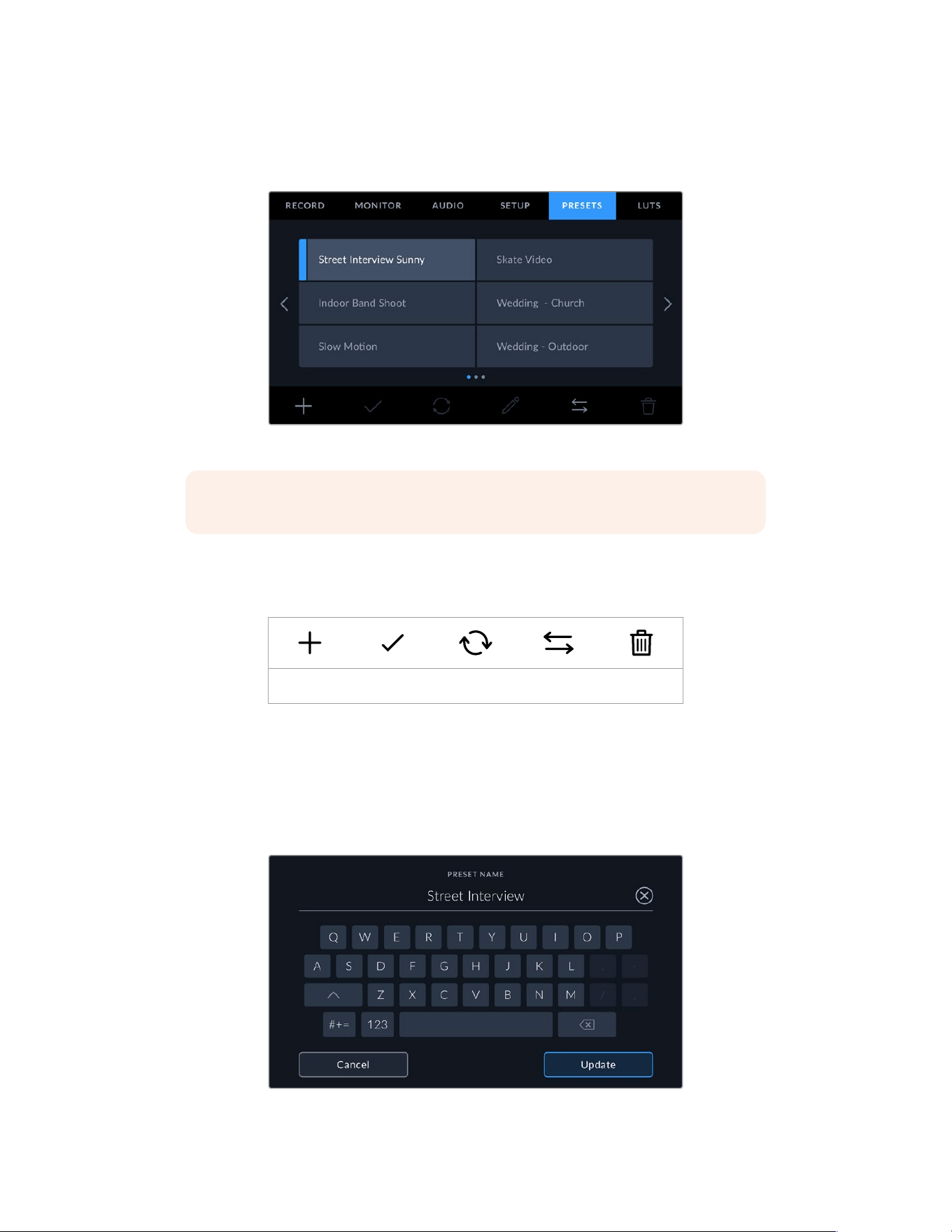
You can also import and export presets, which is very useful for setting up a multi camera shoot.
Simply set up one URSA Broadcast G2 to suit your project, then export that preset for all the
other URSA Broadcast G2s on set.
Your URSA Broadcast G2’s Presets tab
NOTE Your URSA Broadcast G2 can save up to sixty presets to its internal memory.
Preset buttons
The button icons along the bottom of your URSA Broadcast G2’s ‘preset’ menu correspond with
the following functions.
Add Load Update Manage Delete
Saving and loading presets
To create a new preset, tap the ‘add’ icon. This will bring up a touch keyboard on your
LCDtouchscreen where you can name your preset. Once you’ve typed in the name, tap
‘update’ tosave all of your URSA Broadcast G2’s current settings to that preset.
If your URSA Broadcast G2 already has a preset loaded with the same name, you will be
prompted to overwrite the existing preset or keep both.
Enter a name for your preset by tapping the ‘add’ icon in the preset tab and
using the touch keyboard
131Settings
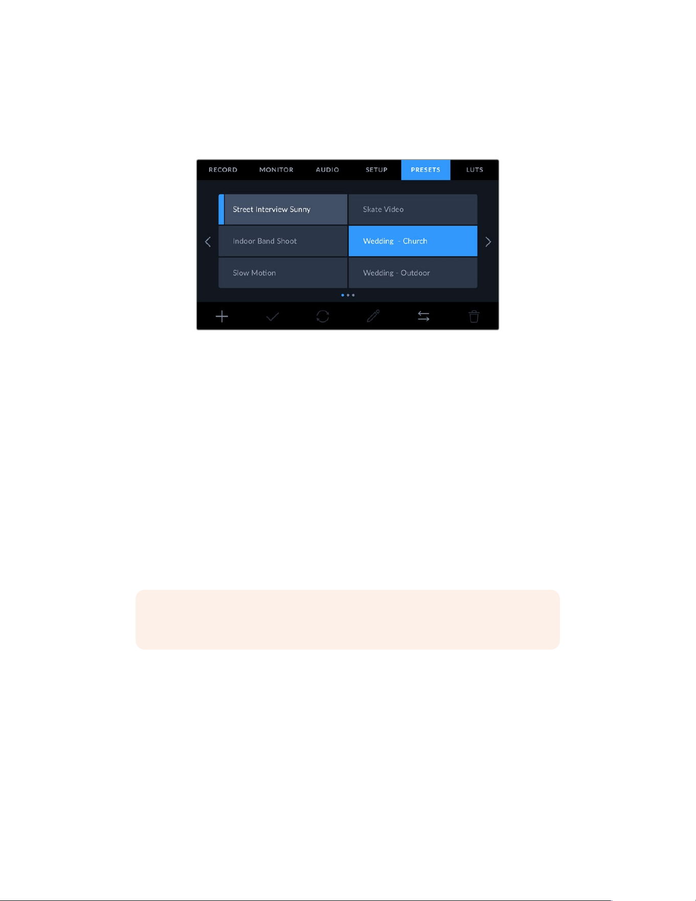
Once you have a preset saved, tap its name in the preset menu to select it. To load it tap the
‘load’ icon.
You can update a preset by tapping the ‘update’ icon. This will bring up a prompt asking you ifyou
want to update the preset with your URSA Broadcast G2’s current setting. Tap ‘update’ to confirm.
Select a preset and tap the ‘load’ icon to load it. Selected presets will appear solid
blue,while currently loaded presets have a blue line on the left of their icon
Importing presets
To import a preset, tap the ‘manage’ icon at the bottom of the preset menu. Select either SD or CFast
with the storage media selection switch, depending on where your presets are saved. You can
also import presets from a USB-C flash disk or from an SSD if you are using URSA Mini Recorder.
From the ‘import from’ options tap the card or drive that contains the preset you want to import
and confirm your selection by tapping the ‘import’ button. This will bring up the import screen.
You can use the buttons at the top left of this screen to display any available presets on other
cards or drives connected to your camera.
Your URSA Broadcast G2 will search the root directory and ‘presets’ folder on theselected storage
media. It’s worth noting that presets saved elsewhere on your storage media will not be visible.
Tap a preset to select it and tap ‘import’ to confirm. If the preset you want to import has the
same name as a preset already saved to your camera, you will be prompted to overwrite the
existing preset or keep both. At the top right of this screen, you’ll see the number of remaining
empty preset slots available on your camera.
NOTE If your URSA Broadcast G2’s preset slots are full, the import menu will not be
available. You will need to delete an existing preset to make room.
Exporting presets
To export a preset to a CFast or SD card, select the preset you want to export by tapping it,
andtap the ‘manage’ icon.
From the ‘manage preset’ options choose ‘export selected preset’. Use the storage media selection
switch to select either SD or CFast, depending on the location you would like to export the preset
to. You can also export presets to a USB-C flash disk or to an SSD if you are using URSA Mini
Recorder. From the ‘export to’ options tap the card or drive you would like to export your preset
to. Confirm your choice by tapping ‘export’.
If the storage media you’ve chosen already has a preset saved to it with the same name as the one
you’re exporting, you will be prompted to overwrite the preset on the card, or keep both presets.
132Settings
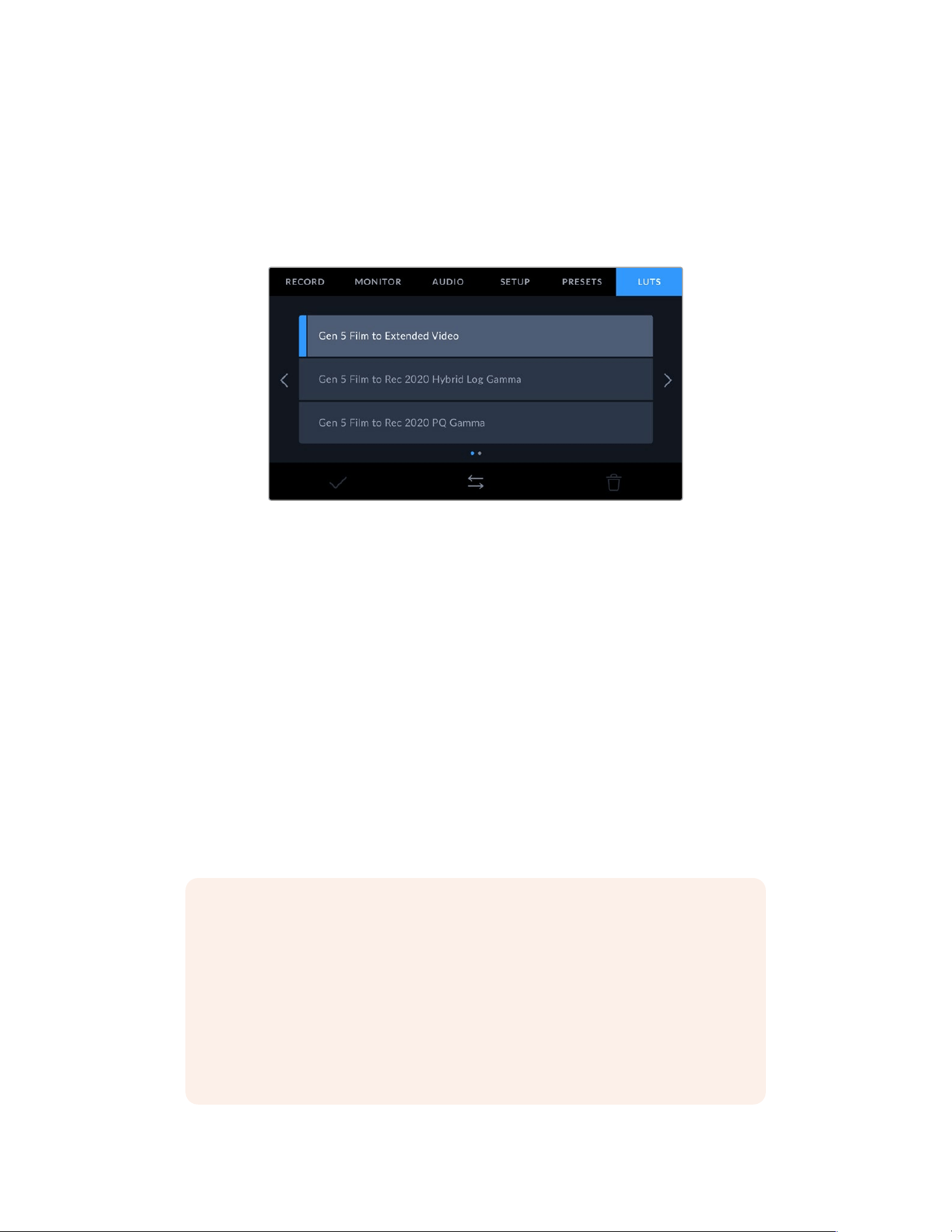
Deleting presets
Your URSA Broadcast G2 has space for sixty presets. To delete a preset, select it and tap the
‘delete’ icon. You will be prompted to confirm your choice. Tap ‘delete’ to confirm.
LUTS
The ‘LUTS’ menu lets you import, export and apply 3D LUTs to your camera’s outputs.
Your URSA Broadcast G2’s LUT tab
Introducing 3D LUTs
Your URSA Broadcast G2 can apply 3D LUTs to images on its LCD touchscreen, front SDI and
mainSDI. LUTs work by telling your camera what color and luminance output to show for a particular
color and luminance input. For example you may want to record internally in camera with normal
color but send a preview out to your monitors and switcher of what broadcast legalcolors for your
region will look like. This is also useful when shooting Blackmagic RAW footage or using
‘film’ dynamic range, both of which have an intentionally undersaturated, ‘flat’ appearance.
Byapplying a LUT, you can get an idea of what your footage will look like after it has been graded.
It is easy to create 3D LUTs using DaVinci Resolve or other color correction software, and LUTs are
available online from a variety of sources. Your URSA Broadcast G2 can store up to thirty 17point or
33point 3D LUTs, of up to 1.5 megabytes each. Once loaded, you can choose to display agivenLUT
on your camera’s LCD touchscreen, front SDI, main SDI or any combination of theseoutputs.
Your URSA Broadcast G2 supports 33 point 3D LUTs in .cube format created in DaVinci Resolve
and17point 3D LUTs converted to Resolve .cube format via LUT conversion programs. Yourcamera
processes 3D LUTs using high quality tetrahedral interpolation.
For more information on displaying LUTs, see the ‘monitor settings’ section in thismanual.
NOTE Your Blackmagic URSA Broadcast G2 does not apply, or ‘bake in,’ LUTs by default
to recorded footage, however you can choose to ‘bake in’ the LUT to your footage.
This can be a useful option for situations where you do not have the time to grade your
footage in post-production, or where you need to give the footage directly to a client
or an editor.
When you are using LUTs as a preview tool on set, the information on the LUT applied
is saved as metadata with your recordings. DaVinci Resolve can display this
information in the ‘LUT used’ field in the metadata tab, which can be helpful for
colorists to verify the name of the LUT that was used on set.
133Settings
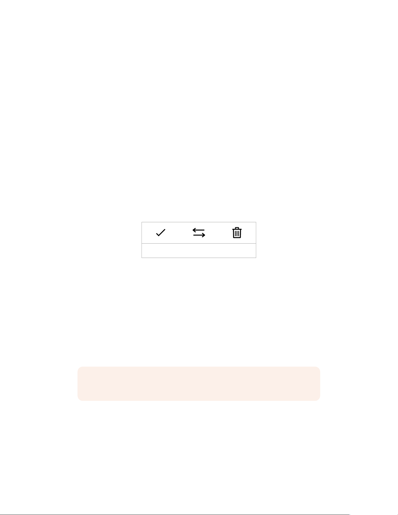
Built-in LUTs
Your URSA Broadcast G2 provides a number of built-in LUTs, that allow you to preview different
looks whilst shooting in ‘film’ dynamic range or when shooting Blackmagic RAW.
Gen 5 Film to Extended Video
Displays a wider dynamic range than the ‘film to video’ LUT, and applies a mild contrast
change with a smooth roll off in the highlights.
Gen 5 Film to Rec 2020 Hybrid Log Gamma
Displays a gamma curve that is suitable for HDR screens and compatible with standard
dynamic range screens.
Gen 5 Film to Rec 2020 PQ Gamma
Displays a gamma curve that is based on what we can perceive with our eyes, for efficient
encoding of HDR images.
Gen 5 Film to Video
Similar to the REC 709 color standard for high definition video, and has a high level of
contrast and saturation. You may find this setting useful when using Blackmagic URSA
Broadcast G2 alongside other broadcast cameras using the REC 709 color space.
LUTS buttons
The button icons along the bottom of your URSA Broadcast G2’s ‘LUTS’ screen correspond to
the following functions:
Load Manage Delete
Importing LUTs
To import a 3D LUT, tap the ‘manage’ icon at the bottom of the LUT menu. Select either SD or
CFast with the storage media selection switch, depending on where your LUTs are saved. You
can also import LUTs from a USB-C flash disk or from an SSD if you are using URSAMini Recorder.
Tap the card or drive that contains the LUT you want to import from the ‘import from’ menu
and tap the ‘import’ button. From the import screen you can use the buttons on the top left to
display any available LUTs on other cards or drives attached to your camera.
Your URSA Broadcast G2 will search the root directory and ‘3DLUTS’ folder on your selected
storage media. Any LUTs you have saved elsewhere will not be visible.
Tap a LUT to select it and tap ‘import’ to confirm your selection. The LUT will be saved to your
URSA Broadcast G2.
NOTE If your URSA Broadcast G2’s thirty 3D LUT slots are full, you will not be able to
import until you delete some existing LUTs to make space.
If the LUT you want to import has the same name as a LUT already saved to your camera,
youwill be prompted to overwrite the existing LUT or keep both. At the top right of this screen,
you’ll see the number of remaining empty LUT slots available on your camera. You will only be
able to import as many LUTs as you have free slots on your camera.
134Settings

NOTE If you are having trouble importing a LUT to your URSA Broadcast G2, it may
be the wrong size. You can use a LUT editor like Lattice to check its size, or open it
in any text editor on your computer. Next to the tag ‘LUT_3D_SIZE’ will be a number
indicating the LUT’s size. If this value is not 17 or 33, you can use Lattice to resize your
3D LUT to 17points.
Applying a LUT
Once you have a LUT saved onto your camera, tap it in the LUT menu to select it, and tap the
‘load’ icon. This will enable that LUT to all outputs on your camera. However, you will still have
to turn ‘display LUT’ on in the monitor menu for each output to apply it. See the ‘monitor
settings’ section in this manual for more information.
Exporting LUTs
To export a LUT to a CFast or SD card, select the LUT you want to export and tap the ‘manage’
icon. From the ‘manage LUT’ options choose ‘export selected LUT’. Use the storage media
selection switch to select either SD or CFast, depending on the location you would like to
export the LUT to. You can also export LUTs to a USB-C flash disk or to an SSD if you are using
URSA Mini Recorder.
From the ‘export to’ options choose the card or drive you want save your LUT to. Tap ‘export’
to confirm your choice. If a duplicate LUT is found on the card or drive you are exporting to,
you will be asked if you want to overwrite the LUT or keep both.
Deleting LUTs
Your URSA Broadcast G2 has space for thirty 17 point or 33 point 3D LUTs. To delete LUTs you
are no longer using, or make room for more, select the LUTs you want to delete and tap the
icon. Youwill be prompted to confirm your choice. Tap ‘delete’ to confirm.
Embedded 3D LUTs
When a 3D LUT is used whilst shooting Blackmagic RAW on URSA Broadcast G2, the selected
LUT will be embedded into the Blackmagic RAW file that you are recording. The 3D LUT is
actually saved with your recorded files in the header of the .braw file, and can easily be applied
to footage in post production without needing to handle a separate file.
So when Blackmagic RAW files are delivered to an editor or colorist, they will be able to easily
access the LUT that was used whilst filming, which greatly reduces the possibility that the
wrong 3D LUT could be applied to a clip. They can then choose whether to apply the 3D LUT
whilst editing or color grading the footage, and can disable the 3D LUT at any time.
When the ‘Apply LUT in file’ switch is set to ‘on’ in URSA Broadcast G2’s record menu, the
recorded clip will open in Blackmagic RAW Player and DaVinci Resolve with the chosen 3D LUT
already applied to it. The 3D LUT can then be easily toggled ‘on’ or ‘off’ but will always travel
with the Blackmagic RAW file as it is written into the clip itself.
DaVinci Resolve also has an ‘Apply LUT’ switch in the RAW settings palette for enabling or
disabling the 3D LUT in the Blackmagic RAW file. The ‘Apply LUT’ setting in DaVinci Resolve is
the same setting as in the camera. This means that when shooting you can direct the colorist to
use the LUT by setting it in the camera, but they can switch it off easily in DaVinci Resolve by
setting ‘Apply LUT’ to ‘off’.
135Settings
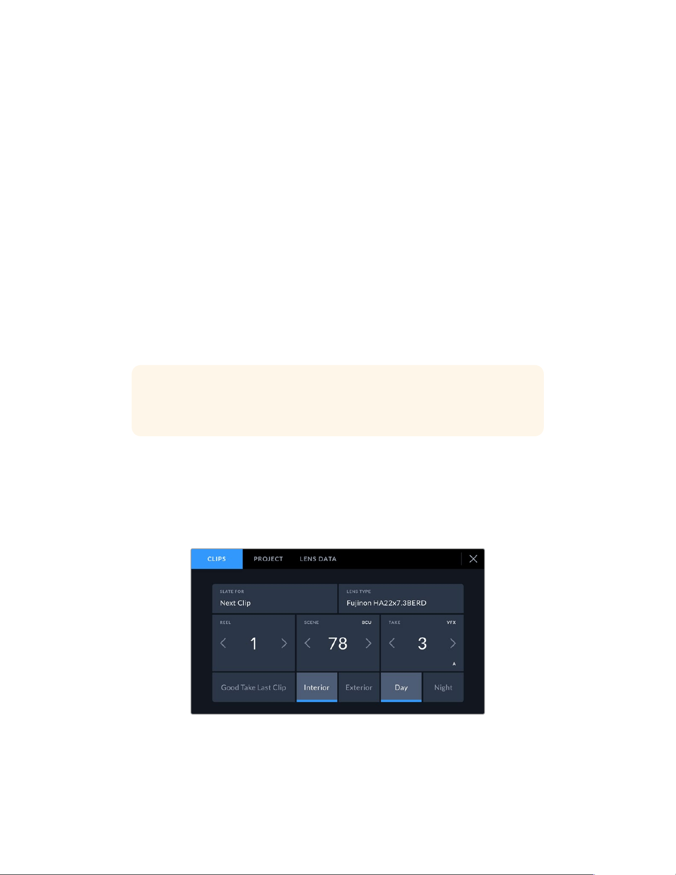
Entering Metadata
Metadata is information saved inside your clip, such as shot numbers, camera settings and
other identifying details. This is extremely useful when sorting and processing footage in
postproduction. For example, take and shot and scene numbers are essential organizational
tools, while lens information can be used to automatically remove distortion or better match
VFXassets to plates.
Your Blackmagic URSA Broadcast G2 automatically saves some metadata to each clip, such
as camera settings, timecode, date and time. You can use your camera’s slate to add many
additional details.
The Slate
Swiping left or right on your URSA Broadcast G2’s touchscreen will bring up the slate.
The slate is divided into ‘clips’, ‘project’ and ‘lens data’ tabs. The ‘clips’ tab contains information
that may vary clip by clip, while ‘project’ is where you enter details common between clips,
such as the project name, director, and camera and operator ID. The ‘lens data’ tab displays
information about the lens fitted to your camera. If the lens automatically sends information
back to your camera it will be displayed here. You can also enter lens data manually.
TIP Metadata entered into the slate is viewable on your URSA Broadcast G2’s front or
main SDIoutputs when ‘display status text for’ is set to ‘director’ on the ‘monitor’ tab.
See the ‘monitor settings’ section in this manualfor more information.
‘Clip’ metadata
Changes made to clip metadata work slightly differently in standby mode, when your
URSABroadcast G2 is ready to record, and playback mode, when you’re reviewing footage
you’ve already shot. In ‘standby,’ clip metadata will be saved to the next clip recorded, except
for ‘goodtake last clip’ which refers to the most recently recorded clip.
In playback mode clip metadata is always recorded to the current clip being viewed.
Your URSA Broadcast G2’s slate is divided into ‘clip’, ‘project’ and ‘lens data’ tabs
136Entering Metadata

Slate for
This setting shows the clip which the metadata currently displayed in the ‘clip’ applies to.
Instandby mode, this refers to the next clip that will be recorded.
Lens Type
This displays information about the lens attached to your camera. For more information about
‘lens type’ data, refer to the ‘lens data’ section below.
Reel
The ‘reel’ indicator shows the current reel.
Your URSA Broadcast G2 automatically increments reel numbers, so there is usually no need to
enter this manually. When you are moving to a new project and want to start from reel ‘1’ again
go into the project tab of the slate and tap ‘reset project data’.
Scene
The ‘scene’ indicator shows the current scene number, and can also show the current shot
number and type.
The number on this indicator always refers to the current scene. You can adjust it with the left
and right arrows on either side of the scene number, or tap the scene number to enter the
scene number editor.
Scene numbers range from 1 to 999.
By adding a letter to the scene number in the scene number editor, you can also indicate the
current shot. For example 23A indicates scene twenty three, shot one. If you have a shot letter
added to your scene number, your camera suggests the next scene number and shot letter
whenever you enter the scene number editor. For example, if your current scene number is 7B,
the camera suggests ‘8’ and ‘7C’.
The scene number indicator can also show information about the current shot type in the top right
corner. You can select these in the scene number editor at the right hand side of the scene keyboard.
The shot types available are:
WS wide shot
MS medium shot
MCU medium close up
CU close up
BCU big close up
ECU extreme close up
137Entering Metadata
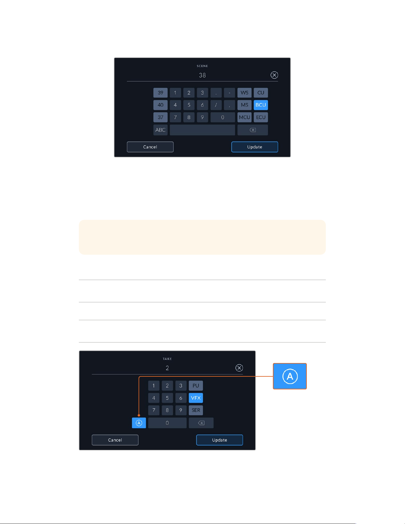
When entering ‘scene’ metadata, your URSA Broadcast G2 will prompt you with
increment suggestions to the left of the touch keyboard, and shot types to the right
Take
The ‘take’ indicator shows the take number for the current shot. You can increment this up
or down by tapping the left or right arrows on either side of the take number, or tapping the
indicator to enter the take number editor.
TIP When the shot number or scene letter are advanced, the take number will
revertto‘1.’
You can add take descriptions in the take number editor. These are offered to the right of the
take number keyboard, and correspond to the following scenarios:
PU
‘Pick up.’ This refers to a reshoot of a previous take to add additional material after
principal photography has wrapped.
VFX ‘Visual effects.’ This refers to a take or shot for visual effect use.
SER
‘Series.’ This refers to a situation in which multiple takes are shotwhile the camera
is kept running.
Tap ‘A’ to automatically
increment the take
number for each clip
while in standby mode.
Asmall ‘A’ appears next
to the take number on
the slate when enabled.
When entering ‘take’ metadata, your URSA Broadcast G2 will offer prompts
for additional shot types to the right of the touch keyboard
138Entering Metadata
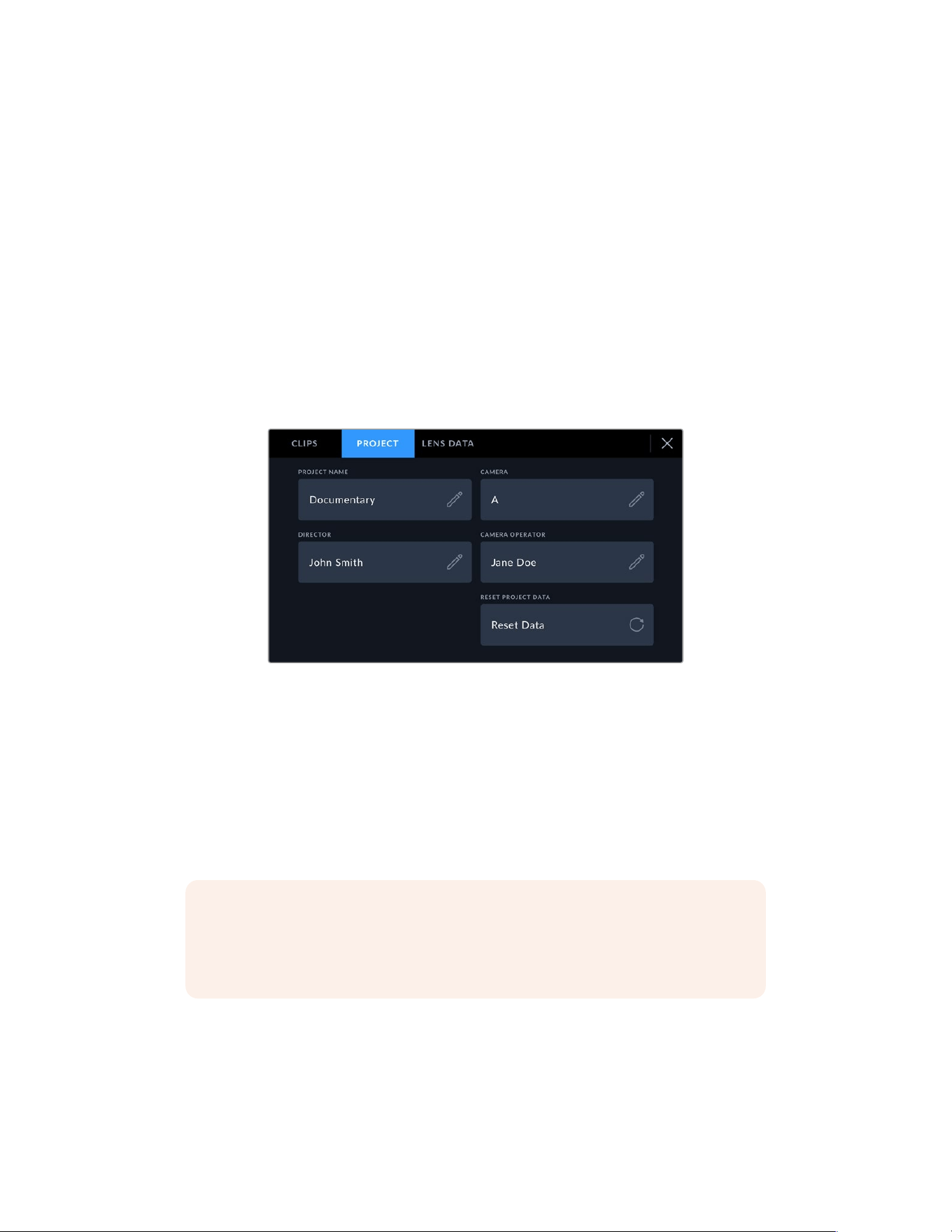
Good take
Tap the ‘good take’ indicator to flag good takes for easy recall in post production. This tag
applies to either the last clip recorded, if your URSA Broadcast G2 is in standby mode, or the
clip currently being viewed in playback mode.
Interior/Exterior
Tap ‘interior’ or ‘exterior’ to add a tag to the next clip in standby mode, or the current clip in
playback mode.
Day/Night
Tap the ‘day’ or ‘night’ icons to add a ‘day’ or ‘night’ tag to the next clip in standby mode,
or the current clip in playback mode.
‘Project’ Metadata
Project metadata behaves the same way whether you are in standby or playback mode.
Thismetadata always refers to your project as a whole and is independent of clip numbers.
Your URSA Broadcast G2’s ‘project’ slate tab
Project name
Displays your current project name. Tap the pencil icon to change the project name.
Camera
Displays a letter camera index. Tap the pencil icon to change the camera index.
Director
Displays the director’s name for the current project. Tap the pencil icon to change the
director name.
NOTE Camera index is used in metadata and for file naming purposes and differs
from your URSA Broadcast G2’s ATEM Camera ID, which is used when controlling your
URSABroadcast G2 with an ATEM switcher. For more information on ATEM Camera ID,
see the ‘Understanding Studio Camera Control’ section in this manual.
Camera Operator
Displays the camera operator. Tap the pencil icon to change the camera operator name.
Reset project data
To clear project data tap the ‘reset data’ button and then confirm your choice. This will clear all
the entered project data.
139Entering Metadata
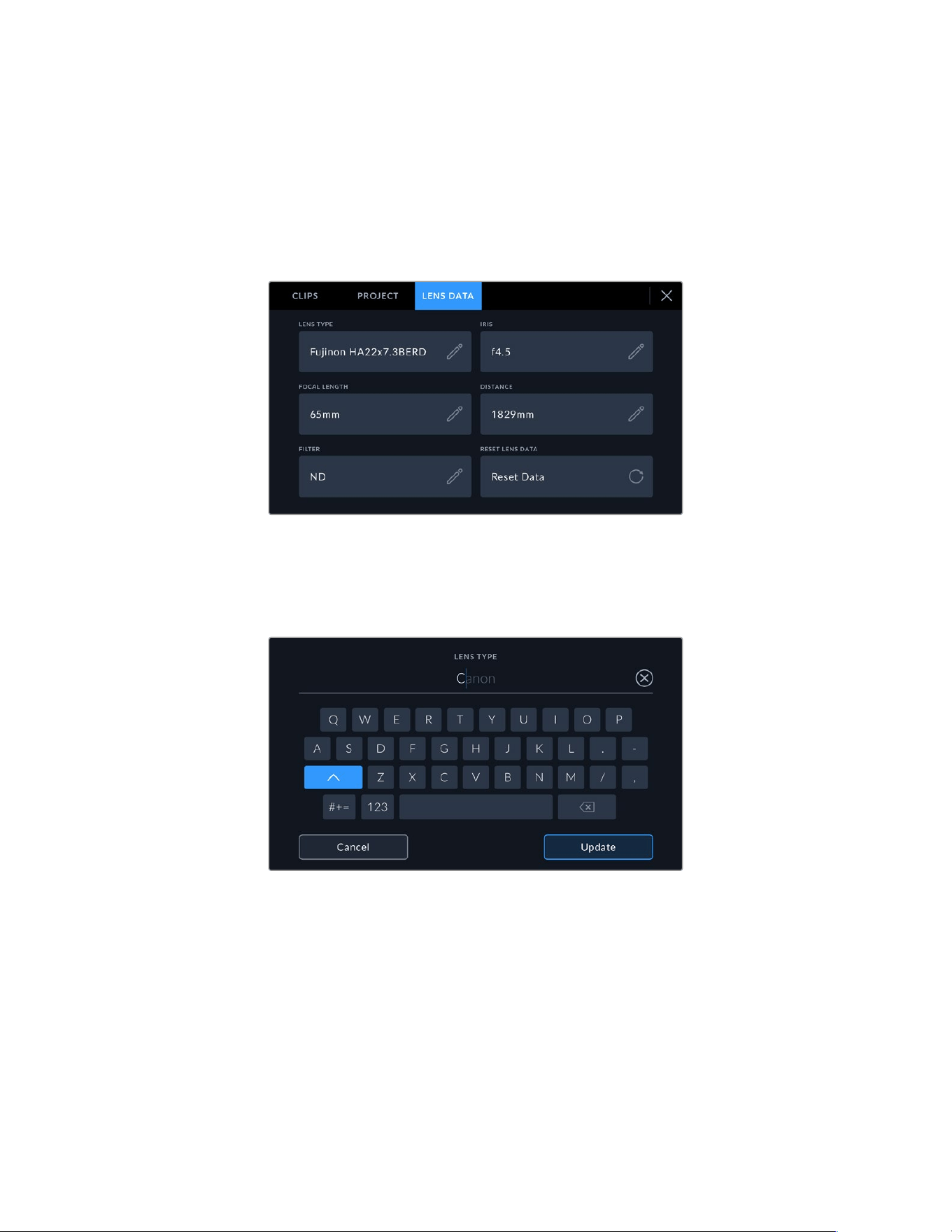
Lens Data
The ‘lens data’ page displays information about the lens fitted to your URSA Broadcast G2.
Many electronic lenses automatically supply information such as the lens model, aperture and
focal length.
If you are using a lens that does not provide this information, or you want to enter additional
data, you can tap the pencil icon in this setting to enter the information manually. This will bring
up the ‘lens data’ menu, which contains the following information:
The lens data page showing information automatically
populated from a Fujinon lens
Lens Type
Shows the lens model. If your lens type is not automatically shown here, you can tap this
setting to enter the data manually.
Use the touch keyboard to enter lens data if it is not provided automatically
Iris
Shows the iris aperture setting at the start of your clip. If this information is supplied
automatically it can be displayed in f- or T-stops depending on your lens. If the iris
information for your lens is not automatically shown here, you can tap this setting
to enter the data manually.
Focal length
Shows the focal length setting of the lens at the start of the recorded clip. When
automatically supplied, this is shown in millimeters. If the focal length information for your
lens is not automatically shown here, you can tap this setting to enter the data manually.
140Entering Metadata
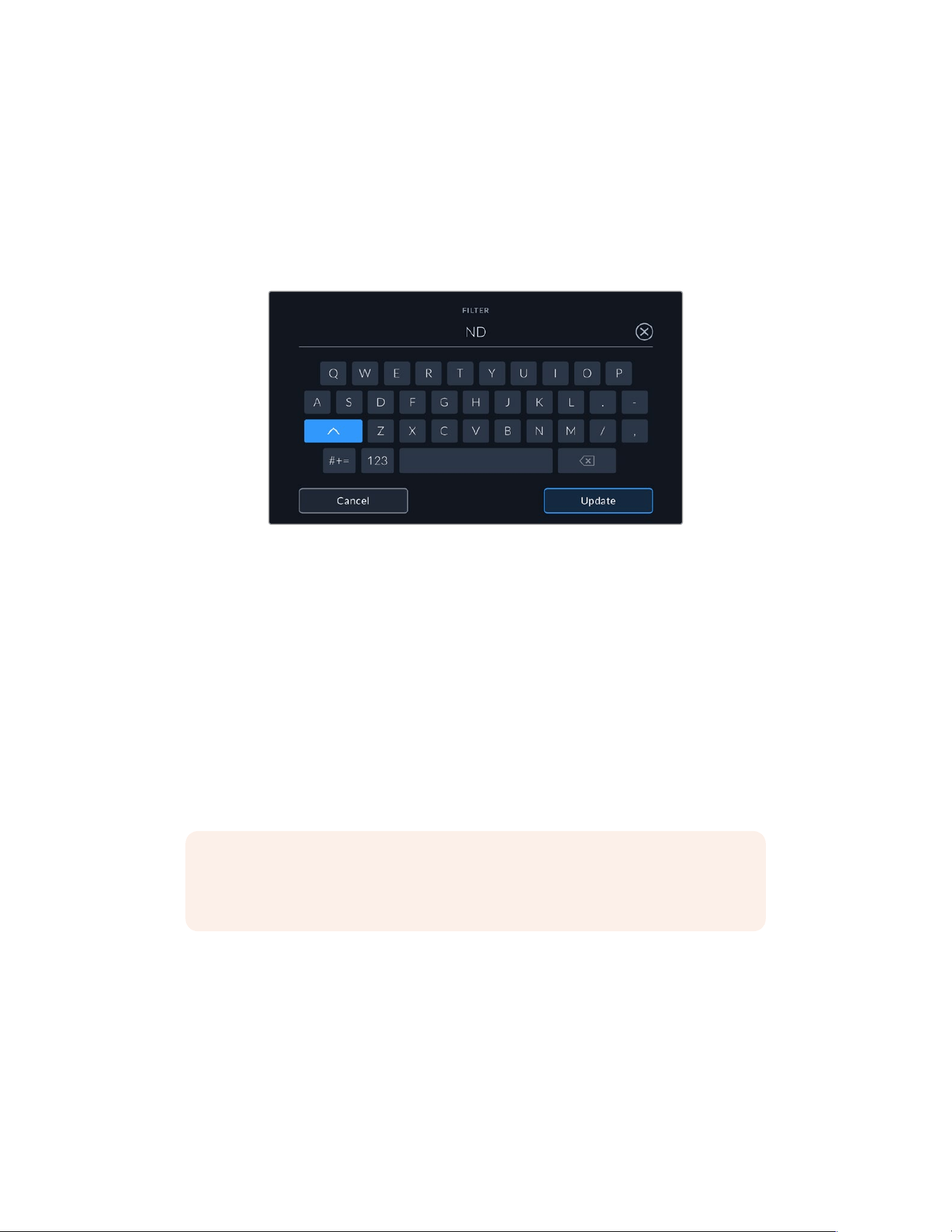
Distance
Shows the focus distance settings of the lens for the recorded clip. Some lenses can
provide this data automatically and it will be provided in millimeters. If the focal distance
information for your lens is not automatically shown here, you can tap this setting to enter
the data manually.
Filter
Shows the current lens filters used. Tap this setting to enter data manually. You can make
multiple entries separated by commas.
Filter information needs to be entered manually
Reset lens data
You can clear lens data at any time by tapping the ‘reset data’ button. You will be prompted
to confirm your choice. This will reinitialize communication with your lens and refresh the
electronically populated data, any fields that have been manually added will also be cleared.
Gyro Stabilization
Your Blackmagic URSA Broadcast G2 Camera automatically records pan, tilt and roll data
captured by an internal motion sensor. This data is also known as gyro data, which DaVinci
Resolve can then use to stabilize handheld shots.
It’s important to calibrate your camera’s motion sensor prior to recording to ensure that the
recorded gyro data is accurate. You can find more information in the ‘settings’ section under
‘motion sensor calibration’.
NOTE To enable the gyro stabilization you will need to make sure your lens’s optical
image stabilization is turned off. EF and B4 lenses with built in optical stabilization have
a physical switch to turn it on or off.
Recording Gyro Data with Manual Lenses
For gyro stabilization to work at its best, it requires accurate lens focal length information which
is included in the metadata that is automatically recorded when using most EF and B4 lenses.
For manual lenses that do not support electronic communication with the camera, or analog B4
lenses, you will need to enter this information into the camera’s slate.
1 Swipe left or right on your camera’s touchscreen from the main view to bring up the slate.
2 Tap the ‘lens data’ tab.
141Entering Metadata
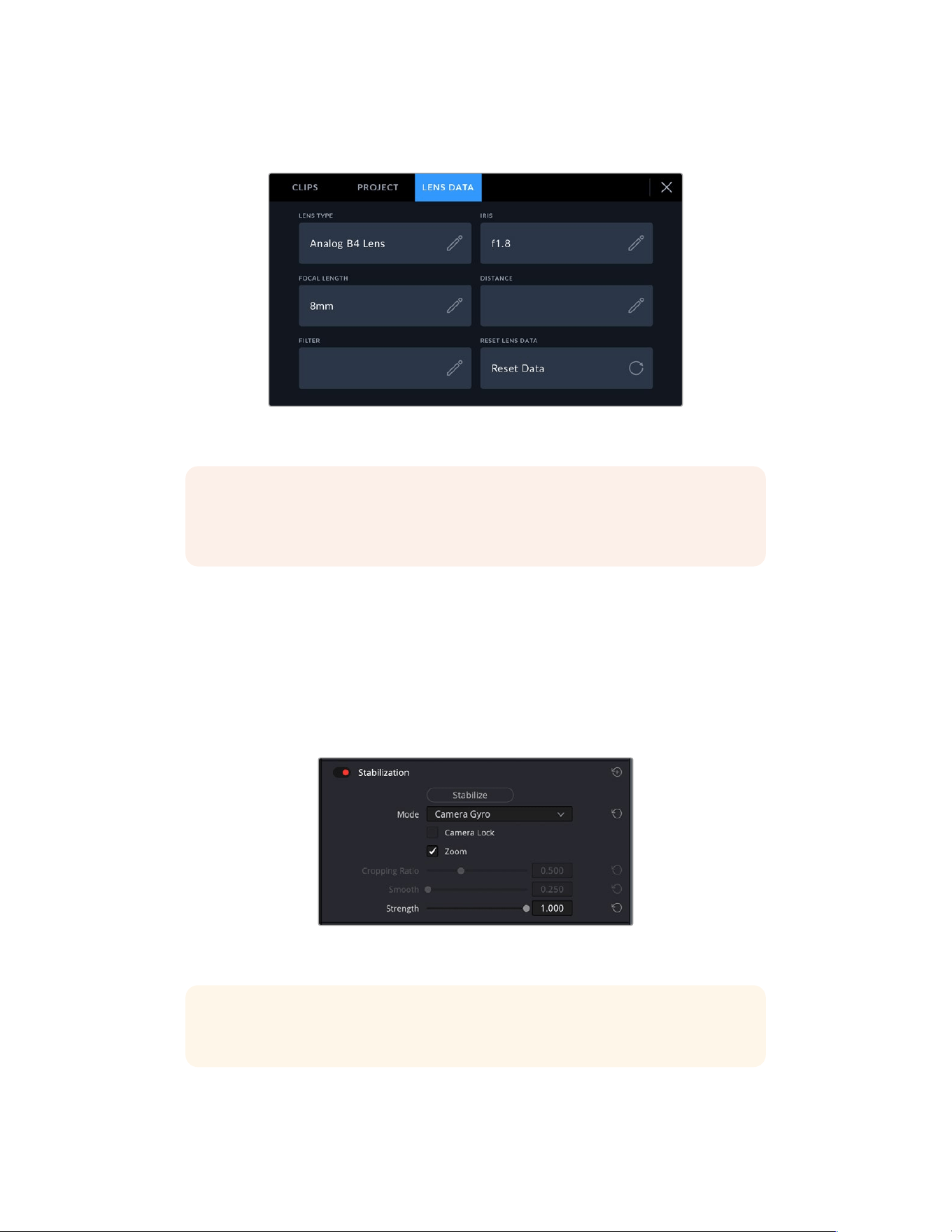
3 Tap on the ‘focal length’ section and type in the focal length of the lens you are using.
For example, if you are using an analog B4 lens at a 8mm focal length type in ‘8mm’.
Enter ‘lens data’ when using lenses that do not have electronic communication
with the camera
NOTE You will need to update this information each time you change focal lengths
onmanual or analog lenses. Lenses with in built electronics will automatically
overwrite the metadata.
Applying Gyro Stabilization in DaVinci Resolve
After importing your clips and setting them up on a timeline:
1 Go to the ‘edit’ page’s inspector window and scroll down to ‘stabilization’.
2 Set the stabilization mode to ‘gyro’.
3 Click ‘stabilize’.
A progress bar will let you know when the stabilization is complete.
In the inspector window select ‘camera gyro’ to stabilize
the footage using gyro data
TIP You can enhance the results by shooting with narrow shutter angles to minimize
motion blur. For example, 45 degrees.
142Entering Metadata
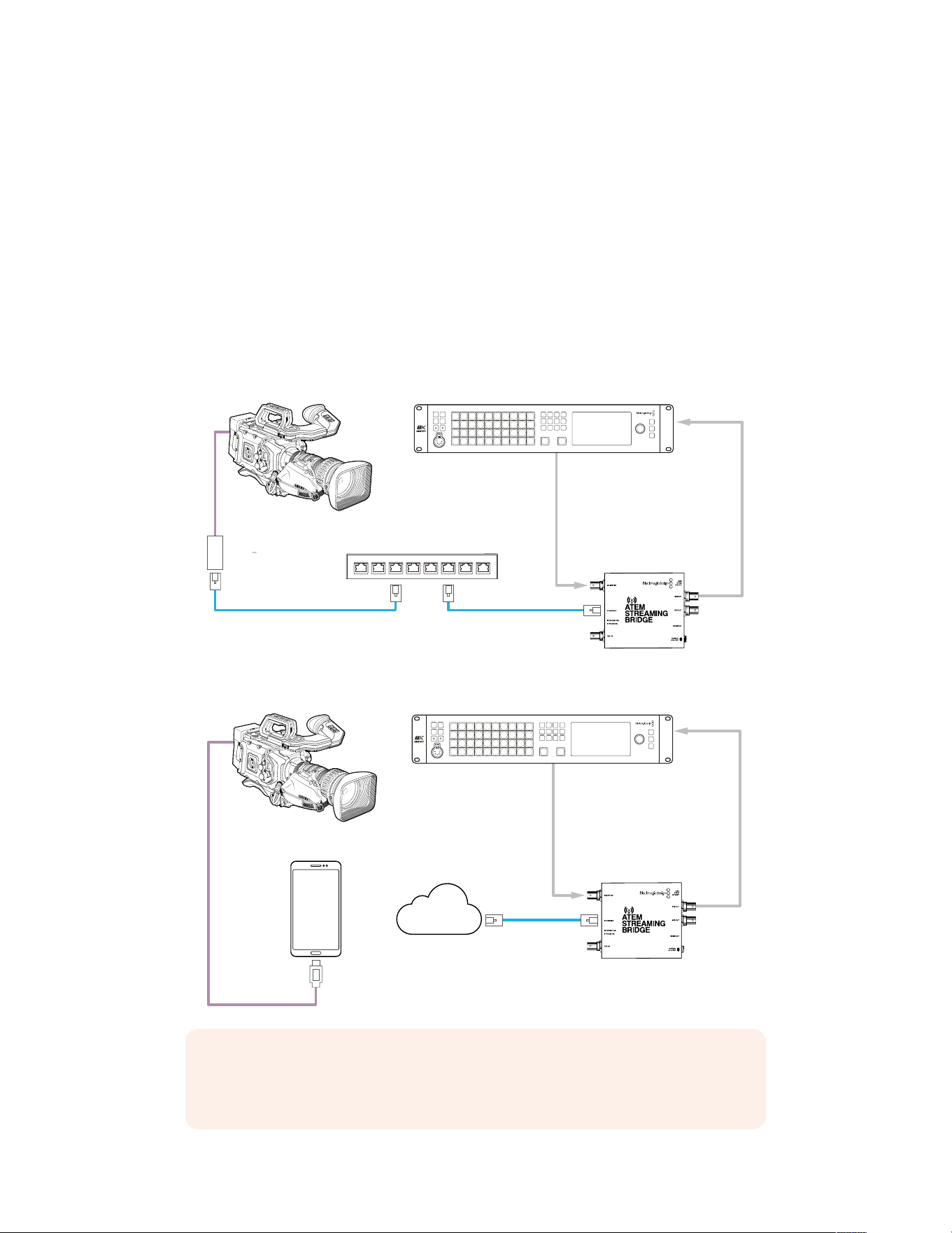
Streaming Video
URSA Broadcast G2 has its own built in streaming engine that enables the camera to stream
directly to platforms such as YouTube, Facebook Live and Twitch.
You can also connect URSA Broadcast G2 to an ATEM switcher on the same Ethernet network,
orvia the Internet anywhere in the world using an optional ATEM Streaming Bridge. When
streaming to an ATEM switcher, this setup also includes tally, talkback and camera control
functionality.
Below are two examples showing URSA Broadcast G2 connected to an ATEM switcher using
anATEM Streaming Bridge. The first shows connecting locally over a network and the second
illustration shows transmitting video over the Internet using a smartphone.
Connecting over a Network
SDI I
n
SDI R
e
f
I
n
SDI O
ut
SDI O
ut
E
therne
t
E
therne
t
Net
w
or
k
USB
-
C
t
o E
therne
t
A
dap
t
er
URS
A
B
r
oadc
as
t G
2
A
TEM
C
ons
t
ellation 8K
PROD
T
ALK
ENG
T
ALK
CALL
PGM
MIX
5
4
3
2
1
1
2
3
4
5
6
7
8
9
10
KEY 1
MI
X
D
SK 1
MI
X
D
SK 2
MI
X
F
TB
BAR
S
BLACK
MP
1
MP
2
MI
X
WI
PE
DI
P
DV
E
LOCK
ME
N
U
SET
11
12
13
14
15
16
17
18
19
20
21
22
23
24
25
26
27
28
29
30
31
32
33
34
35
36
37
38
39
40
C
U
T
A
U
T
O
LEN
S
A
TEM S
tr
eaming B
ridge
Connecting over the Internet
USB-C
I
n
t
erne
t
SDI I
n
SDI R
e
f
I
n
SDI O
ut
SDI O
ut
E
therne
t
URS
A
B
r
oadc
as
t G
2
A
TEM
C
ons
t
ellation 8K
PROD
T
ALK
ENG
T
ALK
CALL
PGM
MIX
5
4
3
2
1
1
2
3
4
5
6
7
8
9
10
KEY 1
MI
X
D
SK 1
MI
X
D
SK 2
MI
X
F
TB
BAR
S
BLACK
MP
1
MP
2
MI
X
WI
PE
DI
P
DV
E
LOCK
ME
N
U
SET
11
12
13
14
15
16
17
18
19
20
21
22
23
24
25
26
27
28
29
30
31
32
33
34
35
36
37
38
39
40
C
U
T
A
U
T
O
LEN
S
A
TEM S
tr
eaming B
ridge
NOTE For streaming via an Ethernet adapter we recommend the Belkin USB-C to
Gigabit Ethernet Adapter. While other USB-C to Ethernet adapters may work, the chipset
used in the Belkin adapter is the most reliable for RTMP streaming video workflows.
143Streaming Video
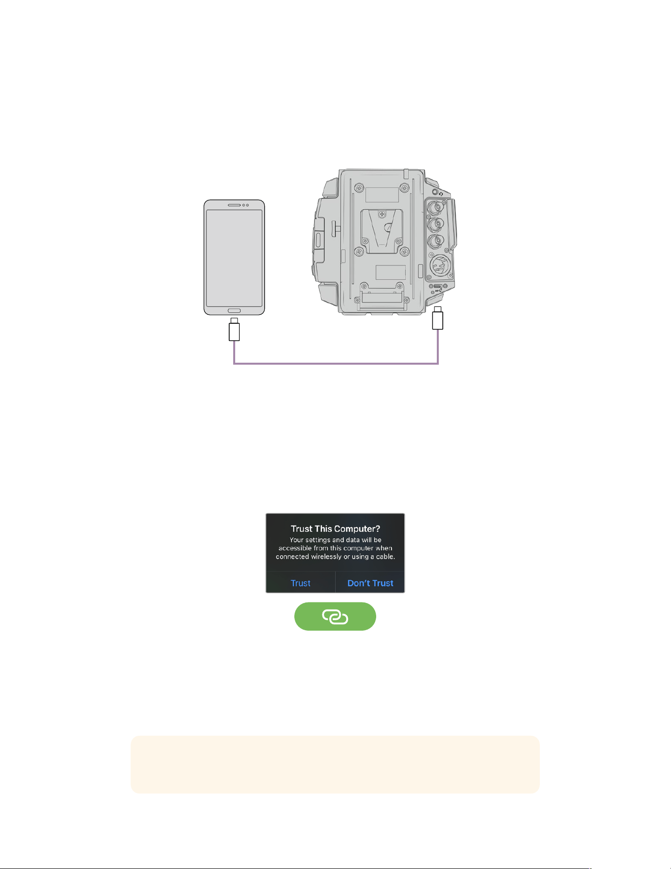
Smartphone Setup
Connect a smartphone to your camera’s USB-C expansion port using a USB-C cable. This
connection lets you set up fast and be streaming to the world in any location where your
smartphone has a 4G or 5G cellular connection.
USB
Settings
The first step to setting up your smartphone for internet streaming is to make sure it has hotspot
activated.
1 On your iOS device open settings>personal hotspot and make sure the ‘allow others to join’
option is on.
2 You will see a message appear asking whether to trust the connected computer. Select
‘trust’ and a green tethering icon will be visible on the screen. This is how you can verify
the connection is working.
The tethering icon will
appear when enabled
Your smartphone’s clock will always appear within a green background icon while tethering
is enabled.
For Android devices, swipe the screen to display the quick menu. Press and hold the hotspot
icon and then turn on USB tethering.
TIP Once you have finished streaming, we recommend turning off tethering on your
phone to save your phone’s battery life.
144Smartphone Setup
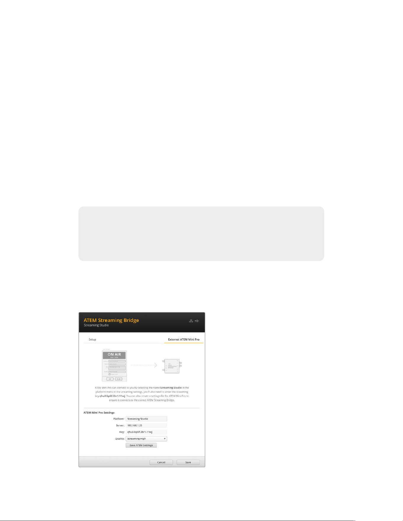
Setting the ATEM Camera ID
The ATEM camera ID is a setting in your camera’s menu settings that determines which SDI
input your URSA Broadcast G2 is connected to on the ATEM switcher. When the camera ID
corresponds to the switcher’s input number, your camera will detect tally data for that input and
tally and camera control will work correctly.
For more information on setting your camera’s ATEM Camera ID, refer to the ‘Setup Settings’
section earlier in this manual.
Creating the XML File
To create an XML settings file connect ATEM Streaming Bridge to the internet by plugging a
network cable from the ‘Ethernet’ port to an internet router or network switch.
Connect ATEM Streaming Bridge to your computer using a USB-C cable and launch
ATEM Setup.
In the setup tab, confirm the network settings are correct and select ‘internet’ from the ‘stream
service’ options. You should see a ‘visible worldwide’ message in the internet status box. This
means everything is working correctly.
A Note About Port Forwarding
If you see a port forwarding or UPnP error in the ‘internet status’ box you will need to
ask your internet provider or network administrator to set up port forwarding on your
internet connection to ‘TCP port 1935’.
Exporting the XML File
Once you have confirmed your settings in the ATEM Setup tab and have successfully
connected your ATEM Streaming Bridge to your network or the internet, you can export the
XML setup file.
1 Click the ‘external ATEM Mini Pro’
tab in the top right of the window.
2 Click in the ‘platform’ box and
type a new name. This name will
be the name listed in the remote
Blackmagic URSA Broadcast G2’s
platform menu.
3 Select the quality you want to
stream. This setting will set the
quality setting in the remote URSA
Broadcast G2.
4 Click the ‘Save ATEM Settings’
button, choose a location on your
computer to save the XML file and
click ‘save’.
5 You can now email the saved XML
file to the remote operator.
145Smartphone Setup
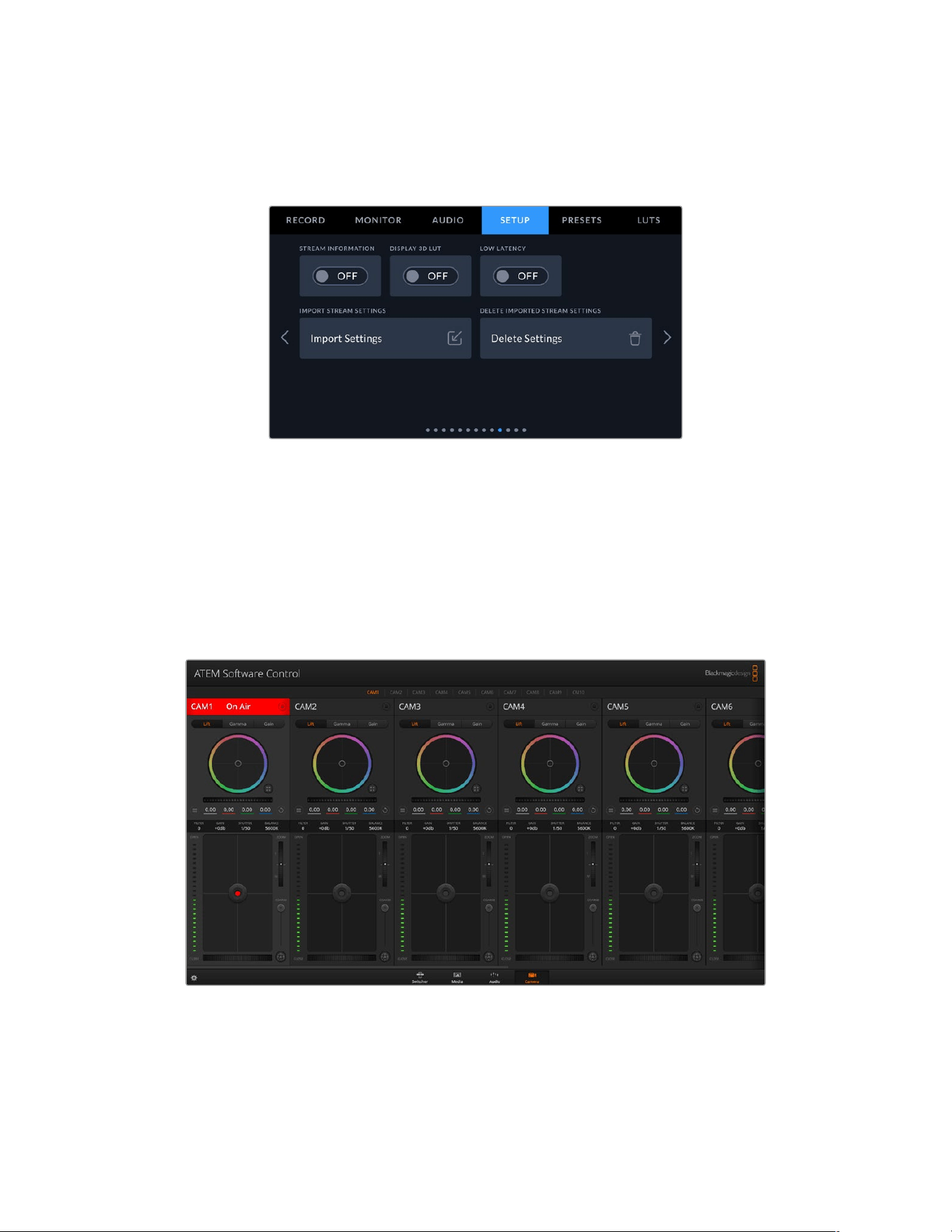
Loading the XML File
To import an XML settings file in to your URSA Broadcast G2, copy the file to an SD card,
CFast card or USB-C flash disk.
1 On the tenth page of your camera’s setup menu, tap on the button labeled ‘import settings’.
2 At the top of the screen, tap the card or drive where the xml settings file is saved. Tap the
file name and then tap ‘import’. After the setup file has been successfully imported, the
ATEM Streaming Bridge will automatically be selected in your camera’s platform menu.
All you need to do now is tap your camera’s live stream button to turn the stream ‘on’.
You can test your setup is working by getting the switcher operator at the studio to switch to
your camera. You will see the tally light illuminate on the camera including a red tally border
around the camera’s LCD. When your camera is switched to the preview output, the tally will
illuminate green.
Try adjusting the iris and pedestal in ATEM Software Control’s camera page to test camera control
146Smartphone Setup
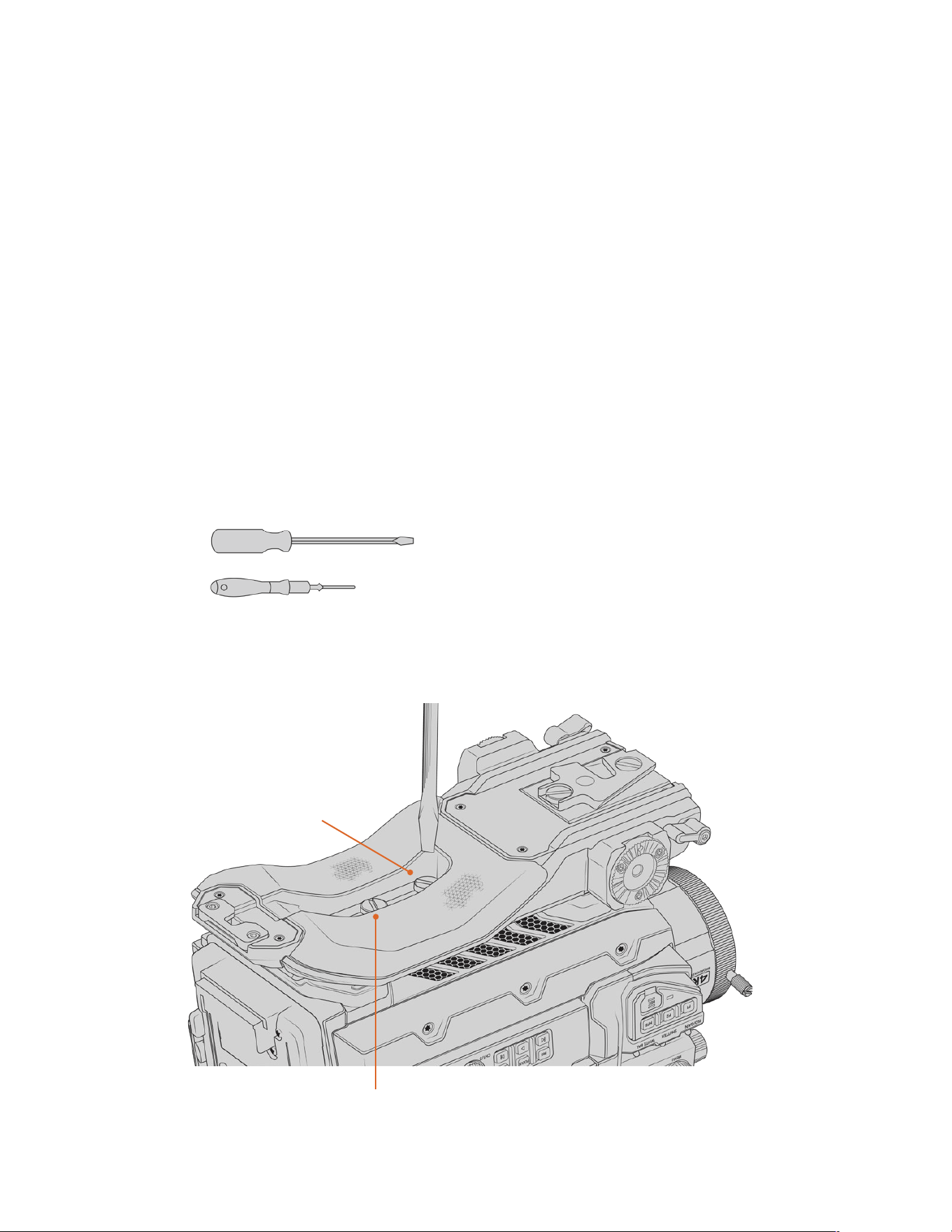
URSA Mini Shoulder Kit
Attaching the shoulder kit
The URSA Mini Shoulder Kit lets you carry your Blackmagic URSA Broadcast G2 on the
shoulder for ENG style shooting. Most of the items in the URSA Mini Shoulder kit are shipped
with your Blackmagic URSA Broadcast G2, including the shoulder pad, baseplate, top handle
and viewfinder adapter plate. The URSA Mini extension arm and long LANC cable are available
as optional accessories.
The quick release mount on the baseplate lets you lock your camera into an ENG style tripod
plate or place it on your shoulder so you can follow the action.
The URSA Mini Shoulder Kit works with any tripod plate modeled after the Sony VCT 14.
Thesemounts are easily found at camera stores or online.
It’s also worth mentioning that mounts modeled after the VCT U14 tripod plate are a different
system and are not compatible.
When attaching the Shoulder kit, you will need the following tools:
1 x flat head screwdriver for the 2 x ¼" shoulder mount base plate screws.
1 x 3/16" Hex key driver for the 2 x ¼" top handle screws.
To attach the shoulder kit to your URSA Broadcast G2 you will need a large
flat head screwdriver and a 3/16” Hex Key driver for the top handle
To attach the shoulder pad and baseplate
Insert screws via threaded
hole in slot
2 x ¼" baseplate screws
147URSA Mini Shoulder Kit
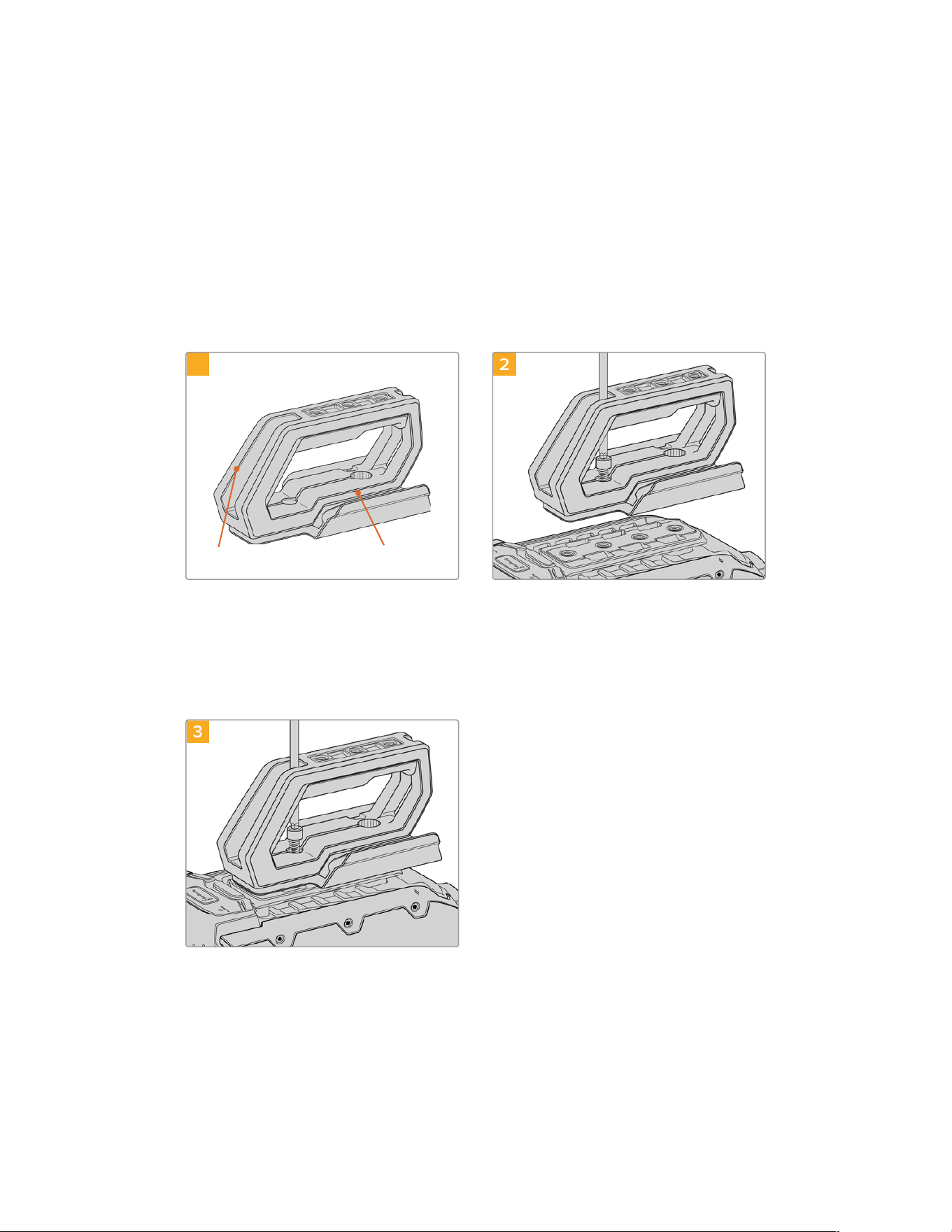
1 Gently place your URSA Broadcast G2 upside down on a flat, stable surface so you can
easily access the base of your camera.
2 Fasten the shoulder kit baseplate to URSA Broadcast G2 using the 2 x 1/4" flat head screws
and driver.
3 Tighten the screws until the baseplate is firmly attached and the screws won’t loosen.
Avoid over-tightening as it may damage the screw threads.
To attach the top handle with URSA Viewfinder adapter plate
The top handle is supplied with URSA Viewfinder adapter plate already fitted. For information
on installing the optional Blackmagic URSA Viewfinder, refer to the next section of this manual.
1
Top handle URSA Viewfinder cap
2
Place your URSA Broadcast G2 on a flat, stable
surface so you can access the top of your camera.
Fasten the handle to any two of your
URSABroadcast G2’s top 1/4" mounting points
using the two supplied 1/4" screws with a 3/16" Hex
key driver. URSA Broadcast G2’s rear two mounting
points are recommended for most situations, but
you can choose any pair for better weight balance
when using large lenses.
3
Tighten the screws until the handle is firmly in
place and the screws won’t easily loosen. Avoid
over-tightening the screws as it may damage the
screw threads.
The URSA Mini Shoulder Kit extension arm and LANC cable are available as optional accessories.
148URSA Mini Shoulder Kit
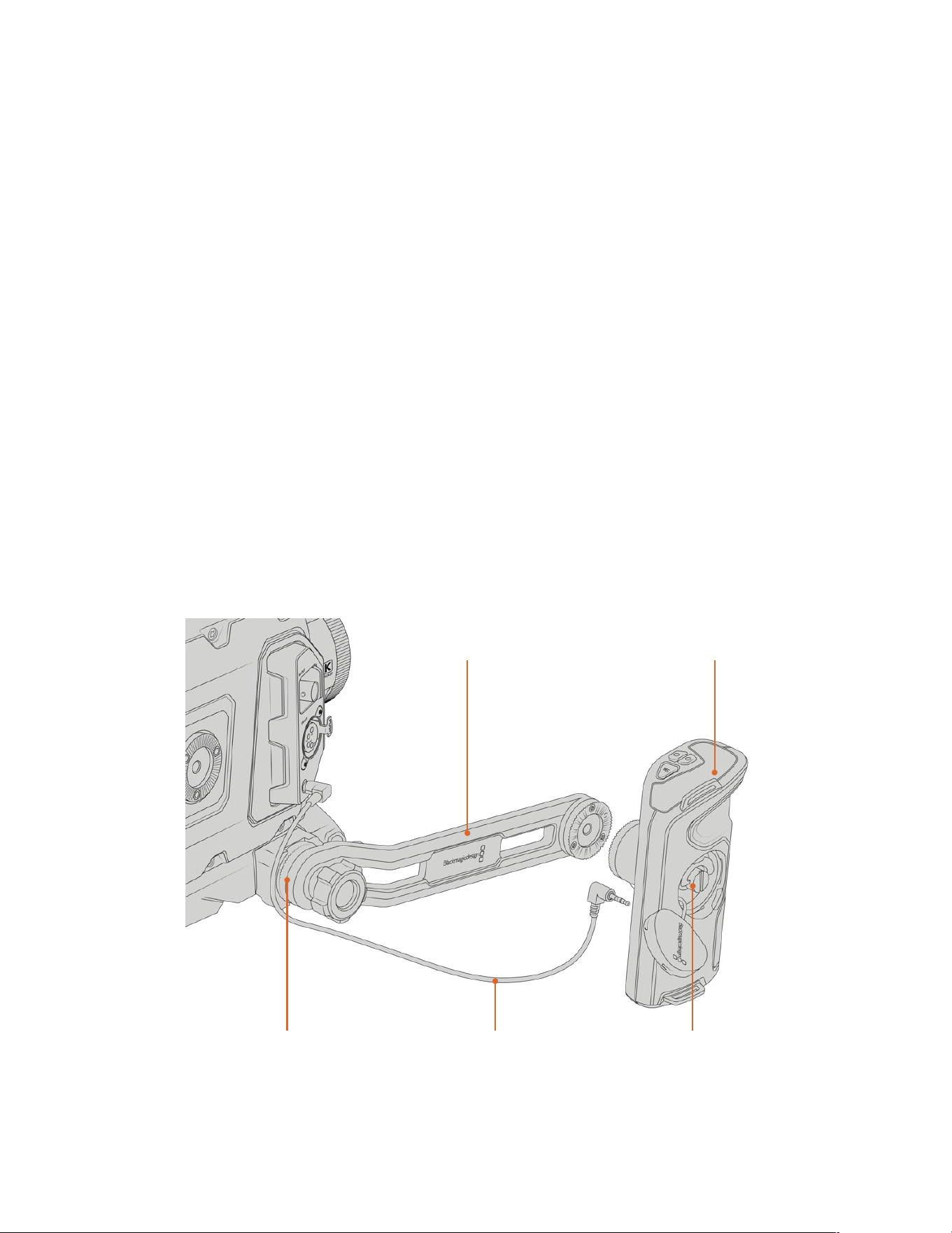
Attaching the extension arm
B4 lenses typically feature a handgrip on the lens body, so a side handle isn’t necessary when
shooting with URSA Broadcast G2 on your shoulder.
If you have a different lens mount fitted, however, you may find it useful to fit the optional
URSAMini side handle on an extension arm for comfortable shoulder based shooting.
URSA Mini Shoulder Kit comes with an extension handle and longer LANC cable to move the
optional side handle to a more ergonomic position.
To attach the side handle extension arm:
1 Place your URSA Broadcast G2 on a flat, stable surface allowing room next to the camera to
lower the extension arm. Mounting URSA Broadcast G2 to a tripod is helpful for this purpose.
2 Attach the indented end of the extension arm to the baseplate rosette, lower the arm
to suit, and fasten with the supplied rosette thumbscrew.
3 Attach the side handle to the extension arm’s front rosette. Fasten by tightening the side
handle screw with the large flat head screwdriver, or by twisting the D ring with your thumb
and forefinger.
4 Connect the side handle LANC output to the camera LANC input using the long LANC
cable supplied with your URSA Mini Shoulder Kit.
You can easily adjust the extension arm and side handle to suit your preference by loosening
the rosette screws, making your adjustment, then retightening.
With your URSA Mini Shoulder Kit now attached, you have additional speed for fast shooting
on the run, plus the ability to quickly mount your camera on a tripod for tight, stable shots!
Connect the side handle to the camera using
thelongLANCcable supplied with the kit
Side handleSide handle extension arm
Extension arm attaches
tobaseplate rosette
Tighten via side
handlescrew
149URSA Mini Shoulder Kit
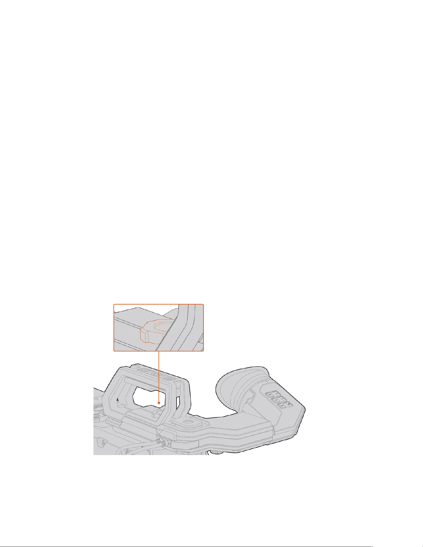
Blackmagic URSA Viewfinder
Blackmagic URSA Viewfinder is a powerful electronic viewfinder designed for your
BlackmagicURSA Broadcast G2. The 1080HD color OLED display and precision glass optics
provides abright, vivid, and lifelike image so you can quickly find focus and see the finest detail
in your images.
This viewfinder is perfect for handheld operation on the shoulder, or for environments where
you need absolute precision with zero reflection and light glare, for example in extremely bright
shooting conditions.
The viewfinder is connected and powered by the camera and uses the embedded SDI data
from the camera to generate the various display options. This means that your camera can
output a clean SDI feed to the viewfinder but still allows you to toggle various display options
within the viewfinder for quick access to camera status, plus accurate information.
For example, if you select the ‘2.40:1’ frame guide option in URSA Broadcast G2’s menu, it will
actually tellthe viewfinder which frame guide is selected in the camera so when you toggle the
frame guide display on the viewfinder, the same ‘2.40:1’ frame guide is also displayed.
Mounting and Connecting to Blackmagic URSA Broadcast G2
Before mounting Blackmagic URSA Viewfinder to your URSA Broadcast G2, you will need to
install the URSA Mini Shoulder Kit top handle that is included with your camera. Refer to the
‘URSA Mini Shoulder Kit’ section for more information.
Slide URSA Viewfinder mount into the URSA Viewfinder adapter plate and use the
1/4"thumbscrew included in URSA Mini Shoulder Kit to secure URSA Viewfinder to the top
handle and adapter plate.
There is no need to use any tools to secure the thumbscrew, finger pressure is sufficient and
will prevent over tightening.
To mount your Blackmagic URSAViewfinder to your URSABroadcastG2, slide the viewfinder
mount along your camera’s handle ridges andtighten the thumbscrew to a¼" mounting point
150Blackmagic URSA Viewfinder
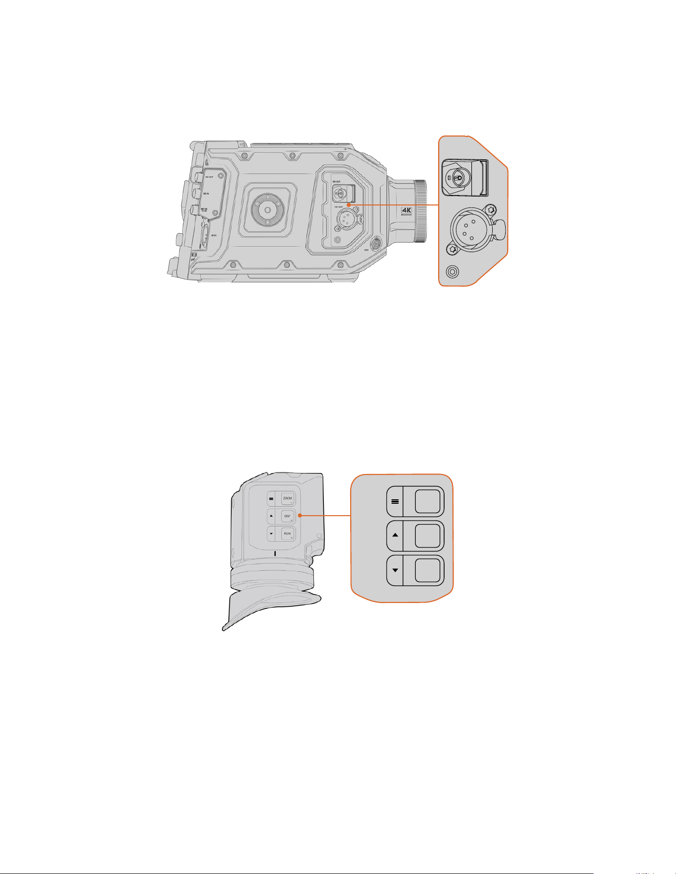
To connect your URSA Viewfinder to your URSA Broadcast G2, simply connect the viewfinder’s
attached cables to your camera’s front 12V power and 3G-SDI outputs. The URSA Viewfinder
will turn on automatically when your camera is powered.
PUSH
Connect your viewfinder’s SDI and power cables to your URSA Broadcast
G2’sHD-SDI monitoring output and +12 volt output
Adjusting the Eyepiece
The detachable rubber eyepiece can be adjusted to fit your left or right eye. Adjust the
viewfinder arm by loosening the knob on the bottom of the arm and sliding it left or right to
comfortably fit your eye.
Button Features
On the top of the viewfinder you’ll find the zoom, display and peak buttons. These buttons are
used for zooming into your image, and turning overlays and focus peaking on or off.
ZOOM
F1
F2
F3
DISP
PEAK
The Zoom (F1), Display (F2) and Peak (F3) buttons are
located on top of the URSA Viewfinder
They are also used for additional features, such as opening the menu and navigating settings.
Icons printed on the side of the buttons show you which buttons are used to control the
viewfinder menu and navigation features.
The buttons also have a customizable function feature so you can assign shortcuts to quickly
enable common features you may use frequently. For example you may wish to assign the false
color feature to the zoom button. Refer to the ‘shortcuts’ section for more information.
151Blackmagic URSA Viewfinder
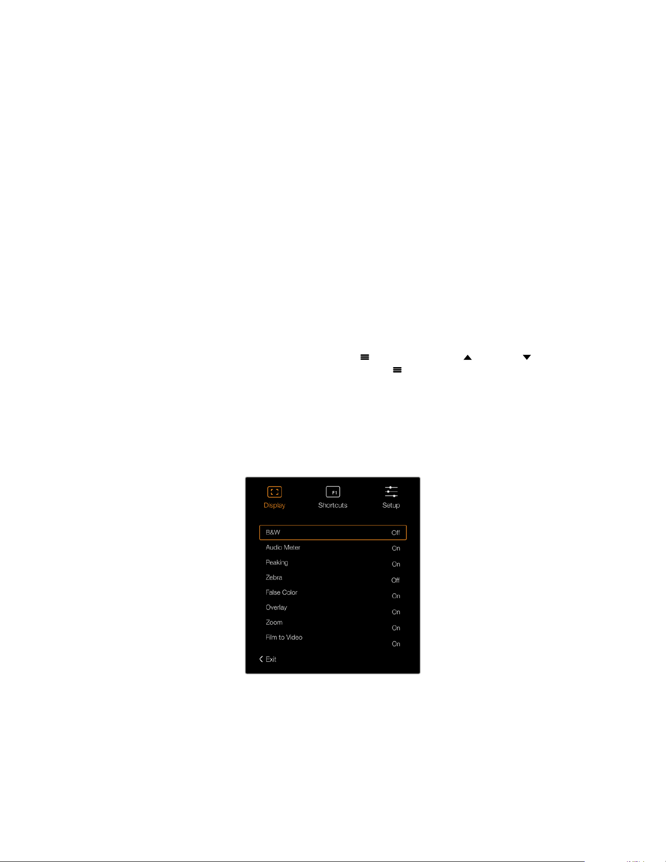
ZOOM (F1) - ‘menu’
The ‘zoom’ feature helps you find sharp focus by zooming into your picture. Press the ‘zoom’
button to zoom in and press again to return to 100% view. When using the settings menu, the
‘zoom’ button also serves as the ‘menu’ button. Press and hold this button to open the settings
menu. In the settings menu, press this button once to confirm setting changes.
DISPLAY (F2) - ‘up’
Press the ‘display’ button to see the overlay view. When using the settings menu, this button
also serves as the ‘up’ button. You can also quickly open the ‘shortcuts’ menu setting by
pressing and holding this button. Refer to the ‘shortcuts’ section for information on how to
set shortcuts.
PEAK (F3) - ‘down’
The focus peaking feature creates a green edge around the sharpest parts of the image so
you can easily confirm your focus. Press the ‘peak’ button to turn the peaking feature on.
Press again to turn peaking off. When using the settings menu, this button also serves as the
‘down’ button. You can also quickly open the ‘setup’ menu by pressing and holding this button.
Menu Settings
The settings menu contains three primary menu headings for display, shortcuts, and setup.
Toopen the settings menu, press and hold the ‘menu’
button. Press the ‘up’ and ‘down’
button to navigate between the settings and press the ‘menu’
button again to confirm
yourselection.
Display
The ‘display’ menu provides the following features:
B&W
Switches between color and monochrome.
The ‘display’ menu in URSA Viewfinder
152Blackmagic URSA Viewfinder
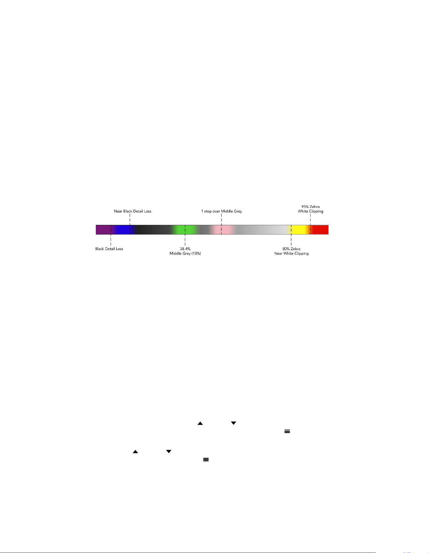
Meters
Switches between the types of meters to display in overlay view. The options are ‘histogram’,
‘audio’, ‘both’ or ‘none’.
Peaking
Switches peaking on and off.
Zebra
Switches zebra levels on and off. Set your desired zebra levels using the camera settings.
For more information, refer to the ‘settings’ section in this manual.
False Color
Switches the false color feature on and off. False color overlays different colors onto your
image that represent exposure values for different elements in your image. Forexample, pink
represents optimum exposure for lighter skin tones, while green is agood match to darker
skin tones. By monitoring the pink or green false color when recording people, you can
maintain consistent exposure for their skin tones. Similarly, when elements in your image
change from yellow to red, that means they are now over exposed.
False Color Chart
Overlay
Switches overlays on and off. You can select which types of overlay to display in your
viewfinder’s ‘setup’ menu. The style of these overlays, such as the safe area percentage,
are set in your camera.
Zoom
Turns the zoom feature on and off.
Film to Video
Switches between film and video display mode. Refer to the ‘record settings’ section in this
manual for information on film and video mode. This setting is only available when your camera
is outputting ‘film’ images to your viewfinder. It is disabled when receiving ‘video’ images to
prevent applying a LUT over a LUT.
Shortcuts
The shortcut function is useful when you need to quickly access a particular setting
for a frequently used feature. To customize your shortcut buttons:
1 In the ‘shortcuts’ menu, press the ‘up’
or ‘down’ button to move up or down and select
one of the 3 buttons to make it your shortcut button. Press the ‘menu’
button to confirm
your selection.
2 Press the ‘up’
or ‘down’ button to toggle and select one of the features below to assign
to the shortcut button. Press the ‘menu’
button to confirm your selection.
B&W
Peaking
Zebra
False Color
Display
Zoom
Film to Video
Meters
Focus Chart
153Blackmagic URSA Viewfinder
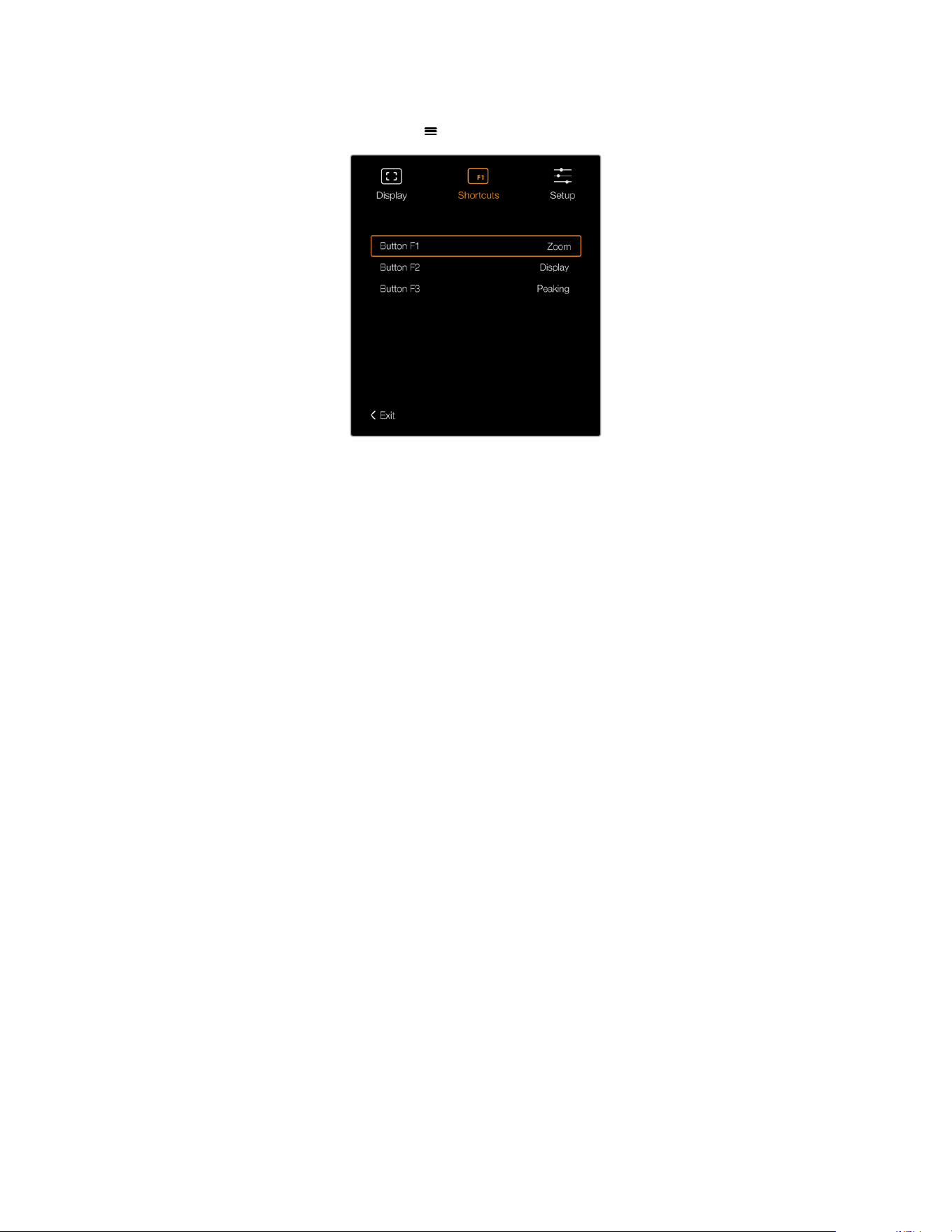
3 Scroll to ‘exit’ and press the ‘menu’ button to close the menu display view.
The ‘shortcuts’ settings in URSA Viewfinder
Setup
The ‘setup’ menu provides the following features:
Brightness Adjustment
Allows adjustments for the brightness of the display with range -10 to +10.
Tally Brightness
Allows adjustments of tally LED brightness.
Focus Chart
Your Blackmagic URSA Viewfinder has a built in focus chart so you can focus the eye piece to
suit your eyes. Simply turn the focus diopter on the eyepiece until the chart is in perfect focus.
Pressing any button on your viewfinder will close the focus chart display.
Frame Guides
Toggles the appearance of frame guides. When ‘frame guides’ are turned ‘on’ in your URSA
Broadcast G2’s ‘front SDI’ monitor settings, you can use this setting to toggle the appearance
of these guides in your Blackmagic URSA Viewfinder.
For more information, see the ‘Monitor Settings’ section in this manual.
Safe Area Guide
Toggles the appearance of a safe area guide. When ‘safe area guide’ is turned ‘on’ inyour
URSA Broadcast G2’s ‘front SDI’ monitor settings, you can use this setting toggle its
appearance in your Blackmagic URSA Viewfinder.
For more information, see the ‘Monitor Settings’ section in this manual.
Grid
Toggles the appearance of a rule of thirds grid, crosshair or center dot. When ‘grids’ are turned
‘on’ in your URSA Broadcast G2’s ‘front SDI’ monitor settings, you can use this setting toggle
their appearance in your Blackmagic URSA Viewfinder.
For more information, see the ‘Monitor Settings’ section in this manual.
154Blackmagic URSA Viewfinder
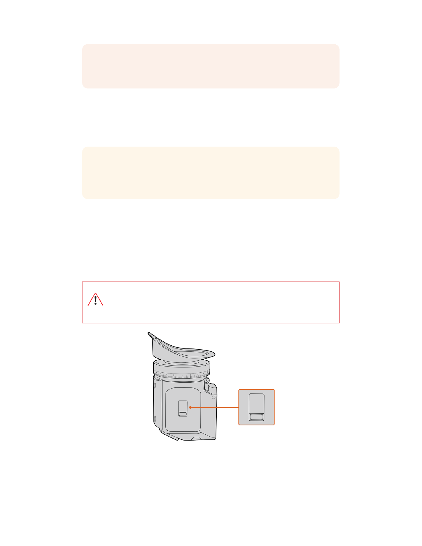
NOTE Enabling ‘Grid’ in your URSA Viewfinder setup menu will also allow your
viewfinder to display tally signals sent from an ATEM switcher. Overlays must also be
set to ‘on’ in the display menu.
Status Text
Toggles the appearance of status text, such as white balance, frame rate and ISO. When ‘status
text’ is turned ‘on’ in your URSA Broadcast G2’s ‘front SDI’ monitor settings, you can use this
setting toggle its appearance in your Blackmagic URSA Viewfinder.
For more information, see the ‘Monitor Settings’ section in this manual.
TIP When using Blackmagic Viewfinder with URSA Broadcast G2, the appearance of
status text can clash if both the viewfinder and camera are set to show status text. In
this situation, we recommend turning status text to ‘on’ in your camera, and status text
to ‘off’ in your viewfinder.
IR Sensor
The IR Sensor on your viewfinder automatically detects when you are near the eyepiece and
turns on the OLED display. If you are away from the viewfinder for over twenty seconds in
standby mode, display turns off to conserve power and to extend the life of the OLED display.
While recording, the timeout sensor is extended to 5 minutes, at which point the OLED
display will be slowly dimmed. Any movement in front of the eyepiece will reset this timer.
The viewfinder will detect when you look into the viewfinder eyepiece, pressing any button
on the viewfinder will also turn the display back on.
Deliberately blocking or covering the IR sensor could cause the viewfinder’s
display to remain powered for prolonged periods of time. This could decrease the
lifespan of the display and cause image retention if high contrast images or frame
guides are displayed on the viewfinder.
The IR sensor is located at the
bottom of the URSA Viewfinder
155Blackmagic URSA Viewfinder
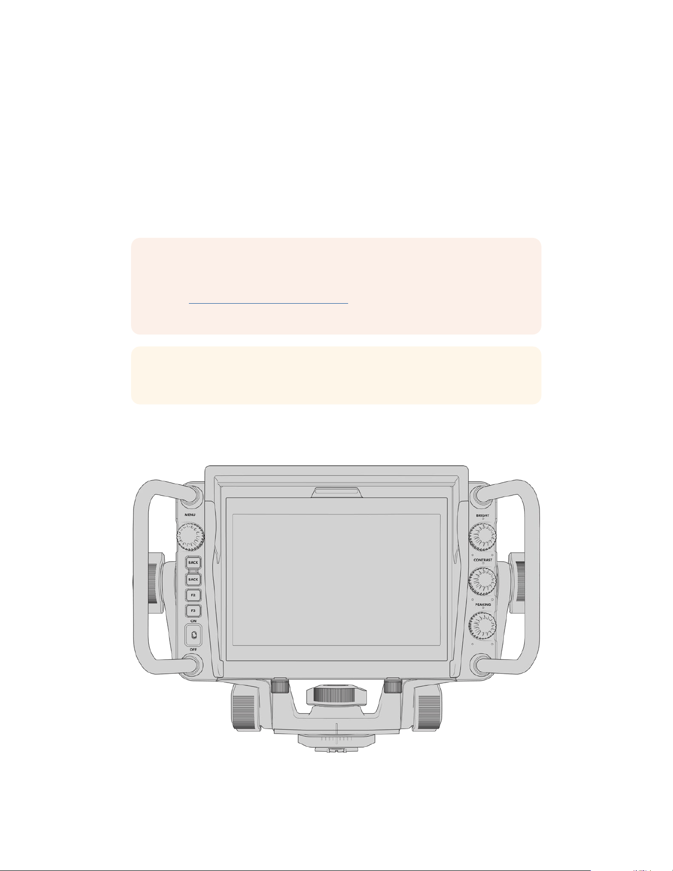
Updating URSA Viewfinder’s Internal Software
Update your viewfinder using the Blackmagic Camera Setup utility software. The viewfinder
will need to be powered when updating, so we recommend keeping the viewfinder connected
to your URSA Broadcast G2 during the update process. This also means your URSA Broadcast
G2 will need to supply consistent power, so be sure to plug into external power.
Connect your computer to the small USB connection located at the front of your viewfinder,
near the eyepiece. When Blackmagic Camera Utility is launched and your viewfinder is
connected to your computer, you will be prompted to update if your computer detects that your
viewfinder is using an older version. Follow the on screen prompts to update your viewfinder’s
internal software.
NOTE When using your Blackmagic URSA Viewfinder with URSA Broadcast G2, we
recommend updating your viewfinder’s internal software to the latest version to ensure
compatibility. The latest software can be found at the Blackmagic Design support
center at www.blackmagicdesign.com/support. Refer to the ‘Blackmagic Camera Setup
Utility’ section in this manual for moreinformation.
TIP We recommend updating all your Blackmagic URSA equipment at the same time
for optimized performance.
Blackmagic URSA Studio Viewfinder
156Blackmagic URSA Studio Viewfinder
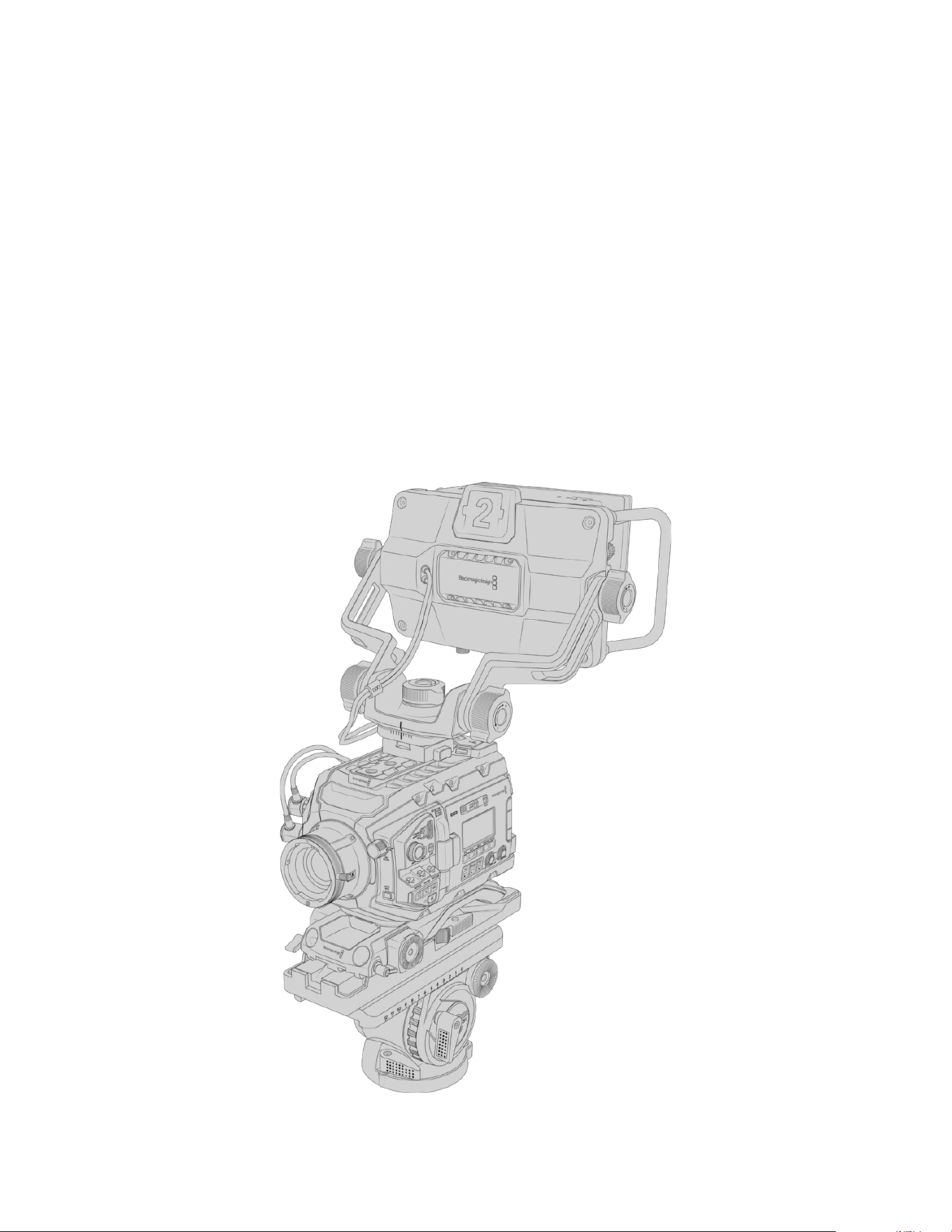
Blackmagic URSA Studio Viewfinder is a powerful viewfinder that allows you to turn your
Blackmagic URSA Broadcast G2 into a professional live production camera. The studio
viewfinder features a bright 7" screen and has a large easily viewable tally light, control knobs,
large handles, sun hood and variable tension articulated mount. These features make it easy to
stand behind the camera and comfortably follow the action for extended periods of time,
especially when filming live concerts, sports, and other long events. The URSA Studio
Viewfinder is perfect for professional live production in the studio or on location.
Mounting and Connecting to Blackmagic URSA Broadcast G2
When using the Blackmagic URSA Studio Viewfinder with Blackmagic URSA Broadcast G2, you
have the option of mounting the unit to the camera in a number of ways.
Using the supplied VLock mount plate you can mount the Blackmagic URSA Studio Viewfinder
directly to the top of your URSA Broadcast G2 or to the top handle of the URSA Mini Shoulder
Kit that is included with your camera.
Attach the V-lock mount plate to the top of the camera with the supplied 1/4" screws. As this
will make the center of gravity on the camera much higher. We recommend doing this while
the camera is attached to atripod for stability.
157Blackmagic URSA Studio Viewfinder
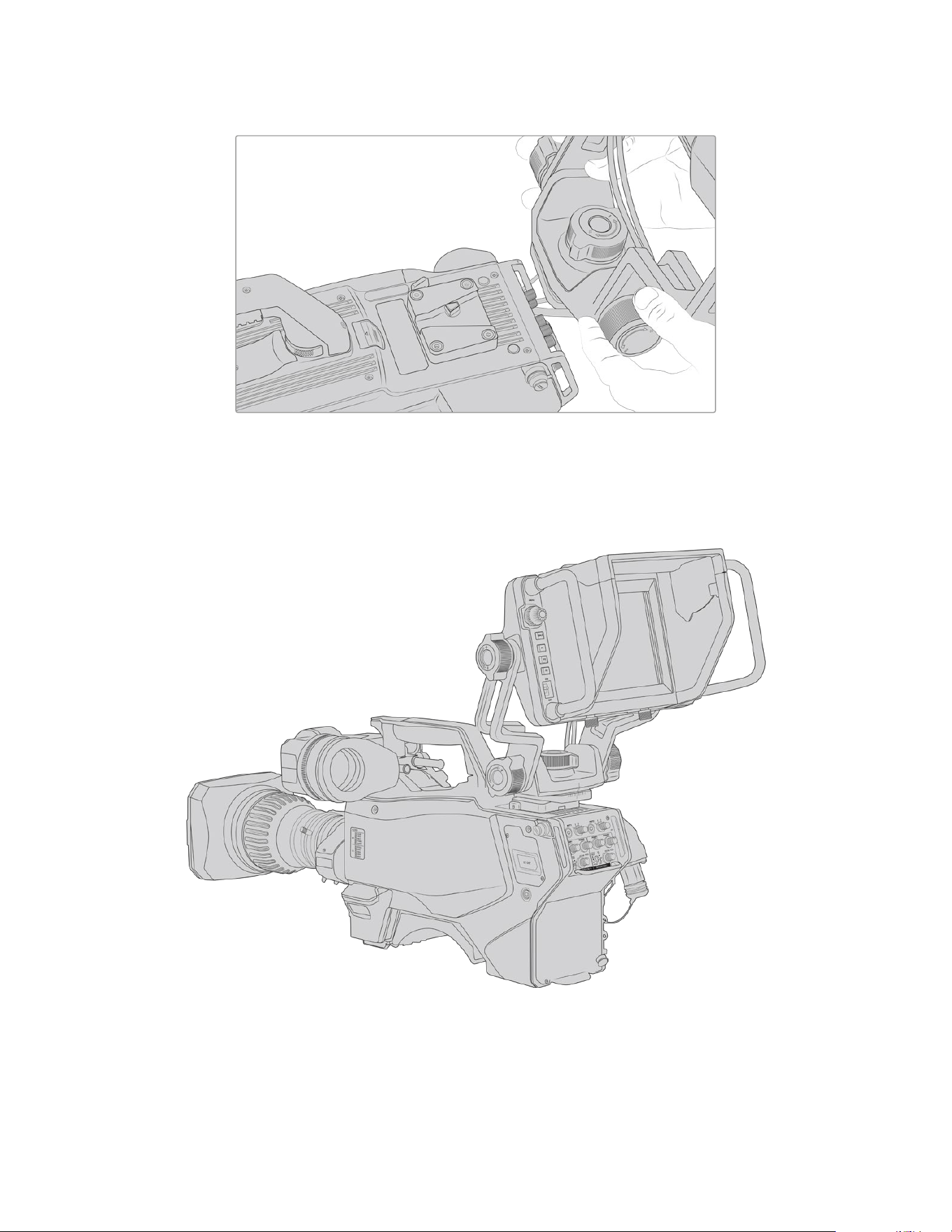
V-Lock mount plate being attached to 3rdparty camera
The V-Lock mount plate can also be installed on any camera you want to use the URSA Studio
Viewfinder with that has 1/4" mounting points, or by using a third party cheese plate. You can
also mount the Blackmagic URSA Studio Viewfinder to a third party camera system that has an
existing V-lock mount plate as many of them have this quick release plate on them already.
158Blackmagic URSA Studio Viewfinder
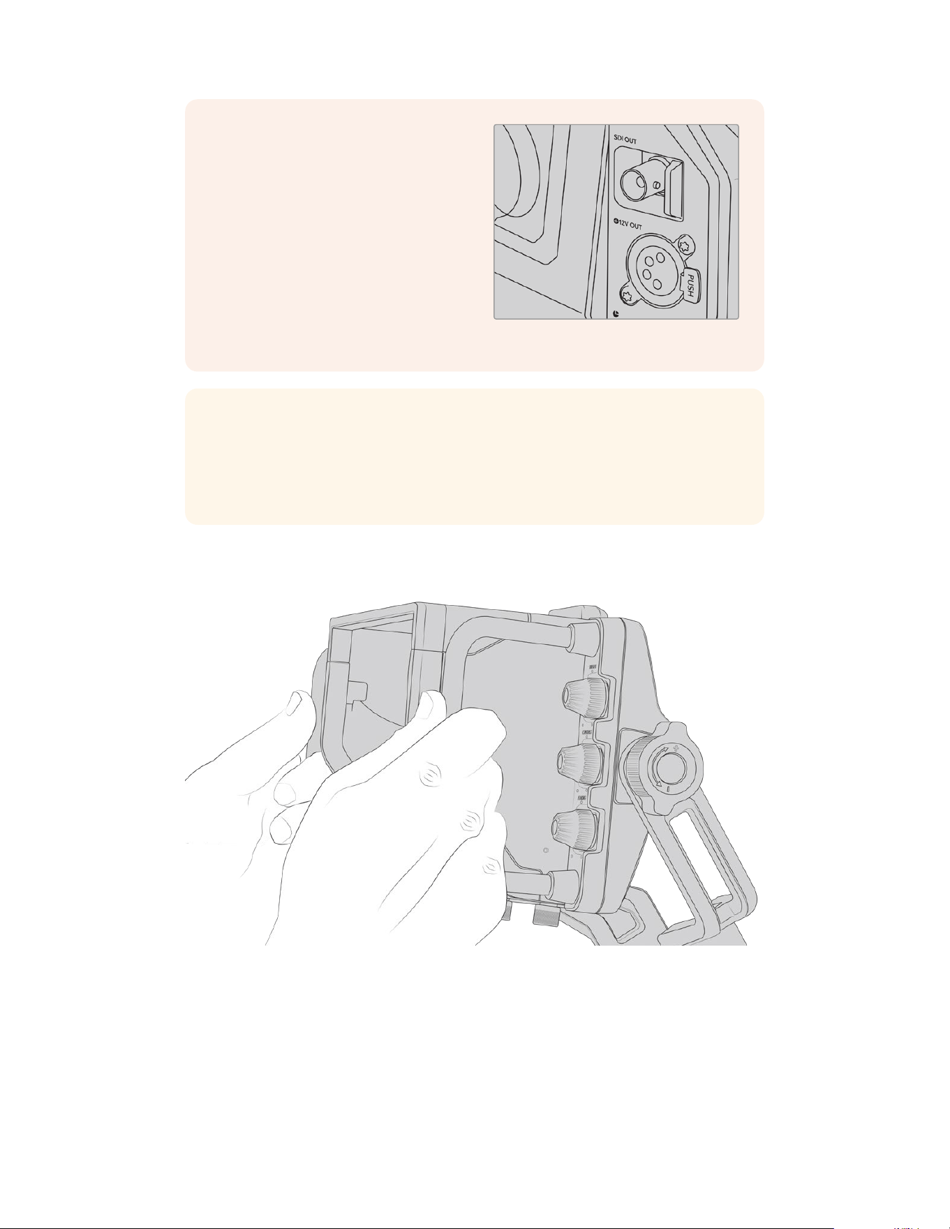
To connect your Blackmagic URSA Studio
Viewfinder to your URSA Broadcast G2,
simply connect the viewfinder’s attached
cables to your camera’s front 12V power
and 3G-SDI outputs.
The power switch on the viewfinder will
then allowyou to turn on the viewfinder
instantly when your camera is powered.
Note that there are cable clamps on the
side of the URSAMini handle mount to
keep you cables neat and hold the
cables in place.
TIP The URSA Studio Viewfinder uses open standard SDI and broadcast 4 pin XLR
power connections so it can be used with any other camera or even as an adjustable
portable location monitor. It also uses the open standard ATEM tally and device control
protocol so any other camera system can add this information to their SDI stream to
allow them to work with the tally and overlays on the URSA Studio Viewfinder.
Adjusting the Blackmagic URSAStudio Viewfinder
The Blackmagic URSA Studio Viewfinder features large handles and variable tension articulated
mounting that allow you to adjust the position and angle of the viewfinder. The large handles
allow you to quickly and easily take hold of the viewfinder and adjust the angle and direction of
the unit. Combined with the sun hood the handles also help to protect the screen from damage,
which means that you can store the fully assembled Blackmagic URSA Studio Viewfinder in
a carry case without disassembly. The large handles also allow you easily to pick up and carry
the unit between locations.
SDI and 12v power connections
on URSA Broadcast G2
159Blackmagic URSA Studio Viewfinder
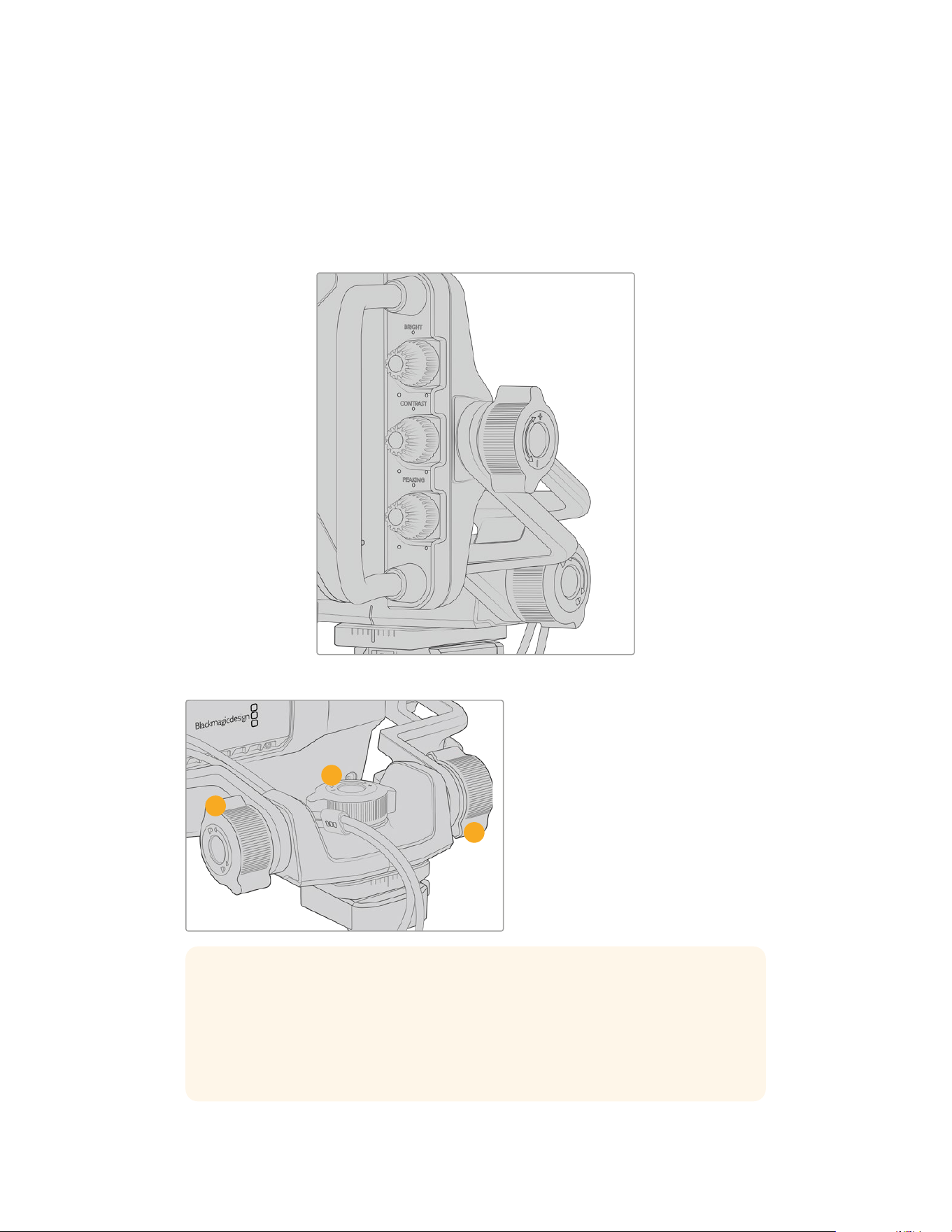
The supplied mount features tension dials for pan and tilt, with additional tension dials on either
side of the viewfinder for additional friction control. The left hand dial allows you to adjust the
drag friction of the arm and the right hand dial allows you to lock the Viewfinder in place once
you have found the angle you require.
These tension dials have a very large range of tension adjustment, allowing you to select a
specific amount of resistance. This allows you to easily pan and tilt the viewfinder to the precise
position you require.
Tension dials on either side of the viewfinder
1 Tilt Lock Dial
Locks the angle of tilt on
the viewfinder mechanism.
2 Pan Tension Dial
Controls pan tension.
3 Tilt Tension Dial
Controls tilt tension.
1
2
3
TIP The center tension dial on the supplied mount controls pan tension, and can
be loosened to allow you to take hold of the viewfinder and move the camera
independently. This means that you can film things like motorsport, where you need
to pan the camera left and right to follow the action, whilst holding the viewfinder
positioned towards your eyes. A visual guide on the mount helps to ensure that the
viewfinder can easily be returned to the center.
160Blackmagic URSA Studio Viewfinder
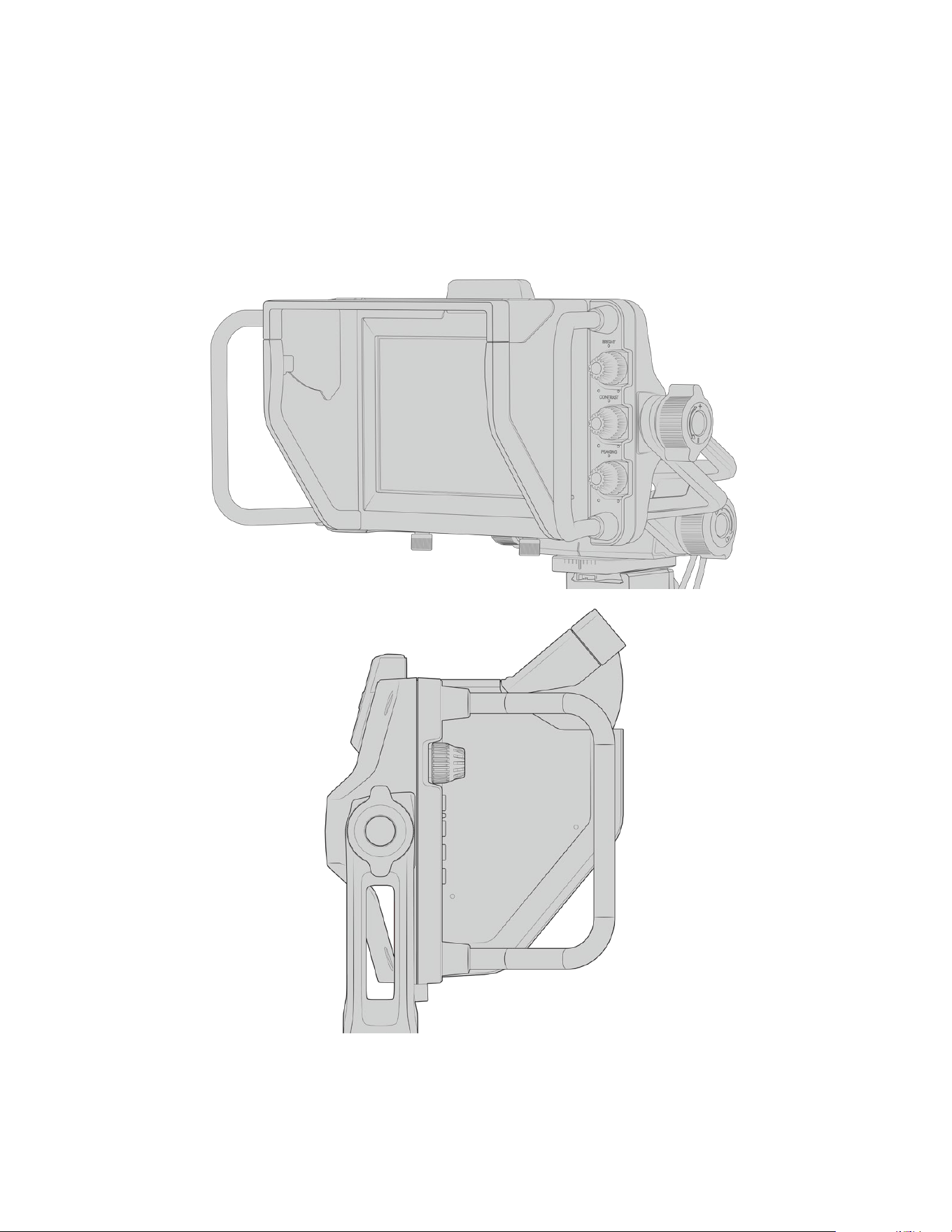
Sun hood
The sun hood helps you to see the screen in bright or sunny conditions. To attach the sun hood,
slide it over the top of the Blackmagic URSA Studio Viewfinder and push it into place, securing
it with the two captive screws on the base of the sun hood. The top section of the visor is
adjustable, and can raise and lower to provide additional viewing angles. The sun hood
provides additional protection for the 7” screen, and can be removed quickly and easily if
desired or to access the USB-C connector for software updates.
Sun hood and adjustable visor
161Blackmagic URSA Studio Viewfinder
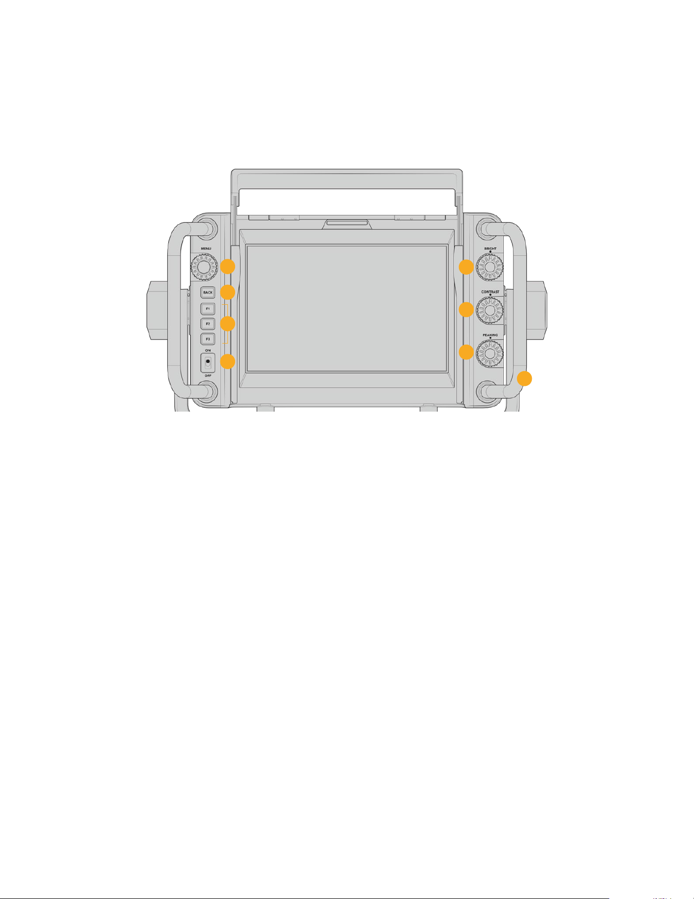
Button Features
The dials down the right hand side let you change brightness, contrast, peaking quickly and
easily. The dials are ergonomically designed so you can adjust the dials from the side with your
thumb when using the sun hood, or with two fingers for finer more controlled adjustment.
1
5
6
7
8
2
4
3
1 Menu Dial
The push button ‘menu’ dial allows you to
enter the menu, and navigate through the
viewfinder settings.
2 Back button
Exits the menu system
3 F1, F2, F3
Assignable function buttons. You can
assign functions to these buttons for easy
access to your most commonly used
functions.
4 ON/OFF switch
Switches the Blackmagic URSA Studio
Viewfinder on and off.
5 Bright
Adjusts the brightness of the image
on screen. Overlays on screen will
show the brightness level on a scale of
-100 to +100.
6 Contrast
Adjusts the contrast of the image on
screen. Overlays on screen will show the
contrast level on a scale of -100 to +100.
7 Peaking
Adjusts the focus peaking level for the
image on screen. Overlays on screen will
show the peaking level on a scale of -100
to +100. In the setup menu you can select
between various styles of peaking to suit
your environment. There is the option
for the traditional style of focus peaking
that many will be familiar with from other
broadcast systems, as well as the option
to use colored lines for focus. As with
URSA Broadcast G2 you have the option
of ‘red’, ‘green’, ‘blue’, ‘black’ and ‘white’
lines which gives you flexibility to make
them easily viewable when shooting
in environments that have a lot of a
particular color.
8 Handles
The built in handles are large and allow
you to hold the Studio Viewfinder in
place as you reposition the camera while
shooting. They also provide protection
for the screen when setting up and
packing down.
162Blackmagic URSA Studio Viewfinder
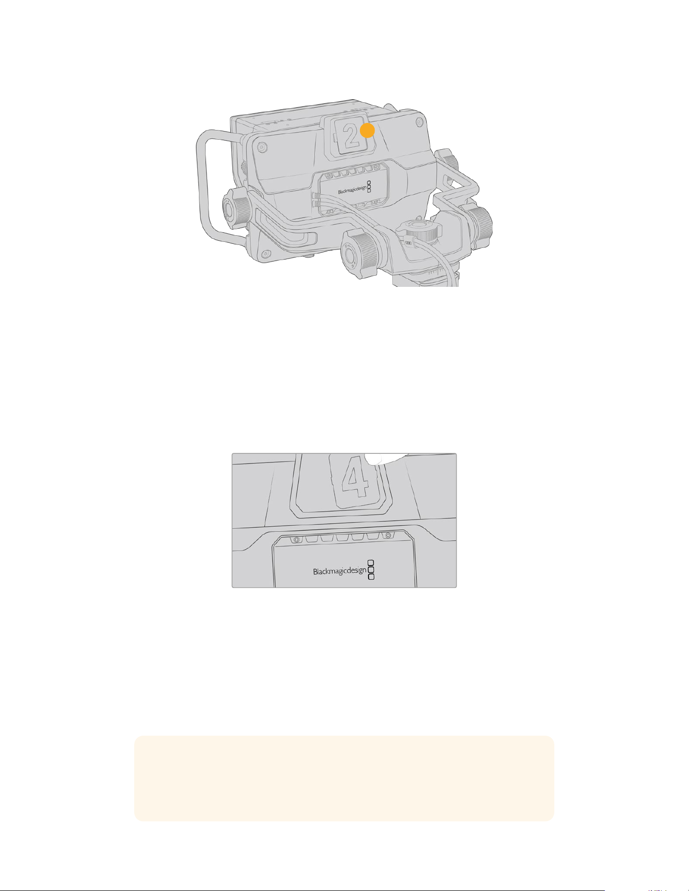
9
9 Tally Light
The large tally light on the rear of the Blackmagic URSA Studio Viewfinder lets both the
talent and operator know which camera is on the air, which camera is about to be on air,
and if they are ISO recording. The tally illuminates red for on-air, green for preview and
when used with URSA Broadcast G2 will illuminate yellow for ISO record.
As the director cuts between cameras on the ATEM switcher, tally information is sent back
to the camera over SDI so the light is lit when the camera is being previewed to switch to,
on the air or recording. In addition, the URSA Studio Viewfinder also includes clip-on
transparent camera numbers that attach to the tally light, making it easy for talent to clearly
see camera numbers from up to 20 feet away.
We have included editable PDF’s in the software installer that allows you to edit and print
out your own tally numbers to match the ones provided, and also to create your own
custom tally number inserts. After installing the Blackmagic cameras software these can
be found on a Mac in the Application > Blackmagic Cameras > Documents folder and on
aPC in the Blackmagic Design > Documents folder.
The tally light will illuminate according to the ATEM switching operations, and when the
camera is not connected to a switcher the tally light will illuminate red as a simple record
tally indicator. Refer to the ‘Understanding Studio Camera Control’ section in this manual
for more information.
TIP When using the Blackmagic URSA Studio Viewfinder with an ATEM switcher, it is
important to select ‘clean feed’ on URSA Broadcast G2 to ensure that you don’t see
overlays or the focus box on the SDI output to the ATEM switcher. Navigate to the
‘monitor’ menu on URSA and select ‘clean feed’ for ‘main SDI’.
163Blackmagic URSA Studio Viewfinder
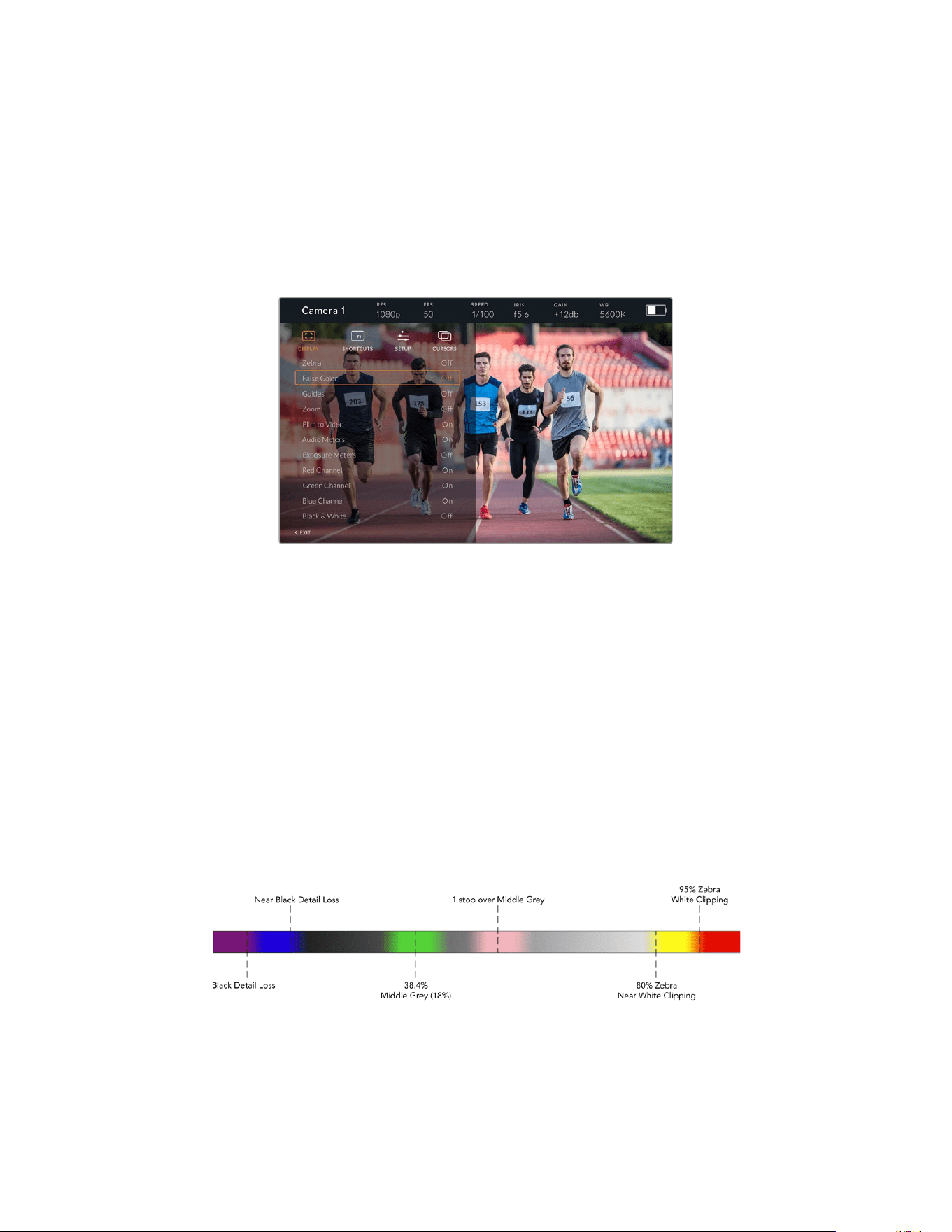
Menu Settings
The push button ‘menu’ dial allows you to enter the menu by pressing it, whilst rotating the
dial navigates up and down through the menu options. Pressing the ‘menu’ dial whilst a menu
heading is highlighted, will allow you to switch between the display, shortcuts, setup and cursor
sub menus. Rotating the dial will scroll through the settings in each menu. Pressing the dial
when a setting is highlighted allows you to adjust that setting by rotating the ‘menu’ dial.
Confirm your selection by pressing the ‘menu’ dial once more. You can exit out of the menu
by hitting the ‘back’ button or by navigating to and selecting exit.
Display
Zebra
Switches zebra levels on and off. The level of zebra will be determined by the setting
on your URSA Broadcast G2, in the third page of the ‘Monitor’ settings menu. When the
Studio Viewfinder is not connected with URSA Broadcast G2, the zebra level will
represent 95% of the luminance levels of a Rec 709 signal. For more information, refer
to the ‘settings’ section in this manual.
False Color
Switches the false color feature on and off. False color overlays different colors onto your
image that represent exposure values for different elements in your image. For example, pink
represents optimum exposure for skin tones. By monitoring the pink false color when recording
people, you can maintain consistent exposure for skin tones. Similarly, when elements in your
image change from yellow to red, that means they are now over exposed. False color is a good
feature to assign to one of the function buttons, as it provides quick and easy access to a
commonly used reference tool for exposure.
False Color Chart
164Blackmagic URSA Studio Viewfinder

Guides
This setting gives you the option to show or hide your guides. The guides will match the style
of guides that have been set in the URSA Broadcast G2, in the fourth page of the ‘Monitor’
settings menu.
The aspect ratio, frame guide opacity level, safe area percentage, and the type of grids shown
will match what you have set in the camera. The ‘setup’ menu in the Studio Viewfinder then
allows you to configure which type of guides you would like to see in the Studio Viewfinder
when guides in the display menu are switched on. Guides then allows you to then switch these
‘on’ or ‘off’ with one command.
Zoom
Turns the ‘zoom’ feature on and off. The ‘zoom’ feature helps you find sharp focus by
zoominginto your picture. When zoomed in, you can navigate to specific parts of the screen
by rotating the menu dial left and right. The overlay will indicate which part of the picture you
arezoomed into.
Film to Video
When sending a ‘film’ dynamic range SDI signal from your URSA Broadcast G2, the ‘film to
video’ setting allows you to apply a more colorful and contrasty LUT to the image. This setting
will only be available when ‘film’ dynamic range is detected and will otherwise be grayed out
to prevent the wrong LUT being applied to the image.
Audio Meters
The audio meters display the audio level that is being input via SDI into the Blackmagic
URSAStudio Viewfinder, therefore the meters will show you URSA Broadcast G2’s audio input
levels. If you have program input selected, the audio meter will display these audio levels.
Exposure Meters
Switches the display of the histogram ‘on’ or ‘off’.
Red Channel
Allows you to switch on or off the red channel of your image.
Green Channel
Allows you to switch on or off the green channel of your image.
Blue Channel
Allows you to switch on or off the blue channel of your image.
Black and White
Switches between color and monochrome.
Shortcuts
The shortcut function allows you to map specific functions to the F1, F2 and F3 buttons.
These shortcut buttons allow you to quickly toggle ‘on’ and ‘off’ any of the settings in the
display menu, or your cursors. This is extremely useful when you need to quickly access a
particular setting for a frequently used feature.
To customize your shortcut buttons: In the ‘shortcuts’ menu, rotate the push button ‘menu’ dial
to move up or down and select one of the 3 buttons. Press the ‘menu’ dial to confirm your
selection and then rotate the ‘menu’ dial to scroll through the assignable features. You will
have the option to select one of the following features: ‘zoom’, ‘cursor 1’, ‘cursor 2’, ‘cursor 3’,
‘zebra’, ‘false color’, ‘guides’, ‘film to video’, ‘audio meters’, ‘exposure meters’, ‘red channel’,
‘greenchannel’, ‘blue channel’, ‘black and white’. Once chosen click the menu button to confirm
that selection, and assign that function to the chosen shortcut button. Pressing the shortcut
button will now switch this feature ‘on’ and ‘off’.
165Blackmagic URSA Studio Viewfinder
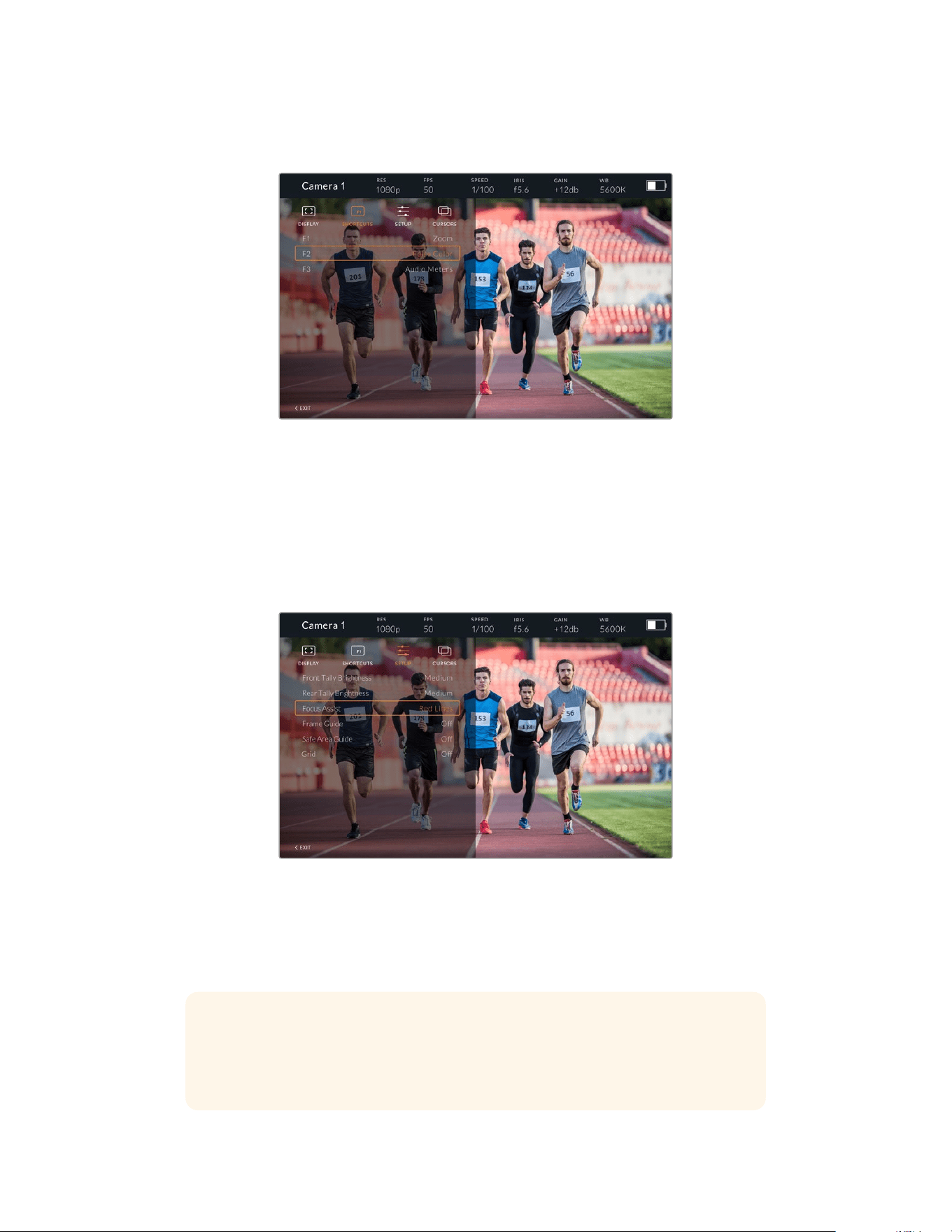
Once you have set up your shortcuts as required you can either scroll to ‘exit’ and press the
‘menu’ dial to close the menu display view, or hit the back button to exit out of the menu.
The ‘shortcuts’ submenu
Setup
The ‘setup’ menu is where you choose your preferences for how the viewfinder is setup.
Front Tally Brightness
Allows adjustments of tally LED brightness between ‘off’, ‘low’, ‘medium’ and ‘high’. Thetally
light will illuminate whilst adjustments are being made so you can see what each brightness
level represents.
The ‘setup’ submenu
Rear Tally Brightness
Allows adjustments of tally LED brightness between ‘low’, ‘medium’ and ‘high’. The tally light
willilluminate whilst adjustments are being made so you can see what each brightness
levelrepresents.
TIP A high LED brightness setting is recommended for bright conditions, as
it will provide greater visibility for talent and operators in the conditions. A low LED
brightness is recommended when filming in darker environments where
it is easier to see when the light is on.
166Blackmagic URSA Studio Viewfinder
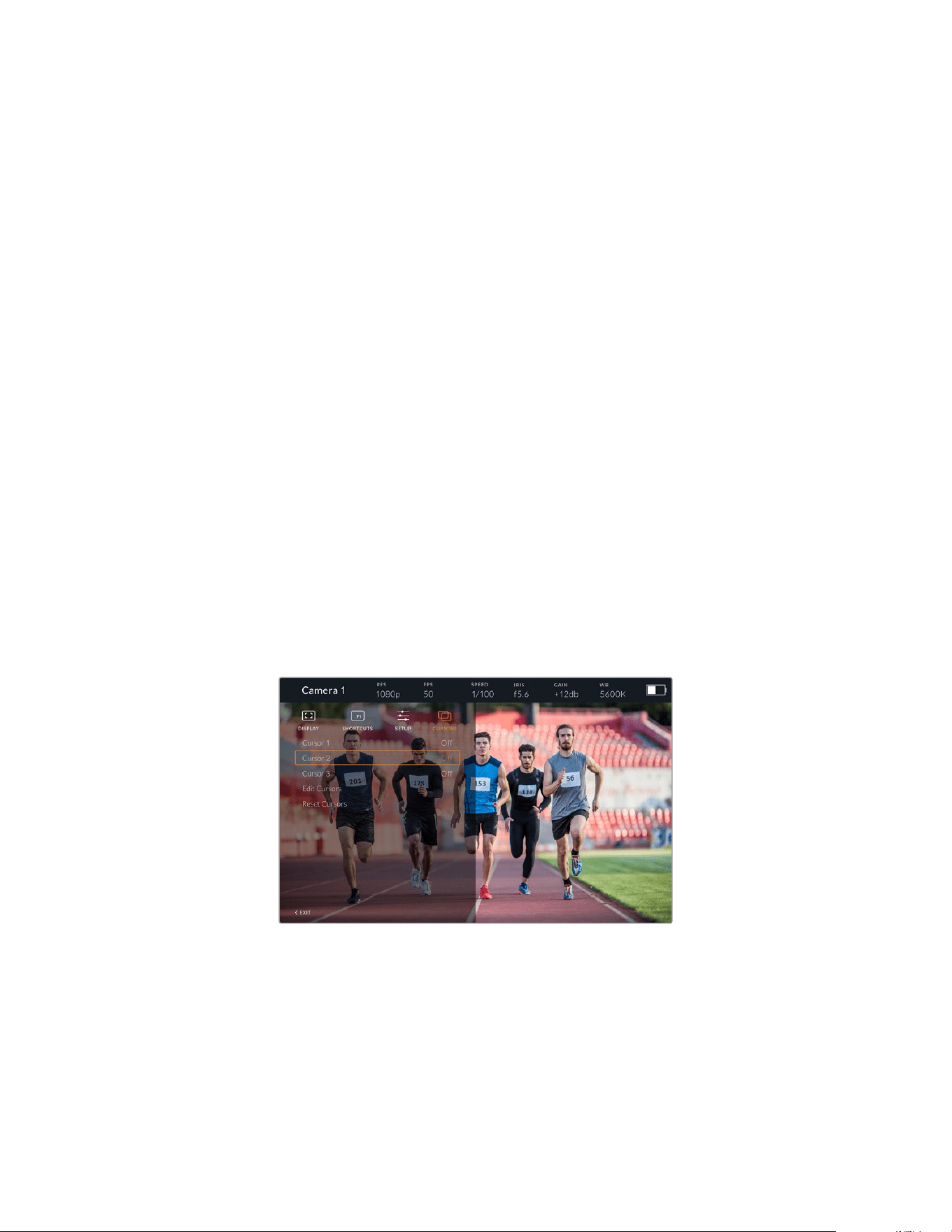
Focus Assist
The ‘focus assist’ setting toggles the appearance of peaking on the viewfinder. You have the
choice of ‘red’, ‘green’, ‘blue’, ‘black’ and ‘white’ as well as traditional peaking.
Frame Guide
Gives you the option to show ‘frame guides’ as part of your Studio Viewfinder’s ‘Guides’. When
connected to URSA Broadcast G2 they will match your camera’s ‘frame guides’ aspect ratio.
When connected to other systems they will default to the 14:9 aspect ratio.
Safe Area Guide
Gives you the option to show the ‘safe area’ indicator as part of your Studio Viewfinder’s
‘Guides’. When connected to URSA Broadcast G2 these will match your camera’s ‘safe area
guide’ percentage. When connected to other systems they will default to 90%.
Grid
Gives you the option to show grids as part of your Studio Viewfinder’s ‘Guides’.
Whenconnected to URSA Broadcast G2 these will match your camera’s ‘grids’ settings.
When not connected, this will switch your crosshairs on or off.
LCD Brightness
If you have the updated model of URSA Studio Viewfinder then the LCD Brightness setting
will appear at the bottom of the setup menu. This adjusts your Studio Viewfinder LCD
backlight brightness.
Cursors
The cursors allow you to mark an area on screen where graphics like a lower third, graphic,
logo or ticker will be overlaid. To adjust these cursors go to ‘cursors’ and select ‘edit cursors’.
This will bring up a page that shows you all three cursors and allows you to select each one
individually and then dial in the width, height, x and y co-ordinates for positioning each
oneindividually.
The cursors submenu
167Blackmagic URSA Studio Viewfinder

Cursors displayed on screen
Once you have set them up they can be switched on or off from the ‘cursors’ menu or assigned
to your function keys for quick access. This is important for live production, as it allows the
camera operator to take this into consideration and accurately compose and frame shots. You
can create up to three black or white custom cursors that can have variable height, width and
position, making it easy to match the size and location for all the graphics that will be added live
or during later broadcast. You also have the option to reset the cursors to their default state.
Using a headset with the Blackmagic URSA Studio Viewfinder
When using the Blackmagic URSA Studio Viewfinder with URSA Broadcast G2, the headphone
connection on the camera will now become a talkback headset connection, allowing for direct
communication with the director.
For more advanced talkback functionality, you can also use Blackmagic Camera Fiber Converter
and Blackmagic Studio Fiber Converter to allow you to use standard broadcast headsets with
5pinXLR connectors. For more information, refer to the ‘Blackmagic Fiber Converters’ section
inthis manual.
TIP Because URSA Broadcast G2’s headphone socket is iPhone headset compatible,
you can use your iPhone headset to communicate with the director. Pushing the button
on the built-in remote will allow you to talk back to the director.
Updating URSA Studio Viewfinder’s Internal Software
Update your viewfinder using the Blackmagic Camera Setup utility software. The viewfinder
will need to be powered when updating, so we recommend keeping the viewfinder connected
to your URSA Broadcast G2 during the update process. This also means your camera will need
to supply consistent power, so be sure to plug into external power.
Remove the sun hood to provide access to the small USB-C connection located on the bottom
of the Blackmagic URSA Studio Viewfinder, and connect your computer to the USB-C port.
When Blackmagic Camera Utility is launched and your viewfinder is connected to your
computer, you will be prompted to update if your computer detects that your viewfinder is using
an older version. Follow the on screen prompts to update your viewfinder’s internal software.
Refer to the ‘Blackmagic Camera Setup Utility’ section in this manual for more information.
We recommend updating all your Blackmagic URSA equipment at the same time for
optimized performance.
168Blackmagic URSA Studio Viewfinder
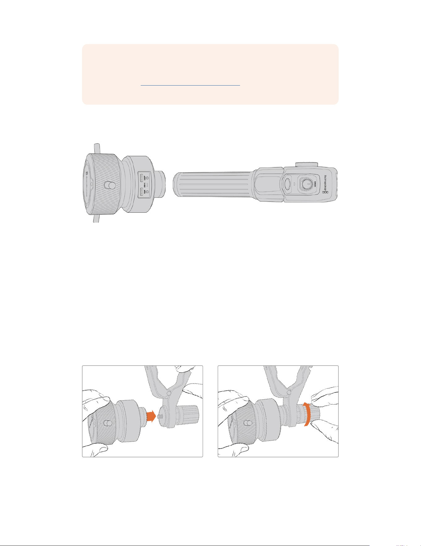
NOTE When using your Blackmagic URSA Studio Viewfinder with URSA Broadcast G2,
we recommend updating your viewfinder’s internal software to the latest version to
ensure compatibility. The latest software can be found at the Blackmagic Design
support center at www.blackmagicdesign.com/support. Refer to the ‘Blackmagic
Camera Setup Utility’ section in this manual for more information.
Blackmagic Zoom and Focus Demands
Blackmagic Zoom Demand and Blackmagic Focus Demand are optional accessories for
controlling focus and zoom when using compatible servo driven B4, EF and PL lenses.
Each unit attaches to a tripod handle on your tripod or camera pedestal. This lets you control
focus and zoom while simultaneously panning and tilting the camera using both hands.
Additional buttons and controls let you refine the speed and sensitivity of the zoom control,
engage talkback, monitor program return and more.
Connecting and Attaching to your Camera
Attaching to Tripod Handles
Each unit attaches to a tripod handle via their mounting brackets. Attach each unit to the
brackets via their rosette mounts:
To attach the demand units to their brackets, simply connect them together via their rosette
mounts and secure them by tightening the fastening knob.
1 Place the zoom demand or focus demand against their bracket’s rosette mount.
2 Tighten their fastening knob so the demand units are firmly attached to their brackets.
169Blackmagic Zoom and Focus Demands
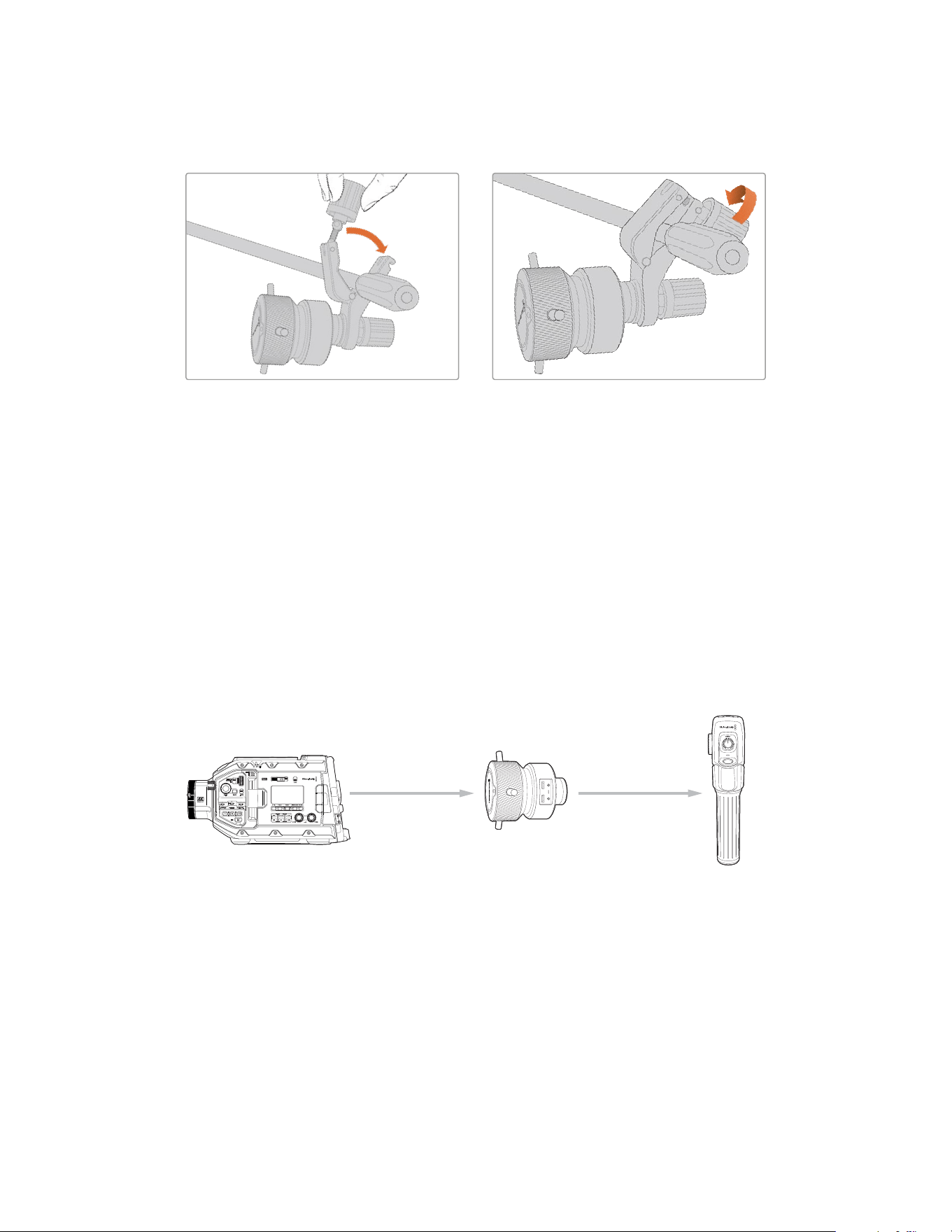
Now that the units are attached to the brackets, you can attach the brackets to the tripod arms.
One end of each bracket contains a ‘T’ shaped latch that hinges into a slot and is then tightened.
1 Loosen the latch by unscrewing the latch knob in a counterclockwise motion. This will
release the ’T’ shaped latch.
2 With the latch open, place the bracket onto the tripod arm and clamp the bracket shut by
closing the latch into its fastening slot. Rotate the bracket to your preferred position on the
tripod arm.
3 Tighten the latch knob to secure the bracket to the tripod arm.
Connecting to Your Camera
Blackmagic Focus and Zoom Demands have two USB-C ports. This lets you use one unit
individually, or both units together.
Each unit is supplied with a 1 meter long USB-C cable which is connected directly from your
URSA Broadcast G2’s rear USB-C port to the demand unit’s ‘cam’ port.
If you are using both demand units, daisy chain them together by connecting the first unit to
thesecond unit via USB-C.
Blackmagic
F
ocus D
emand
Blackmagic
Z
oom D
emand
Blackmagic
URSA
Br
oadc
ast
G2
R
ear
USB-C port
USB-C
CAM
USB-C
L
O
O
P
USB-C
C
A
M
US
B-C
CAM
L
OOP
ON
OFF
Daisy chaining allows for both units to be controlled using the rear USB-C port on your
URSABroadcast G2. For example, connect a USB-C cable into your camera’s rear USB-C port
and connect the other end of the cable into the focus demand’s ‘cam’ port. With a second
cable, plug the focus demand’s ‘loop’ port into the zoom demand’s ‘cam’ port.
170Blackmagic Zoom and Focus Demands
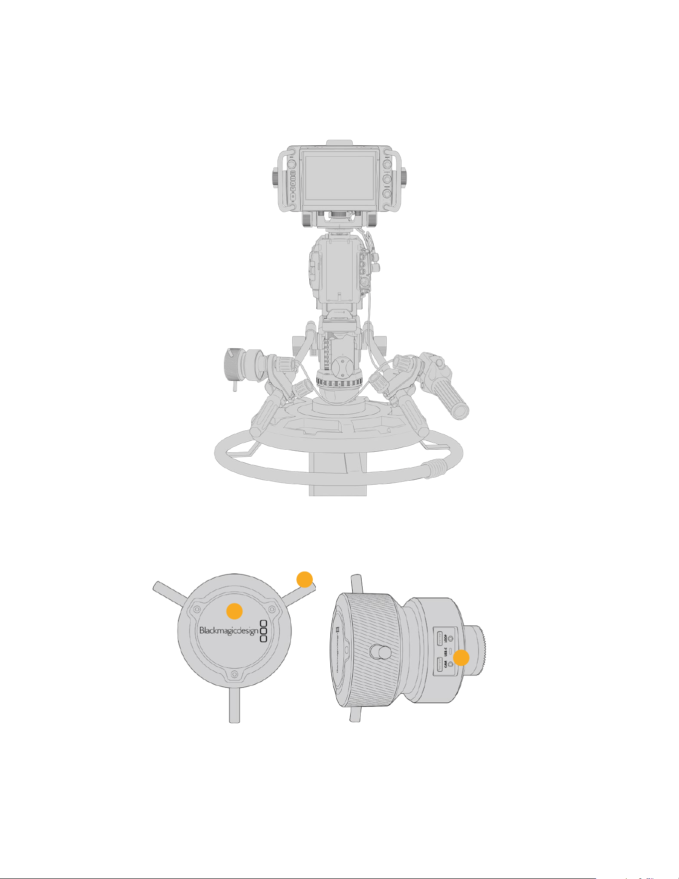
The USB-C cable has locking screws on each end to secure the connectors to each unit,
preventing accidental disconnection. You don’t have to use the locking screws, but they are
helpful for studio setups where the units are always connected to your URSA Broadcast G2.
The Blackmagic Focus and Zoom Demands let you control focus
and zoom without moving your hands away from the handles
Using Blackmagic Focus Demand
3
2
1
1 Control Knob
Rotate the focus wheel clockwise to focus on subjects closer to the lens, or
counterclockwise to focus on subjects further away. You can change the focus direction in
the menu by setting it to either ‘normal’ or ‘reverse’.
171Blackmagic Zoom and Focus Demands
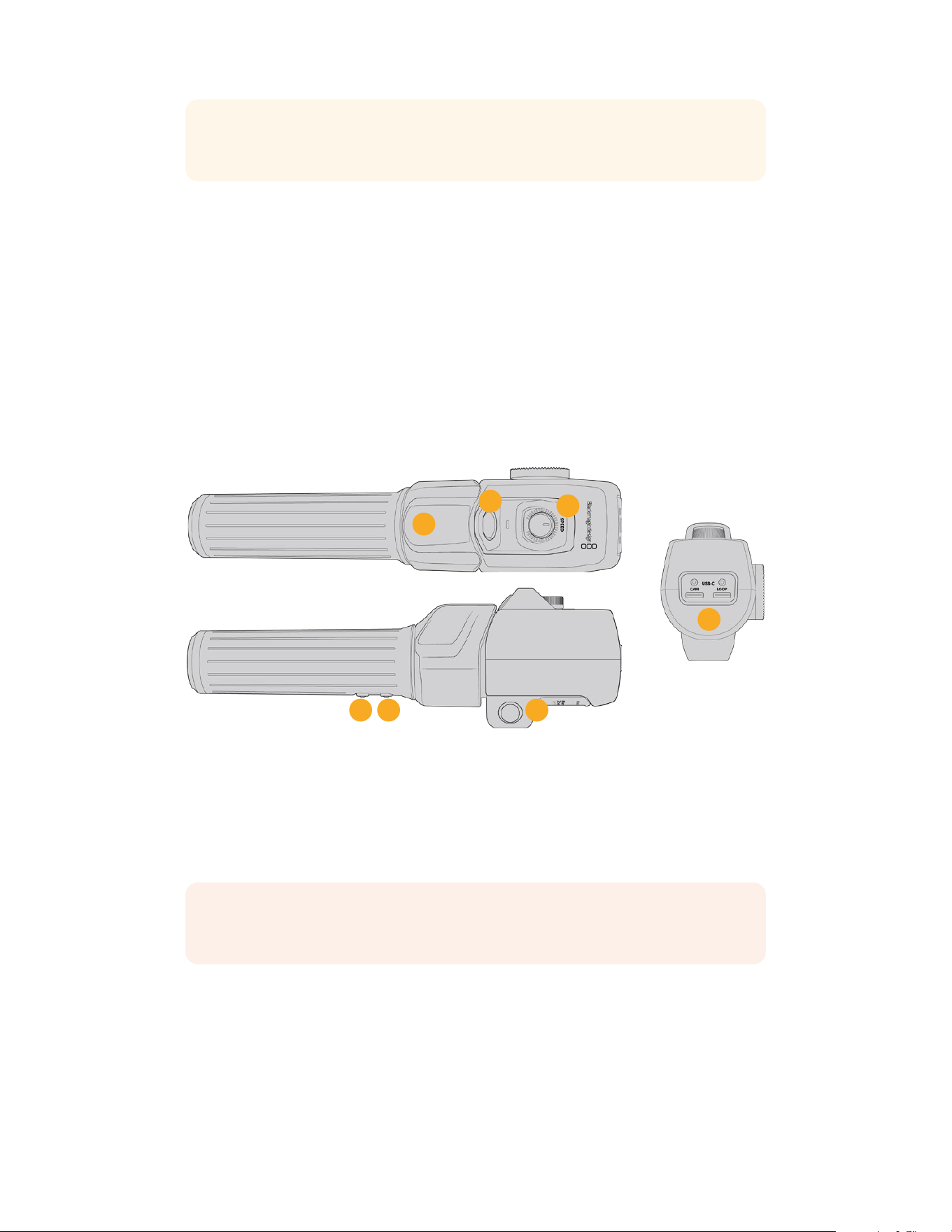
TIP If you are also using a Blackmagic Zoom Demand, press the quick zoom button to
magnify the image as you focus using the focus demand.
2 Control Prongs
These three prongs expand the diameter of the control surface to let you make finer focus
adjustments with the tip of a finger.
3 USB ports
Allows for connecting the focus demand to the camera and daisy chaining to the zoom
demand. The ‘cam’ port is also used for updating the internal software via the Blackmagic
Camera Setup utility.
Using Blackmagic Zoom Demand
The controls on the Zoom Demand are mappable through the Camera settings. To change the
button functions, refer to the ‘setup settings’ chapter in the ‘settings’ section.
The following commands are set as default:
7
2
3
4
5
6
1
1 Zoom F1
This is the zoom function button 1. By default, it is mapped as a ‘record’ button.
2 Zoom F2
This is the zoom function button 2. On the other side of the controller is an identical button
that performs the same function, allowing for left and right handed control. Bydefault, it is
set as a quick zoom function which instantaneously punches into the live image.
NOTE The quick zoom feature is only visible on the Blackmagic URSA Broadcast G2’s
LCD and will not be visible on the output video connected toaswitcher or recorder.
3 Zoom F3
This is the zoom function button 3. The default action for this button is set to program
return. This would normally be a switcher’s program return feed, but can be any SDI signal
connected to your camera’s SDI input.
172Blackmagic Zoom and Focus Demands
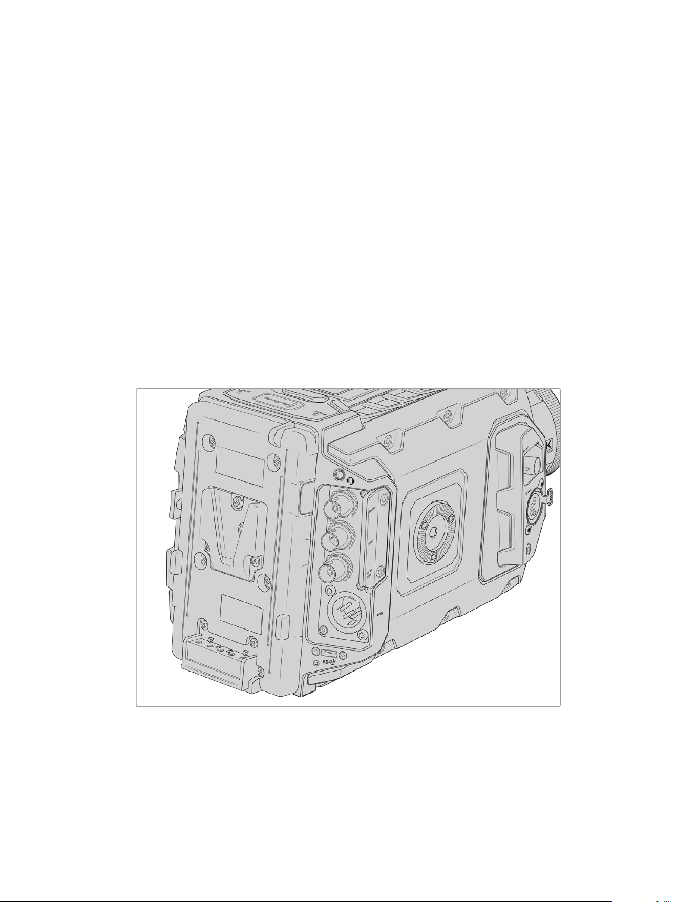
4 Zoom F4
This is the zoom function button 4. The default action for this button is set to push to talk.
When connected to an ATEM switcher via SDI, press andhold the button to communicate
with the switcher operator.
5 Thumb Rocker
The zoom demand handle provides a thumb rocker control. Push the thumb rocker left to
zoom out, and right to zoom in. The direction of the zoom can be reversed using the
camera’s menu settings.
6 Speed Dial
Finely adjust the speed of the zoom by adjusting the speed dial at the top of the unit.
You can map this dial to also control the headphone level, iris adjustment and even
focus adjustment!
7 USB-C Ports
Allows for connecting the zoom demand to the camera and daisy chaining to the
focus demand. The ‘cam’ port is also used for updating the internal software via the
Blackmagic Camera Setup utility.
Mounting Batteries
Mounting V-mount or GoldMount Batteries
Your Blackmagic URSA Broadcast G2 comes fitted with a URSA VLock Battery Plate for
attaching industry standard VLock batteries to your camera.
Other battery types can also be mounted by attaching an optional Blackmagic URSA Gold
Battery Plate, or a third party battery plate.
173Mounting Batteries
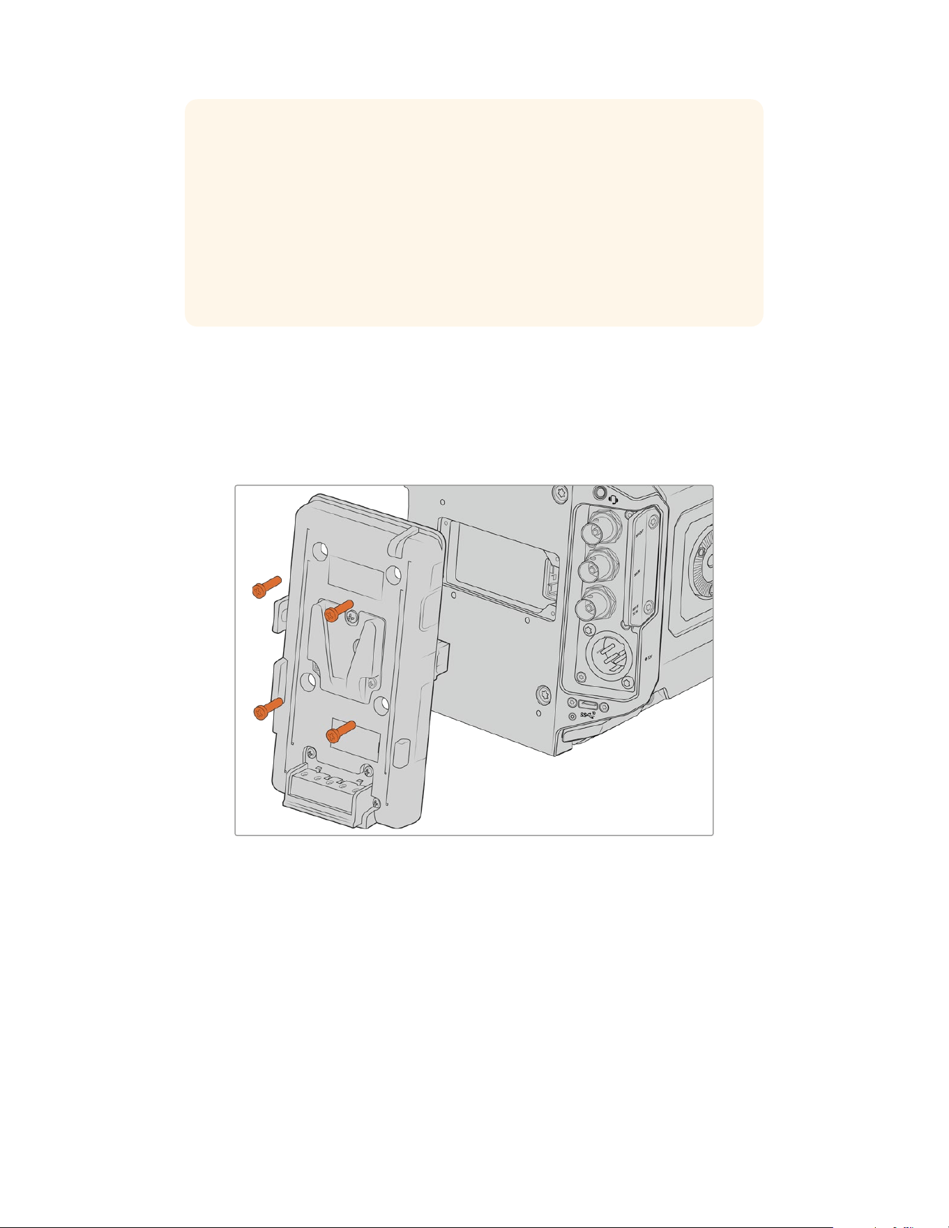
TIP Blackmagic URSA VLock Battery Plate and URSA Gold Battery Plate support
displaying percentage information with compatible batteries. Blackmagic battery
plates have a ‘+12V out’ connector referred to as a ‘D-tap’ or ‘P-tap’ to power
accessories such as an external monitor. It is worth noting that because this output is
regulated from the camera, it will power down safely when the camera switches off.
This regulated output supplies 12 Volts at up to 1.5 Amps. Some third party
URSA battery plates, and even some batteries, offer an unregulated D-tap output.
These supply continuous power when the camera is rebooting or power cycled, but
the voltage varies depending on the charge level of the battery and accessories
plugged in will drain the battery continuously.
You can purchase Blackmagic URSA VLock Battery Plates and URSA Gold Battery Plates from
Blackmagic Design resellers, or third party battery plates from suppliers of professional digital
cinema and video equipment. If you want to modify your own battery plate to use with your
Blackmagic URSA Broadcast G2, then you can use the supplied adapter cable and connector.
Refer to the ‘using your own battery plate’ section for information about how any battery plate
can be modified to use with URSA Broadcast G2.
To replace the battery plate on your Blackmagic URSA Broadcast G2:
1 Unscrew the 4 x M3 screws from each corner of the URSA VLock Battery Plate.
2 Disconnect the battery plate’s molex connector from your camera’s molex powerconnector.
3 Connect the new battery plate’s molex connector to your camera’s molex powerconnector.
4 Screw the battery plate onto your Blackmagic URSA Broadcast G2’s plate mounting points
using 4 x M3 screws. Make sure the connector cable is tucked safely into the cable slot and
not crushed between the plates when tightening.
5 With the new battery plate connected to your camera, you can now mount a battery and
power up your camera.
174Mounting Batteries
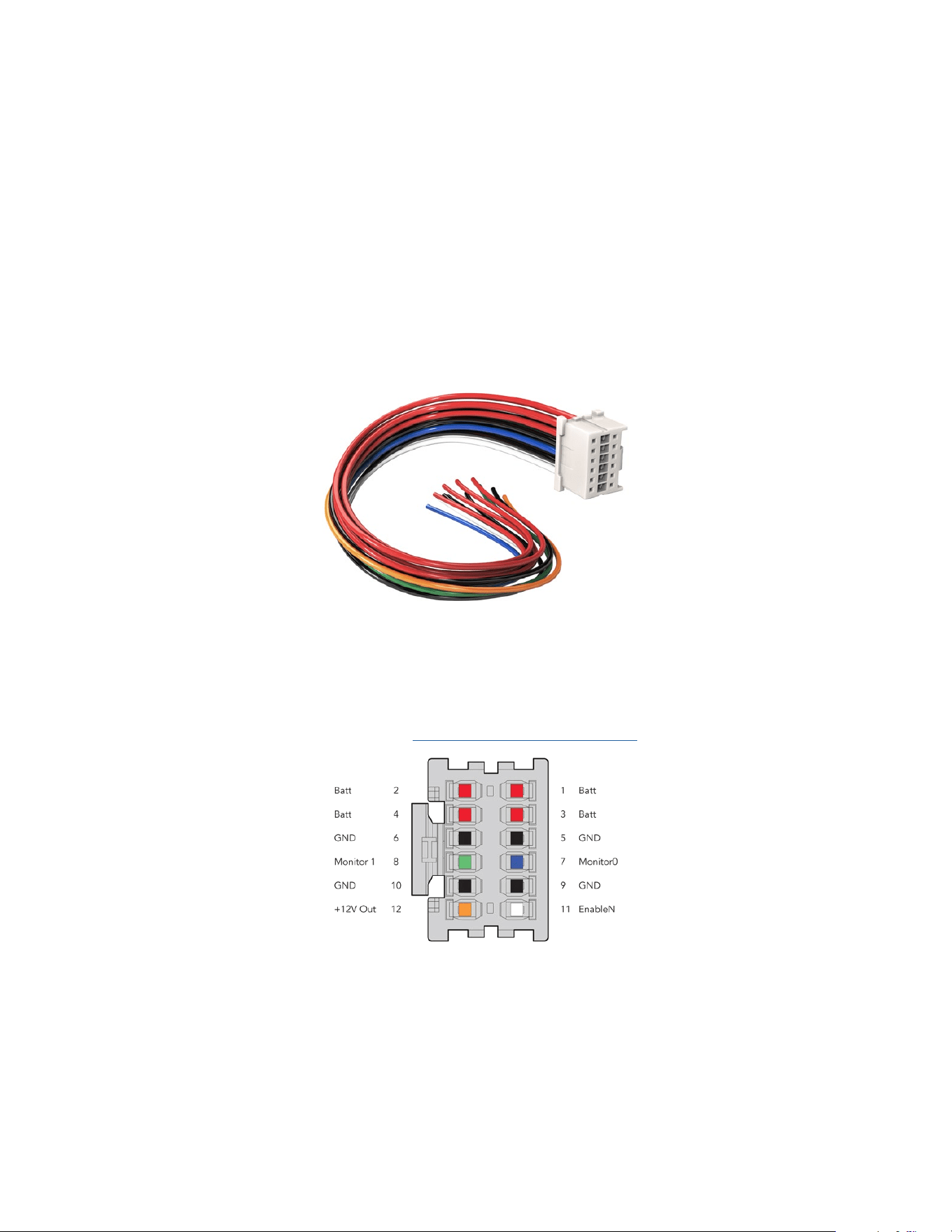
Using your own Battery Plate
Adapter Cable and Connector
If you want to modify a third party battery plate for use with your URSA Broadcast G2, you
can use the supplied adapter cable and connector, which is also available at your local
Blackmagic Design support office.
To wire the adapter cable and connector to your battery plate:
1 Strip approximately half an inch of insulation from the end of each red and black wire.
2 Solder all 4 x red ‘Batt’ wires to the corresponding ‘positive’ wire from your battery plate.
3 Solder all 4 x black ‘GND’ wires to the corresponding ‘negative’ wire from your battery plate.
Ensure the joins are well insulated.
If you need to modify any battery plate to plug into URSA Broadcast G2,
use the supplied adapter cable and connector, which is also available
from your local Blackmagic Design support office
This enables battery power to your camera. You can also connect additional wires for features
such as 12 V output and battery status. Refer to your battery plate information, plus the diagram
and tables on this page for help connecting the wires. If you require further assistance visit the
Blackmagic Design support center at www.blackmagicdesign.com/support.
The rear view of the adapter’s connector housing. Refer to
thewireconfiguration table for a description of each pin
175Mounting Batteries
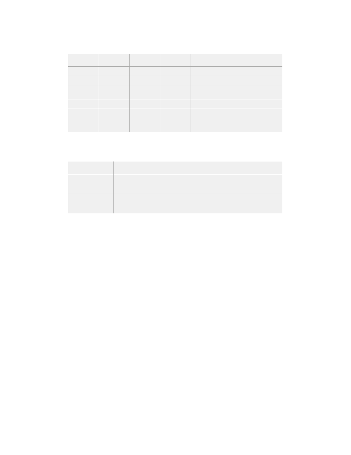
Wire Configuration Table
Pins Signal Color Direction Description
1, 2, 3, 4 Batt Red To URSA 12 V to 20 V
5, 6, 9, 10 GND Black – –
7 Monitor0 Blue To URSA Analog battery level or open drain data line
(20 V max)
8 Monitor1 Green To URSA Open drain clock line (3.4 V max)
12 +12 V out Orange From URSA 12 V regulated output 1.5 A max (18 W)
11 EnableN White To URSA Connect to GND to enable +12 V out.
Leave floating if +12 V out is not required.
Each Batt and GND pin supports 3 amps. Make sure all Batt and GND pins are connected.
Tomonitor the battery status using Anton Bauer, IDX, or Blueshape plates, follow the
connection table below:
Anton Bauer Connect the blue/white striped wire to the housing blue wire at pin 7.
IDX Connect the green wire to the housing green wire at pin 8,
and the gray wire to the housing blue wire at pin 7.
Blueshape Connect the blue wire labelled “SMBC” to the housing green wire at pin 8.
Connect the brown wire labelled “SMBD” to the housing blue wire at pin 7.
Secure any unused wires by cutting them as close as possible to the rear of the
adapterconnector.
176Mounting Batteries
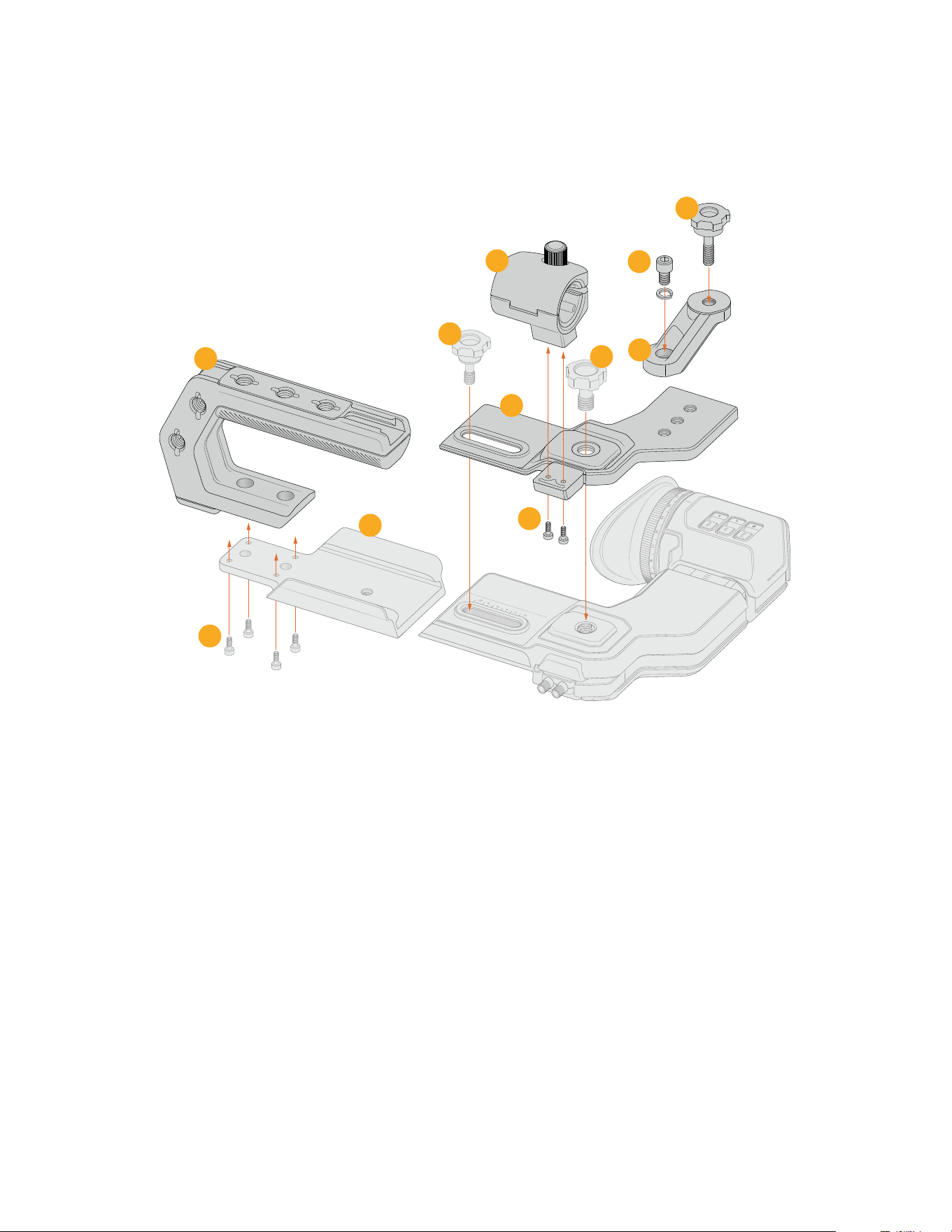
URSA Broadcast ENG Kit
Product Assembly
1 From URSA Broadcast G2, URSA Mini Shoulder Kit or can be purchased as spare parts including the URSA EVF mounting
plate and URSA EVF 1/4” thumbscrew.
2 The URSA EVF 3/8” thumbscrew is included in the URSA Viewfinder accessory or can be purchased as a spare part.
0
2
4
6
8
10
19
20
0
1
18
17
16
15
ZOOM
F1
F2
F3
PEAK
DISP
8
7
6
10
4
11
9
5
3
1
2
1 ENG Top Handle
2 T10 x 8.5mm
1
3 URSA EVF Mounting Plate
1
4 Microphone Mount
5 M3 x 8mm
6 Rotating Light Mount
7 1/4” x 10mm with spring washer
8 1/4” x 17.5mm thumb screw
9 Central Top Mount Plate
10 3/8” x 18.5mm thumb screw
2
11 1/4” x 22.5mm thumb screw
1
177URSA Broadcast ENG Kit
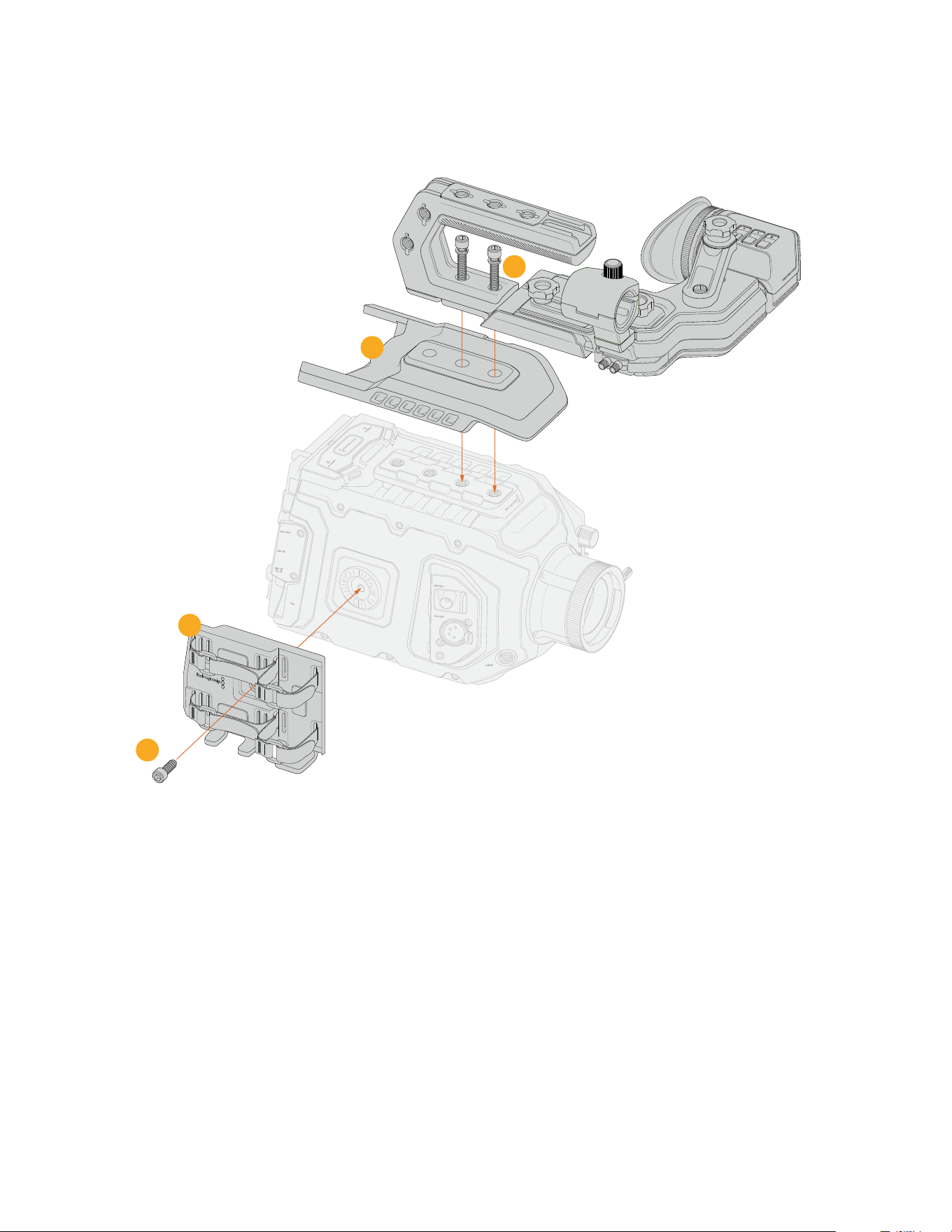
Accessories Attachment
19
0
1
18
17
16
ZOOM
F1
F2
DISP
12 V O UT
SD I O UT
SD I O UT
SD I I N
RE F I N
TC I N
LE NS
AUD IO IN
2
AUDIO IN
1
12 V
4
3
1
2
1 Side Panel Cradle
2 M6 x 9mm, 3/16”, hex driver
3 Breathable Body Armor Top Plate
4 1/4” x 30mm with spring washers
178URSA Broadcast ENG Kit
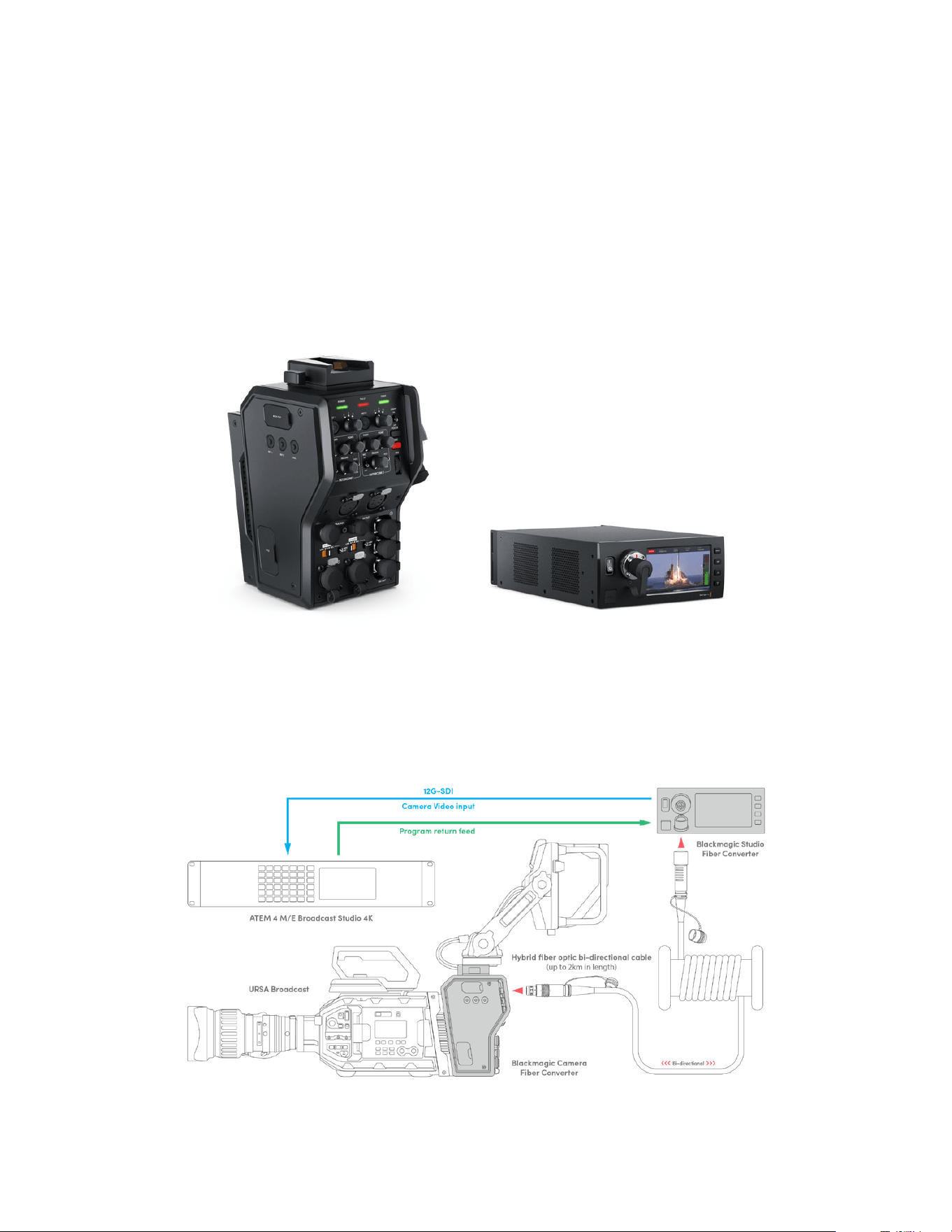
Blackmagic Fiber Converters
Blackmagic Camera Fiber Converter and Blackmagic Studio Fiber Converter are optional
accessories that provide a SMPTE fiber connection between your URSA Broadcast G2 or
URSAMini camera and an ATEM switcher.
SMPTE fiber lets you connect all video, power, talkback, tally and camera control signals
between an ATEM switcher and your camera using one single industry standard SMPTE
hybridfiber optic cable. Using a SMPTE fiber connection greatly reduces the amount of
cables required, which helps makes the production setup more efficient and simpler to run.
Thestandard connectors on Blackmagic Studio Fiber Converter allow you to easily add the
fiber converters into an existing broadcast truck infrastructure.
Blackmagic Camera Fiber Converter
Mounts to the back of your URSA Mini or
URSABroadcast G2 and connects to the
Blackmagic Studio Fiber Converter via
astandard SMPTE hybrid 304 connector.
Blackmagic Studio Fiber Converter
This converter converts the optical fiber SDI
signal from the camera unit to SDI via BNC,
which is then connected to an ATEMswitcher.
The converter also takes all return feed sources,
including program return from the ATEM switcher,
and sends them back to the camera unit.
The Blackmagic camera and studio fiber converters connect via optical fiber to provide efficient
SDI video, power, talkback, tally and control signals via a single SMPTE fiber optic cable.
179Blackmagic Fiber Converters
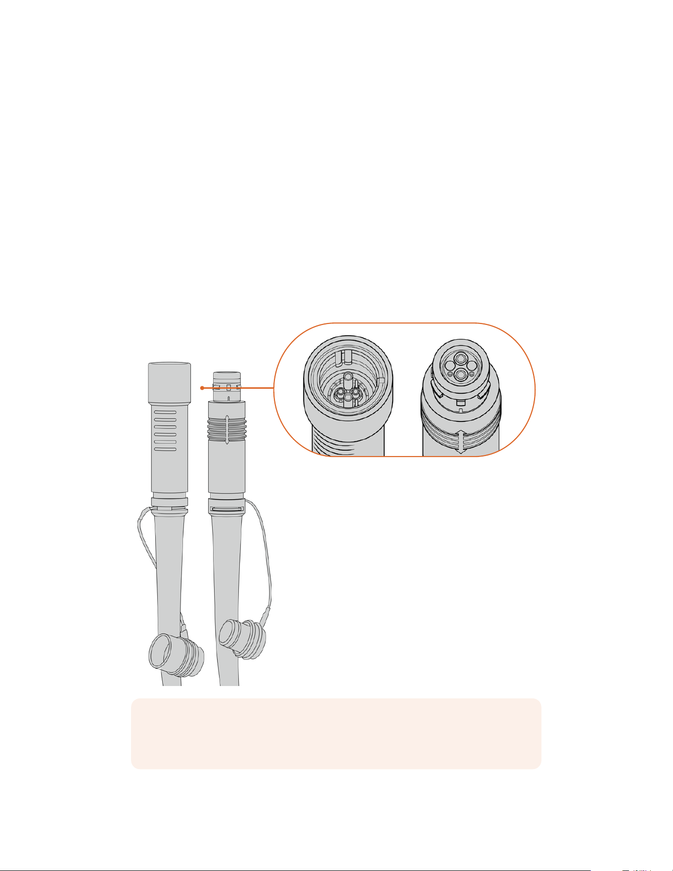
Getting Started with
BlackmagicFiberConverters
Getting started is fast and efficient. It won’t take long before you are producing video content
and enjoying the benefits of SMPTE fiber.
About SMPTE Fiber
SMPTE fiber cables provide you with a simplified way to carry multiple signals as well as power,
over long distances. This is useful in broadcast scenarios, as you don’t need to connect several
cables for each camera that is connected to your switcher.
With a SMPTE 311 hybrid fiber optic cable, you can use one single industry standard optical
fiber cable to connect each camera to your ATEM switcher, and provide all video, power,
talkback, tally and control signals along one cable. With optical fiber you can also carry these
signals and power over longer distances up to 2 kilometers.
NOTE The male and female ends of a SMPTE 311 hybrid fiber optic cable can be
identified by looking for the male and female pins inside the tip of the SMPTE 304
connector. The gender of the connectors is not determined by their outward appearance.
SMPTE 311 hybrid fiber optic cable with
male and female SMPTE 304 connectors
180Getting Started with BlackmagicFiberConverters
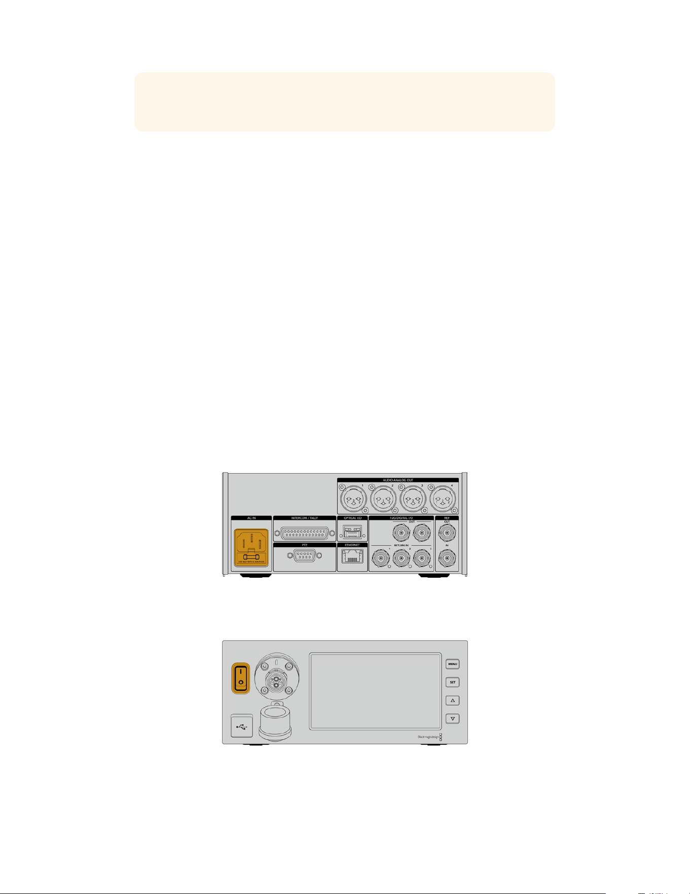
TIP Connect the rubber cap from each end of the SMPTE fiber cable into the rubber
cap on each converter to prevent any dust or debris from entering the caps.
One of the main benefits of using a SMPTE fiber connection is to connect to the control room
or broadcast truck in a traditional live broadcast environment. Most modern sporting stadiums
already have optic fiber cables installed between camera positions and the control room or
broadcast truck, so this means you can plug directly into these systems.
The optic fiber cable used to connect to an existing fiber system, or to connect the two
Blackmagic fiber converters together, is a SMPTE 311 hybrid fiber optic cable with
SMPTE304connectors.
Protecting SMPTE Connectors
It is very important that the SMPTE fiber cable’s connectors are always protected by their
rubber caps. This is because minute dust particles can collect very quickly on the polished
ends of the glass fiber tubes which can interrupt signal flow. The best practice is to immediately
replace the rubber cap as soon as a connector is exposed. For example, immediately prior to
connection, and immediately after disconnection.
It’s also a good idea to connect the rubber cap from each end of the SMPTE fiber cable into the
rubber cap on the converters whilst in use, to prevent any dust or debris from entering the caps.
Plugging in Power
Power from the studio unit is sent through the fiber cable to the camera unit, therefore the first
step to connecting power is to power the studio unit.
Powering the Studio Fiber Converter
Plug a standard IEC power cable into the power connector on the studio unit’s rear panel.
Connect power to your studio fiber converter via a standard IEC
power cable
To turn the unit on, set the power switch on the front control panel to the ‘on’ position.
181Getting Started with BlackmagicFiberConverters
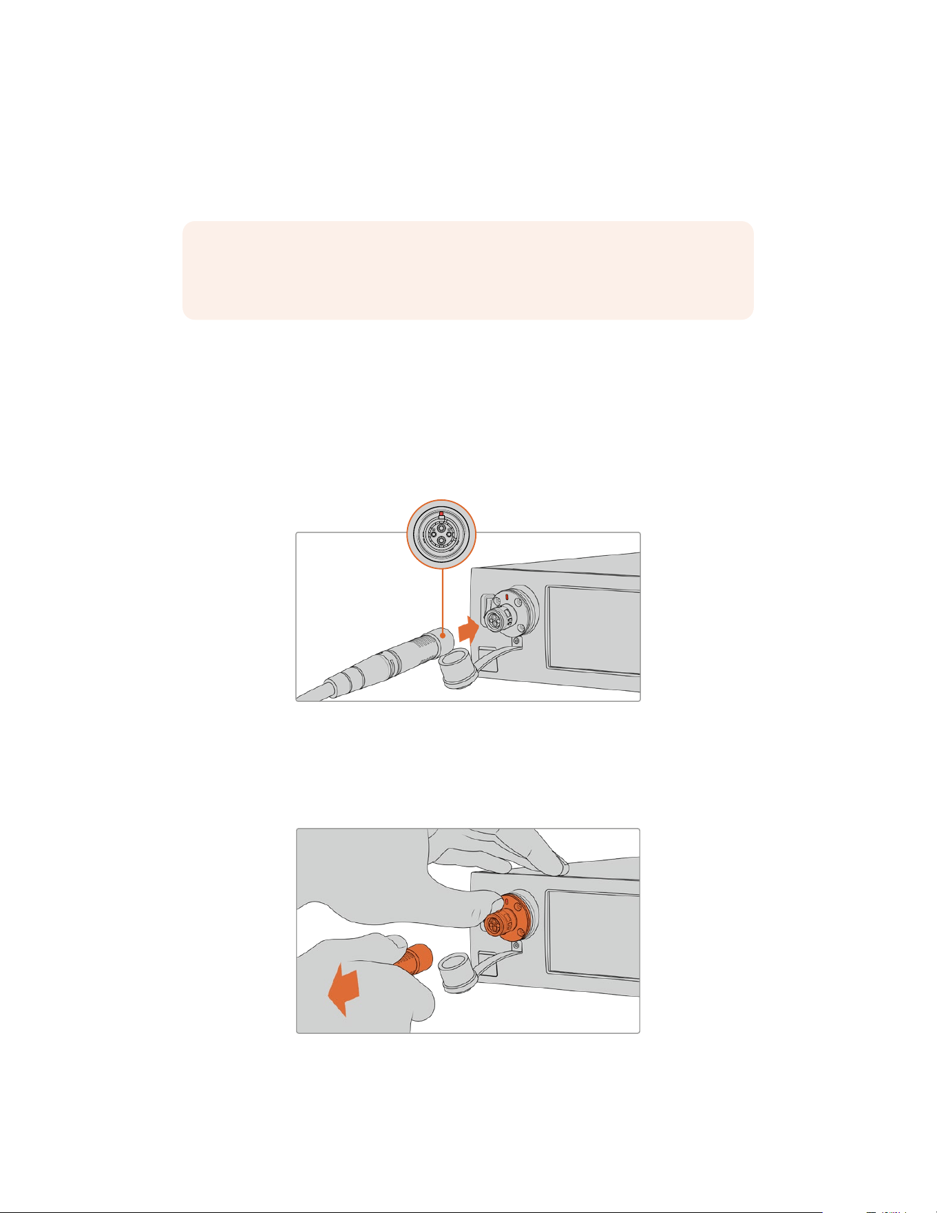
Connecting SMPTE Fiber
The next step in getting started is to connect the SMPTE fiber cable between the studio fiber
unit and the camera unit. This provides power from the studio unit to the camera unit, and fiber
for all video feeds.
NOTE Extensive safety checks are initiated whenever a powered hybrid fiber optic
cable is plugged into the converter and the power safety of the unit is continually
monitored during use.
Connecting the Fiber Cable to the Studio Unit
The male end of the SMPTE fiber cable’s locks securely onto the female fiber connector on the
front panel of the Blackmagic Studio Fiber Converter. This is a secure lock ensuring that the
cable is not accidentally disconnected during broadcast.
To connect the cable:
Align the red indicator on the cable connector with the red dot on the unit’s fiber connector,
and plug the connector in until it securely clicks into place.
Plug the male end of the SMPTE fiber cable into the female
connectoronthe front of Blackmagic Studio Fiber Converter
To disconnect the cable:
Push the metal base of the studio unit’s fiber connector towards the front panel and remove the
cable connector.
Push the metal base of the studio unit’s fiber connector
towards the front panel to disengage the cable connector
allowing you to pull the cable away from the unit.
182Getting Started with BlackmagicFiberConverters
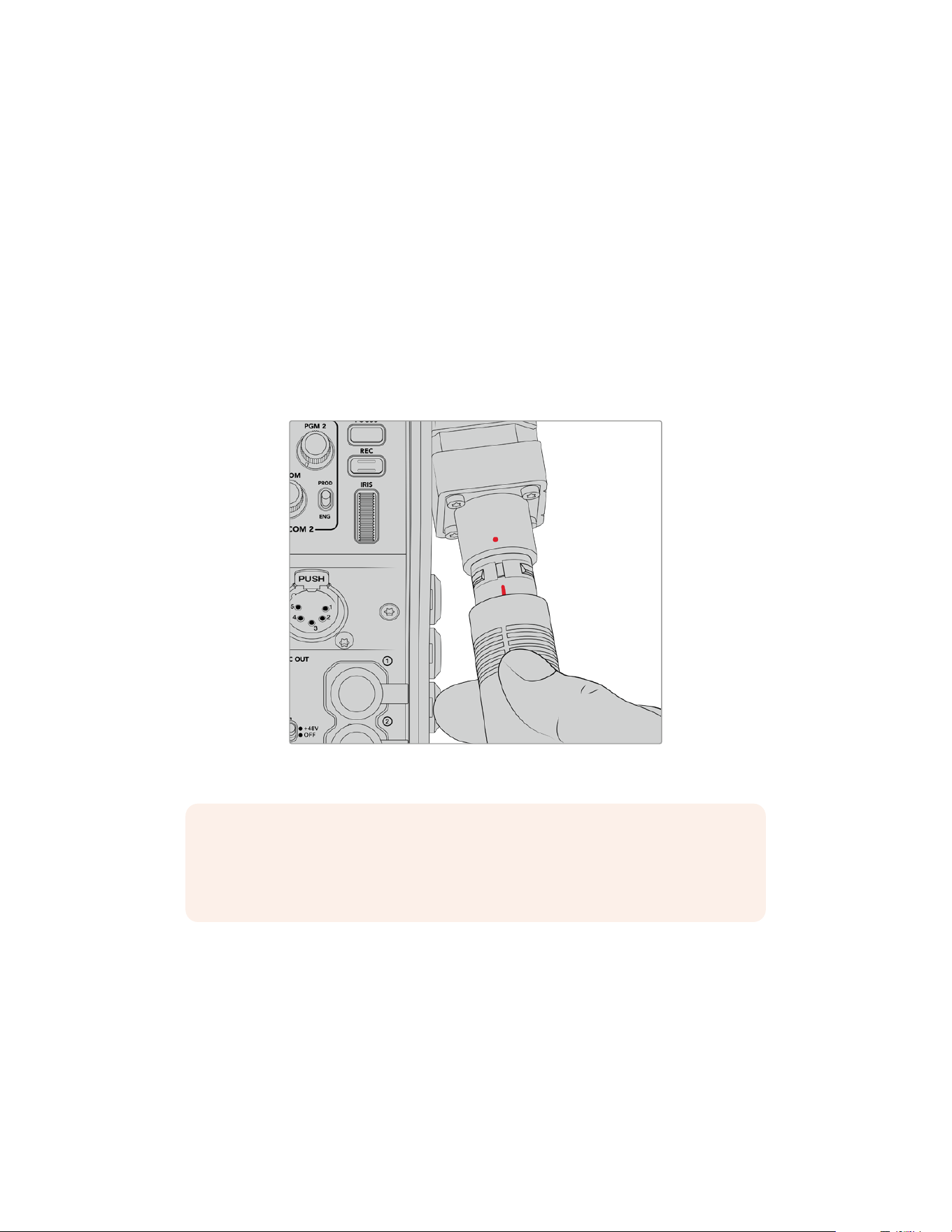
Once plugged in, it is a good idea to connect the rubber cap from the end of the SMPTE fiber
cable into the rubber cap from the Blackmagic Studio Fiber Converter. This will prevent any dust
or debris from entering the caps, and ensure that the caps remain clean.
Connecting the Fiber Cable to the Camera Unit
The female end of the SMPTE fiber cable locks into the male connector on the side of
Blackmagic Camera Fiber Converter, ensuring that the cable is not accidentally disconnected
during broadcast.
To connect the cable:
1 Align the red indicators on each connector, and plug the cable connector into the camera
unit’s connector until it securely clicks into place.
2 Once plugged in, it is a good idea to connect the rubber cap from the end of the SMPTE
fiber cable into the rubber cap from the Blackmagic Camera Fiber Converter. This will
prevent any dust or debris from entering the caps, and ensure that the caps remain clean.
Align the red indicators to connect the SMPTE Hybrid Fiber Optic cable
tothe large connector on the Blackmagic Camera Fiber Converter
NOTE The SMPTE 304 connectors on the SMPTE 311 cable are very durable and lock
firmly to the camera. If you need to disconnect the cable, please ensure that you have
the camera firmly attached to a tripod head or are bracing the camera with your spare
hand while trying to disconnect the cable.
To disconnect the cable:
1 Pinch the top section of the female end of the cable, and compress the rubber sheath
around the cable, pulling it gently away from the tip of the cable until you can see the red
ring under the sheath. This will detach the teeth from the locking mechanism.
2 Put one hand on the camera to brace it gently, and pull the cable away from the connector
on the Blackmagic Camera Fiber Converter. The cable should disconnect easily without the
need for excessive force.
183Getting Started with BlackmagicFiberConverters
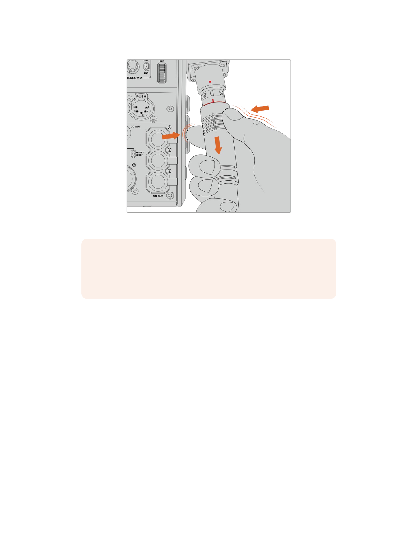
Pinch the rubber around the tip of the cable to reveal the red
ring below, then pull the cable to disconnect
NOTE The SMPTE hybrid fiber cable is the heart of the broadcast ecosystem,
so it iscrucial that great care is taken. For example, avoid kinks in the cable, always
preventthe cable from being pressed under heavy items, and avoid bending at
90degree angles. Avoid dropping the connectors and take care when connecting
and disconnecting. Always cap the connectors as soon as they are exposed.
Confirming Power and Fiber
The two units will now establish a handshake process to determine that power is being
supplied safely and fiber is securely connected.
This process involves the following:
1 The studio unit establishes a low power state with the camera unit. This is shown by the
camera unit’s red power status indicator.
2 Once power is determined as safely connected, a high power state is established and the
camera unit’s power indicator will illuminate green.
3 The fiber connection is confirmed and the fiber status indicator will illuminate green.
This is usually very fast and the indicators can turn green almost immediately. If you are using
acable over greater distances, the handshake process can take a moment longer before
indicators illuminate green.
If the power light remains red for an extended period of time and does not turn green,
or flickers between red and green, check that both ends of the fiber cable are securely
connected. If the interruption persists, check the condition of your fiber cable.
184Getting Started with BlackmagicFiberConverters
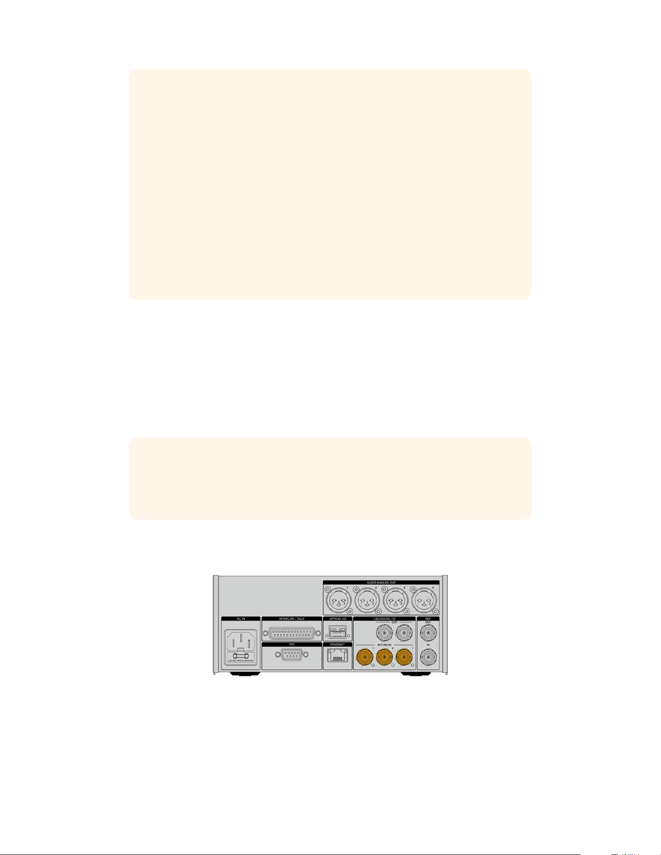
Power Safety Considerations
The SMPTE hybrid fiber optic cable is capable of carrying high voltage over long
distances so that you can power a camera and accessories that are located up to
2kmaway.
To ensure safe operation, your Blackmagic Studio Fiber Converter has safety
mechanisms built in to ensure accurate monitoring and automatic management of the
voltage being carried.
A dedicated micro controller along with internal handshaking and communication
between the Blackmagic fiber converters ensure that a hybrid fiber optic cable
remains off until it is plugged into the Camera Fiber Converter. It then goes into a low
power state and completes safety checks before going into high power mode. High
voltages are not enabled until the converters ensure that an optical signal is present,
there is a 5mA signal core current loop, and there is less than 30mA of imbalance
between the power cores.
Connecting to an ATEM Switcher
How to connect Blackmagic Studio Fiber Converter to your switcher:
1 Connect a BNC cable from Blackmagic Studio Fiber Converter’s rear 12G-SDI output to one
of the SDI inputs on your switcher. Ensure your camera is set to use the same format and
frame rate as your switcher.
2 Connect a BNC cable from your program return feed output on your switcher to the ‘return
in’ 1 input on the studio unit’s rear panel.
TIP When using multiple cameras in a live production, you may need to run the
program return feed from the switcher through a Teranex Mini SDI Distribution 12G or a
Smart Videohub. That is because there are a set number of program outputs on the
switcher and you will likely need access to more.
3 If you require any other return feeds to be sent to your camera such as a clean program
return feed, a teleprompter feed, an ISO feed from another camera, graphics or any other
signal then plug these into ‘return in’ 2 or 3.
Plug the program return feed from the switcher and other return
sourcesinto the ‘return’ inputs on the studio unit’s rear panel
185Getting Started with BlackmagicFiberConverters
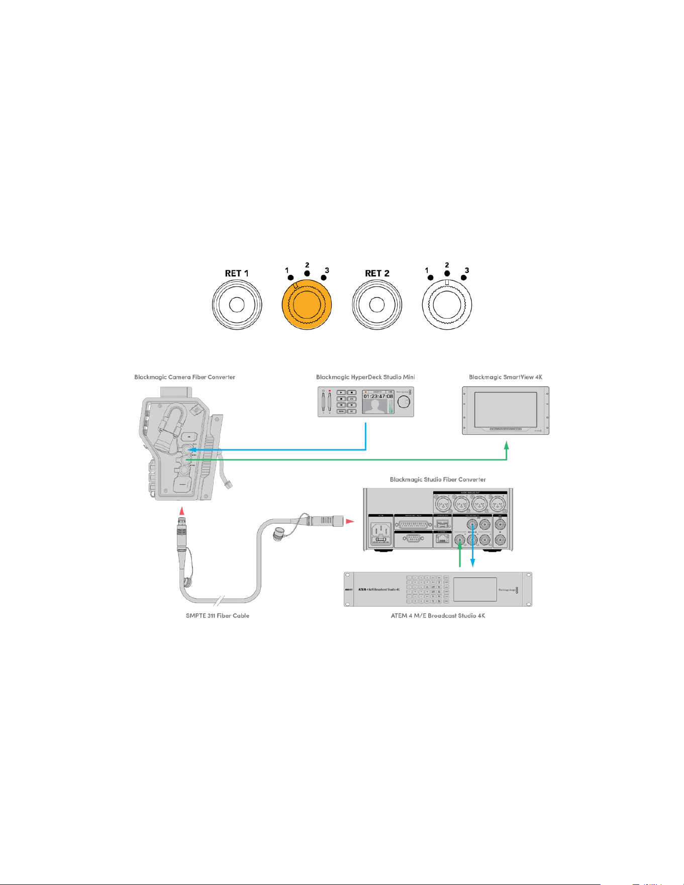
Confirming Video
You can now check that video is working and all return feeds are present.
1 Ensure the ATEM switcher’s program output is connected to the studio unit’s SDI
return input 1.
2 If you want to check all return feeds, plug video sources into SDI return inputs 2 and 3.
3 Now plug an SDI monitor, such as a Blackmagic SmartView 4K, into the ‘SDI out’ on the side
panel of the camera unit.
With a monitor connected to the SDI output, rotate the corresponding selection knob next to
the return button to switch between all three return feeds. You can set the two return buttons
to monitor two different return feeds if you want to.
Switch between the return feeds on the camera unit and press the
corresponding return button to view the selected feed on a monitor
To confirm video, plug video sources into the return feed inputs on the studiounit,then view them on a monitor
connected to the camera unit
Why Connections on the Front?
The fiber connection is located on the front of the studio unit so it can become the optical patch
connection in the rear of a rack. Typically, the studio converter will be installed facing the rear of
a rack so the SMPTE cables can be plugged direct into the unit. This means there is no need for
extra rack patch panels and the cost of an extra short cable to the fiber unit. The large LCD next
to the SMPTE fiber connector lets you quickly verify a good connection to the camera.
186Getting Started with BlackmagicFiberConverters
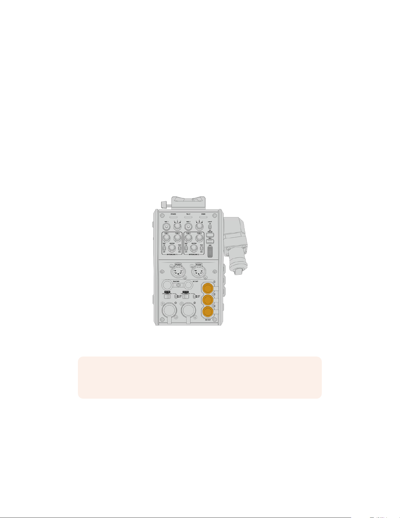
Plugging in Camera SDI
Connecting video signals between your Blackmagic Camera Fiber Converter and URSA
Broadcast G2 or URSA Mini, is as simple as connecting two of the three included SDI cables
from theside of your converter to the rear of your camera.
How to connect your Camera Fiber Converter to your camera
1 Connect one of the included BNC cables from Blackmagic URSA Broadcast G2 or
URSAMini’s rear 12G-SDI output to the SDI input on Blackmagic Camera Fiber Converter.
2 Connect one of the included BNC cables from the SDI output on Blackmagic Camera
Fiber Converter to the 12G-SDI input on Blackmagic URSA Broadcast G2 or URSA Mini’s
rear panel.
Plugging in Return SDI Outputs
The three SDI outputs marked ‘SDI Out’ on the front of the camera unit are loop outputs of the
return feeds coming from the switcher. These let you connect the return feeds to other SDI
equipment near the camera, for example a teleprompter or talent monitor.
The three return feed loop outputs can be
connected to SDI equipment near the camera,
for example a teleprompter or monitor
NOTE The return feed SDI loop outputs support 3G-SDI to provide enough bandwith
for three separate feeds. This means Ultra HD return feeds from the switcher up to
2160p60 are down converted to 1080p at the equivalent frame rate.
Mounting BlackmagicCamera Fiber Converter
Blackmagic Camera Fiber Converter mounts to the back of URSA Broadcast G2 and URSA
Mini directly behind the camera body, and connects to your camera’s rear SDI in and SDI out
BNCconnectors. If you have installed a battery plate to the rear of your camera, you will need
to remove it before connecting the Blackmagic Camera Fiber Converter.
187Getting Started with BlackmagicFiberConverters
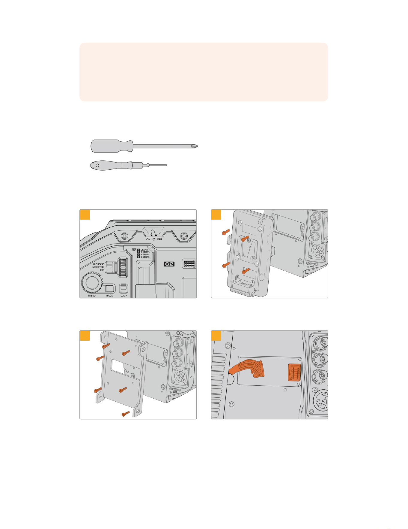
NOTE Before installing Blackmagic Camera Fiber Converter you should check that
URSA Mini’s internal software is version 4.4 or above and URSA Broadcast G2 is 4.6 or
above. You can check your software version on page 4 of the camera’s ‘setup’ menu.
For more information on updating your camera firmware see the section ‘Blackmagic
Camera Setup Utility’ in this manual.
When attaching Blackmagic Camera Fiber Converter, you will need the following tools:
1 x phillips head screwdriver
1 x 2.5mm Hex driver
To attach the Blackmagic Camera Fiber Converter to your URSA Broadcast G2 or
URSAMini, you will need a large phillips head screwdriver and a 2.5mm Hex driver
To mount and connect Blackmagic Camera Fiber Converter:
1 2
Ensure your camera is powered off. If using URSA
Broadcast G2 or URSA Mini Pro, power it off by
moving the power switch to ‘off’.
Remove the battery plate or molex power cover
plate, if attached, using a phillips head screwdriver.
3 4
Attach Blackmagic Camera Fiber Converter’s
mounting bracket using 6 x 2.5mm Hex screws.
Plug the molex connector on Blackmagic Camera
Fiber Converter into the molex power socket on
your camera’s rear panel.
188Getting Started with BlackmagicFiberConverters
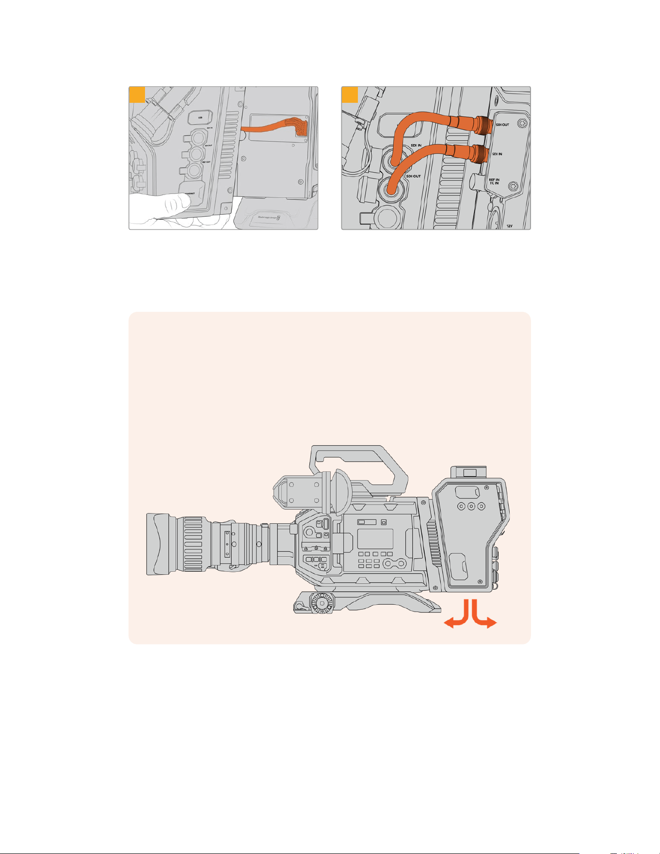
5
6
Slide the Blackmagic Camera Fiber Converter onto
the mounting bracket, and attach it using 2x2.5mm
Hex screws on each side of the bracket.
Use the included BNC cables to connect the
SDIoutput on the back of your camera to the
SDIinput on Blackmagic Camera Fiber Converter,
and the SDI output from the fiber converter to the
SDIinput on the rear of your camera.
NOTE When setting up your production and using URSA Broadcast G2 or URSA Mini
with the fiber unit attached, it’s important to maintain some clearance underneath the
fiber unit to allow adequate ventilation.
As your camera will often be used on a tripod, or shoulder mounted, clearance will
already be provided. However, if you are operating the unit sitting flat on a surface it is
a good idea to attach the URSA Mini shoulder pad, or third party baseplate or bridge
plate as this will maintain the cooling fan’s air flow in the underside of the
FiberConverter.
189Getting Started with BlackmagicFiberConverters
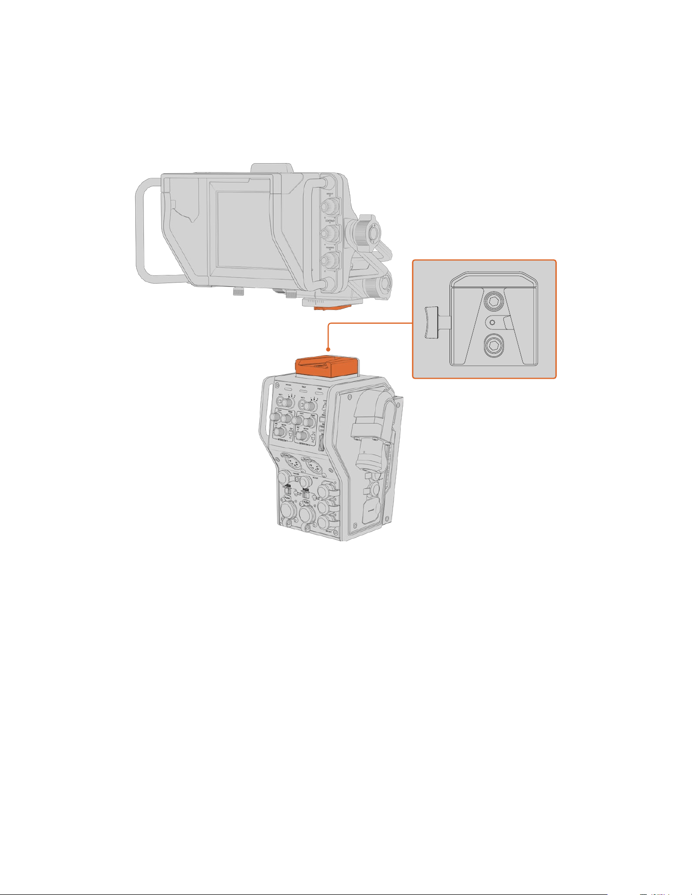
Attaching the URSA Studio Viewfinder
The attached V-lock plate on the top of the unit lets you connect a Blackmagic Studio
Viewfinder. This positions the studio viewfinder directly at the eye level when the camera
ismounted on a pedestal or tripod.
The V-Lock mount on the top of the camera unit lets you mount the Blackmagic URSA Studio Viewfinder
Plugging in a Talkback Headset
Plug a broadcast headset into one of the two 5 pin XLR connectors on the front of the
cameraunit. Having two headset connectors allows two people to communicate with
crewsimultaneously.
That’s all there is to getting started! With the fiber converters powered and video connected
viaSMPTE fiber, you can start using the converters to create your live production with greater
flexibility and efficiency. Please continue reading the manual for more information on how to
use all the features on your Blackmagic fiber converters.
190Getting Started with BlackmagicFiberConverters
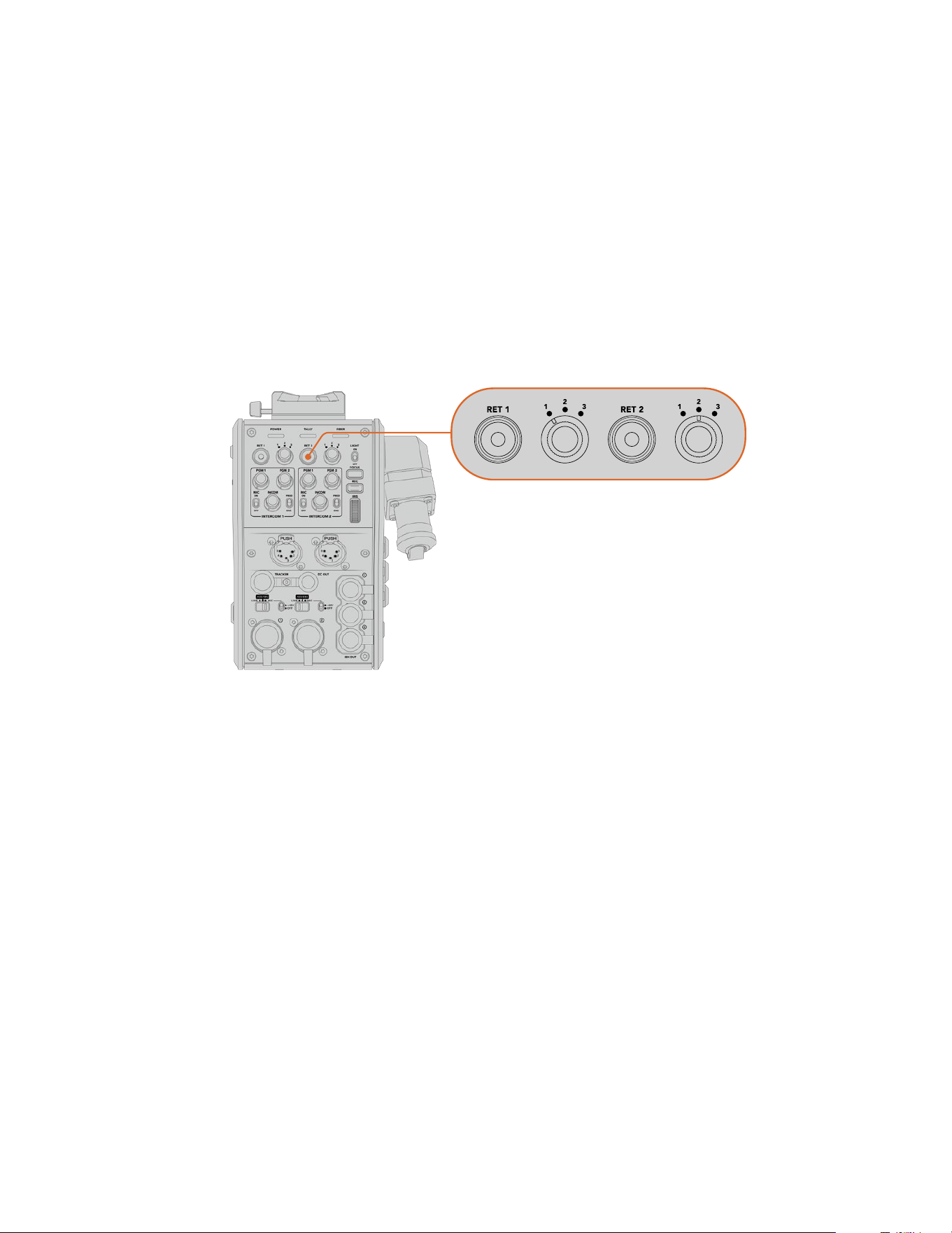
Operating the Camera Fiber Converter
Selecting a Return Feed
The two return buttons on the front panel can be used in the same way as the PGM button
onthe camera, to switch the feed on the LCD, Blackmagic URSA Studio Viewfinder and
HDmonitoring outputs between the camera view and program return view.
The two return buttons marked ‘ret 1’ and ‘ret 2’ switch between two chosen return feeds.
Thethree way rotary switches next to the ‘ret 1’ and ‘ret 2’ buttons assign which return feed you
would like to view when you press the corresponding button to the left of the switch.
Thesepositions on the rotary switch relate to the ‘return in’ 1, 2 and 3 SDI connectors that are
on the back of the Studio Fiber Converter.
The return buttons and three way rotary switches allow you to select
which return feed to view when the return buttons are pressed
Press and hold one of the return buttons to see the selected program feed. The program feed
will continue to display whilst the return button is being held. Double press the return button to
lock the display to the return feed. Pressing the return button again will exit the return feed and
return to the camera view.
This means you can quickly and easily adjust which of the three return feeds being sent from
Blackmagic Studio Fiber Converter you would like to have fast access to on the two return
buttons. For example the three return feeds might be the switcher’s program output feed
complete with graphics, a teleprompter feed and a feed direct from another camera.
By using these switches you could assign ‘ret 1’ to be your program feed permanently and then
use the second ‘ret 2’ button to check what is being sent to the teleprompter, and to
occasionally switch it to check framing on another camera when you need to match its
framing or angle.
There are also return buttons on the left side of the unit, marked ‘ret 1’ and ‘ret 2’ that provide
additional access to view the return feeds when operating your camera from the side. They
perform the same function as the return buttons on the front of the unit.
191Operating the Camera Fiber Converter
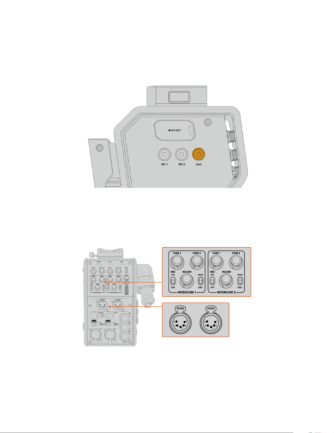
Using the Call Button
Next to the return buttons is a ‘call’ button, that when pressed, flashes the red tally indicator
on your Blackmagic Studio Fiber Converter’s LCD screen. The ‘call’ button also makes a
numbered ‘press to talk’ button on the panel of ATEM Talkback Converter 4K flash red.
Thesevisual indicators are to alert people in the control room that you need assistance.
Using Talkback
The two female 5 pin XLR connectors allow you to plug in two headsets, so that you and
another crew member can have communication with the rest of the crew simultaneously.
The intercom controls for each headset are grouped into two sets for two independent
intercoms, and are effectively three way audio mixers for each headset XLR connector that is
directly below.
The intercom controls for each headset are located directly above each headset connection
You will hear the audio from the feeds that you have selected for ‘ret 1’ and ‘ret 2’ through a
connected headset. The ‘pgm 1’ and ‘pgm 2’ dials adjust the audio levels of those feeds, and
the ‘incom’ dial adjusts the overall volume. The ‘mic’ switch allows the operator to turn their
headset microphone ‘on’ or ‘off’.
192Operating the Camera Fiber Converter
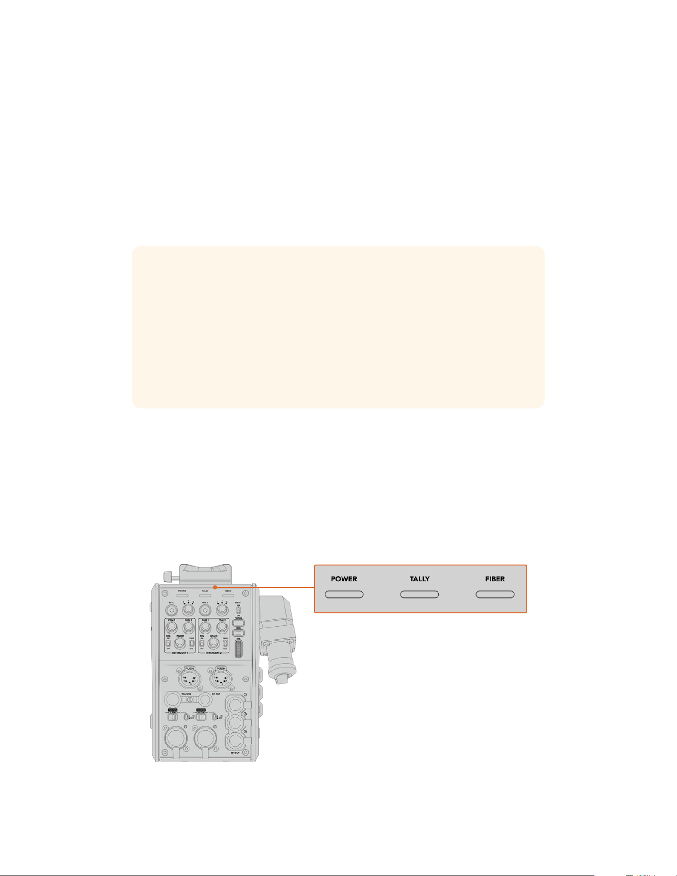
Each intercom also has 2 selectable channels, a production channel and an engineering channel.
This means that for broadcast setups with a large crew, you can split your crew communications
between the two channels. The production channel lets you communicate with the director,
producer and other crew members in the control room or broadcast truck, whilst the engineering
channel lets you communicate with the lighting crew, technical operators and other camera
operators. You can use the ‘talkback’ page in the menu of your Blackmagic Studio Fiber Converter
to select the source for each channel as ‘SDI + DB25’ or ‘intercom tally DB25’ on your Studio Fiber
Converter. For more information refer to the ‘operating the studio fiber converter’ section.
The Blackmagic Camera Fiber Converter also includes a standard 10 pin connection for tracker
talkback, which is perfect when both headset connections are in use and you need to feed an
additional talkback connection for your crane operator.
TIP Effective two-way communication between camera operators and the production
and engineering crew is essential for busy broadcast and studio productions.
Blackmagic Camera Fiber Converter has a ‘call’ button so camera operators can alert
production and engineering crew and talk via their intercom headsets. Pressing this
button flashes a numbered ‘press to talk’ button on ATEM Talkback Converter 4K, and
makes the tally indicator on the LCD of Blackmagic Studio Fiber Converter flash.
Likewise, if crew in a control room or broadcast truck have an urgent need to talk with
a camera operator, they can press the ‘call’ button for that camera on the ATEM
Camera Control panel. This makes the tally light on the Camera Fiber Converterflash
and the tally light on the camera’s URSA Viewfinder or URSA StudioViewfinder flash.
Using Tally
The tally indicator on the front of the panel, provides a traditional tally indicator with red for
program and green for preview, so that you know when the camera you are operating is on air.
Status Indicators
The ‘power’, ‘tally’ and ‘fiber’ status LEDs at the top of the converter will illuminate different
colors depending on the status of the unit. When the fiber cable is unplugged, no lights
areilluminated.
The status LEDs will illuminate different colors
to let you know the status of the unit
193Operating the Camera Fiber Converter
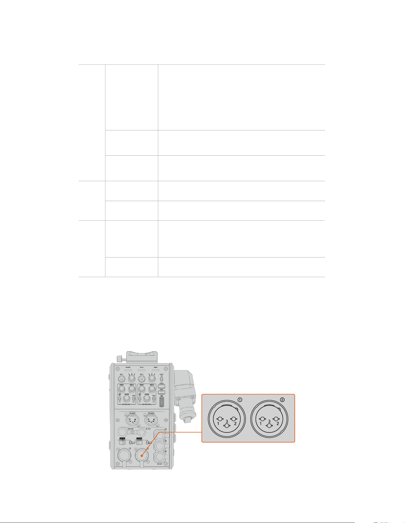
Below is a description of each LED color, LED action, and the status represented:
Power
Constant Red
When the SMPTE hybrid fiber optic cable is connected to a powered
Blackmagic Studio Fiber Converter, and the other end of the cable is
connected to Blackmagic Camera Fiber Converter, the power LED on the
converter turns red to indicate that it is receiving power, and is in a low
power state. In this low power state, intercom functionality is enabled but
the full power required to operate the unit has not yet been enabled.
If the power LED remains red for an extended period of time and does not
turn green, check that both ends of your SMPTE hybrid fiber optic cable are
securely connected. If the connection remains unstable, check the condition
of your fiber cable.
Constant Green
After a successful fiber connection has been established and Blackmagic Studio
Fiber Converter has determined that the cable connection is safe, the power
LED will turn green and the camera converter will enter high power mode.
Flickering between
Red and Green
If the power LED flickers between red and green, check that both ends
of your SMPTE hybrid fiber optic cable are securely connected. Ifthe
connection remains unstable, check the condition of your fiber cable.
Tally
Constant Red
The tally LED illuminates red to indicate that the camera you are operating is
currently on air.
Constant Green
The tally LED illuminates green to indicate that the camera you are operating
is currently in preview mode.
Fiber
Constant Red
When the SMPTE hybrid fiber optic cable is plugged into the camera
fiber converter, the fiber LED will turn red to indicate that the handshake
process has begun, and the converter is in a low power state. In this
state, intercom functionality is enabled for use while setting up or for
troubleshooting the camera chain in case the fiber link is down.
Constant Green
Once a successful SMPTE hybrid fiber optic cable connection is established,
the fiber LED will turn green.
Once both the power and fiber lights are green, this indicates that the safety checks have been
completed, and the converters have entered high power mode.
Audio Inputs
Your Blackmagic Camera Fiber Converter has two XLR inputs labelled ‘1’ and ‘2’ that allow you
to plug in external analog audio from professional equipment such as audio mixers, PA systems
or external microphones.
Use the he XLR input assign switch
to select the audio input type
you have connected, and enable
phantom power if required
194Operating the Camera Fiber Converter
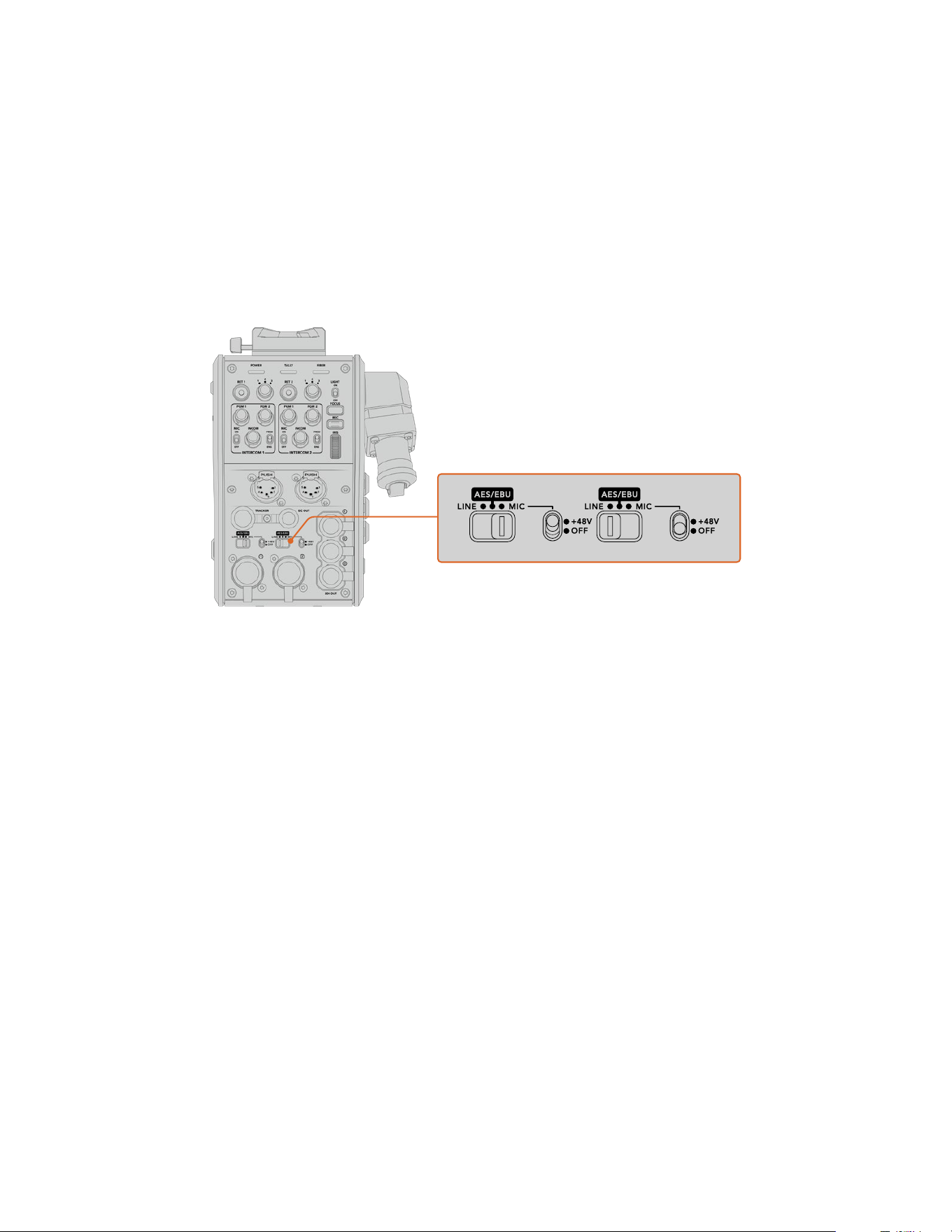
The camera audio is embedded into channels 1 and 2 of the camera feed, and the 2 audio
inputs on the back of the camera fiber converter are embedded as channels 3 and 4. All 4
audio channels are also deembedded at the other end on the studio fiber converter as analog
audio outputs.
The ‘audio’ page in the menu of your Blackmagic Studio Fiber Converter lets you adjust the
input levels for audio sources connected to the XLR inputs on your Blackmagic Camera Fiber
Converter. For more information refer to the ‘operating the studio fiber converter’ section.
Onceconnected, you can use the XLR input assign switch to set how the XLR inputs behave
when selected as an input source. The options available are mic audio, line level audio and
AESdigital audio.
If you would like to connect microphones that aren’t self powered, you can enable 48V phantom
power. Move the phantom power switch to ‘+48V’ to enable phantom power for any microphone
connected to the XLR below, or ‘off’ to disable phantom power.
IP Video
A connected SMPTE Fiber cable provides for a 10-Gbit IP link between your Camera Fiber
Converter and the Studio Fiber Converter. This allows all of your video and return feeds to be
IPvideo based using high end, visually lossless broadcast quality 10-bit video encoding and
decoding. All other connections such as talkback, tally, camera control and lens control are
alsoconverted to low-latency IP so you get incredibly reliable performance.
Power Specifications
The Blackmagic Studio Fiber Converter provides power for Blackmagic Camera Fiber
Converter, your camera and it’s accessories. A molex connector plugs into the molex socket on
your camera’s rear panel to send power to your camera from the Camera Fiber Converter.
If you need to position your camera at a distance of more than 2.1 km from the broadcast truck,
and your camera and converter are not receiving enough power over the long cable run, you
can power the camera and converter locally by having the 4 pin XLR from the camera’s power
supply plugged into the +12V input on your URSA Broadcast G2 or URSA Mini. The power will
be sent through the molex connector to the Camera Fiber Converter.
The ‘+12V out’ connector, sometimes referred to as a ‘D-tap’ or ‘P-tap’ allows you to power
accessories like an external monitor or a large box lens, with 12V DC nominal at up to 500 mA. The
‘DC out’ connector provides an additional option for powering accessories likean external monitor.
195Operating the Camera Fiber Converter
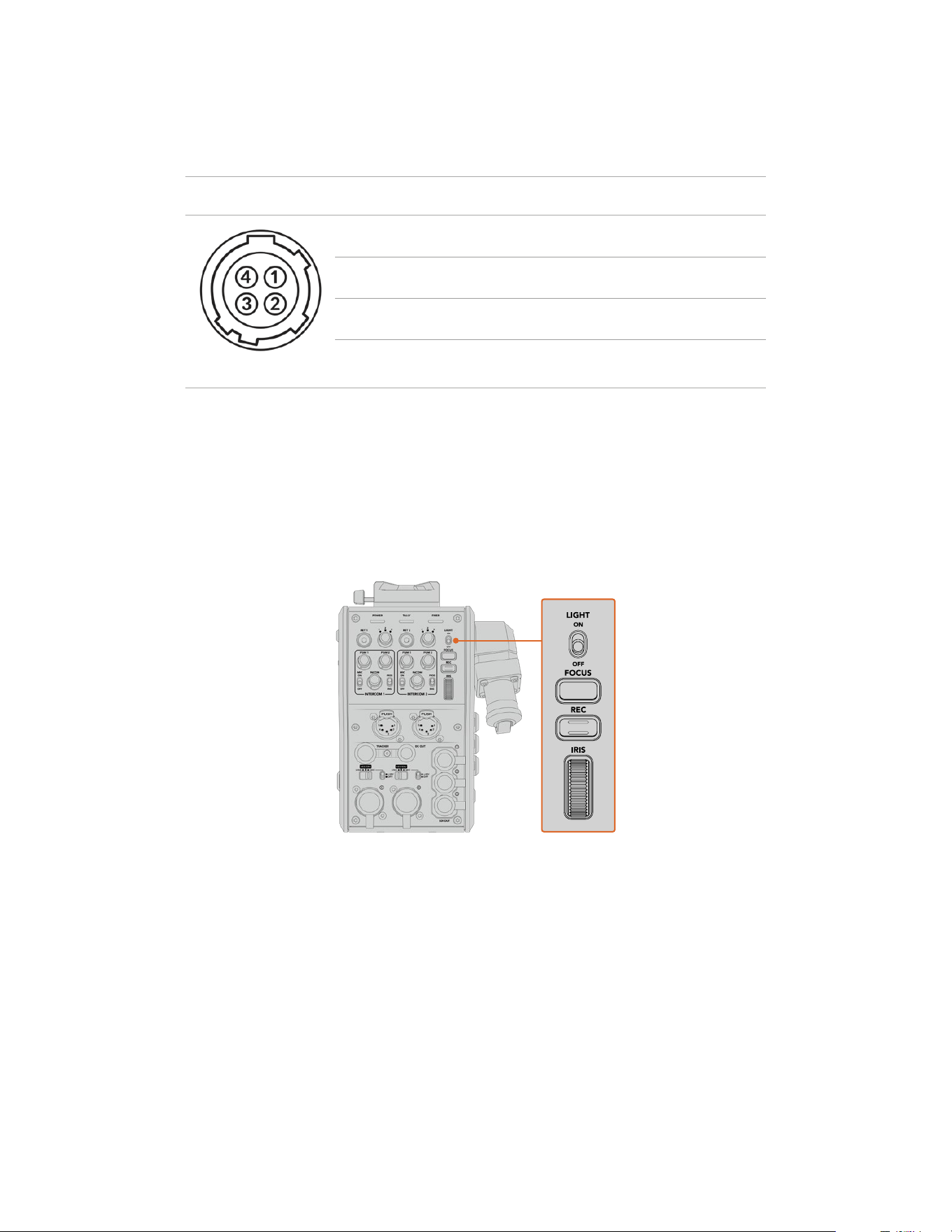
A pinout table for the DC out connector is provided below.
DC out connector Pinout Diagram
External view Pins Signal I/O Specifications
‘DC out’ connector
1 Unregulated GND – GND for Unregulated Out
2 NC – No connection
3 NC – No connection
4 Unregulated Out Out 12V DC nominal at up to 500 mA.
Additional Camera Controls
When URSA Broadcast G2 or URSA Mini is being used as a studio camera, we have added
camera controls on the fiber converter including iris and focus control, so you can control
compatible lenses from behind the camera. This is helpful if you don’t have a camera control
operator controlling the lens remotely.
As a studio camera, URSA Broadcast G2 and URSA Mini still have the ability to record internally,
so the record button lets you trigger internal recording on the camera.
Light
Turns on the backlight to illuminate the operation panel, so that all your controls can be seen
easily when operating in a dark environment.
Focus
Pressing the button marked ‘focus’ will trigger the autofocus if you are using a lens that
supports autofocus.
Record
Pressing the button marked ‘rec’ will trigger the recording when pressed, and will stop
recording when pressed again.
196Operating the Camera Fiber Converter
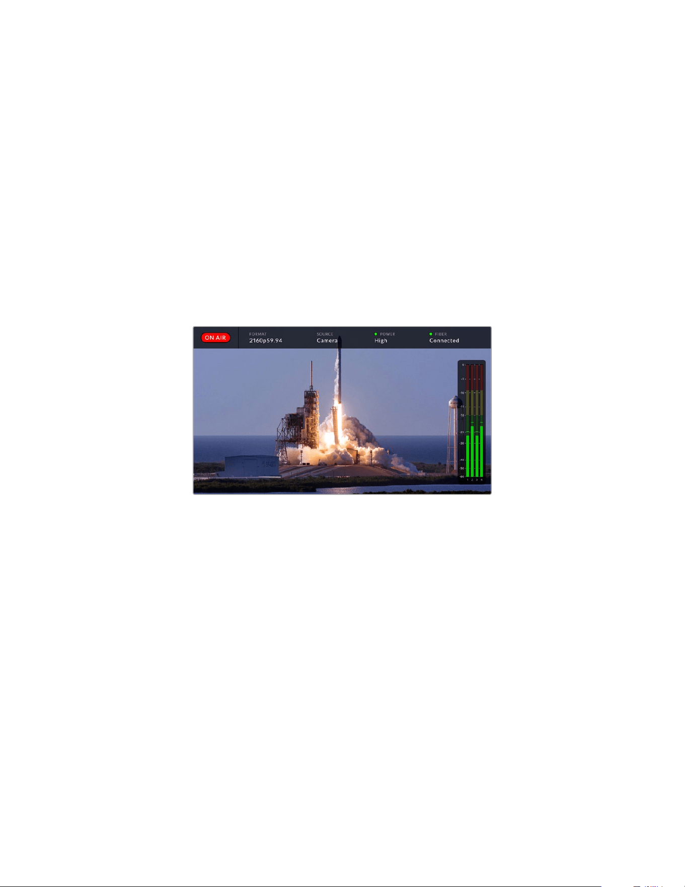
Iris
If you are using a compatible active lens that allows control from the camera, you can open
or close the iris using the ‘iris’ wheel. Rotate the wheel up or down to open or close the
lens aperture.
Operating the Studio Fiber Converter
Selecting the LCD Source
When powered on, your Blackmagic Studio Fiber Converter’s large LCD will display the feed
from your camera. As the central base unit, the Studio Fiber Converter takes the program feed
from your switcher plus all return sources, and feeds them to the Blackmagic Camera Fiber
Converter via the SMPTE fiber cable.
The built in LCD lets you monitor the camera feed and each source connected to the return
feed inputs. It provides a heads-up type display with status information and audio meters.
The overlays allow you to confirm the name and format of the source
you are monitoring when switching between feeds
On Air
The red ‘on air’ icon will be displayed when the connected camera is being used in the program
feed, and will remain blank when not on air.
Format
Displays the resolution and frame rate of the current source.
Source
Displays the current source name.
Power
Displays the current power status. ‘Low’ will be displayed with a red status light during
connection to indicate a low power state and ‘high’ will be displayed with a green status light
after the unit has entered high power mode. For more information, refer to the ‘status indicators’
section in the ‘operating the camera fiber converter’.
Fiber
Displays the current fiber status. ‘Connecting’ will be displayed with a red status light during the
initial connection process and ‘connected’ will be displayed with a green status light once a successful
SMPTE hybrid fiber optic cable connection is established. For more information, refer to the ‘status
indicators’ section in the ‘operating the camera fiber converter’.
197Operating the Studio Fiber Converter
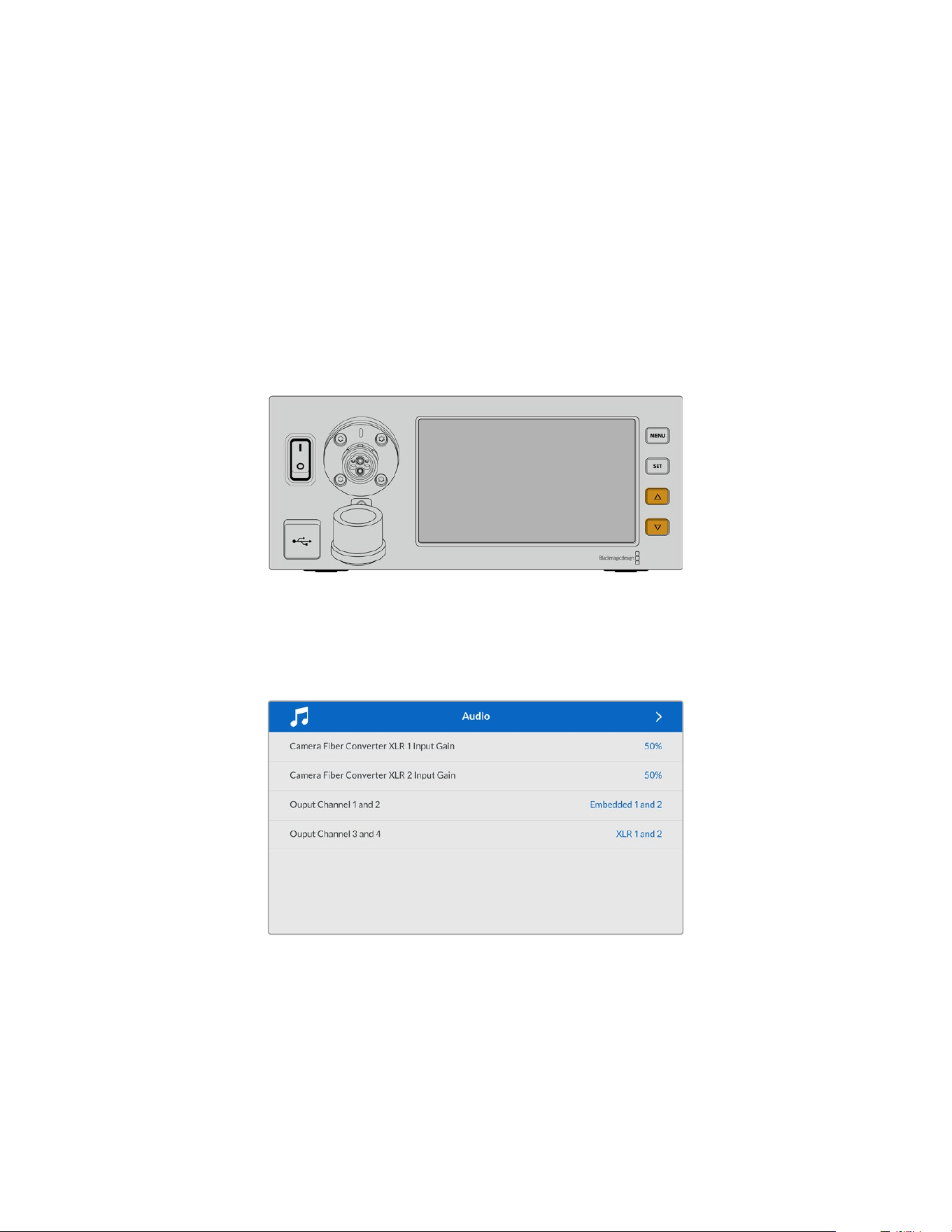
Audio Meters
The peak audio meters display audio levels when using camera audio embedded into channels
1 and 2 of the camera feed. Channels 3 and 4 correspond with audio sources connected to the
two XLR inputs on the back of your Blackmagic Camera Fiber Converter. The display is
calibrated to dBFS units and features peak hold indicators which stay visible for a short time so
you can clearly see the maximum levels reached.
Using the Menu
Pressing the up and down arrow buttons will scroll through the four possible sources ‘camera’,
‘return 1’, ‘return 2’ and ‘return 3’. Press the ‘menu’ button to enter the menu system and adjust
your settings. The arrow buttons can then be used to navigate through the various menu
screens and the options within each screen, whilst the ‘set’ button will confirm your selection.
The settings in the menu are divided between ‘audio’, ‘talkback’ and ‘setup’ pages.
Press the up and down arrow buttons to scroll through the four
possiblesources and to navigate through the menu
Audio
The ‘audio’ page lets you adjust the input levels for audio sources connected tothe XLR inputs
on your Blackmagic Camera Fiber Converter.
198Operating the Studio Fiber Converter
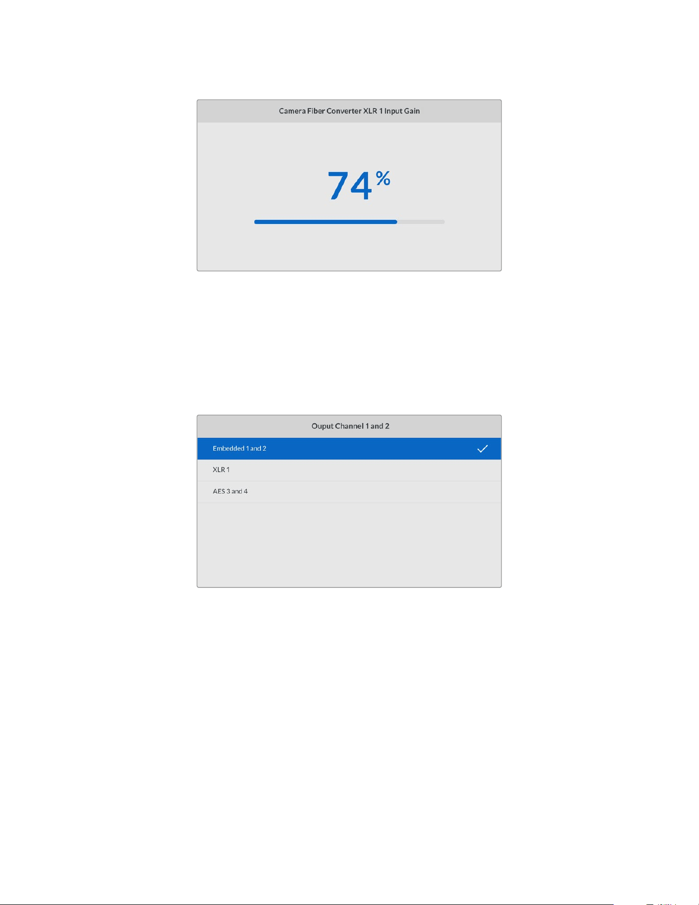
Use the arrow buttons to adjust the input level for eachXLR input and the
‘set’ button to set the level
You can configure which audio channels from the Camera Fiber Converter get mapped to the
embedded SDI and XLR outputs. The embedded audio channels from URSA Mini or URSA
Broadcast G2 are on channels 1 and 2 by default. Line or Mic level XLR inputs that are plugged
into the Camera Fiber Converter are mapped to channels 3 and 4 by default. You can adjust the
output channel settings to change these mappings from their default settings. If either of the
XLR inputs on the Camera Fiber Converter are set to AES, this expands your channel mapping
options to include channel 5 and 6, which are sent on your embedded SDI output.
Mapping the embedded XLR channels from the camera to output channel 1 and 2
Talkback
Use the ‘talkback’ menu to select your program audio source and talkback source for the
production and engineering channel. Set the talkback source to ‘SDI + DB25’ or ‘intercom tally
DB25’ on your Studio Fiber Converter.
You can also adjust the ‘headphone gain’ and ‘headset microphone gain’ for each intercom
headset to account for the impedance levels of the headsets. The ‘phantom power’ settings let
you switch on the phantom power being sent to the respective headset. Adjust the ‘sidetone
level’ settings to let camera operators hear their own voice in their headset at a clear and
comfortable level.
199Operating the Studio Fiber Converter
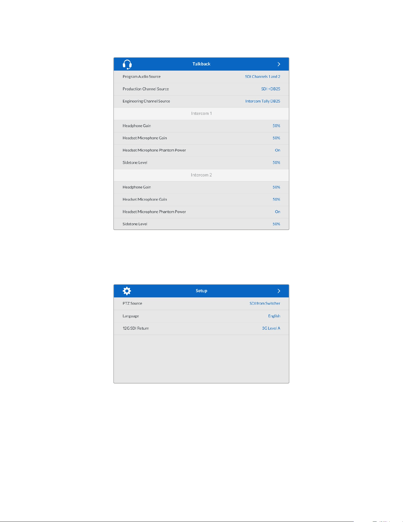
The intercom section will be grayed out when nothing is connected totheXLR inputs
and will display ‘connecting’ during connection
Setup
The ‘setup’ menu lets you configure the PTZ source, select the language for the menus,
and select the type of SDI level return.
Select the source of PTZ commands using the PTZ source setting. You can select from ‘SDI’
or ‘9-pin’, which correspond with the ‘return in’ SDI inputs and the DE-9 connector for PTZ
on the rear of your Blackmagic Studio Fiber Converter.
This means that you can control a PTZ camera’s pan, tilt and zoom on an ATEM switcher
and send these PTZ commands to your Blackmagic Studio Fiber Converter via SDI. These
commands will be sent along the SMPTE fiber cable to your Blackmagic Camera Fiber
Converter, where they will be de-embedded and output via the DE-9 serial connector,
for connection to a PTZ motorized head.
You can also connect a PTZ controller to your Blackmagic Studio Fiber Converter via
the DE-9 connector, to control a remote head at the camera end.
200Operating the Studio Fiber Converter
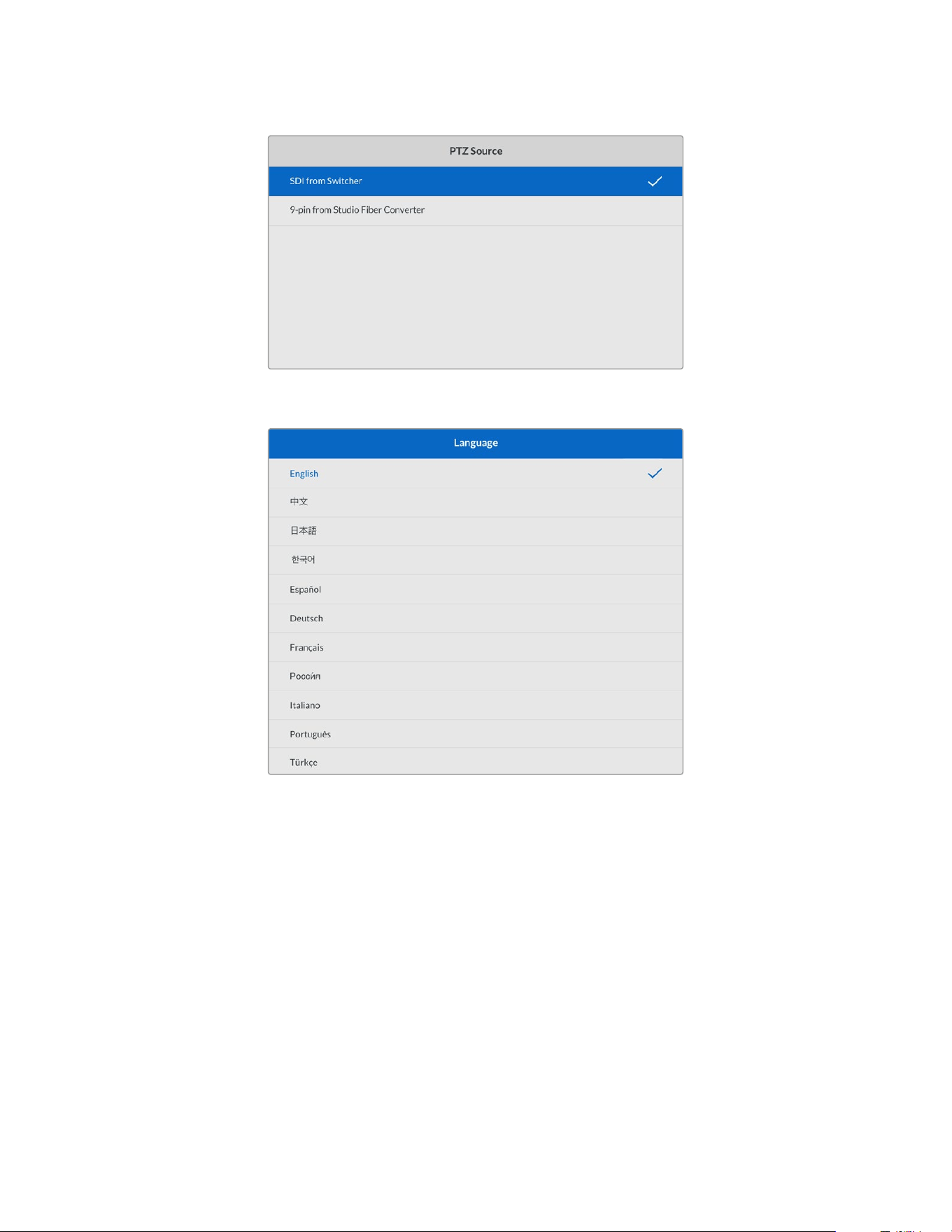
The settings menu page provides the option to select ‘SDI’ or ‘9-pin’ as
the source of PTZ commands
The ‘language’ setting sets the language for the menus. Studio Fiber Converter supports
11 popular languages: English, Chinese, Japanese, Korean, Spanish, German, French, Russian,
Italian, Portuguese and Turkish. The language page will also appear on initial start up and
after you update the internal software.
The ‘12G SDI return’ option sets whether to down convert 12G program return signals to 3G
Level A or 3G Level B. All 12G signals sent into return inputs on Studio Fiber Converter get
down converted on their way to the Camera Fiber Converter.
Rack Mounting the Studio Unit
If you’re running multiple Blackmagic Studio Fiber Converters, you can use Blackmagic Studio
Fiber Rack Kit to install your converters into a broadcast rack or road case. Using the rack kit,
you can mount two studio units in a rack side by side, or fitted to either side. A blanking panel is
supplied with the Studio Fiber Rack Kit to cover the empty side of the rack if you only want to
mount a single unit.
201Operating the Studio Fiber Converter
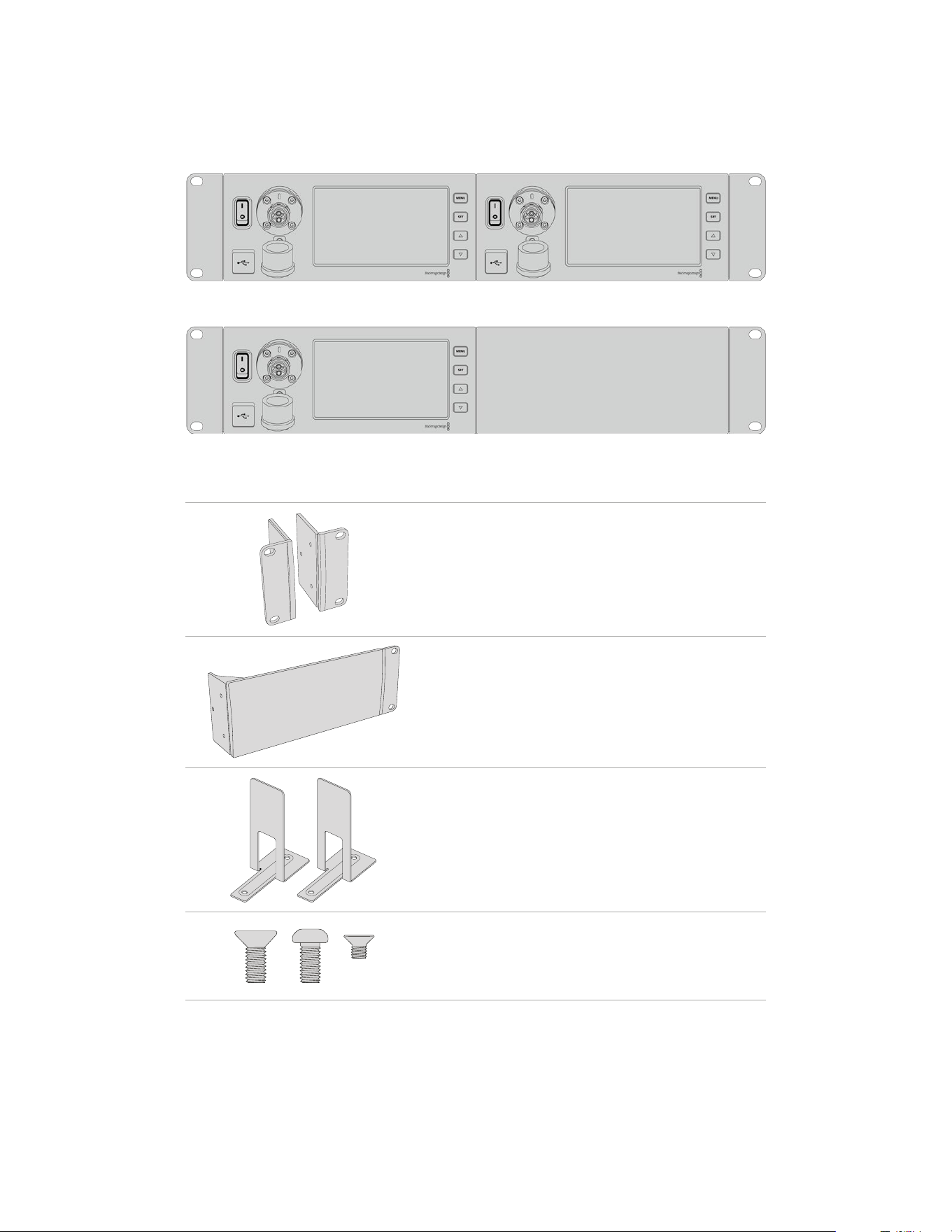
Your Studio Fiber Converter is two rack units high, and is half the width of a standard rack shelf,
so two Studio Fiber Converters can fit neatly side by side in a 2RU rack space.
Blackmagic Studio Fiber Converters mounted side by side
The supplied blanking plate can be used to cover an empty rack space if needed
The Blackmagic Studio Fiber Rack Kit contains the following items:
2x Rack ears
Attach rack ‘ears’ to the outside edge of Blackmagic
StudioFiber Converter for mountingina rack.
1x Half rack width blanking panel
The blanking panel has a mounting ear on one side so
you can cover the empty rack space if you are installing
a single unit. The illustration shows the ear on the right
side. Simply rotate thepanel 180° to mount it to the
other side.
2x Support brackets
The T-shaped support brackets attach underneath the
two Studio Fiber units where thetwo units meet at the
front and the rear toprovide support.
Screws
8 x M4 10mm
Rack
ear screws
4 x M4 8mm
Blanking panel
screws
5 x M3 5mm
Support
bracket screws
202Operating the Studio Fiber Converter
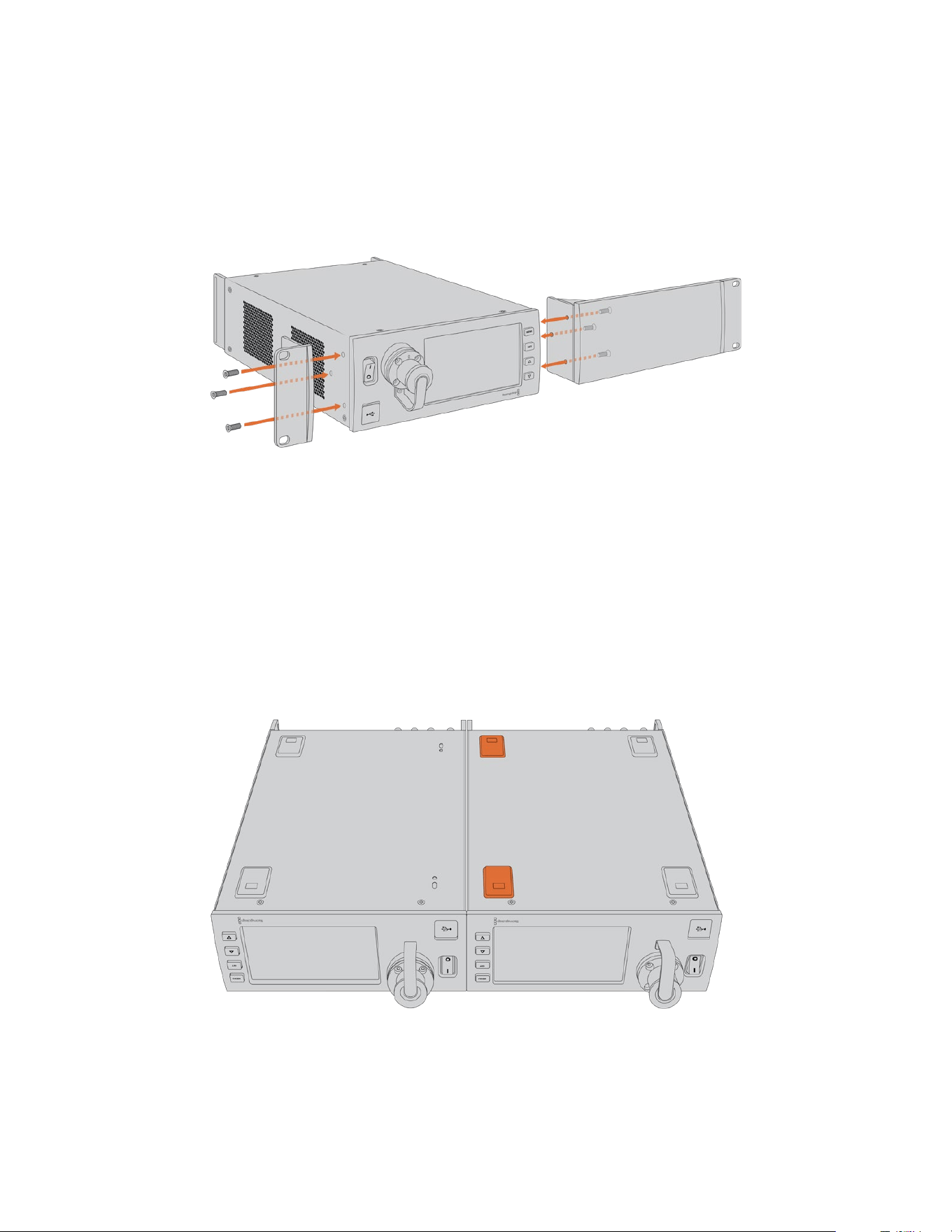
Preparing the Blackmagic Studio Fiber Converter for installation into a rack:
1 Position the blanking panel on one of the sides of your Studio Fiber Converter, depending
on whether you would like the unit to sit on the left or right side of the rack shelf. The front
face of the blanking panel should be parallel with the front panel of the unit.
2 Attach the blanking panel to the side of your Studio Fiber Converter near the front using
three of the supplied blanking panel screws.
3 Use three of the supplied rack ear screws to attach a rack ear to the other side of your
Studio Fiber Converter.
With the rack ear and blanking panel attached, you can now install your converter into
astandard two rack unit space using the mounting holes on both sides and standard
rack screws.
Preparing two Blackmagic Studio Fiber Converters for side by side installation into a rack:
If you are mounting two converters side by side, you can attach them to each other using
support brackets which secures them together so you can mount them more easily.
To secure the two units:
1 Turn the two converters over so that they are upside down and placed side by side.
Remove two rubber feet from the edges of each converter where they meet.
2 Attach the two supplied T-shaped support brackets to the base of the two Studio Fiber
units at the front and the back where the two units meet, using the screw holes provided
and the supplied support bracket screws.
203Operating the Studio Fiber Converter
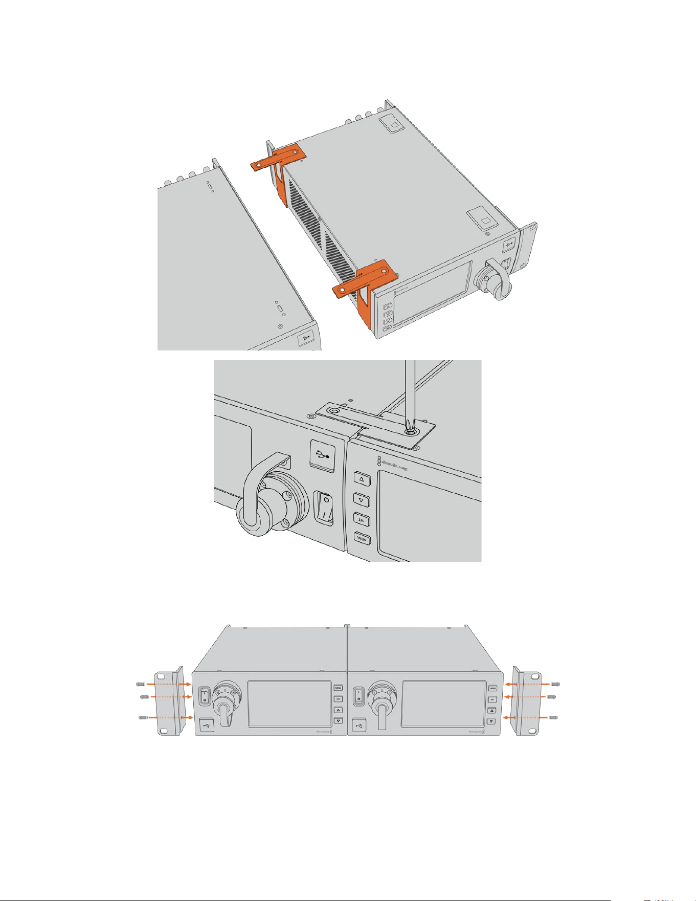
3 Turn the attached units back over and attach the rack ears to the outer edges near the front
of both converters, using the supplied rack ear screws. Your converters are now ready to
be installed into a rack using the mounting holes on both sides and standard rack screws.
204Operating the Studio Fiber Converter
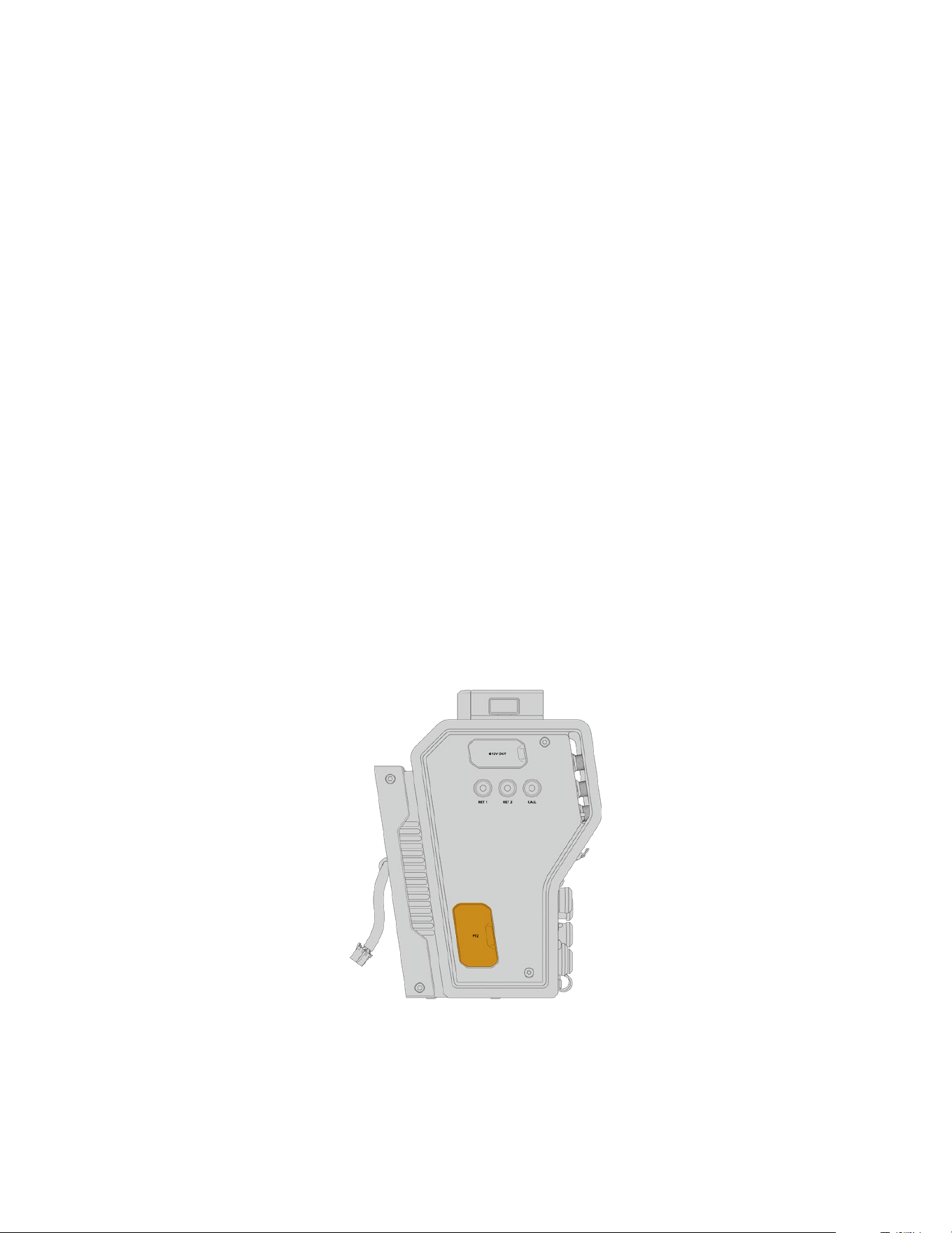
Camera Unit Connections
Connections are located on Blackmagic Camera Fiber Converter’s rear and side panels.
When the connections are not in use, the rubber caps should be replaced to ensure weather
sealing in rain and other outside environments. This is especially true for the SMPTE fiber
connection, as dust particles can very quickly collect on the polished edge of the glass fibers
which can disrupt signal flow. It’s always a wise choice to remove the caps on both the cable
and unit connector immediately before connection, and then replace the caps immediately
after disconnection.
Camera Power Connection
Power is primarily supplied to the camera unit and your camera from the studio converter via a
SMPTE hybrid fiber cable. This also powers all accessories that may be attached to the camera,
for example Blackmagic URSA Studio Viewfinder.
However, you can also power the Blackmagic Camera Fiber Converter via the camera if your
camera has its 12V XLR connector plugged into a power supply. This is not normally required,
but is an option if you have your camera positioned further than 2 kilometers away from the
studio unit where power may not be as reliable over the SMPTE fiber cable.
PTZ Interface
The DE-9 serial connector allows you to connect to a PTZ motorized head. For example, if your
Blackmagic URSA Broadcast G2 or URSA Mini is attached to a camera crane using a pan, tilt,
zoom head that is controlled remotely. You can select the source of PTZ commands being sent
to your camera in the menu of your Blackmagic Studio Fiber Converter. The source of the
commands can be set to the DE-9 connector on your Studio Fiber Converter or an SDI feed
coming from an ATEM switcher. For more information refer to the ‘operating the studio fiber
converter’ section.
PTZ Interface
205Camera Unit Connections
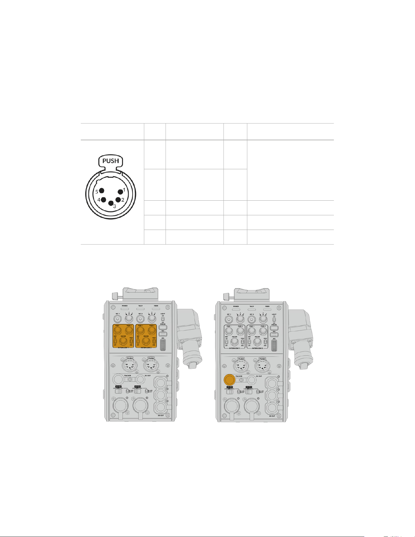
Talkback Connection
The two female 5 pin XLR connectors let you plug in two headsets, which allows two people to
communicate via talkback simultaneously. For example, the camera operator’s headset can be
plugged into the first XLR connector, and a crane operator or fellow crew member, such as a
sound operator, could plug into the second XLR headset connector. A pinout diagram for the
headset XLR connector is included below.
Headset XLR Pinout Diagram
External views Pins Signal I/O Description
5 pin XLR ‘headset’
connector
1 Intercom MIC (Y) In -
The intercom mic input supports
electret condenser mics and
dynamic mics, which can be
balanced or unbalanced. Pin 1 is the
mic signal common, and pin 2 is the
mic signal input for both types. With
electret mics, a DC bias supply is
also output via the same mic signal
input pin.
2 Intercom MIC (X) In +
3 GND GND GND
4 Intercom left Out
5 Intercom right Out
The corresponding intercom controls are located above each headset connection.
For more information on how to use the intercom controls, refer to the ‘Operating the Camera
Fiber Converter’ section.
The intercom controls are used to mix Tracker Interface connector
talkback audio levels
206Camera Unit Connections
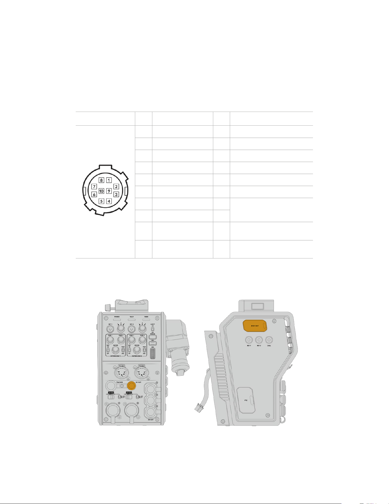
Tracker Interface
The 10 pin ‘tracker’ connector provides a multiplexed output for talkback and tally signals,
plus data such as teleprompter information. This output is commonly used by support crew
operating production equipment such as a camera crane.
A pinout diagram is provided in this section if you want to build your own cable.
Tracker Output Pinout Diagram
External view Pins Signal I/O Specifications
10 pin ‘tracker’ connector
1 Tracker left Out Tracker output, -20 dBu unbalanced
2 GND (Talk) – GND for tracker talk
3 GND (Receive/PGM/tally) – GND for receive/PGM/tally
4 Tracker right Out Tracker output, -20 dBu unbalanced
5 Unregulated Out 12V DC (nom), 500mA (max)
6 GND (Unregulated) – GND for unregulated
7 Tracker talk (X) In
Tracker talk 0 dBu /-20 dBu,
high impedance balanced
8 Tracker talk (Y) In
9 G Tally Out
On: 12V
Off: high impedance (open)
10 R Tally Out
On: 12V
Off: high impedance (open)
DC Connection
You can power additional accessories, for example an external monitor, via the DC out connector.
The DC out connector lets you power D-Tap Output
additional accessories, such as a monitor
or external recording equipment
207Camera Unit Connections
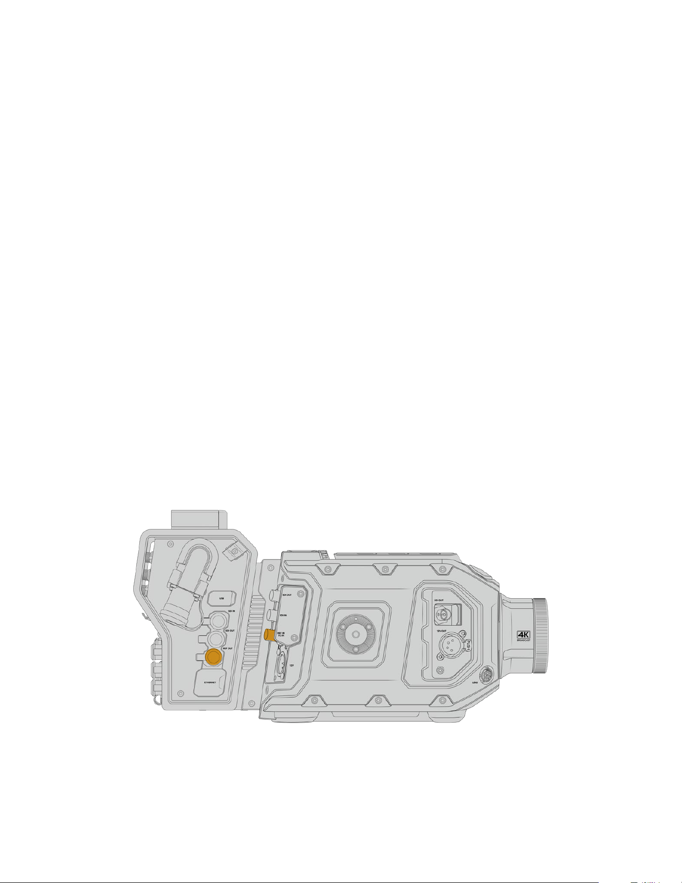
D-Tap Output
The +12V output on the left side panel is often referred to as a ‘D-tap’ or ‘P-tap’ and lets you
power accessories like a monitor or a large box lens. The output supports box lenses that
require +12 Volts DC nominal at 2 amps.
Reference Output and Operation
The reference output can be used to connect a reference signal to your camera via a BNC cable.
To connect a reference signal to your camera:
1 Connect the reference output from the Blackmagic Camera Fiber Converter, marked
‘REF OUT’, to the reference input on your camera marked ‘REF IN’ using one of the small
SDI cables supplied with your camera fiber converter.
2 Set your camera’s reference setting to the reference input.
A sync reference signal lets you genlock video equipment to a common reference, so all
equipment shares the exact same timing. This means all video sources are synced and will
switch smoothly.
ATEM switchers have built in re-synchronizers, so if you are using Blackmagic cameras with
an ATEM Switcher then you don’t need to worry about connecting a sync reference. The
camera will lock to the incoming SDI program feed from the ATEM switcher, so all you need to
do is make sure the ‘program’ input is selected in your URSA Broadcast G2 or URSA Mini’s
reference setting on page two of the ‘setup’ menu. The re-synchronizing process will add a
frame delay.
If you want to reduce the latency of the re-synchronizing process within the ATEM, firstly apply
a reference signal to the URSA Broadcast G2 or URSA Mini, then adjust the back timing so the
line input is before the switch timing of the ATEM.
To adjust the reference sync on the URSA Broadcast G2 or URSA Mini, enter the ‘setup’ menu
and change the line number under ‘reference’.
If you’re using an external reference signal, connect the reference output from thecamera fiber unit to
URSA Broadcast G2 or URSA Mini’s reference input.
208Camera Unit Connections
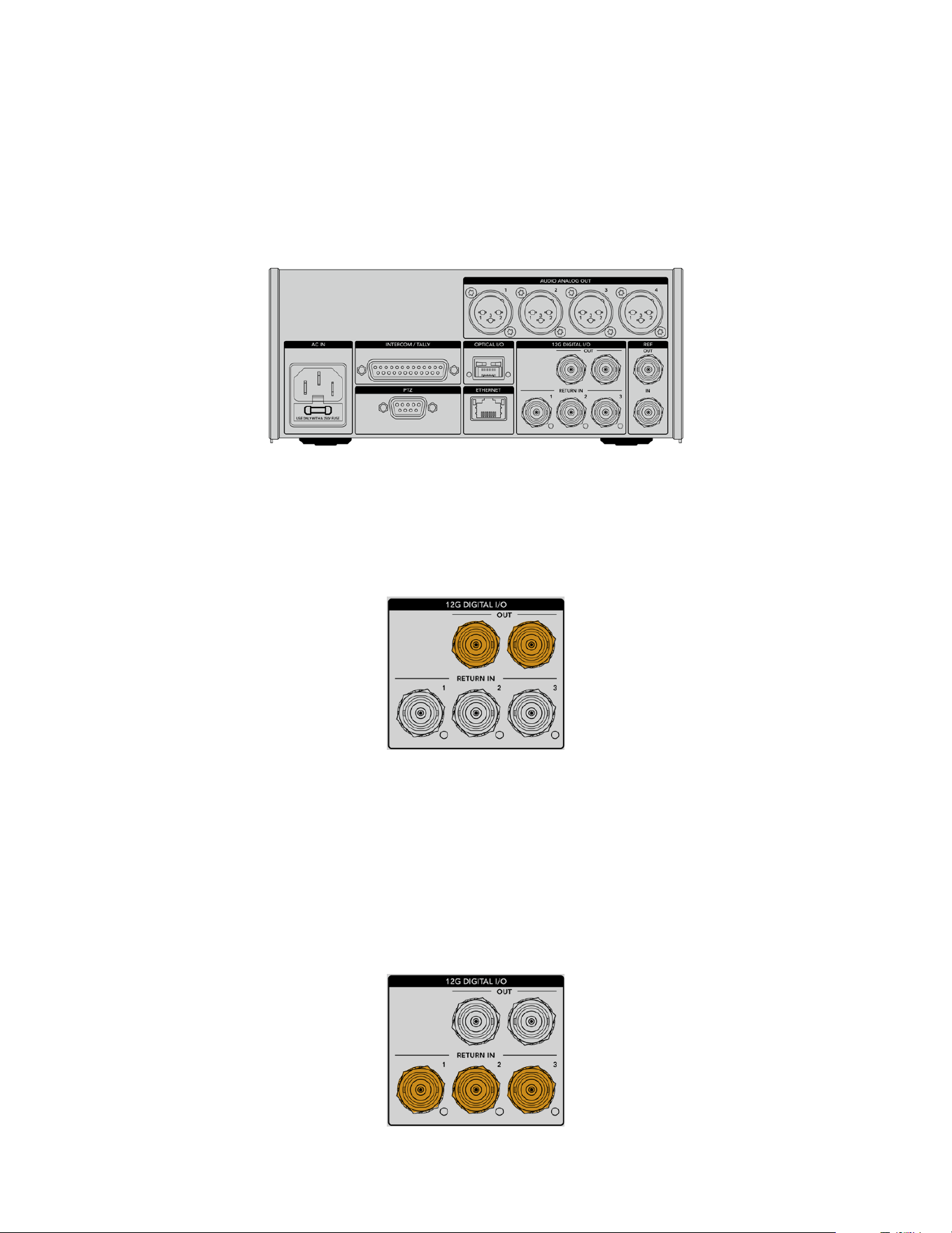
Studio Unit Connections
The rear panel of the Blackmagic Studio Fiber Converter provide SDI return feed and reference
BNC connectors, intercom and tally DB-25 connector, PTZ 9 pin serial port, audio outputs,
andEthernet.
All SDI inputs support 12G-SDI for video formats up to Ultra HD 2160p60.
12G-SDI Output
The two 12G-SDI outputs are for connecting the camera signal from the studio unit to any of
your switcher’s camera SDI inputs. The second connector can be used to output the same
signal to other video equipment, for example a Blackmagic Videohub router, SmartView monitor
or a HyperDeck Disk Recorder.
The 12G-SDI outputs allow for signals
from 720p50 up to 2160p60
Return SDI Inputs
The 12G-SDI return feed BNC connectors give you the option to plug in up to three return
SDIfeeds. For example, the program feed from a switcher should be connected to return 1 and
have a matched frame rate to that of your camera. Other sources like a second camera output,
HyperDeck playback, or even a teleprompter can be connected to return feeds 2 and 3. If you
are using an ATEM switcher, the program return connected to return 1 will also include tally,
talkback, reference and camera control signals.
209Studio Unit Connections
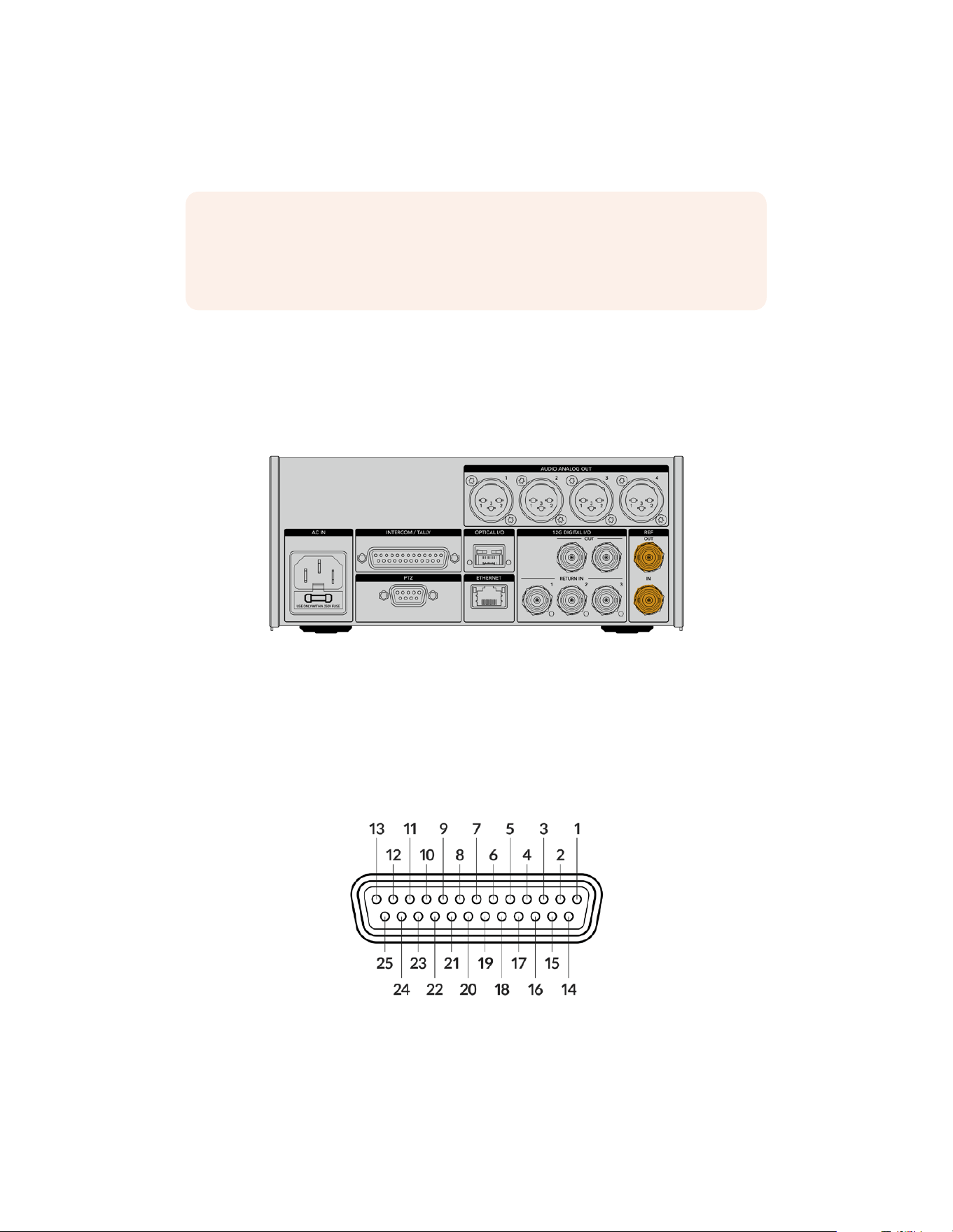
The return SDI inputs allow you to connect up to three return feeds from your switcher. These
feeds will be fed to your camera so that they can be viewed by the camera operator, or fed out
via SDI to other equipment.
NOTE If you connect Ultra HD to the return inputs, the Ultra HD video will be down
converted to 1080p at the same frame rate, so the output from the camera unit will be
HD. Down converting the Ultra HD return signals to HD allows for greater bandwidth
so you can send multiple return sources.
Reference Input and Output
If you are not using an ATEM switcher and need to lock equipment to a common external
reference signal, plug the externally generated signal into the reference BNC input. This sends
the reference to the camera unit via the SMPTE fiber cable. The reference BNC output from the
studio unit can be used to loop the reference source to other equipment.
Use the ‘ref in’ connection to send traditional reference timing
from other broadcast equipment to your camera
Talkback Interface
The DB-25 intercom and tally connector lets you connect to third party intercom and tally
systems. A pin out diagram is provided below if you need to build a custom cable. Once you
have wired up to the pins for engineering, production, tally or program audio input, you will
need to set the menu accordingly on your Blackmagic Studio Fiber Converter.
The external view of the 25 pin ‘intercom/tally’ connector
210Studio Unit Connections

Talkback Pinout Diagram
Pins Signal Specifications
1 ENG(R) IN+
Engineering channel input
0dBu balanced
2 ENG(R) IN-
3 ENG GND GND for ENG
4 ENG(T) OUT +
Engineering channel output
0dBu balanced
5 ENG(T) OUT -
6 PGM IN+ -20dBu
7 PGM IN- -20dBu
8 PGM GND -20dBu
9 GND GND for aux
10 N/C –
11 Red Tally IN On = 5-24Vdc, Off= 0Vdc
12 Red Tally GND –
13 GND Chassis GND
14 PROD(R) IN+
Production channel input
0dBu balanced
15 PROD(R) IN-
16 PROD GND –
17 PROD(T) OUT+
Production channel output
0dBu balanced
18 PROD(T) OUT-
19 N/C –
20 N/C –
21 N/C –
22 N/C –
23 N/C –
24 Green Tally IN On = 5-24Vdc, Off= 0Vdc
25 Green Tally GND –
PTZ Interface
Both the studio unit and camera unit has a DE-9 connector so you can connect a PTZ controller
at the studio end, and the remote head at the camera end. The PTZ commands are embedded
in the SDI signal connected between the units via the SMPTE fiber cable.
The settings menu on Blackmagic Studio Fiber Converter lets you select the source of PTZ
commands that are sent to your Blackmagic Camera Fiber Converter. You have the option to
select from the PTZ connector on the back of the Studio Fiber Converter or a program SDI feed
coming from an ATEM Switcher instead. For more information, refer to the ‘operating the studio
fiber converter’ section.
211Studio Unit Connections
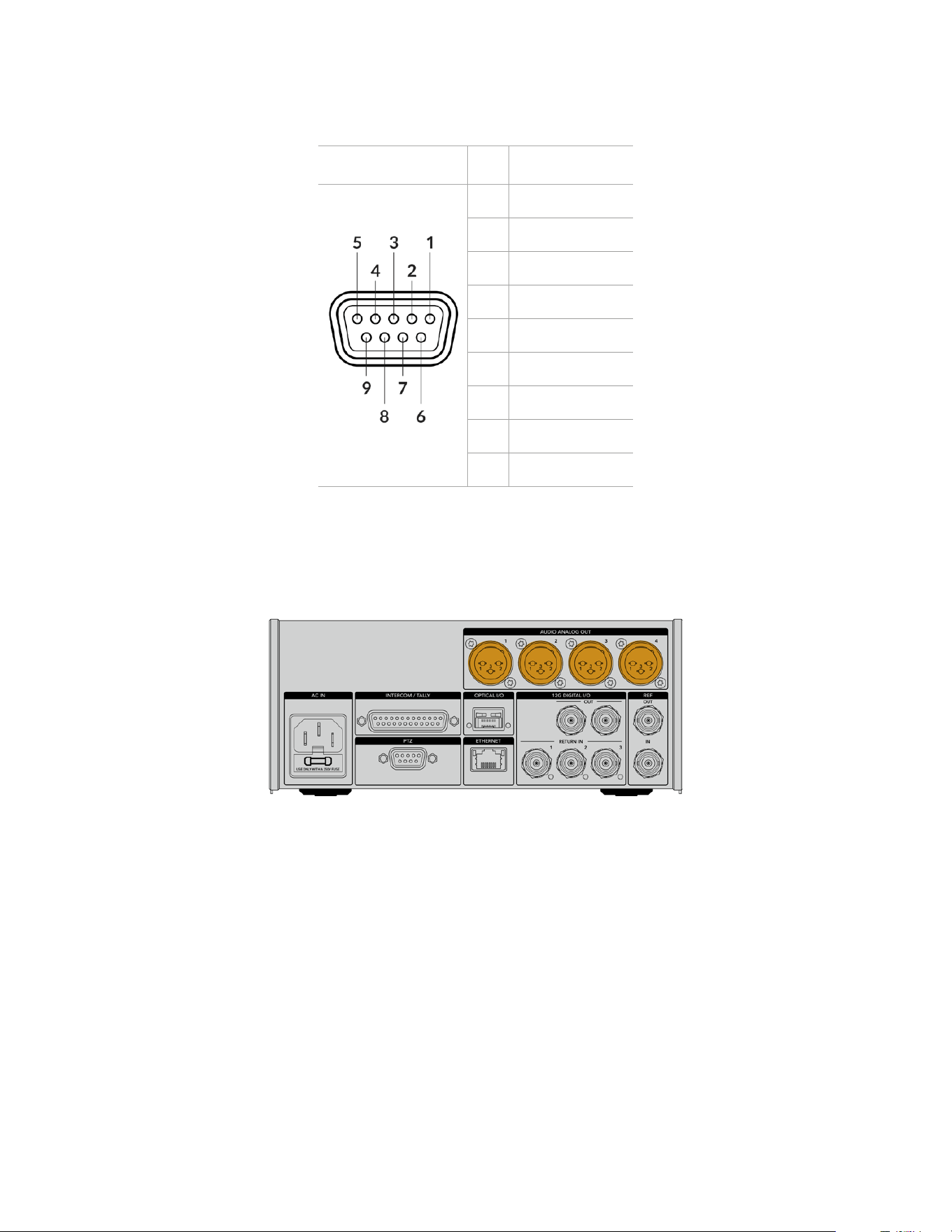
PTZ Interface Pinout Diagram
External view Pins Signal
9 pin ‘PTZ’ connector
1 GND
2 RS422 Tx-
3 RS422 Rx+
4 GND
5 N/C
6 GND
7 RS422 Tx+
8 RS422 Rx-
9 GND
Audio Outputs
The four XLR audio outputs on the studio unit give you the option to output the audio plugged
into inputs 1 and 2 from your URSA Broadcast G2 or URSA Mini camera, and the two XLR audio
inputs on the Camera Fiber Converter.
Outputs 1 and 2 on the studio unit correspond to embedded XLR input channels 1 and 2 on
URSA Broadcast G2 or URSA Mini by default. Outputs 3 and 4 on the studio unit correspond
to XLR inputs 1 and 2 on the Blackmagic Camera Fiber Converter by default. You can use the
menu to change these settings for mapping. For more information, see the ‘using the
menu’ section.
212Studio Unit Connections
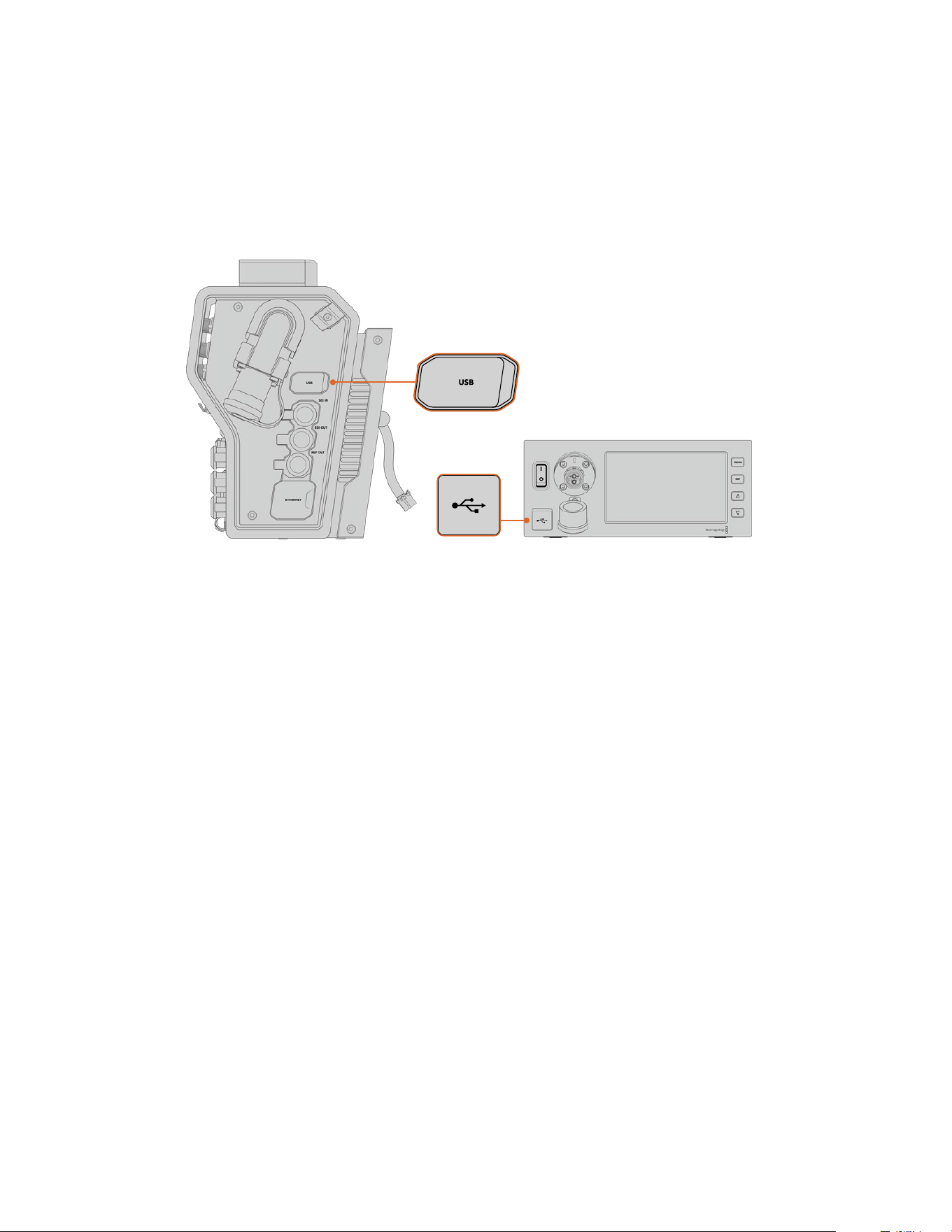
Updating Internal Software
From time to time Blackmagic Design releases updates that can enhance and enable features
on your Blackmagic Fiber Converters. We recommend checking the Blackmagic Design
website regularly to ensure your fiber converters are using the latest internal software. Update
your Fiber Converters using the Blackmagic Camera Setup Utility software.
The USB-C ports on the Blackmagic Fiber converters let you update their internal software.
Updating Blackmagic Camera Fiber Converter
Your Camera Fiber Converter will need to be powered when updating, so we recommend
keeping the converter connected to URSA Broadcast G2 or URSA Mini during the
update process.
It’s important that you unplug the SMPTE Fiber cable from your Camera Fiber Converter, and
power your camera via the supplied URSA camera Power Supply instead for consistent power.
Blackmagic Camera Fiber Converter has a USB-C connector on the right side of the unit for
updating its internal software. Connect your computer to this USB connector and launch
Blackmagic Camera Setup Utility. You will be prompted to update if your computer detects that
your Camera Fiber Converter is using an outdated version. Follow the on screen prompts to
update your converter’s internal software.
Updating Blackmagic Studio Fiber Converter
Your Studio Fiber Converter will need to be powered when updating, so we recommend
keeping the IEC power cable plugged into the power connector on the studio unit’s rear panel
during the update process.
Blackmagic Studio Fiber Converter has a USB-C connector on the front of the unit for updating
its internal software. Connect your computer to this USB connector and launch Blackmagic
Camera Setup Utility. You will be prompted to update if your computer detects that your Studio
Fiber Converter is using an outdated version. Follow the on screen prompts to update your
converter’s internal software.
213Updating Internal Software
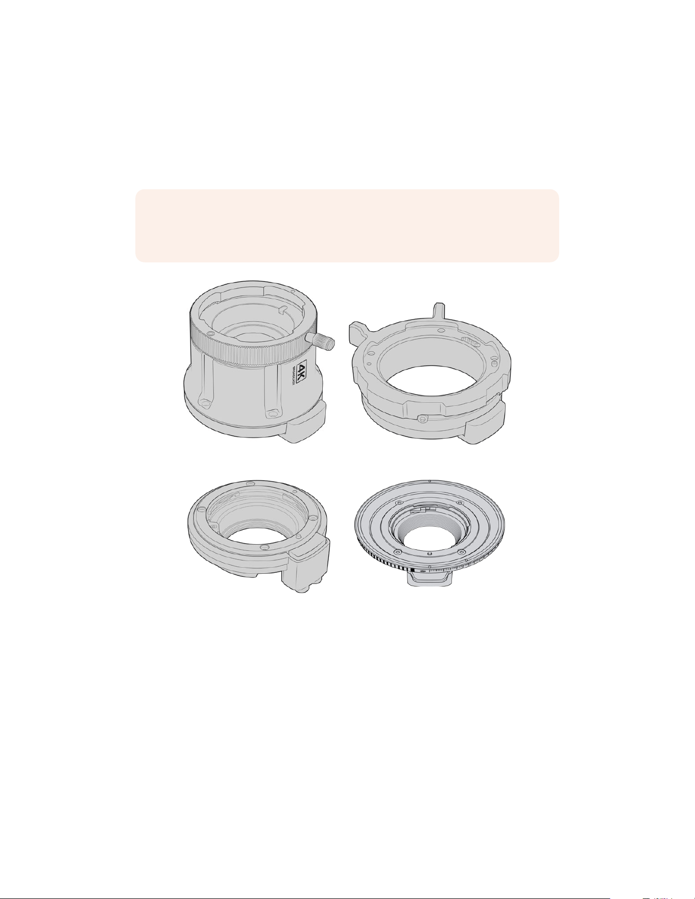
Interchangeable Lens Mount
Blackmagic URSA Broadcast G2 is shipped with its own custom B4 mount attached, as well as
an additional EF mount. The interchangeable lens mount means you can also attach Blackmagic
URSA Mini Pro PL or URSA Mini Pro F Mount kits to your camera. Lens mount kits are available
from Blackmagic Design Resellers.
NOTE A B4 mount is available for Blackmagic URSA Mini Pro but this is not the same
as the B4 mount on URSA Broadcast G2 camera and is designed for a different sensor.
Use only the B4 mount that originally came with your URSA Broadcast G2 camera.
PL mount Broadcast B4 mount
EF mount F mount
With the ability to interchange four separate mounts, you have the freedom to use different
lenses based on the type of assignments you’re working on. For example, the EF mount lets
you use high quality stills lenses, the B4 mount is perfect if you want to use par-focal zoom
lenses for electronic news gathering or wedding shoots, while the PL mount lets you use high
end, robust cinema lenses designed for absolute precision and repeatable control. The F mount
gives you access to a huge range of Nikon lenses manufactured from 1959 to today.
Attaching each mount is as simple as unscrewing the original B4 mount and replacing it with the
new mount.
214Interchangeable Lens Mount
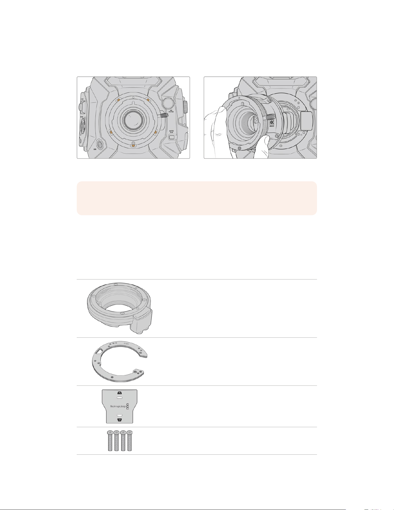
Removing the B4 Mount
To remove the B4 mount, simply unscrew the five M3 Hex screws using a 2mm Hex driver.
The B4 mount is removed by unscrewing the five M3 Hex screws and lifting the mount from the camera body.
NOTE When removing the original B4 mount, make sure the shim underneath the
mount always stays attached to your camera.
Keep reading this section for details about the PL, B4, and EF lens mount kits and how to install
each mount to your URSA Broadcast G2.
Blackmagic URSA Mini Pro EF Mount
The EF mount lets you attach EF stills lenses to your URSA Broadcast G2.
The EF mount kit includes:
1x EF mount
The EF mount lets you attach common EF stills lenses.
1 x Shim set
The shim set includes the following thicknesses:
0.50mm
0.30mm
0.20mm
0.18mm
0.15mm
0.12mm
0.10mm
0.05mm
0.025mm
1x Baffle tool
The baffle in the EF mount is not removable, however we have
included a baffle tool in the EFkit as a spare item you can use
if you also have the PL mount.
4 x 2mm Hex M3 x 18mm mount screws
The four M3 x 18mm Hex screws are exclusive to the EF mount so
you can keep the screws together with the respective mount.
215Interchangeable Lens Mount
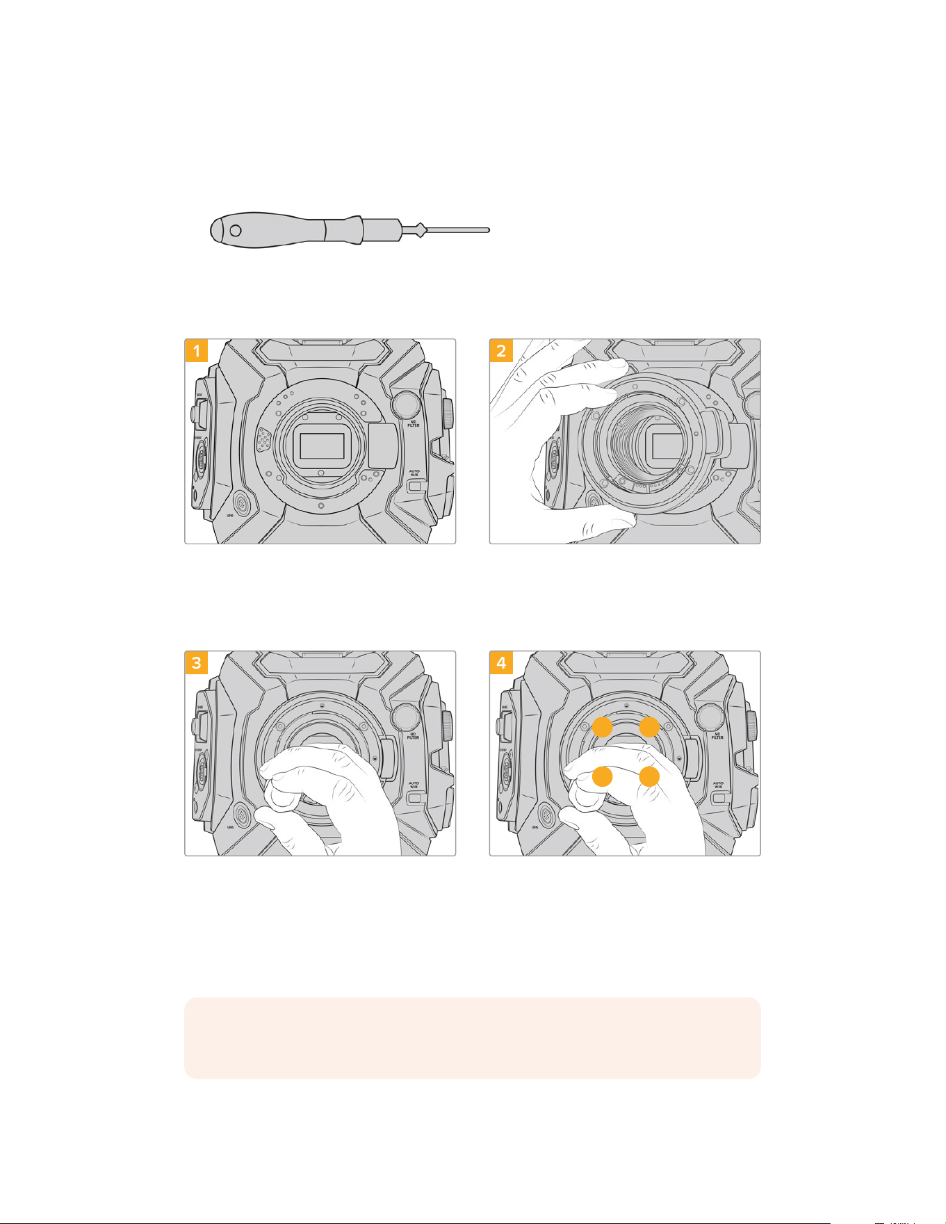
Tools Required
When attaching the EF mount, you will need a 2mm Hex driver. While it’s not absolutely
required, we recommend using a torque wrench able to accurately set a maximum torque
of 0.45Nm to reduce the potential of over tightening the screws.
2mm Hex driver
Attaching the EF Mount
1 2
Place Blackmagic URSA Broadcast G2 vertically
ona solid, clean bench top toensure that the mount
can be inserted vertically. If changing from the PL to
the EFmount, ensure that you have removed thePL
baffle before inserting the EF mount.
Carefully place the Blackmagic URSA MiniPro
EFmount onto the camerabody ensuring the
reddot is at the 12o’clock position.
3 4
1 3
4 2
Loosely turn the four mounting screws until initial
contact is made with the shoulder of the lensmount.
Using the 2mm Hex driver, or torque wrench with
2mm Hex key, apply one full turn of pressure to
mounting screw 1, followed by one full turn to screw
2, and repeat for screw 3 and then 4. Continue to
apply one full turn to each screw in the sequence
above until all screws have reached the maximum
torque of 0.45Nm.
NOTE When removing the EF mount, simply follow the instructions in reverse order
from step 4 to step 1.
216Interchangeable Lens Mount
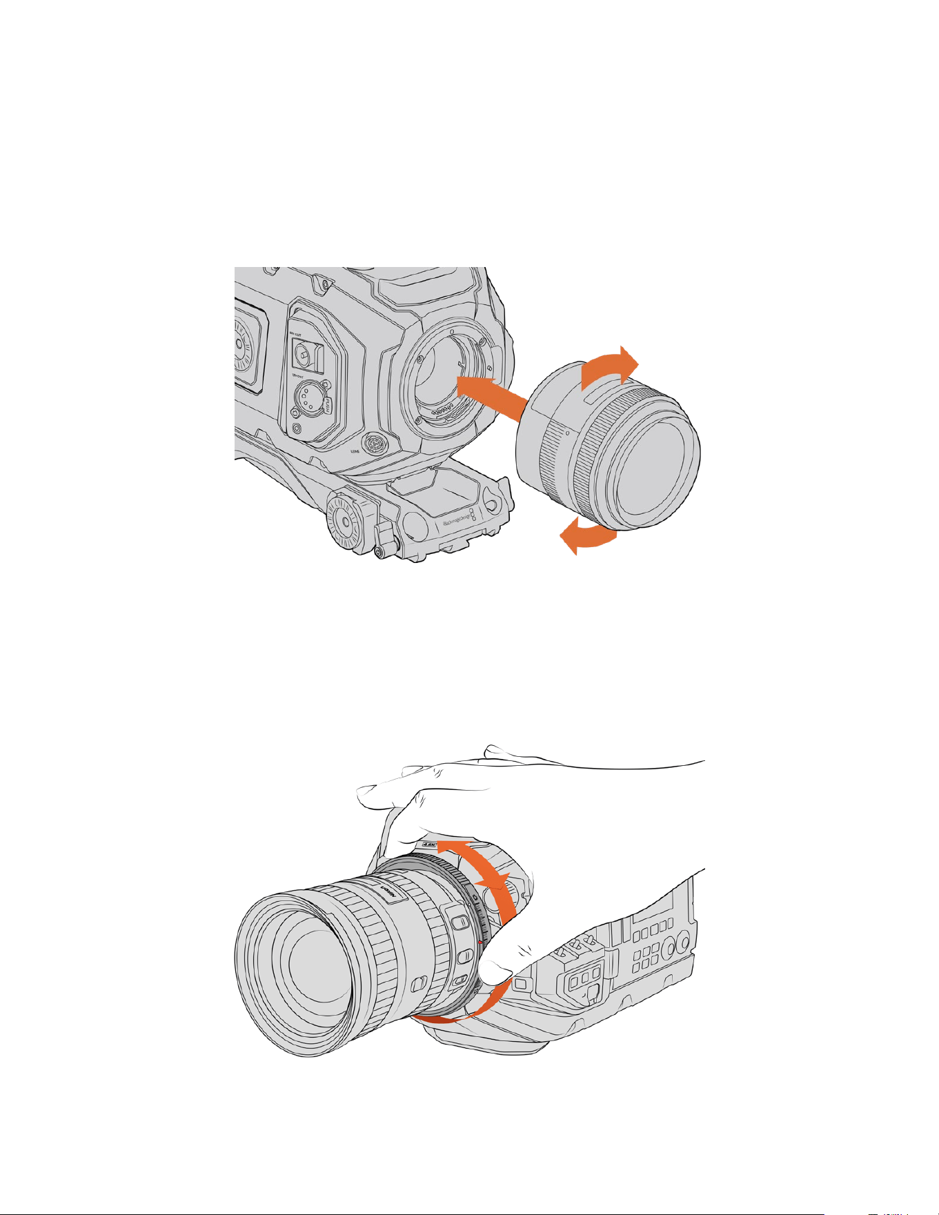
To attach an EF mount lens:
1 Align the dot on your lens with the dot on the camera mount. Many lenses have a visual
indicator, for example a blue, red or white dot.
2 Insert the lens into the mount and twist clockwise until it locks into place.
3 To remove the lens, hold down the locking button, rotate the lens counterclockwise until its
dot or indicator reaches the 12 o’clock position, and gently remove.
Attaching and removing an EF mount lens
Blackmagic URSA Mini Pro F Mount
With the Blackmagic URSA Mini Pro F Mount attached to your URSA Broadcast G2, you can use
Fmount lenses. Nikon’s Fmount system stretches back to 1959, and F mount lenses are still
made today. This means that with the Blackmagic URSA Mini Pro F mount, you have access to
ahuge range of vintage and contemporary lenses.
Use URSA Mini Pro F mount’s iris adjustment ring to smoothly
change the aperture of F mount lenses.
217Interchangeable Lens Mount
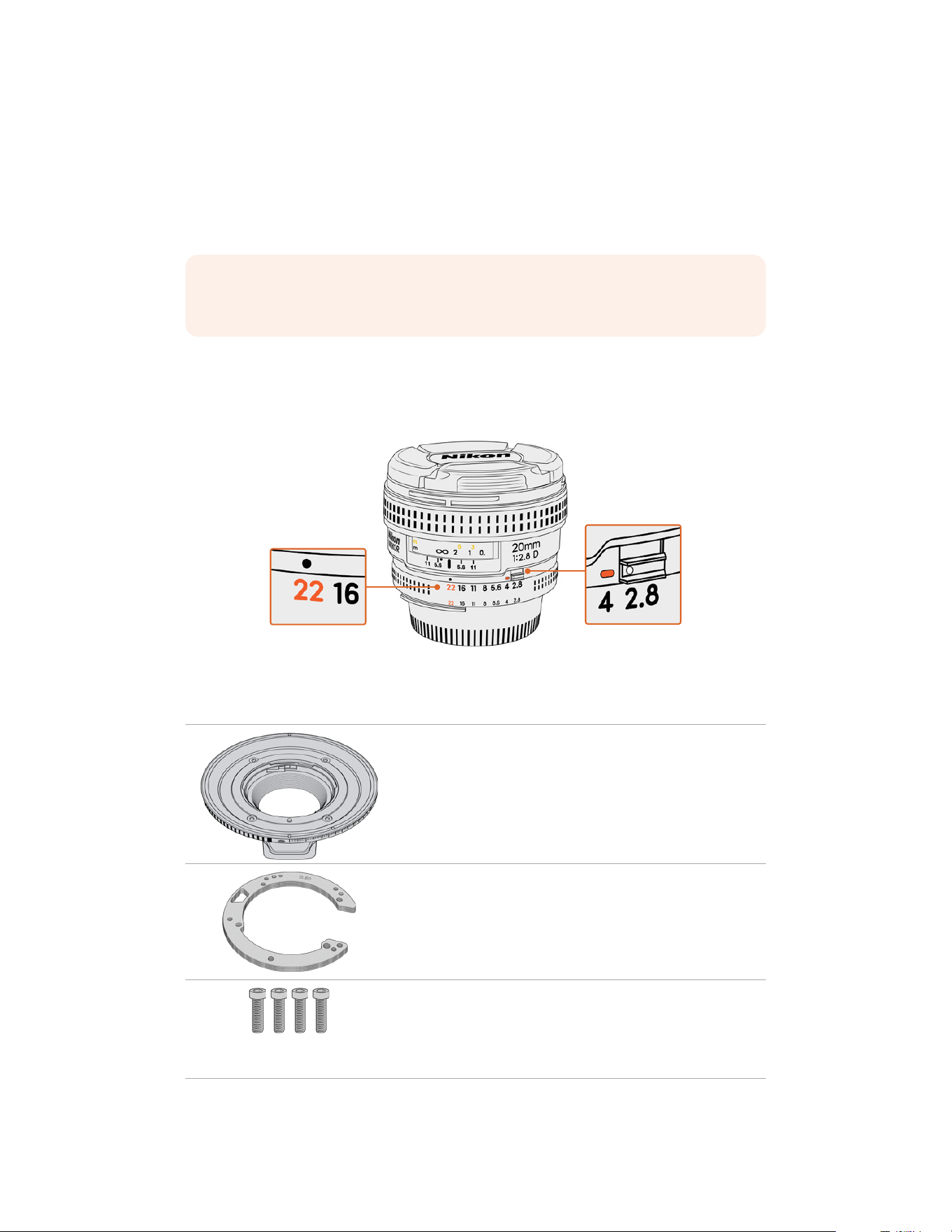
It’s worth noting that the F mount is a mechanical mount. This means it does not offer electronic
focus or iris control. Instead, the F mount features a mechanical iris adjuster. This moves the iris
pin present in most Nikon lenses to achieve smooth cine style iris adjustment.
With an F mount mounted, simply move the iris adjuster on Blackmagic URSA Mini Pro F mount
to achieve your preferred exposure. The red dot on the F mount and the markings on the iris
adjuster let you mark iris settings to easily return to particular exposure or depth of field settings.
NOTE When removing the F mount, simply follow the instructions in reverse order
from step 4 to step 1.
Nikon AF-D lenses
When using Nikon AF-D series lenses, it is necessary to lock your lens aperture to its
smallestsetting, such as f/22, to use the full range of Blackmagic URSA Mini Pro Fmount’s
irisadjustment ring.
Setting and locking AF-D lenses to their smallest aperture
is easiest before mounting to your camera.
The F mount kit includes:
1x F mount
The F mount lets you attach commonFstills lenses.
1 x Shim set
The shim set includes the following thicknesses:
0.50mm
0.30mm
0.20mm
0.18mm
0.15mm
0.12mm
0.10mm
0.05mm
0.025mm
4 x 2mm Hex M3 x 18mm mount screws
The four M3 x 18mm Hex screws are used in the EFand F mount
so it is best to keep the screws together with the respective mount.
The F mount kit also comes with a full spare sets ofscrews in case
the originals are misplaced.
218Interchangeable Lens Mount
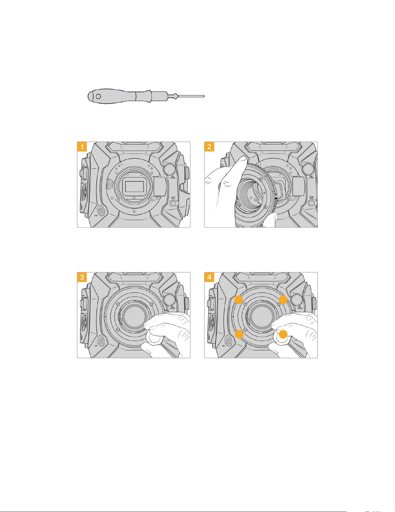
Tools Required
When attaching the F mount, you will need a 2mm Hex driver. While it’s not absolutely required,
we recommend using a torque wrench able to accurately set a maximum torque of 0.45Nm to
reduce the potential of over tightening the screws.
2mm Hex driver
Attaching the F Mount
1 2
Place Blackmagic URSA Broadcast G2 vertically on
a solid, clean bench top to ensure the mount can be
attached vertically. If changing from the PL to the F
mount, ensure that you have removed the PL baffle
before inserting the F mount.
Carefully place the Blackmagic URSAMiniPro
Fmount onto the camera bodyensuring the
whitedot is atthe2o’clock position.
3 4
1 3
4 2
Loosely turn the four mounting screws until initial
contact is made with the shoulder of the lens mount.
Using the 2mm Hex driver, or torque wrench with
2mm Hex key, apply one full turn of pressure to
mounting screw 1, followed by one full turn to screw
2, and repeat for screw 3 and then 4. Continue to
apply one full turn to each screw in the sequence
above until all screws have reached the maximum
torque of 0.45Nm.
219Interchangeable Lens Mount
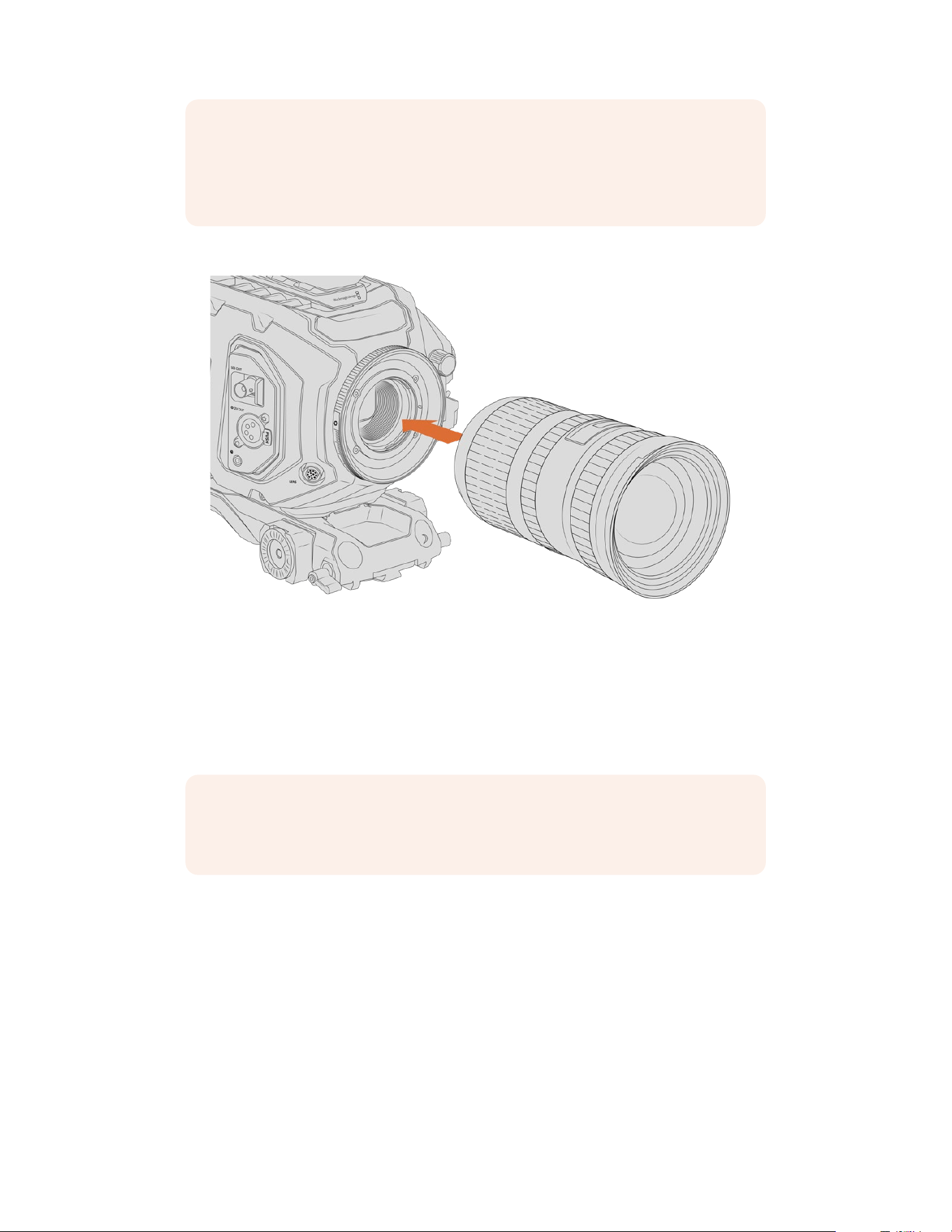
NOTE Because of the way URSA Mini Pro F mount works, a small number of F mount
lenses are not compatible.
These are Nikkor AF-S E series lenses, which do not offer mechanical iris control,
andNikon PC-E tilt-shift lenses like the 24mm f/3.5D PC-E and 85mm PC-E.
To attach a F mount lens:
Attaching and removing a F mount lens on Blackmagic URSABroadcast G2
with the optional F mount fitted
1 Align the dot on your lens with the dot on the camera mount. Many lenses have a visual
indicator, for example a blue, red or white dot.
2 Insert the lens into the mount and twist counterclockwise until it locks into place.
3 To remove the lens, hold down the locking button, rotate the lens clockwise until its dot or
indicator reaches the 2 o’clock position, and gently remove.
NOTE Blackmagic URSA Mini Pro F mount features a mechanical iris adjuster. To use
older style F mount lenses with built in focus rings with this mount, your lenses
aperture will need to be set and locked to its smallest setting, such as f/22.
220Interchangeable Lens Mount
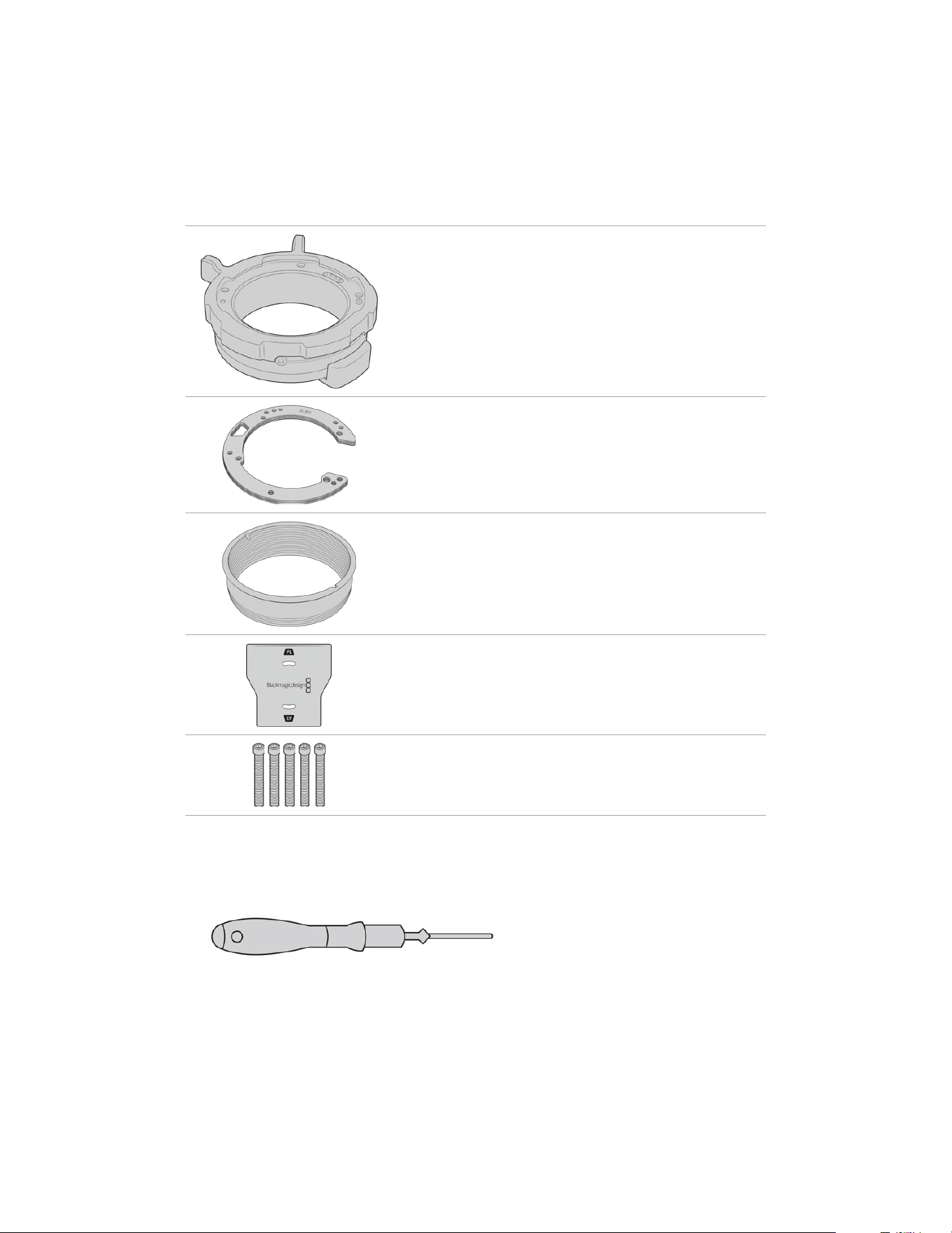
Blackmagic URSA Mini Pro PL Mount
Attaching the PL mount to your URSA Broadcast G2 lets you use high end precision cinema
lenses and Super 16mm PL lenses for feature film and television production.
The PL mount kit includes:
1x PL mount
The PL mount is shipped with a protective dust cap.
1 x Shim set
The shim set includes the following thicknesses:
0.50mm
0.30mm
0.20mm
0.18mm
0.15mm
0.12mm
0.10mm
0.05mm
0.025mm
1x PL baffle
The PL mount baffle helps to control and direct the light entering
the sensor.
1x Baffle tool
Use the PL baffle tool to tighten the baffle in your camera.
5 x 2mm Hex M2.5 x 22mm mount screws
The five M2.5 x 22mm Hexscrews are exclusive to the PLmount
so you can keep the screws together with the respective mount.
Tools Required
When attaching the PL mount, you will need a 2mm Hex driver. While it’s not absolutely
required, we recommend using a torque wrench able to accurately set a maximum torque
of0.45Nm to reduce the potential of over tightening the screws.
2mm Hex driver
221Interchangeable Lens Mount
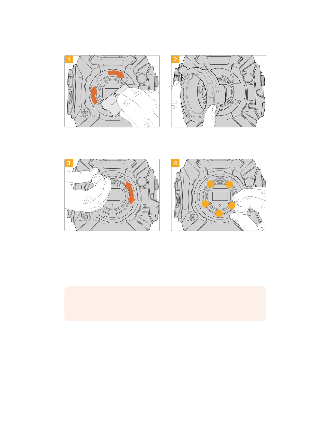
Attaching the PL Mount
1 2
Gently insert the PL baffle into the center of the lens
mount and turn until it is finger tight. Use the wide
end of the baffle tool to tighten the baffle slightly.
You need just enough pressure to keep it in place.
Ensurethe pins on the PL mount for
Cooke/iTechnology are located at the
12o’clockposition.
3 4
1
3
4
5
2
Loosely turn the five mounting screws until initial
contact is made with the shoulder of the lens
mount. To access all five screws, you will need to
rotate the PL locking ring, as some holes are
obscured when the ring is either open or closed.
Using the 2mm Hex driver, or torque wrench with
2mm Hex key, apply one full turn of pressure to
mounting screw 1, followed by one full turn to
screw2. Repeat for screws 3and 4, then 5.
Continue to apply one full turn to each screw in
the sequence above until all screws have reached
the maximum torque of 0.45Nm.
NOTE When removing the PL mount, simply follow the instructions in reverse order
from step 4 to step 1. Don’t forget to remove the PL baffle and store it securely with the
PL mount.
To attach a PL mount lens:
1 Open your camera’s PL locking ring by rotating it counterclockwise until it stops.
2 Align one of the lens’ four flange notches with the locating pin on the camera mount.
Be sure to align the lens for easy viewing of the lens marks.
3 Tighten the PL locking ring by rotating it clockwise. If attaching a PL lens with a servo unit to
URSA Broadcast G2, you can also connect the 12 pin broadcast connector for servo control.
222Interchangeable Lens Mount
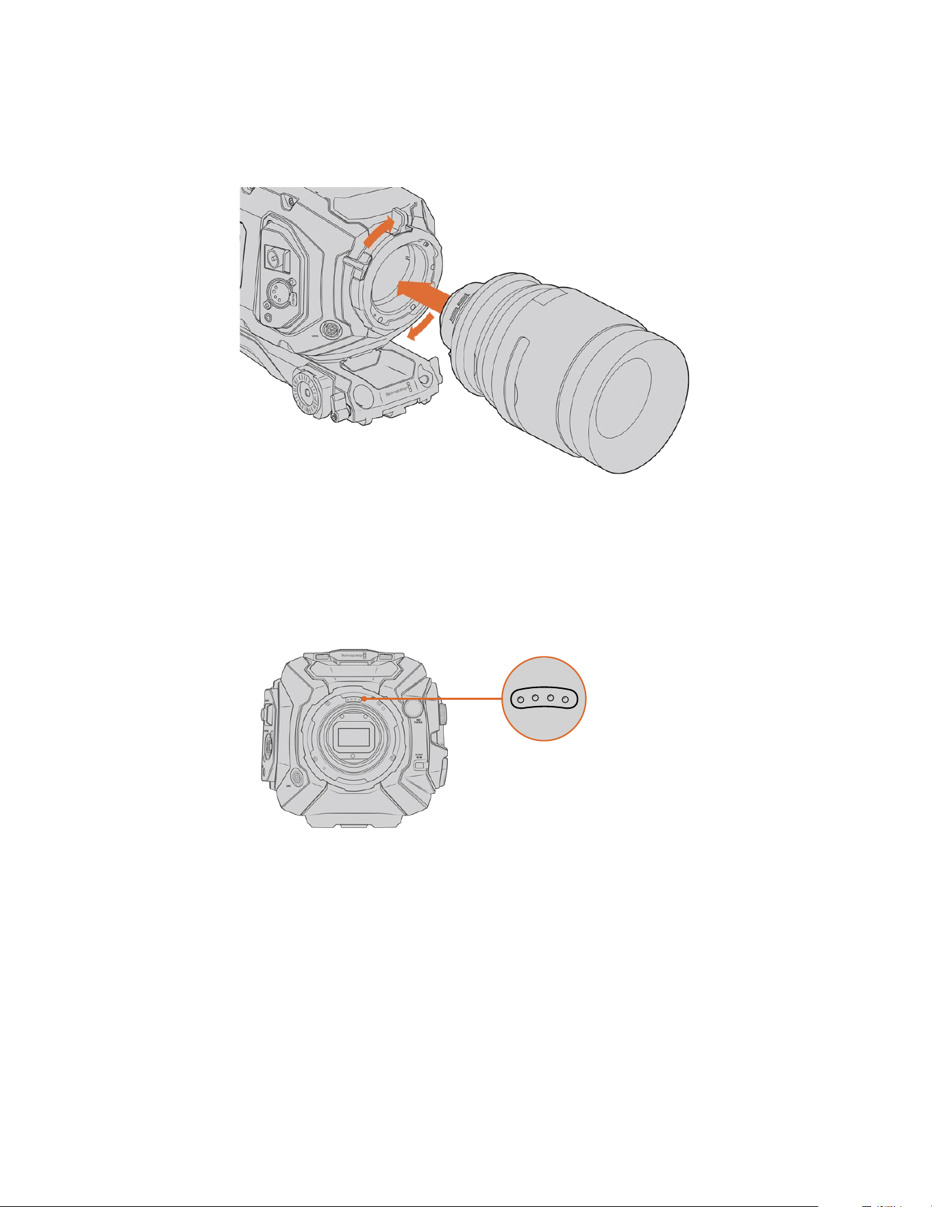
4 To remove the lens, rotate the locking ring counterclockwise until it stops, then gently
remove the lens by pulling it directly out from the camera body. There is no need to
rotate the lens.
Attaching and removing a PL lens
Cooke Lenses /i Technology Support
The optional Blackmagic URSA Mini Pro PL Mount available for URSA Broadcast G2 features
four pins at the 12 o’clock position that are used to communicate with lenses featuring Cooke’s
/iTechnology interface. The lenses that support this interface include lenses from Canon, Cooke,
Fujinon, Leica and Zeiss. Thislets you record lens information in your clips’ metadata such as the
lens model, focal length, aperture setting, focus distance and other lens specific information.
When mounting a PLlens with Cooke
/iTechnology to URSA Broadcast G2,
make sure the lens pins align withthe
mount pins at the 12o’clock position
The information that is recorded as metadata via Cooke’s /i Technology interface canbe very
helpful in post production and VFX. Knowing the lenses used in productionand their precise
settings can be helpful in the event that the setup needsto be replicated at a later date.
This detailed information can also be utilized by powerful applications such as DaVinciResolve
and Blackmagic Fusion for a wide variety of advanced functions. Forexample, the recorded
metadata can be used to simulate the specific lens in 3Dspace, or correct lensdistortions.
PL Mount Servo Lenses
URSA Broadcast G2 supports control of PL 35mm lenses with servo handgrips. When the lens
is plugged in to the lens connector on the camera, URSA Broadcast G2 will provide power and
control signals to your lens in the same way it does with B4 lenses. For more information refer
to the ‘Using Servo Zoom Lenses’ section in this manual.
223Interchangeable Lens Mount
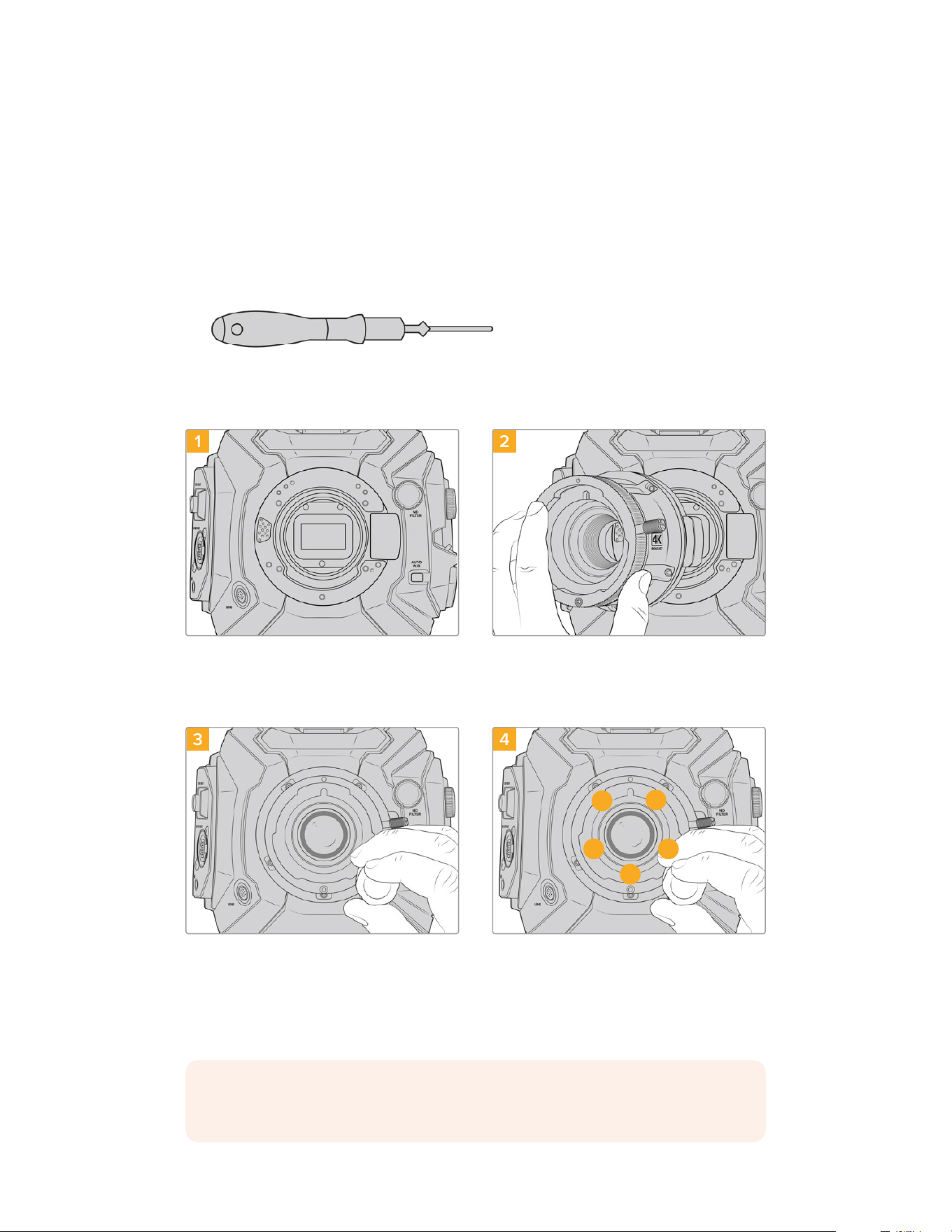
Blackmagic URSA Broadcast G2 B4 Mount
The Broadcast B4 mount is the mount that your URSA Broadcast G2 camera originally ships
with. Ifyou have removed the mount to fit the included Blackmagic URSA EF mount or optional
URSA PL or F mount, follow these instructions to reattach your B4 mount.
Tools Required
When attaching the B4 mount, you will need a 2mm Hex driver. While it’s not absolutely
required, we recommend using a torque wrench able to accurately set a maximum torque
of 0.45Nm to reduce the potential of over tightening the screws.
2mm Hex driver
Attaching the B4 Lens Mount
1 2
Place Blackmagic URSA Broadcast G2 vertically on
a solid, clean bench top to ensure that the mount
can be inserted vertically.
Keeping the original .50mm shim in place, gently
put the Blackmagic URSA Broadcast G2 B4 mount
onto the camera body ensuring the red dot is at the
12o’clock position.
3 4
1
3
4
5
2
Loosely turn the five mounting screws until initial
contact is made with the shoulder of the lens mount.
Using the 2mm Hex driver, or torque wrench with 2mm
Hex key, apply one full turn of pressure to mounting
screw 1, followed by one full turn to screw2. Repeat
for screws 3and 4, then 5. Continue to apply one full
turn to each screw in the sequence above until all
screws have reached the maximum torque of 0.45Nm.
NOTE When removing the B4 mount, simply follow the instructions in reverse order
from step 4 to step 1.
224Interchangeable Lens Mount

Shimming Lens Mounts
What is a Shim?
Shims are thin disks of varying thickness that let you make fine adjustments to the distance
between your lens and URSA Broadcast G2’s sensor. This distance is commonly known as the
flange focal distance, and can change slightly due to variables such as lens age and the
environmental conditions of your shoot.
URSA Broadcast G2 Shim
Shims are placed between the lens mount and the camera body so the distance from your
subject to the sensor matches the focus marks on your lens. These are most commonly used
forPL lenses. These cine lenses are manually focused and have very accurate focal distance
markings on their barrels. Shims are also used for URSA Broadcast G2’s interchangeable
lens mount.
The Blackmagic URSA Mini Pro Shim Kit contains additional shim sets of various thicknesses,
and can be purchased from your local Blackmagic Design reseller. A set of shims is also
included with all mount kits and are compatible with URSA Broadcast G2. Use shim thicknesses
depending on your back focus requirements.
Blackmagic URSA Mini Pro Shim Kit
Your URSA Broadcast G2 camera ships with two shims, a 0.10mm plastic shim and a 0.50mm
metal shim. These shims set the proper focal distance for your URSA Broadcast G2 camera’s
B4, EF, and F mount lenses. Very occasionally, you will need to use additional shims to suit
PLlenses that require very specific clearances to maintain accurate focus marks. Blackmagic
URSAMini Pro Shim Kit includes the following additional tools. Other thicknesses are included
in the kit in case you need to re-shim your camera to suit PL lenses that may require slightly
different clearances to maintain accurate focus marks.
The shim kit includes:
1x Baffle tool
Use the baffle tool to loosen or tighten the PL baffle when
removing or attaching the PL mount to your URSA Broadcast G2.
1 x Shim set
The shim set includes the following thicknesses:
0.50mm
0.30mm
0.20mm
0.18mm
0.15mm
0.12mm
0.10mm
0.05mm
0.025mm
225Shimming Lens Mounts
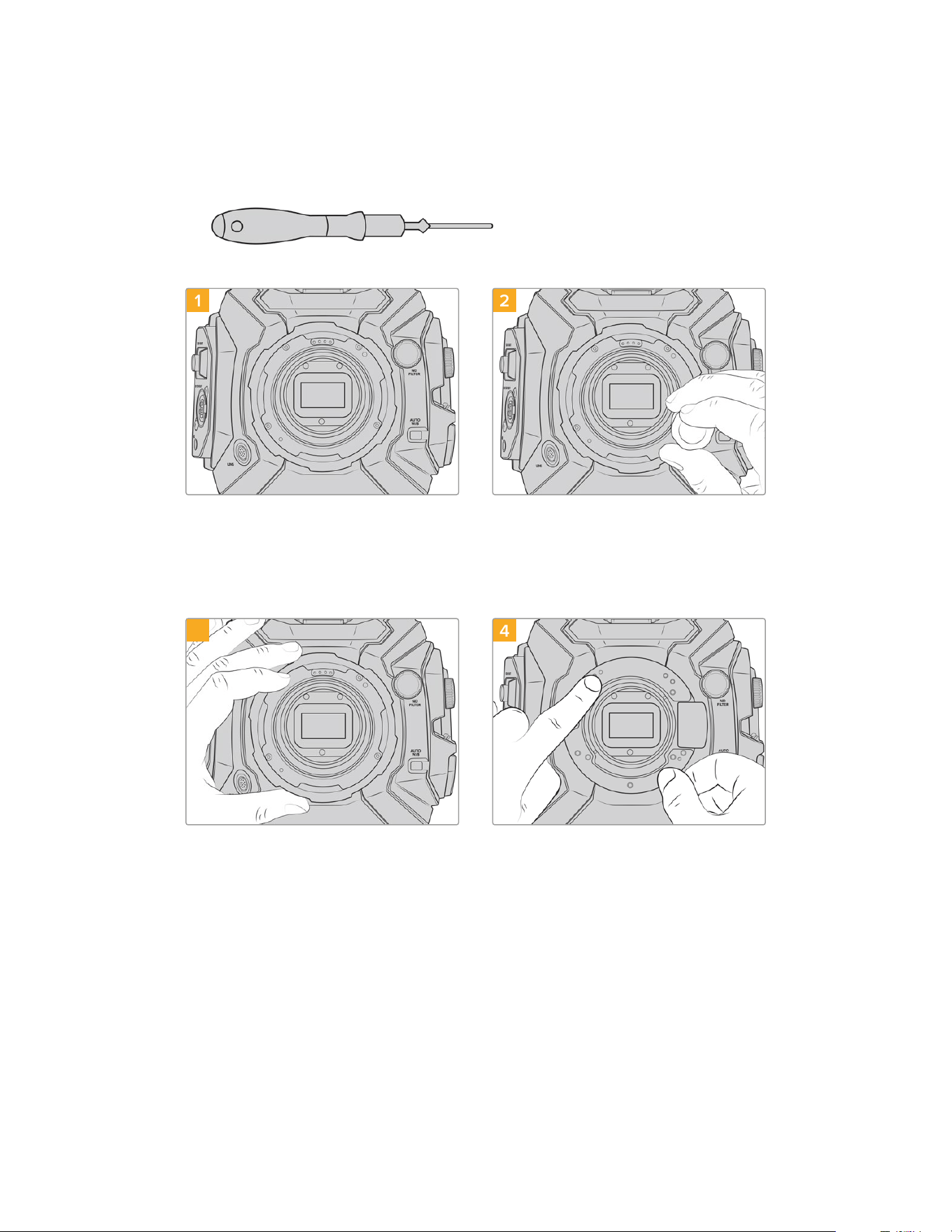
Shimming mounts
To shim your camera’s mounts you’ll need a torque wrench able to accurately set a maximum
torque of 0.45Nm, with a 2.0mm Hex key and driver.
Torque wrench
1 2
Place URSA Broadcast G2 vertically on a solid,
clean bench top and remove your lens or dust cap.
Thefilter covering the sensor will be exposed for the
duration of the shimming process, so it’s important
to keep the filter as clean as possible. Be careful not
to touch the filter while shimming mounts.
Remove the screws holding your mount in place
using a 2.0mm Hex driver. For more information
on removing particular mounts, see the
‘interchangeable lens mount’ section in this manual.
3 4
Carefully lift the lens mount away from the camera
body. Keep the screws safely located close to the
lens mount.
Note the alignment of the existing shim with the
alignment pin at the 11 o’clock position.
226Shimming Lens Mounts
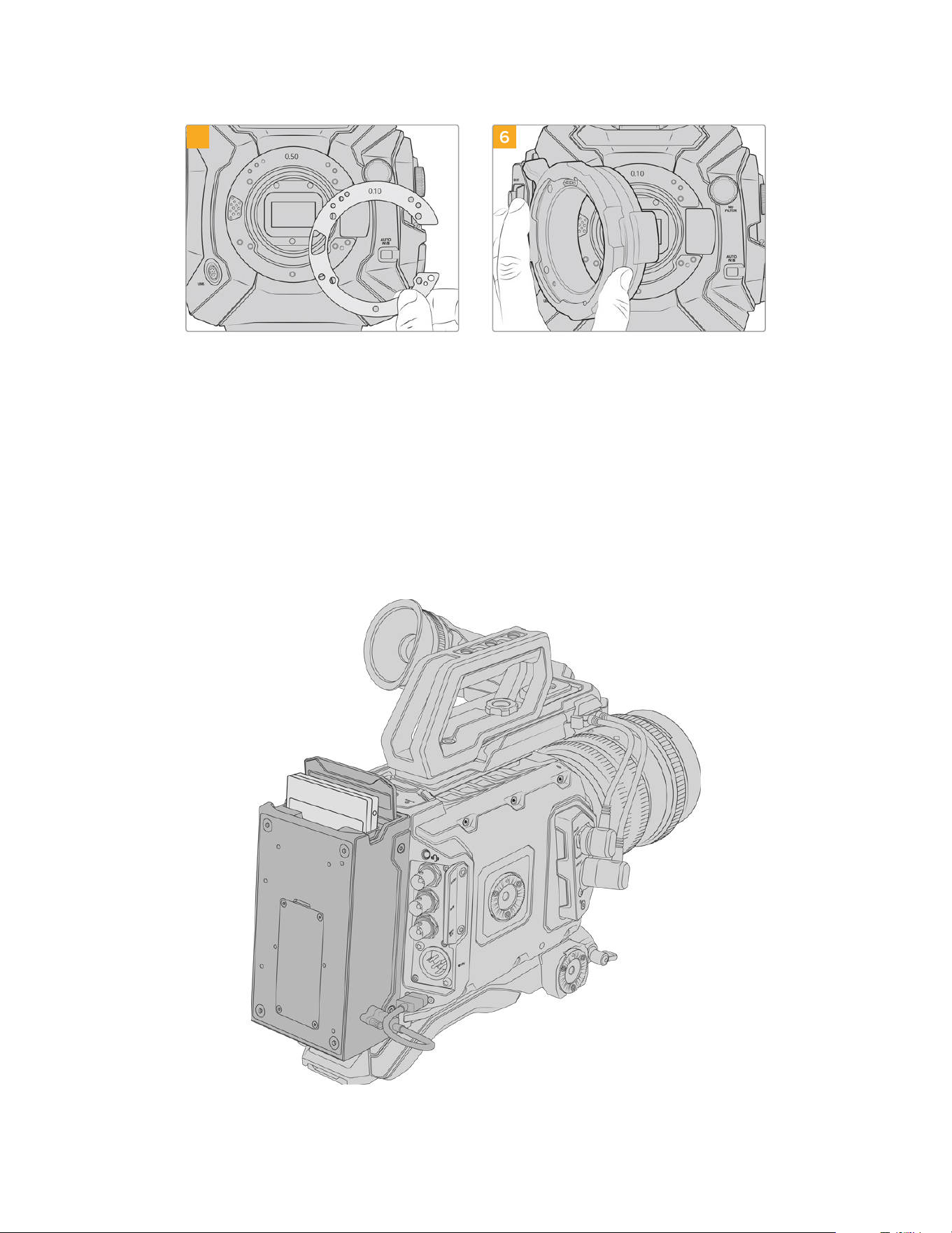
5 6
Add or remove shims to slightly change the depth of
your mount. It is a good idea to start with a small
shim thickness such as a 0.10mm.
Place your lens mount onto the camera body,
tighten screws and remount your lens and check if
your lens focus marks are now in alignment with the
focal distance. If not then continue steps 1 to 6,
adjusting shimming a small amount at a time until
your lens is hitting hits marks.
URSA Mini Recorder
Blackmagic URSA Mini Recorder is an optional module which attaches to the rear of URSA
Broadcast G2. This recorder allows you to record footage, including 6K Blackmagic RAW files,
tohigh capacity and inexpensive solid state drives, or ‘SSDs’.
227URSA Mini Recorder
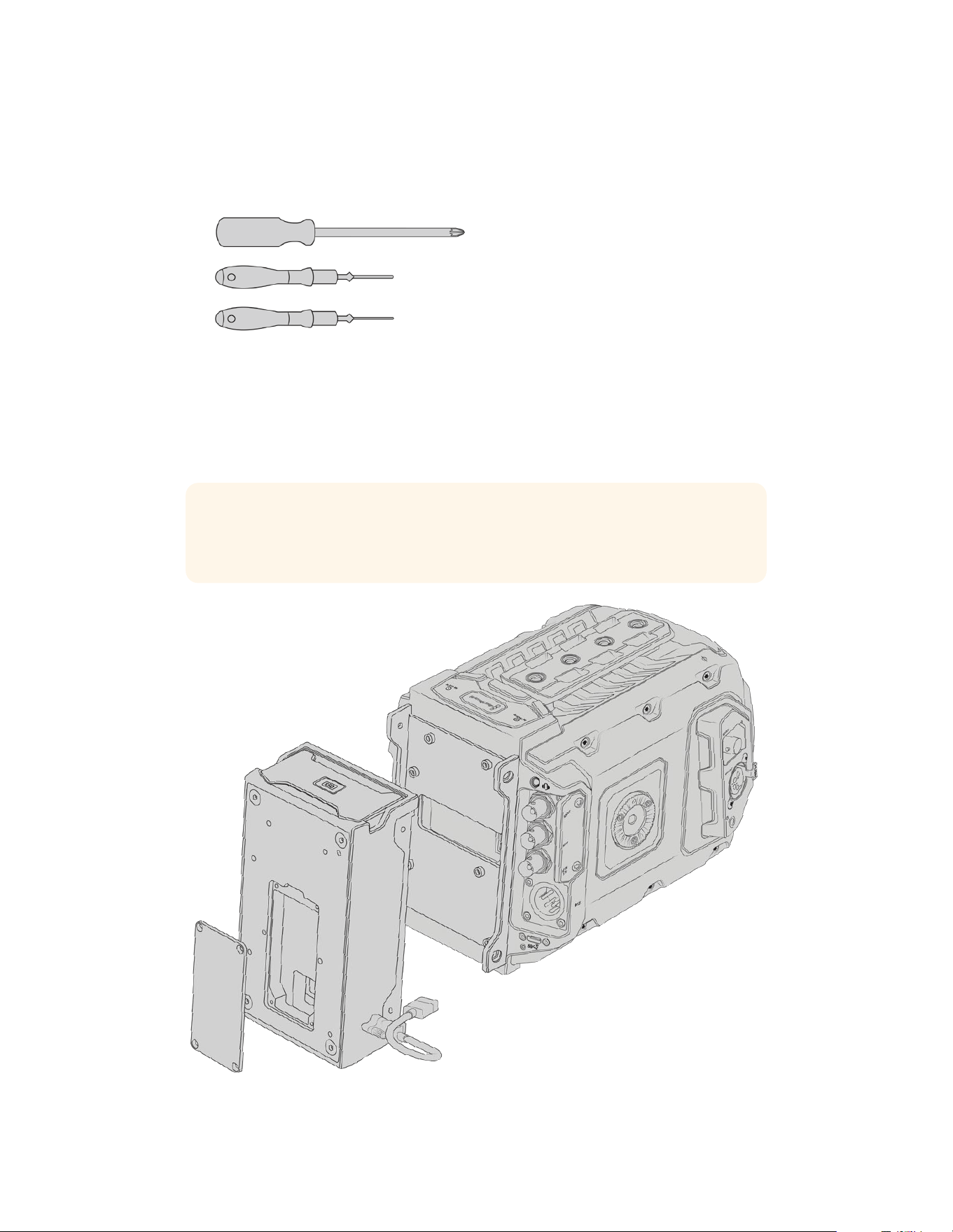
When attaching URSA Mini Recorder, you will need the following tools:
1 x phillips head screwdriver
1 x T10 torx screwdriver
1 x 2mm hex key driver
To attach the URSA Mini Recorder to your URSA Mini you will need a large
phillips head screwdriver, a T10 torx driver, and a 2mm hex key driver
Mounting and connecting URSAMini Recorder
URSA Mini Recorder mounts to the back of URSA Broadcast G2 directly behind the camera
body, using your camera’s rear USB-C data port to pass data to and from URSA Mini Recorder.
TIP URSA Mini Recorder features a passthrough cable for your camera’s battery
power supply, so you can attach V-mount or gold mount batteries to the rear of the
camera behind the recorder.
228URSA Mini Recorder
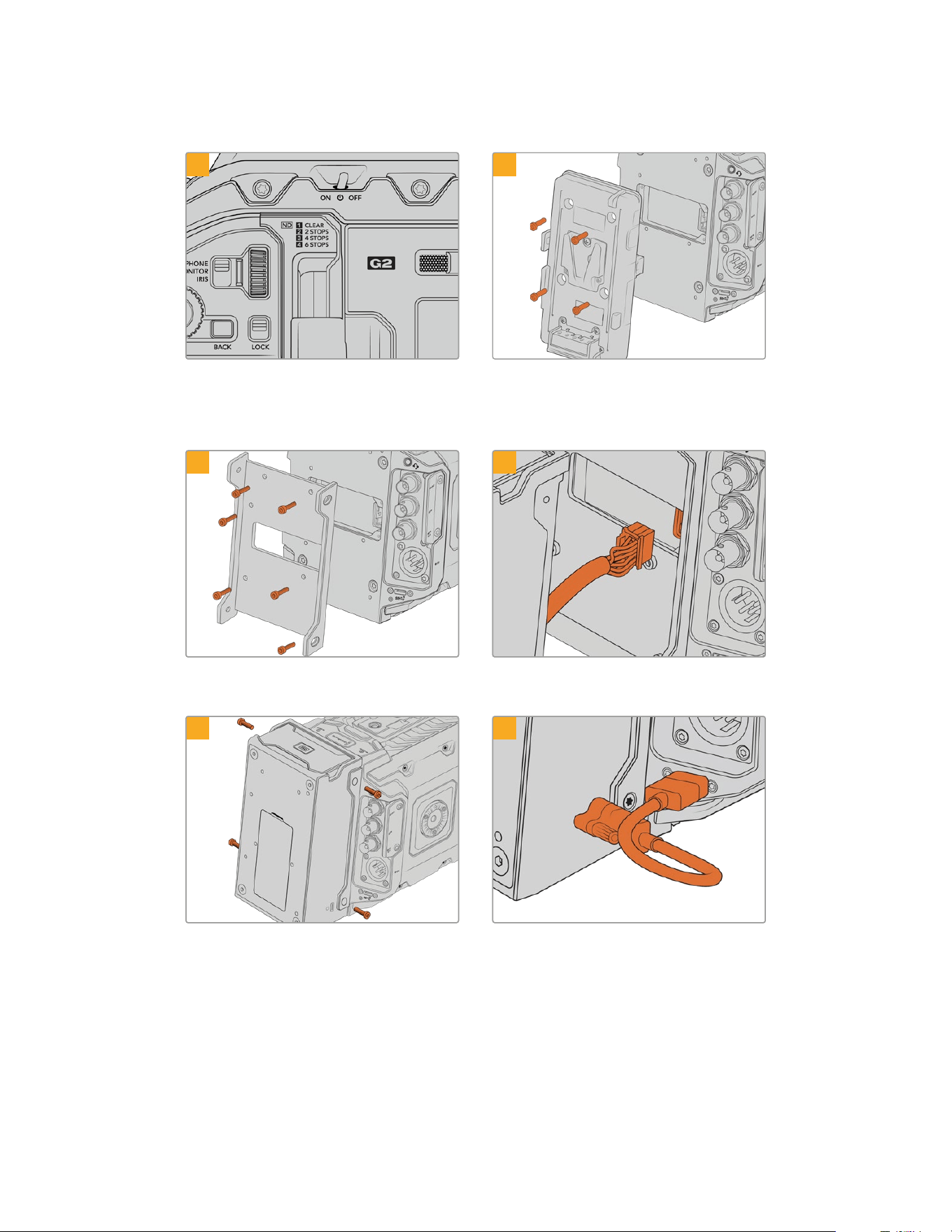
To mount and connect URSA Mini Recorder:
1 2
Power off URSA Broadcast G2 by moving the
‘power’ switch to ‘off’.
Unmount any battery plates currently fittedto your
camera. For more information on mounting and
unmounting battery plates, see the section
‘mountingbatteries’ in this manual.
3 4
Attach URSA Mini Recorder’s mounting bracket
using 6 x T10 torx screws.
Plug the molex connector on URSA Mini Recorder
into the molex socket on your camera’s rear panel.
5 6
Attach URSA Mini Recorder to the mounting bracket
using 2 x T10 torx screws onthe left and right side
of the brackets.
Connect the Mini Recorder’s USB-C cable to the
USB-C data port on the rear of URSA Broadcast G2.
Tighten the locking connectors with your fingers,
or use a 2mm hex key driver.
229URSA Mini Recorder
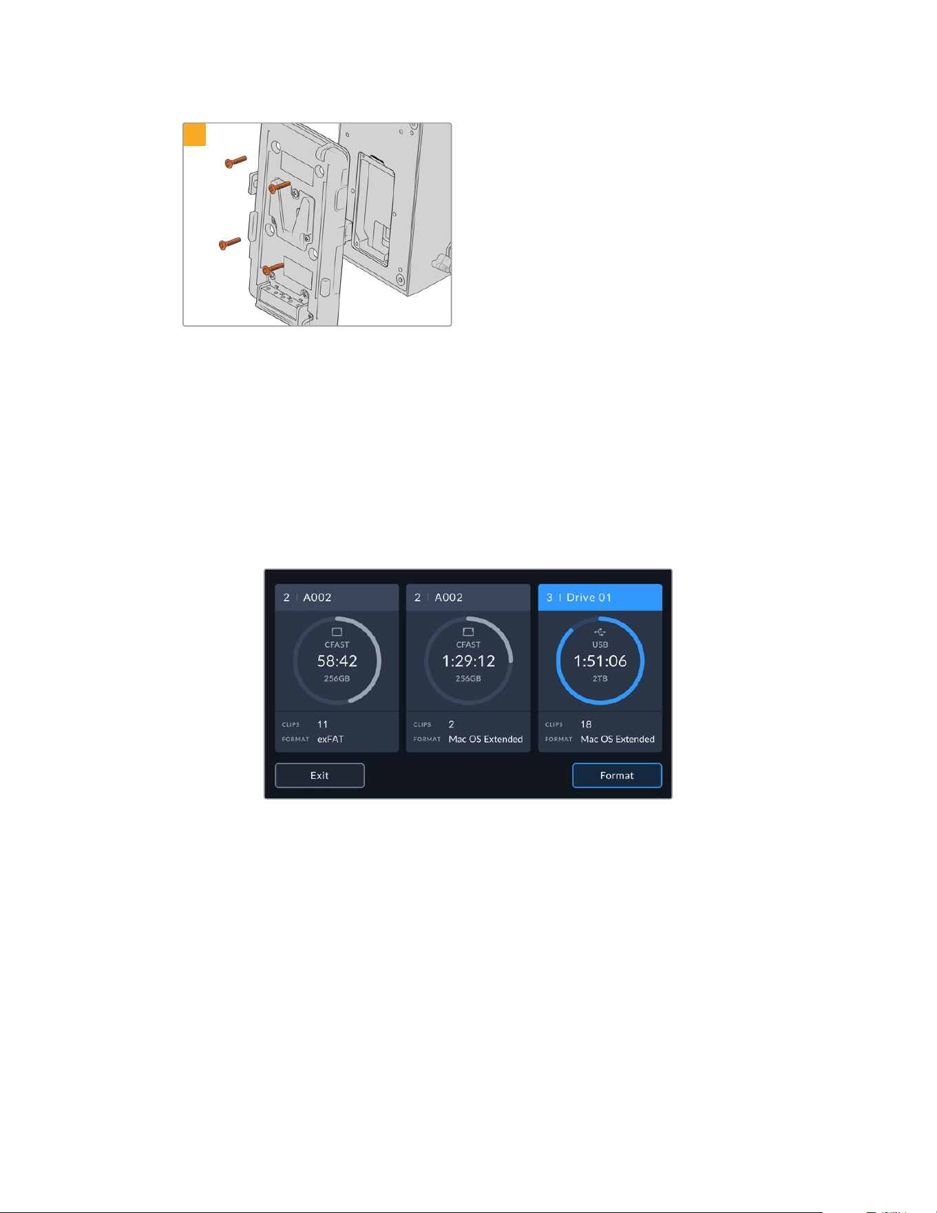
7
If you want to use a battery plate with URSAMini
Recorder, use a 2mm hex key driver to remove the
four M3 screws holding the molex socket cover
panel in place. Once the molex socket is uncovered,
attach a battery plate using the steps outlined in the
section ‘mounting batteries’ in this manual.
Using URSA Mini Recorder
When URSA Mini Recorder is connected and an SSD is loaded, the recorder occupies slot 3
in URSA Broadcast G2’s operating system. You’ll see an ‘SSD’ indicator over slot 3 on your
camera’s storage manager when URSA Mini Recorder is in use.
This means that recording, playback and storage management is exactly the same for SSDs as
it is for CFast or SD cards. For general information on storage management, as well as specific
instructions for choosing SSDs, see the ‘storage media’ section of this manual.
Status LEDs
URSA Mini Recorder has one status light on the left side for ‘SSD.’ The brightness of this
indicator can be set to ‘low,’ ‘medium,’ ‘high’ or ‘off’ in your camera’s ‘setup’ menu.
230URSA Mini Recorder

SSD
The ‘SSD’ indicator shows the status of the SSD currently inserted. This LED provides the
following status indicators:
White Your URSA Mini Recorder will show a solid white light when powered on and
communicating with your URSA Broadcast G2.
Red Your URSA Mini Recorder will show a red light while it is recording to SSD. When
the space on your SSD is running low the red light will begin to flash slowly.
A fast flashing red light indicates that SSD is dropping frames. If this happens please
check that you are using a disk from our recommended list of SSDs and that you are
recording at a data rate that is compatible with your media.
Orange If a problem has occurred while mounting the SSD the status light will go Orange. This
may be the result of an improperly formatted or incompatible SSD. See the ‘storage
media’ section in this manual for a list of compatible SSDs and formatting instructions.
TIP If the ‘SSD’ LED indicates a drive mounting error it may need to be ‘initialized’ on a
mac or PC using disk utility or disk management.
Updating URSA Mini Recorder’s internal software
Update your URSA Mini Recorder using the Blackmagic Camera Setup Utility software.
The MiniRecorder will need to be powered when updating, so we recommend keeping the
MiniRecorder connected to URSA Broadcast G2 during the update process. This also means
your camera will need to supply consistent power, so be sure to plug into external power or
battery pack.
Connect your computer to the Mini Recorder with a USB-C cable and launch Blackmagic
Camera Setup Utility. You will be prompted to update if your computer detects that your
URSAMini Recorder is using outdated version. Follow the on screen prompts to update your
URSA Mini Recorder’s internal software. Refer to the ‘Blackmagic Camera Setup Utility’ section
in this manual for more information.
TIP We recommend updating all your Blackmagic URSA equipment at the sametime
foroptimized performance.
231URSA Mini Recorder
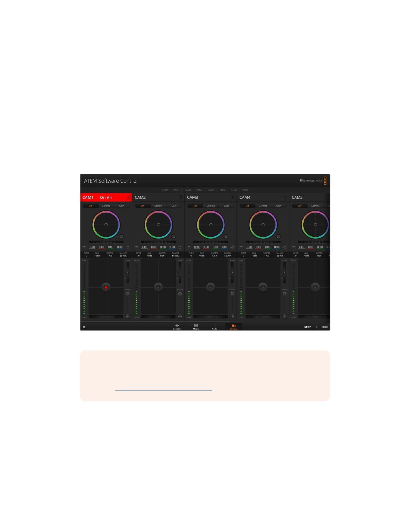
Understanding Studio Camera Control
Blackmagic URSA Broadcast G2 can be used as a studio camera and controlled from an ATEM
switcher using the Camera Control feature in ATEM Software Control. This lets you add a
camera with large sensor picture quality and amazing dynamic range to your broadcast studio
and control it just as you would any studio camera.
Clicking on the ‘camera’ button opens the camera control feature. Settings such as iris, gain,
focus and zoom control are easily adjusted using compatible lenses, plus you can color balance
cameras and create unique looks using the DaVinci Resolve primary color corrector.
The ATEM switcher control works by broadcasting camera control packets via all the non down
converted SDI outputs of an ATEM switcher. So this means you can connect an SDI output of an
ATEM switcher to URSA Broadcast G2’s 12G SDI input, your camera will detect the control
packets in the SDI link and allow you to control features in the camera itself.
ATEM Camera Control
NOTE When using Blackmagic URSA Broadcast G2 with your ATEM switcher, we
recommend updating the internal software to the latest version on both units to ensure
compatibility. The latest software can be found at the Blackmagic Design support
center at www.blackmagicdesign.com/support.
Connecting your URSA Broadcast G2
1 Connect your Blackmagic URSA Broadcast G2’s 12G-SDI Out to any SDI In on the
ATEM switcher.
2 Connect any one of the ATEM switcher’s SDI outputs, except down converted or multi view
outputs, to your URSA Broadcast G2’s 12G-SDI input. Camera control signals are not sent
via the multi view and down converted SDI outputs.
232Understanding Studio Camera Control
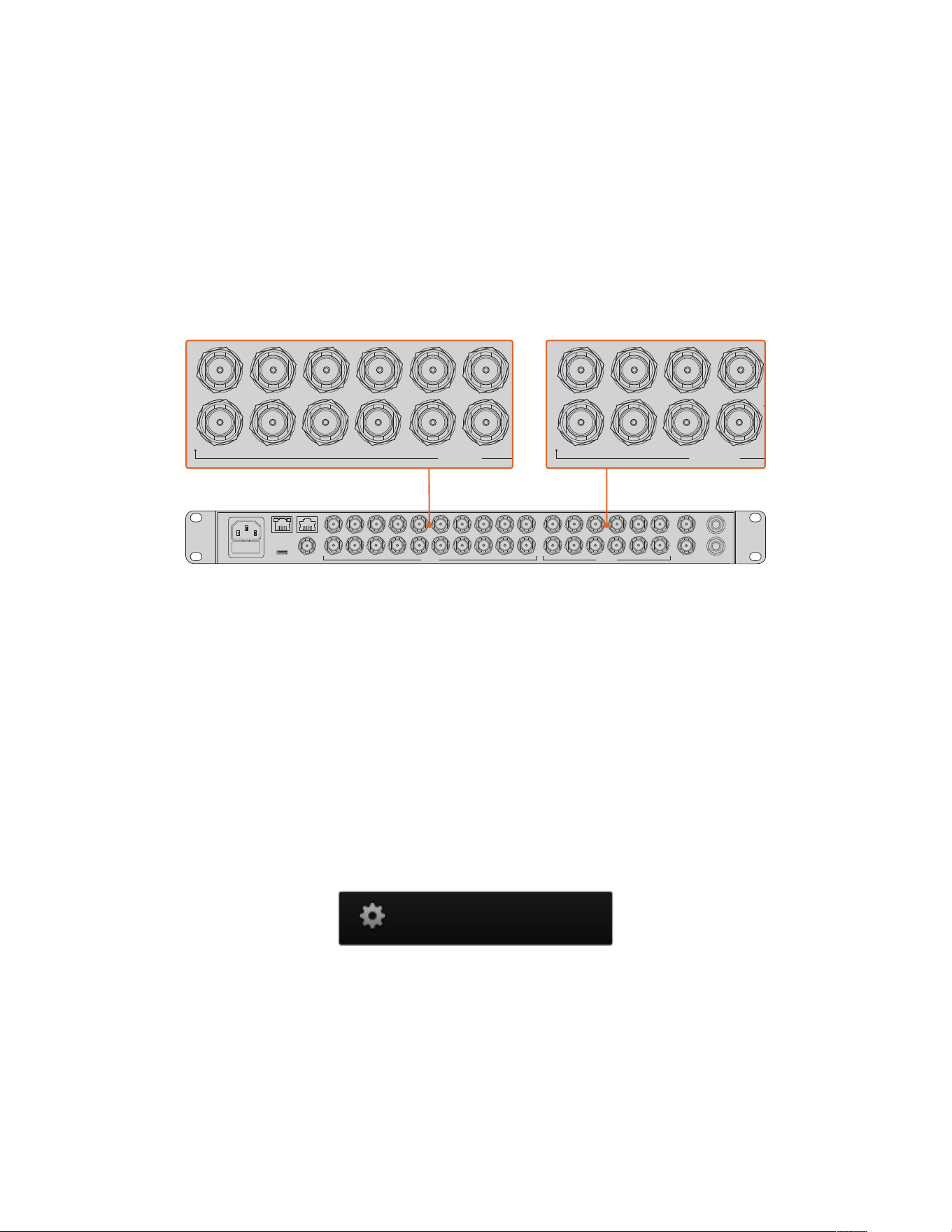
3 On your URSA Broadcast G2, navigate to ‘ATEM Camera ID’ in the ‘setup’ menu and set
your camera’s ATEM ID to match the switcher input. For example, if URSA Broadcast G2
1 is connected to Cam 1 on the ATEM switcher, the camera number must also be set to 1.
This ensures tally is sent to the correct camera.
4 In the ‘setup’ menu select your ‘reference source’. Unless you have a genlock signal being
sent to all of your cameras and your switcher, we recommend setting ‘reference source’ to
‘program’ when attached to ATEM.
5 Navigate to the ‘monitor’ menu and ensure that you have selected ‘clean feed’ for
‘mainSDI’ to ensure that you don’t see overlays or the focus box on the SDI output to the
ATEM switcher.
CONTROL TALKBACK
REF INUSB-C
1 3 5 7 9
2 4 6 8 10
11 13 15
12
1 3 5 7 9
2 4 6 8 10
11 1
12 214 16
17 19
18 20
ANALOG AUDIO I NMULTIVIEW
CH 2
CH 1
SDI OU TPUTSSDI IN PUTS
1
3
5
7
9
2
4
6
8
10
11
13
12
14
S
D
I
I
N
P
U
T
S
1
3
5
7
2
4
6
8
10
S
D
I
O
U
T
P
U
T
S
Connect your URSA Broadcast G2 to any of the ATEM switcher’s SDI inputs
Using Camera Control
Launch ATEM Software Control and click on the ‘camera’ button located at the bottom of the
software window. You’ll see a row of labeled camera controllers containing tools to adjust and
refine each camera’s image. The controllers are easy to use. Simply click the buttons using your
mouse, or click and drag to adjust.
Camera Control Selection
The button row at the top of the camera control page lets you select the camera number you
would like to control. If you have more cameras that fit onto the window size, or you are running
the color corrector window, then you can use these buttons to select between which camera
you would like to control. If you are using an Aux output for monitoring your camera control,
pushing these buttons to change the camera to control will also send that camera’s video
output to the Aux output setup in the switcher preferences.
Click on the settings icon to select theAuxoutput for
camera control
Channel Status
The channel status at the top of each camera controller displays the camera label, On Air
indicator and lock button. Press the lock button to lock all the controls for a specific camera.
When on air, the channel status illuminates red and displays the On Air alert.
233Understanding Studio Camera Control
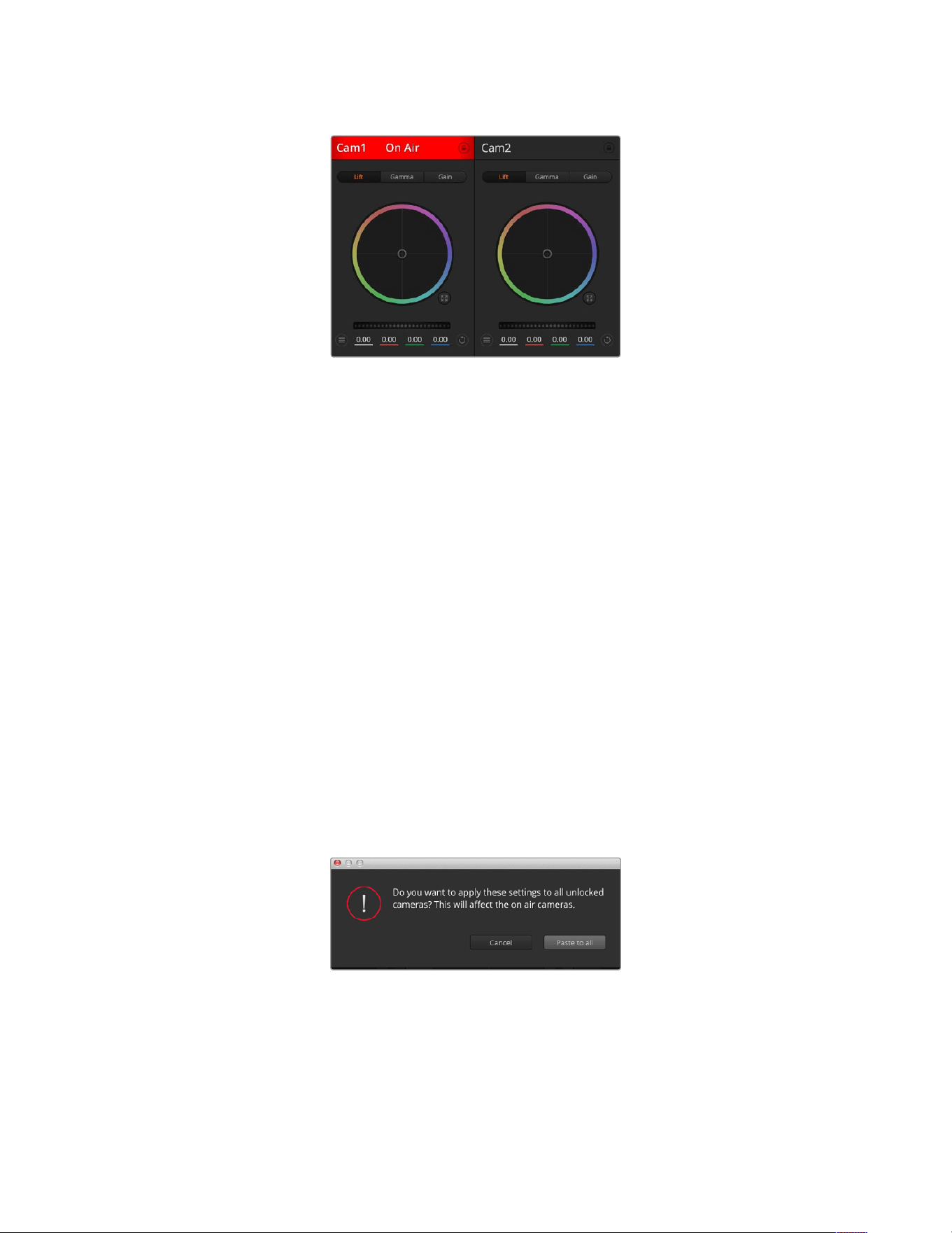
Each camera controller displays the channel status so you
know which camera is on air. Use the color wheels to adjust
each YRGB channel’s lift, gamma and gain settings
Color Wheel
The color wheel is a powerful feature of the DaVinci Resolve color corrector and used to make
color adjustments to each YRGB channel’s lift, gamma and gain settings. You can select which
setting to adjust by clicking on the three selection buttons above the color wheel.
Master Wheel
Use the master wheel below the color wheel to make contrast adjustments to all YRGB
channels at once, or luminance only for each lift, gamma or gain setting.
Reset Buttons
The reset button near the top right of each camera controller lets you easily choose color
correction settings to reset, copy or paste. Each color wheel also has its own reset button.
Press to restore a setting to its default state, or copy/paste a setting. Locked controllers are not
affected by the Paste feature.
The master reset button on the top right corner of the color corrector panel lets you reset lift,
gamma and gain color wheels plus Contrast, Hue, Saturation and Lum Mix settings. You can
paste color correction settings to camera controllers individually, or all cameras at once for a
unified look. Iris, focus, coarse and pedestal settings are not affected by the Paste feature.
When applying Paste to all, a warning message will appear asking you to confirm your action.
This is so you don’t accidentally paste new settings to any unlocked cameras that are
currently on air.
When applying Paste to all, a warning message will appear asking
you to confirm your action. This is so you don’t accidentally paste
new settings to any unlocked cameras that are currently on air
234Understanding Studio Camera Control
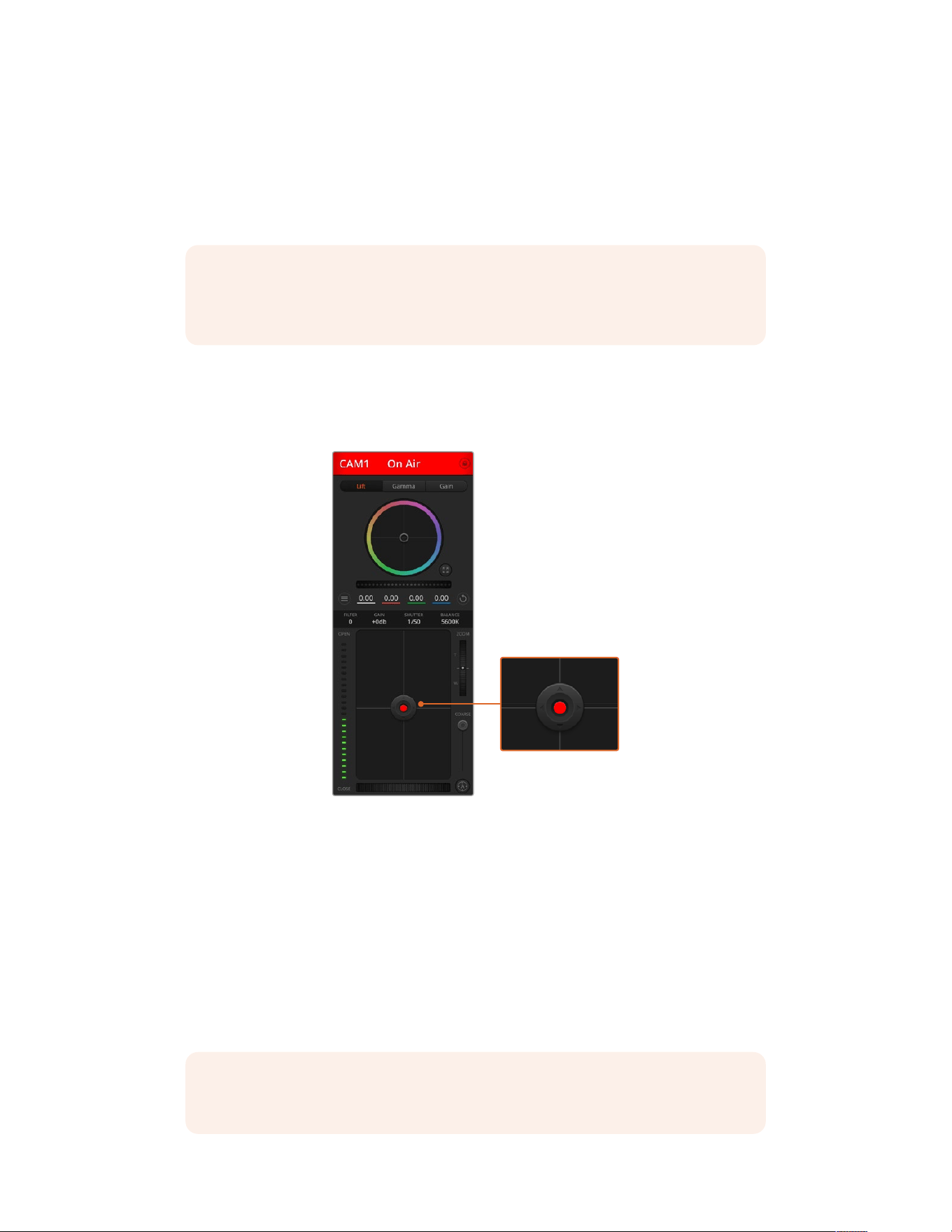
Iris/Pedestal Control
The iris/pedestal control is located within the cross hairs of each camera controller. The control
illuminates red when its camera is on air.
To open or close the iris, drag the control up or down. Holding the shift key allows only iris
adjustments.
NOTE When connected to ATEM ensure that you have Auto Exposure switched off.
Ifyou require Iris, zoom or focus control ensure that you have a lens that can be
controlled electronically by the camera.
If you’re using a B4 or PL lens connected via the broadcast 12 pin connector on
URSABroadcast G2, make sure the lens iris switch on the handgrip is set to ‘A’ or ‘auto’.
To darken or lift the pedestal, drag the control left or right. Holding the command key on a Mac,
or the Control key on Windows, allows only pedestal adjustments.
The iris/pedestal control illuminates red when
itsrespectivecamera is on air
Zoom Control
When using compatible lenses with an electronic zoom feature, you can zoom your lens in
and out using the zoom control. The controller works just like the zoom rocker on a lens, with
telephoto on one end, and wide angle on the other. Click on the zoom control, located above
the coarse slider, and drag up to zoom in, or drag down to zoom out.
If your lens does not have active lens control or your camera does not support zoom control via
the SDI camera control protocol then these settings will have no effect. For example, EF lenses
do not have built in servos that can zoom the lens electronically so will not be zoomable with
ATEM camera control.
NOTE Analogue B4 lenses do not support ATEM zoom control. For more information
on analogue B4 lenses refer to the ‘using servo zoom lenses’ section
235Understanding Studio Camera Control
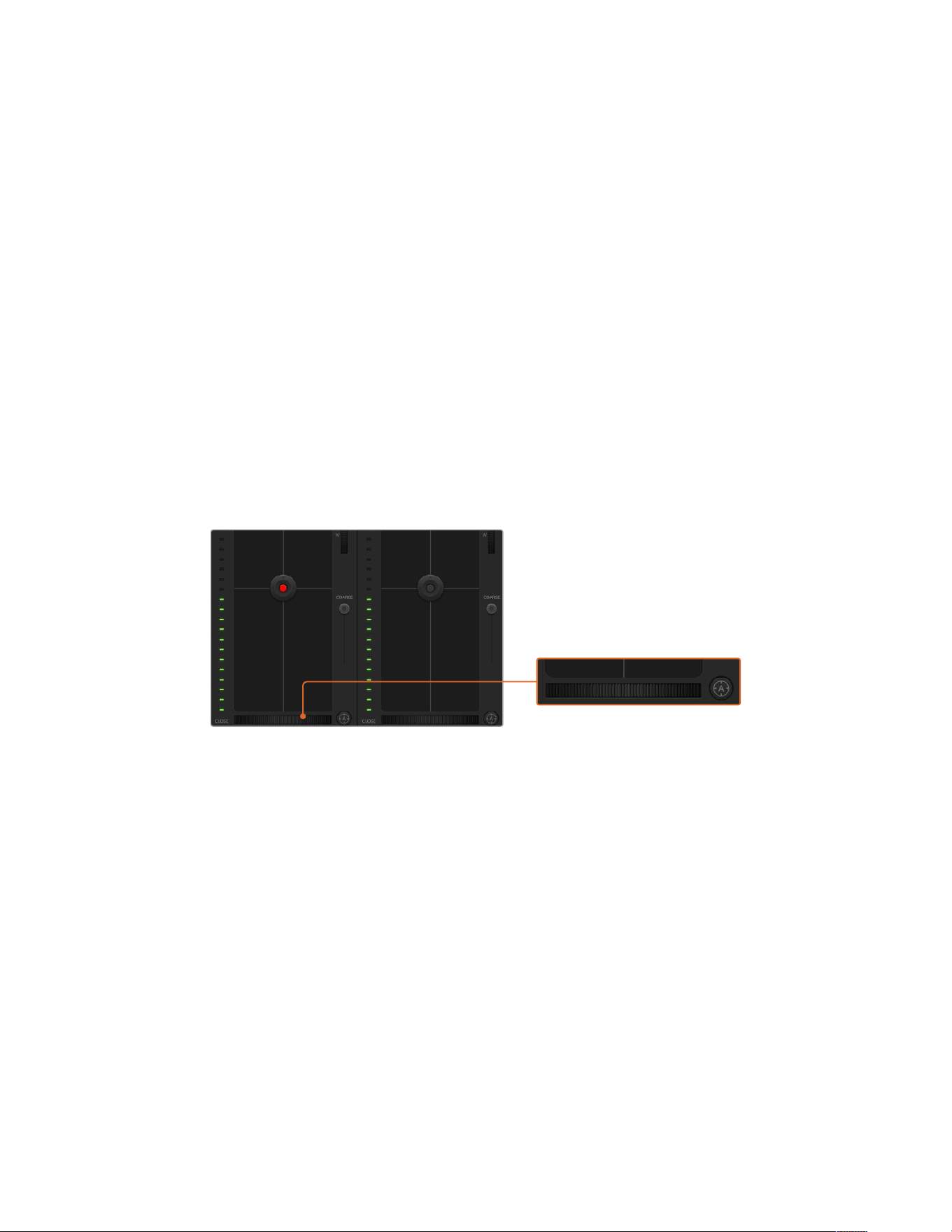
Coarse Setting
The coarse setting is located to the left of the iris/pedestal control and is used to limit the iris
range. This feature helps you prevent over exposed images from going to air.
To set your coarse threshold, completely open the iris using the iris control, then drag the
coarse setting up or down to set optimum exposure. Now when you adjust the iris, the coarse
threshold will prevent it from going above optimum exposure.
Iris Indicator
The iris indicator is located to the left of the iris/pedestal control and displays a visual reference
so you can easily see how open or closed the lens aperture is. The iris indicator is affected by
the coarse setting.
Auto Focus Button
The auto focus button is located at the bottom left corner of each camera controller. Press to
automatically set the focus when you have an active lens that supports electronic focus
adjustments. It’s important to know that while most lenses support electronic focus, some
lenses can be set to manual or auto focus modes, and so you need to ensure your lens is
set to auto focus mode. Sometimes this is set by sliding the focus ring on the lens forward or
backward. On B4 lenses with servo zoom control, you will need to set the switch at the bottom
of the handgrip to ‘servo’.
Click on the auto focus button or drag the manual focus adjustment left or right to focus a compatible lens
Manual Focus Adjustment
When you want to manually focus your lens using ATEM Camera Control, you can use the focus
adjustment located at the bottom of each camera controller. Drag the wheel control left or right
to manually adjust focus while viewing the video feed from the camera to ensure your image is
nice and sharp.
Manual focus control is only available from your switcher when using B4 and PL lenses with
servo focus controls. As EF lenses do not have servo focus this option is not available when
using EF lenses.
Camera Gain
When operating in varying light conditions, you might want to increase or decrease your
camera’s gain to avoid under exposing your images. To do this click the left arrow to decrease
gain and the right arrow to increase gain.
236Understanding Studio Camera Control
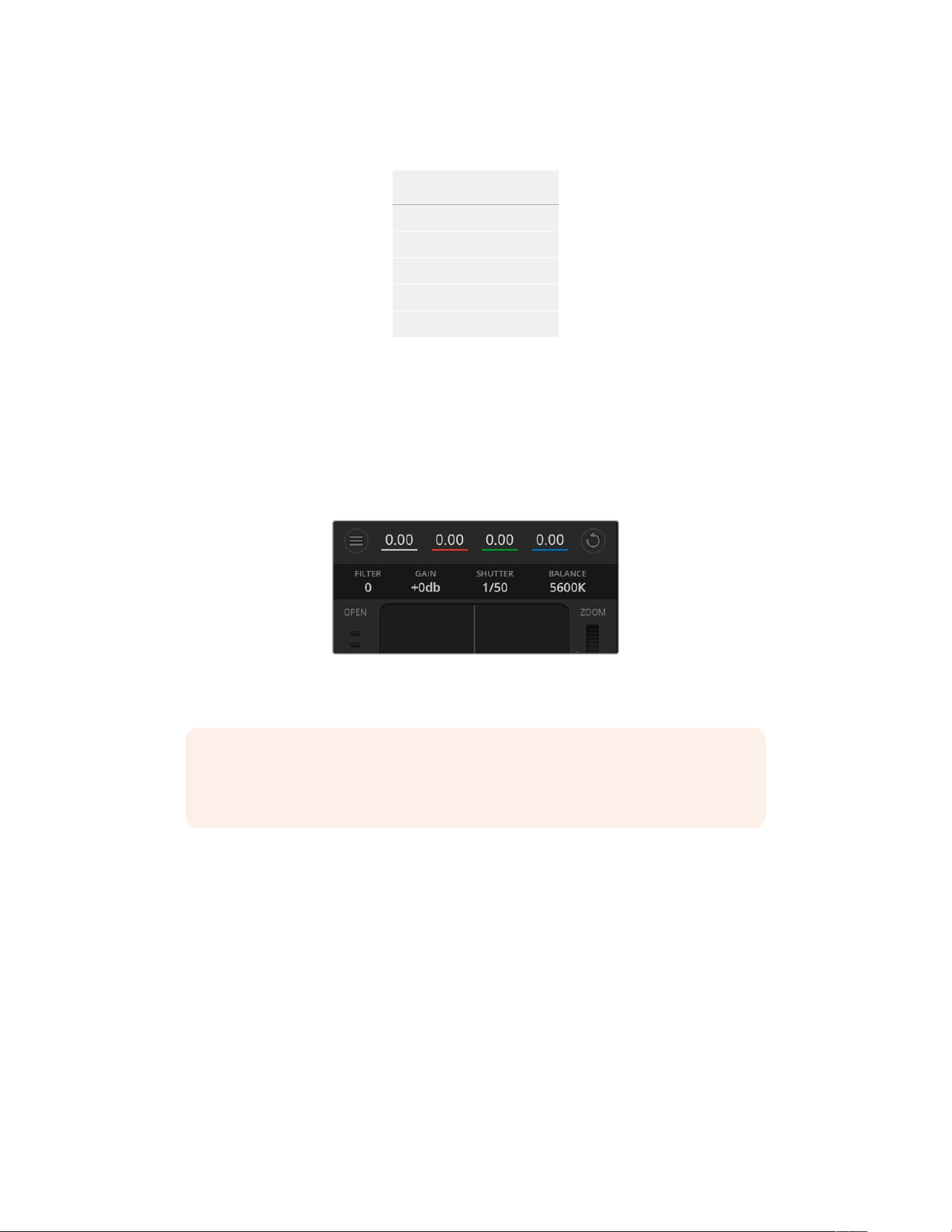
Your ATEM switcher will display gain in dB. This corresponds to the gain settings on your
camera in the following way:
Gain
-6
0
+6
+12
+18
The gain settings are displayed
using dB indicators
Shutter Speed Control
Shutter speed control is used to change your URSA Broadcast G2’s shutter speed.
The shutter speed control is located between the color wheel and the iris/pedestal control.
Decrease or increase the shutter speed by hovering your mouse pointer over the shutter
speed indicator and clicking the left or right arrow.
Hovering your mouse pointer over the gain, shutter
speed and white balance indicators reveal arrows
youcan click on to adjust their respective settings
NOTE As ATEM shutter speed control takes priority over the shutter speed selected
on your URSA Broadcast G2, your camera’s shutter speed controls are disabled when
connected to an ATEM switcher.
The table below shows the available shutter speeds in shutter speed control and their
equivalent shutter angles. It’s worth noting that some shutter speeds fall outside of URSA
Broadcast G2’s minimum and maximum shutter angles of 11.25 and 360 degrees, respectively.
Ifthis happens, the closest available shutter angle is used.
When your URSA Broadcast G2 is connected to an ATEM switcher, the shutter speed setting is
alsobe visible in your camera’s touchscreen status display. It is visible in an URSA Viewfinder
ifattached.
237Understanding Studio Camera Control
Shutter
Speed
Shutter
Angle
at
23.98 fps
Shutter
Angle
at
24 fps
Shutter
Angle
at
25 fps
Shutter
Angle
at
29.97 fps
Shutter
Angle
at
50 fps
Shutter
Angle
at
59.94 fps
1/50 172.7 172.8 180 215.8 360 360*
1/60 143.9 144 150 179.8 300 359.6
1/75 115.1 115.2 120 143.9 240 287.7
1/90 95.9 96 100 120 200 239.8
1/100 86.3 86.4 90 107.9 180 215.8
1/120 71.9 72 75 89.9 150 179.8
1/150 57.5 57.6 60 71.9 120 143.9
1/180 48 48 50 59.9 100 119.9
1/250 34.5 34.6 36 43.2 72 86.3
1/360 24 24 25 29.97 50 59.94
1/500 17.3 17.3 18 21.6 36 43.2
1/725 11.9 11.9 12.4 14.9 24.8 29.8
1/1450 11.25* 11.25* 11.25* 11.25* 12.4 14.9
1/2000 11.25* 11.25* 11.25* 11.25* 11.25* 11.25*
* Shutter speeds outside URSA Broadcast G2’s shutter angle range use
its closest available minimum or maximum shutter angle.
TIP Decreasing shutter speed is a good way to brighten your images without using
camera gain because you are increasing the exposure time of the image sensor.
Thiscan also reduce or eliminate light flicker when shooting under fluorescent lights.
Increasing shutter speed reduces motion blur and is best used for action shots when
you want your images to be clean and sharp.
White Balance
The white balance setting next to the shutter speed control can be adjusted by clicking on the
left or right arrows on each side of the color temperature indicator. Different light sources emit
warm or cool colors, so you can compensate by adjusting the white balance. This ensures the
whites in your image stay white.
DaVinci Resolve Primary ColorCorrector
If you have a color correction background, then you can change the camera control from a
switcher style CCU interface to a user interface that’s more like a primary color corrector on
apost production color grading system.
238Understanding Studio Camera Control
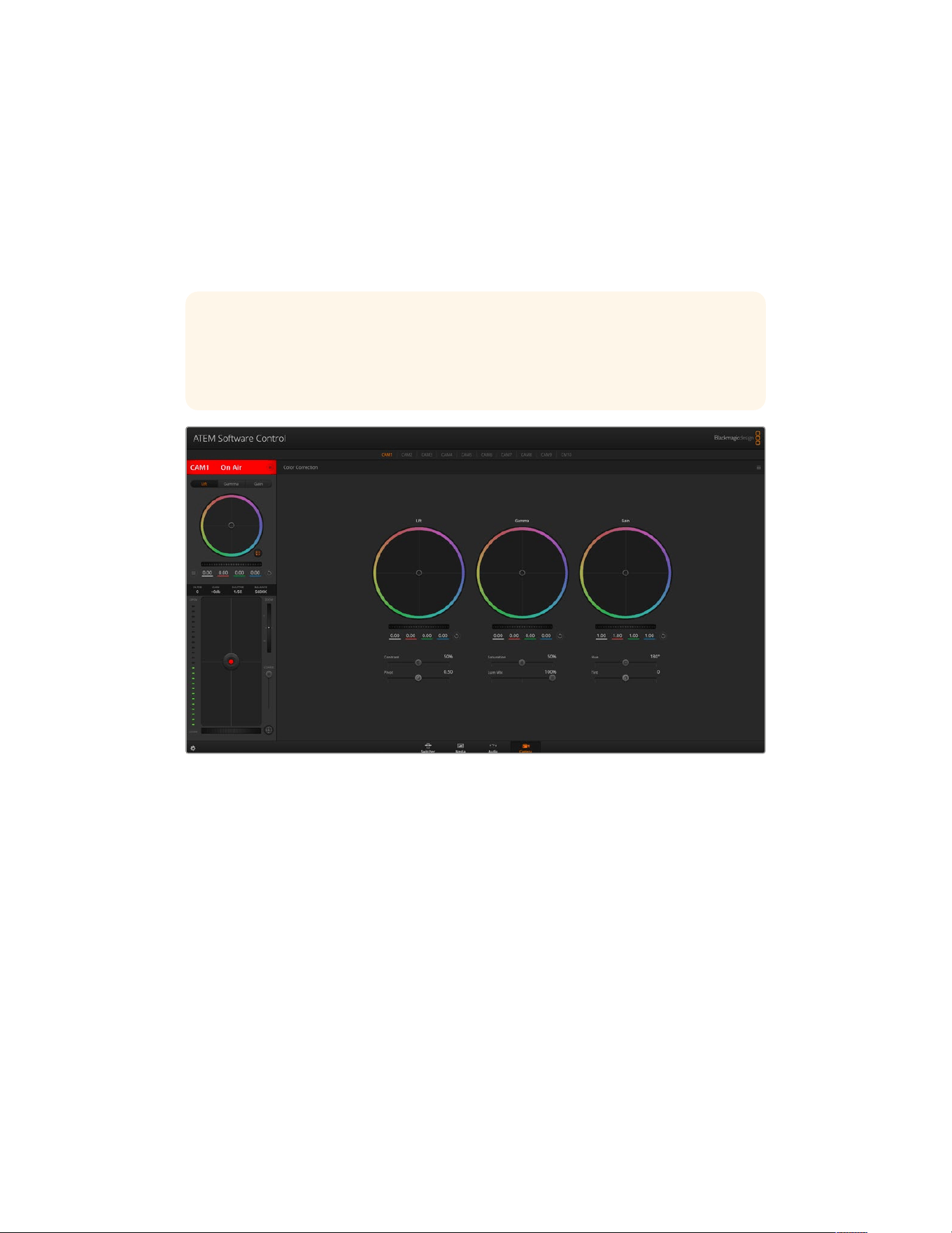
Your Blackmagic URSA Broadcast G2 features a DaVinci Resolve primary color corrector built
in. Ifyou have used DaVinci Resolve, then creatively, grading in your URSA Broadcast G2 will be
identical so you can use your color grading experience for live production. The color corrector
panel can be expanded out of any camera controller and provides expanded color correction
control with extra settings and a full primary color corrector interface.
You have color wheels and settings such as saturation available and you can see shadows,
midtones and highlight settings all at the same time. Simply switch between cameras using the
camera selection controls at the top of the window as you need.
TIP DaVinci Resolve color correction is applied to your URSA Broadcast G2’s SDI output
and ProRes video recorded on camera. As RAW video is intended for extensive post
processing, color correction is not applied to RAW video. When recording RAW video,
however, color correction can still be applied to URSA Broadcast G2’s SDI output.
Click on the DaVinci Resolve primary color corrector button to expand the color correction window and
adjust settings
Color Wheels
The Lift/Gamma/Gain controls allow tonally specific yet overlapping regions of adjustment.
Inphotographic terms lift, gamma and gain corresponds to shadows, mid tones and highlights.
Use the color wheels in the following ways to make fine or aggressive adjustments:
Click and drag anywhere within the color ring:
Note that you don’t need to drag the color balance indicator itself. As the color balance
indicator moves, the RGB parameters underneath change to reflect the adjustments being
made to each channel.
Shift-Click and drag within the color ring:
Jumps the color balance indicator to the absolute position of the pointer, letting you make
faster and more extreme adjustments.
Double-click within the color ring:
Resets the color adjustment without resetting the master wheel adjustment for that control.
239Understanding Studio Camera Control
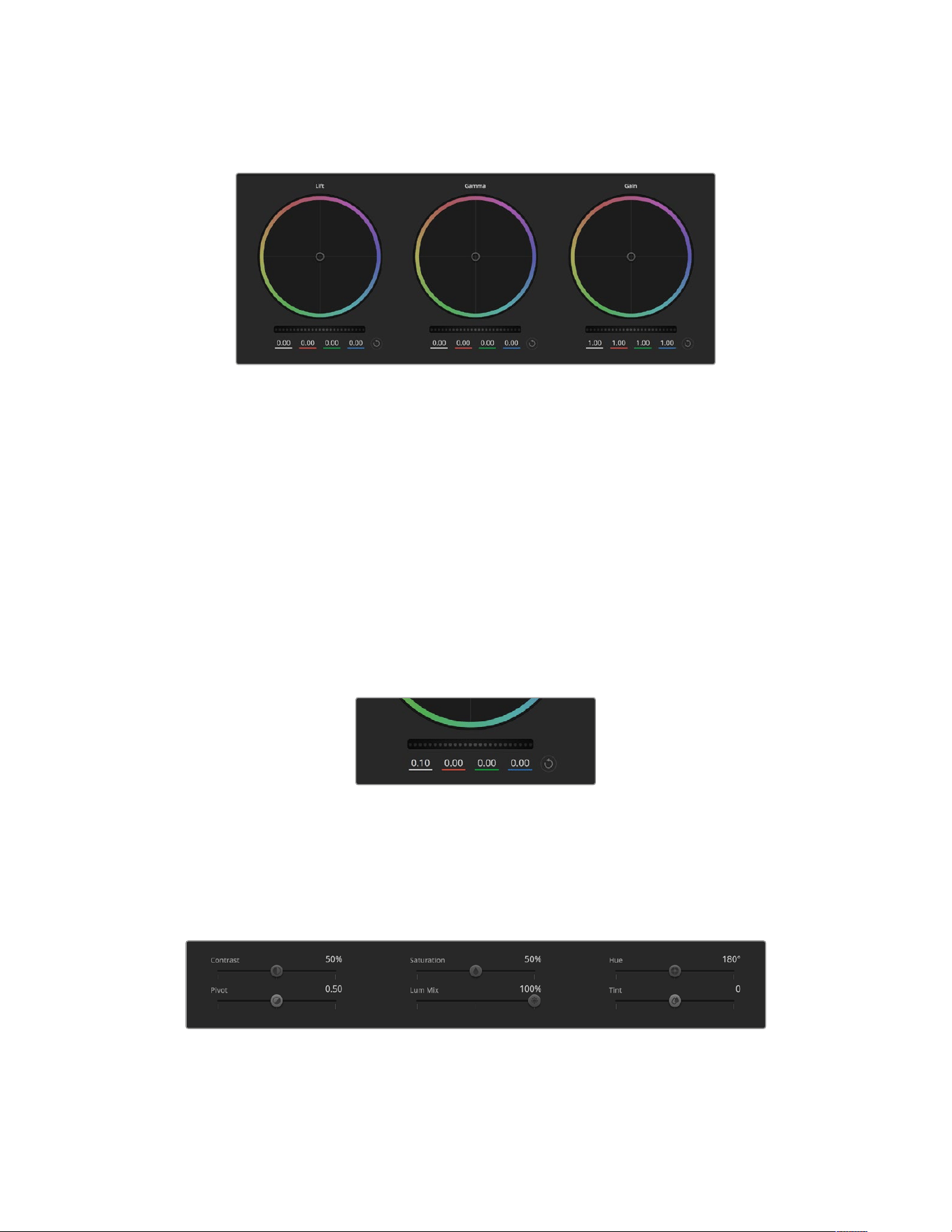
Click the reset control at the upper-right of a color ring:
Resets both the color balance control and its corresponding master wheel.
Lift, gamma and gain color wheels in the color corrector panel
Master Wheels
Use the master wheels below the color wheels to adjust each YRGB channels’ lift, gamma and
gain controls.
To make adjustments using the master wheel:
Drag the master wheel left or right: Dragging to the left darkens the selected parameter
of the image, dragging to the right lightens that parameter. As you make an adjustment, the
YRGB parameters underneath change to reflect the adjustment you’re making. To make a
Y-only adjustment, hold down the ALT or Command key and drag left or right. Because the
color corrector uses YRGB processing, you can get quite creative and create unique affects
by adjusting the Y channel only. Ychannel adjustments work best when the Lum Mix
setting is set to the right side to use YRGB processing vs the left side to use regular RGB
processing. Normally, most DaVinci Resolve colorists use the YRGB color corrector as you
get a lot more control of color balance without affecting overall gain, so you spend less time
getting the look you want.
Adjust the master wheels by dragging
the wheel control left or right
Contrast Setting
The Contrast setting gives you control over the distance between the darkest and lightest
values of an image. The effect is similar to making opposing adjustments using the lift and gain
master wheels. The default setting is 50%.
Drag the sliders left or right to adjust Contrast, Saturation, Hue and Lum Mix settings
240Understanding Studio Camera Control

Saturation Setting
The Saturation setting increases or decreases the amount of color in the image. The default
setting is 50%.
Hue Setting
The Hue setting rotates all hues of the image around the full perimeter of the color wheel. The
default setting of 180 degrees shows the original distribution of hues. Raising or lowering this
value rotates all hues forward or backward along the hue distribution as seen on a color wheel.
Lum Mix Setting
The color corrector built into your Blackmagic URSA Broadcast G2 is based on the DaVinci
Resolve primary color corrector. DaVinci has been building color correctors since the early
1980’s and more Hollywood films are color graded on DaVinci Resolve than any other method.
This means the color corrector built into your URSA Broadcast G2 has some unique and
creatively powerful features. The YRGB processing is one of those features.
When color grading, you can choose to use RGB processing, or YRGB processing. High end
colorists use YRGB processing because you have more precise control over color and you can
independently adjust the channels with better separation and more creative options.
When the Lum Mix control is set to the right side, you have the 100% output of the YRGB color
corrector. When you have the Lum Mix control set to the left side, you get 100% output of the
RGB corrector. You can set the Lum Mix to any position between the left and right to get a blend
of output from both the RGB and YRGB correctors.
Which is the correct setting to use? That’s up to you, as color correction is a pure creative
process and there is no right and wrong, and the best setting is what you like the most and
what you think looks good!
Pivot Setting
Once the contrast setting is adjusted, modifying the pivot value will adjust the midpoint of the
contrast. The Pivot control establishes the contrast balance by placing more or less priority on
either side of the luminance scale. By lifting the control, you will increase the overall brightness
and clarity of the image, although at the inverse expense of the shadows, which will be reduced.
Tint Setting
Adjusting the tint setting will add green or magenta to the image to help balance the color.
Thiscan assist when filming with artificial lighting sources such as fluorescent and sodium
vapor lighting fixtures.
Synchronizing Settings
When connected, camera control signals are sent from the ATEM switcher to your Blackmagic
URSA Broadcast G2. If a setting is accidentally adjusted from your URSA Broadcast G2, camera
control will automatically reset that setting to maintain synchronization.
TIP Even if you disconnect its 12G-SDI input, your URSA Broadcast G2 will keep using
any image adjustments made with DaVinci Resolve color correction. This lets you
change camera angles without needing to dial in your image settings again. To return
your URSA Broadcast G2 to its default color settings, simply power cycle your
URSABroadcast G2 after disconnecting its 12G-SDI input.
241Understanding Studio Camera Control

Using DaVinci Resolve
Shooting with your Blackmagic URSA Broadcast G2 is only part of the process of creating film
and television content, and just as important is the process of media backup and management
as well as editing, color correction and encoding final master files. Your Blackmagic URSA
Broadcast G2 includes a version of DaVinci Resolve for Mac and Windows so you have a
complete solution for shooting and post production!
NOTE We recommend using the latest version of DaVinci Resolve for accurate color
treatment of clips shot using URSA Broadcast G2. Version 18 or later will provide
accurate color for URSA Broadcast G2 and the latest Blackmagic RAW features like
image gyro stabilization using the camera’s recorded motion sensor data.
After connecting your CFast, SD card or SSD to your computer, you can use DaVinci Resolve’s
‘clone’ tool, in the ‘media’ page, to create running backups as you shoot. This is recommended
as any type of media is susceptible to becoming damaged or developing a fault so creating
backups means your shots will be immune to loss. Once you have used DaVinci Resolve to
backup your media, you can then add your clips to the DaVinci media pool, then edit, color
correct, and finish your production without ever having to leave DaVinci Resolve.
DaVinci Resolve is the same tool used on most major blockbuster movies, so it’s much more
than a simple NLE software tool, as it has extremely advanced technology built in for high end
digital film. You get the advantage of this technology when you use DaVinci Resolve to edit and
color correct your work.
Included here is information on how to get started using DaVinci Resolve with your camera files.
Of course, DaVinci Resolve is extremely advanced and includes a lot more features than you
immediately see when first looking at its user interface. To learn more about how to use
DaVinci Resolve, please check for the DaVinci Resolve instruction manual on the Blackmagic
website, where you can also find many training courses and tutorial videos.
Project Manager
Before you import your clips and start editing, you will need to set up your project using the
project manager.
The project manager is the first screen you will see when launching DaVinci Resolve, but you
can open the manager at any time by clicking on the ‘home’ icon at the bottom right of the user
interface. This is helpful when you want to open previous projects and create new ones.
242Using DaVinci Resolve
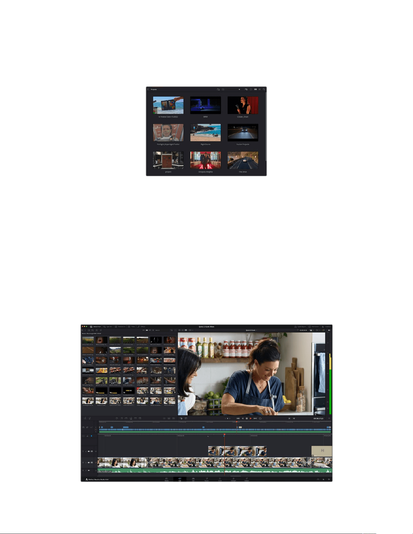
To create a new project, click on ‘new project’ at the bottom of the window and give your
project a name. Click ‘create’.
Using the ‘cut’ page, you can start working on your edit immediately.
The project manager shows all projects belonging to the current user
For more information about the Project Manager, refer to the DaVinci Resolve manual which
isavailable to download on the Blackmagic Design website support page.
Editing with the Cut Page
The ‘cut’ page gives you a fast, dynamic editing workflow that lets you quickly assemble,
trim and edit clips efficiently.
Two active timelines let you work with your entire edit plus a detailed area simultaneously.
This means you can drop clips anywhere on a large timeline, then refine your edit in a detailed
timeline within the same workspace. Using this workflow, you can edit on a laptop without
needing to zoom in and out and scroll as you work, which can be an enormous time saver.
The Cut Page Layout
When you open the cut page, you will see the media pool, viewer window and timeline.
These three primary windows give you complete control over your edit.
The Cut page default workspace, with the Media Pool in icon view
243Using DaVinci Resolve
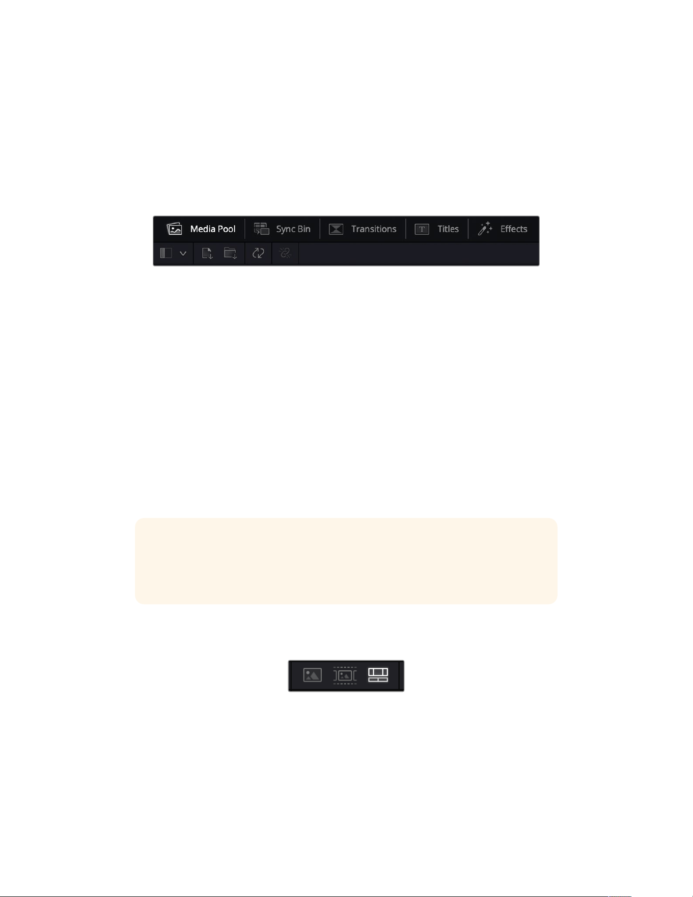
For more information on the Cut page, see the ‘The Cut Page’ chapter in the
DaVinci Resolve manual.
Media Tabs
At the top left corner of the user interface you will see five tabs.
Click on these tabs to open the media toolsets you will use when creating your edit.
For example, the first tab is the media pool and you can see it is already selected. The other
tabs are for the sync bin, media transitions, titles and effects.
Media Pool: The media pool contains all your clips, folders and files you imported using
the media page. You can also import files directly from the cut page, so you don’t have to
go back to the media page if you want to import a new clip.
Sync Bin: This powerful feature automatically syncs all your clips via timecode, date and
time so you can choose angles from all cameras on a multi camera project.
Transitions: If you click on the neighboring transitions tab, you will see all the video and
audio transitions you can use in your edit. These include common transitions such as cross
dissolves and motion wipes.
Titles: Next to transitions is the ‘titles’ tab. Here you can select the title type you want to
use. For example a scroll, standard text or lower thirds title. There are also a list of Fusion
templates you can use for more animated dynamic titles which can be customized in
DaVinci Resolve’s ‘Fusion’ page.
Effects: The fifth tab is the ‘effects’ tab. This provides all the different filters and effects
you can use to bring more life to your edit, for example customizable blurs, glows and lens
effects. There are many powerful effects to choose from and you can find them quickly
using the search tool.
TIP Use the search tool near the media tab icons to find the exact items you are
looking for. For example, if you have the transitions tab selected, type “dissolve” in the
search tool and only dissolve transition types will be shown in the viewer, making it
quicker for you to find the dissolve transition you want.
Viewer Tabs
In the top left corner of the viewer window you will see the viewer mode buttons.
The viewer mode buttons
These buttons control which viewer is currently being used, including ‘source clip’, ‘source tape’,
and ‘timeline’. These viewer modes give you an enormous amount of control when selecting
clips for your edit and it’s worth spending a moment to look at how they work.
244Using DaVinci Resolve
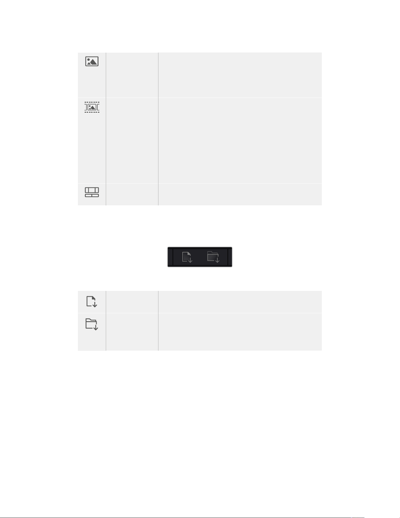
Source Clip The source clip viewer displays a single clip from the media pool
and you can set in and out points along the entire length of the
viewer timeline. This gives you greater control. Select a source
clip to view by double clicking on a clip in the media pool, or
dragging it into the viewer.
Source Tape Source tape lets you view all the source clips in the media pool.
This powerful feature is helpful if you want to quickly search
through all your clips to find a specific event. As you scrub the
playhead over the clips, you will see their thumbnails selected
in the media pool. This means once you have found the clip
you want to edit, you can click on the source clip tab and its
corresponding source clip will appear in the viewer automatically.
The source tape viewer really lets you take advantage of non-
linear editing, giving you the freedom to work on your edit, find
shots quickly, try new ideas and stay in the moment.
Timeline The timeline viewer lets you view the edit timeline so you can
play back your project and refine your edits.
Importing Clips to the Media Pool
Now you can start importing media into your project. You can do this in the media pool window
of the cut page using the import tools at the top.
Select one of the import options
toadd media to your project
Import Media The import media option will import individual media files
selected from your storage location.
Import Media
Folder
To import a folder from your media storage, select the import
folder option. When importing a folder, DaVinci Resolve will keep
the file structure, treating each folder as a separate bin so you can
navigate between bins to find your videos and other media files.
To import media:
1 Click on the ‘import media’ or ‘import media folder’ icon.
2 Navigate to your media storage for the media you want to import.
3 Select the file or folder and click ‘open’.
Once you’ve added media to your project, it is a good time to save your changes. DaVinci
Resolve features a fast, on the go autosave called ‘live save’. Once you save you project once,
‘live save’ will save further changes as you make them, removing the risk of losing your work.
For more information on ‘live save’ and other auto save functions, refer to the DaVinci
Resolve Manual.
245Using DaVinci Resolve
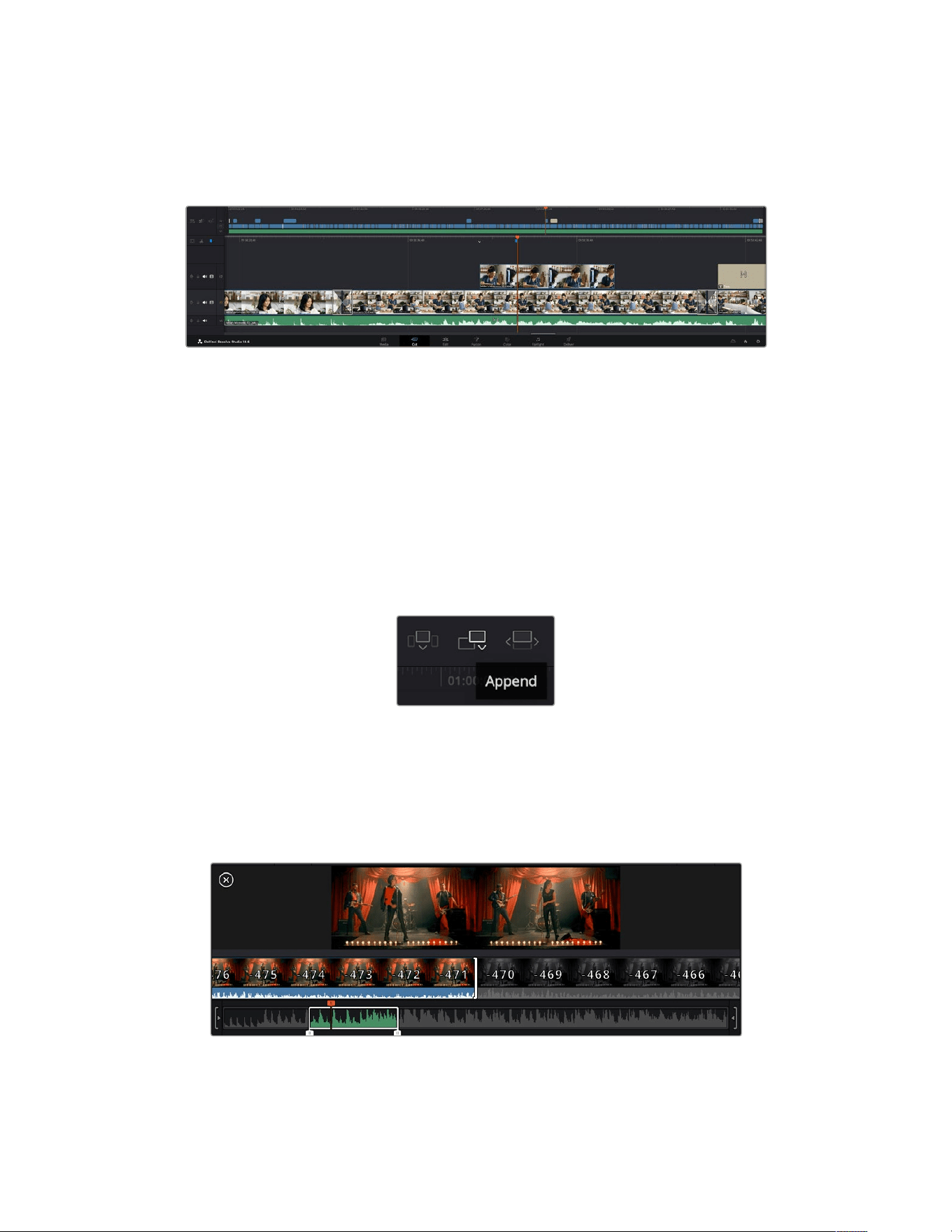
Adding Clips to the Timeline
Now that you are familiar with the media tabs and viewer mode buttons, you can open the
media pool and quickly start adding clips to your timeline.
The timeline of the cut page, comprising the upper timeline and the zoomed in timeline below
The timeline is where you will build your edit and is like a board with tracks you can attach clips
to, move them around and trim their edits. Tracks let you layer clips over others which gives you
more flexibility to try different edits and build transitions and effects. For example, you can try
an edit with a clip on one track without affecting other clips on tracks below it.
There are different ways to add clips to the timeline, such as smart insert, append, place on
top and more.
Appending Clips
When selecting takes and assembling an edit, you will likely want to add these shots to your
timeline one after the other. The append tool is perfect for this task and will get you editing
very fast.
Click on the append icon to quickly
add clips to the end of the last clip
To append a clip:
1 Double click on a clip in the media pool to open it in the viewer.
2 Using the scratch trim tool, drag the in and out points to select the precise duration of your
shot. You can also press the ‘i’ and ‘o’ keyboard shortcuts to set in and out points.
3 Now click the ‘append’ icon underneath the media pool.
Your first clip will be placed at the head of the timeline.
246Using DaVinci Resolve
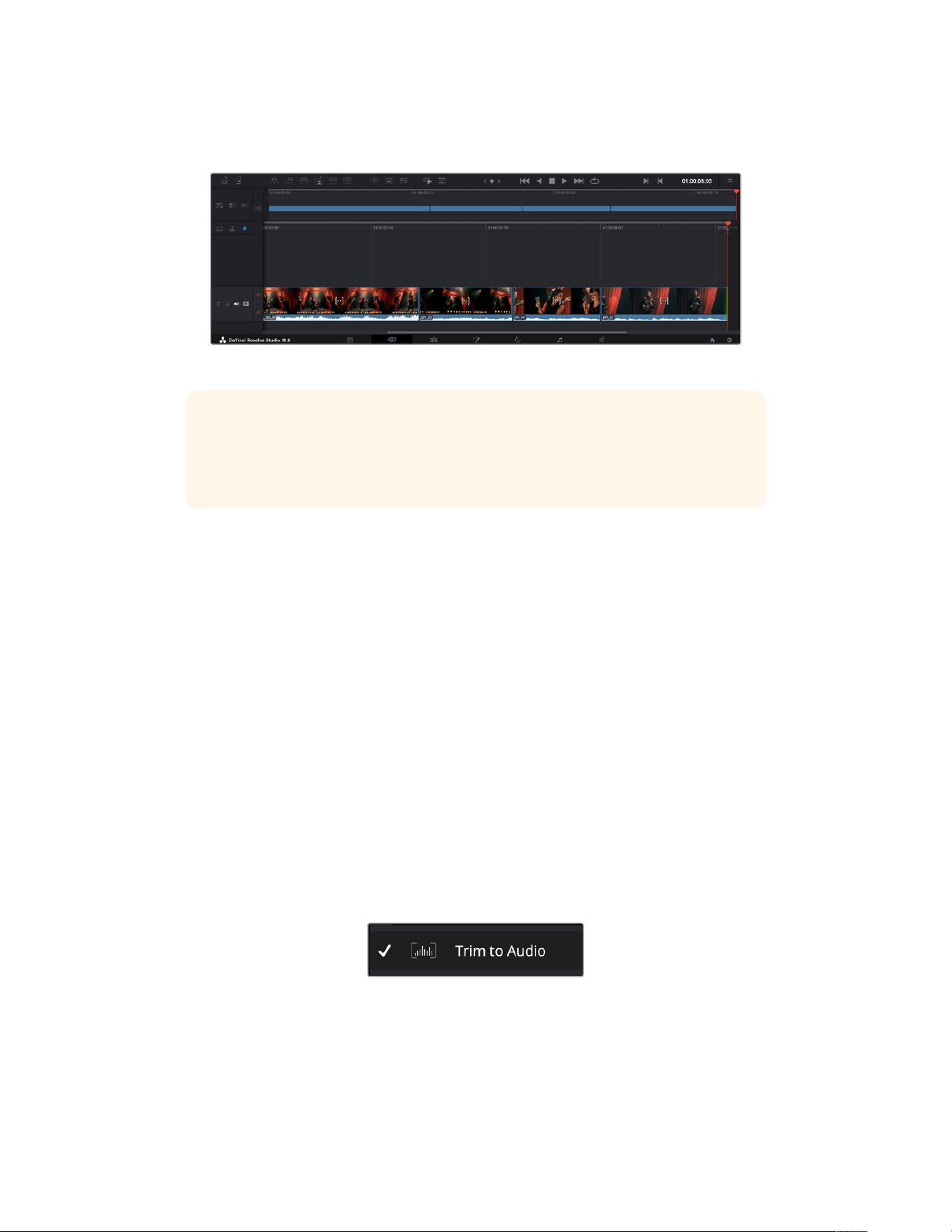
Repeat steps 1 to 3 to keep adding more clips and they will automatically append, ensuring
there are no gaps in the timeline.
Appending clips ensures there are no gaps between them on the timeline
TIP You can speed up the process further by assigning a keyboard shortcut to the
‘append’ icon. For example, if you assign the ‘P’ key, you can set your in and out points
using ‘I’ and ‘O’ then press ‘P’ to append the clip. Refer to the DaVinci Resolve manual
for information on how to assign shortcut keys.
Trimming Clips on the Timeline
With clips added to the timeline, you have complete control to move them around and
trim edits.
To trim an edit, hover the mouse over the start or end of a clip, then click and drag it left or right.
For example, drag the end of the clip left or right to decrease or increase its duration. You might
notice that all clips after that edit will shift on the timeline to accommodate the new adjustment.
This is one way the ‘cut’ page helps to save you time.
You can even pick the clip up and drop it on a new video track in the large timeline without
having to zoom in or out. This speeds up the edit process because it minimizes time navigating
a long timeline.
Audio Trim View
Audio trim view helps you make accurate audio edits by expanding the audio waveform in the
timeline. This is useful if you’re editing a dialogue scene or a music clip and makes it easy to
find an edit point between words or beats.
To use Audio Trim view:
1 Click the ‘timeline options’ icon to the left of the timeline and select ‘trim to audio’.
The ‘trim to audio’ option
2 Now when you trim an edit you will see an expanded waveform in the timeline. When you
finish trimming, the clips in the timeline will return to their normal size.
247Using DaVinci Resolve
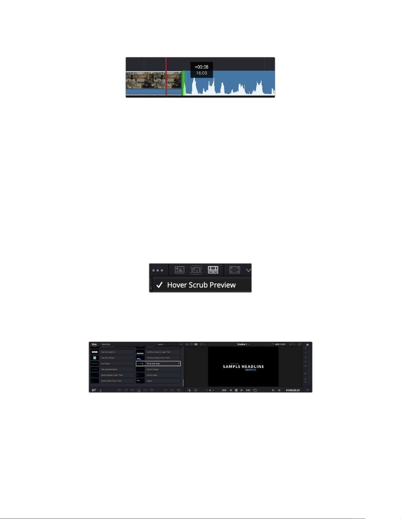
Audio trim view expands the audio waveform in the timeline.
After you have finished editing clips using the ‘cut’ page, you might want to add a title. The next
section will show you how.
Adding Titles
Placing a title on your timeline is easy and you have many options.
To see the different types of titles you can use, click on the ‘titles’ media tab at the top left
corner of the user interface. In the selection window you will see all the different title generators
you can use displayed as thumbnails, from lower thirds, scrolls, to a standard text title. You can
even add any of the Fusion titles which are animated titles that you can customize.
Previewing Titles
Before you add a title to your timeline you can preview it from the ‘titles’ selection window. This
lets you quickly scan through all the available options before making a choice.
To preview a title:
1 Click the option menu to the top right-hand side of the titles panel and check ‘hover
scrub preview’.
Enable Hover Scrub Preview from the option menu.
2 In the ‘titles’ selection window, hover your mouse pointer over a thumbnail to preview a title
in the viewer. If you are previewing an animated or Fusion title move the pointer across the
title’s thumbnail from left to right to see the animation.
Hover over a title’s thumbnail to preview it in the viewer.
Once you’ve chosen a title you can add it to your timeline.
248Using DaVinci Resolve

To add a standard title:
1 Click on the title and drag it onto the timeline. It doesn’t matter which timeline, but for
greater accuracy we recommend using the detailed timeline. The title will automatically
create a new video track for the title and will snap to the playhead.
2 Release the mouse and the title will appear on the new track. You can now move it or
change its duration like you would another video clip.
3 To edit the title, click on the new title clip and then click the tools icon underneath the
clip viewer.
You will now see a row of tools you can use to modify the title clip. For example transform,
crop, dynamic zoom and more.
4 Now click the inspector tab.
This will open the inspector window where you can type in the title you want and edit the text
settings, for example tracking, line spacing, font type, color and more.
You have a lot of options to customize the title exactly how you want it. We recommend playing
with all the different settings to see how they can change the appearance and shape of
your title.
TIP You can also use the hover scrub function to preview effects, transitions,
generators and filters on the ‘cut’ and ‘edit’ pages.
Working with Blackmagic RAW Files
Blackmagic RAW clips give you maximum flexibility in post production. This lets you make
adjustments to clips, such as white balance and ISO settings, as if you were changing the
original camera settings. Working with Blackmagic RAW also retains more tonal information
within shadows and highlights, which is useful for recovering details, for example in blown out
skies and dark areas of the picture.
It’s worth shooting in Blackmagic RAW if you are after the highest possible quality, or for shots
where there is an extreme variance between highlights and shadows and you may need to
push and pull those regions as much as possible in the grade.
The speed and small file size of Blackmagic RAW means you don’t need to make proxy files and
playback is just like a standard video clip. This section of the manual describes the features of
Blackmagic RAW and how to use Blackmagic RAW files in your DaVinci Resolve workflow.
TIP It is a good practice to adjust the Blackmagic RAW settings for your clips on the
‘color’ page before you start color grading.
Clip Settings for Blackmagic RAW
When you first import Blackmagic RAW files, DaVinci Resolve will decode the camera data
contained in the files using the ISO, white balance and tint settings used at the time of shooting.
If you’re happy with the look of these settings, you can start editing right away.
The great thing about shooting Blackmagic RAW is that you’re not tied to these settings at all!
The breadth of available post processing options when working with Blackmagic RAW files
mean that you’ll develop your own workflow over time. Experimenting with the ‘clip’ settings for
249Using DaVinci Resolve
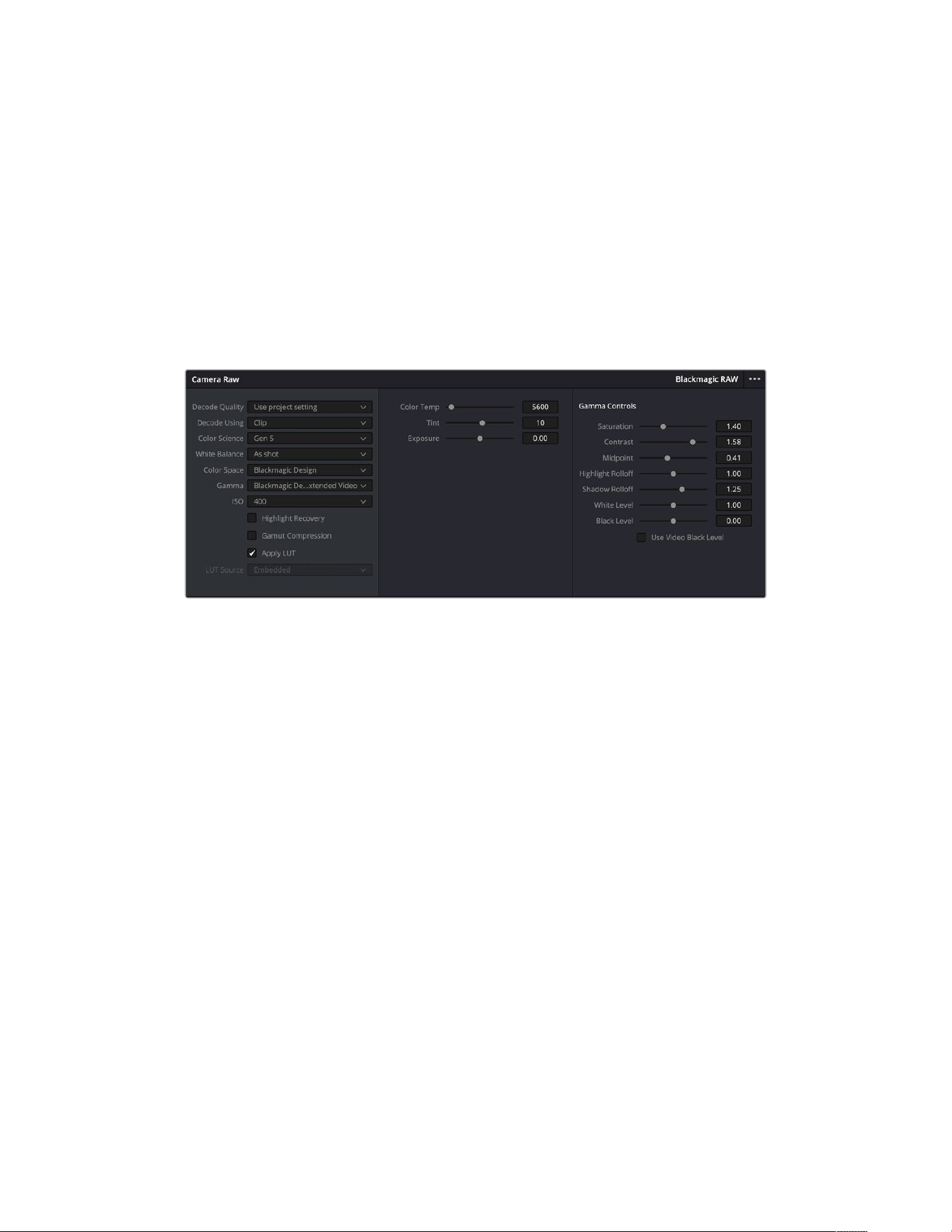
each clip in the ‘camera raw’ tab will show you just how powerful and flexible working with
Blackmagic RAW can be.
Color Science
Lets you choose whether to interpret your footage with generation 4 or 5 color science.
URSABroadcast G2 uses Blackmagic Design generation 5 color science. Files made on
different cameras with generation 4 color science can be reinterpreted with generation
5colorscience to match your shots from URSA Broadcast G2.
Alternatively, if you are shooting mainly with cameras that create Blackmagic RAW files with
generation 4 color science, you can mix in clips shot on URSA Broadcast G2 with generation
5color science by reverting them to generation 4. This makes it easy to match shots filmed on
cameras using different generations of Blackmagic color science.
In the ‘camera raw’ tab, select ‘clip’ from the ‘decode using’ menu
to make adjustments to your clip’s Blackmagic RAW settings
Changing Blackmagic RAW Settings
Once you have set DaVinci Resolve to enable clip settings for Blackmagic RAW, the clip settings
and gamma controls are now adjustable. Adjusting these settings to optimize your clips can
bring them close to a full primaries grade. This is especially powerful when using DaVinci
Resolve’s scopes which can help you neutralize and balance the clips ready for applying a look.
The following information contains descriptions for the clip and gamma controls.
ISO
The ISO value can be changed by increasing or decreasing this setting. This setting is helpful
if you need to set the clip to a brighter or darker starting point for optimization.
Highlight Recovery
Check the box to reconstruct highlight information in clipped channels using information from
non-clipped channels.
Gamut Compression
Check the box to automatically maintain safe Gamut levels.
Color Temp
Adjust the color temperature to warm or cool the image. This can be used to help neutralize
the color balance in each image.
Tint
Adjusting this setting will add green or magenta into the image to help balance the color.
250Using DaVinci Resolve

Exposure
Use this setting to refine the overall brightness of the image.
Saturation
Saturation controls default at 1 and range from 0 for the minimum saturation to 4 for
maximum saturation.
Contrast
Defaulting at 1.0, drag the slider to the left for the least amount of contrast at 0 or to the right
to increase the contrast up to 2.
Midpoint
In Blackmagic Design Film, your middle gray value defaults to 0.38, or 38.4%. Drag the slider
to the left to lower your midpoint or to the right to raise it to 100. When contrast is adjusted away
from the default setting, you can modify your highlight and shadow rolloff.
Highlight Rolloff
Adjust the highlights by dragging the slider to the left to lower the value to 0, or to the right to
increase the highlights to 2. The default value is 1.
Shadow Rolloff
Drag the slider to the left to lower your shadows to 0 or to the right to raise your shadows to 2.
White Level
Adjust the white point of the gamma curve by dragging the slider from the highest value
of 2 to the lowest value of 0. The default value is 1.
Black Level
Raise the black point of the custom gamma curve by dragging the slider to the right from
the lowest value of -1 to a maximum of 1. The default value is 0.
Use Video Black Level
Check the box to set your black levels to video.
Export Frame
Clicking the ‘export frame’ button lets you export a single frame from your Blackmagic RAW clip.
Update Sidecar
Click this button to update the Blackmagic RAW sidecar file for the current clip.
Any changes you have made to your Blackmagic RAW clips will be identified by the gamma
setting changing to Blackmagic Design Custom.
Adjusting Exposure using Blackmagic URSA Broadcast’s Gain Setting
If you’re familiar with the DaVinci Resolve workflow for other Blackmagic cameras, it’s worth
noting that URSA Broadcast G2’s ‘gain’ setting is treated a bit differently to the ‘ISO’ setting on
Blackmagic cinema cameras.
The ‘gain’ settings for URSA Broadcast G2 are applied at your camera sensor, rather than later
in software. This is a similar method to how traditional broadcast cameras work, and can slightly
reduce noise at some sensitivity settings. It also limits how far you can adjust the ‘gain’ of an
URSA Broadcast G2 clip after filming. You’ll notice that the ‘ISO’ box in DaVinci Resolve’s
Camera RAW settings will display the equivalent ISO to your camera’s ‘gain’ setting for the clip.
You can increase the ISO by up to three steps from the ISO equivalent to your URSA Broadcast
G2’s ‘gain’ setting when you filmed the clip. Due to the wide dynamic range of Blackmagic RAW
footage, you can make further changes that are functionally equivalent to changing camera
gain by adjusting your clip exposure. Simply adjust the ‘exposure’ value to add or subtract up to
251Using DaVinci Resolve
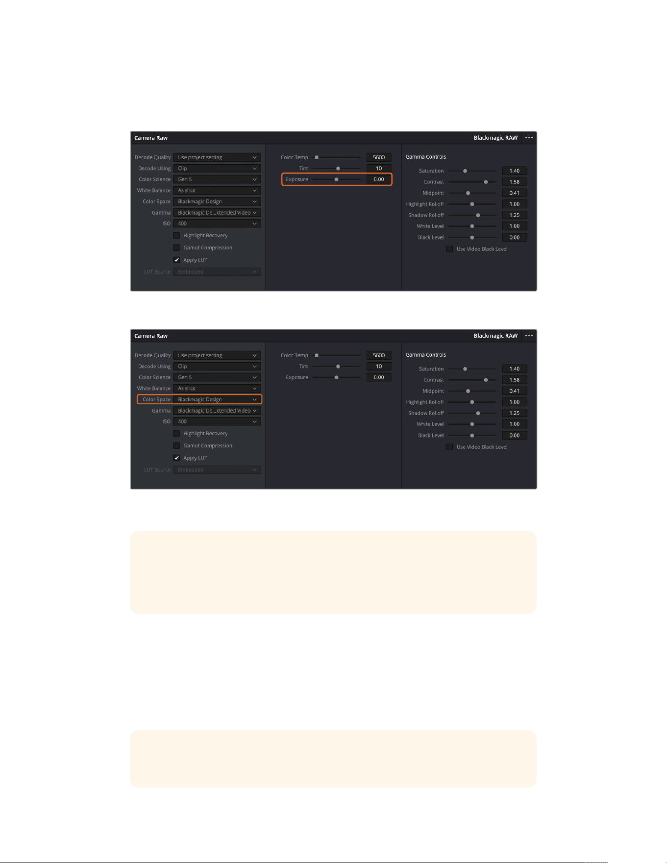
five stops of exposure. Each ‘stop’ is equivalent to one sensitivity step, for example 1 additional
stop of exposure is the equivalent of going from -6 to 0 db of gain, or 200 to 400 ISO, however
you have much finer adjustment here and can go to 0.01 of a stop.
Any changes you have made to your Blackmagic RAW clips will be identified by the gamma setting changing to
Blackmagic Design Custom.
If you want to revert your clip to one of the default gamma options available, simply select it from the gamma
dropdown menu.
TIP Gamma controls are disabled for footage shot with the ‘video’ dynamic range,
butyou have not lost your Blackmagic RAW data. Simply select Blackmagic Design
Film or Blackmagic Design Extended Video from the dropdown gamma menu and
make your adjustments.
Saving your Blackmagic RAW changes
1 Adjust the gamma controls for your Blackmagic RAW clip.
2 Click the ‘update sidecar’ button.
A ‘sidecar’ file will now be created in the same folder as your .braw file. When another user
imports the Blackmagic RAW files, the sidecar files will automatically be read by DaVinci
Resolve. If you make additional adjustments, press ‘update sidecar’ again.
TIP To remove your sidecar file, you can simply delete it from its location on your
media drive.
252Using DaVinci Resolve

Project Settings for Blackmagic RAW
If you need to make a setting change that is common to all the clips, for example a global
change to the white balance or ISO setting, you can set the clips to use the project ‘camera raw’
settings and make global changes from there.
To set project settings for Blackmagic RAW:
1 Enter the project settings menu by clicking ‘file,’ and selecting ‘project settings.’
2 In the ‘Camera RAW’ tab, you’ll see a menu next to RAW profile. Click on the arrow to select
Blackmagic RAW from the list.
3 Select ‘project’ in the ‘Decode Using’ menu.
4 Select a Color Science option from the menu.
5 Set the white balance to ‘custom’.
6 Select ‘Blackmagic Design Custom’ from the gamma menu. Set the color space to
‘Blackmagic Design’.
7 Choose your resolution from the ‘Decode Quality’ menu. A lower resolution will give you
better playback on limited systems. You also have the flexibility to change to full resolution
later on before delivery for the highest quality output.
Now you can adjust the camera settings for your clips such as saturation, contrast and midpoint.
This will affect all clips in your project that are set to decode using ‘project’.
Color Correcting your Clips with the Color Page
Now with your clips on the timeline and titles added, you can start color correcting using the
‘color’ page. The color page is extremely powerful and will define the overall look of your film,
but for this example a good place to start is to neutralize all your clips so they are consistent.
You can also return to the ‘cut’ or ‘edit’ page at any time if you want to make changes to
your edit.
The color page lets you adjust the look of your edit and in many ways color correction is an art
form in itself. You are really adding emotion to your work when you add color correction. It’s an
incredibly creative part of the workflow and very satisfying when you learn these skills and can
see your work come alive! This is usually the first step and is referred to as primary color
correction, or adjusting the primaries. After primary color correction is done, you can then make
secondary color correction adjustments which is where you can make extremely precise color
adjustments of specific objects in your images. That is a lot of fun, but is normally done after
primaries because it helps make the process more efficient and you will get a better result!
First click on the ‘color’ tab to open the color page.
You’ll see the camera raw settings, color wheels, curves palettes and general color correction
tools as well as the preview and nodes window. Don’t feel overwhelmed by the vast array of
features in front of you, they are all there to help you get the most amazing looking pictures.
This getting started section will show the basics, but for more detailed information refer to the
relevant sections in the manual. They will show you exactly what all the tools are for and how to
use them in easy to follow steps. You’ll learn the same techniques the professionals use in high
end color correction facilities.
Generally, the first step for primary color correction is to optimize the levels for shadows, mid
tones and highlights in your clips. In other words adjust the ‘lift’, ‘gamma’ and ‘gain’ settings.
This will help get your pictures looking their brightest and best with a clean, balanced starting
point from where you can begin grading the ‘look’ of your film. To optimize the levels, it’s helpful
to use the scopes.
253Using DaVinci Resolve
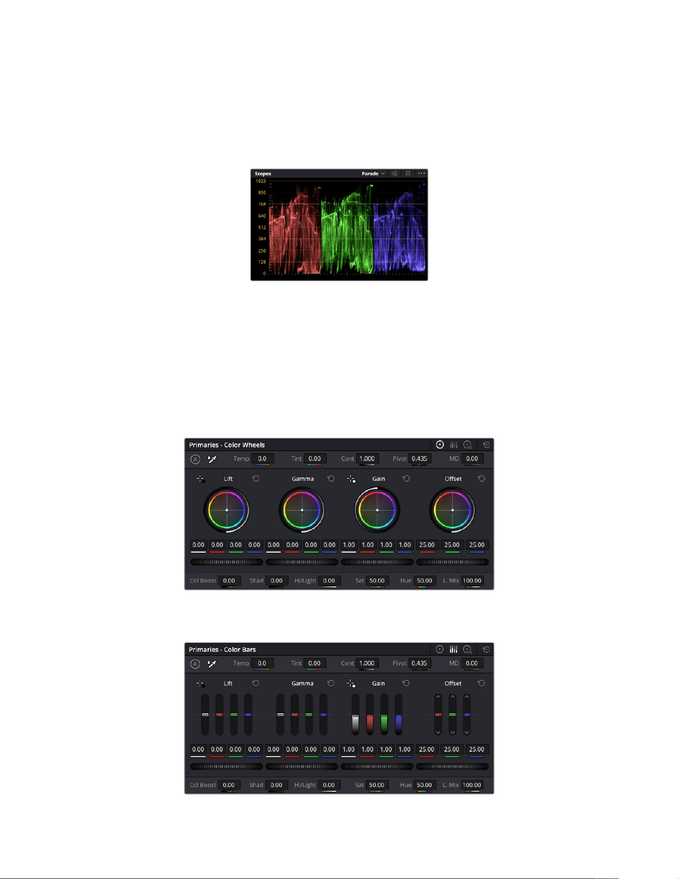
Using Scopes
Most colorists make creative color choices by focusing on the emotion and the look they want
their program to have and then simply work using the monitor to achieve that look. You can look
at everyday objects and how different types of light interact with them to generate ideas on
what you can do with your images and a little practice.
The parade scope helps you optimize
highlights, mid tones and shadows
Another way to color grade is to use the built in scopes to help you balance shots. You can open a
single video scope by clicking the ‘scope’ button, which is the second from the right on the palette
toolbar. You can choose to display a waveform, parade, vectorscope, histogram or CIE chromaticity
scope. Using these scopes you can monitor your tonal balance, check the levels of your video to
avoid crushing your blacks and clipping the highlights, plus monitor any color cast in your clips.
The ‘color wheels’ palette contains the ‘lift’, ‘gamma’ and ‘gain’ controls which will generally constitute
your first adjustment. If you’ve previously had experience with color correction, these should
resemble controls you’ve seen in other applications for doing color and contrast adjustments.
The ‘lift, ‘gamma’, ‘gain’ and ‘offset’ color wheels give you total control over the
color and tonal balance of your clips. To make a uniform adjustment to all colors
for each tonal region, drag the dial underneath the color wheels back and forth
The primaries bars make color adjustments easier when using a mouse.
254Using DaVinci Resolve
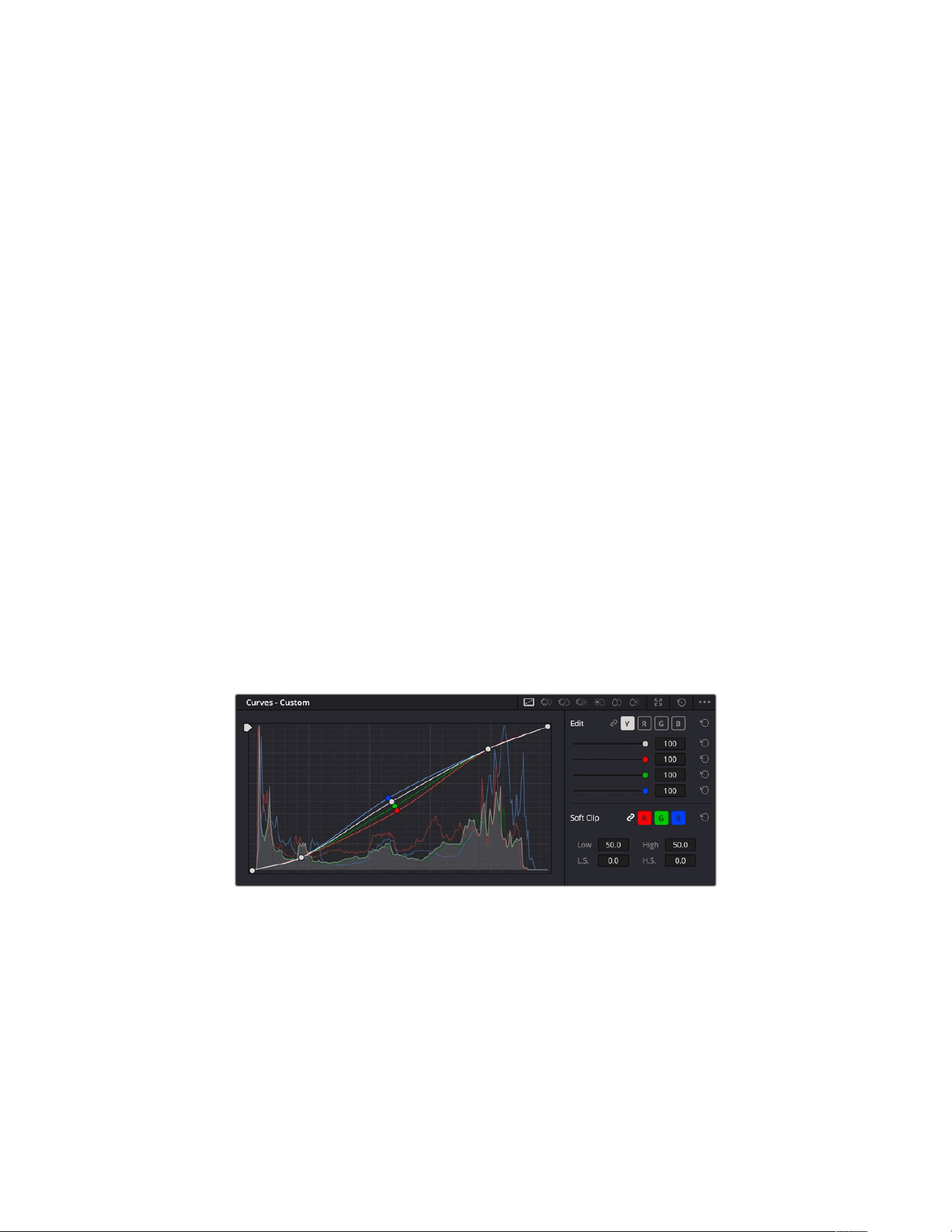
For more accurate control of each color using a mouse, you can change the color wheels to
‘primaries bars’ which let you adjust each color and luminance channel for the lift, gamma and
gain controls separately. Simply select ‘primaries bars’ from the dropdown menu near the top
right of the color wheels.
Adjusting the ‘lift’: With your clip selected on the color timeline, click on the ‘lift’ dial
underneath the first color wheel. Slide it back and forth and watch how it affects your
image. You’ll see the brightness of the dark regions of your picture increase and decrease.
Set it to where you want the dark areas to look their best. If you decrease the lift too much,
you’ll lose details in the blacks and you can use the parade scope to help avoid this. The
optimal position for blacks on the waveform is just above the bottom line of the
parade scope.
Adjusting the ‘gain’: Click on the ‘gain’ dial and slide it back and forth. This adjusts the
highlights which are the brightest areas of your clip. The highlights are shown on the
top section of the waveform on the parade scope. For a brightly lit shot, these are best
positioned just below the top line of the waveform scope. If the highlights rise above
the top line of the waveform scope, they will clip and you will lose details in the brightest
regions of your image.
Adjusting the ‘gamma’: Click on the ‘gamma’ dial underneath the color wheel and slide it
back and forth. Asyou increase the gamma you’ll see the brightness of the image increase.
Notice the middle section of the waveform will also move as you adjust the gamma. This
represents the mid tones of your clip. The optimal position for mid tones generally falls
between 50 to 70% on the waveform scope. However, this can be subjective based on the
look you are creating and the lighting conditions in the clip.
You can also use the curves palette to make primary color corrections. Simply click to create
control points on the diagonal line inside the curve graph, and drag them up or down to adjust
the master RGB contrast at different areas of image tonality. The optimum points to adjust are
the bottom third, mid, and top third of the curve line.
There are many more ways of doing primary color correction in DaVinci Resolve.
The curves palette is another tool you can use to make primary color corrections,
or enhance specific areas of your clip when using a power window
Secondary Color Correction
If you want to adjust a specific part of your image then you need to use secondary corrections.
The adjustments you have been doing up until now using the lift, gamma andgain adjustments
affect the whole image at the same time and so they are called primary color corrections.
255Using DaVinci Resolve

However, if you need to adjust specific parts of your image, say for example you wanted to
improve the color in the grass in a scene, or you wanted to deepen the blue in a sky, then you
can use secondary corrections. Secondary color corrections are where you select a part of the
image and then adjust only that part. With nodes, you can stack multiple secondary corrections
so you can keep working parts of your image until everything is just right! You can even use
windows and tracking to allow the selections to follow movement in your images.
Qualifying a Color
Often you’ll find a specific color in your clip can be enhanced, for example grass by the side
ofa road, or the blue in a sky, or you may need to adjust color on a specific object to focus the
audience’s attention on it. You can easily do this by using the HSL qualifier tool.
Using the HSL qualifier to select colors in your image
is helpful when you want to make areas of your
image ‘pop’, to add contrast, or to help draw the
audience’s attention to certain areas of your shot
To qualify a color:
1 Add a new serial node.
2 Open the ‘qualifier’ palette and make sure the ‘selection range’ picker tool is selected.
3 Click on the color in your clip you want to affect.
4 Usually you’ll need to make some adjustments to soften the edges of your selection and
limit the region to only the desired color. Click on the ‘highlight’ button above the viewer to
see yourselection.
5 Adjust the ‘width’ control in the ‘hue’ window to broaden or narrow your selection.
Experiment with the high, low and softness controls to see how to refine your selection.
Now you can make corrections to your selected color using the color wheels or custom curves.
Sometimes your selection can spill into areas of the shot you don’t want to affect. You can easily
mask out the unwanted areas using a power window. Simply create a new window and shape it
to select only the area of color you want. If your selected color moves in the shot, you can use
the tracking feature to track your power window.
Adding a Power Window
Power windows are an extremely effective secondary color correction tool that can be used to
isolate specific regions of your clips. These regions don’t have to be static, but can be tracked
to move with a camera pan, tilt or rotation, plus the movement of the region itself.
256Using DaVinci Resolve
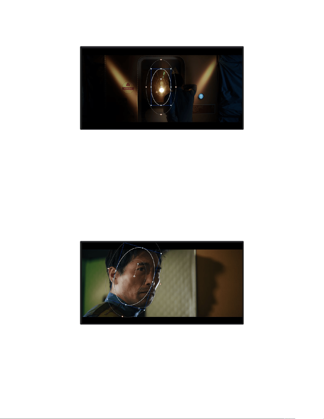
Use power windows to mask out areas you don’t want to be affected by the HSL qualifier
secondary adjustments
For example, you can track a window on a person in order to make color and contrast changes
just to that person without affecting his or her surroundings. By making corrections like this you
can influence the audience’s attention on areas you want them to notice.
To add a power window to your clip:
1 Add a new serial node.
2 Open the ‘window’ palette and select a window shape by clicking on a shape icon. Your
selected window shape will appear on the node.
3 Resize the shape by clicking and dragging the blue points around the shape. The red
points adjust the edge softness. You can position the shape by clicking the center point
and moving it to the area you want to isolate. Rotate the window using the point connected
to the center.
Now you can make color corrections to your image in just the area you want.
Power windows let you make secondary corrections to specific parts of your image
257Using DaVinci Resolve
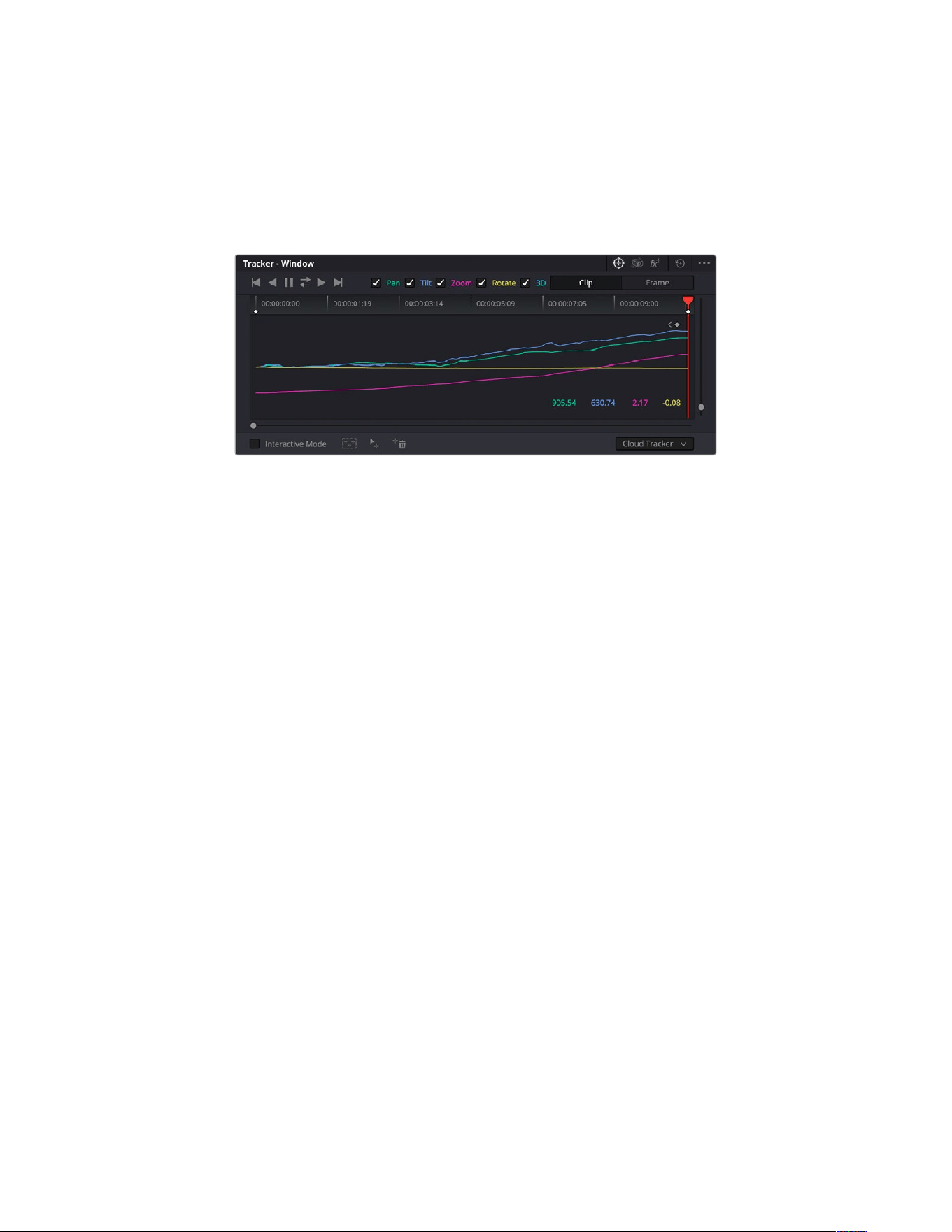
Tracking a Window
The camera, object or area in your shot may be moving, so to make sure your window stays on
your selected object or area, you can use DaVinci Resolve’s powerful tracking feature. The
tracker analyzes the pan, tilt, zoom and rotation of the camera or object in your clip so you can
match your windows to that movement. If this isn’t done, your correction can move off the
selected target and call attention to itself, which you probably don’t want.
You can track objects or areas in your clip using the tracker feature so power windows can
follow the action
To track a window to a moving object:
1 Create a new serial node and add a power window.
2 Go to the start of your clip and position and size the window to highlight just the object or
area you want.
3 Open the ‘tracker’ palette. Select the pan, tilt, zoom, rotate, and perspective 3D settings
appropriate for the movement in your clip by checking or unchecking the relevant ‘analyze’
checkboxes.
4 Click on the ‘forward’ arrow to the left of the checkboxes. DaVinci Resolve will now apply
a cluster of tracking points on your clip and then step through the frames to analyze the
movement. When the tracking is done, your power window will follow the path of the
movement in your clip.
Most of the time automatic tracking is successful, but scenes can be complex and sometimes
an object can pass in front of your selected area, interrupting or affecting your track. This can
be solved manually using the keyframe editor. Refer to the DaVinci Resolve manual to
find out more.
Using Plugins
While making secondary color corrections you can also add Resolve FX or Open FX plugins to
create fast, interesting looks and effects using the ‘color’ page, or imaginative transitions and
effects on your clips on the ‘cut’ and ‘edit’ pages. Resolve FX are installed with DaVinci Resolve,
OFX plugins can be purchased and downloaded from third party suppliers.
After installing a set of OFX plugins, you can access them or Resolve FX plugins on the color
page by opening the Open FX inspector to the right of the ‘node editor’. Once you create a new
serial node, simply click the ‘Open FX’ button to open the FX library and drag and drop a plugin
onto the new node. If the plugin has editable settings, you can adjust these in the adjoining
‘settings’ panel.
258Using DaVinci Resolve
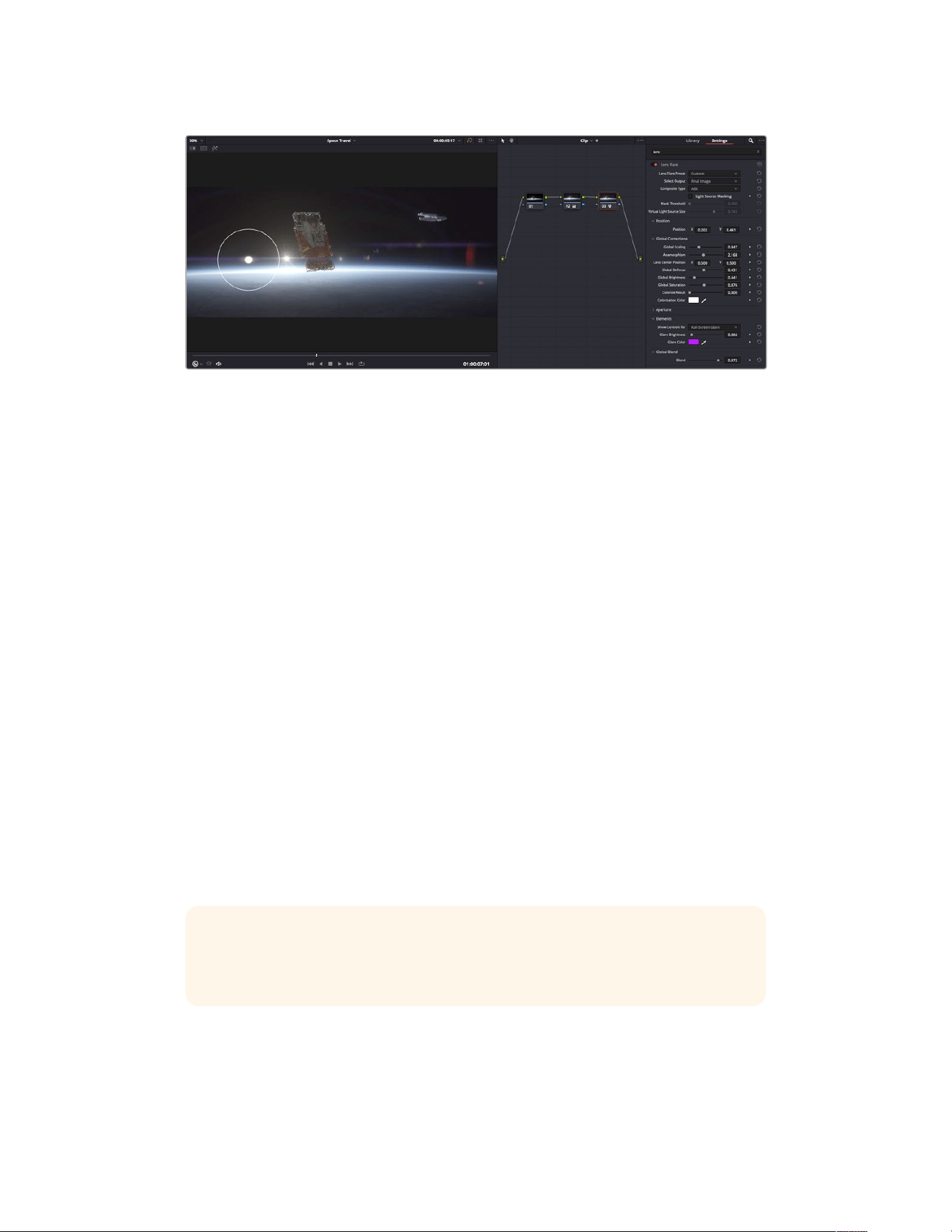
OFX plugins are a quick and easy way to create an imaginative and interesting look
In the ‘edit’ page you can add plugin filters, generators and transitions to clips by opening the
‘Open FX’ panel in the ‘effects library’ and dragging your selected plugin onto the video clip or
track above your clip on the timeline depending on the plugin requirements.
Mixing Your Audio
Mixing Audio in the Edit Page
Once you have edited and color corrected your project, you can begin to mix your audio.
DaVinciResolve has a helpful set of features for editing, mixing and mastering audio for your
project directly in the ‘edit’ page. For projects requiring more advanced audio tools, the
Fairlight page provides you with a full audio post production environment. If you are already
familiar with the edit page and want to move straight to Fairlight, skip this section and move
onto the next.
Adding Audio Tracks
If you are working in the edit page and want to mix a basic sound edit with lots of sound effects
and music, you can easily add more audio tracks when you need them. This can be helpful
when building your sound, and separating your audio elements into individual tracks, for
example, dialogue, sound effects and music.
To Add an Audio Track to the Edit Page
Right click next to the name of any audio track on your timeline and select ‘add track’ and
choose from the options, including ‘mono’, ‘stereo’, and ‘5.1’. This will add the track to the
bottom of the track list. Alternatively select ‘add tracks’ and select the position you would like
the new track or multiple tracks placed.
Your new audio track will appear on the timeline.
TIP If you wish to change the type of track after creating it, right click next to the name
of the track and select ‘change track type to’ and select the type of audio track you
want, such as stereo, mono or 5.1.
Adjusting Audio Levels in the Timeline
Each clip of audio in the timeline has a volume overlay that lets you set that clip’s level by
simply dragging it up or down with the pointer. This overlay corresponds to the Volume
parameter in the Inspector.
259Using DaVinci Resolve
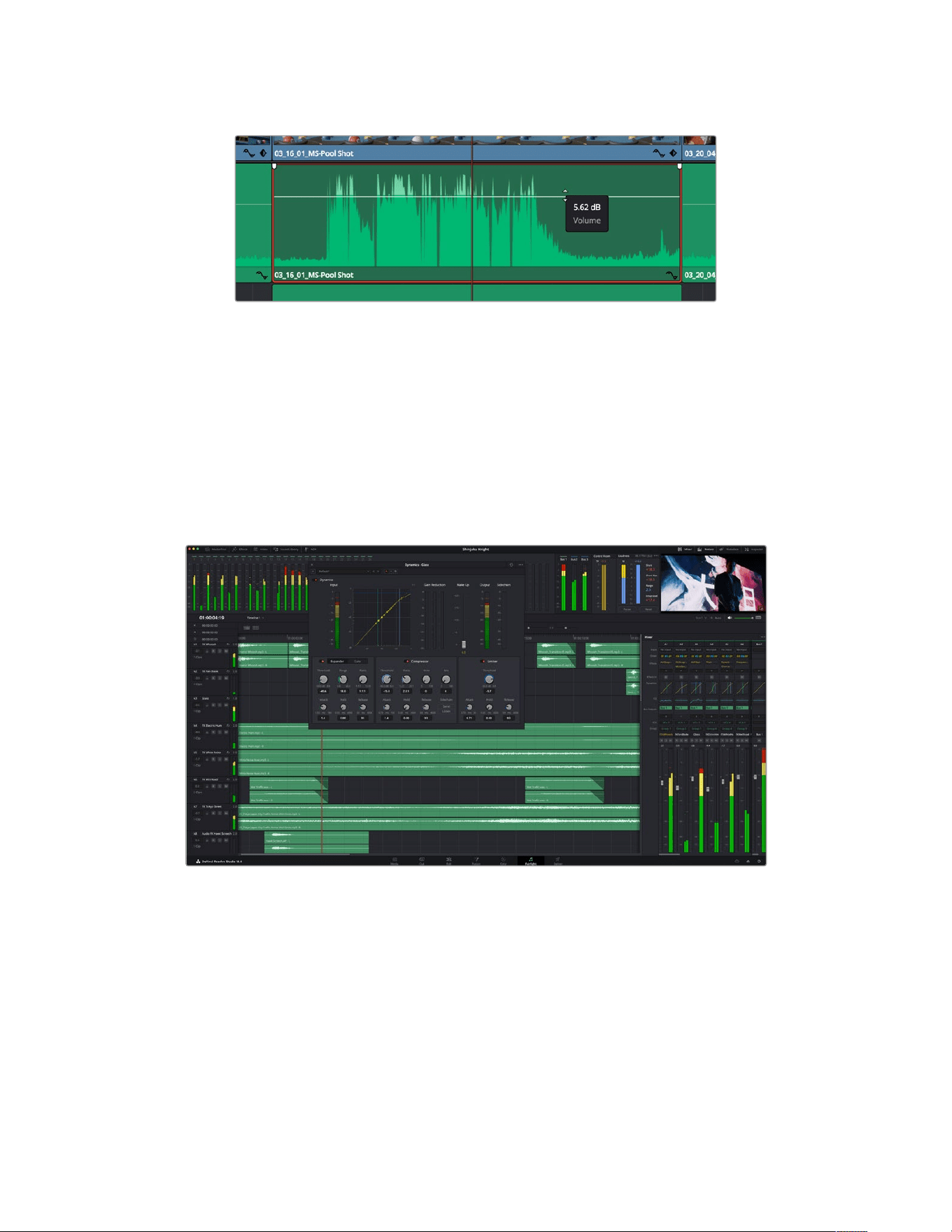
Dragging a volume overlay to adjust the clip level
For projects requiring more advanced audio tools, the Fairlight page provides you with a full
audio post production environment.
The Fairlight Page
The ‘Fairlight’ page in DaVinci Resolve is where you adjust your project audio. In single
monitormode, this page gives you an optimized look at the audio tracks of your project, with
anexpanded mixer and custom monitoring controls that make it easy to evaluate and adjust
levels in order to create a smooth and harmonious mix. Don’t feel overwhelmed by the vast
array of features in front of you, they are all there to help you deliver the best audio quality
foryour project.
This guide provides a basic overview of the features on the Fairlight page, but to learn more
about all the details for each feature, refer to the DaVinci Resolve manual. The DaVinci Resolve
manual provides details on the purpose of each tool and describes how to use them in easy to
follow steps.
260Using DaVinci Resolve
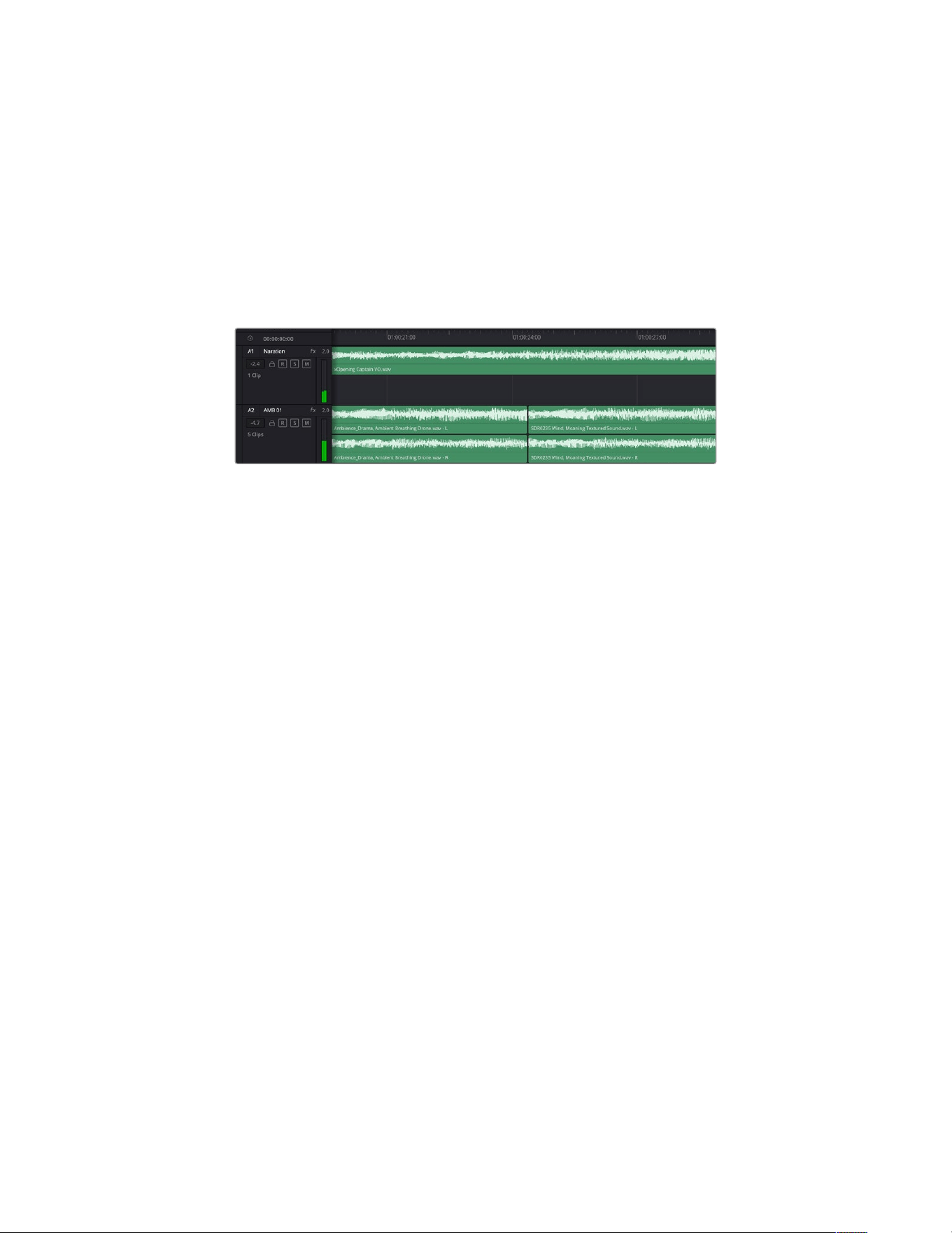
The Audio Timeline
Track Header: At the left of each track is a header area that displays the track number, track
name, track color, audio channels, fader value and audio meters. The track header also
contains different controls for locking and unlocking tracks, plus solo and muting controls.
These controls can help to keep your tracks organized, and let you preview individual
tracks one at a time.
Tracks: Each track on the Fairlight page is divided into lanes, which show each individual
channel of clip audio for editing and mixing. The edit page hides these individual audio
channels, displaying only a single clip in the timeline to make it easier to edit multi channel
sources without needing to manage a huge number of tracks.
The track header on track A1 indicates a mono track with a single lane for mono audio,
and the A2 track header indicates a stereo track with two lanes to accommodate stereo audio
What is a Bus?
A bus is essentially a destination channel made up of audio sources grouped together into a
single signal that can be controlled via a single channel strip. Fairlight automatically creates a
bus for you and all the audio tracks in your timeline are sent to this bus by default, this means
you can adjust the overall level of your audio mix once you have adjusted the level of each
individual track.
If your edit is a bit more complex you can create more buses and combine multiple tracks of
audio that belong to the same category such as dialogue, music or effects so that everything in
that category can be mixed as a single audio signal. For example, if you have five dialogue
tracks, you can route the output of all five dialogue tracks to a separate bus, and the level of all
dialogue can then be mixed with a single set of controls.
The Fairlight Flexbus structure gives you complete flexibility over bus types and signal routing
including the option for bus-to-bus, track-to-bus and bus-to-track routing. For more information
on audio bus settings in Fairlight, refer to the DaVinci Resolve manual.
The Mixer
Each audio track in your timeline corresponds to an individual channel strip in the Mixer, and by
default there’s a single strip on the right for the default bus labeled ‘Bus 1’. Additional channel
strips will appear on the right hand side with a set of controls for each additional bus you create.
A set of graphical controls allows you to assign track channels to output channels, adjust EQ
and dynamics, set levels and record automation, pan stereo and surround audio, and mute and
solo tracks.
261Using DaVinci Resolve
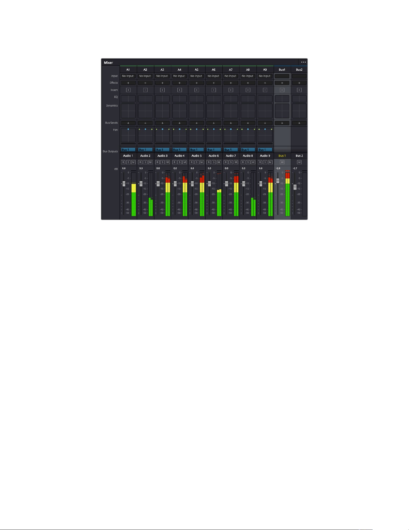
The audio mixer, with channel strips corresponding to the tracks in the timeline
Using the Equalizer to Enhance your Audio
After adjusting the audio levels of your audio clips in your project, you may find that the audio
needs further finessing. In some cases you may find that the dialogue, music and sound effects
are competing for the same frequency on the audio spectrum, making your audio too busy and
unclear. This is where using EQ can help, as it allows you to specify the parts of the audio
spectrum that each track occupies. You can also use an equalizer to help remove unwanted
elements from your audio by isolating and reducing the level on particular frequencies that
contain low rumbles, hums, wind noise and hiss, or simply to improve the overall quality of your
sound so it is more pleasing to listen to.
DaVinci Resolve provides EQ filters that can be applied at a clip level to each individual clip or
at the track level to affect entire tracks. Each audio clip in the timeline has a four band equalizer
in the inspector panel, and each track has a 6 band parametric equalizer in the mixer panel.
The graphical and numeric controls for boosting or attenuating different ranges of frequencies,
and different filter types allow you to define the shape of the EQ curve.
262Using DaVinci Resolve
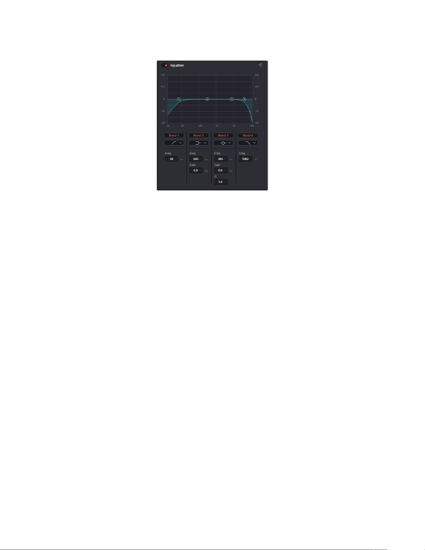
The four band equalizer can be applied
to every clip in the timeline
Outer bands let you make band filter adjustments using hi-shelf, lo-shelf, hi-pass and lo-pass
filters. A pass filter affects all the frequencies above or below a particular frequency, by
removing those frequencies completely from the signal. For example, a high pass filter will
allowthe high frequencies to pass through the filter while cutting the low frequencies.
Anyfrequencies outside the cutoff frequency are cut gradually in a downward sloping curve.
A shelf filter is less aggressive, and is useful when you want to shape the overall top end or
low end of the signal without completely removing those frequencies. The shelf filter boosts or
cuts the target frequency and every frequency either above or below it evenly, depending on
whether you use a high shelf or low shelf.
The middle sets of band controls let you make a wide variety of equalization adjustments, and
can be switched between lo-shelf, bell, notch, and hi-shelf filtering options.
Bell: Bell filters boost or cut frequencies around a given center point of the bell curve, and
as the name suggests the shape of the curve is like a bell.
Notch: Notch filters allow you to specifically target a very narrow range of frequencies.
For example, removing a mains hum at 50 or 60Hz.
Lo-Shelf: Low shelf filters boost or cut the target frequency at the low end, and every
frequency below it
Hi-Shelf: High shelf filters boost or cut the target frequency at the high end, and every
frequency above it
To add EQ to an individual clip:
1 Select the clip in the timeline that you want to add the EQ filter to.
2 Click on the inspector and then click the ‘equalizer’ enable button.
To add EQ to a track:
1 Double click in the EQ section for one of your tracks in the mixer to open the equalizer
for that track.
2 Select the band filter type from the dropdown menu for the band you want to adjust.
263Using DaVinci Resolve
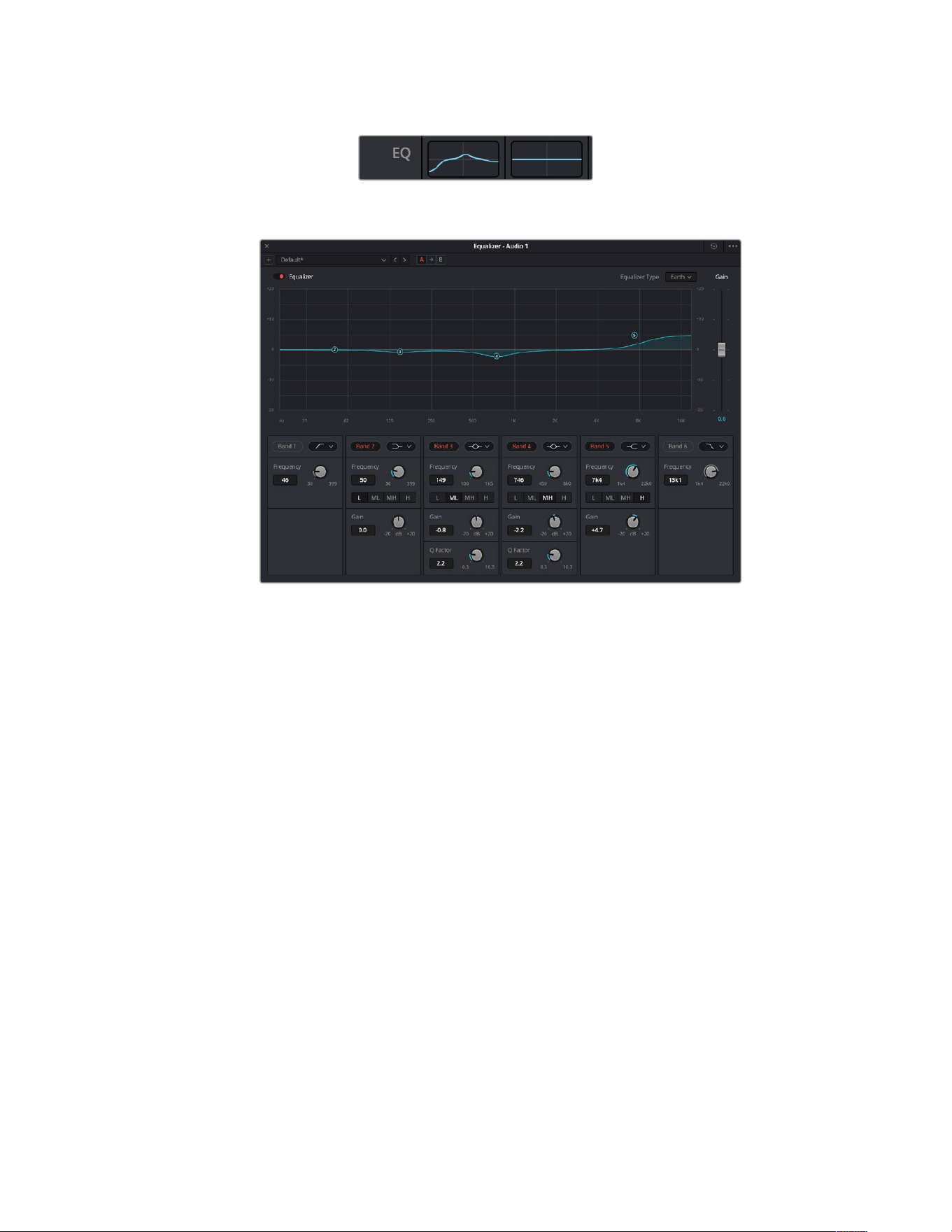
The EQ section in the mixer panel indicating
anEQcurve has been applied to track one
The 6 Band parametric equalizer that can be applied to every track
Once you have added EQ to your clip or track, you can adjust the EQ for each band. Note that
controls may vary depending on which band filter type is selected.
To adjust the EQ for a band filter:
1 Select the band filter type from the dropdown menu for the band you want to adjust.
2 Adjust the ‘frequency’ value to select the center frequency of the EQ adjustment.
3 Adjust the ‘gain’ value to boost or attenuate the frequencies governed by that band.
4 Use the ‘Q factor’ value to adjust the width of affected frequencies.
Use the reset button to reset all controls in the EQ window to their defaults.
Fairlight has many controls you can use to improve the quality of each audio track. You can add
more tracks and arrange buses to organize them, plus add effects like delay or reverb, and
generally perfect your audio mix.
Adding VFX and Compositing on the Fusion Page
Now that you have completed your edit, you can open the Fusion page to add 2D or 3D visual
effects and motion graphics right within DaVinci Resolve. Unlike layer based compositing
software, Fusion uses nodes, giving you the freedom to build complex effects while routing
image data in any direction. The nodes window clearly shows every tool used along the way.
Ifyou have experienced the node workflow in the color page, this will feel familiar to you.
264Using DaVinci Resolve
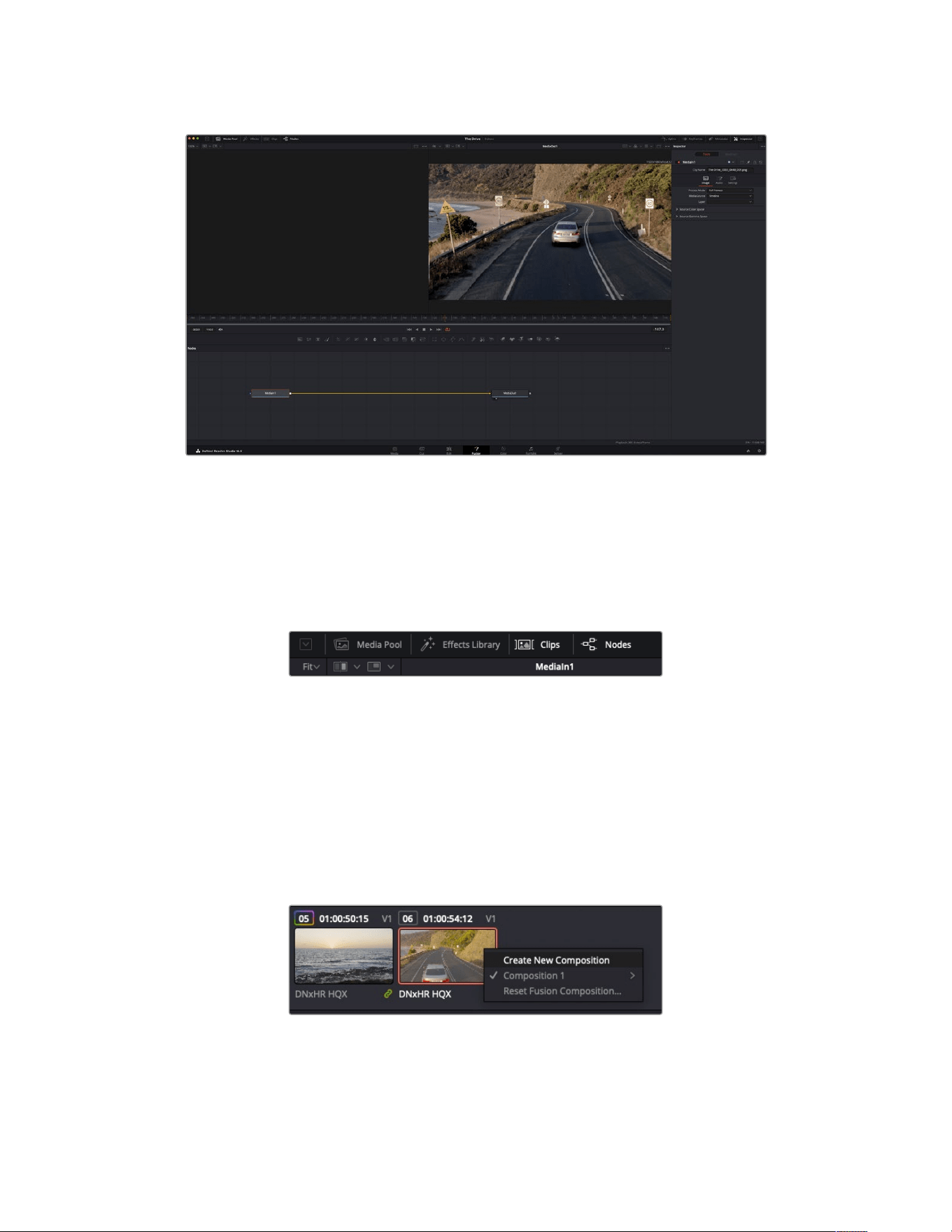
The Fusion Page
The Fusion page features 2 viewer windows across the top with transport controls to view your
media, an inspector window to the right to access tool settings, and a nodes window at the
bottom where you build your composition. While the viewers and transport controls are always
visible, clicking on the icons on the interface toolbar at the very top of the display will let you
show or hide the nodes and inspector windows, or reveal or hide additional windows including
the effects library and editors for spline and keyframes.
Media Pool: The media pool functions the same way as it appears in the edit page. Simply
drag additional media from your bins directly to your composition.
Effects Library: The effects library is where you will find your Fusion tools and templates
sorted into categories including particle, tracking, filters and generators. You can either
click on the tool or drag it to the nodes area to add it to your composition. The media pool
and effects library take up the same screen area, so you can swap between the two to
keep your viewers as large as possible.
Clips: Clicking the clips tab will reveal or hide thumbnails representing clips on your
timeline. The thumbnails are located underneath the nodes editor, letting you instantly
navigate to other clips.
Create a new version of your composition by right clicking on a
thumbnail and selecting ‘create new composition’.
265Using DaVinci Resolve
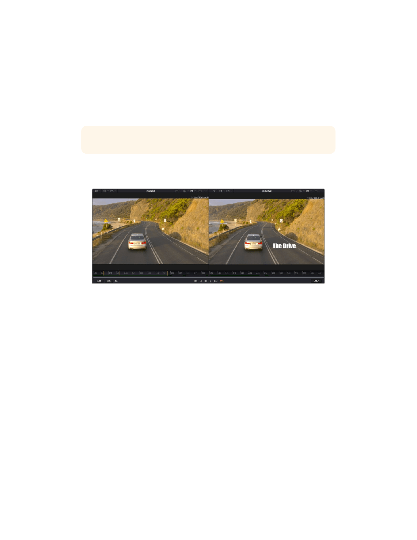
Viewers: The viewers are always visible and let you see the different views of your
composition, for example an overall 3D perspective via the merge 3D node, a camera
output, oryour final render output. These viewers also let you see how your changes are
affecting aspecific element.
You can choose which nodes to view by clicking on a node and typing ‘1’ for the left viewer
or ‘2’ for the right viewer. White button icons appear beneath the node to let you know
which viewer itis assigned to. If you’re using external video monitoring, there will be a third
button available to route your media to your external video monitor.
TIP You can also assign a node to a viewer by dragging the node into the viewer itself.
The transport controls underneath the viewers let you skip to the start or end of the clip,
play forward or reverse, or stop playback. The time ruler displays the entire range of a clip,
with yellow marks indicating the in and out points.
The yellow marks on the time ruler indicate your clip’s in and out points on your
timeline. If you are using a Fusion clip or compound clip, the time ruler will only show
you the duration of the clip as it appears on the timeline, without handles.
Nodes: The nodes window is the heart of the Fusion page where you build your node tree
byconnecting tools together from one node’s output to another node’s input. Thisarea will
change size depending on which editors are open, for example the spline or keyframes
editor. A toolbar atthe top of the nodes area features the most commonly used tools for
fast access.
Spline: When the spline editor is open, it will appear to the right of the nodes window. This
editor lets you make precise adjustments to each node, such as smoothing the animation
between two keyframes using bezier curves.
Keyframes: Keyframes for each tool can be added, removed or modified using the
keyframes editor. This also appears to the right of the nodes viewer.
Metadata: The metadata window will show you metadata available for the active clip,
including the codec, frame rate and timecode.
Inspector: The inspector in the top right corner displays all settings and modifiers available
for one or more selected nodes. Additional tab options will appear to provide quick access
to other settings for nodes sorted by category.
266Using DaVinci Resolve
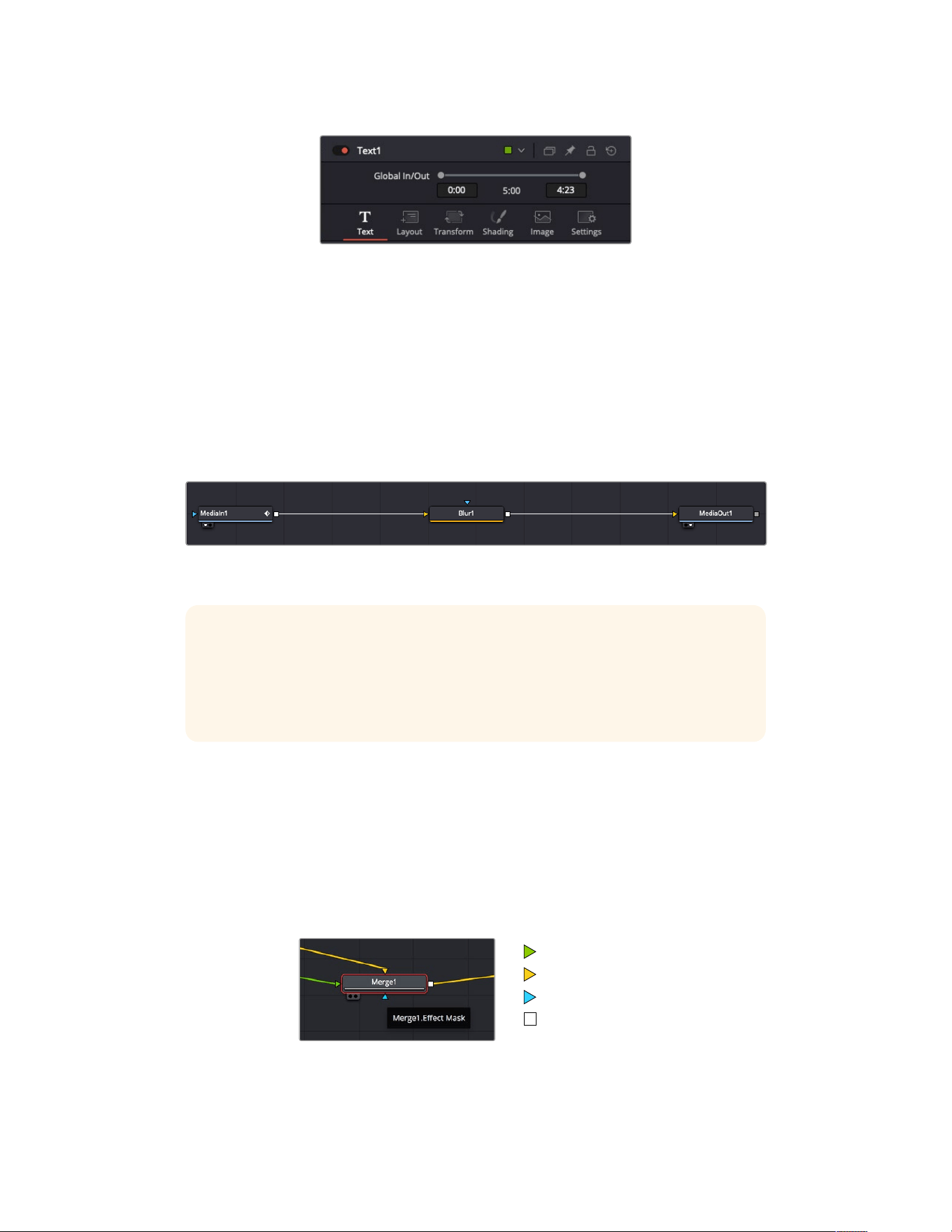
The text inspector contains additional tabs for text, layout,
transform, shading, image and settings.
Getting Started with Fusion
To get started with Fusion, simply position your playhead over any clip on your timeline and
click on the ‘Fusion’ tab to open the Fusion page.
On the Fusion page, your clip is immediately available in a media input node labelled ‘MediaIn’.
Every composition will begin with a ‘mediain’ and a ‘mediaout’ node. This mediain node
represents the top most clip of your timeline at the playhead, and ignores any clips underneath.
Any adjustments you’ve applied to the clip on the edit page, such as transform tools and
cropping changes, are also included.
The media output node, named ‘MediaOut’, is the node that sends the output back to your timeline on
DaVinci Resolve’s edit page.
TIP ResolveFX or OFX plug-ins applied to clips in the cut or edit pages are not
applied in the Fusion page. This is because Fusion effects occur prior to color
correction and OFX/ResolveFX processing. If you want OFX applied before Fusion
effects, right click the clip in the edit page and select ‘new fusion clip’ before clicking
on the Fusion page.
Understanding Nodes
It can be helpful to think of each node as a visual icon representing a single tool or effect.
Nodes are connected to other nodes to build the overall composition, much like ingredients
inacake. It’s important to understand the inputs and outputs of each node as this will help
you navigate the flow of your composition while building detailed visual effects.
Some tools have multiple inputs and outputs you can connect to other nodes. The merge
node, for example, lets you attach a foreground input, background input, and a mask input for
mattes or keys.
Foreground input
Background input
Effect mask input
Output
267Using DaVinci Resolve
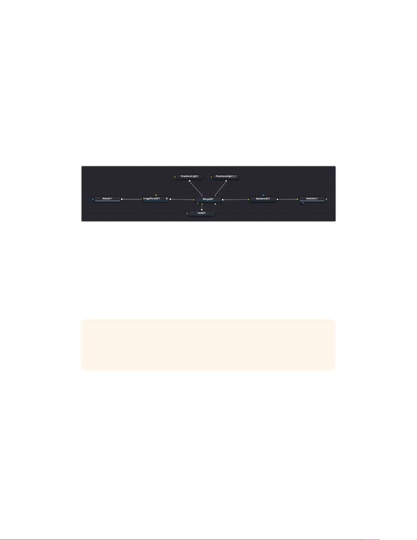
Multiple outputs on nodes means a single node can connect to many different nodes in your
composition, so you don’t have to duplicate clips as you would in layer based software.
Arrows on the line between connected nodes are a great visual indicator to show you which
direction the image data is flowing.
Adding Nodes to the Node Editor
Adding effects is as simple as placing nodes on the line between the ‘mediain’ and
‘mediaout’ nodes.
There are a few ways you can do this. You can hold down the shift button and drop a node
between two nodes, or click on the node you want to attach an effect to and select the
tool you want to add. The new node will automatically connect to the tool selected. You can
also add a node anywhere on the node window and manually connect nodes by dragging the
output of one to the input on another.
The most commonly used tool is the 2D or 3D merge node. This node is like a central hub that combines tools
on the node editor into a single output.
The merge node has controls for how the inputs are managed, including settings for size,
position, and blend. These settings are all accessible in the inspector panel when the merge
node is selected.
The toolbar above the node panel contains the most commonly used tools as icons that you
can either click on to add the node, or drag the tool to the node panel. If you want to see all the
complete tools available, click on the ‘effects library’ in the top left corner and expand the ‘tools’
option. Here you’ll find all the tools sorted by category, as well as a set of pre-built ‘templates’
you can use, for example lens flares, shaders and backgrounds.
TIP Once you’re familiar with the tool names, you can hold down ‘shift’ and press
‘spacebar’ on your keyboard and a ‘select tools’ menu will appear. As you type the tool
name, the menu will suggest the relevant tool. This is a very fast way to select the tool
you want.
Adjusting Nodes Using the Inspector Panel
Adjust your node settings using the inspector panel. Simply click on the node you want to
modify and the panel will update to display its settings and controls.
With Fusion, you don’t have to be viewing the node you’re editing, as you can modify one node
while viewing another in your composition. For example, you can modify the size and center
position of a ‘text+’ node while the merge node is in the viewer, letting you view the text relative
to the background.
268Using DaVinci Resolve
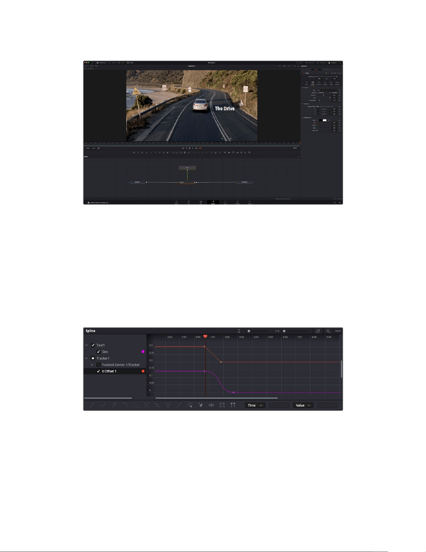
Selected nodes appear with a red border. Here the inspector panel is displaying the layout tab controls
for the text node.
There are different parameters and settings you can adjust for every node depending on its
task, from sizing and center positions to changing the number of particles in an emitter node.
Setting keyframes and changing the settings over time will animate the effect.
Working with Keyframes
In the inspector window, set a keyframe by right clicking on a setting and choosing ‘animate’
from the contextual menu. The keyframe icon to the right of the setting will turn red. This means
keyframes are now active and any changes you make will be applied to the current frame only.
When two or more keyframes are created by changing the setting parameters on a different
frame, a transition is interpolated between them. Arrows on each side of the keyframe icon let
you move the playhead to those exact positions on the timeline.
Here, the ‘size’ keyframe animation has been smoothed into a bezier curve. You can click the bezier
handles to shorten or lengthen the curve, or the keyframe square icons to move the keyframe location.
The splines panel gives you further control over keyframe animation. You can select keyframes,
such as the first and last, and smooth the animation between them into a bezier curve by typing
‘shift’ + ’s’, or right clicking on a keyframe and selecting ‘smooth’.
269Using DaVinci Resolve
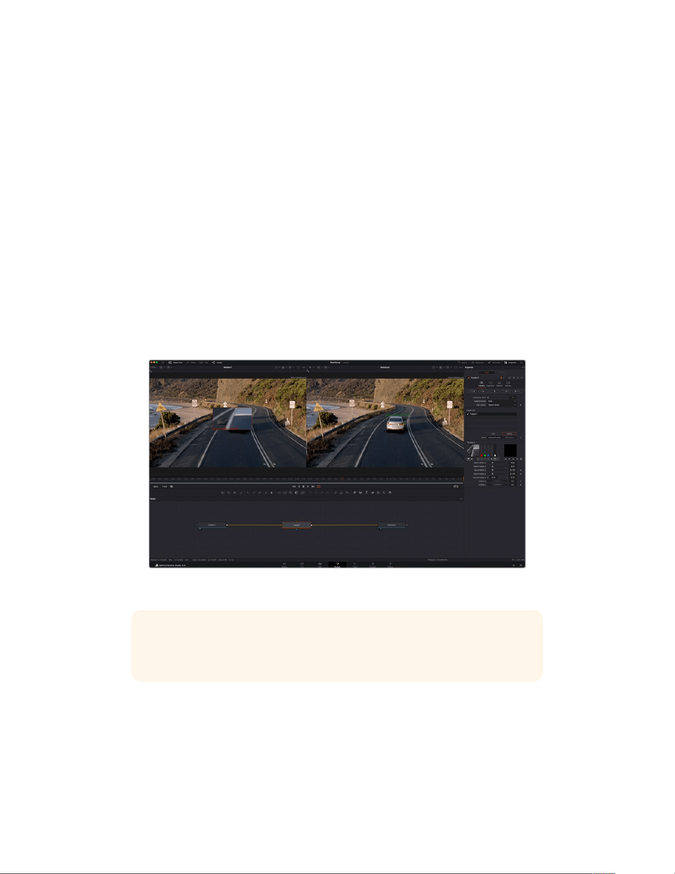
Using the Motion Tracker and Adding Text
To get a better idea of how to use Fusion, we have included the following examples to show
how to use the tracker tool to track an element in a clip, plus add text and attach it to the
element using the tracking data.
The ‘tracker’ tool tracks pixels over time on the x & y axis, and generates data you can use to
attach other elements. This is great for when you want to match the position of text to a moving
object, such as a car driving along the road, or a bird as it flies across frame.
1 In the ‘effects library’, select the ‘tracker’ tool and drag it to the line between the
‘mediain’ and the ‘mediaout’ nodes. Now click the tracker node to reveal its properties
in the inspector.
2 Type ‘1’ on your keyboard to see the ‘tracker’ node on the left viewer. The clip will appear
in the viewer together with the tracker at its default position. Hover your mouse pointer
over the tracker to reveal the tracker handle. Click on the tracker handle at the top left
corner and drag the tracker to an area of interest on your clip. High contrast areas work
well, for example the badge on the hood of a car. The tracker will magnify the image area
for extra precision.
3 In the inspector window, click on the ‘track forward’ button to start tracking. A notification
window will appear when the tracking is done. Click OK.
Tracking options in the inspector panel include track reverse from last frame or
current frame, stop track or track forward from current frame or first frame.
TIP Track reverse or forward from current frame is great for situations where your area
of interest disappears during the render range, such as a car or bird moving out of
frame. This lets you track only the relevant footage.
Now you can take that tracking data and apply the motion path to a text tool.
4 Click on the ‘text+’ node icon from the toolbar of commonly used nodes and drag it to
the node panel near the ‘tracker’ node. Connect the ‘text’ output square to the green
foreground input on the ‘tracker’.
270Using DaVinci Resolve
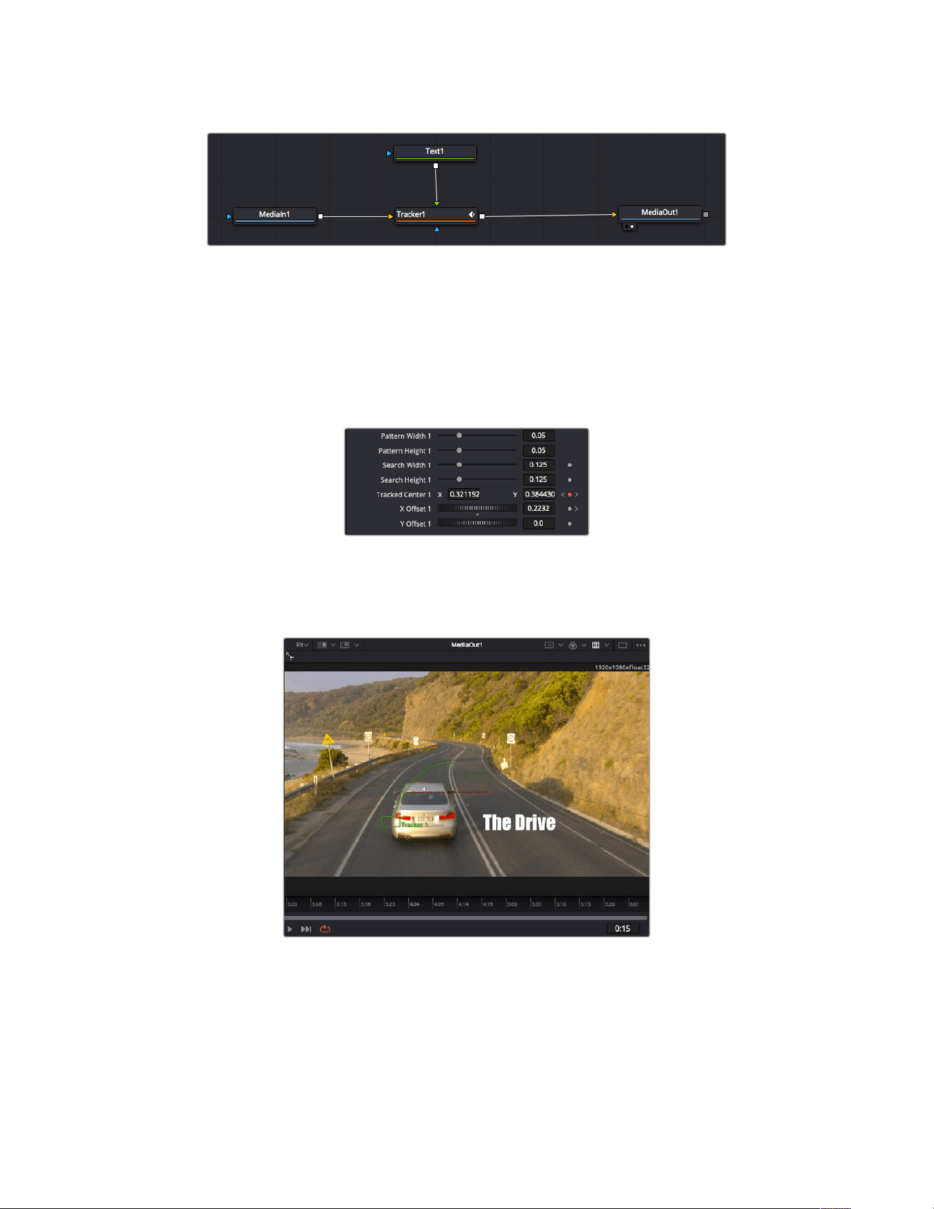
5 Click on the ‘tracker’ node and type ‘1’ so you can see the merged results on your left hand
viewer. In the ‘tracker’ inspector panel, click on the ‘operations’ tab. Click the menu next to
operation and select ‘match move’.
6 Click the ‘text’ node to reveal the properties in the inspector. Type your text into the text
box and change the font, color and size to suit your composition.
This will apply the tracking position data from your tracker to your text. If you want to
change the text offset, click on the ‘trackers’ tab back in the inspector panel and use the
x and y offset scroll wheels to modify the position.
Scroll wheels at the bottom of the tracker inspector
panelletyou adjust the offset position for the text.
Now you can play back your composition and see your text attached to the object you
have tracked!
The green square is the tracker’s current position along the green path,
and the red dashed line is the offset position used to animate the text.
For some shots you might want to remove track points after tracking, such as when the
object you are tracking disappears off the screen. The keyframe editor makes this a very
simple process.
271Using DaVinci Resolve
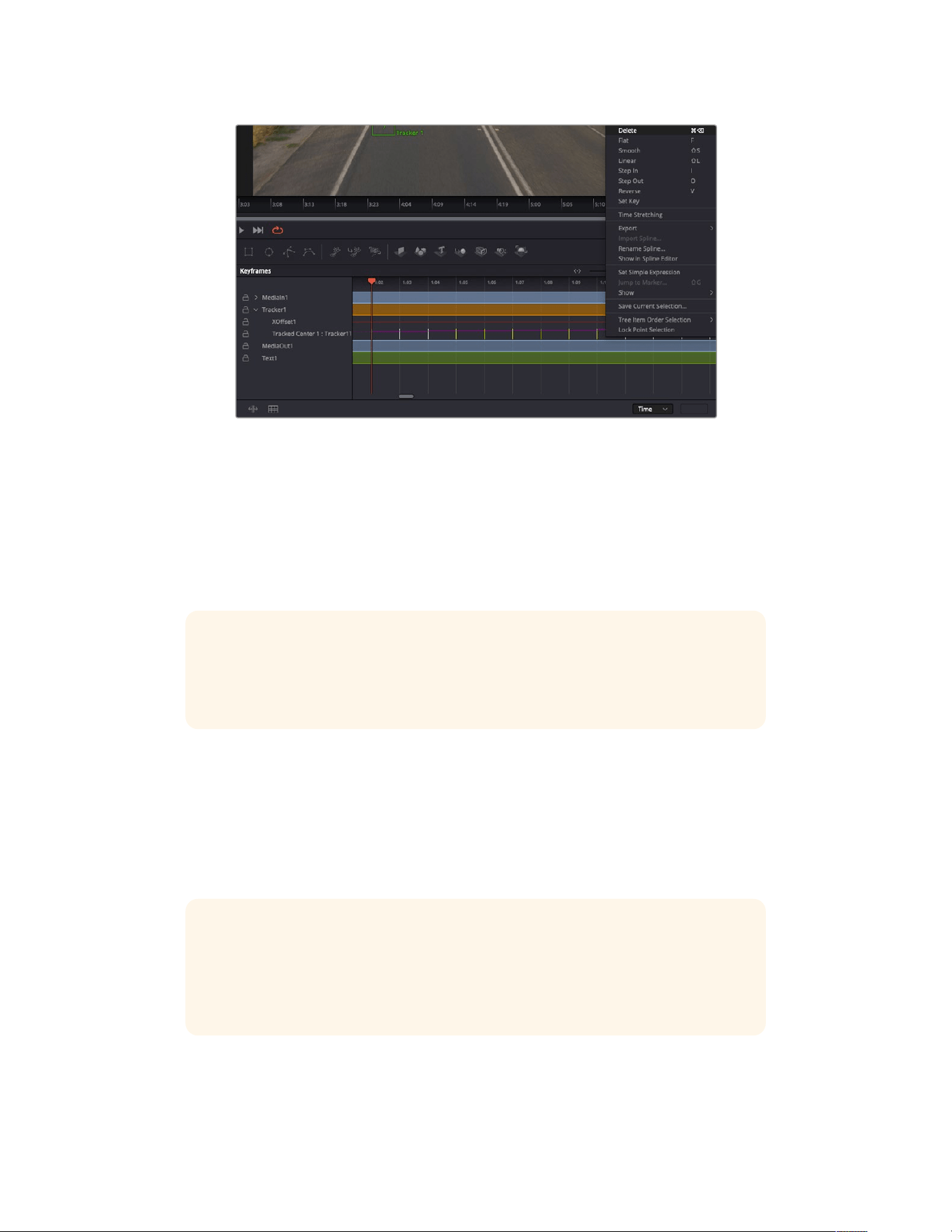
7 Click on the keyframes tab above the inspector to open the keyframes editor. Any nodes
with keyframes applied will have a small arrow next to the node label, and only the
parameter with keyframes added will appear in the list below. Click on the magnify icon and
drag a box around the area you want to edit. This will zoom into that area so you can see
the keyframes easier.
8 Move the playhead to the location of the last keyframe you want. Now select the keyframes
you wish to remove by drawing a box around them with your mouse. The keyframes will
highlight yellow. Right click and choose delete from the menu.
TIP If your effects are particularly system intensive, right clicking on the transport
controls area will give you viewer options, including proxy playback, helping you get
the most out of your system while you build your composition. Refer to the
DaVinci Resolve manual for further detail on all the playback options.
You have now completed your first composition animating text to match a movement in
your footage!
If you want to track an area of the image that contains a flat surface you want to enhance or
replace, you can use the planar tracker. Tracking 2D planes can be helpful for changing labels
and signs in a moving image, or even adding an image to a monitor or TV in your shot.
For more information about the planar tracker and the many powerful tools in the
DaVinci Resolve Fusion page, see the DaVinci Resolve manual.
TIP As you build visual effects in the Fusion page, it’s worth noting if the effect you are
building is a 2D effect, or a 3D effect, as this will determine which merge tool is used. You
may discover yourself frequently combining 2D and 3D effects in the one composite.
In this scenario, it’s helpful to remember that any visual effect using the 3D space
needs to be rendered as a 2D image before it can be merged into a 2D composite.
We believe you will have lots of fun with Fusion and exploring Fusion’s visual effects with the
power of DaVinci Resolve’s edit, color, and Fairlight pages. With all these tools at your finger
tips, DaVinci Resolve is incredibly powerful and there is really no limit to what you can create!
272Using DaVinci Resolve
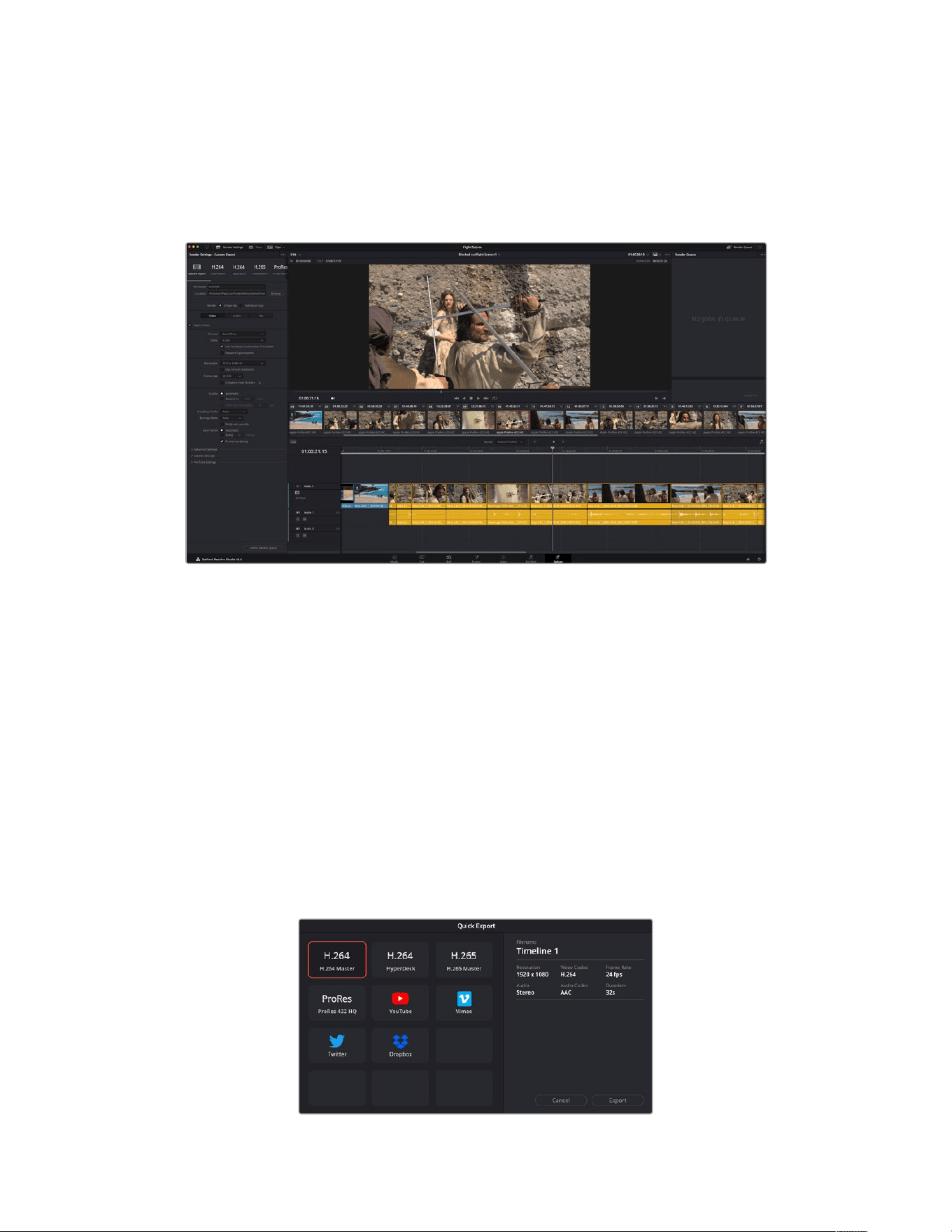
Mastering Your Edit
Now you’ve edited, graded, added vfx and mixed your audio, you’ll want to share it with others.
You can use the Quick Export button, or menu selection, to output the contents of the Timeline
as a self contained file in one of a variety of different formats, or use the additional features of
the ‘deliver’ page.
The ‘deliver’ page is where you export your edit. You can select from many different video formats and codecs
Quick Export
You can choose File > Quick Export to use one of a variety of export presets to export your
program from any page of DaVinci Resolve. You can even use quick export to export and
upload your program to one of the supported video sharing services, including YouTube,
Vimeo, Twitter and Frame.io.
To use Quick Export:
1 In the ‘cut’, ‘edit’, fusion’ or ‘color’ page, optionally set in and out points in the timeline to
choose a range of the current program to export. If no timeline in or out points have been
set, the entire timeline will be exported.
Choose File > Quick Export.
2 Select a preset from the top row of icons in the quick export dialog, and click ‘export’.
3 Choose a directory location and enter a file name using the export dialog, then click ‘save’.
A progress bar dialog appears to let you know how long the export will take.
The quick export dialog
273Using DaVinci Resolve

The Deliver Page
This page lets you select the range of clips you want to export, plus the format, codec and
resolution you want. You can export in many types of formats such as QuickTime, AVI, MXF
and DPX using codecs such as 8-bit or 10-bit uncompressed RGB/YUV, ProRes, DNxHD,
H.264 and more.
To export a single clip of your edit:
1 Click on the ‘deliver’ tab to open the deliver page.
2 Go to the ‘render settings’ window on the top left of the page. Choose from a number of
export presets, for example YouTube, Vimeo and audio presets, or you can set your own
export settings manually by leaving it set to the default ‘custom’ preset and entering your
own parameters. Forthis example, select YouTube, then click on the arrow next to the
preset and select the 1080p video format.
The frame rate will be locked to your project frame rate setting.
3 Underneath the presets you will see the timeline filename and the target location for your
exported video. Click the ‘browse’ button and choose the location where you want to save
your exported file and then select ‘single clip’ from the render option.
4 Immediately above the timeline, you’ll see an options box with ‘entire timeline’ selected.
This will export the entire timeline, however you can select a range of the timeline if you
want to. Simply choose ‘in/out range’ and then use the ‘i’ and ‘o’ hot key shortcuts to
choose the in and out points in your timeline.
5 Go to the bottom of the ‘render settings’ and click on the ‘add to render queue’ button.
Your render settings will be added to the render queue on the right side of the page. Now
all you have to do is click ‘start render’ and monitor the progress of your render in the
render queue.
When your render is complete you can open the folder location, double click on your new
rendered clip and watch your finished edit.
Now that you have a basic knowledge of how to edit, color, mix audio and add
visual effects, we recommend experimenting with DaVinci Resolve. Refer to the
DaVinci Resolve manual for more details on how each feature can help you make the
most of your project!
274Using DaVinci Resolve
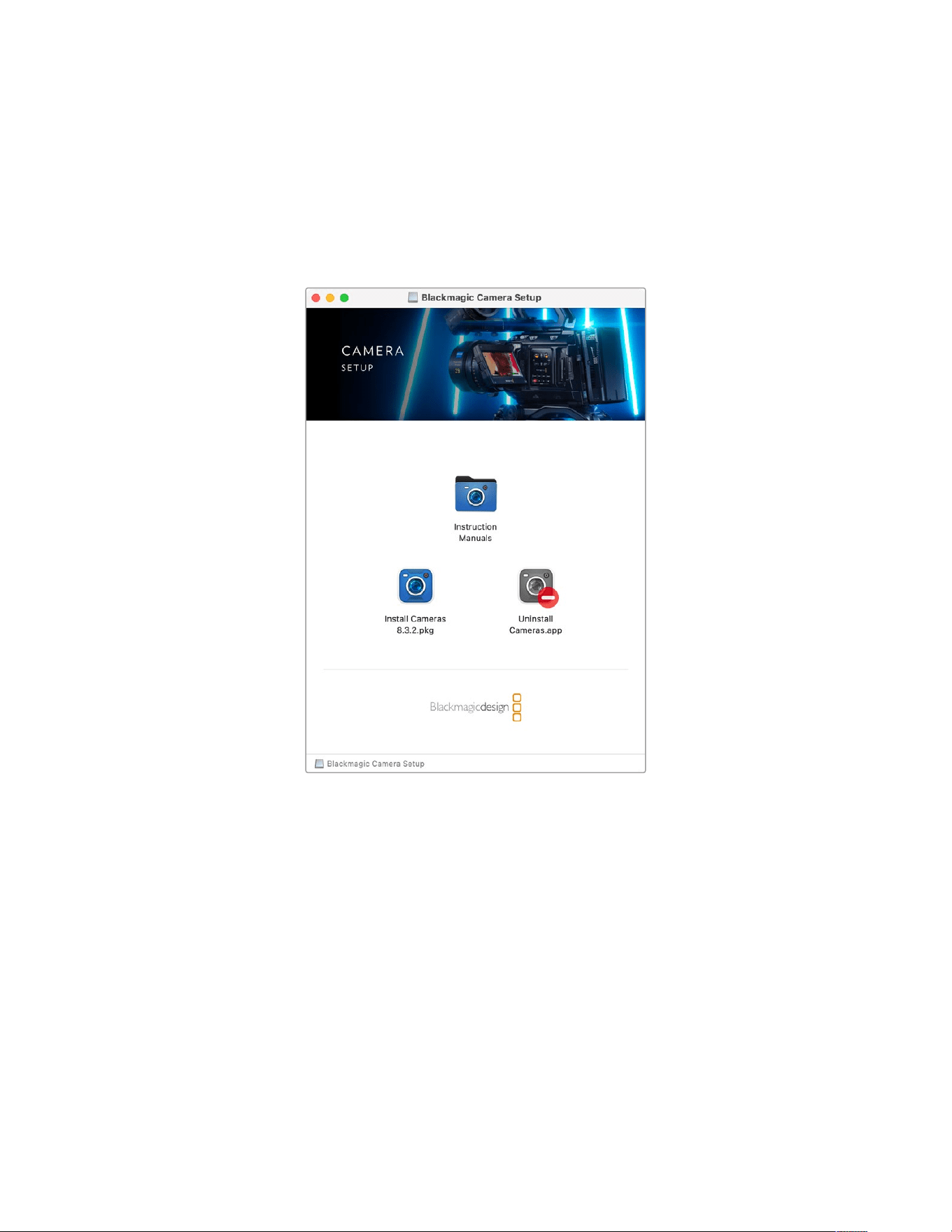
Blackmagic Camera Setup
How to Update Your Camera Software on Mac OS
After downloading the latest Blackmagic Camera Update software from the Blackmagic Design
support center, unzip the downloaded file and double click on the .dmg disk image file. Launch
the ‘Install Cameras’ installer and follow the onscreen instructions.
How to Update Your Camera Software on Windows
After downloading the ‘Blackmagic Camera Setup’ software and unzipping the downloaded file,
you should see a ‘Blackmagic Camera Setup’ installer window. Double click on the installer icon
and follow the onscreen prompts to complete the installation.
After the installation is complete, click on the Windows ‘start’ menu, and go to ‘all programs’.
Click on the Blackmagic Design folder to open the Blackmagic Camera setup software and
instruction manuals.
275Blackmagic Camera Setup
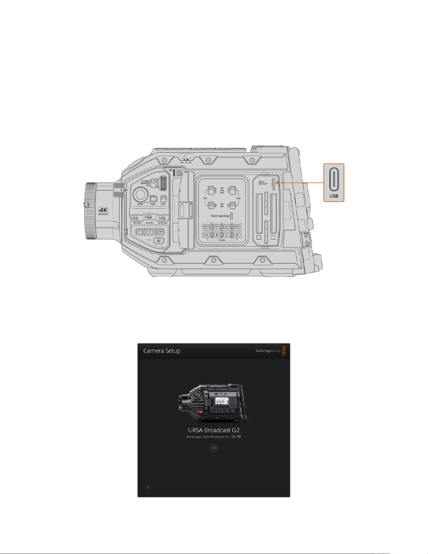
How to Update your Camera’s Internal Software
After installing the latest Blackmagic Camera Setup utility on your computer, connect a USB
cable between the computer and your Blackmagic URSA Broadcast G2. The USB port is
located on the left side panel above the memory card slots.
Power your camera, launch ‘Blackmagic Camera Setup’ and follow any on screen prompt to
update the camera software. It’s important to note that updating your camera software erases
any presets and custom LUTs, and resets all settings. It is a good practice to export them to a
memory card as a backup before performing a software update. After a software update, you
can restore your presets and LUTs quickly by importing them from the memory card.
The USB-C port is used to update the camera software and can be found above the memory
card slots, next to the media selection switch on Blackmagic URSA Broadcast G2
Using Blackmagic Camera Setup
Blackmagic Camera Setup is used to change settings and update the internal software
in your camera.
276Blackmagic Camera Setup
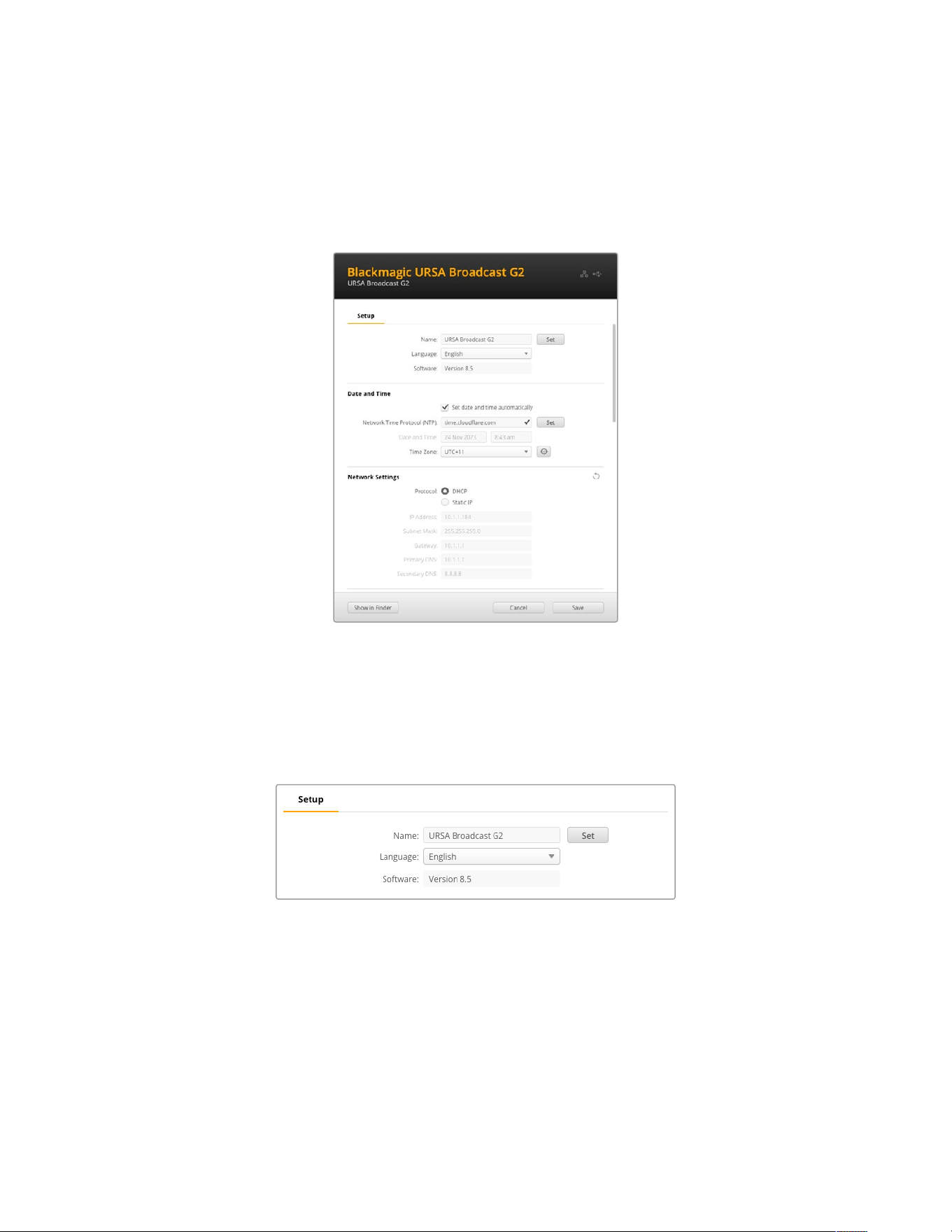
To use Blackmagic Camera Setup:
1 Connect your Blackmagic URSA Broadcast G2 to your computer via USB or Ethernet.
2 Launch Blackmagic Camera Setup. Your camera will be named in the setup utility
home page.
3 Click on the circular ‘setup’ icon or the image of your camera to open the setup page.
Setup
If you have more than one URSA Broadcast G2, you may wish to give each unit a discrete name
to make them easy to identify. You can do this by entering a new name into the name field and
clicking the ‘set’ button. It’s worth noting that changing the name of the camera will invalidate
any digital certificates in use, so it’s worth changing the name before generating a certificate
signing request or self signed certificate. More details on digital certificates is available in the
‘secure certificate’ information later in this section of the manual.
277Blackmagic Camera Setup
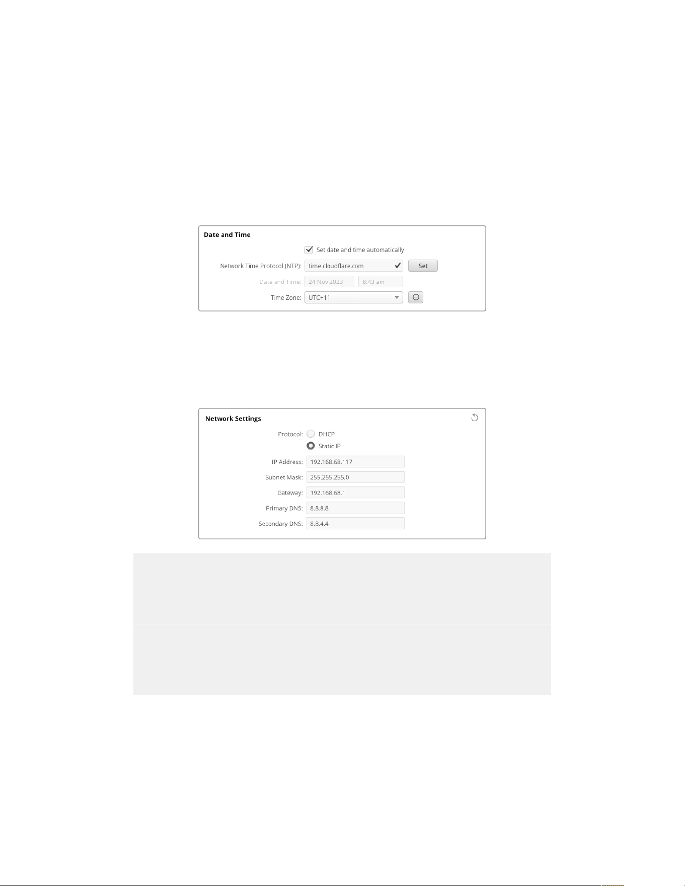
Date and Time
Set your date and time automatically by ticking the ‘set date and time automatically’ checkbox.
When this checkbox is enabled, your camera will use the network time protocol server set in
the NTP field. The default NTP server is time.cloudflare.com, but you can also manually enter
analternate NTP server and then click on ‘set’.
If you are entering your date and time manually, use the fields to enter your date, time and time
zone. Setting the date and time correctly ensures your recorded clips have the same time and
date information as your network and also prevents conflicts that can occur with some network
storage systems.
Network Settings
Protocol
To control your camera remotely via Ethernet, or when connected to ATEM Television Studio
HD8 ISO as a remote source on your network, the camera needs to be on the same network as
your other equipment using DHCP or by manually adding a fixed IP address.
DHCP Your camera is set to DHCP by default. The dynamic host configuration protocol, or DHCP,
is a service on network servers that automatically finds your camera and assigns an IP
address. The DHCP is a great service that makes it easy to connect equipment via Ethernet
and ensure their IP addresses do not conflict with each other. Most computers and network
switchers support DHCP.
Static IP When ‘static ip’ is selected, you can enter your network details manually. When setting IP
addresses manually so all units can communicate, they must share the same subnet mask
and gateway settings. If there are other devices on the network that have the same
identifying number in their IP address, there will be a conflict and the units won’t connect.
Ifyou encounter a conflict, simply change the identifying number in the unit’s IP address.
278Blackmagic Camera Setup
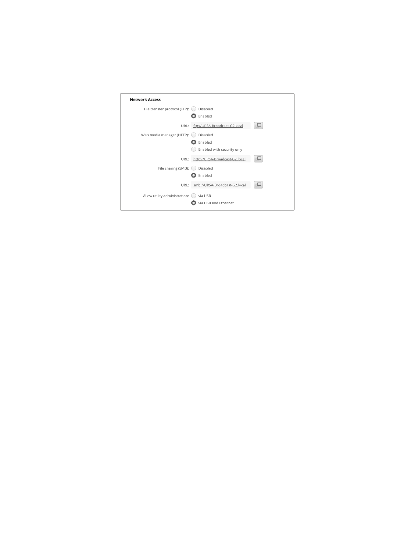
Network Access
Your URSA Broadcast G2 can be accessed via a network for transferring files. Access will be
disabled by default, but you can choose to enable individually or via a username and password
for added security when using the web manager.
File Transfer Protocol
Enable or disable access via FTP using the checkbox. If you are supplying access via an FTP
client such as CyberDuck, click the icon to copy the FTP address. For more information, refer to
the section ‘transferring files over a network’.
File Sharing
At the bottom left corner you will notice a button named ‘Show in Finder’ on a Mac or ‘Show in
Explorer’ on Windows. This button lets you access your media files using your computer’s file
browser. All you need to do is enable ‘file sharing’ and then click on the ‘show in Finder’ button.
You can also copy the URL and paste the file path into your browser.
Your operating system may prompt you to allow access to the drive.
Web Media Manager
Enabling web media manager lets you download clips from your camera’s media storage over
your network, or even delete unwanted clips if you need to free up disk space. When you click
on the link or copy and paste it into your web browser a simple interface will open where you
can access the media.
Enable access via HTTP by selecting the ‘enabled’ checkbox. You can also set up a secure
certificate using the ‘enabled with security only’ option. When using a digital certificate,
connections to web media manager are encrypted via HTTPS. More information on digital
certificates is available in the ‘secure certificate’ section.
REST API also uses HTTP and this means enabling access to media via the web media manager
also enables camera control via REST API.
Allow Utility Administration
Blackmagic Camera Setup can be accessed when your camera is connected via thenetwork or
via USB. To prevent users having access via the network, select ‘via USB’.
279Blackmagic Camera Setup
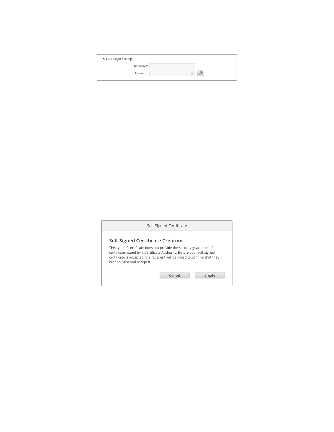
Secure Login Settings
If you have selected ‘enabled with security’ for web media manager access you will need to
enter a username and password. Type a username and password and click ‘save’.
Thepassword field will appear empty once a password is entered. Once a username and
password is set, you will need to enter it when accessing the web media manager.
Secure Certificate
To enable web media manager access via HTTPS, you will require a secure certificate. This
digital certificate acts as an identification card for your URSA Broadcast G2 so that any
incoming connections can confirm they are connecting to the correct unit. Along with
confirming the identity of the unit, using a secure certificate ensures data transmitted between
your camera and a computer or server will be encrypted. When using the secure login settings
the connection will not only be encrypted but require authentication for access.
There are two certificate types you can use with your camera. A secure certificate signed by a
certificate authority, or a self signed certificate. A self signed certificate may be secure enough
for some user workflows, for instance only accessing the camera via a local network.
To generate a self signed certificate click on ‘create certificate’. You will be prompted to confirm
you understand the risks with using a self signed certificate. Once you click on ‘create’, the
certificate details will autofill the ‘domain’, ‘issuer’ and ‘valid until’ fields in the Camera
Setup utility.
Following a factory reset any current certificate will be deleted, but you can also remove it at
any time by clicking on the ‘remove’ button and following the prompts.
When using a self signed certificate to access media files using HTTPS, your web browser will
alert you to the risks of accessing the site. Some browsers will allow you to proceed once you
confirm you understand the risks, however other web browsers may prevent you from
proceeding at all.
280Blackmagic Camera Setup
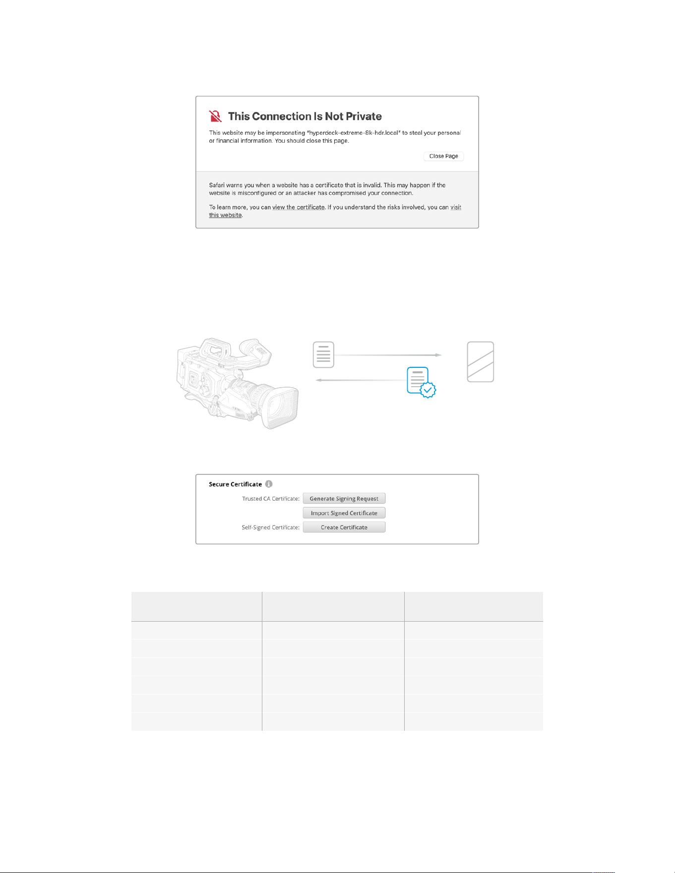
To ensure access is granted to any web browser, you will need to use a signed certificate.
Toobtain a signed certificate, you first need to generate a certificate signing request, or CSR,
using Blackmagic Camera Setup utility. This signing request is then sent to a certificate
authority, also known as a CA, or your IT department to be signed. Once completed, a signed
certificate with a .cert, .crt or .pem file extension will be returned which you can import into
your camera.
U
R
S
A B
r
o
a
d
ca
s
t G2
C
e
r
t
i
f
i
c
a
t
e
A
u
t
h
o
r
i
t
y
L
EN
S
To generate the certificate signing request CSR:
1 Click on the ‘generate signing request’ button.
2 A window will appear prompting you to enter a common name and subject alternative
namefor your camera. Adjust any other details as required using the table below.
Information Description Example
Common Name The domain name you will use studiocamera.melbourne.com
Subject Alternative Name An alternate domain name studiocamera.melbourne.net
Country Country for your organization AU
State Province, region, county or state Victoria
Location Town, city, village etc. name South Melbourne
Organization Name Name of your organization Blackmagic Design
3 Once you have filled in the certificate details, press ‘generate’.
281Blackmagic Camera Setup
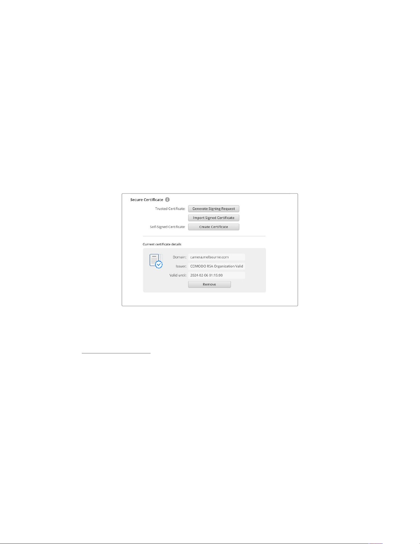
When you generate a .csr you will also be creating a public key and private key at the same
time. The public key will be included with the signing request while the private key will remain
with the unit. Once the CA or IT department have verified the information in the CSR with your
organization, they will generate a signed certificate with the above details along with your
public key.
Once imported, your camera will use the public and private key to confirm the identity of the
camera and to encrypt and decrypt data share via HTTPS.
Importing a signed certificate:
1 Click on ‘import signed certificate’.
2 Navigate to the location of the signed certificate using the file browser and once the file is
selected click on ‘open’.
The domain, issuer and valid until fields will update with the information from your CA.
Generally, a signed certificate will be valid for about a year so the process will need to be
repeated as you reach the expiration date.
Since a domain name was selected, you will need to speak to your IT department about
resolving the DNS entry for your URSA Broadcast G2. This will point all traffic for the IP address
of the camera to the selected domain address in the signing request. Thiswill also be the
HTTPS address you use to access files via the web media manager, for example
https://camera.melbourne
It’s worth noting that the certificate will be invalidated following a factory reset and a new
certificate will need to be generated and signed.
Reset
Select ‘factory reset’ to restore your camera to factory settings. A factory reset will invalidate
thecurrent certificate. If a secure certificate is being used you will need to generate a new
certificate signing request to be signed by a certificate authority or IT department.
282Blackmagic Camera Setup
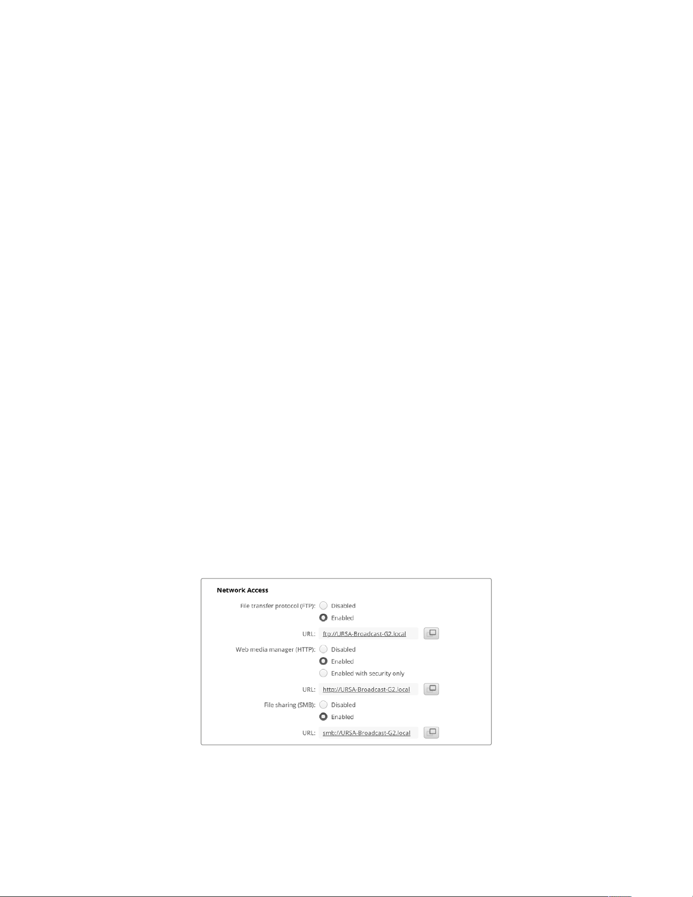
Transferring Files over a Network
When connected to a network via a USB-C to Ethernet adapter, Blackmagic URSA BroadcastG2
can transfer files using the following protocols.
HTTP
Hypertext transfer protocol.
HTTPS
Hypertext transfer protocol secure.
FTP
File transfer protocol.
SMB
Server message block.
These protocol options let you copy files directly from your camera’s storage media to your
computer via a network with the fast speeds a local network can provide. For example, you can
copy clips and start editing them as soon as you have finished recording.
Access to your URSA Broadcast G2 via any of these protocols can be enabled or disabled via
the Camera Setup utility. For example, you could disable FTP access and enable HTTPS access
at the same time.
Connecting to your Camera via HTTPS
To access your camera via the web media manager you will need the URL available via the
network access settings. Network access settings appear in Camera Setup utility when your
computer is connected via USB or Ethernet but are disabled when only Ethernet is connected.
1 Using a USB-C cable, connect your computer to Blackmagic URSA Broadcast G2 via the
USB port on the left panel and open Camera Setup. You should see a USB connection icon
next to the unit name. Click on the circular icon or anywhere on the product image to open
the settings.
2 When using a self signed certificate, navigate to the network access settings and click on
the copy icon beside the URL. This URL is based on the name of your camera. To modify
the URL, modify the name of the unit.
When using a self signed certificate, click on the link
283Transferring Files over a Network
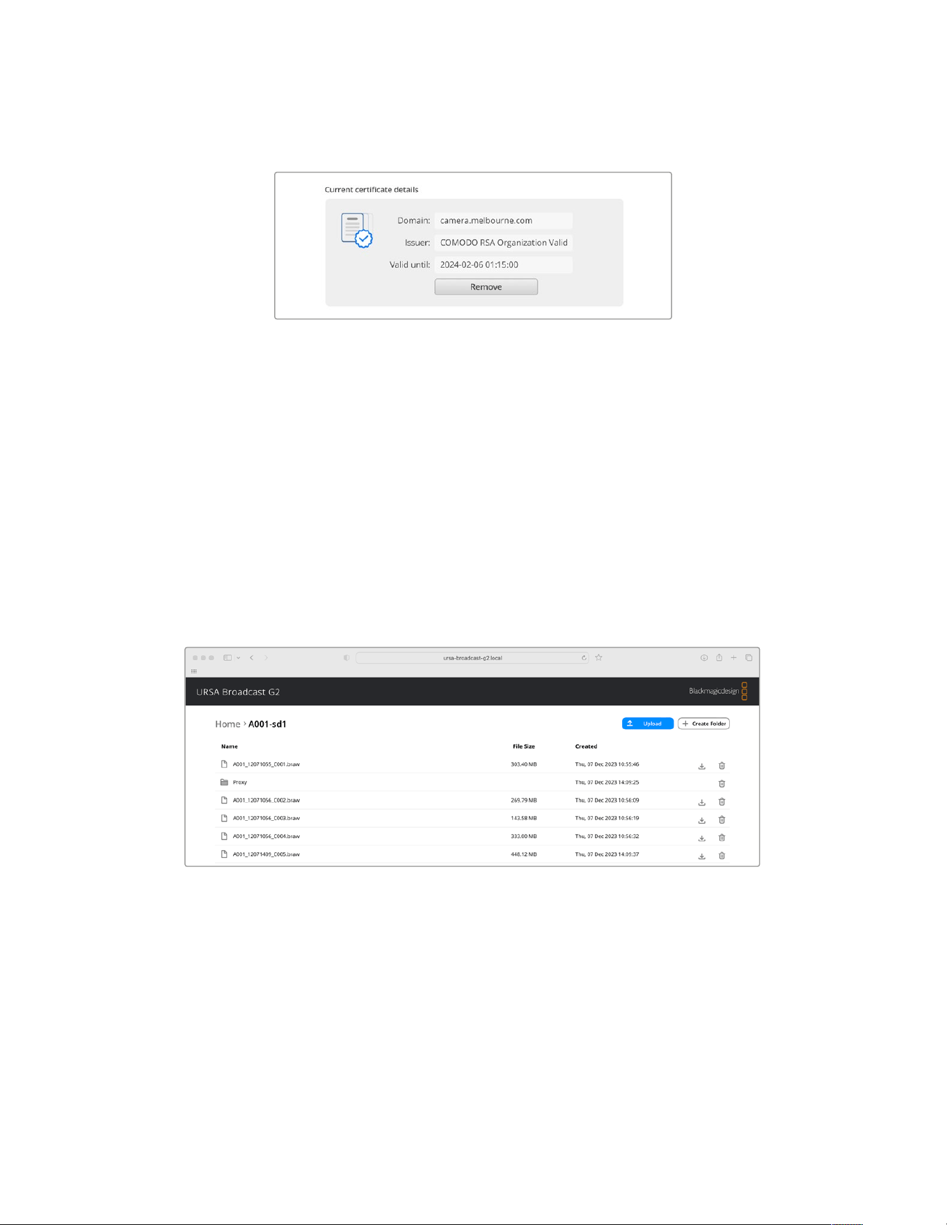
3 If you have imported a certificate signed by a CA or IT department, copy and paste the
address in the domain field for the current certificate.
Copy the domain address and paste into a browser
4 Open your web browser and paste the address into a new window. If you have enabled
access with security only you will be prompted to enter the username and password set in
Camera Setup.
When using a self signed certificate, a browser warning will appear regarding the privacy of the
connection. This means a trusted signed certificate has not been imported via the Camera
Setup utility
To continue without a valid and trusted certificate, follow your browser prompts to acknowledge
the risks and proceed to the website.
Transferring Files Using Web Media Manager
When you first open the web media manager browser view you will see a list of the storage
media connected to your camera.
Double click a media folder to reveal the contents.
Click the download button to download files or the trash icon to delete them
To download files, use the arrow icon on the far right. Your browser may prompt you to allow
downloads from the site. Click on ‘allow’. To delete a file, click the trash can icon and a delete
file window will appear. Click ‘delete’ to proceed.
284Transferring Files over a Network
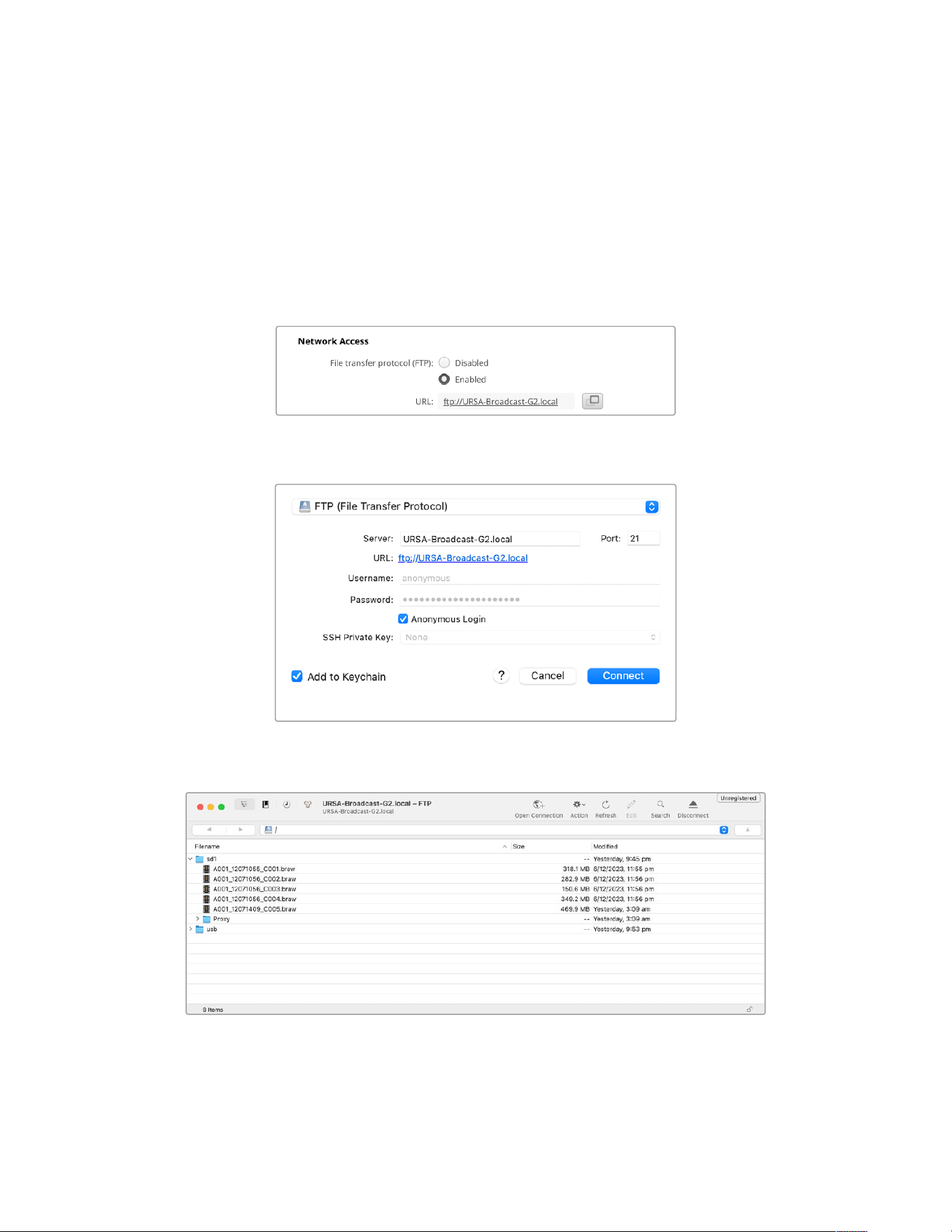
Transferring Files via FTP
With your computer and Blackmagic URSA Broadcast G2 on the same network, all you need is
an ftpclient and your camera’s IP address or the FTP URL in the Camera Setup utility.
1 Download and install an FTP client on the computer you want to connect your camerato.
Werecommend Cyberduck, FileZilla or Transmit but most FTPapplications will work.
Cyberduck and FileZilla are free downloads.
2 With your Blackmagic URSA Broadcast G2 connected to your network, open Camera Setup
and click on URL or press the copy icon to paste it manually. You may need to click the link
a second time if the FTP program doesn’t open a connection.
3 If you are manually opening an FTP connection, paste the URL into the client’s server field.
Check ‘anonymous login’ if available.
4 Expand a media storage folder from the list to view your recorded clips. You can now drag
and drop files using the FTP interface.
285Transferring Files over a Network
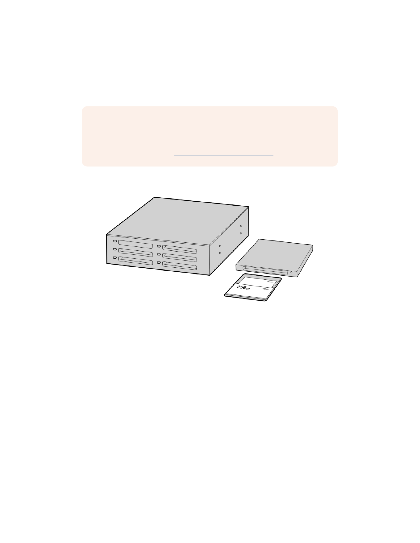
Working with Third Party Software
To edit your clips using your favorite editing software, you can copy your clips to an internal or
external drive or RAID and then import your clips into the software. Or import your clips directly
from your storage media using a dock or adapter for your CFast or SD card or SSD.
NOTE Blackmagic RAW is supported on URSA Broadcast G2 with DaVinci Resolve
16.1.2 and later and has also been adopted by a wide range of third party post-
production editing programs. Plugins for editing Blackmagic RAW in Avid Media
Composer and Adobe Premiere Pro are available with Blackmagic RAW software,
which you can download from www.blackmagicdesign.com/support.
Working with Files from CFast2.0 and SD cards
Edit directly from your CFast card by removing it from your camera and mounting
it on your computer using a CFast 2.0 reader/writer or CFast drive
To import your clips from a CFast 2.0 or SD card:
1 Remove the CFast card or SD card your Blackmagic URSA Broadcast G2.
Mount the card to your Mac or Windows computer using a card reader.
2 Navigate to the card on your operating system to open it and you will see your list of
Blackmagic RAW or QuickTime movie files.
3 Now you can simply drag the files you want from the card onto your desktop or another
hard drive, or you can access the files straight from the card using your editing software.
4 Before you unplug the CFast or SD card from your computer, it is important to always
eject your CFast or SD card from either Mac OS or Windows. Removing your card without
ejecting can corrupt footage in some cases.
286Working with Third Party Software
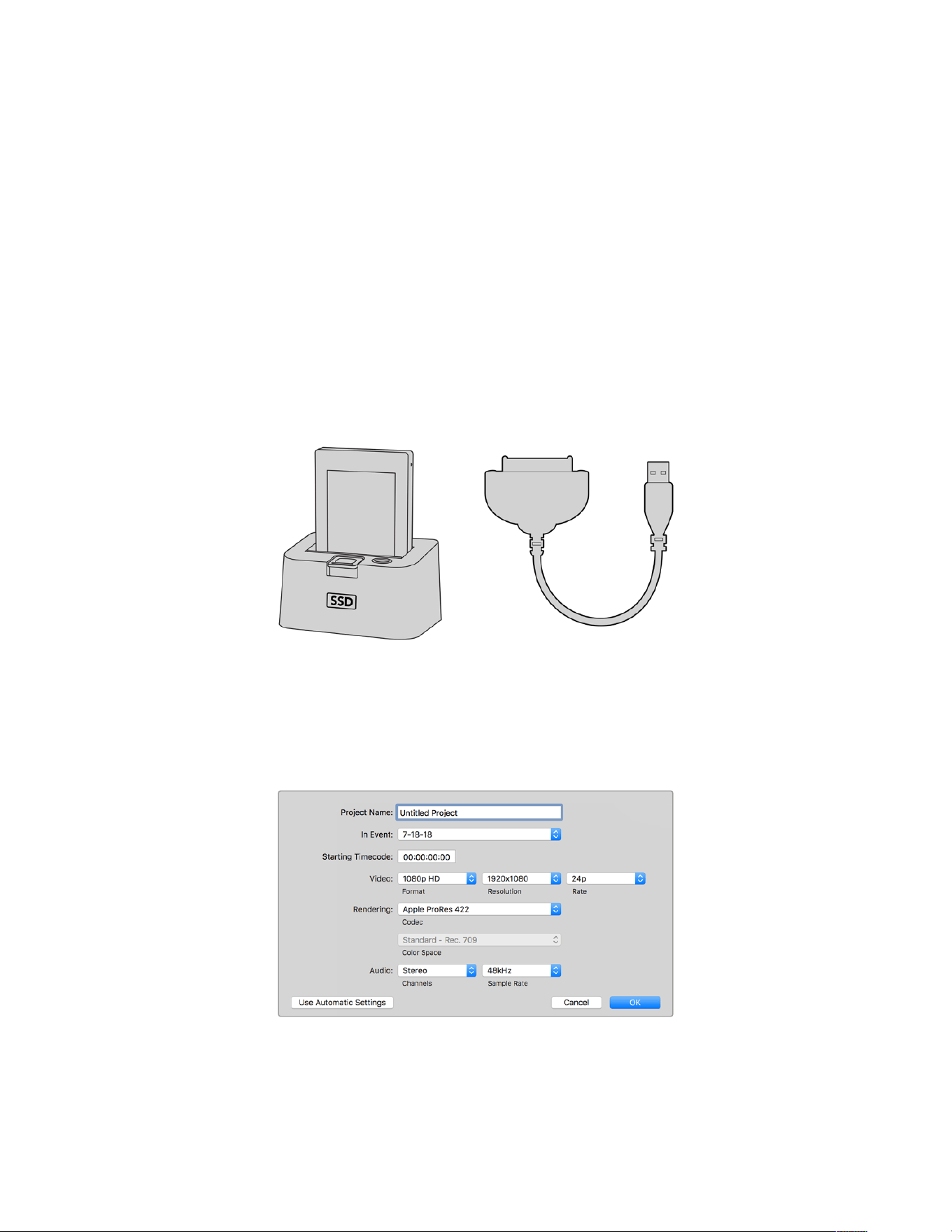
Working with Files from SSDs
To import your clips from a SSD:
1 Remove the SSD from URSA Mini Recorder.
2 You can mount the SSD to your Mac or Windows computer using either an eSATA or
Thunderbolt dock, for example Blackmagic MultiDock. You can also use an eSATA to
USB adapter cable to plug the SSD straight into a USB port on your computer. USB 3.0 is
preferable as USB 2.0 is not fast enough to edit video in real time.
3 Double click on the SSD to open it and you should see a list of QuickTime movie files or
Blackmagic RAW files. Depending on the format you chose to record in, you might have a
mixture of files, but they will all use the same naming convention.
4 Now you can simply drag the files you want from the SSD onto your desktop or another
hard drive, or you can access the files straight from the SSD using your NLE software.
5 Before you unplug the SSD from your computer, it is important to eject the SSD safely from
your computer first.
Edit directly from the SSD by removing it from your camera and mounting it on
your computer using an eSATA Thunderbolt dock or USB 3.0 docking cable.
Using Final Cut Pro X
To edit your clips using Final Cut Pro X, create a new project and set a suitable video format
andframe rate. This example uses ProRes 422 HQ 1080p24.
Final Cut Pro X project settings
287Working with Third Party Software
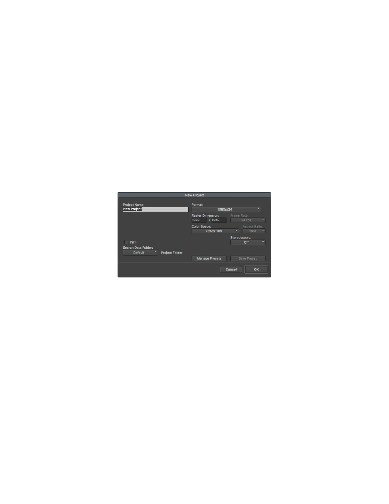
1 Launch Final Cut Pro X, go to the ‘menu’ bar and select ‘file/new project’.
A window will open containing project settings.
2 Name your project and select the ‘custom’ checkbox.
3 Set the ‘video properties’ settings to 1080p HD, 1920x1080 and 24p.
4 Set your ‘audio’ and ‘render properties’ settings to ‘stereo, 48kHz, and Apple
ProRes 422 HQ’
5 Click OK.
To import your clips into your project, go to the ‘menu’ bar and select ‘file/import/media’.
Choose your clips from your CFast card.
You can now drag your clips onto the timeline for editing.
Using Avid Media Composer 2018
To edit your clips using Avid Media Composer 2018, create a new project and set a suitable
video format and frame rate. For this example, clips are set using 1080p24.
Setting the project name and project options in Avid Media Composer 2018
1 Launch Avid Media Composer 2018 and the ‘select project’ window will appear.
2 Click the ‘new project’ button and name your project in the ‘new project’ window.
3 In the ‘format’ drop down menu select HD 1080 > 1080p/24 and click ‘ok’ to create
the project.
4 Double click the project in the ‘select project’ window to open it.
5 Select file > input > source browser and navigate to the files you wish to import.
6 Select your ‘target bin’ from the drop down menu and click ‘import’.
When the clips appear within the media bin you can drag your clips onto the timeline and
begin editing.
288Working with Third Party Software
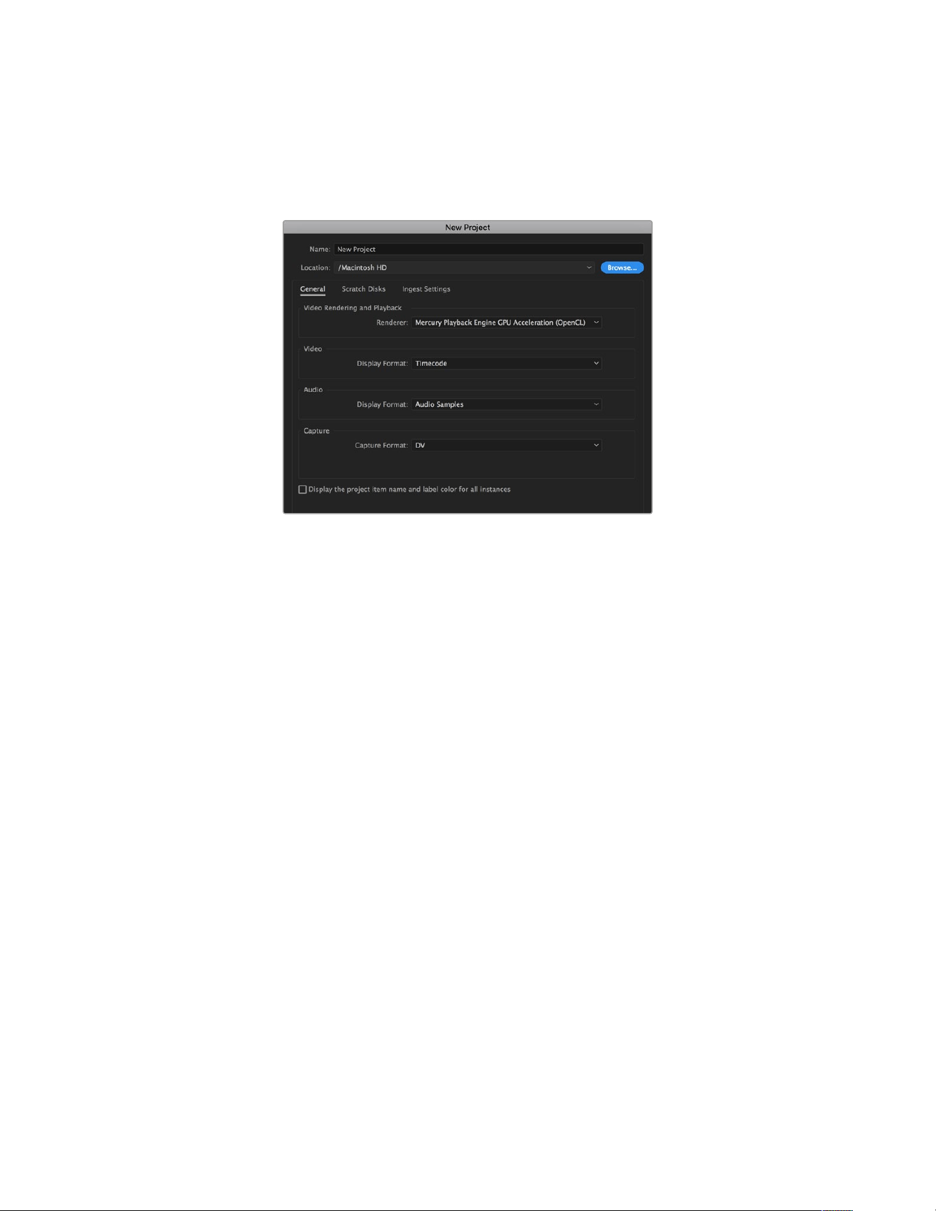
Using Adobe Premiere Pro CC
To edit your Apple ProRes 422 HQ clips using Adobe Premiere Pro CC, create a new project
and set a suitable video format and frame rate. For this example, clips are set using ProRes 422
HQ 1080p25.
Setting the project name and project options in Adobe Premiere Pro CC
1 Launch Adobe Premiere Pro CC. In the ‘welcome’ window select ‘new project’. Awindow
will open containing project settings.
2 Name your project. Choose the location for your project by clicking ‘browse’ and selecting
your desired folder. Once you’ve selected your location folder click OK in the ‘new
project’ window.
3 Go to the Adobe Premiere Pro CC ‘menu’ bar, select ‘file/import’ and choose the clips you
want to edit. Your clips will appear in the project window.
4 Drag the first clip you wish to edit onto the ‘new item’ icon at the bottom right of the project
window. A new sequence will be created matching your clip settings.
You can now drag your clips onto the sequence timeline for editing.
289Working with Third Party Software
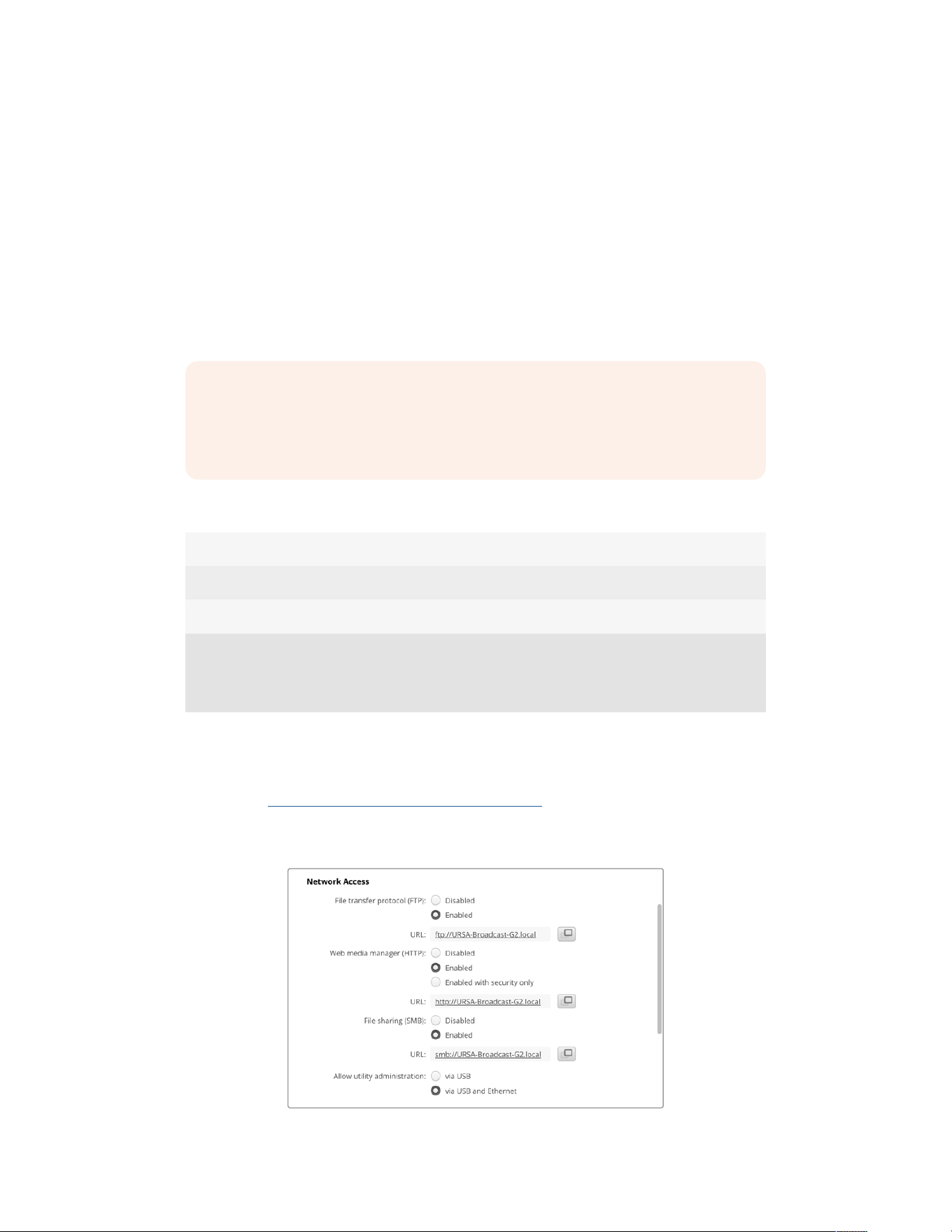
Developer Information
Camera Control REST API
If you are a software developer you can build custom applications or leverage ready to use
tools such as REST client or Postman to seamlessly control and interact with your compatible
Blackmagic camera using Camera Control REST API. This API enables you to perform a wide
range of operations, such as starting or stopping recordings, accessing disk information and
much more. Whether you’re developing a custom application tailored to your specific needs or
utilizing existing tools, this API empowers you to unlock the full potential of your Blackmagic
camera with ease. We look forward to seeing what you come up with!
NOTE It’s important to mention that controlling Blackmagic cameras via REST API
relies on the web manager being enabled on each compatible Blackmagic camera.
Enable the web media manager in the Blackmagic Camera Setup ‘network access’
settings for each camera you are controlling.
The following Blackmagic cameras are compatible with Camera Control REST API:
Blackmagic Cinema Camera 6K
Blackmagic URSA Broadcast G2
Blackmagic Micro Studio Camera 4K G2
Blackmagic Studio Camera 4K Plus
Blackmagic Studio Camera 4K Pro
Blackmagic Studio Camera 6K Pro
Blackmagic Studio Camera 4K Plus G2
Blackmagic Studio Camera 4K Pro G2
Sending API Commands
To send an API command to your camera from a third party application such as Postman,
add /control/api/v1/ to the end of the camera’s Web media manager URL or IP address.
For example, https://ursa-broadcast-g2.local/control/api/v1/
You can find the Web media manager URL and IP address information in Blackmagic
Camera Setup.
The Web media manager URL in Blackmagic Camera Setup
290Developer Information
Downloading API’s from your Camera
You can download REST API YAML documentation from your camera by adding /control/
documentation.html to the end of the camera’s Web media manager URL or IP
address. For example, https://ursa-broadcast-g2.local/control/documentation.html
NOTE It’s worth noting that changing the camera name in Blackmagic Camera Setup
will also change the camera’s Web media manager URL.
Event Control API
API For working with built-in websocket.
GET /event/list
Get the list of events that can be subscribed to using the websocket API.
Response
200 - OK
The response is a JSON object.
Name Type Description
events array
events[i] string
List of events that can be subscribed to using the
websocket API
System Control API
API for controlling the System Modes on Blackmagic Design products.
GET /system
Get device system information.
Response
200 - OK
The response is a JSON object.
Name Type Description
codecFormat object
codecFormat.codec string Currently selected codec
codecFormat.container string Multimedia container format
videoFormat object
videoFormat.name string Video format serialised as a string
videoFormat.frameRate string
Frame rate Possible values are: 23.98, 24.00, 24, 25.00,
25, 29.97, 30.00, 30, 47.95, 48.00, 48, 50.00, 50, 59.94,
60.00, 60, 119.88, 120.00, 120.
videoFormat.height number Height dimension of video format
videoFormat.width number Width dimension of video format
videoFormat.interlaced boolean Is the display format interlaced?
501 - This functionality is not implemented for the device in use.
291Developer Information
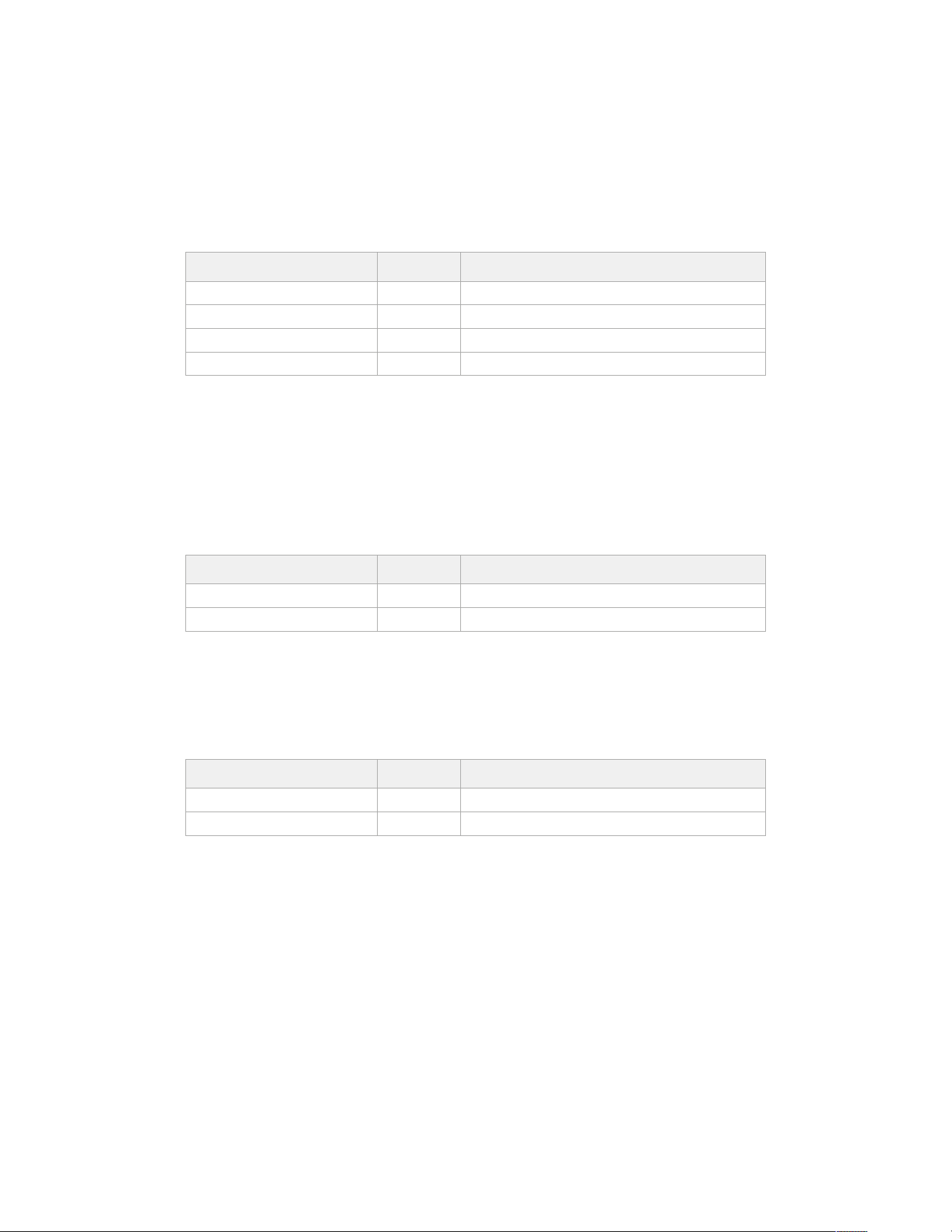
GET /system/supportedCodecFormats
Get the list of supported codecs.
Response
200 - OK
The response is a JSON object.
Name Type Description
codecs array
codecs[i] object
codecs[i].codec string Currently selected codec
codecs[i].container string Multimedia container format
501 - This functionality is not implemented for the device in use.
GET /system/codecFormat
Get the currently selected codec.
Response
200 - OK
The response is a JSON object.
Name Type Description
codec string Currently selected codec
container string Multimedia container format
501 - This functionality is not implemented for the device in use.
PUT /system/codecFormat
Set the codec.
Parameters
Name Type Description
codec string Currently selected codec
container string Multimedia container format
Response
204 - No Content
501 - This functionality is not implemented for the device in use.
292Developer Information
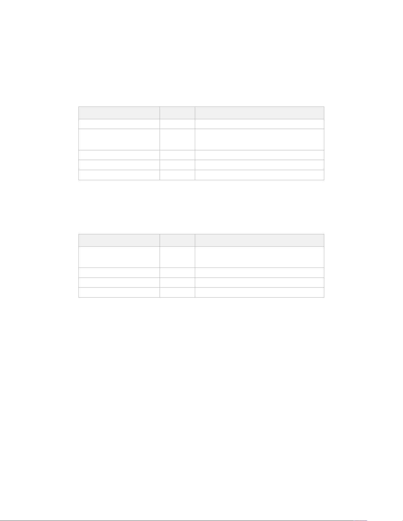
GET /system/videoFormat
Get the currently selected video format.
Response
200 - OK
The response is a JSON object.
Name Type Description
name string Video format serialised as a string
frameRate string
Frame rate Possible values are: 23.98, 24.00, 24, 25.00,
25, 29.97, 30.00, 30, 47.95, 48.00, 48, 50.00, 50, 59.94,
60.00, 60, 119.88, 120.00, 120.
height number Height dimension of video format
width number Width dimension of video format
interlaced boolean Is the display format interlaced?
501 - This functionality is not implemented for the device in use.
PUT /system/videoFormat
Set the video format.
Parameters
Name Type Description
frameRate string
Frame rate Possible values are: 23.98, 24.00, 24, 25.00,
25, 29.97, 30.00, 30, 47.95, 48.00, 48, 50.00, 50, 59.94,
60.00, 60, 119.88, 120.00, 120.
height number Height dimension of video format
width number Width dimension of video format
interlaced boolean Is the display format interlaced?
Response
204 - No Content
501 - This functionality is not implemented for the device in use.
293Developer Information
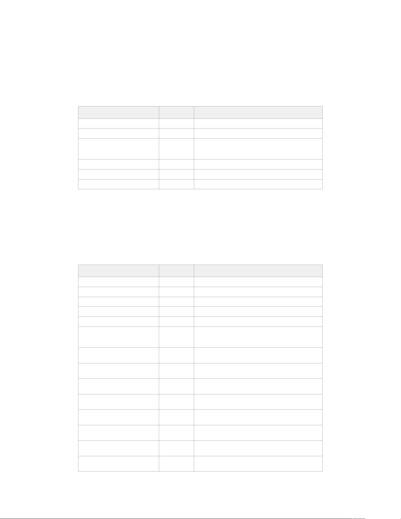
GET /system/supportedVideoFormats
Get the list of supported video formats for the current system state.
Response
200 - OK
The response is a JSON object.
Name Type Description
formats array
formats[i] object
formats[i].frameRate string
Frame rate Possible values are: 23.98, 24.00, 24, 25.00,
25, 29.97, 30.00, 30, 47.95, 48.00, 48, 50.00, 50, 59.94,
60.00, 60, 119.88, 120.00, 120.
formats[i].height number Height dimension of video format
formats[i].width number Width dimension of video format
formats[i].interlaced boolean Is the display format interlaced?
501 - This functionality is not implemented for the device in use.
GET /system/supportedFormats
Get supported formats.
Response
200 - OK
The response is a JSON object.
Name Type Description
supportedFormats array
supportedFormats[i] object
supportedFormats[i].codecs array
supportedFormats[i].codecs[i] string
supportedFormats[i].frameRates array
supportedFormats[i].frameRates[i] string
Possible values are: 23.98, 24.00, 24, 25.00, 25, 29.97,
30.00, 30, 47.95, 48.00, 48, 50.00, 50, 59.94, 60.00, 60,
119.88, 120.00, 120.
supportedFormats[i].
maxOffSpeedFrameRate
number
supportedFormats[i].
minOffSpeedFrameRate
number
supportedFormats[i].
recordResolution
object
supportedFormats[i].
recordResolution.height
number Height of the resolution
supportedFormats[i].
recordResolution.width
number Width of the resolution
supportedFormats[i].
sensorResolution
object
supportedFormats[i].
sensorResolution.height
number Height of the resolution
supportedFormats[i].
sensorResolution.width
number Width of the resolution
501 - This functionality is not implemented for the device in use.
294Developer Information
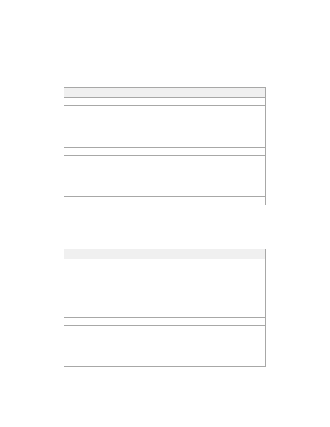
GET /system/format
Get current format.
Response
200 - OK
The response is a JSON object.
Name Type Description
codec string Currently selected codec
frameRate string
Frame rate Possible values are: 23.98, 24.00, 24, 25.00,
25, 29.97, 30.00, 30, 47.95, 48.00, 48, 50.00, 50, 59.94,
60.00, 60, 119.88, 120.00, 120.
maxOffSpeedFrameRate number
minOffSpeedFrameRate number
offSpeedEnabled boolean
offSpeedFrameRate number
recordResolution object
recordResolution.height number Height of the resolution
recordResolution.width number Width of the resolution
sensorResolution object
sensorResolution.height number Height of the resolution
sensorResolution.width number Width of the resolution
501 - This functionality is not implemented for the device in use.
PUT /system/format
Set the format.
Parameters
Name Type Description
codec string Currently selected codec
frameRate string
Frame rate Possible values are: 23.98, 24.00, 24, 25.00,
25, 29.97, 30.00, 30, 47.95, 48.00, 48, 50.00, 50, 59.94,
60.00, 60, 119.88, 120.00, 120.
maxOffSpeedFrameRate number
minOffSpeedFrameRate number
offSpeedEnabled boolean
offSpeedFrameRate number
recordResolution object
recordResolution.height number Height of the resolution
recordResolution.width number Width of the resolution
sensorResolution object
sensorResolution.height number Height of the resolution
sensorResolution.width number Width of the resolution
Response
204 - No Content
501 - This functionality is not implemented for the device in use.
295Developer Information
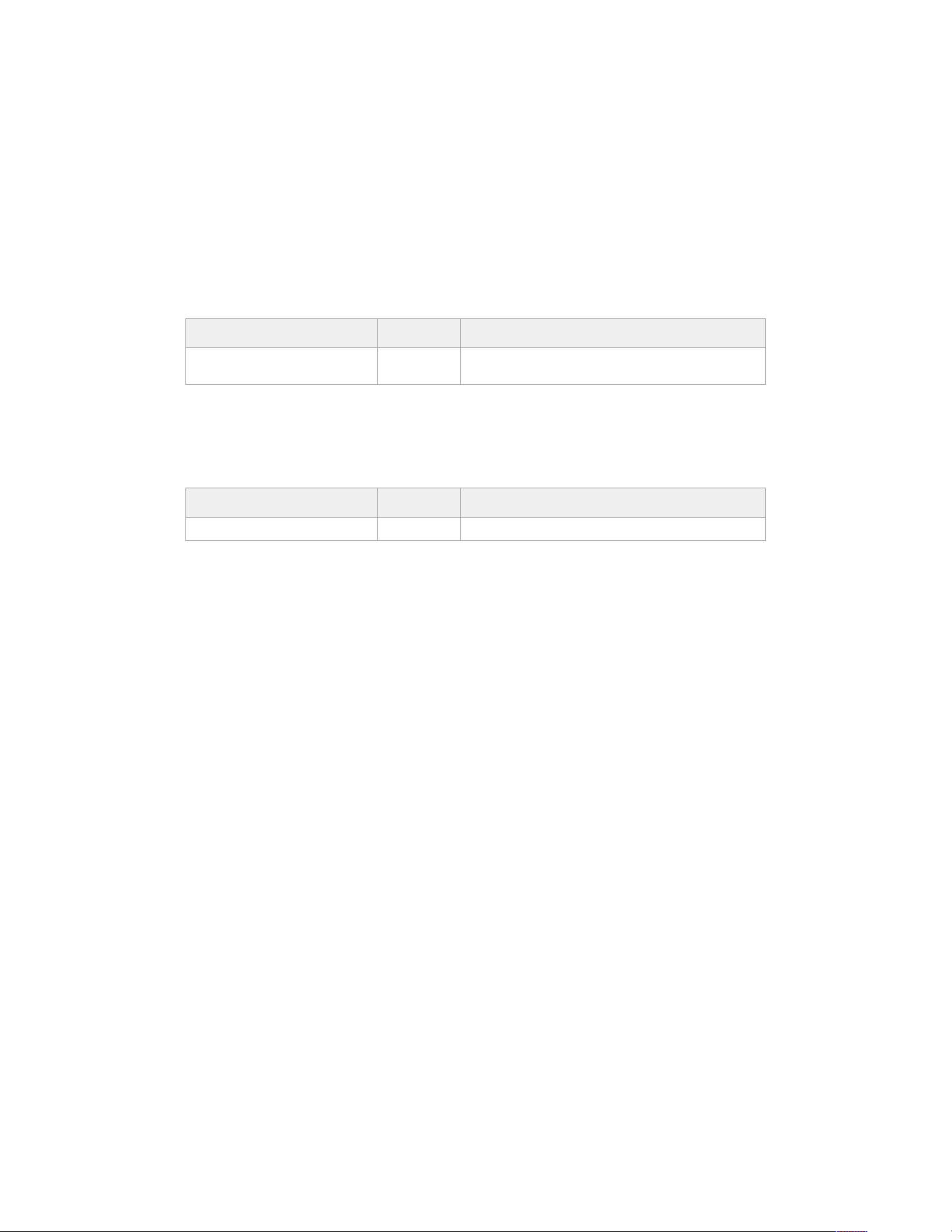
Transport Control API
API for controlling Transport on Blackmagic Design products.
GET /transports/0
Get device’s basic transport status.
Response
200 - OK
The response is a JSON object.
Name Type Description
mode string
Transport mode. Possible values are: InputPreview,
InputRecord, Output.
PUT /transports/0
Set device’s basic transport status.
Parameters
Name Type Description
mode string Transport mode. Possible values are: InputPreview, Output.
Response
204 - No Content
GET /transports/0/stop
Determine if transport is stopped.
Response
200 - OK
The response is a JSON object.
PUT /transports/0/stop
Stop transport.
Response
204 - No Content
GET /transports/0/play
Determine if transport is playing.
Response
200 - OK
The response is a JSON object.
PUT /transports/0/play
Start playing on transport.
Response
204 - No Content
296Developer Information
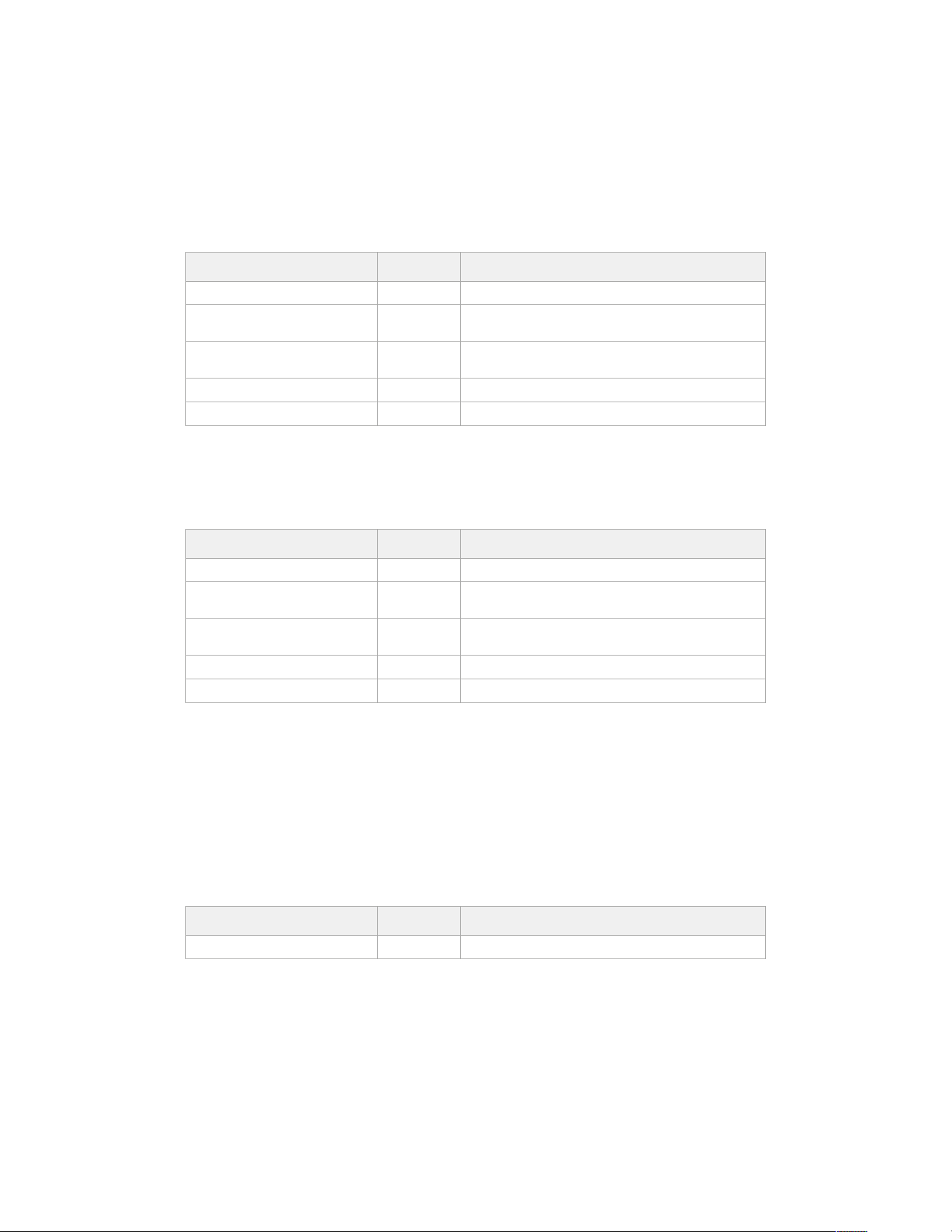
GET /transports/0/playback
Get playback state.
Response
200 - OK
The response is a JSON object.
Name Type Description
type string Possible values are: Play, Jog, Shuttle, Var.
loop boolean
When true playback loops from the end of the timeline to
the beginning of the timeline
singleClip boolean
When true playback loops from the end of the current clip
to the beginning of the current clip
speed number Playback Speed, 1.0 for normal forward playback
position integer Playback position on the timeline in units of video frames
PUT /transports/0/playback
Set playback state.
Parameters
Name Type Description
type string Possible values are: Play, Jog, Shuttle, Var.
loop boolean
When true playback loops from the end of the timeline to
the beginning of the timeline
singleClip boolean
When true playback loops from the end of the current clip
to the beginning of the current clip
speed number Playback Speed, 1.0 for normal forward playback
position integer Playback position on the timeline in units of video frames
Response
204 - No Content
GET /transports/0/record
Get record state.
Response
200 - OK
The response is a JSON object.
Name Type Description
recording boolean Is transport in Input Record mode
297Developer Information
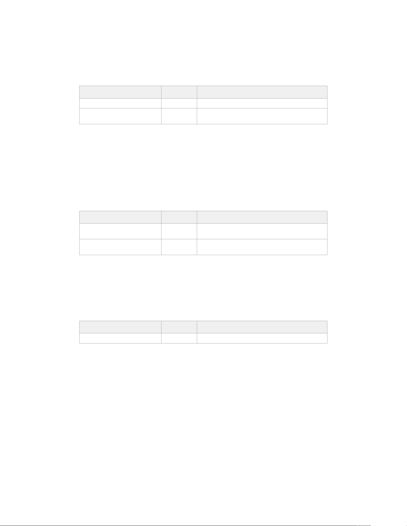
PUT /transports/0/record
Set record state.
Parameters
Name Type Description
recording boolean Is transport in Input Record mode
clipName string
Used to set the requested clipName to record to, when
specifying “recording” attribute to True
Response
204 - No Content
GET /transports/0/timecode
Get device’s timecode.
Response
200 - OK
The response is a JSON object.
Name Type Description
timecode number
The time of day timecode in units of binary-coded decimal
(BCD).
clip number
The position of the clip timecode in units of binary-coded
decimal (BCD).
GET /transports/0/timecode/source
Get timecode source selected on device
Response
200 - OK
The response is a JSON object.
Name Type Description
timecode string Possible values are: Timecode, Clip.
298Developer Information
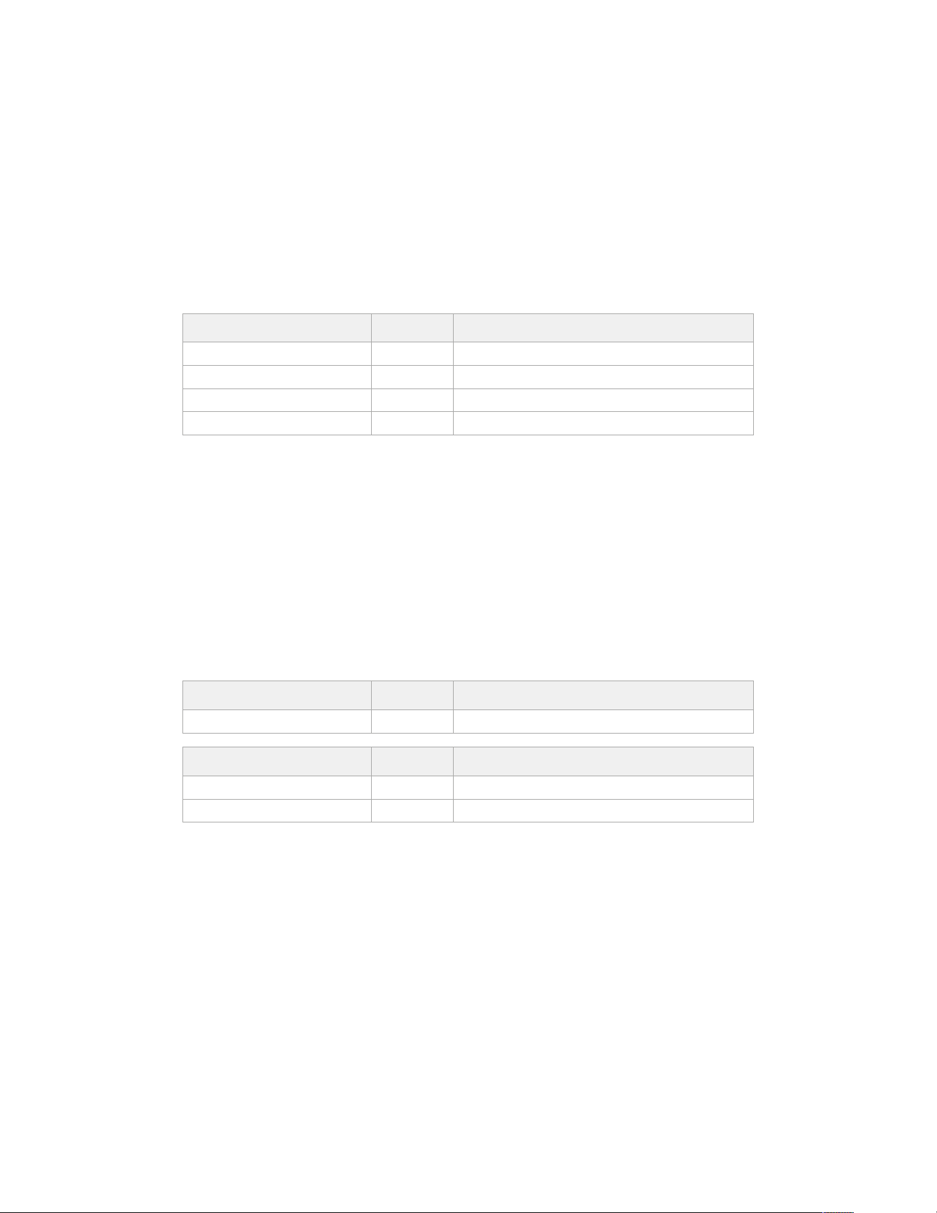
Timeline Control API
API for controlling playback timeline.
GET /timelines/0
Get the current playback timeline.
Response
200 - OK
The response is a JSON object.
Name Type Description
clips array
clips[i] object
clips[i].clipUniqueId integer Unique ID used to identify this clip
clips[i].frameCount integer Number of frames in this clip on the timeline
DELETE /timelines/0
Clear the current playback timeline.
Response
204 - No Content
POST /timelines/0/add
Add a clip to the end of the timeline.
Parameters
This parameter can be one of the following types:
Name Type Description
clips integer Unique ID used to identify this clip
Name Type Description
clips array
clips[i] integer Unique ID used to identify this clip
Response
204 - No Content
299Developer Information
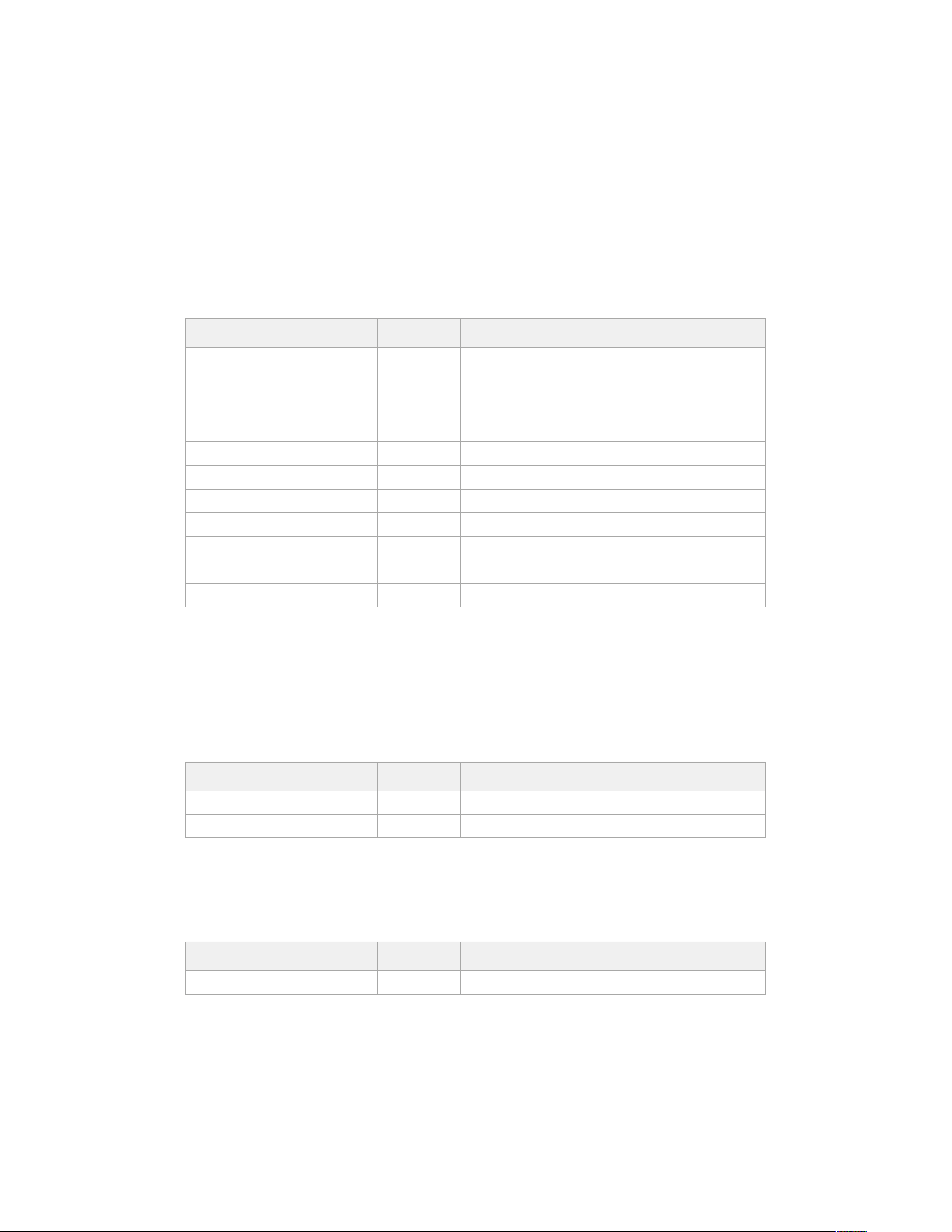
Media Control API
API for controlling media devices in Blackmagic Design products.
GET /media/workingset
Get the list of media devices currently in the working set.
Response
200 - OK
The response is a JSON object.
Name Type Description
size integer The fixed size of this device’s working set
workingset (required) array
workingset[i] object
workingset[i].index integer Index of this media in the working set
workingset[i].activeDisk boolean Is this current item the active disk
workingset[i].volume string Volume name
workingset[i].deviceName string Internal device name of this media device
workingset[i].remainingRecordTime integer Remaining record time on media device in seconds
workingset[i].totalSpace integer Total space on media device in bytes
workingset[i].remainingSpace integer Remaining space on media device in bytes
workingset[i].clipCount integer Number of clips currently on the device
GET /media/active
Get the currently active media device.
Response
200 - OK
The response is a JSON object.
Name Type Description
workingsetIndex integer Working set index of the active media device
deviceName string Internal device name of this media device
PUT /media/active
Set the currently active media device.
Parameters
Name Type Description
workingsetIndex integer Working set index of the media to become active
Response
204 - No Content
300Developer Information
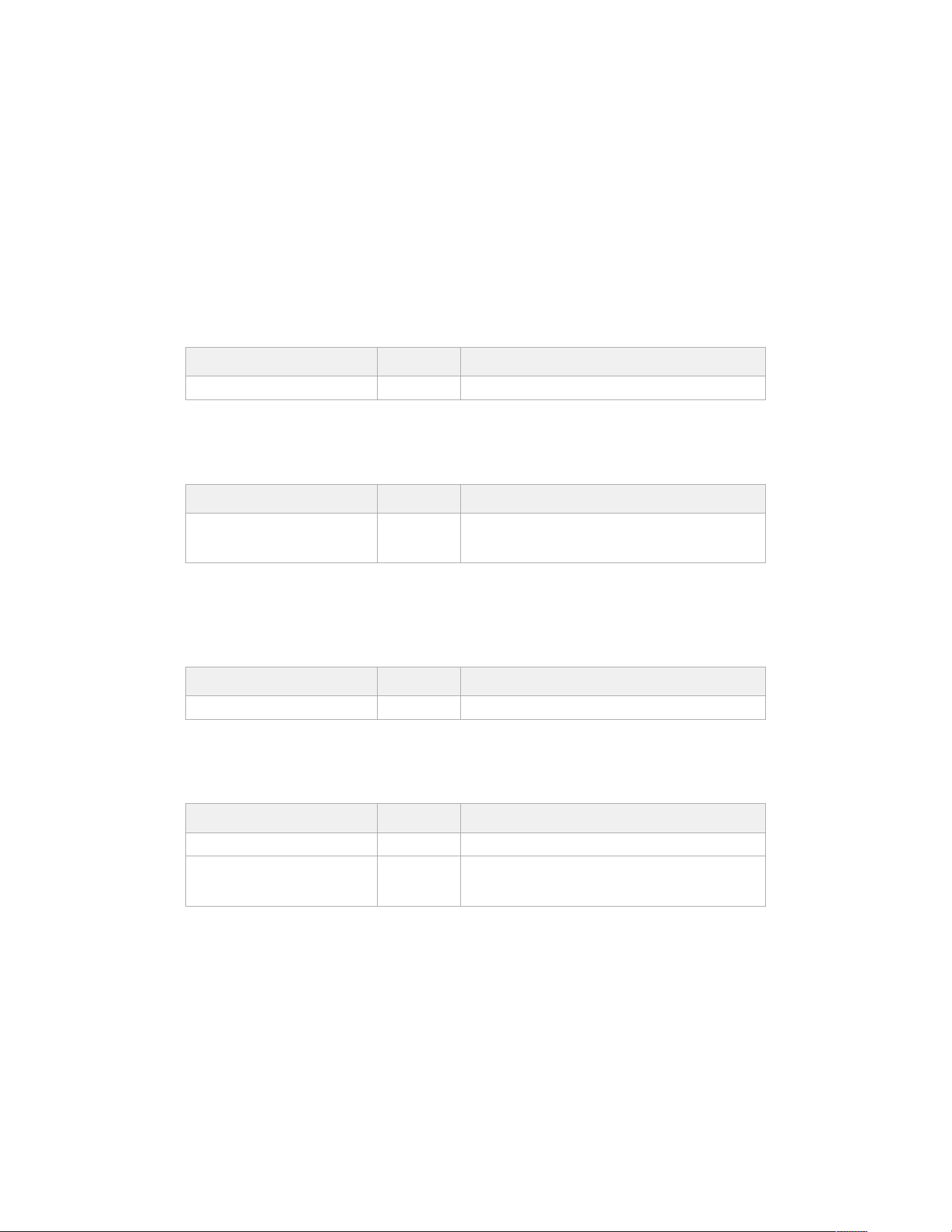
GET /media/devices/doformatSupportedFilesystems
Get the list of filesystems available to format the device.
Response
200 - OK
The response is a JSON object.
GET /media/devices/{deviceName}
Get information about the selected device.
Parameters
Name Type Description
{deviceName} string
Response
200 - OK
The response is a JSON object.
Name Type Description
state string
The current state of the media device. Possible values are:
None, Scanning, Mounted, Uninitialised, Formatting,
RaidComponent.
GET /media/devices/{deviceName}/doformat
Get a format key, used to format the device with a put request.
Parameters
Name Type Description
{deviceName} string
Response
200 - OK
The response is a JSON object.
Name Type Description
deviceName string Internal device name of this media device
key string
The key used to format this device, it must be fetched with
the GET request and then provided back with a PUT
request
301Developer Information
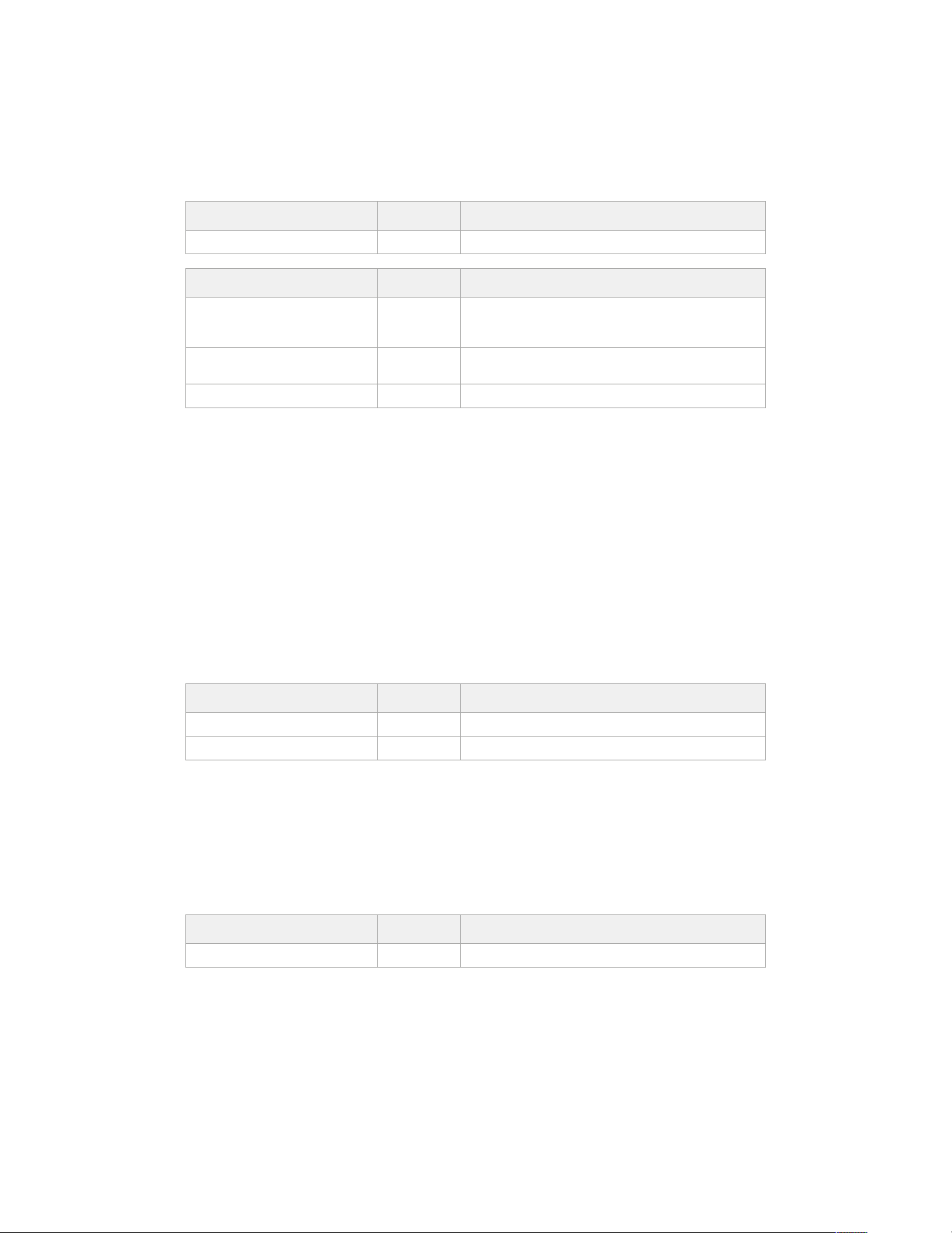
PUT /media/devices/{deviceName}/doformat
Perform a format of the media device.
Parameters
Name Type Description
{deviceName} string
Name Type Description
key string
The key used to format this device, it must be fetched with
the GET request and then provided back with a PUT
request
filesystem string
Filesystem to format to (supportedFilesystems returns list
of supported fileSystems)
volume string Volume name to set for the disk after format
Response
204 - No Content
Preset Control API
API For controlling the presets on Blackmagic Design products
GET /presets
Get the list of the presets on the camera
Response
200 - OK
The response is a JSON object.
Name Type Description
presets array List of the presets on the camera
presets[i] string
POST /presets
Send a preset file to the camera
Response
200 - OK
The response is a JSON object.
Name Type Description
presetAdded string Name of the preset uploaded
302Developer Information
GET /presets/active
Get the list of the presets on the camera
Response
200 - OK
The response is a JSON object.
Name Type Description
preset string
PUT /presets/active
Set the active preset on the camera
Parameters
Name Type Description
preset string
Response
200 - OK
The response is a JSON object.
GET /presets/{presetName}
Download the preset file
Parameters
Name Type Description
{presetName} string
Response
200 - OK
The response is a binary file.
PUT /presets/{presetName}
Update a preset on the camera if it exists, if not create a preset and save current state with the
presetName
Parameters
Name Type Description
{presetName} string
Response
200 - OK
The response is a JSON object.
303Developer Information
DELETE /presets/{presetName}
Delete a preset from a camera if exists
Parameters
Name Type Description
{presetName} string
Response
200 - OK
The response is a JSON object.
Audio Control API
API For controlling audio on Blackmagic Design Cameras
GET /audio/channel/{channelIndex}/input
Get the audio input (source and type) for the selected channel
Parameters
Name Type Description
{channelIndex} integer
Response
200 - Currently selected input
The response is a JSON object.
Name Type Description
input string
Possible values are: None, Camera - Left, Camera - Right,
Camera - Mono, XLR1 - Mic, XLR1 - Line, XLR2 - Mic, XLR2
- Line, 3.5mm Left - Line, 3.5mm Left - Mic, 3.5mm Right -
Line, 3.5mm Right - Mic, 3.5mm Mono - Line, 3.5mm Mono
- Mic.
404 - Channel does not exist
PUT /audio/channel/{channelIndex}/input
Set the audio input for the selected channel
Parameters
Name Type Description
{channelIndex} integer
Name Type Description
input string
Possible values are: None, Camera - Left, Camera - Right,
Camera - Mono, XLR1 - Mic, XLR1 - Line, XLR2 - Mic, XLR2
- Line, 3.5mm Left - Line, 3.5mm Left - Mic, 3.5mm Right -
Line, 3.5mm Right - Mic, 3.5mm Mono - Line, 3.5mm Mono
- Mic.
Response
200 - OK
400 - Invalid input
404 - Channel does not exist
304Developer Information
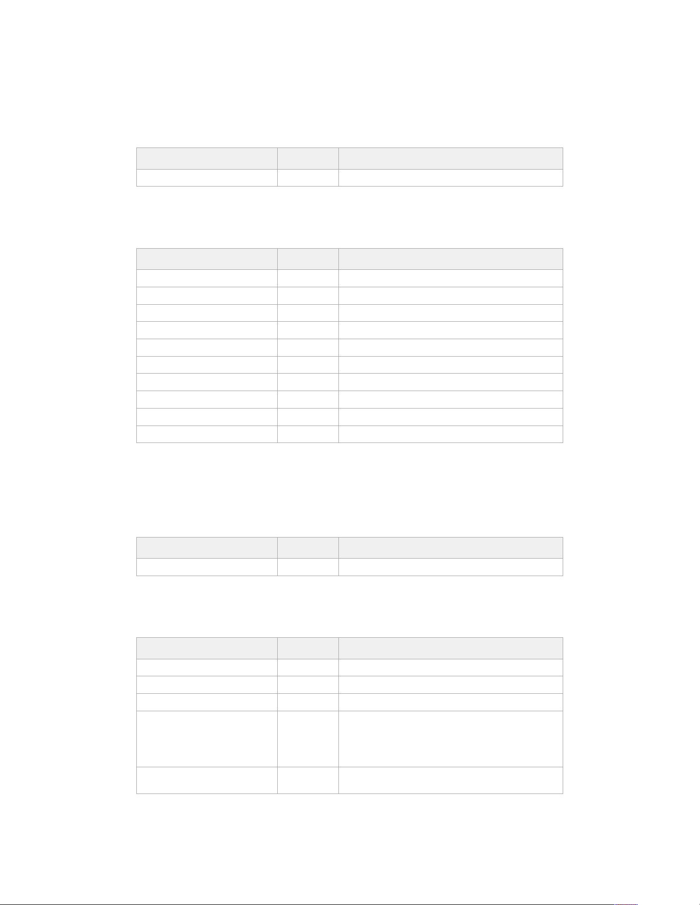
GET /audio/channel/{channelIndex}/input/description
Get the description of the current input of the selected channel
Parameters
Name Type Description
{channelIndex} integer
Response
200 - Description of the current input of the selected channel
The response is a JSON object.
Name Type Description
gainRange object
gainRange.Min number The minimum gain value in dB
gainRange.Max number The maximum gain value in dB
capabilities object
capabilities.PhantomPower boolean Input supports setting of phantom power
capabilities.LowCutFilter boolean Input supports setting of low cut filter
capabilities.Padding object
capabilities.Padding.available boolean Input supports setting of padding
capabilities.Padding.forced boolean Padding is forced to be set for the input
capabilities.Padding.value number Value of the padding in dB
404 - Channel does not exist
GET /audio/channel/{channelIndex}/supportedInputs
Get the list of supported inputs and their availability to switch to for the selected channel
Parameters
Name Type Description
{channelIndex} integer
Response
200 - The list of supported inputs
The response is a JSON object.
Name Type Description
supportedInputs array
supportedInputs[i] object
supportedInputs[i].schema object
supportedInputs[i].schema.input string
Possible values are: None, Camera - Left, Camera - Right,
Camera - Mono, XLR1 - Mic, XLR1 - Line, XLR2 - Mic, XLR2
- Line, 3.5mm Left - Line, 3.5mm Left - Mic, 3.5mm Right -
Line, 3.5mm Right - Mic, 3.5mm Mono - Line, 3.5mm Mono
- Mic.
supportedInputs[i].available boolean
Is the input available to be switched into from the current
input for the selected channel
404 - Channel does not exist
305Developer Information
GET /audio/channel/{channelIndex}/level
Get the audio input level for the selected channel
Parameters
Name Type Description
{channelIndex} integer
Response
200 - Currently set level for the selected channel
The response is a JSON object.
Name Type Description
gain number
normalised number
404 - Channel does not exist
PUT /audio/channel/{channelIndex}/level
Set the audio input level for the selected channel
Parameters
Name Type Description
{channelIndex} integer
Name Type Description
gain number
normalised number
Response
200 - OK
400 - Invalid input
404 - Channel does not exist
GET /audio/channel/{channelIndex}/phantomPower
Get the audio input phantom power for the selected channel if possible
Parameters
Name Type Description
{channelIndex} integer
Response
200 - Currently set level for the selected channel
The response is a JSON object.
Name Type Description
phantomPower boolean
404 - Channel does not exist
306Developer Information
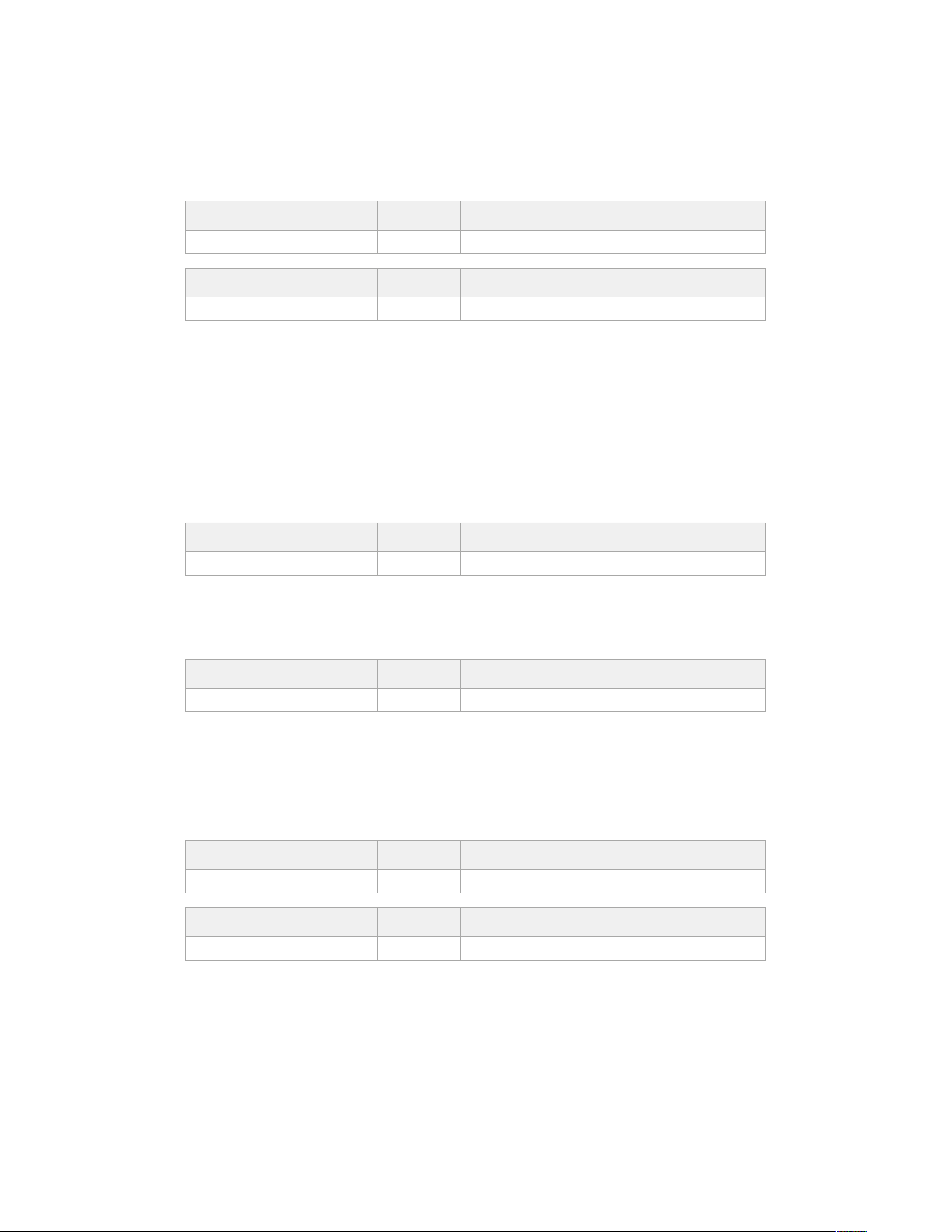
PUT /audio/channel/{channelIndex}/phantomPower
Set the audio phantom power for the selected channel
Parameters
Name Type Description
{channelIndex} integer
Name Type Description
phantomPower boolean
Response
200 - OK
400 - Phantom power is not supported for this input
404 - Channel does not exist
GET /audio/channel/{channelIndex}/padding
Get the audio input padding for the selected channel
Parameters
Name Type Description
{channelIndex} integer
Response
200 - Currently set padding for the selected channel
The response is a JSON object.
Name Type Description
padding boolean
404 - Channel does not exist
PUT /audio/channel/{channelIndex}/padding
Set the audio input padding for the selected channel
Parameters
Name Type Description
{channelIndex} integer
Name Type Description
padding boolean
Response
200 - OK
400 - Padding is not supported for this input
404 - Channel does not exist
307Developer Information
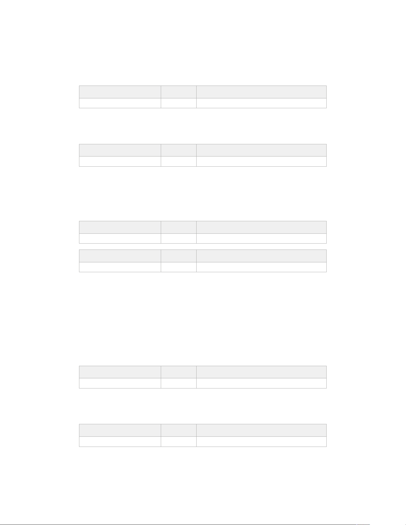
GET /audio/channel/{channelIndex}/lowCutFilter
Get the audio input low cut filter for the selected channel
Parameters
Name Type Description
{channelIndex} integer
Response
200 - Currently set low cut filter for the selected channel
The response is a JSON object.
Name Type Description
lowCutFilter boolean
404 - Channel does not exist
PUT /audio/channel/{channelIndex}/lowCutFilter
Set the audio input low cut filter for the selected channel
Parameters
Name Type Description
{channelIndex} integer
Name Type Description
lowCutFilter boolean
Response
200 - OK
400 - Low cut filter is not supported for this input
404 - Channel does not exist
GET /audio/channel/{channelIndex}/available
Get the audio input’s current availability for the selected channel. If unavailable, the source
will be muted
Parameters
Name Type Description
{channelIndex} integer
Response
200 - Currently set availability for the selected channel
The response is a JSON object.
Name Type Description
available boolean
404 - Channel does not exist
308Developer Information
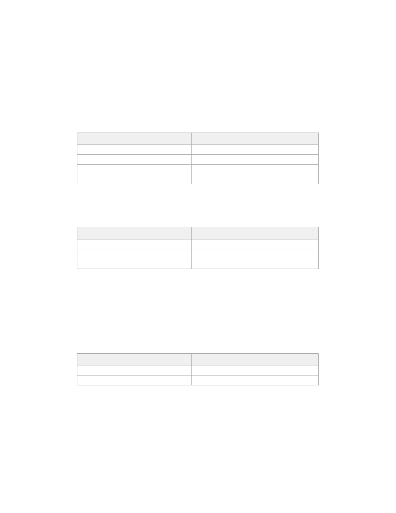
Lens Control API
API For controlling the lens on Blackmagic Design products
GET /lens/iris
Get lens’ aperture
Response
200 - OK
The response is a JSON object.
Name Type Description
continuousApertureAutoExposure boolean Is Aperture controlled by auto exposure
apertureStop number Aperture stop value
normalised number Normalised value
apertureNumber number Aperture number
PUT /lens/iris
Set lens’ aperture
Parameters
Name Type Description
apertureStop number Aperture stop value
normalised number Normalised value
apertureNumber number Aperture number
Response
200 - OK
GET /lens/zoom
Get lens’ zoom
Response
200 - OK
The response is a JSON object.
Name Type Description
focalLength integer Focal length in mm
normalised number Normalised value
309Developer Information
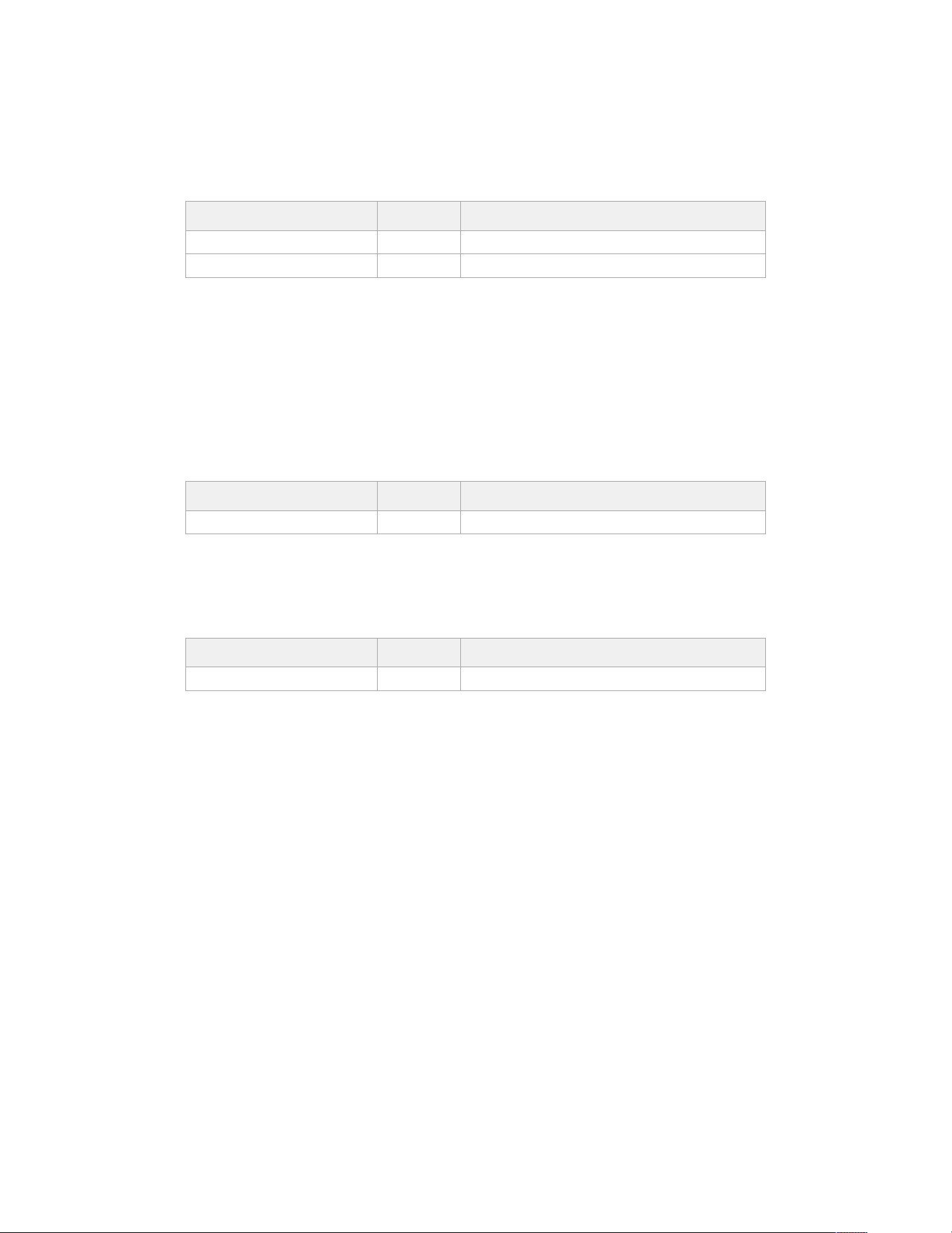
PUT /lens/zoom
Set lens’ zoom
Parameters
Name Type Description
focalLength integer Focal length in mm
normalised number Normalised value
Response
200 - OK
GET /lens/focus
Get lens’ focus
Response
200 - OK
The response is a JSON object.
Name Type Description
focus number Normalised value
PUT /lens/focus
Set lens’ focus
Parameters
Name Type Description
focus number Normalised value
Response
200 - OK
PUT /lens/focus/doAutoFocus
Perform auto focus
Response
200 - OK
310Developer Information
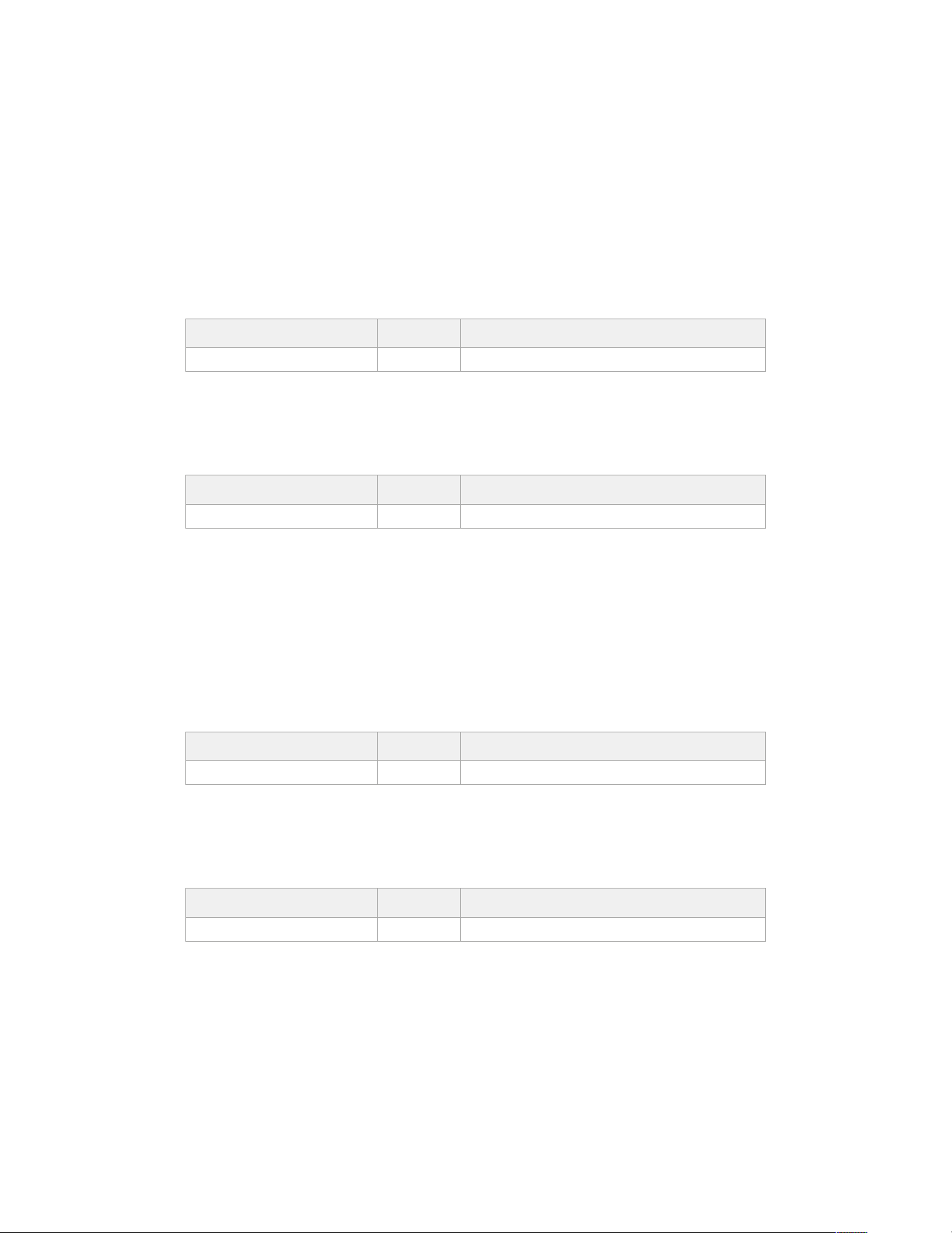
Video Control API
API For controlling the video on Blackmagic Design products
GET /video/iso
Get current ISO
Response
200 - OK
The response is a JSON object.
Name Type Description
iso integer Current ISO value
PUT /video/iso
Set current ISO
Parameters
Name Type Description
iso integer ISO value to set
Response
200 - OK
GET /video/gain
Get current gain value in decibels
Response
200 - OK
The response is a JSON object.
Name Type Description
gain integer Current gain value in decibels
PUT /video/gain
Set current gain value
Parameters
Name Type Description
gain integer Gain value in decibels to set
Response
200 - OK
311Developer Information
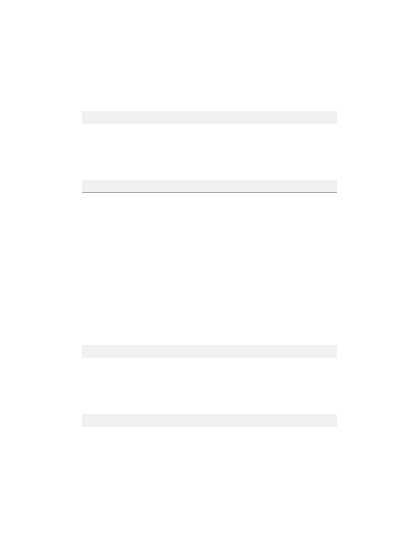
GET /video/whiteBalance
Get current white balance
Response
200 - OK
The response is a JSON object.
Name Type Description
whiteBalance integer Current white balance
PUT /video/whiteBalance
Set current white balance
Parameters
Name Type Description
whiteBalance integer White balance to set
Response
200 - OK
PUT /video/whiteBalance/doAuto
Set current white balance automatically
Response
200 - OK
GET /video/whiteBalanceTint
Get white balance tint
Response
200 - OK
The response is a JSON object.
Name Type Description
whiteBalanceTint integer Current white balance tint
PUT /video/whiteBalanceTint
Set white balance tint
Parameters
Name Type Description
whiteBalanceTint integer White balance tint to set
Response
200 - OK
312Developer Information
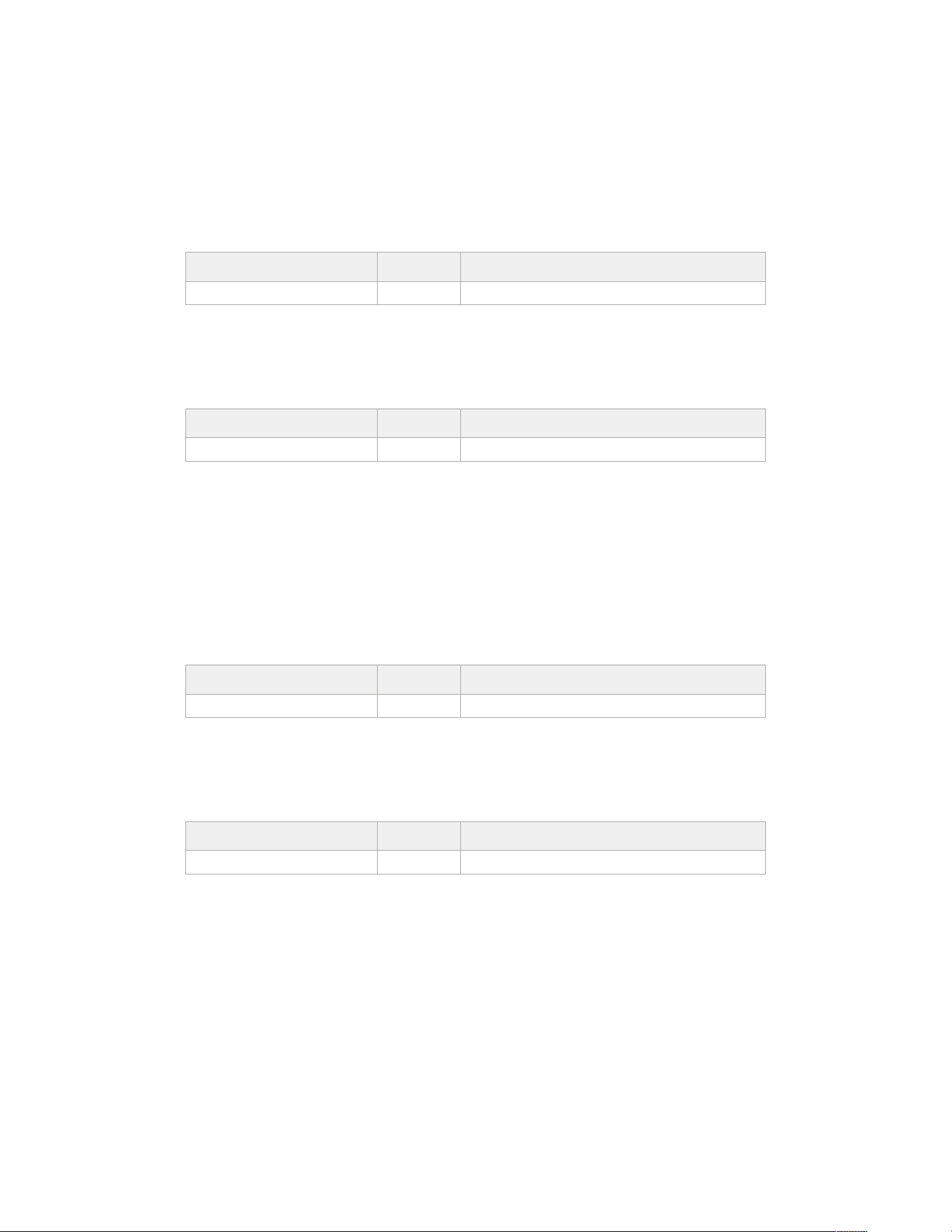
GET /video/ndFilter
Get ND filter stop
Response
200 - OK
The response is a JSON object.
Name Type Description
stop number Current filter power (fStop)
PUT /video/ndFilter
Set ND filter stop
Parameters
Name Type Description
stop number Filter power (fStop) to set
Response
200 - OK
GET /video/ndFilter/displayMode
Get ND filter display mode on the camera
Response
200 - OK
The response is a JSON object.
Name Type Description
displayMode string Possible values are: Stop, Number, Fraction.
PUT /video/ndFilter/displayMode
Set ND filter display mode on the camera
Parameters
Name Type Description
displayMode string Possible values are: Stop, Number, Fraction.
Response
200 - OK
313Developer Information
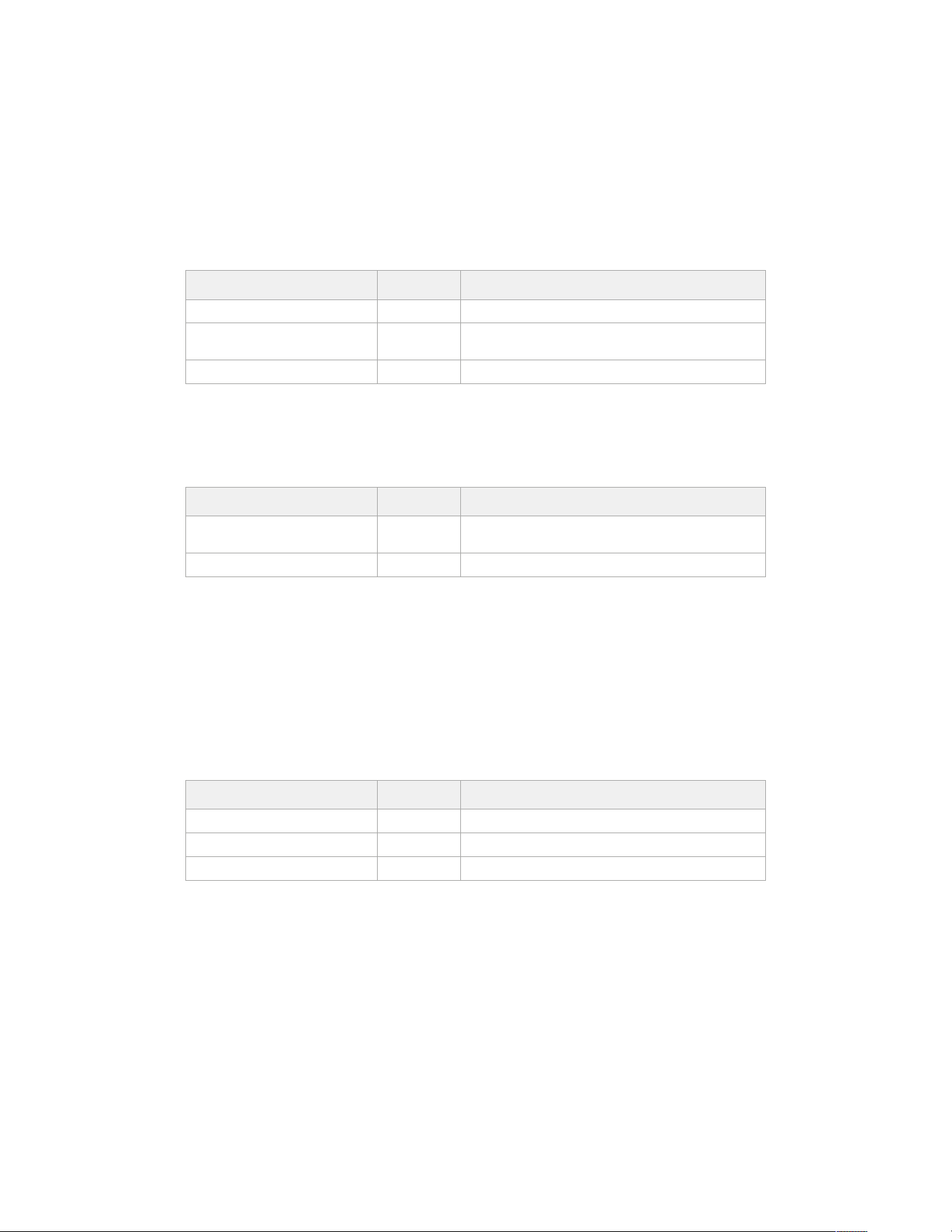
GET /video/shutter
Get current shutter. Will return either shutter speed or shutter angle depending on shutter
measurement in device settings
Response
200 - OK
The response is a JSON object.
Name Type Description
continuousShutterAutoExposure boolean Is shutter controlled by auto exposure
shutterSpeed integer
Shutter speed value in fractions of a second (minimum is
sensor frame rate)
shutterAngle integer Shutter angle
PUT /video/shutter
Set current shutter
Parameters
Name Type Description
shutterSpeed integer
Shutter speed value in fractions of a second (minimum is
sensor frame rate)
shutterAngle integer Shutter angle
Response
200 - OK
GET /video/autoExposure
Get current auto exposure mode
Response
200 - OK
The response is a JSON object.
Name Type Description
mode object Auto exposure mode
mode.mode string Possible values are: Off, Continuous, OneShot.
mode.type string Possible values are: , Iris, Shutter, Iris,Shutter, Shutter,Iris.
314Developer Information
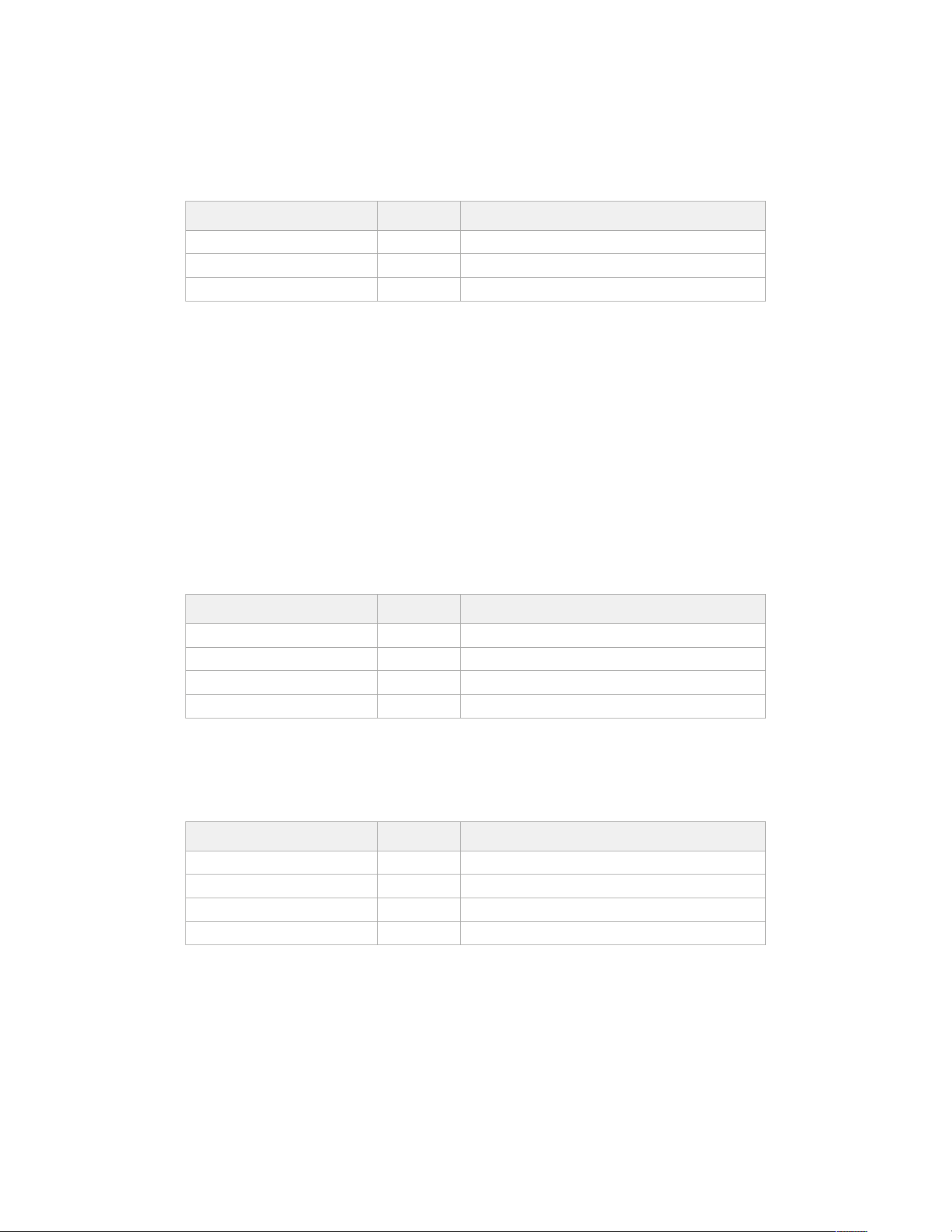
PUT /video/autoExposure
Set auto exposure
Parameters
Name Type Description
mode object Auto exposure mode
mode.mode string Possible values are: Off, Continuous, OneShot.
mode.type string Possible values are: , Iris, Shutter, Iris,Shutter, Shutter,Iris.
Response
200 - OK
Color Correction Control API
API For controlling the color correction on Blackmagic Design products based on DaVinci
Resolve Color Corrector
GET /colorCorrection/lift
Get color correction lift
Response
200 - OK
The response is a JSON object.
Name Type Description
red number
green number
blue number
luma number
PUT /colorCorrection/lift
Set color correction lift
Parameters
Name Type Description
red number
green number
blue number
luma number
Response
200 - OK
315Developer Information
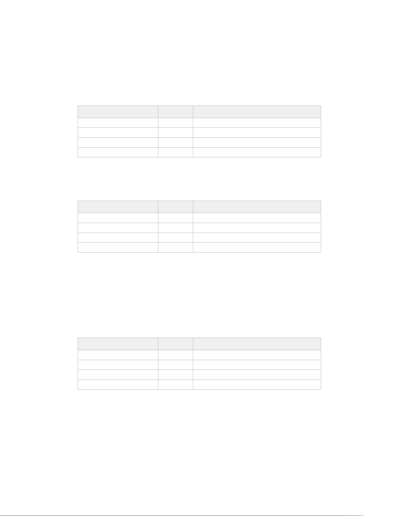
GET /colorCorrection/gamma
Get color correction gamma
Response
200 - OK
The response is a JSON object.
Name Type Description
red number
green number
blue number
luma number
PUT /colorCorrection/gamma
Set color correction gamma
Parameters
Name Type Description
red number
green number
blue number
luma number
Response
200 - OK
GET /colorCorrection/gain
Get color correction gain
Response
200 - OK
The response is a JSON object.
Name Type Description
red number
green number
blue number
luma number
316Developer Information
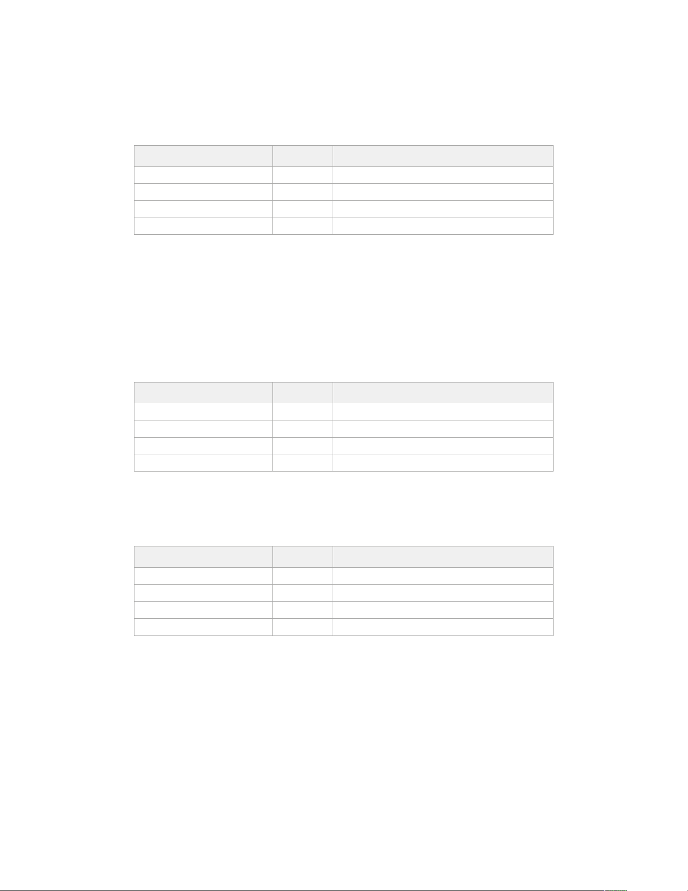
PUT /colorCorrection/gain
Set color correction gain
Parameters
Name Type Description
red number
green number
blue number
luma number
Response
200 - OK
GET /colorCorrection/oset
Get color correction offset
Response
200 - OK
The response is a JSON object.
Name Type Description
red number
green number
blue number
luma number
PUT /colorCorrection/oset
Set color correction offset
Parameters
Name Type Description
red number
green number
blue number
luma number
Response
200 - OK
317Developer Information
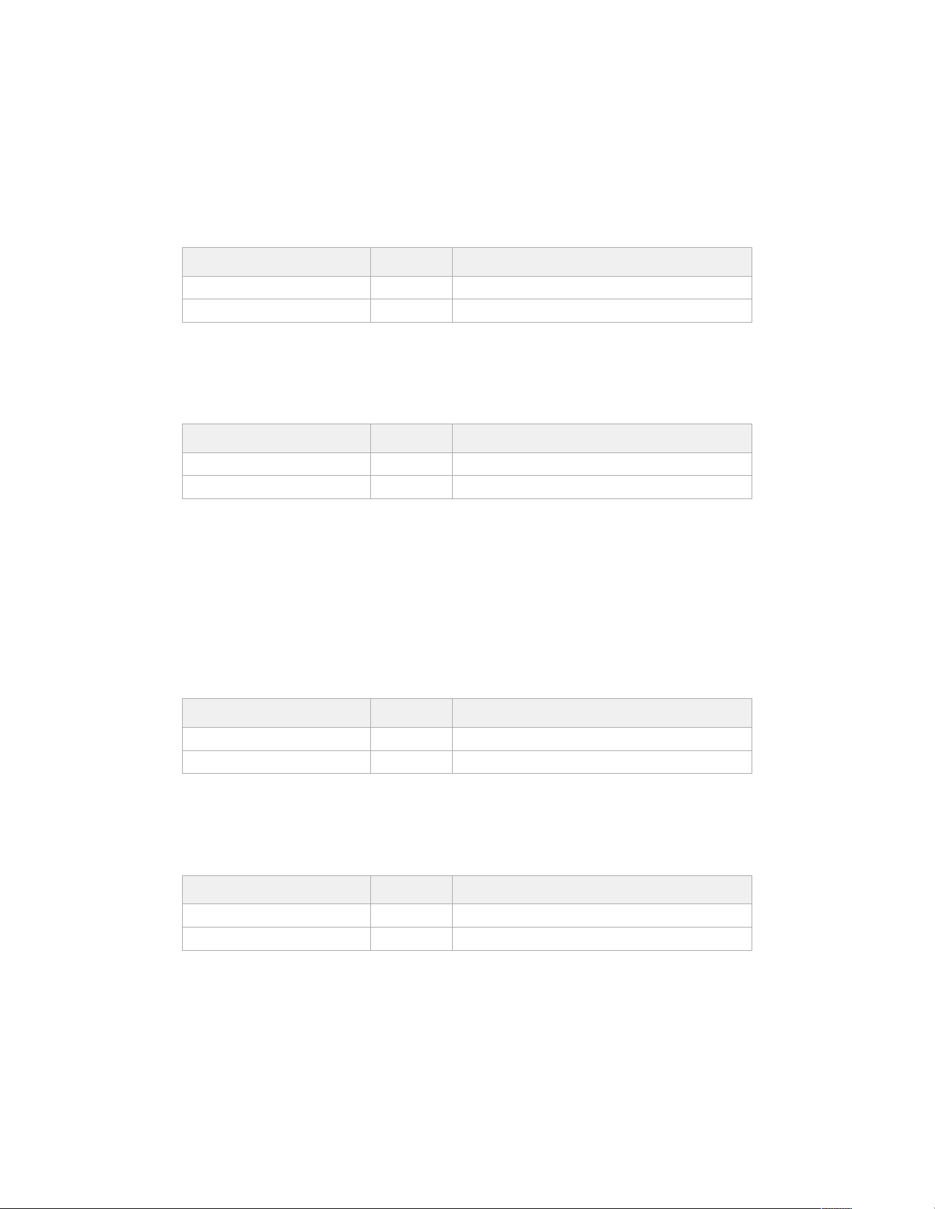
GET /colorCorrection/contrast
Get color correction contrast
Response
200 - OK
The response is a JSON object.
Name Type Description
pivot number Default value is: 0.5.
adjust number Default value is: 1.
PUT /colorCorrection/contrast
Set color correction contrast
Parameters
Name Type Description
pivot number Default value is: 0.5.
adjust number Default value is: 1.
Response
200 - OK
GET /colorCorrection/color
Get color correction color properties
Response
200 - OK
The response is a JSON object.
Name Type Description
hue number
saturation number Default value is: 1.
PUT /colorCorrection/color
Set color correction color properties
Parameters
Name Type Description
hue number
saturation number Default value is: 1.
Response
200 - OK
318Developer Information
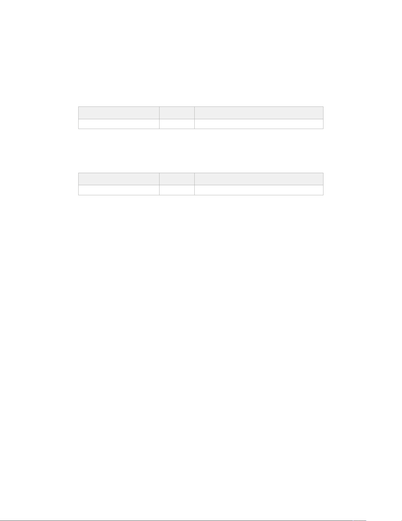
GET /colorCorrection/lumaContribution
Get color correction luma contribution
Response
200 - OK
The response is a JSON object.
Name Type Description
lumaContribution number Default value is: 1.
PUT /colorCorrection/lumaContribution
Set color correction luma contribution
Parameters
Name Type Description
lumaContribution number Default value is: 1.
Response
200 - OK
Blackmagic Bluetooth Camera Control
Blackmagic cameras with Bluetooth LE implement a variety of features and commands that
allow users to control their cameras wirelessly. Developers have full access to these features for
their custom applications.
The following services and characteristics describe the full range of communication options that
are available to the developer.
Service: Device Information Service
UUID: 180A
Characteristics
Camera Manufacturer
UUID: 2A29
Read the name of the manufacturer (always “Blackmagic Design”).
Camera Model
UUID: 2A24
Read the name of the camera model (“URSA Broadcast G2”).
Service: Blackmagic Camera Service
UUID: 291D567A-6D75-11E6-8B77-86F30CA893D3
Characteristics
Outgoing Camera Control (encrypted)
UUID: 5DD3465F-1AEE-4299-8493-D2ECA2F8E1BB
319Developer Information

Send Camera Control messages
These messages are identical to those described in the Blackmagic SDI Camera Control
Protocol section below. Please read that section for a list of supported messages and required
formatting information.
For an example of how packets are structured, please see the ‘example protocol packets’
section in this document.
Incoming Camera Control (encrypted)
UUID: B864E140-76A0-416A-BF30-5876504537D9
Request notifications for this characteristic to receive Camera Control messages from
the camera.
These messages are identical to those described in the Blackmagic SDI Camera Control
Protocol section below. Please read that section for a list of supported messages and required
formatting information.
Timecode (encrypted)
UUID: 6D8F2110-86F1-41BF-9AFB-451D87E976C8
Request notifications for this characteristic to receive timecode updates.
Timecode (HH:MM:SS:mm) is represented by a 32-bit BCD number:
(eg. 09:12:53:10 = 0x09125310)
Camera Status (encrypted)
UUID: 7FE8691D-95DC-4FC5-8ABD-CA74339B51B9
Request notifications for this characteristic to receive camera status updates.
The camera status is represented by flags contained in an 8-bit integer:
None = 0x00
Camera Power On = 0x01
Connected = 0x02
Paired = 0x04
Versions Verified = 0x08
Initial Payload Received = 0x10
Camera Ready = 0x20
Send a value of 0x00 to power a connected camera off.
Send a value of 0x01 to power a connected camera on.
Device Name
UUID: FFAC0C52-C9FB-41A0-B063-CC76282EB89C
Send a device name to the camera (max. 32 characters).
The camera will display this name in the Bluetooth Setup Menu.
Protocol Version
UUID: 8F1FD018-B508-456F-8F82-3D392BEE2706
Read this value to determine the camera’s supported CCU protocol version.
320Developer Information

NOTE Encrypted characteristics can only be used once a device has successfully
bonded or paired with the Blackmagic Camera. Once a connection has been
established, any attempt to write to an encrypted characteristic will initiate bonding.
For example, writing a ‘Camera Power On’ (0x01) message to the Camera Status
characteristic.
Once bonding is initiated, the camera will display a 6-digit pin in the Bluetooth Setup
Menu. Enter this pin on your device to establish an encrypted connection. The device
will now be able to read, write and receive notifications from encrypted characteristics.
Blackmagic SDI and Bluetooth Camera Control Protocol
Version 1.6.2
If you are a software developer you can use the Blackmagic SDI and Bluetooth Camera Control
Protocol to construct devices that integrate with our products. Here at Blackmagic Design, our
approach is to open up our protocols and we eagerly look forward to seeing what you come up with!
Overview
This document describes an extensible protocol for sending a unidirectional stream of small control
messages embedded in the non-active picture region of a digital video stream. The video stream
containing the protocol stream may be broadcast to a number of devices. Device addressing is used
to allow the sender to specify which device each message is directed to.
Assumptions
Alignment and padding constraints are explicitly described in the protocol document. Bit fields are
packed from LSB first. Message groups, individual messages and command headers are defined as,
and can be assumed to be, 32 bit aligned.
Blanking Encoding
A message group is encoded into a SMPTE 291M packet with DID/SDID x51/x53 in the active region
of VANC line 16.
Message Grouping
Up to 32 messages may be concatenated and transmitted in one blanking packet up to a maximum
of 255 bytes payload. Under most circumstances, this should allow all messages to be sent with a
maximum of one frame latency.
If the transmitting device queues more bytes of message packets than can be sent in a single frame,
it should use heuristics to determine which packets to prioritize and send immediately. Lower priority
messages can be delayed to later frames, or dropped entirely as appropriate.
Abstract Message Packet Format
Every message packet consists of a three byte header followed by an optional variable length data
block. The maximum packet size is 64 bytes.
Destination device (uint8)
Device addresses are represented as an 8 bit unsigned integer.
Individual devices are numbered 0 through 254 with the value
255reserved to indicate a broadcast message to all devices.
Command length (uint8)
The command length is an 8 bit unsigned integer which specifies the
length of the included command data. The length does NOT include
the length of the header or any trailing padding bytes.
321Developer Information

Command id (uint8)
The command id is an 8 bit unsigned integer which indicates
themessage type being sent. Receiving devices should ignore any
commands that they do not understand. Commands 0 through 127
are reserved for commands that apply to multiple types of devices.
Commands 128 through 255 are device specific.
Reserved (uint8)
This byte is reserved for alignment and expansion purposes. It should
be set tozero.
Command data (uint8[])
The command data may contain between 0 and 60 bytes of data.
The format of the data section is defined by the command itself.
Padding (uint8[])
Messages must be padded up to a 32 bit boundary with 0x0bytes.
Anypadding bytes are NOT included in the command length.
Receiving devices should use the destination device address and or the command identifier to
determine which messages to process. The receiver should use the command length to skip
irrelevant or unknown commands and should be careful to skip the implicit padding as well.
Defined Commands
Command 0 : change configuration
Category (uint8)
The category number specifies one of up to 256 configuration
categories available on the device.
Parameter (uint8)
The parameter number specifies one of 256 potential configuration
parameters available on the device. Parameters 0 through 127 are
device specific parameters. Parameters 128 though 255 are reserved
for parameters that apply to multiple types of devices.
Data type (uint8)
The data type specifies the type of the remaining data. Thepacket
length is used to determine the number of elements in the message.
Each message must contain an integral number of data elements.
Currently defined values are:
0: void/boolean
A void value is represented as a boolean array of length zero.
The data field is a 8 bit value with 0 meaning false and all other
values meaning true.
1: signed byte Data elements are signed bytes
2: signed 16bit integer Data elements are signed 16 bit values
3: signed 32bit integer Data elements are signed 32 bit values
4: signed 64bit integer Data elements are signed 64 bit values
5: UTF-8 string Data elements represent a UTF-8 string with no terminating character.
Data types 6 through 127 are reserved.
128: signed 5.11fixed
point
Data elements are signed 16 bit integers representing a real number with
5bits for the integer component and 11 bits for the fractional component.
Thefixed point representation is equal to the real value multiplied by
2^11. The representable range is from -16.0 to 15.9995 (15 + 2047/2048).
322Developer Information

Data types 129 through 255 are available for device specific purposes.
Operation type (uint8)
The operation type specifies what action to perform on the specified
parameter. Currently defined values are:
0: assign value
The supplied values are assigned to the specified parameter. Each
element will be clamped according to its valid range. A void parameter
may only be ‘assigned’ an empty list of boolean type. This operation will
trigger the action associated with that parameter. A boolean value may
be assigned the value zero for false, and any other value for true.
1: offset/toggle value
Each value specifies signed offsets of the same type to be added to the
current parameter values. The resulting parameter value will be clamped
according to their valid range. It is not valid to apply an offset to a void
value. Applying any offset other than zero to a boolean value will invert
that value.
Operation types 2 through 127 are reserved.
Operation types 128through 255 are available for device specific purposes.
Data (void)
The data field is 0 or more bytes as determined by the data type and
number of elements.
The category, parameter, data type and operation type partition a 24 bit operation space.
Group ID Parameter Type Index Minimum Maximum Interpretation
Lens
0.0 Focus fixed16 – 0.0 1.0 0.0 = near, 1.0 = far
0.1 Instantaneous autofocus void – – – trigger instantaneous autofocus
0.2 Aperture (f-stop) fixed16 – -1.0 16.0
Aperture Value (where fnumber
= sqrt(2^AV))
0.3 Aperture (normalised) fixed16 – 0.0 1.0 0.0 = smallest, 1.0 = largest
0.4 Aperture (ordinal) int16 – 0 n
Steps through available
aperture values from minimum
(0) to maximum (n)
0.5
Instantaneous auto
aperture
void – – –
trigger instantaneous auto
aperture
0.6 Optical image stabilisation boolean – – – true = enabled, false = disabled
0.7 Set absolute zoom (mm) int16 – 0 max
Move to specified focal length
in mm, from minimum (0) to
maximum (max)
0.8
Set absolute zoom
(normalised)
fixed16 – 0.0 1.0
Move to specified focal length:
0.0 = wide, 1.0 = tele
0.9
Set continuous zoom
(speed)
fixed16 – -1.0 +1.0
Start/stop zooming at specified
rate: -1.0 = zoom wider fast, 0.0
= stop,
+1 = zoom tele fast
323Developer Information

Group ID Parameter Type Index Minimum Maximum Interpretation
Video
1.0 Video mode int8
[0] = frame rate – –
fps as integer
(eg 24, 25, 30, 50, 60)
[1] = M-rate – – 0 = regular, 1 = M-rate
[2] = dimensions – –
0 = NTSC, 1 = PAL, 2 = 720,
3 = 1080, 4 = 2kDCI, 5 = 2k16:9,
6 = UHD, 7 = 3k Anamorphic,
8 = 4k DCI, 9 = 4k 16:9,
10 = 4.6k 2.4:1, 11 = 4.6k
[3] = interlaced – – 0 = progressive, 1 = interlaced
[4] = Color space – – 0 = YUV
1.1 Gain (up to Camera 4.9) int8 1 128
1x, 2x, 4x, 8x, 16x, 32x, 64x,
128x gain
1.2 Manual White Balance
int16 [0] = color temp 2500 10000 Color temperature in K
int16 [1] = tint -50 50 tint
1.3 Set auto WB void – – –
Calculate and set autowhite
balance
1.4 Restore auto WB void – – –
Use latest auto white balance
setting
1.5 Exposure (us) int32 1 42000 time in us
1.6 Exposure (ordinal) int16 – 0 n
Steps through available
exposure valuesfrom minimum
(0) tomaximum (n)
1.7 Dynamic Range Mode int8 enum – 0 2
0 = film, 1 = video,
2 = extended video
1.8 Video sharpening level int8 enum – 0 3
0 = off, 1 = low, 2= medium,
3 = high
1.9 Recording format int16
[0] = file frame rate – –
fps as integer
(eg 24, 25, 30, 50, 60, 120)
[1] = sensor frame
rate
– –
fps as integer, valid when
sensor-off-speed set (eg 24,
25, 30, 33, 48, 50, 60, 120),
no change will beperformed
if this value is set to 0
[2] = frame width – – in pixels
[3] = frame height – – in pixels
[4] = flags
– – [0] = file-M-rate
– –
[1] = sensor-M-rate, valid
whensensor-off-speed-set
– – [2] = sensor-off-speed
– – [3] = interlaced
– – [4] = windowed mode
1.10 Set auto exposure mode int8 – 0 4
0 = Manual Trigger, 1 = Iris,
2 = Shutter, 3 = Iris + Shutter,
4 = Shutter + Iris
1.11 Shutter angle int32 – 100 36000
Shutter angle in degrees,
multiplied by 100
1.12 Shutter speed int32 –
Current
sensor
frame rate
5000
Shutter speed value as a
fraction of 1, so 50 for 1/50th
of a second
1.13 Gain int8 – -128 127 Gain in decibel (dB)
1.14 ISO int32 – 0 2147483647 ISO value
1.15 Display LUT int8
[0] = selected LUT – –
0 = None, 1 = Custom,
2 = film to video,
3 = film to extended video
[1] = enabled or not – – 0 = Not enabled, 1 = Enabled
1.16 ND Filter Stop fixed16
[0] = stop 0.0 15.0 filter power, as f-stop
[1] = display mode – –
0 = stop
1 = density
2 = transmittance
324Developer Information

Group ID Parameter Type Index Minimum Maximum Interpretation
Audio
2.0 Mic level fixed16 – 0.0 1.0 0.0 = minimum, 1.0 = maximum
2.1 Headphone level fixed16 – 0.1 1.0 0.0 = minimum, 1.0 = maximum
2.2 Headphone program mix fixed16 – 0.1 1.0 0.0 = minimum, 1.0 = maximum
2.3 Speaker level fixed16 – 0.1 1.0 0.0 = minimum, 1.0 = maximum
2.4 Input type int8 – 0 3
0 = internal mic,
1 = line level input,
2 = low mic level input,
3 = high mic level input
2.5 Input levels fixed16
[0] ch0 0.0 1.0 0.0 = minimum, 1.0 = maximum
[1] ch1 0.0 1.0 0.0 = minimum, 1.0 = maximum
2.6 Phantom power boolean – – –
true = powered,
false = not powered
Output
3.0
Overlay enables
uint16
bit field
[0] = bit field – –
bit flags:
[0] = display status,
[1] = display frame guides
[2] = clean feed
Some cameras don’t allow
separate control of frame
guides and status overlays.
uint16
bit field
[1] = target displays
bit field
– –
bit flags:
[0] = LCD
[1] = HDMI
[2] = EVF
[3] = Main SDI
[4] = Front SDI
3.1
Frame guides style
(Camera 3.x)
int8 – 0 8
0 = HDTV, 1 = 4:3, 2 = 2.4:1,
3 = 2.39:1, 4 = 2.35:1,
5 = 1.85:1, 6 = thirds
3.2
Frame guides opacity
(Camera 3.x)
fixed16 – 0.1 1.0 0.0 = transparent, 1.0 = opaque
3.3
Overlays
(replaces .1 and .2
abovefrom
Cameras 4.0)
int8
[0] = frame guides
style
– –
0 = off, 1 = 2.4:1, 2 = 2.39:1,
3 = 2.35:1, 4 = 1.85:1, 5 = 16:9,
6 = 14:9, 7 = 4:3, 8 = 2:1,
9 = 4:5, 10 = 1:1
[1] = frame guide
opacity
0 100 0 = transparent, 100 = opaque
[2] = safe area
percentage
0 100
percentage of full frame
used by safe area guide
(0 means off)
[3] = grid style – –
bit flags:
[0] = display thirds,
[1] = display cross hairs,
[2] = display center dot,
[3] = display horizon
325Developer Information

Group ID Parameter Type Index Minimum Maximum Interpretation
Display
4.0 Brightness fixed16 – 0.0 1.0 0.0 = minimum, 1.0 = maximum
4.1
Exposure and focus tools
uint16
bit field
[0] = bit field – –
bit flags:
[0] = Zebra
[1] = Focus Assist
[2] = False Color
uint16
bit field
[1] = target displays
bit field
– –
bit flags:
[0] = LCD
[1] = HDMI
[2] = EVF
[3] = Main SDI
[4] = Front SDI
4.2 Zebra level fixed16 – 0.0 1.0 0.0 = minimum, 1.0 = maximum
4.3 Peaking level fixed16 – 0.0 1.0 0.0 = minimum, 1.0 = maximum
4.4 Color bar enable int8 – 0 30
0 = disable bars,
1-30 = enable bars with timeout
(seconds)
4.5 Focus Assist int8
[0] = focus assist
method
– –
0 = Peak,
1 = Colored lines
[1] = focus line color – –
0 = Red,
1 = Green,
2 = Blue,
3 = White,
4 = Black
4.6 Program return feed enable int8 – 0 30
0 = disable, 1-30 = enable with
timeout (seconds)
4.7 Timecode Source
signed
byte
[0] = source – –
0 = Clip,
1 = Timecode
Tally
5.0 Tally brightness fixed16 – 0.0 1.0
Sets the tally front and tally rear
brightness to the same level.
0.0 = minimum,
1.0 = maximum
5.1 Front tally brightness fixed16 – 0.0 1.0
Sets the tally front brightness.
0.0 = minimum,
1.0 = maximum
5.2 Rear tally brightness fixed16 – 0.0 1.0
Sets the tally rear brightness.
0.0 = minimum,
1.0 = maximum
Tally rear brightness cannot be
turned off
Reference
6.0 Source int8 enum – 0 2
0 = internal,
1 = program,
2 = external
6.1 Offset int32 – – – +/- offset in pixels
Confi-
guration
7.0 Real Time Clock int32
[0] time _ _ BCD - HHMMSSFF (UCT)
[1] date _ _ BCD - YYYYMMDD
7.1 System language string [0-1] _ _
ISO-639-1 two character
language code
7.2 Timezone int32 _ _ _ Minutes offset from UTC
7.3 Location int64
[0] latitude _ _
BCD - s0DDdddddddddddd
where s is the sign:
0 = north (+), 1 = south (-);
DD degrees, dddddddddddd
decimal degrees
[1] longitude _ _
BCD - sDDDdddddddddddd
where s is the sign: 0 = west (-),
1 = east (+); DDD degrees,
dddddddddddd decimal
degrees
326Developer Information

Group ID Parameter Type Index Minimum Maximum Interpretation
Color
Correction
8.0 Lift Adjust fixed16
[0] red -2.0 2.0 default 0.0
[1] green -2.0 2.0 default 0.0
[2] blue -2.0 2.0 default 0.0
[3] luma -2.0 2.0 default 0.0
8.1 Gamma Adjust fixed16
[0] red -4.0 4.0 default 0.0
[1] green -4.0 4.0 default 0.0
[2] blue -4.0 4.0 default 0.0
[3] luma -4.0 4.0 default 0.0
8.2 Gain Adjust fixed16
[0] red 0.0 16.0 default 1.0
[1] green 0.0 16.0 default 1.0
[2] blue 0.0 16.0 default 1.0
[3] luma 0.0 16.0 default 1.0
8.3 Offset Adjust fixed16
[0] red -8.0 8.0 default 0.0
[1] green -8.0 8.0 default 0.0
[2] blue -8.0 8.0 default 0.0
[3] luma -8.0 8.0 default 0.0
8.4 Contrast Adjust fixed16
[0] pivot 0.0 1.0 default 0.5
[1] adj 0.0 2.0 default 1.0
8.5 Luma mix fixed16 – 0.0 1.0 default 1.0
8.6 Color Adjust fixed16
[0] hue -1.0 1.0 default 0.0
[1] sat 0.0 2.0 default 1.0
8.7 Correction Reset Default void – – – reset to defaults
327Developer Information

Group ID Parameter Type Index Minimum Maximum Interpretation
Media
10.0 Codec int8 enum
[0] = basic codec – –
0 = CinemaDNG,
1 = DNxHD,
2 = ProRes,
3 = Blackmagic RAW
[1] = code variant
– –
CinemaDNG:
0 = uncompressed,
1 = lossy 3:1,
2 = lossy 4:1
– –
ProRes:
0 = HQ,
1 = 422,
2 = LT,
3 = Proxy,
4 = 444,
5 = 444XQ
– –
Blackmagic RAW:
0 = Q0,
1 = Q5,
2 = 3:1,
3 = 5:1,
4 = 8:1,
5 = 12:1
10.1 Transport mode int8
[0] = mode – –
0 = Preview,
1 = Play,
2 = Record
[1] = speed – –
-ve = multiple speeds
backwards,
0 = pause,
+ve = multiple speeds forwards
[2] = flags – –
1<<0 = loop,
1<<1 = play all,
1<<5 = disk1 active,
1<<6 = disk2 active,
1<<7 = time-lapse recording
[3] = slot 1 storage
medium
– –
0 = CFast card,
1 = SD,
2 = SSD Recorder
[4] = slot 2 storage
medium
– –
0 = CFast card,
1 = SD,
2 = SSD Recorder
10.2 Playback Control int8 enum [0] = clip – –
0 = Previous,
1 = Next
10.5 Stream bool [0] = enabled – –
true = enabled,
false = disabled
10.6 Stream Information void bool [0] = enabled – –
true = enabled,
false = disabled
10.7 Stream Display 3D LUT void bool [0] = enabled – –
true = enabled,
false = disabled
PTZ
Control
11.0 Pan/Tilt Velocity fixed 16
[0] = pan velocity -1.0 1.0
-1.0 = full speed left,
1.0 = full speed right
[1] = tilt velocity -1.0 1.0
-1.0 = full speed down,
1.0 = full speed up
11.1 Memory Preset
int8
enum
[0] = preset
command
– –
0 = reset,
1 = store location,
2 = recall location
int8
[1] =
preset slot
0 5 –
328Developer Information
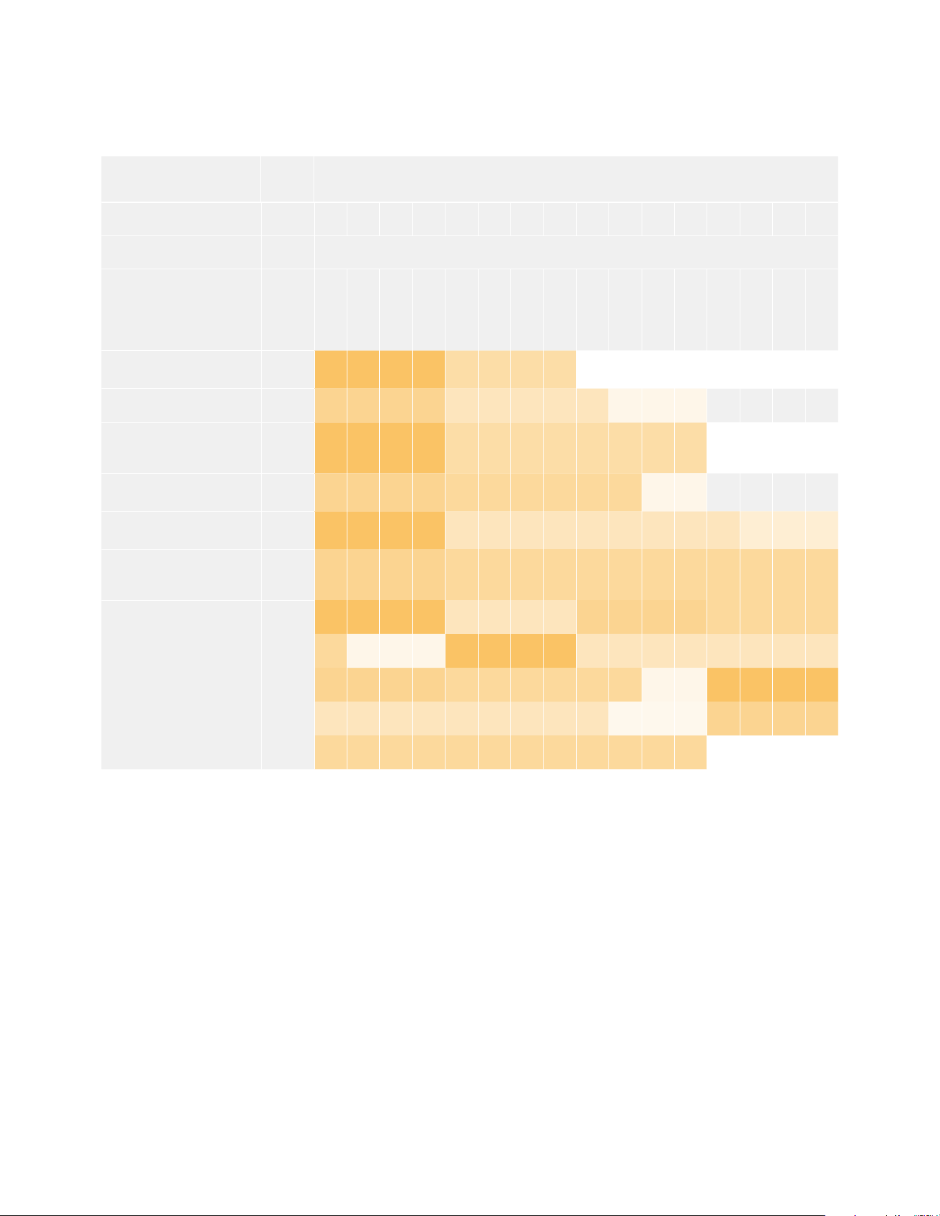
Example Protocol Packets
Operation
Packet
Length Byte
0 1 2 3 4 5 6 7 8 9 10 11 12 13 14 15
header command data
destination
length
command
reserved
category
parameter
type
operation
trigger instantaneous
auto focus on camera 4
8 4 4 0 0 0 1 0 0
turn on OIS on all cameras 12 255 5 0 0 0 6 0 0 1 0 0 0
set exposure to 10 ms on
camera 4 (10 ms = 10000
us = 0x00002710)
12 4 8 0 0 1 5 3 0 0x10 0x27 0x00 0x00
add 15% to zebra level
(15 % = 0.15 f = 0x0133 fp)
12 4 6 0 0 4 2 128 1 0x33 0x01 0 0
select 1080p 23.98 mode on
all cameras
16 255 9 0 0 1 0 1 0 24 1 3 0 0 0 0 0
subtract 0.3 from gamma
adjust for green & blue
(-0.3 ~= 0xfd9a fp)
16 4 12 0 0 8 1 128 1 0 0 0x9a 0xfd 0x9a 0xfd 0 0
all operations combined 76
4 4 0 0 0 1 0 0 255 5 0 0 0 6 0 0
1 0 0 0 4 8 0 0 1 5 3 0 0x10 0x27 0x00 0x00
4 6 0 0 4 2 128 1 0x33 0x01 0 0 255 9 0 0
1 0 1 0 24 1 3 0 0 0 0 0 4 12 0 0
8 1 128 1 0 0 0x9a 0xfd 0x9a 0xfd 0 0
329Developer Information

Blackmagic TallyControl Protocol
Version 1.0 (30/04/14)
This section is for third party developers or anybody who may wish to add support for the
Blackmagic Tally Control Protocol to their products or system. It describes the protocol for
sending tally information embedded in the non-active picture region of a digital video stream.
Data Flow
A master device such as a broadcast switcher embeds tally information into its program feed
which is broadcast to a number of slave devices such as cameras or camera controllers. The
output from the slave devices is typically fed back to the master device, but may also be sent to
a video monitor.
The primary flow of tally information is from the master device to the slaves. Each slave device
may use its device id to extract and display the relevant tally information.
Slave devices pass through the tally packet on their output and update the monitor tally status,
so that monitor devices connected to that individual output may display tally status without
knowledge of the device id they are monitoring.
Assumptions
Any data alignment/padding is explicit in the protocol. Bit fields are packed from LSB first.
Blanking Encoding
One tally control packet may be sent per video frame. Packets are encoded as a SMPTE 291M
packet with DID/SDID x51/x52 in the active region of VANC line 15. A tally control packet may
contain up to 256 bytes of tally information.
Packet Format
Each tally status consists of 4 bits of information:
uint4
bit 0: program tally status (0=off, 1=on)
bit 1: preview tally status (0=off, 1=on)
bit 2-3: reserved (0x0)
The first byte of the tally packet contains the monitor device tally status and a version number.
Subsequent bytes of the tally packet contain tally status for pairs of slave devices. The master
device sends tally status for the number of devices configured/supported, up to a
maximum of 510.
struct tally
uint8
bit 0: monitor device program tally status (0=off, 1=on)
bit 1: monitor device preview tally status (0=off, 1=on)
bit 2-3: reserved (0b00)
bit 4-7: protocol version (0b0000)
uint8[0]
bit 0: slave device 1 program tally status (0=off, 1=on)
bit 1: slave device 1 device preview tally status (0=off, 1=on)
bit 2-3: reserved (0b00)
bit 4: slave device 2 program tally status (0=off, 1=on)
bit 5: slave device 2 preview tally status (0=off, 1=on)
bit 6-7: reserved (0b00)
330Developer Information
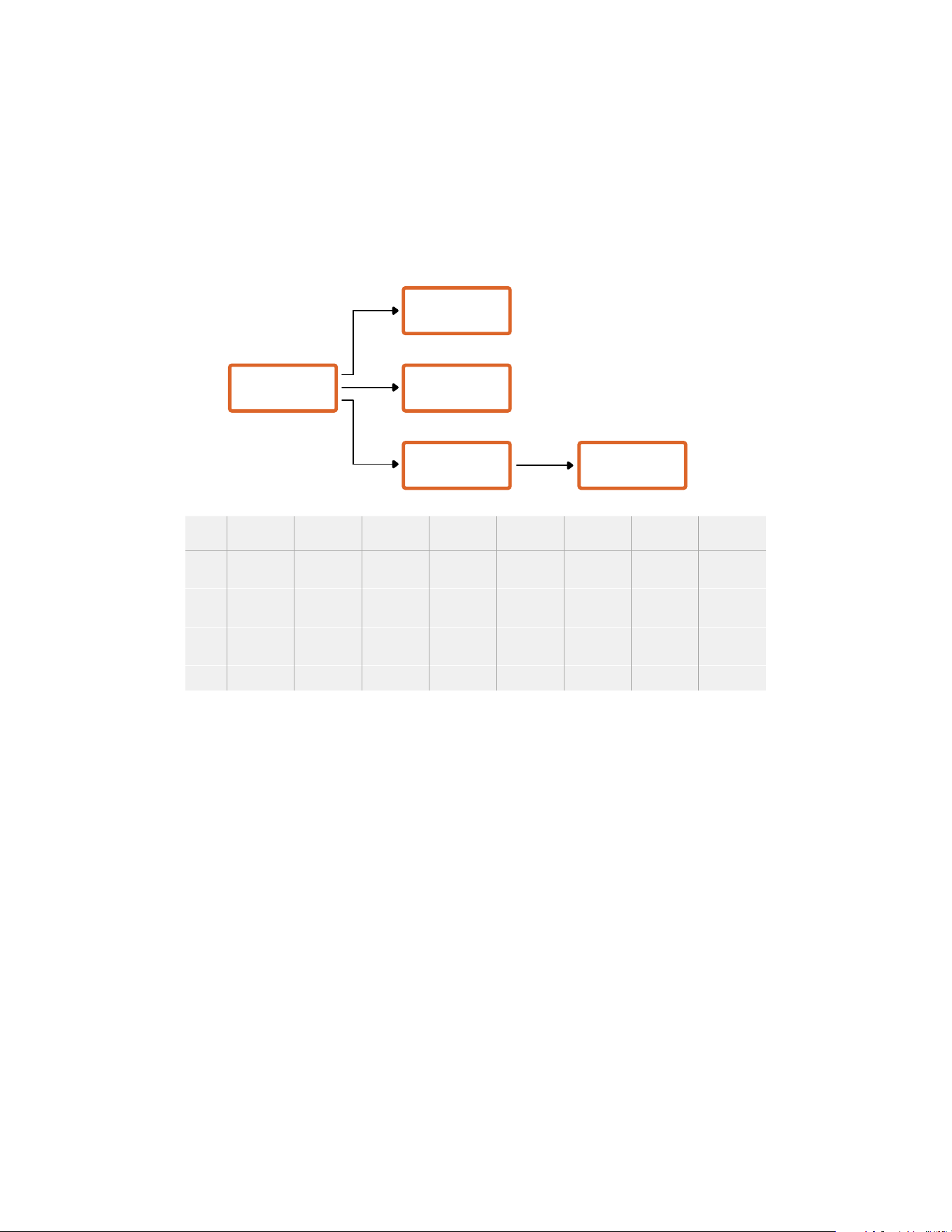
uint8[1]
bit 0: slave device 3 program tally status (0=off, 1=on)
bit 1: slave device 3 device preview tally status (0=off, 1=on)
bit 2-3: reserved (0b00)
bit 4: slave device 4 program tally status (0=off, 1=on)
bit 5: slave device 4 preview tally status (0=off, 1=on)
bit 6-7: reserved (0b00)
. . .
Master Device
Monitor Device
Slave Device
(2)
Slave Device
(3)
Slave Device
(1)
Byte
7 MSB 6 5 4 3 2 1 0 LSB
0
Version
(0b0)
Version
(0b0)
Version
(0b0)
Version
(0b0)
Reserved
(0b0)
Reserved
(0b0)
Monitor
Preview
Monitor
Program
1
Reserved
(0b0)
Reserved
(0b0)
Slave 1
Preview
Slave 1
Program
Reserved
(0b0)
Reserved
(0b0)
Slave 0
Preview
Slave 0
Program
2
Reserved
(0b0)
Reserved
(0b0)
Slave 3
Preview
Slave 3
Program
Reserved
(0b0)
Reserved
(0b0)
Slave 2
Preview
Slave 2
Program
3 ...
331Developer Information

Help
The fastest way to obtain help is to go to the Blackmagic Design online support pages and
check the latest support material available for your camera.
Blackmagic Design Online Support Pages
The latest manual, software and support notes can be found at the Blackmagic Design support
center at www.blackmagicdesign.com/support.
Contacting Blackmagic Design Support
If you can’t find the help you need in our support material, please use the “Send us an email”
button on the support page to email a support request. Alternatively, click on the “Find your
local support team” button on the support page and call your nearest Blackmagic Design
support office.
Checking the Software Version Currently Installed
To check which version of Blackmagic Camera Utility software is installed on your computer,
open the About Blackmagic Camera Utility window.
On Mac, open Blackmagic Camera Utility from the Applications folder. Select About
Blackmagic Camera Utility from the application menu to reveal the version number.
On Windows, open Blackmagic Camera Utility from your Start menu or Start Screen.
Click on the Help menu and select About Blackmagic Camera Utility to reveal the
version number.
How to Get the Latest Software Updates
After checking the version of Blackmagic Camera Utility software installed on your computer,
please visit the Blackmagic Design support center at www.blackmagicdesign.com/support to
check for the latest updates. While it is usually a good idea to run the latest updates, it is wise
to avoid updating any software if you are in the middle of an important project.
332Help

Regulatory Notices
Disposal of waste of electrical and electronic equipment within the European union.
The symbol on the product indicates that this equipment must not be disposed of with other
waste materials. In order to dispose of your waste equipment, it must be handed over to a
designated collection point for recycling. The separate collection and recycling of your waste
equipment at the time of disposal will help conserve natural resources and ensure that it is
recycled in a manner that protects human health and the environment. Formore information
about where you can drop off your waste equipment for recycling, please contact your local
city recycling office or the dealer from whom you purchased the product.
This equipment has been tested and found to comply with the limits for a Class A digital device,
pursuant to Part 15 of the FCC rules. These limits are designed to provide reasonable protection
against harmful interference when the equipment is operated inacommercial environment.
This equipment generates, uses, and can radiate radio frequency energy and, if not installed
and used in accordance with the instructions, maycause harmful interference to radio
communications. Operation of this product in aresidential area is likely to cause harmful
interference, in which case the user will be required to correct the interference at
personal expense.
Operation is subject to the following two conditions:
1 This device may not cause harmful interference.
2 This device must accept any interference received, including interference that may cause
undesired operation.
R-R-BMD-20210915001
R-R-BMD-20200421002
R-R-BMD-20200916001
R-R-BMD-20200916002
R-REM-BMD-201803004
R-REM-BMD-201803003
MSIP-REM-BMD-201612001
ISED Canada Statement
This device complies with Canadian standards for Class A digital apparatus.
Any modifications or use of this product outside its intended use could void compliance
to these standards.
This equipment has been tested for compliance with the intended use in a commercial
environment.
Bluetooth®
The URSA Broadcast G2 is a Bluetooth wireless technology enabled product.
Contains Transmitter Module FCC ID: QOQBGM113
This equipment complies with FCC radiation exposure limits set forth for an
uncontrolledenvironment.
Contains Transmitter Module IC: 5123A-BGM113
This device complies with Industry Canada’s license-exempt RSS standards and exception
fromroutine SAR evaluation limits given in RSS-102 Issue 5.
Certified for Japan, certificate number: 209-J00204. This equipment contains specified radio
equipment that has been certified to the Technical Regulation Conformity Certification under
theRadio law.
333Regulatory Notices

This module has certification in South Korea, KC certification number: MSIP-CRM-BGT-BGM113
Hereby, Blackmagic Design declares that the URSA Broadcast G2 using wideband transmission
systems in 2.4 GHz ISM band is in compliance with Directive 2014/53/EU
The full text of the EU declaration of conformity is available from
compliance@blackmagicdesign.com
Safety Information
The supplied AC to 12V DC power supply for Blackmagic URSA Broadcast G2 and the IEC
power cable for Blackmagic Studio Fiber Converter, must be connected to a mains socket
outlet with a protective earth connection.
Blackmagic URSA Broadcast G2 and Camera Fiber Converter are suitable for use in tropical
locations with an ambient temperature of up to 40°C. Blackmagic Studio Fiber Converter is
suitable for use in tropical locations with an ambient temperature of up to 50°C
Ensure that adequate ventilation is provided around the Blackmagic Studio Fiber Converter and
Camera Fiber Converter so that ventilation is not restricted. When rack mounting the Studio
Fiber Converter, ensure that the ventilation is not restricted by adjacent equipment.
No operator serviceable parts inside Blackmagic URSA Broadcast G2, Camera Fiber Converter
or Studio Fiber Converter. Refer servicing to your local Blackmagic Design service center.
State of California statement
This product can expose you to chemicals such as trace amounts of polybrominated biphenyls
within plastic parts, which is known to the state of California to cause cancer and birth defects
or other reproductive harm.
For more information go to www.P65Warnings.ca.gov.
Blackmagic URSA Broadcast G2
During sunny conditions, consider shading of the camera to prevent exposure of the camera or
Lithium battery to extended periods of sunlight. Keep Lithium batteries away from all
sources of heat.
The 12V DC output connector is suitable to provide power to the Blackmagic URSA Viewfinder
or Blackmagic URSA Studio Viewfinder. When connecting other accessories to this connector,
ensure that the power consumption is less than 18W.
Blackmagic Studio Fiber Converter
To reduce the risk of electric shock, do not expose this equipment to dripping or splashing.
Useonly at altitudes not more than 2000m above sea level.
Blackmagic Camera Fiber Converter
Only use the converter when connected to the Blackmagic Studio Fiber Converter. Under
normal use, the converter is designed to receive hazardous voltages from the Blackmagic
Studio Fiber Converter.
334Safety Information

Warranty
Limited Warranty
Blackmagic Design warrants that this product will be free from defects in materials and workmanship
for a period of 12 months from the date of purchase. If a product proves to be defective during this
warranty period, Blackmagic Design, at its option, either will repair the defective product without
charge for parts and labor, or will provide a replacement in exchange for the defective product.
In order to obtain service under this warranty, you the Customer, must notify Blackmagic Design
of the defect before the expiration of the warranty period and make suitable arrangements for the
performance of service. The Customer shall be responsible for packaging and shipping the
defective product to a designated service center nominated by Blackmagic Design, with shipping
charges pre paid. Customer shall be responsible for paying all shipping charges, insurance, duties,
taxes, and any other charges for products returned to us for any reason.
This warranty shall not apply to any defect, failure or damage caused by improper use or improper
or inadequate maintenance and care. Blackmagic Design shall not be obliged under this warranty:
a) to repair damage resulting from attempts by personnel other than Blackmagic Design
representatives to install, repair or service the product, b) to repair damage resulting from improper
use or connection to incompatible equipment, c) to repair any damage or malfunction caused by
the use of non Blackmagic Design parts or supplies, or d) to service a product that has been
modified or integrated with other products when the effect of such a modification or integration
increases the time or difficulty of servicing the product.
Exposing URSA Viewfinder to direct sunlight could damage the viewfinder display as the viewfinder
optics act as a magnifying glass. Image retention or burn-in could happen on OLED panels when
static or high contrast images, such as frame guides, are displayed on the panels for extended
periods. To avoid this, ensure the IR sensor for face detection is not covered deliberately and
disconnect the viewfinder when not in use for prolonged periods. Image retention is not covered
by this product warranty.
THIS WARRANTY IS GIVEN BY BLACKMAGIC DESIGN IN LIEU OF ANY OTHER WARRANTIES,
EXPRESS OR IMPLIED. BLACKMAGIC DESIGN AND ITS VENDORS DISCLAIM ANY IMPLIED
WARRANTIES OF MERCHANTABILITY OR FITNESS FOR A PARTICULAR PURPOSE. BLACKMAGIC
DESIGN’S RESPONSIBILITY TO REPAIR OR REPLACE DEFECTIVE PRODUCTS DURING THE
WARRANTY PERIOD IS THE WHOLE AND EXCLUSIVE REMEDY PROVIDED TO THE CUSTOMER.
BLACKMAGIC DESIGN WILL NOT BE LIABLE FOR ANY INDIRECT, SPECIAL, INCIDENTAL OR
CONSEQUENTIAL DAMAGES IRRESPECTIVE OF WHETHER BLACKMAGIC DESIGN OR THE
VENDOR HAS ADVANCE NOTICE OF THE POSSIBILITY OF SUCH DAMAGES. BLACKMAGIC
DESIGN IS NOT LIABLE FOR ANY ILLEGAL USE OF EQUIPMENT BY CUSTOMER. BLACKMAGIC
IS NOT LIABLE FOR ANY DAMAGES RESULTING FROM USE OF THIS PRODUCT. USER OPERATES
THIS PRODUCT AT OWN RISK.
© Copyright 2024 Blackmagic Design. All rights reserved. ‘Blackmagic Design’, ‘URSA’, ‘DeckLink’, ‘HDLink’, ‘Workgroup Videohub’,
‘Multibridge Pro’, ‘Multibridge Extreme’, ‘Intensity’ and ‘Leading the creative video revolution’ are registered trademarks in the
US and other countries. All other company and product names may be trademarks of the respective companies with which they
are associated.
335Warranty