Brand: amzchef
Model: 10RVAMB
DC 12V
USER
MANUAL
RV Tankless Water Heater

Welcome to the Amzchef Family!
Cheers to you for owning a new Amzchef product!
We are devoted to making high-quality kitchen, home, and personal
care products for all our customers. As a respected manufacturer, all our
products adhere to rigorous standard, safety, and functionality.
We are dedicated to offering exceptional customer service, which is why
we provide a 1-year warranty on this product to guarantee your
satisfaction for years to come.
If you have questions or need assistance, please get in touch with us
via our website: www.iamzchef.com, or email: info@iamzchef.com.
Problem + order number + a photo or a video attached in the email
would help us solve the problem better and faster.
Your thoughts and suggestions matter to us, so please don't hesitate to
email them at info@iamzchef.com.
The Amzchef Team
PLEASE READ INSTRUCTIONS CAREFULLY BEFORE ASSEMBLY
RETAIN THIS MANUAL FOR FUTURE REFERENCE
Table of contents
Safety Precautions
Technical Specification
Installation
Setting the Appliance
Maintenance
Troubleshooting
Electrical Connection Diagram
Winterizing Water Heater
Error Codes
3
5
6
14
15
17
22
19
22
24
Safety Precautions
Introduction
Thank you for purchasing this RV tankless water heater. Before operating your new product,
please read these instructions carefully.
This will ensure safe use and reduce the risk of injury. This instruction manual contains
information for installation, operation, maintenance of the product and safe use.
1. Do not store or use gasoline or other flammable vapors and liquids in the vicinity of this or
any other appliance.
2. Installation and service must be performed by a qualified installer, service agency or the
gas supplier.
3. Never use this appliance in enclosed spaces or tents.
4. Always turn the appliance off, and shut off the fuel supply while parking the RV in an
enclosed space, such as a garage or repair shop.
5. Never place seating or picnic tables in the direct path of the exhaust outlet.
WATER HEATERS FOR RECREATIONAL VEHICLE INSTALLATION ONLY
If the information in these instructions is not followed exactly, a fire or
explosion may result causing property damage, personal injury or death.
- Evacuate all persons from the vehicle.
- Shut off the gas supply at the gas container or source.
- Do not touch an electrical switch, or use any phone or radio in the vehicle.
- Do not start the vehicle's engine of electric generator.
- Contact the nearest gas supplier or qualified service technician for repairs.
- If you cannot reach a gas supplier or qualified service technician, contact
the nearest fire department.
- Do not turn on the gas supply until the gas leak(s) has been repaired.
WHAT TO DO IF YOU SMELL GAS
WARNING
DANGER!
SUFFOCATION OR FIRE HAZARD
Exhaust gases are hot and contain carbon monoxide, do not breath or
obstruct the exhaust gases.
DANGER!
1
www.iamzchef.com Email: info@iamzchef.com Whatsapp:+1 (838) 910 8317 Facebook: amzchefappliancewww.iamzchef.com Email: info@iamzchef.com Whatsapp:+1 (838) 910 8317 Facebook: amzchefappliance
6. ALWAYS clear any blockages from the air inlet and exhaust outlet to promote efficient
combustion.
7. DO NOT place objects on or against the appliance.
8. AVOID propping items against the water heater's access panel or inserting any foreign
objects.
9. DO NOT spray aerosols near the appliance while it is in operation.
1. The operator is responsible for their health and safety; persons with pacemakers should
discuss with their doctor before opening the access door or performing service repairs.
2. The operator is responsible for the water quality used in the appliance.
3. The operator is responsible for all routine inspections in this manual's Cleaning and
Maintenance section.
4. The operator is responsible for using and maintaining gas cylinders as specified by the RV
manufacturer.
5. The operator is responsible for ensuring that no spray water enters the appliance when
cleaning the RV.
6. The operator is responsible for using the appliance for potable water only. In addition, they
are responsible for ensuring that non-potable water sources, components, or heating
systems, new or old, are not connected by any means to the appliance.
1. The operator ensures all components are seated and locked before moving the RV.
- The access door is flush with the mounting plate.
- Door locker is engaged.
2. The operator is responsible for ensuring the gas system is turned off at the gas cylinders
before transit. Turn off all necessary valves as indicated by the RV manufacturer.
3. The operator is responsible for ensuring the appliance is off when refueling, traveling
through tunnels, parking in garages or carports, or ferries.
Any use other than the intended use (see above) is prohibited:
- Use in food trucks or roadside food vending vehicles.
- Use in construction trailers.
- Use as a pool heater.
- Use in a marine environment.
- Use in mobile homes.
Lists of chemical substances are known to the state to cause cancer, congenital disabilities,
death, serious illness, or other reproductive harm.
This product may contain such substances or such substances may be formed from
combustion of fuel (gas) or be components of the product itself.
CALIFORNIA PROPOSITION 65
Responsibilities of the Operator
While Driving
Prohibited Use
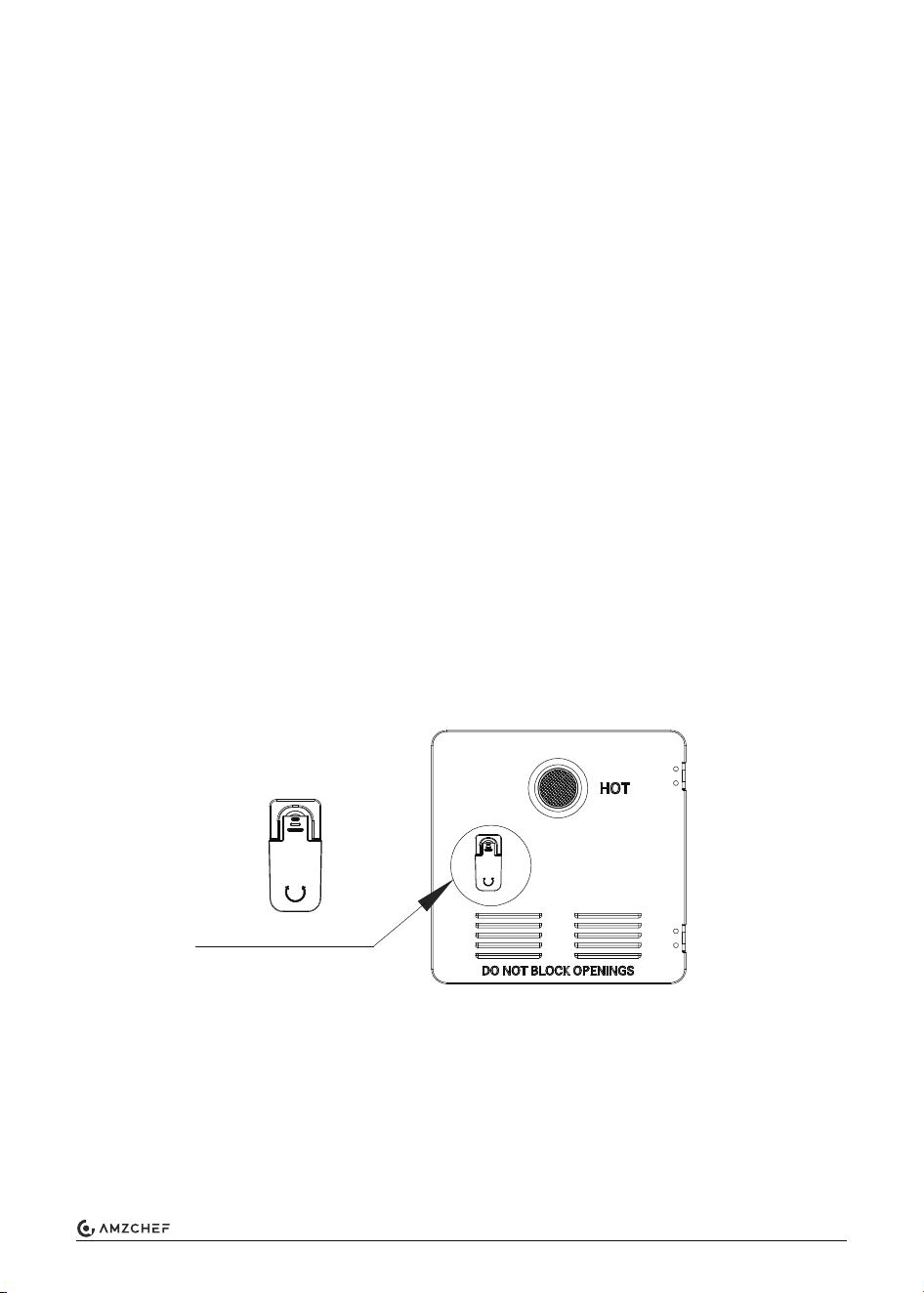
Lock the door tightly
2
www.iamzchef.com Email: info@iamzchef.com Whatsapp:+1 (838) 910 8317 Facebook: amzchefappliance
Model
Max. gas input
Min. gas input
Fuel type
Manifold pressure
Max. inlet gas pressure
Min. inlet gas pressure
Rating voltage
Orifice
Temperature range
Water heating capacity
Operating altitude range
10RVAMB
65,000 Btu/h
17,000 Btu/h
Propane (LP Gas)
(1.0in.WC)(0.25KPa) - (6.34in.WC)(1.58KPa)
(13.0in.WC)(3.23KPa)
(8.0in.WC)(1.99KPa)
DC 12V, less than 5A
Ø1.2x5 mm
95-124°F (35 -51°C)
10L/min ( Δt = 25K)
0-5,000 feet (0-1,524 m)
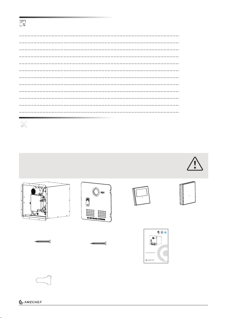
Remove the product from the packaging and make sure you have the following list of items
included. If any item is damaged or missing, contact us or the dealer.
Main unit x 1
Door assembly x 1
Wall controller x 1
ST4.2x30 screws
(door fixing) x 14
ST4.2x20 screws
(controller fixing) x 2
Wire connectors x 6
User Manual x 1
Wall controller
stand x 1
Accessories
Installation
Technical Specification
SUFFOCATION HAZARD
Dispose of packaging material or keep it from the reach of children.
Failure to follow instructions could lead to serious injury or death.
WARNING
Brand: amzchef
Model: 10RVAMB
DC 12V
USER
MANUAL
RV Tankless Water Heater
3
www.iamzchef.com Email: info@iamzchef.com Whatsapp:+1 (838) 910 8317 Facebook: amzchefappliance
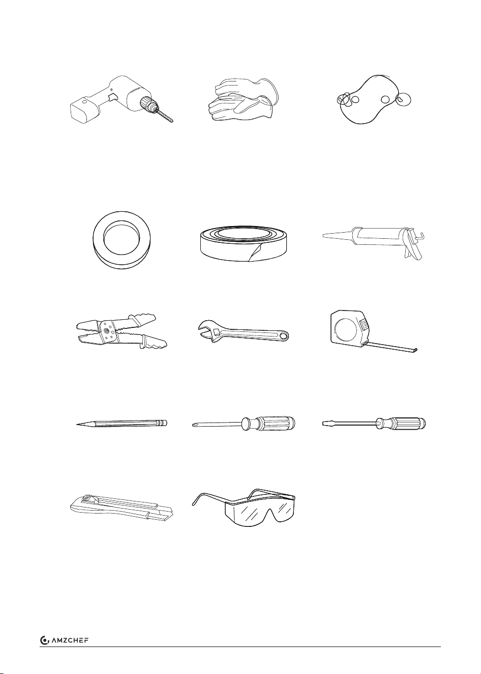
Tools Required (Not Provided)
Electric drill
Bit size: 1/16” (3 mm)
Note: It is use for holes drilling
of exterior sheet metal of RV.
Gloves
Soapy water
Washers Butyl tape Sealant gun
Wire stripper pliers
Pencil
Cutting knife
Eye protection
Phillips screwdriver
Flathead screwdriver
Adjustable wrench
Tape measure
4
www.iamzchef.com Email: info@iamzchef.com Whatsapp:+1 (838) 910 8317 Facebook: amzchefappliance
Prepare Cutout Opening
ELECTRICAL SHOCK AND/OR FIRE HAZARD
• Disconnect power before installation.
• Turn off all gas to the supply system.
SHARP EDGES CAN CAUSE CUTS AND INJURY!
Always wear protective gear such as gloves, eyewear and clothing to
avoid injuries during installation and servicing of the product.
1. Make sure that the appliance is in contact with the vehicle or a platform with adequate
weight-bearing capacity when install.
2. To install on a carpeted area, install a metal or wood panel under the appliance that
extends at least 3” (76 mm) beyond the width and depth of the appliance.
3. If escaping water may damage components or the vehicle, install a collection of the pan
below the appliance, direct the flow of water from the pan to outside the vehicle.
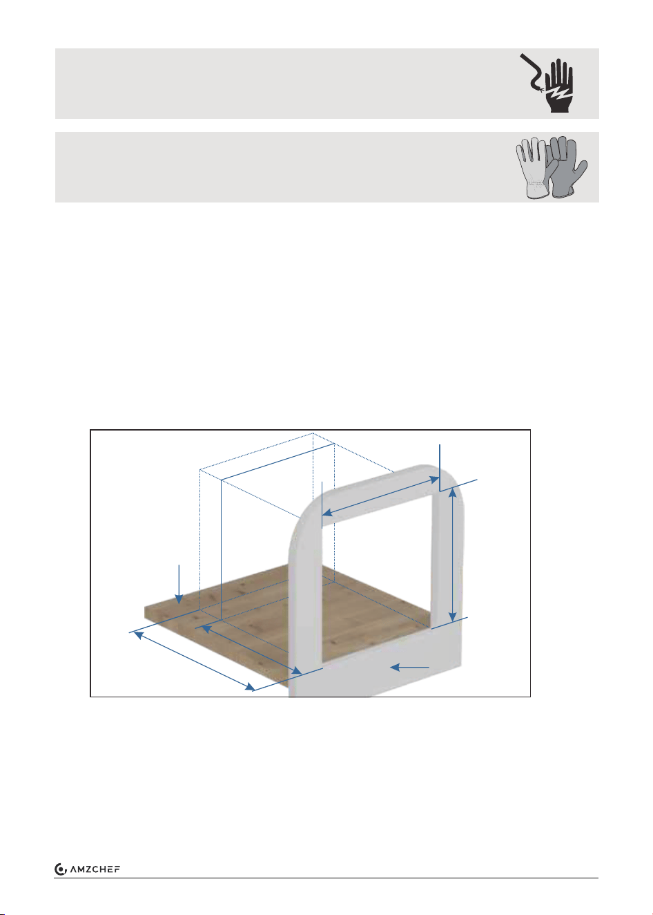
Make sure that the front edge of the opening is surrounded by a solid frame to firmly anchor
the appliance. If needed, build an appropriate frame with the following dimensions:
1. The required depth “C” depends on how the water hoses, electrical connection cable, and
gas line are installed. The depth “C” must be determined for the particular situation before
installation.
2. The corners of the rough opening must be at right angles. The exterior wall opening must
be the same dimensions with no rounded corners.
3. If necessary, create a platform to support the water heater. Below pictures are some
common solutions. Ensure the platform is level front to back, and side to side after
securing to the RV.
Width A = 12.75” (324 mm)
Height B = 12.75” (324 mm)
Depth C > 19” (483 mm)
A = 12.75” (324mm)
B = 12.75”
(324mm)
RV out-wall
RV floor
C = Min. 19”
(483mm)
14.5”
(368mm)
5
www.iamzchef.com Email: info@iamzchef.com Whatsapp:+1 (838) 910 8317 Facebook: amzchefappliance
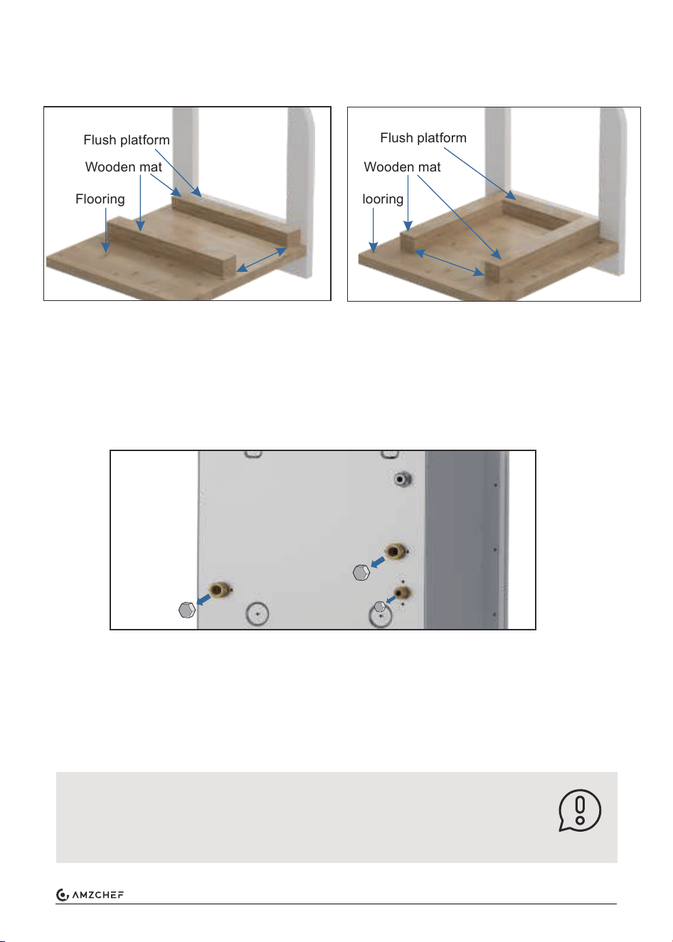
Prepare a Platform
Water-Resistant Treatment
Ensure a solid floor or platform with adequate weight-bearing capacity supports the
appliance.
1. Take the water heater out of its packaging by grasping the metal sides of the housing and
lifting upward until entirely removed from the box.
2. Remove protective caps for COLD, HOT water connector, and GAS connector from the
back side.
3. Apply adequate water sealing material, e.g. butyl tape (recommended width: 1” (25 mm),
not provided), around the entire backside flange area and holes.
4. Position the water heater carefully into the frame opening, and evenly space the flange to
the exterior wall of the RV.
5. Check the opening size if suitable for the appliance after finished.
6. Place the appliance in the designated cutout; if it doesn’t fit, confirm the measurements
and ensure the corners are square, not rounded.
Option 1 Option 2
Flush platform
HOT
COLD
GAS
Wooden mat
Flooring
Flush platform
Wooden mat
Flooring
7”-11.5”
(178-292mm)
6”-8”
(152-203mm)
NOTE
NOTE:
1. Do not use adhesive sealing material, e.g., silicone, for the watertight seal.
2. Ensure the area beneath and behind the appliance is clean without debris
and obstruction. Carefully slide the device across the floor to prevent
linoleum damage.
6
www.iamzchef.com Email: info@iamzchef.com Whatsapp:+1 (838) 910 8317 Facebook: amzchefappliance
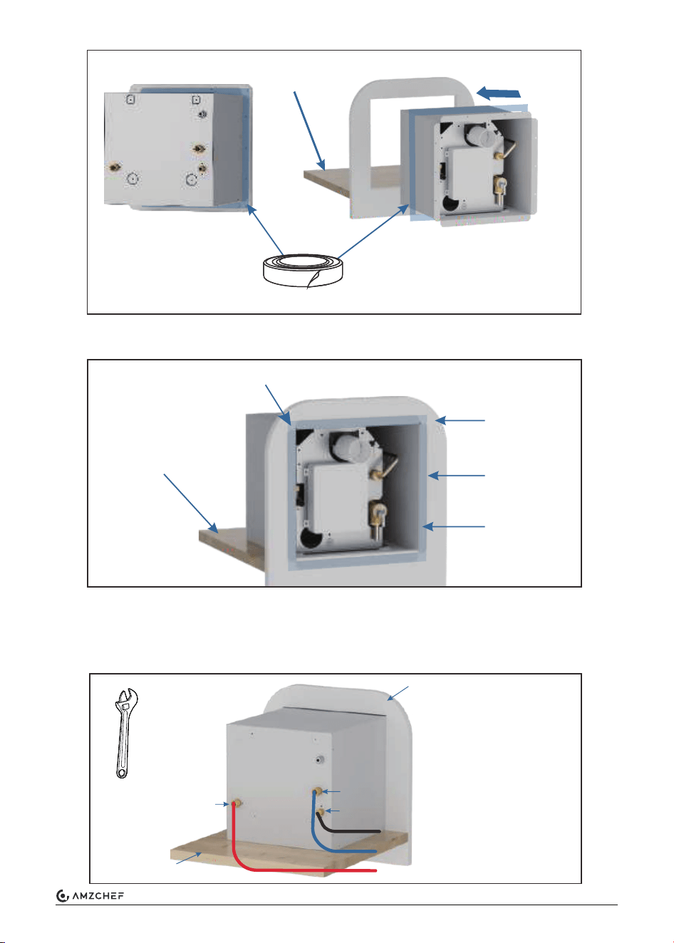
7. Check the sealing between the backside flange and the out wall. Make sure the flange
touches the RV's out wall.
Connect the Water pipe\gas service line to the Water pipe\gas-flared fitting on the back of
the appliance. Use a wrench to tighten the compression fitting. Avoid damaging the unit by
overtightening.
Position and slide
Clean the flooring
before slide
Butyl tape
RV wall
Butyl tape
Flange
Continuous bead around the flange backside and corners with butyl tape.
NOTE: It will cause leakage if there are gaps between the flange and out wall.
Water Pipe / Gas Connection
Water inlet
RV wall
NOTE: Do not use sealing
tape or compound on the
compression-type fitting.
Gas inlet
Water
outlet
RV flooring
Wrench
(not provided)
7
www.iamzchef.com Email: info@iamzchef.com Whatsapp:+1 (838) 910 8317 Facebook: amzchefappliance
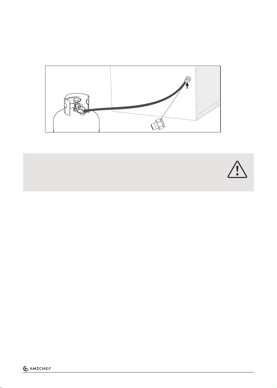
1. Prepare the gas connection
The appliance must be isolated from the gas supply piping system by closing
its individual manual shutoff valve during any pressure testing of the gas supply
piping system at test pressures equal to or less than 1/2 psi (3.5 kPa).
2. Gas plumbing
3. Water plumbing
Prepare Utilities
Gas inlet
5/8” - 18UNF
Connector
5/8” = 16 mm
Follow all applicable codes, regulations, and instruction material when
performing service work. Failure to follow instructions will result in product
damage, serious injury, or death.
• Make sure that the operating pressure of the gas supply corresponds to the operating
pressure of the appliance 11~14 in.WC (2740 ~3490 Pa).
• Fuel entering the appliance must be in the gas phase; the liquid phase must not be used,
and will result in damage to the product.
• Use with LP gas (propane) only. Butane or any mixtures containing more than 10% butane
must not be used.
• The gas line must terminate with a 3/8” (9 mm) flared female compression fitting to connect
with the rear gas connector of the appliance.
• A non-metallic flexible gas hose must be rated for 149°F (65°C). Anchor appropriately to
prevent fatigue and failure from worn edges.
(a) Locate the entry point for the plumbing to service the rear of the appliance. Ensure the
entry point is not in the footprint space of the appliance.
(b) Feed gas line into proximity, leaving enough length to flex into position so that when
connected no kinks are created.
NOTE: An approved semi-flexible metallic pipe is acceptable to connect as an extension
from the gas line to the appliance.
(c) Terminate gas line with fittings to connect to the appliance.
• The water plumbing system must be rated to supply between 35-70 PSI nominal.
• Connections can be made using PEX swivel nut adapters with NPT straight threads and a
cone seal or standard 1/2” (13 mm) FNPT fittings.
• This water heater requires a minimum water flow of 0.32 Gallons per Minute (GPM) for
proper operation.
FIRE OR EXPLOSION HAZARD
DANGER!
8
www.iamzchef.com Email: info@iamzchef.com Whatsapp:+1 (838) 910 8317 Facebook: amzchefappliance
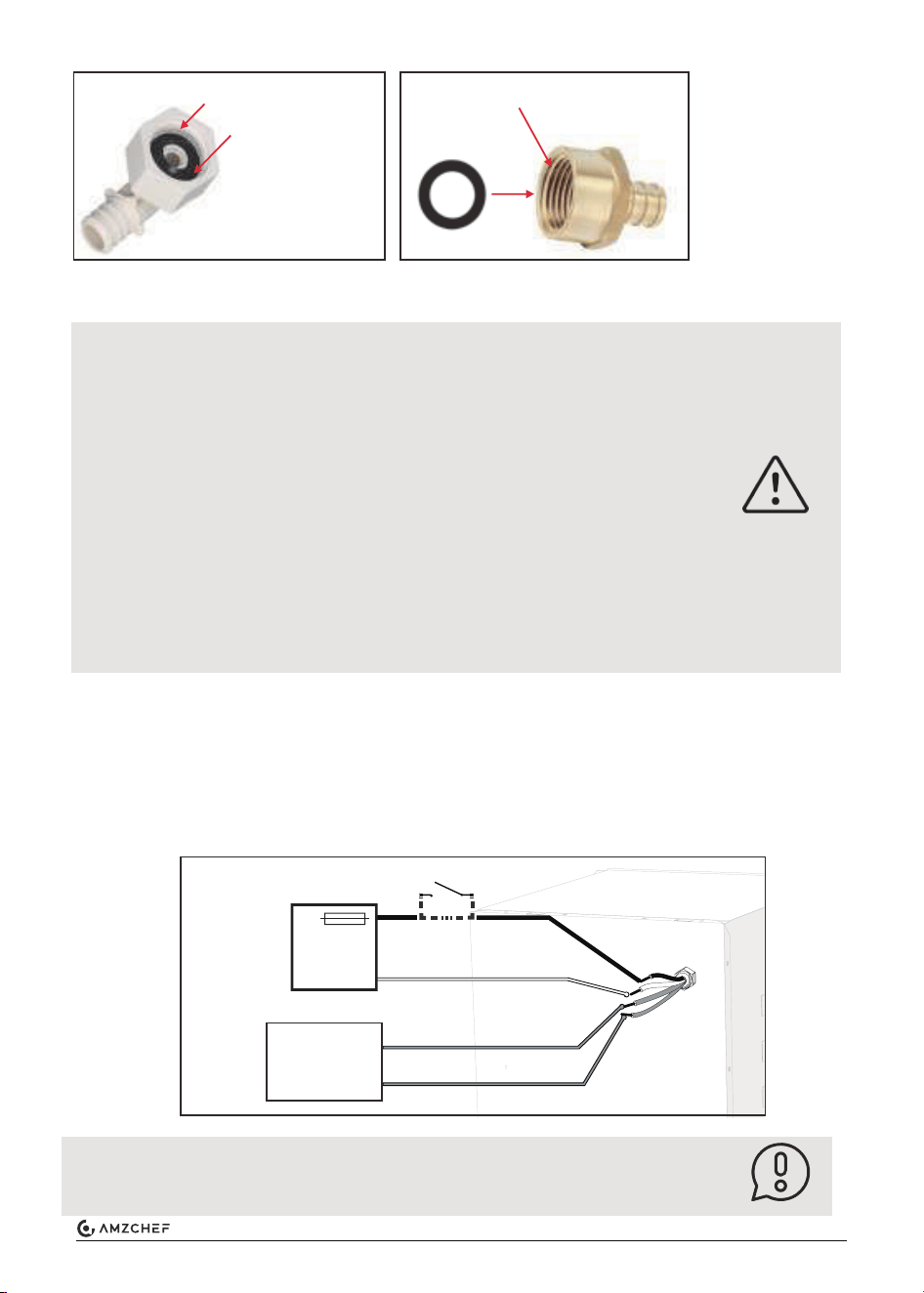
PEX 1/2” NPT swivel nut
Cone seal
rubber
1/2” FNPT fitting
Seal
gasket
4. Preparing the 12V DC electrical connection
• Disconnect all power before performing any work.
• Always use a certified and proven 12V isolated power supply, that is
properly grounded to the RV.
• Follow all applicable codes, regulations and instruction material when
performing service work.
• Failure to follow instructions could result in serious injury or death.
• Wiring connected to or in proximity of the appliance must be rated for
140°F (60°C) minimum.
• Use only insulated terminals for all electrical connections.
• Select a distribution branch greater than 3A, preferably 15A, to provide
nominal 12V to the appliance from the distribution panel.
NOTE: The appliance has a built in 10A fuse, serviceable from the front of
the product. The appliance can be on a dedicated or shared branch circuit
with the same or higher rating.
(a) Power switch can be placed in the living quarters for convenience, but not required as a
switch is located externally on the appliance. If the switch is fused, make sure it is rated for
at least 3A.
(b) Locate entry point for the wiring to service the rear of the appliance. Ensure entry point is
not in the footprint space of the appliance Make sure any edges are protected to prevent
wire abrasion from occurring.
ELECTRICAL SHOCK HAZARD
Optional:
DANGER!
Wiring
White -
Blue
Blue
Black +
Switch ON-OFF (optional)
12V DC
power
supply
Wall
Controller
NOTE
NOTE:
When finished, follow the instructions in section “Maintenance” to check
water and gas leak.
1/2” = 13 mm
9
www.iamzchef.com Email: info@iamzchef.com Whatsapp:+1 (838) 910 8317 Facebook: amzchefappliance
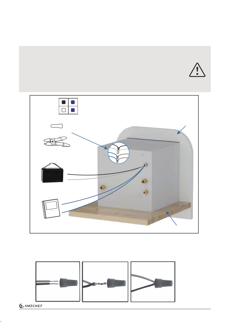
1. Set the power switch in the front of water heater to the “OFF” position.
2. Connect the power supply wires (on the rear of the water heater - white and black wire) to
the appropriate nominal 12V DC power source connection.
3. Connect the wall controller wires (2 blue wires on the appliance).
1. Strip the ends of 2 wires (Pic 1).
2. Manually twist them until they bind together (Pic 2).
3. Twist the connector clockwise while inserting the wires to fix them (Pic 3).
Electrical Connection
ELECTRICAL CONNECTION CAUTION
1. For DC power connection, the black wire is positive (+), and the white
wire is negative (-).
2. For controller connection, polarity does not matter. The wires can be
connected to either blue cables.
3. Do not connect the controller to a 12V DC power source. It will damage
the controller.
CAUTION!
Black: +12V
White: -12V
Blue: controller
Black: +12V
White: -12V
Blue: controller
Blue: controller
Blue: controller
Wire connector
Wire Stripper Pliers
(not provided)
12V DC battery
Wall controller
RV flooring
RV wall
Warnings: This connection is for 12V
battery or direct current only.
Don't connect to 120V or 240V AC.
Wire Connector Usage
Pic 1
Pic 2
Pic 3
RV
Battery
10
www.iamzchef.com Email: info@iamzchef.com Whatsapp:+1 (838) 910 8317 Facebook: amzchefappliance
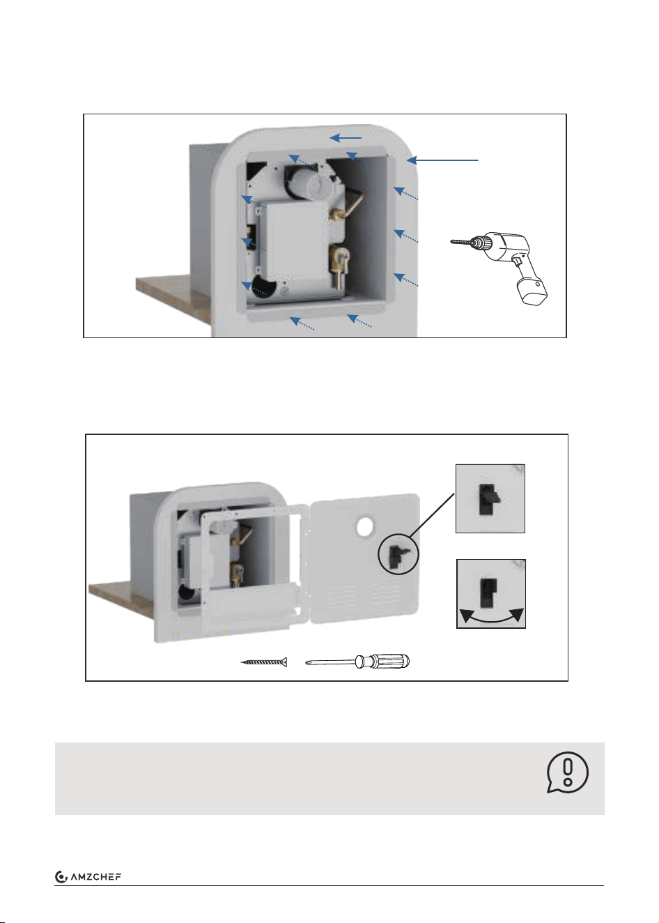
Drill holes on the metal board of the RV out the wall with a 1/8” (3mm) bit.
NOTE: Drill the metal board only—no needy to drill the inner wooden or heat insulation layer.
1. Insert the door flange into the water heater housing and press the flange firmly against the
sidewall.
2. Fix door frame with ST4.2*30 mm screws (14 pcs). Verify that a tight seal exists between
the side wall and the flange.
Drill Holes for the Appliance
Secure the Appliance and the Door frame
Metal board
1. Lift the handle.
Pre-install the door frame and make sure each hole is
aligned to the flange hole.
2. Rotate it 90°.
Heat insulation layer or wooden
NOTE
NOTE:
Ensure the butyl tape completes a tight seal between the RV siding and
appliance flange. If gaps exist, remove the appliance and apply a double
layer of butyl tape.
11
www.iamzchef.com Email: info@iamzchef.com Whatsapp:+1 (838) 910 8317 Facebook: amzchefappliance
1. Determine a location to install the wall controller inside the RV.
2. Drill a 0.75” (19 mm) hole and clean edges.
3. If necessary, run two electrical wires that extend the wall control connections (blue wires) to
the appliance. Connections (blue wires) using the appropriate wire size 16AWG max. 65ft.
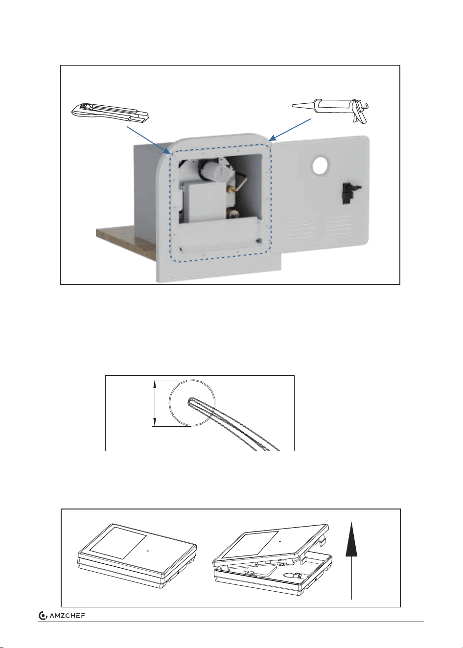
1. Disassemble the wall controller.
a) Press and push up the buckle of the wall controller.
b) Open the cover with a finger or with a flat blade (not provided).
3. Apply a liberal amount of sealant around the door frame to fill any gaps in the RV wall.
Wipe any excess adhesive.
Apply sealing material at the adage of the door frame (for better waterproof-
ing). Remove excess sealing material after sealing.
0.75”
(19 mm)
Prepare for the Wall Controller
Wall Controller Installation
12
www.iamzchef.com Email: info@iamzchef.com Whatsapp:+1 (838) 910 8317 Facebook: amzchefappliance
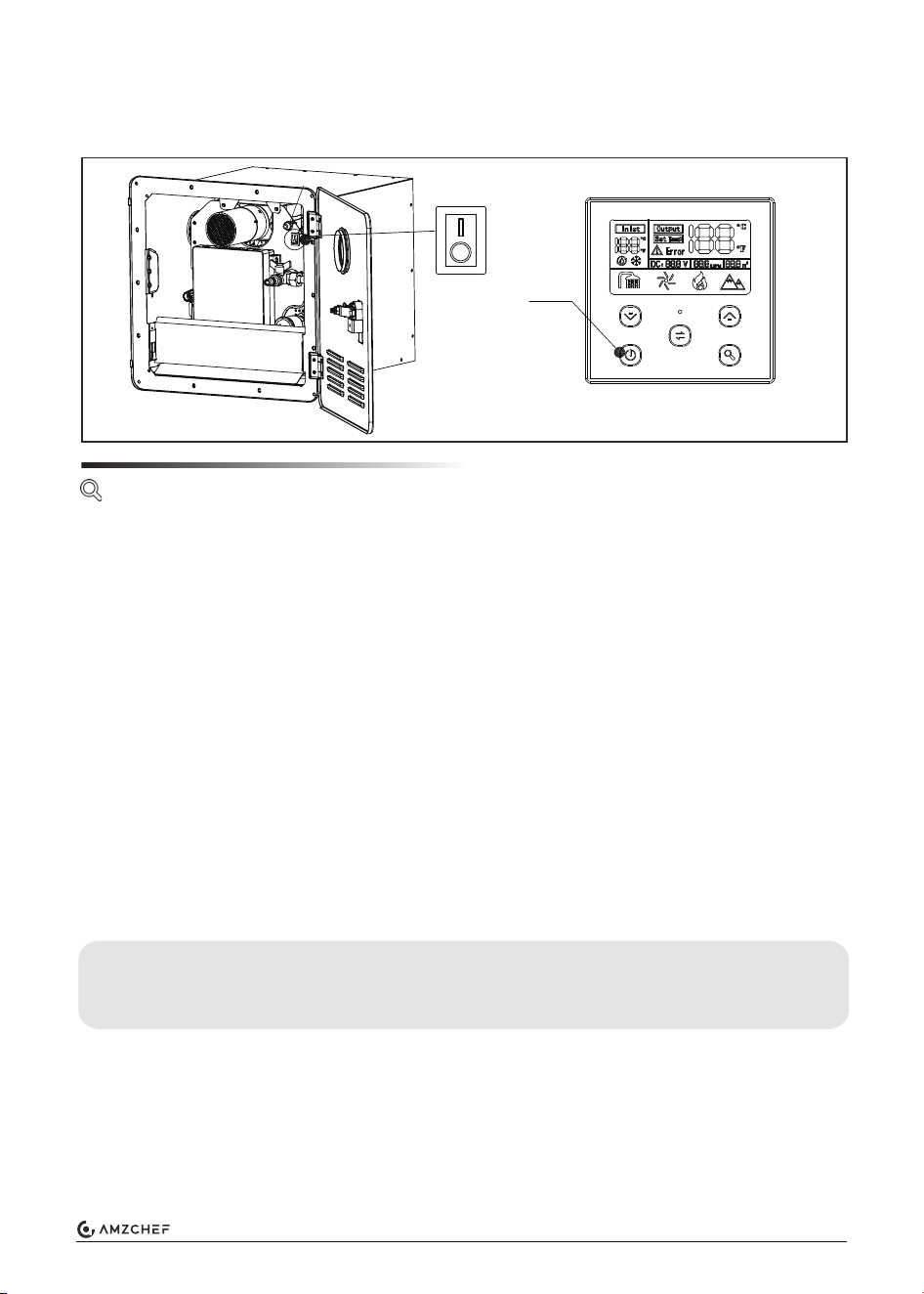
Functional Check
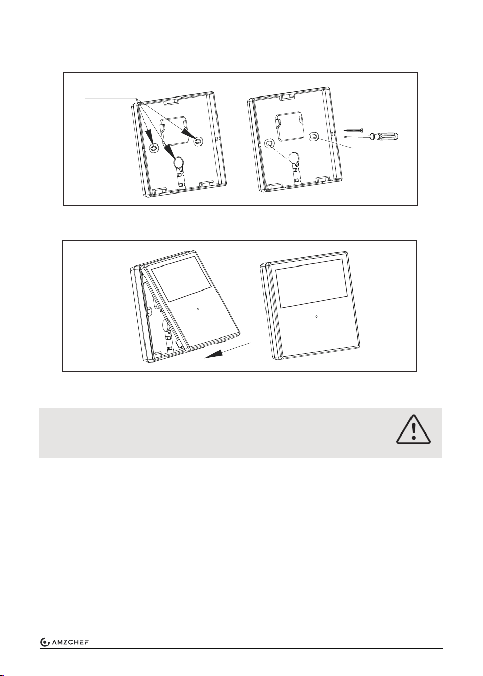
2. Install the back cover of the wall controller.
(a) Install the back cover of the wall controller over the 0.75” (19 mm) hole.
(b) Fix the back cover on the wall with 2 st4.2*20 screws.
3. Assemble the controller.
(a) Assemble the controller again after fixing the back cover.
Drive out with
a screwdriver
St4.2*20
screw
FIRE AND EXPLOSION HAZARD
Ensure all necessary system leak tests are complete before operating any
functional test.
1. Prepare
(a) Verify the power switch is in the “OFF” position.
(b) Confirm that there is a “steady” water flow (not pulsating) and no air in the system. If
pulsating have the water pump settings adjusted.
(c) Make certain all valves that can mix cold and hot water are all shut.
NOTE: Outside faucets with detachable spigots and shower heads with flow interrupters can
bleed hot water into the cold side if the valves are not closed properly. This will hinder the
performance of the water heater.
2. Start to work
(a) Turn the power switch to the “ON” position on the appliance and verify that the wall
controller is illuminated. If the wall controller is not illuminated, press the button on the
wall controller to describe it. The controller display will show the hot water temperature.
NOTE: The default setting is 108°F (42°C).
(b) Turn on the gas supply.
WARNING
13
www.iamzchef.com Email: info@iamzchef.com Whatsapp:+1 (838) 910 8317 Facebook: amzchefappliance
1. The appliance was developed exclusively for use in recreational vehicles (RVs).
2. The appliance is connected between the vehicle’s fresh water supply and its hot water
system.
3. It is powered by propane and a DC 12V power supply. The ventilation grid on the access
door allows combustion air to flow into the appliance and exhaust gas to flow out.
4. When the appliance is switched on, the tap water will be heated on demand:
(a) When the hot water tap is turned on and the volume flow surpasses about 1.6 L/min, the
burner will be activated by the volume-flow sensor in the appliance.
(b) The heater's burner control regulates the heat output by monitoring the flow rate and the
temperature of the incoming water to maintain a hot water outlet temperature of around
123.8°F (51°C). A temperature stabilizer is also installed in the appliance to minimize
fluctuations of the outlet temperature.
(c) After some time the maximum temperature at the tap or in the shower is reached. The
length of time will depend on the model and variations in the water system (length of pipes,
insulation, circulation line, etc.). Like in a home shower, a comfortable water temperature
at the shower head is reached by mixing in cold water.
(d) When the volume flow is less than approximately 1.0 L/min or the tap is closed, the burner
is automatically switched off.
Production Introduction
Production Safety Features
The appliance is equipped with the following safety devices:
1. Flame monitoring device:
The device will cut off the gas flow to the burner if the flame extinguishes.
2. Antifreeze function:
The device has a built-in antifreeze feature that activates when the temperature outside falls
below freezing, warming the water system to 48°F (9°C) before shutting off. Remember to
activate the electricity and gas flow while the anti-freeze period is in effect.
This heater features a thermostatic water tank that helps maintain a constant tempera-
ture for the water it produced. This prevents the water from becoming too hot or too cold,
ensuring a comfortable and enjoyable showering experience.
(c) Open a hot water faucet and verify that the unit ignites and supplies hot water at the tap.
(d) The wall controller display will show the current temperature settings.
NOTE: If any error codes or performance concerns, refer to the section Error Codes of this
manual.
Introduction
OFF
Power
button
ON
Fuse
14
www.iamzchef.com Email: info@iamzchef.com Whatsapp:+1 (838) 910 8317 Facebook: amzchefappliance
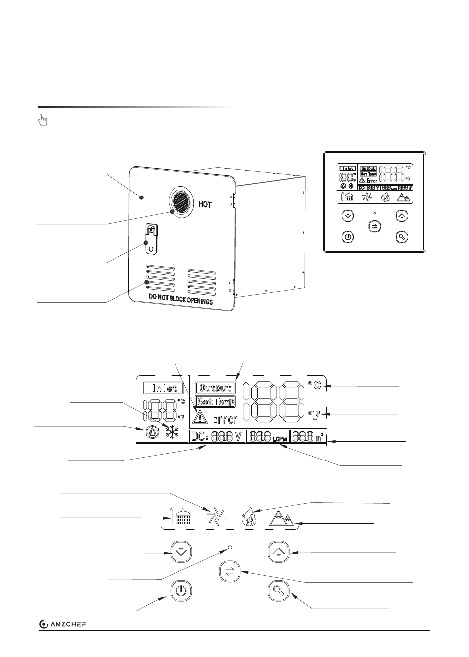
Product Overview
Wall Controller
Door frame
Wall Controller
Exhaust vent
Door locker
Air inlet
Set the Appliance
3. Power positive and negative wires reverse protection:
In case the positive and negative wires are reversed, the device will shut down to
safeguard the circuit board. (However, the fuse will be damaged)
4. Low-voltage/over-voltage shutdown:
If the voltage drops below 10V DC (or rises above 17V DC), the appliance shuts off.
Indicator
Indicator
Indicator
LCD screen
Lookup button
Temp. unit toggle button
Temperature increase
Burner burning symbol
High altitude mode
Gas consumption
Water consumption
Fahrenheit unit
Celsius unit
Antifreeze icon
Water pump symbol
Water flowing symbol
Fan blowing symbol
Input voltage
Temperature decrease
Power button
Fault icon
15
www.iamzchef.com Email: info@iamzchef.com Whatsapp:+1 (838) 910 8317 Facebook: amzchefappliance
Before normal operation of the appliance, perform a basic functional test each time the RV
and water system is setup for use. Make sure electric, water, and gas supply are standard.
There may be a variation between the temperature delivered from the appliance and the
temperature at the faucet due to water conditions between seasons, like hot summer or the
length of pipe from the appliance.
Always check the water temperature, about the chart below, by the display and hand touch
before bathing or with other hot water uses.
Source: Moritz, A.R. / Herriques, F.C.: Studies of thermal injuries: the relative importance of
time and surface temperature in causation of cutaneous burns A. J. Pathol 1947; 23: 695 - 720.
This appliance can be used at high altitude and has been tested up 4500 ft.
Press the and lookup button for 3 seconds, to enable the High Altitude Mode.
The icon will be lit.
Operation
Safe Operation
For High Altitude Use
1. Touch power button to turn ON/OFF the water heater. The panel will be illuminated and
will display the current temperature setting.
2. Touch the temp. unit toggle button to toggle between Celsius and Fahrenheit display.
3. Use and to set your desired temperature. Temperature range: 95-124°F (35-51°C).
4. Remember to turn off the appliance using the front switch when it's not in use for an
extended period, as the power button only puts it into sleep mode.
5. Follow below to use the lookup functton:
(a) During normal operation, the heater displays current input voltage, water and gas
consumption.
(b) Press the lookup button to see a quick overview of the accumulated water and gas
consumption, which will only be displayed for 5 seconds before switching back to the
current data.
(c) While showing the accumulated water and gas consumption, hold down the lookup button
for 3 seconds to reset them to zero.
SCALD HAZARD
Never let infants, children, elderly adjust the water temperature or be left
unsupervised when using hot water.
WARNING
Temperature °F (°C)
148 (64)
140 (60)
133 (56)
127 (52)
124 (51)
120 (48)
155 (68)
100 (37)
Time before skin becomes scalded
2 seconds
5 seconds
15 seconds
1 minute
3 minutes
5 minutes
1 second
Safe bathing temperature
16
www.iamzchef.com Email: info@iamzchef.com Whatsapp:+1 (838) 910 8317 Facebook: amzchefappliance
Thoroughly flush the water heater and system with clean drinking water through the hot and
cold sides before using. Drain water several times out of the water heater drain plug. Sanitize
the water system per the recommendations of your coach manufacturer.
Checking for Gas Leak
Checking for Water Leak
Storage and transit
For Next Season Using
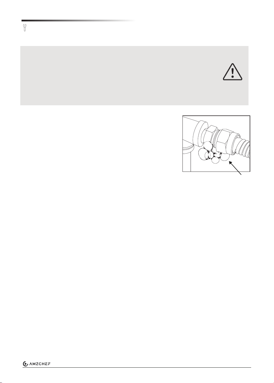
1. Turn on the gas supply or alternative pressure supply.
2. Check the appliance and all gas connections for gas
leaks with leak detection liquid (not provided) or an
equivalent gas leak detection method. Bubbles indicate a
gas leak that must be repaired.
3. Repair gas leaks as needed by a qualified technician.
4. Repeat the gas leak check after any adjustments to loose
connections.
5. After leak checking, ensure the gas supply pressure
corresponds to the operating pressure of the appliance
10.5~14 in.WC (2620~3490 Pa).
1. Verify that the power switch on the water heater is in the “OFF” position.
2. Turn on the water supply to the appliance.
3. Open water faucets to fill the system with water. Close the taps when the water flows
smoothly and all air is removed from the lines.
4. Check all connections for water leaks by eye and touch.
5. Repair water leaks as needed.
6. Repeat the water leak check after any adjustments or loose connections.
Anytime the RV is not intended to be used, it is considered in storage or transit.
To prepare the water heater, follow the below steps:
1. Turn off the gas supply.
2. Turn off the water heater main switch.
3. Drain the water out of the system and water heater by removing the filter cover and drain
plug. If freezing conditions could occur, then winterize according to the "Winterizing Water
Heater" (Refer to the above operation).
Maintenance
FIRE OR EXPLOSION HAZARD
• DO NOT use matches, candles, or other ignition sources when checking for
gas leaks.
• After the gas supply is connected, check for gas leaks at all gas connections.
Use a gas leak detection liquid or equivalent. Ensure test pressure is below 40
in.WC (100kPa).
• Make sure to re-test all fittings after making adjustments to loose connec-
tions.
DANGER!
Bubbles
17
www.iamzchef.com Email: info@iamzchef.com Whatsapp:+1 (838) 910 8317 Facebook: amzchefappliance
Routine inspection is critical for maintaining the proper operation of your appliance. Unless
specified, review the following items yearly or before each season:
Routine Inspection
1. Inspect the gas system, water system, and installation every two years or otherwise
restricted by your RV coach manufacturer by a qualified person.
2. Inspect for cracks, separation, and peeling of seals to the RV wall. Remove and reseal as
necessary (caulking or tape) between the side wall and the water heater door and ensure
that the unit is solidly mounted to the vehicle.
3. Before actively using your vehicle, pre-inspect that the air intake openings (louvers) are
completely open and clear of any debris, including mud, leaves, twigs, insects, etc...
Remove all obstructions to allow total air flow.
4. Before actively using the vehicle, open the door and verify that no debris or extraneous
combustible materials are present anywhere (especially in the area of the burner and the
gas controls). Remove any item present and wipe clean the bottom of the housing.
5. Before actively using the vehicle, verify that the exhaust tube and screen are completely
clear of obstructions, including mud, leaves, twigs, insects, nests, etc. Clean by gently
breaking it up and using a vacuum to clear it. Use only water and apply gently from a spray
bottle. Never spray directly with high-pressure water. Next, run the appliance to dry any
moisture and blow out loose debris. Using any aftermarket protective screen is prohibited
and will void the warranty.
6. Inspect the interior surface of the housing for any cracks or corroded areas that could allow
the penetration of gases into or out of the vehicle’s interior. Check especially around the
hot water, cold water, gas, and electrical connections.
7. Check that all wire connections are firmly in place and that there are no signs of chafing or
cracks on the insulation. Verify that the spark ignition cable between the Control Board and
the igniter is securely in place and not shorted to any metal component.
8. Inspect the pressure safety valve to ensure it has not been leaking (no water residue). See
"Pressure Safety Valve Maintenance" for further inspection.
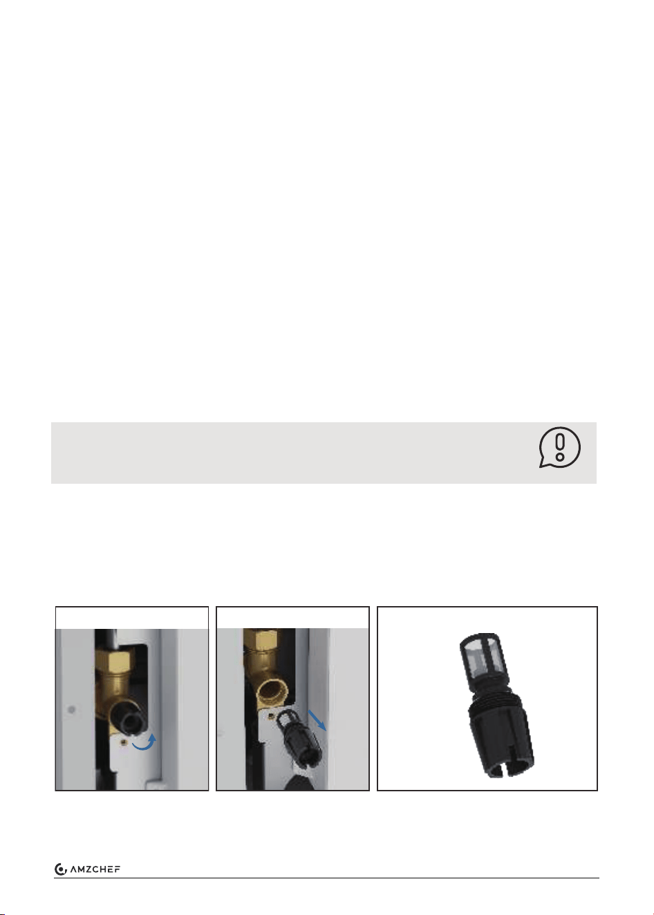
9. Inspect/clean/replace the water inlet filter as necessary. Use a brush to clean the filter.
NOTE
NOTE:
If damages are found, please get in touch with a technician to repair or
contact after-sales service.
1. Unscrew the filter.
2. Pull out the filter.
3. Use a brush to clean the filter.
18
www.iamzchef.com Email: info@iamzchef.com Whatsapp:+1 (838) 910 8317 Facebook: amzchefappliance
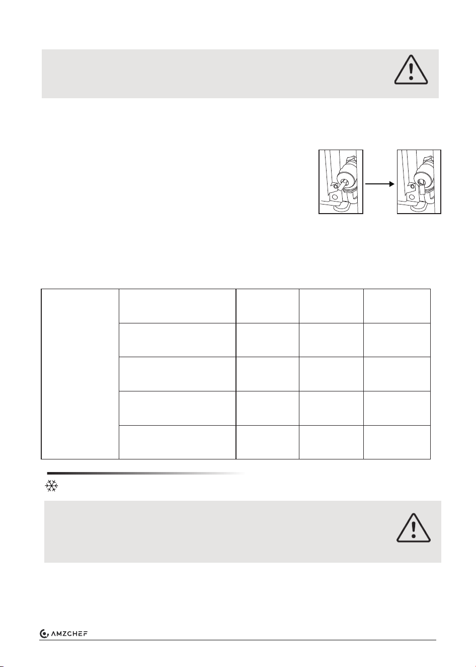
1. The unit is equipped with a water pressure safety valve, which must operate once yearly to
ensure this safety device is effective.
2. The valve is a safety component and must not be removed for any reason other than
replacement.
3. Tampering with the pressure safety valve will void the
warranty.
4. Lift the pressure safety valve handle upward. Water will drip
out of the pressure safety valve if it is operating correctly.
When exposed to higher water hardness concentrations for prolonged usage, it is advised
to provide a proper water treatment device for the incoming water to the coach. Hard
water may lead to performance reduction of your appliance overtime.
It is advisable to maintain an annual schedule for decalcification.
Recommended decalcification frequency per year
Winterizing Water Heater
Pressure Safety Valve maintenance
BURN OF SCALD HAZARD
• Never actuate the pressure relief valve while the appliance is in operation.
• Never tamper with the pressure relief valve.
WARNING
Break it
Hard Water and Decalcification
Automatic Winterizing:
PRODUCT DAMAGE DUE TO FROST CONDITION
In frost conditions, ambient temperatures are below 39°F (4°C).
There is a risk that water in pipes, faucets and appliance could freeze. This
can cause considerable damage.
The device comes with an automatic antifreeze feature. It activates when the water tempera-
ture falls to 43°F (6°C) and deactivates when the water temperature rises to 90°F (32°C). This
process repeats in a continuous cycle.
CAUTION!
Water
hardness
mg/l CaCo3
Very hard: > 180
Hard: 121-180
Moderately hard: 61-120
Soft: 0-60
Frequency of use
1
1
1
1
low
2
1
1
1
normal
4
3
2
1
high
19
www.iamzchef.com Email: info@iamzchef.com Whatsapp:+1 (838) 910 8317 Facebook: amzchefappliance
NOTE:
Ensure the appliance has its electric and gas supply activated, while the
controller can be switched off (put on standby). If there is no electric and
gas supply, the automatic winterizing feature will not function.
Tap 1
Shower
B
A
Hot water
outlet
Cold water
outlet
Valves A, B
bypass position
Tap 2
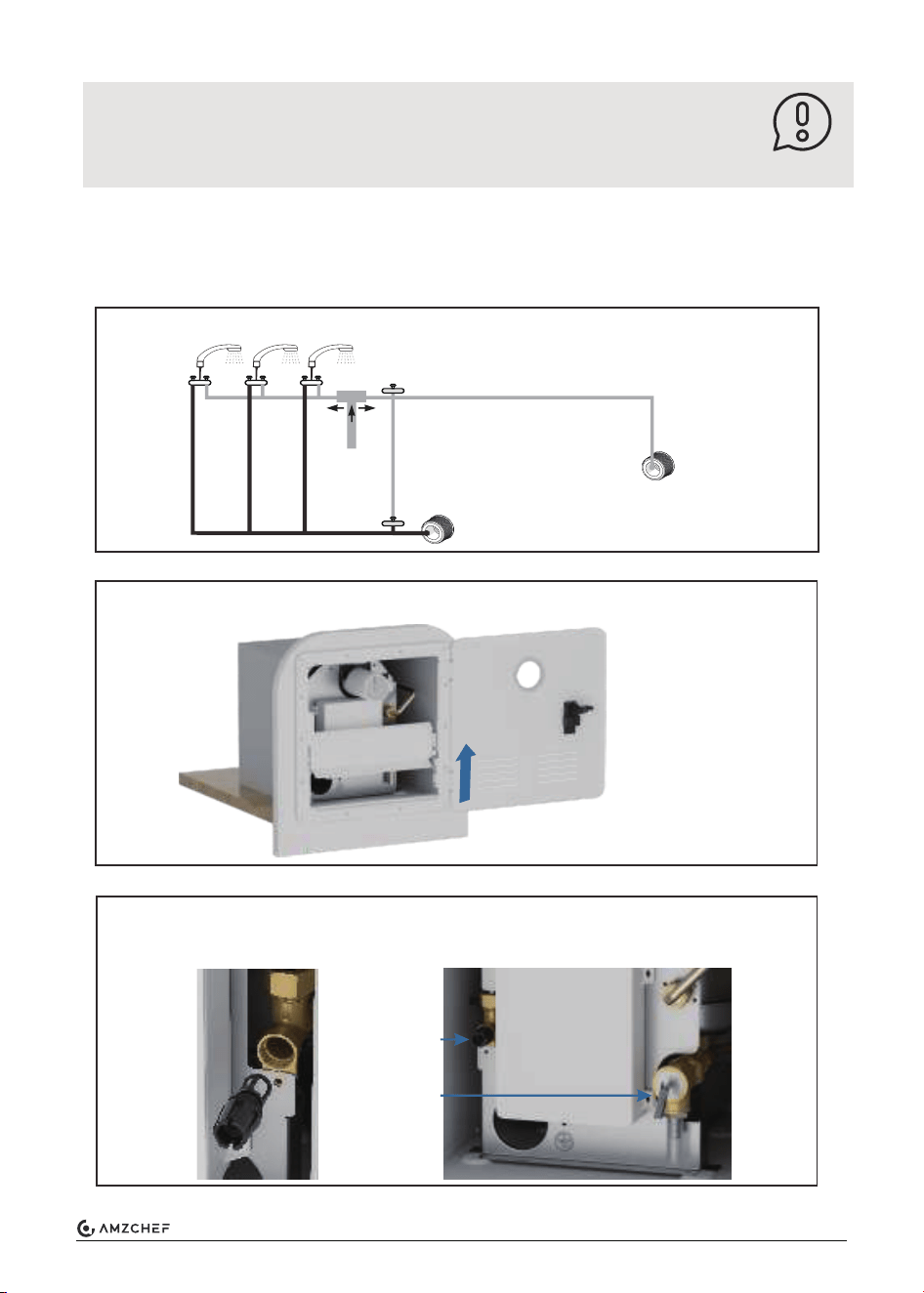
Manual Winterizing Operation:
To winterize the appliance for a long time or for storage, you must drain all water from the
appliance. To do this we advise the following steps:
1. Close valves A and B, and open the pressure safety valve.
2. Open the door and pull out the baffle from the door frame.
3. Open the safety valve by hand and allow the water to drain completely from
the unit. Unscrew the water inlet filter to clean the filter.
NOTE
Filter
Drain
plug
20
www.iamzchef.com Email: info@iamzchef.com Whatsapp:+1 (838) 910 8317 Facebook: amzchefappliance
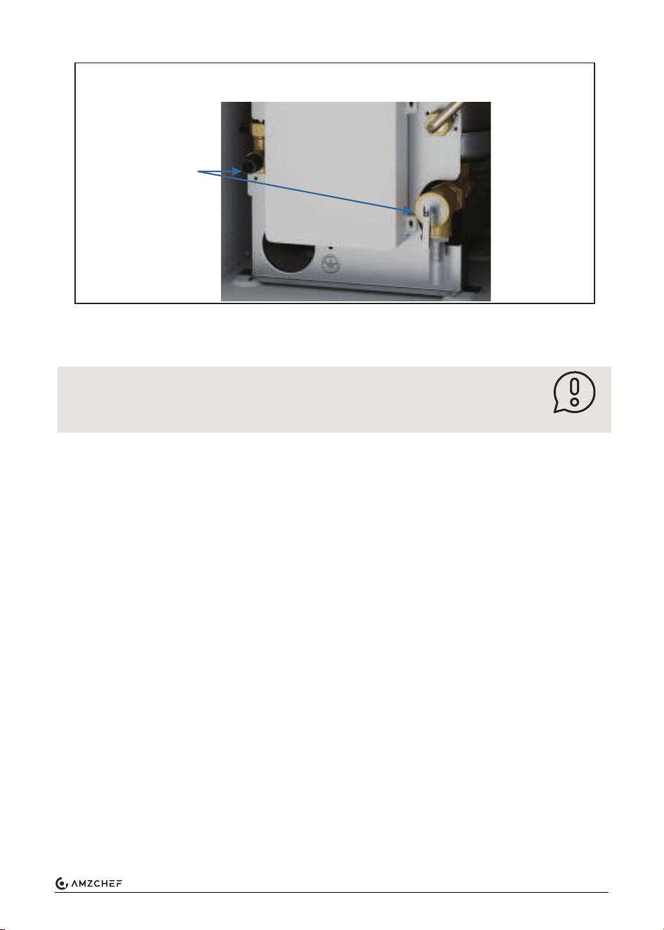
Winterizing the RV with a Winterizing fluid:
4. Make sure the water in the appliance has totally drained. Then screw the
drain plug and the filter again.
5. Flush the RV's water system with a suitable winterizing fluid according to the
supplier's or RV manufacturer's guidelines.
Winterizing the RV with a winterizing fluid is only possible with an installed bypass kit (not
provided).
Follow the instructions provided by the RV coach manufacturer for winterizing water system.
Supplement the following important water heater instructions when completing any winteriz-
ing steps:
1. Compressed air pressure for blowing water heater:
(a) DO NOT exceed 30 PSI when air pressure is in the water heater.
(b) While completing the blowout process for the entire water system, take time to isolate
the water heater by closing all drain plugs and faucets and only open the water heater
drain plug and filter cover. This ensures maximum pressure and flow are isolated through
the water heater for complete evacuation.
2. Anti-freeze:
(a) Use a non-toxic antifreeze recommended by the RV coach manufacturer.
(b) Antifreeze can be used directly in the water heater. Plan for an additional 1L to fill the
system.
3. Optional:
(a) A bypass valve can be installed or used to bypass filling the water heater with antifreeze.
Before bypassing, the water heater must be evacuated with compressed air (see steps
above).
NOTE:
The appliance is protected against freezing conditions once the water has
been drained.
NOTE
Water
draining
21
www.iamzchef.com Email: info@iamzchef.com Whatsapp:+1 (838) 910 8317 Facebook: amzchefappliance
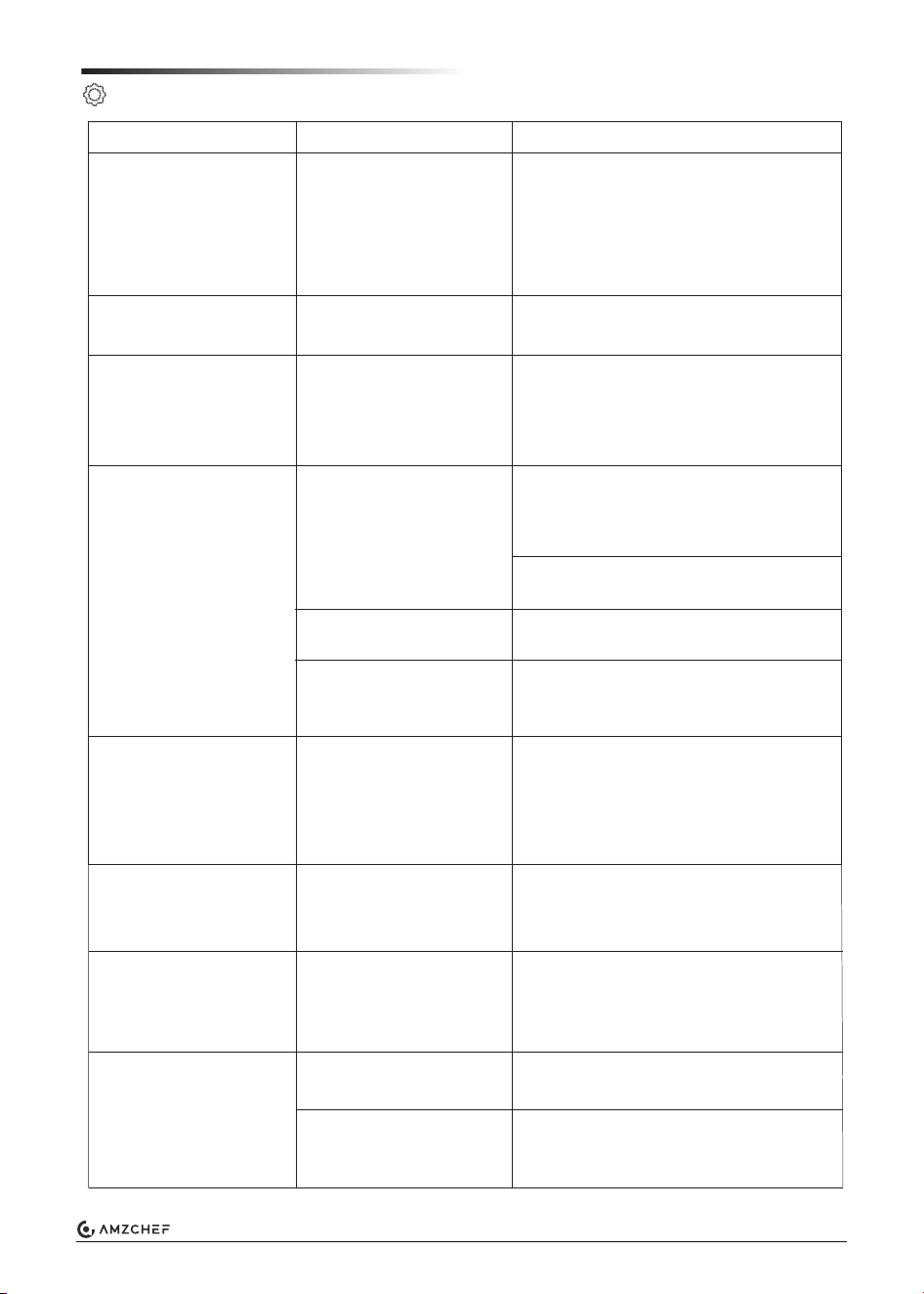
Problem
No hot water
Gas supply is turned off
or interrupted.
Gas tank is empty.
The appliance is
switched off.
Water supply is turned
off.
The power supply to the
appliance is switched
off.
Check and/or turn on the gas supply.
Refill/replace the gas tank.
Switch on the appliance according to
the instructions.
Open the water supply.
Switch on the power supply to the
appliance.
Potential cause
Solution
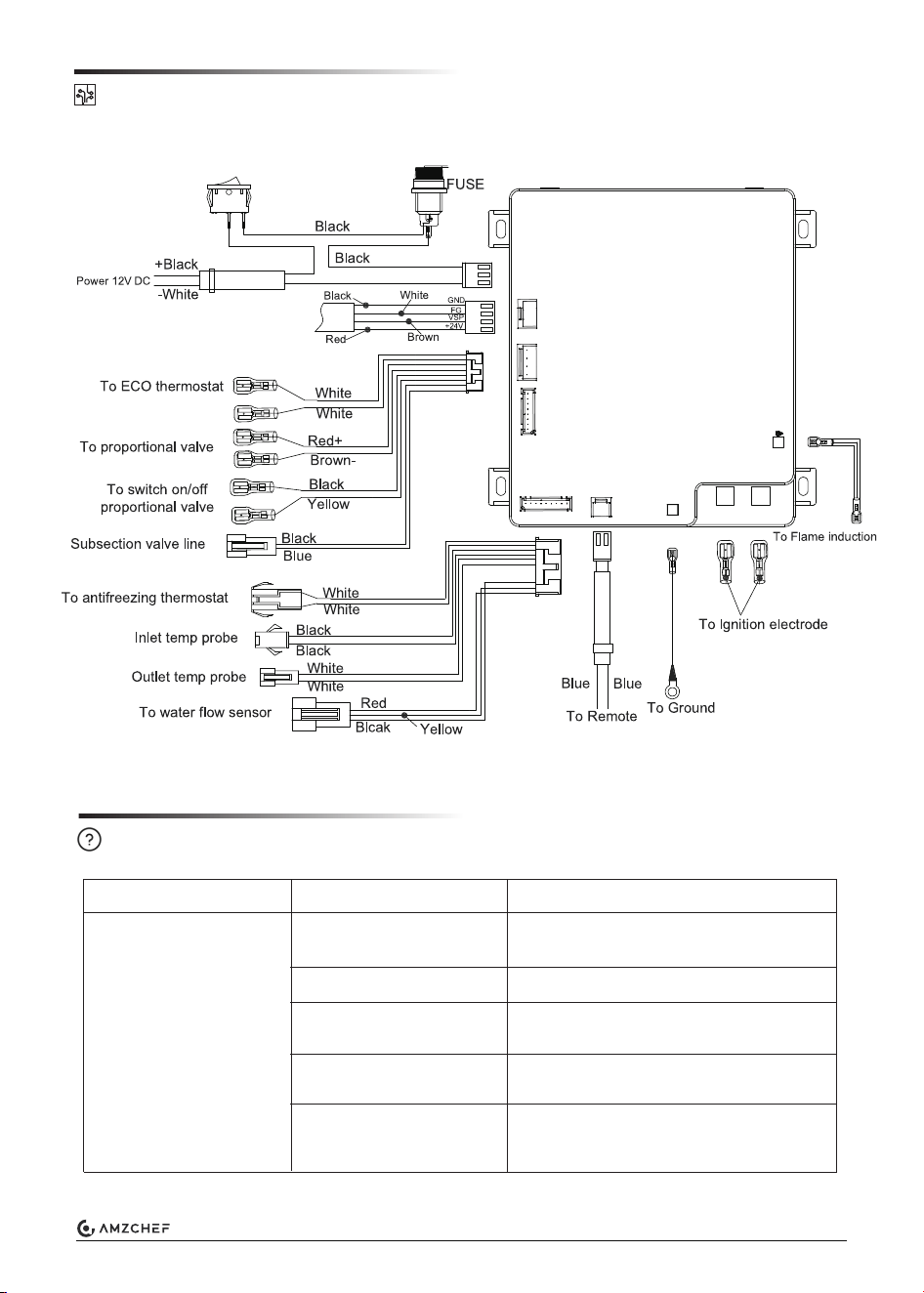
Electrical Connection Diagram
Troubleshooting
22
www.iamzchef.com Email: info@iamzchef.com Whatsapp:+1 (838) 910 8317 Facebook: amzchefappliance

Water leakage at the
water inlet filter
Water heater stops
working often and water
is found on the drainage
tray
The power status LED
is off although an
operating the mode
was selected.
The unit is over heating, and
the pressure relief valve
discharged periodically.
Power supply to the
appliance is switched off.
Blown fuse.
Contact a qualified technician.
Switch on the power supply to the
appliance.
Switch the standard 125V/10A fuse.
Contact a qualified technician.
Lime or dirt under the
O-ring seats.
Clean the O-rings and their
corresponding sealing surfaces with
clean water.
Hot water takes too
long to reach tempera-
ture
Water is not hot
enough
Water escaping at
pressure safety valve
1. Cold water mixing
into the hot water side.
2. Higher elevation.
Gas flow to the
appliance is too low
(gas inlet pressure 11in.
WC).
The volume flow of hot
water is too high /
incoming water
temperature is too low.
Too much lime scale in
the appliance.
Cold water mixing into
Hot water side.
Water pressure in water
system too high.
1. Check all valves, inside and
outside, to ensure they are closed.
Check the shower head valve to make
sure it is not partially closed.
2. This is normal due to less oxygen
levels.
1. Consult vehicle documentation to
determine if gas supply is capable of
providing the necessary the volume of
gas for the appliance.
2. Contact a service technician to
verify a suitable gas installation.
1. Turn down the hot water at the tap
or shower to reduce volume flow.
2. Potentially retrofit a volume flow
throttle into the water system. This
must be performed only by a certified
service technician.
Decalcify your water heater. See
“Maintenance” section.
Check all valves, inside and outside,
to ensure they are closed. Check the
shower head valve to make sure it is
not partially closed.
1. Adjust the water pump pressure to
a maximum of 65 PSI.
2. A water pressure reducer must be
used if the water system is connected
to a central water supply higher than
65 PSI (rural or urban connection).
3. Install a water pressure regulator at
the freshwater supply.
23
www.iamzchef.com Email: info@iamzchef.com Whatsapp:+1 (838) 910 8317 Facebook: amzchefappliance
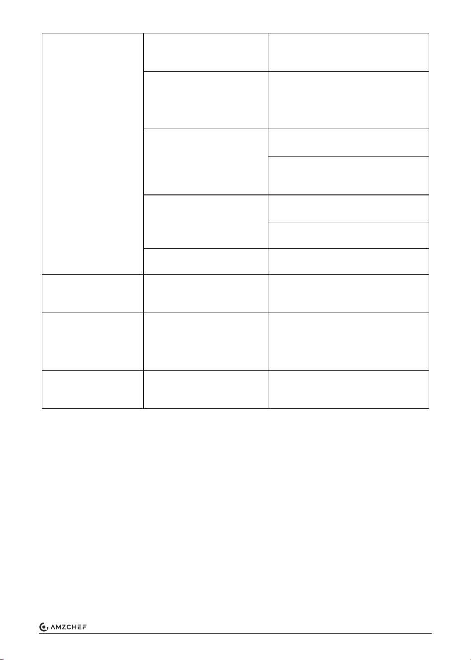
Error Code
Possible cause
Solution
Error Codes
Eu: Under-voltage and
over-voltage protection
Under-voltage: voltage
drops to 9.5+0.1V and
then rises to 10+0.1V.
Over-voltage: voltage
rises to 17.3+0.1V and
then falls to 16.7+0.1V.
Check the vehicle voltage and exclude
unstable voltage.
En: Set time is up
E0: Water outlet
temperature sensor
fault
E1: Flame sense fault
E2: Detected fake
flame signal
Temperature sensor or
system failure.
Insufficient fuel supply
to start operation.
Low gas inlet pressure.
Flame sensor or
system failure.
Set the end of a device
runtime.
Rebooting the device.
Check the water outlet temperature
wires connection, If it loosens, tighten
it, If not, the outlet temperature sensor
may fails. Replace it.
Confirm all gas valves are open and
restart the appliance 4-5 times (first
time for using).
Confirm adequate fuel in tanks.
Check regulator for operation, replace
if needed.
If the flame sensor induction or PCB
board is broken, it need to be replaced
by one of them.
Flame sensor or
system failure.
PCB primary control board failure or
program faulty. Replace the main
control board.
E3: Over temperature
mechanical sensor
fault
Thermostat system fault.
PCB primary control board failure or
program faulty. Replace the main
control board.
E4: Water inlet
temperature sensor
fault
Temperature sensor or
system failure.
Check the water outlet temperature
wires connection: if loosened, tighten
it. If not, maybe the outlet temperature
sensor fails. Replace it.
E5: Air pressure fault
Exhaust Blockage.
Strong winds blowing on
exhaust.
Remove obstruction, then restart the
appliance.
Move or re-orient the coach exhaust is
not facing strong winds. Then restart
the appliance.
24
www.iamzchef.com Email: info@iamzchef.com Whatsapp:+1 (838) 910 8317 Facebook: amzchefappliance
25
www.iamzchef.com Email: info@iamzchef.com Whatsapp:+1 (838) 910 8317 Facebook: amzchefappliance
Cold water surge in
system.
Cold water mix ratio.
Insufficient water supply.
Insufficient water flow
Temperature sensor or
system fault.
Solenoid valve or system
fault.
Solenoid valve or system
fault.
During normal combustion,
the fan speed exceeds the
current load speed limit for
five consecutive seconds.
E6: Temperature surge
alarm
E7: Solenoid valve fault
E8:Wind speed over
limit fault
Reduce toilet flushes and the number
of cold water faucets opened during
operation.
Reduce temperature setting to reduce
cold water mix ratio.
Check for shower head and outdoor
faucet valves leaking cold water to the
hot side.
Confirm water tank is full or city water
valve is fully open.
Replace the outlet temperature or
main PCB control board.
Check the solenoid valve wires
connection to see if it loosens or is
broken.
Check the fan air inlet.
Filter plugged- review "Cleaning and
Maintenance" section of this manual.
Low flow faucets - check that the
minimum flow is 0.32 gpm.
Air in the water lines-continue to run
all faucets, hot and cold. Open until
the air purged.
EC: Circuit fault
Wrong controller or
damaged parts
Use the correct wire controller. If the
problem persists, consult the customer
services.