Before attempting to connect or operate this product,
please read these instructions carefully and save this manual for future use.
User's Manual
GV-IP Camera
UBN-UM-ZM
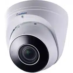
GV-ABL / TBL Series
GV-ADR / TDR Series
GV-AVD / TVD Series
GV-BLFC5800
GV-EBD Series
GV-EBDP / TBLP Series
GV-EBFC5800
GV-FER5702
GV-PTZ5810-IR
GV-TFD Series
GV-TMS Series
©2025 GeoVision, Inc. All rights reserved.
Under the copyright laws, this manual may not be copied, in whole or in part,
without the written consent of GeoVision.
Every effort has been made to ensure that the information in this manual is
accurate. GeoVision, Inc. makes no expressed or implied warranty of any kind
and assumes no responsibility for errors or omissions. No liability is assumed
for incidental or consequential damages arising from the use of the information
or products contained herein. Features and specifications are subject to
change without notice.
GeoVision, Inc.
9F, No. 246, Sec. 1, Neihu Rd.,
Neihu District, Taipei, Taiwan
Tel: +886-2-8797-8377
Fax: +886-2-8797-8335
http://www.geovision.com.tw
Trademarks used in this manual: GeoVision, the GeoVision logo and GV
series products are trademarks of GeoVision, Inc. Windows is the registered
trademark of Microsoft Corporation.
May 2025
Scan the following QR codes for product warranty and technical support
policy:
[Warranty] [Technical Support Policy]
i
Preface
Welcome to the GV-IP Camera User’s Manual.
IMPORTANT: The features described in the manual vary among camera models and
firmware versions. Some features may not be available in your camera.
This Manual is designed for the following models:
Model
Model Number
IR Eyeball Dome
GV-EBD2702 / 2704 / 2705
GV-EBD4700 / 4701 / 4704 / 4711 / 4712 / 4813
GV-EBD8700 / 8711 / 8800 / 8813
GV-EBFC5800
Bullet IP Camera
GV-ABL2701 Series / 2702 / 2703 Series
GV-ABL4701 Series / 4703 / 4711 / 4712
GV-ABL8712
GV-TBL2703 Series / 2705 / 2706 / 2718 / 4700 / 4703 /
4705 / 4710 / 4711 / 4807 / 4810
GV-TBL8710 / 8804 / 8810
GV-BLFC5800
Mini Fixed IP Dome
GV-TFD4700 / 4800
Mini Fixed Rugged IP Dome
GV-ADR2701 / 2702
GV-ADR4701 / 4702
GV-TDR2700 / 2702 / 2704 / 2705
GV-TDR4700 Series / 4702 Series / 4703 Series / 4704
Series / 4803 Series
GV-TDR8805
Multi-Sensor IP Camera
GV-TMS8800
Panoramic IP Camera
GV-TBLP5800 / 8800
GV-EBDP5800 / 8800
Vandal Proof IP Dome
GV-AVD2700
GV-AVD4710
GV-AVD8710
GV-TVD2712 / 4700 / 4710 / 4711 / 4810 / 4811
GV-TVD8710 / 8810
IR Fisheye Rugged IP
Camera
GV-FER5702
IR Mini PTZ Camera
GV-PTZ5810-IR

ii
Contents
Preface........................................................................................i
Contents ....................................................................................ii
Naming Definition ....................................................................ix
Note for Connecting to GV-VMS / DVR / NVR ........................x
Note for Installing Camera Outdoor .......................................x
Note for Powering the Camera ...............................................xi
Chapter 1 Introduction ..........................................................1
1.1 GV-EBD / EBFC / EBDP Series ............................................................................. 1
1.1.1 Packing List................................................................................................ 3
1.1.2 Optional Accessories .................................................................................. 3
1.1.3 Overview .................................................................................................... 4
1.1.3.1 GV-EBD2702 / 2704 / 2705 / 4700 / 4701 / 4704 / 8700 / 8800
and GV-EBFC5800 ...................................................................... 4
1.1.3.2 GV-EBD4711 / 4712 / 4813 / 8711 / 8813, GV-EBDP5800 / 8800
.................................................................................................... 5
1.1.4 Installation .................................................................................................. 6
1.1.4.1 GV-EBD2702 / 2704 / 2705 / 4700 / 4701 / 4704 / 8700 / 8800 and
GV-EBFC5800 ............................................................................. 6
1.1.4.2 GV-EBD4711 / 4712 / 4813 / 8711 / 8813, GV-EBDP5800 / 8800
.................................................................................................... 9
1.1.5 Optional Installation ...................................................................................12
1.1.5.1 GV-Mount211P ...........................................................................13
1.1.5.2 GV-Mount212P ...........................................................................19
1.1.5.3 GV-Mount420 + GV-Mount211P .................................................23
1.1.5.4 GV-Mount212P + GV-Mount107 .................................................26
1.2 GV-ABL / BLFC / TBL / TBLP Series .....................................................................28
1.2.1 Packing List...............................................................................................29
1.2.2 Optional Accessories .................................................................................30
1.2.3 Overview ...................................................................................................30
1.2.3.1 GV-ABL2701 / 2703 / 4701 / 4703, TBL2703 / 2705 / 2706 /
4703 / 4705 / 8804, TBLP5800 / 8800 ........................................30
1.2.3.2 GV-ABL2702 / 4711 / 4712 / 8712, TBL4700 / 4710 / 4711 /

iii
4807 / 4810 / 8710 / 8810, and BLFC5800 .................................32
1.2.4 Installation .................................................................................................33
1.2.5 Optional Installation .................................................................................36
1.2.5.1 GV-Mount502 .............................................................................38
1.2.5.2 GV-Mount503 .............................................................................41
1.2.5.3 GV-Mount420 + GV-Mount503 ...................................................44
1.2.5.4 GV-Mount504 .............................................................................46
1.2.5.5 GV-Mount440 + GV-Mount502 ...................................................48
1.2.5.6 GV-Mount440 + GV-Mount504 ...................................................50
1.2.5.7 GV-Mount924 .............................................................................52
1.3 GV-ADR / TDR Series ...........................................................................................53
1.3.1 Packing List...............................................................................................54
1.3.2 Optional Accessories .................................................................................55
1.3.3 Overview ...................................................................................................55
1.3.4 Installation .................................................................................................56
1.3.5 Optional Installation ...................................................................................59
1.3.5.1 GV-Mount213 .............................................................................60
1.3.5.2 GV-Mount924 .............................................................................64
1.4 GV-AVD / TVD Series ...........................................................................................65
1.4.1 Packing List...............................................................................................66
1.4.1.1 GV-TVD4711 / TVD4811 ............................................................66
1.4.1.2 GV-AVD / TVD Series .................................................................67
1.4.2 Optional Accessories .................................................................................68
1.4.3 Overview ...................................................................................................69
1.4.3.1 GV-AVD2700 / 4710 / 8710, GV-TVD4700 / 4710 / 4810 / 8710 /
8810 ...........................................................................................69
1.4.3.2 GV-TVD4711 / TVD4811 ............................................................70
1.4.3.3 GV-TVD2712 ..............................................................................71
1.4.4 Installation .................................................................................................72
1.4.4.1 GV-AVD2700 / 4710 / 8710, GV-TVD4700 / 4710 / 4810 / 8710 /
8810 ...........................................................................................72
1.4.4.2 GV-TVD4711 / TVD4811 ............................................................74
1.4.5 Optional Installation ...................................................................................75
1.4.5.1 GV-Mount211-2 ..........................................................................76
1.4.5.2 GV-Mount212-2 ..........................................................................78
1.4.5.3 GV-Mount420 + GV-Mount211-2 ................................................81
1.4.5.4 GV-Mount606 .............................................................................82

iv
1.5 GV-TFD Series .....................................................................................................84
1.5.1 Packing List...............................................................................................84
1.5.2 Optional Accessories .................................................................................85
1.5.3 Overview ...................................................................................................85
1.5.3.1 GV-TFD4700 / 4800....................................................................85
1.5.4 Installation .................................................................................................86
1.5.4.1 GV-TFD4700 / 4800....................................................................86
1.5.5 Optional Installation ...................................................................................87
1.6 GV-FER5702 ........................................................................................................88
1.6.1 Packing List...............................................................................................88
1.6.2 Optional Accessories .................................................................................89
1.6.3 Overview ...................................................................................................89
1.6.3.1 GV-FER5702 ..............................................................................89
1.6.4 Installation .................................................................................................90
1.6.5 Optional Installation ...................................................................................92
1.7 GV-PTZ5810-IR ....................................................................................................93
1.7.1 Packing List...............................................................................................93
1.7.2 Optional Accessories .................................................................................94
1.7.3 Overview ...................................................................................................94
1.7.3.1 GV-PTZ5810-IR ..........................................................................94
1.7.4 Installation .................................................................................................95
1.7.5 Optional Installation ...................................................................................97
1.8 GV-TMS Series .....................................................................................................98
1.8.1 Packing List...............................................................................................99
1.8.1.1 GV-TMS8800 ..............................................................................99
1.8.1.2 GV-TMS20811 ............................................................................99
1.8.2 Optional Accessories ............................................................................... 100
1.8.3 Overview ................................................................................................. 100
1.8.3.1 GV-TMS8800 ............................................................................ 100
1.8.3.2 GV-TMS20811 .......................................................................... 101
1.8.4 Installation ............................................................................................... 101
1.8.5 Optional Installation ................................................................................. 101
1.9 System Requirements ......................................................................................... 102
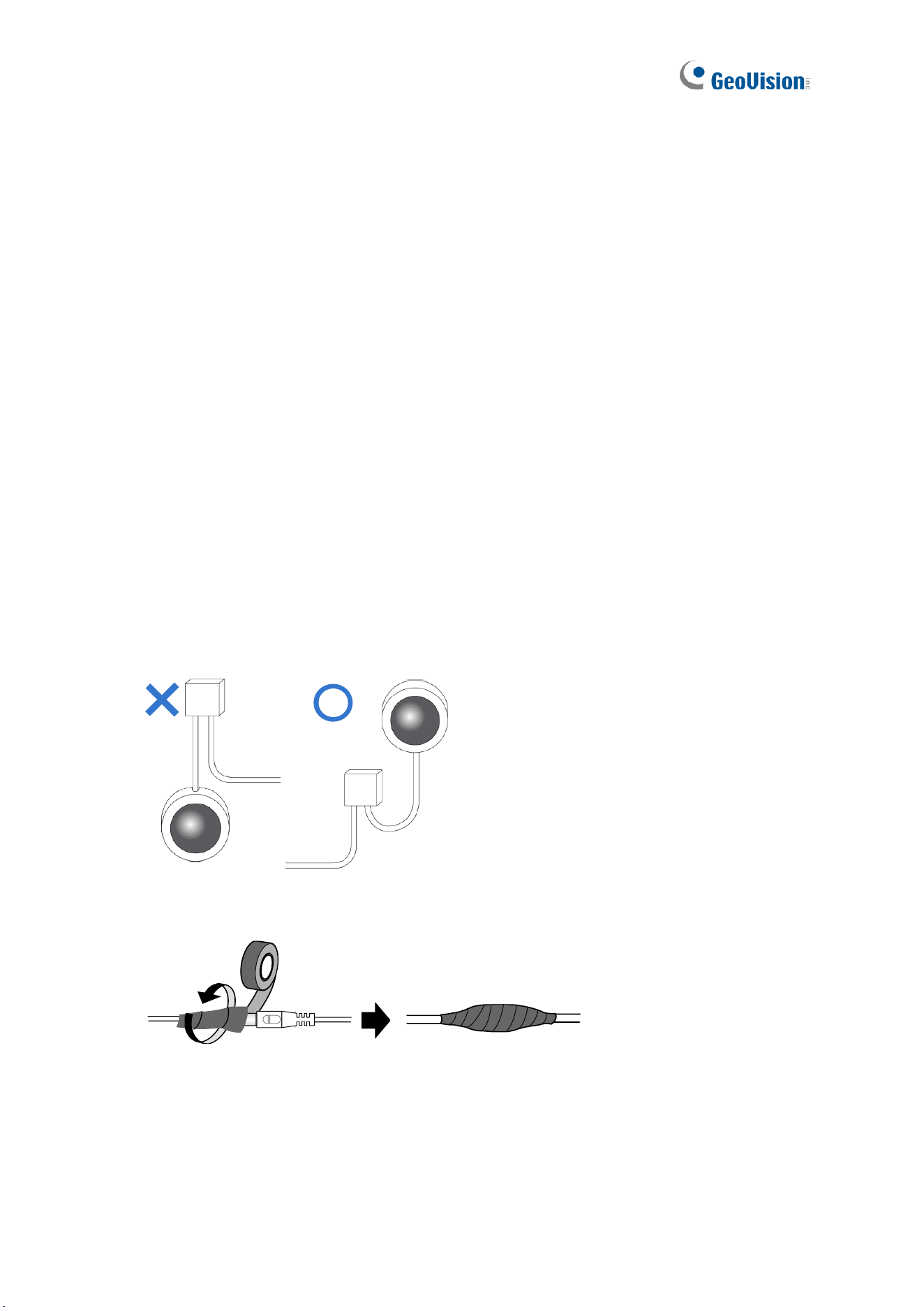
1.10 Waterproofing the Cable ................................................................................... 103
Chapter 2 Accessing the Camera .....................................105
2.1 Installing on a Network ........................................................................................ 105

v
2.1.1 Looking Up the Dynamic IP Address and Logging In ............................... 106
2.1.2 Configuring the IP Address ...................................................................... 107
2.2 Accessing Live View ........................................................................................... 108
2.2.1 Digital Zoom ............................................................................................ 112
2.2.2 Start Recording ....................................................................................... 112
2.3 PTZ Control Panel .............................................................................................. 113
2.3.1 Accessing the PTZ Control Panel ............................................................ 113
2.3.2 Setting Presets ........................................................................................ 115
2.3.3 Setting Patrol .......................................................................................... 116
2.4 Playing Back Recorded Videos ........................................................................... 120
2.4.1 Recording Download ............................................................................... 121
Chapter 3 Administrator Mode .........................................122
3.1 Common ............................................................................................................. 125
3.1.1 Basic Info ................................................................................................ 125
3.1.2 Local Parameters .................................................................................... 126
3.2 Network .............................................................................................................. 128
3.2.1 Wired Network ........................................................................................ 128
3.2.2 DNS ........................................................................................................ 129
3.2.3 Port ......................................................................................................... 130
3.2.4 DDNS ...................................................................................................... 131
3.2.5 E-mail ...................................................................................................... 133
3.2.6 SNMP ..................................................................................................... 134
3.2.7 802.1x ..................................................................................................... 135
3.2.8 QoS ........................................................................................................ 136
3.2.9 ONVIF (ANR) .......................................................................................... 137
3.2.10 Platform Access .................................................................................... 138
3.2.10.1 Server ..................................................................................... 138
3.2.10.2 WebSocket ............................................................................. 141
3.3 Video & Audio ..................................................................................................... 142
3.3.1 Video ....................................................................................................... 142
3.3.2 Snapshot ................................................................................................. 144
3.3.3 Audio....................................................................................................... 146
3.3.4 ROI ......................................................................................................... 147
3.3.5 Media Stream .......................................................................................... 148
3.4 PTZ ..................................................................................................................... 150
3.4.1 Basic Settings ......................................................................................... 150

vi
3.4.2 Home Position ......................................................................................... 151
3.4.3 Limit ........................................................................................................ 151
3.4.4 Remote Control ....................................................................................... 152
3.4.5 Patrol ...................................................................................................... 153
3.4.6 Orientation .............................................................................................. 154
3.5 Image ................................................................................................................. 155
3.5.1 Image ...................................................................................................... 155
3.5.1.1 Image .......................................................................................... 155
3.5.1.2 Image Scene Switch .................................................................... 160
3.5.1.3 Engineering ................................................................................. 162
3.5.2 OSD ........................................................................................................ 163
3.4.2.1 For all models except GV-EBD2702 ......................................... 164
3.4.2.2 For GV-EBD2702 ...................................................................... 165
3.5.3 Privacy Mask ........................................................................................... 166
3.6 Intelligent ............................................................................................................ 167
3.6.1 Smart Settings ............................................................................. 167
3.6.1.1 Cross Line ................................................................................ 169
3.6.1.2 Intrusion .................................................................................... 173
3.6.1.3 Object Removed ....................................................................... 176
3.6.1.4 Object Left Behind .................................................................... 177
3.6.1.5 Defocus .................................................................................... 178
3.6.1.6 Scene Change .......................................................................... 179
3.6.1.7 Face Detection .......................................................................... 180
3.6.1.8 People Counting / People Flow Counting .................................. 183
3.6.1.9 Human Body Detection ............................................................. 185
3.6.1.10 Enter Area / Leave Area ......................................................... 186
3.6.1.11 Crowd Density Monitoring ....................................................... 188
3.6.2 Advanced Settings .................................................................................. 189
3.6.3 Metadata Analysis ................................................................................... 190
3.7 Events................................................................................................................. 192
3.7.1 Motion Detection ..................................................................................... 192
3.7.2 Tampering Alarm ..................................................................................... 195
3.7.3 Audio Detection ....................................................................................... 196
3.7.4 Alarm Input.............................................................................................. 197
3.7.5 Alarm Output ........................................................................................... 198
3.7.6 One-Key Disarming ................................................................................. 199
3.8 Storage ............................................................................................................... 200

vii
3.8.1 Formatting Storage ................................................................................. 200
3.8.2 FTP ......................................................................................................... 203
3.8.3 Backing Up Storage ................................................................................ 206
3.9 Security ............................................................................................................... 207
3.9.1 User ........................................................................................................ 207
3.9.2 Network Security ..................................................................................... 208
3.10 System .............................................................................................................. 216
3.10.1 Time ...................................................................................................... 216
3.10.2 Server ................................................................................................... 218
3.10.3 Maintenance ......................................................................................... 219
3.10.4 Network Diagnosis ................................................................................ 220
3.10.5 Log ........................................................................................................ 220
3.10.6 Ports and Devices ................................................................................. 221
Chapter 4 Advanced Applications ...................................222
4.1 Upgrading System Firmware ............................................................................... 222
4.1.1 Using the Web Interface .......................................................................... 223
4.1.2 Using GV-IP Device Utility ....................................................................... 224
4.2 Restoring to Factory Default Settings .................................................................. 225
Chapter 5 DVR / NVR / VMS ..............................................226
5.1 Setting Up IP Cameras on GV-DVR / NVR ......................................................... 227
5.2 Setting Up IP Cameras on GV-VMS ................................................................... 230
Appendix ...............................................................................232
A. RTSP Multicast Protocol Support ......................................................................... 232
B. RTSP Protocol Support ........................................................................................ 232
C. HTTP Protocol Support ........................................................................................ 234
D. Compatible Versions of GV-VMS / DVR / NVR ..................................................... 235
E. GV-Mount Dimensions ......................................................................................... 238
F. GV-Mount300-2 / 310-2 ........................................................................................ 246
G. Screw Position Chart ............................................................................................ 249
H. Note for Fisheye Camera with IR LED .................................................................. 250
I. Retrieve Camera’s Password ................................................................................. 250
J. Installation Guidelines for Perimeter Protection ..................................................... 251
K. Installation Guidelines for People Flow Counting .................................................. 253

viii
L. Installation Guidelines for Crowd Density Monitoring ............................................ 255
M. Installation Guidelines for Face Detection ............................................................ 256
N. Installation Guidelines for Face Detection (Non-AI) .............................................. 259
O. Installation Guidelines for People Counting (Non-AI) ........................................... 260
ix
Naming Definition
GV-DVR / NVR
GeoVision Analog and Digital Video Recording Software. The
GV-DVR also refers to GV-Multicam System or GV-Hybrid DVR.
GV-VMS
GeoVision Video Management System for IP cameras.
x
Note for Connecting to GV-VMS / DVR / NVR
The GV-IPCAM in this Manual is designed to work with and record on GV-VMS / DVR / NVR,
a video management system.
• Once the camera is connected to the GV-VMS / DVR / NVR, the resolution set on the
GV-VMS / DVR / NVR will override the resolution set on the camera’s Web interface.
You can only change the resolution settings through the Web interface when the
connection to the GV-VMS / DVR / NVR is interrupted.
• The login password of the camera cannot contain the character “&” or any whitespace
when connecting to GV-VMS.
• The Video Analytic features under Intelligent (see 3.6 Intelligent) cannot be integrated
with GV-VMS / DVR / NVR.
Note for Installing Camera Outdoor
When installing the camera outdoor, be sure that:
1. The camera is set up above the junction box to prevent water from entering the camera
along the cables.
2. Any PoE, power, audio and I/O cables are waterproofed using waterproof silicon rubber
or the like.
3. The screws are tightened and the cover is in place after opening the camera cover.

xi
Note for Powering the Camera
The camera is powered by PoE or a power adapter. If you want to power the camera using
the power connector, an optional power adapter is required.

Introduction
1
1
Chapter 1 Introduction
1.1 GV-EBD / EBFC / EBDP Series
The H.265 Eyeball Dome is an outdoor, network camera equipped with an automatic IR-cut
filter and IR LEDs for day and night surveillance. For GV-EBFC5800, it’s equipped with full
color smart warm LEDs for accurate day and night surveillance. The camera adheres to IP67
standards for dust / water protection and supports H.265 video codec to achieve better
compression ratio while maintaining high quality image at reduced network bandwidths.
For GV-EBD4711 / 4712 / 4813 / 8711 / 8813, with their motorized lenses, the user can
zoom and focus the camera from the Web interface.
Model No.
Description
GV-EBD2702
Fixed lens
2 MP, H.265, Low Lux, WDR
GV-EBD2704
2 MP, H.265, Low Lux, WDR Pro
GV-EBD2705
2 MP, H.265, Low Lux, WDR Pro
GV-EBD4700
4 MP, H.265, Super Low Lux, WDR Pro
GV-EBD4701
GV-EBD4704
GV-EBD8700
8 MP, H.265, Low Lux, WDR Pro
GV-EBD8800
GV-EBD4711
Motorized
varifocal lens
4 MP, H.265, Super Low Lux, WDR Pro
GV-EBD4712
GV-EBD4813
GV-EBD8711
8 MP, H.265, Super Low Lux, WDR Pro
GV-EBD8813
2
GV-EBDP5800
Fixed lens
5 MP, H.265, Super Low Lux, WDR Pro, 180° Panoramic
GV-EBDP8800
Fixed lens
8 MP, H.265, Super Low Lux, WDR Pro, 180° Panoramic
GV-EBFC5800
Fixed lens
5 MP, H.265, Super Low Lux, WDR Pro, Warm LED
Introduction
3
1
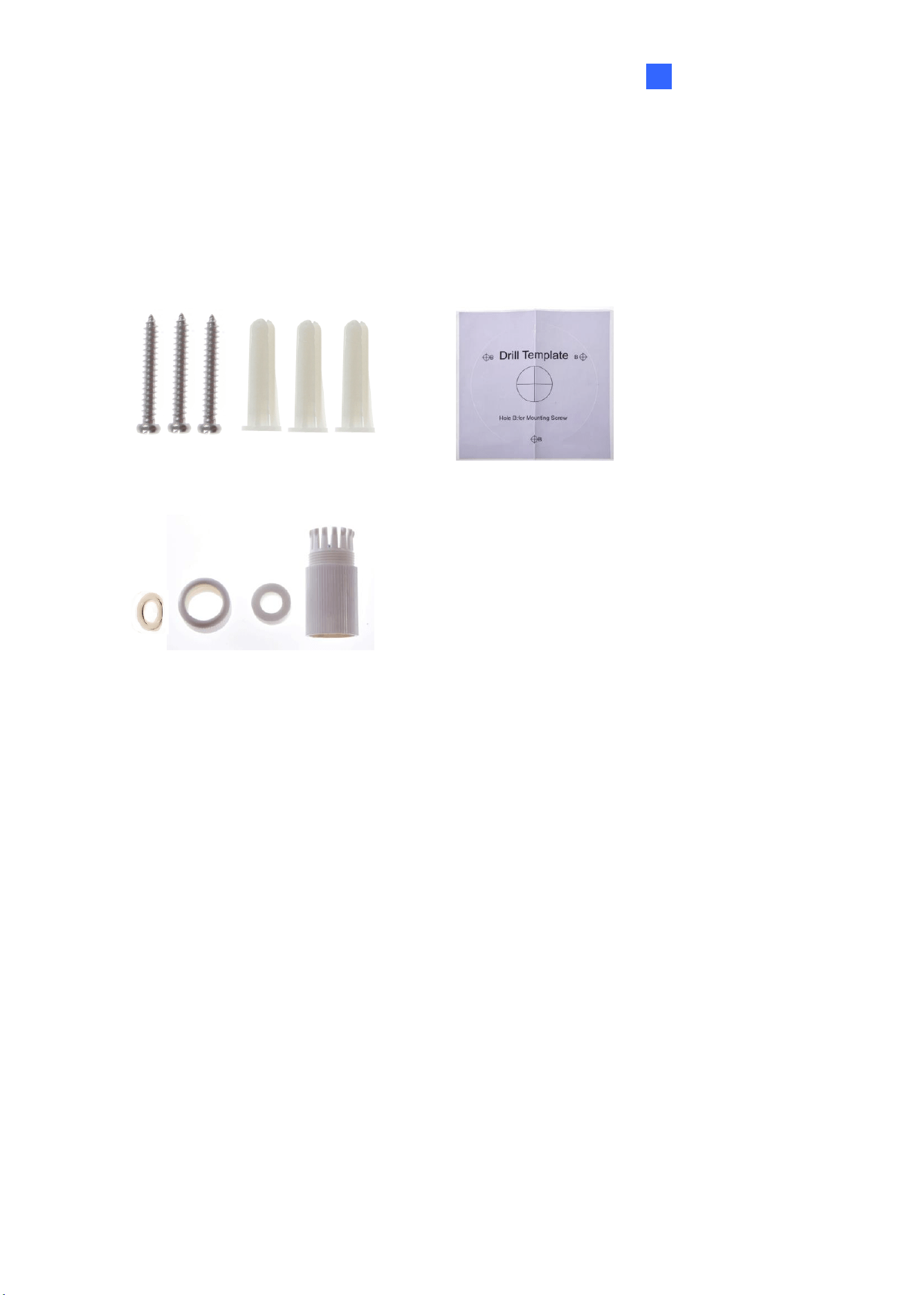
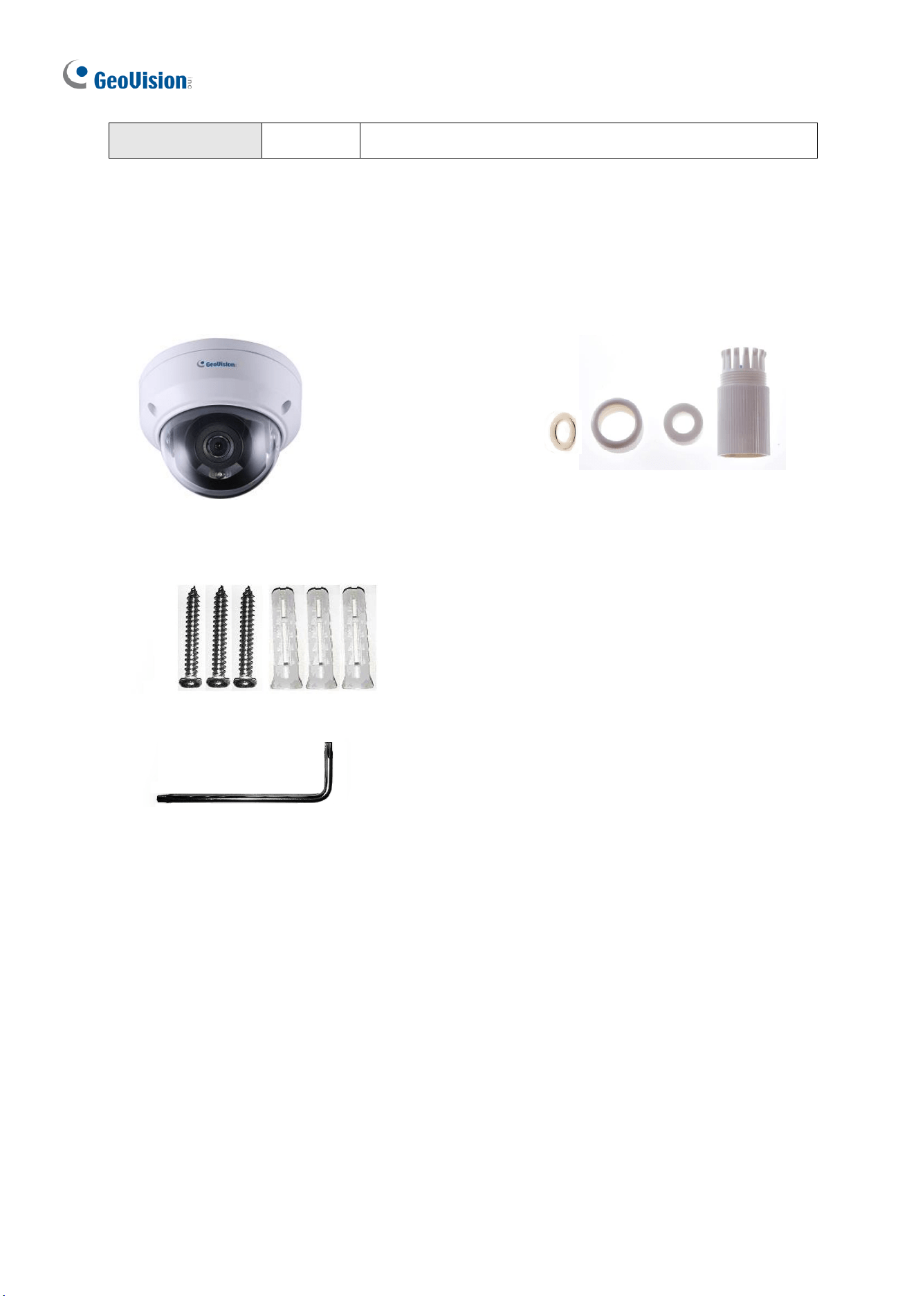
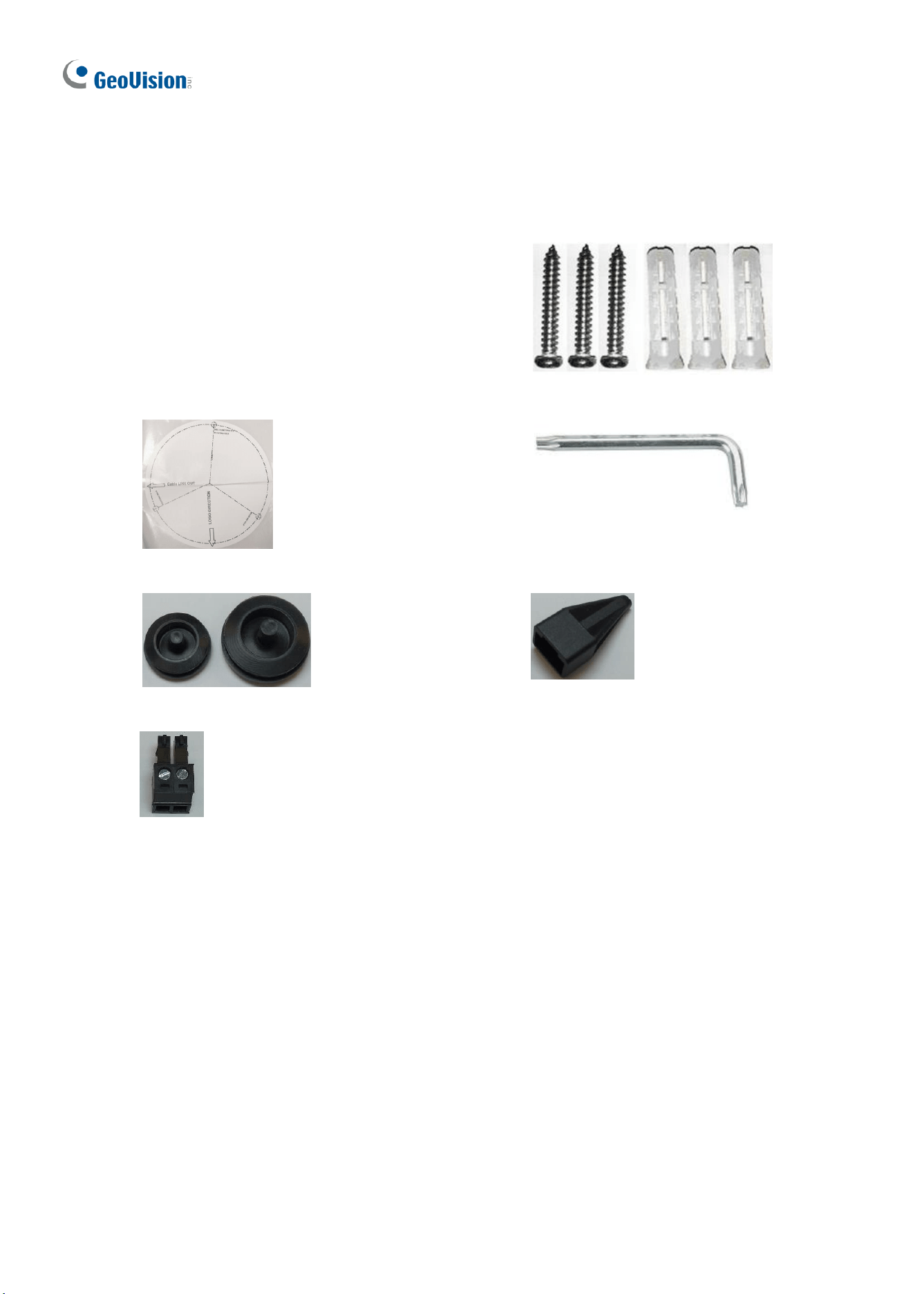
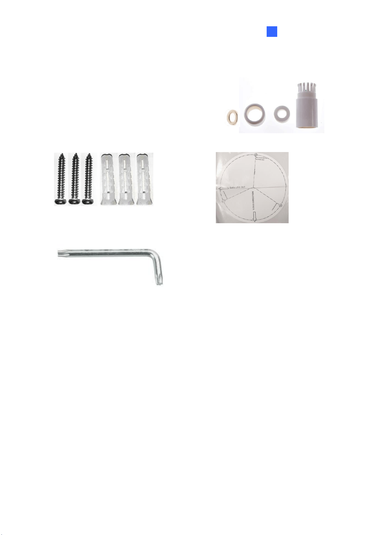
1.1.1 Packing List
The packing list varies depending on the model. Product details can be found on the
datasheet.
• Eyeball Dome
• Screw Kit
• Drill Template Paster
• Waterproof Rubber Set
• Download Guide
1.1.2 Optional Accessories
Optional accessories can expand the capabilities and versatility of your camera. Accessory
details can be found on the datasheet.
4
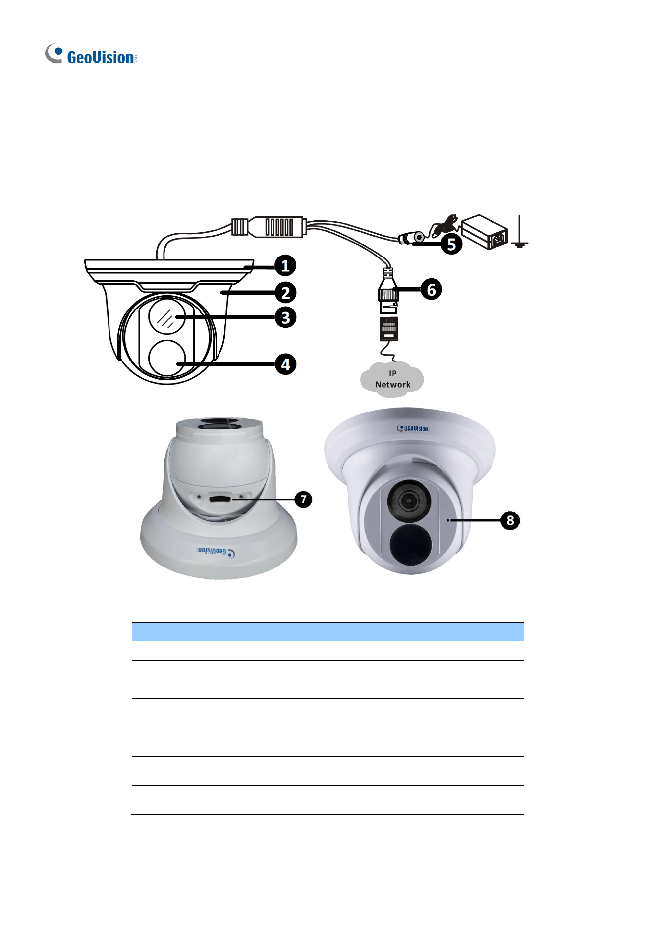
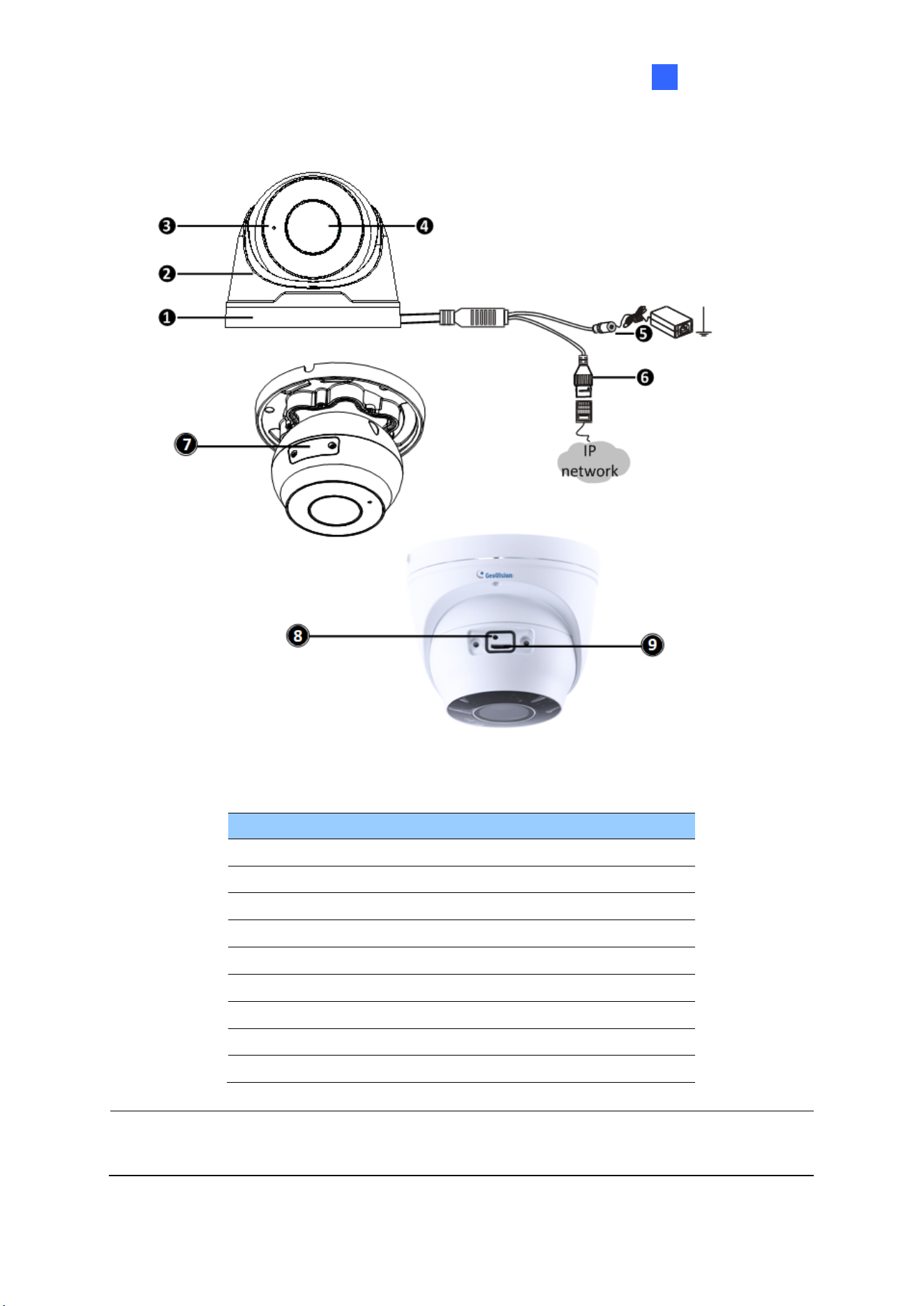
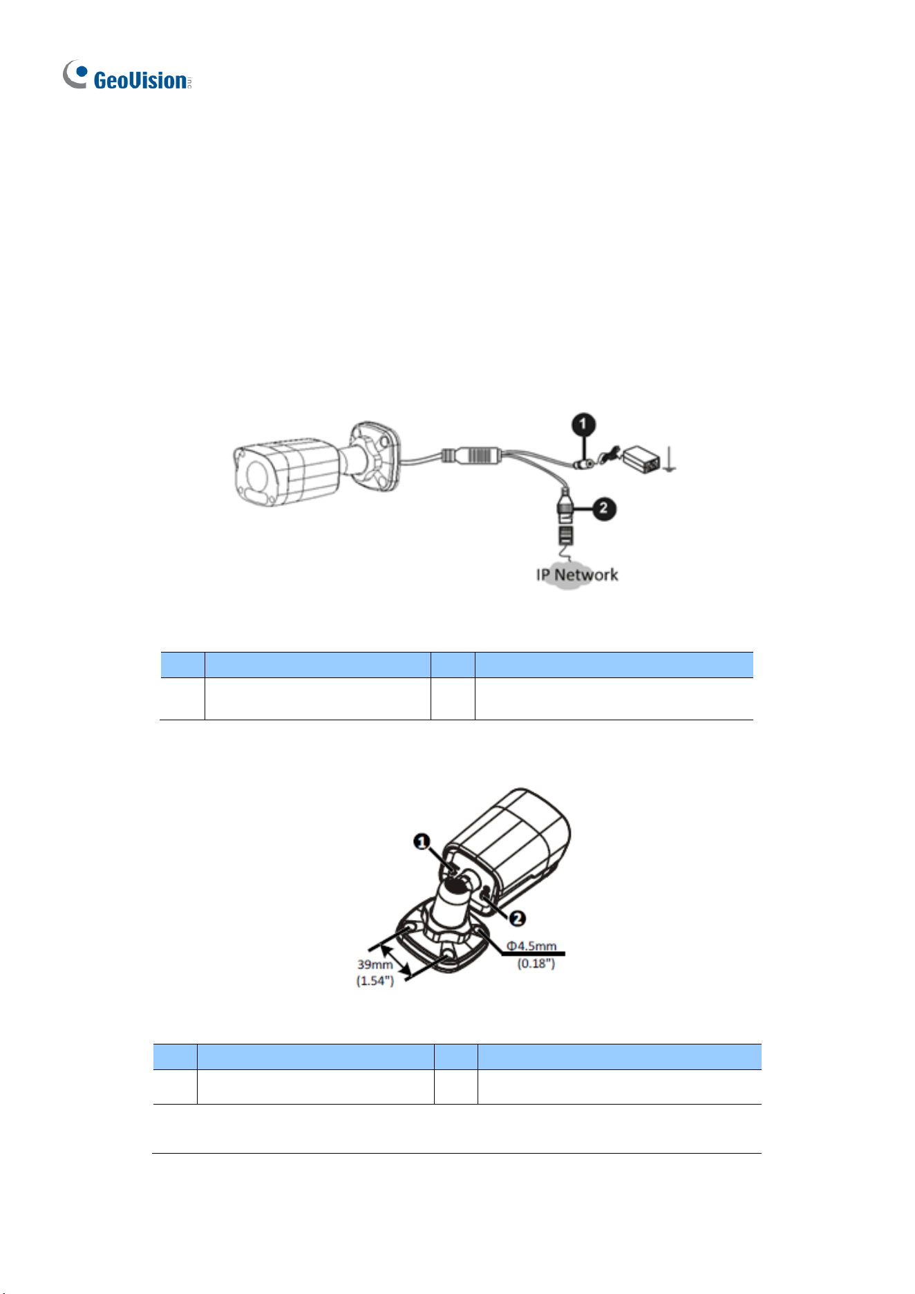
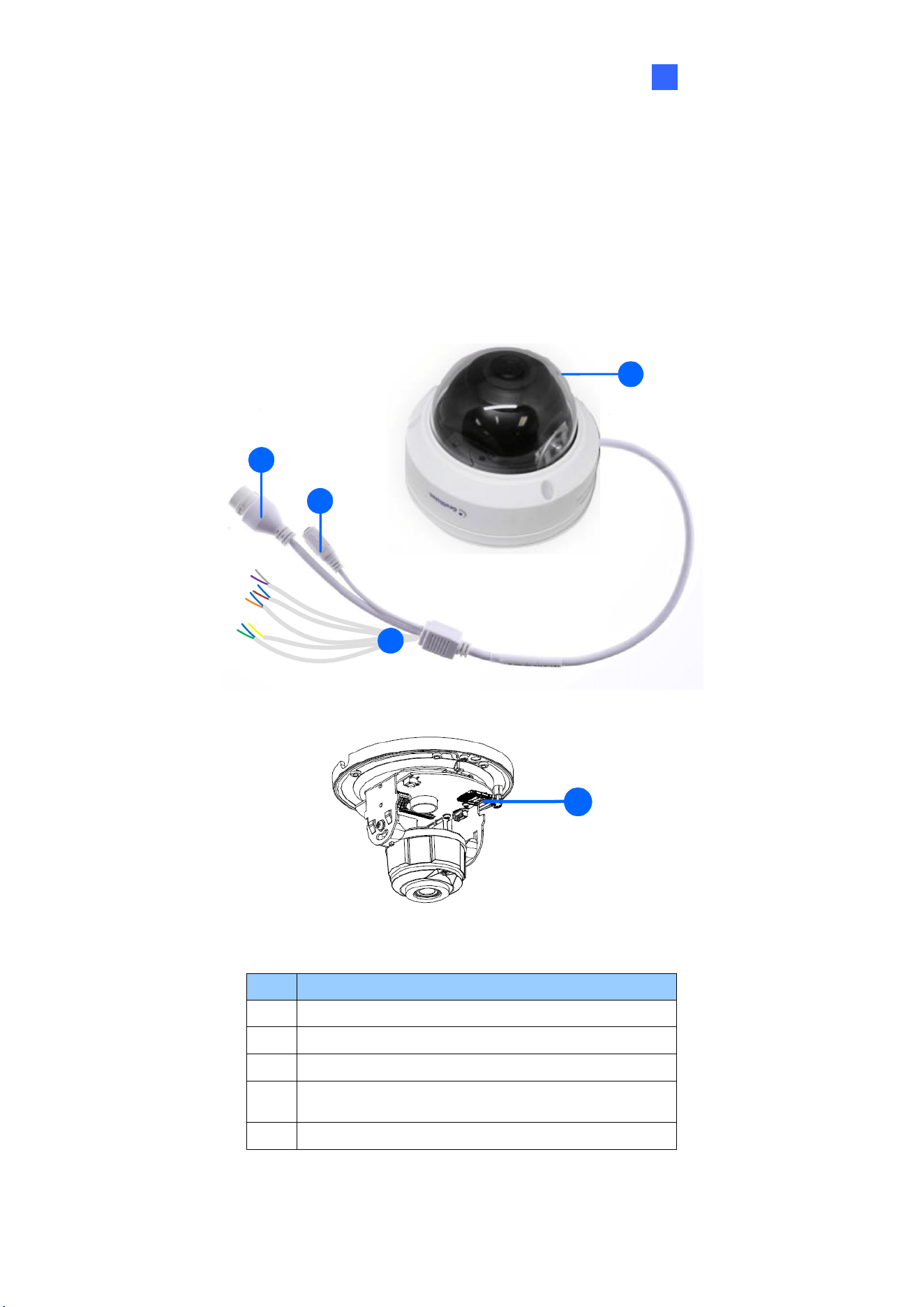
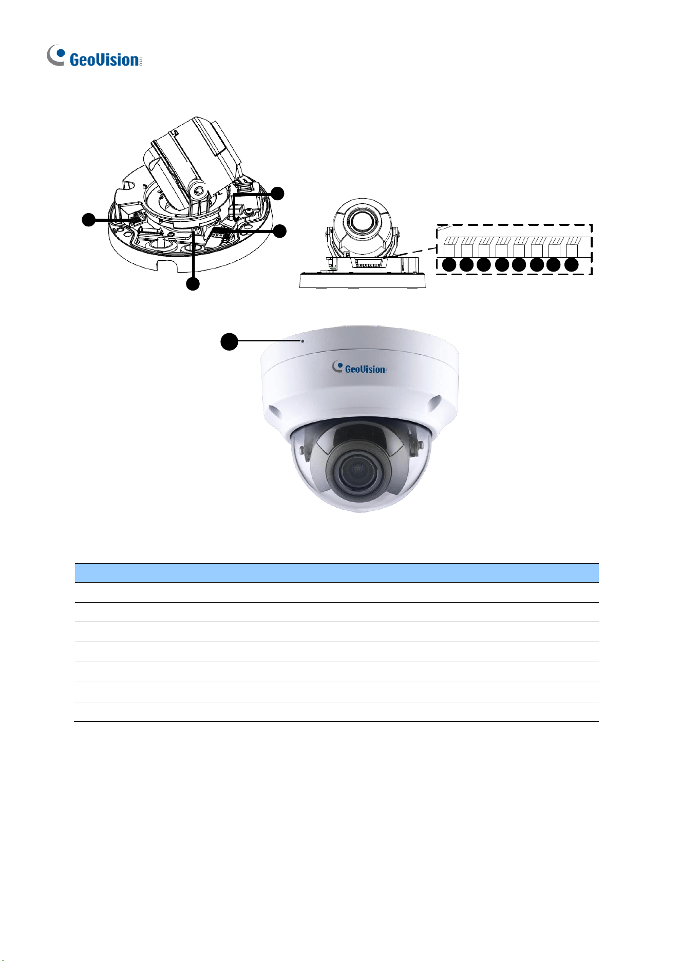
1.1.3 Overview
1.1.3.1 GV-EBD2702 / 2704 / 2705 / 4700 / 4701 / 4704 / 8700 / 8800
and GV-EBFC5800
Figure 1-1
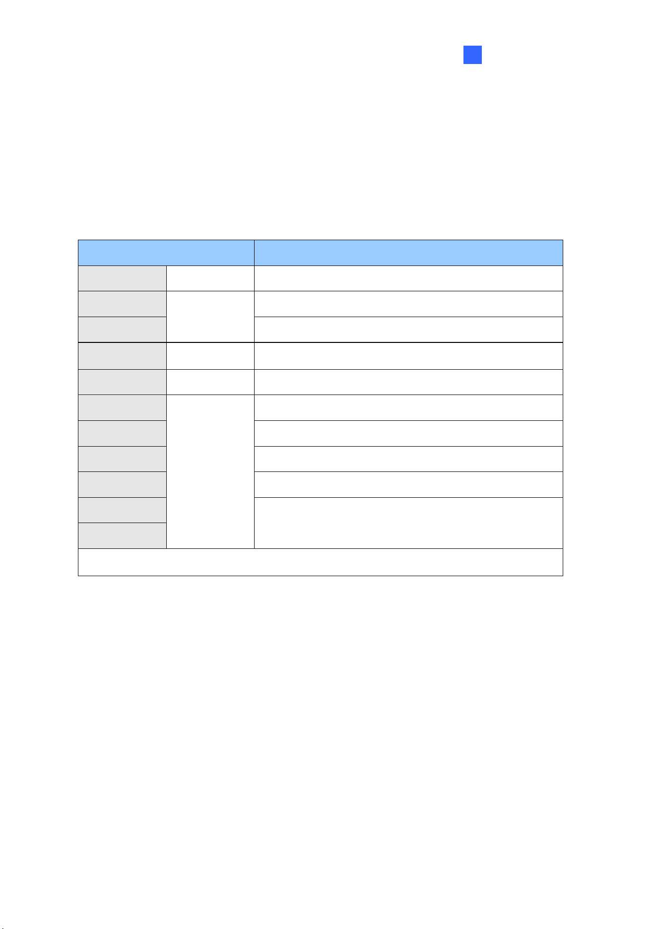
No.
Description
1
Bottom ring
2
Housing
3
Lens
4
Infrared indicator / Warm LEDs (GV-EBFC5800 only)
5
Power connector (DC 12 V)
6
Ethernet connector / PoE
7
Micro SD card slot (GV-EBD2704 / 2705 / 4701 / 4704 / 8800
and GV-EBFC5800 only)
8
Microphone (GV-EBD2704 / 2705 / 4701 / 4704 / 8800 and GV-
EBFC5800 only)
Introduction
5
1
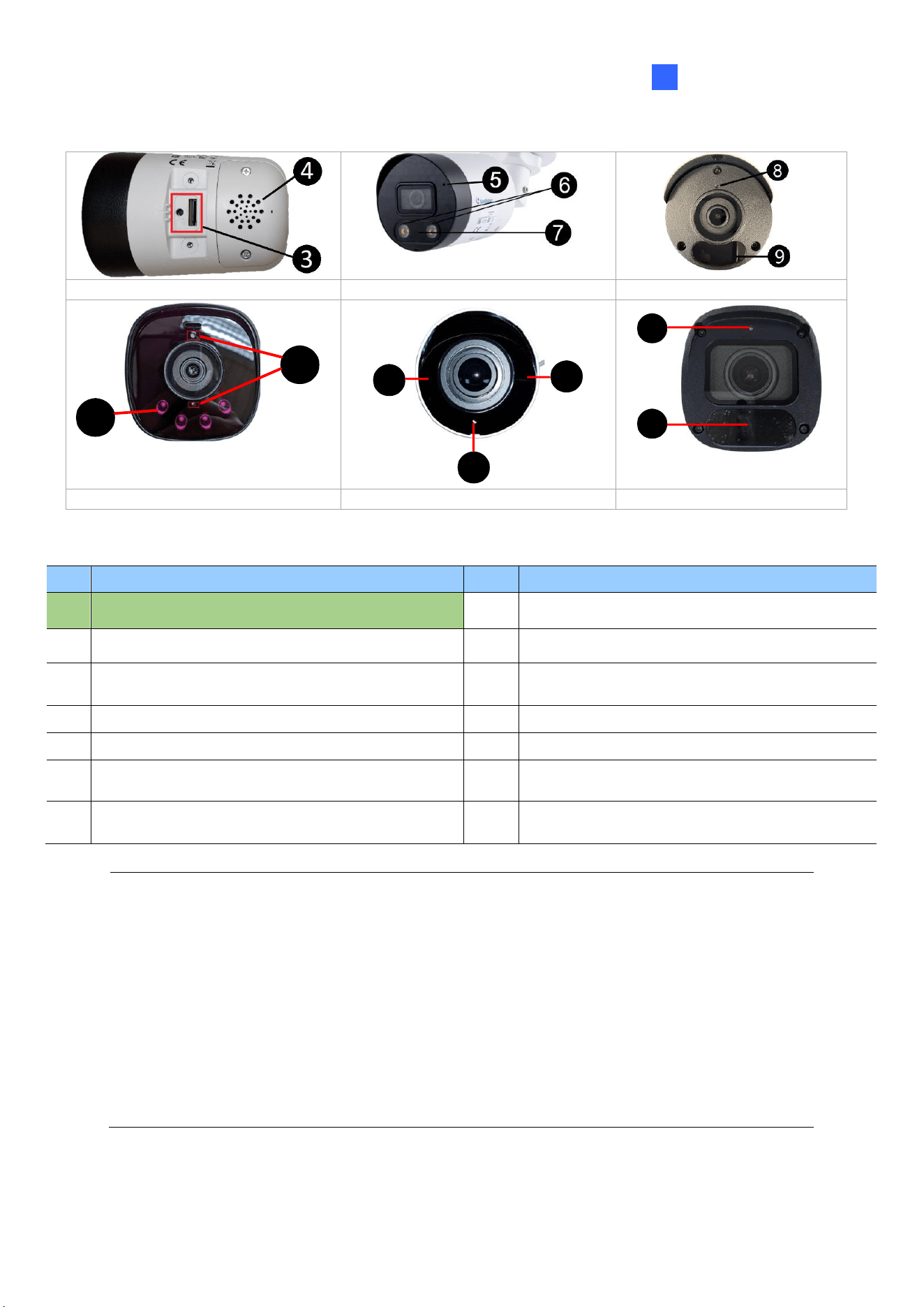
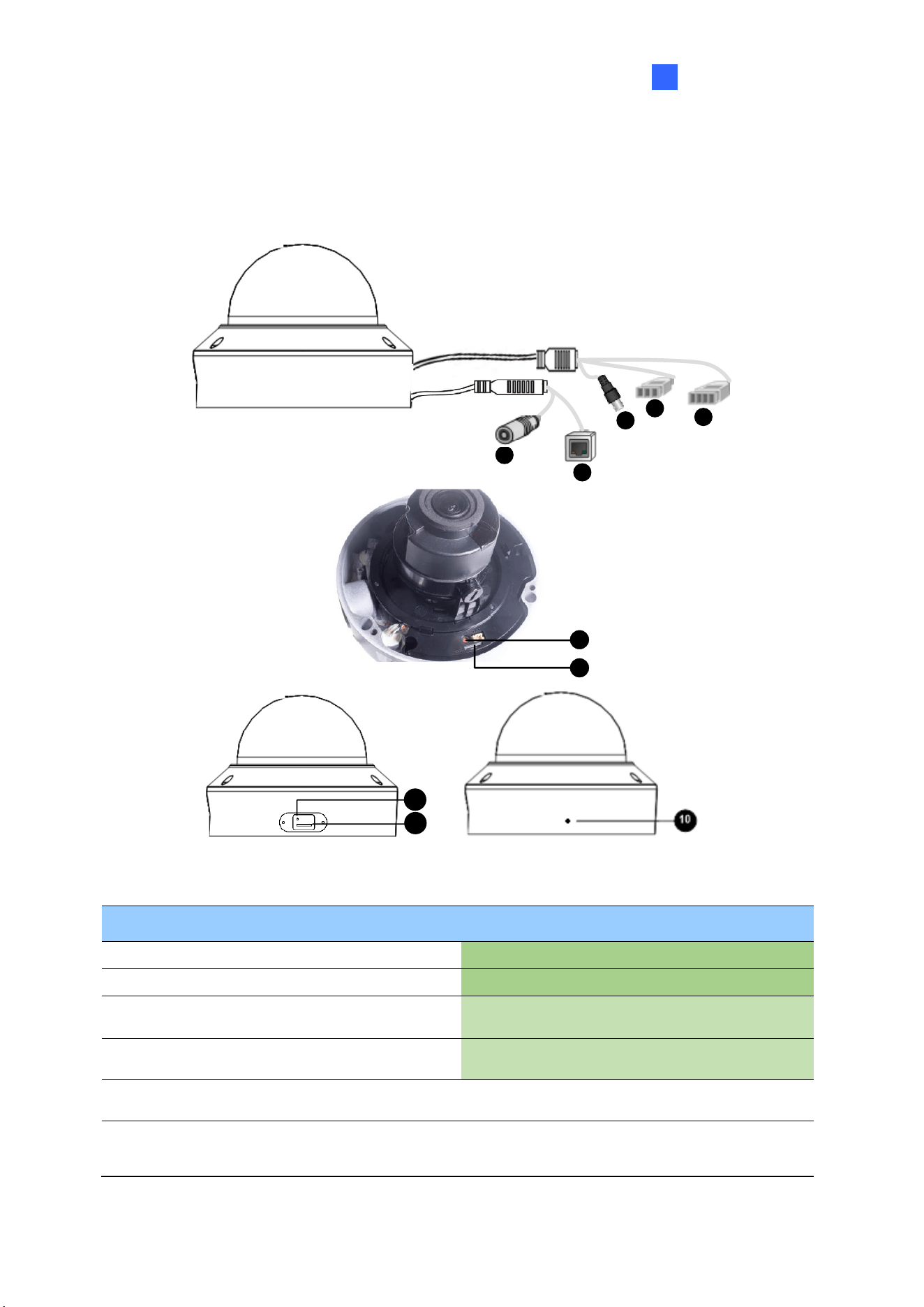
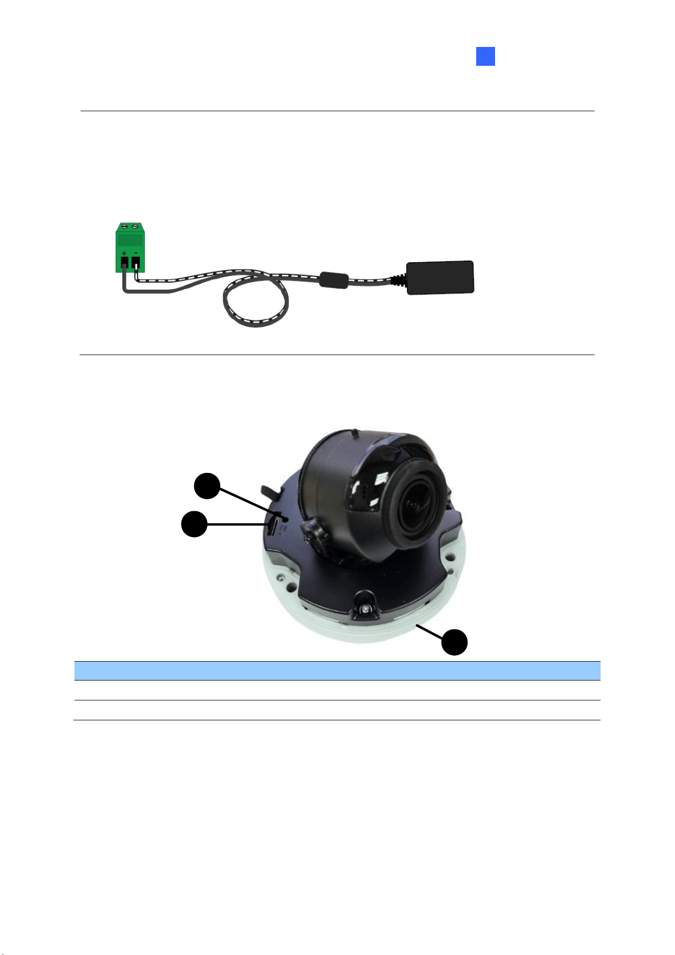
1.1.3.2 GV-EBD4711 / 4712 / 4813 / 8711 / 8813, GV-EBDP5800 / 8800
Figure 1-2
No.
Description
1
Bottom ring
2
Housing
3
Microphone
4
Lens
5
Power connector (DC 12 V)
6
Ethernet connector / PoE
7
Micro SD card slot and default button compartment
8
Default button
9
Micro SD card slot
Note: If the default button doesn’t respond after pressing for 15 seconds, reboot the
camera and try again within 10 minutes of rebooting.
6
1.1.4 Installation
The Target Eyeball Dome is designed for outdoors. With the standard package, you can
install the camera on the ceiling. Alternatively, you can purchase optional mounting
accessories to mount the dome on a wall.
Below are the instructions for Ceiling Mount. There are two kinds of Ceiling Mount:
Concealed Installation and Open Installation. In concealed installation, the cables are
hidden in the ceiling. In Open Installation, the cables are led out from the open slot on the
bottom ring.
1.1.4.1 GV-EBD2702 / 2704 / 2705 / 4700 / 4701 / 4704 / 8700 / 8800
and GV-EBFC5800
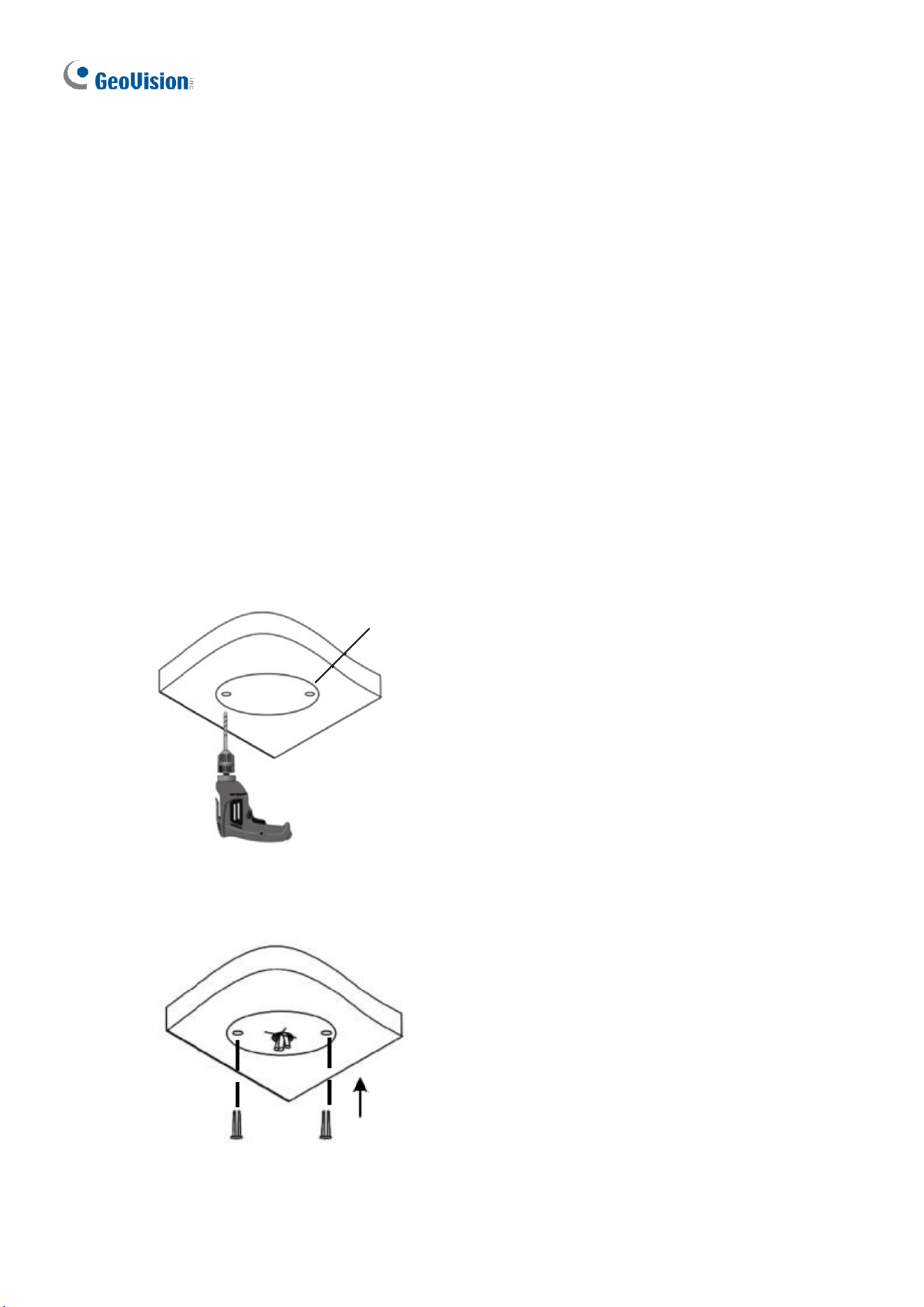
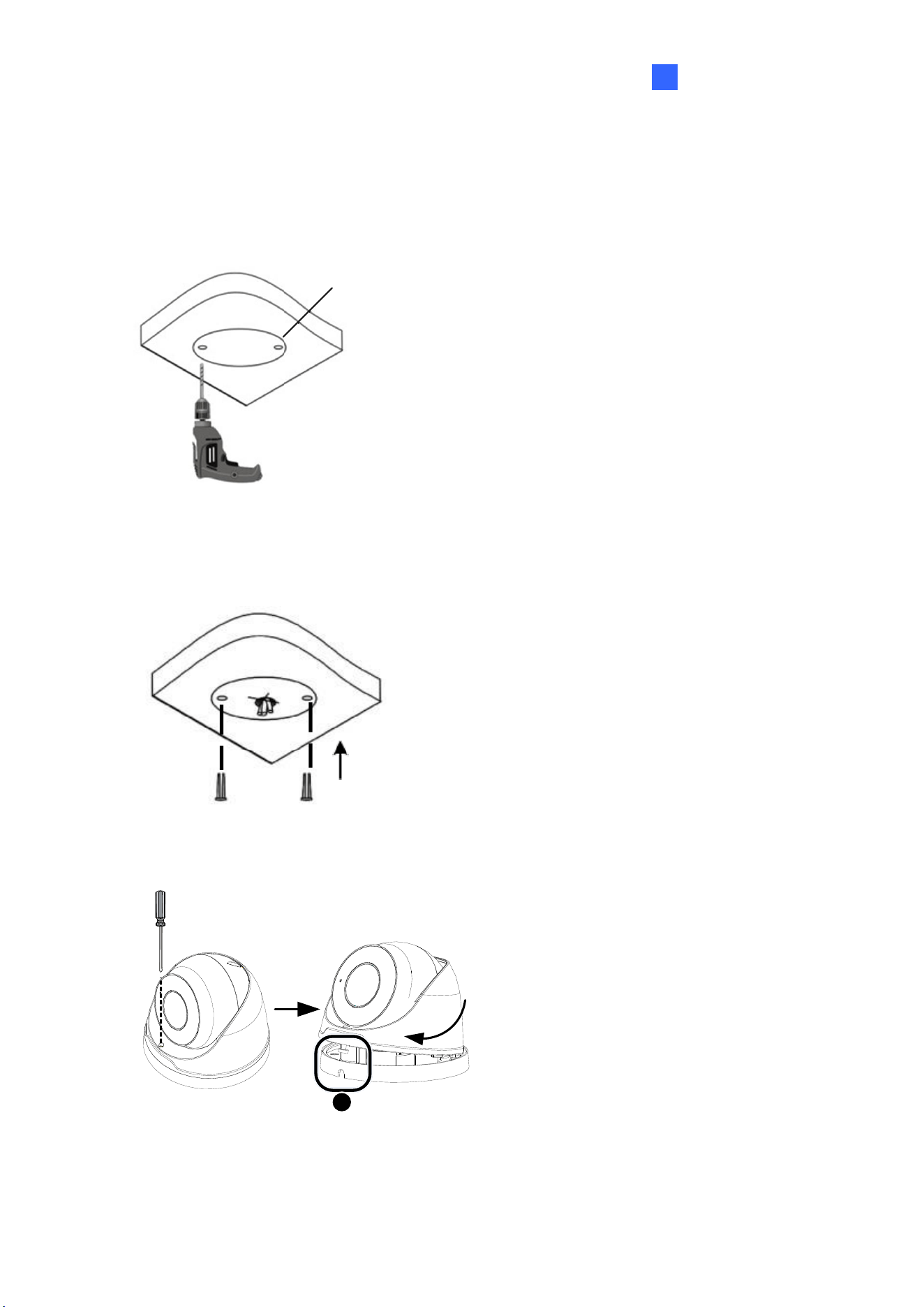
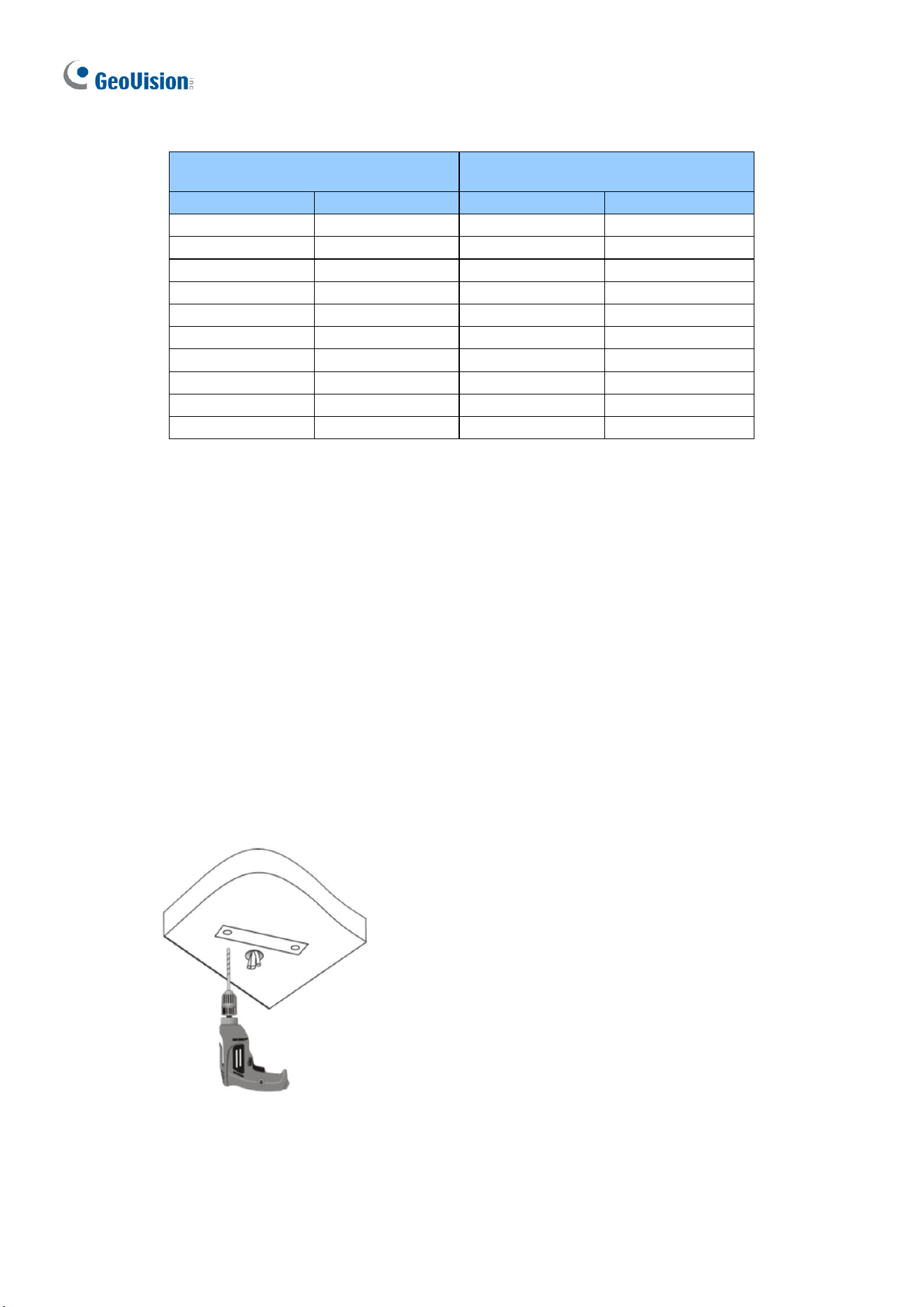
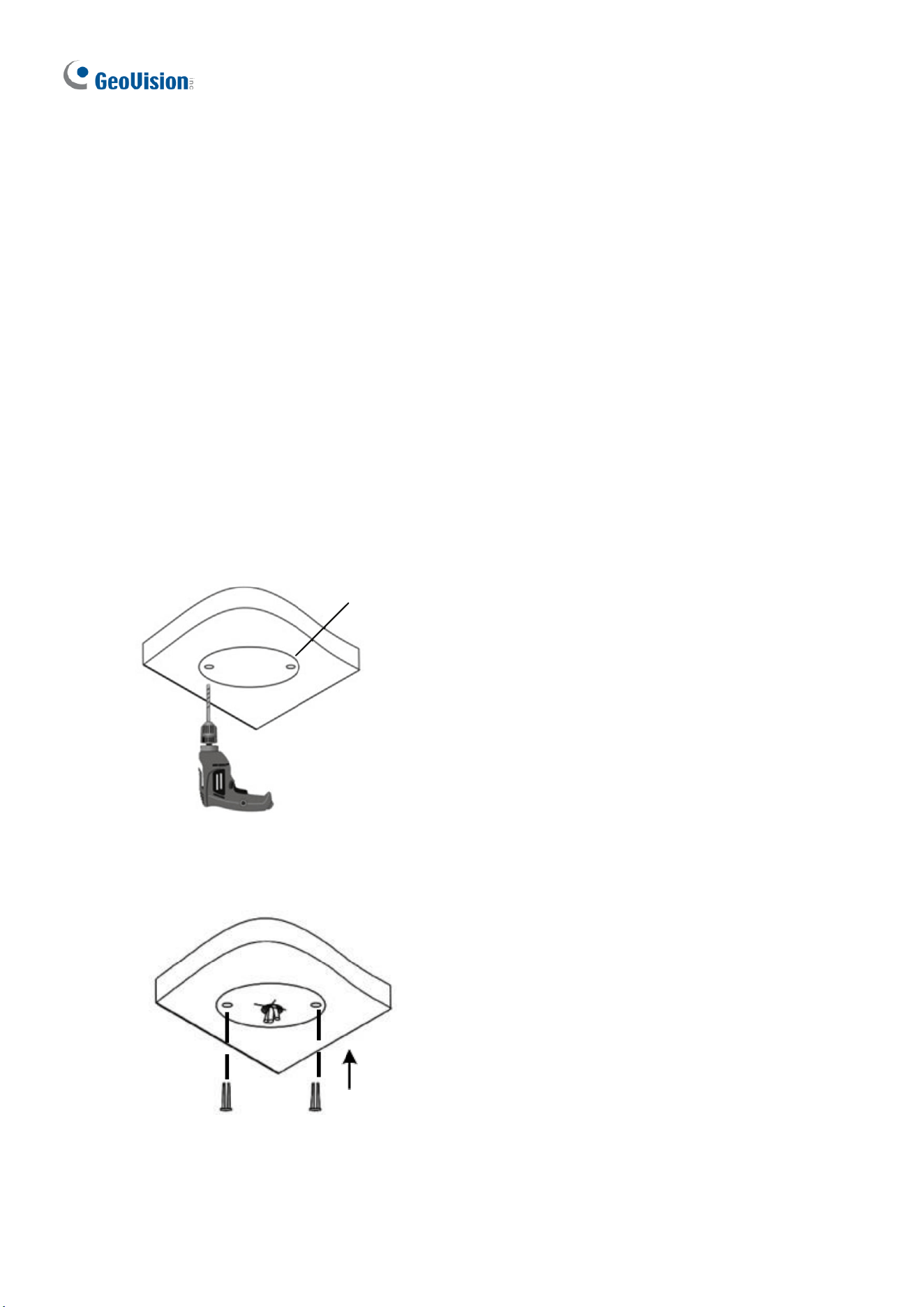
For Concealed Installation
1. Stick the drill template paster to the ceiling and drill three holes according to the drill
template.
Drill Template Paster
Figure 1-3
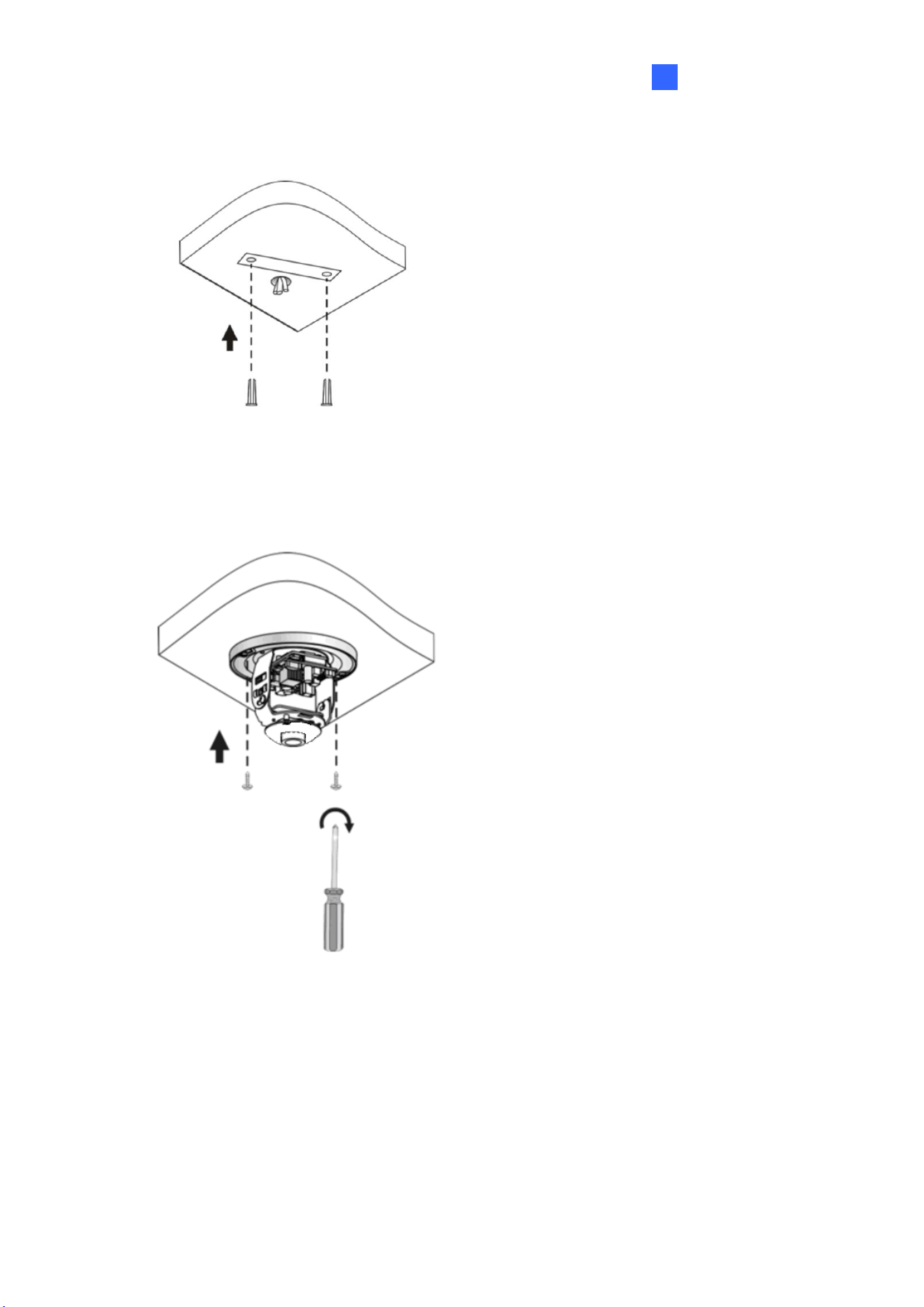
2. Insert the screw anchors.
Drill a hole to lead the cables out of the ceiling
Knock in screw anchors
Figure 1-4
Introduction
7
1
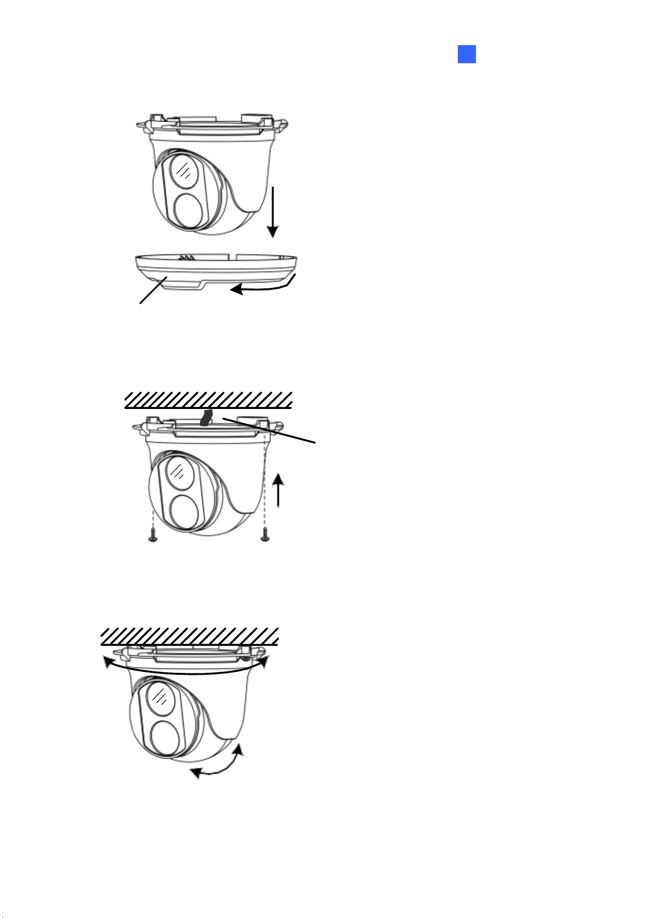
3. Remove the bottom ring by turning it anticlockwise.
Bottom Ring
Figure 1-5
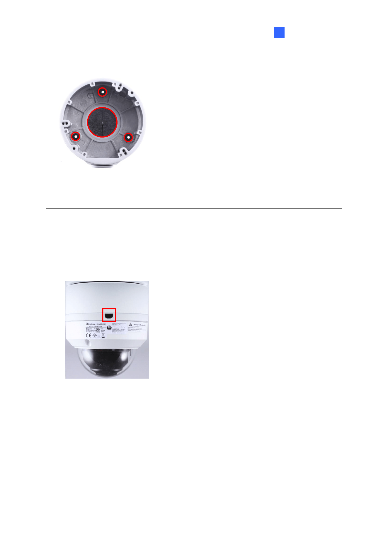
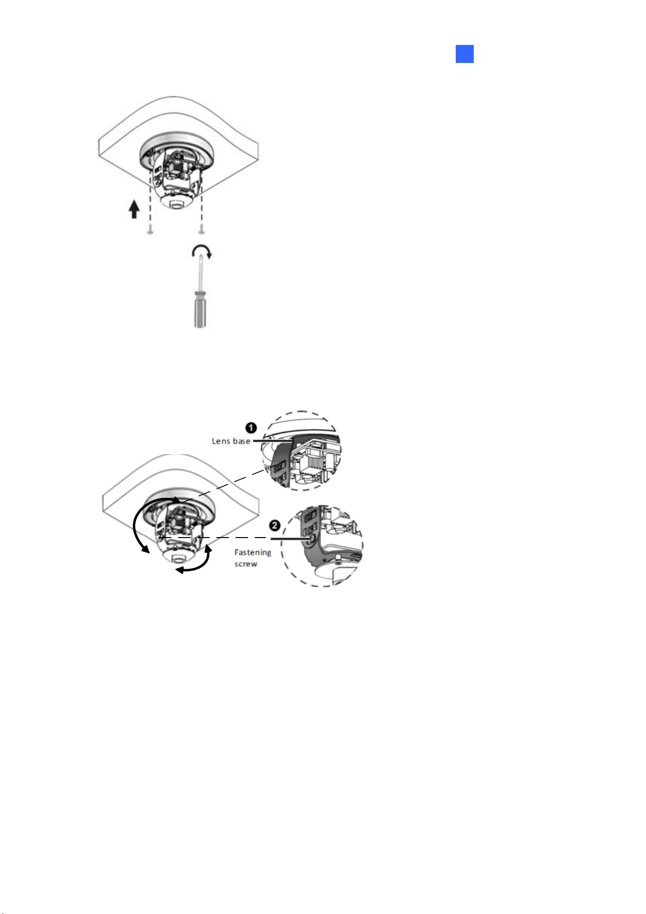
4. Connect the cables and secure the camera.
Connect the cables and protect
them with waterproof tape
Attach the camera to ceiling
with screws
Figure 1-6
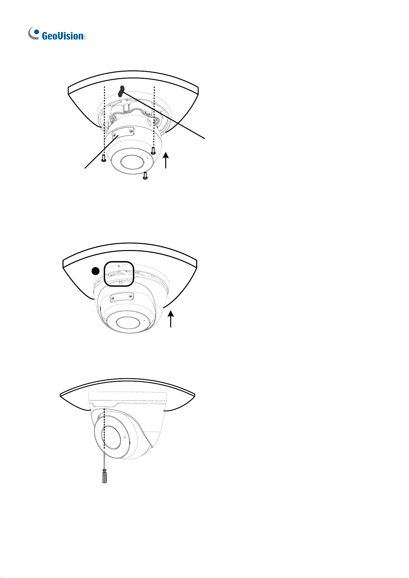
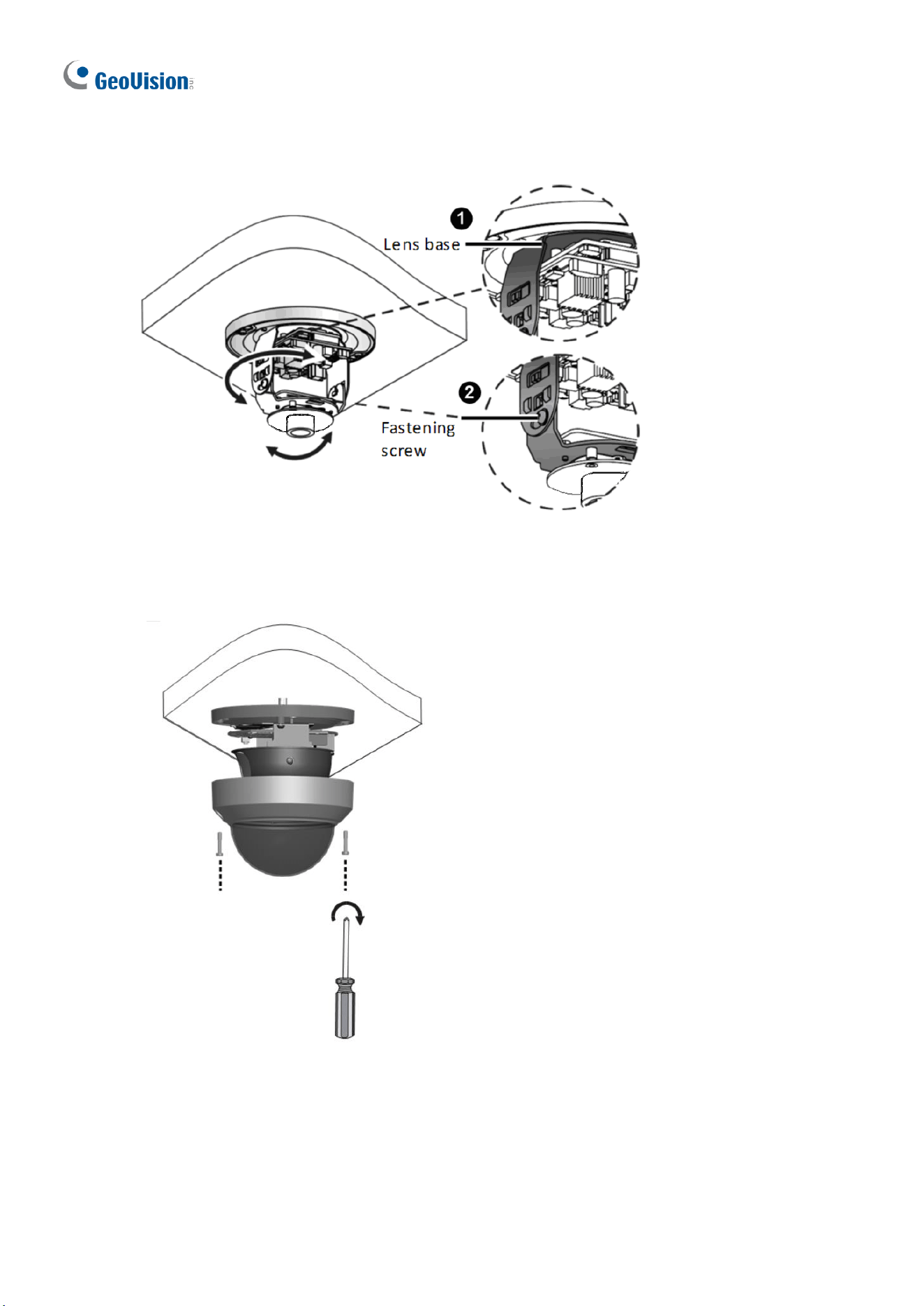
5. Adjust the monitoring direction.
The camera can rotate
360 degrees horizontally
The lens can rotate 80
degrees vertically
Figure 1-7
8
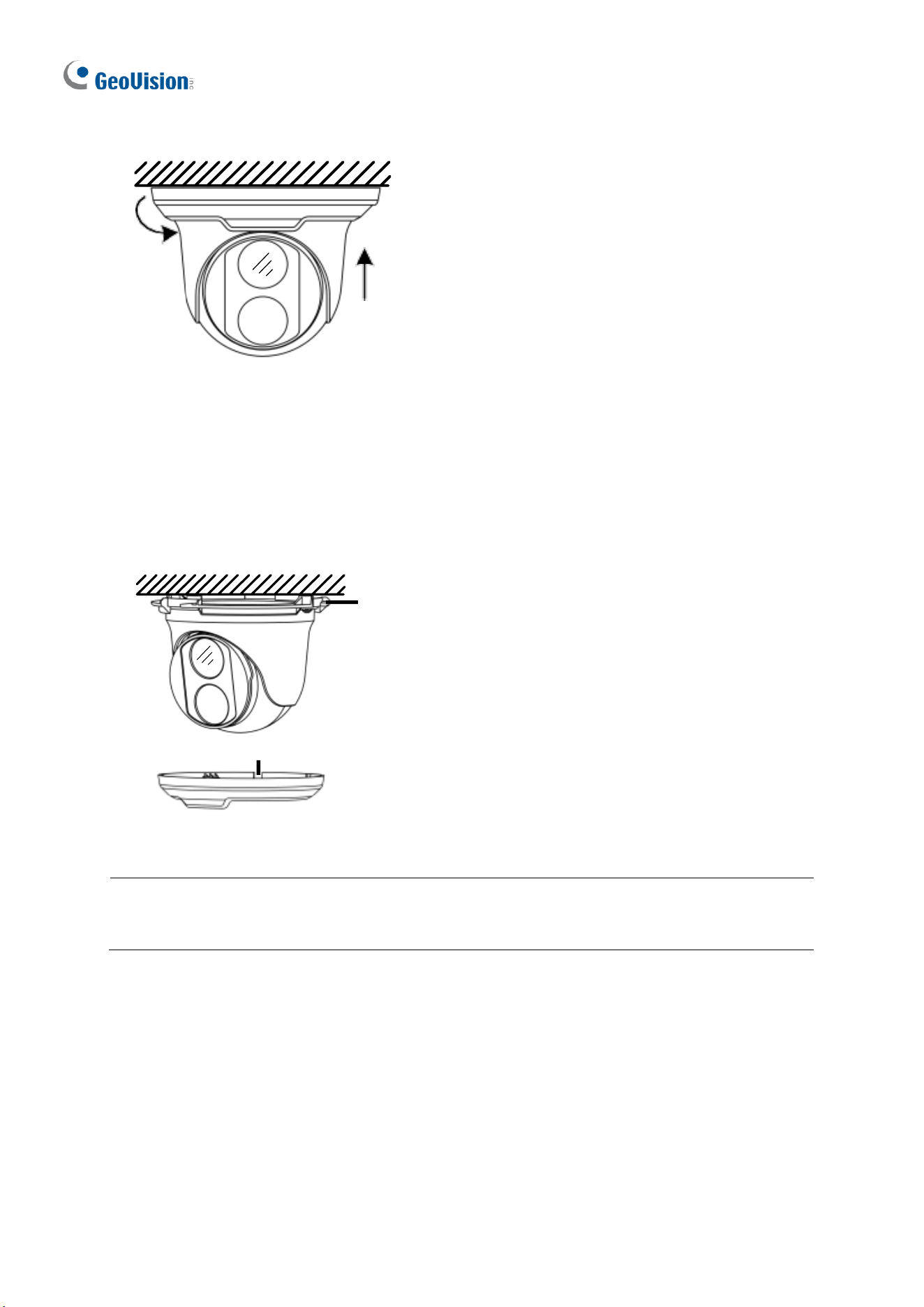
6. Mount the bottom ring.
Push the bottom ring back up and turn
it clockwise to lock into position
Figure 1-8
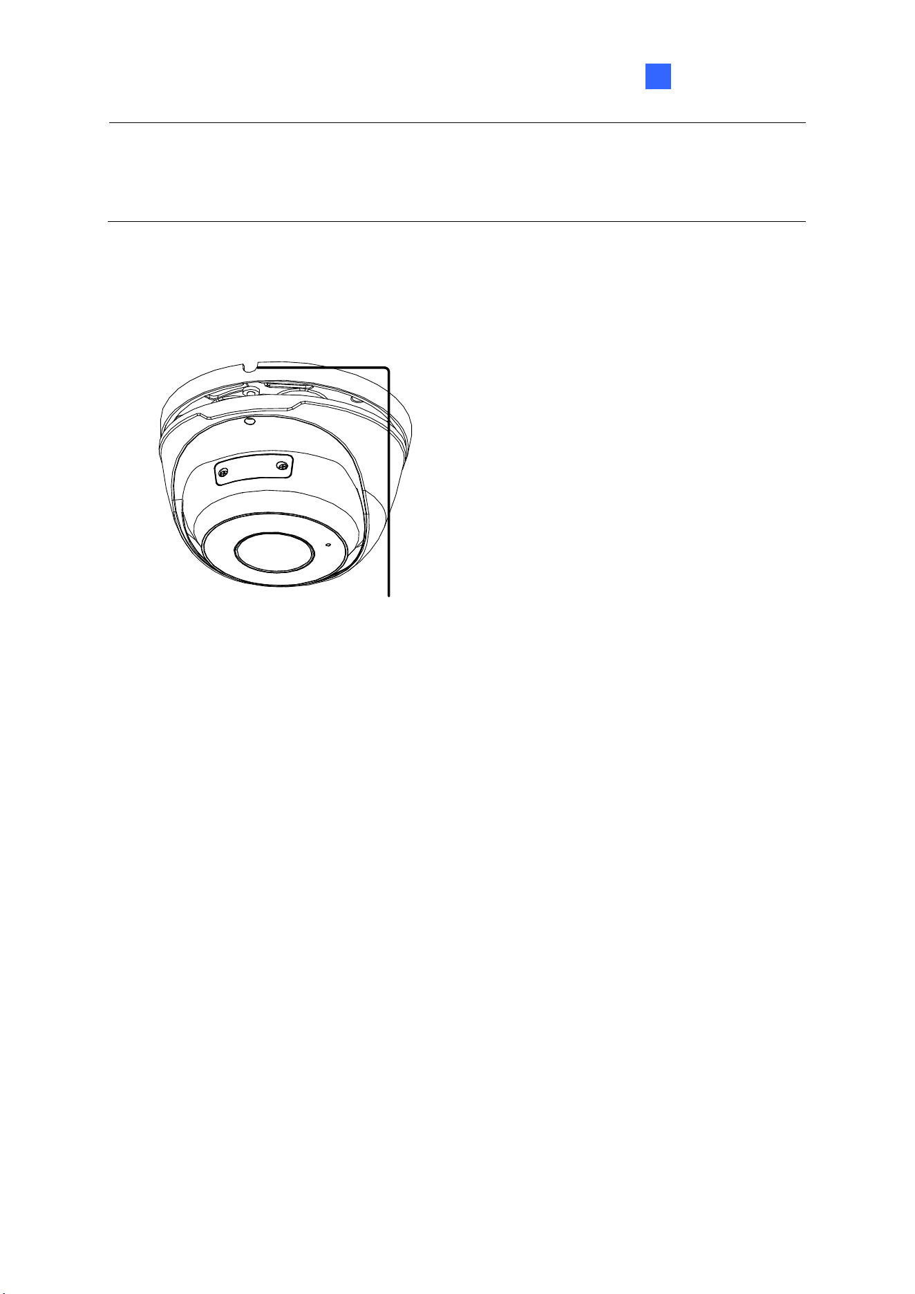
For Open Installation
Lead the cables out from the open slot on the bottom ring before screwing the camera to the
ceiling as shown in Figure 1-6.
Open slot on the bottom ring
Lock
Figure 1-9
Note: To adjust the monitoring direction at Step 5, loosen the screw indicated at the Lock
position as shown in the figure above. Tighten it when the adjustment is completed.
Introduction
9
1
1.1.4.2 GV-EBD4711 / 4712 / 4813 / 8711 / 8813, GV-EBDP5800 / 8800
For Concealed Installation
1. Stick the drill template paster to the ceiling and drill three holes according to the drill
template.
Drill Template Paster
Figure 1-10
2. Insert the screw anchors.
Drill a hole to lead the cables out of the ceiling
Knock in screw anchors
Figure 1-11
3. Loosen the fixing screw and remove the housing by turning it to the position as shown.
1
Figure 1-12
10
4. Secure the bottom ring to the ceiling with 3 supplied screws and connect the cable.
Connect cable and protect
it with waterproof tape
Attach bottom ring to
ceiling with taping screws
(Optional) insert a
micro SD card
Figure 1-13
5. Mount the housing by adjusting to the position as shown and press and turn to anywhere
but .
1
Figure 1-14
6. Adjust the monitoring direction. Then tighten the screw.
Figure 1-15
Introduction
11
1
WARNING: Make sure the housing is not dismounted from the bottom ring when adjusting
the monitoring direction. Unintentional removal of the housing may result in circumstantial
damages.
For Open Installation
Lead the cables out from the open slot on the bottom ring before mounting the housing as
shown in Figure 1-14.
Open slot on the bottom ring
Figure 1-16

12
1.1.5 Optional Installation
You can optionally purchase the following accessories to fit your mounting environment:
⚫ GV-Mount107 + GV-Mount212P for Pendant Tube Mount: see section 1.1.5.4.
⚫ GV-Mount107 + GV-Mount213 for Pendant Mount
⚫ GV-Mount211P + GV-Mount420 for Pole Box Mount
⚫ GV-Mount211P for Wall Box Mount
⚫ GV-Mount212P for Wall Box Mount: see section 1.1.5.2.
⚫ GV-Mount213 for Wall / Ceiling Box Mount
⚫ GV-Mount300-2 / 310-2 for Corner Mount
⚫ GV-Mount924 for Power Box Mount
Note: For detailed instructions on GV-EBDP series, see GV-A/T/EBD Series IP Camera
Mount Installation Guide.
Introduction
13
1
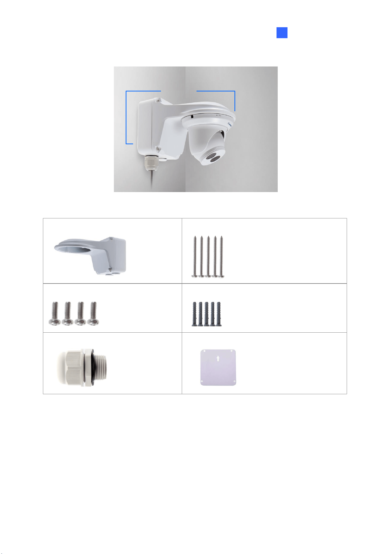
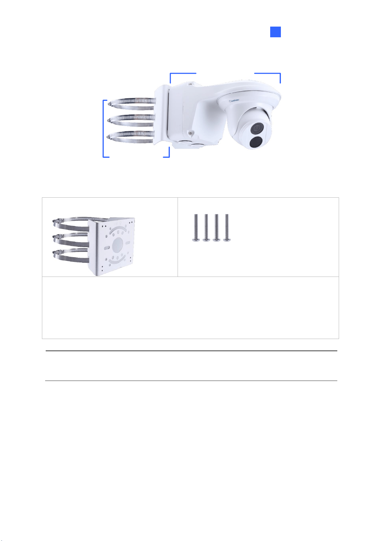
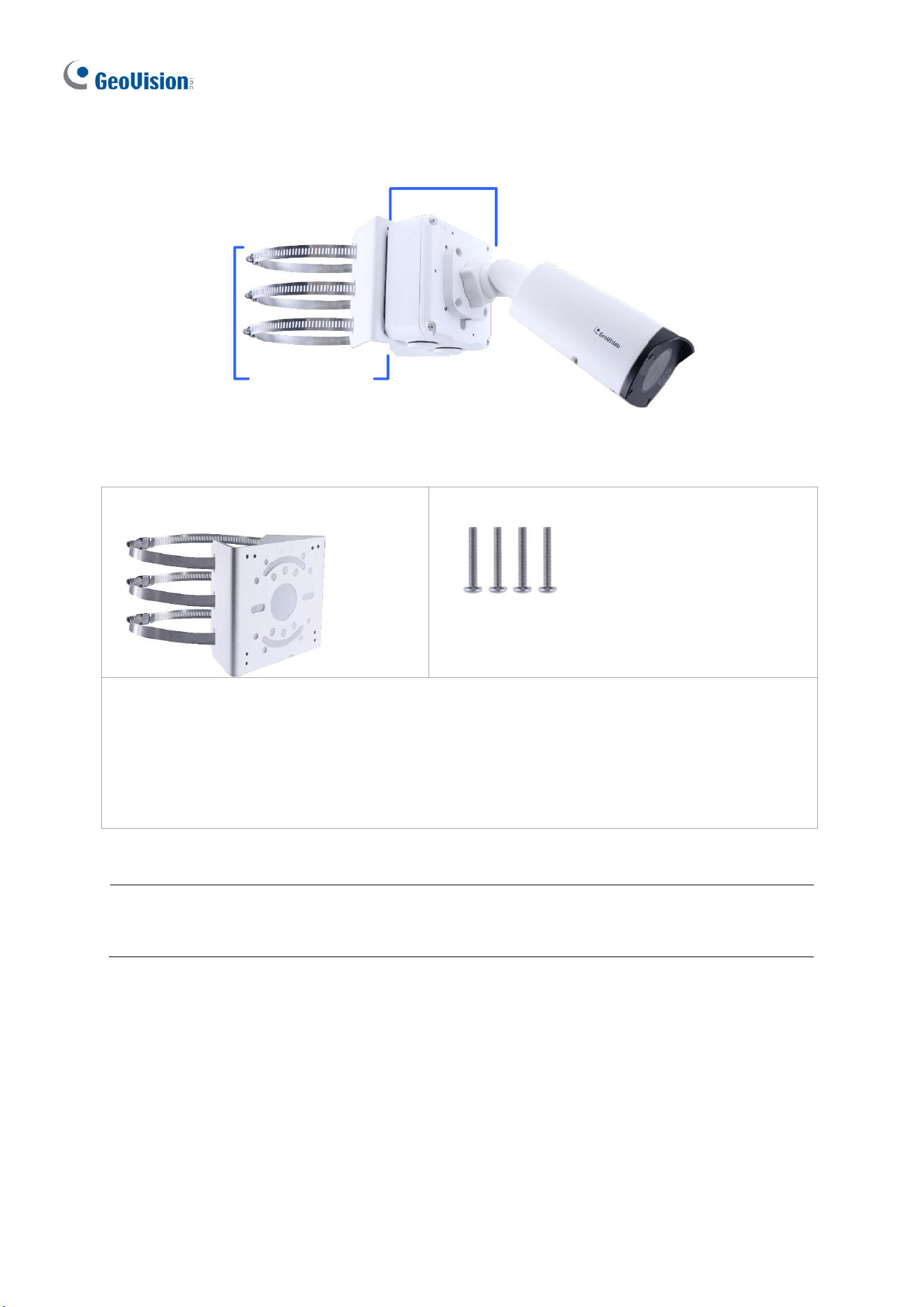
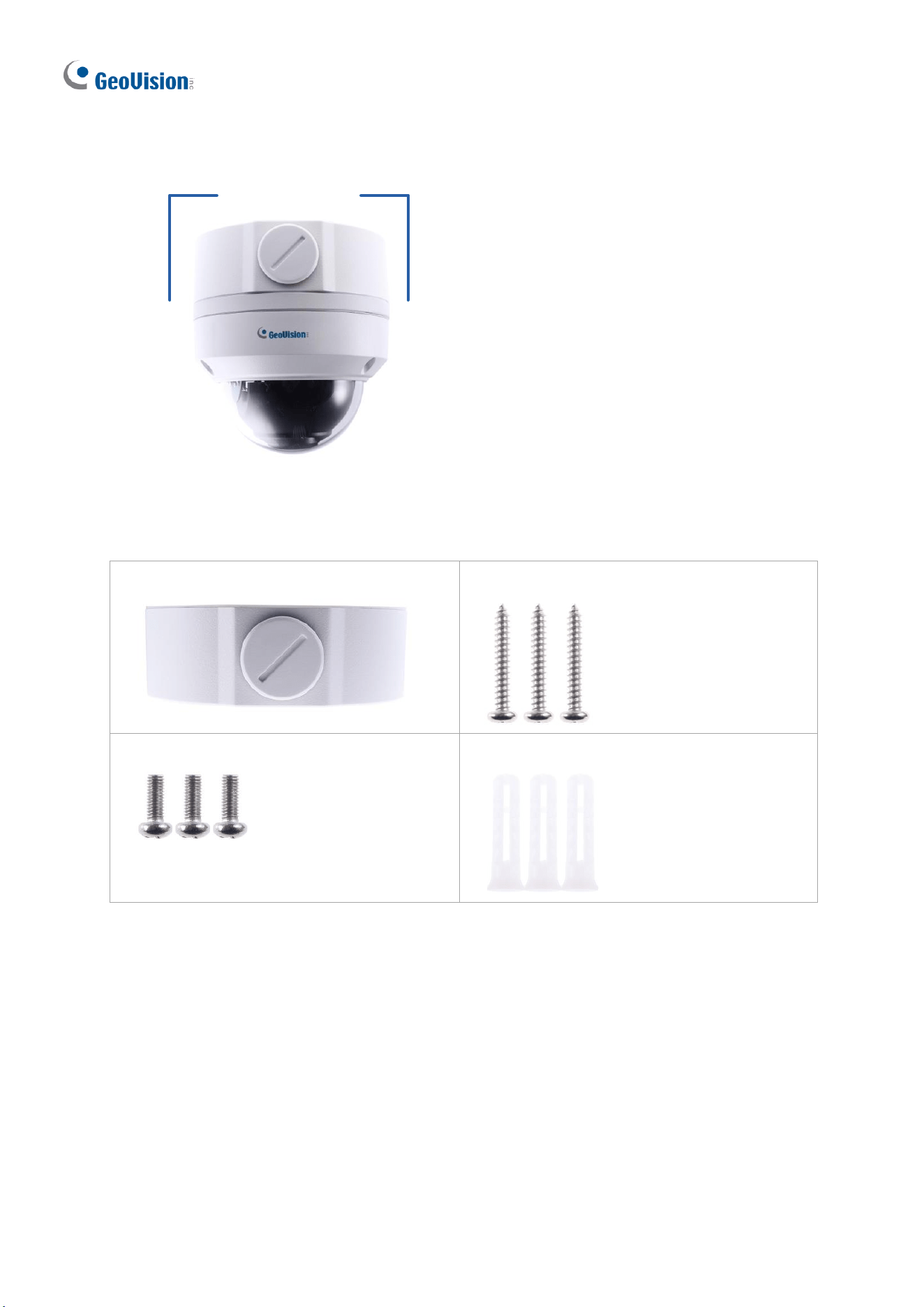
1.1.5.1 GV-Mount211P
GV-Mount211
GV-Mount211P
Figure 1-17
GV-Mount211P Packing List
• GV-Mount211P
• Long Screw x 5
• Short Screw x 4
• Screw Anchor x 5
• Plastic PG21 Conduit Connector
• Drill Template Paster
14
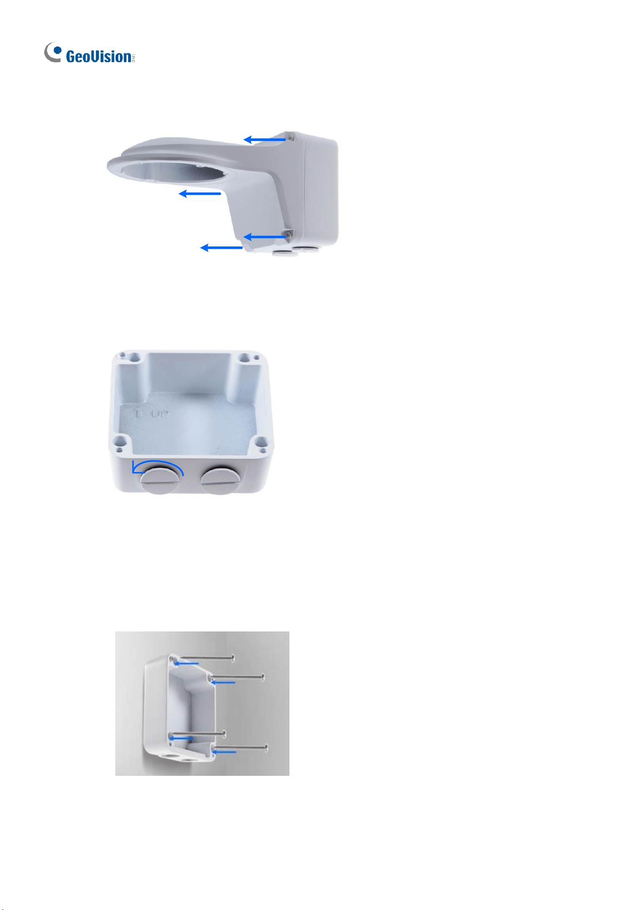
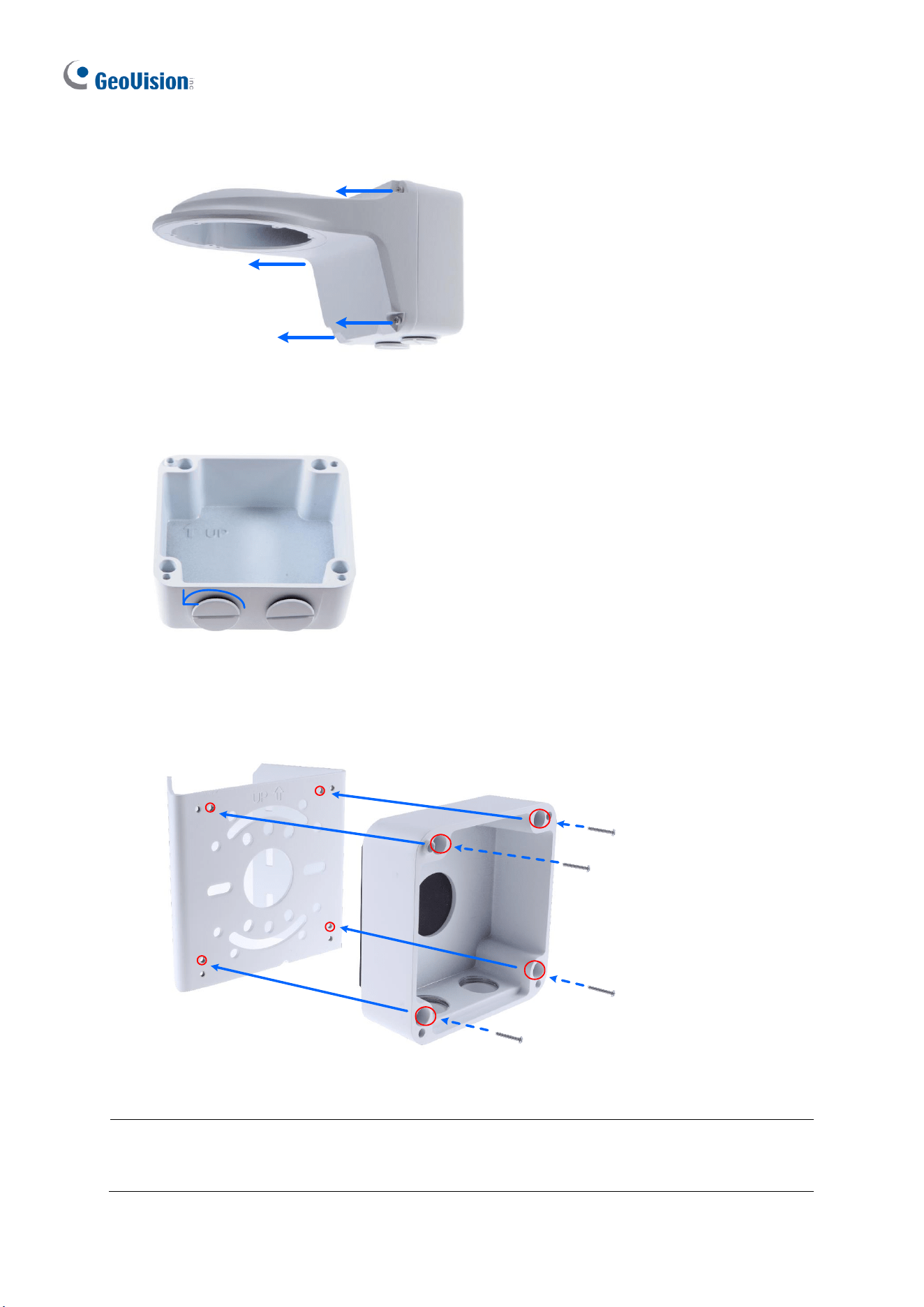
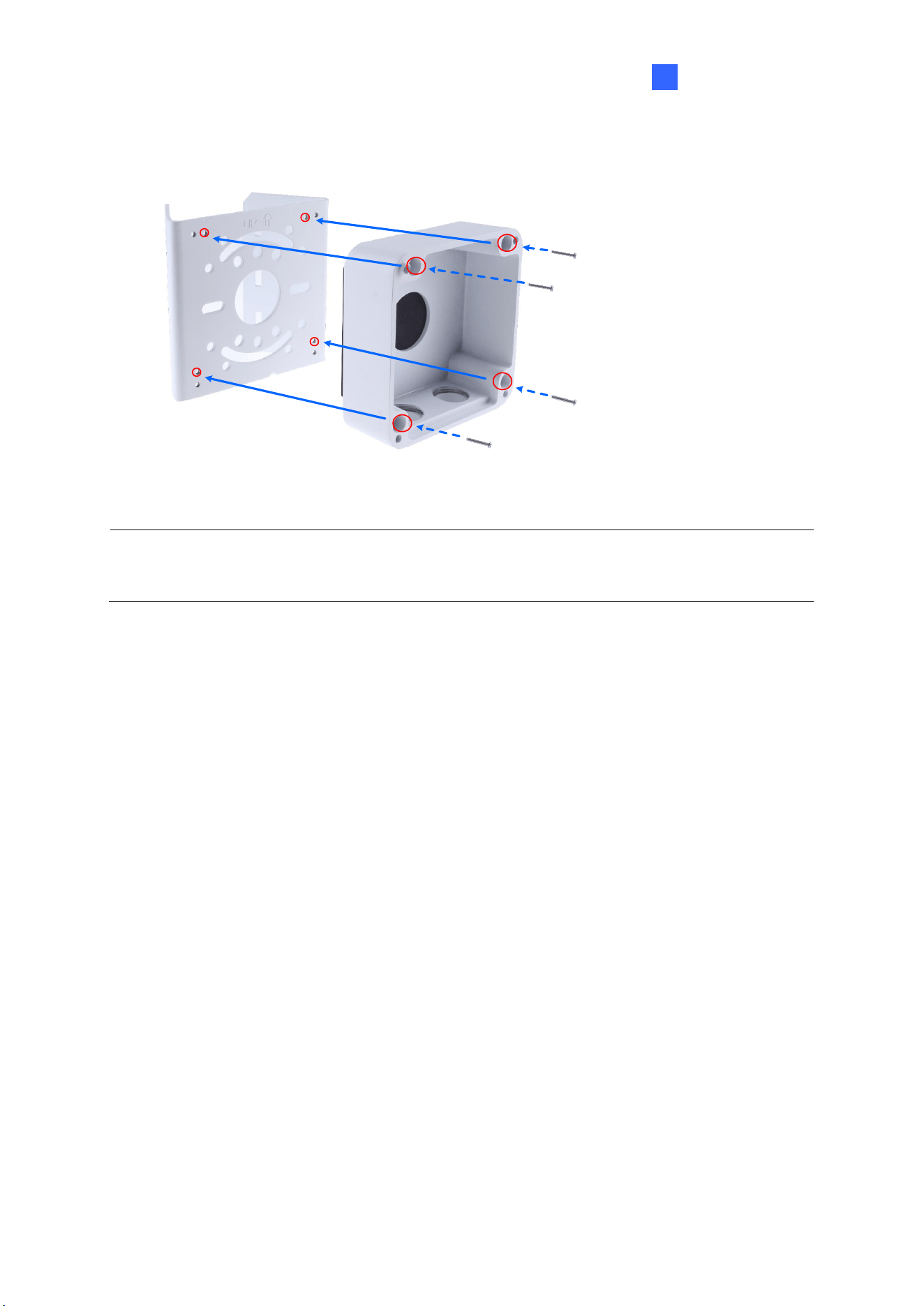
1. Unscrew the bracket.
Figure 1-18
2. Loosen the indicated area by turning it anticlockwise.
Power Box
Figure 1-19
3. Stick the drill template paster to the wall with the arrow pointing up.
4. Drill 4 holes according to the sticker and insert the 4 screw anchors to the 4 holes.
5. Secure the power box to the wall with 4 long screws.
Figure 1-20
Introduction
15
1
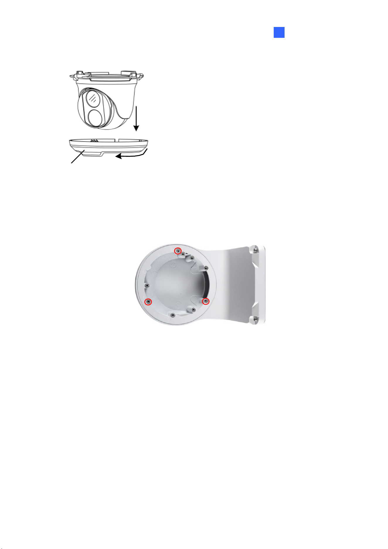
6. Remove the bottom ring by turning it anticlockwise.
Bottom Ring
Figure 1-21
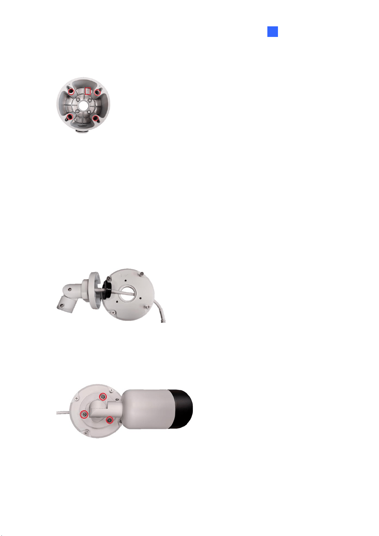
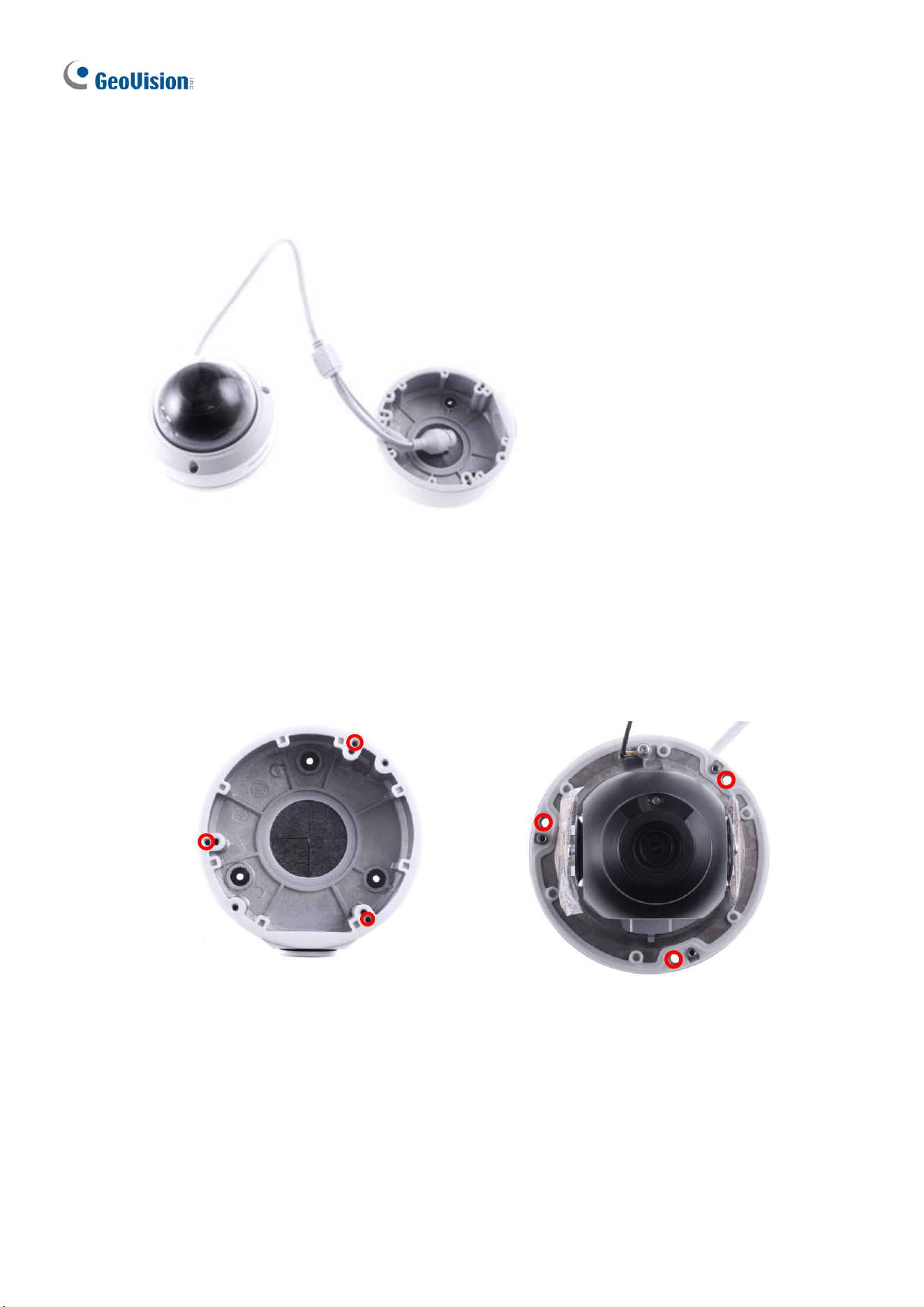
7. Secure the camera to the wall mount bracket with the provided short screws according
to the screw position for each model:
GV-EBD2705 / 4700 / 4701 / 4704 / 4711 / 4712 / 4813 / 8700 / 8711 / 8800 / 8813,
and GV-EBFC5800
Figure 1-22
16
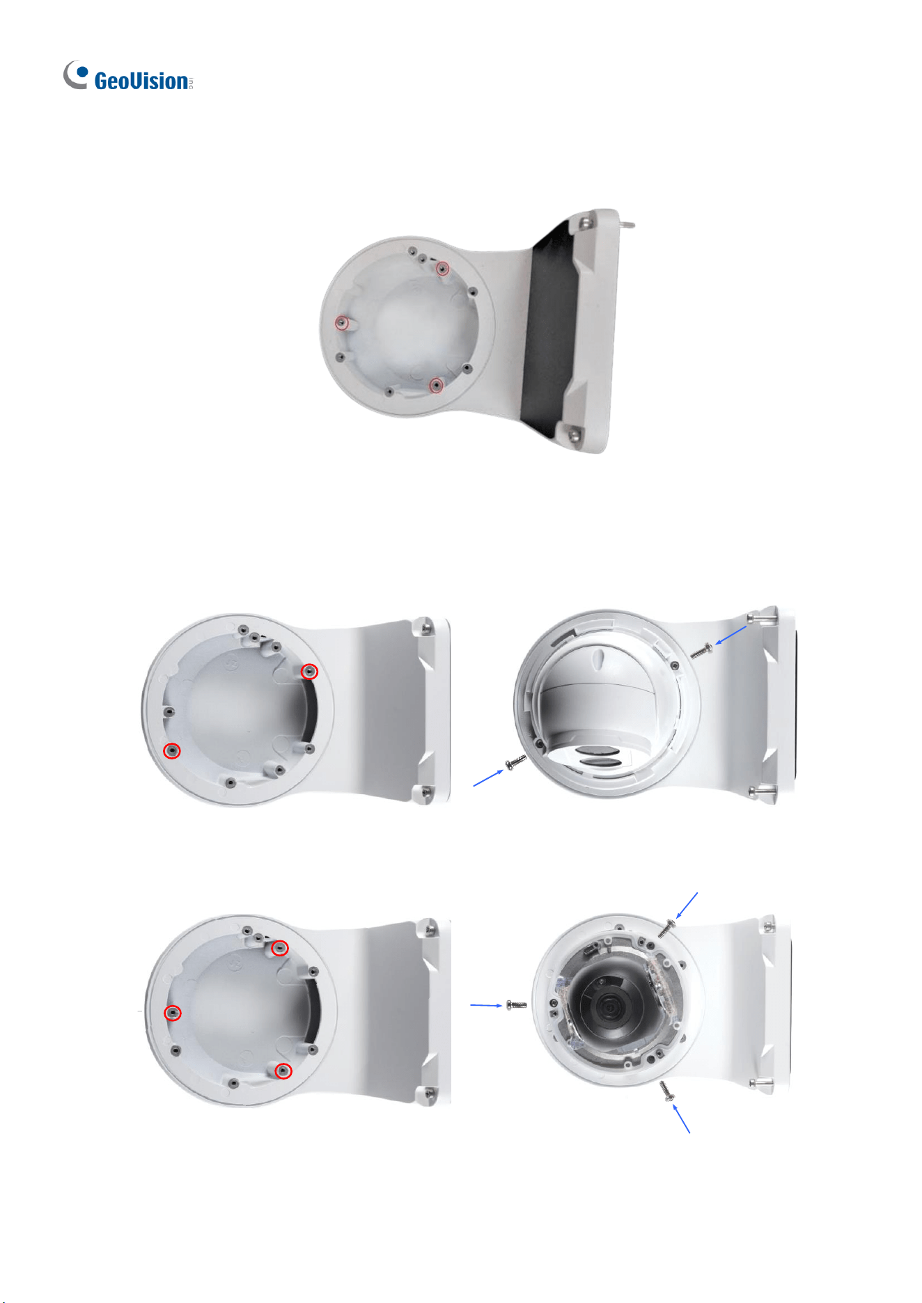
GV-EBDP5800 / 8800
Figure 1-22-1
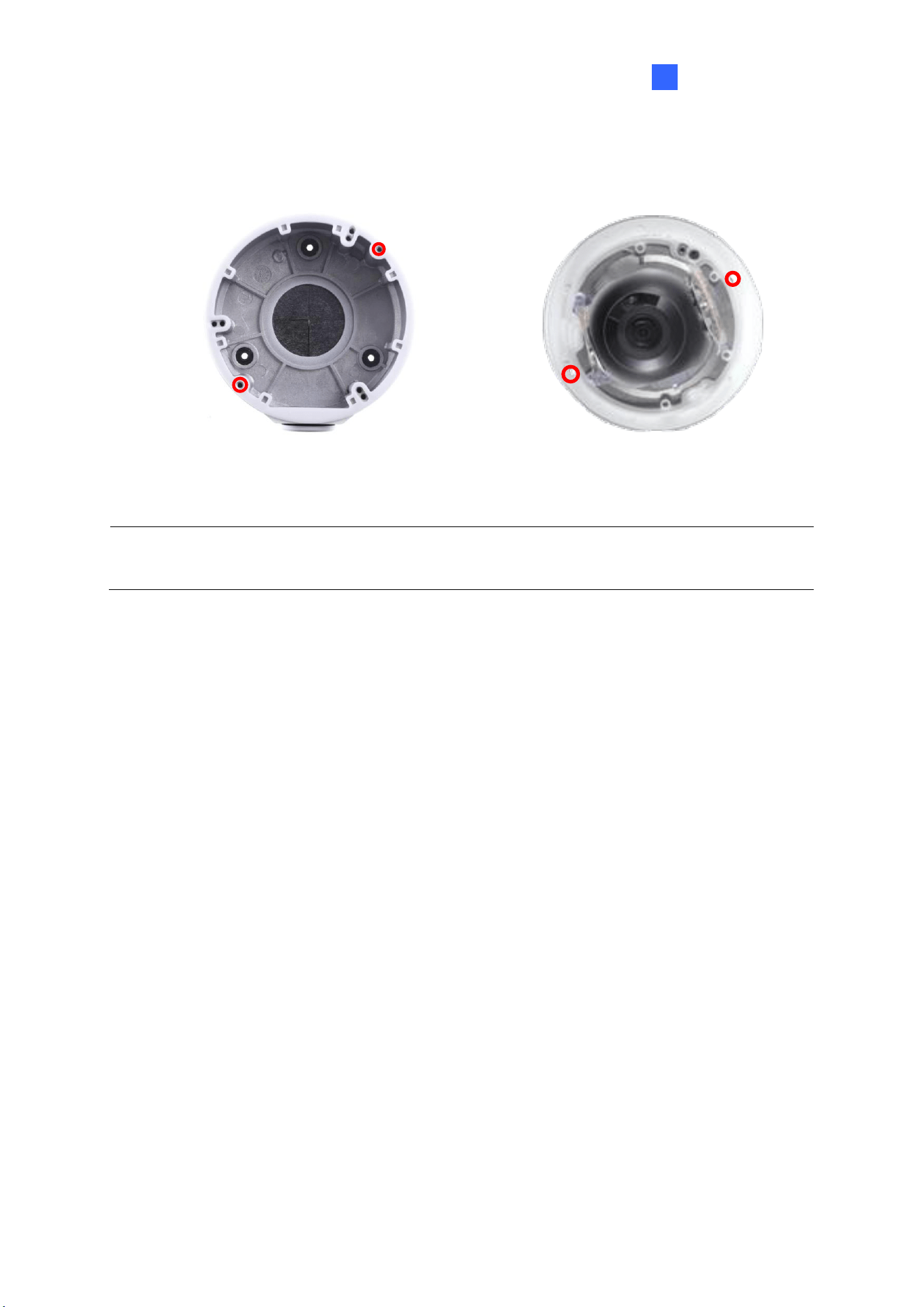
GV-EBD2702 / 2704
Figure 1-23
GV-ADR2701 / 4701
Figure 1-24
Introduction
17
1
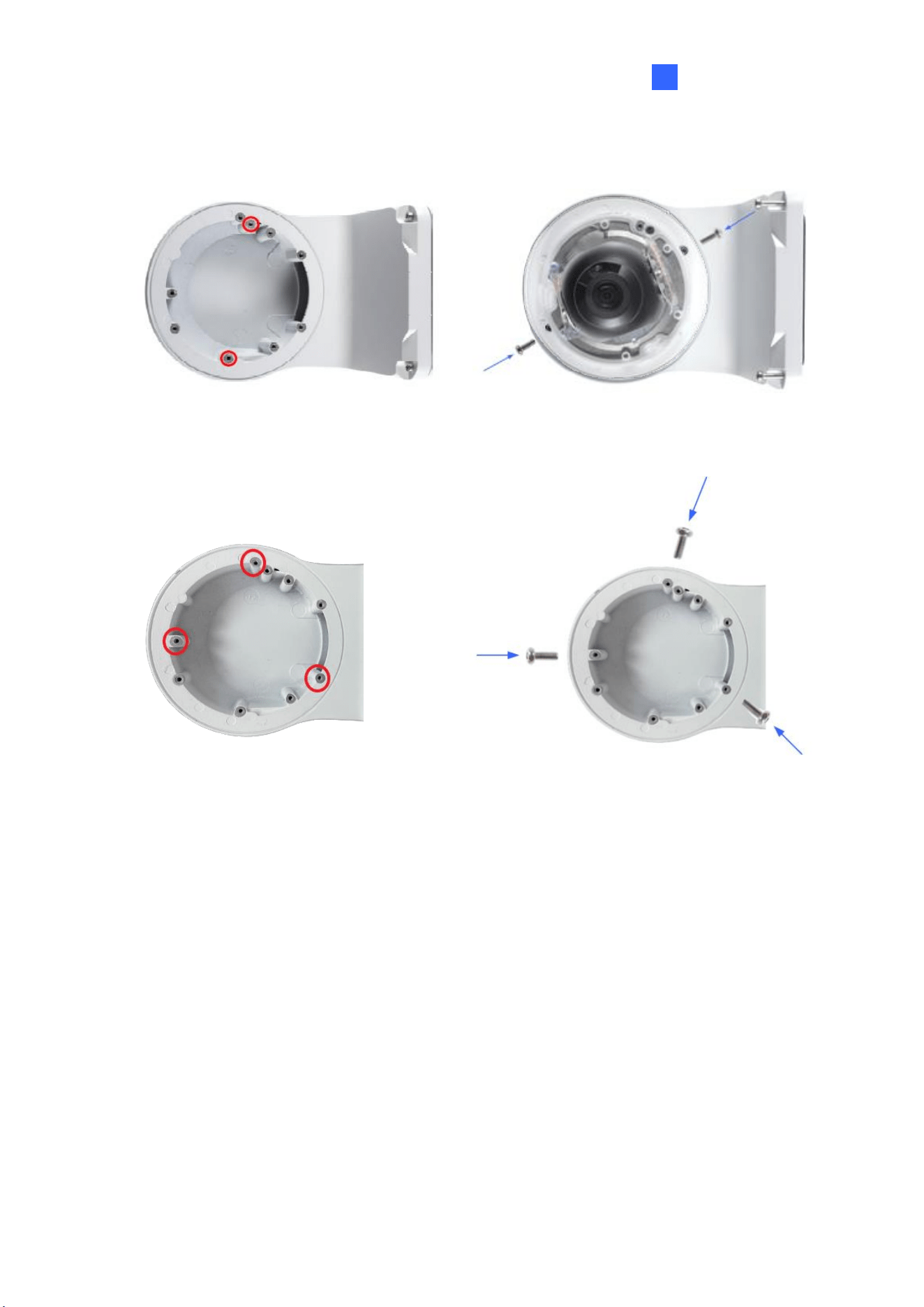
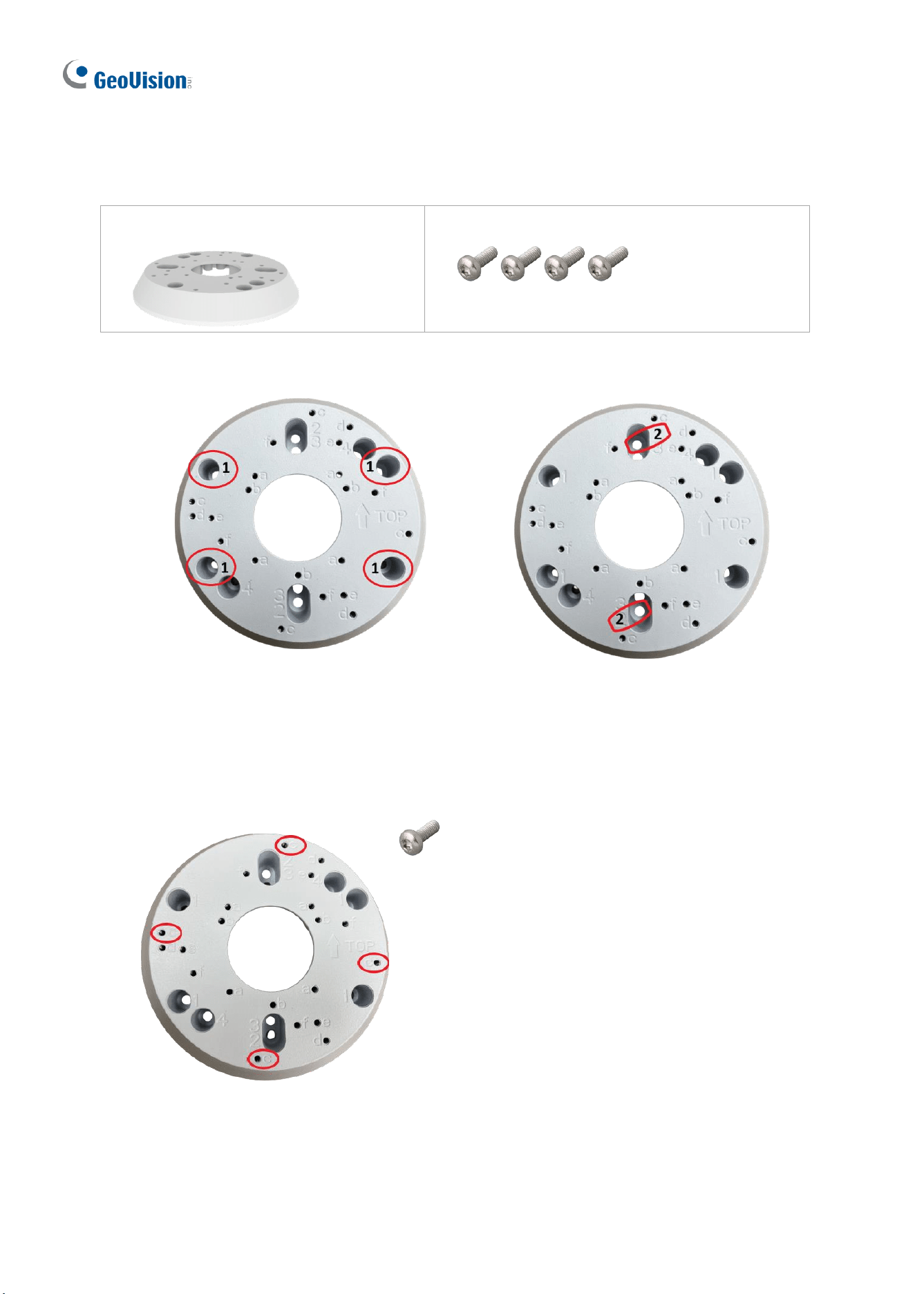
GV-ADR2702 / ADR4702 / TDR2700 / TDR2702 / TDR2704 / TDR4700 / TDR4702 /
TDR4703 / TDR4704 / TDR4803 / TDR8805
Figure 1-25
GV-TVD4711 / TVD4811
Figure 1-26
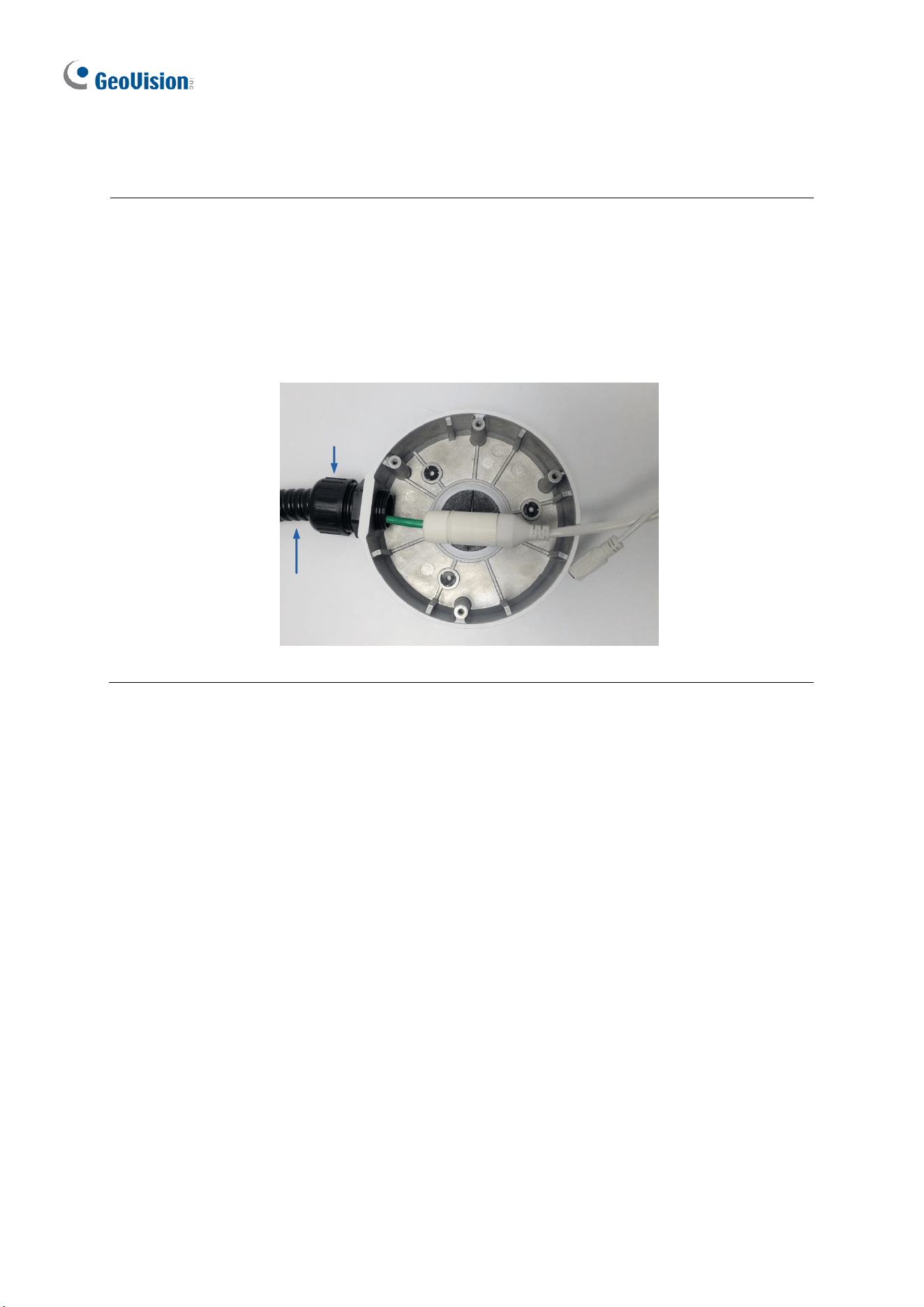
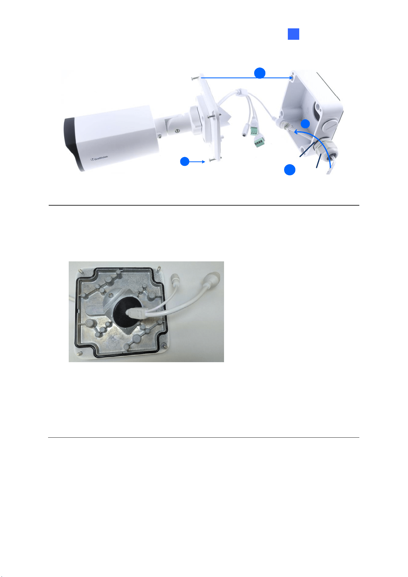
8. Thread the Ethernet cable through the PG21 conduit connector and the power box as
shown in No. 8, Figure 1-27. Then connect the cable to the camera. To waterproof the
cable, see 1.8 Waterproofing the Cable.
9. Rotate the plastic ring to secure the conduit connector to the power box. Screw in the
cap as shown in No. 9, Figure 1-27.
10. Screw the wall mount bracket to the power box as shown in No. 10, Figure 1-27.
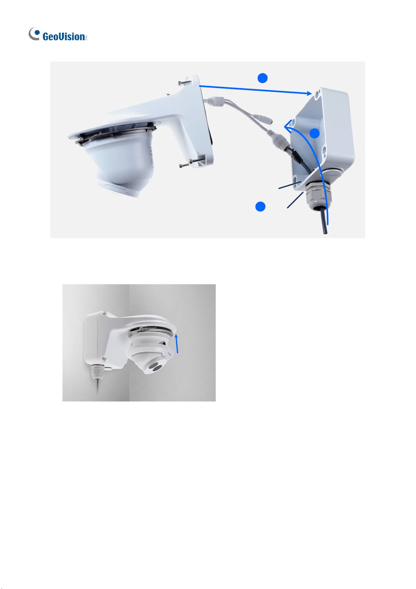
18
Plastic Ring
Cap
8
8
9
10
Figure 1-27
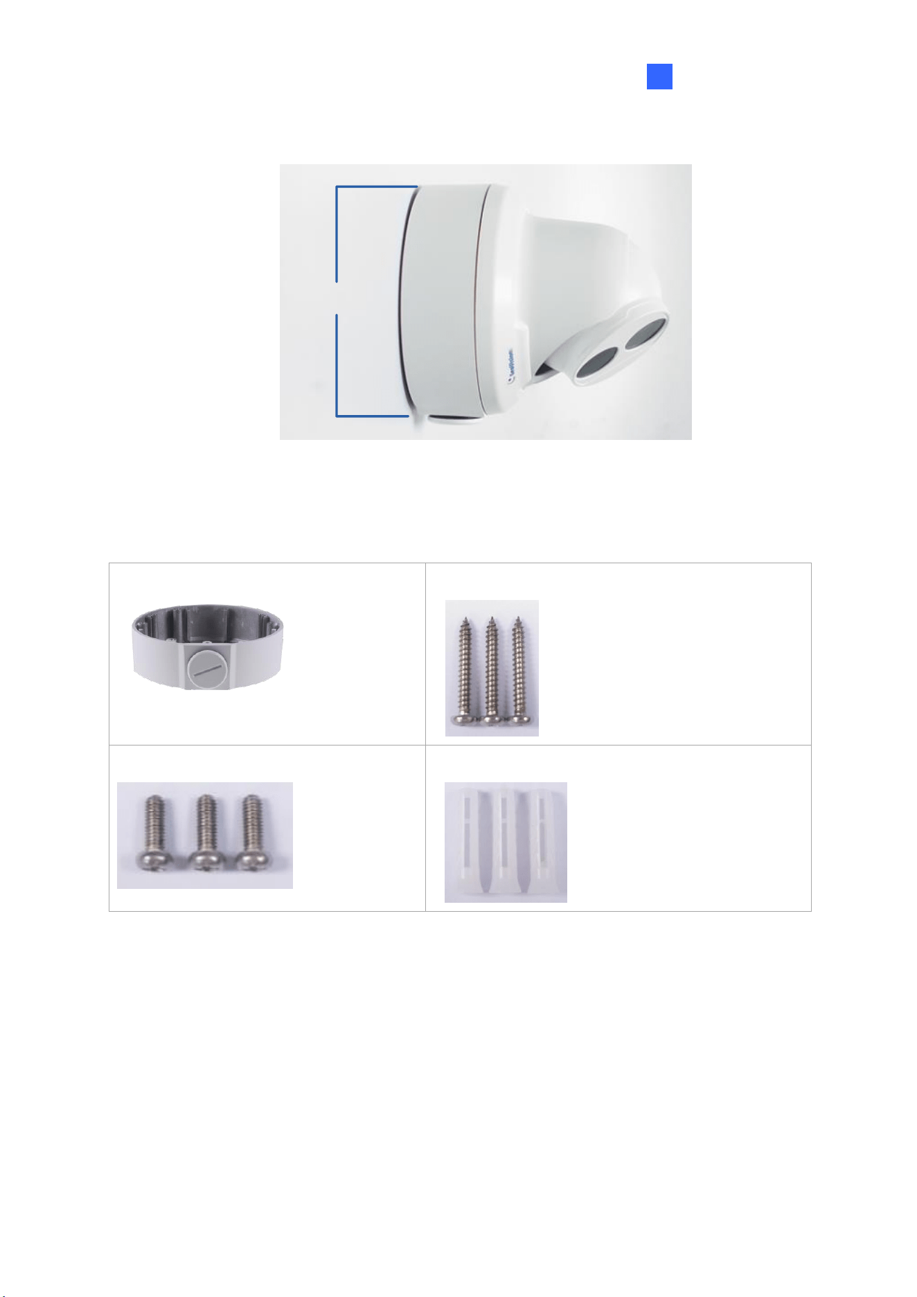
11. Mount the bottom ring.
Figure 1-28
Introduction
19
1
1.1.5.2 GV-Mount212P
GV-Mount212P
Figure 1-29
GV-Mount212P Packing List
• GV-Mount212P
• Long Screw x 3
• Short Screw x 3
• Screw Anchor x 3
20
Standard Installation
1 Attach the wall box to the wall and use a marker to mark the location for the center
socket and the screws. Make sure the knob points down.
This knob points down
Long Screw
Figure 1-30
2 Drill 3 holes according to the screw location. Then, drill a bigger hole at the center
socket location for the Ethernet cable.
3 Insert 3 screw anchors to the screw location and secure the wall box to the wall with 3
long screws.
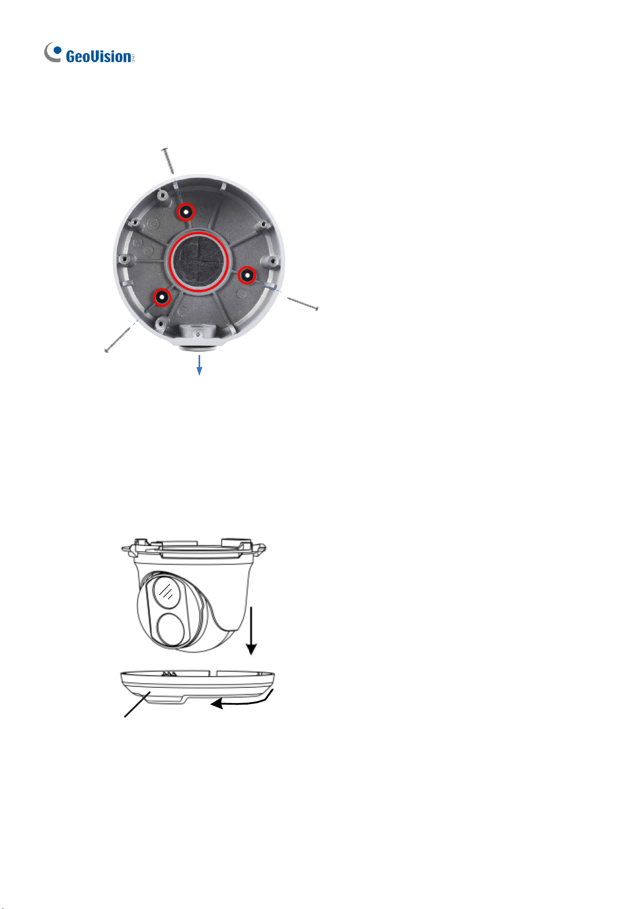
1. Remove the bottom ring by turning it anticlockwise.
Bottom Ring
Figure 1-31
Introduction
21
1
5. Thread the Ethernet cable through the center socket and waterproof the Ethernet cable.
For details, see 1.8 Waterproofing the Cable.
`
Figure 1-32
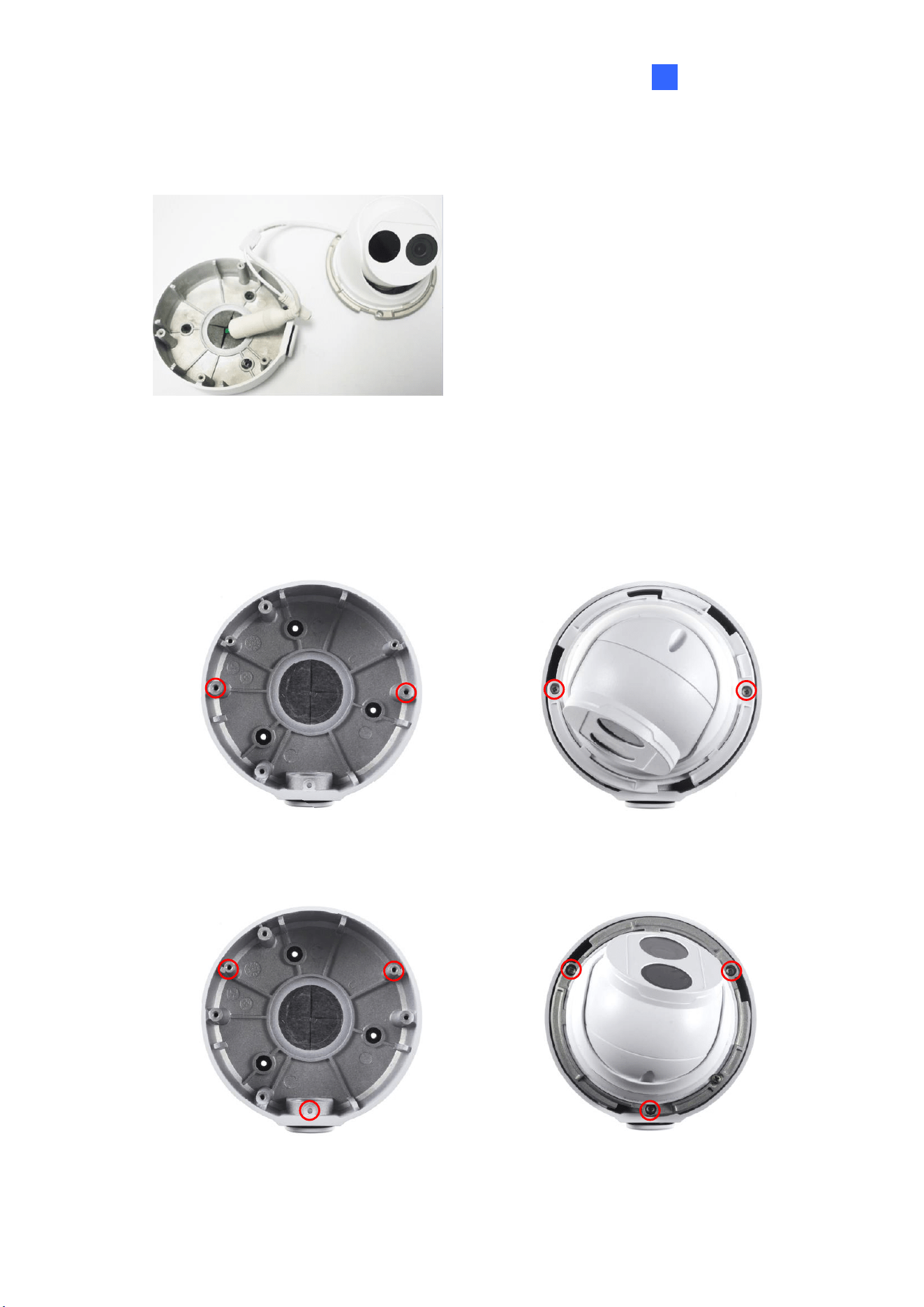
6. Fit the cable into the wall box.
7. Secure the camera by locking the provided short screws to the screw position for each
model:
GV-EBD2702 / 2704
Figure 1-33
GV-EBD2705 / 4700 / 4701 / 4704 / 4711 / 4712 / 4813 / 8700 / 8711 / 8800 / 8813
and GV-EBFC5800
Figure 1-34
22
8. Mount the bottom ring.
Note: In addition to the Standard Installation, you can also choose to run the Ethernet
cable through a corrugated tube. To do this, you will have to purchase your own conduit
connector and corrugated tube. 3/4” NPS is the recommended type of connector. After you
secure the wall box to the desired location, remove the knob at the bottom and connect the
conduit connector with a self-prepared corrugated tube to the wall box. Then, thread the
Ethernet cable through the corrugated tube and waterproof the cable.
¾” NPS
Conduit Connector
Corrugated
Tube
Figure 1-35
Introduction
23
1
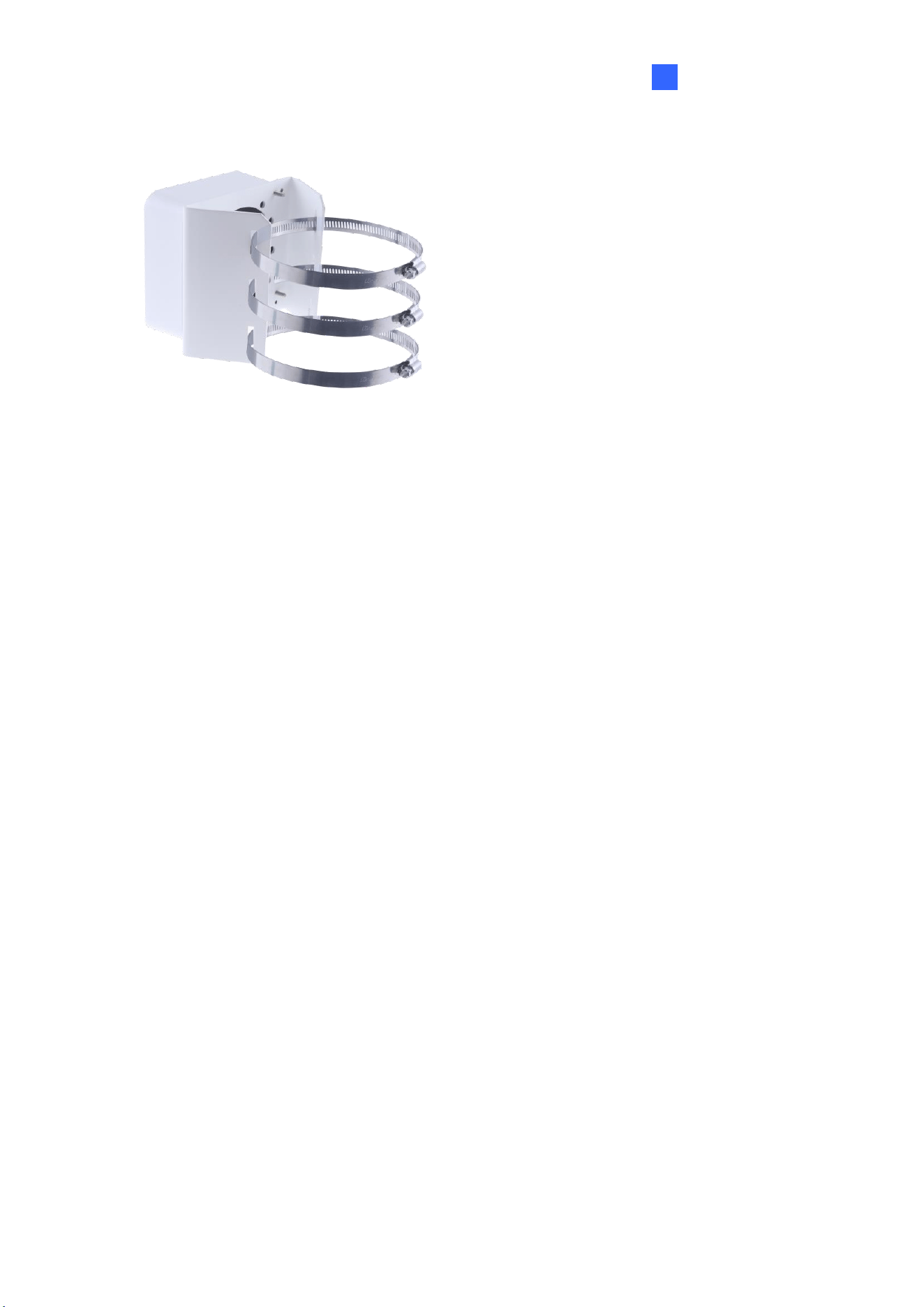
1.1.5.3 GV-Mount420 + GV-Mount211P
GV-Mount211P
GV-Mount420
Figure 1-36
GV-Mount420 Packing List
• GV-Mount420
• M4 Screw x 4
• Additional Screw Kit
- M6 Screw x 4
- M6 Nut x 4
- M6 Plain Washer x 4
- M6 Split Washer x 4
Note: For GV-ADR / TDR / EBD Series, GV-Mount420 can only be used in conjunction
with GV-Mount211P.
24
1. Unscrew the bracket.
Figure 1-37
2. Loosen the indicated area by turning it anticlockwise.
Power Box
Figure 1-38
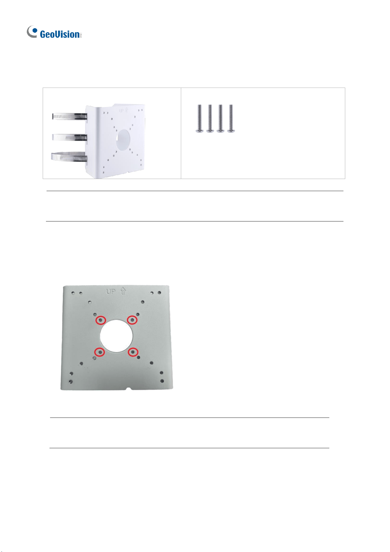
3. Align and attach the power box to the back plate using the 4 supplied M4 screws as
indicated.
Figure 1-39
Note: Make sure the direction of the “up ↑” indicator on the back plate match that of the
power box.
Introduction
25
1
4. Thread the 3 steel straps onto the back plate.
Figure 1-40
5. Follow Step 6 ~ 12 in 1.1.5.1 GV-Mount211P.
6. Secure the camera onto the desired pole by tightening the steel straps.
26
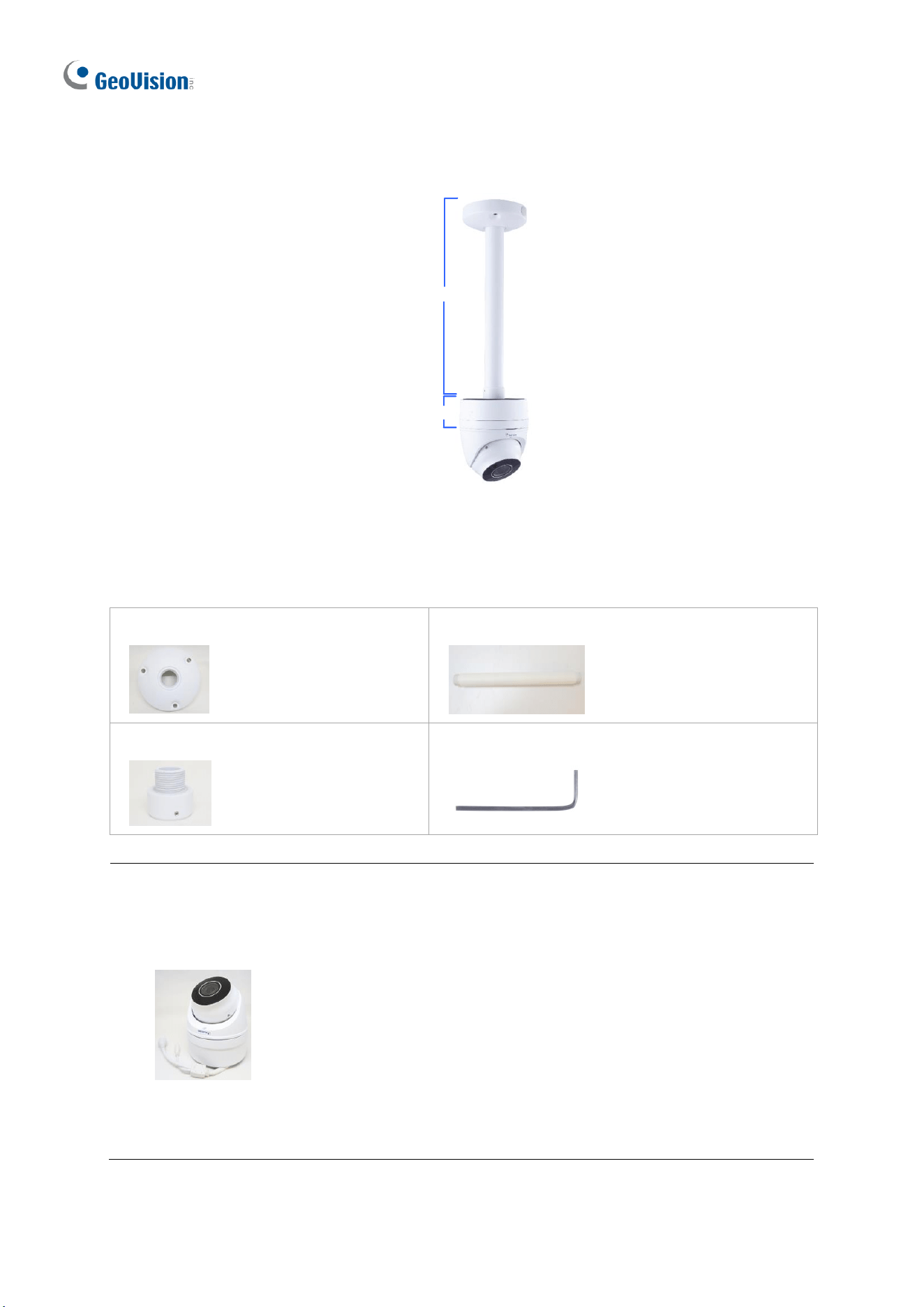
1.1.5.4 GV-Mount212P + GV-Mount107
GV- Mount107
GV-Mount212P
Figure 1-41
GV-Mount107 Packing List
• Pendant Bracket
• Pendant Tube
• Tube Connector
• Torx Wrench
Note: Before installing GV-Mount107, note the following.
• Install your GV-EBD Series camera on a GV-Mount212P by cutting a hole in the
center of the mount and thread the camera wires through.
• Prepare 3 long screws for securing the Pendant Bracket to the ceiling.
• GV-Mount107 optionally extends with GV-Mount704.
Introduction
27
1
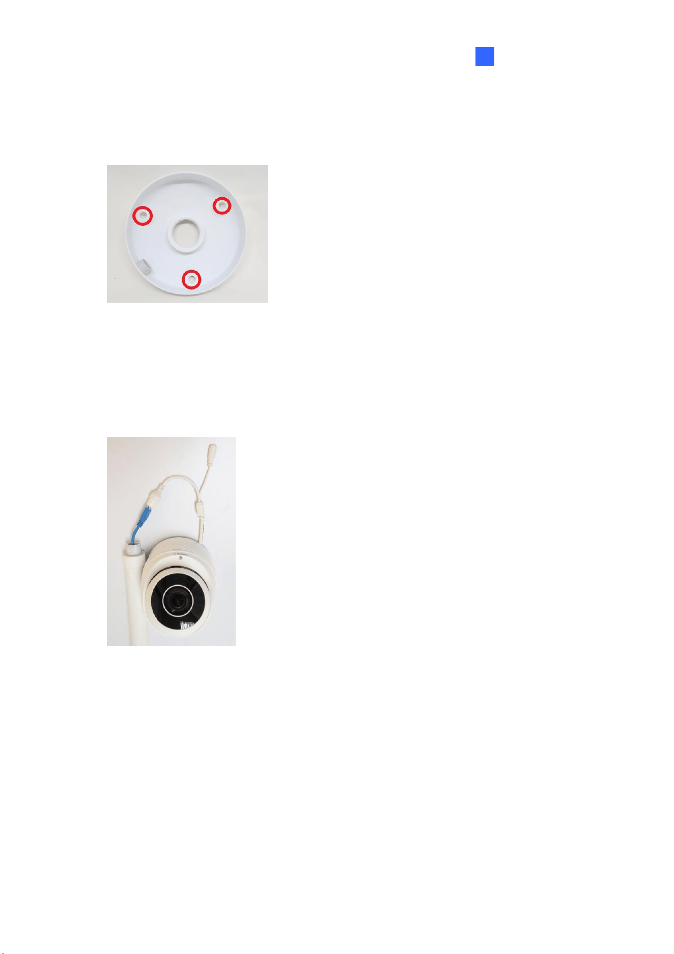
1. Place GV-Mount107 on the ceiling and mark the location for the center socket and the 3
screws.
2. Drill the marks and secure the Pendant Bracket onto the ceiling.
Figure 1-42
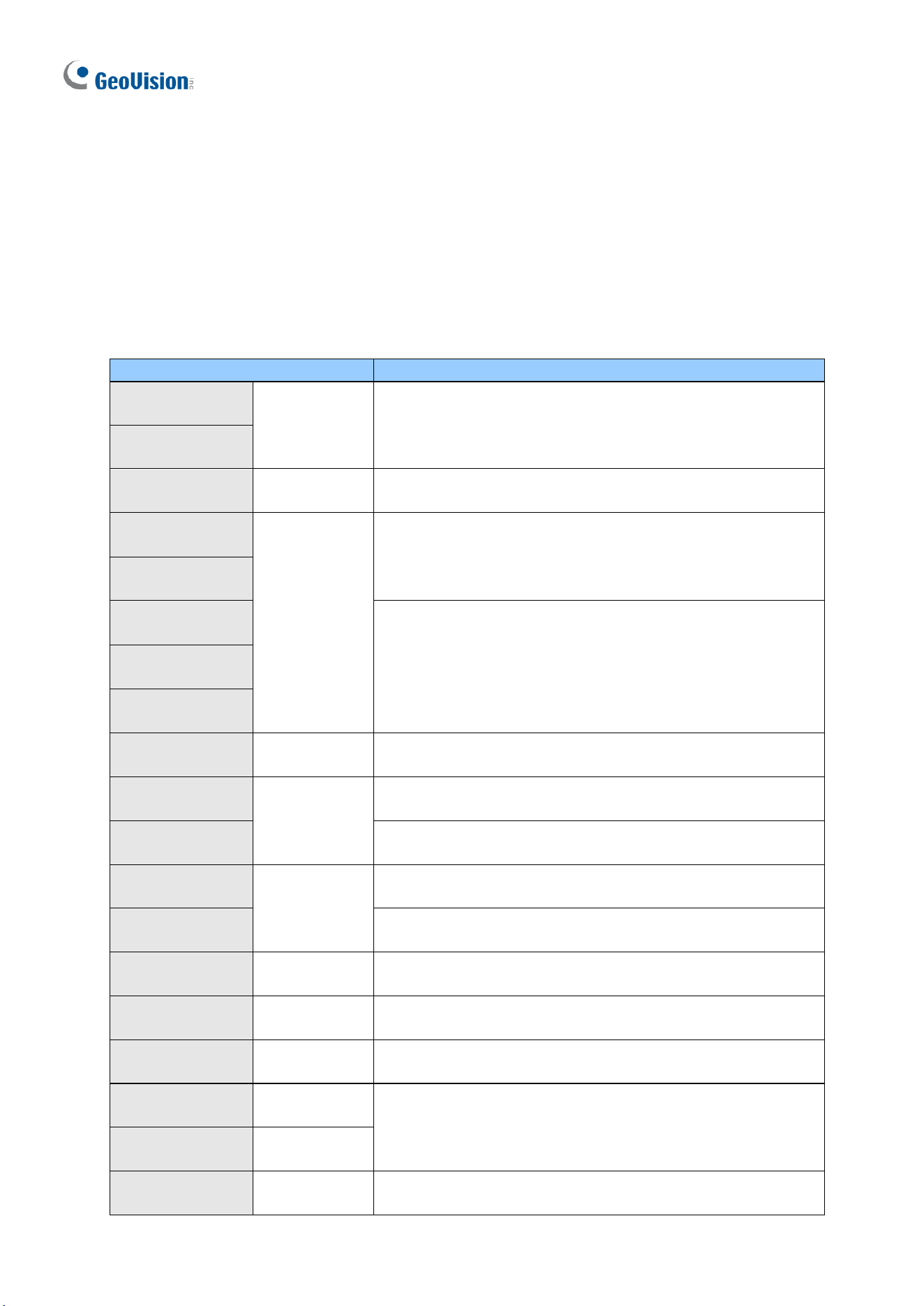
3. Attach one end of the Pendant Tube to the Pendant Bracket, and the other end to the
Tube Connector.
4. Thread the necessary wires from the ceiling through the Pendant Tube and connect to
the camera wires.
Figure 1-43
5. Push and arrange the connected wires inside Mount212P.
6. Secure the camera onto the Tube Connector.
28
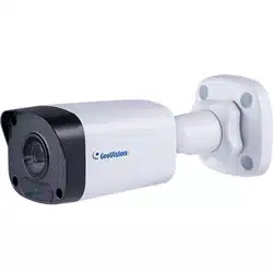
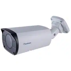
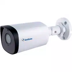
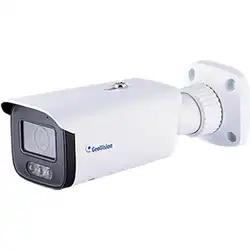
1.2 GV-ABL / BLFC / TBL / TBLP Series
The Bullet IP Camera is an outdoor, fixed, network camera equipped with an automatic IR-
cut filter and an IR LED for day and night surveillance. For GV-BLFC5800, it’s equipped with
full color smart warm LEDs for accurate day and night surveillance. The camera supports
H.265 video codec to achieve better compression ratio while maintaining high quality image
at reduced network bandwidths. The camera adheres to IP66 / IP67 standards and can be
powered through PoE.
Model No.
Description
GV-ABL2701-0F
Fixed lens
2 MP, H.265, Low Lux, WDR
GV-ABL2701-1F
GV-ABL2702
Varifocal
Lens
2 MP, H.265, Low Lux, WDR Pro
GV-ABL2703-0F
Fixed lens
2 MP, H.265, Low Lux, WDR
GV-ABL2703-1F
GV-ABL4701-0F
4 MP, H.265, Super Low Lux, WDR
GV-ABL4701-1F
GV-ABL4703
GV-ABL4711
Motorized
varifocal lens
4 MP, H.265, Super Low Lux, WDR Pro
GV-ABL4712
Motorized
varifocal lens
4 MP, H.265, Super Low Lux, WDR Pro
GV-ABL8712
8 MP, H.265, Super Low Lux, WDR Pro
GV-TBL2703-0F
Fixed lens
2 MP, H.265, Low Lux, WDR
GV-TBL2703-1F
2 MP, H.265, Low Lux, WDR
GV-TBL2705
Fixed lens
2 MP, H.265, Low Lux, WDR Pro
GV-TBL2706
Fixed lens
2 MP, H.265, Low Lux, WDR Pro
GV-TBL2718
Motorized
varifocal lens
2 MP, H.265, Super Low Lux, WDR Pro
GV-TBL4700
Varifocal lens
4 MP, H.265, Super Low Lux, WDR
GV-TBL4703
Fixed lens
GV-TBL4705
Fixed lens
4 MP, H.265, Super Low Lux, WDR Pro
Introduction
29
1
GV-TBL4710
Motorized
varifocal lens
GV-TBL4711
4 MP, H.265, Super Low Lux, WDR Pro
GV-TBL4810
GV-TBL8710
8 MP, H.265, Super Low Lux, WDR Pro
GV-TBL8804
Fixed lens
8 MP, H.265, Super Low Lux, WDR Pro, Warm LED
GV-TBL8810
Motorized
varifocal lens
8 MP, H.265, Super Low Lux, WDR Pro
GV-TBL4807
Fixed lens
4MP, H.265, Super Low Lux, WDR Pro
GV-TBLP5800
Fixed lens
5MP, H.265, Super Low Lux, WDR Pro, 180° panoramic
GV-TBLP8800
Fixed lens
8MP, H.265, Super Low Lux, WDR Pro, 180° panoramic
GV-BLFC5800
Fixed lens
5 MP, H.265, Super Low Lux, WDR Pro, Warm LED
1.2.1 Packing List
The packing list varies depending on the model. Product details can be found on the
datasheet.
• Bullet IP Camera
• Drill Template Paster
• Screw Kit
• Download Guide
• Torx Wrench (not available for all
models)
• Waterproof Rubber Set
30
1.2.2 Optional Accessories
Optional accessories can expand the capabilities and versatility of your camera. Accessory
details can be found on the datasheet.
1.2.3 Overview
1.2.3.1 GV-ABL2701 / 2703 / 4701 / 4703, TBL2703 / 2705 / 2706 /
4703 / 4705 / 8804, TBLP5800 / 8800
Figure 1-44
No.
Description
No.
Description
1
Power connector (DC 12 V)
2
Ethernet connector / PoE
Figure 1-45
No.
Description
No.
Description
1
Load Default button
2
Grounding screw (GV-TBL8804)
Note: The Load Default button is for GV-ABL2703 / 4703 & GV-TBL2703 /
4703 / 8804 only.
Introduction
31
1
GV-TBL8804
GV-TBL2705 / 2706 / 4705
10
11
13
11
12
12
1
14
15
GV-TBL4807
GV-TBLP5800
GV-TBL2718
Figure 1-46
No.
Description
No.
Description
3
Default button / SD card slot
10
Built-in microphone x 2 (GV-TBL4807)
4
Built-in speaker (GV-TBL8804)
11
IR LED x 4 (GV-TBL4807)
5
Built-in microphone (GV-TBL8804)
12
IR LED x 2 (GV-TBLP5800 / 8800)
Built-in microphone (GV-TBLP5800 / 8800)
6
Warm LED x 2 (GV-TBL8804)
13
Built-in microphone (GV-TBLP5800 / 8800)
7
IR LED (GV-TBL8804)
14
Built-in microphone (GV-TBL2718)
8
Built-in microphone (GV-TBL2705 / 2706 /
4705)
15
IR LED x 3 (GV-TBL2718)
9
IR LED x 2 (GV-TBL2705 / 4705)
IR LED x 1 (GV-TBL2706)
Note:
1. The Default button is only available in the following models: GV-ABL2703 / 4703, GV-
TBL2703 series / 2718 / 4703 / 4807 / 8804, and GV-TBLP5800 / 8800.
2. If the Default button doesn’t respond after pressing for 15 seconds, reboot the camera
and try again within 10 minutes of rebooting.
3. For safety precautions, it is recommended to connect a grounding wire to the
grounding screw, and do not loosen or remove the grounding screw under any
circumstances.
32
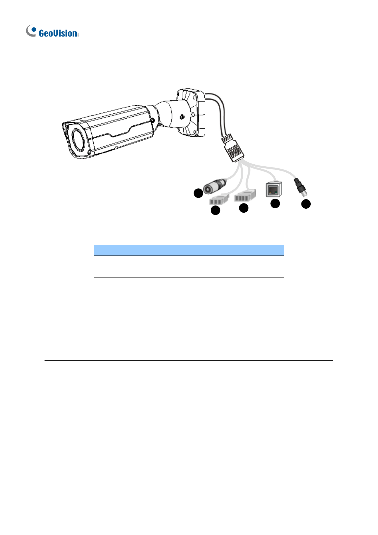
1.2.3.2 GV-ABL2702 / 4711 / 4712 / 8712, TBL4700 / 4710 / 4711 /
4807 / 4810 / 8710 / 8810, and BLFC5800
1
2
3
4
5
Figure 1-47
No.
Description
1
Power connector (DC 12 V)
2
Audio input / Audio output / GND
3
Alarm input (IN, GND) / Alarm output (N, P)
4
Ethernet connector / PoE
5
Video Output (GV-ABL8712 / TBL8710 Only)
Note: GV-TBL4807 does not have the terminal blocks for audio input / output (No. 2) and
alarm input / output (No. 3). Instead, it features 4 wires for connecting alarm input and
output devices.
Introduction
33
1
1.2.4 Installation
The Bullet IP Camera is designed for outdoors. With the standard package, you can install
the camera on the wall or ceiling. Or, you can purchase optional mounting accessories to
mount your camera on a wall.
Below are the instructions for Wall Mount. There are two kinds of Wall Mount: Concealed
Installation and Open Installation. In Concealed Installation, the cables are hidden in the
wall. In Open Installation, the cables are led out from the open slot on the base.
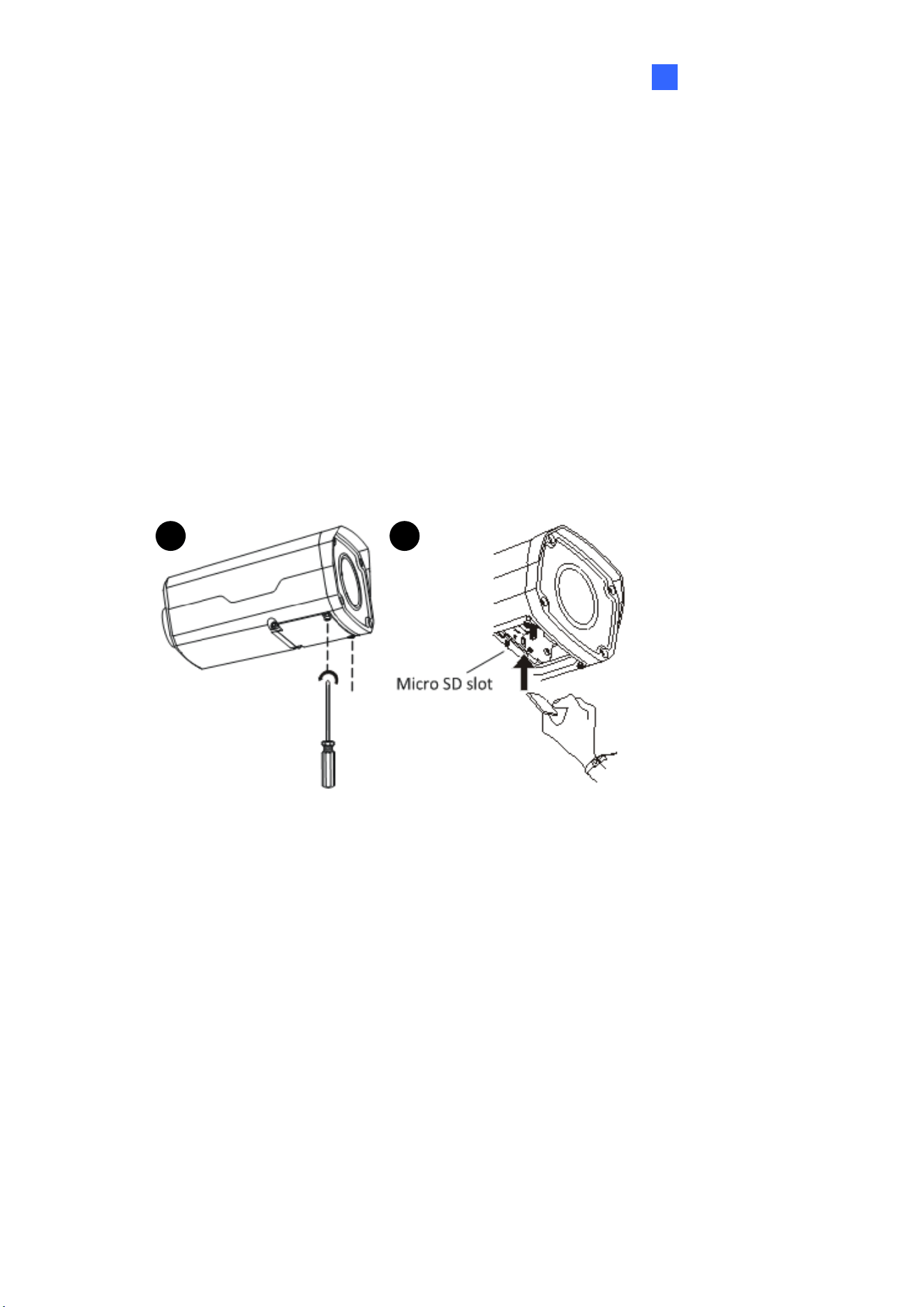
For Concealed Installation
Note that the following camera illustrations may differ between models.
1. Optionally loosen the two screws at the bottom of the camera to insert a SD card.
A B
Figure 1-48
2. Stick the drill template paster to the wall and align the cross center to the hole in the wall.
34
Lead the cables across the hole on the wall.
Figure 1-49
3. Drill the holes according to the drill template.
Figure 1-50
4. Insert the screw anchors.
Figure 1-51
Introduction
35
1
5. Screw the locknut and loosen the universal joint before attaching the camera to the wall.
Locknut
Figure 1-52
6. Secure the camera to the wall and connect all cables.
Figure 1-53
36
To adjust the monitoring direction:
GV-ABL2702 / 4711 / 4712 / 8712, TBL2705 / 2706 / 4700 / 4705 / 4710 / 4711 / 4807 /
4810 / 8710 / 8804 / 8810, and BLFC5800
Figure 1-54
GV-TBL8804 and GV-TBLP5800 / 8800
Figure 1-55
For Open Installation
Lead the cables out from the open slot on the base before screwing the camera to the wall
as shown in Figure 1-51.
1.2.5 Optional Installation
You can optionally purchase the following accessories to fit your mounting environment:
⚫ GV-Mount504 for Wall Mount
⚫ GV-Mount440 + GV-Mount504 for Pole Box Mount
⚫ GV-Mount504 for Wall Mount
⚫ GV-Mount924 for Gang Box Mount
⚫ GV-Mount300-2 / 310-2 for Corner Mount

Introduction
37
1
⚫ GV-Mount300-2 / 310-2 for Corner Mount
⚫ GV-Mount300-2 / 310-2 + GV-Mount504 for Convex Corner Mount
⚫ GV-Mount502 for Wall Box Mount: see section 1.2.5.1.
⚫ GV-Mount503 for Wall Box Mount: see section 1.2.5.2.
⚫ GV-Mount420 + GV-Mount503 for Pole Box Mount: see section 1.2.5.3.
⚫ GV-Mount440 + GV-Mount502 for Pole Box Mount: see section 1.2.5.5.
Note: For detailed instructions on GV-TBLP series and GV-TBL2718, see GV-A/T/EBD
Series IP Camera Mount Installation Guide.
38
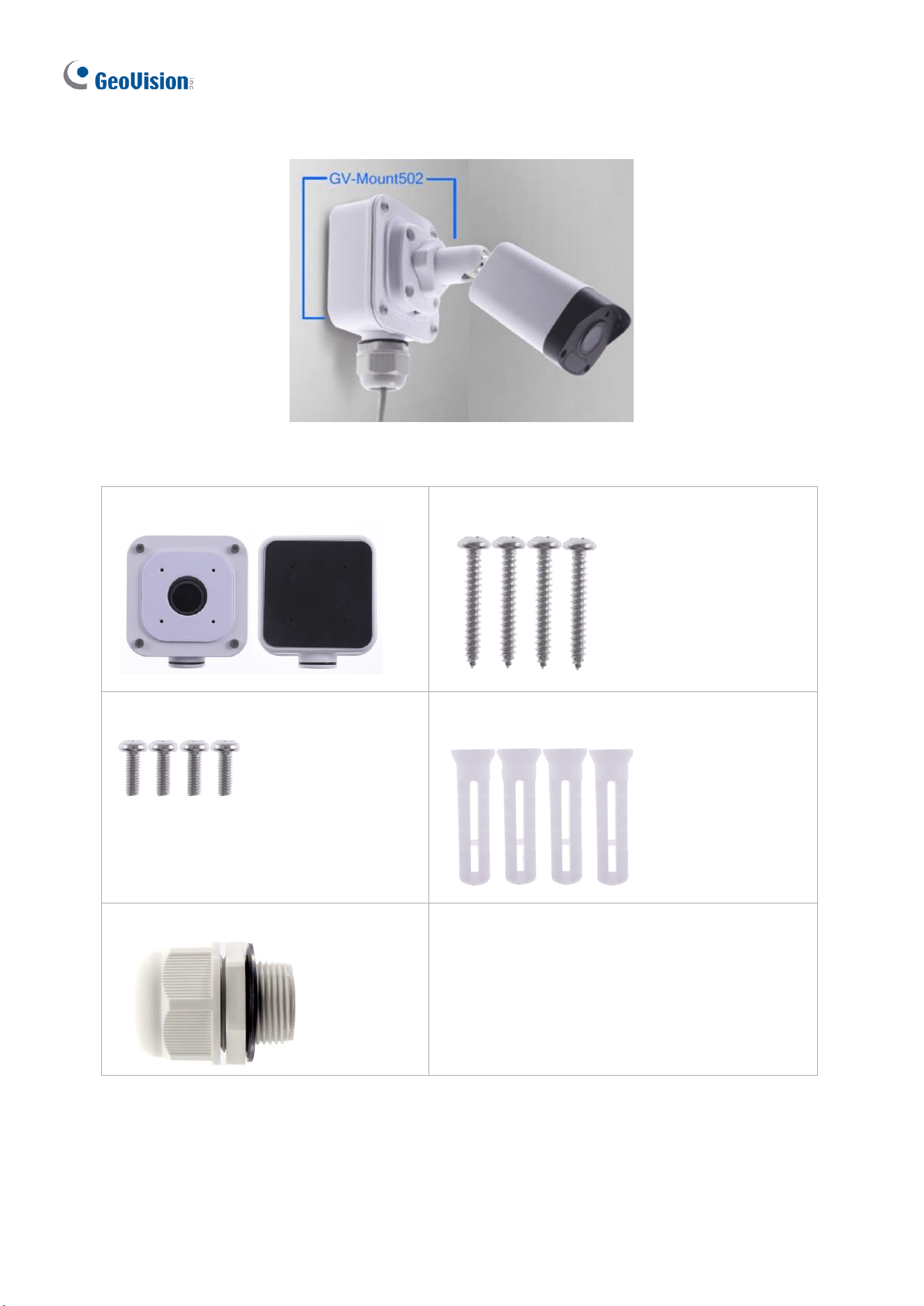
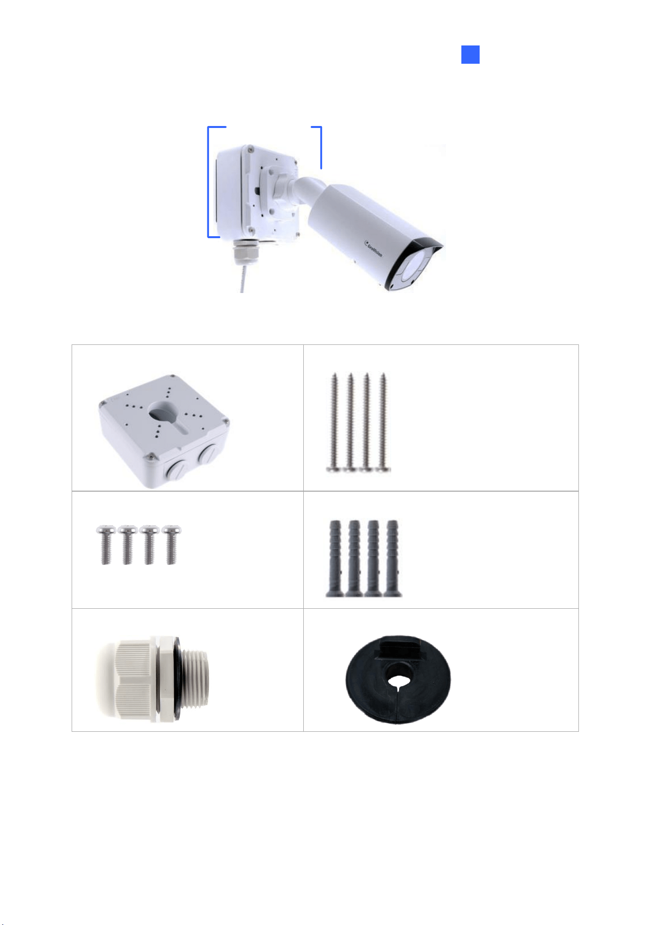
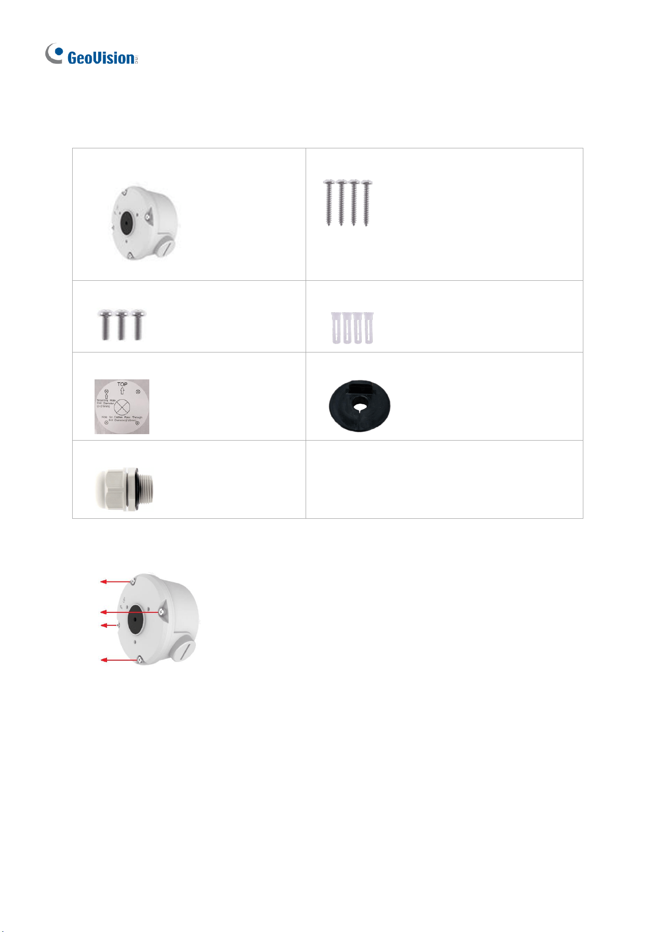
1.2.5.1 GV-Mount502
Figure 1-56
GV-Mount502 Packing List
• GV-Mount502
• M3 25 mm Screw x 4
• M3 12 mm Screw x 4
• Screw Anchor x 4
• Plastic PG21 Conduit Connector
Introduction
39
1
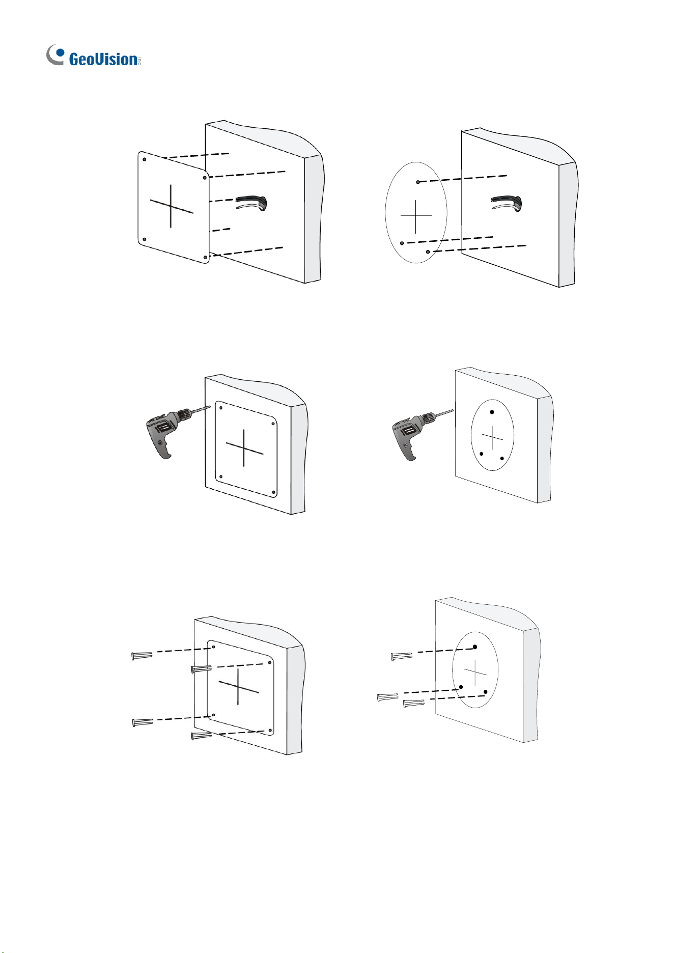
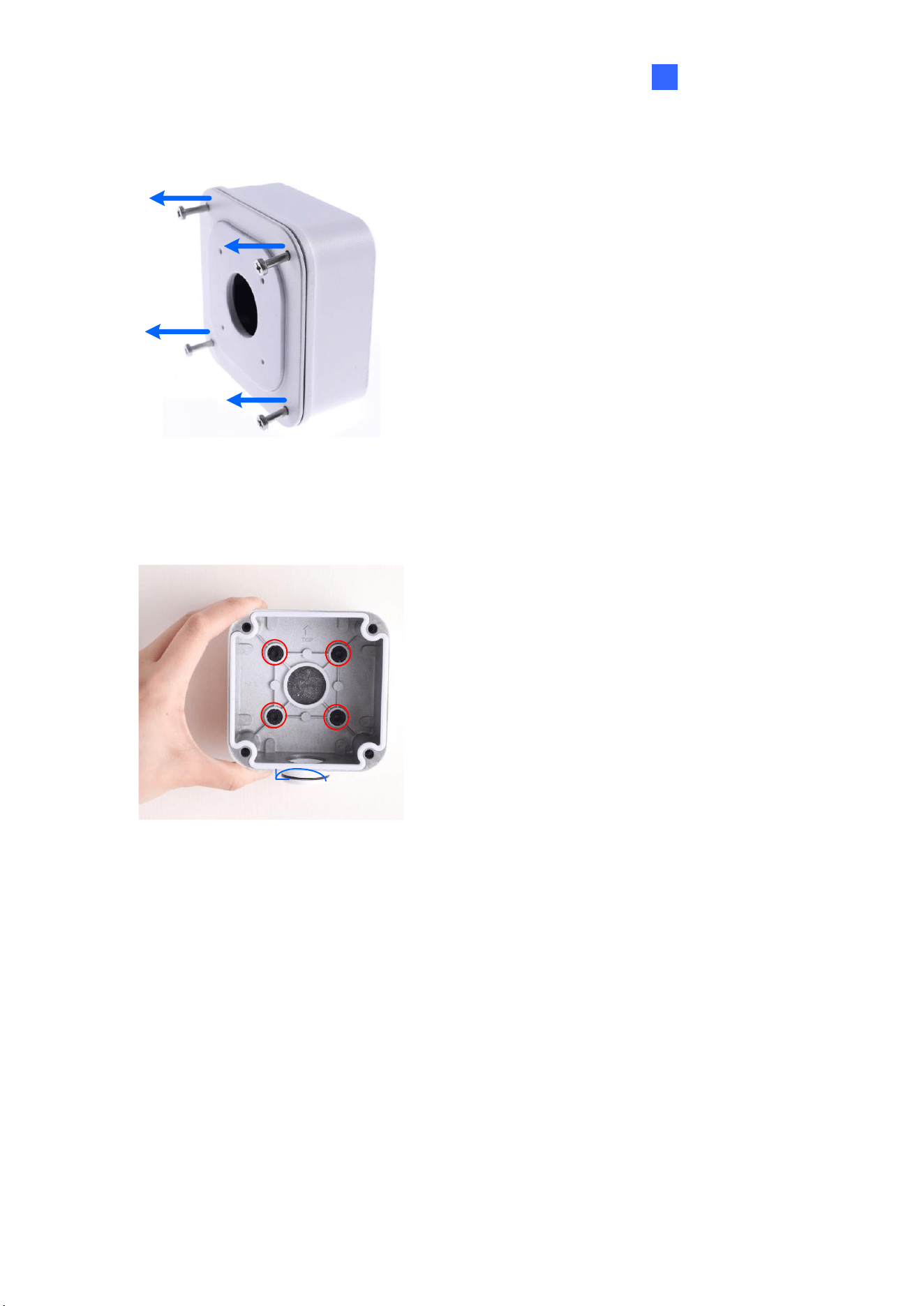
1. Unscrew the box cover.
Figure 1-57
2. Loosen the knob by turning it anticlockwise.
Loosen the knob
Figure 1-58
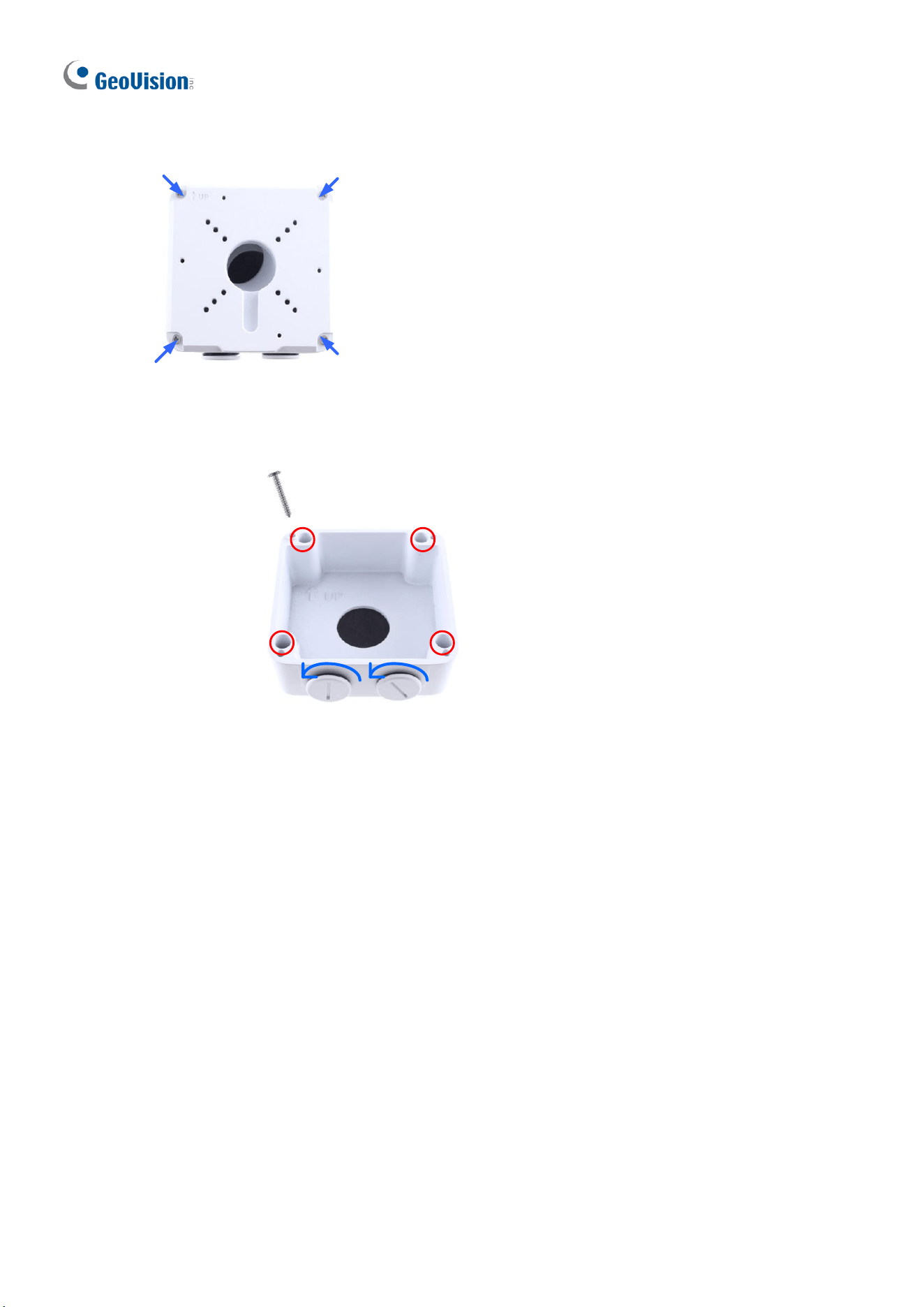
3. Attach the box to the wall with the knob pointing down and use a marker to mark 4 dots.
4. Drill 4 holes according to the marks.
5. Insert the 4 screw anchors to the holes and secure the box to the wall with 4 long screws.
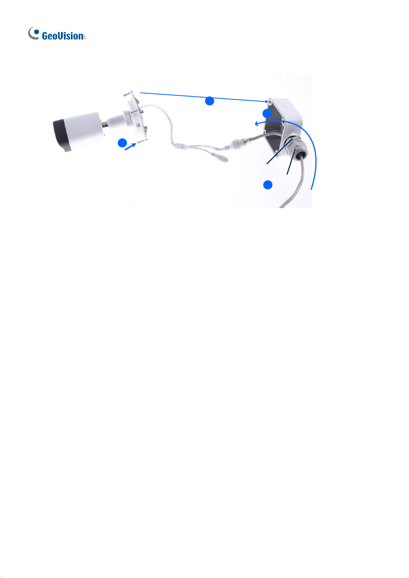
6. Secure the camera to the box cover with 4 short screws, as illustrated in No. 6, Figure 1-
59.
7. Thread the Ethernet cable through the PG21 conduit connector and the wall box, as
shown in No. 7, Figure 1-59. Then connect the cable to the camera. To waterproof the
Ethernet cable, see 1.10 Waterproofing the Cable.
8. Rotate the plastic ring to secure the conduit connector to the wall box. Screw in the cap,
as shown in No. 8, Figure 1-59.
40
9. Screw the box cover to the wall box, as shown in No. 9, Figure 1-59.
6
Plastic Ring
Cap
9
7
8
9
7
6
Figure 1-59
Introduction
41
1
1.2.5.2 GV-Mount503
GV-Mount503
Figure 1-60
GV-Mount503 Packing List
• GV-Mount503
• Long Screw x 4
• Short Screw x 4
• Screw Anchor x 4
• Plastic PG21 Conduit Connector
⚫ Waterproof Rubber Plug
42
1. Unscrew the box cover.
Figure 1-61
2. Loosen the knobs by turning it anticlockwise.
Loosen the knob
Long Screw
Figure 1-62
3. Attach the box to the wall with the knobs pointing down and use a marker to mark 4 dots.
4. Drill 4 holes according to the marks.
5. Insert 4 screw anchors to the holes and secure the to the wall with 4 long screws.
6. Thread the camera cable through the box cover and secure the camera to the cover with
4 short screws.
7. Reattach the box cover to the power box, as shown in No. 7, Figure 1-63.
8. Thread the Ethernet cable through the PG21 conduit connector and the power box as
shown in No 8, Figure 1-63. Then connect the cable to the camera. To waterproof the
cable, see 1.8 Waterproofing the Cable.
9. Rotate the plastic ring to secure the conduit connector to the power box. Secure in the
cap, as shown in No 9, Figure 1-63.
Introduction
43
1
10. Secure the box cover to the power box, as shown in No 10, Figure 1-63.
Cap
10
7
Plastic Ring
13
9
8
Figure 1-63
Note: Alternatively, you can use the supplied waterproof rubber plug to seal the box cover
by following the steps below.
1. Thread the camera cable through the box cover, and then through the supplied
waterproof rubber plug from the bottom side.
Figure 1-64
2. Align the gap of the waterproof rubber plug to the direction of the “up ↑” indicator and
press firmly to embed the waterproof plug onto the inside of the box cover.
3. Thread the Ethernet cable through the power box and connect to the camera. Secure
the box cover to the power box.
44
1.2.5.3 GV-Mount420 + GV-Mount503
GV-Mount503
GV-Mount420
Figure 1-65
GV-Mount420 Packing List
• GV-Mount420
• M4 Screw x 4
• Additional Screw Kit
- M6 Screw x 4
- M6 Nut x 4
- M6 Plain Washer x 4
- M6 Split Washer x 4
Note: For GV-ABL2702 / 4711 / 4712 / 8712 and GV-TBL4700 / 4710 / 4711 / 4810 / 8710
/ 8810, GV-Mount420 can only be used in conjunction with GV-Mount503.
1. Follow Step 1 & 2 in 1.2.5.2 GV-Mount503.
Introduction
45
1
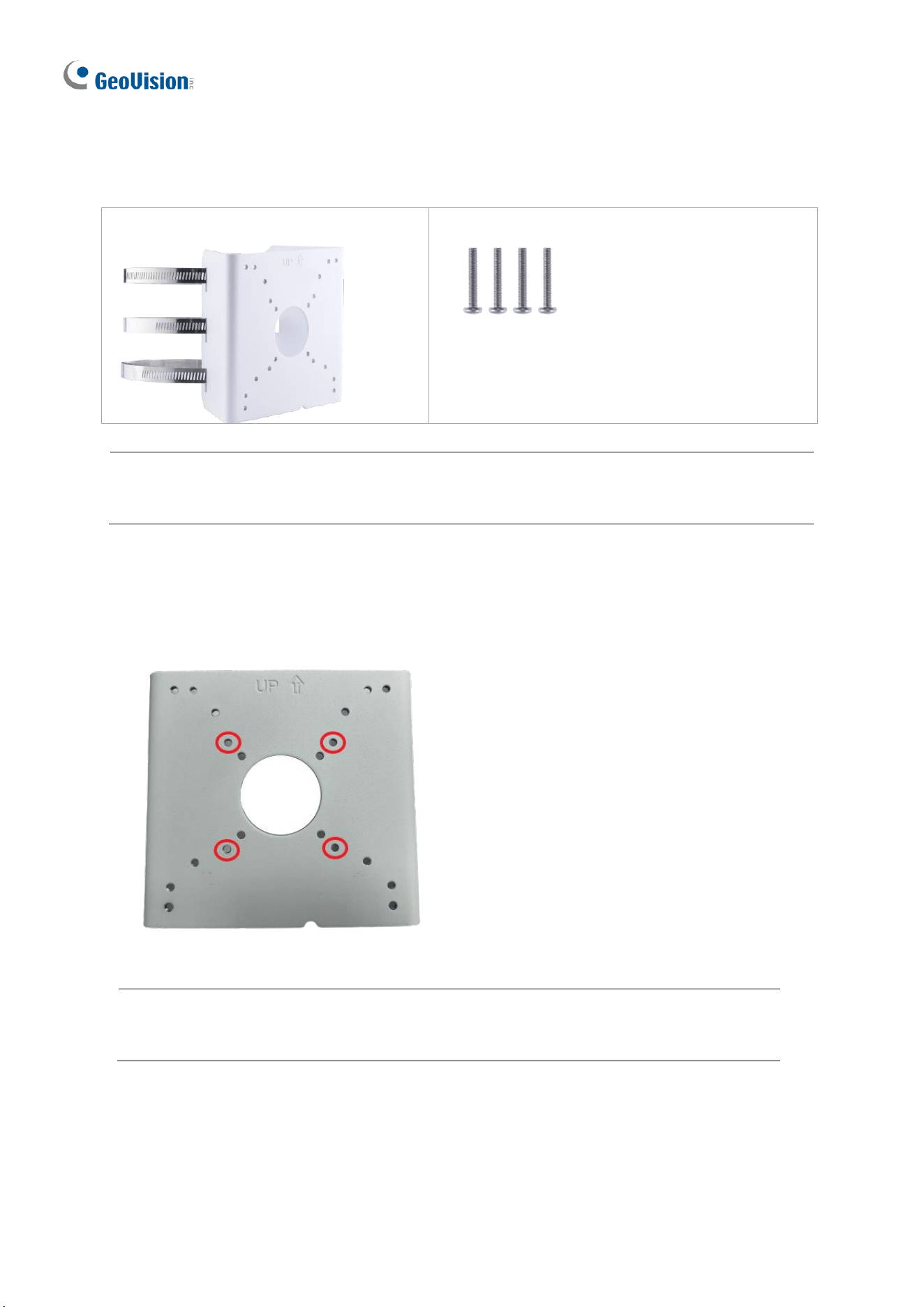
2. Align and attach the power box to the back plate using the 4 supplied M4 screws as
indicated.
Figure 1-66
Note: Make sure the direction of the “up ↑” indicator on the back plate matches that of the
power box.
3. Thread the 3 steel straps onto the back plate.
Figure 1-67
4. Follow Step 6 ~ 10 in 1.2.5.2 GV-Mount503.
5. Secure the camera onto the desired pole by tightening the steel straps.
46
1.2.5.4 GV-Mount504
GV-Mount504 Packing List
• GV-Mount504
• Long Screw x 4
• Short Screw x 3
• Screw Anchor x 4
• Drill Template Paster
• Waterproof Rubber Plug
• Plastic PG21 Conduit Connector
1. Unscrew the box cover.
Figure 1-67-1
2. Stick the drill template paster to the wall with the arrow pointing up.
3. Drill the 4 mounting holes according to the drill template.
4. Insert the 4 screw anchors to the mounting holes.
Introduction
47
1
5. Position the power box on the wall with the “up ↑” indicator pointing up and align the
screw holes indicated below to the 4 mounting holes on the wall.
Figure 1-68
6. Secure the power box to the wall with the supplied long screws.
7. Thread the Ethernet cable through the center hole (proceed to Step 9) or through the
PG21 conduit connector and the power box as shown in No 8, Figure 1-63 (proceed to
Step 8).
8. Rotate the plastic ring to secure the conduit connector to the power box. Secure in the
cap, as shown in No 9, Figure 1-63.
9. Thread the camera cable through the box cover from the top, and then attach the
supplied waterproof rubber plug to the camera cable at around the camera base, as
shown in the figure below.
Figure 1-69
10. Press firmly to embed the waterproof plug onto the box cover.
11. Use the supplied short screws to secure the camera to the box cover at the indicated
holes below.
Figure 1-70
12. Connect the Ethernet cable to the camera cable, align the “up ↑” indicators on the box
cover and power box, and then secure the box cover to the power box.
48
1.2.5.5 GV-Mount440 + GV-Mount502
GV-Mount440 Packing List
• GV-Mount440
• M4 Screw x 4
Note: For GV-ABL2701 / ABL2703 / ABL4701 / ABL4703 / TBL2703 / TBL4703, GV-
Mount440 can only be used in conjunction with GV-Mount502.
1. Follow Step 1 & 2 in 1.2.5.1 GV-Mount502.
2. Align and attach the power box to the back plate using the 4 supplied M4 screws as
indicated.
Figure 1-71
Note: Make sure the direction of the “up ↑” indicator on the back plate matches that
of the power box.

Introduction
49
1
3. Thread the 3 steel straps onto the back plate.
Figure 1-72
4. Follow Step 6 ~ 9 in 1.2.5.1 GV-Mount502.
5. Secure the camera onto the desired pole by tightening the steel straps.
50
1.2.5.6 GV-Mount440 + GV-Mount504
GV-Mount440 Packing List
• GV-Mount440
• M4 Screw x 4
Note: For GV-TBL2705 / TBL2706 / TBL4705 / TBL8804, TBLP5800 / 8800, GV-
Mount440 can only be used in conjunction with GV-Mount504.
1. Follow Step 1 in 1.2.5.4 GV-Mount504.
2. Align and attach the power box to the back plate using the 4 supplied M4 screws as
indicated.
Figure 1-73
Note: Make sure the direction of the “up ↑” indicator on the back plate matches that
of the power box.

Introduction
51
1
3. Thread the 3 steel straps onto the back plate.
Figure 1-74
4. Follow Step 7 ~ 12 in 1.2.5.4 GV-Mount504.
5. Secure the camera onto the desired pole by tightening the steel straps.
52
1.2.5.7 GV-Mount924
GV-Mount924 Packing List
• GV-Mount924
• M3 8 mm Screw x 4
1. Secure the gang box onto the back of GV-Mount924 using the ports indicated below.
Figure 1-75
Figure 1-76
US Double Gang Box
US Single Gang Box
2. Thread the camera’s cables through GV-Mount924 and secure the camera onto the
mount using the ports indicated below using the supplied screws.
Figure 1-77
Introduction
53
1
1.3 GV-ADR / TDR Series
The IR Mini Fixed Rugged IP Dome is an outdoor, fixed, network camera equipped with an
automatic IR-cut filter and an IR LED for day and night surveillance. The camera supports
H.265 video codec to achieve better compression ratio while maintaining high quality image
at reduced network bandwidths. The WDR Pro models can produce clear image for scenes
containing contrasting intensity of lights.
Model No.
Description
GV-ADR2701
Fixed lens
2 MP, H.265, Low Lux, WDR
GV-ADR2702-0F
2 MP, H.265, Low Lux, WDR
GV-ADR2702-1F
GV-ADR4701
4 MP, H.265, Super Low Lux, WDR
GV-ADR4702-0F
GV-ADR4702-1F
GV-TDR2700-0F
2 MP, H.265, Low Lux, WDR Pro
GV-TDR2700-1F
GV-TDR2702-0F
2 MP, H.265, Low Lux, WDR
GV-TDR2702-1F
Fixed lens
2 MP, H.265, Low Lux, WDR
GV-TDR2704-2F
2 MP, H.265, Low Lux, WDR Pro
GV-TDR2704-4F
GV-TDR2705
2 MP, H.265, Low Lux, WDR Pro
GV-TDR4700-0F
4 MP, H.265, Super Low Lux, WDR Pro
GV-TDR4700-1F
GV-TDR4702-0F
4 MP, H.265, Super Low Lux, WDR
GV-TDR4702-1F
GV-TDR4703-2F
4 MP, H.265, Super Low Lux, WDR Pro
GV-TDR4703-4F
GV-TDR4704-2F
GV-TDR4704-4F
GV-TDR4803-2F
Fixed lens
4 MP, H.265, Super Low Lux, WDR Pro
GV-TDR4803-4F
54
GV-TDR8805
Fixed lens
5 MP, H.265, Super Low Lux, WDR Pro
1.3.1 Packing List
The packing list varies depending on the model. Product details can be found on the
datasheet.
• IR Mini Fixed Rugged IP Dome
• Waterproof Rubber Set
• Screw Kit
• Drill Template Paster
• Download Guide
• Torx wrench (comes with some models)
Introduction
55
1
1.3.2 Optional Accessories
Optional accessories can expand the capabilities and versatility of your camera. Contact your
dealer for more information. Accessory details can be found on the datasheet.
1.3.3 Overview
1
3
2
3
4
5
Figure 1-78
No.
Description
1
Ethernet connector / PoE
2
Power connector (DC 12 V)
3
Transparent Dome Cover
4
For GV-TDR2700 / 4700 / 4703 / 4803 series
and GV-TDR8805 only, see the table below.
5
Micro SD card slot
56
Wire Definition
GV-TDR2700 series / 4700 series
GV-TDR4703 series / 4803 series /
GV-TDR8805
Wire
Definition
Wire
Definition
Green
Audio in
Gray
Audio Out
Blue
GND
Purple
GND
Yellow
Alarm Out
Green
Audio In
White
Alarm Out
Brown
GND
Orange
Alarm Input
Orange
Alarm Input
Blue
GND
Blue
GND
Brown
Audio in
Yellow
Alarm Output
Blue
GND
White
Alarm Output
Gray
Audio Out
Purple
GND
1.3.4 Installation
The IR Mini Fixed Rugged IP Dome is designed for outdoors. With the standard package,
you can install the camera on the ceiling.
Below are the instructions for Ceiling Mount. There are two kinds of Ceiling Mount:
Concealed Installation and Open Installation. In Concealed Installation, the cables are
hidden in the ceiling. In Open Installation, the cables are led out from the open slot on the
camera base.
For Concealed Installation
1. Stick the drill template paster to the ceiling and drill 30-mm deep holes according to the
drill template.
Figure 1-79
Introduction
57
1
2. Insert the screw anchors.
Figure 1-80
3. Unscrew the transparent dome cover with the supplied torx wrench.
4. Connect the cables and secure the camera.
Figure 1-81
58
5. Adjust the monitoring direction and tighten the screws after vertically adjusting the lens.
Figure 1-82
6. Secure the transparent dome cover with the supplied torx wrench.
Figure 1-83
Introduction
59
1
Note: Before securing the transparent dome cover, make sure the waterproof rubber strip is
tightly held by the six retainers on the bottom ring.
Figure 1-84
For Open Installation
Lead the cables out from the open slot on the camera base before screwing the camera to
the ceiling as shown in Figure 1-82.
1.3.5 Optional Installation
You can optionally purchase the following accessories to fit your mounting environment:
⚫ GV-Mount211P for Wall Mount: see section 1.1.5.1.
⚫ GV-Mount213 for Wall / Ceiling Box Mount: see section 1.3.5.1.
⚫ GV-Mount420 + GV-Mount211P for Pole Box Mount: see section 1.1.5.3.
⚫ GV-Mount213 + Mount107 for Pendant Bracket Mount: see section 1.1.5.4.
⚫ GV-Mount300-2 / 310-2 for Corner Mount: see Appendix F. GV-Mount300-2 / 310-2.
For GV-TDR2704-2F / TDR2704-4F / TDR2705 / TDR4704-2F / TDR4704-4F / TDR4803-2F
/ TDR8805, you can optionally purchase:
⚫ GV-Mount924 for Gang Box Mount: see section 1.3.5.2.
60
1.3.5.1 GV-Mount213
GV-Mount213
Figure 1-85
GV-Mount213 Packing List
• GV-Mount213
• Long Screw x 3
• Short Screw x 3
• Screw Anchor x 3
Introduction
61
1
1. Attach the GV-Mount213 to the wall / ceiling and use a marker to mark the location for
the center socket and the 3 screws.
Figure 1-86
Note: To prevent rain from getting into GV-ADR2701 / 2702 / 4701 / 4702 & TDR2702 /
2704 / 4702 / 4703 / 4704 / 4803 / 8805,
• For ceiling mount installation, turn the indicated hole inwards.
• For wall mount installation, make sure the indicated hole points down and towards the
ground.
Figure 1-87
2. Drill 3 holes according to the screw locations. Then, drill a bigger hole at the center
socket location for the Ethernet cable.
62
3. Insert 3 screw anchors to the screw locations and secure GV-Mount213 to the wall /
ceiling with 3 long screws.
4. Thread the Ethernet cable through the center socket and waterproof the Ethernet cable.
For details, see 1.8 Waterproofing the Cable.
Figure 1-88
5. Fit the cable into the GV-Mount213.
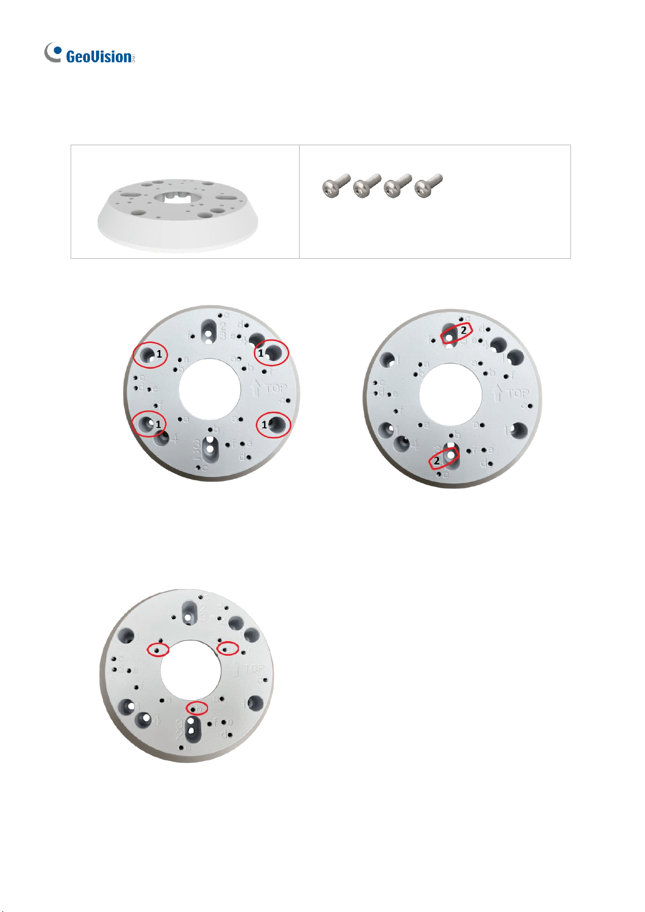
6. Remove the camera cover and fasten the camera to the wall box mount as indicated
below using the supplied short screws.
GV-ADR2701 / 4701
Figure 1-89
Introduction
63
1
GV-ADR2702 / ADR4702 / TDR2700 / TDR2702 / TDR2704 / TDR4700 / TDR4702 /
TDR4703 / TDR4704 / TDR4803 / TDR8805
Figure 1-90
7. Secure the camera cover.
Note: In addition to the Standard Installation, you can also choose to run the Ethernet
cable through a corrugated tube. To do this, see Figure 1-34 and its related Note.
64
1.3.5.2 GV-Mount924
GV-Mount924 Packing List
• GV-Mount924
• M3 8 mm Screw x 4
1. Secure the gang box onto the back of GV-Mount924 using the holes indicated below.
Figure 1-91
Figure 1-92
US Double Gang Box
US Single Gang Box
2. Unscrew the transparent dome cover of the camera.
3. Thread the camera’s cables through GV-Mount924 and secure the camera onto the holes
indicated below using the supplied screws.
Figure 1-93
4. Secure the transparent dome cover onto the camera.
Introduction
65
1
1.4 GV-AVD / TVD Series
The Vandal Proof IP Dome is an outdoor camera designed with IK10 vandal resistance and
IP67 ingress protection. The camera is equipped with an automatic IR-cut filter and IR LEDs
for day and night surveillance. Adjustable in 3 axes (pan, tilt and rotate), it offers an entry-
level surveillance solution with all the essential features and excellent image quality.
Model No.
Description
GV-AVD2700
Varifocal lens
2MP, H.265, Low Lux, WDR
GV-AVD4710
Motorized
varifocal lens
4 MP, H.265, Super Low Lux, WDR Pro
GV-AVD8710
8 MP, H.265, Super Low Lux, WDR Pro
GV-TVD2712
Motorized
varifocal lens
2 MP, H.265, Super Low Lux, WDR Pro
GV-TVD4700
Varifocal lens
4 MP, H.265, Super Low Lux, WDR
GV-TVD4710
Motorized
varifocal lens
4 MP, H.265, Super Low Lux, WDR Pro
GV-TVD4711
4 MP, H.265, Super Low Lux, WDR Pro
GV-TVD4810
4 MP, H.265, Super Low Lux, WDR Pro
GV-TVD4811
4 MP, H.265, Super Low Lux, WDR Pro
GV-TVD8710
8 MP, H.265, Super Low Lux, WDR Pro
GV-TVD8810
Note: GV-Mount606 is not supported by GV-TVD4711.
66
1.4.1 Packing List
1.4.1.1 GV-TVD4711 / TVD4811
• IR Vandal Proof IP Dome
• Screw Kit
• Drill Template Paster
• Torx Wrench
• Spare Waterproof Rubber Plug
• Cable Protection Connector
• 2-Pin Power Terminal Block
• Download Guide
Introduction
67
1
1.4.1.2 GV-AVD / TVD Series
• IR Vandal Proof IP Dome
• Waterproof Rubber Set
• Screw Kit
• Drill Template Paster
• Torx Wrench
• Download Guide

68
1.4.2 Optional Accessories
Optional accessories can expand the capabilities and versatility of your camera. Contact your
dealer for more information. Accessory details can be found on the datasheet.
Introduction
69
1
1.4.3 Overview
1.4.3.1 GV-AVD2700 / 4710 / 8710, GV-TVD4700 / 4710 / 4810 / 8710 /
8810
1
2
3
4
5
6
7
8
9
Figure 1-94
No.
Description
No.
Description
1
Power connector (DC 12 V)
6
Default button
2
Ethernet connector / PoE
7
Micro SD card slot
3
Video output
(Not applicable to GV-TVD4700 / 8810)
8
Default button (For GV-TVD4810 /
8810)
4
Audio input / Audio output / GND (Not
applicable to GV-TVD4700)
9
Micro SD card slot (For GV-TVD8810)
5
Alarm input (IN, GND) / Alarm output
(N, P) (Not applicable to GV-TVD4700)
10
Built-in microphone (For GV-TVD4810
/ 8810)
Note: If the default button doesn’t respond after pressing for 15 seconds, reboot the camera
and try again within 10 minutes of rebooting.
70
1.4.3.2 GV-TVD4711 / TVD4811
1
2
3
4
6
7
9
10
5 8
11
12
13
Figure 1-95
No.
Description
No.
Description
1
Ethernet port
8
Digital Input
2
Power port (2-Pin terminal block)
9
GND
3
Micro SD card slot
10
Audio In
4
Default button
11
GND
5
Digital Output (N)
12
Audio Out
6
Digital Output (P)
13
Microphone (GV-TVD4811 only)
7
GND
Introduction
71
1
Note: There are two ways to supply power to the camera:
⚫ Use a Power over Ethernet (PoE) adapter to connect the camera to the network, and
the power will be provided at the same time.
⚫ Plug the power adapter to the supplied 2-pin terminal block by inserting the striped
wire to the right pin (-) and the black wire to the left pin (+), then insert the 2-pin
terminal block to Power Connector, No. 2 in Figure 1-95.
Figure 1-96
1.4.3.3 GV-TVD2712
1
2
3
No.
Description
No.
Description
1
Micro SD card slot
3
Built-in microphone
2
Default button
72
1.4.4 Installation
The Target Vandal Proof Dome is designed for outdoors. With the standard package, you
can install the camera on the ceiling. Alternatively, you can purchase optional mounting
accessories to mount the camera on a wall.
Below are the instructions for Ceiling Mount. There are two kinds of Ceiling Mount:
Concealed Installation and Open Installation. In Concealed Installation, the cables are
hidden in the ceiling. In Open Installation, the cables are led out from the open slot on the
camera base.
1.4.4.1 GV-AVD2700 / 4710 / 8710, GV-TVD4700 / 4710 / 4810 / 8710 /
8810
For Concealed Installation
1. Stick the drill template paster to the ceiling, and then drill three holes according to the drill
template.
Drill Template Paster
Figure 1-97
2. Insert the screw anchors.
Drill a hole to lead the cables out of the ceiling
Knock in screw anchors
Figure 1-98
3. Unscrew the transparent dome cover with the supplied torx wrench.
4. Connect the camera cables and secure the camera.
Introduction
73
1
Figure 1-99
5. Insert a SD card into the slot.
6. Adjust the monitoring direction and tighten the screws after vertically adjusting the lens.
Figure 1-100
7. Secure the transparent dome cover with the supplied torx wrench.
For Open Installation
Lead the cables out from the open slot on the camera base before screwing the camera to
the ceiling as shown in Figure 1-99.
74
1.4.4.2 GV-TVD4711 / TVD4811
1. Follow steps 1 to 3 in 1.4.4.1 GV-AVD2700 / 4710 / 8710, GV-TVD4700 / 4710 / 4810 /
8710 / 8810.
To install an Ethernet / PoE cable:
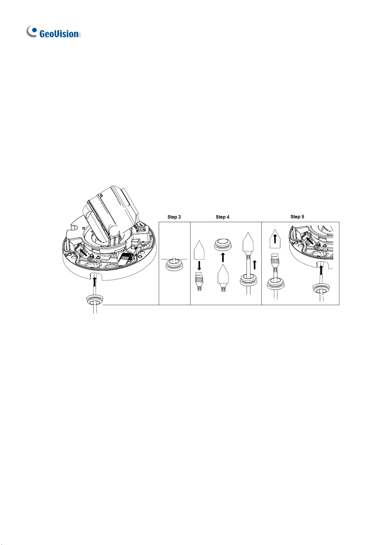
2. Remove the large waterproof rubber plug from the base of the camera.
3. Cut a small opening on the tip of the large waterproof rubber plug.
4. Attach the cable protection connector to the Ethernet cable head and push the Ethernet
cable through the opening.
5. Remove the cable protection connector. Thread the Ethernet cable through the large
hole to connect to the camera and press to embed the waterproof rubber plug.
Figure 1-101
To install optional power and I/O wires:
6. Repeat steps 2 to 3 for the small waterproof rubber plug at the base of the camera.
7. Push the power and I/O wires through the opening on the small waterproof plug.
8. Thread the wires through the small hole and press to embed the waterproof rubber plug.
9. Attach the supplied 2-pin terminal block to the power wires.
10. Connect the 2-pin terminal block and I/O wires to the camera.
Introduction
75
1
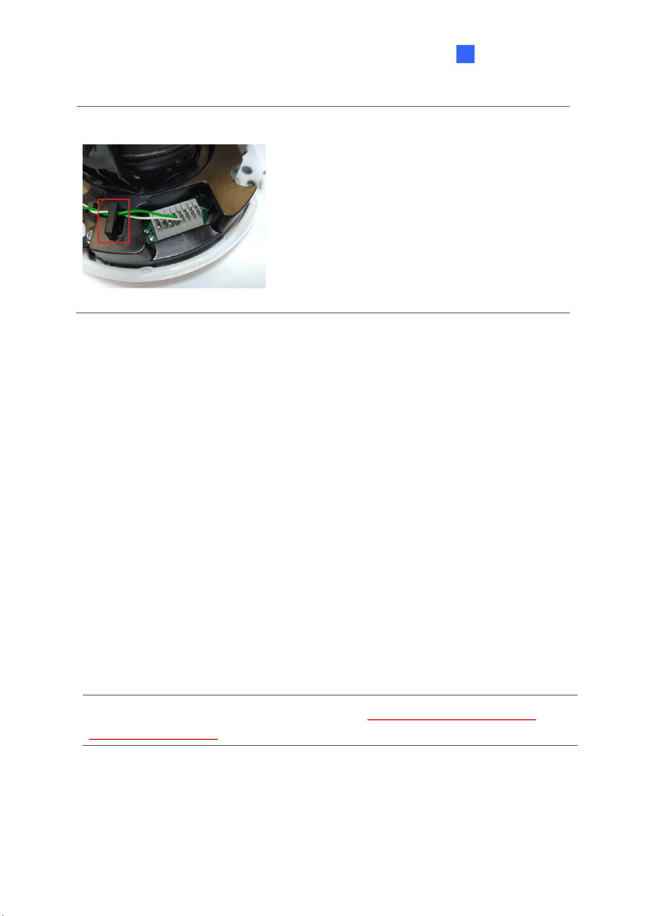
Tip: When connecting the I/O wires to the camera, thread the I/O wires through the
protruded loop.
Figure 1-102
To finish the installation:
11. Secure the camera and insert a micro SD card to the slot.
12. Secure the transparent dome cover with the supplied torx wrench.
1.4.5 Optional Installation
You can optionally purchase the following accessories to fit your mounting environment:
⚫ GV-Mount211P / GV-Mount212P for Wall Box Mount: see section 1.1.5.1 and 1.1.5.2.
⚫ GV-Mount420 + GV-Mount211P for Pole Box Mount: see section 1.1.5.3.
⚫ GV-Mount212P / GV-Mount212-2 + GV-Mount107 for Pendant Tube Mount: see
section 1.1.5.4.
⚫ GV-Mount211-2 for Wall Mount: see section 1.4.5.1.
⚫ GV-Mount212-2 for Wall / Ceiling Box Mount: see section 1.4.5.2.
⚫ GV-Mount420 + GV-Mount211-2 for Pole Box Mount: see section 1.4.5.3.
⚫ GV-Mount606 for In-Ceiling Bracket Mount: see section 1.4.5.4.
⚫ GV-Mount300-2 / 310-2 for Corner Mount: see Appendix F. GV-Mount300-2 / 310-2.
Note: For detailed instructions on GV-TVD2712, see GV-A/T/EBD Series IP Camera
Mount Installation Guide.
76
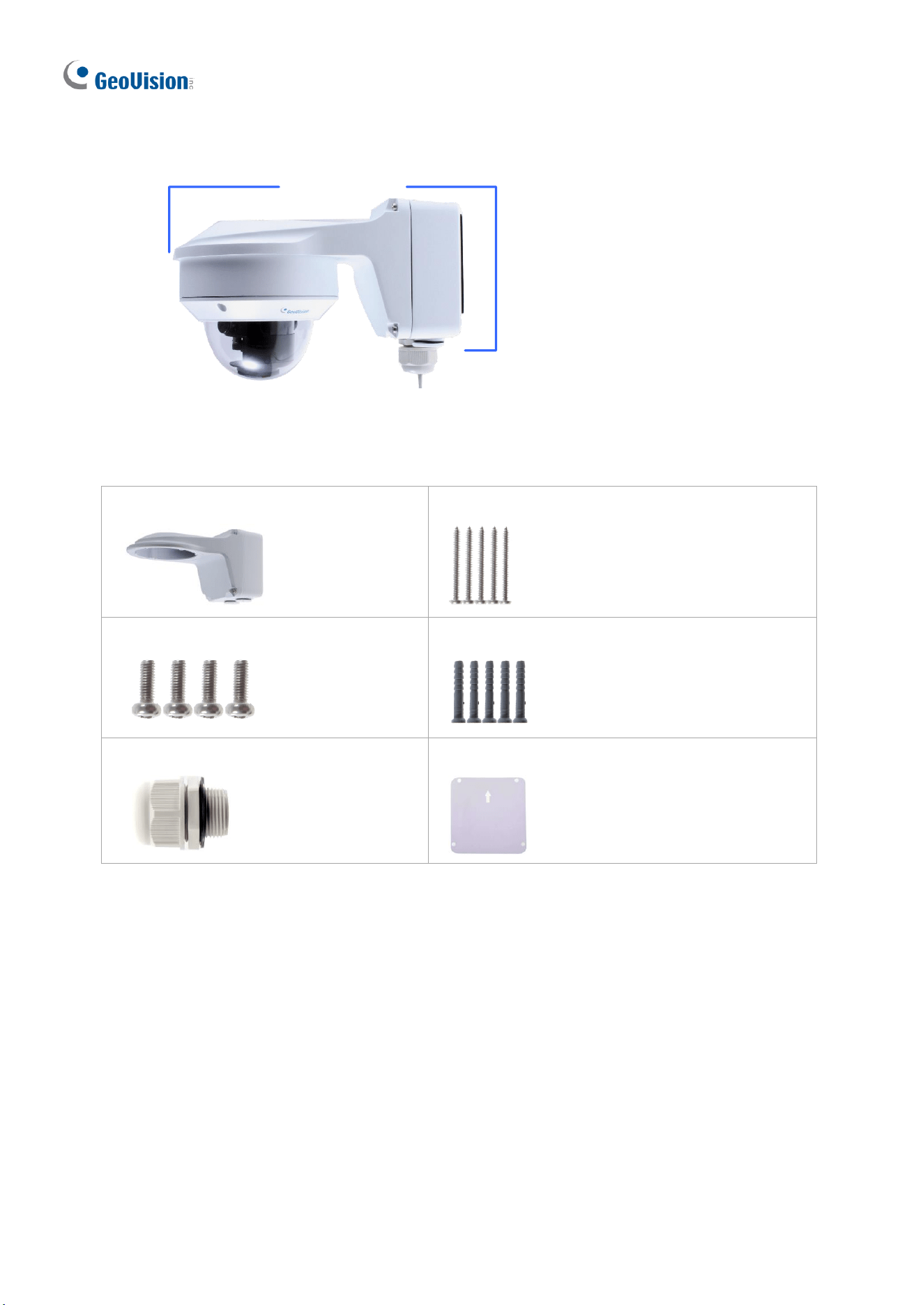
1.4.5.1 GV-Mount211-2
GV-Mount211-2
Figure 1-103
GV-Mount211-2 Packing List
• GV-Mount211-2
• Long Screw x 5
• Short Screw x 4
• Screw Anchor x 5
• Plastic PG21 Conduit Connector
• Drill Template Paster
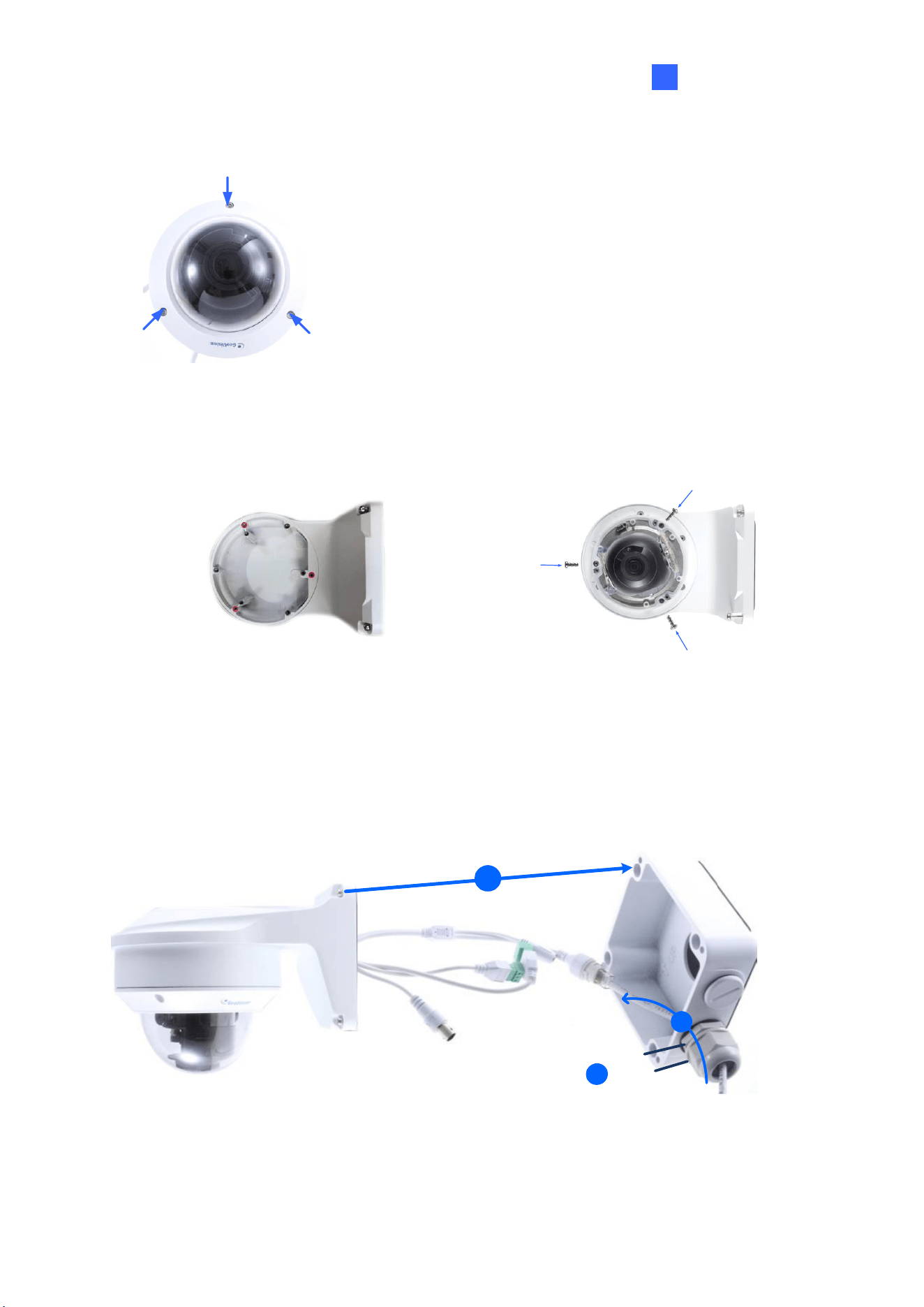
1. To install the power box from the wall mount bracket on the wall, follow steps 1 to 5 in
1.1.5.1 GV-Mount211P.
Introduction
77
1
2. Unscrew the transparent dome cover with the supplied torx wrench.
Figure 1-104
3. Optionally insert a SD card into the slot.
4. Thread the camera cables through the bracket.
5. Secure the camera to the wall mount bracket with the provided short screws.
Figure 1-105
6. Thread the Ethernet cable through the PG21 conduit connector and the power box, as
shown in No 6, Figure 1-106 below. Then connect the cable to the camera.
7. Rotate the plastic ring to secure the conduit connector to the power box. Screw in the cap
shown in No 7, Figure 1-106 below.
8. Screw the wall mount bracket to the power box, as shown in No. 8 below.
Cap
6
7
Plastic Ring
8
Figure 1-106
78
1.4.5.2 GV-Mount212-2
GV-Mount212-2
Figure 1-107
GV-Mount212-2 Packing List
• GV-Mount212-2
• Long Screw x 3
• Short Screw x 3
• Screw Anchor x 3
Introduction
79
1
1. Attach the ceiling box to the ceiling and use a marker to mark the location for the center
socket and the screws. Make sure the knob points inwards.
Screw Location
This knob points down
Figure 1-108
2. Drill 3 holes according to the screw location. Then, drill a bigger hole at the center socket
location for the Ethernet cable.
3. Insert 3 screw anchors to the screw location and secure the ceiling box to the ceiling with
3 long screws.
4. Thread the Ethernet cable through the center socket, connect other wires and fit the
camera cable into the ceiling box. See 1.8 Waterproofing the Cable.
Figure 1-109
5. Unscrew the transparent dome cover with the supplied torx wrench.
80
6. Secure the camera to the ceiling box.
Figure 1-110
Note: In addition to the Standard Installation, you can also choose to run the Ethernet
cable through a corrugated tube. To do this, see Figure 1-34 and its related Note.
Introduction
81
1
1.4.5.3 GV-Mount420 + GV-Mount211-2
GV-Mount211-2
GV-Mount420
Figure 1-111
GV-Mount420 Packing List
• GV-Mount420
• M4 Screw x 4
• Additional Screw Kit
- M6 Screw x 4
- M6 Nut x 4
- M6 Plain Washer x 4
- M6 Split Washer x 4
Note: For GV-AVD Series, GV-Mount420 can only be used in conjunction with GV-
Mount211-2.
1. Follow Step 1 ~ 4 in 1.1.5.3 GV-Mount420 + GV-Mount211P.
2. Follow Step 2 ~ 8 in 1.4.5.1 GV-Mount211-2.
3. Secure the camera onto the desired pole by tightening the steel straps.
82
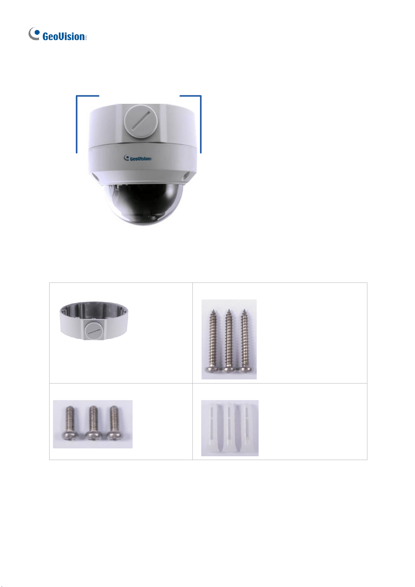
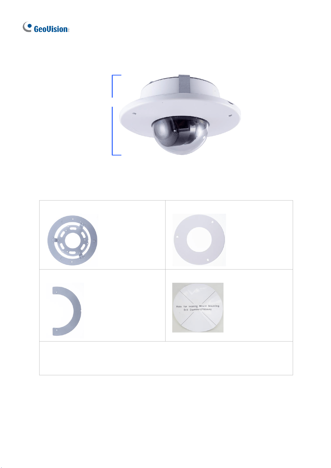
1.4.5.4 GV-Mount606
GV- Mount606
Figure 1-112
GV-Mount606 Packing List
• In-Ceiling Mount Bracket
• In-Ceiling Cover
• In-Ceiling Plate
• Drill Template Paster
• Screw Kit:
- M4 Screw (8 mm) x 3
- M4 Screw (40 mm) x 2
Introduction
83
1
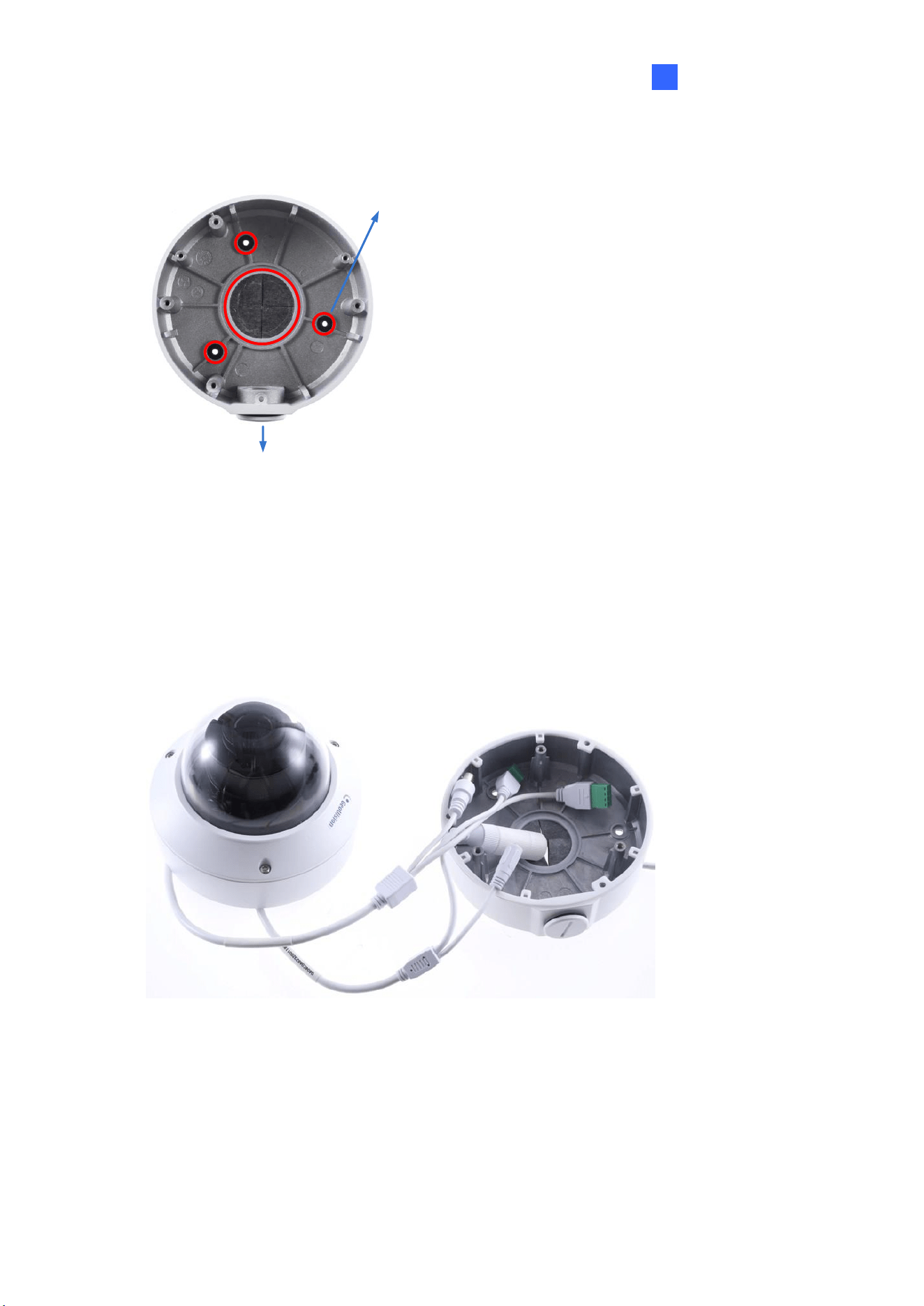
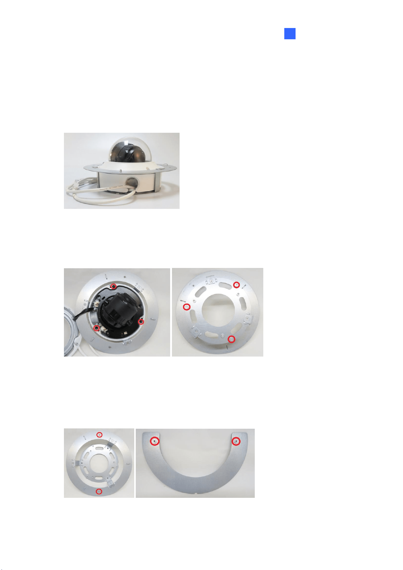
1. Paste the drill template to the ceiling and drill the ceiling to the size of the drill template.
2. Place the In-Ceiling Plate behind the ceiling with the flat side facing down.
3. Loosen the knob on the side of the camera and thread the camera wires through.
4. Thread the camera wires through the side of the In-Ceiling Mount Bracket and place the
camera in the Mount Bracket.
Figure 1-113
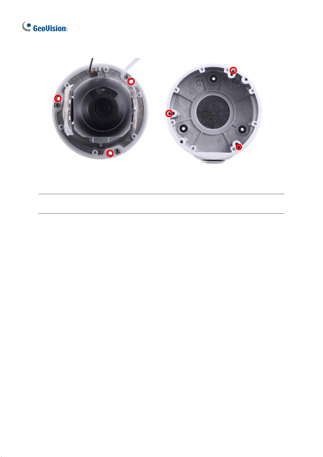
5. Open the transparent dome cover and insert the 3 M4 Screws (8 mm).
6. Align and secure the camera to the Mount Bracket with 3 M4 Screws (8 mm).
Figure 1-114
7. Connect the camera wires to the necessary wires.
8. Secure the housing cover, flip and hold the camera upside down against the ceiling.
9. Align and secure the Mount Bracket to the In-Ceiling Plate with 2 M4 Screws (40 mm).
Figure 1-115
10. Put on the In-Ceiling Cover to finish installation.
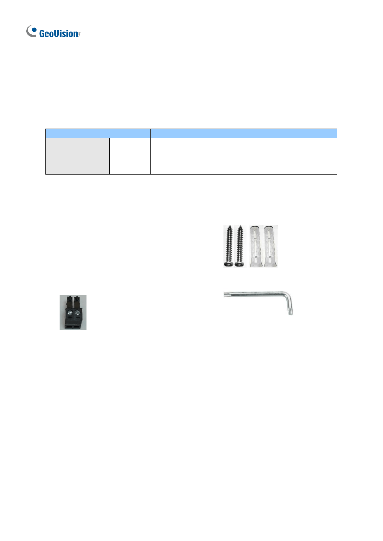
84
1.5 GV-TFD Series
The IR Mini Fixed IP Dome is an indoor, fixed, network camera equipped with an automatic
IR-cut filter and an IR LED for day and night surveillance. The camera supports H.265 video
codec to achieve better compression ratio while maintaining high quality image at reduced
network bandwidths.
Model No.
Description
GV-TFD4700
Fixed lens
4 MP, H.265, Super Low Lux, WDR Pro
GV-TFD4800
Fixed lens
4 MP, H.265, Super Low Lux, WDR Pro
1.5.1 Packing List
• IR Mini Fixed IP Dome
• Screw Kit
• 2-Pin Power Terminal Block
(only for GV-TFD4700)
• Torx Wrench
• Drill Template Paster
• Download Guide
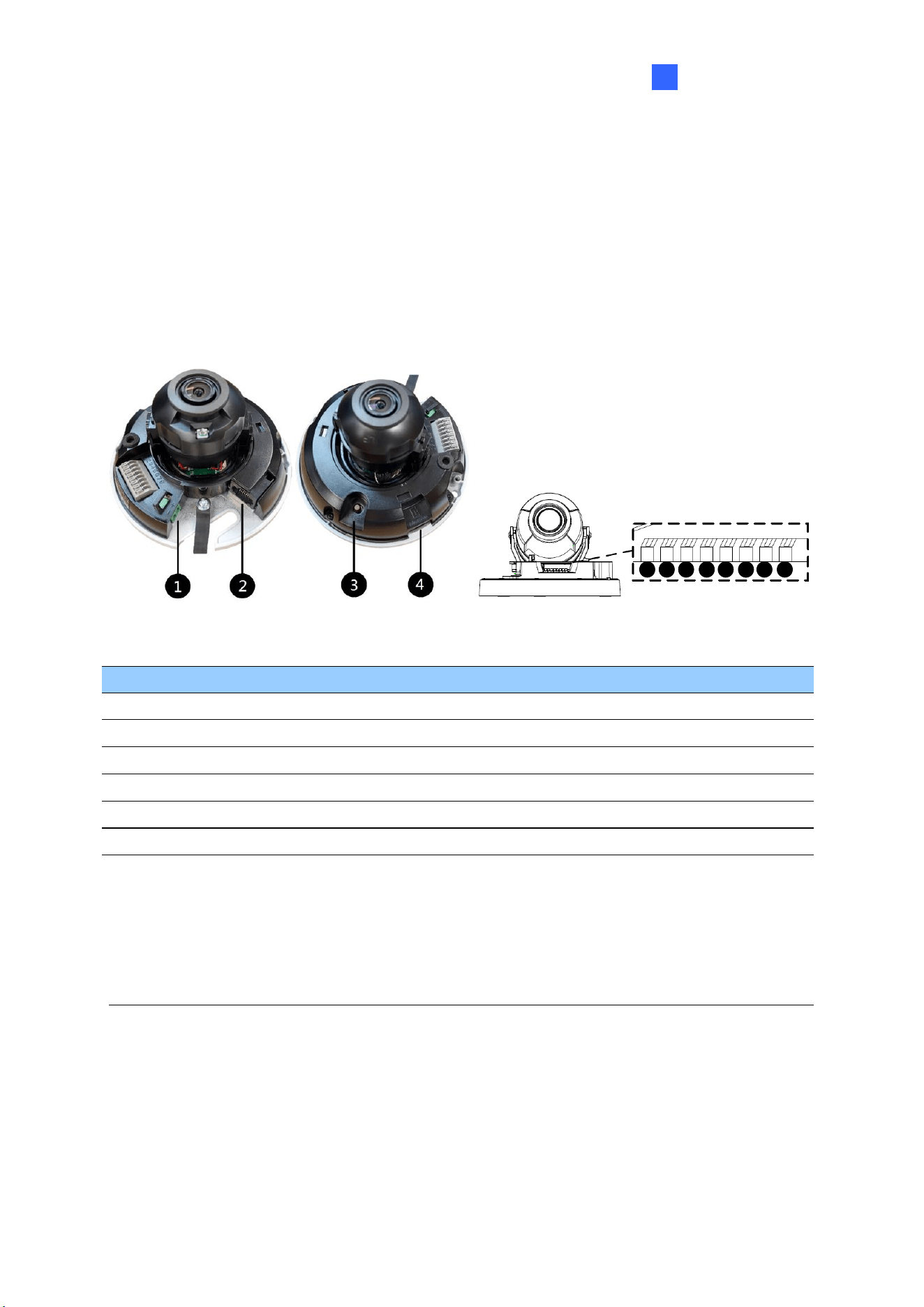
Introduction
85
1
1.5.2 Optional Accessories
Optional accessories can expand the capabilities and versatility of your camera. Accessory
details can be found on the datasheet.
1.5.3 Overview
1.5.3.1 GV-TFD4700 / 4800
6
7
9
10
5 8
11
12
Figure 1-116
No.
Description
No.
Description
1
Power port (2-Pin terminal block)
7
Audio In
2
Ethernet port
8
GND
3
Default button
9
Alarm Input
4
Micro SD card slot
10
GND
5
Audio Out
11
Alarm Output P
6
GND
12
Alarm Output N
Note: There are two ways to supply power to the camera:
⚫ Use a Power over Ethernet (PoE) adapter to connect the camera to the network, and
the power will be provided at the same time.
⚫ Plug the power adapter to the supplied 2-pin terminal block by inserting the striped
wire to the right pin (-) and the black wire to the left pin (+), and then insert the 2-pin
terminal block to Power Connector, No. 1.
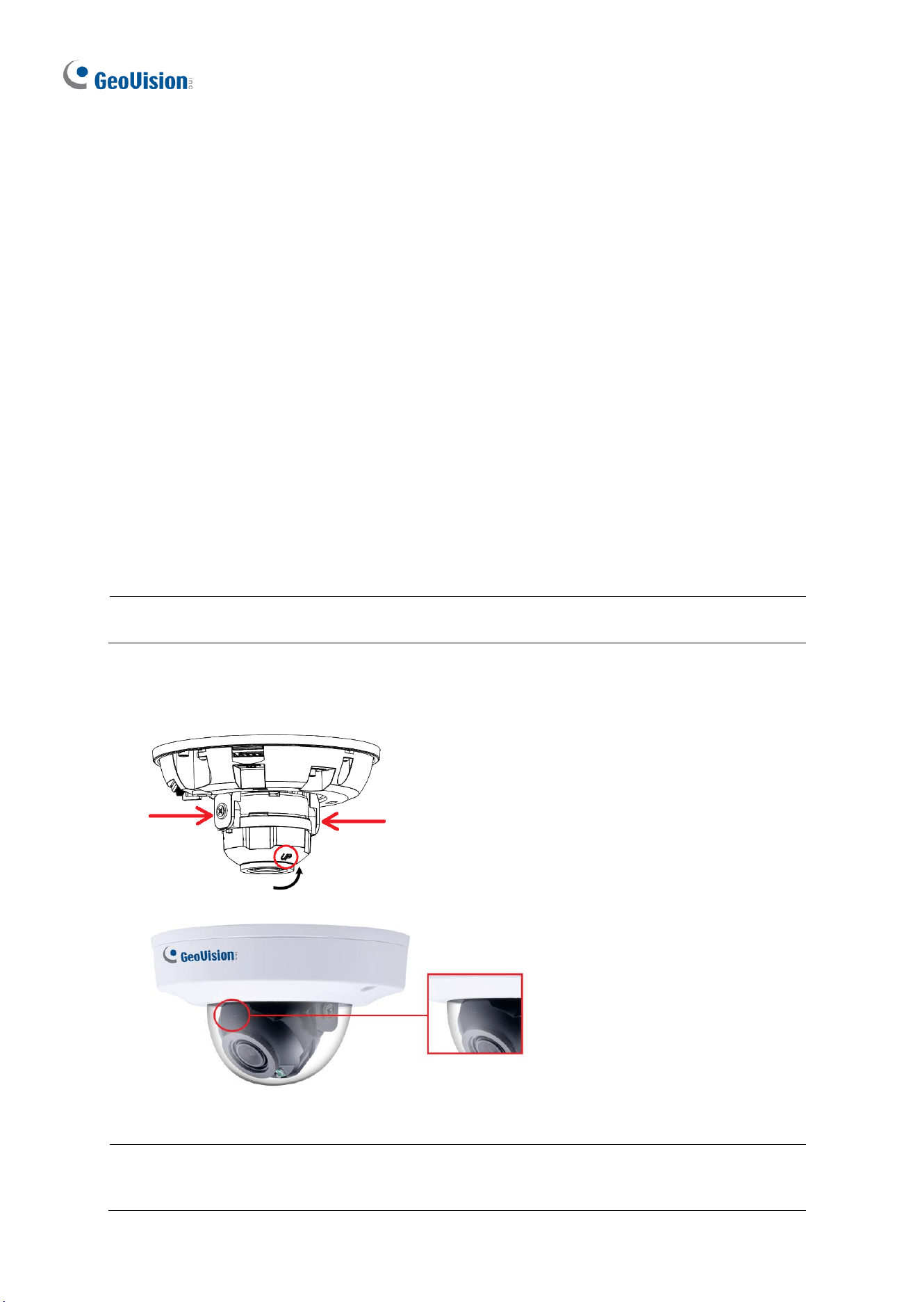
86
1.5.4 Installation
The IR Mini Fixed IP Dome is designed for indoors. With the standard package, you can
install the camera on the ceiling.
Below are the instructions for Ceiling Mount. There are two kinds of Ceiling Mount:
Concealed Installation and Open Installation. In Concealed Installation, the cables are
hidden in the ceiling. In Open Installation, the cables are led out from the open slot on the
camera base.
1.5.4.1 GV-TFD4700 / 4800
For Concealed Installation
1. Follow steps 1 to 3 in 1.3.4 Installation.
2. Insert a micro SD card.
3. Connect the Ethernet cable, I/O wires, and power terminal block to the camera through
the opening on the camera base, and secure the camera to the ceiling.
Tip: When connecting the I/O wires to the camera, thread the I/O wires through the
protruded loop as shown in Figure 1-102.
4. Loosen the fastening screws and rotate the lens vertically toward the camera base on
the side with the “UP” indicator.
Figure 1-117
Figure 1-118
Note: Make sure to adjust the lens as stated in Step 4 for any type of installation, in order
for the lens to rotate smoothly upon powering up. For installation on the wall, also make
sure the “UP” indicator is facing up towards the ceiling.

Introduction
87
1
5. Secure the transparent dome cover with the supplied torx wrench.
For Open Installation
Lead the cables out from the opening on the camera base before screwing the camera to the
ceiling in Step 3.
1.5.5 Optional Installation
For optional installations, refer to the following sections:
⚫ GV-Mount213 for Wall / Ceiling Box Mount: see section 1.3.5.1.
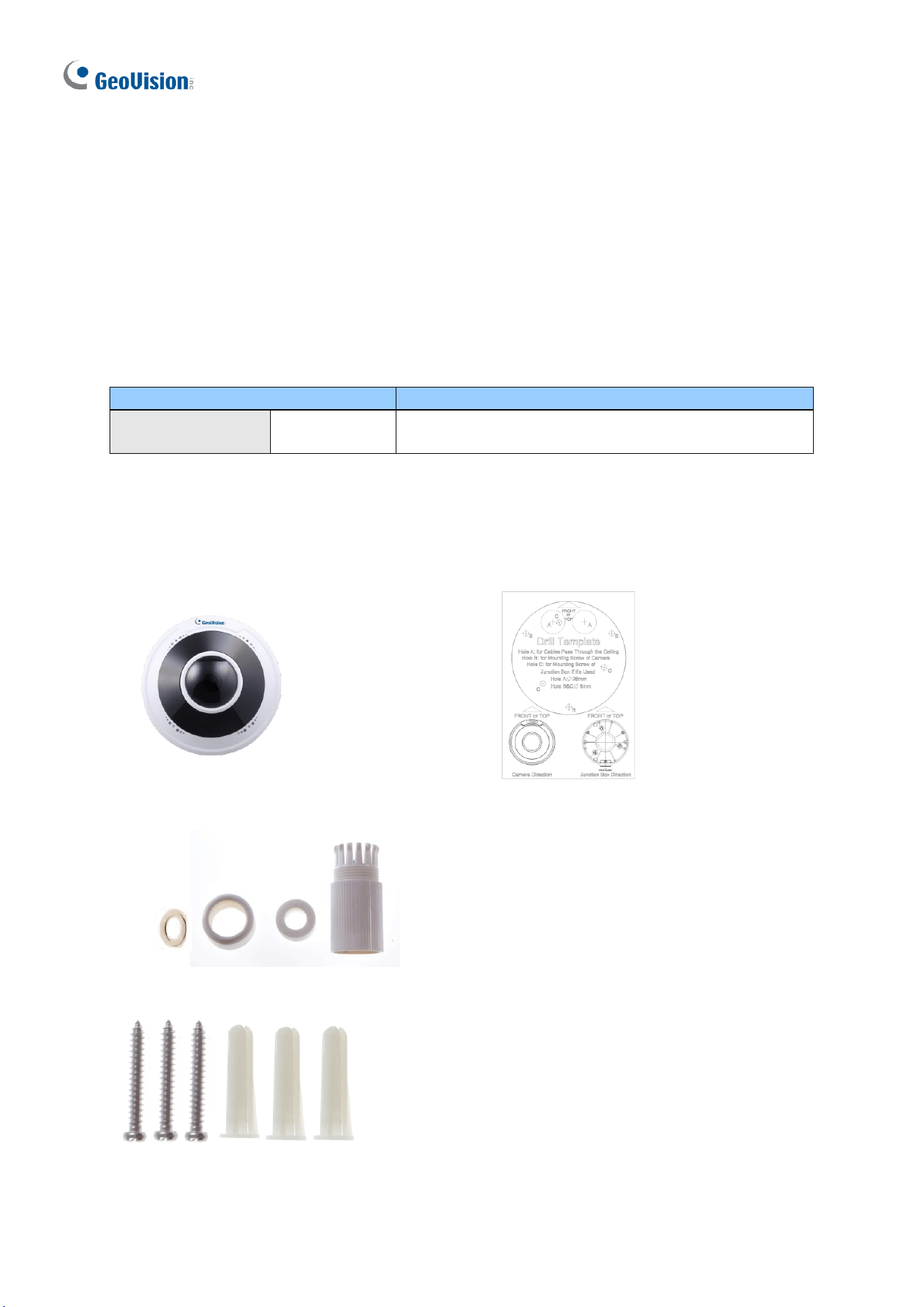
88
1.6 GV-FER5702
The IR Fisheye Rugged IP Camera is an outdoor, fixed, network camera equipped with an
automatic IR-cut filter and an IR LED for day and night surveillance. The camera supports
H.265 video codec to achieve better compression ratio while maintaining high quality image
at reduced network bandwidths. The camera adheres to IP66 standards for dust / water
protection and IK10 for metal casing and can be powered through PoE. With its WDR Pro, it
can process scenes with contrasting intensity of lights and produce clear image. It is also
equipped with a built-in micro SD card slot for local storage.
Model No.
Description
GV-FER5702
Fixed lens
5 MP, H.265, Super Low Lux, WDR Pro
1.6.1 Packing List
• IR Fisheye Rugged IP Camera
(GV-FER5702)
• Drill Template Paster
• Waterproof Rubber Set
• Download Guide
• Screw Kit
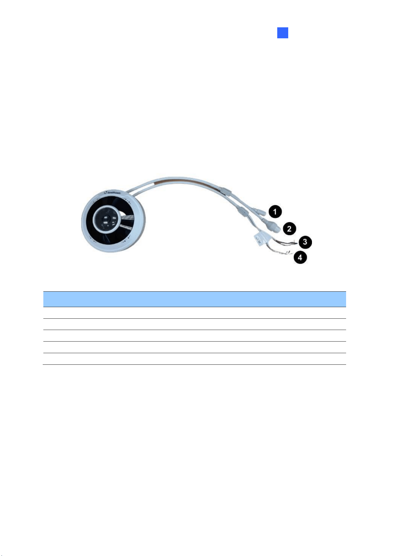
Introduction
89
1
1.6.2 Optional Accessories
Optional accessories can expand the capabilities and versatility of your camera. Accessory
details can be found on the datasheet.
1.6.3 Overview
1.6.3.1 GV-FER5702
Figure 1-119
No.
Description
No.
Description
1
Power connector (DC 12V)
3
Green wire-Alarm output -
2
Ethernet connector / PoE
4
Yellow wire-Audio output
3
Brown wire-Alarm input
4
White wire-GND
3
Blue wire-GND
4
Purple wire-Audio input
3
Orange wire-Alarm output +
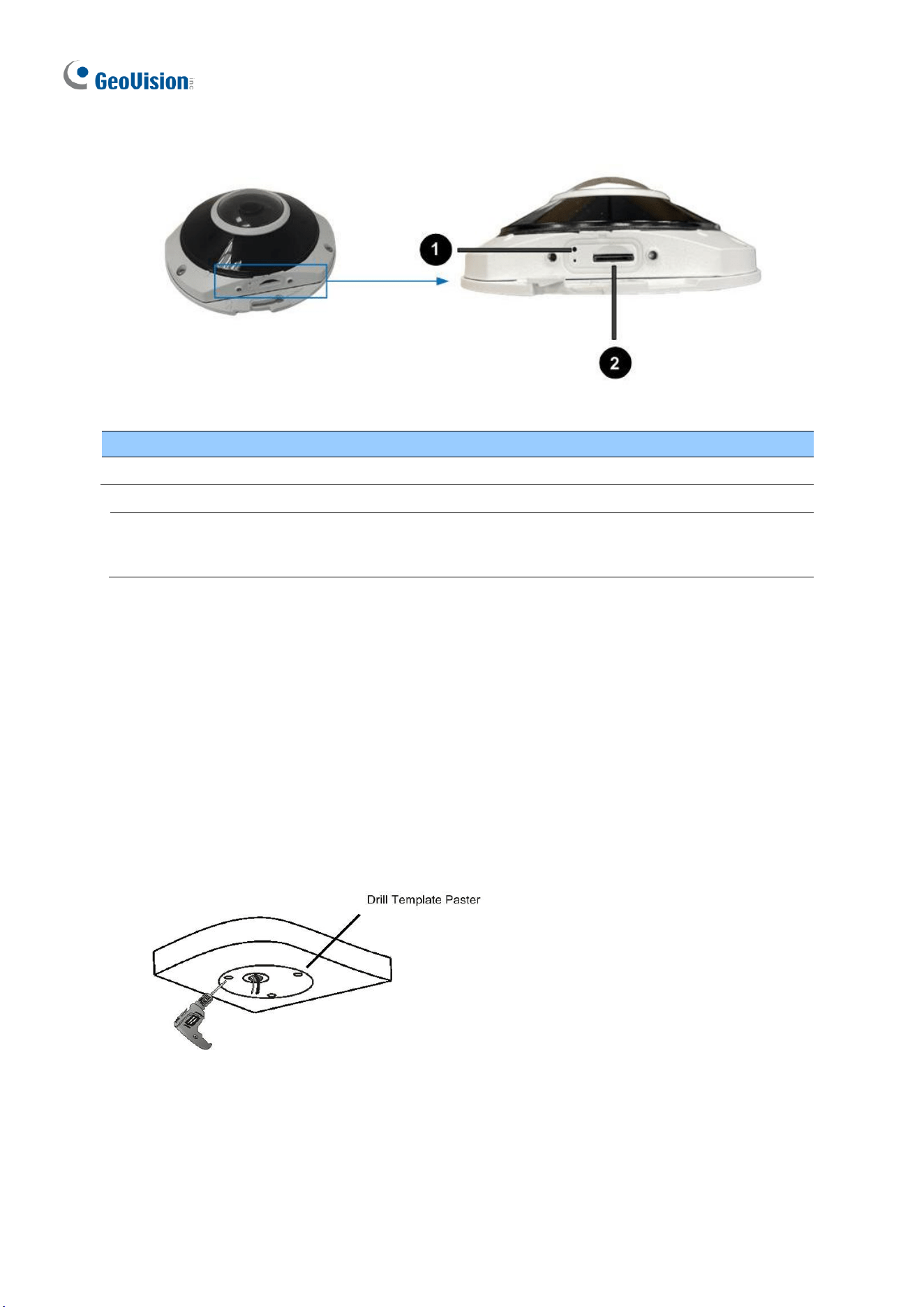
90
Load Default Button
Figure 1-120
No.
Description
No.
Description
1
Load default button
2
SD card slot
Note: If the default button doesn’t respond after pressing for 15 seconds, reboot the
camera and try again within 10 minutes of rebooting.
1.6.4 Installation
The IR Fisheye Rugged IP Camera is designed for outdoors. With the standard package, you
can install the camera on the wall or ceiling. Or, you can purchase optional mounting
accessories to mount your camera on a wall.
Below are the instructions for Ceiling Mount.
1. Stick the drill template paster to the ceiling and drill holes on the ceiling according to
the drill template.
Figure 1-121
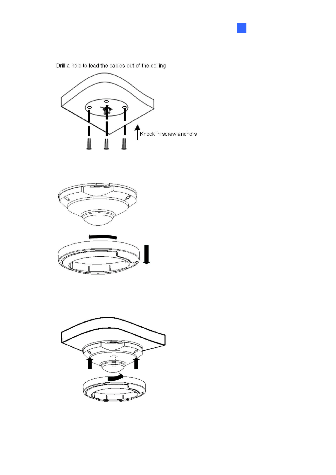
Introduction
91
1
2. Insert the screw anchors.
Figure 1-122
3. Remove the housing by turning it anticlockwise.
Figure 1-123
4. Secure the camera base onto the ceiling with 3 screws supplied and lock up the
housing by turning it clockwise.
Figure 1-124

92
1.6.5 Optional Installation
You can optionally purchase the following accessories to fit your mounting environment:
⚫ GV-Mount212P for Wall Box Mount: see similar installation procedures in section
1.1.5.2.
⚫ GV-Mount107 + GV-Mount212P for Pendant Tube Mount: see similar installation
procedures in section 1.1.5.4.
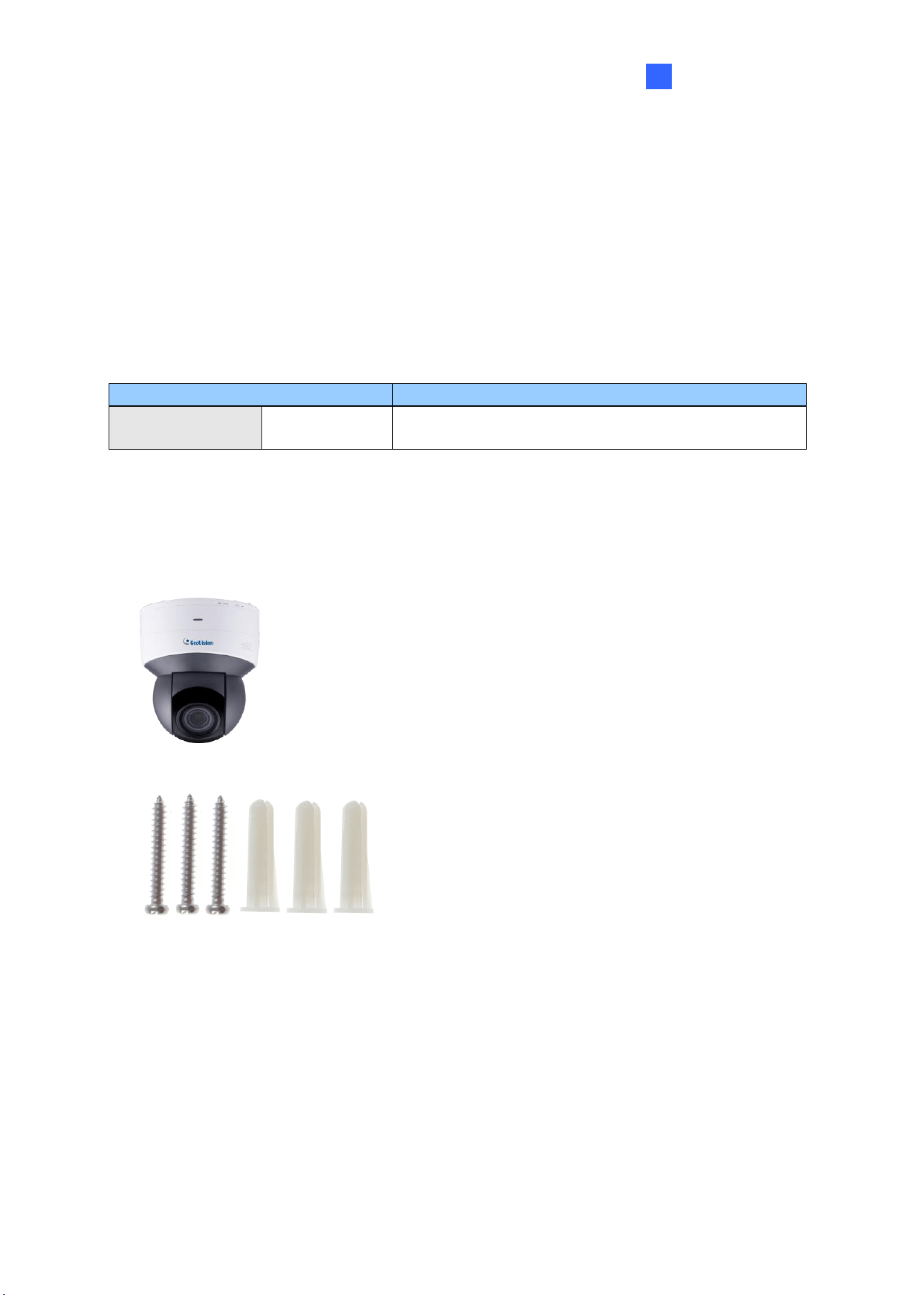
Introduction
93
1
1.7 GV-PTZ5810-IR
GV-PTZ5810-IR is an indoor network PTZ camera that offers 5x optical zoom, capable of
showing smooth live view with great details. This camera can simultaneously deliver three
video streams in resolutions up to 2880 x 1620 at 30 fps. In low-light environments, night
vision is enhanced with its LEDs, which allow up to 30 m (100 ft) effective IR distance. The
camera can process scenes with contrasting intensity of lights and produce clear image
using the built-in WDR Pro. GV-PTZ5810-IR supports H.265 video codec to achieve better
compression ratio while maintaining high quality pictures at reduced network bandwidths.
Model No.
Description
GV-PTZ5810-IR
Motorized lens
5 MP, H.265, Super Low Lux, WDR Pro
1.7.1 Packing List
• IR Mini PTZ IP Camera
(GV-PTZ5810-IR)
• Drill Template Paster
• Screw Kit
• Download Guide
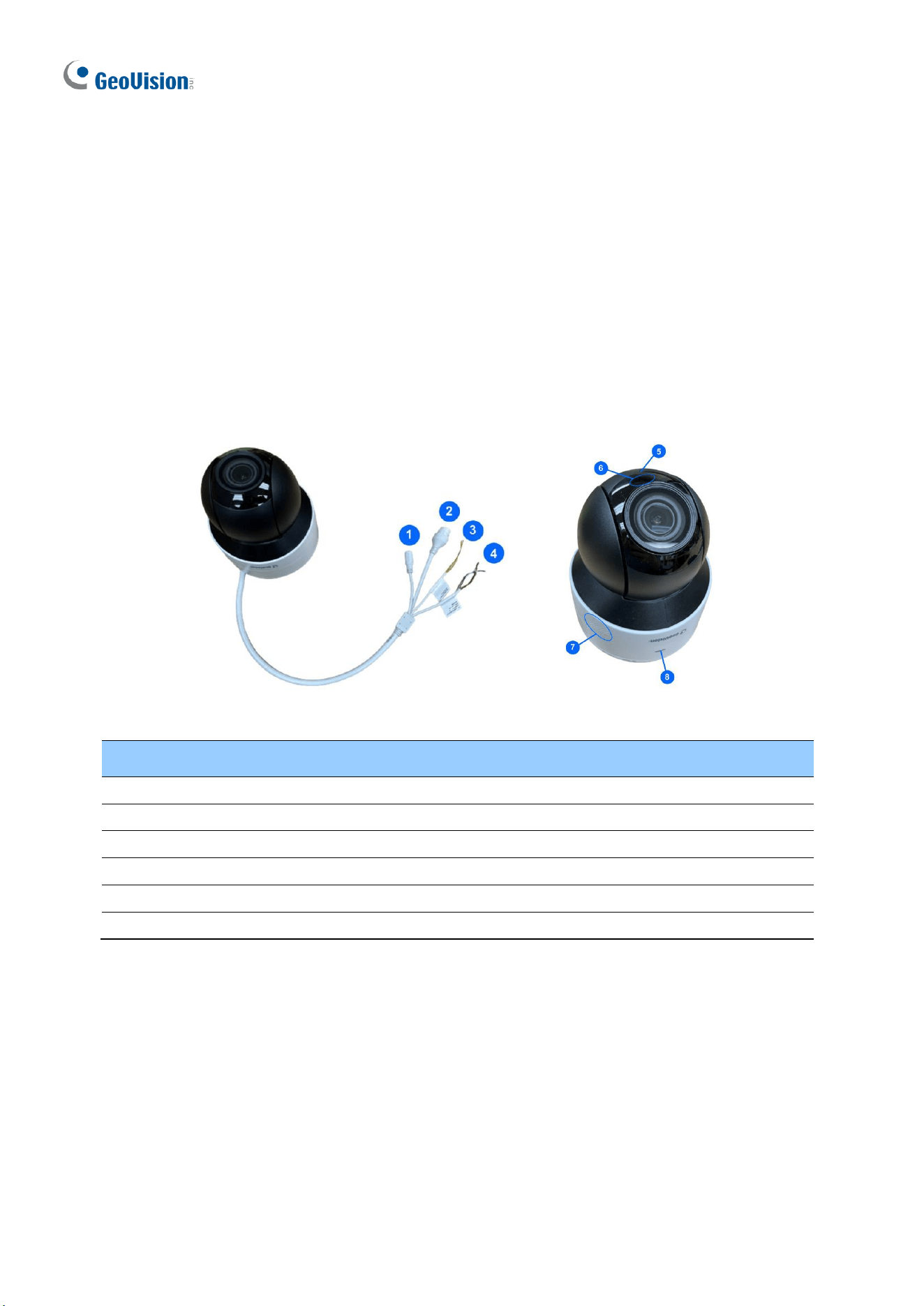
94
1.7.2 Optional Accessories
Optional accessories can expand the capabilities and versatility of your camera. Accessory
details can be found on the datasheet.
1.7.3 Overview
1.7.3.1 GV-PTZ5810-IR
Figure 1-125
No.
Description
No.
Description
1
Power connector (DC 12V)
4
Orange / white wire-Alarm output_P
2
Ethernet connector / PoE
4
Orange wire-Alarm output_N
3
Yellow / black wire-RS485_A
5
Built-in microphone
3
Yellow wire-RS485_B
6
IR LED
4
Purple wire-Alarm input
7
Built-in speaker
4
Black wire-GND
8
Ready LED
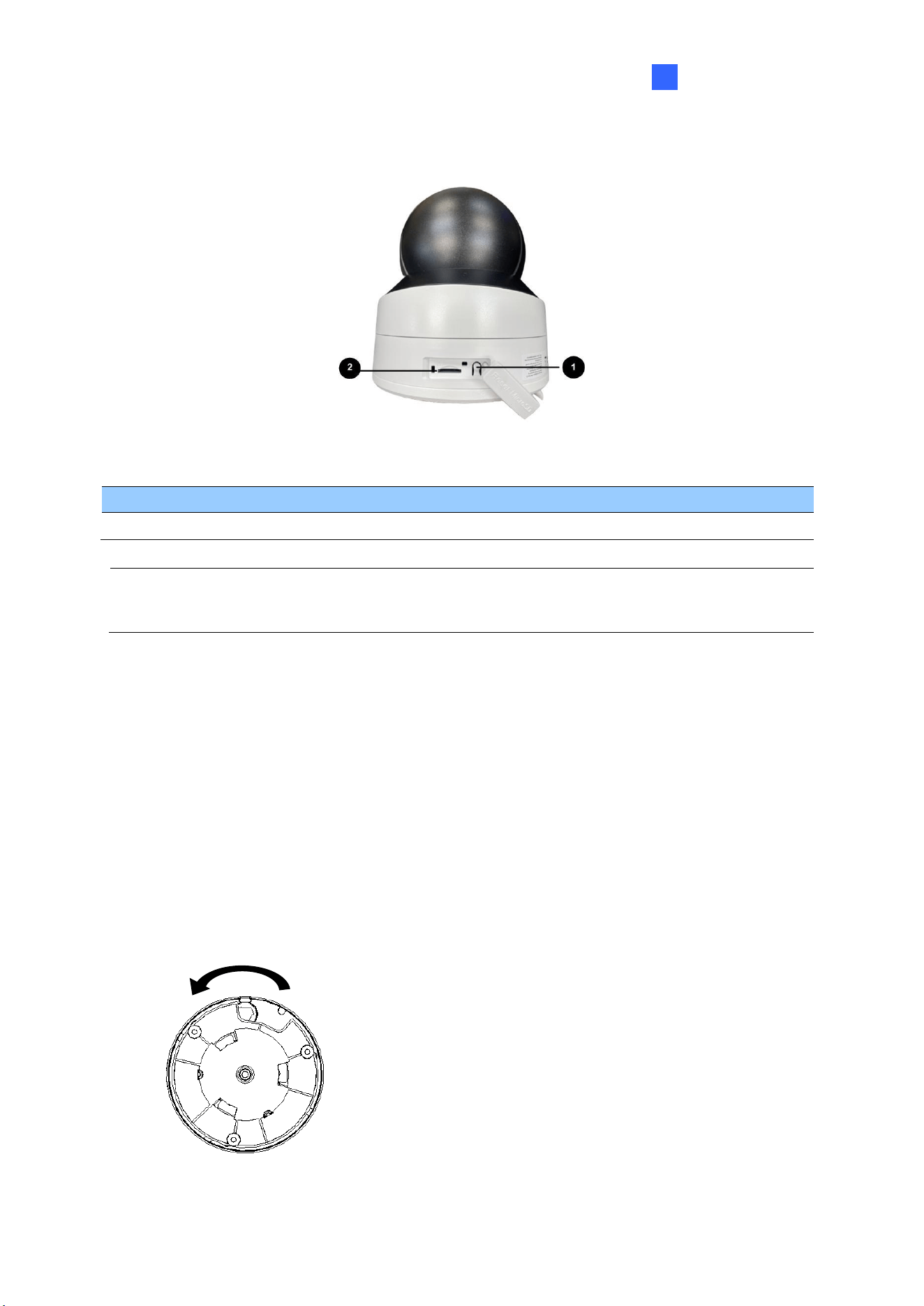
Introduction
95
1
Load Default Button
Figure 1-126
No.
Description
No.
Description
1
Load default button
2
SD card slot
Note: If the default button doesn’t respond after pressing for 15 seconds, reboot the
camera and try again within 10 minutes of rebooting.
1.7.4 Installation
The IR IP Mini PTZ Camera is designed for indoors. With the standard package, you can
install the camera on the wall or ceiling. Or, you can purchase optional mounting accessories
to mount your camera on a wall.
Below are the instructions for Ceiling Mount.
1. Hold the camera and rotate the adapter plate counterclockwise to detach it from the
camera.
Rotate counterclockwise
OPEN
LOCK
Figure 1-127
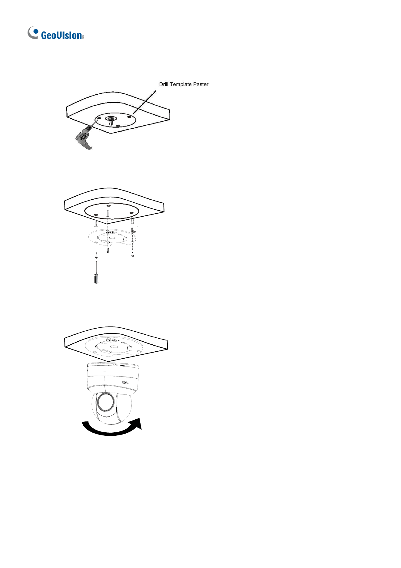
96
2. Stick the drill template paster to the ceiling and drill holes on the ceiling according to the
drill template.
Figure 1-128
3. Fix the adapter plate to the ceiling with screws.
Figure 1-129
4. Secure the camera to the adpater plate and rotate the camera counterclockwise until it’s
fastened.
Figure 1-130

Introduction
97
1
1.7.5 Optional Installation
You can optionally purchase the following accessories to fit your mounting environment:
⚫ GV-Mount107 + GV-Mount212P for Pendant Tube Mount: see similar installation
procedures in section 1.1.5.4.
⚫ GV-Mount211P / GV-Mount212P for Wall Box Mount: see section 1.1.5.1 and 1.1.5.2.
⚫ GV-Mount300-2 / 310-2 for Corner Mount: see Appendix F. GV-Mount300-2 / 310-2.
⚫ GV-Mount420 + GV-Mount211P for Pole Box Mount: see section 1.1.5.3.
98
1.8 GV-TMS Series
The Multi-Lens IR Fixed IP Dome is an outdoor, fixed, network camera equipped with an
automatic IR-cut filter and IR LEDs for day and night surveillance. The camera supports
H.265 video codec to achieve a better compression ratio while maintaining high-quality
pictures at reduced network bandwidths. The camera adheres to IP67 and IK10 standards,
and can be powered through PoE.
For GV-TMS8800, it features two 4MP CMOS image sensors to deliver a video resolution of
2688 x 1520 at up to 25 fps.
For GV-TMS20811, it features four 5MP CMOS image sensors to deliver a video resolution
of 2880 x 1620 at up to 30 fps. With its motorized lenses, the user can zoom and focus the
camera from the Web interface.
Model No.
Description
GV-TMS8800
Fixed lens
4 MP x 2, H.265, Super Low Lux, WDR Pro
GV-TMS20811
Motorized
varifocal lens
5 MP x 4, H.265, Super Low Lux, WDR Pro
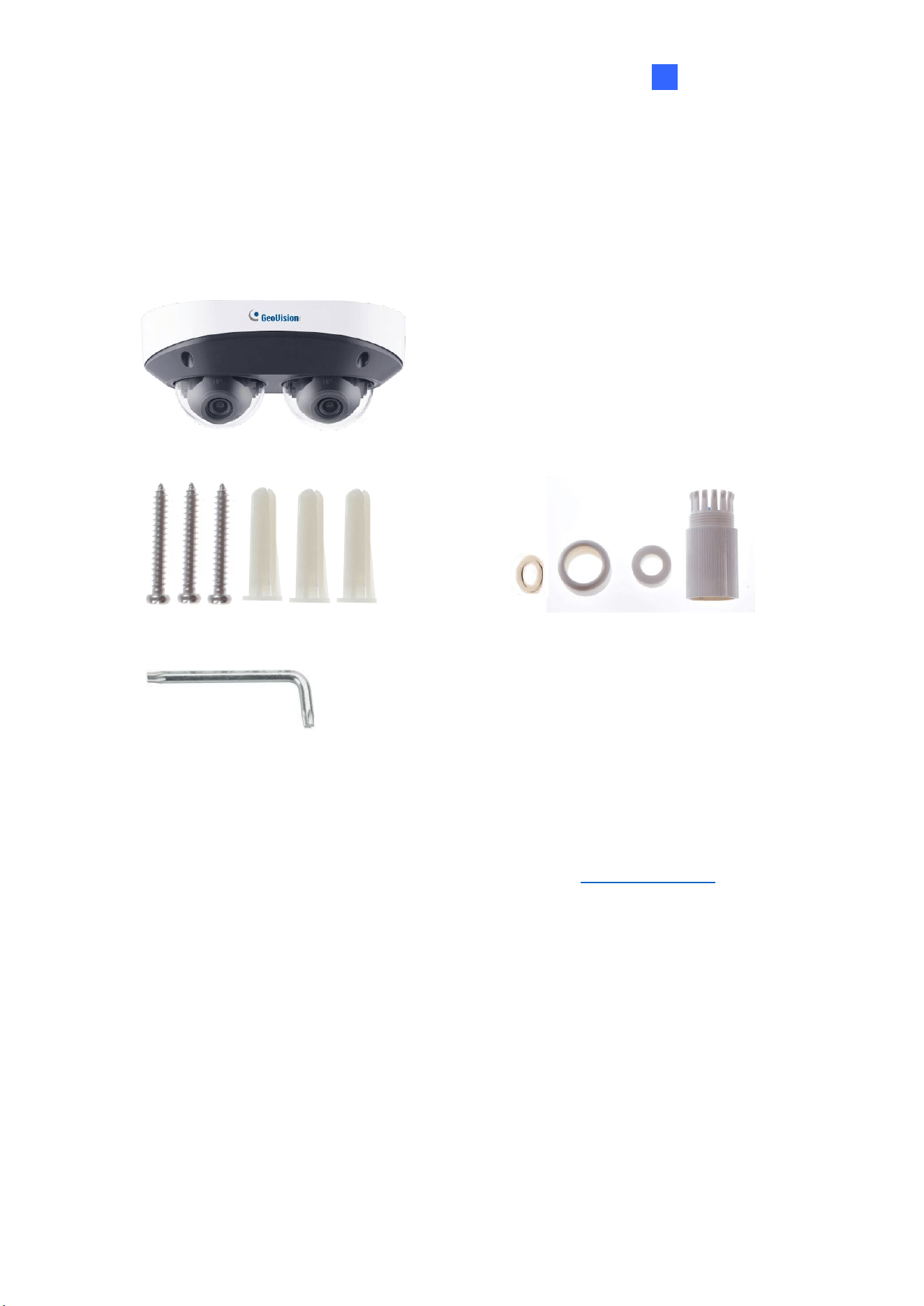
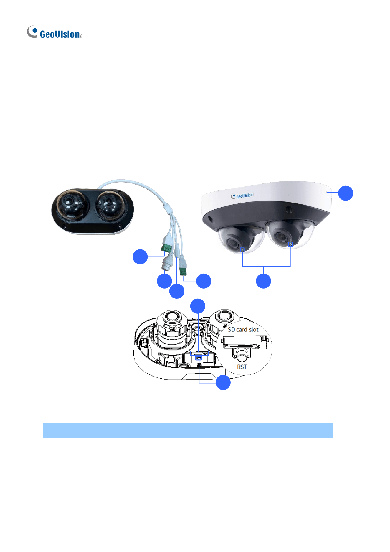
100
1.8.2 Optional Accessories
Optional accessories can expand the capabilities and versatility of your camera. Accessory
details can be found on the datasheet.
1.8.3 Overview
1.8.3.1 GV-TMS8800
1
2
3
4 6
5
7
8
Figure 1-131
No.
Description
No.
Description
1
Alarm input / output
5
Built-in microphone x 2 (on both
sides)
2
Ethernet connector / PoE
6
IR LED x 2
3
Power connector (DC 12V)
7
Micro SD card slot
4
Audio input / output
8
Default button

Introduction
101
1
Note: If the default button doesn’t respond after pressing for 15 seconds, reboot the
camera and try again within 10 minutes of rebooting.
1.8.3.2 GV-TMS20811
For details on the camera overview, see 8.2.2 GV-TMS20811 in the Quick Start Guide.
1.8.4 Installation
See 8.3 Installation in the Quick Start Guide for details.
1.8.5 Optional Installation
You can optionally purchase the GV-Mount accessories to fit your mounting environment:
For details, see GV-A/T/EBD Series IPCamera Mount Installation Guide.
102
1.9 System Requirements
CPU
Intel Core i5-4670, 3.40 GHz
Memory
DDR3 8 GB RAM
On Board Graphics
Intel HD Graphics 4600 (Versions of driver from year 2014 or later
required)
Web Browsers
⚫ Internet Explorer 11.0 or later
⚫ Google Chrome
⚫ Microsoft Edge
⚫ Mozilla Firefox
⚫ Safari
Note:
1. Some functions are not available on non-IE browsers, e.g., Local Parameters (see
3.1.2 Local Parameters) and Photo (see 3.8.3 Backing Up Storage) are not supported
by Google Chrome.
2. Non-IE browsers supporting complete functions include Google Chrome 45.0 or later,
Microsoft Edge 52.0 or later, and Mozilla Firefox 79 or later.
3. The following models support complete functions on non-IE browsers: GV-BLFC5800,
GV-EBD2705 / 4704 / 4813 / 8800 / 8813, GV-EBDP5800, GV-EBFC5800, GV-
FER5702 (V1.06 or later), GV-TBL2706 / 4705 / 4807 / 4810 / 8804 / 8810, GV-
TBLP5800, GV-TDR2705 / 4704 / 4803 / 8805, GV-TFD4800, GV-TMS8800 / 20811,
GV-TVD4810 (V1.05 or later) / 4811 / 8810, GV-PTZ5810-IR (V1.02 or later).
4. Live view is not supported on Safari for the following models: GV-BLFC5800, GV-
EBD4704 / 4813 / 8800 /8813, GV-EBDP5800 / 8800, GV-EBFC5800, GV-FER5702,
GVPTZ5810-IR, GV-TBL2705 / 2718 / 4705 / 4807 / 4810 / 8804 / 8810, GV-
TBLP5800 / 8800, GV-TDR2704-2F / 4704-2F / 4704-4F / 4803-2F / 8805, GV-
TFD4800, GV-TMS20811, GV-TVD2712 / 4810 / 4811 / 8810.
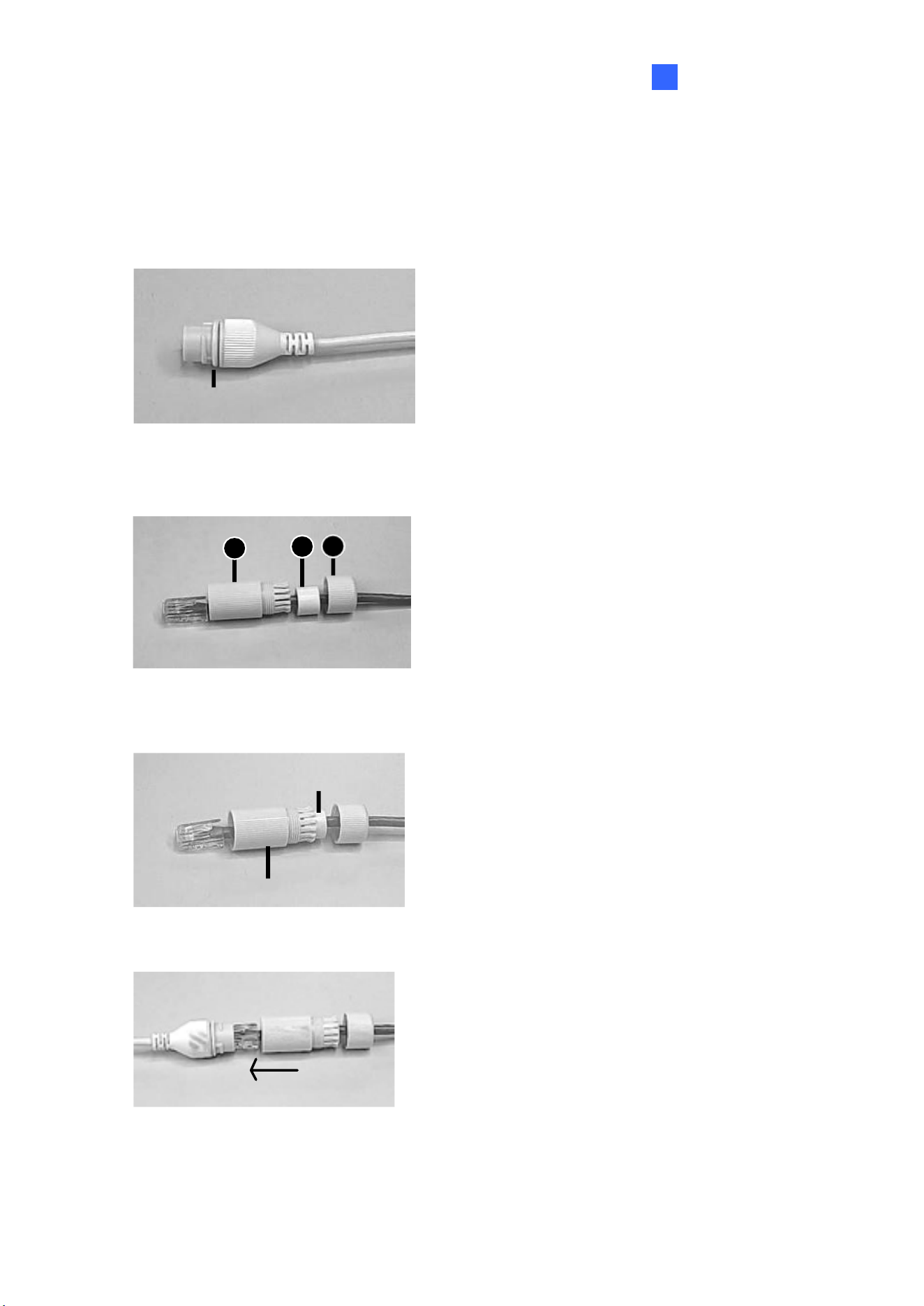
Introduction
103
1
1.10 Waterproofing the Cable
Waterproof the Ethernet cable by using the supplied waterproof rubber set.
1. Attach the seal ring to the RJ-45 plug.
Seal ring
Figure 1-132
2. Insert the waterproof components through the Ethernet cable as shown below.
3
2
1
Insert in order
1
Figure 1-133
3. Insert the cylindrical waterproof ring into waterproof bolt.
Cylindrical waterproof ring
Waterproof bolt
Figure 1-134
4. Insert the cable into the RJ-45 plug and screw the waterproof bolt in.
Figure 1-135
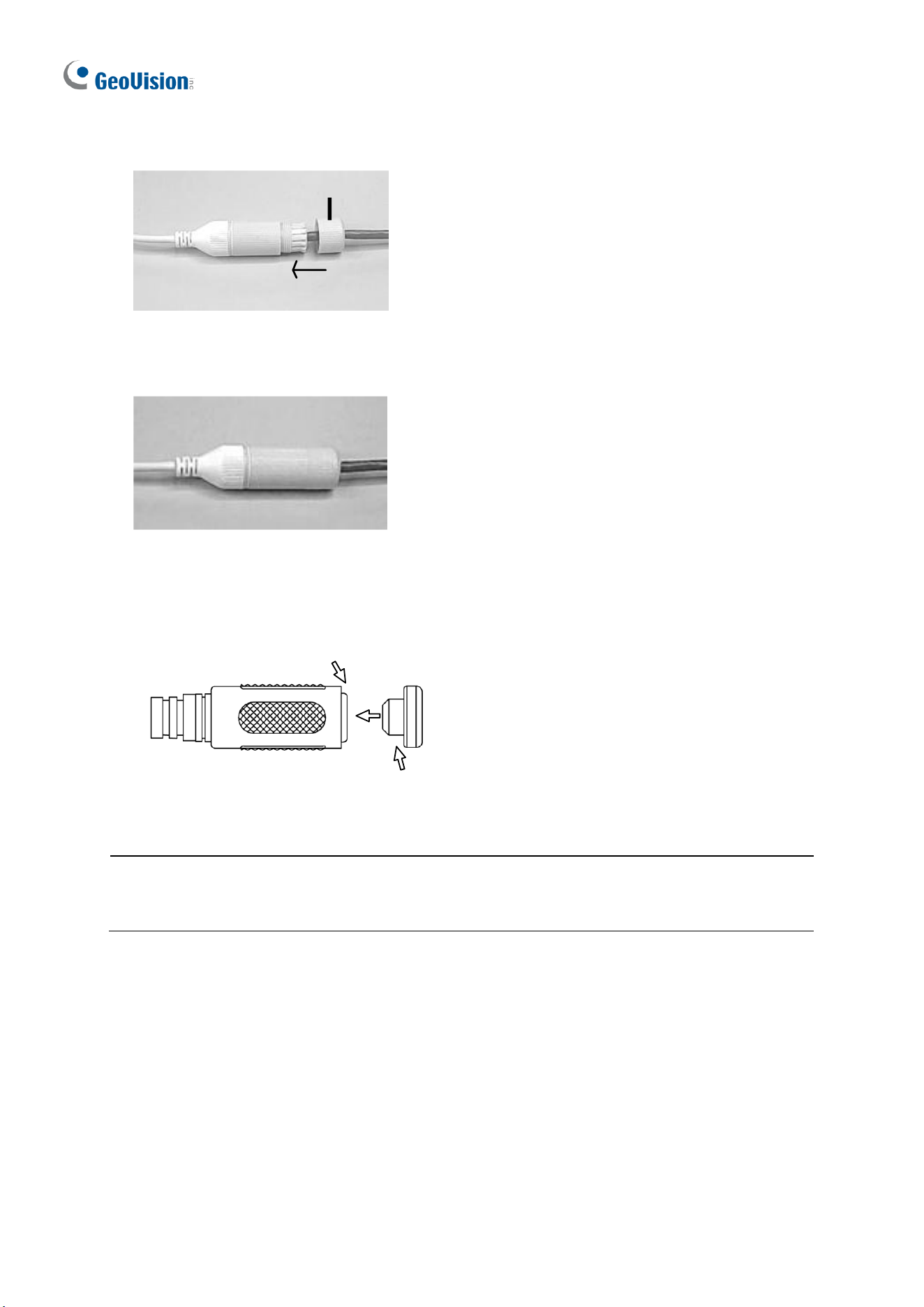
104
5. Screw in the waterproof bolt lid.
Bolt lid
Figure 1-136
6. Finish the waterproof installation.
Figure 1-137
7. If the camera has a DC cable and is not in use, you can waterproof it by inserting the supplied
plug into the DC interface.
DC interface
Plug
Figure 1-138
IMPORTANT: After installing the camera, it is required to use waterproof tapes to cover
and protect any of the tail cables and connection points that are exposed, see Note for
Installing Camera Outdoor at the beginning of the manual.

105
Chapter 2 Accessing the Camera
Once installed, the IP camera is accessible on a network. Follow these steps to configure the
network settings and access your surveillance images.
2.1 Installing on a Network
These instructions describe the basic connections to install the camera on the network.
1. Using a standard network cable, connect the camera to your network.
2. Connect to power using one of the following methods:
⚫ Use the optional power adapter to connect to power.
⚫ Use the Power over Ethernet (PoE) function in which power is supplied over the
network cable.
3. You can now access the Web interface of the camera.
⚫ If the camera is installed in a LAN with DHCP server, use GV-IP Device Utility to look
up the camera’s dynamic IP address. See 2.1.1 Looking up the Dynamic IP Address
and Logging In.
⚫ If the camera is installed in a LAN without DHCP server, the default IP address
192.168.0.10 is applied. To assign a different static IP address, see 2.1.2 Configuring
the IP Address.
Note: You must set your browser to allow ActiveX Control and perform a one-time
installation of the ActiveX component onto your computer upon your first login.
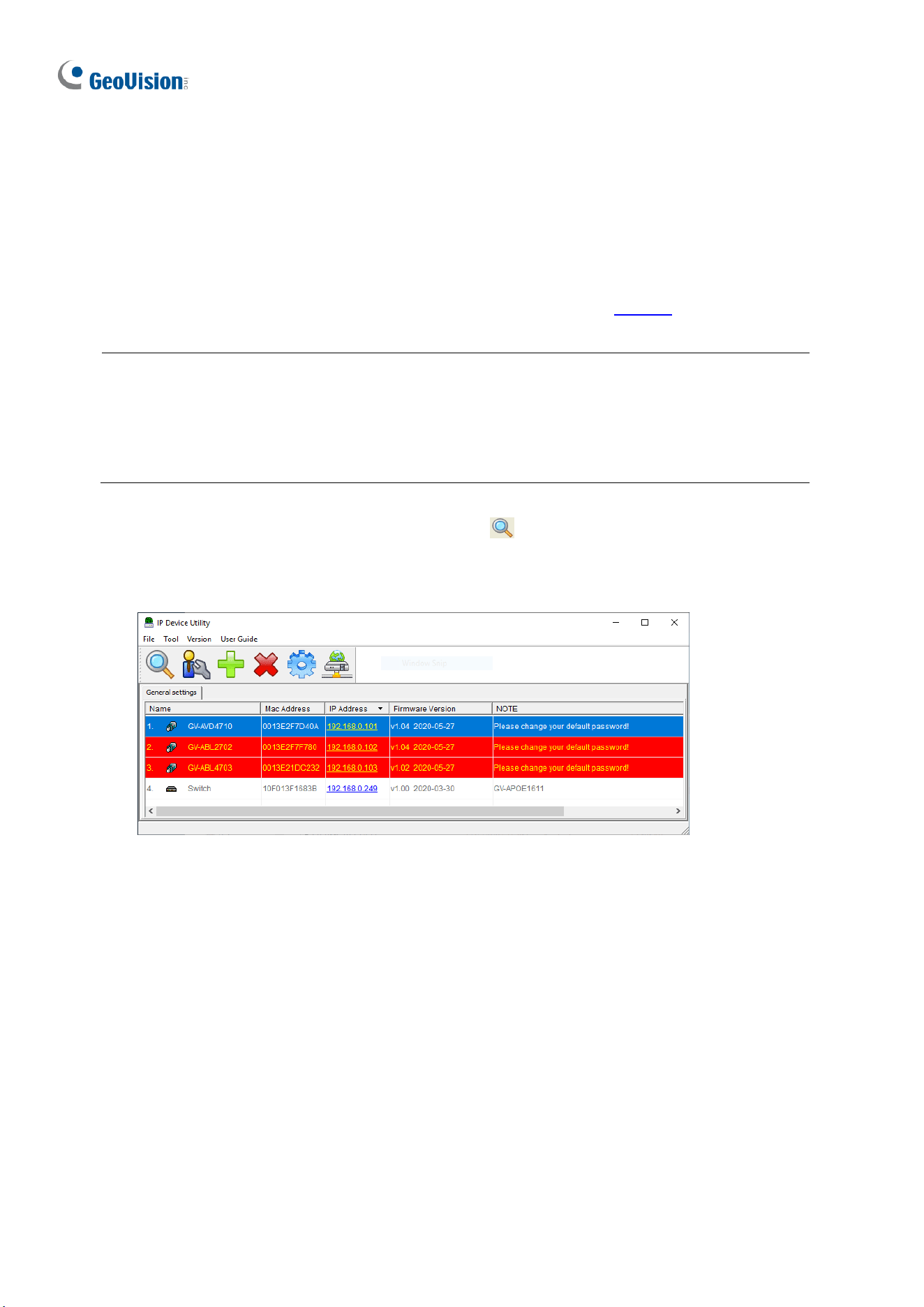
106
2.1.1 Looking Up the Dynamic IP Address and Logging In
By default, when the device is connected to LAN with a DHCP server, it is automatically
assigned with a dynamic IP address. Follow the steps below to look up its IP address and log
in the Web interface.
1. Download and install GV-IP Device Utility from the company website.
Note:
1. The PC installed with GV-IP Device Utility must be under the same LAN as the
camera you wish to configure.
2. By default, the Administrator’s username is admin and cannot be modified.
2. On the GV-IP Device Utility window, click the button to search for the IP devices
connected in the same LAN. Click the Name or Mac Address column to sort.
3. Find the camera with its Mac Address, click on its IP address.
Figure 2-1
4. For the first-time users, you will be requested to set up a password.
5. Type a new password and click OK.
6. Type your username and password on the login page and click Login.
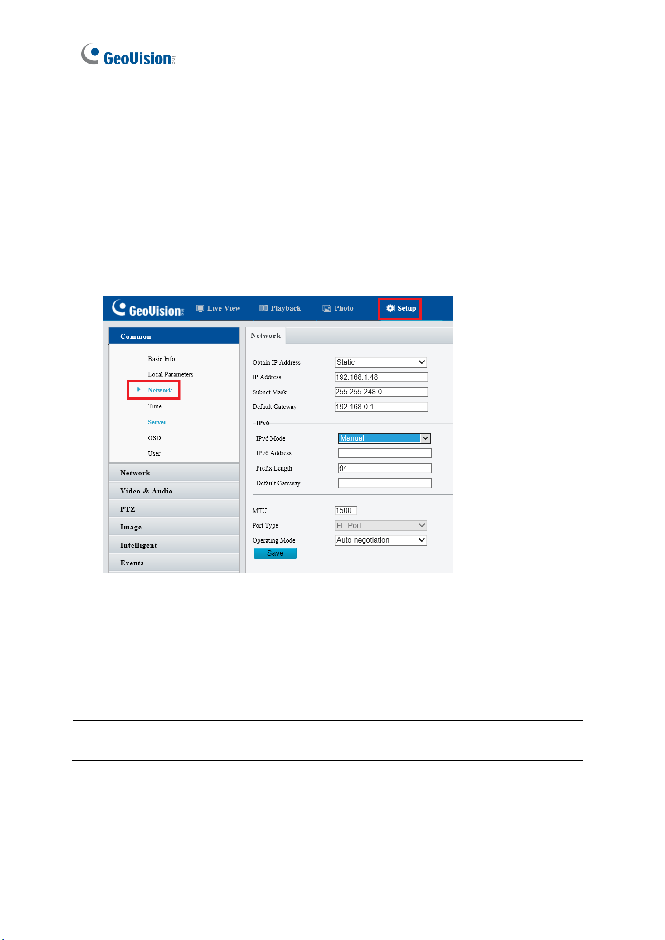
107
2.1.2 Configuring the IP Address
By default, when the device is connected to LAN without a DHCP server, it is assigned with a
static IP address of 192.168.0.10. Follow the steps below to assign a new IP address to
avoid IP conflict with other GeoVision devices.
1. Open your Web browser and type the default IP address 192.168.0.10.
2. Type your username and password. Click Login.
3. Click Setup, select Common in the left menu and select Network.
Figure 2-2
4. Select Static IP from the Obtain IP Address drop-down list.
5. Enter the IP address, subnet mask, and default gateway address. Make sure that the IP
address of the camera is unique in the network.
6. Click Save.
Note: When you change the network segment through the Web interface or GV-IP Device
Utility, you must also change the default gateway for the change to take effect.
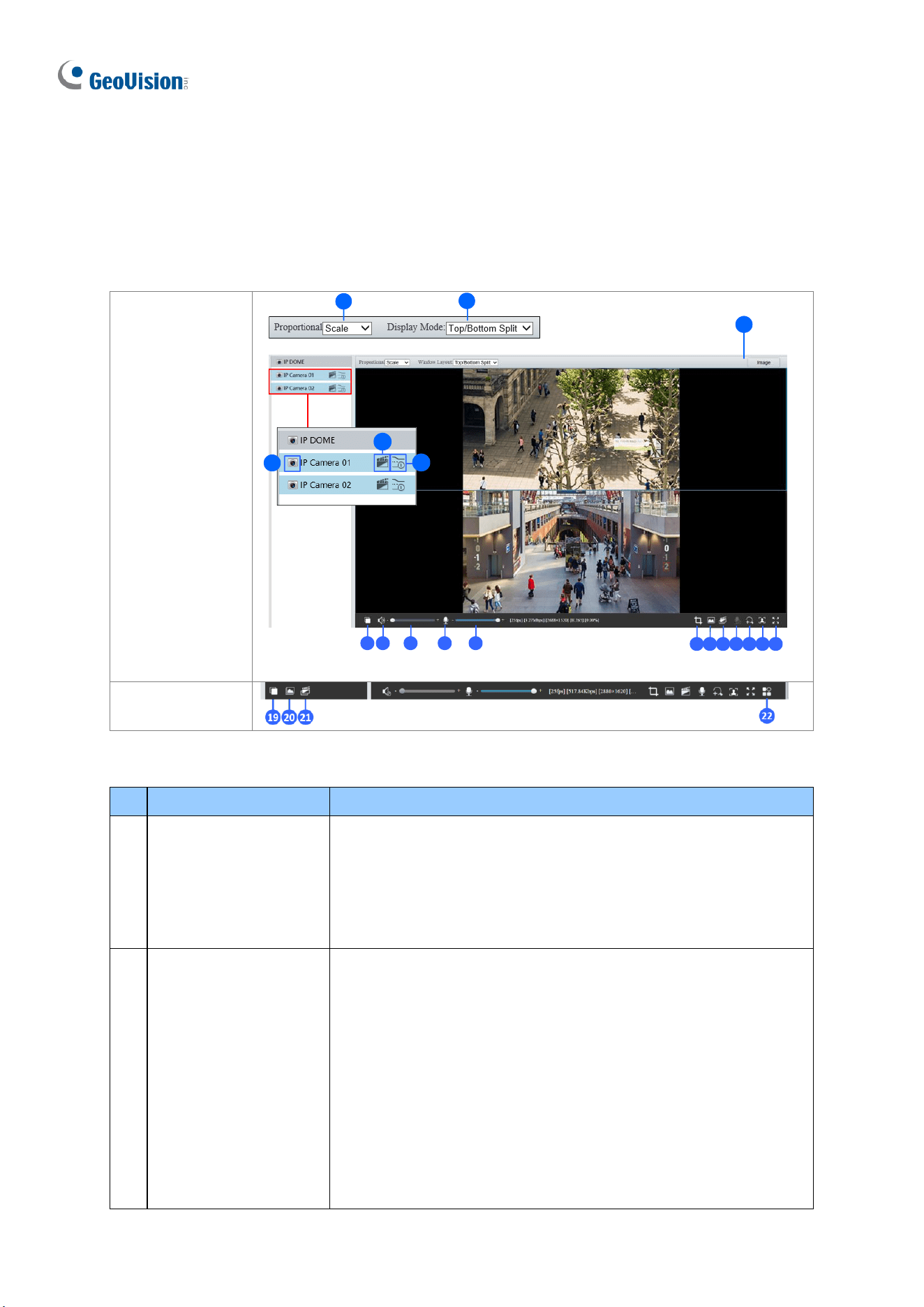
108
2.2 Accessing Live View
Once you log in the Web interface, you will see the live view as shown below.
GV-TMS Series
GV-TMS8800:
1
2
6
3
4
5
7 8 9 10 11
12 13 14 15 16 17 18
GV-TMS20811:
Figure 2-3
No.
Name
Function
1.
Proportional
Set the display ratio of the image.
◼
Scale: display images by 16:9.
◼
Stretch: display images by window size.
◼
Original: display images in its original size (only for GV-
TMS8800).
2.
Display Mode
Set the display mode in the window.
◼
Single Channel: display live video of a single channel.
◼
Left/Right Split: display live video in left / right split mode
(only for GV-TMS8800).
◼
Top/Bottom Split: display live video in top / bottom split
mode (only for GV-TMS8800).
◼
Picture in Picture: open a floating live view window on top
of the current window (only for GV-TMS8800).
◼
4-Split: display live video in 4-split mode (only for GV-
TMS20811).
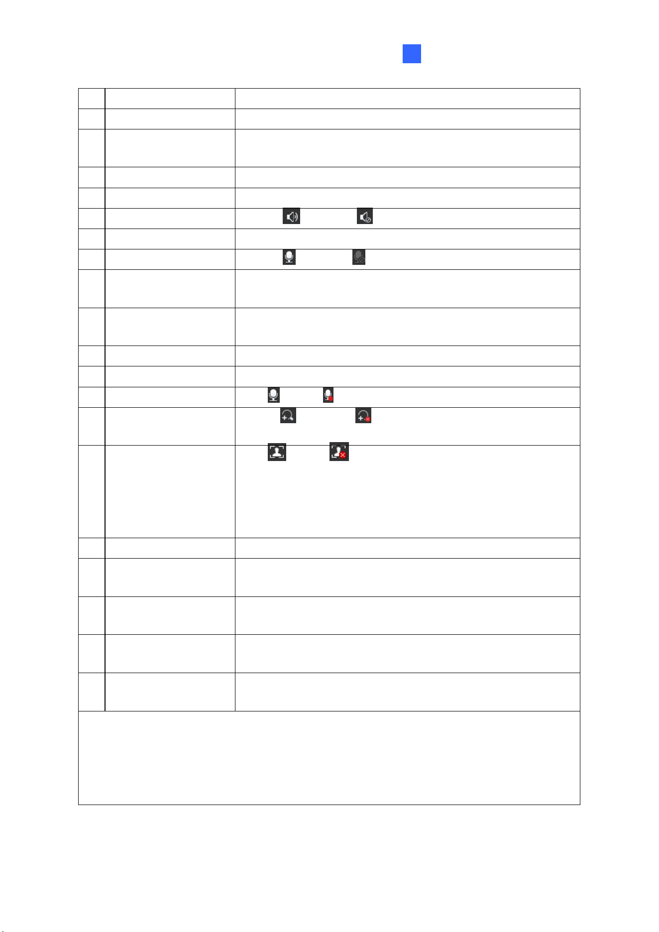
Accessing the Camera
109
2
3.
Stop / Start Live View
Stop/start live view of the selected channel.
4.
Local Recording
Stop/start local recording.
5.
Live Stream
Select a live video stream: main stream, sub stream or third
stream (when enabled).
6.
Image
Open the image setting page. – See 3.5.1 Image.
7.
Play/Stop
Play or stop live video. This is the same function as No. 3.
8.
Turn Audio Off / On
Disable or enable audio.
9.
Video Volume
Adjust the audio output volume on the PC.
10.
Microphone
Disable or enable microphone.
11.
Microphone Volume
Adjust the microphone volume on the PC during audio
communication between the PC and the camera.
12.
Calculate Pixels
Enable and drag the mouse on the desired object on the live
view to calculate its size in pixels (only for GV-TMS20811).
13.
Snapshot
Take a snapshot of the current image displayed on the PC.
14.
Local Recording
Stop/start local recording. This is the same function as No. 4.
15.
Two-way Audio
Start or stop two-way audio.
16.
Digital Zoom
Enable or disable digital zoom. – See 2.2.1 Digital
Zoom.
17.
Face Snapshot
Start or stop face snapshot.
By activating this function, the camera takes face snapshots,
and displays them on the right of the live view window. Before
activating this function, you must enable Face Detection - See
3.6.1.7 Face Detection.
18.
Full Screen
Display in full screen mode.
19.
Play/Stop for
All Channels
Play or stop live video for all channels (only for GV-
TMS20811).
20.
Snapshot for
All Channels
Take a snapshot of the current image displayed on the PC for
all channels.
21.
Local Recording for
All Channels
Stop/start local recording for all channels.
22.
Control Panel
Hide or show the camera’s optical zoom and focus, or the
general parameter functions (only for GV-TMS20811).
Note:
1. To configure individual channels separately, click on the corresponding live view
before proceeding with the configurations.
2. The paths for saving snapshots and local recordings are set in Local Settings. See
3.1.2 Local Parameters.
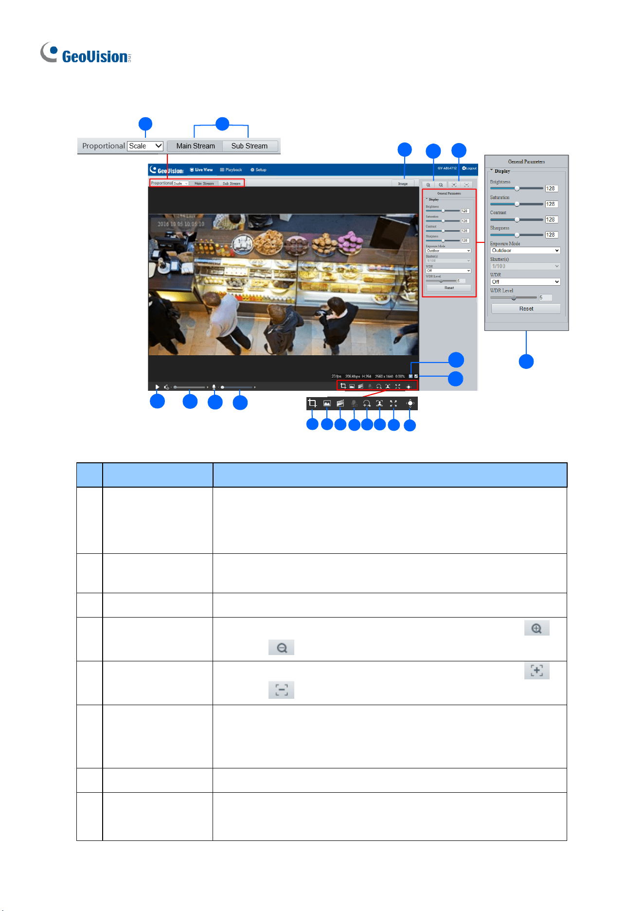
110
Other Models
1 2
4
19
15
20
3
10
12
13
14
15 16
17
18
11
5
6
7
8
9
Figure 2-4
No.
Name
Function
1.
Proportional
Set the display ratio of the image.
◼
Scale: display images by 16:9.
◼
Stretch: display images by window size.
◼
Original: display images in its original size.
2.
Live Stream
Select a live video stream: main stream, sub stream or third
stream (when enabled).
3.
Image
Open the image setting page. – See 3.5.1 Image.
4.
Zoom +/-
Only for models with motorized varifocal lens, increase or
decrease the camera’s optical zoom.
5.
Focus +/-
Only for models with motorized varifocal lens, increase or
decrease the camera focus.
6.
General
Parameters
Only for GV-EBD2704, EBD2705, TBL2705, TBL2706,
TDR2704, TDR2705. Configure the parameters for image
enhancement and exposure. See 3.5.1 Image for details.
7.
Play/Stop
Play or stop live video.
8.
Video Volume
Only for the audio-supporting models, adjust the audio output
volume on the PC.
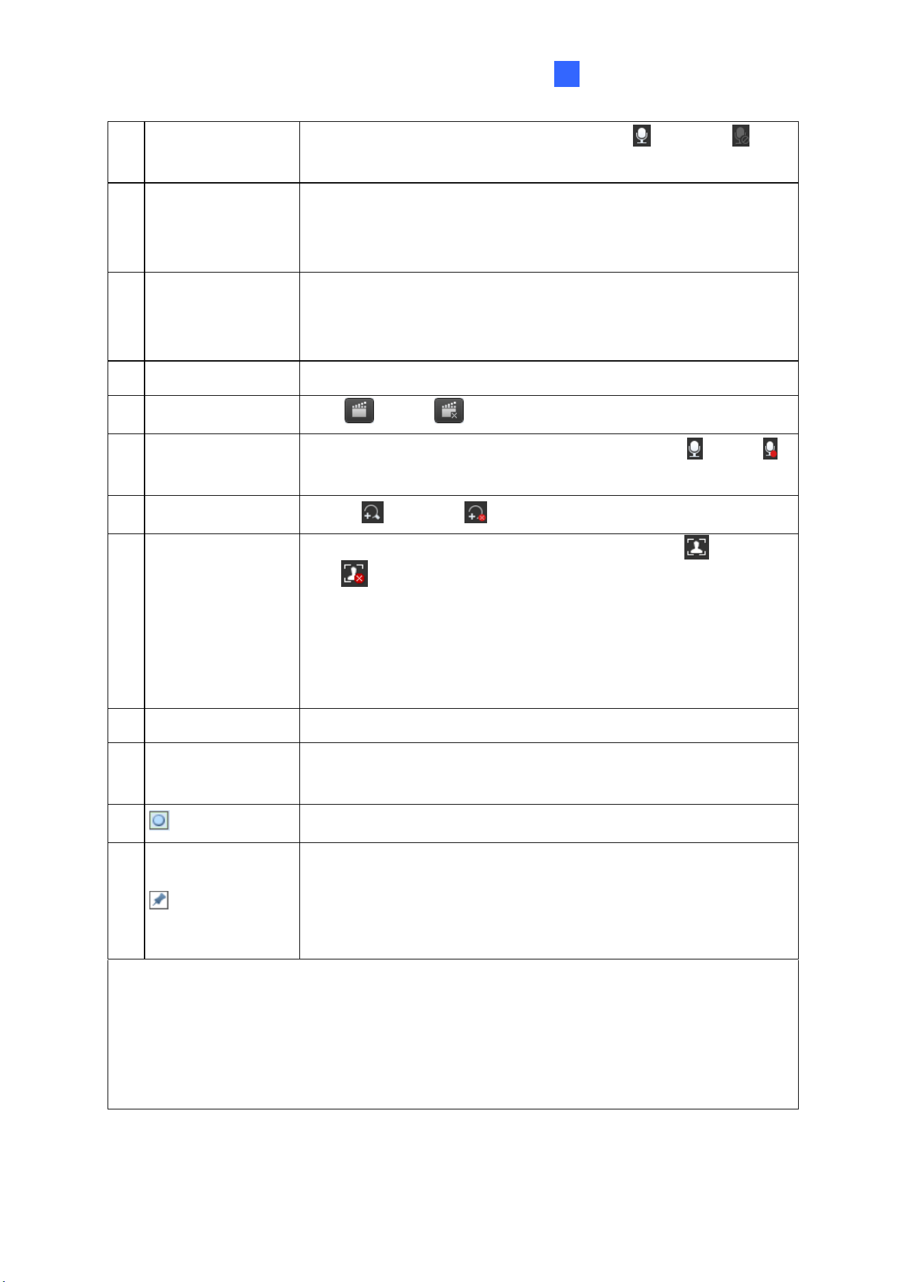
Accessing the Camera
111
2
9.
Microphone
Only for audio-supporting models, enable or disable
microphone.
10.
Microphone
Volume
Only for audio-supporting models, adjust the microphone
volume on the PC during audio communication between the PC
and the camera.
11.
Calculate Pixels
Only for GV-EBD2704, EBD2705, TBL2705, TBL2706,
TDR2704, TDR2705. Enable and drag the mouse on the desired
object on the live view to calculate its size in pixels.
12.
Snapshot
Take a snapshot of the current image displayed on the PC.
13.
Local Recording
Start or stop local recording.
14.
Two-way Audio
Only for two-way-audio-supporting models, start or stop
two-way audio.
15.
Digital Zoom
Enable or disable digital zoom. – See 2.2.1 Digital Zoom.
16.
Face Snapshot
Only for face-snapshot-supporting models, start or
stop face snapshot.
By activating this function, the camera takes face snapshots, and
displays them on the right of the live view window. Before
activating this function, you must enable Face Detection - See
3.6.1.7 Face Detection.
17.
Full Screen
Display in full screen mode.
18.
Control Panel
Hide or show the camera’s optical zoom and focus or the general
parameter functions.
19.
Reset the packet loss rate to zero.
20.
Click to always display packet loss rate and bit rate information at
the bottom. Click again to restore to only displaying the
information for 3 seconds when the mouse cursor is moved onto
the live view.
Note:
1. The paths for saving snapshots and local recordings are set in Local Settings. See
3.1.2 Local Parameters.
2. The No. 19 and 20 buttons will appear on the floating toolbar when you move the
mouse cursor onto the live view.
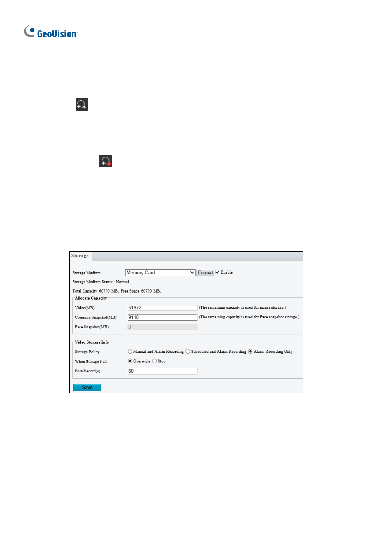
112
2.2.1 Digital Zoom
To use the digital zoom function, follow these steps:
1. Click (No. 16, Figure 2-3 / No. 15, Figure 2-4) on the toolbar.
2. Click and drag the mouse button in any direction to specify an area.
3. To restore the original image size, right click on the enlarged area.
4. To exit, click (No. 16, Figure 2-3 / No. 15, Figure 2-4) on the toolbar.
2.2.2 Start Recording
For models with local storage, you can start/stop recording manually or by schedule. At the
top of Home page, select Setup, select Storage in the left menu and select Storage. For
details, see 3.8.1 Formatting Storage.
Figure 2-5
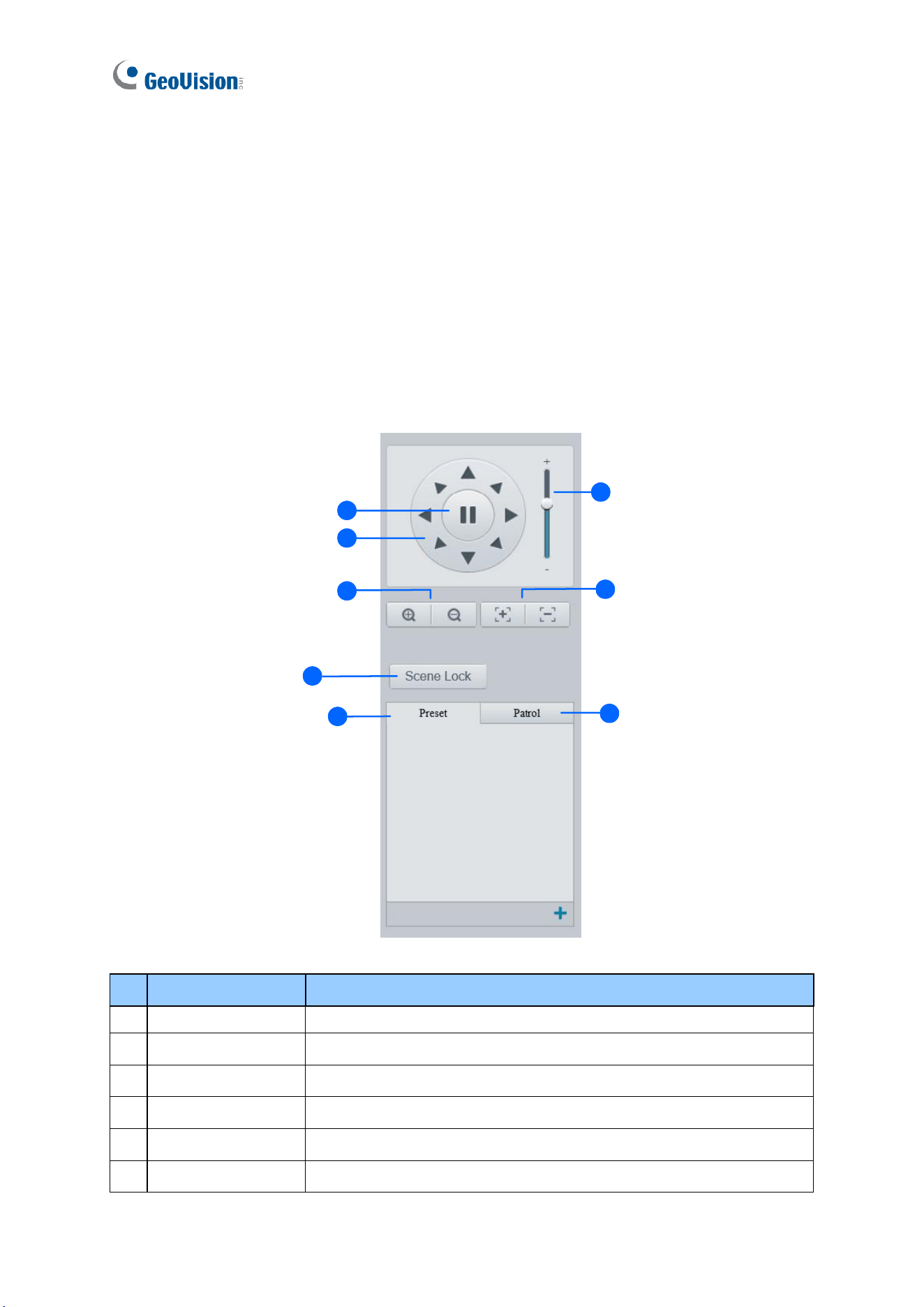
113
2.3 PTZ Control Panel
In this section, you will be guided through the various functions of PTZ Control Panel. The
PTZ Control Panel is accessed from the live view interface of the camera.
Note this is only applicable to GV-PTZ5810-IR.
2.3.1 Accessing the PTZ Control Panel
1
1
2
3
4
5
6
7
8
Figure 2-6
No.
Item
Function
1
Auto Pan
Start or stop auto panning of the camera.
2
PTZ Control Panel
Control the direction of the camera and release the control.
3
PTZ Speed
Adjust the moving speed of the PTZ camera.
4
Zoom
Adjust the camera’s zoom (optical).
5
Focus
Adjust the camera’s focus.
6
Screen Lock
Lock or unlock the camera direction.
114
7
Preset
Select a preset and the camera goes to the selected preset.
-- See 2.3.2 Setting Presets.
8
Patrol
Select a patrol route. -- See 2.3.3 Setting Patrol.
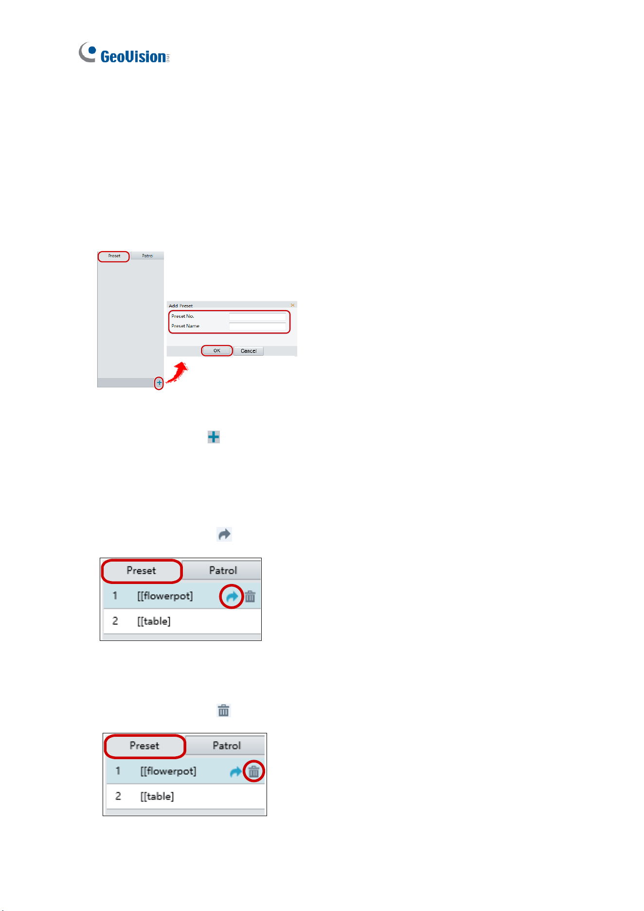
115
2.3.2 Setting Presets
You can create and delete preset points by clicking Preset on the control panel of Live View.
Adding a Preset
1. Select Preset on the control panel, and adjust the camera view to the desired direction,
zoom and focus.
4
Figure 2-7
2. Click the Add button to add it as a preset.
3. Type a number and name for the preset and click OK.
Going to a Preset
On the control panel, click for a preset. The PTZ camera goes to the selected preset.
Figure 2-8
Deleting a Preset
On the control panel, click for a preset and confirm the delete.
Figure 2-9
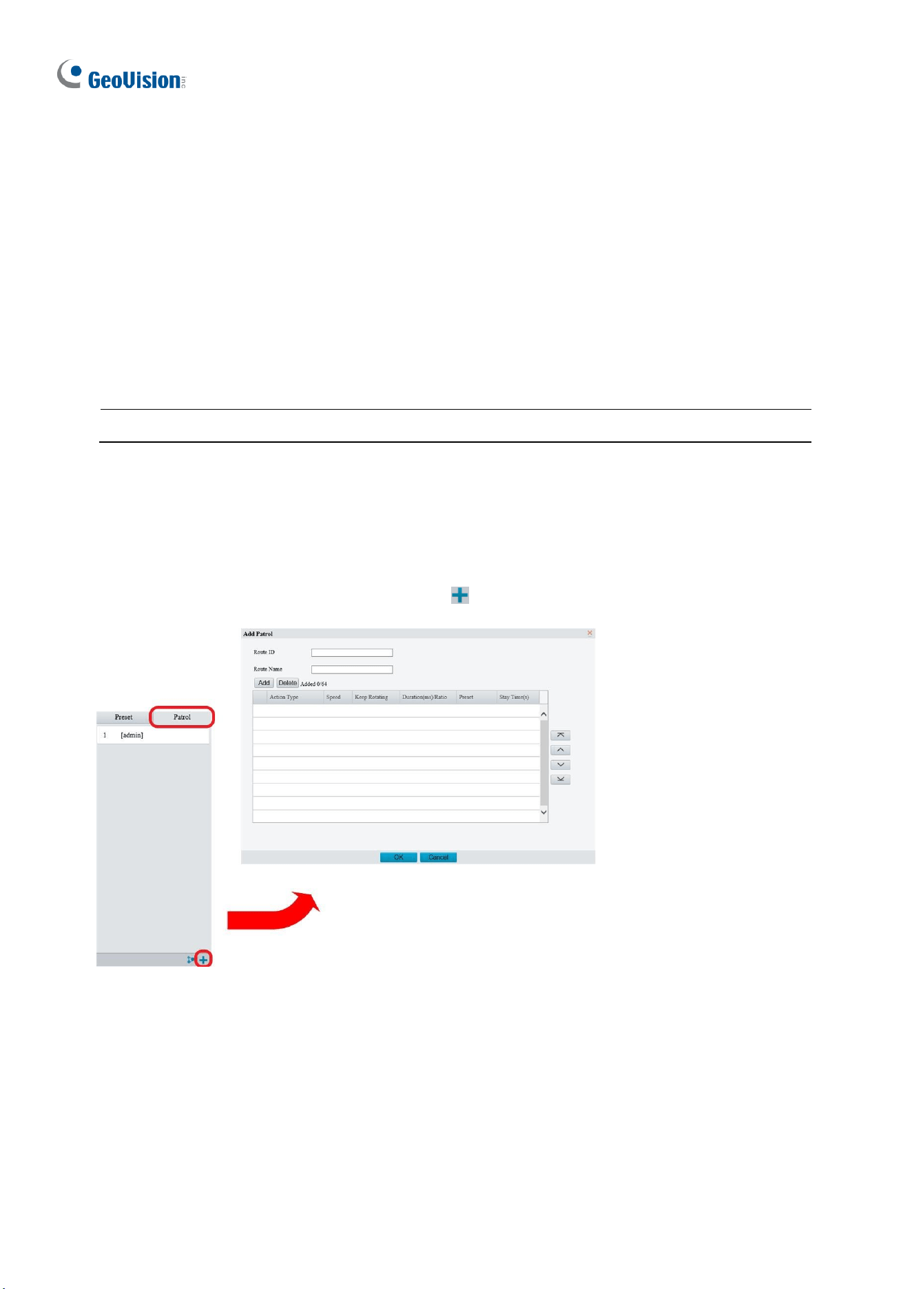
116
2.3.3 Setting Patrol
A patrol route is the track by which the camera follows when moving from a preset to the next.
The length of time that the camera stays at each preset is configurable. Multiple patrol routes
are allowed for the camera.
Patrol actions include going to a preset and staying at the preset for a certain amount of time
before going to the next. You can set the rotation direction, zoom, rotation speed, patrol time,
and stay time. You can also record a route and add it to the action list.
Note: To enable Preset Snapshot, see 3.4.5 Patrol.
To access the Patrol functions, click Patrol on the control panel of Live View.
Adding a Patrol Route
1. On the control panel, click the Add button to add a patrol route.
Figure 2-10
2. On the Add Patrol page, type the desired route ID and name.
3. Click Add to add a patrol action. Use the buttons to adjust the sequence of the actions
and click OK.
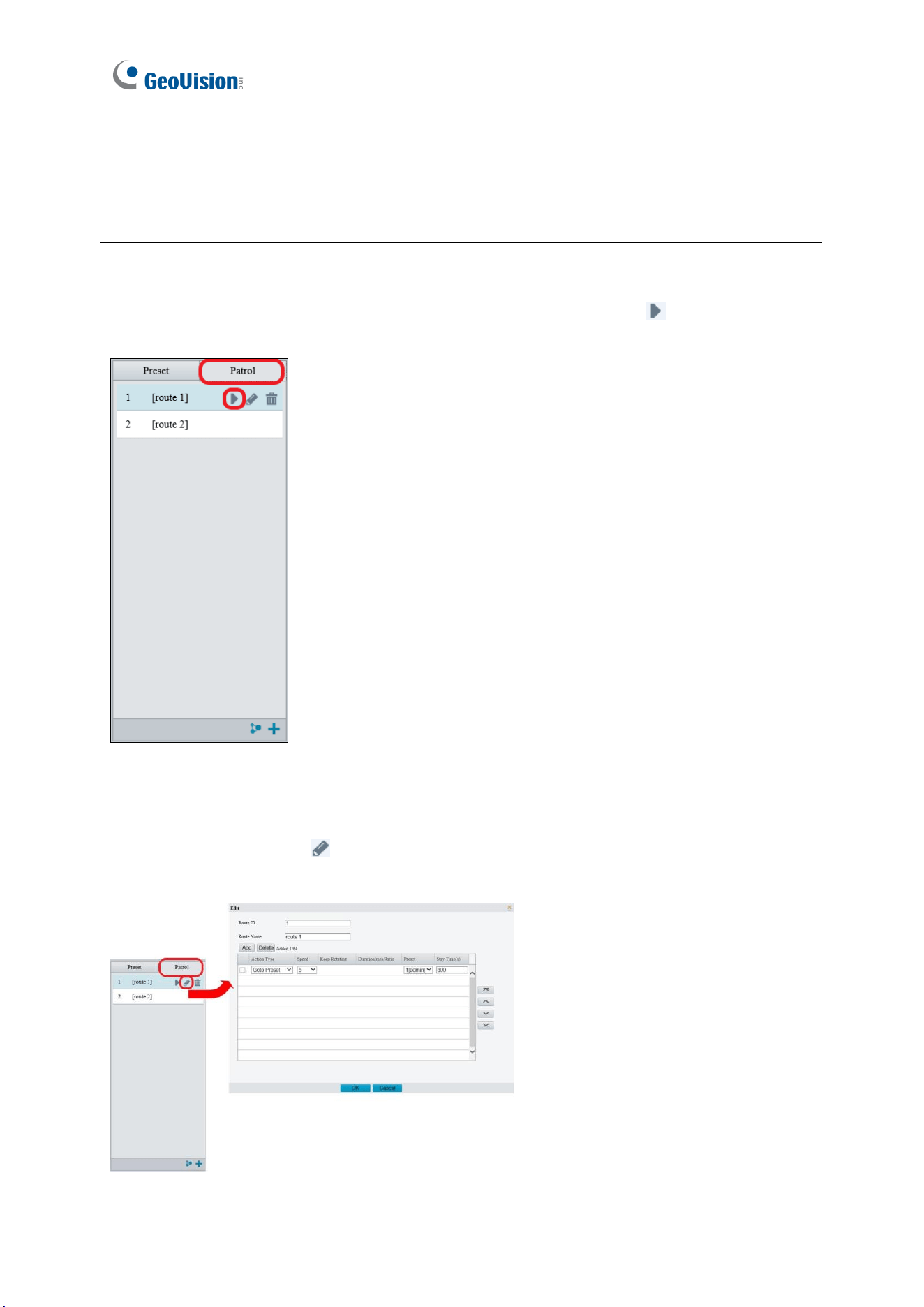
117
Note:
1. It is recommended that the first action type is Go to Preset.
2. If Keep Rotating is selected, the camera will rotate at the set speed and zoom in the set
direction or position for a certain amount of time.
Starting a Patrol Route
After you have added a patrol route, you can start patrolling by clicking on the control
panel.
Figure 2-11
Editing a Patrol Route
On the control panel, click to modify the ID, name and movement of an existing patrol
route.
Figure 2-12
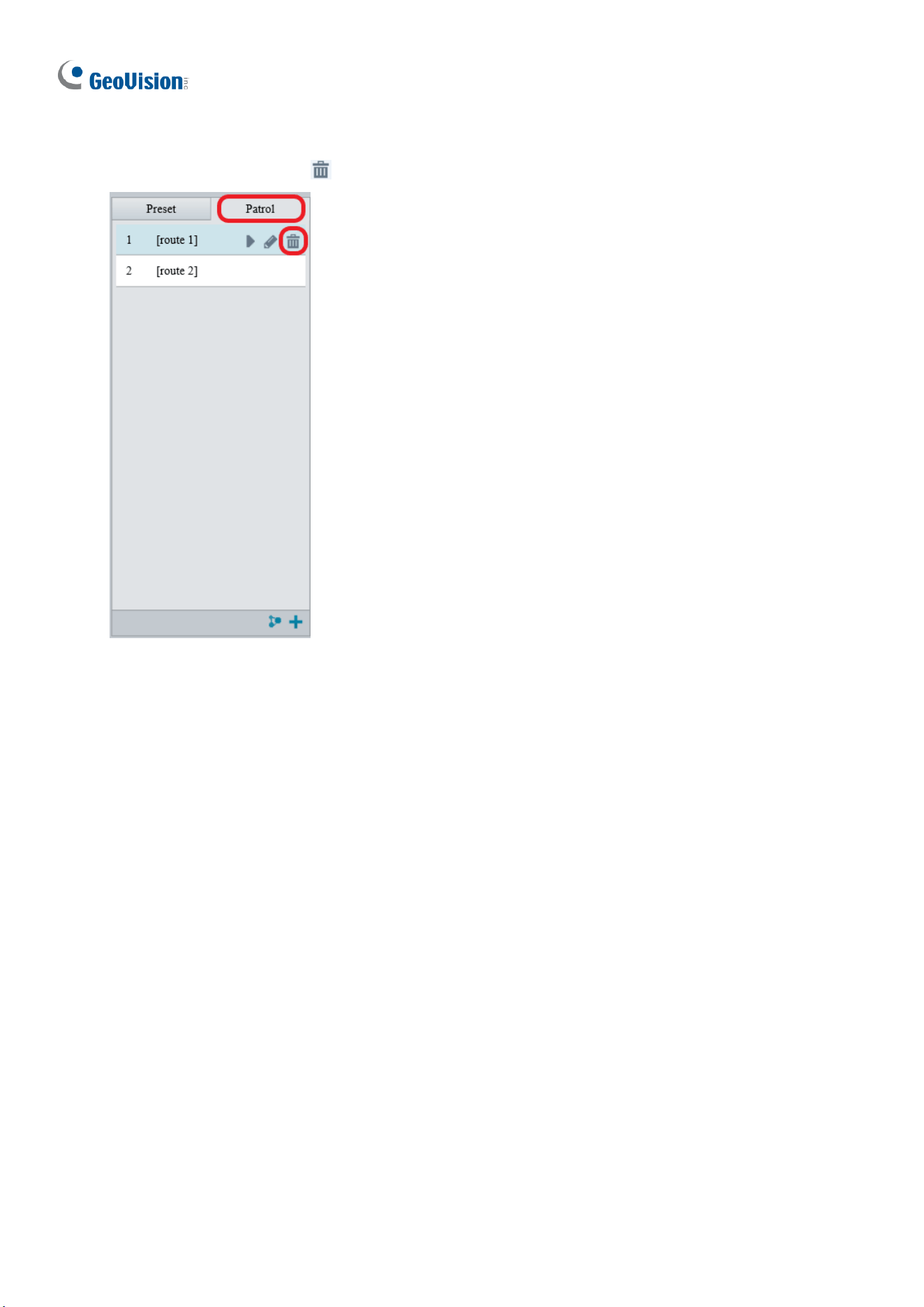
118
Delete a Patrol Route
On the control panel, click for a patrol route and confirm the delete.
Figure 2-13
Making a Patrol Plan
You can set up the camera to perform different patrol routes at different time periods
throughout the week by making a patrol plan.
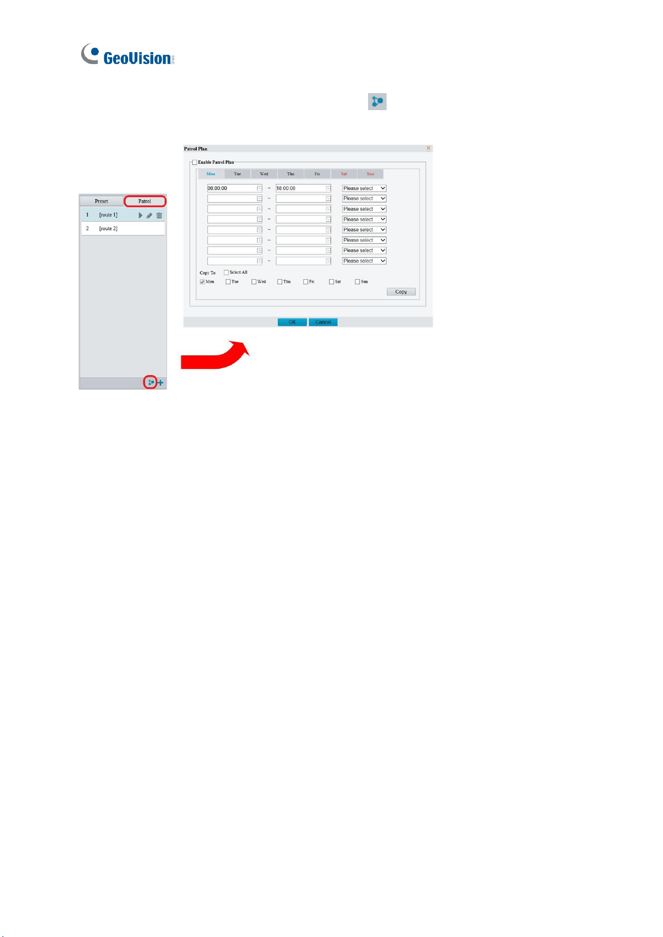
119
1. On the control panel, click the Patrol Plan button to set the correct patrol time and
route.
Figure 2-14
2. Select Enable Patrol Plan.
3. Click OK.
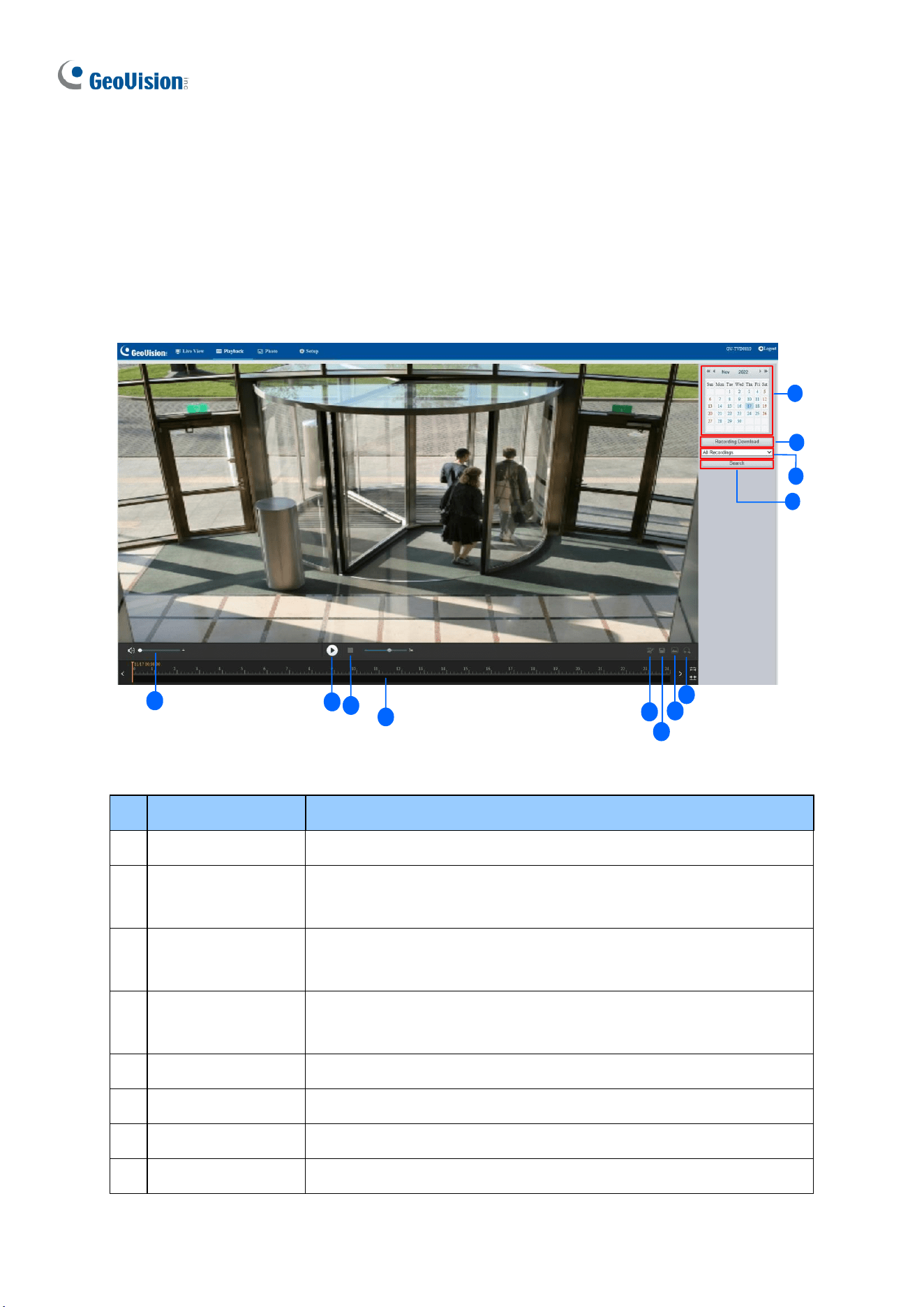
120
2.4 Playing Back Recorded Videos
To play back recorded videos from the camera’s local storage, click Playback at the top of
the Web interface.
Note this function is only applicable to models with a SD card slot for local storage.
5
4
6
9
10
1
2
3
11
12
4
7
8
Figure 2-15
No.
Name
Function
1
Date
Select the date of the video to playback.
2
Recording
Download
Select to download a recorded video from the camera’s local
storage. See 2.4.1 Recording Download for details.
3
Recording Type
Select All Recordings or Alarm Recordings to access and
download the desired recording type.
4
Query/Search
Click Query / Search to show the list of recorded videos of the
date specified.
5
Playback
Play back the recorded video selected.
6
Stop
Stop playback of the recorded video selected.
7
Cut
Cut the clips of the playback recordings.
8
Save
Save the playback recordings.
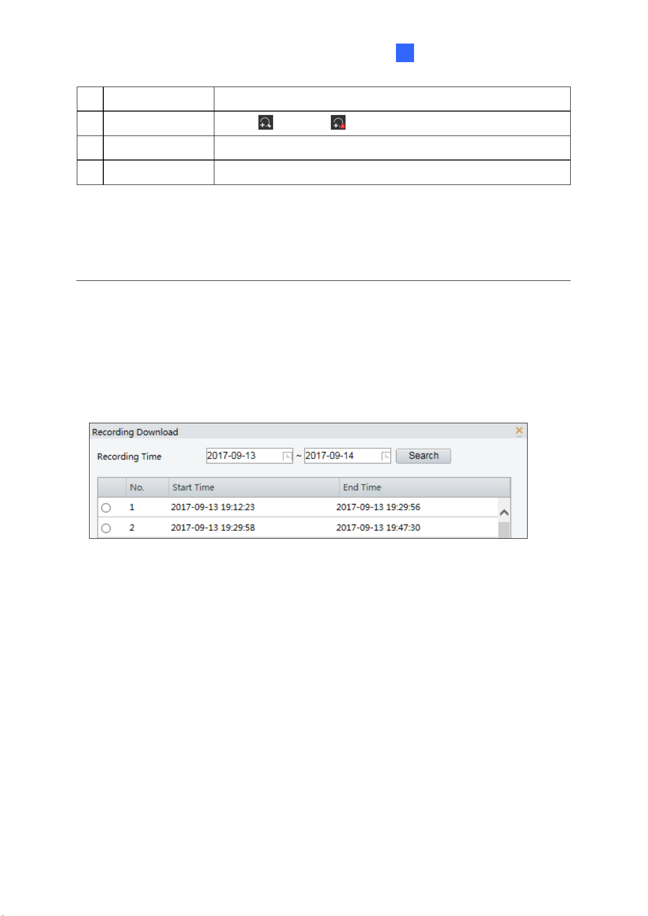
Accessing the Camera
121
2
9
Snapshot
Take a snapshot of the current playback image displayed.
10
Digital Zoom
Enable or disable digital zoom. – See 2.2.1 Digital Zoom.
11
Volume
Adjust the audio output volume on the PC.
12
Timeline
Users can select the desired time to play the recordings.
Note:
1. To store and play back recorded videos to and from the camera’s local storage, make
sure to configure the storage settings in Storage. For details, refer to 3.7.1 Formatting
Storage.
2. The Recording Type option is only available for the models supporting I/O devices.
2.4.1 Recording Download
To download recorded videos from the local storage, follow the steps below:
1. Click Recording Download (No. 2, Figure 2-15) on the right of the Playback window.
Figure 2-16
2. Search for video within a specified time period. The results are shown in a list.
3. Select your video and click Download to download a video to your local path from the
local storage.
4. Click Open to show the folder in which the downloaded videos are saved.
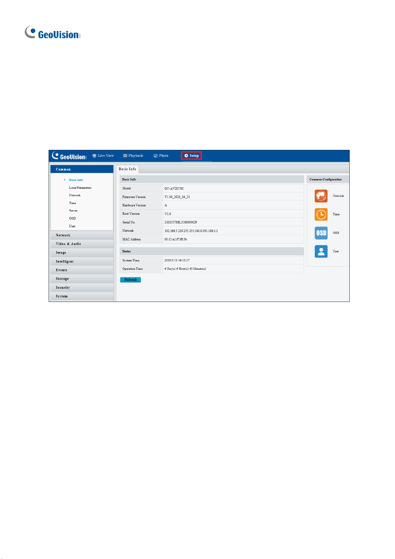
122
Chapter 3 Administrator Mode
The Administrator can access and configure the GV-IP Camera through the network. Click
Setup at the top of the Web interface to access the following configuration tabs: Common,
Network, Video & Audio, Image, Intelligent, Events, Storage, Security, and System.
Figure 3-1

Administrator Mode
123
3
List of Options
See the table below for the settings available on the Web interface. Find the topic of interest
by referring to the section number prefixed to each option.
IMPORTANT: The available functions may differ between camera models and firmware
versions. In addition, based on the model and firmware version, the options in the left-side
menu of the Web interface may be organized into different categories (such as Common,
Network, etc.).
3.1 Common
3.1.1 Basic Info
3.1.2 Local Parameters
3.2 Network
3.2.1 Wired Network
3.2.2 DNS
3.2.3 Port
3.2.4 DDNS
3.2.5 E-mail
3.2.6 SNMP
3.2.7 802.1x
3.2.8 QoS
3.2.9 ONVIF (ANR)
3.2.10 Platform Access
3.3 Video & Audio
3.3.1 Video
3.3.2 Snapshot
3.3.3 Audio
3.3.4 ROI
3.3.5 Media Stream
3.4 PTZ
3.4.1 Basic Settings
3.4.2 Home Position
3.4.3 Limit
3.4.4 Remote Control
3.4.5 Patrol
3.4.6 Orientation
3.5 Image
3.5.1 Image
3.5.2 OSD
3.5.3 Privacy Mask
3.6 Intelligent
3.6.1 Smart Settings
3.6.2 Advanced Settings
3.6.3 Attribute Collection
3.7 Events
3.7.1 Motion Detection
3.7.2 Tampering Alarm
3.7.3 Audio Detection
3.7.4 Alarm Input
124
3.7.5 Alarm Output
3.7.6 One-Key Disarming
3.8 Storage
3.8.1 Formatting Storage
3.8.2 FTP
3.8.3 Backing Up Storage
3.9 Security
3.9.1 User
3.9.2 Network Security
3.10 System
3.10.1 Time
3.10.2 Server
3.10.3 Maintenance
3.10.4 Network Diagnosis
3.10.5 Log
3.10.6 Ports and Devices
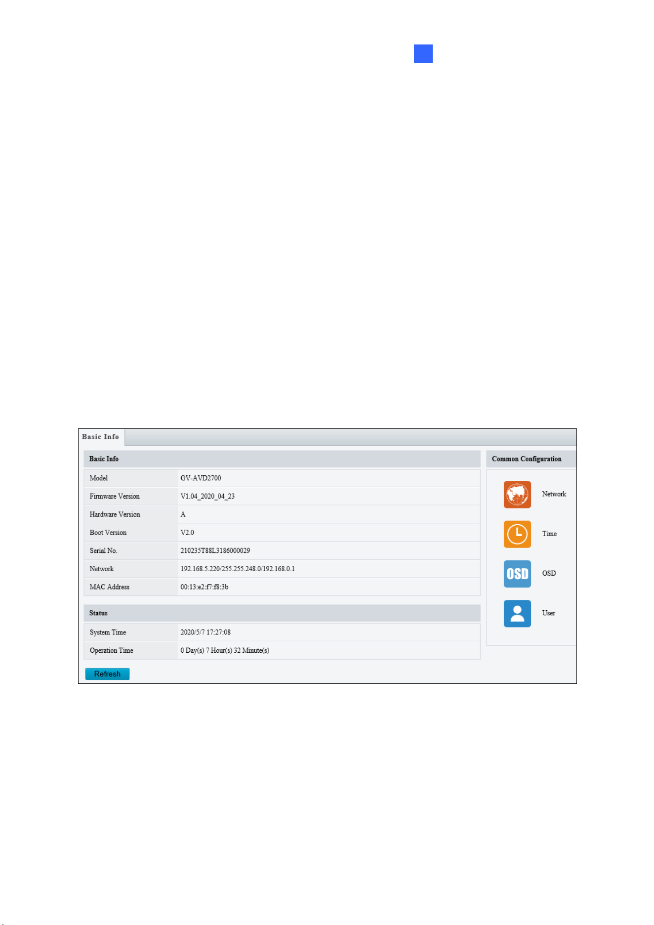
Administrator Mode
125
3
3.1 Common
Under the Common tab, the Administrator can find the general settings of the camera, as
well as shortcuts to the following setting pages.
◼ Network: See 3.2.1 Network for details.
◼ Time: See 3.10.1 Time for details.
◼ OSD: See 3.5.2 OSD for details
◼ User: See 3.9.1 User for details
3.1.1 Basic Info
You can view the current status of your camera. Click Refresh for the latest status
information. Under Common Configuration on the right, you can click on the icons to
quickly access the corresponding configuration pages.
Figure 3-2
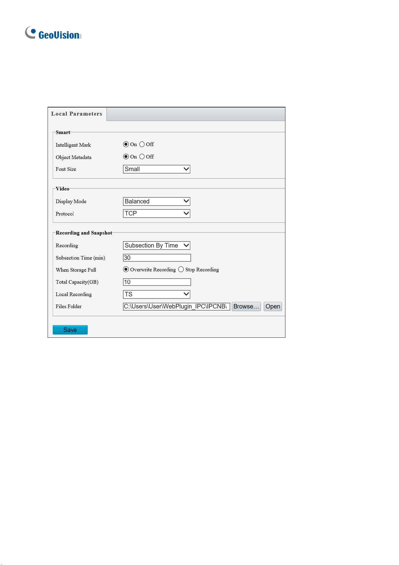
126
3.1.2 Local Parameters
You can set the local parameters for your PC.
Figure 3-3
[Smart / Intelligent Mark]
◼ Intelligent Mark: When enabled, the detection line or area as defined by Smart
Settings will be displayed. See details in 3.6.1 Smart Settings.
◼ Untriggered Target / Target Mark: When enabled, an on-screen mark will display on
the target and track it as defined by Smart Settings on Live View. You must set up
Smart Settings first for this function to work, see 3.6.1 Smart Settings (not applicable to
GV-BLFC5800, EBFC5800, TVD4811, TMS8800 / 20811).
◼ Object Attributes / Object Metadata: When this feature and snapshot are enabled,
snapshot thumbnails will show object attributes (only applicable to GV-EBDP5800 /
8800, TBLP5800 / 8800, TMS20811).
◼ Font Size: Set the font size of object attributes, including Large, Medium, and Small
(only applicable to GV-EBDP5800 / 8800, TBLP5800 / 8800, TMS20811).

Administrator Mode
127
3
Note: The Smart / Intelligent Mark option is not available for GV-ABL2701 series / 2703
series / 4701 series / 4703 / 4711, GV-ADR2701 / 2702 / 4701 / 4702, GV-EBD2704 / 2705 /
4701 / 4702 / 4704 / 4712, GV-TBL2703 series / 2705 / 2706 series / 4700 / 4703 / 4705 /
4711, GV-TDR2702 series / 2704 series / 2705 / 4702 series / 4703 series / 4704 series, GV-
TFD4700, GV-TMS8800, GV-TVD4700 / 4711, and GV-FER5702.
[Video]
◼ Processing Mode
Real-Time Priority: Select this if the network is in good condition.
Fluency Priority: Select this if you want short time lag for live video.
Ultra-low Latency: Select this if you want the minimum time lag for live video.
◼ Display Mode: Set the display mode according to the network status, including Min.
Delay, Balanced Delay, and Fluent Delay for low to high delay. Or customize the
display mode parameters by selecting Customize / Custom.
◼ Protocol: Select the protocol used to transmit media streams to be decoded by the PC,
including TCP and UDP.
[Audio] This function is only applicable to audio-in-supporting models.
◼ Encoding Format: Select the format used to encode audio.
[Recording and Snapshot]
◼ Recording
Subsection by Time (1~60 min): Set a maximum time length of each recording file.
If you select 5 minutes, a 30-minute event will be chopped into six 5-minute event
files.
Subsection by Size: Set a maximum size limit of each recording file.
◼ When Storage Full
Overwrite Recording: When the assigned storage space on the computer is full, the
camera deletes the oldest existing recording files to make room for the new ones.
Stop Recording: When the assigned storage space on the computer is full,
recording stops automatically.
◼ Total Capacity (1~1024 GB): Set a capacity limit to the assigned storage space on the
computer.
◼ Local Recording: Set the file format for saving local recordings, including TS and MP4.
◼ Files Folder: Click Browse to set a folder to store the recorded videos and captured
snapshots at your local computer.
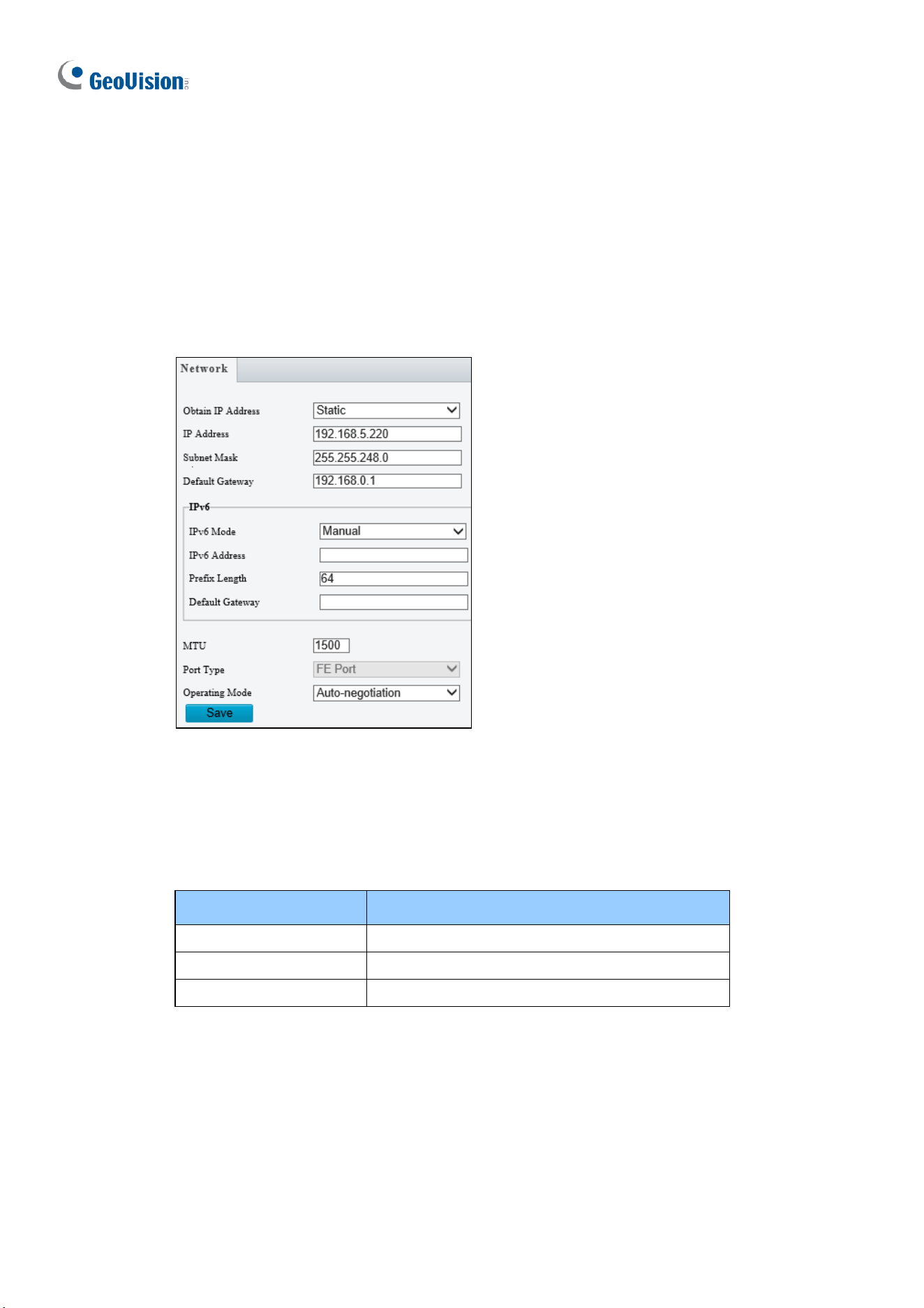
128
3.2 Network
The network section allows you to configure the network settings, modify ports, configure
FTP server, and set up e-mail for notification.
3.2.1 Wired Network
Figure 3-4
◼ Obtain IP Address: Select Static IP, DHCP, or PPPoE according to your network
environment.
Static IP address: Assign a static IP or fixed IP to the camera. Type the camera’s IP
address, Subnet Mask and Router/Gateway.
Parameters
Default
IP address
192.168.0.10
Subnet Mask
255.255.255.0
Router/Gateway
192.168.0.1
PPPoE: The network environment is xDSL connection. Type the Username and
Password provided by ISP to establish the connection. If you use the xDSL
connection with dynamic IP addresses, first use the DDNS function to obtain a
domain name linking to the camera’s changing IP address.
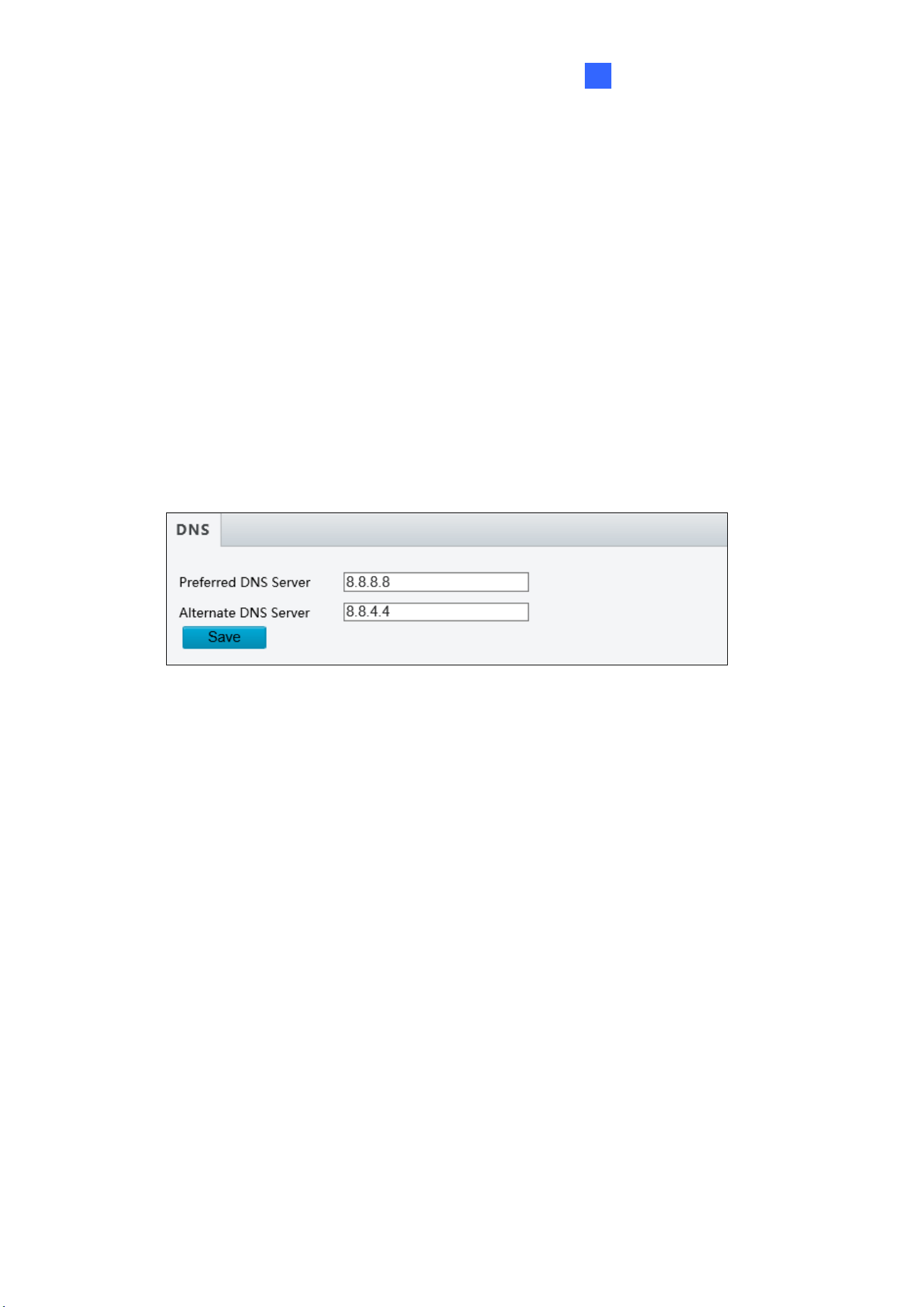
Administrator Mode
129
3
DHCP: The network environment has a DHCP server which will automatically assign
a dynamic IP address to the camera. You can look up the current IP address using
GV-IP Device Utility.
◼ IPv6: Type the camera’s IPv6 Address and Default Gateway. Optionally change the
Prefix Length according to your network settings.
◼ MTU: Type the Maximum Transfer Unit (MTU). The default value is 1500.
◼ Operating Mode: Select a mode to control the bandwidth.
3.2.2 DNS
Type the camera’s Preferred DNS Server and Alternate DNS Server.
Figure 3-5
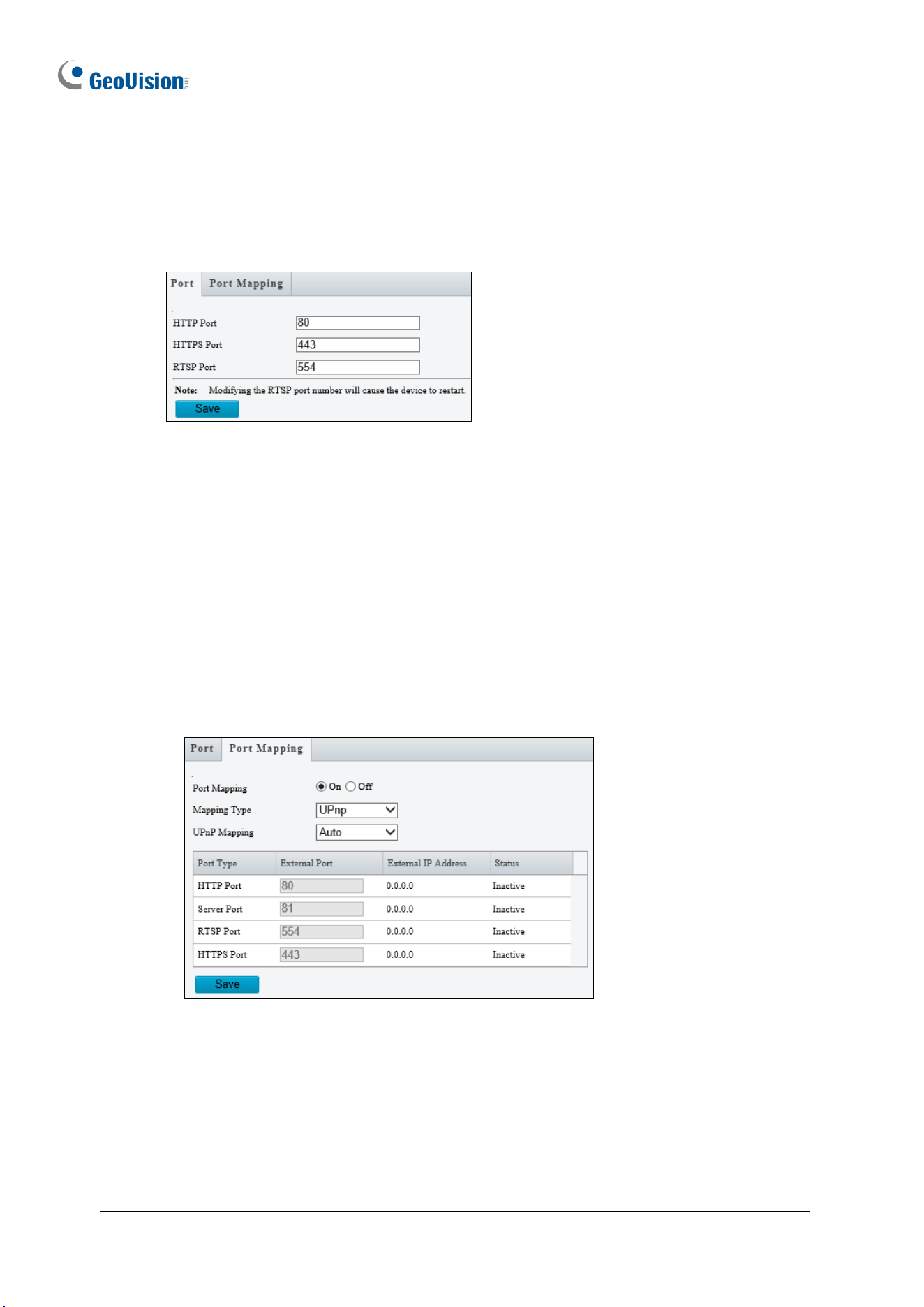
130
3.2.3 Port
Port
You can modify the default HTTP, HTTPS and RTSP ports if necessary.
Figure 3-6
Port Mapping
This function can automatically forward and open certain ports on your router, allowing
connection to your camera from the Internet.
1. Enable Port Mapping, and select UPnP or Manual for Mapping Type.
• If you select UPnP, select between Auto and Manual to have the router
automatically configure the external ports or manually configure the external ports.
If the configured port is occupied, the Status will show inactive.
Figure 3-7
• If you select Manual, configure external ports. External IP is applied to the camera
automatically.
2. Click Save.
Note: For this function to work, your router needs to support port forwarding.
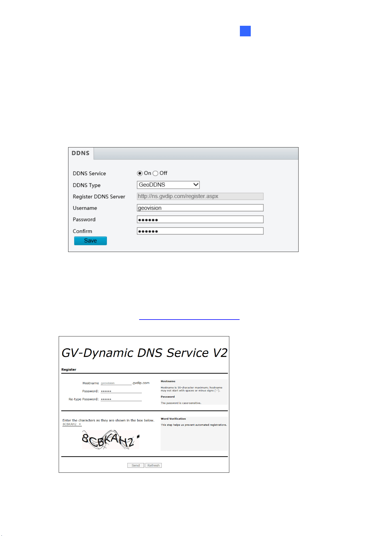
Administrator Mode
131
3
3.2.4 DDNS
DDNS (Dynamic Domain Name System) provides a convenient way of accessing the camera
when using a dynamic IP. DDNS assigns a domain name to the camera, so that the
Administrator does not need to go through the trouble of checking if the IP address assigned
by DHCP Server or ISP (in xDSL connection) has changed.
Figure 3-8
1. Click On to enable DDNS Service.
2. Select the DDNS service provider you have registered with. If you choose DynDNS, skip
to Step 5.
3. Copy the website address http://ns.gvdip.com/register.aspx to a browser to access
Geovision DDNS service.
Figure 3-9
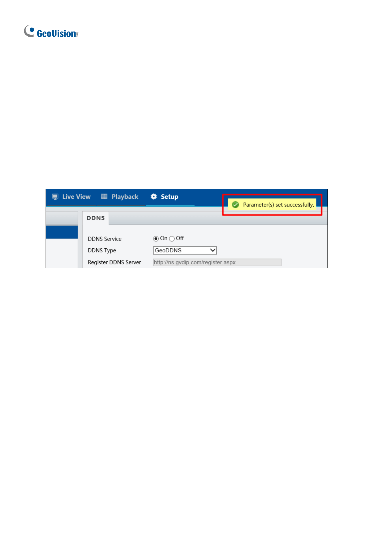
132
4. In the Geovision DDNS Server page, type a desired Hostname and Password. Re-type
Password and type the verification letters shown in the image. Click Send.
5. In the Web interface of your camera, type Username. The username is the hostname
registered in DDNS Server.
6. Type Password, and Confirm Password.
7. Click Save.
After the DDNS is successfully configured, a notification bar will be displayed as shown in
Figure 3-10. Next time when you log in the camera, type the domain name like this:
(hostname).gvdip.com; for example, geovision.gvdip.com.
Figure 3-10
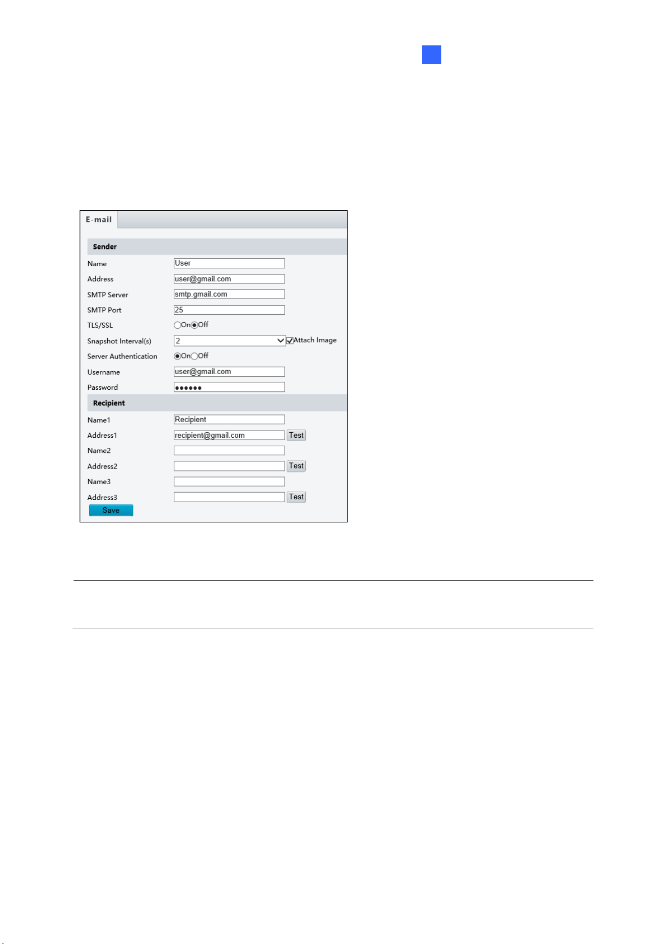
Administrator Mode
133
3
3.2.5 E-mail
After the configuration of E-mail, you will be able to send messages to the specified E-mail
addresses when alarms are triggered.
Figure 3-11
1. Type the Name and Address of the
sender.
2. Type the SMTP Server.
3. Type the SMTP Port number.
4. To send the e-mail through TLS /
SSL encryption, enable TLS/SSL.
5. Enable Attach Image to include 3
instant snapshots as attachment in
the e-mail according to the
Snapshot Interval specified.
6. If the SMTP Server needs
authentication, enable Server
Authentication and type a valid
username and password to log in the
SMTP server.
7. Type the name(s) and e-mail
address(s) of the Recipient(s).
8. Click Save.
Note: To send snapshots to the specified E-mail addresses, make sure to enable the
Snapshot function. For more detailed instructions, refer to 3.3.2 Snapshot.
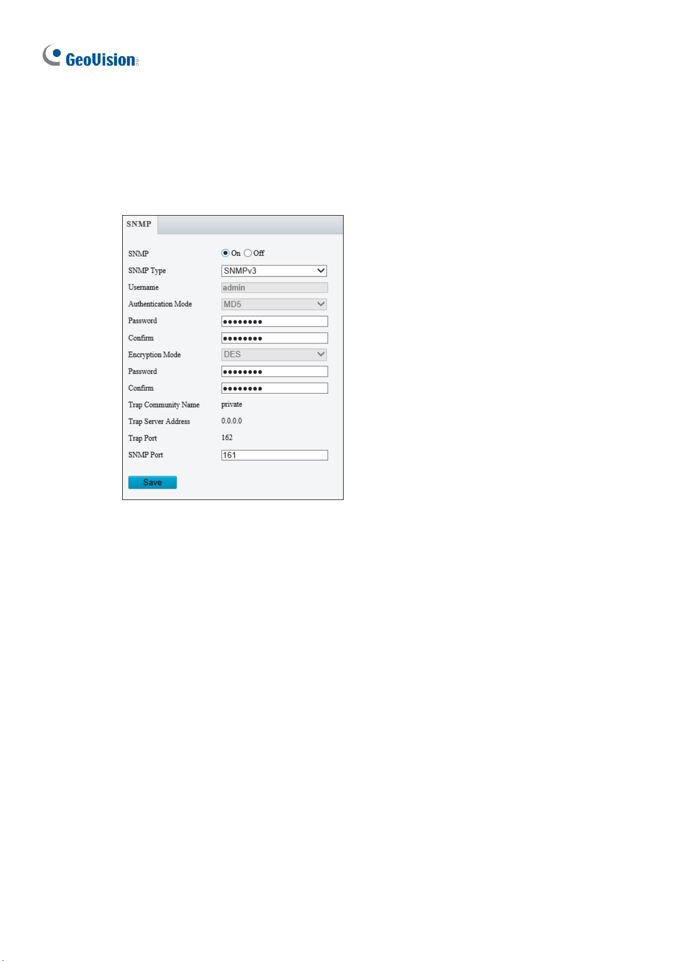
134
3.2.6 SNMP
Users can transfer the configurations of the device through SNMP protocol to communicate
with and/or integrate it into a central server.
Figure 3-12
◼ SNMP Switch: Select On to enable the SNMP function.
◼ SNMP Type: Select the type of SNMP desired, between SNMPv3 and SNMPv2.
◼ Authentication Mode: Define a desired password for authentication between the device
and the central server.
◼ Encryption Mode: Define a desired password for encryption that needs to be matched
by the central server.
Click Save for the changes to take effect.
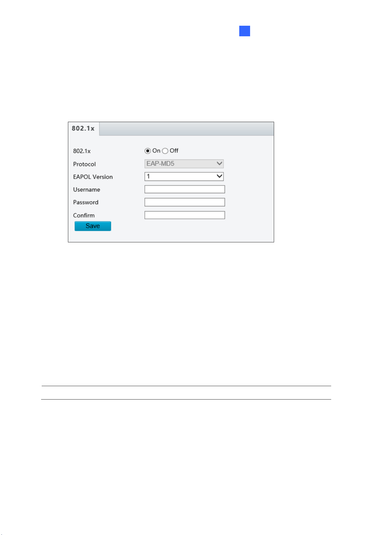
Administrator Mode
135
3
3.2.7 802.1x
IEEE 802.1x is an IEEE standard for port-based Network Access Control. It provides an
authentication mechanism to devices wishing to attach to a LAN or WLAN.
Figure 3-13
1. Enable IEEE 802.1x.
2. Select a Protocol from the drop-down list. Options include EAP-MD5 and EAP-TLS
(EAP-TLS is only available for GV-BLFC5800 / EBD4704 / EBD4813 / EBFC5800 /
TBL4705 / TBL4807 / TBL4810 / TDR4704 / TDR4803 / TFD4800 / TVD4810 / TVD4811
and GV-EBD8800 / EBD8813 / EBDP5800 / FER5702 / TBL8804 / TBL8810 / TBLP5800
/ TDR8805 / TVD8810 and GV-TMS8800 and GV-PTZ5810-IR).
3. Type the Username and Password. Type the password again for confirmation.
4. Click Save.
Note: To use this function, your network environment needs to support 802.1x.
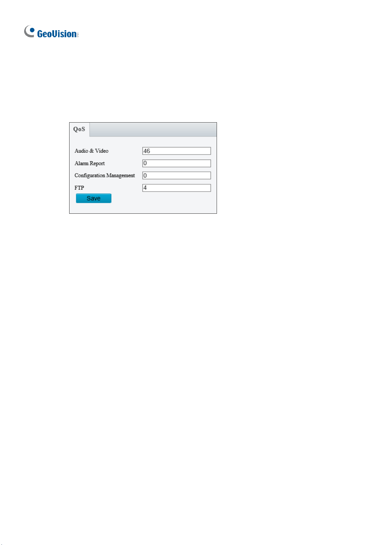
136
3.2.8 QoS
QoS is the prioritization of network traffic used to ensure resource reservation under
abundant data flow.
Figure 3-14
◼ Audio & Video: Optionally modify the priority of value of Audio & Video. The higher the
value, the higher the priority.
◼ Alarm Report: Optionally modify the priority of value for Alarm Report. The higher the
value, the higher the priority.
◼ Configuration Management: Optionally modify the priority for Configuration Manager.
The higher the value, the higher the priority.
◼ FTP: Optionally modify the priority of value for FTP. The higher the value, the higher the
priority.
Click Save the apply the QoS settings configured.
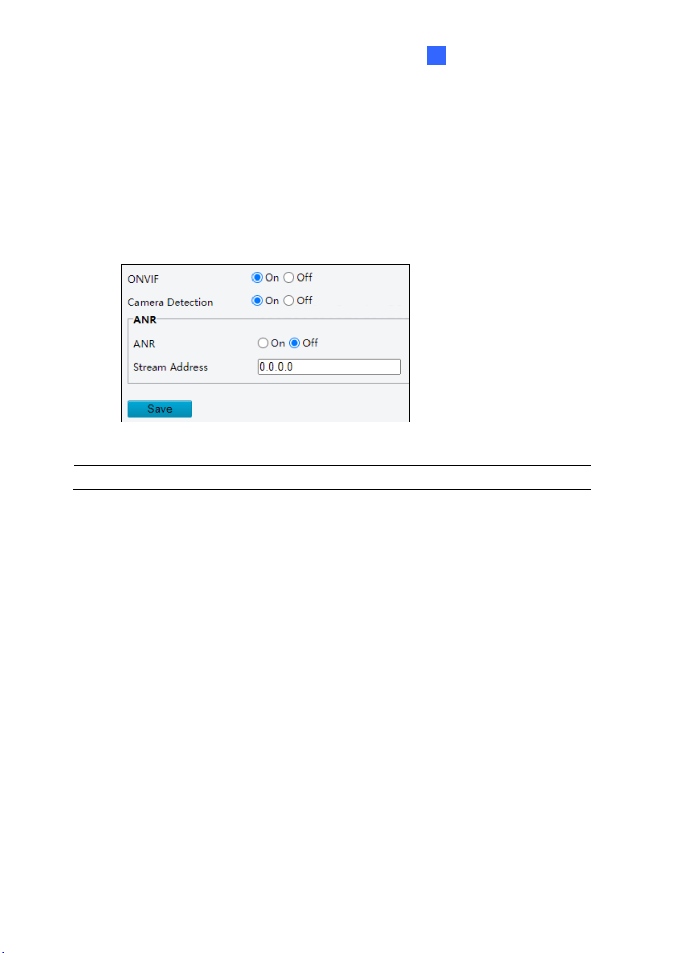
Administrator Mode
137
3
3.2.9 ONVIF (ANR)
If the network connection between the camera and the stream receiving address is
disconnected, the camera can store videos; and after the network connection is restored, the
camera can retransfer the video stored during the interruption period to the stream receiving
address.
Figure 3-15
Note: The ANR functionality is only applicable to GV-TMS20811.
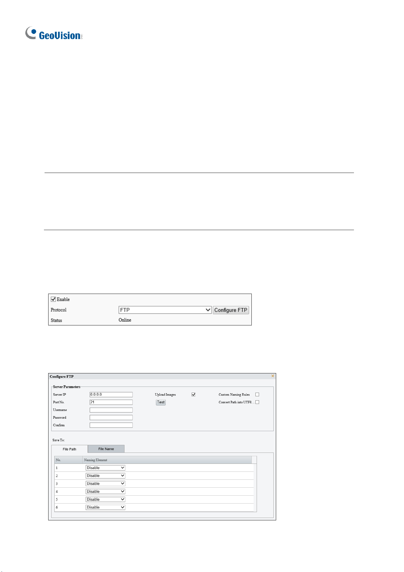
138
3.2.10 Platform Access
3.2.10.1 Server
Configure to receive smart snapshots from the camera. A camera can be managed by two
intelligent servers. Local snapshot cannot be enabled when the number of subscriptions has
reached the upper limit.
If local snapshot has been enabled, when the number of subscriptions reaches the upper
limit, higher-priority subscriptions will take precedence, and local snapshot will be disabled.
Note:
1. This function is only applicable to GV-TMS20811.
2. The number of subscriptions supported may vary with camera.
2. Priority level of subscription from different platforms: Platform 1 > Platform 2 > LAPI
subscription > WebSocket subscription.
⚫ FTP
1. Go to Setup > Network > Platform Access > Server.
2. Select the Enable checkbox.
3. Choose FTP as the protocol.
Figure 3-16
4. Click Configure FTP. A page as shown below appears.

Administrator Mode
139
3
Figure 3-17
140
5. Set server parameters.
Item
Description
Server IP
Enter the IP address of the FTP server.
Port No.
Use the default 21.
Username
Enter the username used for accessing the FTP server.
Password
Enter the password used for accessing the FTP server.
Test
Click to test the connection to the FTP server.
Upload Images
Select the checkbox to enable uploading smart snapshots.
Overwrite Storage: After the number of photos in the lowest-level folder reaches the
set threshold, new photos will overwrite older photos in the folder. For example, the
storage path is “\IP\date”, the lowest-level folder is the level-2 folder named “date”.
When the number of photos uploaded on Jan. 4, 2022 reaches 1000 (default value),
new photos overwrite old photos in the 20220104 folder.
NOTE!
To choose Overwrite Storage, make sure the last naming element of the files is the
image sequence number.
Overwrite At (image): The default is 1,000, up to 100,000 is allowed.
Custom Naming Rule
Select the checkbox, and then you can customize the file naming rules as needed. For
the naming rules, see
File Path
in step 6.
Convert Path into
UTF8
Select the checkbox, and the path will be converted into UTF8 format.
6. Configure the image storage path.
Item
Description
File Path
Six levels are allowed. If not set, the default path “\IP\Date\Intelligent” will be used,
where “Intelligent” means smart snapshots.
File Name
Naming element: Up to 20 fields are allowed. If not set, sequence numbers will be used
as file names, for example, “1, 2, 3”, etc.
Naming rule: Format string: prefix <(front string) front length % > suffix.
7. Click Save.
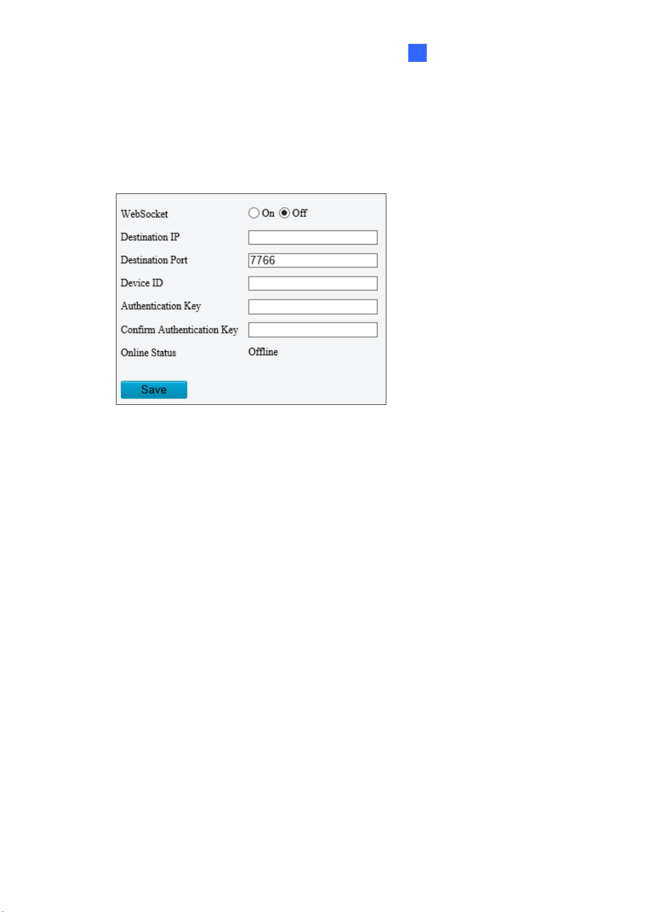
Administrator Mode
141
3
3.2.10.2 WebSocket
WebSocket can connect your camera to a third-party platform and enable remote
management of the camera from the third-party platform, including viewing device version
and capabilities, control PTZ, and receive alarms.
Figure 3-18
◼ WebSocket: Select to enable or disable WebSocket.
◼ Destination IP: Enter the IP address of the third-party platform.
◼ Destination Port: Enter the listener port of the third-party platform.
◼ Device ID: The default device ID is the device’s serial number. You can set a device ID
as needed.
◼ Authentication Key: Enter the authentication key used to connect the camera to the
third-party platform. Make sure the authentication keys configured on the camera and the
third-party platform are the same. Note if you first choose not to enable Authentication
Key and then enable it after the camera is connected to the platform, authentication does
not take effect immediately; it will take effect when the next time the camera is
successfully connected to the platform.
◼ Confirm Authentication Key: Confirm the authentication key by entering it again.
◼ Online Status: Check whether the device is successfully connected to the third-party
platform.
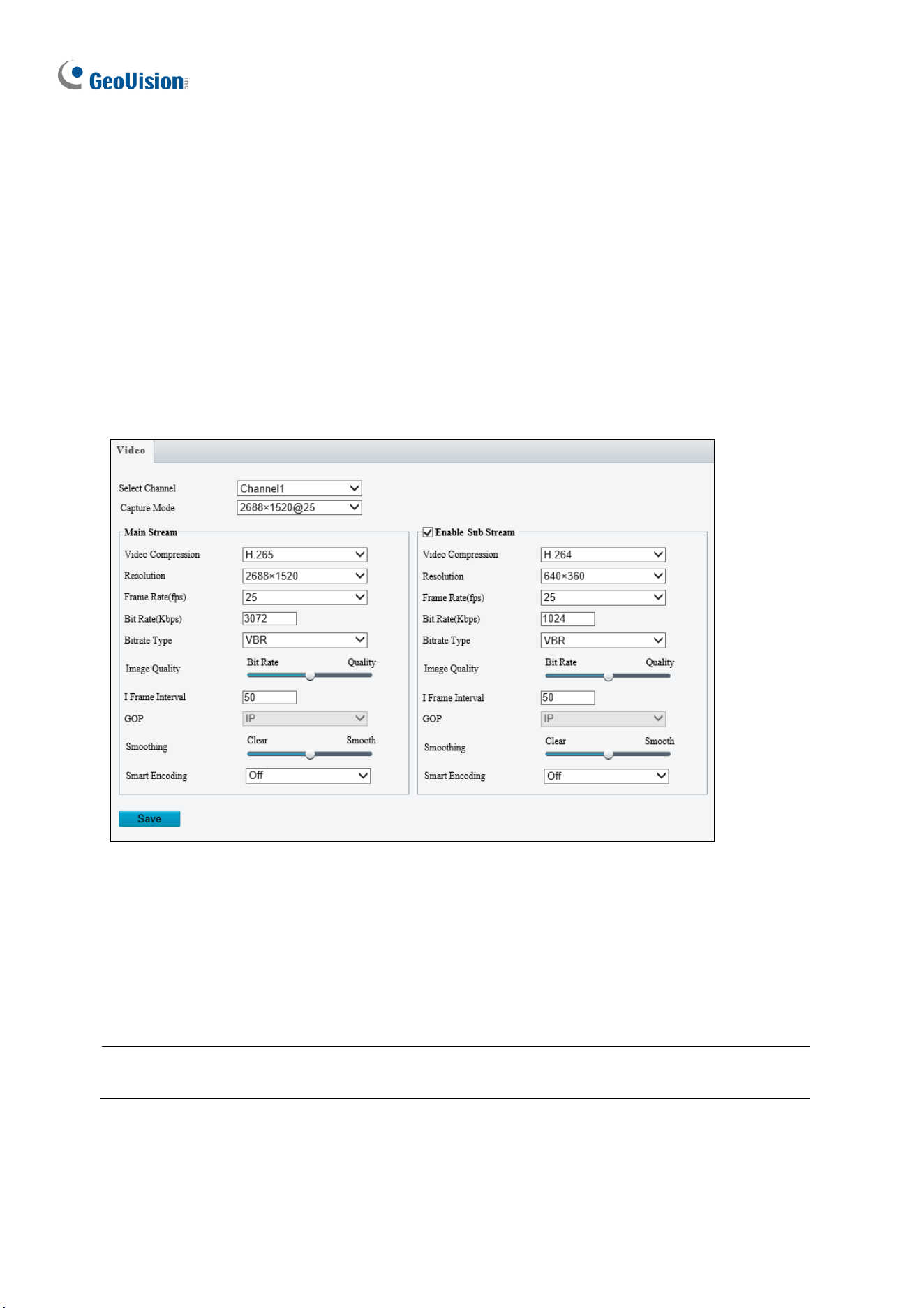
142
3.3 Video & Audio
This section allows you to configure the three video streams and audio input.
The audio function is only applicable to audio-supporting models
3.3.1 Video
You can set video parameters that your camera supports. You may also enable the sub-
stream and third stream as needed. The third stream is disabled by default.
Figure 3-16
◼ Select Channel: Select the desired channel for video parameters configuration. Note
this is only applicable to GV-TMS8800 / 20811.
◼ Capture Mode: Sets the resolution of Main Stream and the maximum frame rate
allowed.
Note: The Resolution under Main Stream will change according to the resolution selected
for Capture Mode.
The following options are available for the main, sub, and third streams.
◼ Video Compression: Set the codec type to H.265, H.264 or MJPEG.
◼ Resolution: Select different resolutions for each stream.

Administrator Mode
143
3
Note:
1. Changing the resolution in this option will not affect the Capture Mode.
2. For GV-ABL4711, GV-EBD4701 / 4712, GV-TBL4700 / 4711, GV-TDR4703 series,
GV-TFD4700, and GV-TVD4700 / 4711, the resolution of the main stream cannot be
modified.
◼ Frame Rate: Select a frame rate for encoding images. The unit is frame per second.
◼ Bit Rate: Set the value between 128~16384.
◼ Bitrate Type:
CBR: The camera transmits data at a constant data rate by varying the quality of the
video stream.
VBR: The quality of the video stream is kept as constant as possible at the cost of a
varying bitrate.
◼ Image Quality: When VBR is selected for the encoding mode, you can move the slider
to adjust the desired quality level the for images. Moving the slider toward Bit Rate
decreases the bit rate and may affect image quality. Moving the slider toward Quality
increases the bit rate and improves image quality.
◼ I Frame Interval: Set the number of frames, from 5 to 250, between each I frame (key
frame). This option is only available when H.265 or H.264 is selected as the codec.
◼ GOP: The GOP is IP by default.
◼ Smoothing: Set the extent of smoothing. Choosing Clear means disabling Smoothing.
Moving the slider toward Smooth increases the level of smoothing but will affect image
quality.
◼ Smart Encoding: Select Basic Mode to enable Smart Encoding.
[BNC Output] Only for GV-AVD2700 / 4710 / 8710, GV-ABL8712 and GV-TBL8710, the
status of the BNC device is shown.
◼ Mode: Set the signal format of the video output to either NTSC or PAL.
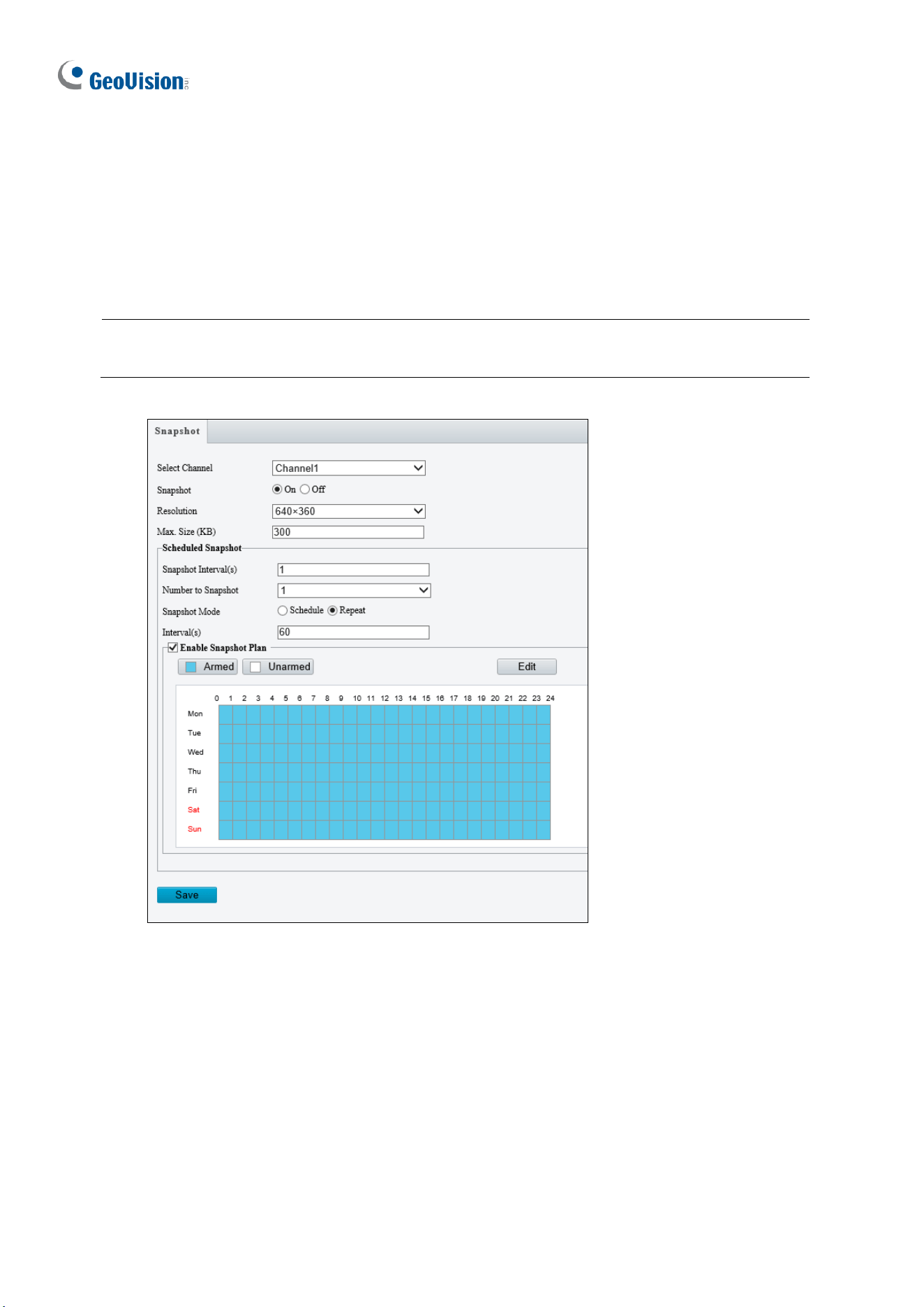
144
3.3.2 Snapshot
Using the Snapshot function, when an alarm is triggered, the camera will automatically
upload the captured snapshots to the FTP server and/or send snapshots to the specified e-
mail addresses.
Note: If Upload Images is selected in Figure 3-67, 3.8.2 FTP, the captured snapshots will
only be sent to the FTP server.
Figure 3-17
1. Select the desired channel from the Select Channel dropdown list (only applicable to
GV-TMS8800 / 20811).
2. Select On to enable Snapshot.
3. Select the Resolution.
4. Specify the maximum size (250~1500 KB) of the snapshot image for Max. Size (KB).
5. Specify the length of interval (1~60 sec) between snapshots for Snapshot Interval(s).

Administrator Mode
145
3
6. Choose the Number (of snapshot) to Snapshot upon alarm trigger.
7. Select Schedule or Repeat to set up the Snapshot Mode.
• If you select Schedule, click to specify the desired time to take a snapshot.
• If you select Repeat, type the interval, from 1 to 86400 seconds, to repeat the
process of taking snapshots and sending them to the FTP server or e-mail.
8. Click Save.
9. For Snapshot Plan, follow Step 7 at the bottom of 3.6.1.1 Cross Line.
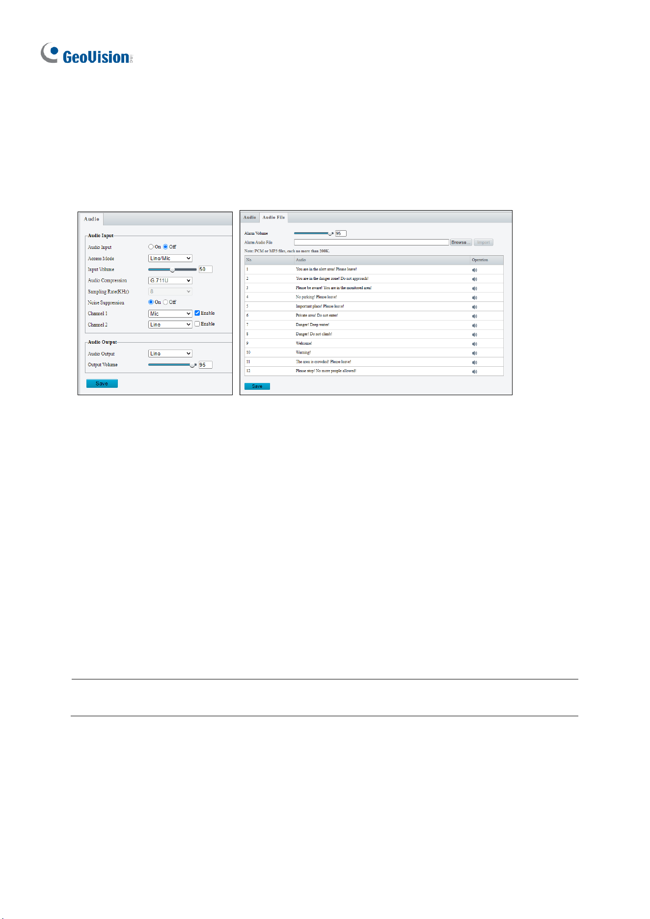
146
3.3.3 Audio
Note this function is only applicable to audio-supporting models.
You can configure the audio settings of the camera.
Figure 3-18
◼ Audio Input: Select On to enable audio input.
◼ Input Volume: Set the audio signal amplification for sampling. The greater the volume,
the greater amplification.
◼ Audio Compression: Select an audio codec.
◼ Noise Suppression: Select On to reduce the noise of the audio.
◼ Channel 1 / 2: Click Enable to enable audio in through the camera’s built-in microphone
and/or Audio In wire(s) depending on the model.
◼ Audio Output: Select the source of audio output.
◼ Output Volume: Set the volume for audio output.
◼ Alarm Audio File: For GV-TBL8804 and PTZ5810-IR only, select Browse to locate a
custom PCM / .mp3 audio file, and click Import.
Note: Connection(s) to any software/application must be reestablished when the camera’s
audio input channel has been alternated for the change to take effect.
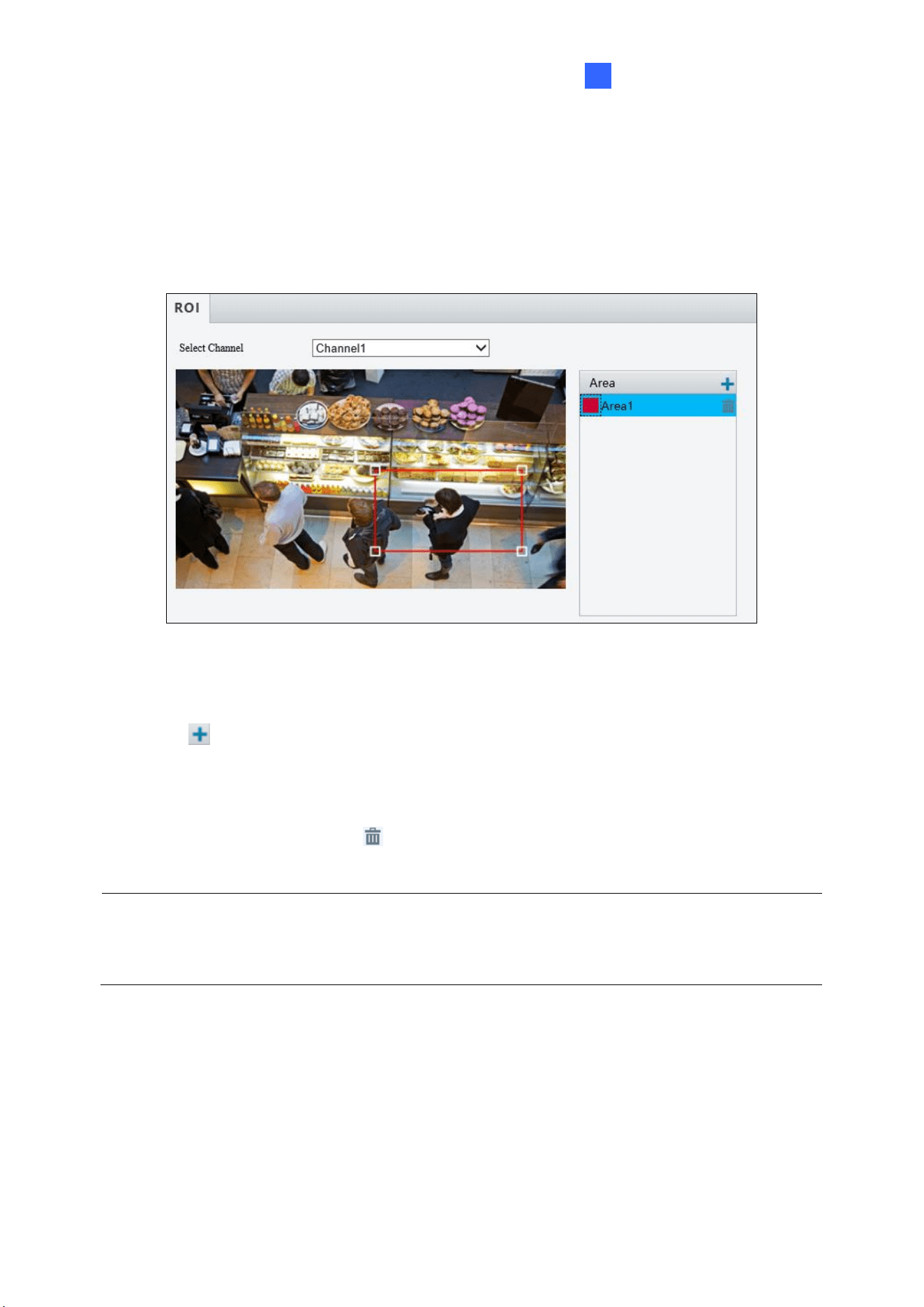
Administrator Mode
147
3
3.3.4 ROI
When Region of Interest (ROI) is enabled, the system ensures image quality for ROI first if
the bit rate is insufficient.
Figure 3-19
1. Select the desired channel from the Select Channel dropdown list (only applicable to
GV-TMS8800 / 20811).
2. Click to enable and add ROI.
3. Click and drag on the image to specify an area.
4. To add additional ROI areas, repeat steps 1 and 2.
5. To delete an ROI area, click .
Note: Up to two ROI areas can be specified for GV-ABL2703 series / 4703, GV-ADR2702 /
4702, GV-TBL2703 series / 4703 and GV-TDR2702 series / 4702 series, four for GV-
ABL4711, GV-EBD4701 / 4712, GV-TBL4711, GV-TDR4703 series, GV-TFD4700, and GV-
TVD4711, and eight for all other models.
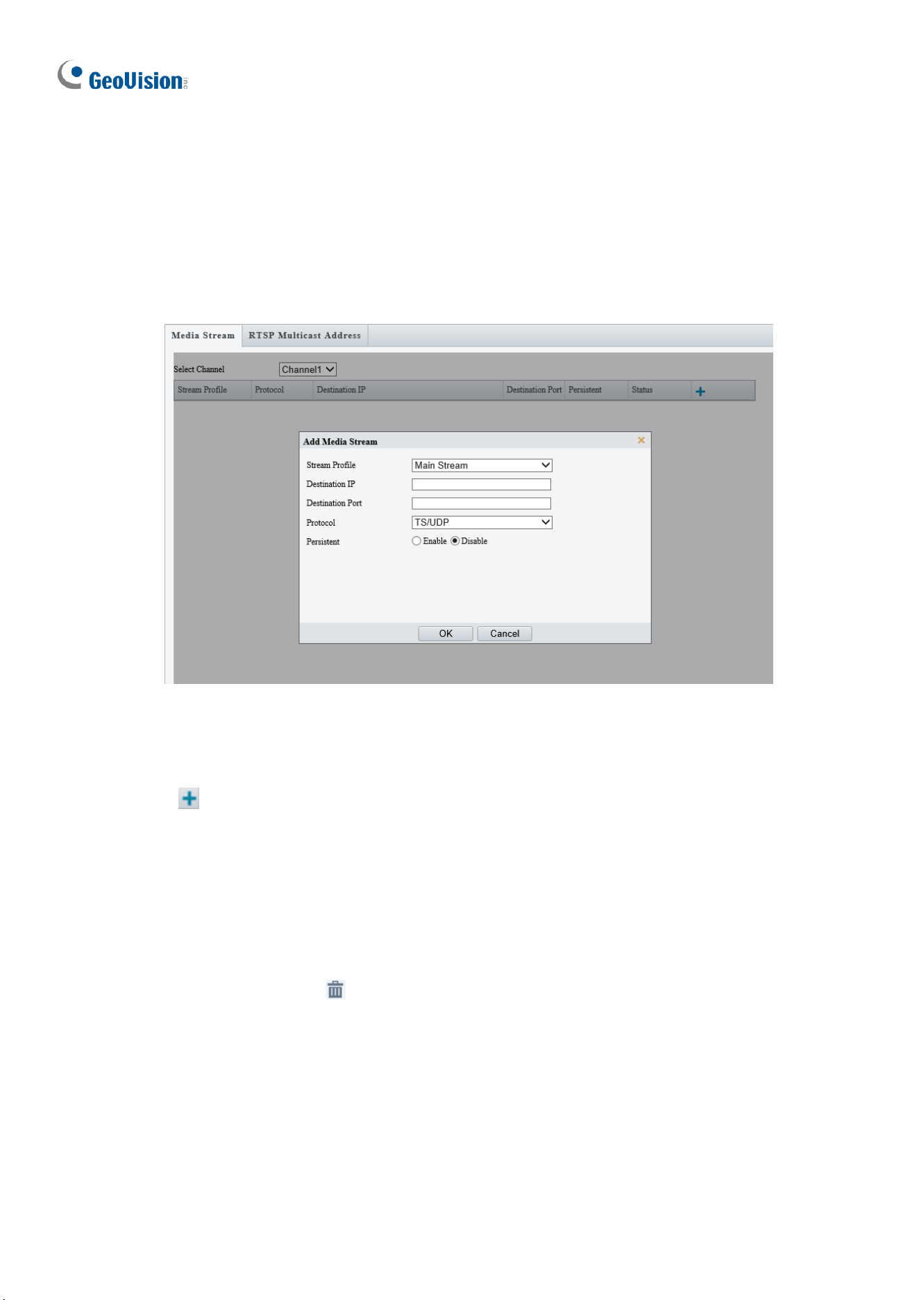
148
3.3.5 Media Stream
Media Stream
By configuring media stream, you can set the camera to transmit code streams by UDP or
TCP protocol to a specified IP address and port number. The settings can be saved and take
effect after the camera is rebooted.
Figure 3-20
1. Select the desired channel from the Select Channel dropdown list (only applicable to
GV-TMS8800 / 20811).
2. Click and select a stream from the Stream Profile drop-down list.
3. Type the Destination IP and Port number of the unicast or multicast group for the
decoding device that receives video streams from the camera.
4. Select a Protocol type for the media stream, including RTMP.
5. If you want the device to automatically establish the media stream that has been
previously configured after the restart, Enable Persistent.
6. To delete a stream, click .
7. Click OK to complete the settings.
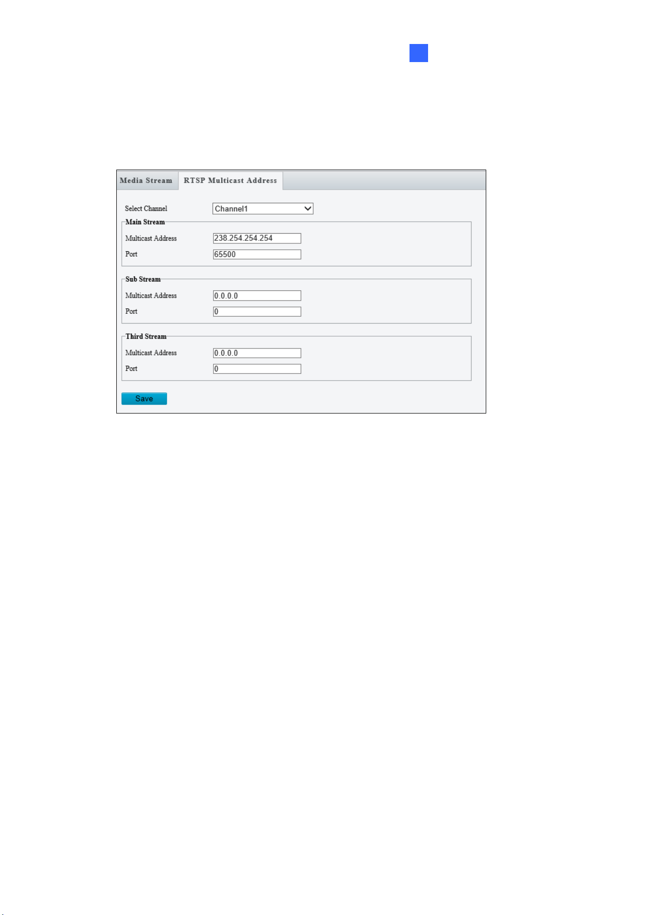
Administrator Mode
149
3
RTSP Multicast Address
After an RTSP multicast address is configured, the third-party player can request for the
RTSP multicast media stream from the camera through RTSP protocol.
Figure 3-21
1. Select the desired channel from the Select Channel dropdown list (only applicable to
GV-TMS8800 / 20811).
2. Type the Multicast Address (224.0.1.0 to 239.255.255.255) and Port number (0 to
65535).
3. Click Save.
For RTSP Multicast command, see Appendix A.
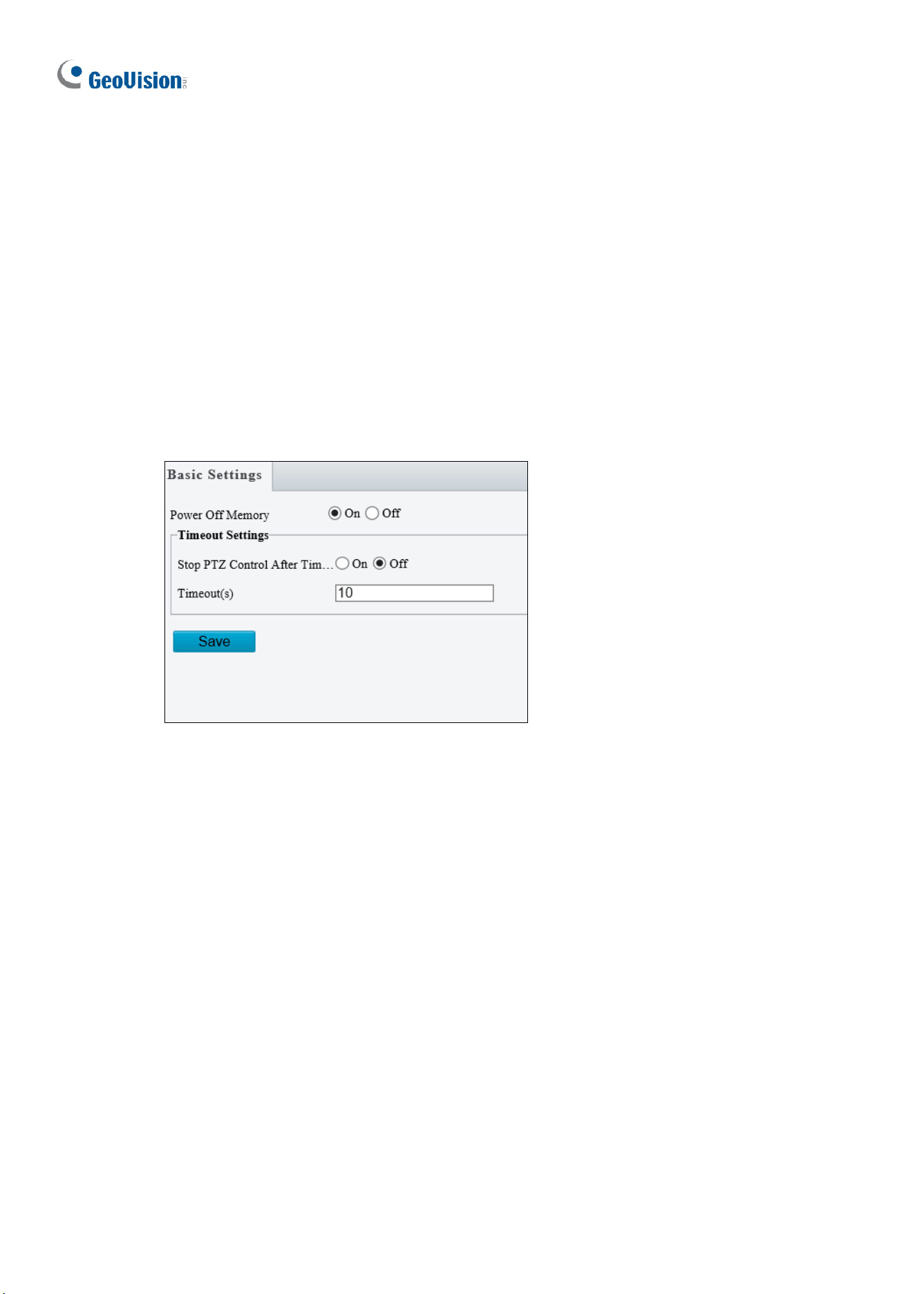
150
3.4 PTZ
This section allows you to configure basic PTZ settings, home position, remote control,
orientation and more on the PTZ camera.
Note that this is only applicable to GV-PTZ5810-IR.
3.4.1 Basic Settings
Basic settings allows you to configure basic PTZ settings related to the camera’s position
and PTZ control timeout.
Figure 3-22
[Power Off Memory] Select On to enable this function. When restarted, the camera returns
to the position before it’s powered off.
[Timeout Settings] Select On and set the timeout duration. PTZ control is disabled after the
set timeout duration.
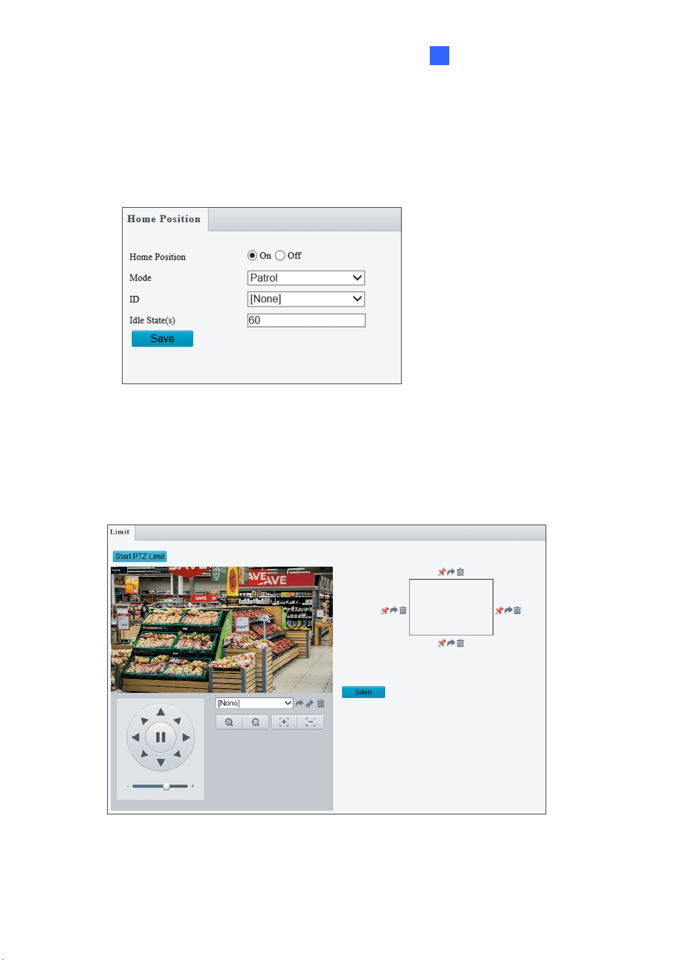
Administrator Mode
151
3
3.4.2 Home Position
The PTZ camera will return to home position if no operation is made within a specified period.
Home Position allows you to select the desired preset as the home position and set the time.
Figure 3-23
3.4.3 Limit
Users can set PTZ limitations to prevent the camera from hitting obstacles such as walls.
Figure 3-24
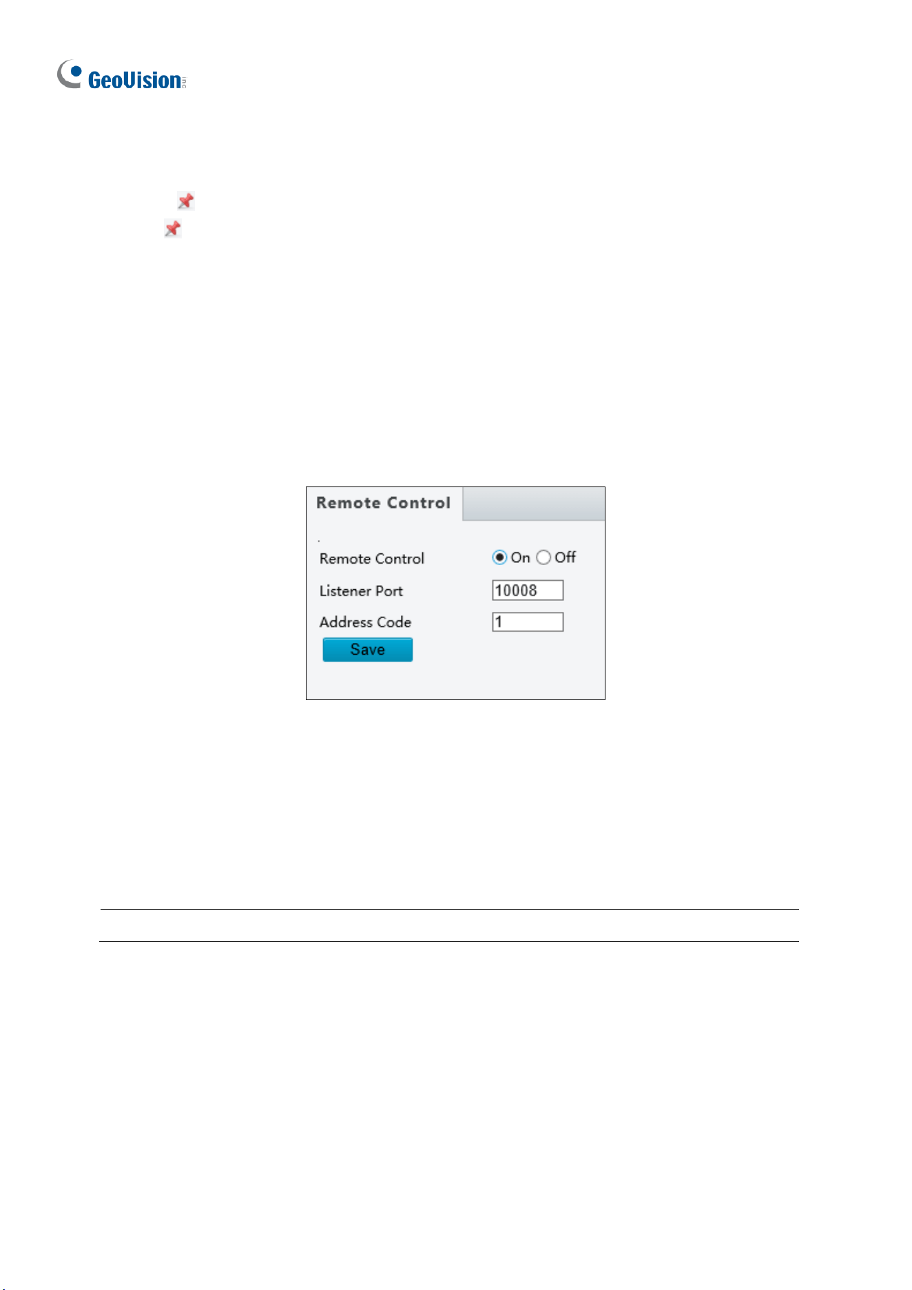
152
1. Click Start PTZ Limit to enable the function.
2. Adjust the view in such a way that it reaches the PTZ limit you want to set.
3. Click to set the position relative to the current dome view as a limit. For example, click
the at the top to set the upper limit.
4. Repeat Step 2 & 3 to set all limits as needed and click Save.
3.4.4 Remote Control
You can connect a third-party PTZ remote control program to your GV-IR IP Mini PTZ
Camera once this function is enabled.
Figure 3-25
1. Specify the Listener Port to which the third-party PTZ remote control program connects.
2. Assign an individual Address Code (between 0 ~ 255) to each PTZ remote control
program
3. Click Save.
Note: To use this function, your router needs to support port forwarding.
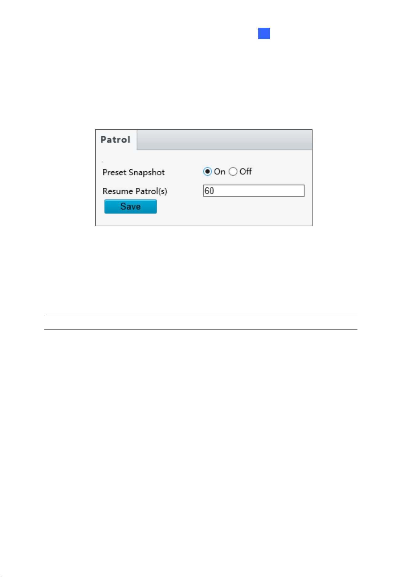
Administrator Mode
153
3
3.4.5 Patrol
You can set the camera to take a snapshot and upload the image to the FTP server when
the camera goes to the preset during the patrol route.
Figure 3-26
1. Enable Preset Snapshot.
2. Type the Resume Patrol(s) interval in seconds to upload snapshots.
3. Click Save.
Note: To use this function, make sure to configure the settings in 3.8.2 FTP first.
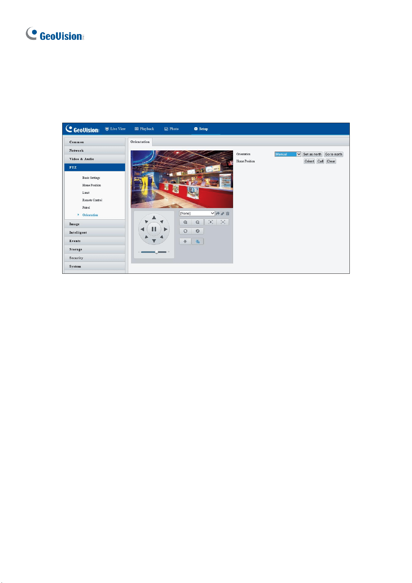
154
3.4.6 Orientation
You can manually set a north direction or home position for the camera.
Figure 3-27
[Orientation]
◼ Set as north: After the camera is positioned to a specific direction, the position will be
set as the north direction.
◼ Go to north: The camera will move to the specified north direction no matter which
direction it points to.
[Home Position]
◼ Orient: Click Orient to set a position as the home position.
◼ Call: Click Call to move the camera to the specified home position no matter which
direction it points to.
◼ Clear: Click Clear to delete the home position.
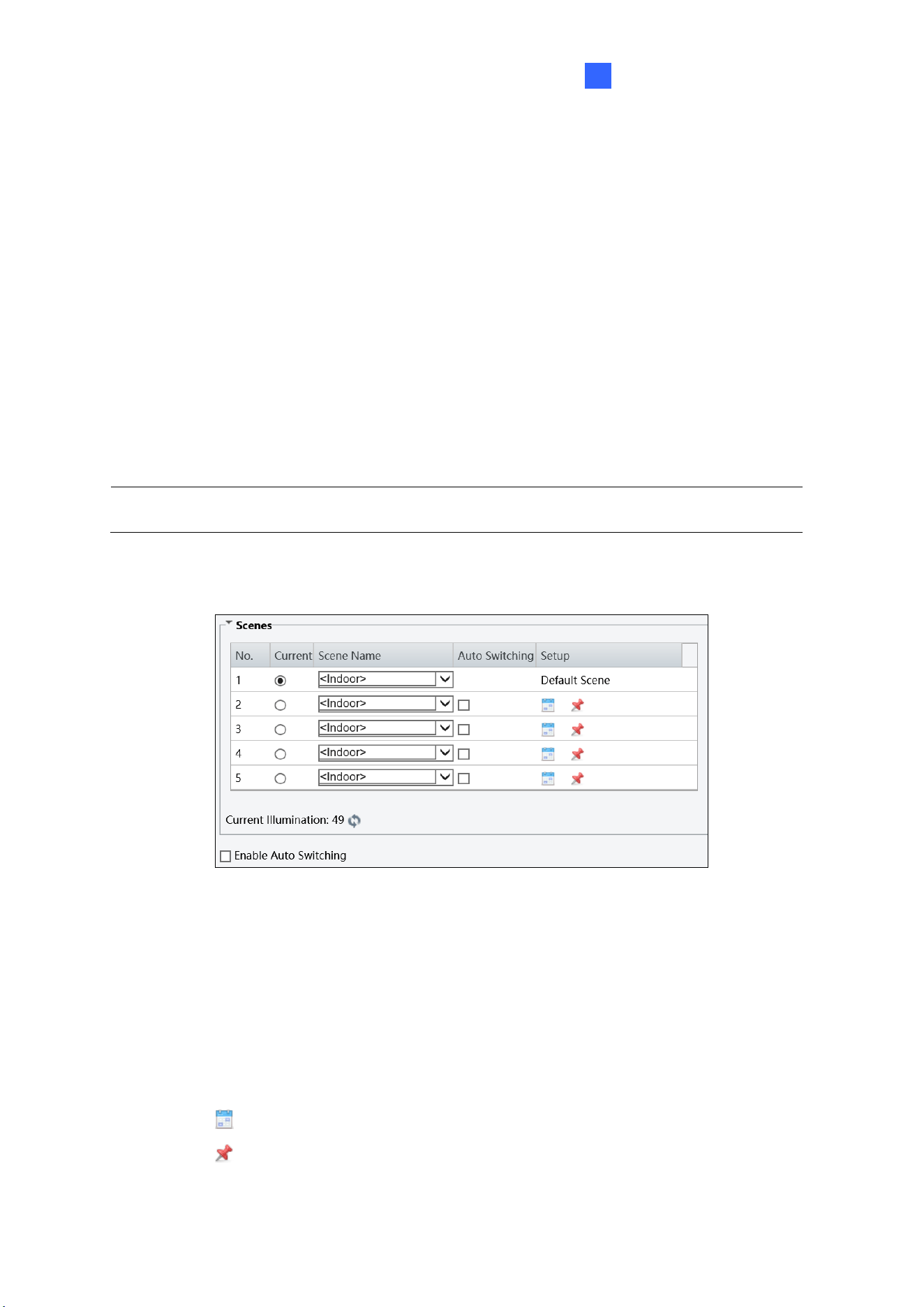
Administrator Mode
155
3
3.5 Image
This section introduces the Image Settings, On-screen Display, and Privacy Mask.
3.5.1 Image
3.5.1.1 Image
Go to Setup > Image > Image > Image.
This page allows you to adjust image settings such as brightness, exposure, IR illumination,
white balance, and focus.
Note: Make sure to select the desired channel for configuration before proceeding with
the following items for GV-TMS8800 / 20811.
[Scene]
Figure 3-28
◼ Current: Indicates the scene that is being used.
◼ Scene Name: When you select a scene, the corresponding image parameters are
displayed. You can adjust the image settings according to actual needs.
◼ Auto Switching: Indicates whether to add a scene to the auto-switching list.
◼ Setup:
⚫ Click to set a schedule for illumination.
⚫ Click to set a scene as the default scene.
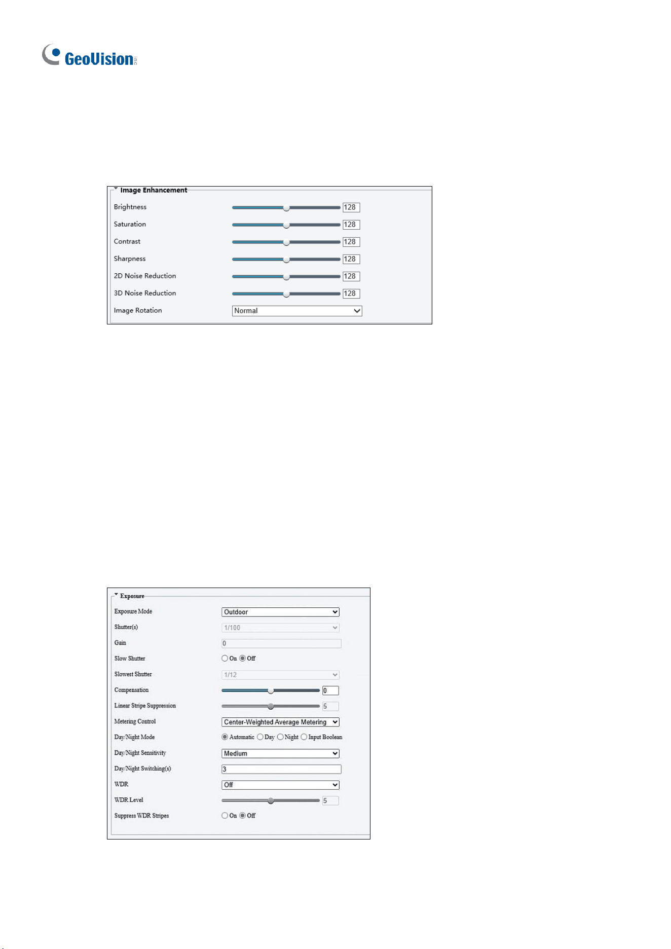
156
◼ Enable Auto Switching: Allow the camera to switch to the scene automatically when
the condition for switching to a non-default scene is met.
[Image Enhancement]
Figure 3-29
◼ Brightness: Adjust the degree of brightness of the image.
◼ Saturation: Adjust the amount of hue contained in a color.
◼ Contrast: Set the degree of difference between the blackest pixel and the whitest pixel.
◼ Sharpness: Adjust the sharpness of the image.
◼ 2D / 3D Noise Reduction: Reduce the noise of the image.
◼ Image Rotation: Change the rotation of the image by selecting Normal, Flip Vertical,
Flip Horizontal, 180°, 90° Clockwise, or 90° Anti-clockwise.
[Exposure]
Figure 3-30

Administrator Mode
157
3
◼ Exposure Mode: Select the correct exposure mode to achieve the desired exposure
effect. The default setting is Outdoor.
⚫ Low Motion Blur: Improve image quality by reducing motion blur in low light
conditions.
◼ Shutter(s): The length of time that allows light to enter into the lens. You can set a
shutter speed when Exposure Mode is set to Manual / Custom.
Note: If Slow Shutter is set to Off, the reciprocal of the shutter speed must be greater than
the frame rate.
◼ Gain: Control image signals so that the camera outputs standard video signals
according to the light condition. You can set this parameter only when Exposure Mode
is set to Manual / Custom.
◼ Slow Shutter: Improve image brightness in low light conditions.
◼ Slowest Shutter: Set the slowest shutter speed that the camera can use during
exposure.
◼ Compensation: Adjust the compensation value as required to achieve the desired
effects. You can set this parameter only when Exposure Mode is not set to Manual /
Custom.
◼ Linear Stripe Suppression: For indoor use only. Reduces stripes by limiting shutter
frequency. To enable this function, turn off WDR. Adjust the suppression level to
balance stripe reduction and image clarity (not applicable to GV-TMS20811).
◼ Metering Control: Set the way the camera measures the intensity of light. You can only
set this parameter when Exposure Mode is not set to Manual /Custom.
⚫ Center-Weighted Average Metering: Measure light mainly in the central part of the
images.
⚫ Evaluative Metering (BLC): Measure light in the customized area of the images.
⚫ Face Metering: Measure light where facial recognition is established.
⚫ Spot Metering: Measure light spot(s) in the specified area of the images.
◼ Day/Night Mode: Select Automatic for automatic switch between day mode and night
mode depending on the amount of light detected. Select Night to produce high-quality
black and white images using the existing light. Select Day to produce high-quality color
images using the existing light. Select Input Boolean to trigger an output device and
switch on night mode upon common alarm / AI event alarm (only applicable to GV-
EBFC5800 / TDR8802).
◼ Day/Night Sensitivity: Set the light threshold for switching between day mode and
night mode. The higher the sensitivity, the more easily the camera is to switch from day
mode to night mode and vice versa.
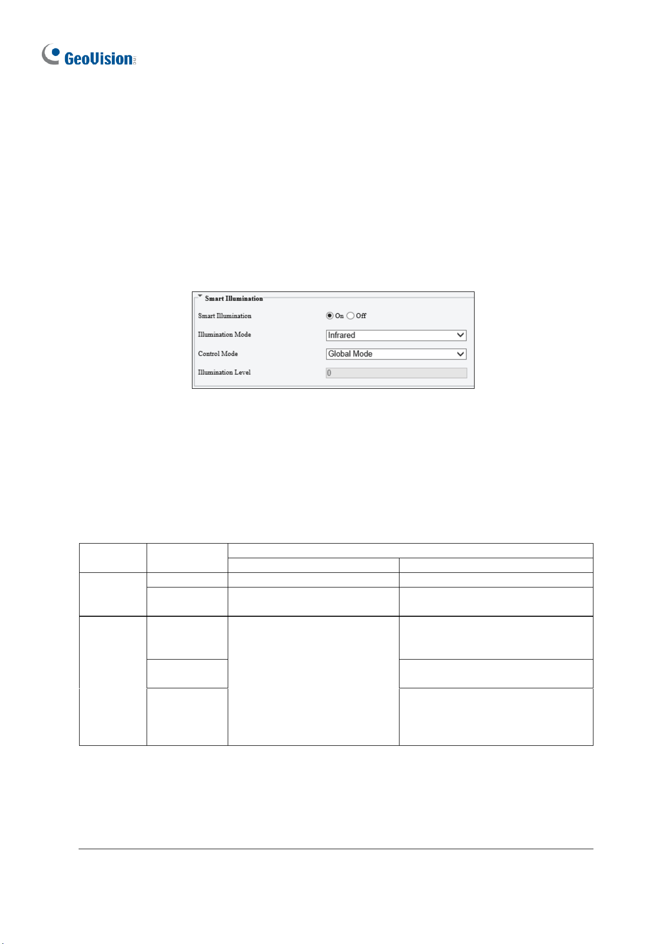
158
◼ Day/Night Switching(s): Set the length of time before the camera switches between
day mode and night mode after the conditions for switching are met.
◼ WDR: Enable WDR to distinguish the bright and dark areas in the same image.
◼ WDR Level: After enabling the WDR function, you can improve the image by adjusting
the WDR level.
◼ Suppress WDR Stripes: Enable Suppress WDR Stripes to automatically adjust shutter
frequency based on the frequency of light measured.
[Smart Illumination]
Figure 3-31
◼ Smart Illumination: Select On to adjust the IR illumination settings.
◼ Illumination Mode:
For regular models: Set to Infrared by default.
For GV-BLFC5800 / EBFC5800: Set to White Light by default.
For GV-TBL8804: Refer to the table below to configure the settings.
Illumination
Mode
Action
Daytime
Nighttime
With AI
functions
disabled
Infrared
Day Mode enabled
Night Mode and IR light enabled.
White Light
Day Mode enabled
Day Mode and White LED light
enabled.
With AI
functions
enabled
Infrared
Day Mode enabled.
White LED light flashes for
10 seconds upon an alarm
trigger.
Night Mode and IR light enabled.
White LED light flashes for 10
seconds upon an alarm trigger.
White Light
Day Mode and White LED light
enabled.
Dual Light
Night Mode and IR light enabled.
Switches to Day Mode and White
LED light flashes for 10 seconds
upon an alarm trigger.
Note:
1. AI functions refer to the smart settings, including Cross Line, Intrusion, Object
Removed, Object Left Behind, Defocus, Scene Change, Enter Area, Leave Area, Face
Detection, People Counting, Crowd Density Monitoring, and Human Body Detection.
See details in 3.6.1 Smart Settings.
2. White Light refers to Warm Light LED for GV-BLFC5800 / EBFC5800 / TBL8804.
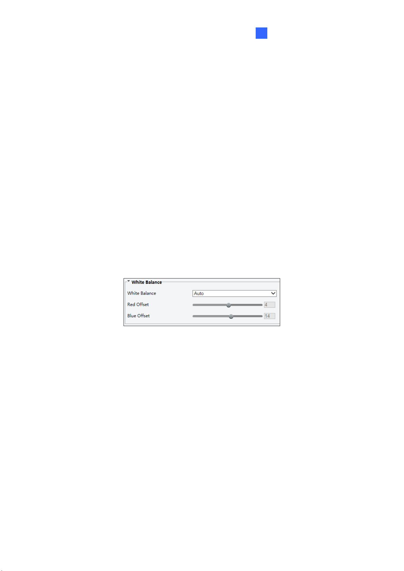
Administrator Mode
159
3
◼ Control Mode:
Global Mode: Adjust IR illumination and exposure to achieve balanced image effects.
Some areas might be overexposed if you select this option. This option is
recommended if monitored range and image brightness are your first priority.
Overexposure Restrain: Adjust IR illumination and exposure to avoid regional
overexposure. Some areas might be dark if you select this option. This option is
recommended if clarity of the central part of the image and overexposure control are
your first priority.
Manual / Custom Level: Allow you to manually control the intensity of IR illumination.
◼ Illumination Level: When Control Model is set to Manual / Custom Level, you can
set the intensity level of the IR light. The greater the value, the higher the intensity. 0
means that the IR light is turned off.
◼ Near / Far Illumination Level: For GV-TBL8804 / TMS20811, when Control Mode is
set to Custom Level, you can set the intensity level of the IR light respectively for wide-
angle scene (near illumination level) and telephoto view (far illumination level).
[White Balance]
Figure 3-32
◼ White Balance: Adjust the red or blue offset of the image.
◼ Auto / Auto 2: Adjust the red and blue offset automatically according to the light
condition (the color tends to be blue). Select Auto 2 if the images remain
unnaturally red or blue.
◼ Outdoor: It is recommended for outdoor scenes with a wide range of color
temperature variation.
◼ Fine Tune: Allow you to adjust the red and blue offset manually.
◼ Sodium Lamp: Adjust the red and blue offset automatically according to the light
condition (the color tends to be red).
◼ Locked: Lock the current color temperature settings without adjustment.
◼ Area White Balance: Suitable for large pure color scenes and complex color
scenes. By customizing the white balance area, this mode improves the accuracy
of white balance correction and reduces color casting.
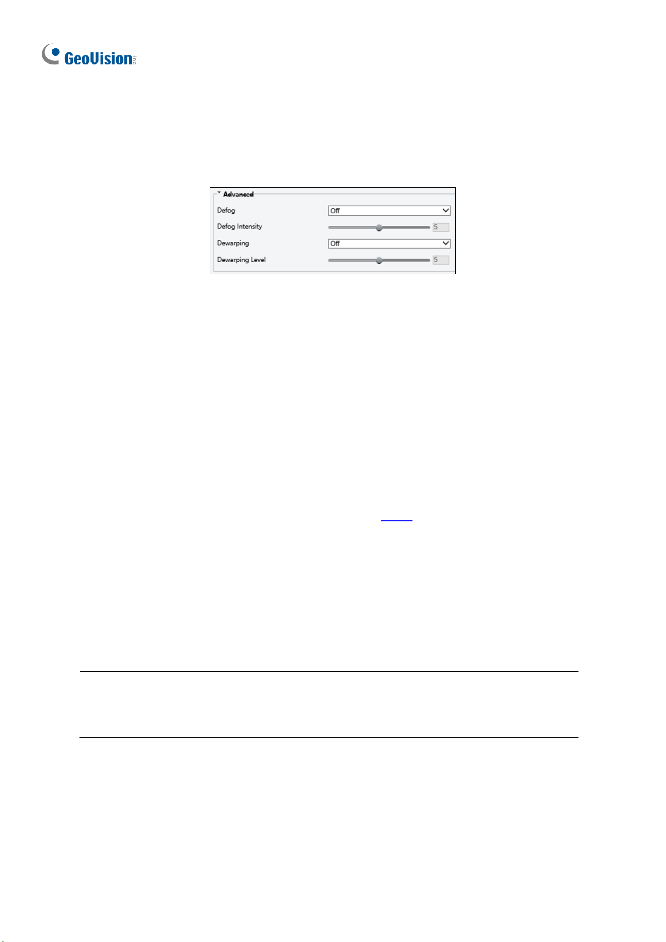
160
◼ Red/Blue Offset: Set the red/blue offset. Configurable when White Balance is set to
Fine Tune.
[Advanced]
Figure 3-33
1. Defog: Select On to activate the slider for adjusting the defog intensity of the image.
2. Dewarping: Only for GV-ABL2703 series / 4703, GV-ADR2702 / 4702, GV-EBD8800 /
8813, GV-EBDP5800, GV-TBL2703 series / 4703 / 8804 / 8810, GV-TBLP5800, GV-
TDR2702 series / 4702 series / 8805, GV-TVD8810, and GV-TMS20811, select On to
activate the slider for adjusting the Dewarping Level of the camera image.
[Advanced]
◼ Video Standard: Select the P/N standard for video capture to suppress the stripes in
the image. Even if you switch the capture mode in Video, the P/N standard configured in
this page still prevails. Options include PAL and NTSC. Not applicable to GV-TMS20811.
3.5.1.2 Image Scene Switch
This page allows you to configure the image scene switch so the camera can automatically
switch image scenes according to the configured time schedules or linked presets.
Note:
1. This function is only applicable to GV-TMS20811.
2. Make sure to select the desired channel for configuration before proceeding with the
following items for GV-TMS20811.
1. Go to Setup > Image > Image > Image Scene Switch.
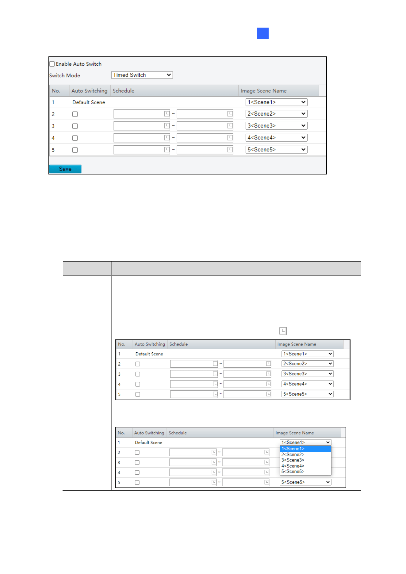
Administrator Mode
161
3
2. Choose a switch mode.
◼ Timed Switch: Switch to a specified scene at a set time.
◼ Preset Switch: Switch to a specified scene at a set time specified for a specified
preset.
3. Configure the switch mode parameters.
◼ Timed Switch
Item
Description
Auto
Switching
When auto switch is enabled and switching conditions are met, the
system switches scenes automatically. The list includes the default
scene.
Schedule
The default scene (No.1) takes effect when the current time is not within
the listed periods. You can add up to 5 periods and assign a scene for
each period. The periods must not overlap. Click to set time.
Image
Scene
Name
Choose a scene for each period. The scenes are configured on the
Scenes page (see
錯誤
!
找不到參照來源。
).
◼ Preset switch
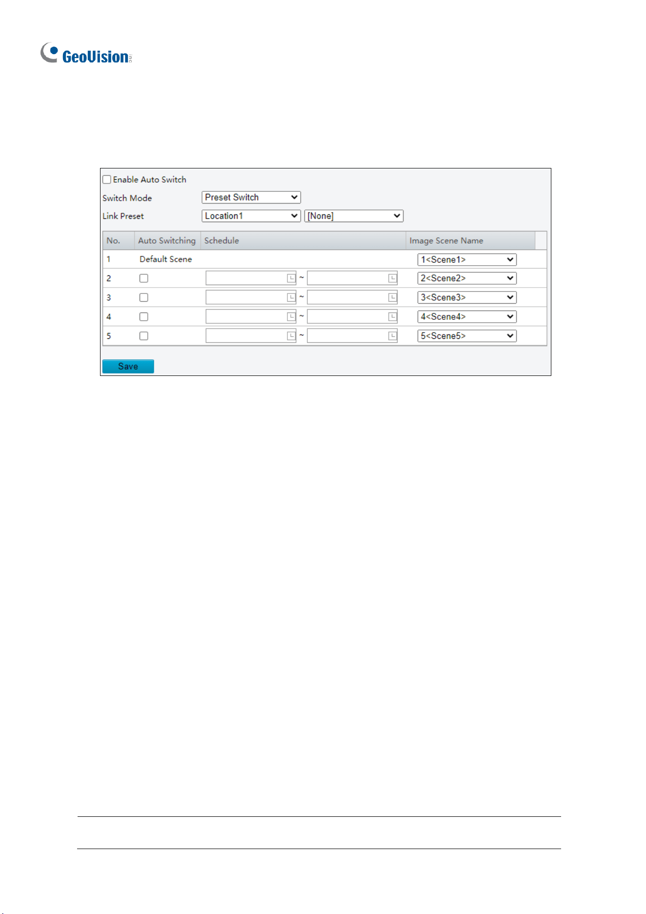
162
Choose linked presets for locations. You can set up to 4 locations and link them to
different presets (which need to be configured in advance, see 錯誤! 找不到參照來源。),
and configure 4 schedules for the locations, each schedule includes different periods
and corresponding image scenes.
4. (Optional) Select the Enable Auto Switch checkbox.
◼ Timed Switch
The camera switches to the linked image scene at the start time of a period.
The camera switches to the default scene at the end time of a period, or to the
corresponding scene at the start time of the next period.
The camera switches image scene at once when Auto Switch is enabled.
◼ Preset Switch
The camera switches scenes when calling a linked preset.
The camera checks the current time when calling a preset:
If the current time is within a listed period, the camera switches to the scene
corresponding to the period.
If no scene has been set for the period, the camera switches to the default scene.
If the current time is not within any listed periods, the camera switches to the
default scene.
5. Click Save.
3.5.1.3 Engineering
During lens rotation, the camera may lose focus, causing unclear images. In this case, you
can initialize the lens to refocus.
Note: Make sure to select the desired channel for configuration before proceeding with
the following items for GV-TMS20811.
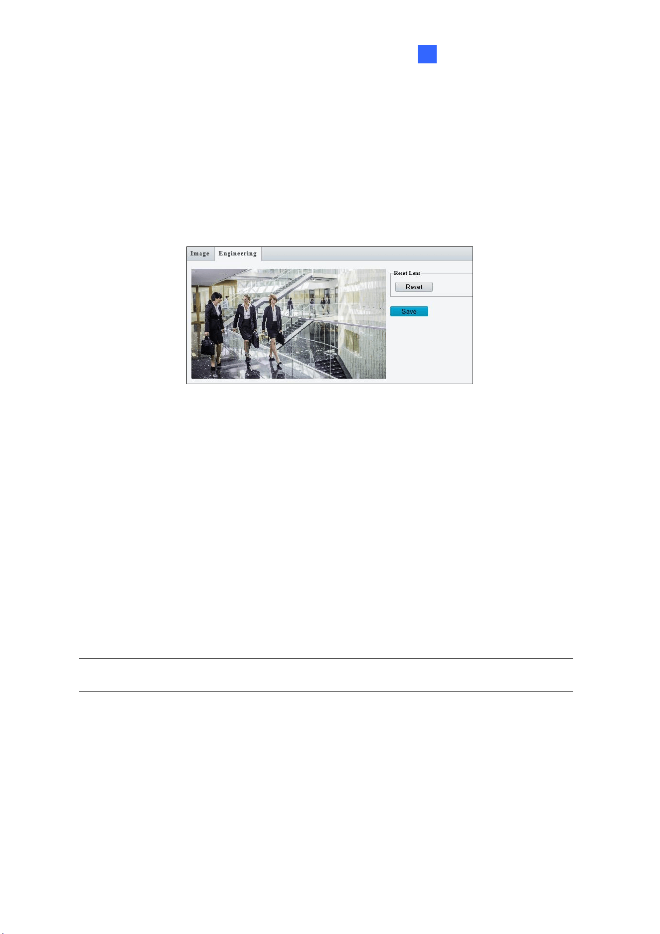
Administrator Mode
163
3
1. Go to Setup > Image > Image > Engineering.
2. Click Reset to reset the focus of the camera. Note that this function is only applicable to
the following models: GV-BLFC5800, GV-EBD4704 / 4813, GV-EBFC5800, GV-
TBL4705 / 4810, GV-TDR4704 / 4803, GV-TFD4800, GV-TVD4810 / 4811, and GV-
TMS20811.
Figure 3-34
3.5.2 OSD
On Screen Display (OSD) is the text displayed on the screen of video images and may
include the date and time and other customized contents.
Note GV-ABL2703 series / 4703 / 4711, GV-ADR2702 / 4702, GV-EBD2704 / 2705 / 4701 /
4704 / 4712 / 4813, GV-TBL2703 series / 2705 / 2706 series / 2718 / 4700 / 4703 / 4705 /
4711, GV-TDR2702 series / 2704 series / 2705 / 4702 series / 4703 series / 4704 series,
GV-TFD4700, and GV-TVD2712 / 4700 / 4711 only support up to 4 OSD.
Note: Make sure to select the desired channel for configuration before proceeding with
the followings for GV-TMS8800 / 20811.
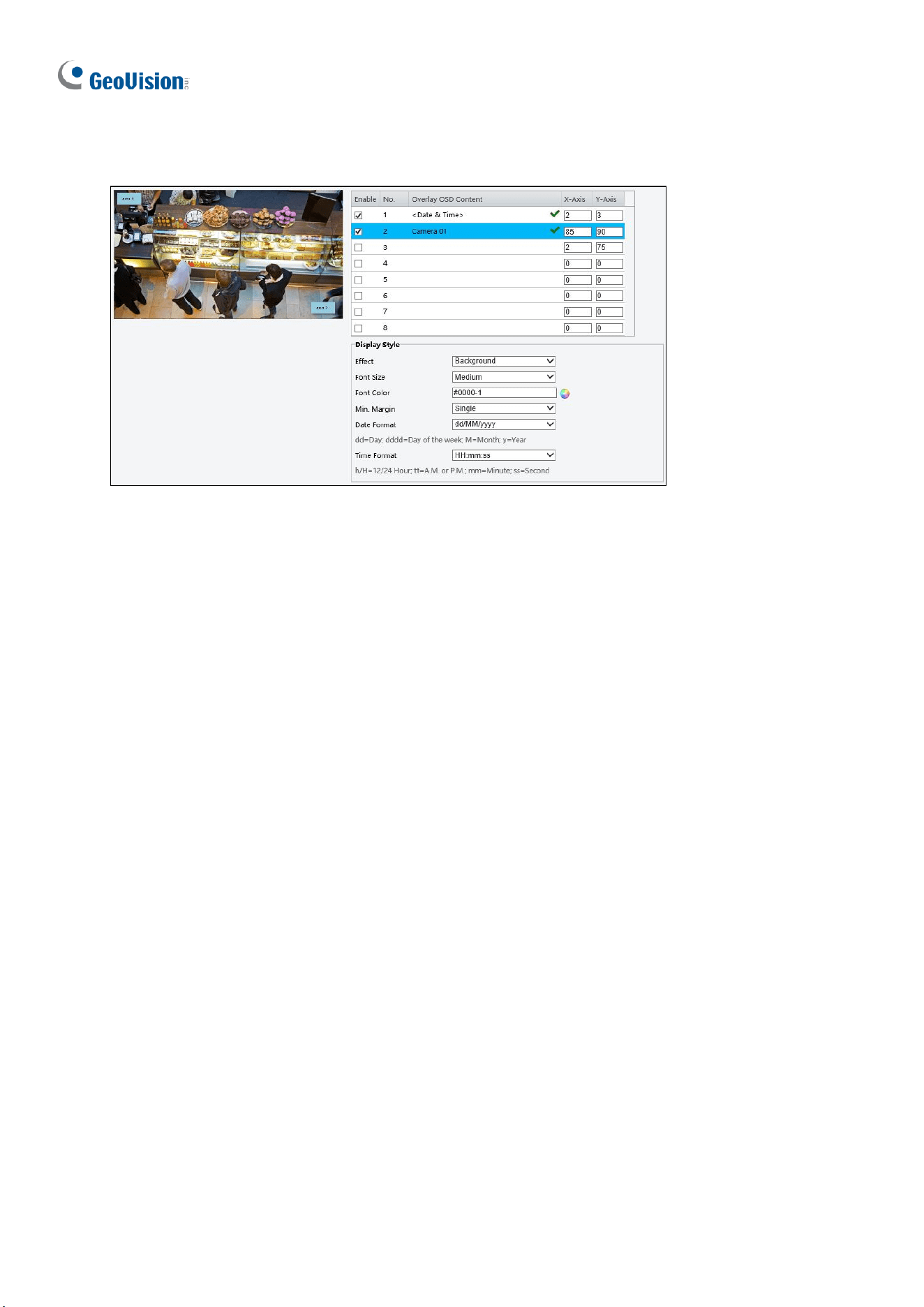
164
3.4.2.1 For all models except GV-EBD2702
Figure 3-35
1. Enable a number to select an area #, and click Overlay OSD Content to select the
content to display on the screen.
2. Adjust the position of the Area # boxes either by dragging them directly on the live view
or by specifying the coordinates under X-Axis / Y-Axis column.
3. Under Display Style, customize the text style and date/time format and use Min. Margin,
to adjust the minimum margin between the OSD and the image’s border.
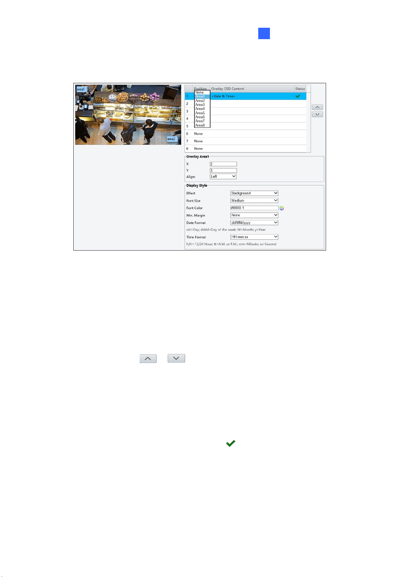
Administrator Mode
165
3
3.4.2.2 For GV-EBD2702
Figure 3-36
1. Click Overlay OSD Content to select the content or type a self-defined text to be
displayed on the screen.
2. Click Position and select from Areas 1 to 8 to specify the position of the OSD on the
image. If more than one OSD are specified to one Area #, they are displayed at the same
position in numerical order, as accorded to the number column.
3. Click the arrow buttons or to adjust the order of the OSD displayed.
4. Adjust the position of the Area # boxes either by dragging them directly on the live view
or by specifying the coordinates under X-Axis / Y-Axis column.
5. Under Display Style, customize the text style and date/time format and use Min. Margin,
to adjust the minimum margin between the OSD and the image’s border.
After you have set the position and OSD content, the symbol appears in the Status
column, which means that the OSD is set successfully.
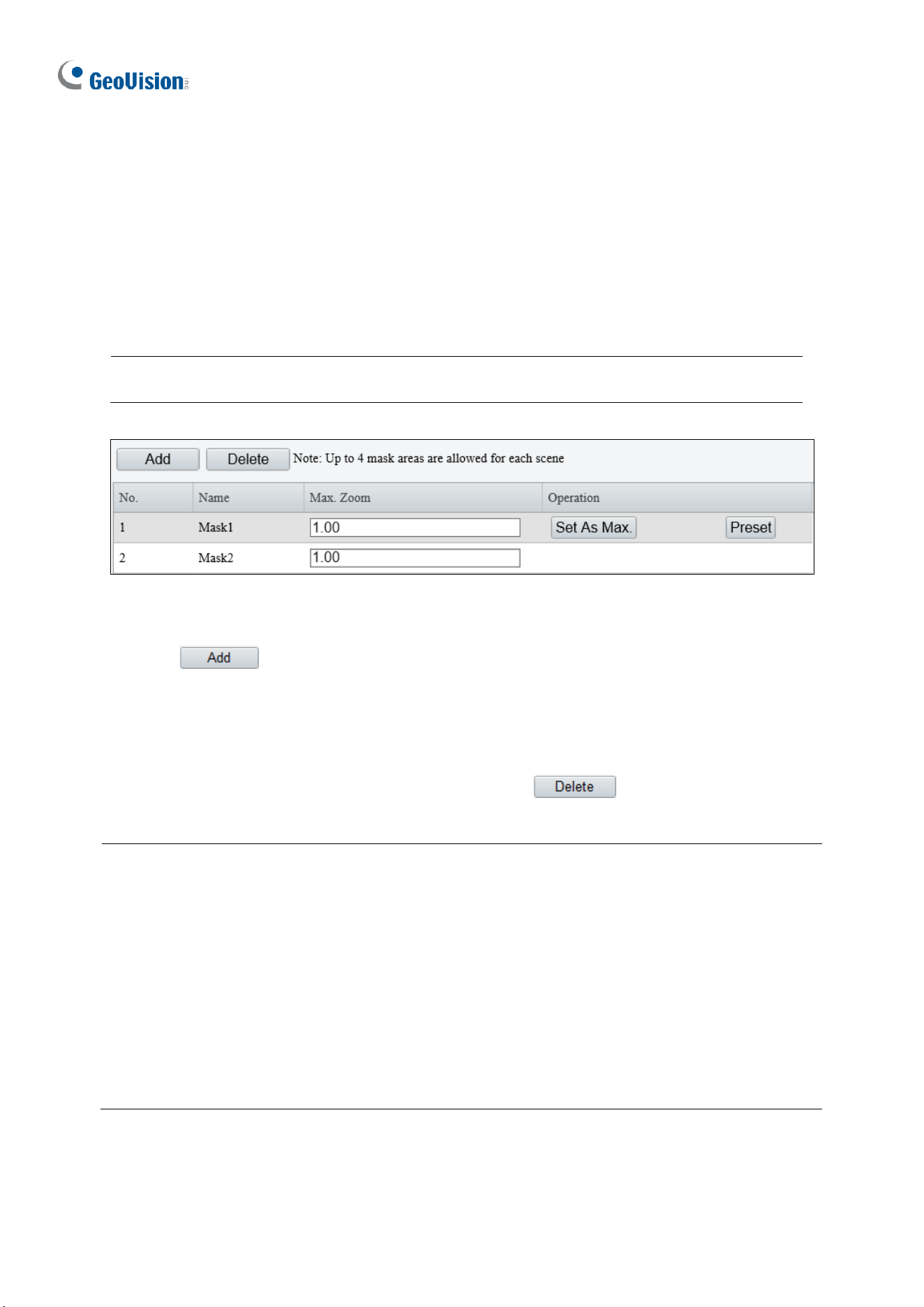
166
3.5.3 Privacy Mask
On certain occasions, you may need to set a mask area to block out parts of the camera
image to protect privacy, for example, the keyboard of an ATM machine. When PTZ changes
its position or zooms, the Privacy Mask will be adjusted accordingly to protect the area all
along.
Note: Make sure to select the desired channel for configuration before proceeding with
the following items for GV-TMS8800 / 20811.
Figure 3-37
1. Click to place a privacy mask on the live view.
2. Drag the Mask box to the intended position and adjust the size of the box. Alternatively,
you can also use the mouse to draw a box on the area you want to mask.
3. Repeat steps 1 and 2 to add more masks.
4. To delete a mask, select the desired mask and click .
Note:
1. The max. number of mask areas can be defined:
˙ Up to four mask areas for GV-ABL2703 series / 4703 / 4711, GV-ADR2702 / 4702,
GV-BLFC5800, GV-EBD2705 / 4701 / 4712 / 4813, GV-EBDP5800 / 8800, GV-
EBFC5800, GV-TBL2703 series / 2706 series / 2718 / 4700 / 4703 / 4711 / 4810 /
8710, GV-TBLP5800 / 8800, GV-TDR2702 series / 2705 / 4702 series / 4703
series / 4803 series, GV-TFD4700 / 4800, GV-TVD2712 / 4700 / 4711 / 4810 /
4811,
˙ Up to twenty-four mask areas for GV-PTZ5810-IR
˙ Up to eight mask areas for all other models.
2. Max. Zoom and Operation are only applicable to GV-PTZ5810-IR.

Administrator Mode
167
3
3.6 Intelligent
Under Intelligent, users can set the camera to detect for a number of video-analytic events,
which can be used to send FTP and/or e-mail alerts, based on the parameters set. Note this
function is NOT supported by GV-ABL2701 series / 2703 series / 4701 series / 4703, GV-
ADR2701 / 2702 / 4701 / 4702, GV-TBL2703 series / 4703, GV-TDR2702 / 4702, and GV-
FER5702.
3.6.1 Smart Settings
Smart Settings allow alerts to be sent to FTP or designated e-mail address(es) upon Cross
Line, Intrusion, Object Removed, Object Left Behind, Defocus, Scene Change, Enter
Area, Leave Area, Face Detection, People Counting, Crowd Density Monitoring or
Human Body Detection events.
Note:
1. In order for event alerts to work, you also need to configure the necessary settings of
FTP, e-mail server or snapshots, see 3.8.2 FTP, 3.2.5 E-mail and 3.3.2 Snapshot,
respectively.
2. For certain models, to display the detection lines and/or areas on the live view, you need
to enable Untriggered Target as mentioned in 3.1.2 Local Parameters.
3. GV-ABL4711, GV-EBD4701 / 4712, GV-TBL4700 / 4711, GV-TDR4703 series, GV-
TFD4700, and GV-TVD4700 / 4711 only support two smart settings: Intrusion and
Human Body Detection.
4. GV-EBD2704 / 2705 / 4704, GV-TBL2705 / 2706 series / 2718 / 4705, GV-TDR2704
series / 2705 / 4704 series, and GV-TVD2712 only support two smart settings: Cross
Line and Intrusion.
5. GV-BLFC5800, GV-EBD4813 / 8800 / 8813, GV-EBFC5800, GV-TBL4810 / 4807 / 8804 /
8810, GV-TDR4803 / 8805, GV-TFD4800, GV-TVD4810 / 4811 / 8810, and GV-
PTZ5810-IR support the following smart settings: Cross Line, Intrusion, Enter Area,
Leave Area, Face Detection, People Counting, and Crowd Density Monitoring.
6. GV-EBDP5800 / 8800 and GV-TBLP5800 / 8800 only support the following smart
settings: Cross Line, Enter Area, Leave Area, and Intrusion.
7. For GV-TMS8800 / 20811, smart settings can be set separately for each channel. See
the tables below for the smart settings supported by each channel:
◼ GV-TMS8800:
Channel
Smart Setting
Channel 1
Cross Line, Intrusion, Enter Area, Leave
Area, Face Detection, People Counting,
Crowd Density Monitoring
Channel 2
Cross Line, Intrusion, Enter Area, Leave
Area
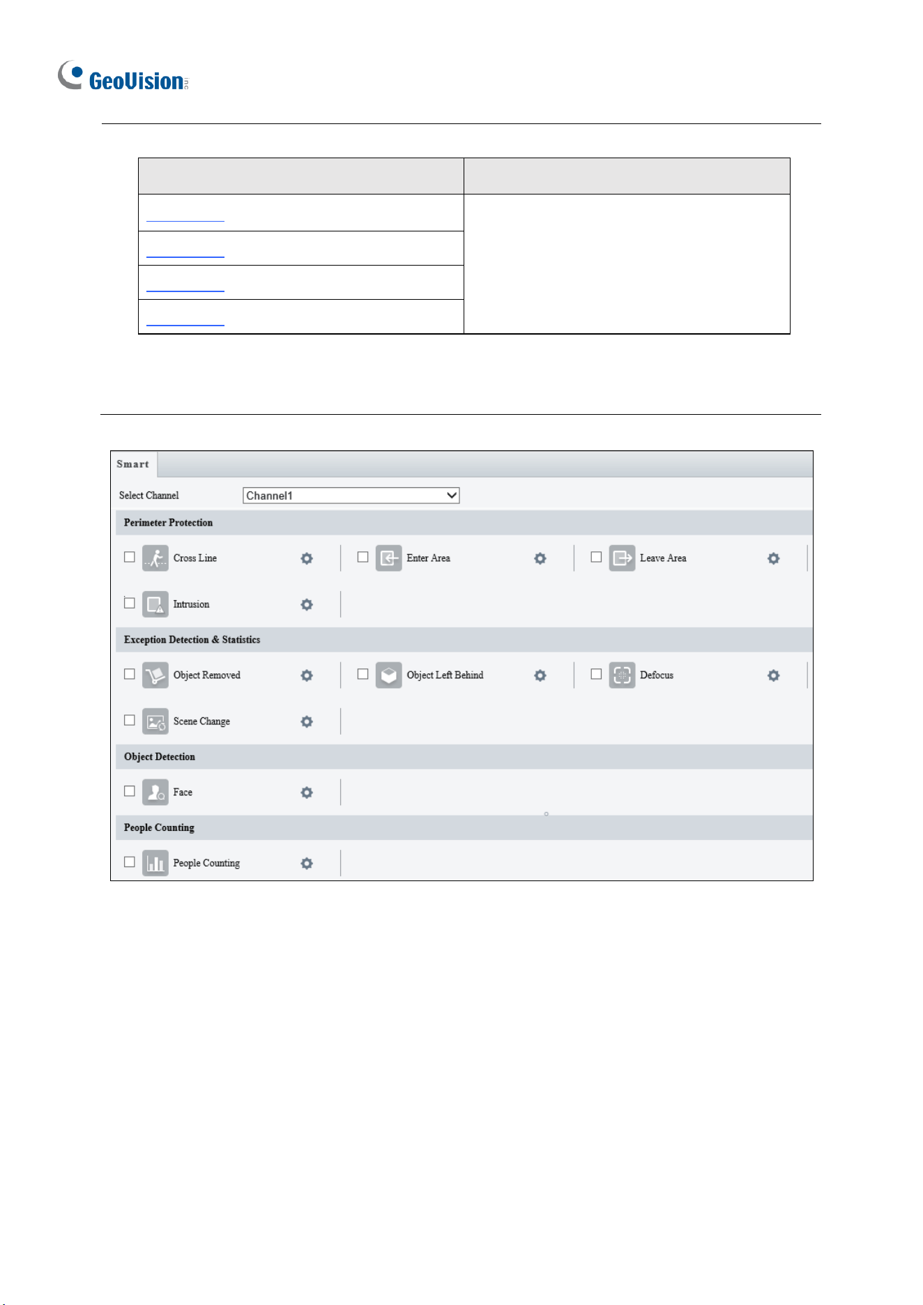
168
◼ GV-TMS20811:
Channel
Smart Setting
Channel 1
Cross Line, Intrusion, Enter Area, Leave
Area, Face Detection, People Flow
Counting, Crowd Density Monitoring
Channel 2
Channel 3
Channel 4
8. Smart Settings will not work if Image Rotation is set to 90° Clockwise or 90° Anti-
clockwise under the Image Enhancement settings in 3.5.1 Image.
Figure 3-38
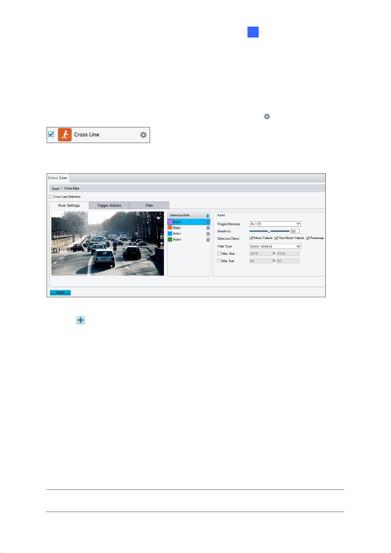
Administrator Mode
169
3
3.6.1.1 Cross Line
Cross line detection generates an alarm when an object moves past the detection threshold
in the direction you defined. Up to 4 detection lines can be added. Note that when adding
multiple detection lines, make sure they do NOT intersect as it may affect the detection
results. Select the checkbox next to Cross Line to enable and click to configure.
For AI models:
Figure 3-39
1. Click to add a detection line. Repeat to add another detection line (maximum of 4).
2. Drag the ends of the detection line to the intended position to mark the detection
boundary.
3. Select the Trigger Direction, which defines the direction to trigger an alarm. For
example, if you choose A -> B, people moving from direction A to B will trigger an alarm.
4. For Sensitivity, drag the slider to adjust the detection sensitivity.
5. For Detection Object, select the type of object you want to take a snapshot of.
6. For Filter Type, select the type of object you want to define and its minimum or
maximum size for detection. Once selected, click Max. Size and/or Min. Size, drag the
nodes of the size area to adjust and the system will detect objects within that size range.
Repeat this step to define the size range for another type of object.
7. For Trigger Actions and Plan, follow Step 6 ~ 7 below.
Note: Motor Vehicle includes cars, trucks, and buses. Non-Motor Vehicle includes bicycles
and motorcycles.
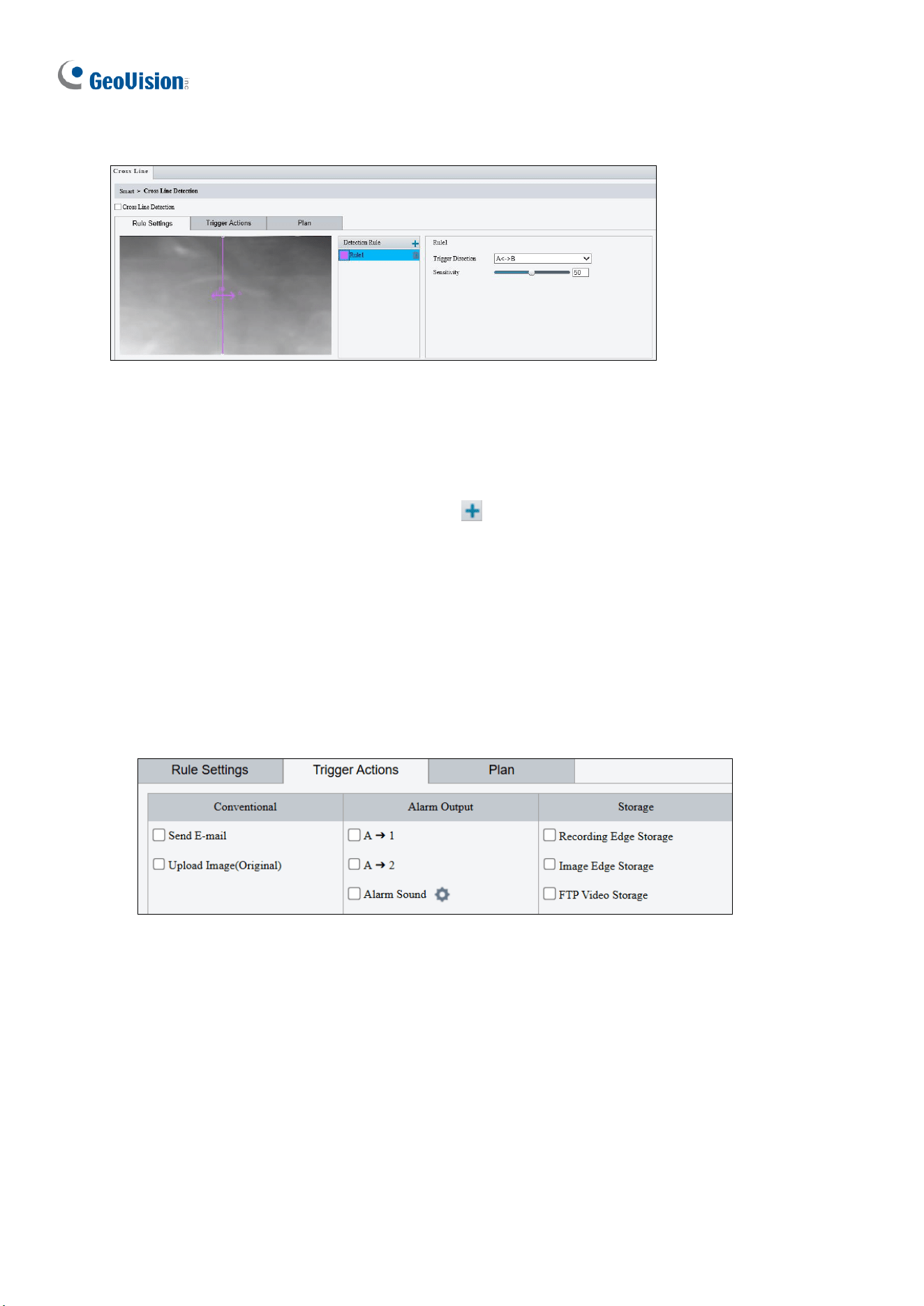
170
For non-AI models:
Figure 3-40
1. Based on your installation environment, select the Detection Scene between outdoor
and indoor (see Detection Parameters in 3.6.2 Advanced Settings). By default, Outdoor
is selected.
2. Once enabled, select Rule Settings > click to add a detection line. Repeat to add
another detection line.
3. Drag the ends of the detection line to the intended position to mark the detection
boundary.
4. Select the Trigger Direction, which will define the direction to trigger an alarm. For
example, if you choose A -> B, people moving from direction A to B will trigger an alarm.
5. Move the slider to adjust the detection Sensitivity.
6. Set up Trigger Actions:
Figure 3-41
A. Select Upload to FTP / Send E-mail / Upload Image (Original) / Attribute
Collection under Trigger Actions to automatically upload snapshots to the specified
FTP server, send snapshots to the specified e-mail address upon the video analytic
events, and/or upload object attribute information to the server.
B. Select A -> 1 / A -> 2 / Alarm Sound to trigger an output device upon cross line
detection. Depending on your model, select A -> 1, A-> 2, or Alarm Sound to trigger
an output device upon people / vehicle / non-motor vehicle detection.
A->1: A refers to the ALARM OUT interface on the device, 1 means the first ALARM
OUT interface. A->2 means the second ALARM OUT interface on the device, and so
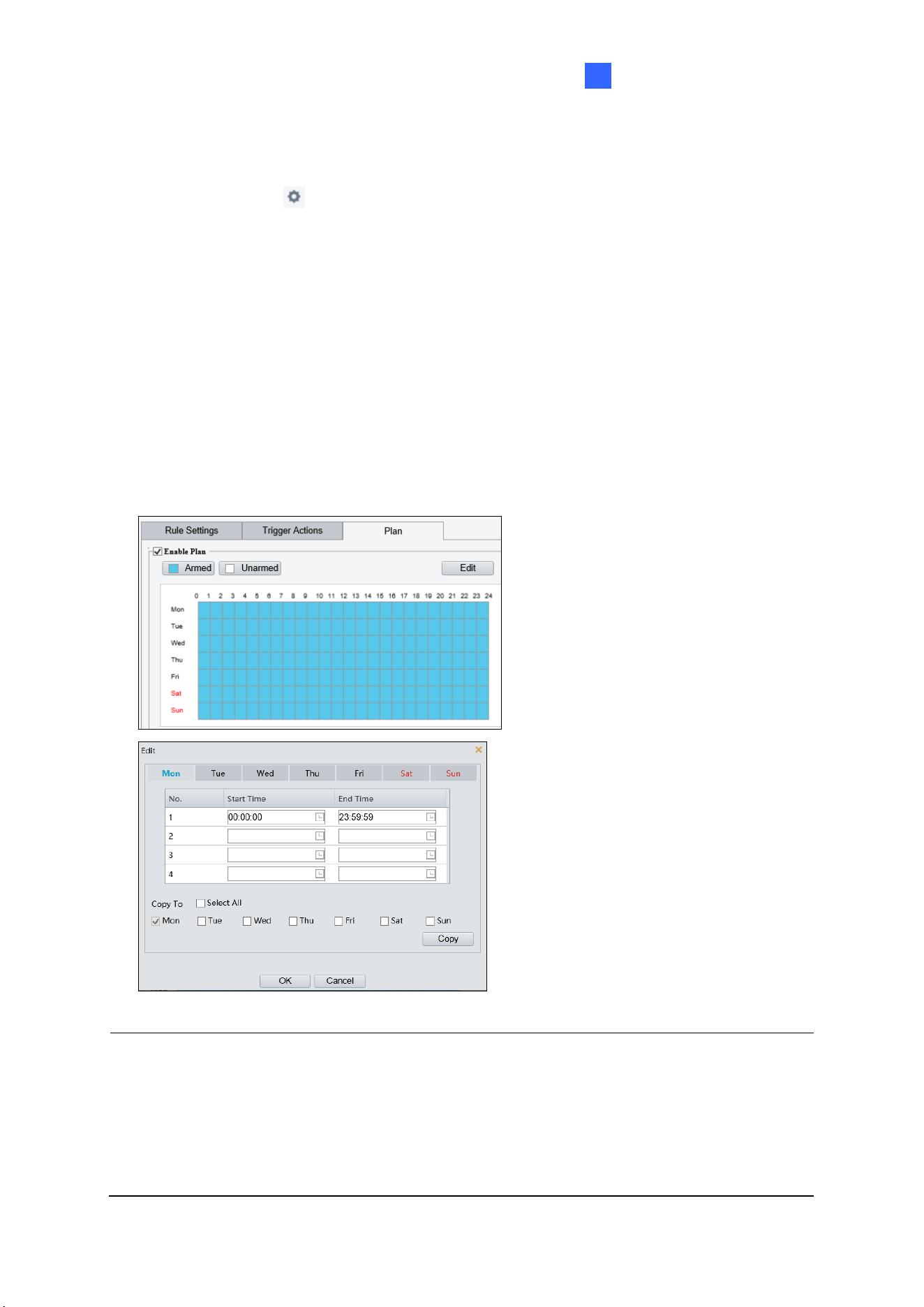
Administrator Mode
171
3
on. The number of ALARM OUT interfaces may vary with the device model. See the
device datasheet for specifications.
C. Optionally click next to Alarm Sound to set the desired Day, Start Time, End
Time, Alarm Audio, and Number of Repeat Times. You can set up to four periods
for each time, and the time periods cannot overlap.
D. Select Recording Edge Storage, Image Edge Storage, or FTP Video Storage.
Snapshots captured or videos recorded will automatically be stored in the selected
storages.
7. Optionally select Enable Plan under Plan to set the start and end times during which the
video analytic monitoring is enabled. You can directly drag the mouse to draw a plan or
click Edit to edit time periods in the table. You can set up to four periods for each day,
and the time periods cannot overlap. The camera reports alarms during the specified
period only.
Figure 3-42
Note:
1. Certain models may only support uploading snapshots to an FTP server and output
trigger for Trigger Actions.
2. Alarm Sound is only applicable to GV-PTZ5810-IR / TBL8804 / TMS20811, and Alarm
Light is only applicable to GV-BLFC5800 / EBFC5800 / TBL8804. See details in 3.3.3
Audio for Alarm Sound and 3.5.1 Image (Smart Illumination) for Alarm Light.
3. Attribute Collection is only applicable to certain models. See 3.6.3 Attribute Collection
172
for details.
Also see Appendix J. Installation Guidelines for Perimeter Protection.
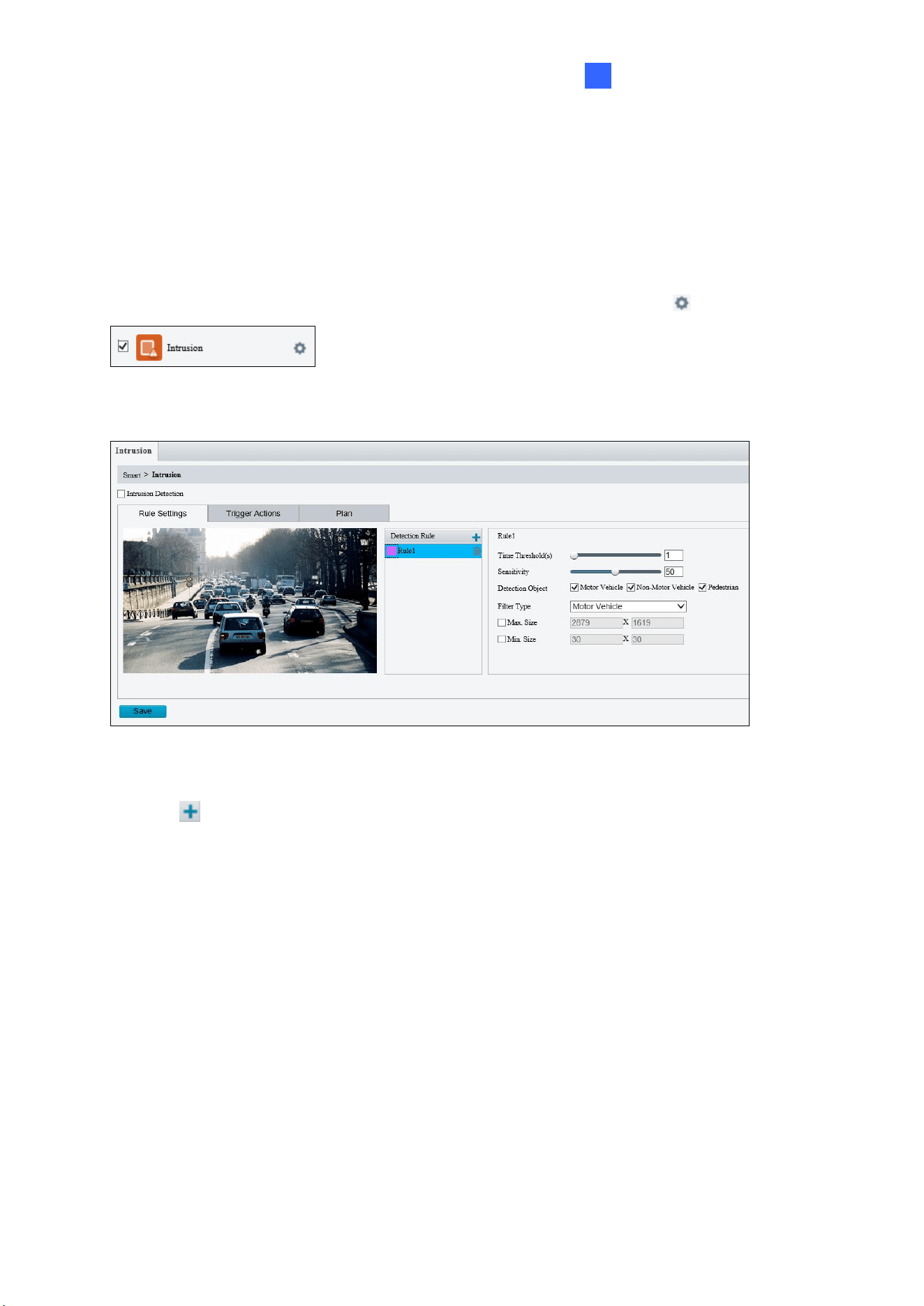
Administrator Mode
173
3
3.6.1.2 Intrusion
With Intrusion Detection, an alarm is generated when an object enters the boundaries of the
detection area. Up to 4 detection areas can be added.
Note that it is recommended NOT to overlap the detection areas when adding multiple
detection areas. Select the checkbox next to Intrusion to enable and click to configure.
For AI models:
Figure 3-43
1. Click to mark the live view with a detection area. Repeat this step to add another
detection area (maximum of 4).
2. Drag the nodes of the detection area to mark the boundary for detection.
3. You can use the following functions to reduce false alarm.
◼ Time Threshold: The minimum period of time for an object to stay within the
detection area before an alarm is triggered.
◼ Sensitivity: Move the slider to adjust the detection sensitivity.
4. For Detection Object, select the type of object you want to take a snapshot of.
5. For Filter Type, select the type of object you want to define and its minimum or
maximum size for detection. Once selected, click Max. Size and/or Min. Size, drag the
nodes of the size area to adjust and the system will detect objects within that size range.
Repeat this step to define the size range for another type of object.
6. For Trigger Actions and Plan, follow Step 6 ~7 at the bottom of 3.6.1.1 Cross Line.
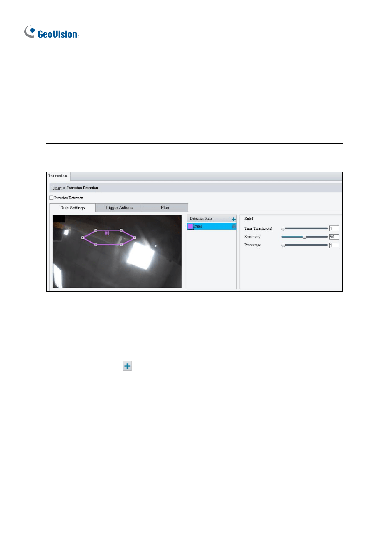
174
Note:
1. Certain models may only support uploading snapshots to an FTP server and output
trigger for Trigger Actions.
2. Motor Vehicle includes cars, trucks, and buses. Non-Motor Vehicle includes bicycles
and motorcycles.
3. Alarm Sound is only applicable to GV-PTZ5810-IR / TBL8804 / TMS20811 and Alarm
Light is only applicable to GV-BLFC5800 / EBFC5800 / TBL8804. See details in 3.3.3
Audio for Alarm Sound and 3.5.1 Image (Smart Illumination) for Alarm Light.
For non-AI models:
Figure 3-44
1. Based on your installation environment, select the Detection Scene between outdoor
and indoor (see Detection Parameters in 3.6.2 Advanced Settings). By default, Outdoor
is selected.
2. Once enabled, click to mark the live view with a detection area. Repeat this step to
add another detection area.
3. Drag the nodes of the detection area to mark the boundary for detection.
4. You can use the following functions to reduce false alarm.
◼ Time Threshold: The minimum period of time for an object to stay within the
detection area before an alarm is triggered.
◼ Sensitivity: Move the slider to adjust the detection sensitivity.
◼ Percentage: Type the minimum size of the object compared to the detection area
for the object to be detected.

Administrator Mode
175
3
5. For Trigger Actions and Plan, follow Step 6 ~ 7 at the bottom of 3.6.1.1 Cross Line.
Also see Appendix J. Installation Guidelines for Perimeter Protection.
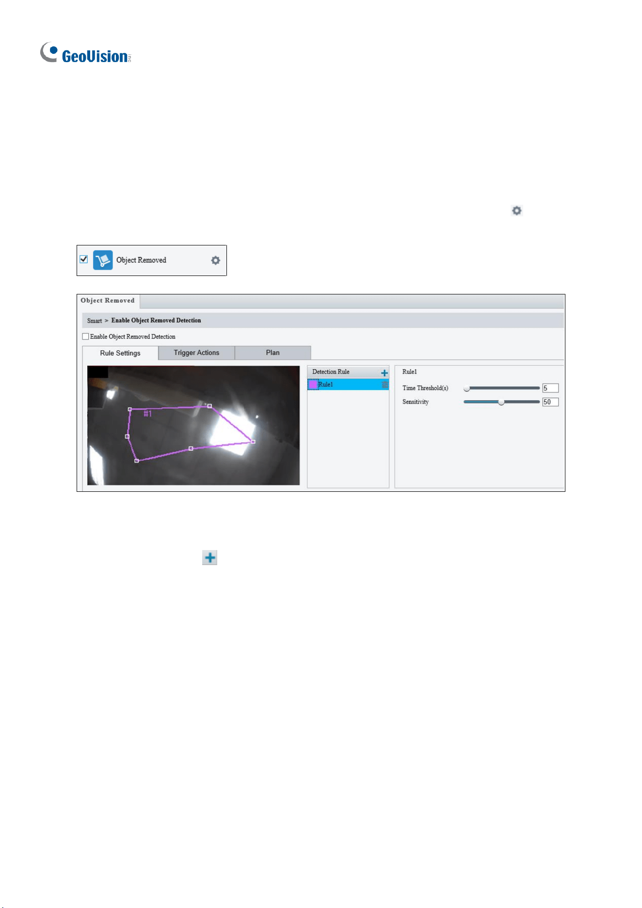
176
3.6.1.3 Object Removed
Object Removed can generate an alarm when an object is removed from the specified area.
Up to 4 detection areas can be added.
Note that it is recommended NOT to overlap the detection areas when adding multiple
detection areas. Select the checkbox next to Object Removed to enable and click to
configure.
Figure 3-45
1. Once enabled, click to mark the live view with a detection area. Repeat this step to
add another detection area.
2. Drag the nodes of the detection area to mark the boundary for detection.
3. You can use the following functions to reduce false alarm.
◼ Time Threshold: The minimum period for an object to be absent from the
detection area before an alarm is triggered.
◼ Sensitivity: Move the slider to adjust the detection.
4. For Trigger Actions and Plan, follow Step 6 ~ 7 at the bottom of 3.6.1.1 Cross Line.
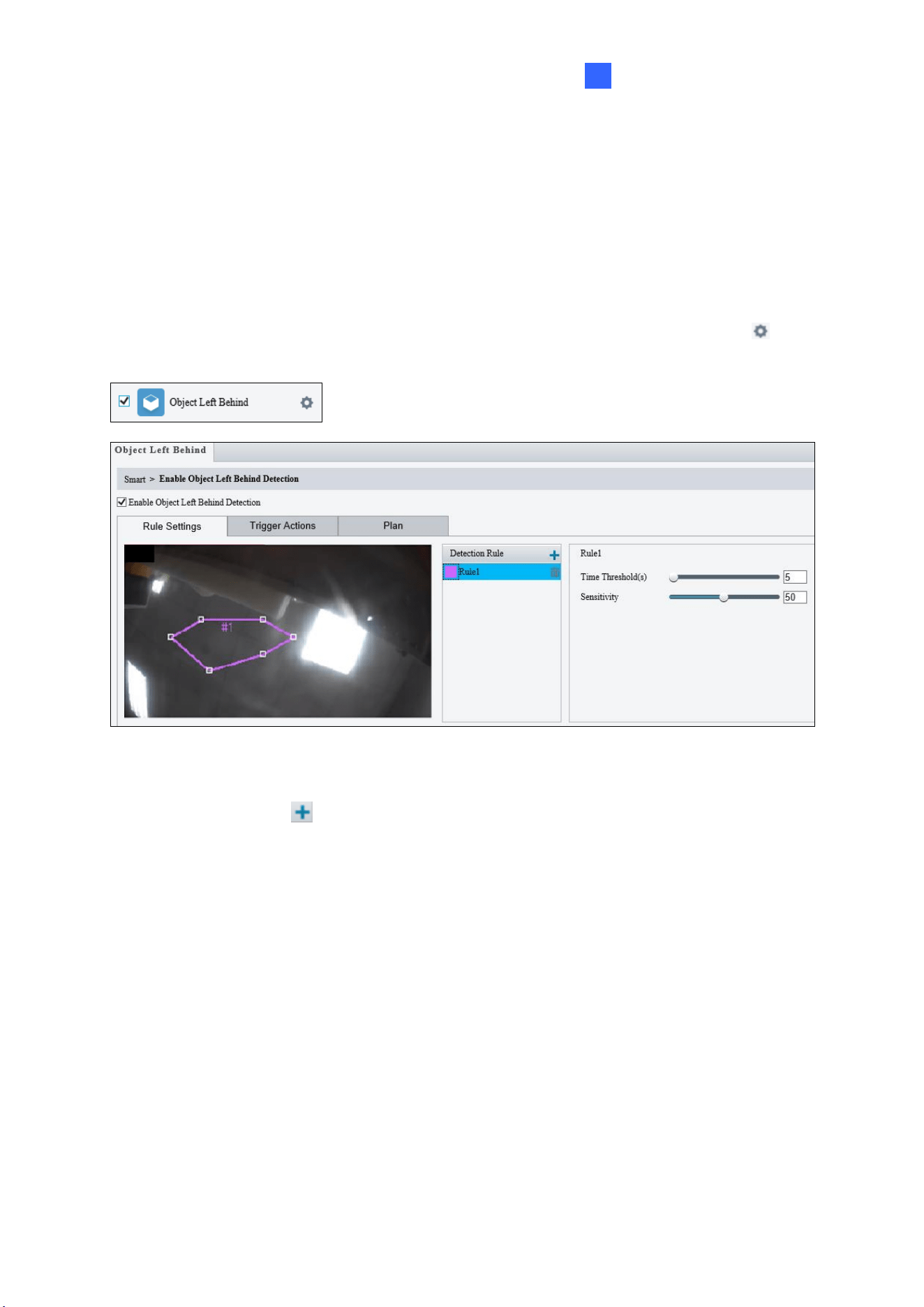
Administrator Mode
177
3
3.6.1.4 Object Left Behind
With Object Left Behind, an alarm can be generated when an object which remained in the
detection area for the specified period of time, leaves the specified region. Up to 4 detection
areas can be added.
Note that it is recommended NOT to overlap the detection areas when adding multiple
detection areas. Select the checkbox next to Object Left Behind to enable and click to
configure.
Figure 3-46
1. Once enabled, click to mark the live view with a detection area. Repeat this step to
add another detection area.
2. Drag the nodes of the detection area to mark the boundary for detection.
3. You can use the following functions to reduce false alarm.
◼ Time Threshold: The minimum period of time for an object to stay within the
detection area for an alarm to trigger.
◼ Sensitivity: Move the slider to adjust the detection sensitivity.
4. For Trigger Actions and Plan, follow Step 6 ~ 7 at the bottom of 3.6.1.1 Cross Line.
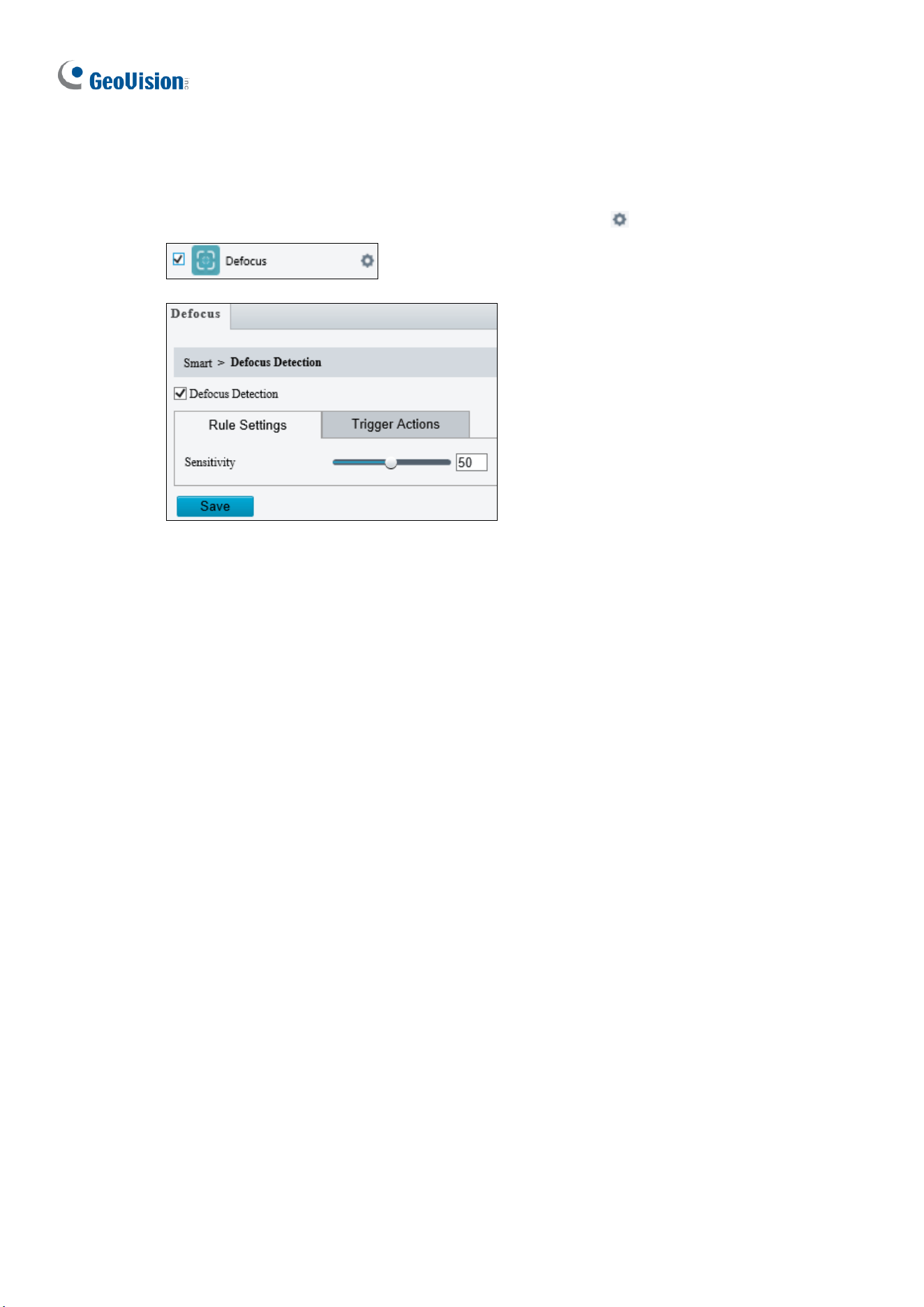
178
3.6.1.5 Defocus
Defocus generates an alarm to be sent through e-mail whenever the camera’s image is out
of focus. Select the checkbox next to Defocus to enable and click to configure.
`
Figure 3-47
Once enabled, drag the slider to adjust the detection Sensitivity. For Trigger Actions,
follow Step 6 at the bottom of 3.6.1.1 Cross Line.
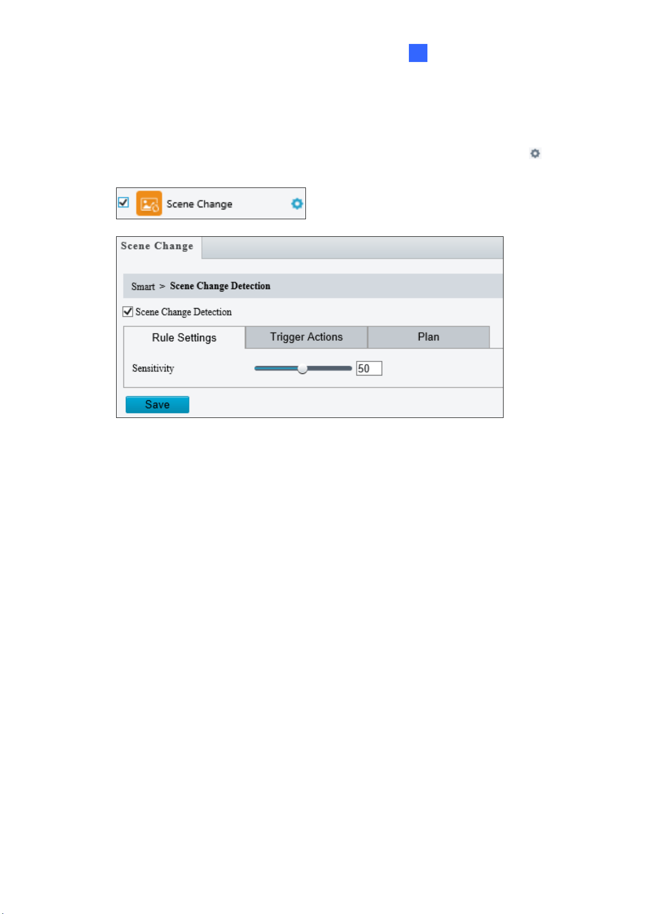
Administrator Mode
179
3
3.6.1.6 Scene Change
Scene Change is able to generate an alarm whenever there is a drastic scene change to the
image of the camera. Select the checkbox next to Scene Change to enable and click to
configure.
Figure 3-48
Once enabled, drag the slider to adjust the detection Sensitivity. For Trigger Actions and
Plans, follow Step 6 ~ 7 at the bottom of 3.6.1.1 Cross Line.
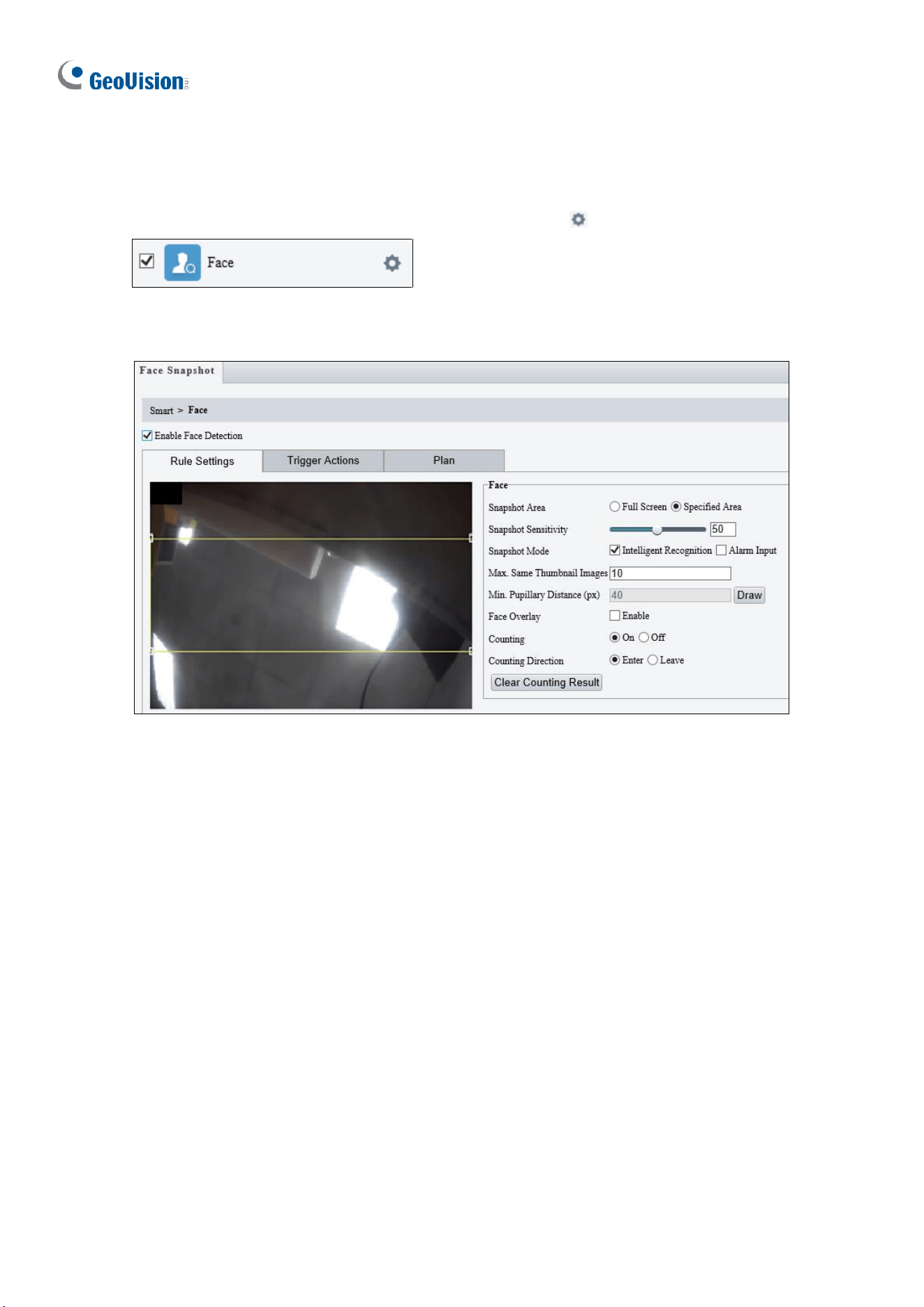
180
3.6.1.7 Face Detection
The Face function can detect for and capture face(s) in a specified area and send to an FTP
server. Select the checkbox next to Face to enable and click to configure.
For non-AI models:
Figure 3-49
1. Once enabled, define the detection area, either by drawing a desired area on the image
or select Full Screen next to Specified Area to set the entire image as detection area.
2. Configure the following functions as needed:
◼ Snapshot Sensitivity: Drag the slider to adjust the detection sensitivity. By default,
the value is set to 50. When the sensitivity is increased, the detection rate
increases but so does the false detection rate, and vice versa.
◼ Snapshot Mode: Select Intelligent Recognition to set the maximum of repeated
face snapshots (1~30) for Max. Same Thumbnail Image.
◼ Min. Pupillary Distance (px): Click Draw and draw in the live view window. Set
according to camera resolutions. The min. pupillary distance should be 1/2 of face
pixel.
◼ Face Overlay: Enable to include the camera’s text overlay on the snapshot(s)
captured.
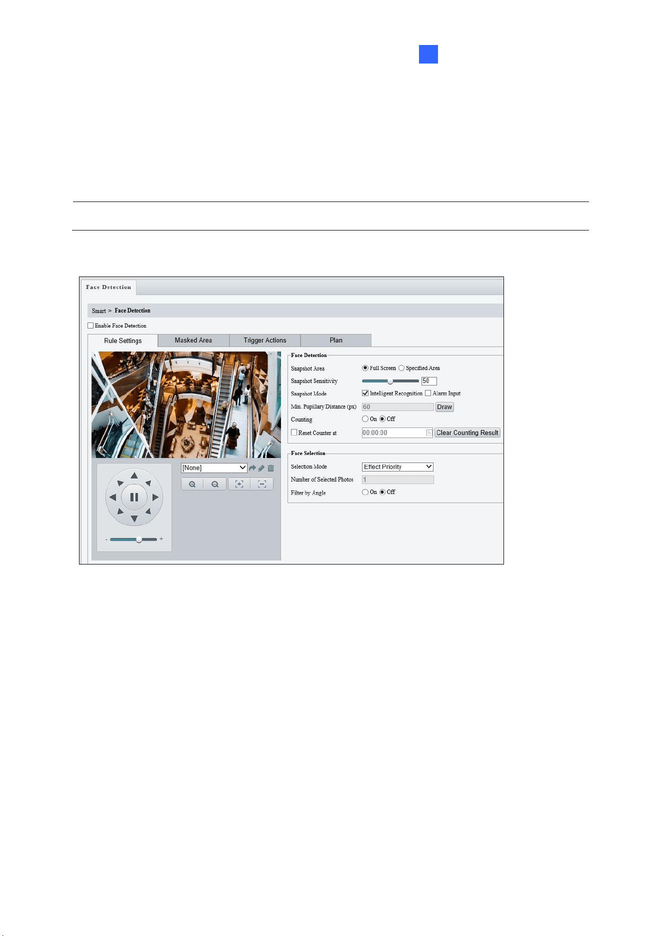
Administrator Mode
181
3
3. Under Trigger Actions, select Upload Image (Original) to upload a snapshot of the
entire image and a snapshot of the face detected upon face detection. Select Upload
Image (Target) to upload only the snapshot of the face detected.
4. For Plan, follow Step 7 at the bottom of 3.6.1.1 Cross Line.
Note: The Counting and Counting Direction features are currently nonfunctional.
For AI models:
Figure 3-50
1. Once enabled, define the detection area, either by selecting Specified Area and drawing
a desired area on the image, or select Full Screen to set the entire image as detection
area.
2. Configure the following functions as needed:
[Face Detection]
◼ Snapshot Sensitivity: Drag the slider to adjust the detection sensitivity.
◼ Snapshot Mode: Select Intelligent Recognition for the camera to detect and take
snapshots of the object automatically.
◼ Min. Pupillary Distance (px): Click Draw and draw in the live view window.
◼ Counting: To count the number of people entering / exiting in the detection area,
enable this function. To display the counting results in the live view window, select
People Counting in OSD settings. Refer to 3.5.2 OSD for details.
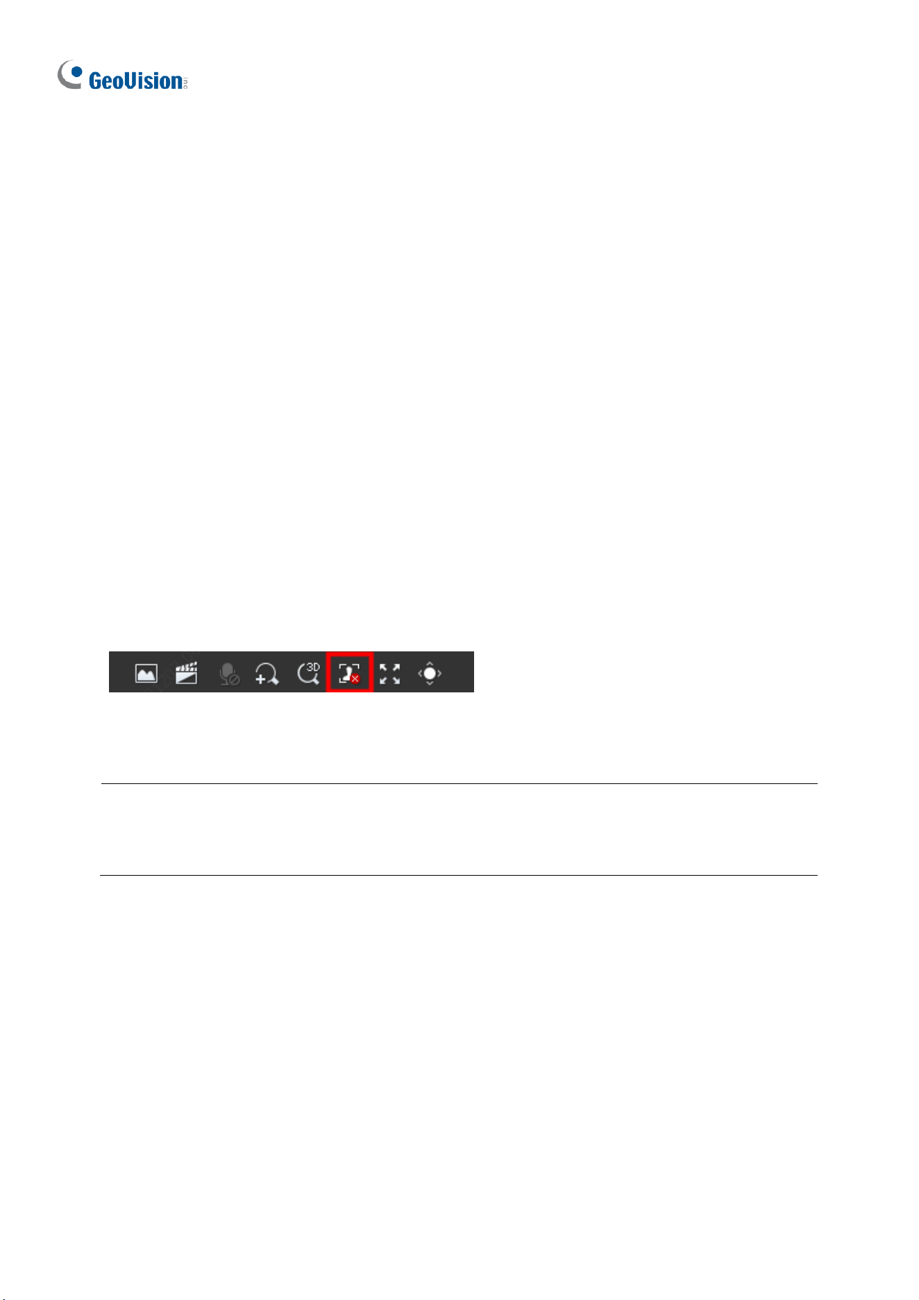
182
[Face Selection]
◼ Selection Mode: Select Effect Priority for the best image quality of the captured
snapshots, Speed Priority for optimal snapshots from the moment of detection until
the specified timeout is up, and Periodic Selection for a snapshot captured in every
selection period. For example, if Periodic Selection is set to 500 millisecond (ms),
the camera selects a face snapshot every 500 ms.)
◼ Number of Selected Photos: Set 1 ~ 3 selected photos for different selection
modes.
◼ Filter by Angle: Enable this function to set the desired face angle for detection.
3. Under Trigger Actions, select Upload Image (Original) to upload a snapshot of the
entire image and a snapshot of the face detected upon face detection. Select Upload
Image (Target) to upload only the snapshot of the face detected.
4. For Plan, follow Step 7 at the bottom of 3.6.1.1 Cross Line.
Local Snapshot
Click the Start Capture button (see figure below) on the Live View page to start taking local
snapshots.
When enabled, captured faces and people will display in real time on the right side of the
Live View page.
Note: If green detection boxes are displayed but local snapshots are not, re-install the plugin,
disable the firewall on your computer, and disable the protected mode for all the zones in
your IE (Internet options > Security).
Also see Appendix M. Installation Guidelines for Face Detection, and Appendix N.
Installation Guidelines for Face Detection (Non-AI).
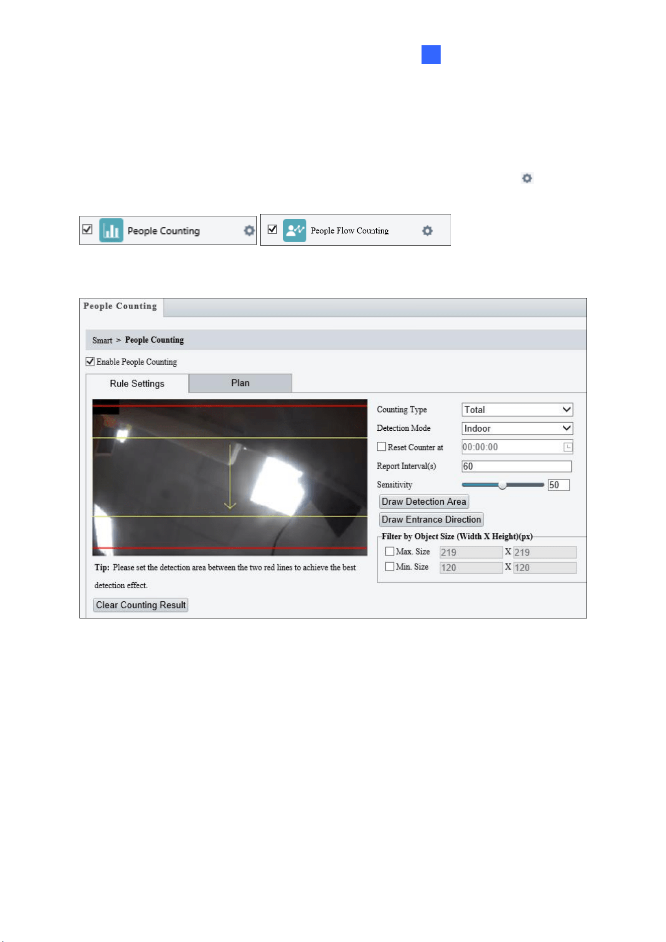
Administrator Mode
183
3
3.6.1.8 People Counting / People Flow Counting
The People Counting / People Flow Counting function can count the number of person(s)
entering and leaving the vicinity, which is useful at an entrance/exit setting. Select the
checkbox next to People Counting / People Flow Counting to enable and click to
configure.
For non-AI models:
Figure 3-51
1. Once enabled, draw a detection area and entrance direction on the image by clicking
Draw Detection Area and Draw Entrance Direction, respectively.
2. Select the desired Counting Type, from Total, People Entered or People Left.
3. Select a Detection Mode, between Indoor and Outdoor, depending on your environment.
4. Under Filter by Object Size, set the Max. and Min. Size of the objects to be counted.
5. Select Reset Counter at to set a time within a day when to reset the counter.
6. Adjust the detection sensitivity by dragging the Sensitivity slider.
7. For Plan, follow Step 7 at the bottom of 3.6.1.1 Cross Line.
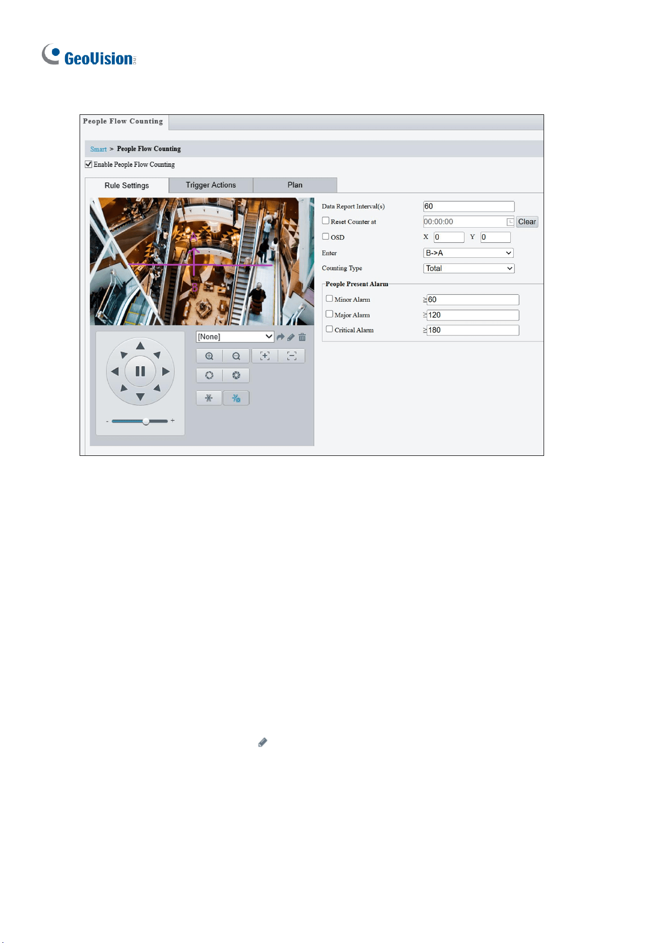
184
For AI models:
Figure 3-52
1. Once enabled, draw a detection line and define the entrance direction. Select the
entrance direction from the Enter drop-down list.
2. Select the desired Counting Type, from Total, People Entered or People Exited. When
any of the People Present Alarms is enabled, this function will not be available.
3. Under People Present Alarm, set the Minor Alarm, Major Alarm, or Critical Alarm.
When the number of people present reaches a set threshold, an alarm will be triggered.
4. Select Reset Counter at to set a time within a day when to reset the counter.
5. Select OSD and adjust the OSD position. Specify the exact position of the OSD by
entering the X and Y coordinates. The top left corner of the image is the origin (0,0), the
horizontal axis is the X-axis, and the vertical axis is the Y-axis.
6. For Trigger Actions, select to edit the desired trigger actions under each alarm. See
Step 6 at the bottom of 3.6.1.1 Cross Line for details.
7. For Plan, follow Step 7 at the bottom of 3.6.1.1 Cross Line.
Also see Appendix K. Installation Guidelines for People Flow Counting, and Appendix O.
Installation Guidelines for People Counting (Non-AI).
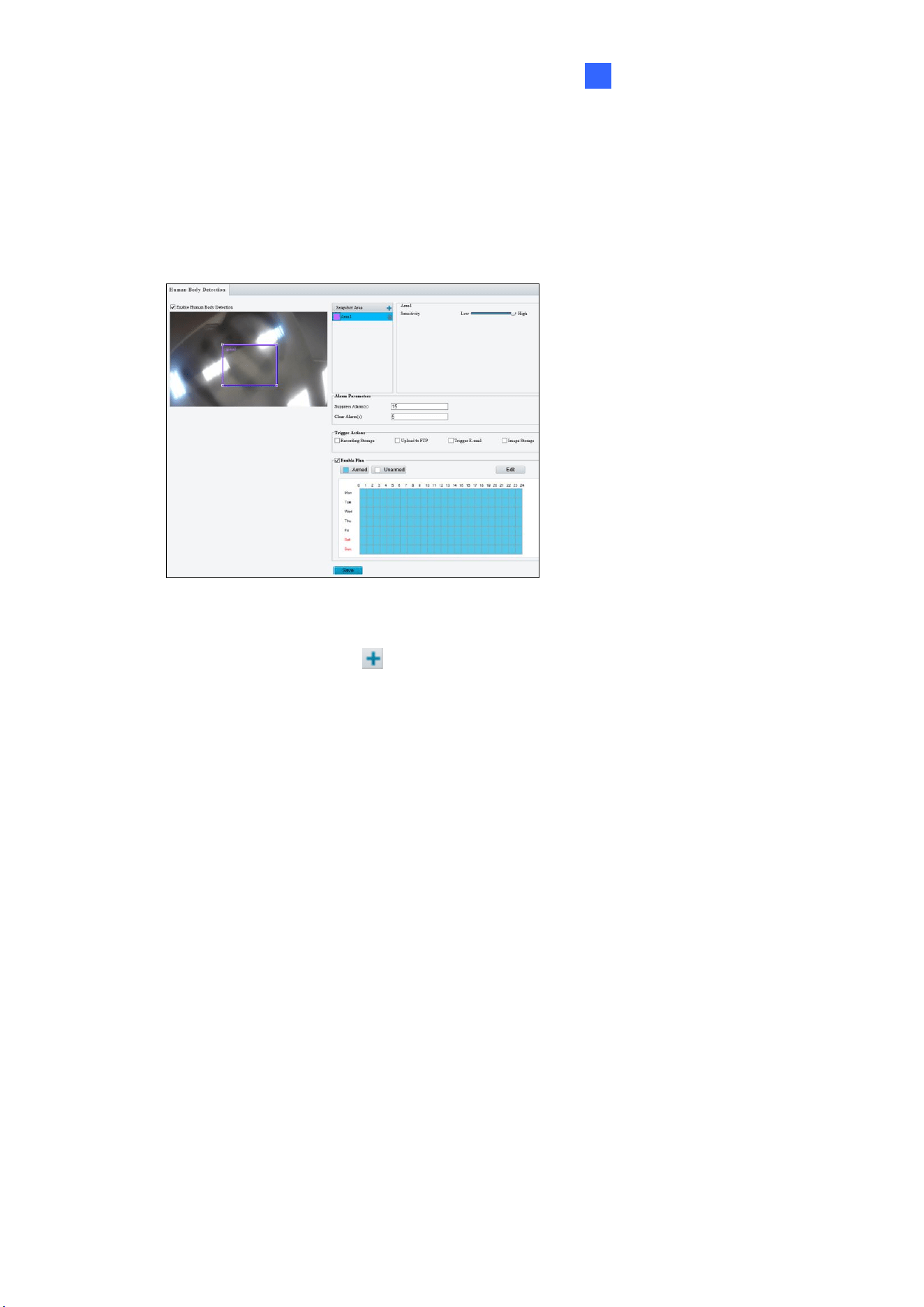
Administrator Mode
185
3
3.6.1.9 Human Body Detection
Human Body Detection is used to generate an alarm whenever a human figure appears in
the specified area. Note this function is only applicable to GV-ABL4711, GV-EBD4701 /
4712, GV-TBL4700 / 4711, GV-TDR4703 series, GV-TFD4700, and GV-TVD4700 / 4711.
Figure 3-53
1. In the Snapshot Area, click to add a new detection area.
2. Click and drag the detection area to a desired location.
3. Adjust the detection sensitivity by dragging the Sensitivity slider.
4. Set up Alarm Parameters.
◼ Suppress alarm: After a detection is triggered, the detection will not be reported
within the set time.
◼ Clear alarm: After a detection is triggered,
• If the detection is not triggered within the set time, the detection will be cleared
and the detection can be reported again.
• If the detection is triggered within the set time, the detection will not be cleared
until the suppress alarm time expires. Then the detection can be reported
again.
5. Set up Trigger Actions.
◼ Upload to FTP and Trigger E-mail: Automatically upload snapshots captured to
the specified FTP server and/or send snapshots to the specified e-mail address.
◼ Recording Storage and Image Storage: Automatically save videos and/or
snapshots captured to the selected storage(s).
6. For Enable Plan, follow Step 7 at the bottom of 3.6.1.1 Cross Line.
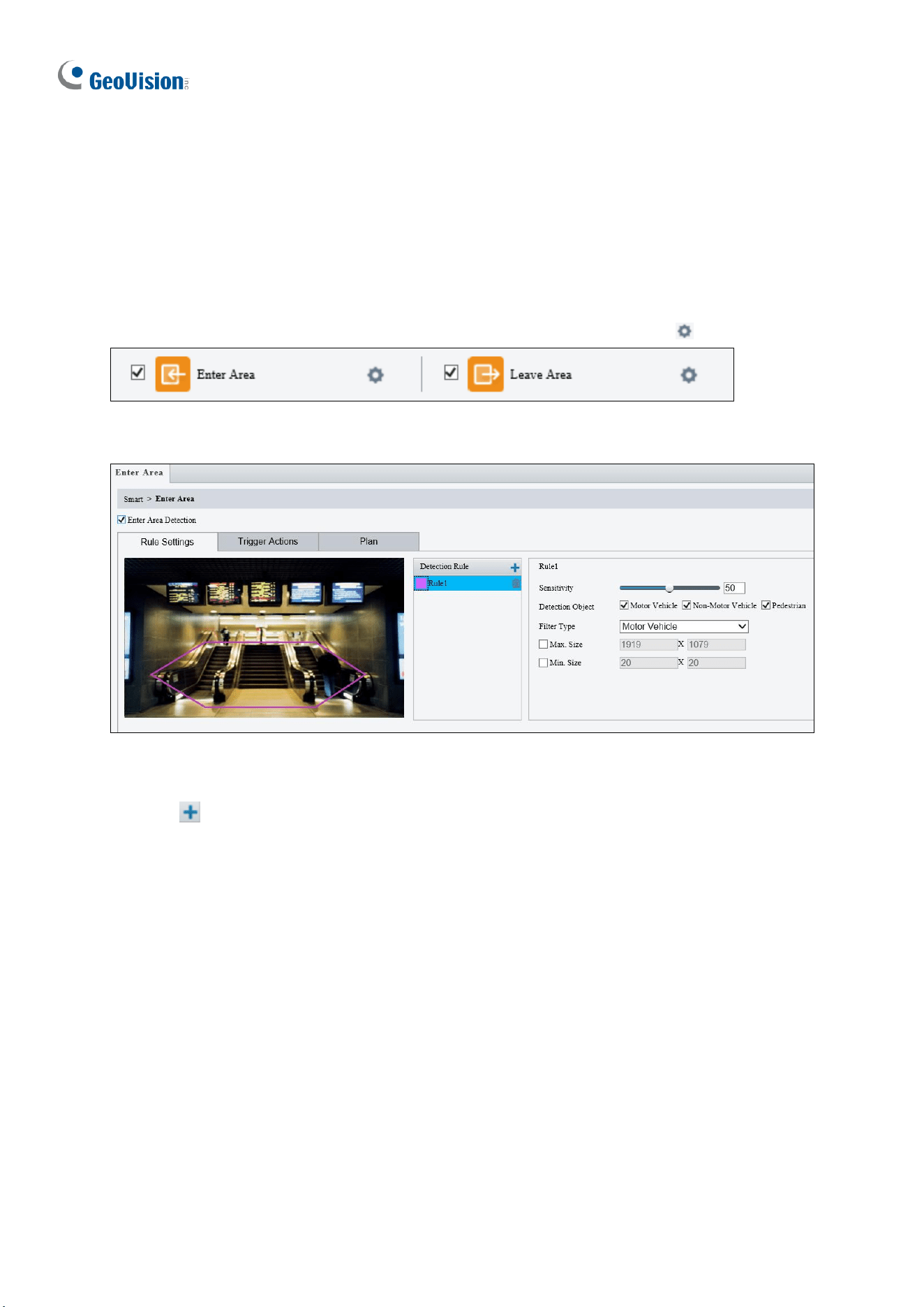
186
3.6.1.10 Enter Area / Leave Area
With Enter Area / Leave Area, an alarm is generated when a person or vehicle enters /
leaves the boundaries of the detection area.
It is NOT recommended to overlap the detection areas when adding multiple detection areas.
Select the checkbox next to Enter Area or Leave Area to enable and click to configure.
Here we use Enter Area as an example.
Figure 3-54
1. Click to mark the live view with a detection area. Repeat this step to add another
detection area (maximum of 4).
2. Drag the nodes of the detection area to mark the boundary for detection.
3. For Sensitivity, drag the slider to adjust the detection sensitivity.
4. For Detection Object, select the type of object to detect when it enters / leaves area.
5. For Filter Type, select the type of object you want to define and its minimum or
maximum size for detection. Once selected, click Max. Size and/or Min. Size, drag the
nodes of the size area to adjust and the system will detect objects within that size range.
Repeat this step to define the size range for another type of object.

Administrator Mode
187
3
6. Under Trigger Actions, select Upload Image (Original) to automatically upload
snapshots to the specified FTP server. Depending on your model, select A -> 1, Alarm
Sound, or Alarm Light to trigger an output device upon people / vehicle / non-motor
vehicle detection.
⚫ Optionally click next to Alarm Sound to set the desired Day, Start Time, End
Time, Alarm Audio, and Number of Repeat Times. You can set up to four periods
for each time, and the time periods cannot overlap.
7. For Plan, follow Step 7 at the bottom of 3.6.1.1 Cross Line.
Note:
1. Certain models may only support uploading snapshots to an FTP server and output
trigger for Trigger Actions.
2. Motor Vehicle includes cars, trucks, and buses. Non-Motor Vehicle includes bicycles
and motorcycles.
3. Alarm Sound is only applicable to GV-PTZ5810-IR / TBL8804 / TMS20811, and Alarm
Light is only applicable to GV-BLFC5800 / EBFC5800 / TBL8804. See details in 3.3.3
Audio for Alarm Sound and 3.5.1 Image (Smart Illumination) for Alarm Light.
Also see Appendix J. Installation Guidelines for Perimeter Protection.
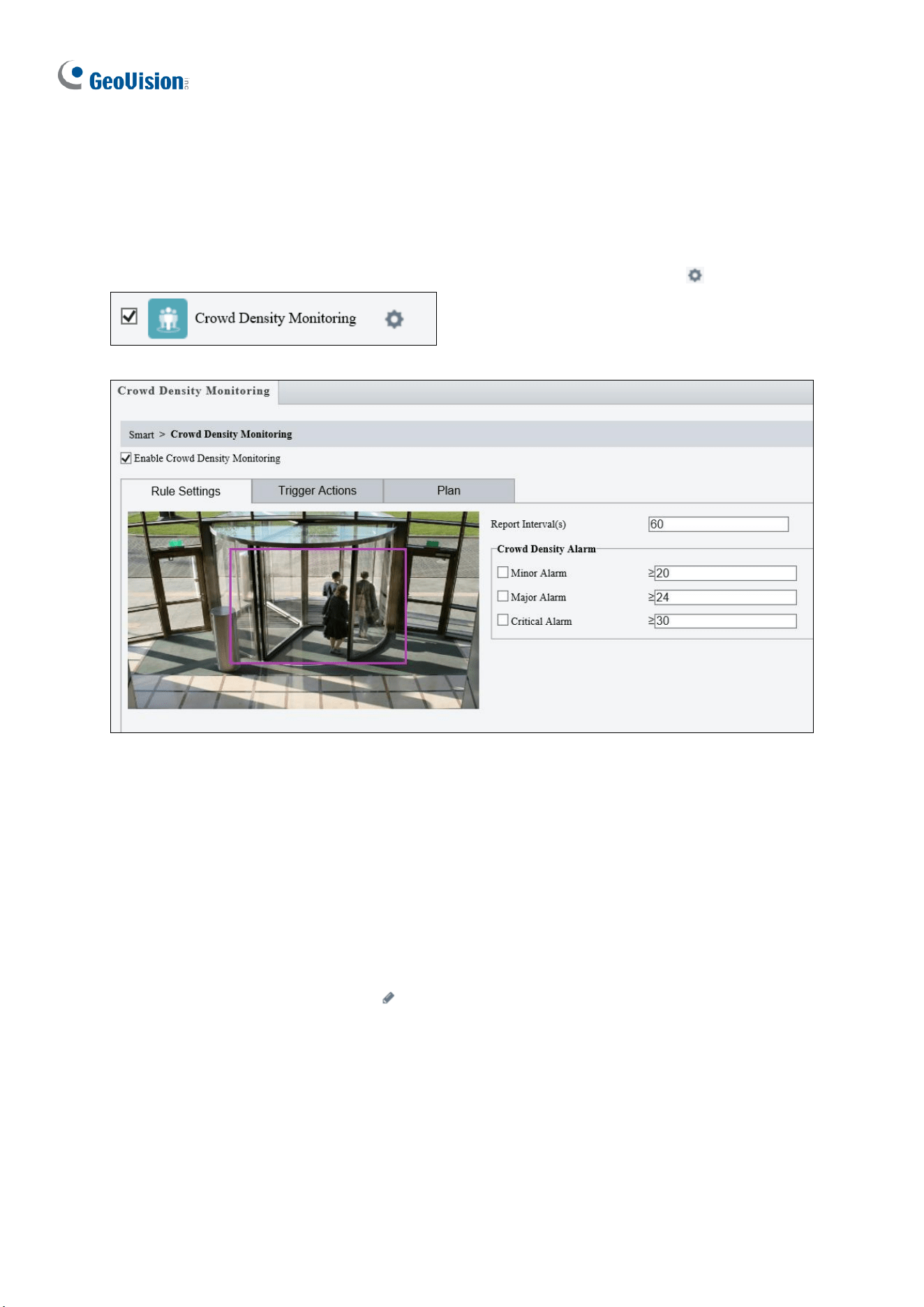
188
3.6.1.11 Crowd Density Monitoring
With Crowd Density Monitoring, an alarm is triggered when the number of people in a
specified area exceeds the defined alarm threshold.
Select the checkbox next to Crowd Density Monitoring to enable and click to configure.
Figure 3-55
1. Once enabled, define the detection area on the live view.
2. For Report Interval(s), set the time interval (in seconds) for reporting crowd density data.
3. Under Crowd Density Alarm, set the alarm threshold for Minor Alarm, Major Alarm,
and Critical Alarm. The number of people set for Critical Alarm accounts for the
largest and Minor Alarm the smallest. The value ranges from 1 to 40, and each alarm
will be triggered when the number of people reaches the set threshold.
4. Under Trigger Actions, select on the desired alarm. See details in Step 6 at the
bottom of 3.6.1.1 Cross Line.
5. For Plan, follow Step 7 at the bottom of 3.6.1.1 Cross Line.
Also see Appendix L. Installation Guidelines for Crowd Density Monitoring.
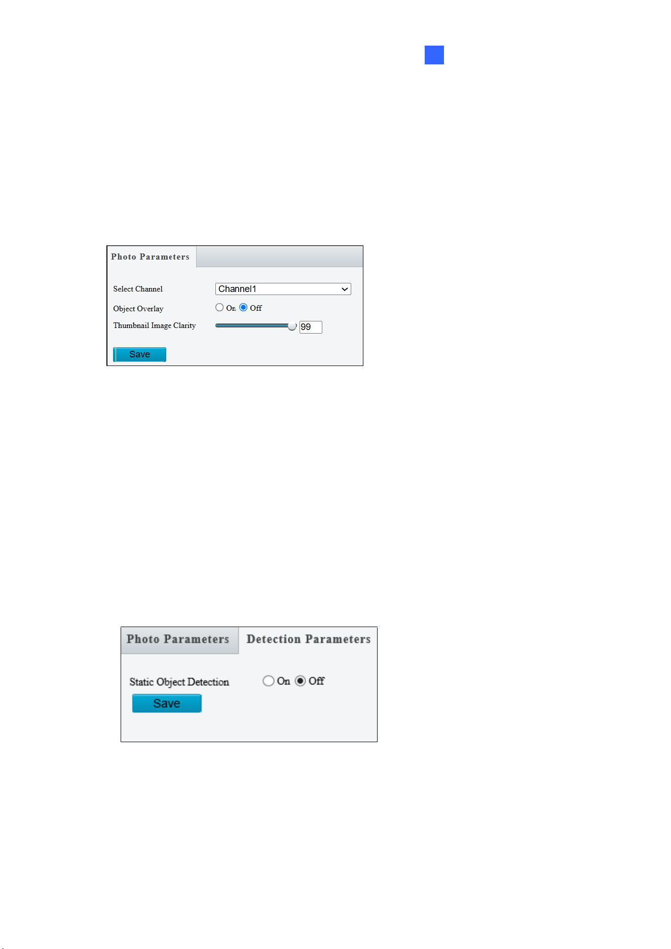
Administrator Mode
189
3
3.6.2 Advanced Settings
This section allows you to configure the clarity of the snapshots captured by face detection
events and choose the detection modes used for all video-analytic events.
Photo Parameters
Figure 3-56
◼ Select Channel: Select the desired channel from the Select Channel dropdown list
(only applicable to GV-TMS20811).
◼ Object Overlay: Select to enable or disable object overlay on the image. When enabled,
a bounding box will overlay on the object in the original image (only applicable to GV-
TMS20811).
◼ Thumbnail Image Clarity: Drag the slider to adjust the clarity of the snapshots
captured by face detection events.
Detection Parameters
Figure 3-57
◼ Static Object Detection: Select On for the camera to detect both static and moving
targets and Off to detect moving targets only.
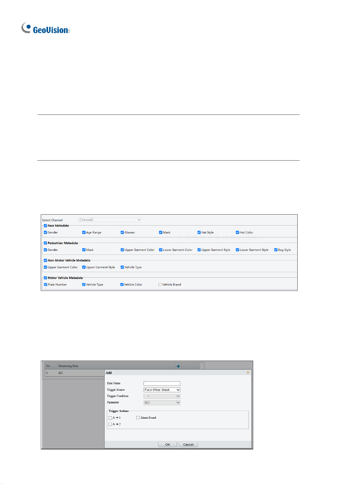
190
3.6.3 Metadata Analysis
You can configure metadata collection rules to collect desired metadata information of the
monitored objects.
Note:
1. This function is only applicable to GV-EBDP5800 / 8800, TBLP5800 / 8800, and
TMS20811.
2. For multi-channel cameras, you can configure metadata collection parameters for the
channels separately.
Collect Metadata
Configure metadata collection rules to collect desired metadata information of the monitored
objects.
Figure 3-58
Select the desired metadata to be collected and click Save.
Monitor by Metadata
1. Go to Setup > Intelligent > Metadata Collection > Monitor by Metadata.

Administrator Mode
191
3
2. Click to add a monitoring rule.
3. Set the monitoring rule.
Item
Description
Rule Name
Set a name for the rule.
Trigger Source
Choose the metadata to trigger monitoring: Face-Wear Mask or Face-
Body Temperature.
Trigger Actions
See Alarm-triggered Actions for details.
4. Click OK.
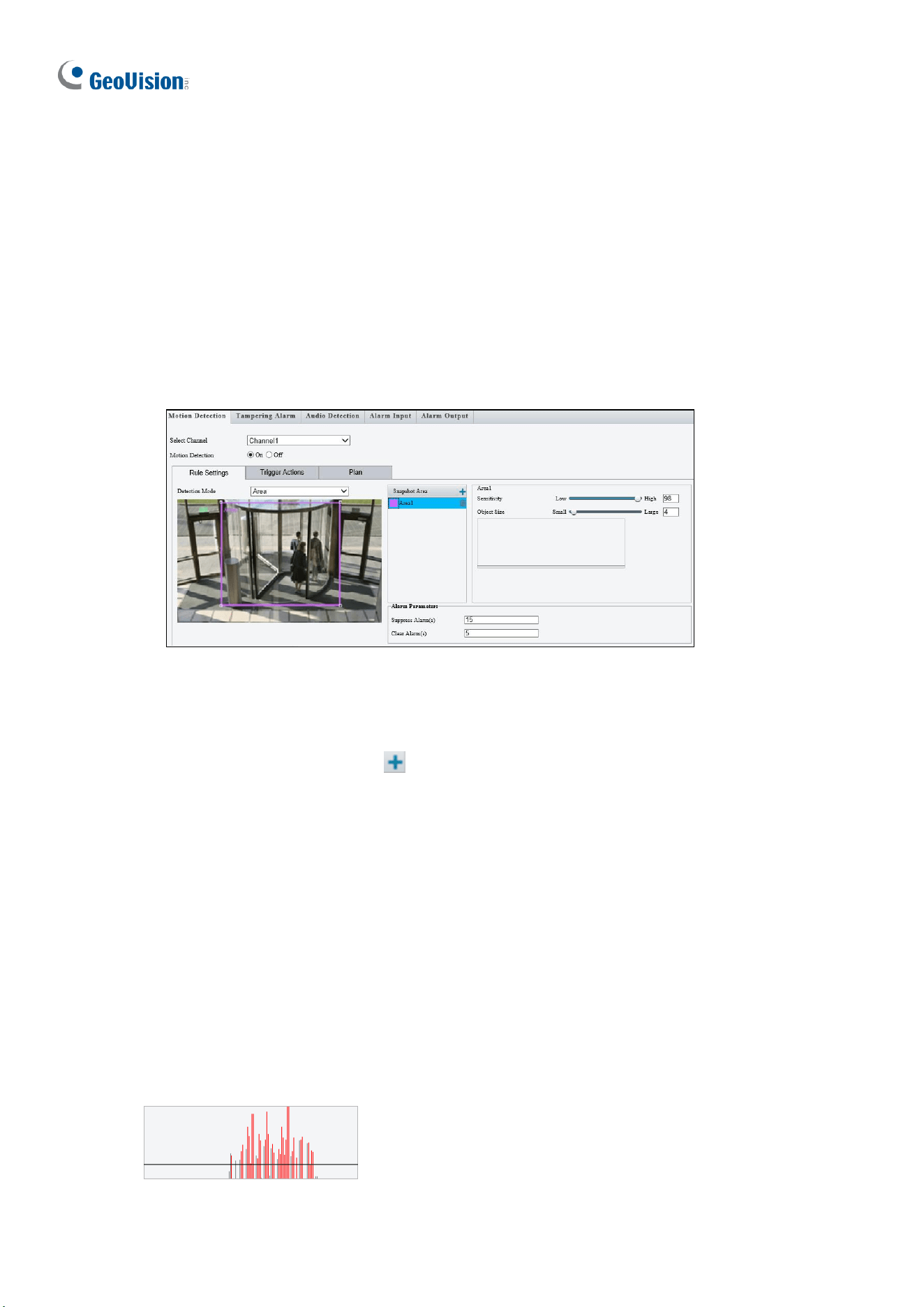
192
3.7 Events
You can set the camera to generate an alarm upon motion detection, tampering alarm, audio
detection and one-key disarming.
3.7.1 Motion Detection
Motion detection is used to generate an alarm whenever movement occurs in the specified
area.
Figure 3-58-1
1. Select the desired channel from the Select Channel dropdown list (only applicable to
GV-TMS8800 / 20811).
2. To create a detection area, click . A rectangle appears on the image.
3. Adjust the position, size and shape of the rectangle detection area.
4. Alternatively, select Grid as the Detection Mode to define the area for detection.
5. Use the following functions to reduce false alarm.
◼ Sensitivity: Move the slider to adjust the detection sensitivity.
◼ Object Size: When the extent of motion within the detection area exceeds the set
object size, motion detection alarm is triggered.
Motion detection results of the current detection area are shown below in real time. The
red means motions that have triggered a motion detection alarm. The height of the lines
indicates the extent of motion. The density of the lines indicates the frequency of motion.
The higher a line, the greater the extent. The denser the lines, the higher the frequency.
6. Set up Alarm Parameters.
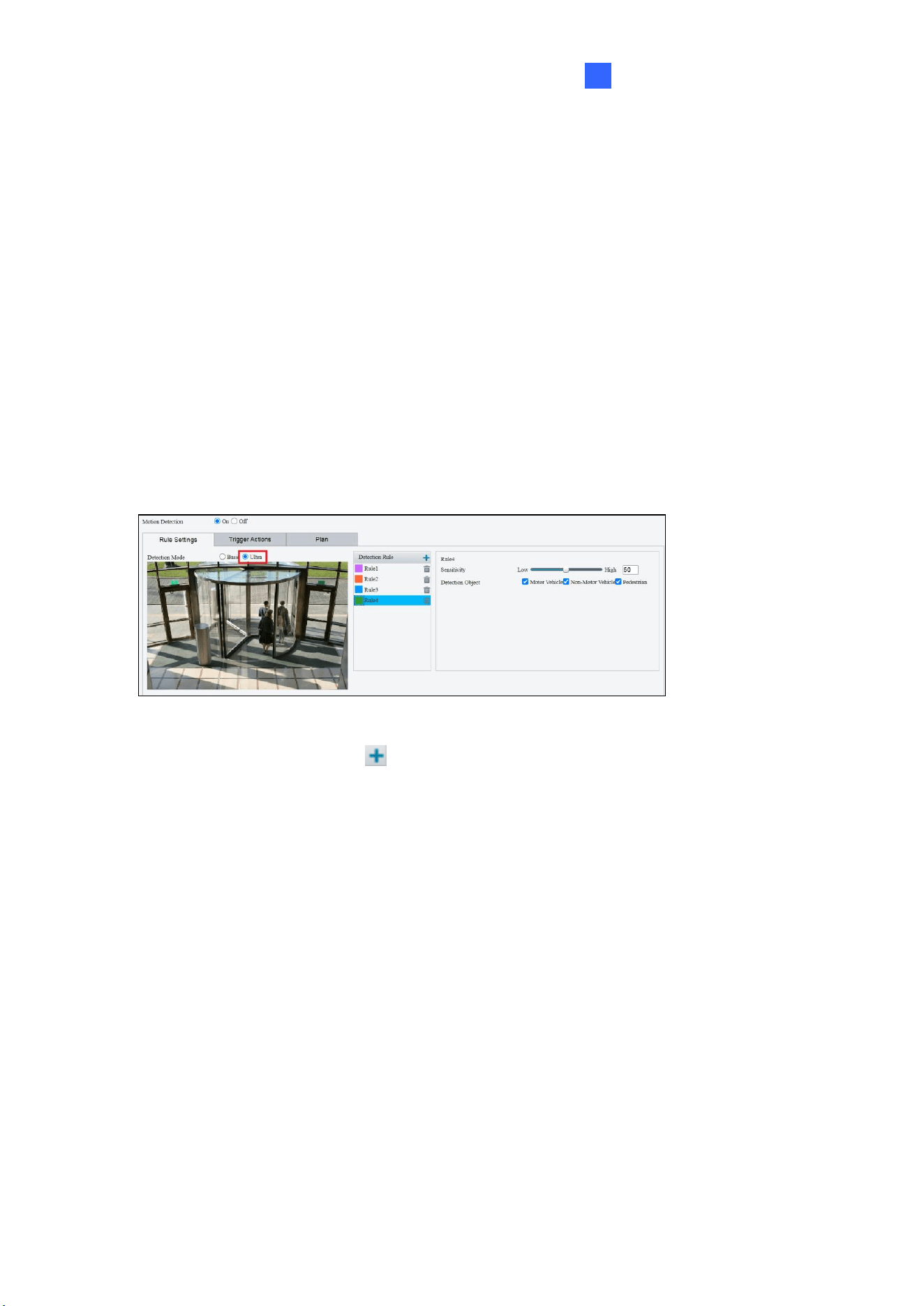
Administrator Mode
193
3
◼ Suppress alarm (5~3600): After an alarm is triggered, the alarm will not be
reported within the set time.
◼ Clear alarm (1~600): After an alarm is triggered,
⚫ If the alarm is not triggered within the set time, the alarm will be cleared and the
alarm can be reported again.
⚫ If the alarm is triggered within the set time, the alarm will not be cleared until the
suppress alarm time expires. Then the alarm can be reported again.
7. For Trigger Actions and Plan, follow Step 6 ~ 7 at the bottom of 3.6.1.1 Cross Line.
[Ultra Motion Detection]
The camera detects motions of motor vehicles and pedestrians in specified detection areas
and reports an alarm when detection rules are triggered.
Figure 3-58-2
1. To add a detection area, click . A rectangle appears on the image.
2. Adjust the position, size and shape of the rectangle detection area.
3. Move the Sensitivity slider to adjust the detection sensitivity. The higher the sensitivity
level, the higher the detection rate of small motions, and the higher the false alarm rate.
Configure the setting based on the scene and your actual needs.
4. Select the detection objects: Motor Vehicle, Non-Motor Vehicle and Pedestrian.
5. For Trigger Actions and Plan, follow Step 6 ~ 7 at the bottom of 3.6.1.1 Cross Line.
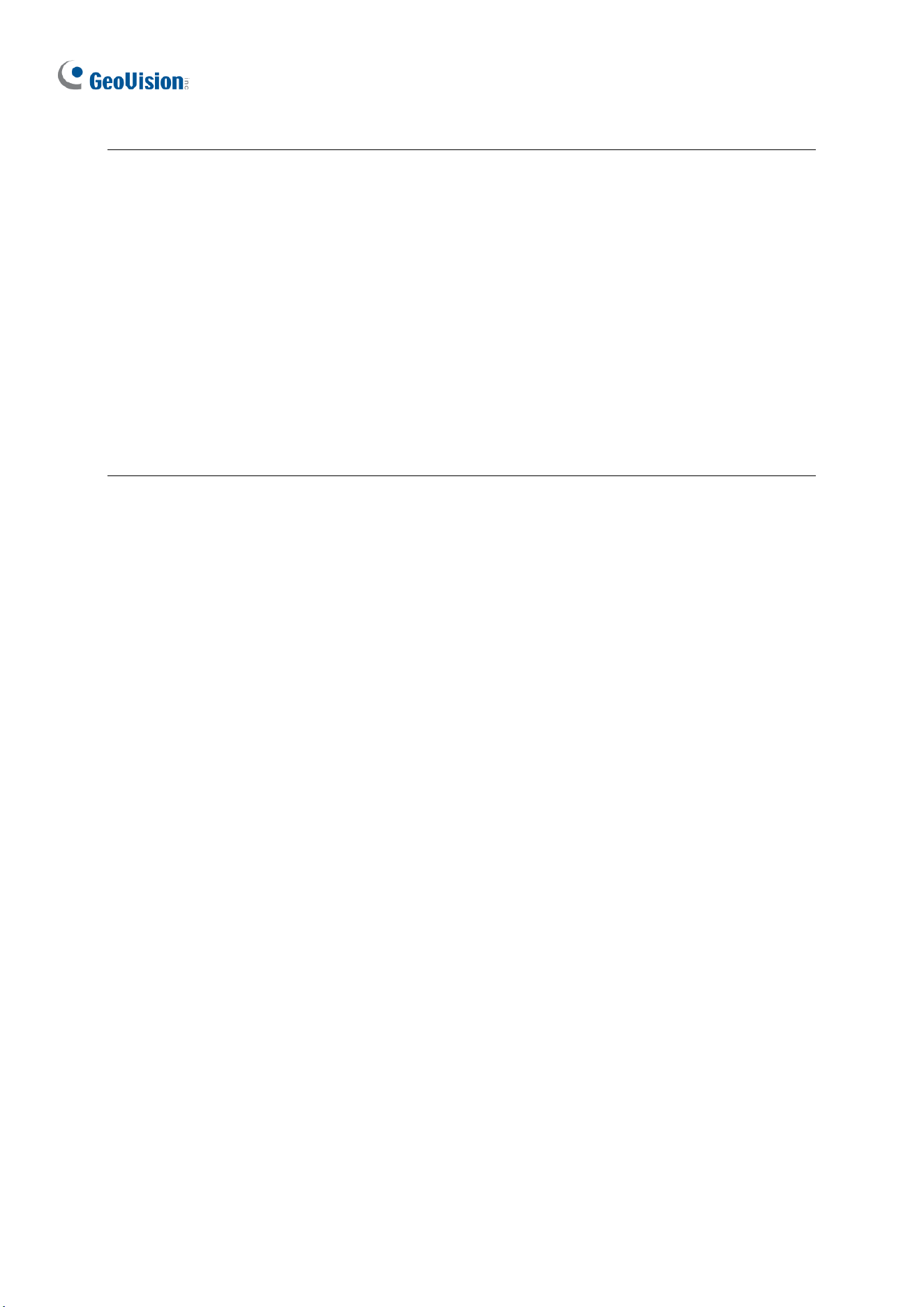
194
Note:
1. GV-ABL2703 series / 4703 / 4711, GV-ADR2702 / 4702, GV-BLFC5800, GV-EBD2704 /
2705 / 4701 / 4704 / 4712 / 4813 / 8800 / 8813, GV-EBDP5800 / 8800, GV-EBFC5800,
GV-PTZ5810-IR, GV-TBL2703 series / 2705 / 2706 series / 2718 / 4700 / 4703 / 4705 /
4711 / 4810 / 8710 / 8804 / 8810, GV-TBLP5800 / 8800, GV-TDR2702 series / 2704
series / 2705 / 4702 series / 4703 series / 4704 series / 4803 series / 8805, GV-TFD4700
/ 4800, GV-TMS8800 / 20811, GV-TVD2712 / 4700 / 4711 / 4811 / 4810 / 8810, and GV-
FER5702 support up to 4 Motion Detection areas while all other models support up to 8.
2. For the Upload to FTP function, make sure to configure the settings in 3.8.2 FTP and
3.3.2 Snapshot first.
3. For the Trigger E-mail function, make sure to configure the settings in 3.2.5 E-mail and
3.3.2 Snapshot first.
4. Enabling the Ultra Motion Detection (for Motor Vehicle, Non-Motor Vehicle or Pedestrian)
helps detect specific objects and reduces false alarms. However, note that the accuracy
of this feature may vary due to environmental factors. Adjust settings as needed for
optimal performance.
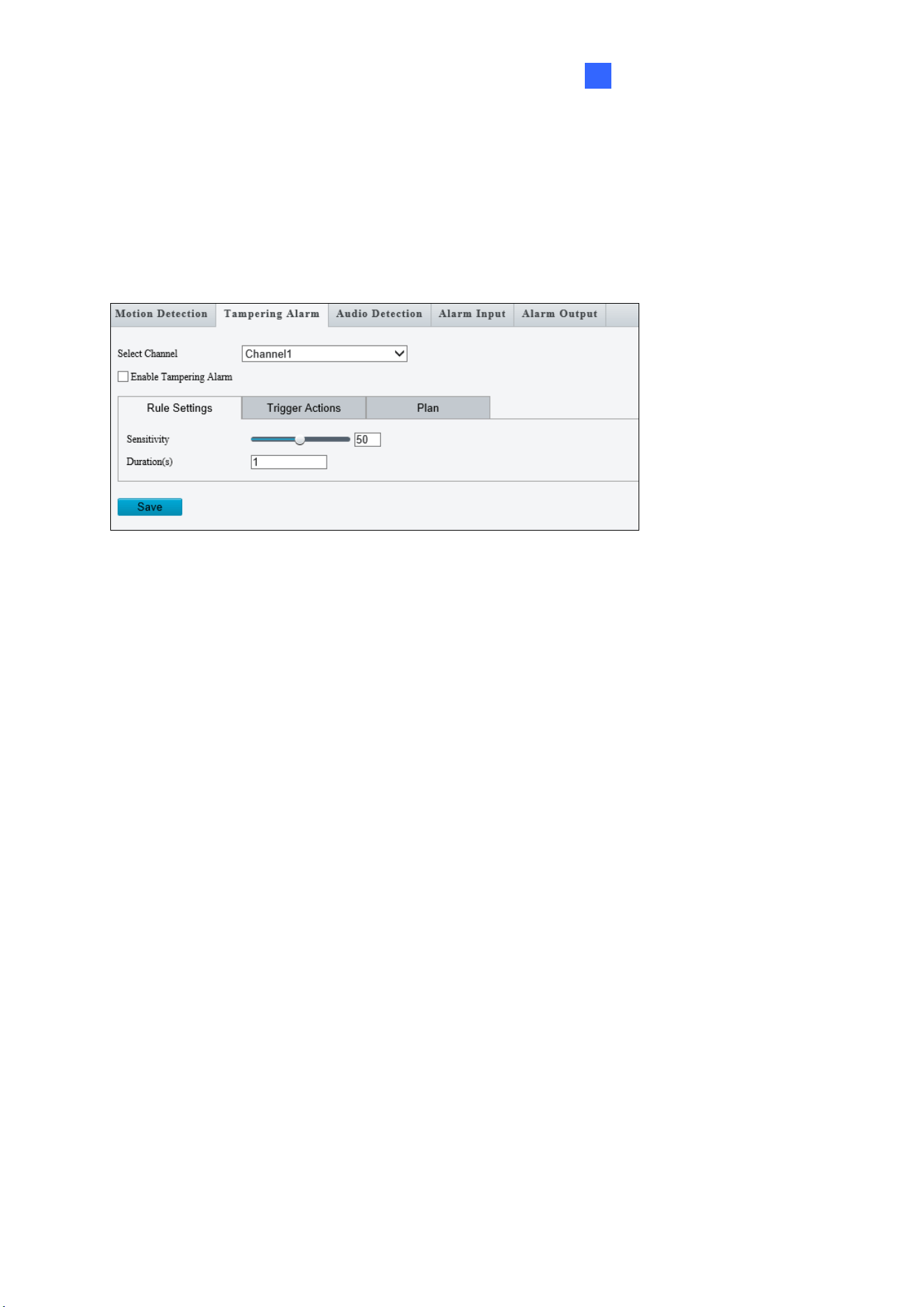
Administrator Mode
195
3
3.7.2 Tampering Alarm
Tampering alarm is used to detect when the camera is being physically tampered with. An
alarm can be generated when the camera is moved, covered up, or out of focus.
Figure 3-59
1. Select the desired channel from the Select Channel dropdown list (only applicable to
GV-TMS8800 / 20811).
2. Select On / Enable Tampering Alarm to enable Tampering Alarm.
3. Use the following functions to adjust the alarm settings.
◼ Sensitivity: Move the slider to increase or decrease detection sensitivity.
◼ Duration: Specify the duration of the alarm after which the triggered output device
will be turned off.
4. For Trigger Actions and Plan, follow Step 6 ~ 7 at the bottom of 3.6.1.1 Cross Line.
196
3.7.3 Audio Detection
Note this function is only applicable to audio-in-supporting models.
Audio detection is used to detect abnormal audio volume. When the rise, fall, or change of
volume exceeds the set limit, or when the input volume reaches the set threshold, an alarm
is generated. Make sure audio input is enabled.
Figure 3-60
1. Select On to activate Audio Detection.
2. Select a Detection Type.
◼ Sudden Rises: An alarm is reported when the rise of volume exceeds the set
Difference.
◼ Sudden Fall: An alarm is reported when the fall of volume exceeds the set
Difference.
◼ Sudden Change: An alarm is reported when the rise or fall of volume exceeds the
set Difference.
◼ Threshold: An alarm is reported when the volume exceeds the set Threshold.
3. Set a Difference or Threshold.
4. For Trigger Actions and Plan, follow Step 6 ~ 7 at the bottom of 3.6.1.1 Cross Line.
Select the actions to be triggered by an audio alarm and set a schedule plan if needed. Refer
to 3.7.1 Motion Detection for detailed instructions.
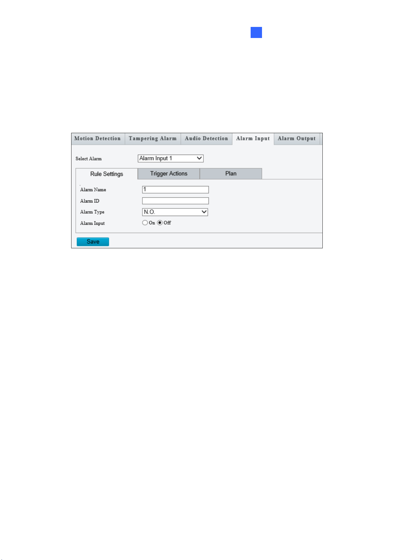
Administrator Mode
197
3
3.7.4 Alarm Input
The camera can receive alarm information from an input device.
Note this function is only applicable to the models supporting the I/O device.
Figure 3-61
1. Select Alarm Input 1 or Alarm Input 2 from the drop-down list.
2. Type an Alarm Name, and set an Alarm ID.
3. Select Normally Open or Normally Closed according to the type of the alarm input
device.
4. Select Enable next to Alarm Input.
5. For Trigger Actions and Plan, follow Step 6 ~ 7 at the bottom of 3.6.1.1 Cross Line.
6. Click Save.
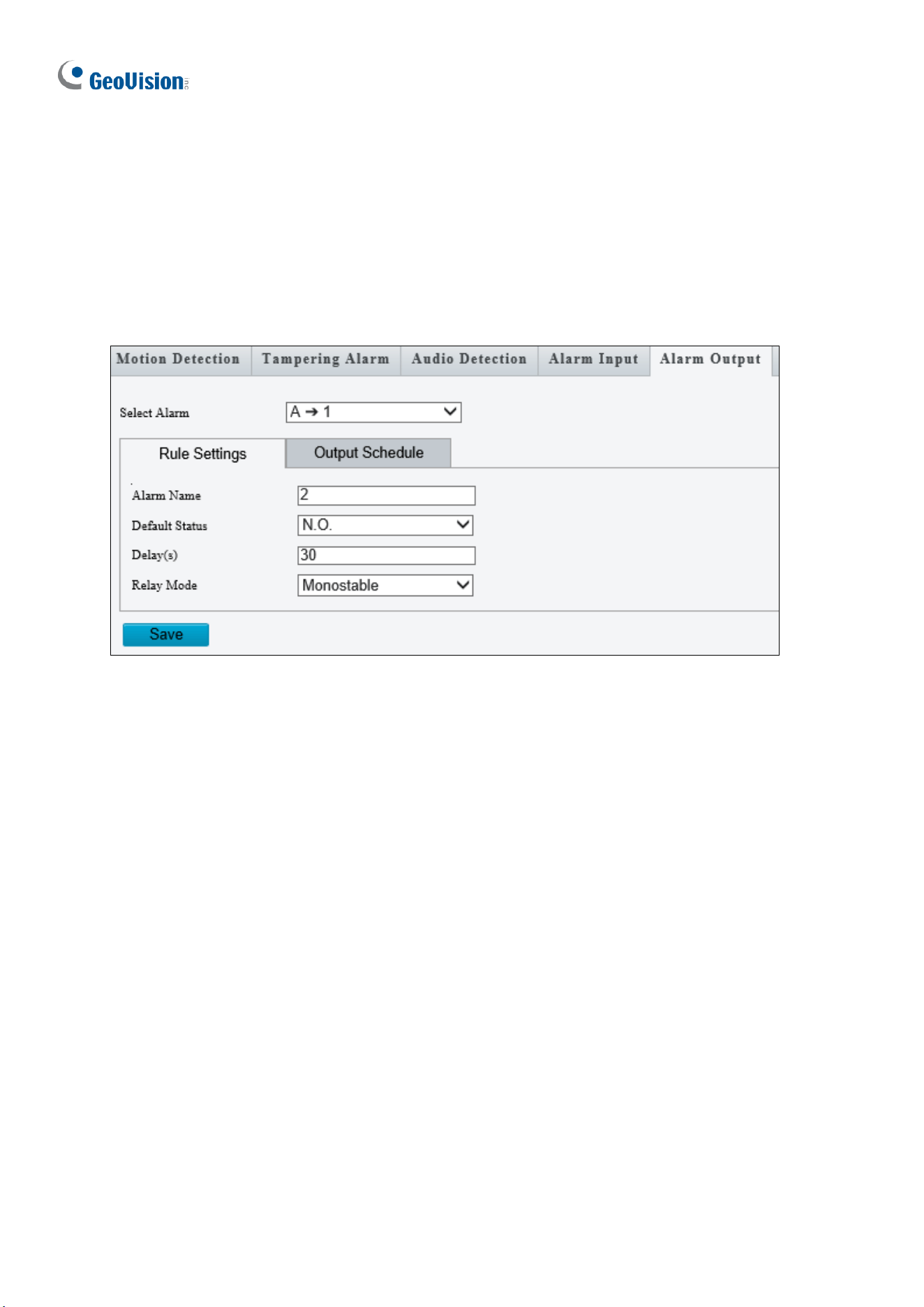
198
3.7.5 Alarm Output
After alarm output is triggered by a motion detection alarm, temperature alarm or input alarm,
the camera can trigger an output device.
Note this function is only applicable to the models supporting the I/O device.
Figure 3-62
1. Type the Alarm Name for the output device.
2. Set the status to Normally Open (default setting).
3. Set the alarm duration.
4. Set relay mode to trigger the output device as alarm lights. Select Monostable to trigger
by pulse or Bistable by low or high level.
5. Set a schedule plan in Output Schedule by following Step 7 at the bottom of 3.6.1.1
Cross Line.
6. Click Save.
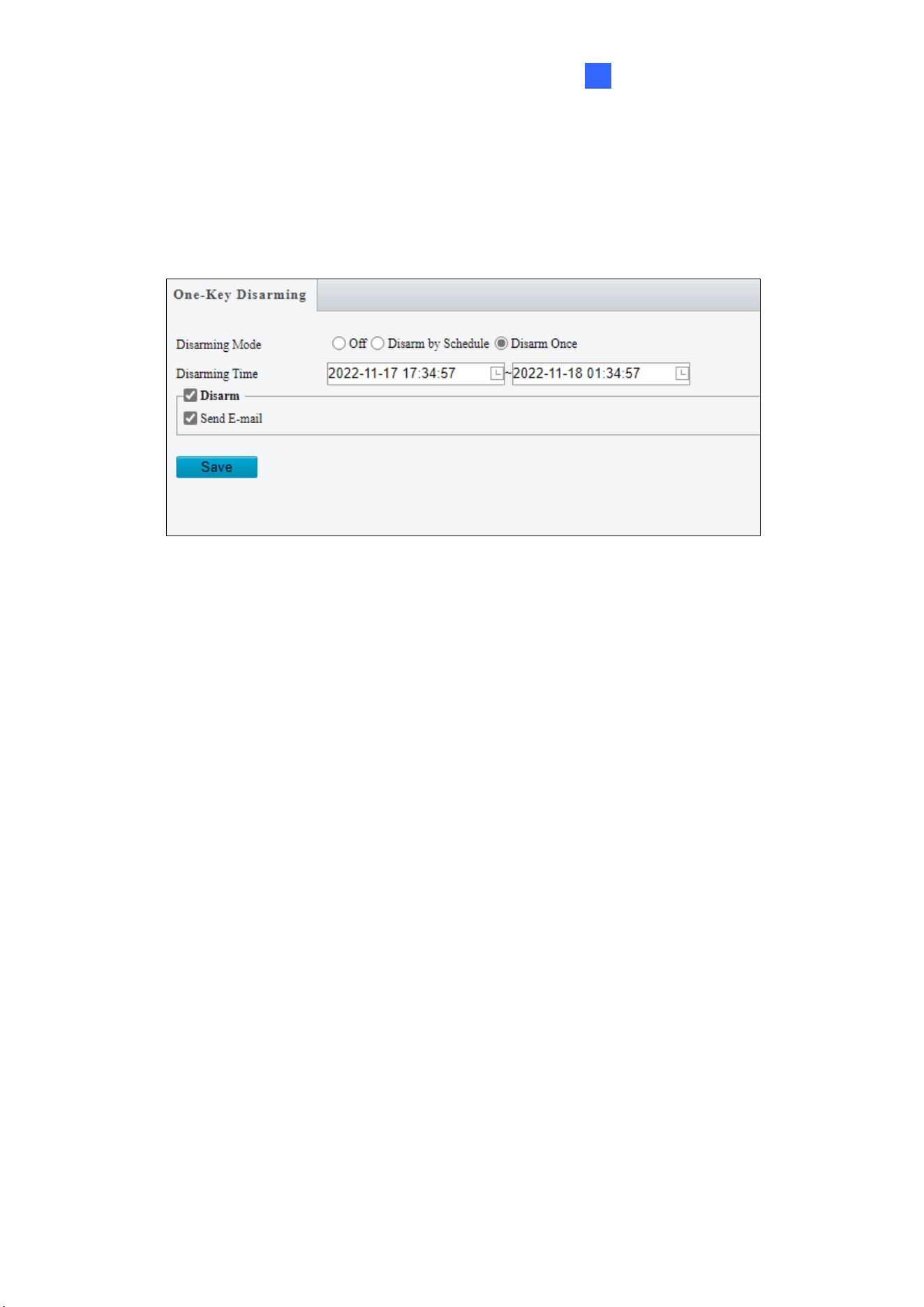
Administrator Mode
199
3
3.7.6 One-Key Disarming
You can disable input / output alarms or e-mail alert triggers over a specified time period.
Figure 3-63
1. Select Off, Disarm by Schedule, or Disarm Once under the Disarming Mode. For
Disarm by Schedule and Disarm Once, set the desired shielding time period under
Disarming Time.
2. Select Alarm Input / output / Send E-mail / Alarm Sound you wish to disable under
Disarm.
3. Click Save.
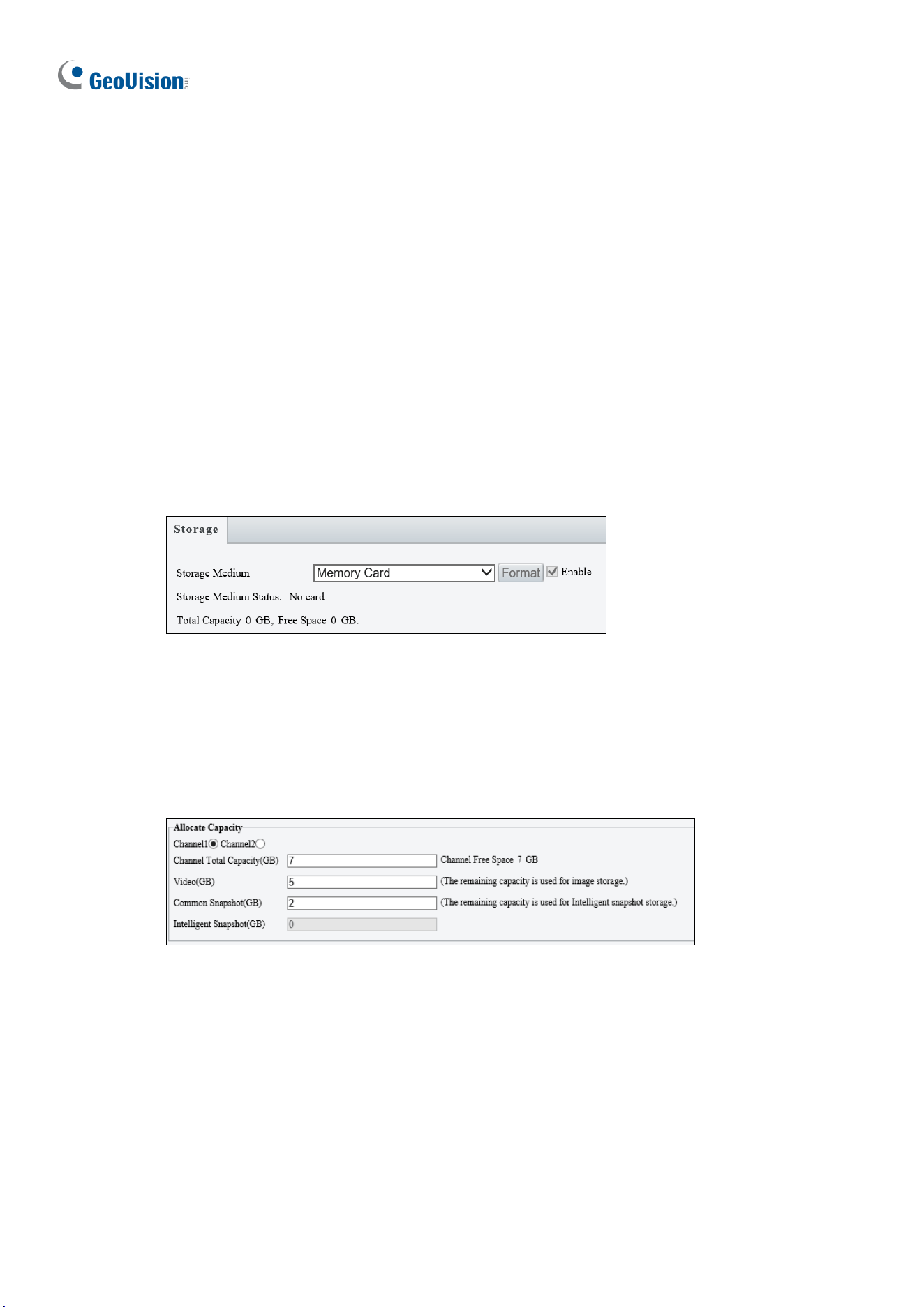
200
3.8 Storage
This section allows you to configure storage related settings and set up FTP server.
3.8.1 Formatting Storage
After inserting a memory card, you need to reboot the camera and refresh the Web interface.
You can configure the storage settings on the Storage page.
Note this function is only available on the models with a SD card slot.
[Storage]
Figure 3-64
◼ Storage Medium: Click the Format button to format the memory card before you start
recording and Enable the memory card.
[Allocate Capacity]
Figure 3-65
◼ Channel 1 / Channel 2 / Channel 3 / Channel 4: Select the channel for the following
capacity configurations (only applicable to GV-TMS8800 / 20811, two channels for GV-
TMS8800 and four channels for GV-TMS20811).
◼ Channel Total Capacity (GB): Specify the total capacity for the selected channel (only
applicable to GV-TMS8800 / 20811). The camera will automatically allocate the capacity
for the other channel after the capacity for one channel is set.
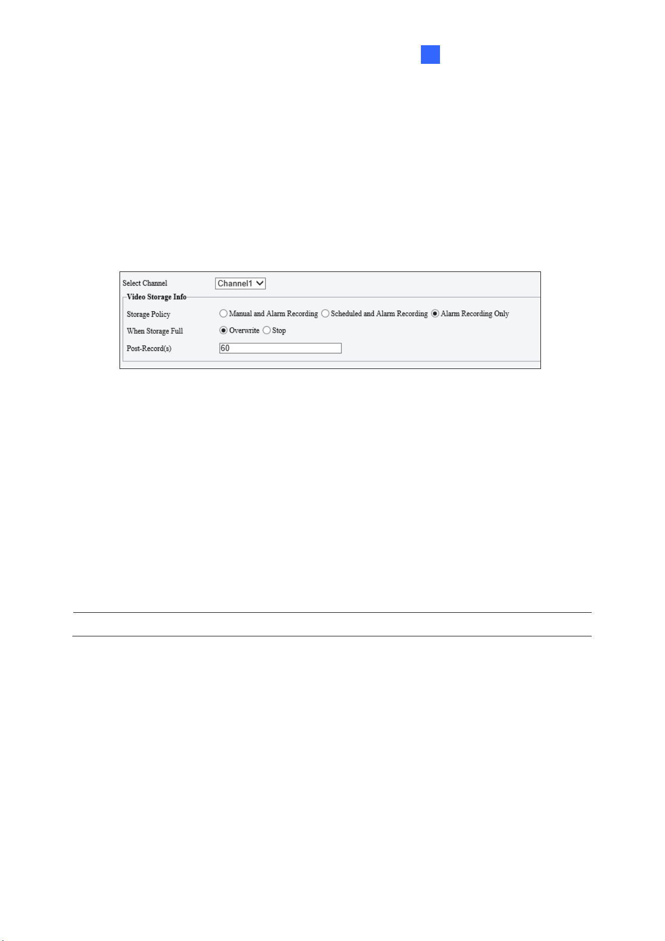
Administrator Mode
201
3
◼ Video: Set the storage capacity used to store recorded videos. The remaining capacity
is used for captured snapshots.
◼ Common Snapshot: The storage capacity used to store captured snapshots.
◼ Face Snapshot: The storage capacity used to store captured face snapshots.
◼ Intelligent Snapshot: The storage capacity used to store captured snapshots of motor
vehicle (cars, trucks, and buses), non-motor vehicle (bicycles and motorcycles), and
people.
[Video Storage Info]
Figure 3-66
◼ Select Channel: Select the desired channel for video storage configurations from the
dropdown list (only applicable to GV-TMS8800 / 20811).
◼ Storage Policy: Choose the Storage Policy from the three options.
Manual and Alarm Recording: Manually start recording and upon input-triggered
events.
Scheduled and Alarm Recording: Start recording by schedule and upon input-
triggered events.
Alarm Recording Only: Start recording upon input-triggered events.
Note: The file size of more than 500 MB is required to create one recording file.
Note for GV-ABL4711, GV-EBD2704 / 4701 / 4712, GV-TBL2705 / 4700 / 4711, GV-
TDR2704 series / 4703 series, GV-TFD4700, and GV-TVD4700 / 4711, the options for
Storage Policy are as follows:
◼ Manual Storage: Manually start recording.
◼ Planned Storage: Start recording by schedule.
◼ Off: Stop recording.

202
◼ Stream: Select the stream you want to use for recording.
◼ When Storage Full:
Overwrite: If there is no free space in the memory card, new data will overwrite the
existing date repeatedly.
Stop: If there is no free space in the memory card, new data will not be saved to the
memory card.
Note: This function is NOT applicable to GV-ABL4711 / TBL4711 / TFD4700 / TVD4711.
◼ Post Record(s): When an alarm is raised, the camera is triggered to record live video
and continues recording for the specified post-record time after the alarm is cleared.
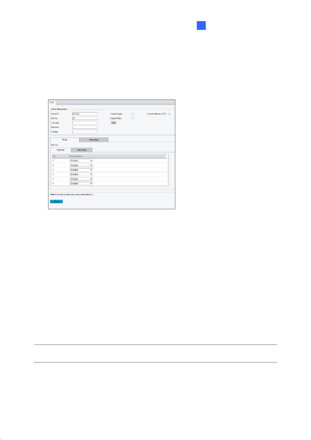
Administrator Mode
203
3
3.8.2 FTP
You can upload snapshots and videos from the camera to a specified FTP server.
FTP
Figure 3-67
1. Type the Server IP address.
2. Change the Port No. of the FTP server if needed.
3. Type the Username and Password of the upload account.
4. Enable Upload Images / Upload Video.
5. Select Convert Path to UTF8 format if necessary.
6. Under File Path on the Photo / Recording tab, select a directory in which to save the
images / recordings, or select Custom to name a storage folder on the FTP server.
7. Under File Name, select a Separator and a combination of Naming Element(s) to name
the snapshots captured. A template of the file name is shown.
8. Click Save.
Note: To upload snapshots, make sure to enable the Snapshot function. For more detailed
instructions, refer to 3.3.2 Snapshot.
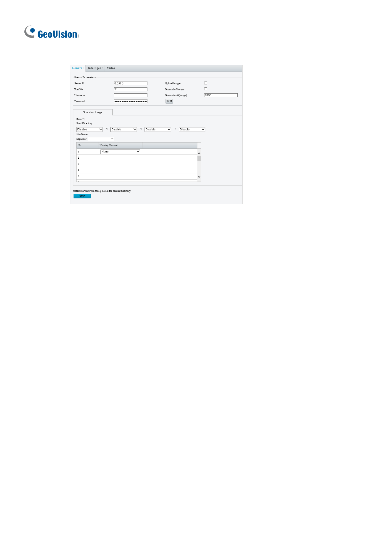
204
Certain models have the following UI:
Figure 3-68
1. Type the Server IP address.
2. Change the Port No. of the FTP server if needed.
3. Type the Username and Password of the upload account.
4. Enable Upload Images.
5. Select Overwrite Storage to overwrite the oldest images when the storage is full. You
can set the maximum number of images allowed in Overwrite At (Image). When the
defined image threshold is reached, the oldest image is overwritten.
6. Save To Root Directory: Select a directory in which to save the images, or select
Custom to name a storage folder on the FTP server.
7. Under File Name, select a Separator and a combination of Naming Element(s) to name
the snapshots captured. A template of the file name is shown.
8. Click Save.
Note:
1. To upload snapshots, make sure to enable the Snapshot function. For more detailed
instructions, refer to 3.3.2 Snapshot.
2. If Overwrite Storage is not selected and the storage is full, snapshots can no longer be
taken.
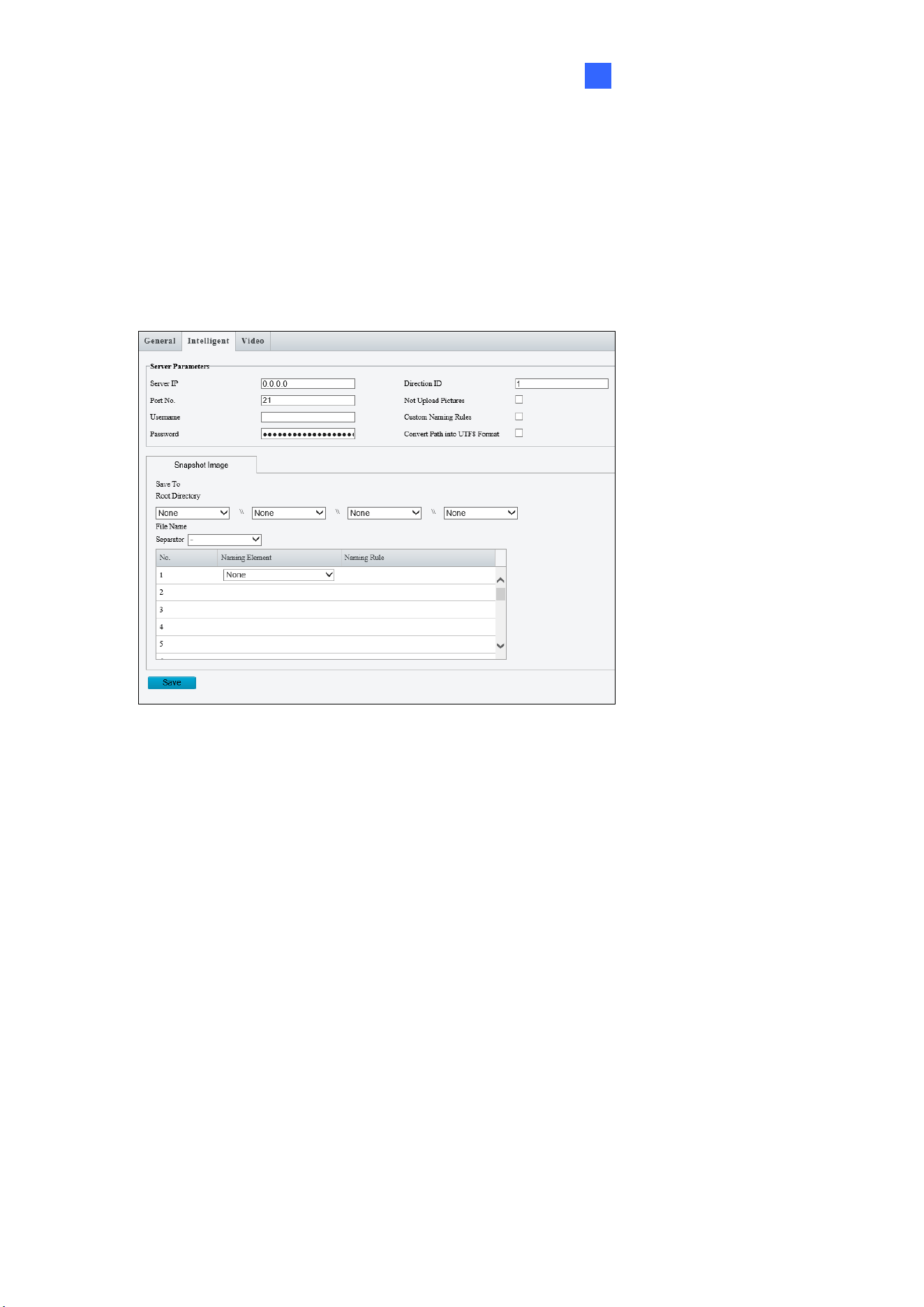
Administrator Mode
205
3
Face (Intelligent)
This function is used to store snapshots taken for smart functions such as face detection.
For GV-BLFC5800, GV-EBD4813 / 8800 / 8813, GV-EBFC5800, GV-PTZ5810-IR, GV-
TBL4810 / 8804 / 8810, GV-TDR4803 series / 8805, GV-TFD4800, and GV-TVD4810 / 8810,
this function is named Intelligent to store captured snapshots of motor vehicle (cars, trucks,
and buses), non-motor vehicle (bicycles and motorcycles), and people.
Figure 3-69
1. Type the Server IP address.
2. Change the Port No. of the FTP server if needed.
3. Type the Username and Password of the upload account.
4. Save To Root Directory: Select a directory in which to save the images, or select
Custom to name a storage folder on the FTP server.
5. Under File Name, select a Separator and a combination of Naming Element(s) to name
the snapshots captured. A template of the file name is shown.
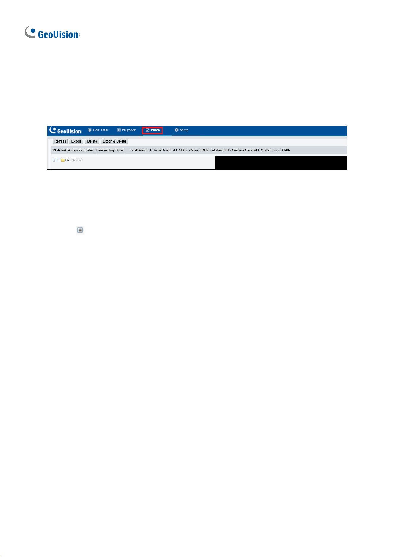
206
3.8.3 Backing Up Storage
Note this function is only applicable to Internet Explorer browsers.
In the Photo setting, you can back up the existing videos and snapshots to your local PC.
Figure 3-70
1. Select Photo at the top of the Web interface and click Refresh.
2. Click Ascending Order or Descending Order to sort the folders.
3. Click to view more folders and select or deselect the folders to back up.
4. Click Export and select a destination to store the selected folders.
5. Click Delete to delete the selected folders.
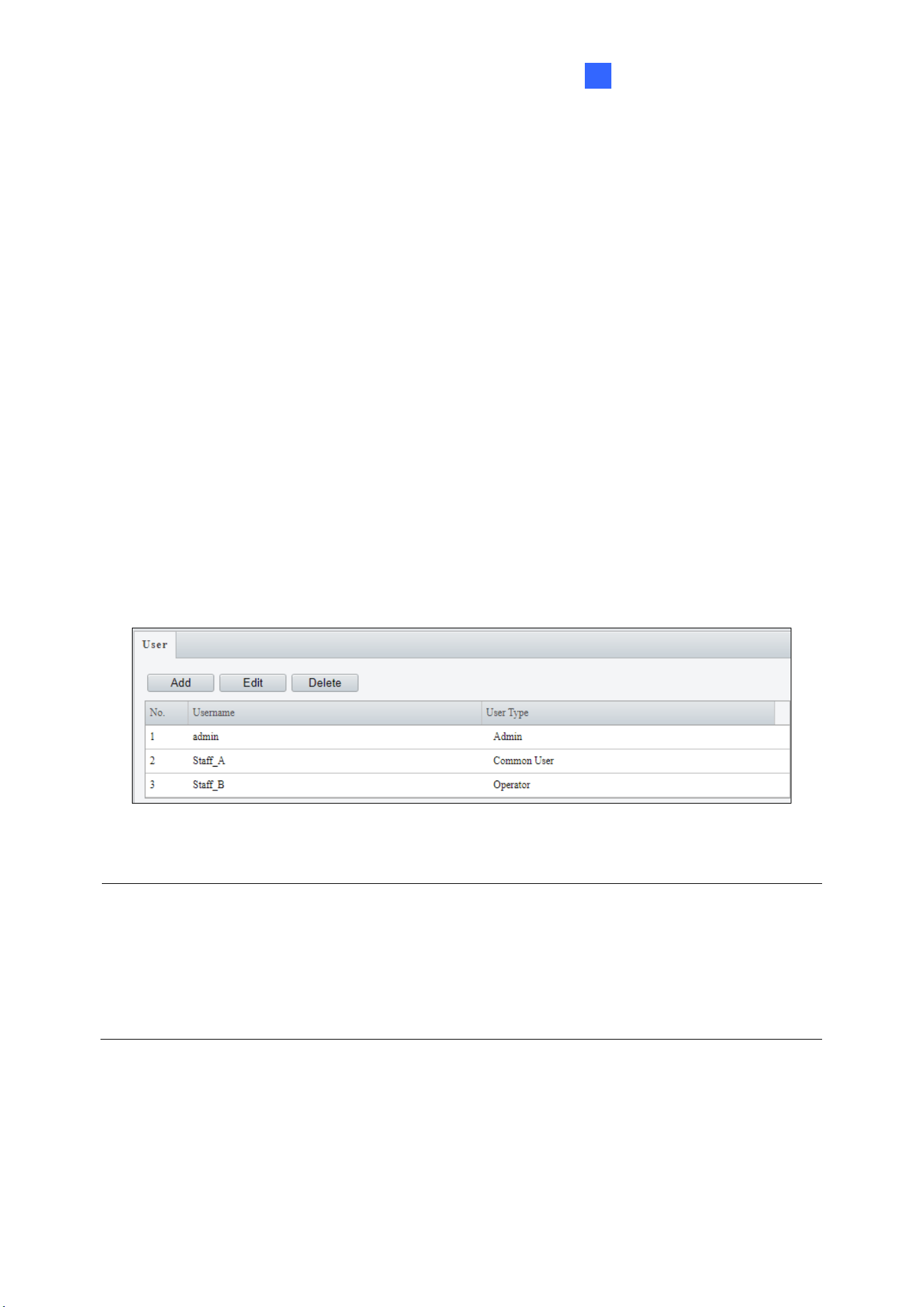
Administrator Mode
207
3
3.9 Security
This section allows you to create user accounts and set the network security settings.
3.9.1 User
There are three types of accounts: Administrator, Common User, and Operator.
◼ Administrator: Admin has full permission and can manage all users and devices. Only
one admin account is allowed in the system.
◼ Common User: Common User only has permission to play live and recorded video. Up
to 31 common users are allowed in the system.
◼ Operator: Operator has access to live view, playback, snapshot, two-way audio, PTZ
control, log, and has permission for configurations under Parameter Configuration,
Event, Subscription, Maintenance, and Upgrade.
Figure 3-71
Note:
1. The Username of the Admin account cannot be modified.
2. Changing the username or password of a user while the user is logged in will force the
user to log out. The user must use the new username or password to log in.
3. A total of 31 common and operator users are allowed in the system.
4. The Operator is not available in some models.
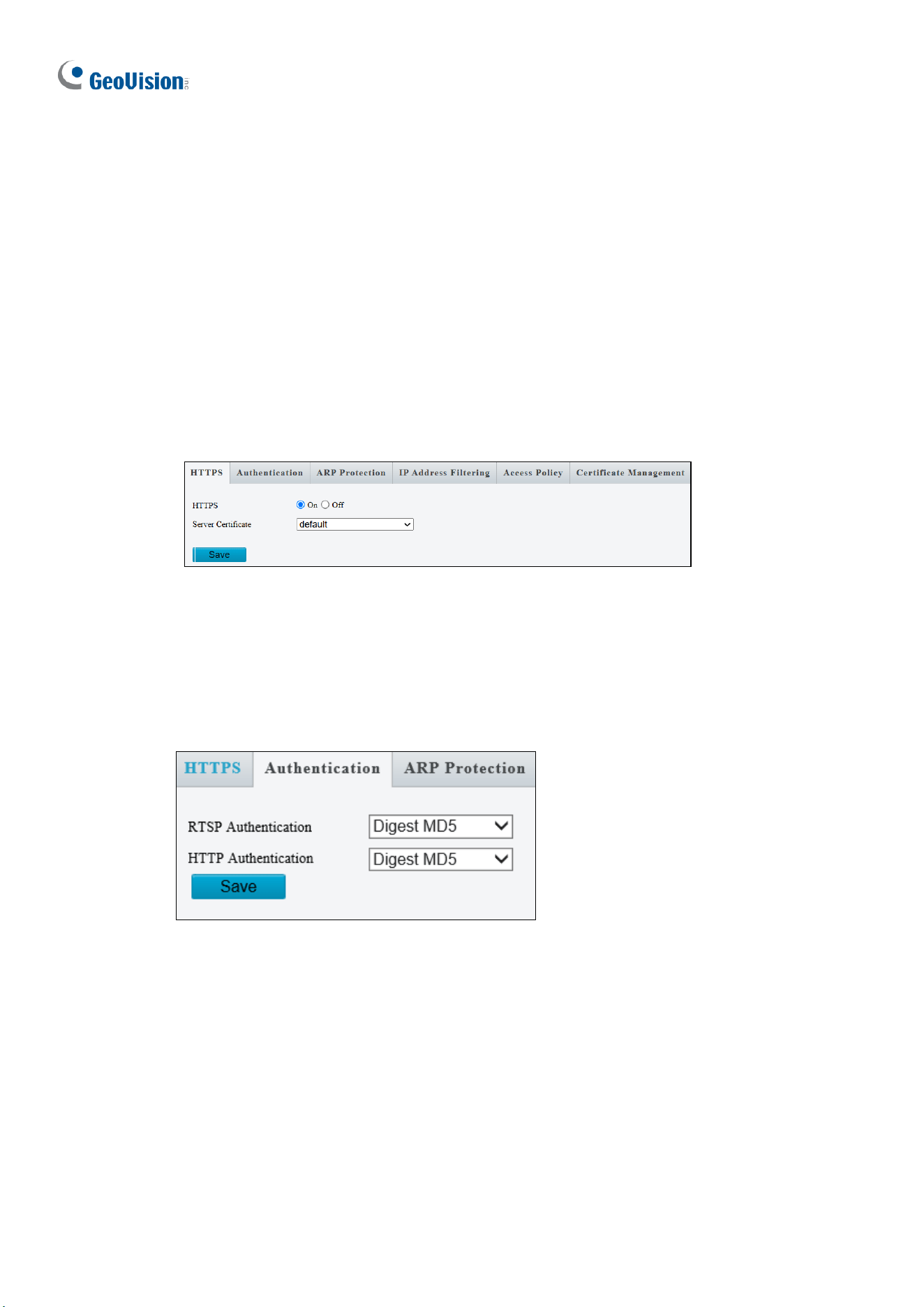
208
3.9.2 Network Security
There are eight types of network security settings: HTTPS, Authentication, ARP Protection,
IP Address Filtering, MAC Address Filtering, Access Policy, WebSockets, and
Certificate Management.
HTTPS
You can enable the Hypertext Transfer Protocol Secure (HTTPS) settings to access the
camera through a secure protocol. Click On to enable, and optionally click Browse to locate
an SSL certificate from your local computer and click Upload.
Figure 3-72
Authentication
RTSP (Real Time Streaming Protocol) and HTTP (Hypertext Transfer Protocol) are different
application layer protocols for transmitting video. Set the Authentication mode for RTSP
streaming or HTTP streaming.
Figure 3-73
For RTSP command, see Appendix B.
For HTTP command, see Appendix C.
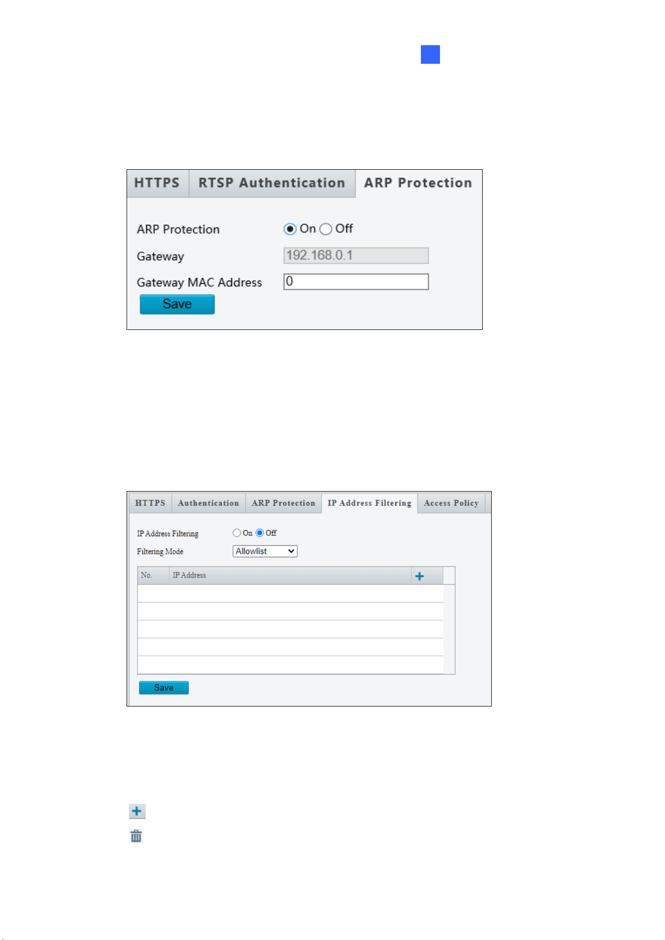
Administrator Mode
209
3
ARP Protection
This function can protect the camera from ARP attacks. When the camera visits an IP of
another network segment via a gateway, it can only communicate with the MAC address
binding to the gateway address in the same segment.
Figure 3-74
1. Select On to enable ARP Protection.
2. Type Gateway MAC Address.
3. Click Save.
IP Address Filtering
Figure 3-75
1. Select On to enable IP Address Filtering.
2. Choose a Filtering Mode: Allowlist or Deny Access.
3. Click to add an IP address.
4. Click to delete an IP address.
5. Click Save.
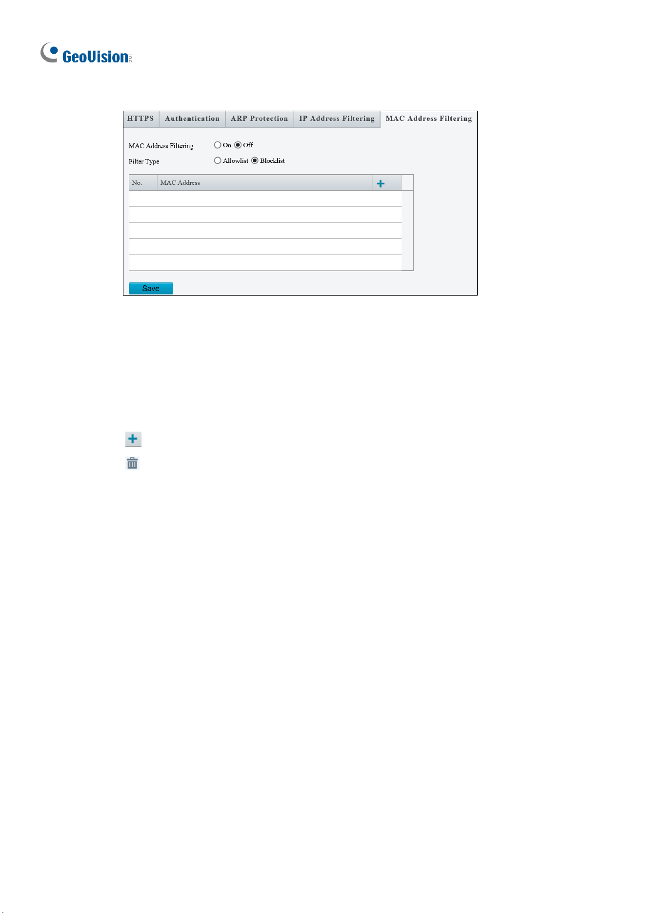
210
MAC Address Filtering
Figure 3-75
Note that this function is not applicable to GV-TMS20811.
1. Select On to enable MAC Address Filtering.
2. Choose a Filtering Mode: Allowlist or Blocklist.
3. Click to add a MAC address.
4. Click to delete a MAC address.
5. Click Save.
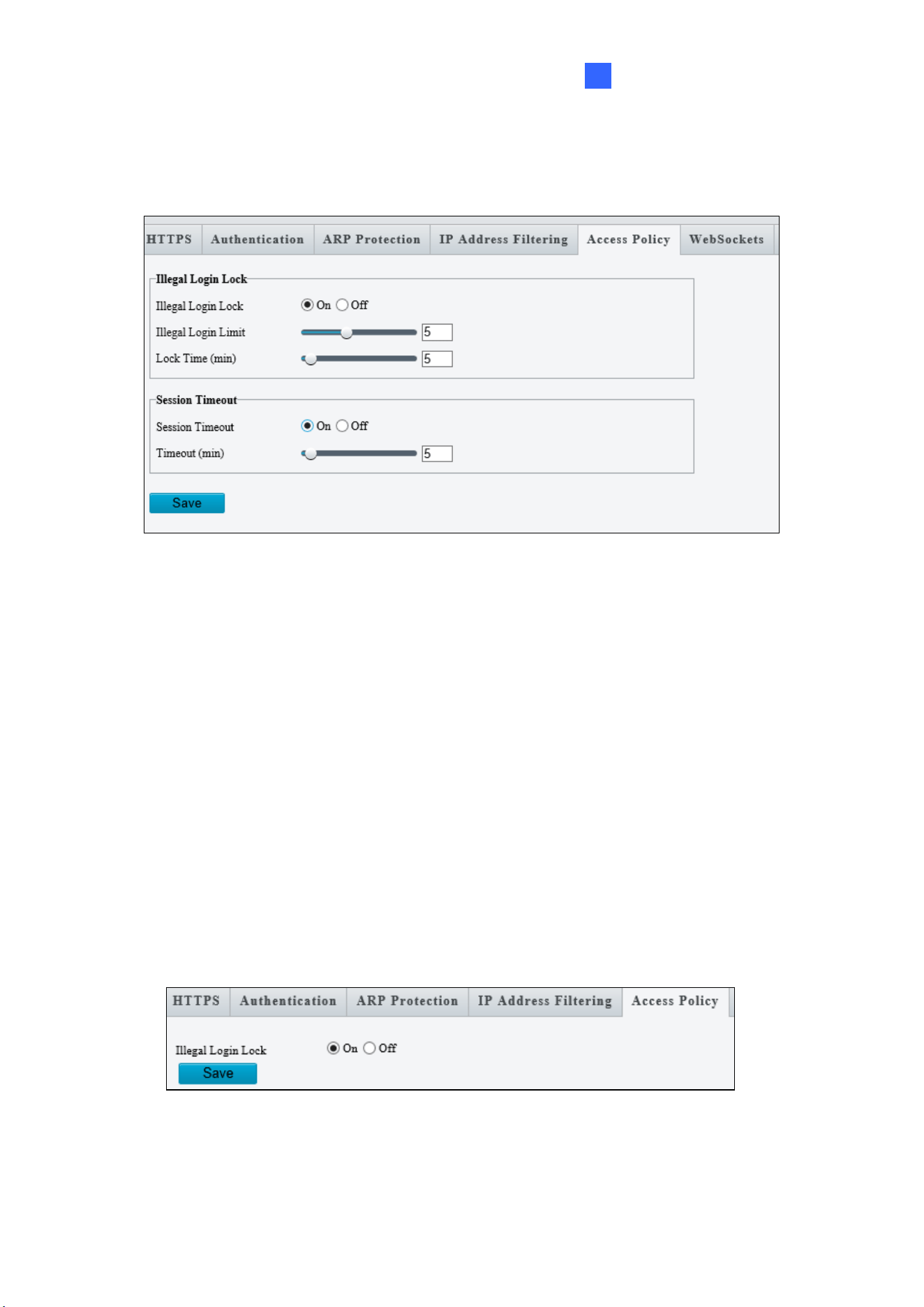
Administrator Mode
211
3
Access Policy
Access Policy measures the strength of account passwords upon login.
Figure 3-76
[Illegal Login Lock]
1. Select On to enable Illegal Login Lock for the camera to apply an account lockout.
2. Specify the Illegal Login Limit and Lock Time to activate the lockout when reaching
the number of failed login attempts and for the lockout duration.
[Session Timeout]
1. Select On to enable an automatic logout.
2. Specify the Timeout duration for the camera to automatically log out when reaching the
set duration.
Some models have the following setting page:
Figure 3-77
By enabling Illegal Login Lock, the camera will apply a 5-minute account lockout duration
after 5 failed login attempts.
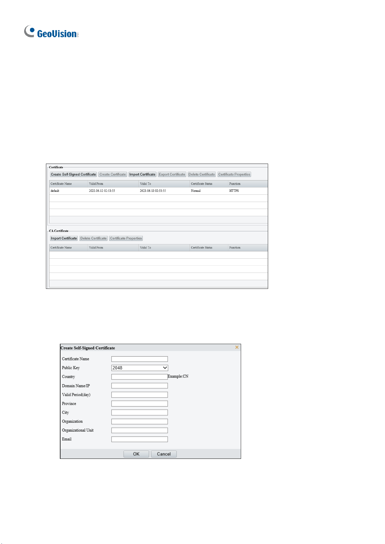
212
WebSocket
The page allows you to enable and disable WebSocket settings. For details, see 3.2.10.2
WebSocket.
Note that this function is not applicable to GV-TMS20811.
Certificate Management
On the Certificate Management page, you can create and manage certificates, view
certificate properties, etc.
[Certificate]
1. Create a self-signed certificate or import a certificate.
⚫ Create a self-signed certificate for application scenarios with low-security requirements.
(1) Click Create Self-Signed Certificate.
(2) Complete the settings.
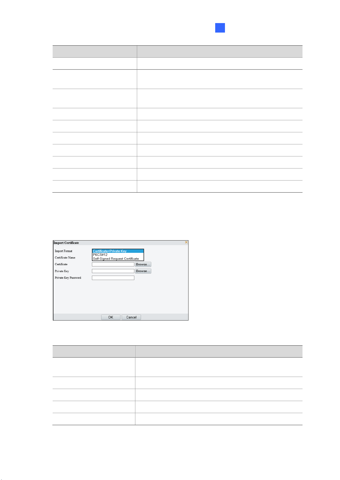
Administrator Mode
213
3
Item
Description
Certificate Name
Set a name as needed.
Public Key
Choose a length for the public key: 2048 or 1024.
Default: 2048.
Country
Enter the two-character country code, for example, CN
for China.
Domain Name/IP
Enter the device’s IP address or domain name.
Valid Period(day)
Enter the validity period of the certificate.
Province
Enter the complete province name.
City
Enter the complete city name.
Organization
Enter the organization name.
Organizational Unit
Enter the organizational unit name.
Email
Enter a valid email address of the contact.
(3) Click OK.
⚫ Import a non-CA certificate.
(1) Click Import Certificate.
(2) Complete the settings.
Item
Description
Import Format
You may choose Certificate+Private Key, PKCS#12, or
Self-Signed Request Certificate.
Certificate Name
Enter the certificate name.
Certificate
Click Browse and locate the certificate.
Private Key
Click Browse and locate the private key.
Private Key Password
Enter the private key password.
(3) Click OK.
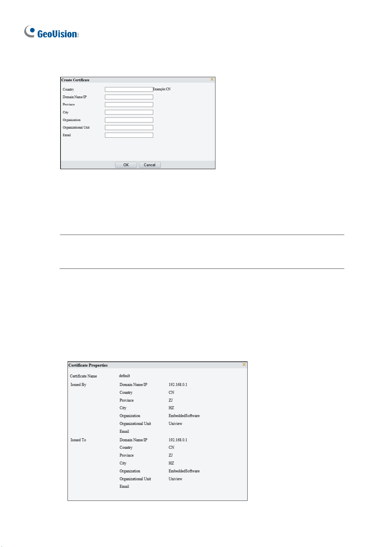
214
2. (Optional) Create a certificate request to obtain a trusted signed certificate for application
scenarios with high-security requirements.
(1) After creating or importing a certificate, select the certificate, click Create Certificate
Request.
(2) Complete the settings.
(3) Click OK.
Note: After the certificate request is created, export the certificate request file. After the
certificate authority (CA) signs and issues a certificate in accordance with the request,
import the certificate into the device.
⚫ Export certificate.
Click Export Certificate to save the certificate to your computer.
⚫ Delete certificate.
Select a certificate and delete it. A certificate that is in use cannot be deleted.
⚫ View certificate properties.
Select a certificate to view its properties.
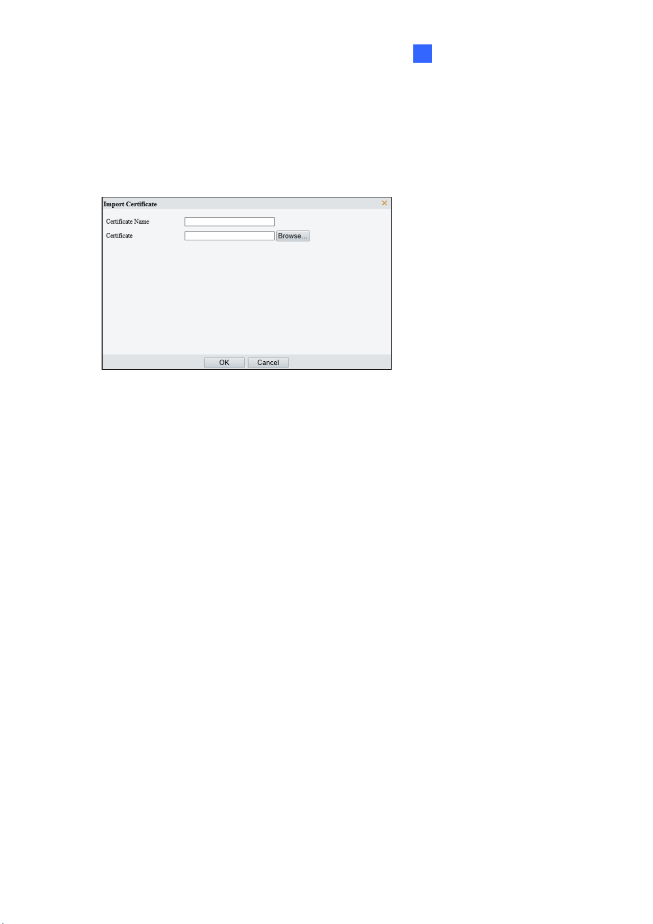
Administrator Mode
215
3
[CA Certificate]
A CA certificate is a certificate issued by a trusted certificate authority (CA) and thus is more
secure and reliable.
1. Click Import Certificate.
2. Enter the certificate name, select the certificate.
3. Click OK.
⚫ Delete certificate.
Select a certificate and delete it. A certificate that is in use cannot be deleted.
⚫ View certificate properties.
Select the certificate to view its properties.
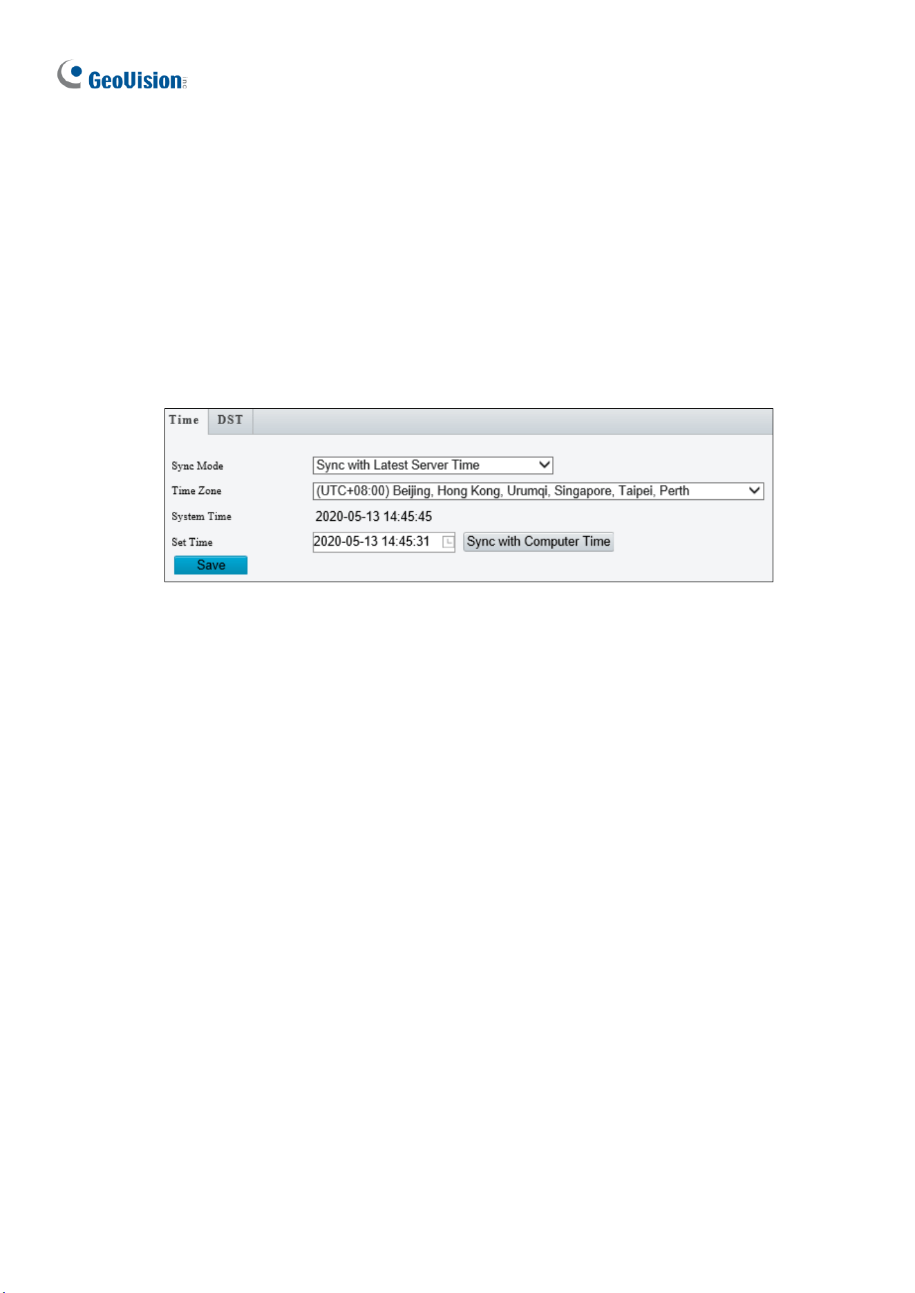
216
3.10 System
This section allows you to set the camera time and update the firmware.
3.10.1 Time
You can use the following methods to adjust the system time of your camera.
Time
Figure 3-78
1. Select a Sync Mode.
Sync with System Configuration: Select a Time Zone, manually set a time by
clicking on the System Time, or synchronize with the computer time.
Sync with NTP Server: To synchronize with a network time server, type the IP
address of the network time server next to NTP Server Address and specify the
Update Interval.
Sync with Management Server (ONVIF): The device time is synchronized with
Management Server (ONVIF).
Sync with Latest Server Time: The device time is synchronized with the latest
updated time, either on ONVIF or the Web interface.
2. Select a Time Zone.
3. Next to System Time, manually set the camera’s time or click Sync with Computer
Time to synchronize with the time of your PC.
4. Click Save.
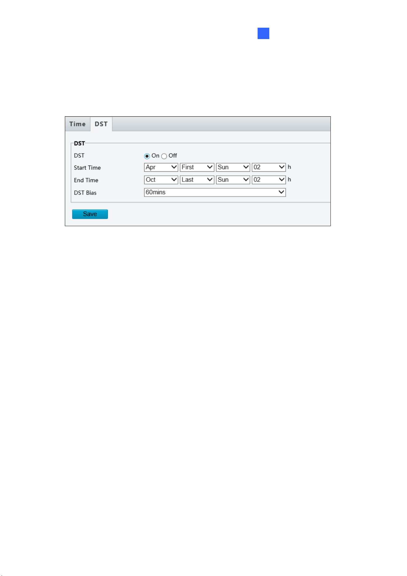
Administrator Mode
217
3
DST
To adjust the camera’s time for daylight saving time:
1. Click the DST tab at the top.
Figure 3-79
2. Select On to enable DST.
3. Set a Start Time and End Time for the Daylight Saving Time.
4. Select a time period for DST Bias.
5. Click Save.
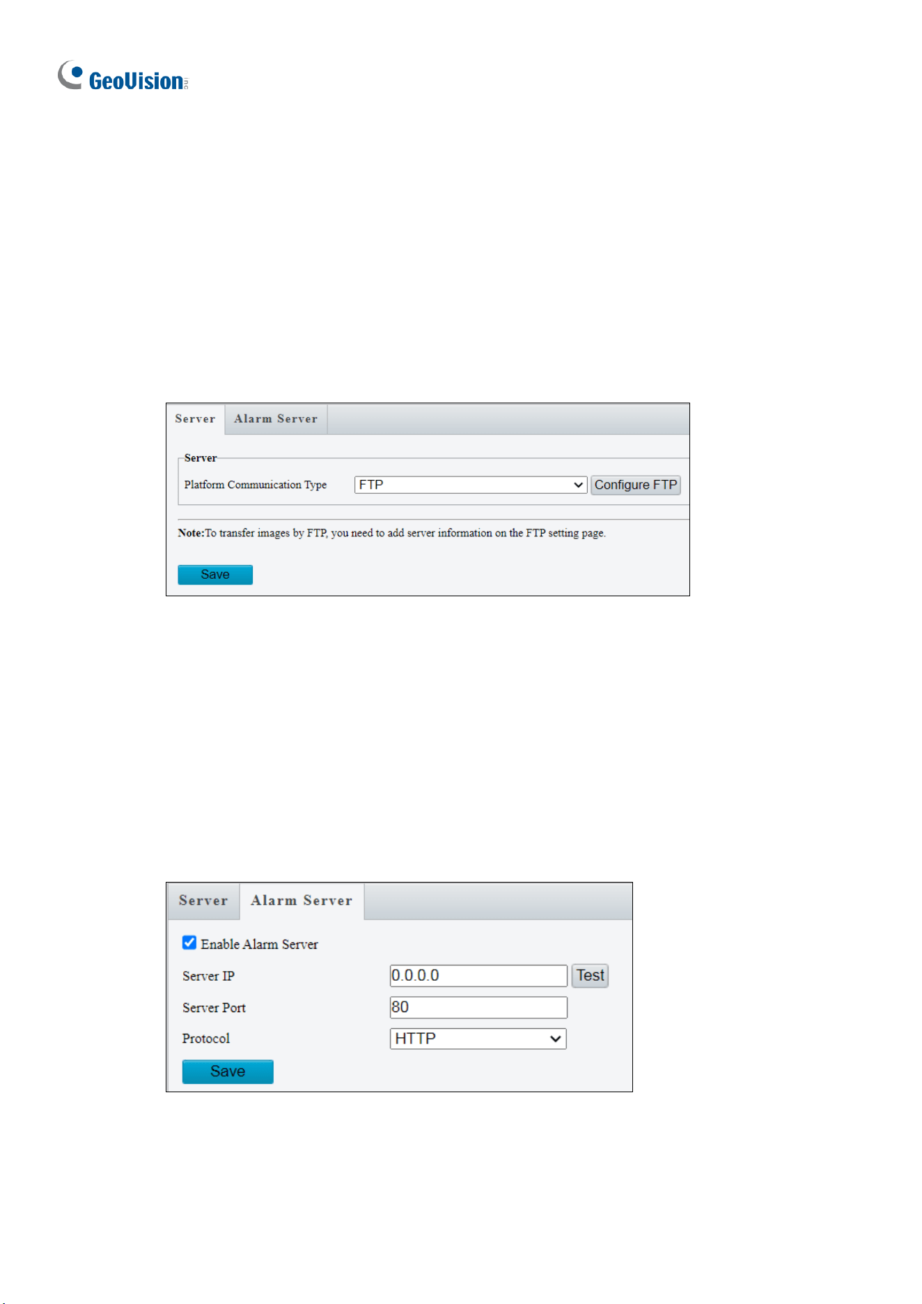
218
3.10.2 Server
Server
The Server allows you to quickly access the FTP setting page. Click the Configure FTP
button to go to the FTP settings page and complete the storage settings. See 3.8.2 FTP for
details.
Note that this function is not applicable to GV-TMS20811.
Figure 3-80
Alarm Server
The camera can automatically report alarms to a specified third-party server. You need to
configure the server IP, port, and protocol (HTTP or HTTPS). Then the camera can report
alarms to the server.
Note that this function is not applicable to GV-TMS20811.
Figure 3-81
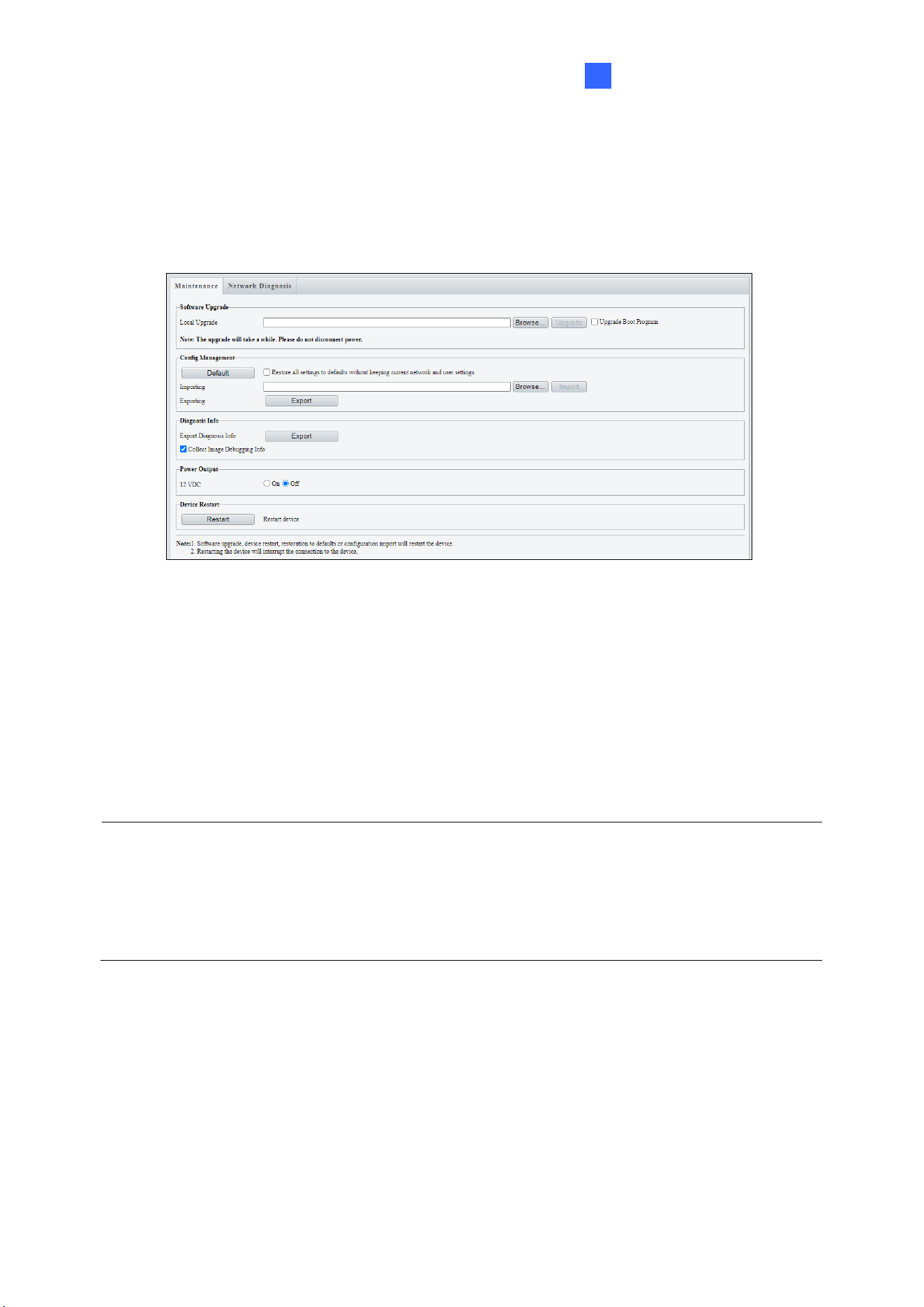
Administrator Mode
219
3
3.10.3 Maintenance
This section allows you to upgrade the firmware, restart the camera, and backup/import
camera configurations.
Figure 3-82
[Software Upgrade]
For detailed instructions, refer to 4.1 Upgrading System Firmware and 4.1.1 Using the Web
Interface.
[Config Management] Export the current configurations of the camera and save them to the
PC or an external storage medium. You can also quickly restore configurations by importing
backup configurations stored on the PC or an external storage medium back to the camera.
Note:
1. When exporting the configuration file, you will be prompted to set the password, which
will be later requested for importing the file.
2. To ensure a successful configuration import, avoid using the exported file from a
different firmware version and model.
[Diagnosis Info] Includes logs and system configurations. Click Browse to select a
destination folder on your PC and then Export to save diagnostic information.
[Power Output] Click On to enable 12V DC power output. Note this is only applicable to GV-
TFD4800, TMS8800 / 20811, and TVD4810 / 4811 / 8810.
[Device Restart] Click Restart to restart the device after you confirm the operation.
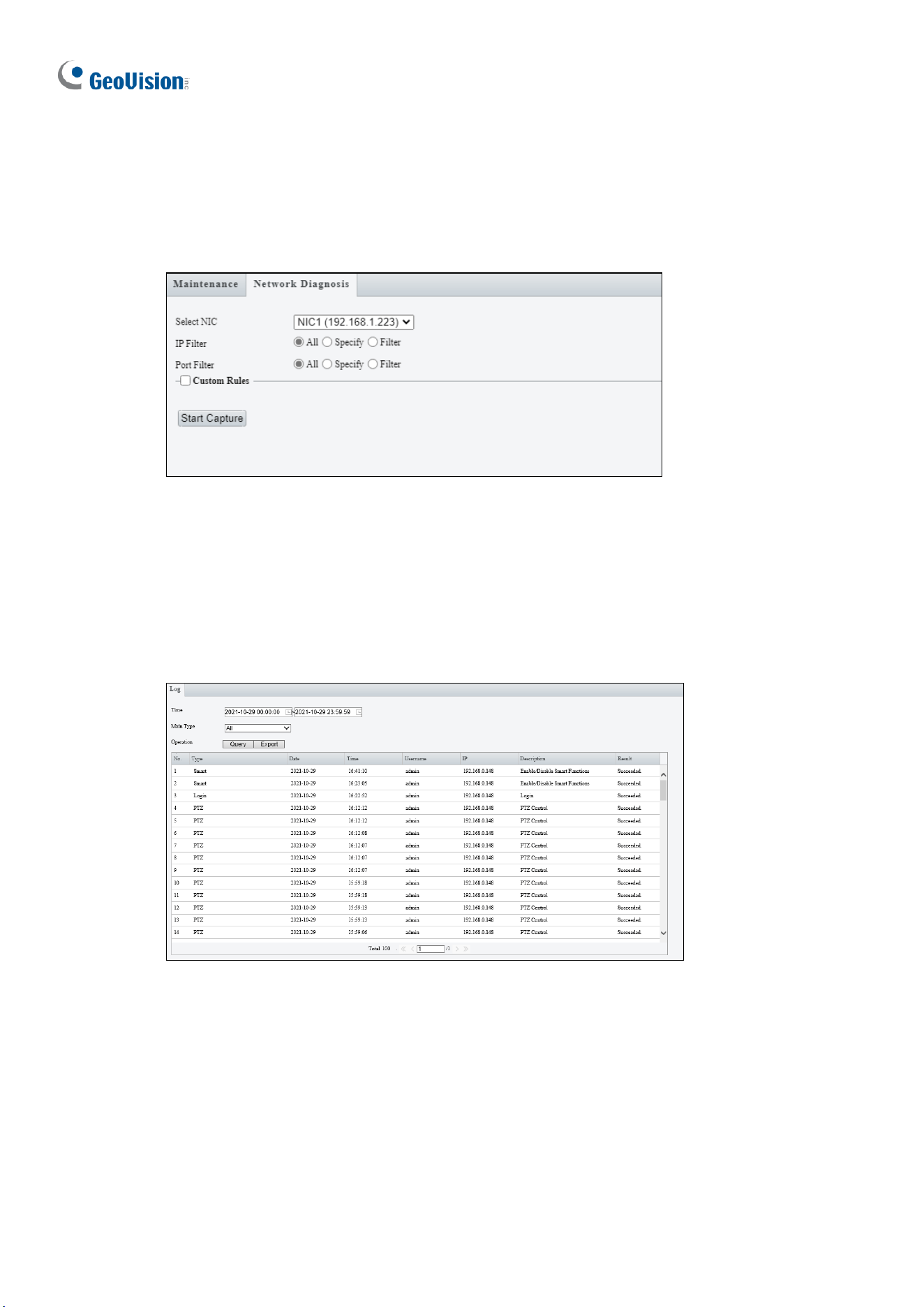
220
3.10.4 Network Diagnosis
This section allows personnel to examine your network environment.
Figure 3-83
3.10.5 Log
Log allows you to inquire configurations made on the camera and export the information to
the local PC.
Figure 3-84
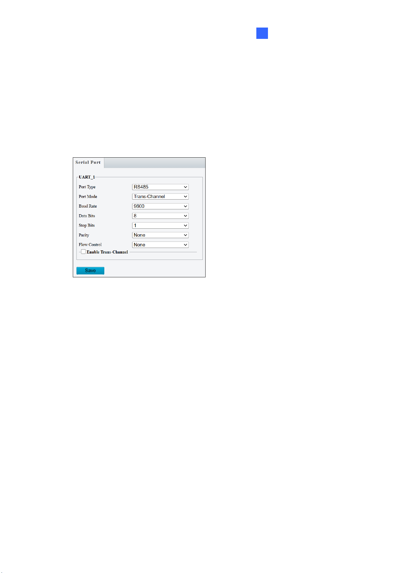
Administrator Mode
221
3
3.10.6 Ports and Devices
This section allows you to exchange data with a third-party device with the RS485 serial port.
Note that the serial setting on the camera should match that of the connected third-party
device.
Note this function is only applicable to GV-PTZ5810-IR / TMS20811.
Figure 3-84
1. Select a Port Mode.
Transparent Channel: Select Trans-Channel from the drop-down list of Port Mode
to achieve a transparent data transmission with a third-party device.
OSD: Select OSD from the drop-down list of Port Mode to display information from a
third-party device. This mode allows the camera to receive information from the third-
party device through the RS485 serial port, translate the received information, and
display it on the local OSD.
Local PTZ Control: Select Local PTZ Control from the drop-down list of Port Mode.
This mode allows you to control a local PTZ camera through a third-party device
without having to use the local camera’s PTZ control panel (not applicable to GV-
TMS20811).
ONVIF Transparent Channel: Select Trans-Channel via ONVIF from the drop-
down list of Port Mode. This mode allows you transmit data through ONVIF
transparent channel between the camera’s RS485 port and a third-party device.
2. If OSD is selected, optionally select Enable OSD Report, so that OSD data will be
uploaded to the platform.
3. Configure the parameters.
4. Click Save.

222
Chapter 4 Advanced Applications
This chapter introduces more advanced applications.
4.1 Upgrading System Firmware
GeoVision periodically releases updated firmware on the company website. The new
firmware can be loaded into the camera using the Web interface or GV-IP Device Utility.
Important Notes before You Start
Before you start updating the firmware, please read these important notes:
1. If you use GV-IP Device Utility for firmware upgrade, the computer used to upgrade
firmware must be under the same network as the camera.
2. Stop monitoring on the camera.
3. Stop the camera’s connection to GV-VMS / DVR / NVR and all remote connections.
4. While the firmware is being updated, the power supply must not be interrupted.
5. If firmware upgrade fails, you will need to restore the camera back to its default settings.
For details, see 4.2 Restoring to Factory Default Settings.
WARNING:
1. The interruption of power supply during updating causes not only update failures but
also damages to your camera. In this case, please contact our sales representatives
and send your device back to GeoVision for repair.
2. It is not suggested to downgrade firmware since it may cause unpredictable issues.
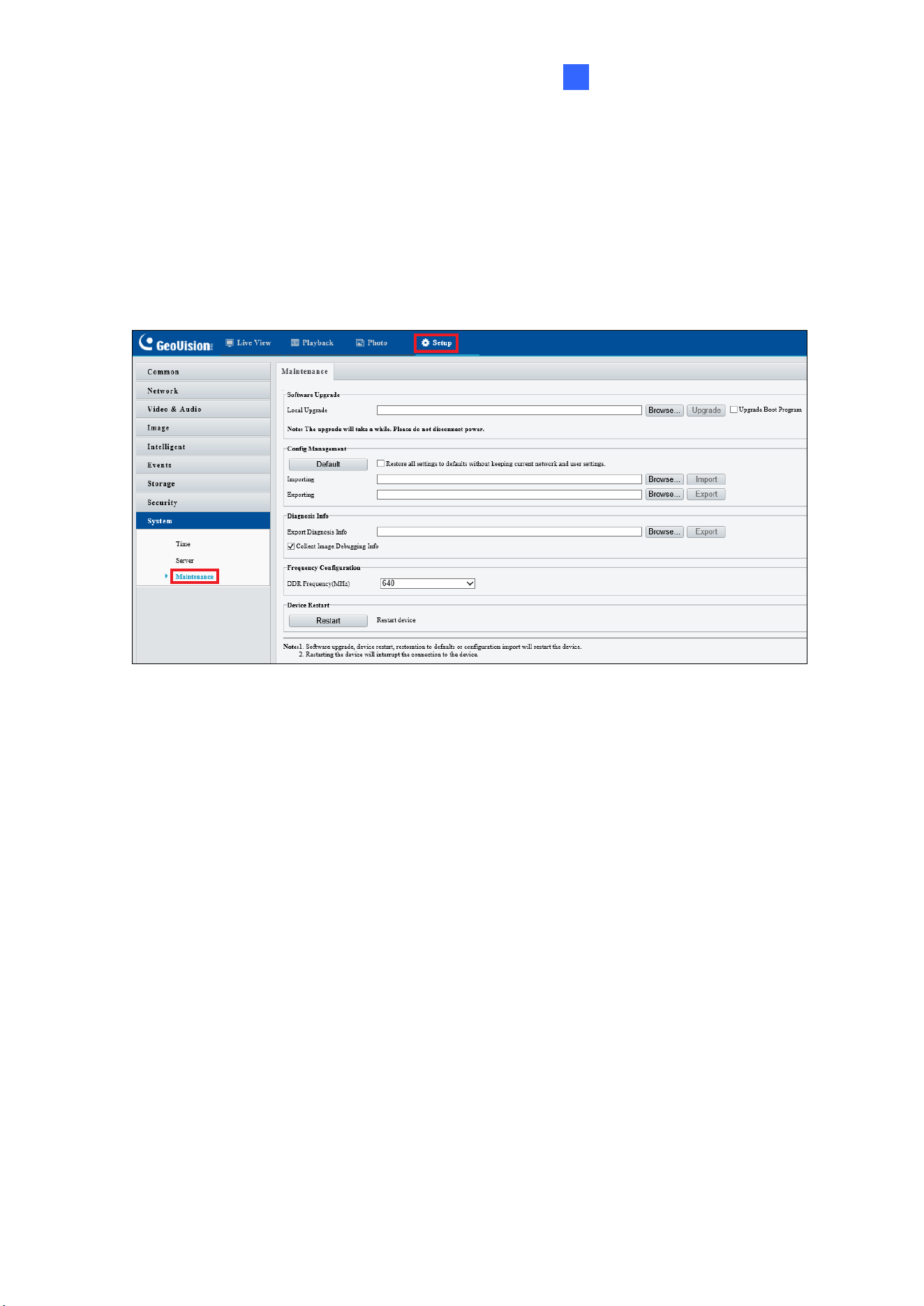
Advanced Applications
223
4
4.1.1 Using the Web Interface
Log into the Web interface and follow the steps below to update the firmware.
1. At the top, click Setup.
2. In the left menu, select System and select Maintenance. This page appears.
Figure 4-1
3. Click Browse under Software Upgrade to locate the firmware file (.zip) saved at your
local computer.
4. Click Upgrade to process the upgrade.
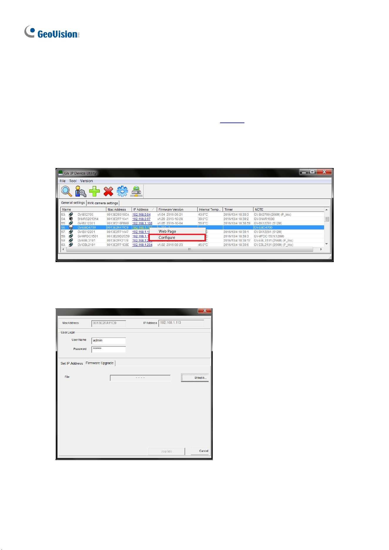
224
4.1.2 Using GV-IP Device Utility
You can upgrade the camera firmware using GV-IP Device Utility. Note the computer used to
upgrade firmware must be under the same network as the camera.
1. Download GV-IP Device Utility from the company website. Then follow the onscreen
instructions to install the program.
2. Double-click the GV IP Device Utility icon created on your desktop.
3. Click the camera in the list and select Configure.
Figure 4-2
5. Type the camera’s user name and password to log in.
6. Click the Firmware Upgrade tab. This dialog box appears.
Figure 4-3
7. Click Browse to locate the firmware file (.zip) saved at your local computer.
8. Click Upgrade to start upgrading the firmware.
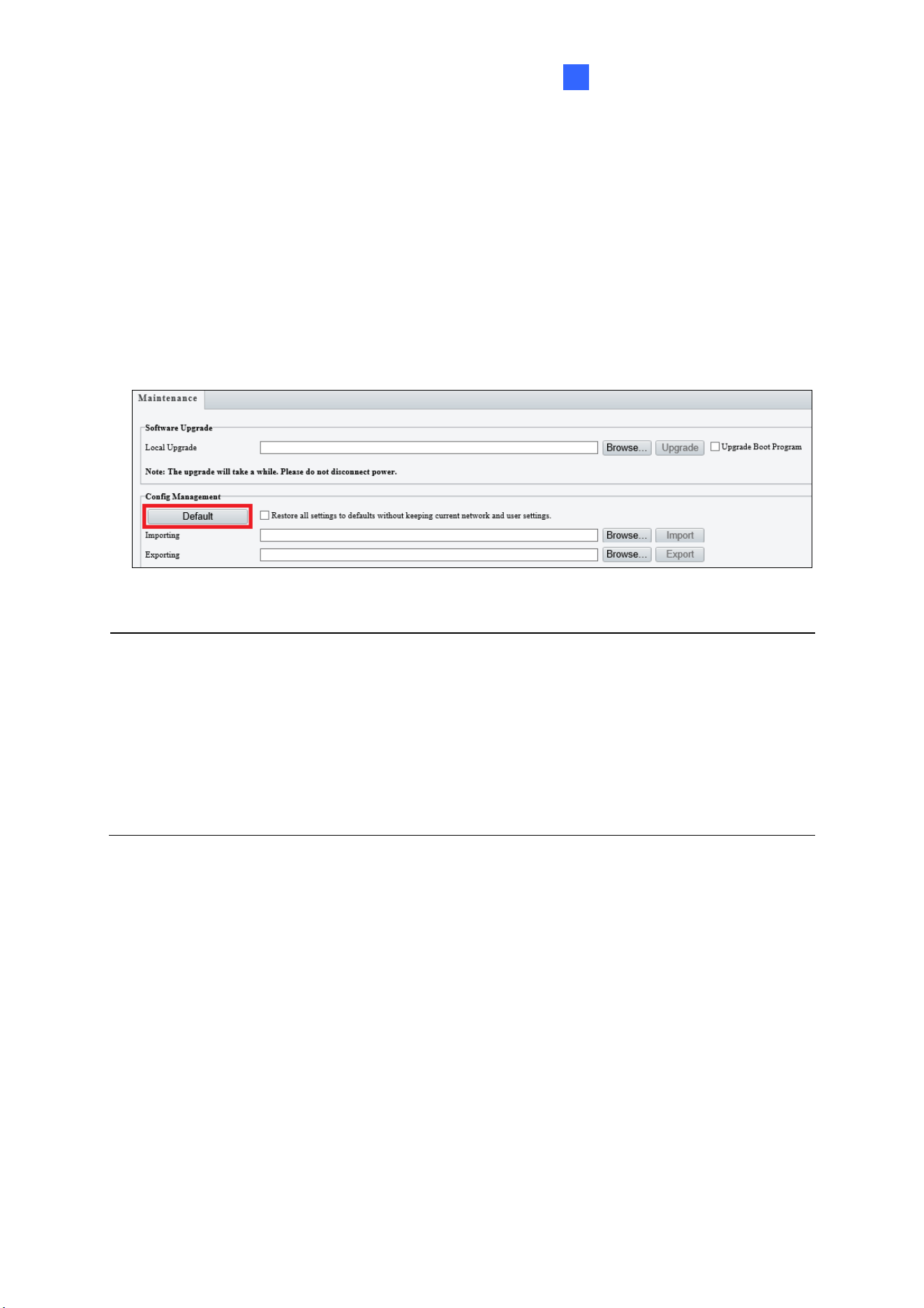
Advanced Applications
225
4
4.2 Restoring to Factory Default Settings
If for any reason the camera is not responding correctly, you can restore the camera back to
its factory default settings using the Web interface or the Default button.
To use the Web interface:
1. In the Web interface, click Setup.
2. In the left menu, select System and select Maintenance.
3. Under the Config Management section, click Default.
Figure 4-4
Note:
1. Only the following models have a default button: GV-EBD4711 / 4712 / 8711 / 8813,
GV-EBDP5800, GV-ABL2703 series / 4703, GV-AVD2700 / 4710 / 8710, GV-
FER5702, GV-PTZ5810-IR, GV-TBL2703 series / 2718 / 4703 / 4807 / 8804, GV-
TBLP5800, GV-TFD4700 / 4800, GV-TMS8800 / 20811, and GV-TVD2712 / 4700 /
4710 / 4711 / 4811 / 8710 / 8810. For where the button is on the camera, see the
Overview section in their respective chapters.
2. If the default button doesn’t respond after pressing for 15 seconds, reboot the camera
and try again within 10 minutes of rebooting.
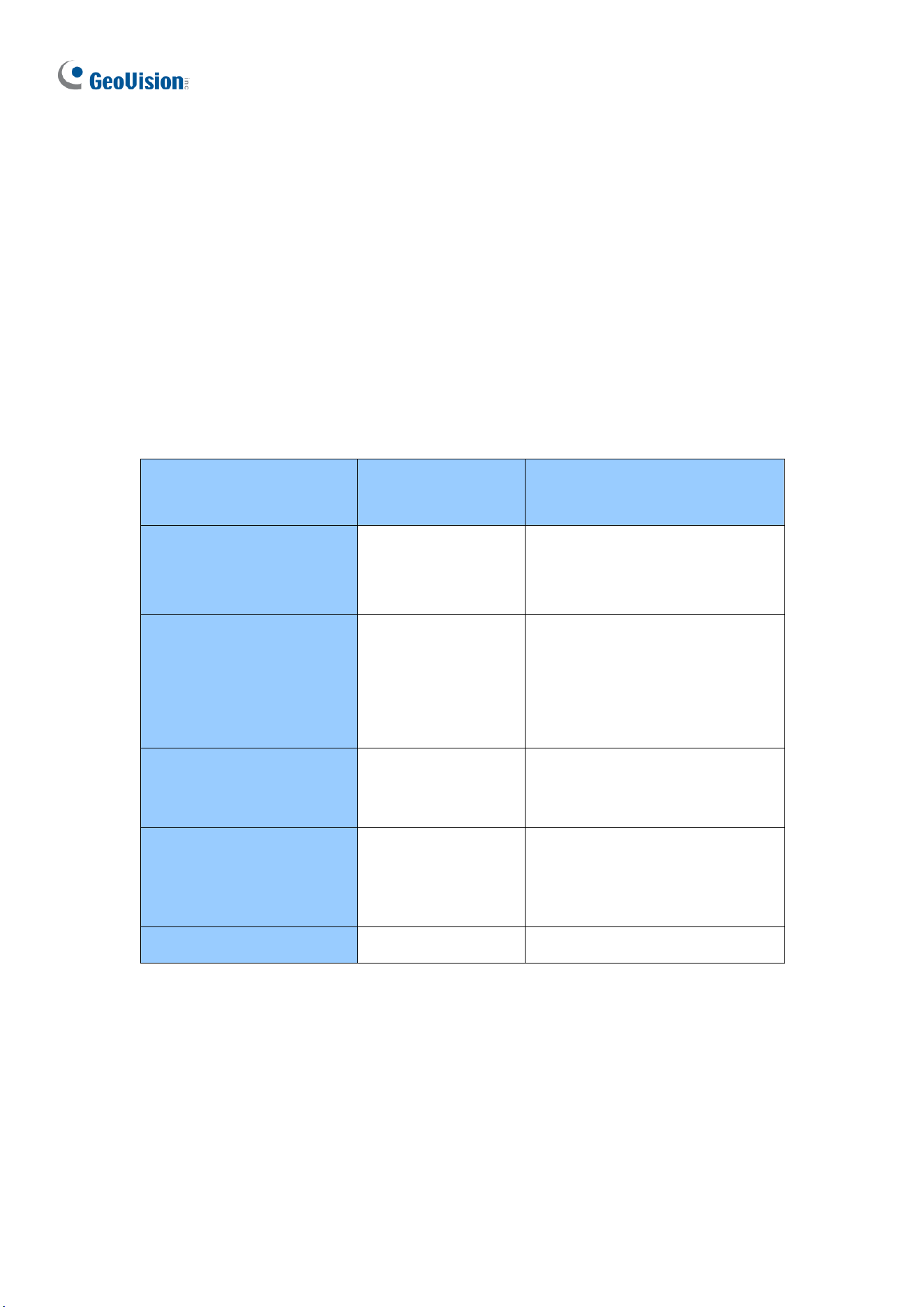
226
Chapter 5 DVR / NVR / VMS
The GV-VMS / DVR / NVR provides a full range of video management functions and features,
such as video viewing, recording, playback, alert settings, and more. The following is a list of
related integration specifications:
• For a list of compatible versions of GV-VMS / DVR / NVR based on your camera model,
see Appendix D.
• The following lists the maximum throughput and streams when an IP camera is
connected to other applications:
Model
Maximum
throughput
Maximum stream
(When the total bitrate is within
the maximum throughput)
GV-ABL4712
GV-AVD4710
GV-TBL4710
GV-TVD4710
30 Mbps
20
GV-EBD2704
GV-EBD4704
GV-TBL2705
GV-TBL4705
GV-TDR2704
GV-TDR4704
40 Mbps
6
GV-EBDP8800
GV-TBLP8800
GV-TMS8800
GV-TMS20811
50 Mbps
20
GV-EBD2705
GV-TBL2706 series
GV-TBL2718
GV-TDR2705
GV-TVD2712
50 Mbps
6
Other models
40 Mbps
20
• When an IP camera is connected to IE browser or any GeoVision CMS application, it
takes up 1 stream; when it is connected to GV-VMS / DVR / NVR, it takes up 2 streams.
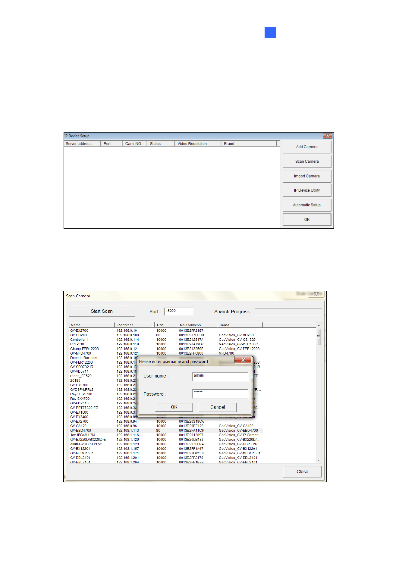
DVR /NVR / VMS
227
5
5.1 Setting Up IP Cameras on GV-DVR / NVR
To set up the camera on GV-DVR / NVR, follow these steps:
1. On the main screen, click the Configure button, select System Configure, select
Camera Install and click IP Camera Install. This dialog box appears.
Figure 5-1
2. To automatically set up the camera, click Scan Camera to detect any camera on the
LAN.
3. Double-click your camera and type the camera’s User name and Password.
Figure 5-2
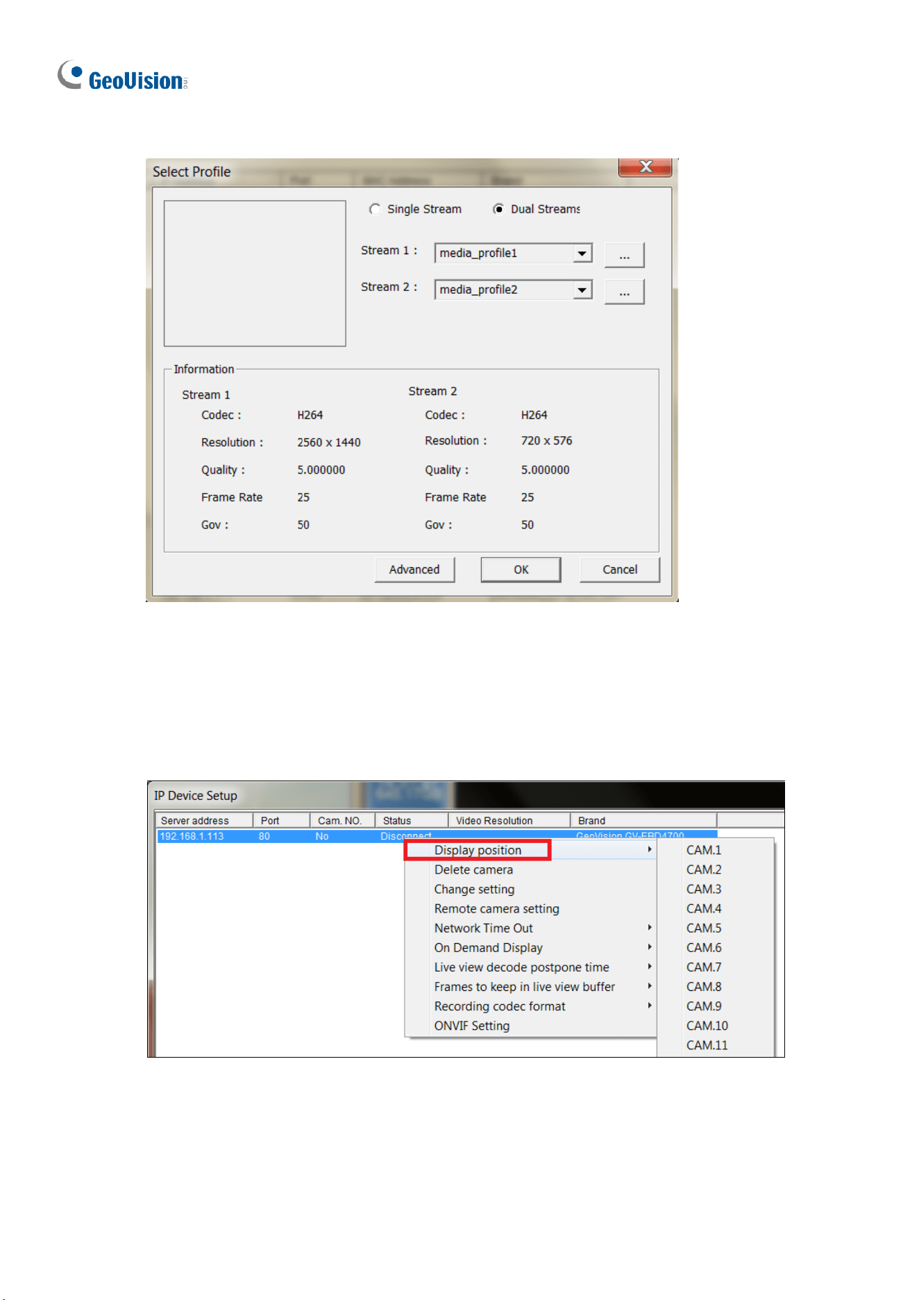
228
4. Click OK. This dialog box appears.
Figure 5-3
5. Click OK. The IP camera is added to the connection list.
6. Click the listed camera and select Display position to map the IP camera to a channel
on the GV-DVR / NVR.
Figure 5-4
7. The Statue column should display “Connected”. Click OK.
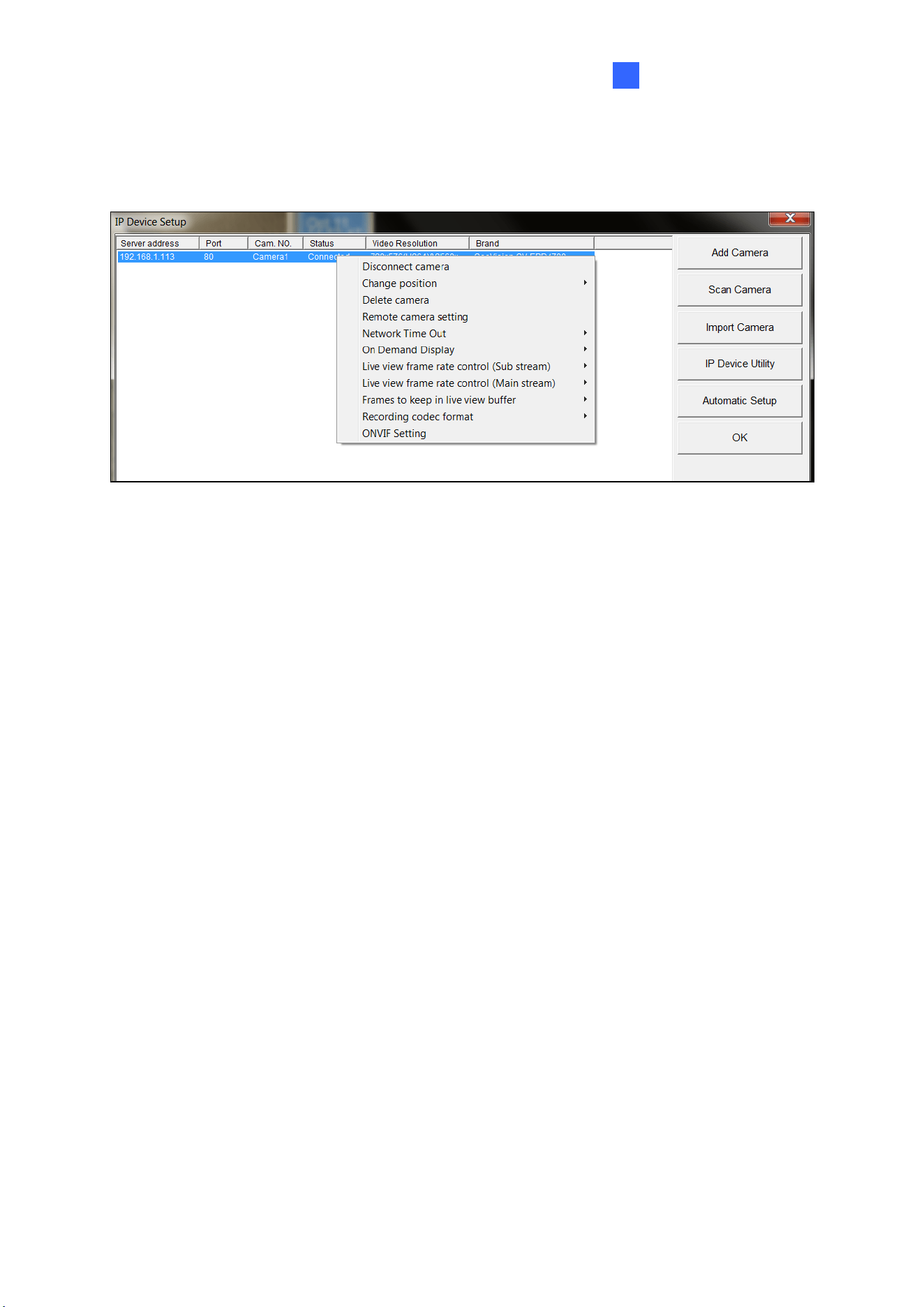
DVR /NVR / VMS
229
5
After the camera is connected and assigned with a display position, you can configure the
camera’s settings, such as frame rate, codec type and resolution. Right-click the desired
camera to see the following list of options:
Figure 5-5
◼ Network Time Out: When network disconnection exceeds the specified time period, the
camera status displayed as Connection Lost.
◼ On-Demand Display: Enable automatic switching between main stream and sub
stream based on the size of camera image on screen.
◼ Live-view frame rate control (Sub / Main): Set the frame rate of the stream to help
reduce the CPU usage. If the codec is set as MJPEG, select the number of frames to
allow in a second. If the codec is H.265 or H.264, select one of the following options:
Maximum Live-view Frame Rate: View the video at the maximum frame rate
possible.
Live-view Key Frame only: You can choose to view the key frames of the videos
only instead of all frames on the live view. This option is related to the GOP setting
of the IP camera. For example, if the GOP value is set to 30, there is only one key
frame in every 30 frames.
◼ Frames to keep in live view buffer: Specify the number of frames to keep in the live
view buffer.
◼ Recording Codec Format: Select the codec to record in.
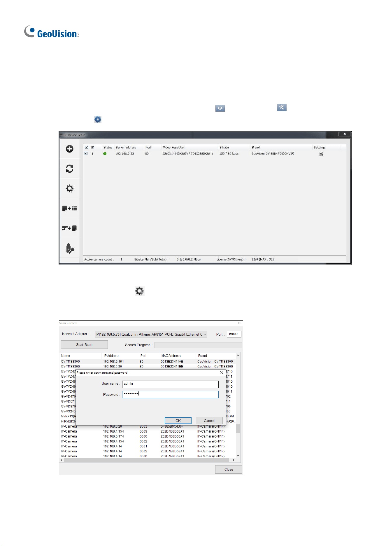
230
5.2 Setting Up IP Cameras on GV-VMS
Follow the steps below to manually connect your camera to GV-VMS.
1. To access the IP Device Setup page, click Home , select Toolbar , click
Configure and select Camera Install.
Figure 5-6
2. Click Automatic Setup .
3. Double-click the camera and type the User name and Password of the camera.
Figure 5-7
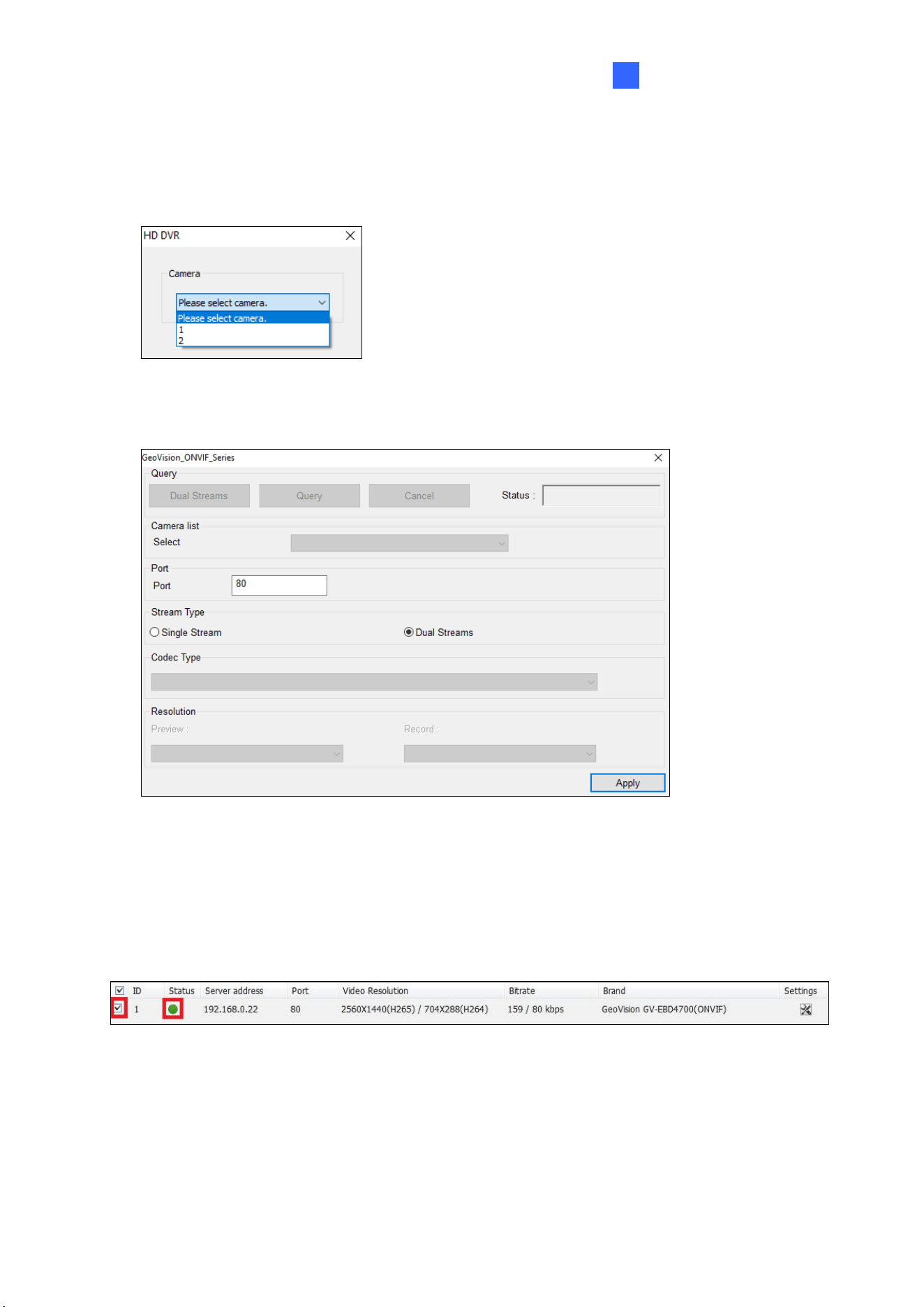
DVR /NVR / VMS
231
5
4. Click OK.
5. For GV-TMS8800 / 20811, select the desired channel. To fully display the live view of the
camera, add the 2 channels one by one at a time.
Figure 5-8
6. This dialog box appears.
Figure 5-9
7. Click Apply to add the camera to the list.
8. To connect the added camera, click the box beside the ID column. Upon successful
connection, the Status icon shows green, with the video resolution and bitrate being
displayed in the correspondent columns.
Figure 5-10

232
Appendix
A. RTSP Multicast Protocol Support
The camera allows video and audio streaming using the RTSP multicast protocol. To view
camera images, use the following RTSP multicast command:
• In general:
rtsp://<IP>/media/<video#>/multicast
<IP> specifies the IP address of the camera.
<video#> specifies the main stream (1) or sub stream (2).
For example, to view the main stream of a camera, the command is as follows: rtsp://
192.168.4.115/media/video1/multicast
• GV-TMS8800 / 20811:
rtsp://<IP>/<media#>/<video#>/multicast
<IP> specifies the IP address of the camera.
<media#> specifies the channel number.
<video#> specifies the main stream (1) or sub stream (2).
For example, to view the channel No. 2 and the main stream of GV-TMS8800 / 20811, the
command is as follows: rtsp:// 192.168.4.115/media2/video1/multicast
B. RTSP Protocol Support
The camera allows video and audio streaming using the RTSP protocol.
To access live view:
You can use the following RTSP multicast command to access live view.
rtsp://<ID>:<Password>@<IP>/<media#>/<video#>
<IP> specifies the IP address of the camera.
<media#> specifies the channel number.
<video#> specifies the main stream (1) or sub stream (2).

Appendix
233
For example, to view the channel No. 2 and main stream of GV-TMS8800 / 20811, the
command is as follows: rtsp://admin:admin@192.168.3.111/media2/video1
To access playback:
You can use the following RTSP multicast command to access playback from the local SD
card.
Note: Playback access is only available for GV-BLFC5800 / EBD4704 / EBD4813 /
EBFC5800 / TBL4705 / TBL4807 / TBL4810 / TDR4704 / TDR4803 / TFD4800 / TVD4810 /
TVD4811 and GV-EBD8800 / EBD8813 / EBDP5800 / FER5702 / TBL8804 / TBL8810 /
TBLP5800 / TDR8805 / TVD8810 and GV-PTZ5810-IR and GV-TMS8800 and GV-TMS20811.
rtsp://<ID>:<Password>@<IP>/media/<record#>?begintime=<begindate>T<begintime>
Z&endtime=<enddate>T<endtime>Z
<IP> specifies the IP address of the camera.
<record#> specifies the main stream (1) or sub stream (2).
For example,
rtsp://admin:admin@10.0.0.112:554/media/record1?begintime=20240823T071000Z&endtim
e=20240823T071100Z
IMPORTANT: The above times must be in the UTC+0 time zone. If the user is in the
UTC+8 time zone, the requested time should be adjusted by -8 hours.
For example, if the original time is:
begintime=20240823T071000Z; endtime=20240823T071100Z (UTC+8)
It should be adjusted to:
begintime=20240822T231000Z; endtime=20240822T231100Z (UTC+0)
Note:
1. See 3.9.2 Network Security for RTSP related settings on the Web interface.
2. Only VLC and QuickTime players are supported for video streaming via RTSP
protocol.
234
C. HTTP Protocol Support
The camera supports HTTP protocol for accessing snapshots. To obtain a snapshot of the
live view, type the following HTTP command on your Web browser:
http://<IP of the camera>/images/snapshot.jpg
For example, http://192.168.0.10/images/snapshot.jpg
When the Windows Security dialog box appears, type the camera’s username and
password to receive the captured snapshot.
Note: See 3.9.2 Network Security for HTTP related settings on the Web interface.

Appendix
235
D. Compatible Versions of GV-VMS / DVR / NVR
Compatible versions of GV-VMS / DVR / NVR based on camera models are listed as follows:
Camera Model
Compatible GV-DVR / NVR
Compatible GV-VMS
GV-ABL2701 Series
V8.7.4.0 with patch files or later
V16.11.0.0 with patch files or later
GV-ABL2702
V8.7.4.0 with patch files or later
V17.1 with patch files or later
GV-ABL2703
V8.8.0 with patch files or later
V17.2.0 (no patch files required)
GV-ABL4701 Series
V8.7.4.0 with patch files or later
V16.11.0.0 with patch files or later
GV-ABL4703
V8.8.0 with patch files or later
V17.2.0 (no patch files required)
GV-ABL4711
V8.8.0 with patch files or later
V17.3.0 with patch files or later
V18.1.1 with patch files or later
GV-ABL4712
V8.7.4.0 with patch files or later
V16.11.0.0 with patch files or later
GV-ABL8712
V8.7.4.0 with patch files or later
V17.1 with patch files or later
GV-ADR2701
V8.7.4.0 with patch files or later
V16.11.0.0 with patch files or later
GV-ADR2702
V8.8.0 (no patch files required)
V17.1.0.100 with patch files or later
GV-ADR4701
V8.7.4.0 with patch files or later
V16.11.0.0 with patch files or later
GV-ADR4702
V8.8.0 (no patch files required)
V17.1.0.100 with patch files or later
GV-AVD2700
V8.7.4.0 with patch files or later
V17.1 with patch files or later
GV-AVD4710
V8.7.4.0 with patch files or later
V16.11.0.0 with patch files or later
GV-AVD8710
V8.7.4.0 with patch files or later
V17.1 with patch files or later
GV-BLFC5800
V8.9.1 with patch files or later
V17.4.3 with patch files or later
V18.2.1 with patch files or later
GV-EBD2702
V8.7.4.0 with patch files or later
V17.1 with patch files or later
GV-EBD2704
V8.9.1 with patch files or later
V17.4.1 with patch files or later
V18.2.1 with patch files or later
GV-EBD2705
N/A
V17.4.7 or later
V18.3.2 or later
GV-EBD4700
V8.7.3.0 with patch files or later
V16.11.0.0 with patch files or later
GV-EBD4701
V8.9.0 (no patch files required)
V17.4.0 (no patch files required)
V18.1.1 with patch files or later
GV-EBD4704
V8.9.1 with patch files or later
V17.4.1 with patch files or later
V18.2.1 with patch files or later
GV-EBD4711
V8.7.4.0 with patch files or later
V16.11.0.0 with patch files or later
GV-EBD4712
V8.9.0 (no patch files required)
V17.4.0 (no patch files required)
V18.1.1 with patch files or later
GV-EBD4813
V8.9.1 with patch files or later
V17.4.2 with patch files or later
V18.2.1 with patch files or later
GV-EBD8700
V8.8.0 with patch files or later
V17.1.0.100 with patch files or later
GV-EBD8711
V8.7.4.0 with patch files or later
V17.1 with patch files or later
GV-EBD8800
V8.9.1 with patch files or later
V17.4.1 with patch files or later
V18.2.1 with patch files or later
GV-EBD8813
V8.9.1 with patch files or later
V17.4.1 with patch files or later
V18.2.1 with patch files or later
GV-EBDP5800
V8.9.1A with patch files or later
V17.4.7 with patch files or later
V18.3.2 with patch files or later
236
GV-EBDP8800
N/A
V17.4.7 or later
V18.3.2 or later
GV-EBFC5800
V8.9.1 with patch files or later
V17.4.4 or later
V18.2.1 with patch files or later
GV-TBL2703 Series
V8.8.0 with patch files or later
V17.3.0 with patch files or later
GV-TBL2705
V8.9.1 with patch files or later
V17.4.1 with patch files or later
V18.2.1 with patch files or later
GV-TBL2706
N/A
V17.4.7 or later
V18.3.2 or later
GV-TBL2718
N/A
V17.4.8 with patch files or later
V18.3.4 with patch files or later
GV-TBL4700
V8.8.0 with patch files or later
V17.3.0 with patch files or later
V18.1.1 with patch files or later
GV-TBL4703
V8.8.0 with patch files or later
V17.3.0 with patch files or later
GV-TBL4705
V8.9.1 with patch files or later
V17.4.1 with patch files or later
V18.2.1 with patch files or later
GV-TBL4710
V8.8.0 with patch files or later
V17.1.0.100 with patch files or later
GV-TBL4711
V8.8.0 with patch files or later
V17.3.0 with patch files or later
V18.1.1 with patch files or later
GV-TBL4807
V8.9.1A with patch or later
V17.4.7 with patch files or later
V18.3.2 with patch files or later
GV-TBL4810
V8.9.1 with patch files or later
V17.4.2 with patch files or later
V18.2.1 with patch files or later
GV-TBL8710
V8.8.0 with patch files or later
V17.1.0.100 with patch files or later
GV-TBL8804
V8.9.1 with patch files or later
V17.4.1 with patch files or later
V18.2.1 with patch files or later
GV-TBL8810
V8.9.1 with patch files or later
V17.4.1 with patch files or later
V18.2.1 with patch files or later
GV-TBLP5800
V8.9.1A with patch files or later
V17.4.7 with patch files or later
V18.3.2 with patch files or later
GV-TBLP8800
N/A
V17.4.7 or later
V18.3.2 or later
GV-TDR2700
V8.7.6.0 with patch files or later
V17.1.0.100 with patch files or later
GV-TDR2702
V8.8.0 with patch files or later
V17.3.0 with patch files or later
GV-TDR2704 Series
V8.9.1 with patch files or later
V17.4.1 with patch files or later
V18.2.1 with patch files or later
GV-TDR2705
N/A
V17.4.7 or later
V18.3.2 or later
GV-TDR4700 Series
V8.8.0 with patch files or later
V17.1.0.100 with patch files or later
GV-TDR4702
V8.8.0 with patch files or later
V17.3.0 with patch files or later
GV-TDR4703 Series
V8.9.0 (no patch files required)
V17.4.0 (no patch files required)
V18.1.1 with patch files or later
GV-TDR4704 Series
V8.9.1 with patch files or later
V17.4.1 with patch files or later
V18.2.1 with patch files or later
GV-TDR4803 Series
V8.9.1 with patch files or later
V17.4.2 with patch files or later
V18.2.1 with patch files or later

Appendix
237
GV-TDR8805
V8.9.1 with patch files or later
V17.4.4 or later
V18.2.1 with patch files or later
GV-TFD4700
V8.9.1 with patch files or later
V17.4.1 with patch files or later
V18.2.1 with patch files or later
GV-TMS8800
N/A
V17.4.8 with patch files or later
V18.3.3 with patch files or later
GV-TMS20811
N/A
V17.4.8 with patch files or later
V18.3.5 with patch files or later
GV-TFD4800
V8.9.1 with patch files or later
V17.4.5 or later
V18.3.0 or later
GV-TVD2712
N/A
V17.4.8 with patch files or later
V18.3.4 with patch files or later
GV-TVD4700
V8.8.0 with patch files or later
V17.3.0 with patch files or later
V18.1.1 with patch files or later
GV-TVD4710
V8.8.0 with patch files or later
V17.1.0.100 with patch files or later
GV-TVD4711
V8.8.0 with patch files or later
V17.3.0 with patch files or later
V18.1.1 with patch files or later
GV-TVD4810
V8.9.1 with patch files or later
V17.4.2 with patch files or later
V18.2.1 with patch files or later
GV-TVD4811
V8.9.1 with patch files or later
V17.4.6 or later
V18.3.2 or later
GV-TVD8710
V8.8.0 with patch files or later
V17.1.0.100 with patch files or later
GV-TVD8810
V8.9.1 with patch files or later
V17.4.1 with patch files or later
V18.2.1 with patch files or later
GV-FER5702
N/A
V17.4.3 with patch files or later
V18.2.1 with patch files or later
GV-PTZ5810-IR
V8.9.1 with patch files or later
V17.4.3 with patch files or later
V18.2.1 with patch files or later
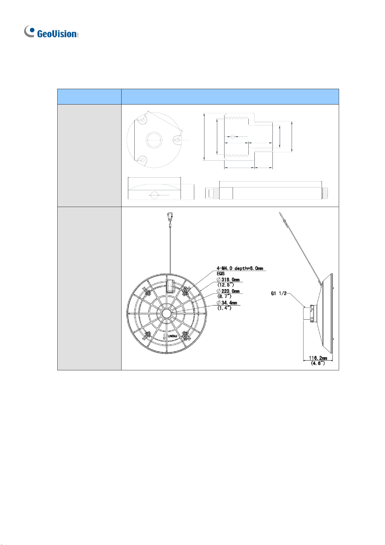
238
E. GV-Mount Dimensions
Dimensions of various GV-Mounts are illustrated below:
GV-Mount Models
Dimensions
GV-Mount107
87mm
87mm
120mm
34mm
1"NPT
8mm
16mm
(3.42")
(0.3")
(4.72")
(0.63")
(1.34")
(3.42")
500mm
23.5mm
1"NPT
300mm
100mm
35mm
200mm
(3.94")
(0.93")
(1.38")
23.5mm
1"NPT
35mm
(0.93")
23.5mm
1"NPT
35mm
(0.93")
23.5mm
1"NPT
35mm
(0.93")
(1.38")
(1.38")
(1.38")
(7.87")
(11.8")
(19.7")
40mm
1"NPT
20mm
25mm 15mm
19mm
3/4"PF
20mm
M4
(1.57")
(0.79")
(0.98") (0.59")
(0.75")
(0.79")
GV-Mount113
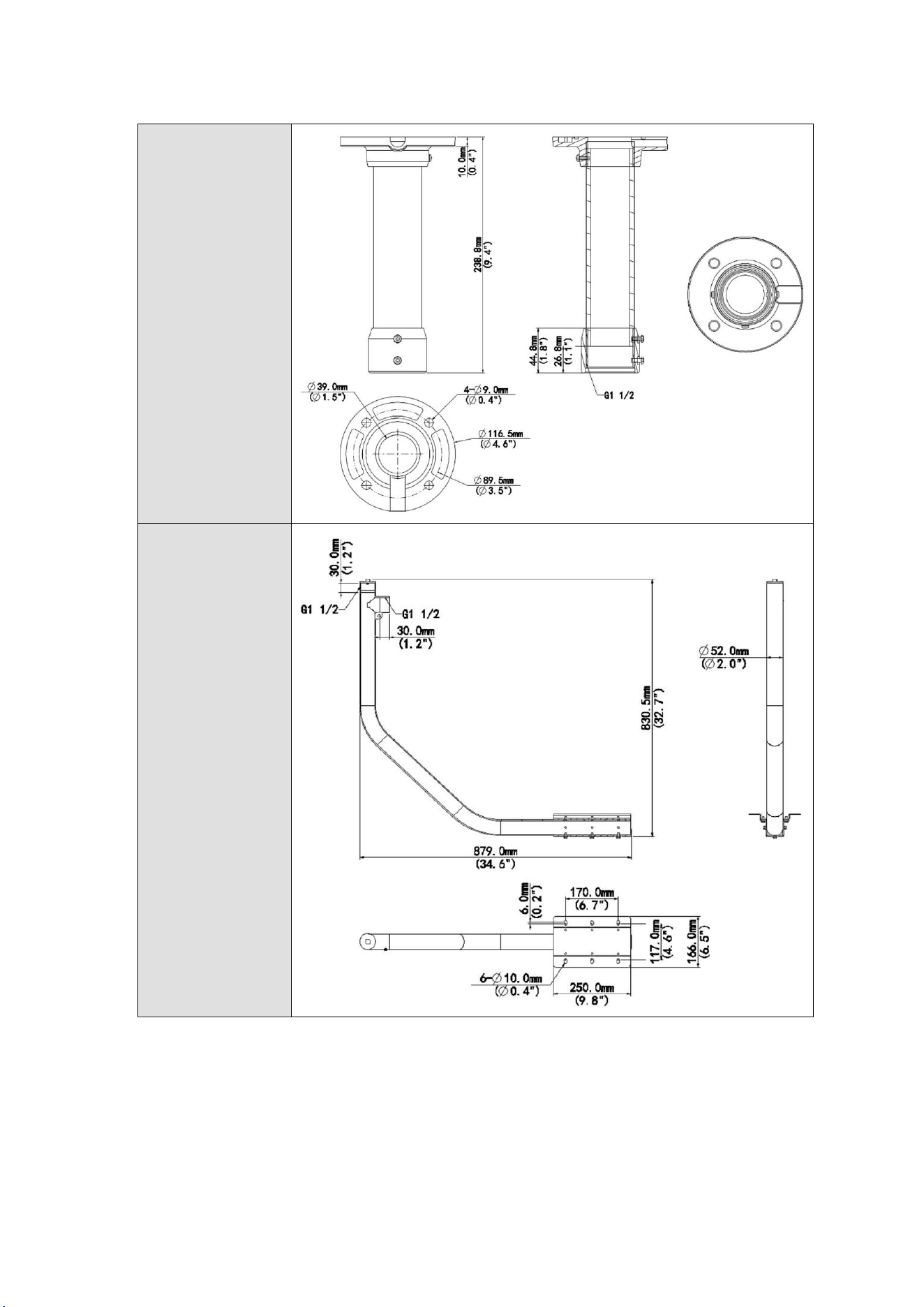
Appendix
239
GV-Mount114
GV-Mount208-5
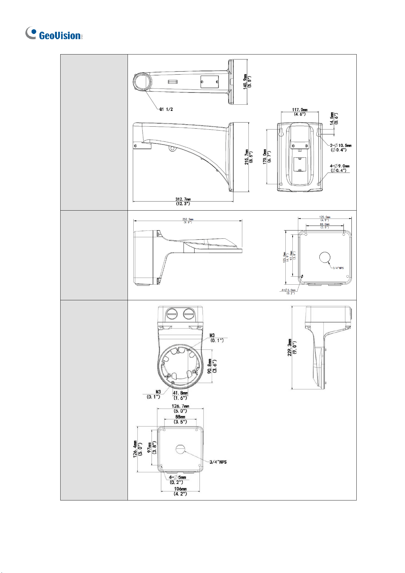
240
GV-Mount210-3
GV-Mount211-2
GV-Mount211-12
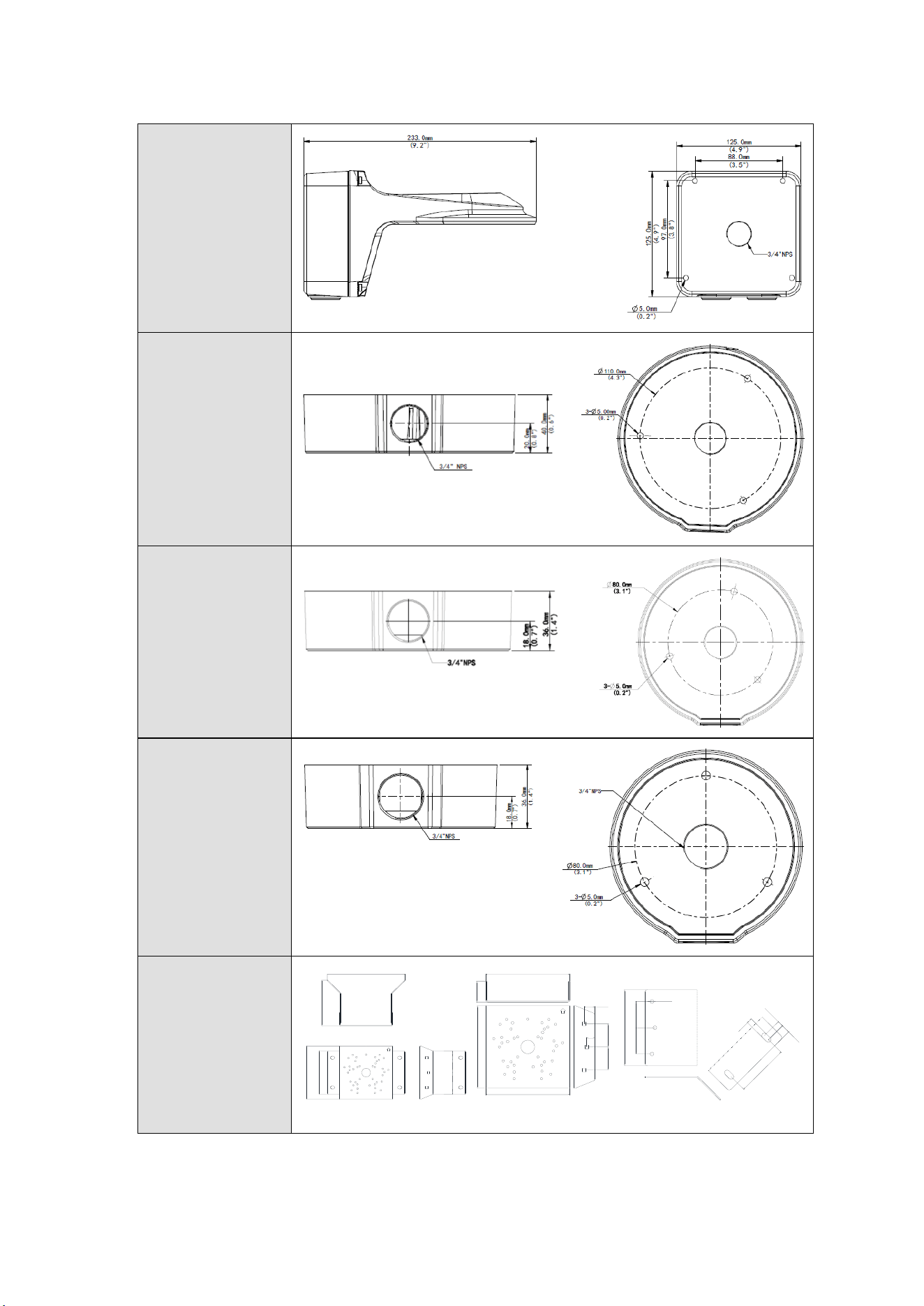
Appendix
241
GV-Mount211P
GV-Mount212-2
GV-Mount212P
GV-Mount213
GV-Mount300-2
233mm
137mm
160mm
130mm
(5.11")
(6.3")
(9.17")
(5.4")
40mm
160mm
160mm
160mm
20mm
15mm
45mm
45mm
(1.77")
(1.77")
(6.3")
(1.57")
(6.3")
(6.3")
(0.79")
(0.59")
90mm
15mm
10mm
9mm
45mm
7.5mm
45mm
(1.77")
(1.77")
(0.3")
(0.35")
(0.39")
(0.59")
(3.54")
130mm
(5.11")
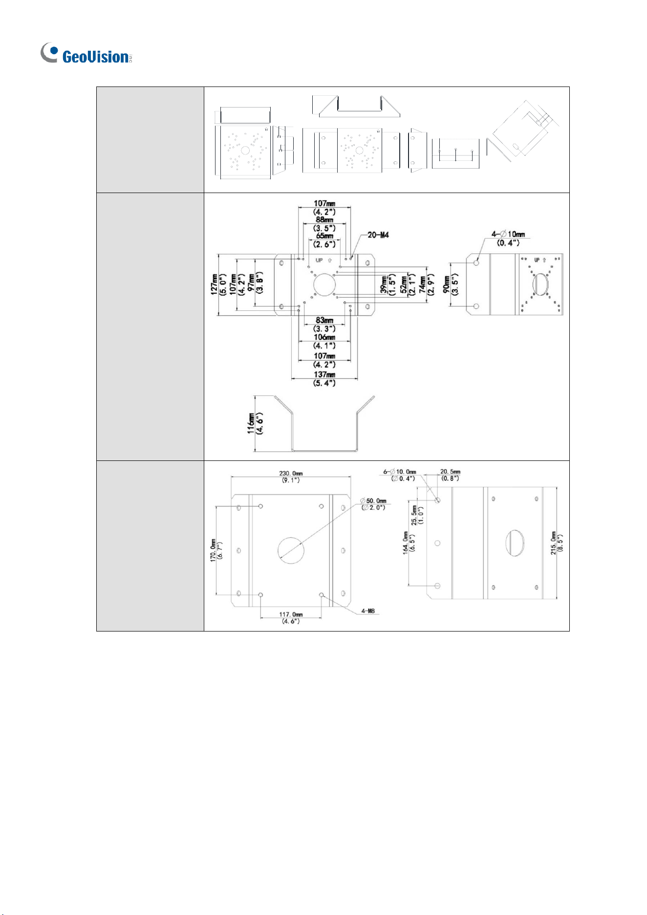
242
GV-Mount310-2
40mm
160mm
160mm
160mm
20mm
15mm
45mm
45mm
(1.77")
(1.77")
(6.3")
(1.57")
(6.3")
(6.3")
(0.79")
(0.59")
90mm
15mm
10mm
9mm
45mm
7.5mm
45mm
(1.77") (1.77")
(0.3")
(0.35")
(0.39")
(0.59")
(3.54")
130mm
(5.11")
290mm
66mm
160mm
130mm
(11.4")
(2.6")
(5.11")
(6.3")
GV-Mount312
GV-Mount313
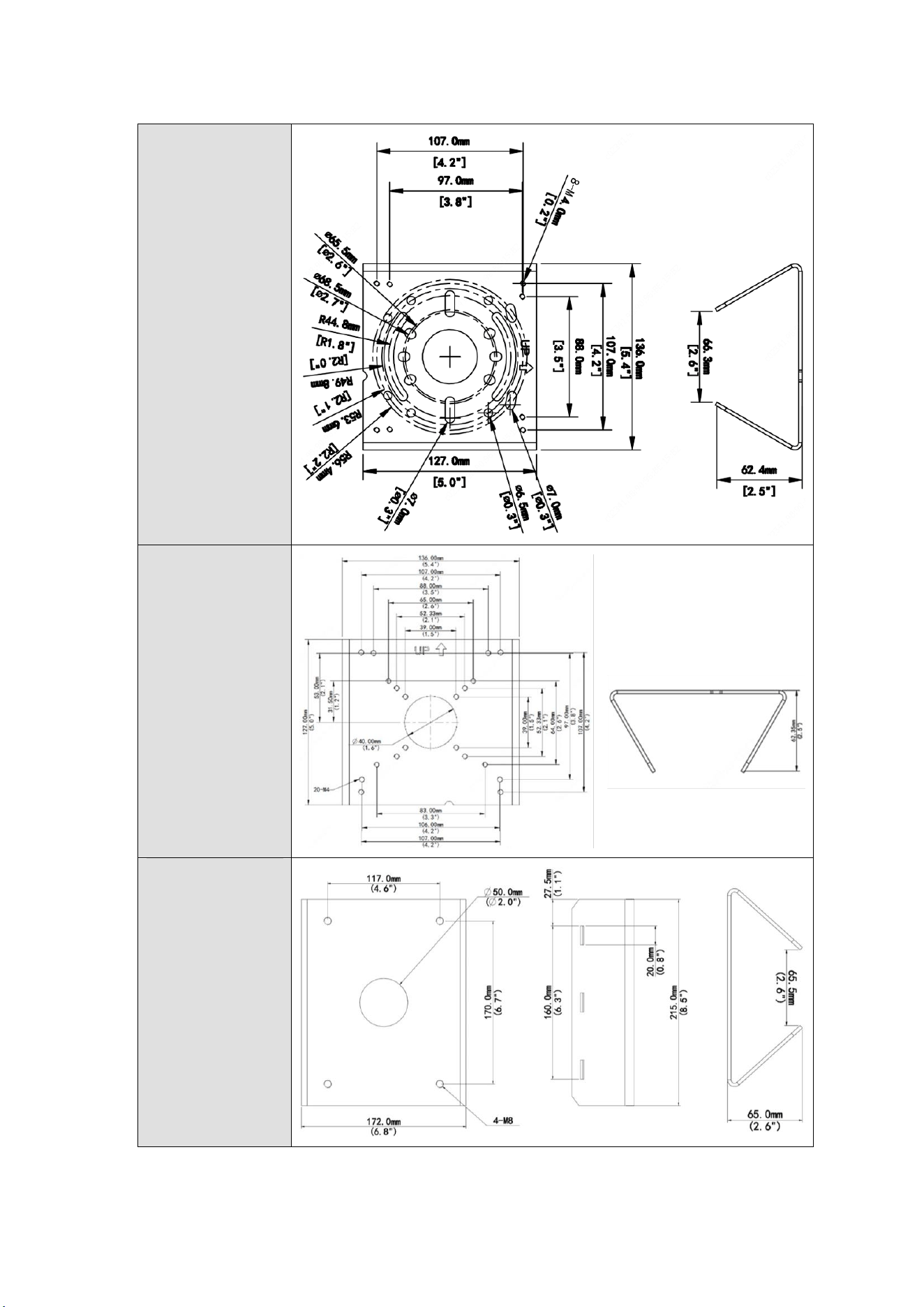
Appendix
243
GV-Mount420
GV-Mount440
GV-Mount480
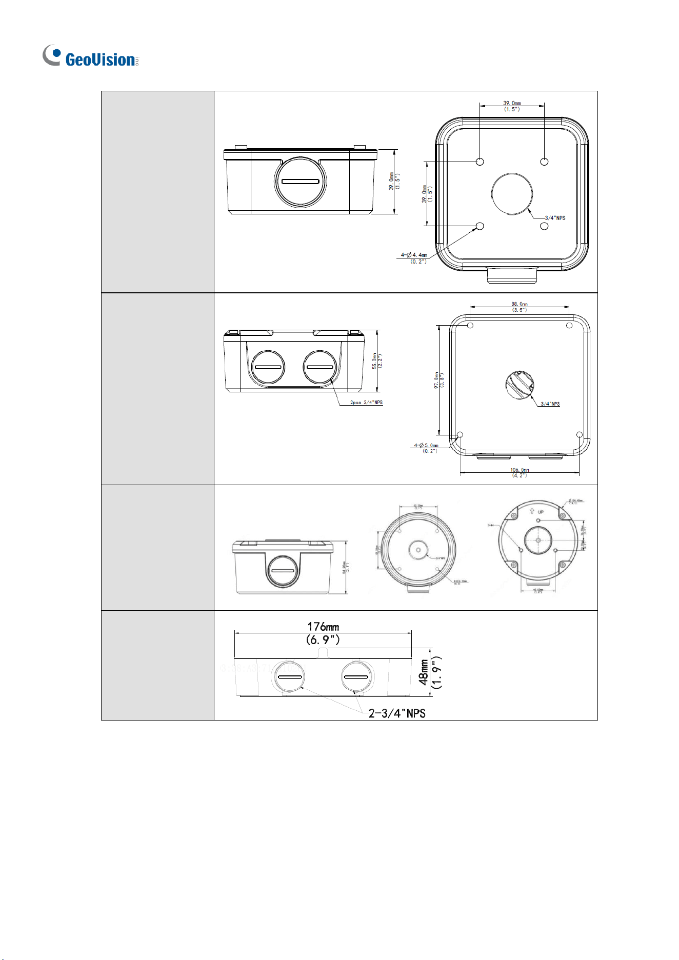
244
GV-Mount502
GV-Mount503
GV-Mount504
GV-Mount511
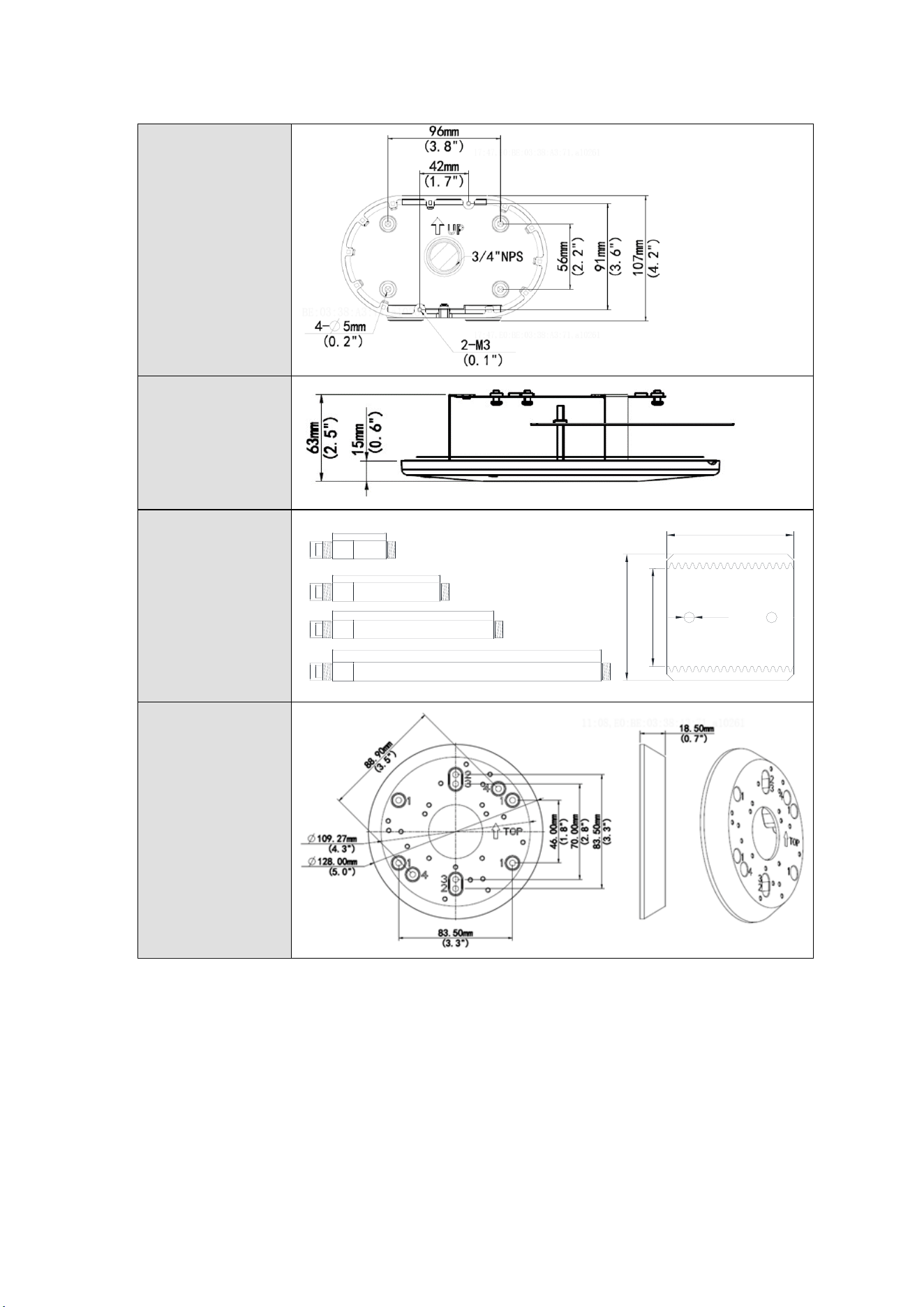
Appendix
245
GV-Mount606
GV-Mount704
10 / 20 / 30 / 50 cm
500mm
23.5mm
1"NPT
300mm
100mm
35mm
200mm
(3.94")
(0.93")
(1.38")
23.5mm
1"NPT
35mm
(0.93")
23.5mm
1"NPT
35mm
(0.93")
23.5mm
1"NPT
35mm
(0.93")
(1.38")
(1.38")
(1.38")
(7.87")
(11.8")
(19.7")
40mm
1"NPT
M4
40mm
(1.57")
(1.57")
GV-Mount924
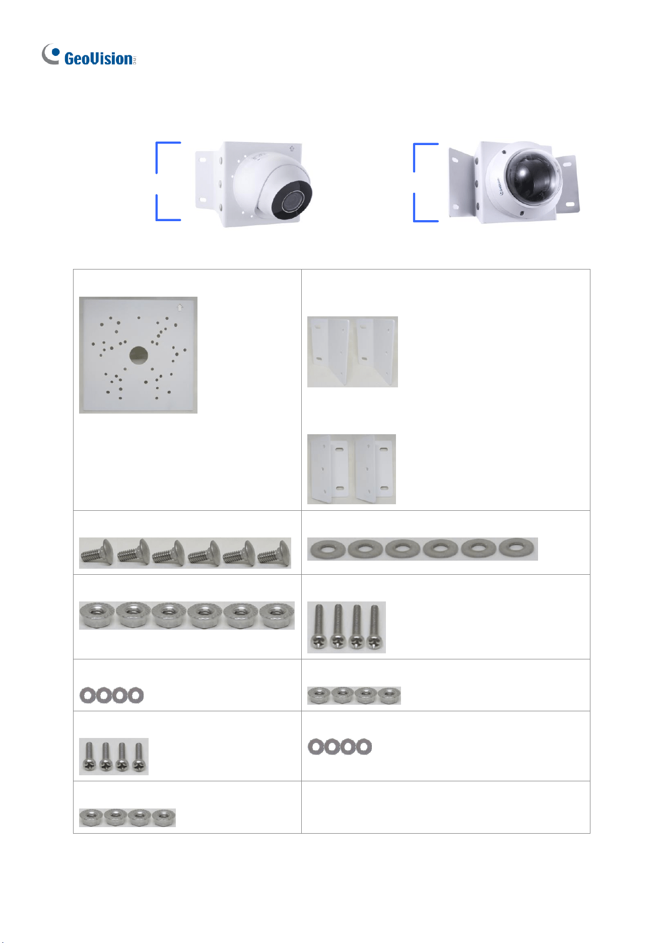
246
F. GV-Mount300-2 / 310-2
GV- Mount310-2
GV- Mount
300-2
GV-Mount300-2 / 310-2 Packing List
• Mounting Bracket
• Convex Mounting Plate x 2
(for GV-Mount300-2)
• Concave Mounting Plate x 2
(for GV-Mount310-2)
• Carriage Bolt x 6
• 1/4” Plain Washer x 6
• 1/4” Flange Nut x 6
• M4 Screw (25 mm) x 4
• M4 Plain Washer x 4
• M4 Flange Nut x 4
• M3 Screw (15 mm) x 4
• M3 Plain Washer x 4
• M3 Flange Nut x 4

Appendix
247
To install GV-ABL / TBL Series, GV-ADR2702 / 4702, GV-AVD / TVD Series, GV-
BLFC5800, GV-EBD Series, GV-EBFC5800, GV-PTZ5810-IR, GV-TDR Series, GV-
TFD4700 / 4800, and GV-TBL2705 / TBL2706 / TBL4705 / TBL8804, or directly on GV-
Mount300-2 / 310-2, follow the instructions below.
1. Assemble the GV-Mount300-2 / 310-2, by attaching the two mounting plates onto the
mounting bracket with the supplied carriage bolts, 1/4” plain washers, and 1/4” flange
nuts.
2. Thread the camera wires through the hole in the center of the mounting bracket.
3. Position the base of your camera according to the enclosed Screw Position Chart.
4. Attach the camera onto the mounting bracket.
A. For GV-EBD2702 / 2704 / 4700 / 4701 / 4704 / 8700 / 8800 and GV-EBFC5800
Remove the camera housing and attach the camera base to the mounting bracket
with the supplied M3 screws, washers, and flange nuts. See similar installation in
Step 3 ~ 6, 1.1.4.1 GV-EBD2702 / 2704 / 4700 / 4701 / 4704 / 8700 / 8800 Standard
Installation.
B. For GV-EBD4711 / 4712 / 4813 / 8711 / 8813, GV-EBDP5800 / 8800,
GV-PTZ5810-IR
Remove the camera housing and attach the camera base to the mounting bracket
with the supplied M3 screws, washers, and flange nuts. See similar installation in
Step 3 ~ 6, 1.1.4.2 GV-EBD4711 / 4712 / 4813 / 8711 / 8813 Standard Installation.
C. For GV-ABL / TBL Series & GV-BLFC5800 (Not applicable to GV-TBL2705 / 4705
/ 8804)
Attach the camera to the mounting bracket with the supplied M4 screws, washers,
and flange nuts.
D. For GV-ADR2702 / 4702 / GV-TDR Series / GV-TFD4700 / 4800
Attach the camera to the mounting bracket with the supplied M3 screws, washers,
and flange nuts. Close and secure the camera housing.
E. For GV-AVD / TVD Series
Remove the camera housing and attach the camera base to the mounting bracket
with the supplied M4 screws, washers, and flange nuts. See similar installation in
Step 3 ~ 4, 1.4.4 Installation.
5. Secure the assembled GV-IP Camera and GV-Mount300-2 / 310-2 to the wall with the 4
self-prepared screws with the arrow pointing up.
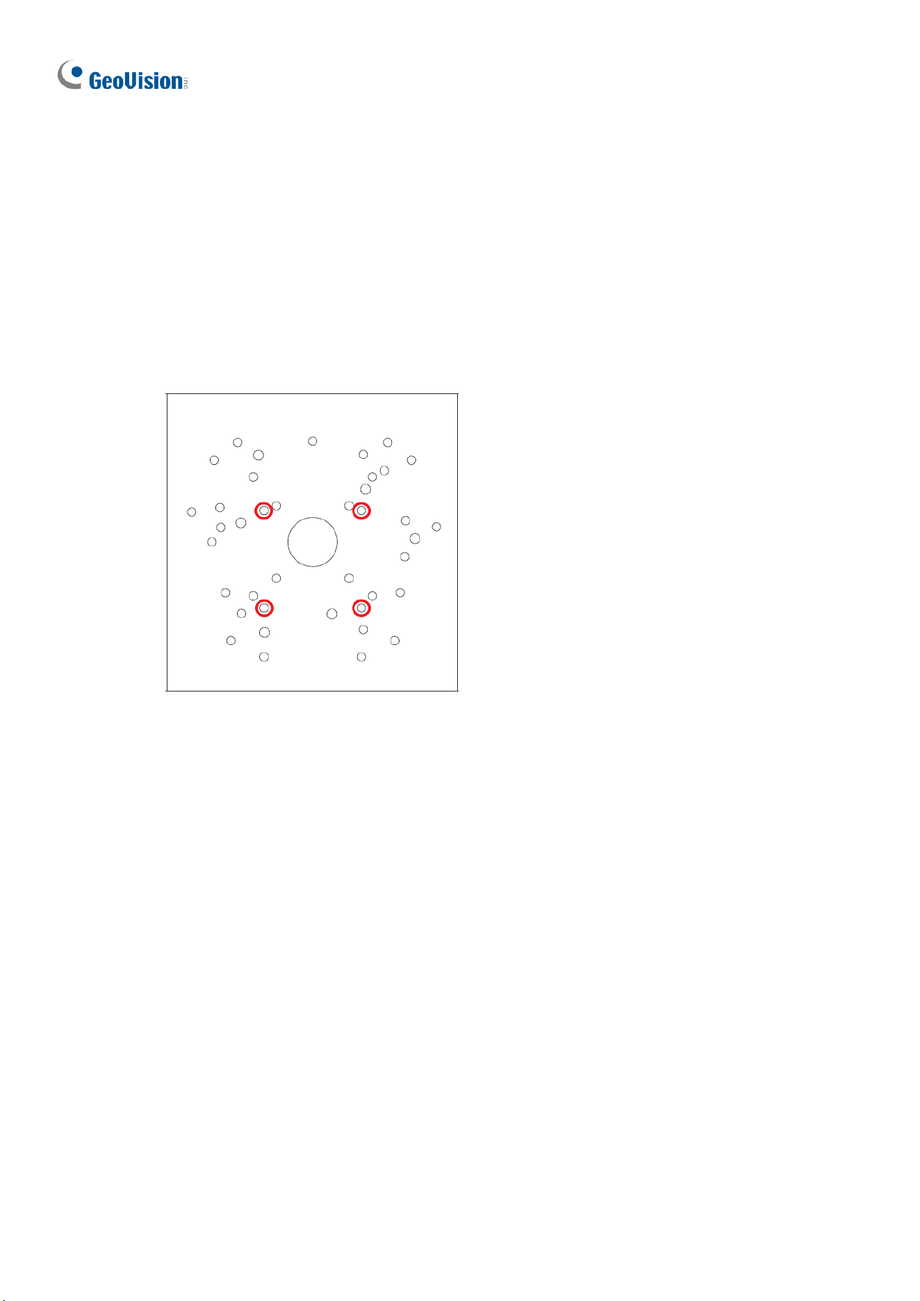
248
To install GV-TBL2705 / TBL4705 / TBL8804, on GV-Mount300-2 / 310-2 with GV-
Mount504, follow the instructions below.
1. Assemble the GV-Mount300-2 / 310-2, by attaching the two mounting plates onto the
mounting bracket with the supplied carriage bolts, 1/4” plain washers, and 1/4” flange
nuts.
2. Detach the upper cover of GV-Mount504.
3. Secure the base of GV-Mount504 to GV-Mount300-2 / 310-2 based on the following
holes.
4. Secure the camera to the upper cover of GV-Mount504.
5. Assemble the upper cover of GV-Mount504 to its base and thread the wires through the
center of GV-Mount504.
6. Secure the assembled GV-IP Camera, GV-Mount300-2 / 310-2, and GV-Mount504 to
the wall with the 4 self-prepared screws with the arrow pointing up.
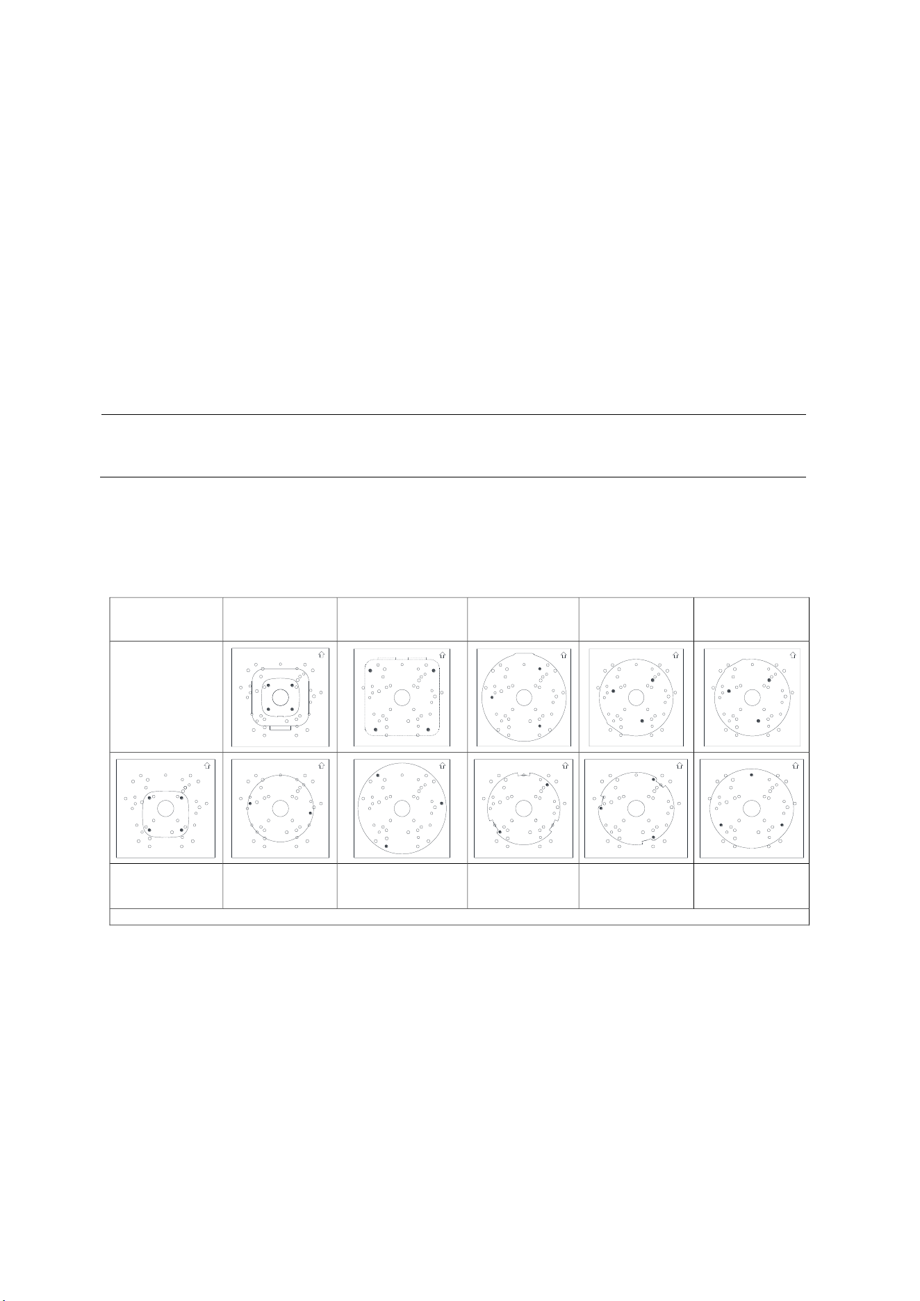
Appendix
249
To install GV-Mount211P / 211-2 / 212-2 / 212P / 213 / 502 / 503 on GV-Mount300-2 / 310-2
1. Assemble the GV-Mount300-2 / 310-2, by attaching the two mounting plates onto the
mounting bracket with the supplied carriage bolts, 1/4” plain washers, and 1/4” flange
nuts.
2. Position and secure GV-Mount211P / 211-2 / 212-2 / 212P / 213 / 502 / 503 to GV-
Mount300-2 / 310-2 as instructed on the enclosed Screw Position Chart.
3. Secure your GV-IP Camera to the GV-Mount211P / 211-2 / 212-2 / 212P / 213 / 502 /
503 to complete the installation.
Note: For details on attaching your GV-IP Camera to GV-Mount211P / 211-2 / 212-2 /
212P / 213 / 502 / 503 / 504, see optional installations in Chapter 1 Introduction.
G. Screw Position Chart
Screws:M4*25
GV-Mount502
GV-TBL2703/4703
GV-ABL2701/4701/2703/4703
Screws:M4*25
GV-Mount503
GV-Mount211P
GV-Mount211-2
Screws:M4*25
GV-Mount212-2
Screws:M4*25
GV-Mount212P
Screws:M4*25
GV-Mount213
Screws:M4*25
GV-ABL2702/4711/4712/8712
GV-TBL4700/4710/4711/4810
/8710/8810
Screws:M3*15
GV-ADR2702/4702
GV-TFD4700
GV-TDR2700/2702/2704/4700/
4702/4703/4704/4803
GV-AVD2700/4710/8710
GV-TVD4700/4710/4711/4810/8710/8810
Screws:M3*15
GV-EBD2702/2704
Screws:M3*15
GV-EBD4700/4701/4704/8700/8800
Screws:M3*15
GV-EBD4711/4712/4813/8711/8813
If you cannot find the desired camera model, please visit our website for more information.
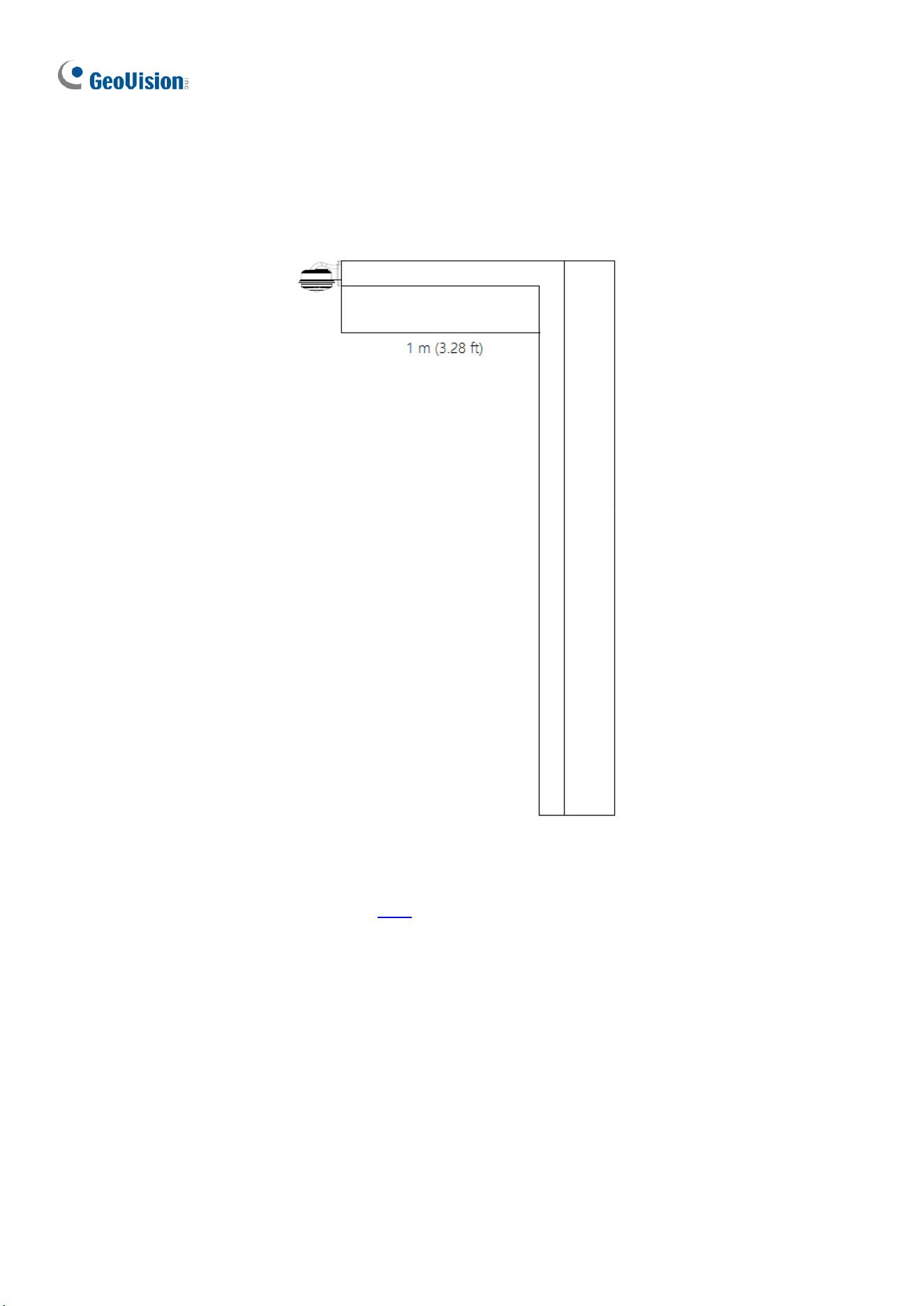
250
H. Note for Fisheye Camera with IR LED
When installing Mount107 / 211P / 212P to your GV-FER5702, leave a distance of 1 M (3.28
ft) or more between the camera body and nearby walls to avoid reflected glare by IR LED.
I. Retrieve Camera’s Password
You can collect required information and contact our support teams to retrieve your camera’s
password. Refer to the instructions here.
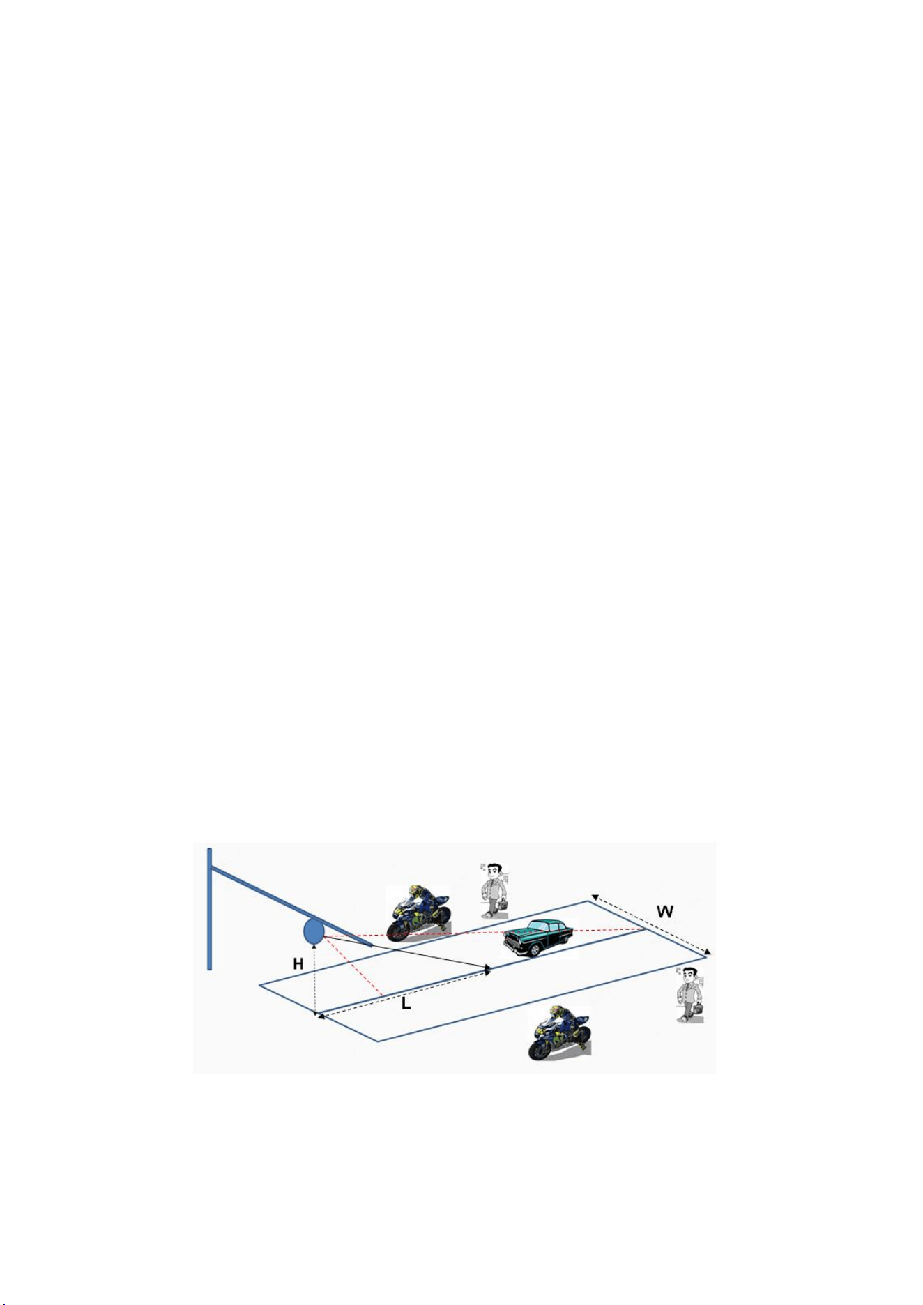
Appendix
251
J. Installation Guidelines for Perimeter Protection
To use the functions of Cross Line, Intrusion Detection, Enter Area, and Leave Area,
which is only supported by AI-capable cameras, it is recommended to install the camera
according to the criteria listed below:
Lighting Requirements
1. Lighting at the site must be greater than 50 lux.
2. Lighting at the site must be even and stable.
Environmental Requirements
3. Mount height: 3 ~ 6 meters.
4. Monitoring distance: 6 ~ 30 meters.
5. Coverage width: 10 ~ 20 meters with a maximum of 30 meters.
6. Avoid strong backlight or front light in outdoor scenes.
7. Avoid scenes with strobe or flash illuminators in outdoor scenes.
Note: The mount height, monitoring distance and coverage width are all affected by the
object pixel. For motor vehicle/non-motor vehicle/pedestrian, 200 pixels or more is
recommended, and it must not be lower than 100 pixels.
Surveillance Illustration
H: Mount height; L: Capture distance; W: Coverage width
Recommended Scenes
Clear background, even lighting, and installation angle meets the requirement.
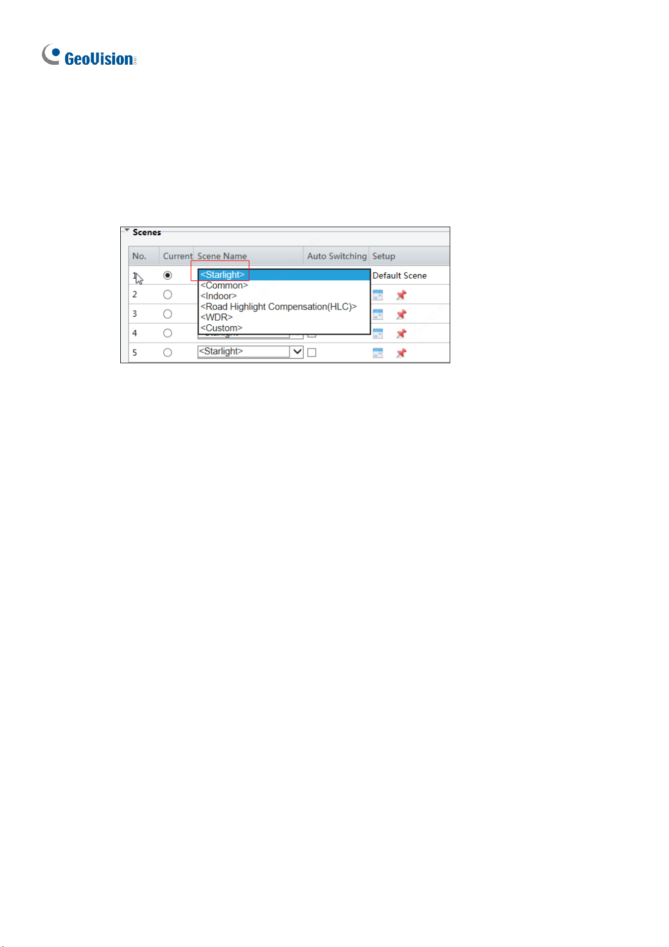
252
Note Recommended Scenes
Complex perimeter, bad environment; large top view angle, causing objects hard to
recognize; uneven lighting.
Image Configuration
Use the default parameters of Starlight or Common scene.

Appendix
253
K. Installation Guidelines for People Flow Counting
To use the People Flow Counting function, which is only supported by AI-capable cameras, it
is recommended to install the camera according to the criteria listed below:
Installation Considerations
1. It is recommended to install the camera at a height of 4 ~ 9 meters (13.1 ~ 29.5 ft)
when the overhead angle of the camera is 30°~60°, and the effective monitoring width
is between 1 ~ 8 meters (3.3 ~ 26.2 ft).
2. It is recommended to install the camera at a height of 3 ~ 5 meters (9.8 ~ 16.4 ft) when
the overhead angle of the camera is 60°~90°, and the effective monitoring width is
between 1 ~ 5 meters (3.3 ~ 16.4 ft).
3. Avoid areas that may affect accuracy as far as possible, such as in the detection area
there are leaf shaking interference, serious shadow shaking, glass floor tile reflective
scenes.
4. If the flow of people in the area is too dense and stagnant, if there is a block on the
head, it will have an impact on the index. Such scenes should be avoided as far as
possible in the detection area.
5. The camera should be well fixed, unable to move or shake.
6. Input image aspect ratio is required to be 16:9.
7. It does not support infrared scenes, strong backlight, dim scenes and night light
changing scenes, etc.
8. The scene with reflection is not supported, which will cause more false detections. It is
recommended to adjust the camera angle to eliminate the reflection.
9. When there is unusual weather such as rain, snow and fog, the scene indicators will be
greatly affected.
10. All functions are not suitable for scenes with more occlusion and interference.

254
11. When adjusting the monitoring range and setting business rules, attention should be
paid to the pixel size of pedestrian head and shoulder. When the resolution is 1920 x
1080, the pixel size requirements of head and shoulder are: lower limit: 55 x 55; upper
limit: 180 x 180; best: 65 x 65 ~ 160 x 160, and other dimensions are converted
according to the proportion of single side length of the picture.
Resolution Ratio
Recommended Min.
Pixel
Recommended Max Coverage
(width x depth)
1920 x 1080
65 x 65
12 m x 10 m
2560 x 1440
90 x 90
12 m x 10 m
3840 x 2160
130 x 130
12 m x 10 m
Recommended Scenes
People Flow Counting applicable scenarios: The entrances and exits of shopping malls,
parks, squares, escalators, and other places; passages and gates of railway stations and
subways. The scene is relatively clean, with few people present and no light, leaves shaking,
shadow, or other interference.
Not Recommended Scenes
1. The scene where many people gather in the room and basically stop moving.
2. There are umbrellas in rainy days.
3. The pixels from heads to shoulders of some people occupy too many pixels in the
image, which cannot meet the pixel requirements.
4. The screen is too dark, and the installation height falls short of the required height.
5. The camera installation location is too far from the horizontal distance of the escalator,
which does not meet the requirement of 0.5 ~ 2 m.
6. The installation position of the camera is tilted, and the detection box is horizontally
tilted, which affects the recognition rate.

Appendix
255
L. Installation Guidelines for Crowd Density Monitoring
To use the Crowd Density Monitoring function, which is only supported by AI-capable
cameras, it is recommended to install the camera according to the criteria listed below:
Installation Considerations
1. The scene should be open, wide, without shielding interference and non-dense crowd.
2. The effective monitoring width is affected by the depression angle of the camera and the
installation height. The higher the installation height, the larger the monitoring range;
The larger the depression angle of the camera, the smaller the monitoring scope.
Recommended Scenes
Crowd Density Monitoring is applicable to squares, open places, shelters and places with
less Interference and non-dense population.
Not Recommended Scenes
1. The camera installation height is low, and the depth of the scene is too deep (that is, the
People Flow Counting scene should not be used for the Crowd Density Monitoring).
2. The distance is too far, the target is too small.
Note: People Flow Counting is applicable to places such as squares and open places. Crow
Density Monitoring is applicable to places such as roads, entrances and exits.
Installation Requirements
1. Installation height: It is recommended between 6 ~ 10m
2. Installation position: it is installed in the place with wide vision to avoid backlighting and
many light interferences.
3. The camera depression angle: Between 30 ° ~ 80 °, the best angle is 45 ° ~ 75 °
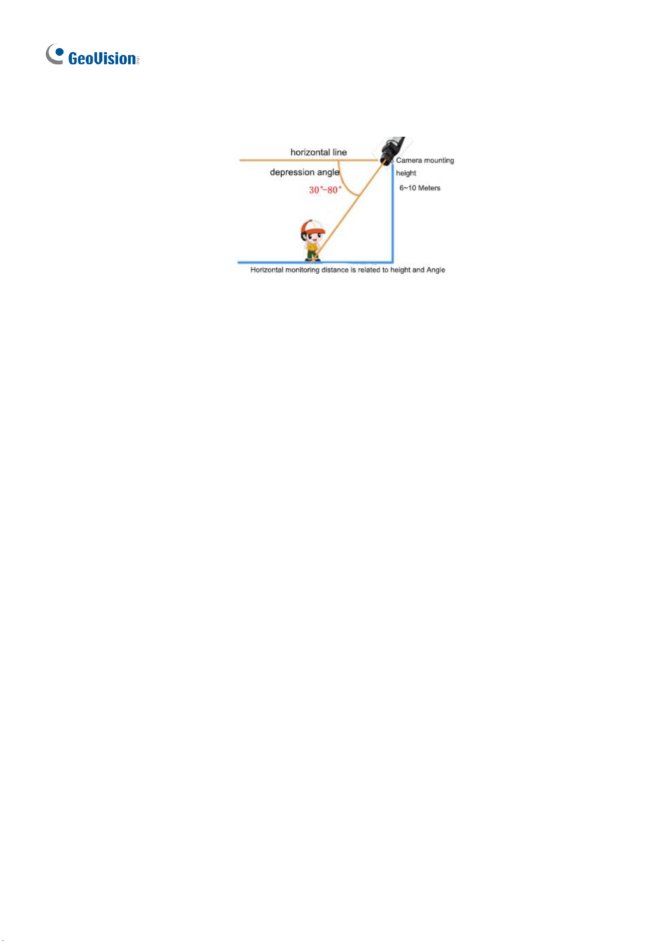
256
4. Monitoring range: It is related to the focal length and installation height of different
lenses. The target size shall meet the requirements of head and shoulder size.
M. Installation Guidelines for Face Detection
To use the Face Detection function, which is only supported by AI-capable cameras, it is
recommended to install the camera according to the criteria listed below:
Lighting Requirements
1. Select a bright scene (with light no less than 100 lux). Scenes with wide dynamic range
and backlight are not recommended.
2. Lighting at the site must be even and stable.
Note: Illuminators are required if the natural lighting in the scene is lower than 100 lux.
Environmental Requirements
1. Mount height: 2.5 ~ 4.5 m.
2. Capture distance: 3 ~ 15 m.
3. Angle: It is recommended to install the camera right in front of the passageway, with
horizontal deflection angle ≤30°, the top view angle ≤15° (≤10° is recommended).
4. Surveillance coverage width:
4MP IPC: ≤4.5m
8MP IPC: ≤6m
5. In outdoor scenes, avoid installing in an east-west direction (avoid strong backlight or
front light).
6. Install the camera in a bright spot to capture people coming from the dark for
installations at a passageway, entrance or exit, etc.
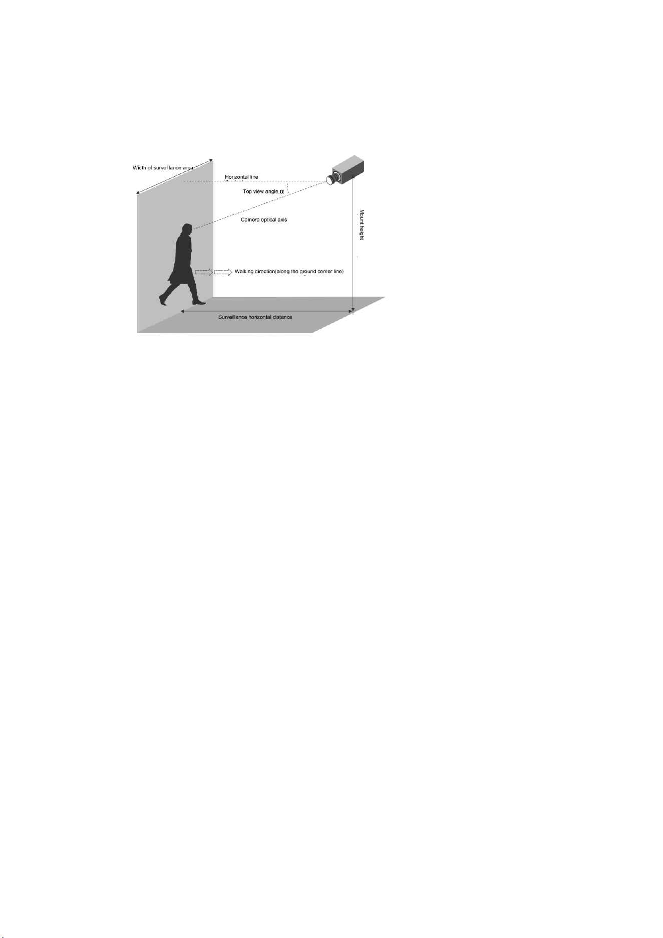
Appendix
257
Note: The surveillance coverage width of the camera is determined by face pixel. It is
recommended that the minimum face pixel is no less than 80.
Recommended Scenes
Face Detection is applicable to turnstile passageway, indoor passageway, and outdoor
sidewalk.
Not Recommended Scenes
1. Crossroads, turns, and zebra crossings where faces are not captured from the front
2. Tilted mount with an excessively large face deflection angle
3. Dark scenes in which faces are not clear enough
4. Super wide-angle scenes with insufficient face pixel
5. Scenes with LED screens in which lighting is unstable due to the LED screen
Special Scenes
1. Scenes with WDR or strong backlight: Use curtains or a double-glazed door to avoid
WDR or strong backlight.
2. Scenes with strong reflection on the ground: Avoid strong light reflections on the
ground by laying carpets on the floor or setting up screens.
Note: For special scenes, assessment must be done thoroughly during survey to determine
whether solutions can be fully implemented. Scenes that cannot be fully implemented shall
be avoided; otherwise, image quality and capture results may not be satisfactory.
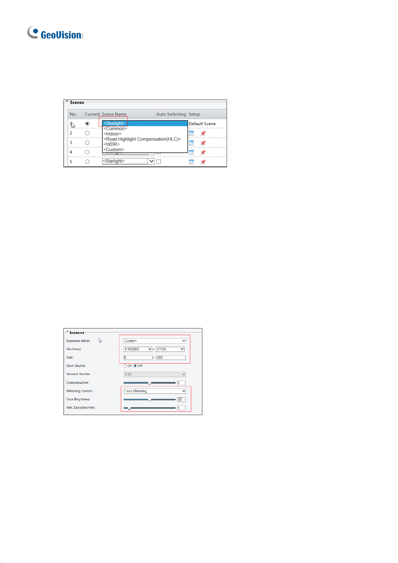
258
Image Configuration
1. Scenes
Scenes: Starlight
2. Exposure Parameters
⚫ Exposure Mode: Select Custom.
⚫ Shutter(s): 1/100-1/200 is recommended for the upper limit. Set appropriately according
to the face movement speed.
⚫ Gain: It is recommended to set the upper limit to 40. Set appropriately according to the
brightness of face.
⚫ Metering Control: Select Face Metering.
⚫ Face Brightness: 50 is recommended. Set appropriately if the captured face is too dark
or overexposed.
⚫ Min. Duration(min): 5 is recommended. Set appropriately as required.
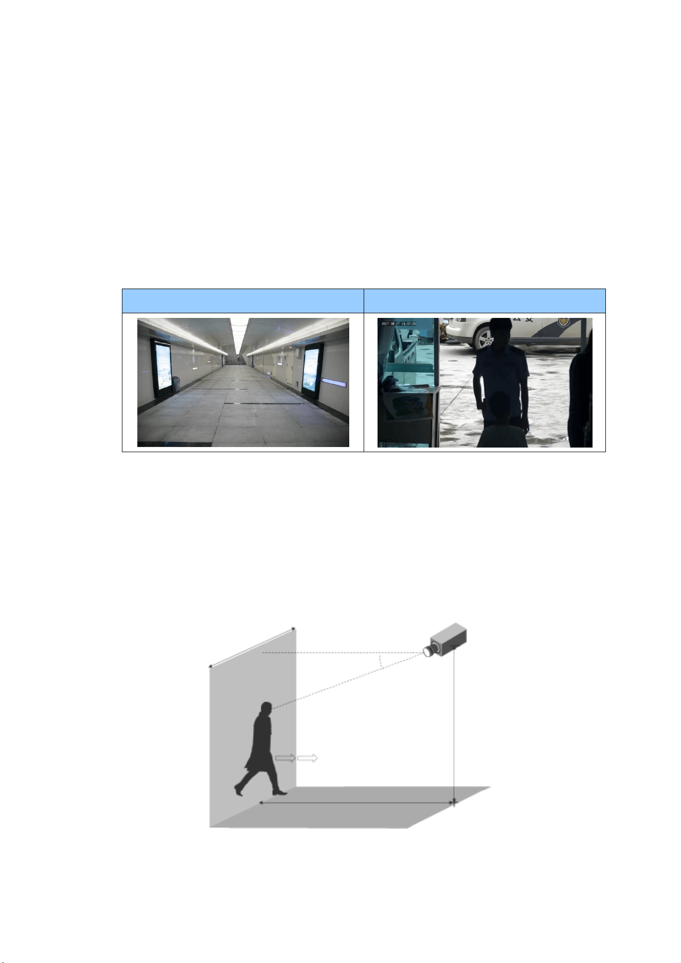
Appendix
259
N. Installation Guidelines for Face Detection (Non-AI)
To use the camera’s built-in face detection feature (see 3.6.1.7 Face Detection), which is
only supported by certain models, it is recommended to install the camera according to the
criteria listed below:
Surveillance Condition
• The camera shall be installed at a site with uniform, sufficient lighting, where the
face(s) to be detected are fully illuminated.
Example of Recommended Scene
Example of Non-recommended Scene
Camera Position
• The camera shall be mounted at a recommended height of 2.5 ~ 3 m (8.2 ~ 9.84 ft).
• The camera shall be mounted with a recommended depression angle of around 10°.
• The camera shall be positioned so that the face(s) to be detected are directly aligned
with the lens of the camera, with a horizontal deviation of no greater than 30°, a
vertical deviation of no greater than 15° and a face size of at least 120 pixels.
Surveillance
area width
Horizontal line
Depression angle α
Optical axis of
the camera
Pedestrian walking direction
(straight along the center of
the ground)
Horizontal surveillance distance
Device mounting height
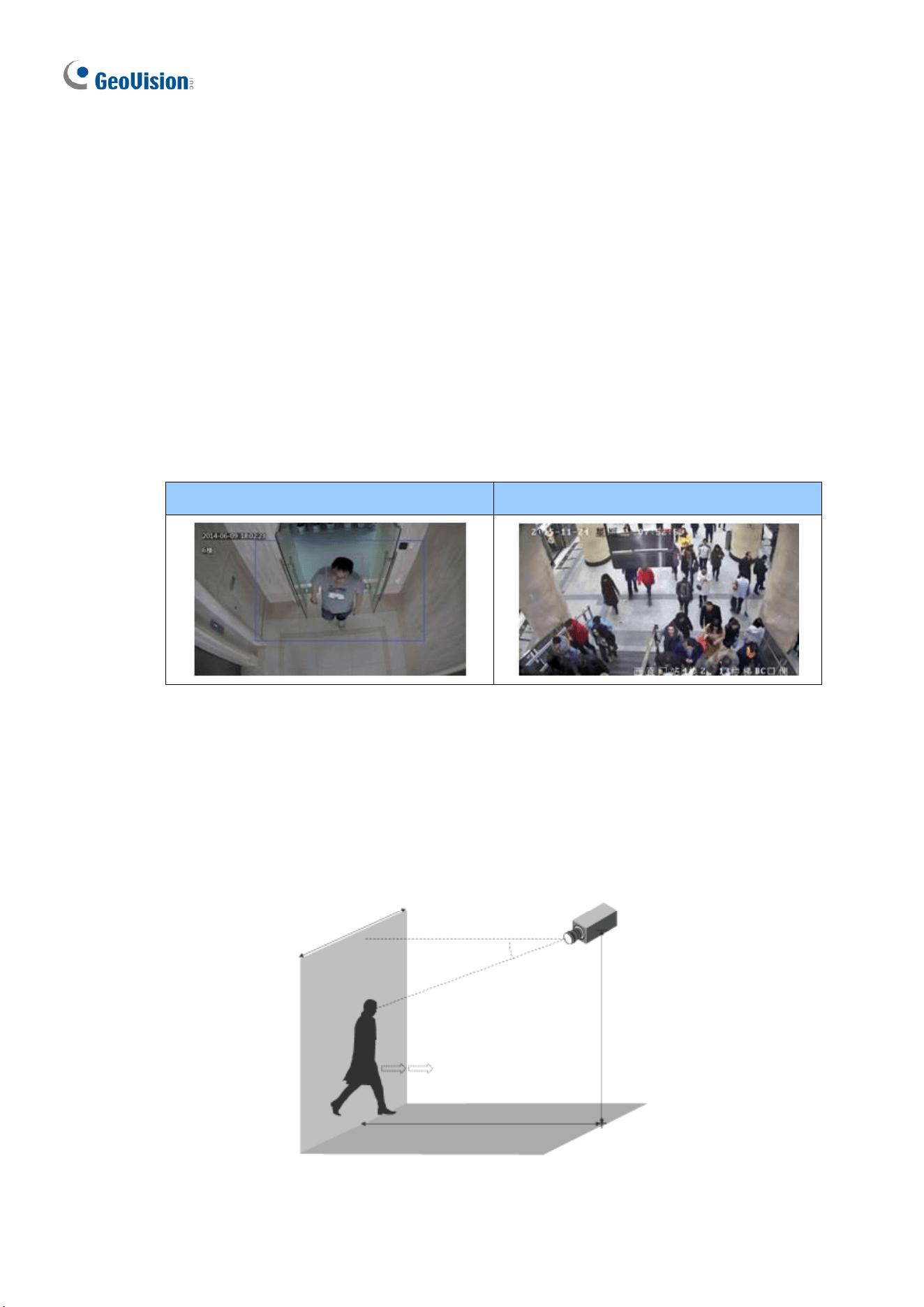
260
O. Installation Guidelines for People Counting (Non-AI)
To use the camera’s built-in people counting feature (see 3.6.1.8 People Counting), which is
only supported by certain models, it is recommended to install the camera according to the
criteria listed below:
Surveillance Condition
• The camera shall be installed at a site with uniform, sufficient lighting, where the
person(s) to be counted are fully illuminated.
• The camera shall be installed at an entrance or exit with an ideal width of 1 ~ 4 m
(3.28 ~ 13.12 ft), where the persons(s) to be counted move toward the lens of the
camera in single file.
Example of Recommended Scene
Example of Non-recommended Scene
Camera Position
• The camera shall be mounted at a recommended height of 3 ~ 5 m (9.84 ~ 16.4 ft).
• The camera shall be mounted with a recommended depression angle of 70 ~ 80°.
• The camera shall be positioned so that the person(s) to be counted face toward the
lens of the camera and are displayed on the image with a shoulder size of between
120 ~ 160 pixels.
Surveillance
area width
Horizontal line
Depression angle α
Optical axis of
the camera
Pedestrian walking direction
(straight along the center of
the ground)
Horizontal surveillance distance
Device mounting height