User’s Information Manual
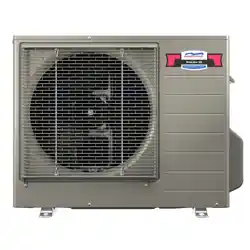
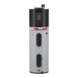
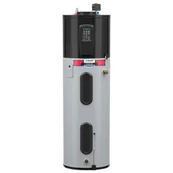
NWP500 Electric Heat Pump Water Heaters
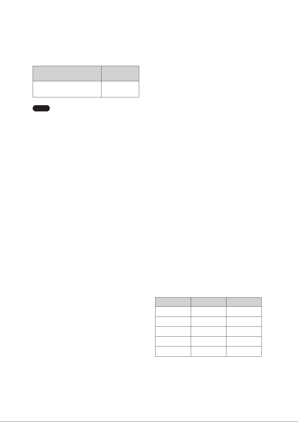
Model
NWP500-50
NWP500-65
NWP500-80
ALWAYS read and follow this manual completely before
using the water heater. Save for future reference.
Tested and Certied to NSF/ANSI 372 for lead free*
compliance.
* The wetted surface of this product contacted by
consumable water contains less than one quarter of
one percent (0.25%) of lead by weight.
WARNING
Improper installation, operation, or service can damage the water heater, your home, and other
property and can create hazards such as re, burns, electric shock, and explosion, which can
result in serious injury or death.
Read this manual and the water heater’s label before installing, operating, or servicing. If you have
diculty following the instructions or are not sure that you can safely and properly perform this
work yourself, contact a qualied installer or service organization for installation and servicing.
Do not destroy this manual; read it carefully and keep it in a safe place for future reference.

2 FCC and IC STATEMENT
This equipment has been tested and found to
comply with the limits for a Class B digital device,
pursuant to part 15 of the FCC Rules. These limits are
designed to provide reasonable protection against
harmful interference in a residential installation.
This equipment generates, uses and can radiate
radio frequency energy and, if not installed and
used in accordance with the instructions, may cause
harmful interference to radio communications.
However, there is no guarantee that interference
will not occur in a particular installation. If this
equipment does cause harmful interference to radio
or television reception, which can be determined
by turning the equipment off and on, the user is
encouraged to try to correct the interference by one
or more of the following measures:
Ɣ
Reorient, or relocate, the receiving antenna.
Ɣ
Increase the distance between the equipment
and receiver.
Ɣ
Connect the equipment into an outlet on a
circuit different from that to which the receiver is
connected.
Ɣ
Consult the dealer or an experienced radio/TV
technician for help.
FCC Part 15 Related Statement - Keep
for Liability Purposes
This device complies with part 15 of the FCC Rules.
Operation is subject to the following two conditions:
(1) This device may not cause harmful interference.
(2) This device must accept any interference
received, including interference that may cause
undesired operation.
Any changes or modifications in construction of
this device which are not expressly approved by
the party responsible for compliance could void the
user’s authority to operate the equipment.
WARNING
The manufacturer is not responsible for any
radio or TV interference caused by unauthorized
modifications to this equipment. Such
modifications could void the user’s authority to
operate the equipment.
FCC RF Radiation Exposure Statement
This equipment complies with FCC RF Radiation
exposure limits set forth for an uncontrolled
environment. This device and its antenna must not
be co-located or operating in conjunction with any
other antenna or transmitter.
“To comply with FCC FR exposure compliance
requirements, this grant is applicable to only
Mobile Configurations. The antennas used for this
transmitter must be installed to provide a separation
distance of at least 8 inches (20 cm) from all
persons and must not be co-located or operating in
conjunction with any other antenna or transmitter.”
FCC IDENTIFIER: P53-EMC3290
Canadian Compliance Statement
This device complies with industry Canada license-
exempt RSS standard(s). Operation is subject to the
following two conditions:
(1) This device may not cause interference.
(2) This device must accept any interference,
including interference that may cause undesired
operation of the device.
To reduce potential radio interference to other users,
the antenna type and its gain should be so chosen
that the equivalent isotropic radiated power (e.i.r.p)
is not more than that permitted for successful
communications.
Industry Canada Statement
Complies with the Canadian ICES-003 Class B
specifications.
This device complies with RSS 210 of Industry
Canada. This Class B device meets all the
requirements of the Canadian interference-causing
equipment regulations.
This radio transmitter (IC: 23507-EMC3290) has
been approved by Industry Canada to operate with
the antenna types listed below with the maximum
permissible gain and required antenna impedance
for each antenna type indicated. Antenna types not
included in this list, having a gain greater than the
maximum gain indicated for that type, are strictly
prohibited for use with this device.
FCC and IC STATEMENT

3Contents
4. Maintaining the Water Heater 27
4.1 Maintaining the T&P Relief Valve 27
4.2 Cleaning the Air Filter 28
4.3 Inspecting the Condensate Drain
28
4.4 Draining and Flushing the Water Heater
29
4.5 Maintenance for Extended Periods of
Inactivity
29
4.6 Replacing the Battery on the Front Panel 29
4.7 Setting the DIP Switches 30
4.8 Installing Emergency Part Kit for Repairs
30
5. Troubleshooting 32
5.1 Solving Basic Problems 32
6. Appendixes 34
6.1 Wiring Diagram 34
6.2 Component Assembly Diagrams and
Parts Lists
35
LIMITED WARRANTY NAVIEN, INC.
1. Important Safety Information 4
2. About the Water Heater
7
2.1 Included Items 7
2.2 Accessories
7
2.3 Specifications
8
2.4 The Front Panel 9
2.5 Components 11
3. Operating the Water Heater 12
3.1 Turning the Water Heater On or Off 12
3.2 Start-Up Wizard
13
3.3 Selecting the Operation Mode &
Adjusting Water Temperature
13
3.4 About Operating Modes
14
3.5 Setting Operation Schedules and
Configuring Communication Settings
15
3.6 Viewing Status Information
17
3.7 Viewing System Information 19
3.8 Viewing Error History
20
3.9 Viewing Other System Operation
Information
21
3.10 Setting the Recirculation Mode 21
3.11 Setting the Display Options
23
3.12 Initializing All Parameter Settings
(Factory Reset)
24
3.13 Connecting the NaviLink App with
the Water Heater
24
3.14 Water Heater Protection Features 25
3.15 Additional Features 26
Contents
Product Installation Information
Model Number
Date Purchased
Serial Number
4 Important Safety Information
The following Safety Alert Symbols are used
in this manual. They are used to alert you to
potential personal injury hazards. Obey all
safety messages that follow this symbol to avoid
possible serious injury or death. This Safety Alert
Symbol precedes any safety message about risk of
personal injury. It may also be accompanied by one
of the following signal words.
If the information in these instructions is not
followed exactly, a fire or explosion may result,
causing property damage, personal injury or death.
DANGER
Indicates a hazardous situation that if not
avoided will result in death or serious injury.
WARNING
Indicates a hazardous situation that if not
avoided could result in death or serious injury.
CAUTION
Indicates a potentially hazardous situation that
if not avoided could result in minor or moderate
injury.
NOTICE
Indicates information considered important but
not hazard-related (such as property damage).
DANGER
Electric Shock Hazards
Ɣ
Contact with electrical parts in the junction
box, behind access doors, and inside the top
shroud can result in severe injury or death
due to electric shock.
Ɣ
Disconnect power by opening the circuit
breaker or removing the fuses before
installation or servicing.
Ɣ
Use a non-contact circuit tester to confirm
that the power is off before working on or
near any electrical parts.
Ɣ
Replace the junction box cover and access
doors after servicing.
Ɣ
When making electrical connections for your
water heater, follow the Wiring Diagram
carefully to ensure safety and proper
operation. Use 10-gauge solid copper wire for
all connections to handle the electrical load
effectively. It is also important to use a UL-
listed or CSA-approved strain relief to secure
the wires and prevent them from being pulled
or damaged. Finally, connect the ground wire
securely to the green ground screw to ensure
proper grounding and reduce the risk of
electrical shock.
1. Important Safety Information
5Important Safety Information
DANGER
This water heater’s water temperature is set
to 120°F (49°C) at the factory for your safety
and comfort. Increasing the temperature
increases the risk of accidental scalding. Water
temperatures at or above 125°F (52°C) can cause
instant scalding, severe burns, or death. Before
you decide to change the temperature setting,
read the following table carefully.
Temperature Time to Produce Serious Burn
120°F (49°C) More than 5 minutes
125°F (52°C) 1.5 to 2 minutes
130°F (54°C) Approx. 30 seconds
135°F (57°C) Approx. 10 seconds
140°F (60°C) Less than 5 seconds
145°F (62°C) Less than 3 seconds
150°F (65°C) Approx. 1.5 seconds
154°F (68°C) Approx. 1 second
Ɣ
Regardless of the water heater’s set
temperature, higher temperatures may occur
in certain circumstances:
- In some cases, repeated small draws of
water can cause the hot and cold water in
the tank to “stack” in layers. If this happens,
the water temperature can be as much as
30°F (15°C) hotter than the set temperature.
This temperature variation is the result of
your usage pattern and is not a malfunction.
- Water temperature will be hotter if someone
adjusted the thermostat(s) to a higher
setting. Problems with the thermostat(s), or
other malfunctions may result in higher than
expected water temperatures.
- If the water heater is in a hot environment,
the water in the tank can become as hot as
the surrounding air, regardless of the set
temperature.
- If the water supplied to the water heater
is pre-heated, the temperature in the tank
may be higher than the water heater’s set
temperature. Connecting an additional
heat source, such as a solar water heating
system, to the water heater inlet is not
recommended, as it may reduce efficiency
or cause malfunctions.
Ɣ
According to the national standard American
Society of Sanitary Engineering (ASSE 1070)
and most local plumbing codes, the water
heater’s thermostat should not be used as the
sole means to regulate water temperature to
avoid scalds.
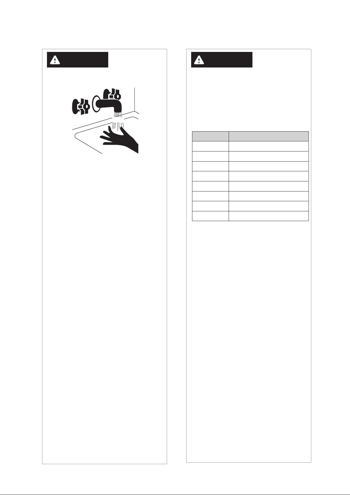
DANGER
Scald Hazards
+27
%851
Water temperatures over 125°F (52°C) can cause
severe burns instantly or death from scalds.
Children, disabled and elderly are at highest risk
of being scalded. Feel water with your elbow
before bathing or showering. Temperature
limiting valves are available, contact a licensed
plumber for more information.
To prevent burns:
Ɣ
Set the operating temperature to the lowest
level that still meets your needs.
Ɣ
If your household has children or elderly or
disabled residents, consider using a lower
temperature setting.
Ɣ
Check local codes for maximum water
temperature setting allowed when used in
nursing homes, schools, day care centers and
other public applications.
Ɣ
Do not leave children, the elderly, or disabled
persons unsupervised.
Ɣ
Do not allow small children to play
unsupervised in the bathroom.
Ɣ
Do not allow anyone to change the water
temperature while hot water is running.
Ɣ
Read all the instructions in this manual carefully
before changing the temperature setting.
Ɣ
Feel the water before using it on children, the
elderly, or the disabled.
Ɣ
If it is necessary to set the water temperature
above 125°F (52°C), consider installing a
thermostatically-controlled mixing valve or
temperature-limiting valve. Contact a licensed
plumber or your local plumbing authority for
more information.
6 Important Safety Information
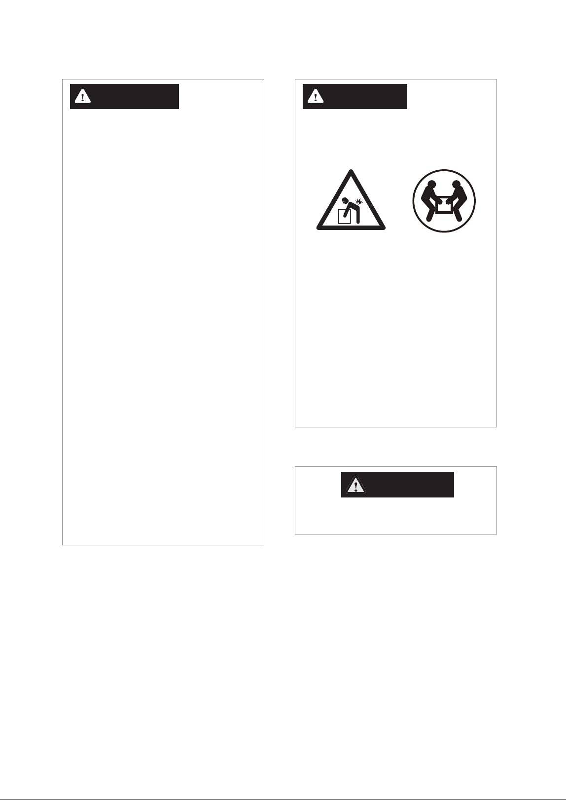
CAUTION
Ɣ
The water heater is heavy. Always lift the
unit with assistance. Be careful not to drop
the water heater while lifting or handling it
to avoid bodily injury or damage to the unit.
Ɣ
California law requires that all new and
replacement water heaters and all existing
residential water heaters be braced, anchored,
or strapped to prevent falling or horizontal
displacement due to earthquakes. At a
minimum, all water heaters must be protected
in accordance with the California Plumbing
Code, or Section 17958.5, as amended by the
city, county, or city and county. The California
General Guidelines, entitled “Guidelines for
Seismically-Reinforced Residential Water
Heaters,” are available through relevant
government resources for homeowners and
installers to ensure compliance with these
safety standards.
California law requires the following Prop 65
warning to be provided:
WARNING
Cancer and Reproductive Harm -
www.P65Warnings.ca.gov
WARNING
To prevent death, serious injury, or property
damage:
Ɣ
Do not use or store flammable products,
such as gasoline, solvents, or adhesives in
the same room or area as the water heater.
Keep all flammable products far away from
the water heater and store them in approved
containers. Keep the containers closed tightly
and out of the reach of children and pets.
Ɣ
Ensure the junction box cover and the
heating element access door covers are in
place. These covers keep debris from entering
and potentially being ignited, and help keep
any internal fires from spreading.
Ɣ
Prevent the water heater from getting wet.
If the wiring, thermostat, or surrounding
insulation becomes exposed to water,
immediately turn off the water heater and
have it inspected by a qualified professional.
Water exposure can cause serious damage,
and if the water heater is submerged in water
due to flooding, or if the thermostat has been
submerged, the entire unit must be replaced.
Regularly inspect your water heater to ensure
it remains dry, and take immediate action if it
comes into contact with water.
Ɣ
High temperatures and pressures in the
water heater may lead to an explosion.
Ensure the included temperature and
pressure (T&P) relief valve, which meets ANSI
Z21.22 standards, is properly maintained
and not blocked, capped, or plugged, as it
discharges hot water to prevent such risks.
7About the Water Heater
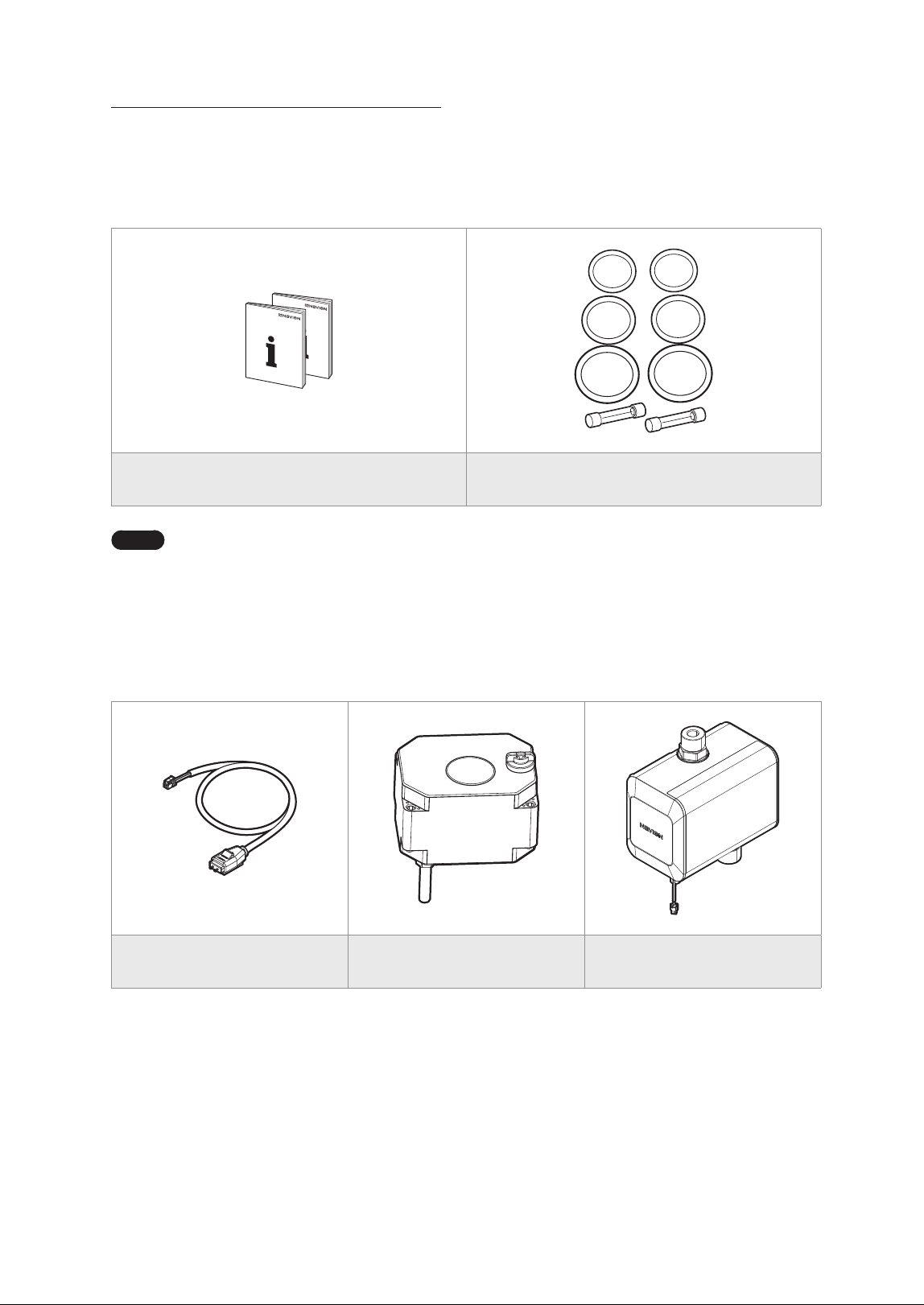
2.1 Included Items
When you open the box, you will find the following items with the water heater. Check the box for each of the
following items before installing the water heater.
Installation Manual, User’s Information Manual Emergency Part Kit
Note
To locate the emergency part kit on the water heater, refer to “4.8 Installing Emergency Part Kit for
Repairs” on page 30.
2.2 Accessories
The following optional accessories are available for the water heater.
Navien Leak Detection System Shut-off Valve Navien Recirculation Pump
2. About the Water Heater
8 About the Water Heater
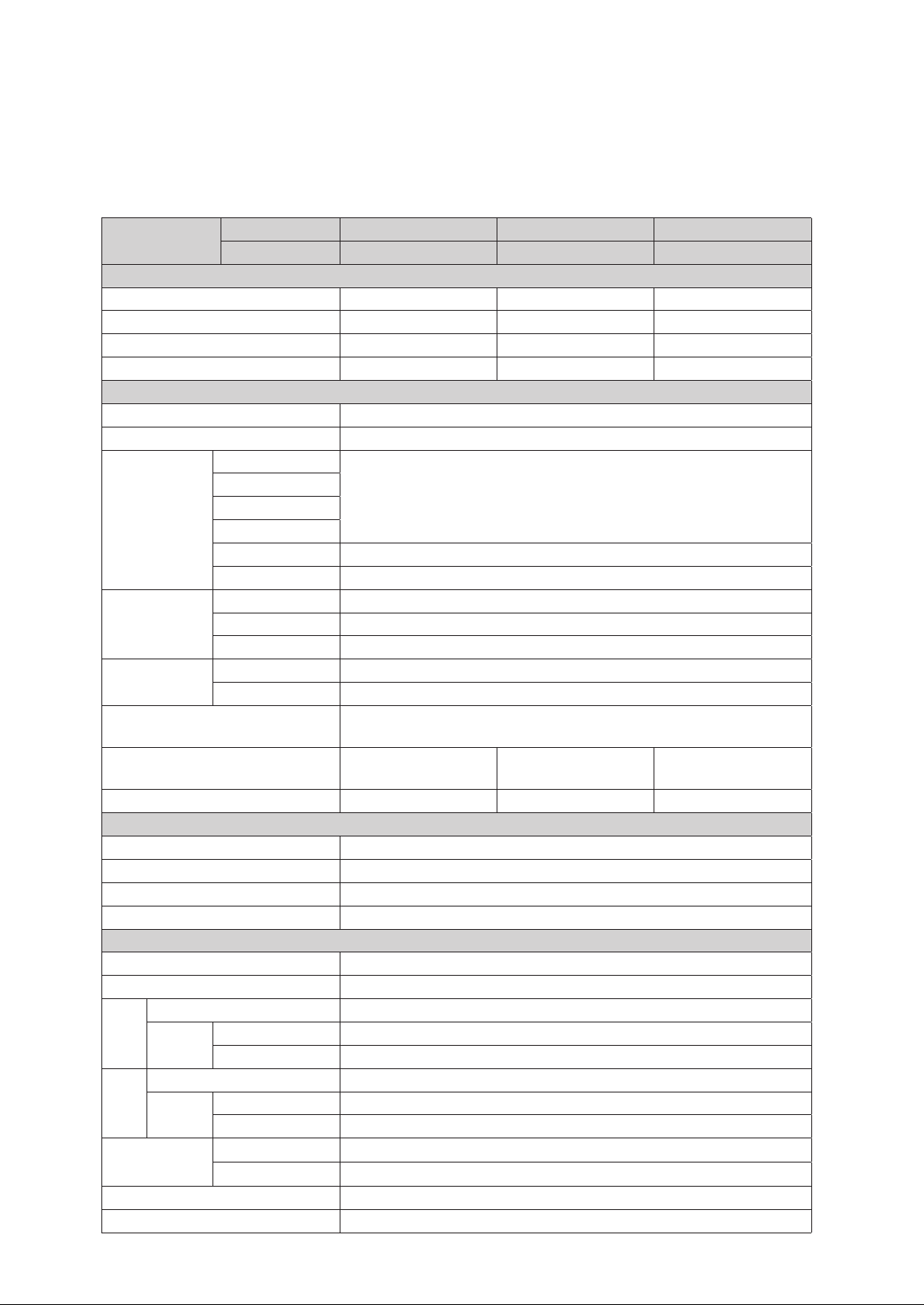
2.3 Specifications
The following table lists the specifications for the water heater. Additional specifications about water, electric, and
air supplies appear in the Installation section.
Items
Model Series NWP500-50 NWP500-65 NWP500-80
Model No. NWP500S050AUMB NWP500S065AUMB NWP500S080AUMB
Capacity & Efficiency
Nominal Capacity (gallons) 50 65 80
Rated Storage Volume (gallons) 45.2 63.2 76.1
UEF (Uniform Energy Factor) 3.85 4.03 4.05
First Hour Rating (gallons) 65 80 85
Product General Data
Installation Location Indoor
Water Pressure 15–150 psi
Connections
Size
Cold Water Inlet
¾ in. NPT
Hot Water Outlet
Drain
T&P Relief Valve
Condensate Drain ¾" NPT Plastic connection
Heating Element 1” NPSM (Thread per Inch 11 ½)
Materials
Casing Cold Rolled Carbon Steel
Storage Tank Stainless Steel
Condenser Aluminum Coil
Air In/Out Size
Air Intake Ø8“
Air Exhaust Ø8“
Safety Devices
Condensate Level Sensor, ECO (Energy Cut Off),
Temperature & Pressure (TP) Relief Valve.
Dimensions
Ø21.7” × 63”
(Ø 552 mm × 1,600 mm)
Ø25” × 63”
(Ø 636 mm × 1,600 mm)
Ø25” × 71.6”
(Ø 636 mm × 1,819 mm)
Shipping Weight (lbs) 229 265 282
Electrical Data
Power Supply 208-240 V AC, 60 Hz, 1 Phase
MCA 208 V (25.9A) / 240 V (28.8A)
CKT BKR Amps 30A
Wire Size Up to 10 AWG (Suitable for 167°F (75°C))
Component Data
Compressor [LRA] 11.6A
Fan Motor [FLA] 0.22A
208 V
Compressor [RLA] 2.0A
Heating
Element
Upper 3,755W
Lower 3,755W
240 V
Compressor [RLA] 1.75A
Heating
Element
Upper 5,000W
Lower 5,000W
Max. Pressure
Discharge
2.654 / 385 PSIG
Suction
1.724 / 250 PSIG
Refrigerant R-134a
Refrigerant Charge 28.2 Oz / 800 g
9About the Water Heater
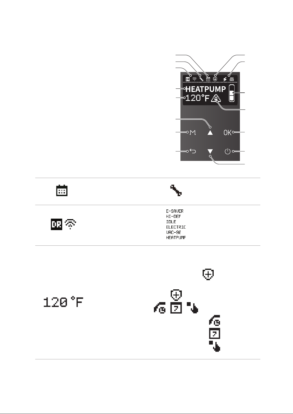
2.4 The Front Panel
The front panel allows you to adjust the water
temperature and view the operating status or error
codes. Remove the protective sheet from the front
panel before using it.
a
b
g
c
i
m
n
o
d
e
j
k
l
h
f
a
Schedule
Displays the schedule
settings.
b
Error status
Displays error status.
c
Demand Response / Wi-Fi
Displays the when the
DR module and Wi-Fi is
connected
d
Operation Mode
Displays the current
operation mode.
e
Set Hot Water
Temperature
Displays the set hot water
temperature.
f
Anti-Legionella function
Displays when anti-
legionella function is
in progress. This icon
appears even if the
unit is currently in
recirculation mode.
Recirculation status
Displays the current
recirculation mode.
Ɣ
Always On
Ɣ
Weekly
Ɣ
HotButton
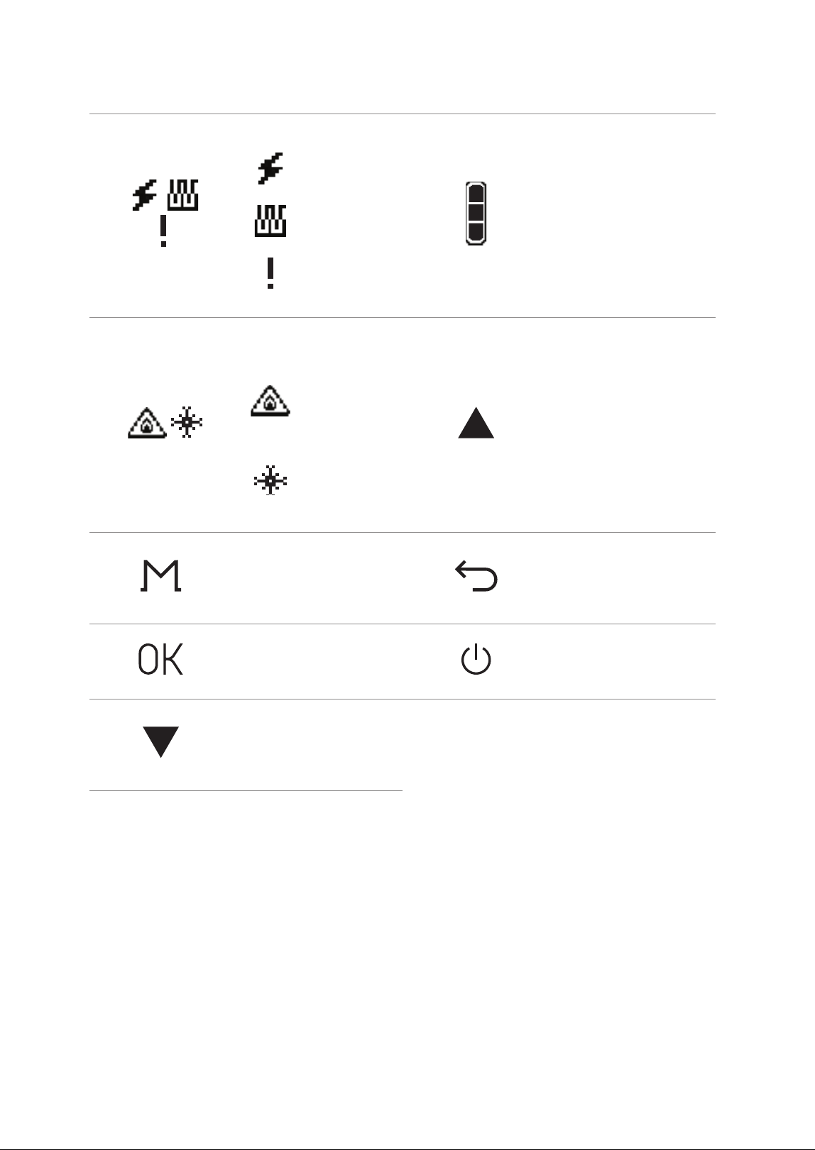
10 About the Water Heater
g
Heating Element status
Ɣ
Displays when the
electric heater is
operating.
Ɣ
Displays when
the heat pump is
operating.
Ɣ
Displays when
the heat pump’s
operation stops.
h
Hot water charge rate
Displays the current hot
water charge rate.
i
Scald warning /
Freeze Protection
Ɣ
Displays a warning
to alert you to the
danger of scalding
from hot water
temperatures.
Ɣ
Displays when the
freeze protection
function is
operating.
j
Up button
Increases the temperature
setting, parameter or moves
down.
k
Menu button
Change the operation
mode and access to the
menu screen.
l
Back button
Access to the previous
screen.
m
OK button
Access to the selected
item.
n
Power button
Turns the water heater on
or off.
o
Down button
Decreases the temperature
setting, parameter or
moves down.
11About the Water Heater
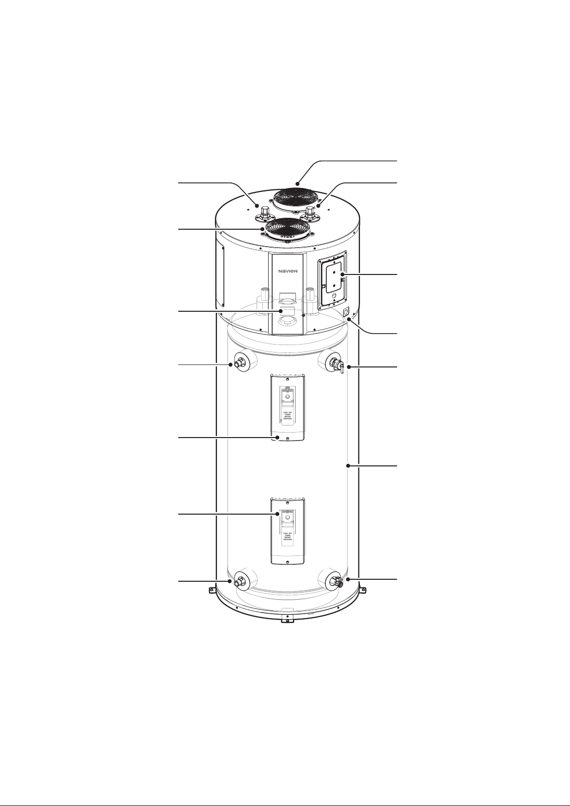
2.5 Components
The following diagram shows the key components of the water heater. Component assembly diagrams and
particular parts lists are included in the Appendixes.
Hot Water Outlet
Exhaust Air
Cold Water Inlet
Power/CTA Module
Wiring Connections
Front Panel
Condensate Drain
Temperature and Pressure
(T&P) Relief Valve
Storage Tank
Drain Valve
Intake Air (Air Filter)
Optional Side Outlet
Upper Heating Element
Lower Heating Element
Optional Side Inlet
12 Operating the Water Heater
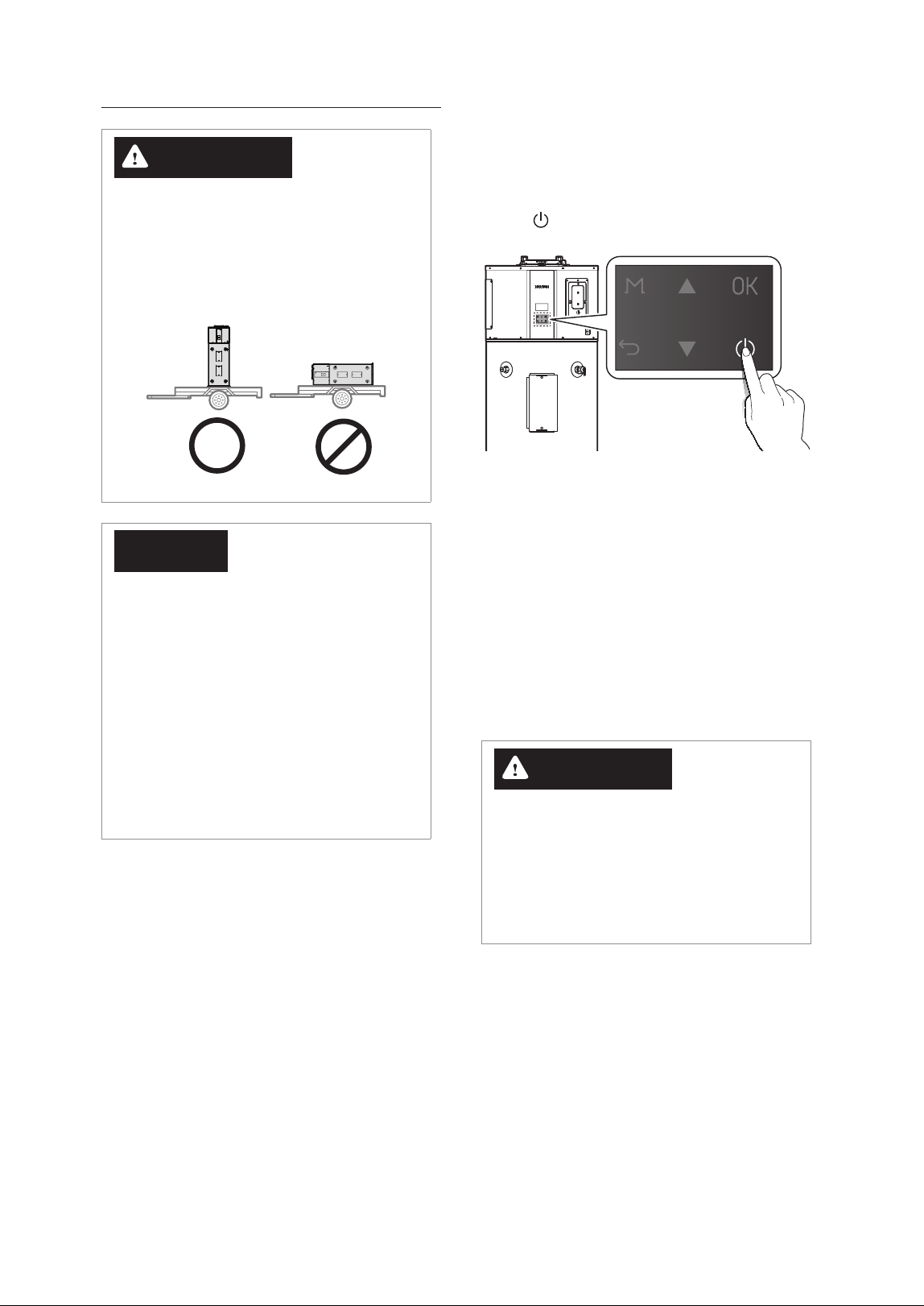
WARNING
If the water heater was transported horizontally,
do not power it on immediately. Allow the
unit to stand upright for at least 24 hours
before operation. Failure to do so may cause
compressor damage and reduced system
efficiency due to improper oil distribution.
NOTICE
Do not turn on the water heater without
ensuring that all air has been purged from the
tank and that the tank is completely filled with
water. This water heater is equipped with a “Dry
Fire” protection function that detects if the tank
is not fully filled with water at the initial power
connection. However, if the heating element
operates when the tank is empty, there is a
risk of fire or electric shock. Therefore, before
turning on the water heater, ensure the tank is
filled with water and all air is removed. The “Dry
Fire” protection function operates only at the
initial power connection.
3.1 Turning the Water Heater On
or Off
To turn the water heater on or off, press the Power
button (
).
When the power is turned on, the product performs
the Self Diagnostic operation. (This operation is
performed each time the power is turned on after
being in an unpowered state.)
The Self Diagnostic process takes approximately
10minutes, during which the front panel will display
[Self Diagnostic in Progress].
If an issue is detected during the Self Diagnostic
process, an error code will be displayed. If the error
is one that prevents the product from operating, the
product will remain in a stopped state until the issue
is resolved.
WARNING
Do not disconnect the power from the
product during the Self Diagnostic operation.
Disconnecting the power during the Self
Diagnostic process may damage the product.
Additionally, if the power is disconnected and
then turned on, the Self Diagnostic process will
start again from the beginning.
3. Operating the Water Heater
13Operating the Water Heater
3.3 Selecting the Operation
Mode & Adjusting Water
Temperature
After the 10-minute Self Diagnostic mode is
completed, the product will enter Idle mode.
You can select the desired operation mode
according to your preferences or usage
environment. For a description of each mode, refer
to “3.4 About Operating Modes” on page 14.
The same tank temperature can be set for all
provided operation modes. The setting range is
from the set minimum operation temperature to
150°F (65.5°C). If it is set to 120°F (49°C) or higher,
[Scald Risk] will be displayed on the front panel.
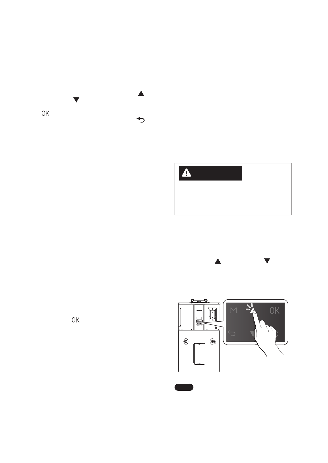
WARNING
Before adjusting the water temperature, read “To
prevent burns:” on page 5 carefully. Water
above 120 °F can cause instant scalding, severe
burns, or death.
The water heater is set to 120°F (49°C) by default. To
adjust the water temperature:
1. Make sure that all hot water faucets are closed.
2. Press the Up (
) or Down button ( )
until the desired temperature appears on the
display. You can adjust the temperature while
the display is flashing. Once the display stops
flashing, the temperature setting is stored.
Note
The water heater will retain your
settings during a power outage.
3.2 Start-Up Wizard
The setup wizard should run the first time the unit is
powered on. The wizard must be completed before
the water heater can be used.
When the setup wizard is displayed after turning
on the water heater first time, press the Up (
) or
Down button (
) to scroll through the items in
the Start-Up Wizard, and then, press the OK button
(
) to confirm and continue. To return to the
setup wizard menu, press the Back button (
).
1. Set the time.
Ɣ
YYYY.MM.DD HH:MM:SS
2. Set the units to display.
Ɣ
°F
Ɣ
°C
3. Accessories Check
Ɣ
Leak Detection System: Installed / Not
installed
4. Water Fill Tank
Ɣ
A description of the water fill tank is displayed.
5. Operation Mode
Ɣ
Select the operation mode.
6. Tank Setting Temperature
Ɣ
Setting Range: 95°F (35°C)–150°F (65.5°C)
Ɣ
Default: 120°F (49°C)
7. Wi-Fi Setting
Ɣ
Follow the instructions to configure the Wi-Fi
settings.
8. Eco Port Setting
Ɣ
Follow the instructions to configure the Eco
Port settings.
9. Setup Summary
Ɣ
Once the Setup Wizard is finished, a summary
of the settings will be displayed. Press the OK
button (
) at each summary screen until
the main screen is displayed.
14 Operating the Water Heater
3.4.3 Heat Pump
This mode controls the heating of the tank using
only the heat pump as the heat source. It is the
most energy-efficient mode among the available
operating modes, but it also has the longest
recovery time. When operating solely with the heat
pump, the energy efficiency and recovery time
may vary depending on the ambient temperature
and relative humidity (the higher the ambient
temperature and relative humidity, the greater the
energy efficiency and the shorter the recovery time).
3.4.4 Electric
This mode controls the heating of the tank using
only the electric heater (upper and lower). It is the
least energy-efficient mode, but it offers the shortest
recovery time. When this mode is set, it can be used
continuously for up to 72 hours (3 days), after which
it will automatically return to the previous operating
mode. (The upper and lower heaters do not operate
simultaneously.)
3.4.5 Vacation - Default: OFF
This mode is provided to prevent unnecessary
tank heating operations during vacations or long
absences. The number of days for the Vacation
mode can be set from 0 days (OFF) to 1 to 99 days.
When this mode is set, the tank heating operation
is suspended for the set number of days, and only
minimal operations (such as freeze protection and
anti-seize) are performed to protect the product.
However, 9 hours before the set number of days
is reached, the mode automatically reverts to
the previous operating mode and performs tank
heating operations until the set temperature is
reached.
Mode Efficiency Recovery
Electric Very Low Fast
Heat Pump High Very Slow
High Demand Low Very Fast
Energy Saver Very High Fast
Vacation Very High None
You can adjust the temperature by 1 degree
increments as shown below, depending on the
temperature range:
Temperature Range
Temperature
Increment
[Min. operation Temp.]–150°F
(65.5°C)
1°F or 0.5°C
increments
Note
The minimum operation temperature
can be set from 95°F (35°C) to 113°F
(45°C), with a default setting of 95°F
(35°C). To adjust this setting, refer to
“Setting the Protection Function” in the
Installation Manual.
3.4 About Operating Modes
3.4.1 Energy Saver (Hybrid: Efficiency) –
Default
This mode combines the heat pump and electric
heater (heating element) as the heat source to
heat the tank. The heat pump is primarily used to
enhance energy efficiency, while the electric heater
is used to reduce the recovery time. This mode is
the default operating mode applied during initial
shipment and factory reset.
3.4.2 High Demand (Hybrid: Boost)
This mode controls the tank’s heating by combining
the heat pump and electric heater (heating
element). The electric heater is used more frequently
than when it is in the Energy Saver mode to further
shorten the recovery time. This mode is set when a
higher supply of hot water is desired.
15Operating the Water Heater
Item Description
4. Air Filter Alarm
Reset
Set the air filter replacement
alarm reset.
Ɣ
Setting range : Yes, No
Ɣ
Default : No
3. Press the Back button (
) to return to the
previous screen or menu.
3.5.1 Setting the Weekly Operation
Schedule
You can schedule the weekly operation and view
the weekly operation schedule list.
1. From the Setting Menu, select Schedule.
2. Press the Up ( ) or Down button ( ) to scroll
through the items, and set the weekly operation
schedule details.
Item Description
1. Weekly Enable
Enable or disable the weekly
operation schedule.
Ɣ
Setting range: On, Off
Ɣ
Default: Off
2. Weekly Set
Set the weekly operation
schedule.
3. Weekly List
View the list of weekly
operation schedules.
4. Weekly Delete
Delete the weekly operation
schedule.
3. Press the Back button (
) to return to the
previous screen or menu.
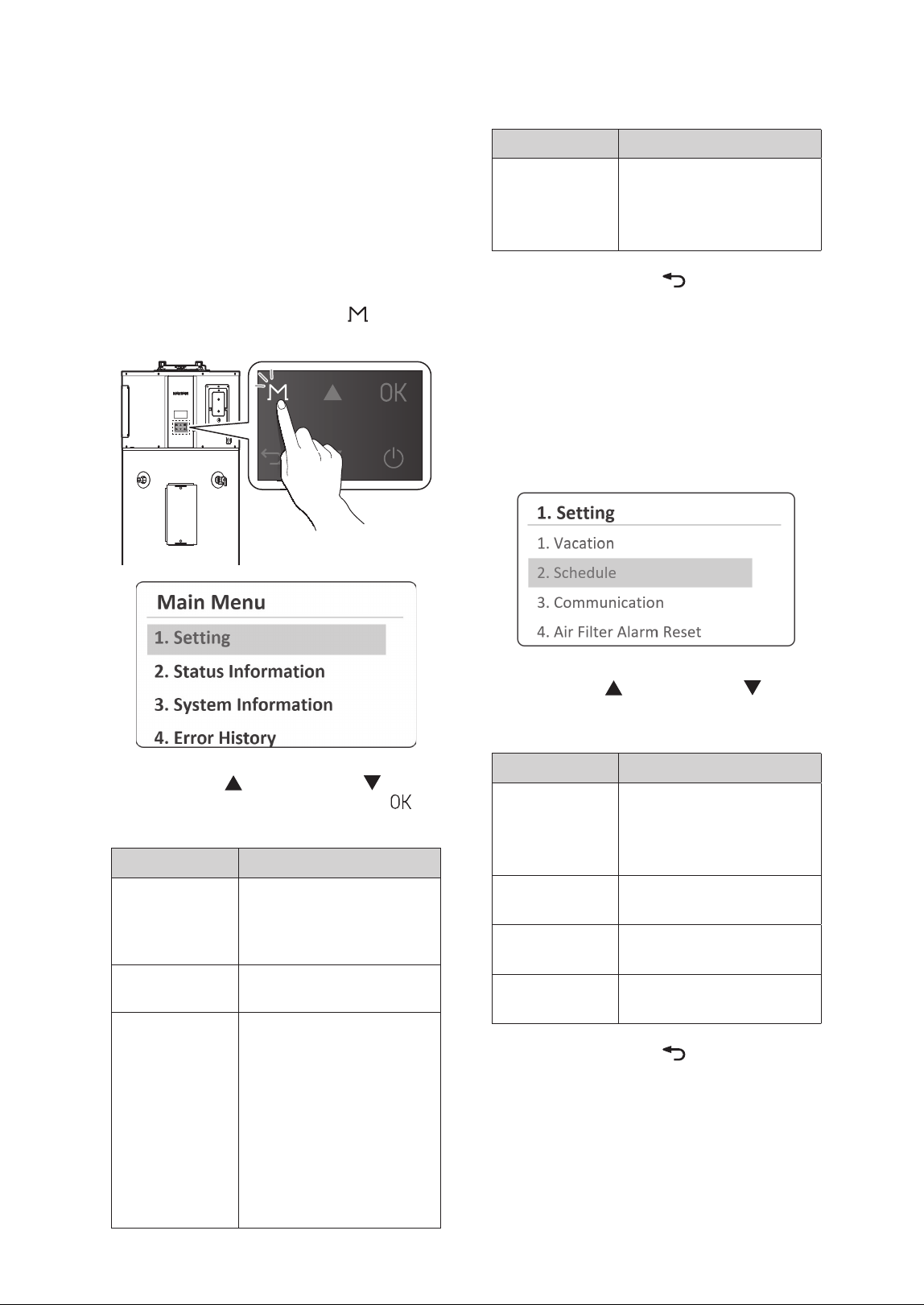
3.5 Setting Operation Schedules
and Configuring Communication
Settings
You can set the water heater's operation for vacation
and configure the weekly operation schedule and
communication settings to customize the water
heater's operation based on your needs.
1. Press and hold the Menu button (
) for more
than 5 seconds, and then select Setting.
2. Press the Up ( ) or Down button ( ) to scroll
through the items. Press the OK Button (
) to
select an item.
Item Description
1. Vacation
Set the vacation period.
Ɣ
Setting range: 0 Day (Off),
1–99 Days
Ɣ
Default: 0 Day
2. Schedule
Set the weekly operation
schedule.
3. Communication
Enable or disable the Wi-Fi
and DR communication.
1. Wi-Fi
Ɣ
Setting range: On, Off
Ɣ
Default: Off
2. DR
Ɣ
Setting range: On, Off
Ɣ
Default: Off
3. Eco Port
Ɣ
Setting range: On, Off
Ɣ
Default: Off
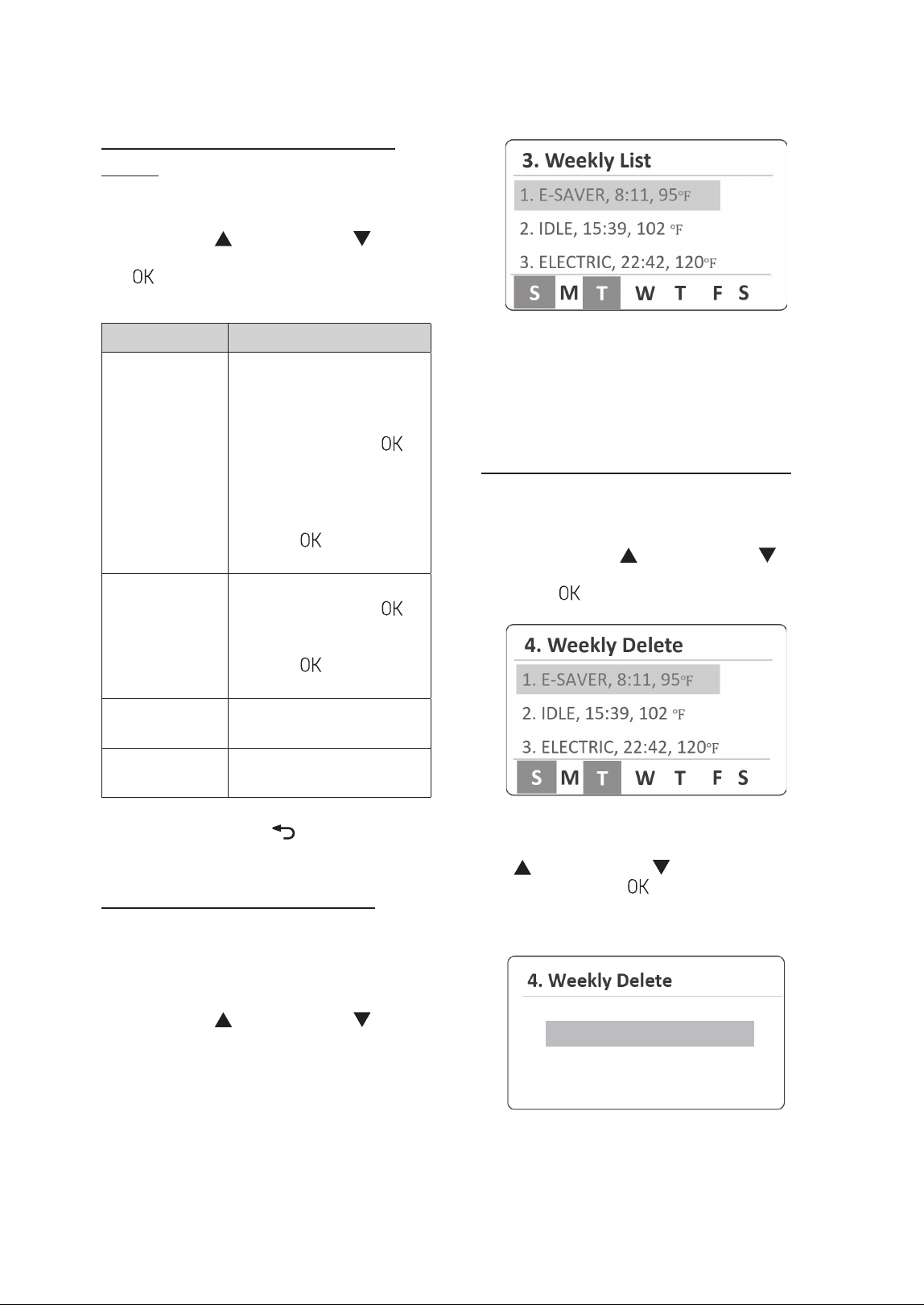
16 Operating the Water Heater
The set operation mode, time, and temperature will
be displayed, while the selected days on the weekly
schedule will be indicated at the bottom of the
screen.
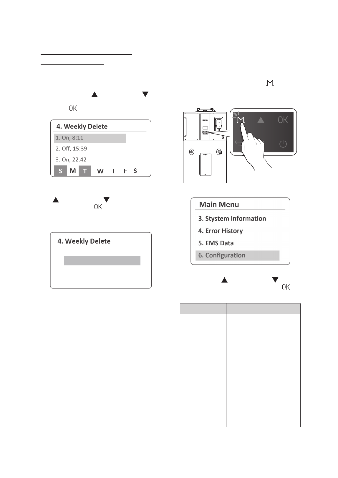
Deleting Weekly Operation Schedules
1. From the Schedule menu, select Weekly List.
2. From the set weekly operation schedules on the
list, press the Up (
) or Down button ( ) to
select a schedule item to delete, and then, press
the OK (
) button.
3. From the Weekly Delete screen, press the Up
(
) or Down button ( ) to select Ye s , and
then press the OK (
) button to delete the
selected schedule item. If you do not want to
delete it, select No.
/P
:FT
Setting Weekly Operation Schedule
Details
1. From the Schedule menu, select Weekly Set.
2. Press the Up (
) or Down button ( ) to scroll
through information items. Press the OK button
(
) to select a sub menu of parameters and
then set the schedule details.
Item Description
Day
Set the days for the water
heater to operate. You can
select multiple days for
operation.
1. Press the OK button (
) to
select the day of the week.
Ɣ
Setting range: Sun, Mon,
Tue, Wed, Thurs, Fri, Sat
2. Press and hold the OK
button (
) to move to the
next setting.
Time
Set the operating time.
1. Press the OK button (
)
to select the time.
2. Press and hold the OK
button (
) to move to the
next setting.
Operating Mode
Select the operating mode for
selected days and time.
Temperature
Set the operating
temperature.
3. Press the Back button (
) to return to the
previous screen or menu.
Viewing the Weekly Schedule List
Once the weekly operation schedule is created, you
can view the weekly schedule list.
1. From the Schedule menu, select Weekly List.
2. Press the Up (
) or Down button ( ) to scroll
through schedule items, and select an item to
view its schedule information.
17Operating the Water Heater
3.6.1 Viewing the Hot Water
Information
1. From the Status Information Menu, Select Hot
Water.
2. Press the Up ( ) or Down button ( ) to scroll
through information items. Press the OK button
(
) to select an item to view the information.
Item Description
1. Tank Upper
Temp
Current upper temperature of
the tank (°F/°C)
2. Tank Lower
Temp
Current lower temperature of
the tank (°F/°C)
3. Press the Back button (
) to return to the
previous screen or menu.
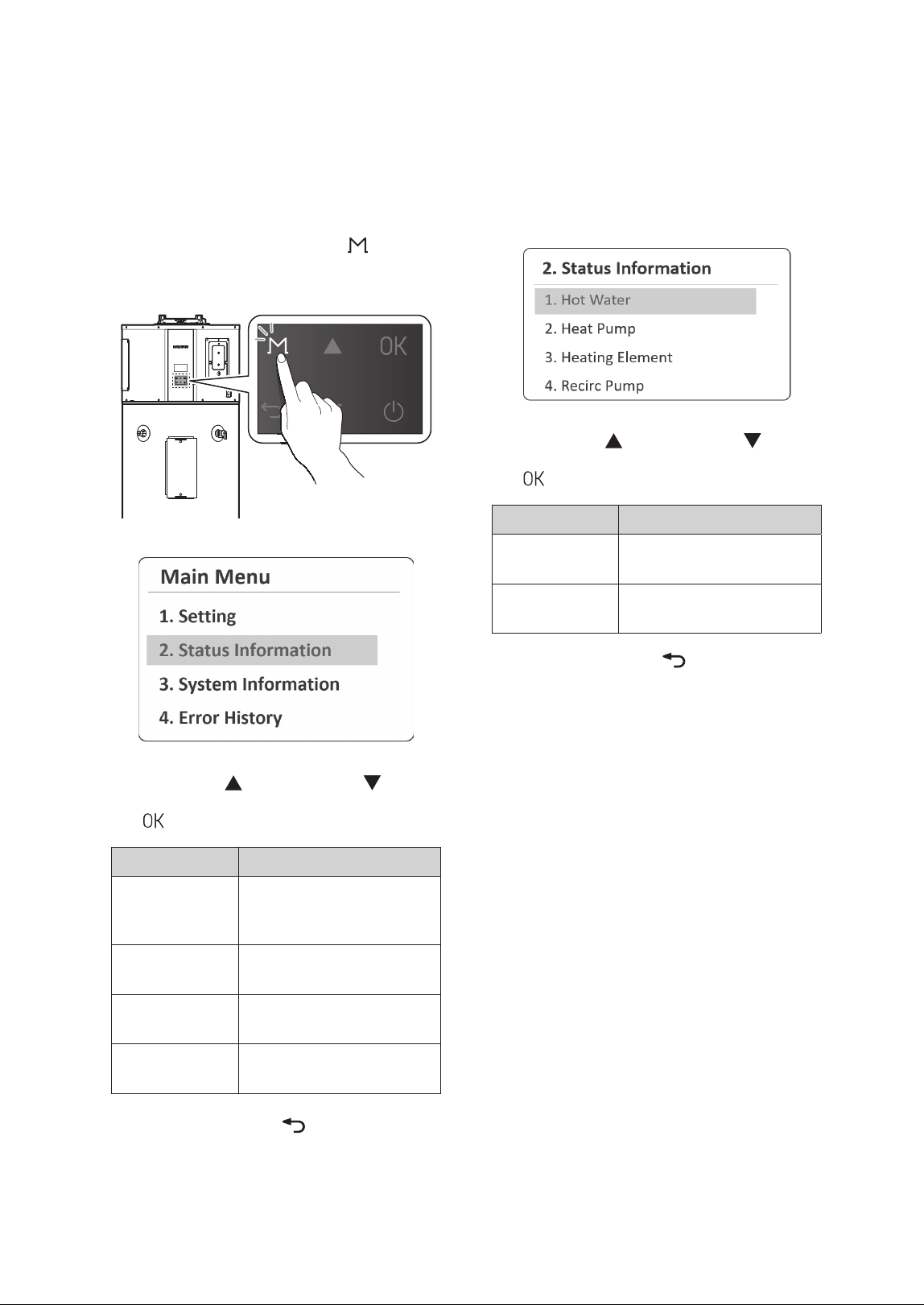
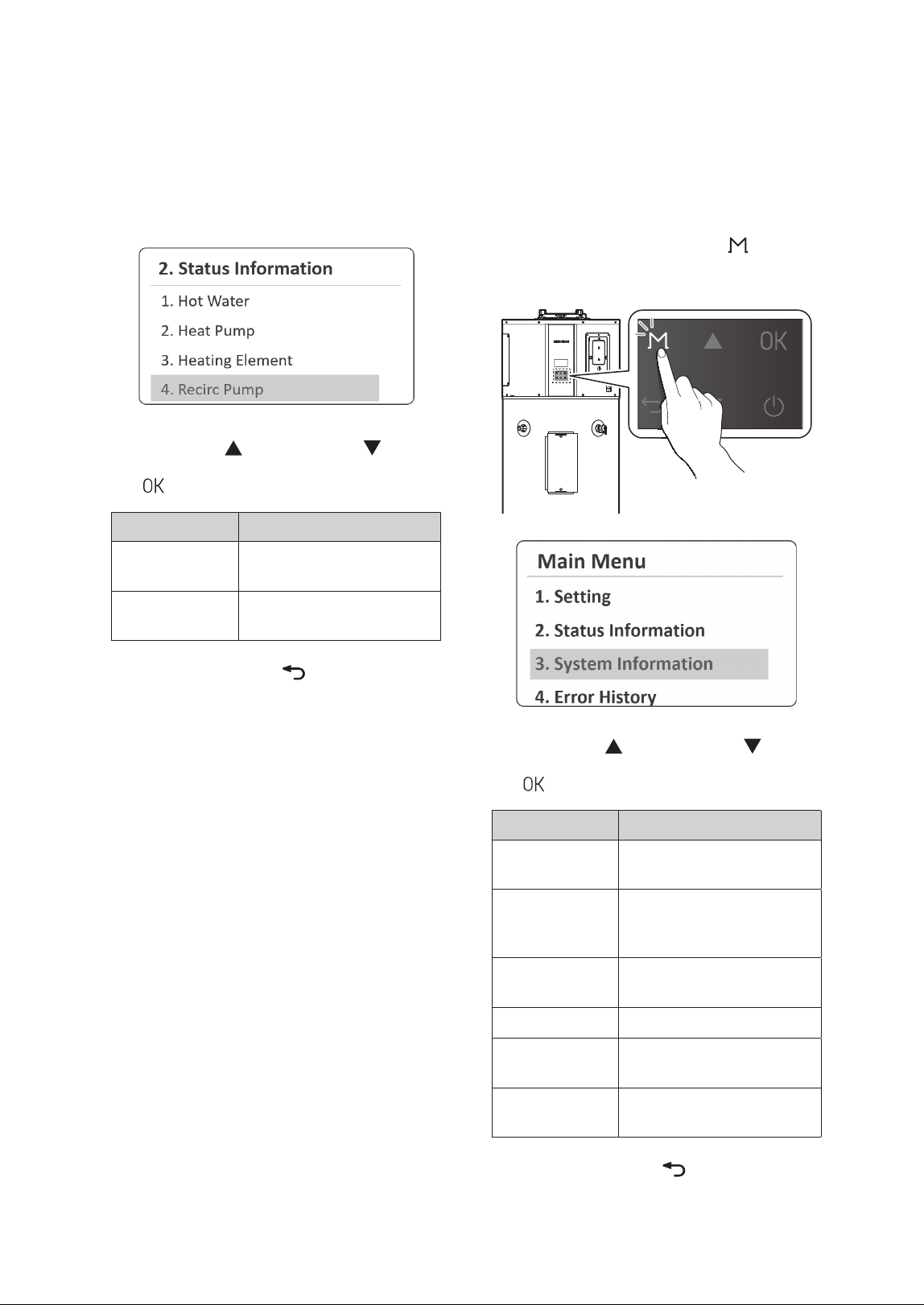
3.6 Viewing Status Information
You can view operating status information,
including, hot water, heat pump, and heating
element.
1. Press and hold the Menu button (
) for
more than 5 seconds and then select Status
Information.
2. Press the Up ( ) or Down button ( ) to scroll
through information items. Press the OK button
(
) to select an item to view the information.
Item Description
1. Hot Water
Temperature of the pump, hot
water temperature, and water
flow rate
2. Heat Pump
Heat pump module’s
operating information
3. Heating
Element
Heating element's operating
information
4. Recirc Pump
Recirculation pump kit’s
operating Information
3. Press the Back button (
) to return to the
previous screen or menu.
18 Operating the Water Heater
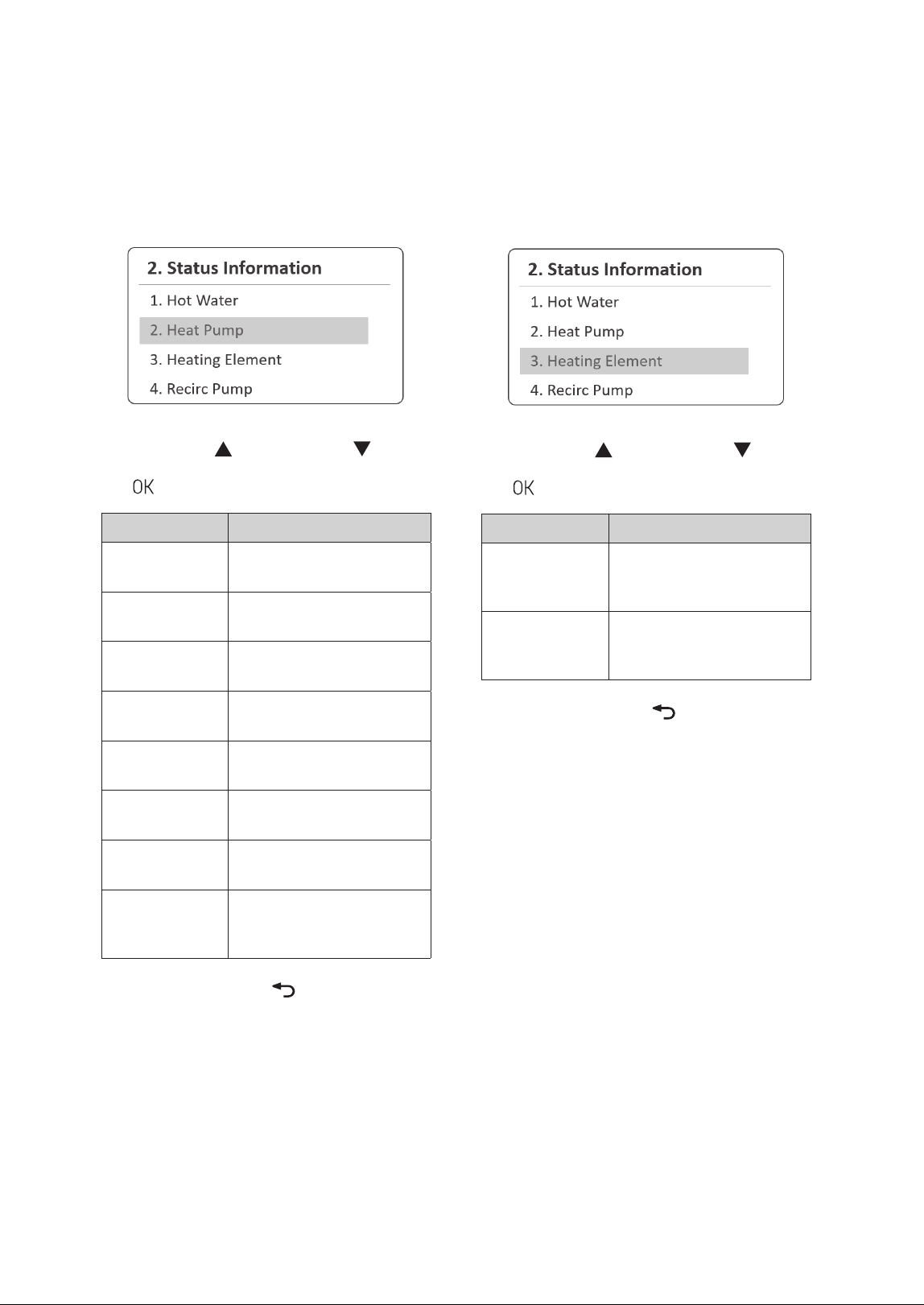
3.6.3 Viewing the Heating Element
Information
1. From the Status Information Menu, select
Heating Element.
2. Press the Up ( ) or Down button ( ) to scroll
through information items. Press the OK button
(
) to select an item to view the information.
Item Description
1. UHE Output
Current operating status of
the upper heating element
(On or Off)
2. LHE Output
Current operating status of
the lower heating element
(On or Off)
3. Press the Back button (
) to return to the
previous screen or menu.
3.6.2 Viewing the Heat Pump
Information
1. From the Status Information Menu, Select Heat
Pump.
2. Press the Up ( ) or Down button ( ) to scroll
through information items. Press the OK button
(
) to select an item to view the information.
Item Description
1. Compressor
On/Off
Current operating status of
the compressor (On or Off)
2. Discharge Temp
Current discharge
temperature (°F/°C)
3. Suction Temp
Current suction temperature
(°F/°C)
4. Evaporate Temp
Current evaporate
temperature (°F/°C)
5. Ambient Temp
Current ambient temperature
(°F/°C)
6. Evaporate Fan
Speed
Current evaporator fan speed
(RPM)
7. Current Super
Heat
Current super heat
temperature (
ӛ
°F/
ӛ
°C)
8. EEV Step
Valve opening rate (%) of the
electronic expansion valve
(EEV)
3. Press the Back button (
) to return to the
previous screen or menu.
19Operating the Water Heater
3.7 Viewing System Information
You can view the system information, including tank
capacity, product category, and Wi-Fi connection
status.
1. Press and hold the Menu button (
) for
more than 5 seconds and then select System
Information.
2. Press the Up ( ) or Down button ( ) to scroll
through information items. Press the OK button
(
) to select an item to view the information.
Item Description
1. Tank Capacity
Set tank capacity (50 Gallon,
65 Gallon or 80 Gallon)
2. Product
Category
Set product's category
(Standard, Premium or Plug-
in)
3. Wi-Fi
Connection
Wi-Fi Connection status
(Connect or Disconnect)
4. Date/Time Current date and time
5. RTC Battery
Current voltage of the RTC
battery
6. F/W Version
Firmware version of the
controller
3. Press the Back button (
) to return to the
previous screen or menu.
3.6.4 Viewing the Recirculation Pump
Kit Information
1. From the Status Information Menu, select Recirc
Pump.
2. Press the Up ( ) or Down button ( ) to scroll
through information items. Press the OK button
(
) to select an item to view the information.
Item Description
1. Recirc
Temperature
Current recirculation pump
return water temp (°F/°C)
2. Recirc Flow Rate
Current recirculation pump
water flow rate (GPM/LPM)
3. Press the Back button (
) to return to the
previous screen or menu.
20 Operating the Water Heater
3. Press the Back button ( ) to return to the
previous screen or menu.
Note
Ɣ
The front panel display flashes in
red and the error icon is displayed
(flashing) when a level 1 error is
detected. You can press the OK
button (
) to enter error display
mode. The operation is maintained
during a level 1 error.
Ɣ
Level 1 errors are automatically
cleared when the problem is
resolved.
Ɣ
You can press the Back button ( )
to clear a level 1 error. The error is
then cleared if the problem has been
resolved.
Ɣ
You can press and hold the Back
button (
) for 5 seconds to clear a
level 1 error. The error is then cleared
if the problem has been solved.
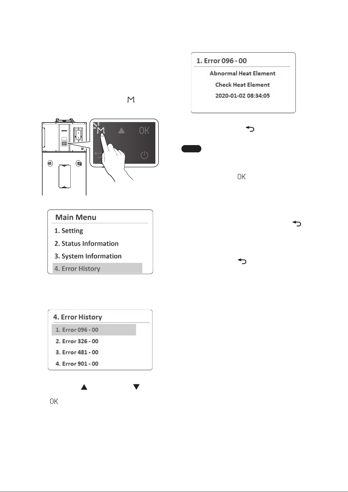
3.8 Viewing Error History
You can view a list of recent errors and check for
details. For more information about the error
codes, refer to “Understanding Error Codes” in the
Installation Manual.
1. Press and hold the Menu button (
) for more
than 5 seconds and then select Error History.
A list of 10 recent errors are displayed on the screen, with
the most recent error displayed at the top of the list.
2. Press the Up ( ) or Down button ( ) to scroll
through the list of errors. Press the OK button
(
) to select an error to view the detailed
information.
21Operating the Water Heater
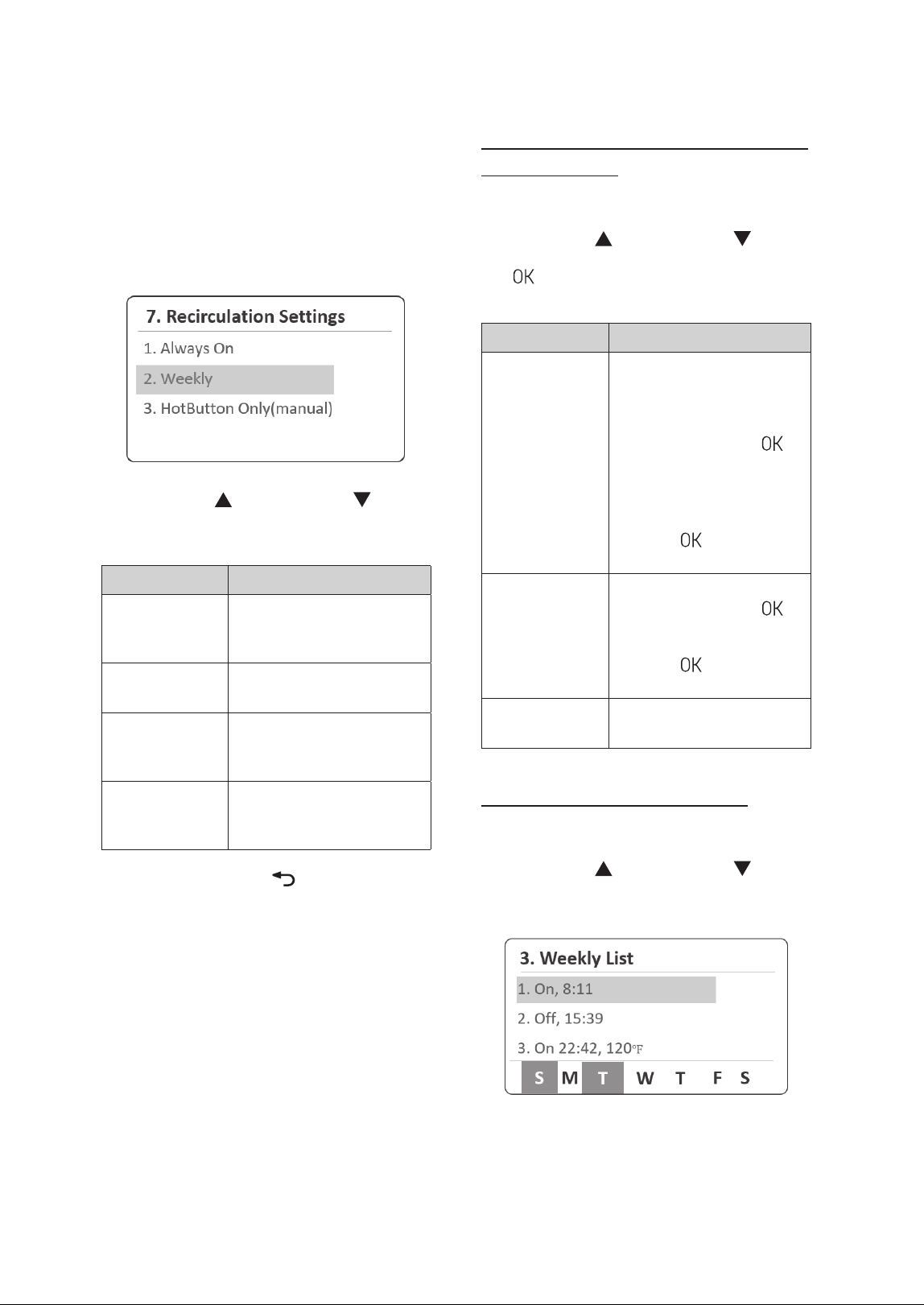
3.10 Setting the Recirculation
Mode
You can customize the water heater's operation
by enabling the preheating function through the
recirculation mode to match your lifestyle.
1. Press and hold the Menu button (
) for more
than 5 seconds, and then select Recirculation
Settings.
2. Press the Up ( ) or Down button ( ) to scroll
through the items. Press the OK button (
) to
select an item.
Item Description
1. Always On
Set for continuous repeat
DHW recirculation.
2. Weekly
Schedule the weekly
recirculation operation.
3. HotButton
Only(Manual)
Set to manually activate a
one-time DHW recirculation
cycle using an external
HotButton or the mobile app.
3. Press the Back button (
) to return to the
previous screen or menu.
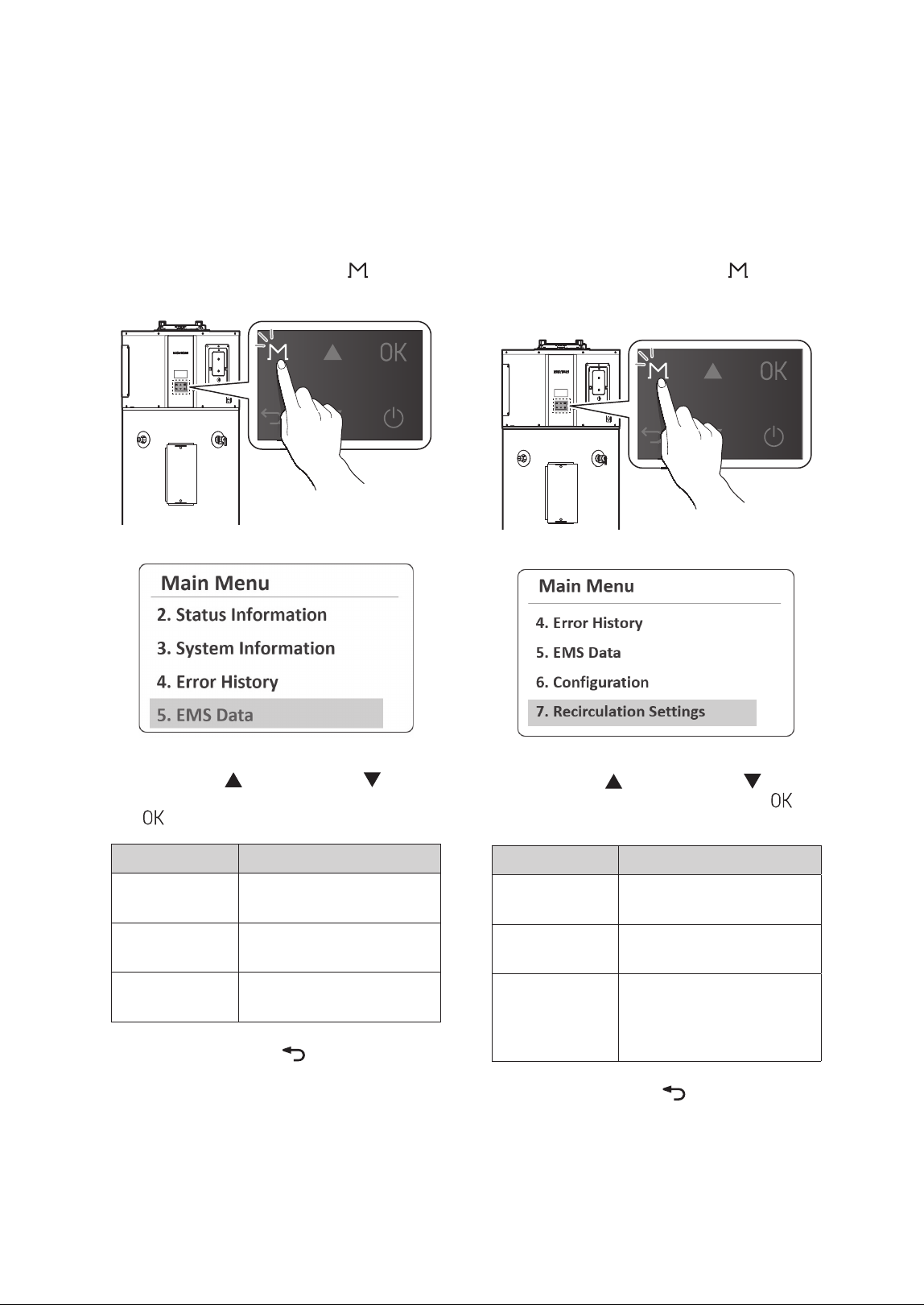
3.9 Viewing Other System
Operation Information
You can view system operation information,
including heat pump operation time, heating
element operation time, and power consumption."
1. Press and hold the Menu button (
) for more
than 5 seconds and then select EMS Data.
2. Press the Up ( ) or Down button ( ) to scroll
through information items. Press the OK button
(
) to select an item to view the information.
Item Description
1. HP Operation
Time
Monthly heat pump operating
time
2. HE Operation
Time
Monthly heating element
operating time
3. Power
Consumption
Monthly power consumption
3. Press the Back button (
) to return to the
previous screen or menu.
22 Operating the Water Heater
Setting Weekly Recirculation Operation
Schedule Details
1. From the Weekly Menu, select Weekly Set.
2. Press the Up (
) or Down button ( ) to scroll
through information items. Press the OK button
(
) to select a sub menu of parameters and
then set the schedule details.
Item Description
Day
Set the days for the
recirculation to operate. You
can select multiple days for
operation.
1. Press the OK button (
) to
select the day of the week.
Ɣ
Setting range: Sun, Mon,
Tue, Wed, Thurs, Fri, Sat
2. Press and hold the OK
button (
) to move to the
next setting.
Time
Set the operating time.
1. Press the OK button (
)
to select the time.
2. Press and hold the OK
button (
) to move to the
next setting.
Operation
Select the recirculation On or
Off for selected days and time.
Viewing the weekly schedule list
1. From the Weekly Menu, select Weekly List.
2. Press the Up (
) or Down button ( ) to scroll
through schedule items, and select an item to
view its schedule information.
The set On and Off time will be displayed, while
the selected days on the weekly schedule will be
indicated at the bottom of the screen.
3.10.1 Setting the Recirculation Weekly
Operation Schedule
You can schedule the weekly recirculation operation
and view the weekly operation schedule list.
1. From the Recirculation Settings Menu, select
Weekly.
2. Press the Up ( ) or Down button ( ) to scroll
through the items, and set the weekly operation
schedule details.
Item Description
1. Weekly Enable
Enable or disable the weekly
recirculation operation
schedule.
2. Weekly Set
Set the weekly recirculation
operation schedule.
3. Weekly List
View the list of weekly
recirculation operation
schedules.
4. Weekly Delete
Delete the weekly
recirculation operation
schedule.
3. Press the Back button (
) to return to the
previous screen or menu.
23Operating the Water Heater
3.11 Setting the Display Options
You can configure display options, such as display
unit, time, and error alarm, on the front panel.
1. Press and hold the Menu button (
)
for more than 5 seconds and then select
6.Configuration.
2. Press the Up ( ) or Down button ( ) to scroll
through the items. Press the OK button (
) to
set its configuration.
Item Description
1. Display Units
Setting
Set the display units.
1. °F, GPM, Feet
2. °C, L/M, Meter
Ɣ
Default: °F, GPM, Feet
2. Time Setting
Set the time format.
Ɣ
Display: YYYY.MM.DD/
HH:MM:SS
3. Error Alarm
Set the error alarm mode.
Ɣ
Setting range: On, Off
Ɣ
Default: Off
4. Backlight Time
Setting
Set the backlight time.
Ɣ
Setting range: 0–60 min
Ɣ
Default: 1 min
Deleting Weekly Recirculation
Operation Schedules
1. From the Weekly Menu, select Weekly Delete.
2. From the set weekly operation schedules on the
list, press the Up (
) or Down button ( ) to
select a schedule item to delete, and then, press
the OK (
) button.
3. From the Weekly Delete screen, press the Up
(
) or Down button ( ) to select Ye s , and
then press the OK (
) button to delete the
selected schedule item. If you do not want to
delete it, select No.
/P
:FT
24 Operating the Water Heater
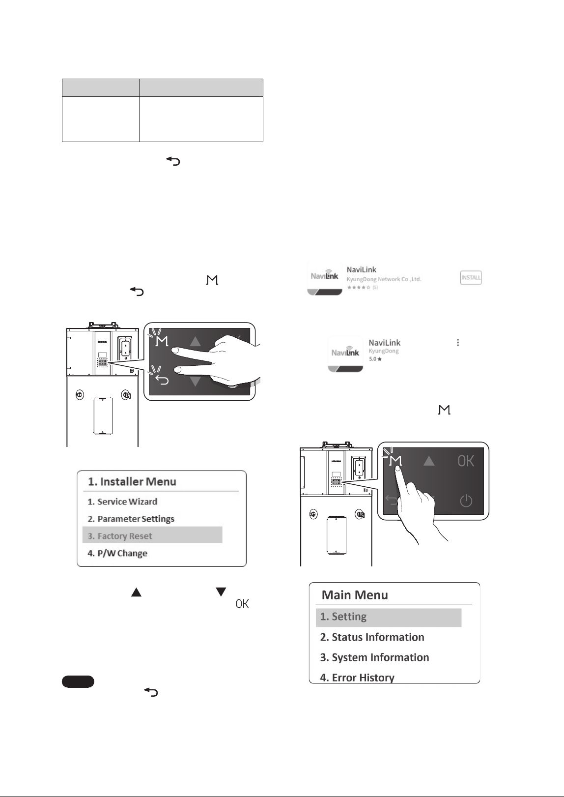
3.13 Connecting the NaviLink App
with the Water Heater
By using the water heater's Wi-Fi communication to
connect the NaviLink app with the water heater, you
can monitor temperature settings and EMS data,
turn the water heater on or off, schedule settings,
and set the water temperature through the app.
Follow the procedure below to connect the app and
water heater.
1. Search for "NaviLink" in the App Store (iOS) or
Google Play Store (Android) and download the
app to your smartphone. After installation is
complete, launch the NaviLink app.
[Google Play Store]
[Apple App Store]
2. Press and hold the Menu button (
) for more
than 5 seconds, and then select Setting.
3. From the Setting Menu, select Communication
and set the Wi-Fi communication to On to
enable it.
Item Description
5. Sound Setting
Set the beep sound.
Ɣ
Setting range: On, Off
Ɣ
Default: On
3. Press the Back button (
) to return to the
previous screen or menu.
3.12 Initializing All Parameter
Settings (Factory Reset)
You can initialize all parameter settings and data of
the water heater system to factory default.
1. Press and hold the Menu button (
) and the
Back button (
) simultaneously for more than
5 seconds, and then select Factory Reset.
2. Press the Up ( ) or Down button ( ) to
select Ye s and then press the OK button (
)
to initialize all parameter settings (panel and
main controller) to the factory default. The
factory reset process status will be displayed on
the front panel. After the factory reset, the Start
Wizard will run.
Note
If you select No or press the Back
button (
), it will return to the
previous screen or menu.
25Operating the Water Heater
3.14 Water Heater Protection
Features
3.14.1 Heat Pump Operation Prevention
The heat pump will only operate when the ambient
temperature around the product is between 41°F
(5°C) and 113°F (45°C), and the water temperature
inside the tank is between 50°F (10°C) and 149°F
(65°C). Outside of these temperature ranges, the
heat pump does not operate, and the front panel
displays “Operation Prevention in Progress.”
3.14.2 Freeze Protection
This protection feature prevents the freezing of
water inside the tank. When the water temperature
inside the tank falls below the set threshold (default:
43°F (6°C)), the electric heater is activated to raise
the water temperature inside the tank. Once
the water temperature inside the tank rises to a
certain level, this operation stops. While the freeze
protection feature is active, the front panel displays
“Freeze Protection in Progress.”
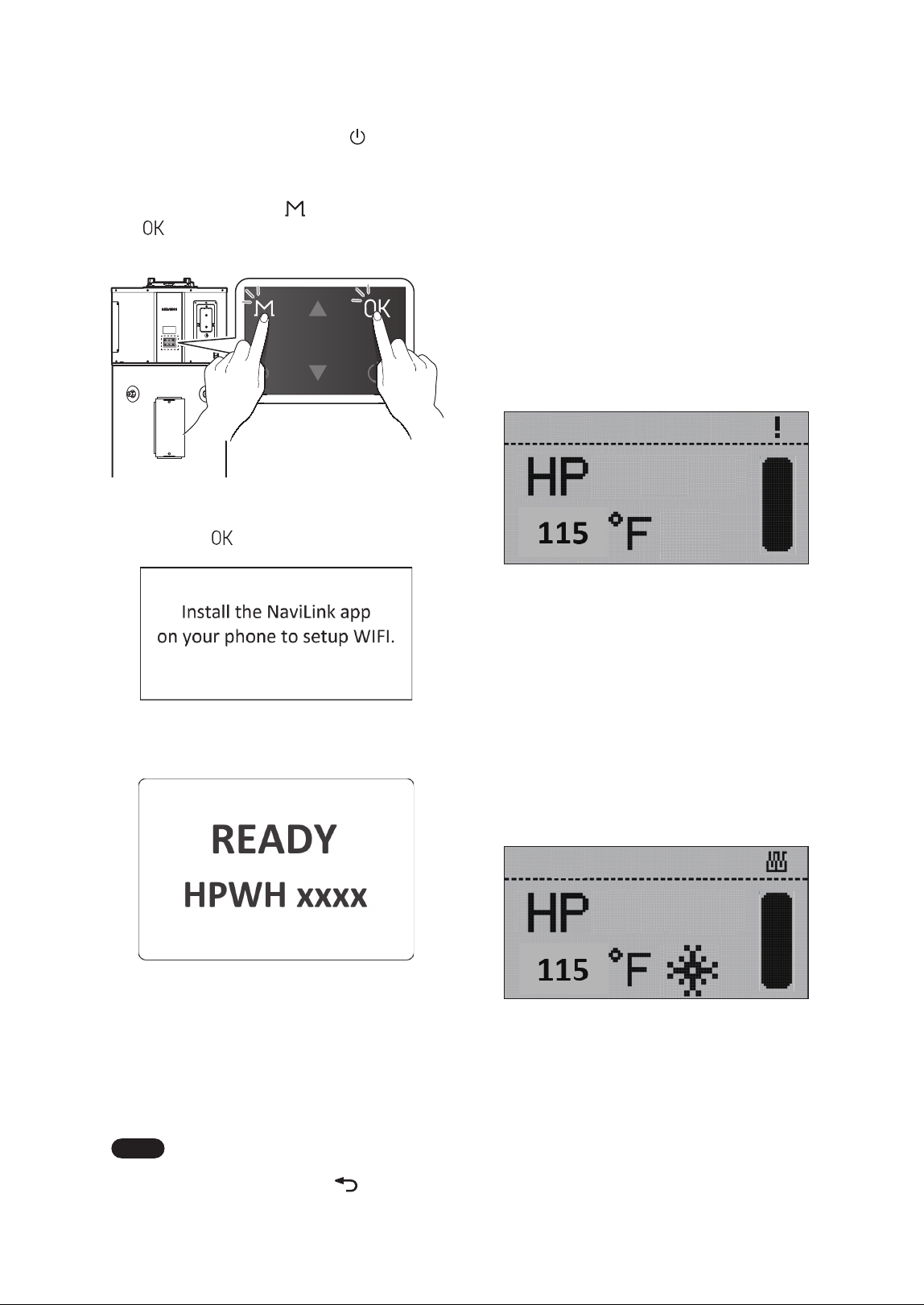
4. Press and hold the Power button ( ) to turn off
the water heater.
5. When the water heater is turned off, press and
hold the Menu button (
) and the OK button
(
) simultaneously for 3 seconds. The water
heater will be in Wi-Fi Connection mode.
6. When the guidance screen appears, press the
OK button (
).
The Wi-Fi connection ready mode screen will be
displayed.
7. While the water heater is in Wi-Fi Connection
mode, register the product (water heater) via
the NaviLink app. If registration is successful,
"WIFI CONN-SUCCESS" will be displayed on
the front panel, and the water heater will
complete Wi-Fi Connection mode and turn off
automatically.
Note
To exit Wi-Fi Connection mode and
turn off the water heater, press and
hold the Back button (
).
26 Operating the Water Heater
3.15.3 Demand Response (CTA 2045-B) -
Default: Disable
NOTICE
In demand response applications, a thermostatic
mixing valve certified to ASSE 1017 is required
to be installed on the hot water outlet pipe.
Refer to the installation instructions provided
by the valve manufacturer.
If the CTA-2045 Module (or EcoPort Module) is
connected to the product and the DR (Demand
Response) function is enabled in the front panel
settings menu, power usage control will be
performed according to DR commands sent by
the Electric Utility. Various commands, such as
Shed or Load Up, can be received. Upon receiving
a command from the Grid, normal operation will
immediately stop, and the corresponding action will
be performed. While performing actions in response
to a DR command, the front panel will display
the DR label. If necessary, you can disable the DR
function to operate in normal mode, which will
remain in effect for up to 72hours (3 days).
3.15.4 Weekly Schedule - Default:
Disable
When the weekly schedule feature is enabled, the
tank’s thermal storage operation is performed
according to the schedule type and settings.
The schedule time, operating mode, and tank
temperature settings can be configured. While
operating using the schedule settings, if you change
any settings (such as operating mode or tank
temperature), the product will immediately operate
according to the new settings. When the next
scheduled operation time is reached, it will continue
operating according to the previously reserved
settings.
3.14.3 Anti-Seize
The shut-off valve and electronic expansion valve
(EEV) will operate for a set period at regular intervals
to prevent seizing.
3.14.4 Alternating from Heat Pump to
Electric Operation
If there is a problem with the heat source used in
the selected operating mode and that heat source
cannot be operated, tank heating will continue
with the remaining alternative heat source that
is confirmed to be in normal condition until the
problematic heat source returns to normal.
Ɣ
If the heat pump cannot operate, the electric
heater will be used to heat the tank.
Ɣ
If the electric heater cannot operate, the heat
pump will be used to heat the tank.
Ɣ
If the upper electric heater cannot operate, the
lower electric heater will be used to heat the tank.
3.15 Additional Features
3.15.1 Hot Water Charge Display
This feature calculates the thermal energy (energy
storage) status inside the tank based on the current
water temperature and displays it on the front
panel.
3.15.2 Anti-Legionella - Default: Disable
CAUTION
A mixing valve must be installed to prevent
the risk of burns from high-temperature water
when the anti-legionella feature is activated.
When the anti-legionella function is enabled,
the water temperature in the tank will be heated
to 140°F (60°C) at a set interval (default: 7 days,
adjustable from 1 to 30 days) to prevent Legionella
bacteria.
27Maintaining the Water Heater
Note
If you need assistance with component
replacement, contact a licensed
professional or Navien Technical
Support at 1-800-519-8794.
To operate the water heater safely, perform proper
routine maintenance. Follow the instructions in this
chapter to ensure optimal performance, prevent
potential issues, and extend the lifespan of the unit.
Ɣ
At least once a year, open the T&P valve handle
on the side of the water heater and release 1–2
gallons of water.
Ɣ
Clean the air filter on top of the water heater
at least once a year or whenever the air filter
cleaning alarm is displayed on the front panel.
Ɣ
The internal condensate system requires no
maintenance unless a fault code or overflow
condition occurs. (For more information, refer to
“4.3 Inspecting the Condensate Drain” on page
28.)
WARNING
Ɣ
Follow the service and maintenance
procedures given throughout this manual
and in component literature shipped with the
water heater.
Ɣ
Failure to perform the service and
maintenance could result in damage to the
water heater or system.
Ɣ
Failure to follow the directions in this manual
and component literature could result in
severe personal injury, death, or substantial
property damage.
Ɣ
The boiler must be inspected annually,
preferably at the start of the heating season,
by a qualified service technician. In addition,
the maintenance and care of the boiler must
be performed to assure maximum boiler
efficiency and reliability. Failure to service
and maintain the boiler and system could
result in equipment failure.
Ɣ
Electrical shock hazard – Turn off power
to the boiler before any service operation
on the boiler except as noted otherwise in
this instruction manual. Failure to turn off
electrical power could result in electrical
shock, causing severe personal injury or
death.
Ɣ
After each act of maintenance or servicing,
proper operation of the boiler must be
verified by a qualified service technician.
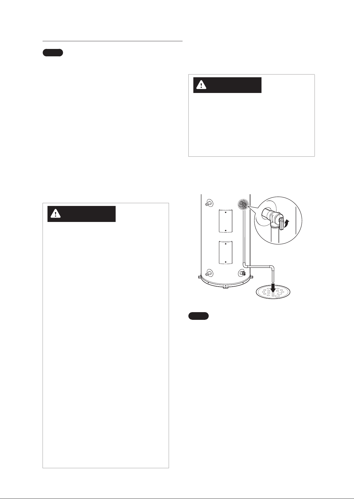
4.1 Maintaining the T&P Relief
Valve
WARNING
The water heater must be equipped with a T&P
valve. Operating the water heater without the
T&P valve may lead to the risk of explosion.
Ɣ
When discharging water, ensure no one is
nearby, as the temperature is extremely high.
Ɣ
Do not block the T&P valve discharge outlet.
At least once a year, open the T&P valve’s handle on
the side of the water heater to drain 1–2 gallons of
water, preventing the valve from sticking.
Note
Ɣ
If no water is drained when the T&P
valve’s handle is opened, turn off the
water heater and contact a licensed
professional or Navien Technical
Support at 1-800-519-8794.
Ɣ
If there is a leak from the T&P valve,
follow these guidelines:
- Install a PRV (Pressure Reducing
Valve) on the cold water inlet
side. (Recommended pressure:
50–60psi)
- Install an expansion tank with the
appropriate pressure.
- Adjust the temperature setting as
needed.
4. Maintaining the Water Heater
28 Maintaining the Water Heater
4.3 Inspecting the Condensate
Drain
The internal condensate system requires no
maintenance unless a fault code or overflow
condition occurs.
Ɣ
When such conditions occur, check whether the
condensate drain pan or hose is clogged due to
sediment or algae buildup.
Ɣ
Compressor operation will automatically stop
when condensate leakage or overflow is detected
to protect the product and user safety.
Ɣ
In case the condensate drain line is clogged,
follow the instruction below to clean the line.
Recommended cleaning tools include a cleaning
brush, wet/dry vacuum cleaner, bleach, and other
appropriate household items.
Cleaning Port
1. Ensure the electrical power to the water heater
is turned off.
2. Remove the condensate drain and open the
cleaning port.
3. Remove internal debris using a brush or pipe
cleaner from the cleaning port.
4. Use a vacuum cleaner or bleach (if necessary)
to remove remaining debris and foreign
substances.
5. Restore the cleaning port and supply power to
the water heater.
WARNING
The water heater must be equipped with a T&P
valve. Operating the water heater without the
T&P valve may lead to the risk of explosion.
Ɣ
When discharging water, ensure no one is
nearby, as the temperature is extremely high.
Ɣ
Do not block the T&P valve discharge outlet.
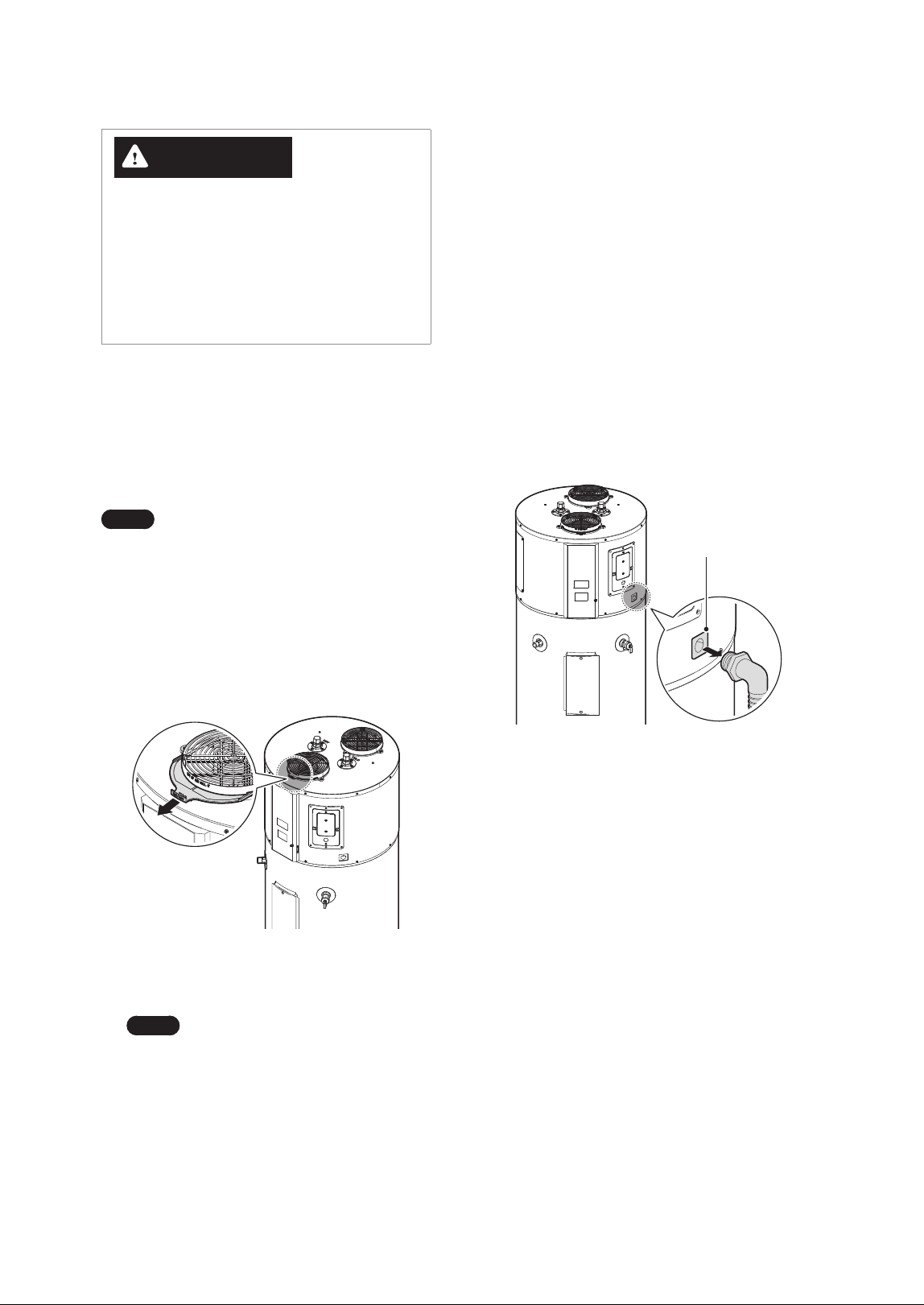
4.2 Cleaning the Air Filter
When an air filter alarm notification appears on the
front panel, clean or replace (if required) the air filter
on the intake air duct at the top of the water heater.
Note
Although the filter is not clogged, clean
the air filter at least once a year to help
improve the water heater’s efficiency.
1. Ensure the electrical power to the water heater
is turned off.
2. Hold the air filter by its handle, then lift it up and
pull it out from the intake air duct at the top of
the water heater.
3. Remove dust or debris from the filter using
water or a vacuum cleaner.
Note
If you use water to clean the filter,
make sure to dry it completely or
wipe it down with a cloth.
4. Push the air filter all the way in to fully insert it
into the intake air duct.
29Maintaining the Water Heater
4.5 Maintenance for Extended
Periods of Inactivity
If the water heater will be unused for an extended
period, follow the instructions below.
Ɣ
Disconnect the power supply to the water heater.
Ɣ
Use the Vacation mode to save energy. To set the
Vacation mode, refer to “3.5 Setting Operation
Schedules and Configuring Communication
Settings” on page 15.
Ɣ
Be sure to drain the pipes to prevent the risk of
freezing due to outdoor temperatures.
CAUTION
Before turning the water heater back on after it
has been unused for an extended period, make
sure the storage tank is full of water. If the water
heater is turned on without enough water in the
tank, it may overheat, causing damage to the
heating element. This may lead to malfunction,
increased energy consumption, or even a
complete failure of the system. Ensuring the
tank is full of water helps prevent these risks and
ensures safe operation.
4.6 Replacing the Battery on the
Front Panel
CAUTION
Ɣ
Impacting the battery may cause an
explosion.
Ɣ
Do not attempt to recharge the battery.
Ɣ
After replacing the battery, you may need to
set the time on the front panel.
The water heater is shipped from the factory with a
protective film on the battery. After completing the
installation and before connecting the water heater
to power, remove the battery protective film from
the side of the front panel. It is recommended to
replace the battery every five years.
4.4 Draining and Flushing the
Water Heater
At least once a year, drain and flush the water heater
to remove mineral deposits and reduce unpleasant
odors in the water.
1. Ensure the electrical power to the water heater
is turned off.
2. Open all faucets and connect a hose to the drain
valve.
3. Close the cold water supply valve and open the
drain valve (Opening the T&P valve will speed
up the draining process.).
4. Once draining is complete, close the drain valve
and reopen the cold water supply valve.
5. Keep the faucets open while the storage tank
fills with water.
6. When the storage tank is full, close the faucets
and supply power to the water heater to turn
it on.
WARNING
Ɣ
Ensure the power to the water heater is
turned off before performing this procedure.
Ɣ
After completing draining and flushing, make
sure the storage tank is fully filled with water
before supplying power to the water heater
to turn on the water heater.
30 Maintaining the Water Heater
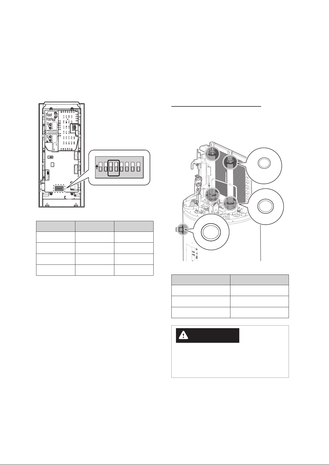
4.8 Installing Emergency Part Kit
for Repairs
The emergency parts kit for repairs includes three
types of O-rings and fuses. Use these components to
replace damaged parts, if necessary.
O-Ring Replacement Locations
If the O-rings on the upper, lower, or side pipes
need replacement, use the corresponding O-rings
provided in the Emergency Parts Kit.
P22A
P26
P24
O-ring Type Location
P22A Top Pipe Upper
P26 Top Pipe Lower
P24 Side Pipes
WARNING
Using a damaged O-ring or installing an O-ring
improperly may cause water leaks, which could
result in severe personal injury or property
damage.
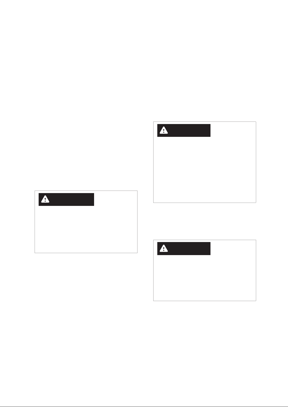
4.7 Setting the DIP Switches
The water heater has 8 dip switches on the back of
the front panel. Dip switches 3 and 4 can be used to
set the capacity of the heat pump water heater. The
capacity setting is set at the factory and cannot be
changed except when the front panel is replaced.
O
N
1 2 3 4 5 6 7 8
Capacity DIP SW 3 DIP SW 4
50 Gallon OFF OFF
65 Gallon ON OFF
80 Gallon OFF ON
Setting Error ON ON
31Maintaining the Water Heater
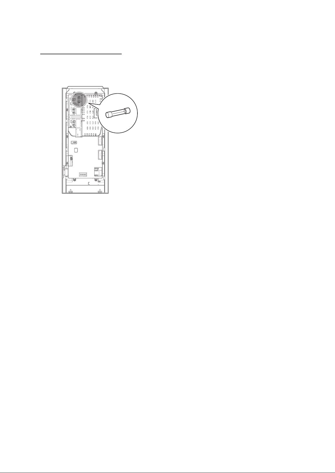
Fuse Replacement Location
If the fuse located on the back of the front panel
is blown, replace it with the fuse provided in the
Emergency Parts Kit.
32 Troubleshooting
WARNING
Ɣ
If resetting the water heater and attempting the remedies suggested below do not resolve the problem,
contact an authorized technician, a licensed professional, or Technical Support at 1-800-519-8794 for
service instructions.
Ɣ
Do NOT attempt to service or repair the water heater yourself.
Problem Possible Causes What to Do
Rumbling
noise
Water conditions in your
home caused a buildup of
scale or mineral deposits in
the water heater.
Allow a few quarts of water to run from the drain valve to
remove sediment settings.
Relief valve
producing
popping
noise or
draining
Pressure build up caused
by thermal expansion in a
closed system
This is an unacceptable condition and must be corrected.
Contact a licensed professional or Navien Technical Support
at 1-800-519-8794 for assistance.
5. Troubleshooting
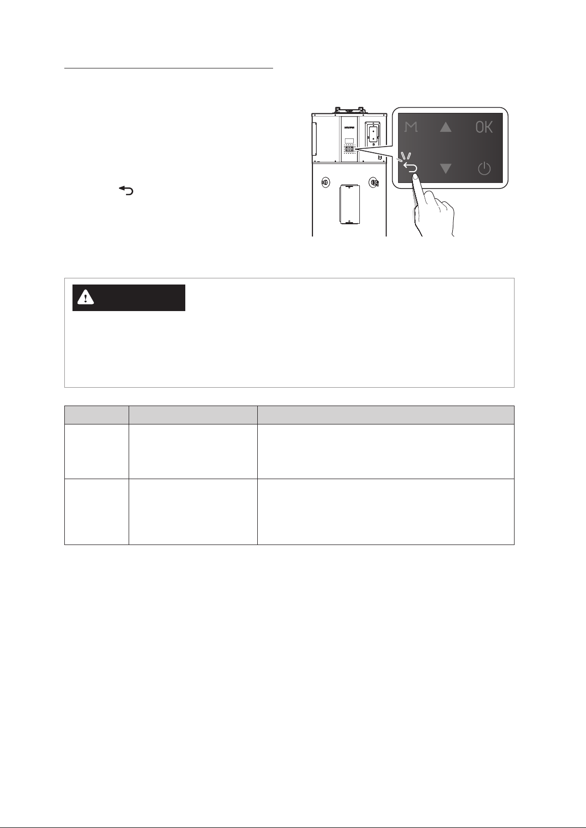
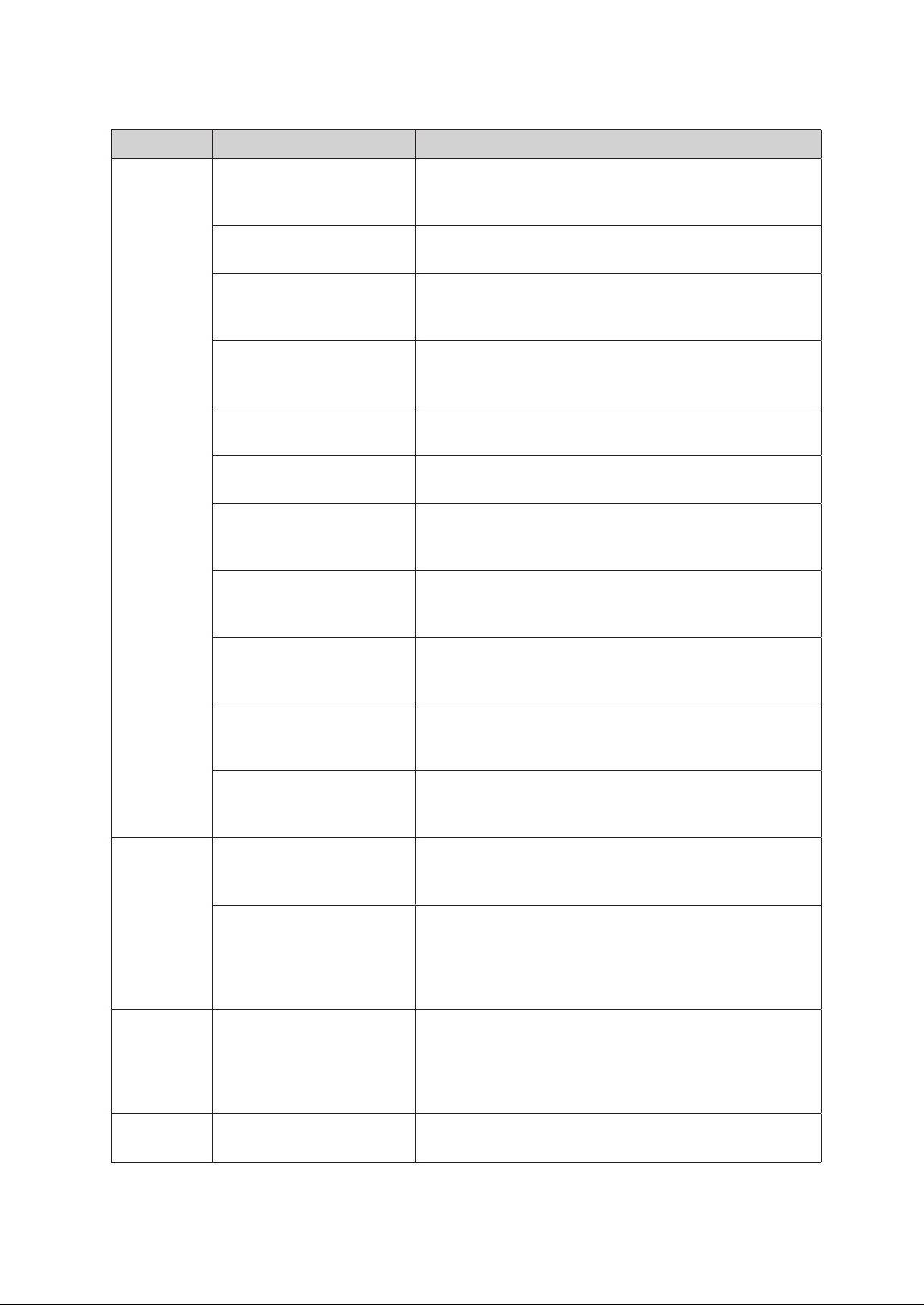
5.1 Solving Basic Problems
If you experience a problem with the water heater,
refer to the following chart for possible remedies.
Error codes that appear on the front panel display
are explained in the following section.
For minor problems, resetting the water heater may
resolve the issue. To reset the water heater, press the
Back button (
) on the front panel.
33Troubleshooting
Problem Possible Causes What to Do
Not enough
or no hot
water
Water usage may have
exceeded the capacity of the
water heater.
Wait for the water heater to recover after an abnormal
demand.
A fuse is blown or a circuit
breaker tripped.
Replace fuse or reset circuit breaker.
Electric supply may be turned
off.
Confirm that electric supply to the water heater is properly
connected. For more detailed instructions, refer to
“Connecting the Power Supply” in the Installation Manual.
The thermostat may be set
too low.
Check the water heater’s temperature setting. Refer to
“3.3 Selecting the Operation Mode & Adjusting Water
Temperature” on page 13.
Leaking or open hot water
faucets
Make sure all faucets are closed and check for plumbing leak.
Electric service to your home
may be interrupted
Contact the local electric utility.
Improper wiring or sensor
failure
Confirm that power supply wires are properly connected. For
more detailed instructions, refer to “Connecting the Power
Supply Wires” in the Installation Manual.
Manual reset limit(ECO)
Check the temperature regulation of the water heater. For
more information, refer to “Important Safety Information” on
page 5 for more information.
The water heater may be in
Vacation Mode.
To disable Vacation Mode, refer to “3.5 Setting Operation
Schedules and Configuring Communication Settings” on page
15.
Cold water inlet temperature
may be colder during the
winter months
This is normal. The colder inlet water takes longer to heat.
Not enough air exchange
for Efficient Heat Pump
Operation
If the air temperature drops more than 15°F (8°C) during
Heat Pump Operation, more air circulation around heater is
required.
Water is too
hot
The thermostat is set too
high
Check the water heater’s temperature setting. Refer to
“3.3 Selecting the Operation Mode & Adjusting Water
Temperature” on page 13.
The Anti-Legionella function
may be used.
This water heater is factory set to heat up to 120°F (49°C) once
a week to prevent Legionella bacteria. Disable this function
or adjust the heating frequency in the settings. To disable
the function, refer to “Setting the Protection Function” in the
Installation Manual.
Water odor
Harmless bacteria present in
tap water
A higher tank temperature setting of 140°F (60°C) kills the
bacteria that cause 'smelly water' and can help reduce the
levels of bacteria that cause waterborne diseases. A properly
adjusted thermostatic mixing valve should be installed at
each point of use.
Low water
pressure
Partially closed supply valve Open the water heater’s supply valve fully.
34 Appendixes
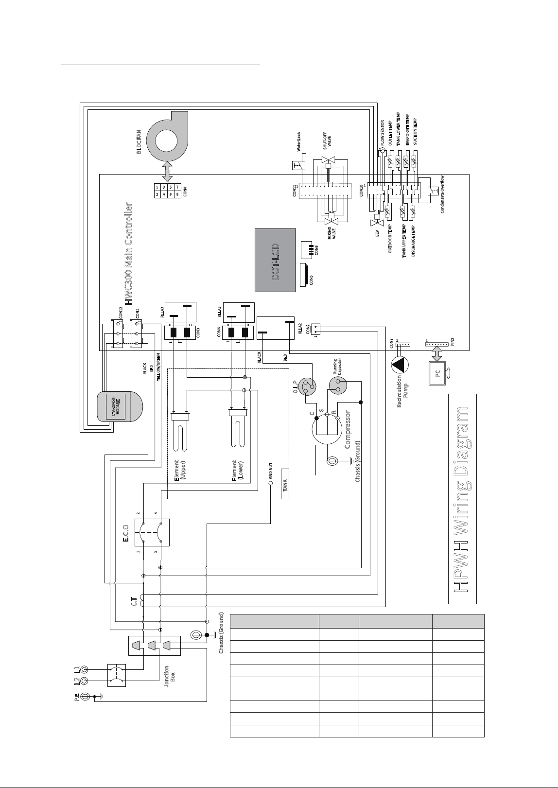
6.1 Wiring Diagram
Wire Name AWG Temperature Spec. UL No.
Main Power Input 12 105 1015
Controller 18 105 1015
E.C.O 12 105 1015
Compressor 18 105 1015
Heating Element (Upper/
Lower)
12 105 1015
Sensor 22 105 1569, 21914
Fan Motor 22 105 1015
CTA Module 18, 22 105 1015, 1569
3--"
)18)8JSJOH%JBHSBN
)8$.BJO$POUSPMMFS
-
1&
-
"$7@108&3@*/165
+VODUJPO
#PY
$IBTTJT(SPVOE
&$0
$0/
$0/
&MFNFOU
6QQFS
&MFNFOU
-PXFS
$0/
$0/
$0/
$5
1$
1*/
$0/
46$5*0/5&.1
%*4$)"3(&5&.1
065%0035&.1
5"/,611&35&.1
065-&55&.1
5"/,-08&35&.1
&&7
$0/
8BUFS-FBL
4)650''
7"-7&
.*9*/(
7"-7&
3--"
$PNQSFTTPS
$0/
$0/
$0/
%05-$%
$5"#
.0%6-&
$POEFOTBUF0WFSPX
&7"103"5&5&.1
'-084&/403
0-1
$
4
3
3VOOJOH
$BQBDJUPS
3--"
3--"
#-"$,
3&%
:&--08(3&&/
#-"$,
3&%
5"/,
(/%/65
#-%$'"/
'"/31.'&&%#"$,
'"/$0/530-4611-:70-5"(&%$7
'"/$0/530-4*(/"-%$_7
(306/%
'"/4611-:70-5"(&%$7
$IBTTJT(SPVOE
$0/
3FDJSDVMBUJPO
1VNQ
6. Appendixes
35Appendixes
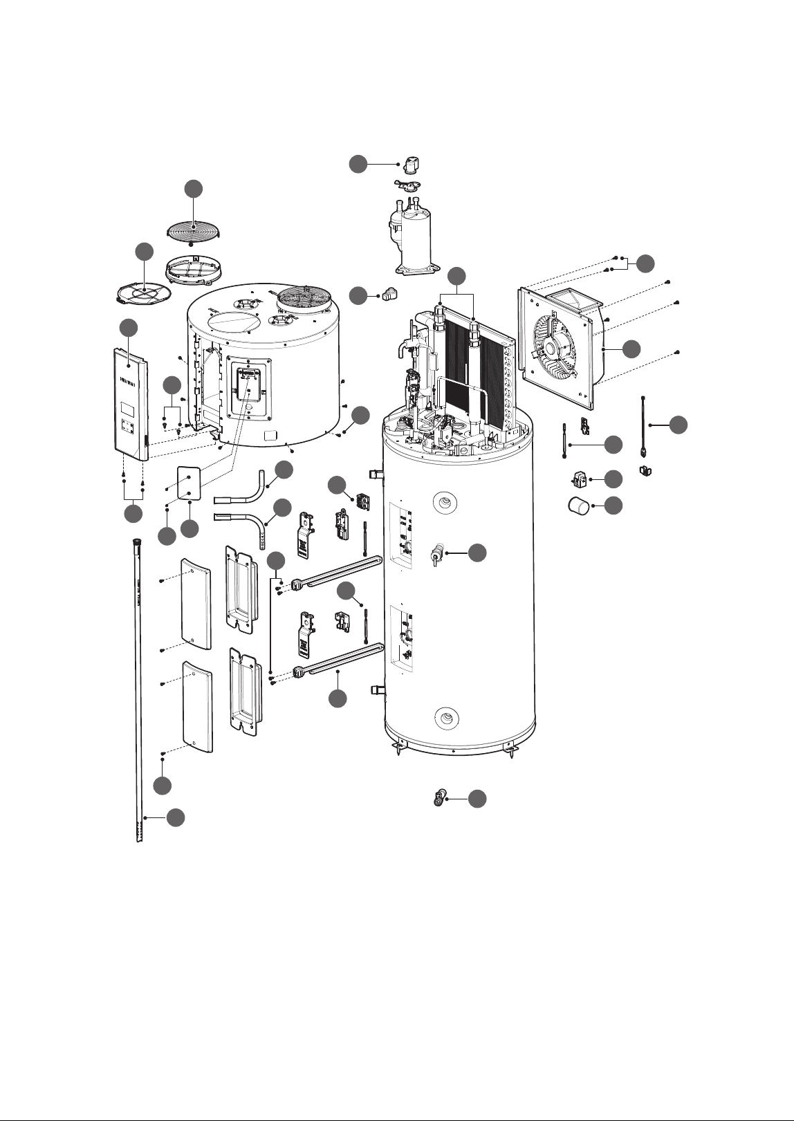
6.2 Component Assembly Diagrams and Parts Lists
4
3
6
8
7
9
10
12
14
1
16
18
2
15
13
11
5
21
17
20
19
22
23
24
25
26
27

36 Appendixes
# Part Name Service Code Remark
1 Intake Filter 20068915*
2 Intake Filter Grille 20072241*
3 Electronic Expansion Valve (EEV) Coil 30036215*
4 Overload Protector 30036800*
5 Upper Inlet & Outlet Pipe 30036106*
6 Fan Assembly 30035398*
7 Outside Air Temp sensor 30038926*
8 Water Leak Detection Sensor 30031685*
9 CT Sensor 20071987*
10 Capacitor 20071120*
11 Energy Cut Off (ECO) Switch 30035521*
12 Temperature and Pressure (T&P) Relief Valve (150 psi) 30036068*
13 Heating Element Temperature Sensor 30038926*
14 Drain Valve 30036062*
15 Heating Element 30036069*
16 Control Assembly 30036288*
17 Fan Assembly Fixing Screw 20072676*
18 Top Kit Fixing Screw (Side) 20072409*
19 Top Kit Fixing Screw (Bottom) 20072676*
20 Main Controller Screw 20072408*
21 Heating Element Wire Screw 20077432*
22 Heating Element Case Fixing Screw 20072407*
23 CTA-2045 Cover - Not supplied
24 CTA-2045 Cover Screw - Not supplied
25 Upper Inlet Tube (Dip Tube) - Not supplied
26 Optional Side Outlet Tube - Not supplied
27 Optional Side Inlet Tube - Not supplied
LIMITED WARRANTY NAVIEN, INC.
For instant warranty registration, please register your product online at www.navieninc.com
Customer Name :
Customer Address :
Telephone : Fax :
Email :
Installer Name : License No :
Installer Address :
Place of Purchase :
Model No :
Serial No :
Date of Purchase :
PLACE
STAMP
HERE
Navien, Inc.
20 Goodyear, Irvine, CA 92618
Tel : 1-800-519-8794
Fax : 949-420-0430
www.navieninc.com
This Limited Warranty is provided by Navien, Inc. (“Navien”) to cover
only labor, parts and the tank for the Navien NWP500 Heat Pump Water
Heater (“Product”) as originally installed by a properly licensed plumber
or contractor and operated in strict compliance with the Installation &
User’s Information Manuals procedures and subject to the terms within
this Warranty document. Improper installation or use will void this
Warranty.
How Long is the Coverage?
The warranty periods begin from the date of original installation
(“Commencement Date”), and proof of such date must be provided
to Navien. When the Product is installed in new construction, the
Commencement Date shall be the date that the end-user takes title to
the property. If proof of the installation date is unavailable, then the
original installation date shall be deemed to be six months after the
unit’s manufacture date.
This Warranty runs from the Commencement Date and extends to the
original purchaser and subsequent owners (“Purchaser”), but only while
the Product remains at the site of the original installation. This Warranty
includes a limited warranty as set forth herein.
What is covered?
Subject to the terms and conditions set forth in this limited warranty,
Navien will repair or furnish replacement parts, at no charge, for
installation by a qualified service provider, if the part fails due to
a manufacturing defect under normal use and maintenance. This
limited warranty for the Applicable Warranty Periods specified herein
(“Warranty”) covers defects in materials or workmanship when the
Product is installed by a properly licensed plumber or contractor
and operated in strict compliance with the Installation & User’s
Information Manuals procedures, subject to the terms within this
Warranty document. Navien will pay reasonable labor charges for the
repair subject to Navien’s prior written approval and in accordance
with Navien’s schedule of approved labor allowances for a period of
one (1) Year from the Commencement Date. All repair parts must be
genuine Navien parts unless otherwise authorized by Navien. All repairs
and replacements must be performed by an individual or servicing
company that is qualified to do the type of repair. During the applicable
warranty period, replacement of the Product or part requires Navien’s
direct prior written approval, and no third party is authorized to provide
such approval on behalf of Navien. The replacement part or Product will
be warranted only for the unexpired portion of the applicable warranty
period for the original part or Product.
Applicable Warranty Periods
NWP500 Series – Coverage Table for Labor, Parts, and Tank Only
Residential* Commercial
Labor 1 Year
No coverage for
Commercial Use
Parts 10 Years
Tank 10 Years
*Residential use means a Single-Family Residence
Eligibility Requirements
To be covered under this limited warranty, the Product or Parts must
meet the following requirements: (i) The Product must be in the same
location where it was originally installed; (ii) The Product must be
properly installed, operated, and maintained by a licensed HVAC service
provider in accordance with the specifications or installation, operation,
and maintenance instructions provided by Navien, and you must upon
request, present written maintenance records, (iii) The Product or Parts
replaced under this limited warranty must be given to the servicing
provider for return to Navien; and (iv) All claims under this limited
warranty must be filed within 30 days of the failure date.
How do I get service?
You must contact the original installer of your Product who must then
contact Navien to report the issue. If you cannot find or do not wish to
use the original installer, you may choose any service provider who is
qualified to complete the necessary repair. Your service provider must
contact and obtain approval from Navien’s Technical Support team at
800-519-8794 or an authorized Navien distributor prior to commencing
any warranty service. The installer and/or service provider must comply
with Navien’s warranty service and return procedures as available on
Navien’s website.
What is not covered?
This warranty does not cover issues that are cosmetic and have no effect
on the functionality of the Product, or for reasons of noise, taste, odor,
discolored and/or rusty water. This warranty does not cover damage
to the surrounding property. A properly sized metal drain pan must
be installed in an area where leakage from the tank or its connections
would result in damage to the area adjacent to the water heater. This
warranty does not apply to water heaters used to heat pools, whirlpools
or hot tubs or used for space heating. This warranty gives you specific
legal rights, and you may have other rights which vary under the laws of
each state. If any provision of this warranty is prohibited or invalid under
applicable state law, that provision shall be ineffective to the extent of
the prohibition or invalidity without invalidating the remainder of the
affected provision or the other provisions of this warranty.
Additional terms and conditions are continued on the reverse side.
SKIP THE STAMP!
Use your camera to scan this QR
and register your unit online.
code

For instant warranty registration, please register your product online at www.navieninc.com
Navien’s Limited Warranty shall be void in the event of an occurrence of
any of the following:
Ɣ
Product purchased through the internet, other e-commerce channels, or
any installer that obtained the Product from a supplier or distributor not
authorized by Navien.
Ɣ
Improper installation, failure to install in strict compliance with the
Installation Manual procedures, installed by a non- licensed installer, and
installation in violation of applicable rules, fire codes, plumbing codes,
ordinances, regulations, good industry practices and proper safety
practices.
Ɣ
Failure to perform regular maintenance, misuse, operation at settings
other than those recommended or specified, non- compliance with
instructions or guidelines set forth in the User’s Information Manual.
Ɣ
Modification or alteration of the Product in any manner, including
but not limited to, removal of any component or part, addition of any
nonapproved components, relocating or moving the Product from its
original installation site, or any accidental or intentional damage to the
Product.
Ɣ
Installation for non-recommended uses including Commercial use. Or
installation outdoors.
Ɣ
Any damage caused by local adverse conditions including but not limited
to hard water deposits, lime or mineral build- up, operating in corrosive
atmospheric elements; any operation of the water heater on desalinated
(deionized) water.
Ɣ
Any damage, malfunction or failure caused by abuse, negligence,
alteration, accident, fire, flood, freezing, wind, lightning, power supply
issues, electrical surges, acts of God, abnormal external temperature,
and any other cause of damage not directly caused by a manufacturing
defect.
Ɣ
Installer’s failure to fully comply with the Warranty Service and Return
Policy procedures as available on Navien’s website. Such policies include
but are not limited to the Installer’s failure to first contact Navien Tech
Support while in front of the product for purposes of trouble shooting
the identified problem or issue.
Ɣ
Performance problems caused by improper sizing of the water heater,
the venting connection, combustion air openings, electric service
voltage, wiring, fusing or any other components, parts or specifications.
Ɣ
Operating, using or storing the water heater in a corrosive or
contaminated atmosphere or environment.
Ɣ
Operating the water heater at water temperatures outside the factory
calibrated temperature limits and/or exceeding the maximum setting of
the high limit control.
Ɣ
Operating the water heater when it is not supplied with potable water at
all times, free of damaging water sediment or scale deposits.
Ɣ
If a new temperature and pressure relief valve, certified by the Canadian
Standards Association, is not properly installed and piped to the nearest
drain.
Ɣ
Any damage caused by attempts to repair tank leaks or parts
Ɣ
Installation at any location outside the United States and Canada.
Ɣ
Removal or alteration of the rating plate.
Ɣ
Used at water pressures exceeding 80 psi static pressure.
Ɣ
When water is not able to freely circulate at all times and with the tank;
dry-firing.
Ɣ
Installation anywhere other than its original installation location.
Ɣ
Product is not sized in accordance with proper sizing techniques for
residential water heaters.
Ɣ
Product is not being used with a properly sized and installed thermal
expansion tank.
Ɣ
Product is not connected to the proper voltage or operated outside of
the factory rated input.
Ɣ
Any attempt to modify or alter the water heater’s design in any way,
including but not limited to, the attachment of non-company approved
appliances or equipment, including any additional aftermarket
equipment introduced into the sealed system.
Warranty Limitations
EXCEPT AS EXPRESSLY PROVIDED HEREIN, THERE ARE NO OTHER
WARRANTIES, EXPRESSED OR IMPLIED, INCLUDING, BUT NOT LIMITED
TO WARRANTIES OR MERCHANTABILITY OR FITNESS FOR A PARTICULAR
PURPOSE, WHICH EXTEND BEYOND THE DESCRIPTION OF THE
WARRANTY HEREIN AND FURTHER NAVIEN SHALL NOT BE LIABLE
FOR INDIRECT, INCIDENTAL, SPECIAL, CONSEQUENTIAL, PUNITIVE OR
OTHER SIMILAR DAMAGES THAT MAY ARISE, INCLUDING LOST PROFITS,
DAMAGE TO A PERSON OR PROPERTY, LOSS OF USE, INCONVENIENCE,
OR LIABILITY ARISING FROM IMPROPER INSTALLATION, SERVICE OR USE
OF THE PRODUCT. ANY IMPLIED WARRANTIES OF MERCHANTABILITY
AND FITNESS ARISING UNDER STATE LAW ARE LIMITED IN DURATION TO
THE PERIOD OF COVERAGE PROVIDED BY THIS WARRANTY, UNLESS THE
PERIOD PROVIDED BY STATE LAW IS LESS.
No one is authorized to make any other warranties on behalf of Navien.
Some states do not allow the exclusion or limitation of incidental or
consequential damages, or how long an implied warranty lasts, so the
above limitation may not apply to you. This Limited Warranty gives you
specific legal rights and you may also have other rights which vary from
state to state. If this Product is considered a consumer product, please
be advised that some local laws do not allow exclusions or limitations
on incidental or consequential damages, or limitations on how long
a warranty lasts; or how long an implied warranty lasts, so that the
above limitations may not apply to you. Refer to your local laws for your
specific rights under this limited warranty. If you have any questions
regarding this limited warranty, please contact your original installation
dealer, or any participating dealer, should your original installation
dealer no longer be available. No action arising out of any claimed
breach of this limited warranty may be brought by the Purchaser (or any
subsequent purchaser retaining the balance of a properly transferred
limited warranty) more than one (1) year after the cause of action or
claim has arisen.
Retain this document for future reference.
Rev. April, 2025

Memo


Getting Service
If your water heater requires service:
All repairs require pre-authorization by Technical Support.
Request for your installer or any licensed professional to contact Technical Support at 1-800-519-8794
Option 2 once at the installation site.
A short list of independent service providers in your area can be found on the website:
www.navieninc.com/installers.
Contact a licensed professional for the aected system (for example, a plumber or electrician).
When you contact Technical Support, please have the following information at hand:
Model number
Serial number
Date purchased
Installation location and type
Error code, if any appears on the front panel display
Navien, Inc.
800.519.8794 www.navieninc.com
20 Goodyear, Irvine, CA 92618
User’s Information Manual
NWP500 Electric Heat Pump Water Heaters
THE LEADER IN CONDENSING TECHNOLOGY
Version: 1.0 (November, 2025)
20074231A