
MINIMAL
OS24NMTDB1, OS24NMTDG1, OS24NMLB1, OS24NMLG1 &
OS24NMTNB1 models
CONTEMPORARY
OS24NDTDX1, OS24NDLX1 models
COMPACT COMBINATION
STEAM OVEN
INSTALLATION GUIDE
US CA
2
SAFETY AND WARNINGS
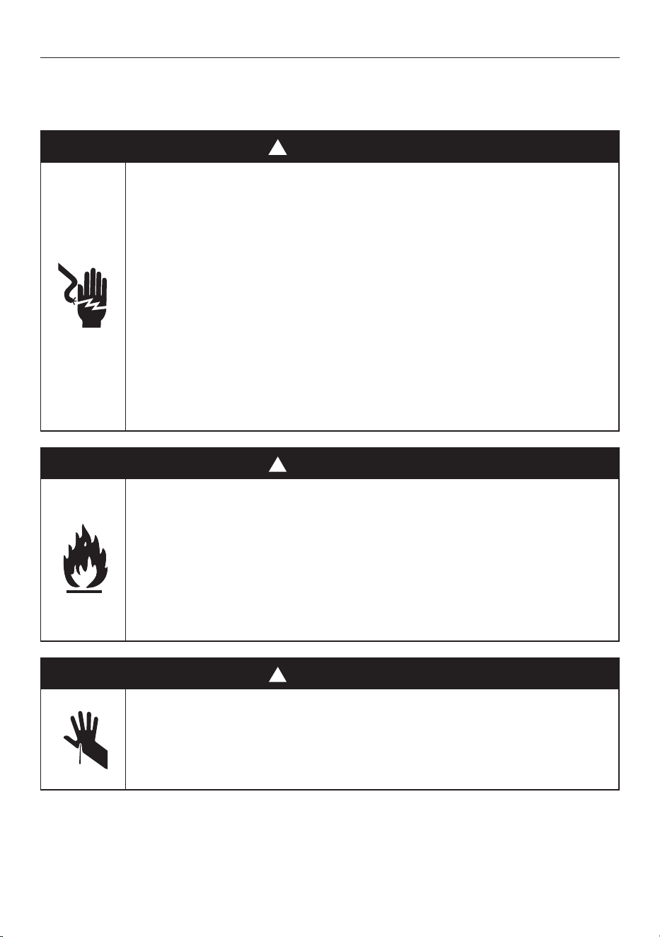
!
WARNING!
Electric Shock Hazard
Failure to follow this advice may result in
electric shock or death.
• Before carrying out any work on the electrical
section of the appliance, it must be disconnected
from the mains electricity supply.
• Connection to a good ground wiring system is
absolutely essential and mandatory.
• Alterations to the domestic wiring system must
only be made by a qualified electrician
!
WARNING!
Fire Hazard
Failure to follow this advice may result in
overheating, burning, and injury.
• Do not use adapters, reducers, or branching
devices to connect this appliance to the mains
power supply.
!
WARNING!
Cut Hazard
Failure to use caution could result in injury.
• Take care: some edges are sharp.
IMPORTANT SAFETY INSTRUCTIONS

3
SAFETY AND WARNINGS
READ AND SAVE THIS GUIDE
WARNING!
To avoid hazard, follow these instructions carefully before installing or using this
appliance.
z
Please make this information available to the person installing the appliance—doing so
could reduce your installation costs.
z
Save these instructions for the local inspectors use.
z
This oven is to be installed and connected to the electricity supply only by an
authorized person.
z
If the installation requires alterations to the domestic electrical system, call a qualified
electrician. The electrician should also check that the socket cable section is suitable
for the electricity drawn by the oven.
z
The oven must be grounded.
z
Installation must comply with your local building and electricity regulations.
z
This appliance must be installed and connected to the mains power supply only by a
suitably qualified person according to these installation instructions and in compliance
with any applicable local building and electricity regulations. Failure to install the
appliance correctly could invalidate any warranty or liability claims.
z
If the power supply cable is damaged, it must be replaced by the manufacturer, its
service agent or similarly qualified person in order to avoid a hazard.
z
A circuit breaker is recommended.
z
Do not use adaptors, reducers or branching devices to connect the oven to the mains
electricity supply, as they can cause overheating and burning.
z
The appliance must not be installed behind a decorative door in order to avoid
overheating.
z
The manufacturer does not accept any responsibility for damage resulting from
incorrect installation.
Electrical requirements
z
Connect oven with copper wire only.
z
Do not cut the conduit.
z
A U.L. listed conduit connector must be provided at the junction box.
z
Do not ground to a gas pipe.
z
Do not have a fuse in the grounding or neutral circuit.
z
Fuse both sides of the line.
z
A time delay fuse or circuit breaker is recommended. If using a time delay fuse, then
fuse both sides of the line.
z
Flexible armored cable from the appliance should be connected directly to the junction
box.
z
Connect directly to the fused disconnect (or circuit breaker box) through flexible,
armored or non-metallic sheathed, copper cable (with grounding wire).
z
If codes permit and a separate grounding wire is used, it is recommended that
a qualified electrician determine that the grounding path and wire gauge are in
accordance with local codes.

4
PRIOR TO INSTALLATION
AFTER INSTALLATION
Ensure that:
z
The oven cavity is square and level based on the required dimensions
z
The installation will comply with all clearance requirements and applicable standards and
regulations
z
The isolating switch will be easily accessible to the customer with the oven installed
z
The electrician provides sufficient free length of power supply cable to reach from the
bottom rear of the cavity to at least 5ft (1.5m) in front of the bottom edge of the opening
z
The cable may enter the cavity from the side, top or bottom, but top entry must be at the
rear of the cavity
z
The oven connection socket is outside the cavity if the oven is flush to the rear wall
z
The oven will rest on a surface that can support its weight
z
The height from the floor suits the customer
z
You consult local building authorities and by-laws if in doubt regarding installationn
IMPORTANT!
Some environmental factors and cooking habits can cause condensation in and around the
oven during use. To protect surrounding cabinetry from possible damage caused by frequent
or excessive condensation, we recommend moisture-proofing the oven cavity.
Ensure that:
z
The oven door can open fully without obstruction
z
The oven is not sealed into the cabinetry with silicone or glue. This makes future servicing
difficult. Fisher & Paykel will not cover the costs of removing the oven, or of damage caused
by this removal
z
The power supply cable does not touch any hot metal parts
z
The isolating switch is easily accessible to the customer with the oven installed
z
You complete the ‘Installer checklist’ at the end of the installation
z
There is enough clearance for opening and closing operation of the moving control panel.
If, after following the guidance given, correct performance cannot be achieved, please contact
your nearest Fisher & Paykel trained and supported service technician, Customer Care, or
contact us through our website fisherpaykel.com

5
COMPONENTS REQUIRED
TOOLS
Supplied
F Powered driver
F Cross-head screwdriver
INSTALLATION KIT
All imagery shown in this guide is representative. Your product may differ.
F Screws (2)
F Metal side shelves fixing nut (2)
6
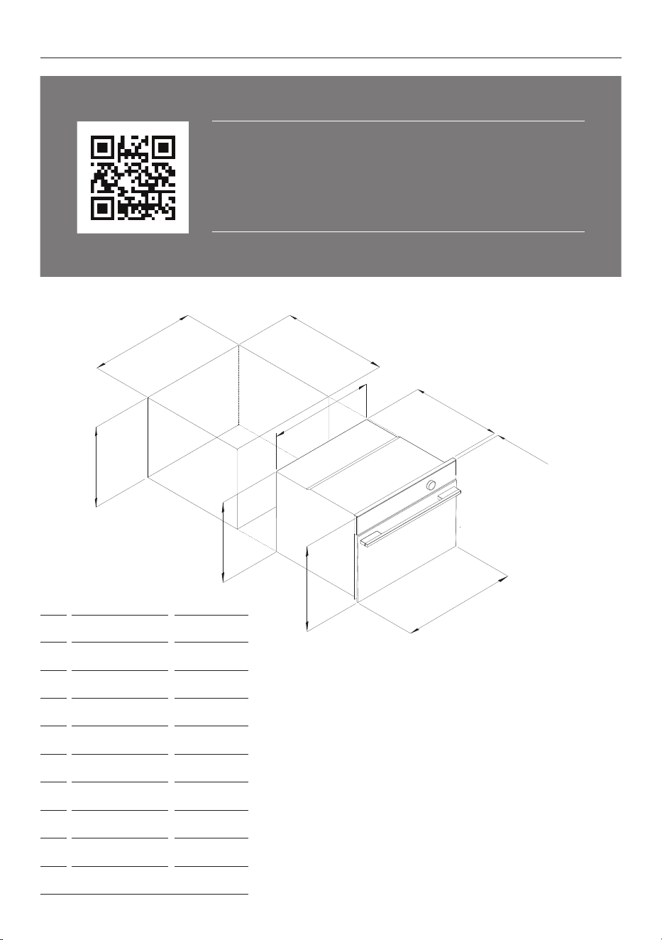
ACCESSING YOUR PRODUCT SPECIFICATIONS
For full product, cabinetry and service specifications, refer
to the Planning Guide. To access the Planning Guide, scan
the QR code or visit fisherpaykel.com/specify. Search by
appliance type, product name or model code.
D
f
i
g
H
B
C
e
A
INCHES MM
A
min. 17 3/4 min. 440
B
min. 22 min. 560
C
min. 21 5/8 min. 550
D
17 1/8 435
E
21 7/8 556
F
21 1/2 545
G
18 458
H
23 7/16 596
i
13/16 20

7
SERVICES
OS24N MODELS
VOLTAGE MAX. CURRENT DRAW MAX LOAD
208 V 16.5 A 3.4 kW
240 V 19 A 4.5 kW
z
This oven must be connected to the mains power supply only by a suitably
qualified person.
z
This oven must be earthed.
Before connecting the oven to the mains power supply, check that:
the domestic wiring system is suitable for the power drawn by the oven (as specified on the
rating plate)
the voltage corresponds to the value given on the rating plate.
8
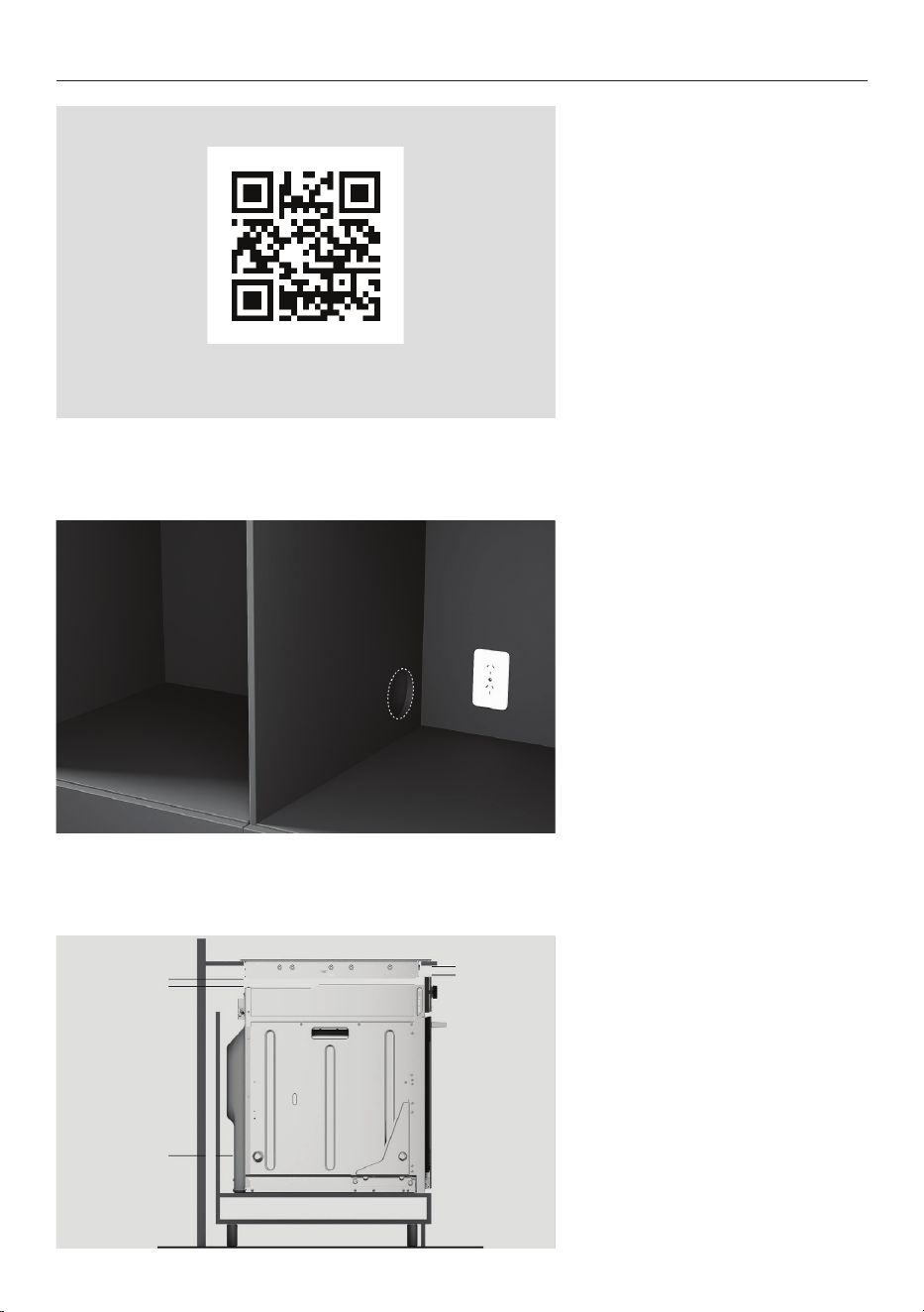
CHECK CAVITY
1. Measure cavity dimensions.
Ensure all minimum
specifications have been met.
Refer to the planning guide for
details.
For dark cabinetry, ensure
clashing has been considered
and installed.
2. Ensure service access
complies with local
requirements.
3. Ensure any cooktop
ventilation requirements have
been considered.
fisherpaykel.com/specify
9
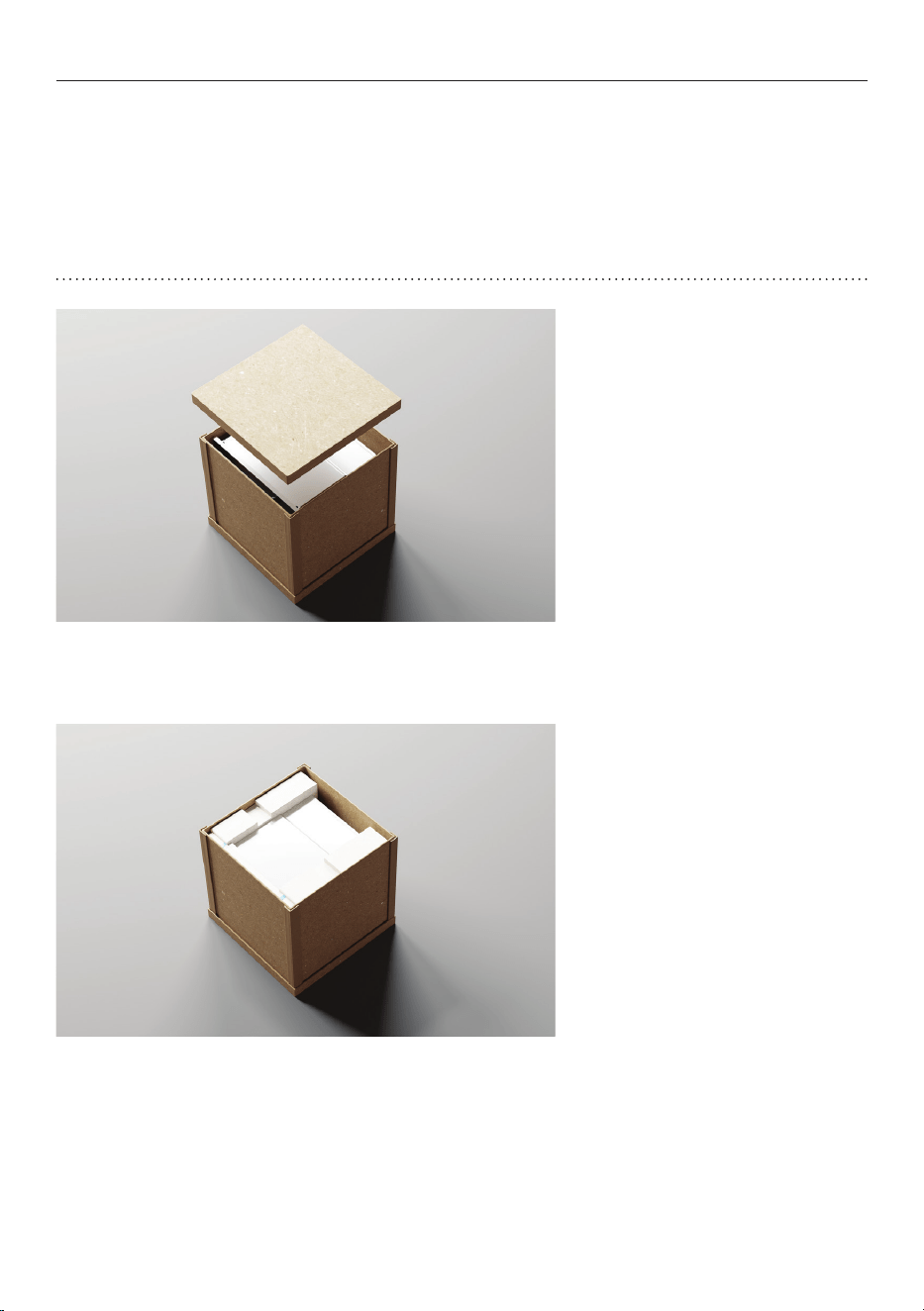
1. Cut all straps and remove the
carton top cap.
2. Lift the carton sleeve and
remove any transit packaging.
Set aside any accessories.
Dispose of packaging
responsibly.
UNPACK PRODUCT
z
Do not lift or move the product using the door handle.
z
Keep all packing materials until the unit has been inspected.
z
Inspect the product to ensure there is no shipping damage. If any damage
is detected contact the dealer or retailer you brought the product from to
report the damage.
z
Fisher & Paykel is not responsible for shipping damage.
10
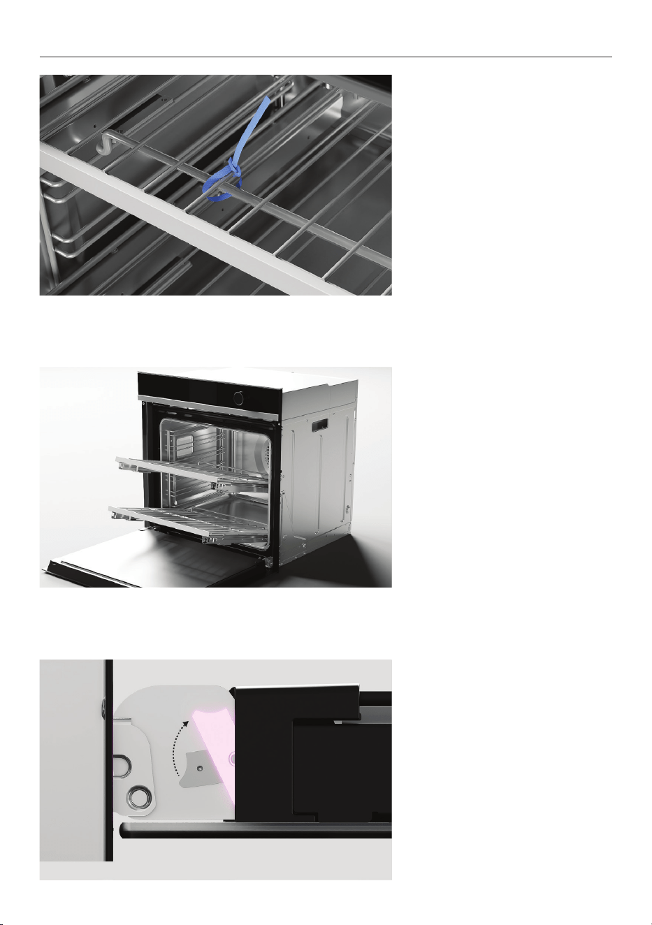
REMOVE DOOR
1. Open the door and remove
all cable ties and packaging
holding the oven shelves in
place.
2. Grip the shelves at the front,
making sure to hold the wire
shelf and frame together. Lift
upwards and pull out from the
oven.
3. Locate the hinge locks on
either side of the door. Push
the locks upwards to release.

11
REMOVE DOOR
4. Holding the door on both
sides, partially close the door
and carefully pull the door
away from the hinges.
12
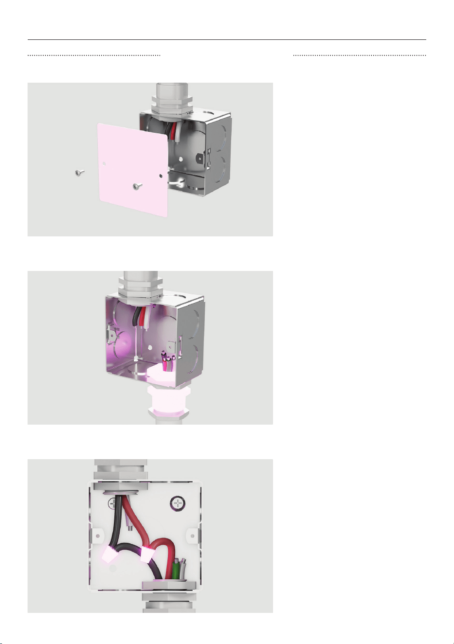
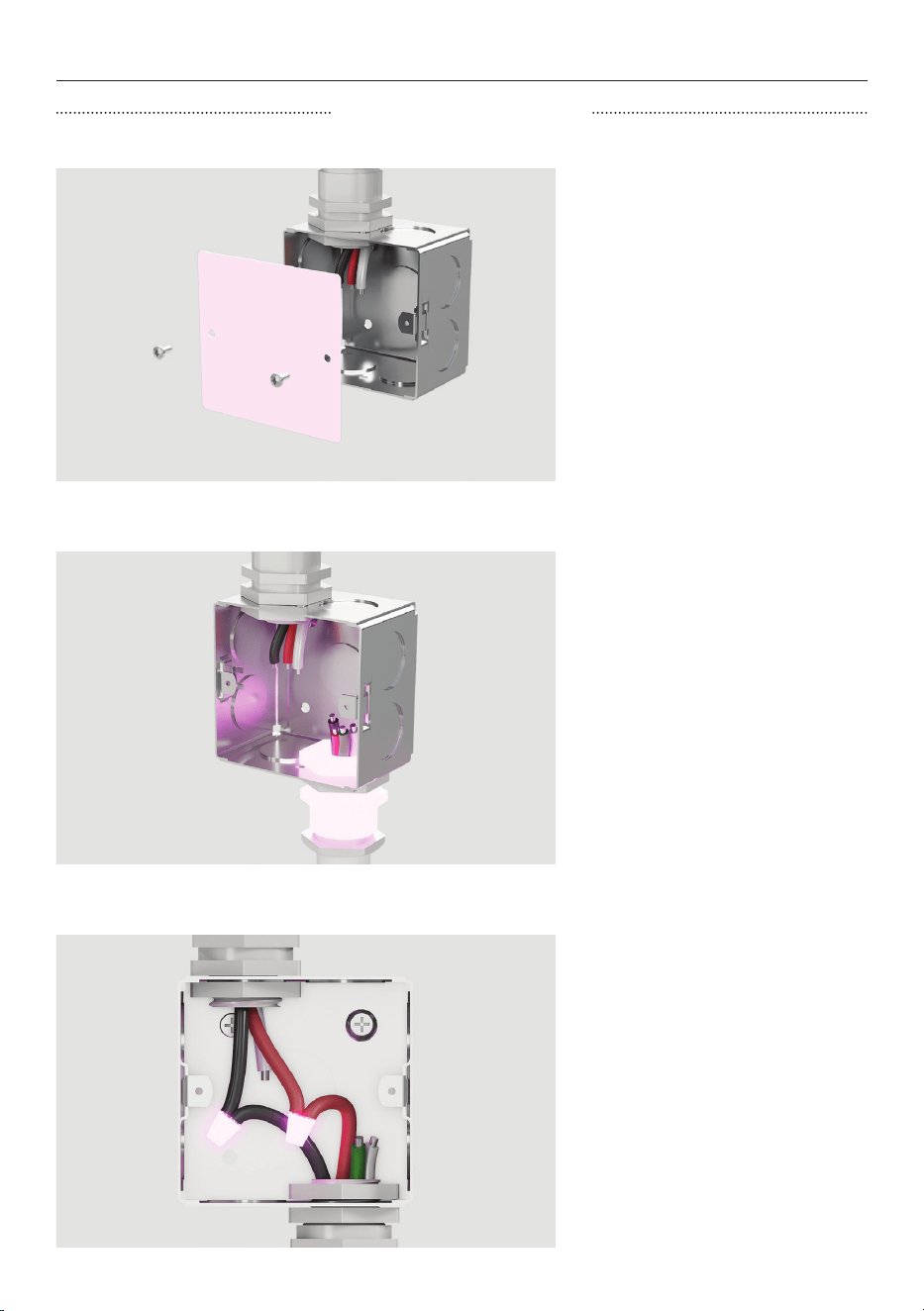
CONNECT POWER
1. Disconnect the power supply
and remove the junction box
cover.
2. Connect the oven cable to
the junction box through the
U.L-listed conduit connector.
3. Connect the two black
wires together with twist-on
connectors and the two red
wires together with twist-on
connectors.
Connect electrical connection
according to local codes and
ordinances.
THREE WIRE CONNECTION
13
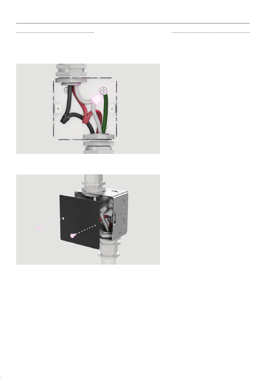
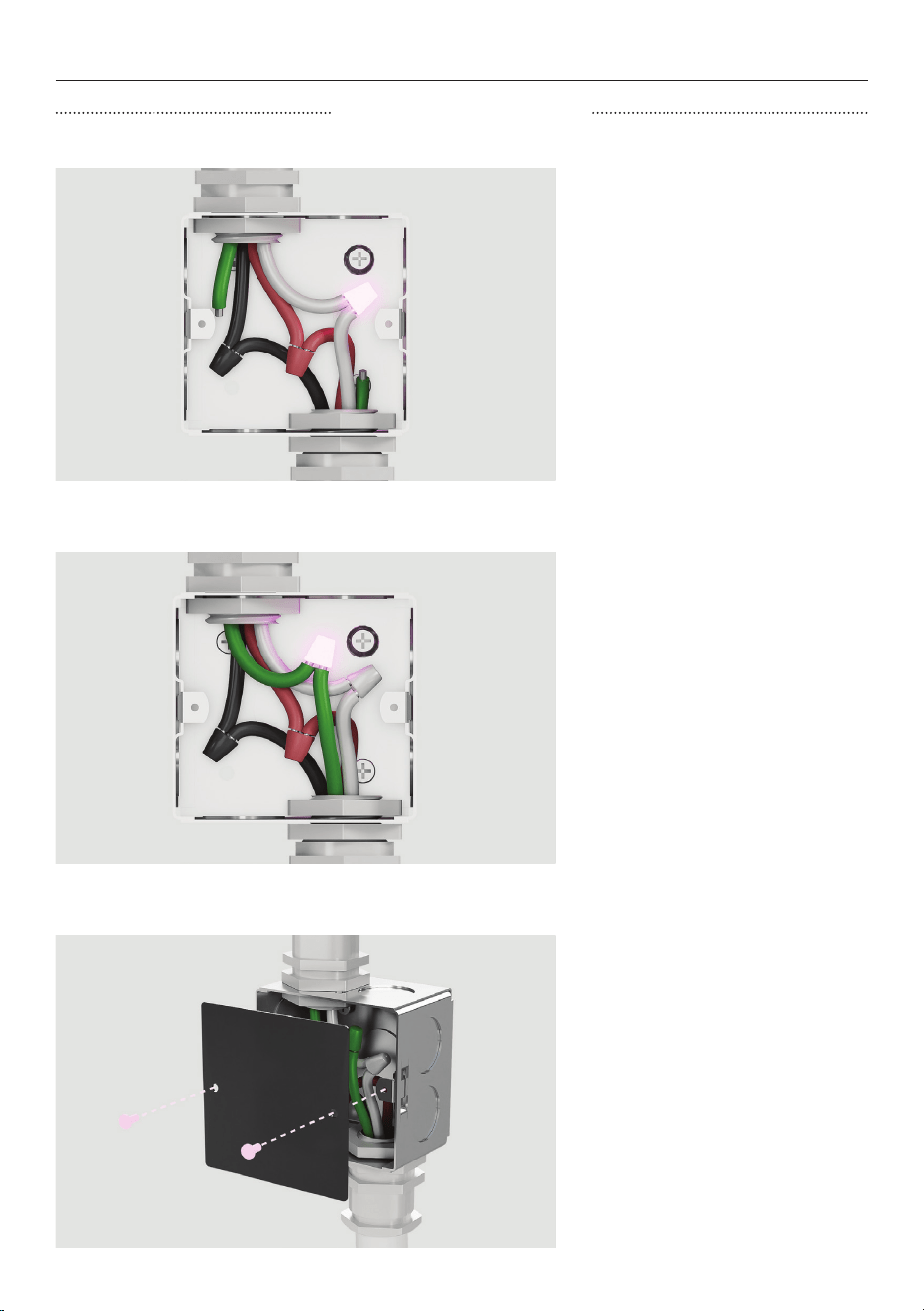
CONNECT POWER
1. Seperate the factory-
taped green and white oven
cable wires. If junction box is
grounded, connect the green
wire to the metal junction box
with a screw before connecting
the white oven cable wire to
the neutral (white) wire in
juction box.
2. Replace the junction box
cover.
THREE WIRE CONNECTION
If local codes DO NOT PERMIT connecting the cabinet-grounding conductor to the neutral
(white) wire in junction box.
14
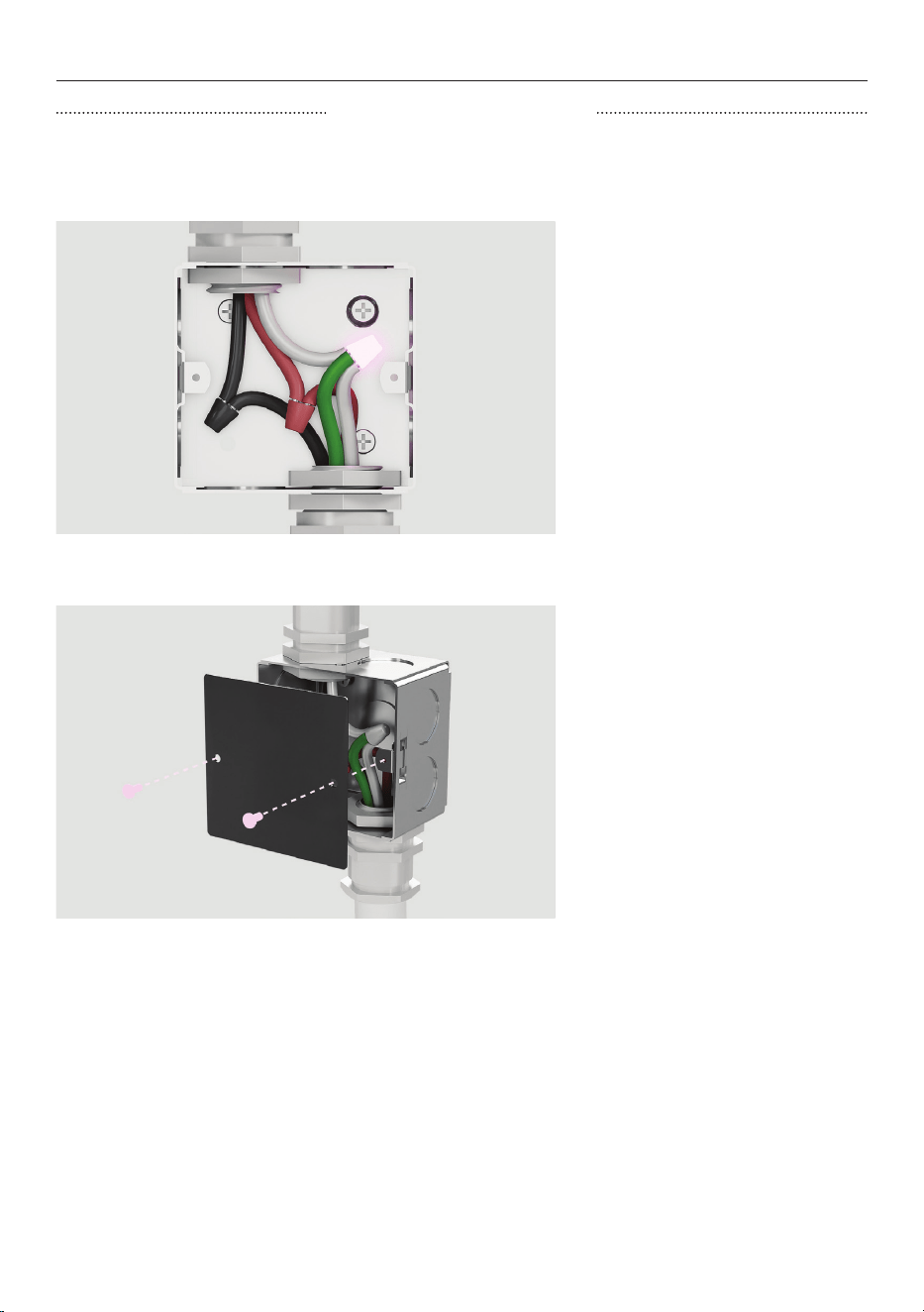
CONNECT POWER
1. Connect the factory-taped
gree and white oven wires to
the neutral (white) wire in the
junction box.
2. Replace the junction box
cover.
THREE WIRE CONNECTION
If local codes permit connecting the cabinet-grounding conductor to the neutral (white)
wire in junction box.
15
CONNECT POWER
FOUR WIRE CONNECTION
1. Disconnect the power supply
and remove the junction box
cover.
2. Connect the oven cable to
the junction box through the
U.L-listed conduit connector.
3. Connect the two black
wires together with twist-on
connectors and the two red
wires together with twist-on
connectors.
Connect electrical connection
according to local codes and
ordinances.
16
CONNECT POWER
FOUR WIRE CONNECTION
1. Seperate the green and white
oven cable wires. Connect the
white oven cable wire to the
neutral (white) wire in junction
box.
2. Connect the green grounding
oven cable wire to the (green)
grounding wire in the junction
box. Do not connect the green
grounding wire to the neutral
(white) wire in junction box.
3. Replace the junction box
cover.
17
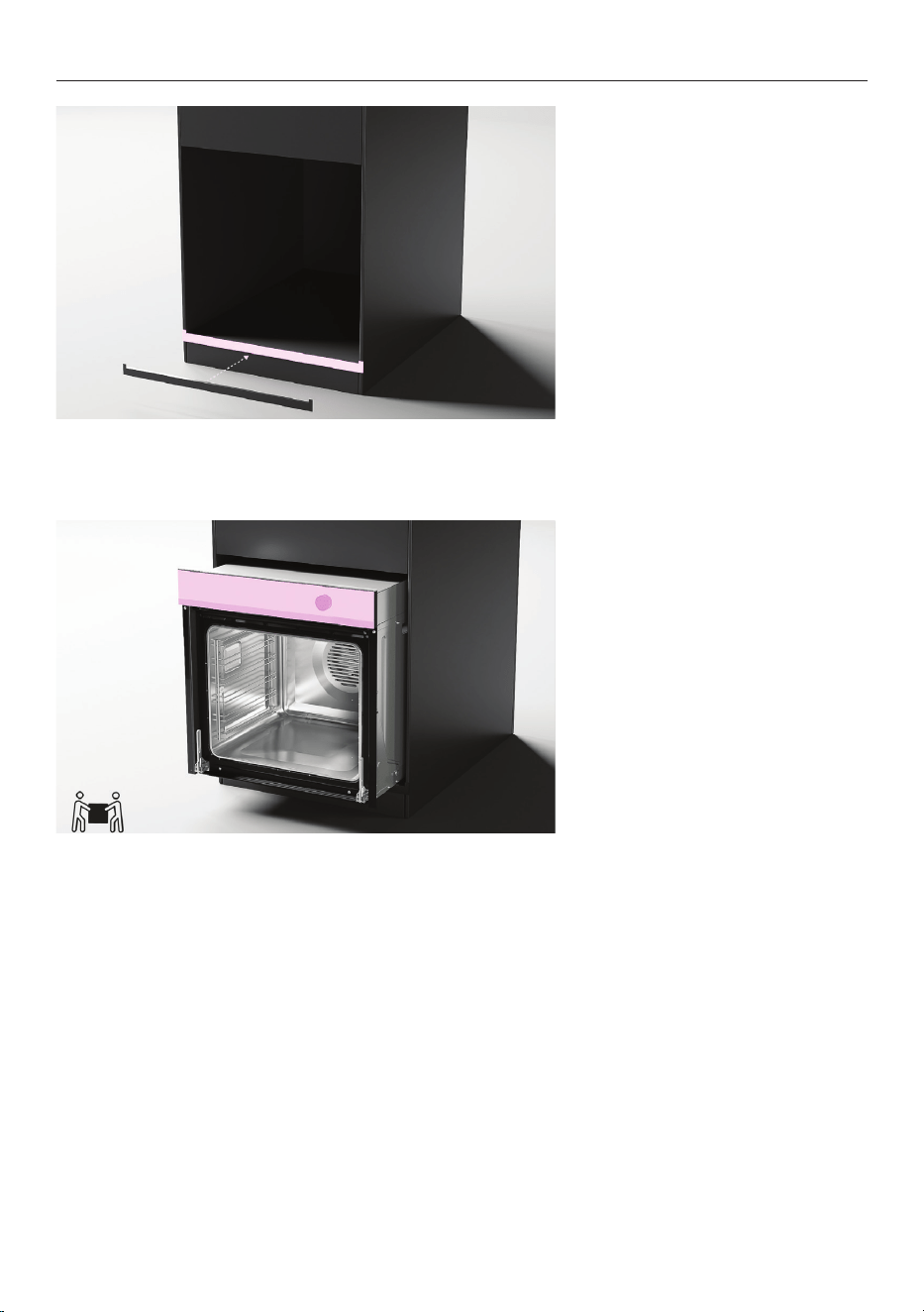
POSITION OVEN IN CAVITY
1. Some models only*
For dark cabinetry, the supplied
trim can be used to enhance
clashing finish.
To install, remove the trim
adhesive and press to secure to
cavity.
2. Ensure control panel is
closed. Lift product into cavity
taking care not to lift from the
control panel.
*To purchase cabinetry trim as an optional accessory, visit fisherpaykel.com
18
REFIT DOOR
1. Holding the door on both
sides, carefully lift door back
onto the hinges.
2. Open the door fully and push
each locking lever down and
lock into place.
3. Ensure both hinges are fully
locked before shutting the
door.
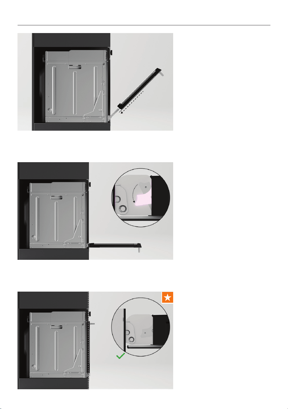
19
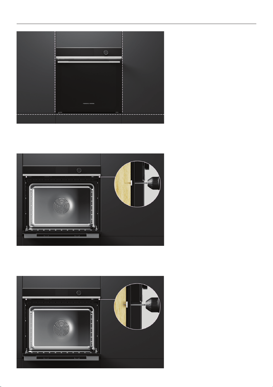
1. Align oven with surrounding
cabinetry and appliances.
2. Using the product as a guide,
pre-drill 2 x 1/8" (3mm) pilot
holes.
3. Secure oven to cavity using
the 2 x screws provided.
ALIGN AND SECURE
20
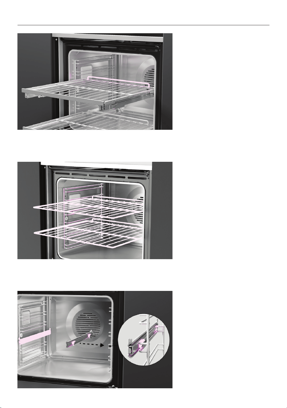
REFIT SHELVES
Sliding shelves
Place shelves back into the
oven at the desired level.
Ensure shelves are level and
correctly positioned with the
guard rail at the back.
Wire shelves
Slide shelves into the cavity.
Clip on sliding shelf supports
Ensure the slides are positioned
the correct way around, with
the triangular tab at the front.
Fit the top clips over the side
rack. The front clip should be
fitted as close to the front of
the side rack as possible. Make
sure the rear clip has engaged.
Click the bottom clips into
place.

21
ALIGN AND SECURE
1. Follow the guidance on
screen to ensure oven turns on
and heats correctly.
Refer to your User Guide for
more information.

22
Complete and keep for safe reference:
Model
Serial no.
Purchase date
Purchaser
Dealer address
Installer’s name
Installer’s signature
Installation company
Installation date
INSTALLER CHECKLIST
TO BE COMPLETED BY THE INSTALLER
F Ensure the oven is level and securely fitted to the cabinetry.
F Open the oven door slowly until it is fully open and check there is adequate clearance
between the bottom of the door and the lower trim.
This is to ensure correct air circulation. Should the lower trim become damaged,
straighten the trim and ensure the oven door opens fully without obstruction.
F Ensure all internal packaging (including the circular yellow packing retainers holding
the accessory box in place) is removed.
F Ensure all oven vents and openings are clear and free of any obstruction or damage.
Failure to make sure all oven vents are clear may result in poor product performance.
F Ensure the isolating switch is accessible by the customer.
90002693B 12.24
FISHERPAYKEL.COM

90002693B 12.24
FISHERPAYKEL.COM
© Fisher & Paykel Appliances 2024. All rights reserved.
The models shown in this guide may not be available in all markets
and are subject to change at any time.
The product specifications in this guide apply to the specific products and
models described at the date of issue. Under our policy of continuous product
improvement, these specifications may change at any time.
For current details about model and specification availability in your country,
please go to our website or contact your local Fisher&Paykel dealer.

