REV G DATE: 06/28/2023
USER MANUALS\20-88466_REVEAL_USER MANUAL_NE(L)(H)DSV_AMBIENT_SVC_SLIDE-IN_CASE
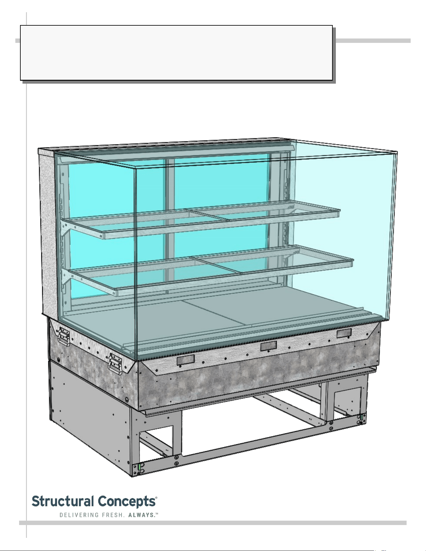
REVEAL® SLIDE-IN, DRY (AMBIENT) SERVICE MERCHANDISERS
> UV-BONDED GLASS > ADJUSTABLE SHELVES > REAR SLIDING DOORS
> CAUTION! DO NOT PUSH OR PULL ON UPPER GLASS ENCLOSURE!
> ONLY USE HANDLES (AT EACH END OF CASE) TO PUSH OR PULL CASE INTO POSITION!
Model NE4827DSV Slide-In Dry
(Ambient) Service Merchandiser
SCC P/N
20-88466
USER
MANUAL
Reveal
®
READ AND SAVE THESE INSTRUCTIONS
Structural Concepts Corp. ∙ 888 E. Porter Rd ∙ Muskegon, MI 49441 Phone: 231.798.8888 Fax: 231.798.4960 ∙ www.structuralconcepts.com
2
TABLE OF CONTENTS
TABLE OF CONTENTS …………………………………………………………………………………...…...
OVERVIEW / COMPLIANCE / LAMP REPLACEMENT / ELECTRICAL HAZARD WARNING /
WIRING DIAGRAM ……………………………………………………………………..……………...
WEIGHT LOAD ON GLASS - PREVENTING SAGGING / SEALING COUNTER-MOUNTED UNITS .
REVEAL® SLIDE-IN DRY (AMBIENT) SELF-SERVICE MODEL APPLICABILITY & DIMENSIONS..
INSTALLATION: TOE-KICK & REAR PANEL REMOVAL / REMOVING CASE FROM PALLET .…...
INSTALLATION, CONT’D: POSITIONING CASE / HANDLES ON SIDES OF CASE ………………….
INSTALLATION, CONT’D: BUBBLE-WRAPPED GLASS (FOR SHELVING) ………………………….
INSTALLATION, CONT’D: SHELVING ASSEMBLY COMPONENTS …………………………………...
INSTALLATION, CONT’D: PLUG IN UNIT / CASE ENERGIZING / UPPER & LOWER REAR
PANELS …..…………………………………………………………………………………….……….
CASE DESIGN: FRONT VIEW OF SLIDE-IN, DRY (AMBIENT) SERVICE MERCHANDISERS ...…...
CASE DESIGN, CONT’D: REAR VIEW OF SLIDE-IN, DRY (AMBIENT) SERVICE
MERCHANDISERS ..…………………………………………………………………………………...
CASE DESIGN, CONT’D: POWER CORD & PLUG / LED LIGHT SWITCH LOCATION / LED
LIGHTS ………………………………………………………………………………………………….
CASE DESIGN, CONT’D: REAR SLIDING DOORS / DOOR OPERATION …………………………….
CLEANING SCHEDULE (TO BE PERFORMED BY STORE PERSONNEL) ..…....…...…………...…..
TROUBLESHOOTING (TO BE PERFORMED BY STORE PERSONNEL) ……………………………...
TROUBLESHOOTING (TO BE PERFORMED BY TRAINED SERVICE PROVIDERS ONLY) ………..
SERIAL LABEL INFORMATION & LOCATION ..…………………………….……...…....……………..…
TECHNICAL SERVICE CONTACT INFORMATION / WARRANTY INFORMATION …………………..
2
3
4
5
6
7
8
9
10
11
12
13
14
15
16
17
18
19
3
OVERVIEW / COMPLIANCE / LAMP REPLACEMENT / ELEC. HAZARD WARNING / WIRING DIAGRAM
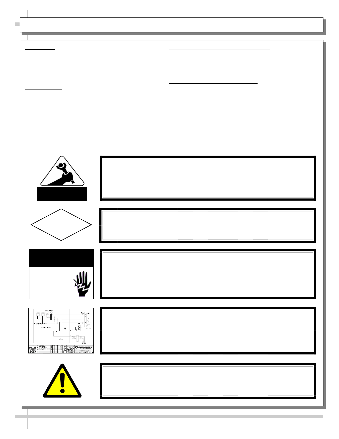
WARNING
Risk of electric shock. Disconnect power before servicing unit.
CAUTION! More than one source of electrical supply is
employed with units that have separate circuits.
Disconnect ALL ELECTRICAL SOURCES before servicing.
WARNING
ELECTRICAL
HAZARD
OVERVIEW
• Cases should be installed and operated according
to this operating manual’s instructions to insure
proper performance.
• Improper use will void warranty.
COMPLIANCE
• Performance issues when in violation of applicable
NEC, federal, state and local electrical codes are
not covered by warranty.
LAMP REPLACEMENT PRECAUTIONS
• Following lamp replacement guidelines can prevent
damage to unit.
• Please read carefully!
ELECTRICAL HAZARD WARNING
• Please read the electrical hazard warning in this
document carefully as it can prevent injury or death.
• Please read carefully!
WIRING DIAGRAM
• Each case has its own wiring diagram folded and in a packet.
• Wiring diagram placement may vary (near ballast box, field
wiring box, raceway cover, or other related location).
COMPLIANCE
This equipment MUST be installed in compliance with
all applicable NEC, federal, state and local
electrical codes.
ATTENTION
CONTRACTORS
CAUTION! LAMP REPLACEMENT PRECAUTIONS
LED lamps reflect specific size, shape and overall design.
Any replacements must meet factory specifications.
CAUTION
WIRING DIAGRAM FORMAT & LOCATION
• Each case has its own wiring diagram folded & in its own packet.
• Wiring diagram placement may vary; it may be placed near field
wiring box, raceway, or other related location.
WARNING: This product can expose you to chemicals, including
Urethane (Ethyl Carbamate), which are known to the state of
California to cause cancer and birth defects or other reproductive
harm. For more information go to P65Warnings.ca.gov.
4
WEIGHT LOAD ON GLASS - PREVENTING SAGGING / SEALING COUNTER-MOUNTED UNITS
WEIGHT LOAD ON GLASS / PREVENTING SAGGING
• Caution! To prevent sagging or breakage of glass, do not
exceed 5 LB (2.3 KG) weight load per top glass section
(between vertical supports).
• To prevent scratching or marring, do not place ANY items on
glass.
SEALING COUNTER-MOUNTED UNITS
• Proper sealing of base support to counter prevents
accumulation of dust, residue and liquids as well as
insect harborage.
• For sanitation purposes, counter-mounted units must
be sealed to counter with silicone that meets or
exceeds food grade NSF/ANSI Standard 51.
• Prior to proceeding, thoroughly clean both counter and
underside of base support to assure a secure seal.
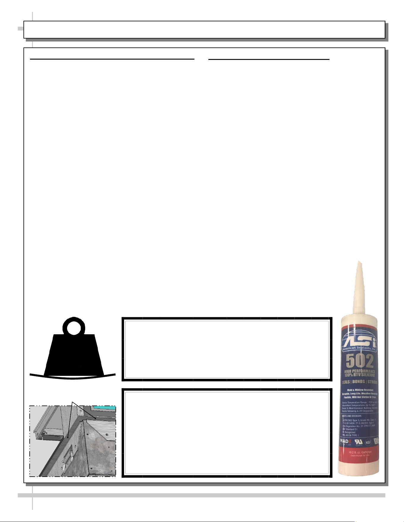
CAUTION!
• To prevent sagging or breakage, do not exceed 5 LBS
(2.3 KG) weight load per top glass section (between
vertical supports).
• To prevent scratching or marring, do not place ANY
items on glass.
5
LBS
SEAL COUNTER-MOUNTED UNITS TO COUNTER
• To assure a secure seal, thoroughly clean both coun-
ter and underside of base support prior to
proceeding.
• Apply a thin, UNINTERRUPTED bead of silicone to
underside of base support before placing into
position on counter.
• Silicone must meet or exceed food grade NSF/ANSI
Standard 51.
Base Support Underside
5
REVEAL® SLIDE-IN DRY (AMBIENT) SERVICE MODEL APPLICABILITY & DIMENSIONS
Model
Upper Display
Height
Overall Height Depth x Length
NE3613DSV 13 5/8”UDH 32 7/8”OH 33”D x 35 3/4”L
NE3620DSV 20 3/8”UDH 39 5/8”OH 33”D x 35 3/4”W
NE3627DSV 27 7/8”UDH 47 1/8”OH 33”D x 35 3/4”W
NE3635DSV 35 1/4”UDH 54 5/8”OH 33”D x 35 3/4”L
NE4813DSV 13 5/8”UDH 32 7/8”OH 33”Dx 47 3/4”L
NE4820DSV 20 3/8”UDH 39 5/8”OH 33”D x 47 3/4”L
NE4827DSV 27 7/8”UDH 47 1/8”OH 33”D x 47 3/4”L
NE4835DSV 35 1/4”UDH 54 5/8”OH 33”D x 47 3/4”L
6
INSTALLATION: TOE-KICK & REAR PANEL REMOVAL / REMOVING CASE FROM PALLET
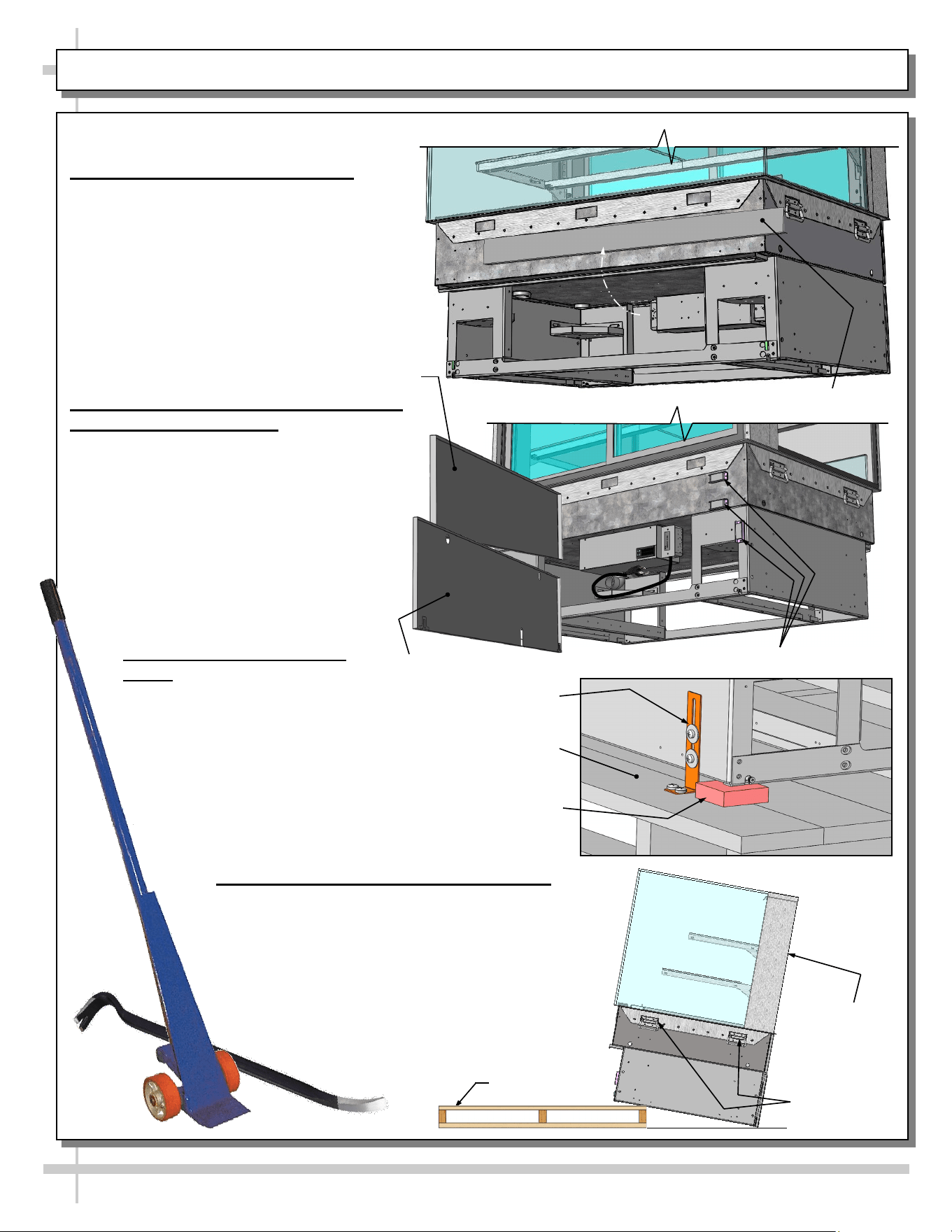
1. Remove Toe-Kick From Case
• If present, remove and discard front
toe-kick from case before removing from
pallet.
• Toe-kick is held in place by magnets
only. No screw removal is required.
2. Remove Lower and Possibly Upper
Rear Panels From Case
• Remove lower rear panels to prevent
damage to case during pallet removal.
• Drop-in units (vs. slide-in units) require
that you ALSO remove upper rear panel
to prevent damage to case.
• Also, drop-in units MAY require rear
magnets to be removed from rear for
case to fit into counter.
3. Disconnect Case From
Pallet
• Remove screws from
shipping brackets. Remove and
discard shipping brackets from pallet.
• Place J-bar/pry under base frame.
Raise case up from pallet; remove
rubber shipping blocks.
Toe-Kick
4. Carefully Remove Case From Pallet
• Use handles to carefully slide case to rear of
pallet (see illustration at right).
• Caution! 4 people are required for this
task!
• Carefully lower to floor. Slide pallet from
under case.
• Maintain support of case at all times or case
may fall.
Pallet
Support case
while removing
from pallet.
Handles
Pallet
Shipping
Bracket
Rubber
Shipping
Block
Upper Rear Panel
Lower Rear
Panel
Rear Magnets (Typ.)
7
INSTALLATION, CONT’D: POSITIONING CASE / HANDLES ON SIDES OF CASE
Handles On Side
of Case (Typ.)
Model NE4827DSV Slide-In
Unit (Shown) May Not Exactly
Reflect Every Feature or
Option of Your Particular Case.
Space For
Countertop
Base Support
Lower Magnets
Upper
Magnets
7. Prepare Case For Counter: Side Handles
> Slide-In Units: Side handles MAY remain on case if
space allows. Otherwise, remove them.
• See “Space For Countertop” shown in illustration
below.
• Keep handles in safe place for future possible
relocation use.
> Drop-In Units: Due to space restraints, REMOVE
SIDE HANDLES to allow case to fit into counter.
• Keep handles in safe place for possible future use.
• See illustration below.
5. Prepare Case For Counter: Rear Panels
• Rear panels must remain OFF case while it is
slid in (or dropped into) counter.
• Panels may be damaged if they remain on the
case while placed in counter.
6. Prepare Case For Counter: Magnets
> Slide-In Units: Rear magnets may remain on case
while SLIDING INTO counters.
> Drop-In Units: Due to space restraints, rear
magnets MAY NEED TO BE REMOVED from case
for case to fit into counter. Measure carefully!
> Lower set of magnets MAY BE REATTACHED to
case to allow lower rear panel to be held in place.
8
INSTALLATION, CONT’D: BUBBLE-WRAPPED GLASS (FOR SHELVING)
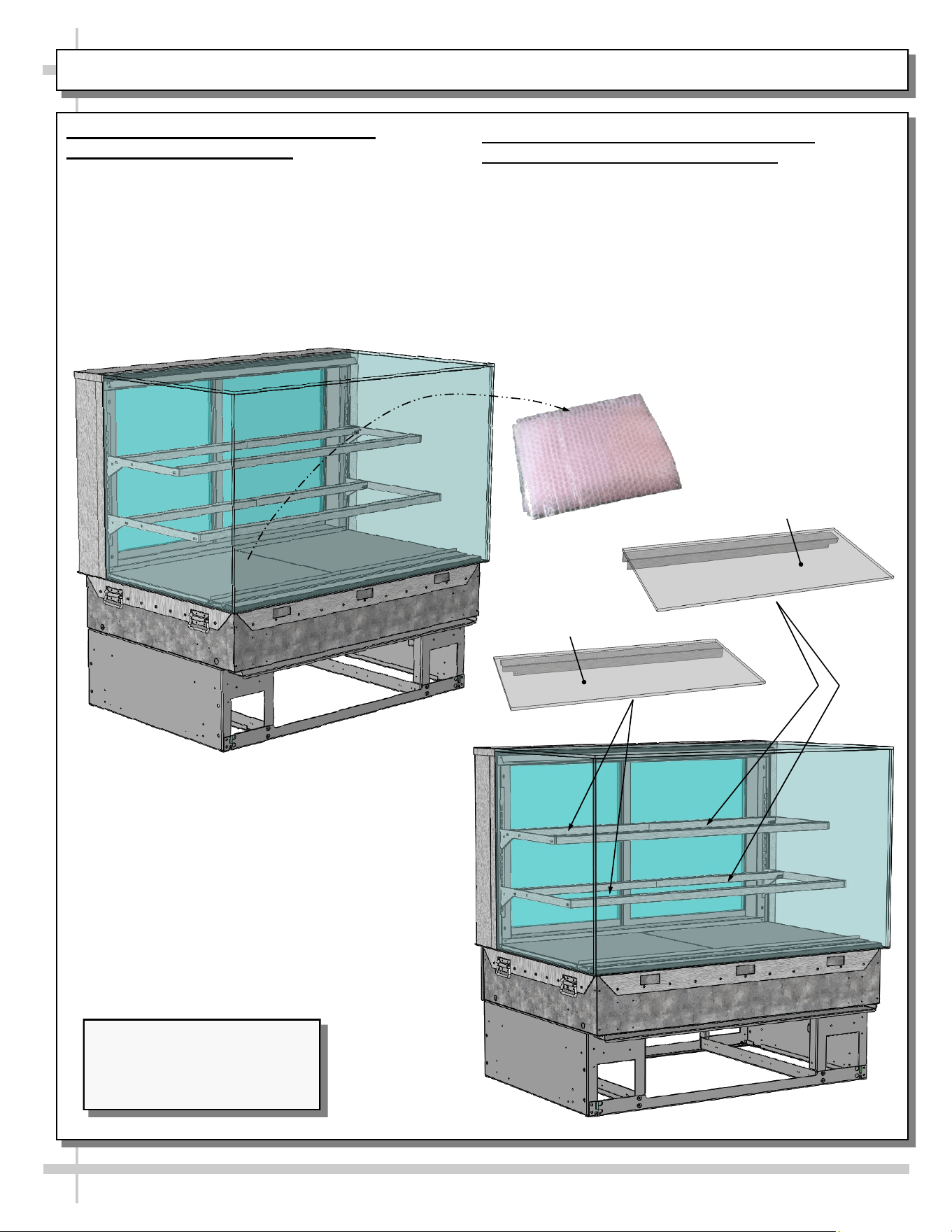
8. Remove Bubble-Wrapped Glass
(For Shelving) From Case
• Carefully remove bubble-wrapped glass shelving
pieces from case through rear sliding doors.
• See illustration below-left.
9. Remove Glass From Bubble-Wrap /
Carefully Place Them On Shelves
• Remove glass (for shelves) from its bubble-wrap.
• Place glass pieces on shelves.
• Caution! Glass pieces ARE NOT IDENTICAL!
Notches on the underside metal covers determine
placement in case.
• See illustration below-right and next page.
Model NE3635DSV Slide-In
Units (Shown) May Not Exactly
Reflect Every Feature or
Option of Your Particular Case.
Right Glass
Shelving Piece
Left Glass
Shelving Piece
9
INSTALLATION, CONT’D: SHELVING ASSEMBLY COMPONENTS
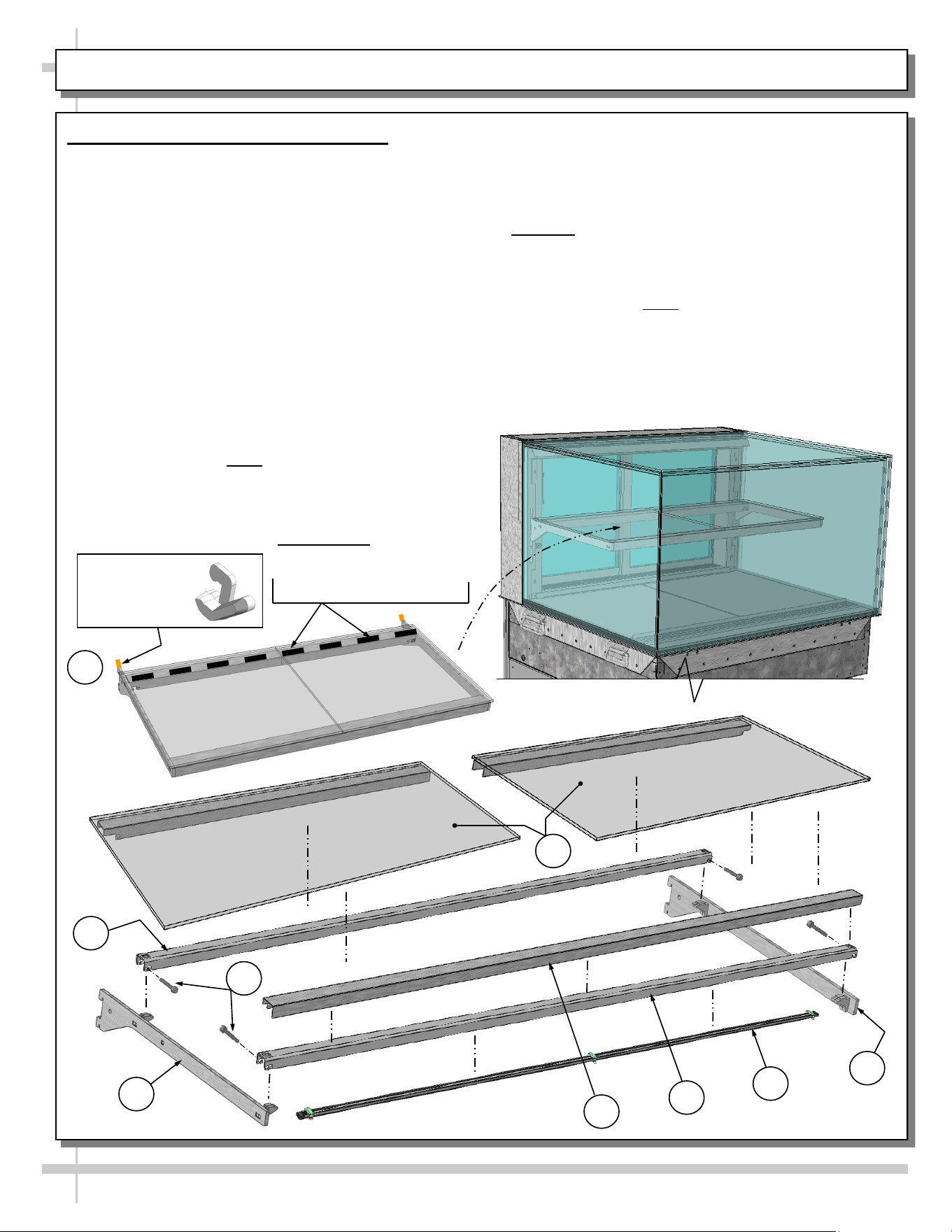
10. Shelving Assembly Components
• Check that glass shelving is in proper position
before placing product in case
• Shelves may be adjusted vertically or entirely
removed from merchandiser.
• Metal shelving brackets ARE NOT able to be
angled. They are at a fixed 90° position.
• There are 12 components comprising each
shelf assembly:
A. Right bracket (with hooks to attach to slots in
upright)
B. LED light with magnets
C. Front shelf support rail (LED light attaches to its
inner cavity via magnets)
D. Cover (rests atop front shelf support rail)
E. Left bracket (hooks to attach to slots in upright)
F. Nylon thumbscrews (4 per shelf) secure shelving
during shipment. Note: Remove (using pliers, if
necessary) and discard thumbscrews after case
is installed so shelves can be disassembled (to
clean or service).
G. Rear shelf support rail
H. Left and right glass shelf/cover assemblies (glass
is affixed to covers with 2-sided tape from factory).
Caution! Glass pieces ARE NOT IDENTICAL!
Notches on underside metal covers determine
placement in case.
I. Nylon retainer clips (2 per shelf) secure brackets
during shipment. Note: To adjust or remove
shelves, you must remove retainers; pliers may be
required to accomplish this task.
Glass Shelving
Glass Shelving
E
A
B
C
D
G
From Factory: Transparent
2-Sided Tape Holds
Glass To Top Of Rear
Shelf Support Rail
H
Right Glass
Shelving Piece
Left Glass
Shelving Piece
Nylon Retainer
Clip (Typ.)
I
F
11. Plug Case In / Case Will Energize
• Power cord with plug is factory-supplied.
• Plug case into customer-supplied electrical outlet.
Case will energize.
• Turn on LED light switch at rear-right upright.
• See illustration at right.
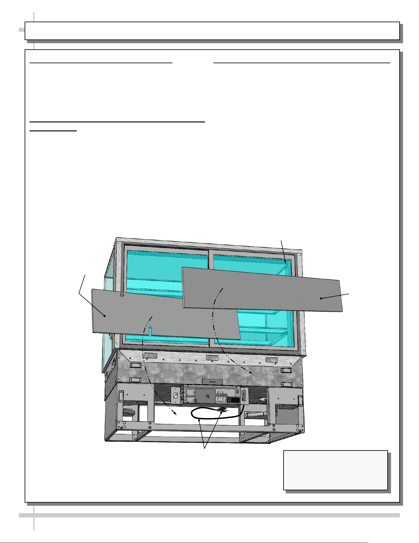
12. Slide-In Units: Reattach Upper and Lower
Rear Panels
• Rear panels are held in place by magnets.
• Lower rear panel has a slot for power cord.
• See illustration below.
10
INSTALLATION, CONT’D: PLUG IN UNIT / CASE ENERGIZING / UPPER & LOWER REAR PANELS
LED Light
Switch
Model NE4827DSV Slide-In
Units (Shown) May Not Exactly
Reflect Every Feature or
Option of Your Particular Case.
Lower Rear
Panel
Upper Rear
Panel
Power Cord
And Plug
13. Drop-In Units: Reattach Lower Rear Panel
• Lower rear panel may be attached to case after it
has been dropped in countertop.
• If lower magnets have been removed from case
(for drop-in), you must REATTACH them in same
position for lower attachment to be held in place.
• Do not return upper rear panel to case.
11
CASE DESIGN: FRONT VIEW OF SLIDE-IN, DRY (AMBIENT) SERVICE MERCHANDISERS
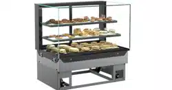
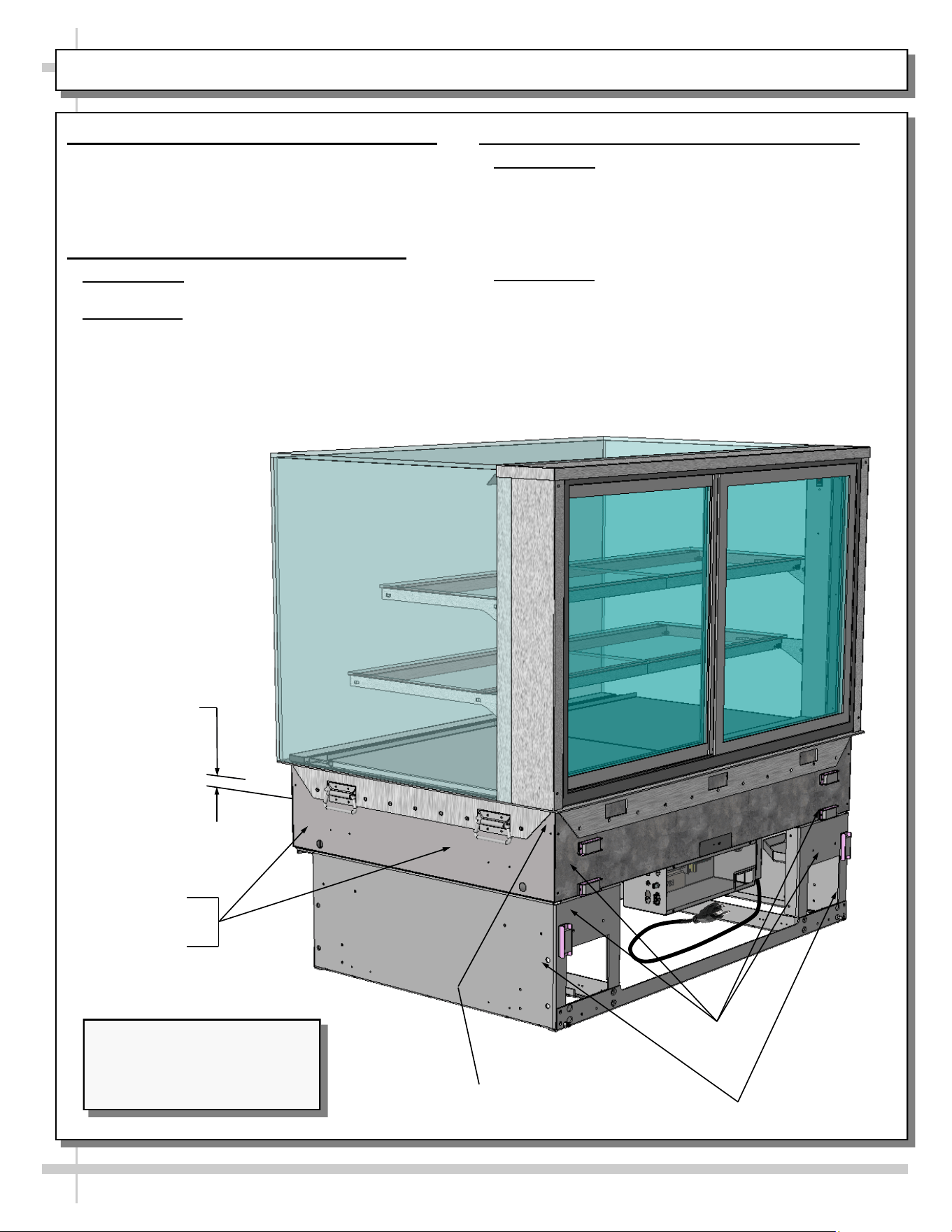
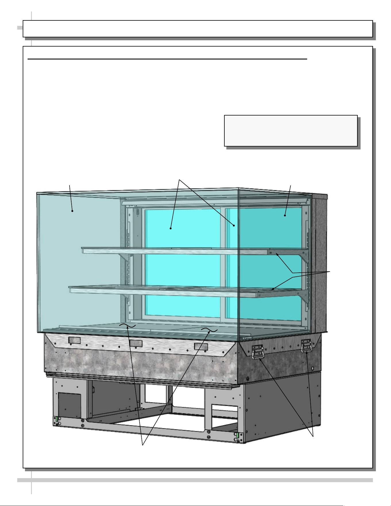
1. Case Design: Front View Of Slide-In, Dry (Ambient) Service Merchandisers
• Model NE4827DSV is illustrated below.
• See next page for rear view of merchandiser.
Deck Pans
Shelving
UV-Bonded Glass
Enclosure
Handles For
Pushing or Pulling
Unit Into Position
Model NE4827DSV Slide-In Unit (Shown)
May Not Exactly Reflect Every Feature or
Option of Your Particular Case.
Rear Sliding
Doors
UV-Bonded
Glass Enclosure
12
CASE DESIGN, CONT’D: REAR VIEW OF SLIDE-IN, DRY (AMBIENT) SERVICE MERCHANDISERS
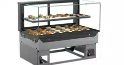
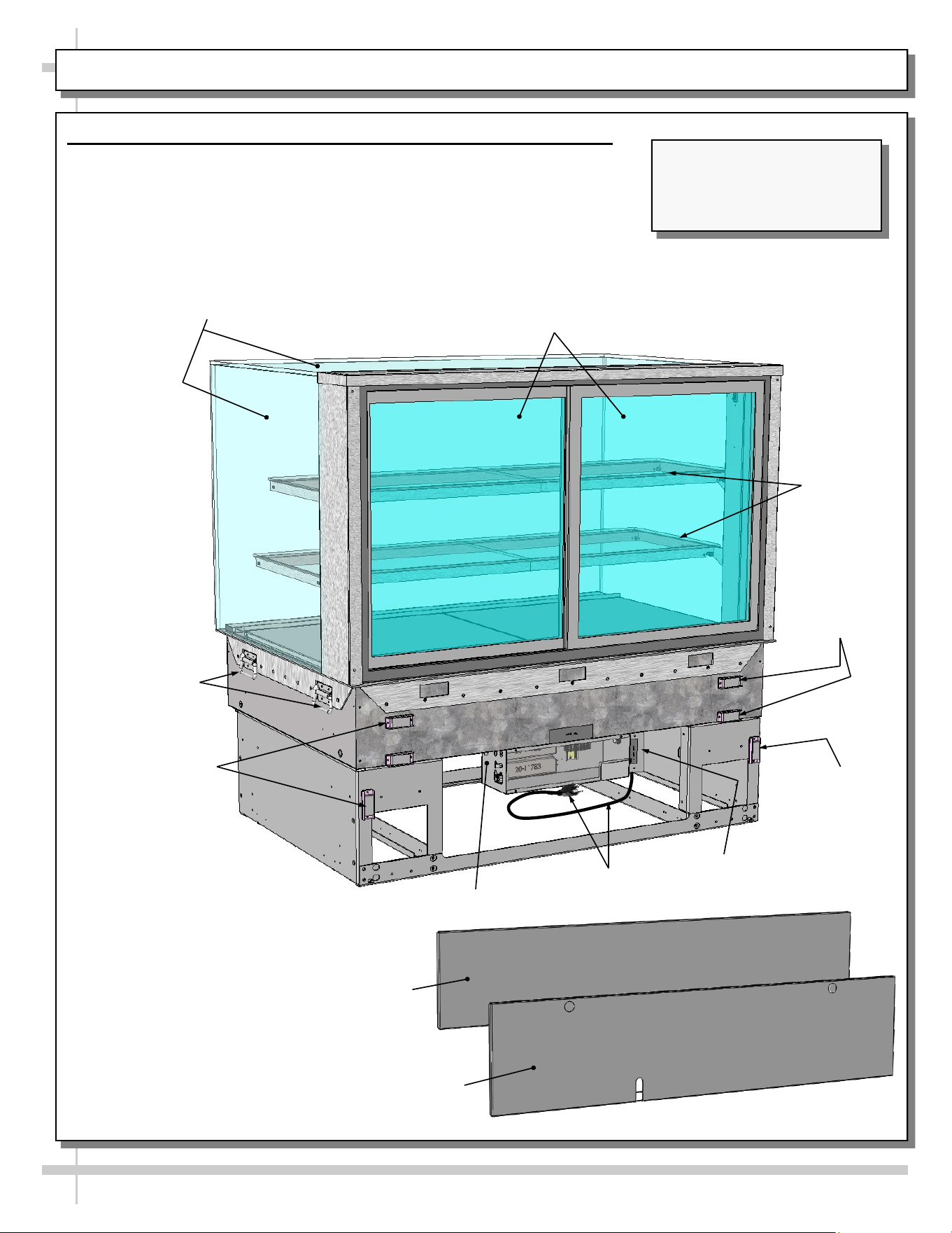
2. Case Design: Rear View Of Slide-In, Service Merchandisers
• Model NE4827DSV slide-in unit is illustrated below.
• Handles (at both ends of case) are for pushing/pulling into position.
• See previous page for front view of merchandiser.
Rear Sliding (And
Removable) Doors
Glass
Shelving
UV-Bonded Glass
Enclosure
Handles Are For
Pushing or
Pulling Unit Into
Position.
Model NE4827DSV Is Shown.
It May Not Exactly Reflect
Every Feature or Option Of
Your Particular Case.
Magnets For
Rear Panel
Upper Rear Panel
Magnet For
Lower Rear
Panel (Typ.)
Lower Rear Panel
Power Cord
And Plug
Field Access
Box
Electrical Box
Magnets For
Rear Panel
13
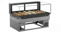
CASE DESIGN, CONT’D: POWER CORD & PLUG / LED LIGHT SWITCH LOCATION / LED LIGHTS
LED Lights In
Shelving And
Header
Model NE4835DSV
Countertop Unit (Shown) May
Not Exactly Reflect Every
Feature or Option of Your
Particular Case.
LED Light
Switch
Rear Sliding
Doors
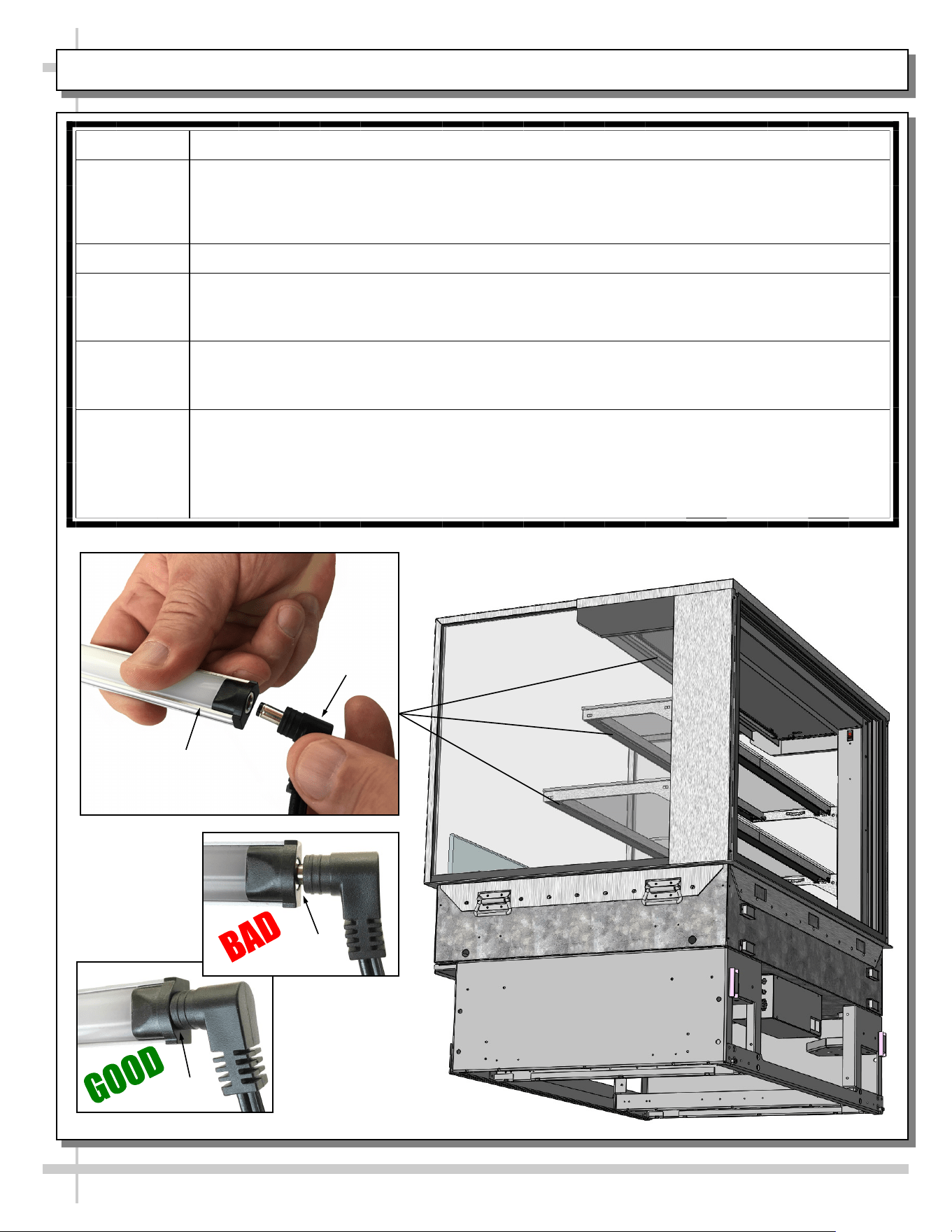
3. Power Cord and Plug
• Power cord and plug (for LED lights) is at case
rear (shown below).
• Caution! You must plugged in an approved outlet!
4. LED Light Switch Location
• Light switch is in column cover (accessible by
sliding open door at case rear).
• See illustrations below-right.
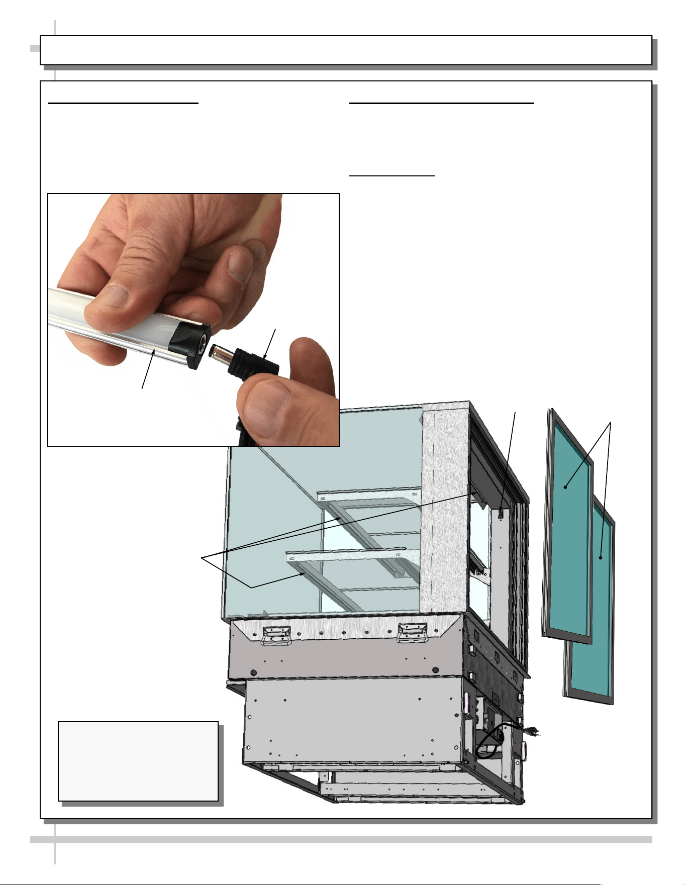
5. LED Lights
• LED lights are located at both header and
shelving of case (as shown below).
• Check that ALL of the light plugs are properly
connected to the LED light.
• Plug must be inserted ALL THE WAY into the
LED light orifice (with no gap) to work properly.
• See TROUBLESHOOTING section in manual
if LED lights malfunction.
LED Light
Plug
14
CASE DESIGN, CONT’D: REAR SLIDING DOORS / DOOR OPERATION
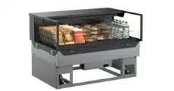
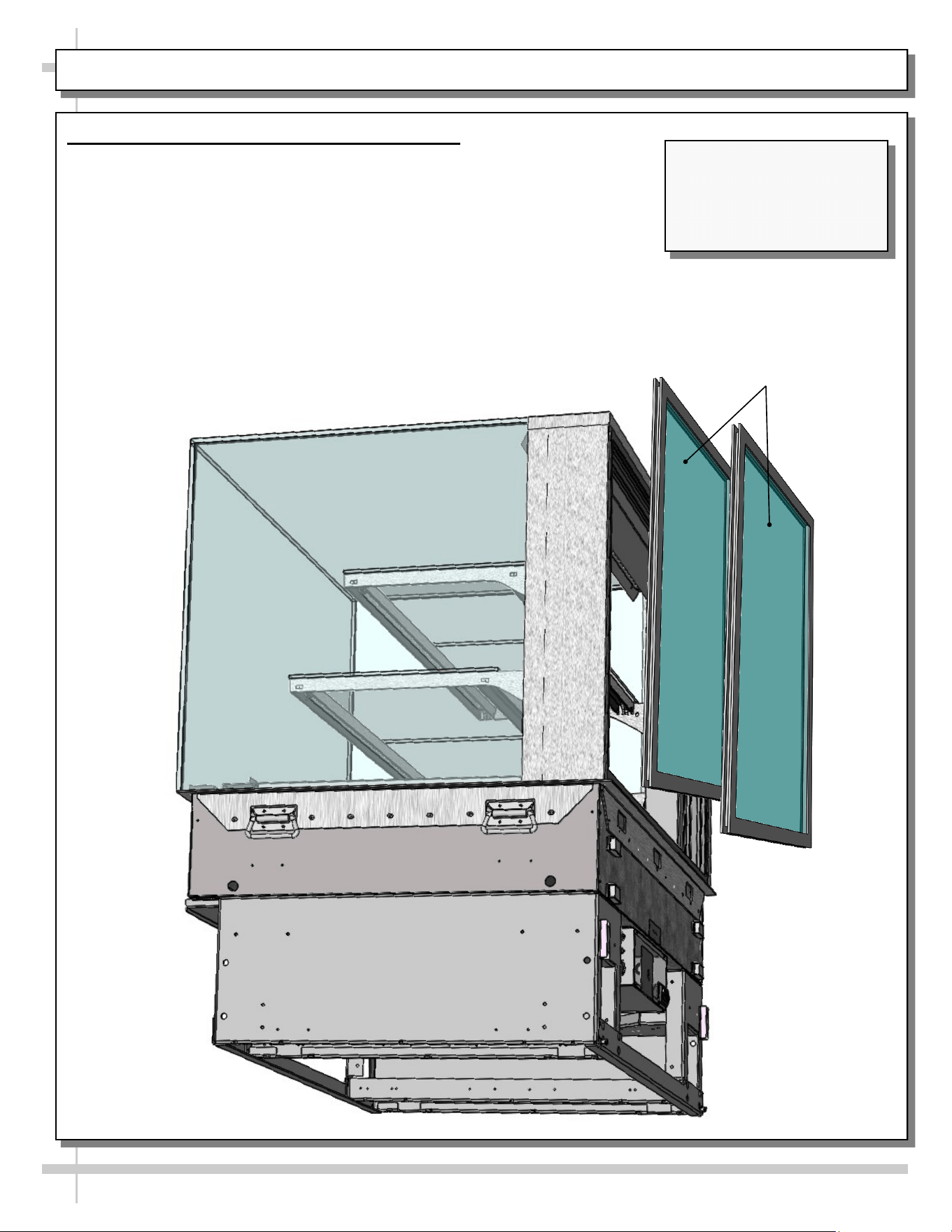
6. Rear Sliding Door Removal / Replacement
• To remove rear sliding doors, move doors toward center of case.
• Individually lift each door up toward the top of the case; pivot the bottom
of the door out.
• Return doors to case in reverse order they were removed.
Rear Sliding
Doors
Model NE4835DSV
Countertop Unit (Shown) May
Not Exactly Reflect Every
Feature or Option of Your
Particular Case.
15
CLEANING SCHEDULE (TO BE PERFORMED BY STORE PERSONNEL)
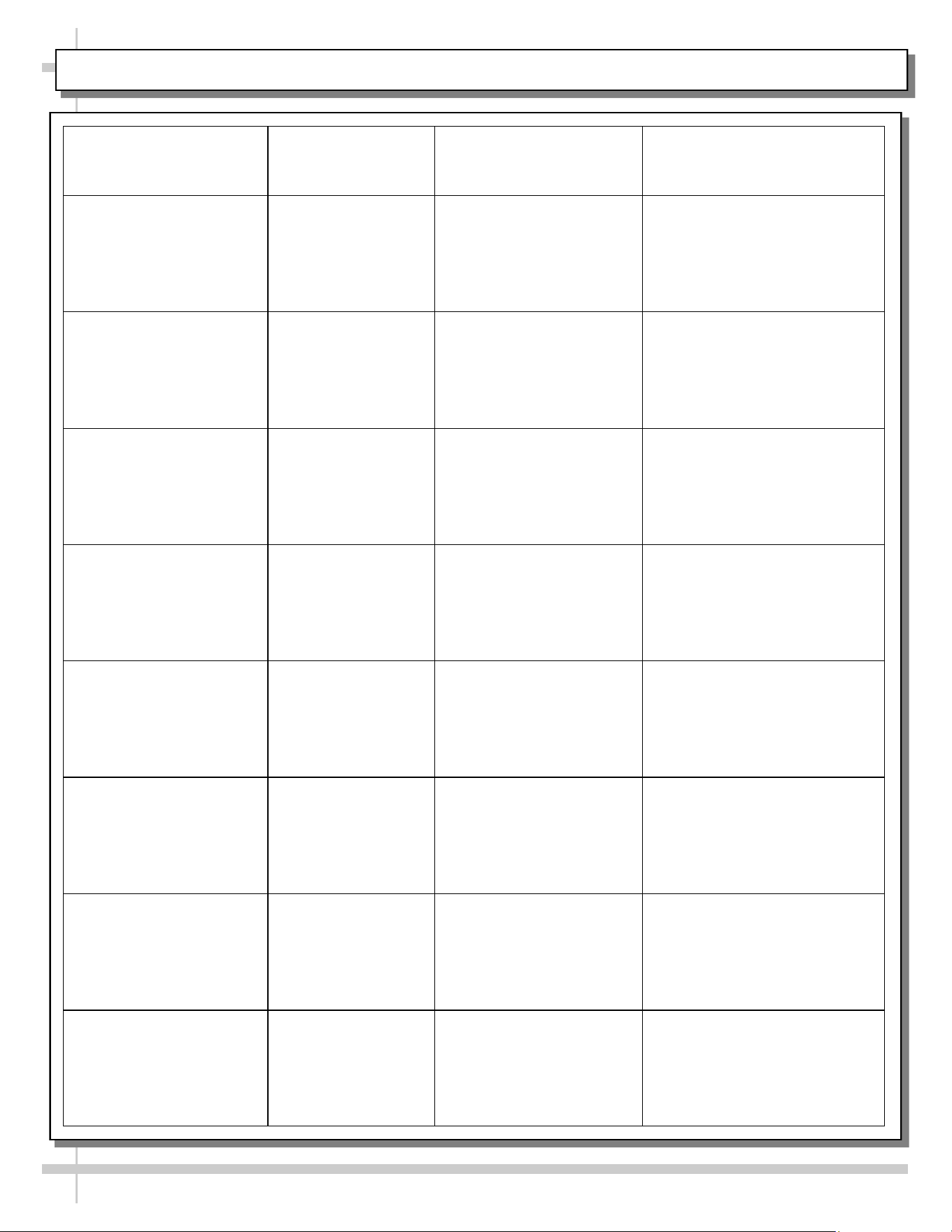
FREQUENCY INSTRUCTIONS
Daily Glass Surfaces: Clean side glass and shelves with household or commercial glass
cleaner.
Daily Rear Sliding Door Glass: Clean with household or commercial glass cleaner. Clean out
rear door track with moist cloth.
Daily End Panels, Front Panel, Toe-Kick, etc.: Wipe off all surfaces with warm water and
mild soap solution and non-abrasive cloth.
Daily Decks: Wipe off decks with moist cloth dipped in mild soap and water solution.
Daily Stainless Steel Surfaces:
• Wash with a solution of hand dishwashing liquid detergent and water, or a solution of
baking soda and water. Rinse and polish dry with paper towel or soft cloth.
• Never use scouring powders or steel wool as they will scratch stainless steel.
• Brighten by polishing with a cloth dipped in vinegar or in ammonia; sprinkle baking
soda on sponge and rub gently; rinse. Polish dry with paper towel.
• Remove streaks or heat stains from stainless steel by rubbing with club soda.
Quarterly Under Case Cleaning:
• Lower rear panel is held in place with magnets and is removable without tools.
• Remove lower rear panel by lifting up and off case. Use vacuum with brush extension
to remove all dust, dirt, food particles or residue at underside of case.
• Replace lower rear panel when cleaning process is complete.
16
TROUBLESHOOTING (TO BE PERFORMED BY STORE PERSONNEL)
CONDITION TROUBLESHOOTING
Case Lights
Not Working
Check that light switch is in the ON position.
• See CASE DESIGN, CONT’D: POWER CORD & PLUG / LED LIGHT SWITCH
LOCATION / LED LIGHTS section in manual for switch location (regardless of case
design).
If case is not hard-wired, check that power cord is properly connected to wall outlet.
Check that ALL of the light plugs are properly connected to the LED light.
• Plug must be inserted ALL THE WAY into the LED light orifice (with no gap).
• See illustrations below-left.
Power may not be reaching the case.
• Contact store management to have trained service provider perform troubleshooting.
• Troubleshooting to be performed by trained service providers only is on next page.
If case light still do not come on, it may need to be replaced.
• Contact Structural Concepts’ Technical Service Department for replacement light
(see TECHNICAL SERVICE section of this manual for contact information).
• To replace, disconnect plug from existing LED light. Disconnect LED light from its
brackets. Replace with new LED light. Insert plug ALL THE WAY into LED light orifice.
No Gap
Gap
LED Light
Plug
17
CONDITION TROUBLESHOOTING
Case Lights Are
Not Working
See TROUBLESHOOTING (TO BE PERFORMED BY STORE PERSONNEL)
section in manual (previous sheet) for most common troubleshooting solutions.
Check power.
• If power is not supplied to the case, facility may have faulty power distribution.
• If power is supplied to the case but lights are not energized, case’s power supply
may be faulty.
TROUBLESHOOTING (TO BE PERFORMED BY TRAINED SERVICE PROVIDERS ONLY)
18
SERIAL LABEL LOCATION & INFO LISTED / TECH INFO & SERVICE - AMBIENT/HEATED CASES ONLY
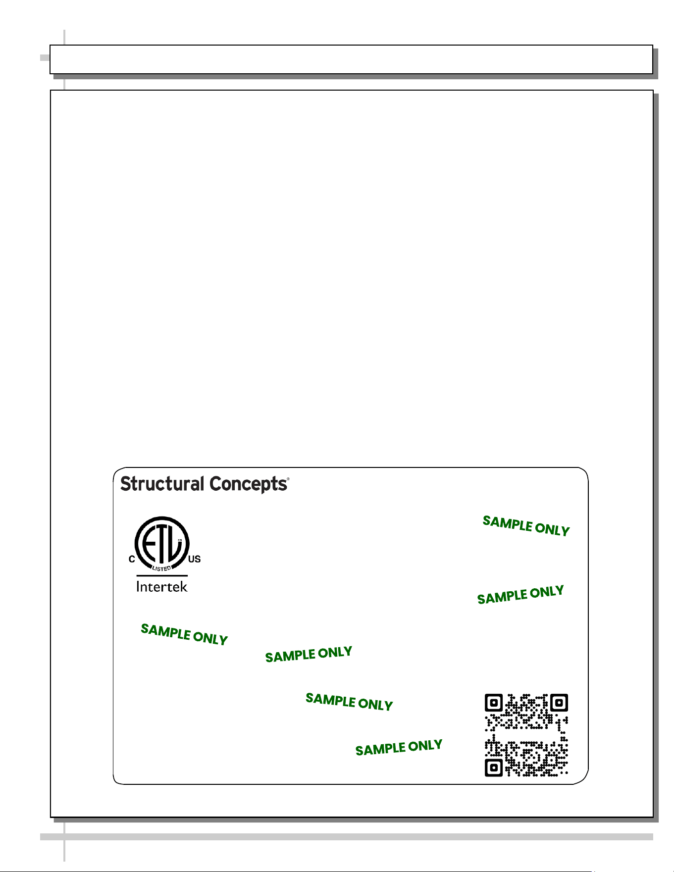
--- Sample Serial Label For Ambient/Heated Cases ---
MODEL NRS3648RXV-SAMPLE
SERIAL NO. 12345X30DZ098765
888 E. Porter Rd - Muskegon, MI 49441
3048256
Conforms to UL Std. 65
CERTIFIED TO CAN/CSA
STD C22.2 NO 120
120 VOLTS 60HZ
FOR PARTS OR SERVICE CALL
STRUCTURAL CONCEPTS
AT 1-800-433-9489
SINGLE PHASE 1.84 AMPS
Serial Label Location & Information Listed /
Technical Information & Service
• Serial labels are affixed at a wide range of places
(on the header, at case rear, behind panels or
toe-kicks, on electrical boxes, etc.).
• Serial labels contain electrical information as well
as regulatory standards to which the case
conforms.
• Sample serial label shown below.
• For additional technical information and service, see
the TECHNICAL SERVICE page in this manual for
instructions on contacting Structural Concepts’
Technical Service Department.
Sample QR Code
SCAN FOR PRODUCT LITERATURE
Reveal
STRUCTURAL CONCEPTS TECHNICAL SERVICE CONTACT INFORMATION & LIMITED WARRANTY
19
TECH SERVICE/WARRANTY CONTACT INFO:
1 (800) 433-9490 / EXTENSION 1
DAYS/HOURS AVAILABLE:
MONDAY - FRIDAY (CLOSED HOLIDAYS)
8:00 a.m. TO 5:00 p.m. EST
YOU MUST HAVE THE FOLLOWING INFO AVAILABLE
BEFORE CONTACTING STRUCTURAL CONCEPTS:
SERIAL NO. / MODEL NO. / STORE NO. / STORE
ADDRESS / DETAILS (PHOTOS, LEAK LOCATIONS,
DAMAGE, STORE’S AMBIENT CONDITIONS, ETC.)
To Access The Limited Warranty To Your
Case, Follow These Instructions:
> If Viewing This Document on Smart Phone,
Tablet or Computer, Select/Click On The QR
Code at Right.
> If Viewing This Document In Print (Hard
Copy), Scan The QR Code at Right With Your
Smart Phone or Tablet.