@2015 Shure Incorporated
User Manual EX 6010 rev I English.docx
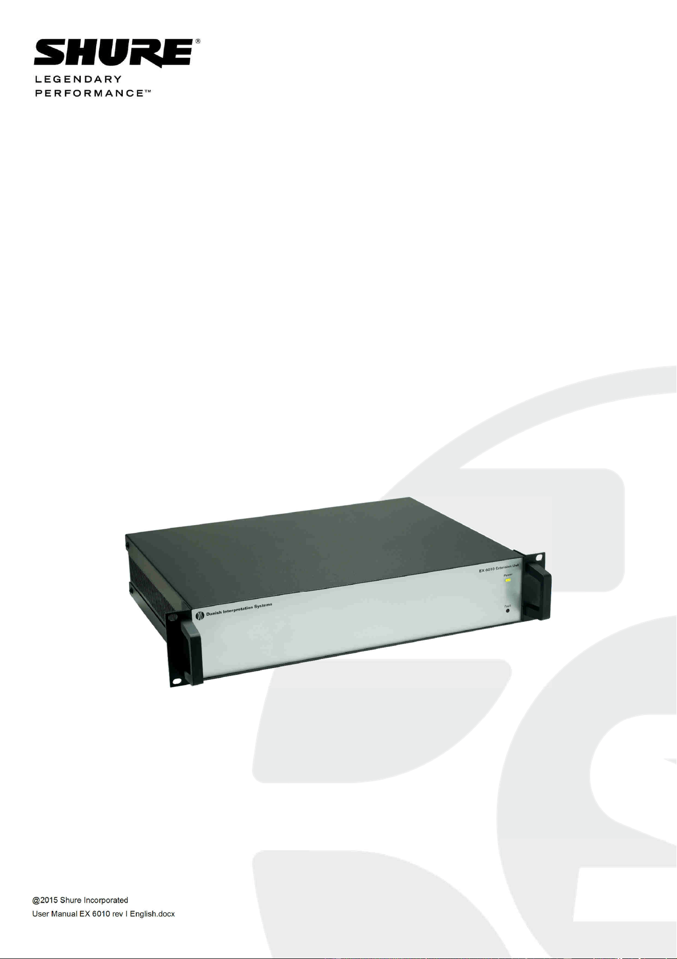
Conferencing and Discussion Systems
EX 6010 Extension Unit
USER GUIDE

DCS 6000 Digital Conference System User Manual
@2015 Shure Incorporated User Manual EX 6010 rev I English.docx
Table of Contents
Table of Contents .................................... 2
Important ................................................ 3
Important Safeguards .......................... 3
Labels .................................................. 4
Note for Power Connections .................... 4
Power Disconnect .................................. 4
Compliancy ........................................... 4
Cleaning ............................................... 5
Repacking ............................................. 5
Warranty .............................................. 5
Your DCS 6000 Conference System ......... 6
The DCS 6000 system ........................... 6
System components ............................. 7
Central equipment etc. ........................... 7
Interpreter equipment ............................ 7
Conference units and Ch. selectors .......... 7
Accessories ........................................... 7
General Description ................................. 8
Features ................................................ 8
Operating instruction............................... 9
User Controls, indications & connectors 9
Front plate layout.................................. 9
Back panel layout.................................10
System design ....................................... 11
‘Repeated chain’ connection ..................11
‘Loop through’ connection .....................12
System Setup ........................................ 13
Installation ......................................... 13
Cabling guidelines ............................... 13
Max. number of units to be connected 14
Typical schematics ................................. 16
Technical Specifications ......................... 17
Connection Details .............................. 18
Accessories ......................................... 18

DIS Digital Conference System User Manual
3
Important
Important Safeguards
1 Read these instructions - All the safety and
operating instructions should be read before
the apparatus or system is operated.
2 Keep these instructions - The important
safety instructions and operating instructions
should be retained for future reference.
3 Heed all warnings - All warnings on the
apparatus and in the operating instructions
should be adhered to.
4 Follow all instructions - All instructions for
installation or use/operating should be
followed.
5 Do not use this apparatus near water - Do
not use this apparatus in a water or moistures
environment - for example, near a bath tub,
wash bowl, kitchen sink, or laundry tub, in a
wet basement, near a swimming pool, in an
unprotected outdoor installation, or any area
which is classified as a wet location.
6 Warning: To reduce the risk of fire or
electric shock, do not expose this
apparatus to rain or moisture and no
objects filled with liquids, such as vases,
should be placed on this apparatus.
7 Clean only with dry cloth - Unplug the
apparatus from the outlet before cleaning. Do
not use liquid cleaners or aerosol cleaners.
8 Do not block any ventilation openings.
Install in accordance with the
manufacturer’s instructions - Openings in
the enclosure, if any, are provided for
ventilation and to ensure reliable operation of
the apparatus and to protect it from
overheating. These openings must not be
blocked or covered. This apparatus should not
be placed in a built-in installation unless
proper ventilation is provided or the
manufacturer’s instructions have been
adhered to.
9 Do not install near any heat sources such
as radiators, heat registers, stoves, air
ducts, or other apparatus (including
amplifiers) that produce heat.
10 Do not install the unit in a place exposed
to direct sunlight, excessive dust or
humidity, mechanical vibration or shock.
11 To avoid moisture condensations do
not install the unit where the
temperature may rise rapidly.
12 Do not defeat the safety purpose of the
polarized or ground-type plug. A
polarized plug has two blades with one
wider than the other. A grounding type plug
has two blades and a third grounding
prong. The wider blade or the third prong is
provided for your safety. If the provided
plug does not fit into your outlet, consult an
electrician for replacement of the obsolete
outlet.
13 Protect the power cord from being
walked on or pinched particularly at
plug, convenience receptacles, and the
point where they exit from the
apparatus.
14 Only use attachments/accessories
specified by the manufacturer. Any
mounting of the apparatus should follow
the manufacturer’s instructions, and should
use a mounting accessory recommended by
the manufacturer.
15 Use only with the cart, stand, tripod,
bracket or table specified by the
manufacturer, or sold with the
apparatus.
When a cart is used, use caution when moving
the cart/apparatus combination to avoid
injury from tip-over - Quick stops,
excessive force, and uneven surfaces may
cause the appliance and cart combination
to overturn.
16 Unplug this apparatus
during lighting storms or
when unused for long
periods of time. – Not
applicable when special
functions are to be maintained,
such as evacuation systems.
17 Refer all servicing to qualified service
personnel. Servicing is required when
the apparatus has been damaged in
any way, such as power-supply cord or
plug is damaged, liquid has been
spilled or objects have fallen into the
DIS Digital Conference System User Manual
4
apparatus, the apparatus has been
exposed to rain or moisture, does not
operate normally, or has been dropped.
18 Replacement Parts - When replacement
parts are required, be sure the service
technician has used replacement parts
specified by the manufacturer or having the
same characteristics as the original part.
Unauthorized substitutions may result in fire,
electric shock or other hazards.
19 Safety Check - Upon completion of any
service or repairs to this apparatus, ask the
service technician to perform safety checks to
determine that the apparatus is in proper
operating condition.
20 Overloading - Do not overload outlets and
extension cords as this can result in a risk of
fire or electric shock.
21 Power Sources - This apparatus should be
operated only from the type of power source
indicated on the marking label. If you are not
sure of the type of power supply you plan to
use, consult your appliance dealer or local
power company. For apparatuses intended to
operate from battery power, or other sources,
refer to the operating instructions.
22 Power Lines - An outdoor system should not
be located in the vicinity of overhead power
lines or other electric light or power circuits, or
where it can fall into such power lines or
circuits. When installing an outdoor system,
extreme care should be taken to keep from
activating such power lines or circuits, as
contact with them might be fatal.
23 Object and Liquid Entry - Never push
objects of any kind into this apparatus through
openings as they may touch dangerous
voltage points or short-out parts that could
result in a fire or electric shock.
Never spill liquid of any kind on the
apparatus. Should any liquid or solid object
fall into the cabinet, unplug the unit and have
it checked by qualified personnel before
operating it further.
Labels
“Lightning Flash Symbol” with
the lightning flash with
arrowhead symbol within an
equilateral triangle, is intended
to alert the user to the presence
of un-insulated "dangerous
voltage" within the product enclosure that may
be of sufficient magnitude to constitute a risk of
shock to persons.
“Exclamation Point Symbol” with the
exclamation point within an equilateral triangle
is intended to alert the user to the presence of
important operating and maintenance
(servicing) instructions in the literature
accompanying the product.
Note for Power Connections
Check that the voltage of your local
power supply is within the
operating voltage of the unit. If a
voltage conversion is required, consult your DIS
dealer or qualified personnel.
Set the Power switch to ‘Off’ if it is not used for
several days.
Important: The equipment must be connected
to earth (ground)
The wires in the main lead supplied with the
equipment are colored in accordance with the
following codes:
Green-and-yellow Earth (Ground)
Blue Neutral
Brown Live
The green-and-yellow wire must be connected
to the terminal in the plug marked with the
letter E or with the safety earth symbol or
marked with green-and-yellow color.
The blue wire must be connected to the
terminal marked with the letter N or marked
with black color.
The brown wire must be connected to the
terminal marked with the letter L or marked
with red color.
For pluggable equipment, the socket-outlet shall
be installed near the equipment and shall be
easily accessible.
Power Disconnect
Apparatuses with or without On/Off switches
have power supplied to the apparatus whenever
the power cord is inserted into the power
source; however, the apparatus is operational
only when the On/Off switch is in the On
position. The power cord is the main power
disconnect for all apparatuses.
Compliancy

DIS Digital Conference System User Manual
5
The equipment has been tested and found to
comply with the limits of the following standards
for digital devices:
• EN55103-1 (Emission)
• EN55103-2 (Immunity)
• EN60065 safety
• UL6500 safety
The device complies with part 15 of the FCC rules.
Operation is subject to the following conditions: (1)
The device may not cause harmful interference, and
(2) the device must accept any interference
received, including interference that may cause
undesired operation.
These limits are designed to provide reasonable
protection against harmful interference when the
equipment is operated in residential, commercial
or light industrial environments. The equipment
generates, uses, and can radiate radio frequency
energy and if not installed and used in accordance
with the user manual it may cause harmful
interference to radio communications.
You are cautioned that any changes or
modifications not expressly approved in this
manual could void your authority to operate this
equipment.
Operation of this equipment in residential area
is likely to cause harmful interference in which
case the user will be required to correct the
interference at his own expense. Intentional or
unintentional changes or modifications not
expressly approved by the party responsible for
compliance shall not be made. Any such
changes or modifications could void the user’s
authority to operate the equipment.
If necessary, the user should consult the dealer
or an experienced radio/ television technician
for corrective action.
Industry Canada ICES-003 Compliance
Label: CAN ICES-3 (A)/NMB-3(A)
Warning: This is a Class A product. In a
domestic environment this product may cause
radio interference in which case the user may
be required to take adequate measures.
Cleaning
To keep the cabinet in its original condition,
periodically clean it with a soft cloth. Stubborn
stains may be removed with a cloth lightly
dampened with a mild detergent solution. Never
use organic solvents such as thinners or
abrasive cleaners since these will damage the
cabinet.
Repacking
Save the original shipping cardboard box and
packing material; they will become handy if you
ever have to ship the unit. For maximum
protection, re-pack the unit as originally packed
from the factory.
Warranty
The units are minimum covered by 24 months
warranty against defects in materials or work-
manship.

DCS 6000 Digital Conference System User Manual
6
Your DCS 6000 Conference System
The DCS 6000 system
DCS 6000 Digital Conference System is a system
to be used at meetings, where a number of people
are addressing the ‘Floor’ in a structured manor.
The audio from the Conference units can be heard
in the built in loudspeakers in the units.
The system does also allow for simultaneous
interpretation for international conferences where
multiple languages are used.
To enable all participants to understand the
proceedings, interpreters can simultaneously
translate the speaker’s language as required.
These interpretations are distributed through the
connected Conference units and delegates can
select the language of their choice and listen to it
through headphones.
DCS 6000 Digital Conference System comprises of
one CU 61xx Central Unit and a number of
Conference Units, Gooseneck Microphones and
other accessories depending on the system
configuration.
The DCS 6000 system has the following main
features:
• Fully digital
• Excellent sound quality
• “State of the Art” fully digital integrated
interpretation, discussion and voting system
offering interpretation, language distribution,
conference microphone and voting facilities with
attendance check with Chip Card ™
• Digital transmission of audio from/to the
Conference unit to/from the central unit using a
unique digital DATA and AUDIO bus named
DCS-LAN
• Control of up to 3800 conference units. This
number does not include Channel Selectors,
Repeaters etc. In practical use there are no
limits for the number of Channel Selectors in a
system
• Delegate and Interpreter units are powered and
controlled by the CU 61xx Central Unit, which
drives up to app. 50 units with the PS CU power
supply
• EX 6010 Extension Unit or PS 6001 DCS-LAN
Power Kit is available if more units are required
• Delayed switching on of power to the two
DCS-LAN chains, to minimize the total ‘in-
rush’ current on the Mains supply
• Designed for 31 interpretation channels and
8 open microphones
• Audio scrambling of the audio to avoid
eavesdropping
• Designed in a standard 1HE 19” cabinet
• TCP/IP connection on CU 61xx for external
operation of the system using a PC or control
system such as AMX ® or Crestron ®
• Functionality on the CU 61xx depends on the
Feature License uploaded into the unit
• Firmware in Delegate units, Interpreter Units,
Central Units etc. is upgradeable
• Operated either stand alone or from a PC
using the CU browser or using SW 6000
software
• Added functionality and comprehensive
features provided by SW 6000 software
package running on PC
The SW 6000 is an optional software package,
which expands the functionality of the DCS
6000 system. The software runs on standard
computer technology (Standard PC with
Windows 7, Server 2008 etc.).
Main features of the SW 6000 are:
• Microphone management
• Mimic panel operation
• Interpretation management
• Voting management
• Message handling
• Agenda handling
• Data stored on SQL data base
• Web service interface available for easy links
to external applications
• Multi language user interfaces
• Supports different User types with different
priorities, user interfaces and control
possibilities

DCS 6000 Digital Conference System User Manual
7
System components
Central equipment etc.
CU 6105 Central Unit
CU 6110 Central Unit
EX 6010 Extension Unit
PS 6001 DCS-LAN Power Kit consisting of one
PS CU and one PI 6000
PS CU Power Supply
PI 6000 DCS-LAN Power Inserter
RC 6000 Redundancy Controller
AO 6004 Audio Output Unit
AO 6008 Audio Output Unit
RP 6004 Repeater for four chains
JB 6104 Junction Box with 4 outputs
SZ 6104 DCS-LAN Switcher
Interpreter equipment
IS 6132 P Interpreter Unit
LS 6132 P Interpreter Loudspeaker
Conference units and Ch. selectors
DC 6990 P Conference Unit (portable) with touch
screen with two built-in channel
selector, Chip-card and 5 voting
buttons, configurable as Delegate,
Dual Delegate or Chairman.
DC 6120 P Conference Unit (portable)
DC 6190 P Conference Unit (portable) with two
built-in channel selectors
DM 6680 P Conference Unit (portable) with voting
CM/DM 6080 F Conference Unit (flush mounted)
with built-in channel selectors
DM 6620 F Conference Unit (flush
mounted) with, Chip-card and 5
voting buttons
CM/DM 6680 F Conference Unit (flush
mounted) with one built-in
channel selector, Chip-card and
5 voting buttons
MU 6040 C/D Microphone Unit for use with
FD/FC front plate with
Loudspeaker, Microphone and
Buttons. Available in Delegate
(D) and Chairman (C) version
MU 6042 D Dual Microphone Unit for use
with FD/FC front plate with
Loudspeaker, Microphone and
two delegate Buttons
DV 6501 F Voting Unit
AM 6040 Ambient Microphone Unit
CS 6340 FV/FH Channel Selector (flush
mounted)
Accessories
In addition to the unit a number of accessories
are available like:
• Storage Boxes
• GM 6523 Gooseneck Microphone, 40 cm
• GM 6524 Gooseneck Microphone, 50 cm
• GM 6525 Gooseneck Microphone, 63 cm
• DH 6021 Delegate Headphone
• DH 6223 Stethoscope Headphone
• DH 6225 Ear Clip Headphone
For detailed instruction in how to use the above
units, please refer to the User Manuals for the
relevant products.

DCS 6000 Digital Conference System User Manual
8
General Description
The EX 6010 Extension Unit provides additional
Power Supplies, Repeater and Splitter
functionality for the DCS 6000 system. One CU
6105 or CU 6110 Central Unit is needed in each
DCS 6000 system, however for expansion of the
system the EX 6010 Extension Unit is suitable.
The EX 6010 consist of two main parts, which are
built into a 19” cabinet:
• Repeater/splitter board with 4 individual
outputs
• 4 individual power supplies.
Features
The main features of the EX 6010 Extension Unit
are:
• Built in Power Supplies for app 200 units
(Conference Units) or app. 600 Channel
Selectors
• 4 outputs for connection to Delegate Units,
Interpreter Units etc.
• Loop through connectors for connection
additional EX 6010 or other units, which are
part of the DCS 6000 system
• Delayed switching on of power to the four
chains, to minimise the total ‘in rush’ current
on the Mains supply.
• Designed in a standard 2HE 19” cabinet.
DCS 6000 Digital Conference System User Manual
9
Operating instruction
User Controls, indications & connectors
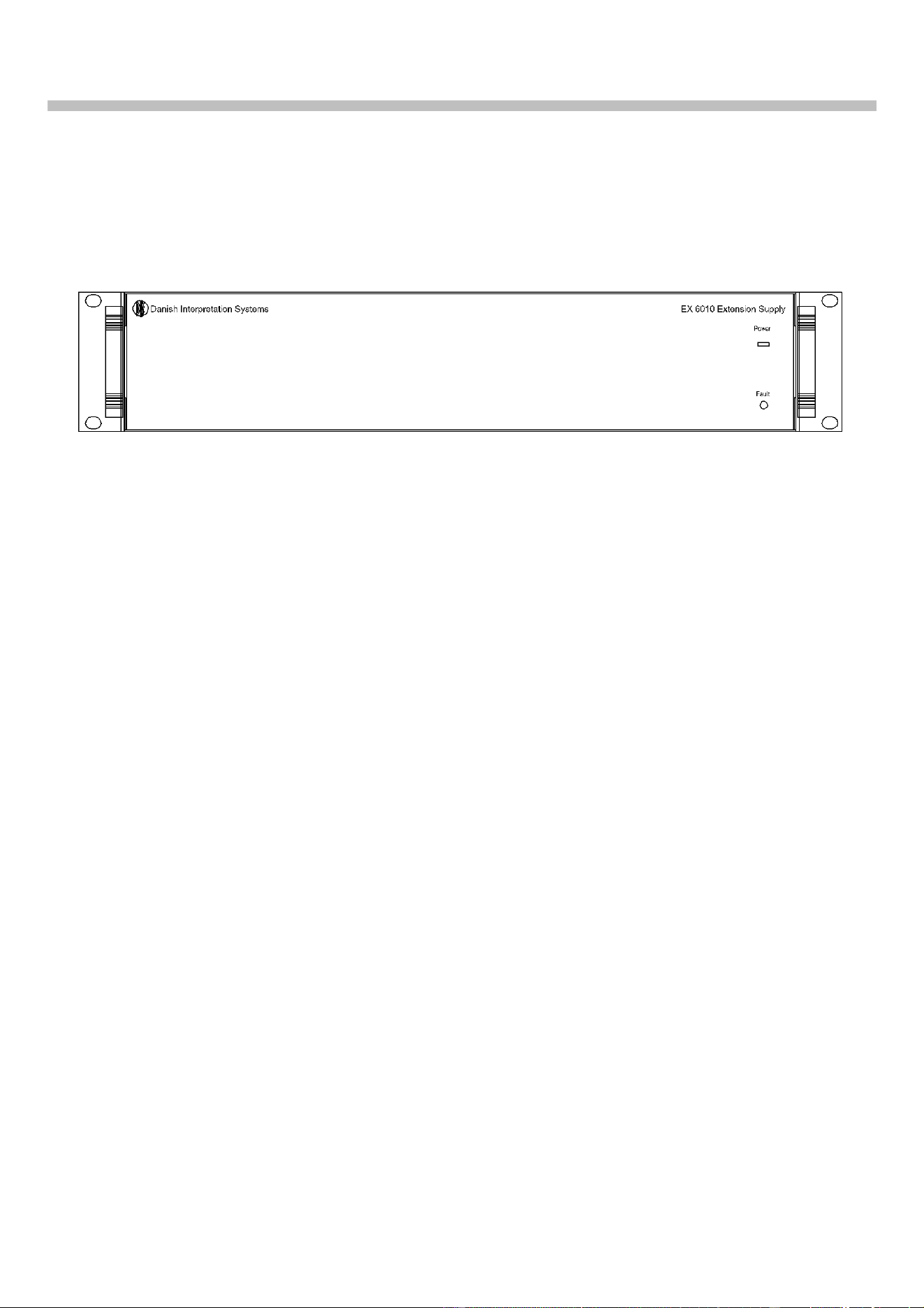
Front plate layout
Front plate controls
The EX 6010 Extension Unit features the following
controls and display:
1. Power Led
When power is switched ON at the CU 6105 or CU
6110 Central Unit any connected EX 6010
Extension Units will automatically be powered up.
An LED indicates when power is switched ON.
2. Fault LED
This indication lights up, if the internal power
supply is malfunctioning i.e. because of
overheating or overload of a chain.
The Fault LED will always light up some seconds
after the unit is switched on caused by the
delayed switching on of the four supplies.
As a warning the light is flashing at an internal
temperature above 45°C. At a temperature
above 55°C or if one of the DCS-LAN outputs is
supplying no voltage, the LED is lighting
constantly.
Please note that the maximum ambient
temperature for the CU 6105 or CU 6110 is 40
deg. Celsius.
DCS 6000 Digital Conference System User Manual
10
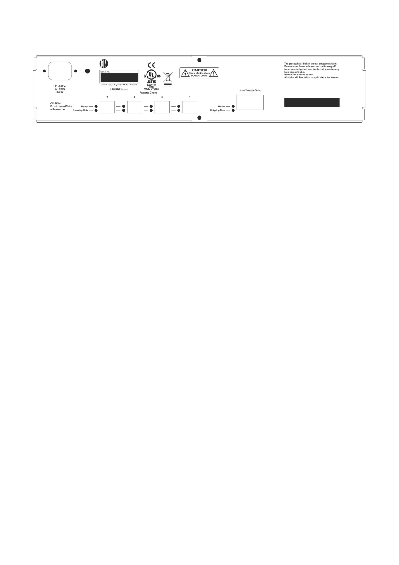
Back panel layout
Connectors
3. Mains Power connector
Connection for mains power. See specs.
4. Loop through connectors
RJ45 connector, 2 pieces with auto-termination
DCS-LAN connectors for connection to the CU
6105 or CU 6110 and for connection to other units
with DCS-LAN connectors, such as more EX 6010.
5. Repeated Chains 1, 2, 3 & 4
RJ45 connector, 4 pieces
Those connectors are DCS-LAN connectors for
connection to DM/CM 6xxx, IS 6132, CS 6032, EX
6010, AO 6004/6008 etc.
6. Power LED’s
Those LED’s light up when Power is available on
the connector next to the LED and only if the
voltage is over 24V (not overloaded).
7. Incoming data LED’s
Those LED’s lights up, when the unit is received
in-coming data from connected units on the
connector next to the LED.
8. Outgoing data LED
This LED lights up when outgoing data is
received from the central unit
DCS 6000 Digital Conference System User Manual
11
System design
There are no settings to be done on the EX 6010
Extension Unit.
However it is important to observe, that the unit is
only repeating one of the chains on the CU 6105 or
CU 6110 Central Unit.
So when designing a system to incorporate EX
6010 Extension units, bear in mind, that as the EX
6010 Extension Unit is repeating only one of the
two outputs on CU 6105 or one of the four outputs
on CU 6110, the max. number of languages
configured on the four outputs (1, 2, 3 and 4) is
totally max. 16.
If more languages are required, Interpreter sets
for those languages have to be connected either
to another EX 6010 Extension Unit, which is
connected to another of the four chains on the
CU 6110, or directly to one other of the four
chains on a CU 6110.
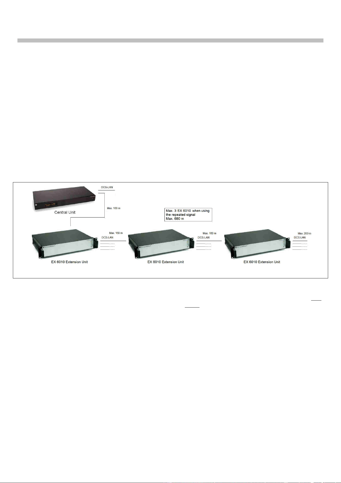
‘Repeated chain’ connection
Figure 0-A Repeated Chain connection
When connecting the EX 6010 Extension Units to
the CU 6105 or CU 6110, the first EX is connected
to the ‘Loop through’ connector.
The next EX 6010 Extension units can be
connected to either the other ‘Loop through’
connector or to one of the ‘Repeated out’
connectors. If using the ‘Repeated’ outputs two
more EX 6010 Extension units (or RP 6004
Repeaters) can be connected extending the
maximum cable length in one chain up to 680
m. The above schematic is showing the
connection using the ‘‘Repeated chains’
connectors.
DCS 6000 Digital Conference System User Manual
12
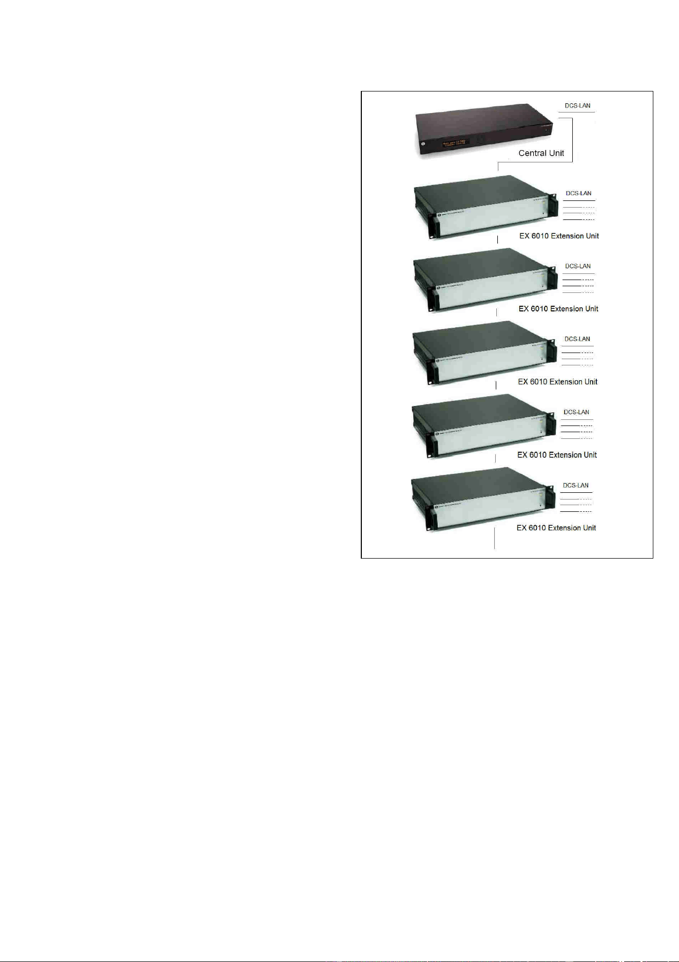
‘Loop through’ connection
When connecting a number of EX 6010 Extension
Units to the CU 6105 or CU 6110 an almost
unlimited number of EX 6010 can be connected by
using the ‘Loop through’ connector.
However the practical limitation is the maximum
cable length in one chain, which is 200 m and the
supply of power to the ‘Loop Through’ connectors
at the EX 6010.
The following schematic is showing the
connections using the ‘Loop through’ connectors.
Figure 0-B Loop through connection
DCS 6000 Digital Conference System User Manual
13
System Setup
Installation
The EX 6010 is suitable for either table-top or
19-inch rack-mounted use. Two mounting
brackets (for rack mounting) are supplied.
When installing in a 19” rack the supplied 19”
brackets shall be used.
The unit has a low noise built-in fan taking air in
at the left side of the unit and blowing the hot air
out at the right side. That allows units in 19”
racks to be stacked close with other units without
extra room for cooling air between them.
Please check that other units in the rack will
allow this.
Connect the EX 6010 to the various DCS 6000
units using CAT5e cabling (F/UTP or U/FTP)
shielded cables following the guidelines in the
next chapter.
The operation and installation of the various DCS
6000 units is found in the User Manuals for the
specific units.
Cabling guidelines
The Conference Units are connected to the CU
61xx Central Unit using Cat5e F/UTP or U/FTP
shielded cables and the following guidelines have
to be observed:
• The Conference units are daisy chain
connected to the central unit
• The number of units, which can be connected
to EX 6010, depends on length of the feeding
cable and the length of the cable between each
unit.
If the feeding cables are short and the cables
between the units are short, more units can
be connected than if the feeding cable is long
and/or the cables are long between the units.
• Maximum cable length in one chain is 200 m
(before using EX 6010 or a RP 6004 Repeater
in a chain). This includes interconnection
cables between the units.
• Maximum cable length in one chain when using
EX 6010 or RP 6004 Repeaters and Cat5e
cables is 680 m.
• Cables must be AWG24 if the number of units
in the tables in section ‘0
• ’ is to be used. AWG26 cables will not allow as
many units. DIS cables series EC 6001-xx are
all AWG 24.
• It is desirable that the square of the feeding
cables is as big as possible to minimize the
voltage drop in the cables. Cat5e cables are
delivered in various gauges:
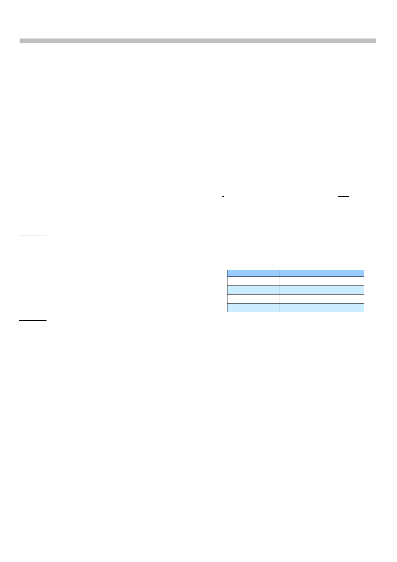
The following table shows the
Diameter/square for various AWG types:
Type Diameter Square
AWG22 0.64 mm 0.32 mm2
AWG23/1 0.57 mm 0.25 mm2
AWG24 0.53 mm 0.22 mm2
AWG26 0.42 mm 0.14 mm2
Although the DCS-LAN chain output connectors
have a 125 W supply, this 125 W power is not all
available with long cables, as there will be a
power drop in the feeding cable from the EX
6010 to the units connected.
Please consult the next sections for details about
the number of units, which can be connected
depending on the cable length.
DCS 6000 Digital Conference System User Manual
14
Max. number of units to be connected
The following tables shows the maximum number
of units, which can be connected to each DCS-
LAN output of an EX 6010.
In the tables the ‘Feeding Cable’ is defined as the
cable between the EX 6010 and the first
Conference Unit and the ‘Interconnecting Cable is
defined as the cable connecting two conference
units.
The following tables show the maximum number
of units, which can be connected to each DCS-
LAN chain output
The same numbers are valid for the output of a
PS 6001.
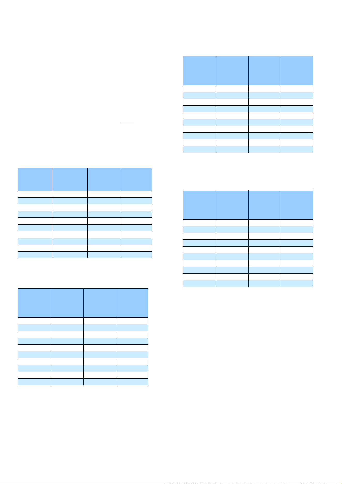
DC 6120 P, DC 6190 P, DM 6680 P Conference
Units
Length of
Feeding Cable
Type CAT5e
AWG24
Length of inter
connecting
Cable, Type
CAT5e AWG24
Total cable
length
Max. number
of units pr
output
10 m 1 m 51 m 42
30 m 1 m 67 m 38
50 m 1 m 83 m 34
100 m 1 m 122 m 23
150 m 1 m 165 m 16
10 m 2 m 88 m 40
30 m 2 m 98 m 35
50 m 2 m 108 m 30
100 m 2 m 140 m 21
150 m 2 m 178 m 15
Figure 0-A DC 6120 P, DC 6190 P or DM 6680 P Conference
Units connected
DC 6990 P Conference Unit
Length of
Feeding Cable
Type CAT5e
AWG24
Length of inter
connecting
Cable, Type
CAT5e AWG24
Total cable
length
Max. number
of DC 6990 P
pr. output
10 m 1 m 35 m 26
30 m 1 m 53 m 24
50 m 1 m 70 m 21
100 m 1 m 112 m 13
150 m 1 m 158 m 9
10 m 2 m 56 m 25
30 m 2 m 72 m 22
50 m 2 m 90 m 19
100 m 2 m 124 m 13
150 m 2 m 166 m 9
Figure 0-B DC 6990 P Conference Units connected
CM/DM 6080 F / DM 6620 F Chairman/Delegate
Length of
Feeding Cable
Type CAT5e
AWG24
Length of inter
connecting
Cable, Type
CAT5e AWG24
Total cable
length
Max. number
of DC 61xxP
pr. output
10 m 1 m 39 m 30
30 m 1 m 56 m 27
50 m 1 m 73 m 24
100 m 1 m 115 m 16
150 m 1 m 160 m 11
10 m 2 m 64 m 28
30 m 2 m 78 m 25
50 m 2 m 94 m 23
100 m 2 m 130 m 16
150 m 2 m 170 m 11
Figure 0-C CM/DM 6080 F or DM 6620 F Chairman/Delegate
Units connected
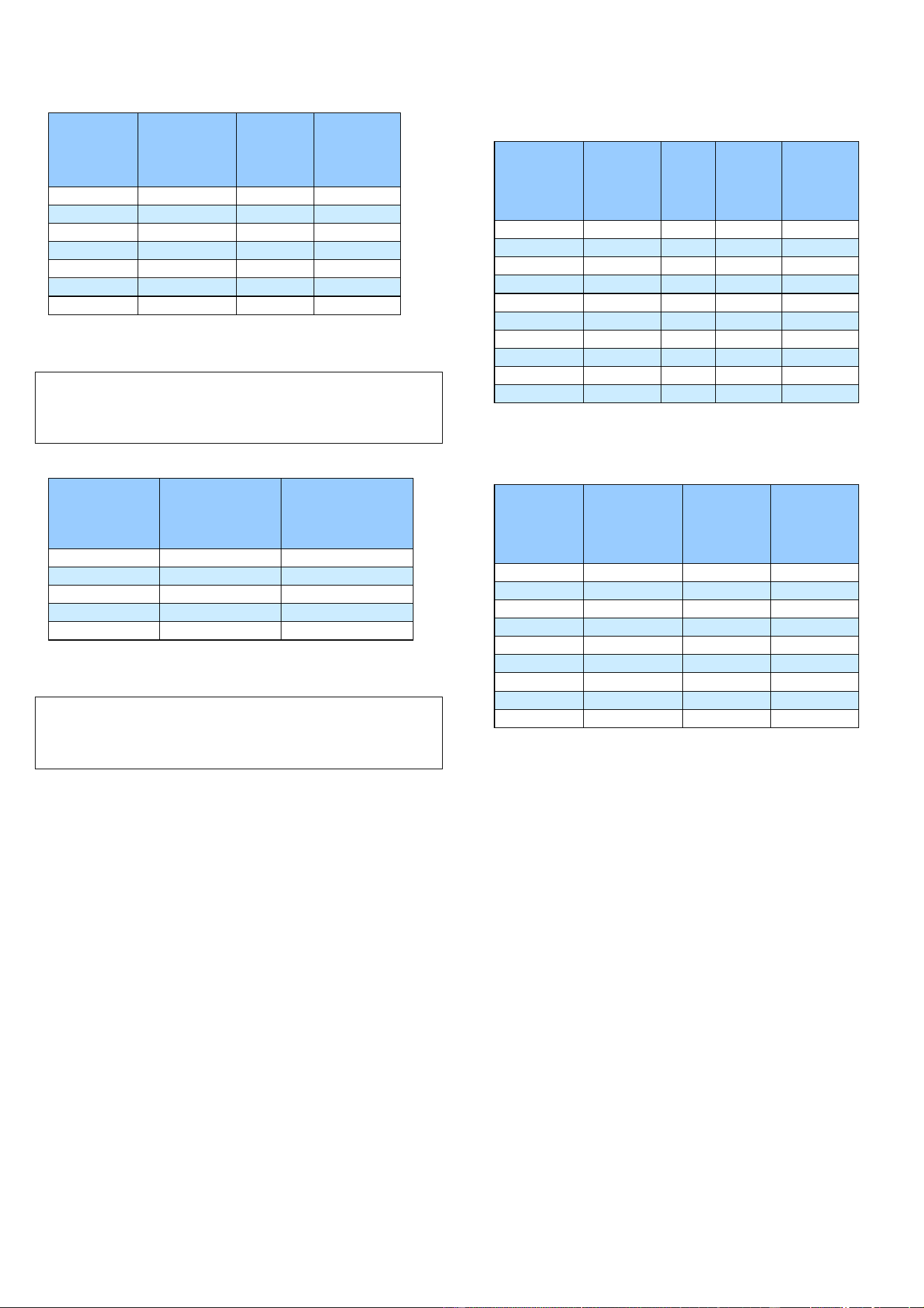
CM/DM 6680 F Chairman/Delegate Units
connected
Length of
Feeding Cable
Type CAT5e
AWG24
Length of inter
connecting
Cable, Type
CAT5e AWG24
Total cable
length
Max. number
of DC 61xxP
pr. output
10 m 1 m 35 m 27
30 m 1 m 53 m 24
50 m 1 m 70 m 21
100 m 1 m 113 m 14
150 m 1 m 159 m 10
10 m 2 m 58 m 25
30 m 2 m 72 m 22
50 m 2 m 88 m 20
100 m 2 m 126 m 14
150 m 2 m 166 m 9
Figure 0-D CM/DM 6680 F Chairman/Delegate Units connected
DCS 6000 Digital Conference System User Manual
15
MU 6040 C/D and MU 6042 D
Length of
Feeding Cable,
Type CAT5e
AWG24
Cable length
between each
MU 6040
Total cable
length
Max. number
of MU 6040
pr. output
10 m 2 m 168 m 80
30 m 2 m 178 m 75
50 m 2 m 188 m 70
100 m 2 m 200 m 51
150 m 2 m 200 m 26
100 m 1 m 151 m 52
150 m 1 m 191 m 42
Figure 0-E MU 6040 C/D and MU 6042 D without connected
loudspeaker.
Note: The numbers are valid with no audio in
loudspeaker or no loudspeaker connected to each unit.
If loudspeakers are used, then use the figures for DC
6120 P or DC 6190 P.
IS 6132 P Interpreter Units
Length of Feeding
Cable, Type CAT5e
AWG24
Length of inter
-
connecting Cables,
Type CAT5e AWG24
Max. number of units
pr output
All ON ½ ON 1/3 ON
10m 2 m 54 x x
30m 2 m 49 57 60
50m 2 m 44 51 x
100m 2 m 35 40 x
150m 2 m 25 30 x
Figure 0-F IS 6132 P Interpreter Units connected. The numbers
are with no loudspeakers connected.
Note: The number of units is dependent of how many
interpreter sets there are per booth (or language), as
there only can be one set switched ON per language
(channel).
IS 6132 P Units and JB 6104
Length of
Feeding Cable,
Type CAT5e
AWG24
Length of
cable
between
booths
Number
of
booths
Number
of IS
6132/
booths
Number of
LS 6132 P/
booths
10 m 5 m 19 4 0
10 m 5 m 12 4 4
30 m 5 m 17 4 0
30 m 5 m 10 4 4
50 m 5 m 15 4 0
50 m 5 m 9 4 4
100 m 5 m 11 4 0
100 m 5 m 7 4 4
150 m 5 m 8 4 0
150 m 5 m 5 4 4
Figure 0-G IS 6132 P Units and JB 6104 and with/without LS 6132
P Loudspeaker connected.
CS 6340 F Channel Selector
Length of
Feeding Cable,
Type CAT5e
AWG24
Length of Inter
-
connecting
cable, Type
CAT5e AWG24
Total cable
length
Max. number
of CS 6340 pr
output
30 m 1 m 139 m 110
50 m 1 m 144 m 95
100 m 1 m 184 m 85
150 m 1 m 200 m 51
10 m 2 m 200 m 96
30 m 2 m 200 m 86
50 m 2 m 200 m 76
100 m 2 m 200 m 51
150 m 2 m 200 m 26
Figure 0-H CS 6340 F Channel Selector w/back light on
DCS 6000 Digital Conference System User Manual
16
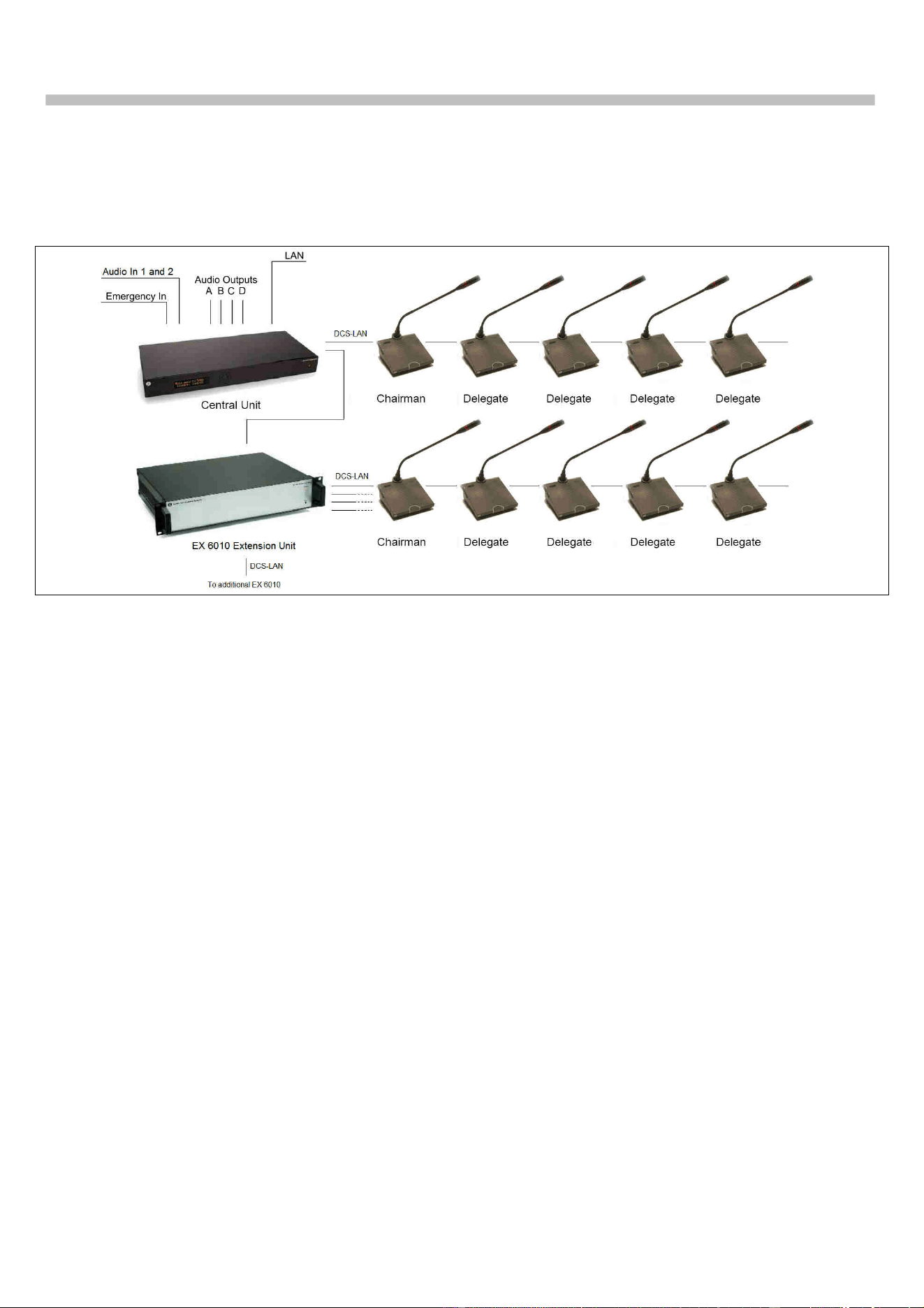
Typical schematics
The following schematics are showing a typical configuration with use of EX 6010.
Figure 0-A System with EX 6010
.

DCS 6000 Digital Conference System User Manual
17
Refer to Setup section for information in how to setup the system using the above menus.
Technical Specifications
General
Power consumption ................................ max. 570W
In-rush current max. 30A @115V or max. 60A@230V
Mains voltage: ...................... 100 - 240V, 50 - 60Hz
Supply voltage for units (each A1, A2, B1, B2)
.......................... 48V/125W
Max. power load on Loop Through connectors ..... 7.5W
Temperature to guarantee specified performance
............. 5 Deg C. to 40 Deg C. (35 to 80% humidity)
Storage temperature
.......... -20 Deg C. to 60 Deg C. (10 to 80% humidity)
Weight ......................................................... 5.5 kg
Dimensions (W x H x D) ... 425 (483) x 87 x 317 (357)
mm
Dimensions in bracket are including 19” brackets
Connectors
DCS-LAN loop through ......................... 2 pieces RJ45
DCS-LAN repeated output ..................... 4 pieces RJ45
Cabling and System Limits
Cable type (min. specification) ......... Cat5e, AWG 24,
shielded
Maximum cable length in one chain ................ 200 m
System Environmental Conditions
Working condition .......... Fixed, stationary or portable
Approvals
Approvals ...............................................CE, cULus
EMC emission According to harmonized
standard EN 55103-1 and
FCC rules part 15, complying
with the limits for a class A
digital devices
EMC immunity According to harmonized
standard EN 55103-2
EMC approvals Affixed with the CE mark
ESD According to harmonized
standard EN 55103-2
Mains harmonics According to harmonized
standard EN 55103-1
Environmental requirements ....... Contains no banned
substances as specified in UAT-0480/100 (e.g. no
cadmium or asbestos)
Accessories supplied ...........................................
.... User Manual, Mains cable and 5 pieces termination
plugs
Specifications are subject to change without
notice
DCS 6000 Digital Conference System User Manual
18
Connection Details
DCS-LAN Chain
The DCS 6000 system uses shielded Cat5e, Cat6
or Cat7 F/UTP or U/FTP cables with shielded RJ45
connectors.
EIA 568-B wiring shall be used.
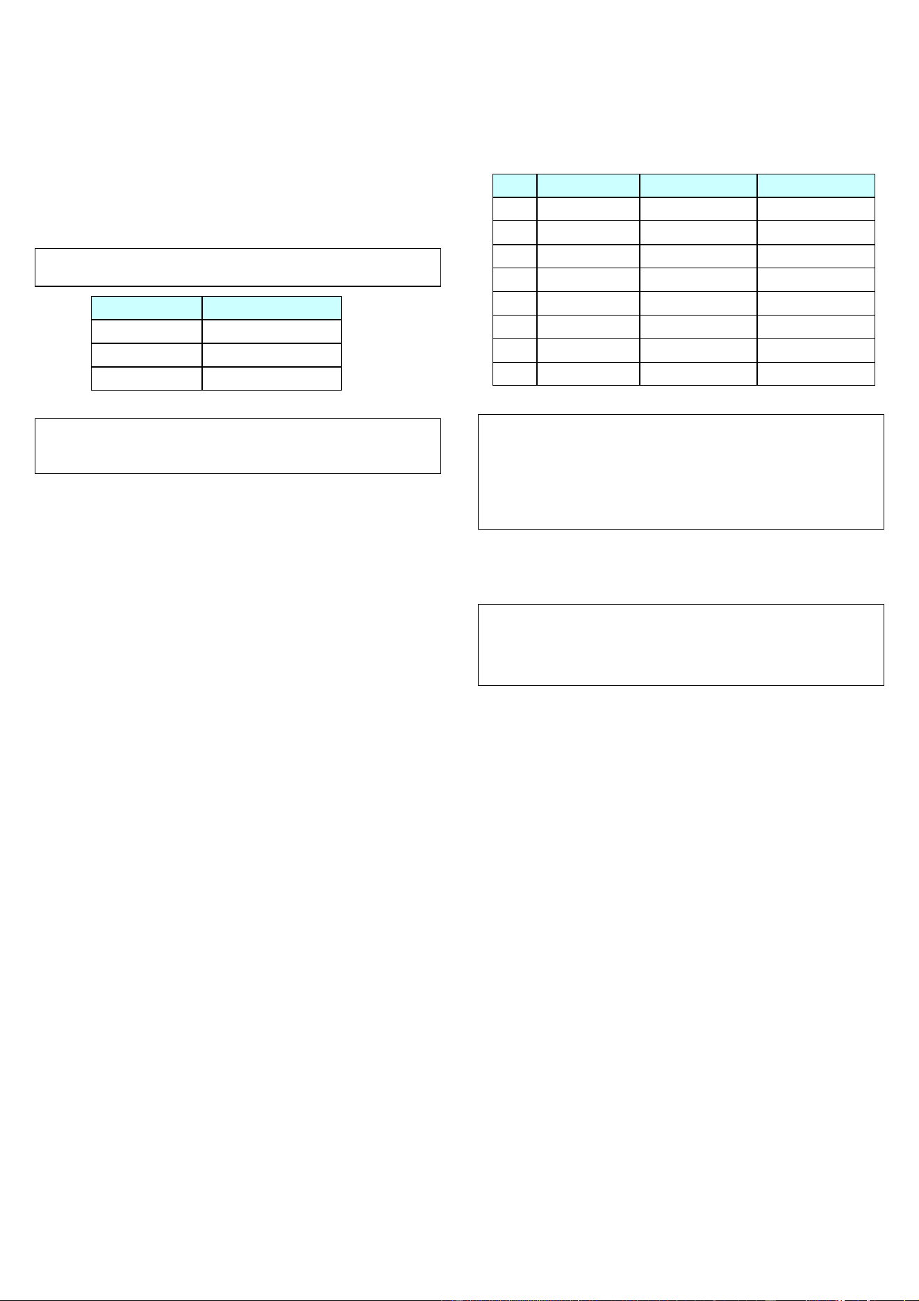
Important: The names of Cat5/6/7 cable type have
changed.
Old name New name
FTP F/UTP
STP U/FTP
UTP U/UTP
Important: Use only F/UTP or U/FTP (shielded) cables
and shielded RJ45 connectors and not U/UTP cable,
which are unshielded.
How to wire a Cat5e (EIA 568-B) cable to a RJ45
con.:
Pin Function Connector #1 Connector #2
1 In-going + ORG/WHT ORG/WHT
2 In-going - ORG ORG
3 +48V GRN/WHT GRN/WHT
4 0V BLU BLU
5 0V BLU/WHT BLU/WHT
6 +48V GRN GRN
7 Outgoing - BRN/WHT BRN/WHT
8 Outgoing + BRN BRN
Important: If other color codes are used then the
four pairs are connected as follows:
Pair 2: Pin 1 & 2
Pair 3: Pin 3 & 6
Pair 1: Pin 4 & 5
Pair 4: Pin 7 & 8
The phase of the pairs must be correct and the
wiring spec. as stated in Cat5e (EIA 568-B) have
to be followed.
Note: Cat6 and Cat7 cables can normally only be
terminated in sockets (female) and not in cable plugs.
Cat6 and Cat7 can thus only be used for feeding cables
terminating in wall outlets or patch panels.
Accessories
Cat5e Connection Cables (AWG24)
EC 6001-0.5 .................. Connection Cable 0.5 m
EC 6001-01 ..................... Connection Cable 1 m
EC 6001-02 ..................... Connection Cable 2 m
EC 6001-05 ..................... Connection Cable 5 m
EC 6001-10 ................... Connection Cable 10 m
EC 6001-20 ................... Connection Cable 20 m
EC 6001-50 ................... Connection Cable 50 m

www.shure.com
United States, Canada, Latin
America, Caribbean:
Shure Incorporated
5800 West Touhy Avenue
Niles, IL 60714-4608
USA
Phone: +1 847 600 2000
Fax: +1 847 600 1212 (USA)
Fax: +1 847 600 6446
Email: info@shure.com
Europe, Middle East, Africa:
Shure Europe Gmbh
Jakob-Dieffenbacher-Str. 12
75031 Eppingen
Germany
Phone: +49 (0) 7262-9249-100
Fax: +49 (0) 7262-9249-114
Email: info@shure.de
Asia, Pacific:
Shure Asia Limited
22/F, 625 King's Road
North Point, Island East,
Hong Kong
Phone: (+852) 2893-4290
Fax: (+852) 2893-4055
Email: info@shure.com.hk