speedqueen.com.au
Need More info?
Call 1300 927 437
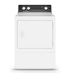
ADE3TR BLACK (ELECTRIC)
ADG3TR BLACK (GAS)
INSTALLATION GUIDE
DRYER

Keep these instructions for future reference.
(If this machine changes ownership, this manual must accompany machine.)
www.alliancelaundry.com
Installation Instructions
for Dryers
Dimensions........................................................................ 3
Before You Start................................................................ 4
Installing the Dryer............................................................ 5
Installer Checklist ........................................... Back Cover
Date Purchased _____________________
Model Number _____________________
Serial Number _____________________
Part No. 514463
January 2014
Inside.......................................
© Copyright, Alliance Laundry Systems LLC – DO NOT COPY or TRANSMIT 514463
2
IMPORTANT: The electrical installation in the site shall comply with the Australian Electrical Standards,
AS3000, SAA wiring rules, and such local regulations that might apply. In Australia and New Zealand
,
installation must comply with the Gas Installations Standard AS/NZS 5601 Part 1: General Installations.
Read complete Installation and Operation Instructions before using unit.
The maximum drying load (dry weight) shall not exceed 9.0 kg (20 pounds).
IMPORTANT: Purchaser must consult the local gas supplier for suggested instructions to be followed if the
dryer user smells gas. The gas utility instructions plus the SAFETY and WARNING note directly above
must be posted in a prominent location near the dryer for customer use.
• Do not store or use gasoline or other flammable vapors and liquids in the vicinity of this or
any other appliance.
• WHAT TO DO IF YOU SMELL GAS:
– Do not try to light any appliance.
– Do not touch any electrical switch; do not use any phone in your building.
– Clear the room, building or area of all occupants.
– Immediately call your gas supplier from a neighbor’s phone. Follow the gas supplier’s
instructions.
– If you cannot reach your gas supplier, call the fire department.
• Installation and service must be performed by a qualified installer, service agency or the gas
supplier.
W052
FOR YOUR SAFETY, the information in this manual must be followed to minimize the risk
of fire or explosion or to prevent property damage, personal injury or death.
W033
WARNING
• Installation of unit must be performed by a qualified installer.
• Install clothes dryer according to manufacturer’s instructions and local codes.
• DO NOT install a clothes dryer with flexible plastic venting materials. If flexible metal (foil
type) duct is installed, it must be of a specific type identified by the appliance manufacturer
as suitable for use with clothes dryers. Refer to section on connecting exhaust system.
Flexible venting materials are known to collapse, be easily crushed, and trap lint. These
conditions will obstruct clothes dryer airflow and increase the risk of fire.
W729R1
WARNING
FOR YOUR SAFETY
Do not store or use gasoline or other flammable vapors and liquids in the vicinity of this or
any other appliance.
W053
© Copyright 2014, Alliance Laundry Systems LLC
All rights reserved. No part of the contents of this book may be reproduced or transmitted in any form or by any
means without the expressed written consent of the publisher.
© Copyright, Alliance Laundry Systems LLC – DO NOT COPY or TRANSMIT
3
514463
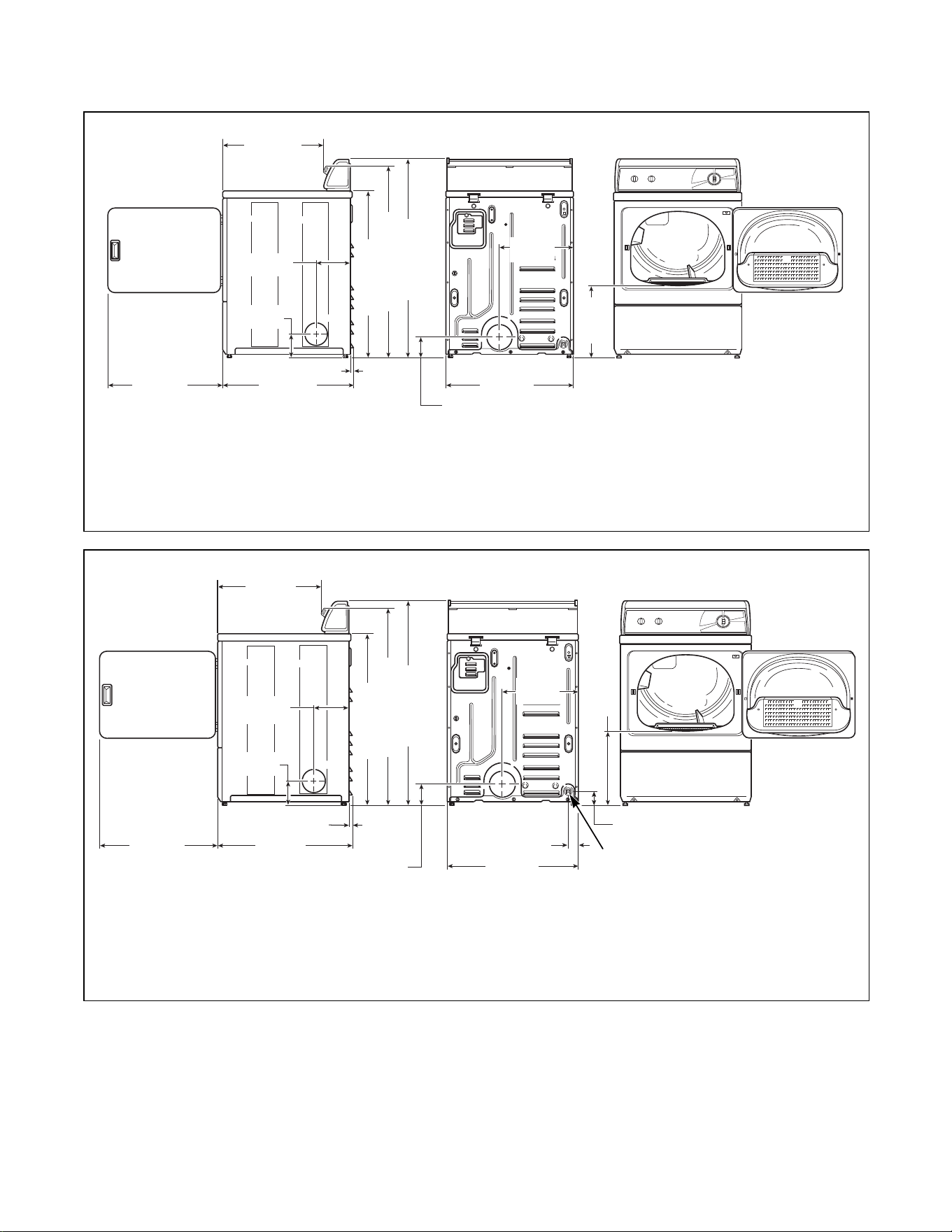
Dimensions
DRY2275N
* With leveling legs turned into base.
NOTE: Exhaust openings are 10.2 cm (4 inch) metal ducting.
DRY2276N
* With leveling legs turned into base.
NOTE: Exhaust openings are 10.2 cm (4 inch) metal ducting.
1 3/8 in. NPT Gas Connection
DRY2275N
*11.4 cm
(4.5 in.)
59.7 cm
(23.5 in.)
1.1 cm
(0.4 in.)
*91.4 cm (36 in.)
*109.2 cm (43 in.)
39.1 cm
(15.4 in.)
68.3 cm
(26.875 in.)
*10.2 cm
(4.0 in.)
ELECTRIC DRYERS
20.3 cm
(8.0 in.)
71.1 cm
(28 in.)
56.85 cm
(22.38 in.)
*102.24 cm (40.25 in.)
*39.2 cm
(15.44 in.)
DRY2276N
GAS DRYERS
1
6 cm
(2.3 in.)
*7 cm
(2.8 in.)
59.7 cm
(23.5 in.)
71.1 cm
(28 in.)
*11.4 cm
(4.5 in.)
*91.4 cm (36 in.)
*109.2 cm (43 in.)
1.1 cm
(0.4 in.)
68.3 cm
(26.875 in.)
39.1 cm
(15.4 in.)
*10.2 cm
(4.0 in.)
20.3 cm
(8.0 in.)
56.85 cm
(22.38 in.)
*102.24 cm (40.25 in.)
*39.2 cm (15.44 in.)
© Copyright, Alliance Laundry Systems LLC – DO NOT COPY or TRANSMIT 514463
4
Before You Start
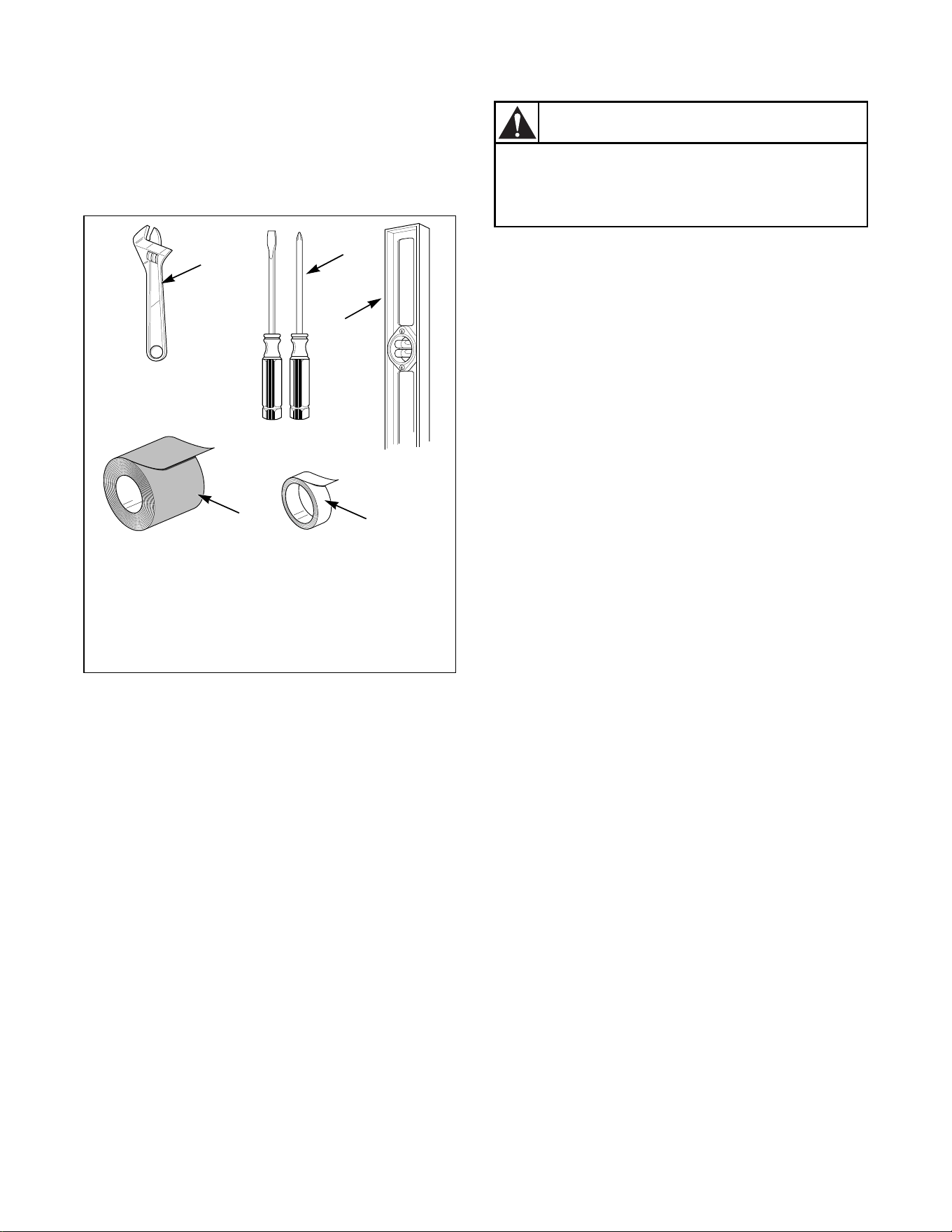
Supplies
For most installations, the basic supplies you will need
are:
Figure 1
Parts Included
An accessories bag has been shipped inside your dryer.
It includes:
· Installation Instructions
· User Guide
· Warranty Bond
· Installer Checklist
D818I
1 Wrench
2 Screwdrivers
3 Level
4 Teflon Tape
5 Duct Tape
1
2
3
4
5
Any disassembly requiring the use of
tools must be performed by a suitably
qualified service person.
W299
WARNING
© Copyright, Alliance Laundry Systems LLC – DO NOT COPY or TRANSMIT
514463
5
Installing the Dryer
Step 1: Position Dryer Near Installation
Area
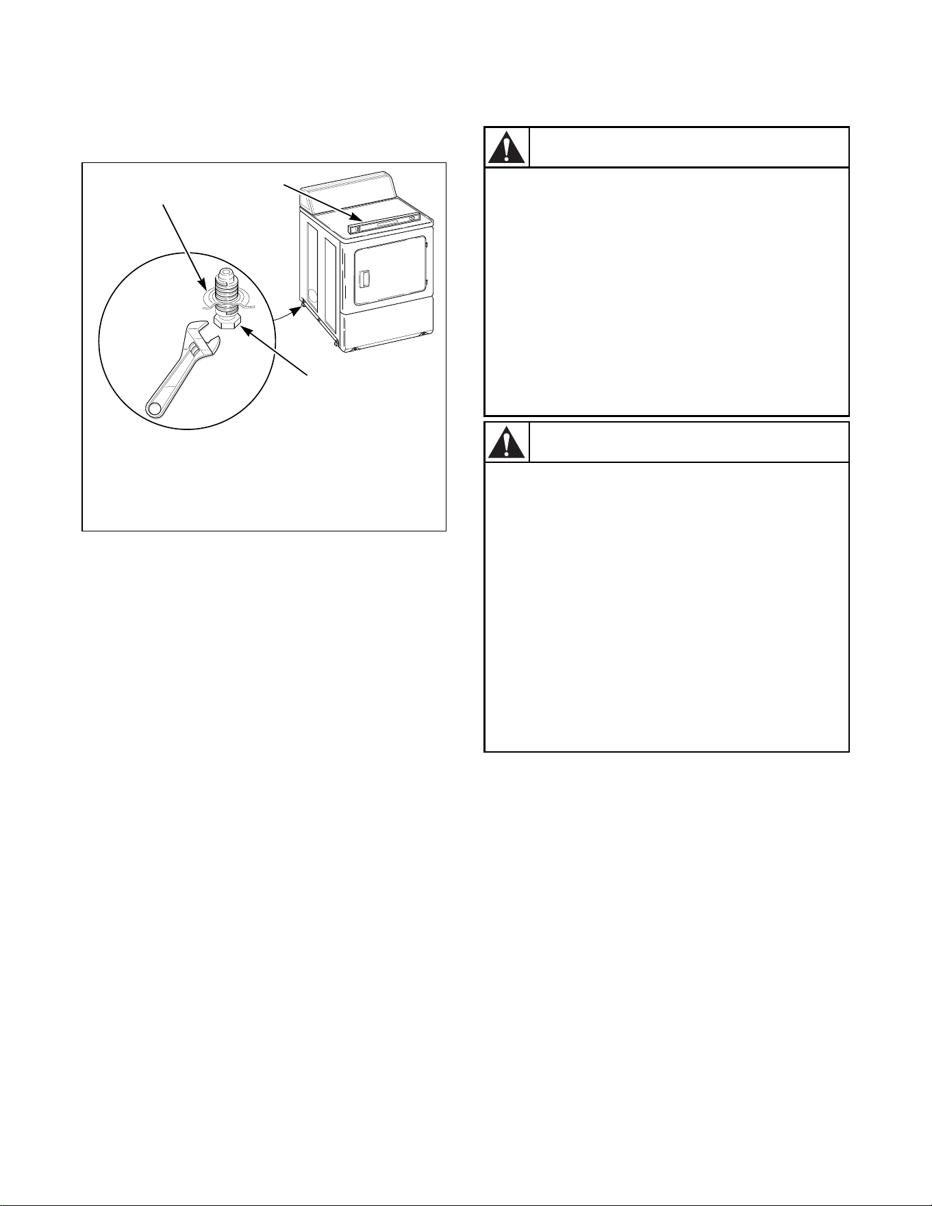
Step 2: Position and Level the Dryer
Install dryer before washer. This allows room for
attaching exhaust duct.
Select a location with a solid floor. Dryers installed in
residential garages must be elevated 46 cm (18 inches)
above the floor.
No other fuel burning appliance should be installed in
the same closet with the dryer.
The dryer must not be installed or stored in an area
where it will be exposed to water and/or weather.
Leveling legs can be adjusted from inside the dryer
with a 1/4 inch driver. All four legs must rest firmly on
the floor so the weight of the dryer is evenly
distributed.
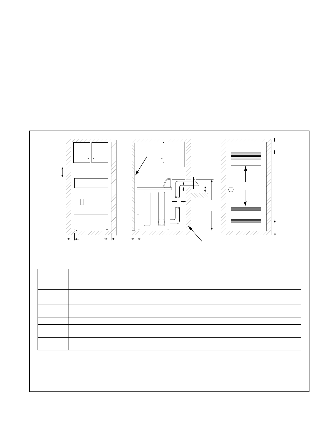
The dryer needs sufficient clearance and an adequate
air supply for proper operation and ventilation, and for
easier installation and servicing. (Minimum clearances
are shown below).
Figure 2
D823I
1 Closet Door
2 Centered Air Openings (G) (2 Openings minimum)
3 Outer Wall of Enclosure
**NOTE: For new installations, locate top of wall vent 106.7 cm (42 inches) above floor to make venting
easier to connect.
1
2 (G)
3
A
E
**106.7 cm
(42 in.)
F
F
B
A
A
C
FRONT VIEW
(w/o Closet Door)
SIDE VIEW
(Closet Door)
FRONT VIEW
(Closet Door)
D
Area Description
Free Standing/Alcove
Installation
Closet Installation
A Dryer sides and rear clearance 0 cm (0 in.) 0 cm (0 in.)
B Dryer top clearance 30.5 cm (12 in.) 30.5 cm (12 in.)
C Dryer front clearance Not Applicable 5.1 cm (2 in.)
D Exhaust duct clearance to
combustible material
5.1 cm (2 in.) 5.1 cm (2 in.)
E Weather hood to ground clearance 30.5 cm (12 in.) 30.5 cm (12 in.)
F Distance from floor or ceiling to
hole edge
Not Applicable 7.6 cm (3 in.)
G* Area of centered air openings in
closet door
Not Applicable 260 sq. cm/open (40 sq. in.)
*Louvered door with equivalent air openings is acceptable. (Minimum clearances are shown.)
© Copyright, Alliance Laundry Systems LLC – DO NOT COPY or TRANSMIT 514463
6
Place the dryer in position, and adjust the legs until the
dryer is level from side to side and front to back. The
dryer must not rock.
Figure 3
IMPORTANT: In mobile home installations, gas
dryers MUST be permanently attached to the floor
at the time of installation. Order No. 526P3 Dryer
Installation Kit (available at extra cost) for a
manufactured (mobile) home installation. Follow
the instructions supplied with the kit.
Step 3: Connect Dryer Exhaust System
D669I
1 Dryer Base
2 Level
3 Leveling Leg
D669I
D259I
1
2
3
A clothes dryer produces combustible lint.
To reduce the risk of fire and combustion
gas accumulation the dryer MUST be
exhausted to the outdoors.
W116
To reduce the risk of fire and the
accumulation of combustion gases, DO
NOT exhaust dryer air into a window well,
gas vent, chimney or enclosed, unventilated
area, such as an attic, wall, ceiling, crawl
space under a building or concealed space
of a building.
W045
WARNING
This gas appliance contains or produces a
chemical or chemicals which can cause
death or serious illness and which are
known to the State of California to cause
cancer, birth defects, or other reproductive
harm. To reduce the risk from substances in
the fuel or from fuel combustion, make sure
this appliance is installed, operated, and
maintained according to the instructions in
this manual.
W115
To reduce the risk of fire, DO NOT use
plastic or thin foil ducting to exhaust the
dryer.
W354
WARNING
© Copyright, Alliance Laundry Systems LLC – DO NOT COPY or TRANSMIT
514463
7
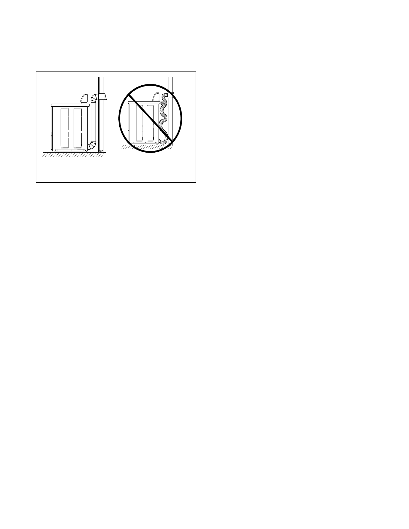
· DO NOT use plastic, thin foil or type B ducting.
Rigid metal duct is recommended. Refer to
Figure 4.
· Locate dryer so exhaust duct is as short as
possible.
· Be certain old ducts are cleaned before installing
your new dryer.
· Use 102 mm (4 inch) diameter rigid or flexible
metal duct.
· The male end of each section of duct must point
away from the dryer.
· Use as few elbows as possible.
· Use of duct tape or pop-rivets on all seams and
joints is recommended, if allowed by local codes.
DO NOT use sheet metal screws or fasteners on
exhaust pipe joints which extend into the duct
and catch lint.
· Ductwork that runs through unheated areas must
be insulated to help reduce condensation and lint
build-up on pipe walls.
· Install backdraft dampers in multi-dryer
installations.
· In mobile home installations, dryer exhaust duct
must be secured to mobile home structure.
· Dryer exhaust duct MUST NOT terminate under
mobile home.
· Dryer exhausts 180 cfm (measured at back of
dryer).
· DO NOT install flexible duct in concealed
spaces, such as a wall or ceiling.
· Static pressure in exhaust duct should not be
greater than .1 kPa water column (.4 in.),
measured with manometer placed on exhaust
duct 61 cm (2 ft.) from dryer (check with dryer
running and no load).
· Exhausting dryer in hard-to-reach locations can
be done by installing 521P3 Flexible Metal Vent
Kit (available as optional equipment at extra
cost).
· Sufficient make-up air must be supplied to
replace the air exhausted by the dryer. The free
area of any opening for outside air must be at
least 260 cm
2
(40 in.
2
).
· Energy efficient buildings with low air
infiltration rates should be equipped with an air
exchanger that can accommodate on demand
make-up air needs in the laundry room. These
devices can be obtained through your building
contractor or building material suppliers.
· Do not draw make-up air from a room containing
a gas fired water heater, a dry cleaner or a hair
salon.
· Failure to exhaust dryer properly will void
warranty.
NOTE: Venting materials are not supplied with the
dryer (obtain locally).
IMPORTANT: DO NOT block the airflow at the
bottom of the dryer’s front panel with laundry,
rugs, etc. Blockage will decrease airflow through
the dryer, thus reducing the efficiency of the dryer.
D314I D315I
Figure 4
DON’T
DO
© Copyright, Alliance Laundry Systems LLC – DO NOT COPY or TRANSMIT 514463
8
Exhaust Direction
The dryer can be exhausted to the outdoors through the
back, left, right or bottom of the dryer. EXCEPTION:
Gas dryers cannot be vented out the left side
because of the burner housing.
Dryer is shipped from factory ready for rear exhaust.
Exhausting the dryer through sides or bottom can be
accomplished by installing a Directional Exhaust Kit,
528P3, available as optional equipment at extra cost.
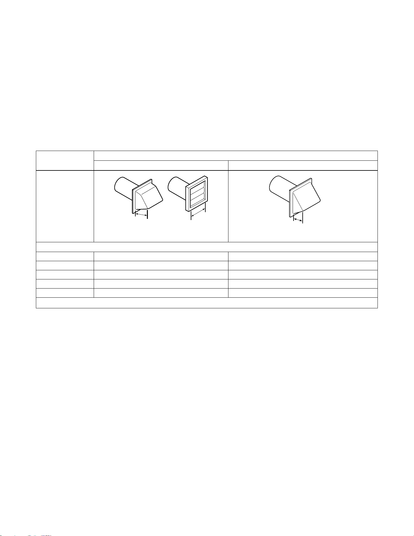
Exhaust System
For best drying results, recommended maximum
length of exhaust system is shown in Table 1.
To prevent backdraft when dryer is not in operation,
outer end of exhaust pipe must have a weather hood
with hinged dampers (obtain locally).
NOTE: Weather hood should be installed at least
30.5 cm (12 inches) above the ground. Larger
clearances may be necessary for installations where
heavy snowfall can occur.
NOTE: The maximum length of a 10.2 cm (4 in.)
diameter flexible metal duct must not exceed 2.4 m
(7.87 ft.), as required to meet UL2158, clause
7.3.2A.
Number of
90° Elbows
Weather Hood Type
Recommended Use Only for Short Run installations
Maximum length of 10.2 cm (4 in.) diameter rigid metal duct.
0 19.8 m (65 feet) 16.8 m (55 feet)
1 16.8 m (55 feet) 14.3 m (47 feet)
2 14.3 m (47 feet) 12.5 m (41 feet)
3 11.0 m (36 feet) 9.1 m (30 feet)
4 8.5 m (28 feet) 6.7 m (22 feet)
NOTE: Deduct 1.8 m (6 feet) for each additional elbow.
Table 1
D673I
10.2 cm
(4 in.)
10.2 cm
(4 in.)
D673I
D802I
6.35 cm
(2-1/2 in.)
© Copyright, Alliance Laundry Systems LLC – DO NOT COPY or TRANSMIT
514463
9
Step 4: (Gas Dryer Only) Connect Gas
Supply Pipe
NOTE: The gas service to a gas dryer must
conform with the local codes and ordinances and
in Australia and New Zealand
, installation must
comply with the Gas Installations Standard AS/
NZS 5601 Part 1: General Installations. In the
absence of local codes and ordinances, applicable
National codes should be followed.
Connection of Gas Supply Pipe
1. Install the dryer with sufficient clearance for
adequate air circulation, and for the ease of the
dryer installation, servicing and operation. For
maximum drying performance, we recommend
you allow more clearance than the clearances that
are listed throughout this manual.
2. Remove the shipping cap from the gas connection
at the rear of the dryer. Make sure you do not
damage the pipe threads when removing the cap.
3. Make certain your dryer is equipped for use with
the type of gas in your laundry room.
NOTE: Natural gas, 37.3 MJ/m
3
(1000 Btu/ft
3
),
service must be supplied at 1.13 kPa (4.54 inch)
water column pressure. Do not connect the dryer to
L.P. (Liquefied Petroleum) gas service without
converting the gas valve. A No. 401P3 L.P. Gas
Conversion Kit must be installed by the
Manufacturer’s Authorized Dealers, Distributors,
or local service personnel.
NOTE: L.P. gas, 93.1 MJ/m
3
(2500 Btu/ft
3
), service
must be supplied at 2.75 kPa (11.04 inch) water
column pressure and a vent to the outdoors must be
provided.
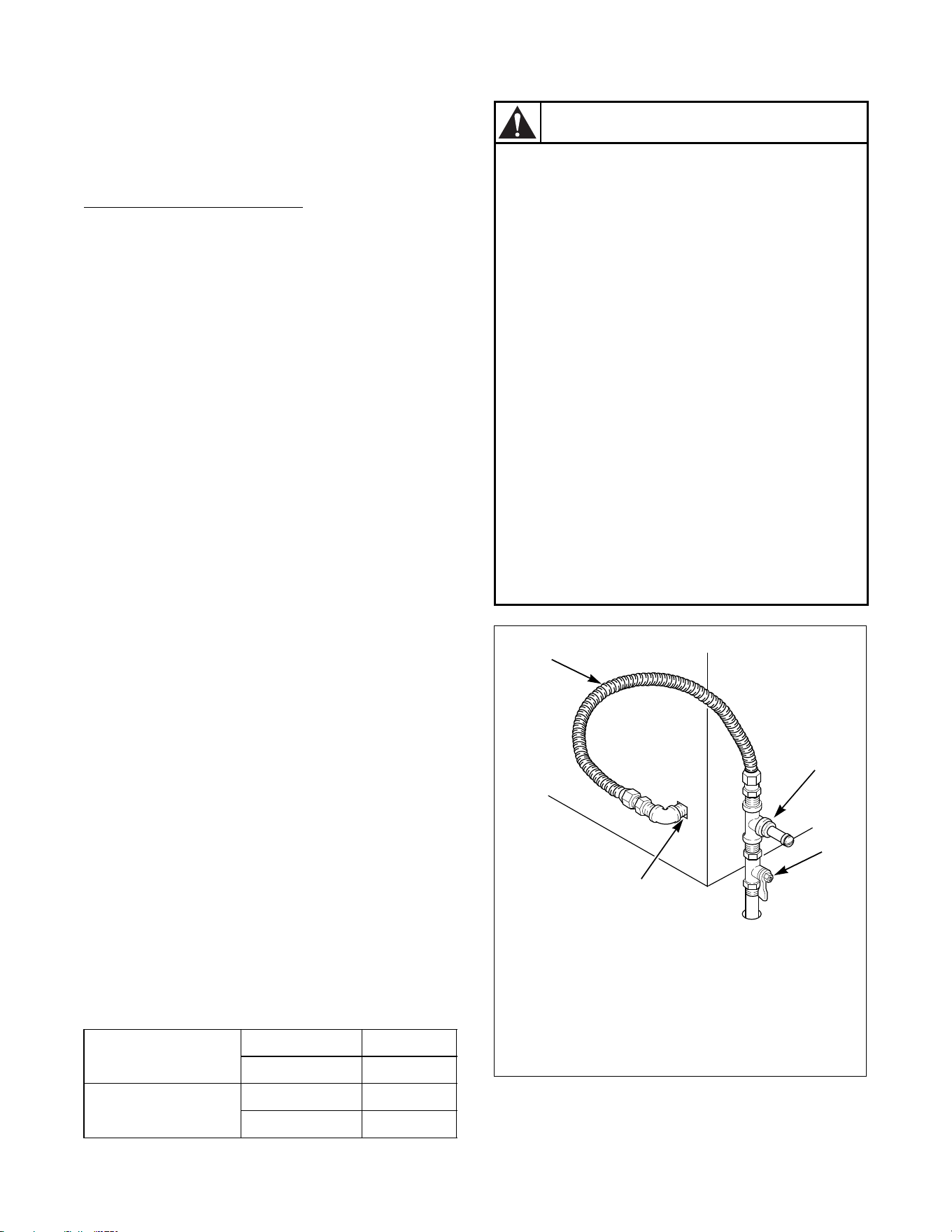
4. If local codes allow the use of flexible gas tubing,
connect the 3/8 inch NPT (National Pipe Thread)
gas connection at the rear of the dryer to the
laundry room’s gas line with new flexible
stainless steel tubing (using design certified
Australian Gas Association connector only).
IMPORTANT: Use local codes of practice for gas
installation.
This dryer is equipped with jet for Natural gas.
Figure 5
Gas Consumption Natural 21.9 MJ
L.P. 21.9 MJ
Gas Supply Pressure Natural 1.13 kPa
L.P. 2.75 kPa
D246I
1 New Stainless Steel Flexible Connector –
Use Only If Allowed By Local Codes
(Use design AGA certified connector)
2 Pressure Test Point
3 External Shut-Off Valve
4 3/8 in. NPT Gas Connection
To reduce the risk of gas leaks, fire or
explosion:
• The dryer must be connected to the type
of gas as shown on nameplate located in
the door recess.
• Use a new flexible stainless steel
connector.
• Use pipe joint compound insoluble in L.P.
(Liquefied Petroleum) Gas, or Teflon tape,
on all pipe threads.
• Purge air and sediment from gas supply
line before connecting it to the dryer.
Before tightening the connection, purge
remaining air from gas line to dryer until
odor of gas is detected. This step is
required to prevent gas valve
contamination.
• Do not use an open flame to check for gas
leaks. Use a non-corrosive leak detection
fluid.
• Any disassembly requiring the use of
tools must be performed by a suitably
qualified service person.
W316
WARNING
1
2
3
4
© Copyright, Alliance Laundry Systems LLC – DO NOT COPY or TRANSMIT 514463
10
NOTE: When connecting gas supply line, a
pressure test point must be installed downstream
from the shutoff valve for checking inlet gas
pressure.
5. The gas line to your laundry room should be
made of black iron pipe. A 3/8 inch pipe with an
inside diameter of 11.7 mm (0.46 inch) will be
adequate if length of supply line is not over 6 m
(20 feet). If length exceeds this, use 12.7 mm
(1/2 inch) pipe. If copper semi-rigid tubing is
used it must be internally tinned or equivalently
treated to resist sulfur corrosion.
NOTE: The dryer and its appliance main gas valve
must be disconnected from the gas supply piping
system during any pressure testing of that system
at test pressures in excess of 3.45 kPa (1/2 psig).
6. Check all pipe connections (internal and
external) for gas leaks with a soapy solution. Gas
connections should be checked annually for
leakage.
7. Be sure the shut off valve in your dryer is OPEN.
Your dryer is shipped with the valve open.
8. The dryer gas valve is equipped with a pressure
test point for checking manifold pressure.
For proper operation at altitudes above 760 m
(2500 feet) the gas valve spud orifice size must be
reduced to ensure complete combustion. Refer to
Table 2 and Tabl e 3.
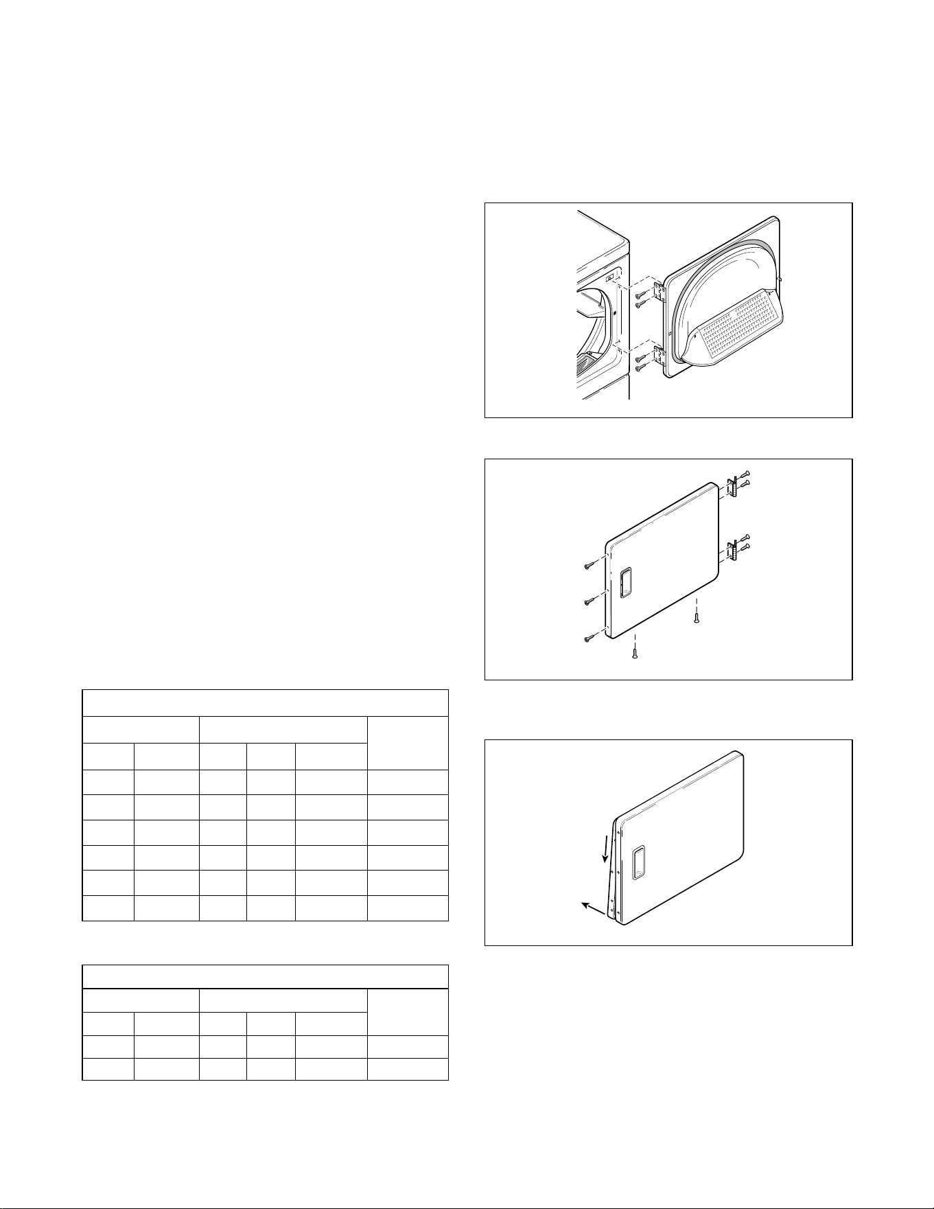
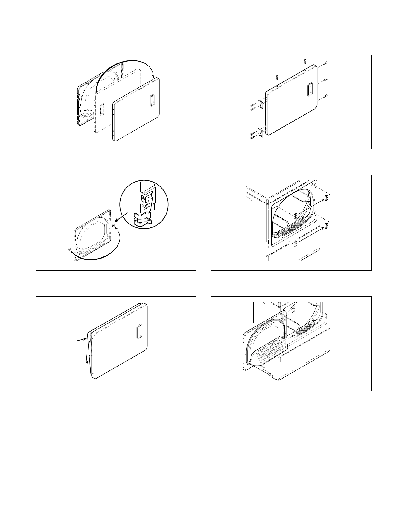
Step 5: Reverse Door, If Desired
The door on this dryer is completely reversible. To
reverse door proceed as follows:
1. Remove four hinge attaching screws.
2. Remove all nine screws
3. Pull bottom of door liner out, then pull down,
removing door liner from door panel.
Natural Gas Altitude Adjustments
Altitude Orifice Size
Part
Number
m ft No. mm inches
760 2500 45 2.08 0.0820 503779
1370 4500 46 2.06 0.0810 503780
1830 6000 47 1.99 0.0785 503781
2290 7500 48 1.93 0.0760 503782
2900 9500 49 1.85 0.0730 503783
3355 11,000 50 1.78 0.0700 503784
Table 2
LP Altitude Adjustments
Altitude Orifice Size
Part
Number
m ft No. mm inches
1370 4500 56 1.2 0.0465 503786
3000 9500 57 1.1 0.043 60941
Table 3
D675I
D272P
DRY1916N
D675I
DRY1916N
B
A
© Copyright, Alliance Laundry Systems LLC – DO NOT COPY or TRANSMIT
514463
11
4. Rotate door panel 180 degrees as shown.
5. Remove door strike from door liner and reinstall
on opposite side.
6. Insert liner under flange on bottom of door, then
push top of door liner into place.
7. Reinstall nine screws removed in step 2.
8. Using a screwdriver, remove two door plugs, and
reinstall on opposite side of door opening.
9. Reinstall four hinge attaching screws removed in
step 1.
D273P
DRY1917N
DRY1918N
DRY1917N
DRY1918N
B
A
DRY1919N
D620I
D623I
DRY1919N
D620I
D623I
© Copyright, Alliance Laundry Systems LLC – DO NOT COPY or TRANSMIT 514463
12
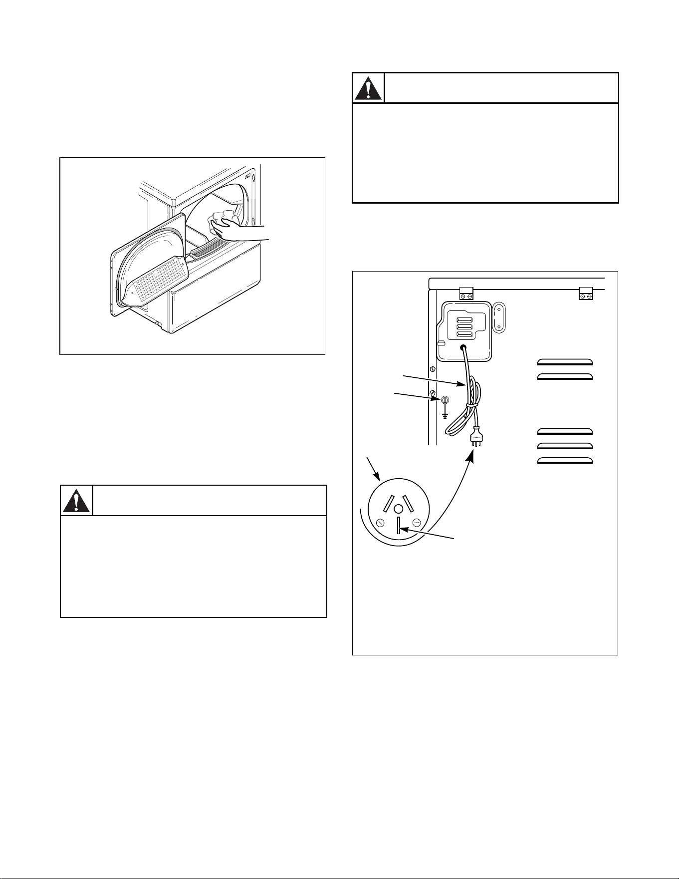
Step 6: Wipe Out Inside of Dryer Drum
Before using the dryer for the first time, use an all-
purpose cleaner, or a detergent and water solution, and
a damp cloth to remove shipping dust from inside the
drum.
Step 7: Connect the Dryer to Electrical
Power
Electric Dryer
NOTE: The wiring diagram is located inside the
control hood.
This dryer is designed to be operated on a two-wire,
plus earth, 240 Volt, 50 Hertz, single-phase circuit,
fused at 20 Amperes.
Insert the dryer’s lead-in cord plug into an earthing
three-slot-plus earth, wall receptacle on a separate
circuit. DO NOT OPERATE OTHER APPLIANCES
ON THE SAME CIRCUIT WHEN THE DRYER IS
OPERATING. DO NOT USE AN EXTENSION
CORD.
If the supply cord is damaged, it must be replaced by a
special cord or assembly available from the
manufacturer or its service agent and is to be replaced
by a qualified service person.
Figure 7
D618I
Figure 6
D618I
To reduce the risk of fire, electric shock or
personal injury, all wiring and earthing to
the dryer MUST conform with the latest
edition of the Australian Electrical
Standards, AS3000, SAA wiring rules, and
such local regulations that might apply.
W478
WARNING
D672I
1 Lead-In Cord
2 Earth Screw
3 Lead-In Cord Plug
4 Earth
If this appliance is supplied from a cord
extension set or an electrical portable
outlet device, the cord extension set or
electrical portable outlet device must be
positioned so that it is not subject to
splashing or ingress of moisture.
W563
CAUTION
20 A
250 V
D672I
1
2
4
3
© Copyright, Alliance Laundry Systems LLC – DO NOT COPY or TRANSMIT
514463
13
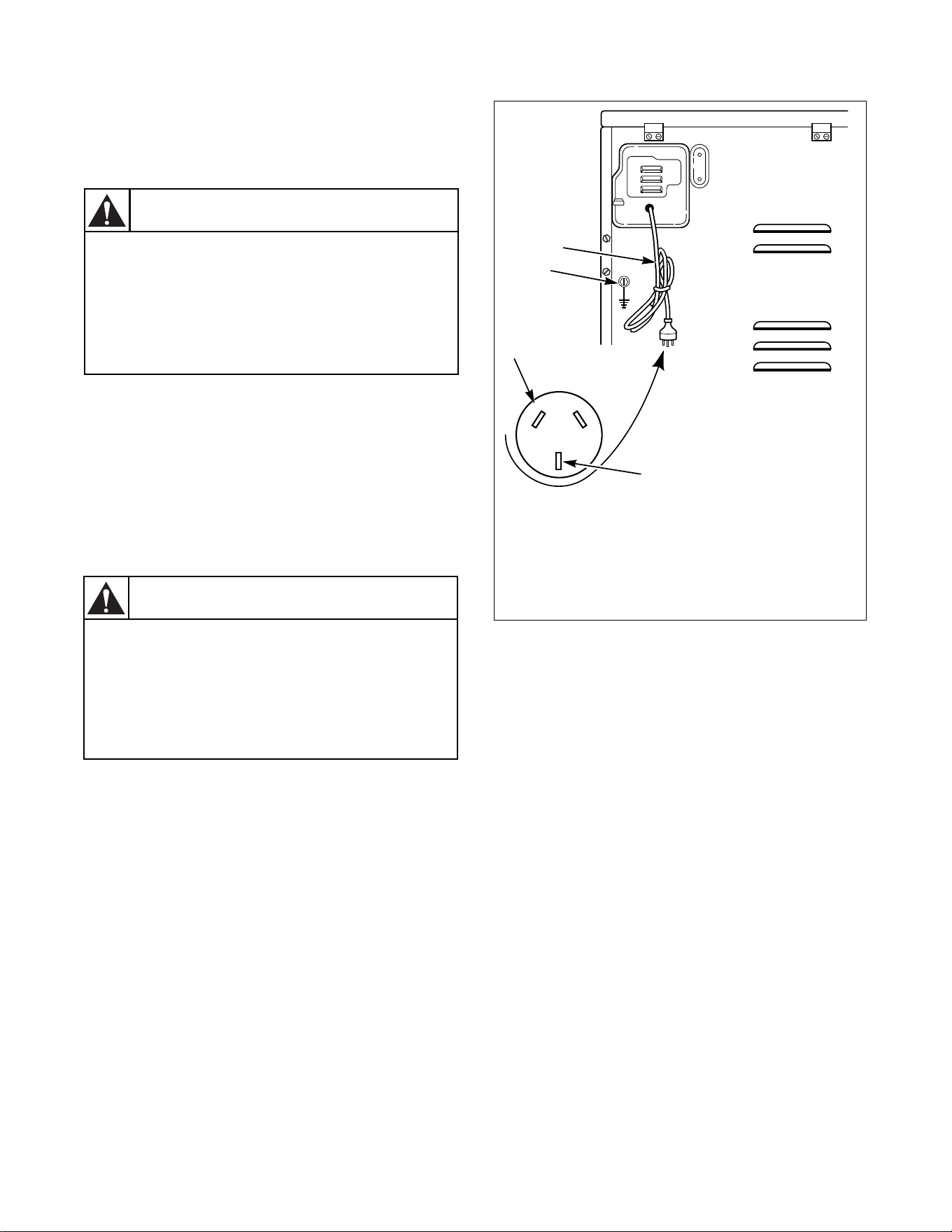
Gas Dryer
NOTE: The wiring diagram is located inside the
control hood.
This dryer is designed to be operated on a two-wire,
plus earth, 240 Volt, 50 Hertz, single-phase circuit,
fused at 10 Amperes.
Insert the dryer’s lead-in cord plug into an earthing
three-slot wall receptacle on a separate circuit. DO
NOT OPERATE OTHER APPLIANCES ON THE
SAME CIRCUIT WHEN THE DRYER IS
OPERATING. DO NOT USE AN EXTENSION
CORD.
If the supply cord is damaged, it must be replaced by a
special cord or assembly available from the
manufacturer or its service agent and is to be replaced
by a qualified service person.
Figure 8
To reduce the risk of fire, electric shock or
personal injury, all wiring and earthing to
the dryer MUST conform with the latest
edition of the Australian Electrical
Standards, AS3000, SAA wiring rules, and
such local regulations that might apply.
W478
WARNING
If this appliance is supplied from a cord
extension set or an electrical portable outlet
device, the cord extension set or electrical
portable outlet device must be positioned
so that it is not subject to splashing or
ingress of moisture.
W563
CAUTION
D676I
1 Lead-In Cord
2 Earth Screw
3 Lead-In Cord Plug
4 Earth
10A
250 V
D676I
1
2
4
3
© Copyright, Alliance Laundry Systems LLC – DO NOT COPY or TRANSMIT 514463
14
Earthing Instructions
The dryer must be earthed. In the event of malfunction
or breakdown, earthing will reduce the risk of electric
shock by providing a path of least resistance for
electric current. The dryer is equipped with a cord
having an equipment-earthing conductor and a
three-prong earthing plug. The plug must be plugged
into an appropriate outlet that is properly installed and
earthed in accordance with local codes and ordinances.
Do not modify the plug provided with the dryer – if it
will not fit the outlet, have a proper outlet installed by
a qualified electrician.
If the electrical supply does not meet the above
specifications and/or you are not sure your building
has an effective earth, have a qualified electrician or
your local electrical utility company check it and
correct any problems.
Step 8: Recheck steps 1-7
Refer to Installer Checklist on the back cover of this
manual and make sure that unit is installed correctly.
Improper connection of the equipment-
earthing conductor can result in a risk of
electric shock. Check with a qualified
electrician or serviceman if you are in doubt
as to whether the dryer is properly earthed.
W159
WARNING
© Copyright, Alliance Laundry Systems LLC – DO NOT COPY or TRANSMIT
514463
15
Step 9: Check Heat Source
Electric Dryers
Close the loading door and start the dryer in a heat
setting (refer to the Dryer User’s Guide supplied with
the unit). After the dryer has operated for three
minutes, the exhaust air or exhaust pipe should be
warm.
Gas Dryers
IMPORTANT: This operation is to be conducted
by qualified personnel only.
To view the burner flame, remove the lower front
panel of the dryer.
Close the loading door, start the dryer in a heat setting
(refer to the Dryer User’s Guide supplied with the
unit). The dryer will start, the igniter will glow red and
the main burner will ignite.
IMPORTANT: If all air is not purged out of gas
line, gas igniter may go off before gas is ignited. If
this happens, after approximately two minutes
igniter will again attempt gas ignition.
IMPORTANT: If igniter does not light, make sure
gas is turned on.
After the dryer has operated for approximately five
minutes, observe burner flame through lower front
panel. Adjust the air shutter to obtain a soft, uniform
blue flame. (A lazy, yellow-tipped flame indicates lack
of air. A harsh, roaring, very blue flame indicates too
much air.) Adjust the air shutter as follows:
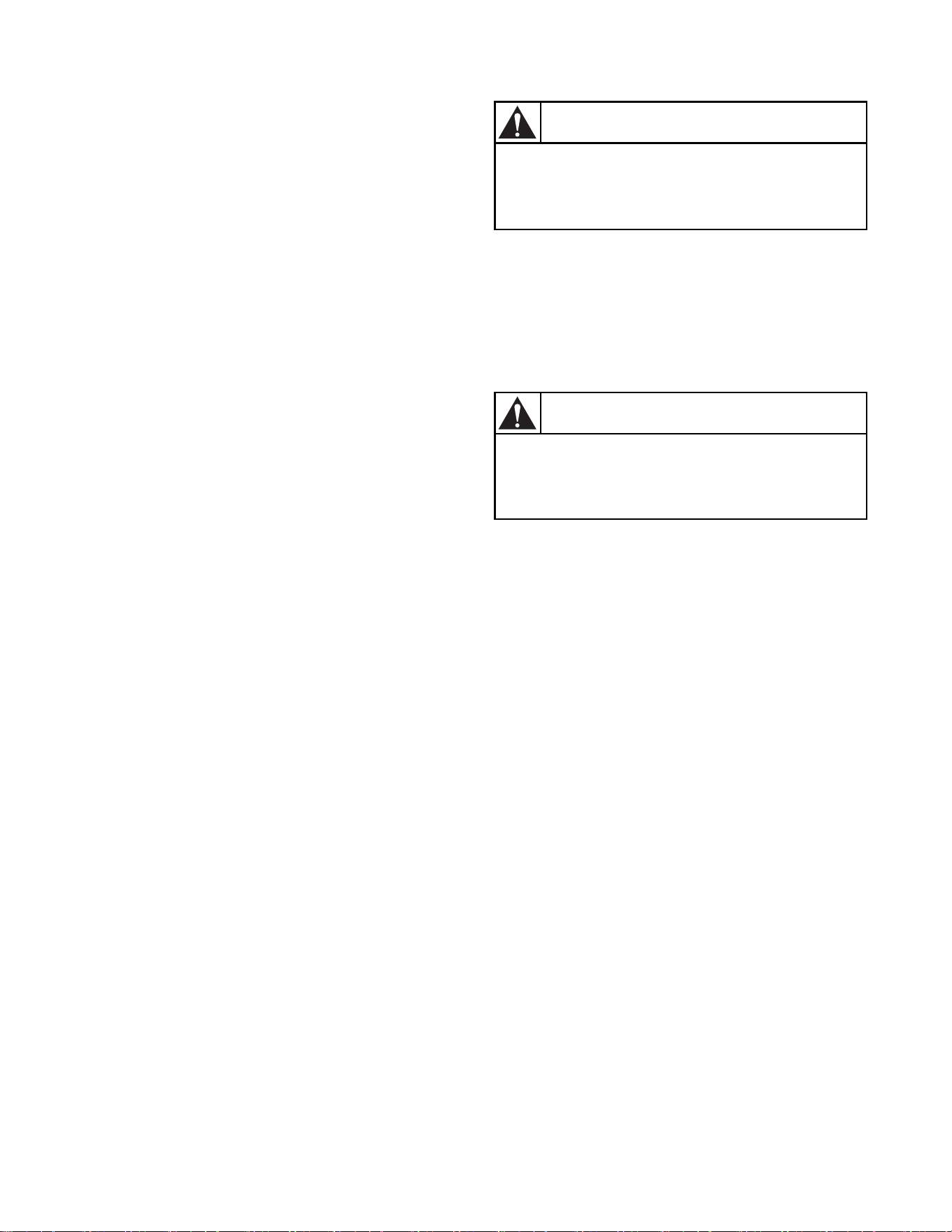
1. Loosen the air shutter lockscrew.
2. Turn the air shutter to the left to get a luminous
yellow-tipped flame, then turn it back slowly to
the right to obtain a steady, soft blue flame.
3. After the air shutter is adjusted for proper flame,
tighten the air shutter lockscrew securely.
4. Reinstall the lower front panel.
After the dryer has operated for approximately three
minutes, exhaust air or exhaust pipe should be warm.
All Dryers
If the dryer heat source is not functioning correctly,
refer to the Troubleshooting section of the Dryer
User’s Guide for corrective action.
To reduce the risk of serious injury or death,
the lower front panel must be in place
during normal operation.
W158
WARNING
Any disassembly requiring the use of tools
must be performed by a suitably qualified
service person.
W299
WARNING
© Copyright, Alliance Laundry Systems LLC – DO NOT COPY or TRANSMIT 514463
16
DRY212N
1 Shut-off Valve Handle 4 Pressure Test Point
2 Air Shutter Lockscrew 5 Open Position
3 Air Shutter 6 Closed Position
Figure 9
1
2
3
4
5
6

© Copyright, Alliance Laundry Systems LLC – DO NOT COPY or TRANSMIT
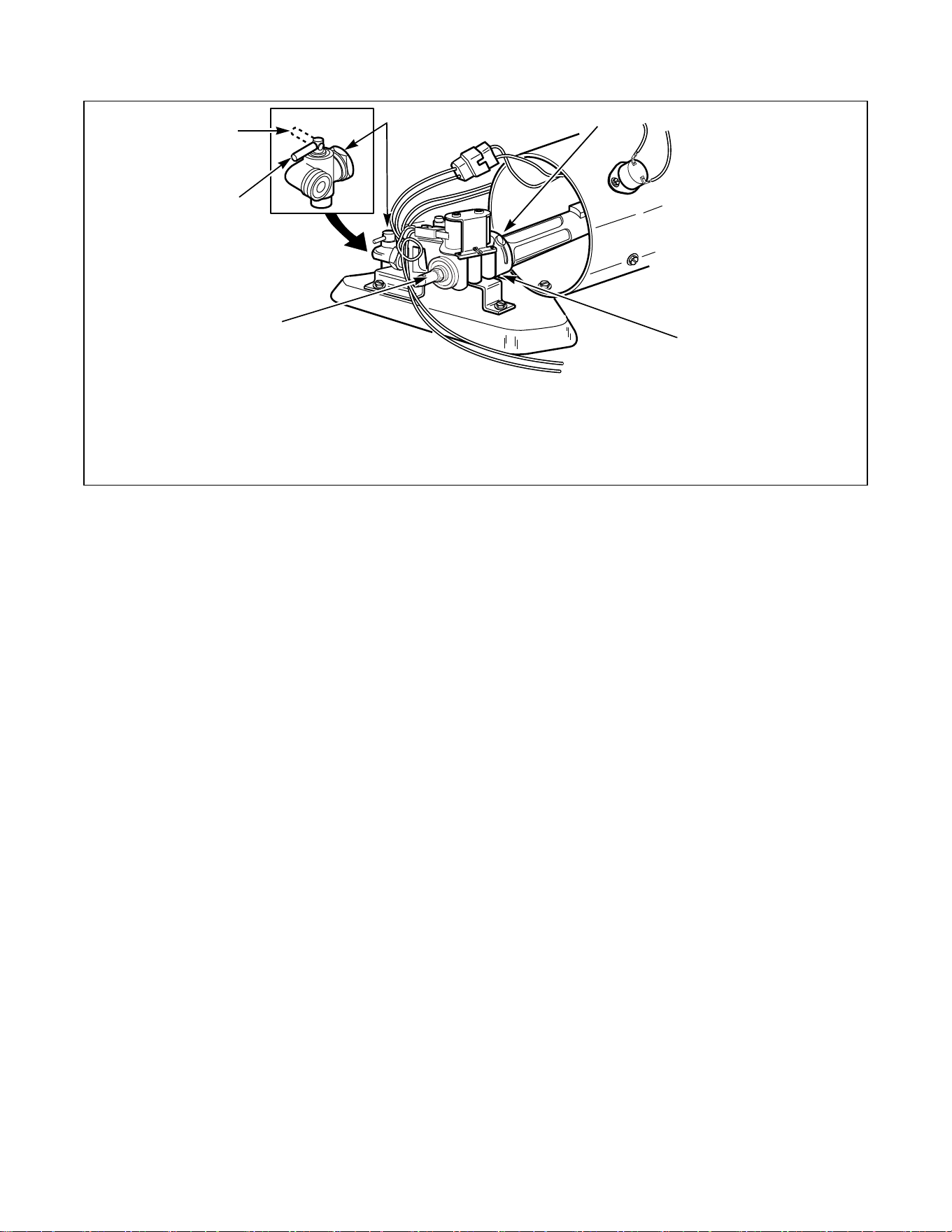
Installer Checklist
D256I
CHECK
LEVEL
D259I
D255I
• Position and Level the Dryer.
CHECK
• Position Dryer Near Installation Area.
1
2
DRY688N
CHECK
• Connect
Dryer
Exhaust
System.
DRY688N
3
TLW1988N
HOT
COLD
C
H
CHECK
• Connect Gas Supply Pipe.
• Check for Gas Leaks.
NOTE: Must be connected
by a licensed professional.
GAS DRYERS ONLY
DR233-IN
D246I
4
CHECK
DRY1956N
• Reverse Door, if
Desired
DRY1956
5
CHECK
•Wipe Out Inside of
Dryer Drum.
DRY1954N
DRY1954N
6
D671I
10A
250 V
CHECK
D670I
20 A
250 V
Electric
Gas
• Connect the Dryer to Electrical Power.
D670I
D671I
7
CHECK
• Recheck Steps 1-7.
NOTE: Refer to User Guide for proper
operation.
8
DRY2509N
FABRIC SELECTOR
AIR FLUFF
NO HEAT
REGULAR
PERM PRESS
DELICATE
CHECK
• Start and Run
Dryer in Heat
Setting to Verify
Dryer is Heating.
NOTE: Refer to
Installation
manual for
corrective action, if
necessary.
DRY2509N
9