Form 43471040
Oct 2013
INSTALLATION AND OPERATION INSTRUCTIONS
OWNER / INSTALLER: For your safety this manual must be carefully and thoroughly read and
understood before installing, operating or servicing this heater.
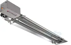
RESIDENTIAL RADIANT GARAGE TUBE HEATER
Single and Two Stage Pull Through System (Negative Pressure)
Models:
R (B,S,M) G 02
22
25 – (N1/L1/N2/L2)
R (B,S,M) G 035 – (N1/L1/N2/L2)
R (B,S,M) G 045 – (N1/L1/N2/L2)
!INSTALLER:
This manual is the property of the owner. Please present this manual to the
owner when you leave the job site.
▲WARNING: Improper installation, adjustment, alteration, service, or maintenance can
cause property damage, injury or death. Read the installation, operation and maintenance
instructions thoroughly before installing or servicing this equipment.
IF YOU SMELL GAS: FOR YOUR SAFETY
FOR YOUR SAFETYFOR YOUR SAFETY
FOR YOUR SAFETY
!
!!
!
DO NOT
DO NOTDO NOT
DO NOT try to light any appliance.
!
!!
! DO NOT
DO NOTDO NOT
DO NOT touch any electrical switch; DO NOT
DO NOTDO NOT
DO NOT use any
telephone in your building.
!
!!
! IMMEDIATELY
IMMEDIATELYIMMEDIATELY
IMMEDIATELY call your gas supplier from a neighbor's
telephone. Follow the gas supplier's instructions. If you
cannot reach your gas supplier, call the fire department.
DO NOT
DO NOT DO NOT
DO NOT store or use gasoline or other
store or use gasoline or other store or use gasoline or other
store or use gasoline or other
flammable vapors and liquids in the vicinity of
flammable vapors and liquids in the vicinity of flammable vapors and liquids in the vicinity of
flammable vapors and liquids in the vicinity of
this or any other appliance.
this or any other appliance.this or any other appliance.
this or any other appliance.
!IMPORTANT:
!IMPORTANT:!IMPORTANT:
!IMPORTANT:
SAVE THIS MANUAL FOR F
SAVE THIS MANUAL FOR FSAVE THIS MANUAL FOR F
SAVE THIS MANUAL FOR FUTURE REFERENCE.
UTURE REFERENCE.UTURE REFERENCE.
UTURE REFERENCE.
Mestek, Inc.
Mestek, Inc.Mestek, Inc.
Mestek, Inc.
260 North Elm St. • Westfield, MA 01085
Telephone (413) 568-9571 • Fax (413) 562-8437 • www.mestek.com
Form 43471040
Oct 2013 -1-
TABLE OF CONTENTS
SECTION DESCRIPTION PAGE
1.0) Safety ................................................................................................................................................... 2
2.0) Installer Responsibility ...................................................................................................................... 2
3.0) General Information........................................................................................................................... 2
4.0) Minimum Clearances to Combustibles ........................................................................................... 4
5.0) Specifications...................................................................................................................................... 5
6.0) Packing List ......................................................................................................................................... 5
6.1) Accessory Packages .......................................................................................................................... 7
7.0) Dimensions ......................................................................................................................................... 8
8.0) Heater Assembly Overview ............................................................................................................... 9
9.0) Typical Suspension Methods .......................................................................................................... 10
10.0) Heater Assembly .............................................................................................................................. 11
11.0) Gas Connections and Regulations ................................................................................................. 14
12.0) Instructions for Pressure Test Gauge Connection ....................................................................... 16
13.0) Electrical and Thermostat Connections ........................................................................................ 17
14.0) Venting ............................................................................................................................................... 25
15.0) Air for Combustion ........................................................................................................................... 30
15.1) Direct Outside Air for Combustion ................................................................................................. 30
16.0) Lighting and Shutdown Instructions .............................................................................................. 32
17.0) Sequence of Operation .................................................................................................................... 32
18.0) Control Component Location .......................................................................................................... 33
19.0) Cleaning and Annual Maintenance ............................................................................................... 34
20.0) Troubleshooting Guide..................................................................................................................... 35
21.0) Replacing Parts ................................................................................................................................ 38
21.1) Removal of Spark Electrode ........................................................................................................... 38
21.2) Removing Main Burner and Gas Valve ......................................................................................... 39
21.3) Air Switch Pressure Check .............................................................................................................. 39
21.4) Ignition System Checks ................................................................................................................... 40
21.5) Motor and Blower Wheel Check ..................................................................................................... 41
22.0) Installation Data ............................................................................................................................... 41
23.0) Replacement Parts Guide ............................................................................................................... 42
24.0) Warnings Card .................................................................................................................................. 46
This heater complies with ANSI Z83.20 (current standard) and CSA 2.34. Copies of the National Fuel Gas Code (ANSI
Z223.1-latest edition) are available from the CSA at 8501 East Pleasant Valley Road, Cleveland, Ohio 44131 or 55 Scarsdale
Road, Don Mills, Ontario M3B 2R3. All NFPA codes are available from the National Fire Protection Association, Batterymarch
Park, Quincy, Massachusetts 02269.
For installations with mounting heights less than 10 feet, install the
heater at the highest possible height for the best radiant energy
distribution.
Form 43471040
-2- Oct 2013
1.0) SAFETY
This heater is a self-contained infrared radiant tube heater. Safety information required during installation and
operation of this heater is provided in this manual and the labels on the product. The installation, service and
maintenance of this heater must be performed by a contractor qualified in the installation and service of gas
fired heating equipment.
All personnel in contact with the heater must read and understand all safety information, instructions and labels
before operation. The following symbols will be used in this manual to indicate important safety information.
SAFETY
SAFETYSAFETY
SAFETY
REQUIREMENTS
REQUIREMENTSREQUIREMENTS
REQUIREMENTS
•
••
• The heater area must be kept clear and free from combustible materials, gasoline and other flammable
vapors and liquids.
•
••
• This heater is designed for use with one type of gas (LPG or Natural). Make sure that the type of gas to be
supplied to this heater matches that shown on the heater rating plate.
•
••
• DO NOT
DO NOTDO NOT
DO NOT install this heater directly onto an LPG container or propane cylinder without directions from your
propane company. LPG containers (propane cylinders) must not be stored indoors or in the vicinity of any
gas-burning appliance.
•
••
• Children and adults should be alerted to the hazards of high surface temperatures and should stay away to
avoid burns or clothing ignition.
•
••
• Clothing or other flammable materials should not be hung from the heater or placed on or near the heater.
•
••
• Young children should be carefully supervised when they are in the same space as the heater.
•
••
• NEVER
NEVERNEVER
NEVER attempt to service the heater while it is plugged in, operating or hot. Any guard or other protective
device removed for servicing a heater must be replaced prior to operating the heater.
Warning
WarningWarning
Warning
instructions must be followed to prevent or avoid hazards which
may cause serious injury, property damage or death.
Caution
CautionCaution
Caution
instructions must be followed to prevent incorrect operati
on or
installation of
the heater which may cause minor injury or property
damage.
2.0) INSTALLER RESPONSIBILITY
The installer is responsible for the following:
•
••
• The heater and venting, as well as electrical and gas supplies must be installed in accordance with these
installation instructions and any applicable codes and regulations.
•
••
• Every heater shall be located with respect to building construction and other equipment so as to permit
access to the heater.
•
••
• Each installer must follow the clearances to combustible materials for the heaters.
•
••
• Install the heater so that the supports and hangers are correctly spaced in accordance with these
instructions. The heater must be supported by materials having a working load limit of at least 115lbs.
•
••
• Supply the owner with a copy of these Installation and Operation Instructions.
•
••
• Where unvented heaters are used, gravity or mechanical means shall be provided to supply and exhaust at
least 4 CFM per 1,000 Btu/hr input of installed heaters.
•
••
• Never use the heater as a support for a ladder or other access equipment. Do not hang anything from the
heater.
•
••
• Supply all installation materials necessary that are not included with the heater.
•
••
• Check the nameplate to make sure that the burner is correct for the gas type in the building and the
installation altitude.
3.0) GENERAL INFORMATION
This heater is a self-contained infrared radiant tube heater for use in locations where flammable gases or vapors
are not generally present (as defined by OSHA acceptable limits) and is intended for space heating of garages,
vestibules and entry ways, workshops, enclosed patios, golf practice ranges and most industrial and commercial
applications. DO NOT
DO NOTDO NOT
DO NOT install this heater in residential bedrooms or bathrooms, mobile homes or recreational
vehicles.

Form 43471040
Oct 2013 -3-
INSTALLATION RE
INSTALLATION REINSTALLATION RE
INSTALLATION REQUIREMENTS
QUIREMENTSQUIREMENTS
QUIREMENTS
The installation must conform to local building codes or in the absence of local codes, with the National Fuel Gas
Code ANSI Z223.1/NFPA54 or the Natural Gas and Propane Installation Code CSA B149.1. Heaters shall be
installed by a licensed contractor or licensed installer. Clearances to combustibles as outlined in this manual
should always be observed. In areas used for storage of combustible materials where they may be stacked
below the heater, NFPA54 requires that the installer must post signs that will “specify the maximum permissible
stacking height to maintain the required clearances from the heater to combustibles.”
Every heater shall be located with respect to building construction and other equipment so as to permit access
to the heater. Each installer shall use quality installation practices when locating the heater and must give
consideration to clearances to combustible materials, vehicles parked below, lights, overhead doors, storage
areas with stacked materials, sprinkler heads, gas and electrical lines and any other possible obstructions or
hazards. Consideration also must be given to service accessibility.
The heater, when installed in aircraft hangars and public garages, must be installed in accordance with
ANSI/NFPA 409-latest edition (Standard for Aircraft Hangars), ANSI/NFPA 88a-latest edition (Standard for
Parking Structures), and ANSI/NFPA 88b-latest edition (Standard for Repair Garages) with the following
clearances:
a. At least 10 feet above the upper surfaces of wings or engine enclosures of the highest aircraft that may be
housed in the hangar and at least 8 feet above the floor in shops, offices, and other sections of hangars
communicating with aircraft storage or service areas.
b. At least 8 feet above the floor in public garages. ▲
▲▲
▲WARNING:
WARNING:WARNING:
WARNING: Minimum clearances marked on the heater
must be maintained from vehicles parked below the heater.
(FOR CANADA ONLY)
a.
Installation of this appliance is to be in accordance with latest edition of
CSA
B149.1 (
Natural Gas and
Propane Installation Code).
b. For installation in public garages or aircraft hangars, the minimum clearances from the bottom of the
infrared heater to the upper surface of the highest aircraft or vehicle shall be 50 percent greater than the
certified minimum clearance, but the clearance shall not be less than 8 feet.
Although these heaters may be used in many applications other than space heating (e.g., process heating),
Mestek will not recognize the warranty for any use other than space heating.
For indoor installation only. No
For indoor installation only. NoFor indoor installation only. No
For indoor installation only. Not for use in residential dwellings.
t for use in residential dwellings.t for use in residential dwellings.
t for use in residential dwellings.
This heater is for Indoor Installation and Covered Patio Installation only and can be used in either Vented or
Unvented mode. The term Unvented actually means Indirect Vented. While the products of combustion are
expelled into the building, national codes require ventilation in the building to dilute these products of
combustion. This ventilation may be provided by gravity or mechanical means.
This heater is not an explosion proof heater.
This heater is not an explosion proof heater.This heater is not an explosion proof heater.
This heater is not an explosion proof heater. Where the possibility of exposure to volatile and low flash point
materials exists, it could result in property damage or death. This heater must not be installed in a spray booth
where the heater can operate during the spraying process. Consult your local fire marshal or insurance company.
High Altitude:
High Altitude:High Altitude:
High Altitude:
Appliances are supplied as standard for altitudes of O to 2,000 feet (0-610 m). High-altitude ratings are obtained
by a change in the orifice size. When ordered for high altitude installations, burners are supplied by the factory
ready for high altitude installation. Check the nameplate for altitude before proceeding with the installation. In
Canada the adjustment for altitude is made in accordance with Standard CGA 2.17, Gas-Fired Appliances for Use
at High Altitudes.
Form 43471040
-4- Oct 2013
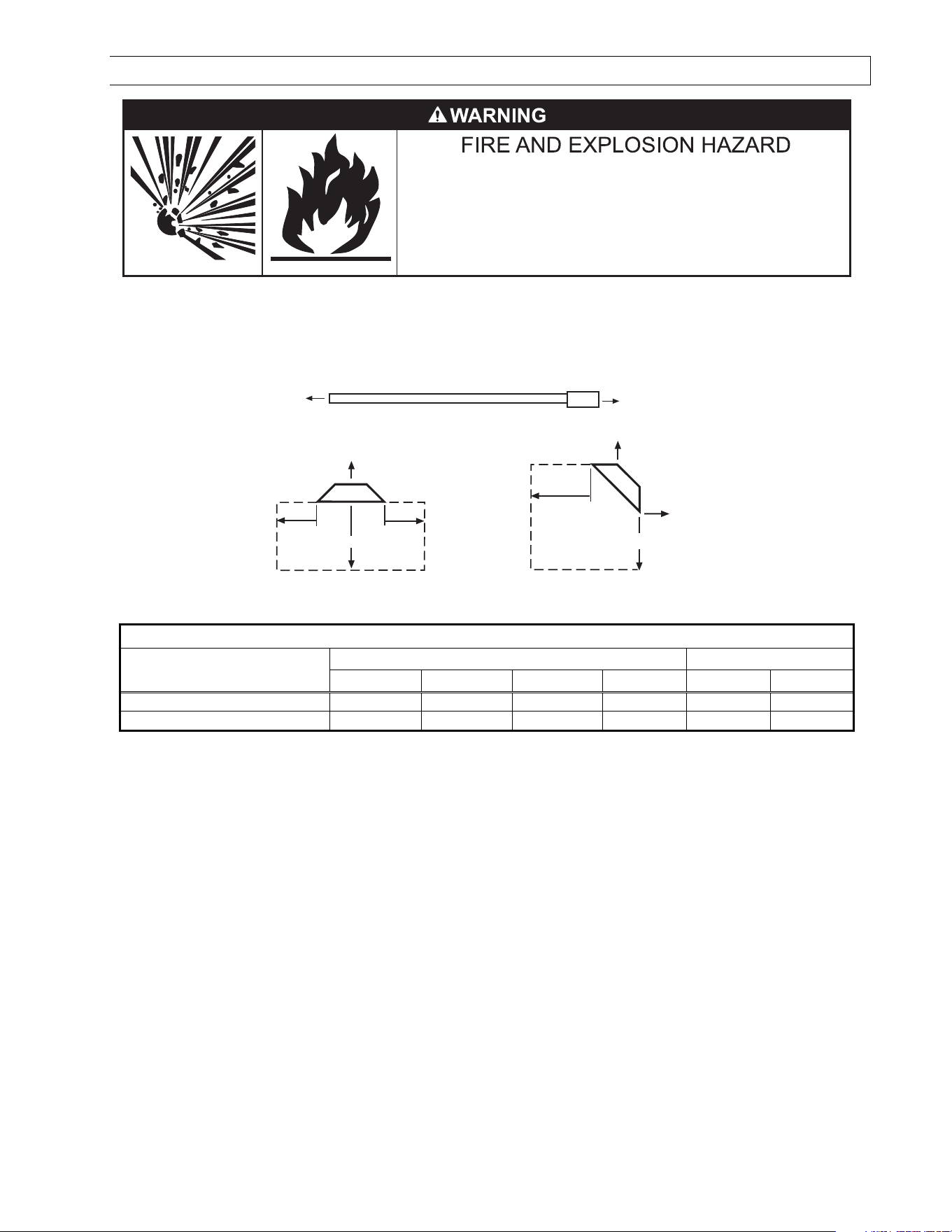
4.0) MINIMUM CLEARANCES TO COMBUSTIBLES
Failure to do so may result in death, serious injury or
property damage.
Combustible material must be located outside the
clearance dimensions listed.
Minimum clearances to combustibles shall be measured from the outer surfaces as shown in the following
diagram. For reduced clearances below the heater, use the Deflector Kit (Part No. 43504010), described in
Section 6.1), and maintain the minimum clearances specified in the notes below. Follow the instructions
packaged with the kit for installation. Install the warnings card (ordered separately) and complete the blank
spaces using the clearances from combustibles table below. See Section 24 for a printed copy of the warnings
card.
End
End
Ceiling
Below
Front
Rear
45° Angle (Maximum)
* Ceiling
Below
Side
Side
Horizontal
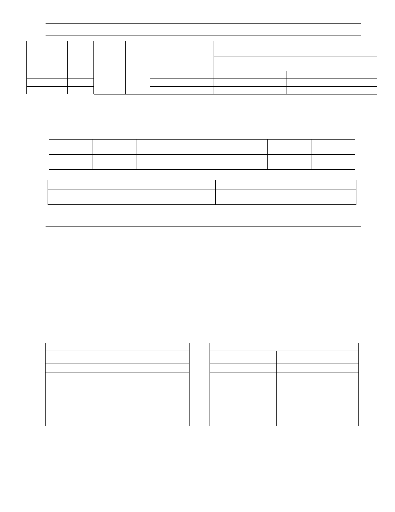
MINIMUM CLEARANCES TO COMBUSTIBLES
MINIMUM CLEARANCES TO COMBUSTIBLESMINIMUM CLEARANCES TO COMBUSTIBLES
MINIMUM CLEARANCES TO COMBUSTIBLES
Model No.
Model No.Model No.
Model No.
Mounted Horizontally
Mounted HorizontallyMounted Horizontally
Mounted Horizontally
Angle Mounted at 45º
Angle Mounted at 45ºAngle Mounted at 45º
Angle Mounted at 45º
Sides
SidesSides
Sides
Ceiling
CeilingCeiling
Ceiling
1
11
1
Below
BelowBelow
Below
2
22
2
Ends
EndsEnds
Ends
45º Front
45º Front45º Front
45º Front
45º Rear
45º Rear45º Rear
45º Rear
R (B,S,M) G
0
25
8
”
4
”
4
1
”
*
8
”
30
”
4
”
R (B,
S,M) G
0
35,
0
45
12
”
4
”
57
”
**
8
”
4
0
”
4
”
1
The clearance is 12” when installed in an UNVENTED
UNVENTEDUNVENTED
UNVENTED configuration in industrial and commercial installations.
2
IN CANADA
IN CANADAIN CANADA
IN CANADA, clearances below the heater are:
R (B,S,M) G 025: 36” (27” with deflector);
R (B,S,M) G 035, 045: 48” (36” with deflector)
* The clearance is 33” with deflector.
** The clearance is 42” with deflector / 30” side clearance with deflector.
▲WARNING:
▲WARNING:▲WARNING:
▲WARNING:
Certain materials or objects, when stored under the heater, will be subjected to radiant heat and
Certain materials or objects, when stored under the heater, will be subjected to radiant heat and Certain materials or objects, when stored under the heater, will be subjected to radiant heat and
Certain materials or objects, when stored under the heater, will be subjected to radiant heat and
could be seriously damaged.
could be seriously damaged.could be seriously damaged.
could be seriously damaged.
Observe the Minimum Clearances to Combustibles listed in the manual and on the
Observe the Minimum Clearances to Combustibles listed in the manual and on the Observe the Minimum Clearances to Combustibles listed in the manual and on the
Observe the Minimum Clearances to Combustibles listed in the manual and on the
heater at all times.
heater at all times.heater at all times.
heater at all times.
NOTE:
NOTE:NOTE:
NOTE:
1.
1. 1.
1. The cleara
The clearaThe cleara
The clearances specified above must be maintained to combustibles and other materials that may be
nces specified above must be maintained to combustibles and other materials that may be nces specified above must be maintained to combustibles and other materials that may be
nces specified above must be maintained to combustibles and other materials that may be
damaged by temperatures 90ºF above ambient temperature.
damaged by temperatures 90ºF above ambient temperature.damaged by temperatures 90ºF above ambient temperature.
damaged by temperatures 90ºF above ambient temperature.
Clearances to combustibles are posted on the
Clearances to combustibles are posted on the Clearances to combustibles are posted on the
Clearances to combustibles are posted on the
control box.
control box.control box.
control box.
In areas used for storage of combustible materials whe
In areas used for storage of combustible materials wheIn areas used for storage of combustible materials whe
In areas used for storage of combustible materials where they may be stacked below the heater,
re they may be stacked below the heater, re they may be stacked below the heater,
re they may be stacked below the heater,
NFPA54 requires that the installer must post signs that will “specify the maximum permissible stacking height
NFPA54 requires that the installer must post signs that will “specify the maximum permissible stacking height NFPA54 requires that the installer must post signs that will “specify the maximum permissible stacking height
NFPA54 requires that the installer must post signs that will “specify the maximum permissible stacking height
to maintain the required clearances from the heater to combustibles.”
to maintain the required clearances from the heater to combustibles.”to maintain the required clearances from the heater to combustibles.”
to maintain the required clearances from the heater to combustibles.”
Mestek
MestekMestek
Mestek
recommends posting these sig
recommends posting these sigrecommends posting these sig
recommends posting these signs
ns ns
ns
adjacent to the heater thermostat or other suitable location that will provide enhanced visibility.
adjacent to the heater thermostat or other suitable location that will provide enhanced visibility.adjacent to the heater thermostat or other suitable location that will provide enhanced visibility.
adjacent to the heater thermostat or other suitable location that will provide enhanced visibility.
2. The stated clearance to combustibles represents a surface temperature of 90
2. The stated clearance to combustibles represents a surface temperature of 902. The stated clearance to combustibles represents a surface temperature of 90
2. The stated clearance to combustibles represents a surface temperature of 90
ºF
ºFºF
ºF
(32
(32(32
(32
ºC) above room
ºC) above room ºC) above room
ºC) above room
temperature. Building materials with a low heat tole
temperature. Building materials with a low heat toletemperature. Building materials with a low heat tole
temperature. Building materials with a low heat tolerance (such as plastics, vinyle siding, canvas, tri
rance (such as plastics, vinyle siding, canvas, trirance (such as plastics, vinyle siding, canvas, tri
rance (such as plastics, vinyle siding, canvas, tri-
--
-ply, etc.)
ply, etc.) ply, etc.)
ply, etc.)
may be subject to degradation at lower temperatures. It is the installer’s responsibility to assure that adjacent
may be subject to degradation at lower temperatures. It is the installer’s responsibility to assure that adjacent may be subject to degradation at lower temperatures. It is the installer’s responsibility to assure that adjacent
may be subject to degradation at lower temperatures. It is the installer’s responsibility to assure that adjacent
materials are protected from degradation.
materials are protected from degradation.materials are protected from degradation.
materials are protected from degradation.
Form 43471040
Oct 2013 -5-
5.0) SPECIFICATIONS
Model
Model Model
Model
Series
Series Series
Series No.
No.No.
No.
R (
R (R (
R (B,S,M)G
B,S,M)GB,S,M)G
B,S,M)G
Btu/hr
Btu/hrBtu/hr
Btu/hr
Input
InputInput
Input
Heat
Heat Heat
Heat
Exchanger
Exchanger Exchanger
Exchanger
Length
LengthLength
Length
Total
Total Total
Total
Heater
Heater Heater
Heater
Length
LengthLength
Length
Flue Restrictor
Flue RestrictorFlue Restrictor
Flue Restrictor
Plate
PlatePlate
Plate
I.D. &
I.D. & I.D. &
I.D. & Part #
Part #Part #
Part #
Orifice Size
Orifice SizeOrifice Size
Orifice Size
Minimum *
Minimum *Minimum *
Minimum *
Mounting Height
Mounting HeightMounting Height
Mounting Height
Natural Gas
Natural GasNatural Gas
Natural Gas
Propane Gas
Propane GasPropane Gas
Propane Gas
@
@@
@
Horizontal
HorizontalHorizontal
Horizontal
@
@@
@
45º Angle
45º Angle45º Angle
45º Angle
025
2
5
,000
16’ 9’-3”
7/8”
#4
2741120
#4
2
(0.
0
94
)
#52
(0.0
64
)
8’
8’
0
3
5
35
,000
1”
#4
2741041
#35
(0.1
10
)
1.75mm
(0.0
69
)
8’
8’
0
45
45
,000
1
-
1/8”
#4
2741031
1/8”
(0.1
25
)
5/64”
(0.0
78
)
8’
8’
* MOUNT HEATERS AS HIGH AS POSSIBLE. Minimums are shown as a guideline for human comfort and uniform
energy distribution for complete building heating applications. Consult your Mestek representative for the
particulars of your installation requirements.
Type
TypeType
Type
Gas
GasGas
Gas
Gas Pipe
Gas PipeGas Pipe
Gas Pipe
Connection
Connection Connection
Connection
Tube
TubeTube
Tube
Diameter
DiameterDiameter
Diameter
Flue
FlueFlue
Flue
Connection
ConnectionConnection
Connection
Fresh Air
Fresh Air Fresh Air
Fresh Air
Connection
ConnectionConnection
Connection
Electrical
ElectricalElectrical
Electrical
Supply
SupplySupply
Supply
Current
CurrentCurrent
Current
Rating
RatingRating
Rating
Natural
or Propane
½” MPT
(Male) 3” 4” Round 4” Round
120 Volt,
60Hz,
1 Phase 2.6 Amp
Fuse
FuseFuse
Fuse
Rating:
Rating:Rating:
Rating:
Ignition System (direct spark):
Ignition System (direct spark):Ignition System (direct spark):
Ignition System (direct spark):
Spark Module: 2
Amp 250V
(for 24V Circuit)
30 second pre-purge period
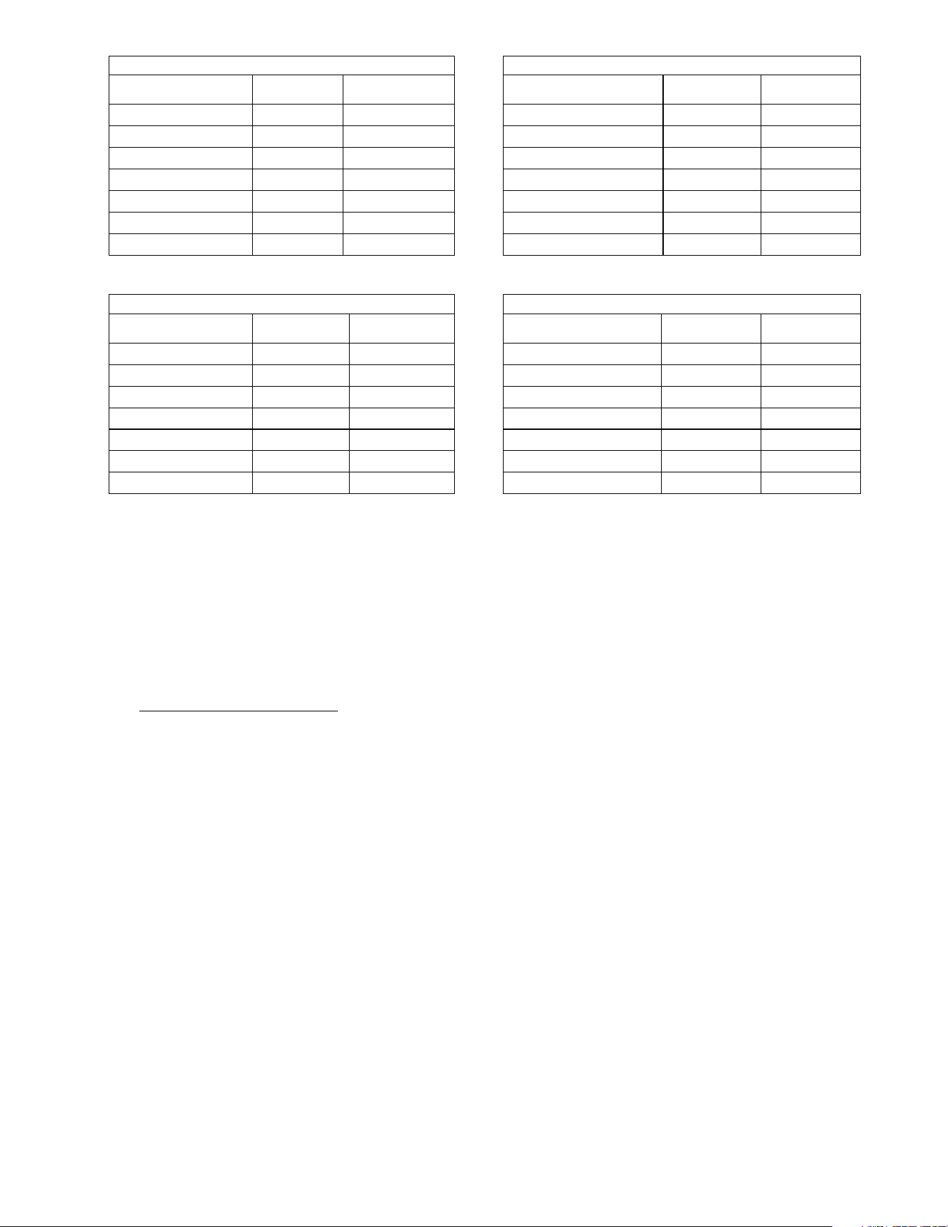
6.0) PACKING LIST
A.
A.A.
A. Control/Draft Inducer
Control/Draft InducerControl/Draft Inducer
Control/Draft Inducer
Package
PackagePackage
Package
Part Description
Part Description Part Description
Part Description
QTY
QTYQTY
QTY
Control Box Assembly
................................
................................
................................
..............................
1
Draft Inducer Assembly (with 4” Starting Collar
#40504020
)
................................
.........................
1
Flue Restrictor Plate (refer to
5.0)
for I.D. & part number)
................................
................................
.
1
15” Plastic Vacuum Air Tube (#03988150)
................................
................................
..........................
1
Control
Fastene
r Kit
(#42
787000
)
................................
................................
................................
........
1
Containing:
¼
-
20 Locknuts
(#02167010)
................................
.............................
6
Gas
C
onnector 5/8” OD x 36”
(#30302360)
................................
................................
.......................
1
Installation & Operation Instructions
(#4
34
710
1
0)
................................
................................
...........
1
CONTROL/DRAFT INDUCER
CONTROL/DRAFT INDUCER CONTROL/DRAFT INDUCER
CONTROL/DRAFT INDUCER PACKAGE NUMBERS
PACKAGE NUMBERSPACKAGE NUMBERS
PACKAGE NUMBERS
1
11
1
-
--
-
STAGE CONTROLS
STAGE CONTROLS STAGE CONTROLS
STAGE CONTROLS
-
--
-
MESTEK
MESTEKMESTEK
MESTEK
2
22
2
-
--
-
STAGE CONTROLS
STAGE CONTROLS STAGE CONTROLS
STAGE CONTROLS
-
--
-
ME
MEME
ME
STEK
STEKSTEK
STEK
MODEL NO.
MODEL NO.MODEL NO.
MODEL NO.
PART NO.
PART NO.PART NO.
PART NO.
GAS TYPE
GAS TYPEGAS TYPE
GAS TYPE
MODEL NO.
MODEL NO.MODEL NO.
MODEL NO.
PART NO.
PART NO.PART NO.
PART NO.
GAS TYPE
GAS TYPEGAS TYPE
GAS TYPE
RMG025N1U0
44499010
NATURAL
RMG025N2U0
44499510
NATURAL
RMG035N1U0
44499030
NATURAL
RMG035N2U0
44499530
NATURAL
RMG045N1U0
44499050
NATURAL
RMG045N2U0
44499550
NATURAL
RMG025L1U0
44499020
PROPANE
RMG025L2U0
44499520
PROPANE
RMG035L1U0
44499040
PROPANE
RMG035L2U0
44499540
PROPANE
RMG045L1U0
44499060
PROPANE
RMG045L2U0
44499560
PROPANE
Form 43471040
-6- Oct 2013
1
11
1
-
--
-
STAGE CONTROLS
STAGE CONTROLS STAGE CONTROLS
STAGE CONTROLS
-
--
-
STERLING
STERLINGSTERLING
STERLING
2
22
2
-
--
-
STAGE CONTROLS
STAGE CONTROLS STAGE CONTROLS
STAGE CONTROLS
-
--
-
STERLING
STERLINGSTERLING
STERLING
MODEL NO.
MODEL NO.MODEL NO.
MODEL NO.
PART NO.
PART NO.PART NO.
PART NO.
GAS TYPE
GAS TYPEGAS TYPE
GAS TYPE
MODEL NO.
MODEL NO.MODEL NO.
MODEL NO.
PART NO.
PART NO.PART NO.
PART NO.
GAS TYPE
GAS TYPEGAS TYPE
GAS TYPE
RSG025N1U0
44497010
NATURAL
RSG025N2U0
44497510
NATURAL
RSG035N1U0
44497030
NATURAL
RSG035N2U0
44497530
NATURAL
RSG045N1U0
44497050
NATURAL
RSG045N2U0
44497550
NATURAL
RSG025L1U0
44497020
PROPANE
RSG025L2U0
4
4497520
NATURAL
RSG035L1U0
44497040
PROPANE
RSG035L2U0
44497540
NATURAL
RSG045L1U0
44497060
PROPANE
RSG045L2U0
44497560
NATURAL
1
11
1-
--
-STAGE CONTROLS
STAGE CONTROLS STAGE CONTROLS
STAGE CONTROLS –
––
–
BEACON/MORRIS
BEACON/MORRISBEACON/MORRIS
BEACON/MORRIS
2
22
2-
--
-STAGE CONTROLS
STAGE CONTROLS STAGE CONTROLS
STAGE CONTROLS –
––
–
BEACON/MORRIS
BEACON/MORRISBEACON/MORRIS
BEACON/MORRIS
MODEL NO.
MODEL NO.MODEL NO.
MODEL NO.
PART NO.
PART NO.PART NO.
PART NO.
GAS TYPE
GAS TYPEGAS TYPE
GAS TYPE
MODEL NO.
MODEL NO.MODEL NO.
MODEL NO.
PART NO.
PART NO.PART NO.
PART NO.
GAS TYPE
GAS TYPEGAS TYPE
GAS TYPE
RBG025N1U0
44501010
NATURAL
RBG025N2U0
44501510
NATURAL
RBG035N1U0
44501030
NATURAL
RBG035N2U0
44501530
NATURAL
RBG045N1U0
44501050
NATURAL
RBG045N2U0
44501550
NATURAL
RBG025L1U0
44501020
PROPANE
RBG025L2U0
44501520
PROPANE
RBG035
L1U0
44501040
PROPANE
RBG035L2U0
44501540
PROPANE
RBG045L1U0
44501060
PROPANE
RBG045L2U0
44501560
PROPANE
B.
B.B.
B. Body Package Descriptions
Body Package DescriptionsBody Package Descriptions
Body Package Descriptions
Part Description
Part Description Part Description
Part Description
QTY
QTYQTY
QTY
#4
3468000
,
8
Ft. Body Package
................................
................................
................................
...........
1
Containing:
#4
3469
000, Pre
-
assembled
8
’ ALC steel tube asse
mbly with reflectors
..........
1
#42762010, Control End Reflector
................................
................................
...........
1
#42761010, Foot End Reflector
................................
................................
................
1
#02125
1
30,
#10
-
24x1/2 Screws
................................
................................
..............
4
#02266010, Speed Clips
................................
................................
...........................
1
4
#42769010, Sliding Clamps
................................
................................
......................
4
Form 43471040
Oct 2013 -7-
6.1) ACCESSORY PACKAGES
A.
A.A.
A.
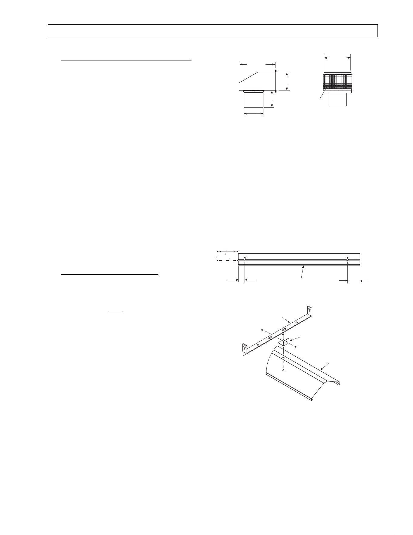
Exhaust Hood Package, Part #42924000
Exhaust Hood Package, Part #42924000Exhaust Hood Package, Part #42924000
Exhaust Hood Package, Part #42924000
Contains:
Exhaust Hood Assembly, #42925550……QTY–1
#8-18 x ½ Self-Drilling Screws, #02189030……QTY–2
4 (10cm)
7 1/2
(19cm)
3 3/4 (10cm)
3 1/2 (9cm)
6
(15cm)
Bird
Screen
Side View
Front View
B.
B.B.
B. Deflector Kit, Part #435040
Deflector Kit, Part #435040Deflector Kit, Part #435040
Deflector Kit, Part #4350401
11
10
00
0
The Deflector Kit is available for use to reduce the
clearances to combustibles below the heater. Refer
to the Minimum Clearances to Combustibles Table
Minimum Clearances to Combustibles TableMinimum Clearances to Combustibles Table
Minimum Clearances to Combustibles Table in
Section 4.0) when using this Deflector Kit. Heater
Heater Heater
Heater
must be mounted
must be mounted must be mounted
must be mounted ONLY
ONLYONLY
ONLY
in the horizontal position
in the horizontal position in the horizontal position
in the horizontal position
when using this kit.
when using this kit.when using this kit.
when using this kit.
Deflector
Deflector
Bracket
Hanger Bracket
(tube & reflector
components not
shown)
Deflector
10 1/2
(267mm)
5 1/2
(140mm)
Form 43471040
-8- Oct 2013
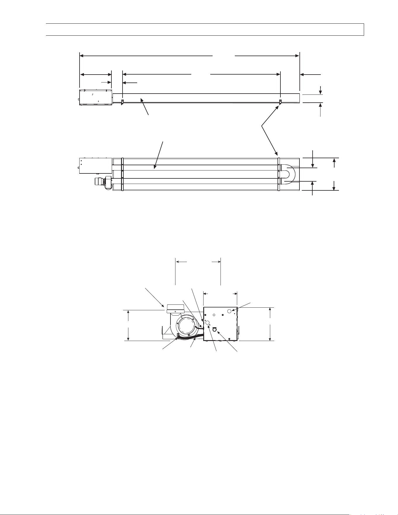
7.0) DIMENSIONS
15
(381mm)
5 1/2
(140mm)
111
(280cm)
80
(203cm)
10 1/2
(267mm)
5 1/4
(133mm)
Side View
Bottom View
Hanger Bracket
(QTY-2)
Emitter Tube
Reflector
8 FT Body Section
18 1/2
(470mm)
7 1/2
(191mm)
Plastic Vacuum
Air Tube
1/4 O.D.
Tube
Strain Relief
Bushing
Motor
Leads
Sight
Glass
1/2MPT
Gas Connection
8 (20cm)
7 (18cm)
8 (20cm)
Electrical
Connection
End View
Control
Box
Draft Inducer
(vertical mounting)
9 (23cm)
Form 43471040
Oct 2013 -9-
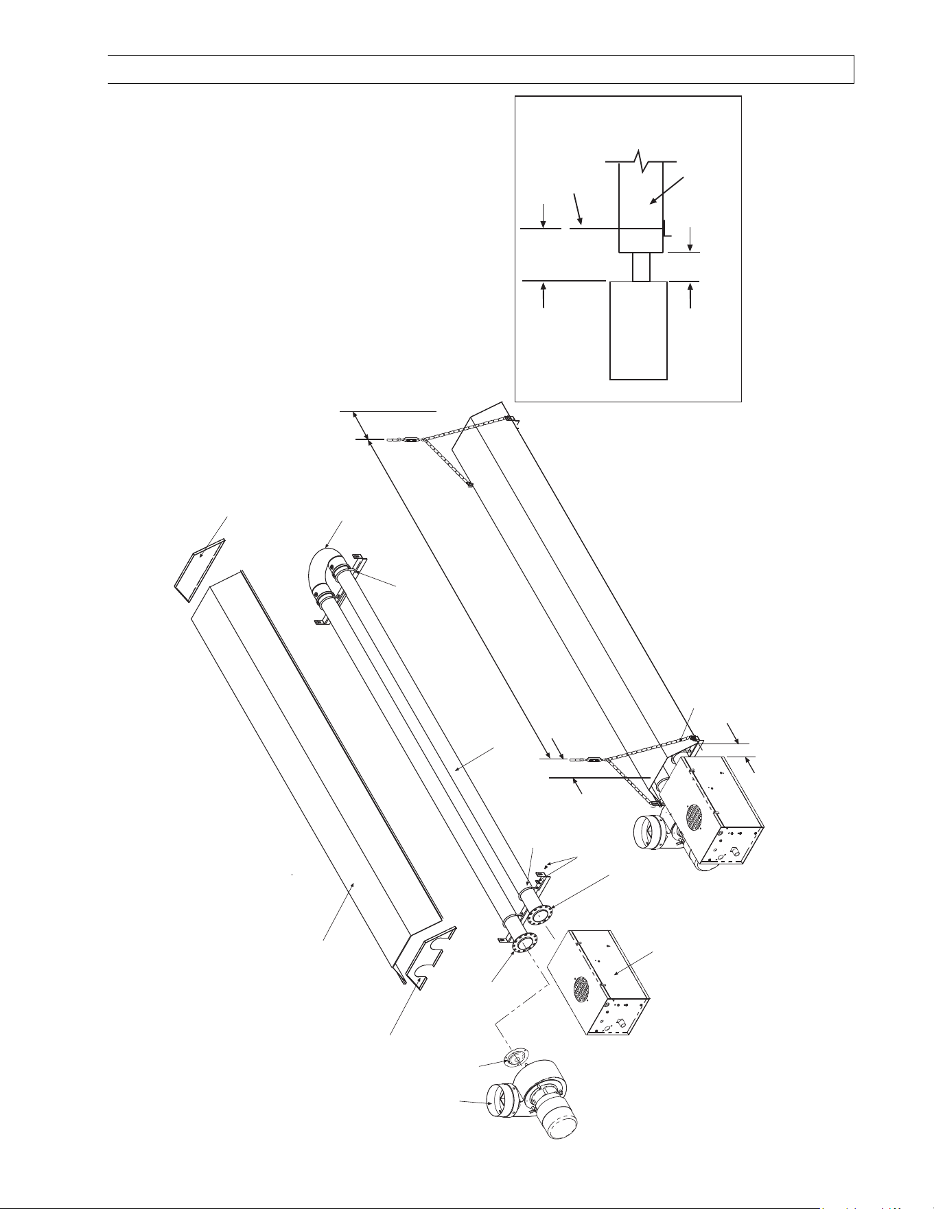
8.0) HEATER ASSEMBLY OVERVIEW
Control Box
Reflector clamp
with screw
Exhauster
assembly
Restrictor
airplate
Tube support/
hanger bracket
U bolt clamp &
5/16 Hex nuts
3 OD x 8 tube
Mounting flange
(12 radial holes)
Mounting flange
(12 radial holes)
Suspension chain
with turnbuckle
Reflector, foot end
5-1/2
80
10-1/2
Reflector, control end
Reflector
3
(control box to reflector)
(control box to chain)
Suspension
chain
Control box
reflector
3
5-1/2
Side View
U bend
Form 43471040
-10- Oct 2013
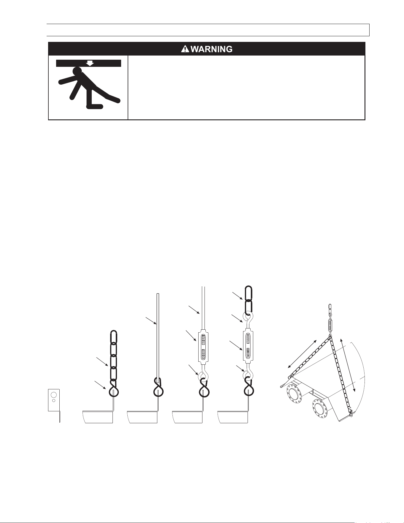
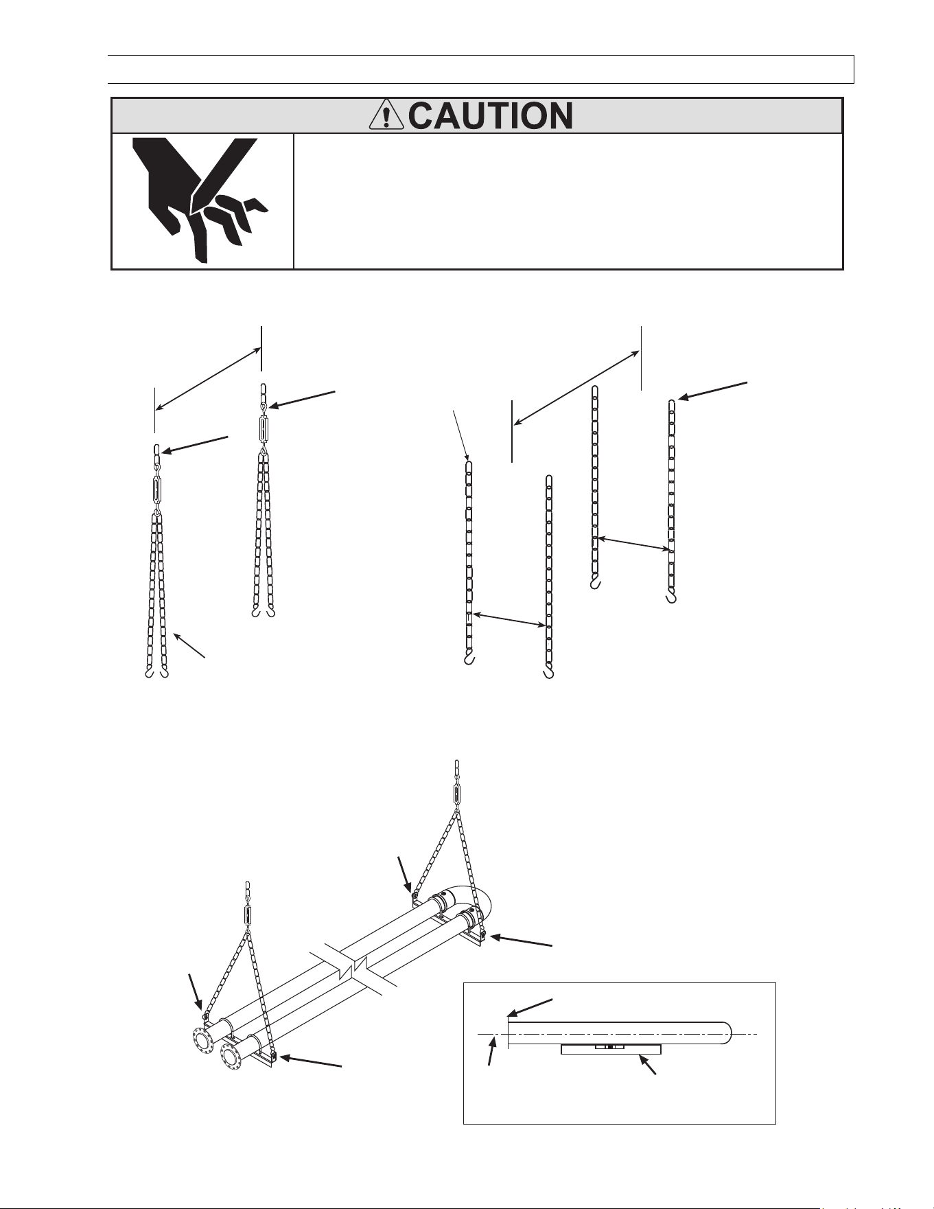
9.0) TYPICAL SUSPENSION METHODS
Burner must be secured to the mounting flange with nuts.
All materials used to suspend the heater must have a minimum working load
of 115 lbs.
All S Hooks must be crimped closed.
Never use the heater to support a ladder or other access equipment.
Failure to do so may result in death, serious injury or property damage.
SUSPENSION HAZARD
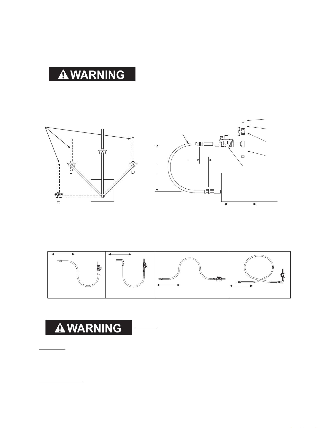
Various means of suspending the heater can be used. See the following drawings for typical examples.
1. Use only noncombustible materials for suspending hangers and brackets.
2. A minimum No. 2 chain with a working load limit of 115 lbs. is required.
3. Turnbuckles can be used with chains to allow leveling of the heater. All “S” hooks and eye bolts must be
manually crimped closed by the installer.
4. When using rigid means for heater suspension (rod, flat bar, etc.) provide sufficient lengths or swing joints to
compensate for expansion. See Figures b and c.
5. Heaters subject to vibration must be provided with vibration isolating hangers.
6. Heaters must not be supported by gas or electric supply lines and must be suspended from a permanent
structure with adequate load capacity.
Mestek recommends that the tube sections be suspended using chains with turnbuckles. This will allow slight
adjustments after assembly and heater expansion/ contraction during operation.
If a “trapeze” method is used for tube support/hanger brackets (shown below), the minimum chain length for the
two connecting chains is 36” to minimize any vibration that might be generated by the draft inducer assembly. If
these chains must be less than 36”, then do not use the trapeze method and, instead, use individual chains on
each tube support/hanger bracket.
c.
Eyebolt
Turnbuckle
Minimum
No. 2 Chain
Eyebolt
b.
Threaded
Rod
Turnbuckle
Eyebolt
a.
3/16 x 1 wide
Flat Bar
36 (91cm) Minimum
36 (91cm) Minimum
Minimum
No. 2 Chain
S-Hook
(typical)
d.
Form 43471040
Oct 2013 -11-
10.0) HEATER ASSEMBLY
Sheet metal parts, particularly reflectors and vent have sharp
edges. Always use gloves when handling.
Failure to do so may result in death, serious injury or property
damage.
CUT HAZARD
During field assembly of the heater, the recommended procedure is as follows:
1. Put the suspension in place (according to Section 7.0) using proper suspension method (see Section 9.0).
1
1
80
chains for suspension
80
Suspension
Chain
18-1/2
18-1/2
1
Trapeze Method
Trapeze MethodTrapeze Method
Trapeze Method
Individual Suspension Method
Individual Suspension MethodIndividual Suspension Method
Individual Suspension Method
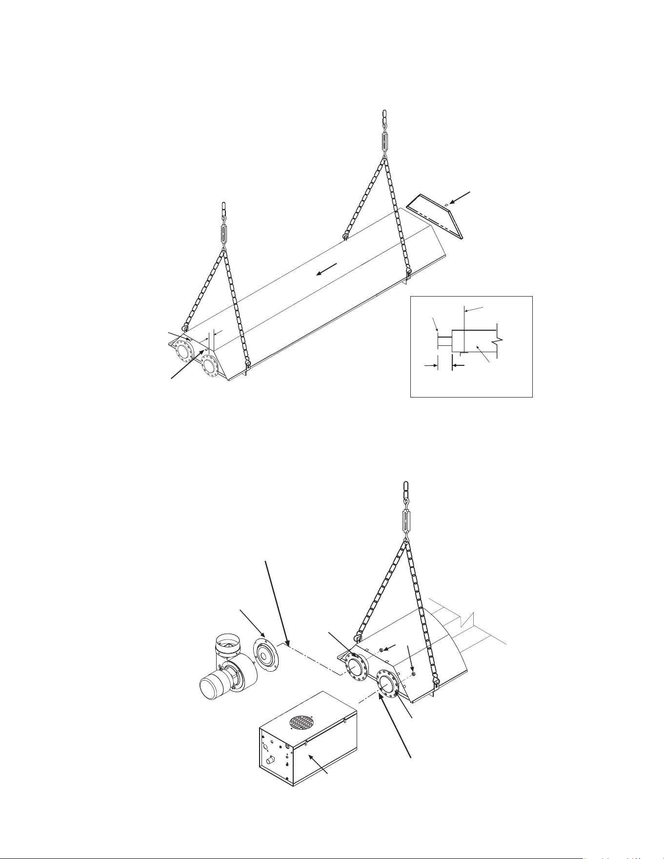
2. Lift the tube section and suspend it into place. When lifting, caution should be used to avoid damaging the
assembly. Make sure that the long axis of heater is level.
2
2
Tube Flange
Level indicator
The long axis of heater
Side View
2
2
Form 43471040
-12- Oct 2013
3. Assembly the reflector onto the tube section. Leave 3” space between the tube flange and the reflector for
later mounting of control box and draft inducer.
4. Place the flanges of the control end reflector flush with the end of the first reflector. Secure by sliding speed
clips onto reflector edges. Evenly space 6 speed clips on sides and top of reflectors to provide a snug fit.
Place foot end reflector on the opposite end of the reflector and secure as above.
4
Speed
Clip
3
Tube Flange
Side View
Suspension
chain
reflector
3
3
4
5. Attach the control box to the right-hand control tube flange and secure with 1/4-20 locknuts. The control box
must be mounted with the perforated fresh air plate on top, facing the ceiling.
6. Attach the draft inducer assembly to the left-hand draft inducer tube flange and secure with 1/4-20 locknuts.
A flue restrictor plate is attached to the draft inducer weld studs. DO NOT DISCARD RESTRICTOR PLATE
DO NOT DISCARD RESTRICTOR PLATE DO NOT DISCARD RESTRICTOR PLATE
DO NOT DISCARD RESTRICTOR PLATE and
make sure this remains in place while the draft inducer is being attached to the heater body.
5
Flue Restrictor
Plate
Do Not Discard.
Draft Inducer
(vertical position)
1/4-20
Locknuts
Tube Flange
(draft inducer)
Tube Flange
(control)
Control Box
Access
Panel
6
Form 43471040
Oct 2013 -13-
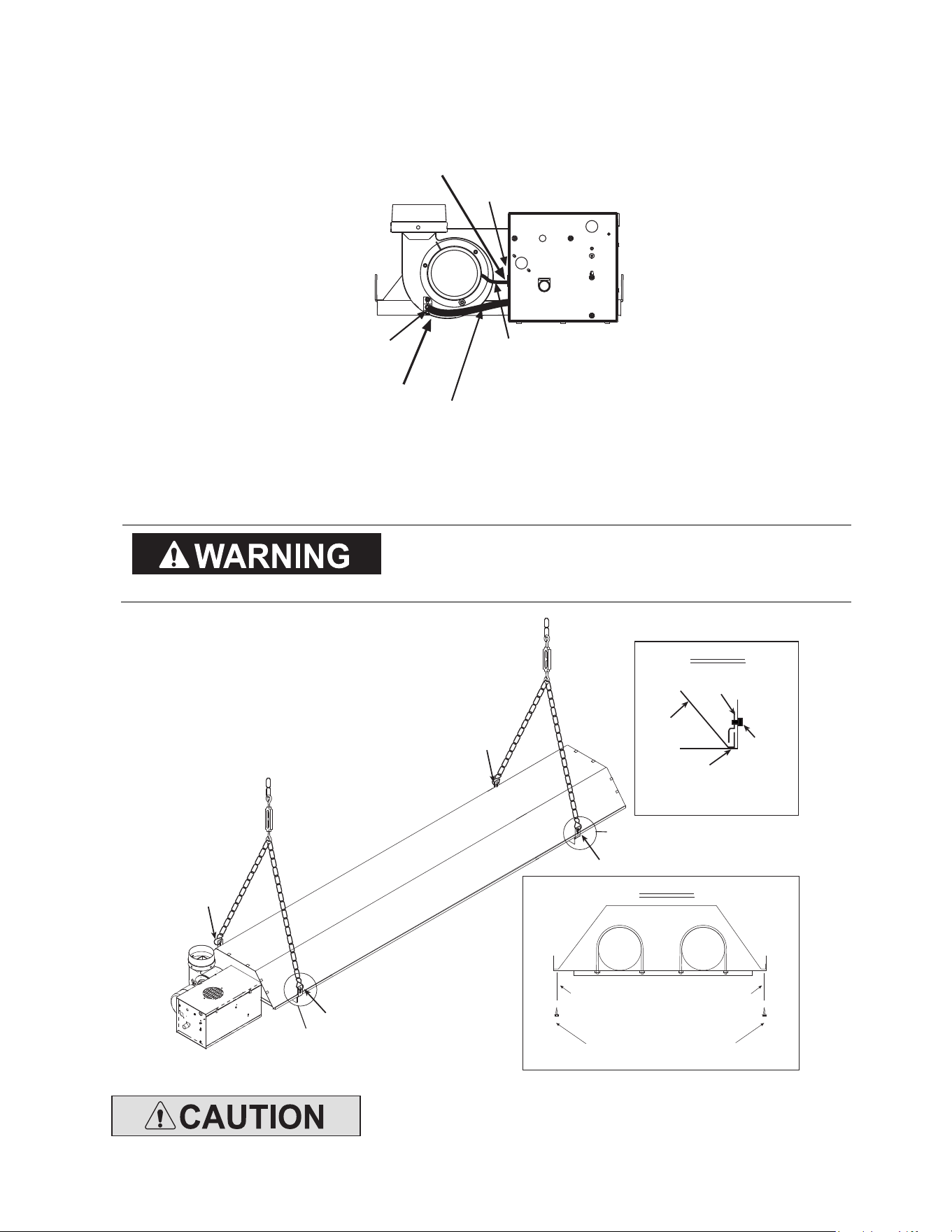
7. Slip the plastic vacuum air tube over the 1/4” O.D. aluminum tube end of the draft inducer and the air
switch probe in the control box. The air tube should be shortened to prevent a downward sag which could
allow condensation build-up in the tube.
8. Insert motor lead wires through the strain relief bushing of the control box and connect to L1 and L2 of
terminal block. Refer also to the wiring diagram in Section 13.0).
Plastic Vacuum
Air Tube
1/4 O.D.
Tube
Motor Leads
(to L1 and L2 of
the terminal block)
Strain Relief
Bushing
7
8
9. Fasten the reflector to the tube support/hanger bracket with (2) #10 sheet metal screws according to Detail
“A”. Mount the sliding reflector clamps (#42769010) per Reflector Clamp Installation (Detail “B”) on both
tube support/hanger brackets. Make sure the reflector can slide under the clamp during heater operation.
T
TT
T
he reflector clamps MUST be installed per reflector
he reflector clamps MUST be installed per reflector he reflector clamps MUST be installed per reflector
he reflector clamps MUST be installed per reflector
clamp installation detail which allows the reflector to
clamp installation detail which allows the reflector to clamp installation detail which allows the reflector to
clamp installation detail which allows the reflector to
slide under the clamp during heater operation.
slide under the clamp during heater operation.slide under the clamp during heater operation.
slide under the clamp during heater operation.
9
9
9
Tube Support &
Hanger Bracket
Reflector
Clamp
Reflector
Clamp
Screw
Reflector Clamp Installation
9
See Detail A & B
DETAIL A
Fasten screws to tube
hanger/support bracket and reflector
(only the tube hanger/support
bracket closest to the control end)
#10 x 1/2 SHEET METAL
SCREWS (QTY - 2)
DETAIL B
See Detail B
Do not relocate the tube support/hanger bracket at the control box end of
Do not relocate the tube support/hanger bracket at the control box end of Do not relocate the tube support/hanger bracket at the control box end of
Do not relocate the tube support/hanger bracket at the control box end of
the heater. This wi
the heater. This withe heater. This wi
the heater. This wi
ll increase the weight on the emitter tube and can result
ll increase the weight on the emitter tube and can result ll increase the weight on the emitter tube and can result
ll increase the weight on the emitter tube and can result
in premature tube failure.
in premature tube failure.in premature tube failure.
in premature tube failure.
Form 43471040
-14- Oct 2013
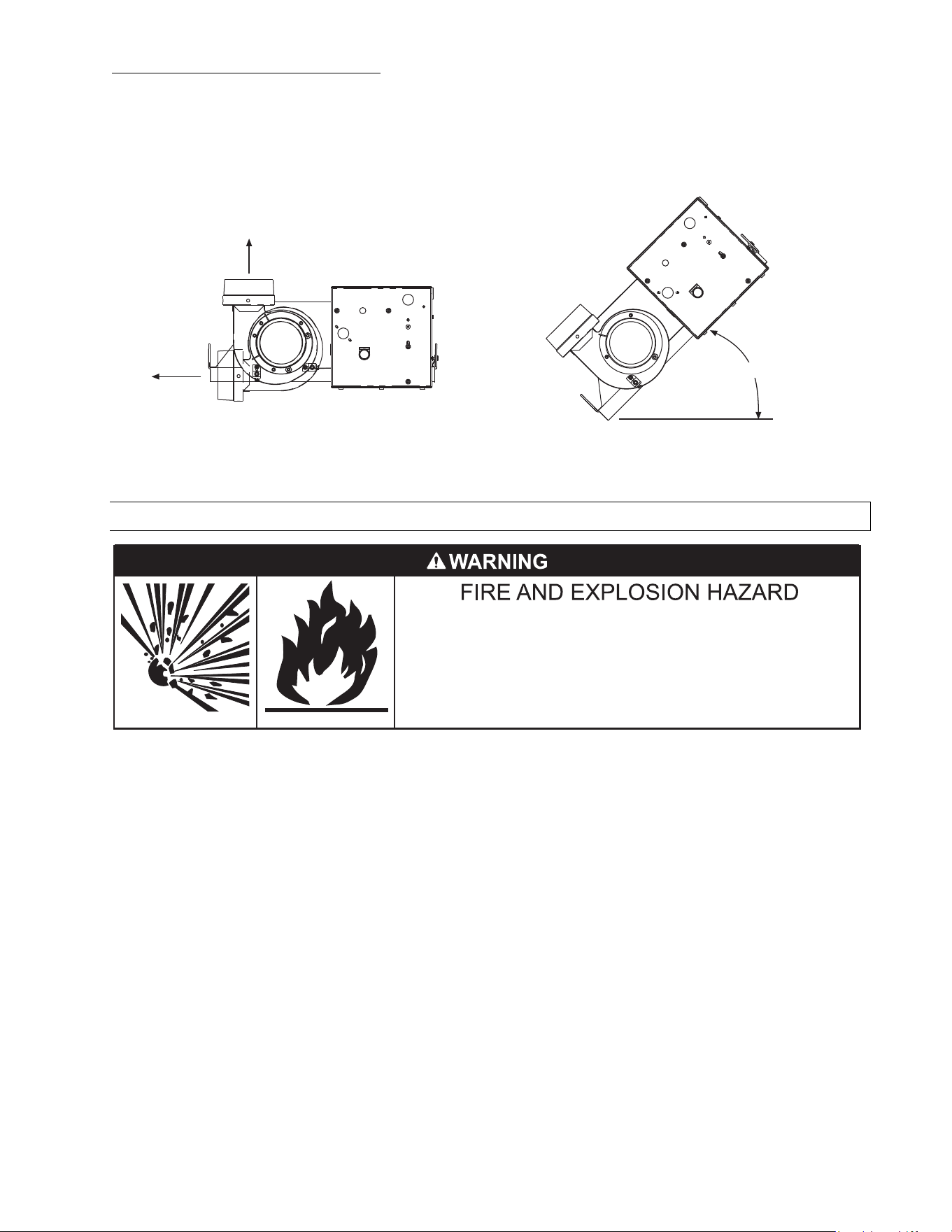
ANGLE MOUNTED HEATERS ONLY
ANGLE MOUNTED HEATERS ONLYANGLE MOUNTED HEATERS ONLY
ANGLE MOUNTED HEATERS ONLY
10. The heater can be mounted horizontally or up to an angle of 45º maximum from horizontal. When the heater
is to be angle mounted adjacent to a sidewall, make sure the draft inducer assembly is on the lower side of
the heater so that the control box access panel is easily accessible. Make sure the long axis of heater is level.
Multiple draft inducer positions can also be used as shown in the diagrams. This allows for the desired
configuration of flue venting.
Horizontal Mounting
Angle Mounting
Horizontal
Vertical
45 Deg. (maximum)
11.0) GAS CONNECTIONS AND REGULATIONS
Tighten flexible gas hose and components securely.
Flexible metal gas hoses must be installed without any twists or
kinks in them. The hose will move during operation of the heater
and it can crack if it is twisted.
Failure to do so may result in death, serious injury or property
damage.
IMPORTANT BEFORE CONNECTING THE GAS TO THE HEATER
IMPORTANT BEFORE CONNECTING THE GAS TO THE HEATERIMPORTANT BEFORE CONNECTING THE GAS TO THE HEATER
IMPORTANT BEFORE CONNECTING THE GAS TO THE HEATER
1. Connect to the supply tank or manifold in accordance with the latest edition of National Fuel Gas Code (ANSI
Z223.1), and local building codes. Authorities having jurisdiction should be consulted before the installation
is made. (In Canada, refer to the latest edition of CSA Standard B149.1, Natural Gas and Propane
Installation Code.)
2. Check that the gas fuel on the burner rating plate matches the fuel for the application.
3. Check that the gas supply piping has the capacity for the total gas consumption of the heaters and any other
equipment connected to the line.
4. Check that the calculated supply pressure with all gas appliances and heaters operating will not drop below
the minimum supply pressure required for these heaters. Check inlet supply pressures on Section 12.0).
5. All gas supply lines must be located in accordance with the required clearances to combustibles from the
heater as listed on the clearances label of the heater and Section 4.0) of this manual.
6. Pipe joint compounds must be resistant to the action of liquefied petroleum gases.
7. Tube heaters will expand/contract during operation. Where local codes do not prohibit, a CSA or U.L.
approved flexible connector supplied with this heater is required for connections between the rigid piping
and the heater. A union should be installed before the control box inlet. An approved shut off valve should be
installed within 6 feet of the union.
8. The gas pipe, flexible hose and connections must be self supporting. The gas pipe work must not bear any of
the weight of the heater or any other suspended assembly.
9. This appliance is equipped with a step-opening, combination gas valve. The maximum supply pressure to the
The maximum supply pressure to the The maximum supply pressure to the
The maximum supply pressure to the
appliance is 14” W.C. or 1/2 P.S.I.
appliance is 14” W.C. or 1/2 P.S.I.appliance is 14” W.C. or 1/2 P.S.I.
appliance is 14” W.C. or 1/2 P.S.I. If the line pressure is more than the maximum supply pressure, then a
second stage regulator which corresponds to the supply pressure must be used.
Form 43471040
Oct 2013 -15-
10. After all gas connections have been made, make sure the heater and all gas outlets are turned off before
the main gas supply is turned on slowly
main gas supply is turned on slowlymain gas supply is turned on slowly
main gas supply is turned on slowly. Turn the gas supply pressure on and check for leaks. To check for
leaks, check by one of the methods listed in Appendix D of the National Fuel Gas Code.
11. If a 2nd stage regulator is used, the ball valve down stream in the supply line must be closed when purging
the gas lines to prevent gas seeping through it. If initial gas pressure is higher than 14” w.c. the redundant
combination gas valve is designed to lock out. Pressure build-up in the supply lines prior to the heater must
be released before proper heater operation.
DO
DO DO
DO not use an open flame of any kind to test for leaks.
not use an open flame of any kind to test for leaks.not use an open flame of any kind to test for leaks.
not use an open flame of any kind to test for leaks.
END VIEW
SIDE VIEW
Alternate Supply
Locations
* Available as Accessories
KEY DIMENSIONS AND COMPONENTS OF THE GAS CONNECTIONS
14 to 17
(36 to 43cm)
Approved
Flexible Connector
36
*Second Stage Regulator with
Vent Leak Limiter to reduce the
Supply Pressure below 14 W.C.
Gas Pressure
= 2 PSIG
Gas Supply
Piping
Sediment Trap
(Drip Leg)
*Manual Gas
Shut Off Valve
Burner Movement
2 (5cm) Max.
Displacement
INCORRECT POSITIONS
Movement
WRONG
Movement
WRONG
Movement
WRONG
Movement
WRONG
US ONLY:
US ONLY:US ONLY:
US ONLY:
Connector MUST be installed in “
Connector MUST be installed in “Connector MUST be installed in “
Connector MUST be installed in “⊃
⊃⊃
⊃
” configuration. Use only
” configuration. Use only ” configuration. Use only
” configuration. Use only
the 36” long connector that was furnished with this heater.
the 36” long connector that was furnished with this heater.the 36” long connector that was furnished with this heater.
the 36” long connector that was furnished with this heater.
US ONLY:
A gas connector certified for use on a tubular type infrared heater per the standard for Connectors
A gas connector certified for use on a tubular type infrared heater per the standard for Connectors A gas connector certified for use on a tubular type infrared heater per the standard for Connectors
A gas connector certified for use on a tubular type infrared heater per the standard for Connectors
for Gas Appl
for Gas Applfor Gas Appl
for Gas Appliances, ANSI Z21.24/CSA 6.10 is supplied for installation in US only. The gas connector is 36” long
iances, ANSI Z21.24/CSA 6.10 is supplied for installation in US only. The gas connector is 36” long iances, ANSI Z21.24/CSA 6.10 is supplied for installation in US only. The gas connector is 36” long
iances, ANSI Z21.24/CSA 6.10 is supplied for installation in US only. The gas connector is 36” long
and
and and
and 1
11
1/
//
/2
22
2” nominal ID, and must be installed as shown above, in
” nominal ID, and must be installed as shown above, in” nominal ID, and must be installed as shown above, in
” nominal ID, and must be installed as shown above, in
one plane, and without sharp bends, kinks or
one plane, and without sharp bends, kinks or one plane, and without sharp bends, kinks or
one plane, and without sharp bends, kinks or
twists.
twists.twists.
twists.
CANADA ONLY:
A Type I hose connector sho
A Type I hose connector shoA Type I hose connector sho
A Type I hose connector should be used that is certified as being in compliance with the
uld be used that is certified as being in compliance with the uld be used that is certified as being in compliance with the
uld be used that is certified as being in compliance with the
Standard for Elastomeric Composite Hose and Hose Couplings for Conducting Propane and Natural Gas
Standard for Elastomeric Composite Hose and Hose Couplings for Conducting Propane and Natural Gas Standard for Elastomeric Composite Hose and Hose Couplings for Conducting Propane and Natural Gas
Standard for Elastomeric Composite Hose and Hose Couplings for Conducting Propane and Natural Gas
(CAN/CGA 8.1) and is of length of 36+/
(CAN/CGA 8.1) and is of length of 36+/(CAN/CGA 8.1) and is of length of 36+/
(CAN/CGA 8.1) and is of length of 36+/-
--
-
6 in (90+/
6 in (90+/6 in (90+/
6 in (90+/-
--
-
15 cm).
15 cm).15 cm).
15 cm).
The gas connector
The gas connector The gas connector
The gas connector must be installed
must be installed must be installed
must be installed as shown
as shownas shown
as shown
above
aboveabove
above, in one plane, and without sharp bends, kinks or twists.
, in one plane, and without sharp bends, kinks or twists., in one plane, and without sharp bends, kinks or twists.
, in one plane, and without sharp bends, kinks or twists.
Form 43471040
-16- Oct 2013
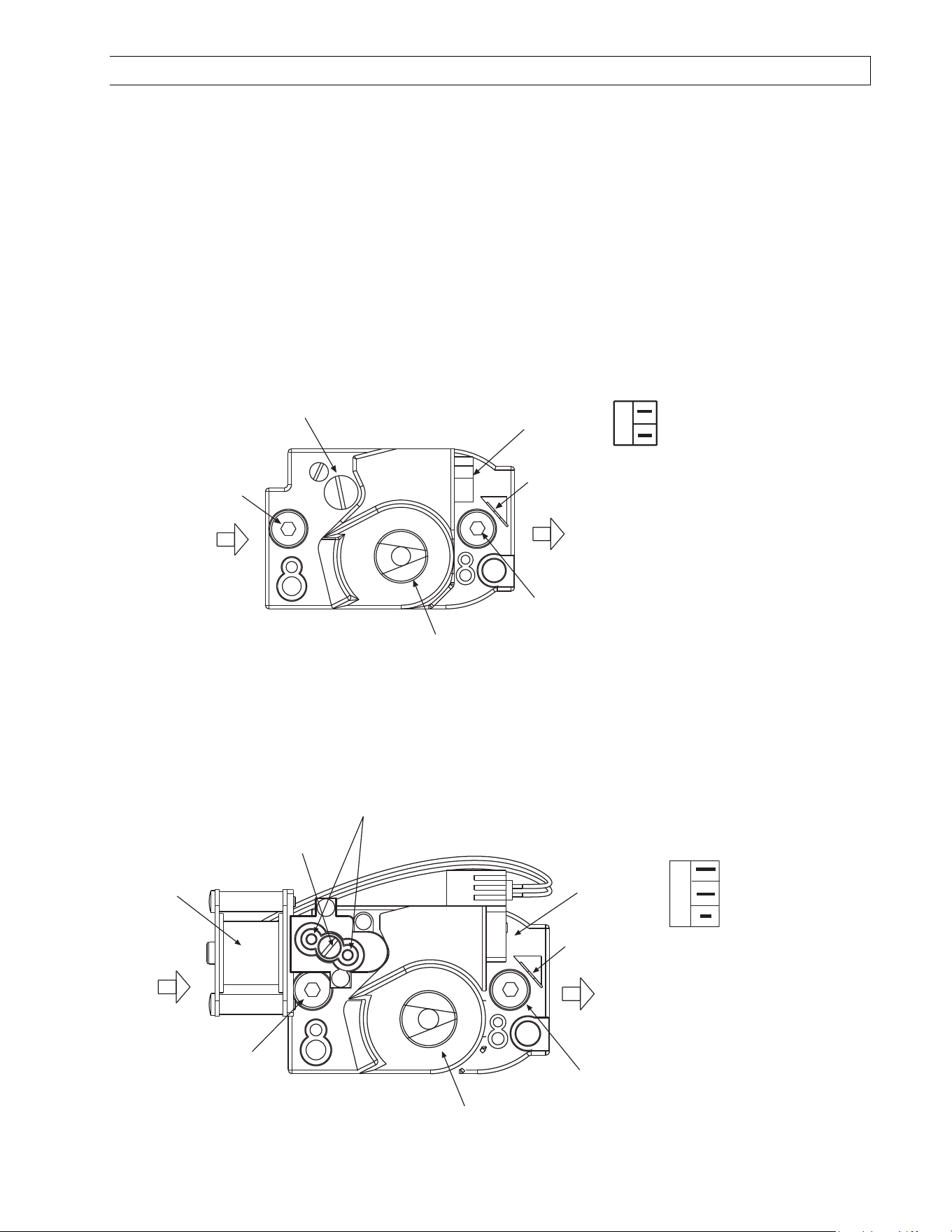
12.0) INSTRUCTIONS FOR PRESSURE TEST GAUGE CONNECTION
SUPPLY PRESSURE
SUPPLY PRESSURESUPPLY PRESSURE
SUPPLY PRESSURE
1. The installer will provide a 1/8” N.P.T. tapped plug, accessible for test gauge connection immediately
upstream of the gas supply connection to the heater.
MANIFOLD PRESSURE
MANIFOLD PRESSURE MANIFOLD PRESSURE
MANIFOLD PRESSURE –
––
–
COMBINATION GAS VALVE IS FACTORY SET
COMBINATION GAS VALVE IS FACTORY SETCOMBINATION GAS VALVE IS FACTORY SET
COMBINATION GAS VALVE IS FACTORY SET
1. Turn the gas valve to the “OFF” position. Remove the 1/8” plug from the combination gas valve at the Outlet
Outlet Outlet
Outlet
Pressure T
Pressure TPressure T
Pressure Tap
apap
ap
shown below and connect a 1/8” nipple to the tapped hole. Connect the test gauge to the
nipple. Turn on the gas supply.
1-STAGE CONTROLS
Pressure Regulator Adjustment
(under cap screw)
1/8 NPT
Inlet Pressure
Tap with 3/16 Hex
Allen Wrench Plug
1/8NPT
Outlet Pressure
Tap with 3/16 Hex
Allen Wrench Plug
Gas Control
Knob
Wiring
Terminals (2)
Ground
Terminals (2)
OUTLET
INLET
CAUTION
Never jumper these terminals. This
shorts out valve coil and may burn
out heat anticipator in thermostat.
STEP-OPENING
GAS CONTROL VALVE
ON
OFF
MV
MV
2-STAGE CONTROLS
HI-LO
Adjustment Screws
(use 3/32 Hex
Allen Wrench)
1/8 NPT
Inlet Pressure
Tap with 3/16 Hex
Allen Wrench Plug
1/8NPT
Outlet Pressure
Tap with 3/16 Hex
Allen Wrench Plug
Gas Control
Knob
Wiring
Terminals (3)
Ground
Terminals (2)
OUTLET
INLET
CAUTION
Never jumper these terminals. This
shorts out valve coil and may burn
out heat anticipator in thermostat.
TWO-STAGE
GAS CONTROL VALVE
HI
LO
ON
OFF
LO
C
HI
Electric
Solenoid
Coil
Regulator
Vent Cover
Form 43471040
Oct 2013 -17-
2. With the main burner operating, check the burner manifold pressure using a water column manometer.
Gauges that measure pressure in pounds per square inch are not accurate enough to measure or set the
manifold pressure. All measurements MUST BE
MUST BEMUST BE
MUST BE made when this heater and all other gas burning equipment
that is connected to the gas supply system are operating at maximum capacity.
3. The combi
The combiThe combi
The combination gas valve is factory set and should not require adjustment.
nation gas valve is factory set and should not require adjustment.nation gas valve is factory set and should not require adjustment.
nation gas valve is factory set and should not require adjustment. If full rate adjustment is
required, remove the cover screw. Using a small screwdriver, turn the adjustment screw clockwise to
increase or counterclockwise to decrease the gas pressure to the burner. Replace the cover screw. NOTE:
NOTE: NOTE:
NOTE:
The step opening pressure of this gas valve is not adjustable.
The step opening pressure of this gas valve is not adjustable.The step opening pressure of this gas valve is not adjustable.
The step opening pressure of this gas valve is not adjustable.
4. Check the burner at step pressure, observing burner ignition and flame characteristics. The burner should
ignite properly and without flashback to the orifice, and should remain lit.
GAS PRESSURE TABLE
GAS PRESSURE TABLEGAS PRESSURE TABLE
GAS PRESSURE TABLE
GAS TYPE
GAS TYPEGAS TYPE
GAS TYPE
MANIFOLD PRESSURE
MANIFOLD PRESSUREMANIFOLD PRESSURE
MANIFOLD PRESSURE
SUPPLY PRESSURE
SUPPLY PRESSURESUPPLY PRESSURE
SUPPLY PRESSURE
Minimum*
Minimum*Minimum*
Minimum*
Maximum
MaximumMaximum
Maximum
Natural Gas 3.5” W.C. 5” W.C. 14” W.C.
Propane Gas 10.0” W.C. 11” W.C. 14” W.C.
* Minimum permissible gas supply pressure for purpose of input adjustment.
13.0) ELECTRICAL AND THERMOSTAT CONNECTIONS
Failure to do so may result in death or serious injury.
This appliance must be connected to a properly grounded electrical source.
Disconnect electrical power and gas supply before servicing.
ELECTRIC SHOCK HAZARD
1. All electric wiring shall conform to the latest edition of the National Electrical Code (ANSI/NFPA No. 70), or
the code legally authorized in the locality where the installation is made.
2. The unit must be electrically grounded in accordance with the National Electrical Code (ANSI/NFPA No.
70-latest edition). In Canada, refer to current standard C22.1 Canadian Electrical Code Part 1.
3. The wiring providing power to the heater shall be connected to a permanently live electrical circuit, one that
is not controlled by a light switch.
4. The power supply to the unit should be protected with a fused disconnect switch or circuit breaker. A service
switch, as required by local codes, shall be located in the vicinity of the heater (check local codes for
allowable distances) and should be identified as Heater Service Switch. All electrical wiring must be located
in accordance with the required Clearances to Combustibles from the heater as listed on the nameplate on
the heater.
5. When connecting the supply circuit
supply circuitsupply circuit
supply circuit to the heater, wiring material having a minimum size of 14 AWG and a
temperature rating of at least 90°C shall be used.
Form 43471040
-18- Oct 2013
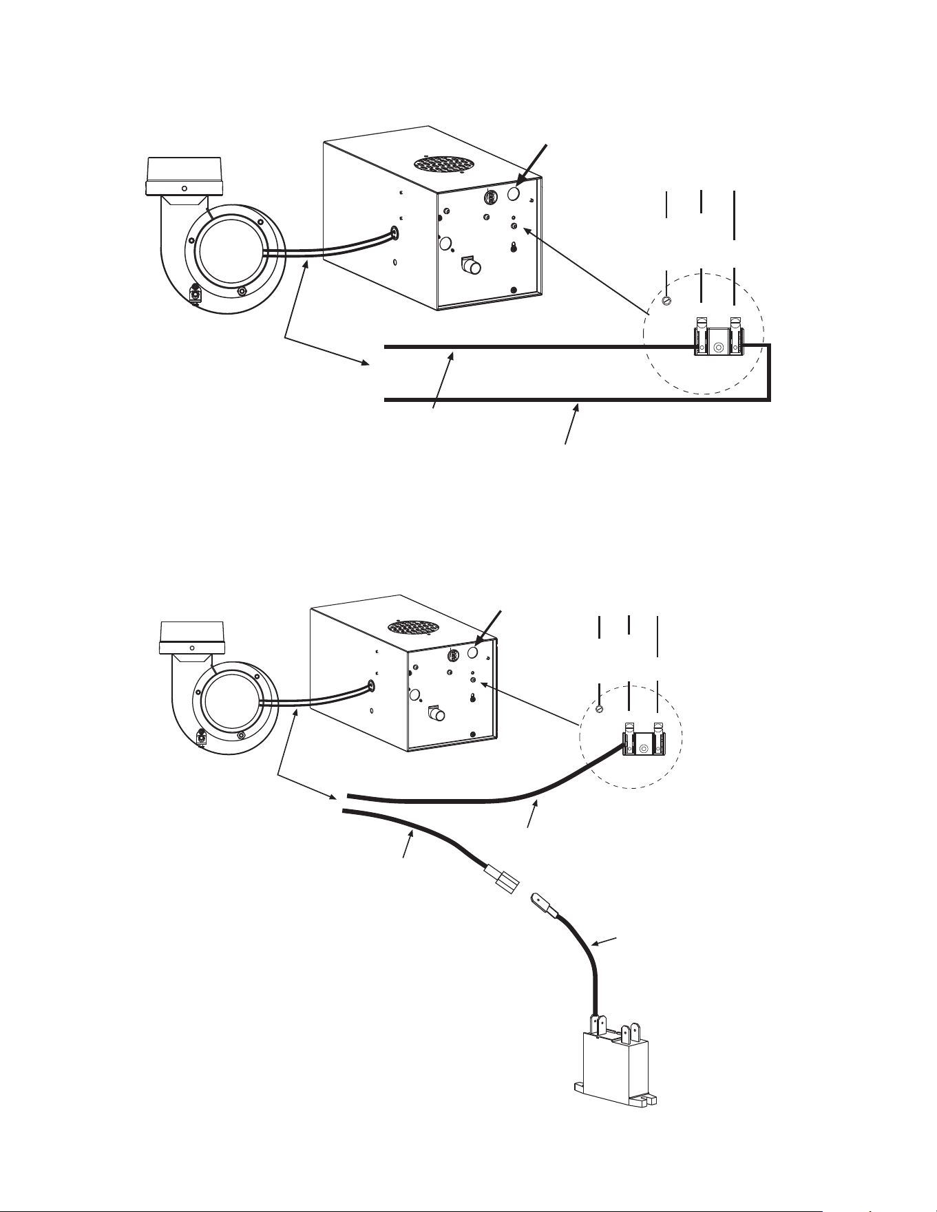
INCOMMING POWER SUPPLY CONNECTION – 1 STAGE CONTROLS
INCOMMING
POWER SUPPLY
CONNECTION
Viewed From
Inside Control Box
Draft Inducer
Control Box
Ground
Screw
Terminal
Block
L2 L1
GROUND
NEUTRAL
120V
Motor Lead Wires
Motor Lead Wire (black)
Motor Lead Wire (white)
INCOMMING POWER SUPPLY CONNECTION – 2 STAGE CONTROLS
INCOMMING
POWER SUPPLY
CONNECTION
Viewed From
Inside Control Box
Draft Inducer
Control Box
Ground
Screw
Terminal
Block
L2
L1
GROUND
NEUTRAL
120V
Motor Lead Wires
Relay
Inside Control Box
3
Connector Wire
(relay to black
motor lead)
Motor Lead Wire (black)
Motor Lead Wire (white)
Form 43471040
Oct 2013 -19-
1
11
1
-
--
-
STAGE CONTROLS
STAGE CONTROLS STAGE CONTROLS
STAGE CONTROLS
-
--
-
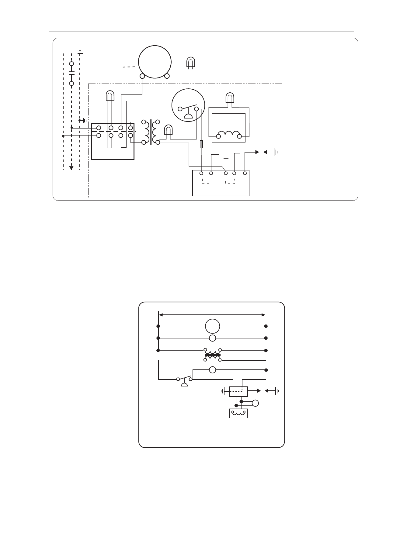
INTERNAL CONNECTION WIRING DIAGRAM
INTERNAL CONNECTION WIRING DIAGRAM INTERNAL CONNECTION WIRING DIAGRAM
INTERNAL CONNECTION WIRING DIAGRAM
—
——
—
Direct Spark Ignition
Direct Spark IgnitionDirect Spark Ignition
Direct Spark Ignition
WIRE LEGEND
ENGLISH FRANCAIS
BK BLACK NOIR
W WHITE BLANC
R RED ROUGE
BL BLUE BLEU
G GREEN VERT
V VIOLET VIOLET
A AMBER AMBRE
42706000 Rev. J 1/2012
BL
BL
BKBK
R
W
BK
BK
R
BK
W
BK
BK
BK
W
DRAFT
INDUCER
MOTOR
GAS VALVE
AIR SWITCH
TRANSFORMER
120V PRIMARY
24V SECONDARY
A
G
R
HIGH VOLTAGE
CABLE
ELECTRODE
GAP 3/16
CONTINUE TO
ADDITIONAL
HEATERS
NEUTRAL
120V THERMOSTAT
GROUND
L1
L2
TERMINAL
BLOCK
FACTORY WIRING
FIELD WIRING
CONNECTION WIRING DIAGRAM
CONTROL CABINET
If any of the original wire as supplied
with the appliance must be replaced.
It must be replaced with wiring material
having a temperature rating of at least
105
o
C. (18 AWG. - UL / CSA 600V
Type TEW)
When connecting the supply circuit to
the heater, wiring material having a
minimum size of 14 AWG and a
temperature rating of at least 90
o
C
shall be used.
MONITORING LIGHTS
Schéma de circuit de connexion
Circuit d'origine
Connexions client
Lampes témoins
Neutre
Terre
Vers les autres
radiateurs
Plaque à
bornes
Transformateur
bobine primaire 120ÊV
bobine secondaire 24ÊV
pressostat
Robinet à gaz
Écartement
d'électrode
4,7Êmm
Haute tension
Armoire de commande
Moteur
d'amorce
d'aspiration
S'il faut remplacer un fil de l'appareil
d'origine, utiliser exclusivement des fils
à température de service nominale
d'au moins 105C (18 AWG. - UL / CSA
600ÊV
Type TEW).
Pour raccorder le circuit d'alimentation
au radiateur, utiliser des fils de calibre
14 AWG ou plus à température de
service nominale d'au moins 90C.
FUSE
2A
G
IGNITION MODULE
GND
(BURNER)
25V
Bloc d'allumage
VALVE
VALVE
NOTES:
NOTES:NOTES:
NOTES:
1. If any of the original wire as supplied with the appliance must be replaced, it must be replaced with wiring
material having a temperature rating of at least 105ºC. (18 Ga. CSA 600V Type TEW)
2. When connecting the supply circuit to the heater, wiring material having a minimum size of 14 AWG and a
temperature rating of at least 90ºC shall be used.
3. A replaceable 2-amp fuse (1-1/4” long) is located inside the control box.
1
11
1
-
--
-
STAGE CO
STAGE COSTAGE CO
STAGE CO
NTROLS
NTROLS NTROLS
NTROLS
-
--
-
SCHEMATIC
SCHEMATICSCHEMATIC
SCHEMATIC
WIRING DIAGRAM
WIRING DIAGRAM WIRING DIAGRAM
WIRING DIAGRAM
—
——
—
Direct Spark Ignition
Direct Spark IgnitionDirect Spark Ignition
Direct Spark Ignition
SCHEMATIC WIRING DIAGRAM
MOT Motor
Moteur
GL Green Light Témoin vert
TRANS 24V Transformer Transformateur 24ÊV
RL Red Light Témoin rouge
AS Air Switch pressostat
SM Ignition Module Bloc d'allumage
IG/S Ignitor / Sensor électrode
V Gas Valve Robinet à gaz
AL Amber Light Témoin ambre
MOT
120V
GL
TRANS
RL
AS
IG/S
AL
V
SM
42785000 Rev. C 10/04
25V GND25V
Form 43471040
-20- Oct 2013
1
11
1-
--
-STAGE CONTROLS
STAGE CONTROLS STAGE CONTROLS
STAGE CONTROLS -
--
-
FIELD CONNECTION
FIELD CONNECTION FIELD CONNECTION
FIELD CONNECTION AND THERMOSTAT
AND THERMOSTAT AND THERMOSTAT
AND THERMOSTAT WIRING DIAGRAMS
WIRING DIAGRAMSWIRING DIAGRAMS
WIRING DIAGRAMS
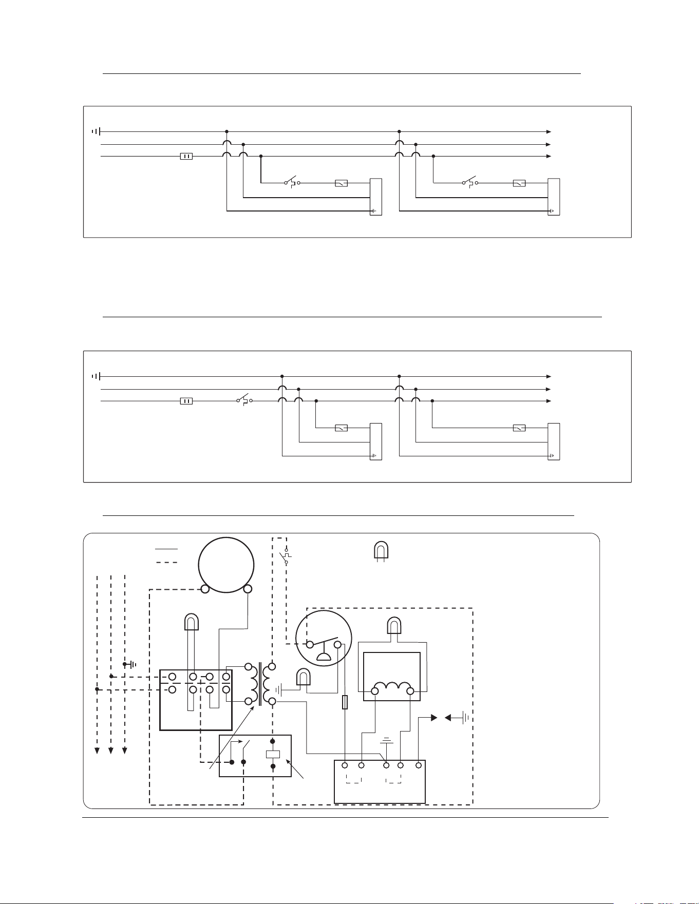
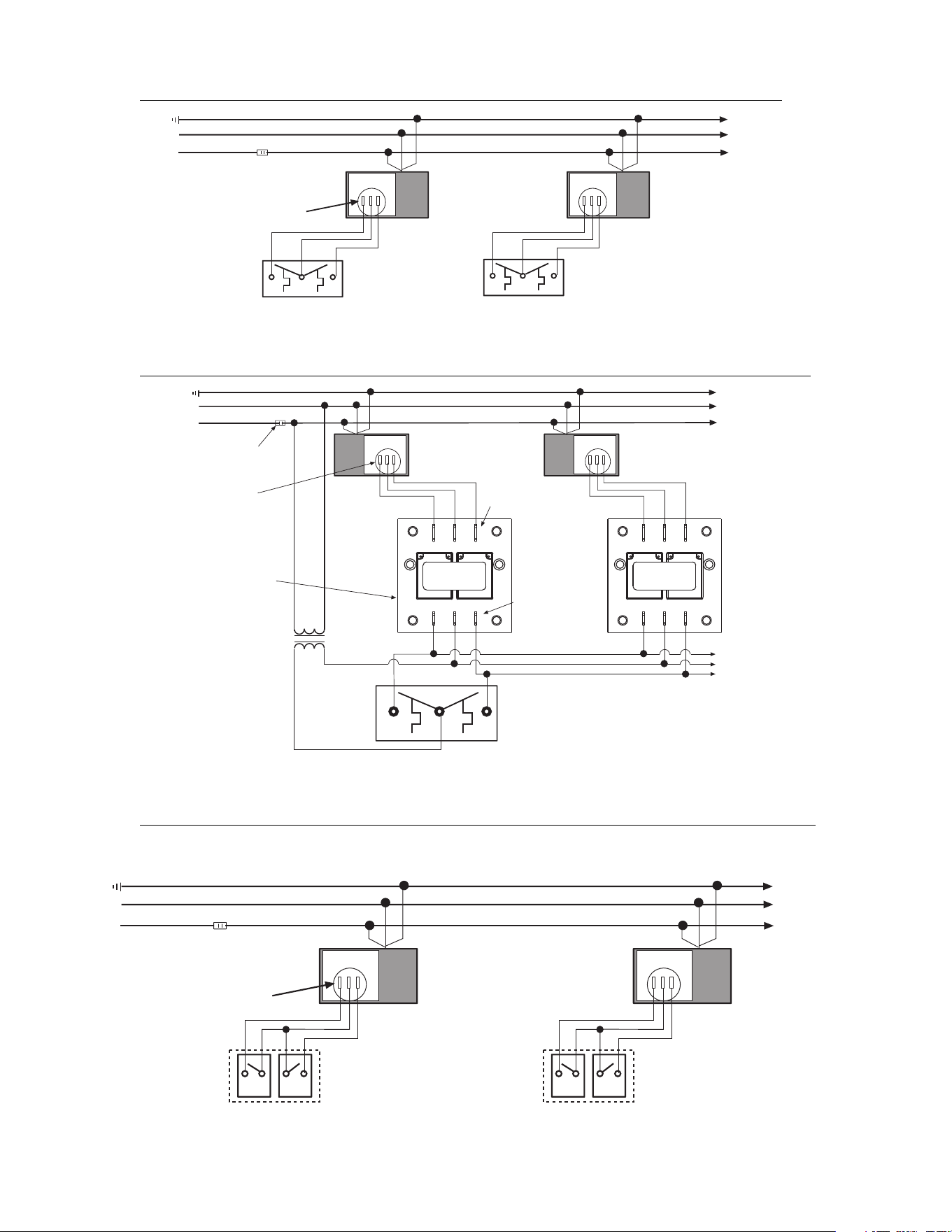
A.
A.A.
A. LINE VOLTAGE (120V) THERMOSTAT CONNECTIONS
LINE VOLTAGE (120V) THERMOSTAT CONNECTIONS LINE VOLTAGE (120V) THERMOSTAT CONNECTIONS
LINE VOLTAGE (120V) THERMOSTAT CONNECTIONS –
––
–
SINGLE HEATER
SINGLE HEATERSINGLE HEATER
SINGLE HEATER
PER THERMO
PER THERMOPER THERMO
PER THERMOSTAT
STATSTAT
STAT
Ground
Neutral
Hot (120VAC)
Fused
Disconnect
Switch
Thermostat
Service
Switch
Heater 1
Continue To
Additional
Heaters
Thermostat
Service
Switch
Heater 2
B.
B.B.
B. LINE VOLTAGE (120V) THERMOSTAT CONNECTIONS
LINE VOLTAGE (120V) THERMOSTAT CONNECTIONS LINE VOLTAGE (120V) THERMOSTAT CONNECTIONS
LINE VOLTAGE (120V) THERMOSTAT CONNECTIONS –
––
–
MULTIPLE HEATERS
MULTIPLE HEATERSMULTIPLE HEATERS
MULTIPLE HEATERS
PER THERMOSTAT
PER THERMOSTATPER THERMOSTAT
PER THERMOSTAT
Ground
Neutral
Hot (120VAC)
Fused
Disconnect
Switch
Thermostat
Service
Switch
Heater 1
Continue To
Additional
Heaters
Service
Switch
Heater 2
C.
C.C.
C. LOW
LOWLOW
LOW
VOLTAGE (
VOLTAGE (VOLTAGE (
VOLTAGE (24
2424
24V) THERMOSTAT CONNECTIONS
V) THERMOSTAT CONNECTIONS V) THERMOSTAT CONNECTIONS
V) THERMOSTAT CONNECTIONS –
––
–
SINGLE HEATER PER THERMOSTAT
SINGLE HEATER PER THERMOSTATSINGLE HEATER PER THERMOSTAT
SINGLE HEATER PER THERMOSTAT
WIRE LEGEND
ENGLISH FRANCAIS
BK BLACK NOIR
W WHITE BLANC
R RED ROUGE
BL BLUE BLEU
G GREEN VERT
V VIOLET VIOLET
A AMBER AMBRE
42706990 Rev. D 1/2012
If any of the original wire as supplied
with the appliance must be replaced.
It must be replaced with wiring material
having a temperature rating of at least
105
o
C. (18 AWG. - UL / CSA 600V
Type TEW)
When connecting the supply circuit to
the heater, wiring material having a
minimum size of 14 AWG and a
temperature rating of at least 90
o
C
shall be used.
S'il faut remplacer un fil de l'appareil
d'origine, utiliser exclusivement des fils
à température de service nominale
d'au moins 105C (18 AWG. - UL / CSA
600ÊV
Type TEW).
Pour raccorder le circuit d'alimentation
au radiateur, utiliser des fils de calibre
14 AWG ou plus à température de
service nominale d'au moins 90C.
BL BL
BKBK
R
W
BK
BK
W
BK
BK
BK
W
DRAFT
INDUCER
MOTOR
GAS VALVE
AIR SWITCH
TRANSFORMER
120V PRIMARY
24V SECONDARY
A
G
R
HIGH
VOLTAGE
CABLE
ELECTRODE
GAP 3/16
CONTINUE TO
ADDITIONAL
HEATERS
NEUTRAL
120V
GROUND
L1
L2
TERMINAL
BLOCK
FACTORY WIRING
FIELD WIRING
CONTROL CABINET
MONITORING
LIGHT
3 4
5
1
LOW VOLTAGE
THERMOSTAT (24V)
BK
BK
BK
W
R
FIELD INSTALLED
RELAY KIT
R
FUSE
2A
Circuit d'origine
Connexions client
Lampes témoins
Neutre
Terre
Vers les autres
radiateurs
Plaque à
bornes
Transformateur
bobine primaire 120ÊV
bobine secondaire 24ÊV
pressostat
Robinet à gaz
Écartement
d'électrode
4,7Êmm
Haute tension
Armoire de commande
Moteur
d'amorce
d'aspiration
G
IGNITION MODULE
GND
(BURNER)
25V
Bloc d'allumage
VALVE
VALVE
Form 43471040
Oct 2013 -21-
Order
OrderOrder
Order
24V Relay Kit (Part No. 4327402
24V Relay Kit (Part No. 432740224V Relay Kit (Part No. 4327402
24V Relay Kit (Part No. 43274020) for Low Voltage (24V) thermostat connecti
0) for Low Voltage (24V) thermostat connecti0) for Low Voltage (24V) thermostat connecti
0) for Low Voltage (24V) thermostat connection.
on.on.
on.
NOTES:
NOTES:NOTES:
NOTES:
1. If any of the original wire as supplied with the appliance must be replaced, it must be replaced with wiring
material having a temperature rating of at least 105ºC. (18 Ga. CSA 600V Type TEW)
2. When connecting the supply circuit to the heater, wiring material having a minimum size of 14 AWG and a
temperature rating of at least 90ºC shall be used.
3. A replaceable 2-amp fuse (1-1/4” long) is located inside the control box.
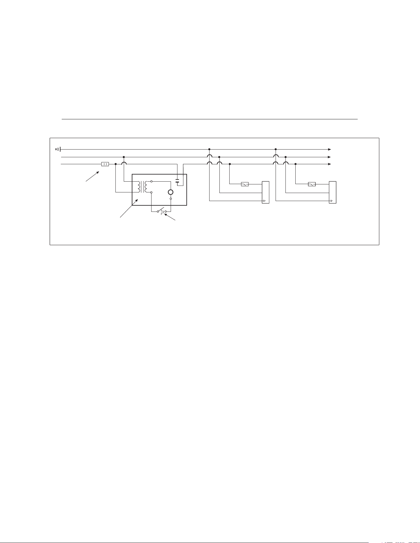
D.
D.D.
D. L
LL
LOW
OWOW
OW
VOLTAGE (
VOLTAGE (VOLTAGE (
VOLTAGE (24
2424
24V) THERMOSTAT CONNECTIONS
V) THERMOSTAT CONNECTIONS V) THERMOSTAT CONNECTIONS
V) THERMOSTAT CONNECTIONS –
––
–
MULTIPLE HEATERS
MULTIPLE HEATERSMULTIPLE HEATERS
MULTIPLE HEATERS
PER THERMOSTAT
PER THERMOSTATPER THERMOSTAT
PER THERMOSTAT
Ground
Neutral
Hot (120VAC)
Fused
Disconnect
Switch
Service
Switch
Heater 1
Continue To
Additional
Heaters
Service
Switch
Heater 2
Low Voltage
Thermostat (24V)
coil
C
R
G
NO
Fan Center Relay Part No. 30169000
Contact Rating: 120V, 40VA, 12A
(maximum of 6 heaters per relay)
Form 43471040
-22- Oct 2013
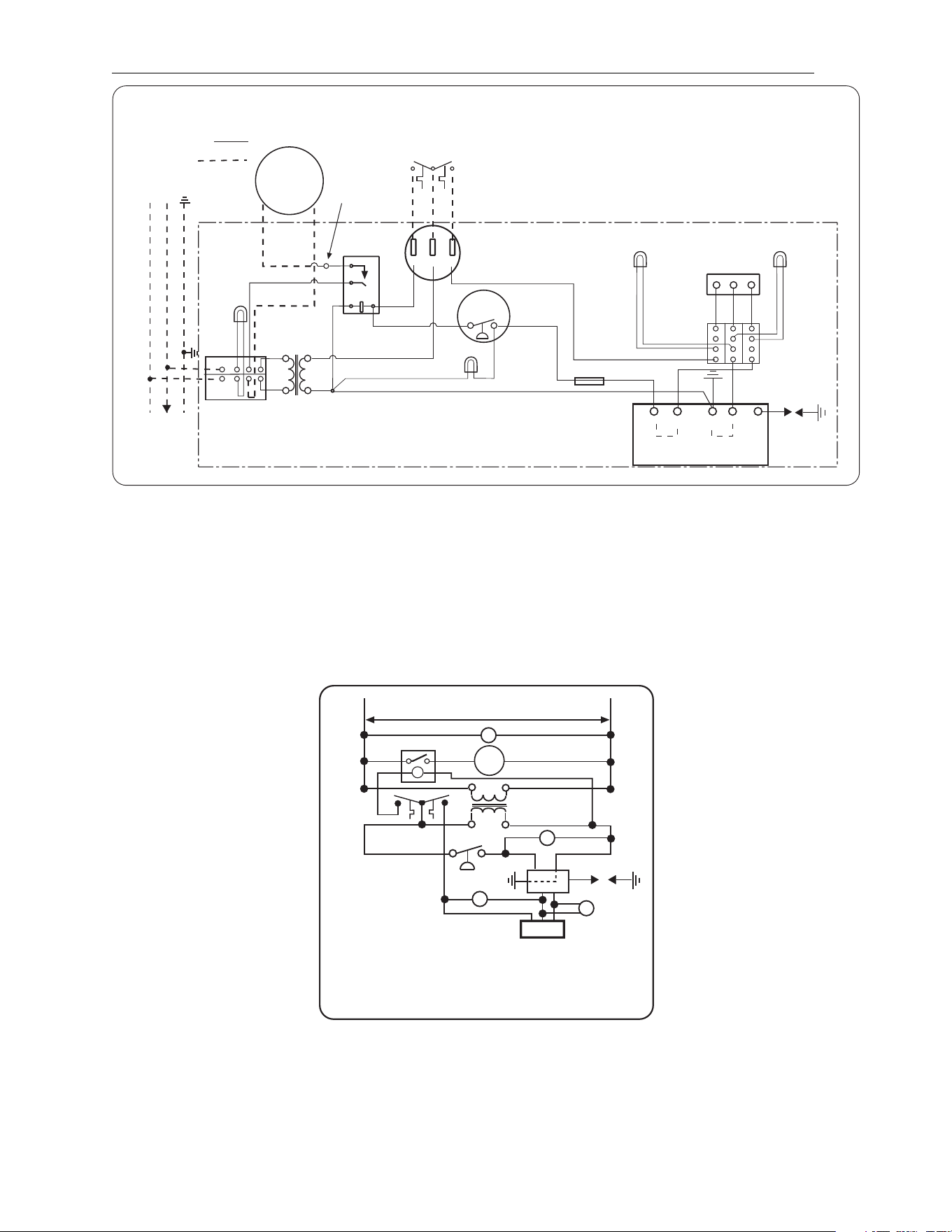
2
22
2
-
--
-
STAGE CONTROLS
STAGE CONTROLS STAGE CONTROLS
STAGE CONTROLS
-
--
-
INTERNAL CONNECTION WIRING DIAGRAM
INTERNAL CONNECTION WIRING DIAGRAM INTERNAL CONNECTION WIRING DIAGRAM
INTERNAL CONNECTION WIRING DIAGRAM
—
——
—
Direct Spark Ignition
Direct Spark IgnitionDirect Spark Ignition
Direct Spark Ignition
Écartement
d'électrode
4,7Êmm
Haute tension
Armoire de commande
Green
Amber
Light
(LO Fire)
Red
Light
HIGH
VOLTAGE
CABLE
ELECTRODE
GAP 3/16
CONTROL CABINET
White
Red
C
HI
LO
2-STAGE
GAS VALVE
White
Blue
Amber
Light
(HI Fire)
Black
Red
Black
White
Black
Black
White
DRAFT
INDUCER
MOTOR
TRANSFORMER
120V PRIMARY
24V SECONDARY
Green
Light
CONTINUE
TO
ADDITIONAL
HEATERS
NEUTRAL
120V
GROUND
L1
L2
TERMINAL
BLOCK
Neutre
Terre
Vers les autres
radiateurs
Plaque à
bornes
Transformateur
bobine primaire 120ÊV
bobine secondaire 24ÊV
Moteur
d'amorce
d'aspiration
1
5
3
4
RELAY
AIR
SWITCH
pressostat
White
CLO
HI
2-STAGE
THERMOSTAT
C
LO
HI
Black
Red
42706020 Rev C 1/2012
Robinet à gaz
CONNECTION WIRING DIAGRAM
Schéma de circuit de connexion
Connexions client
FACTORY WIRING
FIELD WIRING
Circuit d'origine
THERMOSTAT
CONNECTION BLOCK
Plaque à
bornes
Black
TERMINAL
BLOCK
Plaque à
bornes
Black
White
Blue
Yellow
Relais
Black
Black
Black
Black
If any of the original wire as supplied with the
appliance must be replaced. It must be
replaced with wiring material having a
temperature rating of at least 105
o
C. (18
AWG. - UL / CSA 600V Type TEW)
When connecting the supply circuit to the
heater, wiring material having a minimum size
of 14 AWG and a temperature rating of at
least 90
o
C shall be used.
S'il faut remplacer un fil de l'appareil d'origine,
utiliser exclusivement des fils à température
de service nominale d'au moins 105C (18
AWG. - UL / CSA 600ÊV
Type TEW).
Pour raccorder le circuit d'alimentation au
radiateur, utiliser des fils de calibre 14 AWG
ou plus à température de service nominale
d'au moins 90C.
Yellow
FUSE 2A
Wire
Connector
IGNITION MODULE
GND
(BURNER)
25V
Bloc d'allumage
VALVE
VALVE
NOTES:
NOTES:NOTES:
NOTES:
4. If any of the original wire as supplied with the appliance must be replaced, it must be replaced with wiring
material having a temperature rating of at least 105ºC. (18 Ga. CSA 600V Type TEW)
5. When connecting the supply circuit to the heater, wiring material having a minimum size of 14 AWG and a
temperature rating of at least 90ºC shall be used.
6. A replaceable 2-amp fuse (1-1/4” long) is fitted inside the control box.
2
22
2
-
--
-
STAGE CONTROLS
STAGE CONTROLS STAGE CONTROLS
STAGE CONTROLS
-
--
-
SCHEMATIC WIRING DIAGRAM
SCHEMATIC WIRING DIAGRAM SCHEMATIC WIRING DIAGRAM
SCHEMATIC WIRING DIAGRAM
—
——
—
Direct Spark Ignition
Direct Spark IgnitionDirect Spark Ignition
Direct Spark Ignition
SCHEMATIC WIRING DIAGRAM
GL Green Light
Témoin vert
RE Relay Relais
MOT Motor Moteur
TRANS 24V Transformer Transformateur 24ÊV
AS Air Switch pressostat
RL Red Light Témoin rouge
SM Spark Module Bloc d'allumage
IG/S Ignitor / Sensor électrode
AL Amber Light Témoin ambre
V Gas Valve Robinet à gaz
120V
RE
TRANS
RL
AS
IG/S
AL
V
SM
42785030 4/09
25V GND25V
AL
HI C LO
MOT
LO
C
HI
GL
Thermostat
Form 43471040
Oct 2013 -23-
2
22
2-
--
-STAGE CONTROLS
STAGE CONTROLS STAGE CONTROLS
STAGE CONTROLS -
--
-
FIELD CONNECTION AND THERMOSTAT WIRING DIAGRAMS
FIELD CONNECTION AND THERMOSTAT WIRING DIAGRAMSFIELD CONNECTION AND THERMOSTAT WIRING DIAGRAMS
FIELD CONNECTION AND THERMOSTAT WIRING DIAGRAMS
E.
E.E.
E. LOW VOLTAGE (24V) THERMOSTAT CONNECTIONS
LOW VOLTAGE (24V) THERMOSTAT CONNECTIONS LOW VOLTAGE (24V) THERMOSTAT CONNECTIONS
LOW VOLTAGE (24V) THERMOSTAT CONNECTIONS –
––
–
SINGLE HEATER PER THERMOSTAT
SINGLE HEATER PER THERMOSTATSINGLE HEATER PER THERMOSTAT
SINGLE HEATER PER THERMOSTAT
Ground
N Neutral
L1 Hot (120V)
Continue To
Additional
Heaters
Fused
Disconnect
Switch
Control Box
C HiLo
Two-Stage Thermostat
(field supplied)
High FireLow Fire
C HiLo
Two-Stage Thermostat
(field supplied)
High FireLow Fire
Control Box
Thermostat Connection
Block
F.
F.F.
F. LOW VOLTA
LOW VOLTALOW VOLTA
LOW VOLTAGE (24V) THERMOSTAT CONNECTIONS
GE (24V) THERMOSTAT CONNECTIONS GE (24V) THERMOSTAT CONNECTIONS
GE (24V) THERMOSTAT CONNECTIONS –
––
–
MULTIPLE HEATERS PER THERMOSTAT
MULTIPLE HEATERS PER THERMOSTATMULTIPLE HEATERS PER THERMOSTAT
MULTIPLE HEATERS PER THERMOSTAT
Ground
N Neutral
L1 Hot (120V)
Fused
Disconnect
Switch
Continue To
Additional
Heaters
24 V Transformer
1.5 VA rating per relay
(field supplied)
24 V
Continue To
Additional
Heaters
Control Box
Two-Stage Thermostat
(field supplied)
High FireLow Fire
RELAY BOARD
LO
24V
HI
LO
C HI
LO
FIRE
HI
FIRE
C HiLo
RELAY BOARD
LO
24V
HI
LO
C HI
LO
FIRE
HI
FIRE
C HiLo
3/16 Quick
Connect Terminals
1/4 Quick
Connect
Terminals
Relay Kit externally
Mounted
(PN 44195000)
Thermostat
Connection Block
Control Box
G.
G.G.
G. MANUAL SWITCH CONNECTIONS
MANUAL SWITCH CONNECTIONS MANUAL SWITCH CONNECTIONS
MANUAL SWITCH CONNECTIONS –
––
–
SINGLE HEATER OPERATION PER DUAL MANUAL SWITCH
SINGLE HEATER OPERATION PER DUAL MANUAL SWITCHSINGLE HEATER OPERATION PER DUAL MANUAL SWITCH
SINGLE HEATER OPERATION PER DUAL MANUAL SWITCH
Ground
N Neutral
L1 Hot (120V)
Continue To
Additional
Heaters
Fused
Disconnect
Switch
Note: Low Fire Switch MUST stay on during High Fire running.
Control Box
C HiLo
Low Fire
Manual Switch
(field supplied)
Thermostat Connection
Block
High Fire
Manual Switch
(field supplied)
Control Box
C HiLo
Low Fire
Manual Switch
(field supplied)
High Fire
Manual Switch
(field supplied)
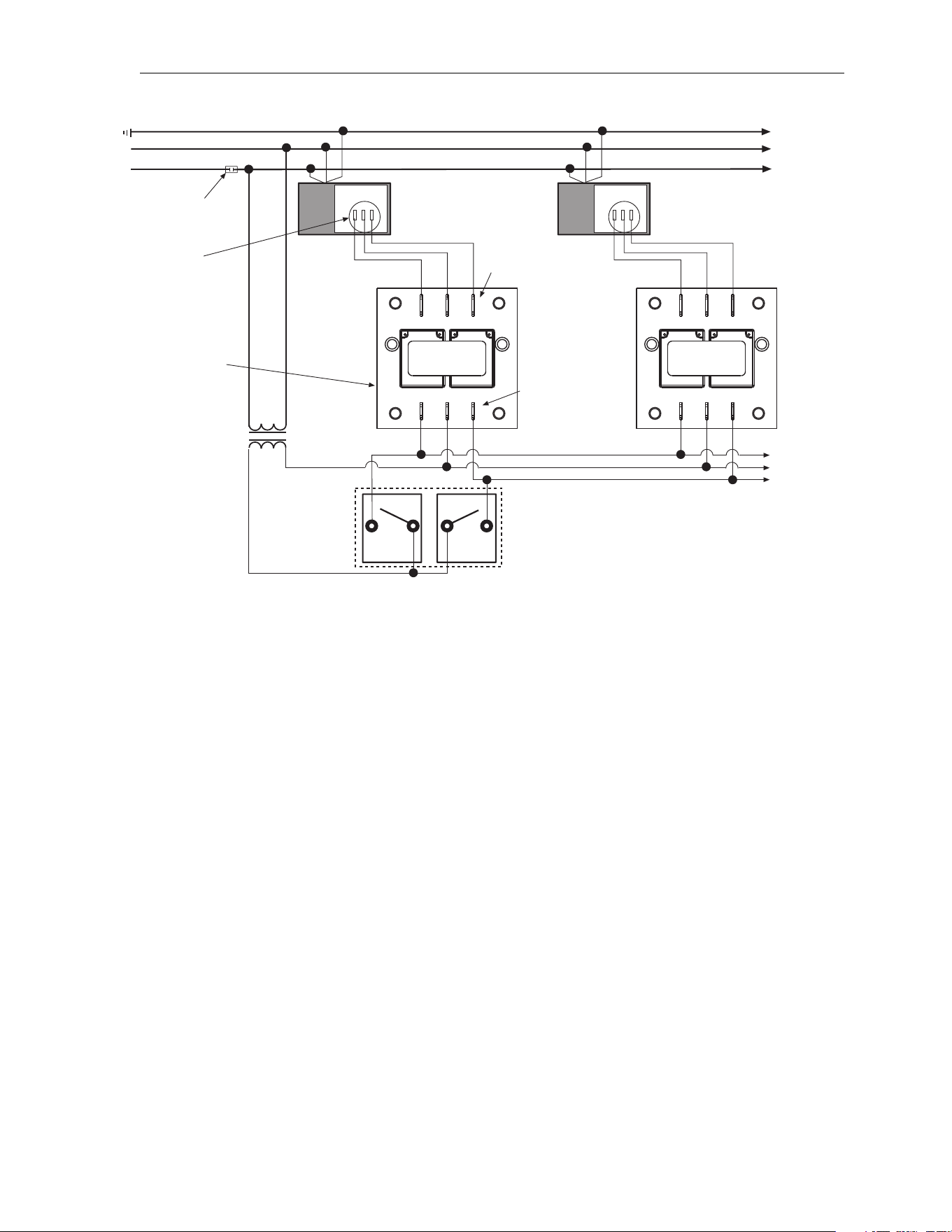
Form 43471040
-24- Oct 2013
H.
H.H.
H. MANUAL SWITCH CONNECTIONS
MANUAL SWITCH CONNECTIONS MANUAL SWITCH CONNECTIONS
MANUAL SWITCH CONNECTIONS –
––
–
MULTIPLE HEATERS OPERATION PER DUAL MANUAL SWITCH
MULTIPLE HEATERS OPERATION PER DUAL MANUAL SWITCHMULTIPLE HEATERS OPERATION PER DUAL MANUAL SWITCH
MULTIPLE HEATERS OPERATION PER DUAL MANUAL SWITCH
Ground
N Neutral
L1 Hot (120V)
Fused
Disconnect
Switch
Continue To
Additional
Heaters
24 V Transformer
1.5 VA rating per relay
(field supplied)
24 V
Continue To
Additional
Heaters
Control Box
High Fire
Manual Switch
(field supplied)
Low Fire
Manual Switch
(field supplied)
RELAY BOARD
LO
24V
HI
LO
C HI
LO
FIRE
HI
FIRE
C HiLo
RELAY BOARD
LO
24V
HI
LO
C HI
LO
FIRE
HI
FIRE
C HiLo
3/16 Quick
Connect Terminals
1/4 Quick
Connect
Terminals
Relay Kit externally
Mounted
(PN 44195000)
Thermostat
Connection Block
Control Box
Note: Low Fire Switch MUST stay on during High Fire running.
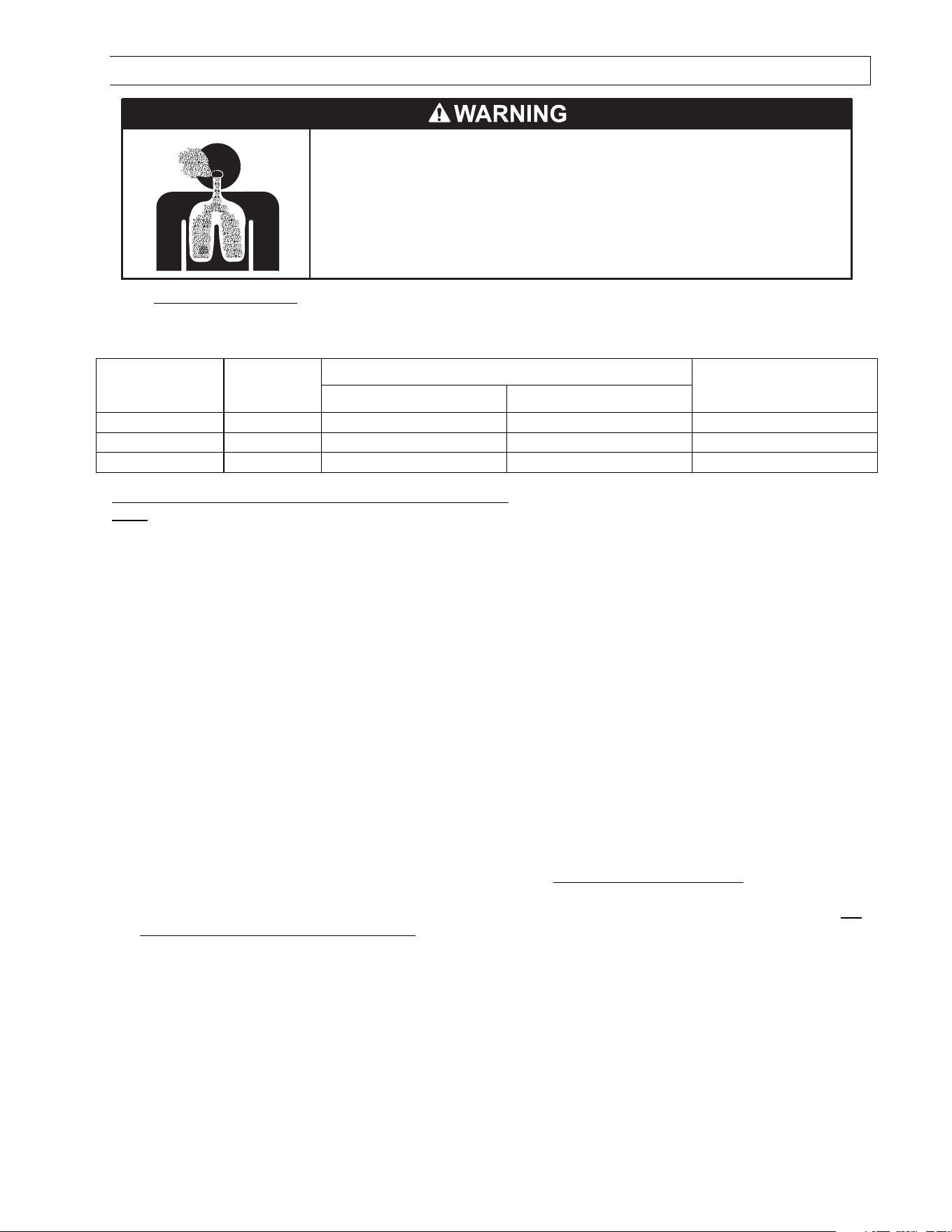
Form 43471040
Oct 2013 -25-
14.0) VENTING
Failure to do so may result in death, serious injury, property damage or illness
from Carbon Monoxide poisoning.
Heaters installed in an unvented mode require a minimum ventilation flow of
4 CFM per 1,000 Btu/hr of total installed capacity.
In buildings with airborne contamination the heater must be installed with
fresh air for combustion.
CARBON MONOXIDE HAZARD
A.
A.A.
A. BASIC F
BASIC FBASIC F
BASIC FLUE VENTING
LUE VENTINGLUE VENTING
LUE VENTING — Venting must comply with the latest edition of the National Fuel Gas Code (ANSI
Z223.1-latest edition) or the authority having jurisdiction. Other venting references are in the equipment
volume of the ASHRAE Handbook.
Model
ModelModel
Model
Heat
Heat Heat
Heat
exchanger
exchanger exchanger
exchanger
le
lele
length ft
ngth ftngth ft
ngth ft
Maximum vent length ft. (4” diameter
Maximum vent length ft. (4” diameterMaximum vent length ft. (4” diameter
Maximum vent length ft. (4” diameter)
))
)
Maximum Fresh air
Maximum Fresh air Maximum Fresh air
Maximum Fresh air
intake length ft
intake length ftintake length ft
intake length ft
(4” diameter)
(4” diameter)(4” diameter)
(4” diameter)
Vertical Venting
Vertical VentingVertical Venting
Vertical Venting
Sidewall Venting
Sidewall VentingSidewall Venting
Sidewall Venting
R (B.S.M) G 0
25
15
100
75
50
R (B,S,M) G 0
35
15
100
75
50
R (B,S,M) G 0
45
15
100
75
5
0
SINGLE HEATER VENTING
SINGLE HEATER VENTINGSINGLE HEATER VENTING
SINGLE HEATER VENTING
(VERTIC
(VERTIC(VERTIC
(VERTICAL THROUGH THE ROOF)
AL THROUGH THE ROOF)AL THROUGH THE ROOF)
AL THROUGH THE ROOF)
Note:
Note:Note:
Note: For residential applications, the heater must not be connected to a separate chimney, but must be
For residential applications, the heater must not be connected to a separate chimney, but must be For residential applications, the heater must not be connected to a separate chimney, but must be
For residential applications, the heater must not be connected to a separate chimney, but must be
installed using the venting system specified below.
installed using the venting system specified below.installed using the venting system specified below.
installed using the venting system specified below.
1. When venting the heater to outside of building through a roof, use single-wall metal pipe. This is to be
constructed of galvanized sheet metal or other approved noncombustible corrosion-resistant material as
allowed by state or local codes.
2. A vent passing through a combustible roof shall extend through an approved clearance roof thimble. Double-
wall, Type B vent must be used for the portion of the vent system which passes through the combustible roof.
An approved vent cap must be attached to end of the flue.
3. The maximum equivalent length of vent pipe should be carefully observed. A safety switch in the heater is
designed to shut the heater off before excessive flue restriction causes bad combustion. Refer to the Vent
Sizing Table for maximum vent lengths and vent pipe diameter.
• Minimum Equivalent Length = 5 ft. of pipe
• Maximum Equivalent Length = 75 ft. of pipe
Use the following correction factors to obtain the equivalent length:
• Subtract 15 ft. if the run is horizontal.
• Subtract 10 ft. for an approved vent cap.
• Subtract 10 ft. for each elbow beyond 15 ft. from the heater.
• Subtract 15 ft. for each elbow within 15 ft. of the heater.
4. Joints between sections of piping shall be fastened by sheet metal screws or other approved means and
should be sealed to prevent leakage of flue gas into building. For Residential Installations:
For Residential Installations:For Residential Installations:
For Residential Installations: The seams along
the length of the piping and the joints between sections of piping should be sealed to prevent a potential
leakage of flue gas into building. Use 100% RTV Silicone Rubber Adhesive sealant suitable for 500 ºF. For
For For
For
Commercial and Industrial Installati
Commercial and Industrial InstallatiCommercial and Industrial Installati
Commercial and Industrial Installations:
ons:ons:
ons: Use aluminum or Teflon tape suitable for 550ºF (3M Company
tapes 433 or 363) or RTV silicone sealant.
5. Avoid locating elbows in the first 5’ of vent pipe whenever possible. Limit to (2) 90° elbows. When vent pipe
is in a horizontal run, it must have 1/4 inch per foot rise.
6. All portions of the vent pipe shall be supported to prevent from sagging (6’ spacing is recommended).
7. When the vent pipe passes through areas where the ambient temperature is likely to induce condensation
of the flue gases, the vent pipe should be insulated and a condensation drain should be provided.
8. Minimum clearance for single-wall flue pipe to combustible material shall be 6 inches. This may be reduced
when the combustible material is protected as specified in the National Fuel Gas Code or the authority
having jurisdiction.
9. Single-wall metal pipe shall not originate in any unoccupied attic or concealed space and shall not pass
through any attic, inside wall or concealed space, or through any floor. For the installation of a single-wall
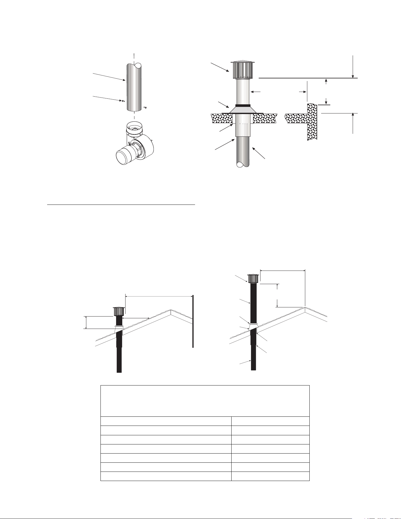
Form 43471040
-26- Oct 2013
metal pipe through an exterior combustible wall, refer to latest edition of the National Fuel Gas Code or the
authority having jurisdiction.
10. A venting system shall terminate at least 3 ft. above any forced air inlet located within 10 ft.
Vent Cap
Flashing
2 (5cm)
Clearance
Thimble
Seal Joint
and Annular
Space
10 ft (305cm)
or less
2 ft (77cm)
minimum
2 ft (77cm) minimum
(when no wall or
parapet exists)
4 Diameter
Vent
Wall or
Parapet
#10 Self-Drill
Screws
(typical)
4 Vent Pipe
(vertical position)
Draft Inducer
(vertical position)
VENT TERM
VENT TERMVENT TERM
VENT TERMINATION (RESIDENTIAL INSTALLATIONS)
INATION (RESIDENTIAL INSTALLATIONS)INATION (RESIDENTIAL INSTALLATIONS)
INATION (RESIDENTIAL INSTALLATIONS)
1. The vent terminal shall terminate above the roof line so that no discharge opening is less than 2 feet (0.6m)
horizontally from the roof surface. The lowest discharge opening will be no closer than the minimum height
specified in the following table. These minimum heights may be used provided the vent is not less than 8
feet (2.4m) from any vertical wall or similar obstruction.
2. All other gas vents shall terminate not less than 2 feet (0.6m) above the highest point where they pass
through the roof and at least 2 feet (0.6m) higher than any portion of a building located within 10 feet (3.1m)
as shown in the illustration below.
Not less than 8ft. (244cm)
2ft. (61cm)
minimum
H
minimum
Vertical Wall
10ft. (305cm) or less
2ft. (61cm)
minimum
Vent Cap
Type B
Vent Pipe
Type B
(Double Wall)
Storm
Collar
Boot
Flashing
Vent Pipe
(Single Wall)
2 (51mm)
Clearance
Seal Joint &
Annular Space
MINIMUM HEIGHT
MINIMUM HEIGHTMINIMUM HEIGHT
MINIMUM HEIGHT
FROM ROOF TO LOWEST DISCHARGE OPENING
FROM ROOF TO LOWEST DISCHARGE OPENINGFROM ROOF TO LOWEST DISCHARGE OPENING
FROM ROOF TO LOWEST DISCHARGE OPENING
Roof Pitch
Roof PitchRoof Pitch
Roof Pitch
H (min)
H (min)H (min)
H (min)
Flat to 6/12 1.0 Feet
Over 6/12 to 8/12 1.5 Feet
Over 8/12 to 10/12 2.5 Feet
Over 10/12 to 12/12 4.0 Feet
Over 12/12 to 16/12 6.0 Feet
Over 16/12 to 20/12 7.5 Feet
Over 20/12 to 21/12 8.0 Feet
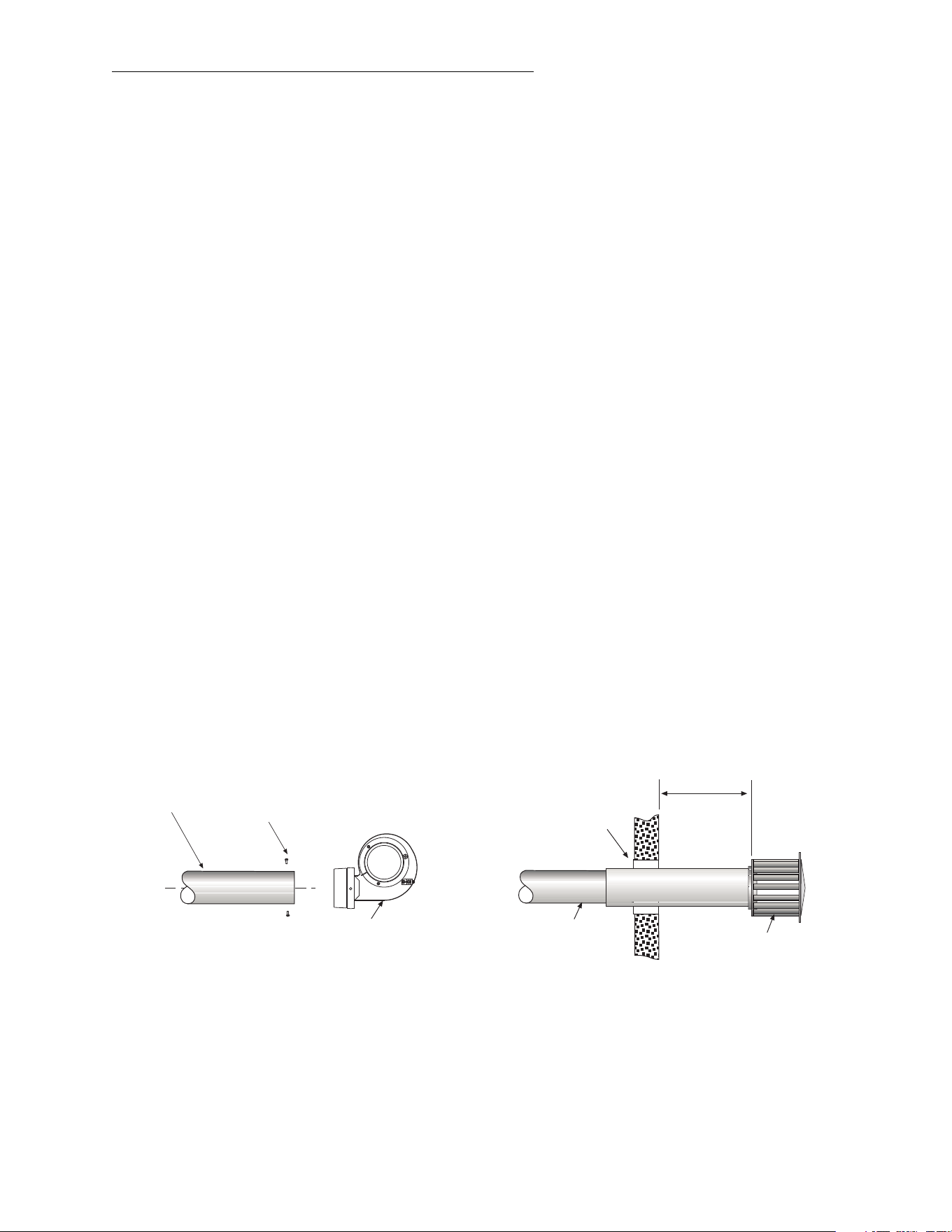
Form 43471040
Oct 2013 -27-
SINGLE HEATER VENTING
SINGLE HEATER VENTINGSINGLE HEATER VENTING
SINGLE HEATER VENTING
(HORIZONTAL THROUGH SIDEWALL)
(HORIZONTAL THROUGH SIDEWALL)(HORIZONTAL THROUGH SIDEWALL)
(HORIZONTAL THROUGH SIDEWALL)
This heater
This heaterThis heater
This heater, when horizontally vented, must be installed with the approved venting system.
, when horizontally vented, must be installed with the approved venting system., when horizontally vented, must be installed with the approved venting system.
, when horizontally vented, must be installed with the approved venting system. When venting the
heater horizontally through a combustible outside sidewall, the same requirements listed previously for venting
Vertical Through The Roof
Vertical Through The RoofVertical Through The Roof
Vertical Through The Roof apply except as follows:
1. For horizontal venting, the vent lengths may be as follows:
• Minimum Equivalent Length = 5 ft. of pipe
• Maximum Equivalent Length = 75 ft. of pipe
Use the following correction factors to obtain the equivalent length:
• Subtract 15 ft. if the run is horizontal.
• Subtract 10 ft. for an approved vent cap.
• Subtract 10 ft. for each elbow beyond 15 ft. from the heater.
• Subtract 15 ft. for each elbow within 15 ft. of the heater.
NOTE:
NOTE:NOTE:
NOTE: To minimize problems associated with condensation in long horizontal runs, vent pipe can be insulated.
2. The horizontal venting system approved with this heater consists of the following components: one 4” Vent
Cap (Part #30297040, one 4” x 36” ‘B’ Vent Section (Part #30496360), and one 4” Wall Thimble (Part
#30500040). Please specify the appropriate number of 24-inch sections of single-wall vent pipe and elbows
when ordering: Vent Pipe (Part #30497240), 90º Elbows (Part #30498040), and 45º Elbows (Part
#30499040).
3. Avoid locating elbows in the first 5 feet of vent pipe whenever possible. Limit the quantity of 90º elbows to
two (2). When vent pipe is in a horizontal run, it must fall 1/4 inch per 10 foot down towards the vent
terminal. The heater must be installed level.
4. A minimum clearance of 18 inches must be maintained between the outside wall and vent cap (18”
clearance will provide stability under high wind conditions).
5. The horizontal venting system shall not terminate:
• Less than 4 ft. (1.2m) below, 4 ft. (1.2m) horizontally from or 1 ft. (30cm) above any door, operable
window or gravity air inlet into any building. The bottom of the vent terminal shall be located at least 7 ft.
(2.1m) above grade or above snow accumulation level as determined by local codes.
• Less than 3 ft. (0.9m) from a combustion air inlet.
• Less than 3 ft. (0.9m) from any other building opening or any gas service regulator.
• Less than 7 ft. (2.1m) above public walkways.
• Directly over areas where condensate or vapor could create a nuisance or hazard or be harmful to the
operation of gas utility meters, regulators, relief valves, or other equipment. Building materials should
be protected from flue gases and condensate.
• Less than 12” (0.30m) when directly below a combustible overhang.
6. In regions of the country where prevailing winds are consistently higher than 40 mph, it may be necessary to
terminate the vent system above the roof level.
#10 Self-Drill
Screws
(typical)
4 Vent Pipe
(horizontal position)
2 (5cm)
Clearance
Thimble
1/4 (6mm) per
10 ft. (3m) down
toward vent terminal
18 (46cm)
minimum
Draft Inducer
(horizontal position)
Sidewall Vent Cap
(Part No. 30297040)
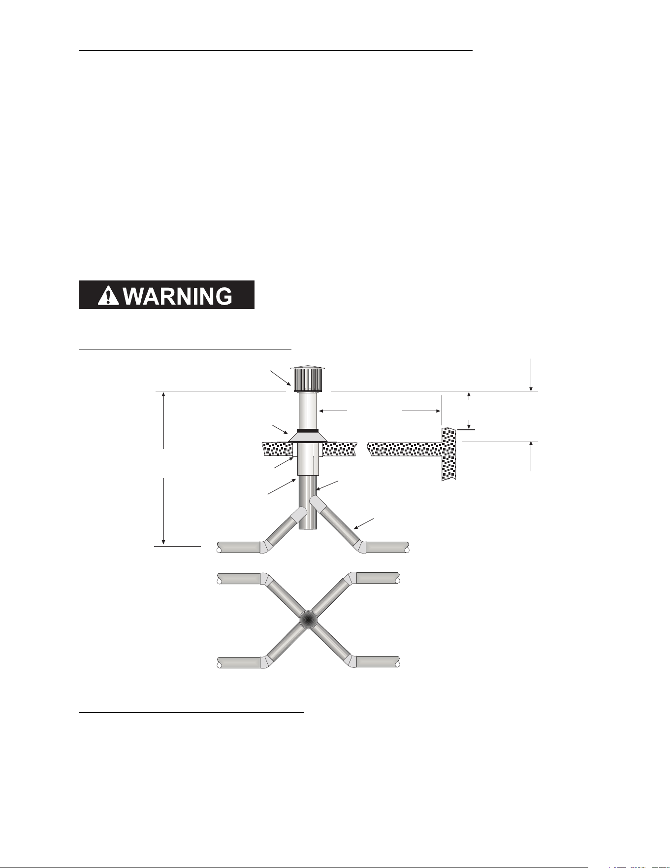
Form 43471040
-28- Oct 2013
MULTIPLE HEATER VENTING
MULTIPLE HEATER VENTINGMULTIPLE HEATER VENTING
MULTIPLE HEATER VENTING
(CONNECTIONS INTO A COMMON VENT OR MANIFOLD)
(CONNECTIONS INTO A COMMON VENT OR MANIFOLD)(CONNECTIONS INTO A COMMON VENT OR MANIFOLD)
(CONNECTIONS INTO A COMMON VENT OR MANIFOLD)
Requirements for venting of multiple heaters are the same as described for SINGLE HEATER VENTING
SINGLE HEATER VENTINGSINGLE HEATER VENTING
SINGLE HEATER VENTING except as
follows:
1. The common vent size and total vent height is normally determined by the number of heaters per common
vent, length of horizontal connector runs, and connector rise. Connector lengths should be as short as
possible and have a minimum 1/4 inch per foot rise. Without regard to connector rise and total vent height
due to many possible venting configurations, the following should be observed:
• Common vent pipe & vent connector diameter should be no less than that shown in the following Vent
Sizing Table.
• The connector length should be no more than 75% of the vertical portion of vent above the connector.
• Where possible, use a Y-connector to the common vent.
2. Material for connectors should be constructed of galvanized sheet metal or other approved noncombustible
corrosion resistant material as allowed by state or local codes. All common vent pipe should be insulated
flue pipe or double-wall, Type B vent.
3. Avoid unnecessary bends. Limit to two (2) 90º elbows.
4. The entire length of vent connector shall be readily accessible for inspection, cleaning and replacement.
5. Groups of heaters with a common vent must be controlled by a common thermostat.
If any heater connected to a common vent system for multiple
If any heater connected to a common vent system for multiple If any heater connected to a common vent system for multiple
If any heater connected to a common vent system for multiple
heaters is found inoperative, the heater should be
heaters is found inoperative, the heater should beheaters is found inoperative, the heater should be
heaters is found inoperative, the heater should be
disconnected from
disconnected from disconnected from
disconnected from
the vent system and its entrance into the vent system capped.
the vent system and its entrance into the vent system capped.the vent system and its entrance into the vent system capped.
the vent system and its entrance into the vent system capped.
Multiple Heater Vertical Venting Arrangement
Total
vent
height
Vent Cap
Flashing
2 (5cm)
Clearance
Thimble
Seal joint
and annular
space
10 ft (305cm)
or less
2 ft (77cm)
minimum
2 ft (77cm) minimum
(when no wall or
parapet exists)
4 diameter
single wall vent
Wall or
Parapet
See Vent
Sizing Table for
diameter
Connections to the common vent
must be arranged to avoid direct
opposition of exhaust products.
Plan View
Multiple Heater Horizontal Venting Arrangement
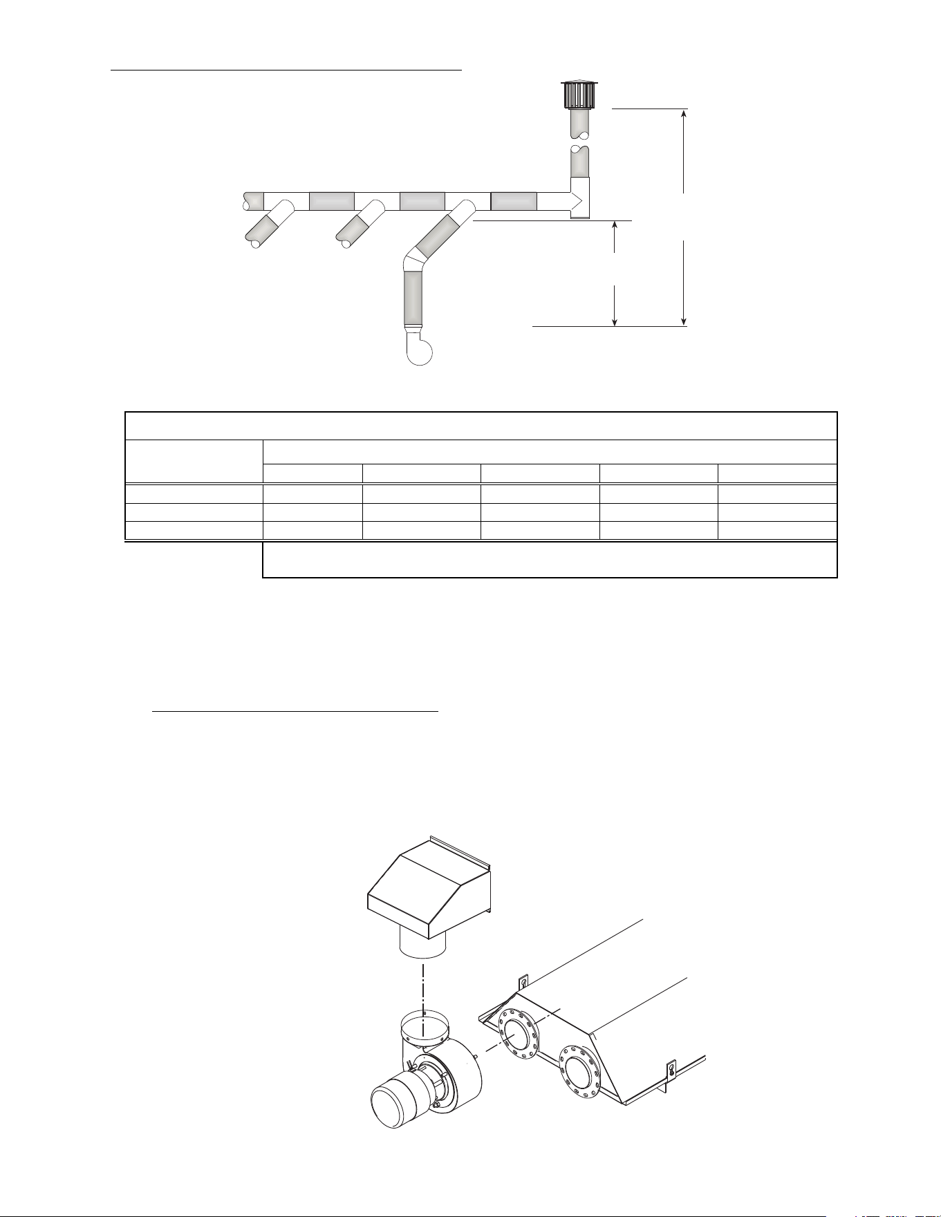
Form 43471040
Oct 2013 -29-
Multiple Heater Venting (Connections into a Manifold)
Total
vent
height
Connector
rise
VENT SIZING TAB
VENT SIZING TABVENT SIZING TAB
VENT SIZING TABLE
LELE
LE
—
——
—
Multiple Heater Venting
Multiple Heater VentingMultiple Heater Venting
Multiple Heater Venting
Number of Heaters
Number of HeatersNumber of Heaters
Number of Heaters
1
11
1
2
22
2
3
33
3
4
44
4
5
55
5
R (B,S,M) G 0
25
4”
4”
4
”
5
”
5
”
R (B,S,M) G 0
35
4”
4”
5
”
5
”
6
”
R (B,S,M) G 045
4”
4
”
5
”
5
”
6
”
COMMON VENT DIAMETER
COMMON VENT DIAMETERCOMMON VENT DIAMETER
COMMON VENT DIAMETER
(If a size is not available use the next larger size.)
THE ABOVE ILLUSTRATIONS AND TABLE OF VENT SIZES FOR COMMON VENTING OF MULTIPLE HEATERS ARE IN
ACCORDANCE WITH THE NATIONAL FUEL GAS CODE ANSI Z223.1-LATEST EDITION, NFPA 54-LATEST EDITION, EQUIPMENT
VOLUME OF 1988 ASHRAE HANDBOOK, CURRENT CAN/CGA-B149.1/2-M86 INSTALLATION CODE, AND AGA PUBLICATION
NO. 10M5.85 2.5-2 ON FUNDAMENTALS OF GAS APPLIANCE VENTING AND VENTILATION-REVISED BUT ARE NOT A PART OF
THE CSA CERTIFICATION.
B.
B.B.
B. INDIRECT VENTING
INDIRECT VENTINGINDIRECT VENTING
INDIRECT VENTING
(UNVENTED HEATERS)
(UNVENTED HEATERS)(UNVENTED HEATERS)
(UNVENTED HEATERS) — COMMERCIAL AND INDUSTRIAL INSTALLATIONS ONLY
COMMERCIAL AND INDUSTRIAL INSTALLATIONS ONLY COMMERCIAL AND INDUSTRIAL INSTALLATIONS ONLY
COMMERCIAL AND INDUSTRIAL INSTALLATIONS ONLY —
——
—
This heater requires ventilation in the building to dilute the products of combustion and provide fresh air
for efficient combustion. Where unvented heaters are used, gravity or mechanical means shall be
provided to supply and exhaust at least 4 CFM per 1,000 Btu/hr input of installed heaters. Exhaust vents
must be located at the highest point above and in the vicinity of the heaters, and the inlet vents must be
located below the level of the heaters. An exhaust hood (Part #42924000) must be placed on the outlet
collar of the draft inducer or on the existing 4” starting collar when used unvented and must be mounted
must be mounted must be mounted
must be mounted
only in a
only in aonly in a
only in an
nn
n
upright
uprightupright
upright
position
position position
position and directed towards the reflector body
and directed towards the reflector body and directed towards the reflector body
and directed towards the reflector body as shown.
as shown.as shown.
as shown.
Exhaust Hood
-Required for UNVENTED use-
Draft Inducer
(vertical position)
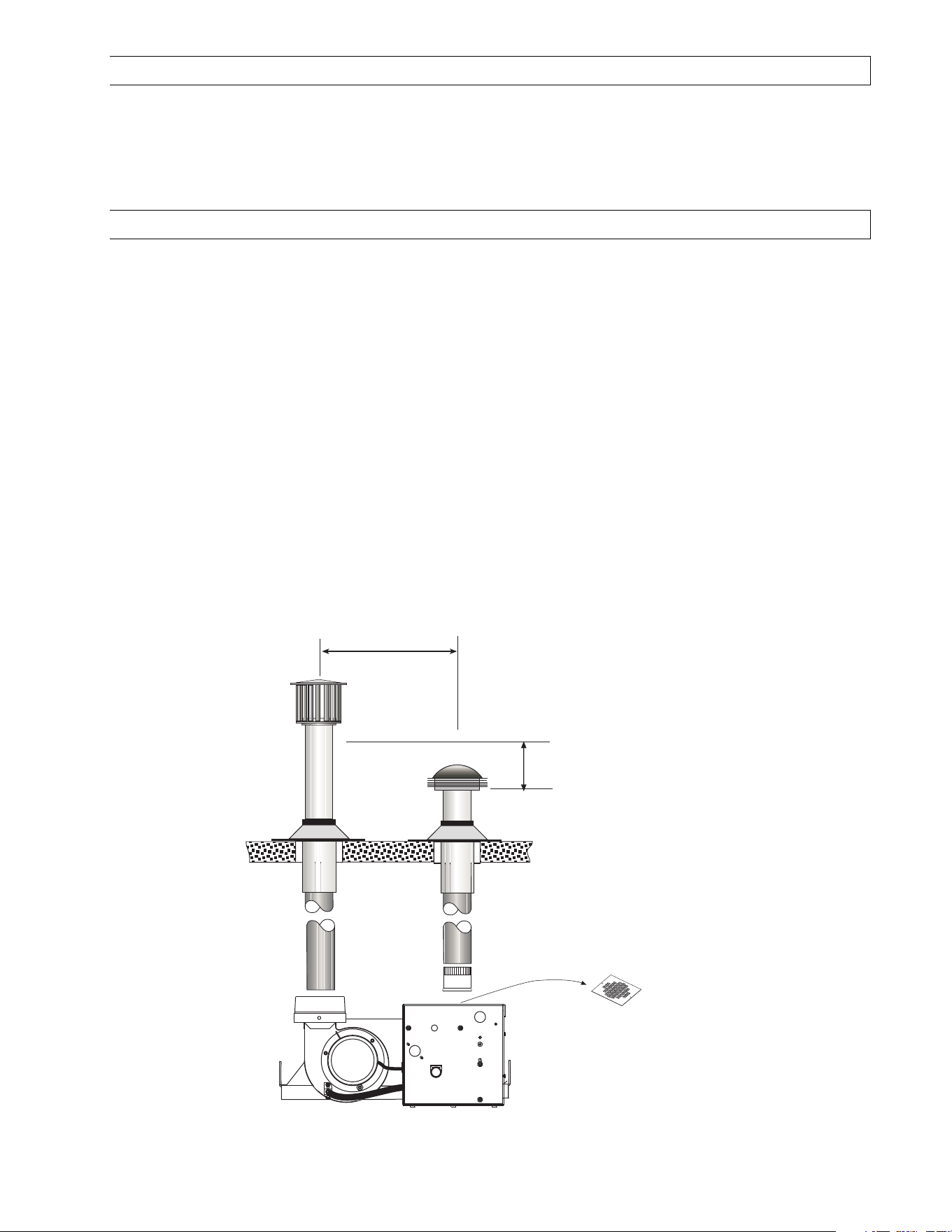
Form 43471040
-30- Oct 2013
15.0) AIR FOR COMBUSTION
If indoor combustion air is to be supplied for a tightly enclosed area, one square inch of free area opening shall
be provided below the heater for each 1,000 Btu/hr per hour of heater input. When outside air is used, the
opening below the heater shall be one square inch of free area for each 4,000 Btu/hr of heater input. In
contaminated atmospheres or high humidity areas, optional outside air for combustion is recommended.
Adequate clearances around the perforated fresh air plate must be maintained at all times. In larger open areas
of buildings, infiltration normally is adequate to provide air for combustion.
15.1) DIRECT OUTSIDE AIR FOR COMBUSTION
Outside combustion air should be supplied directly to the heater when the building is subject to negative
pressure, or when contaminants or high humidity are present in the building air. These contaminants include
paints, solvents, corrosive vapors or any other foreign particles that may cause damage to the heater or result in
poor combustion.
Outside combustion air can be brought directly to the heater by a 4” diameter duct less than 50 ft. long or
equivalent (see table in Section 0 based on selected model and heat exchanger lengths). This is attached to the
4” diameter starting collar. The starting collar is fitted to the top of the control box cabinet after first removing
after first removing after first removing
after first removing
and discarding the perforated cover
and discarding the perforated coverand discarding the perforated cover
and discarding the perforated cover. An approved vent cap must be placed directly on the end of the outside
combustion air inlet pipe. The combustion air inlet should be not less than 3 ft. (0.9m), either vertically or
horizontally, from the flue vent termination. The air intake terminal must be located not less than 1 ft. (30cm)
above grade. It is good installation practice to supply combustion air from the same pressure zone as the vent
outlet. Avoid bringing combustion air to the heater from an attic space. There is no guarantee that adequate
combustion air will be supplied.
In colder climates, where necessary, insulate the outside combustion air duct. Avoid locating the outside
combustion air duct directly above the control box. Provide a capped cleanout T as necessary. In high humidity
applications, the control box should be sealed with silicone sealer.
In multiple heater applications
multiple heater applicationsmultiple heater applications
multiple heater applications, the combustion air intake may be ducted individually or common ducted in the
same configuration as shown for venting in Section 0. For combustion air intake duct sizing, please refer to the
Vent Sizing Table
Vent Sizing TableVent Sizing Table
Vent Sizing Table and use the diameter indicated, based on the number of heaters per duct.
Flue vent termination
must be 1 ft. (30cm)
higher than combustion
air inlet cap
Perforated Cover
(Remove)
The combustion air inlet should
be not less than 3 ft. (0.9m),
either vertically or horizontally,
from the flue vent termination.
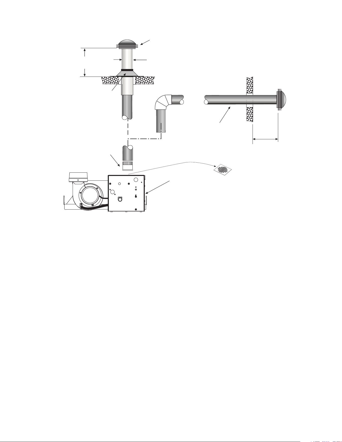
Form 43471040
Oct 2013 -31-
Combustion Air Cap
(Leslie VersaCap
Type B)
4 Diameter
Single-Wall Pipe
Flashing
1/2 (12mm) fall per 20ft (6m)
toward vent terminal
Horizontal
Through Sidewall
6 (15cm)
Minimum
4 Starting Collar
(field supplied)
3 ft. (91cm)
Minimum
Vertical
Through the roof
Control Box
Perforated Cover
(Remove)
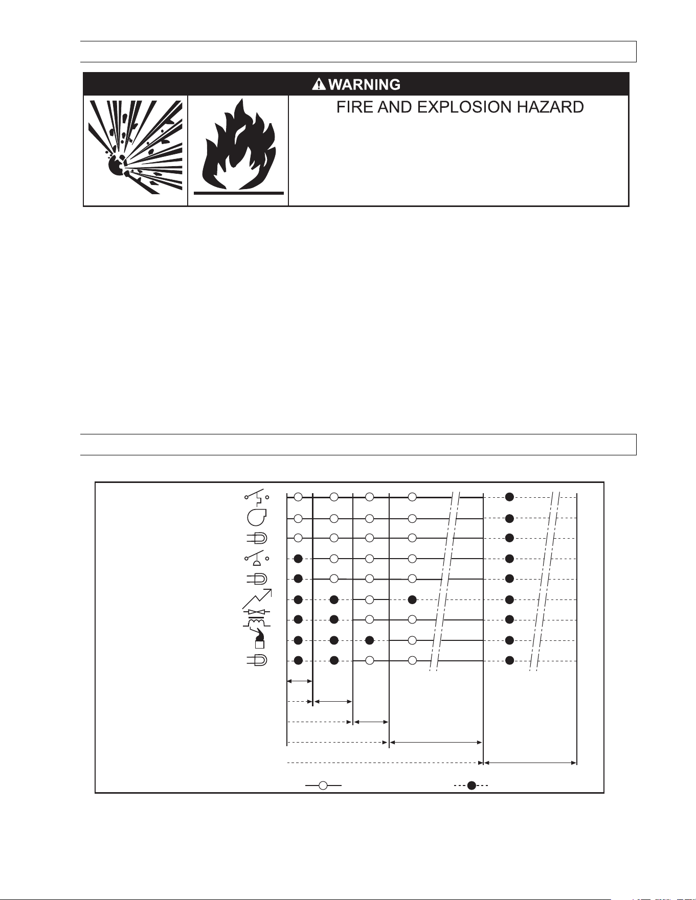
Form 43471040
-32- Oct 2013
16.0) LIGHTING AND SHUTDOWN INSTRUCTIONS
Failure to do so may result in death, serious injury or property
damage.
The access panel must be closed tightly during operation.
Never operate the heater with the access panel open or removed.
1. Turn on the gas and electrical supply. Rotate the gas valve knob counter-clockwise to the “ON” position.
2. Set the thermostat to call for heat. The blower motor will energize.
3. Ignition should occur after the 30-second air pre-purge.
4. If ignition fails, the unit will spark for approximately 21 seconds and go into safety lockout. Turn the
thermostat (power) off for 60 seconds to take the system out of lockout.
5. If the heater does not light, manually reset the thermostat or shut off power completely for 5 minutes before
attempting to relight.
6. To permanently shut down the heater, rotate the gas valve knob clockwise to the “OFF” position and turn
off the gas and electrical supply.
NOTE:
NOTE: NOTE:
NOTE: T
TT
The lighting and shutdown instructions are also shown on the perman
he lighting and shutdown instructions are also shown on the permanhe lighting and shutdown instructions are also shown on the perman
he lighting and shutdown instructions are also shown on the permanent nameplate label attached to the
ent nameplate label attached to the ent nameplate label attached to the
ent nameplate label attached to the
heater control box.
heater control box.heater control box.
heater control box.
17.0) SEQUENCE OF OPERATION
The chart below shows the sequence of operation for the normal operating cycle.
T0 T1 T2 T3 T4
Call for heat, Thermostat on
Thermostat
Blower
Red light
Ignition
Air switch
Gas valve
Flame sensing
Amber valve light
Function ON Function OFF
Green power light
30 secs pre-purge
21 secs trial for ignition
Normal operation flame sensing
Thermostat off, Heater OFF
T5
If the flame is not sensed during sequence T3 then the burner will automatically begin ignition sequence T2. If
the flame is not re-established the heater will go to lockout.
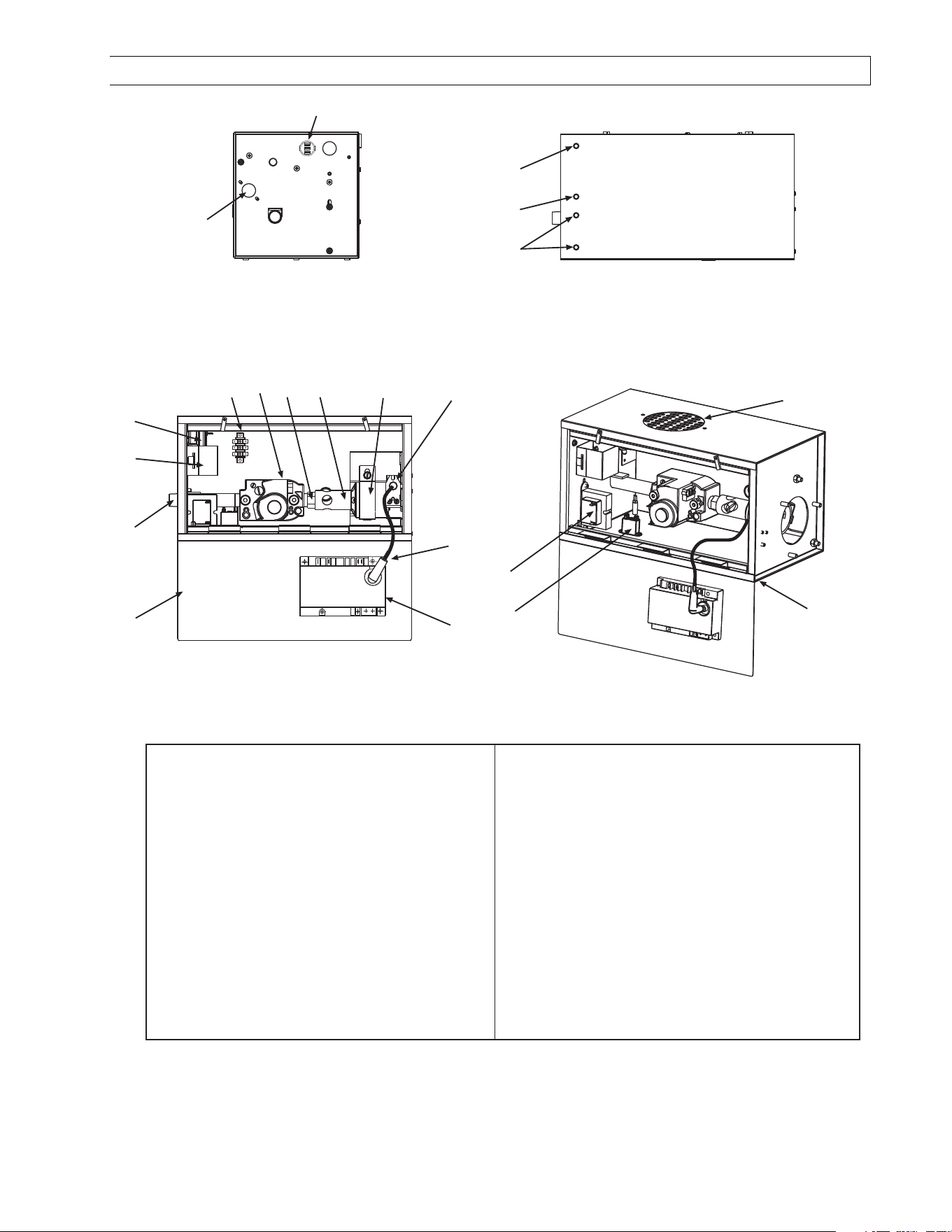
Form 43471040
Oct 2013 -33-
18.0) CONTROL COMPONENT LOCATION
1
2
3
6
5
4
8
7
9
10
12
14 16
17
18
19
20
21
1 Cabinet Assembly
2 Air Inlet Plate
3 Sight Glass
4 Monitoring Light, Green
5 Monitoring Light, Red
6 Monitoring Light, Amber (2) - 2 stage only
7 Access Panel
8 Restrainter Nipple, 5 Long
9 Terminal Block and Shield
10 Air Switch
11 Relay - 2 stage only
12 Gas Valve
13 3-Pole Terminal Block - 2 stage only
14 Orifice
15 Thermostat Connection Block - 2 stage only
16 Main Burner
17 Burner Clamp
18 Spark Electrode
19 Ignition Cable
20 Ignition Module
21 Transformer (120/24 VAC)
11
13
15
NOTE:
NOTE: NOTE:
NOTE: Access panel
Access panel Access panel
Access panel only
only only
only opens
opens opens
opens to
to to
to 90
9090
90°
°°
°.
..
.
Form 43471040
-34- Oct 2013
19.0) CLEANING AND ANNUAL MAINTENANCE
ELECTRIC SHOCK & EXPLOSION HAZARD
Disconnect electrical power and gas supply before
servicing.
Failure to do so may result in death or serious injury.
This heater must be cleaned and serviced annually by a qualified contractor before the start of each heating
season and at any time excessive accumulation of dust and dirt is observed. Maximum heating efficiency and
clean combustion will be maintained by keeping the heater clean. To clean the heater, turn off all electrical and
gas supply to the heater.
The contractor shall check the following during periodic maintenance.
•
••
• Clearances to combustibles:
Clearances to combustibles:Clearances to combustibles:
Clearances to combustibles: Check that clearances are being maintained. Make sure there are no
flammable objects, liquids or vapors near the heater. See also Section 4.0).
•
••
• Reflectors:
Reflectors:Reflectors:
Reflectors: Reflectors should be kept clean, at a minimum blow off the reflectors. (Dirty reflectors may
reduce heat output).
•
••
• Heat exchanger tubes:
Heat exchanger tubes:Heat exchanger tubes:
Heat exchanger tubes: Inspect the heat exchanger tubes to make sure they are not cracked, sagging or
showing signs of fatigue.
•
••
• Combustion air intake:
Combustion air intake:Combustion air intake:
Combustion air intake: Disconnect combustion air intake from the control box and inspect internally using a
flashlight to make sure no foreign material has collected in the tubes and that there is no obstruction
around the air intake openings. Clean any foreign materials. Inspect any joints to make sure they are
completely sealed. See also Section 15.0).
•
••
• Venting System:
Venting System:Venting System:
Venting System: Disconnect vent pipe and inspect internally using a flashlight to make sure no foreign
material has collected in the pipes. Check the external vent cap and make sure that there is no obstruction
around the exhaust openings. Clean any foreign materials. Inspect any joints to make sure they are
completely sealed. See also Section 0.
•
••
• Gas lines:
Gas lines:Gas lines:
Gas lines: Make sure that the gas lines are not leaking. Check the gas connection to the heater for any signs
of damage, fatigue or corrosion. If there are any signs of damage to the gas connection or leaks found in the
gas piping, immediately stop using the heater until the gas pipe and connections have been repaired or
replaced. Check that the gas lines are not bearing the weight of the heater. See also Section 11.0).
•
••
• Control
ControlControl
Control
Box:
Box:Box:
Box: In order to extend the longevity of the heater, the heat exchanger tube and the burner must be
level. Check that the control box is level. Clean the access panel, and the inside of the control box.
•
••
• Blower wheel and housi
Blower wheel and housiBlower wheel and housi
Blower wheel and housing:
ng:ng:
ng: Check that the blower wheel spins freely, blow out any dust or dirt with
compressed air. A dirty wheel can reduce the volume of air pulled and can result in premature tube failure.
•
••
• Electrode condition:
Electrode condition:Electrode condition:
Electrode condition: Visually check that the electrode gap is maintained at 3/16” and that the tips of the
flame sensor and spark electrode are free from deposits. Clean off any deposits. Check that the electrode
ceramic is free from cracks.
. .
. CAUTION: The ceramic portion of the electrode is very fragile so any cleaning or
CAUTION: The ceramic portion of the electrode is very fragile so any cleaning or CAUTION: The ceramic portion of the electrode is very fragile so any cleaning or
CAUTION: The ceramic portion of the electrode is very fragile so any cleaning or
adju
adjuadju
adjustments must be done with care.
stments must be done with care.stments must be done with care.
stments must be done with care. See Section 21.1).
•
••
• Suspension system:
Suspension system:Suspension system:
Suspension system: Check that the suspension system is holding the heater level. Make sure that the heater
is hanging securely, look for any evidence where the heater may have been hit accidentally and tighten any
loose hanging points. Check that S hooks are closed. Check that there is no evidence of wear on the chain at
the connection to the heater and at the ceiling.
•
••
• Main Burner and Orifice:
Main Burner and Orifice:Main Burner and Orifice:
Main Burner and Orifice: Check the Main burner and orifice; remove any dirt or debris including spider webs.
See Section 21.1).
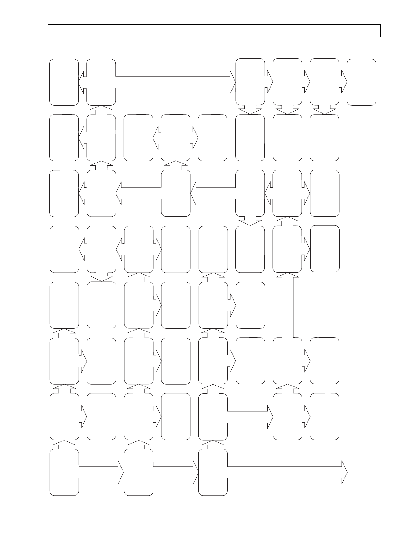
Form 43471040
Oct 2013 -35-
20.0) TROUBLESHOOTING GUIDE
Turn on line voltage
and thermostat. Does
the green monitoring
light come on?
Yes
No
Is there 120V
between the L1 and
L2 terminals on the
terminal block in the
control cabinet?
Yes
No
Are the black lead
wires of the green
light securely on the
terminals?
No
Yes
Replace the green
light.
Repair connection.
Check line voltage at
thermostat and line
voltage curcuit. Repair
fault.
Is the draft inducer
on?
Yes
No
Are the black and
white lead wires of the
draft inducer securely
on the terminals L1
and L2?
No
Yes
Repair connection.
Is 120V on the
terminal of the black
lead wire of the draft
inducer motor?
Does the red
monitoring light come
on?
Yes
No
Is there 24 vac
between terminals of
the transformer on the
secondary side?
Yes
No
Check the terminal
block for continuity;
replace it if no
continuity.
Repair connections.
Is the air hose
securely connected to
the air switch and the
air sensing tubing at
the blower?
No
Clean out hose and
probe.
Troubleshooting
continued on the next
page.
No
Yes
Check terminal block
for continuity. Replace
it if no continuity.
Disconnect the power
and check motor lead
wires. Any wire
broken?
Yes
No
Repair broken wires.
Check the blower
wheel. Does it turn
freely?
Yes
Replace motor
Check blower wheel.
Is there any damage?
Replace blower
wheel.
Readjust blower
wheel on shaft &
retighten set crew.
Check the air sensing
tube and hose. Are
they clear and
unobstructed?
Check the pressure at
the air switch. Is it
higher than the
minimum required?
Is the red wire from
transformer securely
connected to air
switch terminal C?
Move the red wire to
air switch terminal C.
Replace the red
monitoring light.
Is one wire of the red
light connected to air
switch terminal NO?
No
Yes
Replace transformer.
Are the black and
white wires to the
transformer securely
on the terminals?
No
Yes
Repair connection.
No
No
Yes
No
No
Check the voltage
between air switch
terminal C and
ground, is it 24 vac?
Yes
Is there120 vac on the
primary side of the
transformer?
Yes
No
When the blower is
running, is there 24
vac between air
switch terminal NO
and ground ?
No
Move the wire to air
switch terminal NO.
Is the other wire of the
red light connected to
the terminal common
of transformer?
No
Yes
Connect this wire of
the red light to the
transformer terminal
along with the white
wire from ignition
module.
Yes
Yes
No
Yes
Yes
Check the red wire
from transformer for
continuity.
Replace it if no
continuity.
Yes
Replace the air
switch.
No
Check the air intake
and vent. Are there
any blockages?
Yes
No
Remove blockage.
Restart
troubleshooting.
Check vent and fresh
air lengths. Are they
within the maximum
permissible?
No
Yes
Reduce them within
the maximum
permissible.
Remove the blower.
Is the wheel free from
dirt and dust?
Clean the blower
wheel.
Restart
troubleshooting.
No
Yes
Does the blower turn
freely?
No
Yes
Replace the blower
assembly.
Check the restrictor
plate stamped ID. Is
it correct for the
heater?
No
Yes
Replace the restrictor
plate.
Contact factory for
assistance.
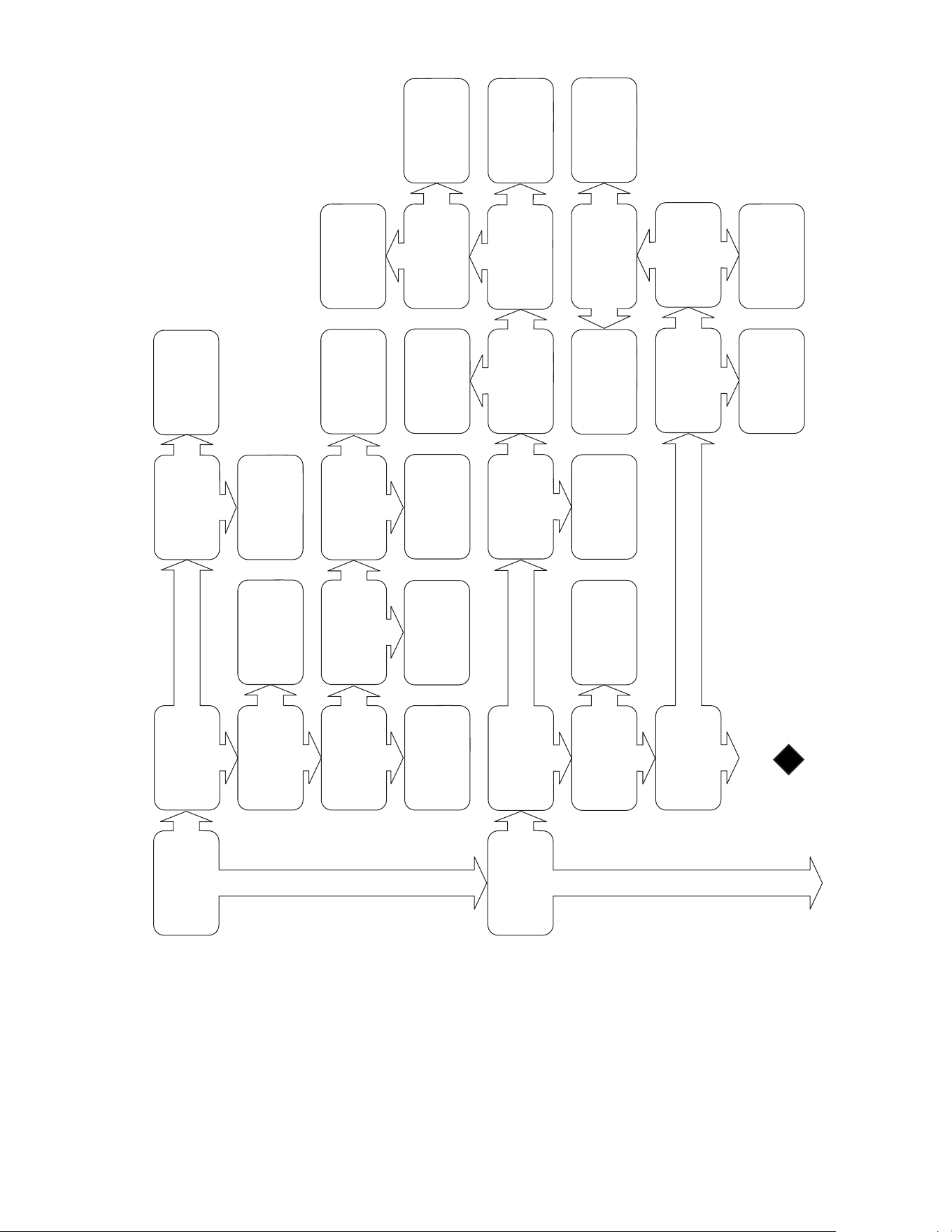
Form 43471040
-36- Oct 2013
30 seconds after
startup, does the
amber monitoring light
come on?
Yes
No
while the amber light
is on, through the
inspection window, is
there a flame visible?
Yes
No
Is the knob on the gas
valve in the ON
position? (Its shipped
from the factory at
OFF position)
Yes
No
Is there 24 vac across
25V(GND) and 25V
terminals on ignition
module?
Replace the amber
light.
Are the two wires to
the amber light
securely hooked to
the terminals of the
gas valve?
Does the amber light
stay on until call for
heat ends?
Yes
No
Repair connection.
Troubleshooting
continued on the next
page.
Move the red wire to
air switch terminal
NO.
Is the red wire from
ignition module 25V
terminal hooked to air
switch terminal NO?
Restart
troubleshooting.
Yes
No
Turn the knob to ON
position.
No
30 seconds after
startup, check the
voltage across valve
terminals on ignition
module. Is it 24 vac?
No
Yes
Move the white wire
to the transformer
terminal.
Is the fuse OK on
ignition module?
Yes
No
Replace the fuse.
Yes
Is there a spark
across igniter/sensor
gap?
Yes
No
Is the ground wiring
between the ignition
module and the
control box OK?
No
Yes
Adjust the electrode
tip into the flame.
Is the ceramic
insulator OK on the
spark electrode?
No
Yes
Replace the spark
electrode.
Is the spark gap
3/16?
No
Yes
Adjust the spark gap
to 3/16.
Replace the ignition
module & ignition
cable.
Spark stops when
burner is lit?
Yes
No
Is the electrode tip
directly in the flame?
No
Yes
Replace the spark
electrode.
Is there continuity
between electrode
sensor and ground
stud in the cabinet?
No
Replace the spark
electrode.
Troubleshooting
continued from the
previous page.
Fix the grounding
problem.
Replace the ignition
module.
Yes
No
Is the white wire from
ignition module
25V(GND) hooked to
transformer?
Yes
No
Yes
Check the flame
current at the ignition
module. Is it over
1.5mA with flame?
No
Yes
Replace ignition
module.
See next page for
troubleshooting
sequence.
Restart
troubleshooting.
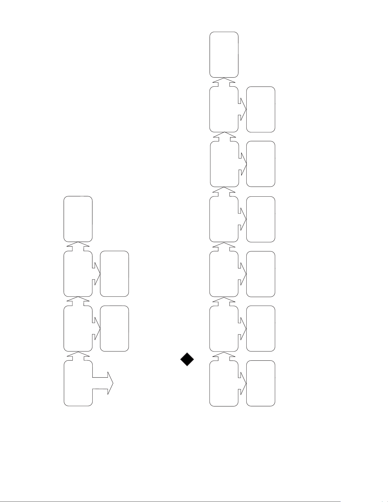
Form 43471040
Oct 2013 -37-
Call for heat ends and
the heater shuts off?
Yes
No
Troubleshooting ends.
Thermostat is not
working properly.
Replace it if
necessary.
Is the green light still
on?
Yes
No
Turn off gas &
electricity
immediately.
Replace the gas
valve.
Remove valve lead at
ignition module. Does
valve close?
No
Yes
Recheck thermostat
and wiring.
Troubleshooting
continued from the
previous page.
Troubleshooting
continued from the
previous page.
Check the spark gap.
Is it 3/16?
No
Yes
Adjust the spark gap
to 3/16.
Has all the air been
purged from the gas
supply lines?
No
Yes
Purge the gas supply
line.
Check the inlet
pressure to the gas
valve. Is it between
minimum and
maximum for the gas
type?
No
Yes
Adjust supply gas
pressure.
Restart
troubleshooting.
Check the manifold
gas pressure during
startup. Is it zero
inches?
Yes
No
Replace gas valve.
After an initial step
opening, is the
manifold gas pressure
correct?
No
Yes
Adjust manifold gas
pressure. Restart
troubleshooting.
Call factory for
assistance.
Check orifice and
holder for blockage
(i.e. spider web). Is
there any blockage?
Yes
No
Clear blockage.
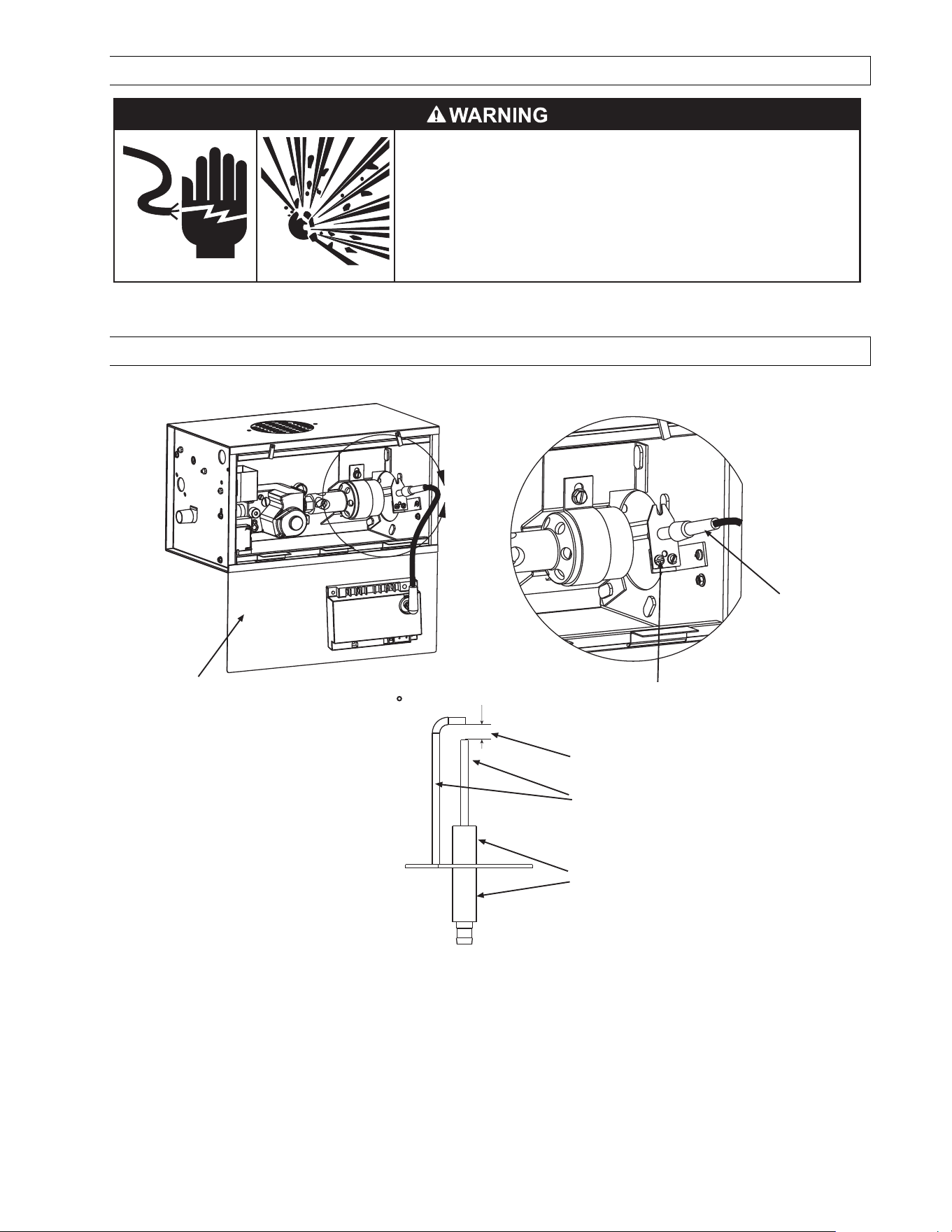
Form 43471040
-38- Oct 2013
21.0) REPLACING PARTS
ELECTRIC SHOCK & EXPLOSION HAZARD
Disconnect electrical power and gas supply before
servicing.
Failure to do so may result in death or serious injury.
Only use genuine Mestek replacement parts. Parts are available from the factory for replacement by a licensed
person. Refer to the Replacement Parts Guide in Section 23.0) for all replacement parts.
21.1) REMOVAL OF SPARK ELECTRODE
A
1
3
2
4
6
5
Access panel only opens to 90 .
3/16
1. Disconnect electrical supply and open access panel.
2. Pull out the ignition cable hooked to spark electrode.
3. Remove two mounting screws.
4. Take out the spark electrode. Check that the spark gap is 3/16”.
5. Check spark electrode. Spark electrode should be clean and free from debris.
6. Check ceramic on the spark electrode. It should be free from cracks.
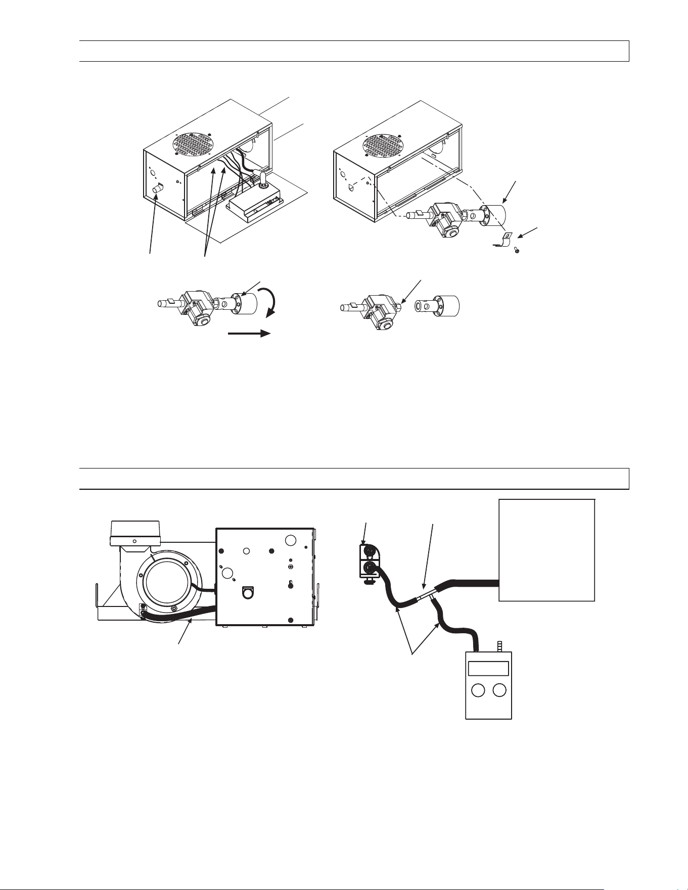
Form 43471040
Oct 2013 -39-
21.2) REMOVING MAIN BURNER AND GAS VALVE
The main burner can be inspected without removing the burner housing from the heat exchanger tube.
21
3
4
5
6
1. Disconnect electrical supply and gas connection at the restrainer nipple.
2. Open the access panel and disconnect the wires from gas valve.
3. Remove the burner clamp and screws.
4. Remove the burner and gas valve assembly from the cabinet.
5. Unscrew the burner from the manifold.
6. Check the orifice. If the gas valve is to be replaced, the pipe joint compounds must be resistant to the action
of liquefied petroleum gases.
21.3) AIR SWITCH PRESSURE CHECK
Plastic Vacuum
Air Tube
0.16 WC
+
-
Connector
Tee
Digital or Inclined
Water Manometer
scale 0-2w.c.
Temporary 1/4 ID Silicone /
plastic tubing for pressure
test.
Control Box
Air sensing
tube bracket
1. Open hinged access panel.
2. Add tubing to connect the air switch with the connector tee and the existing tubing.
3. Connect plastic tubing of a digital or inclined water manometer with a 0-2” scale onto the connector tees.
4. Turn heater on and wait until blower motor is activated.
5. Observe air pressure from manometer. This should be higher than the set point 0.16” w.c. for correct
operation.
All pressures are with the he
All pressures are with the heAll pressures are with the he
All pressures are with the heater in operation for at least 15 minutes.
ater in operation for at least 15 minutes.ater in operation for at least 15 minutes.
ater in operation for at least 15 minutes.
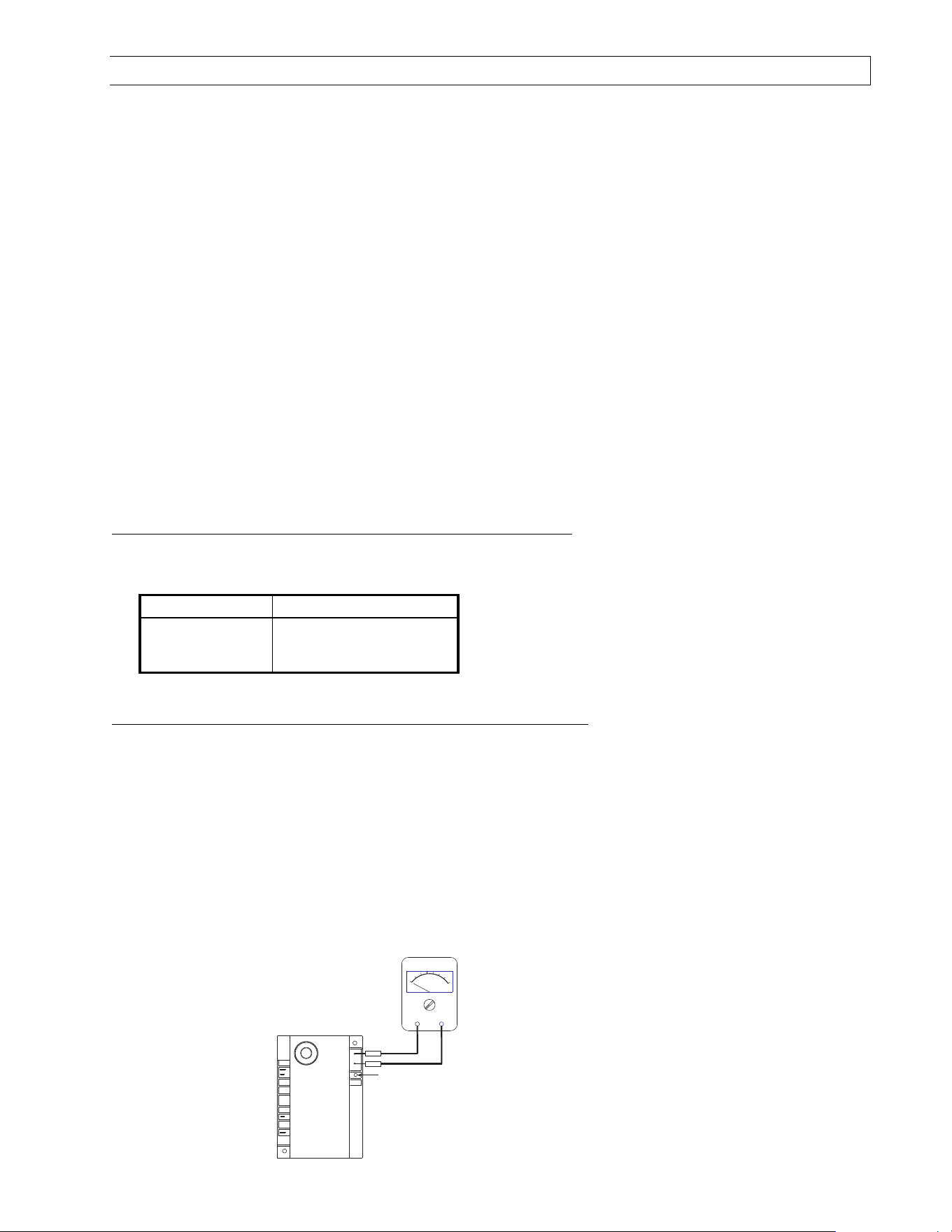
Form 43471040
-40- Oct 2013
21.4) IGNITION SYSTEM CHECKS
TO CHECK
TO CHECK TO CHECK
TO CHECK IGNITION CABLE
IGNITION CABLEIGNITION CABLE
IGNITION CABLE.
..
.
a. Make sure that the ignition cable does not touch any metal surface.
b. Make sure that connections to the stud terminal and the igniter/sensor are clean and tight.
c. Make sure that the ignition cable provides good electrical continuity.
TO CHECK
TO CHECK TO CHECK
TO CHECK IGNITION SYSTEM GROUNDING
IGNITION SYSTEM GROUNDINGIGNITION SYSTEM GROUNDING
IGNITION SYSTEM GROUNDING.
..
.
(Nuisance shutdowns are often caused by a poor or erratic ground.) A common ground is required for the module,
igniter, flame sensor and main burner.
a. Check for good metal-to-metal contact between the igniter bracket and the main burner.
b. Check the ground lead from the GND (BURNER) terminal on the module to the igniter bracket. Make sure
connections are clean and tight. If the wire is damaged or deteriorated, replace it.
c. Replace igniter/sensor with factory replacement part if insulator is cracked.
TO CHECK
TO CHECK TO CHECK
TO CHECK SPARK IGNITION CIRCUIT
SPARK IGNITION CIRCUITSPARK IGNITION CIRCUIT
SPARK IGNITION CIRCUIT.
..
.
▲WARNING:
▲WARNING:▲WARNING:
▲WARNING: The ignition circuit generates a 20,000 Volt open circuit and electrical shock can result.
a. Check ignition cable.
b. Check external fuse located inside the control box.
c. Verify power (24V) at module input terminals and output terminal to gas valve.
d. Replace spark module if fuse and power are OK.
IGNITION MODULE DIAGNOSTICS
IGNITION MODULE DIAGNOSTICS IGNITION MODULE DIAGNOSTICS
IGNITION MODULE DIAGNOSTICS (Fenwal #35
(Fenwal #35(Fenwal #35
(Fenwal #35-
--
-6087J1
6087J16087J1
6087J1-
--
-034 module only)
034 module only)034 module only)
034 module only)
The LED
LEDLED
LED located on the ignition module will flash ON
ONON
ON for ¼ second, then OFF
OFFOFF
OFF for ¼ second during a fault
condition. The pause between fault codes is 3 seconds.
LED Indication Error Mode
Steady On
Internal Control Fault
2 Flashes
Flame Sense Fault
3 Flashes
Ignition Lockout
TO CHECK FLAME SENSOR CIRCUIT
TO CHECK FLAME SENSOR CIRCUITTO CHECK FLAME SENSOR CIRCUIT
TO CHECK FLAME SENSOR CIRCUIT (Fenwal #35
(Fenwal #35(Fenwal #35
(Fenwal #35-
--
-6087J1
6087J16087J1
6087J1-
--
-034 module only)
034 module only)034 module only)
034 module only)
The flame current is the current that passes through the flame from the sensor to the ground. The
minimum flame current necessary to keep the system from lockout is
0.7
0.70.7
0.7 micro-amps.
a. To measure the flame current, connect an analog DC micro-ammeter to the FC
FCFC
FC-
--
-
and FC+
FC+FC+
FC+ terminals per
diagram. The meter should read
0.7
0.70.7
0.7 micro-amps or higher when the burner is running full on.
b. If the meter reads below
zero
zerozero
zero, the meter leads are reversed. Disconnect power and reconnect the meter
leads for proper polarity.
c. Remove micro-ammeter. Return system to normal operation.
MULTIPURPOSE METER
USE
MICROAMP
SCALE
BLACK (-)
RED (+)
LED Display
VALVE
GND
(BURNER)
FC-
FC+
VALVE
25V
Ignition Module - Alternate
(Fenwal #35-6087J1-034)

Form 43471040
Oct 2013 -41-
21.5) MOTOR AND BLOWER WHEEL CHECK
If draft inducer motor fails to run:
a. Check power supply to junction box.
b. Check for loose or broken motor lead wire.
c. Check to see that blower wheel turns freely and is not rubbing housing. Blower wheel may have worked
loose from shaft and jammed against housing.
d. Check for blower wheel damage; replace if necessary. If no damage, readjust blower wheel on shaft &
retighten set screw.
e. If all above does not correct, replace motor.
22.0) INSTALLATION DATA
Date of
Installation:
# of Heaters in
System:
Serial
No.
Model:
R(B,S,M)G
R(B,S,M)GR(B,S,M)G
R(B,S,M)G
N = Natural Gas
L = Propane Gas
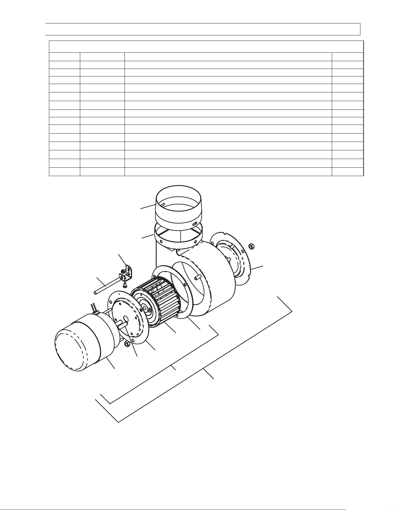
Form 43471040
-42- Oct 2013
23.0) REPLACEMENT PARTS GUIDE
DRAFT INDUCER COMPONENTS
DRAFT INDUCER COMPONENTSDRAFT INDUCER COMPONENTS
DRAFT INDUCER COMPONENTS
Item No.
Item No.Item No.
Item No.
Part No.
Part No.Part No.
Part No.
Description
DescriptionDescription
Description
Qty.
Qty.Qty.
Qty.
1
42737000
Draft Inducer Assembly
1
1a
42928000
Motor Replac
ement Kit
1
2
03721000
Motor
1
3 30347000 Motor Spacer (4 per motor) 4
4 42740000 Motor Plate 1
5 03723000 Blower Wheel 1
6
43221000
Draft Inducer Gasket
1
7
42744000
Sensing Tube, Draft Inducer
1
8 42742000 Sensing Tube Bracket 1
9 42739000 Blower Housing Sub-Assembly 1
10 40504020 4” O.D. Flue Pipe Starting Collar 1
12 42741120 Restrictor Plate, 7/8” I.D. R(B,S,M)G 025 1
13 42741041 Restrictor Plate, 1” I.D. R(B,S,M)G 035 1
14 42741031 Restrictor Plate, 1-1/8” I.D. R(B,S,M)G 045 1
10
9
12,13,14
(Not included in Draft
Inducer Assembly)
6
5
4
3
2
8
7
1
DRAFT INDUCER
COMPONENTS
1a
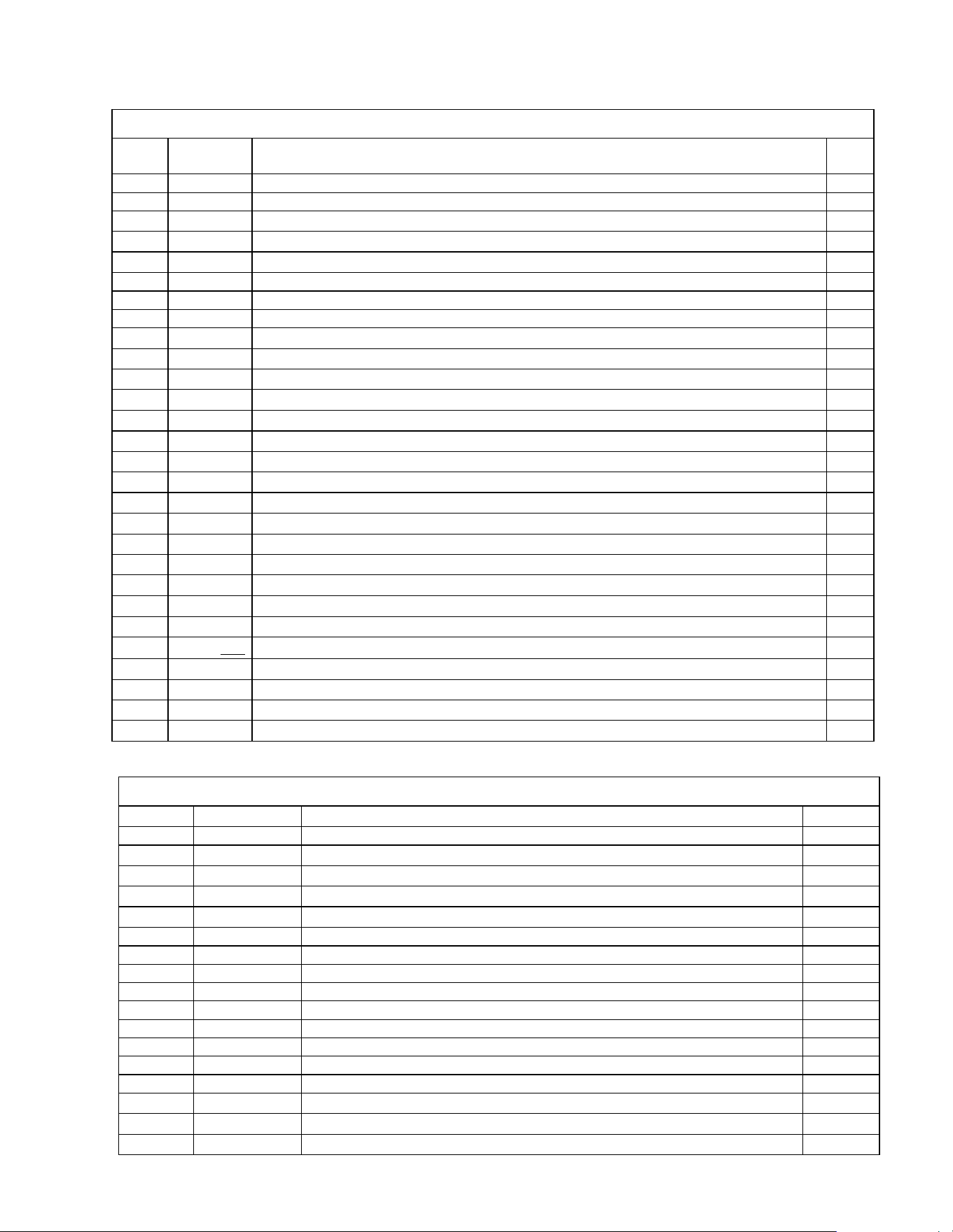
Form 43471040
Oct 2013 -43-
CON
CONCON
CONTROL
TROLTROL
TROL
COMPONENTS
COMPONENTSCOMPONENTS
COMPONENTS
Item
Item Item
Item
No.
No.No.
No.
Part No.
Part No.Part No.
Part No.
Description
DescriptionDescription
Description
Qty.
Qty.Qty.
Qty.
15
03988150
Plastic Vacuum Air Tube, 15” long
1
16
42750000
Cabinet Assembly
1
17 42751000
Access Panel 1
18 42752000
Air Inlet Plate (Perforated) 1
19 42447000
Sight Glass 1
20
42837040
Air Switch
Kit, set @0.11” W.C., #NS2
-
0307
-
00
1
21
30383000
Relay, 24 V, SPST
-
NO
(2
-
stage models only)
1
22
30279980
Transformer, AT120B1051
1
23 42709000
Terminal Block Shield 1
24 30281000
Terminal Block, EK-204 1
24a 30743000
Terminal Block, EL-3008 (2-stage models only) 1
24b 30738030
Thermostat Connection Block – 3 Pole (2-stage models only) 1
25 42759000
Electrode Bracket 1
26 30295000
Electrode PSE-GF1 (Igniter/Sensor) 1
27 30314070
Ignition Cable, 7” long 1
28 30632060
Spark Module – Fenwal #35-608711-034 1
29 42398040
Monitoring Light, Green 1
30 42398060
Monitoring Light, Red 1
31 42398050
Monitoring Light, Amber (2) each for 2-stage models 1
32 42757000
Restrainer Nipple, 5” long 1
33 30333250
Valve, VR8205Q-3819 @3.5” W.C/1.4” W.C. (Natural Gas) 1
34 30333260
Valve, VR8205Q-3827 @10” W.C./4”W.C. (Propane Gas) 1
35 42701000
Orifice Fitting & Test Gauge Connection 1
37
03259
xxx
xxxxxx
xxx
Main Burner Orifice (State Model & Gas Type for Size)
(State Model & Gas Type for Size)(State Model & Gas Type for Size)
(State Model & Gas Type for Size) 1
38 42700000
Main Burner 1
39 30148000
Universal Bushing, 7/8” 1
40 42755000
Burner Bracket Sub-Assembly 1
41 42753000
Burner Clamp 1
Labels / Manual
Labels / ManualLabels / Manual
Labels / Manual
Item No.
Item No.Item No.
Item No.
Part No.
Part No.Part No.
Part No.
Description
DescriptionDescription
Description
Qty.
Qty.Qty.
Qty.
42
42785030
Label, Ladder Wire Diagram
1
43 42706020 Label, Connection Wire Diagram 1
44 43471040 Installation and Operation Instructions (not shown) 1
45 43344050 Label, Gas Connector Warning 1
46 43470080 Label, Clearance to Combustibles 1
47
42848250
Label, Nameplate
–
Sterling 1
-
Stage
1
47a
42848251
Label, Nameplate
–
Mestek 1
-
Stage
1
47b
42848252
Label, Nameplate
–
Beacon/Morris 1
-
Stage
1
47c
42848260
Label, Nameplate
–
Sterling 2
-
Stage
1
47d
42848261
Label, Nameplate
–
Mestek 2
-
Stage
1
47e
42848262
Label, Nameplate
–
Beacon/Morris 2
-
Stage
1
48
4201308
0
Label, Logo
-
Mestek
1
48a
42013070
Label, Logo
-
Sterling
1
48b
42013090
Label, Logo
–
Beacon/Morris
1
49 43470030 Label, Warning (residential) 1
50 42834000 Label, 120V Caution 1
51 42875000 Label, Warning 1
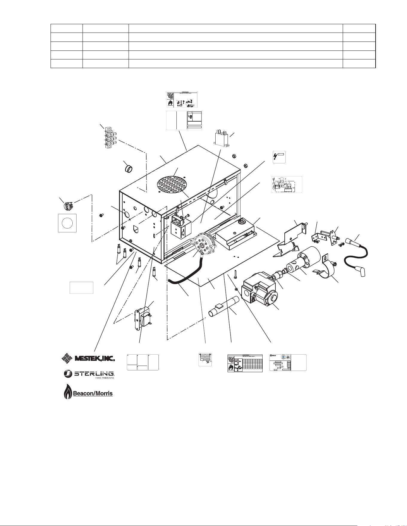
Form 43471040
-44- Oct 2013
52 43470040 Label, Operating Instructions 1
53 43470050 Label, Caution/Attention 1
54 43470060 Label, Horizontal Venting 1
55 43269060 Label, Thermostat Connection 1
56 43269070 Label, 2-stage 1
25
26
40
41
38
37
35
33,34
32
22
20
23,24
16
39
18
19
15
17
31
30
29
24b
45
50
ELECTRICAL SHOCK
HAZARD
DISCONNECT POWER
BEFORE OPENING COVER
CAUTION
120 VOLTS
42834000
Alternate Supply
Locations
TYPICAL GAS
CONNECTION
END VIEW
Movement
14 - 17
(356 - 432mm)
Control Box
SIDE VIEW
Flexible Connector
Optional Second Stage Regulator with
Vent Leak Limiter if required to reduce
the Supply Pressure below 14 W.C.
Recommended Gas
Pressure 2 PSIG
Gas Supply
Piping
Sediment Trap
(Drip Leg)
43344050 Rev. C 3/09
Install the gas flexible hose as shown in the diagram below:
Sharp bends, kinks, twists and tension in the hose may cause failure resulting in a gas
leak.
Failure to follow these instructions may result in death, serious injury or property damage.
CONTROL
COMPONENTS
42
SCHEMATIC WIRING DIAGRAM
MOT Motor
Moteur
GL Green Light Témoin vert
TRANS 24V Transformer Transformateur 24ÊV
RL Red Light Témoin rouge
AS Air Switch pressostat
SM Ignition Module Bloc d'allumage
IG/S Ignitor / Sensor électrode
V Gas Valve Robinet à gaz
AL Amber Light Témoin ambre
MOT
120V
GL
TRANS
RL
AS
IG/S
AL
V
SM
42785000 Rev. C 10/04
25V GND25V
Combustible material must be located outside the clearance dimensions listed.
Ceiling Clearance is 12 (30cm) when installed in an UNVENTED configuration. Ceiling
clearance is 18 (46cm) when the optional corner reflectors are not used on ETS or LTS.
Failure to do so may result in death, serious injury or property damage
Models LTS/LTU/ETS/ETU
43344000 Rev. B 10/04
Le dégagement au-dessus de l'appareil doit être d'au moins 30 cm quand l'appareil est installé
SANS ÉCHAPPEMENT.
Le dégagement au-dessus de l'appareil doit être d'au moins 46cm
quand les réflecteurs d'angle optionnels ne sont pas utilisés sur l'ETS ou le LTS.
D
D
Dessous, 6m du brûleur
Below 20ft from burner
C*
20ft (6m)
Model No A B C D E F C*
40,50 27 6 40 30 48 12 -
(69cm) (15cm) (104cm) (76cm) (122cm) (30cm)
60,75 27 6 60 30 48 12 -
(69cm) (15cm) (145cm) (76cm) (122cm) (30cm)
80,90 52 6 84 30 52 12 72
(132cm) (15cm) (145cm) (76cm) (122cm) (30cm) (183cm)
100 66 6 88 40 66 20 72
(168cm) (15cm) (224cm) (102cm) (168cm) (30cm) (183cm)
110,120, 66 6 101 40 66 20 72
125,130 (168cm) (15cm) (257cm) (102cm) (168cm) (51cm) (183cm)
140,150, 84 6 106 48 84 24 72
160,175 (213cm) (15cm) (269cm) (122cm) (213cm) (61cm) (183cm)
180,200, 84 18 132 48 84 24 72
225,250 (213cm) (46cm) (335cm) (122cm) (213cm) (61cm) (183cm)
Horizontal
B
C
A A
45 degrees
B
C
E
F
Montage horizontal
Montage à 45°
46
GAS TYPE
SUPPLY PRESSURE
Pression de Sortie
Type de Gaz
MAXIMUM
MINIMUM
MANIFOLD PRESSURE
Pression a lechappement
INPUT Btu/Hr
Consommation Btu / Hr
ORIFICE SIZE
Dimensions bec Veilleuse
MODEL NO.
No. de Modelè
Installation in:
1. Aircraft hangars must be in accordance with the standard for Aircraft Hangars.
ANSI/NFPA 409 (latest edition).
2. Public garages must be in accordance with the standard for parking structures,
ANSI/NFPA 88a (latest edition), or with the standard for repair garages,
ANSI/NFPA 88b (latest edition)
SERIAL NO.
No. de Série
LIGHTING & SHUTDOWN INSTRUCTIONS
1. Turn on gas & electrical supply.
2. Set thermostat to call for heat.
3. Ignition should occur after prepurge.
4. If ignition fails, the unit will spark for approximately 21 seconds
& go into safety lockout. Turn thermostat (or power) off for 60
seconds to take out of lockout.
5. If heater does not light, shut off gas completely for 5 minutes
before attempting to relight.
6. To shut down the heater, turn off the gas & electrical supply.
Infrared Radiant Tube Heater
Radiateur à tuve rayonnant à infrarouge
Gas Fired products Inc. Charlotte, NC
INSTRUCTIONS DALLUMAGE ET DE FERMETURE
1. mettre la valve a gaz et linterrupteur a ON.
2. Creer une demande de chauffage au thermostat.
3. Lallumage devrait se produire apres de prepurge.
4. Si lallumage ne se fait pas, le controle dallumage continu de
produire des etincelles sur une periode de 21 sec. et ensuite
tomber en securite. Mettre le thermostat (ou le courant) en
position darret (OFF) pour une periode de 60 sec. a fin
dinterrompre le processus de securite.
5. Si lappareil ne sallume pas, fermez le gaz completement pour
une period de 5 min. avant deffectuer une nouvelle tentative
dallumage.
6. Pour fermer lappareil, fermez le gaz et le courant electrique.
For indoor installation only
Installer à lintérieur seulement
Vented or Unvented
ELECTRICAL:
ALTITUDE
ANSI Z83.20 / CSA 2.34 - 2008 Tel: 1800 438 4936 e-mail [email protected]
CODE DATE
42848000 Rev. K 1/09
MAX ANGLE:
Max Angle
Electrique
47
48
WARNING: Improper
installation, adjustment,
alteration, service or
maintenance can cause
property damage, injury
or death. Read the
Installation, Operating
and Maintenance
Instruction thoroughly
before servicing this
equipment.
AVERTISSEMENT: Une
installation, un r
églage, une
modification, une r
éparation
ou un entretien incorrect peut
entraîner des dommages
matérials, des blessures ou
la mort. Lisez attentivement
les instructions dinstallation,
de fonctionnement et
dentretien avant de procéder
à linstallation ou à lentretien
de cet équipment.
WARNING: If not
installed, operated and
maintained in accordance
with the manufacturers
instructions, this product
could expose you to
substances in fuel or from
fuel combustion which can
cause death or serious
illness and which are
known to the State of
California to cause cancer,
birth defects or other
reproductive harm.
WARNING: This product
contains a chemical known
to the state of California to
cause cancer.
This heater can be
installed in various
configurations as shown
in the heater layout
section of the instructions
42875000 Rev. E 10/04
51
43
WIRE LEGEND
ENGLISH FRANCAIS
BK BLACK NOIR
W WHITE BLANC
R RED ROUGE
BL BLUE BLEU
G GREEN VERT
V VIOLET VIOLET
A AMBER AMBRE
42706000 Rev. G 1/05
G
BL BL
BKBK
R
W
BK
BK
R
BK
W
BK
BK
BK
W
DRAFT
INDUCER
MOTOR
GAS VALVE
AIR SWITCH
25V
(GND)
25V GND
(BURNER)
VALVE VALVE
TRANSFORMER
120V PRIMARY
24V SECONDARY
A
G
R
IGNITION MODULE
HIGH VOLTAGE
CABLE
ELECTRODE
GAP 3/16
CONTINUE TO
ADDITIONAL
HEATERS
NEUTRAL
120V THERMOSTAT
GROUND
L1
L2
TERMINAL
BLOCK
FACTORY WIRING
FIELD WIRING
CONNECTION WIRING DIAGRAM
CONTROL CABINET
If any of the original wire as supplied
with the appliance must be replaced.
It must be replaced with wiring material
having a temperature rating of at least
105
o
C. (18 AWG. - UL / CSA 600V
Type TEW)
When connecting the supply circuit to
the heater, wiring material having a
minimum size of 14 AWG and a
temperature rating of at least 90
o
C
shall be used.
MONITORING LIGHTS
Schéma de circuit de connexion
Circuit d'origine
Connexions client
Lampes témoins
Neutre
Terre
Vers les autres
radiateurs
Plaque à
bornes
Transformateur
bobine primaire 120ÊV
bobine secondaire 24ÊV
pressostat
Robinet à gaz
Écartement
d'électrode
4,7Êmm
Haute tension
Armoire de commande
Bloc d'allumage
Moteur
d'amorce
d'aspiration
S'il faut remplacer un fil de l'appareil
d'origine, utiliser exclusivement des fils
à température de service nominale
d'au moins 105C (18 AWG. - UL / CSA
600ÊV
Type TEW).
Pour raccorder le circuit d'alimentation
au radiateur, utiliser des fils de calibre
14 AWG ou plus à température de
service nominale d'au moins 90C.
53
2-Stage Thermostat
43269060 rev A
HI
C
LO
52
28
27
24a
21
49
Note: When venting a single
heater horizontally through a
combustible outside wall the
vent must pass through a 2
clearance thimble (Air Jet No.
4VT or Ameri-vent No 4EWT
for the 40 75,000 BTU
heaters and Air-Jet No 6VT or
Ameri-Vent No. 6EWT for the
80 250,000 Btu heaters) or
other thimbles which are listed
by nationally recognized testing
agency.
Attach a vent cap (Breidert No.
4L or equivalent for the 40-
75,000 BTU heaters or Breidert
No. 6L or equivalent for 80
250,000 BTU heaters) to the
end of the pipe.
Minimum equivalent length of
vent pipe = 5ft (1.5m)
Maximum equivalent length of
vent pipe = 75ft (23m)
THIS UNIT EQUIPPED WITH A
2 AMP IN LINE-FUSE FOR
OVERCURRENT PROTECTION
OF CONTROL CIRCUIT
ELECTRIC SHOCK
HAZARD
Disconnect electrical supply
before servicing
Failure to follow these
instructions may result in
death, serious injury or
property damage.
WARNING
DRAFT INDUCER SERIAL NUMBER
42922020 Rev C 8/05
SIDEWALL VENTING ONLY
UN MUR LATÉRAL
AÉRATION
GAS-FIRED UNIT HEATERS
48a
48b
Two Stage
43269070 4/08
High Fire
Low Fire
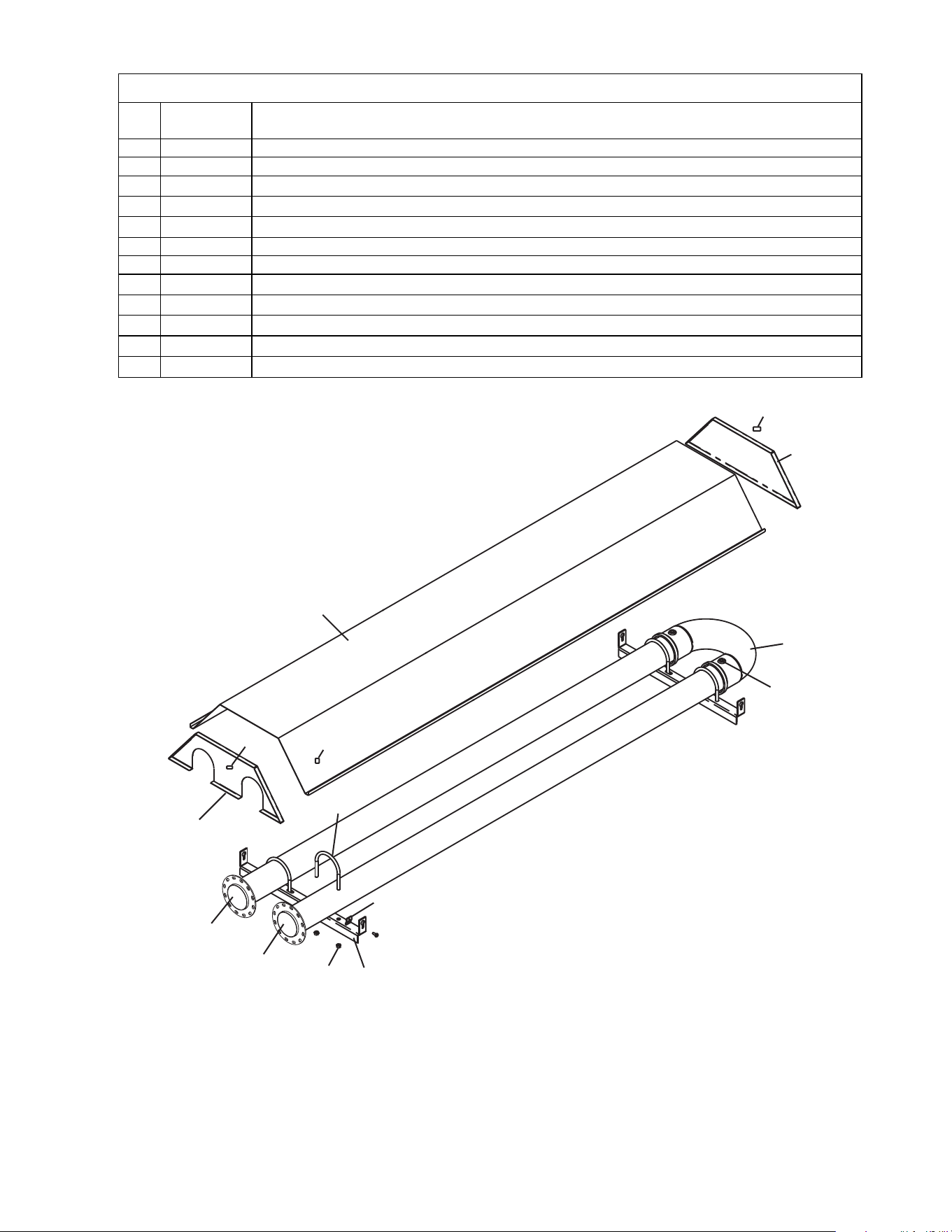
Form 43471040
Oct 2013 -45-
BODY COMPONENTS
BODY COMPONENTSBODY COMPONENTS
BODY COMPONENTS
Item
Item Item
Item
No.
No.No.
No.
Part No.
Part No.Part No.
Part No.
Description
DescriptionDescription
Description
1
02266010
Reflector Speed Clip
2
42769011
Reflector Clamp with screw
(
4
per heater)
3 42770000
“U” Bolt Clamp, 3” OD Tube (6 per heater)
3a 02127110
“U” Bolt Hex Nut, 5/16-18 (2 per “U” Bolt)
4 42773000
Tube Support/Hanger Bracket, 18-1/2” (2 per heater)
5
42763080
Reflector, 8’ long
(
1
per heater)
6
42762010
Reflector, control end
7 42761010
Reflector, foot end
8 44028132
7-1/2’ Tube Replacement Kit, 3” OD, ALC w/one 12 radial hole flange
9 42764000
U Bend, 3” OD x 3-3/4” centerline radius
10 02251040
Set Screw, 5/16-24 x 1/2” (2 per heater)
7
5
1
1
9
10
6
8
8
3a
2
4
3
1
Note:
1) Screws, Nuts and Washers are standard hardware items and can be purchased at any local hardware store.
2) Please order by PART NUMBER – not by Item Number.
3) Replacement Part Prices are available when ordering.
4) Please refer to complete Model Number when ordering.
ALL ILLUSTRATIONS ARE INTENDED TO GIVE THE GENERAL IMPRESSION OF UNITS ONLY. WE RESERVE THE RIGHT TO ALTER
ANY SPECIFICATION WITHOUT NOTICE.
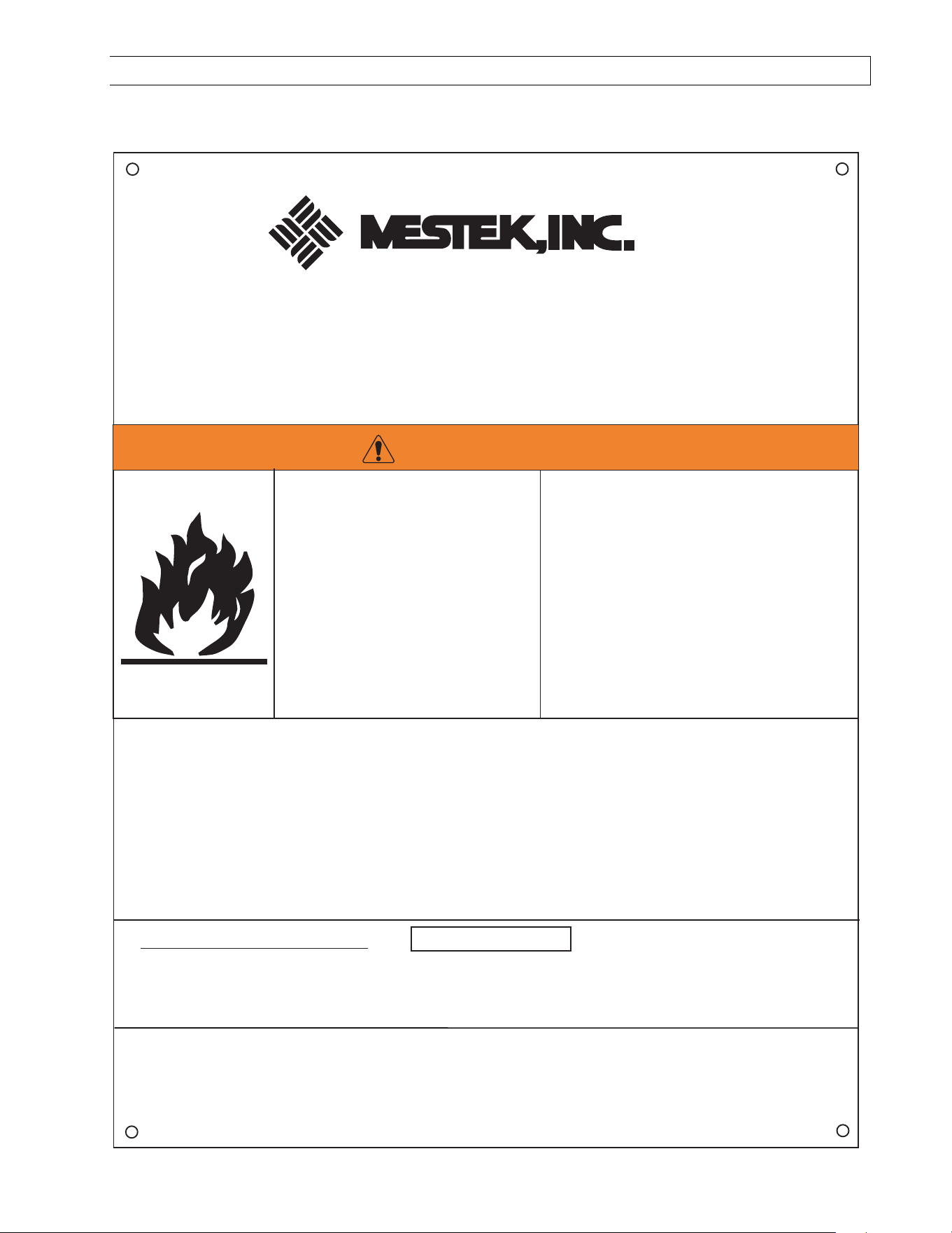
Form 43471040
-46- Oct 2013
24.0) WARNINGS CARD
Copies of this card may be ordered under part no. 43344970 for installation near the heater.
IF YOU SMELL GAS: FOR YOUR SAFETY
! DO NOT try to light any appliance.
! DO NOT touch any electrical switch; DO NOT use any telephone in your building.
! IMMEDIATELY call your gas supplier from a neighbor's telephone. Follow the gas supplier's instructions.
If you cannot reach your gas supplier, call the fire department.
Attach this information card adjacent to the thermostat which controls the Mestek heater(s).
Read the Installation and Operating Instructions thoroughly before installation, operation or
service.
INSTALLER: Write the clearance distance for the highest BTU model in the building in the blank spaces
below using permanent ink. The clearances to combustible materials are based on each individual
heater model number. Locate the heater model number on the nameplate affixed to the heater. The
clearances to combustibles distances can be located adjacent to the nameplate or in the Installation
& Operating (I & O) Instructions.I & Os can also be located on www.spaceray.com
Maintain the following clearances:
_____ to the side, _____ above
and _____below the heater
from combustible materials.
43344970
Oct 2013
Installation Code and Annual Inspections:
Installation and Service of Mestek equipment must be performed by a qualified contractor and conform with all requirements
set forth in the Mestek Installation and Operating Instructions and any National and Local codes pertaining to the installation,
service and operation of the equipment. Annual inspection is recommended prior to the heating season to ensure proper
operation of the heating equipment.
Maintain Clearances to Combustibles to
Prevent the Risk of Fire.
Clearance to combustibles must be
maintained at all times in order to prevent
the ignition of combustible materials. In
locations used for the storage of combustible
materials signs must be posted to specify
the maximum permissible stacking height
to maintain the required clearances from
the heater to the combustibles. Signs must
either be posted adjacent to the heaters
thermostats or in the absence of such
thermostats, in a conspicuous location.
Mestek, Inc.
260 North Elm Street * Westfield, MA 01085 *
Phone (413) 568-9571 * Fax (413) 562-8437 * www.mestek.com *
FIRE HAZARD
Combustible material must be located
outside the clearance distance listed
from heater.
Some objects will catch fire or
explode when placed close to heater.
Failure to follow these instructions
can result in death, injury or property
damage.
WARNING