Ver.20190720
D1524R Tabletop High-speed Refrigerated
Micro Centrifuge
This user manual needs to be read before operating this product.
Please follow the safety instructions provided in this manual.

1
Table of Contents
Safety Warnings .................................................................................................................................. 3
1. Performance indicators ............................................................................................................... 5
2. Conformity to standards ............................................................................................................. 5
3. Environmental conditions ........................................................................................................... 5
3.1. Basic operating conditions ...................................................................................................... 5
3.2. Transport and storage conditions ........................................................................................... 6
4. Installation ................................................................................................................................... 6
4.1. Mounting position ................................................................................................................... 6
4.2. Connection between power cable and ground wire ............................................................... 7
5. Structure ...................................................................................................................................... 7
6. Operating panel ........................................................................................................................... 8
7. Rotor preparation ...................................................................................................................... 10
7.1. Prepare the samples to be separated ................................................................................... 10
7.2. Place samples into the centrifuge tube ................................................................................. 10
7.3. Ensure the balanced centrifuge tube .................................................................................... 10
7.4. Check the rotor ...................................................................................................................... 11
7.5. Insert the centrifuge tubes symmetrically onto the rotor in place without imbalance........ 11
8. Operation .................................................................................................................................. 11
8.1. Normal operation .................................................................................................................. 11
8.2. RCF operation ........................................................................................................................ 15
8.3. Transient operation ............................................................................................................... 16
9. Maintenance and servicing ....................................................................................................... 16
9.1. Cleaning ................................................................................................................................. 16
9.2. Sterilization ............................................................................................................................ 17
9.3. Wearing parts ........................................................................................................................ 18
9.4. Replacement of rotor seal ..................................................................................................... 18
9.5. Routine check ........................................................................................................................ 19
10. Common failures and solutions ................................................................................................. 19
10.1. List of common failures ......................................................................................................... 19

2
10.2. How to open the outer lid ..................................................................................................... 20
10.3. Replace the fuse .................................................................................................................... 21
11. Introduction to rotor and centrifuge tube ................................................................................ 21
11.1. Rotor description ................................................................................................................... 21
11.2. Centrifuge tube ..................................................................................................................... 23
12. RCF calculation .......................................................................................................................... 24
13. Ordering information ................................................................................................................ 25
14. Warranty ................................................................................................................................... 25
14.1. Unit warranty ........................................................................................................................ 25
14.2. Rotor warranty ...................................................................................................................... 25
15. After-sales services .................................................................................................................... 26

3
Safety Warnings
The symbol is an internationally accepted safety mark. Please carefully read and fully
understand the following safety rules:
⚫ Comply with the operation requirements contained herein and ensure safe operation.
⚫ Carefully read all safety information and reminders provided in this manual.
⚫ Safety information is marked as follows. The safety symbol is combined with the “Warning”
and “Caution” respectively, reminding users of the potential danger. These two combinations and
the “reminder” symbols are defined as follows:
Warning: personal danger.
Warning against potential dangers, which might result in injury or death if the requirements
contained herein are not strictly complied.
Caution: Potential danger to instrument
Ensure to comply with all the safety requirements as mentioned to avoid potential dangers of
damage to the instrument
Reminder: matters that generally call for attention.
⚫ Do not use this centrifuge in any manner not mentioned in this user manual.
⚫ In case of any problem, please contact the vendor/supplier.
⚫ This user manual provides complete details of the potential dangers, however users are advised
to stay alert against unpredictable circumstances and use this centrifuge with care.
Warning:
⚫ This centrifuge is non-explosion proof and may not be used for separation of flammable or explosive
samples.
⚫ Do not install this centrifuge in the vicinity of any flammable gas or chemical substances.
⚫ Do not place anything that causes danger within 30cm radius of this centrifuge.
⚫ Don’t centrifuge any toxic, radioactive or pathogenic organisms without appropriate safety measures. If
the microorganism sample being centrifuged is secondary hazard (as defined in the WHO’s “Laboratory
Biosafety Manual”), ensure to use biological sealing devices.
⚫ Ensure to sterilize it according to decontamination procedures that are mentioned under sterilization
section.
⚫ If there is any need for onsite assistance, sterilize and decontaminate the centrifuge in advance and notify

4
the service representative about the details.
⚫ Never touch the power cable/switch with wet hands and avoid electric shocks.
⚫ As a safety measure, ensure to maintain atleast 30cm distance from the centrifuge while in operation.
⚫ For safety reasons, when the centrifuge is running, the personnel should maintain a 30cm distance from
the centrifuge.
⚫ Never open the outer lid while the rotor is in operation.
⚫ The centrifuge should be opened for repair/ dismantling by trained staff only.
Caution
⚫ Ensure that the centrifuge is stable, before its operation.
⚫ Ensure that the angle between the outer lid and housing is larger than 90° while opening the lid.
⚫ Never place hands/any other things in between the outer lid and the housing.
⚫ Never open the outer lid while the centrifuge is in operation.
⚫ Don’t move or lean against the centrifuge if it is in operation mode.
⚫ If there is any liquid found in the centrifuge, ensure to wipe it OFF with a cloth in time to prevent sample
contamination.
⚫ Ensure that the centrifuge chamber is left clean and free of any foreign objects/ tube fragments before
each and every operation
⚫ Reminders about rotor:
⚫ Check and ensure that the rotor surface is free of corrosions/ damages before its operation.
(1) The set rotation speed of the centrifuge should not exceed the allowed minimum speed of the rotor
assembly and accessories (rotor and adapter) and ensure to run the centrifuge under minimum allowed
speed.
(2) Don’t exceed the allowed amount of imbalance.
(3) The centrifuge tubes used should be within their allowed capacity.
(4) If the rotor has a lid, ensure to tighten it before operation.
(5) Use genuine accessories only.
⚫ If there is any abnormality or strange noise observed in operation, please stop the centrifuge operation
and contact the service center and intimate the failure code immediately.
⚫ Earthquake might cause damage to the centrifuge. If any abnormality occurs, please contact the service
center.

5
1. Performance indicators
Maximum rotation speed
15,000rpm (200-15,000rpm)
step: 100rpm
Maximum relative centrifugal
acceleration
21,380×g, step: 10×g
Capacity
1.5/2ml×24; 0.5ml×36; PCR8 tube bank ×4; 5ml×12; 5ml×18;
Temperature setting range
Tabletop high-speed refrigerated micro-centrifuge: -20℃- 40℃
Timing
30s-99 min; HOLD (continuous running)
Drive motor
DC brushless motor
Safety performance
Dual door locks, overspeed, overtemperature and Internal
diagnosis system.
Power
Single phase
220-230V, 5A, 50/60Hz, 400W
110-120V, 5A, 50/60Hz, 490W
Dimensions (mm)
(Width) 332× (depth) 553× (height) 283
Weight
30kg
Acceleration and deceleration time
25s↑25s↓
Noise
≤56dB
Other functions
Rotation speed/RCF switchover, inching operation, running
process indication and sound reminder; 9-step acceleration, 9-
step deceleration; stored program capability.
2. Conformity to standards
The centrifuge’s structure conforms to the following safety standards:
IEC 61010-1:2010,
AMD1: 2016/EN 61010-1:2010,
UL 61010-1:2012 R4.16 and CAN/CSA-C22.2 NO.61010-1-12+ GI1+GI2
CB Scheme N/A
EN 61010-2-020
The centrifuge’s structure conforms to the following electromagnetic compatibility standard:
EN 61326-1
Compliant with the following EU standards:
EMC standard: 2014/30/EU
3. Environmental conditions
3.1. Basic operating conditions
(1) Power supply: single phase, 220-230V, 5A, 50/60Hz, 400W or 110-120V, 5A, 50/60Hz, 490W

6
(2) Ambient temperature: 2~40℃.
(3) Relative humidity: ≤80%.RH
(4) No vibration or air flow present nearby that might affect performance.
(5) No conductive dust, explosive gas or corrosive gas exists in ambient air.
3.2. Transport and storage conditions
(1) Range of ambient temperature: -40℃-55℃.
(2) Range of relative humidity: ≤93%.RH
(3) The centrifuge must remain upright while in transit, suitably protected using wooden Kart box
(4) Lift the centrifuge by the chassis only.
(5) Pay attention to the centrifuge’s weight while in transit (see the “performance indicators”).
(6) Centrifuges with cooling device, should be left for about 1hour after being relocated to a new
position to stabilize the refrigerant in the compressor
.
4. Installation
Users must strictly comply with the installation instructions contained in this chapter.
Be advised! Remove the rotator before moving the centrifuge.
Warning
⚫ Improper power connection might damage the centrifuge.
⚫ Before connecting the power supply, please check the power supply for
compliance with the requirements.
4.1. Mounting position
(1) This centrifuge must be mounted on a solid, flat and tabletop with contact between the four feet
of the centrifuge and the tabletop. Don’t mount the centrifuge on any sliding tabletop,
otherwise significant vibration might occur. Carefully place the centrifuge to avoid damage.
(2) The ideal ambient temperature is 20°C ±5 °C and the ambient temperature should not be more
than 30℃. Avoid direct sunlight on this centrifuge.
(3) Place the centrifuge at >30cm distance from the wall and other instruments if using multiple
units together to ensure effective cooling.
(4) Ensure that there is no water leakage/ heat loss near the centrifuge as it may cause the rise in
temperature and thereby leading to centrifuge failure.
7
4.2. Connection between power cable and ground wire
Warning
⚫ Don’t touch the power cable with wet hands and avoid electric
shocks.
⚫ Ensure that the centrifuge is well grounded.
(1) This centrifuge uses three-core power cable and three-core flat plug, the latter of which may be directly
connected to the power socket.
(2) Ensure that the centrifuge is protected by good grounding terminal and that the label on it
indicated the correct voltage (>10A) before connecting the device to power supply.
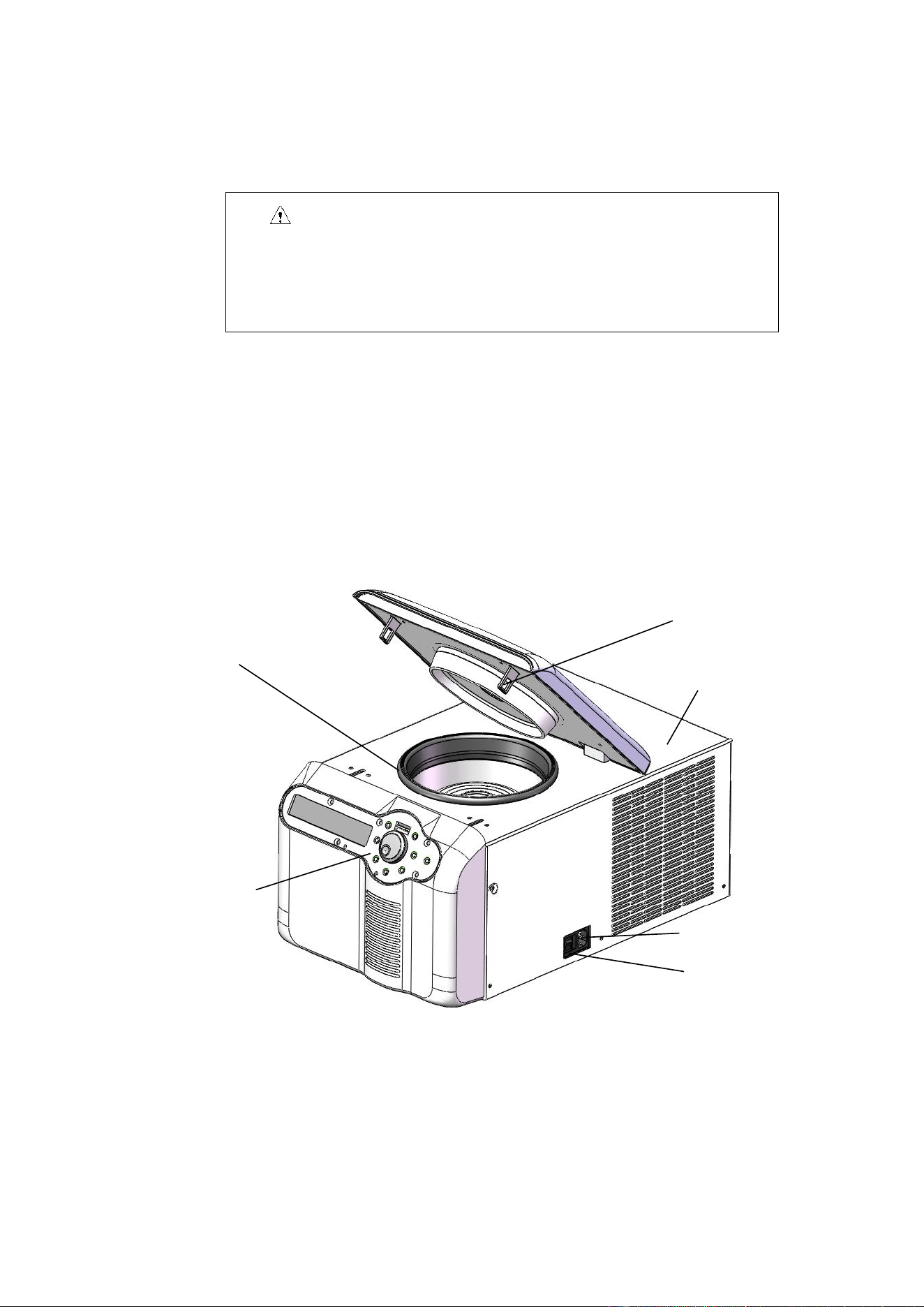
5. Structure
D1524R
Fig. 5.3. Front view of centrifuge
Sealing ring
Bolt
Housing
Power socket
Operating panel
Power switch
8
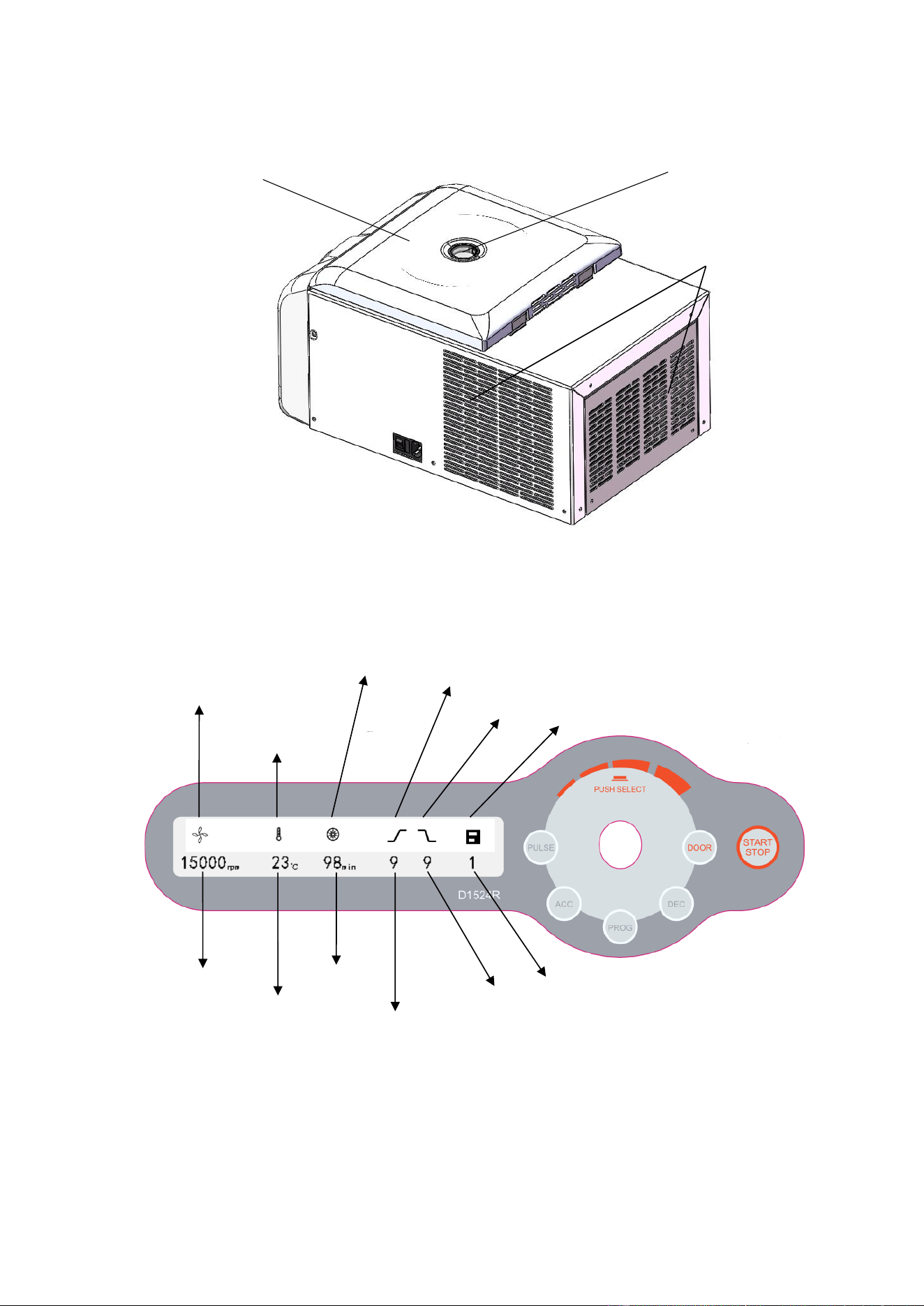
Fig. 5.4 Rear view of centrifuge
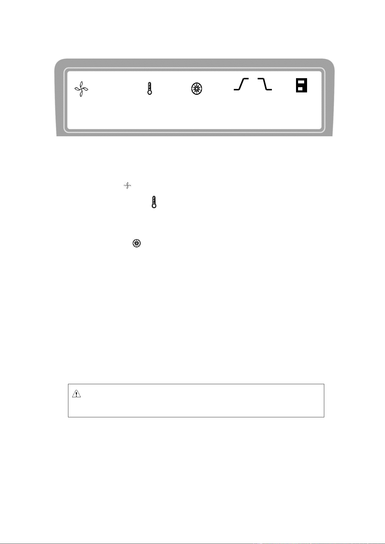
6. Operating panel
Fig. 6.1 Schematics of operating panel
Sight glass
Outer lid
Vent
Motor start indicator
Compressor
running indicator
Acceleration
Deceleration
Program
Speed display
Temperature display
Time display
Remaining running time
Acceleration level
Deceleration level
Program number
9
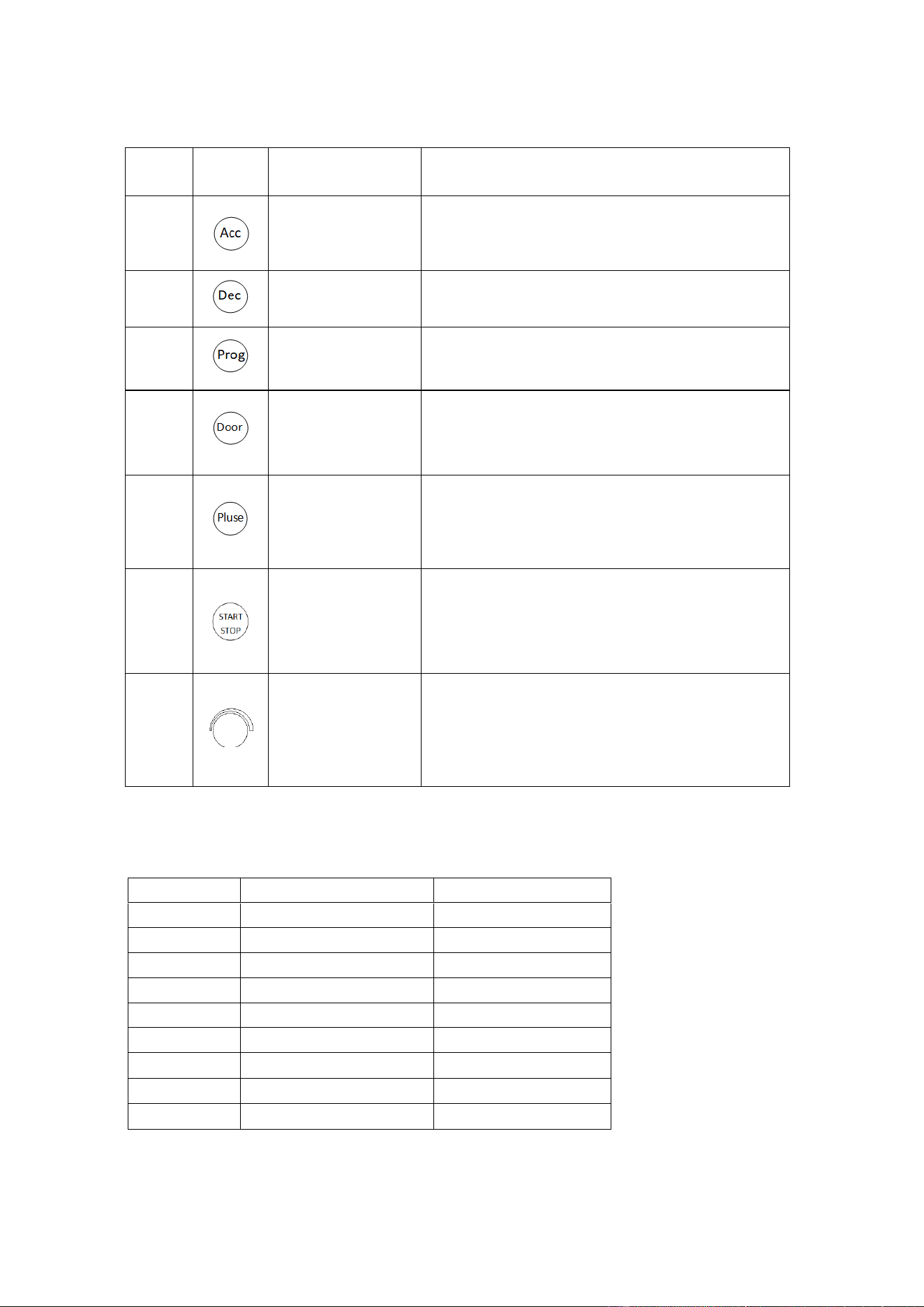
No.
Legend
Name
Function
1
Acceleration level
adjustment+ key
Press this key to increase the speed level by 1;
acceleration level 1-9 cycle.
2
Deceleration level
adjustment+ key
Press this key to decrease the speed level by 1;
deceleration level 1-9 cycle.
3
Program key
Press this key to switch to the stored program +1,
stored program, program 0-9 cycle.
4
Door lock open key
When the speed is zero, press this key to release the
door lock. When the speed setting is above zero, the
door locks automatically.
5
Inching key
When the outer lid is locked tightly, by pressing and
keeping this key, the centrifuge runs up to the set
rotation speed. Press and hold this key
6
Running/stop key
When the speed is zero, press this key to start run
operation
While the centrifuge is operating, press this key to stop
its run.
7
Parameter input key
Turn this key clockwise to increase the parameter; turn
this key counterclockwise to decrease the parameter.
Press this key to choose the speed setting, centrifugal
force setting, temperature setting and time setting.
The following table provides comparison between acceleration and deceleration time in 1-9 positions:
(error ±10%)
Position
Acc (0—15,000rpm)
Dec (15,000-0rpm)
1
75s
73s
2
52s
44s
3
44s
42s
4
35s
38s
5
30s
36s
6
28s
34s
7
26s
31s
8
24s
28s
9
23s
26s
10
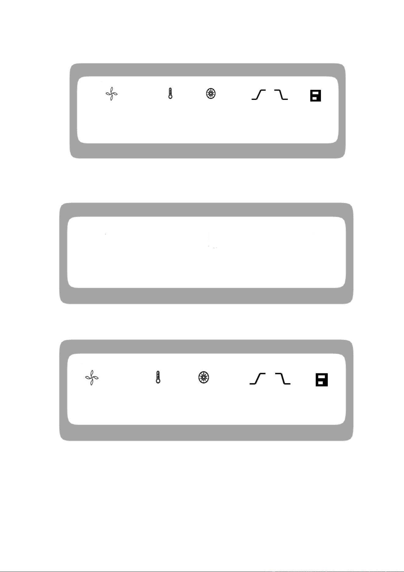
Fig. 6.2 Schematics of main display
The D1524R main display is shown in Fig. 6-2. At this time, the speed is set at 15,000rpm, indicating
the presumed sample temperature of 23℃ and the set running time of 12 min.
When the speed icon rotates, it indicates that the machine is in run mode.
The temperature display icon indicates three states: when it is lit ON, it indicates the presumed
sample temperature; when it is OFF, it indicates the set temperature; when it flashes, it indicates the
compressor starts refrigerating to control the temperature of the centrifugal chamber.
The time display icon divides the entire runnig time into 10 equal parts, displaying the ratio of
elapsed time to the total time.
7. Rotor preparation
7.1. Prepare the samples to be separated
7.2. Place samples into the centrifuge tube
The amount of sample should not exceed the allowed maximum amount set forth in this user manual.
7.3. Ensure the balanced centrifuge tube
◼ Although this centrifuge may be used with visually confirmed balance, it is suggested that samples
be weighed using a balance to ensure balanced centrifuge tube in order to prolong the service life
Caution: Adding excessive samples into the centrifuge tube will result in leakage,
therefore don’t add excessive samples.
15000
rpm
23
℃
12
min
9 9 1

11
of centrifuge.
◼ Although the partial imbalance is allowed, don’t run this centrifuge under poor balance conditions.
7.4. Check the rotor
Check the rotor for any corrosion or scratch before use
7.5. Insert the centrifuge tubes symmetrically onto the rotor in
place without imbalance
Caution:
⚫ Ensure to tighten the rotor to the main shaft firmly and the lid is secured properly on
the rotor. Otherwise, the rotor might fall OFF while the centrifuge is in operation,
resulting in centrifuge or rotor damage.
⚫ Tighten the rotor lid and rotor firmly.
8. Operation
8.1. Normal operation
When the power switch is turned ON, the display screen is lit and the centrifuge shows HELLO page, as
shown in Fig. 8-1.
Caution:
●Avoid using the rotor with scratches or corrosion.
● Never use the rotor of other brands/ specifications on this centrifuge.
● Do not expose the rotor and its accessories to direct sunlight/Ultraviolet.
12
Fig. 8-1. Self-test page of centrifuge
The centrifuge shows the centrifuge model 1524R and program version 1.0, as shown in Fig. 8-2.
Fig. 8-2 Model and version interface
Then, the centrifuge displays the last operating parameters, as shown in Fig. 8-3.
Fig. 8-3. Last operation interface
◼ Speed set at 15000rpm, time set at 12 min and centrifugal chamber temperature 25℃.
◼ The outer lid lock is released.
8.1.1. Rotor installation and replacement
HELLO
88 ℃ 88 min 8 8 8
15000
rpm
25
℃
12
min
9 9 1
1524R --- Uo L 10
13
Mount the rotor on the main shaft Mount the tubes symmetrically Mount the rotor cover.
Fig. 8-4. Rotor installation
Caution
⚫ Place the rotor on the main shaft and ensure full contact between the rotor and the main
shaft. Screw up the nut on the rotor tightly using a wrench to connect the rotor with the
main shaft firmly, otherwise the rotor might fall OFF, causing damage to the centrifuge.
⚫ Tighten the rotor and the lid firmly.
◼ When placing the rotor, ensure the full contact between the rotor and the main shaft.
◼ After placing the rotor in place, rotate the rotor gently with hands to check for normal operation
of the rotor. Check and adjust the rotor position once again.
◼ Rotate the locking nut clockwise using the rotor wrench and tighten the rotor and main shaft
firmly.
◼ Place the rotor lid and rotate it clockwise to screw the rotor tightly. Close the outer lid and run the
centrifuge.
◼ The rotor is dismantled in a manner opposite the aforesaid, with the tightening direction being
counterclockwise.
8.1.2. Set operating parameters
The parameter key is used to input and modify the operating parameters. Press the parameter
key gently so that the centrifuge enters into adjustment mode. Press and select the parameter to
adjust its value to desired setting. Adjust the values only when the required parameter icon flashes. The
minimum rotation speed is 100rpm, the minimum step of centrifugal force is 10g and the minimum step
time is 1second if within 1 minute and if not it is 1 minute.
(1) Set the rotation speed
Locking nut
Rotor cover
Latch

14
◼ Press the parameter key to choose the rotation speed parameter value in rpm.
◼ Set the speed value to desired setting when it enters into the adjustment mode and flashes.
◼ The minimum set speed is 200rpm, and the minimum step is 100rpm.
◼ The parameter increase or decrease is cyclic. Turn the parameter key clockwise or
anticlockwise to increase or decrease the adjusting parameter values.
(2) Set the run time
◼ Press the parameter key to select the time parameter and wait until its value flashes.
◼ Set the time parameter value to desired setting within the range of 10s-99min.
◼ Turn the parameter key to input the set time within a range of 10 s-99min.
◼ When the time enters HD, it indicates that the instrument is in continuous run mode.
(3) Set the operating temperature
◼ Press the parameter key to set the temperature and wait until its value flashes.
◼ Turn the parameter key to adjust the temperature within a range of -20℃ ~ 40℃.
◼ When the temperature icon flashes, it means the refrigerating system is working,
otherwise the refrigerating system is not working.
8.1.3. Start Run
(1) Press the key to start operation.
◼ The rotor starts rotating.
◼ Timer starts to operate after the instrument reaches the set rotation speed only.
◼ The screen displays the actual time left to complete the running operation.
(2) Inquire and change the operating parameters
◼ The operating parameters can be modified after the centrifuge operates at a steady speed.
◼ Press the parameter key to return to ready mode interface with set operating
parameters.
◼ Press the parameter key gently and required parameter to modify the set values.
◼ After 7 seconds of no activity, the centrifuge will return to the normal operating state with
the new operating parameters.
◼ In case if there are any changes in the operation time setting, the elapsed time will not be
zeroed.
(3) Error message

15
◼ The centrifuge will automatically stop if any failure occurs in the run mode, with the failure
code indicated on the time display window. By looking up table 10-1, the cause of failure can be
found and appropriate action should be taken.
8.1.4. Stop running
(1) When the set run time is completed the centrifuge stops its run operation automatically or it can
be stopped by pressing the .
(2) The outer lid lock is opened.
◼ The centrifuge beeps when the rotor ceases to rotate, indicating that the operation is over.
◼ After the end of operation, the outer lid lock on the centrifuge remains closed and the outer lid
lock should be opened by pressing key. Open the outer lid to remove the samples and rotor.
◼ The centrifuge will automatically retrieve the last set parameters as soon as it is switched ON.
8.2. RCF operation
Turn power switch ON and Set the RCF (relative centrifugal force).
Caution
⚫ The relative centrifugal force set should not exceed the maximum relative centrifugal
force allowed by the centrifuge tube and its adaptor.
⚫ The relative centrifugal acceleration is calculated based on the maximum centrifugal
radius and operating speed of the rotor. (See Table 11.1 for the maximum centrifugal
radius).
◼ Press the parameter key to choose the rotation speed unit as xg. If the RCF value
flashes it indicates that the RCF value can be set as it is in adjustment mode.
◼ Turn the parameter key to adjust the relative centrifugal acceleration, in
increments of 100xg.
◼ The instrument will automatically enter into ready mode from adjustment mode, if it is left
inoperated for more than 7seconds.
Set the operating conditions
See Section 8.1 for operation of other parts.

16
8.3. Transient operation
This function is generally used to remove the samples attached to the inner wall of the centrifuge
tube.
(1) Turn power switch ON, fix the rotor on the main shaft and secure tightly with the rotor lid.
(2) Close the outer lid.
(3) The centrifuge enters into ready mode and displays the last operated parameter values.
(4) Press and hold the key down to increase and set the rotation speed.
(5) Release the key to start decelerating and shutdown.
9. Maintenance and servicing
9.1. Cleaning
Caution
⚫ Disconnect the power supply before cleaning the centrifuge.
(1) Centrifuge
◼ The color of housing might change and the label thereon might fall OFF if the centrifuge is
exposed to ultraviolet for a prolonged period of time and hence cover the centrifuge with cloth to
avoid exposure to light.
◼ Clean the centrifuge using a cloth/ sponge soaked with neutral cleansing agent in case if it is dirty
after use
◼ The centrifuge can be sterilized using cloth soaked with 70% alcohol solvent.
(2) Centrifugal chamber
Caution
⚫ Never pour water or other solvents directly into the centrifugal chamber as they might
enter into the drive unit and cause corrosion or damage to the bearings.
(3) Drive shaft
Reminder: this key works only when the rotor is inactive and the outer
lid is locked firmly.

17
◼ It is suggested that the drive shaft be subjected to periodical maintenance by wiping it using soft
cloth and applying a thin layer of silicone grease on it.
(4) Outer Lid
◼ Clean or sterilize the outer lid in the same manner as mentioned under subsection (1) centrifuge.
(5) Rotor
◼ If the rotor is left unused for a prolonged period of time, remove the rotor and its lid from the
centrifugal chamber, and place the rotor upside down to dry the rotor hole and prevent corrosion.
◼ Clean the rotor using mild detergent with PH value of 6-8 and immediately dry the aluminum
portion after cleaning by putting it into a warm-air dryer at a temperature not exceeding 50℃.
(6) Drainage
◼ D1524R is equipped with drainage slots, which need to be drained when a substantial amount
of water is accumulated in those slots.
9.2. Sterilization
If the centrifuge tubes contain infectious materials leaks, you must immediately sterilize the rotor and/or
centrifuge.
◼ Infectious substances might enter the centrifuge if the centrifuge tube breaks or is overfilled.
◼ Danger of infection might occur through contact. Personnel shall be provided with suitable
protective measures.
◼ Be aware of the allowed filling volume and loading limit of the centrifuge tubes.
◼ When contamination occurs, the operator must ensure that others are not endangered.
◼ The contaminated portion must be sterilized immediately.
◼ Take further protective measures if necessary.
9.2.1. Sterilize using common neutral sanitizers
The rotor and the centrifugal chamber must be treated with common neutral sanitizers. The most
suitable way is to spray the spray-type sanitizer evenly over the rotor and accessories.
Sterilize the rotor and accessories as follows:
(1) Disconnect the power supply.
(2) Unscrew the rotor from the rotating shaft.
(3) Remove the rotor and pull it up vertically from the rotating shaft.
(4) Take out the centrifuge tubes and adaptors and sterilize or dispose of them when necessary.
(5) Treat the rotor and rotor lid (soaking or spraying) according to the sanitizer instructions.
(6) Drain the sanitizer by turning the rotor upside down and then flush it with water.
(7) Remove the residual sanitizer in an effective way.
(8) The aluminum rotor must then be treated with anti-corrosion oil.
18
(9) All sealing rings must be re-lubricated.
9.2.2. Sterilize using bleaching alkali liquor
Caution
Bleaching alkali liquor contains highly concentrated erosive hypochlorite, therefore it may
not be used for aluminum rotor.
The following are the protective measures for plastic rotor:
(1) Avoid high temperature and ensure the temperature of bleaching solution and rotor is not
more than 25℃.
(2) Do not bleach longer than necessary!
(3) After sterilization, flush the rotor thoroughly with distilled water and dry it.
(4) All sealing rings must be re-lubricated.
9.3. Wearing parts
Please replace the below wearing parts in time according to the suggestions in the following table
or whenever it is necessary.
No.
Wearing part
Replacement
conditions
1
Rubber seat of temperature sensor
Crack
2
Sealing ring of centrifugal chamber
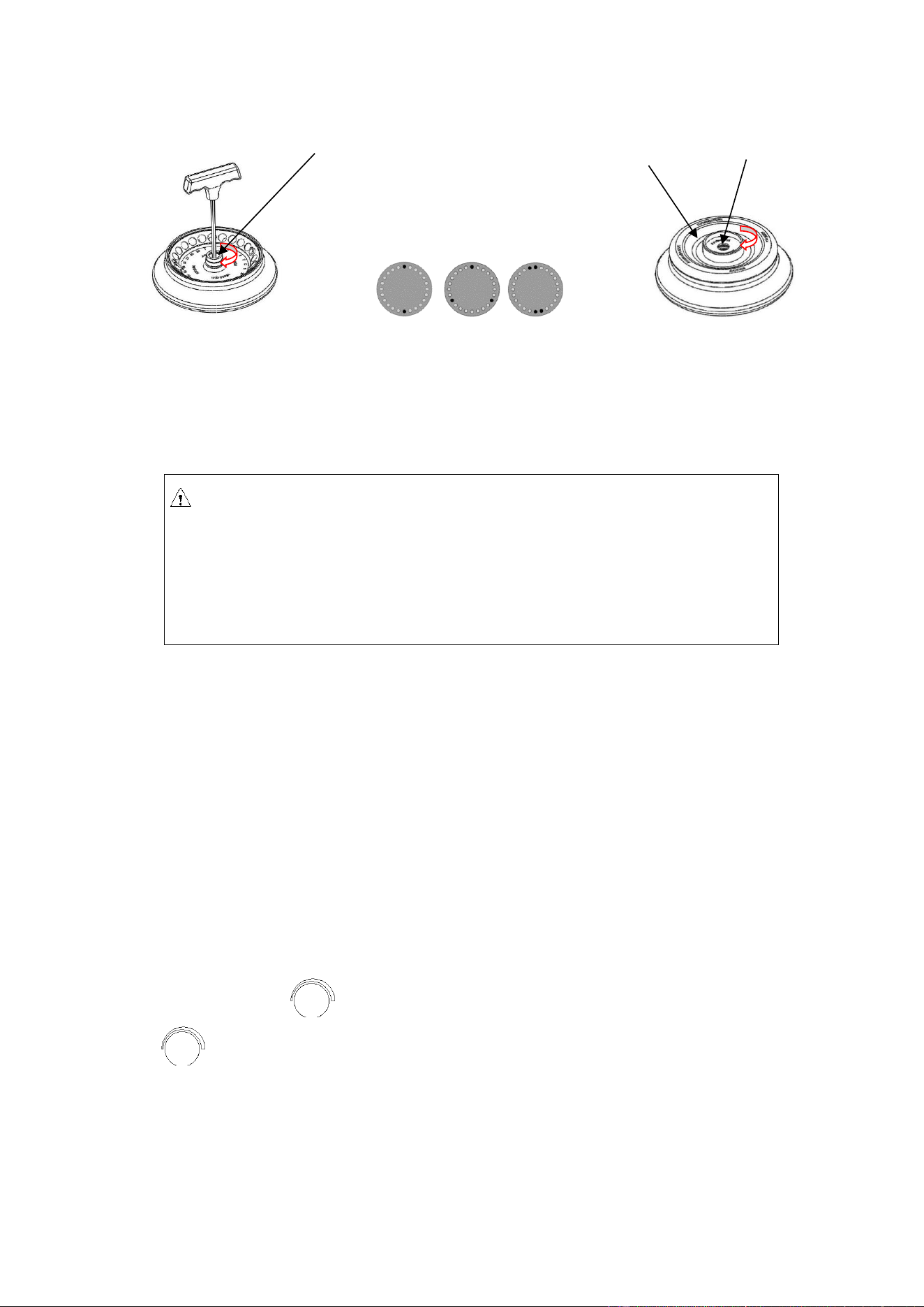
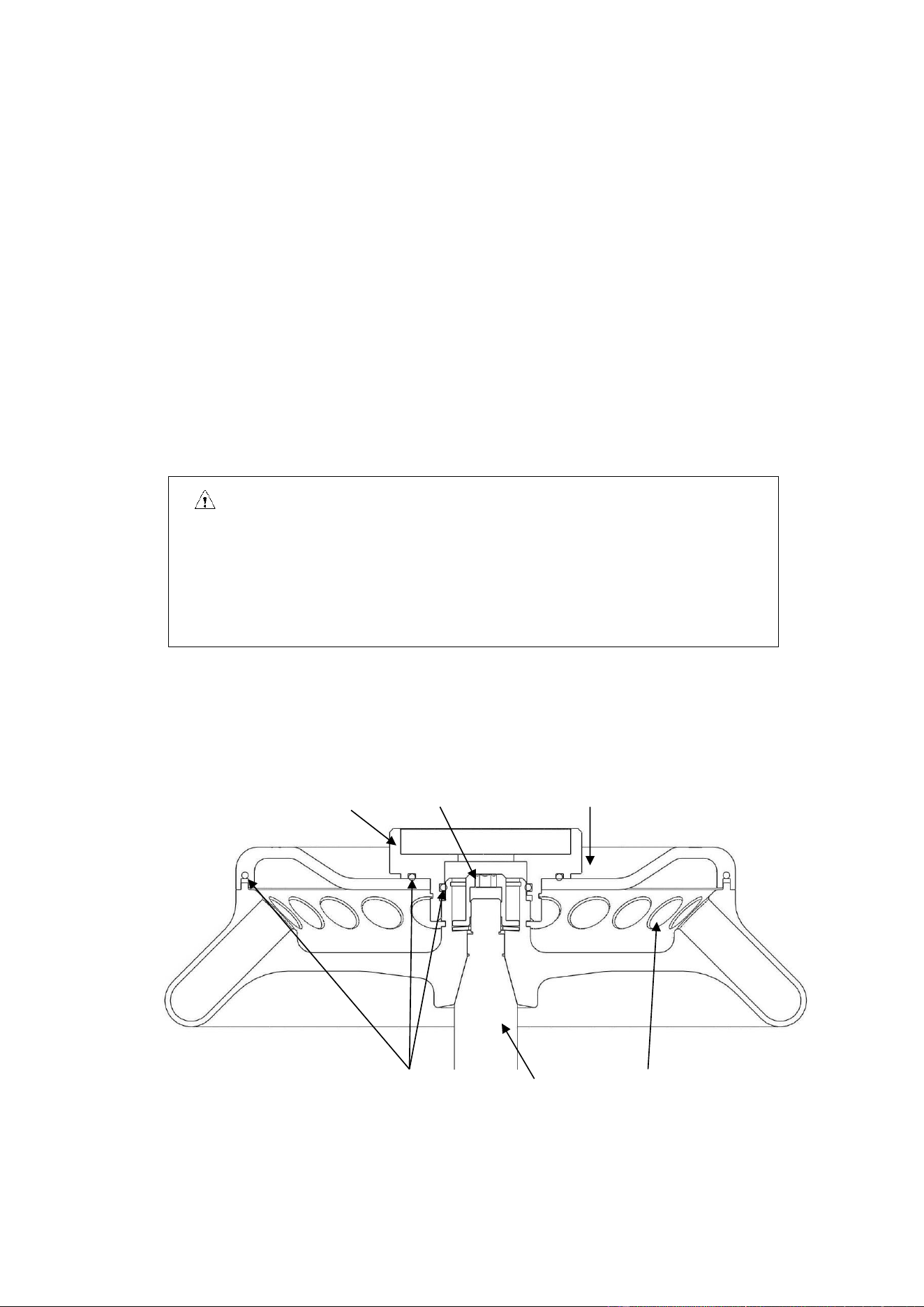
9.4. Replacement of rotor seal
9.4.1. Introduction
Three rubber rings are used in order to achieve biological sealing, as shown in the following figure.
After multiple autoclaving runs, the rubber rings might age or fall off and need to be replaced or remounted.
Sealing ring 1 Sealing ring 2 Sealing ring 3
Sealing ring 2 Sealing ring 3

19
Fig. 9-1 Rotor sealing ring
9.4.2. How to replace
(1) Clean the rubber ring groove using neutral cleaning solution before air drying it.
(2) Apply glue evenly inside the rubber ring groove before placing the rubber ring into its groove and
evenly pressing it to make the rubber ring contact with the groove bottom and firmly adhered.
(3) Leave it for 20 min and wait for the glue to completely solidify.
9.5. Routine check
(1) Ensure that the centrifuge is placed on a solid, level and flat table top surface and ensure that 3/4
th
of
it is on the table surface.
(2) Ensure that the machine is reliably grounded: using a multi-meter, check whether the grounding pin in
the power cable plug and the centrifugal chamber and motor shaft are short-circuited. In case of short-
circuit, it indicates reliable grounding. In case of disconnection, identify the causes and eliminate the
failure before the centrifuge operation.
10. Common failures and solutions
10.1. List of common failures
This centrifuge is capable of self diagnosis. When the centrifuge fails, the time display window will
indicate the failure code, leading to the immediate identification of possible failure causes.
Phenomenon
Possible cause
Solution
No display after power ON
· No power supply to the power
socket.
· Fuse burned out.
·Eliminate the failure and
reconnect the power supply.
· Replace the fuse.
Alarm code indicated on the time
display
E-02
Outer lid failure
·The door opens while in
operation.
· is pressed when the
door is opened.
· Immediately close the cover.
·Close the outer lid before
operation.
E-04
Temperature
abnormality
·The housing vent might got
blocked.
· The cooling fan might got
damaged.
·Unblock the vent.
·Replace the cooling fan.

20
E-06
Abnormal
rotation speed
setting
·Change the set rotation speed
value.
·Change the set rotation speed
value.
E-10~86
·Check the service manual.
·Contact the service
representative.
Table 10-1 Common failures and solutions
◼ Failure code E-1~E-6 is related to erroneous operation. The centrifuge may continue running after
elimination of the failure.
10.2. How to open the outer lid
10.2.1. When turned ON
(1) When the centrifuge is turned ON, the outer lid opens automatically.
(2) At the end of centrifuge operation, the outer lid remains locked.
(3) When the rotor stops, press key and unlock the outer lid and one can observe that the lid
can be opened now.
10.2.2. When power is OFF
When the outer lid cannot be opened in case of unexpected power failure, the outer lid may be
opened as follows:
(1) Check whether the rotor is in run mode.
◼ Listen carefully to ensure that there is no rotation sound.
(2) Insert a wrench into the housing hole to open the outer lid lock.
◼ The hole is located above the front end of the right side panel.
◼ Insert the wrench into the right hole to push forward and rotate clockwise to open the outer
lid lock and then the lid.
Reminder: When the centrifuge is switch power ON, open the outer lid
only when the rotor is not running.
21
10.3. Replace the fuse
(1) The D1524R centrifuges fuse is 250V, 10A, fast-acting, size: Ф5×20, one fuse.
(2) The centrifuges 250V, 10A fuse is on the power socket. It may be replaced by taking the fuse box out
of the power socket; 250V, 3.15A fuse is on the circuit board, It may be replaced by taking the fuse box
out of the circuit board.
11. Introduction to rotor and centrifuge tube
Caution
●Carefully read the user manual and correctly install and use the rotor correctly.
●Don‘t exceed the maximum allowed speed of the rotor, test tube and adaptor. The
maximum allowed speed by certain adaptors is lower than the maximum speed of the
rotor and check before operation.
11.1.Rotor description
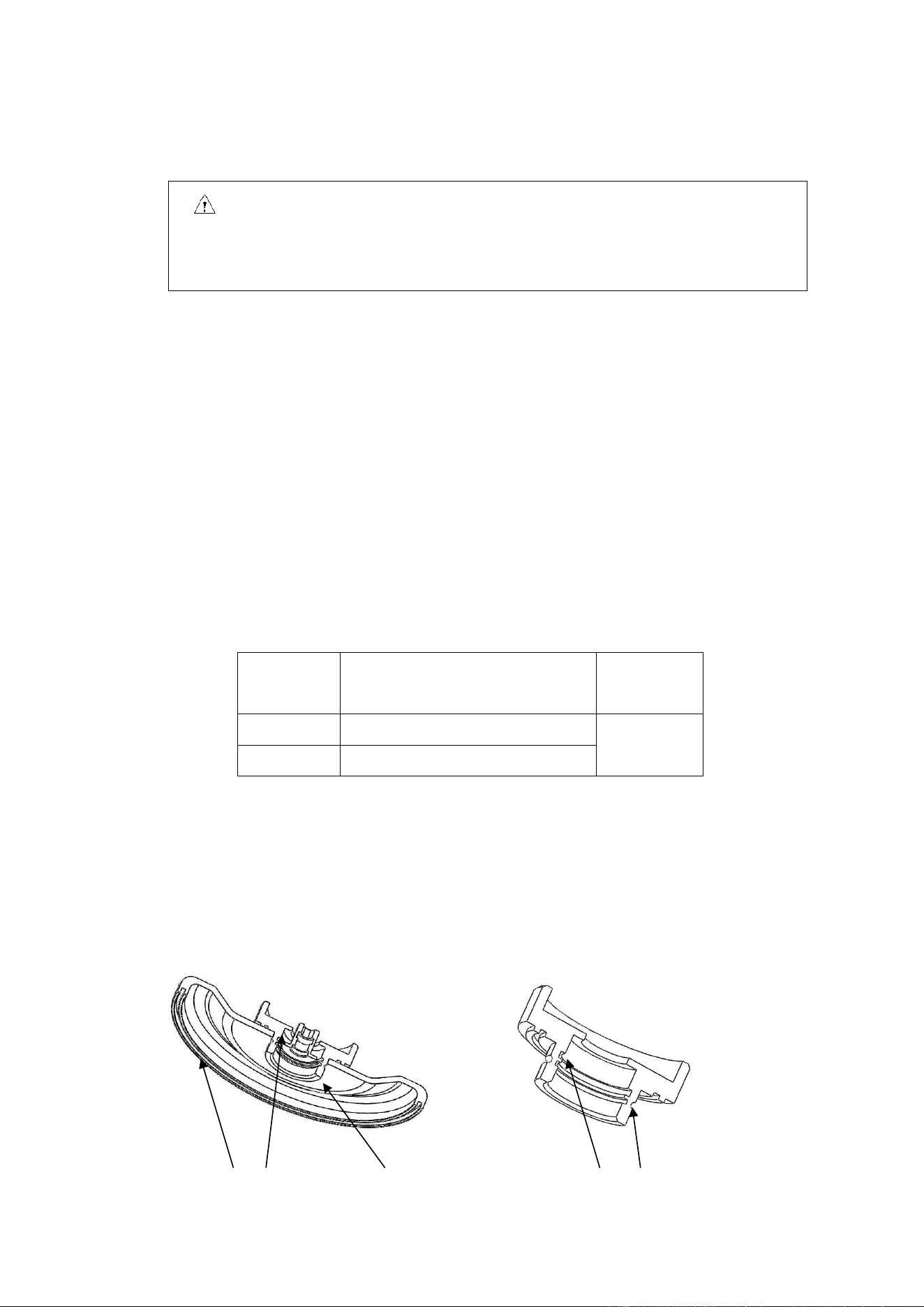
11.1.1. Rotor structure
Fig. 11-1 Rotor structure
Sealing ring Main shaft Tube hole
Knob Locking nut Rotor cover

22
11.1.2. Rotor and adaptor
All rotors are bio-sealed such that centrifuge tube is sealed inside the rotor and when the rotor lid
and rotor are secured tightly to ensure no sample leakage during the centrifuge operation. While the
rotor lid is not used, the rotor will be incapable of bio-sealing. The rotors and adaptors which are
suitable for use with this centrifuge are listed as follows:
Table 11.1 List of rotors and adaptors
Rotor
number
Rotor name
Centrifuge
tube
Adaptor
Maximum
speed
(rpm)
Maximum
centrifugal
radius
r
max
(cm)
Maximum
relative
centrifugal
force RCF (×g)
1
AS24-2
2/1.5mL
centrifuge
tube
15000
8.5
21380 (program
correspondence)
0.2mL PCR
tube
A02P2
15000
6.9
17350
0.5mL micro-
tube
A05P2
15000
7.6
19100
2
AS36-05
0.5mL micro-
tube
15000
8.5
21380 (program
correspondence)
0.2mL PCR
tube
A02P05
15000
7.6
19100
3
AS4-PCR8
PCR8 tube
bank
15000
6.5/7.2
16350/18100
4
AS12-V5
5mL conical
tube
15000
8.5
21380
5
AS18-5
5mL culture
tube
15000
8.5
21380
11.1.3. Precautions
(1) The density of sample that the centrifuge rotor can separate is less than 1.2g/ml. If the density of sample
to be separated exceeds 1.2g/ml, please calculate the allowed rotation speed using the following formula:
Allowed rotation speed (rpm) = maximum rotation speed × (1.2 (g/ml) /sample density (g/ml))
1/2
(2) If the rotor is left unused for long time, please remove the rotor from the centrifugal chamber, remove
the rotor lid and place the rotor upside down to dry the rotor hole and prevent corrosion.
(3) If any sample leaks into the rotor hole, flush the rotor hole with clean water and apply a thin layer of
silicone grease on the rotor surface after it dries up.
(4) It is suggested that the rotor to be cleaned once in every three months to ensure cleanliness of the tube
hole and main shaft hole before applying a thin layer of silicone grease.
11.1.4. Autoclaving
This rotor is made of high-strength aluminum alloy and may be autoclaved at 121℃(1.0kg/cm
2
)for 20
min.
11.1.5. Bio-sealing
The rotor of this device employs bio-sealed structure and uses three high-temperature-resistant

23
rubber rings for sealing. After multiple autoclaving runs, the rubber rings might age or fall off and need to
be replaced or remounted using the method detailed in 9.4.
11.2. Centrifuge tube
11.2.1. Please clean and sterilize the centrifuge tube by reference to the following table.
Table 11.2 Conditions for cleaning and sterilization of centrifuge tube O: Yes X: No
Condition Material
PA
PC
PP
Cleaning
Fluid cleaning
Acidic cleaning agent (pH5 or
lower)
X
X
X
Acidic cleaning agent (above pH5)
O
O
O
Alkaline cleaning agent (above
pH9)
O
X
O
Alkaline cleaning agent (pH9 or
lower)
O
O
O
Neutral cleaning agent (pH7)
O
O
O
70℃ hot water
O
O
O
Ultrasonic
cleaning
Neutral cleaning agent (pH7)
O
O
O
Sterilization
Autoclaving
115℃ (0.7kg/cm
2
) 30min
O
O
O
121℃ (1.0kg/cm
2
) 20min
X
O
O
126℃ (1.4kg/cm
2
) 15min
X
X
X
Boiling
sterilization
15-30min
O
O
O
Ultraviolet
sterilization
200-300nm
X
X
X
Gas sterilization
Ethylene oxide
O
X
O
Formaldehyde
O
O
O
PA: polyallomer PC: polycarbonate PP: polypropylene
11.2.2. PC centrifuge tube cleaning
PC material has relatively low chemical stability to alkaline solvent, therefore use of cleaning agent
with pH value of over 9 should be avoided. Some neutral cleaning agents still have pH value of over 9
after being diluted as recommended by the vendor, therefore use of cleaning agent with pH value of 7-9

24
only is recommended.
11.2.3. Autoclaving of PA, PC and PP centrifuge tube
PA begins softening at the temperature of 120℃, while PC and PP begin softening at 130℃.
Generally, PA may be sterilized for 30 min at 115℃(0.7 kg/cm
2
), while PC and PP may be sterilized
for 20 min at 121℃(1.0 kg/cm
2
). Too high temperature would result in deformation of centrifuge tube.
When autoclave is used, take the following steps:
(1) Place the centrifuge tube upright with opening facing upward. If the centrifuge tube is placed
in an inclined or horizontal manner, it will deform due to the effect of gravity.
(2) Remove the threaded cover and inner cover to prevent deformation or crack of the centrifuge
tube.
(3) Take the centrifuge tube only when the autoclave cools down to the room temperature.
11.2.4. Service life of centrifuge tube
The service life of plastic centrifuge tube depends upon the nature of sample, rotor speed and
centrifugation temperature. When the plastic centrifuge tube is used for centrifugation of conventional
neutral samples (pH5-pH9), its estimated service life at the maximum rotation speed is as follows:
High-quality centrifuge tube (PA, PC, PP): 30-50 times.
Conventional centrifuge tube: about 10 times (frequency of use may be increased in case of low-speed
application use)
The service life of centrifuge tube is also related to the cleaning and sterilization conditions.
Note: Never use any centrifuge tube with cracks.
12. RCF calculation
Relative centrifugal force (RCF)can be calculated using the following formula:
RCF=1.118×r×n
2
×10
-5
r-rotation radius, unit: cm; n-rotation speed, unit- rpm

25
13. Ordering information
Order code
Model
Description
9013111121
D1524R
Tabletop high-speed refrigerated micro-centrifuge
Accessories
19400002
AS24-2
Rotor package, suitable for D1524R, maximum speed 15,000
rpm, maximum capacity 2 ml*24
19400003
AS36-05
Rotor package, suitable for D1524R, maximum speed 15,000
rpm, maximum capacity 0.5 ml*36
19400004
AS4-PCR8
Rotor package, suitable for D1524R, maximum speed 15,000
rpm, maximum capacity 4-PCR8
19400032
AS12-V5
Rotor package, suitable for D1524R, maximum speed 15,000
rpm, maximum capacity 5ml*12
19400012
AS18-5
Rotor package, suitable for D1524R, maximum speed 15,000
rpm, maximum capacity 5 ml*18
19500001
A02P2
0.2 ml rotor adaptor, suitable for A12-2/AS24-2 rotor, 24 pcs/pk
19500002
A05P2
0.5 ml rotor adaptor, suitable for A12-2/AS24-2 rotor, 24 pcs/pk
19500003
A02P05
0.2 ml rotor adaptor, suitable for AS36-05 rotor, 36 pcs/pk
14. Warranty
14.1. Unit warranty
The entire unit will have two-year warranty period commencing from delivery date under the
conditions of normal maintenance.
14.2. Rotor warranty
The rotor will have 5-year warranty period from the date of delivery. Don’t use any rotor
damaged due to corrosion or fatigue. The damage to the entire unit or rotor due to any of the
following reasons is outside the scope of warranty:
(1) Damage due to improper installation;
(2) Damage due to brutal or improper operation;
(3) Damage due to relocation or transport after completion of installation;

26
(4) Damage due to dismantling or modification by any unauthorized entity or individual;
(5) Damage due to use any parts not supplied by our company, such as rotor and adaptor;
(6) Damage due to natural disasters, including fire and earthquake;
(7) Wearing parts and parts with warranty period.
15. After-sales services
To ensure safe and efficient operation of the centrifuge, periodical maintenance is required. If
the centrifuge fails, don’t attempt to repair it. Please contact the service center.