User's Guide
RB192 Diagnostic Relay Buddy 12/24
Introduction
RB192 Diagnostic Relay Buddy 12/24 is a quick go/no-go tester for automotive Relays. It is also a diagnostic tool that will help you
determine the original cause of the circuit problem! RB192 will examine the functionality of the relay and if a problem is discovered the
tester will report its findings by flashing a trouble code. The trouble codes pinpoint where the trouble was found, helping you determine
the root cause of the problem.
Diagnostic Relay Buddy will check the control side of the relay by applying a signal to the internal coil while it checks for proper
functioning of the relay contacts. The relay is switched several times during each test session as it watches for consistency in every
cycle. Whatever trouble is discovered will be reported in the form of a flashing code. If the relay is found to be functioning properly, a
Green LED will be lit.
Remember, it is impossible for Diagnostic Relay Buddy to test the relay contacts under every different load (Amp draw) scenario that your
relay may encounter. A Voltage drop check across the closed contacts while in the actual live circuit may also be advisable.
International Safety Symbols
Refer to the manual for further information
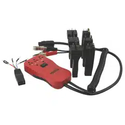
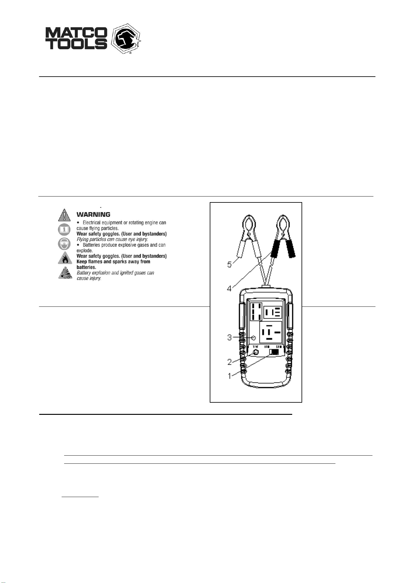
Controls
① 4 pin or 5 pin switch
② test button
③ LED
④ black alligator clip
⑤ red alligator clip
OPERATING INSTRUCTIONS FOR DIAGNOSTIC RELAY BUDDY
1. Connect the power leads to a 12V or 24V power source ~ i.e vehicle battery. Black alligator clip to negative terminal, red
alligator clip to positive terminal. Ensure that the Voltage you are connecting to is the proper Voltage for the relay you are
testing – only test 12V relays using a 12V source and 24V relays using a 24V source.
~ Be particularly mindful if you're testing a 24V relay. If you connect Relay Buddy to a 12V source while testing a 24V relay,
you may get false BAD test results. If you have any doubts, check the voltage source first with a multimeter. ~
2. Check the relay before plugging into the tester. If it’s a 4 pin relay, select “4 pin” on the tester. If it’s a 5 pin Relay, select “5
pin” on the tester.
4. Plug the relay or relay/adapter into one of the three receptacles.
5. Press and hold the “Test” button until the test sequence is complete.
6. The Tester will open and close the relay several times. The GREEN LED will cycle on and off as the test progresses. If the test
is successful and the relay is good, the LED will illuminate GREEN. If any trouble was detected during the tests, the RED LED will
flash a number of times to indicate the particular trouble that was detected. The relay will need to be replaced of course, but the
trouble Codes will help you find the root cause of the trouble.
7. Release the “Test” button after retrieving the test result. Disconnect power leads from the car battery and remove the relay
from the tester.

Trouble Code List
Code 1: Ensure that the Relay Selector Switch is set properly. Double check the number of pins of the Relay you are testing.
If this is a 5 pin Relay, slide the Relay selector to “5 pin” and re-start the test. If this is a 4 pin Relay, slide the Relay selector to “4 pin” and
re-start the test. If you are testing a 5 pin Relay and Code 1 persists, then the relay is not making a connection between the 30 and 87a
terminals when the Relay is not powered. This alerts you to “burnt” or “pitted” contacts. This Relay will need to be replaced and the
vehicles circuit will need to be checked to ensure that it does not have an abnormally high Current (Amperage) draw or a blown fuse
within the circuit that contains terminals 30 and 87a.
Code 2: Terminal 30 is closed to Terminal 87 when the Relay is not powered. Terminals 30 and 87 should only be
connected when the Relay is turned on (while the coil is energized). This is the code you will get for “stuck” or “welded” contacts. This
Relay will need to be replaced and the vehicles circuit will need to be checked to ensure that it does not have an abnormally high Current
(Amperage) draw or a blown fuse within the circuit that contains terminals 30 and 87.
Code 3: Terminal 30 is not closing to Terminal 87 when the Relay is powered. First, ensure you are using a 24 Volt source
if you are testing a 24 Volt Relay. For a 4 or 5 Pin Relay, if you do not hear the Relay “clicking” during the testing, then the Relay coil is
defective. If the coil is defective make sure that this Relay is the proper one specified for the application and in particular, is the Coil
Voltage Rating correct for the application – i.e. is this a 12V Relay being used in a 24V application?
If you do hear the Relay “clicking” during the testing, then terminals 30 and 87 are not making a connection when the Relay is powered.
This alerts you to “burnt” or “pitted” contacts. This Relay will need to be replaced and the vehicles circuit will need to be checked to ensure
that it does not have an abnormally high Current (Amperage) draw or a blown fuse within the circuit that contains terminals 30 and 87.
Notice_________________________________________________________________________________________
After testing is finished, do not touch legs of the end piece or adapter legs with hands/fingers for at least 5 minutes as they can become
hot during testing.
Warranty Information
This product is warranted to be free from defects for one year. If this product fails during the first 12 months due to faulty materials or
workmanship, it will be repaired or replaced free of charge, at the discretion of the manufacturer.
NOTE: This one year warranty does not cover dead batteries and blown fuses.
For warranty and service coverage, please return this product to your Matco dealer for processing and evaluation. OR, return it directly to:
Electronic Specialties, Inc.
139 Elizabeth Ln.
Genoa City, WI 53128
262-279-1400 Fax 262-279-1300
WWW.ESITEST.COM
Defective units being returned to your dealer or to the factory should include proof of purchase date.
Any testers that do not function due to misuse or abuse will be subject to “out of warranty service charges.