To reduce the risk of injury, the user must read and understand the Operator’s
Manual before using this product. Save these instructions for future reference.

2
TABLE OF CONTENTS
SAFETY INFORMATION
1.1 Operating Safety
TECHNICAL PERFORMANCE
SPECIFICATIONS
3.1 Parts
3.2 Unpacking the Unit
STARTING
4.1 Motor Initial Servicing
4.2 Start Up
ADJUSTMENT
5.1 Emergency Shutdown
5.3 Stopping the Machine
OPERATION
TRANSPORTING
CUTTER DRUM REMOVAL AND REPLACEMENT
CUTTER DRUM MAINTENANCE
AFTER USE
10.1 Drive Belt Maintenance
10.2 Belt Tensioning
STORAGE
REPLACEMENT PARTS
MAINTENANCE RECORD
EQUIPMENT WARRANTY
SERVICE CENTERS
PARTS MANUAL
4
5
6
6
6
7
8
8
8
9
9
9
9
10
10
10
11
12
12
13
13
13
14
15
18

3
Register Your Equipment
Thank you for purchasing TOMAHAWK equipment! Your product is covered by the
TOMAHAWK Warranty policy, but in order to activate your warranty, we need you to register
your product. In addition to activating your equipment warranty, product registration will
grant you access to important product updates, streamlined customer service and more.
INCLUDED WITH YOUR REGISTRATION
STEPS TO REGISTER YOUR EQUIPMENT
1. Visit www.tomahawk-power.com
2. Choose “Product Registration” at the bottom of the page
3. Enter your equipment’s serial number to get started
4. Provide all required information
5. Submit Registration
Equipment Resources
Tomahawk Customer Service doesn’t stop at checkout. We understand to keep a job-site
running smoothly - the proper equipment, spare parts, instruction manuals, and more are
needed at the drop of a hat. Visit www.tomahawk-power.com to gain access to the incredible
resources below.
How To Video Library
More of a visual person? Visit our Video Library for equipment
assembly instructions, troubleshooting tips, and more!
Found on each product listing or the Service Videos Page
Manual and Assembly Guide Library
Visit our Manual Library if you are looking for a lost
operations manual or a particular spare part?
Found on each product listing or the Tomahawk Manuals Page
Service Requests
Service Request and a Tomahawk Technician will respond
shortly to get you the help you need.
Choose “Service Request” at the bottom of www.tomahawk-power.com

4
This manual provides information and procedures to safely operate and maintain this
equipment. For your own safety and protection from injury, carefully read, understand, and
observe the safety instructions described in this manual.
Keep this manual or a copy of it with the equipment. If you lose this manual or need an
additional copy, please contact Tomahawk Power, LLC or visit
www.tomahawk-power.com
This equipment is built with user safety in mind; however, it can present hazards if
improperly operated or serviced. Follow operating instructions carefully. If you have
questions about operating or servicing this equipment, contact TOMAHAWK®.
The information contained in this manual is based on equipment’s production at the time of
publication. TOMAHAWK® reserves the right to change any portion of this information
without notice.
No part of this publication may be reproduced in any form or by any means,
from TOMAHAWK®.
Any type of reproduction or distribution not authorized by TOMAHAWK® represents an
make technical modifications, even without due notice, which aim at improving our
machines or their safety standards.
1. SAFETY INFORMATION
This manual contains DANGER, WARNING, CAUTION, and NOTE callouts which must be
followed to reduce the possibility of personal injury, damage to the equipment,
or improper service.
This is the safety alert symbol. It is used to alert you to potential personal injury
hazards. Obey all safety messages that follow this symbol to avoid possible injury
or death.
DANGER indicates an imminently hazardous situation which, if not avoided, will
result in death or serious injury.
WARNING indicates a potentially hazardous situation which, if not avoided, could
result in death or serious injury.
CAUTION indicates a potentially hazardous situation which, if not avoided, may
result in minor or moderate injury.
DANGER
WARNING
CAUTION

5
1.1 Operating Safety
Familiarity and proper training are required for the safe operation of equipment!
Equipment operated improperly or by untrained personnel can be dangerous! Read the
operating instructions contained in this manual and familiarize yourself with the location
someone familiar with the equipment before being allowed to operate the machine.
1.1.1 NEVER allow anyone to operate this equipment without proper training. People
operating this equipment must be familiar with the risks and hazards associated with it.
1.1.2 ALWAYS be safety-conscious by dressing appropriately during operation. Always
wear protective footwear, safety glasses/eyeware, and a hard hat.
1.1.3 NEVER operate this equipment when not feeling well due to fatigue, illness or when
medication.
1.1.4 NEVER operate this equipment under the influence of drugs or alcohol.
1.1.5 ALWAYS wear appropriate personal noise protection must be used. The scarifier may
1.1.6 DO NOT use the equipment for any purpose other than its intended purposes
or applications.
1.1.7 ALWAYS clear the work area of any debris, tools, etc. that would constitute a hazard
while the equipment is in operation.
1.1.8 ALWAYS use only the accessories or attachments recommended by the Tomahawk
Power for this equipment. Using unapproved accessories or attachments can result in
damage to the equipment and/or injury to the user.
1.1.9 ALWAYS
1.1.10 Do not remove the side plate or belt guard until the cutter drum has come to a
complete stop.
1.1.11 Do not tip the machine backward until the cutters have fully stopped.
1.1.12 Never operate the machine outdoors in wet conditions, as the electrical
components are not waterproof.
NOTE: Noise and vibration levels will vary depending on the attachments and the work
being performed.
WARNING
WARNING
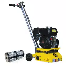
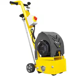
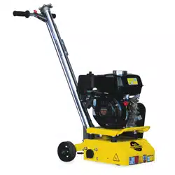
2. TECHNICAL PERFORMANCE
The Tomahawk eTSCAR-8 Electric Scarifier is your ultimate solution for precision concrete
work. Whether you're repairing trip hazards, cleaning floors, or preparing concrete
3. SPECIFICATION
6
Power
Amp
Hz
2.3HP
18
1.5
60
2800
8 in. (20.32 cm)
2088
42 (106 cm)
18 (45 cm)
18 (45 cm)
eTSCAR8 ROLLER COMPACTOR
eTSCAR8 NOISE EMISSIONS
86.7
102.67
3
eTSCAR8 VIBRATION EMISSIONS
5.2
1.5
NOTE:
7
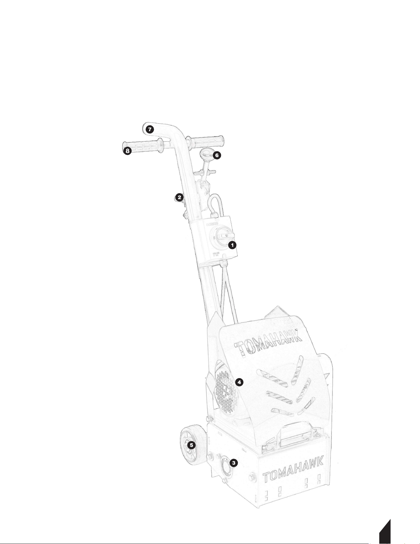
1. Power Switch
2. Depth Crank
3. Drum Blade
4. Motor
5. Wheel Kit
6. Adjustment lever
7. Vacuum Outlet
8. Handles
3.1 Electric Scarifier Parts

8
3.2 Unpacking the Unit
you have inspected all parts and successfully operated the machine. Do not discard this
operations manual.
If any parts are missing or damaged, please contact TOMAHAWK® customer support by
4. STARTING
4.1 Motor Initial Servicing
4.1.1 Before starting the machine, ensure :
• Condition of the cutter drum assembly
• Tightness of all bolts
• Condition and tension of the drive belt
• Condition of plugs and cables for any damage
• Oil lever position, which should be at 1/4 to 1/3 of the full travel range.
4.2 Start Up
• Prepare the Cutter Drum: Ensure the cutter drum assembly is clear of the ground by
• Connect the Dust Control Vacuum (if applicable): If a dust control vacuum is being
used, connect the vacuum hose to the dust port located at the top of the scarifier
handle.
• Begin Cutting: To start cutting, move the oil lever to the full-speed position and gently
Use the fine height adjustment hand wheel to achieve the desired depth of cut.
• Set Oil Lever: Ensure the oil lever is set to the IDLE position to prevent the blade from
rotating when starting.
• NOTE: DO NOT set the depth too low, as this can overload the machine. The cutters
cutters to function as intended, acting as flails rather than grinders or picks. The
machine should run smoothly with minimal vibration.
5. ADJUSTMENT
5.1
the blade is in working condition.
FIGURE 1.
5.2 To adjust the cutting depth, rotate the set-screw
handle until the desired depth is achieved.
FIGURE 2.
5.1.2 Emergency Shutdown
5.1.2 In case of an emergency, press the Emergency Stop
button immediately to halt the machine.
FIGURE 3.
5.3 Stopping the Machine
5.3.1 Follow proper shutdown procedures when stopping
the machine to ensure safety and prevent damage.
5.3.2
the power.
FIGURE 3.
5.4 Braking
When braking is necessary, engage the braking bar on the
wheel to safely stop the machine.
FIGURE 3.
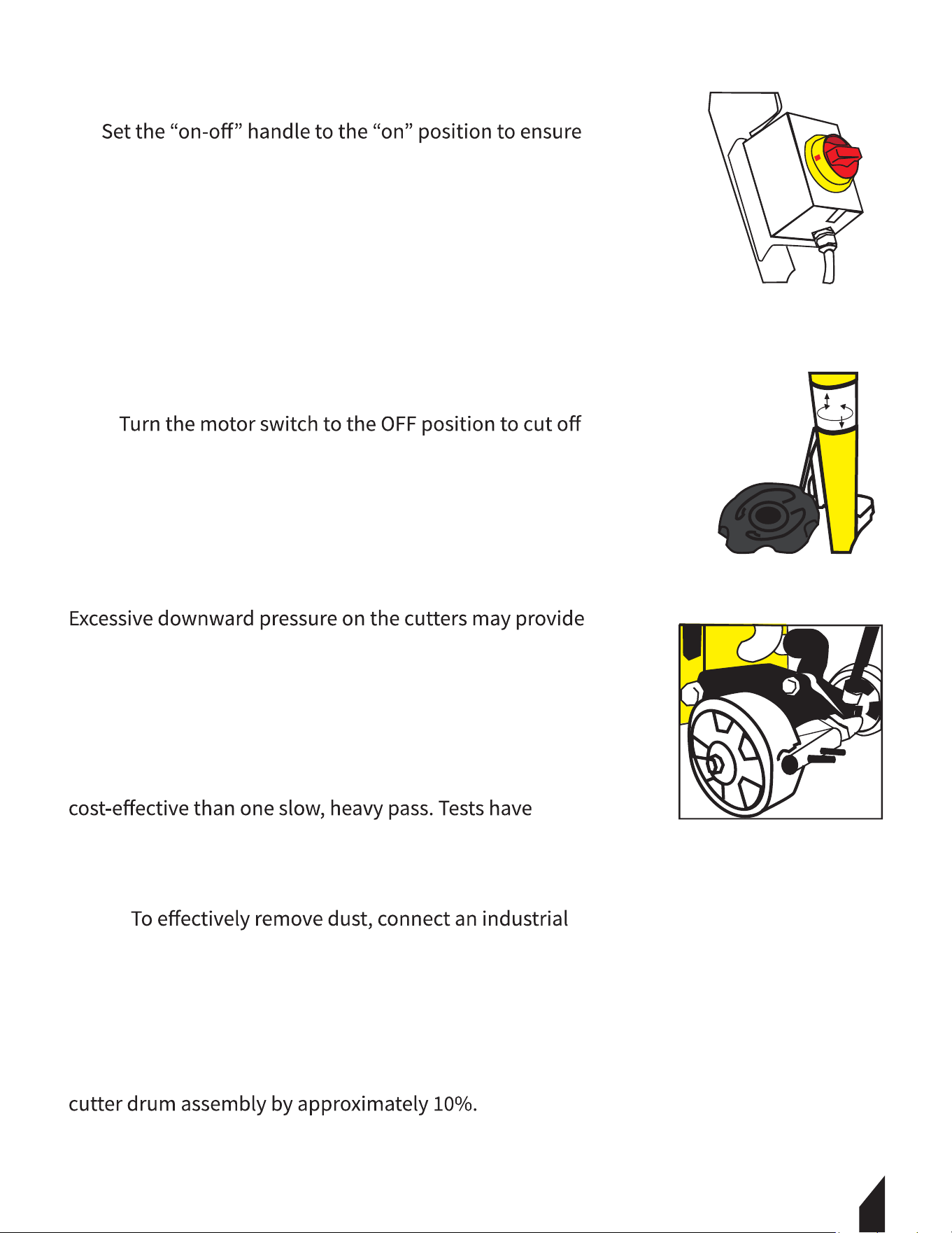
6. OPERATION
a marginal improvement in work rate and finish; however,
this leads to significantly increased wear on the cutter
drum assembly, other machine components, and other
can overload the motor.
NOTE: Two light passes are quicker and more
conclusively shown that heavy downward pressure can
reduce the life of the cutter and drum by over 50%.
NOTE:
dust collector or vacuum to the 50mm port at the rear of
the machine. We recommend using CIMAR Dust Control
units for nearly 100% dust control. If a dust control unit is
not available, it is acceptable to spray water onto the
surface or feed water down the vacuum port. Operating
the machine in this manner can increase the life of the
9
FIGURE 1
FIGURE 2
FIGURE 3
7. TRANSPORTING
• Shutdown the Motor:
• Secure the Machine: Lock the machine securely to prevent it from moving or toppling
over during transport.
• Qualified Operators: Ensure that operators responsible for movement and installation
hold a valid qualification certificate.
• Use Proper Tools: Move the press using appropriate, safe, and reliable tools.
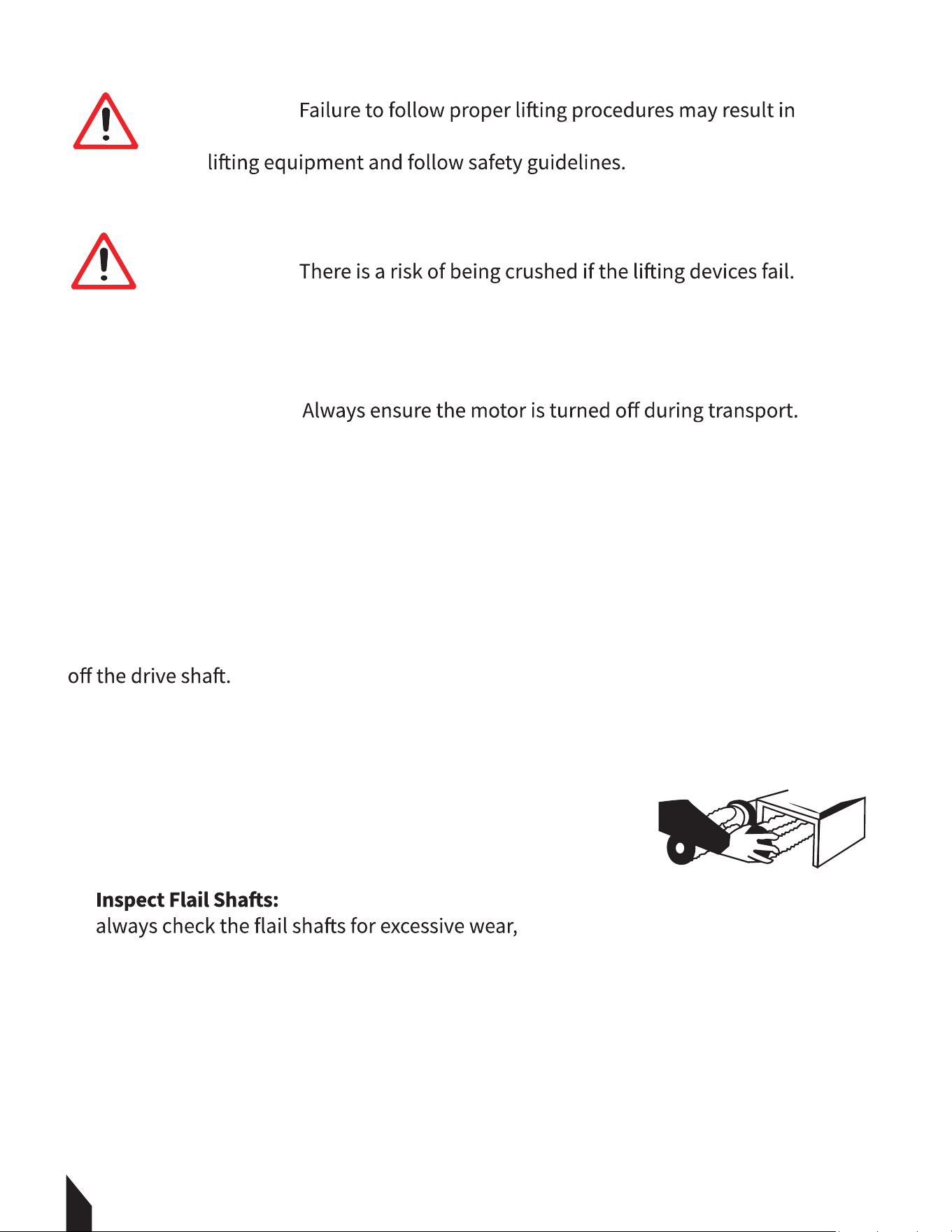
8. CUTTER DRUM REMOVAL AND REPLACEMENT
8.1 To remove the cutter drum, first remove the side plate. The cutter drum will then slide
8.2 Installing a new cutter head is simply the reverse of the
removal process.
FIGURE 4.
NOTE: It is crucial to ensure that the four 8 mm set screws
remain tight at all times.
9. CUTTER DRUM MAINTENANCE
• When changing the cutter drum,
particularly for pronounced grooves. Ensure that the
centers of the cutters and spacers are not elongated or starting to mushroom.
10
CAUTION
damage to the machine or personal injury. Always use appropriate
CAUTION
CAUTION
CAUTION
FIGURE 4

11
• Check End Plate Screws: Ensure that the screws holding the drum end plates in
position are tight and in good condition. Running the cutter drum components until
parts before they cause significant problems. Remember, the drum assembly strikes
• Cost Management:
job costing.
• While changing the drum, check the condition of the
buildup, which could complicate future drum changes.
•
the side plate bearing can cause it to bend.
• Final Checks: With the drum removed, check that the vacuum port is free from
blockages and ensure that the dust skirt is in good condition.
10. AFTER USE
• Motor Shut Down: Ensure the motor is stopped during maintenance, cleaning
operations, tool changes, and when transporting the machine using means other than
its own power.
• Cleaning: Clean the machine to remove all dust and surface residue. When using a hose
or pressure washer, avoid directing water onto electrical components and switches, as
motors and switches are not waterproof.
•
• Regular Checks: Regularly check that all bolts and nuts are tightened, and retighten
them if necessary.
• Cooling Before Storage: The motor must be completely cooled before storing the
machine indoors or covering it.

12
• Long-Term Storage:
specific instructions in this manual.
• Safety Labels: Maintain or replace safety and instruction labels as needed.
• Use Original Parts: Only use original spare parts or accessories. Using non-original
parts or accessories will invalidate the warranty.
• Silencer Maintenance: Replace faulty silencers.
• Braking: Ensure the brake is engaged when necessary.
• Height Adjustment Maintenance: Clean and lightly oil the height adjustment thread.
Periodically, remove the threaded section to clean and oil it regularly to ensure smooth
height adjustments.
10.1 Drive Belt Maintenance
Following basic procedures will help ensure a long and trouble-free operating life for the
drive belt.
• Daily Checks:
Inspect the drive pulleys for buildup of debris and trapped stones.
Check the belt and teeth for surface cuts and cracks. Once the belt surface is damaged,
it will fail quickly.
Dirt buildup in the pulley teeth can lead to two problems: it can cause the belt to
become too tight and prevent the teeth from fully meshing, resulting in power being
transmitted only through the tips of the teeth, leading to negative outcomes.
• Belt Tensioning:
The drive belt is tensioned using two eye bolts at the front of the motor. Ensure the belt
is not over-tensioned; it should be tight enough for all teeth to make full contact but
produce a low hum or whistle when the motor is running.

13
NOTE: That the Electric Scarifier should never be operated without a belt guard.
Component Checks: Check all components daily for tightness and verify that the drive belt
tension is appropriate.
11. STORAGE
11.1
water splash on the electric components.
11.2 Cover the machine to prevent dust and dirt buildup.
11.3 Store the machine in a dry area away from direct sunlight.
11.4 Do not leave the machine outdoors. Keep it indoors.
11.5
and drum before use.
12. REPLACEMENT PARTS
12.1 For replacement parts and technical questions visit www.tomahawk-power.com
or scan the QR code on the front of this manual.
12.2 Not all equipment components are available for replacement. The illustrations within
this manual are a convenient reference to the location and position of parts
in the assembly sequence.
12.3 When ordering parts, the following may be required: equipment model number, serial
number/lot, date code, and description. The manufacturer reserves the right to make
design changes and/or improvements to equipment, parts, accessories, and manuals
without notice.
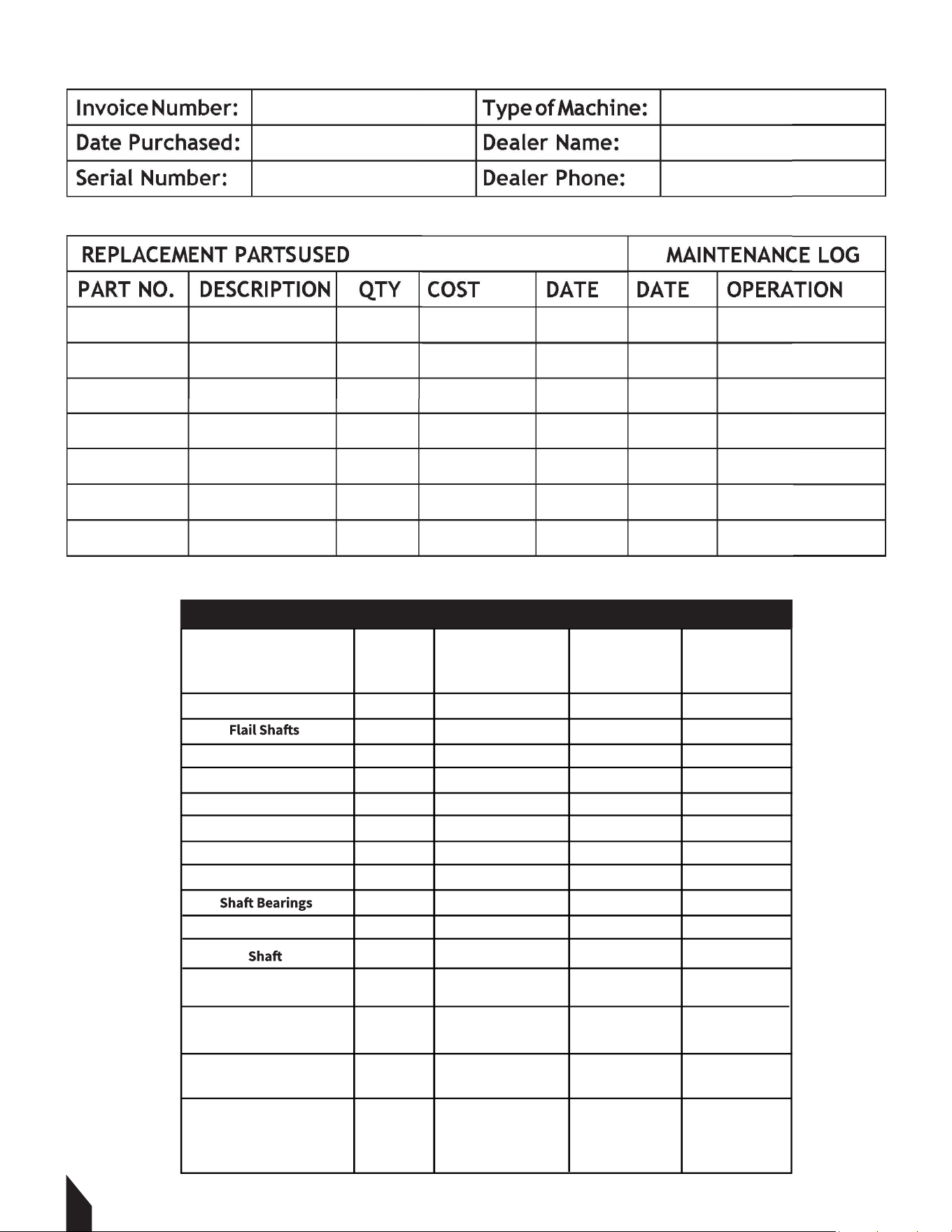
13. MAINTENANCE RECORD
TOMAHAWK® tools are assembled with care and will provide years of service when properly
maintained. Preventative maintenance and routine service are essential to the long life of
your equipment. Adhere to reading through this manual thoroughly. You will find that you
can do some of the regular maintenance yourself. However, when in need of parts or major
service, be sure to contact a TOMAHAWK® Technician. For your convenience we have
provided this space to record relevant data and maintenance schedule about your
TOMAHAWK® equipment.
14
Cutters
Nuts And Bolts
Belt Tension
Plugs And Cables
Air Filter
Side Plate
Drum
Bush
Support Wheels And
Grease
Strip Down Fully
The Winding Mechanism
Clean All Threads And
Re-Grease
Grease All Moving Parts
On The Height
Adjustment Mechanism
MAINTENANCE CHECKLIST
X
X
X
X
X
X
X
X
X
X
X
X
X
X
X
X
X
X
X
X
X
X
X
X
X
X
X
X
X
X
X
X
X
CHECK
CHECK
CHECK
CHECK
CHECK
CHECK
CHECK
CHECK
CHECK
CHECK
CHECK
CHECK
CHECK
CHECK
CHECK
Description
ACTION
DAILY:
WEEKLY:
MONTHLY:
Every 8 hrs to 10 hrs

15
14. EQUIPMENT WARRANTY
Your new TOMAHAWK® equipment is warranted to the original purchaser for a period of
against defects in design, materials and workmanship.
The following are not covered under the warranty:
14.1 Damage caused by abuse, misuse, dropping or other similar damage caused by or as a
result of failure to follow assembly, operation or user maintenance instructions.
14.2 Alterations, additions or repairs carried out by persons other than TOMAHAWK® or their
recognized agents.
14.3 Transportation or shipment costs to and from TOMAHAWK® or their recognized agents,
for repair or assessment against a warranty claim, on any machine.
14.4 Materials and/or labor costs to renew, repair or replace components due to fair
wear and tear.
14.5 TOMAHAWK® and/or their recognized agents, directors, employees or insurers will not
by reason of or the inability to use the machine for any purpose.
Warranty Claims
Before submitting any warranty claim, you will need to register
your new TOMAHAWK® equipment through
www.tomahawk-power.com.
Follow the steps on page 3 or scan this QR codes to complete
all warranty claims should firstly be directed to TOMAHAWK®
through the online Service Request form found
at www.tomahawk-power.com/pages/service-request.
15. SERVICES CENTERS
Our service centers are equipped to handle your equipment maintenance and repair needs
support and genuine parts needed to keep your equipment running smoothly. All locations
are listed on the webpage https://tomahawk-power.com/pages/find-a-service-center.

16
Item #: TGDR10
10” ELECTRIC FLOOR
G R I N D E R
www.tomahawk-power.com
FAST TRACK
YOUR FIXER
U P P E R
Transform concrete surfaces faster with
Tomahawk 10” Electric Floor Grinders! For big
projects and busy schedules, remove surfaces
imperfections, coatings, and leveling surfaces -
leaving behind a smooth, textured, or
polished finish.

17
FIX TRIP HAZARDS
SAVE THOUSANDS
Tomahawk Scarifiers are perfect for sidewalk trip hazard
Item #: TSCAR-8H
GAS-POWERED
CONCRETE SCARIFIER
www.tomahawk-power.com

17
18

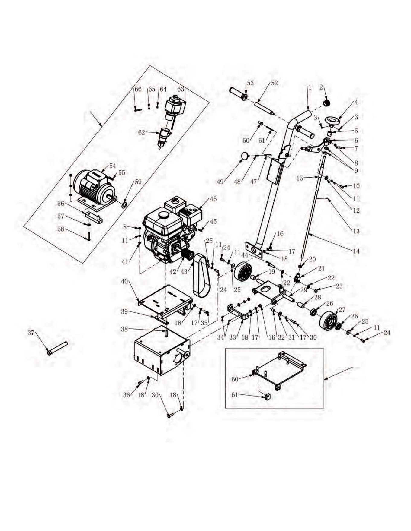

PARTS LIST
No. Description
1
QtyDrawing No.
1Handle Bar Assy. 1001-09000-3
2 Vac Cap 1
3
1001-00024-4
16060805 2
4
Set Screw M6x8
Handle Wheel 1
5
1001-00027-4
Bushing 11001-00018-1
6 1
7
1001-10000-3Lift-Off Handle
150802016 2
8 13080000
Set Screw M8x20
9Nut M8
9 13160004Nut M16 2
10 15080200 1
11
Bolt M8x20
12080000 11
12
Spring Washer M8
11082604 1
13
Washer M8x26x4
19031601 1
14 Adjustment Bar
Spring Pin 3x16
11001-00017-1
15 Adjustment Tube 11001-02000-3
16 13100000 4Nut M10
17 12100000 8
18
Spring Washer M10
11100000 10
19
Washer M10
Bushing 1
20
1001-00012-1
13120000Nut M12 1
21 Fork Head 11001-00020-4
22 11120000 2
23
Washer M12
13120001 1
24
Lock Nut M12
15080250 3
25
Bolt M8x25
11083003 3
26
Washer M8x30x3
Bearing 6204 216204-2R 4
27 Wheel 24125501 2
28 Bushing (Long) 1
29
1001-00013-1
Wheel Shaft Assy. 11001-07000-3
30 15100350 4
31
Bolt M10x35
11103003 2
32
Washer M10x30x3
Washer 21001-00035-4
33 1Wheel Balance Holder 1001-00003-2

PARTS LIST CONT.
17
No. Description QtyDrawing No.
34 19061603 2
35
Spring Pin 6x16
15100250 2
36
Bolt M10x25
15100300 2
37
Bolt M10x30
Wrench 189218-ZE1-000C
38 15080450 4
39
Bolt M8x45
2
40
1001-00015-2Base Plate for Engine
1
41
1001-00001-2Base Support for Engine
11080000 7Washer M8
42 Gear 1
43
1001-06100-4
Belt 1
44
27HTD720-8M
15120450 1
45
Bolt M12x45
12050530A 1Key 5x30
46 25160001Engine 1
47 1Fixation Pin 1001-00019-1
48 Spring 11001-00023-4
49 Knob M10x20 11001-00026-4
50 Finger Knob 2
51
1001-00025-4
1
52
1001-00022-4Shaft for Finger Knob
Handle 2
53
1001-03000-3
70220000 2
54
Handle Grip
25000019 1
55
Electric Motor
20080740AKey 8x40 1
56 21001-00036-4
57
Rubber Plate for Electric Motor
11082202 4
58
Washer M8x22x2
15080550 4
59
Bolt M8x55
Washer 11001-00050-2
60 11001-15000-3
61
Diesel Engine Plate
2
62
1001-00051-2Support, Diesel Engine Plate
1Wire Assy. 1001-14000-1
63 11001-00045-4
64
Safety Switch
11060000 2
65
Washer M6
12060000 2
66
Spring Washer M6
16065503 2Allen Screw M6x55
Qty

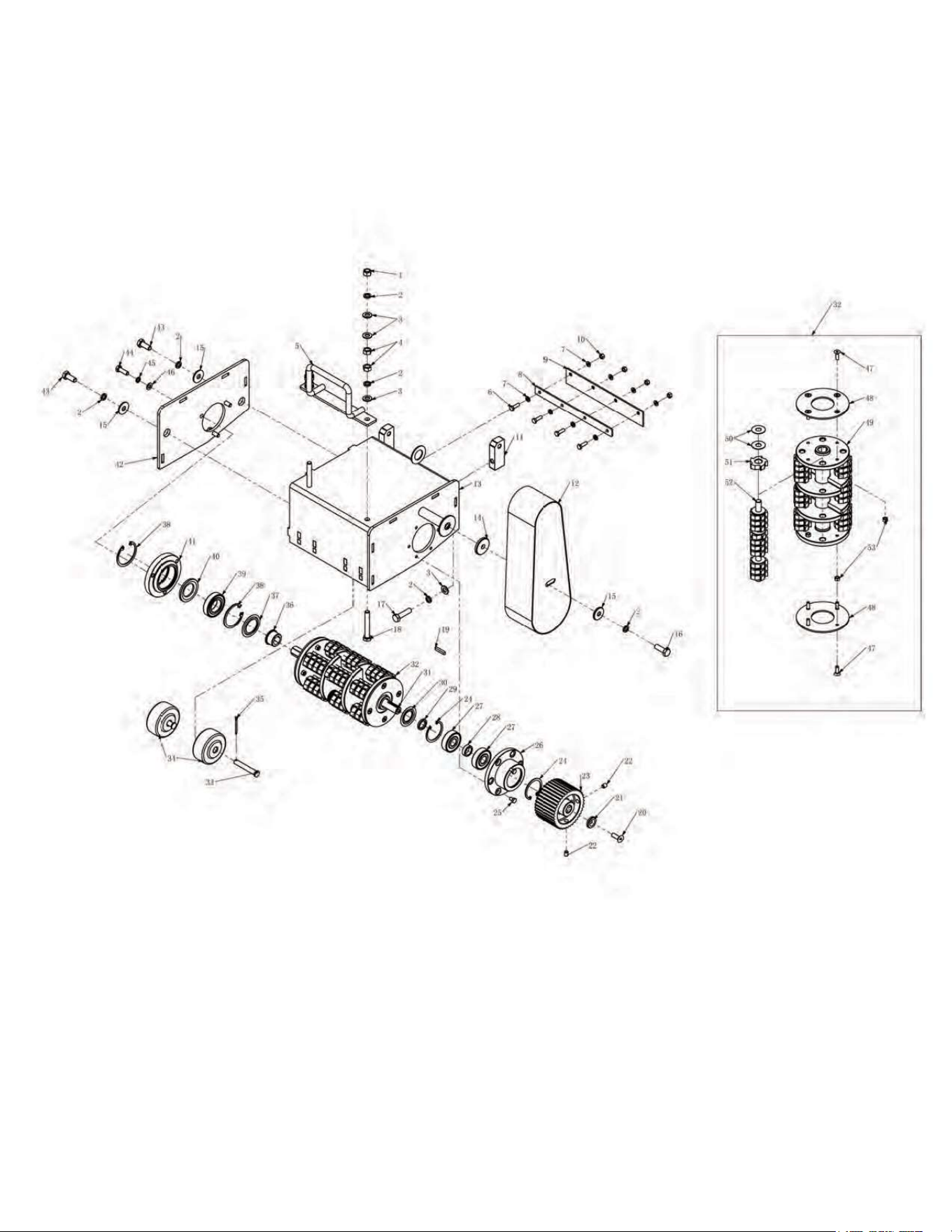
PARTS LIST
No. Description Drawing No. Qty
1 Lock Nut M10 13100001 2
2 Spring Washer M10 12100000 9
3 Washer M10 11100000 10
4 Nut M10 13100000 4
5 Handle Bar 1001-01000-3 1
6 Bolt M6x20 15060200 4
7 Washer M6 11060000 8
8 Wear Plate 1001-00014-2 1
9 Dust Skirt 1001-00030-4 1
10 Lock Nut M6 13060001 4
11 Base Plate Support 1001-00002-2 2
12 Belt Cover 1001-05000-3 1
13 Housing for Cutter 1001-08000-3 1
14 Washer M10x40x5 11104005 1
15 Washer M10x30x3 11103003 3
16 Bolt M10x30 15100300 1
17 Bolt M10x40 15100400 2
18 Bolt M10x70 15100700 2
19 Key 5x30 12050530A 1
20 Allen Screw M8x25 16082504 1
21 Washer 1001-00049-1 1
22 Set Screw M8x10 16081005 2
23 Shaft Gear 1001-00016-4 1
24 18470002Circlip 47 2
25 Bolt M6x10 15060100 6
26 Bearing Housing Left 1001-00004-4 1

PARTS LIST CON.
No. Description Drawing No. Qty
26 Bearing Housing Left 1001-00004-4 1
27 Bearing 6303 216303-2Z 2
28 Collar (Long) 1001-00005-1 1
29 Collar (Short) 1001-00032-1 1
30 1001-00033-4Spacer (Small) 1
31 Hexagon Shaft 1001-00009-4 1
32 Drum Assy. 1001-12000-1 1
33 Front Axle 1001-00010-1 2
34 Front Wheel 1001-00029-1 2
35 Pin 3x30 19032003 2
36 Hexagon Bushing 1001-00011-1 1
37 Spacer (Big) 1001-00034-4 1
38 18550002Circlip 55 2
39 Bearing 6006 216006-2Z 1
40 Spacer 1001-00008-4 1
41 Bearing Housing Right 1001-00007-4 1
42 Housing Cover Right 1001-00006-2 1
43 Bolt M10x25 15100250 2
44 Bolt M8x25 15080250 3
45 Spring Washer M8 12080000 3
46 Washer M8 11080000 3
47 Allen Screw M6x20 16062004 8
48 Safety Plate Cover 1001-00021-2 2
49 Drum Body of Cutter 1001-04000-3 1
50 Washer 12x30x1 1001-00040-4 144
51 Cutter 1001-0004X-4 42/84
52 Cutter Shaft 1001-00031-4 4
53 Lock Nut M6 13060001 8

Rammers
8 ft Hydraulic Steer, 35 HP Vanguard,
CVT Clutch, 180 RPM
10 ft Full Hydrostatic, 74 HP Hatz
Diesel
Part#:
TPT24H
TPT36H
TPT46H
Part#:
JXPT30T
Part#:
TRT46V
TRT60V
2 ft Edger, Honda GX160, 0-28
o
Blade Pitch
3 ft, Honda GX160/GX270, 0-28
o
Blade Pitch
4 ft, Honda GX270/GX390, 0-28
o
Blade Pitch
We’re here to help!
Email us at sales@tomahawk-power.com
Forward Plate Compactors
Reverse Plate Compactors
Part#:
TR68H
JX60H
eJX60H
TVSA-H
eTVSA
Part#:
Part#:
TPC80H
Power Screeds
Porta-Trowels
Concrete Sprayers
Walk Behind Trowels
Ride on Trowels
Early Entry Saws
Part#:
6-16 ft Magnesium Blades
Honda GX35, Adjustable Handles
6-16 ft Magnesium Blades
36V/5 Ah Battery, Adjustable Handles
Part#:
TFS6H
TFS10H
Part#:
TCS6.5
6" Blade Diameter, Blade Compatibility,
Honda GX120
10" Blade Diameter, Self Propelled,
Blade Compatibility, Honda GX270/GX390
TPC85H
TPC90H
TPC170H
TPC100H
TPC400H
Equipment Guide
3,000 lbs/sq ft, Honda, 21”x17” Plate
3,200 lbs/sq ft, Honda, 23”x17” Plate
3,400 lbs/sq ft, Honda, 22”x20” Plate
3,500 lbs/sq ft, Honda, 19”×14” Plate
7,000 lbs/sq ft, Honda, 28”x20” Plate
11,690 lbs/sq ft, Honda, 32”x22” Plate
Lightweight at 40 lbs
Adjustable 18 ft Extension Bull Float Poles
30" Diameter, 4-Blade Assembly
Adjustable Blade Pitch from 0-28
o
Adjustable from 0-450 PSI
Handles 30% + Solids,1.8 HP 2 Stroke Motor,
24" Brass Wand 0.5 GPM, Fan Nozzle Included,
Spray 15,000 ft
2
in 10 Minutes
3,550 lbs/sq ft, Honda GX120
3,350 lbs/sq ft, Honda GX100
3,350 lbs/sq ft, Honda GXE2.0S
Items Listed Includes Combo Blades
QUIET INVERTER
QUIET INVERTER
Welder GeneratorsPower Buggy
48V-20Ah Battery
Handles up to 8 cu ft or 660 lbs. Bucket Capacity
Hydraulic Bucket with 92
o
Tilt, 8 Hour Run Time
Snow Plow Attachment & Bucket Extender Available
Part#:
TGDR10
TSCP8
4,500 - 5,500 Watt Series
10,500 Watt Series
Concrete Scarifier
Floor Sweepers
Grinders and Scrapers
Part#:
TSCAR-8H
Trash Water Pumps
Part#:
TW3H
TW4H
3" Pump, Honda GX270, 375 GPM,
Elevation: 89ft, Suction: 25ft
4" Pump, Honda GX390, 581 GPM,
Elevation: 92ft, Suction: 26ft
QUIET INVERTER
tomahawk-power.com
ASSEMBLED IN THE
PARTS SOURCED GLOBALLY
TG2000i
TG3000i
2,000 - 3,300 Watt Series
Equipment Guide
10" Disc, 120V, 1/32" Per Pass,
11 AMP, 1.5 HP, 1,725 RPM
8" Blade, 120V, 11 AMP, 3/4 HP,
1,725 RPM, Carpet & Tile Remover
Honda GX160 Engine, Scarifies 350 - 500ft
2
/hr
OSHA Compliant Vacuum Port
8" Carbide Tungsten Drum Kit, 1/8" Per Pass
38" Working Width, Triple Broom
System, 14.5 Gallon
30" Working Width, Battery Powered
Triple Broom System, 13.5 Gallon
120 Amp Welder, 60% Duty Cycle,
2000w, Includes Wheel Kit
210 Amp Welder, 60% Duty Cycle,
2000w, Includes Wheel Ki
t
4,500w Max
/
3,800w Rated
5,500w Max / 5,000w Rated, 120/220V
Run Time 8 Hrs @ 50% Load
CARB Compliant, GFCI
TG4500i
TG5500i
10,500w Max
/
8,500w Rated
Voltage Selector, 120/220V
Run Time 14.5hrs @ 25% Load
CARB Compliant, GFCI, CO Detector
TG9000i
2,200w Max
/
2,000w Rated
3,300w Max
/
3,000w Rated,
120/220V, 30 AMP Twist Lock
Run Time 8 Hrs @ 50% Load
CARB Compliant, GFCI 120v
6010-7024 Rods Compatible
Part#: TBUGGY300e
Part#:
TWG120A
TWG210A
Part#:
TOS38
eTOS30

TOMAHAWK®, LLC
San Diego, CA
Sales Support
(866) 577-4476
Equipment Support
(866) 577-4476
www.tomahawk-power.com
Tomahawk understands to keep a job-site running smoothly the proper equipment and
spare parts are needed at the drop of a hat. With same day shipping and faster
delivery times, count on Tomahawk to keep you powered throughout the day! With
long lasting parts and engines, Tomahawk equipment will be the star of your fleet for
years to come. Visit www.tomahawk-power.com to get started today!
Power Your World
FACEBOOK
facebook.com/TomahawkPowerUSA
YOUTUBE
youtube.com/TomahawkPower
INSTAGRAM
@tomahawkpower