
2
18 19
36
17
7
18
15a
15b
16
15
15a
15b
3
10
9
4a
4b
5,6
11a
11b
11c
13a
14a
1
2 3 7 9
10 12 38
13
4 5
11 13a
14
4 6
11 14a
4
4a
4b
11
11a 11b
11c
36
38
20
19
(x2)
0
00
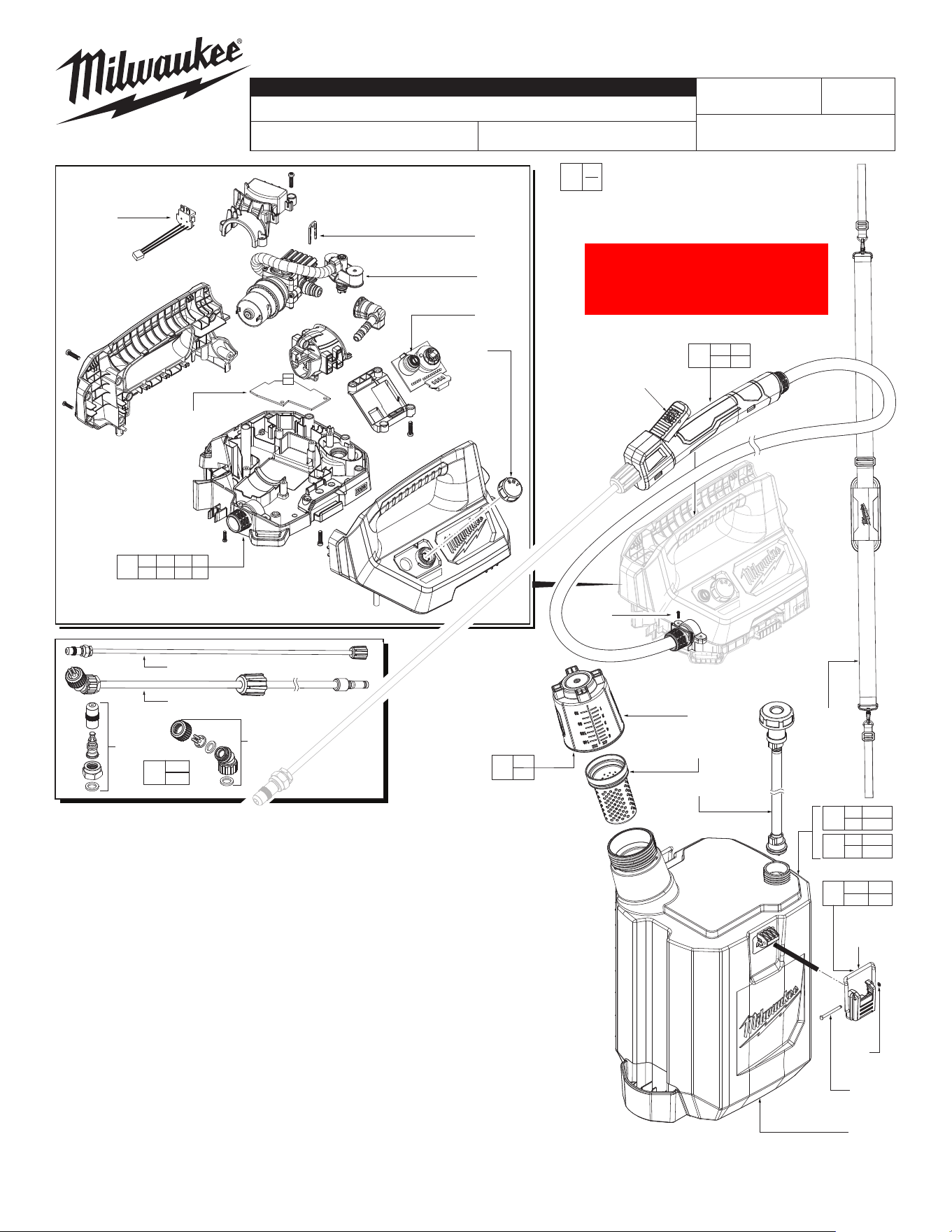
EXAMPLE:
Component Parts (Small #)
Are Included When Ordering
The Assembly (Large #).
2 Gallon
Tank Assembly
49-16-2762
Shown
M12™ Sprayer
Power Head
2528-20
NOTE: When ordering 14-46-0173 Wand
Service Assembly (2), the screws to
fasten the assembly into the Power
Head (1) are included.
MILWAUKEE TOOL
l
www.milwaukeetool.com
13135 W. LISBON RD., BROOKFIELD, WI 53005
Drwg. 5
BULLETIN NO.
54-07-0030
SERVICE PARTS LIST
CATALOG NO.
REVISED BULLETIN
SPECIFY CATALOG NO. AND SERIAL NO. WHEN ORDERING PARTS
M12™ HANDHELD SPRAYER (POWER HEAD)
SERIAL NO.
DATE
May 2025
WIRING INSTRUCTION
N07A
See Page 2
2528-20
FIG. PART NO. DESCRIPTION OF PART NO. REQ.
1 31-01-5481 M12™ Sprayer Power Head Assembly (1)
2 14-34-2581 Trigger Handle and Hose Assembly (1)
3 14-20-7326 Pump Motor Service Assembly (1)
4 14-46-0219 Measuring Cap and Filter Service Kit (1)
4a --------------- Measuring Cap (1)
4b --------------- Cap Filter (1)
5 14-37-6130 Inlet Hose/Check Valve Service Assembly - 1 Gallon (1)
6 14-37-6131 Inlet Hose/Check Valve Service Assembly - 2 Gallon (1)
7 23-18-0085 Pressure Selector Knob (1)
9 14-20-0448 Main PCBA (1)
10 14-20-0449 Speed Control PCBA (1)
11 14-46-0239 Latch Service Kit (2)
11a --------------- Latch (2)
11b --------------- Latch Pin Retainer (2)
11c --------------- Latch Pin (2)
12 12-20-0409 Power Head Service Nameplate (Not Shown) (1)
13 49-16-2761 1 Gallon Sprayer Tank Assembly (Accessory, Not Shown) (1)
13a --------------- 1 Gallon Sprayer Tank (Accessory, Not Shown) (1)
14 49-16-2762 2 Gallon Sprayer Tank Assembly (Accessory, Shown) (1)
14a --------------- 2 Gallon Sprayer Tank (Accessory, Shown) (1)
15 49-16-2728 Replacement Spray Nozzles (Accessory) (1)
15a --------------- Adjustable Nozzle (Accessory) (1)
15b --------------- Angled Adapter (Accessory) (1)
16a 49-16-2729 18" Short Sprayer Wand (Accessory) (1)
17 49-16-2764 Shoulder Strap (Accessory) (1)
18 45-72-0230 Trigger Lock on Wand Handle (1)
19 --------------- ST 4x12 Screw (2)
20 45-86-0072 24" Sprayer Wand (1)
36 --------------- Retaining Clip (1)
38 14-20-7336 Battery Terminal Wire Harness (1)
52 12-20-0513 Tank Service Nameplate (Not Shown) (1)
53 10-20-3707 Power Head Warning Label (Not Shown) (1)
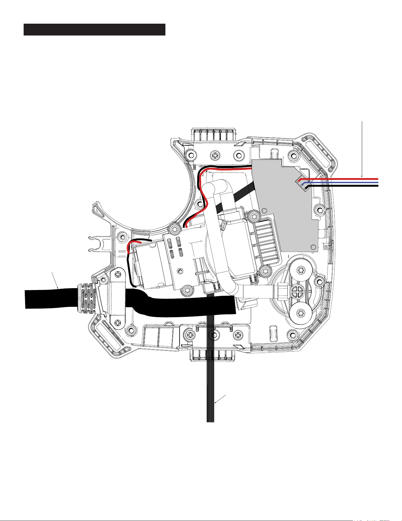
This view is from the
top looking down.
Wires go to Battery Terminal
Hose to Wand
Service Assembly (2).
White wire ribbon goes to
Speed Control PCBA (10)
Main PCBA
Wiring
WIRING INSTRUCTIONS