1
E
ULTRA-DYNE
®
PRO
DSP9024
Version 1.0 October 1998
User´s Manual
Bedienungsanleitung
D
www.behringer.de
2
EC Declaration of Conformity
INTERNATIONAL GmbH
acc. to the Directives
89/336/EWG and 73/23/EWG
We, BEHRINGER INTERNATIONAL GmbH
Hanns-Martin-Schleyer-Strasse 36-38
D - 47877 Willich, Germany
Name and address of the manufacturer or the introducer of the product on the market who is established in the EC
herewith take the sole responsibility to confirm that the product:
ULTRA-DYNE PRO DSP9024
Type designation and, if applicable, Article-No
which refers to this declaration, is in accordance with the following standards or
standardized documents:
x EN 60065 x EN 61000-3-2
x EN 55020 x EN 61000-3-3
x EN 55013 x EN 55022
The following operation conditions and installation arrangements have to be
presumed:
acc. to Operating Manual
B. Nier, President Willich, 1.10.1998
Name, address, date and legally binding signature of the person responsible
3
E
This symbol, wherever it appears,
alerts you to the presence of
uninsulated dangerous voltage inside
the enclosure - voltage that may be
sufficient to constitute a risk of shock.
This symbol, wherever it appears, alerts
you to important operating and mainte-
nance instructions in the accompanying
literature. Read the manual.
SAFETY INSTRUCTIONS
CAUTION: To reduce the risk of electrical shock, do not remove
the cover (or back). No user serviceable parts in-
side; refer servicing to qualified personnel.
WARNING: To reduce the risk of fire or electrical shock, do not
expose this appliance to rain or moisture.
DETAILED SAFETY INSTRUCTIONS:
All the safety and operation instructions should be read before the appliance is operated.
Retain Instructions:
The safety and operating instructions should be retained for future reference.
Heed Warnings:
All warnings on the appliance and in the operating instructions should be adhered to.
Follow instructions:
All operation and user instructions should be followed.
Water and Moisture:
The appliance should not be used near water (e.g. near a bathtub, washbowl, kitchen sink, laundry tub, in a
wet basement, or near a swimming pool etc.).
Ventilation:
The appliance should be situated so that its location or position does not interfere with its proper ventilaton.
For example, the appliance should not be situated on a bed, sofa rug, or similar surface that may block the
ventilation openings, or placed in a built-in installation, such as a bookcase or cabinet that may impede the
flow of air through the ventilation openings.
Heat:
The appliance should be situated away from heat sources such as radiators, heat registers, stoves, or other
appliance (including amplifiers) that produce heat.
Power Source:
The appliance should be connected to a power supply only of the type described in the operating instructions
or as marked on the appliance.
Grounding or Polarization:
Precautions should be taken so that the grounding or polarization means of an appliance is not defeated.
Power-Cord Protection:
Power supply cords should be routed so that they are not likely to be walked on or pinched by items placed
upon or against them, paying particular attention to cords and plugs, convenience receptacles and the point
where they exit from the appliance.
Cleaning:
The appliance should be cleaned only as recommended by the manufacturer.
Non-use Periods:
The power cord of the appliance should be unplugged from the outlet when left unused for a long period of
time.
Object and Liquid Entry:
Care should be taken so that objects do not fall and liquids are not spilled into the enclosure through openings.
Damage Requiring Service:
The appliance should be serviced by qualified service personnel when:
- The power supply cord or the plug has been damaged; or
- Objects have fallen, or liquid has been spilled into the appliance; or
- The appliance has been exposed to rain; or
- The appliance does not appear to operate normally or exhibits a marked change in performance; or
- The appliance has been dropped, or the enclosure damaged.
Servicing:
The user should not attempt to service the appliance beyond that is described in the Operating Instructions.
All other servicing should be referred to qualifield service personnel.
4
DSP9024
ULTRA-DYNE PRO
Ultra-high performance Digital Stereo Mainframe powered by two 24-bit High-Speed Signal Processor
s High-end 24-bit AD/DA converters for ultra-high dynamic range and resolution of detail with selectable
Sampling Rate of 44.1 or 48 kHz
s Ultimate 6-way Multiband Dynamics Processor for analog and digital Mastering and Sound Reinforcement
systems
s 6-Band Compressor with separate Peak Limiter section for inaudible compression. No side-effects,
such as bass pumping etc.
s 6-Band Gate with adjustable threshold, hold time, release time and peak width
s ULTRAMIZER
®
automatically adjusts output level and signal density for maximum perceived loudness
s VIRTUOSO
®
function for super-easy, program-dependent and self-learning program setup
s 3-Band Harmonics Exciter with user-definable balance for odd / even harmonics and unique kick control
s Extremely sophisticated Tube emulation with selectable tube types (12AX7, 12AY7, EL34, EL84) for ultra-
warm sound
s Internal 600 msec. Delay enables a Look Ahead for intelligent, anticipating processor function
s Ultra-accurate Level Peak Meter with Peak Hold and selectable Reference Levels (+4 dBu / -10 dBV / Dig Max)
s Full MIDI parameter and snapshot control allow for real time editing
s Free ULTRA-DYNE software allows for total remote control via PC (download at www.behringer.de)
s Extremely versatile presets give you outstanding and instant sound results for numerous standard
applications
s 100 settings can be stored under any alphabetic name. Memory backed up by a long life battery
s Security Key Password can be installed for programs or unattended use
s Open-ended and future-proof architecture allows for future software upgrades
s Extremely flexible Stereo Link, Band Link & Clone functions
s 24-bit AES/EBU Interface for Digital inputs and outputs at 32, 44.1 and 48 kHz (optional)
s Large high-resolution LCD Graphic Display with high-contrast LED backlight
s Servo-balanced inputs and outputs on gold-plated XLR and jack connectors for high signal integrity
s Relay-controlled hard bypass with an auto bypass function during power failure (fail-safe relay)
s High-quality components and exceptionally rugged construction ensure long life and durability
s Internal power supply design for professional applications
s Manufactured under the stringent ISO9000 management system

5
E
FOREWORD
Dear Customer,
Welcome to the team of ULTRA-DYNEPRO users and thank you very much for expressing your confidence
in BEHRINGER products by purchasing this unit.It is one of my most pleasant tasks to write this preface for
you, because it is the culmination of many months of hard work on the part of our engineering team to reach
a very ambitious goal:to present an outstanding device, which due to its flexibility is suitable for deployment in
studios and PA rental companies, as well as discotheques and clubs.The task of developing our new
ULTRA-DYNE PRO certainly meant a great deal of responsibility, which we assumed by focusing on you, the
discerning user and musician. It also meant a lot of work and night shifts to accomplish this goal. But it was
fun, too. Developing a product always brings a lot of people together, and what a great feeling it is when
everybody who participated in such a project can be proud of what they've achieved.
It is our philosophy to share our joy with you, because you are the most important member of our team.
You've contributed greatly to shaping our company and making it successful with your highly competent
suggestions for new products. In return, we guarantee you uncompromising quality (manufactured under an
ISO9000 certified management system) as well as excellent technical and audio properties at an extremely
favorable price. All of this will enable you to fully unfold your creativity without being hampered by budget
constraints.
We are often asked how we can produce such high-grade devices at such unbelievably low prices. The
answer is quite simple: it's you, our customers! Many satisfied customers means high sales volumes, en-
abling us to get better terms of purchase for components, etc. Isn't it only fair to pass this benefit back to you?
We know that your success is our success, too!
I would like to thank everyone whose help on the ULTRA-DYNE PRO project made it all possible. Everyone
involved made very personal contributions, starting from the designers of the unit, to the many staff members
in our company, to you, the user of BEHRINGER products.
My friends, it's been worth the effort!
Thank you very much,
Uli Behringer

6
TABLE OF CONTENTS
1. INTRODUCTION..................................................................................................................... 8
1.1 The concept .................................................................................................................................... 8
1.2 Before you begin ............................................................................................................................. 9
1.3 Control elements ............................................................................................................................. 9
2. OPERATION .......................................................................................................................... 11
2.1 The ULTRA-DYNE PRO operating concept ..................................................................................... 11
2.1.1 The program level ................................................................................................................ 12
2.1.2 The editing level .................................................................................................................. 12
2.1.3 The meter level.................................................................................................................... 12
2.1.4 The setup level .................................................................................................................... 12
2.2 PROCESS mode .......................................................................................................................... 12
2.2.1 Editing parameters .............................................................................................................. 13
2.2.2 Program administration ....................................................................................................... 13
2.2.3 Loading a program .............................................................................................................. 14
2.2.4 Saving programs ................................................................................................................. 14
2.2.5 Activating VIRTUOSO ......................................................................................................... 14
2.2.6 Band-specific editing........................................................................................................... 15
2.2.7 Tube Simulation .................................................................................................................. 15
2.3 METER mode ............................................................................................................................... 16
2.3.1 Advanced level meter .......................................................................................................... 16
2.3.2 Editing in METER mode......................................................................................................17
2.4 Setup level 1 ................................................................................................................................. 18
2.4.1 Input/output menu ............................................................................................................... 18
2.4.2 Band menu ......................................................................................................................... 19
2.5 Setup level 2 ................................................................................................................................. 20
2.5.1 Global setup ....................................................................................................................... 20
2.5.2 MIDI setup .......................................................................................................................... 22
3. APPLICATIONS ..................................................................................................................... 22
3.1 Compression/Leveling/Limiting/Clipping ......................................................................................... 23
3.2 The Gate section .......................................................................................................................... 23
3.2.1 Suppression of crosstalk in multi-channel operation ............................................................ 24
3.2.2 Basic settings of the Gate section ...................................................................................... 24
3.2.3 Reduction of crosstalk from stage microphones .................................................................. 25
3.2.4 Reduction of feedback from stage microphones .................................................................. 25
3.2.5 Noise reduction in effects chains......................................................................................... 25
3.2.6 Creative application of the Gate section .............................................................................. 25
3.3 The Compressor section ............................................................................................................... 26
3.3.1 Basic settings of the Compressor section ........................................................................... 27
3.3.2 The ULTRA-DYNE PRO as an effect device ........................................................................ 27
3.3.3 The "dull" sound of compressors ......................................................................................... 28
3.4 The VIRTUOSO function ............................................................................................................... 28
3.5 The ULTRAMIZER function ............................................................................................................ 29
3.6 Peak Limiter section ..................................................................................................................... 29
3.6.1 Basic settings of the Peak Limiter section .......................................................................... 30
3.7 Tube simulation ............................................................................................................................. 30
3.7.1 Application .......................................................................................................................... 30
3.8 The Exciter function ...................................................................................................................... 31
3.8.1 Audio enhancement during the copying process ................................................................. 31
3.8.2 Audio enhancement of instruments ..................................................................................... 31
3.8.3 Audio enhancement of PA systems .................................................................................... 31
3.9 The ULTRA-DYNE PRO in the recording and copying fields .......................................................... 32
3.9.1 The ULTRA-DYNE PRO for digital recording and sampling .................................................. 32
3.9.2 Mastering with the ULTRA-DYNE PRO ............................................................................... 32

7
E
3.10The ULTRA-DYNE PRO as a protective device for sound systems ................................................ 33
3.10.1Protecting a system with passive crossovers ...................................................................... 33
3.10.2 Protecting a system with active crossovers........................................................................ 34
3.10.3 Audio enhancement of processor-controlled PA system ..................................................... 34
3.11 The deployment of the ULTRA-DYNE PRO in conjunction with multitrack machines ..................... 34
3.12The ULTRA-DYNE PRO in the broadcasting field ........................................................................... 34
3.12.1 The deployment of the ULTRA-DYNE PRO in the broadcasting field ................................... 35
3.12.2 The deployment of the ULTRA-DYNE PRO in telephone and transmission lines ................. 35
4. TECHNICAL BACKGROUND .............................................................................................. 35
4.1 Audio dynamics ............................................................................................................................ 35
4.1.1 Noise as a physical phenomenon ....................................................................................... 35
4.1.2 Audio dynamics .................................................................................................................. 36
4.1.3 Compressors/limiters .......................................................................................................... 37
4.1.4 Expanders/noise gates ....................................................................................................... 38
4.2 Digital audio processing ................................................................................................................ 38
4.2.1 The AES/EBU and S/PDIF standards.................................................................................. 40
4.3 Artificial generation of harmonics ................................................................................................... 41
4.4 Tube technology............................................................................................................................ 41
4.5 The structure of the ULTRA-DYNE PRO ........................................................................................ 42
5. INSTALLATION ..................................................................................................................... 42
5.1 Rack mounting .............................................................................................................................. 43
5.2 AC power connection .................................................................................................................... 43
5.3 Analog audio connections ............................................................................................................. 43
5.4 Digital audio connections per AES/EBU (optional) ......................................................................... 44
5.5 MIDI connections .......................................................................................................................... 45
6. APPENDIX ............................................................................................................................. 45
6.1 AES8024 ...................................................................................................................................... 45
6.2 Operating software ........................................................................................................................ 46
6.3 Changing the memory buffer battery .............................................................................................. 46
6.4 In planning .................................................................................................................................... 46
6.5 MIDI implementation ..................................................................................................................... 47
6.6 Technical specifications ................................................................................................................ 48
7. WARRANTY .......................................................................................................................... 50

8
1. INTRODUCTION
With the BEHRINGER ULTRA-DYNE PRO, you have purchased a fully digital sound processing device
based on DSPs and 24-bit A/D and D/A converters. The high speed DSPs are capable of performing any
process in fractions of a second, the only element governing their performance being the software.
The BEHRINGER ULTRADYNE PRO has two channels which can be used independently or coupled via
software.
+ The following user's manual will introduce you to the BEHRINGER ULTRA-DYNE PRO and its
various functions. After reading the manual carefully, make sure it is always on hand for future
reference.
1.1 The concept
Unlike analog technology with its response speed limitations regarding changes in amplitude, digital signal
processing permits differences in amplitude to be identified in advance using a preliminary signal delay.
Increasing this preliminary delay also increases the potential for the intelligent control. Even looking ahead
by only a few samples is sufficient to ensure the intelligent application of dynamic processing such as
limiting, which ensures an absolutely reliable signal ceiling without clipping.
The signal delay may make itself unpleasantly noticeable in live use due to the mix of direct and delayed
sound. Very short delay times are thus advisable!
You are probably familiar with the effect of a solo instrument or voice being briefly "swallowed" by a bass
drum beat or a solid bass guitar pulse. This is a typical problem with broad-band compressors and limiters.
The powerful low frequencies generally dictate the overall level of the complete frequency spectrum. When
these high amplitudes exceed the set threshold of the compressor, the compression process is activated,
resulting in a muffled sound when the high frequencies are also attenuated. This problem does not occur
when using multiband technology as the low frequencies are controlled independently, effectively preventing
adverse effects on the other frequency bands. In multiband operation, the program material is divided into
several frequency bands. Unlike broadband units, a separate compressor or limiter is available for each of
these bands. The frequency ranges are merged once again downstream of these control units.
The ULTRA-DYNE PRO breaks the audio spectrum down into six frequency bands, thus offering "inaudible",
but highly effective compression. A completely new, intuitive operating concept permits the easy modification
of parameters, either for the individual bands, or globally. In addition, the ULTRA-DYNE PRO offers a Gate with
a wide range of user-definable parameters, a lightning-fast Peak Limiter, Tube Simulation and an Exciter. The
ULTRA-DYNE PRO also includes the VIRTUOSO and ULTRAMIZER functions for program material analysis to
facilitate your work, adapting the Compressor parameters quickly and automatically to suit your audio mate-
rial.
The philosophy behind BEHRINGER products guarantees a no-compromise circuit design and the best choice
of components. Top-quality 24-bit AD/DA converters which belong to the best components available owing to
their outstanding specifications and excellent sonic characteristics are the heart of the BEHRINGER
ULTRADYNE PRO. Two 24-bit DSPs perform the precise calculations needed for the processing of the
complex algorithms. Additionally, the unit uses resistors and capacitors with very tight tolerances, high-grade
integrated circuits and other selected components.
The ULTRADYNE PRO DSP 9024 uses SMD (Surface Mounted Device) technology. These subminiature
components known from aerospace technology allow for an extreme packing density and enhance the unit's
reliability. Additionally, the unit is manufactured in compliance with an ISO 9000 certified management sys-
tem.
Fail-safe relays have been incorporated into the design of the BEHRINGER ULTRA-DYNE PRO. These
automatically and silently bypass the unit in the event of power supply disconnection or failure. These relays
are also active at switch-on to isolate the unit from potentially damaging switch-on thump.
1. INTRODUCTION
9
E
1.2 Before you begin
Your BEHRINGER ULTRA-DYNE PRO was carefully packed in the factory and the packaging was designed
to protect the unit from rough handling. Nevertheless, we recommend that you carefully examine the packag-
ing and its contents for any signs of physical damage which may have occurred in transit.
+ If the unit is damaged, please do not return it to us, but notify your dealer and the shipping
company immediately, otherwise claims for damage or replacement may not be granted.
The BEHRINGER ULTRA-DYNE PRO fits into two standard 19" rack units of space (3 1/2). Please allow at
least an additional 4" depth for the connectors on the back panel.
Be sure that there is enough space around the unit for cooling and please do not place the ULTRA-DYNE PRO
on high-temperature devices such as power amplifiers to avoid overheating.
+ Please ensure that the ULTRA-DYNE PRO is set to the correct supply voltage before connecting
the unit to the power supply system!
The AC power connection of the ULTRA-DYNE PRO is made using a standard power supply cable and IEC
receptacle. It meets all of the international safety certification requirements.
+ Please make sure that all units have a proper ground connection. For your own safety, never
remove or disable the ground conductor of the unit or of the AC power cable.
As standard, the BEHRINGER ULTRA-DYNE PRO is installed with electronically servo-balanced inputs and
outputs. The circuit design features automatic hum rejection for balanced signals, permitting trouble-free
operation even at the highest operating levels. Externally induced power-line hum, etc. is thus suppressed
effectively. The automatic servo function recognizes the presence of unbalanced connectors and adjusts the
nominal level internally to avoid level differences between the input and output signals (6dB correction).
The optional digital input and output (AES/EBU interface) connections are balanced with a negative ground.
High-quality connectors ensure isolated, noise-free signal throughput. The MIDI connections (IN/OUT/THRU)
have been realized with standardized DIN plug-in connectors. Optocouplers have been used for isolated data
communications.
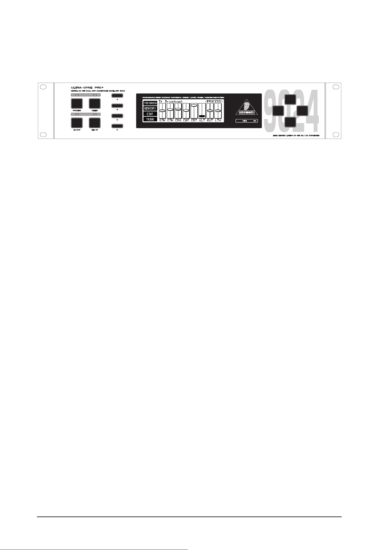
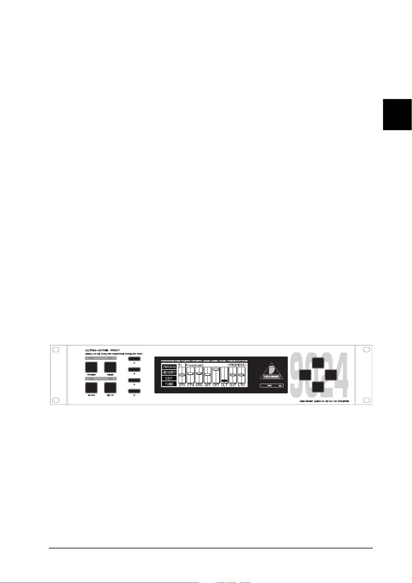
1.3 Control elements
Fig. 1.1: The ULTRA-DYNE PRO front panel
The front panel of the ULTRA-DYNE PRO is equipped with four mode keys, four softkeys, four cursor keys
and a MIDI monitor LED. Status information is displayed on the backlit 240 x 64 panel.
1. INTRODUCTION
10
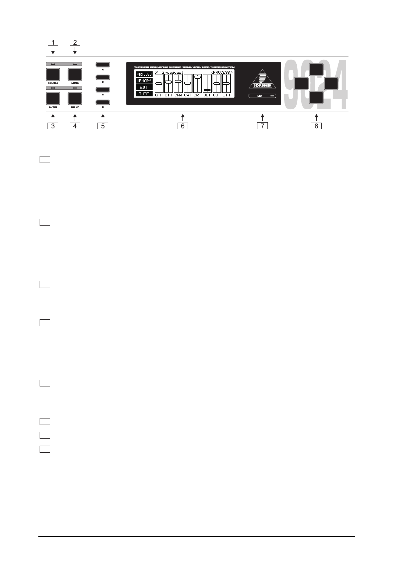
Fig. 1.2: The front panel controls
1
Press the PROCESS key to quickly and conveniently access all of the unit's major program functions
via virtual faders. This permits you to call up, save and edit programs with ease. The ULTRA-DYNE
PRO's factory presets are a solid foundation for a variety of applications. The automatic
VIRTUOSO and ULTRAMIZER functions permit the convenient customization of these applications to
suit your audio material. The first setup level provides global access to the parameters of all bands
simultaneously, while the second permits the manual adjustment of band-specific controls.
Here you will also find a screen for access to the Tube and Exciter functions.
2
Press the METER key for a multiple level display with the levels of the individual bands, as well as those
of the input and output signals. In addition, the respective level differences to the original signal are
also displayed.
+ The last fader used remains active when switching from the PROCESS to the METER operating
mode. The parameter in question may still be modified using the vertical cursor keys while
monitoring changes to the signal processing on the corresponding display.
3
Press the IN/OUT key to include the ULTRA-DYNE PRO in the signal path (green LED) or switch to
bypass mode (LED is dark). The LED flickering red indicates DSP overflow. This does not necessarily
mean clipping. Flickering starts as soon as an internal processing overflow occurs, while input and
output levels may be OK. When this LED lights up often, reduce the input level.
4
Press the SETUP key to access the setup levels which permit the individual numerical editing of each
parameter. Pressing the SETUP key briefly accesses the first setup level in which the complete range
of values for all available ULTRA-DYNE PRO parameters can be edited (see Chapter 2.1.4).
Holding the SETUP key for about two seconds switches to the second SETUP level. Here all the basic
settings of the device can be found, such as the choice of input source, sample rate, password
protection, MIDI configuration etc.
5
Four SOFTKEYS marked A, B, C and D are arranged vertically to the left of the display. The functions
of these keys are defined by the user software and are indicated by a pictogram or text to the right of
each key in the display. Each pictogram and its associated functions will be explained in detail in
Chapter 2.
6
Central in the control of the ULTRA-DYNE PRO is the LED-backlit 240 x 64 DISPLAY.
7
The MIDI LED which displays the input of MIDI data is located to the right of the display.
8
The CURSOR KEYS are also positioned to the right of the display. These keys can be used for the
selection (horizontal) and operation (vertical) of the faders shown on the display, as well as the selection
of parameter fields in the SETUP menu.
+ In each case if you hold the key being used and then press the opposite key you will acceler-
ate whatever operation you are undertaking.
1. INTRODUCTION
11
E
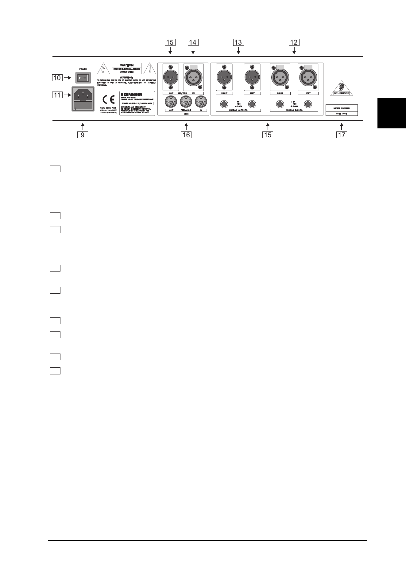
Fig. 1.3: The back panel layout of the ULTRA-DYNE PRO
9
FUSE HOLDER / VOLTAGE SELECTOR. Before connecting the unit to AC power, ensure that the
operating voltage is set to your local AC voltage. Always use replacement fuses of the same type. In
some units, the fuse holder can be inserted in two positions to switch between 220 - 240 V and 100 -
120V. Please note that a higher fuse rating must be used when operating the unit outside of Europe
with 115 V (See the INSTALLATION chapter).
10
Use the POWER switch to activate your ULTRA-DYNE PRO.
11
AC POWER CONNECTION. Use only the included AC cable to connect the unit to your AC power
supply. Please also ensure that your AC power socket has a ground. This ground conductor must NOT
be disabled to prevent hum pick-up. If you experience AC hum problems, use a DI box such as the
BEHRINGER ULTRA-DI to preserve the protective function.
12
ANALOG INPUTS. The ULTRA-DYNE PRO has balanced XLR and jack connector inputs designed for
maximum levels of +22 dBu. Microphone signals thus require pre-amplification, e.g. via a mixer.
13
ANALOG OUTPUTS. The analog outputs of the ULTRA-DYNE PRO have also been realized as bal-
anced XLR and jack connectors. A maximum output level of +16 dBu is available at the internal digital
maximum (DIGIMAX).
14
AES/EBU INPUTS (optional). An optionally available female XLR digital interface can be installed here.
15
AES/EBU OUTPUTS (optional). The optional male XLR digital interface output can be installed here.
The AES/EBU option transfers 24-bit data words at 32, 44.1 or 48 kHz.
16
MIDI IN, OUT and THRU. These connectors permit the MIDI remote control of the ULTRA-DYNE PRO.
17
SERIAL NUMBER. Please take the time to have the warranty card completed by your dealer and
return it to us within 14 days of the purchase date for protection by the extended warranty.
2. OPERATION
2.1 The ULTRA-DYNE PRO operating concept
The complex nature of the parameter settings required the development of a new operating concept for the
ULTRA-DYNE PRO. This permits quick, simple editing of the key parameters, as well as the fine optimization
of each of the individual parameters to suit the program material.
The operation of the ULTRA-DYNE PRO can be broken down into four different levels:
1. The programming level, with the selection and editing of presets.
2. The editing level, which permits the convenient optimization of nearly all available parameters.
3. The METER menu, which in addition to its graphical display of levels also permits editing.
2. OPERATION
12
4. The SETUP menu, which provides access to all of the global and band-specific parameters for the six
frequency bands on several text pages.
2.1.1 The program level
The ULTRA-DYNE PRO has over 100 program memory locations, some of which contain factory-preset pro-
grams. These programs contain a large number of basic settings to cover a wide variety of applications. These
programs can be called up very quickly and generally provide good results in practice. Of course, user-defined
settings can be saved as required and recalled at a later time.
2.1.2 The editing level
Use the editing level to modify the preset programs to suit the program material.
The editing window contains eight faders which can be used to optimize these programs. Please note that the
faders do not represent absolute levels, but parameter changes relative to the presets, with the adjustment
limited to a suitable range. These limits only apply to the factory presets and to programs based on the preset
programs.
2.1.3 The meter level
The input and output levels of the six individual bands is displayed in the meter level. It also permits the editing
of parameters while monitoring the effects of the changes on the meters.
2.1.4 The setup level
The full range of all available ULTRA-DYNE PRO parameters can be edited on the setup level. The results can
range from "interesting" to "surprising" to "brilliant". Completely new applications can also be created. The
setup level is thus the domain of experts and those with a passion for experimentation.
The programs and parameters of the editing level can be accessed by pressing the PROCESS key.
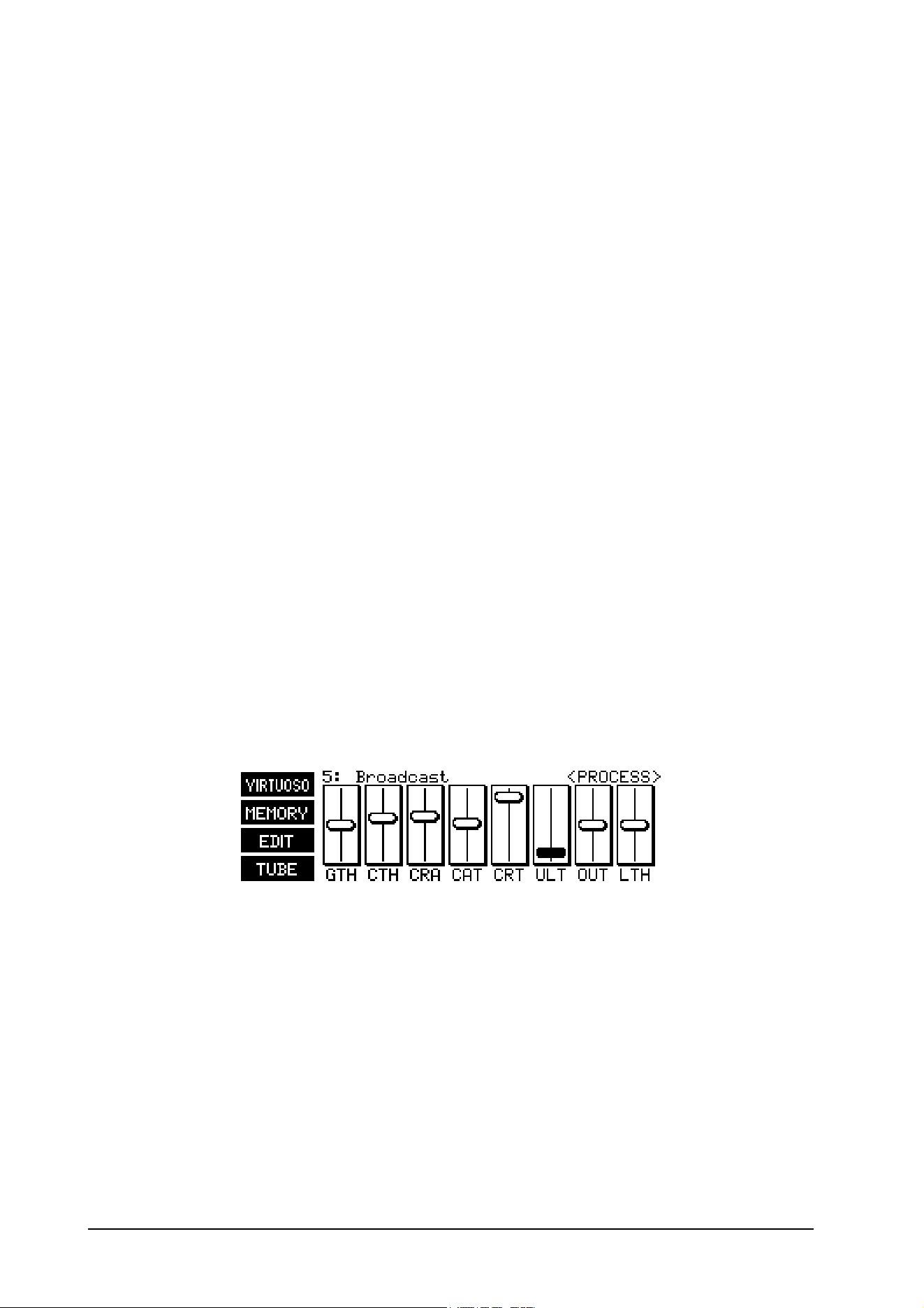
2.2 PROCESS mode
The ULTRA-DYNE PRO is in PROCESS mode immediately after being switched on.
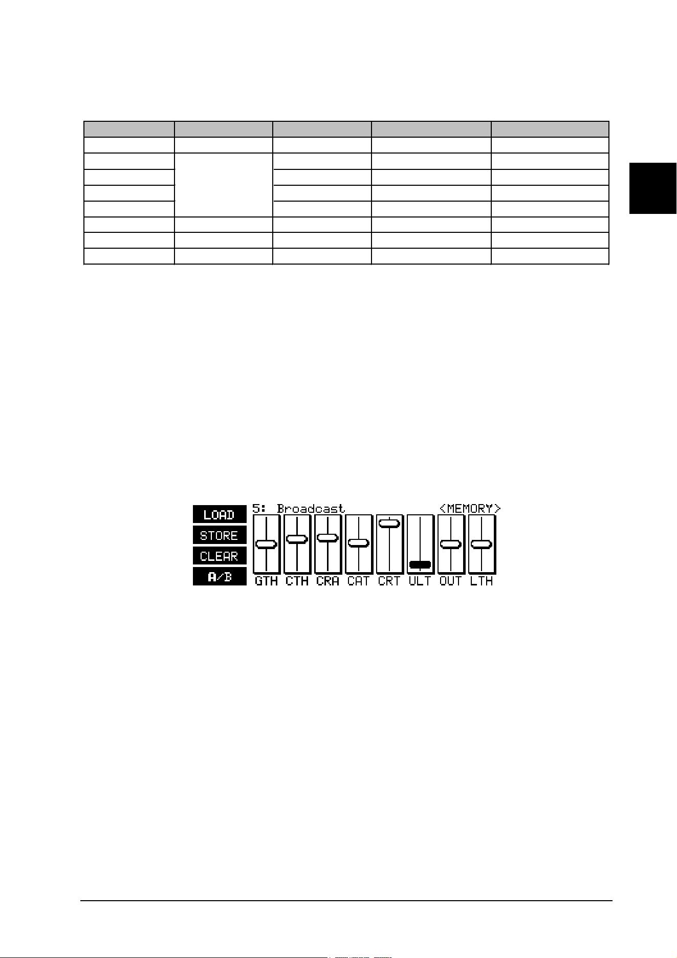
Fig. 2.1: <PROCESS> menu
Use this mode to call up the <MEMORY> menu for loading and saving programs. It also provides direct
access to the main parameters of the individual ULTRA-DYNE PRO functions. The VIRTUOSO function can
also be called up directly from the <PROCESS> menu. ULTRA-DYNE PRO uses this function to analyze the
program material and automatically set the Compressor parameters. An information window appears with the
exact designation and value of the selected parameter when using a fader. The softkey C (EDIT) takes you to
the band-specific editing level which permits the individual editing of the Gate and Compressor values for all six
bands. The softkey D (TUBE) provides access to the Tube Simulation and Exciter parameters.
2. OPERATION
13
E
2.2.1 Editing parameters
Please refer to Table 2.1 for the structure of the parameters and the meanings of the abbreviations.
Display Function Parameter Range Default Value
GTH Gate Threshold -90 to -40 dB, OFF OFF
CTH Threshold -70 to 0 dB, OFF OFF
CRA Ratio 1:1 to 88:1, INF:0 1:1
CAT Attack Time 0 to 250 ms 0 ms
CRT Release Time 0.05 to 5 s 5 s
ULT Ultramizer Process 0 to 100 0
OUT Outgain Gain -24 to +24 dB 0 dB
LTH Limiter Threshold -36 to 0 dB, OFF 0 dB
Compressor
Tab. 2.1: Fader functions in PROCESS mode
The first five parameters in the <PROCESS> menu are contained in all six bands. The last three entries pertain
to the complete frequency range, however. Please see chapters 2.4.1 and 2.4.2 for the definitions of the
parameters.
+ Parameters edited in the <PROCESS> menu have a global effect on all six bands.
2.2.2 Program administration
A program stores all of the parameter settings affecting the signal. Global hardware settings such as the
configuration of the inputs and MIDI interface, i.e. the setup level 2 settings, are not stored in the respective
programs. The ULTRA-DYNE PRO has over 100 program memory locations that contain the factory presets,
as well as room for your own creations.
Fig. 2.2: <MEMORY> menu
Press the softkey B (Memory) in the <PROCESS> menu to access the <MEMORY> menu. The Up and Down
cursor keys can be used to select and listen to programs in this menu. An information window displaying the
selected program appears as soon as you press one of the cursor keys. At the same time, the displayed
preset is automatically played. Use softkey D (A/B) to compare it with the program you have been editing.
The currently active program is indicated by a bold letter in the pictogram: A is the edited version, while B is
the selected program. To load the program, press softkey A (LOAD) and follow the instructions in Chapter
2.2.3. Softkey C (CLEAR) clears your current program from the memory and permits the selection of a
default preset.
+ The message CLEAR WORKSPACE is displayed when the softkey C (CLEAR) is pressed.
Confirm the query with OK to reset all current parameters to their defaults. Be sure to save
the edited program first if desired.
2. OPERATION
14
2.2.3 Loading a program
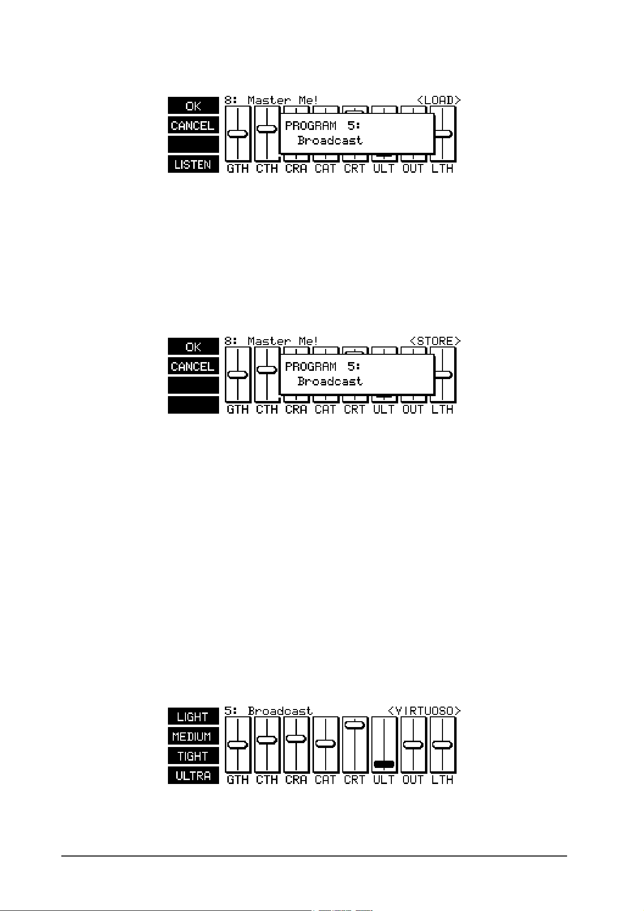
Fig. 2.3: <LOAD> menu
Press the softkey A (Load) in the <PROCESS> menu to access the <LOAD> menu. The same information
window is displayed in the fader area as when operating a fader. Use the Up and Down cursor keys to select
a program and listen to it with the softkey D (LISTEN). The listening function is indicated by a highlighted
LISTEN in the pictogram. Next, select the desired program with softkey A (OK) or return to the
<PROCESS> menu with softkey B (CANCEL).
2.2.4 Saving programs
Fig. 2.4: <STORE> menu
Use the softkey B to access the <STORE> menu. This also displays an information window in which you can
select a program location to save your own creation using the Up and Down cursor keys. Use softkey A (OK)
to assign a name to the program or softkey B (CANCEL) to cancel the save operation and return to the
<PROCESS> menu. If a program location is already occupied, the warning OVERWRITE PROGRAM? will
appear.
Press softkey A (OK) again to assign a name to your program. A window with a character map will now
appear in the display. Choose the character you require with the cursor keys and it will appear at the flashing
cursor in the name field. Use the softkeys B and C to move the cursor in the name field. Softkey D (CLEAR)
deletes any characters which may have already been entered. Program names can have a maximum of 12
characters. Once the name is complete, press softkey A (OK) to return to the <PROCESS> menu.
2.2.5 Activating VIRTUOSO
The VIRTUOSO function can reduce your setup work considerably by analyzing your audio material and
automatically determining the compression values. Press the softkey A in the <PROCESS> or <METER>
menus to access the VIRTUOSO function. This brings you to the <VIRTUOSO> menu in which you can select
the required degree of compression using the four softkeys.
Fig. 2.5: <VIRTUOSO> menu
2. OPERATION
15
E
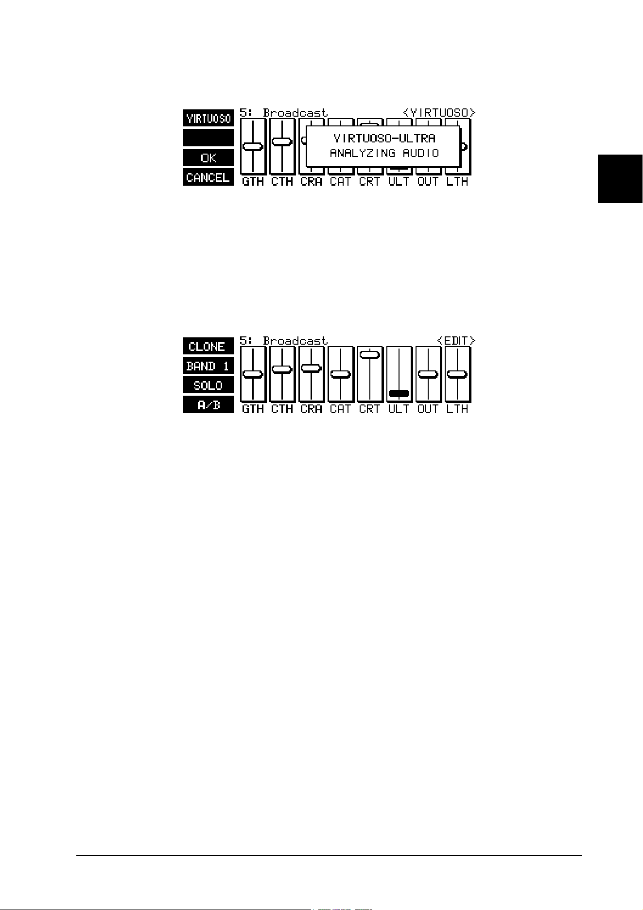
The ULTRA-DYNE PRO now analyzes the audio material until you end the analysis with softkey C (OK) or
cancel it with softkey D (CANCEL). The analysis is indicated by the flashing VIRTUOSO pictogram.
Fig. 2.6: VIRTUOSO analysis window
Next, the ULTRA-DYNE PRO automatically sets the Threshold parameters of all six Compressors for the
individual bands to suit the audio material, ensuring optimal compression (see Chapter 3.4, VIRTUOSO
function). The compression can also be corrected subsequently by changing the INGAIN parameter in the
setup menu. If the compression is too powerful, reduce the INGAIN value and vice versa.
2.2.6 Band-specific editing
Fig. 2.7: <EDIT> menu
Press the softkey C (EDIT) in the <PROCESS> menu to access the <EDIT> menu, which permits band-
specific editing via the faders. Select one of the six bands with softkey B. The pictogram shows the currently
selected band. Pressing the key once more will switch to the next higher band.
The first six parameters (1 Gate, 4 Compressor, 1 Outgain) are available for each band, whereas the last two
(1 Ultramizer, 1 Limiter) apply to the entire frequency range.
+ BANDLINK must be OFF to change settings per band
Softkey D (A/B) allows you to compare the current setting with the settings of the program as it was loaded.
The B in the pictogram is displayed in bold whenever you modify a loaded program. If you are not satisfied
with the new setting, you can return to the original program by pressing softkey D a second time and trying a
new setting from there. As soon as you change a value, the B in the pictogram will once again be displayed in
bold. Upon loading a new program, neither A nor B will be highlighted as long as no changes have been
made.
Use the softkey A (CLONE) to copy the parameters of the selected frequency band to any or all other
frequency bands of the given channel. The settings are also copied to all bands of the other channel when in
stereo mode (setup level 2). The message COPY BAND X TO ALL BANDS will be displayed. Use the Up and
Down cursor keys to select whether the parameters of the current band should be copied to all other bands
(ALL BANDS) or to a specific band (BAND X).
2.2.7 Tube Simulation
Press the softkey D (TUBE) in the <PROCESS> menu to access the <TUBE> menu.
2. OPERATION
16
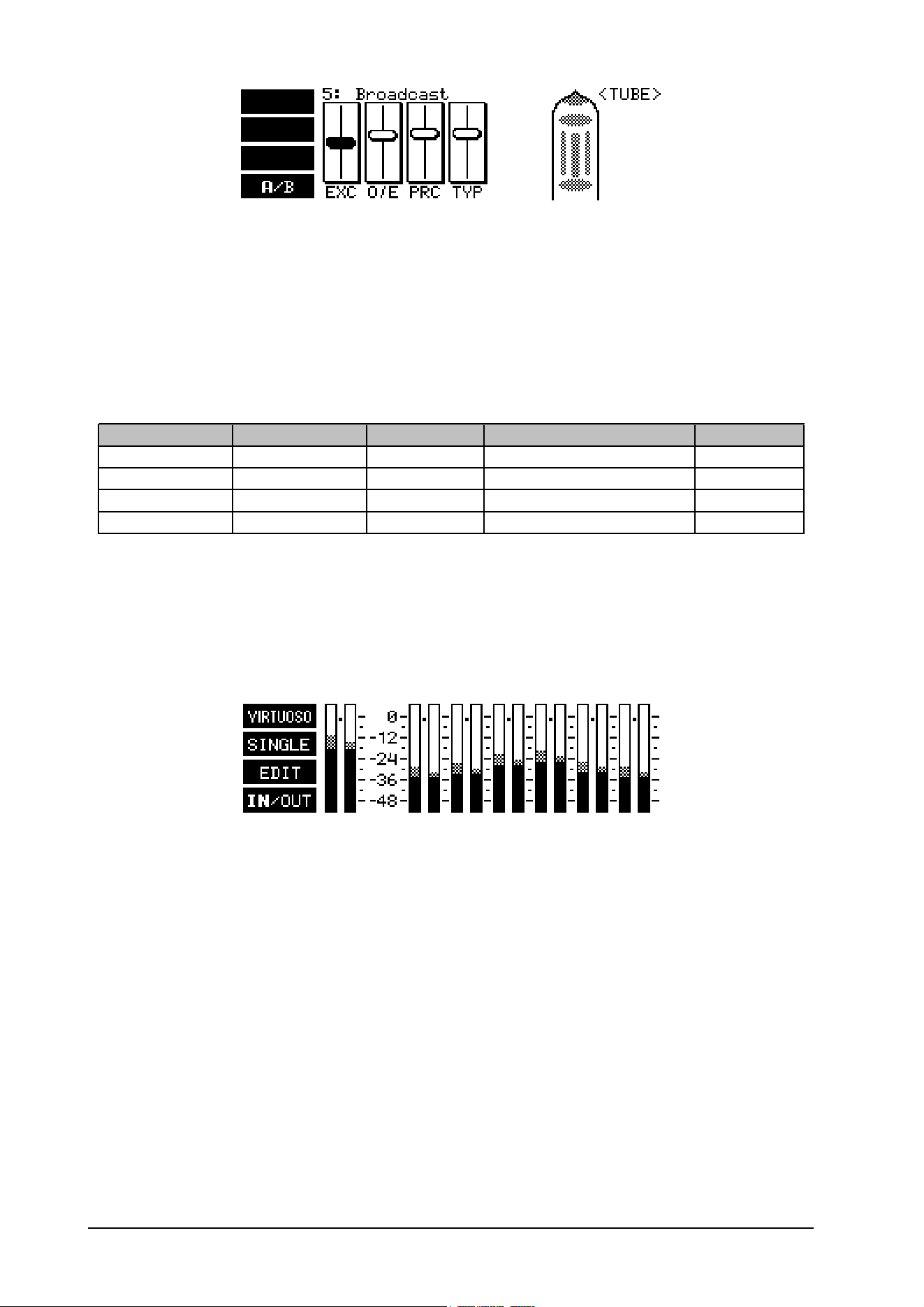
Fig. 2.8: <TUBE> menu
Use this menu to set up the Exciter and Tube Simulation. Please refer to Table 2.2 for the structure and the
meanings of the abbreviations. Softkey D (A/B) allows you to compare the current setting with the settings of
the program as it was loaded. The B in the pictogram is displayed in bold whenever you modify a loaded
program. If you are not satisfied with the new setting, you can return to the original program by pressing
softkey D a second time and trying a new setting from there. As soon as you change a value, the B in the
pictogram will once again be displayed in bold. Upon loading a new program, neither A nor B will be high-
lighted as long as no changes have been made.
Display Function Parameter Range Default Value
EXC Exciter Process 0 to 100 0
O/E Exciter Odd/Even 1/19 to 19/1 10/10
PRC Tube Process 0 to 100 0
TYP Tube Type 12AX7, 12AY7, EL34, EL84 12AX7
Tab. 2.2: Fader functions in the <TUBE> menu
2.3 METER mode
Press the Meter key to enter the METER mode.
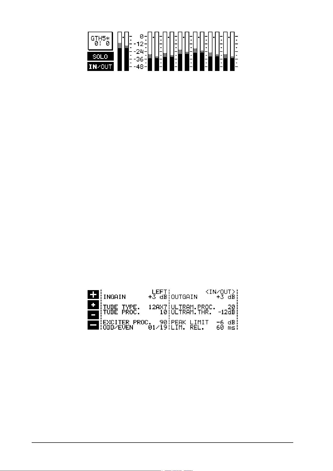
Fig. 2.9: METER mode
This mode displays the input and output levels of all frequency bands (ascending from left to right) and the
overall levels of the two channels. Information is also shown regarding level changes made by the ULTRA-
DYNE PRO. Gain reductions are displayed as a small bar extending downward from the 0 dB mark. It is
possible to activate the VIRTUOSO mode while in METER mode by pressing softkey A (see 3.4). Softkey D
toggles between the display of the input and output levels. IN or OUT are highlighted accordingly.
2.3.1 Advanced level meter
Press the softkey B (SINGLE) to call up the advanced level meter.
2. OPERATION
17
E
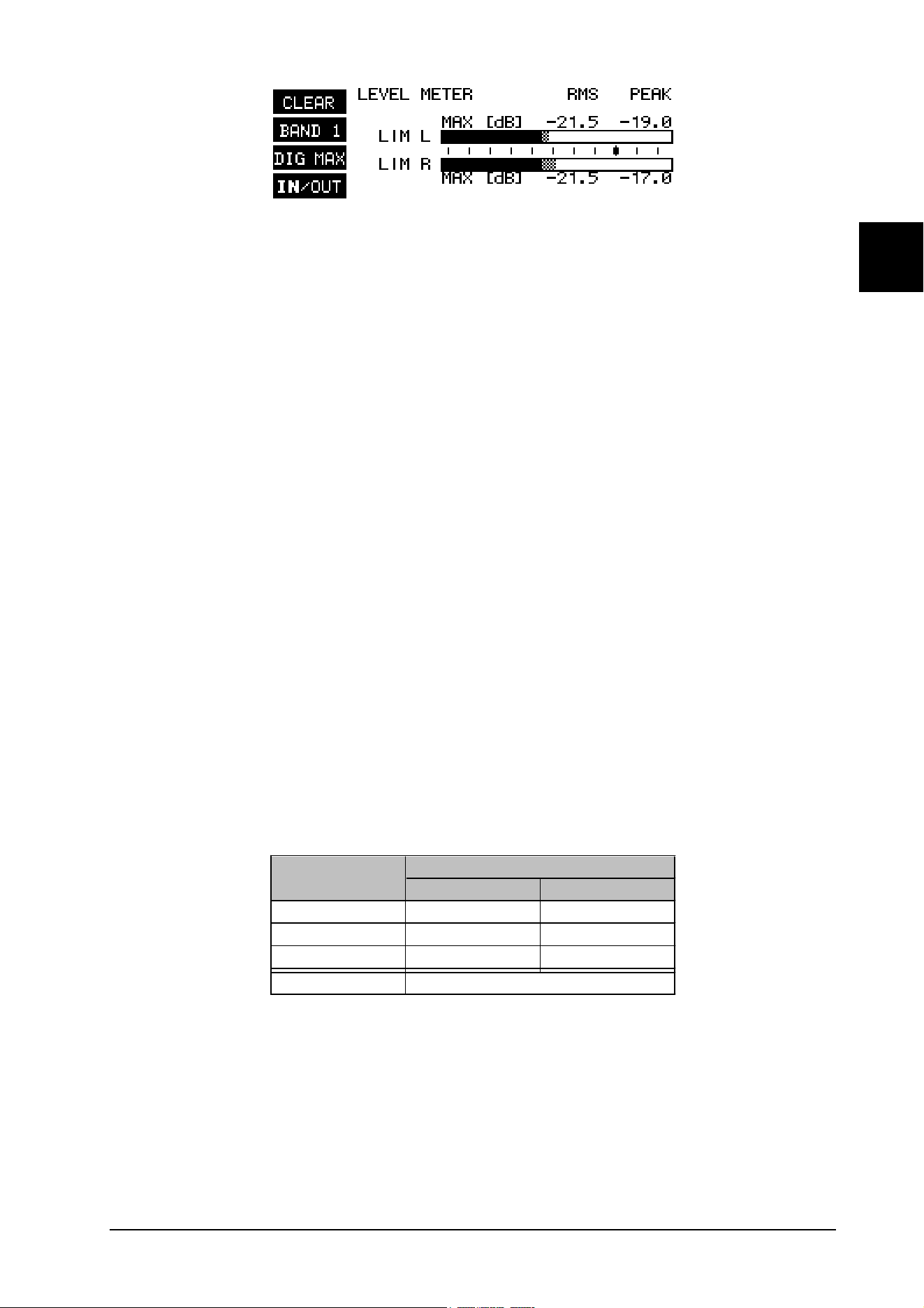
Fig. 2.10: Advanced level meter
You can use the advanced level meter to control the input and output levels of the ULTRA-DYNE PRO. The bar
graph displays the effective RMS level (solid parts of the bars), and the peak level (checkered tips of the bars)
simultaneously. To save your eyes, the release time of the peak display is 20 dB/s. Use softkey A (CLEAR) to
erase the maximum levels from the memory. Softkey B switches between the display of the individual bands
(BAND 1 to 6) and the master channel (MASTER). The current selection is shown in the pictogram. Softkey D
(IN/OUT) toggles the display between the input and output levels. Peak Limiter activity is indicated by the "LIM"
in the display. Use softkey C to choose between three different tables of reference levels. The reference
levels are shown with a bold mark on the scale, and the numerical display changes simultaneously.
DIGMAX refers to the digital maximum. This level must not be exceeded under any circumstances. This will
result in a very noticeable form of distortion, which occurs much faster and sounds very much more unpleasant
than the familiar distortion associated with analog devices.
+4 dBu refers to the operating level found in professional audio equipment (analog inputs and outputs of the
ULTRA-DYNE PRO).
-10 dBV refers to the operating level found in home recording and domestic audio equipment, a typical example
being tape recorders with unbalanced RCA connectors.
When setting the ULTRA-DYNE PRO's internal level, or when using the optional AES/EBU interface, the peak
level display of the DIGMAX scale is the ONLY one to use. The +4dBu and -10dBV scales serve to monitor the
analog inputs and outputs of the ULTRA-DYNE PRO. Please note that the RMS level will usually be quoted in
the technical specifications of analog devices, such as for the input sensitivity of power amplifiers.
+ The RMS level will always be lower than the peak level. The difference is dependent upon the
signal structure. For a static sine wave, the RMS level is about 71% of the peak level, a differ-
ence of 3 dB.
The DIGMAX level is, of course, related to the analog input and output levels, as 0 dB DIGMAX corresponds
to the maximum output level of the ULTRA-DYNE PRO.
The following example, using a sine wave at maximum amplitude, clearly illustrates the relationship between
the various scales:
Scale Maximum level
RMS PEAK
DIGMAX -3 dB 0 dB
+4 dBu +9 dB +12 dB
-10 dBV +21 dB +24 dB
Absolute value: +16 dBu
Tab. 2.3: Relationship between display and output level
As can be seen from the above table, the ULTRA-DYNE PRO's maximum analog output level is +16 dBu. The
ULTRA-DYNE PRO's analog input can handle a maximum of +22 dBu.
2.3.2 Editing in METER mode
Press the softkey D to access the <EDIT> menu in METER mode. This menu can also be opened by pressing
any cursor key.
2. OPERATION
18
Fig. 2.11: <EDIT> menu in METER mode
The eight parameters in the <PROCESS> menu can be edited while visually monitoring the effects of the
edits on the level meters. Softkey D (IN/OUT) toggles the display between the input and output levels. Your
selection is indicated by a highlighted IN or OUT in the pictogram. Use the softkeys A and B to select the
parameter to be edited. The Left and Right cursor keys can be used to switch between the individual bands (1
to 6), as well as to change between the left and right channels when in 2-channel mode. Use the Up and Down
cursor keys to edit the selected parameter. Softkey C (SOLO) lets you listen to the current band being
affected by the selected parameter separately. The meter also displays only the selected band while in solo
mode. The other displays are disabled while the solo mode is active.
2.4 Setup level 1
Press the SETUP key to access setup level 1. The LED above the SETUP button will start to flash. This level
contains all of the settings which are related to the actual signal processing. Pressing the SETUP key will take
you to the input/output menu <IN/OUT> and the band menus (BAND 1 to 6). The LEFT and RIGHT entries
in the first line let you switch between the left and right channels. If stereo mode is activated in setup level 2,
this display will not be present, i.e. both channels are linked and will be edited at the same time. The param-
eters are selected using the cursor keys in all setup menus. Parameters can be modified and modes switched
using the softkeys marked + and -. The two outer softkeys can be used to make modifications over a wider
range than the inner ones. In each case, pressing the opposite key while holding the key being used will
accelerate the operation being carried out. Pressing the PROCESS or METER keys will cause the unit to exit
from either setup level.
+ All of the SETUP settings are stored when switching off the ULTRA-DYNE PRO and remain
unchanged until the next time you edit them.
2.4.1 Input/output menu
Fig. 2.12: <IN/OUT> menu in setup level 1
This window is split vertically, with the parameters related to the input on the left and the output on the right.
The input side:
LEFT/RIGHT
The selected channel is displayed here. The channels can be toggled with the Plus or Minus softkeys.
INGAIN
The input gain can be adjusted in 1 dB increments from -24 to +24 dB.
TUBE TYPE
Four different Tube Types are available for the Tube Emulation: 12AX7, 12AY7, EL34 and EL84.
TUBE PROCESS
The Tube Process value determines the degree of tube-type distortion to be added to the signal. The value
2. OPERATION
19
E
range is 0 to 100.
EXCITER PROCESS
The addition of harmonics by the Exciter can be set in a range from 0 to 100.
ODD/EVEN
Determines the Ratio of Even to Odd harmonics in the Exciter. This may be varied from 1/19 to 19/1.
The output side:
OUTGAIN
The Output Gain can be adjusted in 1 dB increments from -47 to +24 dB.
ULTRAMIZER PROCESS
This function is a special feature of the ULTRA-DYNE PRO which continuously and automatically optimizes
the Input Gain and Compressor Thresholds to the program material. This parameter determines the degree to
which this automatic function affects the dynamic control. The values for ULTRAMIZER PROCESS range
from 1 to 100.
ULTRAMIZER THRESHOLD
Determines the Ultramizer's range of application. The Ultramizer function does not become active if the input
signal does not have to be raised beyond the value set here. The range can be set between 0 and 24 dB.
PEAK LIMIT
A Peak Limiter with a user-definable Threshold of -70 to +0 dB can be applied to the overall signal. OFF
disables the Gate Threshold.
LIMITER RELEASE
Set the Release time of the Peak Limiter here. The Release time is the time constant after which the attenu-
ation is released once the signal has dropped below the Threshold. Values in the full second range are gener-
ally used. The range can be set between 0.5 and 5 seconds.
2.4.2 Band menu
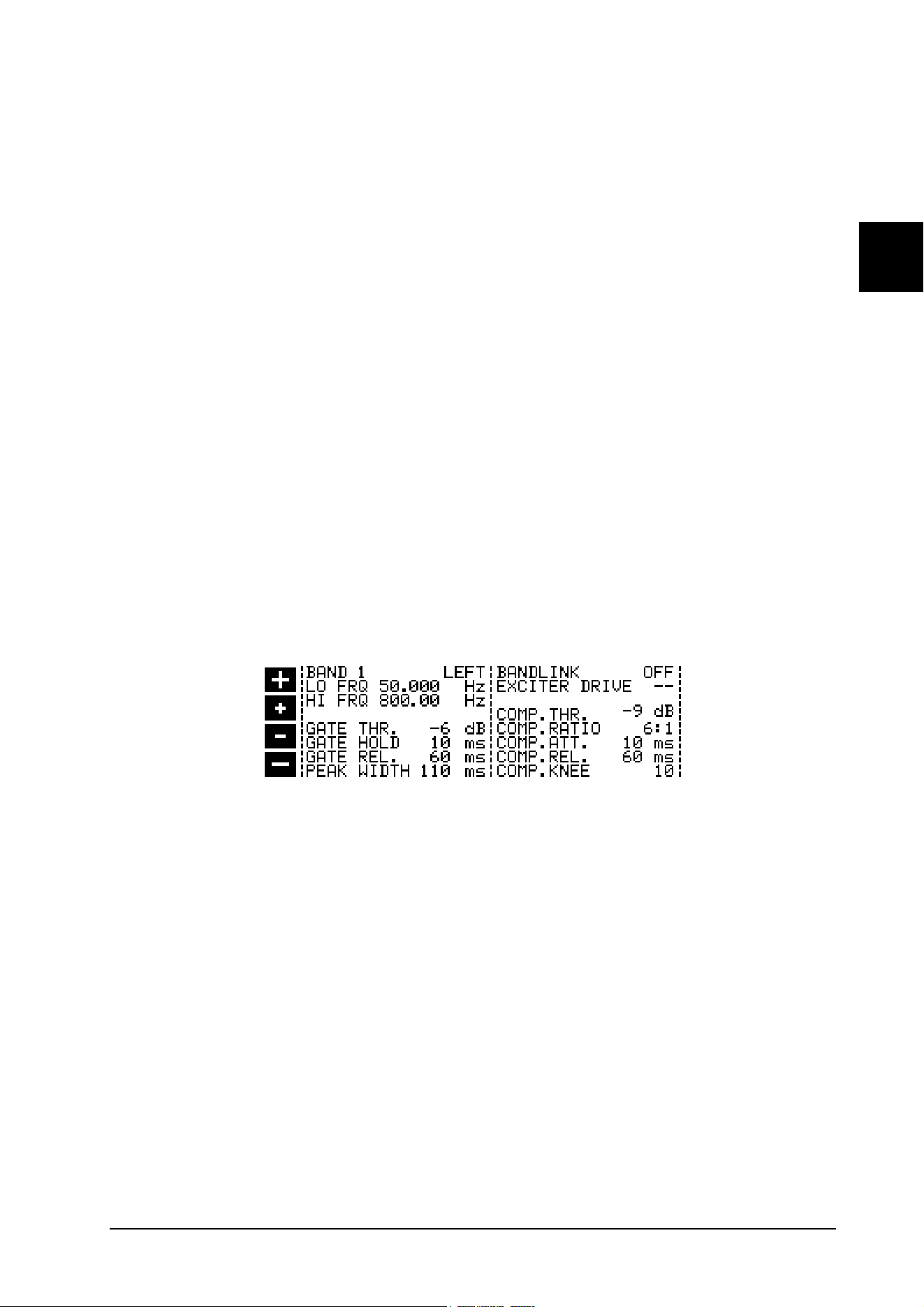
Fig. 2.13: <BAND> menu in setup level 1
The BAND X parameter for the selection of individual bands may be found in the top left corner of the band
menu. The LEFT/RIGHT toggle field for the channel is just to the right. This field is not activated in stereo
mode (setup level 2).
The ULTRA-DYNE PRO automatically goes to the SETUP window for the band last selected when switching
from PROCESS mode to SETUP. The cursor will also reappear at the last selected parameter.
LO FRQ
Sets the Lower limit Frequency for the band.
HI FRQ
This parameter determines the Upper limit Frequency for the band.
+ In the case of neighboring bands, the upper limit frequency of the lower band is always iden-
tical with the lower limit frequency of the next higher band. In other words, changing one
value automatically adjusts the related value as required.
2. OPERATION

20
GATE THRESHOLD
Determines the Threshold for the Noise Gate in this band, with a Threshold value between -96 dB and
-25 dB. OFF disables the Gate Threshold.
GATE HOLD
This parameter sets the waiting time before the noise Gate release process starts.
GATE RELEASE
The GATE RELEASE parameter determines the time which the noise Gate requires to return to 1:1.
+ The GATE HOLD and RELEASE times can be set from 20 to 720 ms in 20 ms increments.
PEAK WIDTH
This parameter determines the Width of peaks to be ignored by the Gate. The valid time range for this setting
is 0 to 150 ms. This can be used to specifically suppress clicks.
EXCITER DRIVE
This parameter determines the Exciter Effect control for the three upper bands (4 to 6). The intensity of the
Exciter can be set using the Exciter process parameter in the <TUBE> and <IN/OUT> menus. This parameter
can be adjusted from 0 to 100.
COMPRESSOR THRESHOLD
The Threshold for the Compressor can be set from -70 dB to 0 dB. OFF disables the Compressor Threshold.
COMPRESSOR RATIO
The Compression Ratio can be set from 1:1 (no compression) to INF:0 (INF = infinite). INF:1 corresponds to
the action of a limiter.
COMP. ATT.
The Compressor Attack time is the time in which the Compressor regulates the signal to the set Ratio after the
Threshold has been exceeded.
COMP. REL.
The Compressor Release time is the time in which the Compressor returns the signal to 1:1 after the level has
dropped below the Threshold.
KNEE
The Knee parameter determines whether the compression should become effective abruptly (hard), or gently
and gradually before reaching the actual Threshold value (soft). A total of 36 increments are also available for
this parameter. Factory default is value 18.
2.5 Setup level 2
Hold the SETUP key for about 2 seconds to enter setup level 2. This level contains all of the global unit settings
such as memory management and the configuration of the MIDI interface. At this level, the LED above the
SETUP key remains continuously lit. Use the SETUP key to switch between the <GLOBAL SETUP> and
<MIDI SETUP> menus.
+ The setup level 2 settings are saved globally and do not affect the program memory.
2.5.1 Global setup
Fig. 2.14: <GLOBAL SETUP> menu in setup level 2
2. OPERATION

21
E
INPUT
The input field is used to determine whether the input signal should be derived from the optional digital input,
or from the analog input. In addition, the sampling frequency is set here for analog operation. The available
frequencies are 32 kHz / 44.1 kHz and 48 kHz (the digital input automatically synchronizes to these frequen-
cies). When changing sample rates, the ULTRA-DYNE PRO will be muted briefly.
+ In purely analog mode the 48 kHz rate should be used. Apart from the fact that the high sample
rate gives the widest frequency response and correspondingly the best possible sound, the
fastest signal processing takes place at this rate.
If the ULTRA-DYNE PRO unexpectedly doesn't output a signal, this may be due to an incorrect input configu-
ration.
VIEWING ANGLE
Viewing Angle controls the contrast adjustment for the display in increments from 0 to 31.
MODE
The two channels of the ULTRA-DYNE PRO can be stereo-linked using this parameter. This automatically
copies all settings to the opposite channel. The channels are also linked in such a manner that both are edited
simultaneously. Both channels operate completely independently in 2CHANNEL mode.
DELAY
The ULTRA-DYNE PRO has an integrated memory for the delay and intermediate storage of the input signal.
This permits the optimal adaptation of the control processes, as the signal can already be analyzed before
processing. Delay times of 20 to 40 ms ensure optimal compression characteristics with your ULTRA-DYNE
PRO. The delay time may be set from 0 to 600 ms. Factory default is 10 ms.
+ This signal delay can easily cause unpleasant side effects in live applications, making it advis-
able to keep the delay time as short as possible.
SECURITY
The SECURITY function offers effective protection against unauthorized manipulation of the ULTRA-DYNE
PRO. UNLOCK means that all functions may be accessed, with the exception of programs that are secured
under PROTECT MEMORY. LOCK prevents any of the parameters on the device being accessed, the only
exceptions being the DISPLAY of the present setting, plus the input and output level with the LEVEL METER.
The only other way to access the parameters is via MIDI. To use the SECURITY function, enter a PASS-
WORD with the cursor keys and softkeys. The softkeys are used to select the letter or symbol to be used, and
have the following functions:
Softkey A confirms entry of the password and immediately activates the LOCK status. Softkeys B and C move
the cursor left and right within the PASSWORD. Softkey D erases any characters which may have already
been entered.
The LOCK status can be cleared by calling up SETUP menu again. The relevant PASSWORD field is
displayed immediately, and the PASSWORD may be re-entered. This returns the ULTRA-DYNE PRO to
UNLOCK status. If the device is locked without entering the PASSWORD, simply enter OK to UNLOCK.
+ Do not forget the password! If this happens, there is only one way to remove it: Open the
casing of the ULTRA-DYNE PRO and take the battery out for a short while. After replacing it
and switching the unit on, the original factory presets will be reloaded. We recommend that
this should only be performed by an experienced engineer to avoid inadvertent damage to the
unit. Warning! Doing this will cause you to lose all your programs, AND void the warranty!
PROTECT MEM
The PROTECT MEMORY parameter switches the write protection for the program memory on and off.
LOW and HIGH
The functions LOW and HIGH determine the area of program memory which will be protected by the PRO-
TECT MEMORY function. LOW determines the lowest, HIGH the highest program number of the protected
area. The PROTECT MEMORY function can be disabled with OFF (also see Security).
2. OPERATION
22
2.5.2 MIDI setup
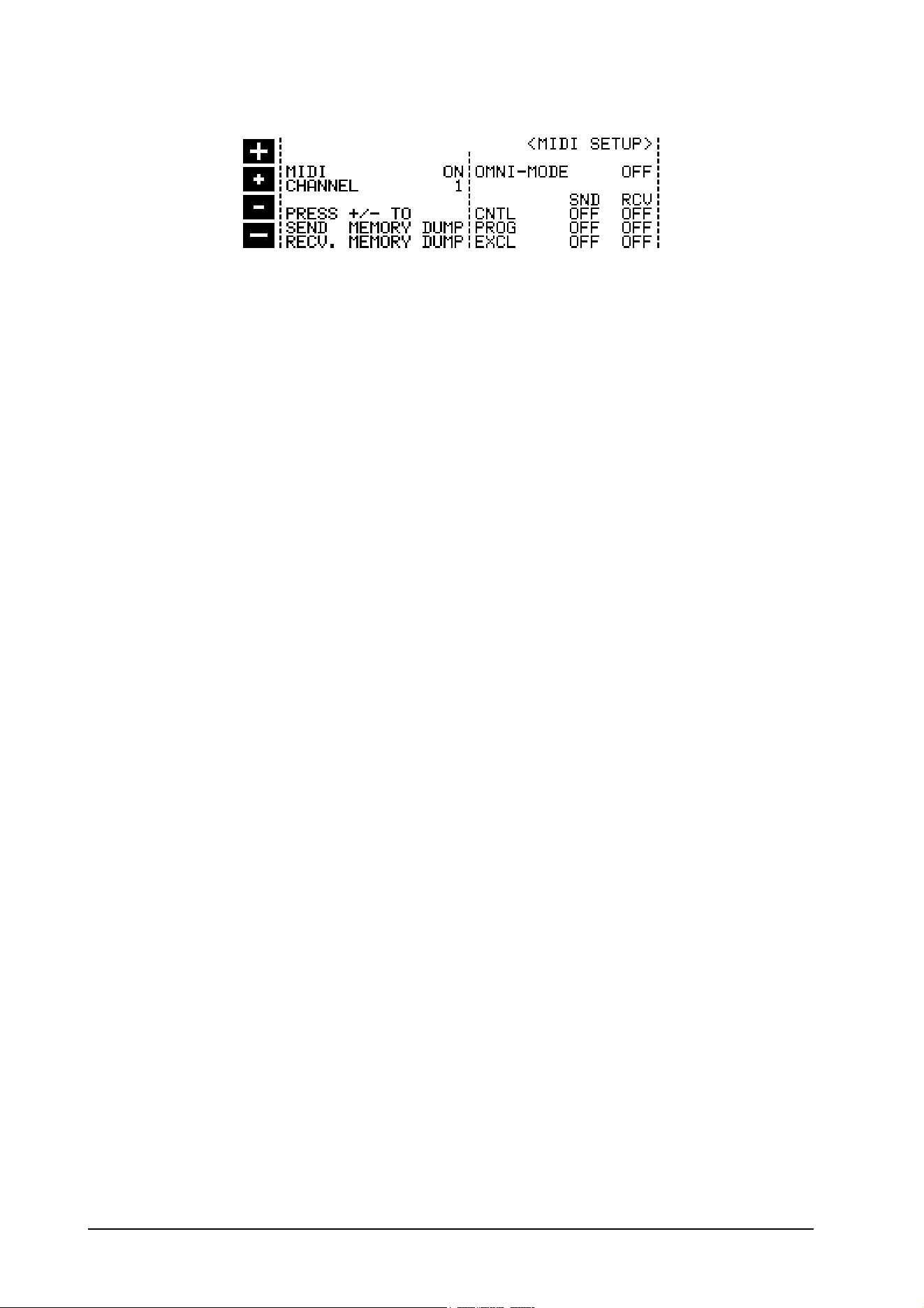
Fig. 2.16: <MIDI SETUP> menu in setup level 2
MIDI
ON = MIDI interface enabled, OFF = MIDI interface disabled.
CHANNEL
Sets the MIDI send and receive channels; the channels 1-16 may be selected.
SND MEMORY DUMP and RCV MEMORY DUMP
The complete contents of the ULTRA-DYNE PRO memory can be transferred via MIDI to another ULTRA-
DYNE PRO or a PC (SEND MEMORY DUMP). Conversely, the contents of the memory can also be received
via MIDI (RECEIVE MEMORY DUMP). The transmission or readiness to receive is activated in both cases by
simultaneously pressing one Plus and one Minus key each.
OMNI MODE
With the OMNI MODE enabled, the ULTRA-DYNE PRO can receive data on all MIDI channels. This may prove
useful to test the unit's response to incoming MIDI commands or in cases in which you are unsure of the MIDI
channel being used for the transmission.
CNTL, PROG and EXCL
These fields can be used to additionally enable the Sending (SND) and Receiving (RCV) of controller data
(CNTL), Program Change commands (PROG) and System Exclusive data (EXCL).
+ Caution: Receiving a memory dump will overwrite the existing programs!
3. APPLICATIONS
This section will cover a number of typical applications for the BEHRINGER ULTRA-DYNE PRO. Most prob-
lems related to dynamics can be solved using the following basic settings.
Please take the time to study the following sample applications in detail in order to ensure the optimum
deployment of the unit's broad range of features.
Primary applications and basic settings
Generally speaking, BEHRINGER ULTRA-DYNE PRO applications can be broken down into seven areas:
1. The GATE section removes noise and suppresses crosstalk in multi-channel operation.
2. The COMPRESSOR section increases the density of the program material and can be used to create
special effects and sounds frequently encountered in the recording and music fields.
3. The VIRTUOSO function ensures compression suited to your requirements and adapted to the character-
istics of the program material.
4. The ULTRAMIZER function automatically adjusts the input gain and Compressor parameters to suit your
program material.
5. The PEAK LIMITER section is designed to protect speaker systems, tape machines, transmission lines,
etc. from overload.
6. The TUBE simulation adds additional harmonics to the audio signal for a lively, warm character.
7. The EXCITER function is designed to enhance the audio quality after compression.
3. APPLICATIONS

23
E
3.1 Compression/Leveling/Limiting/Clipping
After describing the the individual sections in detail, we would now like to acquaint you with further important
concepts pertaining to the processing of dynamics:
Compression
A compressor reduces a broad dynamic range to a limited dynamic band. The resulting dynamic range
depends on the threshold, attack, release and ratio settings. As the desirable effects of a compressor include
the boosting of low-level signals, the threshold value is generally set low. Inaudible compression requires
fast attack and release times and low compression rates. Faster attack and release times and higher com-
pression rates increase the effect on short-term dynamics. This may be put to use to achieve audible,
creative sound effects, for example.
Leveling
The leveling function is used to keep the output level constant, i.e. to compensate for long-term changes in the
input level without restricting short-term dynamics. The threshold is generally set low to ensure that low-level
signals will be boosted. The leveling function uses slow attack and release times in conjunction with a high
ratio. Due to its very long attack times, leveling does not affect signal peaks or short-term changes of the
average level.
Limiting
The limiting function uses short attack times, a high compression ratio and a release time which depends on
the given application and the desired audio effect. The threshold must be set high, as a limiter is only used to
set a ceiling for high signal levels. The degree of dynamic range reduction depends on the ratio setting and
the extent to which the threshold is exceeded. A so-called program limiter uses attack times greater than 20
ms and is designed to control the average level. Short-term signal peaks exceeding the set threshold value can
also pass the limiter in this case. Peak limiters use attack times set to less than 5 ms to control signal peaks
as well.
Clipping
Unlike the two previous limiter types, the clipping function is characterized by the use of instantaneous attack
and release, as well as infinite compression rates to ensure absolute limiting for all signals above the set
threshold (brickwall limiting). Clipping has the effect of a radical cutoff of signal peaks exceeding the
threshold without restricting the amplitude of the actual signal form. Under normal circumstances, the clipping
function is inaudible and may even result in improved audio quality under certain circumstances by cutting off
artificial harmonics. Clipping causes conspicuous, harsh distortion, which at its most extreme can result in
rectangular waveforms.
3.2 The Gate section
The main task of a Gate is to separate undesirable background noise from the program signal and "remove" it
inaudibly. As described in Chapter 4.1.4, a so-called Downward Expander automatically reduces the overall
level for all signals below a user-definable threshold and thus increases the dynamic range of the program
material. The Expander can thus be regarded as the opposite of a compressor/limiter. Expanders generally
work with a relatively flat ratio characteristic to ensure that the signal is continuously suppressed. On the other
hand, noise gates can be regarded as high-ratio expanders, which radically cut signals off that drop below the
threshold.
The BEHRINGER ULTRA-DYNE PRO is equipped with six Noise Gates with intelligent look-ahead functions.
The Threshold parameters can be set up individually for each band using faders in the EDIT menu of the
PROCESS mode. Additional parameters such as the Hold and Release times and look-ahead can be found on
setup level 2 in the band menus. The following definitions describe the parameters in greater detail:
Gate Threshold:
This is the value after which the audio signal no longer passes through the Gate.
Gate Hold Time:
The Gate Hold time is the duration of the wait after the Threshold has been passed before the release time
3. APPLICATIONS

24
begins.
Gate Release Time:
The Gate release time is the time in which the Gate returns the signal to 1:1 after the hold time has elapsed.
Peak Width:
Use the Peak Width parameter to set the maximum signal impulse width to be ignored by the Gate.
+ The Peak Width parameter is dependent upon the delay parameter in the <GLOBAL SETUP>
menu. The Peak Width Gate parameter will have no effect if the delay has been set to 0 ms. In
addition, the delay time set in the <GLOBAL SETUP> menu should be twice as long as the
desired Peak Width time of the Gate.
Using the Peak Width parameter permits the ULTRA-DYNE PRO to identify and ignore brief signal peaks on
the basis of their duration. For this reason, select a suitable setting for this parameter corresponding to the
maximum duration of the signal peaks to be ignored. The peak width parameter also ensures that an open
gate does not close for signals shorter than the set duration.
3.2.1 Suppression of crosstalk in multi-channel operation
One of the most common applications for an expander/gate is the suppression of undesirable crosstalk
between individual channels during recording and playback. This application is used very frequently when
recording acoustic percussion instruments due to the close proximity of the microphones to one another. The
high sound pressure levels of the individual instruments causes crosstalk in all of the neighboring micro-
phones, leading not only to frequency cancellations but also to a lack of definition in the sound (comb filter
effect). The optimal solution is thus to use a separate microphone for each instrument, with individual gating for
each microphone.
Insert the BEHRINGER ULTRA-DYNE PRO in the recording channel in of the snare, for example, and set the
unit to respond to signals from the snare only. Each microphone should be carefully positioned and checked
beforehand, and the Threshold value set to ensure a clean acoustic separation of the drum sound, as if the
instrument were being played alone.
Correct miking technique is decisive for the optimal function of the Expander/Gate. Be especially careful when
instruments with pronounced high frequencies are being played next to or behind a cardioid microphone.
The directional characteristic of most microphones is considerably less effective at high frequencies. A
difference of only 2 to 3 dB in the response sensitivity between the main and lateral axes in the 5 to 10 kHz
range can result in severe cymbal crosstalk in the tom microphones, or masking of the snare by the hi-hat.
Take maximum advantage of the directional characteristics of the respective microphones to ensure the best
possible acoustic isolation of the instruments.
Be sure to do everything possible to isolate the individual sources with proper miking technique alone.
Otherwise, the Expander/Gate will not be able to provide a clear acoustic separation.
3.2.2 Basic settings of the Gate section
Parameter Setting
Threshold -90 dB
Hold Time 20 ms
Release Time 20 ms
Peak Width 0 ms
Tab. 3.1 Basic settings of the Gate section
Begin with very low Threshold values so that the entire signal can pass unhindered. Next, move the fader
upwards until all background noise has been removed and only the desired instrument is still audible.
The hold time can be adjusted to optimize the unit for the program material. It may contain many, frequently
short, pauses which can result in the Gate being activated repeatedly in short succession. The Hold function
prevents the disturbing "flutter" common to conventional gates by delaying the release process. This ensures
3. APPLICATIONS

25
E
that the Gate remains open during short pauses. The Gate closes the audio channel in the preset release time
after the hold time has elapsed.
The release time may also be used to adapt the Gate perfectly to the program material. As a rule, percussive
audio material with little or no reverb is processed with quick release times, whereas longer release times are
used for signals with a slow decay or heavy reverb. You will note that short release times are suitable for most
percussion instruments, while longer times are generally required for toms and cymbals.
Due to its digital design, the ULTRA-DYNE PRO Gate features a look-ahead function. The ULTRA-DYNE PRO
can analyze the audio signal and thus work without losses. As a result, the Gate always opens at the correct
time without cutting off signal flanks.
If you do not want the Gate to remain open during brief signal peaks, set the impulse width of the signals to be
ignored with the peak width parameter. Increase the value until the Gate only opens for the program material.
Drums will sound dry, snappy and well-defined when the parameters are correctly set. If you do not have
enough individual microphones (or ULTRA-DYNE PRO!) at your disposal, try to arrange several microphones
into subgroups.
The objective is to position the group microphones and set the Gate section in such a manner that a signal
from a given instrument opens only one microphone, while the other microphones remain muted.
3.2.3 Reduction of crosstalk from stage microphones
The ULTRA-DYNE PRO has a wide range of applications in live or stage operation and multiple microphone
deployment: The moderate, careful application of the Gate can effectively suppress background noise, com-
pressor-related background noise accentuation, microphone crosstalk, etc. without undesirable side effects.
The processing of vocal tracks is a typical application for the Gate. The distance of a vocalist to the microphone
becomes increasingly critical when using a compressor. Increasing amounts of background noise are trans-
mitted the further the vocalist moves away from the microphone. Use the Gate function with long release times
to "inaudibly" eliminate unwanted background noise during pauses. In live applications, drum crosstalk in
piano tracks can be suppressed for example, or recordings cleaned of acoustic "contamination".
3.2.4 Reduction of feedback from stage microphones
A vocalist singing into a stage microphone masks background noises, which are then no longer apparent. In
pauses, however, the microphone picks up noise from the PA and monitor speakers, which can cause
unpleasant feedback.
This susceptibility to feedback can be reduced considerably if the ULTRA-DYNE PRO is inserted into the
vocal channel and set to mute the microphone when it is not in use. In principle, all stage microphones should
be included in this application.
3.2.5 Noise reduction in effects chains
One of the most frequently overlooked sources of noise in a sound system is the effect rack. The prices of
reverb and multi-effect devices have dropped drastically in recent years, making them standard equipment
even in small studios and home recording environments. The noise level increases drastically with the number
of devices, however, quickly spoiling the pleasure to be had from the new effects.
This can be countered by inserting the ULTRA-DYNE PRO as the last unit in the effect chain and using the
noise-reducing function of the Gate section. Set the unit for a long release time to ensure a natural reverb.
3.2.6 Creative application of the Gate section
In addition to the applications described above, the Gate can also be used for the creative modification of audio
characteristics. For example, the quality of environmental reverberation or the spatial impression of instruments
can be modified. During its decay time, the reverberation of an instrument will drop below a user-defined
threshold. The duration of the reverberation can be controlled using the preset threshold and release time. The
adjustment of the release time permits the reproduction of the decay characteristic of the instrument in a
manner that preserves the instrument's character. Take the time to experiment with modification of the decay
of a signal. Long release times result in a slow fade, while short release times can completely remove the
reverberation of the instrument.
3. APPLICATIONS
26
3.3 The Compressor section
The purpose of the Compressor is to reduce the dynamic range of the program material and monitor the levels.
The extensive selection of controls in the Compressor section permit a wide variety of dynamic effects, from
gentle, musical compression, to the limiting of signal peaks, to an extreme, effective compression of the entire
dynamic range.
A low ratio and very low Threshold setting can be used, for example, to provide a soft, musical compression of
the overall dynamic range of the program material. Relatively high ratios in conjunction with a low Threshold
setting will result in a relatively constant volume (leveling) for instruments and vocals. High Threshold values are
generally used to limit the overall level of the program material. Ratios greater than 6:1 effectively prevent the
output levels from significantly exceeding the Threshold value, provided that the Outgain parameter has been
set to 0 dB).
Please note that compression of the entire program material due to low Threshold settings tends to sound
unnatural at higher ratios. Ratios in the range of 3:1 or less have less effect on the dynamic range and are
often used to compress the signals of a bass guitars, snares or vocals. Careful, moderate settings are
generally used for mixes and level control in the broadcasting field.
The ULTRA-DYNE PRO is equipped with six Compressors with intelligent look-ahead functions. The Thresh-
old, Ratio, Attack and Release times can be configured in the <PROCESS> and <EDIT> menus. In addition,
a knee configuration function with 36 increments can be found in the band setup menu. The look-ahead for the
six Compressors can be set using the delay parameter in the <GLOBAL SETUP> menu. The following defini-
tions describe the Compressor parameters in greater detail:
Compressor threshold:
The Compressor Threshold is the Threshold value at which the attack time starts to regulate the Compressor
to the set Ratio.
Compressor Ratio:
The Compressor Ratio is the Ratio of the input gain to the output gain.
Compressor attack time:
The Compressor Attack time is the time in which the Compressor regulates the signal to the set Ratio after the
threshold has been exceeded.
Compressor release time:
The Compressor release time is the time in which the Compressor returns the signal to 1:1 after the level has
dropped below the Threshold.
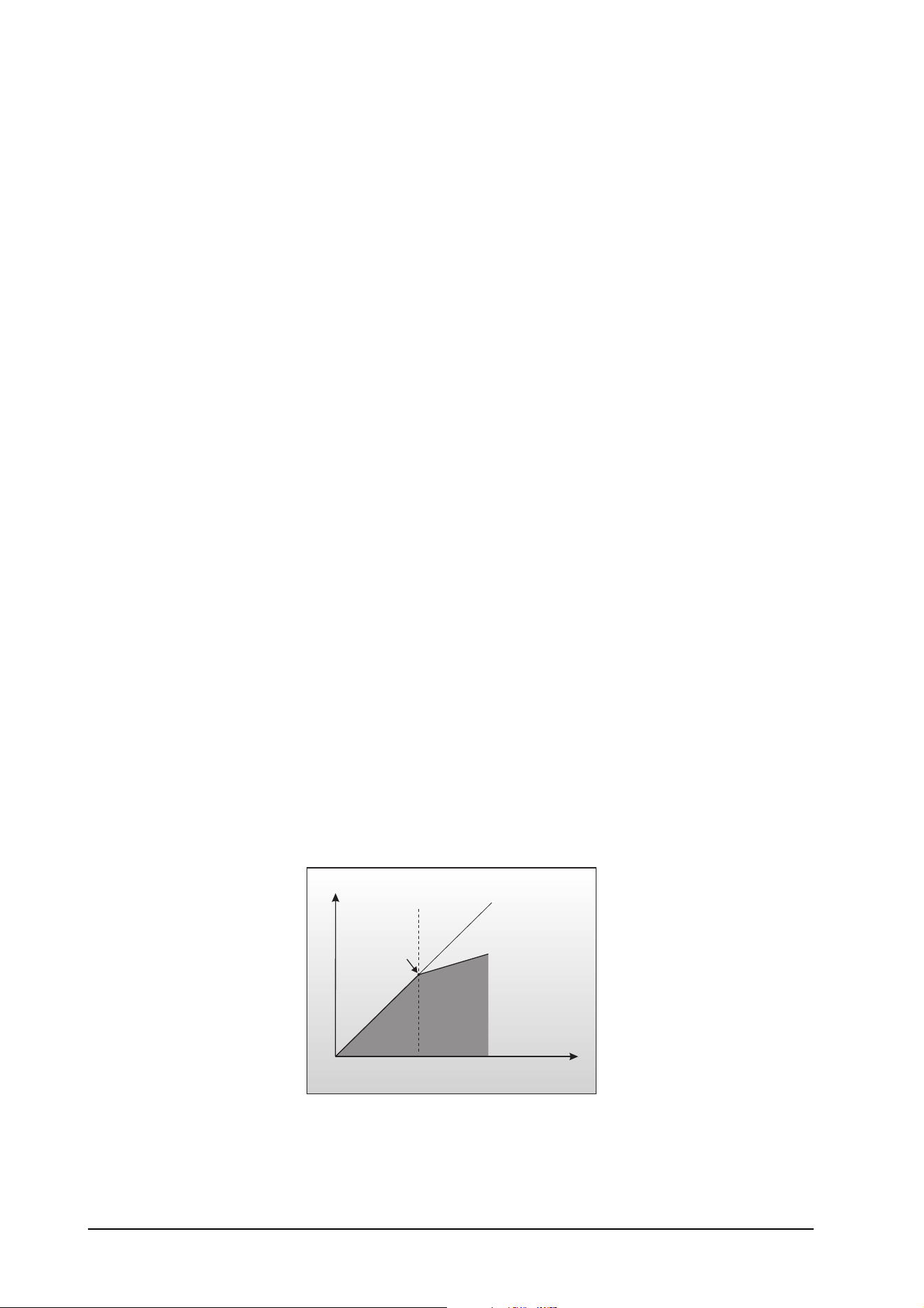
Compressor knee:
This parameter determines the Compressor characteristic at the Threshold.
"Hard knee" is an abrupt transition to preset gain. The use of a hard knee in conjunction with powerful compres-
sion at high ratios can sound conspicuously unnatural.
Threshold
Gain 0 dB
Input
Output
Hard Knee
Ratio
Fig. 3.1: Hard-knee compressor characteristic
3. APPLICATIONS
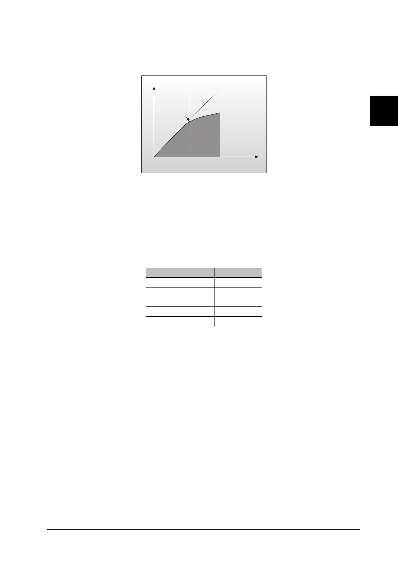
27
E
Therefore, always use a soft-knee compressor characteristic when working with high ratios. This results in a
gradual transition to the preset gain. The ULTRA-DYNE PRO permits the adjustment of the Compressor knee
in 36 increments.
Threshold
Gain 0 dB
Input
Output
Soft Knee
Ratio
Fig. 3.2: Soft-knee compressor characteristic
The delay parameter in the <GLOBAL SETUP> menu determines the time for the delay and intermediate
storage of the input signal. This delay permits the ULTRA-DYNE PRO to recognize changes in the dynamics
of the audio signal in time to optimize the control functions to the signal. Delay times of 20 to 40 ms ensure
effective compression characteristics and a consistent level.
3.3.1 Basic settings of the Compressor section
Parameter Setting
Threshold +0 dB
Ratio 1:3
Attack Time variable
Release Time variable
Knee variable
Tab. 3.2: Basic settings of the Compressor section
Move the Threshold fader downwards until the Gain Reduction meter in the METER mode indicates a clear
reduction of the level. This will be accompanied with an audible volume reduction. Next, raise the Outgain fader
until the loss of volume has been compensated. The levels of the compressed and uncompressed signals can
be compared using the input/output Level Meter in Meter mode.
Fine-tune the settings according to your requirements using the Ratio, Attack and Release controls. You can
also adjust the compression knee characteristics in the Band Setup menu.
3.3.2 The ULTRA-DYNE PRO as an effect device
In the early 1960s, musicians began exploring new sounds. One idea was to use the otherwise undesirable
"pumping" effect of cheap compressors to create new sound effects. These effects are the cornerstone for
sounds which are still a staple in today's music. The primary intention was the conspicuous, audible applica-
tion of the control processes; dynamic control was only a secondary consideration.
The BEHRINGER ULTRA-DYNE PRO is also suitable for this application due to its great flexibility. Sound
effects of this type can be realized using extreme settings. Use a low Threshold, set the Ratio close to its
maximum value and use the Attack and Release controls to achieve the desired effect.
Be sure to experiment with all of the controls to get a feel for their functions!
3. APPLICATIONS

28
3.3.3 The "dull" sound of compressors
Compressors are often blamed for muffling the sound when the dynamic range control begins to take effect.
We would like to explore this issue in greater detail. Bass frequencies generally contain the greatest share of
physical energy in a piece of music and are thus responsible for causing the compressor to reduce the
overall dynamic range. The levels of the high frequency material are also reduced accordingly. This is
explains why cymbals and the hi-hat are swallowed acoustically by powerful snare or bass drum pulses in
highly compressed drum recordings. Echo and environmental reverb signal shares are also severely af-
fected.
The usual solution for this fundamental problem is generally to either reduce the compression rate or to
lengthen the attack time to the point that high frequencies pass through the compressor unhindered before
the compression becomes fully effective.
The ULTRA-DYNE PRO offers a far more elegant solution to the problem. Splitting the frequency spectrum
into six completely user-definable bands ensures that the bass band does not affect the degree of compres-
sion of the other bands. This permits an increase in the density and loudness of the music without the
disadvantages described above.
What's more, the integrated Exciter and Tube Simulation functions of the ULTRA-DYNE PRO are outstanding
ways to add polish to the processed signal.
3.4 The VIRTUOSO function
With its multiband principle, the ULTRA-DYNE PRO offers a wealth of parameters which can have a great
effect on the function of the six Compressors. The compression always sets in at the correct moment due to
its ability to analyze the program material in advance. However, other parameters are also decisive as to
whether the compression is pleasant and effective or conspicuous. The Ratio parameter in the Compressor
section can be used to set the gain Ratio of the input to the output signal. This permits you to follow your own
objectives with the degree of signal attenuation. Establishing the Threshold parameters for all six bands is
considerably more difficult and is strongly dependent upon the program material.
With its VIRTUOSO function, the ULTRA-DYNE PRO lets you analyze the program material over a period of
time and set the Threshold parameters for all six bands automatically. Simply let the VIRTUOSO function
analyze the passage of program material which is decisive for the Compressor in order to determine the
Thresholds. Monitoring a short section with VIRTUOSO is sufficient if the material does not contain any
pronounced differences in its dynamic range. The selection of the passage and the duration of the analysis is
entirely up to you.
You can select from four different gain reduction levels when activating the VIRTUOSO function. These four
choices provide an adequate selection for most types of music:
LIGHT
The LIGHT option provides a very gentle and subtle compression. This setting is recommended for program
material which has already been highly compressed. It can, however, also be used for classical music with a
wide dynamic range if only a slight, virtually inaudible reduction of the range is required.
MEDIUM
The MEDIUM setting adapts the Thresholds so as to compensate major differences in the dynamics of the
program material, without causing the material to seem truly dense.
TIGHT
TIGHT provides strong compression with a substantial reduction of the natural dynamic range of the program
material. Use this setting to consciously increase the density and loudness of the material.
ULTRA
The ULTRA setting involves extremely high compression of the program material and permits the application
of maximum compression levels. The result is an extremely dense output signal, but without dullness or loss of
transparency.
Be sure to experiment with the VIRTUOSO function to gain experience of your own, so that you can quickly
and effectively determine the degree of compression required for your music in the future.
3. APPLICATIONS
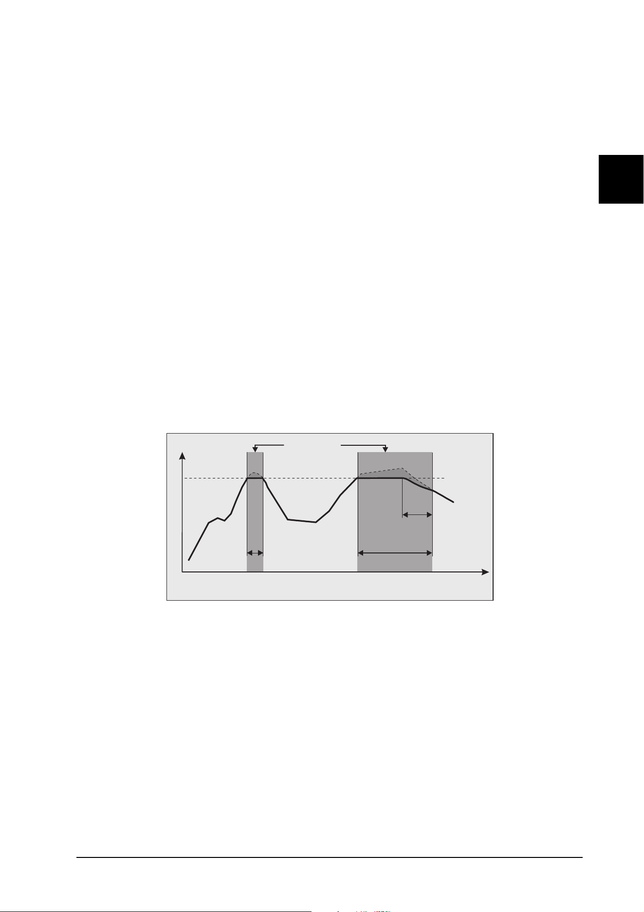
29
E
3.5 The ULTRAMIZER function
Like the VIRTUOSO, the ULTRAMIZER function is an aid in determining the correct parameter settings. It has
two different operating modes which function in dependence on the Peak Limiter.
ULTRAMIZER PROCESS
If the Peak Limiter is disabled, the ULTRAMIZER continuously monitors the audio material and increases the
input gain until the Threshold of one of the six bands is exceeded and a gain reduction corresponding to the
ULTRAMIZER Process parameter has been achieved. The Thresholds of the other bands are then adjusted to
provide approximately the same level attenuation in all bands. To use this function effectively, enable the band
link function and set the Threshold parameter for all six bands to the same value. Next, set the intensity of the
ULTRAMIZER with the ULTRAMIZER Process parameter.
If the Peak Limiter is enabled, the ULTRAMIZER will additionally attempt to raise the output gain to the point
that the Peak Limiter also realizes an effective level attenuation corresponding to the ULTRAMIZER Process
parameter.
ULTRAMIZER RANGE
The ULTRAMIZER Range parameter determines the range in dB over which the ULTRAMIZER should be
active. This permits fade-outs and brief program pauses to be excluded from the ULTRAMIZER's loudness
optimization.
3.6 Peak Limiter section
The Peak Limiter provides the option of limiting the maximum level of the ULTRA-DYNE PRO's output indepen-
dently of all other control functions. It was designed for use in conjunction with the Compressor section.
Downstream equipment can thus be protected from signal peaks, short-term overloads and overmodulation
(transmitters, etc.) regardless of their function.
Peak Limiting
Threshold
t(ms)
Level
Extrem short
Release Time
Long
Release Time
Release Time
Fig. 3.3: The Peak Limiter function
This diagram shows the characteristic of the Peak Limiter. The bold line represents the output signal, while the
input signal is shown by the dashed line above it. The areas between the curves represent the degree of
signal attenuation. With extremely short release times, the Peak Limiter responds like a clipper and restricts
the gain to the Threshold. Select a longer release time for a more natural and homogeneous limiting character-
istic.
The available ULTRA-DYNE PRO Peak Limiter parameters are the Threshold, to be found in the <PROCESS>
menu, and the release time in the <IN/OUT> menu of setup level 2. The following definitions describe the
parameters in greater detail:
Peak Limiter Threshold:
This is the value at which the Peak Limiter begins to attenuate the signal.
3. APPLICATIONS

30
Peak Limiter Release Time:
When the signal falls below the Limiter Threshold, the gain reduction is returned to zero. The release time
determines the speed at which the signal is returned to its original level.
3.6.1 Basic settings of the Peak Limiter section
Parameter Setting
Threshold 0 dB
Release Time 200 ms
Tab. 3.3: Basic settings of the Peak Limiter section
Use the Threshold parameter of the Peak Limiter to set a level that will protect downstream devices from
overload. If the LIM warning on the advanced level meter lights up frequently or continuously, reduce the
Threshold slowly toward the 0 dB position.
Because fast level changes are more noticeable than slow changes, long release times are used where
unobtrusive signal processing is required. In some situations such as live operation in which the ULTRA-
DYNE PRO is used for the final processing of the main mixer output signal, the principal goal is to protect
devices such as speakers and power amplifiers from short-term overloads. In those cases a short release time
is more appropriate to ensure that the Limiter only intervenes when it is needed and the level returns to normal
as soon as possible. Long release times are better suited when the Limiter should remain inaudible, for
instance in broadcasting, quiet club environments or when a signal is transferred to tape.
3.7 Tube simulation
The BEHRINGER ULTRA-DYNE PRO features a newly-developed Tube Emulation which generates harmonics
for additional warmth and punch in your material. This Simulation is intended more as a subtle sound enhance-
ment and not primarily as an effects processor. Four different tube types commonly used in preamplifier and
power amplifier circuits are available. The intensity of the effect can be controlled with the TUBE Process
parameter.
3.7.1 Application
The ULTRA-DYNE PRO Tube Simulation is a subtle audio processing option to add polish to your compressed
and limited signal. Increasing the Tube Process parameter gives the signal a lively, warm character.
In many cases, highly compressed audio signals suffer a loss of presence and sparkle. The Tube Emulation of
the ULTRA-DYNE PRO counteracts this effect and adds life to the material. It can add punch to percussion
instruments, for example. The clarity of instrument sounds which are rich in harmonics by nature can also be
enhanced. Overall, the input material gains fullness and brilliance. A better separation in the low-frequency
range contributes to the clear acoustic location of individual instruments. Thanks to the Tube Simulation,
vocals gain in presence and volume without becoming obtrusive, facilitating their integration in the mix. The
natural quality of synthetic sounds is enhanced; especially guitar sounds from MIDI expanders gain in realism
when processed by the ULTRA-DYNE PRO. This contributes actively to the quality and subtlety of the mix.
The design of the Tube Simulation is strongly oriented toward musical applications.
3. APPLICATIONS

31
E
3.8 The Exciter function
An additional special feature of the ULTRA-DYNE PRO is its integrated Exciter function. This permits the
addition of supplementary harmonics to your program material. The intensity of the effect can be set with the
Exciter Process parameter in the <TUBE> and <IN/OUT> menus. The Ratio of odd to even harmonics can be
set with the Odd/Even parameter.
The ExciterDrive parameter can be found in the band menus of the upper three bands. Use this parameter to
determine the share of each of the three upper bands to be processed by the Exciter. The result is a multiband
Exciter tailored precisely to your tastes, offering the most perfect audio enhancement possible.
3.8.1 Audio enhancement during the copying process
Even under the most favorable conditions, program material loses some of its presence, life and clarity with
each copy operation. These losses are especially conspicuous when copying cassettes with the noise reduc-
tion enabled.
The use of the ULTRA-DYNE PRO Exciter can help minimize or compensate for these copying losses. When
copying a high-quality, low-noise source, it's even possible to produce copies that sound better than the
original with careful application of the ULTRA-DYNE PRO.
3.8.2 Audio enhancement of instruments
The bandwidth of most electronic instruments is limited by their sampling rate. The ULTRA-DYNE PRO can
help synthesizers, samplers and drum machines sound more natural and transparent.
It can also be used to highlight subtleties in the sounds of acoustic instruments such as guitars without altering
the character of the instrument. The punch of percussion instruments such as toms, bass drums, etc. can be
enhanced for more power and impact.
3.8.3 Audio enhancement of PA systems
The ULTRA-DYNE PRO provides astonishing advantages for PAs and permanently installed systems for
background music:
1. For PA and background music applications, insert the ULTRA-DYNE PRO into the signal chain as you
would during recording and transmission work, directly upstream of your power amplifier. The Exciter en-
hances the intelligibility and range of your system, as well as giving the sound a pleasantly open and
transparent quality at low volumes. Problems related to fluctuating noise levels, the acoustic environment
(reflections) and speaker setup are reduced. For example, the high frequencies do not require adjustment
in discotheques or clubs as the room becomes fuller. This is not only beneficial for the ears of the
customers, but for the speaker system as well. In the case of bars and restaurants, background music
remains clearly audible without seeming loud or obtrusive.
2. The sound of any PA system can be enhanced with the ULTRA-DYNE PRO's Exciter. For example, vocals
and announcements become much more transparent and intelligible, and the separation of the instru-
ments is clearly enhanced. The bass also gains additional solidity.
The ULTRA-DYNE PRO Exciter increases the acoustic presence of your system, especially under adverse
conditions.
As the subjective loudness is increased, it's also possible to get satisfactory results with less amplifier power.
It's thus possible to achieve powerful, room-filling sound, even with a "weak" system, without major invest-
ments.
3. APPLICATIONS

32
3.9 The ULTRA-DYNE PRO in the recording and copying fields
A major objective in the recording and copying sectors should always be to ensure the optimum utilization of
the dynamic range of the recording medium. The failure to observe this can result in side effects such as
excessive noise and distortion. Full attention must be paid during multitrack recording, final mixing and while
copying to ensure that the available dynamic range of the tape machine, DAT recorder, etc. is fully exploited.
In principle, it's possible to continuously adjust the recording levels using the faders, i.e. boosting or cutting
the levels manually as required. However, it's obvious that this method is inadequate, as the signal levels often
cannot be anticipated, particularly during live recordings. Especially in the case of multitrack recordings
being "run" under hectic circumstances, the signal levels of the relevant channels simply can't all be moni-
tored and adjusted at the same time. Manual control is simply not fast enough to achieve satisfactory record-
ing results.
An automatic control system can provide better and more consistent results. For these reasons, deploy the
ULTRA-DYNE PRO starting with the known basic settings and take advantage of its dynamic control functions
to "run" analog and digital recordings at the limits of their dynamic ranges without noise or distortion.
3.9.1 The ULTRA-DYNE PRO for digital recording and sampling
Too low a signal level leads to increased noise in analog recordings; overloading a tape machine can result in
a compressed or "constricted" sound, or in the worst case, distortion due to tape saturation. The same errors
in digital recording lead to extremely obvious effects. Inadequate levels result in a loss of resolution in digital
media as the signal level drops. The recording sounds rough and lacks atmosphere. Overloads, on the other
hand, give the recording a hard sound with harsh distortion. This can be prevented by placing the Peak Limiter
of the ULTRA-DYNE PRO before the sampler. It's thus a trouble-free way of ensuring optimal levels for digital
recording or sampling. The Tube Emulation and Exciter sections of the ULTRA-DYNE PRO can also be used
to add life to the cold, sterile character of multitrack digital recording systems by adding additional harmonics.
3.9.2 Mastering with the ULTRA-DYNE PRO
Mastering is one of the most critical steps of the recording process. The goal of this production stage is to
create a copy of the recording with a minimum of noise and distortion and at optimum levels. In many
applications, a high average loudness of the program material is also required. Among commercial audio
media, recordings intended for LPs and cassettes especially require attention to this end. In many cases, the
dynamic range of the program material suffers considerably due to the excessive use of compressors and
limiters. The combined application of the Compressor and Peak Limiter sections of the ULTRA-DYNE PRO
permit a drastic increase of the average loudness without audible restrictions of the dynamic range. Proceed
as follows:
1. Reduce the dynamic range of the source material by a maximum of 6 dB using the Peak Limiter section.
This application limits only the transients without affecting the actual audio material, permitting a better
utilization of the available dynamic range. The overall level can now be raised by 6 dB, leading to a greater
loudness. The Limiter should not be set to more than 6 dB to avoid audible side effects.
2. Apply compression for this reason as well. We recommend restricting the compression to the "top" 6 dB of
the dynamic range.
The effect is especially obvious with DAT recorders with level displays that have a response time of less than
1 ms. Set the DAT recorder to 0 dB and reduce the Threshold of the Peak Limiter until the LIM LED starts
flashing. The "cut off" signal peaks lead to a reduction of the recording level by approx. 6 dB, as can be seen
by the level meter of the DAT recorder. Now raise the recording level of the recorder back to 0 dB. The result
is a noticeable gain in loudness without audible impairment of the audio quality.
3. APPLICATIONS
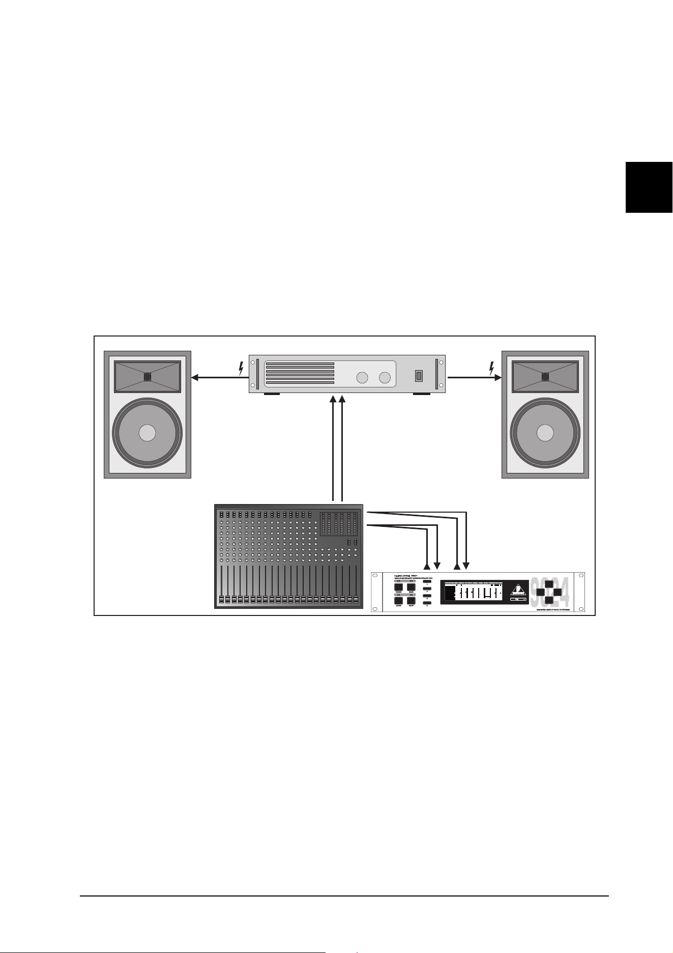
33
E
3.10 The ULTRA-DYNE PRO as a protective device for sound systems
Distortion is generally the result of overdriven amplifiers and speakers, resulting in hard clipping of the signal.
This limitation of the signal results in unpleasant distortion which is also dangerous for the speakers.
In the course of a normal, constant signal, the displacement of the speaker cone takes place with controlled
and generally low relative acceleration. The clipped signal, however, results in the acceleration and abrupt
reversal of the speaker cone, followed by another hard acceleration. As the laws of physics also apply to
speakers, this sort of treatment is not exactly beneficial to their service life.
In addition to long-term overload, speakers can also be damaged by brief but powerful impulses, such as
those resulting from a dropped microphone. Even if the speaker is not destroyed immediately, it can suffer
damage from severe mechanical stresses, the effects of which may not be apparent immediately. The
BEHRINGER ULTRA-DYNE PRO can provide valuable services for the protection of your system. "Brick wall"
limiting is generally not required for PA systems, as the amplifiers and speakers tend to be tolerant of brief
signal peaks. Nevertheless, conventional limiters generally must be set to well below the distortion Threshold
of an amplifier in order to limit the level and duration of distortion transients. As a result, the performance
reserves of the system cannot be fully exploited.
Power Amp
Output L
Power Amp
Output R
Power Amp
Input L & R
ULTRA-DYNE PRO
Inputs & Outputs L & R
Mixer Main
Inserts
Mixer Main
Outputs L & R
Fig. 3.4: Deployment of the ULTRA-DYNE PRO in a sound system
The use of the Peak Limiter of the ULTRA-DYNE PRO to achieve an increase of 3 dB in the overall level
effectively corresponds to a doubling of amplifier power. The ULTRA-DYNE PRO thus puts you in a position
to deliver the distortion-free performance of a 10,000 watt system with only 5,000 watts at your disposal! The
following notes outline the insertion of the ULTRA-DYNE PRO in the signal chain.
3.10.1Protecting a system with passive crossovers
If your speakers use passive crossovers (integrated in the speaker cabinets), insert the BEHRINGER
ULTRA-DYNEPRO directly before the power amplifiers. This effectively prevents a technical K.O. of the midrange
and tweeter branches by powerful basses! While this may appear to be a paradox at first, low frequencies with
high amplitudes mainly tend to overload the amplifier power supplies. The resulting clipping of the signal peaks
produces powerful distortion (harmonics) which are suddenly added to the midrange and treble signals. For
this reason its important to limit the input dynamic range, especially when using weak power amplifiers. To
achieve the highest possible S/N ratio, its particularly advantageous to use the device in the main insert of the
mixing desk.
3. APPLICATIONS

34
3.10.2 Protecting a system with active crossovers
The BEHRINGER ULTRA-DYNEPRO can be deployed in two ways in systems with electronic crossovers.
Either use it in the main insert as described in 3.10.1, or before the power amplifier. With this arrangement, the
BEHRINGER ULTRA-DYNE PRO covers the entire frequency range.
Alternatively, insert the BEHRINGER ULTRA-DYNE PRO between the output of the crossover and the input of
the power amplifier to process a specific frequency band. This form of deployment is particularly useful to
protect the most sensitive components of a multiway speaker system from destructive signal levels. If, for
example, the tweeters of the system are damaged regularly, it would be necessary to either run the entire
system at a lower sound pressure level or replace the tweeters with different models. Using the ULTRA-DYNE
PRO in the relevant high-frequency band prevents the overload and thus the destruction of the speakers.
3.10.3 Audio enhancement of processor-controlled PA system
A processor-controlled PA is a system with a special active crossover system. The outputs of the crossover
are connected to the speakers via separate power amplifiers. Each band of the crossover has its own limiter
as a protection against excessive signal peaks. This prevents the overload of the power amplifiers and/or
destruction of the speakers.
The limit frequencies of the crossover change with the level to reproduce a "natural" frequency response. In
some case, however, this function tends to cause more of a deterioration than an improvement of the audio
quality. If the ULTRA-DYNE PRO is installed upstream of the processor, signal peaks can be limited in
advance before reaching the processor's limiters. This results in a more natural sound, free of unwanted side
effects.
3.11 The deployment of the ULTRA-DYNE PRO in conjunction with multitrack machines
When used with multitrack machines, the BEHRINGER ULTRA-DYNE PRO can be used to prevent distortion
resulting from tape saturation and to improve the S/N ratio.
The configuration of a compressor or limiter for this application is not particularly problematic, as technical
specifications such as tape saturation levels, total headroom and output levels are generally known in ad-
vance. Limiting the audio level permits a better utilization of the dynamic range of the tape material, which also
significantly improves the S/N ratio.
3.12 The ULTRA-DYNE PRO in the broadcasting field
Dynamics processing tools are commonly used by TV and radio stations to achieve maximum transmission
power.
What is loudness?
Loudness is defined as the ratio of the average level of the program material to its peak value with regard to
amplitude and duration. A higher average level for the program material, i.e. greater duration at high levels, is
perceived as louder by the listener. This higher average level can only be achieved by a substantial restriction
of the dynamic range, resulting in a loss of sound quality.
A primary goal of radio and TV studios is thus to ensure that the listener experiences the same sound as in
the studio. The fact that a greater dynamic range is audible in a studio than in a residential environment with
its typical background noise works against this aim. Audio engineers counter this problem by deploying
compressors in the transmission path. It's obvious, however, that subsequent compression is unsuitable, as it
changes the audio characteristics of the entire production.
A further point is that the recording team generally only uses average values (VU meters) for orientation and
thus overlook impulse peaks that can require drastic signal corrections by the broadcasting limiter.
Thanks to its multiband technology, the ULTRA-DYNE PRO is able to provide inaudible corrections of the
dynamic range, permitting downstream equipment to operate in their optimal ranges without the danger of
3. APPLICATIONS

35
E
distortion. The signal processing by the ULTRA-DYNE PRO is perceived as a clear enhancement of the audio
quality at the same or higher subjective levels of loudness, without requiring corrective action by the broadcast
limiter.
While an outstanding reproduction of the differentiated dynamic range of classical music is possible using
digital recording media, unsuitable playback conditions pose a special problem: Environmental noise, such
as in the interior of a car, can mask quiet passages very easily. The loudness of these passages can be
boosted using the ULTRA-DYNE PRO without audible adverse effects on the dynamic range or signal peaks.
Annoying loudness differences are frequently apparent in TV programs, with announcements, jingles, dialogs
and background music contributing to the impression of a wildly fluctuating level. In cases such as these, the
ULTRA-DYNE PRO can correct the subjective volume level of the entire program, ensuring a homogeneous
audio impression.
The moderate use of the Compressor, Peak Limiter, Tube and Exciter sections of the ULTRA-DYNE PRO
provides clean, high average volumes with a lively quality.
3.12.1 The deployment of the ULTRA-DYNE PRO in the broadcasting field
AM radio has a clearly defined transmission bandwidth and a relatively limited dynamic range. For this
reason it's important to limit the signal dynamics to ensure the maximum utilization of transmission power. The
ULTRA-DYNE PRO also permits the continuous optimization of the individual frequency bands to fully exploit
the naturally limited bandwidth and interference margin.
FM radio is more sensitive to signal processing due to its greater bandwidth and dynamic range. Most
commercial stations intend to broadcast with the highest possible average volume and attempt to achieve this
end with a long chain of signal processors. Needless to say, the quality of the program material suffers in the
process.
If your transmission chain contains a limiter with active pre-emphasis, place the ULTRA-DYNEPRO directly in
front of it. This will result in less activity on the part of the subsequent limiter.
As TV audio is also generally transmitted in FM, the same issues apply as described under FM radio.
Additional demands result from the nature of the program material, which consists primarily of speech.
Listeners are far more sensitive to colorations of human speech than of music. The quality requirements of
audio signal processing in the TV field are also very high for this reason. In this case the ULTRA-DYNE PRO
can also be used effectively to optimize the utilization of the transmission channel.
3.12.2 The deployment of the ULTRA-DYNE PRO in telephone and transmission lines
The ULTRA-DYNE PRO ensures that the signal level in telephone and transmission lines remains well above
the background noise without overloading subsequent equipment. It provides a consistent level of modulation
and keeps amplitude peaks continuously under control. This permits the power available for transmission
from the studio to the transmitter to be utilized fully without risk of overload.
4. TECHNICAL BACKGROUND
4.1 Audio dynamics
By employing current modern analog technology it is possible to manufacture audio equipment with a dy-
namic range of up to 130 dB. In contrast to analog techniques, the dynamic range of digital equipment is
approximately 25 dB less. With conventional record and tape recorder technology, as well as broadcasting,
this value is further reduced. Only a fraction of the original dynamic range remains. Generally, dynamic
restrictions are due to noisy storage in transmission media and also the maximum headroom of these sys-
tems.
4.1.1 Noise as a physical phenomenon
All electrical components produce a certain level of inherent noise. Current flowing through a conductor leads
to uncontrolled random electron movements. For statistical reasons, this produces frequencies within the
4. TECHNICAL BACKGROUND
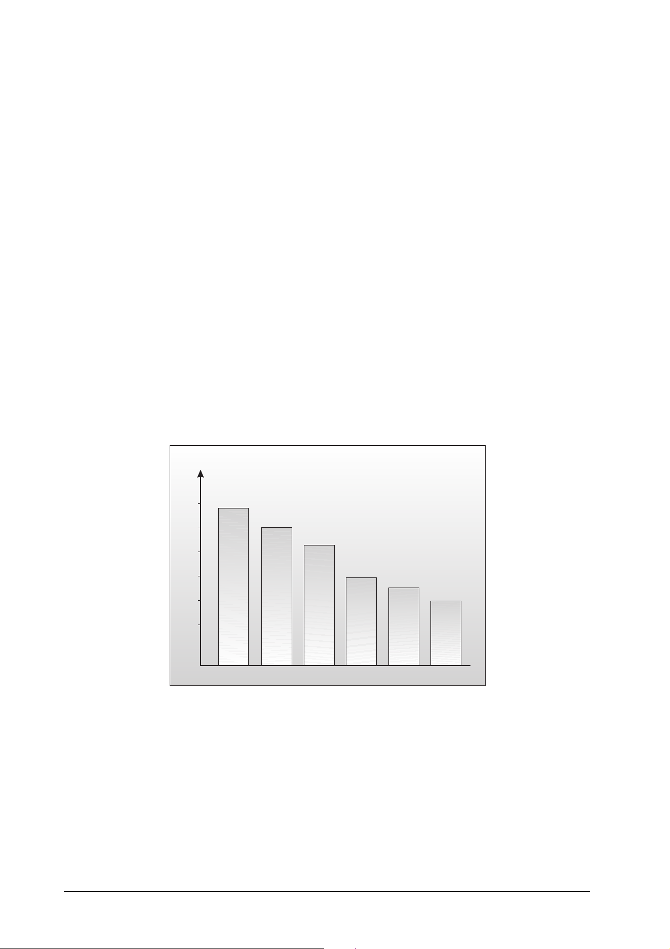
36
whole audio spectrum. If these currents are highly amplified, the result will be perceived as noise. Since all
frequencies are equally affected, we term this white noise.
It is fairly obvious that electronics cannot function without components. A certain level of background noise is
inevitable despite the deployment of special low-noise components.
This effect is similar when replaying a tape. The non-directional magnetic particles passing the replay head
can also cause uncontrolled currents and voltages. The resulting sound of the various frequencies is heard as
noise. Even the best possible tape biasing can "only" provide signal-to-noise ratios of about 70 dB, which is
not acceptable today since the demands of listeners have increased. Due to the laws of physics, improving
the design of the magnetic carrier is impossible using conventional means.
4.1.2 Audio dynamics
A remarkable feature of the human ear is that it can detect the most wide-ranging amplitude changes - from the
slightest whisper to the deafening roar of a jet plane. The attempt to record and reproduce this broad spectrum
of amplitudes with the aid of amplifiers, cassette recorders, LPs or even digital recording media (CD, DAT, etc.)
soon runs into the physical limitations of electronic and acoustic playback options.
The usable dynamic range of electroacoustic equipment is limited as much at the low end as at the high end.
The thermal noise of the electrons in the components results in an audible basic noise floor and thus repre-
sents the bottom limit of the transmission range. The upper limit is determined by the levels of the internal
operating voltages; if they are exceeded, audible signal distortion is the result. Although in theory, the usable
dynamic range sits between these two limits, it is considerably smaller in practice, since a certain reserve
must be maintained to avoid distortion of the audio signal if sudden level peaks occur. Technically speaking,
we refer to this reserve as "headroom" - usually this is about 10 - 20 dB. A reduction of the operating level
would allow for greater headroom, i.e. the risk of signal distortion due to level peaks would be reduced.
However, at the same time, the basic noise floor of the program material would be increased considerably.
Ear
Microphone Amplifier
Power Amplifier
Tape Recorder
Radio
Cassette
Recorder
P/dB
140
120
100
80
60
40
Fig. 4.1: The dynamic range capabilities of various devices
4. TECHNICAL BACKGROUND
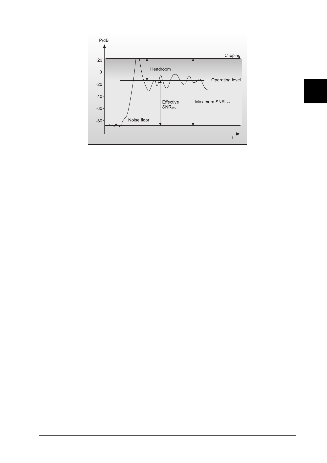
37
E
Fig. 4.2: The interactive relationship between the operating level and the headroom
It is therefore useful to keep the operating level as high as possible without risking signal distortion in order to
achieve optimum transmission quality.
It is possible to further improve the transmission quality by constantly monitoring the program material with the
aid of a volume fader, which manually levels the material. During low passages the gain is increased, during
loud passages the gain is reduced. Of course it is fairly obvious that this kind of manual control is rather
restrictive; signal peaks are hard to predict and impossible to compensate manually in the available time.
Manual control is simply not fast enough to be satisfactory.
The need therefore arises for a fast acting automatic gain control system that can constantly monitor the
signals and which will always adjust the gain to maximize the signal-to-noise ratio without incurring signal
distortion. This device is called a Compressor or Limiter, and is a component of the BEHRINGER
ULTRA-DYNE PRO.
4.1.3 Compressors/limiters
With broadcasting and recording, signal peaks can easily lead to distortion due to the high dynamic range of
microphones and other musical equipment. Compressors and limiters reduce the dynamics by means of an
automatic gain control. This reduces the amplitude of loud passages and therefore, restricts the dynamics to
a desired range. The dynamic range of a microphone channel can thus be compressed from 90 dB to 50 dB
or less, ensuring trouble-free processing in broadcasting, stage or recording environments.
Although compressors and limiters perform similar tasks, one essential point makes them different:
limiters abruptly limit the signal above a certain level, while compressors control the signal "gently" over a
wider range. Both continuously monitor the signal and intervene as soon as the level exceeds a user-adjust-
able threshold. Any signal exceeding this threshold will be immediately reduced in level.
Limiters reduce the output level to the adjusted threshold whenever the input signal exceeds this point. With
compression, in contrast to the action of a limiter, the signal is reduced in gain relative to the amount the
signal exceeds the threshold. The output of a compressor will still rise if the input level is increased, while the
maximum output of a limiter will always be equal to the threshold level.
Generally, threshold levels for compressors are set below the normal operating level to allow for the upper
dynamics to be musically compressed. For limiters, the threshold point is set above the normal operating level
so that it only intervenes to protect subsequent equipment from signal overload. The ULTRA-DYNE PRO is
equipped with such an output limiter.
There are generally also significant differences in the control times. Although both limiters and compressors
use very short attack times, the release time of a compressor are in the 100 ms region whereas a limiter uses
release times of seconds. To be exact: The release time is a time constant of an exponential function. It is the
time it takes the gain reduction to decrease by 36.8% (= 8.7 dB).
Because fast level changes are more noticeable than slow changes, long release time are used where unobtru-
4. TECHNICAL BACKGROUND

38
sive signal processing is required. However, in some situations such as live performances, the principal goal
is simply to protect the system from brief overloads. In those cases a short release time is more appropriate
to ensure that the limiter only intervenes when it is needed and the level returns to normal as soon as
possible.Long release times are better suited when the limiter should remain "inaudible", for instance in
broadcasting, club applications, or when a signal is transferred to (analog) tape.
4.1.4 Expanders/noise gates
The dynamic range of signals will often be restricted by noise. Outdoor recordings generally include a high
level of background noise such as traffic, wind, etc. Synthesizers, effects devices, guitar pickups, amplifiers
etc. usually produce a high level of noise, hum or other ambient background hiss, which can restrict the
dynamic range of the program material. Normally these noises are inaudible if the level of the desired signal
lies significantly above the level of the noise. This perception by the ear is based on the "masking" effect:
noise will be masked and thus becomes inaudible as soon as considerably louder sound signals in the same
frequency band are added. Nevertheless, the further the level that the desired signal decreases, the more the
noise floor becomes a disturbing factor.
An expander can be used to enhance the dynamic range of signals, thus providing the inverse function of a
compressor. These devices attenuate signals when their amplitudes drop, thereby fading out the background
noise. Gain controlling amplifiers such as expanders can thus effectively extend the dynamic range of a
signal.
The most common audio application for this system is in complementary noise reduction systems (coding
decoding).
The advantages of expanders for the removal or background noise and crosstalk between individual tracks in
multitrack recording was recognized at an early stage.
The noise gate is the simplest form of an expander: The signal passes through the unit unchanged above a
user-definable threshold. If the signal drops below this threshold, it is simply "cut off" completely. Needless to
say, this method is not suitable to most applications, as the transition would be too abrupt and would be
perceived as unnatural by the listener. A device of this type can be improved by the option of user-definable
control times.
4.2 Digital audio processing
In order to convert an analog signal such as music into a series of digital words, a so-called "Analog to Digital
Converter" or ADC is used. These converters measure the signal at constant time intervals and output the
current signal amplitude as a numerical value. This form of measuring the signal regularly over a period of
time is known as sampling, the conversion of the amplitude into a numerical value, quantizing. The two actions
together are referred to as digitizing.
In order to carry out the opposite - the conversion of a digitized signal into its original analog form - a "Digital
to Analog Converter" or DAC is used.
In both cases the frequency at which the device operates is called the sampling rate. The sampling rate
determines the effective audio frequency range. The sampling rate must always be more than twice the value
of the highest frequency to be reproduced. Therefore, the CD sampling rate of 44.1kHz is slightly higher than
twice the highest audible frequency of 20 kHz.
The accuracy at which quantization takes place is primarily dependent on the quality of the ADCs and DACs
being used. The resolution, or size of digital word used (expressed in bits), determines the theoretical Signal/
Noise ratio (S/N ratio) the audio system is capable of providing.
The number of bits may be compared to the number of decimal places used in a calculation - the greater the
number of places, the more accurate the end result. Theoretically, each extra bit of resolution should result in
the S/N ratio increasing by 6 dB. Unfortunately, there are a considerable number of other factors to be taken
into account which hinder the achievement of these theoretical values.
4. TECHNICAL BACKGROUND
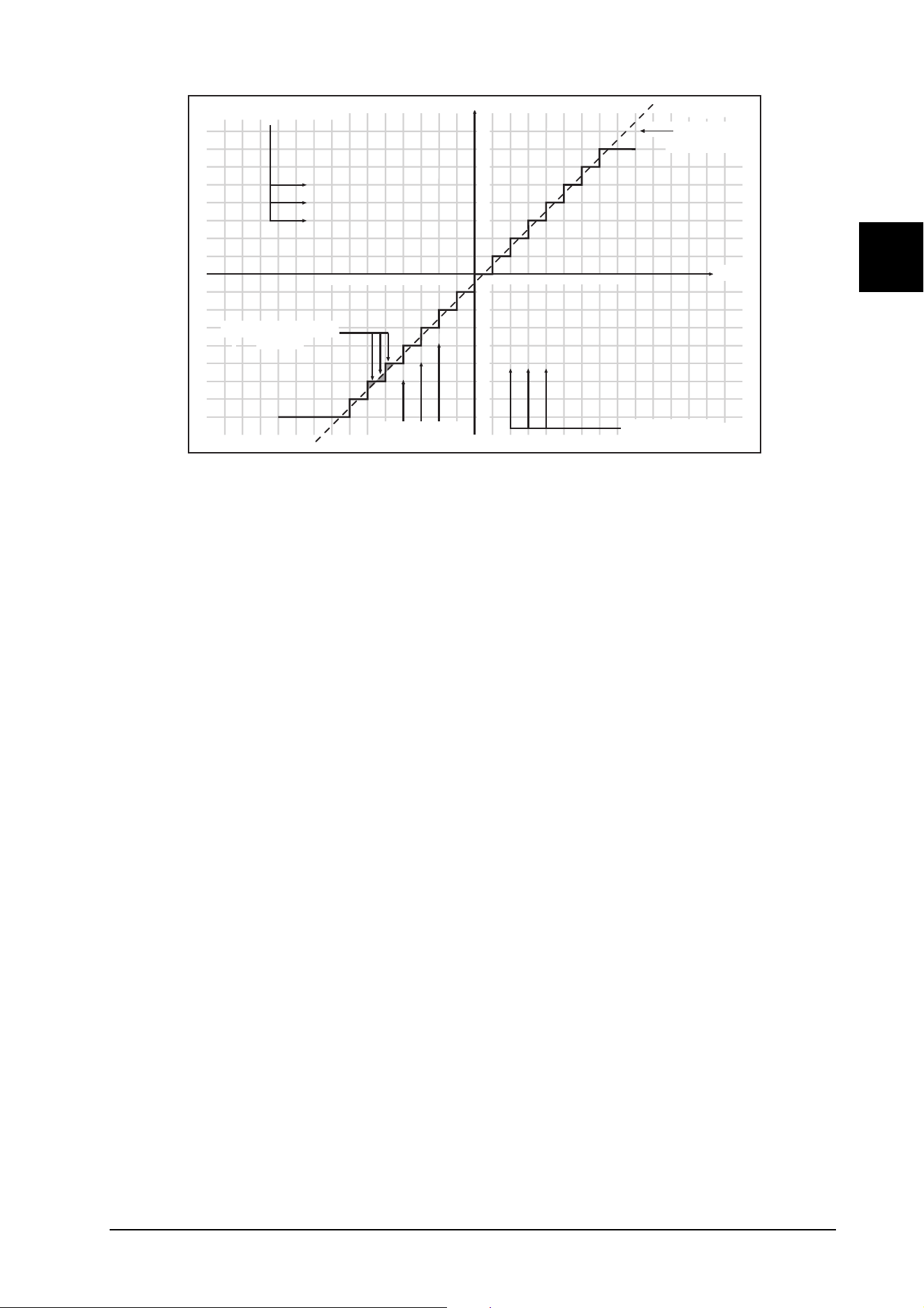
39
E
Quantization Steps
U (Voltage)
-8 -7 -6 -5 -4 -3 -2
Digital Words
1111
1110
1101
1100
1011
1010
1001
1000
0000
t (Time)
0001
0010
0011
0100
0101
0110
0111
Conversation Rate
8
7
6
5
4
3
1 2 3 4 5 6 7 8
-1
-2
-3
-4
-5
-6
-7
-8
Quantization Errors
(Noise)
Continuous
Analog Signal
Fig. 4.3: Sampling quantization error
If you picture an analog signal as a curve, then the sampling procedure may be thought of as a grid
superimposed on the curve. The higher the sampling rate (and the higher the number of bits), the finer the
grid. The analog signal is a continuous line which only meets the intersections of the grid exactly at very few
points. All other points on the line are at greater or smaller distances from the intersections. This limit to the
resolution of the grid gives rise to errors, and these errors are the cause of quantizing noise. This quantiza-
tion noise has the unfortunate characteristic of sounding much more unpleasant than "natural" analog noise
when highly amplified.
In a digital signal processor, such as the DSPs in the ULTRA-DYNE PRO, the data will be modified in a
number of ways. In other words, various calculations, or processes, will be done in order to achieve the
desired effect on the signal.
This gives rise to further errors, as these calculations are approximations, due to their being rounded off to a
defined number of decimal places. This causes further noise. To minimize these rounding errors, the calcu-
lations must be performed with larger data words than those of the audio data. This process is comparable to
a pocket calculator that performs its calculations with a greater number of decimal places than can be shown
on the display. The DSPs in the ULTRA-DYNE PRO operate with a 24-bit resolution. This is accurate enough
to reduce quantization noise to levels which are usually below the audible threshold. However, when using
extreme equalizer settings, some quantizing side effects may be detected.
Digital sampling has one further, very disturbing effect: its high sensitivity to overloads.
A simple sine wave will serve as our example. If an analog signal starts to overload, it results in the amplitude
of the signal reaching a maximum level, and the peaks of the wave starting to get compressed, or flattened.
The greater the proportion of the wave being flattened, the more harmonics, audible as distortion, will be
heard. This is a gradual process.
Digital distortion is quite different, as illustrated by this simplified example. If we take the situation where a
4<->bit word has the positive maximum value of 0111, and add to it the smallest possible value of 0001 (in
other words, the smallest increase in amplitude possible), the addition of the two results in 1000 - the value of
the "negative" maximum. The value is turned on its head, going instantly from positive max to negative max,
resulting in the very noticeable onset of extreme signal distortion.
4. TECHNICAL BACKGROUND
40
4.2.1 The AES/EBU and S/PDIF standards
Essentially, two standards exist for the transfer of digital audio data. Their most important electrical specifica-
tions are summarized in Table 4.1. AES/EBU is a professional, balanced connection using XLR connectors.
For semiprofessional users, Sony and Philips have opted against balanced connections and use either cinch
connectors or optical waveguides. The process which was standardized as IEC 958 and is generally known
as S/PDIF (Sony/Philips Digital Interface) became best known for the associated efforts to introduce copy
protection, however.
Typ AES / EBU IEC 958 (S/PDIF)
Connection XLR Cinch / Optisch
Mode Balanced Unbalanced
Impedance 110 Ohm 75 Ohm
Level 0,2 V bis 5 Vpp 0,2 V bis 0,5 V pp
Clock accuracy Not specified I: ± 50 ppm II: 0,1 % III: Variable Pitch
Jitter ± 20 ns Not specified
Tab. 4.1: Important data for the AES and IEC specifications
Unfortunately, the professional standard was soon watered down, as the design of many units didn't provide
enough room for XLR connectors. Instead, stereo jacks, miniature jacks and special adapters for sub-D
connectors were used.
In addition to the electrical differences, the formats also have a slightly different structure. The audio informa-
tion occupies the same position in the data stream, making the two formats compatible in principle. The
differences between the two standards can be found in the information blocks. Table 4.2 shows a section of
the professional format data structure generally used in AES/EBU connections.
Byte Bit
01234567
0 P/C Audio?
Emphasis Locked Sampl. Freq.
1
Channel Mode Use of User bits
2
Use of AUX bits Length of audio sample Reserved
3
Reserved for description of multichannel recording
4
Audio reference Reserved
5
Reserved
Tab. 4.2: Professional format (AES/EBU) ID data
Table 4.3 shows the corresponding data of the consumer format commonly used for S/PDIF connections. The
first bit serves to identify the following data as professional or consumer format.
Byte Bit
01234567
0 P/C Audio? Copy
Emphasis Mode
1
Category code Gen.St.
2
Source number Channel number
3
Sampling frequency Clock accuracy Reserved
Tab. 4.3: Consumer format (S/PDIF) ID data
As can be seen, there are major differences in the significance of the following bits between the two formats. If
a device such as a commercially available DAT recorder only has a S/PDIF input, the device will normally only
understand that format. Generally, it will switch off when receiving professional-format data. The reason is
simple: As the illustrations show, a signal coded in professional format would lead to copy-protection and
emphasis errors in a device only capable of processing the consumer format!
As was already the case with the connectors, this point is often not immediately obvious. Many units do not
switch off, others can process both formats despite having only a single connector type, and still others are
4. TECHNICAL BACKGROUND

41
E
simply faulty designs which refuse to work properly even when receiving correct ID data.
The ULTRA-DYNE PRO can be equipped with an AES/EBU interface as an option.
4.3 Artificial generation of harmonics
In the year 1955, the American Charles D. Lindridge invented the Exciter, a unit that "excites" upper harmon-
ics, and presented a unit for "improving the sound of music and speech". He enriched signal sources with
artificially generated upper harmonics and found that sound quality, transparency and the perceived posi-
tioning of musical instruments could be improved substantially using this effect. He was granted an American
patent on his circuit design under the number US 2 866 849.
Compared with today's technology, Lindridge's device was far from mature. However, it already incorporated
all of the essential features of modern circuits. Recent scientific findings on the psychological aspects of
acoustics and advances in technology have since led to new and improved devices.
The digital reproduction of this harmonic generation process in a "virtual" Exciter also opens whole new per-
spectives for the control of the spectral distribution of the generated harmonics.
Vacuum tubes also generate harmonics due to nonlinear distortion. The harmonic structure of this distortion
is distinctly different from that of the distortion generated by overdriven transistor circuits. The tube-specific
sound is subjectively perceived as warm, pleasant and "harmonious". The ULTRA-DYNE PRO is capable of
simulating a variety of tube types, each with their own typical acoustic characteristics.
4.4 Tube technology
When observing the development and trends associated with audio engineering, it quickly becomes apparent
that tubes are experiencing a true renaissance. And that despite the fact that today's amateur musicians take
digital effects devices and recording media for granted, and that increasingly affordable digital mixing desks
are appearing among the equipment of semiprofessional studios. Manufacturers are constantly experimenting
with new algorithms in order to extract maximum performance from the DSPs (digital signal processors), the
heart of digital audio systems.
Despite that, many audio engineers, especially highly experienced ones, still use old and new tube equip-
ment. They are often willing to accept the comparatively high noise levels of their "old jewels" in order to take
advantage of the typical warm sound of this equipment in their productions. As a result, a number of micro-
phones, equalizers, preamps and compressors based on tube technology can be found in the recording and
mastering sectors today. Digital simulation of tube technology has created a way to enjoy the best of both
worlds and compensate for their typical disadvantages.
The use of tubes in a recording studio should not be equated with their function in an overdriven guitar amplifier,
however. In a guitar amplifier, the extreme saturation of the tube causes a complete, intentional transformation
of the input signal which often goes hand-in-hand with a serious increase of the noise level. A far more subtle
approach is generally required in a studio environment. In this situation, the tube circuits give the signal a lively,
punchy character. In many cases a higher subjective loudness is also attained in relation to the unprocessed
signal, i.e. the perceived volume is higher at the same level. This results from the limiting of the top of the
dynamic range of the input audio signal by the saturation of the tube circuit, thus reducing the amplitude
difference between the softest signals and the loudest. An increasing saturation of the tubes thus results in a
gentle compression of the entire usable dynamic range.
A similar effect occurs when analog tape machines are overdriven. This so-called tape saturation effect also
causes a slight compression of the recorded audio material, as well as generating additional harmonics.
The ULTRA-DYNE PRO uses a Tube Emulation which delivers a sophisticated, authentic effect and which was
developed as a result of investigations of a variety of tube circuit characteristics. This newly developed
algorithm is intended to provide a subtle refinement of the sound, not the powerful distortion common to
overdriven guitar amplifiers.
4. TECHNICAL BACKGROUND
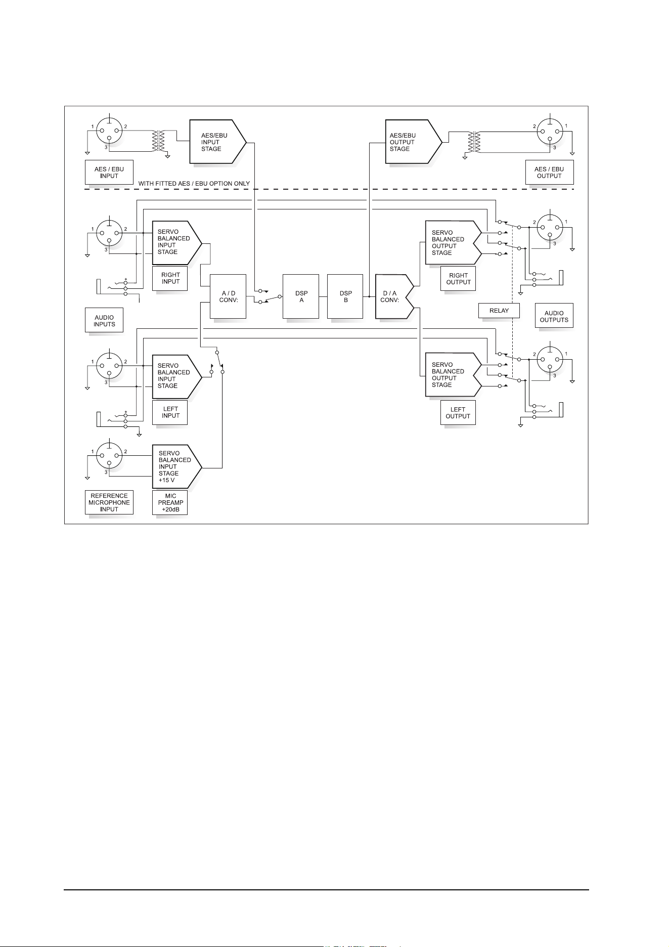
42
4.5 The structure of the ULTRA-DYNE PRO
Fig. 4.4: Block diagram of the BEHRINGER ULTRA-DYNE PRO
The analog input signals first pass through the electronic balancing amplifier and are then fed to the A/D
converters. The input signals are converted there to a digital multiplex signal and sent to the DSPs for
processing. The digital input signal is passed from the transformer balanced input section directly to the
DSPs (only possible with the AES/EBU option installed). Switching between the analog and digital input
sources is done in the GLOBAL SETUP menu.
Signal processing is performed by the two DSPs. Next, the signal is sent to the D/A converters where it is
converted back to two analog signals (left and right). Finally, they are sent to the electronically balanced
outputs. If the AES/EBU option is installed, the digital signal from the DSPs is also sent to the digital output.
The digital output is transformer balanced, providing a transmission in the digital domain free of induced hum
and noise.
5. INSTALLATION
Your BEHRINGER ULTRA-DYNE PRO was carefully packed in the factory and the packaging was designed
to protect the unit from rough handling. Nevertheless, we recommend that you carefully examine the packag-
ing and its contents for any signs of physical damage which may have occurred during shipping.
+ If the unit is damaged, please do not return it to us, but notify your dealer and the shipping
company immediately, otherwise claims for damage or replacement may not be granted.
5. INSTALLATION
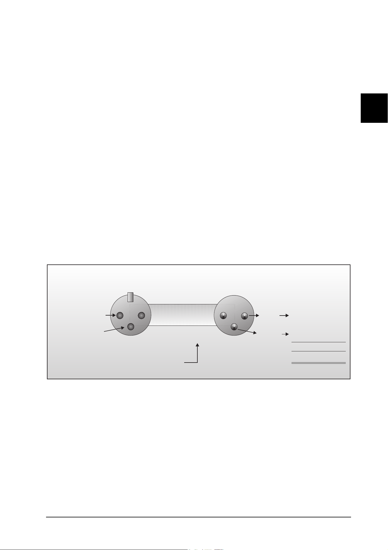
43
E
5.1 Rack mounting
The BEHRINGER ULTRA-DYNE PRO fits into two standard 19" rack units of space (3 1/2"). Please allow at
least an additional 4" depth for the connectors on the back panel.
Be sure that there is enough space around the unit for cooling and please do not place the ULTRA-DYNE
PRO on high temperature devices such as power amplifiers to avoid overheating.
5.2 AC power connection
Please ensure that the ULTRA-DYNE PRO is set to the correct supply voltage before connecting the
unit to the AC power system! Three triangular markings can be found on the fuse holder at the AC power
connection socket. Two of these three triangles will be aligned with one another. The ULTRA-DYNE PRO is
set to the operating voltage shown next to these markings and can be switched over by twisting the fuse holder
by 180°. IMPORTANT: This does not apply to export models designed only for 115 V AC!
The power connection of the ULTRA-DYNE PRO is made with a standard power supply cable and IEC
receptacle. It meets all of the international safety certification requirements.
+ Please make sure that all units have a proper ground connection. For your own safety, never
remove or disable the ground conductor of the unit or of the power supply cable.
5.3 Analog audio connections
As standard, the BEHRINGER ULTRA-DYNE PRO is installed with electronically servo-balanced inputs and
outputs. If you have the option of using balanced connections to other equipment, please take advantage of
them to ensure a maximum of interference suppression.
1 2
3
2 1
3
Pin 1
Cable InputOutput
Pin 2 = (+) Signal Positive
Pin 3 = (-) Signal
Shield
(+) Signal + Hum
(-) Signal + Hum
Negative
(+)Hum + Signal
(-)Hum + Signal
2 x Signal
Ground
RFI and Hum
= Signal + 6 dB
Fig. 5.1: Compensation of interference with balanced connections
+ Please ensure that only qualified persons install and operate the unit. Take care that the
persons doing the handling are always adequately grounded during and after the installation
due to the electrostatically sensitive nature of the unit.
5. INSTALLATION
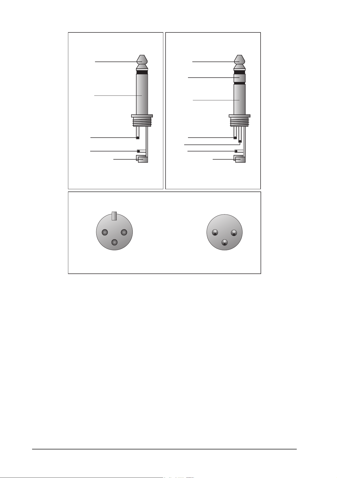
44
Unbalanced use of
mono 1/4" jack plugs
Ring
Balanced use of
stereo 1/4" jack plugs
Balanced use with XLR connectors
1 2
3
2 1
3
Input Output
Tip =
Signal
Tip =
hot (+ve)
Sleeve =
Ground / Shield
Sleeve =
Ground / Shield
Tip
Tip
Sleeve
Sleeve
Strain relief clamp
Strain relief clamp
Ring =
cold (-ve)
For connection of balanced and
unbalanced plugs, ring and sleeve have
to be bridged at the stereo plug.
1 = Ground / Shield
2 = hot (+ve)
3 = cold (-ve)
For unbalanced use pin 1 and pin 3 have to be bridged
Fig. 5.2: Different plug types
5.4 Digital audio connections per AES/EBU (optional)
The AES/EBU interface (Audio Engineering Society/European Broadcasting Union) is the most widely used
digital interface for professional audio devices. The connection is balanced, negative earth, using bipolar
shielded cable with XLR connectors. We recommend the use of a high quality, low capacitance cable
capable of the error-free transmission of the wide bandwidth signal (with frequencies of over 3 MHz). The
AES/EBU signal can carry, in addition to the pure audio data (up to 24-bit), various code signals including
built-in emphasis, the sampling rate, time code information and user-definable bits.
The S/P-DIF (Sony/Philips Digital Interface Format) digital format found in consumer products has similari-
ties in its data structure to the AES/EBU format. In principle, it is possible to connect an S/P-DIF device to the
ULTRA-DYNE PRO AES/EBU input, although this was not intended in the design of the two formats.
The S/P-DIF connector is normally an unbalanced RCA socket, requiring the use of an adapter. Connect the
tip of the RCA socket to pin 2 of the XLR, and the RCA shield to pin 3 of the XLR. The connection between the
two devices should be as short as possible.
5. INSTALLATION
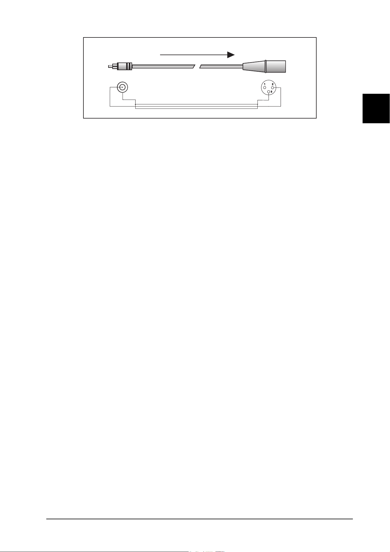
45
E
Digital Output
S/PDIF
ULTRA-DYNE PRO
Input
Signal flow
Tip
Sleeve
Shield
Cable
Fig. 5.3: ULTRA-DYNE PRO S/P DIF interface adapter
Connecting the ULTRA-DYNE PRO AES/EBU output to an S/P-DIF input will probably not work, because the
copy protection function present at the S/P-DIF device will be triggered by a channel status bit, or possibly
another AES/EBU defined bit, preventing data transfer.
5.5 MIDI connections
The MIDI (Musical Instruments Digital Interface) standard was developed in the early 1980s to allow elec-
tronic musical instruments from different manufacturers to communicate with each other. The use of MIDI
has developed over the years to the point where it is now common to find complete recording studios based
completely on MIDI.
The centerpiece in such a studio is usually a computer running a sequencer software which not only controls
various keyboards, samplers and sound modules, but can also run the programming of outboard effect
devices, typically digital reverberation and delay units. The ULTRA-DYNE PRO may be controlled in real time
in this studio environment.
The MIDI connectors found on the rear panel are of the universally used 5 pin DIN type. Suitable MIDI cables
are required to connect the ULTRA-DYNE PRO to other MIDI devices. Normally, complete cables can be
purchased for this application, but you can of course make your own, using a high quality cable with two
cores and shielding (such as microphone cable), and with two good 180° DIN plugs. Pin 2 (center) is
connected to the cable's shield, pins 4 and 5 (left and right next to 2) carry the two cores, pins 1 and 3 are not
used. MIDI cables should not exceed 45 feet in length.
MIDI IN: Used for the reception of MIDI control data. Select the receive channel in the SETUP menu.
MIDI THRU: The MIDI THRU socket can be used to receive incoming MIDI signals without modifying them. This
permits the chaining of multiple ULTRA-DYNE PROs.
MIDI OUT: MIDI OUT serves to send data to a connected computer or other ULTRA-DYNE PRO. Program data
and signal processing status information is transmitted via this output.
6. APPENDIX
6.1 AES8024
Digital AES/EBU I/O contains an additional board with the driver hardware for the AES/EBU inputs and out-
puts, the required XLR fittings including balancing transformers, and an update of the operating software. You
have the choice of ordering the option with the purchase of your ULTRA-DYNE PRO, or adding it at a later
stage. For subsequent installation, please send your ULTRADYNE PRO to the address given in Chapter7
FREIGHT PREPAID, indicating the desired option.
+ Return your ULTRA-DYNE PRO to us for the installation, otherwise you will void your warranty.
6. APPENDIX

46
6.2 Operating software
The ULTRA-DYNE PRO operating software is under continuous development to improve its performance and
control, and to keep pace with your expectations and requirements. Please inform us of your needs and
suggestions for this reason. We will make every effort to put your ideas into practice in future software
updates. To receive a software update, you must send your ULTRA-DYNE PRO to the address given in
Chapter 7. Information about new software versions will be available through music magazines, from your
dealer, our Web site www.behringer.de or directly from BEHRINGER (phone +49 (2154) 920666).
The current software version will always be shown in the lower right of the display shortly after switching the
ULTRA-DYNE PRO on.
6.3 Changing the memory buffer battery
The battery which maintains the program memory when power is switched off has a life of several years,
depending on the frequency and duration of use. As the battery becomes depleted, the following message will
appear on the display:
WARNING: BATTERY LOW
You should send the unit back to us as quickly as possible. We are able to replace the battery without losing
the programs stored in the memory.
If you fail to replace the buffer battery, the message
BATTERY EMPTY: MEMORY CLEARED
will appear on the display after a while. If this happens, you have lost all your programs. Furthermore, new
programs will also be lost once the ULTRA-DYNE PRO is switched off.
If you decide to replace the battery yourself please note that you will invalidate your warranty. We recommend
that you let qualified personel replace the battery.
+ Disconnect the ULTRA-DYNEPRO from mains before opening the enclosure.
+ Warning: Danger of explosion when battery is placed incorrectly! Replace only with the same
type (see technical specifications). When replacing the battery, the correct polarity should be
observed.
+ Empty batteries are toxic waste and must be disposed of properly.
6.4 In planning
A convenient PC application is being developed for the control of one or more ULTRA-DYNE PROs via MIDI
with extended functionality. An IBM-compatible PC with a MIDI interface will be required.
6. APPENDIX
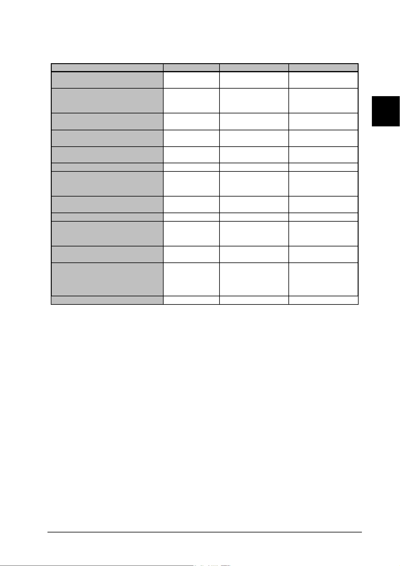
47
E
6.5 MIDI implementation
Function Transmitted Recognized Remarks
Basic Default X 1 - 16 memorized
Channel Changed X 1 - 16 -16
Default X 1,2,3,4
Mode Messages X X
Altered X X
Note X X
Number True Voice X X
Velocity Note ON X X
Note OFF X X
After Key’s X X
Touch Ch’s X X
Pitch Bender X X
Control
Change O O
Progr.
Change True #
System Exclusive O O
System Song Pos X X
Song Sel X X
Common Tune X X
System Clock X X
Real Time Commands X X
Aux Local ON/OFF X X
All notes OFF X X
Messages Active Sense X X
Reset X X
Notes X X
O = YES
X = NO
Mode 2: OMNI ON, MONO Mode 4: OMNI OFF, MONO
offset of the first
controller adjustable
0 - 99 0 - 99 1 - 100
Mode 1: OMNI ON, POLY Mode 3: OMNI OFF, POLY
Tab. 6.1: MIDI implementation of the ULTRA-DYNE PRO
6. APPENDIX
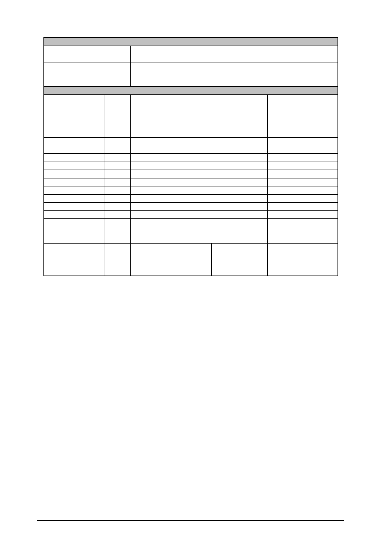
48
Status Bytes
Program Changes
Pcxx c = Channel
xx = Program (0..99)
Controller
Controller Offset adjustable from 0 to 64*
Ccxx c = Channel
xx = Number
Data Bytes
Display Controller Value
0 = Left Channel
1 = Right Channel
2 = Stereolink On
c= 0..5 Selected Band
c= 80 Bandlink On
GTH 0..127**
CTH 0..127**
CRA 0..127**
CAT 0..127**
CRT 0..127**
ULT 0..127**
OUT 0..127**
LTH 0..127**
EXC 0..127**
ODE 0..127**
PRC 0..127**
12AX7 0..31
12AY7 32..63
EL34 64..95
EL84 96..127
Tube TypeTYP
Output Gain
Limiter Threshold
Exciter Process
Band Mode
Compressor Ratio
Compressor Attack Time
Compressor Release Time
Ultramizer Process
Odd / Even
Tube Process
0
3
4
5
6
7
Gate Threshold
Compressor Threshold
Controller
Number
Parameter / Function
1
2
Channel Mode
12
8
9
10
11
13
Tab. 6.2: The controller functions via MIDI
* It is possible to set an offset for the MIDI controller. Begin then starting at that number.
** The controller value ranges are adapted to the real value ranges.
6.6 Technical specifications
ANALOG AUDIO INPUTS
Connections XLR and 6.3 mm TRS jacks
Type RF-suppressed, servo-balanced input
Impedance 50 kOhm balanced, 25 kOhm unbalanced
Max. Input Level +21 dBu balanced and unbalanced
CMR typ. 40 dB, >55 dB @ 1 kHz
ANALOG AUDIO OUTPUTS
Connections XLR and 6.3 mm TRS jacks
Type Electronically controlled, servo-balanced output amplifier
Impedance 60 Ohm balanced, 30 Ohm unbalanced
Max. Output Level +16 dBu balanced and unbalanced
BYPASS
Type Relaycontrolled Hard-Bypass
6. APPENDIX

49
E
SYSTEM SPECIFICATIONS
Frequency Range 20 Hz to 20 kHz, +/- 0.5 dB
S/N Ratio >-88 dBu, non-weighted, 22 Hz to 22 kHz
THD 0.004 % typ. @ +4 dBu, 1 kHz, unity gain
Crosstalk <-103 dB, 22 Hz to 22 kHz
DIGITAL INPUT (optional)
Type AES / EBU transformer-balanced
Impedance 10 kOhm balanced
Input Level 3 to 10 V (peak-to-peak)
DIGITAL OUTPUT (optional)
Type AES / EBU transformer-balanced
Impedance 100 Ohm balanced
Output Level 5 V (peak-to-peak)
MIDI INTERFACE
Type 5-pin DIN socket: In, Out and Thru
Implementation (see Chapter 10)
DIGITAL PROCESSING
Converters 24-bit sigma-delta
Sampling Rates 48 kHz, 44.1 kHz and 32 kHz (32 kHz only with AES/EBU)
CONTROLS
Process Switch to PROCESS mode
Meter Switch to METER mode
In/Out Inserts the device into the signal path
Setup Access to both setup levels
4 Softkeys Functions corresponding to the pictogram
4 Cursor Keys Modification of parameters and scrolling in menus
DISPLAY
4 Function Switch LEDs Indicate the active functions
MIDI LED LED for monitoring the reception of MIDI data
DISPLAY
Type 240 x 64 dot matrix, liquid crystal display (LCD)
Backlight LED array
Contrast Adjustable via software
POWER SUPPLY
AC Power USA/Canada ~ 120 V AC, 60 Hz
U.K./Australia ~ 240 V AC, 50 Hz
Europe ~ 230 V AC, 50 Hz
General Export Model ~ 100-120 V AC,~200-240 V AC, 50-60 Hz
Power Consumption 21 W
Fuse 100-120 V AC: 630 mA (slow)
200-240 V AC: 315 mA (slow)
AC Connection Standard IEC receptacle
DIMENSIONS/WEIGHT
Dimensions 3.5" (89 mm) * 19" (482.6 mm) * 12" (304.8 mm)
Weight Approx. 4.8 kg
Shipping Weight Approx. 6.0 kg
BEHRINGER constantly strives to ensure the highest possible quality standards. As a result of these efforts, modifications may be made
from time to time to existing products without prior notice. Specifications and appearance may differ from those listed or shown.
6. APPENDIX

50
The information contained in this manual is subject to change without notice. No part of this manual may be reproduced or transmitted
in any form or by any means, electronic or mechanical, including photocopying and recording of any kind, for any purpose, without the
express written permission of BEHRINGER GmbH.
ULTRA-DYNE, ULTRAMIZER, VIRTUOSO and BEHRINGER are registered trademarks. © 1998 BEHRINGER.
BEHRINGER INTERNATIONAL GmbH, Hanns-Martin-Schleyer-Str. 36-38, D-47877 Willich-Münchheide II
Tel. +49 (0) 21 54 / 92 06-0, Fax +49 (0) 21 54 / 92 06-30
this modification/adaptation shall not be considered a defect in
materials or workmanship. The warranty does not cover any
such modification/adaptation, irrespective of whether it was
carried out properly or not. Under the terms of this warranty,
BEHRINGER INTERNATIONAL shall not be held responsible for
any cost resulting from such a modification/adaptation.
3. Free inspections, maintenance/repair work and replacement
of parts are expressly excluded from this warranty, in particular
if caused by inappropriate use. Likewise, the warranty does not
cover defects of expendable parts caused by normal wear of
the product. Expendable parts are typically faders, potentiom-
eters, switches and similar components.
4. Damages/defects caused by the following conditions are not
covered by this warranty:
s
misuse, neglect or failure to operate the unit in compliance
with the instructions given in the user or service manuals.
s
connection or operation of the unit in any way that does not
comply with the technical or safety regulations applicable in
the country where the product is used.
s
damages/defects that are caused by force majeure or by
any other condition beyond the control of BEHRINGER
INTERNATIONAL.
5. Any repair carried out by unauthorized personnel will void the
warranty.
6. Products which do not meet the terms of this warranty will be
repaired exclusively at the buyers expense. BEHRINGER
INTERNATIONAL will inform the buyer of any such circumstance.
If the buyer fails to submit a written repair order within 4 weeks
after notification, BEHRINGER INTERNATIONAL will return the
unit C.O.D. with a separate invoice for freight and packing. Such
cost will also be invoiced separately when the buyer has sent in
a written repair order.
§ 5 WARRANTY TRANSFERABILITY
This warranty is extended exclusively to the original buyer (cus-
tomer of retail dealer) and is not transferable to anyone who
may subsequently purchase this product. No other person (re-
tail dealer, etc.) shall be entitled to give any warranty promise on
behalf of BEHRINGER INTERNATIONAL.
§ 6 CLAIM FOR DAMAGES
Failure of BEHRINGER INTERNATIONAL to provide proper war-
ranty service shall not entitle the buyer to claim (consequential)
damages. In no event shall the liability of BEHRINGER INTERNA-
TIONAL exceed the invoiced value of the product.
§ 7 OTHER WARRANTY RIGHTS
This warranty does not exclude or limit the buyers statutory
rights provided by national law, in particular, any such rights
against the seller that arise from a legally effective purchase
contract.
§ 1 WARRANTY CARD
To be protected by this warranty, the buyer must complete and
return the enclosed warranty card (signed/stamped by retail
dealer) within 14 days of the date of purchase to BEHRINGER
INTERNATIONAL (address see § 3). Failure to return the card in
due time (date as per postmark) will void any extended warranty
claims.
§ 2 WARRANTY
1. BEHRINGER INTERNATIONAL warrants the mechanical and
electronic components of this product to be free of defects in
material and workmanship for a period of one (1) year from the
original date of purchase, in accordance with the warranty regu-
lations described below. If any defects occur within the speci-
fied warranty period that are not caused by normal wear or
inappropriate use, BEHRINGER INTERNATIONAL shall, at its sole
discretion, either repair or replace the product.
2. If the warranty claim proves to be justified, the product will be
returned freight prepaid by BEHRINGER INTERNATIONAL within
Germany. Outside of Germany, the product will be returned at
the buyers expense.
3. Warranty claims other than those indicated above are ex-
pressly excluded.
§ 3 RETURN AUTHORIZATION NUMBER
1. To obtain warranty service, the buyer must call BEHRINGER
INTERNATIONAL during normal business hours BEFORE return-
ing the product (Tel.: +49 (0) 21 54 / 92 06 66). All inquiries must
be accompanied by a description of the problem. BEHRINGER
INTERNATIONAL will then issue a return authorization number.
2. The product must be returned in its original shipping carton,
together with the return authorization number, to the following
address:
BEHRINGER INTERNATIONAL GmbH
Service Department
Hanns-Martin-Schleyer-Str. 36-38
D - 47877 Willich-Münchheide
3. Shipments without freight prepaid will not be accepted.
§ 4 WARRANTY REGULATIONS
1. Warranty services will be furnished only if the product is
accompanied by an original retail dealers invoice. Any product
deemed eligible for repair or replacement by BEHRINGER INTER-
NATIONAL under the terms of this warranty will be repaired or
replaced within 30 days of receipt of the product at BEHRINGER
INTERNATIONAL.
2. If the product needs to be modified or adapted in order to
comply with applicable technical or safety standards on a na-
tional or local level, in any country which is not the country for
which the product was originally developed and manufactured,
7. WARRANTY
7. WARRANTY

