REV D DATE: 06/28/2023
USER MANUALS\20-88461_REVEAL_USER MANUAL_NR(L)(H)DSV_AMBIENT_SVC_FREE STDG_CASE
SCC P/N
20-88461
USER
MANUAL
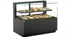
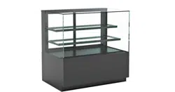
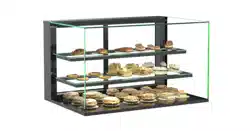
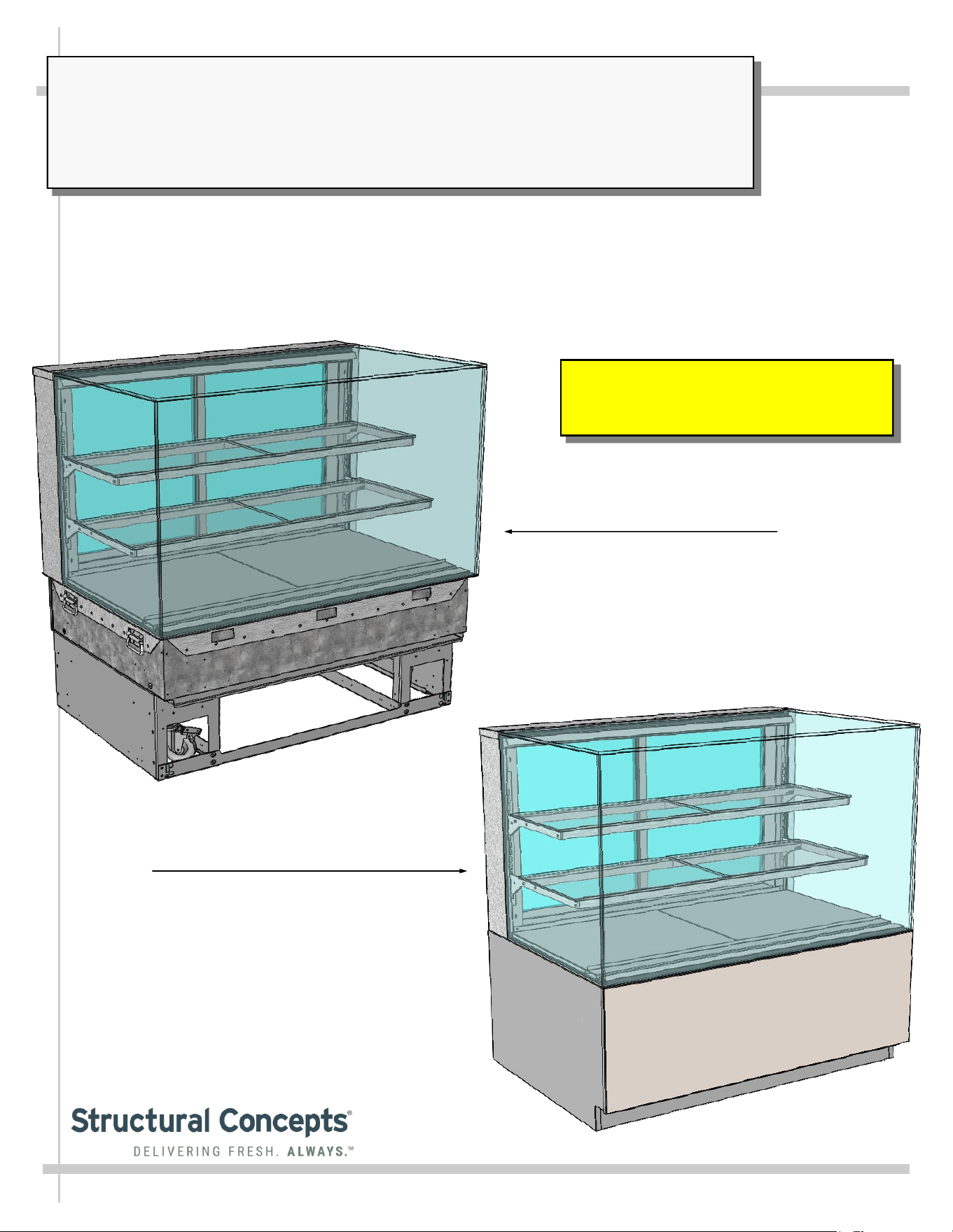
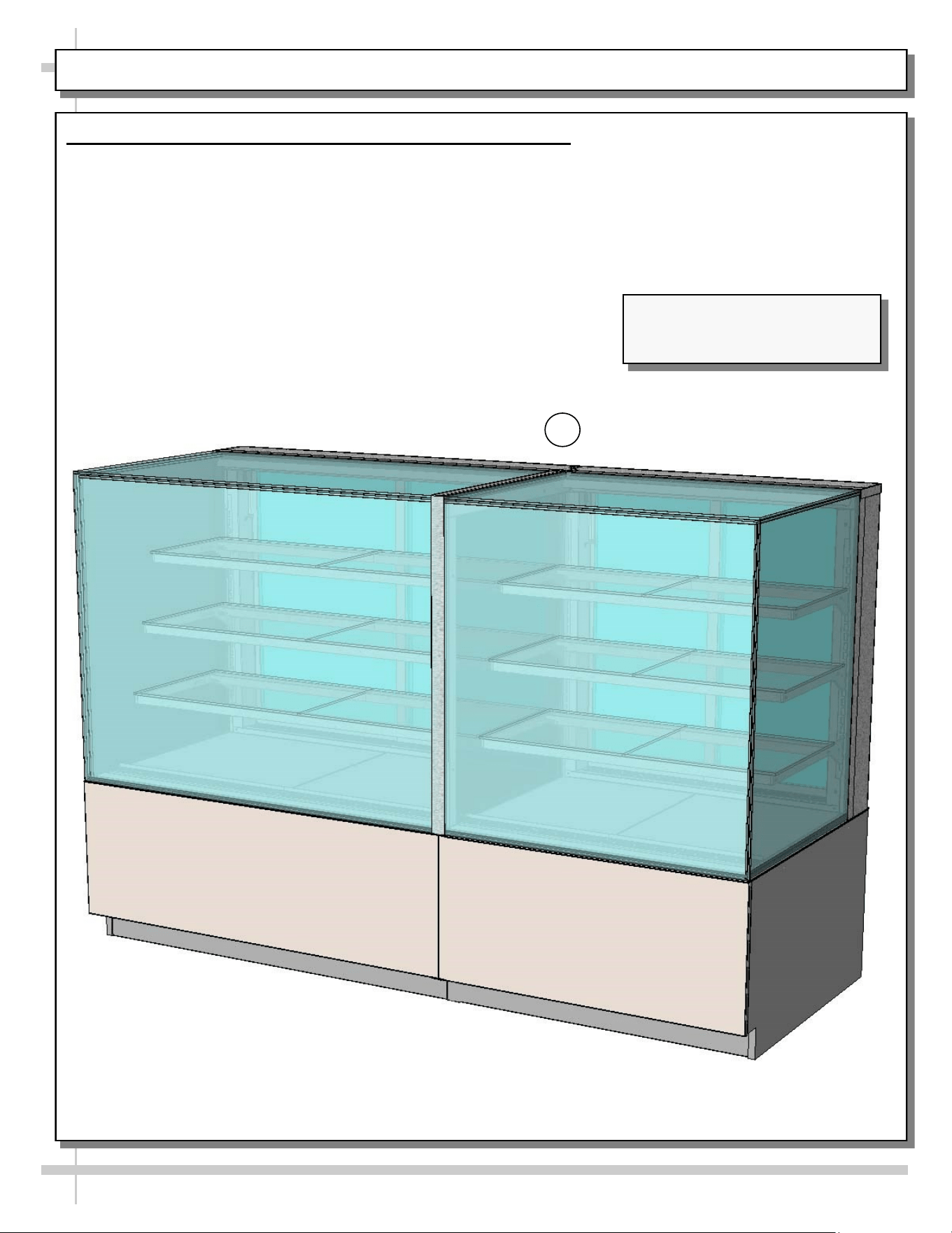
REVEAL® FREE STANDING, DRY (AMBIENT) SERVICE MERCHANDISERS
> REAR SLIDING DOORS
> CAUTION! DO NOT PUSH OR PULL ON UPPER GLASS ENCLOSURE!
> ONLY USE HANDLES (AT EACH END OF CASE) TO PUSH OR PULL CASE INTO POSITION!
> SEE PAGE 8 and 9 FOR FRONT PANEL, SIDE CLADDING, REAR PANEL & TOE-KICK
ATTACHMENT GUIDE
Models Are Shipped WITHOUT Panels or
Cladding Attached. See Pages 8 and 9 For
Component Attachment Instructions.
Model NR4847DSV Free Standing Unit
Shown After Front/Side Cladding and
Toe-Kick Have Been Attached
Model NR4847DSV Shown Before
Front/Side Cladding and Toe-Kick
Have Been Attached
Reveal
®
READ AND SAVE THESE INSTRUCTIONS
Structural Concepts Corp. ∙ 888 E. Porter Rd ∙ Muskegon, MI 49441 Phone: 231.798.8888 Fax: 231.798.4960 ∙ www.structuralconcepts.com
2
TABLE OF CONTENTS
TABLE OF CONTENTS …………………………………………………………………………………...…...
OVERVIEW / COMPLIANCE / LAMP REPLACEMENT PRECAUTIONS / WARNING / WIRING
DIAGRAM ………………………………………………………………………………..……………...
REVEAL® FREE STANDING DRY (AMBIENT) SERVICE MODEL APPLICABILITY &
DIMENSIONS ……………………………………………………………………………………….....
INSTALLATION: TOE-KICK & REAR PANEL REMOVAL / REMOVING CASE FROM PALLET ..….
INSTALLATION, CONT’D.: CASTER ADJUSTMENT / LOCK / UNLOCK / CASE REMOVAL
FROM PALLET ..……………………………………………………………………………………….
INSTALLATION, CONT’D: SHELVING ASSEMBLY COMPONENTS …………………………………..
INSTALLATION, CONT’D: ATTACHING COMPONENTS / HANDLES ...……………………………….
INSTALLATION, CONT’D: ATTACHING SIDE PANELS, REAR UPPER AND LOWER PANEL ..….
INSTALLATION, CONT’D: FIELD WIRE (OR PLUG IN) CASE / TURN ON LED LIGHTS …………...
INSTALLATION, CONT’D: BUBBLE-WRAPPED GLASS (FOR SHELVING) ………………………….
CASE ADJOINMENT INSTRUCTIONS ………………………………………………………………….…..
CASE DESIGN: FRONT VIEW OF FREE STANDING, SERVICE MERCHANDISERS ...……………..
CASE DESIGN: REAR VIEW OF FREE STANDING, SERVICE MERCHANDISERS ..……………….
CASE DESIGN, CONT’D: POWER CORD & PLUG / LED LIGHT SWITCH LOCATIONS / LED
LIGHTS ………………………………………………………………………………………………….
CASE DESIGN, CONT’D: REAR SLIDING DOORS / DOOR OPERATION …………………………….
CLEANING SCHEDULE (TO BE PERFORMED BY STORE PERSONNEL) ..…....…...…………...….
TROUBLESHOOTING (TO BE PERFORMED BY STORE PERSONNEL) .………..………………......
TROUBLESHOOTING (TO BE PERFORMED BY TRAINED SERVICE PROVIDERS ONLY) ……….
SERIAL LABEL INFORMATION & LOCATION ..…………………………….……...…....……………..…
TECHNICAL SERVICE CONTACT INFORMATION / WARRANTY INFORMATION…………………..
2
3
4
5
6
7
8
9
10
11
12-15
16
17
18
19
20
21
22
23
24
3
OVERVIEW / COMPLIANCE / LAMP REPLACEMENT PRECAUTIONS / WARNING / WIRING DIAGRAM
ELECTRICAL HAZARD WARNING
Risk of electric shock. Disconnect power before servicing unit.
CAUTION! More than one source of electrical supply is
employed with units that have separate circuits.
Disconnect ALL ELECTRICAL SOURCES before servicing.
WARNING
ELECTRICAL
HAZARD
OVERVIEW
• Cases should be installed and operated according
to this operating manual’s instructions to insure
proper performance.
• Improper use will void warranty.
COMPLIANCE
• Performance issues when in violation of applicable
NEC, federal, state and local electrical codes are
not covered by warranty.
LAMP REPLACEMENT PRECAUTIONS
• Following lamp replacement guidelines can prevent
damage to unit.
• Please read carefully!
ELECTRICAL HAZARD WARNING
• Please read the important warning in this document
carefully as it can prevent injury or death.
WIRING DIAGRAM
• Each case has its own wiring diagram folded and in a packet.
• Wiring diagram placement may vary (near ballast box, field
wiring box, raceway cover, or other related location).
WEIGHT LOADS ON GLASS / PREVENTING SAGGING
• Caution! To prevent sagging or breakage of glass, do not
exceed 5 LB (2.3 KG) weight load per top glass section
(between vertical supports).
• To prevent scratching or marring, do not place ANY items on
glass.
COMPLIANCE
This equipment MUST be installed in compliance with
all applicable NEC, federal, state and local
electrical codes.
ATTENTION
CONTRACTORS
CAUTION! LAMP REPLACEMENT PRECAUTIONS
LED lamps reflect specific size, shape and overall design.
Any replacements must meet factory specifications.
CAUTION
WIRING DIAGRAM FORMAT & LOCATION
• Each case has its own wiring diagram folded & in its own packet.
• Wiring diagram placement may vary; it may be placed near field
wiring box, raceway, or other related location.
CAUTION!
• To prevent sagging or breakage, do not exceed 5 LBS (2.3 KG)
weight load per top glass section (between vertical supports).
• To prevent scratching or marring, do not place ANY items on glass.
5
LBS
4
REVEAL® FREE STANDING DRY (AMBIENT) SERVICE MODEL APPLICABILITY & DIMENSIONS
Model
Upper Display
Height
Overall Height Depth x Length
NR3633DSV 13 5/8”UDH 32 7/8”OH 33”D x 35 3/4”L
NR3640DSV 20 3/8”UDH 39 5/8”OH 33”D x 35 3/4”W
NR3647DSV 27 7/8”UDH 47 1/8”OH 33”D x 35 3/4”W
NR3655DSV 35 1/4”UDH 54 5/8”OH 33”D x 35 3/4”L
NR4833DSV 13 5/8”UDH 32 7/8”OH 33”Dx 47 3/4”L
NR4840DSV 20 3/8”UDH 39 5/8”OH 33”D x 47 3/4”L
NR4847DSV 27 7/8”UDH 47 1/8”OH 33”D x 47 3/4”L
NR4855DSV 35 1/4”UDH 54 5/8”OH 33”D x 47 3/4”L
5
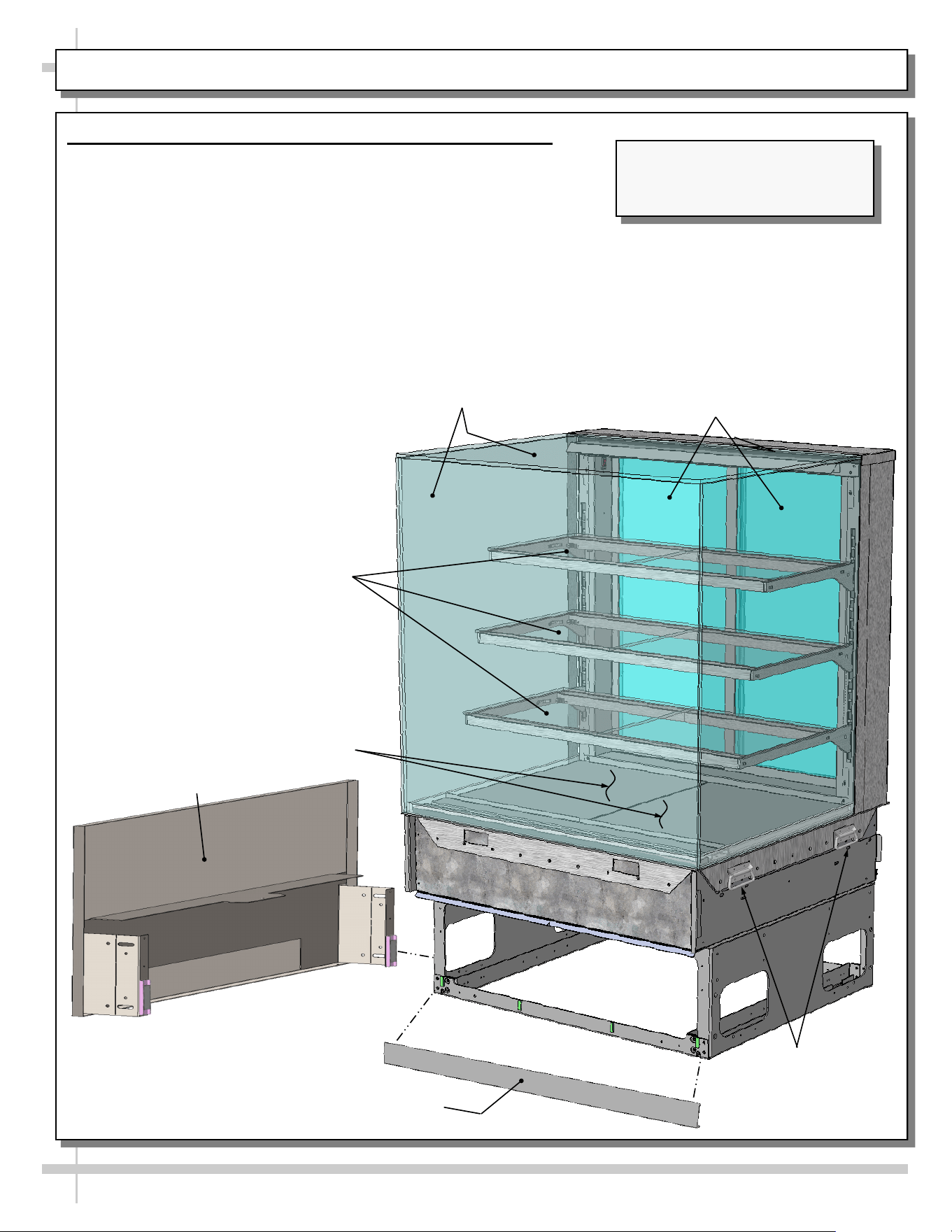
INSTALLATION: TOE-KICK & REAR PANEL REMOVAL / REMOVING CASE FROM PALLET
Front Toe-Kick
Pallet Rubber
Shipping Block
Shipping
Bracket
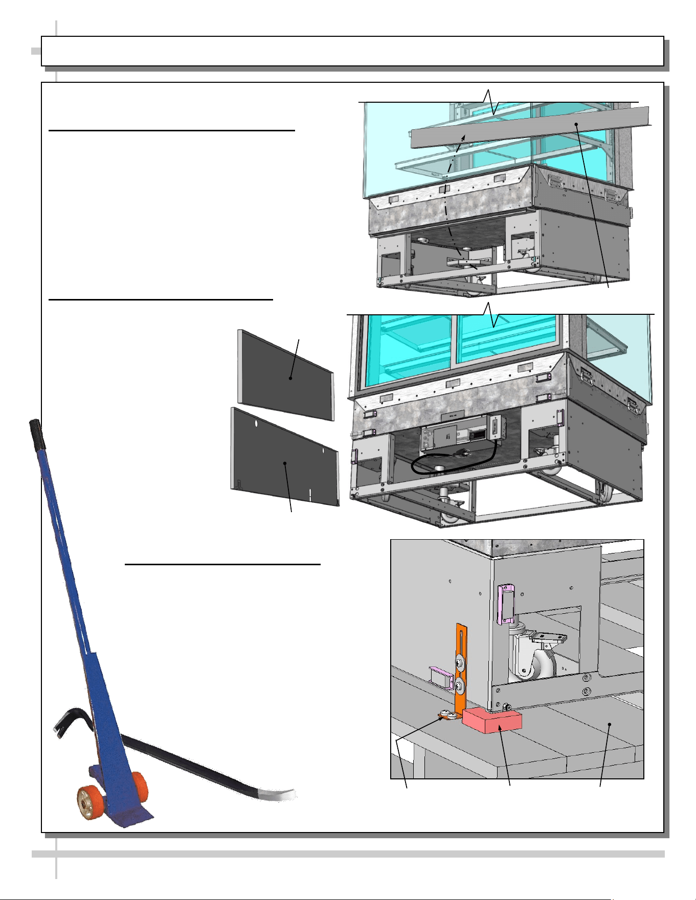
1. Remove Front Toe-Kick From Case
• To prevent damage to case, remove front
toe-kick from case before removing from pallet.
• Place front toe-kick in secure location while
removing case from pallet.
2. Remove Rear Panels From Case
• To prevent damage to case,
if upper panel and toe-kick is
on the case, lift them UP
and OFF.
• Upper and lower rear panels
are held in place by magnets.
• No screw removal is required.
• Place panels in
secure location while
removing case from
pallet.
3. Removing Case From Pallet
• Use Phillips driver to remove screws from
shipping brackets. Remove and discard
shipping brackets from pallet.
• Place J-bar/pry bar under base frame.
Raise case up from pallet to take weight
off casters.
• With case raised, lower casters all the
way down against pallet (see next step
for detailed instructions on lowering or
raising casters).
• Remove rubber shipping blocks.
Upper Rear
Panel
Lower Rear Panel
6
INSTALLATION, CONT’D.: CASTER ADJUSTMENT / LOCK / UNLOCK / CASE REMOVAL FROM PALLET
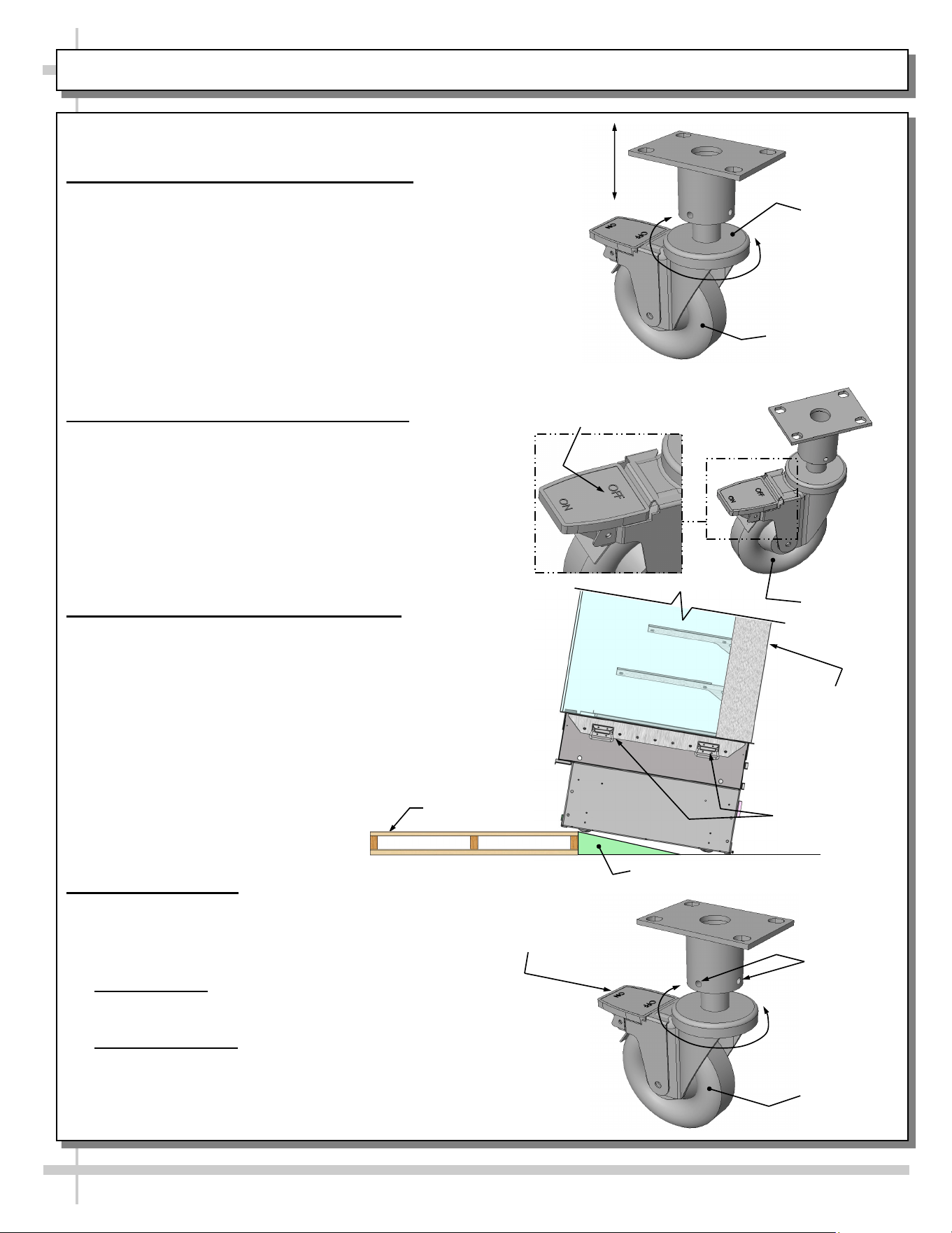
4. Caster Height: Raising and Lowering
• Raise or lower casters (to adjust case height) by
rotating casters’ vertical adjustment rings.
• Rotate vertical adjustment ring clockwise to lower
caster (and increase height of case).
• Rotate vertical adjustment ring counter-clockwise
to raise caster (and decrease height of case).
5. Caster Rolling Capability: Unlocking
• Important! Case is shipped with caster mechanisms
factory set at ON (locked) to prevent case from rolling.
• Unlock casters by pressing OFF on the caster
mechanism.
• See illustration at right.
6. Carefully Remove Case From Pallet
• Check that casters are lowered as far down as they
will go (as instructed in step #4).
• Use handles to carefully slide case to edge of pallet
(see illustration at right).
• Caution! 4 people are required for this task!
• Carefully lower to floor (using ramp if available).
• Slide pallet from under case as required.
• Maintain support of case at all times or case may fall.
• See illustration at right.
7. Casters: Locking
• After case is at desired position (and height),
use level to check that case is level and
plumb.
• Readjust height as needed (as instructed in step #4).
• Locking Height: After proper height (and positioning) of
case is attained, tighten the two (2) set screws to lock
each caster’s height in place.
• Locking Movement: Then, to prevent casters’ rolling
capability, lock casters by pressing ON atop the “ON”
and “OFF” lever mechanism (shown at right). Case
will now be secured at its new location.
Vertical
Adjustment
Ring
Caster
Caster
Tighten Set
Screws To
Lock Caster
Height In
Place
Press “ON” Lever To
Lock Caster In Place
(And Prevent Casters’
Rolling Capability)
Support case
while removing
from pallet.
Press “OFF” Lever To
Unlock Casters (And
Allow Casters To Roll)
Caster
Handles
Pallet
Ramp
7
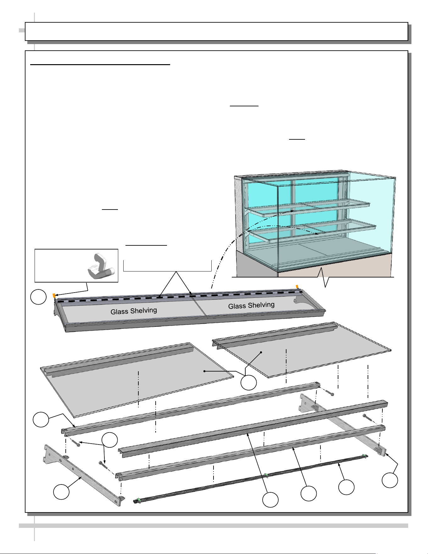
INSTALLATION, CONT’D: SHELVING ASSEMBLY COMPONENTS
E
A
B
C
D
G
From Factory: Transparent
2-Sided Tape Holds
Glass To Top Of Rear
Shelf Support Rail
H
Right Glass
Shelving Piece
Left Glass
Shelving Piece
Nylon Retainer
Clip (Typ.)
I
F
8. Shelving Assembly Components
• Check that glass shelving is in proper position
before placing product in case
• Shelves may be adjusted vertically or entirely
removed from merchandiser.
• Metal shelving brackets ARE NOT able to be
angled. They are at a fixed 90° position.
• There are 12 components comprising each
shelf assembly:
A. Right bracket (with hooks to attach to slots in
upright)
B. LED light with magnets
C. Front shelf support rail (LED light attaches to its
inner cavity via magnets)
D. Cover (rests atop front shelf support rail)
E. Left bracket (hooks to attach to slots in upright)
F. Nylon thumbscrews (4 per shelf) secure shelving
during shipment. Note: Remove (using pliers, if
necessary) and discard thumbscrews after case
is installed so shelves can be disassembled (to
clean or service).
G. Rear shelf support rail.
H. Left and right glass shelf/cover assemblies (glass
is affixed to covers with 2-sided tape from factory).
Caution! Glass pieces ARE NOT IDENTICAL!
Notches on underside metal covers determine
placement in case.
I. Nylon retainer clips (2 per shelf) secure brackets
during shipment. Note: To adjust or remove
shelves, you must remove retainers; pliers may
be required to accomplish this task.
8
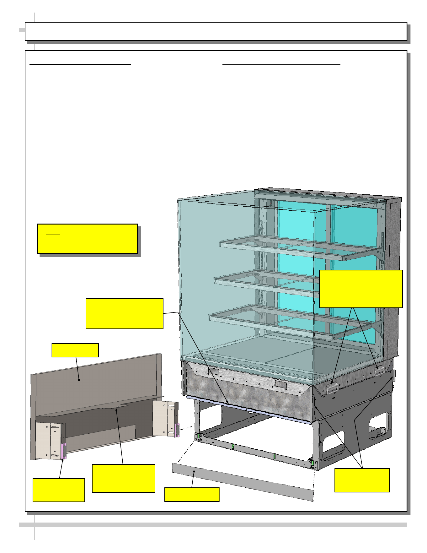
INSTALLATION, CONT’D: ATTACHING COMPONENTS / HANDLES
9. Attaching Components
• Carefully remove components from packaging.
• Attach components to case via magnets.
• Attach front toe-kick to case (via magnets).
• Slide center bracket (attached to front panel) atop
case’s front panel support bracket. Then, slide
front panel into case until magnets attach to case
in flange’s cutout opening.
• Attach side cladding to magnets.
• Attach rear upper panel, rear lower panel and
front toe-kick to case.
10. Handles On Sides of Case
• Handles may remain on case after it has been
moved into position and cladding is attached.
• However, if handles interfere with the placement
of cladding, they may be removed.
>> See Next Page For Instructions on ATTACHING
SIDE PANELS, REAR UPPER AND LOWER
PANEL.
Note: Illustration shown may
not reflect every feature or
option of your particular case.
Handles (on Both Sides
of Case) May Be
Removed If They
Interfere With Cladding.
Front Toe-Kick
Support Slot (For Front
Panel’s Horizontal
Support Bracket)
Front Panel
Horizontal
Support Bracket
Front Panel
Magnet (Typ.)
Front Panel
Hooks For End
Panel (Typ.)
9
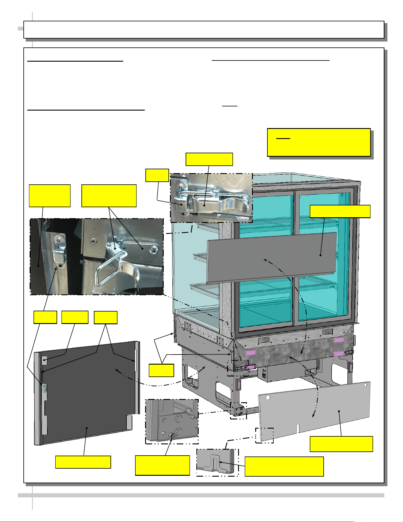
INSTALLATION, CONT’D: ATTACHING SIDE PANELS, REAR UPPER AND LOWER PANEL
11. Attaching Side Panels
• Attach side panels to case using slot/hook method.
• Use latches at case rear to firmly attach side
panels to case.
• See illustrations below.
12. Attaching Rear Upper Panel
• Place rear upper panel onto care rear.
• Four (4) magnets will hold it firmly in place.
• See illustration below
13. Attaching Rear Lower Panel
• Use finger holes to place rear lower panel’s
inner hooks onto case rear’s lower shoulder
screws.
• Snap onto case’s two (2) rear vertical magnets.
>> Note: Components may be removed in reverse
order they were shown being attached on this sheet.
Hook
Unlocked Latch
(Typ.)
Side Panel (Typ.)
Rear Upper Panel
Slots
Side Panel
(Typ.)
Inserts
Hooks
Locked Latch
Hook
Shoulder Screw
(Typ.)
Note: Illustration shown may
not reflect every feature or
option of your particular case.
Rear Lower Panel
Rear Grille Inner Hook
Shown Reversed (Typ.)
10
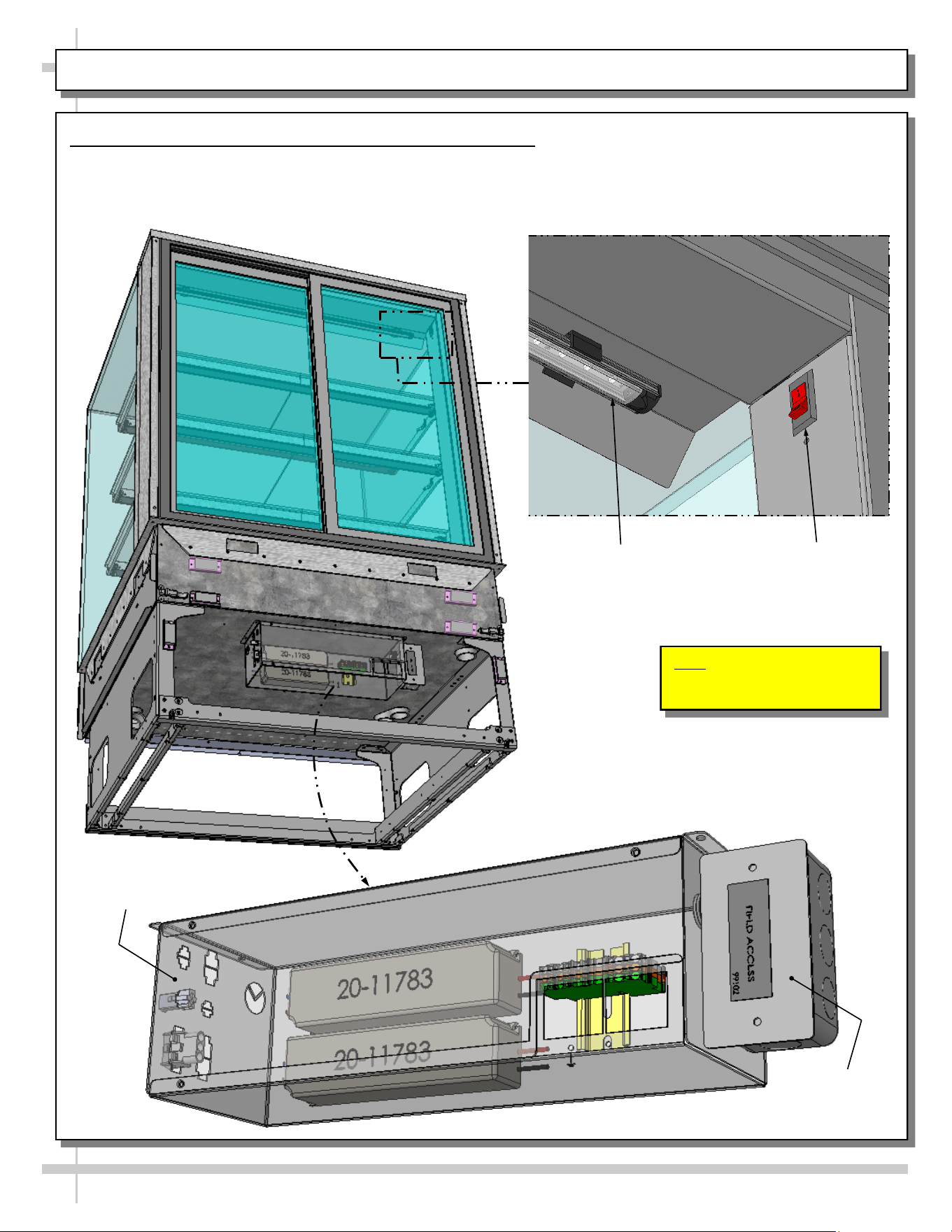
INSTALLATION, CONT’D: FIELD WIRE (OR PLUG IN) CASE / TURN ON LED LIGHTS
14. Field Wire (Or Plug In) Case / Turn on LED Lights
• Field-wired case or plug unit into outlet (if factory-supplied plug is present).
• Case will energize when properly field-wired (or plugged into outlet).
• Turn on LED light switch at front-left header.
Light Switch
LED Light
Electrical / LED
Driver Box
Field
Access Box
Note: Illustrations shown may
not reflect every feature or
option of your particular case.
11
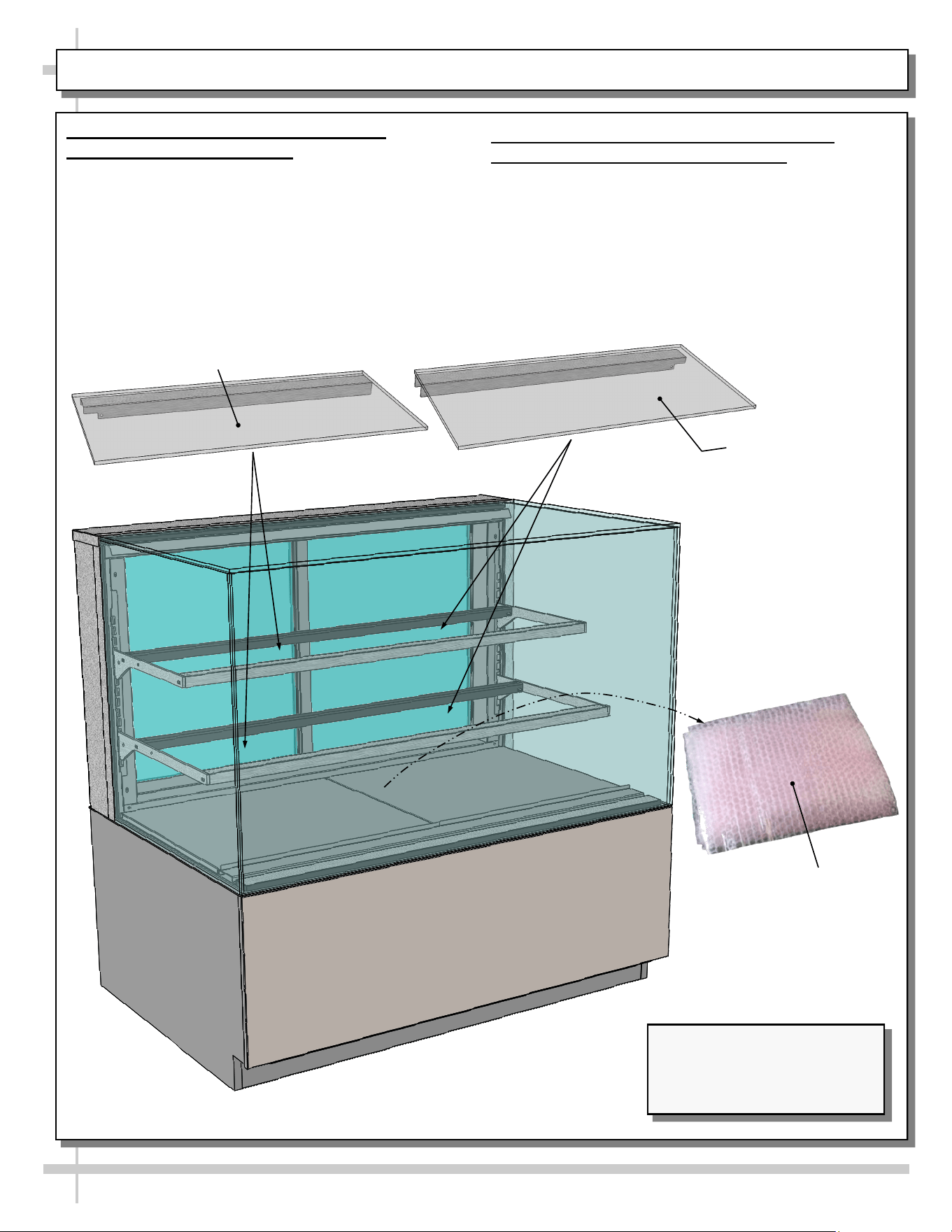
INSTALLATION, CONT’D: BUBBLE-WRAPPED GLASS (FOR SHELVING)
15. Remove Bubble-Wrapped Glass
(For Shelving) From Case
• Carefully remove bubble-wrapped glass shelving
pieces from case.
• See illustration below-right.
16. Remove Glass From Bubble-Wrap /
Carefully Place Them On Shelves
• Remove glass (for shelves) from its bubble-wrap.
• Place glass pieces on shelves.
• Caution! Glass pieces ARE NOT IDENTICAL!
Notches on the underside metal covers
determine placement in case.
• See illustrations below and on next page.
Model NR4847DSV Slide-In
Units (Shown) May Not Exactly
Reflect Every Feature or
Option of Your Particular Case.
Right Glass
Shelving Piece
Left Glass
Shelving Piece
Bubble-Wrapped
Glass (For Shelving)
12
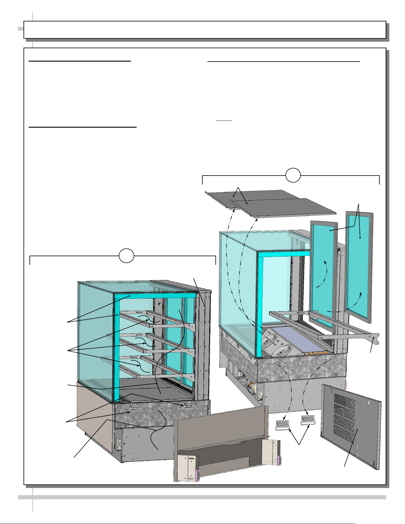
CASE ADJOINMENT INSTRUCTIONS - PAGE 1 of 4
Case Adjoinment Overview
>> Carefully follow these step-by-step case
adjoinment instructions.
>> Warranty is void if unapproved urethane//sealant
is used in case adjoinment process.
>> Move cases into position before beginning this
adjoinment process.
1. Case Arrival From Factory
• Cases that are to be adjoined will NOT have
side magnets nor side cladding on adjoinment
side.
• There is no rear trim piece on adjoinment side.
• Glass shelving is bubble-wrapped and is placed
on decks shipped separately, is bubble-wrapped
and is placed on decking from factory.
• There is no side glass on adjoinment side.
• Handles are still attached.
• Blueboard will be intact (for future application
of urethane).
2. Case Preparation Prior To Adjoinment
• Remove front panel.
• Remove rear grille.
• Remove rear sliding doors.
• Remove decking.
• Remove handles.
• Remove ALL shelving brackets.
Note: Each shelving bracket has a different depth
and must be returned to case accordingly!
• Store components in safe and secure location
away from foot traffic.
• See below-right illustration.
• >> Adjoinment instructions continue on next page.
No Side Magnets
Nor Side Cladding
Handles
Blueboard
No Glass
Shelving
1
No Rear
Trim Piece
No Side
Glass
2
Front Panel
Rear Grille
Rear Sliding
Doors
Decking
Handles
Shelving
Bracket
(Typ.)
13
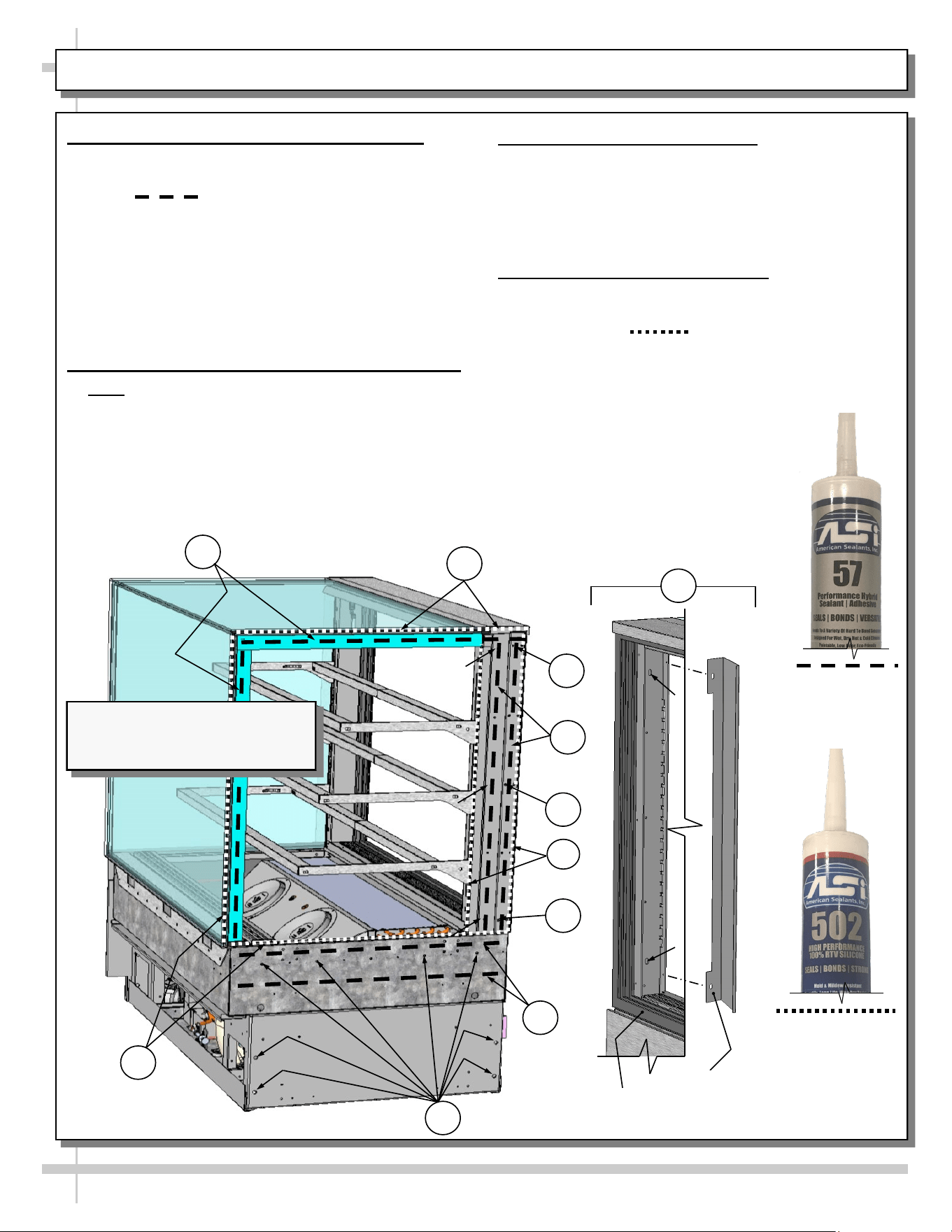
CASE ADJOINMENT INSTRUCTIONS - PAGE 2 of 4
3. Industrial Grade Urethane Application
• Lay a generous, CONTINUOUS bead of
SCC-provided urethane adhesive (as identified
with line pattern shown below).
• Lay a generous bead of industrial grade urethane
adhesive at center of uprights (in non-visible areas).
• This urethane prevents refrigerated air from
escaping between cases (causing condensation
and reducing refrigeration efficiency) as well as
preventing ants or other insects from entering case.
• See illustration below.
4. Case Adjoinment w/SCC-Provided Screws
• Note: Cases in this adjoinment have a wide range
of surfaces (metal, foam board, blueboard, etc.).
• A variety of SCC-provided wood screws, bolts,
washers and nuts are provided in adjoinment kit.
• Due to wide range of hole locations, you must
access adjoinment points through rear door, rear
grille, decking, front panel and rear grille areas.
• Firmly tighten all screws!
Silver, Black or Clear
Silicone Sealant
Conforming To
NSF/ANSI 51
Specifications
(For Sanitation
Bead Applications)
5. Inner Raceway Adjoinment
• Inner raceway cover must be removed
(by removing 2 screws).
• Use 1/4-20 bolts, nuts and washers to attach
inner raceway upright to adjoining case.
• Then, reattach inner raceway cover .
6. Silicone Sealant Application
• After case is adjoined, apply a generous,
CONTINUOUS bead of silicone sealant (as
identified with line pattern shown below)
at both inner and outer adjoinment seams.
• When properly applied, this sealant will prevent
water from seeping between cases (into the
case or to the floor) as well as
prevent crumbs or other residue
from entering between case seams.
>> Adjoinment instructions continue
on next page.
Industrial Grade
Urethane Adhesive
(For Refrigeration
Bead Applications)
5
6
Inner
Raceway
Cover
Rear Sliding
Door Casing
3
6
4
3
4
4
4
3
6
Note: Illustration Shown May Not
Exactly Reflect Every Feature or
Option of Your Particular Case.
14
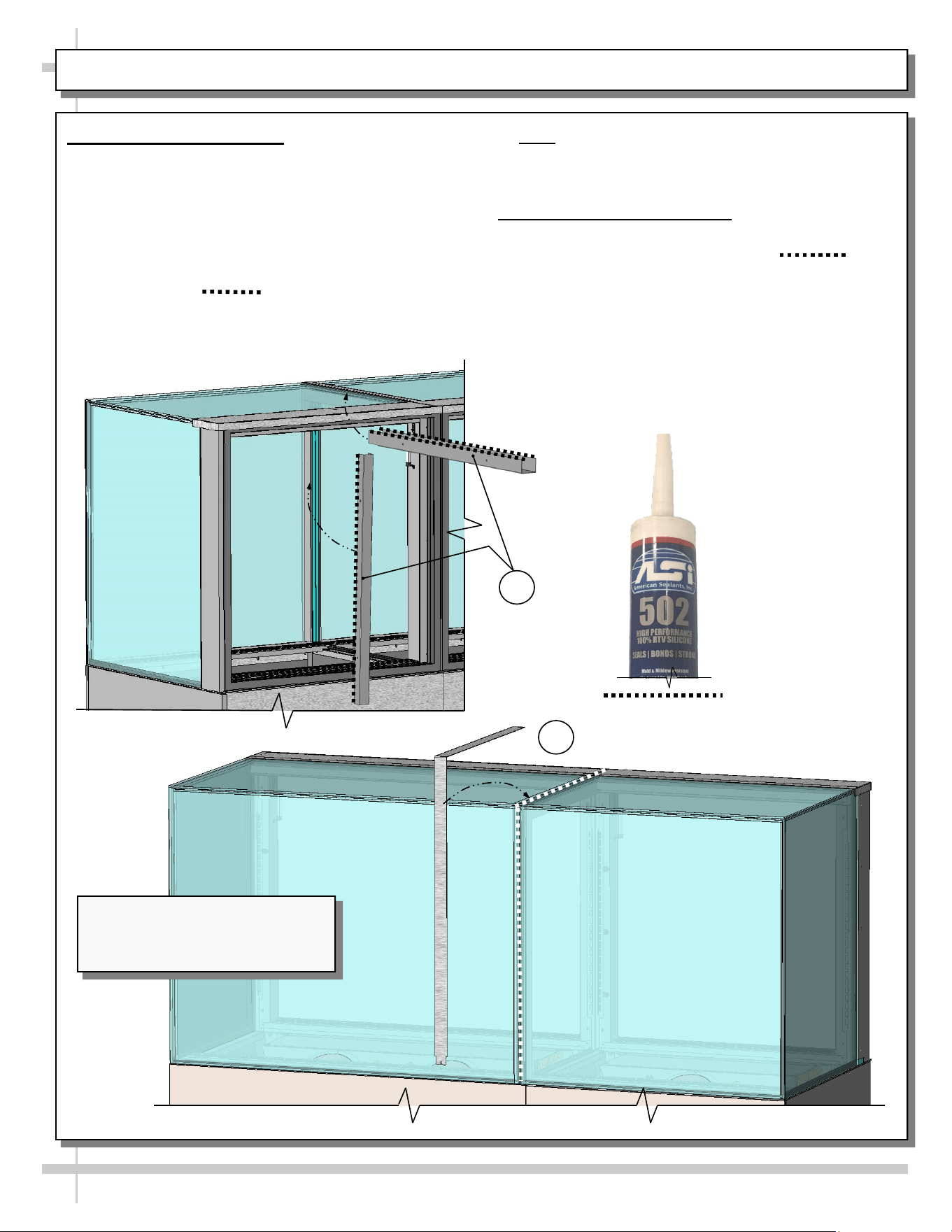
CASE ADJOINMENT INSTRUCTIONS - PAGE 3 of 4
7. C-Bracket Attachment
• After cases are attached, place vertical and
horizontal C-brackets at inner case.
• Use SCC-provided screws to attach to Celtec/
blueboard. Two holes at each side of both
C-brackets are provided for screws.
• After C-brackets are adjoined, apply a generous,
CONTINUOUS bead of silicone sealant (as
identified with line pattern shown).
• Note: Illustration below shows silicone bead
applied at required spot on C-brackets PRIOR to
attachment to case for illustrative purposes only.
8. Middle Trim Attachment
• After placing generous, CONTINUOUS bead of
silicone sealant (as identified with line
pattern shown below) middle trim may be
attached to case.
• Apply a generous bead of silicone at underside of
trim piece and attach at seam.
>> Adjoinment instructions continue on next page.
Silver, Black or Clear
Silicone Sealant
Conforming To
NSF/ANSI 51
Specifications
(For Sanitation
Bead Applications)
7
8
Note: Illustration Shown May Not
Exactly Reflect Every Feature or
Option of Your Particular Case.
15
CASE ADJOINMENT INSTRUCTIONS - PAGE 4 of 4
9. Case Adjoinment Complete / Component Replacement
• After case adjoinment is complete, replace decking, shelving, front panel, rear grille, and rear sliding
doors in reverse order they were removed.
• Glass may now be removed from protective bubble-wrap and placed on shelving brackets.
• Discard handles that had been removed.
• See illustration below.
--- Cases Shown Adjoined ---
9
Note: Illustration Shown May Not
Exactly Reflect Every Feature or
Option of Your Particular Case.
16
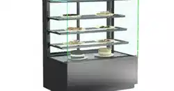
CASE DESIGN: FRONT VIEW OF FREE STANDING, SERVICE MERCHANDISERS
1. Front View Of Free Standing, Service Merchandisers
• Sample free standing model is illustrated below.
• See INSTALLATION, CONT’D: MOVING/POSITIONING CASE
INTO POSITION / ATTACHING COMPONENTS section in manual
for view of front panel, side cladding, rear toe-kick, back panel, etc.
• See next page for rear view of merchandiser.
Decking
Rear Sliding
Doors
Glass
Shelving
(Typ.)
UV-Bonded Glass
Enclosure (Typ.)
Handles For
Pushing or Pulling
Unit Into Position
Model NR3635DSV (Shown) May
Not Exactly Reflect Every Feature
or Option of Your Particular Case.
Front Toe-Kick
Front
Toe-Kick
17
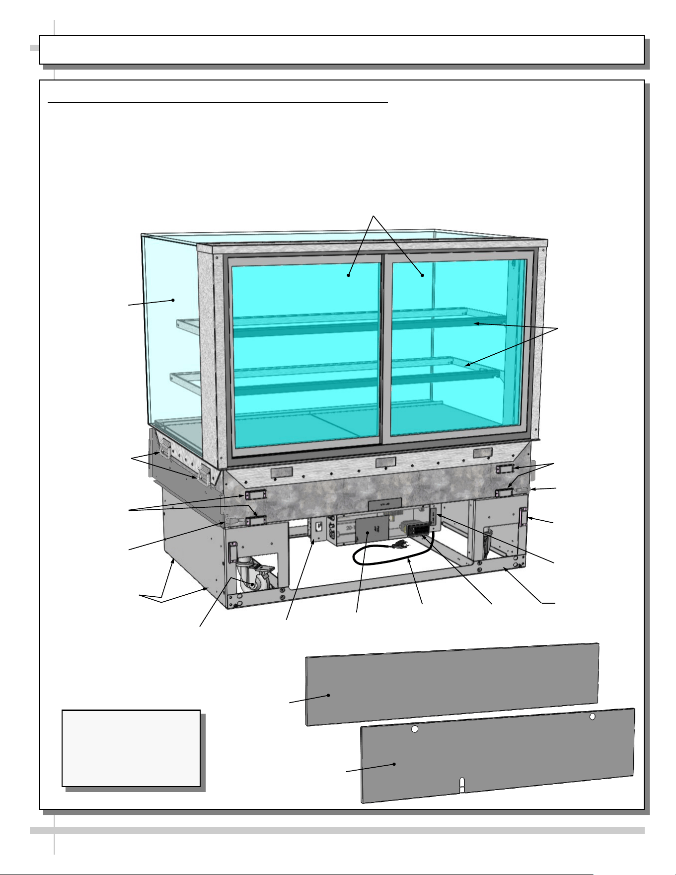
CASE DESIGN, CONT’D: REAR VIEW OF FREE STANDING, SERVICE MERCHANDISERS
2. Rear View Of Free Standing, Service Merchandisers
• Sample free-standing model is illustrated below.
• See INSTALLATION, CONT’D: MOVING/POSITIONING CASE INTO POSITION / ATTACHING
COMPONENTS section in manual for view of front panel, side cladding, front toe-kick,
front panel, etc.
• See previous page for front view of merchandiser.
Model NR4847DSV
(Shown) May Not Exactly
Reflect Every Feature
or Option of Your
Particular Case.
Rear Sliding (And
Removable) Doors
Glass
Shelving
End Glass
Magnets For
Rear Panel
Rear Panel
Magnet For
Rear Toe-Kick
(Typ.)
Rear Toe-Kick
Thermostat
Power Cord
And Plug
Field Access
Box
Field Sensor
Box Location
Electrical
Box
Shipping
Brace
Handles For
Pushing or
Pulling Unit Into
Position.
Caster (Typ.)
Magnet For Side
Cladding (Typ.)
Magnets For
Rear Panel
Latch
Latch
18
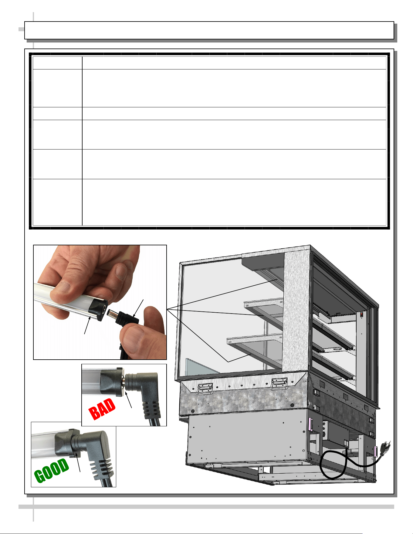
CASE DESIGN, CONT’D: POWER CORD & PLUG / LED LIGHT SWITCH LOCATIONS / LED LIGHTS
3. Power Cord and Plug
• Power cord and plug (for LED lights) is at case
rear (shown below).
• Caution! You must plugged in an approved outlet!
LED Lights In
Shelving And
Header
Model NR4847DSV
Unit Is Shown Partially
Disassembled For
Illustrative Purposes.
It May Not Reflect Every
Feature or Option of
Your Particular Case.
LED Light
Switch
4. LED Light Switch Locations
• Light switch is in column cover (accessible by
sliding open door at case rear).
• See illustrations below-right.
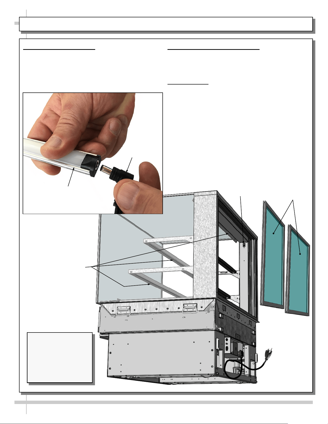
5. LED Lights
• LED lights are located at both header and
shelving of case (as shown below).
• Check that ALL of the light plugs are properly
connected to the LED light.
• Plug must be inserted ALL THE WAY into the
LED light orifice (with no gap) to work properly.
• See TROUBLESHOOTING section in manual
if LED lights malfunction.
Rear Sliding
Doors
LED Light
Plug

19
CASE DESIGN, CONT’D: REAR SLIDING DOORS / DOOR OPERATION
6. Rear Sliding Door Removal / Replacement
• To remove rear sliding doors, move doors toward center of case.
• Individually lift each door up toward the top of the case; pivot the bottom
of the door out.
• Return doors to case in reverse order they were removed.
Rear Sliding
Doors
Model NR4847DSV Unit
Is Shown Partially
Disassembled For
Illustrative Purposes. It
May Not Reflect Every
Feature or Option of Your
Particular Case.
20
CLEANING SCHEDULE (TO BE PERFORMED BY STORE PERSONNEL)
FREQUENCY INSTRUCTIONS
Daily Glass Surfaces: Clean side glass and shelves with household or commercial glass
cleaner.
Daily Rear Sliding Door Exterior Glass: Clean with household or commercial glass cleaner.
Clean out rear door track with moist cloth.
Daily End Panels, Front Panel, Toe-Kick, etc.: Wipe off all surfaces with warm water and
mild soap solution and non-abrasive cloth.
Daily Decks: Wipe off decks with moist cloth dipped in mild soap and water solution.
Daily Stainless Steel Surfaces:
• Wash with a solution of hand dishwashing liquid detergent and water, or a solution of
baking soda and water. Rinse and polish dry with paper towel or soft cloth.
• Never use scouring powders or steel wool as they will scratch stainless steel.
• Brighten by polishing with a cloth dipped in vinegar or in ammonia; sprinkle baking
soda on sponge and rub gently; rinse. Polish dry with paper towel.
• Remove streaks or heat stains from stainless steel by rubbing with club soda.
Quarterly Under Case Cleaning:
A. Rolling Case To New Location:
• If case is NOT hard wired, it may be rolled forward or backward to allow access to
case underside (depending upon its store placement).
• Use vacuum with brush extension or broom and dust pan to remove all dust, dirt,
food particles or residue.
• Roll case back into its previous location after cleaning is complete.
B. Case Component Removal:
• Whether case is hard wired or not, case components may be removed to allow
cleaning under case.
• Case components are held in place with magnets and are removable without tools.
• Remove side cladding, front panel, front toe-kick or lower rear panel by lifting up
and off case. See INSTALLATION, CONT’D: ATTACH COMPONENTS (FRONT &
REAR PANELS, CLADDING, ETC.) section in manual for illustrations.
• Use vacuum with brush extension to remove all dust, dirt, food particles or residue
at underside of case.
• Replace components when cleaning process is complete.
21
TROUBLESHOOTING (TO BE PERFORMED BY STORE PERSONNEL)
CONDITION TROUBLESHOOTING
Case Lights
Not Working
Check that light switch is in the ON position.
• See CASE DESIGN, CONT’D: POWER CORD & PLUG / LED LIGHT SWITCH
LOCATIONS / LED LIGHTS section in manual for switch location (regardless of case
design).
If case is not hard-wired, check that power cord is properly connected to wall outlet.
Check that ALL of the light plugs are properly connected to the LED light.
• Plug must be inserted ALL THE WAY into the LED light orifice (with no gap).
• See illustrations below-left.
Power may not be reaching the case.
• Contact store management to have trained service provider perform troubleshooting.
• Troubleshooting to be performed by trained service providers only is on next page.
If case light still do not come on, it may need to be replaced.
• Contact Structural Concepts’ Technical Service Department for replacement light
(see TECHNICAL SERVICE section of this manual for contact information).
• To replace, disconnect plug from existing LED light. Disconnect LED light from its
brackets. Replace with new LED light. Insert plug ALL THE WAY into LED light orifice.
No Gap
Gap
LED Light
Plug
22
CONDITION TROUBLESHOOTING
Case Lights Are
Not Working
See TROUBLESHOOTING (TO BE PERFORMED BY STORE PERSONNEL)
section in manual (previous sheet) for most common troubleshooting solutions.
Check power.
• If power is not supplied to the case, facility may have faulty power distribution.
• If power is supplied to the case but lights are not energized, case’s power supply
may be faulty.
TROUBLESHOOTING (TO BE PERFORMED BY TRAINED SERVICE PROVIDERS ONLY)
23
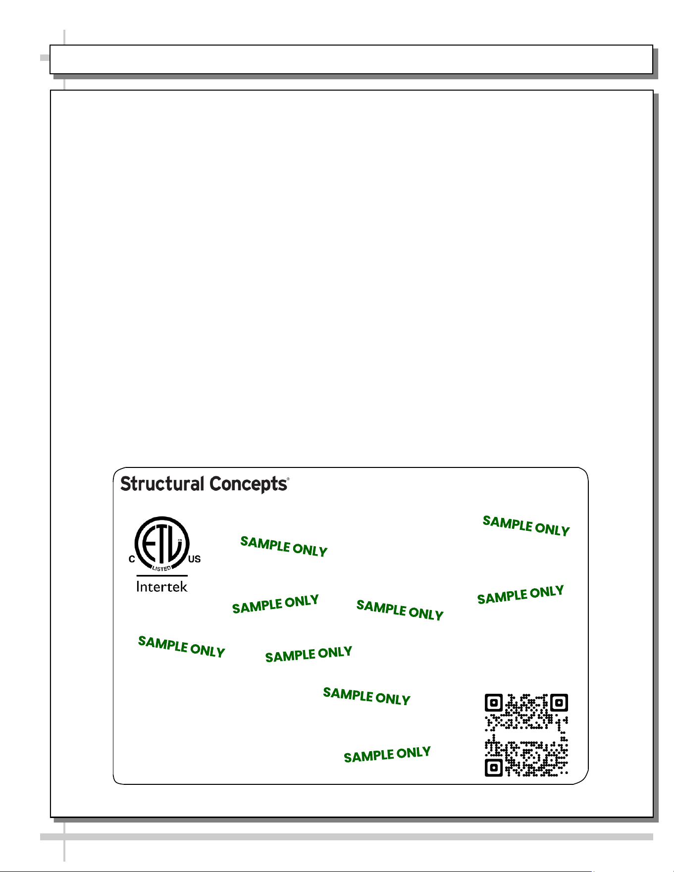
SERIAL LABEL LOCATION & INFO LISTED / TECH INFO & SERVICE - AMBIENT/HEATED CASES ONLY
--- Sample Serial Label For Ambient/Heated Cases ---
MODEL NRS3648RXV-SAMPLE
SERIAL NO. 12345X30DZ098765
888 E. Porter Rd - Muskegon, MI 49441
3048256
Conforms to UL Std. 65
CERTIFIED TO CAN/CSA
STD C22.2 NO 120
120 VOLTS 60HZ
FOR PARTS OR SERVICE CALL
STRUCTURAL CONCEPTS
AT 1-800-433-9489
SINGLE PHASE 1.84 AMPS
Serial Label Location & Information Listed /
Technical Information & Service
• Serial labels are affixed at a wide range of places
(on the header, at case rear, behind panels or
toe-kicks, on electrical boxes, etc.).
• Serial labels contain electrical information as well
as regulatory standards to which the case
conforms.
• Sample serial label shown below.
• For additional technical information and service, see
the TECHNICAL SERVICE page in this manual for
instructions on contacting Structural Concepts’
Technical Service Department.
Sample QR Code
SCAN FOR PRODUCT LITERATURE
Reveal
SAMPLE ONLY
STRUCTURAL CONCEPTS TECHNICAL SERVICE CONTACT INFORMATION & LIMITED WARRANTY
24
TECH SERVICE/WARRANTY CONTACT INFO:
1 (800) 433-9490 / EXTENSION 1
DAYS/HOURS AVAILABLE:
MONDAY - FRIDAY (CLOSED HOLIDAYS)
8:00 a.m. TO 5:00 p.m. EST
YOU MUST HAVE THE FOLLOWING INFO AVAILABLE
BEFORE CONTACTING STRUCTURAL CONCEPTS:
SERIAL NO. / MODEL NO. / STORE NO. / STORE
ADDRESS / DETAILS (PHOTOS, LEAK LOCATIONS,
DAMAGE, STORE’S AMBIENT CONDITIONS, ETC.)
To Access The Limited Warranty To Your
Case, Follow These Instructions:
> If Viewing This Document on Smart Phone,
Tablet or Computer, Select/Click On The QR
Code at Right.
> If Viewing This Document In Print (Hard
Copy), Scan The QR Code at Right With Your
Smart Phone or Tablet.