Table of Contents
3
EN
1 Installation 12
1.1 Positioning in the counter top 12
1.2 Mounting 15
1.3 Gas supply requirements 16
1.4 Electrical requirements 25
1.5 For the installer 26
IMPORTANT SAFETY INSTRUCTIONS
WARNING
If the instructions contained in this manual are not followed
precisely, a fire or explosion may result causing property
damage, personal injury or loss of life.
Do not store or use gasoline or other flammable vapors, liquids
or materials near this or any other appliance.
- WHAT TO DO IF YOU SMELL GAS
• Do not try to light any appliance.
• Do not touch any electrical switch.
• Do not use any telephones in your building.
• Immediately call your gas supplier from a neighbor's phone.
Follow the gas supplier's instructions.
• If you cannot reach your gas supplier, call the fire
department.
- Installation and service must be performed by a qualified
installer, service company or gas supplier.
INSTALLATION AND SERVICE MUST BE PERFORMED BY A
QUALIFIED INSTALLER.
IMPORTANT: SAVE FOR THE LOCAL INSPECTOR’S USE.
Important Safety Instructions
4
The safety messages will inform you of potential hazards, on how to avoid the risk of injury
and what can occur if the instructions are not followed.
IMPORTANT: Installation, gas connections and grounding must comply with
applicable codes. Observe all codes and ordinances in force.
WARNING
• This appliance is intended for residential use only.
• Use this appliance only for its intended purpose.
The manufacturer cannot be held liable for damage
caused by improper use of this appliance.
• This appliance complies with current safety
regulations. Improper use of this appliance can
result in personal injury and property damage.
• Read all the instructions before installing or using
the appliance for the first time.
• Keep these operating instructions in a safe place
and give them to a
ny future user.
NOTE: This appliance is designed for use with natural gas. To convert the
appliance to LPG/Propane gas, see the instructions in the “Conversion to propane
gas (LPG)” section.
The proper gas supply connection must be available. See “Gas supply
requirements”.
WARNING: For your safety, the instructions contained in this
manual must be followed to minimize the risk of fire or
explosion and to prevent property damage, personal injury
or loss of life.
Important Safety Instructions
5
EN
Important Notes to the Installer
• Read all the instructions contained in this
manual before installing the appliance.
• Remove all packing material from the
appliance before connecting the
electrical and gas supplies to the
appliance.
• Observe all governing codes and
ordinances. Be sure to leave these
instructions with the consumer.
• It is the responsibility of the installer to
comply with installation information
specified on the model/serial ID plate.
The ID plates are located in a visible
position on the back of the appliance.
These ID plates must never be removed.
Important Note to the Customer
• Keep these instructions with your owner's
guide for future reference.
• Any additions, changes or conversions
required for this appliance to
satisfactorily meet the application
requirements must be made by a
qualified technician.
NOTE: This appliance is NOT designed for installation in manufactured (mobile)
homes or in recreational vehicles (RVs).
DO NOT install this appliance outdoors. Improper installation is not covered
by the warranty.
WARNING
• Failure to follow the instructions in this manual may
result in fire or electric shock, causing property
damage or personal injury.
• Do not repair, replace or remove any part of the
appliance unless specifically recommended in the
manuals. Improper installation, service or
maintenance can cause injury or property damage.
Refer to this manual for guidance. All other servicing
should be carried out by an authorized servicer.
• To reduce the risk of fire, electric shock, personal
injury or damage when using the appliance, follow
basic safety precau
tions, including the following.
Important Safety Instructions
6
Definitions
• This manual contains important safety
symbols and instructions. Please pay
attention to these symbols and follow all
instructions given.
Appliance Handling Safety
Hidden surfaces may have sharp
edges. Use caution when reaching
behind or under the appliance.
• Wear gloves to avoid cutting fingers on
sharp edges during installation.
• The unit is heavy and requires at least
two persons or proper equipment to
move it.
Safety Codes and Standards
This appliance complies with one or
more of the following Standards:
ANSI Z21.1/CSA 1.1 Household
Cooking Gas Appliances
• It is the responsibility of the owner and
the installer to determine whether
additional requirements and/or
standards apply to specific installations.
• Installation must conform with local
codes or, in the absence of local codes,
with the National Fuel Gas Code, ANSI
Z223.1/NFPA 54 or, in Canada, the
Natural Gas and Propane Installation
Code, CSA B149.1.
• The appliance must be electrically
grounded in accordance with local
codes or, in the absence of local codes,
with the National Electrical Code, NFPA
70 latest edition or, in Canada, the
Canadian Electric Code, CSA C22.1-
02.
• Ensure that the electrical system is
adequate and in compliance with the
national ANSI / NFPA 70 ELECTRICAL
CODE – latest edition – or the
CANADIAN ELECTRICAL CODE,
C22.11 – 1 and C22.2 No. 01982 –
or latest edition – and all local codes
and ordinances. IMPORTANT: Observe
all codes and ordinances in force.
• Proper installation is your responsibility.
WARNING
This symbol will help alert you to
situations that may cause serious bodily
harm, death or property damage.
CAUTION
This symbol will help alert you to
situations that may cause injury or
property damage.
Important Safety Instructions
7
EN
• Make sure your appliance is installed
and grounded properly by a qualified
installer or service technician.
• Make sure that the wall coverings
around the appliance can withstand the
heat generated by the appliance.
• Test the appliance immediately after
installation, following the instructions in
this booklet. If the appliance does not
work properly, disconnect it from the
electrical power supply and call the
service center. DO NOT attempt to
repair the appliance.
• All adjustments and servicing must be
performed by qualified installers or
service technicians.
• Do not leave the packing materials
around the home. Sort the various items
of waste and take them to the nearest
specialized waste collection facility.
• Do not store items of interest to children
in the cabinets above the appliance.
Children could be seriously burned if
they climb on the appliance to reach
items.
• To eliminate the need to reach over the
surface burners, cabinet storage space
above the burners should be avoided.
• Do not store or use gasoline or other
flammable vapors and liquids near this
or any other appliance. Explosions or
fires could result.
• Adjust the size of the surface burner
flame so that it does not extend beyond
the edge of the pan. An excessively
large flame is hazardous.
• Do not use the appliance for warming or
heating the room. Prolonged use without
adequate ventilation can be dangerous.
• In the event of an electrical power
outage, the surface burners can be lit
manually. To light a surface burner, hold
a lit match to the burner head and slowly
turn the Surface Control knob to LITE.
Use caution when lighting surface
burners manually.
• THIS COOKTOP IS NOT REMOVABLE.
Do not attempt to remove the cooktop.
WARNING
Never leave children alone or
unattended in the area where an
appliance is in use. As children grow,
teach them the proper, safe use of all
appliances.
WARNING
Do not repair, replace or remove any
part of the appliance unless specifically
recommended in the manuals. Improper
installation, service or maintenance can
cause injury or property damage. Refer
to this manual for guidance. All other
servicing should be done by an
authorized service provider.
Important Safety Instructions
8
Electric Safety
• Personal injury or death from electrical
shock may occur if the appliance is not
installed by a qualified installer or
electrician.
• Make sure your appliance is properly
installed and grounded by a qualified
electrician. Installation, electrical
connections and grounding must comply
with all applicable codes.
• Switch OFF the power at the service
panel before installation. Lock the
service panel to prevent the power from
being switched ON accidentally.
• For appliances equipped with a cord
and plug, do not cut or remove the
ground prong. It must be plugged into a
matching grounding type receptacle to
avoid electrical shock. If there is any
doubt as to whether the wall receptacle
is properly grounded, the customer
should have it checked by a qualified
electrician.
• Do not use an extension cord.
• Do not use an adapter.
• If required by the National Electrical
Code (or Canadian Electrical Code),
this appliance must be installed on a
separate branch circuit.
• The circuit breaker should have a
contact separation of at least 3 mm on
all poles.
• INSTALLER – show the owner the
location of the circuit breaker or fuse.
Mark it for easy reference.
• Refer to rating label for more information.
Gas safety
• Install a gas shutoff valve near the
appliance. It must be easily accessible in
an emergency.
• Leak testing must be conducted by the
installer according to the instructions in
this manual.
• The appliance and its individual shutoff
valve must be disconnected from the gas
supply piping system during any
pressure testing at pressures in excess of
½ psi (3.5 kPa).
WARNING
Before you plug the electrical cord into
an outlet, make sure that all the
appliance controls are in the OFF
position.
WARNING
Disconnect the power supply before
servicing the appliance.
WARNING
Burning gas cooking fuel generates some
by-products which are on the list of
substances which are known by the State
of California to cause cancer or
reproductive harm. To minimize exposure
to these substances, always operate this
unit according to the instructions
contained in this booklet and provide
good ventilation.
Important Safety Instructions
9
EN
• The appliance must be isolated from the
gas supply piping system by turning off
its individual manual shutoff valve during
pressure testing of the gas supply piping
system at test pressures equal to or less
than ½ psi (3.5 kPa).
• The minimum supply pressure must be 1"
water column above the manifold
pressure printed on the rating label. The
maximum supply pressure of 14.0 inches
water column (34.9 Millibars) must not
exceed.
• IMPORTANT SAFETY NOTICE Burning
gas cooking fuel generates some by
products which are on the list of
substances which are known by the
State of California to cause cancer or
reproductive harm. To minimize
exposure to these substances, always
operate this unit according to the
instructions contained in this booklet and
provide good ventilation.
Proposition 65 Warning:
This product may contain a chemical known
to the State of California, which can cause
cancer or reproductive harm. Therefore, the
packaging of your product may bear the
following label as required by California:
Propane Gas Installation
• The propane gas tank must be equipped
with its own high pressure regulator. In
addition, the regulator supplied with this
unit must also be used.
• The appliance is shipped from the
factory for use with natural gas. It must
be converted for use with propane. The
conversion must be done by a qualified
technician or installer.
• This appliance can operate up to an
altitude of 10,000 ft. (3048 m.)
elevation above sea level. For use with
propane gas, the appliance must be
converted in accordance with the
propane conversion instructions.
For installations in Massachusetts
• Installation must be performed by a
qualified or licensed contractor, plumber
or gas fitter qualified or licensed by the
state, province or region where this
appliance is being installed.
• Shut-off valve must be a “T” handle gas
cock.
• Flexible gas connector must not be
longer than 36 inches.
• Installer - show the owner where the gas
shut-off valve is located.
State of California Proposition 65
WARNING
Cancer or Reproductive Harm -
www.P65Warnings.ca.gov
Important Safety Instructions
10
Related Equipment Safety
• The appliance should only be used if
installed by a qualified technician in
accordance with these installation
instructions and all applicable
regulations and codes. The
manufacturer is not responsible for
damages resulting from incorrect
installation.
• Remove all tape and packaging before
using the appliance. Dispose of the
packaging after unpacking the
appliance. Never allow children to play
with packaging material.
• Never modify or alter the construction of
the appliance. For example, do not
remove leveling legs, panels, wire
covers or anti-tip brackets/screws.
• To eliminate the risk of burns or fire by
reaching over hot surface units, cabinet
storage space located above the
surface units should be avoided. If
cabinet storage is to be provided, the
risk can be reduced by installing a hood
that projects horizontally a minimum of 5
inches (127 mm) beyond the bottom of
the cabinet. Be sure cabinets above the
cooktop are a maximum of 13" (330
mm) deep.
• When installing a cooktop over a single
oven, be sure to follow both the oven
and cooktop installation manuals.
Ventilation Recommendations
• Do not obstruct air vents or heat vent
openings.
• We strongly recommend the installation
of a ventilation hood above this
appliance. The hood must be installed
according to the instructions provided
with the hood.
• Do not obstruct the flow of combustion
air at the oven vent or around the base
or under the lower front panel of the
appliance. Avoid touching the vent
openings or nearby surfaces as they
may become hot while the oven is in
operation. This appliance requires fresh
air for proper burner combustion.
• Air curtains or other overhead range
hoods that work by blowing air
downwards onto the appliance, must
not be used in conjunction with gas
appliances unless the hood and the
appliance have been designed, tested
and listed by an independent test
laboratory for use in combination with
each other.
CAUTION
The appliance should not be installed
with a ventilation system that blows air
downward toward the burners. This type
of ventilation system may cause ignition
and combustion problems with the gas
cooking appliance and may result in
personal injury or unintended operation.
Important Safety Instructions
11
EN
High altitude installation
• This appliance can operate up to an
altitude of 10,000 ft. (3048 m.)
elevation above sea level. If desired, for
altitudes above 2,000 ft (610 m)
elevation above sea level, adjustments
may be made.
• Burners should be checked at the lowest
setting, if the flame is not stable, the
simmer should be increased until the
flame is stable. This can be done by
adjusting the bypass screw in the valve.
If flame performance is satisfactory,
adjustment will not be required.
• It is required that a Certified Professional
make the high altitude adjustments
during installation.
• Improper installation is not covered by
the warranty.
How to read the user manual
This user manual uses the following reading
conventions:
1. Use instruction sequence.
• Single use instructions.
SAVE THESE INSTRUCTIONS
WARNING
Failure to follow the instructions in this
manual may result in fire or electric
shock, causing property damage or
personal injury.
Installation
Information for the qualified
technician: installation, operation
and inspection.
Safety instructions
Advice/Information
Installation
12
1 Installation
Safety instructions
Veneers, adhesives or plastic coatings on
adjacent units should be temperature-
resistant (>194°F/>90°C), otherwise they
might warp over time.
The minimum clearances must also be
complied with regarding the back edge of the
cooktop as indicated in the installation
illustrations.
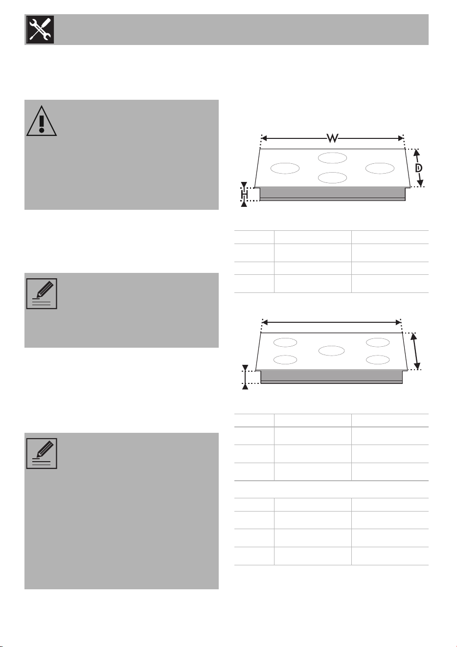
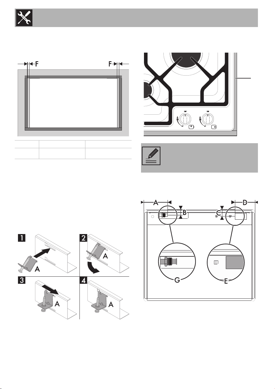
1.1 Positioning in the counter top
Fixing to the traditional built-in model
support structure
Make a hole in the countertop of the
furniture unit of the dimensions shown in the
figure.
24" models:
30" models:
36" models:
WARNING
Risk of fire
• Make sure that the cabinet material is
heat resistant.
• Check that the cabinet has the required
openings.
NOTE: The minimum distance
between a range hood and the
cooktop must be at least the
distance specified in the range
hood installation instructions.
NOTE: The following operation
requires construction and/or
carpentry work and must therefore
be carried out by a competent
technician.
The cooktop may be installed on a
variety of materials, such as
masonry, metal, solid wood or
plastic laminated wood, as long as
they are heat resistant (>194°F/
>90°C).
mm inches
W 617
24
5
/
16
D 509 20
H 88
3
7
/
16
mm inches
W 760
29
15
/
16
D 533
20
15
/
16
H 78
3
1
/
2
mm inches
W 866
34
7
/
64
D 511
20
1
/
8
H 69
2
23
/
32
WW
DD
HH
Installation
13
EN
24" models:
30" models:
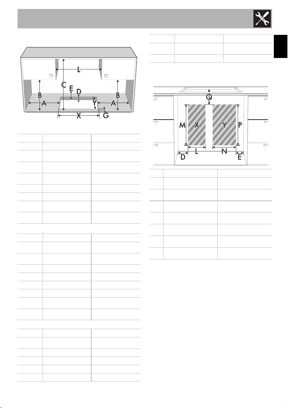
36" models:
Location of the gas and electric
outlets
X = Grounded outlet
Y = Gas supply line
*If there is a piece of furniture above the
cooktop. In the case of hood, refer to the values
in the relevant manual.
To prevent liquids from leaking between the
frame of the cooktop and the countertop, fit
the insulating seal provided before
assembly.
mm inches
A 152 6
B 460
18
1
/
8
C 750
29
9
/
16
D 20 - 50
3
/
4
- 1
15
/
16
E 51 2
G min. 25 min. 1
X 592
23
5
/
16
Y 488
19
1
/
4
mm inches
A 700
27
9
/
16
B 457
19
3
/
8
C 762 30
D 50 2
E 50 2
G 50 2
X 700
27
9
/
16
Y 492
19
3
/
8
mm inches
A 210
8
1
/
4
B 457 18
C 762 30
D 50 2
E 50 2
G 50 2
X 847
23
3
/
8
Y 482 19
mm inches
L 150 mm 6”
M 762 mm 30”
N 260 mm 10”
P 762 mm 30”
Q 25 mm 1”
D 76 mm 3”
E 38 mm
1
1
/
2
“
Installation
14
1. Refer to the dimensions in the figure,
making sure that the front and rear long
sides are flush with the hole.
2. Press lightly to make the seal adhere to
the edge around the hole in the
countertop. The front and rear sides of
the seal must be flush with the hole.
3. Place the cooktop on the insulating seal
and fix it to the support structure using the
screws and fastening brackets supplied
(A) so that the cooktop is perfectly level.
4. Carefully trim any excess material away
from the edge (B) of the seal.
Overall dimensions:: gas and electrical
connection points
View from the bottom
G = Gas pipe connection
E = Electrical connection
mm inches
F 3 - 4
1
/
8
-
3
/
16
NOTE: The brackets should only
be positioned after the cooktop
has been placed on the seal.
B
Installation
15
EN
24" models:
30" models:
36" models
:
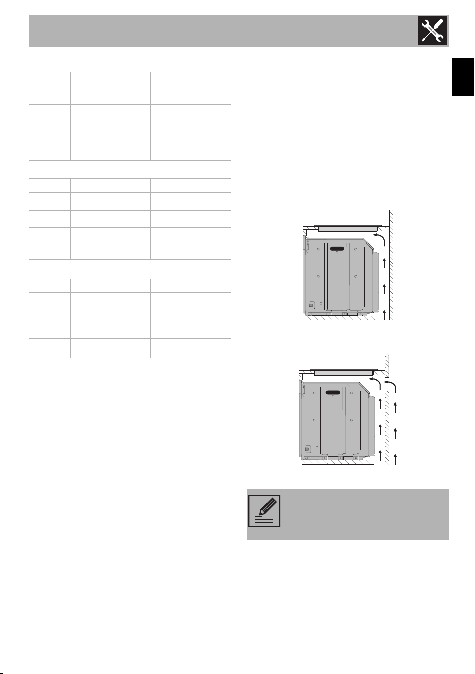
1.2 Mounting
Over built-in oven unit
The clearance between the cooktop and
the kitchen furniture or other installed
appliances must be enough to ensure
sufficient ventilation and air discharge.
If installed above an oven, a space should
be left between the bottom of the cooktop
and the top of the appliance installed
below.
opening on bottom
opening on bottom and on rear
mm inches
A 132
5
3
/
16
B 29.7
1
3
/
16
C 38.5
1
9
/
16
D 115
4
9
/
16
mm inches
A 270
10
5
/
8
B 45
1
3
/
4
C 50 2
D 150
5
15
/
16
mm inches
A 290
11
7
/
16
B 50 2
C 50 2
D 170
6
11
/
16
NOTE: If installed above of an
oven, the latter must be fitted with a
cooling fan.
Installation
16
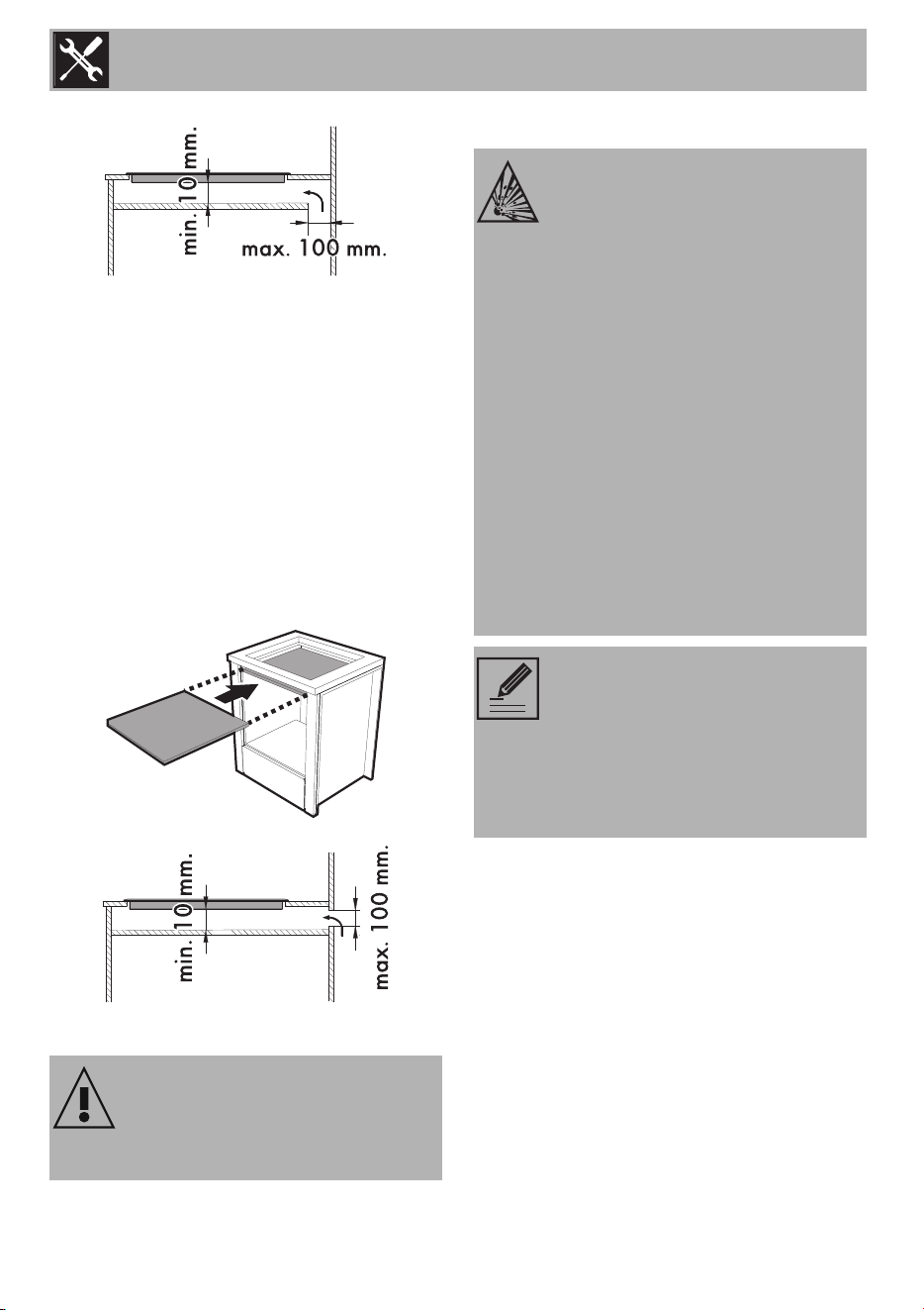
opening at rear
On top of empty kitchen unit or drawers
If there are other pieces of furniture (side
walls, drawers, etc.), dishwashers or
refrigerators under the cooktop, a double-
layer wooden base must be installed at
least 10 mm from the bottom of the
cooktop to prevent accidental contact. It
must be possible to remove the double-
layer base only with the aid of suitable
tools.
opening on bottom
1.3 Gas supply requirements
This installation must conform with all local
codes and ordinances. In the absence of
local codes, installation must conform to the
American National Fuel Gas Code, ANSI
Z223.1/NFPA 54 or, in Canada, the
Natural Gas and Propane Installation
Code, CSA B149.1.
If local codes permit, a flexible metal
appliance connector with the new AGA or
CSA certified design, 4-5 feet (1.2-1.5 m)
long,
1
/
2
” or
3
/
4
" ID NPT, is
recommended for connecting this
appliance to the gas supply line.
Failure to install the double-layer
wooden base exposes the user to
possible accidental contact with
sharp or hot parts.
WARNING
Explosion hazard
• Use a new AGA or CSA-certified
connector.
• Install a manual shut-off valve.
• Securely tighten all gas connections.
• If connected to LPG, have a qualified
technician ensure that the gas pressure
does not exceed a 14" W.C.P.
• Examples of qualified technicians
include licensed heating personnel,
authorized gas company personnel,
and authorized service personnel.
• Failure to do so can result in loss of life,
explosion, or fire.
NOTE:
• Observe all codes and
ordinances in force.
• The appliance must be
connected to a standard gas
supply.
Installation
17
EN
Do not bend or damage the flexible
connector when moving the appliance. The
pressure regulator has 3/8" female pipe
threads. You will need to determine the
fittings required, depending on the
dimension of your gas supply line, the
flexible metal connector and the shut-off
valve. The appliance should be installed in
rooms that have a permanent air supply in
accordance with the applicable standards.
The room in which the appliance is installed
must have sufficient airflow to ensure proper
combustion of the gas and the necessary air
exchange in the room itself. The air vents,
protected by grilles, must be of the correct
size to comply with current regulations and
positioned so that no part of them is
obstructed, even partially. The room must
be sufficiently ventilated to remove the heat
and humidity generated during cooking: it is
advisable to open a window or increase
the speed of any fans, especially after long
periods of use.
Gas connection
The appliance is shipped from the factory
for use with natural gas at a pressure of 4"
of water column. When checking if the
regulator is working properly, the inlet
pressure must be at least 1" greater than the
operating (manifold) pressure above.
When used with natural gas, the pressure
supplied to the regulator must be between
5" and 10.5" of the water column. To
convert the appliance for use with propane,
see “Conversion to propane gas (LPG)”.
The conversion must be done by a qualified
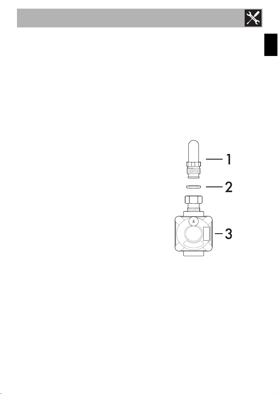
technician or installer. The gas inlet to the
unit is located at the back right of the
appliance. Install the pressure regulator
(supplied with the unit) on the gas inlet.
Place the gasket (supplied with the unit)
between the inlet and the regulator. Position
the regulator so that the cap is easily
accessible. Tighten the nut on the gas inlet
so that it is hand tight plus 1/3 turn.
Connect the gas pipe to the regulator using
Teflon tape or pipe joint compound
(resistant to propane gas and natural gas).
Turn so that it is hand tight plus 1/3 turn. Do
not exceed 1 turn for alignment, to prevent
possible damage to the gas pressure
regulator. Check the inlet connections and
the regulator for leaks.
1 - Gas inlet (attached to the appliance)
2 - Gasket
3 - Pressure regulator
WARNING: Do not attempt to adjust the
pressure regulator, except when converting
to propane. Adjustments could lead to leaks
or cause incorrect gas pressure being
supplied to the appliance.
Installation
18
Testing for gas leaks
Follow these instructions to test the
appliance for leaks:
Use a brush and liquid detergent to check
all gas connections for leaks. Bubbles
around connections indicate a leak. If a
leak is found, shut off the gas valve controls
and tighten the connections. Then check the
connections again.
Wipe off any detergent from the appliance.
Replace the parts on the burner and turn the
knobs on the gas tap valves.
NEVER USE A MATCH OR AN OPEN
FLAME TO TEST FOR GAS LEAKS.
Check the appearance of the flames
• Yellow flames: Further adjustment is
required.
• Yellow tips on outer cones: Normal for
LPG.
• Soft blue flames: Normal for Natural
Gas.
• Orange flames: Can be normal if certain
types of humidifiers are used in the
home. Flames should return to blue
without the humidifier running.
If the flame is completely or mostly yellow,
verify that the regulator is set for the correct
fuel. Retest after adjustment.
Some yellow streaking is normal during the
initial startup. Allow the appliance to
operate for 4–5 minutes and reevaluate
before making adjustments.
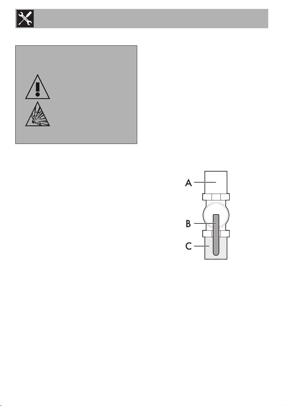
Shut-off valve
The supply line must be fitted with an
approved shut-off valve. This valve should
be in the same room as the appliance and
in a position where it is easy to open and
close. Do not block access to the shut-off
valve. The valve is necessary for turning the
gas to the appliance on or off.
A - To appliance
B - Shutoff valve “open” position
C - Gas supply line
WARNING
FIRE HAZARD
Use a soapy solution
to check for leaks.
Never use a match
or an open flame to
test for gas leaks.
Failure to follow
these instructions
could result in loss of
life or fire.
Installation
19
EN
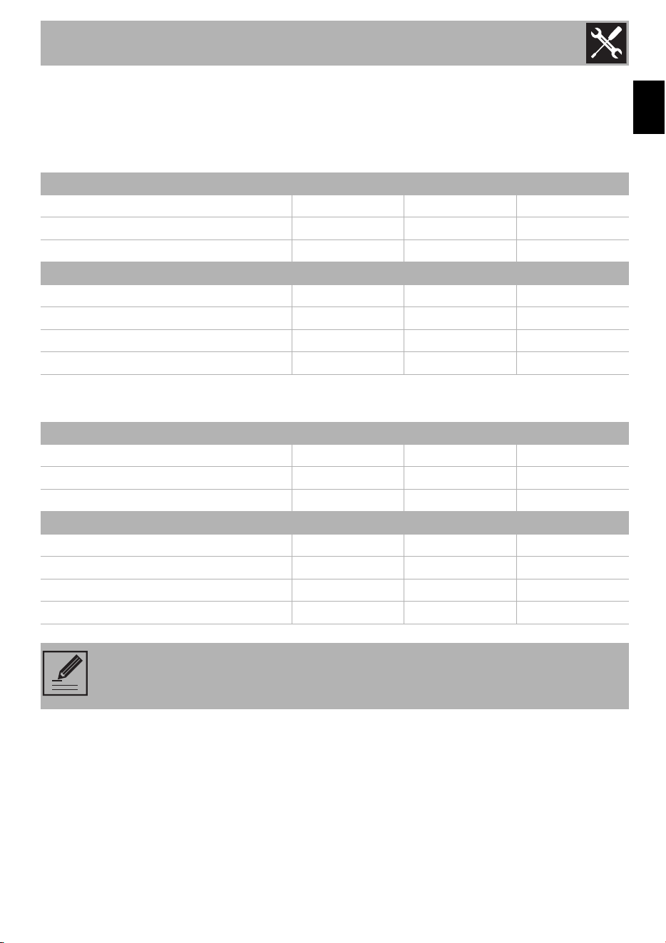
Burner and nozzle characteristics tables
To set the range for propane gas or to revert to Natural Gas, refer to the tables below.
For 24" models:
For 30" and 36" models:
Natural Gas AUX RR UR3
QT (BTU)
3600 9100 12000
Injector Ø (mm)
0.90 1.40 1.65
QR (BTU)
1200 2500 4200
Propane AUX RR UR3
QT (BTU)
3600 9100 12000
Injector Ø (mm)
0.54 0.88 1.02
QR (BTU)
1200 2500 4200
By-pass (mm)
0.32 0.42 0.63
Natural Gas AUX SR UR3
QT (BTU)
3400 6200 13000
Injector Ø (mm)
0.90 1.20 1.75
QR (BTU)
1200 1600 4200
Propane AUX SR UR3
QT (BTU)
3400 6200 13000
Injector Ø (mm)
0.54 0.72 1.02
QR (BTU)
1200 1600 4200
By-pass (mm)
0.32 0.38 0.63
NOTE: Keep the nozzles that were removed from the appliance along with these
instructions for possible future use.

Installation
20
• Connect the gas supply line to the
pressure regulator using a 1/2” flex gas
line connector between the manual shut-
off valve and the pressure regulator. A
metal flex line or fixed metal pipe must
be used to connect the gas to the
appliance. If a metal gas line cannot be
used, consult your local certified
electrician or local electric codes for
proper grounding.
• Check the supply line connections for
leaks using a soap solution or non-
corrosive leak detection fluid. Do not use
a flame of any sort.
Important notes for Gas Connection
• The appliance and its individual gas
shutoff valve must be disconnected from
the gas supply piping system during
pressure testing of the system at test
pressures in excess of 1/2 psi (3.5 kPa).
• The appliance must be isolated from the
gas supply piping system by closing its
manual shut-off valve during the pressure
testing of the gas supply piping system at
test pressures equal to or less than 1/2
psi (3.5 kPa).
Final operations
• Complete the Gas Conversion label
(part no. 92849A078) and attach it to
the rear of the appliance. Do not cover
any other labels with the Gas
Conversion label.
• Over time, the gas taps may become
difficult to turn and jam. Clean them
internally and replace the lubrication
grease.
• Keep the nozzles that were removed
from the appliance together with these
instructions for possible future use.
• For installation of the appliance at high
altitude, please consult your local gas
company for their recommendation on
the correct orifice sizes and any other
necessary adjustments that will provide
proper gas combustion at specified
altitudes.
Inlet pressure
To check the regulator, the incoming line
pressure upstream of the regulator must be
1" (2.5 cm) W.C.P. higher than the manifold
pressure. Incoming line pressure to the
regulator should be as follows for operation
and checking the regulator setting:
• Natural Gas: Set pressure to 4" W.C.P.
Inlet pressure from 5" - 10 1/2" W.C.P
maximum.
• LP Gas: Set pressure to 11" W.C.P. Inlet
pressure from 12"- 13" W.C.P.
maximum.
NOTE: The gas taps should be
lubricated by a qualified
technician.
Installation
21
EN
Conversion to propane gas (LPG)
Always provide an adequate gas supply.
This appliance is shipped from the factory
for use with natural gas. Use this kit to
convert the appliance for use with propane
gas, if necessary. Comply with the
following: Ensure that the range is
converted for use with the appropriate gas
before using it.
This appliance is designed to operate at a
pressure of 11" of water column when used
with propane gas. When checking if the
regulator is working properly, the inlet
pressure must be at least 1" greater than the
operating (manifold) pressure above.
When converting for propane gas use, the
pressure supplied to the regulator must be
between 12" and 13" of the water column.
The pressure regulator located at the inlet of
the range manifold must remain in the
supply line.
Use a flexible metal appliance connector or
rigid pipe to connect the range to the gas
supply. The connector should have an
inside diameter of 1/2” and be 5 ft (1.5 m)
or less in length.
(Exception: Maximum connector length in
Massachusetts installations is 3 ft (0.9 m). In
Canada, the connector must be single-wall
metal and not longer than 6 ft (1.8 m).
Keep the nozzles removed from the
appliance for future use.
WARNING
This conversion kit must be installed by a
qualified service agency in accordance
with the manufacturer's instructions and
all applicable codes and regulations of
the authority having jurisdiction. If the
information in these instructions is not
followed exactly, a fire, explosion or
production of carbon monoxide may
result causing property damage,
personal injury or loss of life. The
professional installation service is
responsible for the correct installation of
this kit. The installation is not proper and
complete until the operation of the
converted appliance is checked as
specified in the manufacturer’s
instructions supplied with the kit.
WARNING
Before proceeding with the gas
conversion, the gas supply must be
turned off before disconnecting the
electrical power.
WARNING
A gas leak test should be performed after
the gas conversion has been carried out.
CAUTION
Before proceeding with the gas
conversion, the gas supply must be
turned off before disconnecting the
electrical power.
Installation
22
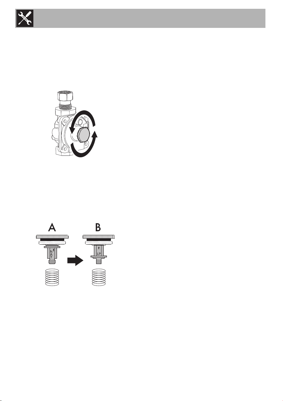
Setting the pressure regulator for
propane gas
To convert the regulator to the type of gas
used, the following must be done:
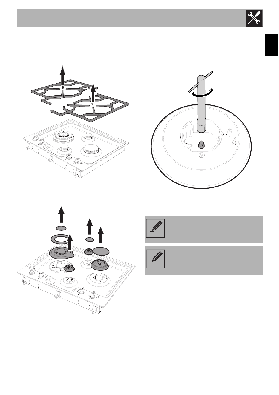
1. Unscrew the cover of the pressure
regulator.
2. Unscrew the plastic regulator stem from the
regulator cap. Configuration "A" is for
Natural Gas.
3. Invert the plastic regulator stem to achieve
the configuration “B” for Propane Gas and
screw it in tightly.
4. Screw the regulator stem and cap into
place.
Conversion kit parts list
This conversion kit consists of the following
components:
• One Gas Conversion label.
• One gasket 12.5x18.5x2 (mm) -
0.5x0.73x0.08 (in).
• One label for LPG injectors.
For 24" models:
• Two injectors Ø 0.54 mm for the
Auxiliary burner.
• One injector Ø 0.88 mm for the
Reduced Rapid burner.
• One injector Ø 1.02 mm for the Ultra-
rapid triple crown burner.
For 30" models:
• Two injectors Ø 0.54 mm for the
Auxiliary burner.
• Two injectors Ø 0.72 mm for the Semi-
rapid burners.
• One injector Ø 1.02 mm for the Ultra-
rapid triple crown burner
For 36" models:
• One injector Ø 0.54 mm for the
Auxiliary burner.
• Three injectors Ø 0.72 mm for the Semi-
rapid burners
• One injector Ø 1.02 mm for the Ultra-
rapid triple crown burner.
Installation
23
EN
Replacing the burner nozzles
1. Remove the components from the
cooktop.
2. Remove the flame-spreader crowns and
corresponding burner caps.
3. Replace the burner nozzles using a 7 mm
socket wrench according to the type of
gas to be used (see “Burner and nozzle
characteristics tables”).
4. Replace the burners in their respective
housings.
Testing for gas leaks
After the conversion, it is important to check
that there are no leaks and that the
appearance of the flames is correct.
NOTE: The tightening torque of the
nozzles must not exceed 3 Nm.
NOTE: There are no burner parts
under the cooktop to clean,
disassemble or adjust.

Installation
24
After the conversion, complete the Gas
Conversion label (part no. 92849A078)
and attach it to the rear of the appliance.
Do not cover any other labels with the Gas
Conversion label.
Minimum adjustment
For natural Gas:
Light the burner and turn the knob to the
minimum position. Remove the gas tap knob
and turn the adjustment screw at the side of
the valve stem until the desired minimum
flame is achieved.
1. Light the burner and turn it to the minimum
position.
2. Remove the knobs by pulling them
upwards.
3. Turn the adjustment screw on the side of
the valve stem until a steady minimum
flame is achieved.
4. Replace the knob and check that the
burner flame is stable.
5. Turn the knob quickly from maximum to
minimum: The flame should not go out.
Repeat the procedure on all the gas
taps.
For LP Gas:
Turn off the burners and unplug the
appliance from the electric power supply.
To adjust the minimum flame setting for LPG,
turn the screw at the side of the valve stem
fully clockwise. Once the regulation has
been completed, replace the seal on the
by-passes using paint or similar materials.
Lubricating the surface burner gas valves
Over time, the surface burner gas valves
may become stiff or jam. Clean them
internally and re-lubricate. This operation
must be carried out by a qualified
technician.
Conversion to natural gas
This appliance is shipped from the factory
for use with natural gas. If the appliance
was previously converted to propane gas,
you have to convert it back to natural gas.
Check the orifices for the right nozzles and,
if required, replace them. Adjust the
minimum gas flow.
The optimum setting is achieved when the
height of the small flame is approx.
1
/
8
"
(3 to 4 mm).
Set the pressure regulator for natural gas.
Turn the spring plate the other way around
as shown in “Setting the pressure regulator
for propane gas”.
Save the nozzles removed from the
appliance for future use.

Installation
25
EN
1.4 Electrical requirements
Make sure that the power supply rating
matches the rating indicated on the ID
plate. The ID plates are located in a visible
position on the back of the appliances.
These ID plates must never be removed.
• Wire size and connections must conform
to the requirements of the National
Electrical Code, ANSI/NFPA 70
ELECTRICAL CODE (*) – last edition or
CSA Standard C22.1-94, Canadian
Electrical code, Part 1 (**) and CSA
C22.2 No. O-91 or latest edition and
all local codes and ordinances for the
kilowatt rating of the appliance.
IMPORTANT: Observe all governing
codes and ordinances.
• It goes without saying that your local
codes and ordinances take precedence
over these instructions. Complete
electrical connections according to local
codes and ordinances.
• Where codes permit and a separate
grounding wire is used, it is
recommended that the suitability of the
ground path be checked by a qualified
electrician.
• Consult a qualified electrician if you are
not sure whether the appliance is
properly grounded. Do not ground to a
gas pipe.
• A 120-volt, 60-Hz, AC-only,
15-ampere, fused electrical supply is
required. A time-delay fuse or circuit
breaker is recommended. It is
recommended that a separate circuit
serving only this appliance be provided.
WARNING
Electrical shock hazard
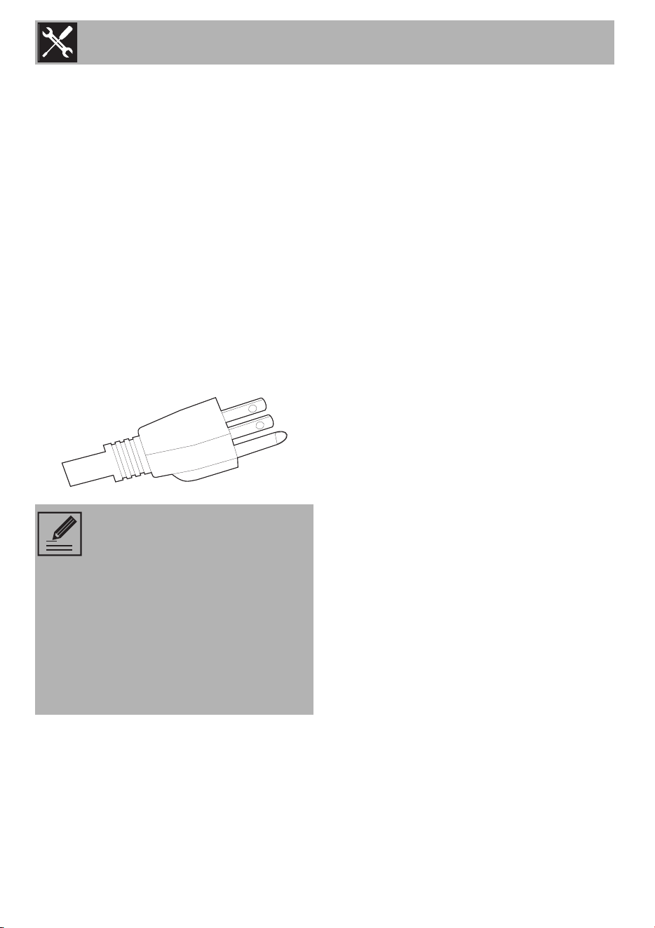
• This appliance is fitted with a three-
prong grounding plug for your
protection against the risk of electric
shock and it should be plugged directly
into a properly grounded receptacle.
Do not cut or remove the grounding
prong from this plug.
• Do not cut or remove the grounding
prong.
• Do not use an adaptor.
• Do not use an extension cord.
• Check with a qualified electrician if you
are not sure whether the appliance is
grounded.
FAILURE TO FOLLOW THESE
INSTRUCTIONS COULD
RESULT IN LOSS OF LIFE, FIRE
OR ELECTRICAL SHOCK.
Installation
26
Recommended Grounding Method
For your personal safety, this appliance
must be grounded. This appliance is fitted
with a 3-prong grounding plug. To minimize
the risk of electric shock, the cord must be
plugged into a mating 3-prong grounding
receptacle that is grounded in accordance
with the National Electrical Code ANSI/
NFPA 70 (latest edition*) or the Canadian
Electrical Code (CSA)** and local codes
and ordinances.
If a mating receptacle is not available, it is
the customer’s personal responsibility and
obligation to have a properly polarized
and grounded 3-prong outlet installed by a
qualified electrician.
1.5 For the installer
• The plug must remain accessible after the
installation is complete. Do not kink or
trap the mains connection cable.
• The appliance must be fitted according
to the installation diagrams.
• When satisfied with the appliance,
please instruct the user on the correct
method of operation.
• Do not attempt to turn or stress the
threaded elbow on the manifold. You
risk damaging this part of the appliance,
which may invalidate the manufacturer’s
warranty.
• Before leaving, check all connections for
gas leaks with soap and water. DO
NOT use a naked flame for detecting
leaks.
• Ignite all burners individually and
concurrently to ensure correct operation
of the gas valves, burner and ignition.
• Turn the gas knobs to the low position
and observe stability of the flame for
each burner individually and all
together.
• If the appliance is still not working
properly after all checks have been
carried out, contact the Authorized
Assistance Center in your area.
• When satisfied with the appliance,
please instruct the user on the correct
method of operation.
• LEAVE THESE INSTRUCTIONS WITH
APPLIANCE AFTER INSTALLATION IS
COMPLETE.
NOTE: Copies of the standards
listed above may be obtained
from:
* National Fire Protection
Association, 1 Batterymarch Park,
Quincy, Massachusetts 02169-
7471
** CSA International, 8501 East
Pleasant Valley Road, Cleveland
OH 44131-5575
