
Read all precautions and instructions in this manual before using this
equipment
Read all precautions and instructions in this manual before using this
equipment
Make Things Easier for Yourself
Everything in this manual is designed to ensure that the weight system can be
assembled suc-cessfully by anyone. However,it is important to realize that the
versatile weight system has many parts and that the assembly process will
take time. Most people find that by setting aside plenty of time, assembly will
go smoothly.
Assembly requires two people.
Before beginning assembly,carefully read the following information and
instructions:
ASSEMBLY
Place all parts in a cleared area and remove the packing materials.Do not
dispose of the packing materials until assembly is completed.
Tighten all parts as you assemble them, unless instructed to do otherwise.
As you assemble the weight system,make sure all parts are oriented as
shown in the drawings.
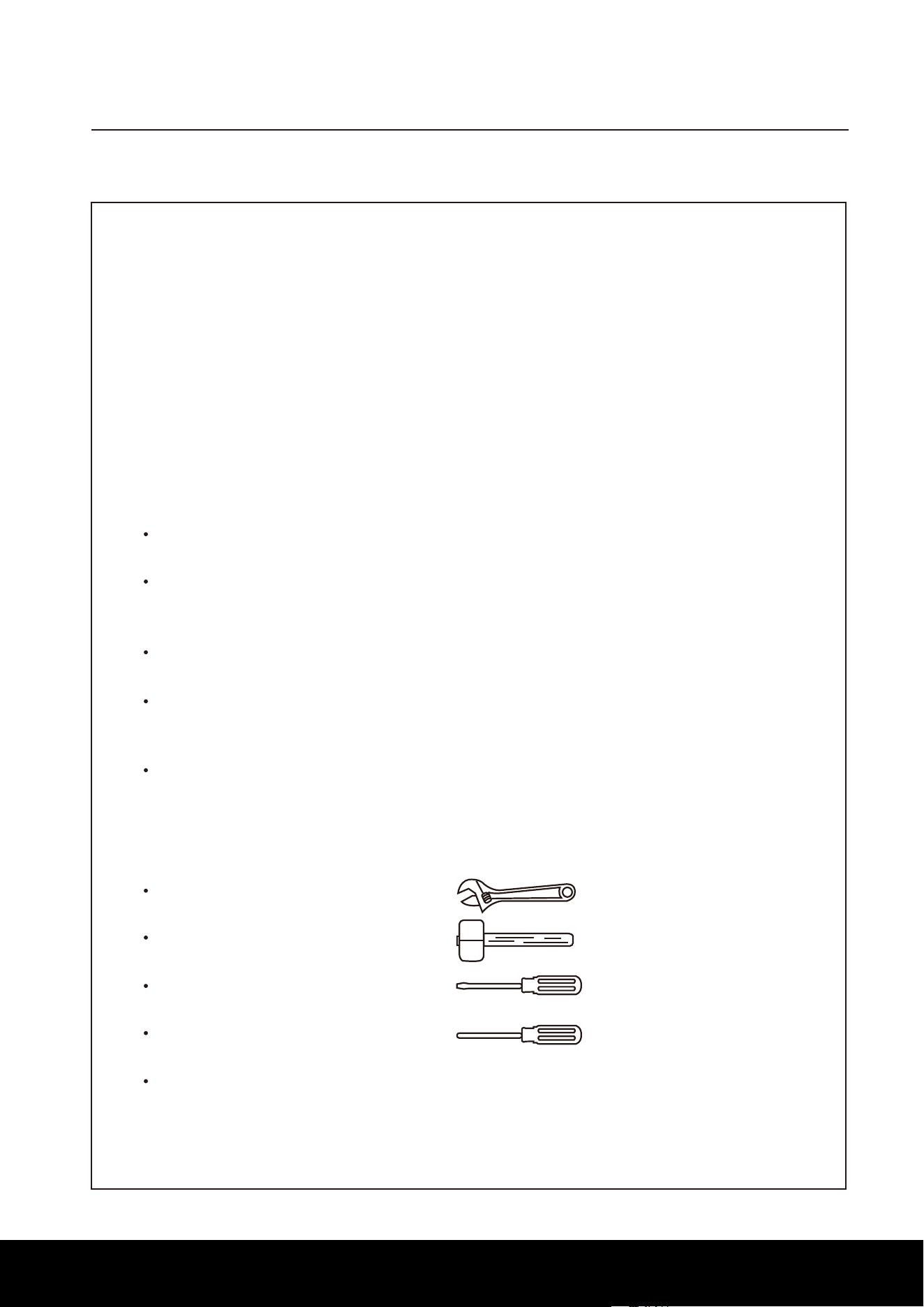
Two adjustable wrenches
One Phillips screwdriver
Lubricant, such as grease or petroleum jelly, and soapy water.
One standard screwdriver
One rubber mallet
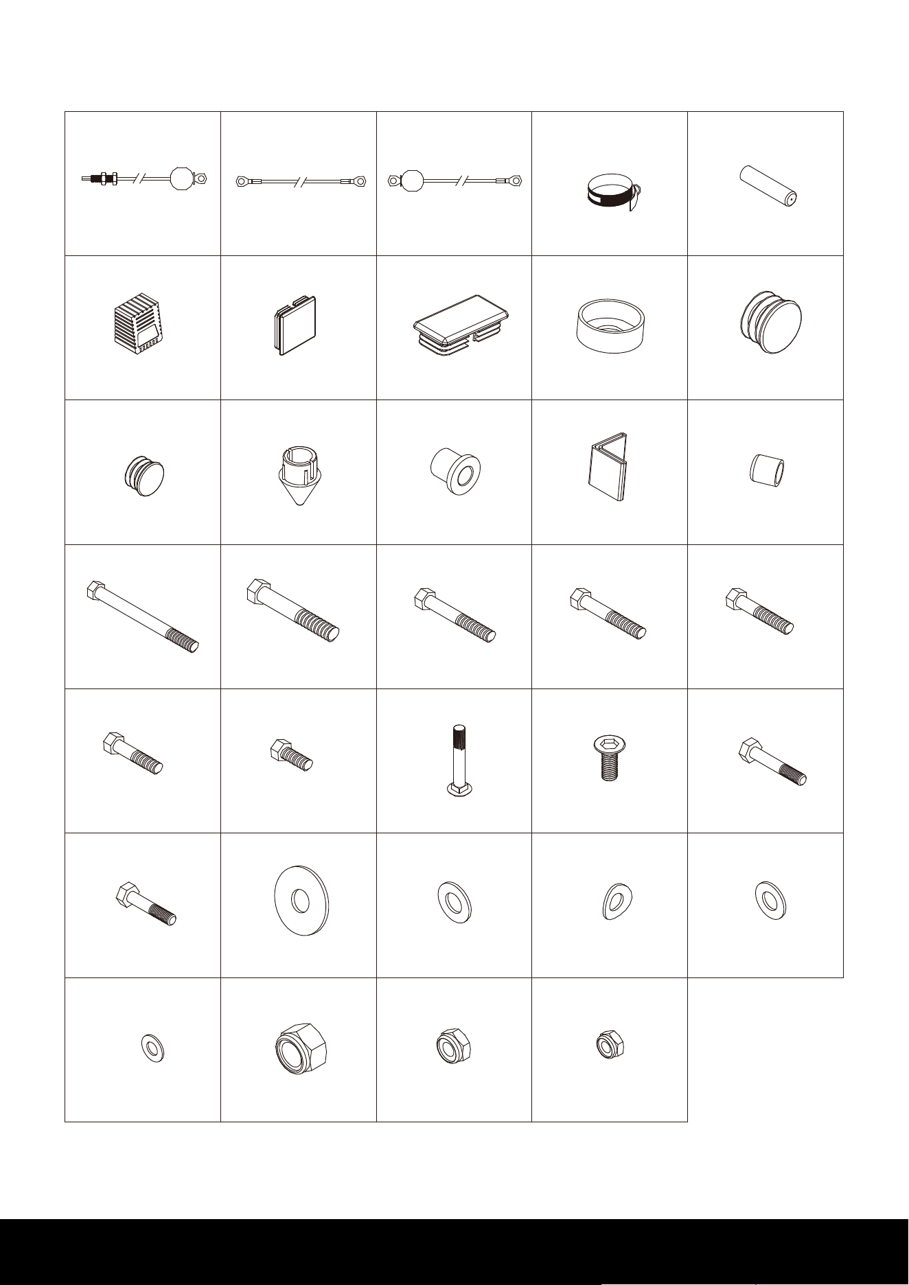
For help identifying small parts, refer to the PART IDENTIFICATION
CHART on page 5.
The following tools (not included) are required for assembly:
Assembly will be more convenient if you have asocket set, a set of
open-end or closed-endwrenches, or a set of ratchet wrenches.
3
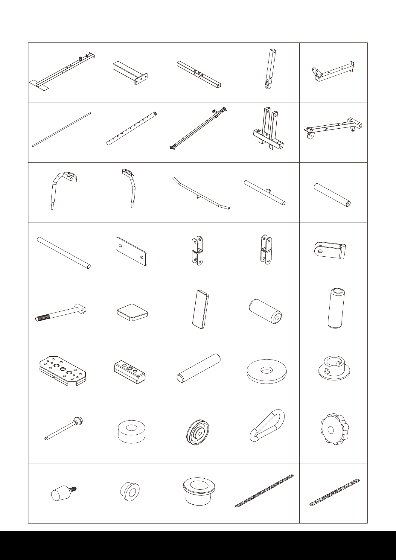
PATRS LIST
4
5
3
2
1
9
10
8
7
6
14
15
13
1211
19 20181716
24
25
23
22
21
29
30
28
27
26
34
35
33
32
31
39
40
38
37
36
Base Frame
1PC
Back Base Frame
1PC
Leg Extension Frame
1PC
Seat Base Frame
1PC
Weight Guide Tube
2PCS
Selector Shaft
1PC
Support Frame
1PC
Press Bar
1PC
Upper Cross Beam
1PC
Right Butterfly Arm
1PC
Left Butterfly Arm
1PC
Lat Bar
1PC
Low Bar
1PC
Handle Tube
2PCS
Foam Tube
2PCS
Plate
3PCS
Reverse U
1PC
Pulley U
1PC
Single Pulley Block
2PCS
Tobacco-pipe
1PC
Seat Cushion
1PC
Ba
ckrest Cushion
1PC
Leg Foam Roller
4PCS
Arm Foam Roller
2PCS
Weight Plate
9PCS
Top Weight Plate
1PC
Selector Shaft Pin
1PC
Plastic Washer
1PC
Selector Shaft Bushing
1PC
Weight Selector Pin
1PC
Rubber Cushion
2PCS
Pulley
12PCS
Chain (short)
1PC
Plum Blossom Nut
1PC
Bumper
1PC
Pothook
4PCS
Oil Bushing (Small)
2pcs
Oil Bushing (Big)
4pcs
Side Base Frame
2PCS
Pre-installed
Chain (long)
1PC
Pre-installed
Pre-installed
Pre-installed
Pre-installed
4
44
45
43
42
41
49
50
48
47
46
54
55
53
52
51
59
60
58
57
56
64
65
63
62
61
69
70
68
67
66
73
72
71
Butterfly Cable
1PC
Lower Cable
1PC
Ankle Strap
1PC
Handle Grip
8PCS
50mm Square Foot End Cap
4PCS
50mm Square End Plug
9PCS
25X50mm Square End Plug
2PCS
Mid-empty Plug
2PCS
Select Shaft End Cap
1PC
Pulley Bushing
6PCS
Bumper Cap
2PCS
Plastic Cover
2PCS
M12X135mm Hex Bolt
1PC
M12X75mm Hex Bolt
1PC
M10X70mm Hex Bolt
9PCS
M10X65mm Hex Bolt
2PCS
M10X45mm Hex Bolt
9PCS
M10X25mm H
ex Bolt
2PCS
M8X65mm Hex Bolt
4PCS
M8X40mm Hex Bolt
2PCS
Carriage Bolt M10X65mm
2PCS
M10X25mm Bolt
4PCS
Washer
¢
30X
¢
10
1PC
M10 Arc washer
2PCS
M12 Washer
6PCS
M10 Washer
46PCS
M8 Washer
8PCS
M12 Nylon Nut
4PC
M10 Nylon Nut
24PCS
M8 Nylon Nut
2PCS
50mm Round End Plug
2PCS
25mm Round End Plug
4PCS
M10X75mm Hex Bolt
2PCS
PATRS LIST
Upper Cable
1PC
74
Pre-installed
6PCS
Pre-installed Pre-installed Pre-installed Pre-installed
Pre-installed Pre-installed Pre-installed
Pre-installed Pre-installed
Pre-installedPre-installed Pre-installed
2PCS
Pre-installed
2PCS
5
1
8
3
17
6
63
64
59
70
70
70
70
73
73
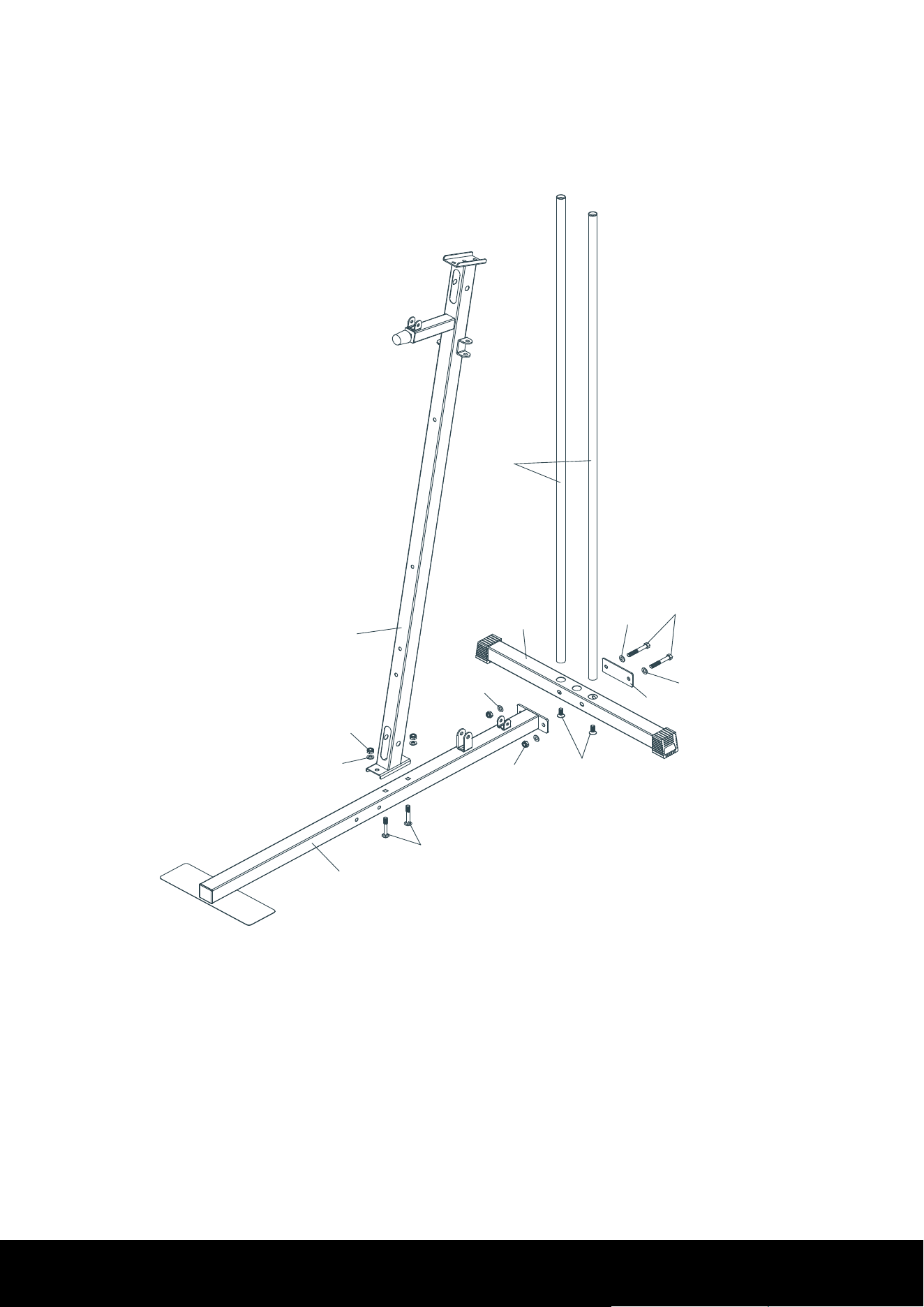
STEP 1:
1. Remove two M10X25mm Bolts (64) from Weight Guide Tube (6).
2. Insert Weight Guide Tube (6) into the Back Base Frame (3), using two M10X25mm
Bolts (64).
3. Attach the Base Frame (1) and one Plate (17) to the Back Base Frame (3), using two
M10X70mm Hex Bolts (59), four M10 Washers (70) and two M10 Nylon Nuts (73).
4. Attach the Support Frame (8) to the Base Frame (1), using two M10X65m
m Carriage
Bolts (63), two M10 Washers (70) and two M10 Nylon Nuts (73).
ASSEMBLY INSTRUCTIONS
6
3
32
26
27
30
28
29
7 6
31
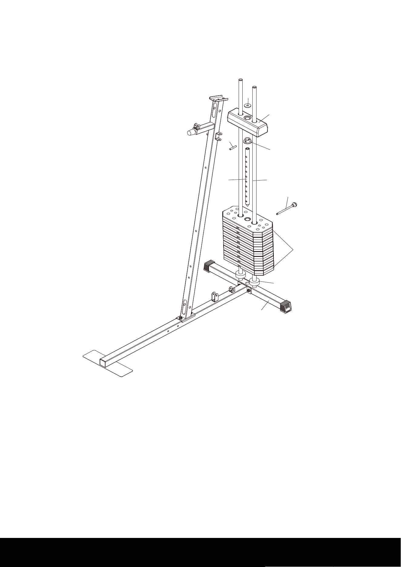
STEP 2:
1. Slide two Rubber Cushions (32) onto Weight Guide Tube (6).
2. Slide nine Weight Plates (26) down the Weight Guide Tube (6).
3. Slide the Selector Shaft Bushing (30) down the Selector Shaft (7) at first hole fix with
Selector Shaft Pin (28).
4. Insert the Selector Shaft (7) into hole of the Weight Plate (26).
5.Slide the Top Weight Plate (27) down the Weight Guide Tube (6), insert the Weig
ht
Selector Pin (31) into hole of desire weight.
6. Put the Plastic Washer (29) on the Top Weight Plate (27).
ASSEMBLY INSTRUCTIONS
7
10
17
8
2
2
1
64
59
58
70
70
70
70
56
68
72
73
73
9
6
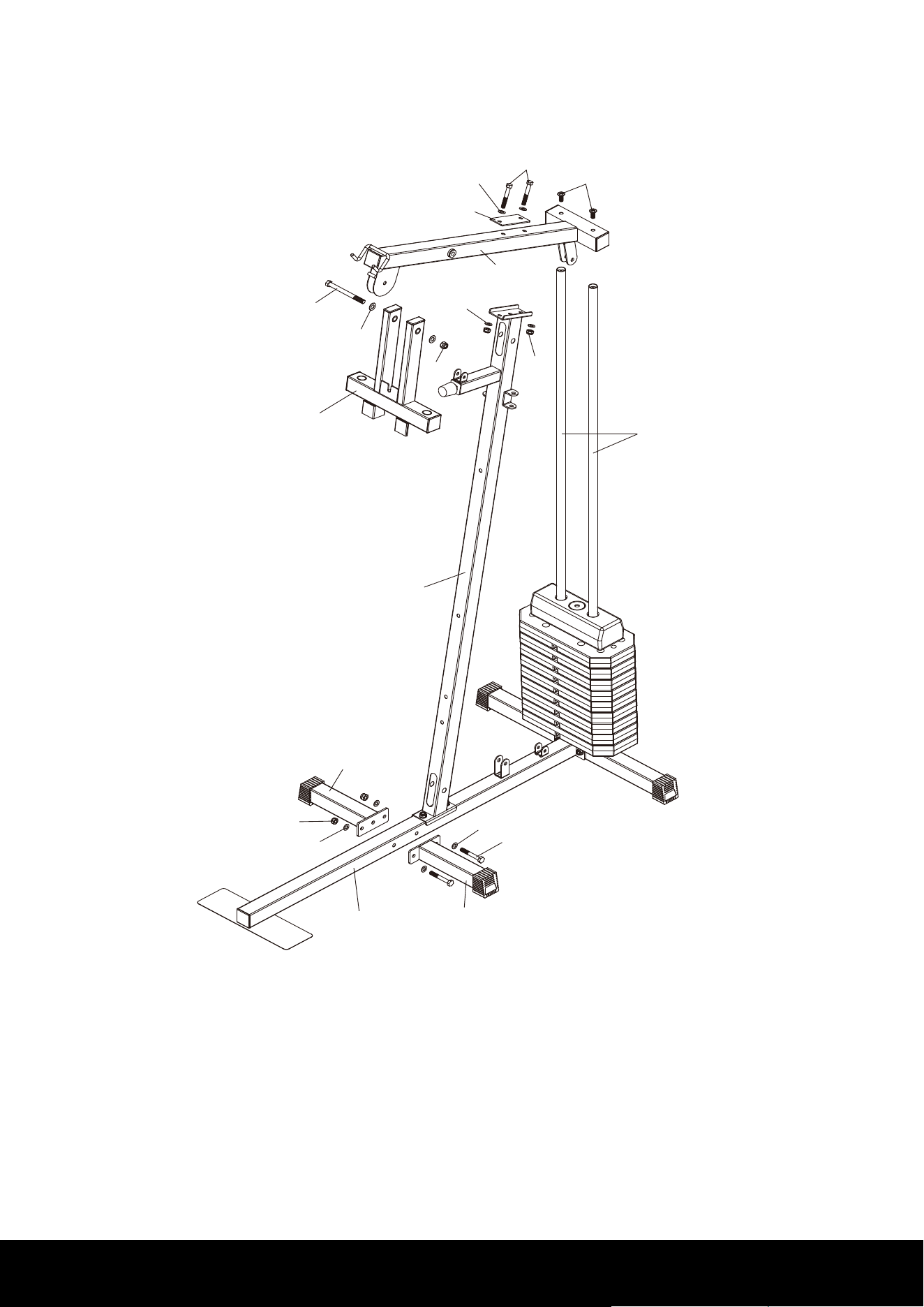
STEP 3:
1. Attach the two Side Base Frames (2) to the Base Frame (1), using two M10X75mm
Hex Bolts (58), four M10 Washers (70) and two M10 Nylon Nuts (73).
2. Remove two M10X25mm Bolts (64) from Weight Guide Tube (6).
3. Attach the Upper Cross Beam (10) to the Weight Guide Tubes (6), using M10X25mm
Bolts (64).
4. Attach the Upper Cross Beam (10) and one Plate (17) to the Support Frame (8), usin
g
two M10X70mm Hex Bolts (59), four M10 Washers (70) and two M10 Nylon Nuts (73).
5. Attach the Press Bar (9) to the Upper Cross Beam (10), using one M12X135mm Hex
Bolt (56), two M12 Washers (68) and one M12 Nylon Nut (72).
ASSEMBLY INSTRUCTIONS
8
9
11
12
15
15
25
25
49
49
45
45
62
62
69
69
38
38
38
68
72
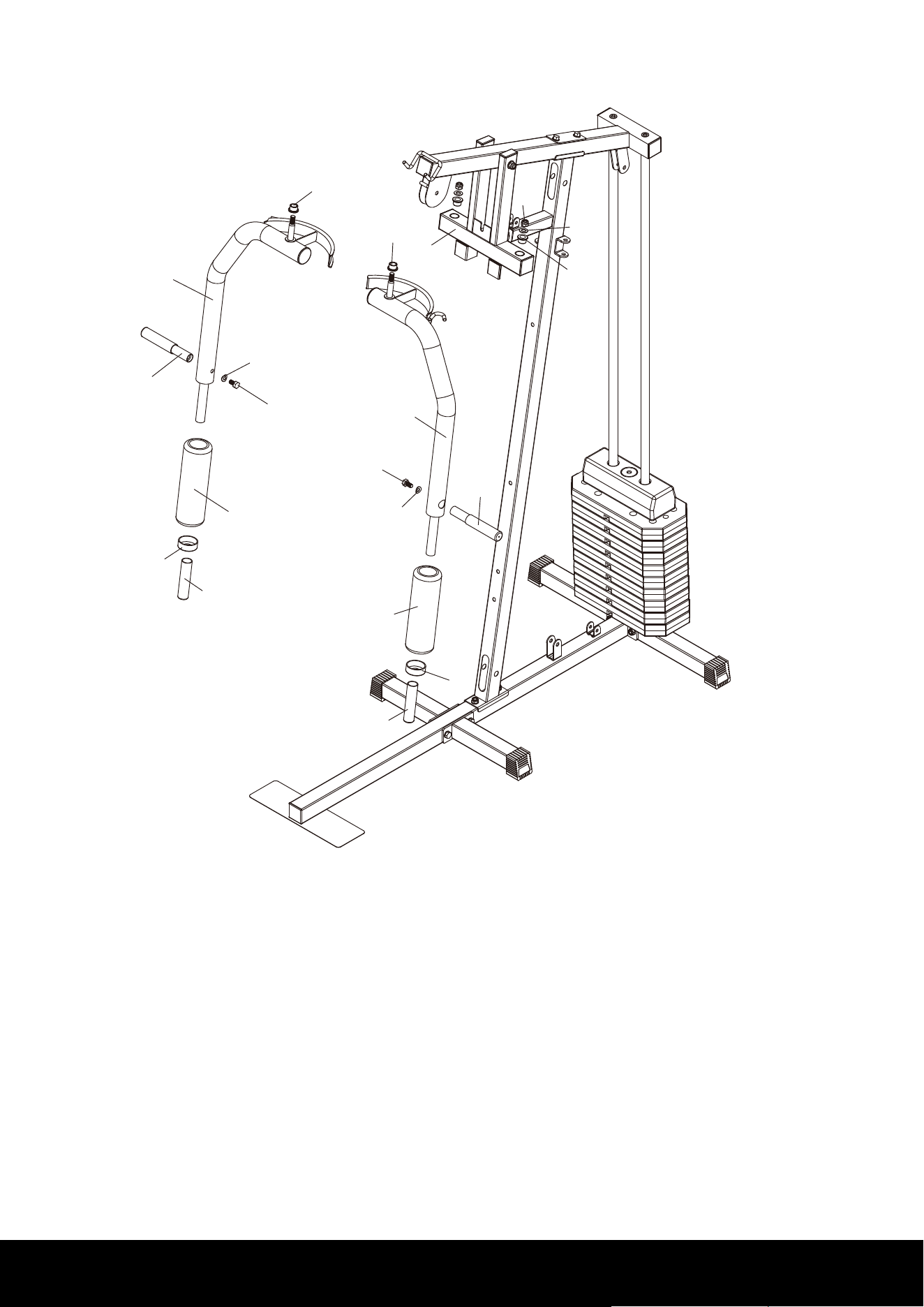
STEP 4:
NOTE:Oil Bushing (big) (38) have been Pre-assembled into Right & Left Butterfly Arm
(11 &12).
1. Remove two Oil Bushing (big) (38), two M12 Washers (68) and two M12 Nylon Nuts
(72).
2. Attach the Right & Left Butterfly Arm (11 &12) to the Press Bar (9), using four Oil
Bushing (big) (38), two M12 Washers (68) and two M12 Nylon Nuts (72).
3. Slide two Arm Foam Rollers (25) onto the Right &
Left Butterfly Arm (11&12).
4. Remove two M10X20mm Hex Bolts (62) and two M10 Arc Washers (69) from Handle
Tube (15).
5. Attach the Handle Tube (15) to the Right & Left Butterfly Arm (11&12), using two
M10X20mm Hex Bolts (62) and two M10 Arc Washers (69).
6. Slide two Mid-empty Plugs (49) and two Handle Grips (45) onto the Right & Left
Butterfly Arm (11&12).
ASSEMBLY INSTRUCTIONS
9
35
67
21
8
66
71
74
20
20
60
60
70
70
73
73
8
5
17
70
70
59
73
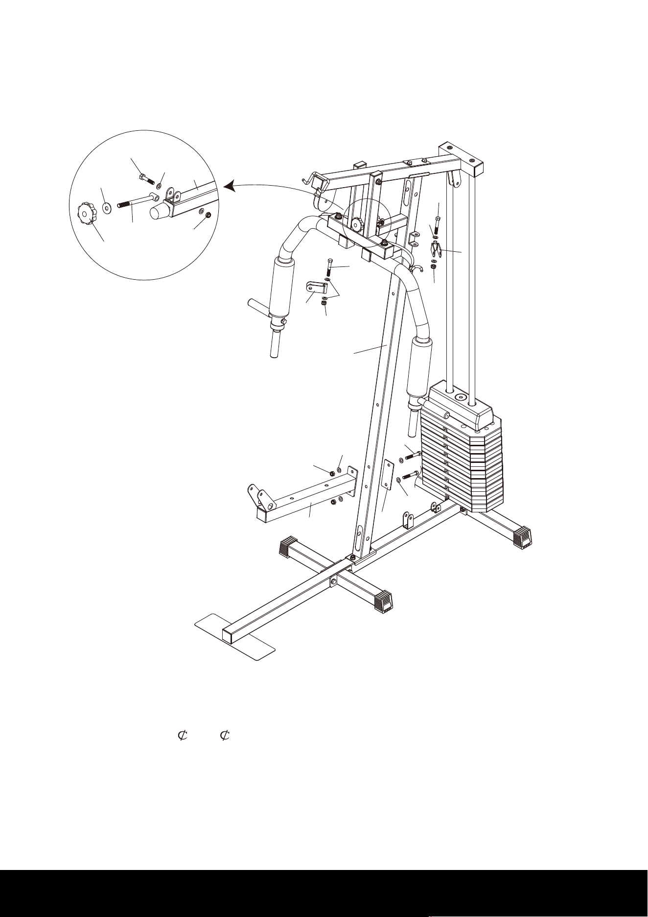
STEP 5:
1. Attach the Tobacco-pipe (21) to the Support Frame (8), using one M8X40mm Hex Bolt
(66), two M8 Washers (71) and one M8 Nylon Nut (74).
2. Slide the Washer (
30X 10) (67) and Plum Blossom Nut (35) onto the Tobacco-pipe
(21).
3. Attach the two
Single Pulley Blocks (20) to the Support Frame (8), using two
M10X65mm Hex Bolts (60), four M10 Washers (70) and two M10 Nylon Nuts (73).
4. Attac
h the Seat Base Frame (5) and one Plate (17) to the Support Frame (8), using
two M10X70mm Hex Bolts (59), four M10 Washers (70) and two M10 Nylon Nuts (73).
ASSEMBLY INSTRUCTIONS
10
4
5
16
16
24
24
24
24
22
23
8
65
65
65
71
71
71
72
68
57
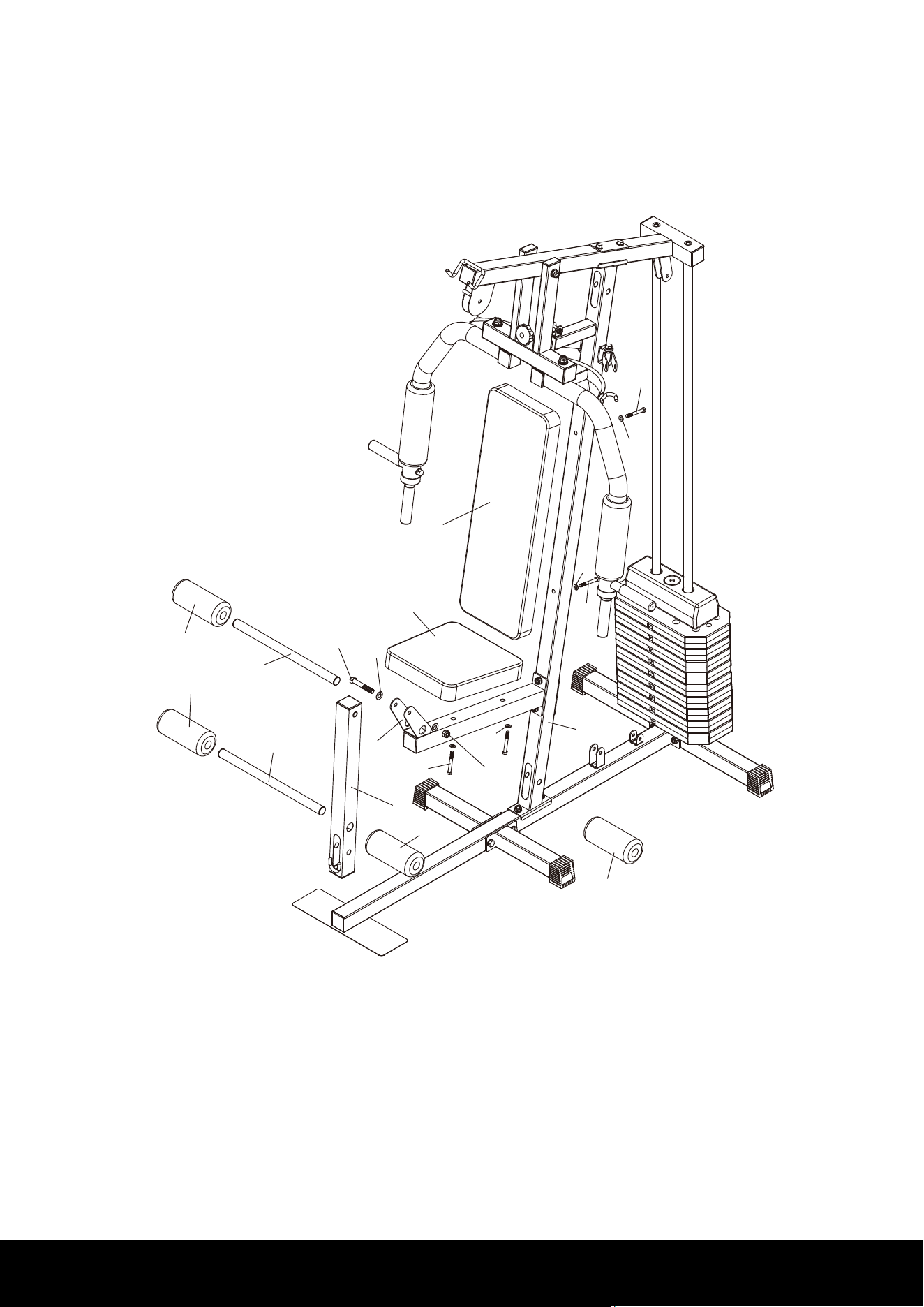
STEP 6:
1. Attach the Leg Extension Frame (4) to the Seat Base Frame (5), using one M12X75mm
Hex Bolt (57), two M12 Washers (68) and one M12 Nylon Nut (72).
2. Insert two Foam Tubes (16) into the Leg Extension Frame (4) and Seat Base Frame (5).
3. Slide four Leg Foam Rollers (24) onto the Foam Tubes (16).
4. Attach the Backrest Cushion (23) to the Support Frame (8), using two M8X65mm Hex
Bolts (
65) and two M8 Washers (71).
5. Attach the Seat Cushion (22) to the Seat Base Frame (5), using two M8X65mm Hex
Bolts (65) and two M8 Washers (71).
ASSEMBLY INSTRUCTIONS
11
NO.1 NO.2 NO.4
NO.3&9
NO.8
NO.5
NO.6
NO.7&11
NO.10&12
13
14
18
19
33
33
33
33
33
33
33
33
33
33
33
34
34
34
34
20
70
ASSEMBLY INSTRUCTIONS
43
43
43
42
42
42
41
41
41
41
41
41
39
40
44
53
53
53
55
59
59
59
61
61
61
61
61
61
61
66
70
70
70
70
70
70
70
70
71
71
73
73
73
73
73
73
73
73
73
73
74
1
1
8
4
8
10
8
10
12
7
29
43
43
43
43
12
41#
1
2
3
4
5
6
7
8
9
10&12
11
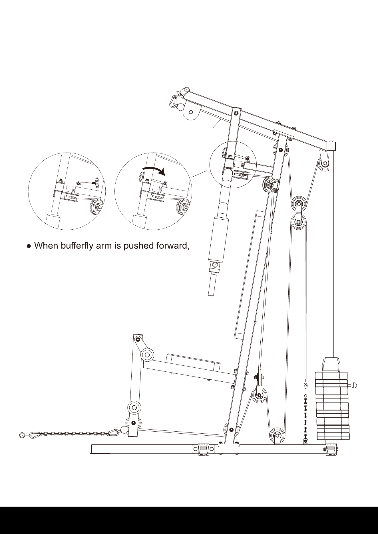
ASSEMBLY INSTRUCTIONS
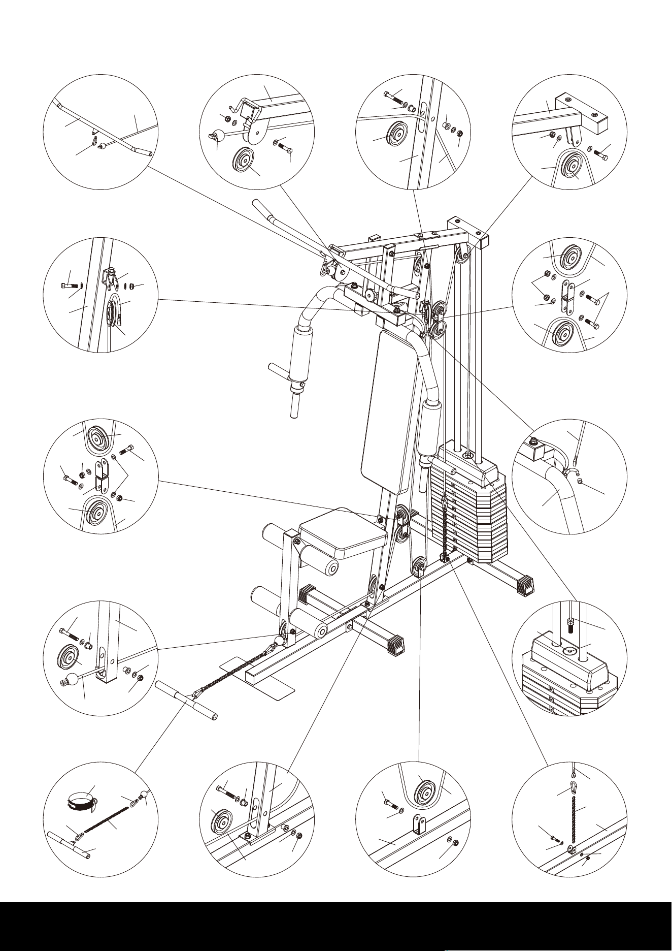
the Tobacco-pipe should be loosened and
placed on the front support frame
13

STEP 7:
1. Start with the Upper Cable (41)
a). With Upper Cable (41) in groove of Pulley (33), thread cable (41) through Upper Cross
Beam (10).
b). Install Pulley No.1 (33) to Upper Cross Beam (10), using one M10X45mm Hex Bolt
(61), two M10 Washers (70) and one M10 Nylon Nut (73).
c). Install Pulley No.2 (33) and two Pulley Bushings (53) to Support Frame (8), using one
M10X70mm Hex Bolt (5
9), two M10 Washers (70) and one M10 Nylon Nut (73).
d). Install Pulley No.4 (33) to Upper Cross Beam (10), using one M10X45mm Hex Bolt
(61), two M10 Washers (70) and one M10 Nylon Nut (73).
e). Attach the bolt end of Upper Cable (41) to Selector Shaft (7) with Plastic Washer (29).
f). Install Pulley No.3 (33) to Pulley U (19), using one M10X45mm Hex Bolt (61), two M10
Washers (70) and one M10
Nylon Nut (73).
g). Attach the Lat Bar (13) to the other end of Upper Cable (41) using one Pothook (34).
2. Assembly the Butterfly Cable (42)
a). Attach the both ends of Butterfly Cable (42) to Right & Left Butterfly Arm (12), using
two Plastic Covers (55).
b). Install Pulley No.10&12 (33) to two Single Pulley Blocks (20), using two M10X45mm
Hex Bolts (61), four M10 Washers (70) and two M10 N
ylon Nuts (73).
c). Install Pulley No.11 (33) to Reverse U (18), using one M10X45mm Hex Bolt (61), two
M10 Washers (70) and one M10 Nylon Nut (73).
3. Assembly the Lower Cable (43)
a). With the Lower Cable (43) in groove of Pulley (33) through Leg Extension Frame (4).
b). Install Pulley No.5 (33) and two Pulley Bushings (53) to Leg Extension Frame (4),
using one M10X70mm Hex Bolt (59), two M10
Washers (70) and one M10 Nylon Nut
(73).
c). Install Pulley No.6 (33) and two Pulley Bushings (53) to Front Support Frame (8), using
one M10X70mm Hex Bolt (59), two M10 Washers (70) and one M10 Nylon Nut (73).
d). Install Pulley No.7 (33)to to Reverse U (18), using one M10X45mm Hex Bolt (61), two
M10 Washers (70) and one M10 Nylon Nut (73).
e). Install Pulley No.8 (33) to Base Frame (1),
using one M10X45mm Hex Bolt (61), two
M10 Washers (70) and one M10 Nylon Nut (73).
f). Install Pulley No.9 (33) to Pulley U (19), using one M10X45mm Hex Bolt (61), two M10
Washers (70) and one M10 Nylon Nut (73).
j). Attach the end of Lower Cable (43) to Base Frame (1), using one Chain (short) (40) and
one Pothooks (34), one M8X40mm Hex Bolt (66), two M8 Washers (71) and one M8
Nylon
Nut (74).
h). Attach Low Bar (14) or Ankle Strap (44) to the other end of Lower Cable (43), using
one Chain (long) (39) and two Pothooks (34).
ASSEMBLY INSTRUCTIONS
14
70
70
70
70
70
70
70
70
70
70
70
71
71
71
71
71
72
72
72
73
73
73
73
73
73
73
74
74
59
59
60
60
62
62
63
64
64
65
65
65
66
66
67
68
68
68
68
68
69
69
1
2
2
3
4
5
6
7
8
9
10
11
12
13
14
15
15
16
16
17
17
17
18
19
20
20
21
22
23
24
24
25
25
26
27
28
29
30
31
32
34
34
34
34
35
36
37
37
38
38
38
38
39
40
44
45
45
45
45
45
45
45
45
46
46
46
46
47
47
47
47
47
47
47
47
48
49
49
50
51
51
51
51
52
54
55
55
56
57
58
59
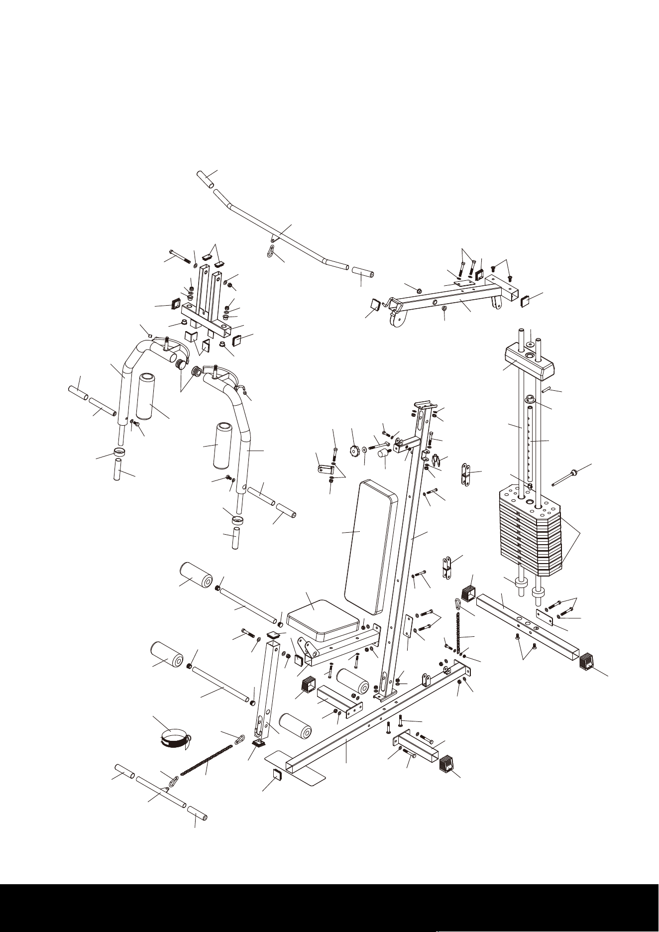
EXPLODED DRAWING
15
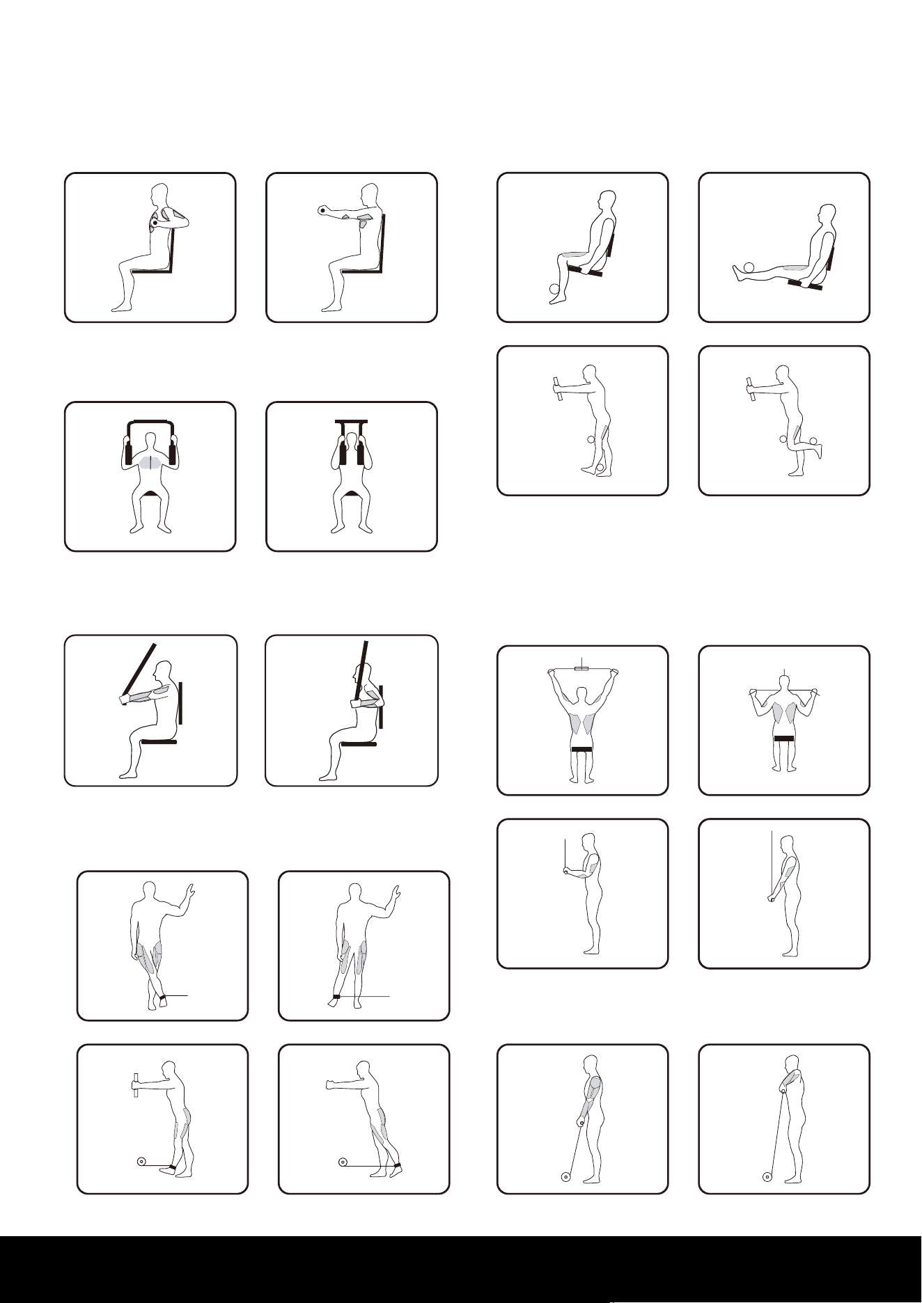
FITNESS GUIDE
PRESS ARM
BUTTERFLY
CHEST PRESS
ANKLE STRAP
LOW BAR
LAT BAR
LEG EXTENSION
16