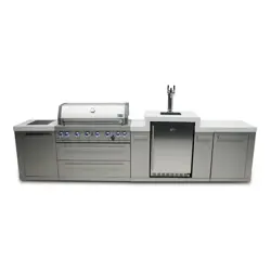
C124KEG
24" Built-in Kegerator
3
3-4
7-10
7
7
7-8
8
8
9-10
11
Installing the Kegerator
Calibrating the Regulator
12
12
12
12
12
12
13
13
13
13
13
13
14
15
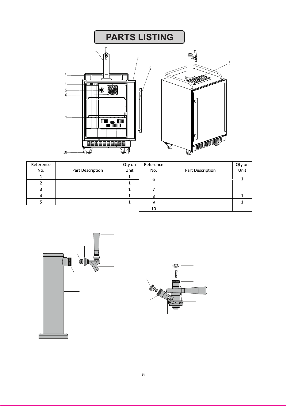
Tap Tower
Drink Guardrail
Drip Tray
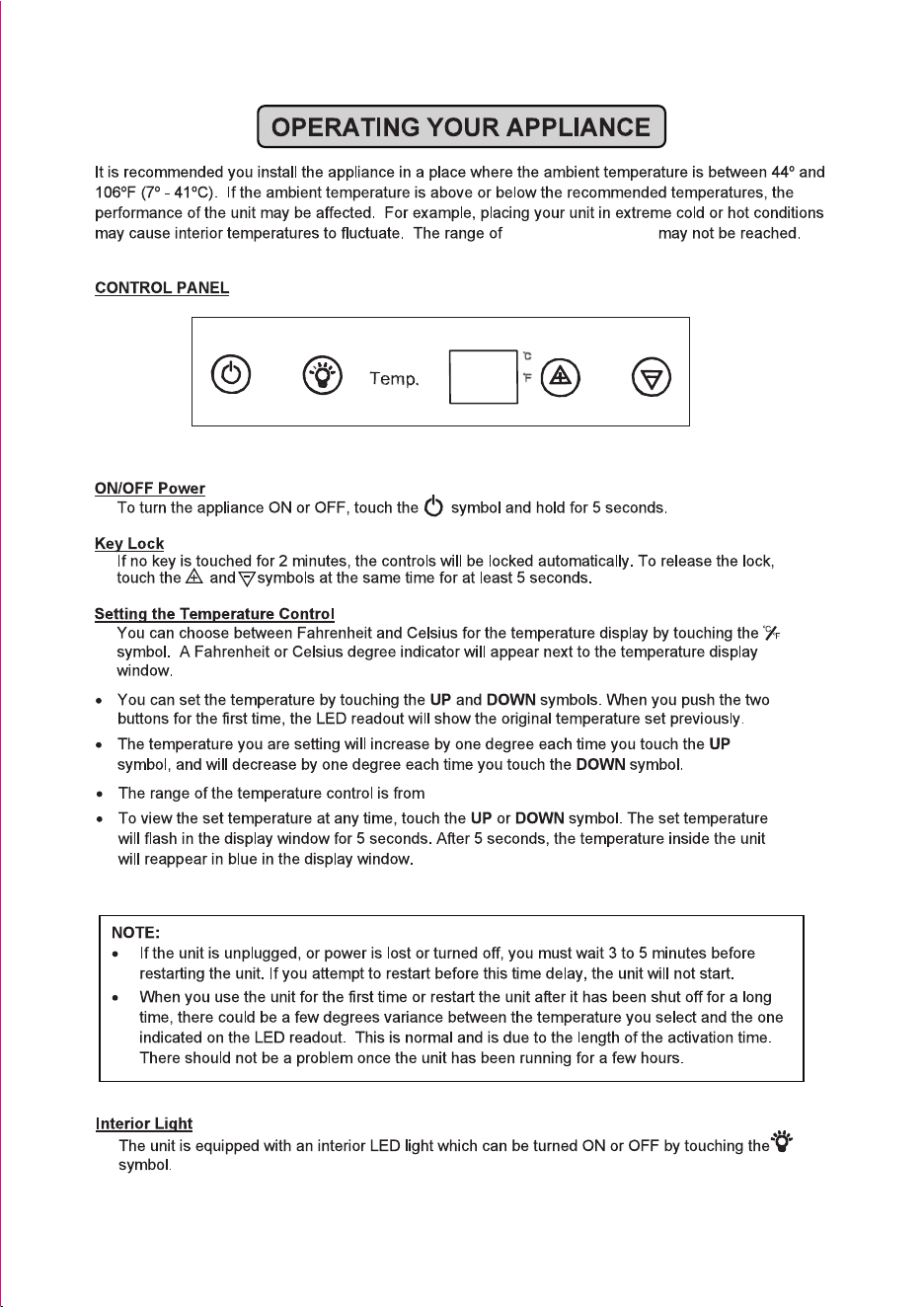
Control Panel
Carbon Filter
Cooling Fan with Beer
Line cooling component
Shelf
Stainless Steel Door
Handle
Caster Wheels
3
4
Parts Identification: Tap Tower and D-Style Keg Coupler
Tap Shank
7/8" -14
NOTE: The tap tower and D-style keg coupler are components from the tap kits, sold separately. There will be
number of openings for the tap tower depending on whether a single, double, or triple tap kit was purchased.
The provided quantity of tap bodies and tap handles will align with the number of openings on the tap tower .
Spring
Shank Assembly
Tap Tower
Tower Sleeve
Tap Handle
Tap Collar
Tap Bonnen
Tap Body
Check Valve
20x13x3 Silicone Washer
Plastic Stopper
7/8" - 14 Beer Line Shank
Coupler Handle
D-Style Connection
Body Seal
Pressure Relief Valve - keg Coupler
7/8" - 14
Gas Line Shank
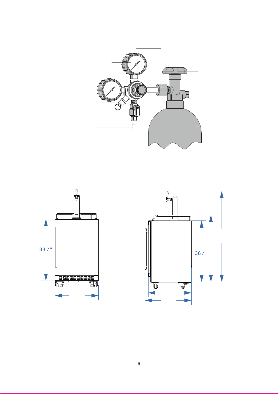
Parts Identification: CO₂ Tank and Regulator
NOTE: The CO₂ tank and regulator are components from the tap kits, sold separately. The pressure relief valve
will be located between the high and low pressure gauges for double and triple regulators. There will be two
shutoff valves and hose barbs for double regulators and three shutoff valves and hose barbs for triple regulators.
Inlet Connection Nut
Low Pressure Gauge
High Pressure Gauge
Pressure Relief Valve - Regulator
Shutoff Valve
Hose Barb
Pressure Adjustment knob
Hand Valve
Co₂ Gas Tank
Dimensions
24"
5
8
53"
40"
23½"
25¼"
7
8
"
7
8
1. Remove all shelving and packaged components
from the interior of the kegerator before
proceeding. The kegerator can be plugged in,
but ensure it is powered off before proceeding.
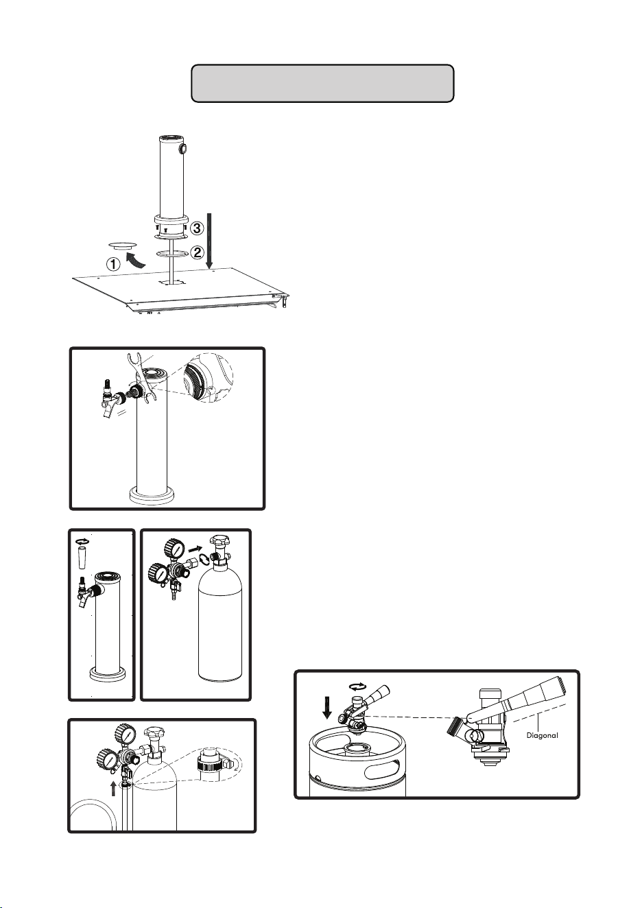
2. Remove the black plastic insulation cap from
the top of the kegerator (FIG. A1).
NOTE: If you are setting up the kegerator as a full
beverage cooler, leave the insulation cap installed.
3. Place the black rubber gasket, included with
the tap kit, on top of the kegerator and align
the gasket with the screw holes (FIG. A2).
4. Guide the beer line through the opening on top
of the kegerator. Secure the tap tower to the
kegerator using the included (4) M5 x 16 screws
(FIG. A3).
FIG. A
5. Attach the tap to the tap tower as shown in FIG. B.
Make sure the tap is aligned properly and turn the
nut counterclockwise by hand. Fully tighten using the
included wrench.
6. Screw the tap handle onto the tap shown in FIG. C.
NOTE: Tap handles use a standard 3/8”-16 UNC
thread to accommodate aftermarket tap handles.
7. Ensure the hand valve on the CO₂ tank is closed.
Attach the regulator to the filled CO₂ tank and hand
tighten the inlet connection nut (FIG. D). Use a
wrench for an additional quarter turn, making sure to
not overtighten the nut.
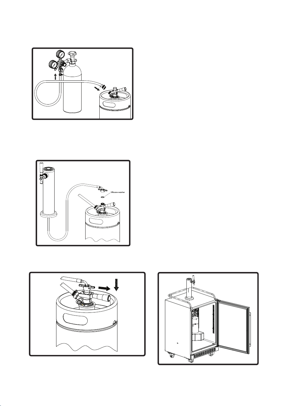
8. Attach the gas line to the hose barb on the regulator
shown in FIG. E. Secure using the included metal
clamp and tighten using a flathead screwdriver.
9. Connect the keg coupler to the beer keg, but first
make sure the handle of the keg coupler is
disengaged in the diagonal/upper position. Refer to
FIG. F for clarification. Insert the keg coupler into the
beer keg and turn 25° clockwise to lock into place.
Do not engage the handle yet.
Wrench
FIG. B
FIG. C
FIG. D
FIG. E
FIG. F
9
INSTALLING THE KEGERATOR
Installing the Kegerator
FIG. G
FIG.H
FIG. I
FIG.J
10.Attach the opposite end of the gas line with the
pre-installed threaded nut to the keg coupler
(FIG. G). Tighten using the included wrench.
NOTE: Make sure the clear silicone check valve is
inside the keg coupler before attaching the gas line.
11.Place a silicone washer on top of the keg coupler
and connect the threaded nut from the beer line to
the coupler by hand tightening it (FIG. H).
12.Tap the keg by pulling the keg coupler handle
outwards - away from the keg coupler and pushing
it down to lock it into position (FIG. I). Listen for the
“click” of the pull handle when it shifts into the final
downward position and your keg will be tapped.
NOTE: The keg needs to be tapped to fit in the
kegerator, otherwise the keg coupler handle will be
too high and will prevent the keg from fitting.
13.Calibrate the regulator. Refer to next page for
detailed instructions.
14.Place the CO₂ tank upright inside the left corner of
the kegerator and secure using the Velcro strap
shown in FIG. J.
15.Place the beer keg inside the kegerator.
16.Power on the kegerator and set to the desired
temperature. We recommend waiting at least 24
hours before dispensing beer to allow the keg to
get to temperature and settle.
17.Place drip tray in front of the tap tower under the tap.
18.Enjoy your beer!
10
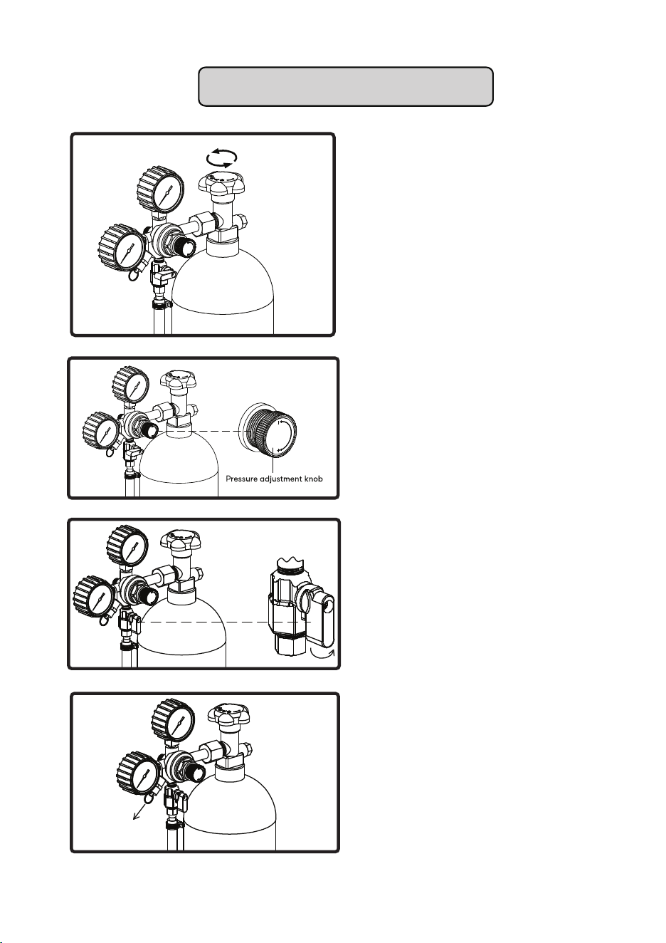
FIG. L
FIG. M
FIG. N
FIG. O
1. With the shutoff valve on the regulator turned off
(perpendicular to the tubing), completely open the
hand valve on the CO₂ tank (FIG. L).
2. Turn the pressure adjustment knob until the
desired pressure is shown on the low pressure
guage (FIG. M). We recommend setting the
regulator between 10-12 PSI to start and adjust
later as needed. Turn the knob clockwise to
increase pressure and counterclockwise to
decrease pressure.
NOTE: Other conditions such as altitude or beer
type may require additional adjustments.
3. Open the shutoff valve on the regulator so it is
parallel with the tubing (FIG N).
4. The keg coupler is designed with a pressure
relief valve (PRV) as shown in FIG. O. Briefly pull
the ring on the PRV to allow CO₂ gas to vent.
This will permit CO₂ gas to flow through the
regulator and help obtain a more accurate
reading on the low pressure guage.
NOTE: We recommend following up on any
adjustment to the regulator with a brief pull of the
PRV ring to ensure an accurate output reading.
Check for leaks.
11
CALIBRATING THE REGULATOR
12
32 - 65°F (0 - 18°C)
32°F to 65°F.
13
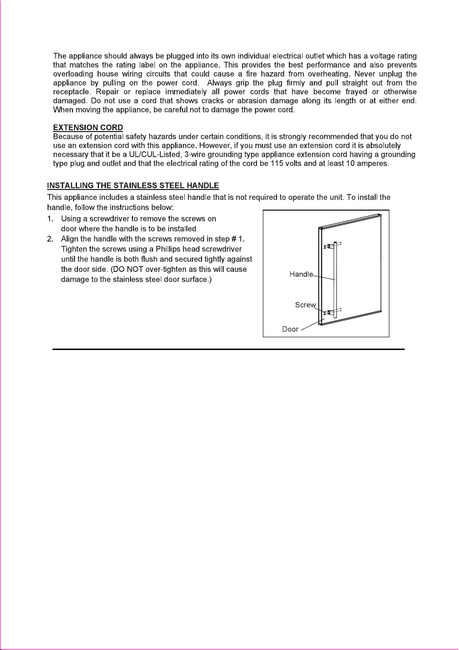
14