507789-02B Issue 2336 Page 1 of 24
This manual must be left with the homeowner for future reference.
This is a safety alert symbol and should never be ignored. When you see this symbol on labels or in manuals, be alert to
the potential for personal injury or death.
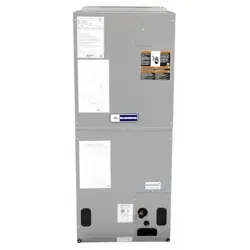
INSTALLATION INSTRUCTIONS
BE5V Series
One-Piece Variable Speed Air Handler
(P) 507789-02B
*P507789-02B*
Blue Summit LLC
8201 C National Turnpike
Louisville, KY 40214
Table of Contents
Unit Dimensions – Upow – Inches (mm) ...................2
Shipping and Packing List ...........................................3
General ........................................................................3
Requirements ..............................................................3
Use of Air Handler During Construction.......................4
Installation Clearances ................................................4
Installation ...................................................................4
Condensate Drain........................................................7
Duct System and Filters .............................................9
Brazing Refrigerant Lines ............................................9
Sealing the Unit .........................................................11
Electrical Connections ...............................................12
BDC3 Blower Control ................................................16
Adjusting the Blower Speed ......................................16
Blower Performance ..................................................17
Checkout Procedures ................................................21
Professional Maintenance .........................................22
Homeowner Maintenance..........................................22
Repairing or Replacing Cabinet Insulation ................22
Improper installation, adjustment, alteration, service
or maintenance can cause property damage, personal
injury or loss of life. Installation and service must be
performed by a licensed professional HVAC installer or
equivalent, service agency, or the gas supplier.
WARNING
The Clean Air Act of 1990 bans the intentional venting
of refrigerant (CFCs, HCFCs and HFCs) as of July
1, 1992. Approved methods of recovery, recycling or
reclaiming must be followed. Fines and/or incarceration
may be levied for noncompliance.
IMPORTANT
As with any mechanical equipment, contact with sharp
sheet metal edges can result in personal injury. Take
care while handling this equipment and wear gloves
and protective clothing.
CAUTION
507789-02BIssue 2336Page 2 of 24
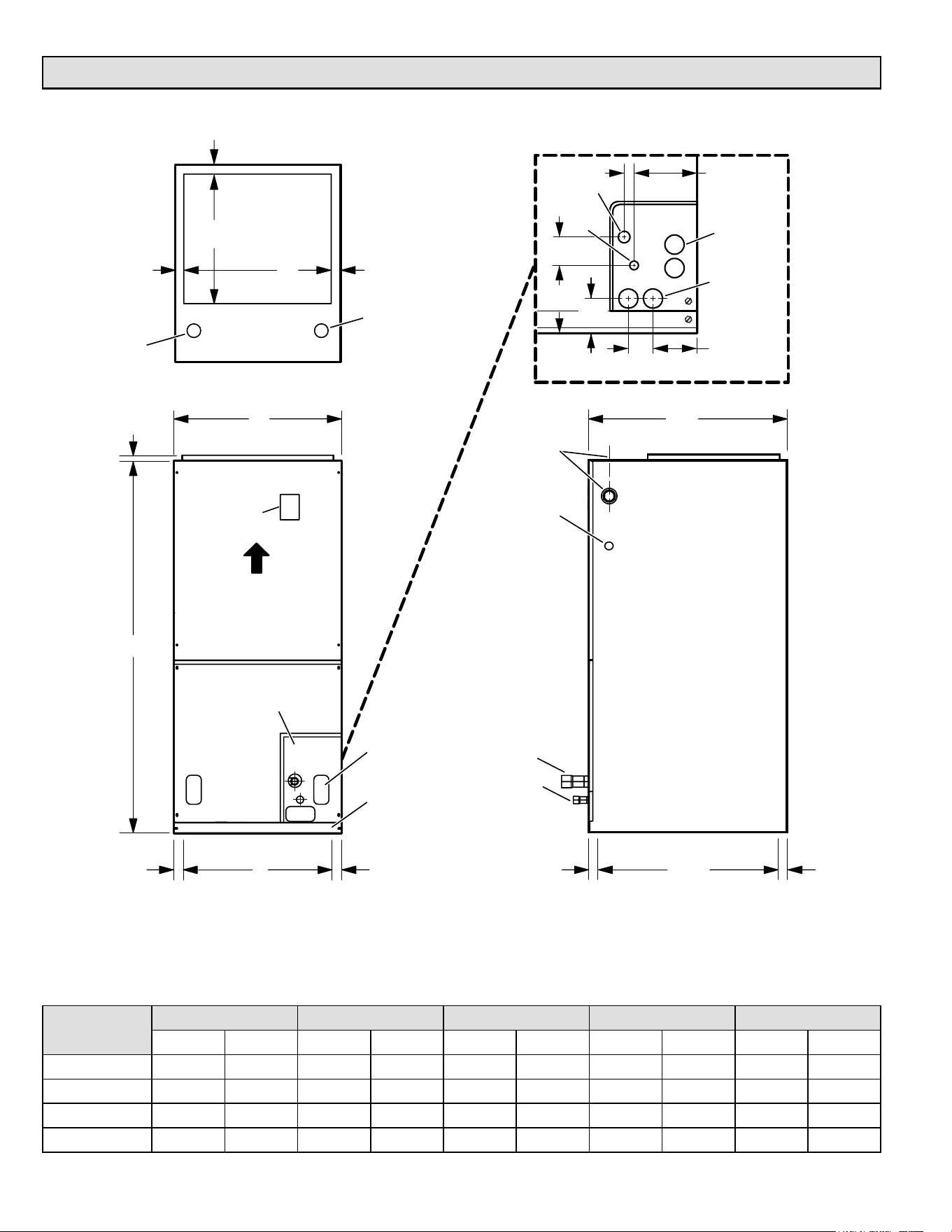
Unit Dimensions – Upow – Inches (mm)
A
B
FRONT VIEW SIDE VIEW
LINE VOLTAGE
INLETS
(Top and Right Side)
LOW VOLTAGE
INLETS
(Either Side)
SUCTION
LINE
LIQUID
LINE
FILTER
ACCESS
3/4
(19)
AIR FLOW
CIRCUIT
BREAKER
COVER
D
1-1/8
(29)
1/2
(13)
C
LINE VOLTAGE
INLETS
(Top and Left Side)
LOW VOLTAGE
INLETS
(Top and Right Side)
1 (25)
SUPPLY AIR
OPENING
TOP VIEW
OPENING
OPENING
1 (25)
1 (25)
1-1/8
(29)
1-1/8
(29)
20-3/8
(518)
22
(559)
14-1/2
(368)
DETAIL OF PIPING PLATE
LIQUID
LINE
CONDENSATE
DRAINS (2)
(Horizontal)
1-3/4
(44)
3/4 (19)
2-3/4
(70)
3-1/2
(89)
PIPING
PLATE
4-3/4
(121)
4-3/8
(111)
2-3/8
(60)
CONDENSATE
DRAINS (2)
(Upflow and
Downflow)
SUCTION
LINE
CONDENSATE DRAIN
PIPING PLATE (3)
(2-1/4 x 3-3/4)
NOTE: Unit is shipped congured for horizontal right-hand air discharge. Unit may be converted to horizontal left-hand air
discharge by repositioning horizontal drain pan. Dimensions remain the same in all congurations.
Dimensions
024 030 036 / 042 048 060
in. mm in. mm in. mm in. mm in. mm
A 45-1/2 1156 47 1194 53-5/8 1362 55 1397 59-3/4 1518
B 18-1/2 470 18-1/2 470 21-1/2 546 21-1/2 546 21-1/2 546
C 16-1/2 419 16-1/2 419 19-1/2 495 19-1/2 495 19-1/2 495
D 16-1/4 413 16-1/4 413 19-1/4 489 19-1/4 489 19-1/4 489
507789-02B Issue 2336 Page 3 of 24
Shipping and Packing List
Package 1 of 1 contains:
1 – Assembled air handler unit factory-equipped for upow
or horizontal air discharge application (includes upow
and horizontal drain pans and pre-installed air lter).
Check the air handler for shipping damage; if found,
immediately contact the last carrier. Check the unit rating
plate to conrm that delivered unit matches order.
General
The BE5V series air handler with aluminum coil is designed
for indoor installation only. As shipped, the unit is ready
for installation in either upow or horizontal right-hand
air discharge applications. Horizontal drain pan may be
repositioned in the eld to allow installation in the horizontal
left-hand air discharge position. Various accessories are
available and listed in the BE5V Product Specication for
ordering.
This instruction is intended as a general guide and does
not supersede local or national codes in any way. Consult
authorities having jurisdiction before installation.
NOTE: Special procedures are required for cleaning the
aluminum coil in this unit. See Page 22 in this instruction
for information.
Requirements
Excessive Weight Hazard - Use two or more people
when moving and installing the unit. Failure to do so
can result in back or other type of injury.
WARNING
BE5V units include a factory-installed check/expansion
valve which will provide optimal refrigerant control
and system performance with outdoor units of varying
capacities. These units must be installed as a part of
a matched system as outlined in the BE5V Product
Specication.
IMPORTANT
These instructions are intended as a general guide.
Compliance with all local, state, or national codes
pertaining to this type of equipment should be determined
prior to installation. Read this instruction manual, as well
as the instructions supplied in separate equipment, before
starting the installation.
In addition to conforming to manufacturer’s installation
instructions and local municipal building codes, installation
of air handler units (with or without optional electric heat),
MUST conform with National Fire Protection Association
(NFPA) standards: “Standard for Installation of Air
Conditioning and Ventilation Systems” (NFPA No. 90A)
and “Standard for Installation of Residence Type Warm Air
Heating and Air Conditioning Systems” (NFPA No. 90B).
All models are designed for indoor installation only. The
installation of the air handler, eld wiring, duct system, etc.
must conform to the requirements of the National Electrical
Code, ANSI/NFPA No. 70 (latest edition) in the United
States, and any state laws, and local ordinances (including
plumbing or waste water codes).
Local authorities having jurisdiction should be consulted
before installation is made. Such applicable regulations
or requirements take precedence over the general
instructions in this manual.
Install the conditioned air plenum, ducts and air lters
(provided) in accordance with NFPA 90B Standard for
the Installation of Warm Air Heating and Air-Conditioning
Systems (latest edition).
The air handler is shipped from the factory completely
assembled. The unit is provided with anges for the
connection of the duct system.
Do not remove the cabinet knockouts until it has been
determined which knockouts will need to be removed for
the installation.
Select the air discharge position which best suits the site
conditions. Consider required clearances, space, routing
requirements for refrigerant line, condensate disposal,
lters, duct system, wiring, and accessibility for service.
Refer to the rating plate on the air handler for specic
information.
Danger of explosion. Keep ammable
materials and vapors, such as gasoline,
away from air handler. Place air handler so
that heating elements are at least 18 inches
(46 cm) above the oor for a garage
installation. Failure to follow these
instructions can result in death, explosion,
or re.
WARNING
507789-02BIssue 2336Page 4 of 24
Excessive condensation may occur if the unit is installed
in a warm, humid place. When the unit is installed in an
unconditioned space, apply sealant around electrical
wires, refrigerant piping and condensate lines at the
point where they enter the cabinet.
Apply sealant on the inside of the cabinet at the
point where the electrical wires exit through the
conduit opening. This will also keep warm and moist
unconditioned air out of the air handler cabinet where
it will form condensate on the cooler control box and
electrical controls.
IMPORTANT
This unit is approved for installation clearance to
combustible material as stated on the unit rating
plate. Accessibility and service clearances must take
precedence over combustible material clearances.
The air handler must be installed so that free access is
allowed to the coil/lter compartment and blower/control
compartment.
IMPORTANT
• During cooling operation, excessive sweating may
occur if the air handler is installed in a warm and
humid space.
• If installed in an unconditioned space, sealant should
be applied around the electrical wires, refrigerant
tubing, and condensate lines where they enter the
cabinet.
• Electrical wires should be sealed on the inside where
they exit the conduit opening. Sealant is required to
prevent air leakage into, and condensate from forming
inside of, the air handler, the control box, and on the
electrical controls.
Use of Air Handler During Construction
Units may be used for heating (heat pumps) or cooling of
buildings or structures under construction, if the following
conditions are met to ensure proper operation.
DO NOT USE THE UNIT FOR CONSTRUCTION HEAT
UNLESS ALL OF THE FOLLOWING CRITERIA ARE
MET:
• A room thermostat must control the air handler. The
use of xed jumpers is not allowed.
• Air lter must be installed in the system and must be
maintained during construction.
• Air lter must be replaced upon construction
completion.
Installation Clearances
Non-Ducted Return Closet Installation
The air handler can be installed in a closet with a false
bottom to form a return air plenum. It may also be installed
with a return air plenum under the air handler.
Louvers or return air grilles are eld-supplied. Local codes
may limit application of systems without a ducted return to
single-story buildings.
When a BE5V unit is installed in a closet with a louvered
return opening, the minimum open area for the louvers will
be:
• 320 square inches for -24 models;
• 360 square inches for -30 and -36 models;
• 450 square inches for -42 thru -60 models
If the free area is not known, assume a 25% free area for
wood or a 75% free area for metal louvers or grilles. Using
the louver dimensions and the 25% or 75% assumption,
determine if the open area meets the minimum open area
listed above.
If a return air plenum is used, the return air grille should be
immediately in front of the opening in the plenum to allow
for the free ow of return air. When not installed in front of
the opening, there must be adequate clearance around the
air handler to allow for the free ow of return air.
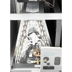
Installation
Each unit consists of a blower assembly, refrigerant coil,
and controls in an insulated galvanized steel factory-
• The air handler evaporator coil, supply fan assembly
and duct system must be thoroughly cleaned following
nal construction clean-up.
• All air handler operating conditions must be veried
according to these installation instructions.
EQUIPMENT MAY EXPERIENCE PREMATURE
COMPONENT FAILURE AS A RESULT OF FAILURE TO
FOLLOW THE ABOVE INSTALLATION INSTRUCTIONS.
FAILURE TO FOLLOW THE ABOVE INSTALLATION
INSTRUCTIONS VOIDS THE MANUFACTURER’S
EQUIPMENT LIMITED WARRANTY. BLUE SUMMIT
DISCLAIMS ALL LIABILITY IN CONNECTION WITH
INSTALLER’S FAILURE TO FOLLOW THE ABOVE
INSTALLATION INSTRUCTIONS.
NOTWITHSTANDING THE FOREGOING, INSTALLER IS
RESPONSIBLE FOR CONFIRMING THAT THE USE OF
CONSTRUCTION HEAT OR COOLING IS CONSISTENT
WITH THE POLICIES AND CODES OF ALL REGULATING
ENTITIES. ALL SUCH POLICIES AND CODES MUST BE
ADHERED TO.
507789-02B Issue 2336 Page 5 of 24
nished enclosure. Knockouts are provided for electrical
wiring entrance.
For ease in installation, it is best to make any necessary
coil conguration changes before setting air handler in
place.
Refrigerant Metering Device
BE5V units are equipped with a factory-installed check/
expansion valve.
HORIZONTAL DRAIN PAN
(MUST BE REMOVED)
UP-FLOW /
DOWN-FLOW
DRAIN PAN
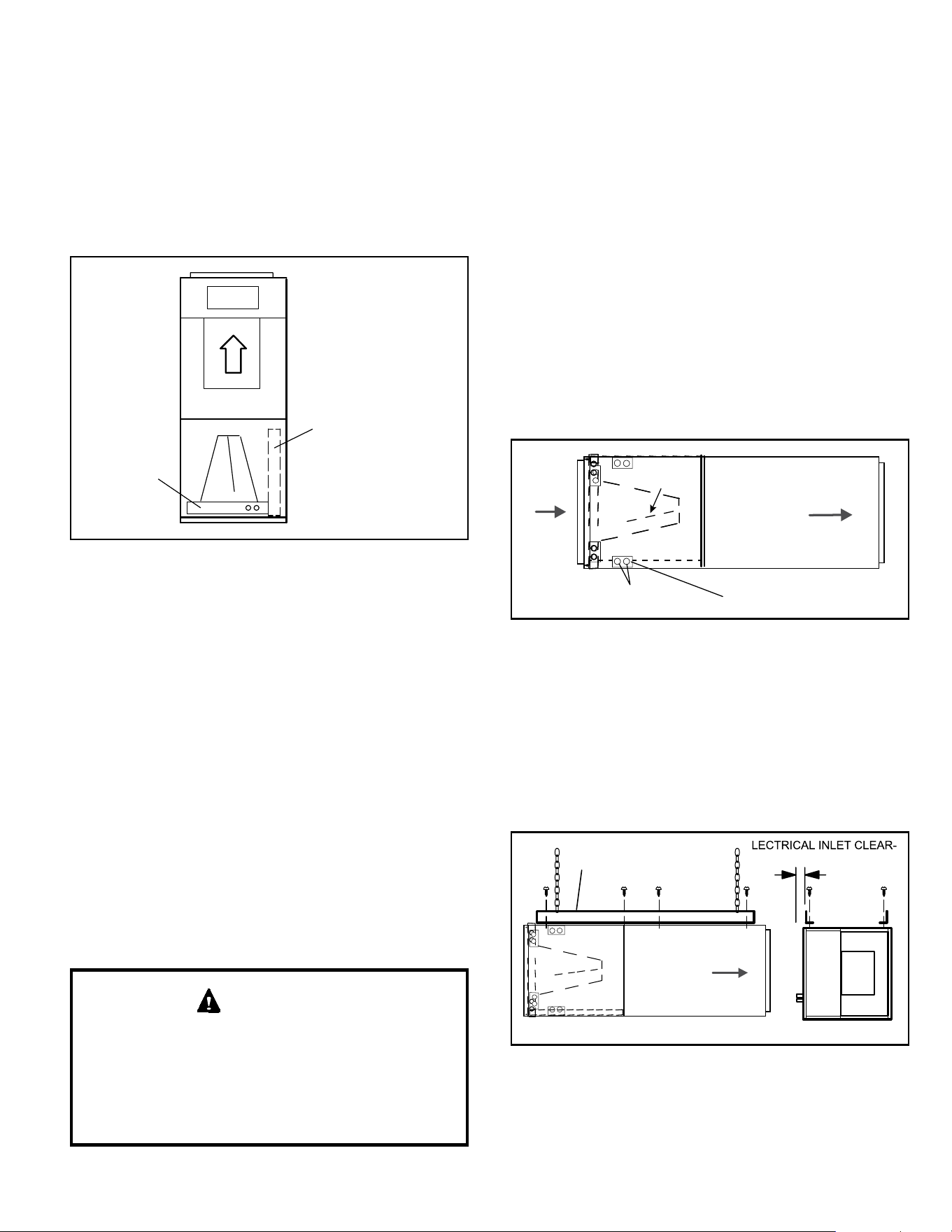
Figure 1. Upow Conguration
Upow Application
1. The air handler must be supported on the bottom only
and set on solid oor or eld-supplied support frame.
Securely attach the air handler to the oor or support
frame.
2. If installing a unit in an upow application, remove the
horizontal drain pan.
NOTE: The horizontal drain pan is not required in
upow air discharge installations; its removal provides
the best eciency and air ow.
3. Place the unit in the desired location and slope unit.
Connect return and supply air plenums as required
using sheet metal screws.
4. Install units that have no return air plenum on a stand
that is at least 14” from the oor. This will allow proper
air return.
Horizontal Applications
When removing the coil, there is a possibility of danger
of equipment damage and personal injury. Be careful
when removing the coil assembly from a unit installed
in right- or left-hand applications. The coil may tip into
the drain pan once it is clear of the cabinet. Support the
coil when removing it..
IMPORTANT
NOTE: When the unit is installed in horizontal applications,
a secondary drain pan is recommended. Refer to local
codes.
NOTE: This unit may be installed in left-hand or right-hand
air discharge horizontal applications. Adequate support
must be provided to ensure cabinet integrity. Ensure that
there is adequate room to remove service and access
panels if installing in the horizontal position.
Right-Hand Discharge
1. Determine which plugs are required for drain line
connections.
2. With access door removed, remove drain line plugs to
install drain lines.
3. Set unit so that it is sloped toward the upow drain pan
end of the unit and level from front to back of unit (see
Figure 6).
4. The horizontal conguration is shown in Figure 2.
Drains
AIR FLOW
PLUGS
RIGHT‐HAND DRAINS
Drip
Shield
Figure 2. Right-Hand Discharge Conguration
5. If the unit is suspended, the entire length of the cabinet
must be supported. If you use a chain or strap, use a
piece of angle iron or sheet metal attached to the unit
(either above or below) to support the length of the
cabinet. Use securing screws no longer than 1/2 inch
to avoid damaging the coil or lter. See Figure 3. Use
sheet metal screws to connect the return and supply
air plenums as required.
FRONT WEIV DNEWEIV
ANGLE IRON OR SHEET
METAL
E
ANCE 4 IN. (102 MM)
MAXIMUM 1/2"
LONG SCREW
AIR FLOW
Figure 3. Suspending Horizontal Unit
507789-02BIssue 2336Page 6 of 24
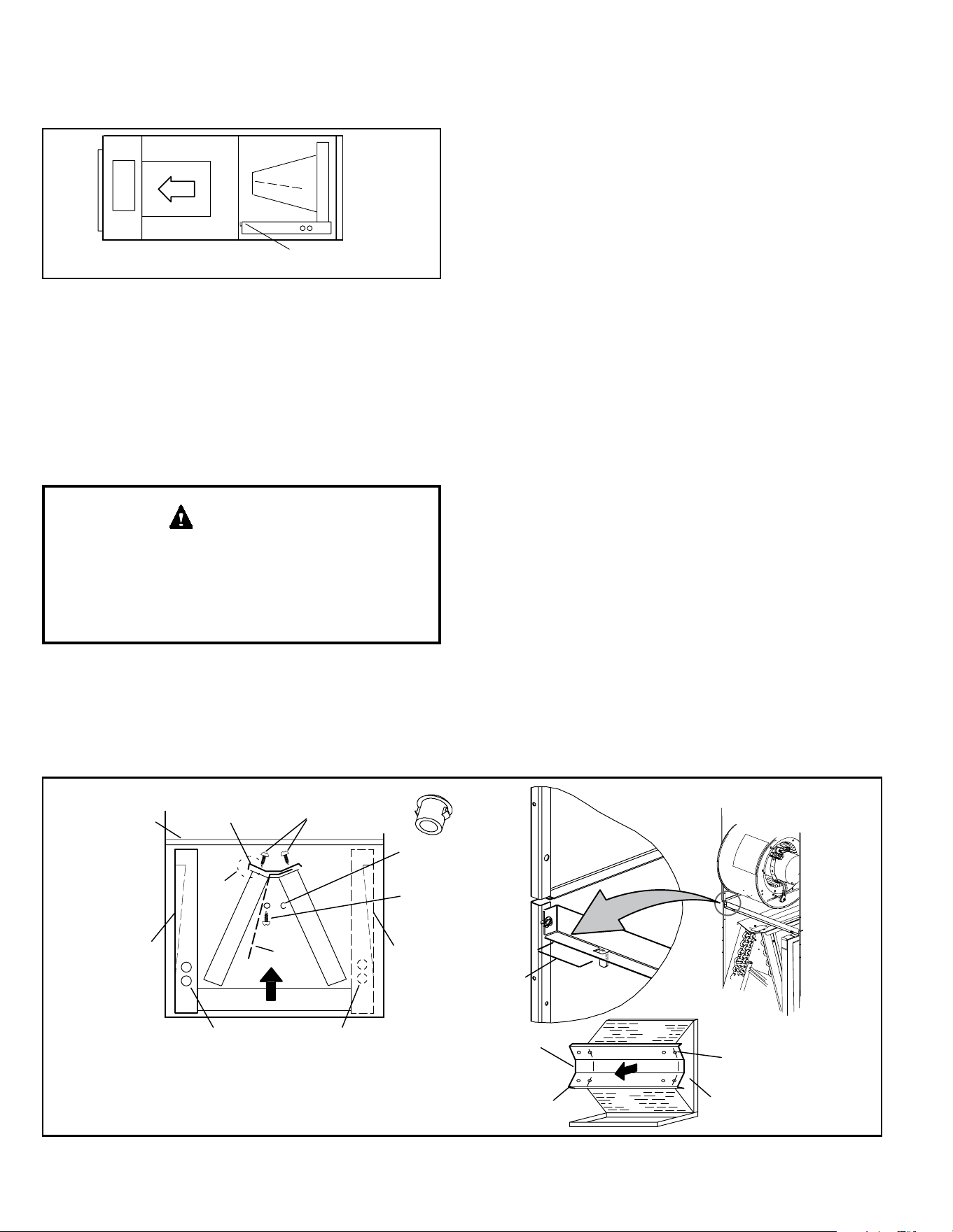
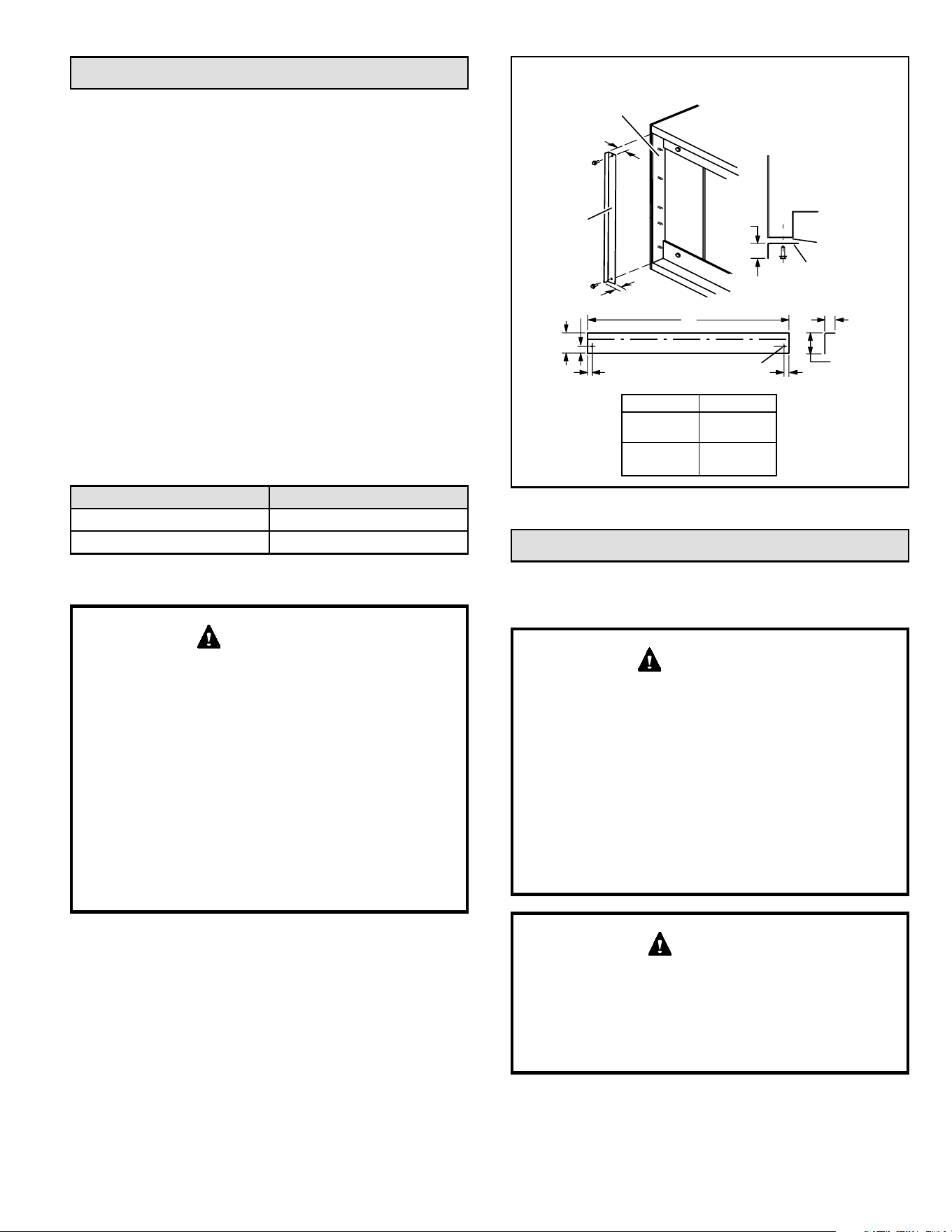
Left-Hand Air Discharge
For horizontal left-hand air discharge, the following eld
modications are required.
FRONT EDGE OF HORIZONTAL
DRAIN PAN
Figure 4. Left-Hand Discharge Conguration
1. Remove access panels and the corrugated padding
between the blower and coil assembly. Discard the
corrugated padding.
2. Pull the coil assembly from unit. Pull o the horizontal
drain pan.
3. Remove the drain plugs from back drain holes on
horizontal drain pan and reinstall them on front holes.
After removal of drain pan plug(s), check drain hole(s)
to verify that drain opening is fully open and free of any
debris. Also check to make sure that no debris has
fallen into the drain pan during installation that may plug
up the drain opening.
IMPORTANT
4. Rotate drain pan 180º front-to-back and install it on the
opposite side of the coil.
5. Remove screws from top cap. Remove drip shield
screw located in the center of the back coil end seal
as illustrated in Detail A in Figure 5.
6. Rotate drip shield 180° front-to-back.
7. Remove plastic plug from left hole on coil front end
seal and reinstall plug in back hole. Reinstall drip
shield screw in front coil end seal. Drip shield should
drain downward into horizontal drain pan inside coil.
8. Rotate top cap 180º front-to-back and align with
unused screw holes. Holes must align with front and
back coil end plates (see Detail B in Figure 5). The top
cap has a 45º bend on one side and a 90º bend on the
other. The 90º bend must be on the same side as
the horizontal drain pan as illustrated in Detail A in
Figure 5.
NOTE: Be very careful when reinstalling the screws
into the coil end plate engaging holes. Misaligned
screws may damage the coil.
9. From the upow position, ip cabinet 90º to the left
and set into place. Replace blower assembly. Secure
coil in place by bending down the tab on the cabinet
support rail as illustrated.
NOTE: Seal around the exiting drain pipe, liquid and
suction lines to prevent inltration of humid air.
10. Flip access door and replace it on the unit.
11. Set unit so that it is sloped 1/4ʺ toward the drain pan
end of the unit. Connect return and supply air plenums
as required using sheet metal screws.
12. If suspending the unit, it must be supported along the
entire length of the cabinet. If using chain or strap,
use a piece of angle iron or sheet metal attached to
the unit (either above or below) so that the full length
of the cabinet is supported. Use securing screws no
longer than 1/2ʺ to avoid damage to coil or lter, as
illustrated in Figure 3. Connect return and supply air
plenums as required using sheet metal screws.
Figure 5. Field Modication for Left-Hand Discharge
90º
BEND
CABINET
SUPPORT
TOP CAP
SCREWS
DRAIN PAN
REINSTALLED
HERE
DRAIN PAN
SHIPPING
LOCATION
TOP CAP ROTATED TO
CORRECT POSITION
———— DRAIN PLUGS ————
REINSTALLED HERE REMOVED FROM HERE
BACK COIL
END SEAL
TOP CAP
90º
BEND
INSTALL DRAIN PAN
BETWEEN TAB AND
EXTERIOR INNER WALL.
DETAIL A
DETAIL B
DETAIL C
FRONT VIEW
3/16” PLASTIC
PLUG (REAR COIL
END SEAL)
ALIGN HOLES WITH
HOLES IN COIL END
PLATE. STARTING WITH
THE ROUND HOLES ON
THIS END.
DRIP SHIELD
SCREW (FRONT
COIL END SEAL)
DRIP
SHIELD
COIL SHOWN IN UPFLOW POSITION FOR EASY
CONVERSION (LEFT-HAND AIR DISCHARGE)
507789-02B Issue 2336 Page 7 of 24
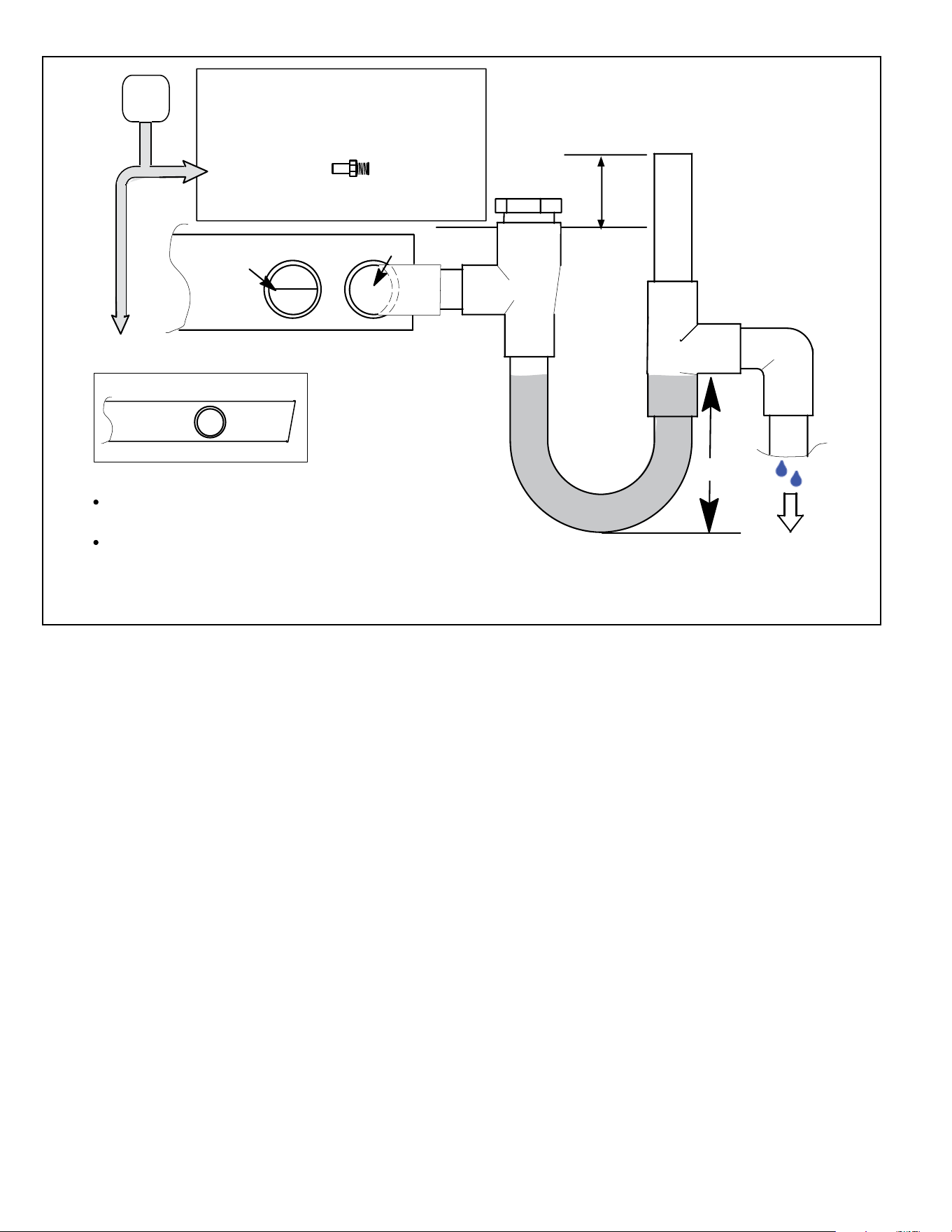
Condensate Drain
On units of this type, where the blower “draws” rather
than “blows” air through the coil, traps must be installed
in the condensate drain lines (primary and auxiliary,
if used). Traps prevent the blower from drawing air
through the drain lines into the air supply.
IMPORTANT
A eld-fabricated secondary drain pan, with a drain
pipe to the outside of the building, is required in all
installations over a nished living space or in any area
that may be damaged by overow from the main drain
pan. In some localities, local codes may require a
secondary drain pan for any horizontal installation.
IMPORTANT
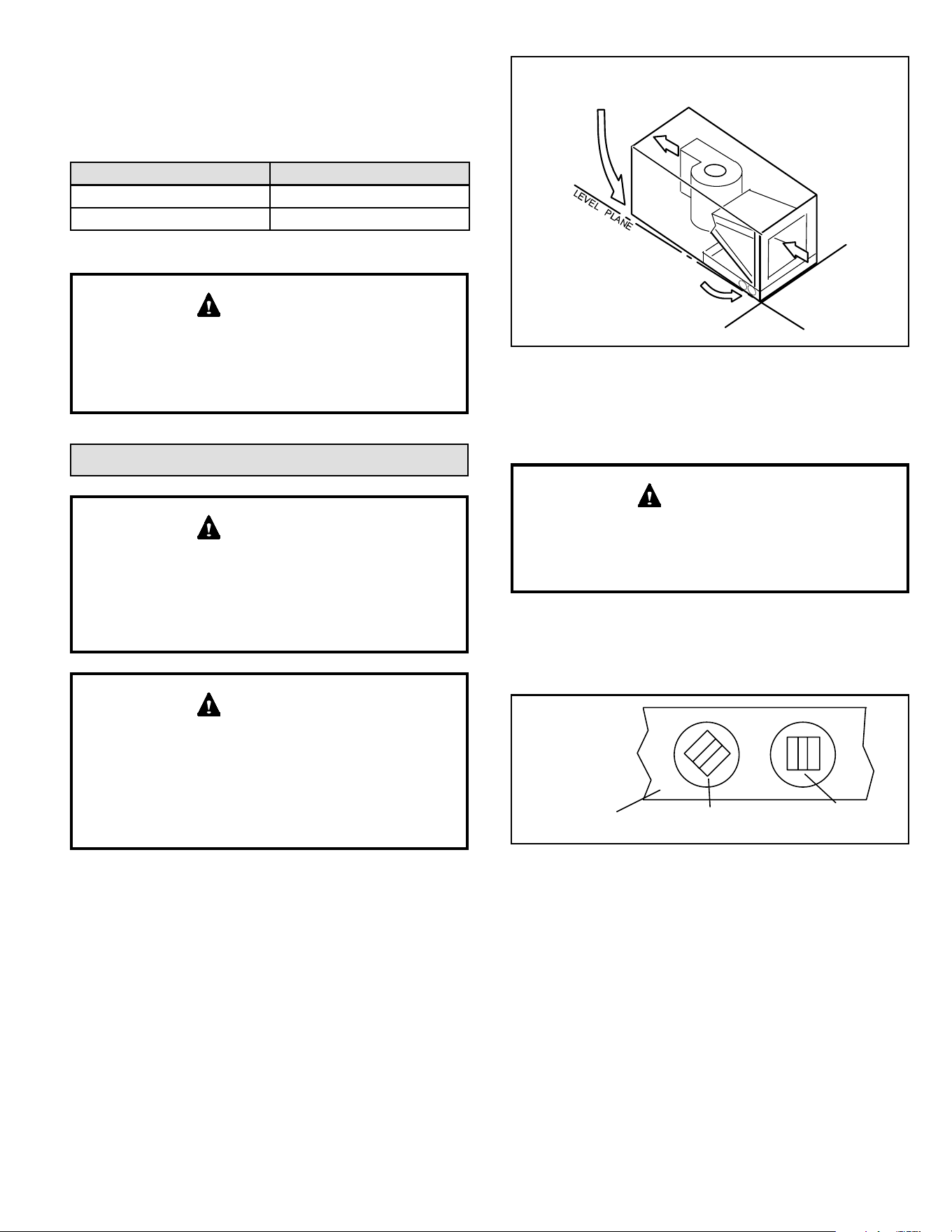
Sloping The Unit
Make sure the unit is sloped (similar to the slope shown
in Figure 6) so that the drain pan will empty completely
without water standing in the pan.
THIS CORNER SHOULD BE 5/8" (+/- 1/8") HIGHER
THAN DRAIN CORNER
DRAIN CORNER
LEVEL PLANE
Figure 6. Sloping the Unit for Proper Drainage
Install Condensate Drain
The air handler is provided with 3/4” NPT condensate drain
connections.
On some pans, the primary and secondary drain holes
have knockouts.
Conrm primary and secondary drains are open.
IMPORTANT
1. BE5V units are equipped with a drain pan, which
includes green (main drain) and red (secondary drain)
plugs. Unscrew the plugs to remove them before
inserting condensate drain ttings.
DRAIN PAN
RED SECONDARY
DRAIN PLUG
UNSCREW PLUGS
AND CONNECT
PROPERLY SIZED
FIELD-PROVIDED
FITTINGS AND
DRAIN LINES.
GREEN MAIN
DRAIN PLUG
Figure 7. Drain Line Connections
2. Install properly sized, eld-provided connection ttings
and connect primary drain line to the main drain pan
connection.
NOTE: When installing drain line connection ttings
to the drain pan, hand tighten the tting and use a
thread sealant. Over-tightening the ttings can split
connections on the drain pan.
3. If the secondary drain line is to be used, remove the
plug or the knockout and route the drain line so that
water draining from the outlet will be easily noticed
by the homeowner. Refer to local codes for drain trap
requirements on the secondary drain line.
Downow Application
If downow application is required, separately order a
downow conversion kit and install per kit instructions.
See Table 1 for kit information. Also use metal or class I
supply and return air plenums.
Model Kit Number
018, 024, 030 Y9658
036, 042, 048, 060 Y9659
Table 1. Downow Conversion Kits
If electric heat section with circuit breakers (ECBA25) is
installed in a BE5V unit in a downow application, the
circuit breakers must be rotated 180° to the UP position.
See ECBA25 installation instructions for more details.
IMPORTANT
507789-02BIssue 2336Page 8 of 24
ABOVE
FINISHED
SPACE?
OVERFLOW DRAIN LINE
ALWAYS RUN AN OVERFLOW DRAIN LINE. IF NOT POSSIBLE TO
ROUTE OVERFLOW DRAIN LINE, INSTALL LOW VOLTAGE
OVERFLOW SWITCH KIT. WIRE KIT TO SHUT DOWN
COMPRESSOR PER INSTRUCTIONS.
NO
YES
PART #
X3169
CLEAN OUT
VENT
PRESS IN
(DO NOT GLUE)
VENT MUST EXTEND
ABOVE HEIGHT OF
COIL DRAIN PAN BY
TWO INCHES (51MM)
1” X 3/4” X 3/4”
REDUCING
TEE WITH
PLUG
1
P-TRAP
49P66, J-TRAP #
91P90 OR ANY
PVC SCH 40 P- OR
J-TRAP 3/4”
OVERFLOW
DRAIN
AIR HANDLER DRAIN PAN
WHEN A COIL IS LOCATED ABOVE A FINISHED SPACE, A
3/4” (19.1MM) SECONDARY DRAIN LINE MUST BE:
CONNECTED TO SECONDARY DRAIN PAN
OR
CONNECTED TO THE OVERFLOW DRAIN OUTLET OF
THE AIR HANDLER DRAIN PAN.
TRAPS MUST BE DEEP ENOUGH TO OFFSET MAXIMUM STATIC
DIFFERENCES — GENERALLY, TWO INCHES (51MM).
DRAIN LINE SHOULD
SLOPE A MINIMUM OF
ONE INCH PER 10
FEET (25MM PER 3
METERS)
MAIN
DRAIN
TO APPROVED
DRAIN
FOR NEGATIVE PRESSURE COILS (BLOWER
AFTER COIL) TRAPS ARE REQUIRED ON ALL
DRAIN LINES CONNECTED TO COIL.
COMPACT OVERFLOW SWITCH WITH 3/4” FEMALE SLIP INLET
AND MALE ADAPTER, TWO PART DESIGN FOR USE WHERE
OBSTRUCTIONS PREVENT DIRECT THREADING
SECONDARY
DRAIN PAN
2”
(51MM)
TRAP DEPTH
1
P-TRAP 49P66 REQUIRES A LARGER INSTALLATION SPACE THAN THE J-TRAP 91P90.
NOTE — WHEN A AIR HANDLER IS LOCATED ABOVE A FINISHED SPACE THE
SECONDARY DRAIN PAN MUST HAVE A LARGER FOOTPRINT THAN THE AIR HANDLER.
Figure 8. Typical Main and Overow Drain
4. Check again to ensure drain ports and drain pan are
free of all debris.
5. Plug and check any unused drain pan openings for
tightness. Torque plugs to 36 in. lb. to prevent water
leaks or seepage from the drain pan.
6. Install a 2” trap in the main (primary) drain lines as
close to the unit as practical (see Figure 8). Make sure
the top of the trap is below the connection to the drain
pan to allow complete drainage of the pan.
NOTE: Horizontal runs must have an anti-siphon air
vent (standpipe) installed ahead of the horizontal run.
See Figure 8. An extremely long horizontal run may
require an oversized drain line to eliminate air traps.
NOTE: Do not operate air handler without a trap in
the main (primary) drain. The condensate drain is on
the negative pressure side of the blower; therefore, air
being pulled through the condensate line will not allow
positive drainage without a proper trap.
7. Route the drain line to the outside or to an appropriate
drain. Drain lines must be installed so they do not block
service access to the front of the air handler. A 24”
clearance is required for lter, coil, or blower removal
and service access.
NOTE: Check local codes before connecting the drain line
to an existing drainage system. Insulate the drain lines
where sweating could cause water damage.
Test Condensate Drain
Test the drain pan and drain line after installation:
1. Pour several quarts of water into drain pan. Use
enough water to ll both the drain trap and the line.
2. Check the installed drain pan. Drain pan must be
draining completely. Drain line ttings must not be
leaking. Water must be draining from the end of the
primary drain line.
3. Correct any leaks found.
507789-02B Issue 2336 Page 9 of 24
Duct System and Filters
Duct System
The air handler is provided with anges for the connection
of the supply plenum.
Supply and return duct system must be adequately sized
to meet the system’s air requirements and static pressure
capabilities. The duct system should be insulated with
a minimum of 1” thick insulation with a vapor barrier in
conditioned areas or 2” minimum in unconditioned areas.
Supply plenum should be the same size as the anged
opening provided around the blower outlet and should
extend at least 3 ft. from the air handler before turning or
branching o plenum into duct runs. The plenum forms
an extension of the blower housing and minimizes air
expansion losses from the blower.
Filters
A lter is provided. Table 2 lists the lter size for each unit.
BE5V Filter Size – in.
-024, -030 15" x 20" x 1"
-036, -042, -048, -060 18" x 20" x 1"
Table 2. Unit Air Filter Size Chart
If a high eciency lter is being installed as part of
this system to ensure better indoor air quality, the lter
must be properly sized. High eciency lters have a
higher static pressure drop than standard eciency
glass/foam lters. If the pressure drop is too great,
system capacity and performance may be reduced.
The pressure drop may also cause the limit to trip
more frequently during the winter and the indoor coil
to freeze in the summer, resulting in an increase in the
number of service calls. Before using any lter with this
system, check the specications provided by the lter
manufacturer against the data given in the appropriate
Product Specications.
IMPORTANT
Installing Duct System
Connect supply air duct to the ange on top of the air
handler. If an isolation connector is used, it must be
nonammable.
Field-Fabricated Return Air Duct Flange For
Horizontal Applications
A return air duct system is recommended, but not factory-
provided. If the unit is installed in a conned space or
closet, run a full-size return connection to a location outside
the closet.
BOTTOM OF
CABINET
DUCT
ADAPTER
1−1/2
(38)
”A”
BRAKE DOWN 90 DEGREES
1/4 (6) DIA.
2−HOLES
"A"
1−1/2(38)
3/4
(19)
3/4
(19)
1−1/2
(38)
3/4
(19)
1/2
(13)
3/4
(19)
DUCT
FLANGE
CABINET
DOOR FLANGE
UNIT SIZE
Cabinet and Duct Flange
-024, -030
-036, -042,
-048, -060
18-3/8"
21-1/2"
Figure 9. Cabinet and Duct Flange
Brazing Refrigerant Lines
Refrigerant lines must be connected by a qualied
technician in accordance with established procedures.
Refrigerant lines must be clean, dry, refrigerant-grade
copper lines. Air handler coils should be installed
only with specied line sizes for approved system
combinations.
Handle the refrigerant lines gently during the installation
process. Sharp bends or kinks in the lines will cause a
restriction.
Do not remove the caps from the lines or system
connection points until connections are ready to be
completed.
IMPORTANT
Polyol ester (POE) oils used with HFC-410A refrigerant
absorb moisture very quickly. It is very important that the
refrigerant system be kept closed as much as possible.
DO NOT remove line set caps or service valve stub
caps until you are ready to make connections.
WARNING
507789-02BIssue 2336Page 10 of 24
NITROGEN
HIGH
LOW
PIPING
PLATE
A
B
C
D
E
REMOVE ACCESS PANEL
ROUTE SUCTION AND LIQUID LINES FROM FITTINGS ON
INDOOR COIL TO FITTINGS ON OUTDOOR UNIT. RUN
LINES IN DIRECT PATH, AVOIDING UNNECESSARY TURNS
AND BENDS.
NOTE - MAKE SURE SUCTION LINE IS INSULATED OVER
ENTIRE EXPOSED LENGTH AND NEITHER SUCTION NOR
LIQUID LINES ARE IN DIRECT CONTACT WITH FLOORS,
WALLS, DUCT SYSTEM, FLOOR JOISTS, OR OTHER
PIPING.
NOTE - Use silver alloy brazing rods with five or six percent
minimum silver alloy for copper-to-copper brazing; 45 percent
alloy for copper-to-brass and copper-to-steel brazing. Do not use
soft solder.
NOTE - Refer to outdoor unit installation instructions for
refrigerant piping size requirements.
REMOVE RUBBER PLUG FROM BOTH LIQUID AND
SUCTION LINES
NOTE - BE5V SERIES UNITS USE NITROGEN OR DRY AIR
AS A HOLDING CHARGE. IF THERE IS NO PRESSURE
WHEN THE RUBBER PLUGS ARE REMOVED, CHECK THE
COIL FOR LEAKS BEFORE INSTALLING.
EITHER REMOVE OR PUSH PIPE WRAPPING BACK
THROUGH HOLE IN PIPING PLATE BEFORE LINE SET
CONNECTION AND BRAZING.
CONNECT PIPES
NOTE - REFRIGERANT LINE
SETS SHOULD BE ROUTED TO
ALLOW FILTER ACCESSIBILITY.
PLEASE READ IMPORTANT ISSUES CONCERNING BRAZING
OPERATIONS IN THE BRAZING REFRIGERANT LINES SECTION
BEFORE PROCEEDING.
CONNECT GAUGES AND
START NITROGEN FLOW.
FLOW REGULATED NITROGEN (AT 1 TO 2 PSIG) THROUGH
THE REFRIGERATION GAUGE SET INTO THE VALVE STEM
PORT CONNECTION ON THE OUTDOOR UNIT LIQUID LINE
SERVICE VALVE AND OUT OF THE VALVE STEM PORT
CONNECTION ON THE SUCTION SERVICE VALVE.
G
H
BRAZE CONNECTION. ALLOW PIPE TO COOL
TO ROOM TEMPERATURE BEFORE REMOVING
WET RAG FROM CTXV SENSING BULB AND
PIPING PANEL AREA.
REINSTALL RUBBER GROMMETS INTO THE
REFRIGERANT PIPING PANEL.
NOTE - MAKE SURE EXPANSION VALVE
CAPILLARY TUBE IS NOT TOUCHING METAL
EDGES OR COPPER TUBING.
PLACE A WET RAG AGAINST PIPING
PLATE AND AROUND THE SUCTION
LINE CONNECTION.
REPEAT PREVIOUS PROCEDURE FOR
LIQUID LINE.
I
J
NOTE - Refer to instructions provided with outdoor unit
for leak testing, evacuating and charging procedures.
Figure 10. Brazing Connections
507789-02B Issue 2336 Page 11 of 24
To prevent the build-up of high levels of
nitrogen when purging, it must be done in a
well-ventilated area. Purge low-pressure
nitrogen (1 to 2 psig, 6.9 to 13.8 kPa)
through the refrigerant piping during
brazing. This will help to prevent oxidation
and the introduction of moisture into the
system.
WARNING
Danger of re. Bleeding the refrigerant
charge from only the high side may result in
pressurization of the low side shell and
suction tubing. Application of a brazing
torch to a pressurized system may result in
ignition of the refrigerant and oil mixture.
Check the high and low pressures before
applying heat.
WARNING
Brazing alloys and ux contain materials which are
hazardous to your health.
Avoid breathing vapors or fumes from brazing
operations. Perform operations only in well-ventilated
areas.
Wear gloves and protective goggles or face shield to
protect against burns.
Wash hands with soap and water after handling brazing
alloys and ux.
CAUTION
Recommended line length is 50’ or less. If more than 50’
line set is required, contact Blue Summit.
NOTE
Sealing the Unit
Seal the unit so that warm air is not allowed into the cabinet.
Warm air introduces moisture, which results in water blow-
o problems. This is especially important when the unit is
installed in an unconditioned area.
If installed in an unconditioned space, sealant should be
applied around the electrical wires, refrigerant tubing, and
condensate lines where they enter the cabinet.
There must be an airtight seal between the bottom of
the air handler and the return air plenum. Use berglass
sealing strips, caulking, or equivalent sealing method
between the plenum and the air handler cabinet to
ensure a tight seal. Return air must not be drawn from a
room where this air handler or any gas-fueled appliance
(i.e., water heater), or carbon monoxide-producing
device (i.e., wood replace) is installed.
WARNING
Use duct tape and/or Permagum to seal closed any
space around the holes where the drain lines exit the
cabinet. Warm air must not be allowed to enter through
any gaps or holes in the cabinet.
IMPORTANT
507789-02BIssue 2336Page 12 of 24
Electrical Connections
Electric shock hazard! - Disconnect all power
supplies before servicing.
Replace all parts and panels before operating.
Failure to do so can result in death or electrical
shock.
WARNING
Run 24V Class II wiring only through specied low
voltage opening. Run line voltage wiring only through
specied high voltage opening. Do not combine voltage
in one opening.
WARNING
Electric Shock Hazard.
Can cause injury or death.
Foil-faced insulation has conductive
characteristics similar to metal. Be sure there
are no electrical connections within 1/2ʺ of the
insulation. If the foil-faced insulation comes in
contact with electrical voltage, the foil could
provide a path for current to pass through
to the outer metal cabinet. While the current
produced may not be enough to trip existing
electrical safety devices (e.g., fuses or circuit
breakers), the current can be enough to cause
an electrical shock hazard that could cause
personal injury or death.
WARNING
Electric Shock Hazard. Can cause injury or
death. Unit must be properly grounded in
accordance with national and local codes.
Line voltage is present at all components when
unit is not in operation on units with single-
pole contactors. Disconnect all remote electric
power supplies before opening access panel.
Unit may have multiple power supplies.
WARNING
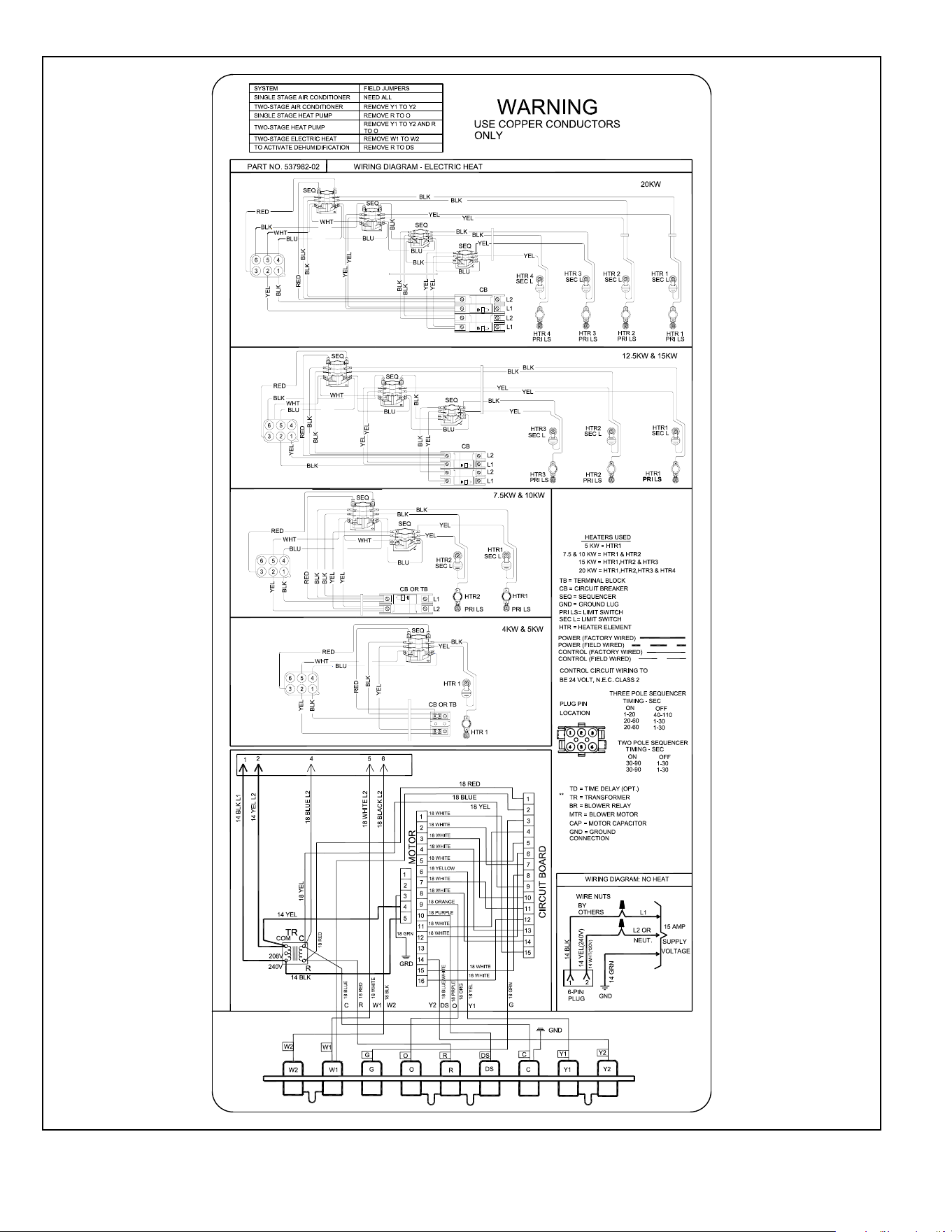
• Wiring must conform to the current National Electric
Code ANSI/NFPA No. 70, or Canadian Electric Code
Part I, CSA Standard C22.1, and local building codes.
Refer to following wiring diagrams. See unit nameplate
for minimum circuit ampacity and maximum over-
current protection size.
• Electrical wiring, disconnect means and over-current
protection are to be supplied by the installer. Refer
to the air handler rating plate for maximum over-
current protection, minimum circuit ampacity, as well
as operating voltage. Select the proper supply circuit
conductors in accordance with tables 310-16 and 310-
17 in the National Electric Code, ANSI/NFPA No. 70 or
tables 1 through 4 in the Canadian Electric Code, Part
I, CSA Standard C22.1.
• The power supply must be sized and protected
according to the specications supplied on the product.
• This air handler is factory-congured for 240 volt,
single phase, 60 cycles. For 208-volt applications, see
“208 Volt Conversion” later in this section.
• Separate openings have been provided for 24V low
voltage and line voltage. Refer to the dimension
illustration of specic location.
• This unit is provided with holes for conduit. Use
provided caps to seal holes not used.
• Typical unit wiring (as well as wiring of optional eld-
installed electric heat) is given in Figure 14. Refer to
the instructions provided with the electric heat section
for proper installation.
USE COPPER CONDUCTORS ONLY
WARNING
Figure 11. Electrical Connections
(Upow Conguration)
End Panel
Side
507789-02B Issue 2336 Page 13 of 24
1. Disconnect all power supplies.
2. Remove the air handler access panel.
3. Route the eld supply wires to the air handler electrical
connection box.
4. Use UL-listed wire nuts to connect the eld supply
conductors to the unit black and yellow leads, and the
ground wire to ground terminal marked GND.
5. Replace the air handler access panel.
Control Panel Relocation
To avoid the possibility of moisture damage to the control
in some right-hand discharge congurations, the control
panel can be relocated to the end panel as shown in Figure
12.
1. Remove the two screws that secure the control panel
to the cabinet. Slide panel out.
2. Slide the control panel into the notch on the electric
heat mounting panel (Figure 11). Using the screws
removed in Step 1, secure the control panel to the end
panel.
End Panel
Side
Figure 12. Control Panel Relocated to End Panel
(Horizontal-Right Conguration)
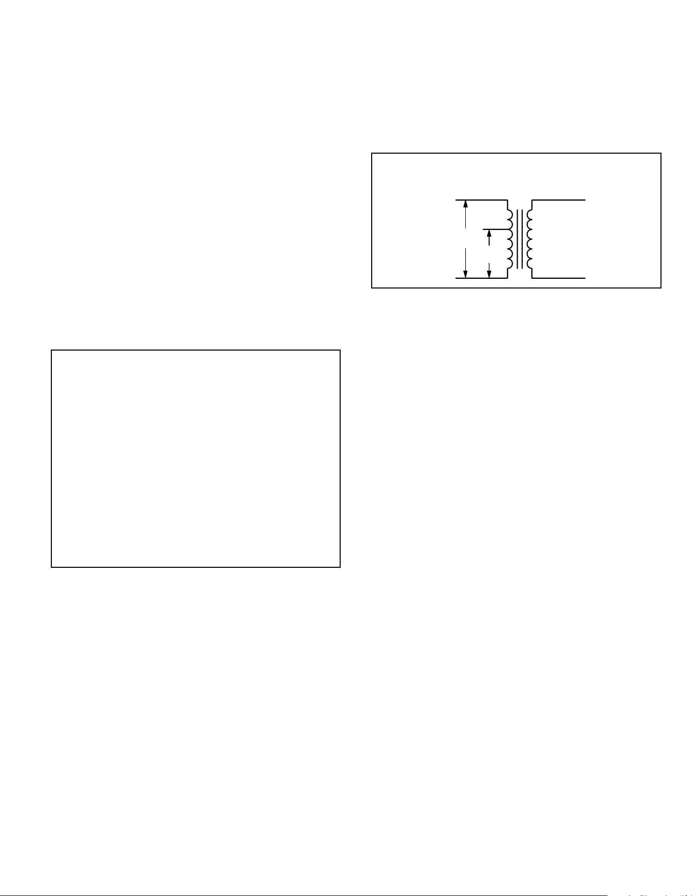
208 Volt Conversion
1. Disconnect all power supplies.
2. Remove the air handler access panel.
3. Using the wiring diagram located on the unit access
panel as a reference, move the 2 connected black
transformer leads from the 240 volt terminal on the
transformer to the 208 volt terminal on the transformer.
208 / 240 VOLT TRANSFORMER
PRIMARY SECONDARY
240 Volts
208 Volts
Figure 13. Converting Unit from 240VAC to 208VAC
507789-02BIssue 2336Page 14 of 24
Figure 14. Typical Wiring Diagram – BE5V Air Handler with Electric Heat – (Variable-Speed Motor)
507789-02B Issue 2336 Page 15 of 24
WARNING
USE COPPER CONDUCTORS ONLY
Y2
Figure 15. Low Voltage Connections (Variable-Speed Motor)
507789-02BIssue 2336Page 16 of 24
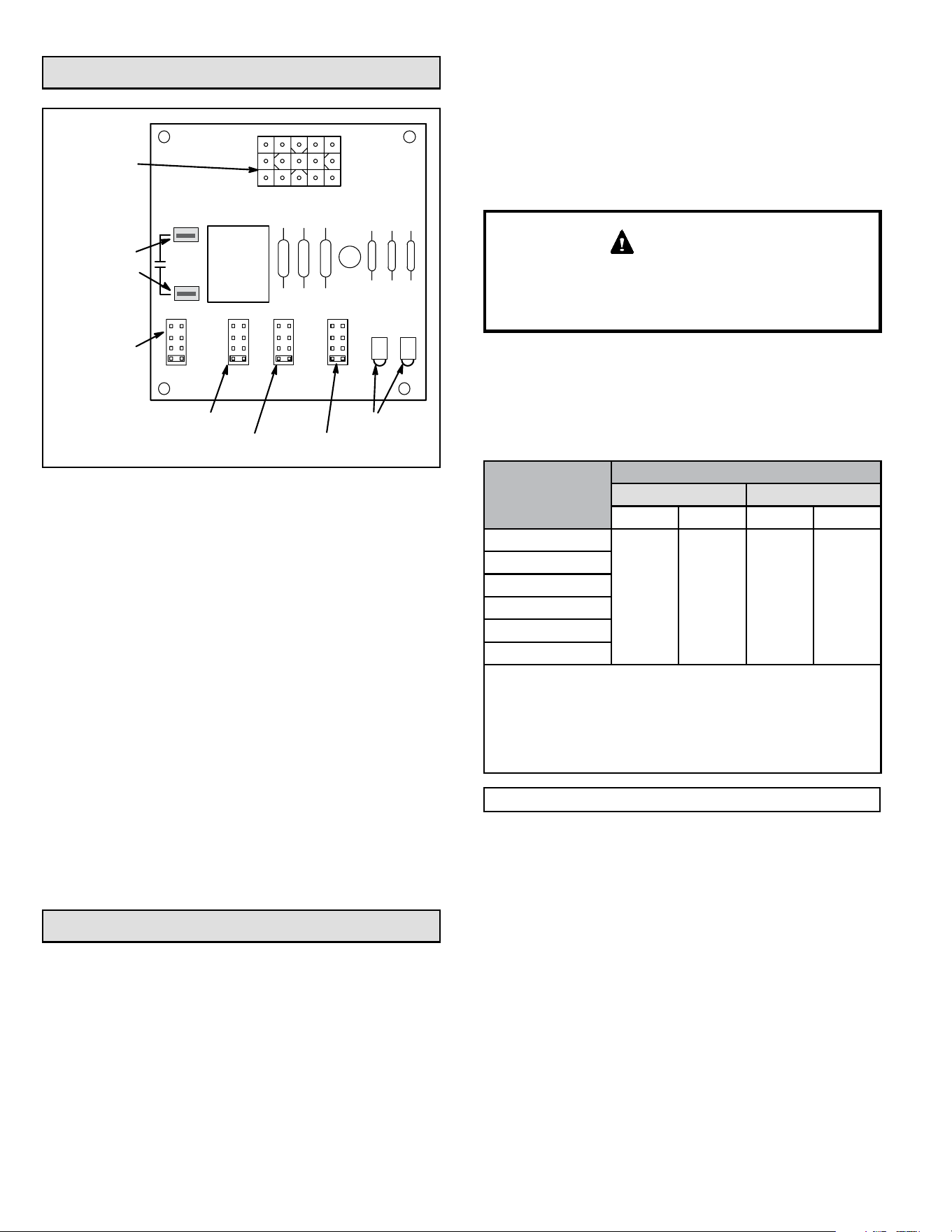
BDC3 Blower Control
JP1 15 PIN
PLUG (BOARD
TO MOTOR)
4
3
2
1
TEST
-
+
NORM
ADJUSTHEAT COOL DELAY CFM RUN
24V/1A
SERVICE
JP1
24V ACCESSORY
CONTACTS –
RATED FOR 1 AMP
OR LESS
OPERATIONAL
SELECTOR PINS
(AFFECTS BOTH
HEATING AND
COOLING MODES)
DIAGNOSTIC
LEDS
HEATING SPEED
SELECTOR PINS
COOLING SPEED
SELECTOR PINS
FAN DELAY
SELECTOR PINS
4
3
2
1
4
3
2
1
QC1
QC2
Figure 16. BDC3 Variable Speed Control Selections
BE5V units are equipped with a variable-speed motor that
is capable of maintaining a specied CFM throughout the
external static range. A particular CFM can be obtained by
positioning jumpers (COOL, HEAT, and ADJUST) on the
BDC3 control.
The jumpers are labeled 1, 2, 3, and 4. This indicates the
selected air volume (CFM). The ADJUST jumper is labeled
Test, -, +, and Norm. The - and + pin settings are used to
add or subtract a percentage of the CFM selected. The
Test jumper is used to operate the motor in the test mode.
The delay jumper controls the timing pattern in which the
fan delay occurs.
Figure 16 illustrates the BDC3 control. Use the blower
performance tables to determine the correct air volume for
heat and cool speed taps.
Diagnostic LEDs located on the BDC3 control to assist in
servicing the unit. Read the jumper settings section before
adjusting blower speed. Refer to Figure 16 for identication.
Adjusting the Blower Speed
Diagnostic LEDs
• RUN LED indicates there is a demand for the blower
motor to run.
• CFM LED indicates the cubic feet per minute at
which the unit is operating. The light ashes once for
approximately every 100 CFM. For example, if the unit
is operating at 1000 CFM, the CFM LED will ash 10
times. If the CFM is 1150, CFM LED will ash 11 full
times plus one fast or half ash.
At times, the light may appear to icker or glow. This is
normal and occurs when the control is communicating with
the motor between cycles.
Move the jumper pins to select the blower speed needed
to meet application CFM requirements.
Jumper Settings
Before changing jumper setting, make sure the motor
has completely stopped. Any jumper setting change will
not take place while the motor is running.
IMPORTANT
Table 3 lists the recommended factory blower speed
tap selections for BE5V series units. These settings are
for nominal tonnage match-ups with the BE5V . When
matched with other sizes, it is recommended that the CFM
be adjusted to provide approximately 400 CFM per ton.
Model
Speed Tap Selection
Cooling Heating*
Note 1 Note 2 Note 3 Note 4
-24
COOL
PIN #3
COOL
PIN #3
HEAT
PIN #3
HEAT
PIN #3
-30
-36
-42
-48
-60
NOTES -
1. Condensing Unit
2. Heat Pump
3. Condensing Unit with electric heat only
4. Heat Pump with electric heat
* Minimum setting for heat
Table 3. Recommended Blower Speed Taps
To change jumper positions, gently pull the jumper o the
pins and insert it onto the desired set of pins. The following
section outlines the dierent jumper selections available
and conditions associated with each one as illustrated in
Figure 16.
After the CFM for each application has been determined,
the jumper settings must be adjusted to reect those
given in the blower performance tables. From the tables,
determine which row of CFM volumes most closely
matches the desired CFM. Once a specic row has been
chosen (+, NORMAL, or -), CFM volumes from other rows
cannot be used. Below are descriptions of the jumper
selections.
507789-02B Issue 2336 Page 17 of 24
Adjust Jumper
The ADJUST pins allow the motor to run at normal speed,
slightly higher (approximately 10%) than normal speed, or
slightly lower (approximately 10%) than normal speed.
The blower performance tables list three rows (+, NORMAL,
and -) with their respective CFM volumes. Notice that for
the 1.5 ton unit, for example, that the normal adjustment
setting for heat speed position #4 is 1050 CFM. The +
adjustment setting for that position is 1150 CFM and for
the - adjustment setting is 950 CFM. After the adjustment
setting has been determined, choose the remaining speed
jumper settings from those oered in the table in that row.
The TEST pin is available to bypass the BDC3 control and
run the motor at approximately 70% to test that the motor is
operational. This is benecial primarily in troubleshooting.
G must be energized for motor to run.
Cool Jumper
The COOL jumper is used to determine the CFM during
either cooling or heat pump operation without a call for
electric heat. These jumper selections are activated
for cooling when Y2 and DS terminals in the BE5V are
energized. They are activated for heating when Y2 is
energized.
The unit will provide 70% of the COOL CFM during rst-
stage cooling for two-stage outdoor units. 100% of COOL
speed is provided for systems with a single-stage outdoor
unit.
For applications with zone control, the air handler CFM
volume is determined by the control center. The minimum
blower speed is predetermined at 250 CFM for -018, -024,
-030 and -036 units and 450 CFM for -042, -048 and -060
units. This speed is not adjustable. See footnotes in the
blower performance tables.
With the thermostat set for Continuous Fan and without a
call for heating or cooling, the BE5V provides 50% of the
COOL CFM selected.
NOTE: For two-stage heat pumps, air handler will operate
at 70% of the COOL selection until supplemental electric
heat is demanded. At that time, the air handler will operate
at the selected HEAT speed. This arrangement provides
warmer supply air during second-stage heating.
Blower Performance
BE5V24 Blower Performance
0 through 0.80 in. w.g. External Static Pressure Range
ADJUST
Jumper Setting
Jumper Speed Positions
“HEAT” Speed First Stage “COOL” Speed Second Stage “COOL” Speed
1 2 3 4 1 2 3 4 1 2 3 4
cfm cfm cfm cfm cfm cfm cfm cfm cfm cfm cfm cfm
+ 450 670 900 1120 340 450 650 770 450 670 900 1120
NORM 420 620 820 1050 300 400 600 700 420 620 820 1050
– 390 570 750 915 280 390 500 650 390 570 750 915
NOTES - The eect of static pressure, lter and electric heater resistance is included in the air volumes listed.
First stage cooling air volume is 70% of COOL speed setting. Continuous blower speed is approximately 50% of COOL
speed setting.
Zoning System applications - minimum blower speed is 250 cfm.
507789-02BIssue 2336Page 18 of 24
BE5V30 Blower Performance
0 through 0.80 in. w.g. External Static Pressure Range
ADJUST
Jumper Setting
Jumper Speed Positions
“HEAT” Speed First Stage “COOL” Speed Second Stage “COOL” Speed
1 2 3 4 1 2 3 4 1 2 3 4
cfm cfm cfm cfm cfm cfm cfm cfm cfm cfm cfm cfm
+ 680 885 1115 1340 490 635 770 930 680 885 1115 1340
NORM 620 810 1020 1220 440 575 715 845 620 810 1020 1220
– 550 725 905 1100 411 530 645 755 550 725 905 1100
NOTES - The eect of static pressure, lter and electric heater resistance is included in the air volumes listed.
First stage cooling air volume is 70% of COOL speed setting. Continuous blower speed is approximately 50% of COOL
speed setting.
Zoning System applications - minimum blower speed is 250 cfm.
BE5V36 Blower Performance
0 through 0.80 in. w.g. External Static Pressure Range
ADJUST
Jumper Setting
Jumper Speed Positions
“HEAT” Speed First Stage “COOL” Speed Second Stage “COOL” Speed
1 2 3 4 1 2 3 4 1 2 3 4
cfm cfm cfm cfm cfm cfm cfm cfm cfm cfm cfm cfm
+ 930 1155 1390 1530 640 815 970 1150 930 1155 1390 1530
NORM 830 1050 1260 1450 590 725 875 1025 830 1050 1260 1450
– 740 940 1135 1330 545 650 780 910 740 940 1135 1330
NOTES - The eect of static pressure, lter and electric heater resistance is included in the air volumes listed.
First stage cooling air volume is 70% of COOL speed setting. Continuous blower speed is approximately 50% of COOL
speed setting.
Zoning System applications - minimum blower speed is 250 cfm.
BE5V42 Blower Performance
0 through 0.80 in. w.g. External Static Pressure Range
ADJUST
Jumper Setting
Jumper Speed Positions
“HEAT” Speed First Stage “COOL” Speed Second Stage “COOL” Speed
1 2 3 4 1 2 3 4 1 2 3 4
cfm cfm cfm cfm cfm cfm cfm cfm cfm cfm cfm cfm
+ 1130 945 1575 1810 780 945 1110 1275 1130 945 1575 1810
NORM 1020 1255 1440 1650 710 860 1000 1160 1020 1255 1440 1650
– 920 1135 1300 1490 670 780 910 1040 920 1135 1300 1490
NOTES - The eect of static pressure, lter and electric heater resistance is included in the air volumes listed.
First stage cooling air volume is 70% of COOL speed setting. Continuous blower speed is approximately 50% of COOL
speed setting.
Zoning System applications - minimum blower speed is 450 cfm.
BE5V48 Blower Performance
0 through 0.80 in. w.g. External Static Pressure Range
ADJUST
Jumper Setting
Jumper Speed Positions
“HEAT” Speed First Stage “COOL” Speed Second Stage “COOL” Speed
1 2 3 4 1 2 3 4 1 2 3 4
cfm cfm cfm cfm cfm cfm cfm cfm cfm cfm cfm cfm
+ 1375 1600 1820 2185 960 1125 1285 1620 1375 1600 1820 2185
NORM 1260 1455 1655 2085 885 1035 1185 1475 1260 1455 1655 2085
– 1125 1310 1490 1885 790 925 1060 1330 1125 1310 1490 1885
NOTES - The eect of static pressure, lter and electric heater resistance is included in the air volumes listed.
First stage cooling air volume is 70% of COOL speed setting. Continuous blower speed is approximately 50% of COOL
speed setting.
Zoning System applications - minimum blower speed is 450 cfm.
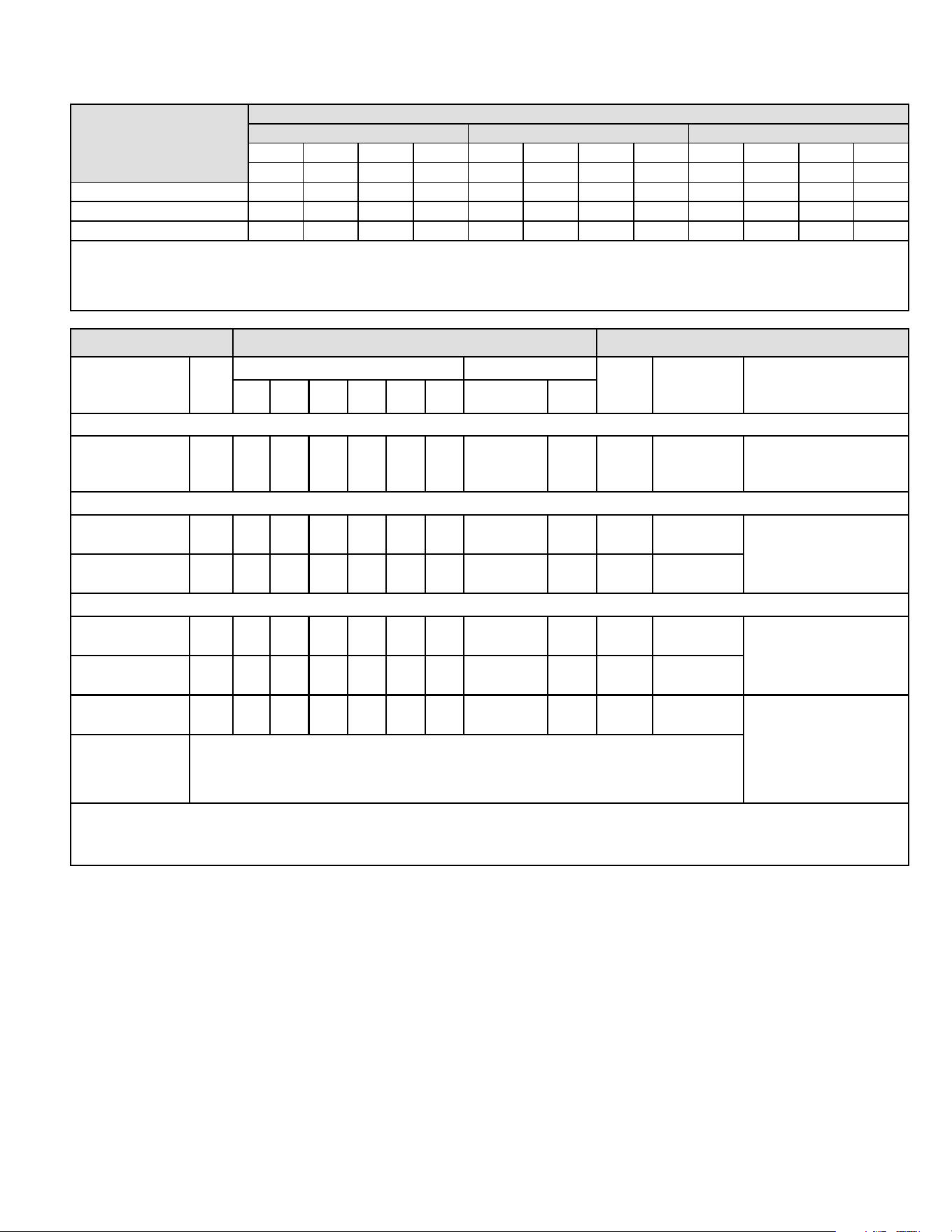
507789-02B Issue 2336 Page 19 of 24
BE5V60 Blower Performance
0 through 0.80 in. w.g. External Static Pressure Range
ADJUST
Jumper Setting
Jumper Speed Positions
“HEAT” Speed First Stage “COOL” Speed Second Stage “COOL” Speed
1 2 3 4 1 2 3 4 1 2 3 4
cfm cfm cfm cfm cfm cfm cfm cfm cfm cfm cfm cfm
+ 1600 1835 2030 2190 1110 1285 1380 1615 1600 1835 2030 2190
NORM 1465 1675 1855 2085 1000 1160 1250 1470 1465 1675 1855 2085
– 1320 1500 1675 1890 895 1035 1115 1320 1320 1500 1675 1890
NOTES - The eect of static pressure, lter and electric heater resistance is included in the air volumes listed.
First stage cooling air volume is 70% of COOL speed setting. Continuous blower speed is approximately 50% of COOL
speed setting.
Zoning System applications - minimum blower speed is 450 cfm.
Operating Sequence System Demand System Response
System
Condition
Step
Thermostat Demand Relative Humidity
Comp
Air Handler
CFM
(COOL)
Comments
Y1 Y2 O G W1 W2 Status D
NO CALL FOR DEHUMIDIFICATION
Normal
Operation
1 On On On Accetpable
24
VAC
High 100%
Compressor and indoor
air handler follow
thermostat demand
BASIC MODE (only active on a Y1 thermostat demand)
Normal
Operation
1 On On On Accetpable
24
VAC
High 100%
Thermostat energizes
Y1 and de-energizes
D on a call for
dehumidication
Dehumidication
Call
2 On On On Demand
0
VAC
High 60/65/70%*
PRECISION MODE (operates independent of a Y1 thermostat demand)
Normal
Operation
1 On On On Accetpable
24
VAC
High 100%
Dehumidication mode
begins when humidity is
greater than setpoint
Dehumidication
Call
2 On On On Demand
0
VAC
High 60/65/70%*
Dehumidication
Call Only
1 On On On Demand
0
VAC
High 60/65/70%*
Thermostat will try to
maintain room humidity
setpoint by allowing
the room space to
maintain a cooler room
thermostat setpoint**
Jumpers at indoor unit with a single stage outdoor unit
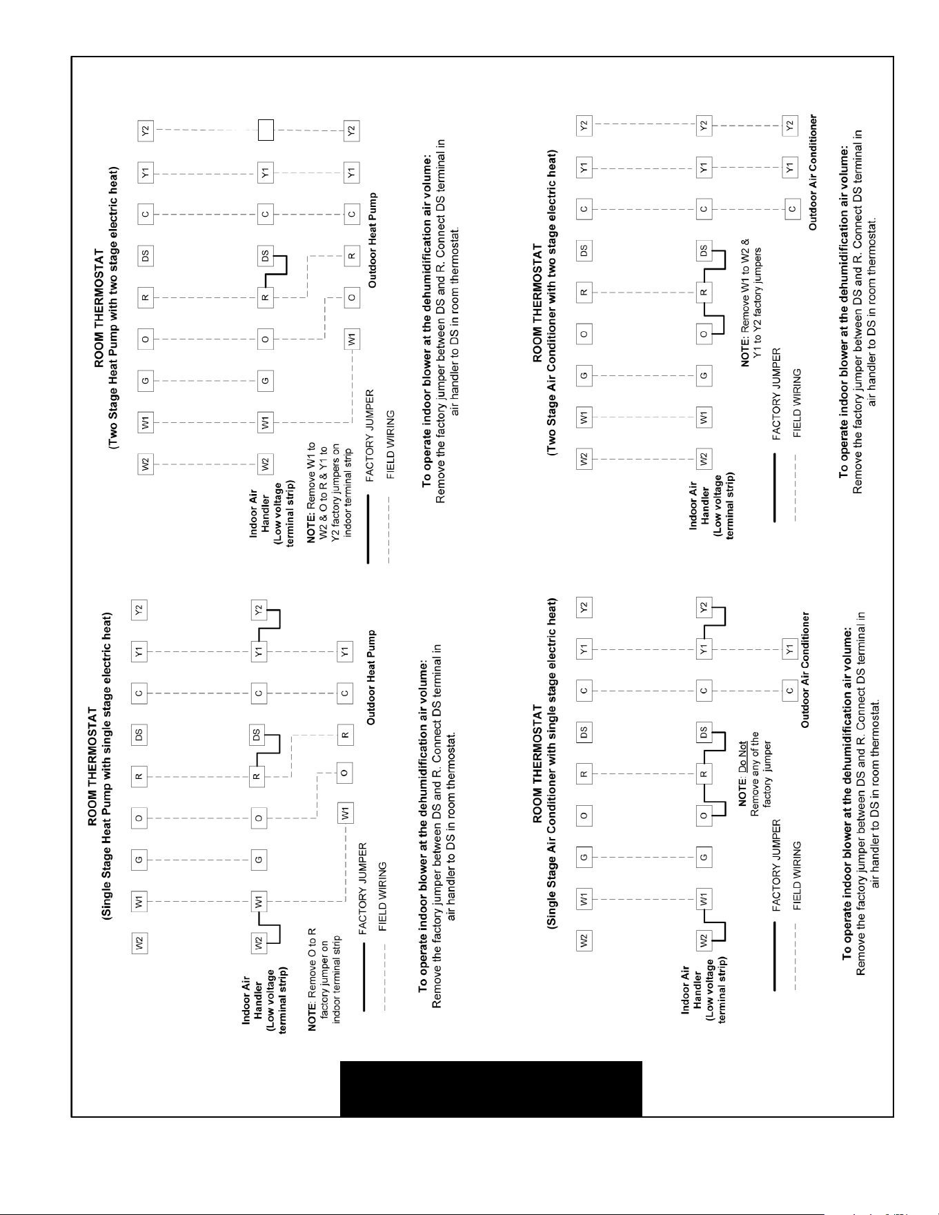
With Condensing unit - Y1 to Y2 and R to O
With Heat Pump - Y1 to Y2
* During dehumidication, cooling air handler speed is as follows: 70% of COOL cfm for 024, 030; 65% for 036; 60% for 042, 048 and
060 units.
** Thermostat will maintain the room temperature up to 2°F (1.2°C) cooler than the room thermostat setting in precision mode.
Table 4. BE5V Thermostat and Single-Stage Outdoor Unit Operating Sequence
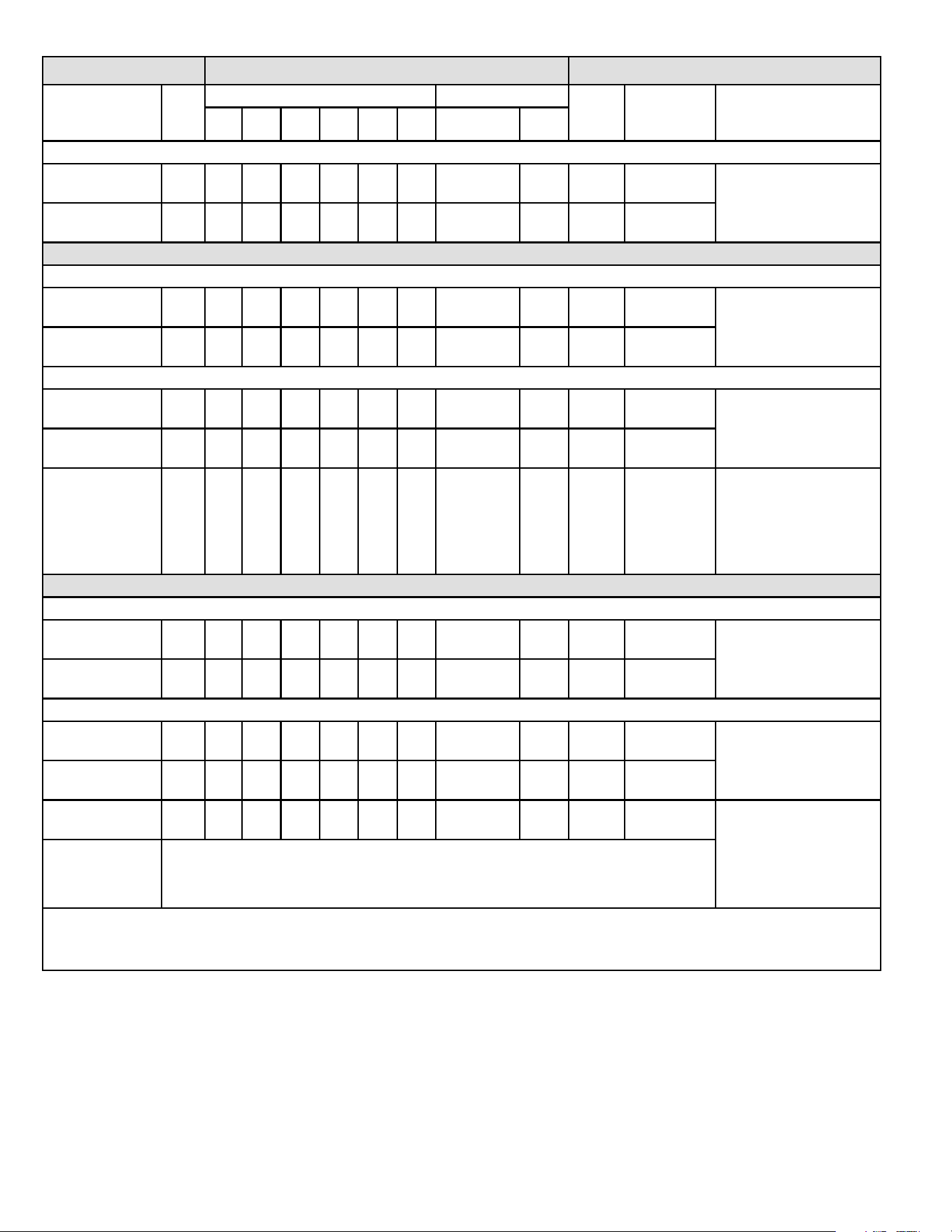
507789-02BIssue 2336Page 20 of 24
Operating Sequence System Demand System Response
System
Condition
Step
Thermostat Demand Relative Humidity
Comp
Air Handler
CFM
(COOL)
Comments
Y1 Y2 O G W1 W2 Status D
NO CALL FOR DEHUMIDIFICATION
Normal
Operation - Y1
1 On On On Accetpable
24
VAC
Low 70%
Compressor and indoor
air handler follow
thermostat demand
Normal
Operation - Y2
2 On On On On Accetpable
24
VAC
High 100%
Room Thermostat Calls for First-Stage Cooling
BASIC MODE (only active on a Y1 thermostat demand)
Normal
Operation
1 On On On Accetpable
24
VAC
Low 70%
Thermostat energizes
Y2 and de-energizes
D on a call for
dehumidication
Dehumidication
Call
2 On On On On Demand
24
VAC
High 60/65/70%*
PRECISION MODE (operates independent of a Y1 thermostat demand)
Normal
Operation
1 On On On Acceptable
24
VAC
Low 70%
Dehumidication mode
begins when humidity is
greater than setpoint
Dehumidication
Call
2 On On On On Demand
0
VAC
High 60/65/70%*
Dehumidication
Call Only
1 On On On On Demand
0
VAC
High 60/65/70%*
Thermostat will try to
maintain room humidity
setpoint by allowing
the room space to
maintain a cooler room
thermostat setpoint**
Room Thermostat Calls for First- and Second-Stage Cooling
BASIC MODE (only active on a Y1 thermostat demand)
Normal
Operation
1 On On On On Accetpable
24
VAC
High 100%
Thermostat energizes
Y2 and de-energizes
D on a call for
dehumidication
Dehumidication
Call
2 On On On On Demand
0
VAC
High 60/65/70%*
PRECISION MODE (operates independent of a Y1 thermostat demand)
Normal
Operation
1 On On On On Accetpable
24
VAC
High 100%
Dehumidication mode
begins when humidity is
greater than setpoint
Dehumidication
Call
2 On On On On Demand
0
VAC
High 60/65/70%*
Dehumidication
Call Only
1 On On On On Demand
0
VAC
High 60/65/70%*
Thermostat will try to
maintain room humidity
setpoint by allowing
the room space to
maintain a cooler room
thermostat setpoint**
Jumpers at indoor unit with a two-stage outdoor unit
With Condensing unit - Y2 and R to O
With Heat Pump - none
* During dehumidication, cooling air handler speed is as follows: 70% of COOL cfm for 024, 030; 65% for 036; 60% for 042, 048 and
060 units.
** Thermostat will maintain the room temperature up to 2°F (1.2°C) cooler than the room thermostat setting in precision mode.
Table 5. BE5V Thermostat and Two-Stage Outdoor Unit Operating Sequence
507789-02B Issue 2336 Page 21 of 24
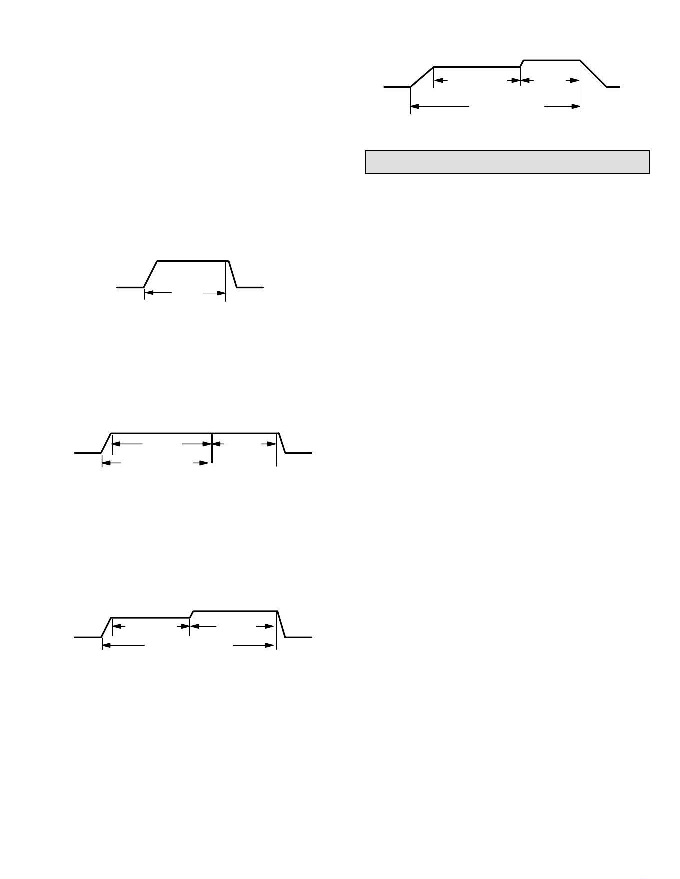
Heat Jumper
The HEAT jumper is used to determine CFM during electric
heat operation only. These jumper selections are activated
only when W1 is energized.
Delay Jumper
The DELAY jumper is used to set the specic motor
fan operation during cooling mode. Depending on the
application, one of four options may be chosen by moving
the jumper to the appropriate set of pins.
#1 Pins Jumpered
a. Motor runs at 100% until demand is satised.
b. Once demand is met, motor ramps down to stop.
OFFOFF
A B
100% CFM
COOLING
DEMAND
#2 Pins Jumpered
a. Motor runs at 100% until demand is satised.
b. Once demand is met, motor runs at 100% for 45
seconds.
c. Motor ramps down to stop.
OFF
OFF
A
B
C
100% CFM
100% CFM
(60 seconds)
COOLING DEMAND
#3 Pins Jumpered
a. Motor runs at 82% for approximately 7-1/2
minutes. If demand has not been satised after
7-1/2 minutes.
b. Motor runs at 100% until demand is satised.
c. Once demand is met, motor ramps down to stop.
OFF
OFF
A
B
C
82%CFM
100% CFM
COOLING DEMAND
7 1/2 MIN
#4 Pins Jumpered
a. Motor ramps up to 82%.
b. Motor then runs at 82% for approximately 7-1/2
minutes. If demand has not been satised after
7-1/2 minutes,
c. Motor runs at 100% until demand is satised.
d. Once demand is met, motor ramps down to stop.
A
B
OFF
OFF
C
D
E
COOLING DEMAND
7 1/2 MIN
82% CFM
100%
CFM
Checkout Procedures
NOTE: Refer to outdoor unit installation instructions for
system start-up instructions and refrigerant charging
instructions.
Pre-Start-Up Checks
• Is the air handler properly and securely installed?
• If horizontally congured, is the unit sloped up to 5/8
inch toward drain lines?
• Will the unit be accessible for servicing?
• Has an auxiliary pan been provided under the unit
with separate drain for units installed above a nished
ceiling or in any installation where condensate overow
could cause damage?
• Have ALL unused drain pan ports been properly
plugged?
• Has the condensate line been properly sized, run,
trapped, pitched, and tested?
• Is the duct system correctly sized, run, sealed, and
insulated?
• Have all cabinet openings and wiring been sealed?
• Is the indoor coil factory-installed TXV properly sized
for the outdoor unit being used?
• Have all unused parts and packaging been disposed
of?
• Is the lter clean, in place, and of adequate size?
• Is the wiring neat, correct, and in accordance with the
wiring diagram?
• Is the unit properly grounded and protected (fused)?
• Is the thermostat correctly wired and in a good
location?
• Are all access panels in place and secure?
Check Blower Operation
1. Set thermostat to FAN ON. The indoor blower should
come on.
Check Cooling Operation
1. Set thermostat to force a call for cooling (approximately
5ºF lower than the indoor ambient temperature).
2. The outdoor unit should come on immediately and the
indoor blower should start between 30 - 60 seconds
later.
507789-02BIssue 2336Page 22 of 24
3. Check the air ow from a register to conrm that the
system is moving cooled air.
4. Set the thermostat 5ºF higher than the indoor
temperature. The indoor blower and outdoor unit
should cycle o.
Check Electric Heat (If Used)
1. Set thermostat to call for auxiliary heat (approximately
5°F above ambient temperature). The indoor blower
and auxiliary heat should come on together. Allow a
minimum of 3 minutes for all sequencers to cycle on.
2. Set the thermostat so that it does not call for heat.
Allow up to 5 minutes for all sequencers to cycle o.
Professional Maintenance
Failure to follow instructions will cause damage to the
unit.
This unit is equipped with an aluminum coil. Aluminum
coils may be damaged by exposure to solutions with
a pH below 5 or above 9. The aluminum coil should
be cleaned using potable water at a moderate pressure
(less than 50psi). If the coil cannot be cleaned using
water alone, it is recommended to use a coil cleaner
with a pH in the range of 5 to 9. The coil must be rinsed
thoroughly after cleaning.
In coastal areas, the coil should be cleaned with potable
water several times per year to avoid corrosive buildup
(salt).
NOTICE
Homeowner Maintenance
Do not operate system without a lter. A lter is required
to protect the coil, blower, and internal parts from
excessive dirt and dust. The lter is placed in the return
duct by the installer.
IMPORTANT
Inspect air lters at least once a month and replace or
clean as required. Dirty lters are the most common cause
of inadequate heating or cooling performance.
Replace disposable lters. Cleanable lters can be cleaned
by soaking in mild detergent and rinsing with cold water.
Install new/clean lters with the arrows on the side pointing
in the direction of air ow. Do not replace a cleanable (high
velocity) lter with a disposable (low velocity) lter unless
return air system is properly sized for it.
If water should start coming from the secondary drain
line, a problem exists which should be investigated and
corrected. Contact a qualied service technician.
Repairing or Replacing Cabinet Insulation
DAMAGED INSULATION MUST BE REPAIRED OR
REPLACED before the unit is put back into operation.
Insulation loses its insulating value when wet, damaged,
separated or torn.
IMPORTANT
Matte- or foil-faced insulation is installed in indoor
equipment to provide a barrier between outside air
conditions (surrounding ambient temperature and humidity)
and the varying conditions inside the unit. If the insulation
barrier is damaged (wet, ripped, torn or separated from the
cabinet walls), the surrounding ambient air will aect the
inside surface temperature of the cabinet.
The temperature/humidity dierence between the inside
and outside of the cabinet can cause condensation on the
inside or outside of the cabinet which leads to sheet metal
corrosion and, subsequently, component failure.
Repairing Damaged Insulation
Areas of condensation on the cabinet surface are an
indication that the insulation is in need of repair.
If the insulation in need of repair is otherwise in good
condition, the insulation should be cut in an X pattern,
peeled open, glued with an appropriate all-purpose glue
and placed back against the cabinet surface, being careful
to not overly compress the insulation so the insulation can
retain its original thickness. If such repair is not possible,
replace the insulation. If using foil-faced insulation, any
cut, tear, or separations in the insulation surface must be
taped with a similar foil-faced tape.
1. CUT INSULATION IN X PATTERN
2. APPLY GLUE
3. PRESS GLUED TABS AGAINST CABINET
GLUE - Make sure there is
full coverage of glue on the
metal or insulation so there
are no areas where air
pockets may form which
can lead to sweating.
Figure 17. Recommended Blower Speed Taps
507789-02B Issue 2336 Page 23 of 24
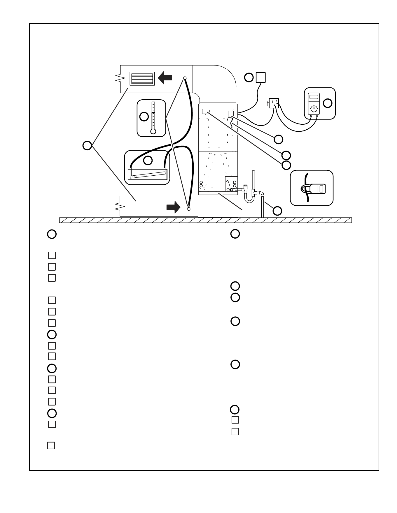
1
Duct
System
Filter
Integrated Control
Electric Heat Amps
Duct Static
5
Line Voltage
3
RETURN
AIR
SUPPLY
AIR
Temperature
8
Blower Motor Amps
6
7
Thermostat
9
2
4
Drain Line
Disconnect
Switch
ELECTRIC HEAT AMPS____________
8
8
7
5
DUCT SYSTEM
SUPPLY AIR DUCT
Sealed
Insulated (if necessary)
Registers Open and Unobstructed
RETURN AIR DUCT
Sealed
Filter Installed and Clean
Registers Open and Unobstructed
INTEGRATED CONTROL
Jumpers Configured Correctly (if applicable)
Appropriate Links in Place (if applicable)
VOLTAGE CHECK
Supply Voltage ___________
Electrial Connections Tight
1
2
3
DRAIN LINE
Leak Free
4
TOTAL EXTERNAL STATIC (dry coil)
Supply External Static ______ ______
TEMPERATURE DROP (Cooling Mode)
Return Duct Temperature ___________
THERMOSTAT
Adjusted and Programmed
Return External Static ______ ______
Total External Static = ______ ______
6
Supply Duct Temperature − ___________
Temperature Drop = ___________
TEMPERATURE RISE (Heating Mode)
Return Duct Temperature __________
Supply Duct Temperature − __________
Temperature Rise = __________
Operation Explained to Owner
9
Explained Operation of System to Homeowner
Technician’s Name:_______________________Date Start−Up & Performance Check Completed__________
Installing Contractor’s Name_______________________
Installing Contractor’s Phone_______________________
Job Address____________________________________
Installing Date_______________________________
Air Handler Model #__________________________
_
INDOOR BLOWER AMPS___________
INDOOR BLOWER CFM____________
Low Voltage _____________
dry coil wet coil
Figure 18. Start-up and Performance Checklist (Upow Conguration)
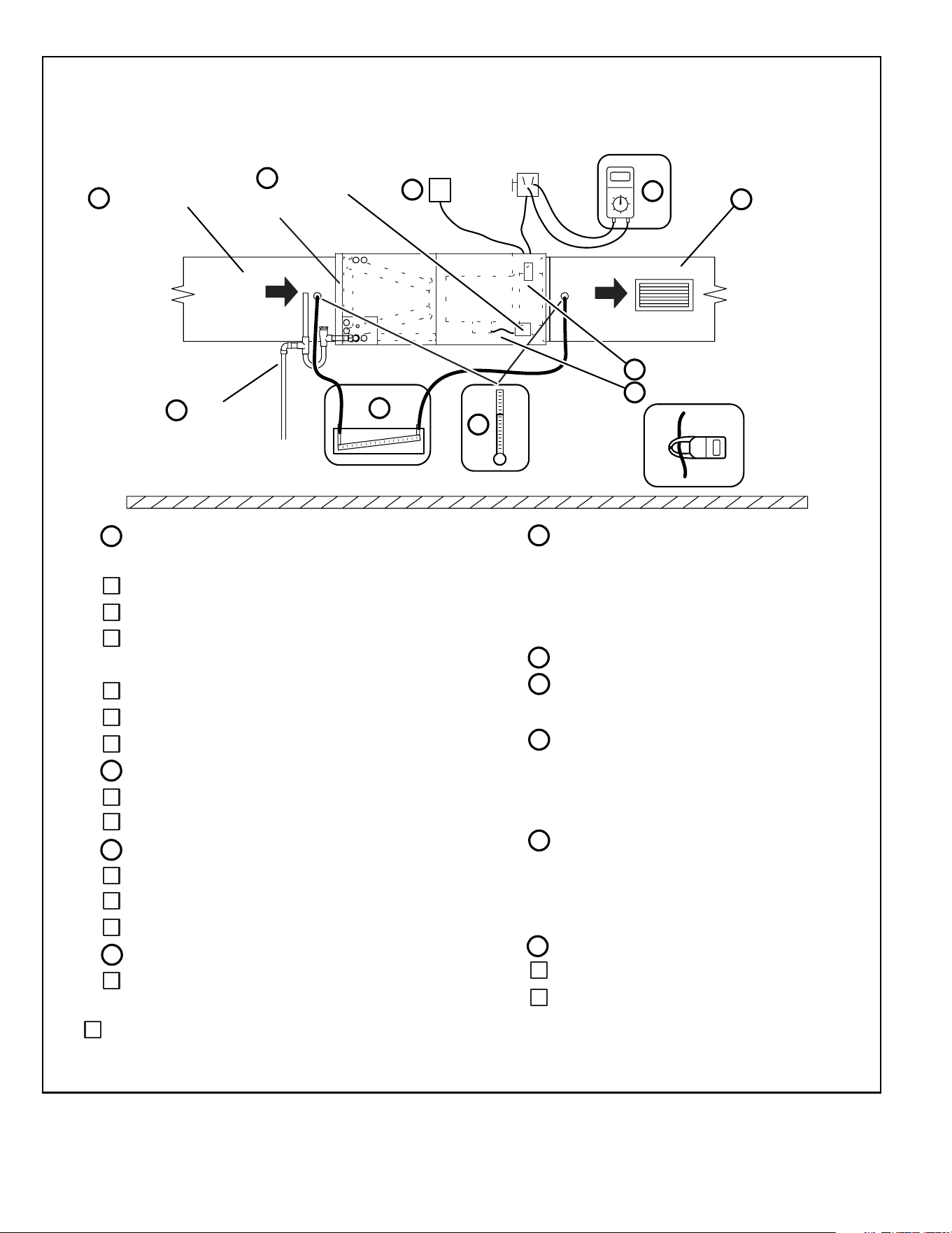
507789-02BIssue 2336Page 24 of 24
RETURN
AIR
SUPPLY
AIR
2
Duct Static
5
Line Voltage
3
4
Drain Line
ELECTRIC HEAT AMPS____________
8
8
7
5
Filter
Blower motor Amps
DUCT SYSTEM
SUPPLY AIR DUCT
Sealed
Insulated (if necessary)
Registers Open and Unobstructed
RETURN AIR DUCT
Sealed
Filter Installed and Clean
Registers Open and Unobstructed
INTEGRATED CONTROL
Jumpers Configured Correctly (if applicable)
Appropriate Links in Place (if applicable)
VOLTAGE CHECK
Supply Voltage ___________
Electrial Connections Tight
1
2
3
DRAIN LINE
Leak Free
4
TOTAL EXTERNAL STATIC (dry coil)
Supply External Static ______ ______
TEMPERATURE DROP (Cooling Mode)
Return Duct Temperature ___________
THERMOSTAT
Adjusted and Programmed
Return External Static ______ ______
Total External Static = ______ ______
6
6
Supply Duct Temperature − ___________
Temperature Drop = ___________
TEMPERATURE RISE (Heating Mode)
Return Duct Temperature __________
Supply Duct Temperature − __________
Temperature Rise = __________
Operation Explained to Owner
9
Electric Heat Amps
7
Explained Operation of System to Homeowner
Technician’s Name:_______________________Date Start−Up & Performance Check Completed__________
Installing Contractor’s Name_______________________
Installing Contractor’s Phone_______________________
Job Address____________________________________
Installing Date_______________________________
Air Handler Model #__________________________
_
Thermostat
9
1
1
8
INDOOR BLOWER AMPS___________
Temperature
Duct System
Duct System
Integrated
Control
Disconnect
Switch
INDOOR BLOWER CFM____________
Low Voltage _____________
dry coil wet coil
Figure 19. Start-up and Performance Checklist (Horizontal Conguration)