
ACTIVESMART™ INTEGRATED
FRENCH DOOR REFRIGERATOR FREEZER
RS80 and RS90 models
INSTALLATION GUIDE
NZ AU GB IE HK SG IN
862068A 06.19


1
@0 FIXING TO CABINETRY
@1 WATER FILTER INSTALLATION
@2 TOE KICK INSTALLATION
@3 COVERS AND TRIMS INSTALLATION
@4 FINAL CHECKLIST
!8 DOOR PANEL INSTALLATION — STAINLESS STEEL !9 DOOR PANEL INSTALLATION — CUSTOM
OR
IMPORTANT!
SAVE THESE INSTRUCTIONS
The models shown in this installation guide may not be available in all markets and are subject to change at any time. For current details about model and specification availability in your country,
go to our website fisherpaykel.com or contact your local Fisher & Paykel dealer.
CONTENTS
1 SAFETY AND WARNINGS
2 COMPONENTS
3 TOOLS
4 APPLIANCE AND CAVITY DIMENSIONS
5 CABINETRY OPTIONS
7 CUSTOM DOOR PANEL INSTALLATION DIMENSIONS
8 CUSTOM DOOR PANEL INSTALLATION TEMPLATE
9 DOOR CLEARANCE
!0 ELECTRICAL AND PLUMBING
!1 BEFORE INSTALLATION
!2 CAVITY PREPARATION
!3 WATER SUPPLY CONNECTION
!4 POWER SUPPLY CONNECTION
!5 INSTALLATION PREPARATION
!6 POSITIONING INTO CABINETRY
!7 ALIGNING INSIDE CABINETRY

3
IMPORTANT!
●
It is very important for the installer to follow the instructions in this installation guide
to ensure proper installation and operation of the appliance. Ensure that you read the
installation guide thoroughly and understand all information.
●
The water connection to your Ice and water appliance must be installed by a qualified
plumber or Fisher & Paykel trained and supported service technician andcomply with
all state and local laws.
●
Installation and use MUST comply with all state and local plumbing codes. Checkwith
your local public works department for plumbing codes. You must follow their
guidelines as you install the water filtration system.
●
To avoid serious illness or death, only connect your water filter to safe drinking water.
●
The water filter cartridge needs to be changed when the replacement indicator icon
illuminates. This will happen every 6 months.
●
If the water filtration system has been allowed to freeze, replace filter cartridge.
Failureto replace the disposable filter at recommended intervals may lead to reduced
filter performance and failure of the filter, causing property damage from water
leakage or flooding.
●
In cases of excessively reduced filter life — we recommend that you consult a local
plumber or your water supplier for advice on suitable filtration requirements for the
water supplied to your home.
●
Filter replacement is the consumer’s responsibility and will not be covered by the
warranty except in the case of faulty parts or materials within the filter cartridge.
●
If the water has not created ice for some time or ice has an unpleasant taste or odor
dispose of ice and refer to the flushing instructions detailed in the installation section
ofthis user guide / installation guide. If unpleasant taste or odor persists, you may wish
tofit a new filter cartridge.
●
Use new tubing supplied with the appliance. DO NOT reuse old tubing from old water
andice connections.
●
Your water filtration system can withstand up to 120psi (827kPa) of water pressure.
Ensure the supplied pressure reducing valve is installed before installing the water
filtration system. DO NOT install if water pressure exceeds 120psi (827kPa).
To reduce the risk associated with property damage due to water leakage or flooding:
●
DO NOT install systems in areas where ambient temperatures may go above 100°F
(38°C) or drop below 33°F (0.6°C).
●
DO NOT install on hot water supply lines. The maximum operating water temperature
ofthis filter system is 100°F (38°C).
●
DO NOT install where water hammer conditions may occur. If water hammer conditions
exist, you must install a water hammer arrester.
WARNING!
To reduce the risk associated with choking:
●
DO NOT allow children under 3 years of age to have access to small parts during the
installation of the water filter.
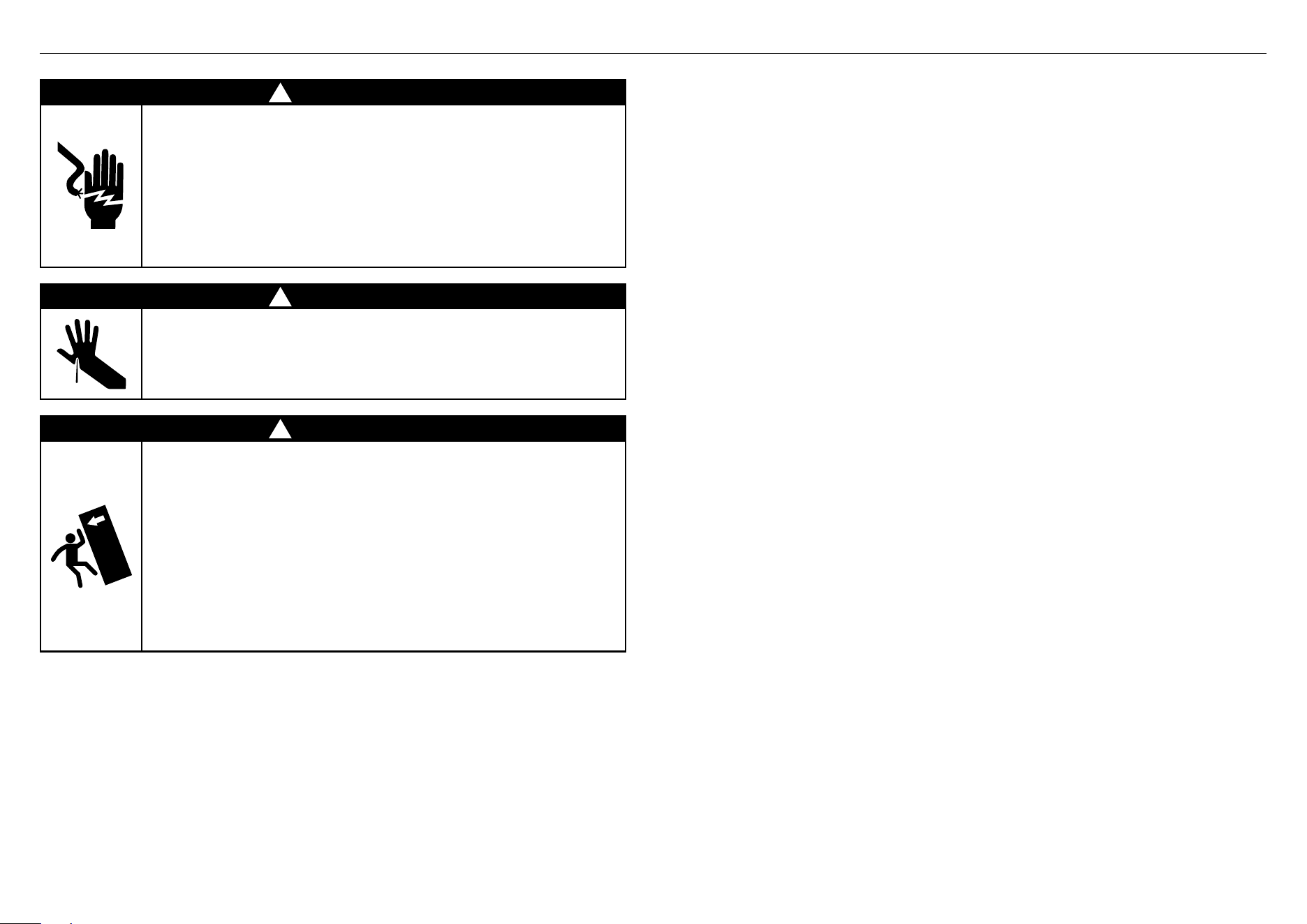
1 SAFETY AND WARNINGS
!
WARNING!
Electric Shock Hazard
Read and follow the safety and warnings
outlined in this installation guide before
operating this appliance.
Failure to do so can result in death, electric
shock, fire or injury topersons.
!
WARNING!
Cut Hazard
Take care — panel edges are sharp. Failure to
use caution could result in injury or cuts.
!
WARNING!
This appliance is top-heavy and must
be secured to prevent the possibility of
tippingforward.
To ensure that the appliance is stable under
all loading conditions, theanti-tip bracket
and fittings supplied must be installed
according tothe following installation steps
by a professional installer.
4
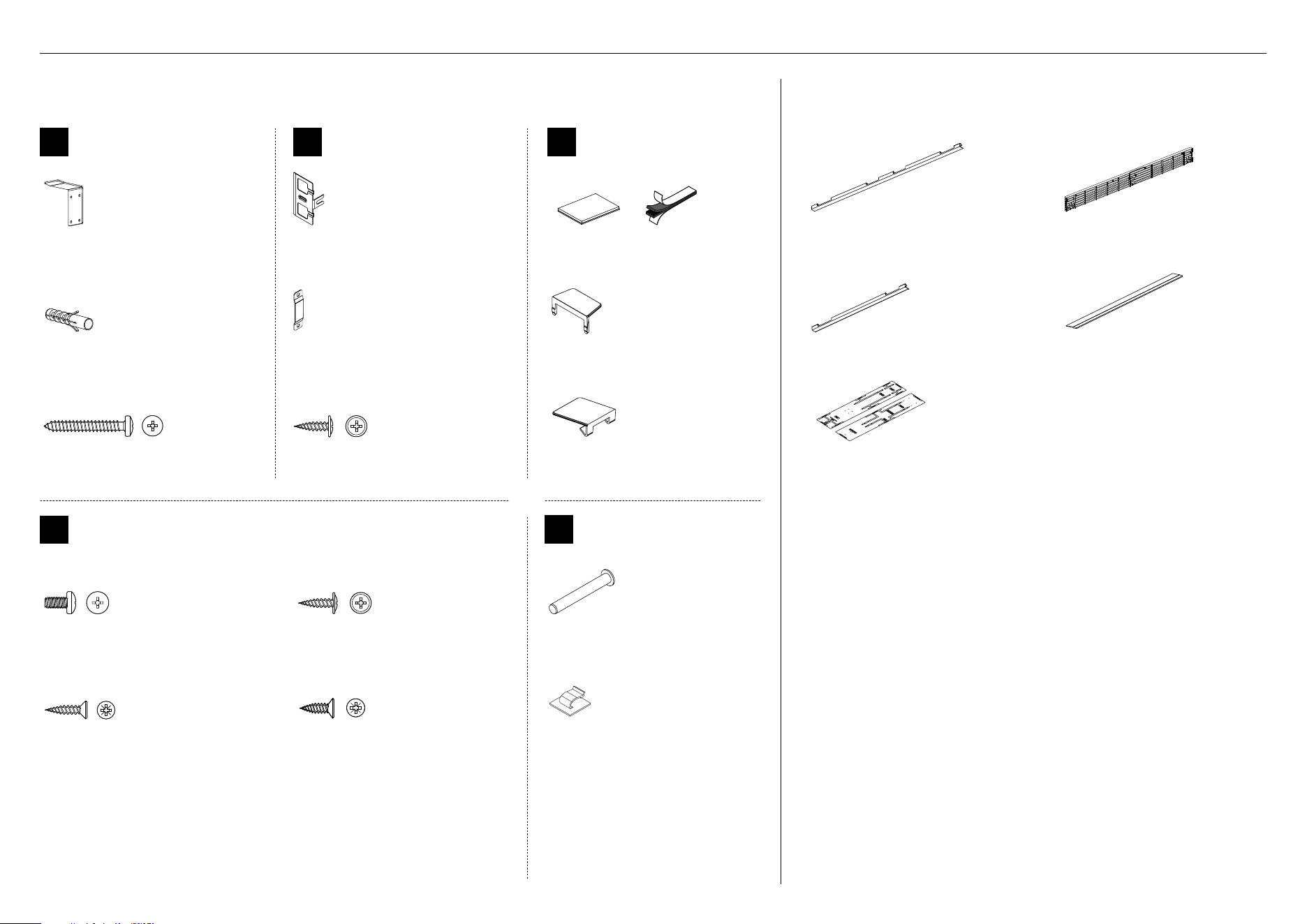
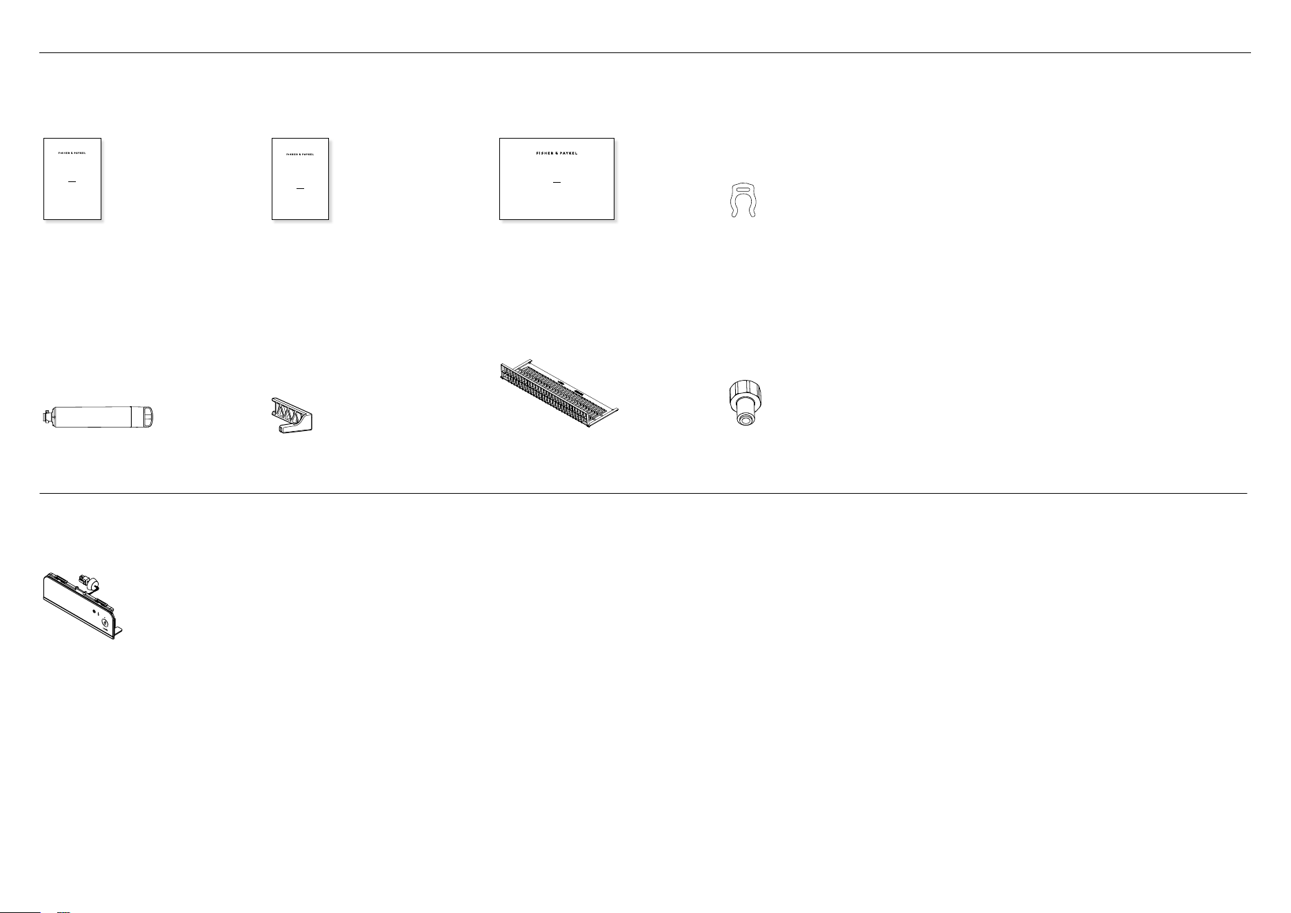
2 COMPONENTS
Internal box (Installation kit)
Located inside appliance
AAZZ
Anti-tip bracket
assemblykit
Anti-tip bracket
(1)
Masonry plug
(4)
#10x40
Pan Head
Philips Screw
#10x40
Pan Head
Philips Screw
#10x40 cross-head screw
(4)
B
Door panel attachment
kit
Side bracket
(10)
Side strap
(10)
#8 x 16
Mush Washer
Twin Thread
Philips Screw
#8 x 16
Mush Washer
Twin Thread
Philips Screw
#8x16 countersunk screw
(36)
C
Door / drawer trim
installkit
Dual adhesive tabs (6 per each strip)
(12)
Side cover
(4)
Top cover
(2)
X
Install fasteners kit
M5 x 10
Pan Head
Philips Screw
M5 x 10
Pan Head
Philips Screw
#8 x 16
Mush Washer
Twin Thread
Philips Screw
#8 x 16
Mush Washer
Twin Thread
Philips Screw
M5x10 cross-head screw
(10)
#8Gx16 flat head screw (2)
Not used for this model
#8 x 19
Countersunk
Twin Thread
Posi Screw
#8 x 19
Countersunk
Twin Thread
Posi Screw
#8Gx19 twin thread screw
(2)
#12x12 Countersunk screw (2)
Not used for this model
Y
Miscellaneous
components
Hinge limiting pin
(1)
Power cord/water tube clip
(2)
External box
Taped to back panel of appliance
Door side trim
(2)
Toe kick grille
(1)
Drawer side trim
(2)
Drawer top trim
(1)
Double-sided door panel template
(1)
5
2 COMPONENTS
Miscellaneous items (MI) pack
Located inside the appliance
USER GUIDE
NZ AU GB IE HK SG IN US
ACTIVESMART™
INTEGRATED REFRIGERATOR
RS90A, RS9120W,
RS36A72, RS36A80 & RS36W80 models
SERVICE & WARRANTY
SERVICE ET GARANTIE
ΣΈΡΒΙΣ ΚΑΙ ΕΓΓΎΗΣΗ
SERVIZIO E GARANZIA
SERVICE & GARANTIE
HUOLTO JA TAKUU
SERVICE OG GARANTI
保修和维修
服務和保修
ACTIVESMART™ INTEGRATED
SLIDE-IN REFRIGERATOR
RS90 & RS90AU models
INSTALLATION GUIDE
NZ AU GB IE HK SG IN
844219B 02.19
User guide
(1)
Service and Warranty
(1)
Installation guide
(1)
Collet locking clip
(1)
Water filter
(1)
Filter cartridge tool
(1)
Toe kick filter
(1)
Water tap adaptor
(1)
Ice and Water display
(Ice and Water models only)
Located inside the appliance
External display module
(1)
6
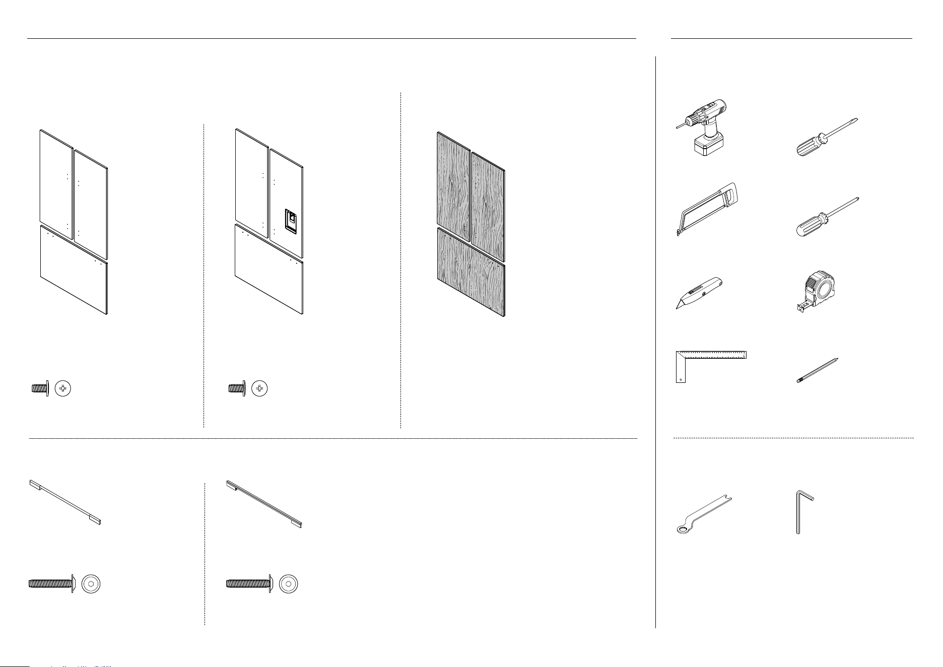
Door panel set
Not supplied and must be purchased separately
Stainless steel (Fisher & Paykel) door panel set:
Includes 2x French door panels and 1x drawer panel.
Custom door panel set:
Supplied by customer to match their cabinetry.
Applicable for non water-dispensing models.
Non-Water dispensing
French panels (2x)
Drawer panel (1x)
(RD80/RD90)
Non-Water dispensing
French panel (1x)
Ice and Water French panel (1x)
Drawer panel (1x)
(RD80U/RD90U)
M5 x 14
Mush Head
SS
Philips Screw
M5 x 14
Mush Head
SS
Philips Screw
M5 x 14
Mush Head
SS
Philips Screw
M5 x 14
Mush Head
SS
Philips Screw
M5x14 mush cross-head (SS) screw
(34)
M5x14 mush cross-head (SS) screw
(34)
Door handle kit
Not supplied and must be purchased separately. Select between the options below:
Contemporary round
door handle (3x)
Contemporary square
door handle (3x)
M5 x 25
Pan Head
Socket Screw
M5 x 25
Pan Head
Socket Screw
M5 x 25
Pan Head
Socket Screw
M5 x 25
Pan Head
Socket Screw
M5x25 pan head socket
screw (12x)
M5x25 pan head socket
screw (12x)
Supplied tools
Included in internal box
FPA spanner
(1)
Hex key
(1)
Required tools
Not included with appliance
Powered driver Flathead screwdriver
Hacksaw Cross-head screwdriver
Cutter Measuring tape
Ruler Pencil
2 COMPONENTS 3 TOOLS
7
b
F
G
c
D
A
H
E
b
F
G
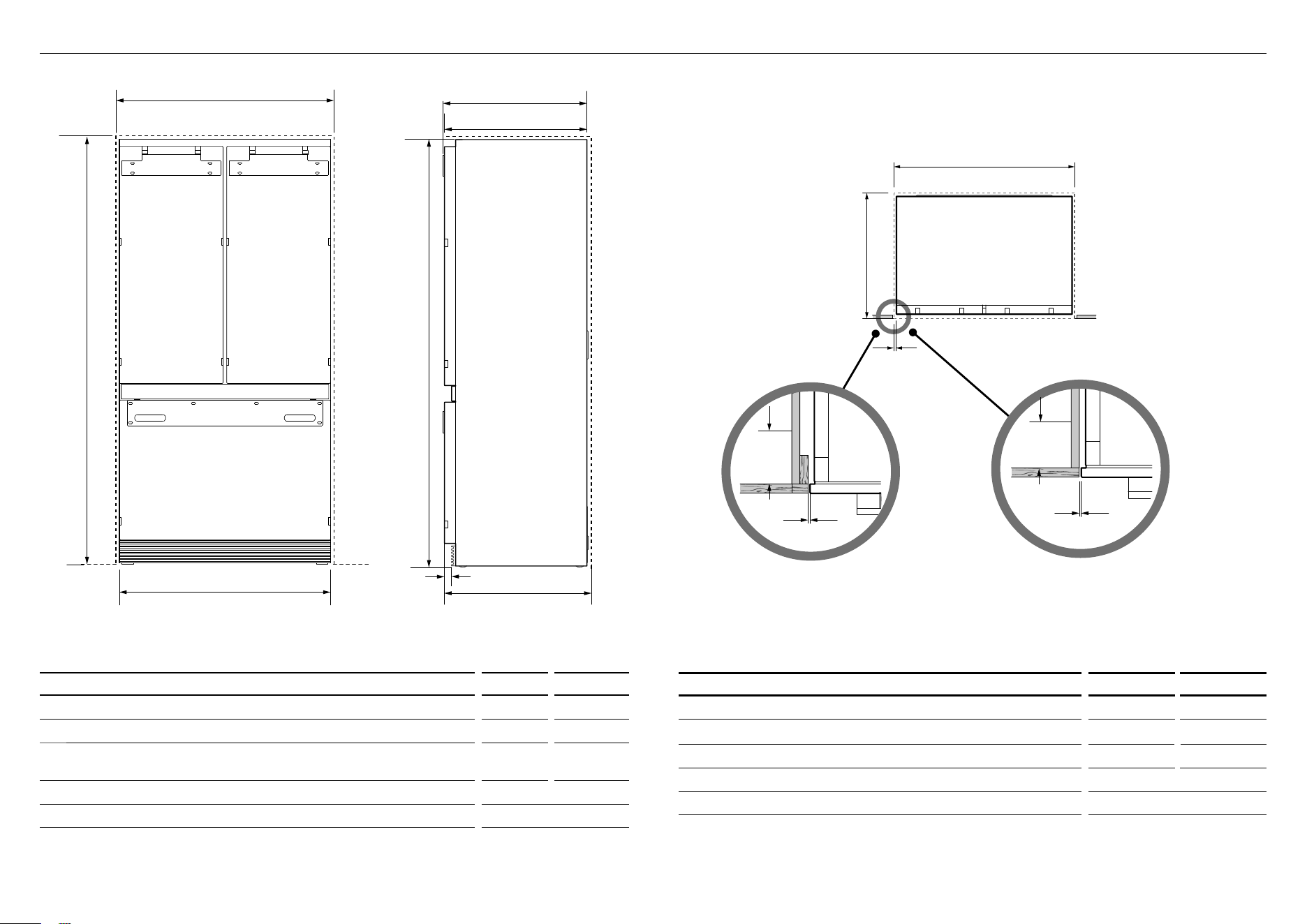
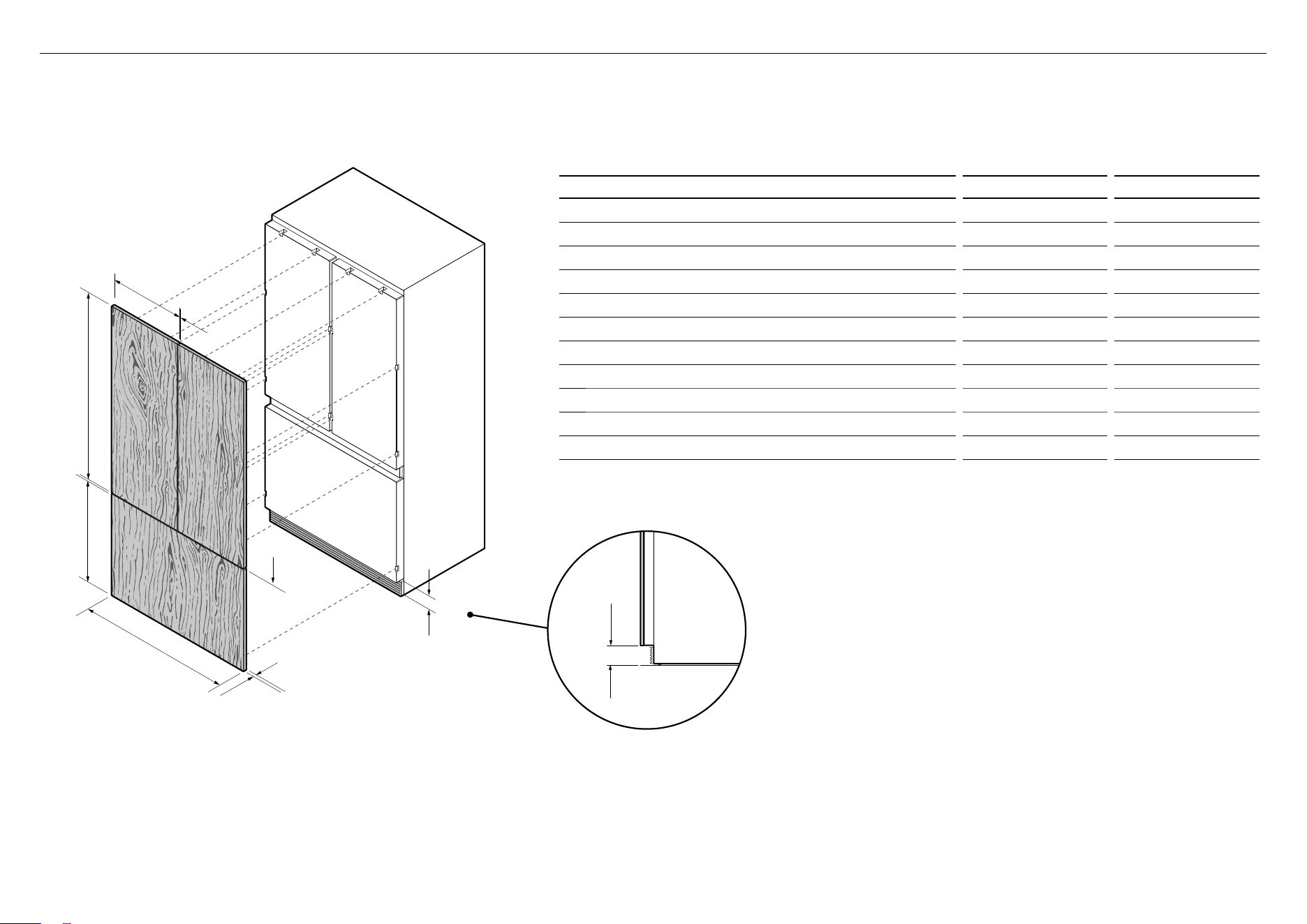
4 APPLIANCE AND CAVITY DIMENSIONS
RS80 RS90
APPLIANCE DIMENSIONS mm mm
A
Overall height of appliance
*
1798
**
1798**
B
Overall width of appliance 790 890
c
Overall depth of appliance (without door panels and hanging
brackets)
602 602
D
Overall depth of appliance (includes hanging brackets) 604 604
E
Depth of toe kick (excluding front of door panel)
50 50
* Includes mounted rollers (20mm adjustment upwards)
** Appliance at its lowest height (both RS80 & RS90 models)
FRONT VIEW PROFILE VIEW
RS80 RS90
CAVITY DIMENSIONS mm mm
F
Overall height of cavity 1800/1802* 1800/1802*
G
Overall width of cavity
*
800/804* 900 / 904*
H
Overall depth of cavity 650 650
I
Minimum cabinetry gap clearance from edge of appliance 4 4
J
Minimum required finished return 89 89
*
When adjoining cabinetry cannot share 4mm door gap,
●
Total front panel width with required gaps at sides = 804mm.
●
For flush cabinetry where gap cannot be shared between appliance and adjoining cabinet, make cavity width
804mm for RS80 and 904mm for RS90 (door opens totally within itself).
●
Total front panel height with required gap above = 1802mm.
Flush install
Frameless: Finished return top and sides
Flush install
Framed: Finished return top and sides
IMPORTANT!
For ease of installation, ensure cavity width is consistent
top to bottom and height isconsistent left to right.
E
B
H
C
A
A
I
J G
C
B
F
F
F
D
K
F
Flush with front
of cabinetry
PLAN VIEW
E
B
H
C
ADA
J
I
L GF
F
K
g
J
I
J
I
E
B
H
C
ADA
J
I
L GF
F
K
g
J
I
J
I
8
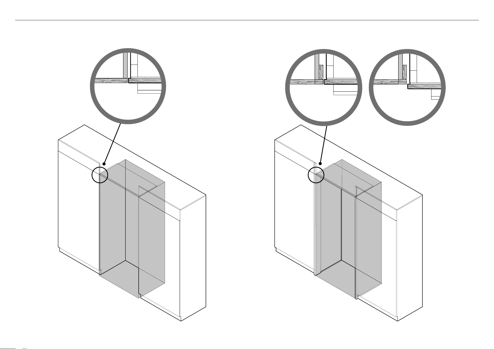
FRAMELESS CABINETRY
(Aligns the appliance with the cabinetry)
Proud
installation
Flush
installation
Note: Drawings are only for reference and not the actual cavity width of the cabinetry.
FRAMED CABINETRY
(Aligns the appliance with the frame of the cabinetry)
5 CABINETRY OPTIONS
9
ISO VIEW
H
F
D
i
g
A
B
PROFILE VIEW
D
g
A
E
C
h
ISO VIEW
6 DOOR PANEL DIMENSIONS
IMPORTANT!
Custom door panels can only be used for non-Water dispensing models.
RS80 RS90
DOOR PANEL DIMENSIONS (STAINLESS STEEL/CUSTOM
*
) mm mm
A
Height of each top door panel 1096 1096
B
Width of each top door panel 396 446
C
Gap between top door panels 4 4
D
Height of bottom drawer panel 598 598
E
Height from bottom of appliance to top of drawerpanel 698 698
F
Width of bottom drawer panel 796 896
G
Gap between top door panels and bottom drawer panel 4 4
H
Depth of door and drawer panels (excluding handle) 18 18
i
Height of toe kick (from bottom of drawer to floor) 100 100
Maximum weight of each top door panel
(with handle) 10kg 10kg
Maximum weight of bottom drawer panel
(with handle) 11kg 11kg
* Custom door panels to be manufactured and fitted by cabinetmaker.
— Door handle kit is not supplied and must be purchased separately.
ISO VIEW
H
F
D
g
A
B
PROFILE VIEW
I
C
h
10
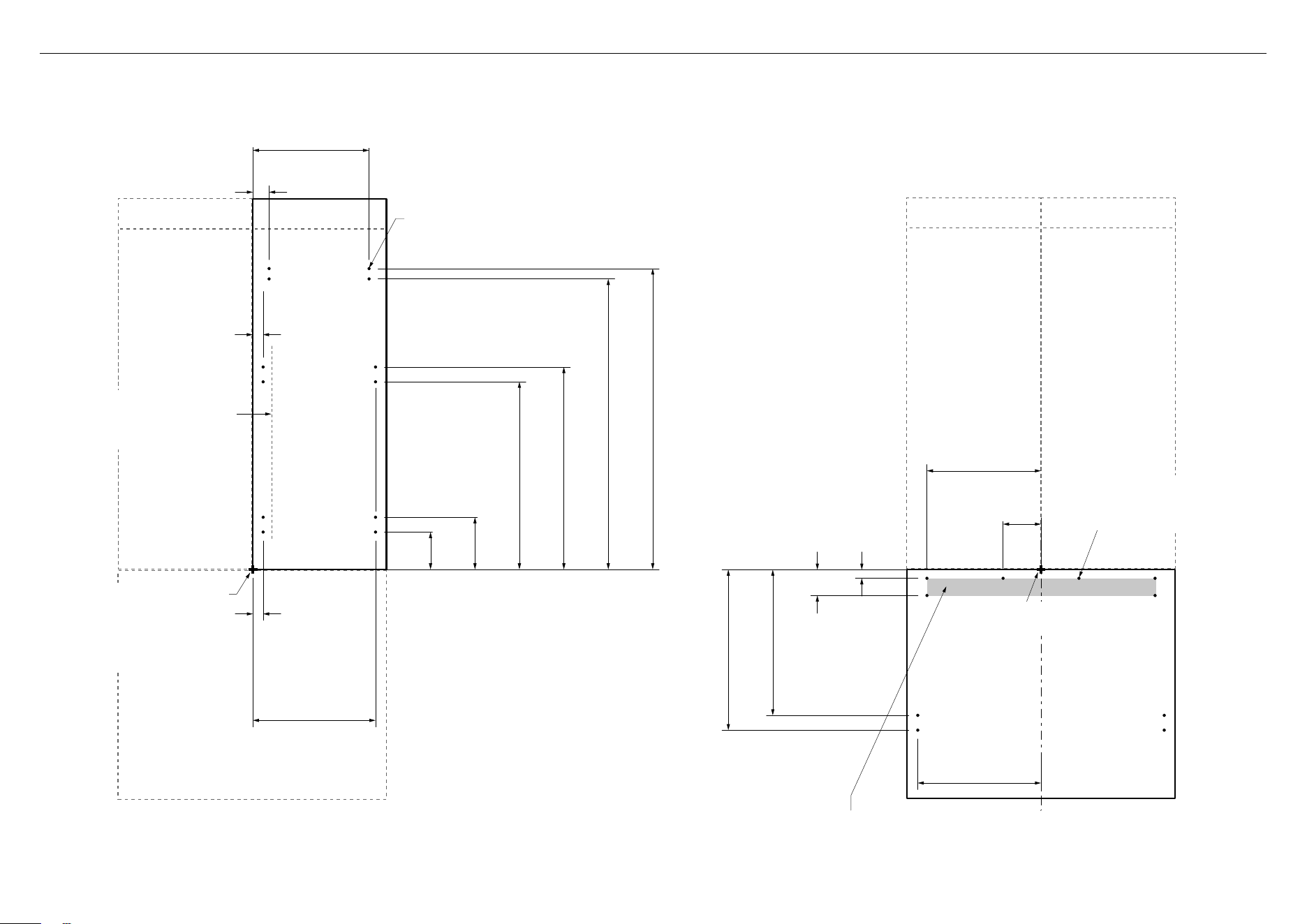
7 CUSTOM DOOR PANEL INSTALLATION DIMENSIONS — RS80
Dimensions apply for the preparation and installation of custom door panels.
For Dwg and Dxf files of the below panel preparation download the folder on thekitchentools.fisherpaykel.com.
Ensure handle is mounted
65mm from inner edge of panel
to the center — this will avoid
interference with brackets.
34.7mm
34.7mm
364mm
54.8mm
126.1mm
176.1mm
633.6mm
683.6mm
981mm
1016mm
Ø 2mm REF
12x Pilot holes recommended for bracket attachment.
(Do not penetrate front surface).
342.3mm
TOP PANEL — REAR VIEW
All measurements to be made
from inner bottom corner.
Forthe second panel mirror
and repeat dimensions using
inner bottom corner as the
reference point.
Ø 2mm REF
10x Pilot holes recommended
forbracket attachment.
(Do not penetrate front surface).
335mm
111.5mm
29.1mm
87.2mm
492mm
542mm
366mm
All measurements to be made
from top and centerline.
BOTTOM PANEL — REAR VIEW
Cut outs are located in attachment bracket for Fisher & Paykel handles only.
Iflocating custom handle in the shaded area above, ensure handle screw heads
are counter sunk into back of panel to avoid interference with hanging bracket.
11
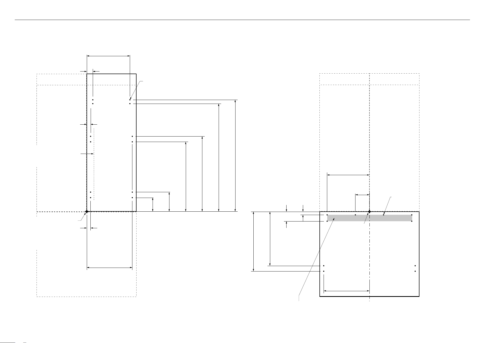
7 CUSTOM DOOR PANEL INSTALLATION DIMENSIONS — RS90
Dimensions apply for the preparation and installation of custom door panels.
For Dwg and Dxf files of the below panel preparation download the folder on thekitchentools.fisherpaykel.com.
Ensure handle is mounted
65mm from inner edge of panel
to the center — this will avoid
interference with brackets.
34.7mm
34.7mm
414mm
54.8mm
126.1mm
176.1mm
633.6mm
683.6mm
981mm
1016mm
Ø 2mm REF
12x Pilot holes recommended for bracket attachment.
(Do not penetrate front surface).
392.3mm
TOP PANEL — REAR VIEW
All measurements to be made
from inner bottom corner.
Forthe second panel mirror
and repeat dimensions using
inner bottom corner as the
reference point.
Ø 2mm REF
10x Pilot holes recommended
forbracket attachment.
(Do not penetrate front surface).
385mm
128mm
29.1mm
87.2mm
492mm
542mm
416mm
All measurements to be made
from top and centerline.
BOTTOM PANEL — REAR VIEW
Cut outs are located in attachment bracket for Fisher & Paykel handles only.
Iflocating custom handle in the shaded area above, ensure handle screw heads
are counter sunk into back of panel to avoid interference with hanging bracket.
12
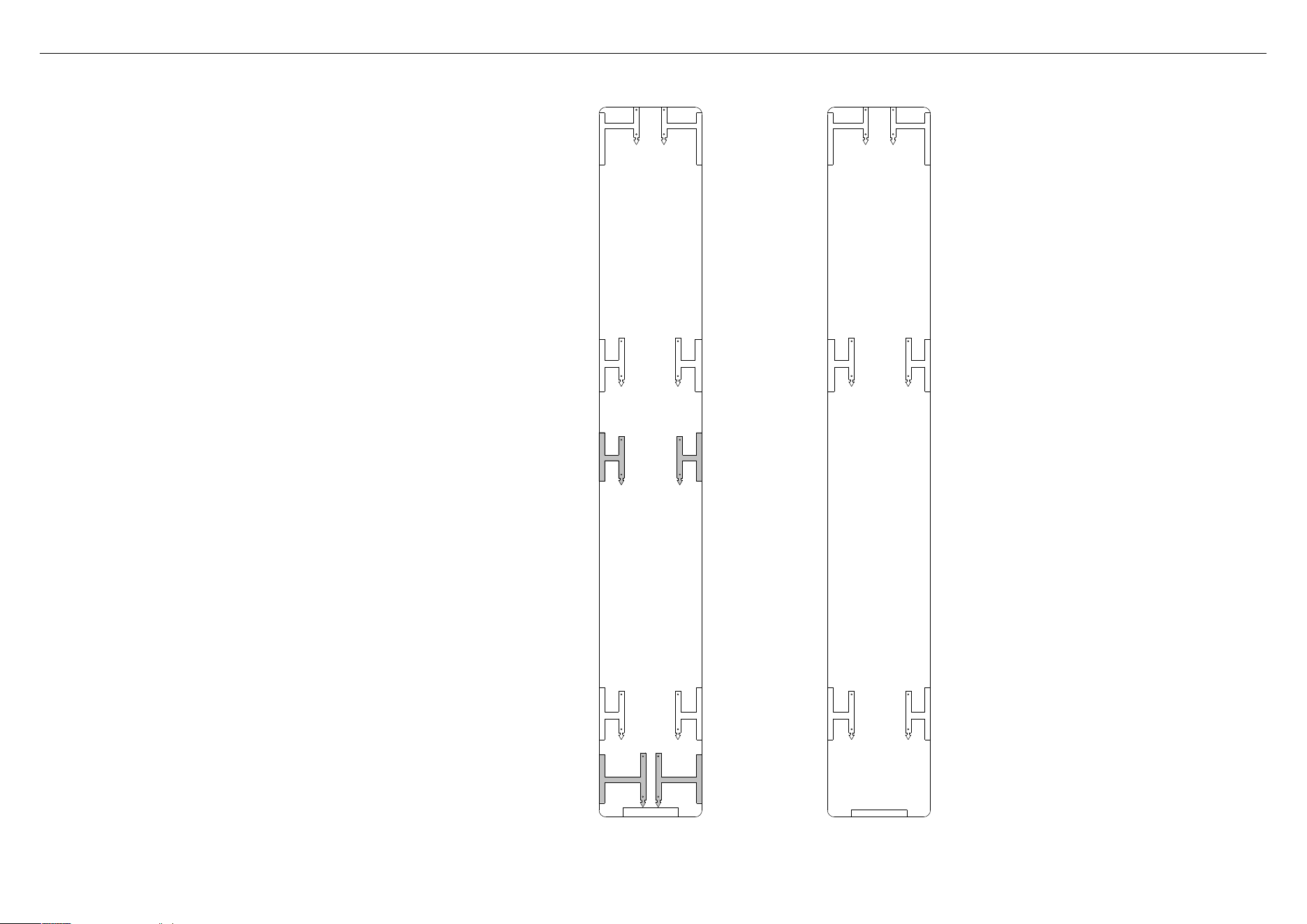
8 CUSTOM DOOR PANEL INSTALLATION TEMPLATE
LEFT DOOR
PANEL SIDE
RIGHT DOOR
PANEL SIDE
This template is a single double-sided sheet used as a
guide to drill screw holes for installing your Custom door
and drawer panels. The actual template is included with
this installation guide.
Refer to ‘Door panel installation — Custom’, (page 28)
formoreinformation.
LH DOOR PANEL HINGE SIDE
LH DOOR PANEL HANDLE SIDE
HANGING BRACKET
HOLES
HANGING BRACKET
HOLES
FLIP FOR RIGHT
HAND DOOR PANEL
LH DOOR PANEL HANDLE SIDE
LH DOOR PANEL HINGE SIDE
SIDE BRACKET HOLES
SIDE BRACKET HOLES
DRAWER PANEL LEFT EDGE
DRAWER PANEL RIGHT EDGE
DRAWE PANEL HANGING
BRACKET HOLES
DRAWE PANEL HANGING
BRACKET HOLES
DRAWER PANEL LEFT EDGE
DRAWER PANEL RIGHT EDGE
DRAWE PANEL
SIDE BRACKET HOLES
DRAWE PANEL
SIDE BRACKET HOLES
LEFT PC PANEL BOTTOM EDGE
DRAWER PANEL TOP EDGE
HANGING BRACKET
HOLES
HANGING BRACKET
HOLES
RH DOOR PANEL HANDLE SIDE
RH DOOR PANEL HANDLE SIDE
RIGHT DOOR
PANEL TEMPLATE
849549
RH DOOR PANEL HINGE SIDE
RH DOOR PANEL HANDLE SIDE
SIDE BRACKET HOLES
SIDE BRACKET HOLES
FLIP FOR LEFT HAND DOOR
AND DRAWER HOLES
RH DOOR PANEL HINGE SIDE
RH DOOR PANEL HANDLE SIDE
SIDE BRACKET HOLES
SIDE BRACKET HOLES
RH DOOR PANEL BOTTOM EDGE
LEFT DOOR PANEL
AND DRAWER TEMPLATE
849549
LH DOOR PANEL HANDLE SIDE
LH DOOR PANEL HINGE SIDE
SIDE BRACKET HOLES
SIDE BRACKET HOLES
PRINT SPECIFICATION REVISIONS
DRWN DAT E CHKD ECN REV
BJ 04/04/19 1
1
862946
GRAPHICS RS90 DOOR TEMPLATETITLE:
DRAWN: DATE:
SCALE: 1:1
FISHER & PAYKEL APPLIANCES LIMITED
GRAPHICS NO:
REVISION:
BINIL JOSE
04/04/2019
400mm
LH DOOR PANEL HINGE SIDE
LH DOOR PANEL HANDLE SIDE
HANGING BRACKET
HOLES
HANGING BRACKET
HOLES
FLIP FOR RIGHT
HAND DOOR PANEL
LH DOOR PANEL HANDLE SIDE
LH DOOR PANEL HINGE SIDE
SIDE BRACKET HOLES
SIDE BRACKET HOLES
DRAWER PANEL LEFT EDGE
DRAWER PANEL RIGHT EDGE
DRAWE PANEL HANGING
BRACKET HOLES
DRAWE PANEL HANGING
BRACKET HOLES
DRAWER PANEL LEFT EDGE
DRAWER PANEL RIGHT EDGE
DRAWE PANEL
SIDE BRACKET HOLES
DRAWE PANEL
SIDE BRACKET HOLES
LEFT PC PANEL BOTTOM EDGE
DRAWER PANEL TOP EDGE
HANGING BRACKET
HOLES
HANGING BRACKET
HOLES
RH DOOR PANEL HANDLE SIDE
RH DOOR PANEL HANDLE SIDE
RIGHT DOOR
PANEL TEMPLATE
849549
RH DOOR PANEL HINGE SIDE
RH DOOR PANEL HANDLE SIDE
SIDE BRACKET HOLES
SIDE BRACKET HOLES
FLIP FOR LEFT HAND DOOR
AND DRAWER HOLES
RH DOOR PANEL HINGE SIDE
RH DOOR PANEL HANDLE SIDE
SIDE BRACKET HOLES
SIDE BRACKET HOLES
RH DOOR PANEL BOTTOM EDGE
LEFT DOOR PANEL
AND DRAWER TEMPLATE
849549
LH DOOR PANEL HANDLE SIDE
LH DOOR PANEL HINGE SIDE
SIDE BRACKET HOLES
SIDE BRACKET HOLES
PRINT SPECIFICATION REVISIONS
DRWN DAT E CHKD ECN REV
BJ 04/04/19 1
1
862946
GRAPHICS RS90 DOOR TEMPLATETITLE:
DRAWN: DATE:
SCALE: 1:1
FISHER & PAYKEL APPLIANCES LIMITED
GRAPHICS NO:
REVISION:
BINIL JOSE
04/04/2019
400mm
13
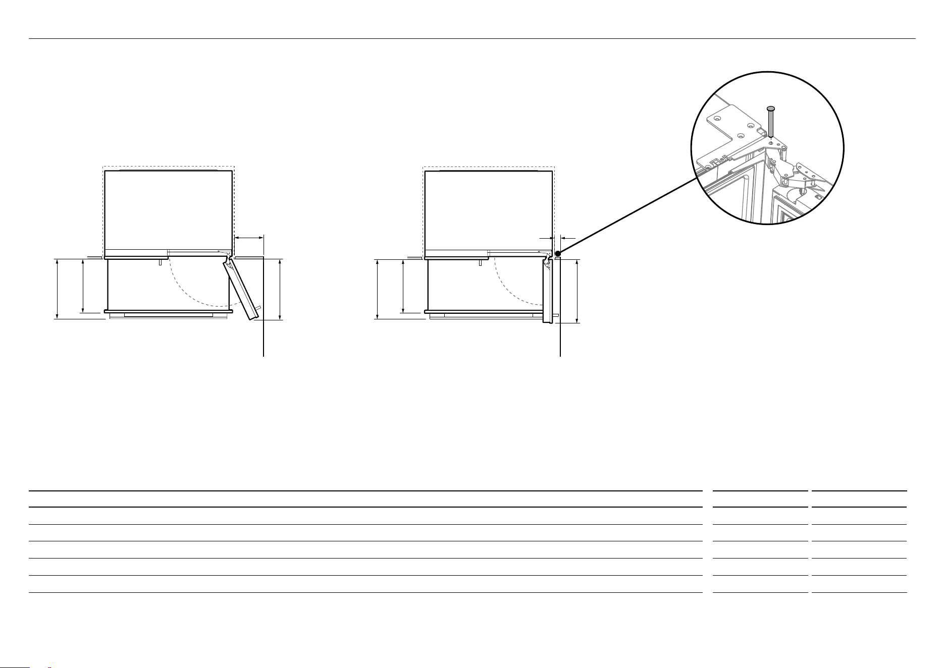
9 DOOR CLEARANCE
90° DOOR OPENING115° DOOR OPENING
[FULL ROTATION]
A
B
C
D
B
C
A
E
Wall
90° DOOR OPENING
90° DOOR OPENING115° DOOR OPENING
[FULL ROTATION]
A
B
C
D
B
C
A
E
Wall
115° DOOR OPENING
(FULL INTERNAL ACCESS)
RS80 RS90
DOOR CLEARANCE DIMENSIONS mm mm
A
Depth of door (widest opening) measured from front of door 395 445
B
Depth of drawer (open) measured from front of drawer, including handle 400 400
C
Depth of drawer (open) measured from front of drawer, excluding handle 360 360
D
Minimum door clearance* to adjacent wall (115° — full internal access) 280 300
E
Minimum door clearance* to adjacent wall (90° — reduced internal access) 100 100
* Measured from front cabinetry edge, includes 2mm cabinetry gap.
Insert hinge limiting pin
WARNING!
●
Before opening the doors, ensure that the appliance is
stable.
●
Follow these steps to avoid risks that can cause serious
injury or death.
For 90° door swing, a hinge limiting pin is supplied with
your appliance. This pin fits in the boreholes of the top
hinge (B).
1
Open door to 90°.
2
Insert the hinge limiting pin vertically into the bore hole.
– Apply a gentle tap to the pin if it does not slide
smoothly.
14
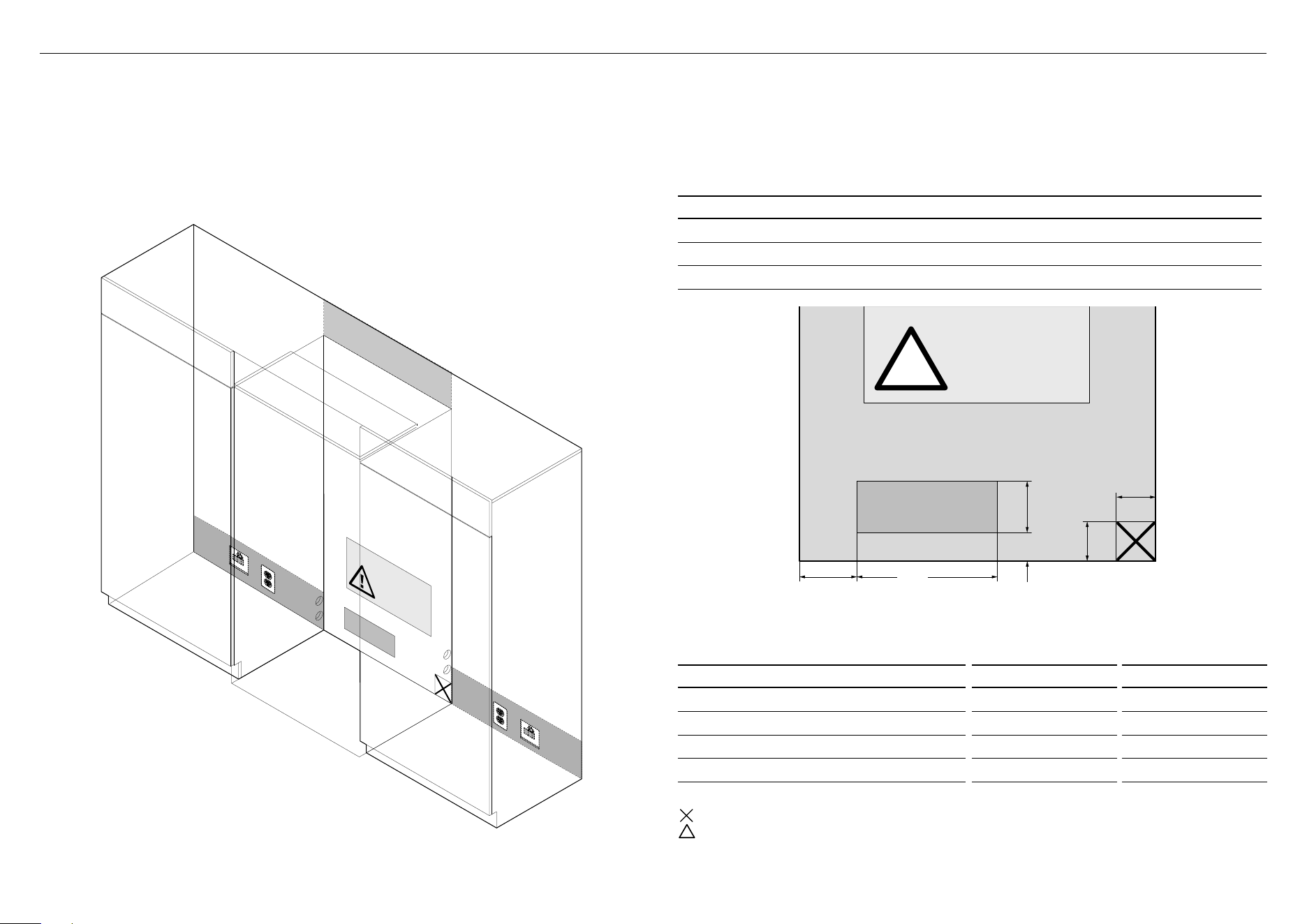
100mm
100mm
!
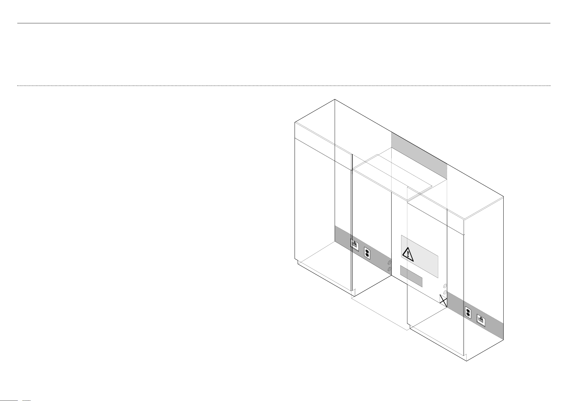
REAR VIEW OF CAVITY
IMPORTANT!
●
Electrical connection should be located in an adjacent cabinet to either side
oftheappliance or above the appliance cavity.
●
We recommend to use an isolating switch that is easily accessible to the user
aftertheappliance is installed.
WARNING!
●
Electrical shock hazard. Assume all parts are live.
●
Disconnect supply before servicing and installation.
ELECTRICAL AND PLUMBING CONNECTIONS
1
Recommended location for connections in adjacent area or unit
2
Alternative location for connections above the cavity
3
Alternative location for connections at rear of cavity
B
1
3
2
1
Electrical and water connections must be within this space if located
behind the appliance and must not protrude from the back wall.
RS80 RS90
ELECTRICAL AND PLUMBING DIMENSIONS mm mm
A
Overall height of supply area 130 130
B
Overall width of supply area 275 355
C
Distance from left side of cavity 145 145
D
Distance from the floor 72 72
Note: Dimensions are based on minimum depth of cavity.
!
Do not locate water or electricity in this area, keep clear of connections.
!
CAUTION: Central area can only fit water outlet and electrical plug if they are placed within a recessed cavity.
* In this location the water tap needs to be recessed into the wall, the recess must allow for an 80mm bend radius for
the watertube.
C
A
D
Left side
of cavity
Floor
Optional electrical
and water connection
location*
b
!0 ELECTRICAL AND PLUMBING
15
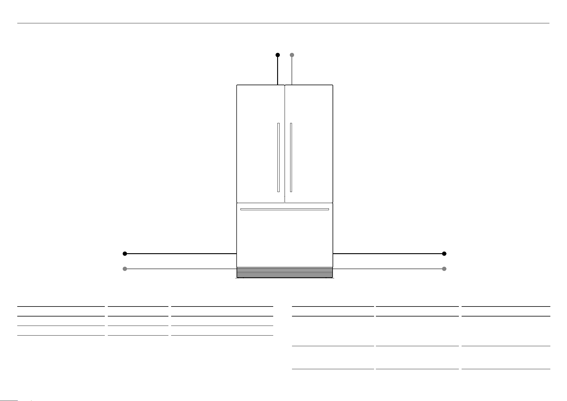
!0 ELECTRICAL AND PLUMBING
Maximum distance of hose and power cord
Power cord (excl.plug) — 2050mm
Water inlet hose* — 3930mm
RIGHT HAND SIDE
Power cord (excl.plug) — 2050mm
Water inlet hose* — 3180mm
LEFT HAND SIDE
Water inlet hose* — 2250mm Power cord (excl.plug) — 800mm
* Applicable to Ice and Water models only.
RS80 RS90
ELECTRICAL SPECIFICATIONS
Supply 230V, 50 Hz 230V, 50 Hz
Service 10 amp circuit 10 amp circuit
RS80 RS90
PLUMBING SPECIFICATIONS
Supply 13mm (1/2") or 19mm
(3/4") BSP threaded water
connection 6.35mm LLDPE
tubing
13mm (1/2") or 19mm
(3/4") BSP threaded water
connection 6.35mm LLDPE
tubing
Service Minimum 22 psi (150 kPa)
Maximum 120 psi (827 kPa)
@ 20°C
Minimum 22 psi (150 kPa)
Maximum 120 psi (827 kPa) @
20°C
16
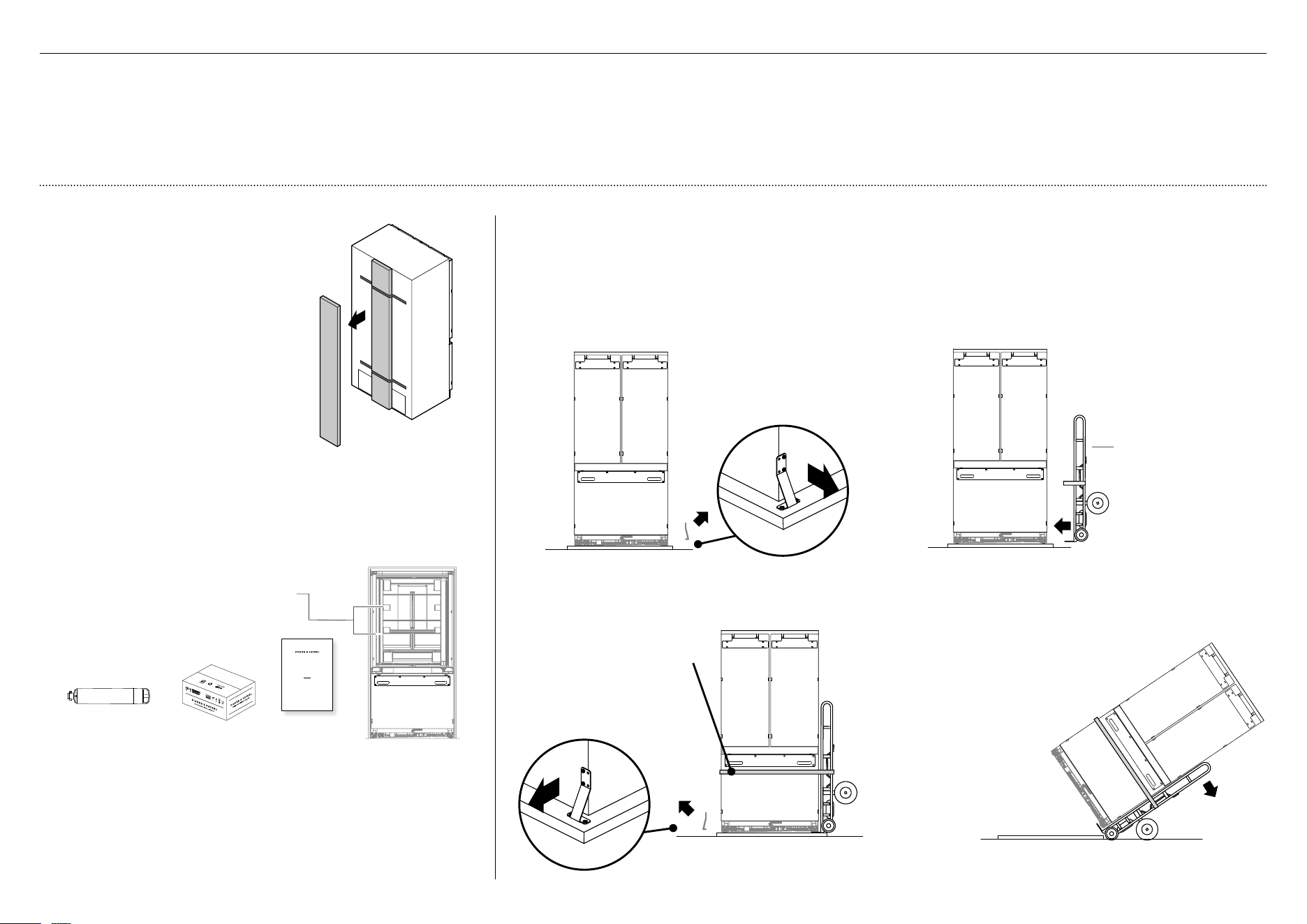
4
Restrain the appliance
to the cart with straps.
5
Remove the brackets
on the other side of
the appliance.
6
Tilt the appliance backward
onto the cart.
7
Set aside the pallet and
push the cart to the
installation location.
2
Tilt the appliance
slightly to the
opposite side.
3
Insert the hand truck
under the side of the
appliance where the
brackets were removed.
Do NOT insert the hand
truck to the front or
back of the appliance.
Moving your appliance
1
Remove the brackets from one side of the
appliance. (For single door models, remove the
brackets on the non-hinged side of the appliance.)
Note: Location of brackets depends on the
modelof your appliance.
Checking your appliance
1
Detach accessories box taped to
back panel ofappliance.
Refer to 'Components' (page 5).
IMPORTANT!
Be aware when removing the
carton that the accessories box
may have dislodged from
the rear of the appliance during
transit.
USER GUIDE
NZ AU GB IE HK SG IN US
ACTIVESMART™
INTEGRATED REFRIGERATOR
RS90A, RS9120W,
RS36A72, RS36A80 & RS36W80 models
Water fittings and
Water filter kits Installation kit
2
Remove the water fittings and water filter
kits, Installation kit, andMiscellaneous
itemspack from inside the appliance.
Refer to 'Components' (pages 4 – 5).
IMPORTANT!
●
Be careful when unpacking to prevent damage to the surface of your appliance.
●
Ensure that the appliance is stable to prevent from tipping over when unpacking.
●
Do not open the doors to prevent the appliance from tipping over.
●
The appliance is heavy and requires a minimum of 2persons to unpack and install.
●
Ensure that the feet of the appliance are retracted.
●
If the appliance is damaged, contact your Fisher & Paykel dealer.
●
Take note of your model and registration numbers located at the lower right side of
theappliance. You will need these to request for servicing or repair of your appliance.
hand truck
Miscellaneous
items pack
!1 BEFORE INSTALLATION
17
!1 BEFORE INSTALLATION
IMPORTANT!
●
Your appliance is fitted with front and rear rollers designed for moving the appliance
forward and backward. Donot move the appliance sideways as this may damage the
rollers or the floor covering / surface.
●
The appliance must be installed by a qualified installer, or Fisher & Paykel trained and
supported service technician to avoid faulty electrical connection and water leaks.
●
All connections for water, electrical power and grounding must comply with local codes
and ordinances and be made by licensed personnel when required.
●
Avoid installation of the appliance/s under a ground fault circuit interrupter (GFCI).
●
Ensure the appliance is installed properly. Improper installation that results in appliance
failure is not covered under the appliance warranty.
Check installation location
1
Check the cabinetry
– Check the dimensions — height, width, depth, floor level,
finishedalcovereturns.
– Ensure that the ventilation openings in the cabinetry are clear of obstruction.
– For integrated installation, a finished return of solid material is required
across thetopand sides of the new or existing alcove.
– Refer to the ‘Appliance and cavity Dimensions’ (page 7) prior to installation
of the appliance.
2
Check the power supply
– Ensure that there is a separate power outlet for the appliance.
– Avoid sharing the power point with other appliances to prevent the
appliancefromaccidentally switching off.
– For power requirements, refer to the information on the serial plate.
Thisislocated atthe front right-hand side of the drawer when open.
– Ensure your appliance is properly grounded (earthed).
– Connect the appliance to the electrical supply (230 VAC, 50 Hz) with fitted
plug andlead.
– We recommend to use an isolating switch that is easily accessible to
theuserafterthe appliance is installed.
– Follow the National Electrical Code and all local codes and ordinances
wheninstallingthis appliance.
3
Check the water supply (for Ice and Water models only)
– Ensure that there is a separate water supply connection for the appliance.
– Your appliance must be installed by a qualified appliance installer as
incorrect plumbingcanlead to water leaks.
– Fisher & Paykel is not liable for damage (including water damage) caused
byfaultyinstallation or plumbing.
18
!2 CAVITY PREPARATION
Internal box
A
Anti tip
bracket kit
Anti-tip bracket
(1)
Masonry plug
(4)
#10x40
Pan Head
Philips Screw
#10x40
Pan Head
Philips Screw
#10x40 cross-head screw
(4)
Tools
Cross-head screwdriver
Powered driver (optional)
Pencil
IMPORTANT!
●
The anti-tip bracket and fittings supplied must be fitted to the wall
ofthefinished enclosure to withstand 100kg load.
●
Ensure that anti-tip bracket is installed correctly to prevent the
appliancetipping forward when door is open.
●
Ensure the bracket is secured to structural beams or wall studs
nearesttothe center of the alcove.
WARNING!
Read the following before fastening with masonry plugs and / or screws:
●
Ensure the screws avoid electrical, gas and water conduits.
●
Ensure lightweight masonry material such as cinder block
andnewconcrete (no curing time) are not used in installation.
●
Do not use metallic materials that may corrode, stain and / or
damagetheenclosure.
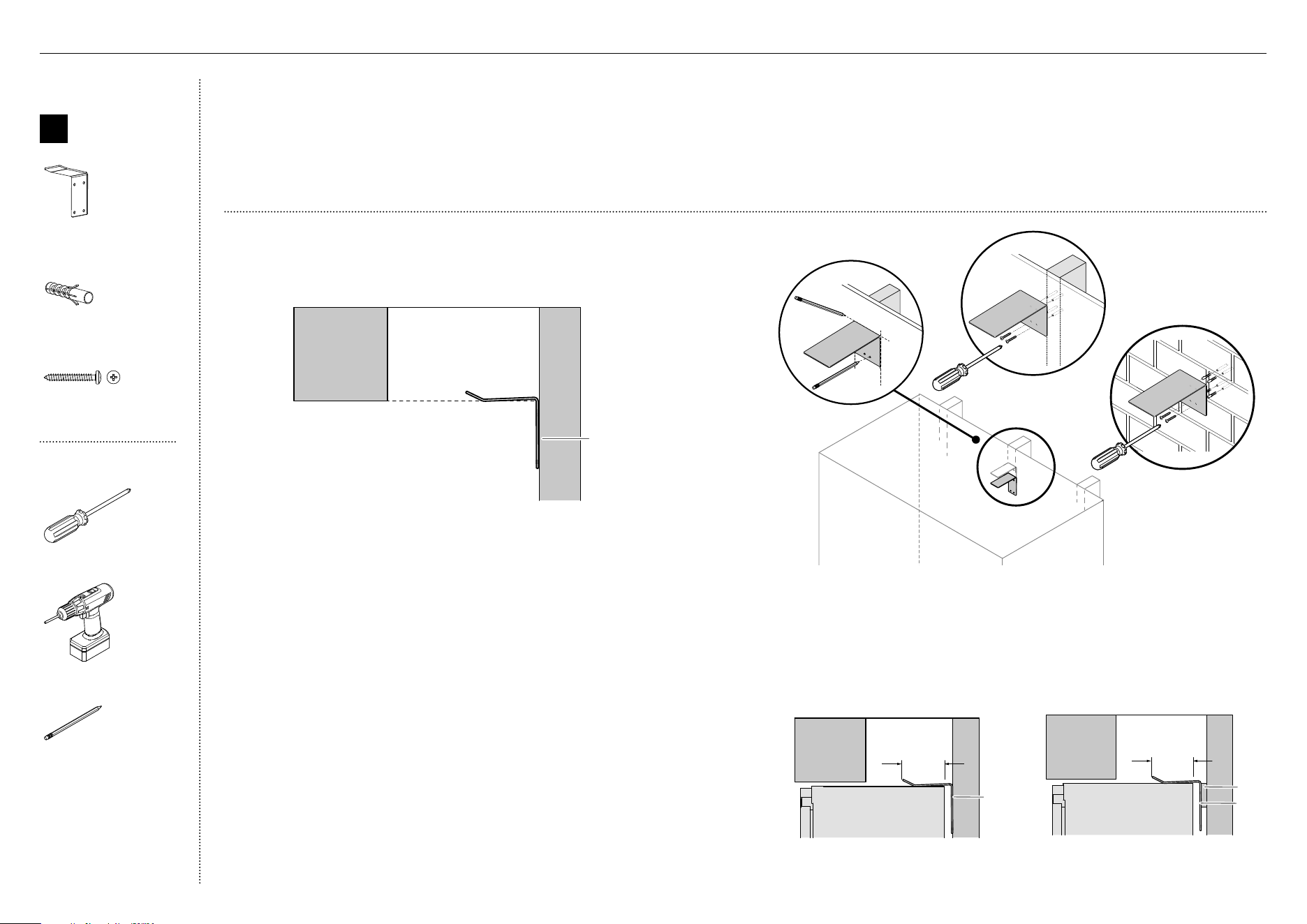
Attach anti-tip bracket
If the minimum 60mm
overlap cannot be
achieved, install a solid
spacer to the wall stud
behind the bracket.
IMPORTANT!
When positioning the appliance
in the cabinetry, ensure that the
anti-tip bracket overlaps the
appliance by a minimum 60mm
for a secure hold.
.
60mm overlap
Anti-tip
bracket
60mm overlap
Spacer
Anti-tip
bracket
D
E
B
C
Anti-tip
bracket
A
1
Project horizontally from the bottom edge of the finished enclosure towards
the center of the back wall (A). This will locate the contact surface between
the bracket and appliance.
2
Mark the location for placement of the anti-tip bracket. Place the bracket so
the top edge of the contact surface aligns with the mark (B).
3
Mark the locations of the screw holes on the wall based on the most central
wall stud (C).
4
Drill screw holes to the marked locations.
5
For wooden / plaster board wall installation:
– Fix the bracket to the wall with #10x40 pan head cross-head screws,
and screw tightly (D).
6
For solid wall installation:
– Hammer masonry plugs into the wall until flush.
– Fix the bracket to the wall with #10x40 pan head cross-head screws
(4x), and screw tightly (E).
19
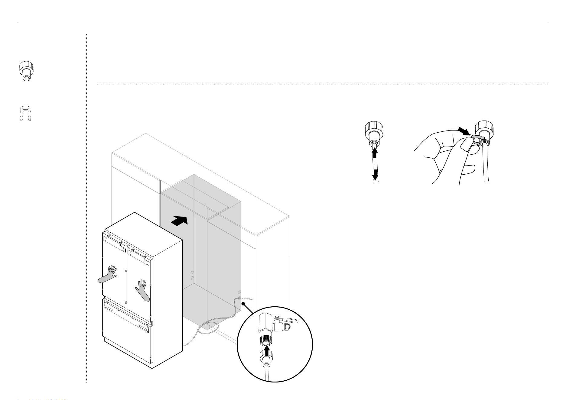
IMPORTANT!
●
The water connection instructions below are intended only for
theprofessional installer.
●
The appliance comes with a pre-connected plastic water tubing.
●
Water fittings are not supplied and must be purchased separately.
●
Ensure the appliance isconnected to its own isolating switch.
●
Ensure there is enough tubing for the water connection and to pull
theappliance outforservice, if required.
●
Flush water through the hose prior to connection to the appliance
toremoveany debris in the hose.
Water fittings kit
(Ice and Water
modelsonly)
Water tap adaptor
(1)
Collet locking clip
(1)
!3 WATER SUPPLY CONNECTION
3
Secure connection by inserting a locking key (D) between the water tap
adaptor and locking collet.
4
Connect the water tap adaptor to a water tap (E).
– Flush water through the hose prior to connection to the appliance
toremove any debris in the hose.
5
Turn on the water tap and check all connection are dry and free of drips.
B
C
D
2
Insert (B) the free end of the plastic water tubing fully into a water tap
adaptor and pull (C) gently to ensure it is locked in.
Connect to water supply (Ice and Water models only)
1
Move the appliance in front of the cabinetry close enough that you still have
access behind for power and waterconnections (A).
A
E
20
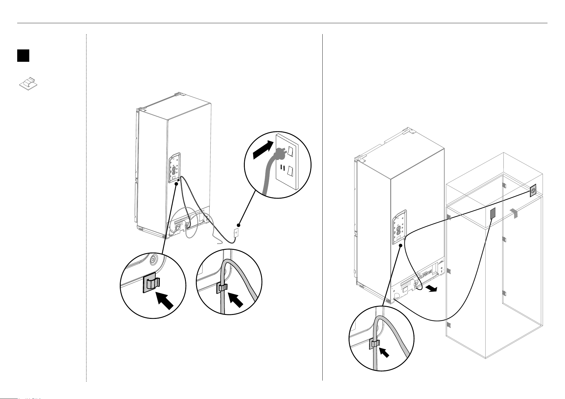
Connect to power supply
1
Locate the power cord and connect the fitted plug to the electrical supply
(230VAC, 50Hz). Turn ON the appliance.
– We recommend to use an isolating switch that can be accessed
easilyafter the appliance is installed.
Alternative water and electrical connection (above the cavity)
1
Connect the water fittings to the water supply (C).
2
Plug-in the power cord to the electrical supply (D), and turn on the
appliance.
3
Attach the power cord clip to the back of your appliance, and secure the
excess power cord length onto the clip (E).
– When pushing the appliance into position, take care not to roll over
ordamage the power cord and / or water tubing.
Refer to 'Electrical and Plumbing' for more information on recommended
and alternative water and power connections.
DETAIL B
SCALE 1 : 5
B
D
C
2
Attach a power cord clip (A) to the back of your appliance.
3
Secure the excess power cord length onto the clip (B).
Internal box
Y
Miscellaneous
components
Power cord clip
(2)
E
A
!4 POWER SUPPLY CONNECTION
21
WARNING!
●
Be careful when working with the appliance outside of the finished enclosure.
●
Ensure that the appliance is secured to prevent tipping forward. Tippingofappliance can lead to serious injury or death.
Internal box
X
Install
fasteners kit
M5 x 10
Pan Head
Philips Screw
M5 x 10
Pan Head
Philips Screw
M5x10 cross-head screw
(10)
Tools
Cross-head screwdriver
Powered driver (optional)
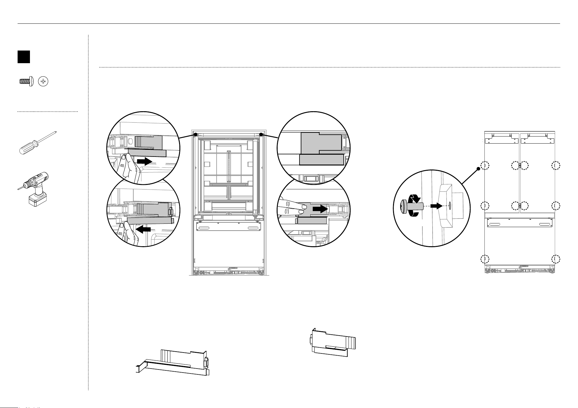
Remove hinge end caps
1
Open the French doors carefully.
4
Loosely screw (1 – 2 turns) M5x10 cross-head
screws into doors (D).
Repeat this process for all appliance doors.
1 – 2 turns
D
150
C
180
L
O
P
B
150
C
180
L
O
P
A
150
C
180
L
O
P
C
2
Remove the left hinge end cap.
– Hold onto the corner of the end cap,
firmlypush to the right to disengage the
securing hook and pull down (A).
– Pull cap gently towards the left hinge
toremove (B).
– Keep the end hinge cap for later installation.
3
Remove the right hinge endcap.
– Pressonthe center of the cap and push
towards the right hinge to remove (C).
– Keep the end hinge cap for later installation.
!5 INSTALLATION PREPARATION
22
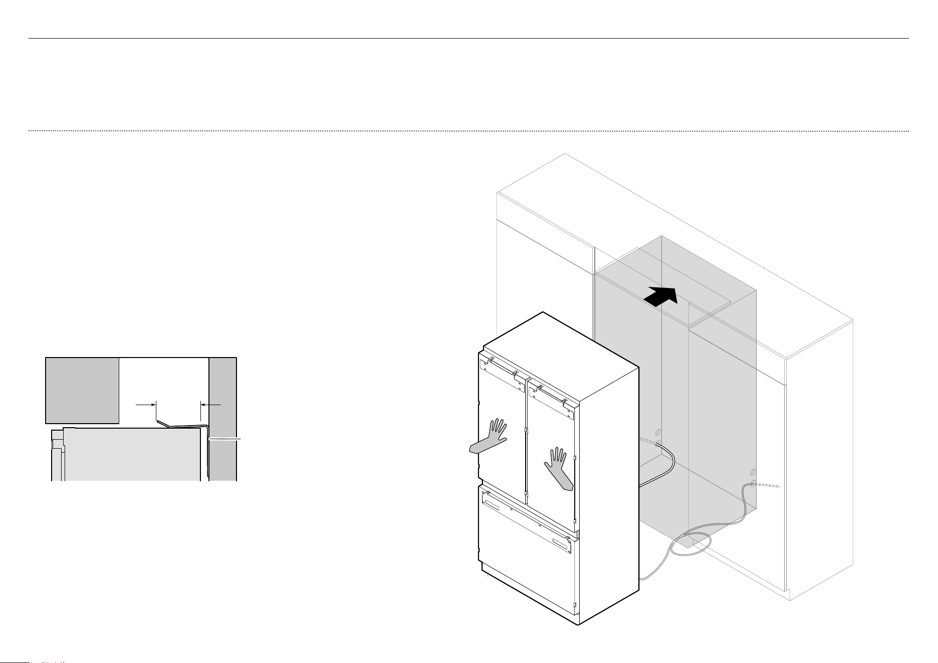
!6 POSITIONING INTO CABINETRY
Position the appliance into the cabinetry
1
Ensure the power cord are secured to the clip at the back of the
appliance (A) and the excess water hose coiled flat behind the
appliance.
2
Push the appliance into the cabinetry until the anti-tip bracket
overlaps the rear top edge of the appliance (B).
– Ensure the appliance is centered.
– Ensure there is firm contact between the appliance and anti-tip
bracket withamin.60mm overlap (C).
IMPORTANT!
When positioning the appliance in the cabinetry, ensure that the
anti-tip bracket overlaps the appliance by a minimum 60mm for
asecure hold.
B
A
IMPORTANT!
●
Your appliance is fitted with front and rear rollers designed for moving the appliance in the
forwards and backwards direction.
●
Avoid moving the appliance in a sideways direction as this may damage the rollers or the
floor covering/surface.
●
Ensure the hose is not run over by the appliance when pushing into the cabinetry to
prevent damage and possible water leaks.
●
Ensure water tubing is routed away from any sharp objects, sharp corners (beware of
kinking the tube as this will stop water flow), and not in a location where it can be kinked
or squashed.
Refer to 'Attach anti-tip bracket' (page18) for more information.
Anti-tip
bracket
Min. 60mm
overlap
23
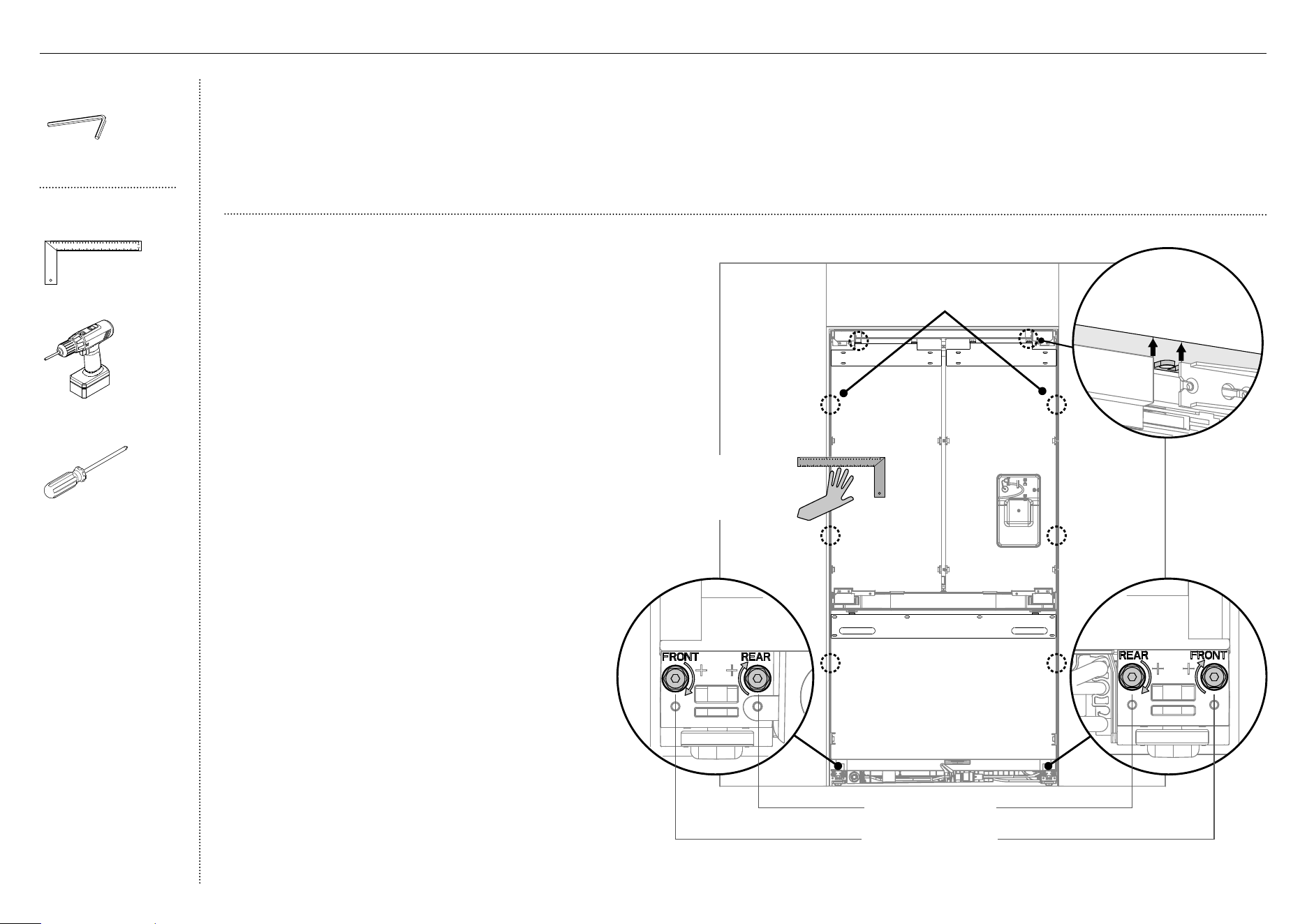
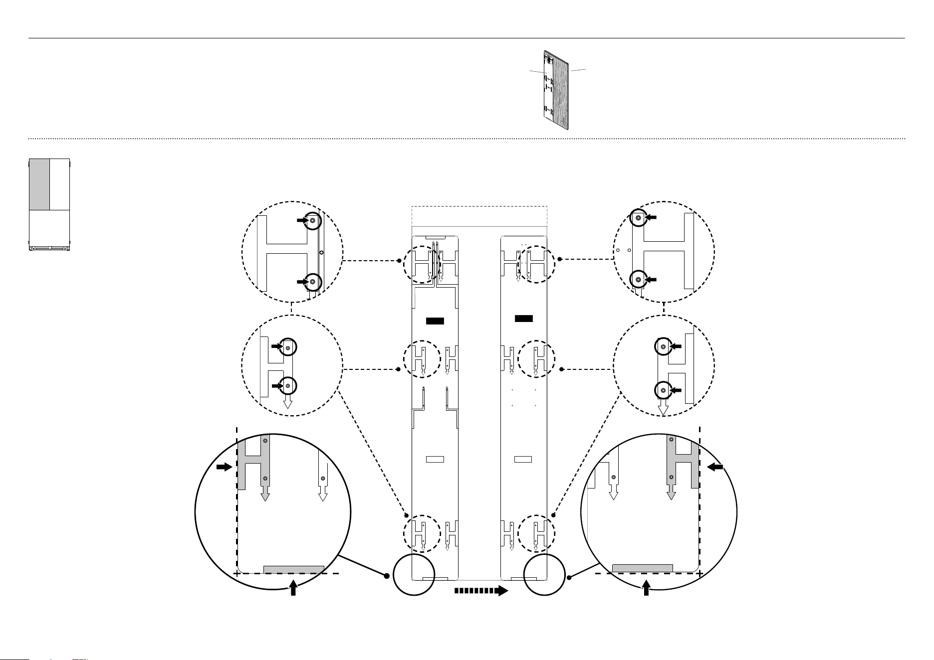
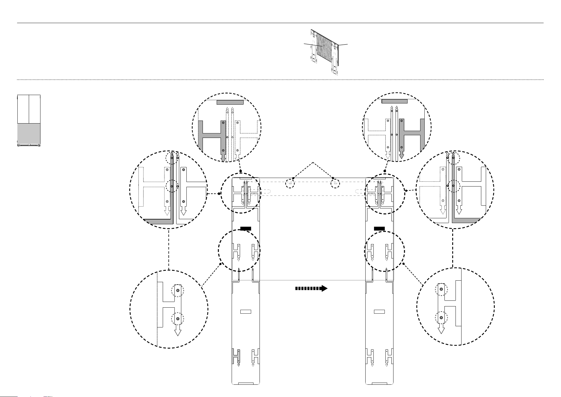
Align appliance inside the cabinetry
1 Centre the appliance within the alcove, using the adjacent
walls as a guide.
2 Raise the front of the appliance until the fixing brackets
contact the ceiling of the enclosure (A).
z
Turn the front and rear adjusting nuts (B) clockwise to
raise the roller or counter-clockwise to lower the roller.
3 To achieve correct alignment between front of the doors
and adjacent cabinetry panels, turn the adjusting nuts
alternately between front and rear rollers.
4 Check the gaps top and bottom, left and right by placing a
ruler on the front of the appliance.
z
Ensure the gaps between appliance and adjacent
cabinetry are even on both sides (C).
z
This step will help ensure the appliance is level with the
adjacent cabinetry
5 Gently push the front of the appliance to check the
stability
Supplied tools
Hex key
Tools
Ruler
Powered driver (optional)
Cross-head screwdriver
IMPORTANT!
●
Ensure all four corners of the appliance is supported firmly onto the floor
to eliminate any movement.
●
DO NOT install the appliance on a soft, uneven, or unlevelled floor
toavoidtwisting the appliance and poor door sealing.
●
We recommend to use A 4mm hex key.
●
One turn of height adjusting nuts is equivalent to 1mm heightadjustment.
Note: Maximum height adjustment is 20mm.
●
If using a powered driver, use low torque setting to avoid the nut
disengaging from the rod and damaging theleveling system. If the nut
disengages, use the hex key to realign with rod.
●
Ensure that the top, bottom and side gap differences are not greater than
1.5mm to achieve correct alignment.
●
Finalalignment will be achieved once door panels have been installed
andthe appliance is pushed back to sit flush with the cabinetry.
!7 ALIGNING INSIDE CABINETRY
Place a ruler on the
front of the appliance to
check flushness top and
bottom, left and right
BB
C
Rear roller adjustment
Front roller adjustment
A
24
IMPORTANT!
●
Follow these steps to avoid difficulties in door panel adjustment and cosmetic cap fitment.
●
Ensure to protect the finish of the Stainless steel door panels.
●
For non-water dispensing door panels: Leave the protective film on the panels when hanging and remove the film only when installation is complete.
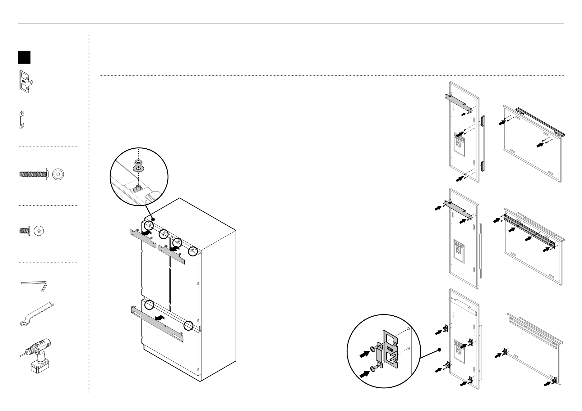
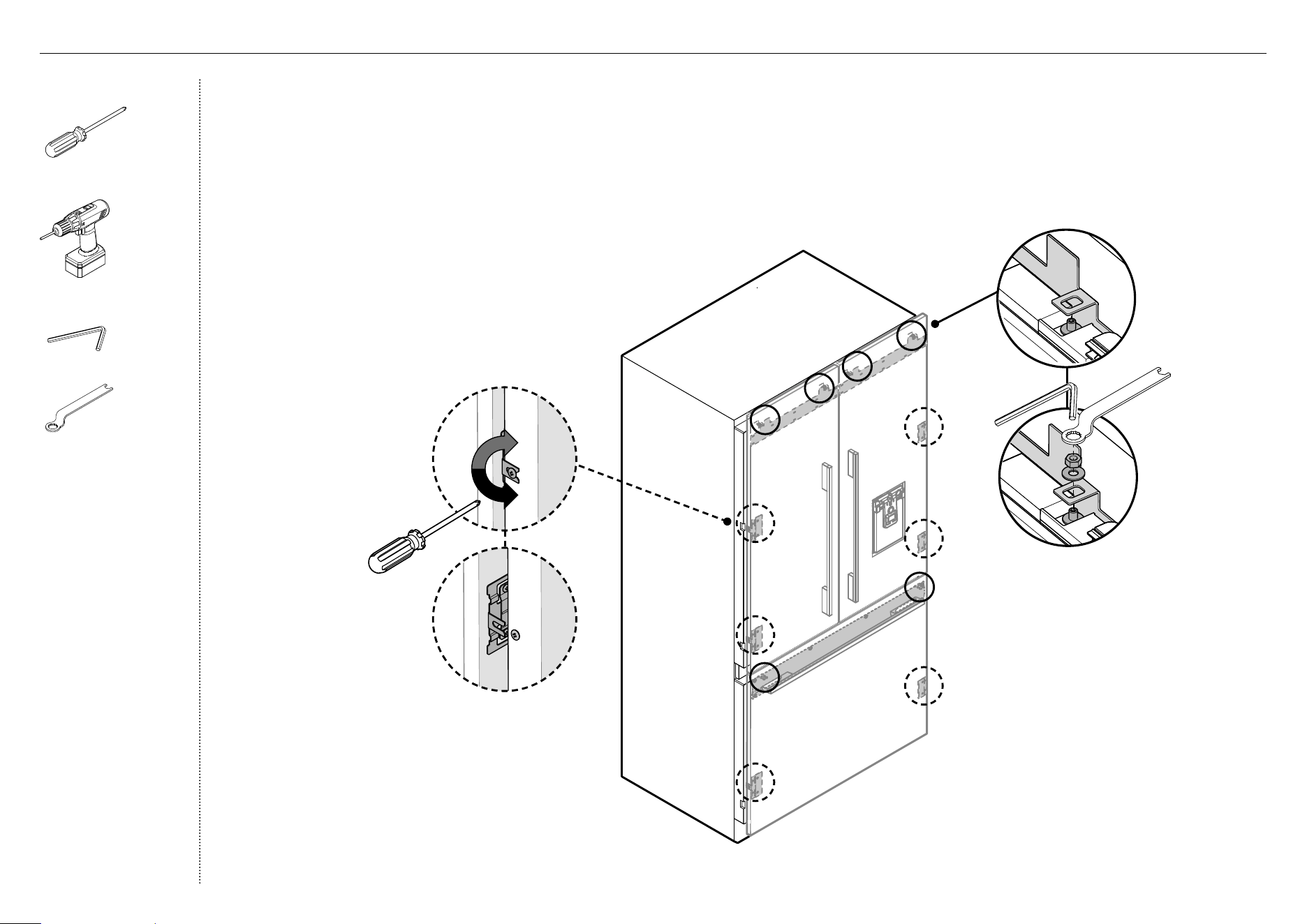
Remove hanging brackets
1
Remove the M8 washers and M8 nuts
fromtheM8 studs at the top the door (A).
Keepthe washers and nuts to reuse later.
2
Remove the hanging bracket from the top of
each door and set aside (B) for later installation.
Attach the door and drawer handles (A)
3
Remove the plastic film and blue tape on the
door panels.
4
Remove the plastic plugs from the handle holes
(4 per each door panel).
5
Align the handle holes with the door panel
holes and secure with M5x25 pan head socket
screws (4 per each door panel).
Note: Door handle kit available and must be
purchased separately. Refer to 'Components'
(page 5) for more details.
A
A
B
B
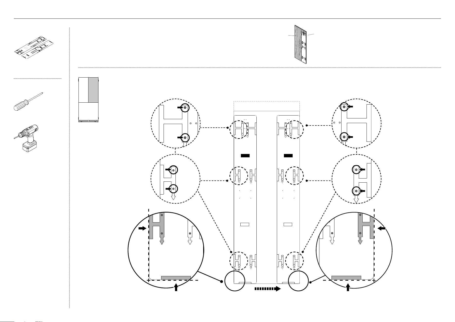
Attach side brackets and straps (C)
7
Align the brackets and straps to the holes on
the side of the panel and secure with M5x14
mush cross-head SS screws (20).
Attach the hanging brackets (B)
6
Align the bracket to the holes and secure
withM5x14 mush cross-head SS screws (14).
B
A
Internal box
B
Door panel
attachment kit
Side bracket (10)
Side strap (10)
Door handle kit
M5 x 25
Pan Head
Socket Screw
M5 x 25
Pan Head
Socket Screw
M5x25 pan head socket
screw (12x)
Door panel set
M5 x 14
Mush Head
SS
Philips Screw
M5 x 14
Mush Head
SS
Philips Screw
M5x14 mush cross-head
(SS) screw (34)
Tools
Hex key
FPA spanner
Powered driver
C
C
!8 DOOR PANEL INSTALLATION — STAINLESS STEEL
25
IMPORTANT!
●
Failure to follow these steps can lead to difficulties in door panel adjustment and cosmetic cap fitment.
●
For water dispensing door panels: Remove the protective film from the appliance doors before hanging door panels.
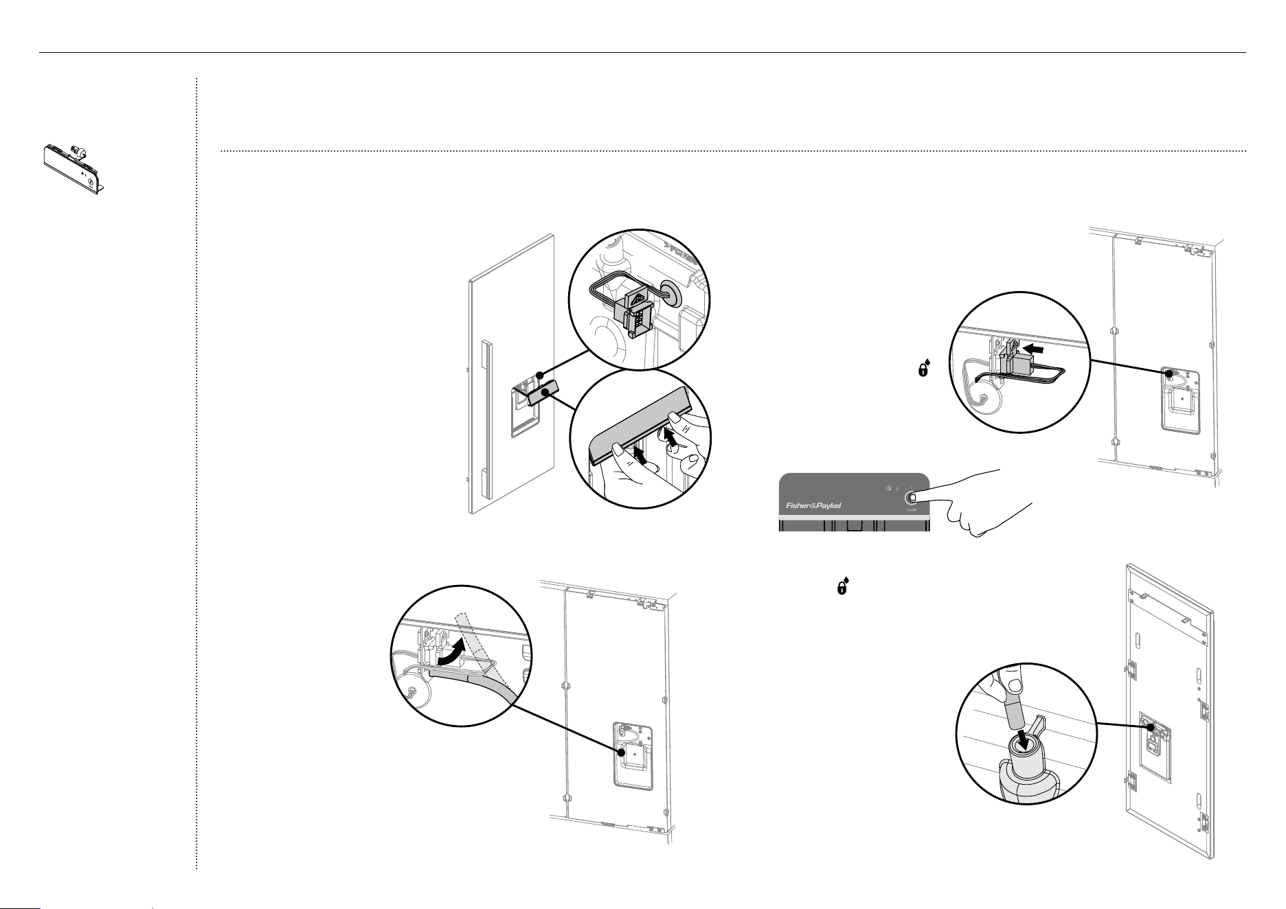
Connect the external display module
(for Water dispensing model only)
1
Locate the external display
module from inside the appliance.
2
Thread the display harness
through the door panel cavity (A).
– Ensure the grommet
isengaged.
3
Turn the top display tabs at an
angle into the door panel (B).
– Ensure the harness is free
ofpinching.
4
Push firmly against the bottom
display tabs and insert into
the door panel until you feel
itclipsecurely.
– Ensure the display is flush
with the door panel.
7
Connect the display harness onto the
appliance door by inserting firmly until you feel
it clip securely (D).
– On the external display, enable the
dispenser lock to
prevent any water
from dispensing
during water
connection.
– To lock, press the
button for 4 seconds.
The LED above the
button will illuminate.
D
B
A
5
Remove water tube
from the holder on
the appliance door
(C).
6
Hang the door panel
onto M8 studs.
– Ensure the
panel is free to
pivot for water
connections.
C
9
Push the water tube firmly
into the spigot behind
the door panel until
the marked line is not
visible(E).
– Ensure the water
tube is routed away
from any sharp
objects or corners,
and not in a location
where it can be
kinked or squashed
when the door panel
is secured, (as this
will stop water flow).
E
Ice and Water display
(Ice and Water models
only)
External display module
(1)
!8 DOOR PANEL INSTALLATION — STAINLESS STEEL
8
Enable the dispenser lock to prevent any water
from dispensing during water connection. To lock,
press the button for 4seconds. The LED above
the button will illuminate.
26
B
D
C
A
E
Tools
Cross-head screwdriver
Powered driver (optional)
Hex key
FPA spanner
!8 DOOR PANEL INSTALLATION — STAINLESS STEEL
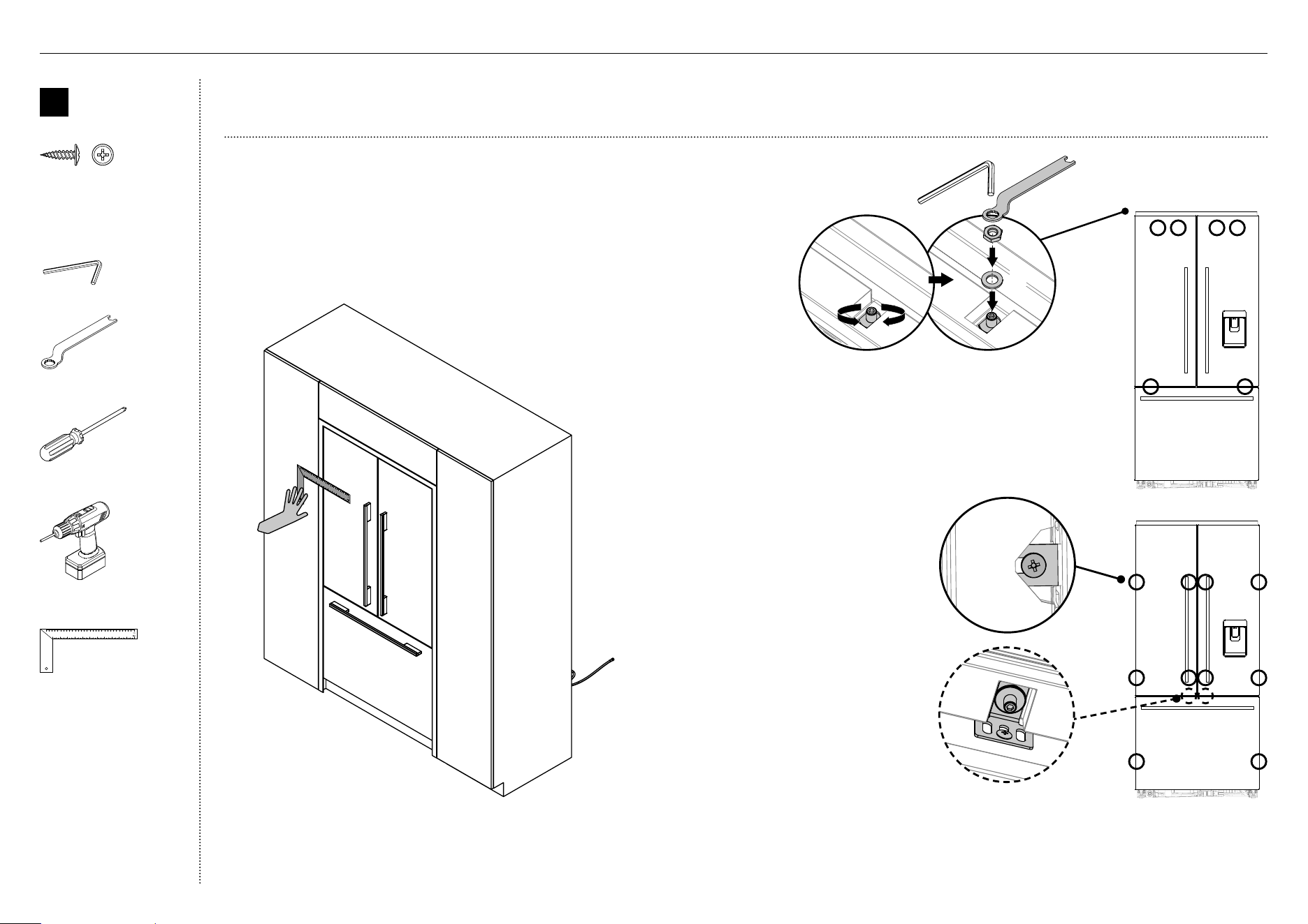
Attach the door panels
1
Open the door and loosen the M5x10 cross-head
screws (do not remove) at the sides of the doors (A).
2
Hang the door panel by inserting the M8 studs
through the holes of the hanging bracket (B).
3
Slide the forks of the side brackets onto the
screws of the door (C).
4
Screw the M8 washer and nut to each stud
(D), and re-tighten the side screws (E) using
the hex key and spanner to fix the door
panel (do not fully tighten). This will allow
opening the door without affecting
adjustment of the door panel.
27
Adjust the door panels
1
Push the appliance into the cavity until the door panels are flush
with adjacent cabinetry surface.
2
Place a ruler on the front of the appliance to check flushness top
and bottom, left and right..
IMPORTANT!
●
Follow these steps to avoid difficulties in door panel adjustment and cosmetic cap fitment.
B
Door panel
attachment
kit
#8 x 16
Mush Washer
Twin Thread
Philips Screw
#8 x 16
Mush Washer
Twin Thread
Philips Screw
8x16 mush washer screw
(1)
Tools
Hex key
FPA spanner
Cross-head screwdriver
Powered driver (optional)
Ruler
!8 DOOR PANEL INSTALLATION — STAINLESS STEEL
2
Each door panel has full axis adjustment to ensure
flushness with adjacent walls. To adjust the height of
the panel, turn the stud clockwise to raise or counter-
clockwise to lower the door panel (A).
3
Once satisfied with the alignment, secure M8 studs with
M8 washer and M8 nut (B). The top of the stud must
remain below the top face of the door panel.
4
Secure side bracket forks by
tightening side screws(C).
Repeat for all door panels.
Note:
– For depth adjustment,
loosen the side screws,
adjustthe panels and then
retightenoncesatisfied.
– Further adjustment of door
panels can be achieved by
removing door panels then
looseningthe fixing screws
for the hanging bracket and
moving the bracket sideways
to suit.
5
Loosen the M8 stud (D) so that
locking bracket can slide freely
back to front.
– Slide the locking bracket out until it touches the
back of the door panel. Fully tighten the M8 stud.
– Screw in place using a #8x16 screw through one
ofthe three slotted holes.
C
B
A
D
28
back side of
door panel
front side of
door panel
IMPORTANT!
●
The template is a single sheet with one side used for the left door
panel / drawer panel and the other side for the right door panel.
●
The template should be placed on the back side of the door panel.
Using the installation template
(for right French door panel)
1
DRAWER PANEL TOP EDGE
LH DOOR PANEL HINGE SIDE
LH DOOR PANEL HANDLE SIDEDRAWER PANEL HANDLE SIDE
DRAWER PANEL HINGE SIDE
LH DOOR PANEL HINGE SIDE
LH DOOR PANEL HANDLE SIDE
DRAWER PANEL HANDLE SIDE
DRAWER PANEL HINGE SIDE
FLIP FOR RIGHT
DOOR PANEL
LH DOOR PANEL HINGE SIDE
LH DOOR PANEL HANDLE SIDE
LH DOOR PANEL BOTTOM EDGE
RH DOOR PANEL HINGE SIDE
RH DOOR PANEL BOTTOM EDGE
RH DOOR PANEL HANDLE SIDE
RH DOOR PANEL HINGE SIDE
RH DOOR PANEL HANDLE SIDE
RH DOOR PANEL HANDLE SIDE
RH DOOR PANEL HINGE SIDE
DOOR PANEL
HANGING BRACKET HOLES
DOOR PANEL
HANGING BRACKET HOLES
DRAWER PANEL
HANGING BRACKET HOLES
DRAWER PANEL
HANGING BRACKET HOLES
LEFT DOOR
PANEL TEMPLATE
RIGHT DOOR
PANEL TEMPLATE
DOOR PANEL
SIDE BRACKET HOLES
DRAWER PANEL
SIDE BRACKET HOLES
DRAWER PANEL
SIDE BRACKET HOLES
DOOR PANEL
SIDE BRACKET HOLES
DOOR PANEL
SIDE BRACKET HOLES
DOOR PANEL
SIDE BRACKET HOLES
DOOR PANEL
SIDE BRACKET HOLES
DOOR PANEL
SIDE BRACKET HOLES
DOOR PANEL
HANGING BRACKET HOLES
DOOR PANEL
HANGING BRACKET HOLES
DOOR PANEL
SIDE BRACKET HOLES
DOOR PANEL
SIDE BRACKET HOLES
FLIP FOR LEFT
DOOR PANEL
3 Move the same template to
right hand side of door panel.
1B Align bottom of template with
bottom edge of top door panel.
1A Align left side edge
of template with
left side edge of
top door panel.
2 Mark drill locations of
screw holes for the left
hanging bracket and
side brackets. Drill 3–32
(2mm) screw holes to
the markedlocations.
5 Mark drill locations of screw
holes for the right hanging
bracket and side brackets.
Drill 3–32 (2mm) screw holes
to the markedlocations.
4B Align bottom of template with
bottom edge of top door panel.
4A Align right side
edge of template
with right side edge
of top door panel.
DRAWER PANEL TOP EDGE
LH DOOR PANEL HINGE SIDE
LH DOOR PANEL HANDLE SIDEDRAWER PANEL HANDLE SIDE
DRAWER PANEL HINGE SIDE
LH DOOR PANEL HINGE SIDE
LH DOOR PANEL HANDLE SIDE
DRAWER PANEL HANDLE SIDE
DRAWER PANEL HINGE SIDE
FLIP FOR RIGHT
DOOR PANEL
LH DOOR PANEL HINGE SIDE
LH DOOR PANEL HANDLE SIDE
LH DOOR PANEL BOTTOM EDGE
RH DOOR PANEL HINGE SIDE
RH DOOR PANEL BOTTOM EDGE
RH DOOR PANEL HANDLE SIDE
RH DOOR PANEL HINGE SIDE
RH DOOR PANEL HANDLE SIDE
RH DOOR PANEL HANDLE SIDE
RH DOOR PANEL HINGE SIDE
DOOR PANEL
HANGING BRACKET HOLES
DOOR PANEL
HANGING BRACKET HOLES
DRAWER PANEL
HANGING BRACKET HOLES
DRAWER PANEL
HANGING BRACKET HOLES
LEFT DOOR
PANEL TEMPLATE
RIGHT DOOR
PANEL TEMPLATE
DOOR PANEL
SIDE BRACKET HOLES
DRAWER PANEL
SIDE BRACKET HOLES
DRAWER PANEL
SIDE BRACKET HOLES
DOOR PANEL
SIDE BRACKET HOLES
DOOR PANEL
SIDE BRACKET HOLES
DOOR PANEL
SIDE BRACKET HOLES
DOOR PANEL
SIDE BRACKET HOLES
DOOR PANEL
SIDE BRACKET HOLES
DOOR PANEL
HANGING BRACKET HOLES
DOOR PANEL
HANGING BRACKET HOLES
DOOR PANEL
SIDE BRACKET HOLES
DOOR PANEL
SIDE BRACKET HOLES
FLIP FOR LEFT
DOOR PANEL
External box
Door panel template
(1)
Tools
Cross-head screwdriver
Powered driver (optional)
!9 DOOR PANEL INSTALLATION — CUSTOM
29
!9 DOOR PANEL INSTALLATION — CUSTOM
back side of
door panel
front side of
door panel
IMPORTANT!
●
Flip the template over to use for the right top door panel.
●
The template should be placed on the back side of the door panel.
1
DRAWER PANEL TOP EDGE
LH DOOR PANEL HINGE SIDE
LH DOOR PANEL HANDLE SIDEDRAWER PANEL HANDLE SIDE
DRAWER PANEL HINGE SIDE
LH DOOR PANEL HINGE SIDE
LH DOOR PANEL HANDLE SIDE
DRAWER PANEL HANDLE SIDE
DRAWER PANEL HINGE SIDE
FLIP FOR RIGHT
DOOR PANEL
LH DOOR PANEL HINGE SIDE
LH DOOR PANEL HANDLE SIDE
LH DOOR PANEL BOTTOM EDGE
RH DOOR PANEL HINGE SIDE
RH DOOR PANEL BOTTOM EDGE
RH DOOR PANEL HANDLE SIDE
RH DOOR PANEL HINGE SIDE
RH DOOR PANEL HANDLE SIDE
RH DOOR PANEL HANDLE SIDE
RH DOOR PANEL HINGE SIDE
DOOR PANEL
HANGING BRACKET HOLES
DOOR PANEL
HANGING BRACKET HOLES
DRAWER PANEL
HANGING BRACKET HOLES
DRAWER PANEL
HANGING BRACKET HOLES
LEFT DOOR
PANEL TEMPLATE
RIGHT DOOR
PANEL TEMPLATE
DOOR PANEL
SIDE BRACKET HOLES
DRAWER PANEL
SIDE BRACKET HOLES
DRAWER PANEL
SIDE BRACKET HOLES
DOOR PANEL
SIDE BRACKET HOLES
DOOR PANEL
SIDE BRACKET HOLES
DOOR PANEL
SIDE BRACKET HOLES
DOOR PANEL
SIDE BRACKET HOLES
DOOR PANEL
SIDE BRACKET HOLES
DOOR PANEL
HANGING BRACKET HOLES
DOOR PANEL
HANGING BRACKET HOLES
DOOR PANEL
SIDE BRACKET HOLES
DOOR PANEL
SIDE BRACKET HOLES
FLIP FOR LEFT
DOOR PANEL
DRAWER PANEL TOP EDGE
LH DOOR PANEL HINGE SIDE
LH DOOR PANEL HANDLE SIDEDRAWER PANEL HANDLE SIDE
DRAWER PANEL HINGE SIDE
LH DOOR PANEL HINGE SIDE
LH DOOR PANEL HANDLE SIDE
DRAWER PANEL HANDLE SIDE
DRAWER PANEL HINGE SIDE
FLIP FOR RIGHT
DOOR PANEL
LH DOOR PANEL HINGE SIDE
LH DOOR PANEL HANDLE SIDE
LH DOOR PANEL BOTTOM EDGE
RH DOOR PANEL HINGE SIDE
RH DOOR PANEL BOTTOM EDGE
RH DOOR PANEL HANDLE SIDE
RH DOOR PANEL HINGE SIDE
RH DOOR PANEL HANDLE SIDE
RH DOOR PANEL HANDLE SIDE
RH DOOR PANEL HINGE SIDE
DOOR PANEL
HANGING BRACKET HOLES
DOOR PANEL
HANGING BRACKET HOLES
DRAWER PANEL
HANGING BRACKET HOLES
DRAWER PANEL
HANGING BRACKET HOLES
LEFT DOOR
PANEL TEMPLATE
RIGHT DOOR
PANEL TEMPLATE
DOOR PANEL
SIDE BRACKET HOLES
DRAWER PANEL
SIDE BRACKET HOLES
DRAWER PANEL
SIDE BRACKET HOLES
DOOR PANEL
SIDE BRACKET HOLES
DOOR PANEL
SIDE BRACKET HOLES
DOOR PANEL
SIDE BRACKET HOLES
DOOR PANEL
SIDE BRACKET HOLES
DOOR PANEL
SIDE BRACKET HOLES
DOOR PANEL
HANGING BRACKET HOLES
DOOR PANEL
HANGING BRACKET HOLES
DOOR PANEL
SIDE BRACKET HOLES
DOOR PANEL
SIDE BRACKET HOLES
FLIP FOR LEFT
DOOR PANEL
DRAWER PANEL TOP EDGE
LH DOOR PANEL HINGE SIDE
LH DOOR PANEL HANDLE SIDEDRAWER PANEL HANDLE SIDE
DRAWER PANEL HINGE SIDE
LH DOOR PANEL HINGE SIDE
LH DOOR PANEL HANDLE SIDE
DRAWER PANEL HANDLE SIDE
DRAWER PANEL HINGE SIDE
FLIP FOR RIGHT
DOOR PANEL
LH DOOR PANEL HINGE SIDE
LH DOOR PANEL HANDLE SIDE
LH DOOR PANEL BOTTOM EDGE
RH DOOR PANEL HINGE SIDE
RH DOOR PANEL BOTTOM EDGE
RH DOOR PANEL HANDLE SIDE
RH DOOR PANEL HINGE SIDE
RH DOOR PANEL HANDLE SIDE
RH DOOR PANEL HANDLE SIDE
RH DOOR PANEL HINGE SIDE
DOOR PANEL
HANGING BRACKET HOLES
DOOR PANEL
HANGING BRACKET HOLES
DRAWER PANEL
HANGING BRACKET HOLES
DRAWER PANEL
HANGING BRACKET HOLES
LEFT DOOR
PANEL TEMPLATE
RIGHT DOOR
PANEL TEMPLATE
DOOR PANEL
SIDE BRACKET HOLES
DRAWER PANEL
SIDE BRACKET HOLES
DRAWER PANEL
SIDE BRACKET HOLES
DOOR PANEL
SIDE BRACKET HOLES
DOOR PANEL
SIDE BRACKET HOLES
DOOR PANEL
SIDE BRACKET HOLES
DOOR PANEL
SIDE BRACKET HOLES
DOOR PANEL
SIDE BRACKET HOLES
DOOR PANEL
HANGING BRACKET HOLES
DOOR PANEL
HANGING BRACKET HOLES
DOOR PANEL
SIDE BRACKET HOLES
DOOR PANEL
SIDE BRACKET HOLES
FLIP FOR LEFT
DOOR PANEL
DRAWER PANEL TOP EDGE
LH DOOR PANEL HINGE SIDE
LH DOOR PANEL HANDLE SIDEDRAWER PANEL HANDLE SIDE
DRAWER PANEL HINGE SIDE
LH DOOR PANEL HINGE SIDE
LH DOOR PANEL HANDLE SIDE
DRAWER PANEL HANDLE SIDE
DRAWER PANEL HINGE SIDE
FLIP FOR RIGHT
DOOR PANEL
LH DOOR PANEL HINGE SIDE
LH DOOR PANEL HANDLE SIDE
LH DOOR PANEL BOTTOM EDGE
RH DOOR PANEL HINGE SIDE
RH DOOR PANEL BOTTOM EDGE
RH DOOR PANEL HANDLE SIDE
RH DOOR PANEL HINGE SIDE
RH DOOR PANEL HANDLE SIDE
RH DOOR PANEL HANDLE SIDE
RH DOOR PANEL HINGE SIDE
DOOR PANEL
HANGING BRACKET HOLES
DOOR PANEL
HANGING BRACKET HOLES
DRAWER PANEL
HANGING BRACKET HOLES
DRAWER PANEL
HANGING BRACKET HOLES
LEFT DOOR
PANEL TEMPLATE
RIGHT DOOR
PANEL TEMPLATE
DOOR PANEL
SIDE BRACKET HOLES
DRAWER PANEL
SIDE BRACKET HOLES
DRAWER PANEL
SIDE BRACKET HOLES
DOOR PANEL
SIDE BRACKET HOLES
DOOR PANEL
SIDE BRACKET HOLES
DOOR PANEL
SIDE BRACKET HOLES
DOOR PANEL
SIDE BRACKET HOLES
DOOR PANEL
SIDE BRACKET HOLES
DOOR PANEL
HANGING BRACKET HOLES
DOOR PANEL
HANGING BRACKET HOLES
DOOR PANEL
SIDE BRACKET HOLES
DOOR PANEL
SIDE BRACKET HOLES
FLIP FOR LEFT
DOOR PANEL
DRAWER PANEL TOP EDGE
LH DOOR PANEL HINGE SIDE
LH DOOR PANEL HANDLE SIDEDRAWER PANEL HANDLE SIDE
DRAWER PANEL HINGE SIDE
LH DOOR PANEL HINGE SIDE
LH DOOR PANEL HANDLE SIDE
DRAWER PANEL HANDLE SIDE
DRAWER PANEL HINGE SIDE
FLIP FOR RIGHT
DOOR PANEL
LH DOOR PANEL HINGE SIDE
LH DOOR PANEL HANDLE SIDE
LH DOOR PANEL BOTTOM EDGE
RH DOOR PANEL HINGE SIDE
RH DOOR PANEL BOTTOM EDGE
RH DOOR PANEL HANDLE SIDE
RH DOOR PANEL HINGE SIDE
RH DOOR PANEL HANDLE SIDE
RH DOOR PANEL HANDLE SIDE
RH DOOR PANEL HINGE SIDE
DOOR PANEL
HANGING BRACKET HOLES
DOOR PANEL
HANGING BRACKET HOLES
DRAWER PANEL
HANGING BRACKET HOLES
DRAWER PANEL
HANGING BRACKET HOLES
LEFT DOOR
PANEL TEMPLATE
RIGHT DOOR
PANEL TEMPLATE
DOOR PANEL
SIDE BRACKET HOLES
DRAWER PANEL
SIDE BRACKET HOLES
DRAWER PANEL
SIDE BRACKET HOLES
DOOR PANEL
SIDE BRACKET HOLES
DOOR PANEL
SIDE BRACKET HOLES
DOOR PANEL
SIDE BRACKET HOLES
DOOR PANEL
SIDE BRACKET HOLES
DOOR PANEL
SIDE BRACKET HOLES
DOOR PANEL
HANGING BRACKET HOLES
DOOR PANEL
HANGING BRACKET HOLES
DOOR PANEL
SIDE BRACKET HOLES
DOOR PANEL
SIDE BRACKET HOLES
FLIP FOR LEFT
DOOR PANEL
3 Move the same template to
right hand side of door panel.
1B Align bottom of template with
bottom edge of top door panel.
1A Align left side edge of
template with left side
edge of top door panel.
2 Mark drill locations of
screw holes for the left
hanging bracket and
side brackets. Drill 3–32
(2mm) screw holes to
the marked locations.
5 Mark drill locations of screw holes
for the right hanging bracket and
side brackets. Drill 3–32 (2mm)
screw holes to the marked locations.
4B Align bottom of template with
bottom edge of top door panel.
4A Align right side edge of
template with right side
edge of top door panel.
DRAWER PANEL TOP EDGE
LH DOOR PANEL HINGE SIDE
LH DOOR PANEL HANDLE SIDEDRAWER PANEL HANDLE SIDE
DRAWER PANEL HINGE SIDE
LH DOOR PANEL HINGE SIDE
LH DOOR PANEL HANDLE SIDE
DRAWER PANEL HANDLE SIDE
DRAWER PANEL HINGE SIDE
FLIP FOR RIGHT
DOOR PANEL
LH DOOR PANEL HINGE SIDE
LH DOOR PANEL HANDLE SIDE
LH DOOR PANEL BOTTOM EDGE
RH DOOR PANEL HINGE SIDE
RH DOOR PANEL BOTTOM EDGE
RH DOOR PANEL HANDLE SIDE
RH DOOR PANEL HINGE SIDE
RH DOOR PANEL HANDLE SIDE
RH DOOR PANEL HANDLE SIDE
RH DOOR PANEL HINGE SIDE
DOOR PANEL
HANGING BRACKET HOLES
DOOR PANEL
HANGING BRACKET HOLES
DRAWER PANEL
HANGING BRACKET HOLES
DRAWER PANEL
HANGING BRACKET HOLES
LEFT DOOR
PANEL TEMPLATE
RIGHT DOOR
PANEL TEMPLATE
DOOR PANEL
SIDE BRACKET HOLES
DRAWER PANEL
SIDE BRACKET HOLES
DRAWER PANEL
SIDE BRACKET HOLES
DOOR PANEL
SIDE BRACKET HOLES
DOOR PANEL
SIDE BRACKET HOLES
DOOR PANEL
SIDE BRACKET HOLES
DOOR PANEL
SIDE BRACKET HOLES
DOOR PANEL
SIDE BRACKET HOLES
DOOR PANEL
HANGING BRACKET HOLES
DOOR PANEL
HANGING BRACKET HOLES
DOOR PANEL
SIDE BRACKET HOLES
DOOR PANEL
SIDE BRACKET HOLES
FLIP FOR LEFT
DOOR PANEL
Using the installation template
(for left French door panel)
DRAWER PANEL TOP EDGE
LH DOOR PANEL HINGE SIDE
LH DOOR PANEL HANDLE SIDEDRAWER PANEL HANDLE SIDE
DRAWER PANEL HINGE SIDE
LH DOOR PANEL HINGE SIDE
LH DOOR PANEL HANDLE SIDE
DRAWER PANEL HANDLE SIDE
DRAWER PANEL HINGE SIDE
FLIP FOR RIGHT
DOOR PANEL
LH DOOR PANEL HINGE SIDE
LH DOOR PANEL HANDLE SIDE
LH DOOR PANEL BOTTOM EDGE
RH DOOR PANEL HINGE SIDE
RH DOOR PANEL BOTTOM EDGE
RH DOOR PANEL HANDLE SIDE
RH DOOR PANEL HINGE SIDE
RH DOOR PANEL HANDLE SIDE
RH DOOR PANEL HANDLE SIDE
RH DOOR PANEL HINGE SIDE
DOOR PANEL
HANGING BRACKET HOLES
DOOR PANEL
HANGING BRACKET HOLES
DRAWER PANEL
HANGING BRACKET HOLES
DRAWER PANEL
HANGING BRACKET HOLES
LEFT DOOR
PANEL TEMPLATE
RIGHT DOOR
PANEL TEMPLATE
DOOR PANEL
SIDE BRACKET HOLES
DRAWER PANEL
SIDE BRACKET HOLES
DRAWER PANEL
SIDE BRACKET HOLES
DOOR PANEL
SIDE BRACKET HOLES
DOOR PANEL
SIDE BRACKET HOLES
DOOR PANEL
SIDE BRACKET HOLES
DOOR PANEL
SIDE BRACKET HOLES
DOOR PANEL
SIDE BRACKET HOLES
DOOR PANEL
HANGING BRACKET HOLES
DOOR PANEL
HANGING BRACKET HOLES
DOOR PANEL
SIDE BRACKET HOLES
DOOR PANEL
SIDE BRACKET HOLES
FLIP FOR LEFT
DOOR PANEL
30
!9 DOOR PANEL INSTALLATION — CUSTOM
back side of
drawer panel
front side of
door panel
IMPORTANT!
●
Use left door panel template to use for the drawer panel.
●
Place the template at the back side of the drawer panel.
Using the installation template
(for drawer panel)
DRAWER PANEL TOP EDGE
LH DOOR PANEL HANDLE SIDEDRAWER PANEL HANDLE SIDE
DRAWER PANEL HINGE SIDE
LH DOOR PANEL HINGE SIDE
LH DOOR PANEL HANDLE SIDE
DRAWER PANEL HANDLE SIDE
DRAWER PANEL HINGE SIDE
FLIP FOR RIGHT
DOOR PANEL
LH DOOR PANEL HINGE SIDE
LH DOOR PANEL HANDLE SIDE
LH DOOR PANEL BOTTOM EDGE
RH DOOR PANEL HINGE SIDE
RH DOOR PANEL BOTTOM EDGE
RH DOOR PANEL HANDLE SIDE
RH DOOR PANEL HINGE SIDE
RH DOOR PANEL HANDLE SIDE
RH DOOR PANEL HANDLE SIDE
RH DOOR PANEL HINGE SIDE
DOOR PANEL
HANGING BRACKET HOLES
DRAWER PANEL
HANGING BRACKET HOLES
DRAWER PANEL
HANGING BRACKET HOLES
LEFT DOOR
PANEL TEMPLATE
RIGHT DOOR
PANEL TEMPLATE
DOOR PANEL
SIDE BRACKET HOLES
DRAWER PANEL
SIDE BRACKET HOLES
DRAWER PANEL
SIDE BRACKET HOLES
DOOR PANEL
SIDE BRACKET HOLES
DOOR PANEL
SIDE BRACKET HOLES
DOOR PANEL
SIDE BRACKET HOLES
DOOR PANEL
SIDE BRACKET HOLES
DOOR PANEL
SIDE BRACKET HOLES
DOOR PANEL
HANGING BRACKET HOLES
DOOR PANEL
HANGING BRACKET HOLES
DOOR PANEL
SIDE BRACKET HOLES
DOOR PANEL
SIDE BRACKET HOLES
FLIP FOR LEFT
DOOR PANEL
DOOR PANEL
HANGING BRACKET HOLES
LH DOOR PANEL HINGE SIDE
DRAWER PANEL TOP EDGE
LH DOOR PANEL HINGE SIDE
LH DOOR PANEL HANDLE SIDEDRAWER PANEL HANDLE SIDE
DRAWER PANEL HINGE SIDE
LH DOOR PANEL HINGE SIDE
LH DOOR PANEL HANDLE SIDE
DRAWER PANEL HANDLE SIDE
DRAWER PANEL HINGE SIDE
FLIP FOR RIGHT
DOOR PANEL
LH DOOR PANEL HINGE SIDE
LH DOOR PANEL HANDLE SIDE
LH DOOR PANEL BOTTOM EDGE
RH DOOR PANEL HINGE SIDE
RH DOOR PANEL BOTTOM EDGE
RH DOOR PANEL HANDLE SIDE
RH DOOR PANEL HINGE SIDE
RH DOOR PANEL HANDLE SIDE
RH DOOR PANEL HANDLE SIDE
RH DOOR PANEL HINGE SIDE
DOOR PANEL
HANGING BRACKET HOLES
DOOR PANEL
HANGING BRACKET HOLES
DRAWER PANEL
HANGING BRACKET HOLES
DRAWER PANEL
HANGING BRACKET HOLES
LEFT DOOR
PANEL TEMPLATE
RIGHT DOOR
PANEL TEMPLATE
DOOR PANEL
SIDE BRACKET HOLES
DRAWER PANEL
SIDE BRACKET HOLES
DRAWER PANEL
SIDE BRACKET HOLES
DOOR PANEL
SIDE BRACKET HOLES
DOOR PANEL
SIDE BRACKET HOLES
DOOR PANEL
SIDE BRACKET HOLES
DOOR PANEL
SIDE BRACKET HOLES
DOOR PANEL
SIDE BRACKET HOLES
DOOR PANEL
HANGING BRACKET HOLES
DOOR PANEL
HANGING BRACKET HOLES
DOOR PANEL
SIDE BRACKET HOLES
DOOR PANEL
SIDE BRACKET HOLES
FLIP FOR LEFT
DOOR PANEL
3 Move the same template to
right hand side of drawer panel.
DRAWER PANEL TOP EDGE
LH DOOR PANEL HANDLE SIDEDRAWER PANEL HANDLE SIDE
DRAWER PANEL HINGE SIDE
LH DOOR PANEL HINGE SIDE
LH DOOR PANEL HANDLE SIDE
DRAWER PANEL HANDLE SIDE
DRAWER PANEL HINGE SIDE
FLIP FOR RIGHT
DOOR PANEL
LH DOOR PANEL HINGE SIDE
LH DOOR PANEL HANDLE SIDE
LH DOOR PANEL BOTTOM EDGE
RH DOOR PANEL HINGE SIDE
RH DOOR PANEL BOTTOM EDGE
RH DOOR PANEL HANDLE SIDE
RH DOOR PANEL HINGE SIDE
RH DOOR PANEL HANDLE SIDE
RH DOOR PANEL HANDLE SIDE
RH DOOR PANEL HINGE SIDE
DOOR PANEL
HANGING BRACKET HOLES
DRAWER PANEL
HANGING BRACKET HOLES
DRAWER PANEL
HANGING BRACKET HOLES
LEFT DOOR
PANEL TEMPLATE
RIGHT DOOR
PANEL TEMPLATE
DOOR PANEL
SIDE BRACKET HOLES
DRAWER PANEL
SIDE BRACKET HOLES
DRAWER PANEL
SIDE BRACKET HOLES
DOOR PANEL
SIDE BRACKET HOLES
DOOR PANEL
SIDE BRACKET HOLES
DOOR PANEL
SIDE BRACKET HOLES
DOOR PANEL
SIDE BRACKET HOLES
DOOR PANEL
SIDE BRACKET HOLES
DOOR PANEL
HANGING BRACKET HOLES
DOOR PANEL
HANGING BRACKET HOLES
DOOR PANEL
SIDE BRACKET HOLES
DOOR PANEL
SIDE BRACKET HOLES
FLIP FOR LEFT
DOOR PANEL
DOOR PANEL
HANGING BRACKET HOLES
LH DOOR PANEL HINGE SIDE
1A Align top of template with
top edge of drawer panel.
1B Align left side edge of
template with left side
edge of drawer panel.
DRAWER PANEL TOP EDGE
LH DOOR PANEL HANDLE SIDEDRAWER PANEL HANDLE SIDE
DRAWER PANEL HINGE SIDE
LH DOOR PANEL HINGE SIDE
LH DOOR PANEL HANDLE SIDE
DRAWER PANEL HANDLE SIDE
DRAWER PANEL HINGE SIDE
FLIP FOR RIGHT
DOOR PANEL
LH DOOR PANEL HINGE SIDE
LH DOOR PANEL HANDLE SIDE
LH DOOR PANEL BOTTOM EDGE
RH DOOR PANEL HINGE SIDE
RH DOOR PANEL BOTTOM EDGE
RH DOOR PANEL HANDLE SIDE
RH DOOR PANEL HINGE SIDE
RH DOOR PANEL HANDLE SIDE
RH DOOR PANEL HANDLE SIDE
RH DOOR PANEL HINGE SIDE
DOOR PANEL
HANGING BRACKET HOLES
DRAWER PANEL
HANGING BRACKET HOLES
DRAWER PANEL
HANGING BRACKET HOLES
LEFT DOOR
PANEL TEMPLATE
RIGHT DOOR
PANEL TEMPLATE
DOOR PANEL
SIDE BRACKET HOLES
DRAWER PANEL
SIDE BRACKET HOLES
DRAWER PANEL
SIDE BRACKET HOLES
DOOR PANEL
SIDE BRACKET HOLES
DOOR PANEL
SIDE BRACKET HOLES
DOOR PANEL
SIDE BRACKET HOLES
DOOR PANEL
SIDE BRACKET HOLES
DOOR PANEL
SIDE BRACKET HOLES
DOOR PANEL
HANGING BRACKET HOLES
DOOR PANEL
HANGING BRACKET HOLES
DOOR PANEL
SIDE BRACKET HOLES
DOOR PANEL
SIDE BRACKET HOLES
FLIP FOR LEFT
DOOR PANEL
DOOR PANEL
HANGING BRACKET HOLES
LH DOOR PANEL HINGE SIDE
4A Align top of template with
top edge of drawer panel.
4B Align right side edge of
template with right side
edge of drawer panel.
2 Mark drill locations of screw
holes for the left hanging
bracket and side brackets.
Drill 3–32 (2mm) screw holes
to the marked locations.
5 Mark drill locations of screw
holes for the left hanging
bracket and side brackets.
Drill 3–32 (2mm) screw holes
to the marked locations.
6 To mark the drill locations of middle
screw holes, align the screw holes of
the drawer hanging bracket with the
right and left drilled screw holes. Drill
screw holes to the marked locations.
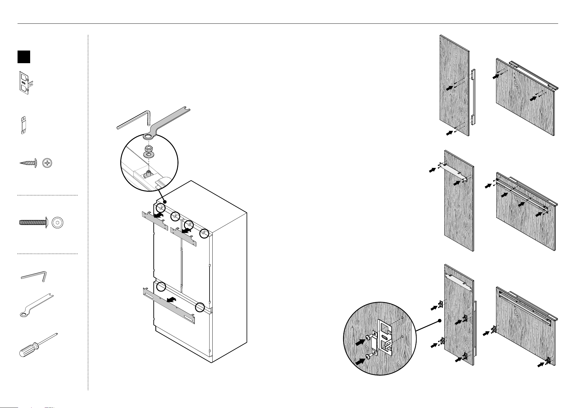
31
Remove hanging brackets
1
Remove the M8 washers and M8 nuts fromthe
M8 studs at the top the door (A) using the hex
key and spanner. Keep the washers and nuts to
reuse later.
2
Remove the hanging bracket from the top of
each door and set aside (B) for later installation.
Attach the door and drawer handles (C)
3
Align the handle holes with the door panel
holes and secure with M5x25 pan head socket
screws (4 per each door panel).
Note: Door handle kit available and must be
purchased separately. Refer to 'Components'
(page 5) for more details.
Attach side brackets and straps (E)
6
Align the brackets and straps to the holes on
the side of the panel and secure with #8x16
mush washer screws (20).
Attach the hanging brackets (D)
4
Align the bracket to the holes and secure
with #8x16 mush washer screwS (14).
C
C
D
D
Internal box
B
Door panel
attachment kit
Side bracket
(10)
Side strap
(10)
#8 x 16
Mush Washer
Twin Thread
Philips Screw
#8 x 16
Mush Washer
Twin Thread
Philips Screw
#8x16 mush washer
(Custom) screw (34)
Door handle kit
M5 x 25
Pan Head
Socket Screw
M5 x 25
Pan Head
Socket Screw
M5x25 pan head socket
screw (12x)
Tools
Hex key
FPA spanner
Cross-head screwdriver
E
E
B
A
!9 DOOR PANEL INSTALLATION — CUSTOM
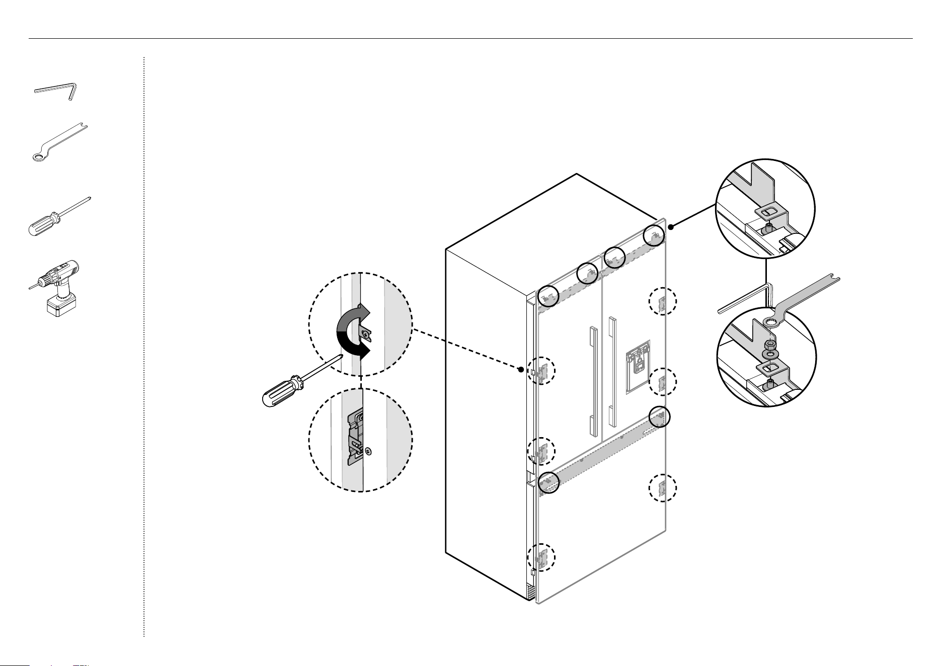
32
Attach the door panels
1
Open the door and loosen the M5x10 cross-head screws
(do not remove) at the sides of the doors (A).
2
Hang the door panel by inserting the M8 studs
through the holes of the hanging bracket (B).
3
Slide the forks of the side brackets onto the
screws of the door (C).
4
Screw the M8 washer and nut to each stud (D),
and re-tighten the side screws (E) to fix the
door panel (do not fully tighten). This will
allow opening the door without affecting
adjustment of the door panel.
B
D
C
A
E
Tools
Hex key
FPA spanner
(1)
Cross-head screwdriver
Powered driver (optional)
!9 DOOR PANEL INSTALLATION — CUSTOM
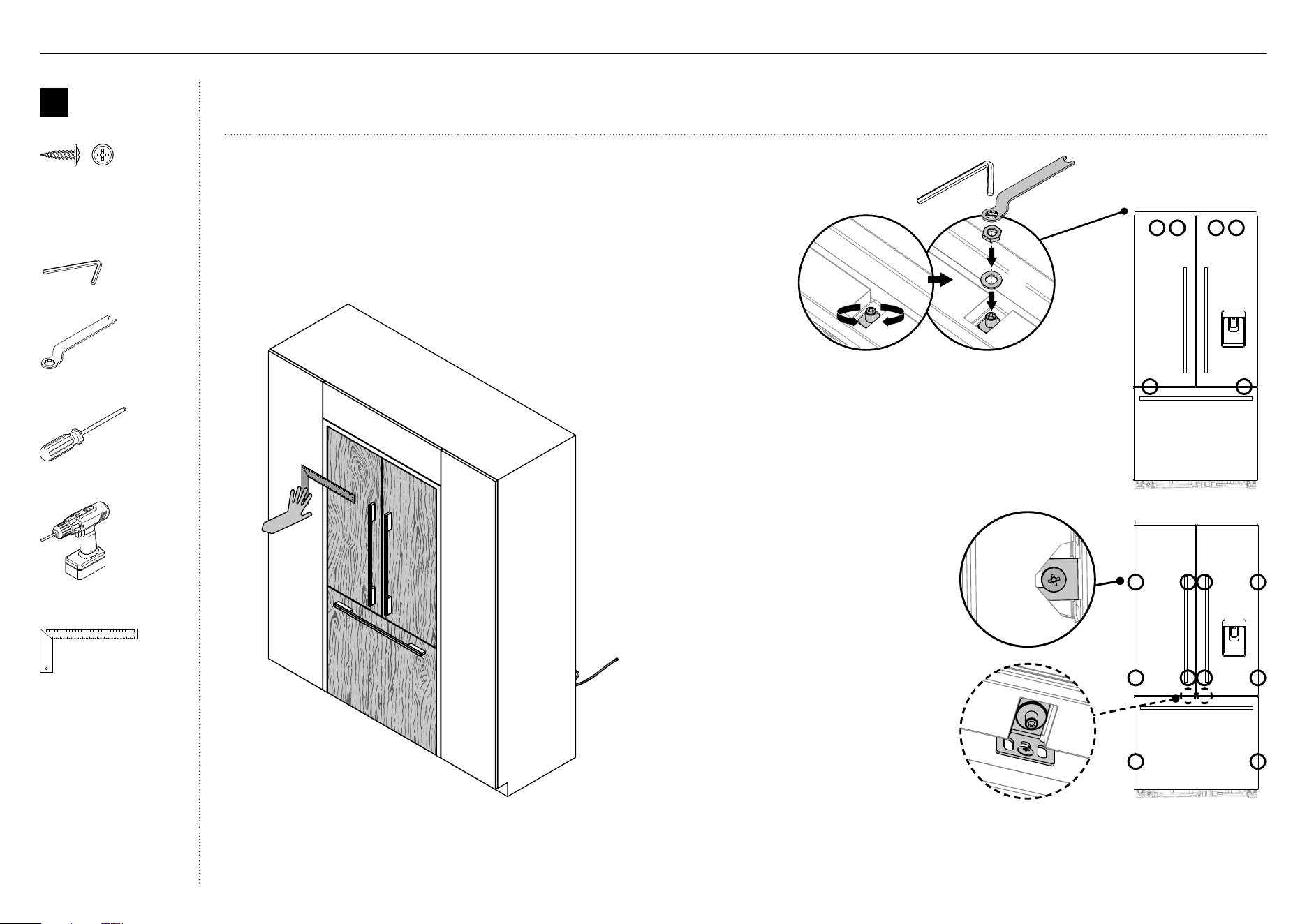
33
Adjust the door panels
1
Push the appliance into the cavity until the door panels are flush
with adjacent cabinetry.
2
Place a ruler on the front of the appliance to check flushness top
and bottom, left and right.
IMPORTANT!
●
Follow these steps to avoid difficulties in door panel adjustment and cosmetic cap fitment.
!9 DOOR PANEL INSTALLATION — CUSTOM
2
Each door panel has full axis adjustment to ensure flushness
with adjacent walls. To adjust the height of the panel, turn the
stud clockwise to raise or counter-clockwise to lower the door
panel (A).
3
Once satisfied with the alignment, secure M8 studs with M8
washer and M8 nut (B). The top of the stud must remain below
the top face of the door panel.
4
Secure side bracket forks by tightening
side screws(C).
Repeat for all door panels.
Note:
– For depth adjustment, loosen the
side screws, adjustthe panels and
then retightenoncesatisfied.
– Further adjustment of door panels
can be achieved by removing door
panels then looseningthe fixing
screws for the hanging bracket and
moving the bracket sideways to suit.
5
Loosen the M8 stud (D) so that locking
bracket can slide freely back to front.
– Slide the locking bracket out until it
touches the back of the door panel.
Fully tighten the M8 stud.
– Screw in place using a #8x16 screw
through one ofthe three slotted
holes.
C
B
A
D
B
Door panel
attachment
kit
#8 x 16
Mush Washer
Twin Thread
Philips Screw
#8 x 16
Mush Washer
Twin Thread
Philips Screw
8x16 mush washer screw
(1)
Tools
Hex key
FPA spanner
Cross-head screwdriver
Powered driver (optional)
Ruler
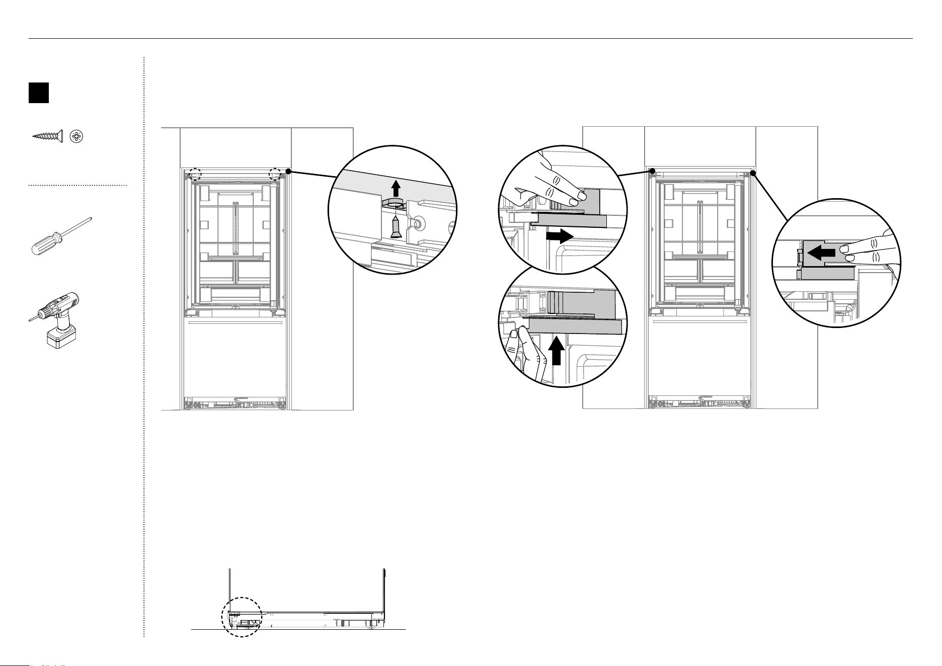
34
Internal box
X
Install
fasteners kit
#8 x 19
Countersunk
Twin Thread
Posi Screw
#8 x 19
Countersunk
Twin Thread
Posi Screw
#8Gx19 twin thread
screw (2)
Tools
Cross-head screwdriver
Powered driver (optional)
Secure the hinge bracket to cabinetry
1 Secure the hinge bracket to the ceiling of the
cabinetry with #8Gx19 twin thread screw (A).
Repeat on the opposite side.
2 Lower the front feet until it engages the floor to
provide more stability to the appliance and prevent
back and forth movement.
Reattach the hinge end caps
3 Reattach the left hinge end cap (B).
z
Align hinge cap to the appliance, press
andfirmly slide the cap to the right.
z
Hold onto the corner of the end cap,
firmly push up and to the left to engage
securing hook. Ensure cap is flush with
the appliance.
150
C
180
L
O
P
B
150
C
180
L
O
P
C
4 Reattach right hinge end cap (C).
z
Align hinge cap to appliance, press
and firmly slide the cap to the left.
z
Ensure cap is flush with the appliance.
IMPORTANT!
Lower the feet until it engages the floor to provide more stability to the
appliance and prevent back and forth movement.
@0 FIXING TO CABINETRY
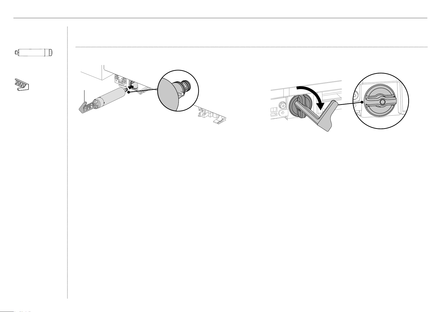
35
IMPORTANT!
●
The water filter head must be firmly pushed into the appliance and secured. incorrect installation can lead to water leaks.
4
Align the filter removal tool over the filter handle and turn 90° clockwise
to tighten (B). Remove filter removal tool and close the freezer drawer.
IMPORTANT!
●
Before turning on your automatic ice maker, the water filter must be
flushed to remove any impurities or trapped air in the water tank and
filter system.
●
Refer to the user guide ‘Operating instructions — Automatic ice maker’
for more information.
Install the water filter
1
Remove the plastic wrapping of the new filter.
2
Pull the freezer drawer out slightly and insert the filter into the casing
at the bottom left corner of the appliance. Ensure the filter handle is
positioned vertically (A).
3
Push the cartridge firmly inside the casing all the way into the filter head.
Filter in locked position
B
A
FRONT VIEW
Filter
handle
Miscellaneous
itemspack
Water filter
(1)
Filter cartridge tool
(1)
@1 WATER FILTER INSTALLATION
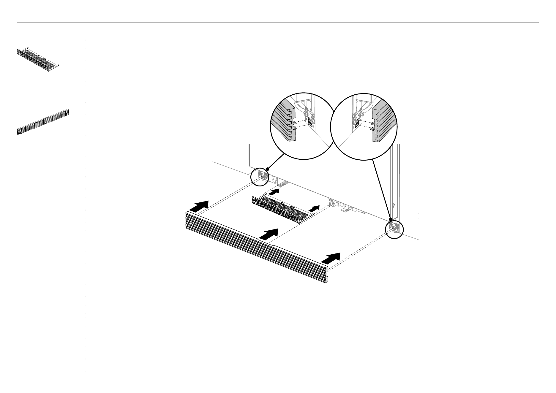
36
B
A
Install the toe kick filter and grille
1
Fit the filter onto the rails and push until it clips securely (A).
2
Alignthe top grille clips to the top plinth slots. Ensure the top grille is in the correct orientation (B).
3
Push the grille firmly onto the appliance until the clips engage (C).
MI Pack
Toe kick filter
(1)
External box
Toe kick grille
(1)
C
@2 TOE KICK INSTALLATION
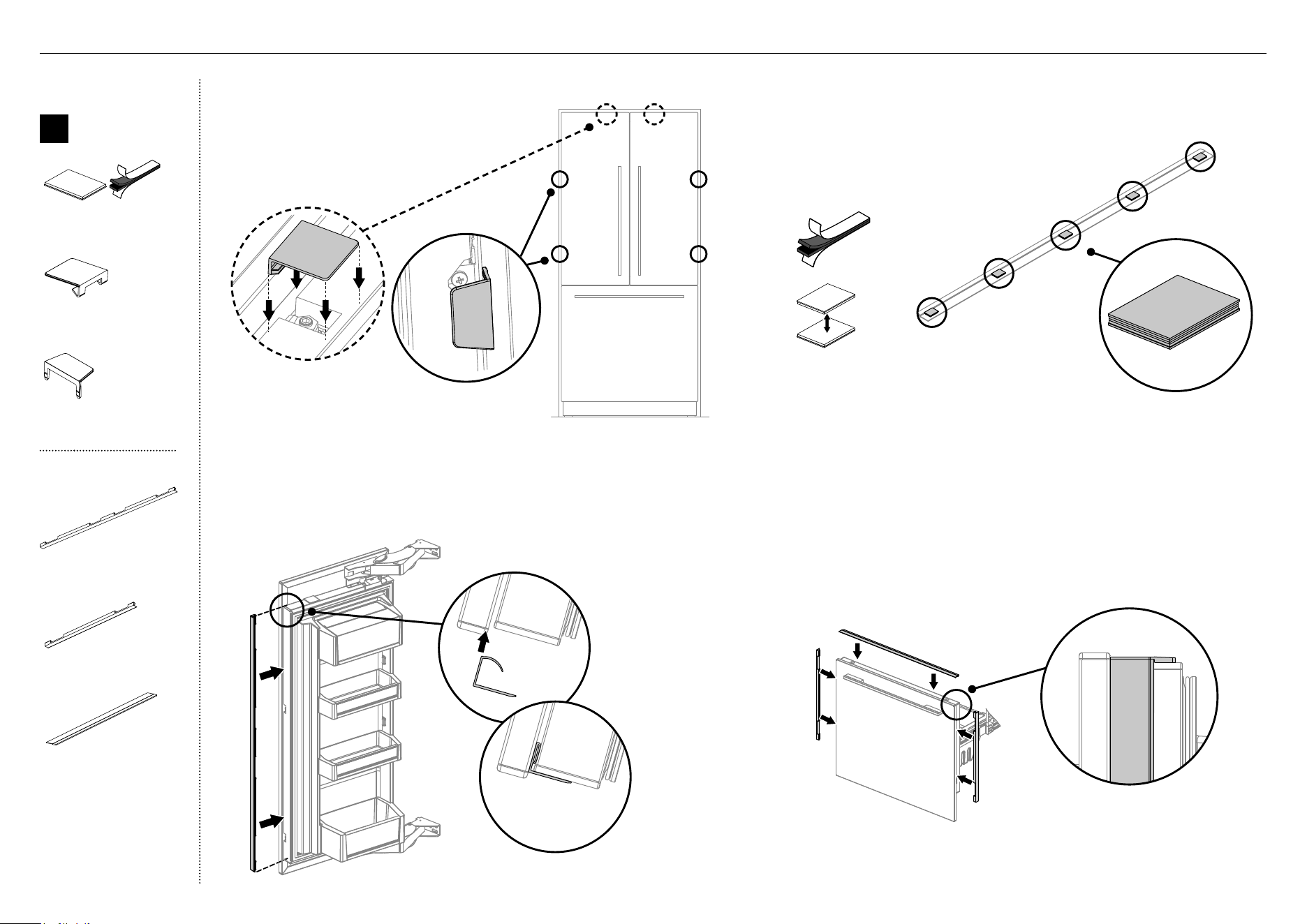
37
Attach the covers
1
Open the French doors.
Attach the top covers (A) firmly
over the top studs, and the side
covers (B) to the side brackets.
Attach the door side trims
2
Install the side trims by inserting into the panel gaps on each
side of the door(s) (C). Align the trim to the top of the door
and press evenly into the panel gap until fully seated (D).
C
D
A
B
F
Attach the drawer top and side trims
3
Peel off two dual adhesive tabs and press them together
to form a pair (E). Remove the adhesive backing on one
side only.
4
Press firmly to the underside of the drawer top trim
inthe indicated locations (F).
5
Remove the remaining adhesive backing from the dual adhesive tabs.
6
Locate the trim against the back surface of the panel and press down firmly.
Ensure the trim is fully seated against the drawer surface (G).
7
Install the side trims by inserting into the panel gaps on each side of the
door(s) (H).
– Make sure the cabinet is centered to prevent the side trims
frominterfering with the cabinet.
G
H
Internal box
C
Door / drawer
trim install kit
Dual adhesive tabs
(12)
Top cover
(2)
Side cover
(4)
External box
Door side trim
(2)
Drawer side trim
(2)
Drawer top trim
(1)
@3 COVERS AND TRIMS INSTALLATION
C

FISHERPAYKEL.COM
© Fisher & Paykel Appliances 2019. All rights reserved.
The appliance specifications in this document apply to the specific
appliances and models described at the date of issue. Under our policy
of continuous appliance improvement, these specifications may change
at any time. You should therefore check with your Dealer to ensure this
booklet correctly describes the appliance currently available.
Complete and keep for safe reference:
Model ____________________________________________________________
Serial No. ____________________________________________________________
Purchase Date ____________________________________________________________
Purchaser ____________________________________________________________
Dealer Address ____________________________________________________________
Installer’s Name ____________________________________________________________
Installer’s Signature ____________________________________________________________
Installation Company ____________________________________________________________
Installation Date ____________________________________________________________
TO BE COMPLETED BY THE INSTALLER
All models
Ensure all internal and external packaging is removed from the
appliance before use.
Check all parts are installed.
Ensure the appliance is level.
Ensure the appliance is securely fastened to the cabinetry with the
supplied anti-tip bracket and fittings.
Ensure the doors / drawer can open and close freely with no
resistance from surrounding cabinetry.
Ensure hinge limiting pin is fitted for 90° door swing.
Ice and Water models only
Ensure the water filtration system has been flushed.
Ensure a manual ice maker cycle has been forced.
@4 FINAL CHECKLIST