To Reduce The Risk Of Injury, User Must Read And
Understand Operator’s Manual. Save These Instructions For Future Reference.
260-9479
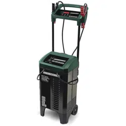
12/24V 300A Rolling Charger

TABLE OF CONTENTS
Safety Symbols..............................................................................Page 3
Safety Information..........................................................................Page 4
Important Safety Instructions........................................................Page 5
Personal Safety Precautions.........................................................Page 6
Grounding And Ac Power Cord Connections.............................. Page 6
Assembly Instructions...................................................................Page 7
Overview..........................................................................................Page 8
Specification...................................................................................Page 9
Display Messages.......................................................................... Page 9
Connecting To The Battery..........................................................Page 10
Operating Steps...........................................................................Page 11
Engine Start..................................................................................Page 12
Repair............................................................................................Page 12
Alternator Check.......................................................................... Page 13
Charging Stages.......................................................................... Page 13
Maintenance And Care................................................................ Page 14
Error Code................................................................ ....................Page 14
Warranty................................................................ .......................Page 19
Page 3
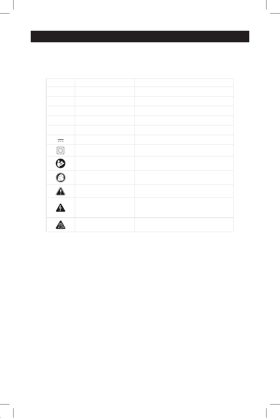
SAFETY SYMBOLS
Some of the following symbols may be used on your charger. Please study
them and learn their meaning. Proper interpretation of these symbols will allow
better and safer operation of the charger.
Symbol Name Designation/Explanation
V Volts Voltage
A Amperes Current
Hz Hertz Frequency
W Watts Power
~ Alternating current Type of current
Direct current Type or characteristic of current
Class II construction Double-insulated construction
Read the operator’s
manual
To reduce the risk of injury, read and
understand the operator’s manual
Wear safety equipment
Operation of the charger can result in
damage to unprotected person
Warning symbol Alerts user to warning message
Electric shock symbol
Connect only to properly grounded
outlets. Replace defective cords or
wire immediately.
Explosive gas symbol
Risk of explosive gases during normal
operation of a lead-acid battery
Page 4
SAFETY INFORMATION
The purpose of safety symbols is to attract our attention to possible dangers. The
safety symbols, and the explanations with them, deserve your careful attention and
understanding. The symbol warnings do not by themselves eliminate any danger.
The instructions and warnings they give are no substitutes for proper accident pre-
vention measures.
Be sure to read and understand all safety instructions in this
manual, including all safety alert symbols, such as “DANGER”, “WARNING” and
“CAUTION” before using this battery charger. Failure to follow all instructions
listed below may result in electric shock, fire and/or serious personal injury.
SYMBOL MEANING
SAFETY ALERT SYMBOL: Indicates DANGER, WARNING or CAUTION.
May be used in conjunction with other symbols or pictographs.
Failure to obey this safety warning WILL result in death or serious
injury to yourself or to others. Always follow the safety precautions to reduce the risk
of fire, electric shock and personal injury.
Failure to obey this safety warning CAN result in death or
serious injury to yourself or to others. Always follow the safety precautions to
reduce the risk of fire, electric shock and personal injury.
Failure to obey this safety warning MAY result in personal
injury to yourself or others, or property damage. Always follow the safety precautions
to reduce the risk of fire, electric shock and personal injury.

Page 5
1. IMPORTANT SAFETY INSTRUCTIONS
Read and understand all Important Safety
and Operating instructions before using
this charger. In addition, read and follow
all battery and vehicle manufacturer’s
instructions and cautionary markings.
SAFETY PRECAUTIONS FOR WORKING
IN THE VICINITY OF A BATTER
Batteries generate explosive gases
during normal operation. Use in
well-ventilated area.
Consider having someone close
enough or within the range of your
voice to come to your aid when you
work near a battery.
Do NOT smoke, strike a match, or
cause a spark in vicinity of battery or
engine. Avoid explosive gas, flames
and sparks.
Remove all personal jewelry, such as
rings, bracelets, necklaces, and
watches while working with a vehicle
battery. These items may produce a
short circuit that could cause severe
burns.
Be extra cautious to reduce risk of
dropping a metal tool onto the
battery. It might spark or short-circuit
a battery or other electrical hardware
which may cause explosion or fire.
Wear complete eye protection, hand
and clothing protection. Avoid touch-
ing eyes while working near a battery.
Study all battery manufacturer’s
specific precautions such as remov-
ing or not removing cell caps while
charging and recommended rates of
charge.
Clean battery terminals before
connected with the charger. Be
careful to keep corrosion from
coming in contact with eyes.
When it is necessary to remove a
battery from vehicle to charge,
always remove grounded terminal
from battery first. Make sure all
accessories in the vehicle are off in
1.
2.
3.
4.
5.
6.
7.
8.
9.
order to prevent an arc.
This product is NOT intended to
supply power to an extra-low-voltage
electrical system or to charge dry-cell
batteries. Charging dry-cell batteries
may burst and cause injury to
persons and property.
NEVER charge a frozen, damaged,
leaking or non-rechargeable battery.
If battery electrolyte contacts skin or
clothing, wash immediately with soap
and water. If electrolyte enters eye,
immediately flood eye with running
clean cold water for at least 15
minutes and get medical attention
immediately.
10.
11.
12.
SAFETY PRECAUTIONS FOR USING
THE CHARGER
Do NOT place the charger in the
engine compartment or near moving
parts or near the battery; place as far
away from them as DC cable permits.
NEVER place a charger directly
above a battery being charged; gases
or fluids from battery will corrode and
damage charger.
Do NOT cover the charger while
charging.
Do NOT expose to rain or wet condi-
tions.
Connect and disconnect DC output
only after setting AC cord from
electric outlet.
Use of an attachment not recom-
mended or sold by the manufacturer
may result in a risk of fire, electric
shock or injury to persons.
Do not overcharge batteries by
selecting the wrong charge mode.
To reduce the risk of damage to
electric plug and cord, pull by the
plug rather than the cord when
disconnecting charger.
To reduce risk of electric shock,
unplug charger from outlet before
attempting any maintenance or
cleaning.
1.
2.
3.
4.
5.
6.
7.
8.

Page 6
Operate with caution if the charger
has received direct hit of force or
been dropped. Have it checked and
repaired if damaged.
9.
This battery charger is for use on a nomi-
nal 120 volt circuit. The plug must be
plugged into an outlet that is properly
installed and grounded in accordance
with all local codes and ordinances. The
plug pins must fit the receptacle (outlet).
Do not use with an ungrounded system.
Use of an adapter plug is not recom-
mended; an adaptor plug should not be
used.
USING AN EXTENSION CORD
Pins sockets on the extension cord
plug must be the same number, size,
and shape as those of plug on
charger.
Ensure that the extension cord is
properly wired and in good electrical
condition.
Wire size must be large enough for
the AC ampere rating of the charger,
as specified below:
3.1
3.2
3.3
The use of an extension cord is not
recommended. If you must use an exten-
sion cord, follow these guidelines:
Length of cord (feet) 25 50 100 150
AWG* size of cord 18 16 14 14
Any repair must be carried out by the
manufacturer or an authorized repair
agent in order to avoid danger.
10.
3. GROUNDING AND AC POWER CORD CONNECTIONS
Never alter the AC
cord or plug provided – if it does not
fit the outlet, have a proper grounded
outlet installed by a qualified elec-
trician. An improper connection can
result in a risk of an electric shock or
electrocution.
2. PERSONAL SAFETY PRECAUTIONS
2.7
Remove personal metal items such
as rings, bracelets, necklaces, and
watches when working with a lead-
acid battery. A lead-acid battery can
produce a short-circuit current high
enough to weld a ring or the like to
metal, causing a severe burn.
2.8
Use charger for charging only
LEAD-
ACID, AGM and GEL-type rechargeable
batteries with rated capacities of
30 -
It is not intended
to supply power to a low voltage
electrical system other than in a
starter-motor application. Do not use
battery charger for charging dry-cell
batteries that are commonly used with
home appliances. These batteries may
burst and cause injury to persons
and
damage to property.
2.9
NEVER charge a frozen battery.
2.1
Consider having someone close
enough by to come to your aid when
you work near a lead-acid battery.
2.2
Have plenty of fresh water and soap
nearby in case battery acid contacts
skin, clothing, or eyes.
2.3
Wear complete eye protection and
clothing protection. Avoid touching
eyes while working near battery.
2.4
If battery acid contacts skin or cloth-
ing, wash immediately with soap and
water. If acid enters eye, immediately
flood eye with running cold water for
at least 10 minutes and get medical
attention immediately.
2.5
NEVER smoke or allow a spark or
flame in vicinity of battery or engine.
2.6
Be extra cautious, to reduce risk of
dropping a metal tool onto battery.
It might spark or short-circuit bat-
tery or other electrical part that may
cause explosion.
550 Ah (12V / 24V ).
Page 7
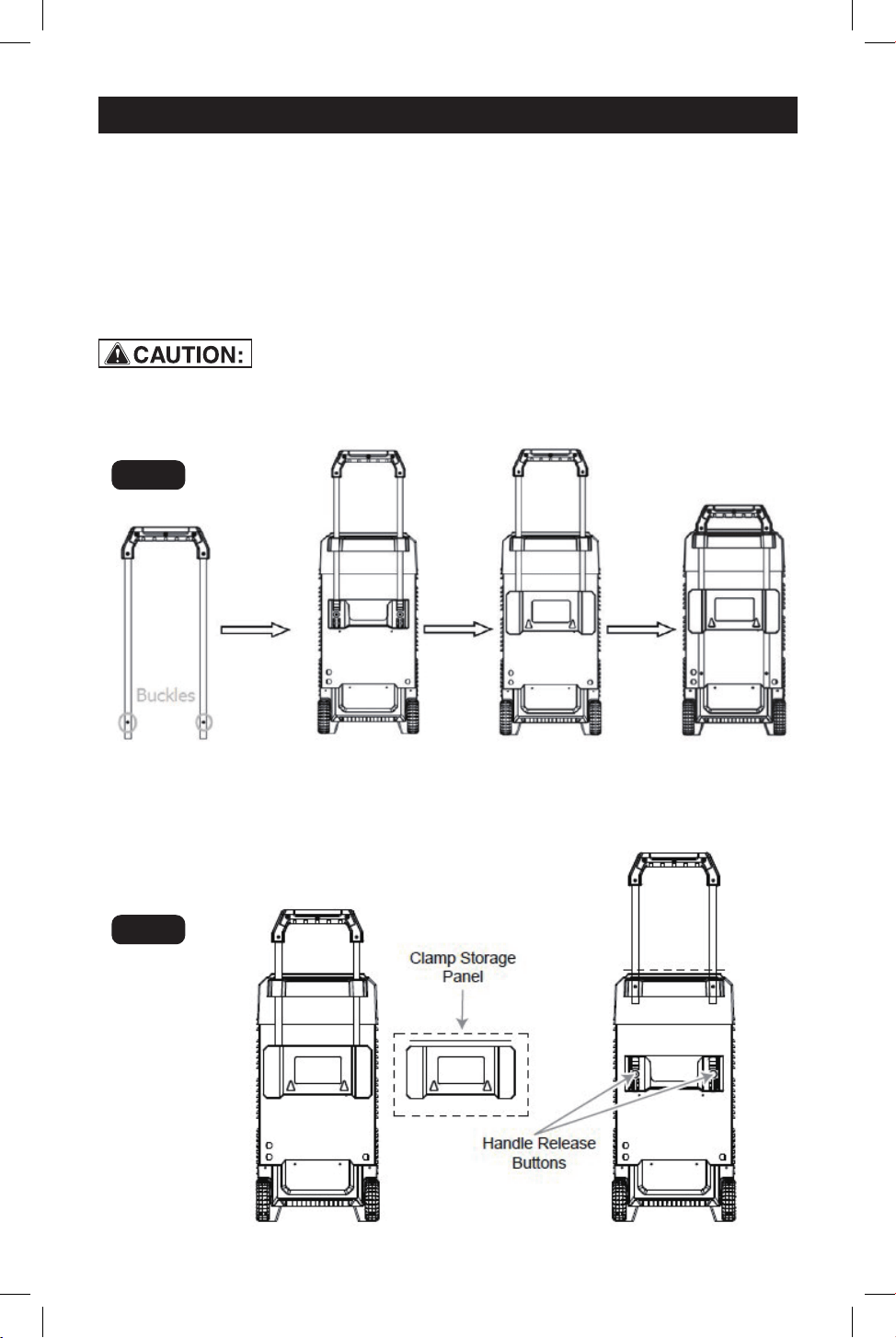
4. ASSEMBLY INSTRUCTIONS
4.1
4.3
It is important to fully assemble your
charger before use. Remove all cord
wraps and uncoil the cables prior
to using the battery charger. Follow
these instructions for assembly.
remove the clamp storage panel by
pulling up-wards on it, then use a
thin, durable tool (i.e. a screwdriver)
to depress the two buckles at the
bottom of the handle. Once
depressed, push the handle to put
the clamp storage panel back on.
If you want to store the charger,
simply press down the buckles once
more and push handle downward
into the bottom most position.
Then depress the handle release
buttons and raise or lower the handle
as desired. Return the Clamp
Storage Panel to the lowered
position when finished.
Fig. 1
Fig. 2
Take care not to pinch
or damage cable during handle installation.
Charger will not function properly if this
cable is damaged.
When you take the charger out
from the package, the handle is
uninstalled. To install the handle, first
4.2
Page 8
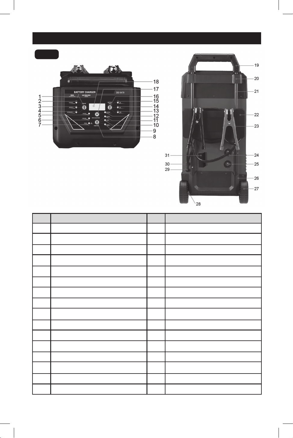
5. OVERVIEW
No.
1
2
3
4
5
6
7
8
9
10
11
12
13
14
15
16
No.
17
18
19
20
21
22
23
24
25
26
27
28
29
30
31
Features
Display Button
Voltage LED Indicator
Battery % LED Indicator
Alternator % LED Indicator
Charged LED Indicator
Charging LED Indicator
Error LED Indicator
Function Button
Repair LED Indicator
Start LED Indicator
Charge LED Indicator
Current LED Indicator
AGM LED Indicator
GEL LED Indicator
STD LED Indicator
Battery Type Button
Features
Rete Selection Button
Digital Display
Handle
Function Display Panel
Metal Bars
Winding Clamp
Positive Battery Clamp
24V Quick Connector
12V Quick Connector
The Pedestal of a Charger
Wheel
Metal Axis of the Wheel
Negative Battery Clamp
Power Supply
50A x 3 Fuse
Fig. 3
Page 9
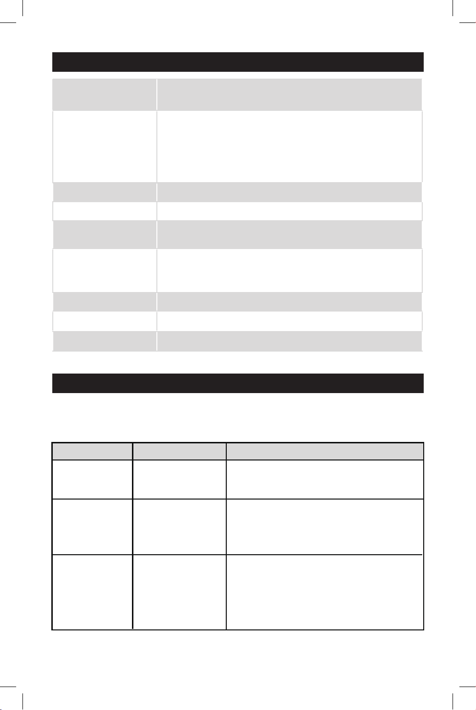
11. OPERATING INSTRUCTIONS6. SPECIFICATION
AC Input AC 120V 60Hz, 3000W Max.(For Charger Mode),
9000W Max.(For Starter Mode)
DC Output
Temperature Controlled
Charge: 12/24VDC, 6A/30A
Boost: 12/24VDC, 60A-180 SECONDS, 30A-60 SECONDS.
Engine Start: 300A INTERMITTENT 5 SECONDS ON,
240 SECONDS OFF
Charger Type 10 Step, Fully Automatic Charging Cycle
Start Voltage > 1V
Safety Feature
Spark Proof, Protection for Reverse Polarity, Short Circuit,
Overheat, Overcharge and Over-current
Battery Type
All Types of 12V Lead-acid and 24V Lead-acid Batteries,
Including WET (Flooded), MF (Maintenance-Free), EFB
(Enhanced Flooded Battery), GEL, AGM (Absorbed Glass Mat)
Battery Capacity 30-550Ah(12V/24V) and Maintains All Battery Sizes
Accessories Included Clamp Connectors
Ambient Temperature 32ºF ~ 104ºF
11. OPERATING INSTRUCTIONS7. DISPLAY MESSAGES
START UP – After display screen and all LEDs illuminate for 0.5 second, battery voltage
shows.
Digital display LED indicator
Battery-voltage Voltage LED lit
When the charger is NOT working in
ENGINE START, the display will show
the battery VOLTAGE.
When the charger is NOT working in
ENGINE START, the digital display shows
percentage of the battery connected to
the charger’s battery clamps.
Battery - % Battery % LED lit
Description
DISPLAY MODE BUTTON
The digital display shows an estimated
output percentage of the vehicle’s charging
system connected to the charger’s battery
clamps, compared to a properly functioning
system. The alternator percent range is from
0% to 100%. Readings below 0% (13.2 volts
Alternator - % Alternator % LED lit
Page 10
Quick connector
selected
LED indicator
12V
STD LED lit
24V
GEL LED lit
AGM LED lit
STD LED lit
GEL LED lit
AGM LED lit
Description
BATTERY TYPE BUTTON
(GEL)-Charged Voltage is 14.5V. When charging,
pressing this button does NOT work.
(AGM)-Charged Voltage is 14.8V. When charging,
pressing this button does NOT work.
(STANDARD)-Charged Voltage is 14.4V. When
charging, pressing this button does NOT work.
((GEL)-Charged Voltage is 29V. When charging,
pressing this button does NOT work.
(AGM)-Charged Voltage is 29.6V. When charging,
pressing this button does NOT work.
(STANDARD)-Charged Voltage is 28.8V. When
charging, pressing this button does NOT work.
Mode Explanation
START
REPAIR
CHARGE
ENGINE START selection
REPAIR mode selection
CHARGE-6A/30A or BOOST mode selection
FUNCTION SELECTION BUTTON
/26.4 volts) will read LO and readings above
100% (14.6 volts/29.2 volts) will read HI. If
you get a HI or LO reading, have the electrical
system checked by a qualified technician.
8. CONNECTING TO THE BATTERY
A SPARK NEAR BATTERY MAY CAUSE
AN EXPLOSION.
IMPORTANT: Do not start the vehicle with
the charger connected to the AC outlet,
or it could damage the charger.
NOTE:
Current will not be supplied to the
battery clamps until a battery is properly
connected. The clamps will not spark if
touched together.
Identify polarity of battery posts. The
positive battery terminal is typically
marked by these letters or symbol
(POS, P, +). The negative battery
terminal is typically marked by these
letters or symbol (NEG, N, –).
Do not make any connections to the
carburetor, fuel lines, or thin metal
parts.
8.1
8.2
Page 11
Identify if you have a negative or
positive grounded vehicle. This can
be done by identifying which battery
post (NEG or POS) is connected to
the chassis.
For a negative grounded vehicle
(most common): connect the RED
POSITIVE clamp first to the positive
battery terminal, then connect the
BLACK NEGATIVE clamp to the
negative battery terminal or vehicle
chassis.
For a positive grounded vehicle (very
uncommon): connect the BLACK
8.3
8.4
8.5
NEGATIVE clamp first to the
negative battery terminal, then
connect the RED POSITIVE clamp to
the positive battery terminal or
vehicle chassis.
When disconnecting, disconnect in
the reverse sequence, removing the
negative first (or positive first for
positive ground systems).
A marine (boat) battery must be
removed and charged on shore. To
charge it on board requires equip-
ment specially designed for marine
use.
8.6
8.7
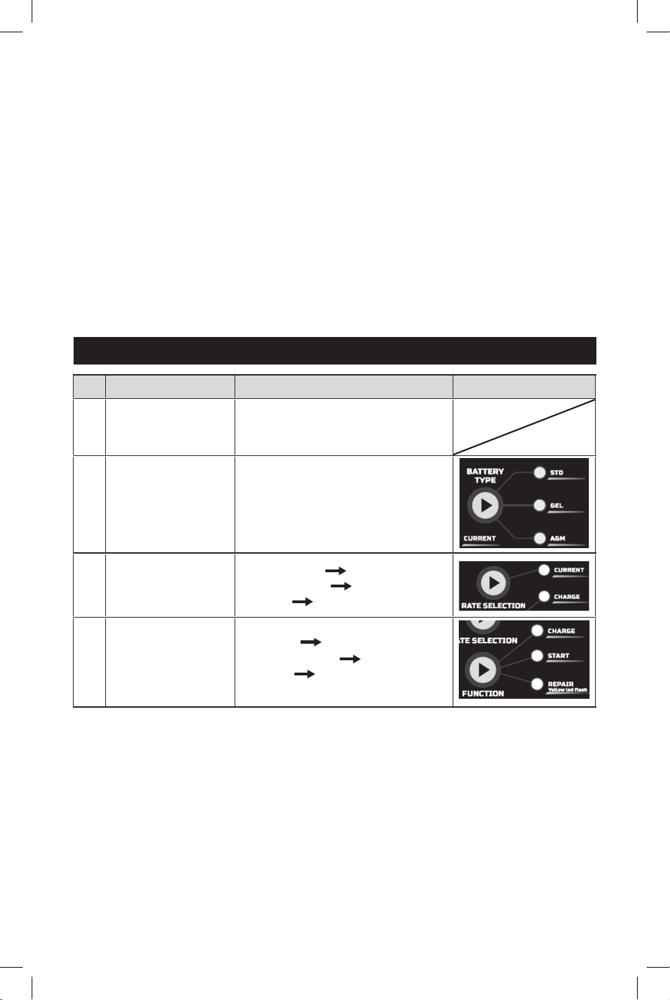
Step
Correctly connect
the charger to
the battery
Confirm battery type
Confirm RATE
SELECTION
Confirm FUNCTION
1
2
3
4
No
Connected battery voltage
Corresponding battery type LED
NORMAL-6A “C06A”
NORMAL-30A “C30A”
BOOST “C60A”
CHARGE “CHARGING”
ENGINE START
“START-READY”
REPAIR “REPAIR-ON”
Digtal Display Step select key
9. OPERATING STEPS

Page 12
10. ENGINE START
Provides additional amps for cranking an
engine with a weak or run-down battery.
Always use in combination with a battery.
Must NOT touch or disconnect clamps
when ENGINE START mode works, other-
wise there may be serious injuries to
people or property.Your battery charger
can be used to jump start your car if the
battery is low. Follow all safety instruc-
tions and precautions for charging your
battery. Wear complete eye protection
and protective clothing. The procedures
are as follows.
Using the ENGINE START feature WITH-
OUT a battery installed in the vehicle will
damage the vehicle’s electrical system.
Connect the charger to the battery
following the instructions given in
the CONNECTING TO THE BATTERY
section.
With the charger plugged in and
connected to the battery and
chassis, press FUNCTION button
until the START LED is lit.
Crank the engine until it starts or 3
seconds pass. If the engine does not
start, wait 4 minutes before cranking
again. This allows the charger and
battery to cool down.
If the engine fails to start, use the
CHARGE maximum rate (60A) to
charge for some minutes before
attempting to crank the engine again.
NOTE: If the engine does turn over but
never starts, there is not a problem with
the starting system; there is a problem
somewhere else with the vehicle. STOP
cranking the engine until the other problem
has been diagnosed and corrected. During
the starting sequence listed above, the
charger is set to one of three states:
If engine starts for a long time, the fuse
may blew, you need to replace all the 3
fuses by thenat a time.
Wait for cranking – While waiting for
cranking, the digital display shows
START-READY. The charger waits until
the engine is actually being cranked
before delivering the amps for engine
start.
Cranking – When cranking is detected,
the charger will automatically deliver up
to its maximum output as required by
the starting system for up to 5 seconds.
Cool Down – After cranking, the charger
enters a mandatory 240 seconds cool
down state (Pressing any button does
NOT work). The digital display indicates
the remaining cool down time in
seconds. It starts at 240 and counts
down to 0. After 4 minutes, the digital
display will change from displaying the
countdown to displaying START-READY.
10.1
10.2
10.3
10.4
11.1 11.2
10.5
•
•
•
After the engine starts, unplug the
AC power cord before disconnecting
the battery clamps from the vehicle.
11. REPAIR
Press FUNCTION button until the
REPAIR LED is lit to enter this mode
(digital display shows REPAIR-ON).
It is an advanced battery recovery
mode for repairing old, idle, stratified
or sulfated batteries. NOT all batter-
ies can be recovered. This mode
uses a high charging voltage and
may cause some water loss in WET
cell batteries.
Plus, some batteries and electronics
may be sensitive to high charging
voltages. To minimize risks, discon-
nect the battery from the vehicle
before using this mode. To stop
repairing, press FUNCTION button
again and REPAIR LED will be off
(digital display shows REPAIR-OFF).
Page 13
12. ALTERNATOR CHECK
Before the charger is connected
with the battery which is well settled
in the vehicle and Alternator % LED
is lit (press DISPLAY button), start
the vehicle and turn on the vehicle’s
headlights. The alternator percent
range is from 0% to 100%.
Readings below 0% will read LO
and readings above 100% will read
HI. If you get a HI or LO reading,
have the electrical system checked
by a qualified technician.
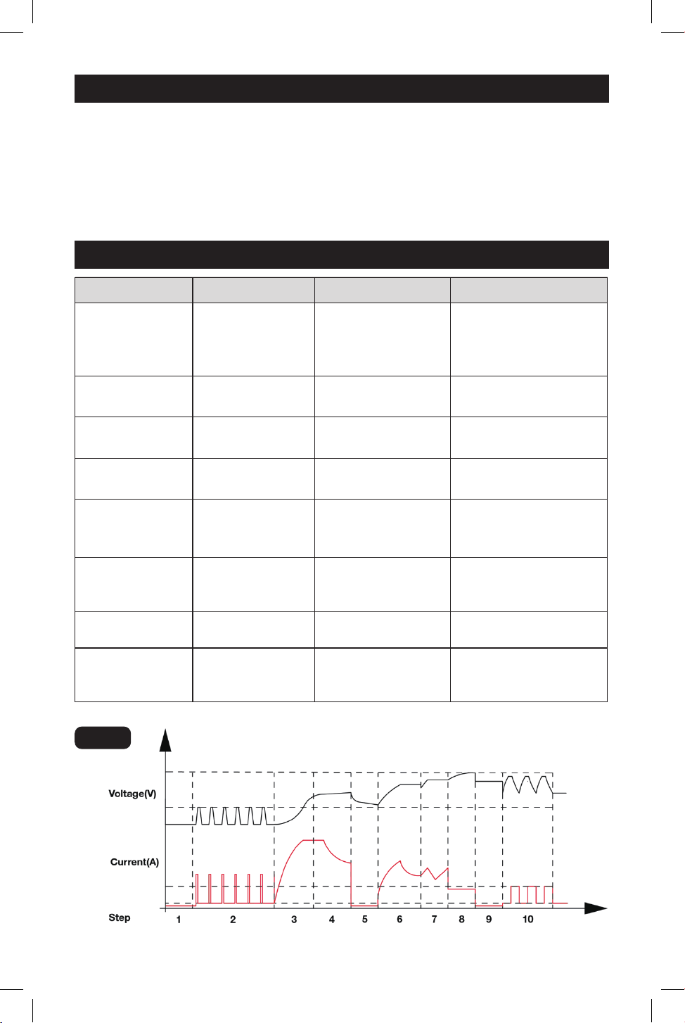
13. CHARGING STAGES
Step Digital display LED indicator Charging state
ANALYSIS-1
ANALYSING-1
BATT-12/24
DESULPHATION
CHARGING
BATT-12/24
CHARGING LED lit
BULK
ANALYSIS-2
ABSORPTION
FLOATING
ANALYSIS-3
MAINTAINING
CHARGING LED lit
CHARGING LED lit
CHARGING LED lit
CHARGING LED lit
CHARGING LED lit
CHARGING or
CHARGED
/MAINTAINING LED
is out
Analyzing whether the
battery voltage type
and the current mode
match
Removing sulphate and
reactivating battery
Providing high current
to quick charge
Analyzing if the battery
can absorb current
Reducing the current
according to the
increase in voltage
Maintaining the battery
voltage to continuously
absorb current
Analyzing if the battery
can store electric charge
The battery is charged
and the charger is
maintaining the battery
CHARGING
BATT-12/24
CHARGING
BATT-12/24
CHARGING
BATT-12/24
ANALYSING-2
BATT-12/24
ANALYSING-3
BATT-12/24
MAINTAINING
BATT-12/24
CHARGED/MAIN
TAINING LED lit
Fig. 4
12.1 12.2

Page 14
Digital
display
Warning LED
indicator
Meaning
Solution
20. ERROR CODE
19. MAINTENANCE AND CARE
A minimal amount of care can keep your
battery charger working properly for years.
• Clean the clamps each time you are
finished charging. Wipe off any battery
fluid that may have come in contact
with the clamps to prevent corrosion.
• Occasionally cleaning the case of the
charger with a soft cloth will keep the
finish shiny and help prevent corrosion.
• Coil the input and output cords neatly
when storing the charger. This will help
prevent accidental damage to the cords
and charger.
• Store the charger unplugged from the
AC power outlet in an upright position.
• Store the clamps on the storage areas
provided on the handle. Do not store
the clamps clipped together, on or
around metal, or clipped to the cables.
E00
E01
E02
E03
E04
BATT -
MISMATCH
WARNING
LED lit
The AC plug is removed.
Connect the AC plug
correctly.
Change red and black
clamps or ring terminals to
the correct battery posts.
DO NOT remove the AC
plug immediately. After
cooling down, the battery
charger will work again.
Replace the battery with a
new one or try the REPAIR
MODE.
1) Connect the red and black
clamps or ring terminals to
battery posts.
2) Clean the battery posts.
3) Replace the battery with
a new one immediately.
4) Disconnect red and black
output terminals.
Replace the battery or
connect the positive output
line to the correct connector.
The connections are
reversed.
Output current reduces
to 0 when temperature
in charger is too high.
The battery cannot store
electric charge
(dead battery).
No battery connected /
battery voltage is lower
than 1 volt (dead battery)
/ red and black clamps
are connected together.
Charging in 12V Mode
for 24V battery or
charging in 24V Mode
for 12V battery.
WARNING
LED lit
WARNING
LED lit
WARNING
LED lit
WARNING
LED lit
WARNING
LED lit

Page 15
NOTES

Page 16
NOTES

Page 17
NOTES

Page 18
NOTES

12/24V 300A Rolling Charger
WARRANTY
90-DAY MONEY BACK GUARANTEE
This MASTERFORCE™ brand battery charger carries our 90-Day Money Back
Guarantee. If you are not completely satisfied with your MASTERFORCE™
brand product for any reason within ninety (90) days from the date of purchase,
return the item with your original receipt to any MENARDS
®
retail store, and we
will provide you a refund – no questions asked.
3-YEAR LIMITED WARRANTY
This MASTERFORCE™ brand battery charger carries our famous No Hassle
3-Year Limited Warranty to the original purchaser. If, during normal use, this MAS-
TERFORCE™ product breaks or fails due to a defect in material or workmanship
within three (3) years from the date of original purchase, simply bring the item
with the original sales receipt back to your nearest MENARDS
®
retail store. At its
discretion, MASTERFORCE™ agrees to have the
item or any defective part(s)
repaired or replaced with the same or similar MASTERFORCE™ product or part
free of charge, within the stated warranty period, when returned by the original
purchaser with original sales receipt. Not withstanding the foregoing, this limited
warranty does not cover any damage that has resulted from abuse or misuse of
the Merchandise. This warranty: (1) excludes expendable parts including but not
limited to blades, brushes, belts, bits, light bulbs, and/or batteries; (2) shall be
void if this product is used for commercial and/or rental purposes; and (3) does
not cove
r any losses, injuries to persons/property or costs. This warranty does
give you specific legal rights and you may have other rights, which vary from
state to state. Be careful, battery chargers are dangerous if improperly used or
maintained. Seller’s employees are not qualified to advise you on the use of this
merchandise. Any oral representation(s) made will not be binding on seller or its
employees. The rights under this limited warranty are to the original purchaser
of the merchandise and may not be transferred to any subsequent owner. This
limited warranty is in lieu of all
warranties, expressed or implied including war-
ranties or merchantability and fitness for a particular purpose. Seller shall not be
liable for any special, incidental, or consequential damages. The sole exclusive
remedy against the seller will be for the replacement of any defects as provided
herein, as long as the seller is willing or able to replace this product or is willing
to refund the purchase price as provided above. For insurance purposes, seller
is not allowed to demonstrate any of these products for you.
For questions/comments, technical assistance or repair parts—
Please call toll free at: 1-877-898-3958.
Page 19
1. WARRANTY

© 2024 Menard, Inc., Eau Claire, WI 54703
01/2024