vikingrange.com
(662) 455-1200
Installation Guide
5-Series Panel-Ready Door Skin
For Full-Overlay Bottom-Mount Freezer
VCDBP536R I VCDBP536L
Five Series

• Before beginning, please read these instructions
completely and carefully.
• Use caution during assembly to minimize scratches
• Do not remove permanently axed labels, warnings,
or plates from the product. This may void warranty.
• The installer should leave instructions with the
customer who should retain for local inspector’s use
and future reference.
• These instructions are for the bottom-mount freezer.
Please confirm that you have the correct instructions
for the unit before moving on.
Model Description:
The tables below show the parts that come with each service kit. Please note that the Bottom-Mount Freezer kits
(VCDPB536) have an “R” or “L” in the kit number. This denotes the swing direction these kits were designed for. A
service kit with an “R” is for a right-hand (right hinge) product, while a kit with an “L” is for a left-hand (left hinge) product.
Installation Preparation
Installers, it is your responsibility to...
Installation of 5-Series Panel-Ready Door Skin
For Full-Overlay Bottom-Mount Freezer
Required Tools
• Electric Drill
• T15 Screwdriver (or bit)
• Phillips-head Screwdriver (or bit)
• Ratchet
• Stepladder or Stool
• Electrical Tape
Service Kit Part QTY
VCDBP536R
Door Skin Assembly, 36”, Right Hand, Painted 1
Drawer Skin Assembly, Painted 1
Door Top Spacer, Right Hand 1
Drawer Top Spacer 1
8-18 X 1 Torx-15 Truss Head Screws 10
Proud Side Trim 2
8X3/8” Phillips Head, Truss Head Screws 22
Spacer Screws 9
Snap Feature Screw Depth Gauge 1
Composite Door Shims 2
088589-000 Install Guide 1
VCDBP536L
Door Skin Assembly, 36”, Left Hand, Painted 1
Drawer Skin Assembly, Painted 1
Door Top Spacer, Left Hand 1
Drawer Top Spacer 1
8-18 X 1 Torx-15 Truss Head Screws 10
Proud Side Trim 2
8X3/8” Phillips Head, Truss Head Screws 22
Spacer Screws 9
Snap Feature Screw Depth Gauge 1
Composite Door Shims 2
088589-000 Install Guide 1
1
FRESH-FOOD DOOR INSTRUCTIONS
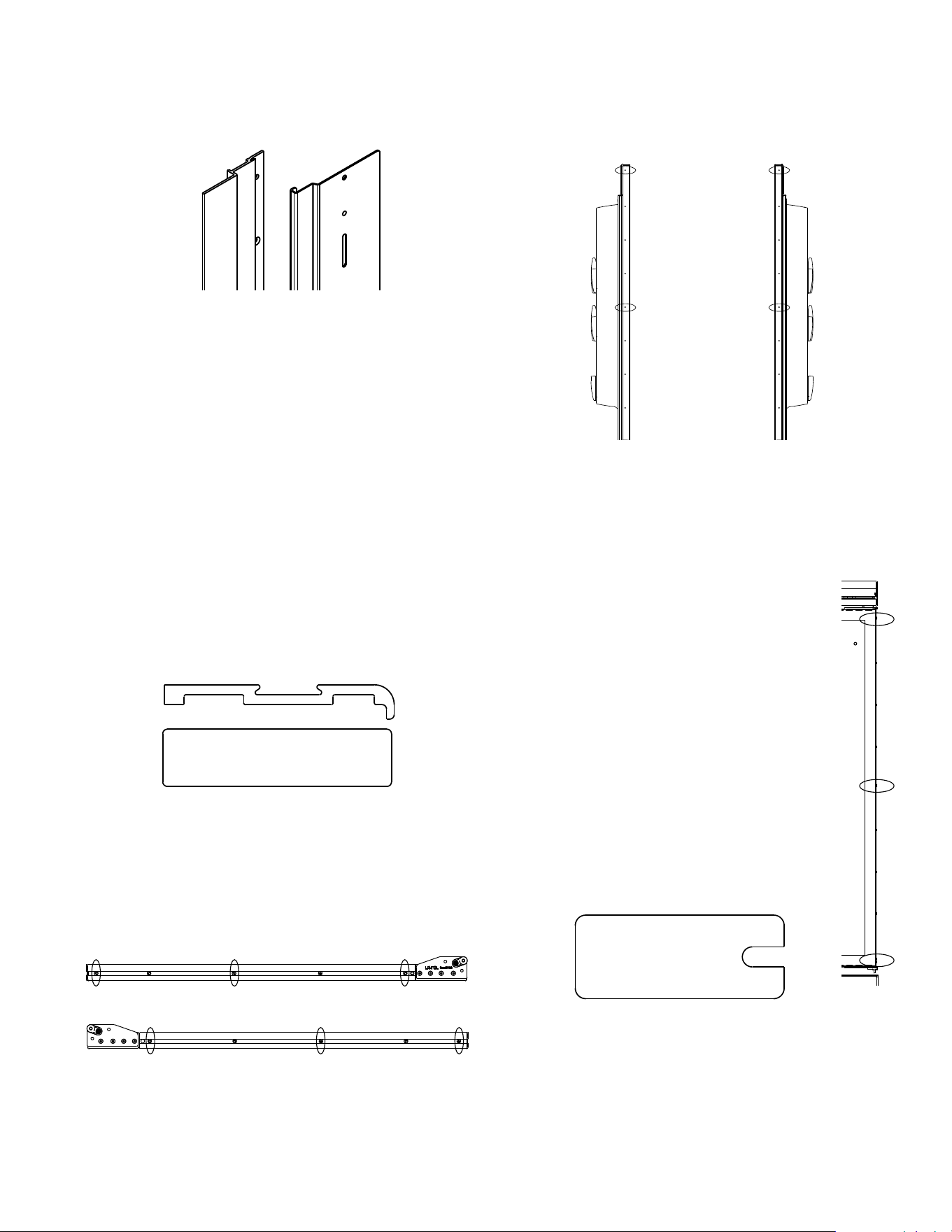
1. Remove the screws securing the flush-install trims to
the sides of the unit.
2. Set aside the flush-install trims and screws in a safe
location.
Left: Flush-mount Trim (PK290066); Right: BM Proud Trim
(PK910123)
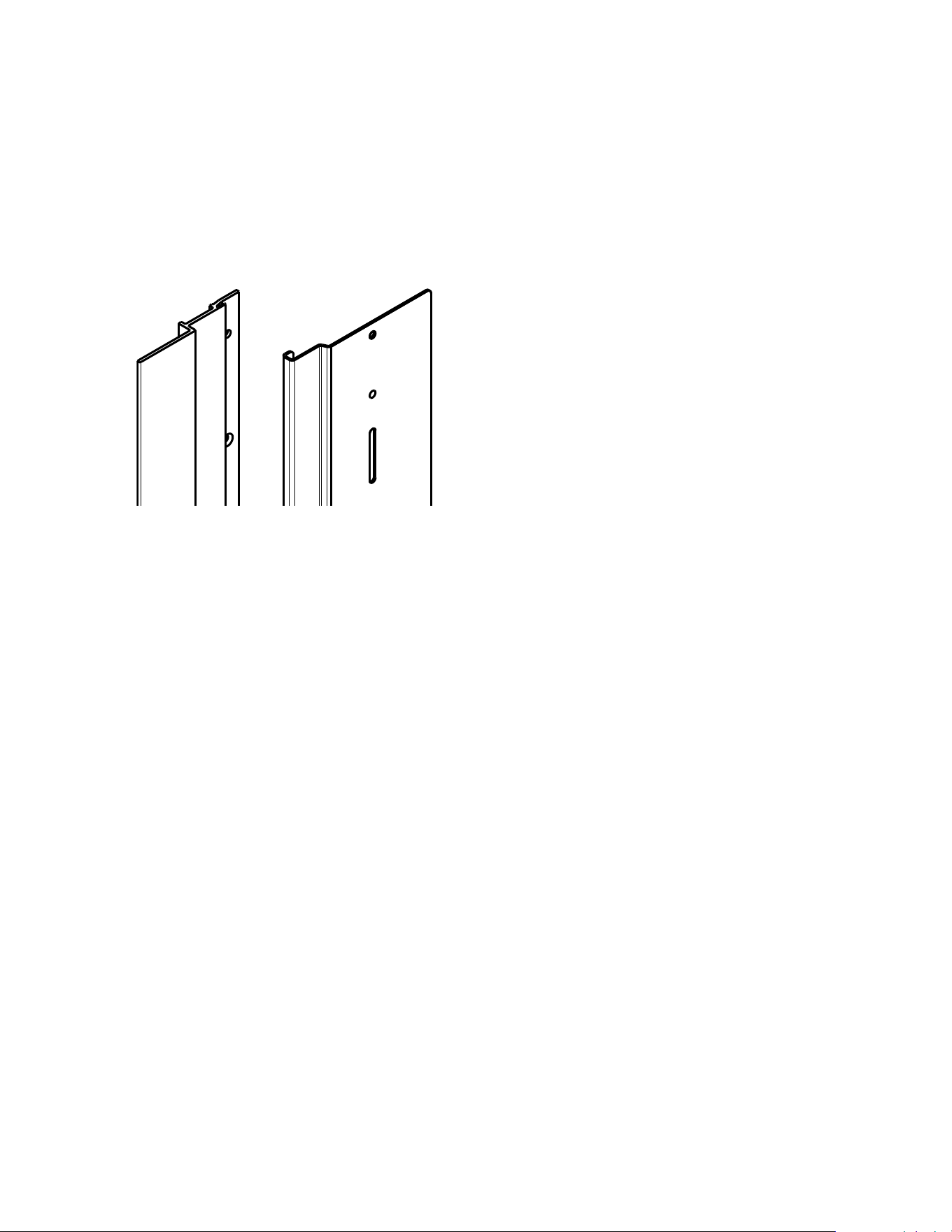
3. On the top surface of the door, remove the screws
holding the extrusion in place. Set aside the old
extrusion and screws for later disposal.
a. Also remove and set aside the small spacer
plate for disposal.
4. Replace the top extrusion with the new spacer
profile.
a. Ensure the new spacer is oriented correctly. The
countersunk holes should line up with holes on
the door without the spacer being out of position.
b. Secure the spacer by running the undercut
screws (M0215321) from the service kit into th
counter sunk holes.
c. Leave the thru-holes open. They will be used to
secure the door skin later.
Top: Old extrusion profile; Bottom: New spacer profile
5. Remove the full-overlay z-brace sitting diagonally
across the door and set aside for later disposal.
6. Remove screws from the bottom extrusion as
specified below.
a. Remove the leftmost, rightmost, and middle
screws.
Bottom Mount Fresh Food RH
Bottom Mount Fresh Food RH
7. Remove the side door trim on the hinge side. Hold on
to three of the screws and set aside the rest.
8. After removing the side door trim, run three screws
back into the door on the hinge side.
a. The screws should be installed in the topmost,
middle, and bottommost holes.
Left: LH screw locations; Right: RH screw locations
b. Do not run the screws flush. The heads should
stick up approximately 1/16” from the surface.
c. Use the screw gauge (087639-000) to measure
the depth by placing it flush with
the side of the door and lining up
the screw heads with the cutouts. If
the screw is the correct depth, the
cutout in the gauge should
fit smoothly around the head with
little to no play.
d. If the gauge has play, run the
screw deeper. If the gauge does
not fit, pull the screw further out.
e. Adjust each screw head until they
all satisfy the gauge. Use a
screwdriver for fine adjustments.
f. These screws will form the snap /
locking feature for the door panel.
Right: Image of the undercut screw heads sticking up.
Left: Flat image of the 087639-000 screw gauge.
2
1. Using the tape, cut several strips and use them to
cover the screw heads.
a. Run the strips across the screw heads and
around the corner towards the front of the door.
b. DO NOT run the tape too close to the inner edge
or corners of the door.
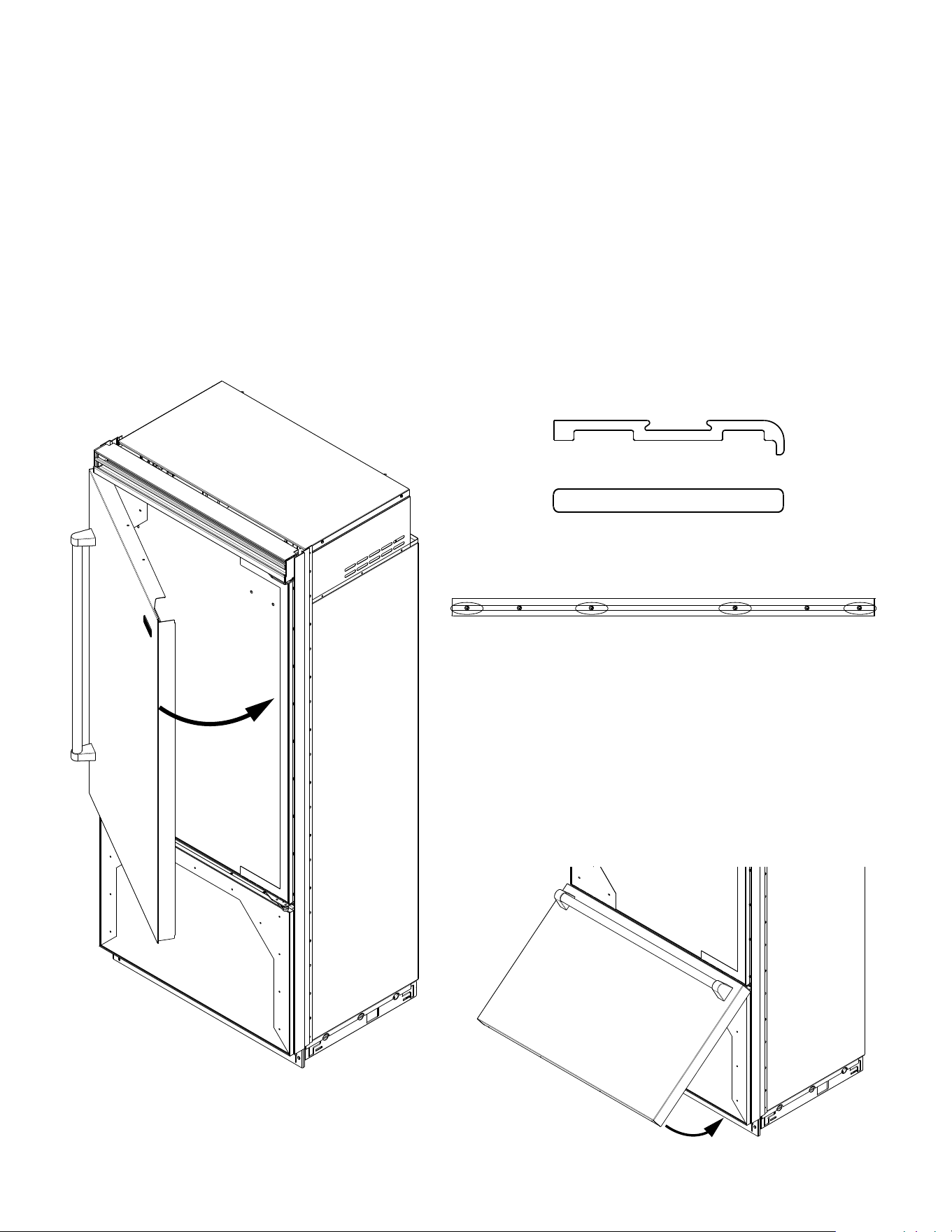
2. Lift the door-skin assembly (preferably with two
people) and hook the handle-side flange around the
remaining side trim.
a. Ensure there is contact between the door-skin
“hook” and the trim.
3. Rotate the door skin into position; make sure that it
remains “hooked” and has clearance around the top
and bottom.
4. Insert the door shims between the panel and the
door near the locations of the screw heads. This will
lever the panel around the corner when you push it
on.
5. Push the rounded edge of the door skin over the
screw-heads on the hinge side until you hear a ‘snap’.
a. The door shims will lift the edge of the panel over
the screw heads to prevent scratching.
b. It helps to pull on the door skin from the inside or
to squeeze from both sides.
c. The snapping sound is the door skin locking in
place around the screw-heads.
6. Install truss-head screws (P#: 010944-000) in the
thru-holes on the top and bottom of the door skin to
secure it.
FREEZER DRAWER INSTRUCTIONS
1. Remove top extrusion. Re-use the screws (M0215318)
to install the new spacer (P#: 086428-000).
Old Extrusion Profile
New Extrusion Profile
2. Remove four screws from the bottom extrusion: the
leftmost, rightmost, and two center screws.
Freezer bottom extrusion
3. Hook the drawer skin assembly onto the top extru-
sion.
4. Rotate the door skin down into position.
a. Make sure it goes smoothly over the bottom
edge of the door.
b. Use the door shims included in the service kit.
5. Install truss-head screws (P#: 010944-000) on the
bottom to secure the door skin.
3
UNIT TRIM INSTRUCTIONS
1. Verify whether the customer requested a proud or a
flush installation.
2. For a flush installation, re-install the flush trims and
countersunk screws set aside in step 2.
3. For a proud installation, install the proud trims includ-
ed in the service kit (053836-000 on side-by-side /
PK910123 on bottom-mount).
4. Refer to unit install guide for instructions regarding
the proud or flush install.
Left: Flush-mount Trim (PK290066);
Right: BM Proud Trim (PK910123)
100225
4