Installation and Service Videos:
www.follettice.com/servicevideolibrary
01555127R00
801 Church Lane • Easton, PA 18040, USA
Toll free (877) 612-5086 • +1 (610) 252-7301
www.follettice.com
Installation, Operation and Service Manual
115 V
Please visit https://www.follettice.com/technicaldocuments
for the Operation and Service manual for your unit.
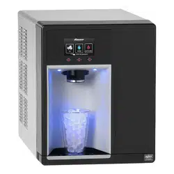
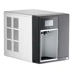
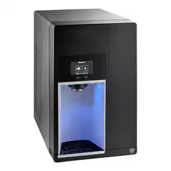
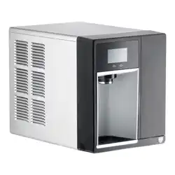
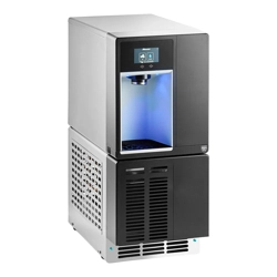
Champion™ 7 and Champion 15
Ice and Water Dispenser
with Chewblet
®
Ice Machine
CI112A, UC112A, UD112A
Welcome to Follett
Follett equipment enjoys a well-deserved reputation for excellent performance, long-term reliability and outstanding
after-the-sale support. To ensure that this equipment delivers that same degree of service, review this guide
carefully before you begin your installation.
Should you need technical help, please call our Technical Service group at (877) 612-5086 or (610) 252-7301.
Please have your model number, serial number and complete and detailed explanation of the problem when
contacting Technical Service.
Getting Started
After uncrating and removing all packing material, inspect the equipment for concealed shipping damage. All freight
is to be inspected upon delivery. If visible signs of damage exist, please refuse delivery or sign your delivery receipt
"damaged." Follett Customer Service must be notied within 48 hours. Wherever possible, please include detailed
photos of the damage with the original packaging so that we may start the freight claim process.
2 Dispenser and Ice Machine - 115 V
CAUTION!
§ Do not tilt unit further than 30° off vertical during uncrating or installation.
§ Dispenser bin area contains mechanical, moving parts. Keep hands and arms clear of this area at all times. If
access to this area is required, power to unit must be disconnected rst.
§ This appliance is not suitable for installation in an area where a water jet could be used.
§ This appliance must not be cleaned by a water jet.
§ User maintenance should not be done by children.
§ Follett recommends a Follett water lter system be installed in the ice machine inlet water line (standard
capacity #00130229, high capacity #00978957, carbonless high capacity #01050442, Claris standard).
§ Prior to operation clean the dispenser in accordance with instructions found in this manual.
§ Do not block air intake or exhaust.
§ This appliance should be permanently connected by a qualied person in accordance with application codes.
§ A qualied person shall provide a readily accessible disconnect device incorporated into the xed wiring.
§ If the supply cord is damaged, it must be replaced by the manufacturer, its service agent or similarly qualied
persons in order to avoid a hazard.
§ This appliance can be used by children aged 8 years and above and persons with reduced physical, sensory,
or mental capabilities, or lack of experience and knowledge if they have been given supervision or instruction
concerning use of the appliance in a safe way and understand the hazards involved. Children should be
supervised to ensure that they do not play with the appliance.
§ This appliance is designed for commercial use.
§ WARNING! To avoid a hazard due to instability of the appliance, it must be xed in accordance with the
instructions.
§ Warranty does not cover exterior or outside installations.
§ To reduce risk of shock, disconnect power before servicing.
§ Connect to potable water supply only.
§ Ice is slippery. Maintain counters and oors around dispenser in a clean and ice-free condition.
§ Ice is food. Follow recommended cleaning instructions to maintain cleanliness of delivered ice.
Dispenser and Ice Machine - 115 V 3
Before You Begin
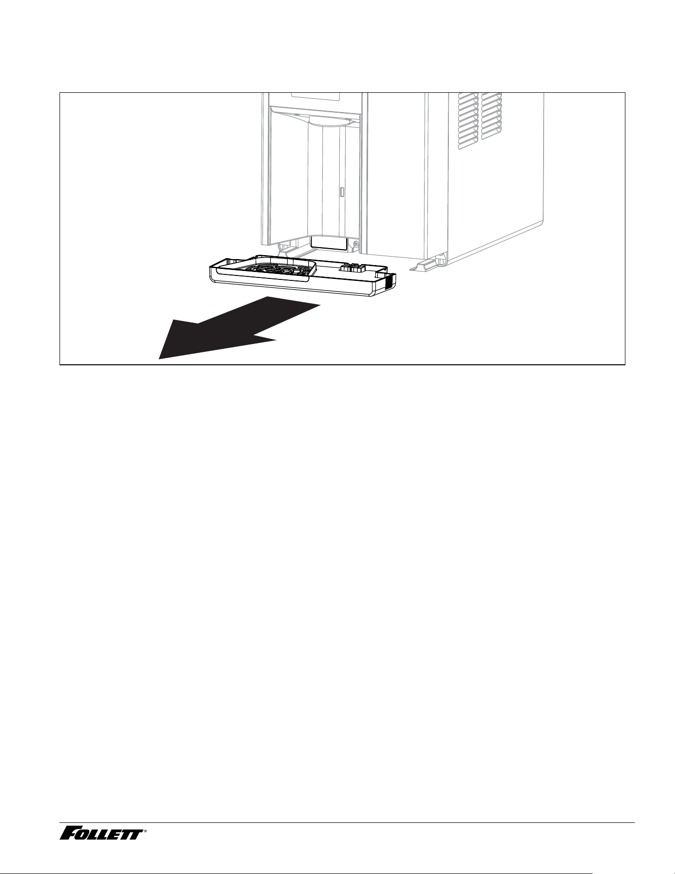
The serial number of your unit is located on the chassis directly behind the front drip tray. The drip tray can be
easily removed by pulling it straight forward. The serial number can also be found on top of the condenser.
4 Dispenser and Ice Machine - 115 V
Specications
Dimensions
Width Depth Height Unit Shipping Weight
7CI112A 14.56" (37 cm) 22.38" (56.8 cm) 17.59" (44.7 cm) 92 lbs (41.7 kg)
15CI112A 14.56" (37 cm) 22.38" (56.8 cm) 22.47" (57.1 cm) 105 lbs (47.6 kg)
7UC112A 14.56" (37 cm) 22.38" (56.8 cm) 33.50" (85.1 cm) 120 lbs (54.4 kg)
7UD112A 14.56" (37 cm) 22.38" (56.8 cm) 31.50" (80 cm) 120 lbs (54.4 kg)
Note: Base stand ships separate
Ambient Information
CAUTION!
The Champion dispensers are for indoor use only. Designed for commercial
use. Follett is not able to provide in-house services for residential installations.
Maximum* Minimum*
Air Temperature
†
100 F (38 C) 50 F (10 C)
Water Temperature 90 F (32.2 C) 40 F (4.5 C)
Water Pressure 70 psi (483 kpa) 10 psi (69 kpa)
Relative Humidity 55% at 78 F (25.5 C)
* Use outside of these limitations is misuse and will void warranty. Maintain proper clearances and ventilations; ensure vents are not blocked or
compromised resulting in above specication temperatures and condenser failure.
† Best performance is achieved between 80 F (27 C) and 50 F (10 C).
Plumbing
§ Water Inlet: 1/4" OD tube, John Guest push-in tting
§ Water shut-off recommended within 5 ft (1.5 m) of dispenser
Options
§ Water dispense (P/N 01536093)
§ Rear drain for ice bin (P/N 01535350)
§ Internal Claris lter (P/N 01535327)
§ 4" legs countertop model (P/N 00956300)
§ 6" legs freestanding models (P/N 00956318)
§ Base stand for countertop models (P/N 01453661)
§ External Claris lter (P/N 01536127)
§ Drip tray drain 7UD, 7UC (P/N 01535335)
§ Drip tray drain with 4" legs 7/15CI (P/N 01535343)
§ Hot water (P/N 01535368)
Dispenser and Ice Machine - 115 V 5
Water
WARNING!
Connect to potable water supply only.
§ Maximum total dissolved solids (TDS) 400 ppm. Ion exchange ltration or RO can reduce hardness.
§ Minimum TDS 10 ppm.
§ Maximum silica 20 mg/L. Reverse osmosis (RO) must be used to remove silica.
§ Maximum water hardness 100 ppm as CaCO3 (6 grains per gallon). Ion exchange ltration or RO can reduce
hardness.
§ Not recommended for use with sodium softened water
§ Ingress Protection (IP) rating: IPX0 (no protection)
§ Use provided water hardness test strips to verify incoming water hardness and adjust bypass setting on Claris
lter head (preinstalled behind front cover on most models). Refer to the below table for appropriate settings.
Adjust the bypass setting after completing the
Internal Claris Filter Flushing Sequence section.
Hardness (ppm) Setting Interval (month) Gallons
0 6 12 1000
50 5 9 800
120 3 6 500
250 2 4 200
425 0 2 100
Note: Claris lter manifold is factory set at 3 prior to shipment.
Clearances
§ CI Models: 3" (7.62 cm) on each side of dispenser, 2" (5.08 cm) behind for electrical/water connection/
ventilation
§ UD/UC Models: 2" (5.08 cm) behind dispenser for electrical and optional drain connection. 6" (15.3 cm) in
front of dispenser for ventilation.
Electrical
115 V
§ 115 V, 60 Hz, 1 phase, 4A (hot water option: 8A), maximum fuse or breaker 15A
§ Connect to dedicated 15A circuit, fuse or breaker
§ Must be grounded - requires 3-prong outlet. Do not remove ground.
§ NEMA 5-15P 90 degree, 8' (2.4 m) cord supplied with machine
Refrigeration
WARNING!
Do not damage the refrigerant circuit. Refrigerant can cause personal injury and/or damage dispenser.
§ Refrigerant
– 115 V: R513a – 6.2 ounces (176 grams)
Heat Rejection
§ 1700 BTU/hr (498 W)
6 Dispenser and Ice Machine - 115 V
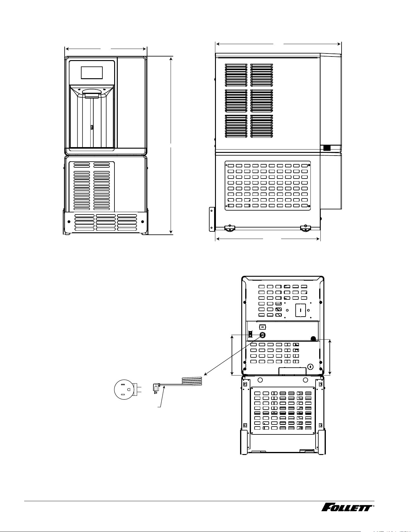
Champion 7 Detailed Drawing - CI Models (with freestanding base)
22.38 in [56.8 cm]
41.92 in
[106.5 cm]
14.56 in
[37.0 cm]
G
L2
L1
NEMA 5-15
right angle
(115 V)
power cord
6.47 in
(16.4 cm)
7.12 in
(18 cm)
power
switch
Dispenser and Ice Machine - 115 V 7
Champion 15 Detailed Drawing - CI Models (with freestanding base)
22.38 in
[56.8 cm]
14.56 in
[37.0 cm]
46.80 in
[118.9 cm]
6.47 in
(16.4 cm)
7.12 in
(18 cm)
G
L2
L1
NEMA 5-15
right angle
(115 V)
power cord
power
switch
8 Dispenser and Ice Machine - 115 V
Champion 7 Detailed Drawing - UC and UD Models
A
C
B
18.61
Dimension 7UC112A 7UD112A (ADA)
A
33.50" (85.1 cm) 31.50" (80 cm)
B
22.38" (56.7 cm) 22.38" (56.7 cm)
C
14.56" (37 cm)14.56" (37 cm)
6.47 in
(16.4 cm)
7.12 in
(18 cm)
G
L2
L1
NEMA 5-15
right angle
(115 V only)
power cord
Dispenser and Ice Machine - 115 V 9
Installation
CAUTION!
No service or maintenance should be performed until the technician
has thoroughly read this service manual. Except for routine cleaning
and sanitizing, only qualied technicians should attempt to service
or maintain this equipment.
Countertop Installation
The Champion 7 countertop model is designed to t on counters underneath
standard mounted cabinets, this does not apply to Champion 15 models.
1. 3" (7.62 cm) on each side of dispenser, 2" (5.08 cm) behind for
electrical/water connection/ventilation (Fig.1).
2. Rough-in the electrical service and water line.
§ Water: supply line (with shut-off valve) connects to the dispenser's
1/4" OD tube quick connect.
NOTICE!
If installing optional Drip Tray Drain Kit or Leg Accessory,
complete those steps before proceeding.
Fig. 1
CAUTION!
Use caution when tipping the dispenser during leg installation. Do
not lay unit on back or side. DO NOT EXCEED 30° angle. Tipping
more than 30° can result in compressor malfunction.
3. If installing optional 4" Leg Accessory (item# 00956300), place a
5" (12.7 cm) spacer underneath the dispenser to ease installation.
4. Remove four plastic, thread-protecting plugs from bottom of
dispenser.
5. Screw each leg into chassis (Fig. 2).
6. Complete Potable Water Connection before proceeding.
Fig. 2
countertop models
minimum 3" (7.6 cm)
clearance required
10 Dispenser and Ice Machine - 115 V
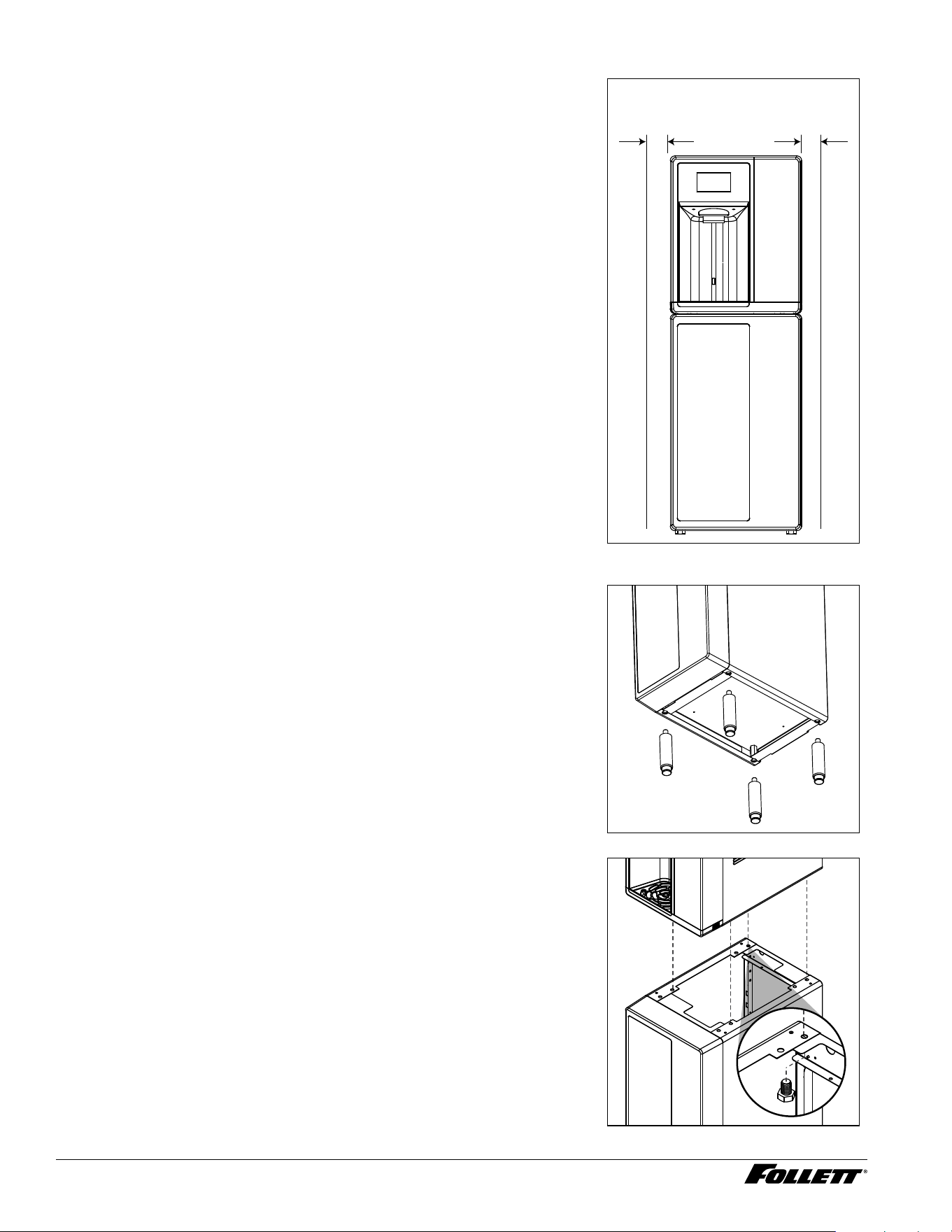
Freestanding Installation
1. 3" (7.62 cm) on each side of dispenser, 2" (5.08 cm) behind for
electrical/water connection/ventilation (Fig.3).
2. Rough-in the electrical service and water line.
§ Electrical: 115 V, single phase, 15A dedicated receptacle required. The
dispenser has an integral 8 ft (2.4 m) cord and plug.
§ Water: supply line (with shut-off valve) connects to the dispenser's
1/4" OD tube quick connect.
Fig. 3
3. If installing optional 6" Leg Accessory (item# 00956318), tilt or lay
base stand on side and screw each leg into stand (Fig.4).
Fig. 4
4. Remove four plastic, thread-protecting plugs from bottom of
dispenser.
5. Attach dispenser to base stand with supplied hardware (Fig. 5).
NOTICE!
If installing optional Drip Tray Drain Kit, refer to instructions
included with the Drip Tray Drain Kit.
Fig. 5
freestanding models
minimum 3" (7.6 cm)
clearance required
X4
Dispenser and Ice Machine - 115 V 11
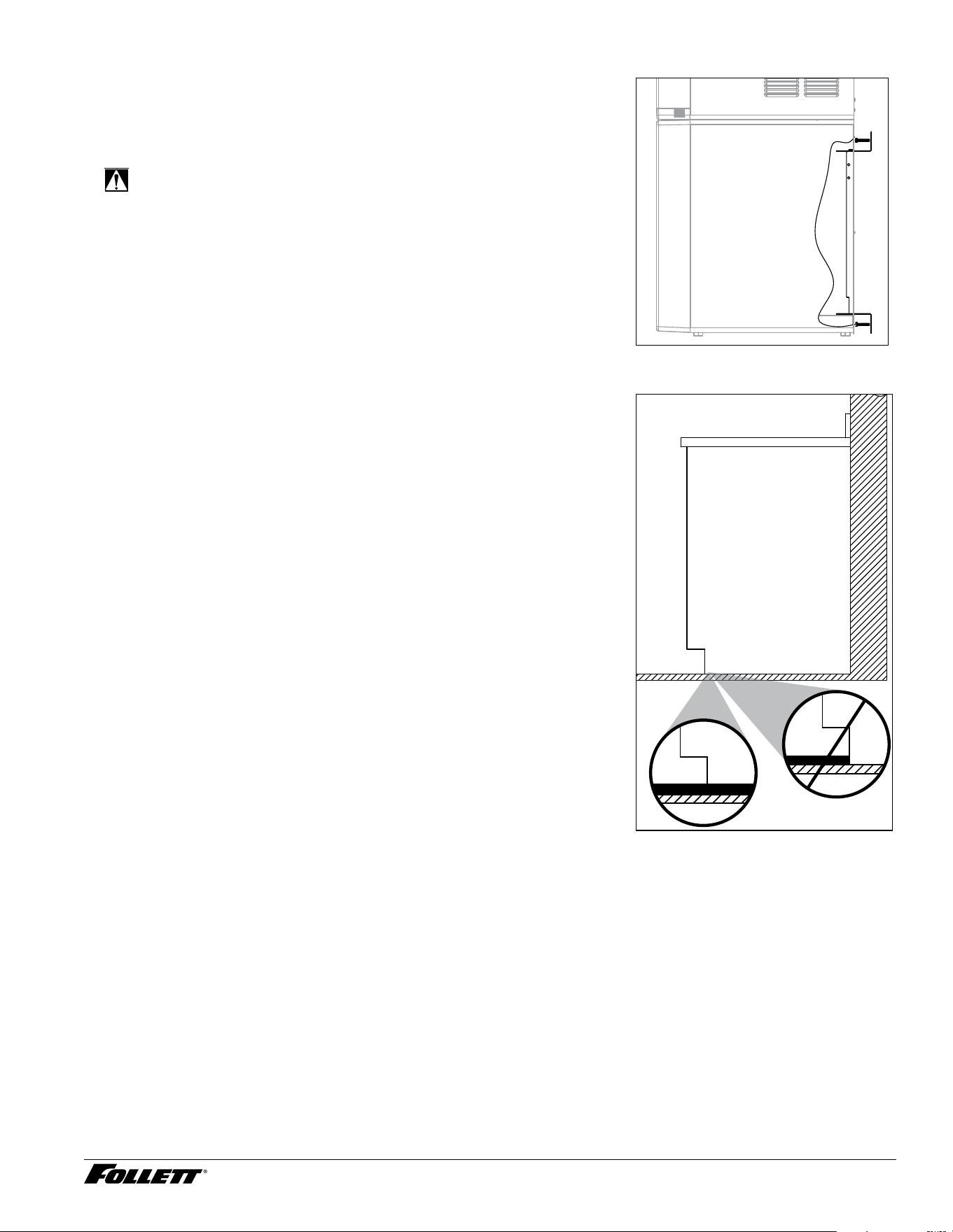
6. Complete Potable Water Connection before proceeding.
7. Secure unit to wall or cove molding with supplied bracket (Fig. 6) to
prevent tipping.
Note: Fasteners must be supplied by installer.
WARNING!
Freestanding unit must be secured to wall to prevent tipping.
Failure to do could result in personal injury or damage to the
unit.
Fig. 6
Undercounter Installation
1. Measure to verify that the dispenser will t in the desired location. A
clearance of at least 2" (5.08 cm) is required behind the dispenser
for the electrical and optional drain connection.
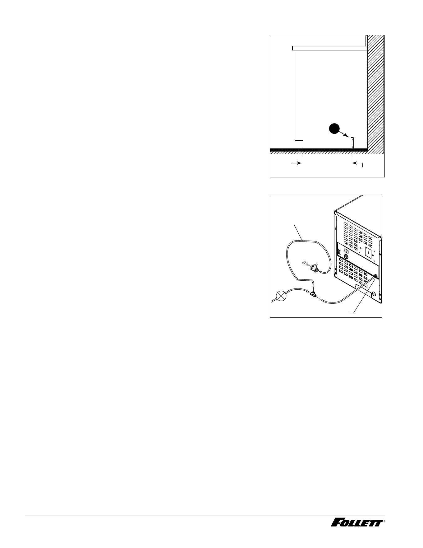
2. Ensure that the nished oor inside the cabinet is ush (level) with
the oor outside the cabinet (Fig. 7). If the cabinet oor is lower
than the nished oor, the cabinet oor must be built up (using
appropriate materials) until it is ush with the nished oor. A ush
oor is required for proper operation and maintenance/service of the
dispenser.
3. Rough-in the electrical service, water line, and optional Drip Tray
Drain Kit*.
Note: The dispenser must be installed such that it can be moved
forward at least 4" (10.16 cm) to allow access to the Bin Lid
Cleaning Spout (Fig. 9.6) for dispenser cleaning and sanitizing.
Take this requirement into consideration during rough-in.
§ Water: supply line (with shut-off valve) connects to the dispenser's
1/4" OD tube quick connect.
* The optional Drip Tray Drain Kit (item# 00956375) requires a oor drain
within 15 ft (4.5 m) of the dispenser. For detailed installation instructions,
please refer to the instructions shipped with the Drip Tray Drain Kit.
Fig. 7
floor
cabinet space
12 Dispenser and Ice Machine - 115 V
4. Install the angle bracket inside the cabinet,18.15" (46.1 cm) from the
toe kick (Fig. 8.1). The bracket prevents the dispenser from being
located/pushed beyond the recommended cabinet space depth. Do
not attach the bracket to the dispenser.
Fig. 8
1
18.15” (46.1 cm)
Potable Water Connection
1. Do not supply power to the unit until after the Initial Sanitizing
Procedure has been completed. This ensures that the evaporator
is warm and does not contain ice.
2. Connect water line. Recommended routing (Fig. 9) allows easy
access to water for cleaning and sanitizing procedure.
3. Sanitize the dispenser prior to use (locate the Initial Sanitizing
Kit shipped with this unit and complete the Initial Sanitizing
Procedure section.
4. If the dispenser has the optional internal water lter*, ensure that
you also complete the Internal Claris Filter Flushing Sequence
section before putting the unit into service.
* If your dispenser has the internal water lter option, the water lter must be
installed for the dispenser to operate.
Fig. 9
Water Inlet
3' (91.4 cm)
Plug
Valve
Dispenser and Ice Machine - 115 V 13
Access Internal Components
CAUTION!
Except for routine cleaning and sanitizing, only qualied
technicians should attempt to service or maintain this equipment.
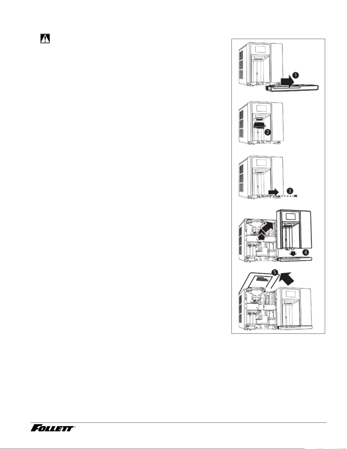
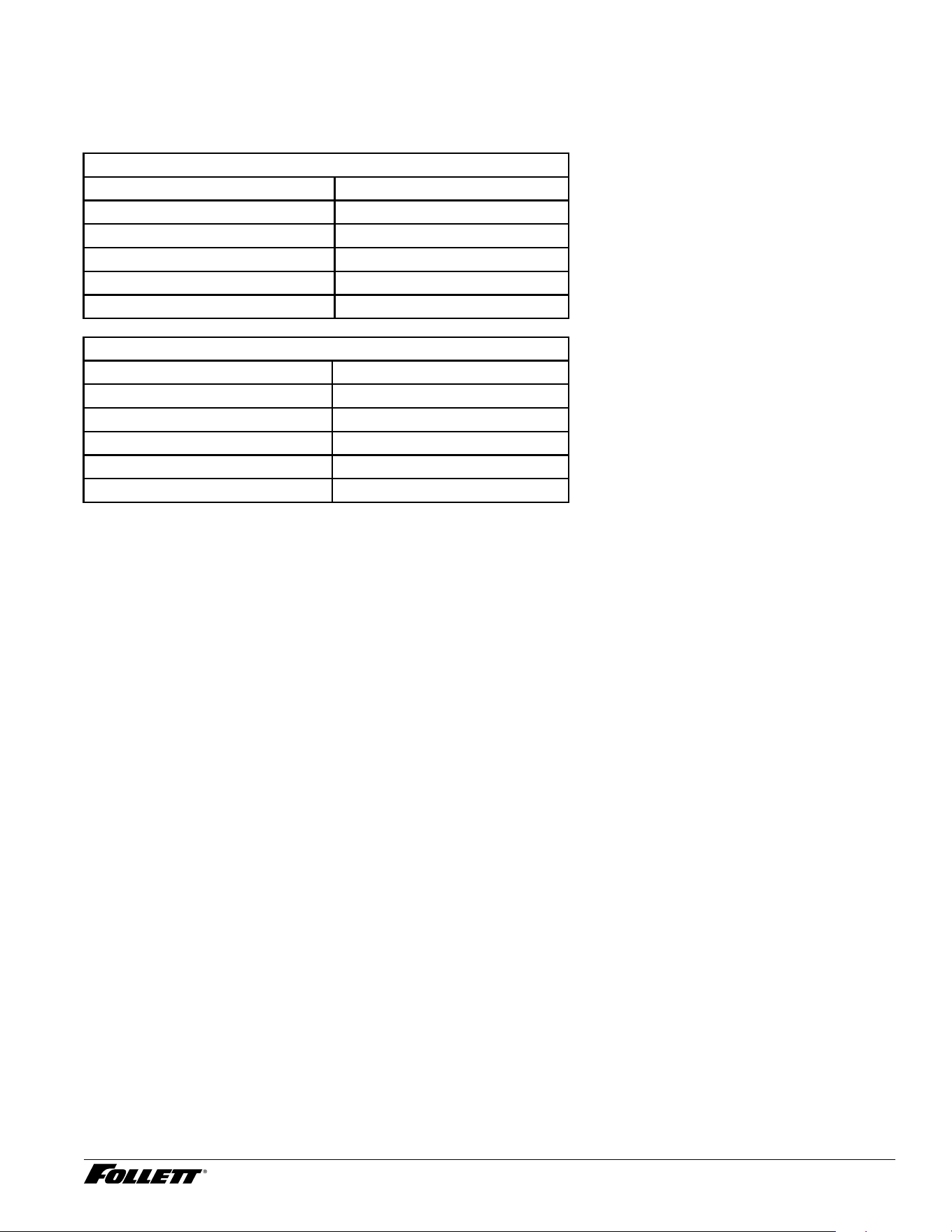
1. Remove the drip tray by pulling straight forward (Fig. 10.1).
2. Unscrew the chute (Fig. 10.2).
3. Remove the one screw securing the front cover (Fig. 10.3).
4. Remove the front cover and set aside. Follett recommends setting
the cover on the drip tray, which provides a stable base. Be careful
not to stretch or damage any cables connecting the front cover to
the unit (Fig. 10.4).
5. Remove top sheet metal cover (Fig.10.5).
Fig. 10
14 Dispenser and Ice Machine - 115 V
Initial Sanitizing Procedure (unit is not powered)
1. Complete the steps in the Access Internal Components section.
2. Remove cap from bin lid cover.
3. Screw bin lid cover cap onto ice discharge chute.
Note: On rear drain units, ensure that the pinch clamp is closed on the ice storage bin rear drain tube. On hot
tank units, ensure that the pinch clamp is closed.
4. Champion 7: mix 2.5 gal. (9.5L) of water and 1 packet Kay-5 sanitizer.
Champion 15: mix 5 gal. (18.9L) of water and 2 packets Kay-5 sanitizer.
5. Pour sanitizing solution into bin lid access spout until solution reaches the spout neck.
6. Allow the solution to remain in unit for 5 minutes.
7. Drain system by opening pinch clamp and/or lowering drain tube.
8. Secure drain tube into holder.
9. Fill and drain twice with potable water. Secure drain tube.
10. Place a bucket under the dispense chute and remove cap. Note: Some sanitizing solution will remain and
drain out when cap is removed. Reposition cap on bin lid spout.
Note: On rear drain units, open the pinch clamp on the ice storage bin rear drain tube. On hot tank units,
open the pinch clamp.
Set Bypass Level on Internal Claris Filter Head
1. Use the provided water hardness test strips to determine and record the incoming water hardness.
Refer to the below table for appropriate bypass settings. The default bypass setting is 3
Hardness (ppm) Bypass
Setting
Filter Replacement Schedule
(month)
Gallons
0 6 12 1000
50 5 9 800
120 3 6 500
250 2 4 200
425 0 2 100
2. If the bypass setting needs to be adjusted, use the following procedure. If the bypass setting does NOT
need to be adjusted, proceed to ush the Claris lter.
3. Remove power from the unit.
4. Place a towel or pitcher under the Claris lter.
5. Ensure power is removed and/or unit is off.
6. Remove lter by turning counterclockwise and set aside lter.
Note: Place a towel or pitcher under lter to catch a small amount of water.
7. Remove the two bracket screws so that the underside of the lter head can be accessed.
8. To adjust the bypass level, insert the bypass setting key into the underside of the lter head, press key
into lter head, and turn the bypass blending disc to the appropriate setting.
9. After positioning the bypass blending disc, remove and keep the bypass setting key.
10. Reinstall the bracket using the bracket screws.
11. Reinstall the Claris lter.
12. Reinstall front panel, ice dispense chute, and drip tray.
Dispenser and Ice Machine - 115 V 15
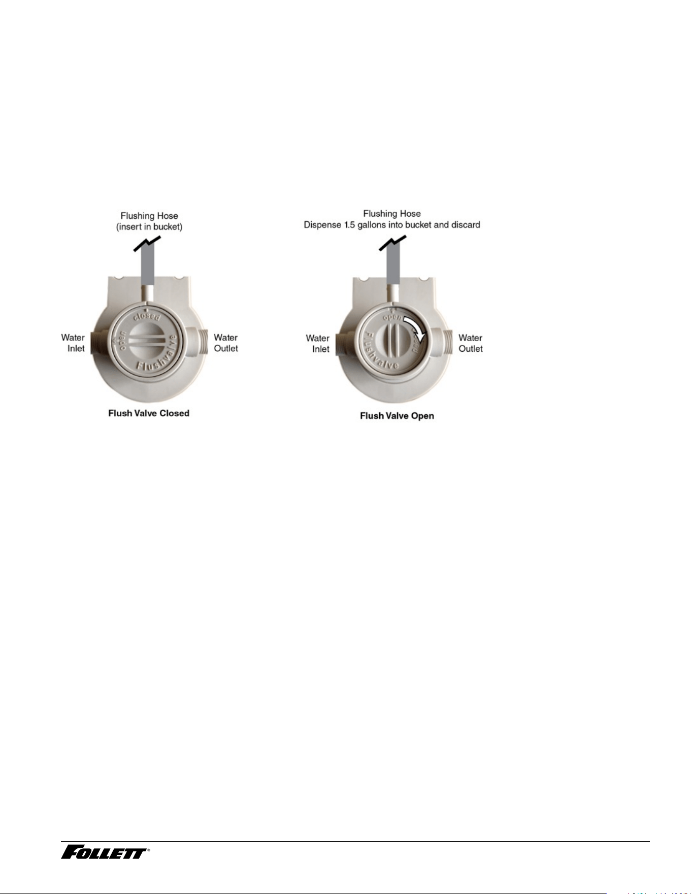
Internal Claris Filter Flushing Sequence
If your dispenser has the internal Claris lter option, the water lter must be ushed prior to use.
To ush the Claris lter, please complete the steps below.
1. Connect power supply and turn on power switch located on back of unit.
2. Place Flushing Hose in 1 gallon (or larger) bucket/container.
3. Rotate ushing valve ¼ turn clockwise so “OPEN” is pointing to the Flush Hose (Fig. 16).
4. Dispense approximately 1.5 gallons of water into a bucket. (If needed, rotate the ushing valve back to the
“CLOSED” position to stop ushing, empty the bucket, then continue ushing until 1.5 gallons has been
collected and discarded).
Fig. 11
5. Rotate the ushing valve to “CLOSED” (with “OPEN” pointed to exit port of manifold).
6. Remove plug cap from the end of water reservoir drain tube and lower tube to drain water into bucket.
After the system has been drained of water, replace plug cap in water reservoir drain tube.
7. Secure tube in holder.
8. Discard water collected in bucket.
9. Reassemble the unit.
16 Dispenser and Ice Machine - 115 V
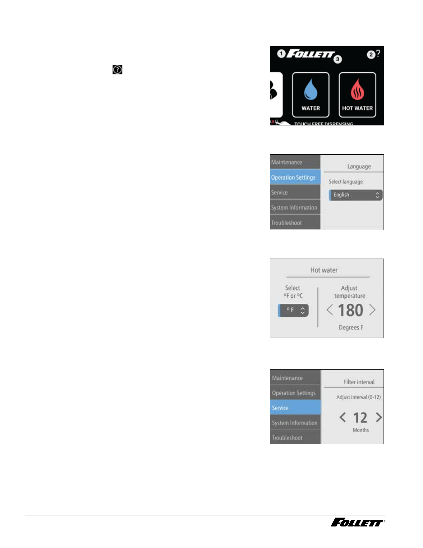
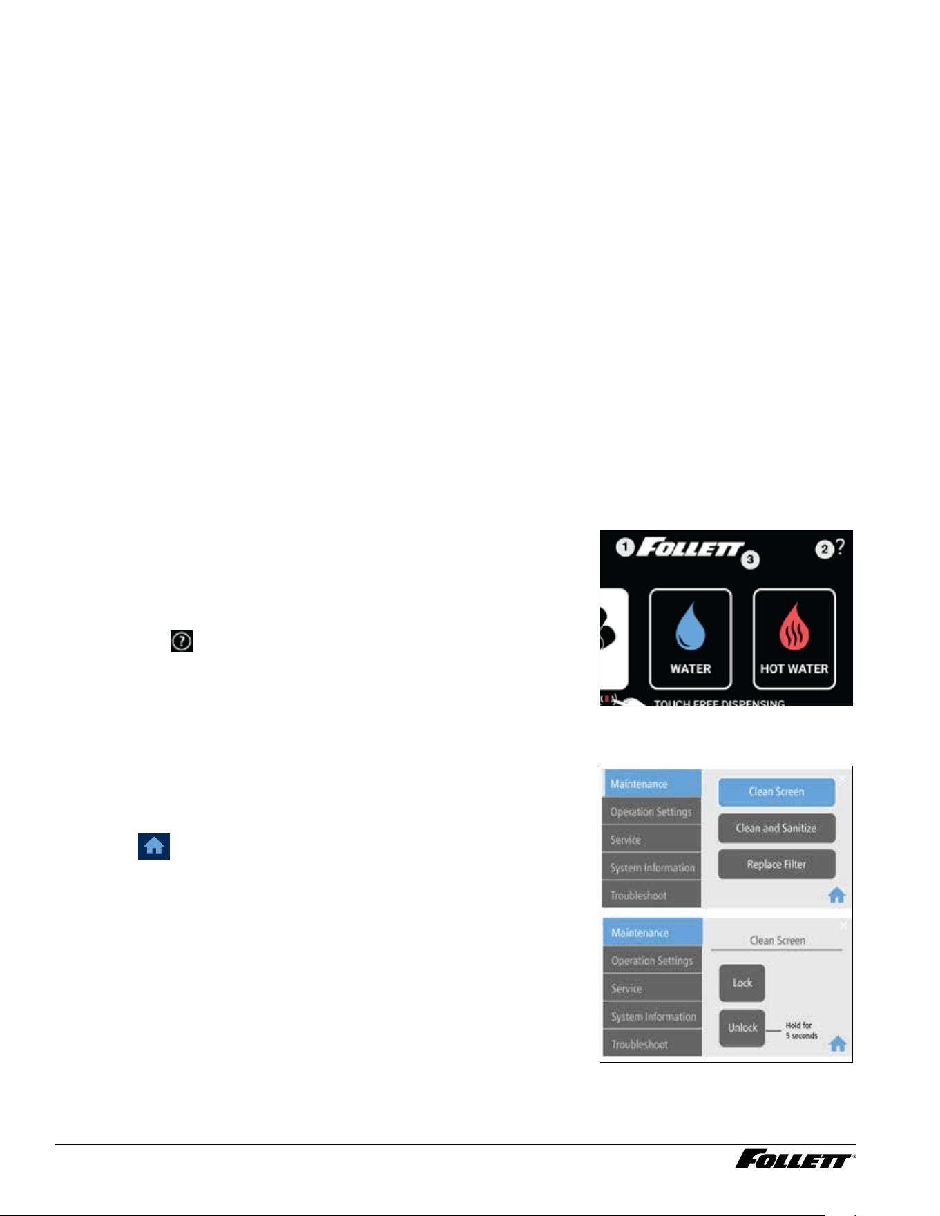
User Interface Menu Access
The user interface has several menus that can be accessed for setting up
and servicing the Champion dispenser.
1. To access the user interface menus, touch the Follett logo
(Fig.12.1), then touch
(Fig.12.2), then touch the Follett logo
again (Fig.18.3).
Fig. 12
Select Language
The user interface can be set to display English, Spanish, or French.
1. To select a language (default is English), Choose Operation
Settings, then Language.
2. Select your language from the dropdown menu.
Fig. 13
Hot Water Temperature and Display Setting
The default hot water temperature value is 120 and displayed in ˚F. To
change the temperature or to display in ˚C, follow the steps below.
1. Access the UI menus, then choose Operation Settings, then Hot
Water.
2. Select F or C from the dropdown menu.
3. Adjust the temperature setting using the arrows.
Fig. 14
Filter Replacement Reminder
The lter replacement reminder can be set from 0 (off) to 12 months
(default). Follett recommends setting the interval based on the results from
the Set Bypass Level on Internal Claris Filter Head section.
1. Access the UI menus, then choose Service, then Filter Interval.
2. Adjust the interval setting using the arrows.
Fig. 15
Dispenser and Ice Machine - 115 V 17
PM (Preventive Maintenance) Reminder – Clean and Sanitize
The PM reminder can be set from 0 (off) to 12 months. The PM reminder
default is 6 months.
1. Access the UI menus, then choose Service, then PM Interval.
2. Adjust the interval setting using the arrows.
Fig. 16
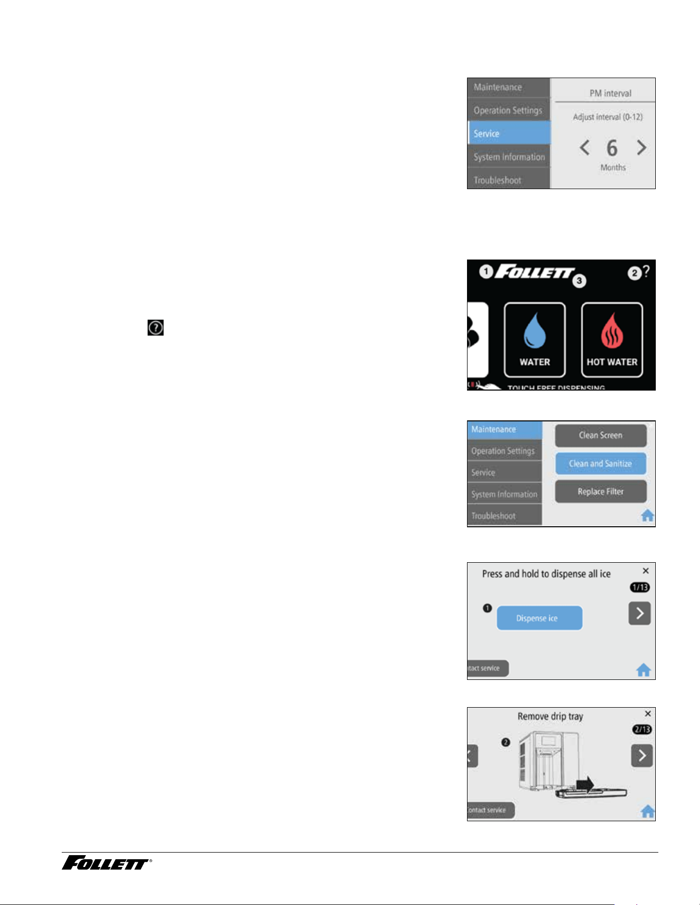
Clean and Sanitize the Unit
Clean and Sanitize Mode (All Operations Disabled) - Use when
cleaning ice machine
Entering Clean and Sanitize Mode disables all operations and allows you to
safely clean and/or sanitize the ice machine and dispenser.
1. To enter Clean and Sanitize Mode, touch the Follett logo (Fig.17.1),
then touch
(Fig.17.2), then touch the Follett logo again
(Fig.23.3).
Fig. 17
2. Choose Maintenance, then Clean and Sanitize (Fig.18). Fig. 18
3. Dispense all ice out of the unit (Fig.19). Fig. 19
4. Remove the drip tray by pulling straight forward (Fig.20). Fig. 20
18 Dispenser and Ice Machine - 115 V
5. Unscrew the chute (Fig.21). Fig. 21
6. Remove the one screw securing the front cover (Fig.22). Fig. 22
7. Remove the front cover and set aside. Follett recommends setting
the cover on the drip tray, which provides a stable base (Fig.23).
Be careful not to stretch or damage any cables connecting the front
cover to the unit.
Fig. 23
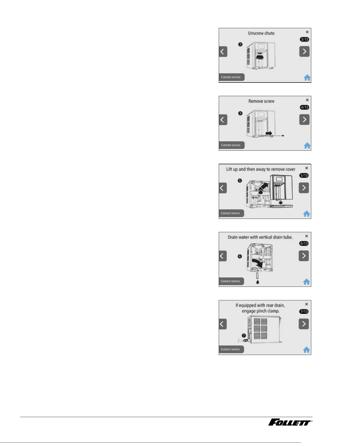
8. Remove plug cap from end of drain tube and lower tube to drain
water into bucket (Fig.24). After the system has been drained of
water, replace plug cap in drain tube and secure tube in holder.
Fig. 24
9. Rear drain units: Locate the storage bin drain tube pinch clamp and
engage (close) (Fig.25).
Fig. 25
Dispenser and Ice Machine - 115 V 19
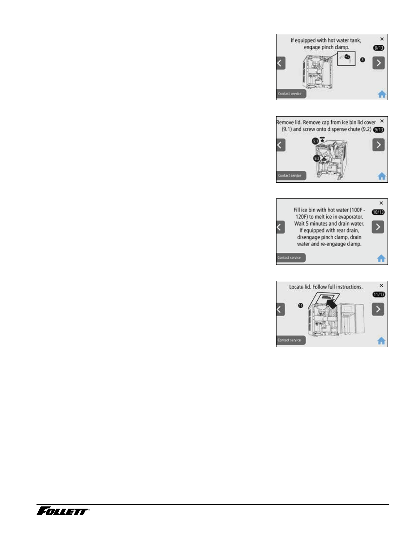
10. Hot water tank units: Locate the pinch clamp and engage (close)
(Fig.26).
Fig. 26
11. Remove top sheet metal cover and remove cap from bin lid cover.
Screw cap onto dispense chute (Fig.27).
Fig. 27
12. Fill ice bin with hot water (100F - 120F) to melt ice in evaporator.
Wait 5 minutes and drain water.
13. If equipped with rear drain, disengage pinch clamp, drain water and
re-engage clamp.
Fig. 28
14. The cleaning and sanitizing instructions can be found on the label
attached to the underside of the lid (Fig.29).
15. Follow the Cleaning and Sanitizing Procedure on the next page.
Fig. 29
20 Dispenser and Ice Machine - 115 V
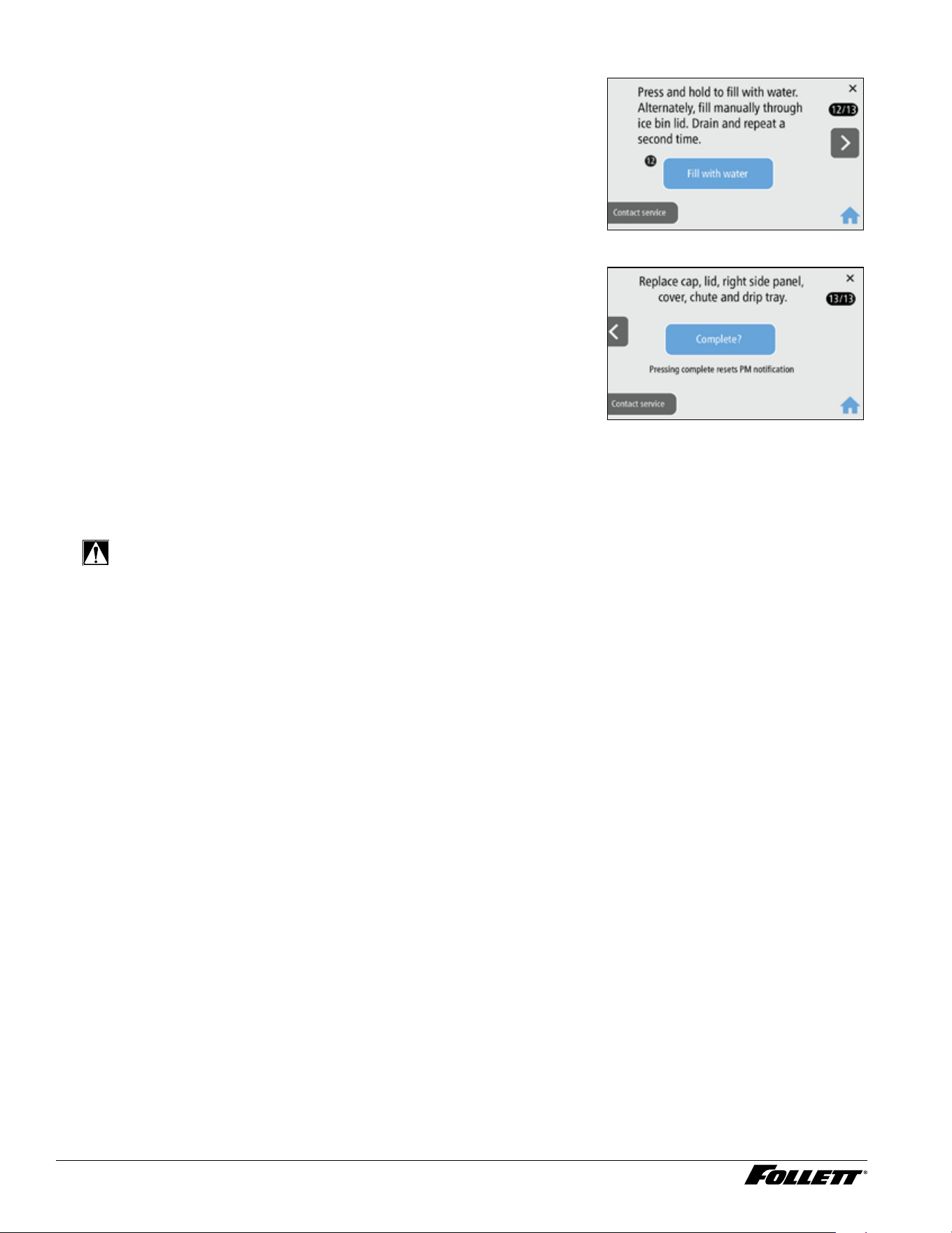
16. Press and hold to ll with water. Alternately, ll manually through ice
bin lid. Drain and repeat a second time (Fig. 30).
Fig. 30
1 7. When the Cleaning and Sanitizing procedure is nished, replace
cap, lid, right side panel, cover, chute and drip tray.
18. Press Complete (Fig. 31).
Fig. 31
Cleaning and Sanitizing Procedure
Cleaning and sanitizing should be performed during initial installation and at least every 6 months (more often if
local water conditions dictate).
WARNING!
§ Place the dispenser in Clean and Sanitize Mode prior to servicing or cleaning the ice machine.
§ For protection, rubber gloves and safety goggles (and/or face shield) should be worn when handling
SafeCLEAN Plus™.
§ Do not use bleach, it will damage the dispenser.
Required Supplies
§ Champion 7: 24 oz. (0.71 L) SafeCLEAN Plus™ liquid
§ Champion 15: 48 oz. (1.42 L) SafeCLEAN Plus™ liquid
§ Funnel
§ Bucket
§ Multi-head screwdriver
§ Towels

Dispenser and Ice Machine - 115 V 21
Ice Machine and Dispenser
If no power to the unit, please follow the user interface (UI) steps below or refer to the Champion service manual at
follettice.com.
1. Touch
located on the upper right corner of the user interface. Scroll down and select Cleaning and
Sanitizing from the menu.
2. Begin the cleaning and sanitizing procedure using the user interface:
§ (UI 1) Dispense all ice out of the unit.
§ (UI 2) Remove the drip tray by pulling straight forward.
§ (UI 3) Unscrew the chute.
§ (UI 4) Remove the one screw securing the front cover.
§ (UI 5) Remove the front cover and set aside. Follett recommends setting the cover on the drip tray, which
provides a stable base. Be careful not to stretch or damage any cables connecting the front cover to
the unit.
§ (UI 6) Remove plug cap from end of drain tube and lower tube to drain water into bucket. After the system
has been drained of water, replace plug cap in drain tube and secure tube in holder.
§ (UI 7) Rear drain units: Locate the storage bin drain tube pinch clamp and engage (close).
§ (UI 8) Hot water tank units: Locate the pinch clamp and engage (close).
§ (UI 9) Remove top sheet metal cover and remove cap from bin lid cover. Screw cap onto dispense chute.
§ (UI 10) Fill ice bin with hot water (100 F – 120 F) to melt ice in evaporator. Wait 5 minutes and drain water.
If equipped with rear drain, disengage pinch clamp, drain water and re-engage clamp.
§ (UI 11) Locate lid. Follow instructions below.
3. Champion 7: Mix 24 oz. (0.71 L) SafeCLEAN Plus liquid with three gallons (11.4 L) of
hot (100 F – 120 F) water.
Champion 15: Mix 48 oz. (1.42 L) SafeCLEAN Plus liquid with six gallons (22.7 L) of
hot (100 F – 120 F) water.
4. Pour SafeCLEAN Plus solution into bin lid access spout until solution reaches the spout neck. Verify
solution maintains level at the spout neck. Allow solution to remain in unit for 15 minutes.
5. Remove right side panel to access and clean the condenser.
6. Submerge dispense chute, drip tray and drip tray grill in the remainder of solution for 2 minutes. Rinse
with clean, potable water.
7. Drain system by lowering drain tube into bucket. Return drain tube back into position.
22 Dispenser and Ice Machine - 115 V
8. Rear drain units: Disengage the storage bin drain tube pinch clamp until cleaning solution is drained, then
engage the storage bin drain tube pinch clamp.
9. (UI 12) Fill and drain twice with potable water. Unit can be lled by pressing the Dispense Water button on
the user interface or ll manually through ice bin lid. Return drain tube back into position when complete
Rear drain units: Disengage the storage bin drain tube pinch clamp when complete.
Hot tank units: Disengage the hot tank vent tube pinch clamp when complete.
10. Place a bucket under the dispense chute and remove cap. Caution: Some solution will remain and drain
out when cap is removed.
11. (UI 13) When the Cleaning and Sanitizing procedure is nished, replace cap, lid, right side panel, cover,
chute and drip tray. Press Complete on the user interface.
12. Dispense water for 5 seconds to rinse the dispense tube. (Hot water units: Dispense hot water for 5
seconds.)
Exterior Cabinet
1. To enter Cleaning Screen Mode, press ?.
2. Choose Clean Screen, then Lock.
3. Clean the user interface screen using a damp - not wet - nonabrasive cloth and mild detergent, if
necessary.
4. Press and hold the unlock button to unlock the user interface.
Clean the User Interface Screen
Clean Screen Mode (Dispensing Disabled) - Use when cleaning
surface
Entering Clean Screen Mode disables the User Interface and allows you to
clean the outside of the dispenser without accidentally dispensing ice and/
or water.
1. To enter Cleaning Screen Mode, touch the Follett logo (Fig.32.1),
then touch
(Fig.32.2), then touch the Follett logo again
(Fig.32.3).
Fig. 32
2. Choose Maintenance, then Clean Screen, then Lock
3. Clean the user interface screen using a damp - not wet -
nonabrasive cloth and mild detergent if necessary.
4. When done, choose Unlock for approximately 5 seconds and then
press
.
Fig. 33
Dispenser and Ice Machine - 115 V 23
Operation
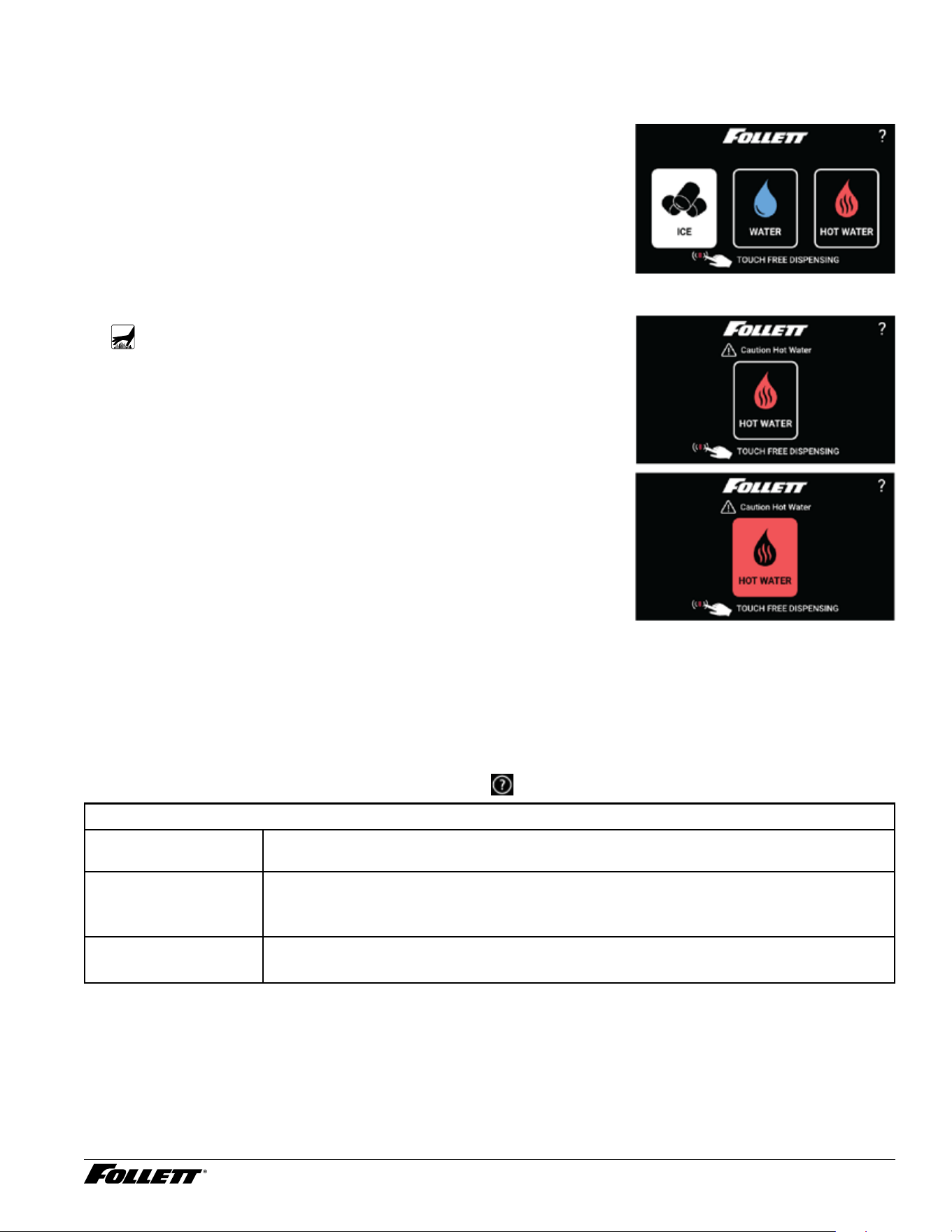
Note: If "Touchless" is activated, simply placing a nger near the button will cause dispensing.
To dispense ice
1. Place cup under ice/water dispense chute.
2. Touch “ICE” button in center of circle. Once depressed, ice will start
dispensing into glass on user interface and into cup placed under
ice chute.
3. Maximum continuous dispense is 60 seconds. If more ice is
needed, release and touch ice dispense once again.
4. Once cup is lled to desired level, release button and remove cup.
Fig. 34
To dispense hot water
WARNING!
Boiling water can cause severe burns. Use caution when
dispensing.
1. Place cup under ice/water dispense chute.
2. Touch “HOT WATER” button. Once touched, a secondary safety
menu will be displayed.
3. Press and hold “HOT WATER” button. Once cup is lled to desired
level, release button and remove cup.
4. After button is released, screen will return to home screen in
approximately 5 seconds.
To dispense water
1. Place cup under ice/water dispense chute.
2. Touch “WATER” button in center of circle. Once depressed, water
will start dispensing into glass on user interface and into cup placed
under ice chute.
3. Maximum continuous dispense is 60 seconds. If more water is
needed, release and water ice dispense once again.
4. Once cup is lled to desired level, release button and remove cup.
Fig. 35
User Interface
From the Home screen, touch the Follett logo, then touch
, then touch the Follett logo again.
Maintenance
Clean Screen § Lock screen, clean User Interface with a damp (not wet) non abrasive cloth and unlock
screen when nished.
Clean and Sanitize § Follow cleaning procedure outlined in service manual and on bottom side of top cover
§ Reset cleaning PM Timer
Replace Filter § Remove old lter turning counterclockwise and install new lter turning clockwise
§ Reset lter PM Timer
24 Dispenser and Ice Machine - 115 V
Preventive Maintenance
Interval (see Preventive
Maintenance Setting
table that follows)
§ Adjust from 1 to 6 month interval based on water chemistry in 1 month increments
(Default 6 months)
Filter Interval § Adjust from 1 to 6 month interval based on water chemistry in 1 month increments
(Default 6 months)
Operation Settings
Sleep Mode § Adjust from 0 to 240 minutes in 20 minute increments (default is 240 minutes)
Language § Select English, Espanol, Francais (default is English)
Brightness § Adjust brightness from 10 to 100 in increments of 5 (Default 80)
Hot Water Temp § Temperature adjusts from 100 F to 185 F degrees in 1 degree increments (Default
180F)
Service
TDS Flush Cycle
(future)
§ Low range = 10 to 200 TDS, Hi range is 201 to 400 TDS (Default 10-200)
Time Delay § Short range = 15 minutes, Long range = 30 minutes (Default is 15 minutes)
Wake On Dispense § Adjust from 0 to 120 seconds in 1 second increments (Default is 35 s)
Flush Enabled (future) § Time Delay
§ Self
§ Shuttle
Screen Timeout § Adjust from 30 to 300 seconds in increments of 30 seconds
(Default 120 s)
System Information
Model Number § EXAMPLE: 7CI112A
Serial Number § EXAMPLE: L54179
Water Filter § INSTALLED/NOT INSTALLED
Drain (drip tray/ice bin) § INSTALLED/NOT INSTALLED
§ Drip tray drain
§ Ice bin drain
Hot Water § INSTALLED/NOT INSTALLED
Ambient Water § INSTALLED/NOT INSTALLED
IMC Software Version § Version #
UI Software Version § Version #
Troubleshoot
Drip Tray Full § Remove drip tray, empty water, clean and dry tray and terminals before re-installing
Low Water § Contact Service
Water Leak § Contact Service
Event Log § Tracks events as they occur
Manual QR Code § Scan QR code with smart phone to access service manuals
Dispenser and Ice Machine - 115 V 25
Preventive Maintenance Setting
To determine the correct preventive maintenance interval for your application, use either the TDS or Hardness
tables below. If you use both the TDS and Hardness and your values are not the same, Follett recommends that you
use the lowest value (shortest interval). Without evidence of regular preventive maintenance, warranty will be void.
Unit needs to be installed with proper ltration system that provides TDS/hardness within Follett specications.
TDS - ppm
TDS Range (ppm) PM Schedule (Months)
10 to 150 6
151 to 250 4
251 to 350 3
351 to 400 2
401 and above RO/Filtration Required
Hardness - ppm
Hardness Range (ppm) PM Schedule (Months
0 to 60 6
61 to 120 4
121 to 180 3
181 to 200 2
201 and above RO/Filtration Required
26 Dispenser and Ice Machine - 115 V
Evaporator Disassembly
1. Disconnect power from the dispenser.
2. Turn off water supply to dispenser.
3. Remove (unscrew) chrome ice dispenser chute
(Fig.36.1).
4. Remove the drip tray (Fig. 36.2).
5. Remove the two screws (Fig. 36.3) on the front panel
(behind the drip tray).
6. Remove and set aside the front panel (Fig. 36.4). Do not
disengage the plug on the back of the User Interface.
7. Lift and remove the top panel, set aside (Fig.36.5).
8. Remove two screws (Fig. 36.6) and remove left side
panel. Remove two screws and remove right side panel.
Fig. 36
2
1
3
4
5
6
Dispenser and Ice Machine - 115 V 27
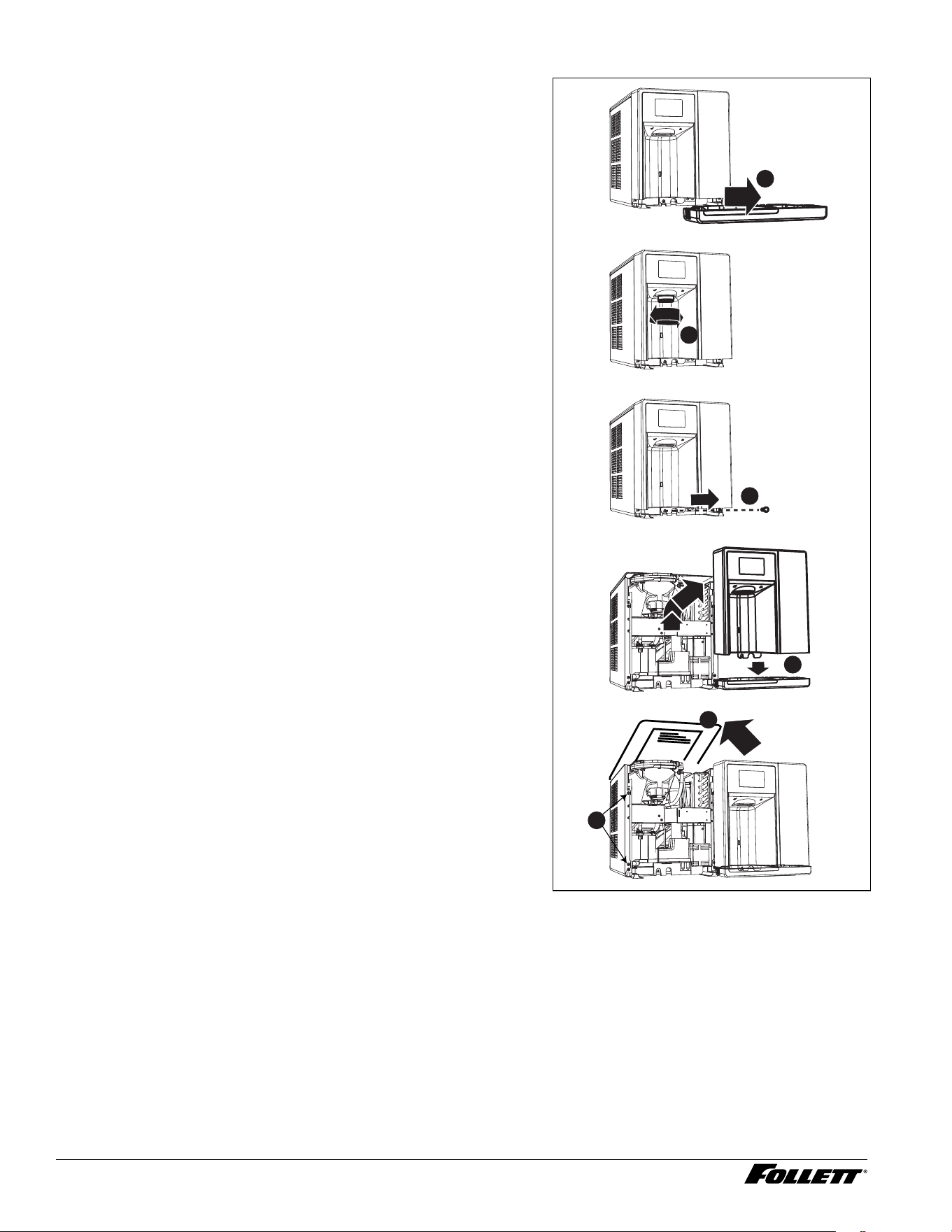
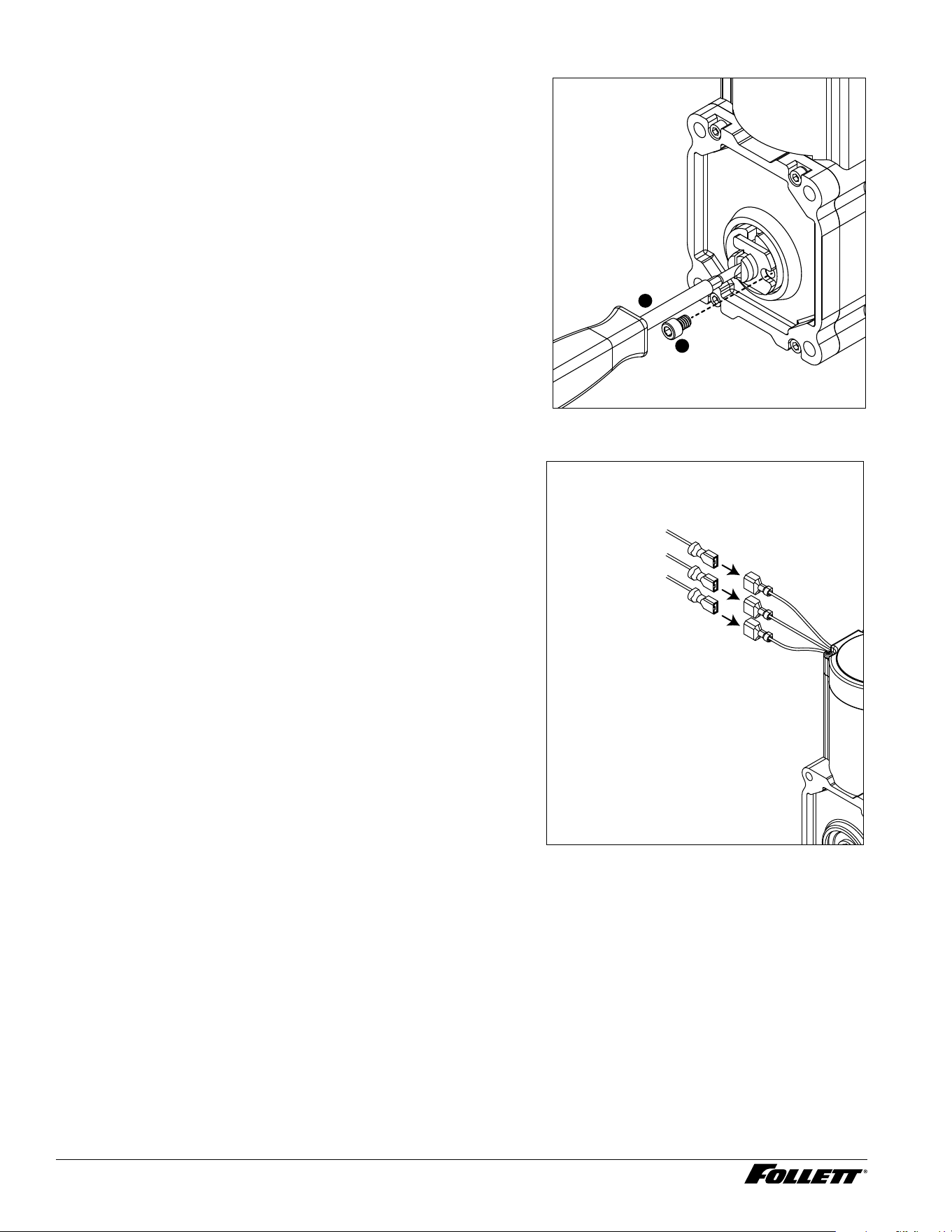
9. Unplug the gear motor (three connectors) (Fig.37).
10. Remove ground screw connection.
Fig. 37
11. Remove compression nozzle:
§ Loosen hose clamp (Fig.38.1).
§ Remove transport tube (Fig. 38.2).
Fig. 38
1
2
12. Remove M6 socket head allen screw (Fig.39.1).
13. Remove compression nozzle retainer (Fig. 39.2).
14. Remove compression nozzle (Fig. 39.3).
Fig. 39
2
1
3
28 Dispenser and Ice Machine - 115 V
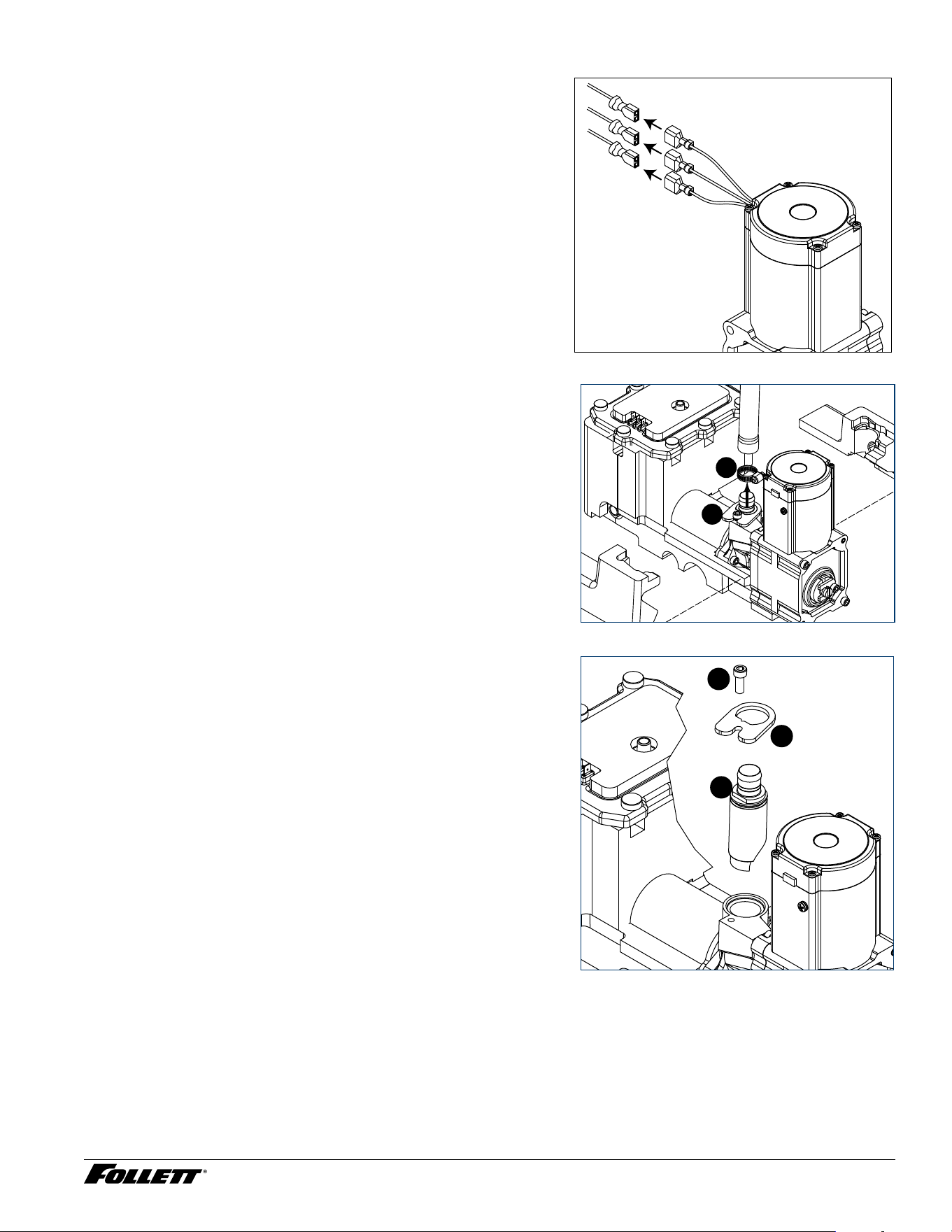
15. Remove gear motor:
§ Remove M6 allen screw, retainer, spacer and key (Fig. 40.1).
§ Remove two M6x90 allen screws (Fig. 40.2).
§ Pull gear motor from auger (Fig. 40.3).
§ Remove main housing insulation (Fig. 40.4).
16. Remove all traces of Petrol-gel from auger shaft.
Fig. 40
2
1
2
3
4
1 7. Remove main housing:
§ Disconnect vent line from T tting (Fig.41.1).
Fig. 41
1
18. Remove three M6x25 socket head allen screws
(Fig.22.1).
19. Remove main housing (Fig. 42.2).
Fig. 42
1
2
Dispenser and Ice Machine - 115 V 29
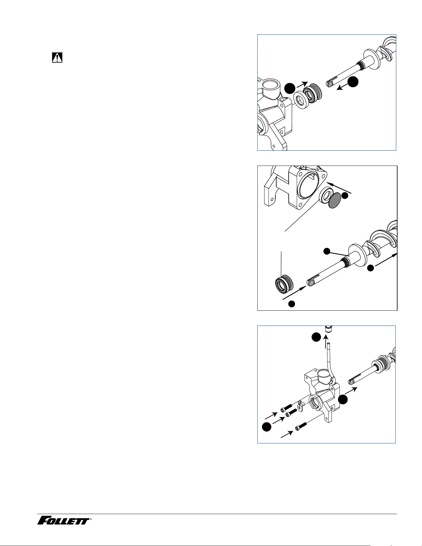
20. Remove and discard mating ring and seal (Fig.43.1).
2 1. Carefully remove auger (Fig. 43.2).
WARNING!
Use caution when removing auger. The auger is very
sharp - handle with care to avoid personal injury.
Fig. 43
1
2
Evaporator Assembly
1. Remove and inspect main housing O-ring seal. Replace if
damaged in any way.
2. Clean O-ring groove. Lubricate O-ring with Petrol-gel and
reinstall.
3. Use cardboard disc to press new mating ring into main
housing (Fig. 44.1).
4. Lube the shaft with liquid soap in the area shown
(Fig.44.2) and slip on seal and spring (Fig. 44.3).
Note: Do not touch the sealing surfaces with bare hands.
Contact with bare skin will cause premature seal failure.
5. Install auger (Fig. 44.4).
Fig. 44
Cardboard
disc
Do NOT
touch!
1
3
2
4
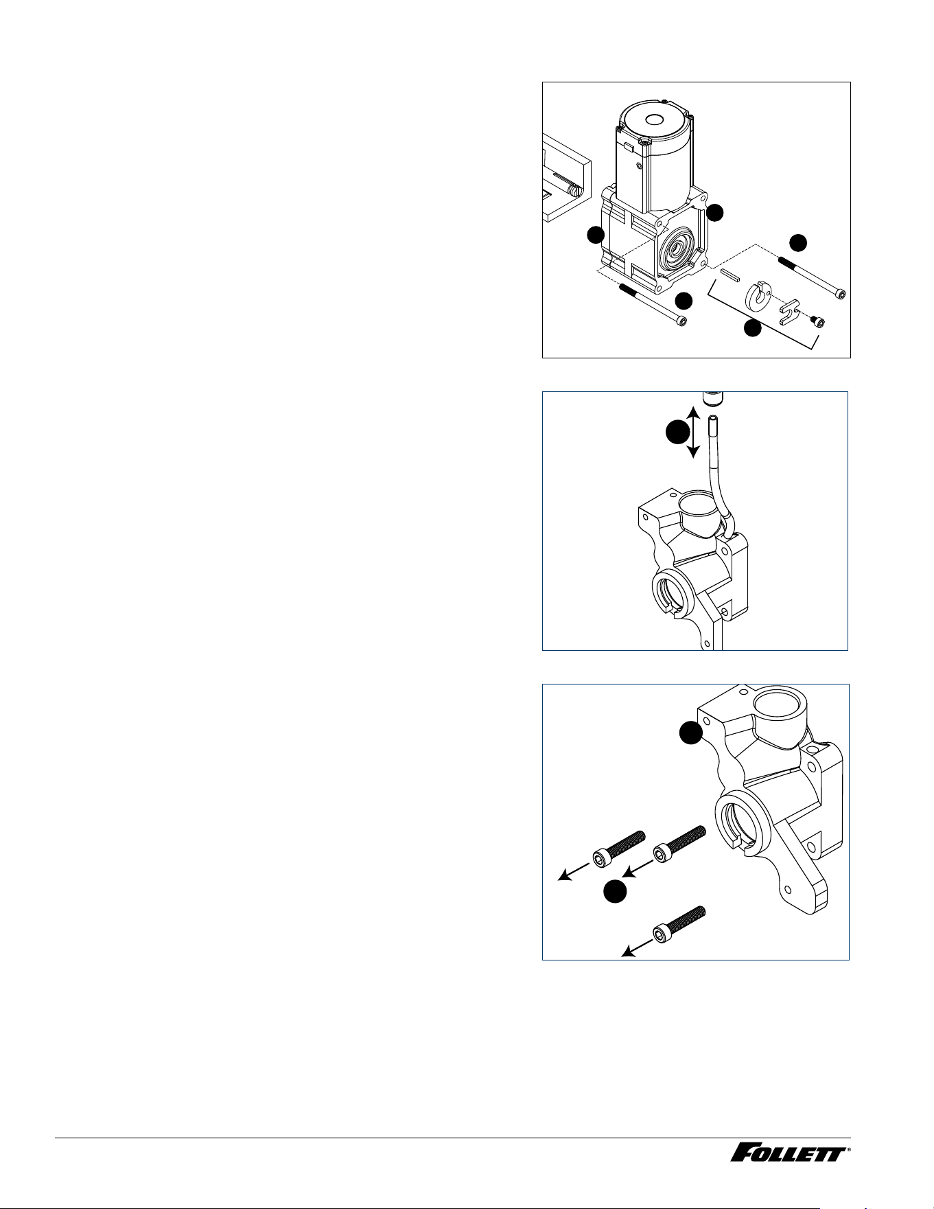
6. Install main housing:
§ Slide main housing onto auger shaft (Fig.45.1).
§ Install three M6x25 allen screws (Fig.45.2).
§ Connect vent line to T tting (Fig.45.3).
Fig. 45
1
2
3
30 Dispenser and Ice Machine - 115 V
7. Install compression nozzle:
§ Remove and inspect compression nozzle O-ring seal.
Replace if damaged in any way.
§ Clean O-ring groove. Lubricate O-ring with Petrol-gel and
reinstall.
§ Install compression nozzle (Fig.46.1).
§ Install compression nozzle retainer (Fig.46.2).
§ Install M6 socket head allen screw (Fig.46.3).
Fig. 46
2
1
3
8. Install transport tube (Fig. 47.1).
9. Tighten hose clamp (Fig.47.2).
Fig. 47
1
2
10. Install gear motor:
§ Install main housing insulation (Fig.48.1).
§ Slide gear motor onto auger shaft (Fig.48.2).
§ Install two M6x90 allen screws (Fig. 48.3).
Fig. 48
3
3
2
1
Dispenser and Ice Machine - 115 V 31
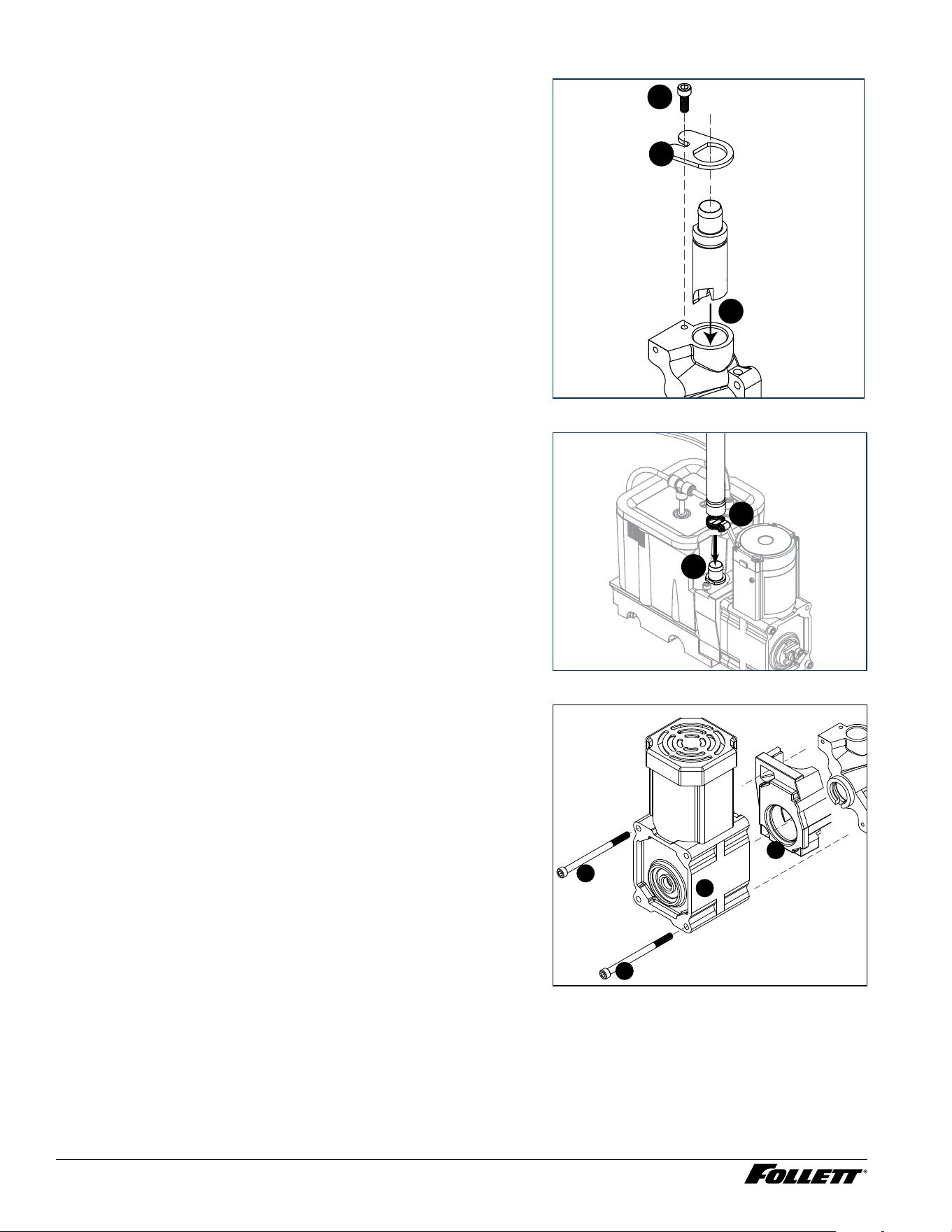
11. Use screwdriver to orient auger shaft to align with motor
shaft keyway (Fig. 49.1).
12. Install key into keyway (Fig. 49.2).
Fig. 49
1
2
3
13. Install spacer, ensure that key is captured in slot
(Fig.50.1)
Fig. 50
1
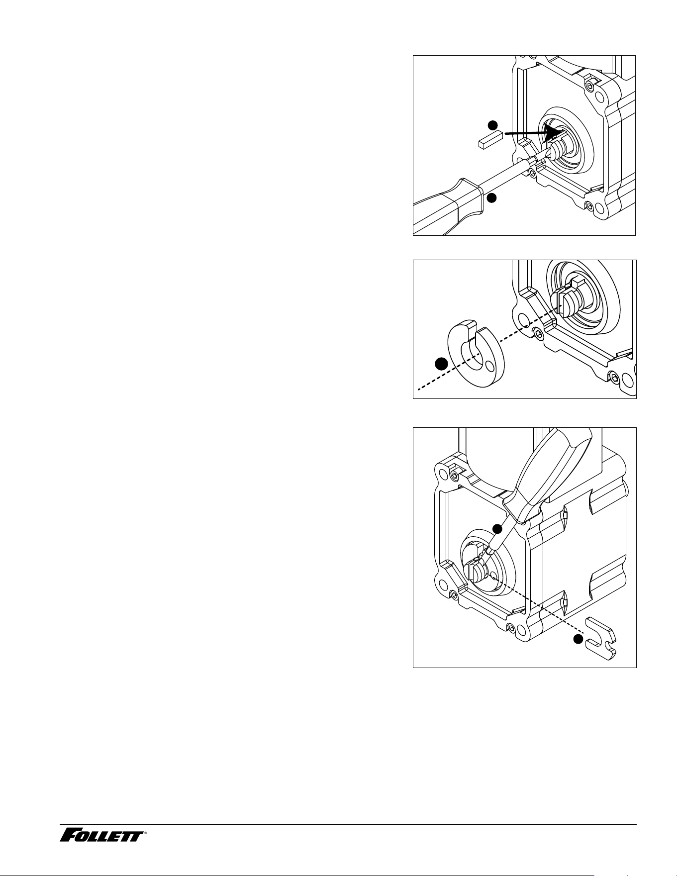
14. Insert screwdriver into groove of auger shaft and pry shaft
outwards (Fig.51.1).
15. Insert retainer into groove (Fig.51.2), ensure that retainer
is aligned with hole in spacer.
Fig. 51
1
2
32 Dispenser and Ice Machine - 115 V
16. Install screw and tighten (Fig.52.1). Fig. 52
1
2
1 7. Plug in gear motor (Fig.53).
§ BLUE to BLUE
§ BLACK to BLACK
§ WHITE to WHITE
§ Connect ground wire with ground screw.
Fig. 53
BLUE to BLUE
BLACK to BLACK
WHITE to WHITE
Dispenser and Ice Machine - 115 V 33
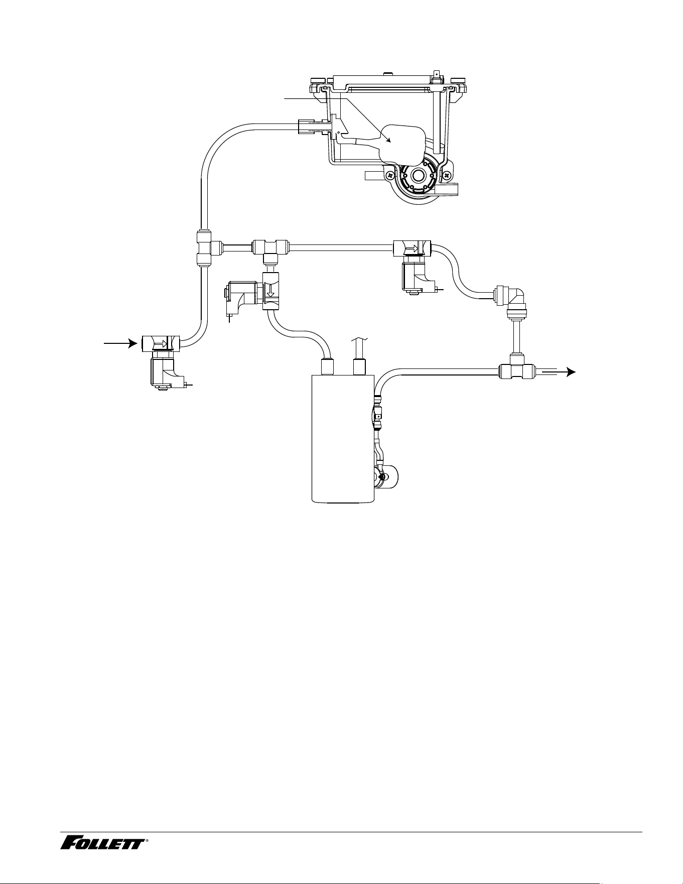
Water Feed Schematic (Hot Water Tank)
Reservoir
Float
Failsafe
Solenoid
Hot Tank Solenoid
Hot Water
Tank
Vent Tube
Pump
Check Valve
To Water Dispense
Water Dispense
Solenoid
Incoming
Water
34 Dispenser and Ice Machine - 115 V
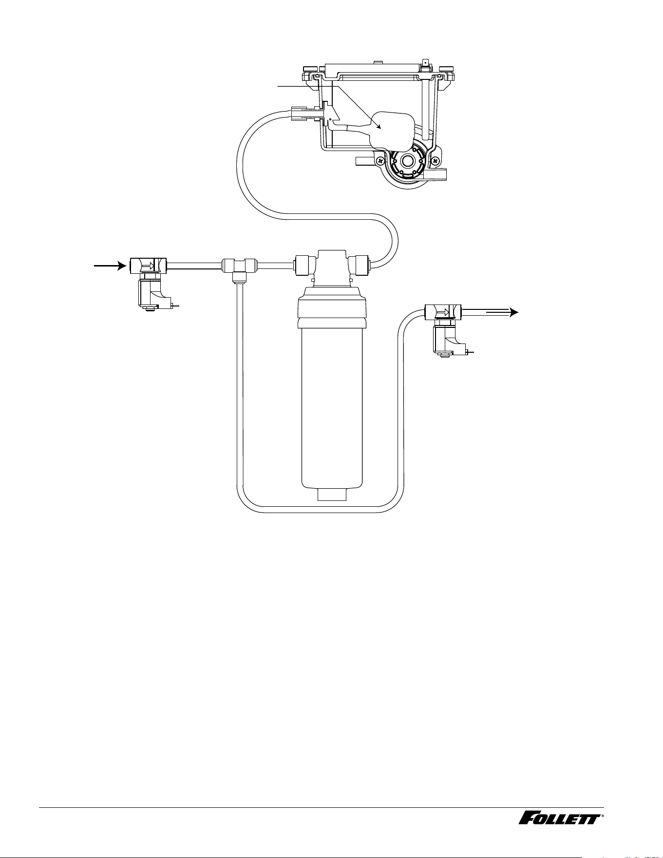
Water Feed Schematic (Claris Filter)
Claris
Filter
Failsafe
Solenoid
Reservoir
Float
Water
Dispense
Solenoid
To Water Dispense
Incoming
Water
Dispenser and Ice Machine - 115 V 35
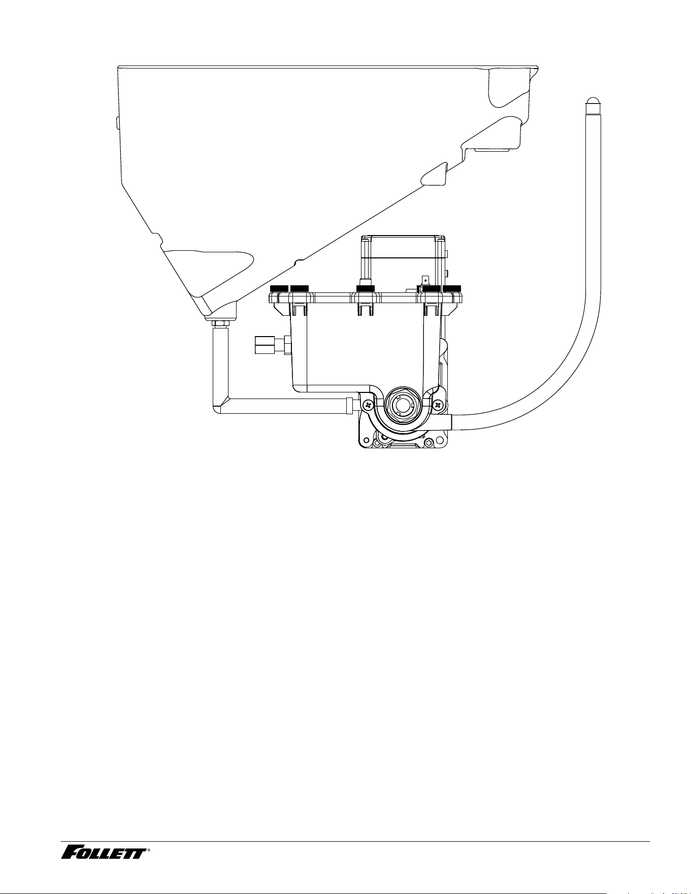
Bin Melt Water/Evaporator Feed/Clean Out System Schematic
Storage Bin
Storage Bin
Drain Tube
36 Dispenser and Ice Machine - 115 V
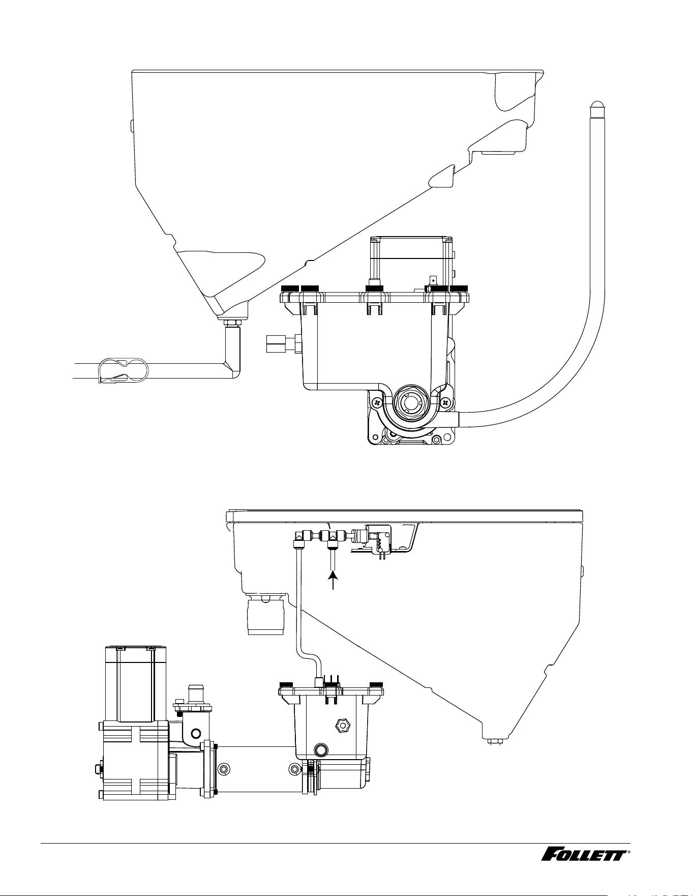
Bin Melt Water/Evaporator Feed/Clean Out System Schematic - Rear Drain
Storage Bin
Storage Bin
Drain Tube
Pinch Clamp
Vent System Schematic
Storage Bin
Vent Tube
Reservoir
From Hot Water
Tank (if equipped)
Dispenser and Ice Machine - 115 V 37
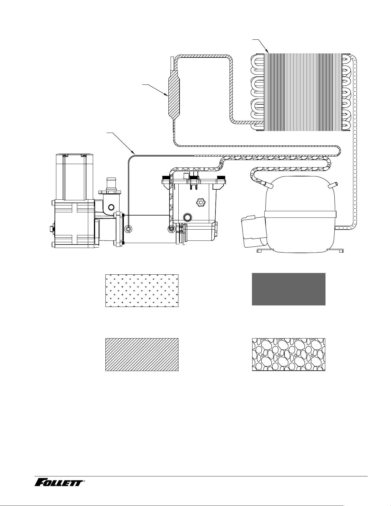
Refrigeration Schematic
LOW PRESSURE LIQUID
HIGH PRESSURE VAPOR
HIGH PRESSURE LIQUID LOW PRESSURE VAPOR
CAP TUBE
FILTER-DRIER
CONDENSER
COMPRESSOR
EVAPORATOR
38 Dispenser and Ice Machine - 115 V
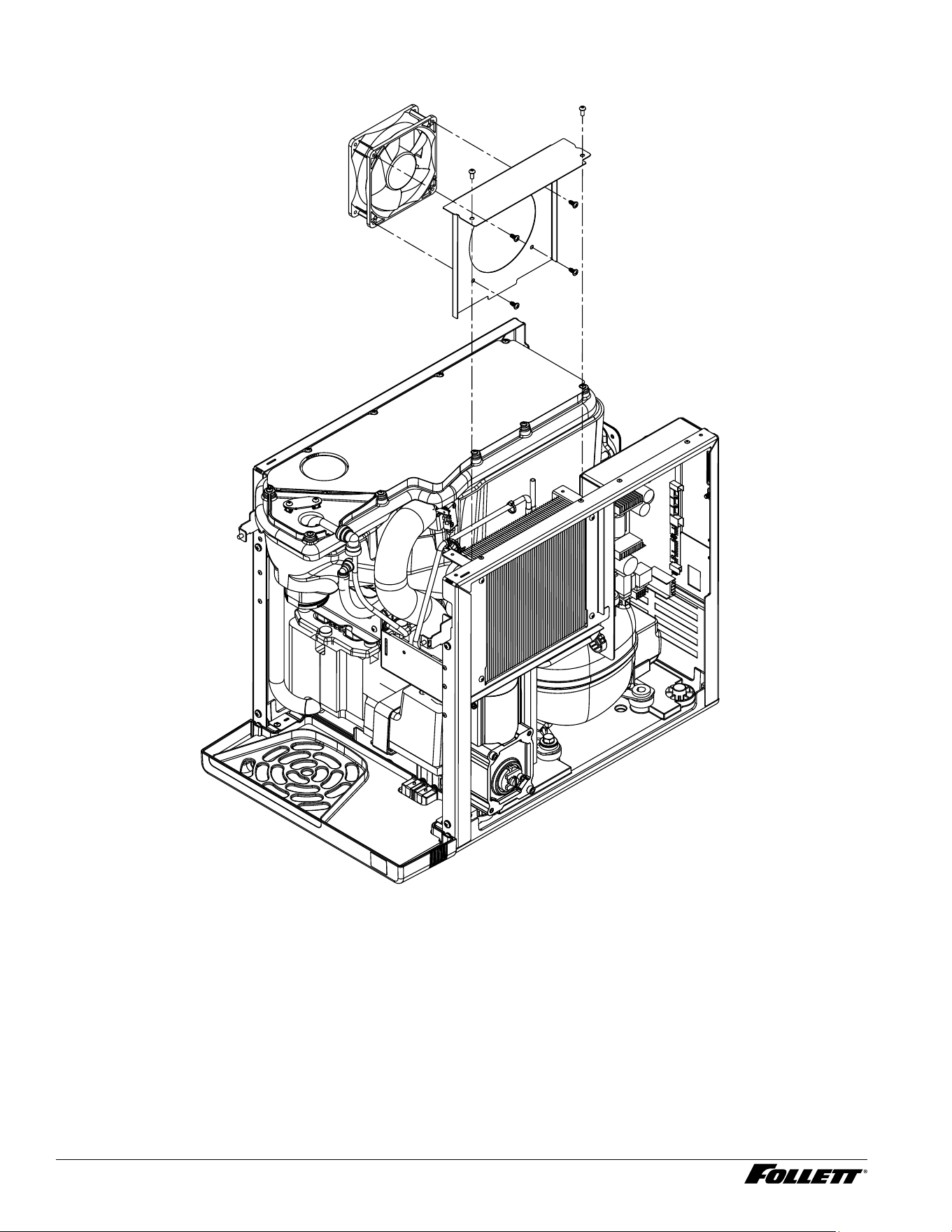
Condenser Fan Motor Removal (Champion 7 Shown)
Dispenser and Ice Machine - 115 V 39
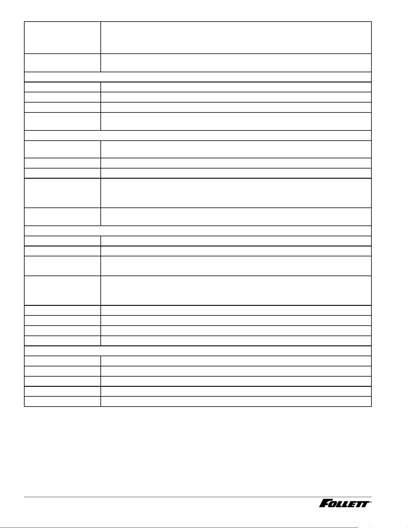
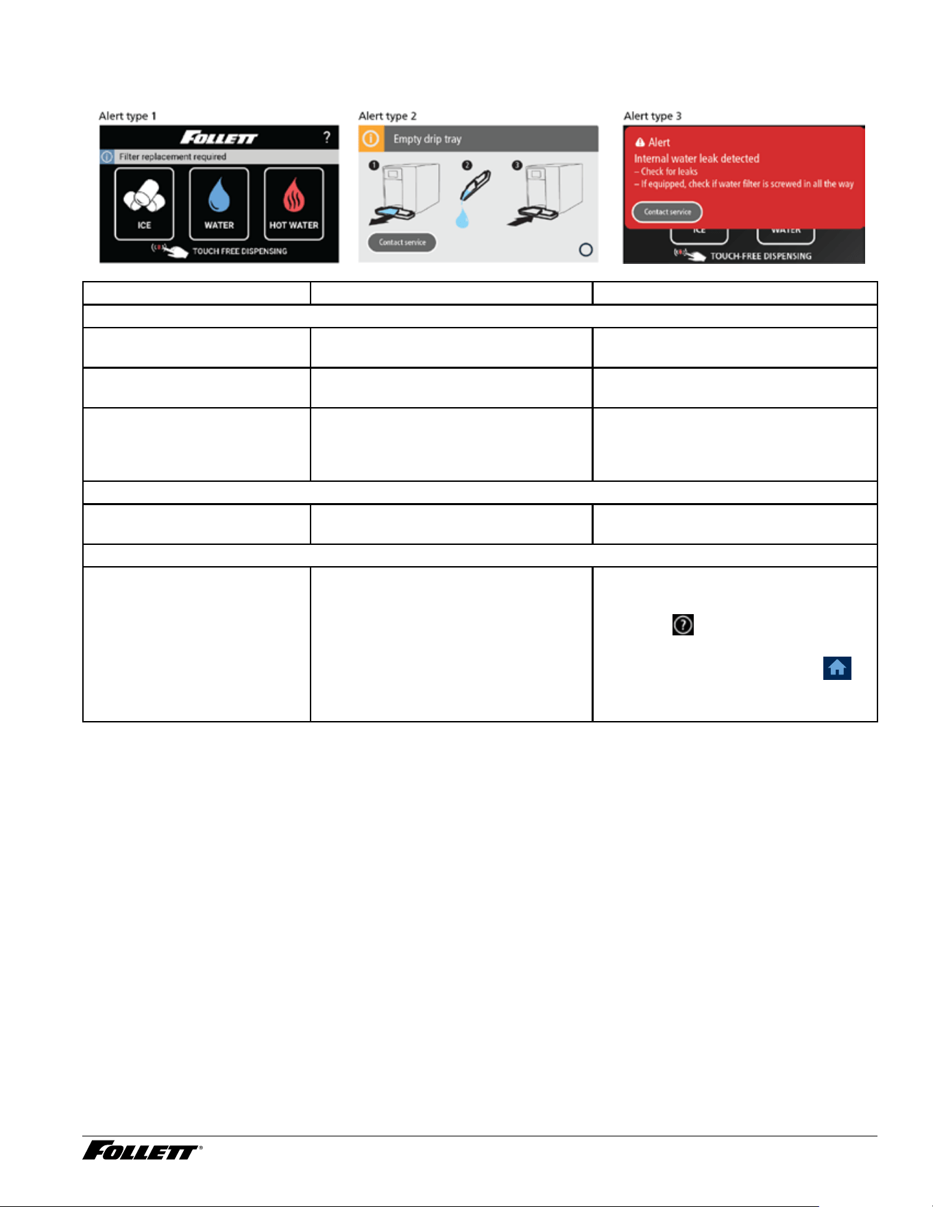
User Interface Alerts
Fig. 54 Interface Alert Examples
Interface Display Condition Remedy
Alert Type 1
Clean and Sanitize Maximum 6 month maintenance
required (Adjustable 1 to 6 months)
Follow PM cleaning procedure in
service manual and reset timer
Filter Replacement Required Maximum 6 month lter replacement
required (Adjustable 1 to 6 months)
Low Water Reservoir sensors are not detecting
water
Verify water is turned "ON" and internal
lter has been installed. If this does not
correct problem, unit will need to be
serviced
Alert Type 2
Empty Drip Tray Drip tray full of water contacting tray
sensors
Empty drip tray, dry tray/terminals and
reinstall
Alert Type 3
Internal Water Leak Detected Unit has internal water leak contacting
chassis sensors
§ Dry chassis, locate leak and repair
§ Reset from user interface menu
(Follett,
, Follett), Service ➔
Advanced ➔ enter access code ➔
Control Board Reset ➔ yes ➔
§ Or, reset control board manually by
pressing reset button
40 Dispenser and Ice Machine - 115 V
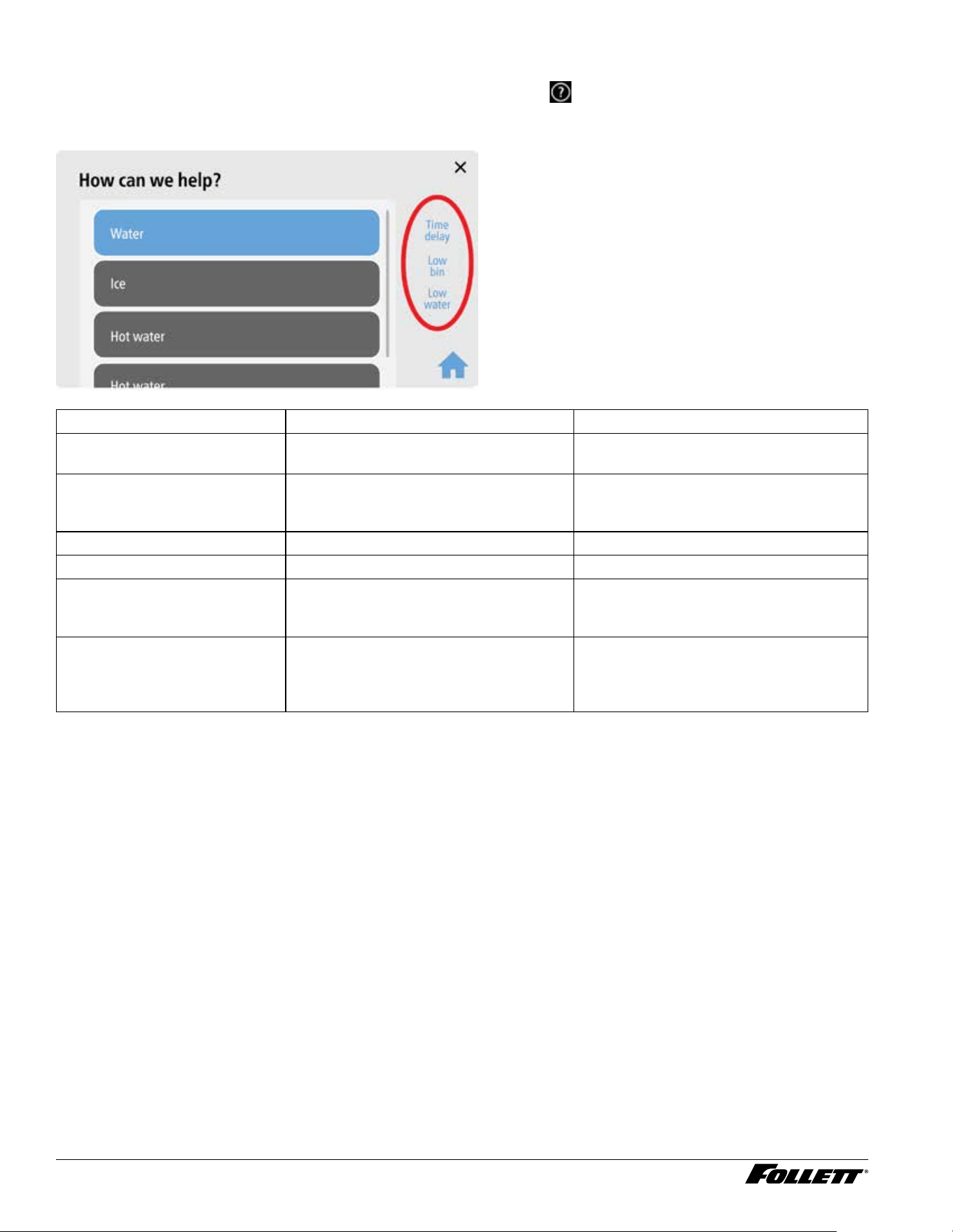
Machine Status
Procedure for viewing status indicators: From the Home screen, touch
to enter help screen. Status will be
displayed on right side of screen.
Fig. 55 Help Screen Example
Interface Display Condition Remedy
Time Delay Ice bin is full and unit is placed into 15
minute time delay (15 or 30 minutes)
After 15 minutes unit will exit time delay
Sleep Mode If unit has not be used during time
delay, unit will enter sleep mode
(adjustable 0 to 240 minutes).
To exit sleep mode you must dispenser
ice for 35 seconds of accumulated time
Making Ice Normal ice operation Normal ice operation
Flush Enabled Future Future
Low Bin Ice bin shuttle micro switch activated This indicates full bin of ice. Inspect bin
and take corrective action if bin is not
full
Low Water Reservoir sensors are not detecting
water
Verify water is turned "ON" and internal
lter has been installed. If this does not
correct problem, unit will need to be
serviced
Dispenser and Ice Machine - 115 V 41
Electrical Wiring Diagram
42 Dispenser and Ice Machine - 115 V
Control Board Output LEDs and Connections
Status
LED
Function Power Connector Pins Input/Output
1 Power "ON" 5 VDC Internal — Internal
2 Auger Gear Motor 120/220 VAC CN5 1, 2 Cap, 8 Output
3 Compressor 120/220 VAC CN5 4, 5 Output
5 Condenser Fan 24 VDC CN6 1, 2 Output
6 Failsafe Solenoid 24 VDC CN6 3, 4 Output
8 Ice Dispense Auger Motor 120/220 VAC CN5 3, 6 Output
9 Water Dispense Solenoid 24 VDC CN6 5, 6 Output
10 Reservoir UV LED/Interlock 24 VDC CN6 7, 8 Output
11 Hot Tank Output Heating Coil 120/220 VAC CN7 1, 2 Output
12 Hot Tank Fill Solenoid 24 VDC CN12 1, 2 Output
13 Hot Water Dispense Pump 24 VDC CN12 3, 4 Output
14 Heart Beat (Program) 5 VDC Internal — Internal
15 Spare Output # 1 (VDC) 24 VDC — — Future
17 Spare Output # 2 (Drain) 24 VDC — — Future
18 Dispenser LED VYV Light - Blue 24 VDC CN14 1, 2 Output
Symptom
(End User)
Alert Problem (ASA) Resolution
Water Leak Alert Type 3 Water has entered
the chassis and has
contacted chassis
water sensors
Step 1) Remove all water from chassis and sensor terminals.
Power unit "OFF" and back "ON" to reset condition or reset by
pressing control board reset switch (this is a hard failt).
Step 2) Enter diagnostic mode, system input status and verify
if chassis water sensor has check mark which means system
is seeing water on terminals
Step 3) Inspect incoming water connection at back of unit for
leaks
Step 4) If unit has internal lter, verify it has been inserted
correctly and is not leaking
Step 5) If unit doesn't reset, disconnect CN3 from control
board and once again power unit "OFF" and back "ON". If
Water Leak error does not reset, replace control board
Step 6) With cable CN3 still disconnected from control board,
ohm check between both wires going from sensors to control
board (pins 9 & 10) and clean terminals of water and scale
build-up located on chassis or replace cable assembly. This
should read innity but If there is a reading between these two
wires, repair wires or replace
Step 7) Fill ice bin with water, inspect for leaks and make
necessary repairs as needed
Step 8) Install seal kit as needed
Dispenser and Ice Machine - 115 V 43
Symptom
(End User)
Alert Problem (ASA) Resolution
Drip Tray Error Alert Type 2 Water in drip tray
is contacting water
sensors
Step 1) Remove and empty water from drip tray, clean and dry.
Once drip tray is removed, error condition should automatically
reset. Place unit back in operation
Step 2) If error does not reset when drip tray is removed,
check contacts on chassis for water and dry as needed
Step 3) If error does not reset, enter diagnostics mode, system
input status and verify if drip tray sensor is checked indicating
sensors are detecting water
Step 4) If drip tray sensor is activated, disconnect the cable
CN3 going to control board and ohm check between both
wires going from sensors to control board. This should read
innity but If there is a reading between these two wires, pull
wires off water sensors and clean terminals of water and scale
build-up or replace cable assembly
Step 5) After removing CN3 cable if empty drip dray error
display does not go away, repace control board
Not making ice Alert Type 1 Low Water Step 1) Verify external water valve is turned "ON"
Step 2) If unit has internal lter, was it installed?
Step 3) Verify unit can dispense water if available?
Step 4) Enter diagnostic mode, system output tests to verify if
failsafe water valve is activated
Step 5) Using a ashligh, verify water is in the reservoir
- No water, inspect failsafe solenoid has 24 VDC when
activated and also solenoid was installed correctly with arrow
on valve base aimed towards inside of unit. Remove screws
and rotate 180 degrees if backwards. Check resistance of
failsafe solenoid coil (101 ohms)
- No water, Inspect oat is not stuck in the up position and
replace oat if stuck
- Yes, check orange wire on reservoir sensors is connected to
middle terminal
- Yes, short black and yellow terminals together. If low water
goes out, inspect water sensors in reservoir for scale build
up and clean as needed. If low water does not go out, ohm
out wire from reservoir to control board to ensure good
connections and replace if needed
- Yes, remove CN3 connector from control board and short out
pins 9 & 10 on control board. If low water condition does not go
away, replace board
44 Dispenser and Ice Machine - 115 V
Symptom
(End User)
Alert Problem (ASA) Resolution
Not making ice Status Low bin is OFF
and Time Delay is
displayed
Step 1) Is ice bin full? If ice bin is full and unit is in time delay
or sleep cycle (this is normal)
Step 2) If ice bin is low or no ice, enter diagnostics mode,
system input status and toggle bin switch to verify operation.
Inspect shuttle assemble for free movement and disassemble
and apply grease to free up movement.
Step 3) Using ohm meter test micro switch and cable
assembly. Replace component if found defective
Step 4) Replace control board if everything else checks out
Not Making Ice Status Not making ice (No
indications on user
interface)
Step 1) Verify external water valve is "ON" and internal lter is
installed if supplied
Step 2) Is unit powered "ON"?
Step 3) Is unit in time delay or sleep cycle? (If yes, this is
normal)
Step 4) Is low bin indicator displayed and is bin full of ice?
- If Low bin is not displayed and bin is full, this is normal
- If Low bin is not displayed and bin is not full of ice. Check
shuttle assemble for sticking and ohm check micro switch
(Wired normally open, wires on common and normall open
terminals)
Step 5) Inspect vent tubes, reservoir ll tube and connecting
ports for blockage due to scale build-up (this could starve
evaporator of water and freeze up). A frozen capilary tube is
also a sign of a starved evaporator.
Step 6) Check if compressor is running, if not verify 120 VAC
is being supplied to compressor. Check compressor overload/
run relay. What is the current draw? Ohm check compressor
windings C-R, C-S, R-S, R-S-C to frame
Step 7) Suspect defective compressor/refrigerant leak. Feel
copper lines to see if they are room temperation. (Escalate to
product specialist for next steps)
Dispenser and Ice Machine - 115 V 45
Symptom
(End User)
Alert Problem (ASA) Resolution
Not Making Ice Event Log Not making ice (Hi
Amp Condition)
Check the following items :
Step 1) Review event log for possible hi amp conditions (Note:
unit will attempt to restart after 1 hour)
Step 2) Check current draw on gear motor (Amp draw of 0.55
amp will create over current condition - Hi Amp)
- Unit needs to be cleaned due to scale build-up (when was
the last PM performed?)
- Blocked or worn ice transport tube
- Defective compression nozzle
- Defective shuttle assembly (mechanically binding or defective
micro switch(
- Defective gear motor (drawing zero or higher amperage)
- Defective start capacitor
- Auger hitting inside of evaporator barrel (check end bushing)
- Check for drop in incoming voltage + or - 10% (is unit on
dedicated line?)
- Dull or scaled up auger
- Evaporator being starved of water (check for blockage in
reservoir end bushing and vent tubes)
Not Dispensing
Water
N/A Not Dispensing
Water
Step 1) Verify external water valve is turned "ON"?
Step 2) If unit has internal lter, was it installed?
Step 3) Depress water dispense button on user interface, does
water dispense into cup?
Step 4) Can you hear water dispense solenoid energizing
when user interface button is depressed?
- Yes, remove 1/4" tubing at input of dispense solenoid and
place into cup. Turn unit back "ON" and re-test. If water is
present, inspect dispense solenoid was installed correcly with
arrow on valve base aimed towards dispense nozzle. If all
checks good, replace dispense solenoid.
- No, verify LED 9 on control board lights when depressing
user interface water dispense button
- No, verify 24 VDC is at solenoid terminals when button is
depressed and Inspect wiring and water dispense solenoid
(101 ohm) with ohm meter. Replace wiring, solenoid or control
board based on ndings
46 Dispenser and Ice Machine - 115 V
Symptom
(End User)
Alert Problem (ASA) Resolution
Not Dispensing
Ice
N/A No ice can be
dispensed
Step 1) Verify external water valve is turned "ON"?
Step 2) If unit has internal lter, was it installed?
Step 3) Depress water dispense button on user interface, does
water dispense into cup?
Step 4) Can you hear ice dispense motor energizing when
user interface button is depressed and is auger turning?
- No, verify LED # 8 on control board is lighting when ice
dispense button is depressed and if it lights, verify 120 VAC is
at motor terminals when button is depressed, inspect wiring
with ohm meter. If all checks OK, replace dispense motor
- Yes, Make sure auger is engaged with motor and ice is not
bridged. If ice is present and auger will not turn, replace motor.
Hot Tank - Not
Dispensing
Water
N/A No hot water is
dispensing
Step 1) Verify external water valve is turned "ON"?
Step 2) If unit has internal lter, was it installed?
Step 3) Depress hot water dispense button on user interface,
does hot water dispense into cup?
Step 4) Enter diagnostics mode and toggle Hot Water
Dispense Pump "ON", is pump activating?
- Yes, verify hot tank ll solenoid is functioning properly and
tank is lled with water
- Yes, replace hot tank pump
- No, verify Hot Water Dispense Pump LED 13 on control
board is "ON". If yes, check 24 VDC going to dispense pump
and replace pump if present.
Dispenser and Ice Machine - 115 V 47
Symptom
(End User)
Alert Problem (ASA) Resolution
Hot Tank - Not
dispensing hot
water
N/A Water is not hot 1) Enter diagnostics mode
- Input screen, verify hot water tank low water sensor is
checked indicating water is present (if not checked, tank is not
lled with water or sensor is defective and heater will not
- Output screen, hot water ll valve turns "ON" when hot water
is dispensed and turns "OFF" when water reaches the high
sensor. Note: If sensor is inoperative the unit will ood with
Step 2) Verify LED 11 on control board is "ON". With a
multimeter, verify 120 VAC (black wire) is at heating element.
Note: Hot tank must have water lled to low water sensor
(white wire) closest to front of unit. This can be tested
by momentarily grounding white wire to the frame while
monitoring for 120 VAC going to the heating element during
power up. If heating element reads 120 VAC, tank may not
have water or low water sensor is scaled and not sensing
water. Verify hot tank ll solenoid is functioning and hot tank is
lled with water.
Step 3) With power "OFF", remove wire from overload and
ohm check overload making sure it is not tripped causing an
open circuit
Step 4) Verify user interface setting for hot water temp is set at
180 degrees (180 degrees is default)
Step 5) If all checks good, replace hot tank
UV Light/
Interlock
N/A Build-up of bacteria
in reservoir
Step 1) Enter diagnostics mode and toggle UV light on and off
(Note: do not look directly at the light when testing)
Step 2) Does UV light come "ON"
- No, does LED # 10 on control board light? Replace control
board if light does not come "ON"
- No, Using multimeter, ohm check interlock is closed when
blocked with small at blade screwdriver
- No, verify 24 VDC is being supplied to UV light. If yes, drain
unit and replace UV light.
- If 24 VDC is not present, ohm out cable and replace UV light
if no continuity is found. If cable is good, replace control board
48 Dispenser and Ice Machine - 115 V
Symptom
(End User)
Alert Problem (ASA) Resolution
Water leaking
from Ice/Water
chute
N/A Water collecting in
ice bin or leaking
out of Ice/Water
dispense chute
Step 1) Verify pressure of the incoming water line (10 PSI
Min/70 PSI max). If pressure is too high, a pressure regulator
will need to be installed.
Step 2) Inspect reservoir oat is functioning properly and
gasket seal is present
Step 3) Inspect vent tubes are not scaled up and blocked
causing a vapor lock. Repair or replace tubing. (water level will
keep rising as water is dipensed)
No User
Interface
Display
N/A No display on User
Interface
Step 1) Verify unit is turned "ON"
Step 2) Is there power to the unit? (check power to outlet)
Step 3) Verify control board has power. (Is power LED # 1
"ON"). You can also carefully check that you have 120 VAC on
pins 1 & 2 of connector CN4 (be careful)
Step 4) Remove cable going to CN10 and verify you have 24
VDC on pins 1 & 4 on control board
Yes - Replace cable and User Interface
No - Replace control board
Unit Squealing
N/A Unit is making
squealing noise
Check the following items:
- Unit needs to be cleaned due to scale build-up (check TDS/
hardness and adjust PM schedule as needed)
- Check if evaporator is being starved of water (check for
blockage)
Ghost
Dispensing
Ice/Water/Hot
Water
N/A Water or ice keeps
dispensing
Step # 1) Verify ground wire is attached to user interface frame
Step # 2) Replace user interface, interface cable and control
board
No touchless
dispensing
N/A No water or ice
dispensing with
touchless
Step # 1) Verify touchless dispensing is turned "ON" (make
sure to save settings and reset UI)
Step # 2) Verify correct sensitivity settings, th = 35, dg = 4, ag
= 0, hy = 1
Step # 3) Wrong rmware on control board (replace control
board)
Reported
Symptom
Soft Alert Problem Resolution
Unit is in Time
Delay
Time Delay Not making ice Step 1) Ice bin full, this is normal (15 minute delay/
default - adjustable)
Step 2) Ice bin not full, check ice transport tube shuttle
is not stuck, disassemble and lube shuttle for proper
operation.
Step 3) Ice bin not full, ohm check shuttle micro switch
and wire to control board and replace if found defective.
Step 4) Replace control board.
Dispenser and Ice Machine - 115 V 49
Unit is in Sleep
Cycle
Sleep Mode Not making ice Step 1) If unit is not used when in time delay, it will enter
sleep cycle (4 hours/default - adjustable).
Step 2) To exit sleep cycle, ice must be dispensed for
35 seconds of accumulated time - default (this time is
adjustable).
Step 3) To exit sleep cycle, perform a reset on control
board or dispense ice. Replace control board if sleep
cycle will no go away.
Unit is in Stand-
by
Stand-by Not making ice Unit will stay in stand-by mode for 15 minutes to protect
compressor. Unit can be placed back in operation by
powering off and back on or performing a control board
reset.
PM Alert Alert Type 1 Soft PM alert Soft alert indicating it's time to perform PM on the unit.
Perform cleaning and sanitizing procedure per service
instructions (default is 6 months - adjustable).
Filter Change
Alert
Alert Type 1 Soft lter change
alert
Soft alert indicating it's time to change water lter.
Replace water lter and ush per service instructions
(default is 6 months - adjustable)
Miscellaneous
Description Part #
Claris Filter 01548635
SafeCLEAN Plus, case of 6
01149954
SafeCLEAN Plus, case of 24
01149962
50 Dispenser and Ice Machine - 115 V
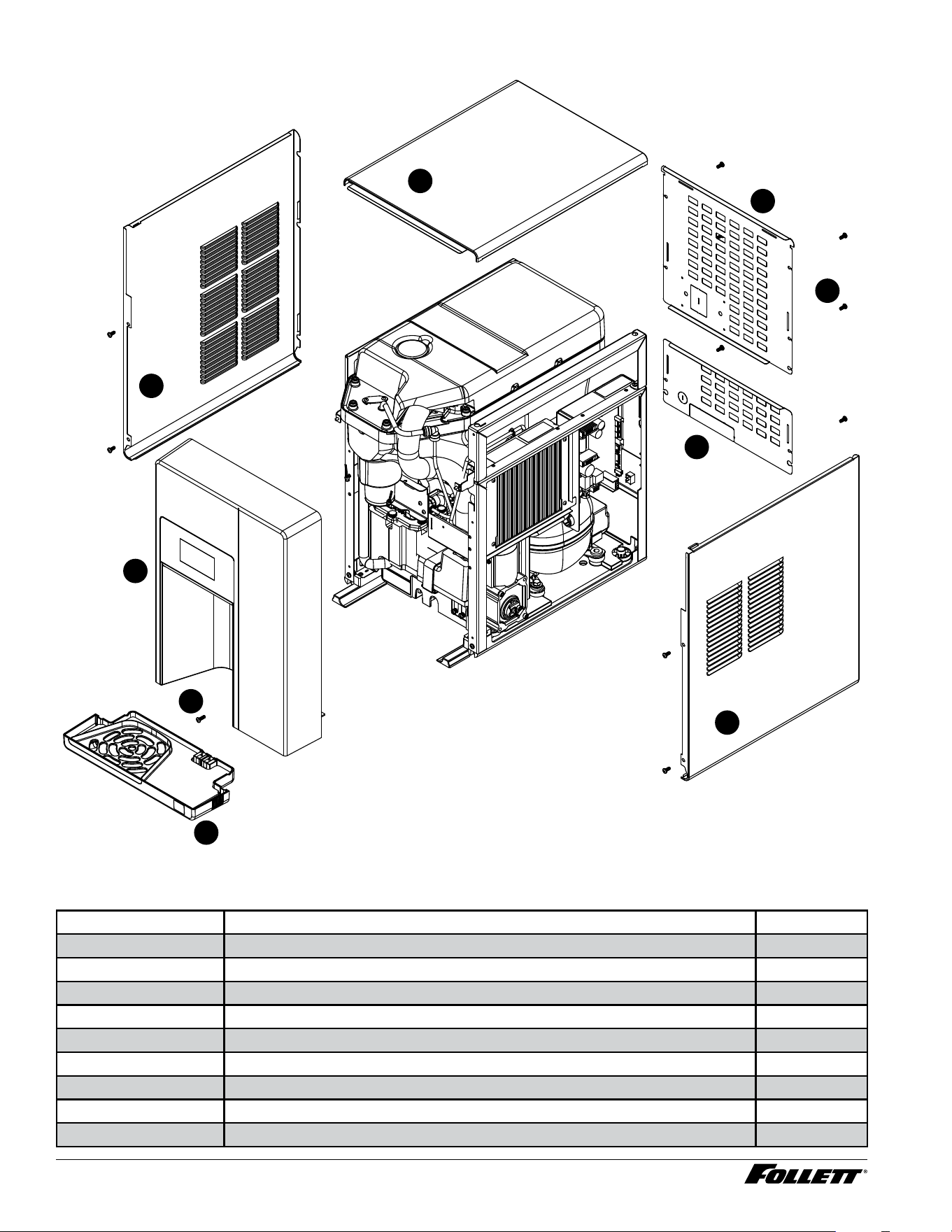
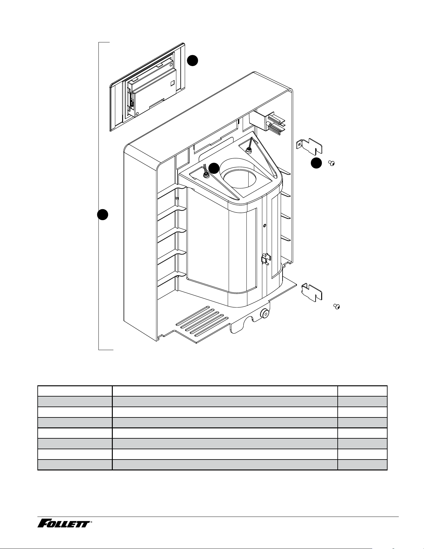
Exterior - Champion 7
6
4
3
1
5
2
9
7
8
Exterior - Champion 7
Reference # Description Part #
1 Panel, Left 01535954
2 Panel, Top Panel 01535939
3 Panel, Back Upper 01535962
4 Panel, Back Lower 01535970
5 Screw, Phillips Pan HD, 10-16x 1 (Qty 11) 01536010
6 Panel, Right 01535947
7 Drip Tray Assy 01535921
8 Screw, M5 X 16, Phillips Pan Head, (Blue) 01539097
9 Front Assembly, Champion 7 01535905
Not Shown Drip Tray Drain Kit 01535335
Dispenser and Ice Machine - 115 V 51
Reference # Description Part #
Not Shown Drip Tray Drain Kit with 4" legs 01535343
52 Dispenser and Ice Machine - 115 V
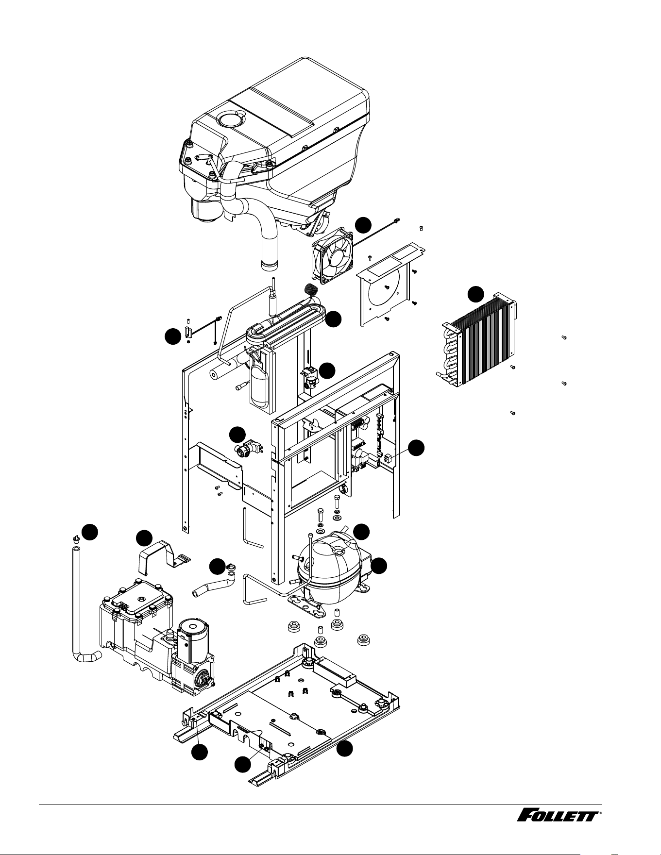
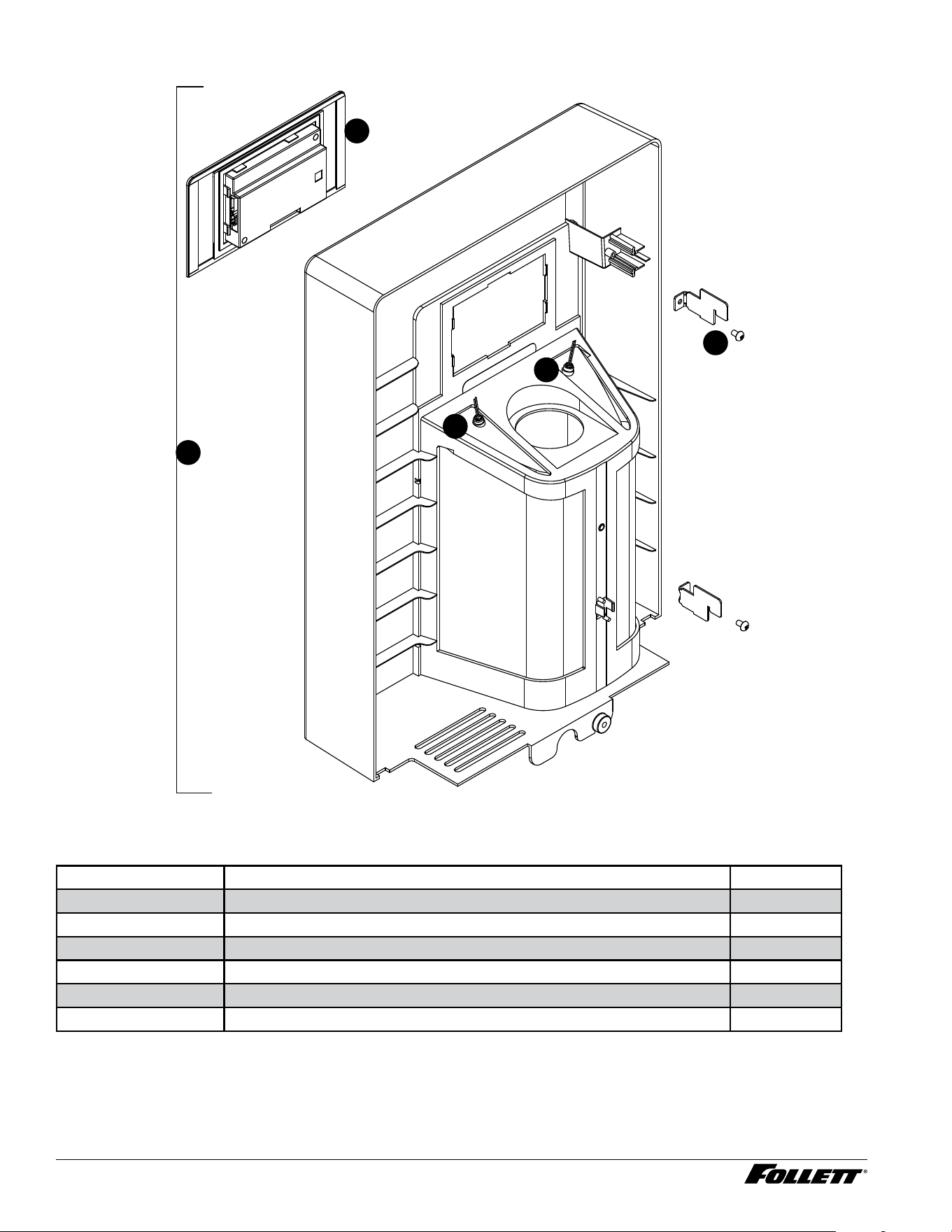
Interior - Champion 7
4
17
5
6
7
8
11
10
13
15
16
9
12
14
3
1
2
Dispenser and Ice Machine - 115 V 53
Interior - Champion 7
Reference # Description Part #
1 Condenser Fan, Cord and Hardware 01536143
2 Condenser 01536150
3 Heat Exchanger, Kit 01536168
4 Valve, Failsafe Solenoid 01536176
5 Solenoid, Water Feed, Champion 7/15 01536184
6 Capacitor, Gearmotor 01536200
7 Power Switch 01536218
8 Control Board with Stand-offs 01536226
9 Strap, Evaporator Module, Champion 7/15 01536259
10 Compressor with Mounting Hardware 01536234
11 Relay and Overload 01537307
12 Tube, Reservoir Drain, Champion 7/15 01536267
13 Tube, Reservoir Ice Melt, Champion 7/15 01536242
14 Sensor, Retainer Hardware Kit 01536275
15 Chassis Assembly 01536291
16 Spring, Drip Tray Sensor, Champion 7/15 01536283
17
UV Interlock Magnetic Switch
01536192
54 Dispenser and Ice Machine - 115 V
Exterior - Champion 15
6
4
3
1
5
2
9
7
8
Exterior - Champion 15
Reference # Description Part #
1 Panel, Left 01536499
2 Panel, Top Panel 01535939
3 Panel, Back Upper 01536507
4 Panel, Back Lower 01535970
5 Screw, Phillips Pan HD, M5x12 (Qty 11) 01536010
6 Panel, Right 01536481
7 Drip Tray Assy 01535921
8 Screw, M5 X 16, Phillips Pan Head, (Blue) 01539097
9 Front Assembly, 15 01536473
Dispenser and Ice Machine - 115 V 55
Reference # Description Part #
Not Shown Drip Tray Drain Kit 01535335
Not Shown Drip Tray Drain Kit with 4" legs 01535343
56 Dispenser and Ice Machine - 115 V
Interior - Champion 15
4
5
7
6
9
8
10
13
14
15
11
12
3
1
2
Dispenser and Ice Machine - 115 V 57
Interior - Champion 15
Reference # Description Part #
1 Condenser Fan, Cord and Hardware 01536143
2 Condenser 01536150
3 UV Interlock Magnetic Switch 01536192
4 Heat Exchanger, Kit 01536168
5 Valve, Failsafe Solenoid 01536176
6 Solenoid, Water Feed, Champion 7/15 01536184
7 Power Switch, Champion 7/15 01536218
8 Tube, Reservoir Drain, Champion 7/15 01536226
9 Strap, Evaporator Module, Champion 7/15 01536259
10 Tube, Reservoir Ice Melt, Champion 7/15 01536242
11 Compressor with Mounting Hardware 01536234
12 Relay and Overload 01537307
13 Sensor, Retainer Hardware Kit 01536242
14 Spring, Drip Tray Sensor, Champion 7/15 01536275
15 Chassis Assembly 01536291
Not shown Capacitor, Gearmotor 01536200
58 Dispenser and Ice Machine - 115 V
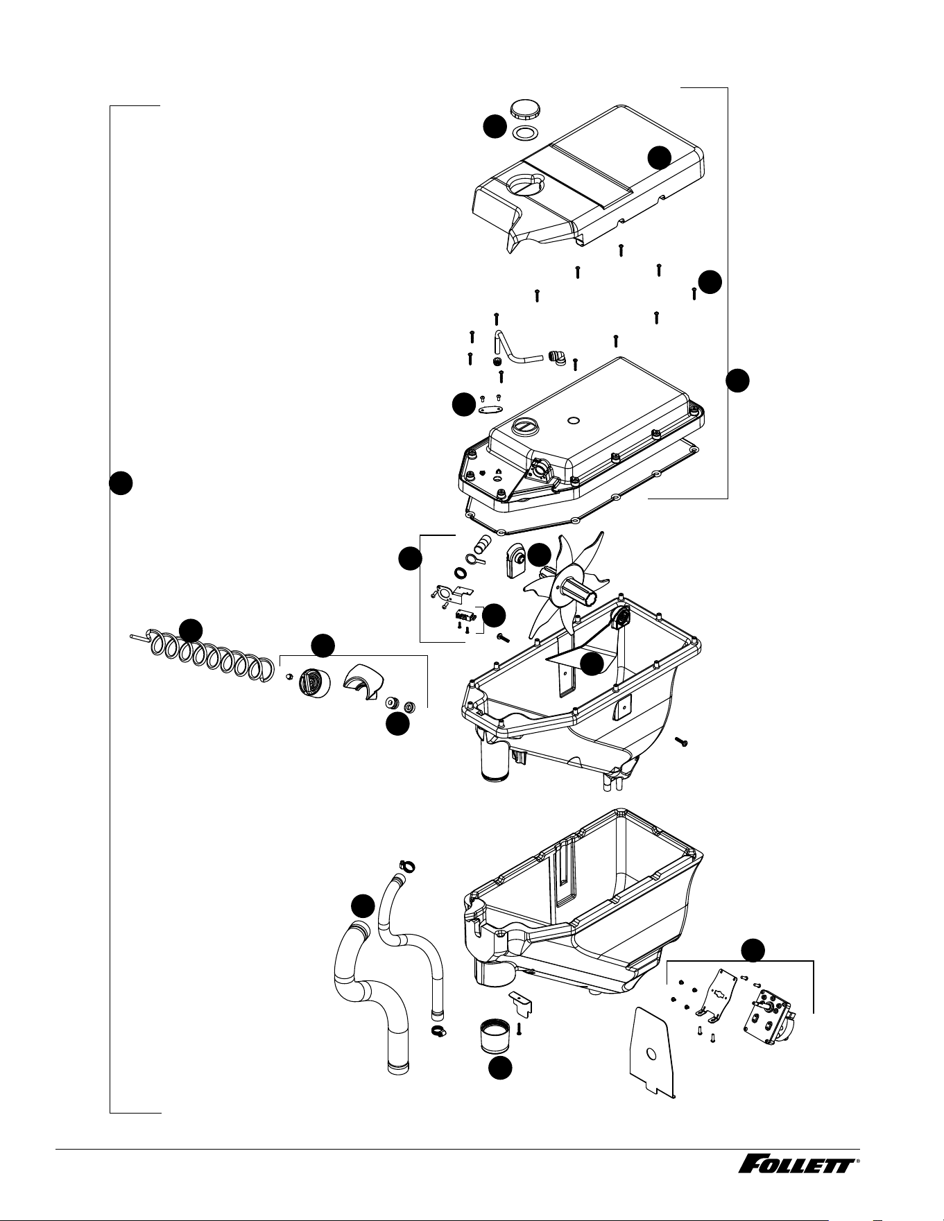
Bin Assembly - Champion 7
6
4
3
1
5
2
9
10
7
8
10
11
12
13
Dispenser and Ice Machine - 115 V 59
Bin Assembly - Champion 7
Reference # Description Part #
1 Cap and gasket 01535988
2 Bin Lid Insulation 01535996
3 LED Dispense 01535002
4 Bin Lid Screw (12) 01537471
5 Lid, Bin Assy 01536028
6 Switch, Shuttle 01536101
7 Shuttle Assembly 01536085
8 Seal 01536069
9 Auger, Dispense 01536036
10 Assembly, Motor Dispense 01536044
11 Ice Chute 01536119
12 Ice Transport Tubing with Insulation 01536077
13 Bin assembly, Champion 7 (does not include ice transport tube and
insulation)
01536135
60 Dispenser and Ice Machine - 115 V
Champion 15 Bin Assembly
6
4
3
1
5
2
9
10
7
8
13
13
10
11
12
14
Dispenser and Ice Machine - 115 V 61
Bin Assembly - Champion 15
Reference # Description Part #
1 Cap and gasket 01535988
2 Bin Lid Insulation 01536515
3 Bin Lid Screw (12) 01537471
4 LED Dispense 01535002
5 Lid, Bin Assy 01536523
6 Switch, Shuttle 01536101
7 Shuttle Assembly 01536085
8 Auger, Dispense 01536531
9 Seal 01536069
10 Assembly, Motor Dispense 01536044
11 Ice Chute 01536119
12 Ice Transport Tubing with Insulation 01536549
13 Agitator, Ice Bin, Champion 15 01536556
14 Bin Assembly, Champion 15 (does not include ice transport tube and
insulation)
01536564
62 Dispenser and Ice Machine - 115 V
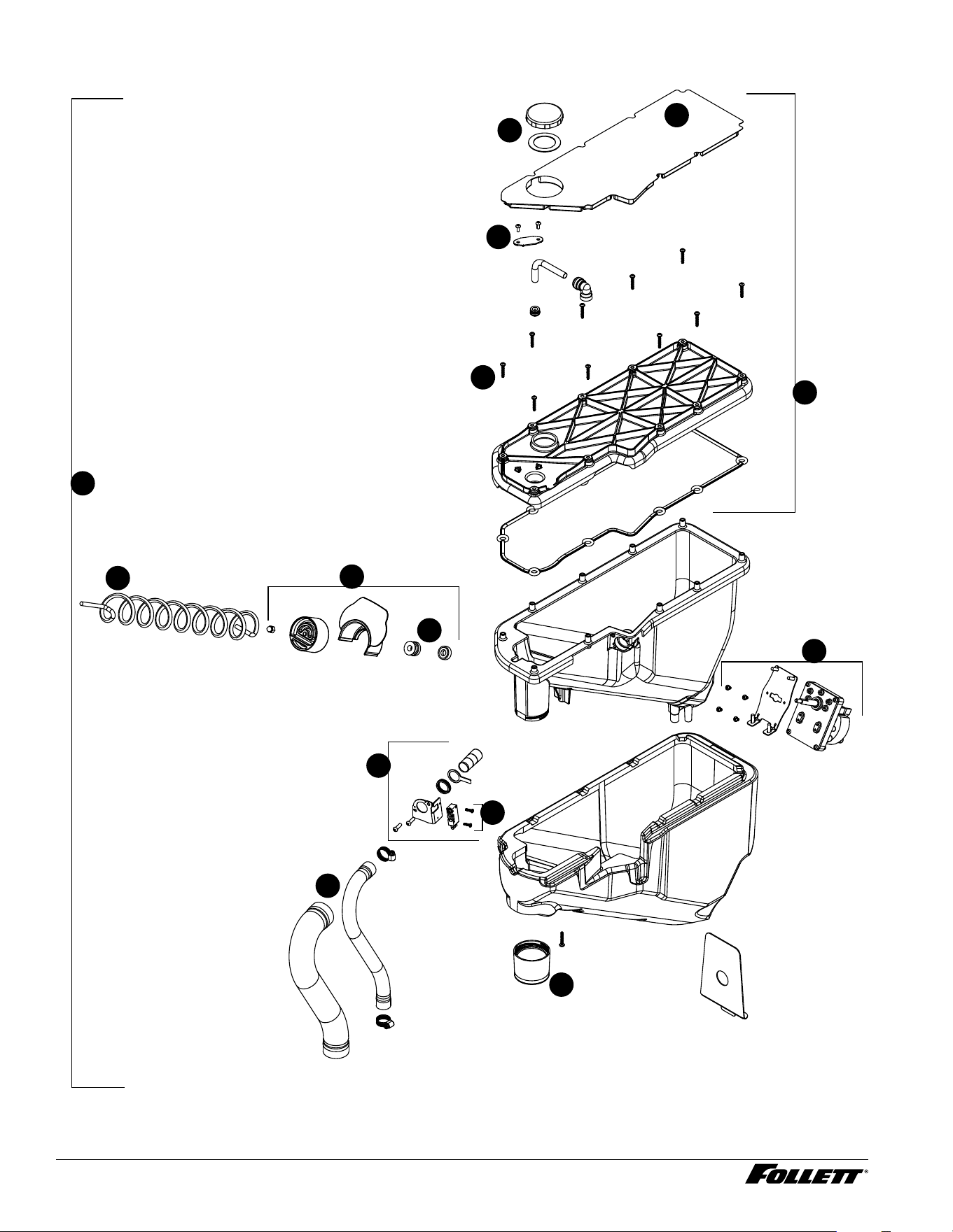
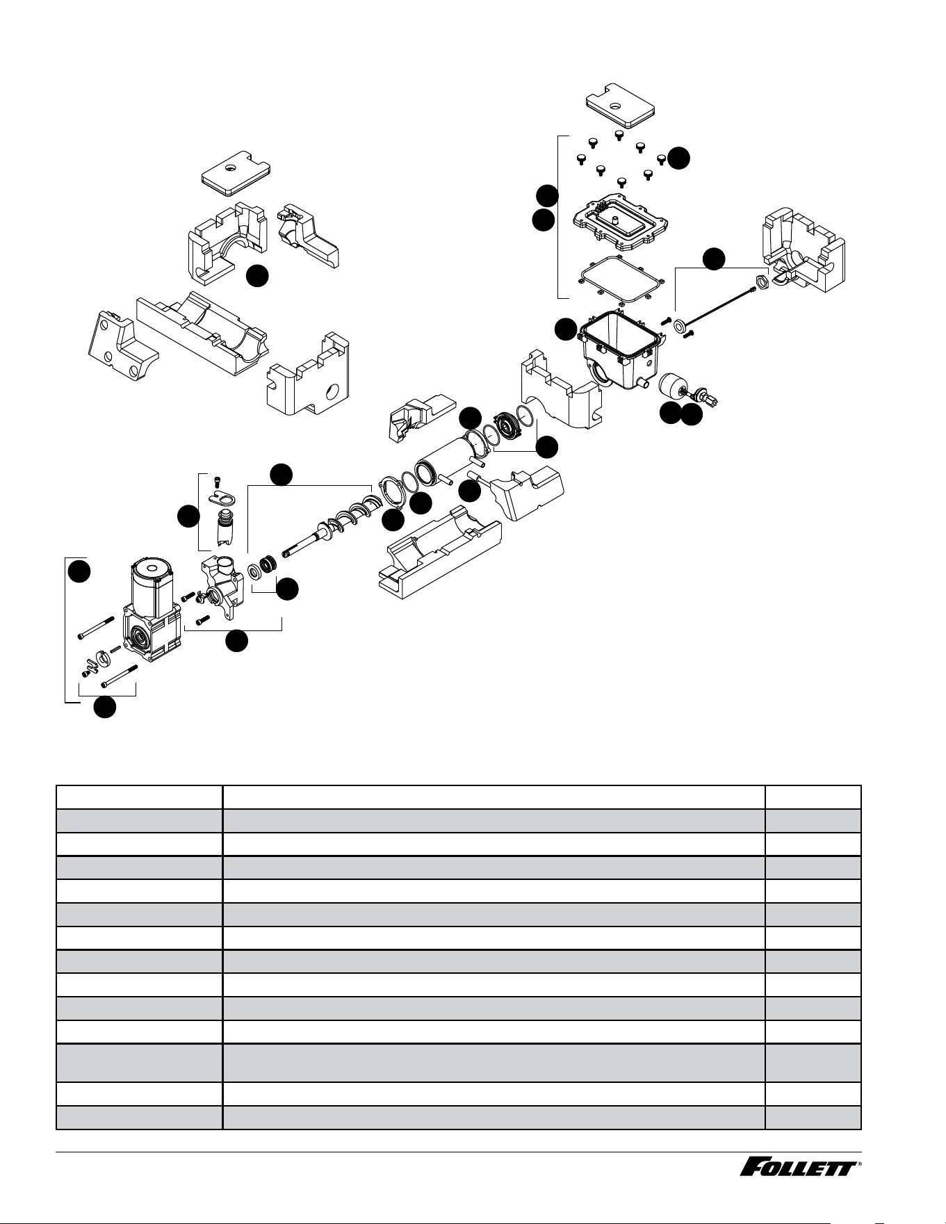
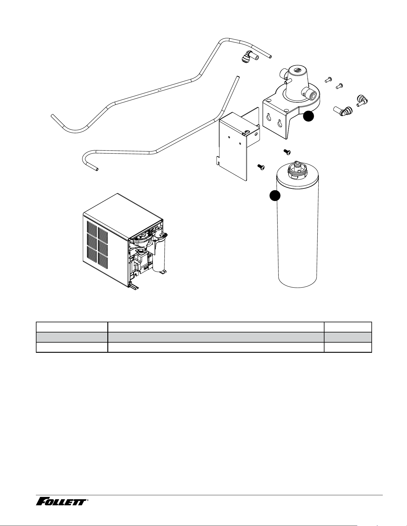
Evaporator Assembly
1
7
8
10
11
9
3
17
4
15
2
15
15
6
5
12
13
14
16
Evaporator Assembly
Reference # Description Part #
1 Insulation Kit (6 pieces) 01536309
2 Lid, Reservoir with Insulation and O-Ring (does not include bolt or insulation) 01536432
3 Light, UV 01536465
4 Float Valve 01536424
5 Housing, Bushing 01536416
6 Rear Flange Jacket 01536390
7 O-ring 01536408
8 Front Flange Jacket 01536382
9 Auger with front seal 01536366
10 Front Auger Seal and Spring 01536358
11 Main Housing with Front Seal, Screws, (includes vent tube, retainer and
o-ring)
01536341
12 Ice Compression Nozzle Assy 01536374
13 Hardware kit, Gearmotor 01536317
Dispenser and Ice Machine - 115 V 63
Reference # Description Part #
14 Gearmotor assembly 01536333
15 Reservoir and Float Complete Assy (does not include insulation) 01536440
15 Reservoir and Float Complete Assy, Rear Drain Unit only (does not include
insulation)
01554823
16 Thermistor, evaporator temperature 01545797
17 Hardware, Reservoir Lid (one M5 thumbscrew and one nut) 01536457
Not shown Nut, reservoir lid nut (m5 x .8 x 4 mm) 01537422
Not shown Tubing, reservoir vent tube 13.5" 01540905
Not shown Tubing, reservoir vent tube 16.5" 01540913
64 Dispenser and Ice Machine - 115 V
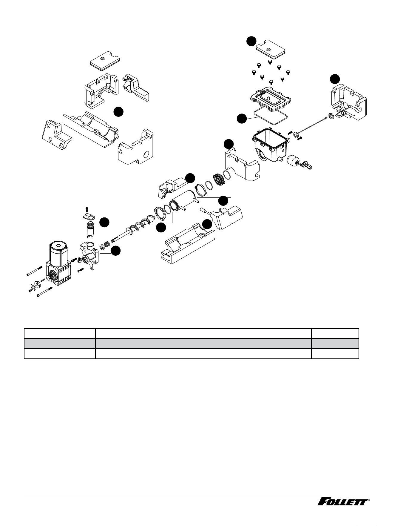
Evaporator Seal Kit
2
2
1
1
1
1
1
1
2
2
2
Evaporator Seal Kit
Reference # Description Part #
1 Insulation, Evaporator Module Kit, Champion 7/15 01536309
2 Evaporator Seal Kit 01536317
Dispenser and Ice Machine - 115 V 65
Front Panel - Champion 7
4
3
1
2
Front Panel - Champion 7
Reference # Description Part #
1 User Interface, Ice & Water, Champion 7/15 01535889
1 User Interface, Ice ONLY, Champion 7/15 01537059
1 User Interface, Ice & Water & Hot Tank, Champion 7/15 01537067
2 Bracket, Front Cover, Champion 7/15 01535897
3 LED Remote Dispense 01535913
4 Front Assembly, Champion 7 01536473
4 Front Assembly, Champion 15 01535905
66 Dispenser and Ice Machine - 115 V
Front Panel - Champion 15
4
3
3
1
2
Front Panel - Champion 15
Reference # Description Part #
1 User Interface, Ice & Water, Champion 7/15 01535889
1 User Interface, Ice ONLY, Champion 7/15 01537059
1 User Interface, Ice & Water & Hot Tank, Champion 7/15 01537067
2 Bracket, Front Cover, Champion 7/15 01535897
3 LED Remote Dispense 01535913
4 Front Assembly, Champion 15 01535905
Dispenser and Ice Machine - 115 V 67
Claris Filter
1
2
Claris Filter
Reference # Description Part #
1 Filter, Claris Filter, Champion 7/15 01548635
2 Manifold, Small Claris Filter 01548643
68 Dispenser and Ice Machine - 115 V
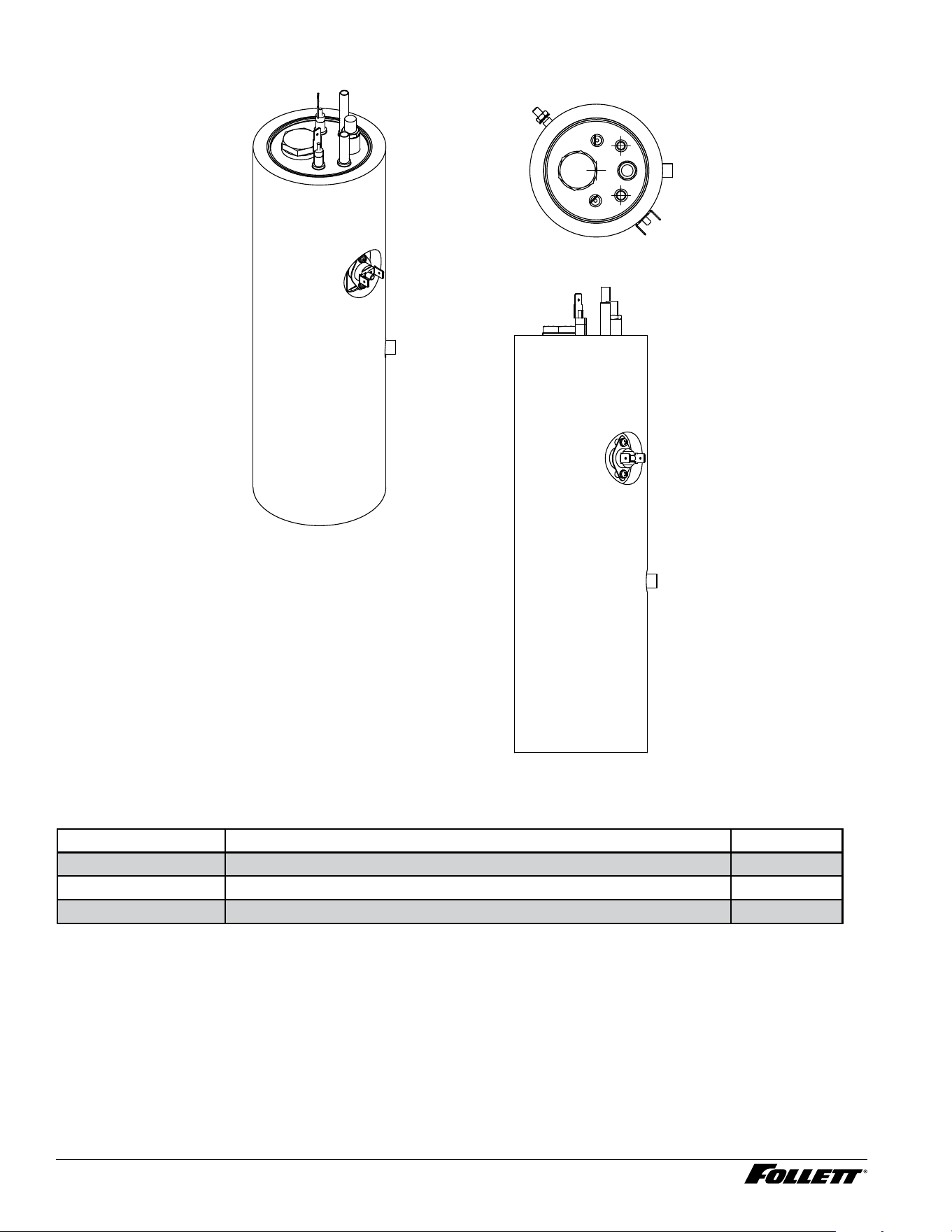
Hot Tank
Hot Tank
Reference # Description Part #
— Hot Tank 01553650
Not shown Hot Tank Dispense Pump 01555572
Not shown Hot Tank Water Fill Solenoid 01536176
Dispenser and Ice Machine - 115 V 69
Miscellaneous
Description Part #
Test strip, water hardness (10) 01548460
Kay-5 sanitizer, 1 oz packets (6) 01550821
SafeCLEAN PLUS, case of 6 01149954
SafeCLEAN PLUS, case of 24 01149962
Wiring harness, low-voltage water sensor 01537257
Wiring harness, high-voltage side 01537265
Wiring harness, hot water 01537273
Cable, 4 wire 01537281
Tube, hot water silicone 01537299
Kit, compressor start components 01537307
Tubing, reservoir vent tube 13.5" 01540905
Tubing, reservoir vent tube 16.5" 01540913
Nut, reservoir lid nut 01537422

01555127R00
© Follett Products, LLC 1/24
SafeCLEAN Plus is a trademark of Follett Products, LLC.
Chewblet and Follett are registered trademarks of Follett Products, LLC, registered in US.
801 Church Lane • Easton, PA 18040, USA
Toll free (877) 612-5086 • +1 (610) 252-7301
www.follettice.com
Warranty Registration and Equipment Evaluation
Thank you for purchasing Follett
®
equipment. Our goal is to deliver high value products and services that earn your complete
satisfaction by delivering high-value products and services backed by outstanding customer and technical support.
Please review the installation instructions thoroughly. It is important that the installation be performed to factory specications so
your equipment operates at its maximum efficiency.
Follett LLC will not be liable for any consequential damages, expenses, connecting or disconnecting charges, or any losses
resulting from a defect of the machine. For full warranty details, visit our website www.follettice.com/productwarranties.
Registering your equipment helps Follett track your equipment's service history should you need to contact us for technical
support, and your feedback helps us improve our products and services. Please visit www.follettice.com/support to complete the
Warranty Registration form.
Should you have any questions, please contact Follett's technical support group at (877) 612-5086 or (610) 252-7301 and we will
be happy to assist you.