
E S S E N T I A L S FOR LIFE
User
Manual
MODEL
GGSAP3500W
V 1.2 | 0524
Portable
Air-conditioner
3.5kW

2 3
For future reference, please record the following information which can be found on the rating plate
and the date of purchase which can be found on your sales invoice.
STORE DETAILS
STORE NAME
|
ADDRESS
|
TELEPHONE
|
PURCHASE DATE
|
PRODUCT DETAILS
MODEL NO.
|
SERIAL NO.*
|
Purchase Details Welcome
Congratulations on purchasing
your new Portable Air-conditioner!
The Sôlt brand is proudly
distributed within Australia
by Residentia Group Pty Ltd.
Please refer to the warranty card at the rear of this manual
for information regarding your product’s parts and labour
warranty, or visit us online at www.residentia.group
At Residentia Group, we are customer obsessed and our
Support Team are there to ensure you get the most out of
your appliance. Should you want to learn more about your
portable air-conditioner features, and importantly taking
care of your appliance when cleaning, our Support Team
are here to help.
You can use our online Support Centre at anytime by
visiting http://support.residentiagroup.com.au, or you can
contact us via calling us on 1300 11 HELP (4357).
It is important that you read through the following use and
care manual thoroughly to familiarise yourself with the
installation and operation requirements of your appliance
to ensure optimum performance.
Again, thank you for choosing an Sôlt appliance and we
look forward to being of service to you.
Kind Regards,
The Residentia Team
Residentia Group
—
Head Office.
165 Barkly Ave
Burnley
Victoria 3121
Australia
—
ACN.
600 546 656
—
Online.
residentia.group

4
ContentsThis page
is intentionally
left blank
2 Purchase Details
3 Welcome
6 General Safety Instructions
12 Your Portable Air-conditioner
14 Installation
17 Operation Instructions
21 Maintenance
22 FAQs & Troubleshooting Guide
24 Technical Specifications
25 Attach Your Receipt
26 Warranty Information
Sôlt recommends the use of original spare parts. When contacting our customer service team, please ensure
that you have the following information at hand (which can be found on your appliances’ rating plate).
— Model Number
— Serial Number
T . 1300 11 4357 | E. support@residentiagroup.com.au
Customer Care

6 7
READ CAREFULLY AND KEEP FOR FUTURE REFERENCE
Read this manual thoroughly before first use, even if
you are familiar with this type of product. The safety
precautions enclosed herein reduce the risk of fire, electric
shock and injury when correctly adhered to. Make sure
you understand all instructions and warnings.
Keep the manual in a safe place for future reference,
along with the completed warranty card and purchase
receipt. If you sell or transfer ownership of this product,
pass on these instructions to the new owner.
Always follow basic safety precautions and accident
prevention measures when using an electrical appliance,
including the following:
ELECTRICAL SAFETY AND CORD HANDLING
– Voltage: Before turning on the air conditioner, ensure
the electrical voltage and circuit frequency correspond
to those indicated on the appliance.
– Socket: Ensure your electrical outlet is properly
installed and earthed and complies with your local
electrical safety requirements.
– Moisture: To reduce the risk of electrocution, never
operate the appliance with wet hands; never
submerge it in water or spill liquids into it. Do not use it
in a bathroom or laundry, or where it can be splashed
with water.
– Power supply cord: Do not kink or damage the
cord. Do not pull the cord or place it near a heat
source. Always unwind the cord completely to avoid
overheating. Run the cord in such a way so that no
one will trip over it.
– Extension cord/adaptor: Do not use this appliance
with an extension cord or power adaptor.
– Damaged cord: If the supply cord is damaged, do
not use the appliance. A damaged power supply cord
must be replaced by the manufacturer or its service
agent or a similarly qualified person in order to avoid
a hazard. Contact our after sales support centre.
– WARNING: Do not use when damaged! In case of
damage, switch off the appliance, unplug it and
contact our after sales support centre. Do not pick
up or operate a damaged appliance, or after it
malfunctions or has been dropped or damaged in
any manner.
– Power button: Always use the on/off button on the
control panel to turn the product on or off. Never
simply switch the product on or off by plugging it into
or unplugging it from the wall socket.
– Disconnect: Turn off the unit first and then unplug
it when it is not in use and before maintenance or
cleaning, but do not unplug it when it is in operation,
as this could create a spark and cause a fire. Grip by
the plug, do not pull by the cord when disconnecting.
– RCD: The installation of a residual current device
(safety switch) is recommended to provide additional
safety protection when using electrical appliances. It
is advisable that a safety switch with a rated residual
operating current not exceeding 30mA be installed in
the electrical circuit supplying the appliance. See your
electrician for professional advice.
– Never try to open the housing, modify or alter the
product in any way.
USAGE CONDITIONS AND RESTRICTIONS
– Intended use: This appliance is intended for air
conditioning domestic environments. It is not suitable
for commercial, industrial or trade use. Do not use it
for any other purpose (such as cooling food, etc.) and
only use it as described in this manual.
– Common sense: These instructions are not intended to
cover every possible condition and situation. As with
any electrical appliance, common sense and caution
are therefore always recommended when installing,
operating and maintaining the unit.
– No outdoor use: Do not use the unit outdoors.
It is for indoor use only.
– Usage restriction: This appliance is not intended
for use by persons (including children) with reduced
physical, sensory or mental capabilities, or lack of
experience and knowledge, unless they have been
given supervision or instruction concerning use of
the appliance in a safe way and understand the
hazards involved.
– No external timer: This appliance is not intended to
be used with an external timer or a separate remote
control system.
– WARNING: Do not cover! Do not cover the air
conditioner or obstruct any air inlet or outlet grilles.
Obstructing these openings causes a fire hazard,
reduces the operating efficiency and may lead to
malfunction or damage.
– Air outlets: Do not insert any objects, or your fingers,
into the air outlet, and make sure to warn children of
the dangers.
– Children: Supervise children to ensure they do not
play with the appliance. Close supervision is necessary
when any appliance is used by or near children.
Cleaning and user maintenance shall not be made by
children without supervision.
General Safety Instructions
– Unattended: Do not leave the appliance unattended
when in use.
– Attachments: The use of attachments not
recommended or sold by the manufacturer may cause
fire, electric shock or injury.
– Startup settings: Set the unit to maximum cooling
and high speed ventilation for the initial startup, then
adjust the unit down to a more comfortable setting
as required.
– Airflow: Do not direct the airflow onto plants or
animals, as long and direct exposure to cold air from
the air conditioner could adversely affect them.
– Cold air exposure: Never remain directly exposed
to the flow of cold air for a long time, as direct
and prolonged exposure to cold air from the air
conditioner could be dangerous for your health. Take
particular care in rooms where there are children, old,
or sick people.
– Moving the appliance: When moving the air
conditioner, always turn off and disconnect the power
supply, and move it slowly.
– Never place any objects containing liquid, such as
flower vases or drinks, on top of the product.
– Never handle the product with wet hands or
while barefoot.
– Switch off and unplug the product when it is not in use.
– WARNING! If the product should tip over, immediately
turn it off and unplug it.
CLEANING AND MAINTENANCE
– Disconnect: Make sure the appliance is disconnected
from the power supply when it will not be used for a
long time and before carrying out any cleaning
or maintenance.
– Air filter: Keep the air filter clean. Do not use the unit
without the air filters fitted. Using it without air filters
could cause an excessive accumulation of dust or
waste on the inner parts of the device with possible
subsequent failures.
– Service and repair: The air conditioner has no
user-serviceable parts contained inside. Do not
attempt to disassemble, modify or conduct repairs on
this unit. It has been built in accordance with relevant
safety and performance standards. An electrical
specialist must carry out all repairs. Contact our after
sales support line for advice on service.
– Cooling efficiency: To help cooling efficiency, keep
blinds and curtains closed during the sunniest part of
the day. Close off any fireplace damper, floor and/or
wall register so cool air does not escape through the
chimney or duct work.
INSTALLATION
– Proper installation: Install the appliance according
to the instructions in this manual and national wiring
regulations. Improper installation may result in the
risk of fire, electric shock and/or injury. We assume no
responsibility for any eventual damages caused by
improper installation or faulty use.
– Upright position: Place the unit on a flat surface to
reduce the risk of it tipping over. Do not tilt the unit,
always keep it upright. If the unit has not been kept
upright (such as during storage), wait for at least
24 hours before operation.
– Obstructions: Do not locate the air conditioner where
furniture or other objects can obstruct the airflow.
– Do not cover: Do not cover the air conditioner or
obstruct any air inlet or outlet grilles. Obstructing
these openings causes a fire hazard, reduces the
operating efficiency and may lead to malfunction or
damage.
– Chemicals: Do not install the air conditioner in
environments where the air could contain gas, oil
or sulphur. Do not let chemical substances come
into contact with the unit. Do not use the unit in the
presence of flammable substances or vapour such as
alcohol, insecticides, petrol etc.
– Heat: Do not install the air conditioner near sources
of heat, or exposed to direct sunlight.
– Room size: The unit is designed for use in a room
of 16–23m² size.
– Clearances: Always keep a clearance of at least
30cm from walls, furniture and curtains.
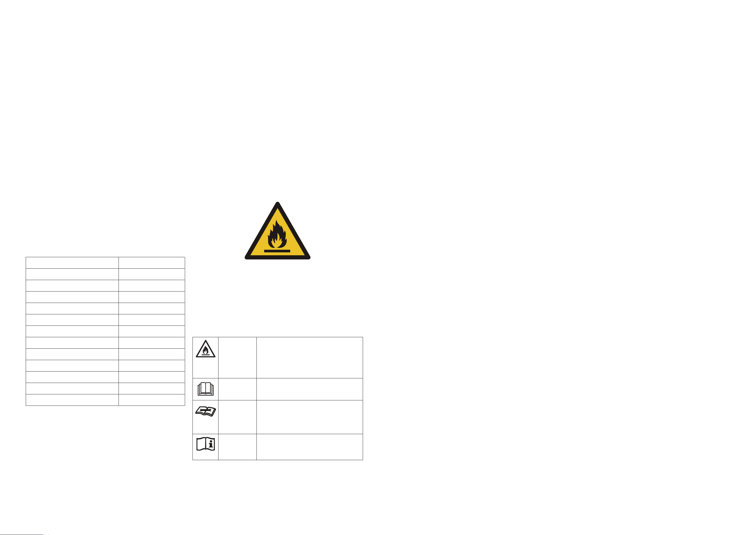
This symbol shows that this appliance uses a flammable refrigerant
(R290). If the refrigerant is leaked and exposed to an external ignition
source, there is a risk of fire.
8 9
General Safety Instructions (Continued)
WARNING FOR USING R32/R290 REFRIGERANT
– Do not use means to accelerate the defrosting
process or to clean, other than those recommended
by the manufacturer.
– The appliance shall be stored in a room without
continuously operating ignition sources (for example:
open flames, an operating gas appliance or an
operating electric heater).
– Do not pierce or burn.
– Be aware that the refrigerants may not contain
an odour.
– Appliance should be installed, operated and stored
in a room with a floor area according to the amount
of refrigerant to be charged. For specific information
on the type of gas and the amount, please refer to
the relevant label on the unit itself. When there are
differences between the label and the manual on the
Min. room area description, the description on label
shall prevail.
For R290:
Amount of refrigerant (kg) Min. room area (m²)
≤ 0.0836 4
> 0.0836 and ≤ 0.1045 5
> 0.1045 and ≤ 0.1254 6
> 0.1254 and ≤ 0.1463 7
> 0.1463 and ≤ 0.1672 8
> 0.1672 and ≤ 0.1881 9
> 0.1881 and ≤ 0.2090 10
> 0.2090 and ≤ 0.2299 11
> 0.2299 and ≤ 0.2508 12
> 0.2508 and ≤ 0.2717 13
> 0.2717 and ≤ 0.2926 14
> 0.2926 and ≤ 0.3135 15
– Compliance with national gas regulations shall be
observed.
– Keep ventilation openings clear of obstruction.
– The appliance shall be stored so as to prevent
mechanical damage from occurring.
– A warning that the appliance shall be stored in a
well-ventilated area where the room size corresponds
to the room area as specified for operation.
– Any person who is involved with working on or
breaking into a refrigerant circuit should hold
a current valid certificate from an industry-
accredited assessment authority, which authorises
their competence to handle refrigerants safely in
accordance with an industry recognised
assessment specification.
– Servicing shall only be performed as recommended by
the equipment manufacturer. Maintenance and repair
requiring the assistance of other skilled personnel shall
be carried out under the supervision of the person
competent in the use of flammable refrigerants.
– The appliance shall be stored in a room without
continuously operating open flames (for example an
operating gas appliance) and ignition sources (for
example an operating electric heater).
Explanation of symbols displayed on the unit
(For the unit adopts R32/R290 Refrigerant only):
Safety
Precautions
Page 6
WARNING for Using R32/R290 Refrigerant
Do not use means to accelerate the defrosting process or to clean, other than those recommended by
the manufacturer.
The appliance shall be stored in a room without continuously operating ignition sources (for example:
open flames, an operating gas appliance or an operating electric heater).
Do not pierce or burn.
Be aware that the refrigerants may not contain an odour.
Compliance with national gas regulations shall be observed.
Keep ventilation openings clear of obstruction.
The appliance shall be stored so as to prevent mechanical damage from occurring.
A warning that the appliance shall be stored in a well-ventilated area where the room size corresponds
to the room area as specified for operation.
Any person who is involved with working on or breaking into a refrigerant circuit should hold a current
valid certificate from an industry-accredited assessment authority, which authorises their competence
to handle refrigerants safely in accordance with an industry recognised assessment specification.
Servicing shall only be performed as recommended by the equipment manufacturer. Maintenance
and repair requiring the assistance of other skilled personnel shall be carried out under the supervision
of the person competent in the use of flammable refrigerants.
The appliance shall be stored in a room without continuously operating open flames (for example an
operating gas appliance) and ignition sources (for example an operating electric heater).
Appliance should be installed, operated and stored in a room with a floor area according to the amount
of refrigerant to be charged. For specific information on the type of gas and the amount, please refer
to the relevant label on the unit itself.
Appliance should be installed, operated and stored in a room with a floor area larger than 4 m .
Caution: Risk of fire/
flammable materials
Explanation of symbols displayed on the unit(For the
unit adopts R32/R290 Refrigerant only):
WARNING
CAUTION
CAUTION
CAUTION
This symbol shows that this appliance used a
flammable refrigerant. If the refrigerant is leaked and
exposed to an external ignition source, there is a risk
of fire.
This symbol shows that the operation manual
should be read carefully.
This symbol shows that a service personnel should be
handling this equipment with reference to the
installation manual.
This symbol shows that information is available such
as the operating manual or installation manual.
2
WARNING
This symbol shows that this appliance
used a flammable refrigerant. If the
refrigerant is leaked and exposed to
an external ignition source, there is a
risk of fire.
Safety
Precautions
Page 6
WARNING for Using R32/R290 Refrigerant
Do not use means to accelerate the defrosting process or to clean, other than those recommended by
the manufacturer.
The appliance shall be stored in a room without continuously operating ignition sources (for example:
open flames, an operating gas appliance or an operating electric heater).
Do not pierce or burn.
Be aware that the refrigerants may not contain an odour.
Compliance with national gas regulations shall be observed.
Keep ventilation openings clear of obstruction.
The appliance shall be stored so as to prevent mechanical damage from occurring.
A warning that the appliance shall be stored in a well-ventilated area where the room size corresponds
to the room area as specified for operation.
Any person who is involved with working on or breaking into a refrigerant circuit should hold a current
valid certificate from an industry-accredited assessment authority, which authorises their competence
to handle refrigerants safely in accordance with an industry recognised assessment specification.
Servicing shall only be performed as recommended by the equipment manufacturer. Maintenance
and repair requiring the assistance of other skilled personnel shall be carried out under the supervision
of the person competent in the use of flammable refrigerants.
The appliance shall be stored in a room without continuously operating open flames (for example an
operating gas appliance) and ignition sources (for example an operating electric heater).
Appliance should be installed, operated and stored in a room with a floor area according to the amount
of refrigerant to be charged. For specific information on the type of gas and the amount, please refer
to the relevant label on the unit itself.
Appliance should be installed, operated and stored in a room with a floor area larger than 4 m .
Caution: Risk of fire/
flammable materials
Explanation of symbols displayed on the unit(For the
unit adopts R32/R290 Refrigerant only):
WARNING
CAUTION
CAUTION
CAUTION
This symbol shows that this appliance used a
flammable refrigerant. If the refrigerant is leaked and
exposed to an external ignition source, there is a risk
of fire.
This symbol shows that the operation manual
should be read carefully.
This symbol shows that a service personnel should be
handling this equipment with reference to the
installation manual.
This symbol shows that information is available such
as the operating manual or installation manual.
2
CAUTION
This symbol shows that the operation
manual should be read carefully.
Safety
Precautions
Page 6
WARNING for Using R32/R290 Refrigerant
Do not use means to accelerate the defrosting process or to clean, other than those recommended by
the manufacturer.
The appliance shall be stored in a room without continuously operating ignition sources (for example:
open flames, an operating gas appliance or an operating electric heater).
Do not pierce or burn.
Be aware that the refrigerants may not contain an odour.
Compliance with national gas regulations shall be observed.
Keep ventilation openings clear of obstruction.
The appliance shall be stored so as to prevent mechanical damage from occurring.
A warning that the appliance shall be stored in a well-ventilated area where the room size corresponds
to the room area as specified for operation.
Any person who is involved with working on or breaking into a refrigerant circuit should hold a current
valid certificate from an industry-accredited assessment authority, which authorises their competence
to handle refrigerants safely in accordance with an industry recognised assessment specification.
Servicing shall only be performed as recommended by the equipment manufacturer. Maintenance
and repair requiring the assistance of other skilled personnel shall be carried out under the supervision
of the person competent in the use of flammable refrigerants.
The appliance shall be stored in a room without continuously operating open flames (for example an
operating gas appliance) and ignition sources (for example an operating electric heater).
Appliance should be installed, operated and stored in a room with a floor area according to the amount
of refrigerant to be charged. For specific information on the type of gas and the amount, please refer
to the relevant label on the unit itself.
Appliance should be installed, operated and stored in a room with a floor area larger than 4 m .
Caution: Risk of fire/
flammable materials
Explanation of symbols displayed on the unit(For the
unit adopts R32/R290 Refrigerant only):
WARNING
CAUTION
CAUTION
CAUTION
This symbol shows that this appliance used a
flammable refrigerant. If the refrigerant is leaked and
exposed to an external ignition source, there is a risk
of fire.
This symbol shows that the operation manual
should be read carefully.
This symbol shows that a service personnel should be
handling this equipment with reference to the
installation manual.
This symbol shows that information is available such
as the operating manual or installation manual.
2
CAUTION
This symbol shows that a service
personnel should be handling this
equipment with reference to the
installation manual.
Safety
Precautions
Page 6
WARNING for Using R32/R290 Refrigerant
Do not use means to accelerate the defrosting process or to clean, other than those recommended by
the manufacturer.
The appliance shall be stored in a room without continuously operating ignition sources (for example:
open flames, an operating gas appliance or an operating electric heater).
Do not pierce or burn.
Be aware that the refrigerants may not contain an odour.
Compliance with national gas regulations shall be observed.
Keep ventilation openings clear of obstruction.
The appliance shall be stored so as to prevent mechanical damage from occurring.
A warning that the appliance shall be stored in a well-ventilated area where the room size corresponds
to the room area as specified for operation.
Any person who is involved with working on or breaking into a refrigerant circuit should hold a current
valid certificate from an industry-accredited assessment authority, which authorises their competence
to handle refrigerants safely in accordance with an industry recognised assessment specification.
Servicing shall only be performed as recommended by the equipment manufacturer. Maintenance
and repair requiring the assistance of other skilled personnel shall be carried out under the supervision
of the person competent in the use of flammable refrigerants.
The appliance shall be stored in a room without continuously operating open flames (for example an
operating gas appliance) and ignition sources (for example an operating electric heater).
Appliance should be installed, operated and stored in a room with a floor area according to the amount
of refrigerant to be charged. For specific information on the type of gas and the amount, please refer
to the relevant label on the unit itself.
Appliance should be installed, operated and stored in a room with a floor area larger than 4 m .
Caution: Risk of fire/
flammable materials
Explanation of symbols displayed on the unit(For the
unit adopts R32/R290 Refrigerant only):
WARNING
CAUTION
CAUTION
CAUTION
This symbol shows that this appliance used a
flammable refrigerant. If the refrigerant is leaked and
exposed to an external ignition source, there is a risk
of fire.
This symbol shows that the operation manual
should be read carefully.
This symbol shows that a service personnel should be
handling this equipment with reference to the
installation manual.
This symbol shows that information is available such
as the operating manual or installation manual.
2
CAUTION
This symbol shows that information
is available such as the operating
manual or installation manual
Transport of equipment containing flammable refrigerants
See transport regulations
Marking of equipment using signs
See local regulations
Disposal of equipment using flammable refrigerants
See national regulations.
Storage of equipment/appliances
The storage of equipment should be in accordance with
the manufacturer’s instructions.
Storage of packed (unsold) equipment
Storage package protection should be constructed such
that mechanical damage to the equipment inside the
package will not cause a leak of the refrigerant charge.
The maximum number of pieces of equipment permitted
to be stored together will be determined by local
regulations.
Information on servicing
1. Checks to the area
Prior to beginning work on systems containing flammable
refrigerants, safety checks are necessary to ensure
that the risk of ignition is minimised. For repair to the
refrigerating system, the following precautions shall be
complied with prior to conducting work on the system.
2. Work procedure
Work shall be undertaken under a controlled
procedure so as to minimise the risk of a flammable
gas or vapour being present while the work is being
performed.
3. General work area
All maintenance staff and others working in the local
area shall be instructed on the nature of work being
carried out. Work in confined spaces shall be avoided.
The area around the workspace shall be sectioned off.
Ensure that the conditions within the area have been
made safe by control of flammable material.
4. Checking for presence of refrigerant
The area shall be checked with an appropriate
refrigerant detector prior to and during work, to ensure
the technician is aware of potentially flammable
atmospheres. Ensure that the leak detection
equipment being used is suitable for use with
flammable refrigerants, i.e. non-sparking, adequately
sealed or intrinsically safe.
5. Presence of fire extinguisher
If any hot work is to be conducted on the refrigeration
equipment or any associated parts, appropriate fire
extinguishing equipment shall be available to hand.
Have a dry powder or CO2 fire extinguisher adjacent
to the charging area.
6. No ignition sources
No person carrying out work in relation to a
refrigeration system which involves exposing any
pipe work that contains or has contained flammable
refrigerant shall use any sources of ignition in such a
manner that it may lead to the risk of fire or explosion.
All possible ignition sources, including cigarette
smoking, should be kept sufficiently far away from the
site of installation, repairing, removing and disposal,
during which flammable refrigerant can possibly
be released to the surrounding space. Prior to work
taking place, the area around the equipment is to be
surveyed to make sure that there are no flammable
hazards or ignition risks. No Smoking signs shall be
displayed.
7. Ventilated area
Ensure that the area is in the open or that it is
adequately ventilated before breaking into the system
or conducting any hot work. A degree of ventilation
shall continue during the period that the work is
carried out. The ventilation should safely disperse any
released refrigerant and preferably expel it externally
into the atmosphere.
8. Checks to the refrigeration equipment
Where electrical components are being changed,
they shall be fit for the purpose and to the correct
specification. At all times the manufacturer’s
maintenance and service guidelines shall be followed.
If in doubt consult the manufacturer’s technical
department for assistance. The following checks
shall be applied to installations using flammable
refrigerants:
The charge size is in accordance with the room size
within which the refrigerant containing parts are
installed;
The ventilation machinery and outlets are operating
adequately and are not obstructed;
If an indirect refrigerating circuit is being used, the
secondary circuit shall be checked for the presence
of refrigerant; Marking to the equipment continues
to be visible and legible. Markings and signs that are
illegible shall be corrected;
Refrigeration pipe or components are installed in a
position where they are unlikely to be exposed to any
substance which may corrode refrigerant containing
components, unless the components are constructed
of materials which are inherently resistant to being
corroded or are suitably protected against being
so corroded.
Caution: Risk of fire /
flammable materials

10 11
Information on servicing (Continued)
9. Checks to electrical devices
Repair and maintenance to electrical components shall
include initial safety checks and component inspection
procedures. If a fault exists that could compromise
safety, then no electrical supply shall be connected to
the circuit until it is satisfactorily dealt with. If the fault
cannot be corrected immediately but it is necessary to
continue operation, an adequate temporary solution
shall be used. This shall be reported to the owner of the
equipment so all parties are advised.
Initial safety checks shall include:
That capacitors are discharged: this shall be done in a
safe manner to avoid possibility of sparking;
That there no live electrical components and wiring
are exposed while charging, recovering or purging the
system; That there is continuity of earth bonding.
10. Repairs to sealed components
• During repairs to sealed components, all electrical
supplies shall be disconnected from the equipment
being worked upon prior to any removal of sealed
covers, etc. If it is absolutely necessary to have an
electrical supply to equipment during servicing, then
a permanently operating form of leak detection shall
be located at the most critical point to warn of a
potentially hazardous situation.
• Particular attention shall be paid to the following to
ensure that by working on electrical components, the
casing is not altered in such a way that the level of
protection is affected. This shall include damage to
cables, excessive number of connections, terminals
not made to original specification, damage to seals,
incorrect fitting of glands, etc. Ensure that apparatus
is mounted securely. Ensure that seals or sealing
materials have not degraded such that they no
longer serve the purpose of preventing the ingress of
flammable atmospheres. Replacement parts shall be in
accordance with the manufacturer’s specifications.
NOTE: The use of silicon sealant may inhibit the
effectiveness of some types of leak detection
equipment. Intrinsically safe components do not have
to be isolated prior to working on them.
11. Repair to intrinsically safe components
Do not apply any permanent inductive or capacitance
loads to the circuit without ensuring that this will
not exceed the permissible voltage and current
permitted for the equipment in use. Intrinsically safe
components are the only types that can be worked on
while live in the presence of a flammable atmosphere.
The test apparatus shall be at the correct rating.
Replace components only with parts specified by the
manufacturer. Other parts may result in the ignition of
refrigerant in the atmosphere from a leak.
12. Cabling
Check that cabling will not be subject to wear, corrosion,
excessive pressure, vibration, sharp edges or any other
adverse environmental effects. The check shall also take
into account the effects of aging or continual vibration
from sources such as compressors or fans.
13. Detection of flammable refrigerants
Under no circumstances shall potential sources of
ignition be used in the searching for or detection of
refrigerant leaks. A halide torch (or any other detector
using a naked flame) shall not be used.
14. Leak detection methods
The following leak detection methods are deemed
acceptable for systems containing flammable
refrigerants. Electronic leak detectors shall be used
to detect flammable refrigerants, but the sensitivity
may not be adequate, or may need re-calibration.
(Detection equipment shall be calibrated in a
refrigerant-free area.) Ensure that the detector is not
a potential source of ignition and is suitable for the
refrigerant used. Leak detection equipment shall be
set at a percentage of the LFL of the refrigerant and
shall be calibrated to the refrigerant employed and
the appropriate percentage of gas (25 % maximum)
is confirmed. Leak detection fluids are suitable for
use with most refrigerants but the use of detergents
containing chlorine shall be avoided as the chlorine
may react with the refrigerant and corrode the copper
pipe-work. If a leak is suspected, all naked flames shall
be removed/ extinguished. If a leakage of refrigerant
is found which requires brazing, all of the refrigerant
shall be recovered from the system, or isolated (by
means of shut off valves) in a part of the system
remote from the leak. Oxygen free nitrogen (OFN) shall
then be purged through the system both before and
during the brazing process.
15. Removal and evacuation
When breaking into the refrigerant circuit to make
repairs or for any other purpose conventional
procedures shall be used. However, it is important
that best practice is followed since flammability is
a consideration. The following procedure shall be
adhered to:
Remove refrigerant; Purge the circuit with inert gas;
Evacuate; Purge again with inert gas; Open the circuit
by cutting or brazing.
The refrigerant charge shall be recovered into the
correct recovery cylinders. The system shall be flushed
with OFN to render the unit safe. This process may
need to be repeated several times. Compressed air or
oxygen shall not be used for this task. Flushing shall be
achieved by breaking the vacuum in the system with
OFN and continuing to fill until the working pressure is
achieved, then venting to atmosphere, and
finally pulling down to a vacuum. This process shall be
repeated until no refrigerant is within the system.
When the final OFN charge is used, the system shall be
vented down to atmospheric pressure to enable work to
take place. This operation is absolutely vital if brazing
operations on the pipe-work are to take place. Ensure
that the outlet for the vacuum pump is not close to any
ignition sources and there is ventilation available.
16. Charging procedures
In addition to conventional charging procedures, the
following requirements shall be followed. Ensure that
contamination of different refrigerants does not occur
when using charging equipment. Hoses or lines shall
be as short as possible to minimise the amount of
refrigerant contained in them.
Cylinders shall be kept upright.
Ensure that the refrigeration system is earthed prior to
charging the system with refrigerant.
Label the system when charging is complete
(if not already).
Extreme care shall be taken not to overfill the
refrigeration system. Prior to recharging the system
it shall be pressure tested with OFN. The system shall
be leak tested on completion of charging but prior to
commissioning. A follow up leak test shall be carried
out prior to leaving the site.
17. Decommissioning
Before carrying out this procedure, it is essential
that the technician is completely familiar with the
equipment and all its detail. It is recommended good
practice that all refrigerants are recovered safely.
Prior to the task being carried out, an oil and
refrigerant sample shall be taken in case analysis is
required prior to re-use of reclaimed refrigerant. It is
essential that electrical power is available before the
task is commenced.
a. Become familiar with the equipment and its operation.
b. Isolate system electrically.
c. Before attempting the procedure ensure that:
Mechanical handling equipment is available, if
required, for handling refrigerant cylinders;All
personal protective equipment is available and being
used correctly; The recovery process is supervised at
all times by a competent person; Recovery equipment
and cylinders conform to the appropriate standards.
d. Pump down refrigerant system, if possible.
e. If a vacuum is not possible, make a manifold so that
refrigerant can be removed from various parts of
the system.
f. Make sure that cylinder is situated on the scales before
recovery takes place.
g. Start the recovery machine and operate in accordance
with manufacturer’s instructions.
h. Do not overfill cylinders. (No more than 80 % volume
liquid charge).
i. Do not exceed the maximum working pressure of the
cylinder, even temporarily.
j. When the cylinders have been filled correctly and the
process completed, make sure that the cylinders and
the equipment are removed from site promptly and all
isolation valves on the equipment are closed off.
k. Recovered refrigerant shall not be charged into
another refrigeration system unless it has been
cleaned and checked.
18. Labelling
Equipment shall be labelled stating that it has been
de-commissioned and emptied of refrigerant. The
label shall be dated and signed. Ensure that there
are labels on the equipment stating the equipment
contains flammable refrigerant.
19. Recovery
When removing refrigerant from a system, either for
servicing or decommissioning, it is recommended good
practice that all refrigerants are removed safely. When
transferring refrigerant into cylinders, ensure that only
appropriate refrigerant recovery cylinders are employed.
Ensure that the correct number of cylinders for holding
the total system charge is available. All cylinders to be
used are designated for the recovered refrigerant and
labelled for that refrigerant (i.e. special cylinders for
the recovery of refrigerant). Cylinders shall be complete
with pressure relief valve and associated shut-off valves
in good working order. Empty recovery cylinders are
evacuated and, if possible, cooled before recovery
occurs. The recovery equipment shall be in good working
order with a set of instructions concerning the equipment
that is at hand and shall be suitable for the recovery of
flammable refrigerants. In addition, a set of calibrated
weighing scales shall be available and in good working
order. Hoses shall be complete with leak-free disconnect
couplings and in good condition. Before using the
recovery machine, check that it is in satisfactory working
order, has been properly maintained and that any
associated electrical components are sealed to prevent
ignition in the event of a refrigerant release. Consult
manufacturer if in doubt. The recovered refrigerant shall
be returned to the refrigerant supplier in the correct
recovery cylinder, and the relevant Waste Transfer Note
arranged. Do not mix refrigerants in recovery units and
especially not in cylinders. If compressors or compressor
oils are to be removed, ensure that they have been
evacuated to an acceptable level to make certain
that flammable refrigerant does not remain within
the lubricant. The evacuation process shall be carried
out prior to returning the compressor to the suppliers.
Only electric heating to the compressor body shall be
employed to accelerate this process. When oil is drained
from a system, it shall be carried out safely
General Safety Instructions (Continued)
12 13
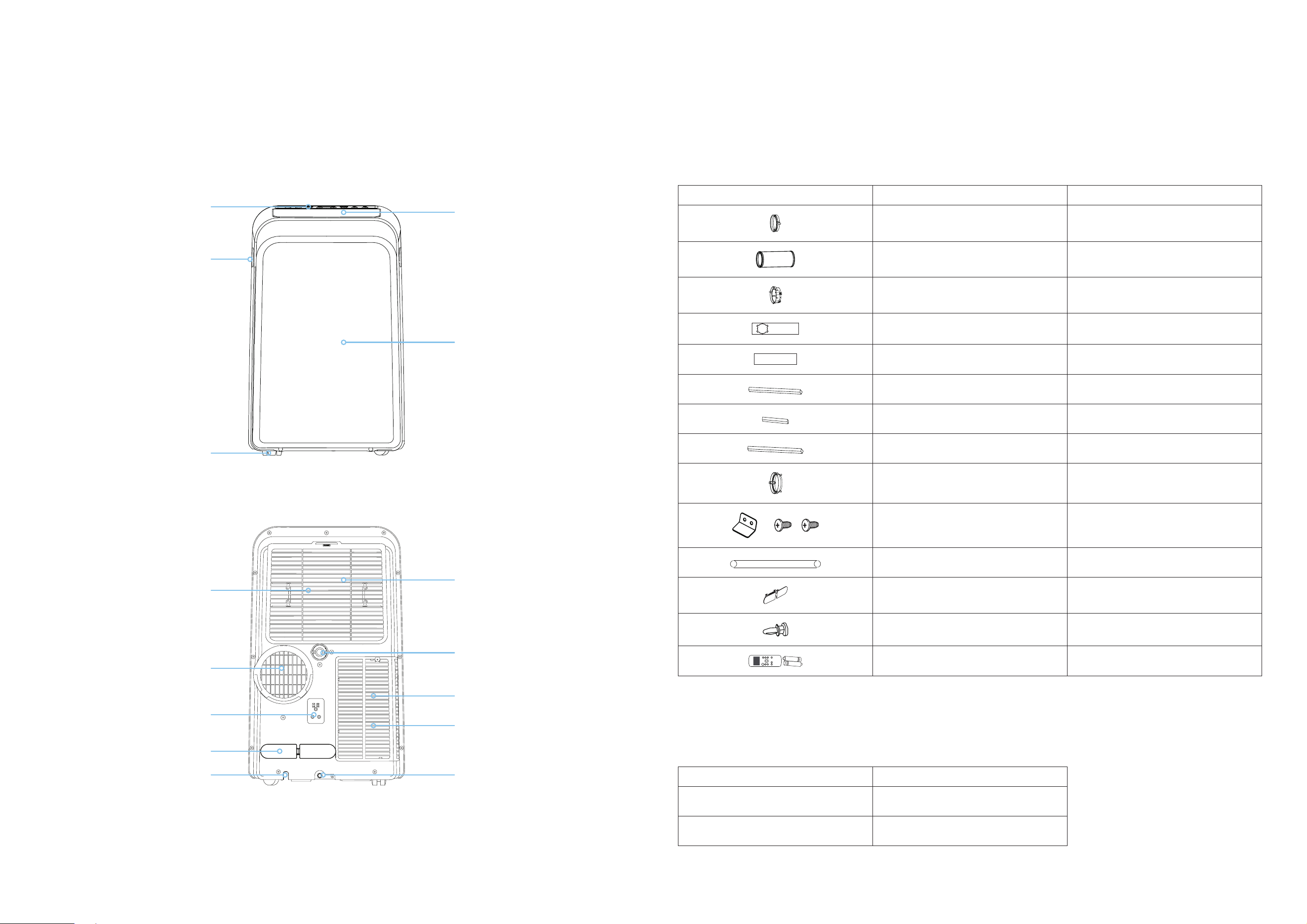
FRONT VIEW
REAR VIEW
Your Portable Air-conditioner
ACCESSORIES
Shape Name of Accessories Quantity
Unit Adaptor 1 piece
Exhaust Hose 1 piece
Window Slider Adaptor 1 piece (*)
Window Slider A 1 piece (*)
Window Slider B 1 piece (*)
Foam Seal A (Adhesive) 2 pieces (*)
Foam Seal B (Adhesive) 2 pieces (*)
Foam Seal C (Non-adhesive) 1 piece (*)
Exhaust Hose Adaptor 1 piece (*)
Security Bracket and 2 Screws 1 set (*)
Drain Hose 1 piece
Power Cord Buckle 1 piece
Bolt 1 piece (*)
Remote Controller and Batteries 1 set (*)
NOTE: Items with (*) are on some models. Slight variations in design may occur.
UNIT OPERATING AMBIENT TEMPERATURE RANGE
Mode Temperature Range
Cool 17-35°C (62-95°F)
Dry 13-35°C (55-95°F)
Upper Air Filter
(Behind the Grille)
Horizontal Louver Blade
(Automatically Swings)
Front Panel
Drain Outlet
Air Outlet
Power Plug Socket
Power Cord Buckle
Power Cord Outlet
Upper Air Intake
Control Panel
Handle
(Both Sides)
Caster Wheel
Lower Air Filter
(Behind the Grille)
Lower Air Intake
Bottom Tray
Drain Outlet
Note: The images in this user manual are for explanatory purposes only.
Your Portable Air-conditioner may appear slightly different.
14 15
Consider the following for optimal performance:
– Make sure that no furniture or other objects are
obstructing airflow.
– Keep the filter clean.
– Shut any curtains in any room exposed to direct
sunlight to prevent the room from becoming
unnecessarily warm.
– Keep all doors and windows closed to prevent warm
air from entering the room.
– The cooling function of the air conditioner works best
in rooms with an ambient temperature of 17–35ºC.
– The dehumidifying function of the air conditioner
works best in rooms with an ambient temperature
of 13–35ºC.
UNPACKING
– This product has been packaged to protect it against
transportation damage. Unpack the appliance and
keep the original packaging carton and materials in
a safe place. It will help prevent any damage if the
product needs to be transported in the future, and
you can use it to store the appliance when it is not in
use. In the event the carton is to be disposed of, please
recycle all packaging materials where possible.
– Plastic wrapping can be a suffocation hazard for
babies and young children, so ensure all packaging
materials are kept out of their reach and disposed
of safely.
– Unwind the cord fully and inspect it for damage.
Do not use if any part is damaged. In case of damage,
contact our after sales support line for advice.
– Read the manual to familiarise yourself with all parts
and operating principles. Pay particular attention to
the safety instructions on the previous pages.
WARNING! ELECTRIC SHOCK HAZARD!
Before installation or servicing, ensure the unit is switched
off and disconnected from the power outlet to prevent
possible injury.
INSTALLATION LOCATION
When deciding on an installation place, keep the
following points in mind:
– Make sure that you install your unit on an even surface
to minimise noise and vibration.
– The unit must be installed near a grounded plug, and
the Collection Tray Drain (found on the back of the
unit) must be accessible.
– There must be a clearance of at least 30cm (12”)
between the appliance and the wall or any other
obstacles. Maintaining this 30cm clearance is
essential; failure to keep that distance can result
in the unit malfunctioning or causing injury.
– The horizontal louver blade should be at least 50cm
(19.7”) away from obstacles.
– DO NOT cover the Intakes, Outlets or Remote Signal
Receptor of the unit, as this could cause damage to
the unit.
IMPORTANT NOTE: Do not install this appliance at a dry
cleaner’s premises.
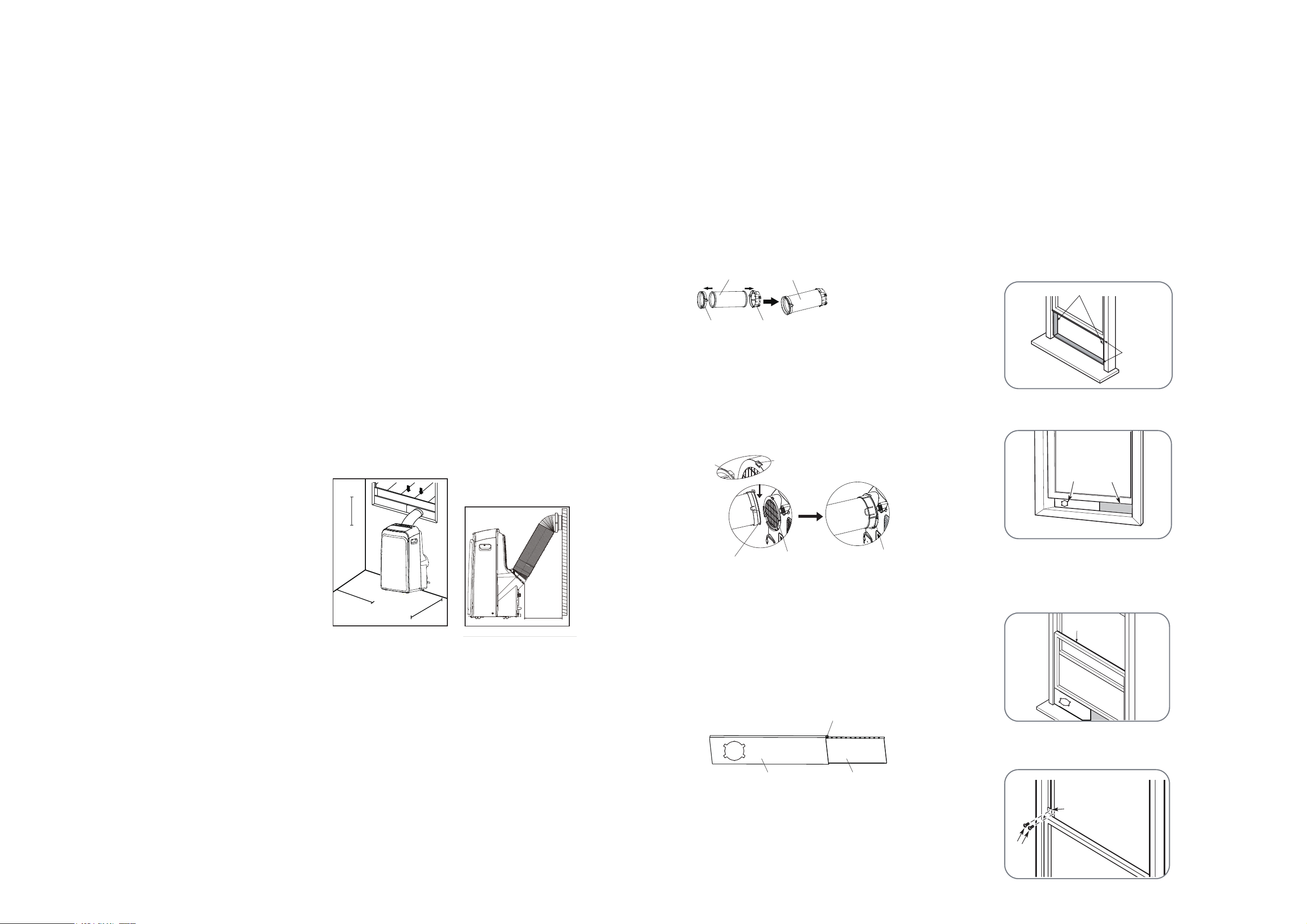
INSTALLING THE AIR EXHAUST DUCT
The portable air conditioner window kit comes with
the parts shown on page 13.
Note:
– The exhaust hose should be used when the COOL
or AUTO functions are selected in order to divert warm
exhaust air.
– The exhaust hose does not need to be mounted when
the FAN or DRY functions are used.
– The exhaust hose can be mounted in a window or
a simple temporary set up can be used to prop up
the exhaust hose to discharge the excess warm
exhaust air.
Installation
WINDOW INSTALLATION KIT
1. Preparing the Exhaust Hose assembly:
Press the exhaust hose (or extended exhaust hose) into
the window slider adaptor (or wall exhaust adaptor) and
unit adaptor, clamp automatically by elastic buckles of
the adaptors.
2. Install the Exhaust hose assembly to the unit:
Insert unit adaptor of the Exhaust hose assembly into
the lower groove of the air outlet of the unit while the
hook of the adaptor is aligned with the hole seat of the
air outlet and slide down the Exhaust hose assembly
along the arrow direction for installation.
3. Preparing the Adjustable Window Slider:
a. Choose the window sliders according the size of
your window. Sometimes, it needs to be cut short to
meet the window size, please take extra care to cut
it properly.
b. Use bolts to fasten the window sliders once they are
adjusted to the proper length.
Once the Exhaust Hose assembly and Adjustable Window
Slider are prepared, choose from one of the following two
installation methods:
TYPE 1: HUNG WINDOW INSTALLATION
1. Cut the adhesive foam seal A and B strips to the proper
lengths, and attach them to the window sash and
frame as shown.
2. Insert the window slider assembly into the window
opening.
3. Cut the non-adhesive foam seal C strip to match the
width(or height) of the window. Insert the seal between
the glass and the window frame to prevent air and
insects from getting into the room.
4. If desired, install the security bracket with 2 screws
as shown.
Page 12
Installation
Instructions
MODE Temperature Range
Ambient Temperature Range For Unit Operat ing
Cool 17-35°C (62-95°F)
Dry 13-35°C (55-95°F)
Exhaust Hose Inst allation
The exhaust hose and adaptor must be installed or removed in accordance with the usage mode. For
COOL or AUTO mode must be installed exhaust hose. For FAN, DRY
hose.
Choosing The Right Location
Recommend Installation
Your installation location should meet the following requirements:
-Make sure that you install your unit on an even surface to minimize noise and
vibration.
-The unit must be installed near a grounded plug, and the Collection Tray Drain
(found on the back of the unit) must be accessible.
-The unit should be located at least 30cm (12”) from the nearest wall to ensure
proper air conditioning. The horizontal louver blade should be at least 50cm
(19.7”) away from obstacles.
-DO NOT cover the Intakes, Outlets or Remote Signal Receptor of the unit, as this
could cause damage to the unit.
30cm
30cm
12inch
12inch
50cm
19.7inch
Energy Rating Information
The unit with 3 meters extended exhaust duct is running by using 2 exhaust ducts(Diameter:150mm, Length:1.5m
+ Diameter: 130mm, Length: 1.5m) .The Energy rating and noise information for unit with 3 meters extended
exhaust duct is not assessed.(For some models)
NOTE:
We recommend that operating the unit at room temperature below 35
°C
. Since there is a risk that the unit with 3
meters extended exhaust duct would not work at room temperature above 35
°C
under some extreme conditions,
such as the lower air intake be blocked for 50%.
The energy rating and noise information for this unit is based on the standard installation using an un-extended
exhaust duct (Diameter:150mm, Length:1.5m) without window slider adaptor or wall exhaust adaptor A.
How to Stay Cool with a New Portable Air Conditioner(For the models comply with the
requirements of Department Of Energy in US)
Because of a new federal test procedure for Portable Air Conditioners, you may notice that the
cooling capacity claims on portable air conditioner packaging are significantly lower than that of
models produced prior to 2017. This is due to changes in the test procedure, not to the portable
air conditioners themselves.
50cm
19.7 inch
mode must be removed exhaust
Page 14
Installation
Instructions
Window Installation Kit
Unit adaptor
Exhaust hose
Exhaust hose
assembly
Window slider
adaptor
Type w indow installation:
Press the exhaust hose(or extended exhaust hose)
into the window slider adaptor(or wall exhaust
adaptor) and unit adaptor, clamp automatically by
elastic buckles of the adaptors.
Step One: Preparing the Exhaust Hose assembly
Model A
Hook
Hole Seat
Lower groove
adaptor
Make sure the adaptor
is inserted into the lower
groove of the air outlet.
Step Two: Install the Exhaust hose assembly to
the unit
Insert unit adaptor of the Exhaust hose assembly
into the lower groove of the air outlet of the unit
while the hook of the adaptor is aligned with the
hole seat of the air outlet and slide down the
Exhaust hose assembly along the arrow direction
for installation.
Step Three: Preparing the Adjustable Window
Slider
Window slider A
MODEL A
Window slider B
Bolt
1. Choose the window sliders according the size of
your window. Sometimes, it needs to be cut short
to meet the window size, please take extra care to
cut it properly.
2. Use bolts to fasten the window sliders once they
are adjusted to the Proper length.
Page 15
Installation
Instructions
Or
Or
Window slider A
Window slider B
(if required)
Foam seal C
(Non-adhesive type)
Installation
NOTE: Once the Exhaust Hose assembly and Adjustable Window Slider are prepared, choose from one of
the following two installation methods.
Type 1: Hung Window or Sliding Window Installation(For some models)
1. Cut the adhesive foam seal A and B strips to the proper lengths, and attach them to the window sash
and frame as shown.
2. Insert the window slider assembly into the window opening.
Or
Foam seal B
(Adhesive type-shorter)
Foam seal A
(Adhesive type)
Foam seal B
(Adhesive type-shorter)
Foam seal A
(Adhesive type)
Window slider A
Window slider B
(if required)
Foam seal C
(Non-adhesive type)
Or
2 Screws
Security Bracket
3. Cut the non-adhesive foam seal C strip to match the width(or height) of the window. Insert the seal
between the glass and the window frame to prevent air and insects from getting into the room.
4. If desired, install the security bracket with 2 screws as shown.
2 Screws
Security
Bracket
16 17
Installation (Continued)
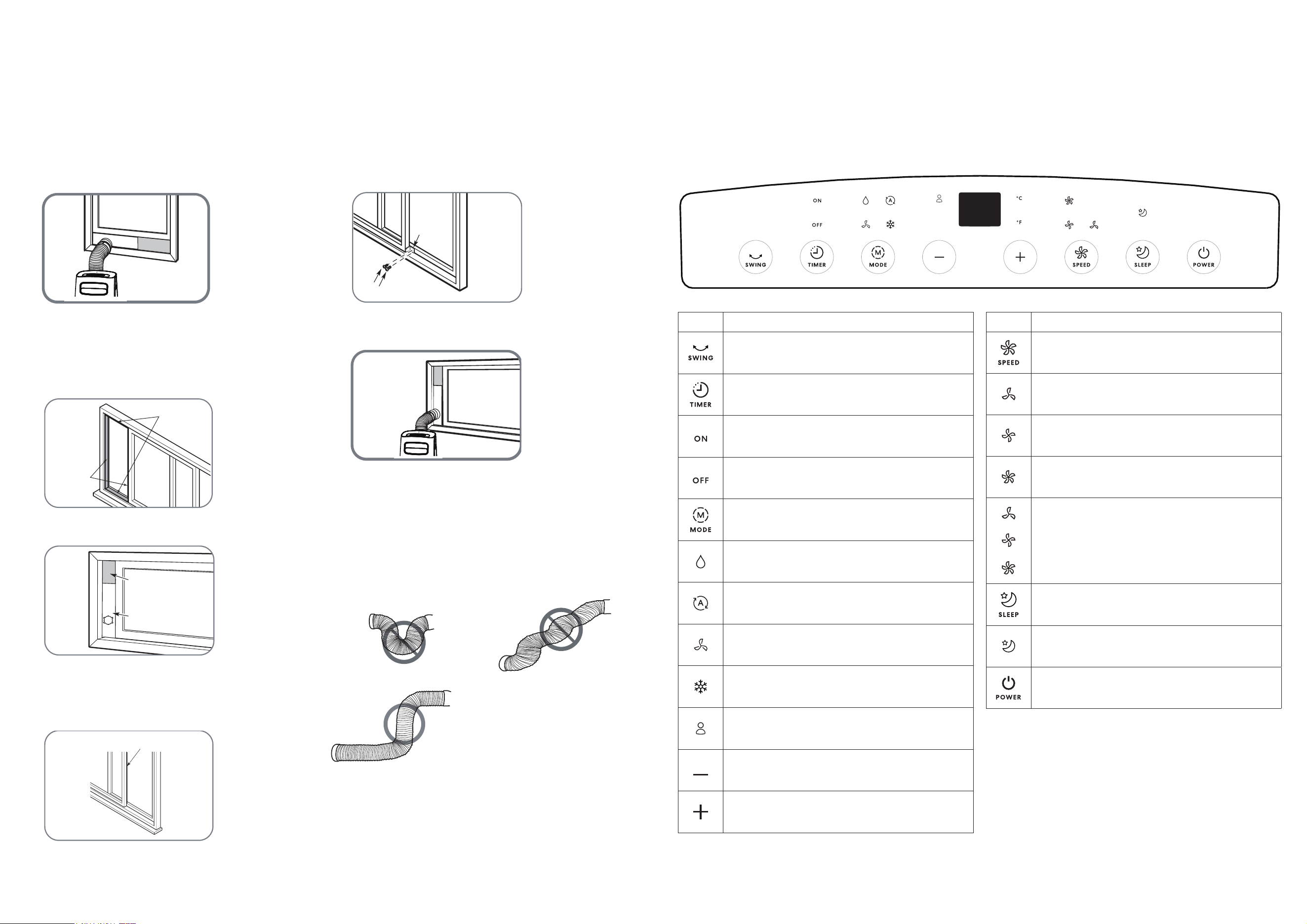
5. Insert the window slider adaptor into the hole of the
window slider.
TYPE 2: SLIDING WINDOW INSTALLATION
1. Cut the adhesive foam seal A and B strips to the proper
lengths, and attach them to the window sash and
frame as shown.
2. Insert the window slider assembly into the window
opening.
3. Cut the non-adhesive foam seal C strip to match the
width(or height) of the window. Insert the seal between
the glass and the window frame to prevent air and
insects from getting into the room.
4. If desired, install the security bracket with 2 screws
as shown.
5. Insert the window slider adaptor into the hole of the
window slider.
Note: To ensure proper function, DO NOT overextend
or bend the hose. Make sure that there is no obstacle
around the air outlet of the exhaust hose (in the range
of 500mm) in order to the exhaust system works
properly. All the illustrations in this manual are for
explanation purpose only. Your air conditioner may
be slightly different. The actual shape shall prevail.
Page 16
Installation
Instructions
Or
MODEL A
5. Insert the window slider adaptor into the hole of the window slider.
NOTE: To ensure proper function, DO NOT overextend or bend the hose. Make sure that there is no obstacle
around the air outlet of the exhaust hose (in the range of 500mm) in order to the exhaust system works
properly. All the illustrations in this manual are for explanation purpose only. Your air conditioner may be
slightly different. The actual shape shall prevail.
Page 15
Installation
Instructions
Or
Or
Window slider A
Window slider B
(if required)
Foam seal C
(Non-adhesive type)
Installation
NOTE: Once the Exhaust Hose assembly and Adjustable Window Slider are prepared, choose from one of
the following two installation methods.
Type 1: Hung Window or Sliding Window Installation(For some models)
1. Cut the adhesive foam seal A and B strips to the proper lengths, and attach them to the window sash
and frame as shown.
2. Insert the window slider assembly into the window opening.
Or
Foam seal B
(Adhesive type-shorter)
Foam seal A
(Adhesive type)
Foam seal B
(Adhesive type-shorter)
Foam seal A
(Adhesive type)
Window slider A
Window slider B
(if required)
Foam seal C
(Non-adhesive type)
Or
2 Screws
Security Bracket
3. Cut the non-adhesive foam seal C strip to match the width(or height) of the window. Insert the seal
between the glass and the window frame to prevent air and insects from getting into the room.
4. If desired, install the security bracket with 2 screws as shown.
2 Screws
Security
Bracket
Page 16
Installation
Instructions
Or
MODEL A
5. Insert the window slider adaptor into the hole of the window slider.
NOTE: To ensure proper function, DO NOT overextend or bend the hose. Make sure that there is no obstacle
around the air outlet of the exhaust hose (in the range of 500mm) in order to the exhaust system works
properly. All the illustrations in this manual are for explanation purpose only. Your air conditioner may be
slightly different. The actual shape shall prevail.
CONTROL PANEL
Operation Instructions
Icon Function
Swing button
Timer button
Timer on indicator
Timer off indicator
Mode button
Dry mode (Dehumidifier) indicator
Auto mode indicator
Fan mode indicator
Cool mode indicator
Follow me indicator
Decrease button
Increase button
Icon Function
Fan speed button
Low fan speed
Medium fan speed
High fan speed
Auto fan speed
(All three icons illuminated)
Sleep button
Sleep indicator
Power button

18 19
SWING BUTTON
Used to initiate the Auto swing feature.
When the operation is ON, press the SWING button can
stop the louver at the desired angle
TIMER BUTTON
Used to initiate the AUTO ON start time and
AUTO OFF stop time program, in conjuction
with the + & - buttons. The timer on/off
indicator light illuminates under the timer on/
off settings.
MODE BUTTON
Selects the appropriate operating mode. Each
time you press the button, a mode is selected
in a sequence that goes from AUTO), COOL,
DRY, FAN. The mode indicator light illuminates
under the different mode settings.
INCREASE (+) AND DECREASE (–) BUTTONS
Used to adjust (increasing/decreasing)
temperature settings in 1°C/1°F (or 2 °F) increments
in a range of 17°C/62°F to 30°C/86°F (or 88°F) or the
TIMER setting in a range of 0~24hrs.
Note: The control is capable of displaying
temperature in degrees Fahrenheit or degrees
Celsius. To convert from one to the other, press
and hold the + and – buttons at the same
time for 3 seconds.
FAN SPEED BUTTON
Press to select the fan speed in four steps:
LOW, MED, HIGH and AUTO.
The fan speed indicator light illuminates under
different fan settings. When select AUTO fan
speed, all the fan indicator lights turn dark. On
some models, when select AUTO fan speed, all
the fan indicator lights illuminate.
POWER BUTTON
Power the appliance on or off.
LED DISPLAY
Shows the set temperature in °C or °F(“°F” no
display for some models) and the Auto-timer
settings. While on DRY and FAN modes, it
shows the room temperature.
Shows Error codes and protection code:
• E1: Room temperature sensor error.
• E2: Evaporator temperature sensor error.
• E3: Condenser temperature sensor error
(On some models).
• E4: Display panel communication error.
• EC: Refrigerant leakage detection malfunction
(On some models).
• P1: Bottom tray is full
Connect the drain hose and drain the collected water
away. If protection repeats, call for service.
Note: When one of the above malfunctions
occurs, turn off the unit, and check for any
obstructions. Restart the unit, if the malfunction
is still present, turn off the unit and unplug the
power cord. Contact the manufacturer or its
service agents or a similar qualified person for
service.
COOL MODE
• Press the “MODE” button until the “COOL” indicator
light comes on.
• Press the “+” or “-” adjustment buttons to select your
desired room temperature. The temperature can be set
within a range of 17°C~30°C/62°F~86°F(or 88°F).
• Press the “SPEED” button to choose the fan speed.
DRY (DEHUMIDIFIER) MODE
• Press the “MODE” button until the “DRY” indicator light
comes on.
• Under this mode, you cannot select a fan speed or
adjust the temperature. The fan motor operates at
LOW speed.
• Keep windows and doors closed for the best
dehumidifying effect.
• Do not put the duct to window
AUTO MODE
• When you set the air conditioner in AUTO mode, it will
automatically select cooling, or fan only operation
depending on what temperature you have selected
and the room temperature.
• The air conditioner will control room temperature
automatically round the temperature point set by you.
• Under AUTO mode, you can not select the fan speed.
NOTE: Under AUTO mode, both the AUTO mode and the
actual operation mode indicator lights illuminate for some
models.
FAN MODE
• Press the “MODE” button until the”FAN “ indicator light
comes on.
• Press the “FAN SPEED” button to choose the fan speed.
The temperature can not be adjusted.
• Do not put the duct to window.
TIMER OPERATION
• When the unit is on, press the Timer button will initiate
the Auto-off stop program, the TIMER OFF indicator
light illuminates. Press the UP or down button to select
the desired time. Press the TIMER button again within
5 seconds, the Auto-on start program is initiated and
the TIMER ON indicator light illuminates. Press the up
or down button to select the desired Auto-on start
time.
• When the unit is off, press the Timer button to initiate
the Auto-on start program, press it again within
5 seconds will initiate the Auto-off stop program.
• Press or hold the UP or DOWN button to change the
Auto time by 0.5 hour increments, up to 10 hours, then
at 1 hour increments up to 24 hours. The control will
count down the time remaining until start.
• The system will automatically revert back to display the
previous temperature setting if there is no operation in
a 5 seconds period.
• Turning the unit ON or OFF at any time or adjusting
the timer setting to 0.0 will cancel the Auto Start/Stop
timer program.
SLEEP BUTTON
• Press this button, the selected temperature will
increase(cooling) by 1°C/2°F(or 1°F) 30 minutes. The
temperature will then increase (cooling) by another
1°C/2°F(or 1°F) after an additional 30 minutes. This
new temperature will be maintained for 7 hours before
it returns to the originally selected temperature. This
ends the Sleep/Eco mode and the unit will continue to
operate as originally programmed.
Note: This feature is unavailable under FAN or DRY mode.
FOLLOW ME (On some models)
Note: This feature can be activated from the remote
control ONLY. The remote control serves as a remote
thermostat allowing for the precise temperature control at
its location.
To activate the Follow Me/Temp Sensing feature, point
the remote control towards the unit and press the Follow
Me/Temp Sensing button. The remote control will send
this signal to the air conditioner until press the Follow Me/
Temp Sensing button again. If the unit does not receive
the Follow Me/Temp Sensing signal during any 7 minutes
interval, the unit will exit the Follow Me/Temp Sensing
mode.
Note: This feature is unavailable under FAN or DRY mode.
AUTO-RESTART
If the unit breaks off unexpectedly due to the power
cut, it will restart with the previous function setting
automatically when the power resumes.
Operation Instructions (Continued)
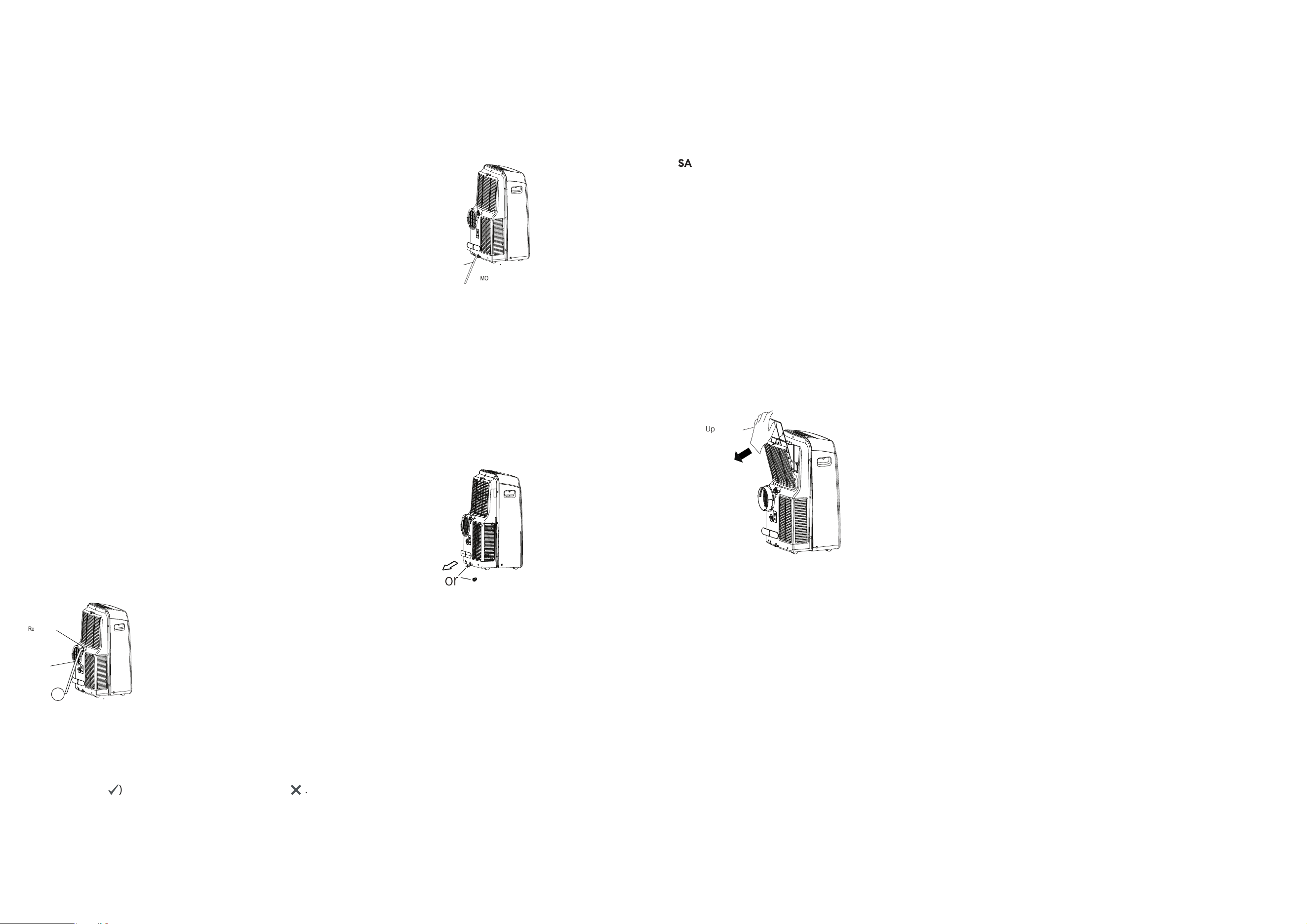
20 21
Operation Instructions (Continued)
AIR FLOW DIRECTION ADJUSTMENT
The louver can be adjusted automatically. Adjust the air
flow direction automatically:
• When the Power is ON, the louver opens fully.
• Press the SWING button on the panel or remote
controller to initiate the Auto swing feature. The louver
willl swing up and down automatically.
• Please do not adjust the louver manually.
RESUMING OPERATION
After the unit has stopped, it can not be restarted
operation in the first 3 minutes. This is to protect the
unit. Operation will automatically start after 3 minutes.
POWER MANAGEMENT FEATURE (On some models)
Under cooling operation, when the ambient
temperature is lower than the setting temperature for
a period of time, the unit will be automatically operate
power management feature. The compressor and fan
motor stop. When the ambient temperature is higher
than the setting temperature, the unit will be
automatically quit the power management feature.
The compressor and (or) fan motor run.
WATER DRAINAGE
During dehumidifying modes, remove the upper
drain plug from the back of the unit, install the drain
connector(5/8” universal female mender) with 3/4”
hose (locally purchased). For the models without drain
connector, just attach the drain hose to the hole. Place the
open end of the hose directly over the drain area in your
basement floor.
Note: Make sure the hose is secure so there are no leaks.
Direct the hose toward the drain, making sure that there
are no kinks that will stop the water flowing.
Place the end of the hose into the drain and make sure
the end of the hose is down to let the water flow smoothly.
(See Figure with
✔
). Do never let it up. (See Figs with
✖
).
When the continuous drain hose is not used, ensure that
the corresponding drain plug and knob are installed firmly
to prevent leakage.
When the water level of the bottom tray reaches a
predetermined level, the unit beeps 8 times, the digital
display area shows “P1” .
At this time the air conditioning /dehumidification
process will immediately stop. However, the fan motor will
continue to operate (this is normal). Carefully move the
unit to a drain location, remove the bottom drain plug and
let the water drain away. Reinstall the bottom drain plug
and restart the machine until the “P1” symbol disappears.
If the error repeats, call for service.
Note: Be sure to reinstall the bottom drain plug firmly to
prevent leakage before using the unit.
Page 20
Operating
Instructions
WAIT 3 MINUTES BEFORE RESUMING OPERATION
After the unit has stopped, it can not be restarted
operation in the first 3 minutes. This is to protect the
unit. Operation will automatically start after 3 minutes.
AIR FLOW DIRECTION ADJUSTMENT
The louver can be adjusted automatically. Adjust the
air flow direction automatically:
· When the Power is ON, the louver opens fully.
· Press the SWING button on the panel or remote
controller to initiate the Auto swing feature. The
louver willl swing up and down automatically.
· Please do not adjust the louver manually.
POWER MANAGEMENT feature(On some models)
Under cooling operation, when the ambient
temperature is lower than the setting temperature for
a period of time, the unit will be automatically operate
power management feature. The compressor and fan
motor stop. When the ambient temperature is higher
than the setting temperature, the unit will be
automatically quit the power management feature.
The compressor and (or) fan motor run.
Water drainage
· During dehumidifying modes, remove the upper
drain plug from the back of the unit, install the drain
connector(5/8" universal female mender) with 3/4"
hose(locally purchased). For the models without
drain connector, just attach the drain hose to the
hole. Place the open end of the hose directly over the
drain area in your basement floor.
MODEL A
Remove the
upper drain plug
√
Continuous
drain hose
that there are no kinks that will stop the warter flowing.
Place the end of the hose into the drain and make sure
the end of the hose is down to let the water flow
smoothly.(See Figs with . Do never let it up.(See Figs
with ). When the continuous drain hose is not used,
ensure that the corresponding drain plug and knob
are installed firmly to prevent leakage.
NOTE: Make sure the hose is secure so there are no
leaks. Direct the hose toward the drain, making sure
√
X
MODEL A1
Continuous
drain hose
Remove the
lower drain plug
· When the water level of the bottom tray reaches a
predetermined level, the unit beeps 8 times, the
digital display area shows "P1" .
At this time the air conditioning
/dehumidification process will
immediately stop. However, the
fan motor will continue to operate
(this is normal). Carefully move the
unit to a drain location, remove the bottom drain
plug and let the water drain away. Reinstall the
bottom drain plug and restart the machine until the
"P1" symbol disappears. If the error repeats, call for
service. NOTE: Be sure to reinstall the bottom drain
plug firmly to prevent leakage before using the unit.
or
SAFETY PRECAUTIONS
• Always unplug the unit before cleaning or servicing.
• DO NOT use flammable liquids or chemicals to clean
the unit.
• DO NOT wash the unit under running water.
Doing so causes electrical danger.
• DO NOT operate the machine if the power supply
was damaged during cleaning. A damaged power
cord must be replaced with a new cord from the
manufacturer.
AIR FILTER CLEANING
• Removal: Take the filter out along the arrow direction.
• Cleaning: Wash the air filter by immersing it gently
in warm water( about 40 C/104 F ) with a neutral
detergent. Rinse the filter and dry it in a shady place.
• Mounting: Install the air filter after cleaning.
MAINTENANCE TIPS
• Be sure to clean the air filter every 2 weeks for optimal
performance.
• The water collection tray should be drained
immediately after P1 error occurs, and before storage
to prevent mould.
• In households with animals, you will have to
periodically wipe down the grill to prevent blocked
airflow due to animal hair or fur.
• CAUTION: DO NOT operate the unit without
filter because dirt and lint will clog it and reduce
performance.
UNIT CLEANING
Clean the unit using a damp, lint-free cloth and mild
detergent. Dry the unit with a dry, lint-free cloth.
BEFORE STORAGE
• Drain the unit’s water collection tray according to the
instructions in the following section.
• Run the appliance on FAN mode for 12 hours in a warm
room to dry it and prevent mould.
• Turn off the appliance and unplug it.
• Clean the air filter according to the instructions in the
previous section. Reinstall the clean, dry filter before
storing.
• Remove the batteries from the remote control.
Note: Be sure to store the unit in a cool, dark place.
Exposure to direct sunshine or extreme heat can shorten
the lifespan of the unit.
Note: The cabinet and front may be dusted with an oil-
free cloth or washed with a cloth dampened in a solution
of warm water and mild liquid dishwashing detergent.
Rinse thoroughly and wipe dry. Never use harsh cleansers,
wax or polish on the cabinet front. Be sure to wring excess
water from the cloth before wiping around the controls.
Excess water in or around the controls may cause damage
to the unit.
SERVICE AND REPAIR
If you look after your portable air conditioner it should
give you years of good service. Should you experience
problems with the appliance that you cannot solve
yourself using the advice given within this manual, please
contact our after sales support centre for advice.
WARNING!
Do not attempt to repair the appliance yourself!
WARNING: Do not remove or install the lower filter by
yourself. It should be installed by an authorised dealer or
licensed service provider.
SPARE PARTS
Our after sales support centre stocks spare parts for this
Portable Air Conditioner. To purchase a part, call the
centre on 1300 11 4357.
Maintenance
Page 21
Safety Precautions
Air Filter Cleaning
Maintenance
· Always unplug the unit before cleaning or servicing.
· DO NOT use flammable liquids or chemicals to clean the unit.
· DO NOT wash the unit under running water. Doing so causes electrical danger.
· DO NOT operate the machine if the power supply was damaged during cleaning. A damaged
power cord must be replaced with a new cord from the manufacturer.
Upper filter
(take out)
MODEL A
Unit Cleaning
CAUTION
DO NOT operate the unit without filter
because dirt and lint will clog it and reduce
performance.
Maintenance Tips
· Be sure to clean the air filter every 2 weeks for
optimal performance.
· The water collection tray should be drained
immediately after P1 error occurs, and before
storage to prevent mold.
· In households with animals, you will have to
periodically wipe down the grill to prevent
blocked airflow due to animal hair.
Clean the unit using a damp, lint-free cloth and mild detergent. Dry the unit with a dry, lint-free
cloth.
Removal
· Take the filter out along the arrow direction.
Cleaning
· Wash the air filter by immersing it gently in warm water( about 40 C/104 F ) with a neutral
detergent. Rinse the filter and dry it in a shady place.
Mounting
· Install the air filter after cleaning .
Maintenance
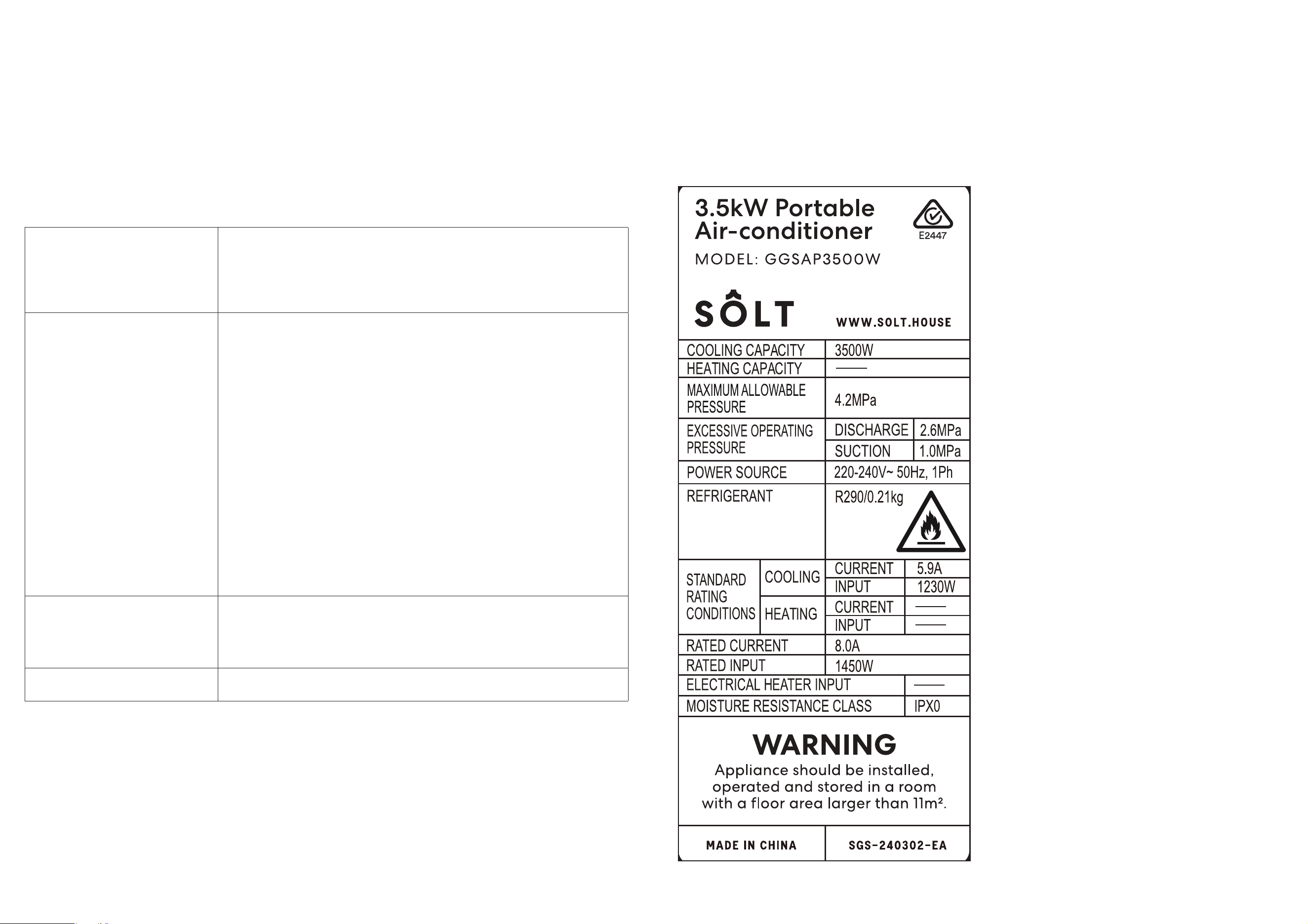
22 23
If you experience problems with your portable air conditioner, or it appears not to be operating correctly, check the
information below for solutions to common problems. If none of the solutions offered help you solve your problem,
please contact our after sales support centre on 1300 11 HELP (4357) or emailing support@residentiagroup.com.au
for advice. Do not attempt to repair the appliance yourself!
Unit does not turn
on when pressing
ON/OFF button
• P1 Protection Code
The Water Collection Tray is full. Turn off the unit, drain the water from the
Water Collection Tray and restart the unit.
• In COOL mode: room temperature is lower than the set temperature
Reset the temperature.
Unit does not cool well • The air filter is blocked with dust or animal fur
Turn off the unit and clean the filter according to instructions
• Exhaust hose is not connected or is blocked
Turn off the unit, disconnect the hose, check for blockage and reconnect
the hose
• The unit is low on refrigerant
Call a service technician to inspect the unit and top off refrigerant
• Temperature setting is too high
Decrease the set temperature
• The windows and doors in the room are open
Make sure all windows and doors are closed
• The room area is too large
Double-check the cooling area
• There are heat sources inside the room
Remove the heat sources if possible
The unit is noisy and vibrates
too much
• The ground is not level
Place the unit on a flat, level surface
• The air filter is blocked with dust or animal hair
Turn off the unit and clean the filter according to instructions
The unit makes a gurgling sound This sound is caused by the flow of refrigerant inside the unit.
This is completely normal.
FAQs & Troubleshooting Guide
COMPLIANCE
This appliance has been fully tested and meets all
requirements as set out by standards AS/NZS 60335.1 and
AS/NZS 60335.2.40.
RESPONSIBLE DISPOSAL
At the end of its working life, do not throw this appliance
out with your household rubbish. Electrical and electronic
products contain substances that can have a detrimental
effect on the environment and human health if disposed
of inappropriately. Observe any local regulations
regarding the disposal of electrical consumer goods and
dispose of it appropriately for recycling and recovery of
the refrigerant. Contact your local authorities for advice
on recycling facilities in your area.
RATING LABEL
Technical Specifications

24 25
Attach your receipt
to this page
This page
is intentionally
left blank

26 27
Warranty Information
WARRANTY TERMS & CONDITIONS
PORTAblE AIR-CONDITIONERS
This document sets out the terms and conditions of the
product warranties for Residentia Group Appliances. It is
an important document. Please keep it with your proof of
purchase documents in a safe place for future reference
should you require service for your Appliance.
1. IN THIS WARRANTY
(a) ‘acceptable quality’ as referred to in clause 10 of this
warranty has the same meaning referred to in the ACL;
(b) ‘ACL’ means Trade Practices Amendment (Australian
Consumer Law) Act (No.2) 2010;
(c) ‘Appliance’ means any Residentia Group product
purchased by you accompanied by this document;
(d) ‘ASR’ means Residentia Group authorised service
representative;
(e) ‘Residentia Group’ means Residentia Group Pty Ltd
of 165 Barkly Ave, Burnley VIC 3121, ACN 600 546 656
in respect of Appliances purchased in Australia;
(f ) ‘major failure’ as referred to in clause 10 of this
warranty has the same meaning referred to in the ACL
and includes a situation when an Appliance cannot be
repaired or it is uneconomic for Residentia Group, at
its discretion, to repair an Appliance during the
Warranty Period;
(g) ‘Warranty Period’ means:
(i) where the Appliance is used for personal,
domestic or household use (i.e. normal single
family use) as set out in the instruction manual,
the Appliance is warranted against manufacturing
defects for 24 months, following the date of
original purchase of the Appliance;
(h) ‘you’ means the purchaser of the Appliance not having
purchased the Appliance for re-sale, and ‘your’ has a
corresponding meaning.
2. This warranty only applies to Appliances purchased
and used in Australia and is in addition to (and does
not exclude, restrict, or modify in any way) any
non-excludable statutory warranties in Australia.
3. During the Warranty Period Residentia Group or its
ASR will, at no extra charge if your Appliance is readily
accessible for service, without special equipment
and subject to these terms and conditions, repair or
replace any parts which it considers to be defective.
Residentia Group or its ASR may use remanufactured
parts to repair your Appliance. You agree that any
replaced Appliances or parts become the property of
Residentia Group. This warranty does not apply to light
globes, baeries, filters or similar perishable parts.
4. Parts and Appliances not supplied by Residentia Group
are not covered by this warranty.
Our goods come with guarantees that cannot be excluded under the Australian
Consumer Law. You are entitled to a replacement or refund for a major failure and
for compensation for any other reasonably foreseeable loss or damage. You are also
entitled to have the goods repaired or replaced if the goods fail to be of acceptable
quality and the failure does not amount to a major failure.
The Australian Consumer Law requires the
inclusion of the following statement with
this warranty:
5. You will bear the cost of transportation, travel and
delivery of the Appliance to and from Residentia
Group or its ASR. If you reside outside of the service
area, you will bear the cost of:
(a) travel of an authorised representative;
(b) transportation and delivery of the Appliance to and
from Residentia Group or its ASR, in all instances,
unless the Appliance is transported by Residentia
Group or its ASR, the Appliance is transported at
the owner’s cost and risk while in transit to and from
Residentia Group or its ASR.
6. Proof of purchase is required before you can make a
claim under this warranty.
7. You may not make a claim under this warranty unless
the defect claimed is due to faulty or defective parts
or workmanship. Residentia Group is not liable in the
following situations (which are not exhaustive):
(a) the Appliance is damaged by:
(i) accident
(ii) misuse or abuse, including failure to properly
maintain or service
(iii) normal wear and tear
(iv) power surges, electrical storm damage or
incorrect power supply
(v) incomplete or improper installation
(vi) incorrect, improper or inappropriate operation
(vii) insect or vermin infestation
(viii) failure to comply with any additional instructions
supplied with the Appliance;
(b) the Appliance is modified without authority from
Residentia Group in writing;
(c) the Appliance’s serial number or warranty seal has
been removed or defaced;
(d) the Appliance was serviced or repaired by anyone
other than Residentia Group, an authorised repairer
or ASR.
8. This warranty, the contract to which it relates and the
relationship between you and Residentia Group are
governed by the law applicable where the Appliance
was purchased.
9. To the extent permied by law, Residentia Group
excludes all warranties and liabilities (other than as
contained in this document) including liability for any
loss or damage whether direct or indirect arising from
your purchase, use or non use of the Appliance.
10. For Appliances and services provided by Residentia
Group in Australia, the Appliances come with a
guarantee by Residentia Group that cannot be
excluded under the Australian Consumer Law. You
are entitled to a replacement or refund for a major
failure and for compensation for any other reasonably
foreseeable loss or damage. You are also entitled
to have the Appliance repaired or replaced if the
Appliance fails to be of acceptable quality and the
failure does not amount to a major failure. The benefits
to you given by this warranty are in addition to your
other rights and remedies under a law in relation to the
Appliances or services to which the warranty relates.
11. At all times during the Warranty Period, Residentia
Group shall, at its discretion, determine whether repair,
replacement or refund will apply if an Appliance has a
valid warranty claim applicable to it.
12. To enquire about claiming under this warranty, please
follow these steps:
(a) carefully check the operating instructions, user manual
and the terms of this warranty;
(b) have the model and serial number of the Appliance
available;
(c) have the proof of purchase (e.g. an invoice) available;
(d) telephone the numbers shown below.
13. You accept that if you make a warranty claim,
Residentia Group and its ASR may exchange
information in relation to you to enable Residentia
Group to meet its obligations under this warranty.
IMPORTANT
Before calling for service, please ensure that the steps in
point 12 have been followed.
Telephone contacts
► Service: Please call 1300 11 HELP (4357)

T. 1300 11 4357
E. support@residentiagroup.com.au
E S S E N T I A L S FOR LIFE
An initiative by
Residentia Group
www.solt.house