Installation & Operation Manual
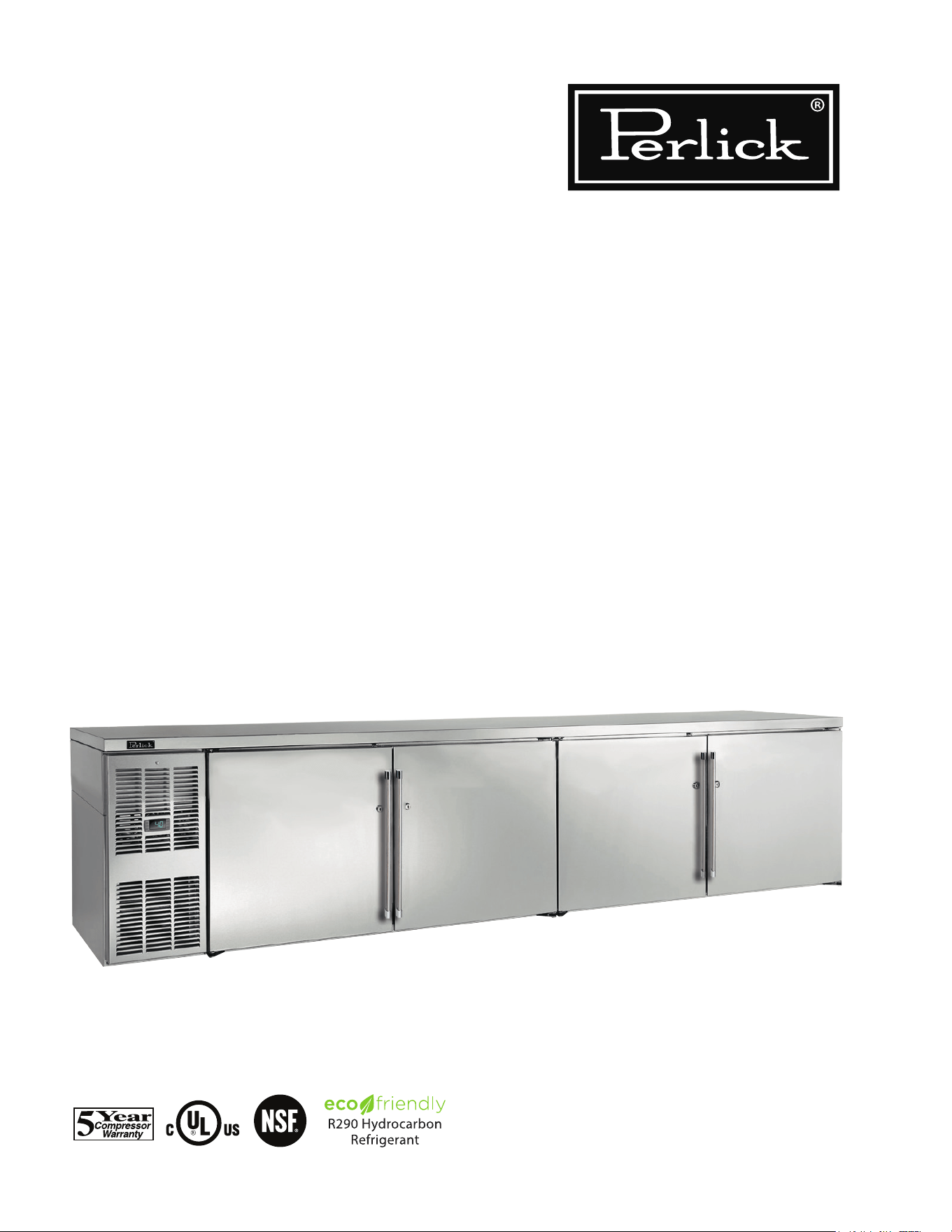
Commercial Back Bar
• Remote & Self-Contained Standard height and low height Models BBR, BBS,
BBRLP & BBSLP Series
• Remote & Self-Contained Narrow Door Models BBRN & BBRSN Series
• Remote & Self-Contained Pass Thru Models PTR & PTS Series
• Remote & Self-Contained Sliding Door Models SDB & SDP Series
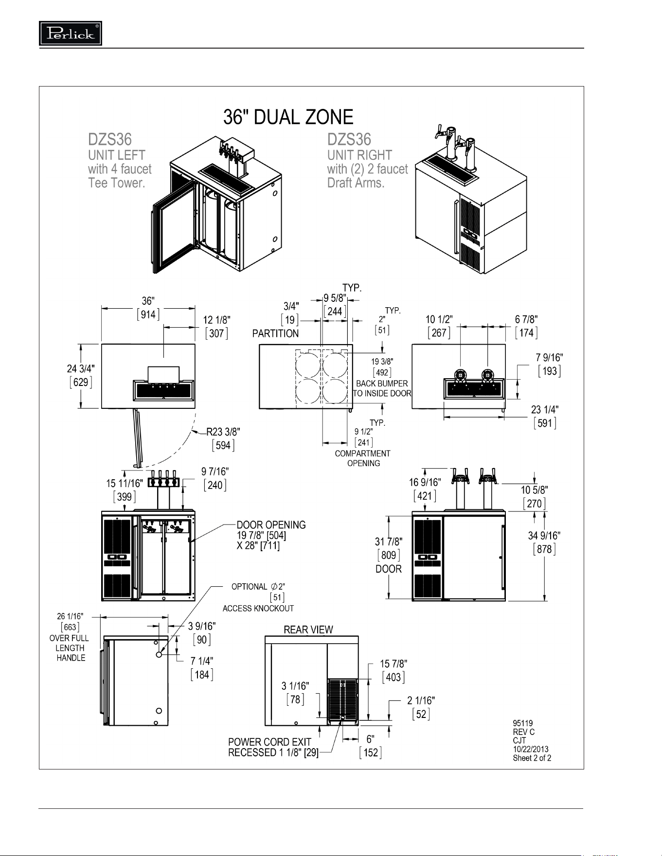
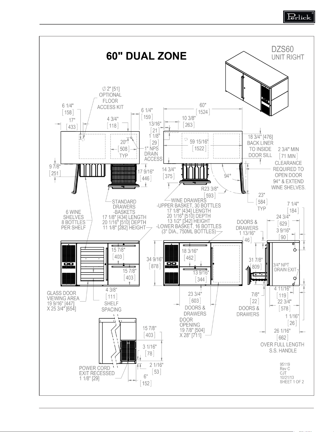
• Self-Contained Dual-Zone DZS Series Concessionaire
• Direct Draw DDC & DDS Series
Form No. Z2604
Rev A 11.24.2020
Model BBSLP108 Shown

Commercial Back Bar Installation & Operation Manual
2
TABLE OF CONTENTS
IMPORTANT!
Read and understand all information in this manual before attempting the installation.
All plumbing and electrical work must be performed by a qualied technician and
conform to all applicable state and local codes.
GENERAL INFORMATION
Warranty
To register your product, visit our web site at
www.perlick.com. Click on “Commercial”, then
“Service”. Click on the link “Warranty Registration
Form”. You must complete and submit this form
or the installation date will revert back to the ship
date.
Please record the purchase date and the dealer’s
name, address and telephone number below.
Model Number: ________________________
Serial Number: _________________________
Purchase Date: _______________________
Dealer Name & Address
______________________________________
______________________________________
______________________________________
Phone Number__________________________
SAFETY
PLEASE READ all instructions completely
before attempting to install or operate the unit.
Take particular note of the DANGER, WARNING
and CAUTION information in the manual. The
information is important for the safe and ecient
installation, operation and care of your Perlick unit.
DANGER
Indicates a hazard that WILL
result in serious injury or
death if precautions are not followed.
W ARNING
Indicates a hazard MAY
cause serious injury or
death if precautions are not followed.
CAUTION
Indicates a hazard where
minor or moderate injury
may occur if precautions are not followed.
NOTICE
Indicates that property
damage may occur if
warnings or instructions are not followed.
Introduction
Congratulations on your purchase of a Perlick
commercial back bar product. This manual has
been prepared to assist you in the installation of
your cabinet and to acquaint you with its operation
and maintenance.
We dedicate considerable time to ensure that our
products provide the highest level of customer
satisfaction. If service is required, your dealer
can provide you with a list of qualied service
agents. For your own protection, never return
merchandise for credit without our approval.
We thank you for selecting a Perlick product
and assure you of our continuing interest in your
satisfaction.
General Information ................................................................................................................................. 2
Safety ...................................................................................................................................................... 2
Prior To Installation .................................................................................................................................. 3
Installation ............................................................................................................................................... 4
Operation ................................................................................................................................................. 5
Adjustments ............................................................................................................................................. 7
Maintenance .......................................................................................................................................... 11
Troubleshooting ..................................................................................................................................... 14
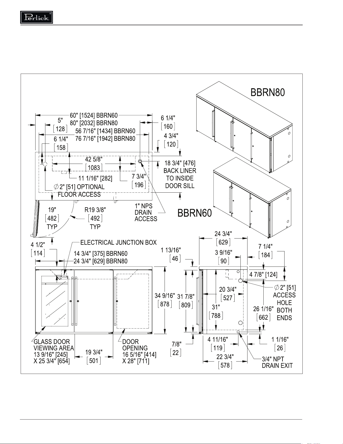
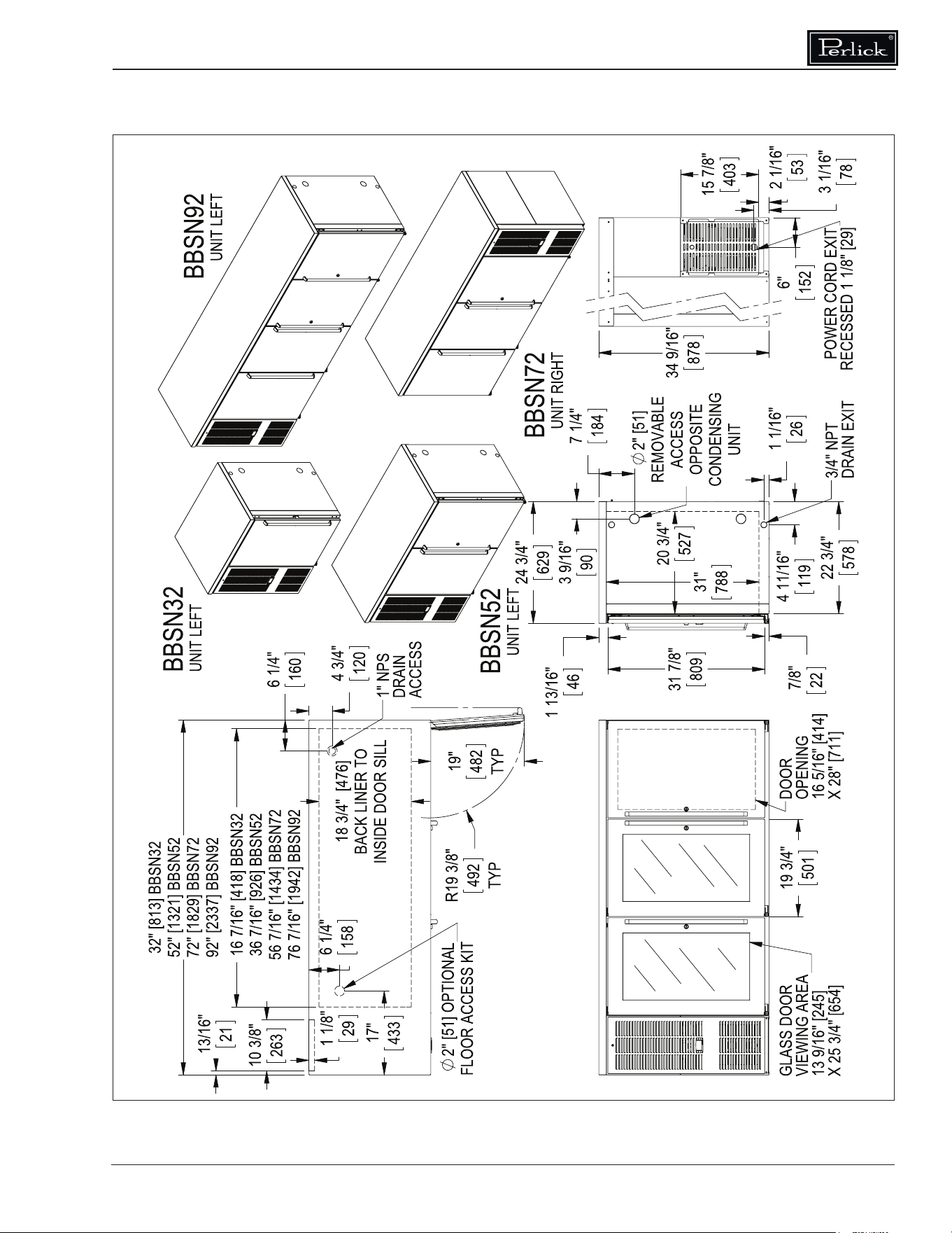
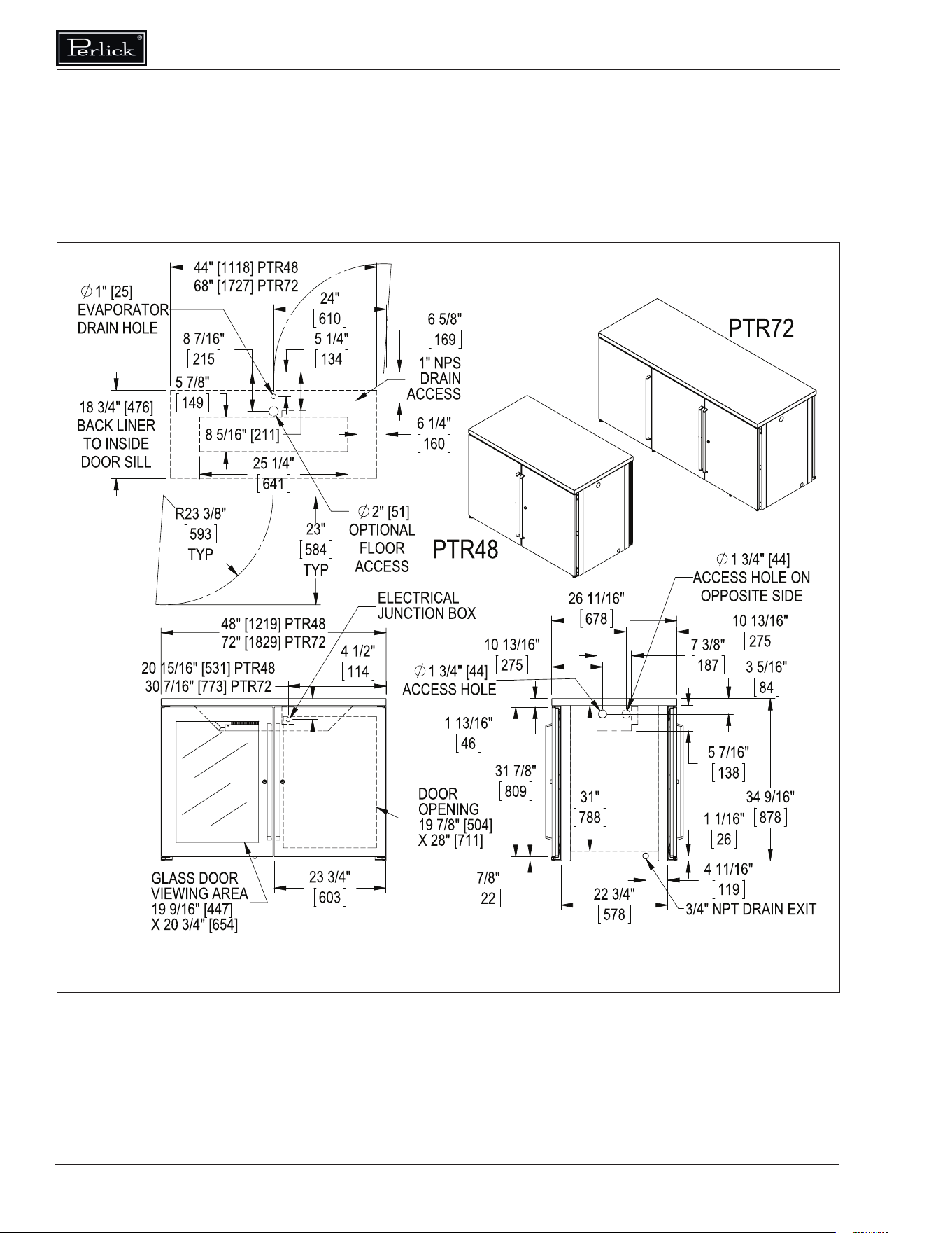
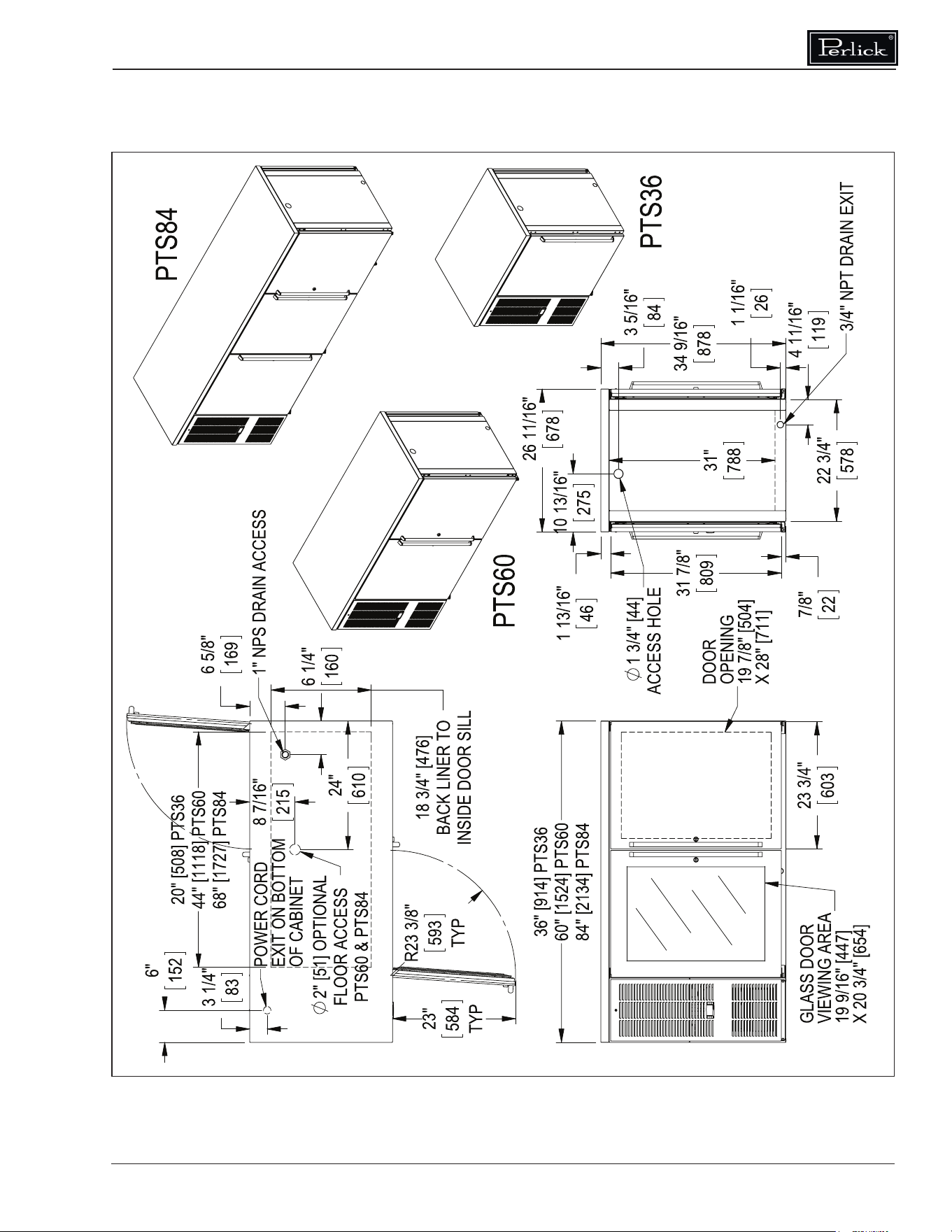
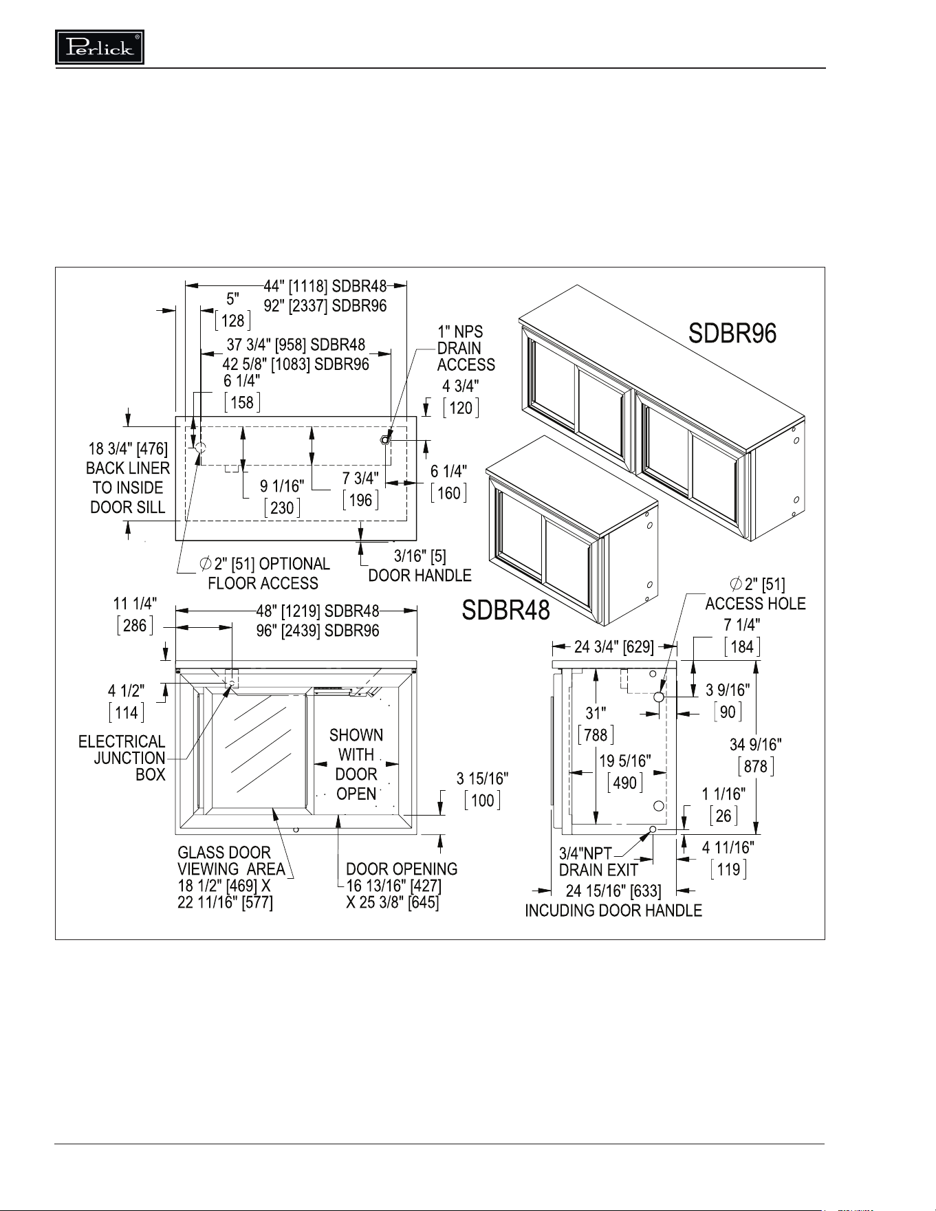
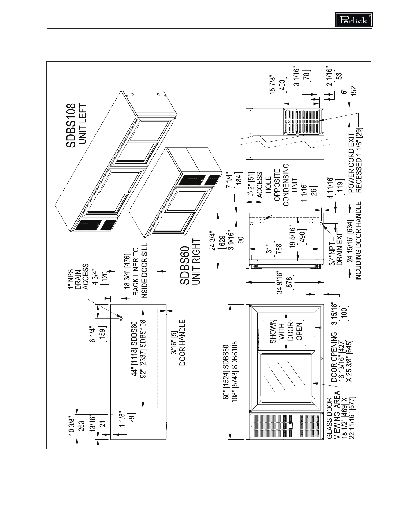
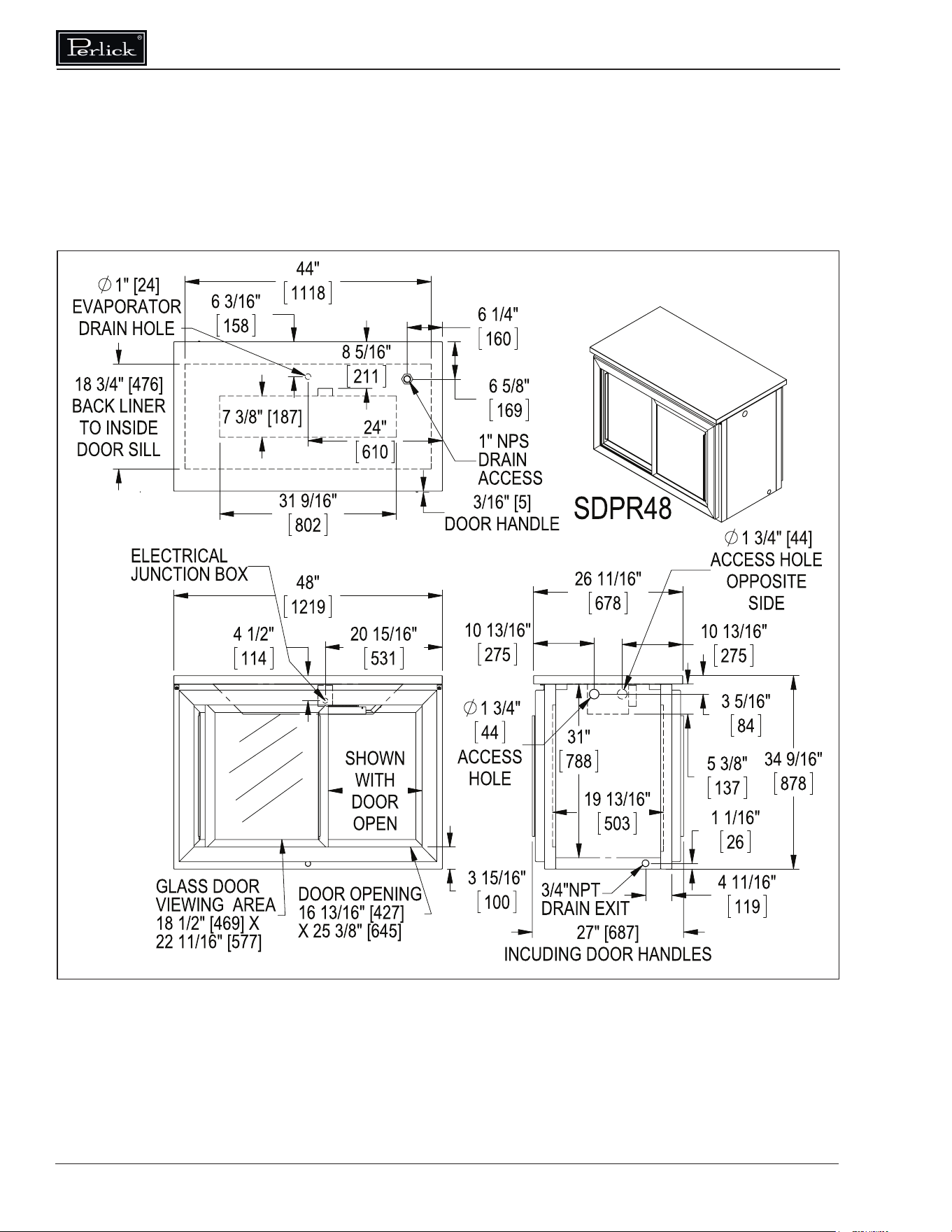
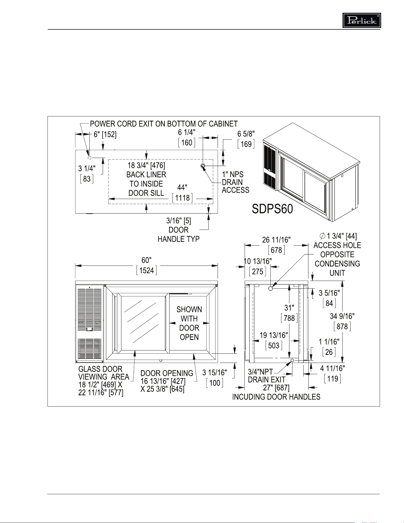
Dimensions ............................................................................................................................................ 16
Wiring Diagrams .................................................................................................................................... 34
Warranty ................................................................................................................................................ 48
Commercial Back Bar Installation & Operation Manual
Form No. Z2604
Rev A 11.24.2020
PRIOR TO INSTALLATION
Uncrating and Inspection
Remove all crating material. Carefully inspect
cabinet for hidden damage. If damage is
discovered, le your claim immediately with the
transport company. Perlick is not responsible for
damage in transit.
W ARNING
Take caution when
handling, moving and
using the product to avoid damaging the
refrigerant tubing or increasing the risk of a
leak.
DANGER
All service work shall be
performed by factory
authorized service personnel and all
component parts shall be replaced with like
components to minimize the risk of possible
ignition due to incorrect parts or improper
service.
CAUTION
If service is necessary,
repair work must be
performed by a Perlick authorized servicer.
Work done by unqualied individuals could
potentially be dangerous and will void the
warranty.
CAUTION
Do not cut cardboard
sleeve covering the unit.
Cutting may result in damage to the exterior
of the cabinet. Failure to follow this procedure
may damage the compressor and void
warranty.
1. Uncrate the unit on at, level surface. Remove
the cardboard sleeve by removing the banding
securing the sleeve to the shipping base.
Carefully lift the cardboard sleeve up over the
top of the unit.
2. Carefully lift unit o the base and onto a hand
truck or dolly. Make sure unit is balanced
on transporting device using soft, exible
strapping. Protect unit surfaces with cloth
material where strapping contacts unit.
CAUTION
Do not lift unit by drawer,
shelving or door handles
or damage to the unit could occur.
W ARNING
To prevent personal injury,
two people minimum
required to lift the unit. Larger units may
require additional personnel.
3. Before moving unit, secure door(s) to unit with
tape to prevent from opening.
4. Carefully move unit to installation site and
place in front of opening.
CAUTION
Finished ooring should
be protected with
appropriate material to avoid damage from
moving the unit.
Plumbing
CAUTION
Do not over-tighten drain
tting or damage to the
threads could occur.
Plumbing
Self-Contained
Condensate from the cooling coil is automatically
evaporated from the condensate pan located in
the condensing unit housing on self-contained
models.
Self-Contained & Remote
Each unit is equipped with a oor drain located
in the right rear corner of the cabinet. The drain
can be plumbed to an external oor drain by
connecting to the 3/4” NPT thread connection on
the side, or the 1” NPS thread connection out the
bottom, of the unit. Both drain ports come plugged
from the factory and can be removed if needed.
Remotes
Dispensing head drainers should be plumbed to
a dump tank or oor drain. Always rinse drainer
with sucient amounts of water daily to prevent
drain from clogging.
Remote evaporator condensate plumbing should
be routed out on of the cabinet side access holes
or to one of the oor drains and should always
be sloped to the drain with no rise to prevent
drainage. A trap should be used, however, trap
peak must be below condensate drain pan nipple.
Electrical
The cabinet must be connected to a separately
fused power source (see Electrical Specication
Plate axed to unit) in accordance with National
and Local electrical codes.
Self-contained Perlick units come equipped with
a NEMA 5-15P 90° plug with an 8’ cord extending
beyond the rear of the cabinet. The electrical
outlet must be ush with, or recessed into, the
wall surface.
NOTE: Never use an extension cord to extend the
power cord to the electrical receptacle.

Commercial Back Bar Installation & Operation Manual
4
CAUTION
If unit has been laid on its
back or sides, place unit
upright and allow
minimum of 24 hours before connecting
power. Failure to follow this procedure may
damage the compressor and void the warranty.
CAUTION
Do not attempt to operate
the equipment on any
other power source than
that listed on the Electrical Specication Plate
attached to the unit.
DANGER
ELECTROCUTION HAZARD!
Electrical grounding is
required. Appliances furnished with a 3-prong
(grounding) polarized plug are equipped for
your protection against possible shock
hazards.
• Never remove the round grounding prong
from the plug.
• Never use a 2-prong adapter.
• Never use extension cord to connect
power to the unit.
• If a 2-prong receptacle is encountered, or
a longer power cord is required, contact
a qualied electrician to have it replaced
in accordance with applicable electrical
codes.
DANGER
Failure to comply with these
electrical guidelines may
result in possible death or serious injury, re,
or loss of property.
N OTICE
This product contains
blown foam insulation
using blowing agent R-611 (Methyl Formate).
The foam in this product does not contain
HFC’s, CFC’s, or HCFC’s.
INSTALLATION
General Information
• For units equipped with a power cord, the
cord and plug may be aligned with a recess in
the back panel to allow the unit to be pushed
closer to the wall. For correct alignment, the
wall outlet must be located 4” - 10” above the
oor.
• Floor must be level in area of installation.
Preparing the Space
CAUTION
Make sure the oor under
the unit is level with the
surrounding nished oor. Protect a nished
oor with plywood, cardboard or some other
suitable material before moving the unit into
place. Failure to do this may result in damage
to the oor.
NOTE: If unit has been laid on its back or sides,
place unit upright and allow minimum of 24 hours
before connecting to a power source. Failure to
follow this procedure may damage the compressor
and void warranty.
1. Make sure the space opening is correctly
sized for the unit. See Dimension drawings at
the back of this manual for correct dimensions.
NOTE: For a cabinet door to open properly, the
door must open a minimum of 90°. Use a minimum
3” ller in corner installations to assure a 90°
opening. Allow 24” clearance in front of the unit
for full door swing and shelf/drawer pull-out.
2. Check that the following are level and square:
• Front and interior opening
• Installation opening and oor surface
NOTE: The oor under the unit must be at the
same level as the surrounding nished oor.
Casters or Legs
Refer to the instructions included with the Casters
or Legs Kit.
Installing the Unit
CAUTION
If unit has been laid on its
back or sides, place unit
upright and allow minimum of 24 hours before
connecting power.
1. With power applied to the unit, check that
the lighting and cooling functions operate
properly, then turn o power to the wall outlet
and/or circuit breaker.
2. Position the cabinet into place using rollers
when necessary.
NOTE: Proper air ow around the condensing unit
is necessary for ecient operation. Never obstruct
the air ow in and out of the condensing unit.
3. When cabinet is in place, check installation
with carpenter’s level. When the unit is level
front-to-back and side-to-side, accumulated
water will drain out of cabinet to evaporator
drain.
4. Turn on power to the outlet and/or circuit
breaker.
Commercial Back Bar Installation & Operation Manual
Form No. Z2604
Rev A 11.24.2020
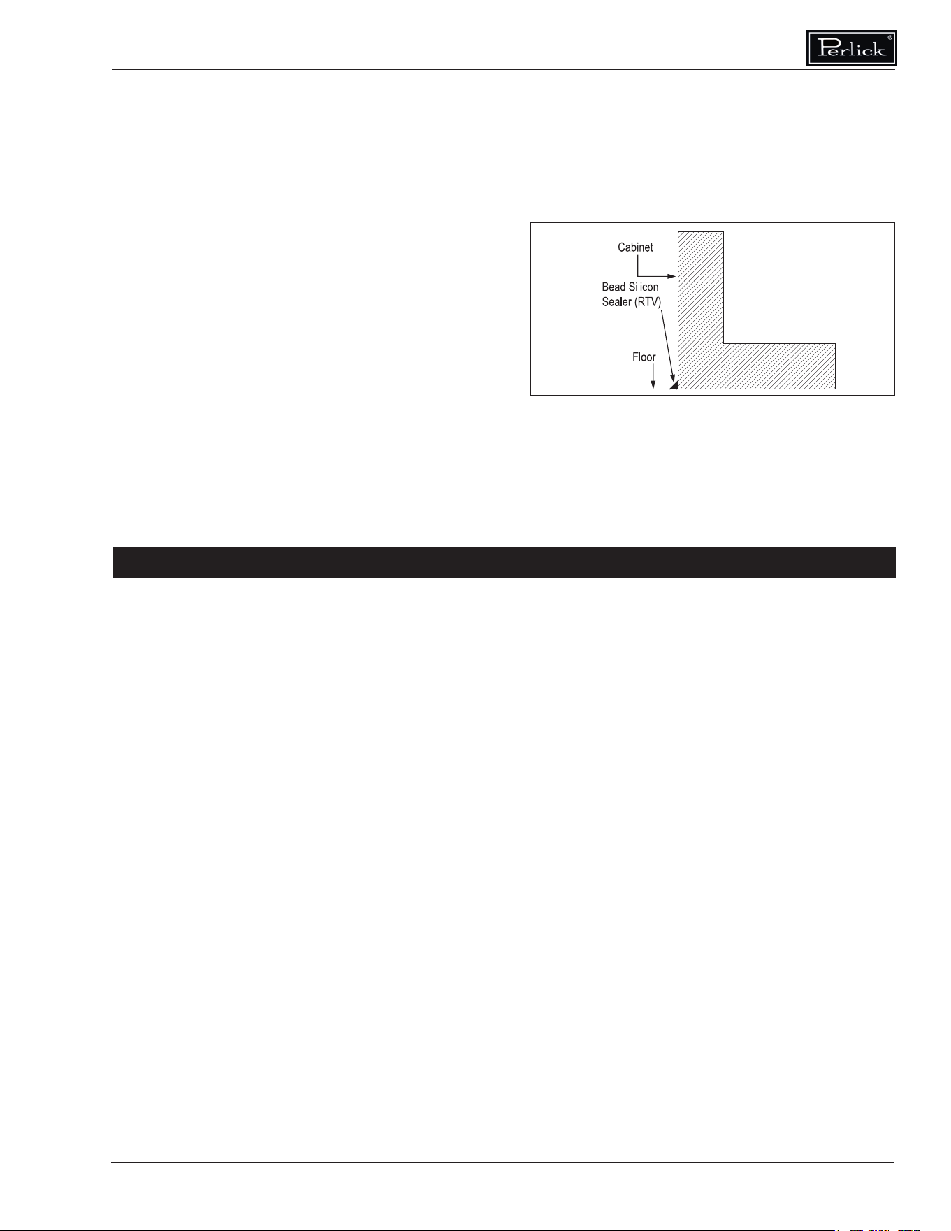
Sealing Cabinet to Floor
For units without casters or legs, it may be
necessary to seal the base of the cabinet to the
oor. This can be accomplished by laying a bead
of silicone sealant between the base of the cabinet
and the oor (Figure 1).
Faucet and Dispensing Head Installation
Refer to the instructions included with the Faucet
and Dispensing Head Kit.
• Factory temperature settings:
Approximately 36°F for refrigerator, 45°F for
white wine storage (compartment closest to
the condensing unit/refrigeration module),
and 60°F for red wine storage. Adjustable
range is 34°F - 42°F for the refrigerator and
40°F - 60°F for wine.
• Coldest compartment must always be the
compartment closest to the condensing
unit/refrigeration module.
• Minimum temperature dierence between
two compartments is 10°F. Maximum
temperature dierence between the two
compartments is 30°F for the DZS60 Model
and 20°F for the DZS36 Model.
• The unit is not intended for temperature
settings outside the paramaters mentioned
above. Attempts to deviate from the
sepecied temperature paramaters
may result in unsatisfactory serving
temperatures.
Allow a minimum of 24 hours for ambient
temperature product to reach storage temperature.
Electric Condensate Evapaway
(Optional)
For installation in areas of high humidity, a 115-
volt electric condensate pan can be installed
underneath the cabinet to collect and evaporate
the condensate from the cabinet evaporator. A 6’
3-prong plug is included. A separate circuit should
be provided for the heater. The kit can be used
only on cabinets equipped with 4” minimum legs;
it cannot be used on units equipped with platform
or base plate kits. Follow instructions supplied
with the kit.
Base Plate Installation (Optional)
Once the unit is secured in place, install the base
plate brackets to the cabinet bottom in the holes
provided. Attach base plate to brackets. Refer
to the installation instructions included with the
Base Plate Kit.
Refrigeration and Temperature Control
(Non-DZS Models)
The cabinet is equipped with a heavy-duty
refrigeration system designed to automatically
maintain a storage temperature of approximately
36° F.
Allow a minimum of 24 hours for ambient
temperature product to reach storage temperature.
Draft beer should be stored at a temperature
between 32° – 38° F. The most common cause
of dispensing problems is improper temperature;
beer will foam at warmer temperatures.
Refrigeration and Temperature Control
(DZS)
The unit is equipped with a heavy-duty, digitally
controlled, dual-zone refrigeration system
designed for two separate compartments. The
temperature controls have been factory set
according to customer specications based on
intended use The digital controller on the left
controls the compartment on the left side and
the digital controller on the right controls the
compartment on the right side.
Figure 1: Sealing Cabinet to Floor
OPERATION
Commercial Back Bar Installation & Operation Manual
6
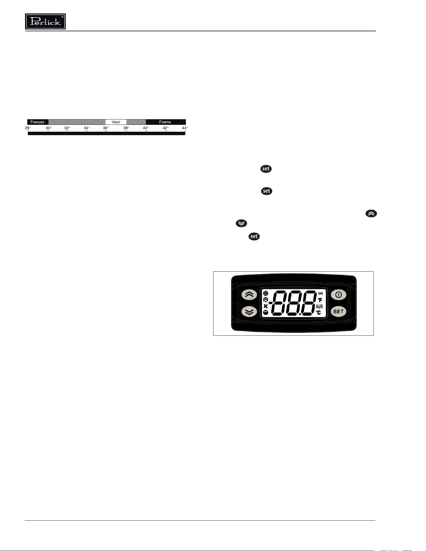
Figure 2: Digital Temperature Controller
Interior Light (Not applicable to all models)
The unit is equipped with an interior LED light in
the upper front of the unit just inside the door or
drawer. The light illuminates when the manual
rocker light switch is turned on. The rocker light
switch is located behind the LED light on the inside
of the frame on either the right or left side (same
side as the compressor).
Digital Temperature Control
To Adjust the Temperature Set Point (Figure 2):
1. Press the button. The label “SET” will be
displayed.
2. Press the button a second time. The set
point will be displayed.
3. To change the Set point value, press the
or keys within 15 seconds.
4. Press to conrm the new setpoint value.
5. After 10 seconds the display will return to
indicating the cabinet temperature.
Beer will freeze at temperatures lower than
30° F. When beer freezes, the alcohol in the beer
may separate and cause the beer to be cloudy
with an “o” taste.
The following chart shows how temperature
aects beer:
Checking Product Temperature
1. To accurately check the temperature of product
stored in the refrigerated compartment, insert
an accurate thermometer into a plastic
unbreakable bottle, partially lled with water.
Tighten bottle cap securely.
2. Place the bottle in the desired area for 24
hours. Refrain from opening the unit during
the testing period. After 24 hours, check
the temperature of the water. Adjust the
temperature accordingly using the procedures
on this page.
The following factors aect the internal temperature
of the unit:
• Temperature setting
• Room temperature where installed
• Number of times the door is opened and
closed
• Length of time door is left open
• Style of door installed
• Door gasket seal and condition
• Amount of time the internal light is illuminated
• Installation in direct sunlight or near a heat
source
Commercial Back Bar Installation & Operation Manual
Form No. Z2604
Rev A 11.24.2020
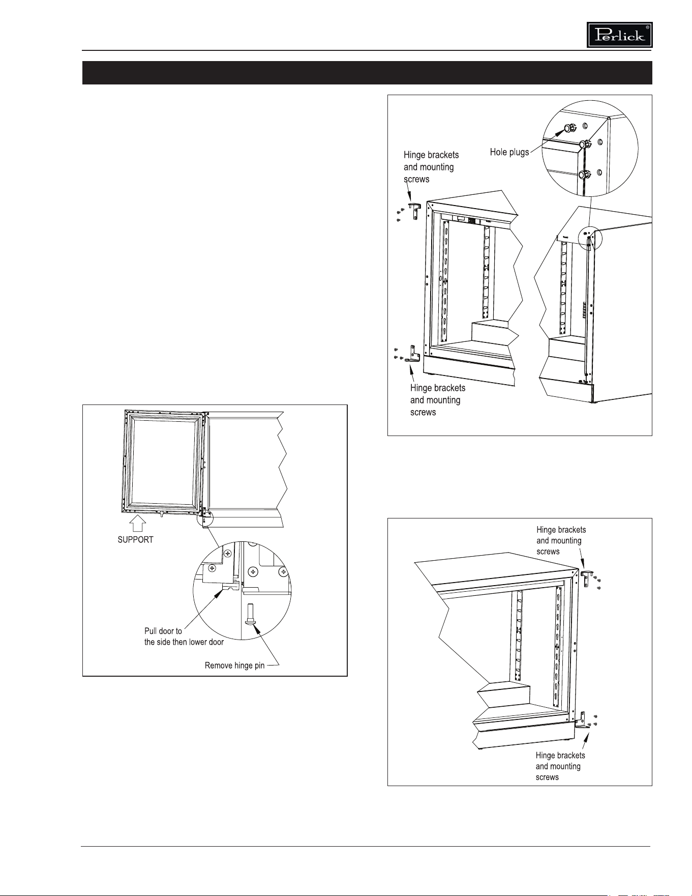
Changing Door Swing Direction
NOTE: Changing the door swing direction is
not advisable if the door is not equipped with
a full length handle. Doing so may result in an
undesirable handle position..
Hinge Kits
Part No. 67439R: Right Hinging
Part No. 67439L: Left Hinging
Tools Required
• Large at head screwdriver
• Regular Phillips head screwdriver
• Hinge Kit from Perlick
• Plastic putty knife
Procedure
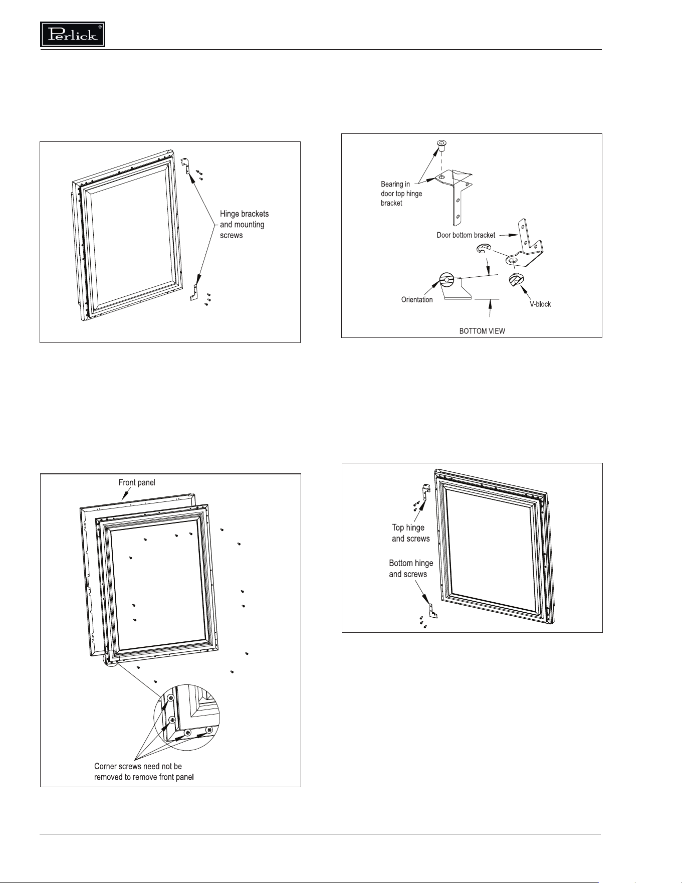
1. Support the door in the open position as
shown in Figure 3. Remove the hinge pin.
2. Pull door to the side and then lower the door.
3. Remove top and bottom hinge brackets.
Retain screws for later use. See Figure 4.
4. Remove the hole plugs from the top and bottom
hinge bracket mounting holes (Figure 4). Place
the plug in the holes on the opposite side made
vacant by removing the hinges in step 3.
5. Using the screws removed in step 3, install
the top and bottom hinge brackets from kit
(Figure 5).
ADJUSTMENTS
Figure 3: Door Removal
Figure 4: Hinge Removal
Figure 5: Hinge Installation
Commercial Back Bar Installation & Operation Manual
8
6°
Figure 8: Bearing and V-Block
Figure 9: Door Hinges
8. Insert bearing into door top hinge bracket
(Figure 8).
9. Insert V-block into door bottom hinge bracket
and attach with e-clip (Figure 8). Note the
orientation of the V-block.
10. Attach the top and bottom door hinges using
screws removed in step 6 (Figure 9).
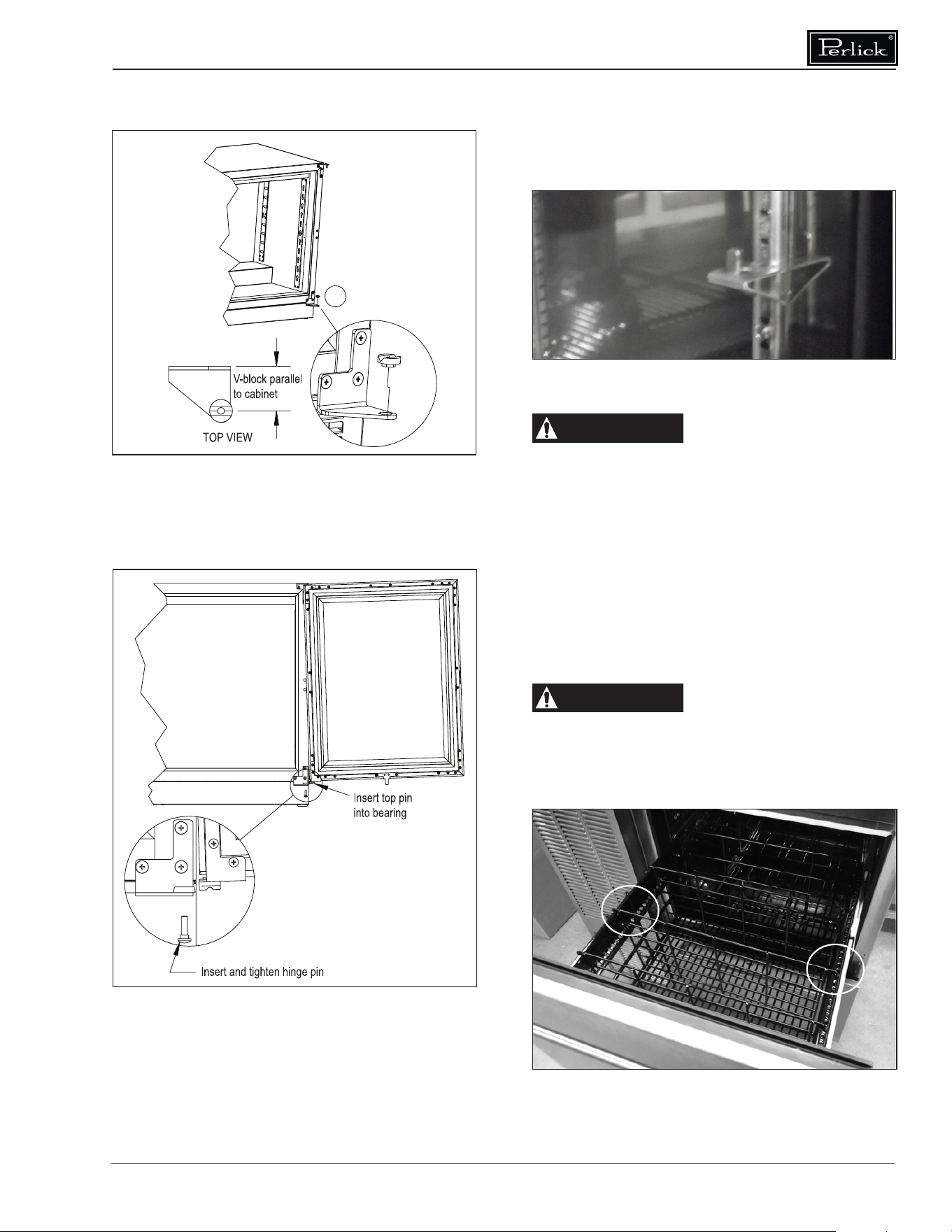
11. Place lower V-block into lower cabinet hinge
with notch parallel to cabinet (Figure 10).
6. Remove the top and bottom hinge brackets
from the door (Figure 6). Retain the screws
for later use.
7. Remove the front panel from the door assembly
by removing the inner mounting screws, 4 per
side, from the perimeter of the door assembly
(Figure 7). Rotate the front panel 180°. The
top becomes the bottom. Reattach using the
same screws and mounting holes.
Figure 6: Door Brackets
Figure 7: Removing Front Panel
Commercial Back Bar Installation & Operation Manual
Form No. Z2604
Rev A 11.24.2020
Shelving Adjustment
See Figure 12.
CAUTION
Completely empty shelf or
drawer before removing.
1. Open the door. Tilt the shelf and remove it
from the unit
2. Reposition each bracket separately. Grasp
the middle of the bracket, pull the front end
up and out, then forward to remove it.
3. Place brackets at desired location and reinstall
shelf(s)
Drawer Dividers Adjustment
See Figure 13.
CAUTION
Completely empty shelf or
drawer before removing.
Lift divider straight up and move to desired
position,engaging tabs in holes. Make sure divider
tabs engage corresponding holes on both sides.
Figure 10: Installing V-Block
Figure 11: Installing Door
Figure 13: Drawer Divider Adjustment
Figure 12: Shelf Bracket
12. Lift door assembly and insert top pin into
bearing. Move door toward cabinet and align
V-blocks (Figure 11).
13. Insert and tighten lower hinge pin to complete
assembly.
Sliding Doors
Removing/Installing
1. To remove the sliding door, simply grasp the
door on each side and lift up o the bottom
track, then tilt outwards and pull down to
remove from the upper track.
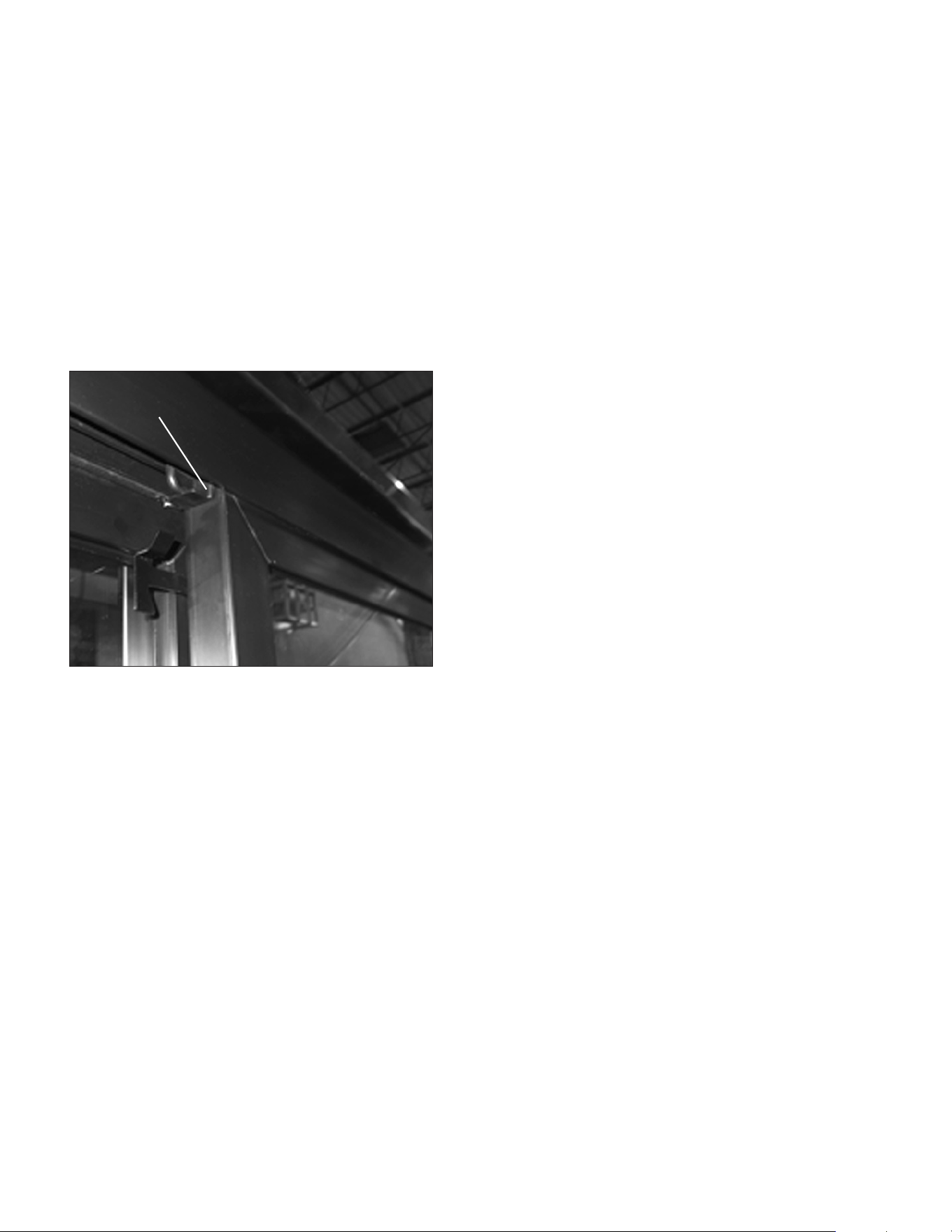
2. To reinstall sliding door, place door in upper
track making sure to engage the bracket
(Figure 4), lift door up into the track and place
into the bottom track.
Adjusting Door Spring Tension
A tension spring is located in the upper track
of each door. To increase or decrease spring
tension, remove the Phillips screw and position
the bracket in one of three detentes and reinstall
screw. The detente farthest to the left creates the
least amount of tension.
NOTE: Units are shipped from the factory with
springs set at the weakest settings.
Sliding Door Lock
Each set of sliding doors is equipped with a keyed
lock located on the bottom of the right side door. To
lock the doors, place the lock lever in the “DOWN”
position and lock with the key. Unlock with the key
and place the lever in the “UP” position to open.
Make sure door engages bracket
Figure 14: Removing/Installing Sliding Door
Commercial Back Bar Installation & Operation Manual
Form No. Z2604
Rev A 11.24.2020
DANGER
Never attempt to repair or
perform maintenance on
the unit until the main electrical power to the
unit has been disconnected!
W ARNING
Take caution when handling,
moving and using the
product to avoid damaging the refrigerant tubing
or increasing the risk of a leak.
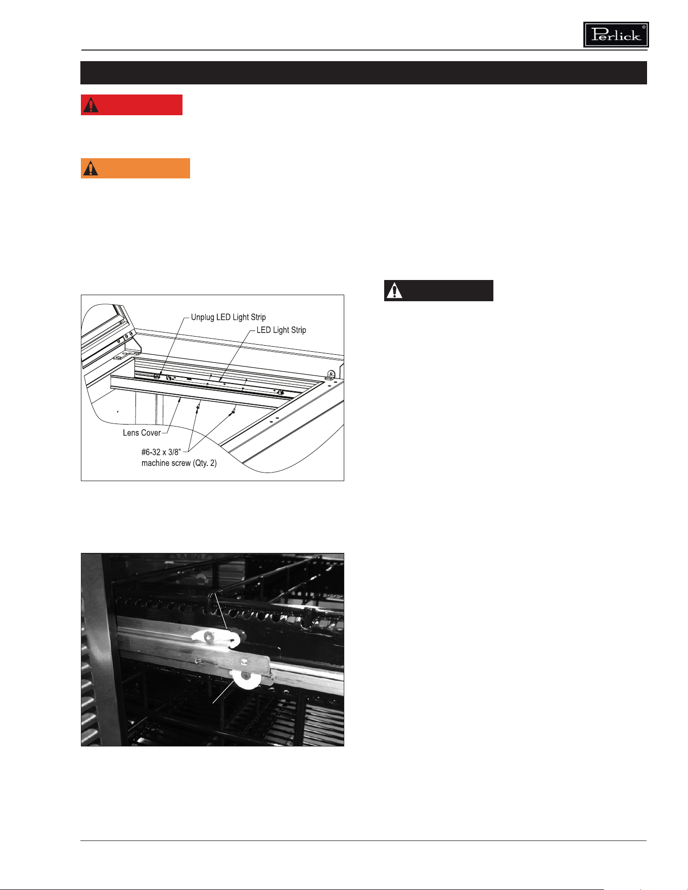
LED Light Replacement
See Figure 15.
1. Open the door, or remove the upper drawer
(see Removing Drawer, Figure 16).
2. Using a at blade screwdriver, carefully pry
o the lens cover.
3. Remove the two screws securing LED light
to housing.
Figure 16: Removing/Installing Drawer
Push latch forward and pull front of latch up to
release; push down and slide back to lock
When reinstalling, make sure wheel engages slot
Figure 15: Interior LED Light
MAINTENANCE
4. Unplug the LED from the wiring harness.
5. Plug new LED into harness and secure to
housing using screws removed in step 2.
6. Snap LED cover into place.
Cleaning/Lubricating Drawer Extenders
Drawer must be removed to clean or lubricate
the extenders. Use a food grade lubricant to
lubricate the drawer extenders.
Removing Drawer
See Figure 15.
CAUTION
Completely empty drawer
before removing.
1. Pull the drawer out to its furthest position.
Locate the latch in the middle of both
extenders. Push each latch forward and lift
front of latch up (unlocked position), then lift
the front of the drawer and pull out.
Installing Drawer
1. Place drawer on to the extenders, making sure
wheels engage the slots on each side.
2. Push drawer all the way in, then pull drawer
out and push the latch down and back to
engage. Make sure front of latches are fully
down and back, engaging the extenders.
Stainless Steel Care & Cleaning
General
Contrary to popular belief, stainless steel is
susceptible to rusting. Corrosion on metals is
everywhere. It is recognized quickly on iron
and steel as unsightly yellow/orange rust. Such
metals are called “active” because they actively
corrode in a natural environment when their atoms
combine with oxygen.
Stainless steel is a “passive” metal because it
contains other metals like chromium, nickel and
manganese that stabilize the atoms. Chromium
provides an invisible passive lm that covers the
steel surface acting as a shield against corrosion.
As long as the lm is intact and not contaminated,
the metal is passive and stainless. If the passive
lm of stainless steel has been broken, equipment
starts to corrode and rust.
Commercial Back Bar Installation & Operation Manual
12
There are three basic things which can break
down stainless steel’s passive layer and allow
corrosion to occur:
• Mechanical abrasion
• Deposits and water
• Chlorides
Mechanical abrasion refers to the things that will
scratch a steel surface. Steel pads, wire brushes
and scrapers are prime examples.
Water comes out of the faucet in varying degrees
of hardness. Depending on what part of the
country you live in, you may have hard or soft
water. Hard water may leave spots. When allowed
to sit, these deposits will break down the passive
layer and rust stainless steel. Other deposits from
food preparation must be promptly removed with
an appropriate cleaning agent.
Chlorides are found nearly everywhere. They
are in water, food and table salt. Household and
industrial cleaners are the worst oenders.
Preventing Stainless Steel Rust
Use the proper tools. Use non-abrasive tools to
clean stainless steel products. Soft cloths and
plastic scouring pads will not harm the steel’s
passive layer.
Clean with polish lines. Some stainless steels
come with visible polishing lines or “grain”. When
visible lines are present, always scrub in a motion
parallel to the lines. When the grain cannot be
seen, play it safe and do not use a circular motion.
Polish in a consistent straight pattern.
Use alkaline, alkaline chlorinated or non-chloride
containing cleaners. While many traditional
cleaners are loaded with chlorides, the industry
is providing an ever-increasing choice on non-
chloride cleaners. If you are not sure of chloride
content in the cleaner being used, contact your
cleaner supplier. If your present cleaner contains
chlorides, ask your supplier if they have an
alternative. Avoid cleaners containing quaternary
salt; it also can attack stainless steel and cause
pitting and rusting.
Keep food equipment clean. Use alkaline
chlorinated or non-chloride cleaners at
recommended strength. Clean frequently to avoid
build-up of hard, stubborn stains. The single most
likely cause of damage is chlorides in the water.
Remember, adding heat to cleaners that contain
chlorides dramatically increases their eect on
stainless steel.
Rinse, rinse, rinse! If chlorinated cleaners are
used, immediately rinse and wipe equipment and
supplies dry. The sooner you wipe standing water,
especially when it contains cleaning agents, the
better. After wiping equipment down, allow it to
air dry. Oxygen helps maintain the stainless steel
passive lm.
Cleaning Cabinet Interior/Exterior
CAUTION
NEVER use hydrochloric
acid (muriatic acid) on
stainless steel. Do not use abrasive cleansers
or cloths on any interior or exterior surfaces
or removable parts.
Glass panels may be cleaned using any standard
glass cleaner available on the market.
To clean interior and exterior non-metallic surfaces
and removable parts, wash with a mild solution of
soap and lukewarm water with a little baking soda.
Rinse and dry thoroughly. Avoid getting water on
lights, controller and fan motors.
Cleaning the Condenser
DANGER
Flammable Refrigerant.
Risk of re or explosion.
Do not damage refrigeration tubes.
The condenser (located behind front grille cover)
should be cleaned every three (3) months. Use
a soft bristle brush and vacuum to remove the
dust and lint.
CAUTION
Avoid damaging or
crushing the condenser
ns or tubing. Failure to follow this procedure
may damage the compressor and void the
warranty.

Commercial Back Bar Installation & Operation Manual
Form No. Z2604
Rev A 11.24.2020
Recommended Cleaners for Specic Situations
Job Cleaning Agent Comments
Routine cleaning. Soap, ammonia, detergent Apply with sponge or soft cloth.
Fingerprints and smears. Areal 20, Lac-O-Nu, Lumin Wash,
O’Ceder Cream Polish
Provides barrier lm to minimize nger-
prints. Can be used on all nishes. Rub
the surface with a cloth as directed on
the package.
Stubborn stains and discolorations. AllChem Concentrated Cleaner, Samae,
Twinkle, Cameo Copper Cleaners, Grade
FFF Italian Pumice Whiting, Steel Bright,
Lumin Cleaner, Zud Restoro, Sta-Clean,
Highlite Cooper’s Stainless Steel Cleaner
or Revere Stainless Steel Cleaner.
Apply with a damp sponge or cloth, then
rinse with clear water and wipe dry.
Old Dutch, Lighthouse Sunbrite,
Wyandotte Bab-O, gold Dust, Sapollo,
Bon Ami or Comet.
For these household cleaners, rub with
a damp cloth. They may contain chlorine
bleaches so rinse thoroughly after use
and wipe dry
Liquid NuSteel or Dubois Temp For these products, rub the surface with
a dry cloth using only a small amount of
cleanser. Rinse with water and dry.
Heat tint or heavy discoloration. Penny-Brite, Copper Brite, Paste Nu-
Steel, Dubois Temp or Tarnite
Rinse and rub onto surface with a dry
cloth.
Bar Keepers Friend, Revere Stainless
Steel Cleaner, Allen Polish, Steel Bright
Wyandotte Bab-O or Zud.
When using these cleaners, apply with a
damp sponge or cloth, rinse thoroughly
and wipe dry.
Tenacious deposits, rust, discoloration,
industrial atmospheric stains.
Oakite No. 33 Dilac, Texo NY, Flash-
Klenz Caddy Cleaner, Turco Scale 4368
or Permag 57.
Use Swab and soak with a clean cloth. Let
stand for 15 minutes or more according
to directions on package then rinse and
wipe dry.
Rust discoloration or corrosion caused
by cleaning agents containing hydro-
chloric (muriatic) acid or chlorine bleach
3M Scotch Brite pad, type A Grade “Fine” Clean o the surface soil using cleaning
methods above. Then rub discolored or
corroded areas lightly with dry pad.
Use of property names is intended only to indicate a type of cleaner and does not constitute an endorsement. Omission of any proprietary
cleaner does not imply its inadequacy. All products should be used in strict accordance with instructions on the package.
NOTE: Do not use steel wool or scouring pads to clean stainless steel.
Commercial Back Bar Installation & Operation Manual
14
DANGER
Never attempt to repair or perform maintenance on the unit until the main
electrical power to the unit has been disconnected!
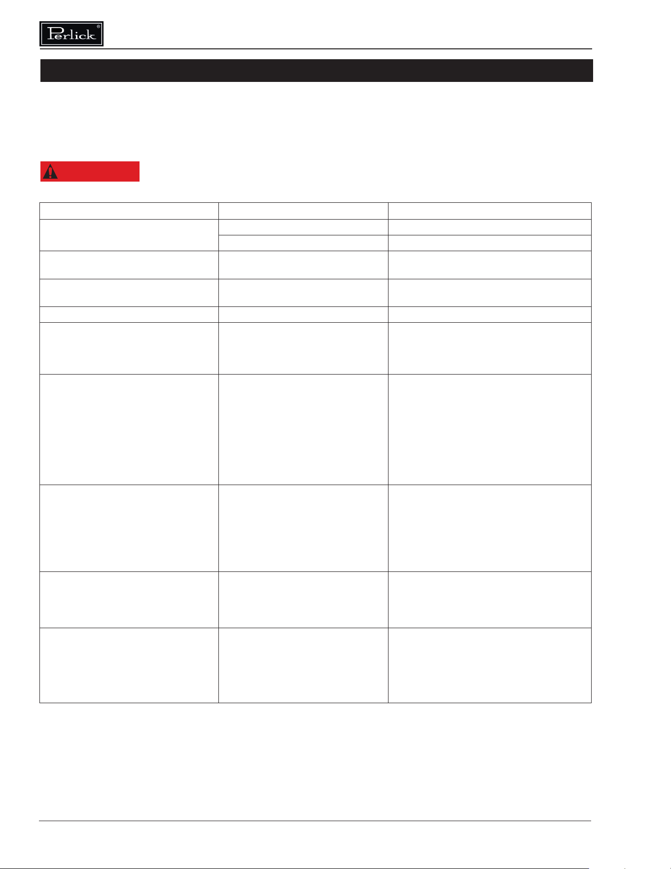
Problem Cause Solution
No interior light. Rocker switch in O position. Turn switch on.
LED board inoperable. Contact your selling dealer.
Light stays on when door is closed. Manual switch on. Turn manual switch o.
Noisy operation. Soft sounds from compressor, fan
motor and valves heard.
Normal operation.
LED Controller display is ashing “E1”. Thermostat probe failure. Contact your selling dealer.
Unit is not running. No power to the unit.
Condenser dirty.
Home circuit breaker tripped. Reset circuit
breaker.
ON/OFF keypad is o. Turn on.
Clean the condenser.
Compartments are warmer than usual. Control preset not set properly.
Light staying on.
Condenser dirty or obstructed.
Door is open or has been opened
more frequently lately.
Internal louvers and/or fan guard
obstructed.
Warm product placed in cabinet
recently.
Reset compartments presets.
Turn manual light switch o.
Clean condenser and clear obstruction.
Wait 24 hours and recheck temperature.
Reset preset temperature if necessary.
Make sure louvers and/or fan is not
obstructed.
System runs for long period of time. Condenser dirty or obstructed.
Door kept open for long time or
opened more frequently.
Warm product place in cabinet
recently.
Hot day and warm room
temperature.
Clean condenser and clear obstruction.
Wait 24 hours and recheck temperature.
Reset preset temperature if necessary.
Normal for system to run more frequently.
Condensation forms inside the
compartments.
High humidity and/or frequent door
opening.
Door not closing and sealing
properly.
Normal operation.
Make sure door is closing properly. Check
door seals and replace if necessary.
Condensation forms on outside of unit. High humidity and/or frequent door
opening.
Door not closing and sealing
properly.
Normal operation.
Make sure door is closing properly. Check
door seals and replace if necessary.
If condensation persists, contact your selling
dealer.
TROUBLESHOOTING
Before Calling For Service
If the unit appears to be malfunctioning, read through the Operation section in this manual rst. If the problem
persists, check through this troubleshooting section. Locate the problem and refer to the cause and remedy
before calling for service. The problem could be something that can be solved without a service call.

Commercial Back Bar Installation & Operation Manual
Form No. Z2604
Rev A 11.24.2020
For Replacement Parts and Accessories
• Use only genuine Perlick replacement parts
and accessories. Genuine Perlick parts and
accessories are designed to work correctly
with Perlick products and offer superior
service life. The use of non-Perlick parts can
damage the unit and may void the warranty.
• Check the model and serial number of your
unit which is located on the right or left interior
panel. Call your Perlick Factory Authorized
Service Center.
• Inquire via the web at www.perlick.com, or call
(800) 558-5592.
Genuine Perlick replacement parts and
accessories have been tested and approved
for use with ammable refrigerants to prevent
hazardous conditions.
For Product Information
• Contact your selling dealer.
• Inquire via the web at www.perlick.com
• Call (800) 558-5592 for factory assistance on
planning installation or product information.
• Write to Perlick Corporation, Customer
Service Department, 8300 West Good Hope
Road, Milwaukee, WI 53223.
• Email us at [email protected].
For Product Service
• Check the model and serial number of your
unit located on the label attached to the inside
top of the cabinet.
• Inquire via the web at www.perlick.com, or call
(800) 558-5592.
Commercial Back Bar Installation & Operation Manual
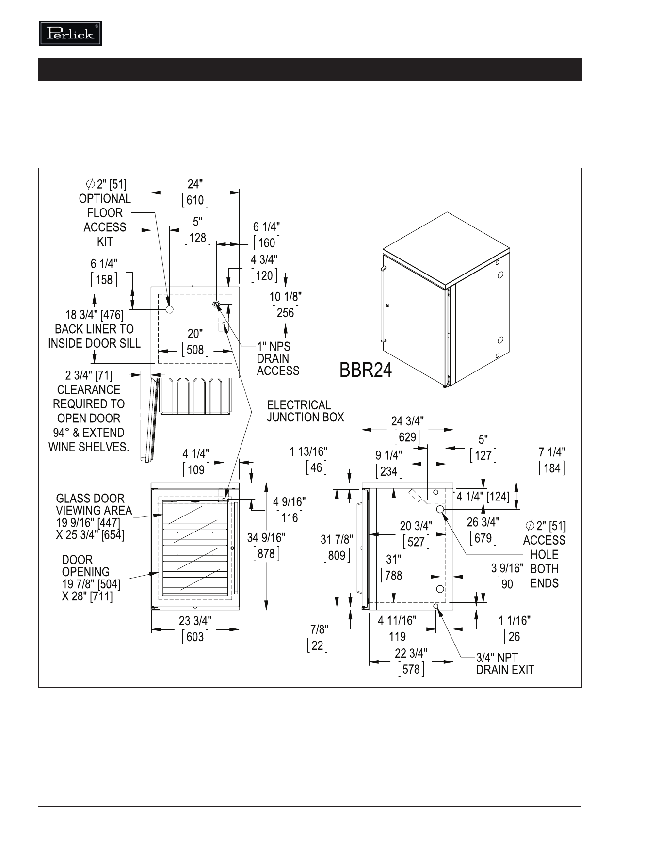
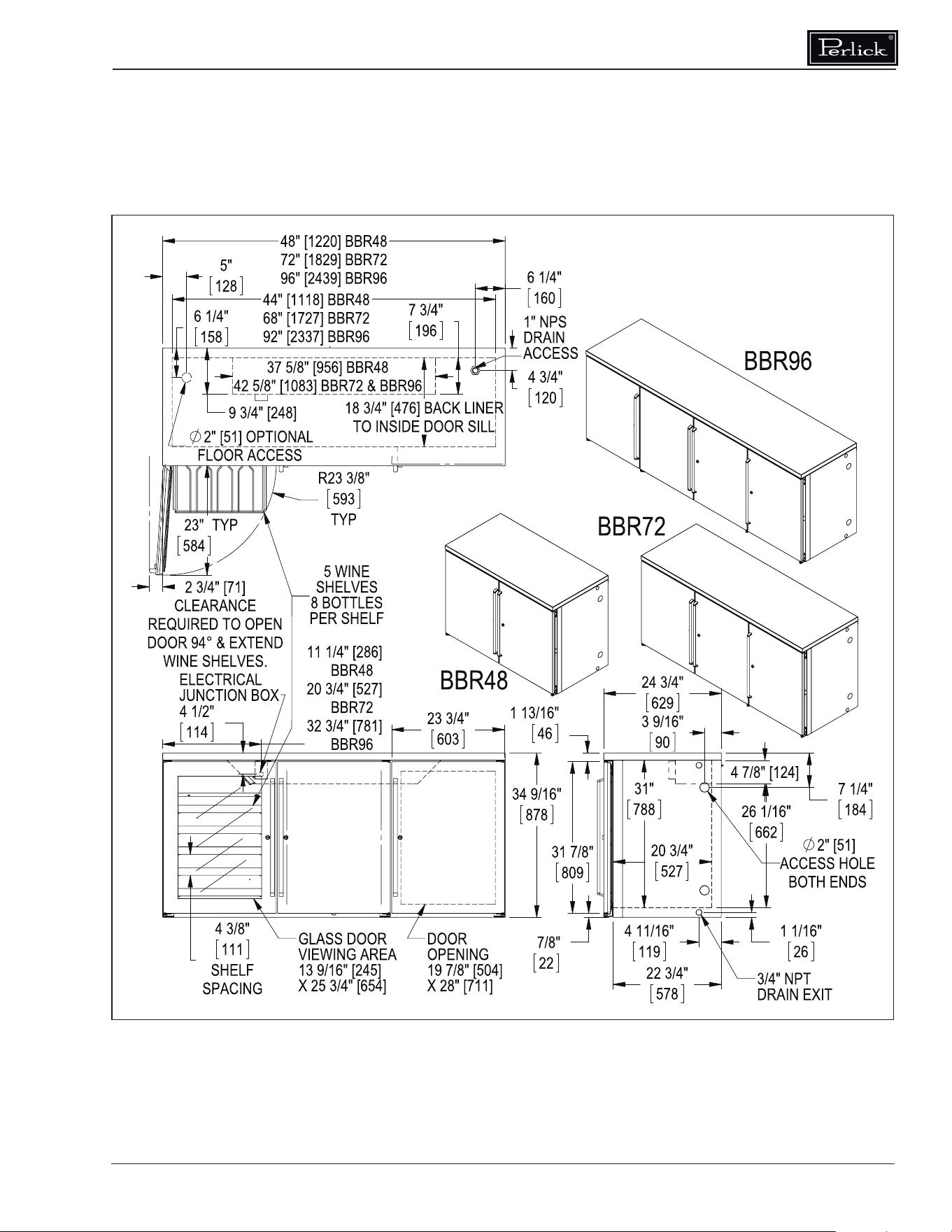
16
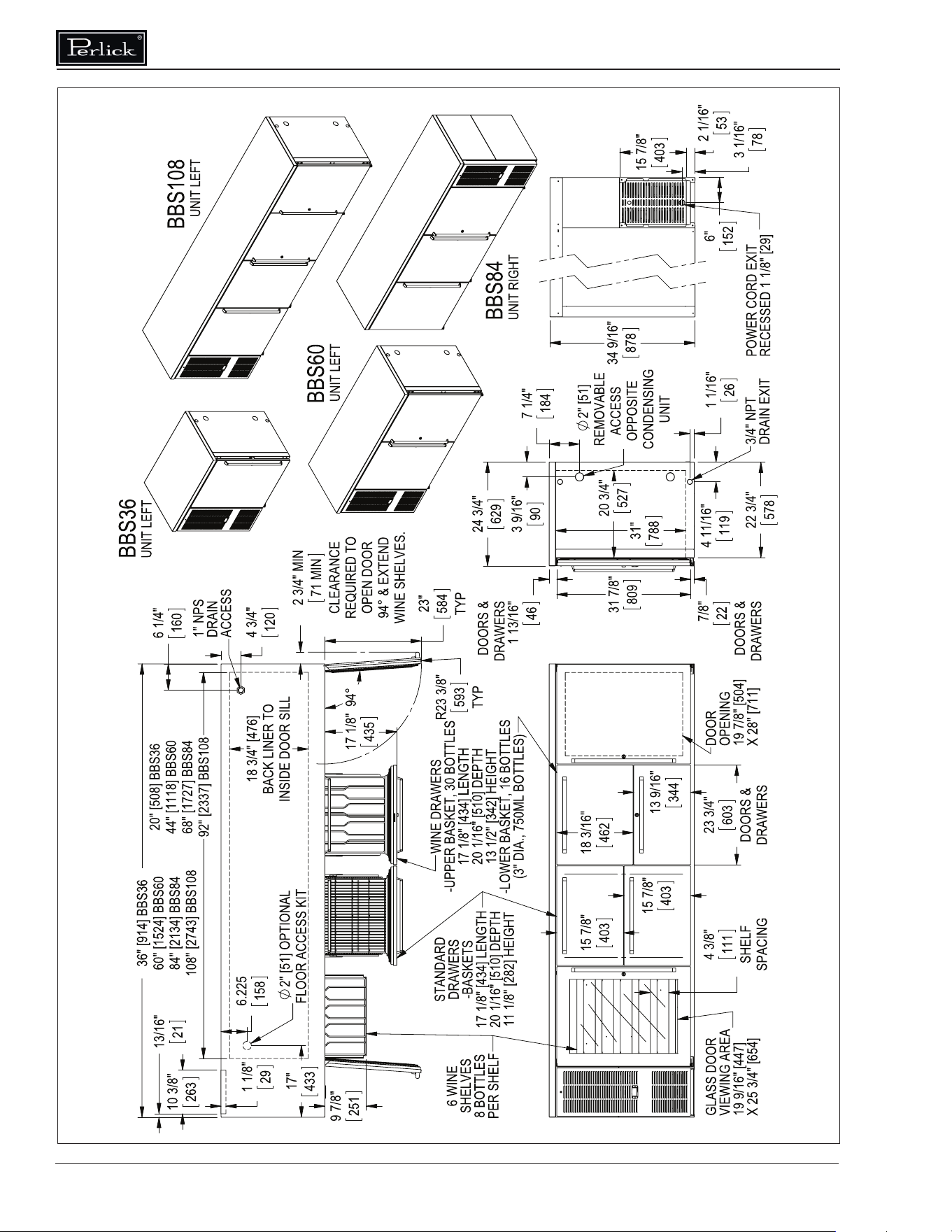
DIMENSIONS
Commercial Back Bar Installation & Operation Manual
Form No. Z2604
Rev A 11.24.2020
Commercial Back Bar Installation & Operation Manual
18
Commercial Back Bar Installation & Operation Manual
Form No. Z2604
Rev A 11.24.2020
REVISIONS
THIS DOCUMENT / PUBLICATION / SOFTWARE / DRAWING CONTAINS PROPRIETARY INFORMATION WHICH IS THE PROPERTY OF THE PERLICK CORPORATION. IT MAY NOT BE REPRODUCED OR TRANSMITTED IN ANY
FORM, ELECTRONIC OR MECHANICAL, INCLUDING PHOTOCOPYING, RECORDING, OR USED IN ANY INFORMATION STORAGE, TRANSMISSION, OR RETRIEVAL SYSTEM, WITHOUT WRITTEN PERMISSION FROM THE PERLICK
CORPORATION. COPYRIGHT 2001 PERLICK CORPORATION. ALL RIGHTS RESERVED.
DESIGNED
DRAWN
FINISH:
QTY.:
.012
HOLES: .0135 THRU .125: .004
.1260 THRU .250: .005
.2510 THRU .500: .006
.5010 THRU .750: .008
.7510 THRU 1.000: .010
1.001 & UP:
BREAK SHARP EDGES - .015 X 45°
RADIUS SHARP FILLETS - .015 TO .031
UNLESS OTHERWISE SPECIFIED:
TITLE:
PURCHASE REC.:
PART NO.
REFERENCE:
DWG NO.
MATERIAL:
Perlick Corporation
DATE
SIGNATURES
Milwaukee, Wisconsin
20 13/16"
528
25 7/16"
647
R23 3/8"
593
23"
584
10 3/8"
263
13/16"
21
1 1/8"
29
2"
OPTIONALFLOOR
ACCESS KIT
51
6 1/4"
159
17"
432
18 3/4"
476
20" [508] BBSLP36
44" [1118] BBSLP60
68" [1727] BBSLP84
92" [2337] BBSLP108
3/4" NPT
DRAIN EXIT
26 5/16"
668
UNIT
CONDENSING
OPPOSITE
ACCESS
REMOVABLE
51
89
3 1/2"
21 3/4"
553
2"
1 1/16"
26
119
4 11/16"
629
24 3/4"
DOORS
1 13/16"
46
7/8"
22
DOORS
RELEASE FOR PRODUCTION
2
2
B
A
3
C
B
A
1
C
1
3
ANGULAR: , FRACTIONS:
SW
J:\Dwg\95000\95318.slddrw
SCALE = 1:24
2/23/2016JMP
LOW HEIGHT SC BACK BAR
CUTSHEET DIMENSIONS
N/A
95318
A
2/25/2016
SHEET 1 OF 2
DIMENSIONS ARE IN INCHES
TOLERANCES:
.X= , .XX = , .XXX = ,
JMP
78
RECESSED 1 1/8" [29]
POWER CORD EXIT
3 1/16"
14 15/16"
379
2 1/16"
53
6"
152
29"
737
GLASS DOOR
VIEWING AREA
17 9/16" [447]
X 20 3/16" [512]
DOOR
OPENING
19 7/8" [504]
X 22 9/16" [573]
23 3/4"
603
DOORS
5 3/8"
137
SHELF
SPACING
WINE SHELVES
-4 SHELVES PER DOOR
-8 BOTTLES PER SHELF
36" [914] BBSLP36
60" [1524] BBSLP60
6 1/4"
84" [2134] BBSLP84
108" [2743] BBSLP108
WINE SHELVES
& EXTEND
94
OPEN DOOR
REQUIRED TO
CLEARANCE
80
4 3/4"
120
160
3 1/8"
9 7/8"
251
2/25/2016 11:27 AM
BBSLP108
Unit Left
Commercial Back Bar Installation & Operation Manual
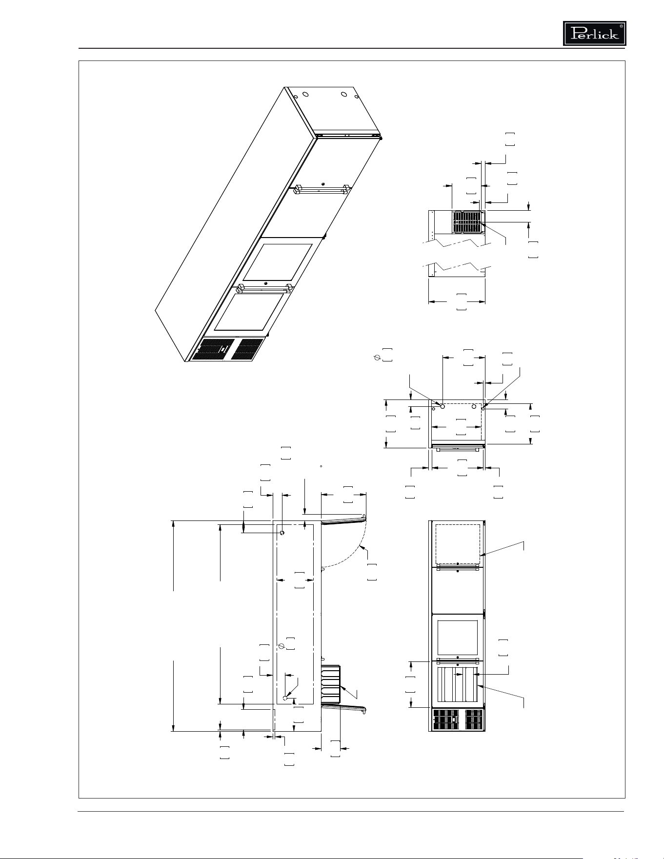
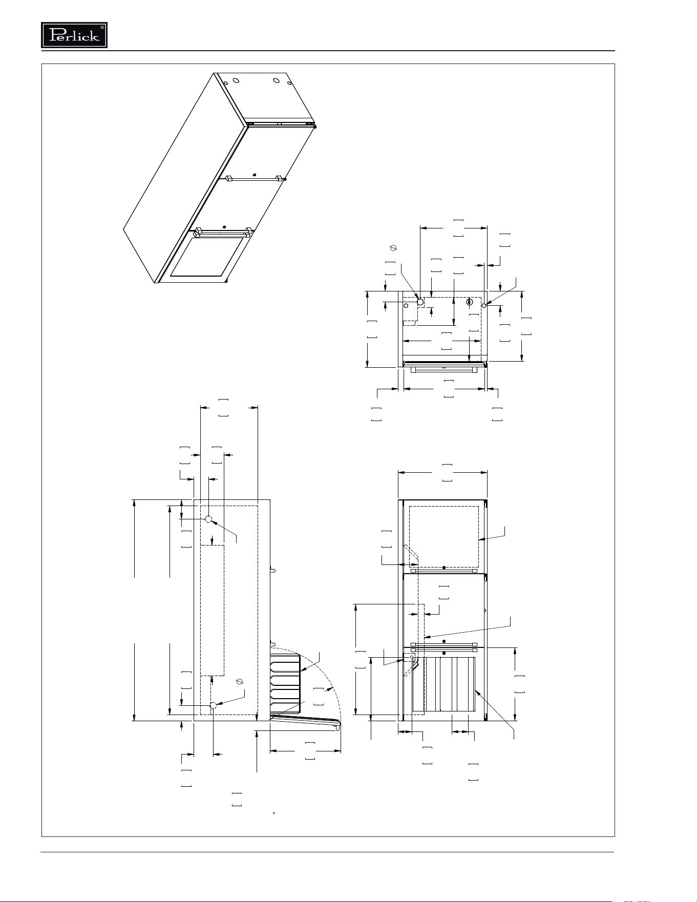
20
REVISIONS
THIS DOCUMENT / PUBLICATION / SOFTWARE / DRAWING CONTAINS PROPRIETARY INFORMATION WHICH IS THE PROPERTY OF THE PERLICK CORPORATION. IT MAY NOT BE REPRODUCED OR TRANSMITTED IN ANY
FORM, ELECTRONIC OR MECHANICAL, INCLUDING PHOTOCOPYING, RECORDING, OR USED IN ANY INFORMATION STORAGE, TRANSMISSION, OR RETRIEVAL SYSTEM, WITHOUT WRITTEN PERMISSION FROM THE PERLICK
CORPORATION. COPYRIGHT 2001 PERLICK CORPORATION. ALL RIGHTS RESERVED.
DESIGNED
DRAWN
FINISH:
QTY.:
.012
HOLES: .0135 THRU .125: .004
.1260 THRU .250: .005
.2510 THRU .500: .006
.5010 THRU .750: .008
.7510 THRU 1.000: .010
1.001 & UP:
BREAK SHARP EDGES - .015 X 45°
RADIUS SHARP FILLETS - .015 TO .031
UNLESS OTHERWISE SPECIFIED:
TITLE:
PURCHASE REC.:
PART NO.
REFERENCE:
DWG NO.
MATERIAL:
Perlick Corporation
DATE
SIGNATURES
Milwaukee, Wisconsin
11 1/4" [286] BBRLP48
20 3/4" [527] BBRLP72
32 3/4" [781] BBRLP96
4 1/2"
114
6 5/16"
161
2"
51
36"
914
23"
584
R23 3/8"
593
2" [51] OPTIONAL
FLOOR ACCESS
37 3/4" [958] BBRLP48
42 3/4" [1085] BBRLP72 & BBRLP96
18 3/4"
476
BACK LINER TO
INSIDE DOOR SILL
7 3/4"
196
1" NPS
DRAIN ACCESS
4 3/4"
120
6 1/4"
160
5"
128
6 1/4"
158
44" [1118] BBRLP48
68" [1727] BBRLP72
92" [2337] BBRLP96
25 7/16"
647
20 3/4"
527
9 1/16"
230
3 3/8"
85
RELEASE FOR PRODUCTION
2
2
B
A
3
C
B
A
1
C
1
3
ANGULAR: , FRACTIONS:
SW
J:\Dwg\95000\95318.slddrw
SCALE = 1:16
2/25/2016JMP
LOW HEIGHT REMOTE BACK BAR
CUTSHEET DIMENSIONS
N/A
95318
A
2/25/2016
SHEET 2 OF 2
DIMENSIONS ARE IN INCHES
TOLERANCES:
.X= , .XX = , .XXX = ,
JMP
ELECTRICAL
EVAPORATOR LINE
COVER (SHOWN LEFT)
X 20 3/16" [512]
17 9/16" [447]
VIEWING AREA
BOX
JUNCTION
GLASS DOOR
DOOR OPENING
19 7/8" [504]
X 22 9/16" [573]
23 3/4"
603
SHELF SPACING
5 3/8"
137
29"
737
WINE SHELVES
-3 SHELVES PER DOOR
-8 BOTTLES PER SHELF
& EXTEND
WINE SHELVES
94
3 1/8"
80
CLEARANCE
REQUIRED TO
OPEN DOOR
48" [1220] BBRLP48
72" [1829] BBRLP72
96" [2439] BBRLP96
DRAIN EXIT
3/4" NPT
2" [51]
ACCESS HOLE
BOTH ENDS
26 5/16"
668
4 11/16"
119
1 1/16"
26
DOORS
7/8"
22
3 1/2"
89
DOORS
1 13/16"
46
553
21 3/4"
629
24 3/4"
22 3/4"
578
2/25/2016 11:27 AM
BBRLP72
Commercial Back Bar Installation & Operation Manual
Form No. Z2604
Rev A 11.24.2020
Commercial Back Bar Installation & Operation Manual
22
Commercial Back Bar Installation & Operation Manual
Form No. Z2604
Rev A 11.24.2020
Commercial Back Bar Installation & Operation Manual
24
Commercial Back Bar Installation & Operation Manual
Form No. Z2604
Rev A 11.24.2020
Commercial Back Bar Installation & Operation Manual
26
Commercial Back Bar Installation & Operation Manual
Form No. Z2604
Rev A 11.24.2020
Commercial Back Bar Installation & Operation Manual
28
Commercial Back Bar Installation & Operation Manual
Form No. Z2604
Rev A 11.24.2020
Commercial Back Bar Installation & Operation Manual
30
Commercial Back Bar Installation & Operation Manual
Form No. Z2604
Rev A 11.24.2020
Commercial Back Bar Installation & Operation Manual
32
R23 3/8"
593
23"
584
44 [1118] DDC68
68" [1727] DDC92
13/16"
21
10 3/8"
263
1 1/8"
29
18 3/4" [476]
BACK LINER
TO INSIDE
DOOR SILL
20 3/4"
527
31"
788
28 1/8" [714]
DDC92 6 CASTERS
DDC68 4 CASTERS
DOOR OPENING
19 7/8" [504] X
68" [1727] DDC68
TEE TOWER
92" [2337] DDC92
12 3/4" [325]
DRAGT ARM OR
23 3/4"
603
1" NPS
DRAIN
ACCESS
813
DDC92 ONLY
32"
363
14 1/4"
24" [610]
4 3/4"
120
22 3/4"
578
809
1 13/16"
46
31 7/8"
629
24 3/4"
34 9/16"
878
40 9/16"
1031
7/8"
22
627
24 11/16"
6"
153
POWER CORD EXIT
RECESSED 1 1/8" [29]
BACK VIEW
53
2 1/16"
403
15 7/8"
3 1/16"
78
6"
152
DDC92
WITH
TEE TOWERS
DDC68
WITH
DRAFT ARM
95181
REV
DAS
6/10/13
6/11/2013 7:44 AM
Commercial Back Bar Installation & Operation Manual
Form No. Z2604
Rev A 11.24.2020
20 3/4"
527
31"
788
R23 3/8"
593
23"
584
20" [508] DDS36
44" [1118] DDS60
68" [1727] DDS84
92" [2337] DDS108
18 3/4" [476]
BACK LINER
TO INSIDE
DOOR SILL
10 3/8"
263
13/16"
21
1 1/8"
29
BACK VIEW
95180
REV A
DAS
6/10/13
DOOR OPENING
19 7/8" [504] X
28 1/8" [714]
603
TEE TOWER
12 3/4" [325]
DRAFT ARM OR
23 3/4"
36" [914] DDS36
60" [1524] DDS60
84" [2134] DDS 84
108" [2743] DDS 108
24"
610
DDS84
WITH TEE TOWERS
POWER CORD EXIT
RECESSED 1 1/8" [29]
152
6"
78
3 1/16"
53
2 1/16"
15 7/8"
403
DDS60
WITH TEE TOWER
48"
1219
DDS108
WITH DRAFT ARMS
3/4 NPT
DRAIN
EXIT
119
4 11/16"
22 3/4"
578
34 9/16"
878
629
24 3/4"
809
31 7/8"
7/8"
22
1 13/16"
46
1 1/16"
26
1" NPS
DRAIN
ACCESS
610
24"
4 3/4"
120
48" [1220] DDS108
24" [610] DDS84
6 1/4"
160
DDS36
WITH DRAFT ARM
Commercial Back Bar Installation & Operation Manual
34
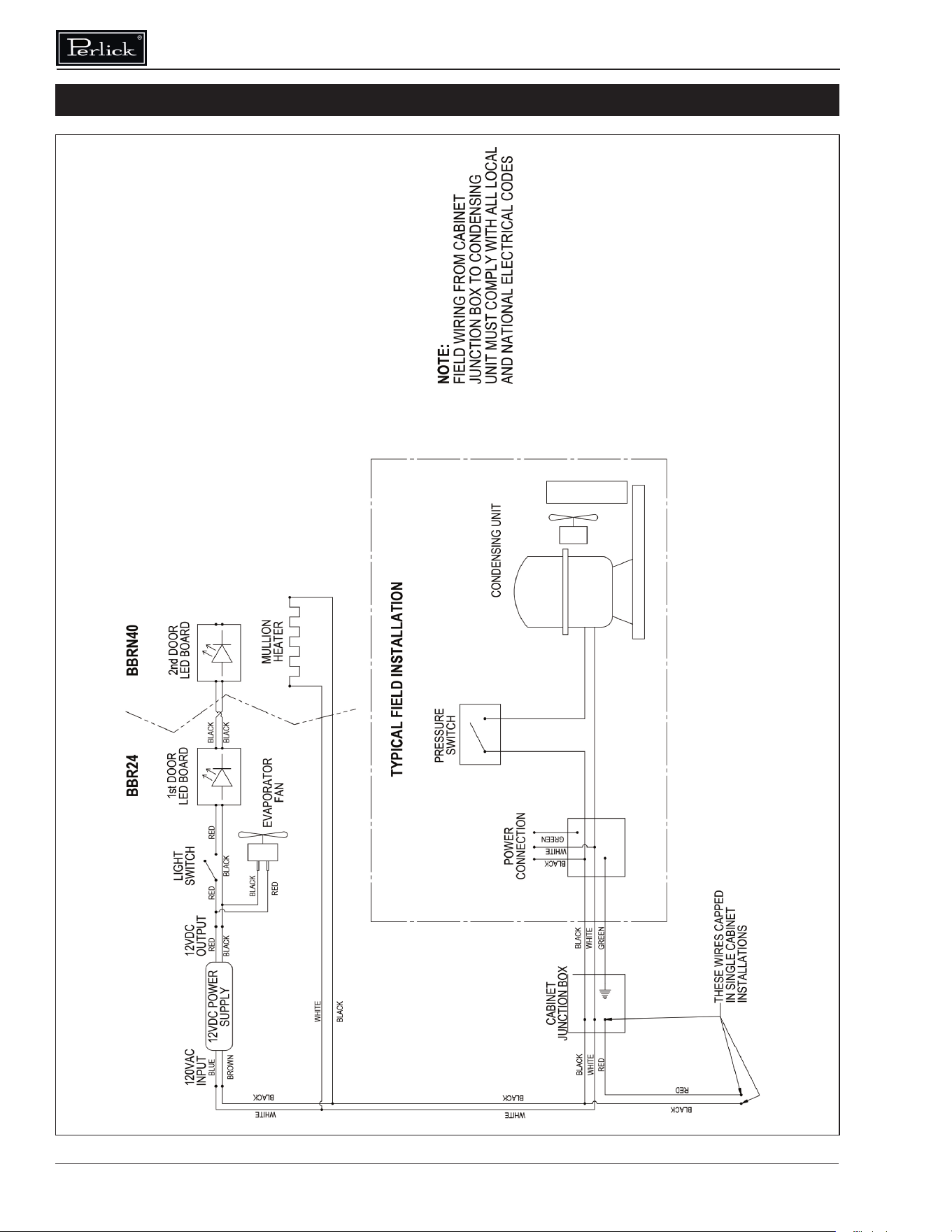
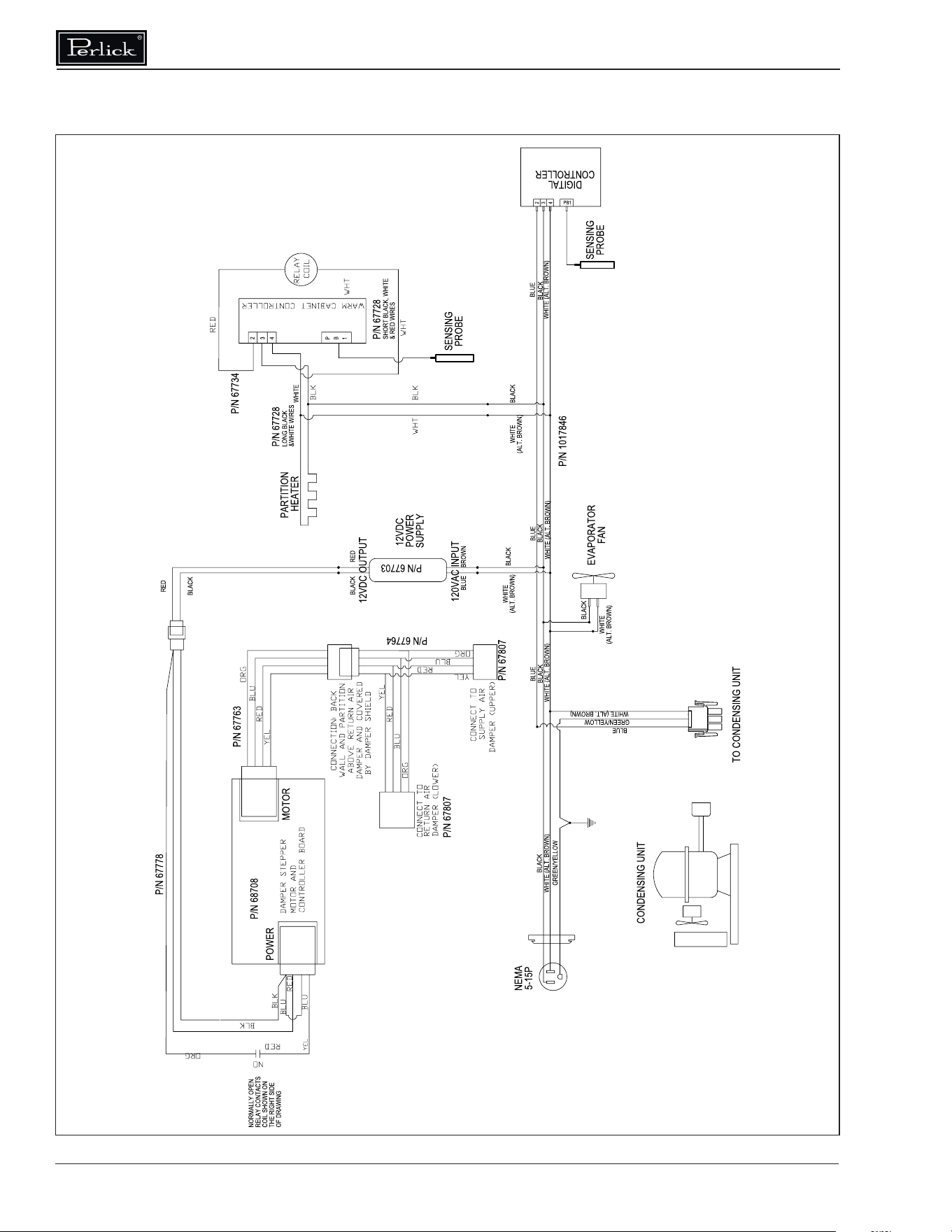
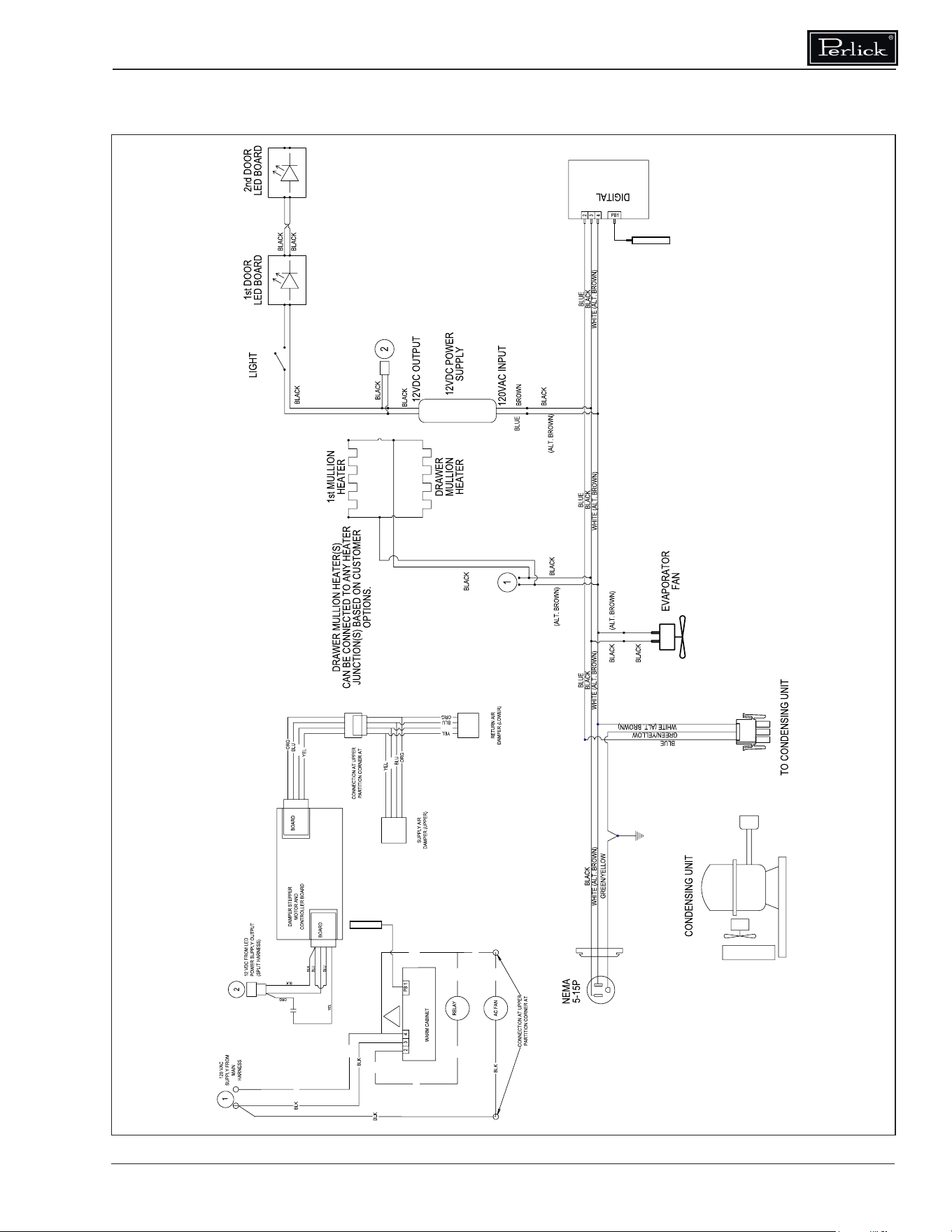
WIRING DIAGRAMS
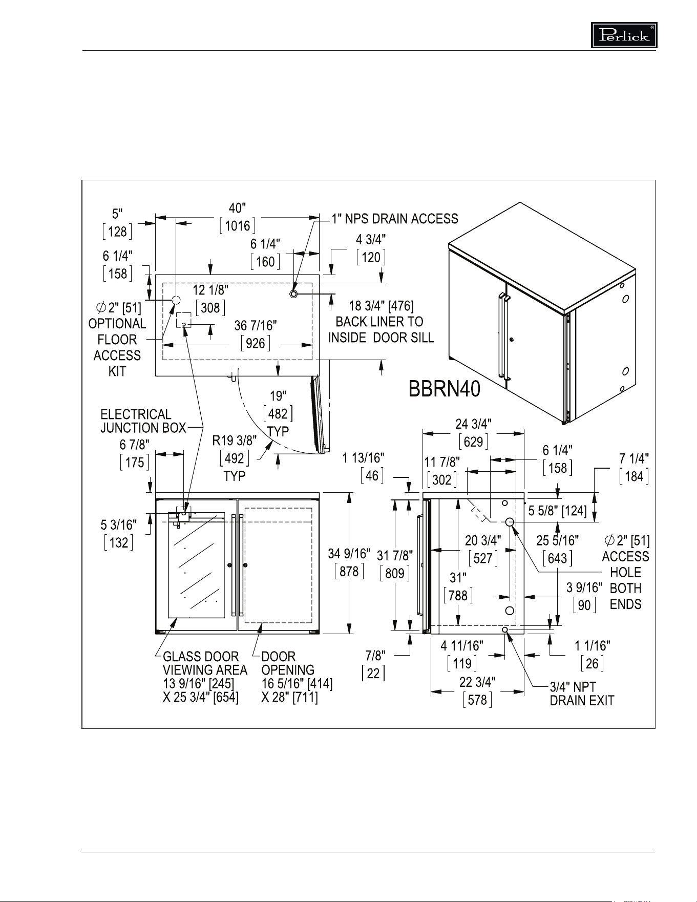
BBR24/BBRN40
57342A-99-120-RevA
Commercial Back Bar Installation & Operation Manual
Form No. Z2604
Rev A 11.24.2020
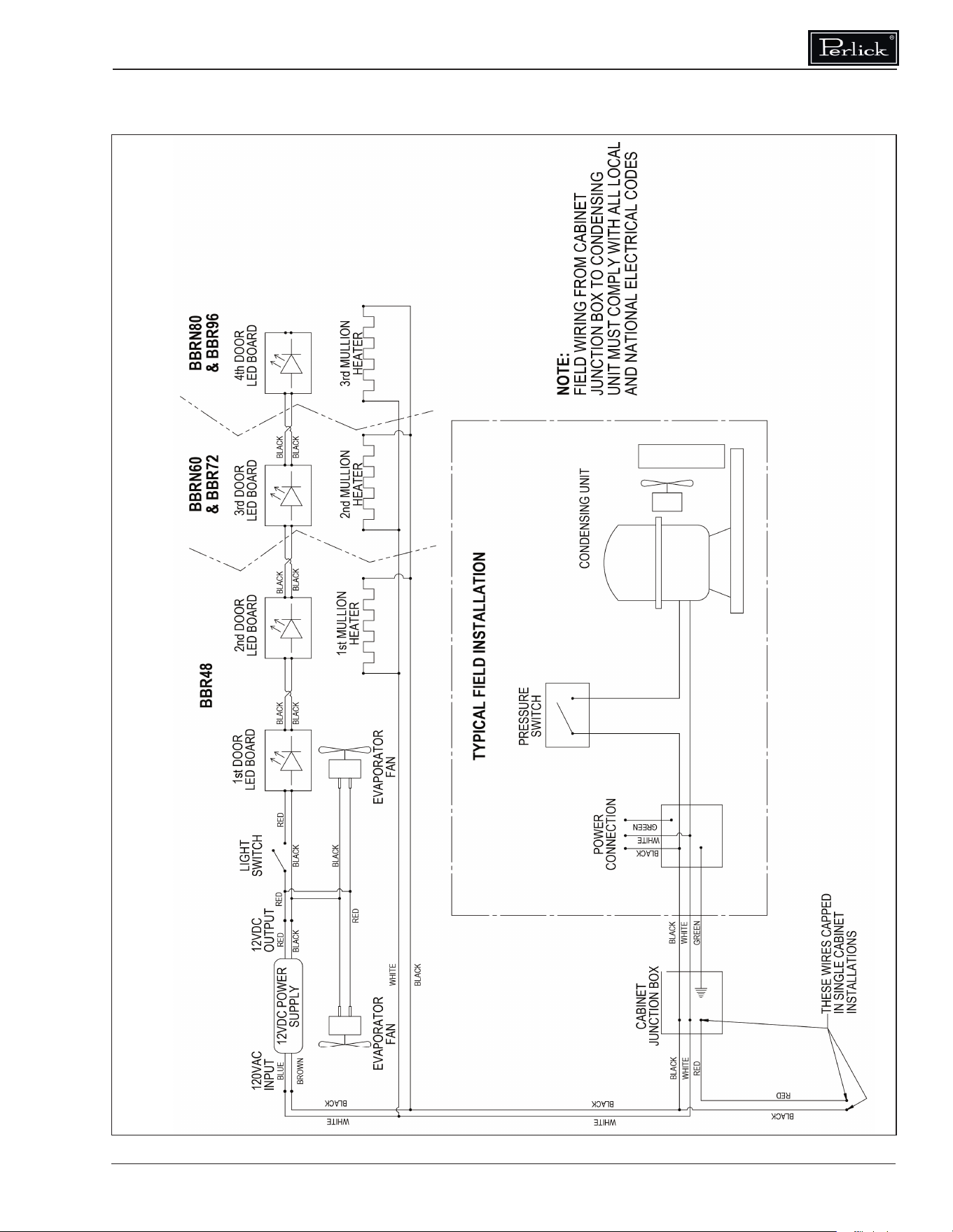
BBR48/BBRN60/BBR72/
BBRN80/BBR96
57342A-98-120-RevA
Commercial Back Bar Installation & Operation Manual
36
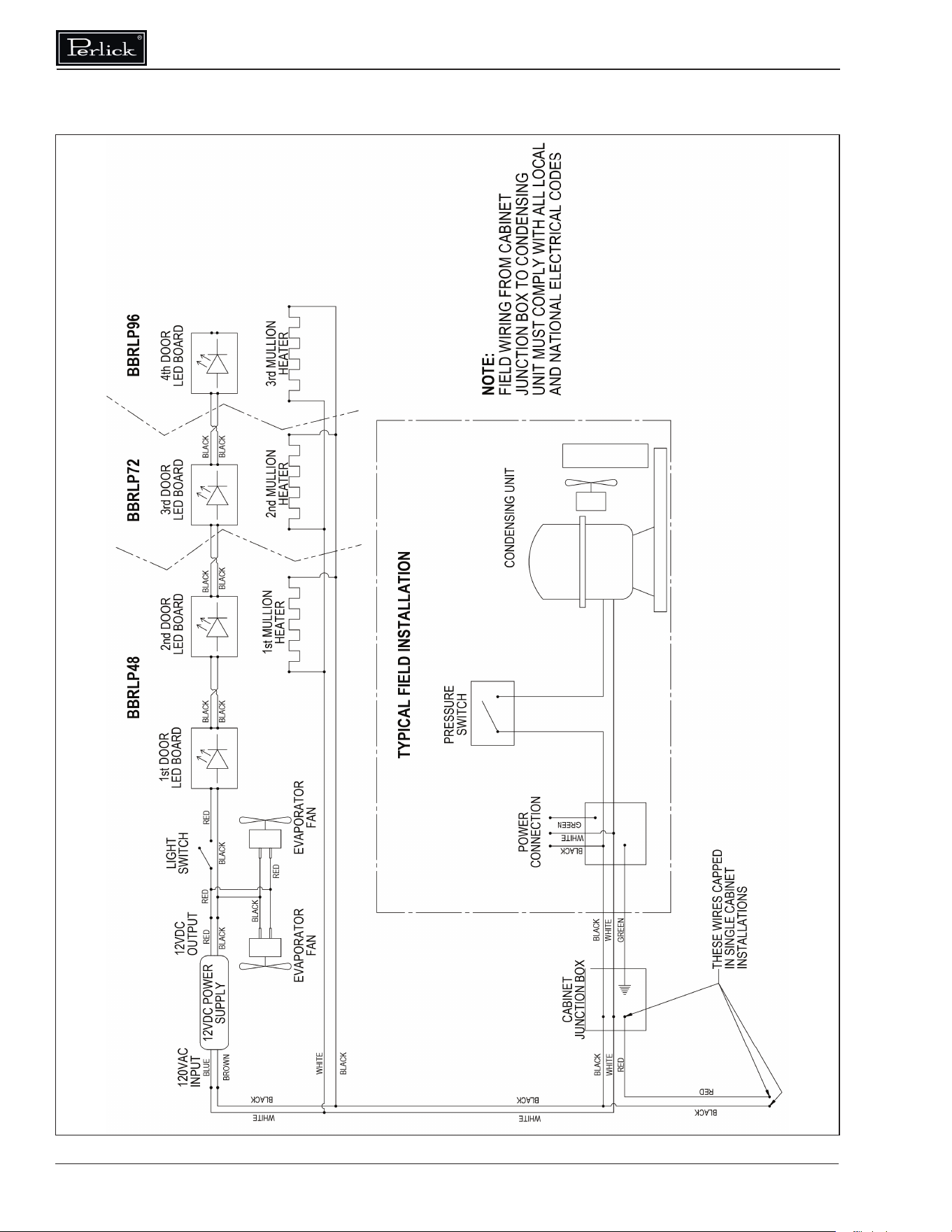
BBRLP
95322A-120-RevA

Commercial Back Bar Installation & Operation Manual
Form No. Z2604
Rev A 11.24.2020
WHITE
RED
WHITE
WHITE
WHITE
RED
RED
RED
CONTROLLER
SWITCH
BBS/BBSN
57342C-97-120
Commercial Back Bar Installation & Operation Manual
38
SWITCH
RED
RED
RED
WHITE
RED
CONTROLLER
WHITEWHITE
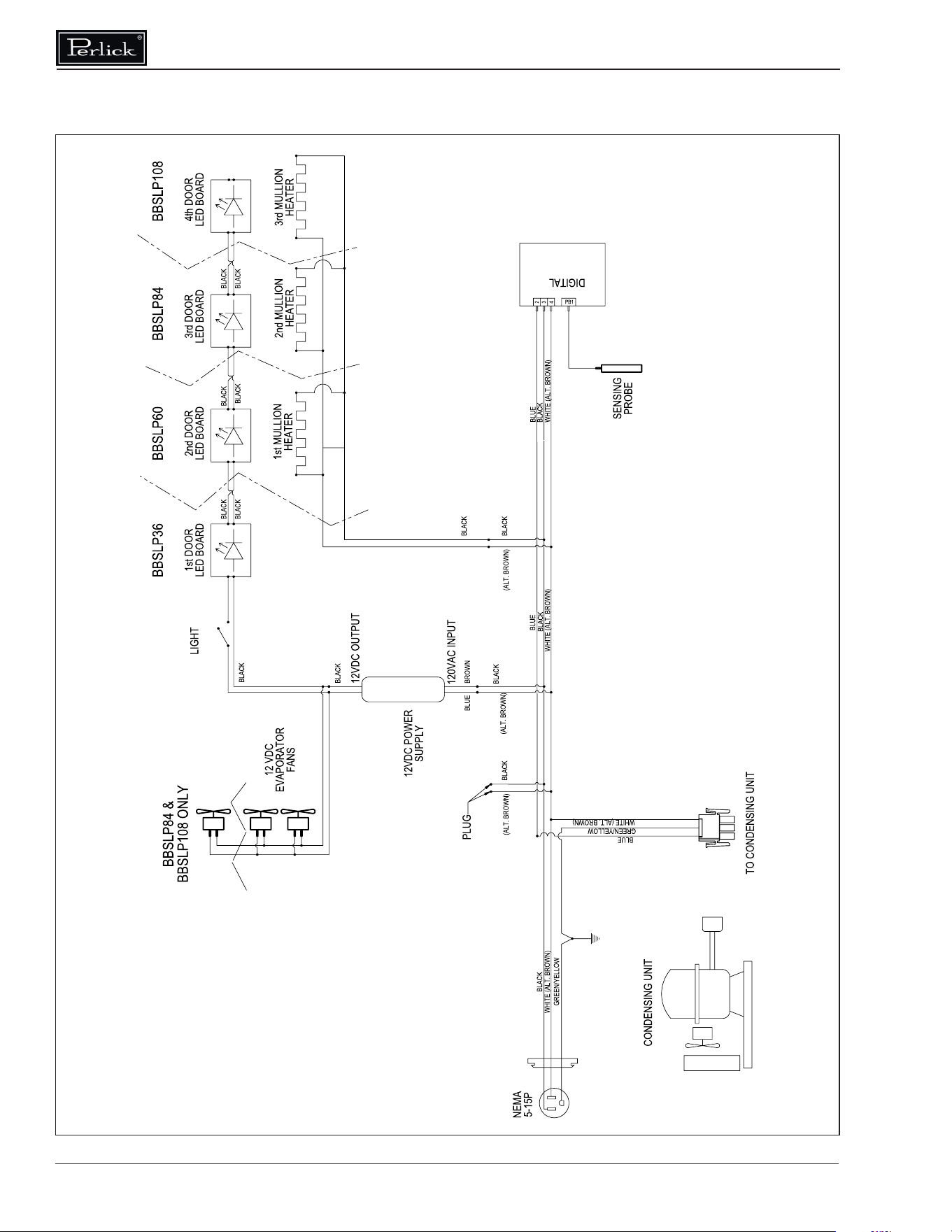
BBSLP
95321C-120

Commercial Back Bar Installation & Operation Manual
Form No. Z2604
Rev A 11.24.2020
WHITE
RED
WHITE
WHITE
WHITE
RED
RED
RED
CONTROLLER
SWITCH
DDS/DDC
57342C-100-120
Commercial Back Bar Installation & Operation Manual
40
DZS36
57342B-108
Commercial Back Bar Installation & Operation Manual
Form No. Z2604
Rev A 11.24.2020
WHT
NO
RED
RED
SENSING
PROBE
OUTPUT
RED
FRONT OF UNIT
RED
CONNECT TO
RED
CONNECT TO
WHT
WHT
RED
RED
FRONT OF UNIT
WHT
WHT
WHT
RED
COIL
CONTROLLER
SWITCH
RED
RED
RED
WHITE
RED
WHITE
RED
CONTROLLER
SENSING
PROBE
INPUT
C
WHITE
WHITE
DZS60
57342B-107
Commercial Back Bar Installation & Operation Manual
42
SWITCH
RED
RED
OUTPUT
INPUT
RED
WHITE
WHITEWHITE
WHITE
RED
RED
WHITE
WHITE
POWER
CONNECTION
PRESSURE
SWITCH
NOTE:
WHITE
SWITCH
RED
RED
PRODUCTION START: 04/20/2020
PRODUCTION END: NA
PTR
57342A-102-120-RevA
Commercial Back Bar Installation & Operation Manual
Form No. Z2604
Rev A 11.24.2020
SWITCH
CONTROLLER
WHITE
RED
RED
WHITE
WHITE
RED
RED
WHITE
WHITE
RED
WHITE
SWITCH
RED
RED
WHITE
RED
WHITE
UNIT HERE
PRODUCTION START: 04/20/2020
PRODUCTION END: NA
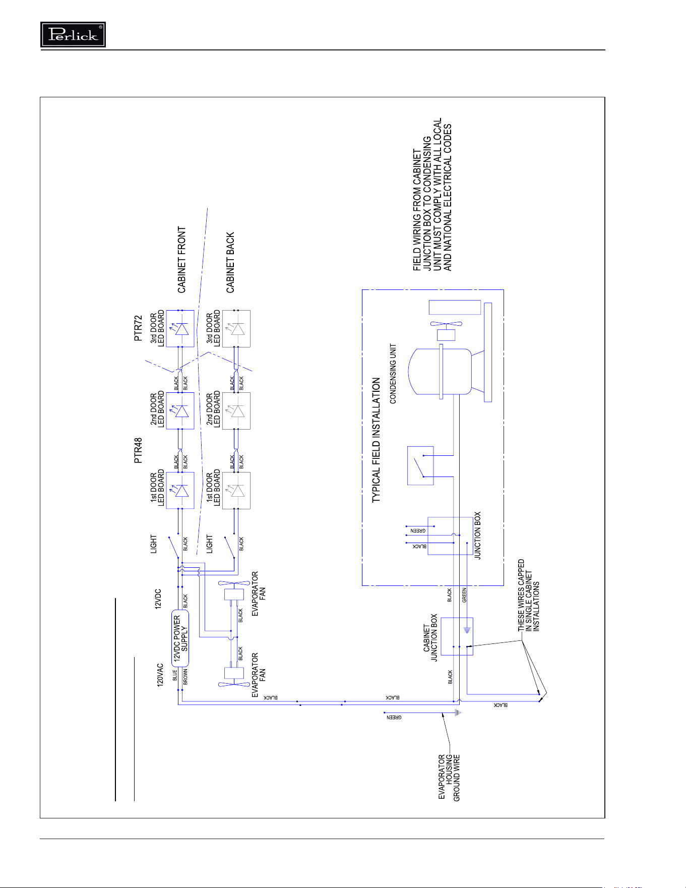
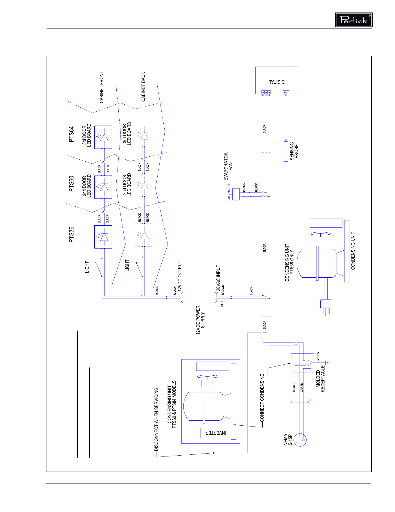
PTS
57342C-101-120
Commercial Back Bar Installation & Operation Manual
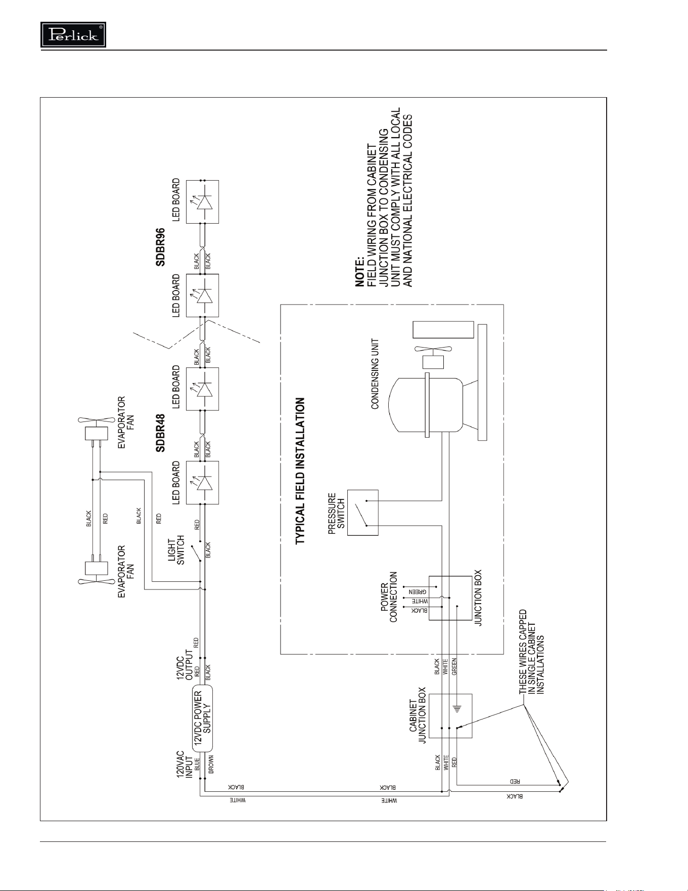
44
SDBR48-SDBR96
57342A-106-120-RevA
Commercial Back Bar Installation & Operation Manual
Form No. Z2604
Rev A 11.24.2020
SWITCH
RED
RED
WHITE
RED
WHITE
CONTROLLER
WHITE
WHITE
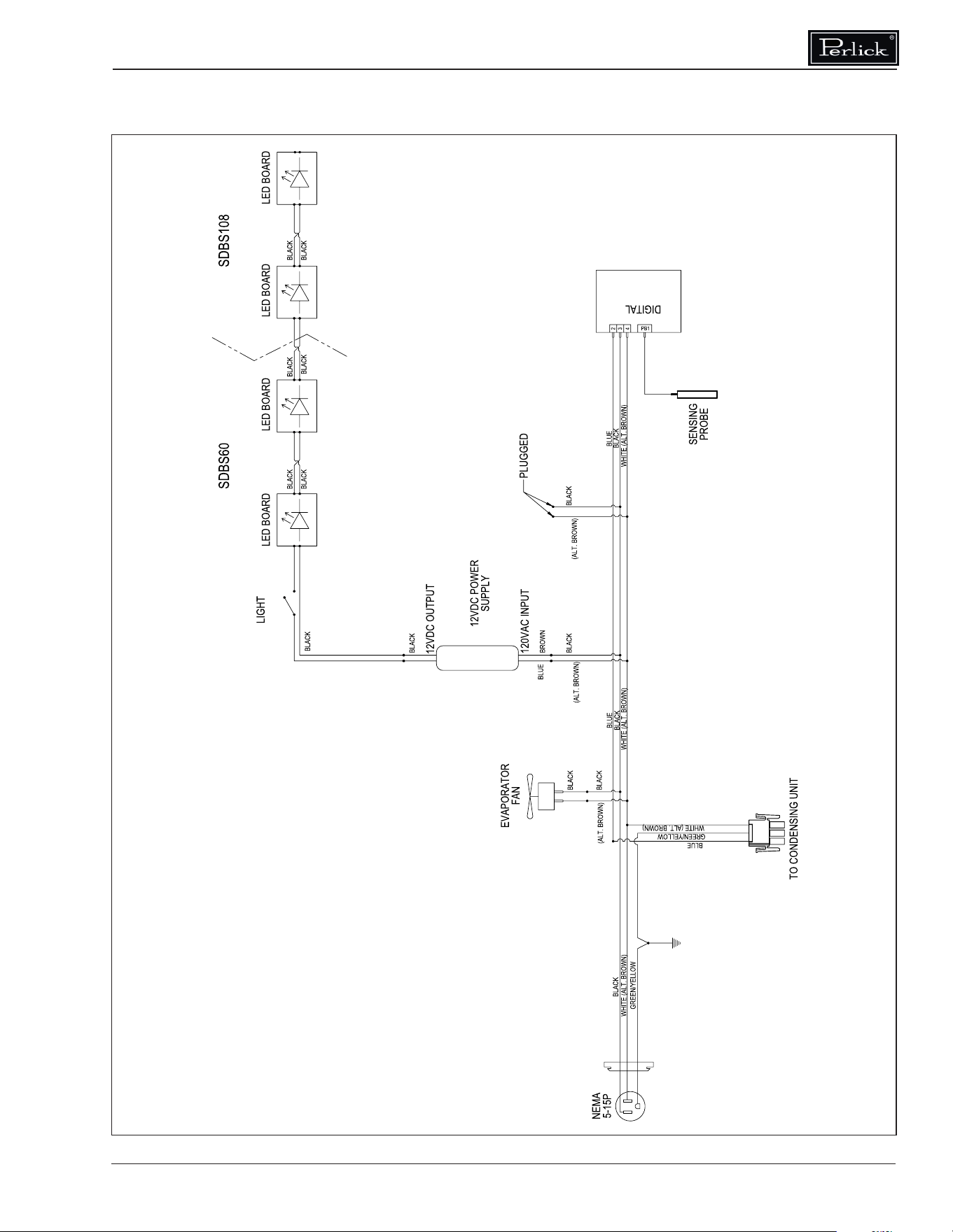
SDBS
57342C-105-120
Commercial Back Bar Installation & Operation Manual
46
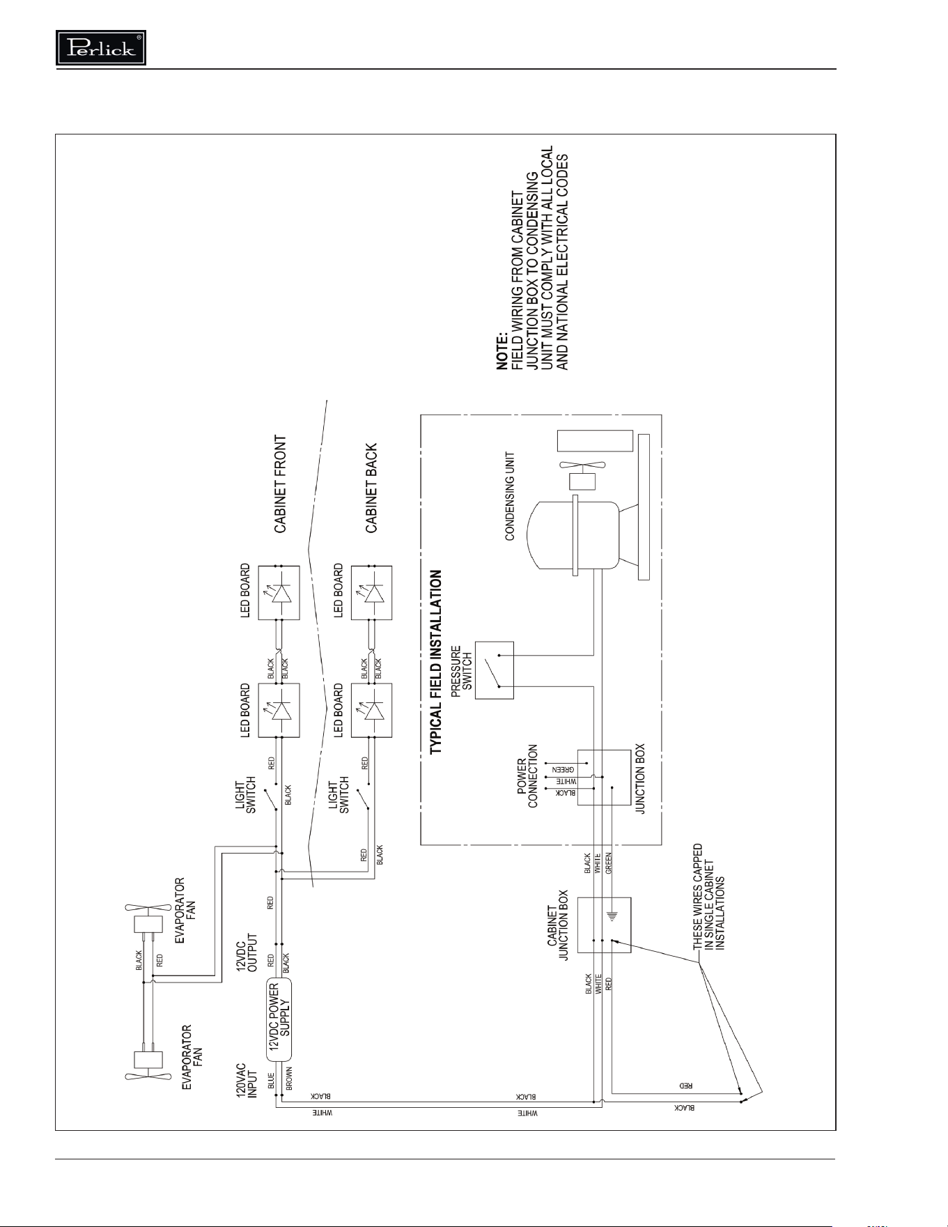
SDPR
57342A-104-120-RevA
Commercial Back Bar Installation & Operation Manual
Form No. Z2604
Rev A 11.24.2020
WHITE
CONTROLLER
RED
SWITCH
RED
WHITE
WHITEWHITE
RED
RED
SWITCH
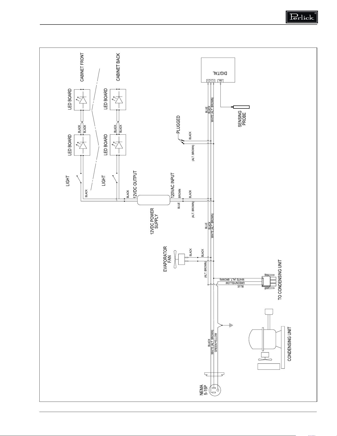
SDPS
57342C-103-120

Commercial Back Bar Installation & Operation Manual
48
WARRANTY
The terms and conditions set forth below
together with those appearing on the face of
the Acknowledgement (the “Order”) constitute
the complete and exclusive agreement between
Perlick Corporation and the Buyer pertaining to
the goods and/or services identied in the Order.
If there is a discrepancy or conict between any
exhibit or supplement to the Order and these
terms and conditions, these terms and conditions
shall control. The Order is intended by Seller and
Buyer to be the complete, exclusive, and nal
statement of their agreement. Any changes to an
Order must be in writing and signed by Perlick
and Buyer.
TERMS NET 30 DAYS
Payment by Visa, MasterCard, American Express
or Discover card accepted or cash in advance
unless prior accommodations have been made
with our Credit Department. Please direct inquiries
for detailed information to our Credit Manager.
All sales, excise, or similar taxes required by
law to be collected or paid by seller shall be in
addition to prices quoted unless an appropriate
Tax Exemption certicate is furnished. All goods
are sold F.O.B. factory. Except for otherwise
provided, Perlick will not be responsible for freight,
transportation, insurance, shipping, storage,
handling, demurrage or similar charges. Invoices
are payable in full in thirty (30) days following
the invoice‚s date of issuance. If by the terms
of sale credit is extended, Perlick reserves the
right to revoke such credit if buyer fails to pay
for any products when due and may demand
payment prior to the commencement of any
further shipment.
WAIVER
Any waiver of strict compliance with the provisions
of an Order must be in writing. No such waiver
shall be construed as a waiver of any other term
or condition except as provided in writing, nor as
a waiver of any subsequent breach of the same
term or condition.
METHOD OF SHIPMENT
All shipments are carefully packed and labeled.
Crates, boxes and cartons used are of approved
weight and strength. Freight rates are based upon
100 pound minimum.
LOST and DAMAGED MERCHANDISE
THE RESPONSIBILITY OF THE PERLICK
CORPORATION CEASES UPON ACCEPTANCE
OF ITS PRODUCTS BY THE CARRIER. Any
damage or loss sustained in shipment is the
carrier’s responsibility. Before giving the carrier
a clean receipt at time of delivery, make sure you
receive every item on the bill and inspect every
carton, crate and box for concealed damage,
i.e., broken boards, crushed or punctured
cartons, torn cardboard. IF ANY ITEMS ARE
SHORT OR DAMAGED, DO NOT ACCEPT THE
SHIPMENT UNLESS THE CARRIER MAKES A
NOTATION OF THIS ON YOUR FREIGHT BILL.
Then request an inspection. Do not destroy the
packing materials. If their agent does not make
an inspection within ve days, advise the carrier
via letter that you notied them regarding the
matter and they have failed to act. You will need
this letter to support your claim. Then le a claim
for your loss. When you give the carrier a clean
receipt, you accept the total responsibility for the
shipment. UPS shipments are insured individually
and UPS will replace all merchandise that is lost
or damaged.
RETURN OF MERCHANDISE
Do not return any merchandise without our
approval. Merchandise returned without a return
merchandise authorization number will not be
accepted at Perlick. Used, discontinued, and
certain custom made items cannot be returned for
credit. These custom items include non-catalog
products (specials) as well as custom assembled
catalog products. Catalog items are designated
as non-returnable on the price list page on which
they appear. Items returned must be in new
condition and packaged in their original carton
or crate. Freight charges must be prepaid on all
return shipments.

Commercial Back Bar Installation & Operation Manual
Form No. Z2604
Rev A 11.24.2020
When a return is authorized, a credit may be
allowed pending an examination of the returned
goods. The amount of the restocking charge will
depend on the condition of the equipment. The
minimum restocking charge for glass washers,
bottle coolers, frosters, direct draws, cooler
series back bars and accessory parts is 20%.
The minimum restocking charge for custom
series cabinets is 50%. The minimum restocking
charge for un-assembled, freestanding underbar
stainless steel modules is 20%. Assembled under
bar modules are considered custom products
and are not returnable for credit. The restocking
charge on the item returned is either a percentage
of the value of the item or $35.00, whichever is
greater.
ONE YEAR PARTS WARRANTY
Perlick products are guaranteed against defects
in both material and workmanship for a period of
one year from date of sale. Defective parts will be
replaced on a no-charge basis, F.O.B. our factory,
when adjudged defective upon inspection. We are
not responsible for parts damaged by alteration,
unauthorized service, accident or abuse. All costs
associated with replacement, including freight,
labor and/or loss of sales, are the responsibility
of the user.
ONE YEAR LABOR WARRANTY
In addition to Perlick’s one year parts warranty
and ve year compressor warranty, ALL PERLICK
REFRIGERATION SYSTEMS are oered with
a one year labor warranty at no extra charge.
Perlick’s one year labor warranty provides
that Perlick will pay for the cost of any labor to
replace any defective part for up to one year
after installation, subject to the following terms
and conditions:
(A) Parts returned to Perlick shall be returned
freight prepaid and shall be identied with
Perlick’s serial number and return authorization
number.
(B) Improper operation due to voltage variances,
inadequate wiring and physical damage is the
responsibility of the purchaser. They are not
manufacturing defects.
(C) Condenser coils shall be cleaned regularly.
Failure to provide an adequate ow of cooling
air will void this warranty.
(D) Factory-specied maintenance and installation
will be provided by the selling dealer who shall
also be responsible for the installation and set-
up of these products in accordance with local
plumbing, refrigeration and electrical codes.
Perlick’s one year labor policy applies to the
United States and Canada. IT DOES NOT
APPLY TO REFRIGERATION SYSTEMS
ADDED BY OTHERS (remote systems) or any
part which has been subject to misuse, neglect,
alteration, accident, or to any damage caused
by transportation, ood, re or other acts of God.

NOTES

NOTES

8300 West Good Hope Road • Milwaukee, WI 53223 •
Toll Free 800.558.5592 • Fax 414.353.7069 • www.perlick.com
Z2604