
User Manual
IP Camera Series
Document Version: r1.0_241227

2
Introduction
Introduction
VIVOTEK 9x99 series and 9x89-V3 series are 8MP and 5MP AI cameras. Both camera series oer excellent
image quality and the powerful AI analytics on the edge. Available in dome and bullet form factors, indoor
and outdoor models, xed and varifocal lenses to suit a variety of applications. VIVOTEK 9x99 series and
9x89-V3 series have the built-in Trusted Platform Module (TPM) for next level cybersecurity, new VIVOTEK
RealSight Engine, most updated VIVOTEK SNV and Smart IR III technology to deliver clear image quality in
both low light and high contrast environments. Both camera series have the built-in microphone, as well
as the capability of two-way audio and alarm I/O either by default or by the optional cable. FD9199-H &
FD9189-H-V3 indoor dome cameras support HDMI output for public display, which is suitable for retail, park-
ing lot, airport, train station…etc. All 9x99 & 9x89-V3 cameras are NDAA and TAA compliant. Visit VIVOTEK
website for more information on both camera series.
EHV and EHTV represent the functional features of these series. EHV models provide extended temperature
resistance, advanced HDR technology, and vandal-proof construction, ensuring stable performance in harsh
climates and high-risk areas. EHTV models enhance exibility with remote focus capabilities, making them
suitable for long corridors, entrances, and long-range monitoring scenarios requiring precise adjustments.
With advanced features and versatile applications, these cameras oer reliable and adaptable solutions for
both indoor and outdoor environments, delivering exceptional image quality, durability, and exibility to
meet various security challenges.

3
Revision History
Revision History
Doc. Ver. Rel. date F/ W Ver. Comment
r1.0_241227 2024/12/27 1.2402.43.01g and above Release for new Camera WebUI.

4
Read Before Use
Read Before Use
The use of surveillance devices may be restricted by law in your country or region. The Network Camera
is not only a high-performance web-ready camera but also a part of a exible surveillance system. Before
installing this device for its intended use, it is the user’s responsibility to ensure that its operation complies
with local laws and regulations.
Before installing the Network Camera, ensure that all contents are complete by referring to the Package
Contents list in the Quick Installation Guide (QIG) included in the packaging. It is also essential to read the
warnings provided in the guide and follow the instructions regarding installation details to avoid damage
caused by improper assembly or installation. Doing so ensures that the device operates as intended.
The network camera features an intuitive design, making it simple and easy to operate for users with ba-
sic networking knowledge. Its settings interface is categorized by functions such as Image, Video & Audio,
Detection, Recording, and System. The camera supports various applications, including security surveil-
lance and video monitoring. Through the available conguration options, users can customize the camera’s
performance, optimize its features, and ensure proper operation. For advanced users and developers, the
structured menu system and
App settings provide exibility for integrating the camera into existing systems
or enhancing specic functionalities.

5
VIVOTEK camera models
The following VIVOTEK camera models are applicable to this user manual:
•
FD9189-H-V3
•
FD9199-H
•
FD9389-EHV-V3
•
FD9389-EHTV-V3
•
FD9399-EHV
•
FD9399-EHTV
•
IB9389-EHV-V3
•
IB9389-EHTV-V3
•
IB9399-EHV
•
IB9399-EHTV
VIVOTEK camera models

6
IMPORTANT:
CAUTION:
The equipment comes with a RTC battery. Note the following:
High or low extreme temperatures that a battery can be subjected to during use, storage or transportation; and low air pressure at
high altitude.
Replacement of a battery with an incorrect type that can defeat a safeguard (for example, in the case of some lithium battery types).
Disposal of a battery into re or a hot oven, or mechanically crushing or cutting of a battery, that can result in an explosion.
Leaving a battery in an extremely high temperature surrounding environment that can result in an explosion or the leakage of am-
mable liquid or gas.
A battery subjected to extremely low aire pressure that may result in an explosion or the leakage of ammale liquid or gas.
Risk of re or explosion if the battery is replaced by an incorrect type.

7
Topic of Content
Get started
Installation
Image
10
19
28
•
Using Device Manager to Locate and Identify Cameras on the LAN
•
Using Shepherd to Locate and Identify Cameras on the LAN
•
Using the Camera Web UI for First-Time Access
•
Using the Video Stream Toolbar
•
Using the Installation Panel to Quickly Adjust the Camera
•
Enhancing Image Quality with VIVOTEK Camera Settings
•
Optimizing Image Clarity with Flexible Focus Controls
(The Focus settings are only supported on EHTV-type VIVOTEK zoom cameras)
•
Using Privacy Masking to Safeguard Condential Information in Images
•
Customizing Image Overlays to Add Additional Information
Set a New Password for the Root User
Log In to the Camera Web UI
Introduction to the Camera Web UI
Control
PTZ
General Settings
Illuminators
Image
Exposure
Focus settings
Privacy mask settings
Overlay
Advanced
Topic of Content

8
Topic of Content
Video & Audio
58
•
Optimizing Surveillance Eciency with Flexible Video Settings
•
Conguring Audio Settings for Enhanced Input and Output Performance
Mode
Stream
Audio settings
Audio clips
Topic of Content
•
Conguring Media Proles to Optimize Video Performance for Versatile Applications
Media prole
PTZ Settings
App
Detection
73
82
85
•
Eortlessly Manage and Customize PTZ Settings for Precise Camera Control
•
Expand Camera Functionality with Powerful Applications
•
Smart VCA: Advanced Video Analysis for Proactive Security and Precision Monitoring
•
Smart Motion: Enhanced Accuracy and Eciency in Surveillance with Smart
Motion Detection
•
Audio Detection: Enhancing Security with Real-Time Audio Anomaly Detection for
Prompt Response
•
Shock Detection: Ensuring Real-Time Protection Against Physical Impact
•
Tampering Detection: Protecting the Surveillance System from Visual Obstruction
Home & Preset
Patrol
Preference
Trend Micro IoT Security
Deep Learning VCA

9
Topic of Content
Event
97
•
Event: Enhancing Security with Automated and Customizable Event
•
Camera link: Enhance Multi-Camera Coordination and Eliminate Blind Spots with
Camera Link
•
Event server & media: Eortless Event Management and Enhanced Security with Event
Server & Media
Topic of Content
System
114
•
Device: Centralized Management for System Monitoring and Camera Conguration
•
Congure and Secure Your Camera’s Network Connection for Seamless Communication
•
Manage User Access and Permissions for Enhanced Security and Control
•
Maintenance: Firmware Updates and Conguration Management for System Maintenance
•
Storage: Optimized Storage Solutions for Reliable Video Recording and Data Retention
•
File: Eortless Management and Retrieval of Recorded Media
•
Monitoring and Managing System Logs and Parameters
•
Theme settings: Customizing Interface Appearance and Branding with Theme Settings
Network Settings
Protocol
Service
Security
User
Privilege
Account block
Logs
Audit log
Parameter
Recording
111
•
Recording: Maximize Surveillance and Storage with Tailored Recording Settings
10
Get started
Get started
After installing the camera, you can quickly nd the IP address of the camera on the local network using the
Device Manager or Shepherd provided by VIVOTEK to access the camera web UI for video monitoring and
various camera settings. Plus, when you access the camera web UI for the rst time, you can set your own
password policy for the camera to enhance information security.
Using Device Manager to Locate and Identify Cameras on the LAN
The Device Manager is a device management tool that facilitates the installation and conguration of multi-
ple VIVOTEK devices (primarily for VIVOTEK cameras) through a client-server framework. This allows device
management and maintenance to be performed remotely by installing and using the Device Manager client.
Here, users can use Device Manager to locate the IP address of the camera they wish to operate within their
local network.
Download and install the Device Manager application from VIVOTEK’s ocial website.
(https://www.vivotek.com/products/software/device_manager)
Run and log in to the Device Manager application.
On the Camera tab, click Add Device to let Device Manager detect cameras on the LAN.
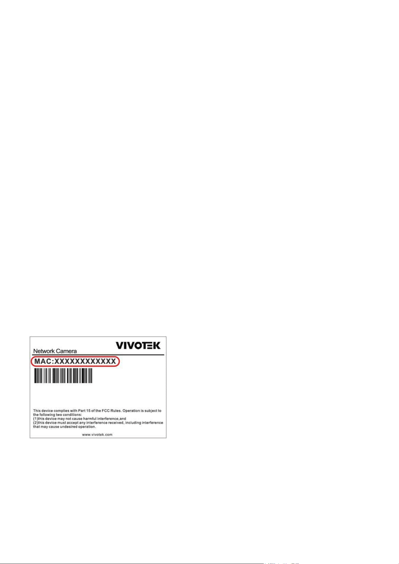
Select the camera to operate based on its MAC address, then click Add.
Step 1.
Step 2.
Step 3.
Step 4.
Note:
Here, users can also note the camera’s IP address and directly enter it in a browser to access the Camera web UI.

11
Get started
Get started
Double-click the camera item you wish to operate, and the Camera web UI will open in the browser.
Step 5.
12
Get started
Get started
Using Shepherd to Locate and Identify Cameras on the LAN
The Shepherd utility is an installation and management tool that helps facilitate the conguration of multiple
cameras. The tool can be used to automatically search the network for cameras, assign IP addresses, display
connectivity, manage rmware/software upgrades, and collectively congure multiple cameras.
Here, users can use Device Manager to locate the IP address of the camera they wish to operate within their
local network.
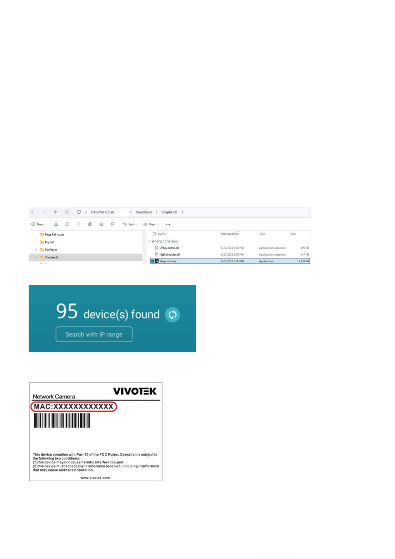
Step 1. Download and extract the Shepherd application from VIVOTEK’s ocial website.
(https://www.vivotek.com/products/software/shepherd)
Step 2. Locate and run the Shepherd application.
Step 3. Click refresh icon to detect all devices on the LAN.
Step 4. Select and double-click the camera to operate based on its MAC address, and the Camera web UI
will open in the browser.
Note:
Here, users can also note the camera’s IP address and directly enter it in a browser to access the Camera web UI.
13
Get started
Get started
Using the Camera Web UI for First-Time Access
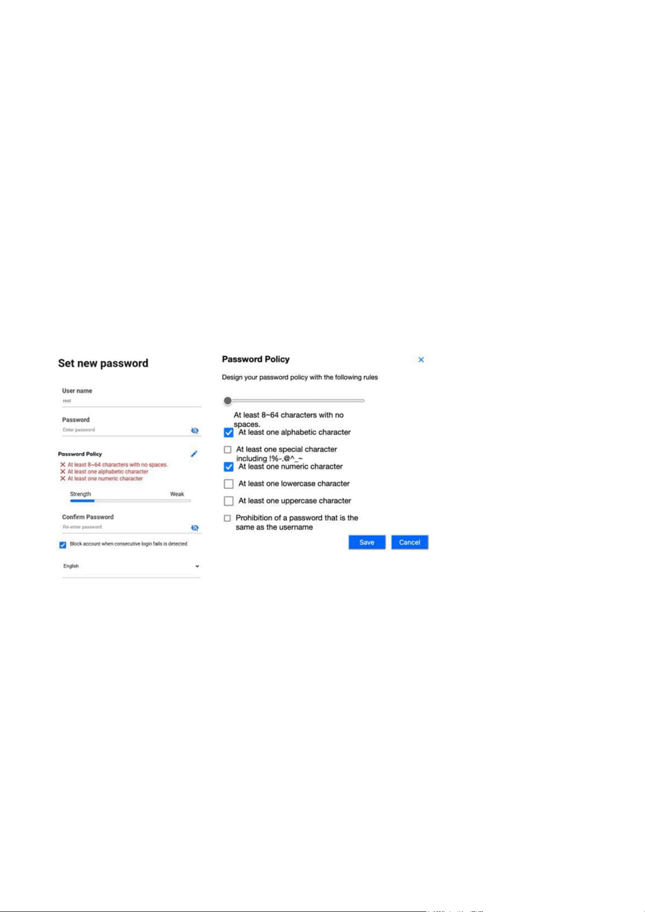
Set a New Password for the Root User
When users access the Camera web UI for the rst time, they must set a new password for the default root
account. If necessary, they can also adjust the password policy for all users of the Camera web UI at this
point.
Step 1. Enter the new password for the root account in the “Password” eld to be used as the root login
password from now on.
Step 2. Re-enter the new password in the “Conrm Password” eld for conrmation.
Step 3. Conrm whether the “Block account when consecutive login failures are detected” mechanism is
enabled.
Step 4. Set the language used in the Camera web UI.
Note:
Note:
At this point, users can click the edit icon to congure the password policy for all users when setting passwords in the Camera web
UI.
By default, if the password is entered incorrectly ve consecutive times within 20 seconds, the account will be blocked for 300 sec-
onds. User can customize the detailed settings from System > User Accounts > Account block later.
14
Get started
Get started
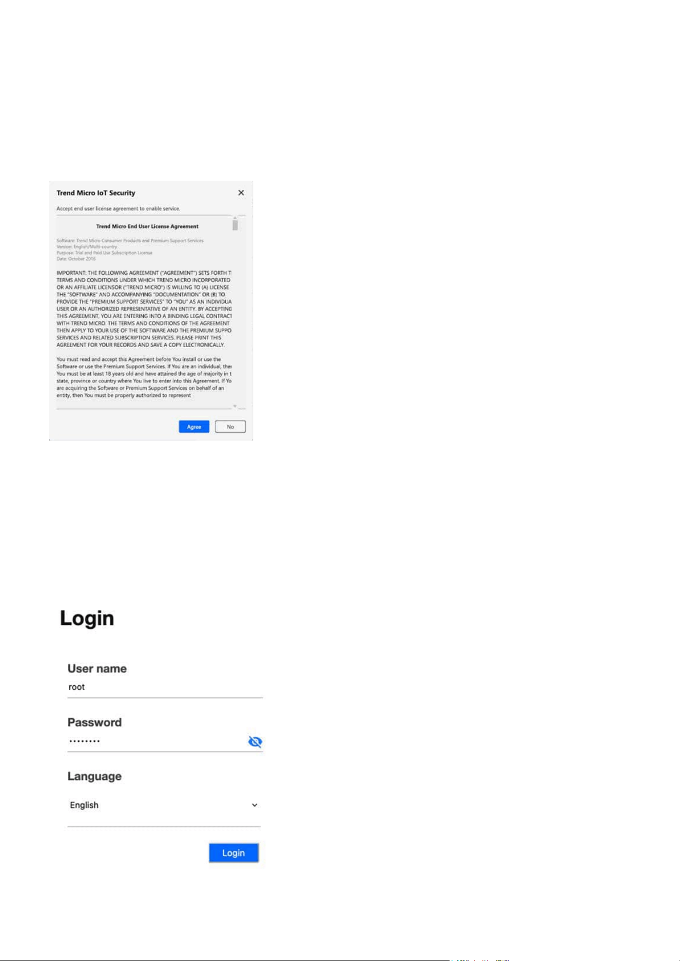
Step 5. Please carefully read the Trend Micro End User License Agreement and click Agree button.
Step 1. Use root account and password to log in when accessing the Camera web UI for the rst time.
Step 6. Click Save button.
Log In to the Camera Web UI
After setting the new password, the user can log in to the Camera web UI with the root account for rst use.
15
Get started
Get started
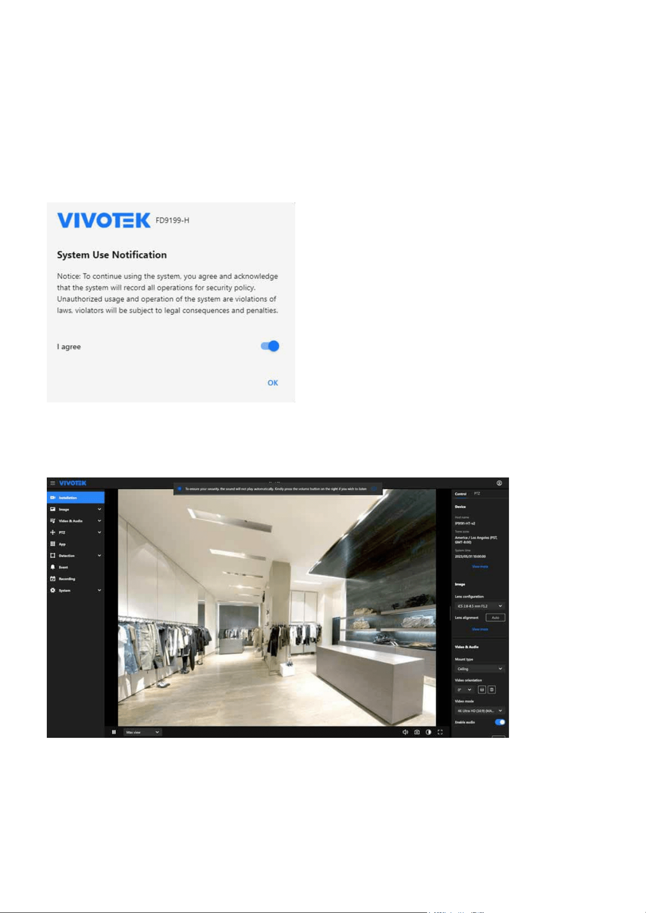
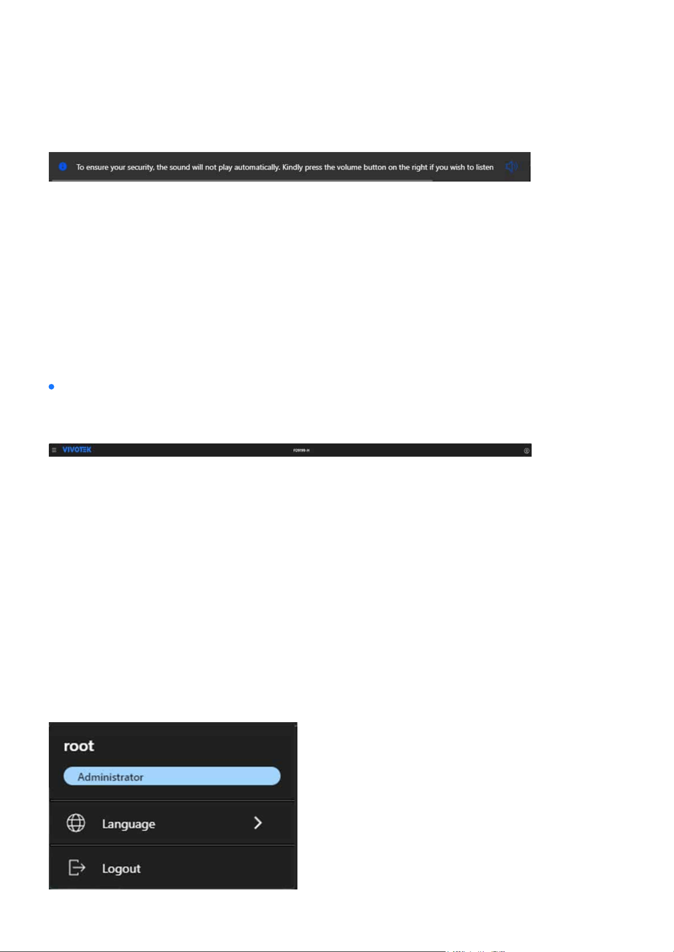
Step 2. After accessing the Camera web UI, please carefully read the System Use Notication message
and agree to its content before proceeding with the conguration and operation of the camera through
the Camera web UI.
Audio Playback Security Notication:
The Audio Playback Security Notication is designed to ensure the privacy and security by preventing au-
dio from playing automatically when entering a video streaming page.
The notication appears when a user logs into the VIVOTEK Camera WebUI with active Video Streaming,
specically to prevent unintended audio playback without consent.
16
Get started
Get started
If the user takes no action, the notication will automatically disappear after 20 seconds; however, if the
user clicks the Volume button (icon) to enable audio, the notication will disappear immediately.
Primarily serves as the title display for the Camera web UI, allowing users to quickly identify it. The func-
tions are arranged from left to right as follows.
Allows control over menu expansion or collapse to maximize the display of image content or settings in-
terface, providing a better experience for users when operating the camera.
By clicking the VIVOTEK logo, users can quickly access the VIVOTEK ocial website for more product infor-
mation. Users can also customize the logo and link displayed in
System > Theme > Logo.
The Camera web UI displays the model name as the default host name. Users can go to
System > Device >
Information to modify the name to something more identiable.
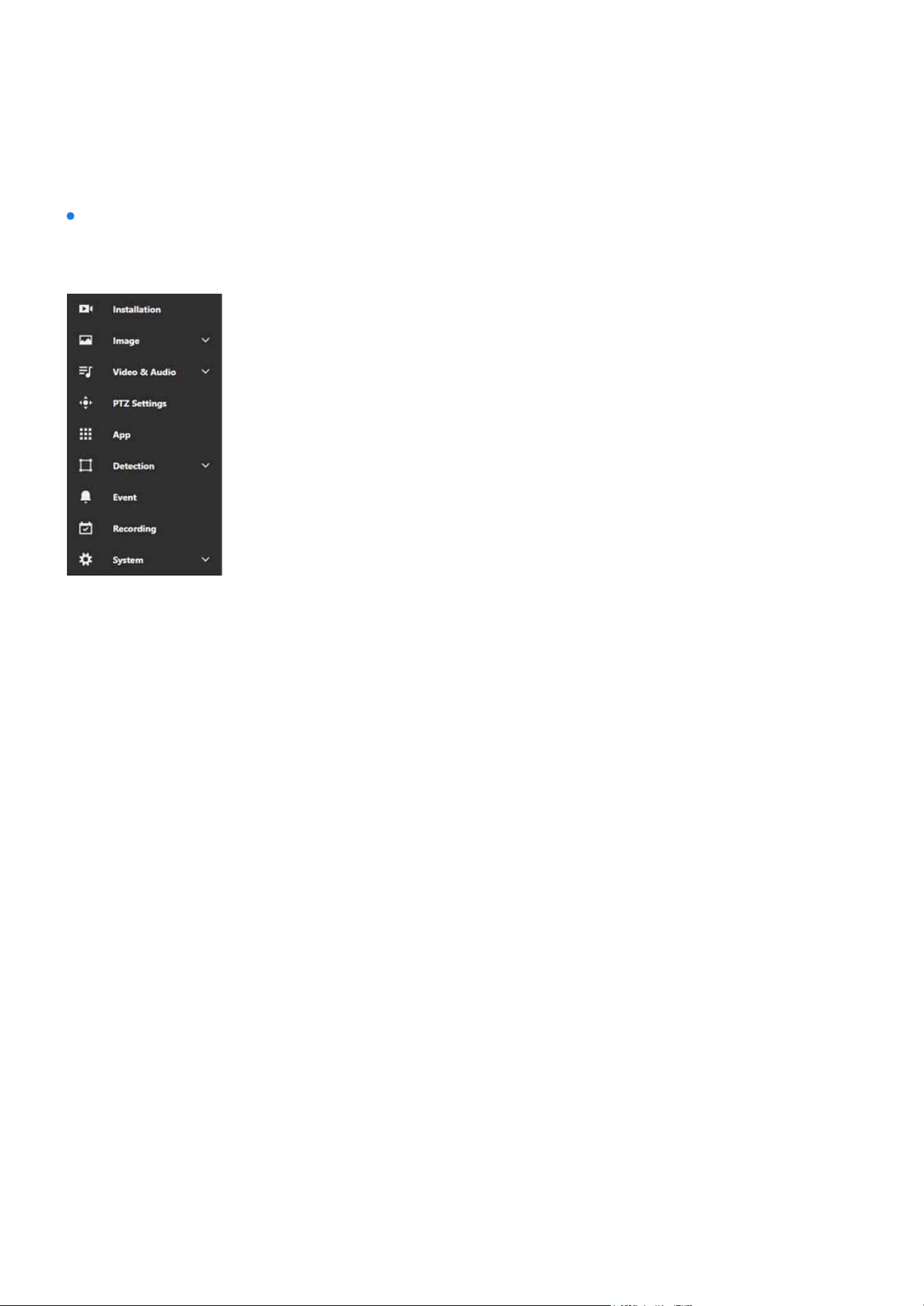
Users can view the current login account information and the associated role permissions here. They can
also adjust the system language to their preference at any time.
Note:
If multiple notications appear simultaneously (e.g., success or failure messages), these additional notications will be displayed
below the primary message without overriding or covering this security notication.
Introduction to the Camera Web UI
The Camera web UI screen is mainly composed of three parts: the title bar, the navigation bar, and the con-
tent display.
The title bar
Menu expansion/collapse button
Logo
Host name
Account information
17
Get started
Get started
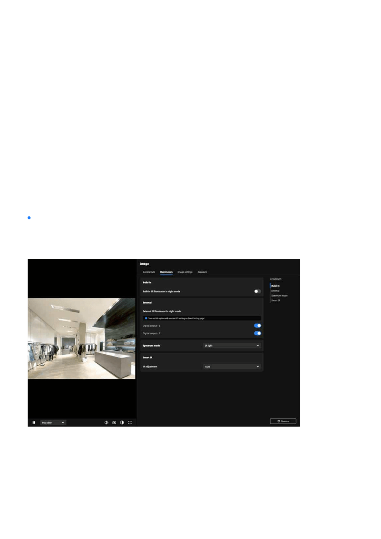
Functions and settings within the Camera web UI are centrally categorized to help users quickly locate the
desired conguration items.
The Installation section helps users set up and ne-tune the camera by providing options for positioning,
focus, and initial conguration to ensure proper alignment and operation.
The Image section allows users to adjust image quality and appearance, including settings for brightness,
contrast, saturation, sharpness, exposure, white balance, and orientation to ensure optimal video output.
The Video & Audio section allows users to congure video settings such as resolution, bitrate, frame rate,
and codecs, as well as manage audio options like enabling recording, selecting codecs, and conguring
microphone or speaker settings.
The PTZ Settings section allows users to manage pan, tilt, and zoom functions by conguring movement
speed, preset positions, and patrol patterns for precise and smooth camera control.
The App section allows users to manage VIVOTEK-specic applications or plugins, using these applications
to expand the camera’s functionality.
The Detection section leverages AI-powered algorithms provide comprehensive monitoring capabilities,
including Smart VCA features like line crossing, intrusion, as well as Motion Detection, Audio Detection,
Shock Detection, and Tampering Detection. Users can congure detection zones, sensitivity, and event
triggers to ensure accurate, intelligent monitoring and enhanced security for various scenarios.
The navigation bar
Installation
Image
Video & Audio
PTZ Settings
App
Detection
18
Get started
Get started
The Event section allows users to dene event triggers and conditions, conguring actions such as send-
ing notications, recording video, or activating alarms to respond eectively to specic events.
The Recording section allows users to congure recording modes, such as continuous, event-based, or
scheduled recording, and set storage locations like SD cards or network storage to manage video footage
eciently.
The System section provides tools for managing device settings, network congurations, user accounts,
maintenance tasks, storage options, logs, and interface customization to ensure optimal performance,
security, and usability of the camera.
Event
Recording
System
This area serves as the main workspace of the Camera web UI, where the layout and content change
based on the dierent categories selected on the navigation bar. The following operational instructions in
this document will focus primarily on this section.
The content display
19
Installation
Installation
This category serves as the rst screen upon entering the Camera Web UI. Its primary purpose is to assist
users in quickly and conveniently setting up the desired monitoring view under the Installation category
after installing the camera.
Navigating the Video Stream Toolbar for Enhanced Control
The Video Stream Toolbar is located at the bottom of the Camera Web UI, providing users with various fea-
tures that can be used in real time during video streaming. The functions are arranged from left to right as
follows.
Pause / Play button
Media prole menu
Volume adjustment
When users want to view or conrm the details presented in the video streaming image, they can press
the Pause button at any time to pause the image. Pressing Play button again will resume the video
streaming playback.
Users can quickly switch between the three dierent media proles—
Recording, Live View, and App
View—based on dierent situational needs, reducing the time required for video settings. Users can also
add or modify media proles in Video & Audio > Media Prole.
Users can adjust the volume of the video streaming according to their needs.

20
Installation
Installation
Snapshot button
Night/Day mode switch
Full screen display
Users can capture images from video streaming at any time.
Users can switch the video streaming display to Black & White or Color mode according to the current sce-
nario, such as nighttime or daytime.
Users can display the video streaming image in full-screen mode.
21
Installation
Installation
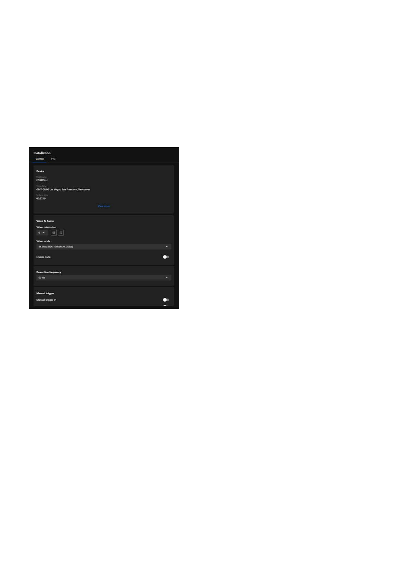
Efciently Adjust Camera Settings via the Installation Panel
The Installation panel provides commonly used and essential information, along with quickly adjustable
settings, to help users complete the camera installation and setup more eciently and conveniently. Addi-
tionally, the adjusted settings are instantly reected on the video streaming display.
Essential settings and functions required during the camera installation process are integrated into the Con-
trol Panel to ensure that users can view the desired display eects while installing the camera.
Control panel
22
Installation
Installation
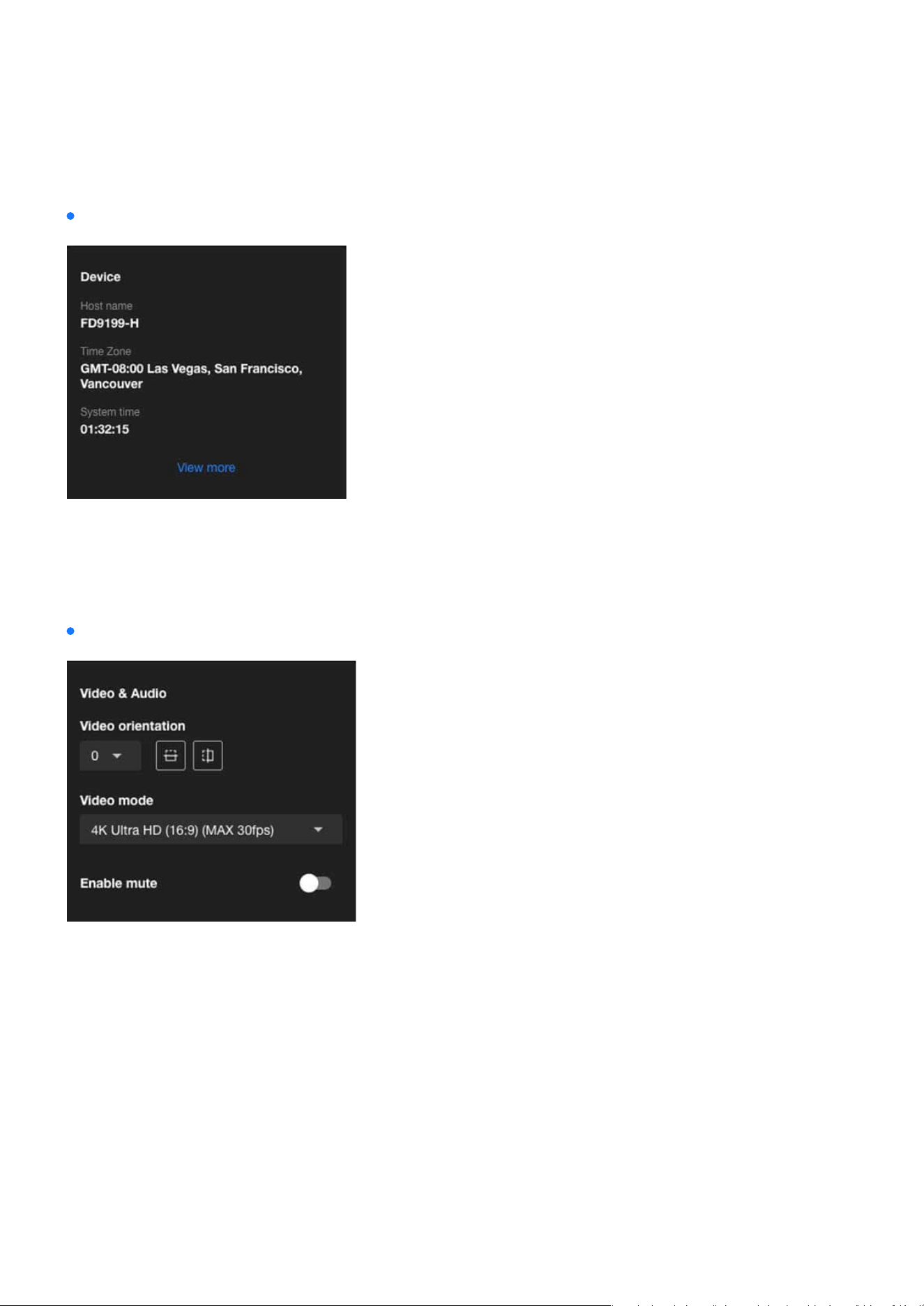
Device:
Video & Audio:
The Device card serves as a quick reference for critical device information, helping users ensure the cam-
era’s identity, time zone, and system time are correctly congured for seamless operation and event
tracking. Additionally, clicking “View More” will navigate to System > Device > Information for further ad-
justments.
23
Installation
Installation
The camera may be installed on a vertical, side-facing, or tilted surface to accommodate the interior or
exterior design of a building. The interior of a building may be shaped as a narrow rectangular space, such
as a corridor. A conventional HD image, such as one with a 16:9 aspect ratio, may be incongruous due to
its wide horizontal view. With video rotation, the camera can more eectively cover the eld of view in a
tall and narrow scene.
Refers to the image processing modes used by IP cameras during video recording and transmission. These
modes are adjusted based on monitoring environments, network bandwidth, storage requirements, and
application scenarios to enhance image clarity and smoothness, achieving optimal performance and e-
ciency under various network conditions.
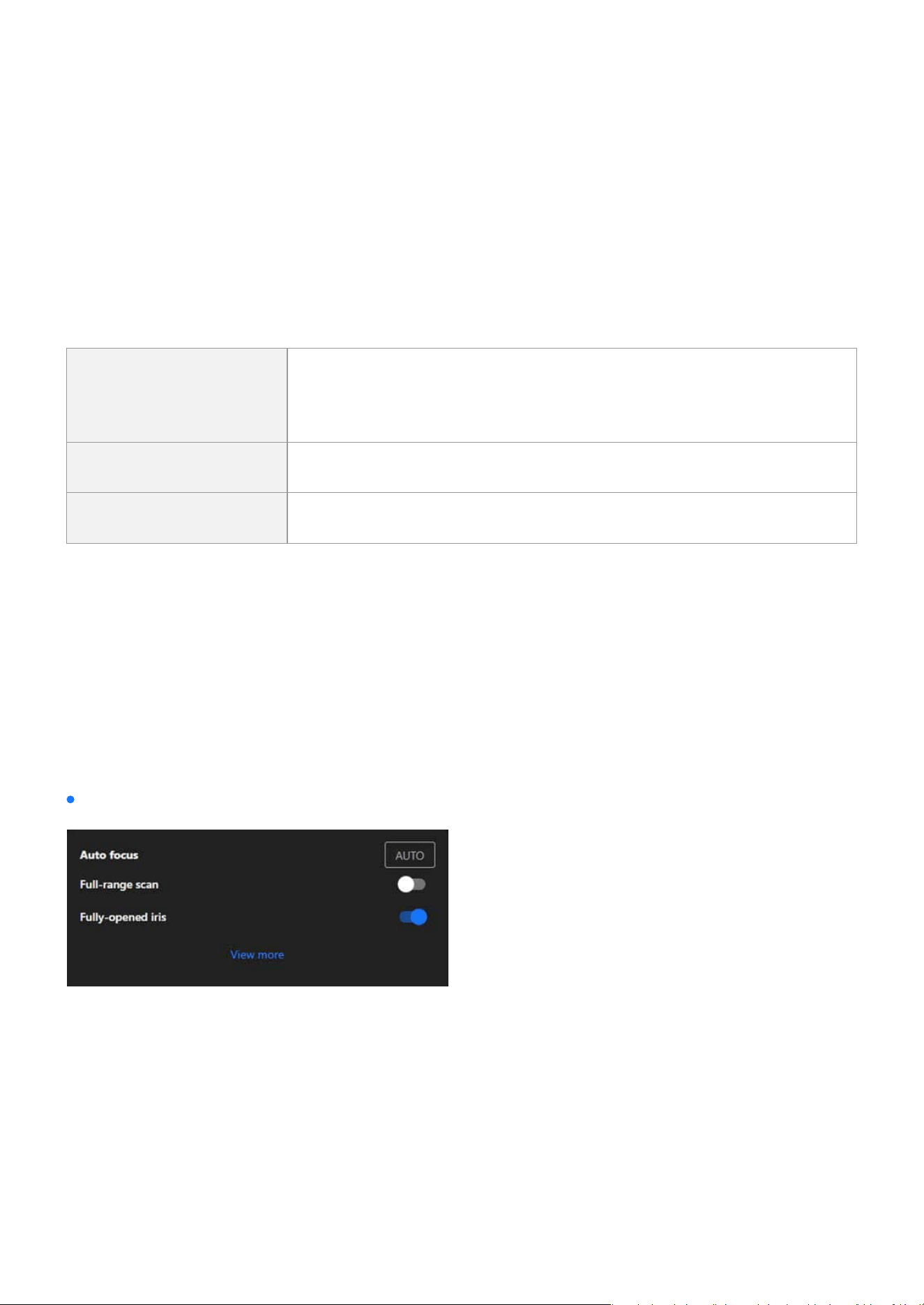
The Auto Focus feature is a one-click function that automatically adjusts the camera’s focal length to deliv-
er the sharpest image, making it perfect for quick setup and general-purpose focusing.
The Auto Focus card in the Installation category provides user-friendly options for both quick and ad-
vanced focus adjustments, ensuring the camera captures clear images across a variety of installation and
environmental conditions. For more detailed customization, users can access additional settings via the
“View More” link.
Provides the option to enable or disable audio recording, where toggling it on mutes the camera audio to
prevent any audio capture.
Video orientation
Video mode
Auto focus
Enable mute
Rotate
The rotation here indicates clockwise rotation. Rotation can be applied
with ip, mirror, and physical lens rotation settings to adapt to dierent
mounting locations.
Flip Vertically reect the display of the live video.
Mirror Horizontally reect the display of the live video.
Auto focus (The Focus settings are only supported on EHTV-type VIVOTEK zoom cameras)

24
Installation
Installation
The Full-range Scan feature allows the camera to perform a comprehensive sweep across its entire focal
length to identify the optimal focus point. This process ensures that the camera evaluates all possible
focal distances, providing the best possible clarity. When enabled, the scan takes approximately 30 to 80
seconds to complete. If the feature is not activated, the camera limits its search to the range where the
focus is most likely, reducing the time required to about 15 to 20 seconds. Full-range Scan is particularly
benecial during initial installations or when the camera requires a complete recalibration of its focus set-
tings, ensuring precise and reliable performance across all distances.
The Fully-opened Iris option ensures the camera operates with its iris fully opened during the autofocus
process, reducing the depth of eld to facilitate pinpointing the exact focus point. This feature enhances
focus precision, especially in low-light conditions or scenarios requiring detailed focusing, making it ideal
for environments where high focus accuracy is critical, such as low-light settings or for capturing intricate
details.
Full-range scan
Fully-opened iris
Step 1. Select Focus Mode
Step 2. Set the Iris Mode
Step 3. Start Auto Focus
Step 4. Access Advanced Settings
Steps to Auto Focus Operation:
For Quick Focus:
It is recommended to enable the Fully-opened iris option.
Click the “AUTO” button to initiate the auto-focus process.
For further adjustments, click the “View More” button to access the Image > Focus settings page.
In this page, you can manually ne-tune the focus, adjust the focal range, and congure other advanced
parameters such as focus speed.
The camera will adjust its focus based on the selected focus mode (Quick Focus or Precise Focus) and
the iris setting (Fully-opened iris or not), ensuring optimal image clarity.
When the iris is fully opened, focus precision is improved by minimizing the depth of eld, especially in
low-light environments or when focusing on ne details.
Precise Focus:
Enable the Full-range scan option.
The camera will perform a full scan across its entire focal length, which can take 30 to 80 seconds,
depending on the focal range.
Ensure the Full-range scan option is disabled.
In this mode, the auto-focus will scan only the range where optimal focus is likely to occur, requiring
approximately 15 to 20 seconds.
25
Installation
Installation
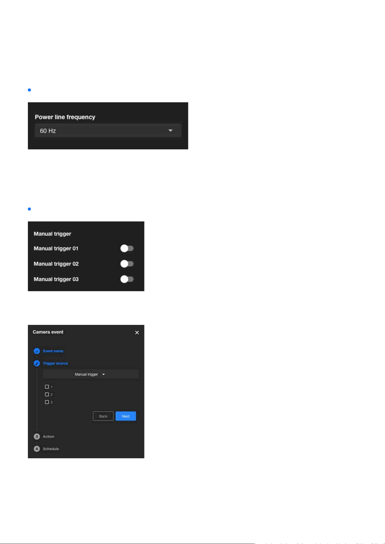
The Power line frequency setting ensures stable video quality by allowing users to align the camera’s
frequency with the local power grid, eectively preventing icker in areas with uorescent or articial
lighting; selecting the correct frequency, such as 60 Hz for North America or 50 Hz for many European and
Asian countries, helps eliminate video icker caused by power line interference.
Power line frequency:
Allows users to manually enable event triggers by clicking the on/o button on the Installation panel. Be-
fore using this function, please add events associated with Manual Trigger 01 to 03 in the Event category.
Manual trigger:
26
Installation
Installation
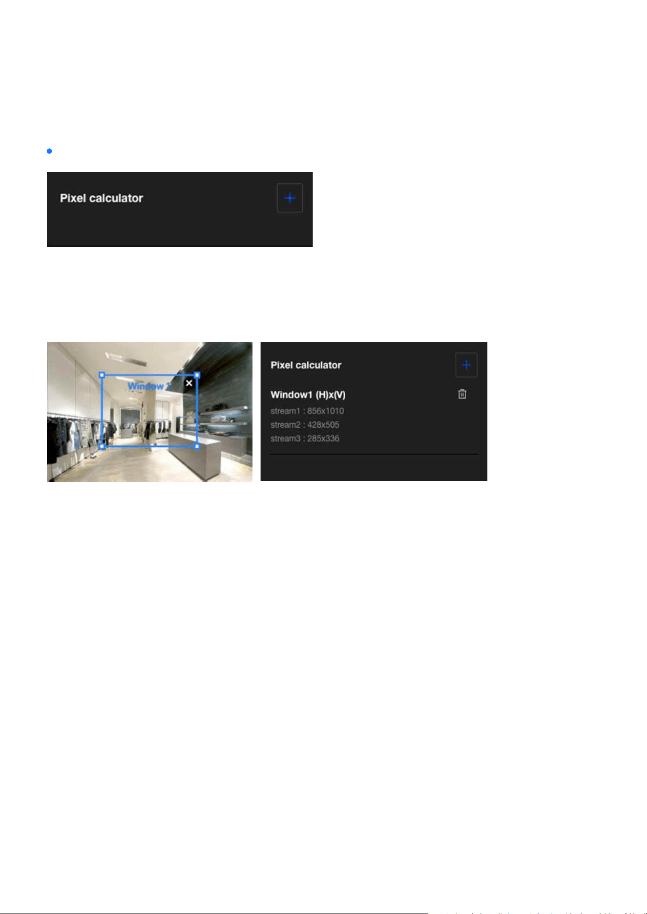
Click the “Add” button to create a pixel calculator window. Move your cursor over the window to position it
in the area of interest, and adjust the window size to t the area. Once the window is congured, the pixel
count on its edges will be displayed, assisting you in assessing whether the current conguration meets
the requirements.
Pixel calculator:
Using this visual tool, you can estimate the coverage area, the distance to the target, and place a ruler or
an object of known size. Then, you can draw a calculator frame to cover the subject of interest. The calcu-
lated values will be listed at the bottom of the screen, helping you determine whether the current settings
meet the pixel count requirements.
27
Installation
Installation
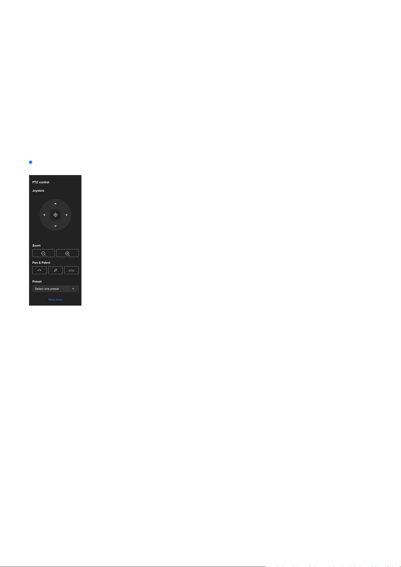
PTZ panel
The PTZ panel provides users with a convenient way to adjust the monitored image position by operating
the pan, tilt, and zoom functions, and quickly switch between preset positions to monitor key areas; how-
ever, the PTZ function is only supported on the 2nd and 3rd media proles, and users need to select a sup-
ported stream for it to work.
PTZ control:
Users can move the monitored area’s image by operating the joystick, adjusting the view to the desired
monitoring area. Additionally, pressing the Home button will restore the view to the preset Home posi-
tion. Users can set the position represented by Home in PTZ Settings > Home & Preset.
Joystick
Users can use the Zoom button to freely zoom in or out on the current monitoring screen to an appropri-
ate size.
When the user clicks the Pan button, the monitoring screen will move left and right, centering on the cur-
rent view, to expand the surveillance range. By clicking the Patrol button, the monitoring screen will move
sequentially to each observation point according to the preset order and time intervals, enabling automat-
ic surveillance of multiple areas. Users can congure the desired preset positions and time intervals for
patrol on the PTZ Settings > Patrol page. Click Stop button to halt the current monitoring screen’s Pan or
Patrol.
Users can quickly switch the current monitoring perspective by selecting a screen set as a Preset. Users
can congure the Preset positions on the PTZ Settings > Home & Preset page.
Zoom
Pan & Patrol
Preset
28
Image
Image
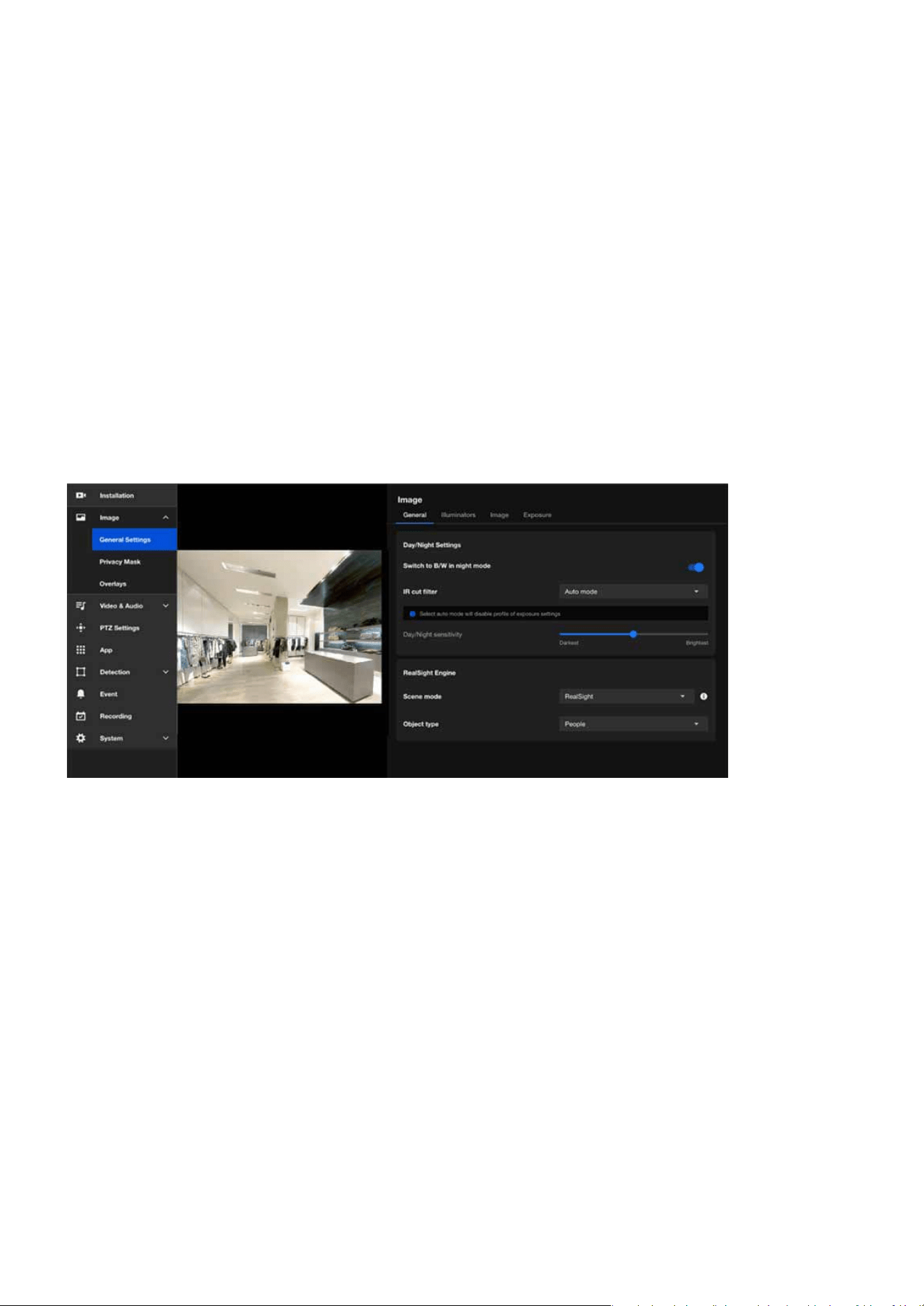
The Image provides various image adjustment options, including General Settings, Privacy Mask, and Over-
lays, to meet the needs of dierent scenarios. These settings can enhance image performance, protect
privacy, and add supplementary information.
The General Settings for images are typically used to adjust and optimize the parameters of cameras or im-
aging systems to ensure that the generated images meet the required specications. These settings can be
divided into four main categories: General, Illuminators, Image, and Exposure. Below is a brief introduction
to each category.
In the General page provides users with core features to adjust image quality, ensuring optimal camera per-
formance in various environments.
Optimizing Image Quality with VIVOTEK Camera Settings
General
29
Image
Image
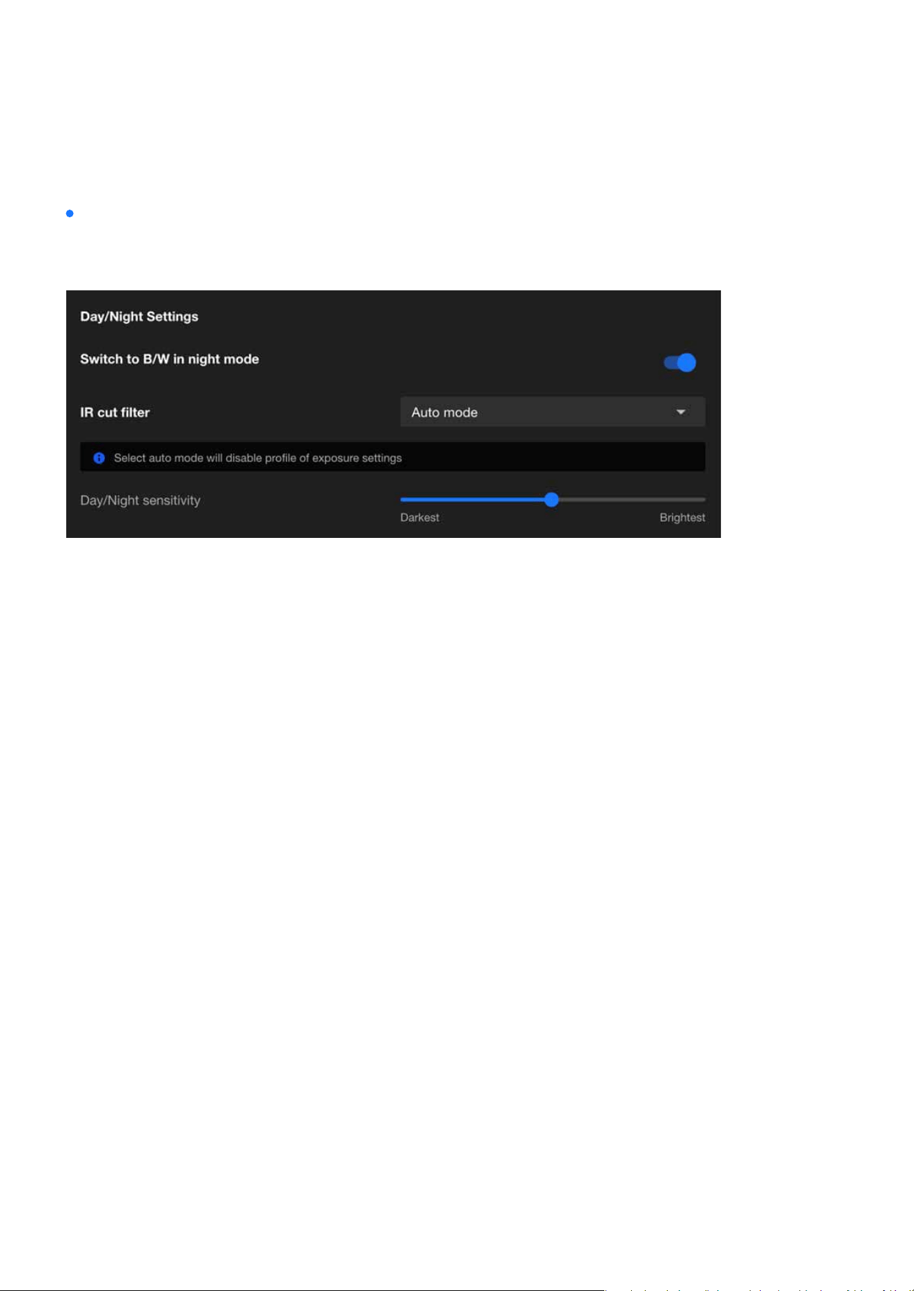
Day/Night Settings
The purpose of the Day/Night Settings is to enhance the imaging quality of cameras under dierent light-
ing conditions.
After enabling this feature, the camera will automatically switch to black-and-white display in night mode.
This design aims to enhance image clarity and contrast in low-light conditions, ensuring clear surveillance
footage even in insucient lighting.
The IR cut lter is a removable lter that blocks infrared light from entering the image sensor during the
day to prevent color distortion in images. In night mode, the camera automatically removes this lter, al-
lowing infrared light to enter the image sensor. This works with built-in or external infrared illumination to
enhance image sensitivity in low-light or no-light conditions, providing clearer night surveillance footage.
The available modes for the IR cut lter are as follows:
The Network Camera automatically removes the lter by judging the level of ambient light.
In day mode, the Network Camera switches on the IR cut lter at all times to block infrared light from
reaching the sensor so that the colors will not be distorted.
In night mode, the Network Camera switches o the IR cut lter at all times for the sensor to accept
infrared light, thus helping to improve low light sensitivity.
If an external IR device is connected that comes with its own light sensor, you can use a digital input
from it to trigger the IR cut lter. Doing so can synchronize the detection of light level between the cam-
era and the external IR device.
The Network Camera switches between day mode and night mode based on a specied schedule. Enter
the start and end time for day mode. Note that the time format is [hh:mm] and is expressed in 24-hour
clock time. By default, the start and end time of day mode are set to 07:00 and 18:00.
Switch to B/W in night mode
IR cut lter
•
Auto mode(Select auto mode will disable prole of exposure settings)
•
Day mode
•
Night mode
•
Synchronize with digital input
•
Schedule mode
30
Image
Image
Adjust the IR cut lter’s sensitivity to lighting conditions from the Darkest to the Brightest.
The RealSight Engine automatically recognizes the presence of people in the scene and optimizes image
details without requiring manual adjustments, oering a seamless plug-and-play experience.
It eectively reduces motion blur caused by fast-moving objects, ensuring that all moving subjects are
captured with clear details, eliminating the need for manual shutter speed adjustments.
The engine prevents blurriness caused by infrared light reection, automatically delivering clear nighttime
images and detailed subject features without repeated manual exposure adjustments.
In challenging backlight scenarios, the RealSight Engine enhances the brightness and details of foreground
subjects (e.g., faces) while maintaining the proper brightness of the background, ensuring clear visibility of
people even in strong backlight.
By leveraging articial intelligence, the RealSight Engine dynamically adjusts camera settings for the best
possible image quality in real-time, adapting to dierent environments and lighting conditions.
RealSight Engine is an AI-based image optimization technology specically designed to enhance the video
quality of network cameras under various lighting conditions. Its key capabilities include:
Day/Night sensitivity
1. Automatic Scene Detection and Optimization
2. Clear Capture of Moving Subjects
3. Enhanced Nighttime Clarity
4. Improved Visibility in Backlight Environments
5. AI-Driven Optimization for Superior Image Quality
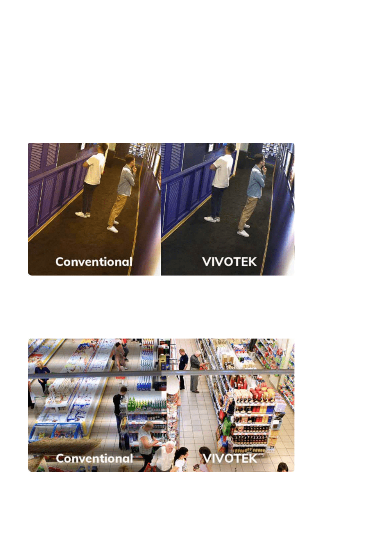
RealSight Engine
The RealSight Engine enhances surveillance performance by ensuring superior image quality in diverse sce-
narios, capturing critical details even in challenging environments such as low light, backlight, or fast motion.

31
Image
Image
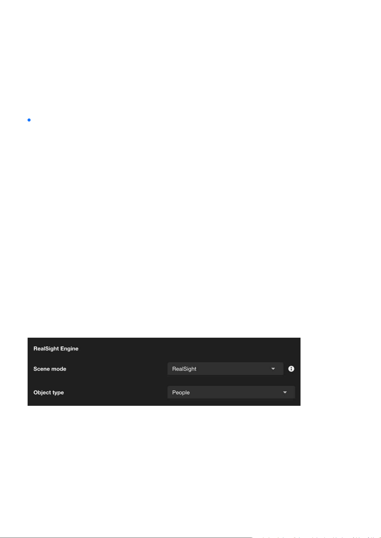
Network cameras supporting the RealSight Engine provide a “Scene Mode” option, allowing users to select
appropriate image settings based on dierent surveillance environment requirements.
RealSight Engine enhances the image quality of selected object types. For example, by selecting “people”
as the object type, the camera automatically adjusts exposure, white balance, and other image controls to
improve the clarity of people in the scene.
Scene mode
Object type
RealSight
Activate VIVOTEK's RealSight Engine technology, which utilizes AI to
automatically analyze scenes and optimize image quality. It is ideal for
environments with signicant lighting changes, backlighting, or low light,
ensuring the best image quality.
Default
Uses the camera's default image settings without enabling specic image
enhancement technologies. Suitable for scenarios with stable lighting
conditions and no special requirements, providing standard image quali-
ty.
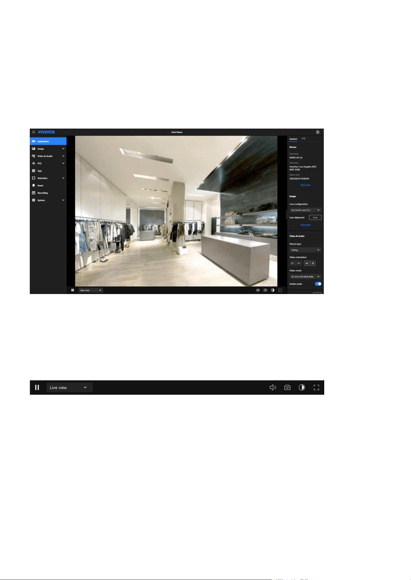
Illuminators
The “Illuminators” page refers to the settings related to the infrared (IR) illuminator. In low-light or complete-
ly dark environments, these IR illuminators automatically activate to provide the necessary lighting, enabling
the camera to capture clear images. This feature is particularly suitable for scenarios requiring surveillance
at night or in low-light conditions.
32
Image
Image
VIVOTEK’s network cameras are equipped with built-in infrared (IR) illuminators designed to enhance im-
age quality in nighttime or low-light environments. These built-in IR illuminators provide uniform lighting,
ensuring clear images even in panoramic views.
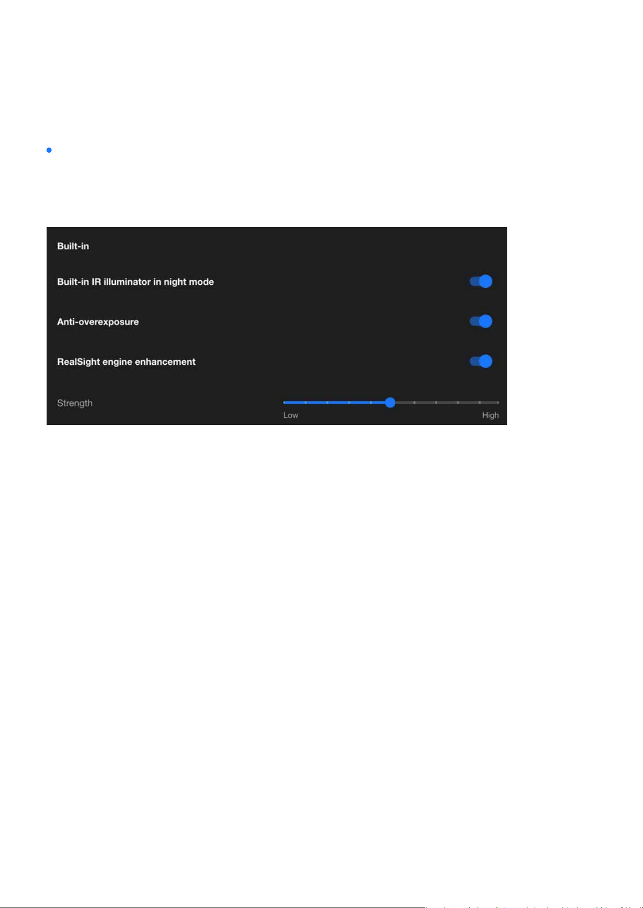
Built-in
Enabling the built-in IR illuminator in night mode, and the built-in IR illuminator will automatically activate
when the camera detects low light conditions and switches to night mode.
Enabling the Anti-Overexposure feature ensures balanced image quality by dynamically adjusting to
challenging lighting conditions, preventing overly bright areas from aecting visibility or detail capture in
surveillance footage.
RealSight engine, powered by AI, delivers the most realistic visual performance, accurately presenting true
scene colors while remaining unaected by environmental factors. Even under any lighting conditions, it
eortlessly preserves critical human details. This solution ensures that users never miss any detail, pro-
viding insightful images for every scene without the need for complex setup. Its key features are:
Solve the problem of motion blur in images caused by the rapid movement of people captured previ-
ously. This ensures that all moving gure details are captured, automatically making the image clearer
without the need to adjust the camera shutter speed.
Built-in IR illuminator in night mode
Anti-overexposure
RealSight engine enhancement
Clear capture moving gures
•
Clear visibility of people in any lighting
33
Image
Image
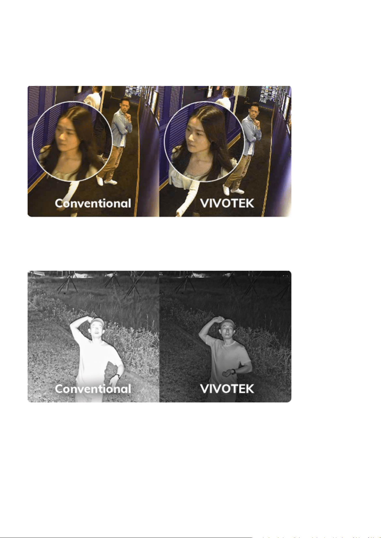
RealSight Engine prevents the camera from being aected by infrared light reected by close objects,
automatically capturing clear nighttime scenes and people without the need for repeated manual ad-
justments of camera’s exposure time.
See individuals without being aected by IR light reections
34
Image
Image
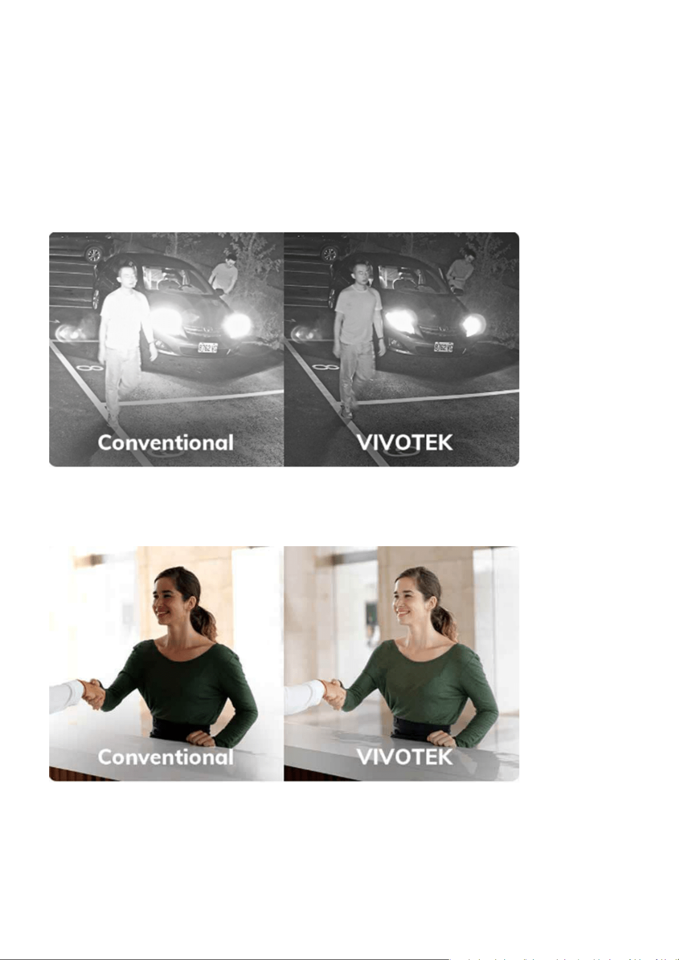
RealSight Engine ensures that cameras are not aected by additional light sources at night. It automat-
ically analyzes the scene, allowing clear capture of individuals passing by at night without the need for
manual adjustments.
RealSight Engine solves the problem of dark portraits caused by backlighting. It not only preserves the
brightness of the background but also enhances the brightness and details in backlight conditions.
See individuals without being aected by additional light sources
Clearly see portraits under backlight
35
Image
Image
RealSight Engine helps the camera capture true colors without being aected by blue objects in the en-
vironment. It also eliminates the need for personnel to spend time using white paper for white balance
maintenance.
With the RealSight Engine, the camera is no longer aected by the continuous ickering frequency of
uorescent lights or LED interference, automatically avoiding rolling bands in the image. This signi-
cantly reduces the need for manual adjustments to the shutter time in response to ambient light sourc-
es.
Capture and restore true colors
Footage remains icker-free
•
True color reproduction
36
Image
Image
Strength
In the RealSight engine enhancement, adjusting the “strength” controls the sensitivity or intensity of the
anti-overexposure feature. Increasing the “strength” value makes the system more proactive in adjusting
exposure parameters to handle drastic changes in lighting, while decreasing the value results in milder
adjustments. This design allows users to exibly congure the anti-overexposure eect based on actual
scene requirements, ensuring optimal image quality.
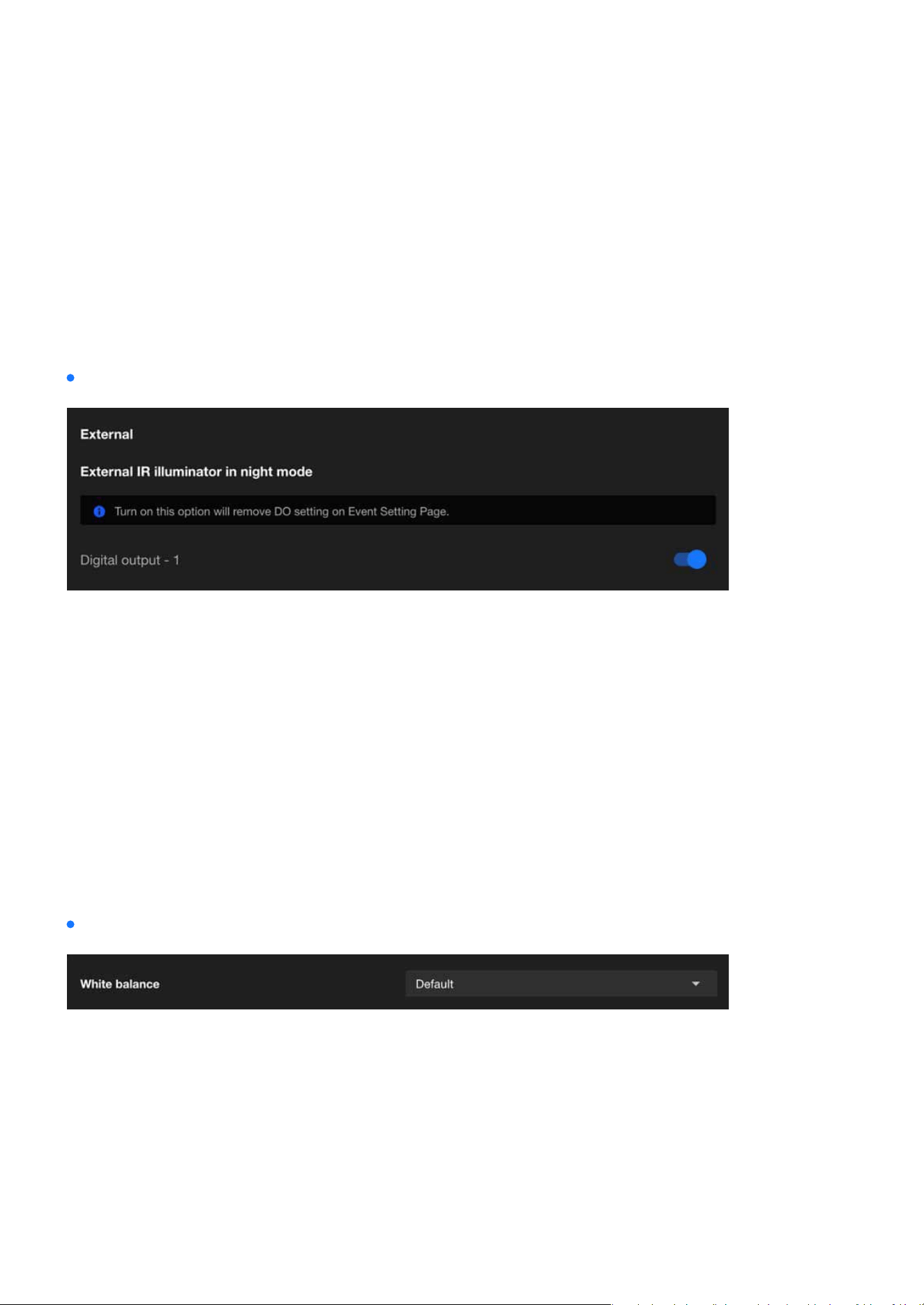
When External IR Illuminator in Night Mode is enabled, the camera will activate the external IR illuminator
through Digital Output. External IR illuminators typically oer higher brightness or a wider illumination
range, making them ideal for scenarios that require enhanced surveillance performance in low-light envi-
ronments.
The White Balance setting is crucial for ensuring that colors in the captured video appear natural under
dierent lighting conditions.
External
White balance
Image
The IPv4 card plays a vital role in setting up the camera’s network conguration and ensuring eective com-
munication. It facilitates dependable connectivity, enables both local and remote access, and allows the
camera to integrate eortlessly into IPv4-based networks. This conguration is crucial for maintaining stable
and ecient performance across diverse networking environments.
37
Image
Image
Default
In this mode, the camera automatically adjusts the white balance based
on the lighting conditions.
It is suitable for environments with changing light sources, such as out-
door areas where sunlight and shade vary throughout the day.
The camera continuously evaluates the scene and dynamically adapts to
ensure accurate color representation.
Fixed current
This mode locks the white balance to the current automatic setting at the
moment it is activated.
It is useful in environments with consistent lighting, where maintaining a
stable white balance is more important than adapting to changes.
For example, this mode is ideal for spaces with xed articial lighting,
such as oces or warehouses.
Manual
This mode allows users to manually set the white balance by adjusting
specic parameters like RGain(red) and BGain(blue) levels.
It oers the most control and is ideal for scenarios with specialized light-
ing, such as theatrical productions, where precise color adjustments are
required.
Users can customize the settings to suit their specic needs and ensure
color accuracy in unique lighting conditions.
By selecting the appropriate white balance mode, users can optimize the performance of their VIVOTEK
cameras for a variety of environments and use cases.
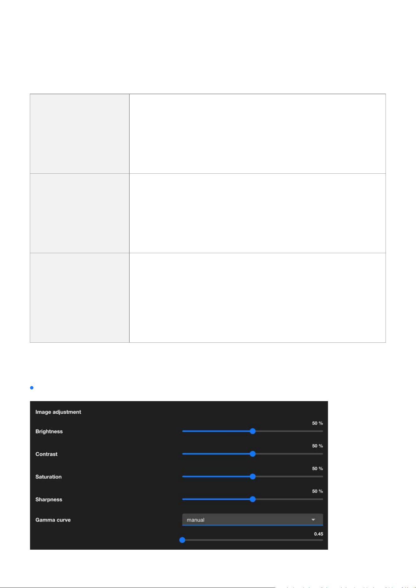
Image adjustment

38
Image
Image
Brightness
Brightness controls the overall lightness or darkness of the image. In-
creasing brightness makes the entire image appear lighter, while decreas-
ing it makes the image darker.
Adjust the brightness to ensure clear visibility in varying light conditions,
such as low-light environments or overexposed areas.
Contrast
Contrast determines the dierence between the lightest and darkest
parts of the image. Higher contrast makes shadows darker and highlights
brighter, enhancing the distinction between objects. Lower contrast re-
sults in a atter, less dynamic image.
Use contrast to improve image clarity by enhancing the dierentiation
between objects in the scene.
Saturation
Saturation controls the intensity of colors in the image. Increasing satu-
ration makes colors more vivid and vibrant, while reducing it leads to a
more muted or grayscale appearance.
Adjust saturation to balance the color intensity for optimal image appear-
ance, especially in scenes with overly vivid or dull colors.
Sharpness
Sharpness determines how clearly the details and edges of objects are
dened in the image. Higher sharpness enhances the clarity of edges, but
excessive sharpness can cause unnatural outlines or noise.
Modify sharpness to emphasize details without introducing artifacts,
particularly in scenes requiring precise identication, like license plates
or facial features.
Gamma Curve
The gamma curve denes the tonal response of the camera, aecting
how brightness levels are distributed. Adjusting gamma alters the mid-
tones of the image without signicantly aecting the darkest or brightest
areas.
Use gamma correction to optimize image brightness and contrast for
better visual representation under challenging lighting conditions.
*This option is disabled when the WDR feature is enabled.
Image Adjustment are essential for ne-tuning the visual quality of the captured images. These adjustments
allow users to customize the appearance of the footage to meet their specic needs or adapt to dierent
environmental conditions.
39
Image
Image
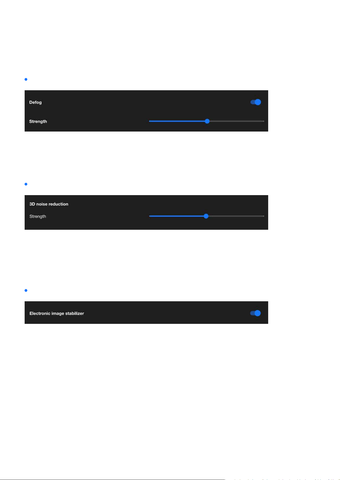
Defog
3D noise reduction
Electronic image stabilizer
Defog is designed to enhance image clarity in foggy, hazy, or smoggy conditions. It works by adjusting the
image’s contrast and visibility to reduce the eects of atmospheric conditions that obscure details. This
feature is particularly useful in outdoor surveillance environments, ensuring better object recognition and
scene visibility despite challenging weather conditions.
3D noise reduction is primarily used in low-light environments to reduce noise and icker in the image.
You can use the slider to adjust the noise reduction strength. Please note that enabling this feature on the
video channel will consume system computing resources. However, when this feature is enabled under
low-light conditions with fast-moving objects, afterimage trails may occur. In such cases, you may choose
to lower the strength.
Electronic Image Stabilizer (EIS) function is designed to reduce image jitter caused by external factors, such
as wind, vibrations, or cameras mounted on unstable structures. This feature stabilizes and smoothens
the footage by adjusting the image output through software algorithms. Enabling Electronic Image Stabi-
lizer (EIS) in VIVOTEK cameras provides several key benets:
These advantages make EIS an essential feature for maintaining reliable surveillance, especially in environ-
ments subject to unavoidable vibrations or movement.
EIS reduces blurriness and jitter caused by vibrations, delivering smoother and clearer video footage.
By stabilizing the image, it becomes easier to identify important details such as license plates, faces,
and objects.
Stability helps reduce false detections, improving the accuracy of analytic features like motion detection
and object recognition.
•
Improves video quality:
•
Enhances critical detail readability:
•
Optimizes video analytics performance:
40
Image
Image
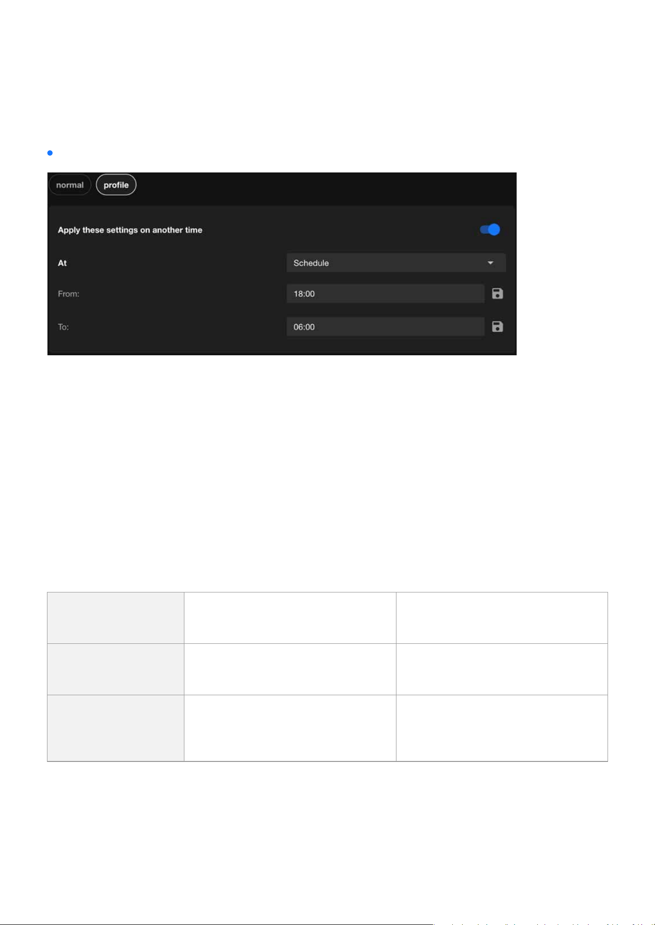
Integrate image-related settings into a prole
The normal mode in VIVOTEK cameras provides a baseline image conguration ideal for standard moni-
toring. Through prole mode, specically Night and Schedule, users can customize and automate image
settings based on specic requirements and time periods. This is not limited to day-night transitions,
oering greater exibility and control.
VIVOTEK cameras ensure consistent performance and high-quality surveillance tailored to various condi-
tions, enhancing both usability and monitoring eectiveness.
The purpose and applications:
This design delivers:
•
Flexible and automated switching of image proles.
•
Optimized image quality for diverse scenarios.
•
Improved operational eciency and resource management.
Normal
Provides standard image settings
for general use
Suitable for daytime or consistent
lighting environments
Night (Prole)
Optimizes image settings for low-
light or nighttime conditions
Enhances clarity and detail, ideal for
night surveillance
Schedule (Prole)
Automatically switches image set-
tings based on custom-dened time
Applies specic settings during des-
ignated periods; not limited to day/
night transitions
41
Image
Image
Exposure
The Image page in the Camera web UI control how much light the camera’s sensor receives to create a
well-balanced image. Proper exposure ensures that the image is neither too bright (overexposed) nor too
dark (underexposed), allowing for clear visibility of objects in various lighting conditions.
External Device Integration
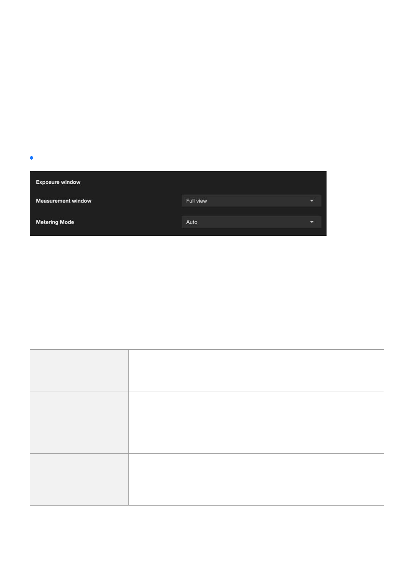
Exposure Window is a feature that allows users to dene a specic area within the camera’s eld of view
to optimize exposure settings. By focusing on this designated area, the camera can adjust its exposure pa-
rameters to ensure that the area is properly illuminated, even in challenging lighting conditions. This fea-
ture is particularly useful in scenarios where dierent areas of the scene have uneven light levels, enabling
the camera to prioritize exposure for critical regions and enhance overall image quality.
This function allows users to set measurement window(s) for low-light compensation. For example, when
low-light objects are positioned against an extremely bright background, user may want to exclude the
bright sunlight shining through a building’s corridor. The types of measurement windows are as follows:
Measurement window
Full view
This option calculates the exposure based on the entire eld of view, en-
suring that the camera considers all areas within the frame for exposure
adjustments.
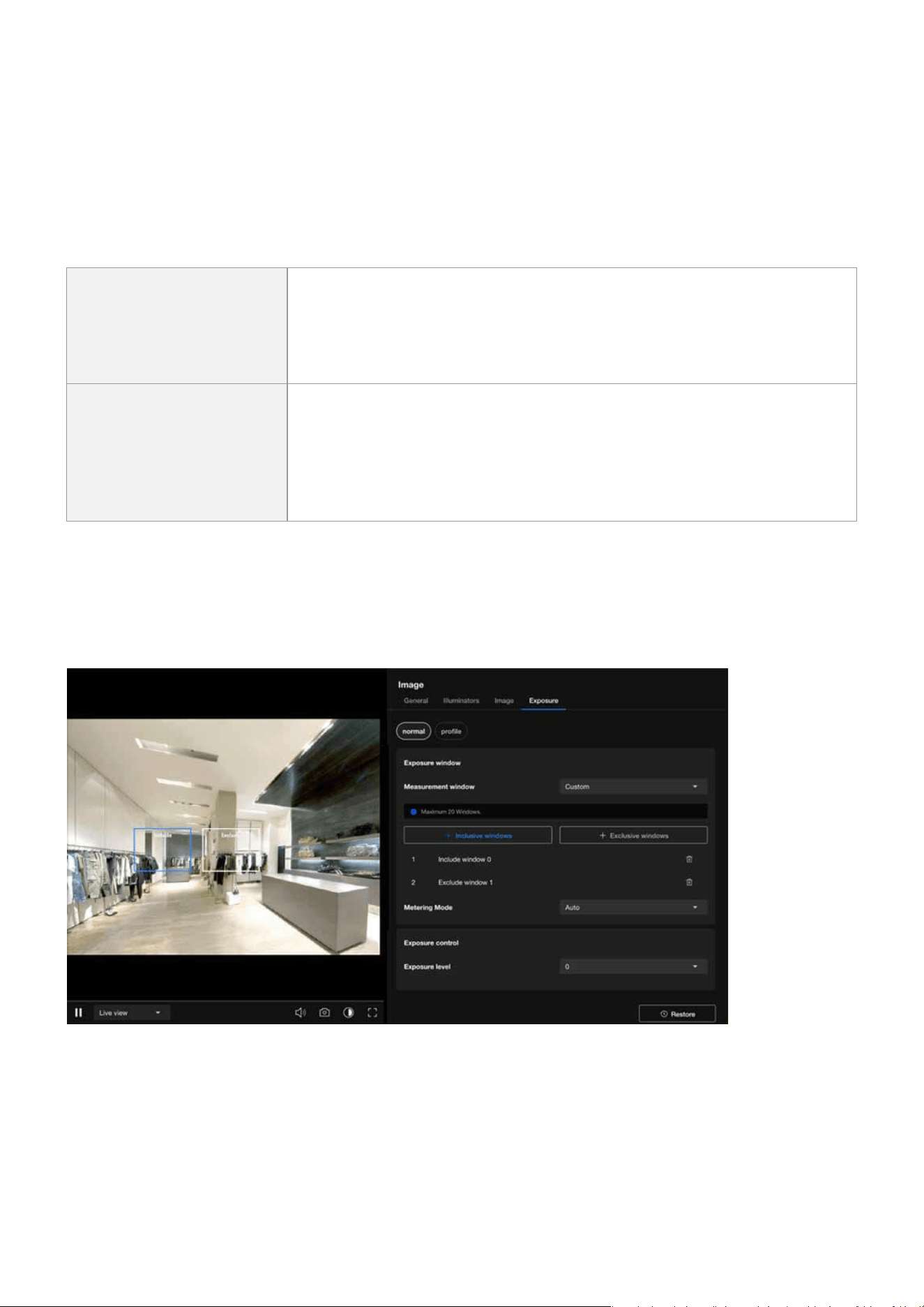
Custom
This option allows users to manually dene specic regions within the
frame for exposure measurement. By selecting this setting, users can
draw one or more measurement windows on the image, enabling precise
control over which areas the camera should prioritize for exposure ad-
justments.
Center
When selected, the camera focuses on the central portion of the image
to determine exposure settings. This is benecial when the main subject
is located in the center of the frame, allowing for optimal exposure in
that area.
42
Image
Image
When users select the Custom mode to use the measurement window, they can dene the inclusive win-
dow and exclusive window by themselves.
When an exclusive window overlaps with a larger inclusive window, the exclusive portion is deducted from
the inclusive window. This ensures that only the remaining portion of the inclusive window contributes
to the calculation. After adjusting for the overlaps between inclusive and exclusive windows, the system
calculates the exposure value based on the remaining portion of the inclusive window using the weighted
averages method.
Inclusive windows
Referred to as “weighted windows.”
These are given higher priority in the calculation process.
Their values are included in the nal computation, unless aected by
overlapping exclusive windows.
Exclusive windows
Referred to as “ignored windows.”
Their role is to exclude portions of the inclusive windows when they
overlap.
They eectively reduce the contribution of the overlapping inclusive
windows.
Metering Mode determine how the camera adjusts its exposure settings in response to dierent lighting
conditions:
Metering Mode

43
Image
Image
Auto
General purpose, when the
scene lighting is balanced.
The camera automatically
evaluates the entire scene to
balance the exposure.
It ensures that the overall
brightness is optimized for
typical scenarios.
Suitable for environments
with relatively uniform lighting
where no extreme light sourc-
es dominate.
BLC (Back Light Compensa-
tion)
When the subject is in front of
a bright light source.
Adjusts the exposure to ad-
dress situations where the
background is much brighter
than the subject (e.g., a person
standing in front of a bright
window).
Ensures that the main subject
is clearly visible and not un-
derexposed, even if the back-
ground becomes overexposed.
Ideal for scenes with strong
backlighting.
HLC (High Light Compensa-
tion)
To manage overexposed bright
spots and ensure other areas
are visible.
Focuses on reducing the im-
pact of overly bright light
sources in the scene, such as
headlights, streetlights, or oth-
er intense light sources.
Darkens overexposed areas
(like light spots) to enhance
overall image quality while
preserving detail in darker
regions.
These settings help optimize the camera’s performance for various lighting conditions, ensuring that criti-
cal details are captured eectively.
44
Image
Image
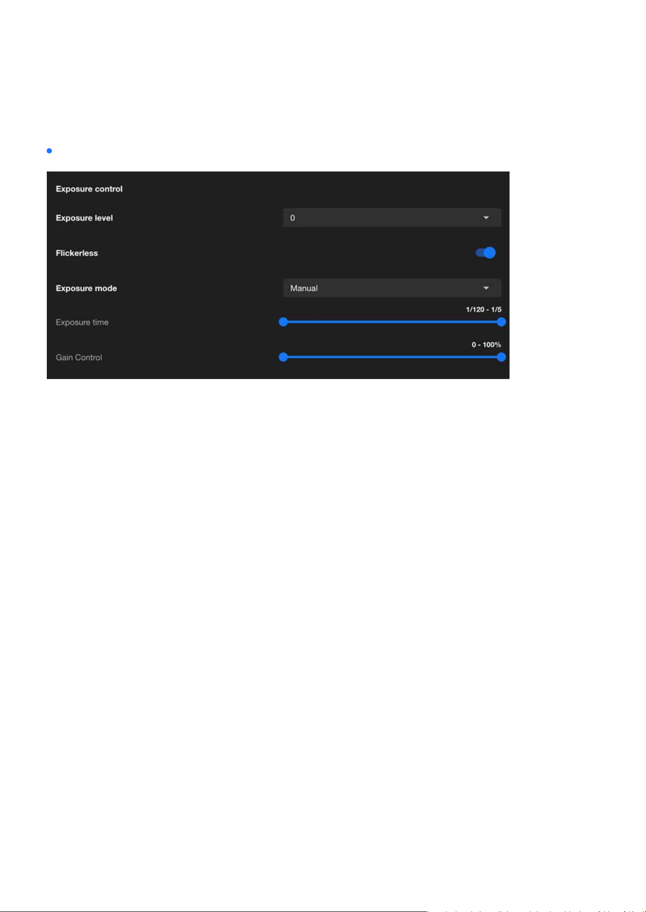
Exposure control
Exposure Control is designed to manage how light interacts with the camera sensor to produce clear,
well-balanced images under varying lighting conditions. The primary purpose of exposure control is to
adjust the camera’s settings to ensure optimal image brightness, clarity, and detail, regardless of the envi-
ronment.
The adjustment range of the Exposure Level is typically from -2.0 to +2.0, used to ne-tune the brightness
of an image. This setting is designed to enhance or reduce the exposure of the image based on ambient
lighting conditions, ensuring the image remains clear and retains complete details.
When the Flickerless is enabled, the camera automatically adjusts its shutter speed to synchronize with
the icker frequency of ambient light sources, such as uorescent or LED lights. This eectively eliminates
ickering stripes or icker eects in the image, ensuring its stability and clarity.
Exposure mode is used to control how the camera adjusts image exposure parameters (such as Expo-
sure time and Gain Control) to adapt to dierent ambient lighting conditions. Once the Exposure mode is
enabled and congured, it helps the camera automatically or manually adjust the exposure according to
scene requirements, ensuring that the image brightness and details meet the desired standards.
Exposure Time refers to the duration for which the camera’s sensor is exposed to light, typically expressed
in seconds or fractions of a second (e.g., 1/120 second to 1/5 second). The primary purpose of this feature
is to control the brightness and clarity of the image, especially under varying lighting conditions.
Gain Control is used to adjust the sensitivity of the camera’s sensor to light. Gain settings are primarily
used to enhance image brightness in low-light environments, though they may increase image noise. This
feature helps the camera produce clear and visible images in low-light or high-contrast scenes.
Exposure level
Flickerless
Exposure mode
Exposure time
Gain control
45
Image
Image
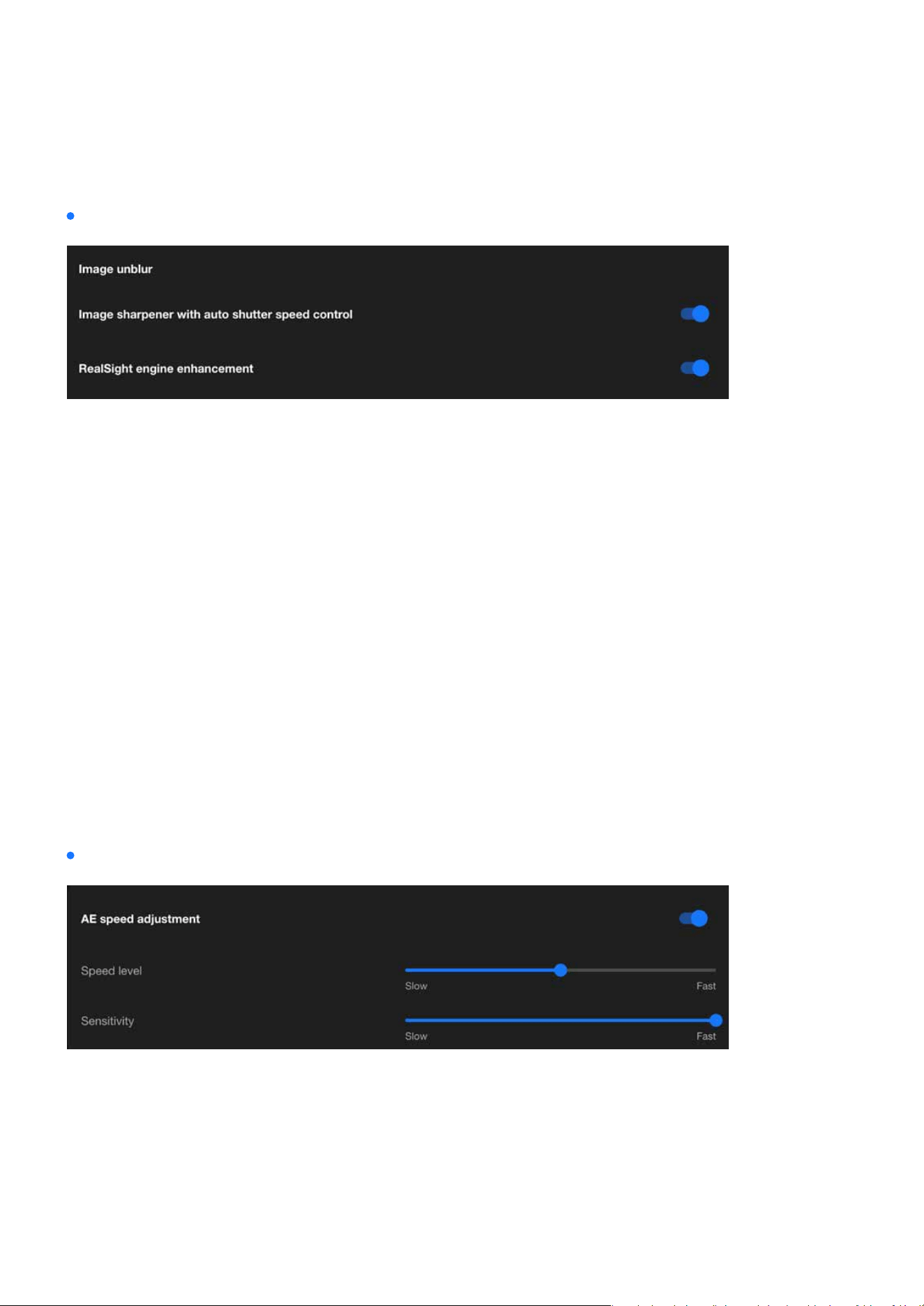
Image unblur
AE speed adjustment
Image Unblur is a feature designed specically for dynamic scenes, eectively reducing motion-induced
image blur to ensure clear images of fast-moving objects. By adjusting shutter speed and other exposure
parameters, this feature is ideal for scenarios requiring high-resolution dynamic recording, such as trac
monitoring or crowd surveillance. However, reasonable adjustments between brightness and image quali-
ty are necessary to achieve optimal results.
AE Speed Adjustment controls the response speed of auto exposure to changes in lighting, balancing the
immediacy and stability of the image. Its purpose is to provide optimal image quality in dierent scenari-
os, avoiding exposure instability or image ickering caused by lighting variations. By exibly adjusting the
AE Speed, diverse surveillance needs can be met, ensuring clear and stable images.
Combining Image sharpener with auto shutter speed control can eectively achieve image unblur. By
shortening the shutter speed to reduce blur and applying image sharpening techniques to enhance de-
tails, the camera can deliver clear images in dynamic scenes while automatically adjusting other parame-
ters to balance brightness, meeting diverse surveillance needs.
By leveraging the dynamic noise reduction, dynamic range optimization, and image sharpening features
of the RealSight Engine, combined with automatic shutter speed control, the eectiveness of Image Un-
blur can be signicantly enhanced. This enables VIVOTEK cameras to deliver stable, clear, and detail-rich
images in fast-moving dynamic scenes and low-light conditions, meeting the requirements of high-quality
surveillance.
Image sharpener with auto shutter speed control
RealSight engine enhancement
46
Image
Image
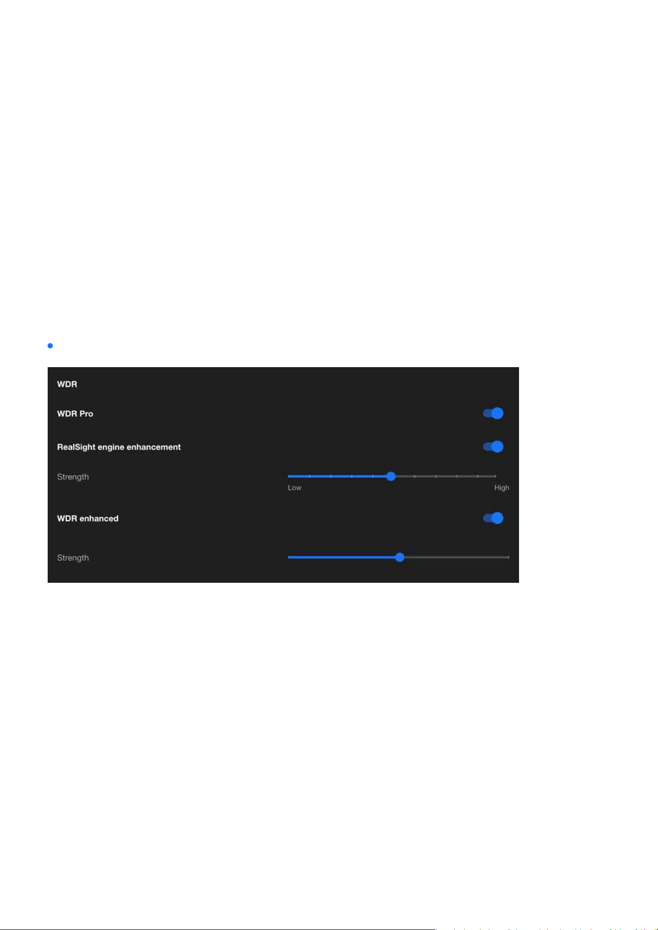
WDR
The WDR (Wide Dynamic Range) feature is primarily used to enhance image quality in high-contrast light-
ing scenarios, balancing the brightness of light and dark areas, preserving details, and ensuring clear vis-
ibility. This feature is crucial for scenarios requiring precise monitoring under diverse lighting conditions,
such as entrances, tunnels, banks, or nighttime surveillance.
The speed level of AE Speed Adjustment should be congured based on the frequency of lighting changes
in the surveillance scene. A slower speed is recommended for stable scenes, while a faster speed is suit-
able for dynamic scenes, ensuring that brightness adjustments are both smooth and responsive. Through
testing and ne-tuning, an optimal balance between image stability and clarity can be achieved.
Adjusting the sensitivity in AE Speed Adjustment controls the camera’s ability to perceive changes in light-
ing.
Low sensitivity is suitable for stable scenes, ensuring a steady image, while high sensitivity is ideal for
rapidly changing scenes, providing real-time response. By testing and tailoring the sensitivity to the specif-
ic scene requirements, the optimal balance between light adaptability and image stability can be achieved.
WDR Pro is an advanced wide dynamic range feature provided by VIVOTEK cameras, oering exceptional
image processing capabilities for high-contrast lighting scenarios. It eectively balances details and colors
in both bright and dark areas, ensuring overall image quality, making it an ideal choice for scenarios de-
manding high standards in image detail and lighting management.
The RealSight engine provides advanced strength control to optimize the performance of WDR Pro, en-
hancing image processing capabilities. By adjusting the strength settings, the camera can better balance
details in bright and dark areas within high-contrast scenes, improving visibility in darker regions. Select-
ing the appropriate strength settings based on the lighting conditions of dierent scenes can signicantly
improve image quality and stability, meeting the needs of various applications.
Speed level
Sensitivity
WDR Pro
RealSight engine enhancement
47
Image
Image
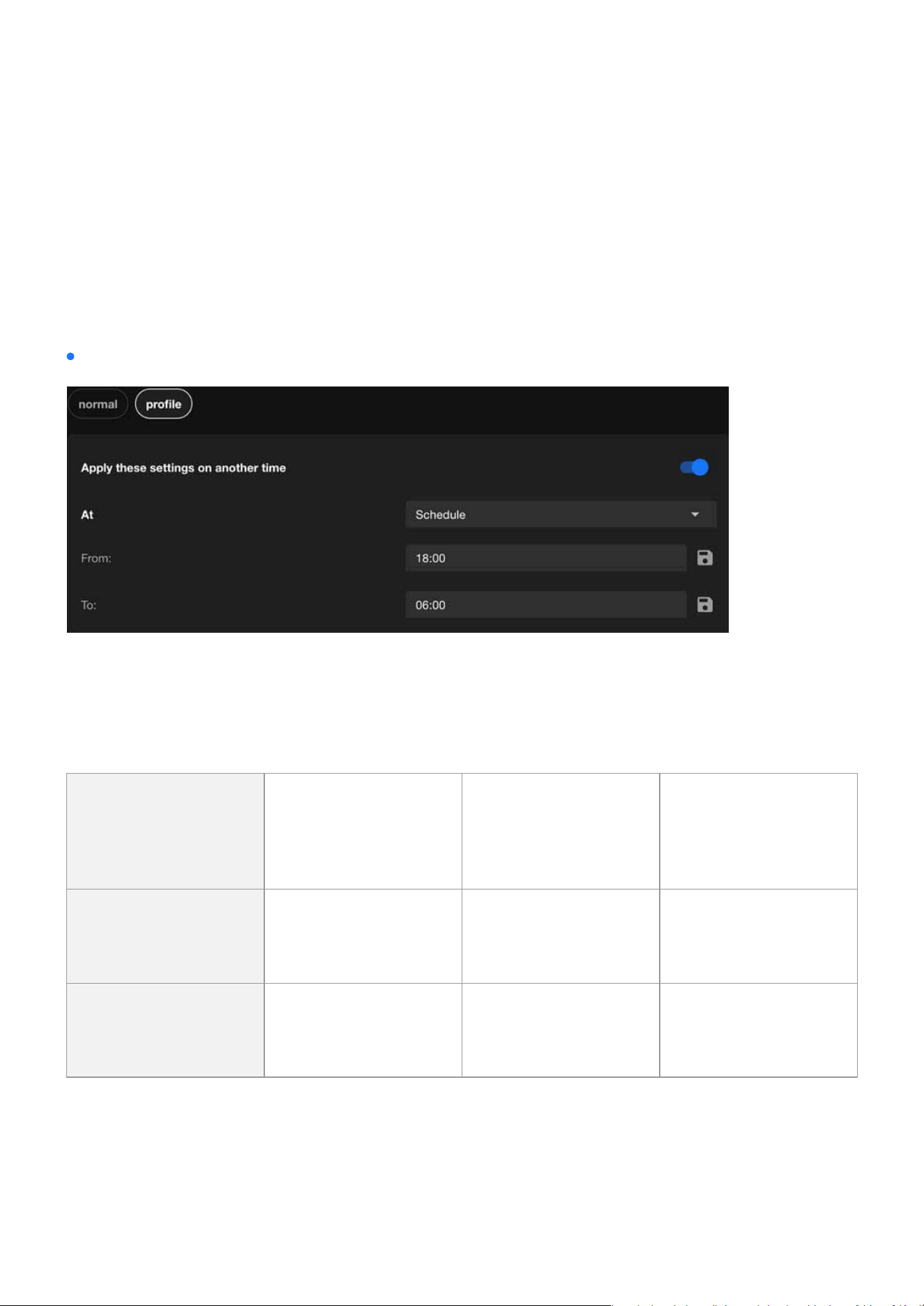
Integrate exposure-related settings into a prole
WDR enhanced is VIVOTEK’s most advanced dynamic range technology for high-contrast scenes, oering
superior detail restoration in bright and dark areas compared to standard WDR and WDR Pro. It is suitable
for scenarios with extreme light contrasts and rapid changes, signicantly enhancing image clarity and
stability, making it particularly ideal for surveillance applications requiring high detail delity.
The Exposure settings in VIVOTEK cameras can be nely tuned using the Prole function, allowing auto-
mated adjustments based on time (Schedule) or lighting conditions (Night/Normal). This ensures the cam-
era consistently delivers optimal image quality across varying lighting environments.
The purpose and applications:
WDR enhanced
Normal
Provides default expo-
sure for general use
Shutter speed, gain,
and exposure com-
pensation under
normal conditions.
Ideal for daytime or
consistent lighting
conditions
Night (Prole)
Optimizes exposure
for low-light condi-
tions
Lower shutter speed,
increased gain, bal-
anced exposure
Enhances visibility
in nighttime or dark
environments
Schedule (Prole)
Time-based switching
of exposure proles
User-dened expo-
sure settings for spe-
cic time periods
Adapts to custom
needs beyond day/
night transitions
48
Image
Image
Optimizing Image Clarity with Flexible Focus Controls
(The Focus settings are only supported on EHTV-type VIVOTEK zoom cameras)
The Focus settings in VIVOTEK zoom cameras is a critical tool for achieving optimal image clarity and en-
suring precise monitoring in various scenarios. This setting allows users to ne-tune the camera’s focus for
capturing clear and detailed images, whether in dynamic environments with moving targets or xed scenes
requiring sharp visuals. By leveraging both Auto Focus and Manual Focus options, users can adapt to dier-
ent distances, lighting conditions, and monitoring needs eciently. Proper use of the Focus setting enhanc-
es not only image quality but also the accuracy of advanced analytics such as facial recognition and license
plate detection, making it an essential component of professional surveillance.
The Focus settings in the Image conguration is designed to ensure optimal image clarity and precision for
surveillance. It allows users to adjust the focus and zoom to achieve the best results for their specic moni-
toring scenario. This section provides tools for both automatic and manual adjustments, catering to dynamic
or static scenes, various distances, and lighting conditions.
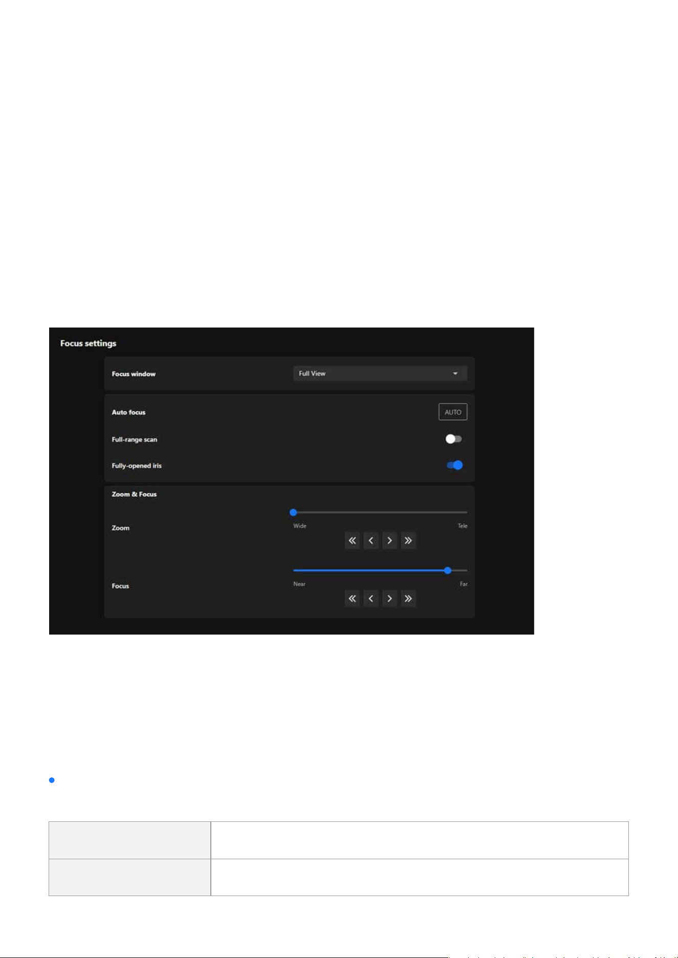
Focus settings
Focus window
Allows the user to dene the area within the camera’s view where the focus should be optimized.
Full View The entire eld of view is considered for focus.
Custom Users can select a specic area for focus optimization

49
Image
Image
Auto focus
Zoom & Focus
Automatically adjusts the focus to achieve the sharpest image.
The Zoom & Focus provides users with intuitive controls to adjust the camera’s eld of view and focus for
precise monitoring.
Allows seamless adjustment between wide-angle and telephoto views using a slider or buttons for
quick or ne-tuned changes.
Enables manual ne-tuning of focus to ensure clarity for objects at varying distances, controlled via a
slider and directional buttons.
If enabled, the camera scans the entire focal length to nd the best focus. This is more comprehensive
but takes longer.
Ensures the iris is fully opened during focusing to reduce depth-of-eld eects and improve accuracy.
Starts the auto-focus process.
Full-range Scan
Zoom
Focus
Fully-opened Iris
AUTO Button
50
Image
Image
Using Privacy Masking to Safeguard Condential Information in
Images
The primary purpose of setting up a Privacy Mask is to protect privacy, comply with regulatory require-
ments, and enhance surveillance eciency. By exibly applying the privacy masking feature in various sce-
narios, it not only prevents unnecessary privacy violations but also allows a focus on key surveillance areas,
improving overall monitoring eectiveness and compliance.
The main benets of setting up a Privacy Mask are as follows:
•
Complies with privacy regulations, reducing legal risks.
•
Avoids capturing footage unrelated to surveillance purposes, improving data processing eciency.
•
Reduces privacy intrusion on monitored subjects, enhancing trust and acceptance.
•
Keeps the focus on target areas, minimizing distractions and improving surveillance eectiveness.
51
Image
Image
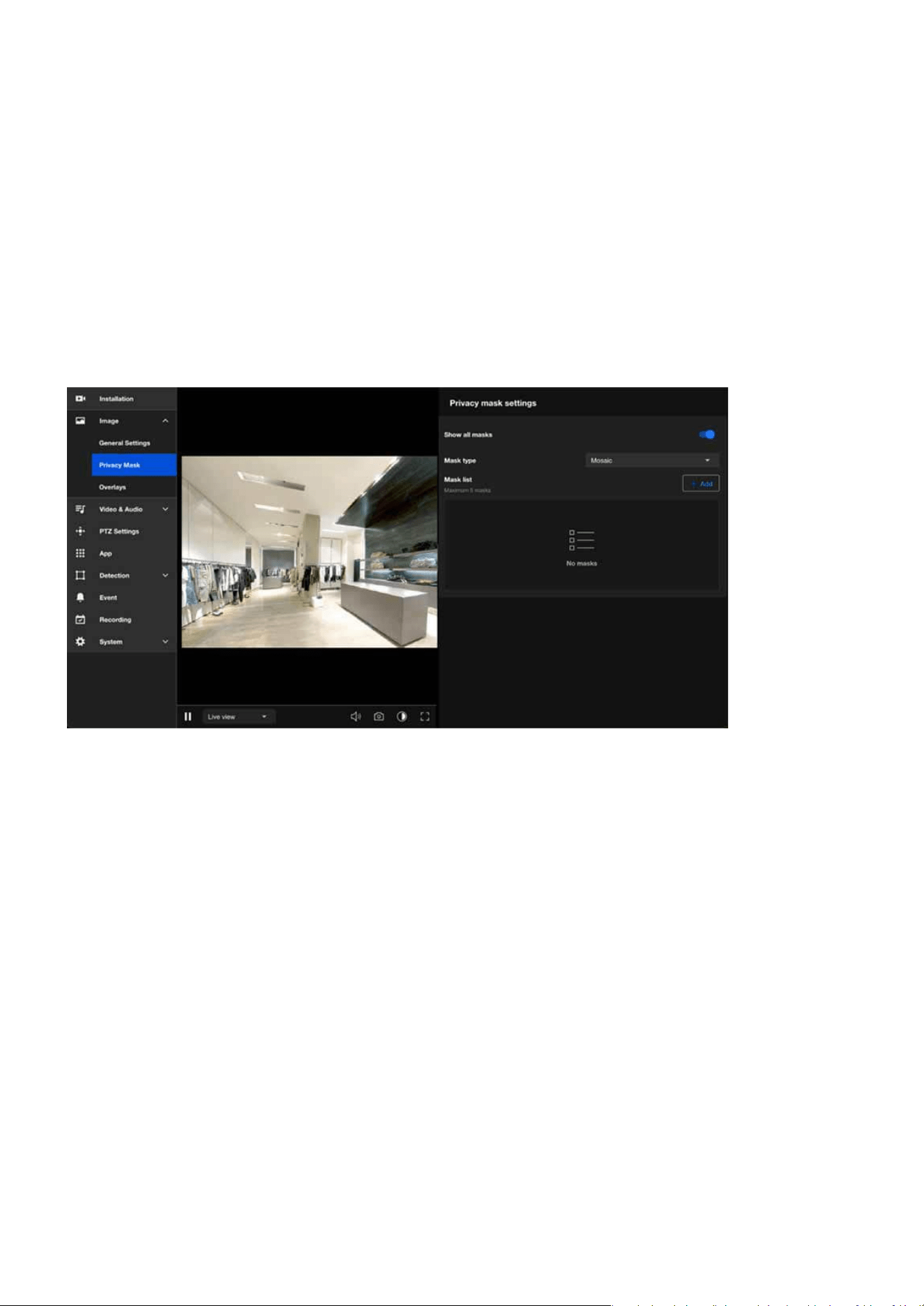
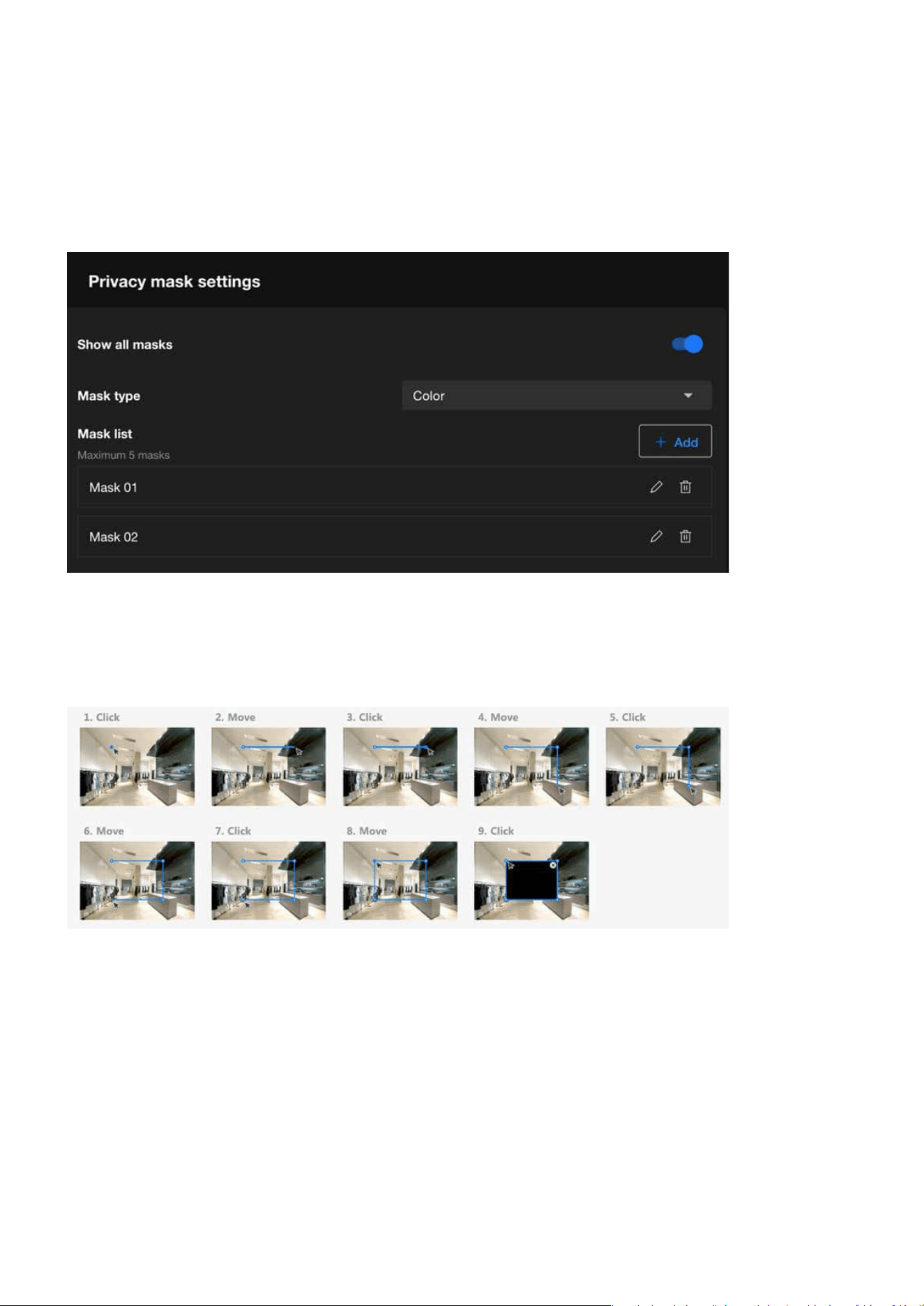
Privacy mask settings
Step 1. Click +Add button in the Mask list.
Step 1. Click delete icon on the mask item.
Step 2. The Mask item will be deleted directly.
Step 2. Draw a closed shape to cover the region you want to hide for privacy concerns on the preview
screen.
Step 3. Enter the privacy mask name.
Step 4. Click Save button.
Step to add a privacy mask:
Step to delete the privacy mask:

52
Image
Image
Step 1. Click edit icon on the mask item.
After the user congures the privacy masks, the “Show all masks” must be enabled to apply the cong-
ured masks to the image.
Privacy mask oers two types, Color (color masking) and Mosaic (mosaic masking), to meet privacy pro-
tection needs in various scenarios. Color Mask is suitable for cases requiring a high level of privacy and
complete concealment, while Mosaic Mask is better for scenarios that need to hide details while maintain-
ing the overall natural appearance of the image. Choosing the appropriate mask type based on specic
situations ensures ecient and exible privacy protection.
Step 2. Drag the mask to the desired Area.
Step 3. Click and drag the corners to adjust the shape (rectangular, trapezoidal, etc.) and size to precisely
cover the target area
Step 4. Click Save button.
Step to edit the privacy mask:
Show all masks
Mask type
53
Image
Image
Customizing Image Overlays to Add Additional Information
The Overlays feature is a powerful tool that enhances the usability and clarity of video streams or recordings
by allowing key information to be superimposed on the video feed.
Below is an explanation of its main purposes and functionalities:
•
Displaying Key Information:
•
Enhancing Evidence Validity:
•
Branding and Identication:
•
Real-time Data Monitoring:
•
Regulatory Compliance and Alerts:
Adds essential details such as the camera name, date and time, location, or custom text to the video, mak-
ing it easier to identify the source and context of the footage.
Timestamp overlays ensure that video recordings can serve as valid evidence for legal or investigative pur-
poses.
Displays logos or other identiers to reinforce brand recognition, especially useful in commercial or public
applications.
With dynamic text overlay, real-time updates (e.g., sensor data, alarms) can be shown directly on the video
feed, making it valuable for environment monitoring or situational awareness.
Ensures adherence to specic industry or regional regulations by displaying required notications or
warning messages on the video feed.
54
Image
Image
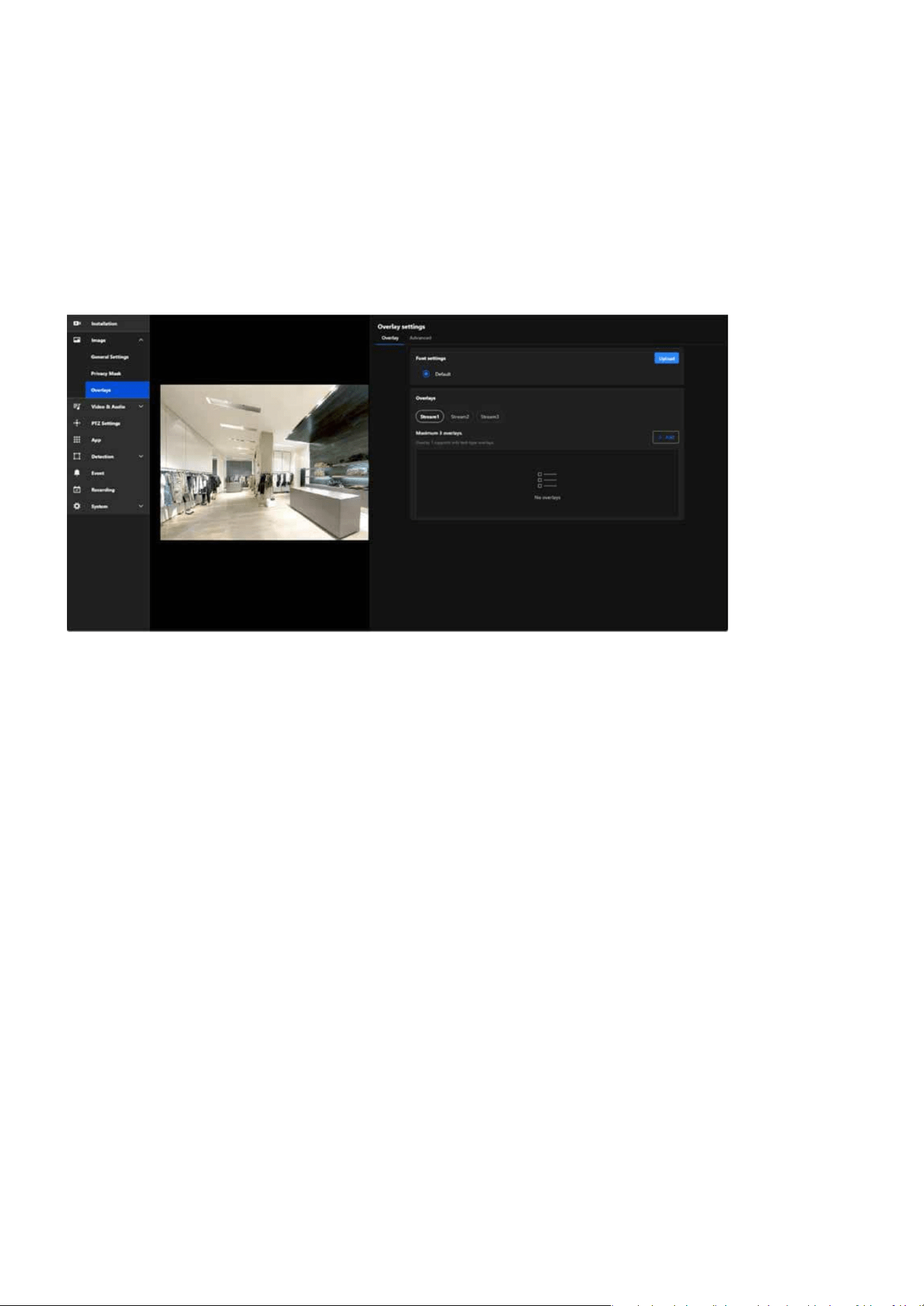
Overlay
The Overlay allows users to add information to images, such as camera names and timestamps. This infor-
mation is directly displayed on recorded or live-streamed footage, facilitating future review and manage-
ment. For instance, by enabling the overlay function, you can display the camera’s name and the recording
time on the footage, which is highly benecial for surveillance system management and event tracing.
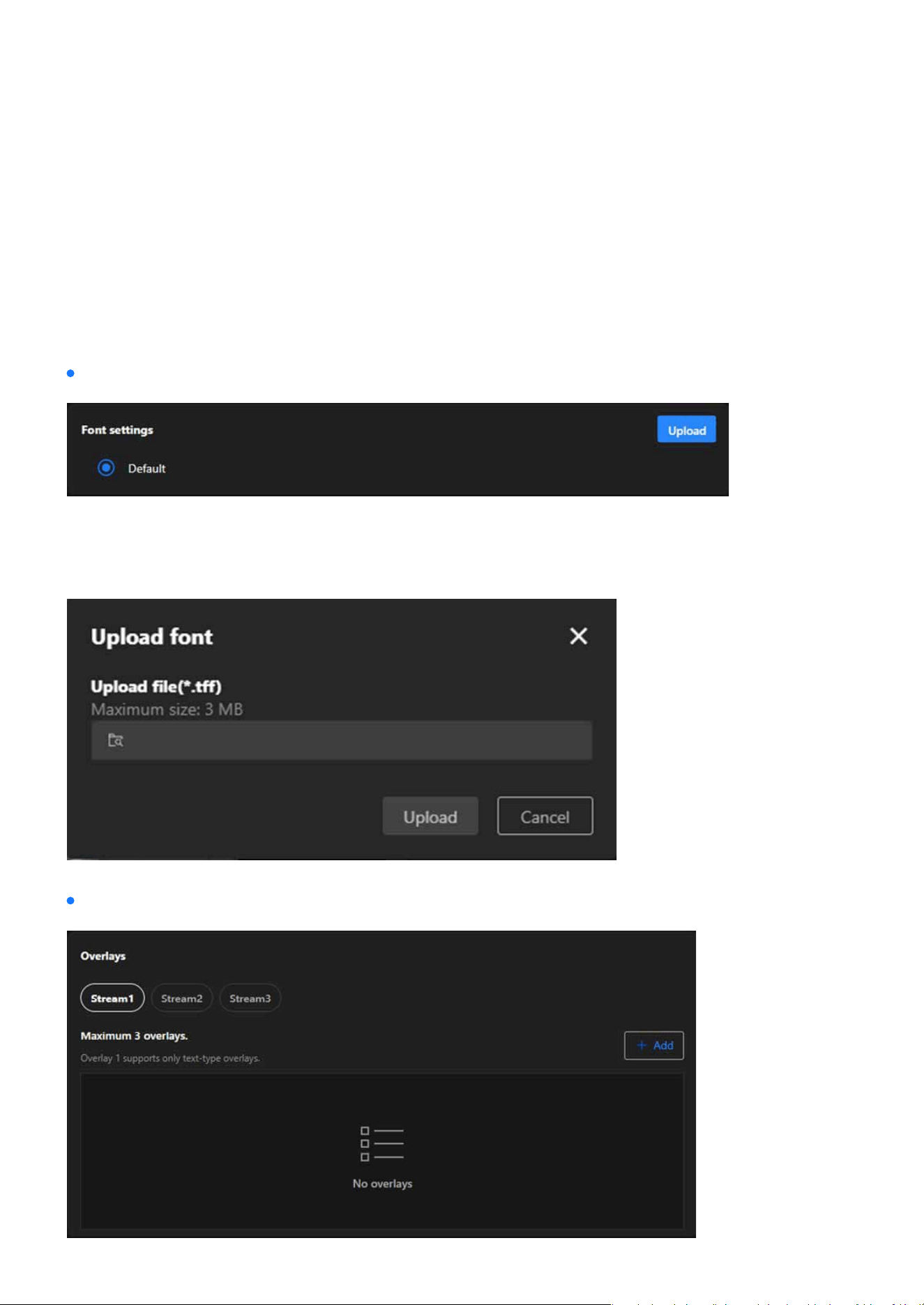
The Font Settings in the Overlay settings allow users to customize the appearance of text overlays on video
feeds. This feature ensures that the displayed information is clear, visible, and matches the specic require-
ments of dierent monitoring environments.
Font settings
Overlays
55
Image
Image
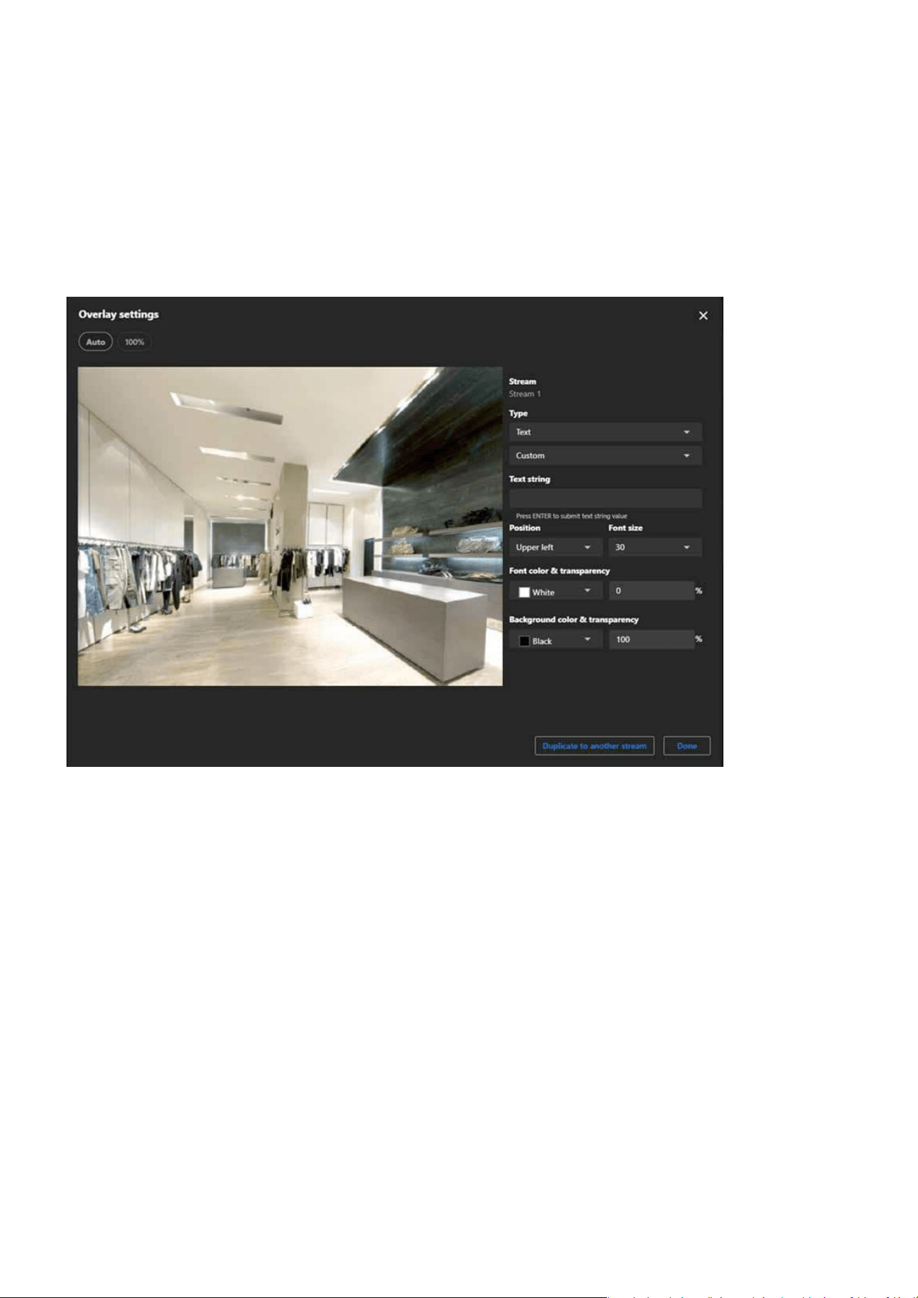
Step 1. Select the stream (e.g., Stream 1, Stream 2, or Stream 3) you wish to congure for overlay.
Step 2. Click the Add button to create a new overlay.
Step to set a overlay:

56
Image
Image
Step 3. Choose the type of overlay:
Step 4. Click the Position dropdown menu to place the overlay (e.g., Upper Left, Bottom Right). Adjust posi-
tioning manually if advanced controls are available.
Step 5. If you select Text, Click the Font size dropdown menu to adjust the text size.
Step 6. If you select Text, please click and congure the Font and Background dropdown menus to choose
the appropriate color and transparency.
Step 7. If you select Image, please click and congure the Image transparency dropdown menus to choose
the appropriate transparency.
Text
Date and Time
The display can show the user-dened date
and time format.
Date
The display can show the user-dened date
format.
Time
The display can show the user-dened time
format.
Custom
The display can show user-dened text con-
tent.
Image
The display can show 256-color BMP images
uploaded by the user.
Live streaming indi-
cator
The Live streaming indicator is a feature with-
in the Overlay settings that visually indicates
when the camera is actively streaming live
video.
Note:
For image overlays, ensure the size and resolution t the video stream properly.
Advanced
The Advanced page in the Overlay settings primarily oers advanced features, enabling users to customize
overlay content on surveillance footage according to specic requirements. Particularly useful for displaying
real-time dynamic data or in professional scenarios, this settings page provides the necessary exibility and
functional support.
57
Image
Image
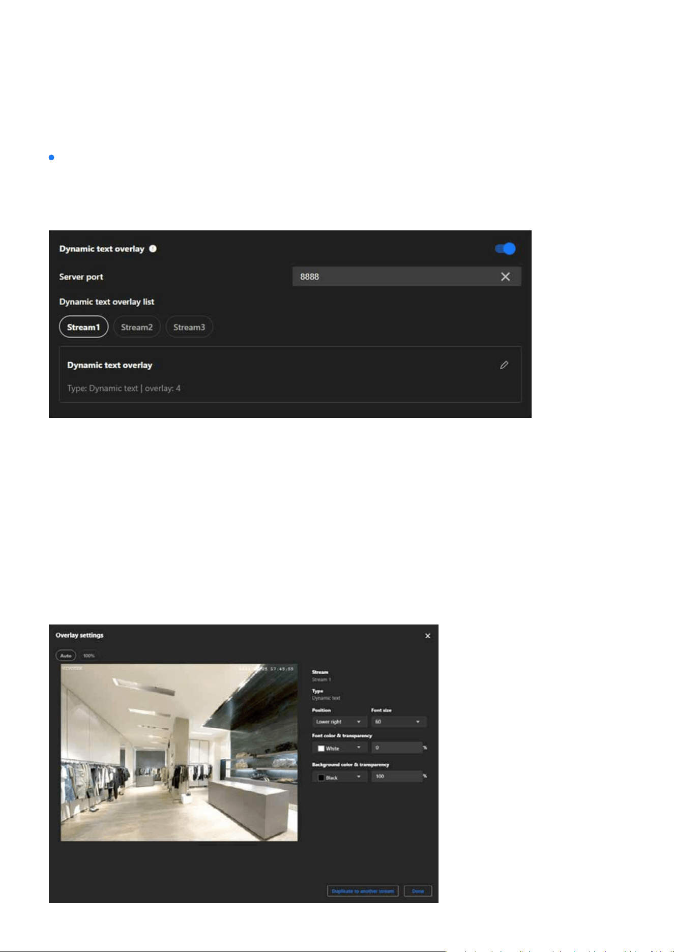
Dynamic Text Overlay
Dynamic Text Overlay is an advanced feature of VIVOTEK cameras that allows users to display real-time
dynamic information from external data sources on surveillance footage. This feature enhances the prac-
ticality and informational value of the footage, making it suitable for various surveillance scenarios.
Step 1. Enable Dynamic text overlay
Step 2. Ensure the Server Port is set to an available port (default: 8888) or specify another unused port if
necessary.
Step 3. Ensure your external data source is congured to send data to the camera’s IP address and the
specied server port (e.g., 8888).
Step 4. Ensure the data format is compatible with the camera’s requirements (refer to VIVOTEK API docu-
mentation for acceptable formats).
Step 5. Select the stream you want to add the dynamic text overlay to.
Step 6. In the “Dynamic Text Overlay List,” click the Edit (pencil icon) to congure overlay details.
Step to set the dynamic text overlay:
58
Video & Audio
Video & Audio
The main purpose of Video & Audio settings is to ensure high-quality video and audio by adjusting resolu-
tion, frame rate, and compression formats, while optimizing bandwidth and storage usage with multi-stream
options. These settings enhance monitoring capabilities with high resolution, smooth frame rates, and two-
way audio, and provide adaptability for various scenarios such as night mode or outdoor environments.
Additionally, they improve system exibility and compatibility by supporting multiple media formats and
protocols for seamless integration across devices.
The Video settings are divided into the Mode page and the Stream page, both primarily used for conguring
the camera’s video output, oering users exible control over video quality and resource management.
Optimizing Surveillance Efciency with Flexible Video Settings
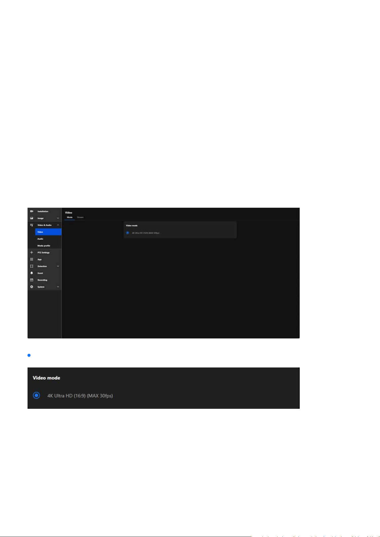
Video mode allows users to customize the camera’s video performance to meet specic monitoring needs
while achieving a balance between high-quality video output and resource eciency. The main features
are as follows:
The Video Mode determines the maximum resolution the camera can output, such as 4K Ultra HD, Full
HD, or other resolutions, ensuring high-quality video feeds.
Video mode
Denes Video Resolution
59
Video & Audio
Video & Audio
Congures the aspect ratio of the video (e.g., 16:9), optimizing the eld of view for modern widescreen
displays.
Species the maximum frames per second (fps), such as 30fps, for smooth motion capture in dynamic
environments.
Sets the overall video performance limits, including resolution and frame rate, which aect the clarity,
smoothness, and resource usage of the video stream.
Denes the video compression format.
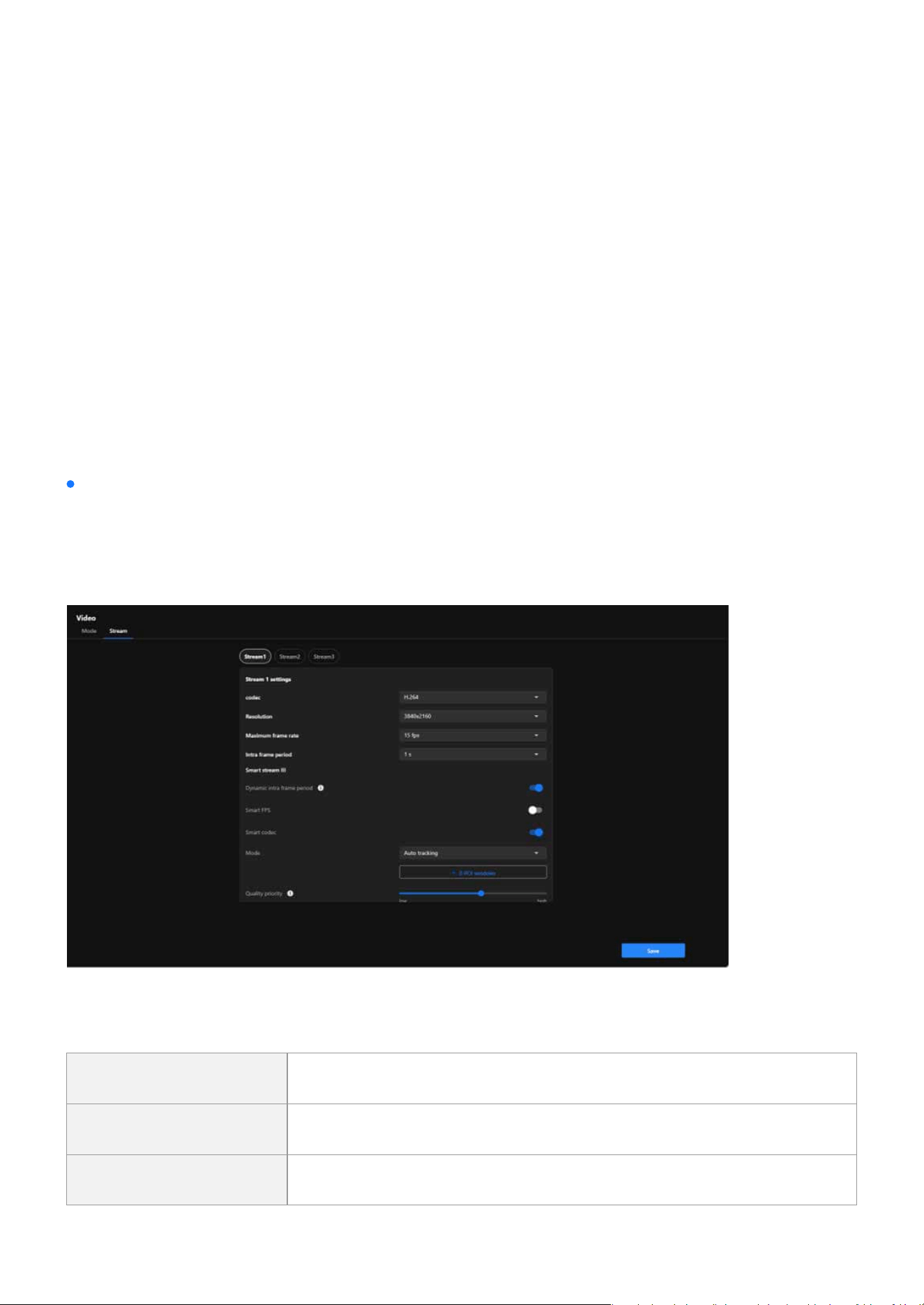
Video Stream is designed to oer exible video output options to meet diverse surveillance needs while
optimizing bandwidth and storage resource usage. Through multi-stream conguration, intelligent com-
pression technology, and regional optimization, Video Stream serves as a key tool for enhancing surveil-
lance eciency and adaptability across various applications.
Sets Aspect Ratio
Controls Frame Rate
Establishes Video Parameters
Codec
Video stream
MJPEG High quality and clarity needed, sucient bandwidth available.
H.264 Dynamic scenes with stable bandwidth.
H.265 High resolution or bandwidth-limited environments.

60
Video & Audio
Video & Audio
Resolution is a key parameter of image quality, directly aecting the clarity of surveillance footage, storage
requirements, and bandwidth usage. Choosing the appropriate resolution requires considering the moni-
toring purpose, scenario needs, and resource constraints.
Maximum frame rate is a parameter that determines the number of video frames captured and transmit-
ted by a camera per second. Frame rate aects the smoothness of the video, detail capture, bandwidth
usage, and storage requirements. Choosing an appropriate frame rate requires considering the monitor-
ing scenario, purpose, and system resources. Recommended frame rate settings as:
Resolution
Maximum frame rate
High-Speed Motion
(e.g., Trac, Sports)
30fps or higher
Smoothly captures fast-moving scenes, suit-
able for scenarios requiring clear observation
of moving objects.
General Surveillance
(e.g., Stores, Oces)
15fps
Balances video smoothness and bandwidth
usage, ideal for most everyday monitoring
needs.
Static Scenarios (e.g.,
Warehouses, Parking
Lots)
10fps or lower
Saves resources, suitable for scenarios em-
phasizing static environments.
Low-Bandwidth
Environments or
Remote Monitoring
5fps
Reduces bandwidth usage, ideal for situations
with network constraints or basic monitoring
requirements.

61
Video & Audio
Video & Audio
Intra Frame Period determine how often for rmware to plant an Intra frame (I-frame). The shorter the
duration, the more likely user will get better video quality, but at the cost of higher network bandwidth
consumption. Recommended settings based on use cases:
Smart Stream III is an advanced video optimization technology in VIVOTEK cameras, focusing on dynam-
ically managing bandwidth and storage usage while maintaining critical details and image quality. This
technology eectively reduces bandwidth and storage requirements by intelligently adjusting frame rates,
compression ratios, and regional quality, making it particularly suitable for scenarios with limited band-
width or requiring long-term recording. The conguration items for Smart Stream III are as follows:
Automatically adjusts the I-frame frequency based on scene activity. Achieves better optimization by
balancing image clarity and resource usage.
Dynamically adjusts the frame rate based on motion in the scene. High motion increases the frame rate
for smoothness, while low motion decreases it to save bandwidth.
Utilizes advanced compression technology to maintain detail in high-motion areas while heavily com-
pressing static areas. Optimizes bandwidth and storage usage without losing critical information.
Denes how the camera manages the ROI (Region of Interest) in the video and optimizes image quality
and resource allocation. Mode oers dierent operating options, allowing users to exibly choose auto
tracking, manual, or hybrid ROI settings based on surveillance needs and scene characteristics.
Intra frame period
Smart stream III
High-Dynamic Sce-
narios (e.g., Trac
Monitoring)
1 second
Quickly generates complete frames, suitable
for capturing fast-moving targets.
General Surveillance
(e.g., Oces, Stores)
2 seconds
Balances video clarity, bandwidth, and stor-
age usage, ideal for most daily surveillance
scenarios.
Static Scenarios (e.g.,
Warehouses)
3 seconds or longer
Reduces the number of I-Frames to save re-
sources, suitable for low-variation scenes.
Remote or
Low-Bandwidth
Monitoring
1–2 seconds
Prevents image degradation and ensures
smoothness and quality in remote viewing.
•
Dynamic intra frame period
•
Smart FPS
•
Smart codec
•
Mode

62
Video & Audio
Video & Audio
Step 1. Click the + ROI Windows button.
Quality Priority is a parameter used to dene the priority of image quality, providing higher or lower image
quality for specic ROI areas to balance resource usage and image clarity.
Bit rate control is used to adjust the transmission bit rate of video, achieving a balance between image
quality and bandwidth usage.
When the surveillance scenario demands high image quality and network and storage resources are
relatively sucient, it is recommended to use Fixed Quality to ensure that no image details are lost.
If the surveillance environment has limited bandwidth or storage resources, it is recommended to
choose Constrained Bit Rate to precisely control resource usage by limiting the bit rate.
Step 2. Drag and resize the selected areas to adjust ROI areas in the preview screen.
Step 3. Click the Save button.
How to add the ROI window?
Quality priority
Bit rate control
Fixed Quality
Constrained Bit Rate
Auto Tracking
High-dynamic scenarios (e.g., trac, public spaces)
Automated processing, no manual conguration needed
Cannot focus on specic static areas
Manual
Static scenarios (e.g., oces, warehouses)
Precise control over areas of interest
Not suitable for dynamic environments
Hybrid
Mixed dynamic and static scenarios (e.g., retail, entrance monitoring)
Balances static and dynamic needs, highly exible
May require additional conguration
Note:
Multiple ROI areas can be added to target dierent critical locations, such as entrances, cash registers, or driveways.

63
Video & Audio
Video & Audio
Target Quality sets the target quality level of the video, instructing the camera on how to compress the
video to achieve the desired clarity. The purpose and applications:
Maximum Bit Rate is a feature used to limit the bit rate of the camera’s video stream, aiming to control
bandwidth and storage resource usage while maintaining video quality. Properly conguring the Maxi-
mum Bit Rate not only ensures stable system operation but also eectively optimizes resource allocation,
making it an essential tool in multi-camera systems and low-bandwidth environments.
The function and purpose of the policy are to achieve exibility and specicity in video transmission, bal-
ancing frame rate and image quality according to scenario requirements, thereby enhancing the eective-
ness, stability, and resource utilization eciency of the monitoring system.
Target quality
Maximum bit rate
Policy
Option Purpose Eect on Stream Application
Customized
User-dened quality
settings
Manual adjustment
for precise stream
control
Scenarios requiring
tailored stream pa-
rameters
Medium
Lower requirements
for target quality
Lower quality, re-
duced bitrate
Low-priority streams
or low-bandwidth
networks
Standard
Balances quality and
eciency
Moderate quality with
controlled bitrate us-
age
General-purpose
monitoring
Good
Enhances stream clar-
ity
Better detail while
keeping bitrate rea-
sonable
Busy areas with mod-
erate detail require-
ments
Detailed
Provides high detail in
the video stream
Higher quality, sharp-
er images, increased
bitrate
Surveillance requiring
detailed object clarity
Excellent
Maximizes stream
quality
Highest image clarity
and bitrate usage
High-security mon-
itoring, critical evi-
dence recording

64
Video & Audio
Video & Audio
Smart Q is an intelligent image management feature designed to dynamically balance image quality and
resource utilization eciency. It not only enhances the eectiveness of surveillance footage but also im-
proves the utilization of bandwidth and storage resources. This is particularly suitable for scenarios re-
quiring long-term recording, attention to detail, or resource-constrained monitoring systems.
Smart Q
Frame Rate Priority
Suitable for dynamic monitoring scenarios, ensuring smooth video play-
back to facilitate real-time monitoring and quick response.
Image Quality Priority
Suitable for static or detail-demanding scenarios, providing higher image
clarity to record critical details eectively.
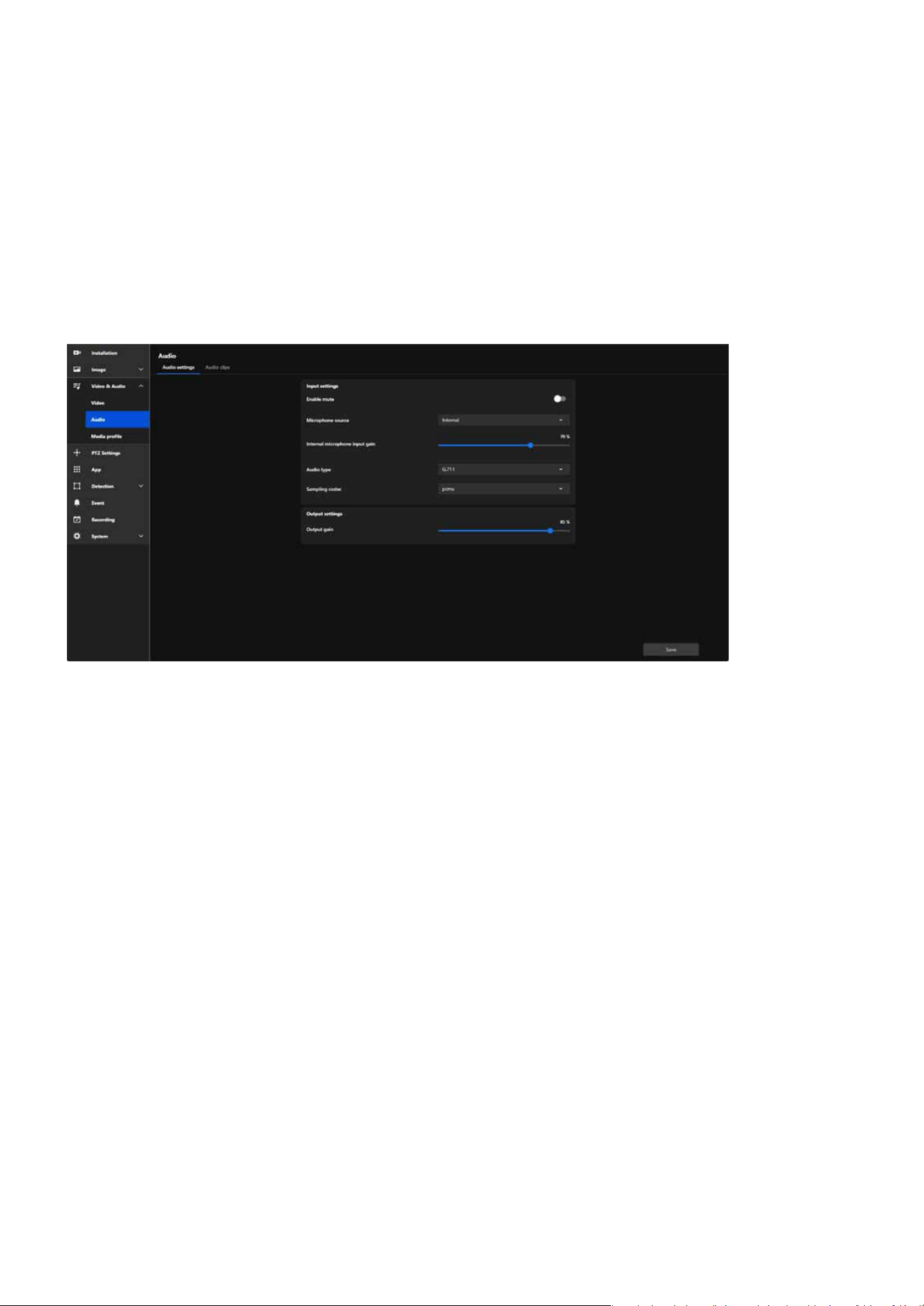
65
Video & Audio
Video & Audio
Conguring Audio Settings for Enhanced Input and Output
Performance
The overall functionality of this page is designed for comprehensive management of the camera’s audio fea-
tures, covering everything from real-time audio input and output to managing audio clip playback.
The purpose of this setting is to provide detailed congurations for audio input and output, optimizing the
audio functionality of surveillance cameras and allowing users to adjust audio quality, volume, and source
based on their specic needs.
Its purposes include:
•
Enhancing overall surveillance eectiveness by leveraging audio to support video for more ecient
security monitoring.
•
Improving communication and incident response capabilities by integrating two-way communica-
tion and alarm features to meet diverse situational needs.
•
Providing exible control and management tools, enabling easy conguration for both real-time
audio processing and pre-recorded audio playback.
Enables interaction with external devices to eThese features make the application of audio in surveillance
environments more exible and ecient.xpand functional applications.
Audio settings
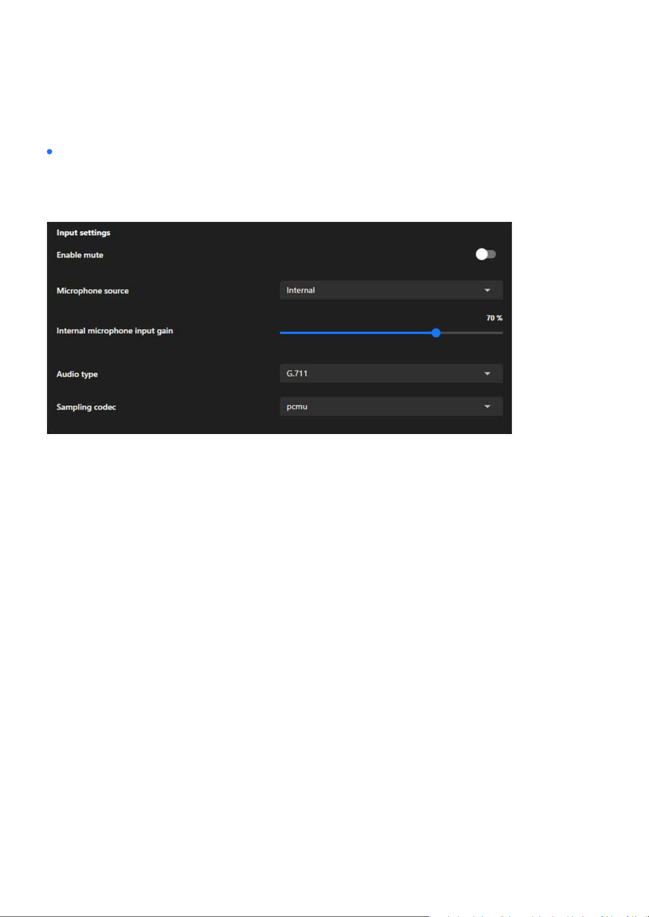
66
Video & Audio
Video & Audio
Enable mute
Microphone source
Internal/External microphone input gain
Audio type
AAC
AAC Bit Rate
The purpose of this setting is to provide detailed congurations for audio input and output, optimizing the
audio functionality of surveillance cameras and allowing users to adjust audio quality, volume, and source
based on their specic needs.
Enable mute allows users to disable audio input, ensuring privacy or preventing unwanted sound record-
ing.
Microphone source lets users select between Internal or External microphones to adapt to dierent audio
capture needs and hardware setups.
Internal/External microphone input gain allows users to adjust the microphone’s sensitivity, enhancing
or reducing audio capture levels to suit varying environmental noise conditions and ensure clear sound
recording.
The audio type setting determines the encoding format for audio, balancing quality, bandwidth usage, and
compatibility:
Oers high-quality audio with ecient compression, ideal for environments requiring clear sound with
minimal distortion.
AAC Bit Rate is a sub-setting under Audio Type, which only appears when AAC is selected. It is used to
ne-tune the quality and resource usage of AAC audio format, enabling users to optimize the cong-
uration based on practical scenarios, such as bandwidth or storage requirements.
Input settings
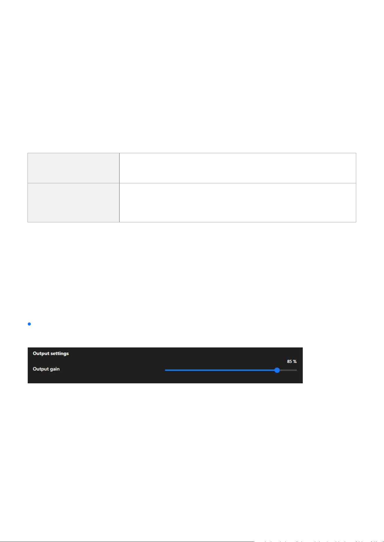
67
Video & Audio
Video & Audio
G.711
G.726
Sampling codec
G.726 Bit Rate
A widely used codec for real-time communication, providing good audio quality with low compression,
suitable for networks with sucient bandwidth.
Provides moderate compression, balancing quality and bandwidth usage, suitable for environments
with bandwidth constraints.
Denes the compression method for the selected audio type (typically G.711), aecting audio quality
and compatibility:
G.726 Bit Rate is a specic conguration option that appears based on the selection of Audio Type
and is only active when G.726 is chosen. This option allows users to further adjust the encoding bit
rate to optimize settings according to practical needs, such as network bandwidth or storage space
limitations.
pcmu
Commonly used in North America and Japan, it provides slightly higher
audio quality with a focus on maximizing dynamic range for voice clarity.
pcma
Commonly used in Europe and other regions, it delivers comparable
quality to pcmu but is optimized for dierent telecommunication stan-
dards.
Users can manually adjust the audio output volume to suit dierent application environments.
Output settings
Output gain
Users can manually adjust the audio output volume to suit dierent application environments:
In scenarios requiring high volume (such as alarms or wide-area broadcasts), gain can be increased to en-
hance the volume.
In scenarios requiring lower volume (such as privacy mode or silent operation), gain can be reduced to
minimize audio interference.
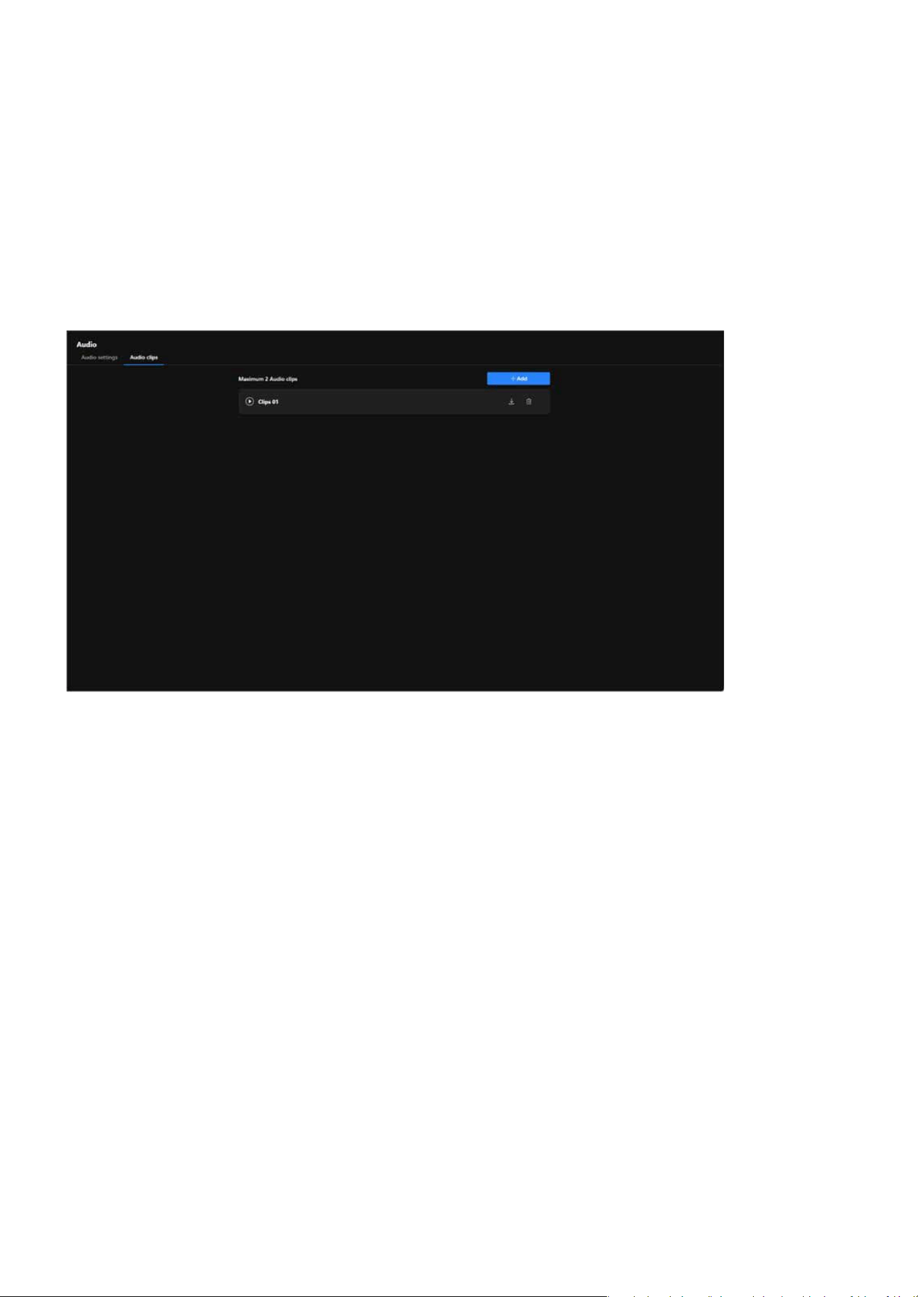
68
Video & Audio
Video & Audio
Audio clips
The Audio Clips feature is designed to integrate audio with event triggers, enabling more ecient notica-
tions, alerts, and interactions, thereby enhancing the application value of cameras in surveillance and secu-
rity scenarios.
Enhance Incident Response Capability
Strengthen Security Deterrence
Increase Monitoring Flexibility
Simplify Operational Processes
By playing audio alerts or notications, it can promptly notify nearby personnel of anomalies or potential
threats.
Play pre-recorded warning messages or alarm sounds upon detecting intruders or suspicious activities,
eectively deterring potential threats.
Support for customizable audio content to cater to various scenarios, such as playing welcome messages
in stores or broadcasting regulatory instructions in parking lots.
Automated audio playback reduces the need for manual operations, further improving surveillance e-
ciency.
The purpose of the functionality:
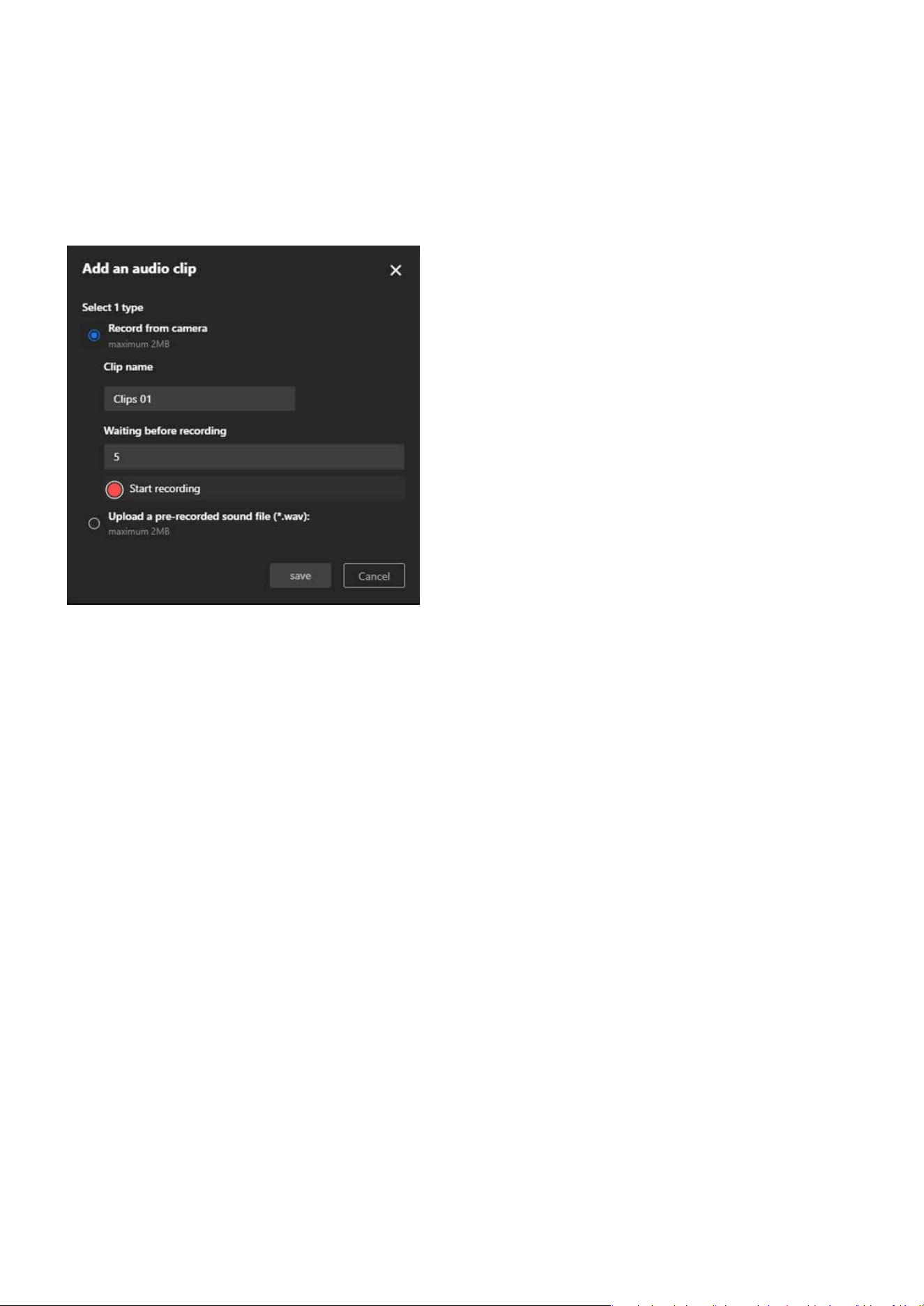
69
Video & Audio
Video & Audio
Record from camera
Upload a pre-recorded sound le
Step to add an audio clips:
Use the camera’s built-in microphone to record audio, with a maximum le size of 2MB.
Upload a pre-existing audio le, which must be in .wav format and not exceed 2MB.
Step 1. Select the one of the two options under “Select 1 type” for the audio source.
Step 2. Enter a name for the audio clip in the “Clip name” eld (e.g., “Clips 01”) to identify it later.
Step 3. In the “Waiting before recording” eld, input the number of seconds to delay the start of the re-
cording (e.g., 5 seconds) to allow time for preparation before recording begins.
Step 4. Click the red “Start recording” button to initiate a countdown for the specied time, after which the
system starts recording audio and automatically saves the recording upon completion for review.
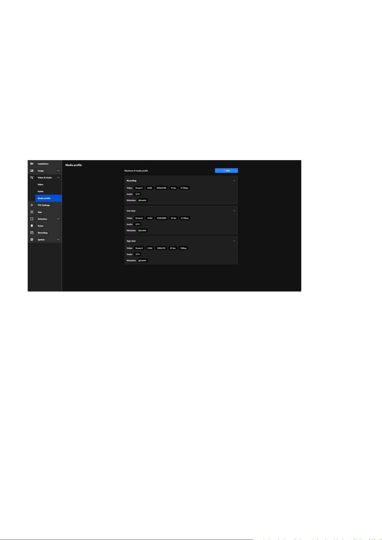
70
Video & Audio
Video & Audio
Conguring Media Proles to Optimize Video Performance for
Versatile Applications
In VIVOTEK cameras, the Media Prole function primarily displays pre-set stream parameters and allows us-
ers to enable or disable video, audio, and metadata. This functionality simplies stream management while
providing the exibility to adapt to various monitoring scenarios, such as recording, live viewing, and mobile
access, ensuring ecient and eective surveillance management.
Stream Management Simplied
Clear Stream Display
Optimized Resource Management
Flexible Application Scenarios
Users can quickly enable or disable video, audio, and metadata features for each prole.
Media Prole displays the precongured stream parameters (e.g., resolution, frame rate, bit rate) for easy
identication and management.
By enabling or disabling features, users can reduce bandwidth and system resource usage as needed.
Users can create multiple proles for dierent needs, such as:
Recording: High-resolution video enabled.
Live View: High frame rate for smooth real-time playback.
App View: Low-resolution video for bandwidth eciency.
Benets and Features:
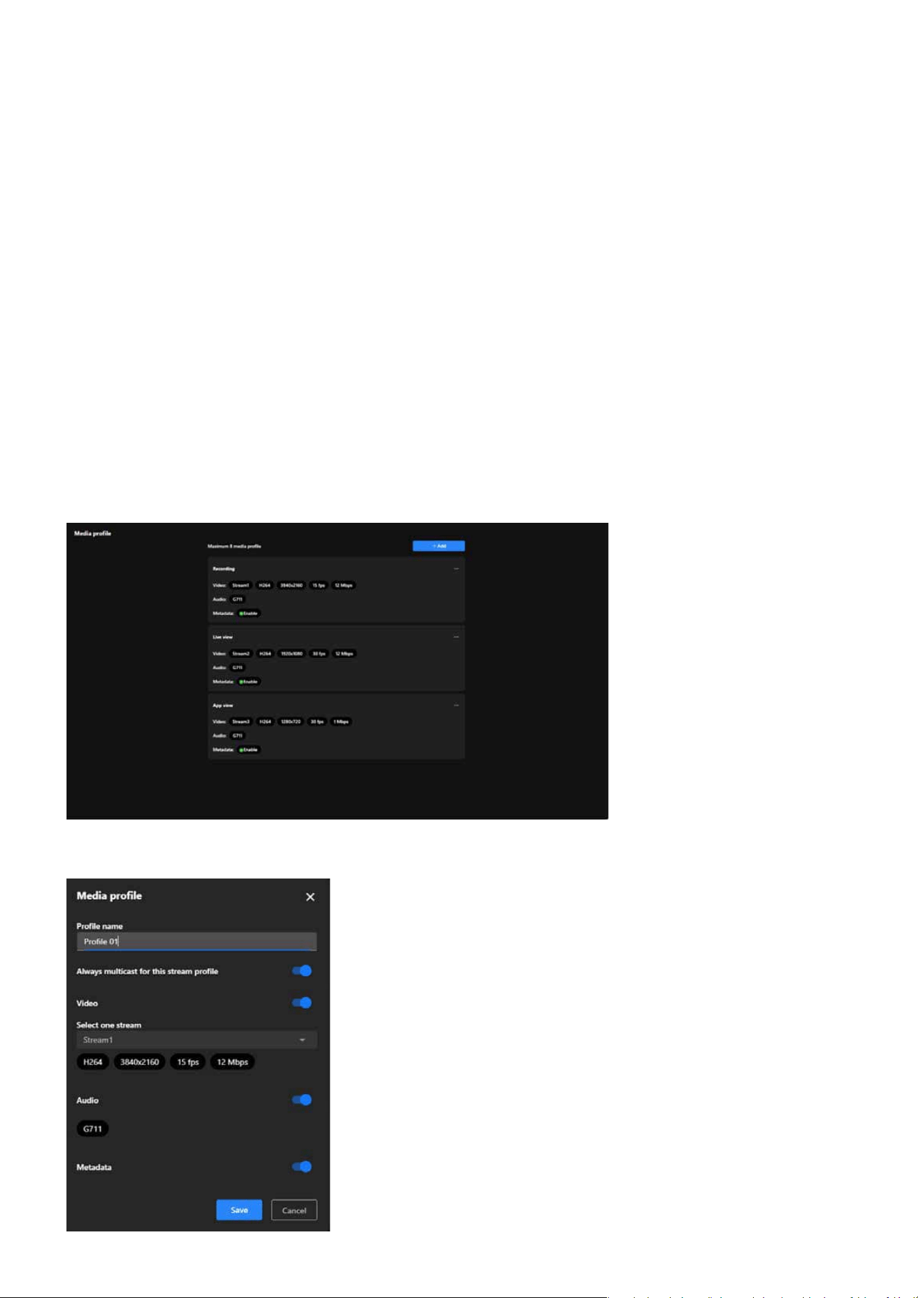
71
Video & Audio
Video & Audio
Media prole
the Media prole is designed to display precongured stream parameters and allow users to enable or dis-
able specic features, such as:
Displays the selected stream settings and allows enabling or disabling the video stream.
Enables or disables the audio feature and displays the audio codec in use.
Enables or disables metadata functionality, supporting further video analysis and event tagging.
Video:
Step to add a Media prole:
Audio:
Metadata:
Note:
Media Prole does not allow conguration of video resolution, frame rate, or bit rate. These parameters are pre-set in the Stream
settings, and Media Prole only displays the relevant settings and enables feature toggling.

72
Video & Audio
Video & Audio
Step 1. Locate and click the blue “+ Add” button on the Media Prole screen.
Step 2. To enter a prole name in the “Prole Name” eld.
Step 3. Enabling the “Always Multicast for this Stream Prole” option allows multiple users to access the
same video stream simultaneously.
Step 4. To enable the “Video” option and select a stream in the Video stream settings.
Step 5. To enable the “Audio” option.
Step 6. To enable the “Metadata” option.
Note:
This feature is particularly benecial in scenarios requiring ecient data transmission, such as large-scale surveillance systems.
By utilizing multicast, the camera sends a single video stream that can be shared among multiple viewers, signicantly reducing
network bandwidth consumption compared to unicast streaming, where separate streams are sent to each user.
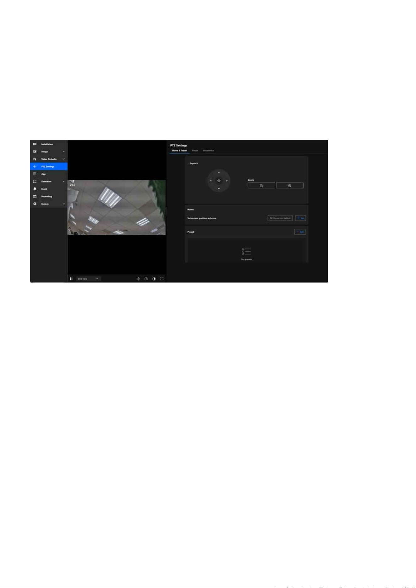
73
PTZ Settings
PTZ Settings
The IPv4 card plays a vital role in setting up the camera’s network conguration and ensuring eective com-
munication. It facilitates dependable connectivity, enables both local and remote access, and allows the
camera to integrate eortlessly into IPv4-based networks. This conguration is crucial for maintaining stable
and ecient performance across diverse networking environments.
PTZ Settings oers a comprehensive and intuitive set of tools for exible operation of PTZ cameras, covering
real-time adjustments, preset management, and automated patrol. These features eectively enhance sur-
veillance eciency, enabling users to quickly focus on critical details or meet the requirements of large-scale
scene monitoring.
The purpose of the Home & Preset tab in PTZ Settings is to assist users in conguring and managing the
primary viewpoints and preset positions of the camera, enhancing operational eciency and enabling quick
transitions.
Effortlessly Manage and Customize PTZ Settings for Precise
Camera Control
Home & Preset
The purpose are as follows:
By conguring Home and Presets, users can quickly switch to and return to specied positions, reducing
the time required for manual adjustments.
Facilitates eective monitoring of multiple key areas, especially in scenarios that require frequent per-
spective switching.
Simplify Camera Operation
Enhance Surveillance Eciency
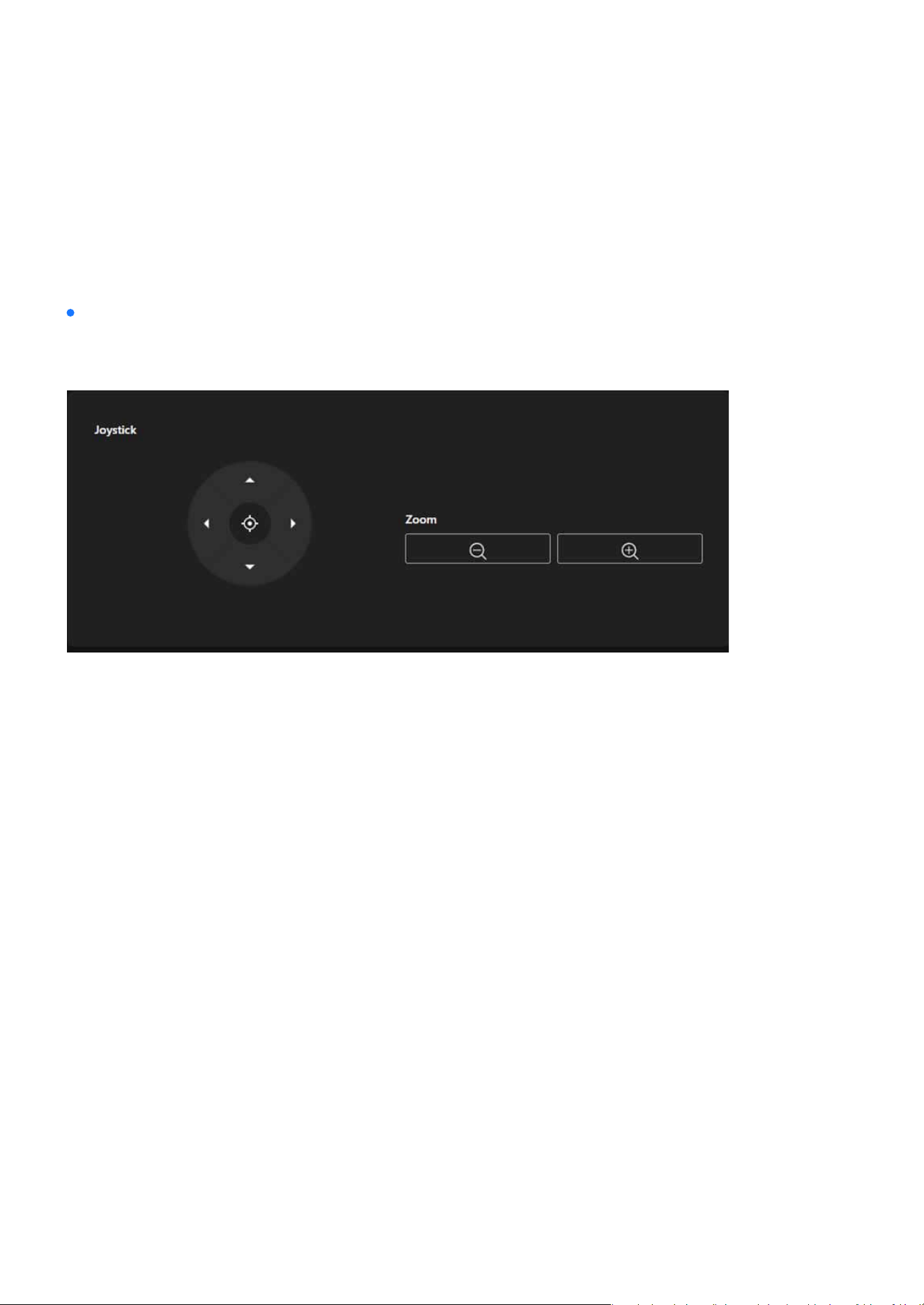
74
PTZ Settings
PTZ Settings
Enables users to precisely congure and adjust the camera’s viewpoints and focal lengths to meet the
demands of various scenarios.
Provides a virtual joystick with directional buttons for up, down, left, and right, enabling users to operate
the camera’s pan and tilt in real time.
The central button can be used to quickly reset or reposition the camera to its current center point or ini-
tial position.
Zoom Out: Reduces the zoom level, expanding the camera’s eld of view.
Zoom In: Increases the zoom level, focusing on details or specic targets.
Clicking the directional arrows moves the camera in the corresponding direction.
Achieve Flexibility and Precision
Direction Control
Center Positioning
Zoom Control
Joystick
The Joystick provides users with precise control over the camera’s direction and focus, suitable for re-
al-time operation, ensuring exibility and accuracy in the monitoring range.
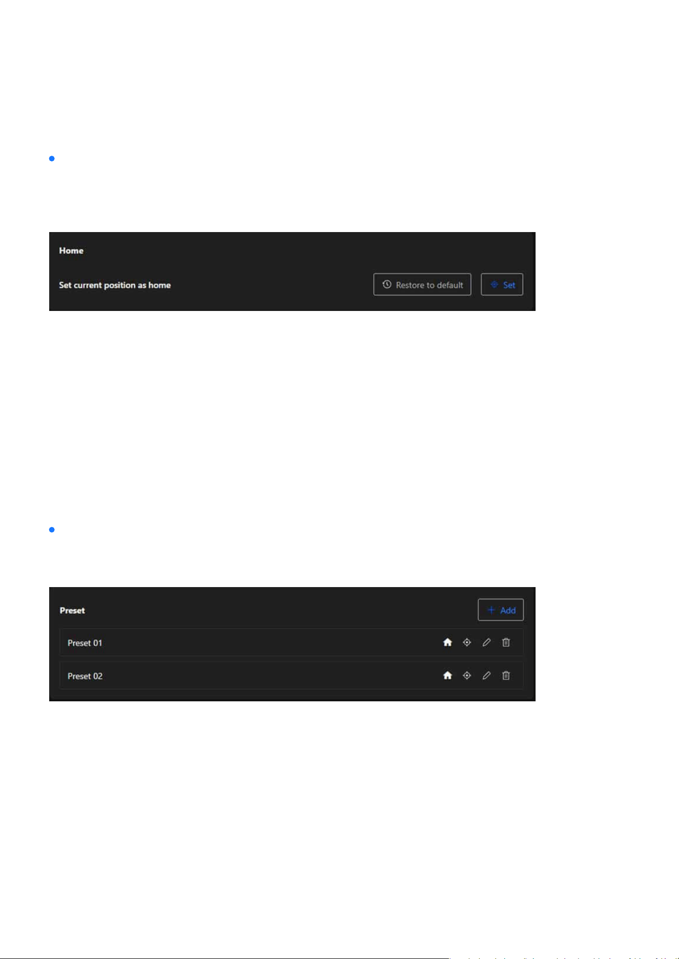
75
PTZ Settings
PTZ Settings
Home
Preset
The Home enables users to set and restore the camera’s baseline viewpoint, aiming to improve operation-
al eciency, simplify camera management, and ensure the stability and exibility of the monitoring pro-
cess.
The Preset allows users to easily manage multiple surveillance viewpoints of the camera, aiming to simpli-
fy operations, enhance eciency, and meet the needs of exible monitoring in various scenarios.
By pressing the Set button, users can designate the camera’s current viewpoint (direction and zoom) as
the Home position, serving as the default baseline.
By pressing the Restore to Default button, the camera’s Home position will be reset to its factory settings
or the predened default position.
By pressing the Restore to Default button, the camera’s Home position will be reset to its factory settings
or the predened default position.
Set Current Position as Home
Restore to Default
Restore to Default
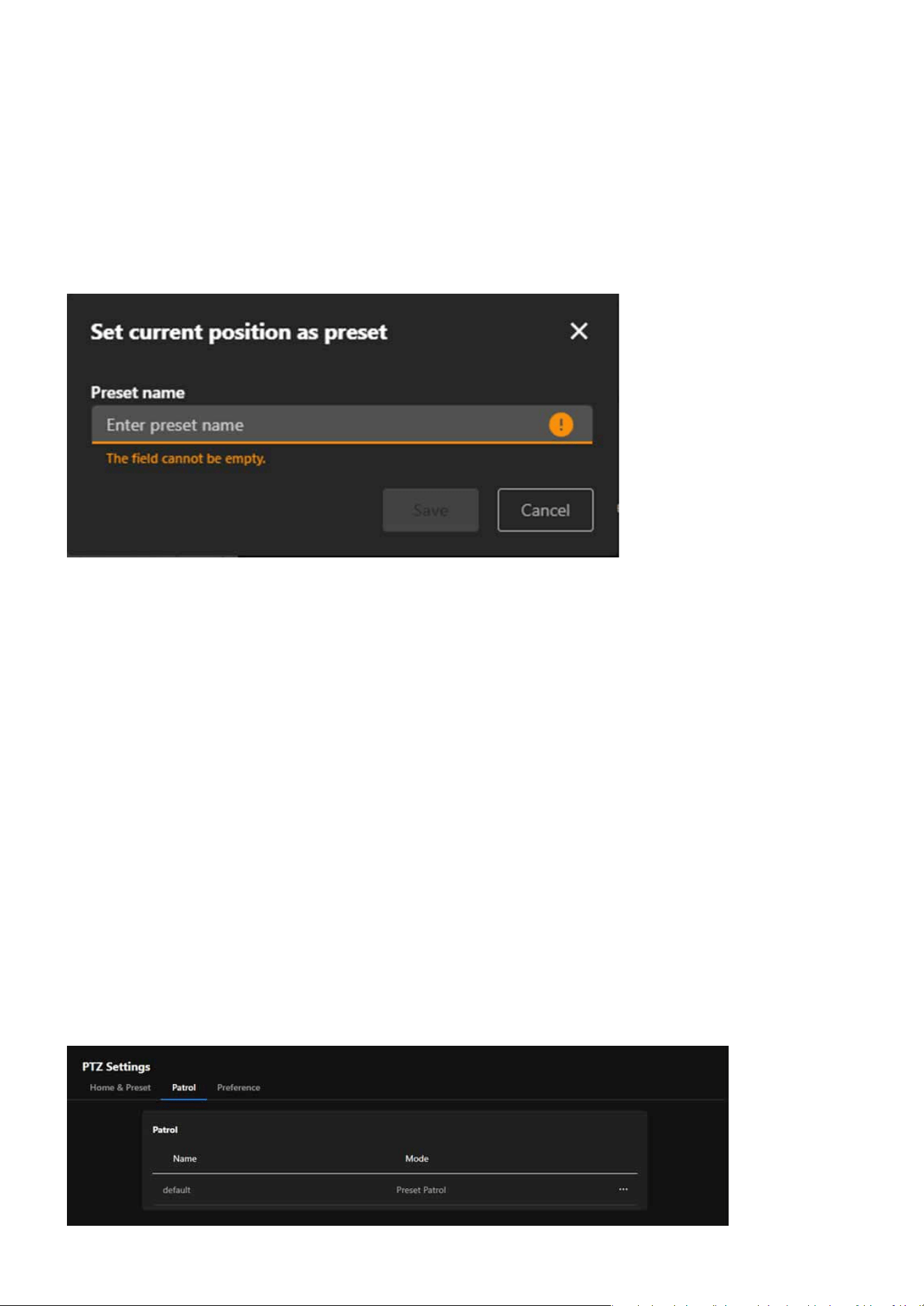
76
PTZ Settings
PTZ Settings
By using the + Add button, users can save the camera’s current viewpoint (direction and zoom) as a new
preset, enabling quick access to that position in the future.
Saved presets are displayed in a list format (e.g., Preset 01 and Preset 02). Users can perform the following
actions for each preset:
Assign a preset as the Home position (via the house icon), making it easy to return to that point.
Click on a preset item to quickly move the camera to that viewpoint.
Modify the name or the associated viewpoint of the preset.
Remove presets that are no longer needed.
Add Preset
Preset List
Set as Home
Switch to Preset
Edit
Delete
Patrol
The Patrol feature utilizes automated patrol routes to enable the camera to eciently cover multiple surveil-
lance points, reducing manual intervention and achieving comprehensive and exible monitoring manage-
ment.
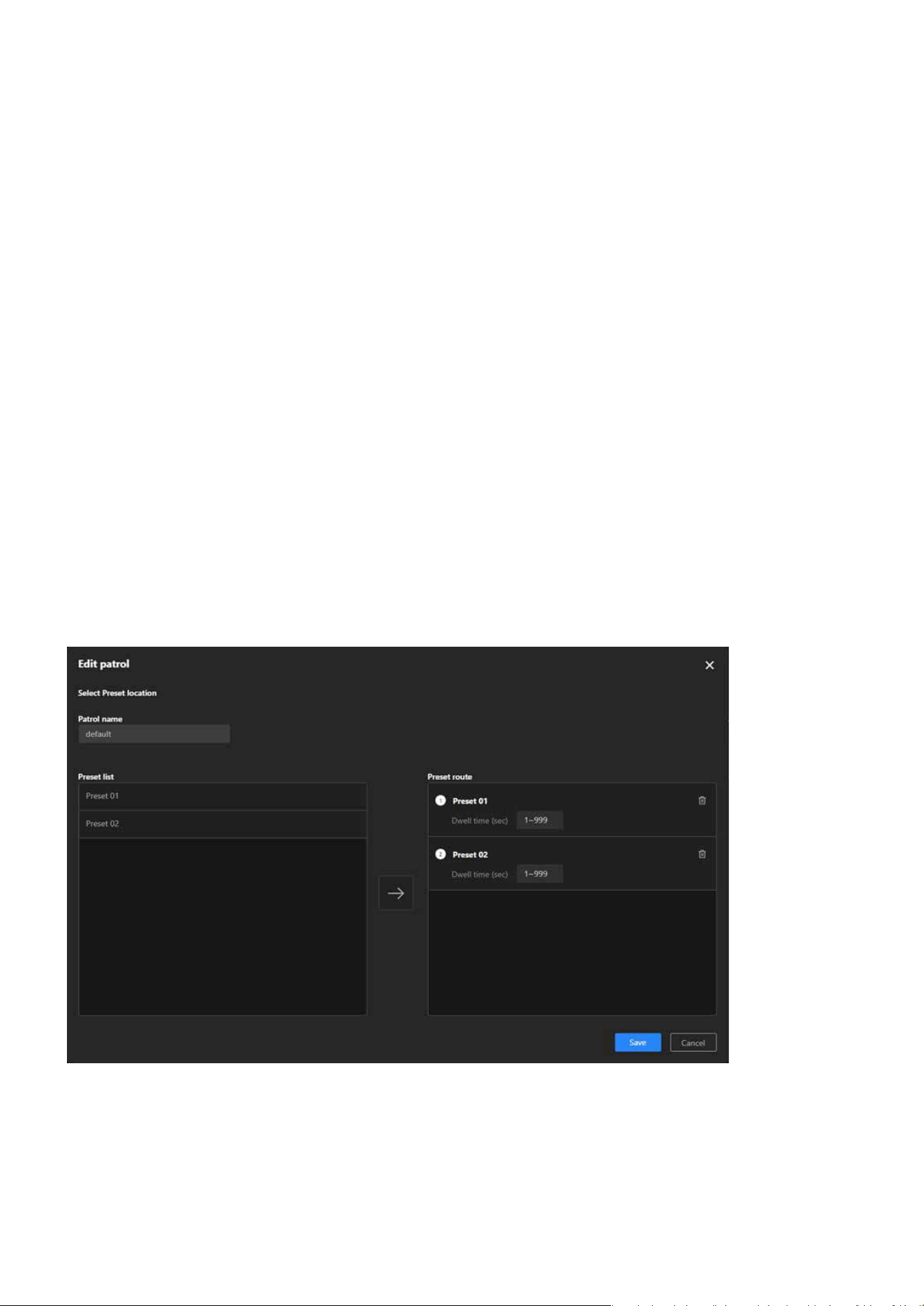
77
PTZ Settings
PTZ Settings
Through predened patrol routes, the camera can automatically move sequentially to dierent surveil-
lance points, ideal for large-scale or multi-area monitoring needs.
The automation feature eliminates the need for frequent manual control, enhancing monitoring eciency
and saving manpower.
Customizable patrol routes and multi-mode support allow the system to adapt to dynamic scenarios or
diverse surveillance targets.
By regularly patrolling all preset points, the system ensures that every critical area is monitored in a timely
manner, reducing the risk of blind spots in surveillance.
Click the Edit button on the right side of the existing route.
The Preset List on the left displays the congured preset points. Browse the list and select the points you
want to include in the patrol route.
The purpose are as follows:
Achieving Automated Patrol
Reducing Manual Operations
Adapting Flexibly to Scene Requirements
Enhancing Security
Edit Patrol Route
Step 1. Click “More” icon > “Edit” button
Step 2. Select Preset Points
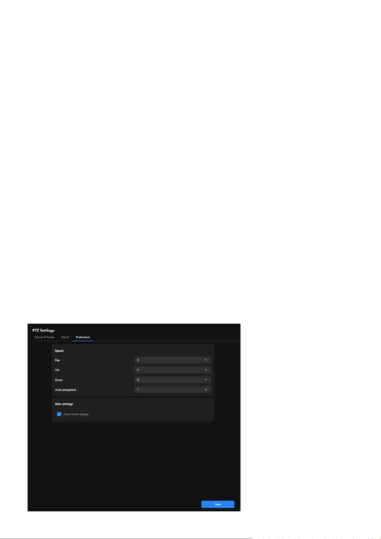
78
PTZ Settings
PTZ Settings
After selecting a preset point on the left, click the arrow “→” in the middle to add it to the Preset Route list
on the right.
In the Preset Route list, assign a dwell time (in seconds) for each added preset point. The dwell time can
range from 1 to 999 seconds, adjusted based on monitoring needs.
To change the patrol order of preset points, adjust their positions in the list on the right (drag, or delete
and re-add them). Remove extra preset points: Click the Trash Can button next to the preset point.
After conrming all preset points, dwell times, and order, click the Save button in the lower-right corner to
save the route.
Return to the Installation category and click the Patrol icon on the PTZ panel to start the Patrol.
Step 3. Add to Patrol Route
Step 4. Set Dwell Time for Each Preset Point
Step 5. Adjust Patrol Order
Step 6. Save the Route
Step 7. Activate Patrol Mode
Preference
The Preference oers features such as speed adjustment and zoom display, enabling users to exibly adjust
camera operation parameters according to their needs, achieving more ecient and precise surveillance
management.
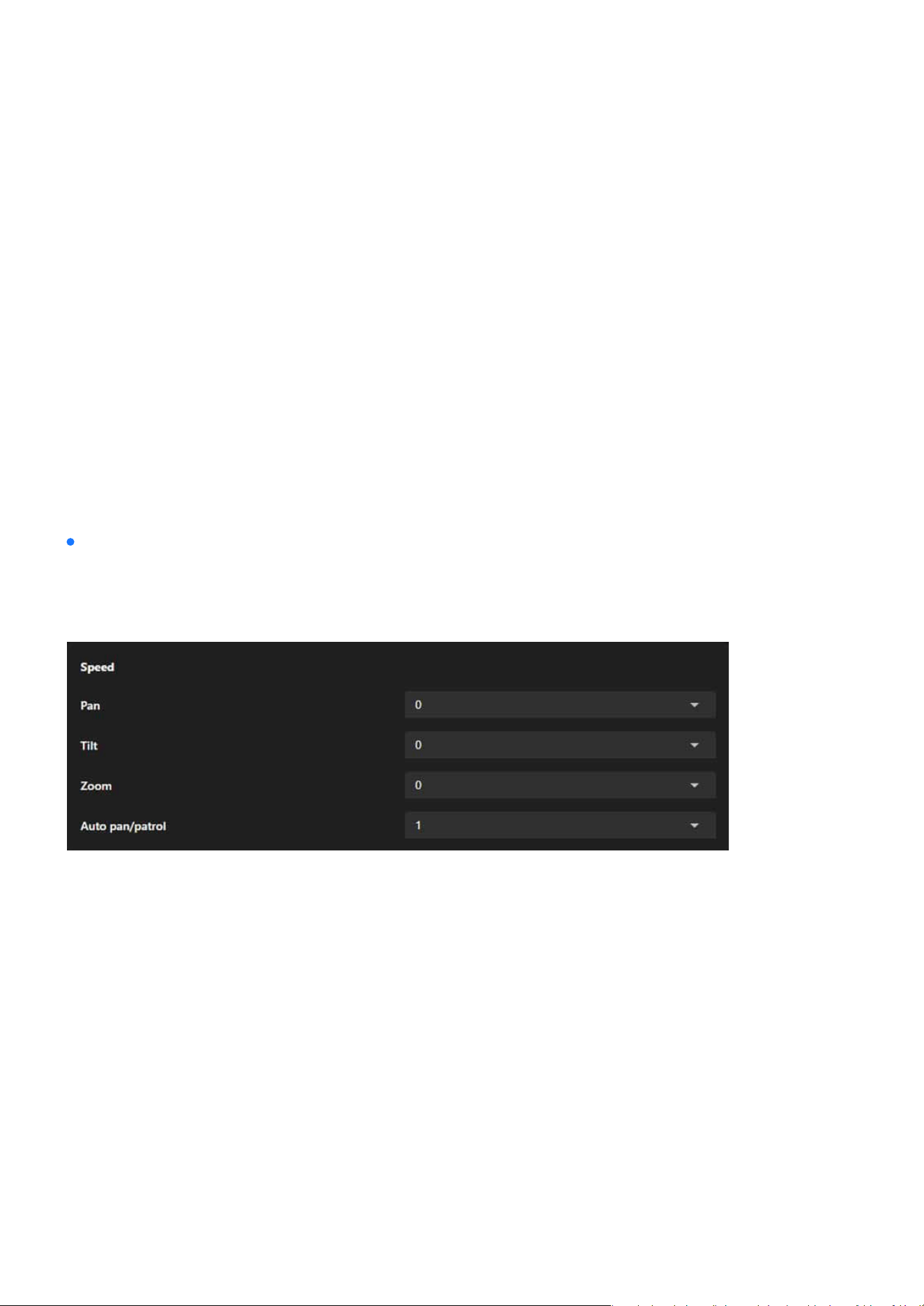
79
PTZ Settings
PTZ Settings
Dierent scenarios may require dierent speed settings. By adjusting pan, tilt, and zoom speeds, users
can achieve more precise control of the camera.
In patrol mode or manual operation, users can set appropriate automatic movement and zoom speeds
based on the importance of the scene or the speed of moving targets.
The zoom level display feature allows users to clearly understand the current magnication, making it
suitable for surveillance scenarios that require focusing on details.
Users can congure parameters that align with their operational preferences, enhancing overall eciency.
Controls the speed at which the camera moves left and right.
Adjusts the speed at which the camera moves up and down.
Congures the speed at which the lens zooms in and out. Ideal for quickly focusing on details or slowly
zooming to maintain a smooth transition.
Sets the movement speed of the camera in auto-panning or patrol mode. Enables users to adjust the
speed to suit surveillance needs, such as faster coverage for large areas or slower movement for observ-
ing details.
The Speed provides comprehensive control over the camera’s movement speed, including pan, tilt, zoom,
and automated patrol, allowing users to exibly adjust the speed based on surveillance needs for precise
and ecient camera operation.
The purpose are as follows:
Enhancing Operational Flexibility
Adapting to Diverse Surveillance Needs
Improving Surveillance Accuracy
Simplifying Personalized Settings
Pan (Horizontal Panning Speed)
Tilt (Tilting Speed)
Zoom (Zooming Speed)
Auto Pan/Patrol (Automatic Panning/Patrol Speed)
Speed
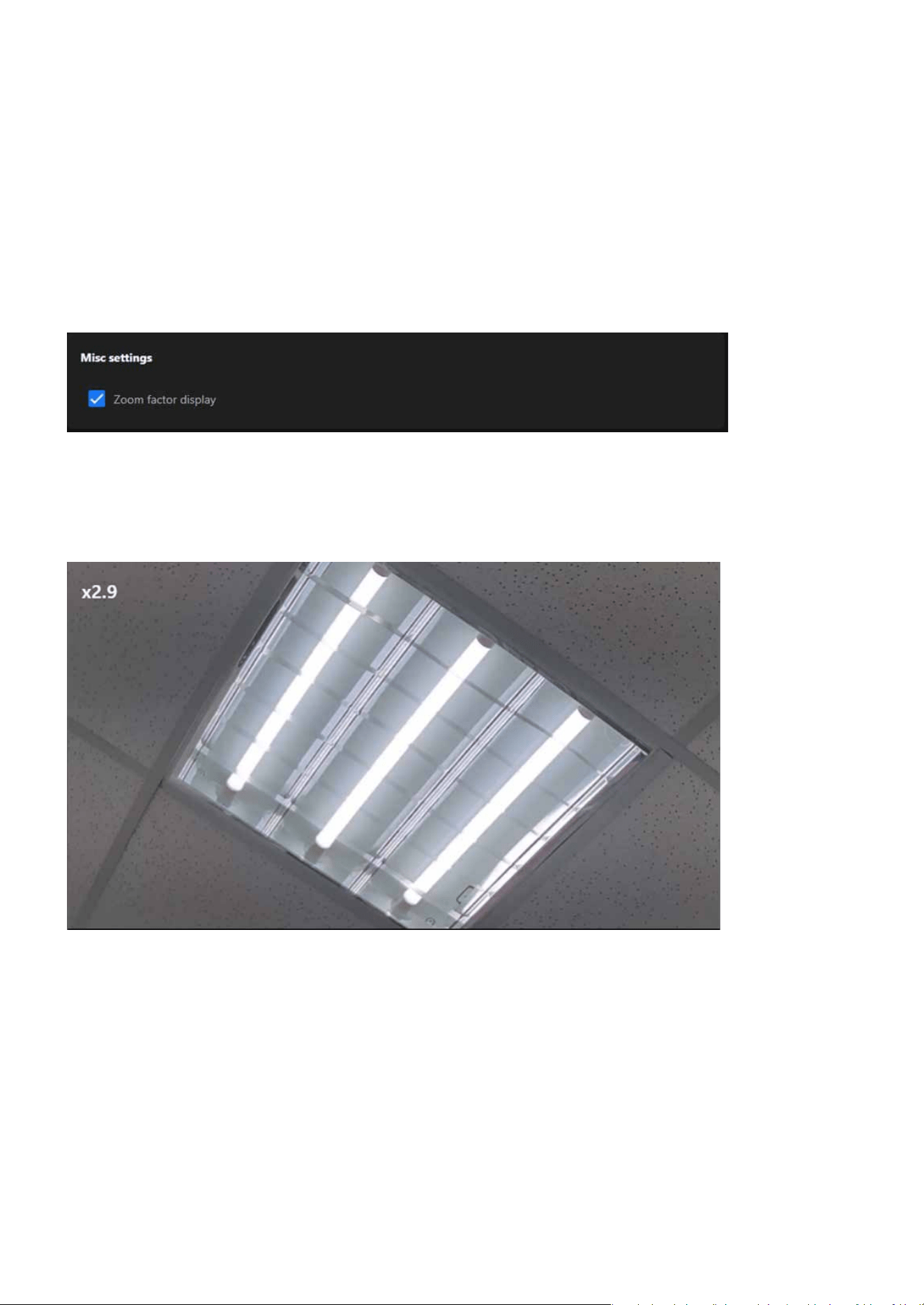
80
PTZ Settings
PTZ Settings
The Zoom Factor Display in Misc settings is designed to enhance user control and convenience during zoom
operations, ensuring precision and eectiveness in monitoring, especially in scenarios that require frequent
zooming or focusing on details.
Misc settings
When this option is selected, the system will display the current zoom factor whenever the camera’s zoom
function is used. The zoom factor is typically presented in numerical form, allowing users to easily under-
stand the current magnication level of the lens.
Zoom Factor Display
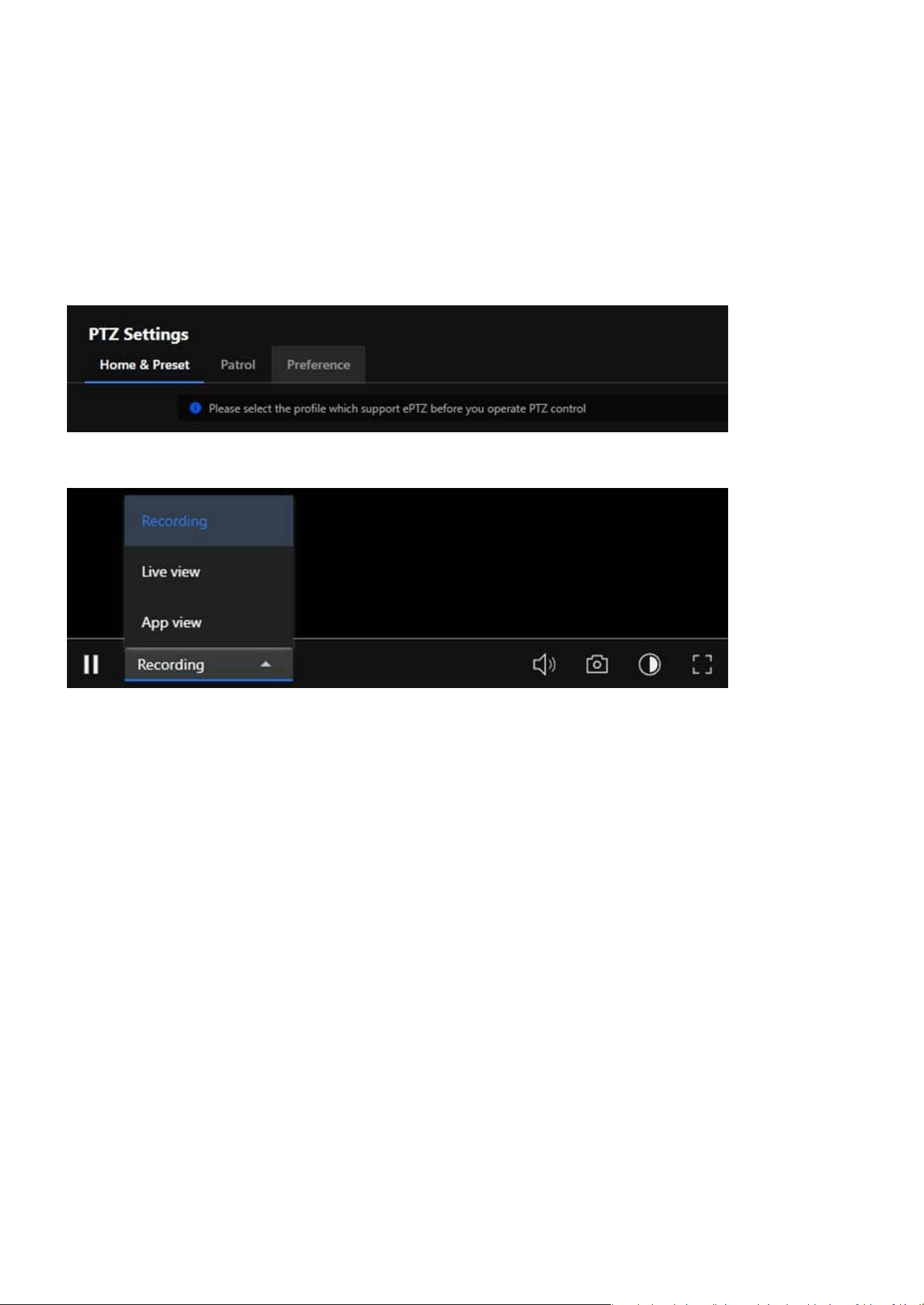
81
PTZ Settings
PTZ Settings
Caution:
PTZ settings are only available for supported Media Proles, specically the 2nd and 3rd proles. This means not all Media Proles
can operate PTZ settings; users must select a supported Media Prole to enable the PTZ function.
If a user navigates to the PTZ Settings page and the currently active Media Prole does not support PTZ functionality, the system
will display a notication: “Please select the prole which supports ePTZ before you operate PTZ control.”
This notication serves as a prompt to guide users to switch to an appropriate prole (2nd or 3rd).
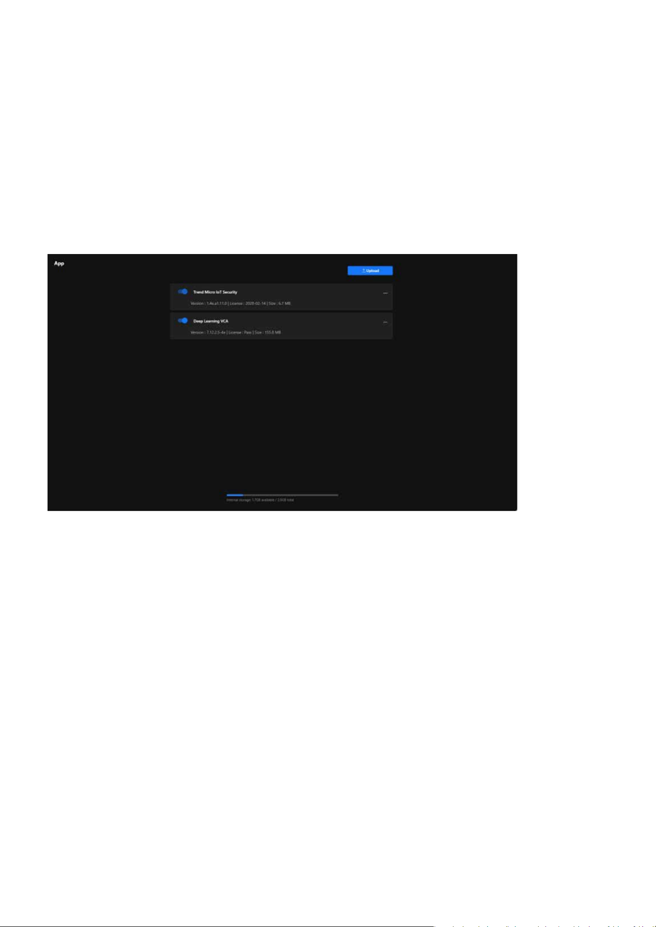
82
App
App
Expand Camera Functionality with Powerful Applications
The IPv4 card plays a vital role in setting up the camera’s network conguration and ensuring eective com-
munication. It facilitates dependable connectivity, enables both local and remote access, and allows the
camera to integrate eortlessly into IPv4-based networks. This conguration is crucial for maintaining stable
and ecient performance across diverse networking environments.
A security application provided by Trend Micro, designed specically for IoT devices. Its main functional
purposes are as follows:
A Visual Content Analysis (VCA) application, an AI-powered tool based on deep learning technology for
intelligent video processing. Its main functional purposes are as follows:
Protects the camera from network attacks that may disrupt its operation.
Ensures the security of video data and settings, preventing unauthorized access.
Minimizes device failures or data loss caused by security issues.
Reduces false positives and missed detections in manual monitoring, enabling intelligent video surveil-
lance.
Achieves automatic event recognition and alarm triggering through AI analysis.
Trend Micro IoT Security
Deep Learning VCA
Enhance Camera Security
Safeguard Data Privacy
Reduce Maintenance Costs
Enhance Surveillance Accuracy
Automate Management
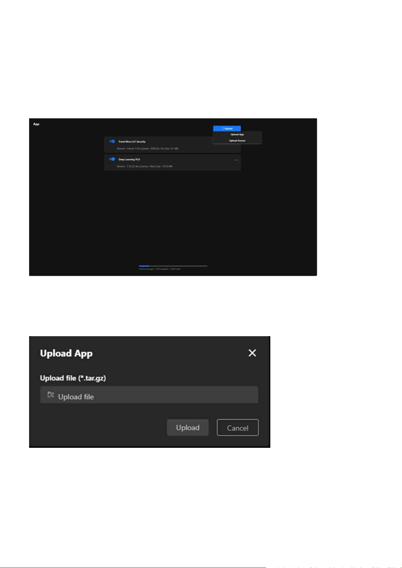
83
App
App
Supports real-time monitoring and analysis in large-scale, high-trac, or multi-vehicle environments.
Handle Complex Scenarios
Step 1. Click the “Upload” button in the upper-right corner of the page. Two options will appear:
Step 2. Click Upload App, and a le upload window will pop up. The accepted le format is .tar.gz.
Step 3. Click Upload le, and select the application le stored on your local device.
Step 4. After verifying the le, click Upload to upload the application.
Step 5. Wait for the Upload to Complete.
Step 6. The system will display the upload progress. Once completed, the application or license le will
appear in the App list.
Step to Upload App
Upload App: For uploading application les.
Upload License: For uploading application license les.
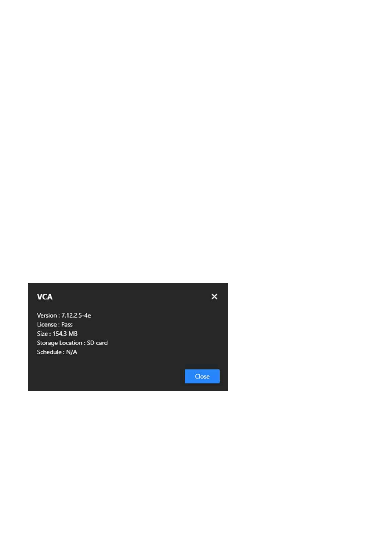
84
App
App
For uploading application les.
For uploading application license les.
Step 1. Click the Upload button in the upper-right corner of the page. Two options will appear:
Step 2. Click Upload License, and a le upload window will pop up. The accepted le formats is *.xml.
Step 3. Click Upload le, and select the appropriate license le.
Step 4. After verifying the le, click Upload to upload the license.
Step 5. Wait for the Upload to Complete
Step 6. A “Upload successfully” message appears.
Each application’s More icon (click the three-dot icon on the right) provides the following features and pur-
poses:
Monitor Application Status helps users quickly understand application details, ensuring the version and
license are accurate, while also assisting in troubleshooting by providing essential information like version
and license to diagnose issues eectively.
Congure the application’s runtime schedule to specify when it should be enabled or disabled, and set
specic time periods to conserve resources or meet dierent scenario requirements. This feature optimiz-
es resources by preventing unnecessary long-term application operation, conserving processing power,
and adapts to various scenarios by automating application start and stop, enhancing exibility.
Free up storage by removing unneeded applications, especially when storage is limited, and adjust func-
tionality by deleting unused or expired applications to make room for new installations.
Step to Upload License
Information
Schedule
Delete
Upload App
Upload License

85
Detection
Detection
The purpose of the Detection is to enhance the automated monitoring capabilities of the camera, reduce
manual intervention, and promptly notify relevant personnel in the event of anomalies, thereby improving
security and eciency. Users can enable and congure the corresponding detection options in the manage-
ment interface based on specic needs.
Advanced Video Analysis for Proactive Security and Precision
Monitoring
Smart VCA
VIVOTEK integrates the advanced Smart VCA (Video Content Analysis) feature into its cameras, leveraging
articial intelligence and machine learning to analyze video footage in real time. It surpasses traditional sur-
veillance methods by oering smarter detection capabilities beyond basic motion detection. Smart VCA can
identify specic events or behaviors, making it a powerful tool for proactive security and monitoring.
Smart VCA (Video Content Analysis) leverages articial intelligence and machine learning to analyze video
footage in real-time. It enhances traditional surveillance by oering intelligent detection capabilities beyond
basic motion detection. Smart VCA allows the camera to identify specic events or behaviors, making it a
powerful tool for proactive security and monitoring. Key Features and Benets of Smart VCA:
Crowd Detection in Smart VCA is designed to identify areas where the number of people exceeds a pre-
dened threshold. This feature ensures eective crowd control in public spaces by alerting users to poten-
tial overcrowding situations. By providing real-time monitoring, it enhances safety, helps manage crowd
ow, and prevents dangerous conditions in sensitive or high-trac areas, such as events, transportation
hubs, or emergency evacuation zones.
Intrusion Detection in Smart VCA is designed to monitor predened zones and trigger alerts whenever an
unauthorized person or object enters the area. This feature enhances security by proactively protecting
restricted or high-security spaces, preventing unauthorized access, and ensuring that critical areas remain
secure and free from potential threats.
Loitering Detection in Smart VCA identies individuals lingering in a specied area for an unusually long
duration. This feature helps detect suspicious behavior early, enabling users to take preventative actions
to mitigate potential security threats such as vandalism, theft, or unauthorized activities in sensitive areas.
Missing Object Detection in Smart VCA alerts users when an object is removed from a predened area.
This feature enhances security by helping to prevent theft or unauthorized removal of critical items, en-
suring that valuable assets remain protected at all times.
Crowd Detection
Intrusion Detection
Loitering Detection
Missing Object Detection
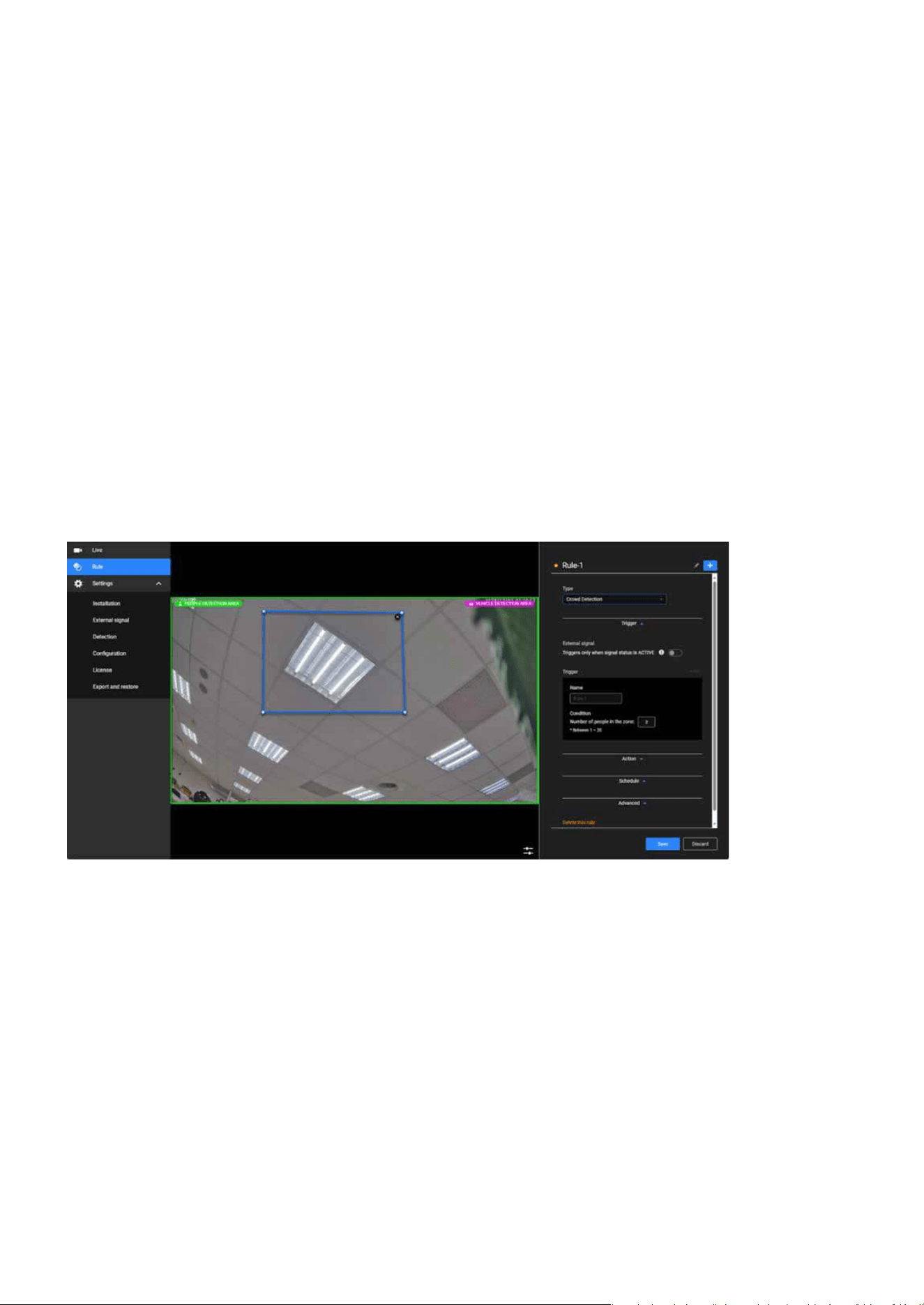
86
Detection
Detection
Unattended Object Detection in Smart VCA identies objects left behind in a specic area. This feature en-
hances safety by promptly detecting potential security risks, such as unattended baggage in public spaces,
allowing for timely investigation and response.
Line Crossing Detection in Smart VCA triggers an alert whenever an object or person crosses a user-de-
ned virtual boundary. This feature is essential for monitoring boundaries and ensuring perimeter securi-
ty, preventing unauthorized entry into restricted areas and enhancing overall access control.
Face Detection in Smart VCA identies and tracks faces within the camera’s eld of view. This feature en-
hances access control, streamlines identication processes, and provides valuable support for post-event
analysis during forensic investigations, ensuring greater security and accountability in monitored areas.
Step 1. Access the Smart VCA Settings.
Step 2. Add a Rule.
Click “Detection” category > “Smart VCA” item on the Camera web UI.
In the Smart VCA utility, click the Add button to add a rule.
Select the Type:
The Smart VCA utility will be automatically started.
Unattended Object Detection
Line Crossing Detection
Face Detection
Steps to Add a Detection Rule
Crowd Detection:
Monitor the number of people in a specic area.
Intrusion Detection: Detect unauthorized entry into a dened area.
Loitering Detection: Detect people lingering for extended periods.
Missing Object Detection: Monitor the removal of objects.
Note:
The Smart VCA and Smart Motion share the same utility window.

87
Detection
Detection
Unattended Object Detection: Detect left-behind objects.
Line Crossing Detection: Monitor objects crossing a virtual boundary.
Face Detection: Detect and track faces in the scene.
Draw the Area
Congure Area Based on Feature:
Name the rule, such as “Crowd Zone 1”.
Use the mouse to dene the detection area on the video feed (e.g., outline the monitored zone). Adjust
the size and shape as needed to precisely cover the target area.
Congure conditions based on the feature, such as:
Assign actions to execute when the trigger conditions are met.
Always: The rule is enabled at all times.
Congure multiple linked actions if necessary.
Repeated schedule: Specify dates and time periods for the rule to be active (e.g., outside working
hours).
Adjust sensitivity to avoid false alarms.
Line Crossing Detection: Draw a virtual line and set the crossing direction (A>B or B>A).
Crowd Detection: Set a people count threshold (e.g., more than 5 people).
Loitering Detection: Dene a linger duration (e.g., more than 10 seconds).
Intrusion Detection: Congure stay or entry conditions.
Missing/Unattended Object Detection: Dene triggers (object removed or added).
Crowd Detection and Intrusion Detection: Outline the specic area.
Missing Object/Unattended Object Detection: Outline the object’s location.
Step 3. Dene the Detection Area.
Step 4. Congure Trigger Conditions.
Step 5. Dene Actions.
Step 6. Set a Schedule.
Step 7. Click Save to save the rule.
Note:
Please refer to the Smart VCA user manual for more information. https://www.vivotek.com/products/analytics/smart_vca

88
Detection
Detection
Enhanced Accuracy and Efciency in Surveillance with
Smart Motion Detection
Smart Motion
Enhanced accuracy and eciency in surveillance with Smart Motion Detection are critically important for
users, as they minimize false alarms and ensure security resources are focused on real threats. By precisely
detecting people and vehicles while ltering out irrelevant movements, users can achieve reliable monitor-
ing and reduce time wasted on unnecessary alerts. This level of precision and eciency not only improves
situational awareness but also enhances overall operational eectiveness, making it an indispensable tool
for safeguarding critical areas and responding swiftly to potential risks.
Smart Motion Detection is designed to improve the eciency and accuracy of motion detection in surveil-
lance systems. Its primary purposes include:
Smart Motion Detection minimizes unnecessary alerts caused by irrelevant motions such as moving shad-
ows, light changes, or environmental factors like wind-blown leaves.
By focusing on specic areas and detecting meaningful activities (e.g., people or vehicles), it allows securi-
ty teams to respond more eectively to potential threats.
With intelligent lters like people and vehicle detection, it ensures that only relevant events are identied
and recorded, reducing the eort required to review footage.
By recording only critical events, it reduces the amount of data stored and transmitted, leading to more
ecient storage usage and lower bandwidth consumption.
Smart Motion Detection enables instant notications for events of interest, helping users take timely ac-
tions in critical situations.
By focusing on high-priority events, it simplies post-event investigations and improves the eciency of
video footage review.
Reducing False Alarms
Enhancing Security Monitoring
Improving Event Detection Accuracy
Optimizing Storage and Bandwidth
Facilitating Real-Time Alerts
Simplifying Event Analysis
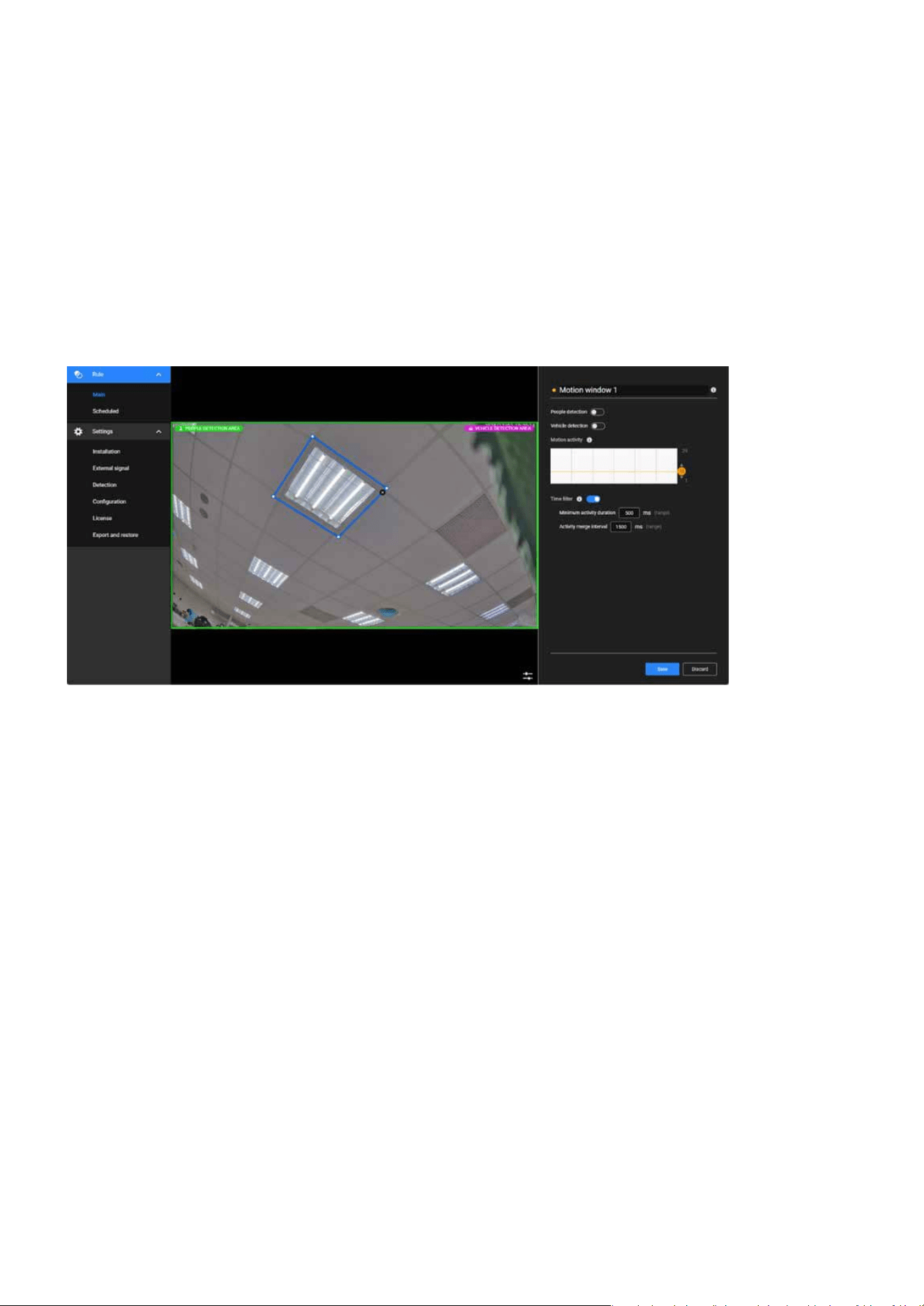
89
Detection
Detection
Step 1. Access the Smart VCA Settings.
Step 2. Dene the Detection Area.
Step 3. Adjust Motion Sensitivity.
Step 4. Congure Time Filters.
Step 5. Enable Object Detection (Optional).
Click “Detection” category > “Motion” item on the Camera web UI.
Use the mouse to draw a shape on the live feed to specify the detection zone.
Set the motion sensitivity slider based on your environment (e.g., higher for indoor, lower for outdoor
with more natural movements).
Turn on “People Detection” and/or “Vehicle Detection” if applicable for your use case.
Minimum Activity Duration: Dene how long a motion must last to be considered an event.
Activity Merge Interval: Congure the interval to merge closely occurring events.
The Smart Motion utility will be automatically started.
Step to congure Smart Motion Detection
Note:
Note:
The Smart VCA and Smart Motion share the same utility window.
Please refer to the Smart VCA user manual for more information. https://www.vivotek.com/products/analytics/smart_vca

90
Detection
Detection
Enhancing Security with Real-Time Audio Anomaly Detection for
Prompt Response
Audio detection
Audio detection enhances security by continuously monitoring ambient sound levels and identifying unusu-
al audio patterns, such as loud noises, glass breaking, or shouting. By analyzing real-time sound data and
triggering alerts when the sound exceeds a predened threshold, it enables swift responses to potential
security breaches or emergencies. This proactive approach ensures that critical events are detected even in
situations where visual cues are insucient, providing an additional layer of protection and improving over-
all situational awareness.
The audio detection feature in VIVOTEK cameras is a powerful tool for augmenting security and safety. By
detecting sound anomalies in real-time, it enhances the camera’s ability to monitor and respond to incidents
eectively. Its primary purposes include:
Detects abnormal sounds (e.g., glass breaking, shouting, or explosions), enabling early identication of
potential threats.
Adds an extra layer of detection in situations where motion or visual triggers may not be eective (e.g., a
quiet area with no visible motion).
Noties security personnel immediately when unusual sounds are detected, allowing for faster responses.
Useful for monitoring sound levels in specic areas, such as factories, schools, or public spaces, to ensure
safety and compliance.
Helps ensure that audio-related incidents are documented for review and investigation.
Enhancing Security
Supplementing Video Monitoring
Real-Time Alerts
Environmental Noise Monitoring
Event Recording
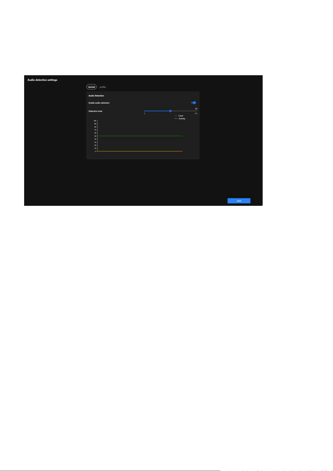
91
Detection
Detection
Step 1. Access the Audio detection settings.
Step 2. Enable Audio Detection.
Step 3. Set the Detection Level.
Click “Detection” category > “Audio detection” item on the Camera web UI.
Turn on the Enable Audio Detection toggle.
Adjust the Detection Level slider.
Use the real-time graph to observe:
Adjust the slider to set an appropriate threshold based on your environment.
Higher levels lter out normal background noise, detecting only loud or unusual sounds.
Lower levels detect even minor audio changes, useful for quieter environments.
Green Line (Level): Represents the detection threshold.
Orange Line (Activity): Represents the live audio levels.
Step to congure the audio detection
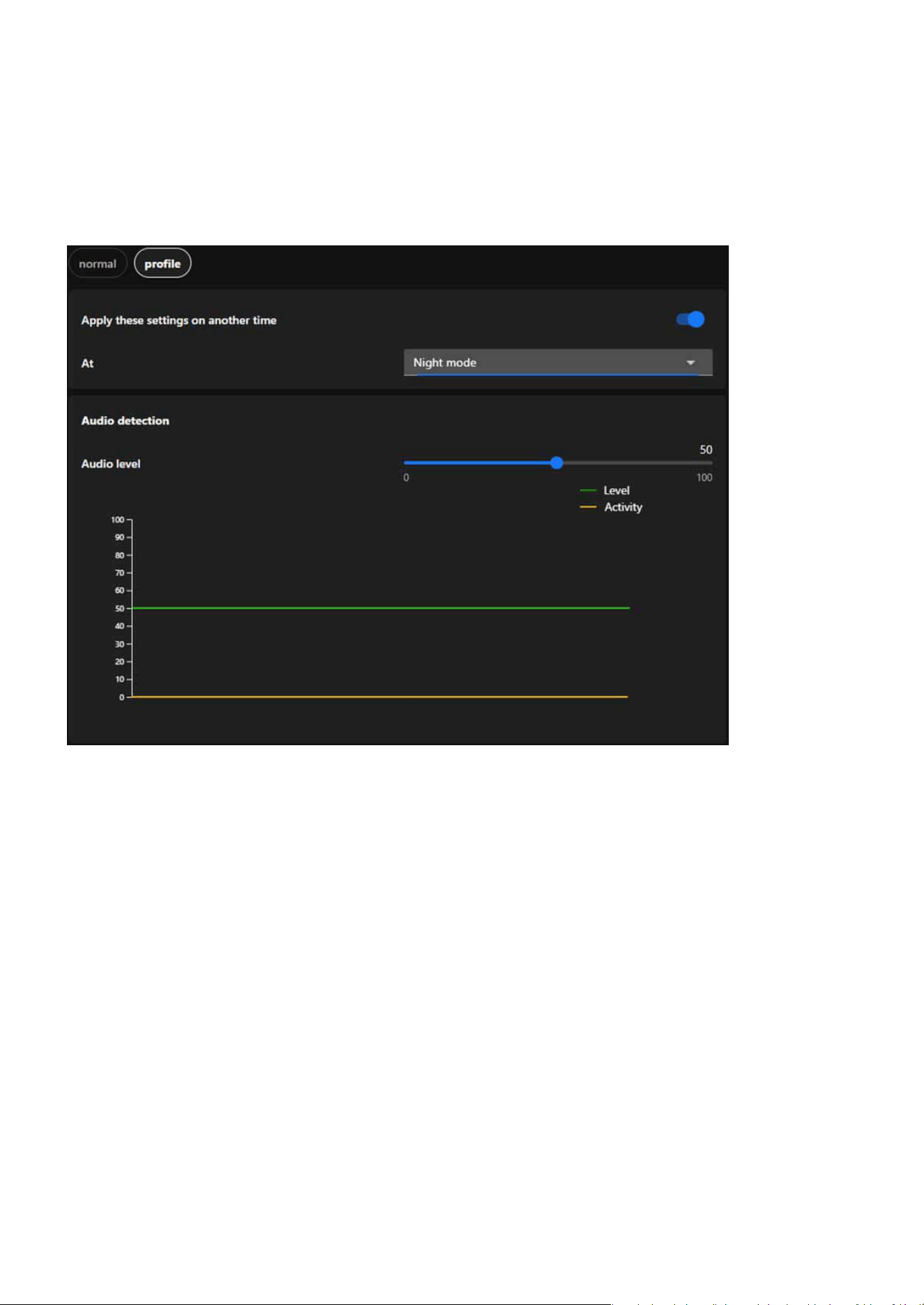
92
Detection
Detection
The Prole Settings for Audio Detection allow users to congure detection settings tailored to specic op-
erational modes, such as Night Mode and Schedule Mode. These settings provide exibility and precision
for various monitoring needs.
Designed for quieter nighttime environments with lower ambient noise levels, it ensures heightened
sensitivity to detect unusual sounds, such as breaking glass or loud footsteps, that might indicate security
breaches. Lower thresholds for audio level detection can be applied to ensure even minor disturbances
trigger an alert, and the system can be activated automatically during preset nighttime hours.
It allows users to apply specic settings during predened time periods, such as working hours, week-
ends, or o-peak times, ensuring customized detection settings based on predictable noise patterns. It
enables precise scheduling for when audio detection thresholds or proles should be active, tailoring the
sensitivity to the expected noise environment during the scheduled time.
Integrate audio detection-related settings into a prole
Night Mode
Schedule Mode
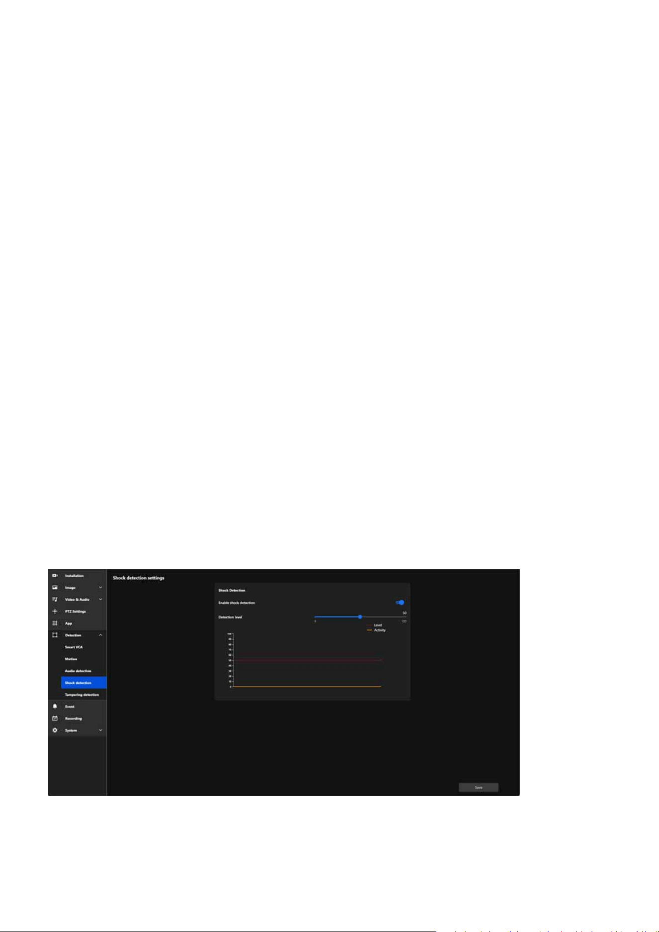
93
Detection
Detection
Ensuring Real-Time Protection Against Physical Impact
Shock detection
Shock detection provides real-time alerts to users when the camera experiences physical impacts or vibra-
tions, ensuring immediate awareness of accidental damage. This proactive monitoring improves the reliabil-
ity of the security system by protecting the camera from disruptions, reducing downtime, and maintaining
consistent surveillance coverage to eectively safeguard critical areas.
The Shock Detection feature in VIVOTEK cameras is designed to detect physical impacts or vibrations aect-
ing the camera. Using built-in sensors, it monitors for sudden movements or shocks, and when detected, it
triggers an immediate alert to notify users. Its primary purposes include:
Protect the camera from potential physical harm caused by tampering, vandalism, or accidental impact.
Ensure users are informed immediately when physical interference occurs, allowing for quick response.
Help ensure the continuous functionality of the camera by identifying physical disturbances promptly.
Enhance the reliability of the surveillance system by preventing disruptions caused by physical impact.
Step 1. Access the Audio detection settings.
Click “Detection” category > “Shock detection” item on the Camera web UI.
Prevent Damage
Real-Time Alerts
Maintain Operation
Reinforce Security
Step to congure the shock detection

94
Detection
Detection
Step 2. Enable Shock Detection.
Step 3. Set the Detection Level.
Turn on the Enable Shock Detection toggle.
Adjust the Detection Level slider.
Observe the Level (Red Line) and Activity (Yellow Line) graphs:
Adjust the slider until the threshold matches your environmental needs.
Higher levels ignore smaller impacts and focus on more signicant events.
Lower levels detect minor shocks or vibrations.
The red line represents the congured detection threshold.
The yellow line shows real-time shock activity.
Protecting the Surveillance System from Visual Obstruction
Tampering detection
To ensure optimal performance and clear monitoring, protecting your surveillance system from visual ob-
struction is crucial. Regularly inspect and maintain cameras to prevent blockages caused by dirt, debris, or
weather conditions. Strategically position cameras to avoid obstructions from vegetation, building struc-
tures, or temporary barriers. Advanced features such as obstruction detection alerts can further enhance
reliability, ensuring uninterrupted surveillance coverage for critical areas.
Tamper detection is an advanced camera feature designed to identify incidents such as blocking, defocusing,
or spray paint interference. This functionality enhances the integrity and reliability of surveillance systems
by ensuring clear and accurate monitoring while providing timely alerts. Its primary purposes include:
Detects and alerts users about attempts to disrupt the camera’s operation, such as covering, defocusing,
or physically tampering with the device.
Monitors brightness and focus to ensure consistent video quality, providing actionable alerts if anomalies
are detected.
Adds an additional layer of protection by identifying visual impairments or malicious actions that compro-
mise the surveillance system.
Delivers real-time alerts to enable security personnel to respond immediately to tampering incidents or
visual issues.
Preventing Sabotage
Maintaining Image Quality
Enhancing Security
Timely Response
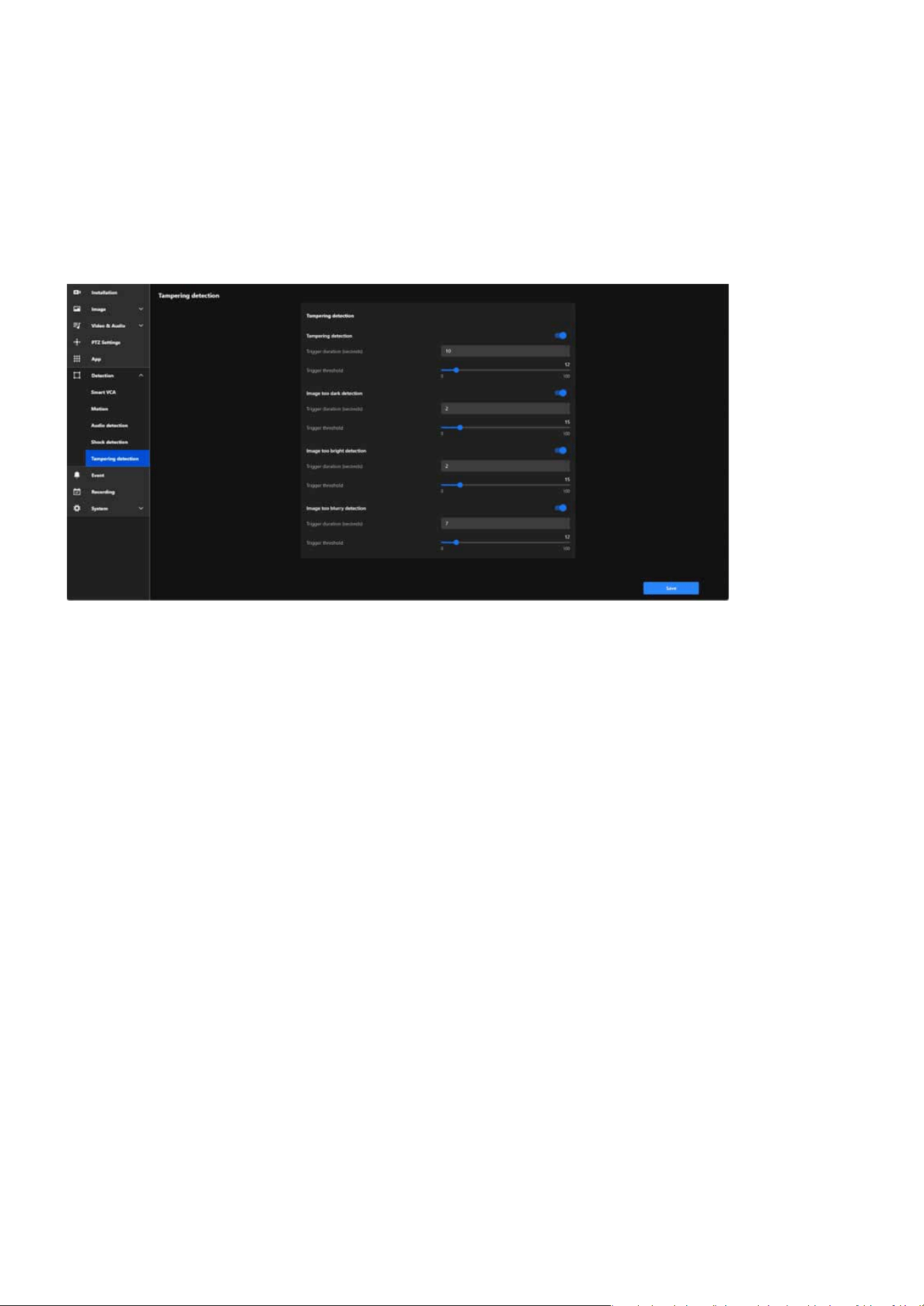
95
Detection
Detection
Ensures continuous, high-quality monitoring, even in challenging or high-risk environments.
Below are the detailed functionalities and corresponding settings for each feature:
Detects physical tampering, including actions like blocking, covering, or moving the camera, ensuring im-
mediate alerts to maintain surveillance integrity.
Detects when the video stream becomes abnormally dark due to intentional actions (e.g., turning o
lights) or environmental changes, ensuring timely alerts to address potential issues.
Detects when the video stream becomes overexposed, potentially caused by intense light directed at the
camera (e.g., ashlights) to obscure visibility, ensuring immediate alerts to maintain surveillance integrity.
Denes the amount of time tampering must persist before triggering an alert.
Sets the duration the image must remain dark to trigger an alert.
Species how long the brightness issue must persist before triggering an alert.
Adjusts the sensitivity to darkness. Lower thresholds detect smaller changes, while higher thresholds
focus on signicant darkness levels.
Adjusts the sensitivity to tampering attempts. Lower thresholds are more sensitive but may result in
false alarms, while higher thresholds are less sensitive.
Operational Reliability
Tampering detection
Image too dark detection
Image too bright detection
Trigger Duration (seconds):
Trigger Duration (seconds):
Trigger Duration (seconds):
Trigger Threshold:
Trigger Threshold:

96
Detection
Detection
Adjusts sensitivity to brightness changes. Lower thresholds detect minor overexposure, while higher
thresholds only trigger for severe brightness levels.
Denes how long the blurriness must persist to trigger an alert.
Adjusts sensitivity to blurriness. Lower thresholds detect minor blurring, while higher thresholds focus
on signicant quality degradation.
Trigger Threshold:
Trigger Duration (seconds):
Trigger Threshold:
Identies when the video feed becomes blurry due to defocusing, lens obstruction, or environmental fac-
tors such as condensation or dirt, ensuring timely alerts to maintain clear surveillance.
Image too burry detection
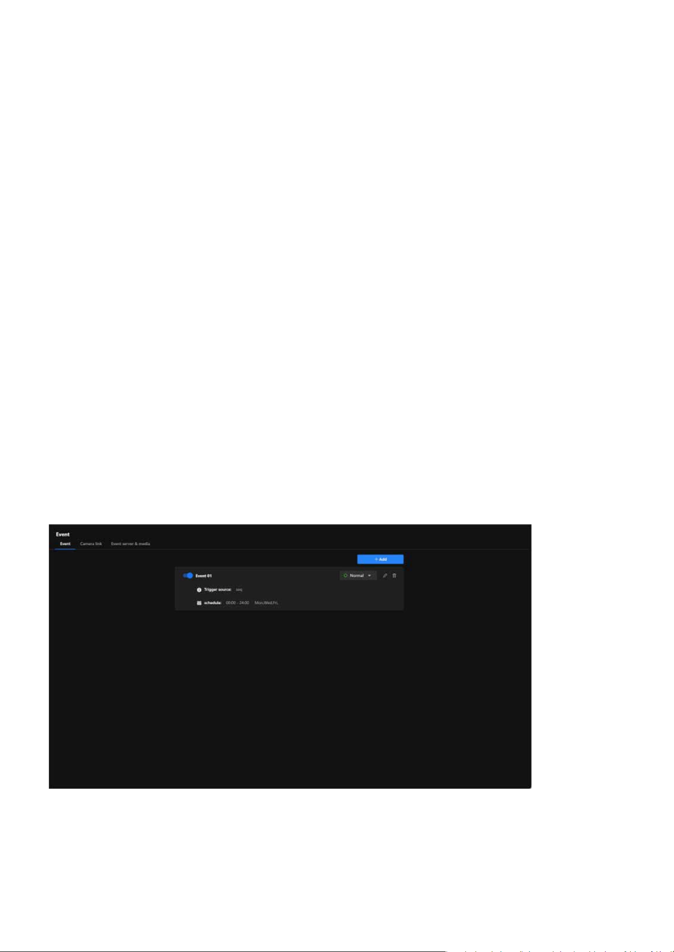
97
Event
Event
Event is a powerful tool designed to enhance security through automation and intelligent monitoring. It
allows users to dene specic conditions, known as trigger sources, that activate pre-congured actions
such as recording, sending alerts, or controlling external devices. By customizing these events with detailed
schedules and conditions, users can ensure the system responds proactively to potential threats or anoma-
lies. This feature not only streamlines surveillance operations but also reduces the need for constant manu-
al monitoring, providing a reliable and ecient way to protect property and assets.
To enhance security with automated and customizable events, users can congure specic conditions to
activate surveillance actions. For example, motion detection, sound detection, or tampering can be set as
trigger sources. Once triggered, the camera can automatically record footage, send alerts via email, or acti-
vate connected devices like alarms. Users can further customize these events by setting schedules, such as
enabling detection only during nighttime, or by linking multiple triggers for advanced scenarios. This exibil-
ity ensures a proactive and ecient security solution tailored to the user’s unique needs.
Event is a smart automation tool designed to enhance the eciency and eectiveness of security monitor-
ing. Its primary purpose is to detect specic conditions or triggers and automatically execute predened ac-
tions to respond to those events. This reduces the need for constant manual monitoring and ensures timely
reactions to critical incidents.
Enhancing Security with Automated and Customizable Event
Event
By enabling cameras to respond instantly to suspicious activities, such as intrusions or tampering, users
can prevent incidents before they escalate.
Key purpose of Event:
Enhance Security
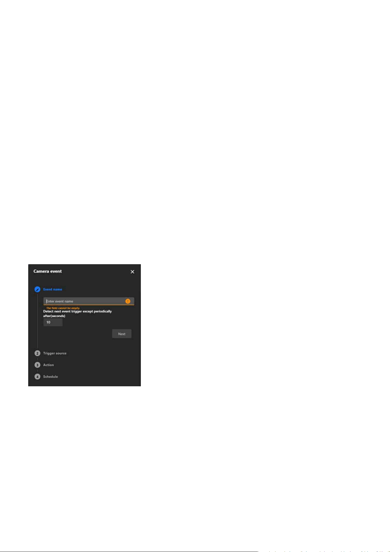
98
Event
Event
Automating responses eliminates the need for constant manual monitoring, saving time and resources.
Step 1. Enter Event Name
Step 2. Select the Trigger Source
Click “+ Add” button on “Event” conguration tab.
Choose a trigger source from the list:
These triggers are based on the camera itself or external devices connected to it.
These triggers rely on the camera’s built-in intelligent analysis features to detect changes or abnor-
malities in the environment.
These triggers are based on the recording status of the camera.
VADP (VIVOTEK Application Development Platform) provides advanced trigger options supported by
custom applications.
Device
Detection
Recording
VADP
In the Event Name eld, enter a descriptive name for the event.
Set the trigger interval. This determines how long the system waits before detecting the same event
again.
Click Next to proceed.
Automatic recording and snapshot capture ensure crucial moments are documented for investigations.
Alerts for device or network issues allow users to address problems quickly, reducing downtime or vulner-
abilities.
Increase Eciency
Steps to Add an Event
Provide Evidence
Proactive Problem Solving
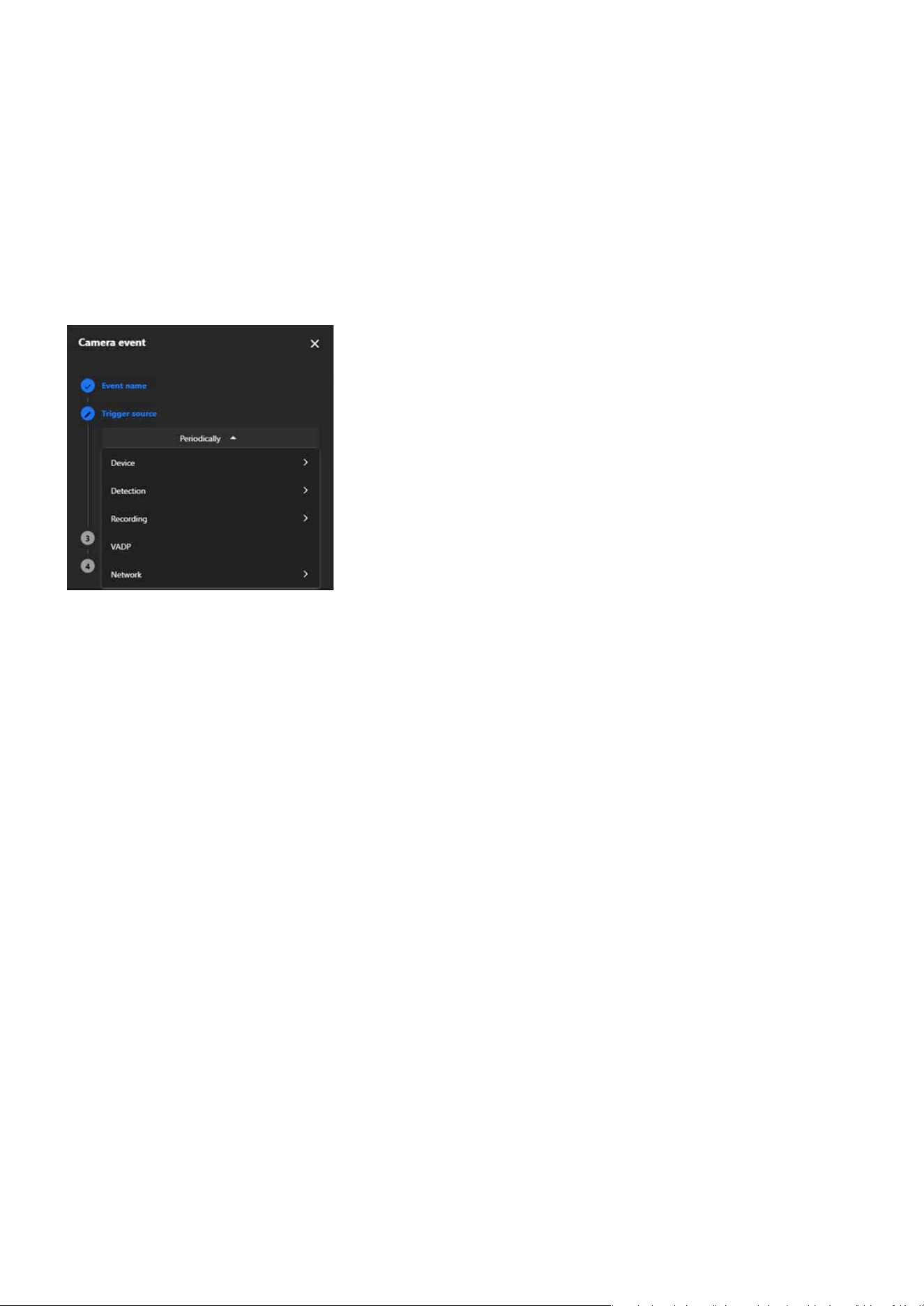
99
Event
Event
These triggers are based on the network status or conditions.
Network
Congure any additional settings for the selected trigger source.
Click Next to continue.
Step 3. Dene Actions
Select the actions to be performed when the event is triggered:
Customize the action settings as needed.
Click Next to proceed.
Activate an external device, such as an alarm.
Backup video footage to storage if the network is disconnected.
Play a pre-congured audio clip (requires prior audio setup).
Link to other cameras for coordinated responses.
Dene the storage location, such as:
0. SD card
1. NAS
Digital Output
Backup
Audio Clips
Camera Link
Event Server & Media
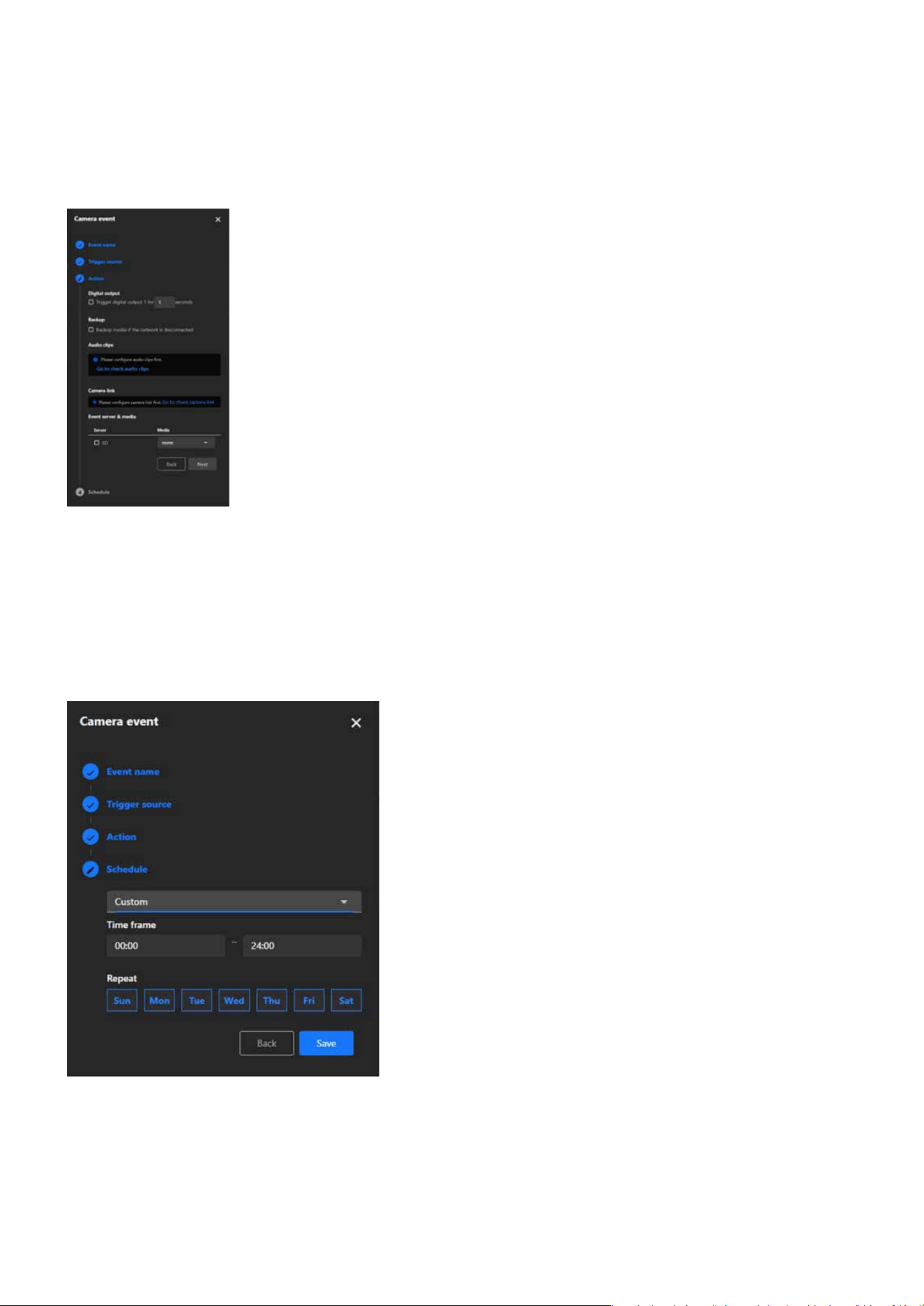
100
Event
Event
Step 4. Set the Schedule
Dene when the event should be active:
Review the schedule and conrm it.
Click Save to nalize the setup.
Always: The event will always be active.
Specic Times: Congure the event to only be active during certain times (e.g., only at night).

101
Event
Event
Note:
The types of Event triggers:
Device
Periodically The event is triggered at regular intervals, as dened by the user.
System Boot The event is triggered when the camera starts up.
Manual Trigger The event is manually triggered by the user.
Digital Input
The event is triggered by a digital signal from an external device, such as
a sensor.
Detection
Motion Detection
The event is triggered when the camera detects a moving object in its
eld of view.
Tampering Detection
The event is triggered when the camera detects tampering, such as being
covered, moved, or obstructed.
Audio Detection
The event is triggered when the camera detects abnormal sounds, such
as sudden loud noises.
Shock Detection
The event is triggered when the camera detects physical shocks or vibra-
tions.
Recording
Recording Notication The event is triggered when recording starts or stops.

102
Event
Event
VADP
BruteForceAttack
The event is triggered when repeated failed login attempts are detected,
indicating a potential brute force attack on the camera system.
CyberAttack
The event is triggered when suspicious network activities resembling a
cyberattack targeting the camera are identied.
LicenseExpiration
The event is triggered when the software or feature license is approach-
ing expiration, alerting users in advance.
Quarantine
The event is triggered when unauthorized breaches or violations occur in
a designated quarantine zone.
Crossed
The event is triggered when an object or person crosses a predened
virtual boundary.
ObjectIsCrowd
The event is triggered when crowd formation or high object density is
recognized in a specic area.
ObjectsInside The event is triggered when objects enter a user-dened monitored area.
ObjectIsLoitering
The event is triggered when objects or individuals linger in a designated
area for an extended period.
ObjectIsRunning
The event is triggered when fast-moving objects, such as running individ-
uals, are identied within the camera’s eld of view.
ObjectsAbandoned
The event is triggered when items are left unattended in a monitored
zone.
ObjectsMissing
The event is triggered when objects are removed or disappear from a
predened area.
Face
The event is triggered when human faces are recognized for identica-
tion or tracking purposes.
Violated
The event is triggered when a restricted or prohibited action occurs in a
dened area.

103
Event
Event
VADP
ObjectIsRestricted
The event is triggered when objects enter or remain in restricted zones
where they are not permitted.
Network
Certicate Expiration
Notify
The event is triggered when the security certicate is about to expire.
Enhance Multi-Camera Coordination and Eliminate Blind Spots
with Camera Link
Camera link
The Camera link in Event settings enables seamless integration and coordination among multiple cameras,
ensuring comprehensive surveillance coverage and eliminating potential blind spots. By facilitating interac-
tion and collaborative responses to triggers, this feature enhances situational awareness, improves monitor-
ing eciency, and provides a robust solution for complex security environments. Whether managing large
facilities, monitoring multiple zones, or ensuring full coverage in critical areas, Camera Link empowers users
with intelligent, event-driven operations tailored to their specic needs.
The Camera Link operates by enabling one camera to trigger actions on other linked cameras when an event
occurs. For example, the Camera Link feature enables a general form factor camera to pair with a PTZ cam-
era. When motion is detected in Motion Window #1, the paired PTZ camera will automatically move to the
designated preset position and initiate object tracking. This coordinated response ensures comprehensive
event coverage, eectively eliminating blind spots by capturing multiple perspectives in real time, even in
complex or large surveillance areas.
Key purpose of Camera link
When an event is detected by one camera, it can trigger actions on other linked cameras, such as play-
ing an audio clip, moving to a preset location, or starting smart tracking for PTZ cameras. This makes it
ideal for small-scale monitoring scenarios where no VMS (Video Management System) is available for
central management.
The Camera Link feature consolidates multiple cameras into a unied system, streamlining operations
and boosting eciency, making it particularly benecial for monitoring systems in security control cen-
ters, smart buildings, or commercial complexes.
Multi-Camera Coordination
Centralized Management
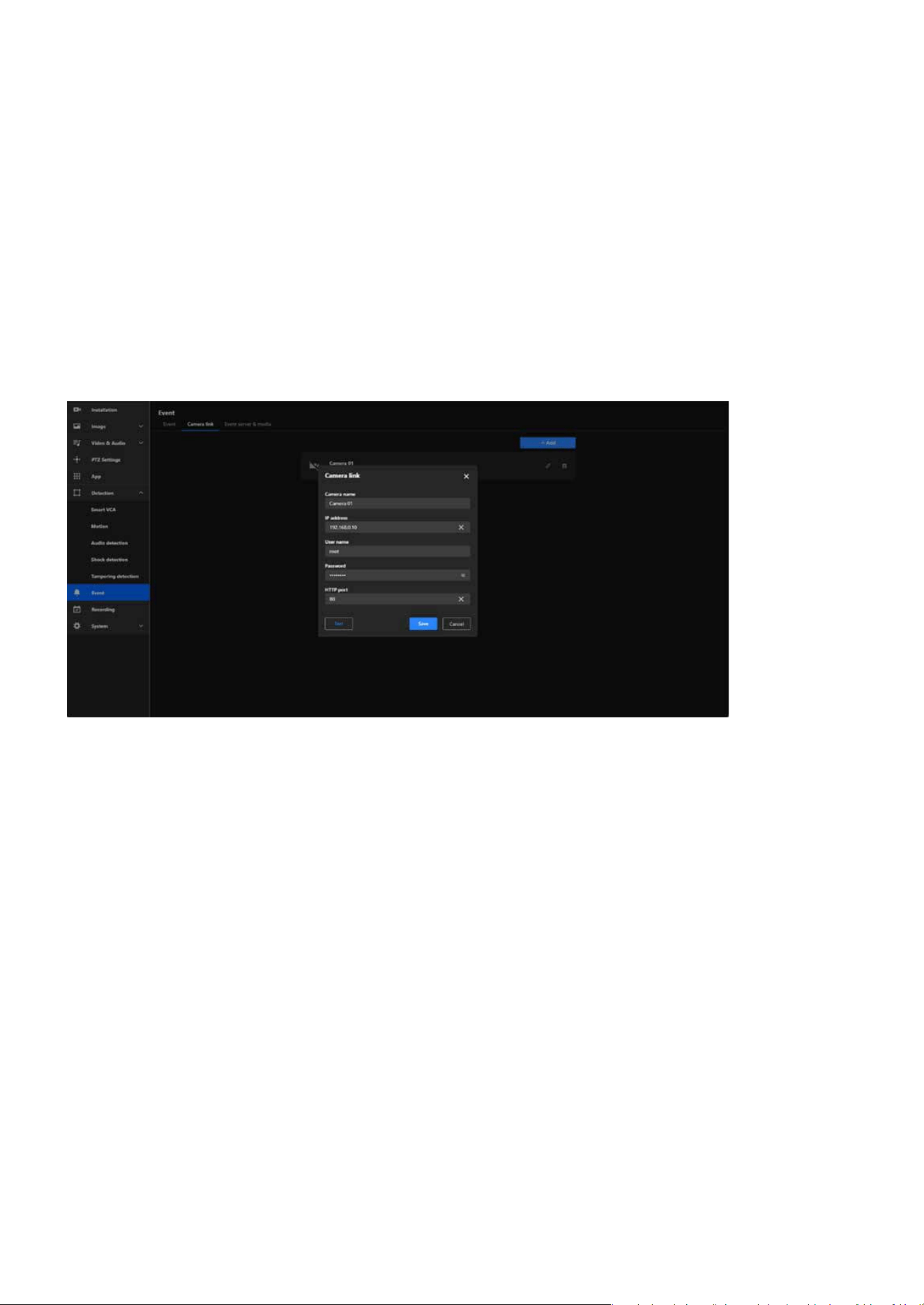
104
Event
Event
The Camera Link feature allows for multi-angle coverage of critical areas by enabling other cameras to
automatically capture footage from dierent viewpoints when an event is triggered in one zone, eec-
tively reducing blind spots and improving situational awareness.
Events and recordings from multiple cameras can be centralized in one server or storage system, en-
abling seamless event tracking and analysis.
Enhanced Security
Data Integration and Event Logging
Step 1. Click on the + Add button to create a new camera link entry.
Step 2. Fill in Camera Details:
Step 3. Click the Test button to ensure the connection details are correct and the camera link is successful-
ly established.
Step 4. Once the connection is successfully tested, click the Save button to store the camera link congu-
ration.
Steps to Add a Camera link
Camera Name:
Enter a descriptive name for the linked camera.
IP Address: Provide the IP address of the target camera you want to link.
Username: Enter the username required to authenticate with the target camera, usually “root” by de-
fault.
Password: Enter the corresponding password for the username.
HTTP Port: Specify the HTTP port used by the target camera. By default, this is usually 80, unless it has
been customized.
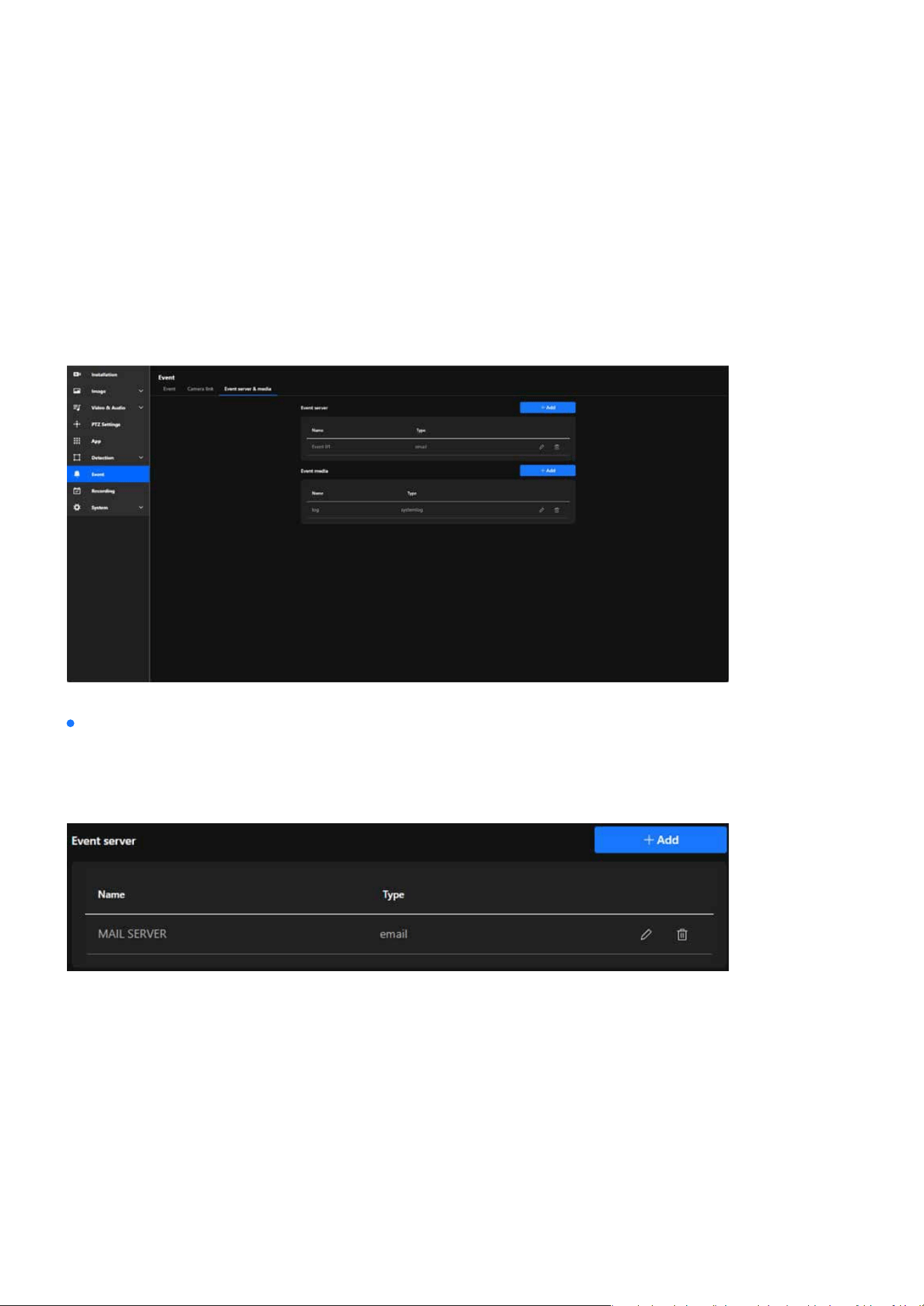
105
Event
Event
Effortless Event Management and Enhanced Security with
Event Server & Media
The Event Server & Media oers robust functionality that simplies event management, improves security,
and enhances user convenience. It ensures that event data is handled eciently, reliably, and in a manner
tailored to each user’s unique requirements, making it an invaluable tool for modern surveillance systems.
External Device Integration
By oering various types of event servers, VIVOTEK cameras provide a exible and robust event manage-
ment solution that can be customized to meet diverse security and monitoring requirements. The main
functions and purposes of these servers are as follows:
This solution sends email notications to predened recipients whenever an event occurs, instantly alert-
ing users with detailed event information. It also supports attaching snapshots or event-related data,
making it an ideal choice for small-scale setups or individual monitoring needs.
This solution uploads event-related les, such as snapshots, videos, or logs, to an FTP server, providing
centralized storage for event media. It is ideal for managing event data in environments with consistent
network connectivity and is particularly suited for large-scale deployments that require organized and
ecient storage solutions.
E-mail
FTP
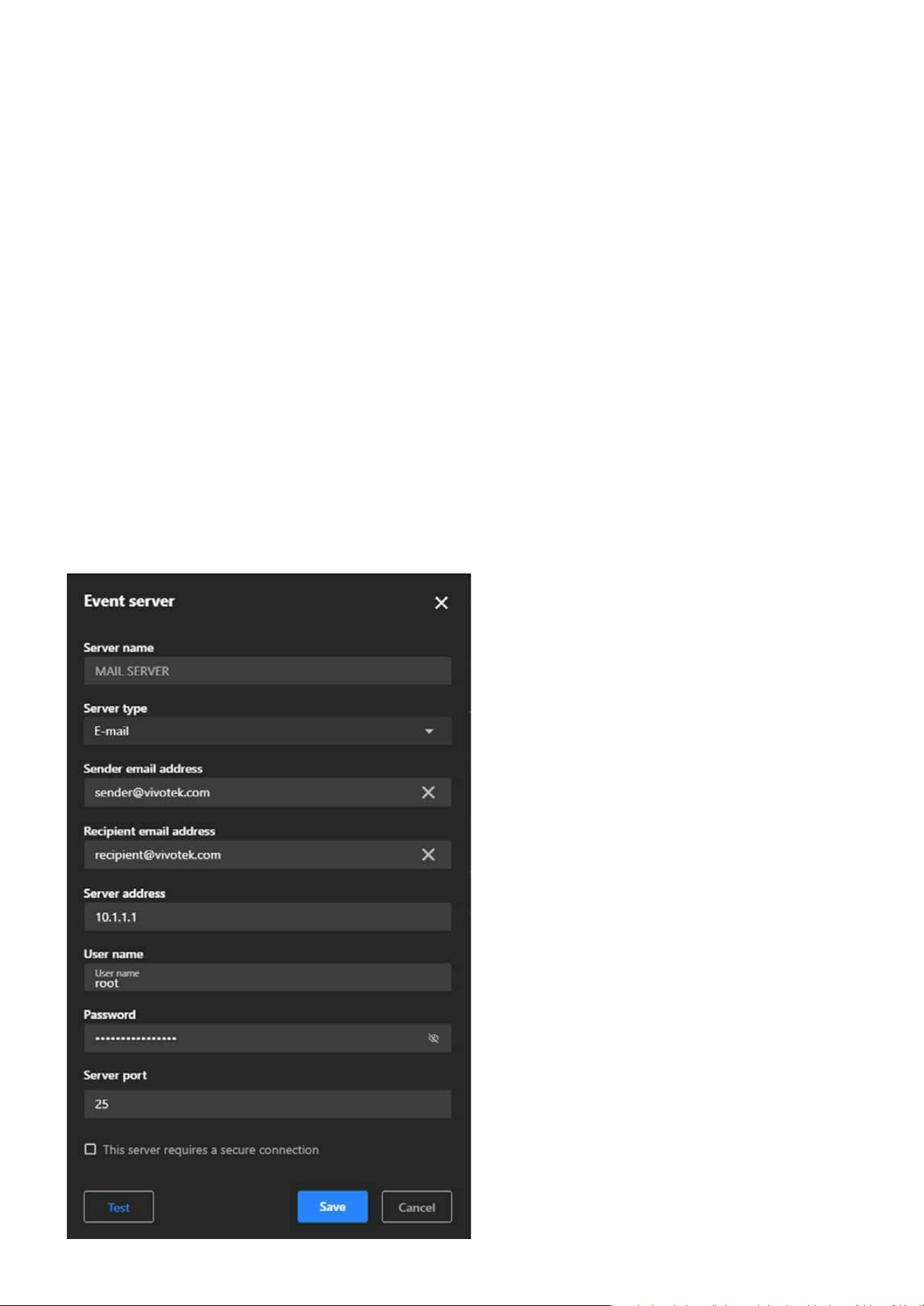
106
Event
Event
This solution securely uploads event-related les to an SFTP server using encryption protocols, enhancing
data protection during transfer. It is ideal for environments requiring the safeguarding of sensitive infor-
mation from interception or tampering and ensures compliance with strict security policies and regulatory
requirements.
This solution sends event notications or data to an HTTP server via HTTP requests, enabling seamless
integration with third-party systems or applications for ecient event handling. It can trigger workows in
advanced security systems, home automation setups, or analytics platforms, and simplies integration in
environments that rely on custom APIs or HTTP-based solutions.
This solution uses the secure HTTPS protocol for encrypted communication, ensuring secure data transfer
to prevent unauthorized access or data breaches. It is ideal for sensitive applications requiring condenti-
ality and is commonly implemented in modern, secure network environments.
SFTP
HTTP
HTTPS

107
Event
Event
Step 1. Click the + Add button to add a new server.
Step 2. In the popup window, choose the type of server you want to congure:
Step 3. Click Next to proceed with the server-specic conguration.
Step 4. Depending on the server type selected, ll in the required elds:
Step 5. Click the Test button to verify that the camera can successfully connect to the server.
Step 6. After a successful test, click “Save” to store the server conguration, and the new server will ap-
pear in the Event Server list.
Email: For sending event notications via email.
Email Server:
FTP Server:
SFTP Server:
HTTP Server:
HTTPS Server:
SMTP Server: Enter the SMTP server address (e.g., smtp.example.com).
Port: Specify the port (e.g., 25, 465, or 587 depending on the SMTP conguration).
Authentication: Enable and enter the username and password for the email account.
Sender Email Address: Enter the “From” address for email notications.
Recipient Email Address: Enter the recipient’s email address for receiving notications.
FTP Server Address: Enter the IP address or domain name of the FTP server.
Port: Default is 21 (adjust if needed).
Username and Password: Enter credentials to authenticate with the FTP server.
Folder Path: Specify the folder where les should be uploaded.
Similar to FTP, but ensure the SFTP protocol is supported, and credentials are entered securely.
Server URL: Enter the full URL of the HTTP server (e.g., http://example.com/api/event).
Same as HTTP but ensure the server URL starts with “https://”.
FTP: For uploading event-related les (e.g., snapshots or videos) to an FTP server.
SFTP: Similar to FTP but uses encrypted le transfer for added security.
HTTP: For sending HTTP requests to a third-party system with event information.
HTTPS: Similar to HTTP but uses a secure communication protocol.
Steps to congure an Event server
Note:
Upload and congure certicates if required for secure communication.
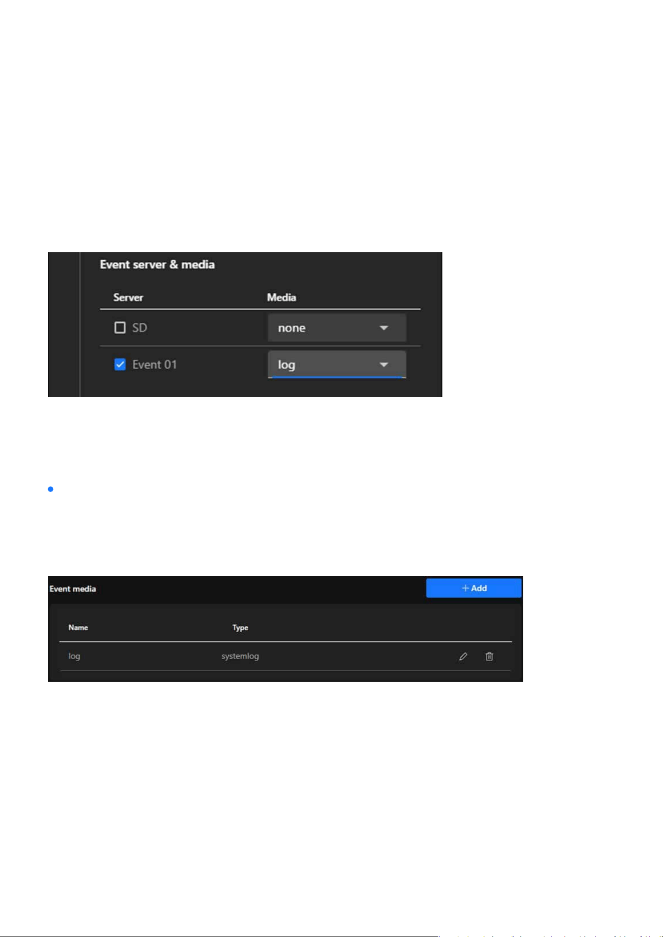
108
Event
Event
Step 7. Link the Server to an Event
The Event Media settings oer a powerful and exible media management solution, enabling users to
quickly generate, store, and transmit media les during events. This meets the needs for real-time mon-
itoring, event recording, and evidence preservation, further enhancing the eciency and reliability of
surveillance systems. The main functions and purposes of these servers are as follows:
Navigate back to the Event tab.
Create a new event or edit an existing one.
Select the congured server under the Event Server section.
Dene the actions and media to be sent to the server when the event is triggered.
Note:
Use strong and unique passwords for server authentication to enhance security.
For HTTPS and SFTP, ensure certicates and encryption settings are correctly congured.
Regularly monitor and test the server connection to ensure reliable event handling.
Event media
Captures a still image at the moment the event is triggered, providing a quick visual representation of the
event that is useful for reviewing specic moments or identifying key elements such as faces or objects.
Records a short video segment before, during, and after the event is triggered, oering detailed context
and a dynamic view of the event to help users thoroughly analyze incidents such as the movement of indi-
viduals or objects.
Snapshot
Video clip
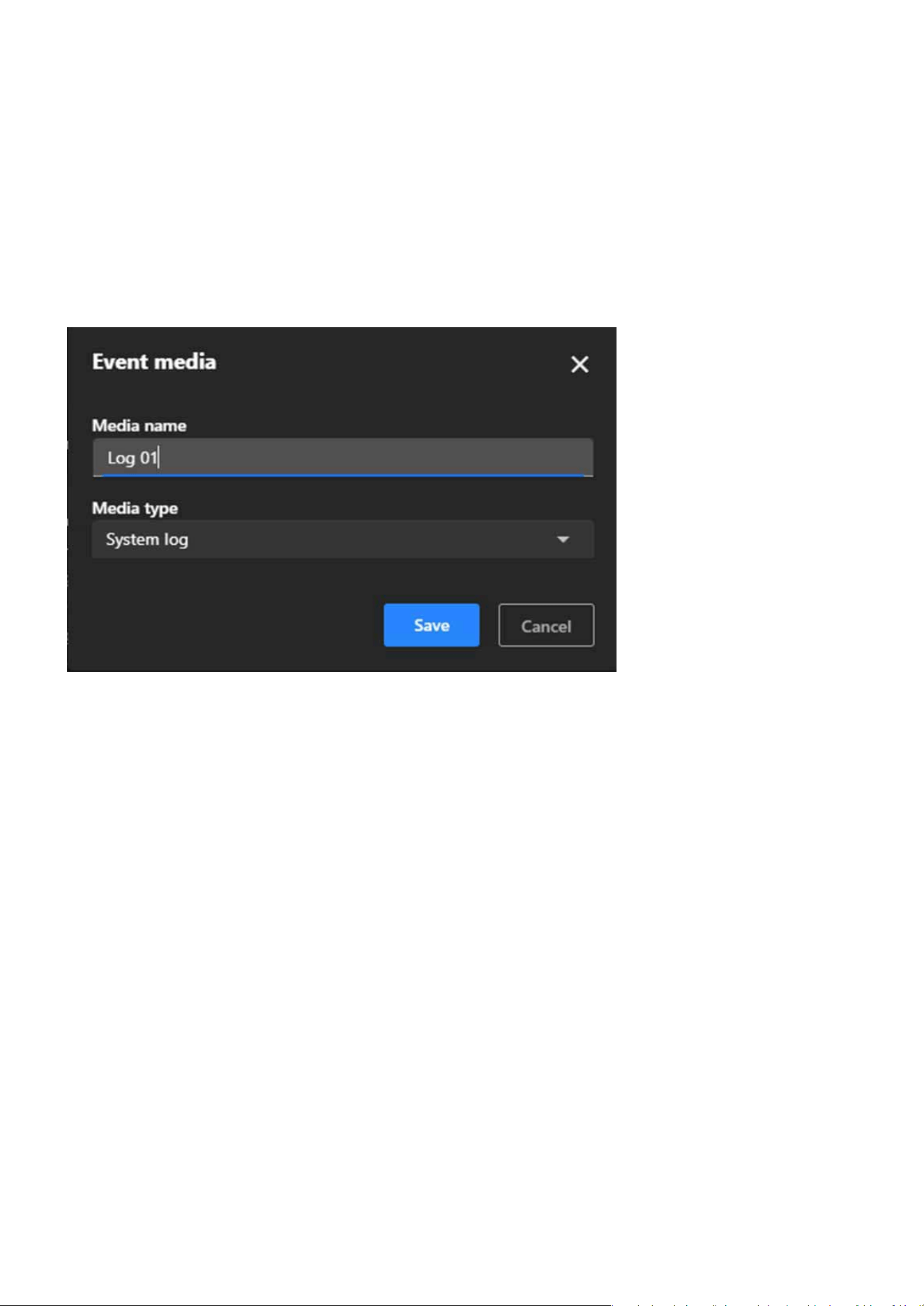
109
Event
Event
Records textual data about the event, including the type of event, time, and related system activity, pro-
viding a chronological record for audits and troubleshooting while being useful for monitoring system
performance and identifying anomalies.
Step 1. Click the + Add button to create a new media conguration.
Choose one of the following media types from the dropdown menu:
Snapshot:
Source:
Select the video stream from which snapshots will be taken.
Pre-Event Buer (seconds): Dene how many seconds before the event to capture snapshots.
Post-Event Buer (seconds): Dene how many seconds after the event to continue capturing snap-
shots.
Custom Image Frequency (frames/second): Set the frequency for capturing images (e.g., 1 frame per
second).
File Name Prex: Enter a custom prex for snapshot lenames.
Optionally, enable the checkbox to add a date and time sux to lenames for better organization.
Snapshot: Captures a still image.
Video Clip: Records a short video clip.
System Log: Logs textual data about the event.
Step 2. Enter a descriptive name for the media in the Media Name eld
Step 3. Select Media Type
Step 4. Congure Media-Specic Settings
System log
Steps to congure an Event server
Note:
The resolution setting may aect the maximum number of snapshots that can be taken. Please refer to the Video & Audio > Video
> Steam page for more information.
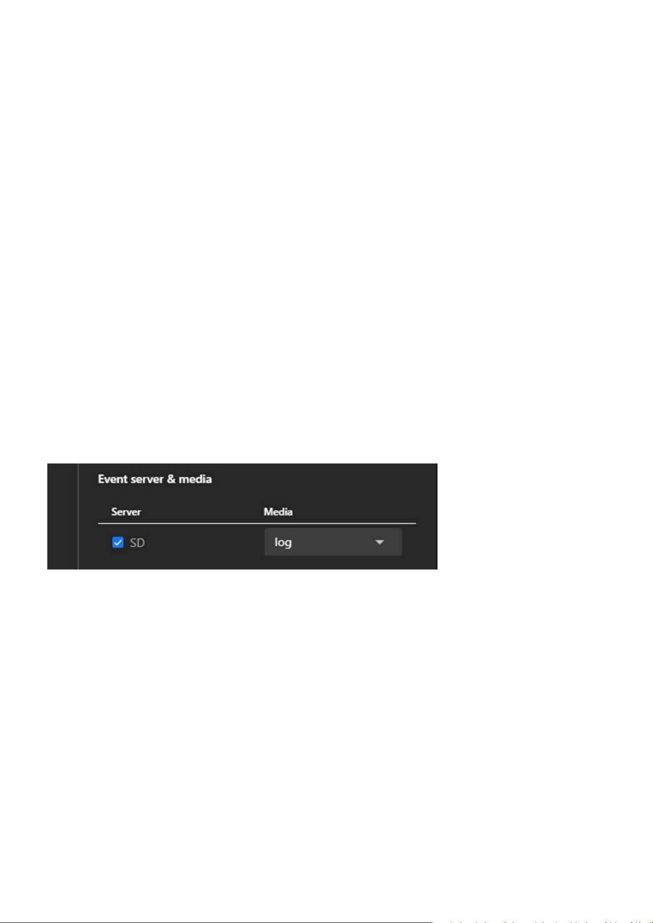
110
Event
Event
Video clip:
System Log:
Source:
Select the video stream to record from.
Pre-Event Recording (seconds): Dene how many seconds before the event the recording should start.
Maximum Duration (seconds): Set the maximum length of the video clip (e.g., 5 seconds).
Maximum File Size (KB): Specify the maximum le size for the video clip.
File Name Prex: Enter a custom prex for video lenames for easy identication.
This media type will record event-related data such as event type, time, and associated system activity.
Navigate to the Event tab.
Create a new event or edit an existing one.
In the event settings, select the congured media under the Event Media section.
This ensures the congured media (e.g., snapshots, video clips, or system logs) will be generated when
the event is triggered.
Step 5. After conguring the settings, click “Save” to nalize the media conguration, which will then ap-
pear in the Event Media list.
Step 6. Link Event Media to an Event.
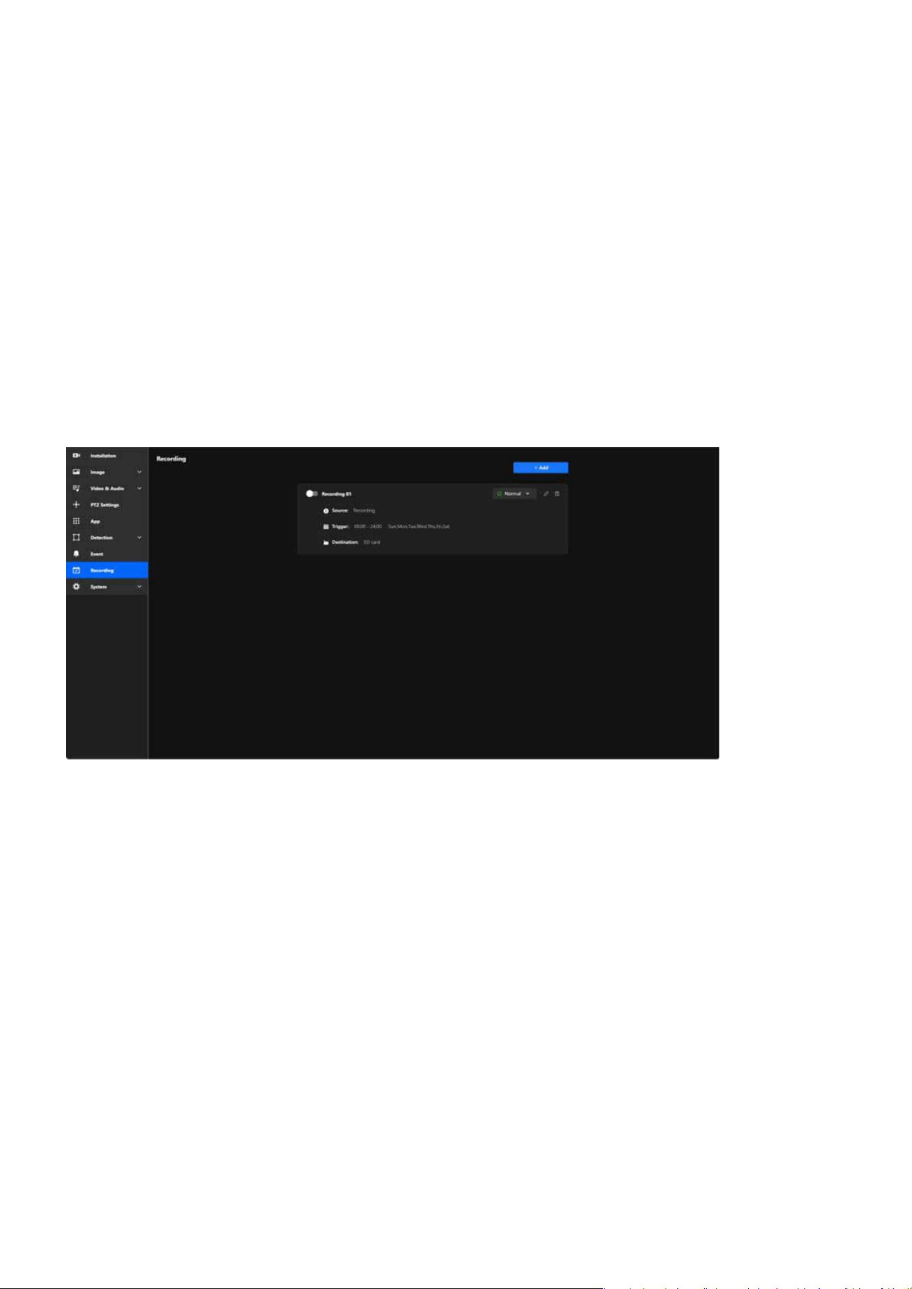
111
Recording
Recording
Maximize Surveillance and Storage with Tailored Recording
Settings
The Recording settings empower users to customize their surveillance experience with precision and e-
ciency. By oering exible scheduling, event-based triggers, and multiple storage options, these settings
ensure that critical footage is captured while optimizing storage usage. Whether you need 24/7 monitoring
or recordings triggered by specic events like motion or sound, the system adapts seamlessly to your needs.
With the ability to store recordings locally on an SD card or on a network drive, users can ensure data secu-
rity and accessibility. This customizable approach simplies management, enhances security, and provides
peace of mind, making it a vital feature for any surveillance setup.
Key purpose of Recording:
Ensures critical areas are monitored and video evidence is captured, whether continuously or based on
events.
Allows users to review recordings to investigate incidents or analyze activities.
By setting specic schedules and triggers, unnecessary recordings are minimized, conserving storage
space.
Accommodates various recording needs, such as round-the-clock monitoring or selective recording based
on motion detection or specic timeframes.
Ensures recordings are stored securely and can be accessed as needed, either from local SD cards or net-
worked storage solutions.
Surveillance and Security
Event Investigation
Ecient Storage Management
Flexibility for Dierent Scenarios
Backup and Data Accessibility

112
Recording
Recording
Step 6. Under Destination, select where the recordings will be stored:
Step 7. Once all elds are congured, click Save to apply the settings.
Save recordings locally on the SD card inserted in the camera. This option is ideal for standalone setups
or when local storage is sucient.
Save recordings to a Network Attached Storage device. This is useful for centralized storage and easier
management of video data, especially in larger surveillance systems.
SD
NAS
Note:
If an SD card is not detected or improperly installed, a warning message will appear. Ensure an SD card is inserted or congure the
NAS settings before proceeding.
Adaptive Recording is an intelligent feature designed to optimize surveillance eciency by dynamically ad-
justing the video frame rate based on real-time events. By reducing bandwidth and storage usage during
routine monitoring and ensuring high-quality video during critical events, Adaptive Recording enhances
both system performance and resource management. Its primary purposes are:
During normal monitoring, the system reduces bandwidth consumption and storage usage by only send-
ing I-frame data.
When an alarm is triggered, the frame rate increases to the full frame rate to capture critical moments in
high quality.
The system optimizes frame rate usage based on actual needs, ensuring ecient use of network and stor-
age resources without compromising performance.
How does Adaptive Recording achieve the above purposes?
When Adaptive Recording is enabled, the camera dynamically adjusts the frame rate based on alarm trig-
gers, such as motion detection, DI devices, or manual triggers.
When an alarm is triggered:
When no alarm is triggered:
The camera records the full frame rate streaming data to ensure high-quality video for critical events.
The camera only sends Intra frame (I-frame) data during normal monitoring to minimize bandwidth and
storage usage.
With adaptive recording
Bandwidth and Storage Optimization:
Enhanced Event Recording:
Resource Eciency:
1. Dynamic Frame Rate Adjustment:
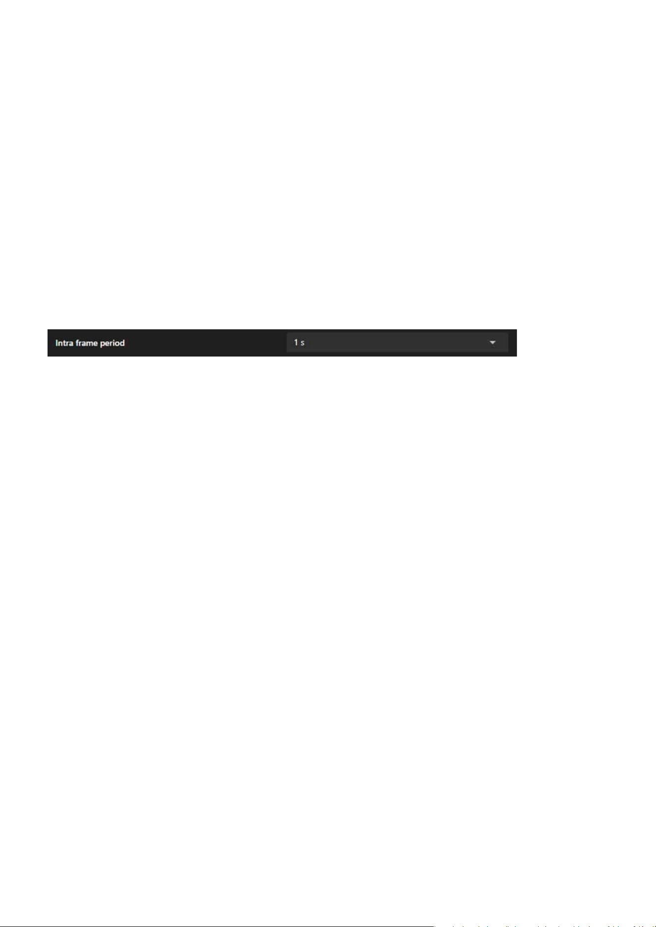
113
Recording
Recording
No Alarm Trigger:
If the Intra frame (I-frame) period is greater than 1 second in the Video & Audio > Video > Stream page, the
rmware will automatically reduce it to 1 second when Adaptive Recording is enabled.
Alarm Trigger:
JPEG mode: 1 Intra frame (I-frame) per second.
H.264 mode: Records Intra frame (I-frame) only.
Automatically increases to the congured full frame rate.
2. Frame Rate Control:
3. Frame Period Limitation:

114
System
System
The System acts as a comprehensive management hub designed for conguring and monitoring the device.
It oers essential tools to manage the camera’s system information, network congurations, user accounts,
storage solutions, and maintenance tasks. Its core aim is to ensure secure and ecient device operation by
enabling features like rmware updates, log analysis, and system diagnostics. Additionally, it improves user
experience through customizable themes and streamlines data management by organizing storage and le
handling. This category plays a vital role in maintaining optimal camera performance and ensuring its seam-
less integration into a networked environment.
The Device item serves as a centralized interface for monitoring and conguring the essential system infor-
mation, operational status, and hardware settings of the camera. Its primary purpose is to provide users
with real-time insights into system performance (CPU, memory, and storage), enable easy identication and
management of the device through network and hardware details, ensure accurate time synchronization for
recordings and logs, and facilitate integration with external devices through LED and DIDO controls. Overall,
it enhances the camera’s manageability, performance monitoring, and operational precision in a user-friend-
ly manner.
The Device item features four functional cards covering the camera’s operational status, basic device infor-
mation, system time synchronization, and interaction with external devices. Its main purposes are as fol-
lows:
Helps users track resource usage and storage capacity of the camera.
Facilitates easy identication and network management through basic device information.
Ensures the accuracy of recording les and event logs.
Enables interaction with external devices to expand functional applications.
Centralized Management for System Monitoring and
Camera Conguration
Real-time Monitoring
Identication and Management
Time Synchronization
External Device Integration
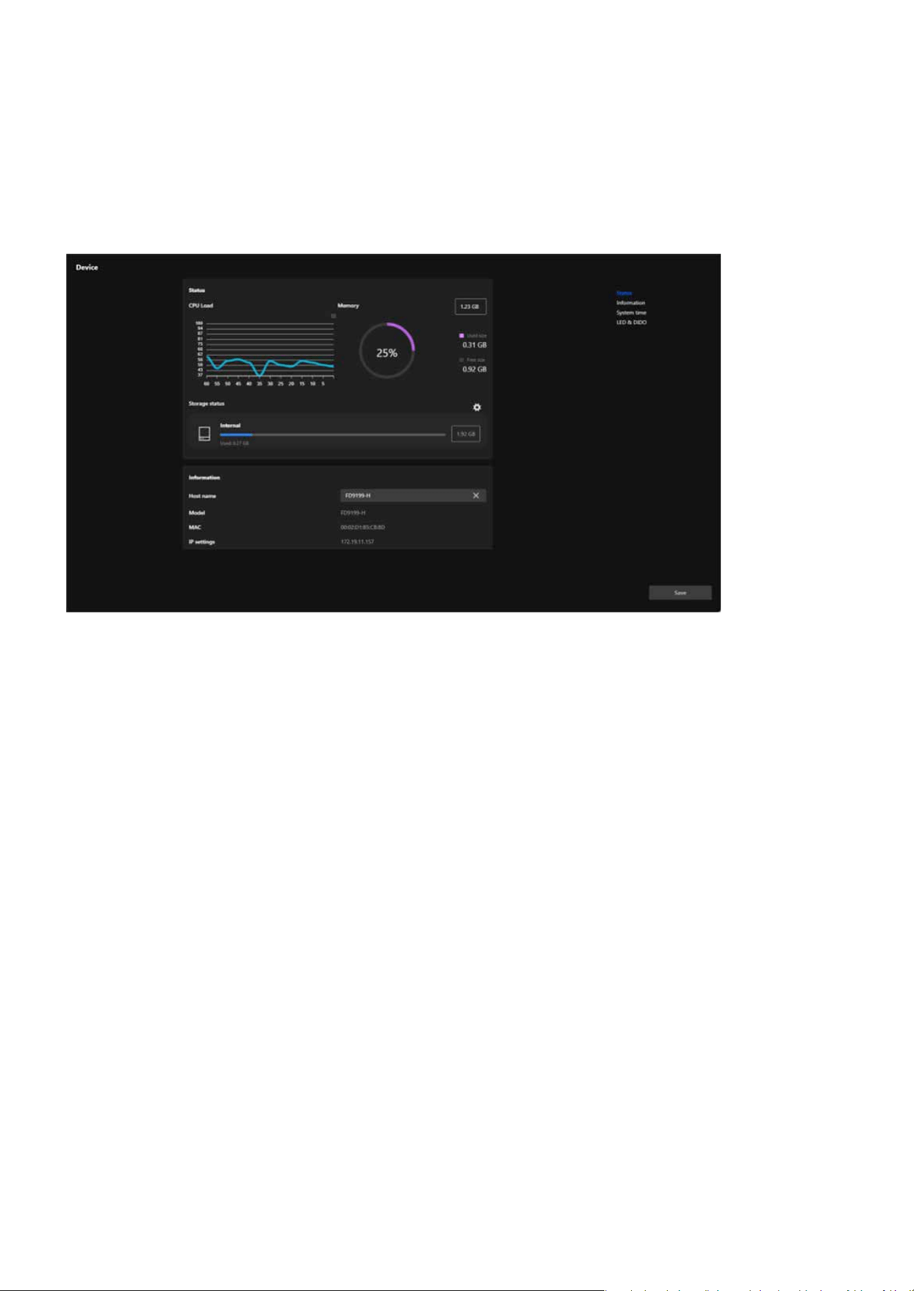
115
System
System
These functions are designed to enhance the camera’s usability, operational exibility, and integration capa-
bility with other devices.
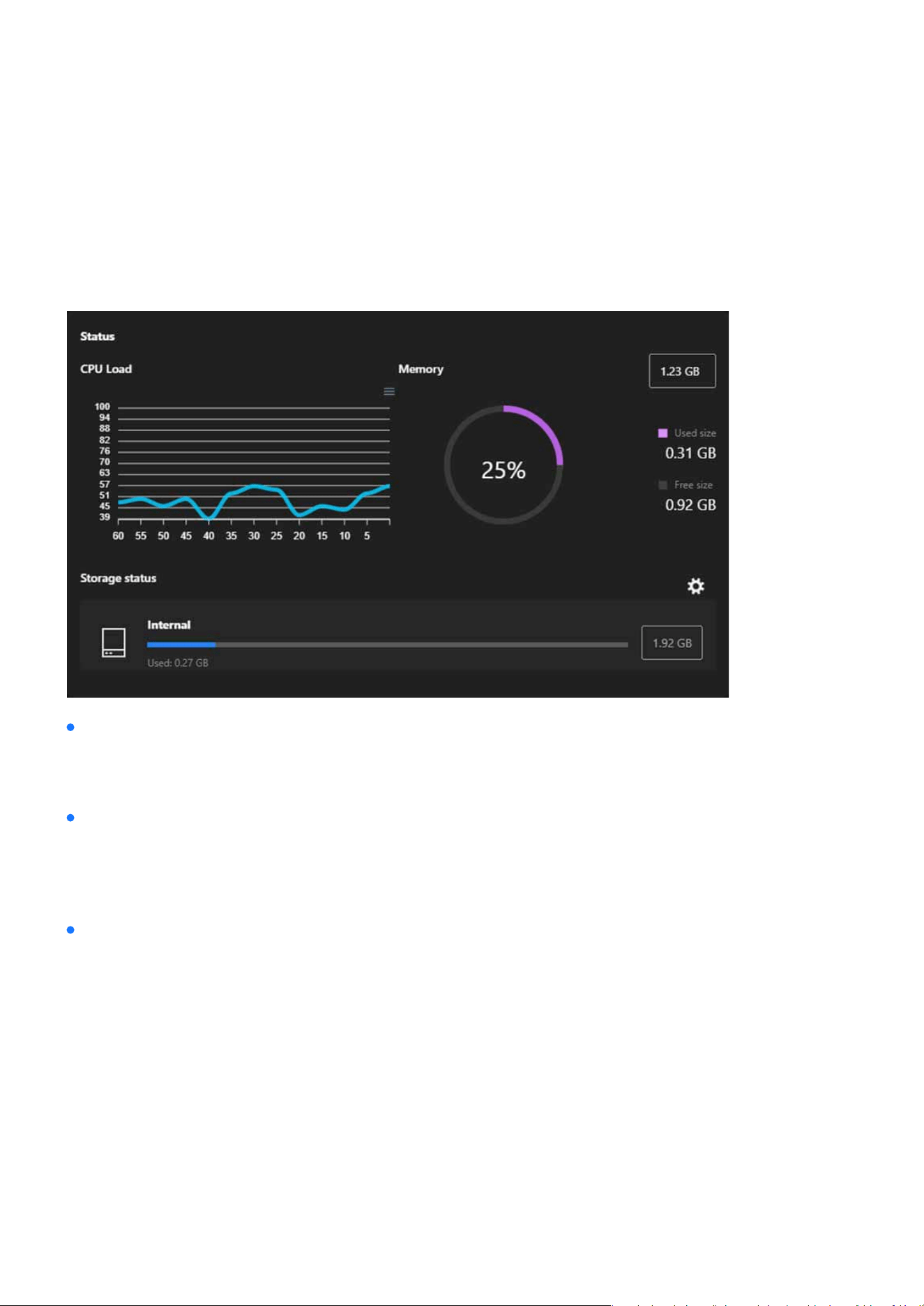
116
System
System
The Status card serves as a real-time dashboard for monitoring the camera’s operational performance. By
providing detailed insights into CPU, memory, and storage usage, it helps users maintain optimal device per-
formance, ensure system stability, and proactively address resource management needs.
Status
Displays the real-time CPU usage of the camera as a line graph, showing uctuations over time.
A circular graph visualizes the memory usage, including: Total memory capacity, Used memory and Avail-
able memory.
Displays the status of internal storage, including: Total storage capacity, Used storage space and Available
storage, represented by a progress bar for clear visualization.
Detailed gures for used and free memory are shown for precise monitoring.
Includes options for further storage management via the gear icon.
Helps users monitor processor load trends and identify potential performance issues.
CPU Load
Memory
Storage Status
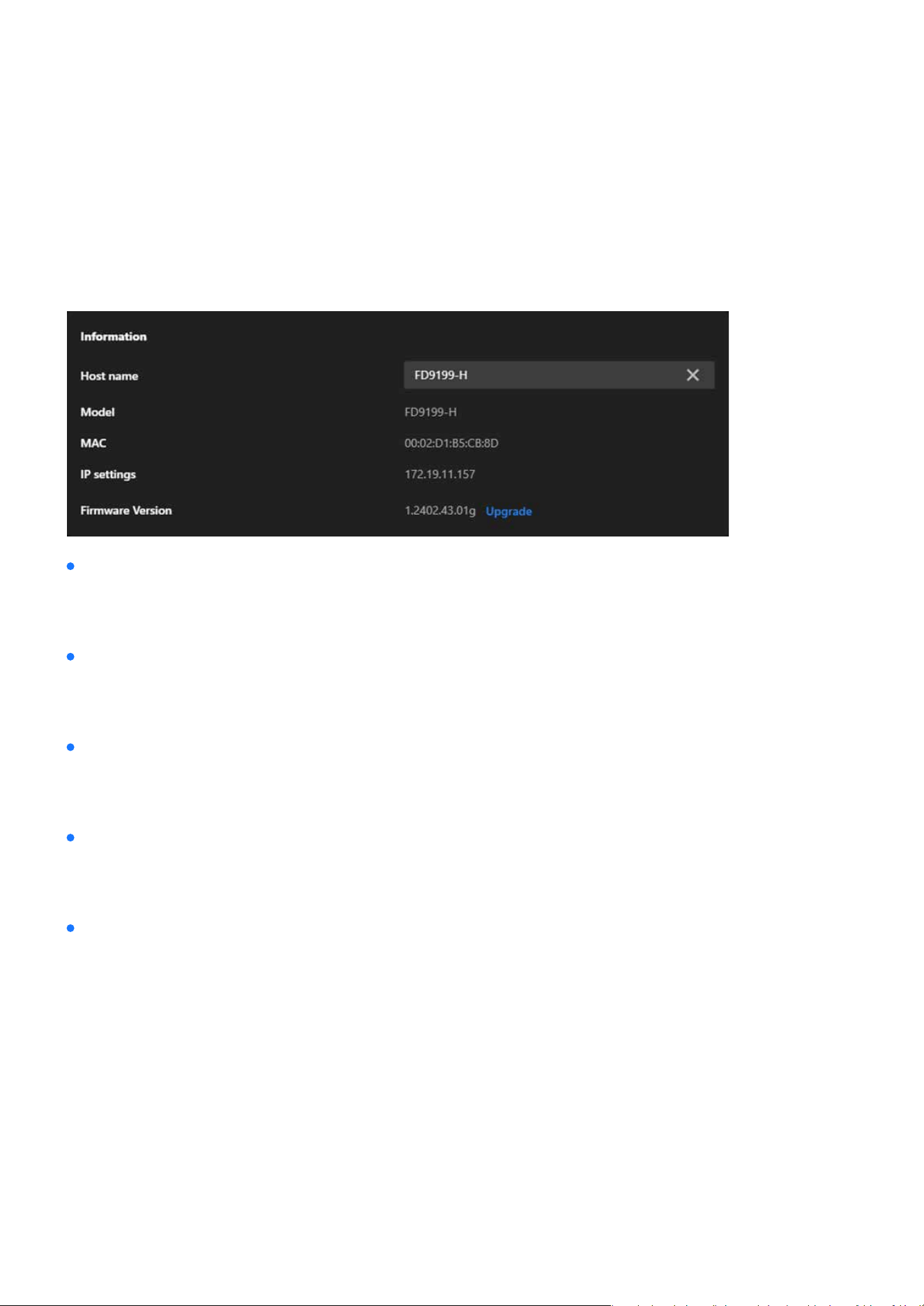
117
System
System
The Information card provides essential details for identifying, conguring, and maintaining the camera. It
simplies network management, ensures the camera is up to date, and provides quick access to critical de-
vice information, aiding in ecient management and troubleshooting.
Information
Displays the camera’s unique name.
Shows the camera’s model number.
Displays the camera’s unique MAC address.
Shows the camera’s current IP address.
Displays the current rmware version installed on the camera.
Can be edited by the user to customize and identify the camera more easily within a network.
Helps in identifying the specic device for maintenance or troubleshooting.
Useful for network diagnostics, device identication, or IP reservation purposes.
Allows users to conrm the network connectivity and conguration.
Includes an Upgrade option for users to update the rmware, ensuring access to the latest features, bug
xes, and security improvements.
Host Name
Model
MAC Address
IP Settings
Firmware Version
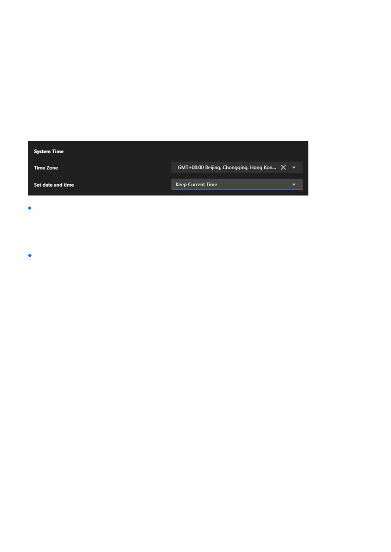
118
System
The System Time card is essential for ensuring that the camera’s time is accurate and synchronized with its
operating environment. By oering exible conguration options, it supports reliable event tracking, seam-
less system integration, and precise log management, enabling ecient and consistent monitoring in vari-
ous setups.
System Time
Allows users to select the time zone based on the camera’s location (e.g., GMT+08:00 Beijing, Chongqing,
Hong Kong).
Oers four options for conguring the camera’s time:
Retains the existing time conguration on the camera without changes.
Matches the camera’s time to the time on the connected computer, providing a quick and convenient way
to set the time.
Enables users to manually set the date and time, suitable for specic use cases requiring custom time set-
tings.
Synchronizes the camera’s time with a Network Time Protocol (NTP) server to maintain accurate, automat-
ed time updates.
Ensures the camera’s time aligns with the local time for accurate recording and event logging.
Keep Current Time
Synchronize with PC
Manually
Synchronizing with NTP Server
Time Zone
Set date and time
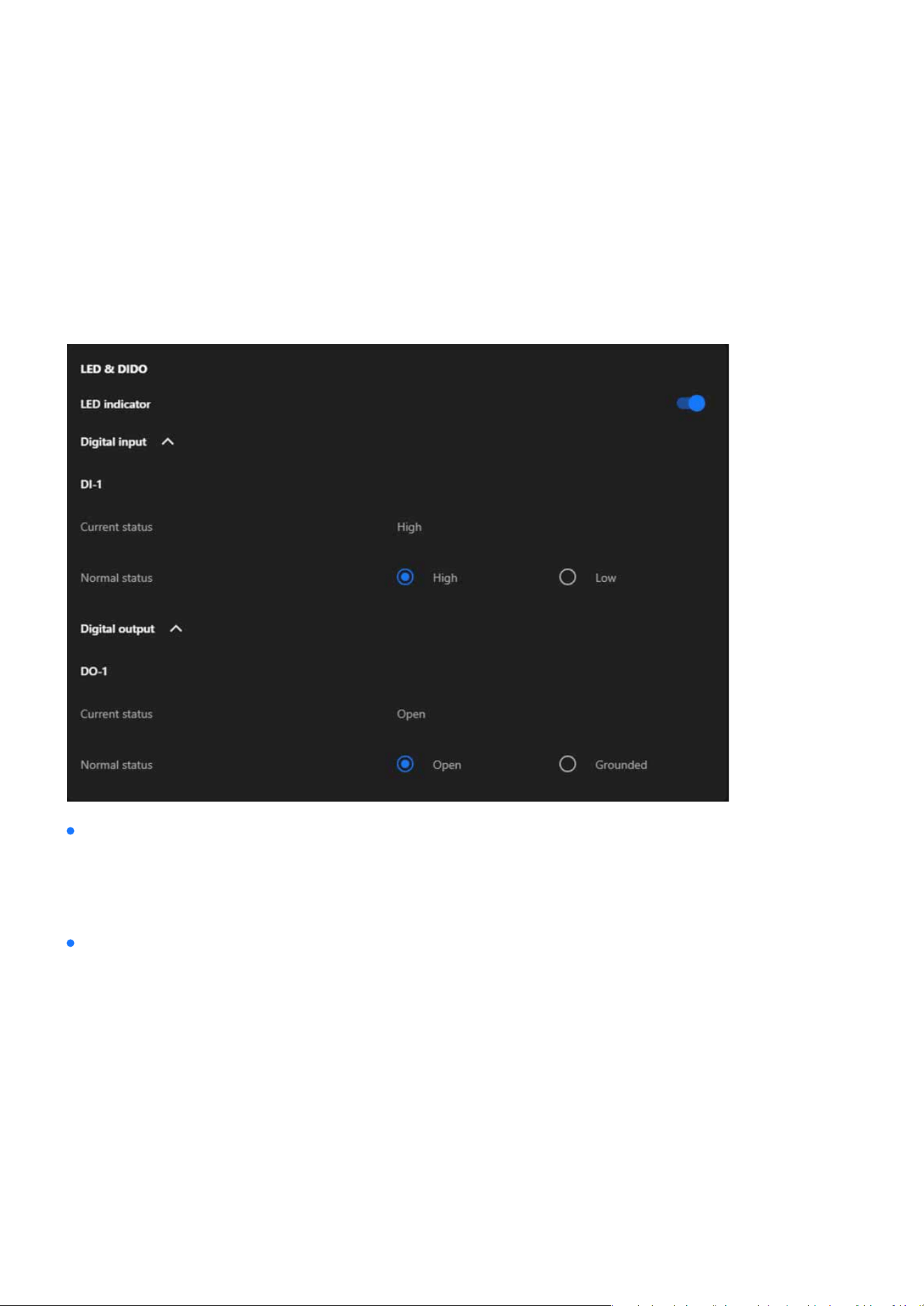
119
System
The LED & DIDO card serves as a bridge for the camera’s interaction with its environment. By controlling the
LED indicator and managing the digital input/output interfaces, it allows the camera to integrate seamlessly
with external devices, enhancing its functionality and supporting a wide range of automation and monitor-
ing applications.
LED & DIDO
A toggle switch to enable or disable the camera’s LED indicator.
DI-1 Current status
DI-1 Normal status
When enabled, the LED provides visual feedback for the camera’s operational status (e.g., power on, re-
cording, or activity detection).
Displays the real-time status of the digital input (e.g., High or Low).
Allows the user to congure the expected normal state for the digital input (either High or Low). Used for
integrating external sensors (e.g., motion detectors or alarms).
LED Indicator
Digital input

120
System
DO-1 Current status
DO-1 Normal status
Shows the current state of the digital output (e.g., Open or Grounded).
Lets the user dene the normal state for the digital output (either Open or Grounded). Used for triggering
external devices (e.g., alarms, lights, or actuators).
Digital output
Note:
High/Low in DI
Open/Grounded in DO
Reects the input signal received from external devices, used for monitoring the status of sensors or triggers.
Controls the output signal sent to external devices, used to activate or deactivate connected equipment such as alarms or actua-
tors.
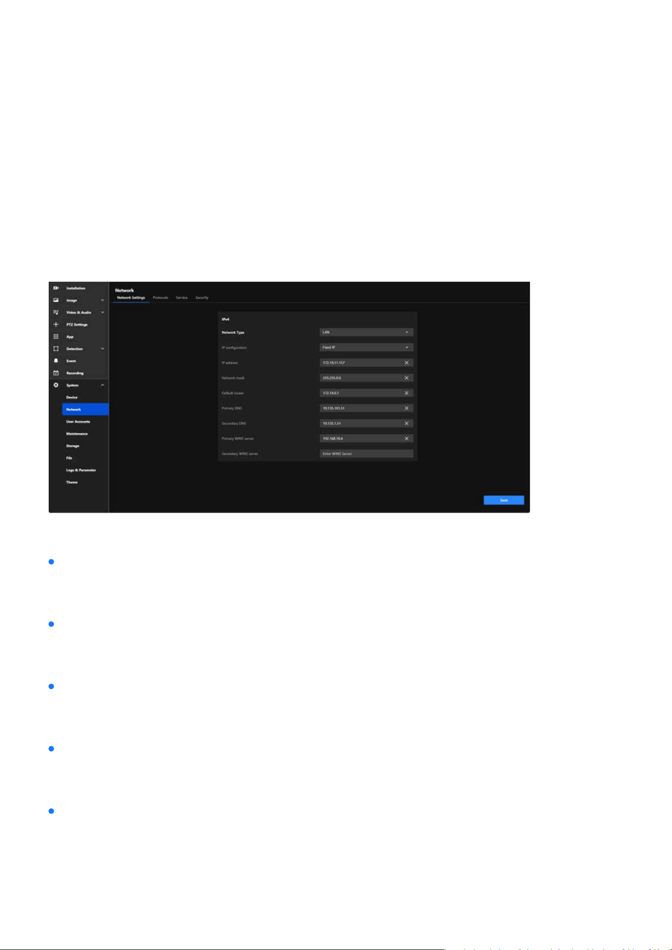
121
System
System
The Network item provides comprehensive tools for conguring the camera’s network connectivity, ensur-
ing reliable communication, remote access, and secure integration with other devices and systems. This
conguration is critical for enabling real-time monitoring, remote management, and data transmission over
various network infrastructures.
Congure and Secure Your Camera’s Network Connection for
Seamless Communication
The main functional purposes are as follows:
Allows the camera to connect to local networks or the internet through proper IP settings, enabling re-
mote access and monitoring.
Provides exible network parameter settings (e.g., static or dynamic IP) to ensure compatibility with vari-
ous network environments.
Ensures seamless communication with external systems (e.g., NVRs or cloud platforms) through proper
conguration of gateways, DNS, and protocols.
Supports secure connections and access controls to protect the camera and its data from unauthorized
access or threats.
Facilitates network troubleshooting and diagnostics using tools like WINS and DNS settings to ensure con-
tinuous operation.
Network Integration
Customized Conguration
Reliable Communication
Security
Ecient Monitoring and Maintenance
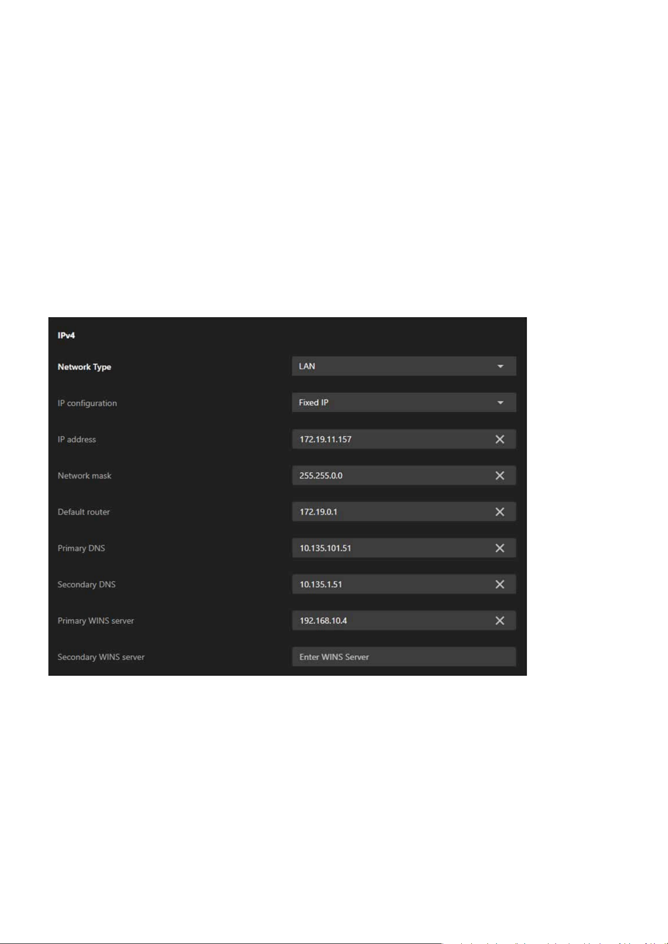
122
System
System
IPv4
By providing detailed conguration options for both IPv4 and IPv6, the Network Settings tab ensures the
camera can seamlessly connect to and operate within diverse and complex network environments.
The IPv4 card plays a vital role in setting up the camera’s network conguration and ensuring eective com-
munication. It facilitates dependable connectivity, enables both local and remote access, and allows the
camera to integrate eortlessly into IPv4-based networks. This conguration is crucial for maintaining stable
and ecient performance across diverse networking environments.
Network Settings

123
System
System
IPv4
Network Type
IP Conguration
IP Address
Network Mask
Default Router
Primary and Secondary DNS
Primary and Secondary WINS Server
Allows the user to select the type of network connection:
Provides two conguration options:
Displays or sets the IPv4 address of the camera, which serves as the unique identier for the camera with-
in the network.
Denes the subnet mask, which determines the range of devices that can directly communicate with the
camera.
Species the default gateway for directing network trac beyond the local subnet, such as accessing the
internet or external servers.
Congures DNS servers to resolve domain names into IP addresses, enabling features like remote access
using hostnames instead of IP addresses.
Species WINS servers to resolve NetBIOS names into IP addresses, typically used in Windows-based envi-
ronments to facilitate name resolution.
LAN
A standard wired network connection, typically used when the camera is
connected to a local network through Ethernet.
PPPoE(Point-to-Point
Protocol over Ethernet)
A protocol used for direct internet connections, often requiring authenti-
cation with a username and password from the Internet Service Provider
(ISP). It’s commonly used in DSL networks or when the camera needs to
connect directly to the internet without a router.
DHCP
Dynamically assigns an IP address to the camera using a network DHCP
server, suitable for networks with automated address assignment.
Fixed IP
Assigns a static IP address to the camera for consistent and reliable iden-
tication on the network.
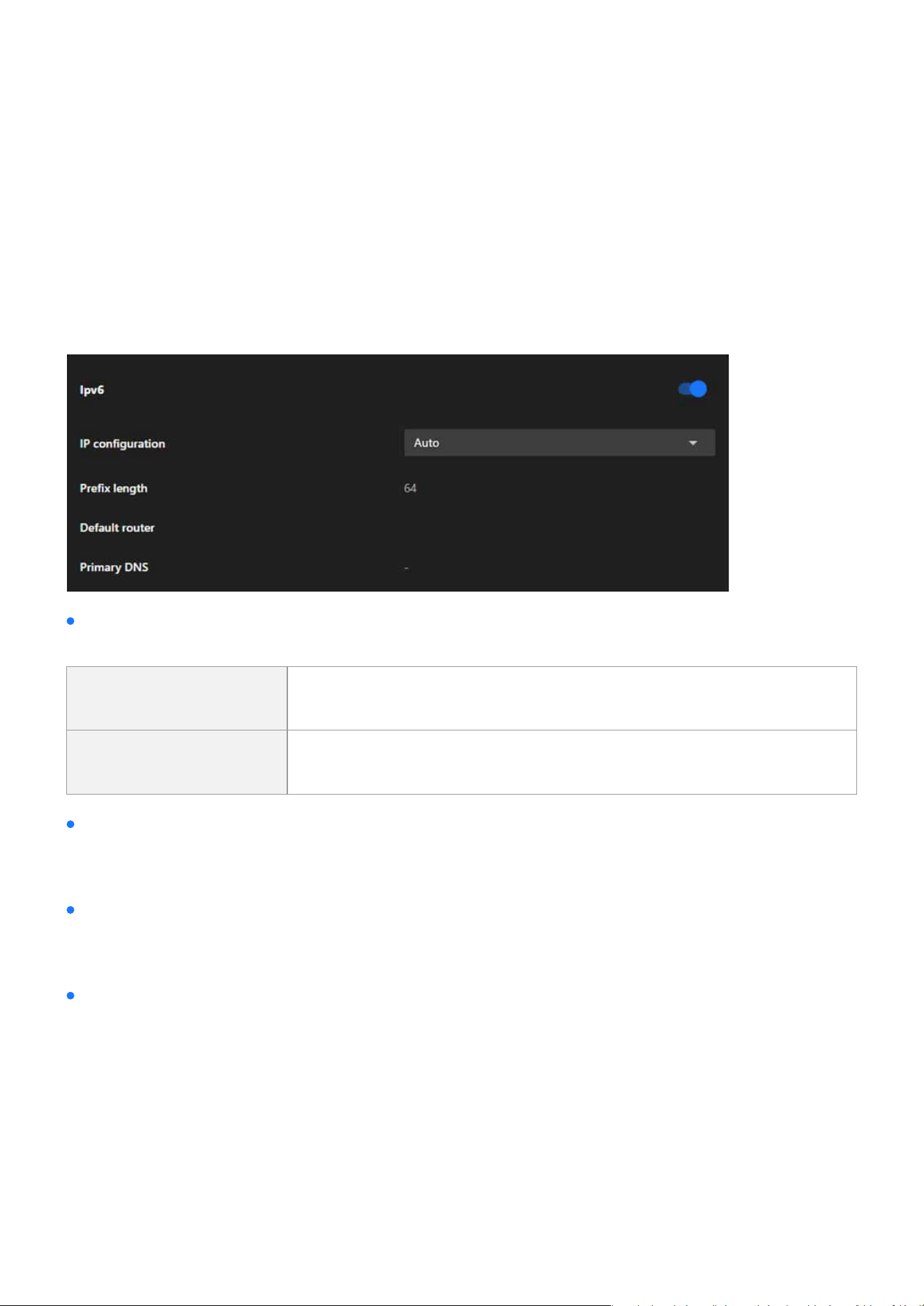
124
System
System
IPv6
The IPv6 card in the Network Settings tab equips the camera with the ability to operate in next-generation
networks, supporting automatic or manual IP address assignment, subnet conguration, and domain name
resolution. This ensures the camera is ready for modern and future network environments, providing en-
hanced connectivity and adaptability.
IP Conguration
Allows the user to select how the IPv6 address is assigned:
Auto
Automatically obtains an IPv6 address using SLAAC (Stateless Address
Autoconguration) or DHCPv6, depending on the network setup.
Manual Enables manual input of a static IPv6 address if required.
Prex Length
Default Router
Primary DNS
Species the subnet prex length, which determines the size of the subnet and the range of addresses
that can communicate directly with the camera. A prex length of 64 is common in IPv6 congurations.
Congures the default gateway for the camera’s outgoing trac to external networks, ensuring communi-
cation beyond the local IPv6 subnet.
Allows the user to specify the primary DNS server to resolve domain names into IP addresses in IPv6 net-
works.
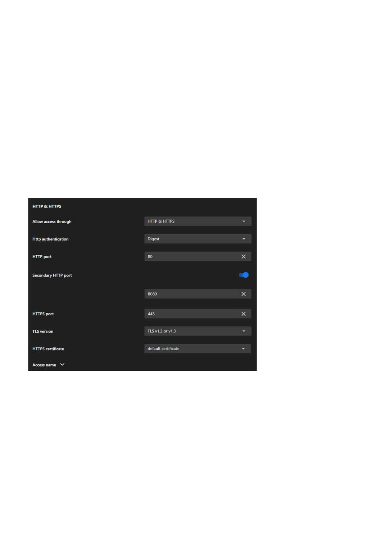
125
System
System
Protocols
The Protocols tab is designed to congure various communication protocols that enable the camera to inter-
act with other devices, systems, and networks. It includes ve key protocol cards: HTTP & HTTPS, RTSP, SIP,
SNMP, and Bonjour, each serving specic purposes for communication, streaming, and network discovery.
The HTTP & HTTPS card is essential for conguring secure and reliable web-based access to the camera. It
provides the exibility to use both encrypted (HTTPS) and unencrypted (HTTP) protocols, ensures compati-
bility with modern security standards, and supports redundancy and customization for a variety of deploy-
ment scenarios.
HTTP & HTTPS

126
System
System
Allow Access Through
HTTP Authentication
HTTP Port
Secondary HTTP Port
HTTPS Port
TLS Version
Allows users to choose the protocols for accessing the camera:
Congures the authentication method for HTTP access:
Denes the primary port used for HTTP communication (default: 80).
Provides an additional HTTP port (e.g., 8080) for accessing the camera as a backup or alternative.
Sets the port for HTTPS communication (default: 443), ensuring encrypted and secure access.
Oers options to select the encryption protocol for HTTPS:
HTTP only Enables access via the unencrypted HTTP protocol.
HTTPS only Enables access via the encrypted HTTPS protocol.
HTTP & HTTPS Supports both protocols simultaneously for exible access options.
TLS v1.2 only For compatibility with older systems.
TLS v1.3 only For maximum security using the latest protocol.
TLS v1.2 or v1.3 Provides exibility by supporting both.
Basic A simpler method that sends plain text credentials (less secure).
Digest A more secure method using hashed credentials.
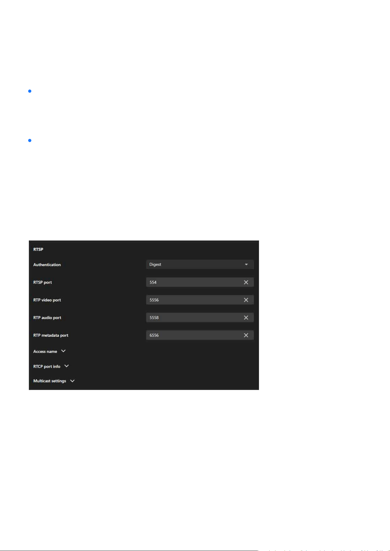
127
System
System
HTTPS Certicate
Access Name
Manages the digital certicate used for HTTPS communication:
•
Default Certicate
Uses the camera’s built-in certicate.
Provides options to customize or manage the camera’s hostname or access URL, simplifying identication
and connection.
RTSP
The RTSP card is designed to congure real-time video and audio streaming settings for the camera. It en-
ables seamless integration with external systems, secure access to live feeds, and optimized network per-
formance through multicast and quality monitoring. This makes it a critical component for deploying the
camera in professional surveillance and media environments.

128
System
System
Authentication
Congures the authentication method for RTSP access:
Disable Disables authentication, allowing unrestricted access to RTSP streams.
Basic
Uses plain-text credentials for authentication (less secure, suitable for
closed networks).
Digest
Employs hashed credentials for authentication, oering a more secure
option for open or sensitive environments.
RTSP Port
RTP Video Port
RTP Audio Port
RTP Metadata Port
Access Name
RTCP Port Info
Multicast Settings
Stream (for Video only)
IP Version
Multicast Address
Species the port number for RTSP communication (default: 554). Used for initializing RTSP sessions be-
tween the camera and the client.
Denes the port for transmitting video streams (default: 5556).
Species the port for transmitting audio streams (default: 5558).
Sets the port for sending metadata (e.g., timestamps or event information) along with the video and audio
streams (default: 6556).
Provides options to congure or customize the access name (URL path) for RTSP streams, simplifying ac-
cess for third-party systems or users.
Congures RTCP (Real-Time Control Protocol) ports, which are used to monitor the quality of service (QoS)
of the streaming session and provide feedback on issues such as packet loss or jitter.
Divided into three sections: Video, Audio, and Metadata, each with specic settings.
Species which video stream to multicast (e.g., Stream 1 or Stream 2).
Allows the selection of IPv4 or IPv6 for multicast trac.
Assigns a unique multicast IP address for each stream (e.g., 239.x.x.x for IPv4 or FF00::/8 for IPv6).
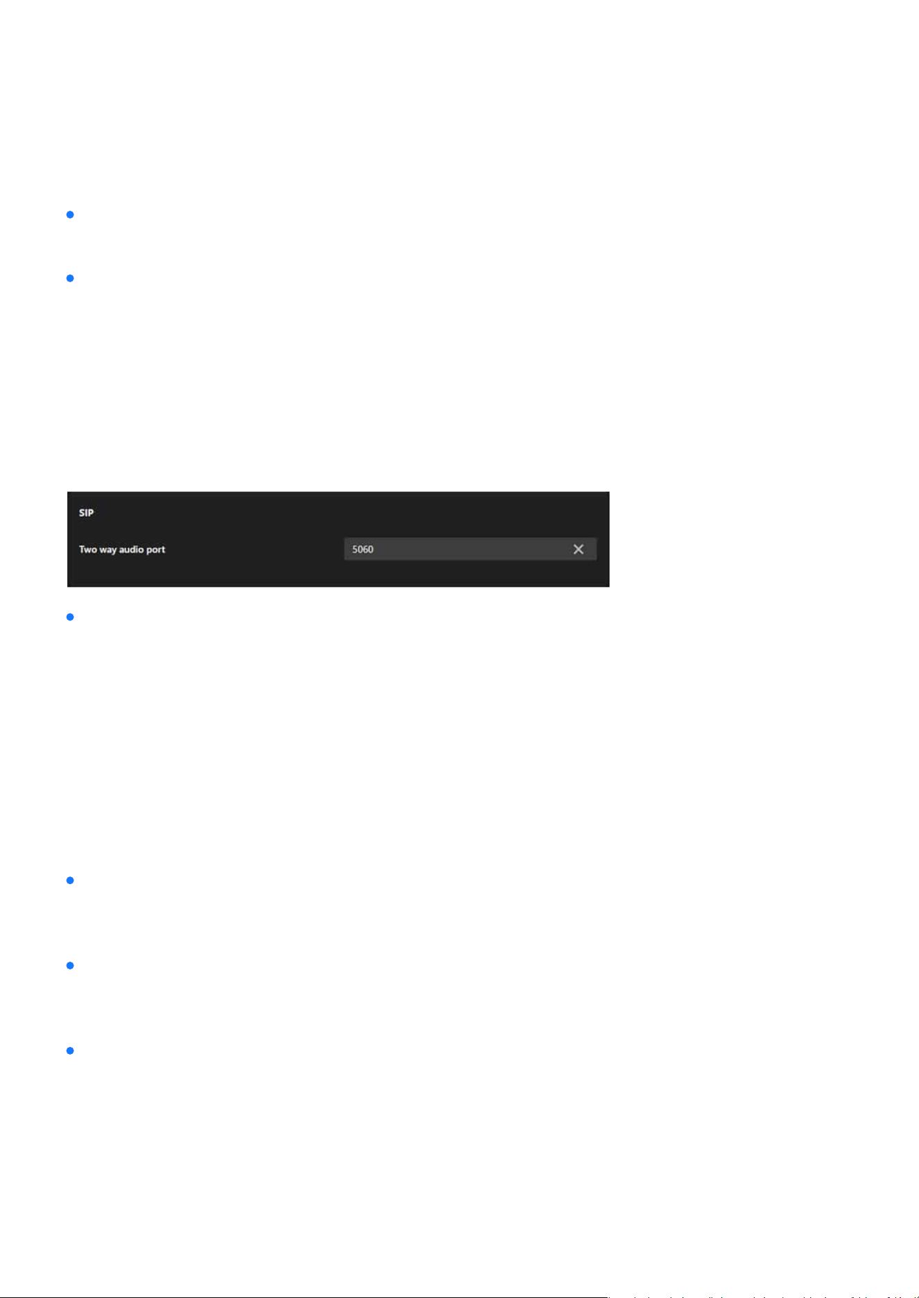
129
System
System
Multicast Port
Multicast TTL (Time-to-Live)
Two way audio port
Congures the port number for multicast streaming (e.g., 5556 for video, 5558 for audio).
Sets the number of network hops allowed for multicast packets, controlling their distribution range.
The Two-Way Audio Port congures the port (default: 5060) used for SIP-based audio communication,
allowing the camera to transmit and receive audio streams for real-time interaction with other SIP-com-
patible devices.
SIP
SNMP
The SIP card is essential for conguring the camera’s two-way audio communication capabilities via the SIP
protocol. It enables integration with SIP-based systems, supports real-time audio interaction, and ensures
exibility with customizable port settings, making it a critical feature for applications requiring interactive
communication.
This section explains how to use the SNMP on the network camera. The Simple Network Management Proto-
col is an application layer protocol that facilitates the exchange of management information between net-
work devices. It helps network administrators to remotely manage network devices and nd, solve network
problems with ease. The SNMP consists of the following three key components:
Manager
Agent
Managed device
Network-management station(NMS), a server which executes applications that monitor and control man-
aged devices.
A network-management station software module on a managed device which transfers the status of man-
aged devices to the NMS.
A network node on a managed network. For example: routers, switches, bridges, hubs, computer hosts,
printers, IP telephones, network cameras, web server, and database.
Note:
Before conguring SNMP settings on this card, please enable your NMS rst.
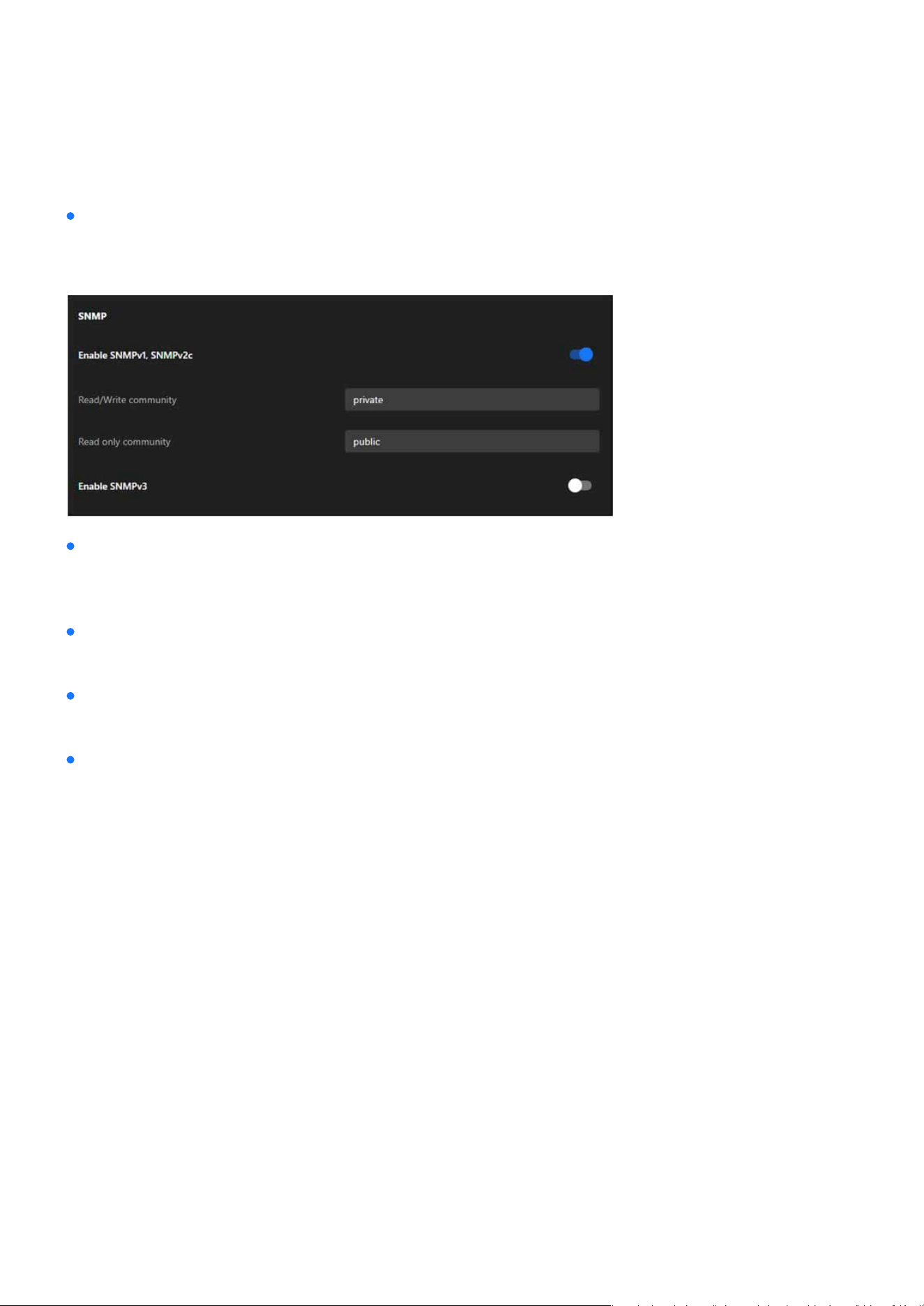
130
System
System
Enable SNMPv1, SNMPv2c
Select the option and enter the names of Read/Write community and Read Only community according to
your NMS settings.
Enable SNMPv3
Read/Write security name
Authentication type
Authentication password
This option contains cryptographic security, a higher security level, which allows you to set the Authentica-
tion password and the Encryption password.
According to your NMS settings, choose Read/Write or Read Only and enter the community name.
Select MD5 or SHA as the authentication method.
Enter the password for authentication (at least 8 characters).
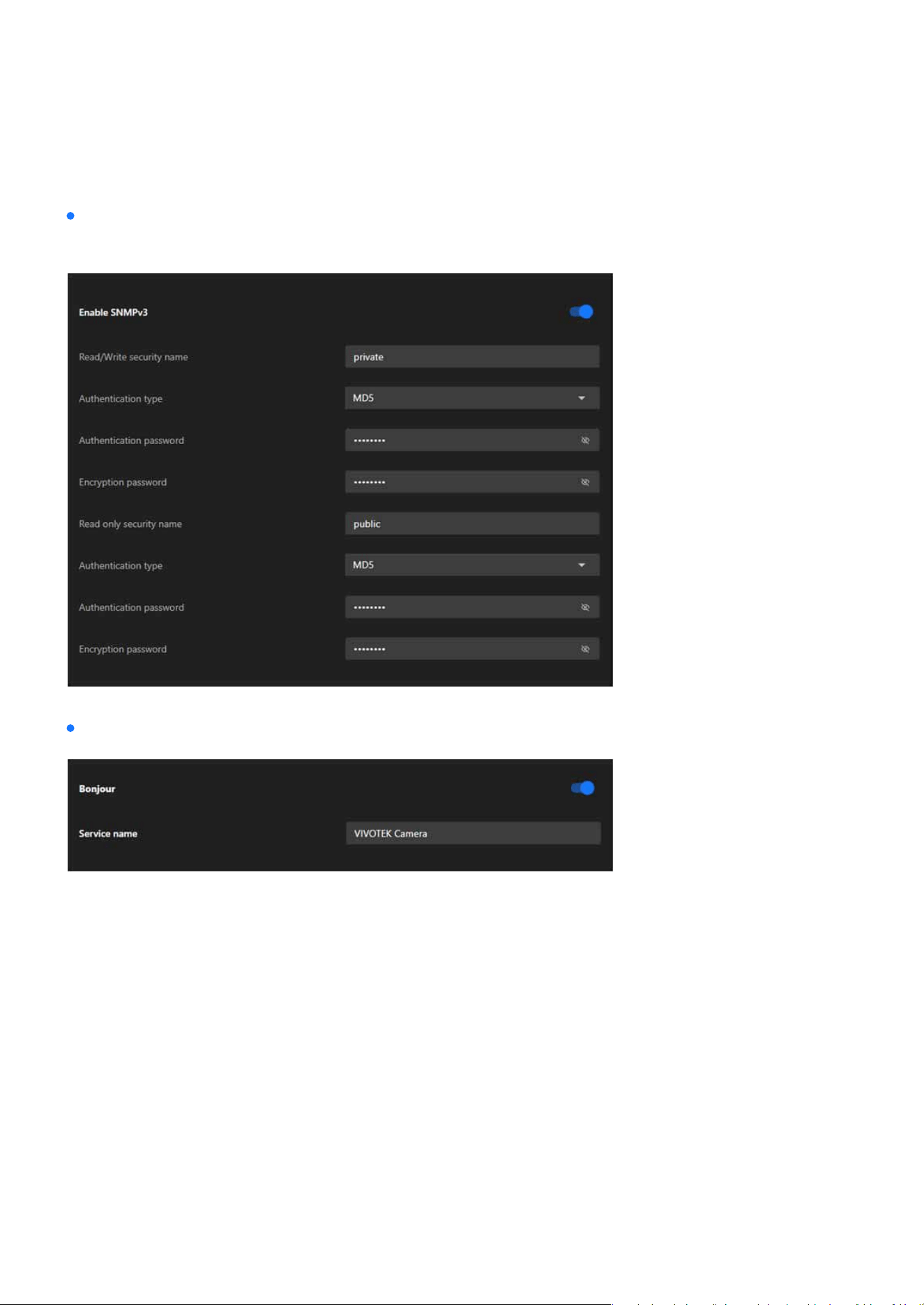
131
System
System
Encryption password
Bonjour
Enter a password for encryption (at least 8 characters).
To access the camera from a MAC computer, go to Safari, click on Bonjour and select the camera from a
drop-down list.
You can go to Safari > Preferences to enter your user name and password, provide the root password the
rst time you access the camera. The camera main page will open in your browser.
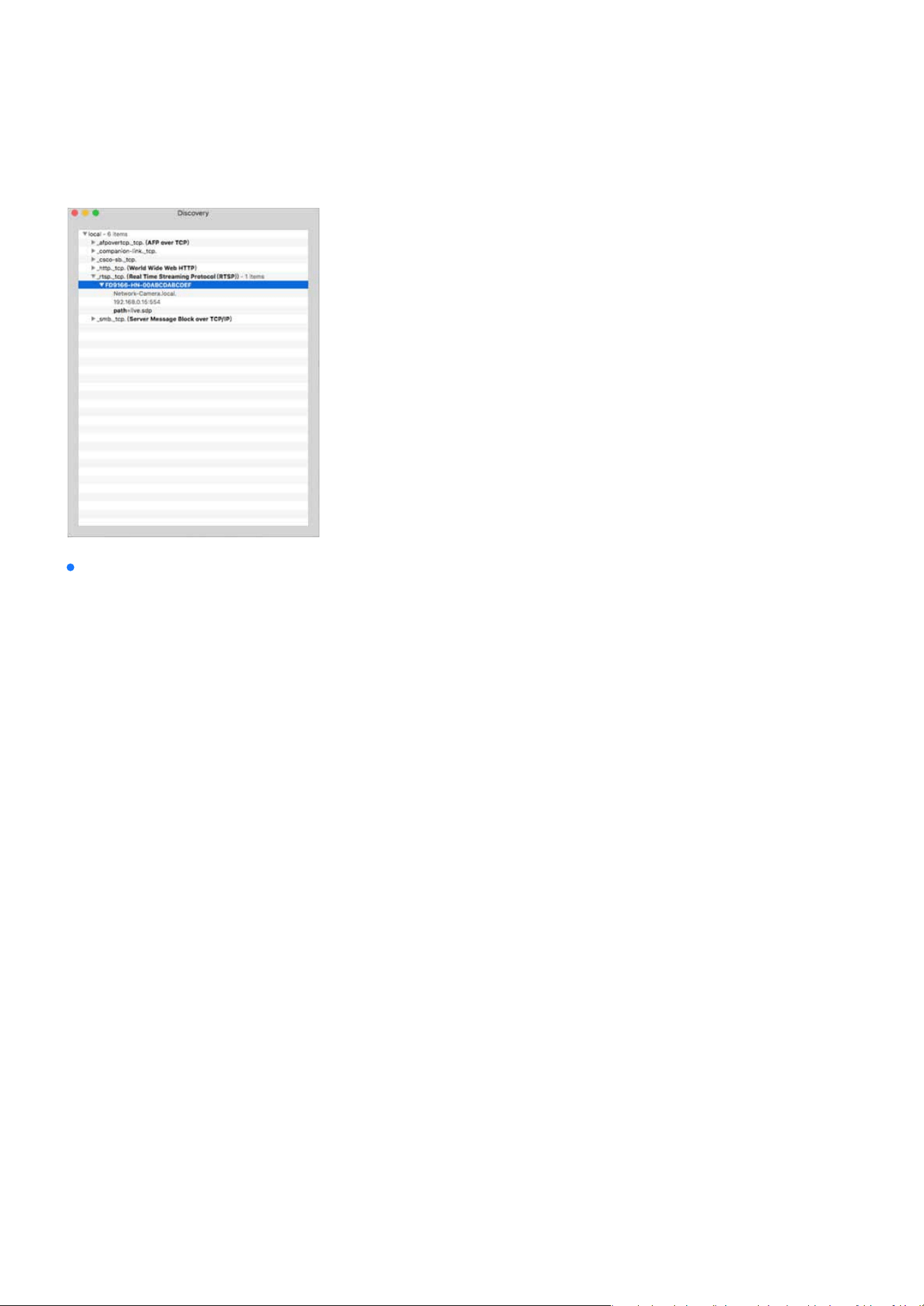
132
System
System
Discovery Utility for Bonjour Services
In some later versions of iOS, the Bonjour option may no longer be available. To address this, you can use
the Discovery utility, which serves as a replacement for the Bonjour Browser. Follow the steps below to get
started:
Previously known as Bonjour Browser, the updated Discovery utility is now distributed exclusively on
the Mac App Store.
System Requirements: Discovery requires macOS 10.12 (Sierra) or later.
http://www.tildesoft.com/les/BonjourBrowser.dmg
Discovery is also available for iOS devices and can be downloaded from the App Store.
https://itunes.apple.com/us/app/discovery-dns-sd-browser/id305441017?mt=8
•
Install Discovery from the Mac App Store
•
Install Discovery for iOS
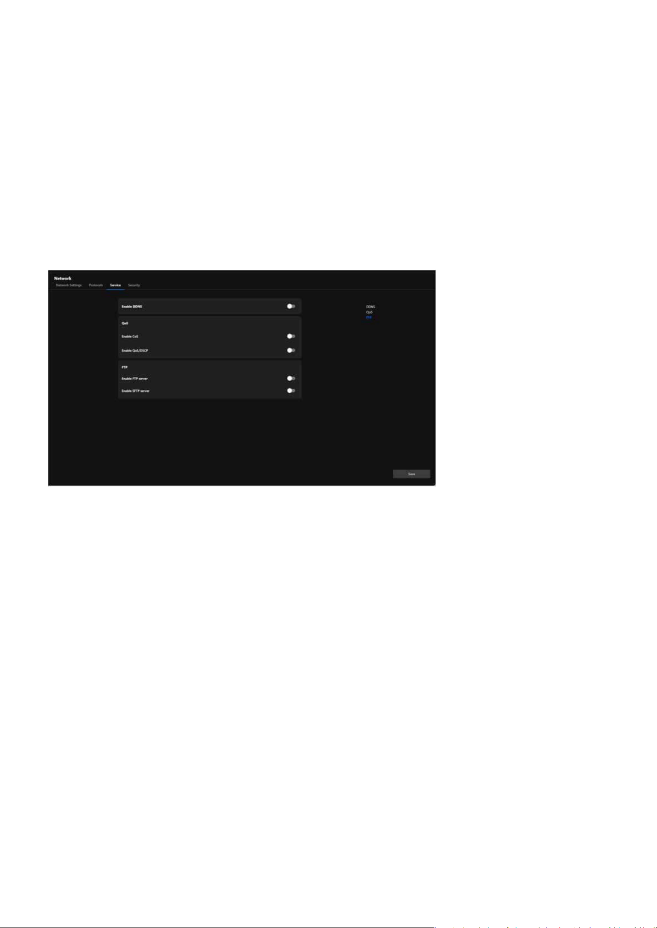
133
System
System
Service
The Service tab provides essential options for managing network services. These include enabling Dynam-
ic Domain Name System (DDNS) for seamless remote access even with dynamic IP addresses, conguring
Quality of Service (QoS) settings to prioritize camera data trac on the network, and activating FTP or SFTP
servers for secure and ecient le transfer. These features ensure reliable connectivity, enhanced data se-
curity, and improved performance, catering to diverse surveillance requirements.
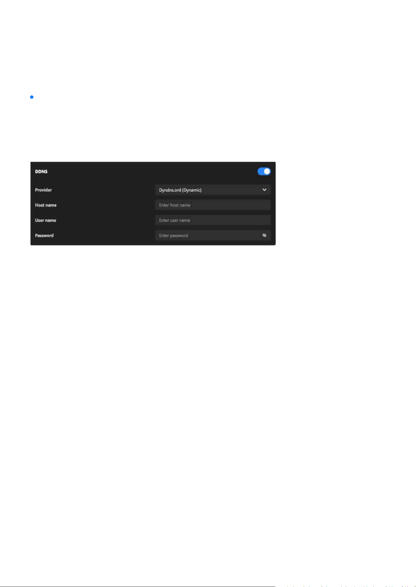
134
System
System
The card integrates with third-party DDNS services to dynamically update the domain name associated
with the camera whenever its IP address changes. Users need to provide valid credentials and a registered
hostname with their DDNS provider to use this feature eectively. The dierence between “Dynamic” and
“Custom” provider modes allows exibility based on the user’s DDNS service plan or provider require-
ments.
Allows the user to activate or deactivate the DDNS functionality.
A dropdown menu allows users to select the DDNS service provider, with options such as “Dyndns.org
(Dynamic)” or “Dyndns.org (Custom).” The selected provider determines how the hostname and creden-
tials are congured for the DDNS connection.
An input eld is provided to specify the unique hostname registered with the selected DDNS provider (e.g.,
yourcamera.dyndns.org), which will be used for remote access to the camera.
Input eld for the account username required by the DDNS provider.
Input eld for the password associated with the DDNS account. A hidden eld ensures privacy during in-
put.
DDNS
Enable DDNS:
Provider:
Host Name:
User Name:
Password:
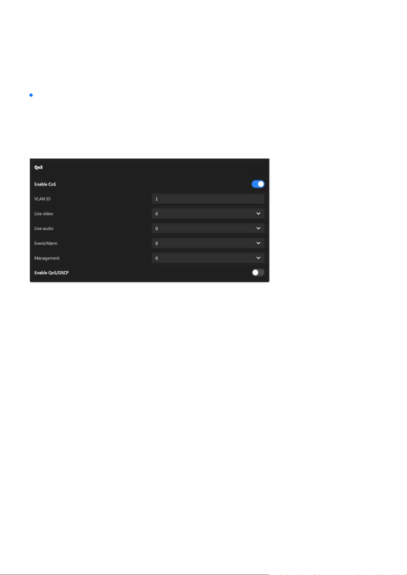
135
System
System
The QoS card allows users to exibly congure the priority of dierent types of data streams based on
network environment requirements. When CoS is enabled, it can integrate with VLANs, making it suitable
for Ethernet networks. Enabling QoS/DSCP, on the other hand, is more appropriate for IP networks. These
settings help enhance the reliability and eciency of camera data transmission, which is particularly cru-
cial when multiple devices share the same network.
QoS
A toggle switch to enable or disable CoS functionality.
Species the VLAN tag for identifying the virtual LAN the camera is part of.
Enable CoS (Class of Service):
VLAN ID:
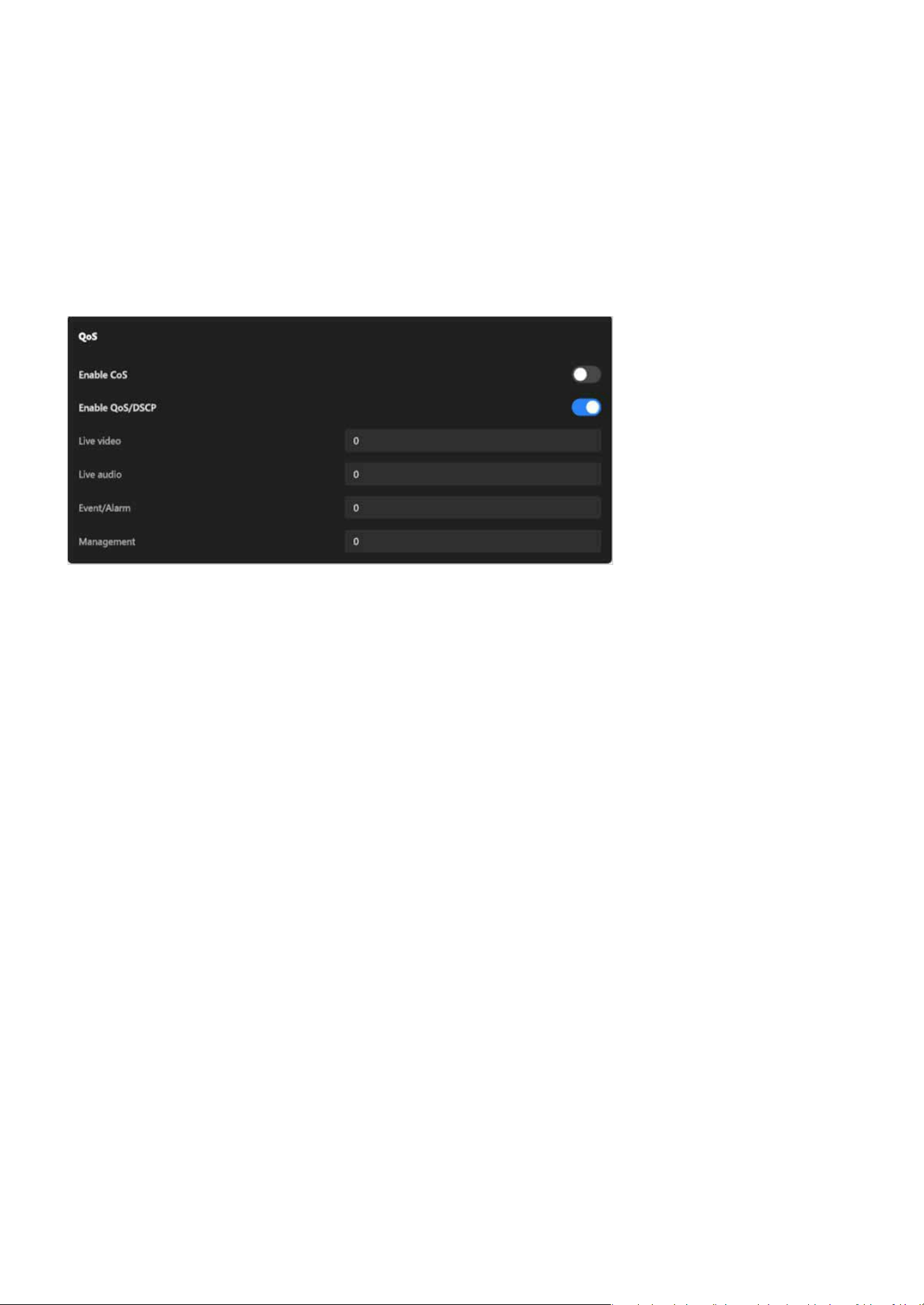
136
System
System
Each data type (Live Video, Live Audio, Event/Alarm, Management) can be assigned a priority level via a 0-7
dropdown menu, where higher numbers indicate higher transmission priority. This allows for ne-grained
control of trac within an Ethernet network.
A toggle switch to enable or disable DSCP functionality.
Allows users to congure a DSCP value for each data type (Live Video, Live Audio, Event/Alarm, Manage-
ment). These values determine the priority of the data in IP networks, ensuring proper trac classication
and ecient routing.
Priority settings for each data type (Live Video, Live Audio, Event/Alarm, Management):
Enable QoS/DSCP (Dierentiated Services Code Point):
DSCP values for each data type (Live Video, Live Audio, Event/Alarm, Management):
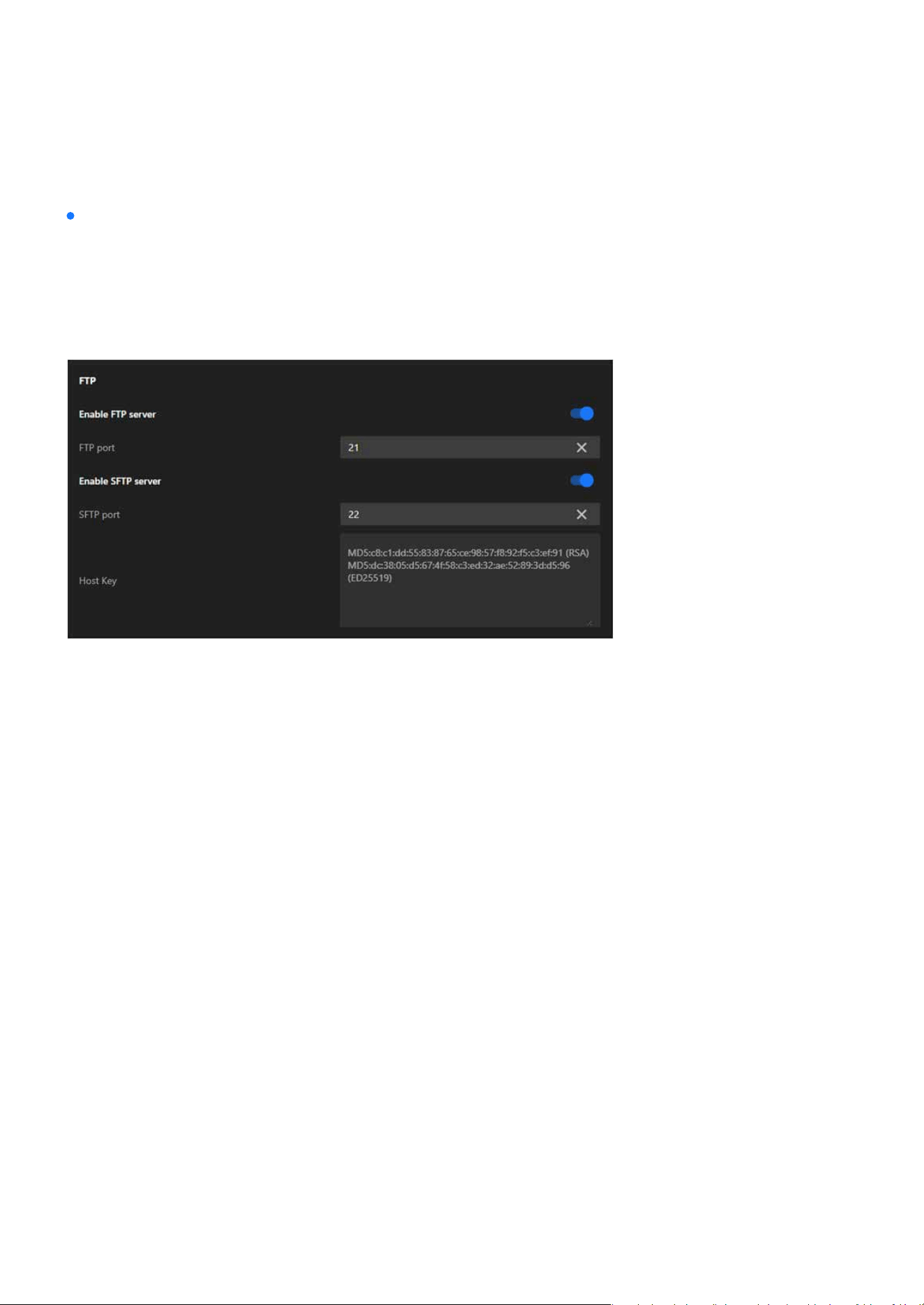
137
System
System
The FTP card provides the exibility to use FTP for simple and ecient le transfers or SFTP for secure,
encrypted transfers, depending on the user’s operational and security needs. The ability to congure the
ports ensures compatibility with various network congurations. Host keys in SFTP further enhance trust
and security during client-server communication. This functionality is particularly useful for automated
storage or backup of surveillance data to remote locations.
FTP
A toggle switch to enable or disable the FTP server functionality.
Species the port used for the FTP service (default is 21). Users can adjust this to align with their network
or security requirements.
A toggle switch to enable or disable the SFTP server functionality.
Species the port used for the SFTP service (default is 22). Users can modify this port if needed to avoid
conicts or meet specic security policies.
Displays the server’s host key information, including hash values (e.g., RSA and ED25519 keys). These keys
are used to authenticate the server and ensure secure connections between the client and the server.
Enable FTP Server:
FTP Port:
Enable SFTP Server:
SFTP Port:
Host Key:
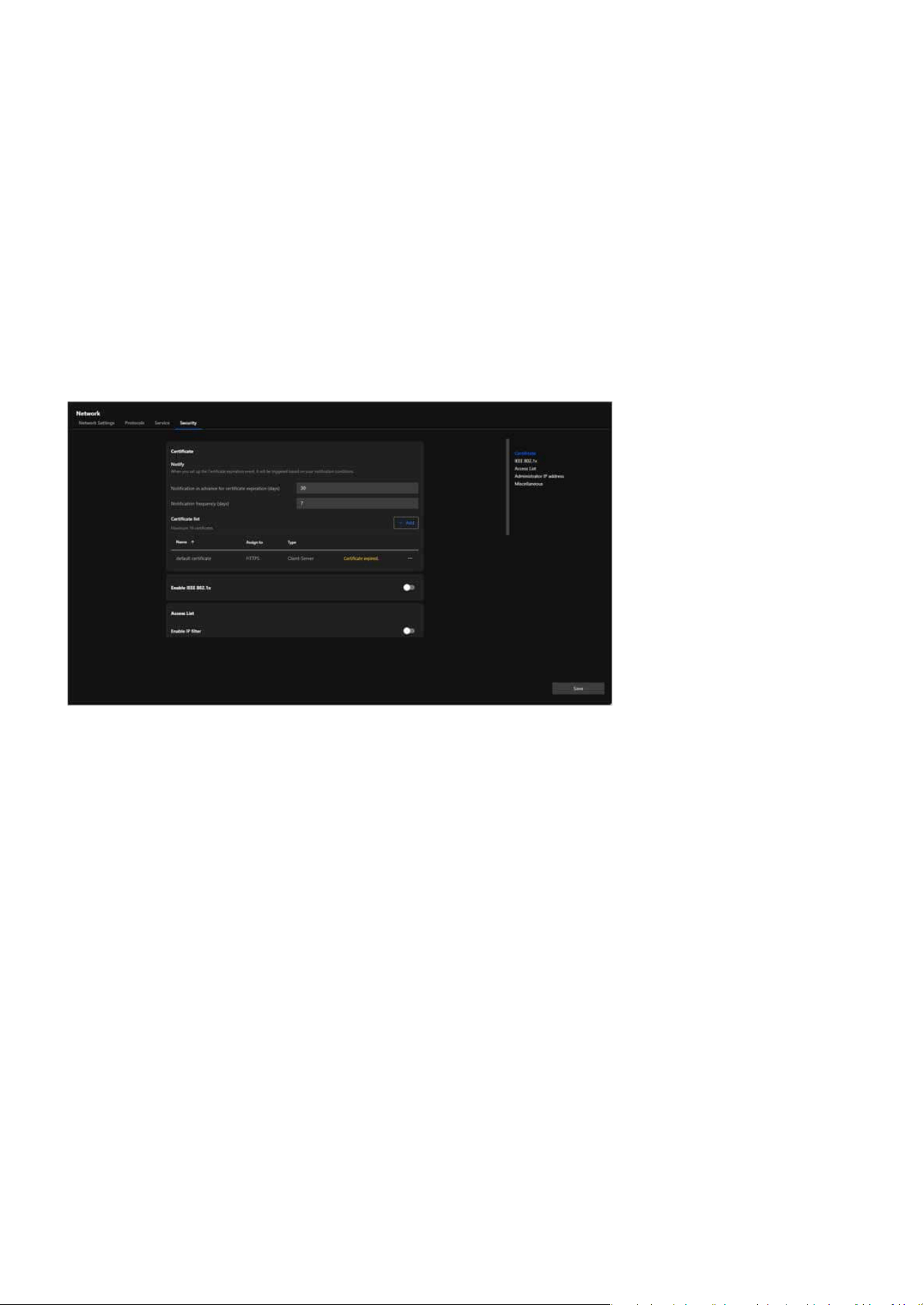
138
System
System
Security
The Security tab provides a comprehensive set of options to enhance network security. It allows users to
manage certicates for encrypted communications, implement access control through IP ltering and IEEE
802.1x authentication, and restrict administrative access to specic IP addresses. By utilizing these features,
users can ensure secure data transmission, prevent unauthorized access, and protect the camera in both
simple and complex network environments. This tab is designed to address the security needs of modern
surveillance systems and oer robust protection against potential threats.
The Certicate card focuses on providing a robust and centralized solution for managing certicates. By
supporting HTTPS encryption, it ensures secure communication between the camera and external sys-
tems, safeguarding data against potential eavesdropping or tampering. The notication feature alerts
users to expired certicates, helping to mitigate associated risks, while the ability to manage multiple
certicates oers exibility to accommodate various network congurations and requirements.
Certicate
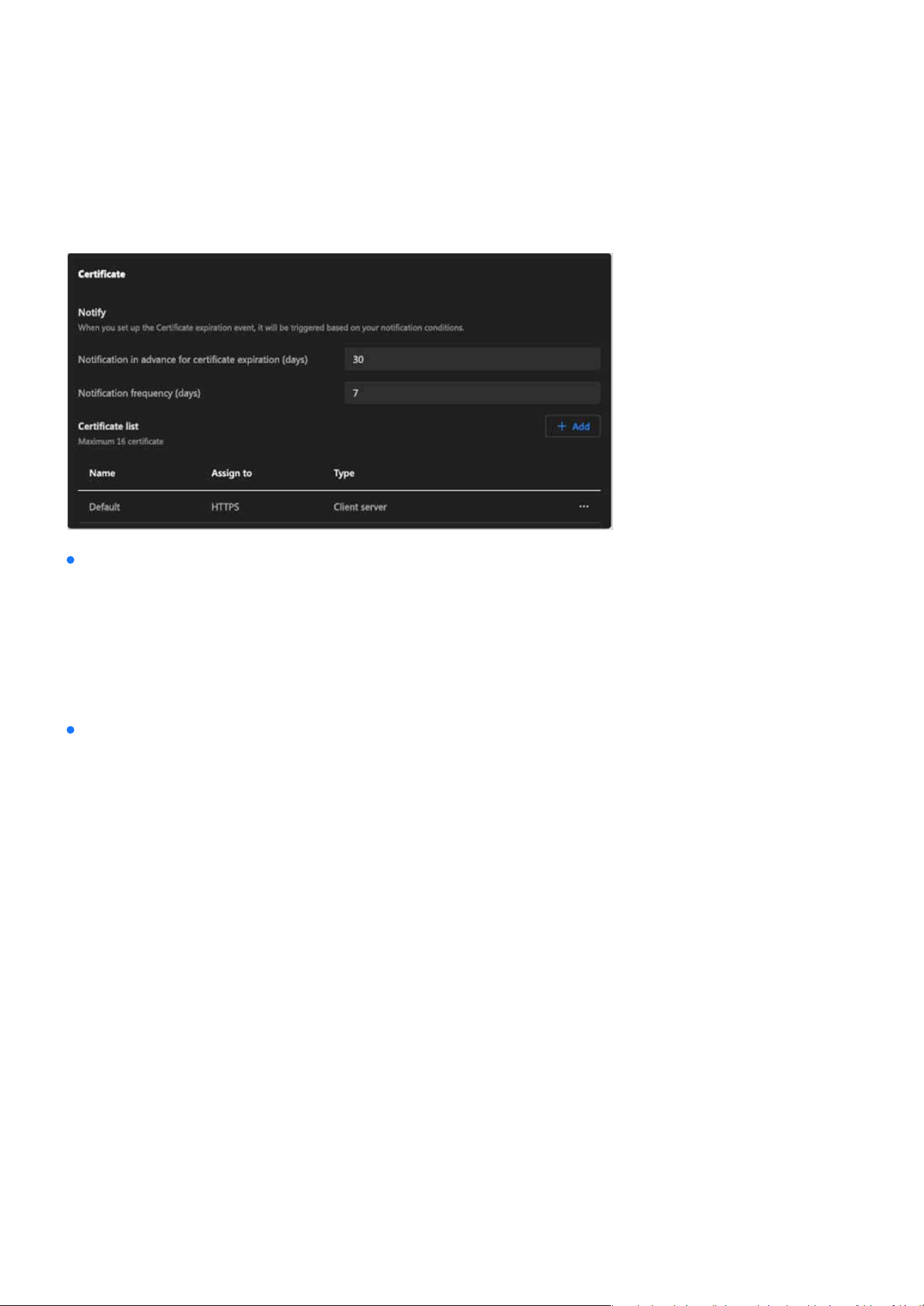
139
System
System
Certicate
Notify:
Certicate List:
Congures notication settings for certicate expiration.
Supports managing up to 16 certicates and displays detailed information about each certicate, in-
cluding:
•
Notication in advance for certicate expiration (days):
•
Name:
•
Assign to:
•
Type:
•
Indicates the current status of each certicate, such as “Certicate expired.”
•
Notication frequency (days):
Sets how many days before expiration the system will send a notication.
Species the frequency of repeated notications.
The name of the certicate.
The application or protocol the certicate is associated with (e.g., HTTPS).
The purpose of the certicate (e.g., Client-Server).
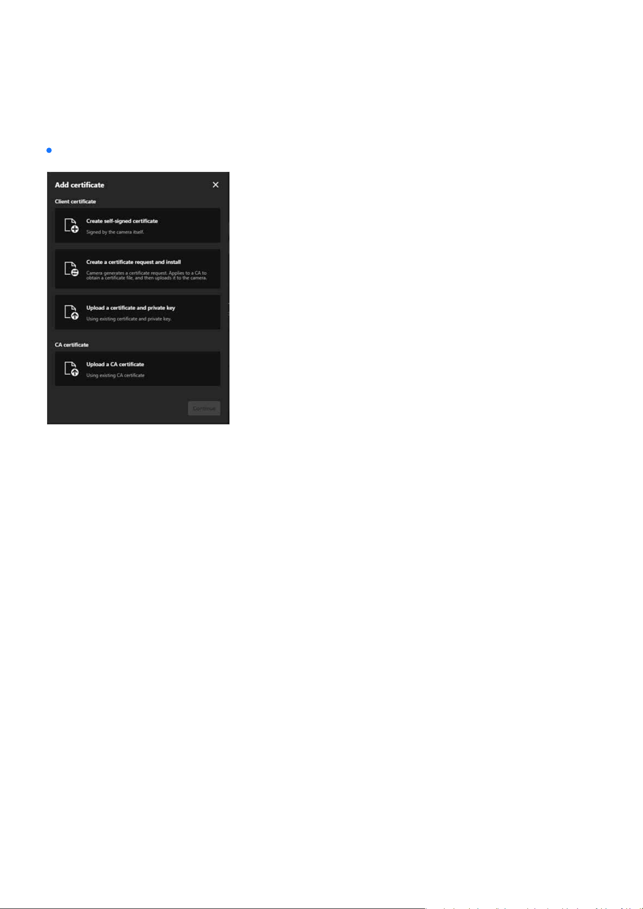
140
System
System
Steps to add a Certicate:
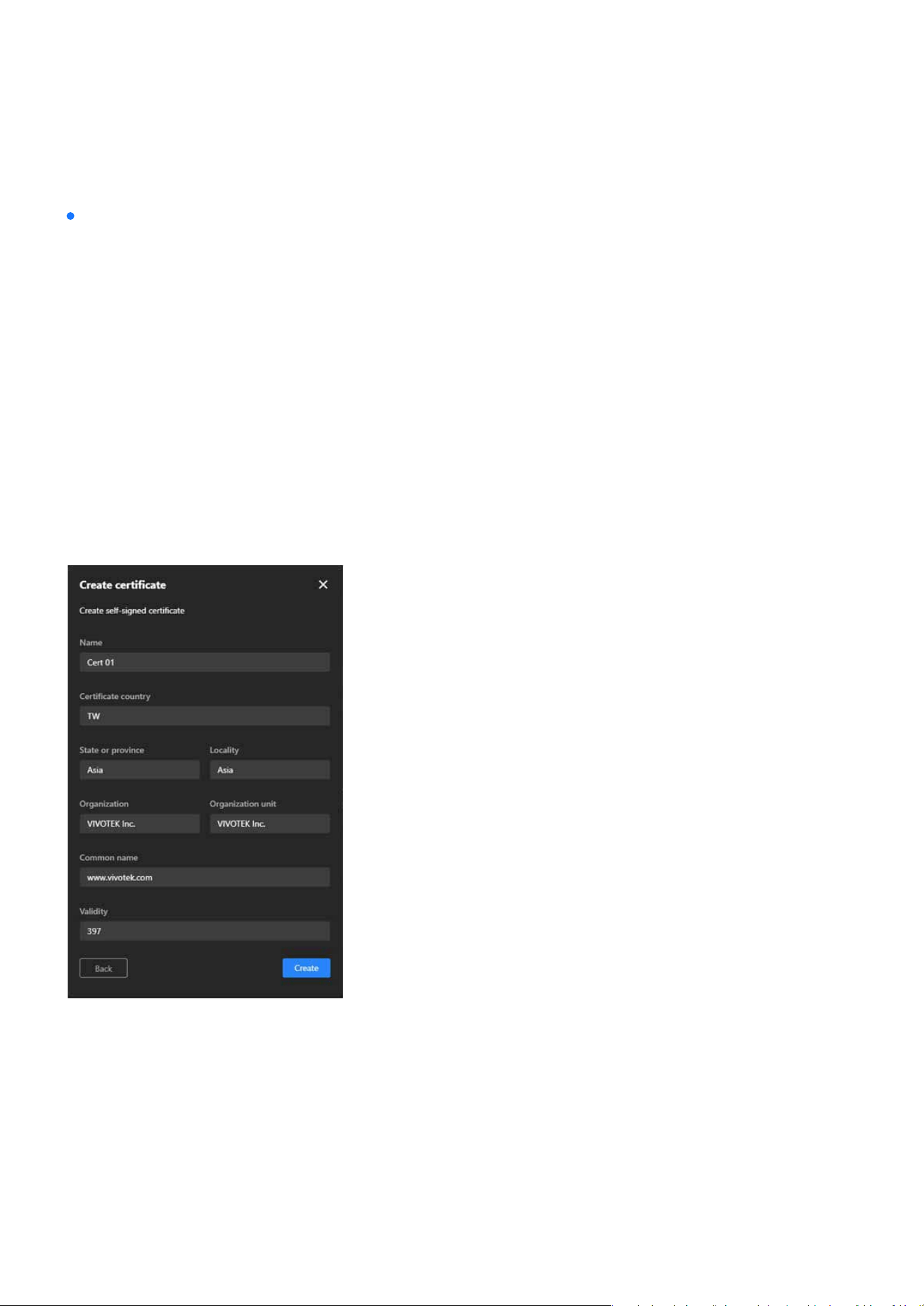
141
System
System
Steps to add a Certicate:
Option 1. Create a self-signed certicate for the Client certicate.
•
Step 1. Click “+Add” button and then pop up the “Add Certicate” window.
•
Step 2. Select Create self-signed certicate.
•
Step 3. Fill in the required elds, including:
•
Step 4. Click Create to start certicate generate procedure.
•
Step 5. A message indicating “Generated successfully” means the process is complete.
Name: Enter a name for the certicate (e.g., “Cert 01”).
Certicate country: Provide the country code (e.g., “TW”).
State or province and Locality: Specify the location (e.g., “Asia”).
Organization and Organization unit: Enter the organization details.
Common name: Provide the domain name (e.g., “www.vivotek.com”).
Validity: Specify the validity period in days (e.g., “397”).
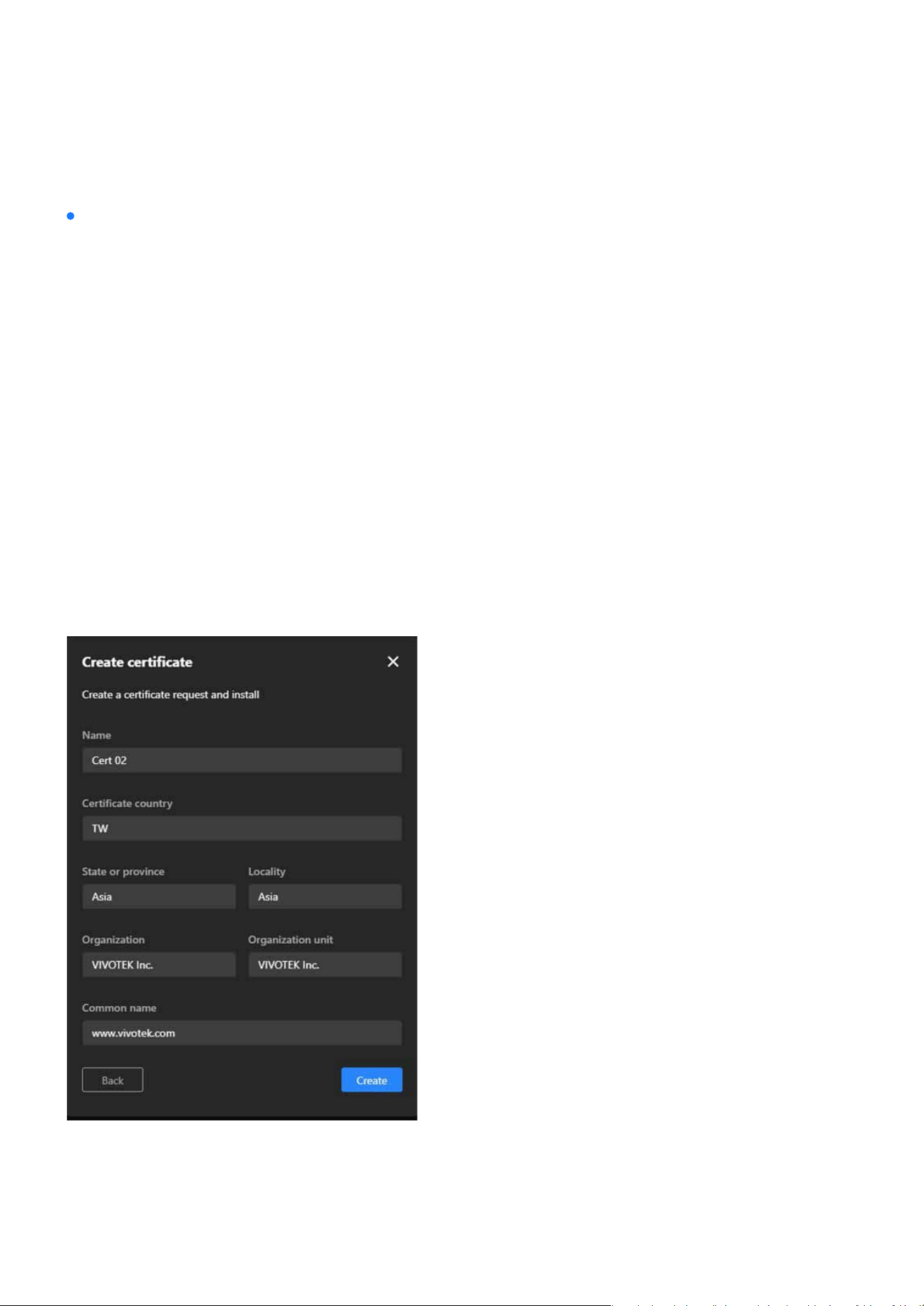
142
System
System
Steps to add a Certicate:
Option 2. Create a Certicate Request and Install for the Client certicate.
•
Step 1. Click “+Add” button and then pop up the “Add Certicate” window.
•
Step 2. Select Create a certicate request and install.
•
Step 3. Fill in the required elds similar to the self-signed certicate (Name, Location, Organization,
Common Name).
•
Step 4. Click Create to start certicate generate procedure.
•
Step 5. A message indicating “Uploaded successfully” means the certicate request is generated
successfully.
•
Step 6. Click “Copy certicate request” button to copy the details of the certicate request (CSR).
•
Step 7. Use the copied CSR to apply for a certicate from a trusted CA, which will then provide a
signed certicate le (e.g., a.crt le).
•
Step 8. After receiving the signed certicate from the CA, return to the same window, click Upload
le, and select the .crt le provided by the CA.
•
Step 9. Click Create to complete the installation of the certicate.
•
Step 10. A message indicating “Uploaded successfully” means the process is complete.
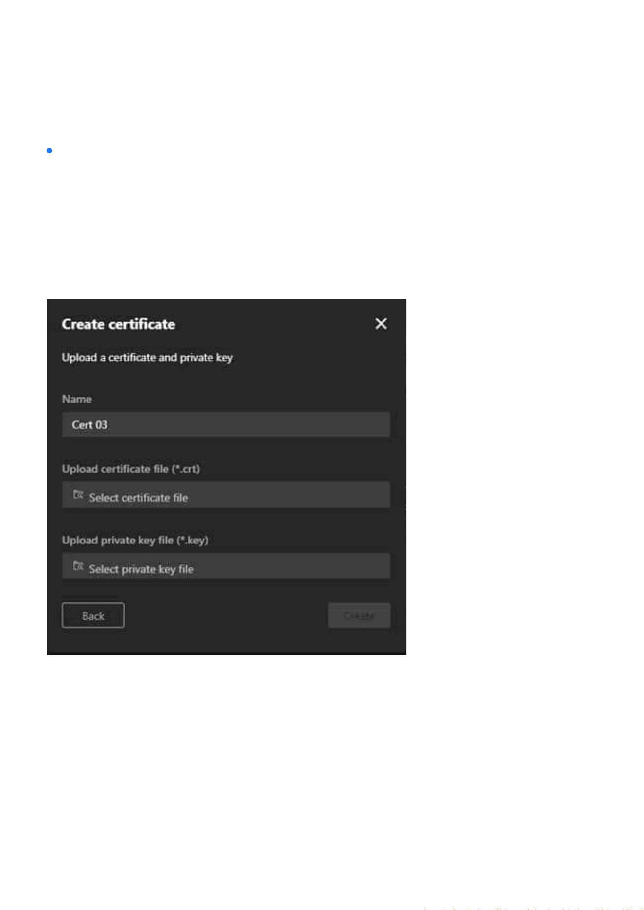
143
System
System
Steps to add a Certicate:
Option 3: Upload a Certicate and Private Key for the Client certicate.
•
Step 1. Click “+Add” button and then pop up the “Add Certicate” window.
•
Step 2. Select Upload a certicate and private key.
•
Step 3. Fill in the certicate name (e.g., “Cert 03”).
•
Step 4. Use the Upload certicate le (*.crt) and Upload private key le (*.key) options to upload the
respective les.
•
Step 5. Click Create to add the certicate.
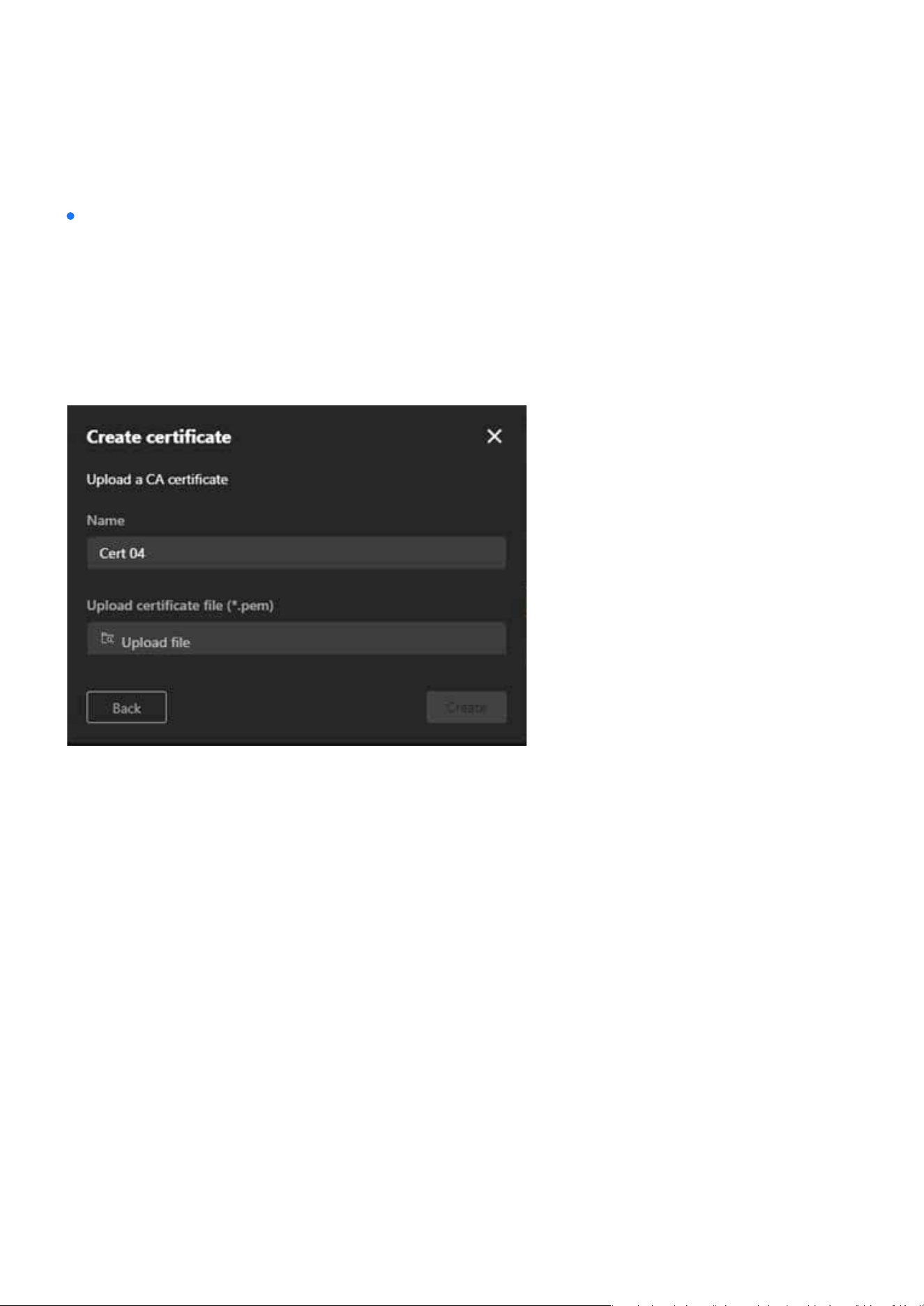
144
System
System
Steps to add a Certicate:
Option 4: Upload a CA Certicate for the CA certication
•
Step 1. Click “+Add” button and then pop up the “Add Certicate” window.
•
Step 2. Select Upload a CA certicate.
•
Step 3. Fill in the certicate name (e.g., “Cert 04”).
•
Step 4. Use the Upload certicate le (*.pem) option to upload the CA certicate.
•
Step 5. Click Create to nalize the process.
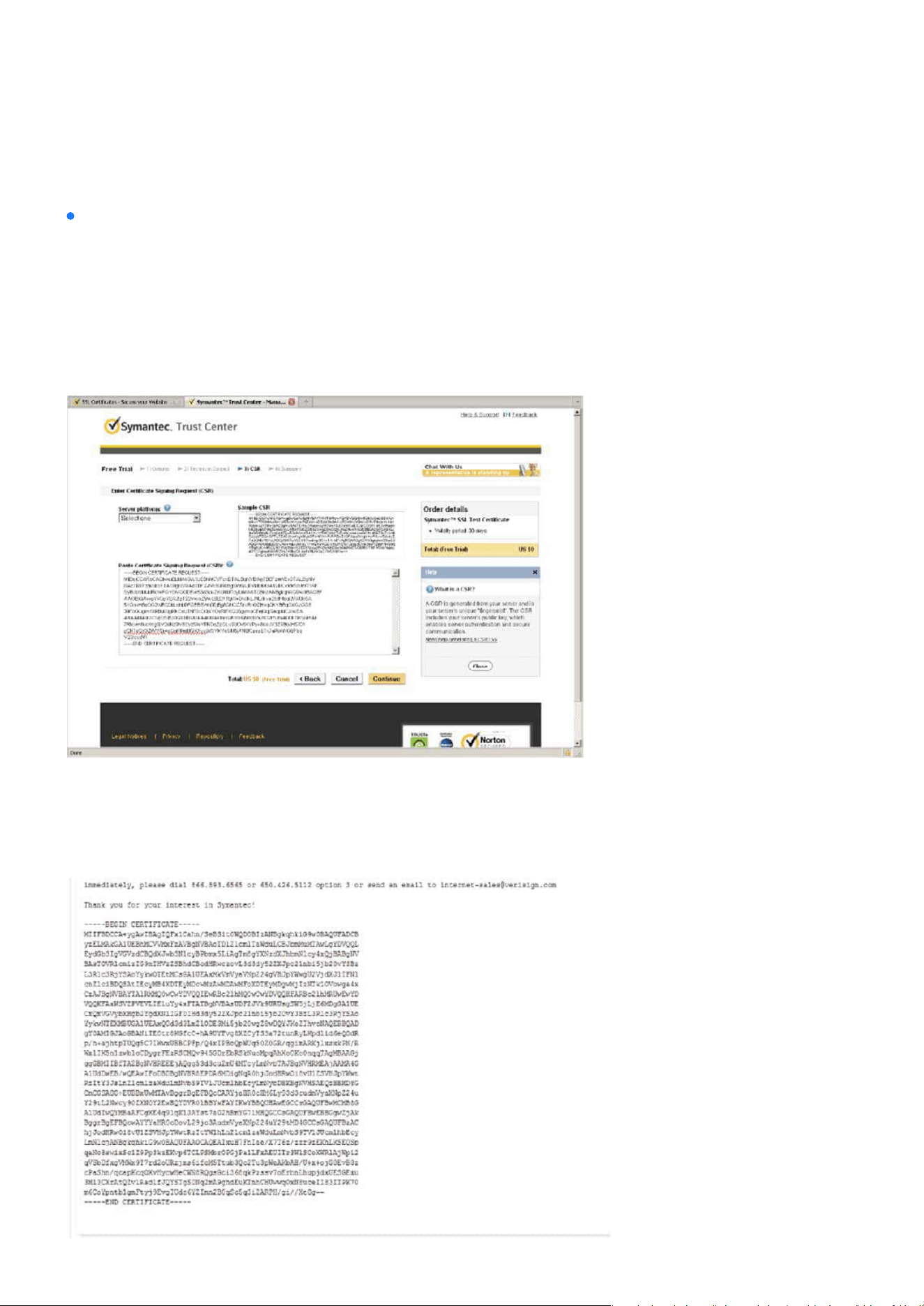
145
System
System
Note:
How to use the copied CSR to apply for a certicate from a trusted CA, which will then provide a signed
certicate le:
•
Step 1. Look for a trusted certicate authority, such as Symantec’s VeriSign Authentication Services,
that issues digital certicates. Sign in and purchase the SSL certication service. Copy the certicate
request from your request prompt and paste it in the CA’s signing request window. Proceed with the
rest of the process as CA’s instructions on their webpage.
•
Step 2. Once completed, your SSL certicate should be delivered to you via an email or other means.
Copy the contents of the certicate in the email and paste it in a text/HTML/hex editor/converter,
such as IDM Computer Solutions’ UltraEdit.
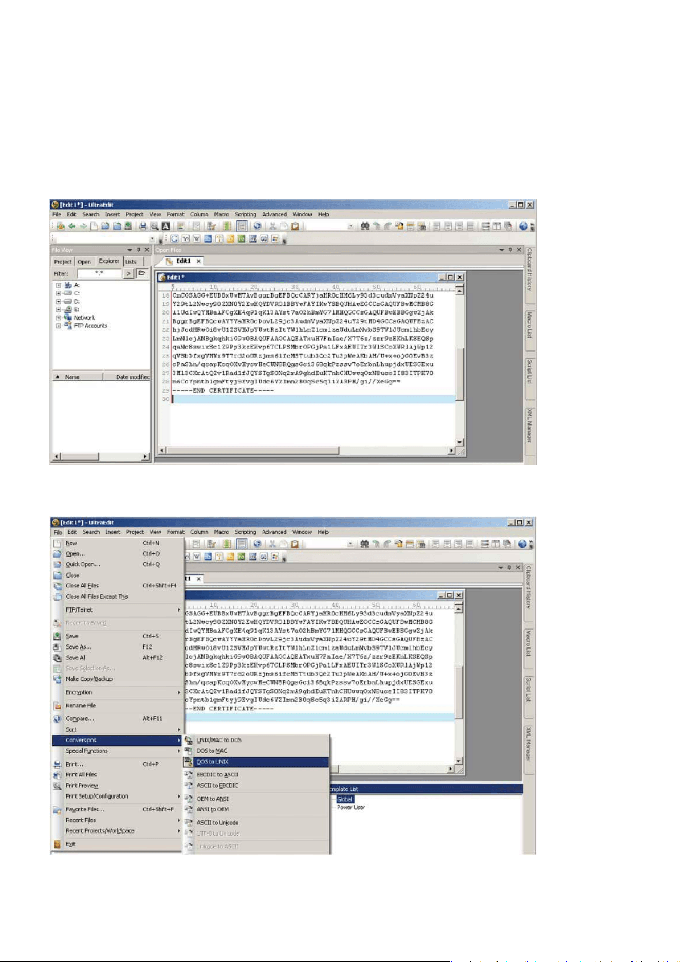
146
System
System
•
Step 3. Open a new edit, paste the certicate contents, and press ENTER at the end of the contents
to add an empty line.
•
Step 4. Convert le format from DOS to UNIX. Open File menu > Conversions > DOS to Unix.
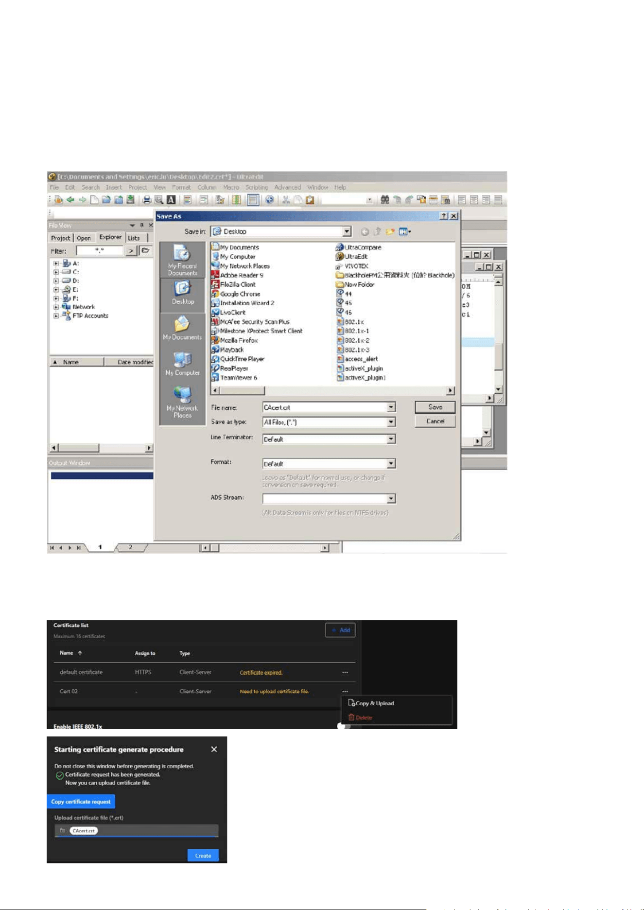
147
System
System
•
Step 5. Save the edit using the “.crt” extension, using a le name like “CAcert.crt.”
•
Step 6. Return to the original rmware session, use the “More” icon > “Copy & Upload” button to
locate the crt certicate le, and click Create to enable the certication.
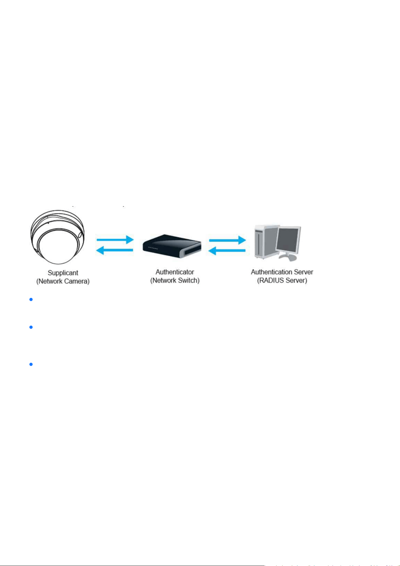
148
System
System
LED & DIDO
Enable this function if your network environment uses IEEE 802.1x, which is a port-based network access
control. The network devices, intermediary switch/access point/hub, and RADIUS server must support and
enable 802.1x settings.
The 802.1x standard is designed to enhance the security of local area networks, which provides authenti-
cation to network devices (clients) attached to a network port (wired or wireless). If all certicates between
client and server are veried, a point-to-point connection will be enabled; if authentication fails, access on
that port will be prohibited. 802.1x utilizes an existing protocol, the Extensible Authentication Protocol (EAP),
to facilitate communication.
The components of a protected network with 802.1x authentication:
VIVOTEK Network Cameras support two types of EAP methods to perform authentication:
EAP-PEAP and
EAP-TLS. Please follow the steps below to enable 802.1x settings:
Supplicant:
Authenticator (an access point or a switch):
Authentication server (usually a RADIUS server):
A client end user (camera), which requests authentication.
A “go between” which restricts unauthorized end users from communicating with the authentication serv-
er.
Checks the client certicate and decides whether to accept the end user’s access request.
•
Step 1. Before connecting the Network Camera to the protected network with 802.1x, please apply a
digital certicate from a Certicate Authority (i.e., your network administrator) which can be vali-
dated by a RADIUS server.
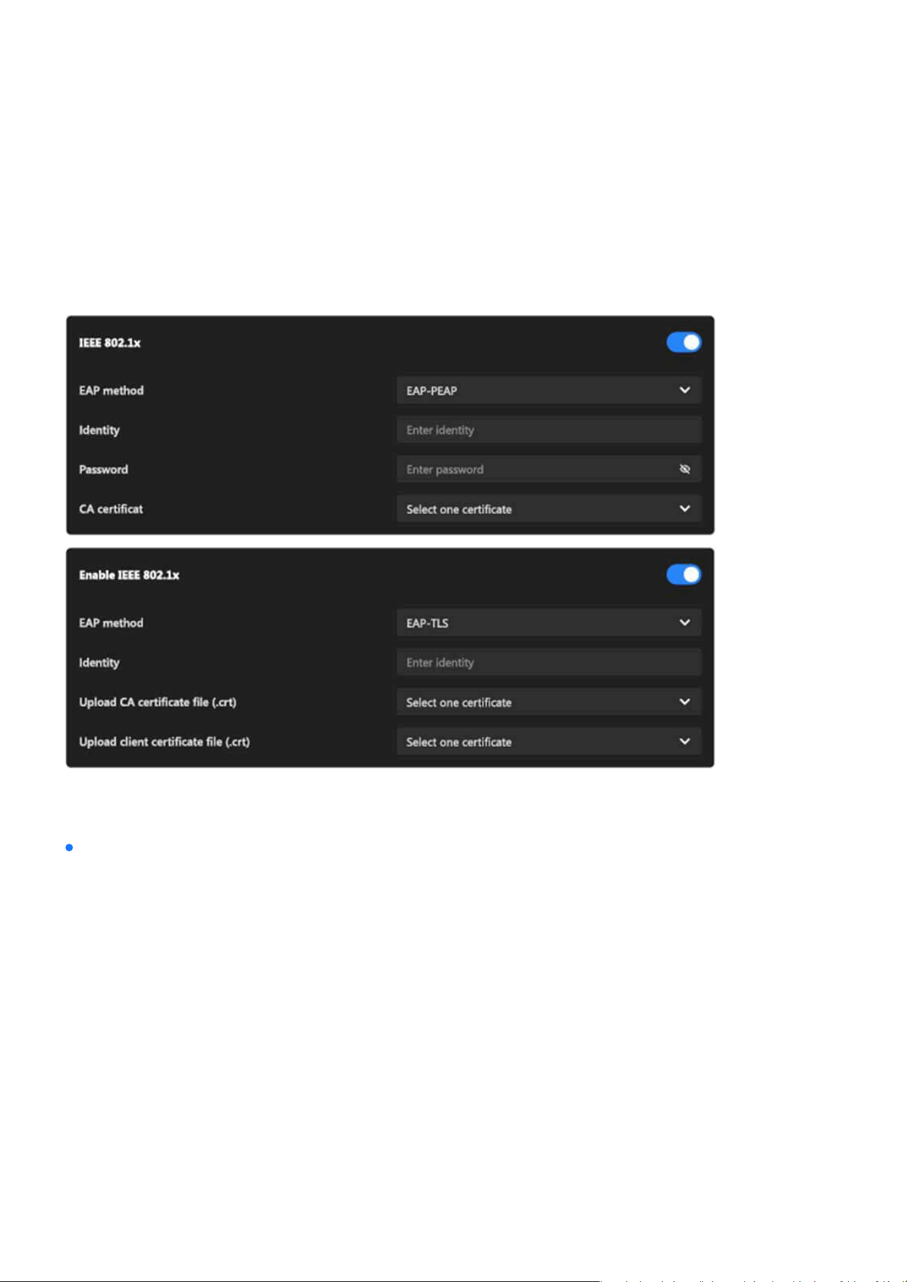
149
System
System
•
Step 2. Connect the Network Camera to a PC or notebook outside of the protected LAN. Open the
conguration page of the Network Camera as shown below. Select EAP-PEAP or EAP-TLS as the EAP
method. In the following blanks, enter your ID and password issued by the CA, then upload related
certicate(s).
•
Step 3. When all settings are complete, move the Network Camera to the protected LAN by connect-
ing it to an 802.1x enabled switch. The devices will then start the authentication automatically.
•
Step 1. The Certicate Authority (CA) provides the required signed certicates to the Network Cam-
era (the supplicant) and the RADIUS Server (the authentication server).
•
Step 2. A Network Camera requests access to the protected LAN using 802.1X via a switch (the
authenticator). The client oers its identity and client certicate, which is then forwarded by the
switch to the RADIUS Server, which uses an algorithm to authenticate the Network Camera and re-
turns an acceptance or rejection back to the switch.
•
Step 3. The switch also forwards the RADIUS Server’s certicate to the Network Camera.
Note:
The authentication process for 802.1x:
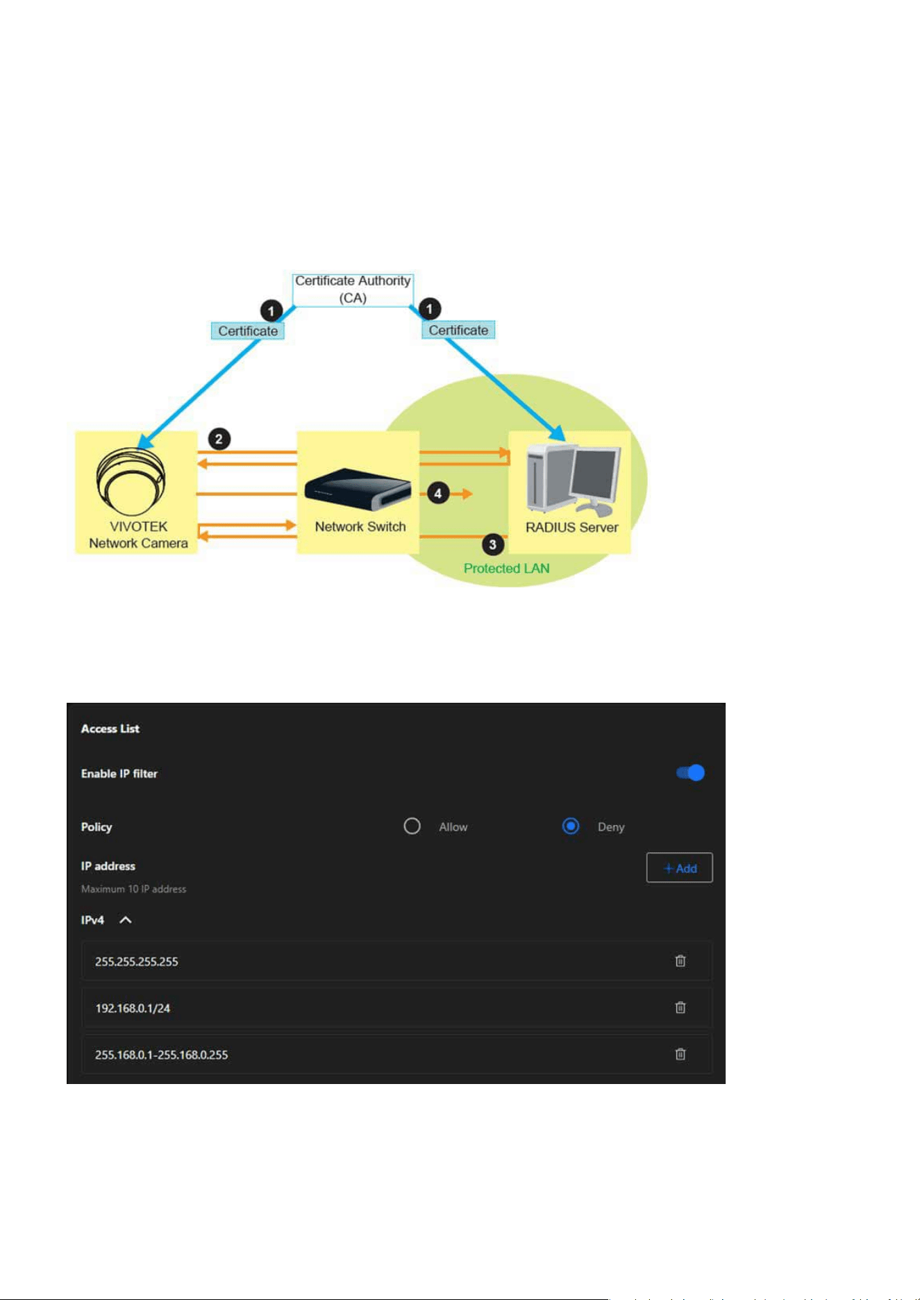
150
System
System
•
Step 4. Assuming all certicates are validated, the switch then changes the Network Camera’s state
to authorized and is allowed access to the protected network via a pre-congured port.
Access List
This feature is particularly useful in environments where the camera is exposed to a larger network or the
internet, ensuring only trusted devices or networks have access.

151
System
System
Enable IP Filter
Policy
IPv4 List
IP Address
A toggle switch to activate or deactivate the IP ltering feature.
Permits only the specied IP addresses to access the camera. All other IPs are denied.
Blocks the specied IP addresses from accessing the camera. All other IPs are allowed.
A section to dene up to 10 IP addresses or ranges that are either allowed or denied access based on the
selected policy.
Allow:
Displays the list of congured IP addresses or ranges, and the entries can be removed using the trash
bin icon next to each address. Each entry can represent:
Steps to add an IP address into Access List:
Deny:
A single IP address (e.g., 192.168.0.1).
A network IP address (e.g., 192.168.0.1/24).
A specic IP range (e.g., 255.168.0.1-255.168.0.255).
Step 1. Click “+Add” button to open the “Add IP Address” window
Step 2. From the IP Type dropdown menu, choose the desired type:
Step 3. From the Rule dropdown menu, select one of the following options:
Step 4. Enter the IP Address:
Step 5. Click Save to add the IP address or range to the Access List.
IPv4: For standard IPv4 addresses or ranges.
Single: To allow or deny a single IP address.
Network: To allow or deny access for an entire subnet.
IP Range: To dene a specic range of IP addresses.
Based on the selected rule, input the relevant details in the IP Address eld:
For Single:
Enter one IP address (e.g., 192.168.0.10).
For Network: Enter an IP address and its subnet mask.
For IP Range: Enter the starting and ending IP addresses.
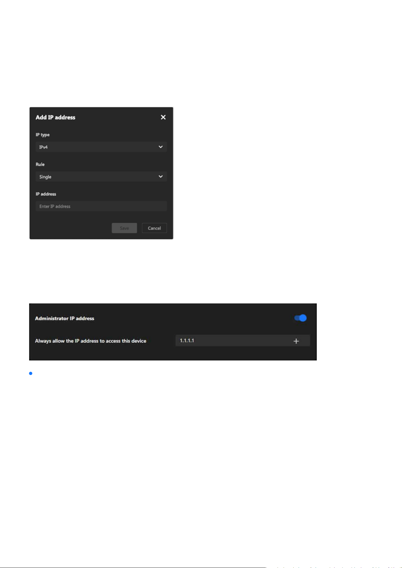
152
System
System
Step 6. The new entry will now appear in the IPv4 section of the Access List.
Administrator IP address
The Administrator IP address provides a simple yet eective way to secure administrative access while en-
suring that authorized personnel can always manage the device, even in complex or restricted network envi-
ronments.
Always allow the IP address to access this device:
You can check this item and add the Administrator’s IP address in this eld to make sure the Administrator
can always connect to the device.
Enter the IP address that should always have administrative access.
Turn on the toggle switch to activate the setting.
Ensure the conguration is saved for the setting to take eect.
Step 1. Input the Trusted IP Address:
Step 2. Enable the Feature:
Step 3. Save Changes:
Steps to set the Administrator IP address:
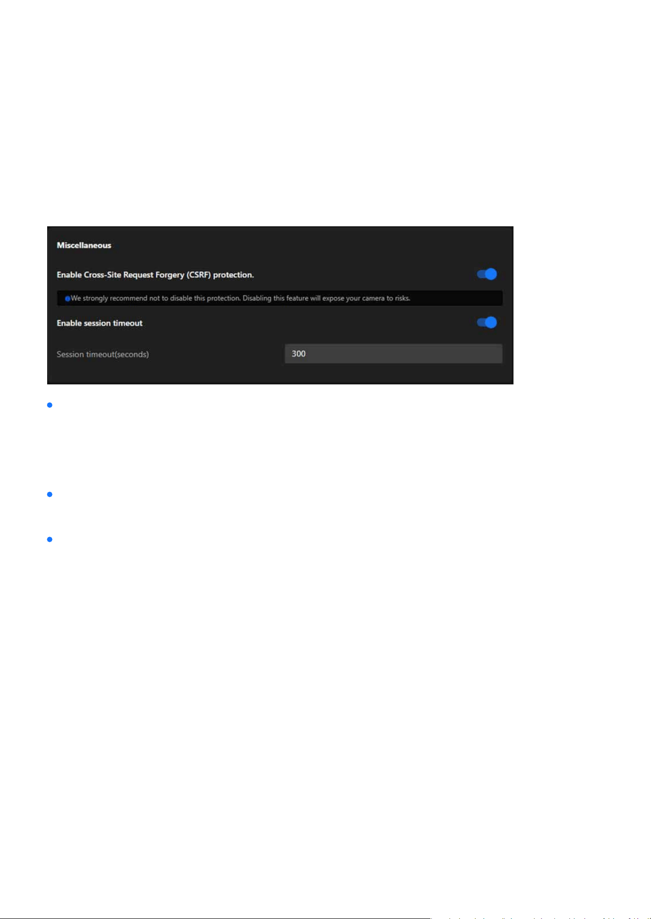
153
System
System
Miscellaneous
The Miscellaneous card in the VIVOTEK camera’s settings provides additional security-related options to en-
hance the safety and usability of the device. It focuses on protecting against cross-site request forgery (CSRF)
attacks and managing session timeouts for user accounts.
Enable Cross-Site Request Forgery (CSRF) Protection:
Enable Session Timeout:
Session Timeout (seconds):
Prevents unauthorized commands being sent from a malicious website to the camera on behalf of an au-
thenticated user.
Automatically logs out a user after a dened period of inactivity to prevent unauthorized access.
Input eld to specify the duration (in seconds) before the session times out. Default value: 300 seconds (5
minutes).
Note:
It is strongly recommended not to disable this feature, as disabling it could expose the camera to signicant security risks.
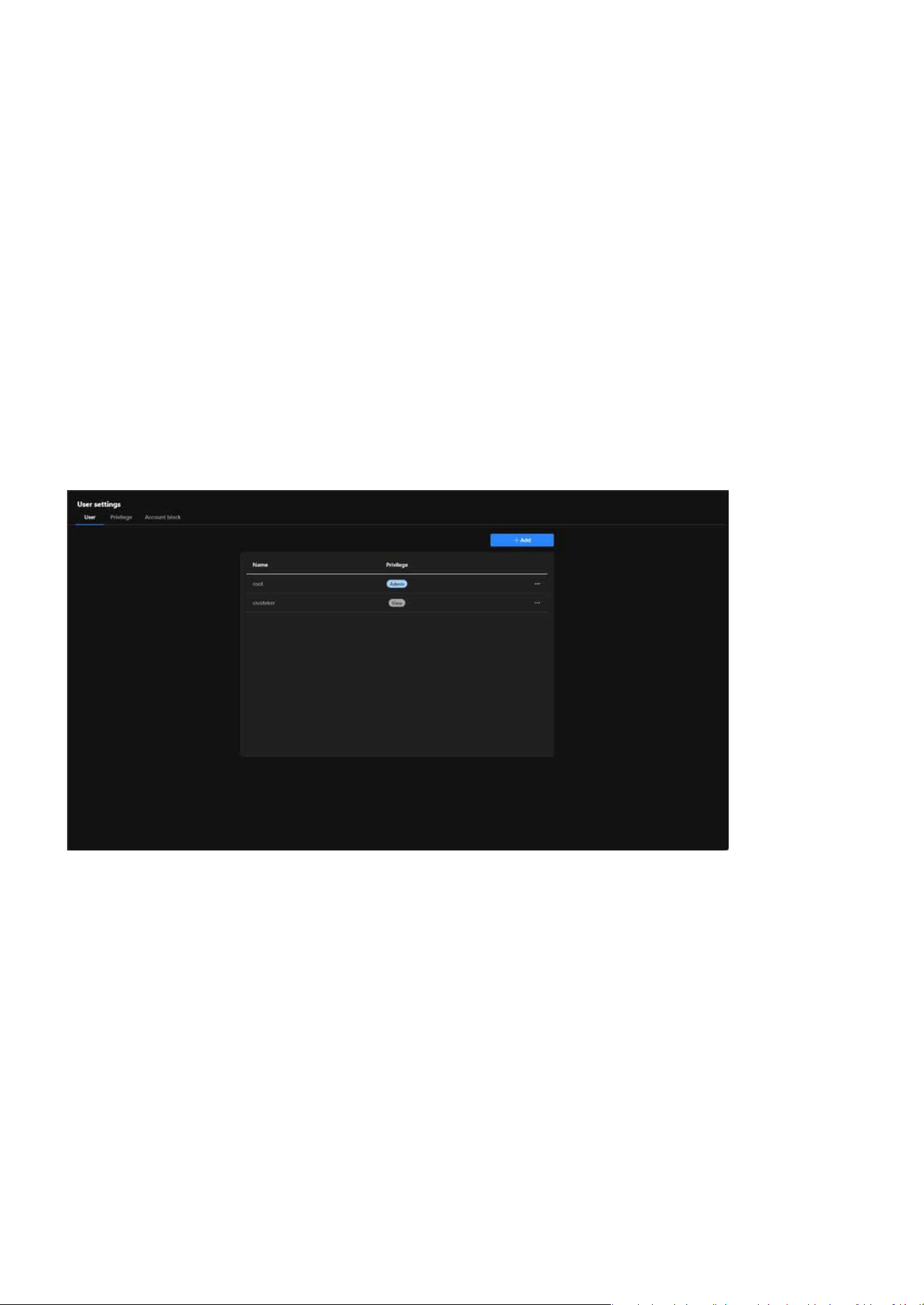
154
System
System
Manage User Access and Permissions for Enhanced Security and
Control
The User Accounts is critical for managing access to the VIVOTEK camera. It allows the system administra-
tors to create and control user accounts, dene permissions, and enforce security measures such as account
blocking, ensuring that the camera is secure, manageable, and accessible only by authorized users.
The User card provides essential tools for managing user accounts, ensuring secure access, and assigning
appropriate privileges. It helps maintain a controlled environment by enabling administrators to dene
roles, monitor user activity, and enhance security for the camera system.
User
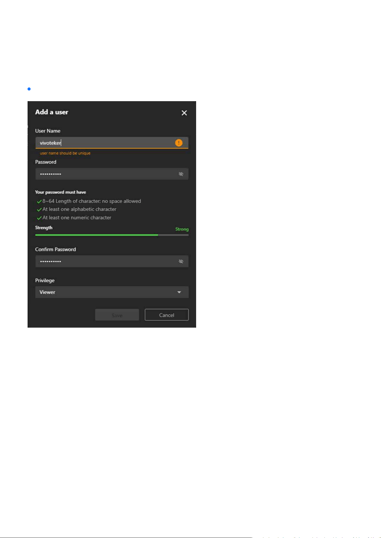
155
System
System
Step to add an User account:
Step 1. Click on the “+ Add” Button
Step 2. Enter the User Name
Step 3. Set the Password
Step 4. Conrm the Password
Locate and click the + Add button to open the “Add a User” form.
Input a password in the Password eld that meets the following criteria:
Ensure the password strength bar indicates Strong for optimal security.
Input a unique username in the User Name eld.
Re-enter the password in the Conrm Password eld to verify it matches.
8–64 characters in length (no spaces allowed).
Contains at least one alphabetic character.
Contains at least one numeric character.
Note:
The username must not duplicate any existing account name.
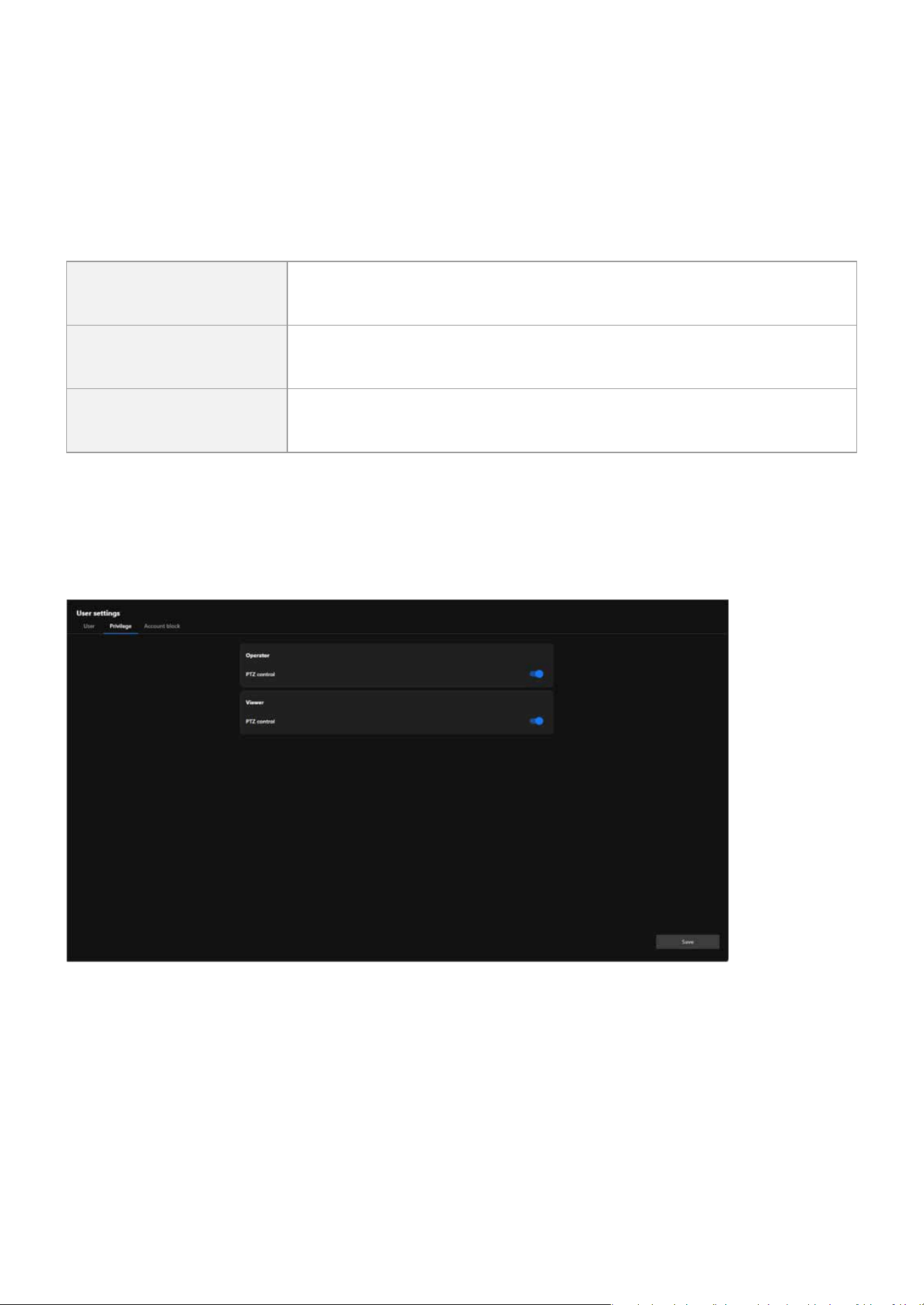
156
System
System
Step 5. Assign a Privilege Level
Select the desired privilege level for the new user from the Privilege dropdown menu:
Administrator Full control.
Operator
Control DO, white-light illuminator, snapshot, and PTZ; unable to enter
the camera Conguration page.
Viewer
Control DO, white-light illuminator, view, listen, PTZ, and talk through the
camera interface.
Privilege
The Privilege card in the User Accounts section allows administrators to manage the specic privileges as-
signed to dierent user roles. This ensures ne-grained control over what actions users can perform, partic-
ularly for users with restricted access levels such as Operator or Viewer.
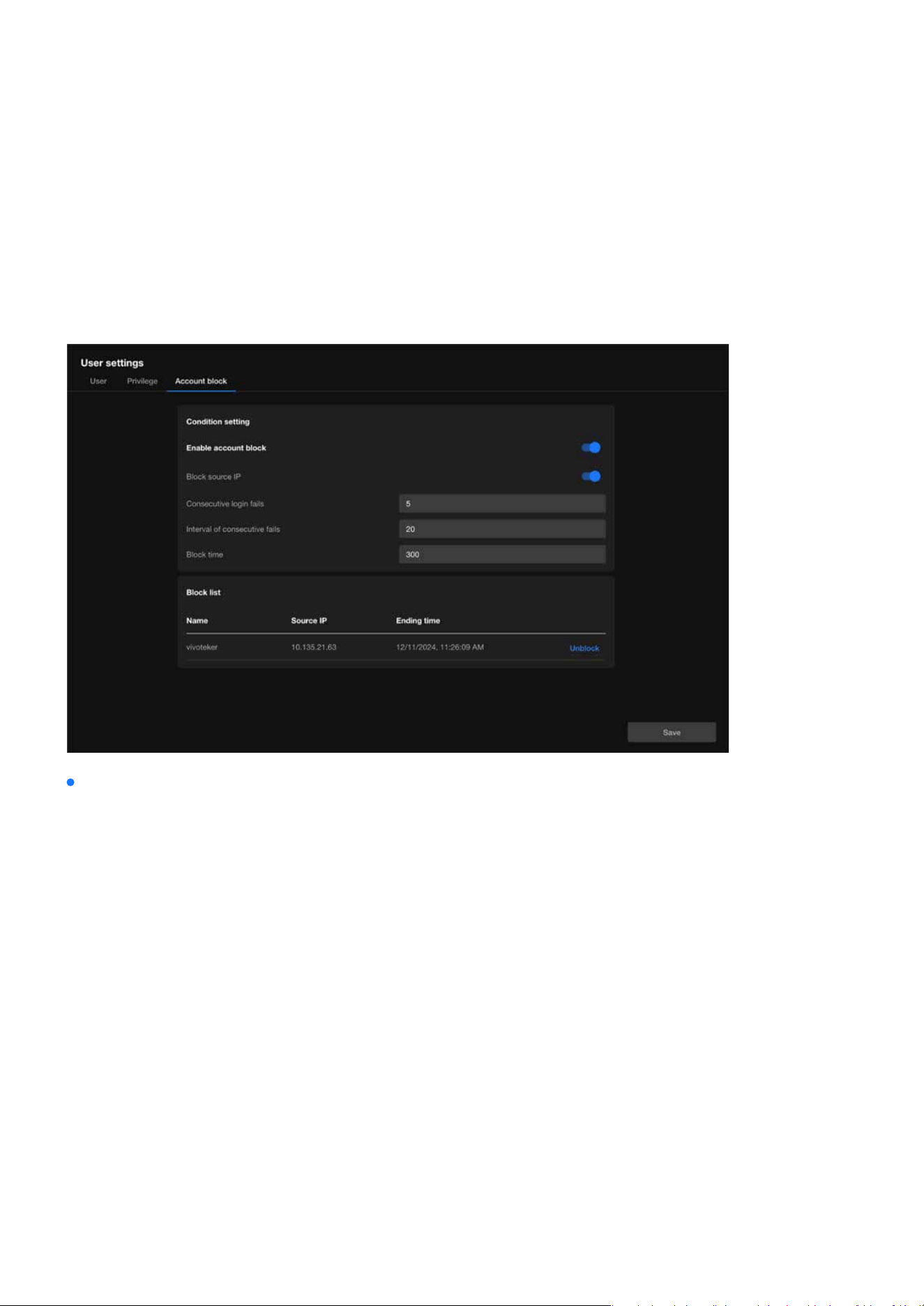
157
System
System
Account block
The Account Block is a crucial security feature that helps administrators automatically block suspicious login
attempts, eectively preventing brute force attacks and enhancing system security. Through exible condi-
tion settings and blocklist management, this feature ensures the camera system remains stable and secure
in multi-user environments.
Condition Setting
Enable Account Block
Block Source IP
Consecutive Login Fails
Interval of Consecutive Fails
Block Time
Activates or deactivates the account block feature. When enabled, the system automatically blocks suspi-
cious login attempts based on the dened conditions.
Blocks the IP address responsible for excessive failed login attempts, restricting further access attempts
from that source.
Species the number of consecutive failed login attempts that trigger the block. For example, if set to 5,
an IP address will be blocked after 5 consecutive failed login attempts.
Denes the time frame (in seconds) within which consecutive failed attempts are counted as a trigger for
blocking.
Sets the duration (in seconds) for which the oending IP address will remain blocked. For example, if set
to 300 seconds, the IP address will be unable to attempt further logins for 5 minutes.

158
System
System
Block List
Displays a list of currently blocked IP addresses or user accounts:
Unblock:
Name: Shows the username aected by the block.
Source IP: Indicates the IP address that triggered the block.
Ending Time: Displays the exact time when the block will expire.
Allows administrators to manually remove a blocked IP or account from the list.
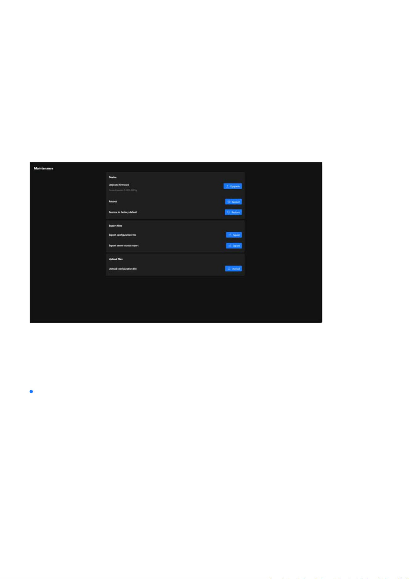
159
System
System
Firmware Updates and Conguration Management for System
Maintenance
The Maintenance oers a centralized hub for managing rmware updates, backing up and restoring con-
gurations, and resetting the system to factory defaults. These tools ensure the VIVOTEK camera operates
eciently, stays updated, and is easy to manage for administrators overseeing surveillance systems.
Maintenance
The Maintenance page under the System category provides tools for managing the device’s rmware, con-
guration, and operational stability. This section enables administrators to perform essential maintenance
tasks to ensure the camera functions optimally. Below is a breakdown of its functionality and purpose:
The Device card provides tools for rmware updates, system reboots, and factory resets. These functions
ensure the camera remains updated, functional, and ready for new congurations or troubleshooting when
necessary.
Device
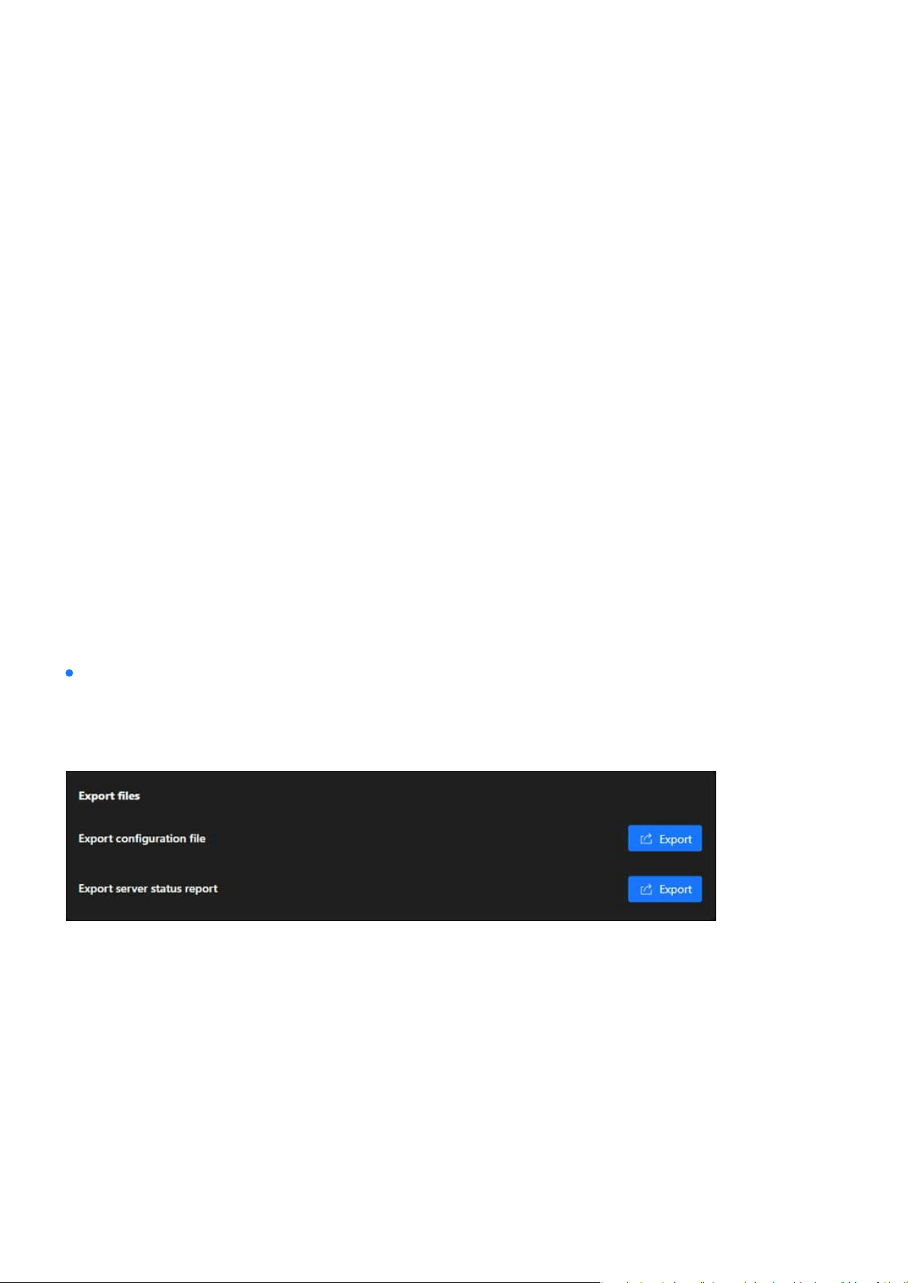
160
System
System
Upgrade Firmware
Reboot
Restore to Factory Default
Export Conguration File
Action:
Action:
Action:
Displayed Information:
Action:
Keeps the camera up to date with the latest features, performance improvements, and security patches.
Ensures compatibility with new technologies and enhanced system functionality.
Restarts the camera to refresh its system processes without altering congurations. Useful for applying
changes or resolving temporary issues.
Resets the camera to its original factory settings, removing all custom congurations. This option is useful
for troubleshooting persistent issues or preparing the device for redeployment.
Creates a backup of the current camera conguration settings. This le can be used to:
Restore the camera settings if needed.
Replicate the same conguration on other cameras for consistency in deployment.
Clicking the Export button downloads the conguration le to the local system.
The Export Files card is designed to provide administrators with tools to export important data from the
camera, such as conguration settings and status reports. These features help in creating backups, diag-
nosing issues, or replicating settings across multiple devices.
Clicking the Restore button clears all congurations and restores default settings.
Clicking the Reboot button triggers a restart of the camera.
Current rmware version (e.g., 1.2402.43.01g) is shown for reference.
Clicking the Upgrade button allows users to upload a new rmware le and update the device.
Export les
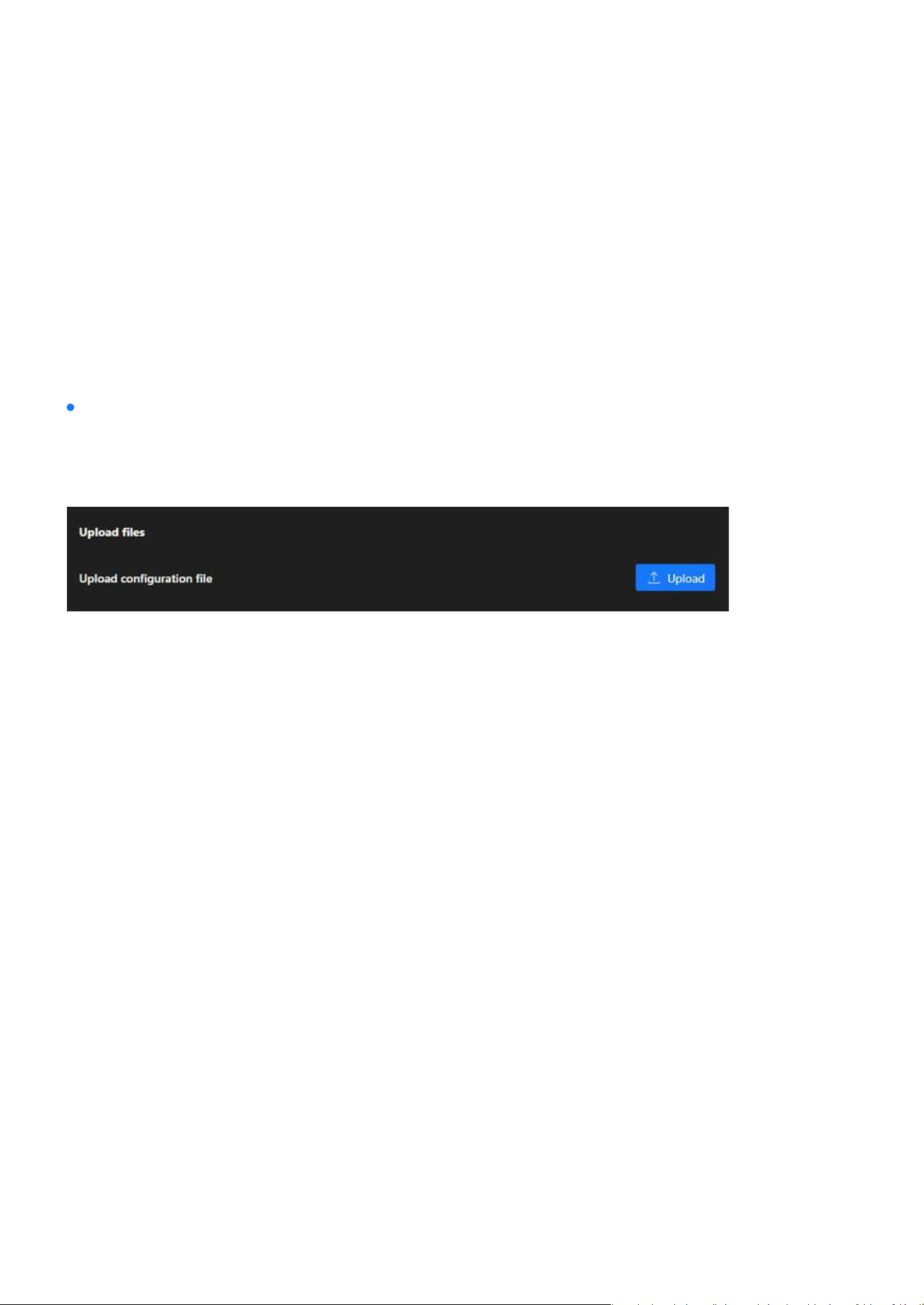
161
System
System
Export Server Status Report
Upload Conguration File
Action:
Action:
Generates and exports a report containing the camera’s operational status, including diagnostics and
logs. This is useful for:
This function enables the restoration of the camera’s settings using a previously exported conguration
le, simplifying the replication of congurations across multiple cameras and speeding up recovery in cas-
es of system resets or data loss.
Analyzing performance and identifying potential issues.
Sharing status information with support teams or system administrators for troubleshooting.
Clicking the Export button downloads the server status report for further analysis.
Clicking the Upload button allows users to select a conguration le from their local system and apply it to
the camera.
The Upload Files card allows administrators to restore or apply precongured settings to the camera by
uploading a conguration le. This feature is particularly useful for system recovery or deploying stan-
dardized congurations across multiple devices.
Upload les
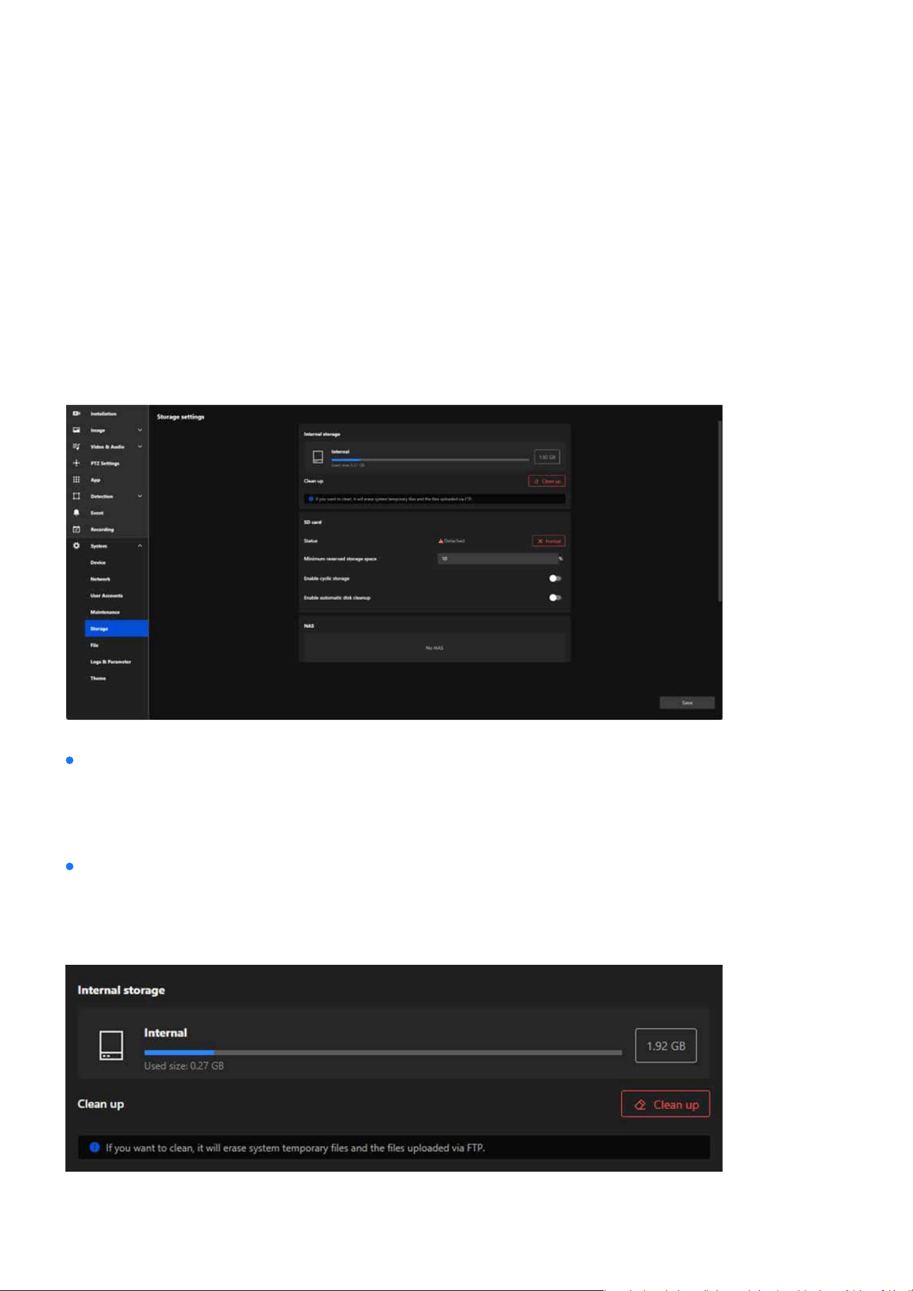
162
System
System
Optimized Storage Solutions for Reliable Video Recording and
Data Retention
The Storage section oers a comprehensive suite of tools to manage and optimize the camera’s storage re-
sources. Whether utilizing internal memory, SD cards, or external NAS devices, this section ensures reliable
video recording and ecient data retention. With features like cyclic storage, reserved space settings, and
automatic cleanup, administrators can ensure continuous operation and maximize storage capacity eort-
lessly.
Storage settings
Internal storage
The Storage settings is designed to manage storage devices and optimize the storage space used for video
recording, le saving, and system operations. This section provides administrators with tools to monitor,
clean, and congure storage options, ensuring the camera operates eciently and retains critical data.
The Internal storage card is designed to manage and monitor the camera’s internal memory usage. It pro-
vides an overview of the storage capacity, current usage, and tools for maintaining storage eciency by
removing unnecessary les.
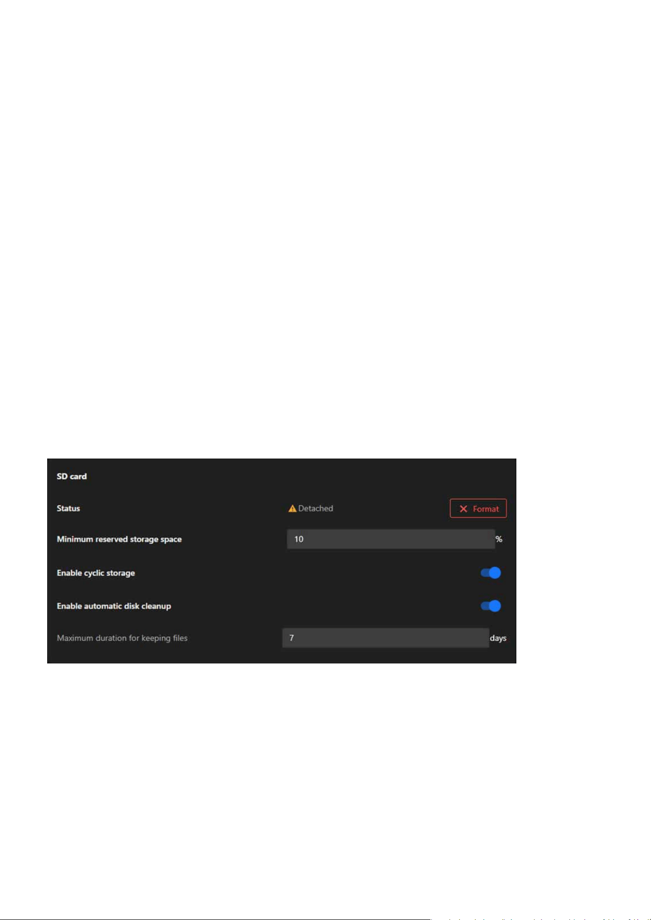
163
System
System
Storage Overview
Clean Up
SD card
Status
Minimum Reserved Storage Space
Actions:
Actions:
Displayed Information:
Frees up internal storage by deleting unnecessary les, such as:
Action:
Total Capacity: Displays the total storage capacity of the internal memory (e.g., 1.92 GB).
System temporary les.
Clicking the Clean Up button initiates the cleanup process, clearing the designated les and making more
space available for important data.
The SD card allows administrators to manage and monitor the SD card’s usage, status, and settings. This
functionality is crucial for ensuring reliable data storage and maintaining continuous video recording or
le saving.
Displays the current status of the SD card (e.g., “Detached” if no card is inserted or recognized).
Reserves a percentage of the SD card’s total capacity to prevent it from being entirely lled, ensuring criti-
cal operations can continue.
Use the Format button to erase all les and initialize the SD card for use.
Enter a percentage (e.g., 10%) to reserve storage space.
Files uploaded via FTP.
Used Size: Indicates the amount of storage currently being used (e.g., 0.27 GB).
Usage Bar: Visually represents the proportion of used and available storage.

164
System
System
Enable Cyclic Storage
Enable Automatic Disk Cleanup
Maximum Duration for Keeping Files
To Prepare the SD Card:
To Congure Storage Settings:
To Ensure Continuous Recording:
Action:
Dependency:
Actions:
Actions:
Enables automatic overwriting of the oldest data on the SD card when it is full, ensuring continuous re-
cording.
Automates the deletion of unnecessary or older les to free up storage space.
Sets a specic retention period for les on the SD card (e.g., 7 days). Files older than the specied duration
are deleted automatically.
Click the Format button to erase its contents and prepare it for use.
Input a percentage (e.g., 10%) to reserve part of the SD card’s capacity.
Turn this feature on to allow the oldest les to be overwritten when the SD card is full.
Toggle this option to activate cleanup functions.
Input the Maximum Duration for Keeping Files (e.g., 7 days) to dene the le retention period.
Step 1. Insert an SD card into the camera’s slot.
Step 1. Set the Minimum Reserved Storage Space:
Step 1. Conrm both Enable Cyclic Storage and Enable Automatic Disk Cleanup are activated.
Step 2. Regularly check the Status to ensure the SD card is functioning properly.
Step 2. Toggle Enable Cyclic Storage:
Step 3. Enable Automatic Disk Cleanup (Optional):
Step 2. Check the Status eld to conrm the SD card is detected.
Step 3. If the SD card is new or needs reinitialization:
Toggle this feature on or o to control storage behavior.
Enabling this feature activates the Maximum Duration for Keeping Files option.
Input the desired number of days for le retention in the text box.
Toggle this feature on to allow automatic cleanup of outdated les.
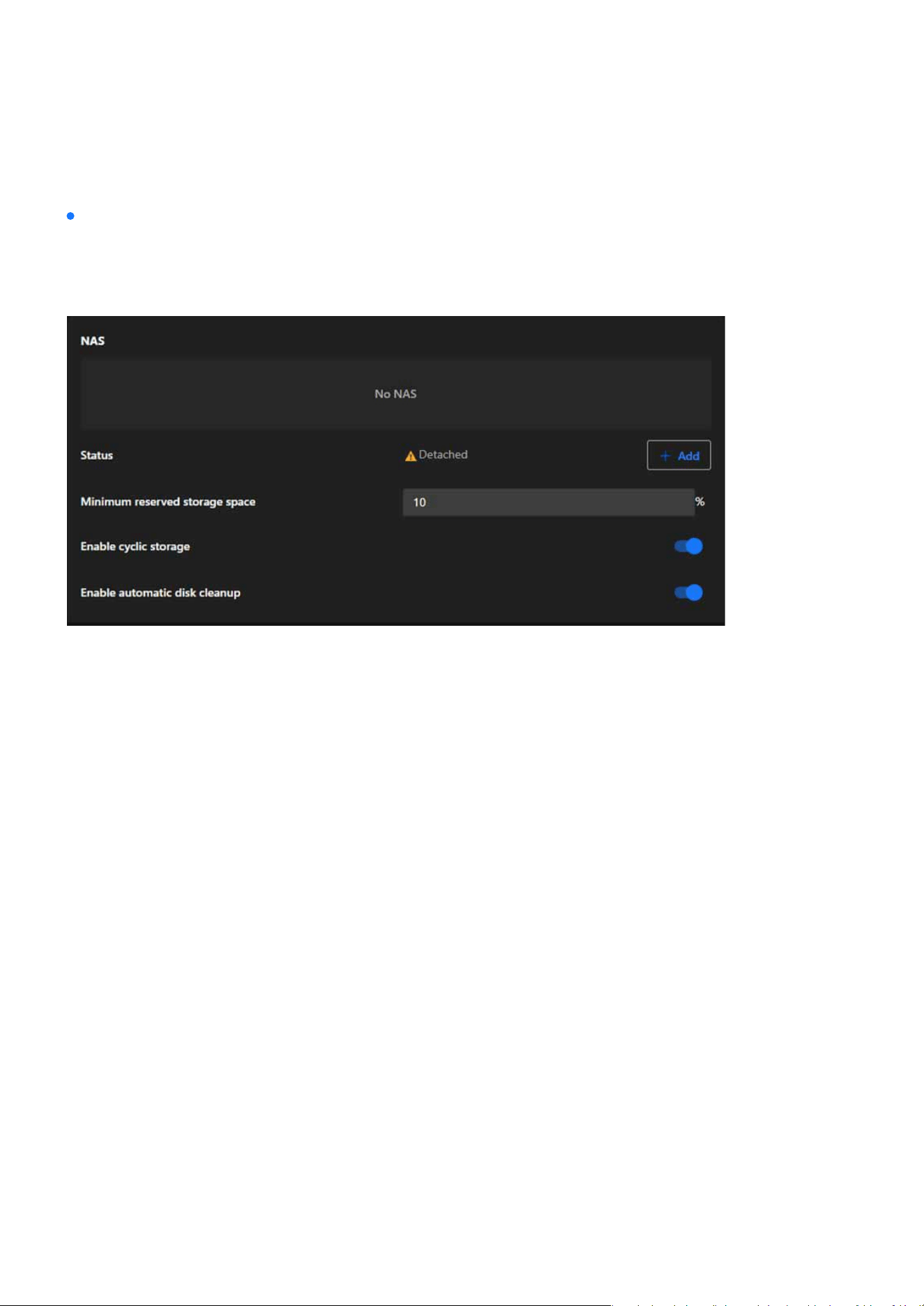
165
System
System
NAS Status
Minimum Reserved Storage Space
Enable Cyclic Storage
Enable Automatic Disk Cleanup
Actions:
Actions:
Actions:
Actions:
The NAS card allows administrators to integrate a Network Attached Storage (NAS) device for extended
and scalable storage. This feature ensures that the camera’s storage capacity can be expanded and data
can be securely stored in a centralized location.
Displays the connection status of the NAS device (e.g., “Detached” if no connection is established).
Ensures that a dened percentage of the NAS storage remains reserved to prevent the system from lling
the NAS entirely.
Allows the camera to overwrite the oldest les stored on the NAS when the storage is full, ensuring unin-
terrupted recording.
Automates the cleanup of outdated or unnecessary les stored on the NAS to maintain sucient available
space.
Click + Add to congure and connect a NAS device.
Administrators can input a percentage (e.g., 10%) to reserve storage space for critical use.
Toggle this feature on or o depending on the storage management preferences.
Toggle this feature on to activate automatic le deletion based on system-dened criteria.
NAS
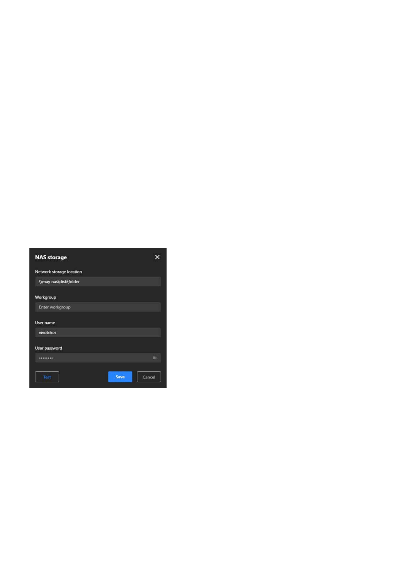
166
System
System
NAS Conguration Steps
Step 1. Open NAS Storage Settings:
Step 2. Set Network Storage Location:
Step 3. Enter Workgroup (Optional):
Step 4. Provide User Credentials:
Step 5. Test the Connection:
Step 6. Save Conguration:
Click + Add in the NAS card to open the conguration window.
Enter the path to the NAS storage folder (e.g., \\NASDevice\SharedFolder).
If required, specify the workgroup to which the NAS device belongs.
Input the Username and Password needed to authenticate and access the NAS device.
Click Test to ensure the camera can successfully connect to the specied NAS location.
Click Save to apply the settings and establish the connection.
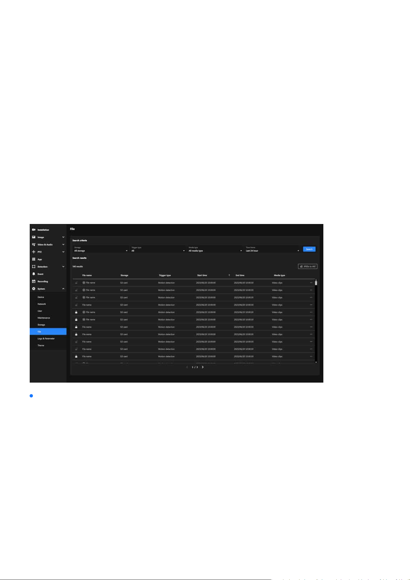
167
System
System
Effortless Management and Retrieval of Recorded Media
The File section oers a user-friendly interface for managing recorded media les. With search and ltering
tools, users can locate specic recordings based on storage type, trigger events, media format, and time
frame. It also allows locking les, exporting recordings, and converting media for ecient handling and pres-
ervation. This ensures organized storage and quick access to important data.
The File section enables users to eciently search, lter, and manage recorded media les. Key features
include advanced search criteria, le locking for data retention, and options to export or convert recordings.
Its primary purpose is to streamline media organization, ensure secure storage, and support quick access
for detailed analysis.
File
Search criteria
Allows users to rene their search for recorded les based on specic parameters, making it easier to
locate relevant recordings.
Search Filters:
•
Storage: Filter by storage type (e.g., SD card, NAS, or all storage devices).
•
Trigger Type: Search for les triggered by specic events (e.g., motion detection, manual recording).
•
Media Type: Filter by the type of media (e.g., video clips, snapshots).
•
Time Frame: Specify a time range (e.g., last 24 hours, custom time range) to narrow the search.
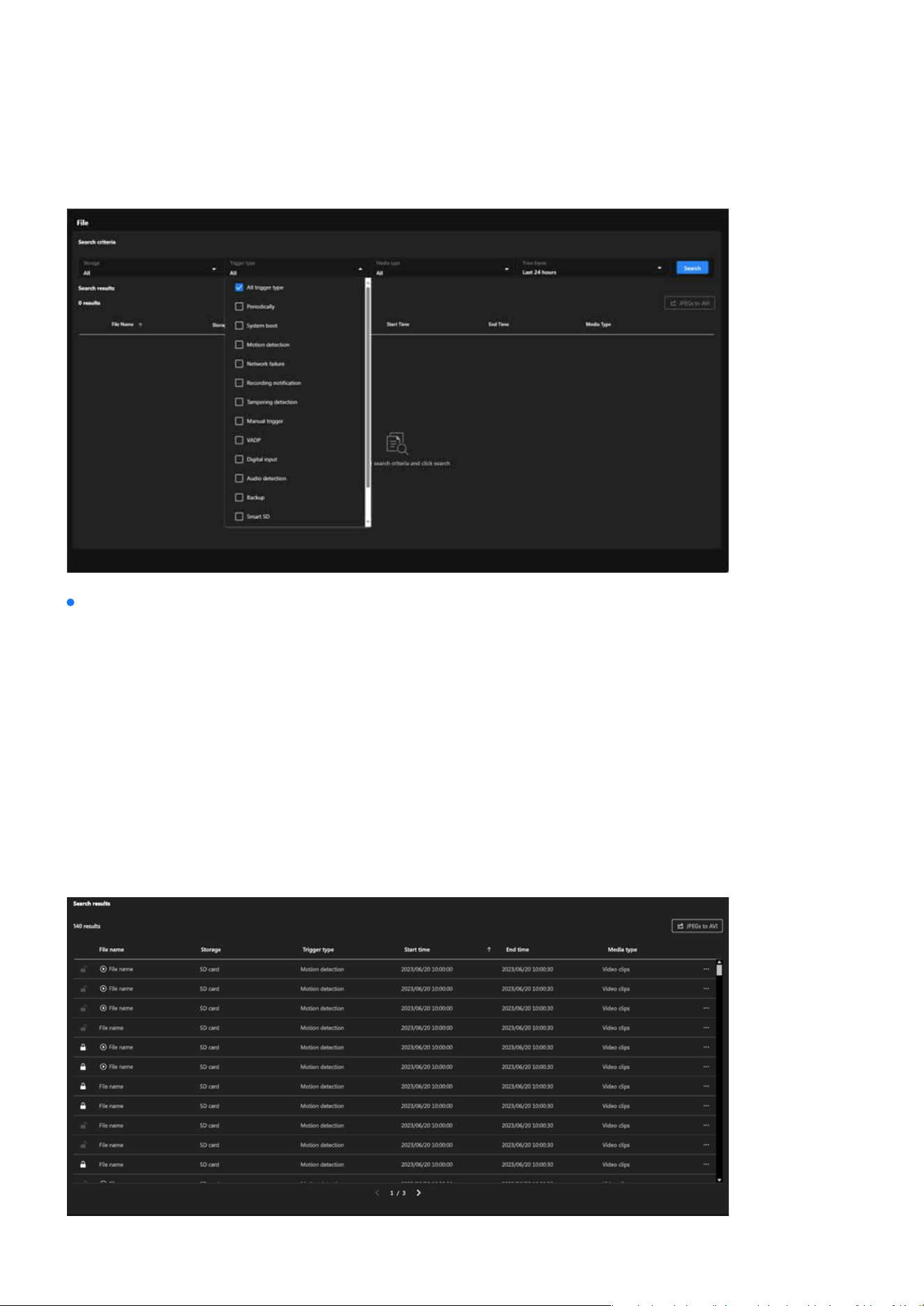
168
System
System
Search Results
File Name:
Storage:
Trigger Type:
Start and End Time:
Media Type:
Name of the recorded le.
Indicates the storage location of the le (e.g., SD card).
Shows the event that triggered the recording (e.g., motion detection).
Provides the time range for each recording.
Species the type of media le (e.g., video clips).
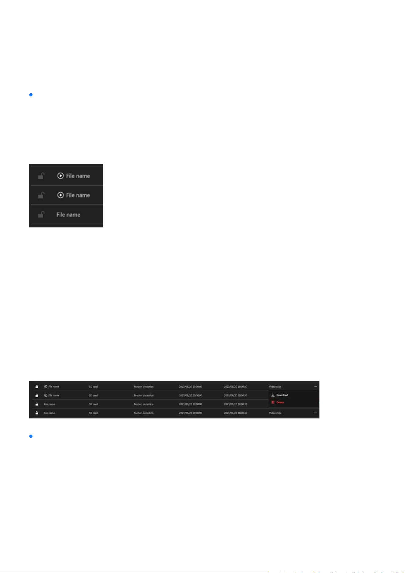
169
System
System
Note:
JPEGs to AVI
File Lock/Unlock button:
Steps to Use JPEGs to AVI:
Play button:
File Options ( More icon )
Each le in the results has additional options accessible via the three-dot menu:
Locked les, identied by a lock icon, are protected from automatic deletion, and their retention can be
managed using the lock/unlock button.
The JPEGs to AVI functionality allows users to convert sequential JPEG image snapshots into a playable
AVI video format. This feature is particularly useful for scenarios where users need to review footage as a
continuous video instead of analyzing individual images.
Only les with recorded data and playback permission will display the Play button.
Allows you to save the le to your local device. Steps:
Permanently removes the le from the storage. Steps:
A checkbox is displayed next to each snapshot le, allowing users to manually select which les to in-
clude in the AVI conversion.
Step 1. Click the three-dot menu next to a le.Steps:
Step 1. Click the three-dot menu next to a le.
Step 1. Click “JPEGs to AVI” button.
Step 2. Selection Feature Activation:
Step 2. Select Download.
Step 2. Select Delete.
Step 3. The le will be saved to your default download location.
Step 3. Conrm the deletion in the pop-up prompt.
•
Download:
•
Delete:
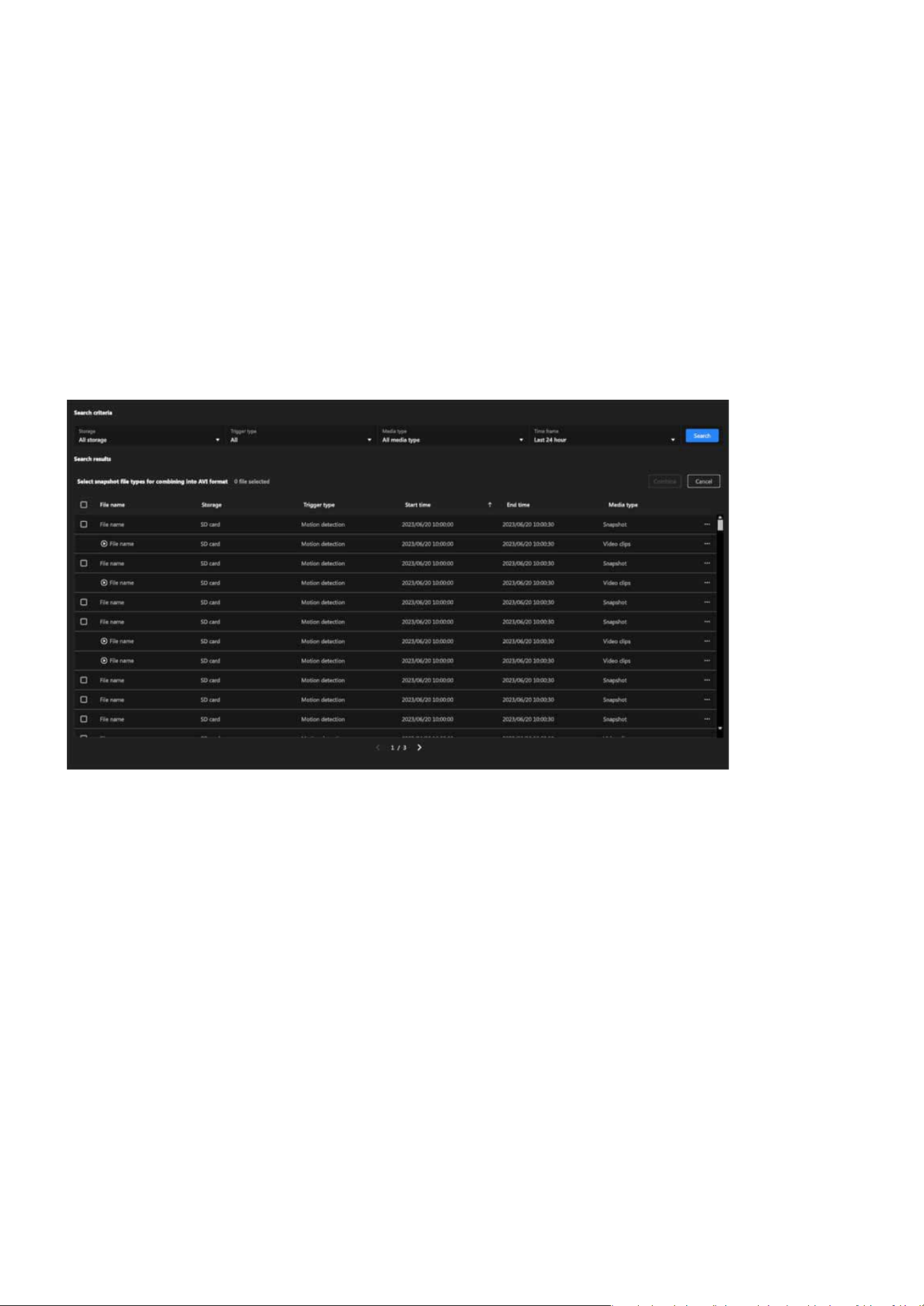
170
System
System
Combine
Cancel
This button allows the user to conrm and initiate the conversion process. It is enabled only after at
least one le is selected.
Clicking this button exits the conversion mode, clearing all selections and restoring the original le view.
Step 3. Two new buttons appear:
Step 4. Start combining into a single AVI le.
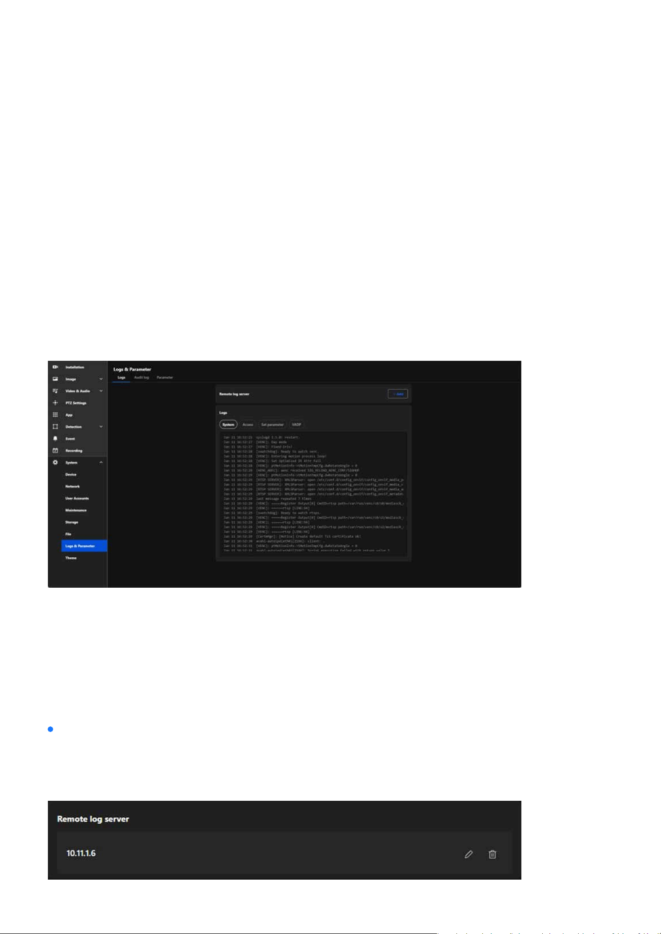
171
System
System
Monitoring and Managing System Logs and Parameters
Eective system management relies on the ability to monitor and analyze detailed logs and parameters.
This section provides tools to view and manage system, access, and conguration logs, enabling users to
diagnose issues, track activity, and maintain optimal performance. With features like remote log server
integration and parameter management, this chapter equips administrators with the necessary controls to
ensure security and operational eciency in both standalone and multi-camera setups.
The Logs & Parameter section in the VIVOTEK camera’s system settings is designed to provide detailed in-
sights into system events, user activity, and conguration changes. It facilitates troubleshooting, monitoring,
and maintaining the overall performance and security of the camera.
The Logs provides users with comprehensive tools to monitor and manage system activities, user access,
and conguration changes on the camera. By oering both real-time local log viewing and the ability to inte-
grate with a remote log server, this tab helps users troubleshoot issues, track security events, and maintain
compliance with operational policies. It is an essential resource for ensuring system reliability, enhancing
security, and supporting centralized log management in multi-device setups.
Logs & Parameter
Logs
Remote log server
The Remote log server provides an ecient, secure, and scalable solution for camera log management,
making it particularly valuable in large-scale deployments or environments with stringent data retention
policies.
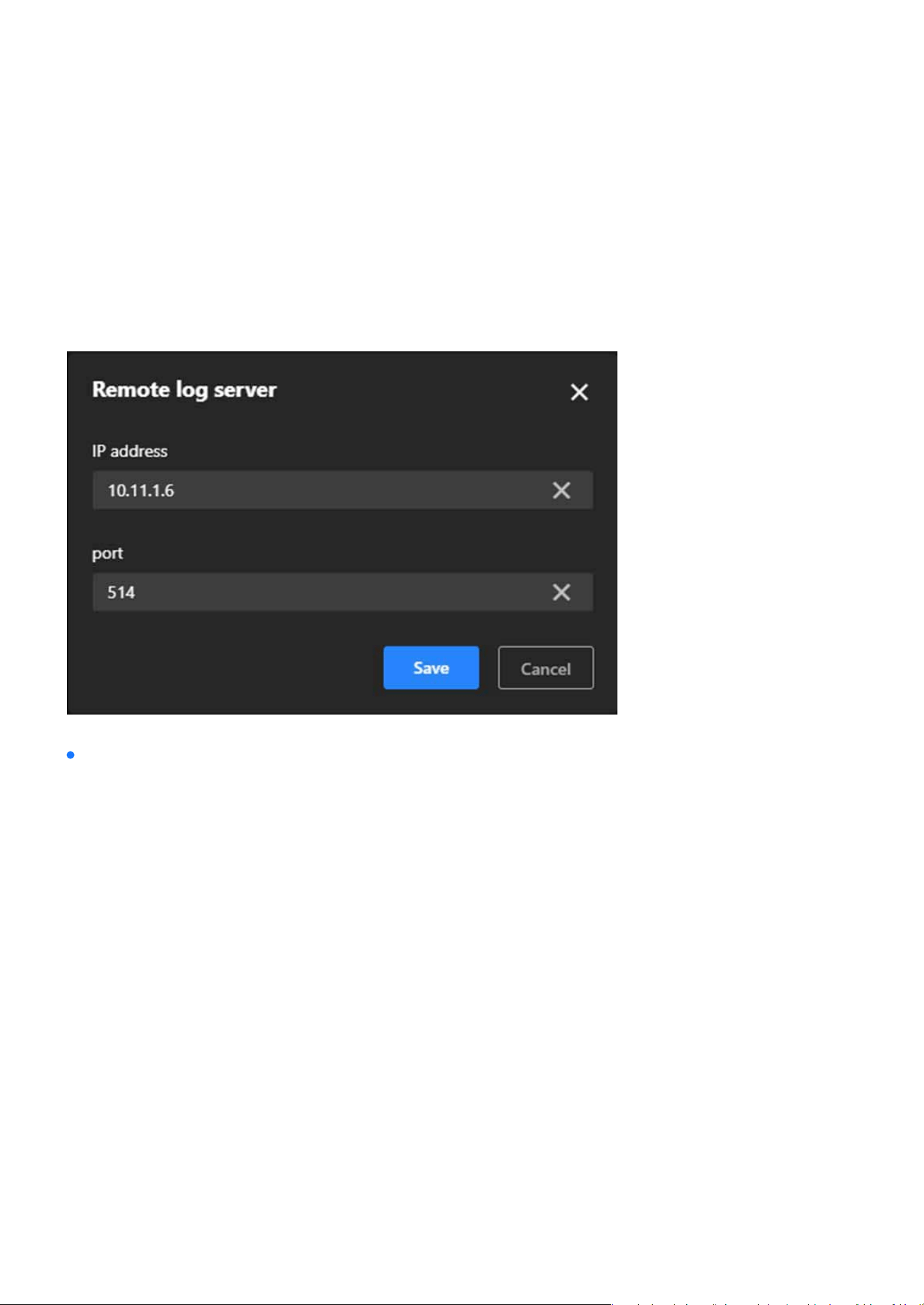
172
System
System
Steps to set up the Remote log server:
System:
Step 1.
Click “+Add” button.
Step 2. In the IP address text box, enter the IP address of the remote server.
Step 3. In the port text box, enter the port number of the remote server.
Step 4. When completed, click Save to enable the setting.
Logs
The Logs provides users with detailed records of system activities, access attempts, conguration chang-
es, and application performance. It simplies troubleshooting by helping users identify issues, enhances
security by monitoring access, and ensures transparency in conguration management. This feature is es-
pecially useful for maintaining system stability, tracking unauthorized access, and diagnosing application
or conguration-related problems. The Logs consists of the following categories, each designed to record
specic types of information:
Records key system activities, including device startup, reboot, error messages, and mode switching, to
help determine system stability and identify potential issues.
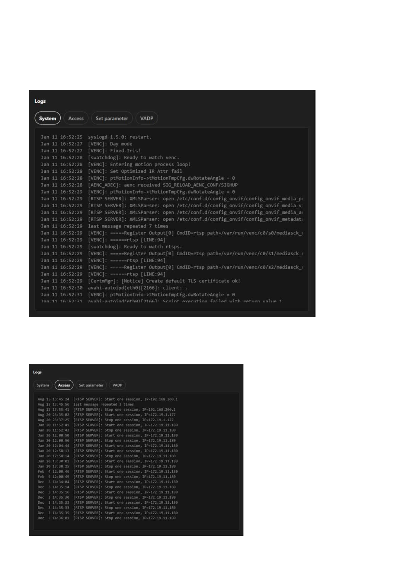
173
System
System
Access:
Logs all access attempts to the camera, including login and logout operations, making it useful for moni-
toring unauthorized access attempts and ensuring system security.

174
System
System
Set Parameter:
Tracks all conguration changes made to the system, assisting users in reviewing and managing adjust-
ments while facilitating troubleshooting of conguration-related issues.
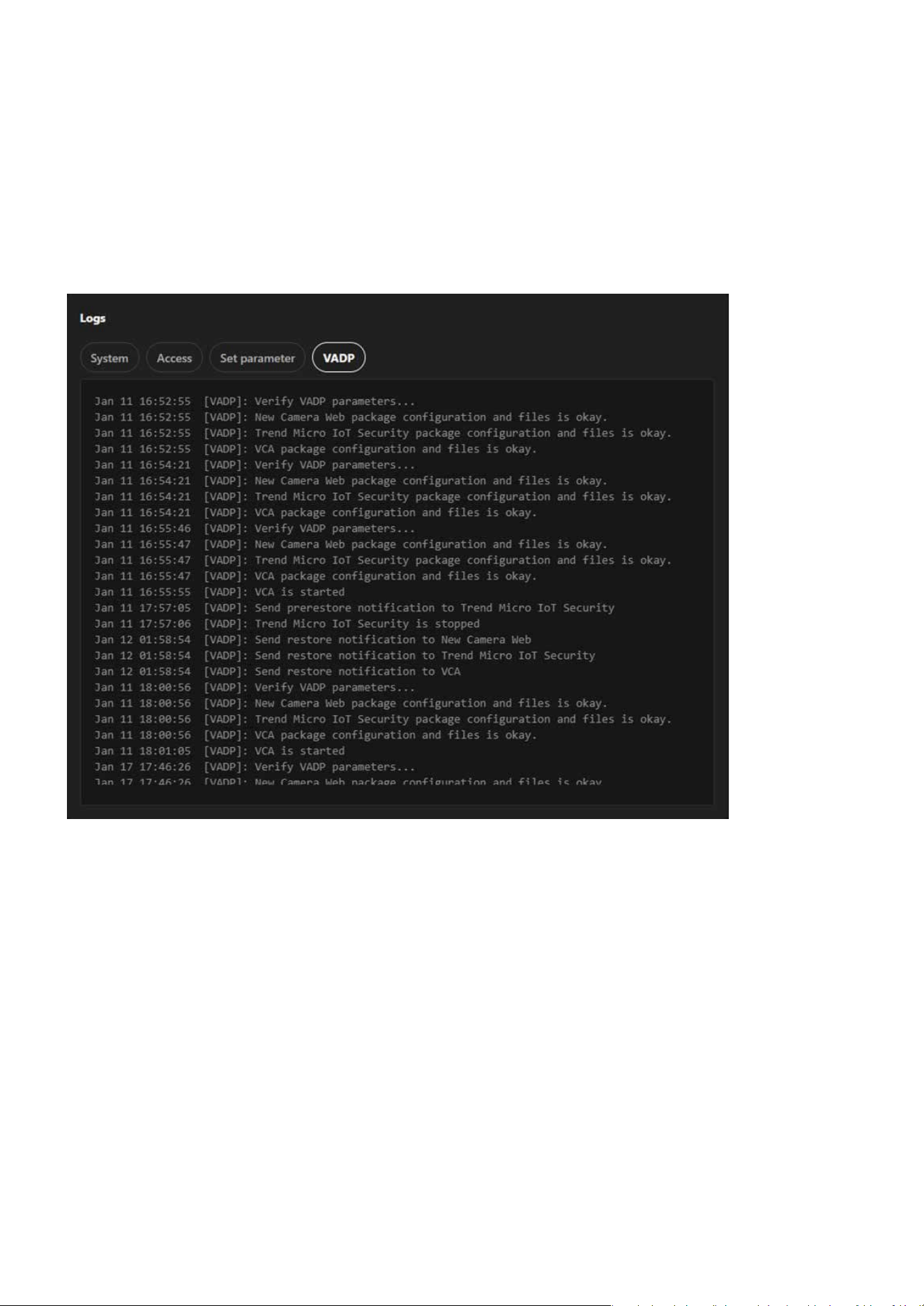
175
System
System
VADP:
Logs related to the VIVOTEK Application Development Platform, documenting the execution of applica-
tions on the camera (if applicable) and helping to diagnose application development and runtime issues.
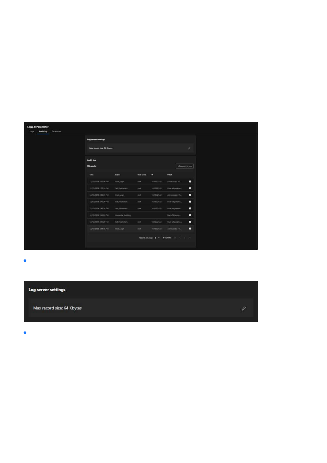
176
System
System
Audit log
The Audit log focuses on recording all administrative operations and activities performed on the camera. Its
purpose is to track user behavior, enhance system security, ensure management transparency, and meet
compliance requirements. By logging detailed user actions, it helps administrators analyze issues, trouble-
shoot errors, and provide reliable historical data for audits.
Log server settings
Audit log
Allows users to adjust log storage capacity to ensure sucient space for recording management activities.
Provides detailed records of each administrative action, including the following elds:
The specic time the action occurred.
The type of action performed (e.g., “User_Login” for logins, “Set_Parameters” for parameter adjustments).
The username of the person performing the action (e.g., “root”).
The IP address of the device initiating the action.
Detailed descriptions of the actions, such as “Allow access HTTP” or “User set parameters.”
Time:
Event:
User Name:
IP:
Detail:
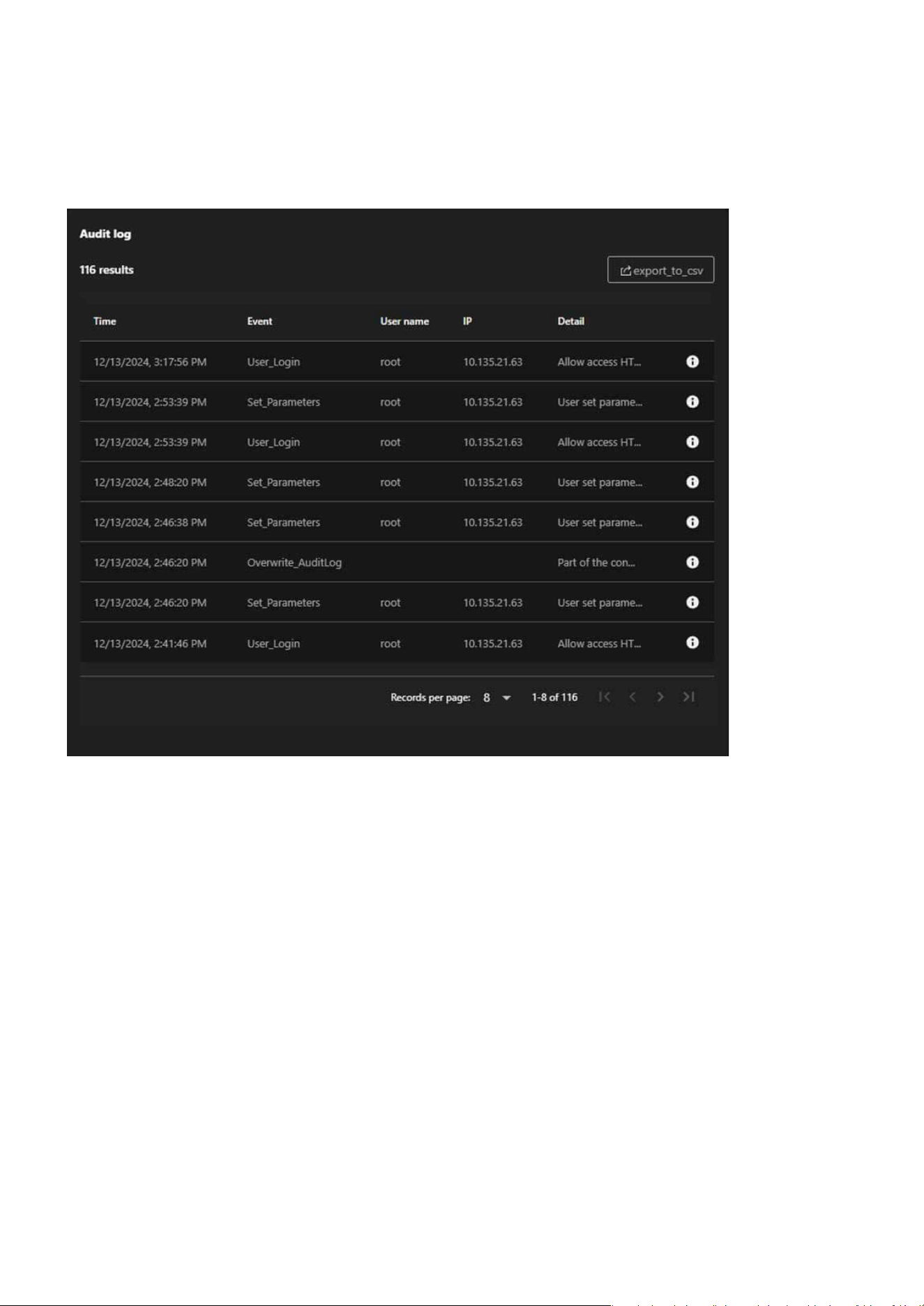
177
System
System
The Export to CSV button allows users to export audit logs as CSV les for archiving, sharing, or further
analysis.
Export Functionality:
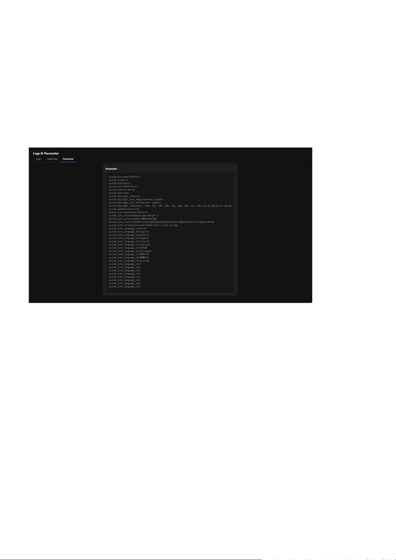
178
System
System
Parameter
The Parameter is designed to display the system parameters and conguration details of the camera, pro-
viding administrators with a centralized view of the device’s operational status, settings, and technical infor-
mation. Its main purpose is to serve as a diagnostic tool, facilitate technical support, and assist in congura-
tion backup and recovery.
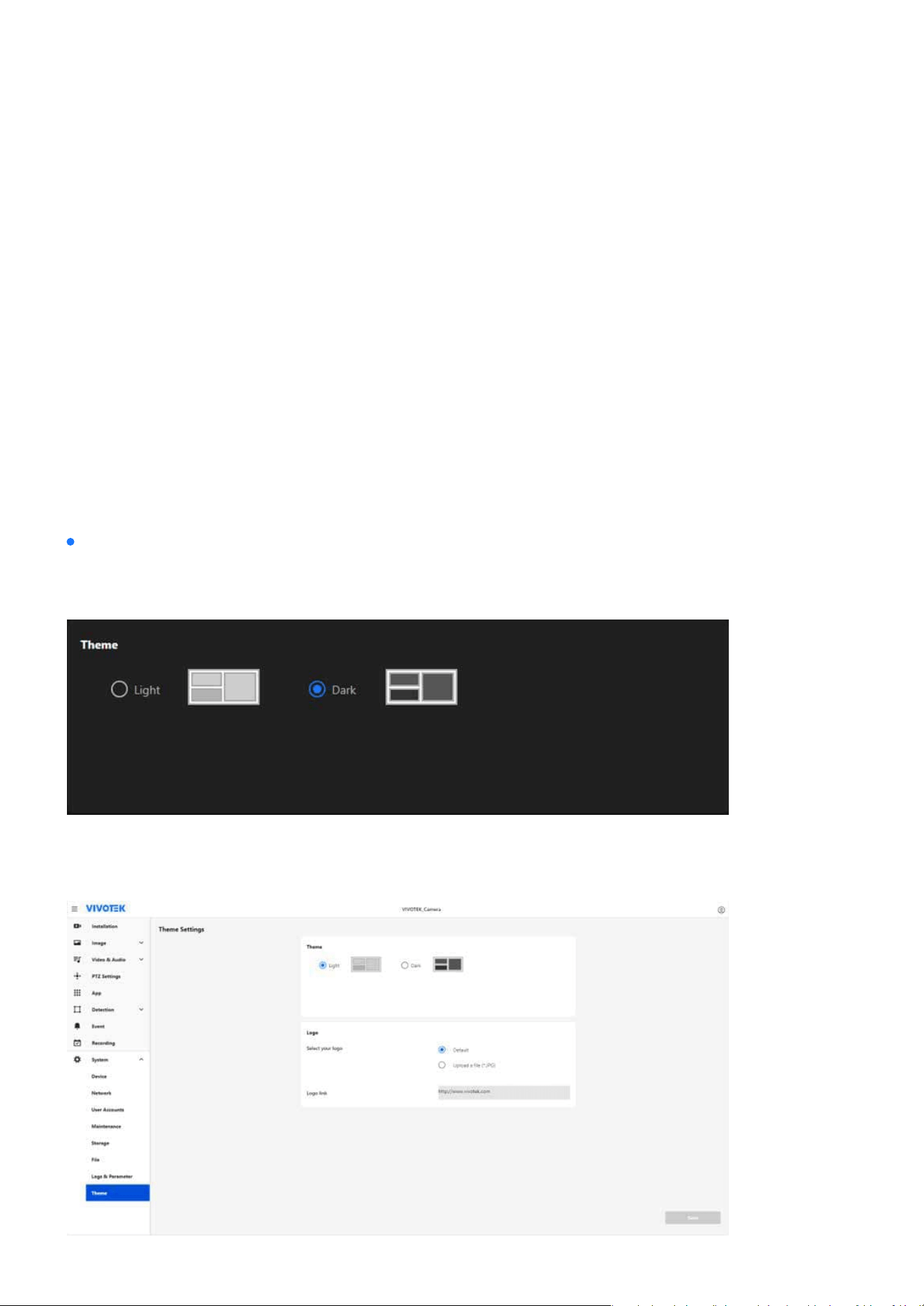
179
System
System
Customizing Interface Appearance and Branding with Theme Set-
tings
The Theme settings section allows users to personalize the camera’s interface to suit their preferences and
enhance the user experience. By providing options to toggle between light and dark modes, users can adapt
the interface for dierent lighting conditions. Additionally, the ability to upload a custom logo and cong-
ure a hyperlink enables businesses and projects to showcase their brand identity directly within the system
interface. This feature combines functionality and customization, ensuring both usability and a professional
presentation.
The Theme settings consists of two sections: Theme and Logo, each providing specic customization options
to enhance usability and branding.
Theme settings
Theme
Allows users to switch between Light and Dark interface display modes to adapt to dierent working envi-
ronments, enhancing user comfort and reducing eye strain in varying light conditions.
Designed with a light background, ideal for bright environments.
Light Mode:
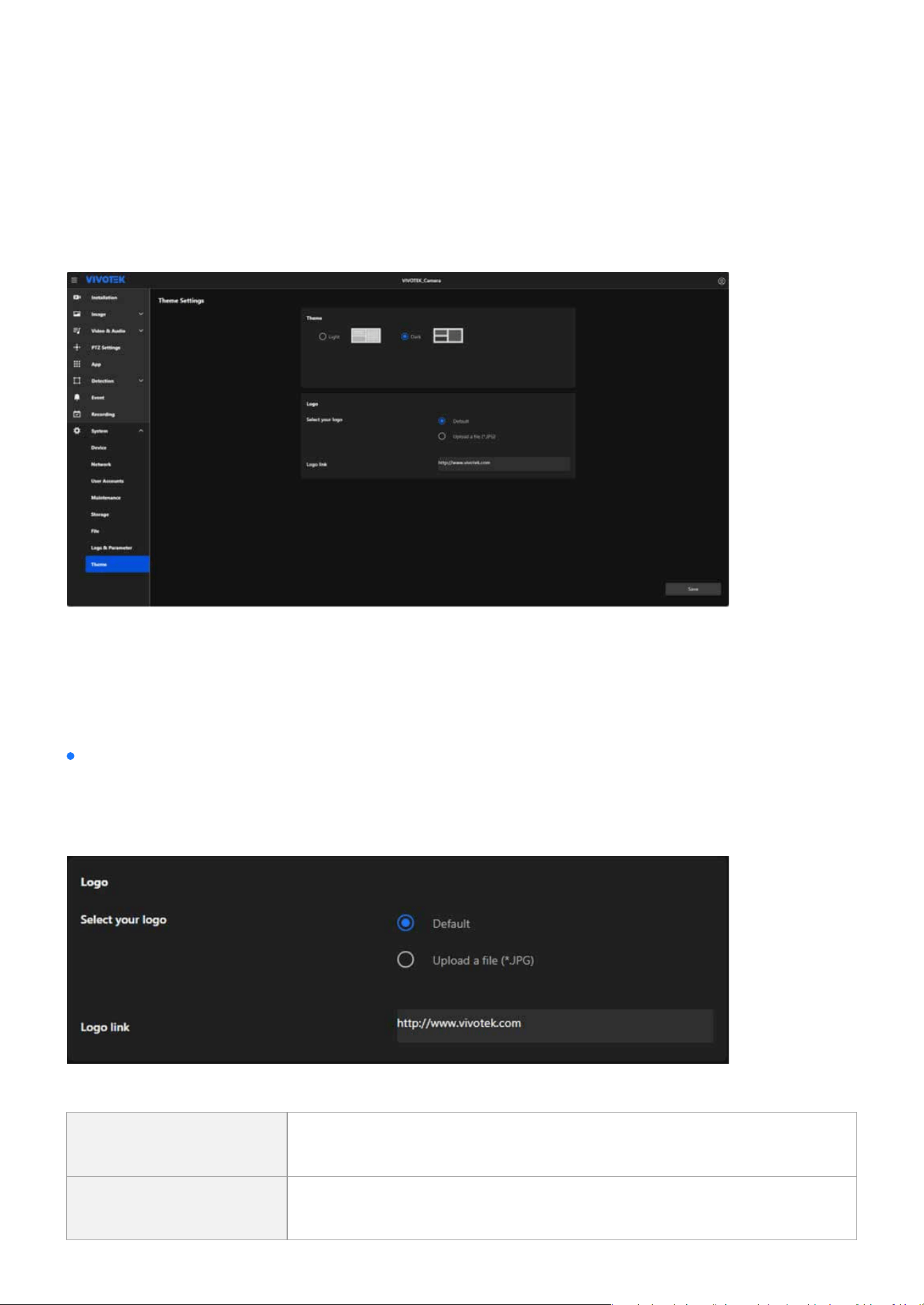
180
System
System
Uses a dark background, reducing glare and improving visibility in low-light conditions.
Enables businesses or users to personalize the interface with their custom logo, enhancing brand recog-
nition and professionalism, while also providing the option to congure a clickable hyperlink for the logo
that redirects users to a specic webpage, such as a company website or support page.
Step 1. Select the desired mode (Light or Dark) by clicking the corresponding option.
Step 2. The interface preview changes dynamically to reect the selected theme.
Step 3. Click the Save button to apply the changes.
Dark Mode:
Select your logo:
How to Operate:
Logo
Default Uses the system's built-in default logo.
Upload a le (*.JPG)
Allows users to upload a custom logo le in JPG format for personaliza-
tion.

181
System
System
Enables users to assign a hyperlink to the logo, redirecting to a specic webpage (e.g., company website).
Logo link:
Note:
Display
The selected or uploaded logo will appear on the title bar of the interface, making it visible to all users, and clicking it will redirect
them to the congured URL.

www.vivotek.com
DESIGN AND SPECIFICATIONS ARE SUBJECT TO CHANGE WITHOUT NOTICE
Copyright © 2024 VIVOTEK INC. All rights reserved.