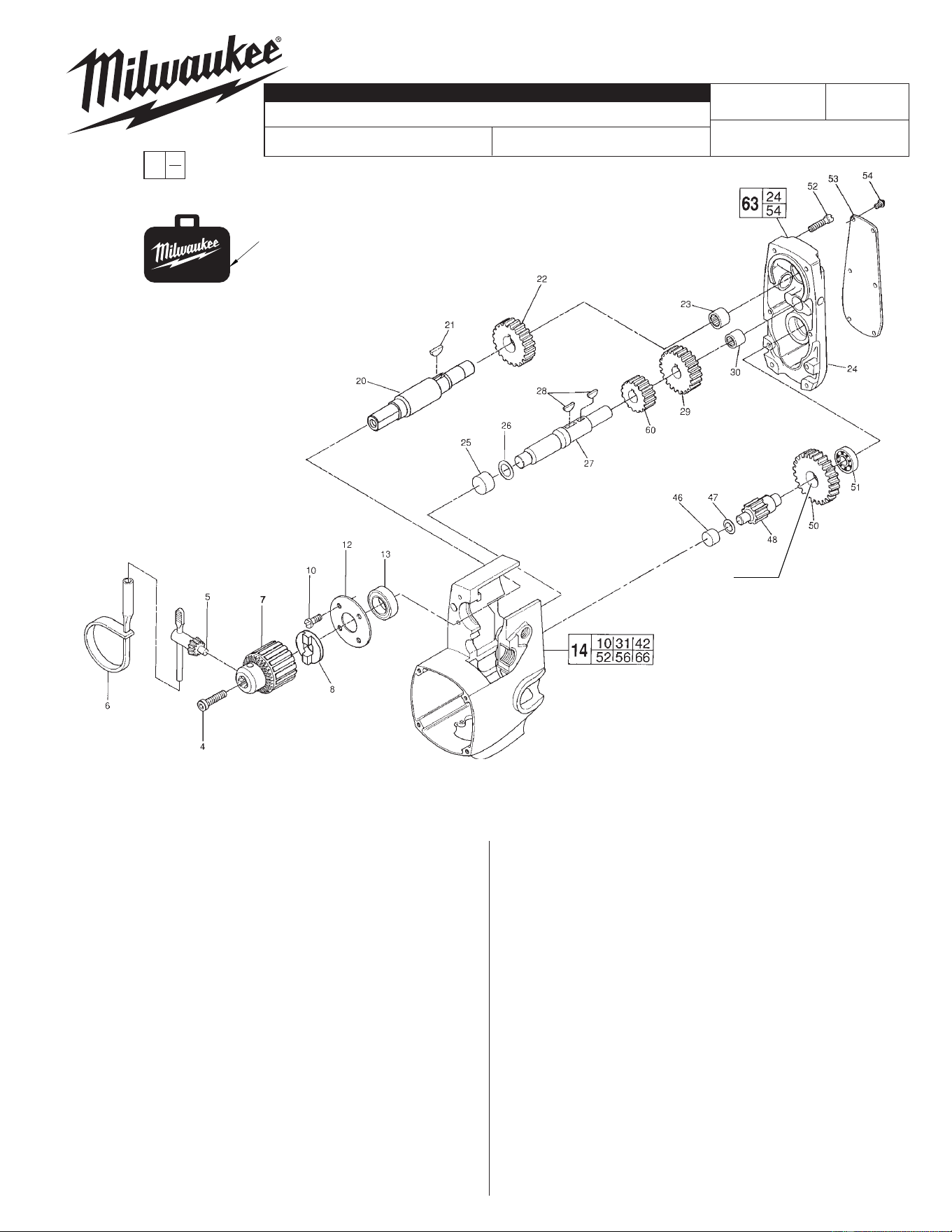
FIG. PART NO. DESCRIPTION OF PART NO. REQ.
50 32-42-1302 1st. Intermediate Gear (1)
51 02-04-0910 Ball Bearing (1)
52 06-82-5362 8-32 x 1" Pan Hd. T-20 Screw (6)
53 12-98-7295 Service Nameplate (1)
54 06-82-5266 4-40 x 1/4" Pan Hd. T-10 Screw (6)
60 32-40-1970 2nd Intermediate Gear (1)
63 28-20-1127 Gear Case Assembly (1)
67 42-55-0121 Carrying Case, Optional (1)
FIG. NOTES
4 Torque to 150-155 in./lbs.
FIG. LUBRICATION
24 3-1/2 oz. Type "E" Grease, No. 49-08-4122.
Prelube all needle bearings with
Type "E" Grease, No. 49-08-4122.
0
00
EXAMPLE:
Component Parts (Small #) Are Included
When Ordering The Assembly (Large #).
FIG. PART NO. DESCRIPTION OF PART NO. REQ.
4 06-75-3155 1/4-20 x 1" L.H. Soc. Hd. Cap Screw (1)
5 48-66-3280 Chuck Key (1)
6 48-66-4040 Key Holder (1)
7 48-66-1481 Chuck (1)
8 43-78-0670 Drive Hub (1)
10 06-82-7316 8-32 x 1/2" Pan Hd. Tapt. T-20 Screw (4)
12 44-66-5241 Bearing Retainer Plate (1)
13 02-04-1700 Ball Bearing (1)
14 28-50-6129 Motor Housing Assembly (1)
20 38-50-5075 Spindle (1)
21 06-42-2000 Woodruff Key (1)
22 32-75-2210 Spindle Gear (1)
23 02-50-3170 Needle Bearing (1)
24 28-20-1252 Gear Case Cover (1)
25 02-50-3180 Needle Bearing (1)
26 45-88-7095 Fiber Thrust Washer (1)
27 36-66-4400 2nd. Intermediate Shaft (1)
28 06-42-1900 Woodruff Key (2)
29 32-44-1190 2nd. Intermediate Gear (1)
30 02-50-2750 Needle Bearing (1)
46 02-50-2435 Needle Bearing (1)
47 45-88-7100 Fiber Thrust Washer (1)
48 36-66-1311 1st. Intermediate Pinion (1)
MILWAUKEE ELECTRIC TOOL CORPORATION
13135 W. LISBON RD., BROOKFIELD, WI 53005
Drwg. 6
BULLETIN NO.
SERVICE PARTS LIST 54-10-4039
REVISED BULLETIN DATE
SINGLE SPEED HOLE HAWG
®
STARTING
SERIAL NO.
54-10-4038
SPECIFY CATALOG NO. AND SERIAL NO. WHEN ORDERING PARTS
WIRING INSTRUCTION
58-01-0626
SEE REVERSE
SIDE
Nov. 2013
472E
CATALOG NO. 1670-1
NOTE:
When replacing the 1st. Intermediate
Pinion (48) or the 1st. Intermediate Gear
(50), place a drop of Type 262 Red Loc-
tite
®
in the hole of the gear before press
fi tting together. - Allow Loctite
®
to cure
24 hours before drilling with tool.
67
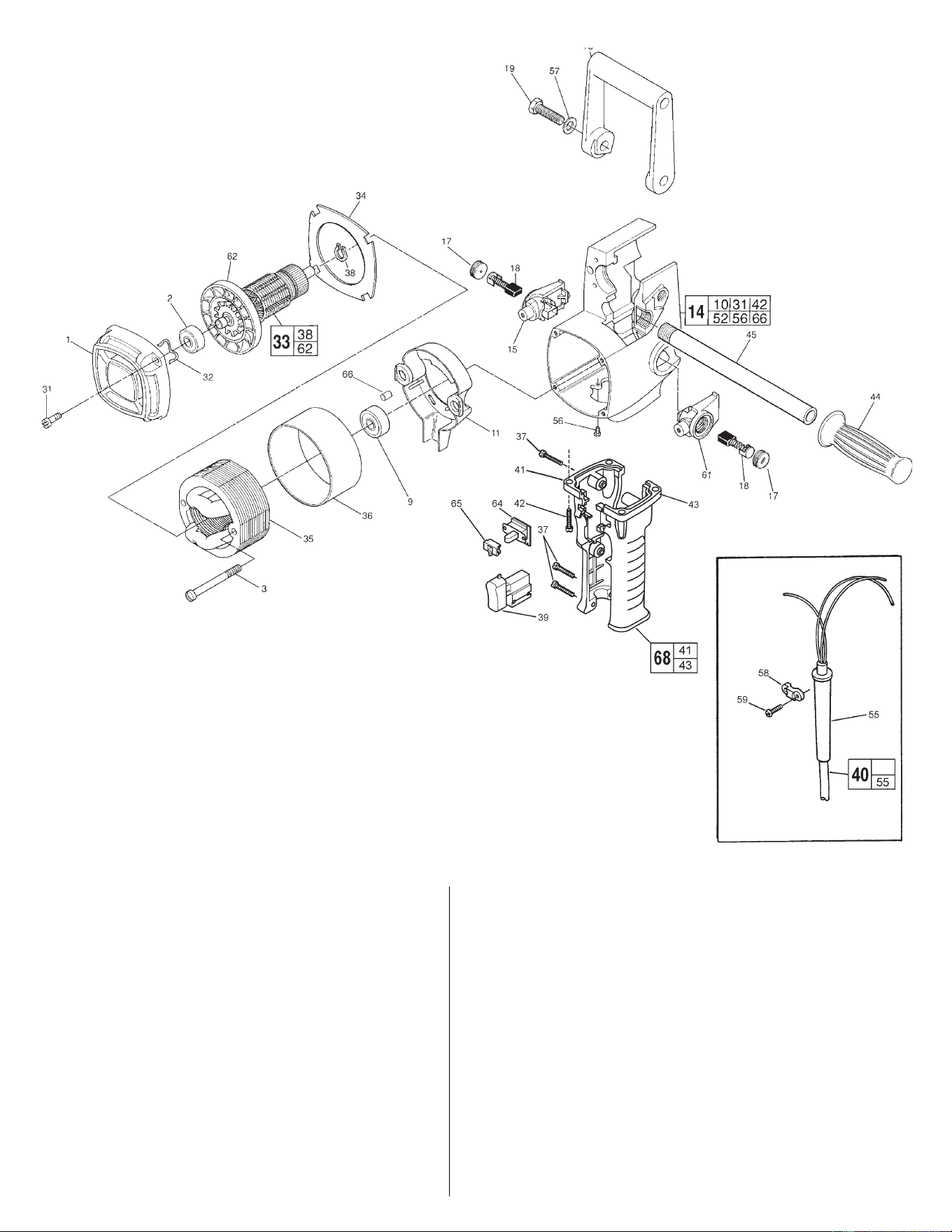
FIG. PART NO. DESCRIPTION OF PART NO. REQ.
40 22-64-1246 Cord Set (1)
41 --------------- R.H. Drill Handle (1)
42 06-82-5382 1/4-20 x 3/4" Pan Hd. Taptite T-27 Screw (4)
43 --------------- L.H. Drill Handle (1)
44 43-62-0246 Handle Grip (1)
45 43-62-0122 Pipe Handle (1)
55 44-76-0150 Cord Protector (1)
56 06-95-5150 6-32 x 1/4" Ground Screw (1)
57 45-88-0605 Flat Washer (2)
58 31-17-0155 Cord Clamp (1)
59 06-82-7270 8-16 x 5/8" Pan Hd. Slt. T-20 Plast. Screw (2)
61 22-22-1355 L.H. Brush Holder Assembly (1)
62 22-84-0660 Fan Assembly (1)
64 23-66-2516 Fwd./Rev. Switch (1)
65 43-72-0220 Interlock (1)
66 45-30-0070 Retaining Slug (1)
68 31-44-1493 Handle Set (1)
10-98-5979 Caution Label (Not Shown) (1)
FIG. PART NO. DESCRIPTION OF PART NO. REQ.
1 28-50-6235 Bearing Support Housing (1)
2 02-04-0913 Ball Bearing (1)
3 06-82-7415 8-16 x 1.8" Pan Hd. Slt. Plast. T-20 Scr. (2)
9 02-04-1050 Ball Bearing (1)
11 31-55-0065 Coil Shield (1)
14 28-50-6129 Motor Housing Assembly (1)
15 22-22-1350 R.H. Brush Holder Assembly (2)
16 31-44-1100 Spade Handle (1)
17 23-44-0220 Brush Retaining Cap (2)
18 22-18-0670 Carbon Brush Assembly (2)
19 06-75-0500 3/8-16 x 1" Hex Hd. Spade Handle Screw (2)
31 06-82-5346 8-32 x 3/4" Pan Hd. T-20 Screw (4)
32 45-88-7110 Spring Washer (1)
33 16-50-1076 Armature Assembly (1)
34 42-14-0150 Baffl e (1)
35 18-50-0077 Field Assembly (1)
36 23-16-0425 Field Insulator (1)
37 06-82-7326 8-16 x 1" Plastite T-20 Screw (4)
38 34-60-0827 Retaining Ring (1)
39 23-66-0115 Switch (1)