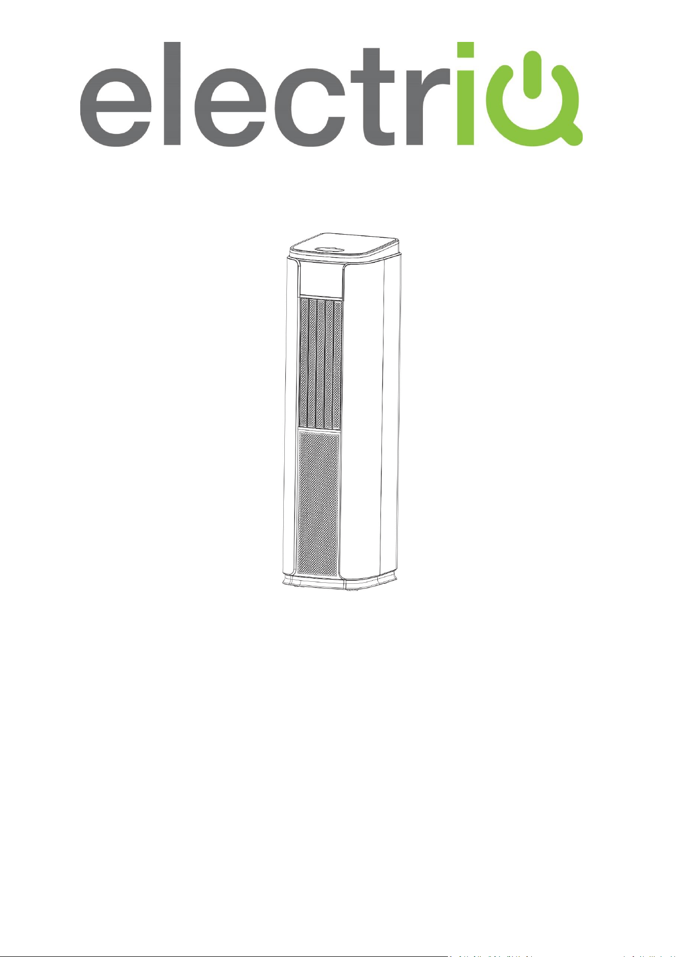
USER MANUAL
PORTABLE LOCAL AIR CONDITIONER
WITH HEAP PUMP AND SMART APP
SC10HPW
10,000 BTU
SC14HPW
14,000 BTU
SC16HPW
16,000 BTU
Thank you for choosing electriQ.
Please read this user manual before using this innovave Air Condioner and keep it safe for future reference.
Visit our page, www.electriQ.co.uk, for our enre range of Intelligent Electricals.

2

3
CONTENTS
SAFETY WARNINGS
4
FEATURES
7
PARTS
7
INSTALLATION
8
OPERATION
11
REMOTE CONTROL
13
WIFI APP CONTROL
14
SETTING UP THE APP
14
CONNECTING THE AIR CONDITIONER
16
CONTROLLING YOUR DEVICE
18
SMART SCENES
21
CLEANING AND MAINTENANCE
26
EMPTYING THE INTERNAL WATER TANK
27
TROUBLESHOOTING
28
ERROR CODES
29
SUPPORT
29
TECHNICAL SPECIFICATION
30

4
SAFETY INSTRUCTIONS
Important!
• Carefully read the instrucons before operang the unit.
• This appliance is for indoor use only.
• Rang: This unit must be only connected to a 220-240 V / 50 Hz
earthed outlet. The fuse rang can be found on the plug itself.
• Installaon must be in accordance with the applicable regulaons of the country where the
unit is used.
• If you have any doubt about the suitability of your electrical supply, have it checked and, if
necessary, modied by a qualied electrician.
• This appliance is not intended for use by persons (including children) with reduced physical,
sensory or mental capabilies. It is also not intended for use by those with a lack of
experience and knowledge unless they have been given supervision or instrucon concerning
the use of the appliance by a person responsible for their safety.
• Do not leave children unsupervised with this appliance.
• You must follow the venng and set-up instrucons; Incorrect operaon can result in damage
to the unit, which is not covered under your warranty.
• This air condioner has been tested and is safe to use. However, as with any electrical
appliance - use it with care.
• Do not obstruct any of the venlaon openings.
• The airow should never be restricted, for example, by venng the unit into a condenser box
or reducing the hose diameter, as this can damage the unit.
• Disconnect the power from the appliance before dismantling, assembling or cleaning.
• An authorised service representave should perform any service other than regular cleaning
or lter replacement. Failure to comply could result in a voided warranty.
• Avoid touching any moving parts of the appliance.
• Never insert ngers, pencils or any other objects through the guard.
• WARNING: Do not pierce or burn any part of the unit.
• Do not clean the unit by spraying it or immersing it in water.
• Never connect the unit to an electrical outlet using an extension cord. If an outlet is not
available, one should be installed by a qualied electrician.
• Never operate this appliance if the cord or plug is damaged. Ensure the power cord is not
stretched or exposed to sharp objects/edges.
• A damaged supply cord should be replaced by the manufacturer or a qualied electrician to
avoid a hazard.
• Do not use the appliance for any purpose other than its intended use.
• The air condioner unit must always be stored and transported upright; otherwise,
irreparable damage may be caused to the compressor. If there is doubt, we suggest waing
at least 24 hours before starng the unit.
• Avoid restarng the air condioning unit unless 3 minutes have passed since being turned o.
This prevents damage to the compressor.
5
• Never use the mains plug as a switch to start and turn o the air condioning unit. Use the
provided POWER buon located on the control panel.
• Always place the unit on a dry, stable, at surface.
• The appliance should not be installed in the laundry or wet rooms.
• The appliance must be placed in a room without sources of ignion (for example, open
ames, an operang gas appliance or an operang electric heater).
• R290 refrigerant gas complies with European environmental direcves.
• R290 has a low GWP (Global Warming Potenal) of 3.
• The air condioners contain the following quanty of refrigerant gas:
SC10HPW
160g
SC14HPW
210g
SC16HPW
230g
• Do not install or store in an unvenlated space with an area smaller than shown in the table
below per system. Smaller room sizes may be suitable if other safety measures are implemented
and a risk assessment conducted
SC10HPW
7.7 m
2
SC14HPW
10.1 m
2
SC16HPW
11.0 m
2
• WARNING: The appliance must be stored in a room without connuously operang ignion
sources, for example, open ames, an operang gas appliance or electric heaters.
• The room must be such as to prevent stagnaon of possible leaks of refrigerant gas as there
could be a danger of re or explosion should the refrigerant come into contact with electric
heaters, stoves or other ignion sources.
• Only store and use the unit whilst upright; do not lay it down or p it.
• Do not place the unit near any ovens or other heat sources. This may be dangerous but will
lead to the unit working harder and using more energy.
• Do not place the unit in direct sunlight; this can aect its appearance and cause it to work
hard and be less energy ecient.
• Refrigerant gas may be odourless.
• Do not use the product and contact the retailer for advice if damage has occurred to the unit,
which may have compromised the refrigerant system.
• Any repairs or maintenance must only be conducted by a suitably qualied engineer. Before
opening and servicing the unit, the authorised engineer must possess a copy of the
manufacturer’s service manual and follow the safety informaon contained within it to
ensure all hazards are minimised.
• The refrigerant system should not be perforated or punctured.
• At the end of the unit’s lifeme, always dispose in line with local regulaons.
• Ensure all storage condions in the manual are followed.
• WARNING: Do not use means to accelerate the defrosng process or to clean the unit.
6
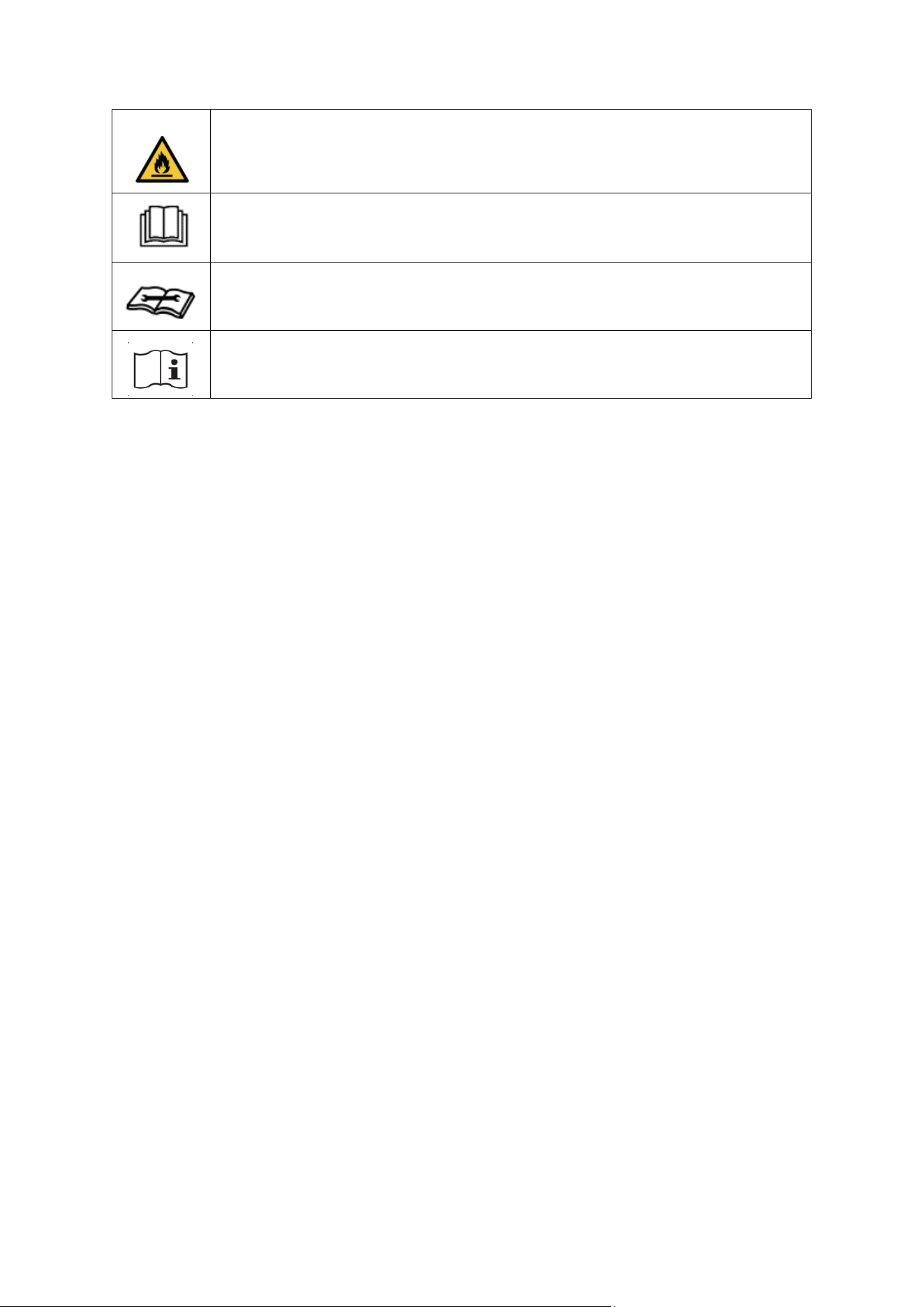
WARNING: This appliance contains ammable refrigerant. If this leaks
and comes into contact with an external ignion source, there is a re
risk.
CAUTION: The operaon manual should be read thoroughly.
CAUTION: Any service personnel working on the unit should read the
service manual prior.
CAUTION: Informaon on operaon and servicing is in the manual.
ENERGY SAVING AND UNIT SAFETY PROTECTION TIPS
• Do not cover or restrict the airow from the outlet or inlet grills.
• For maximum performance, the minimum distance from a wall or object should be 50cm.
• Keep the lters clean. Under normal condions, lters should only need cleaning once every
three weeks (approximately). Since the lters remove airborne parcles, more frequent
cleaning may be necessary, depending on the air quality.
• For the inial start-up, set the fan speed to maximum and the thermostat to 5 degrees lower
than the current temperature. Aerwards, set the fan switch low and set the thermostat to
your desired seng.
• To protect the unit, we recommend not using the cooling funcon when the ambient
temperature exceeds 35
o
C. The unit's performance may be aected at lower temperatures
than this. If a scorching day is predicted, running the unit overnight in the desired room is
recommended.
7
FEATURES
•
4 in 1 cooling, heang, fan, and dehumidier.
•
5-speed fan: Balancing quiet operaon with performance.
•
24 Hours Start/Stop Timer
•
Digital Thermostat: Set the temperature between 16°C and 32 °C.
•
Remote Control.
•
Castors and Handle for Enhanced Portability.
•
Auto-Restart to retain the sengs in the event of power failure.
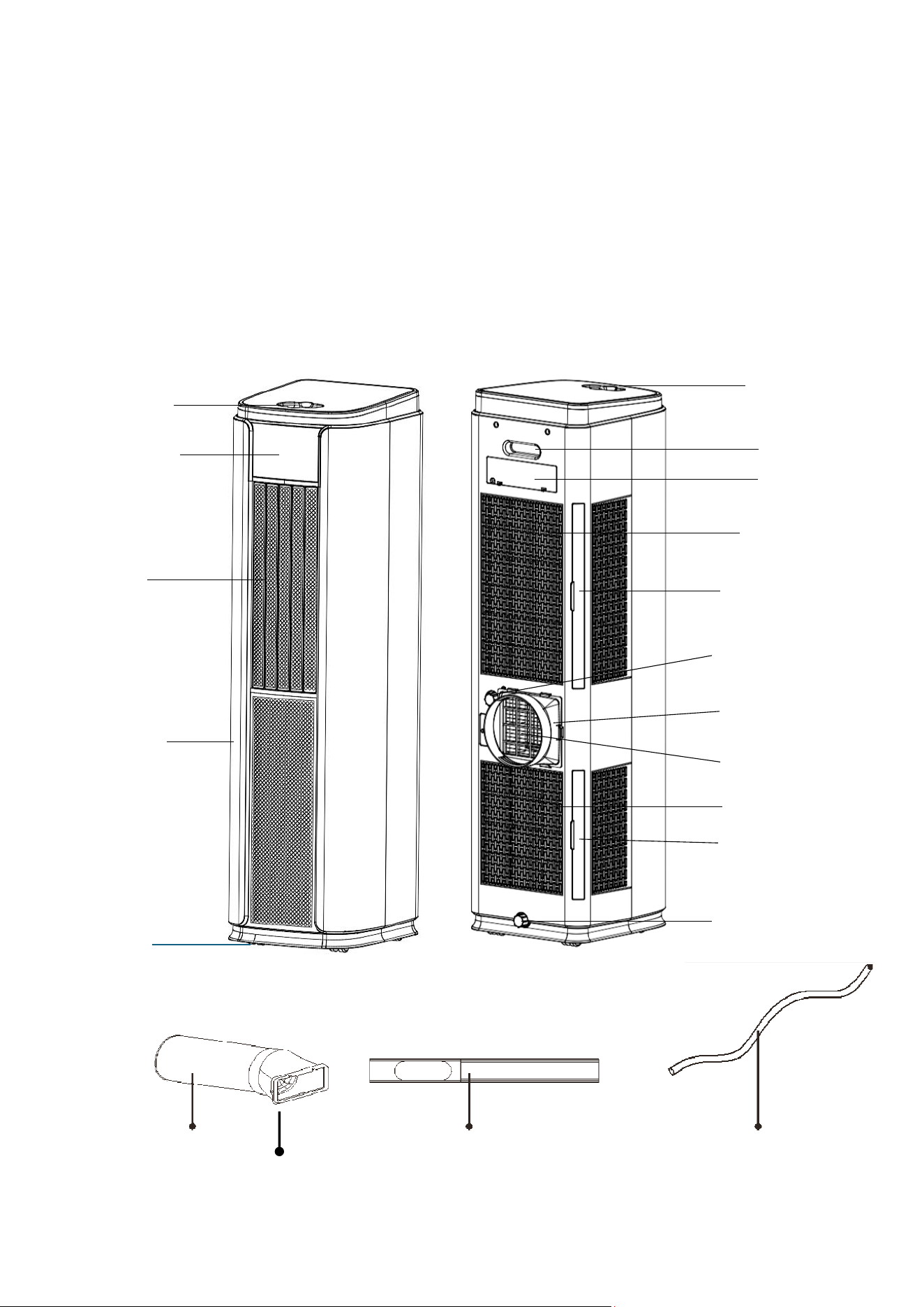
PART LIST
Exhaust Hose
Window Slide Bar
Drainage Pipe
Control Panel
Louvres
Front Cover
Castors
Top Cover
Handle
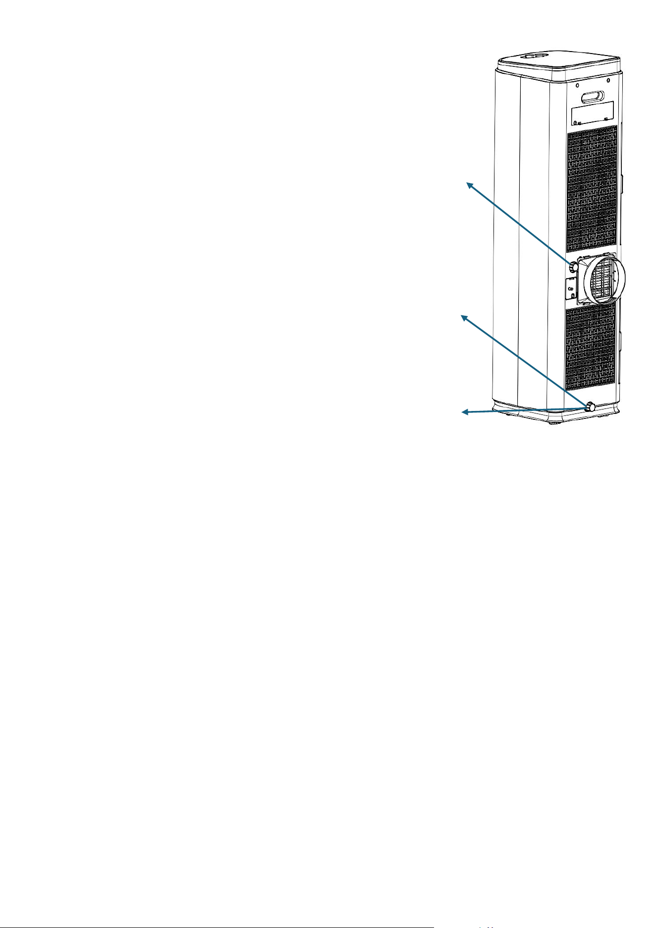
Top Cover
Upper Air Inlet
Upper Drainage Port
Exhaust outlet.
Lower Air Inlet
Lower Drainage Port
Upper Filter Frame
Exhaust Adaptor
Lower Filter Frame
Fishtail Adaptor
Remote Holder
and Handle
Cable Storage
Top Cover
8
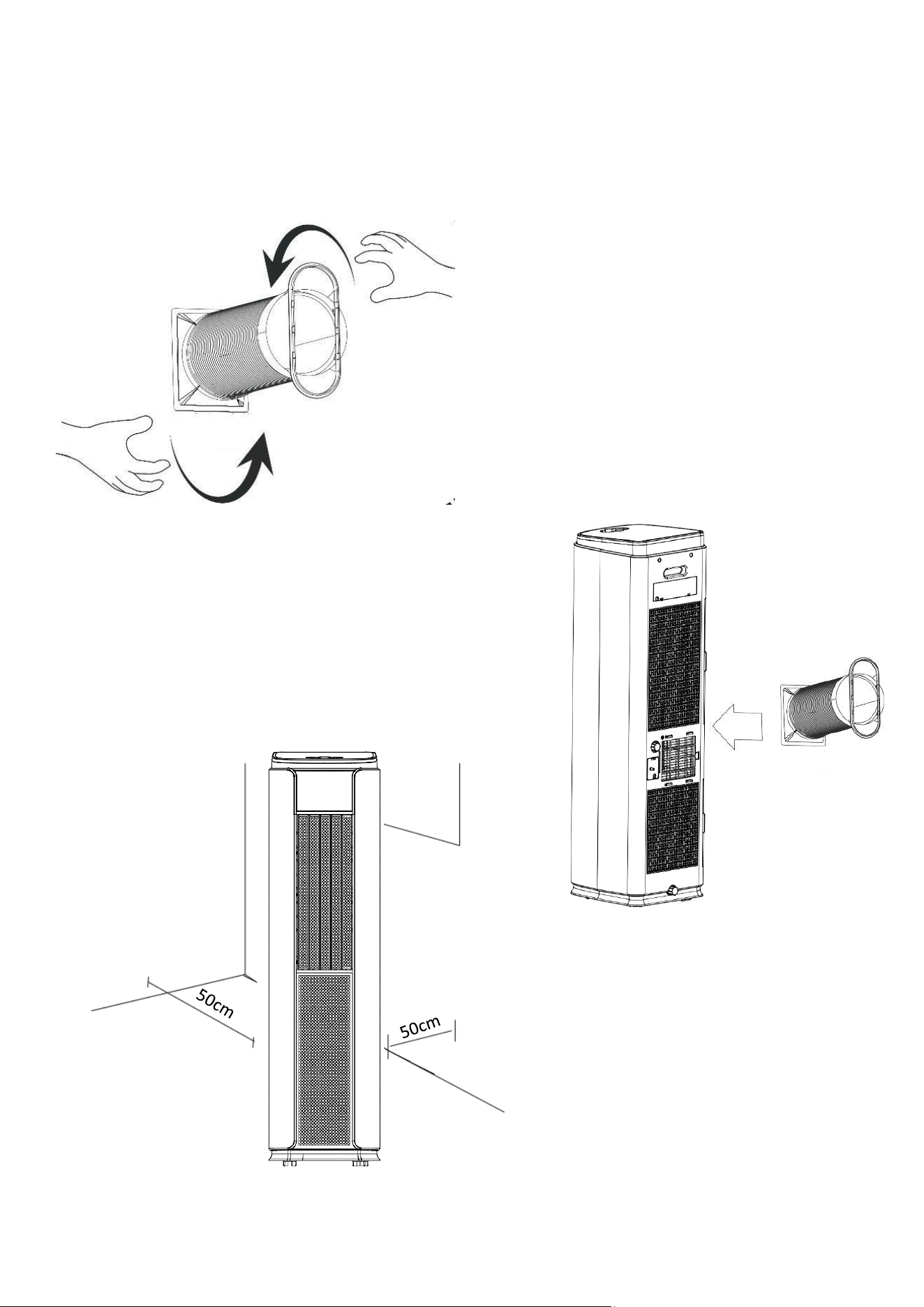
INSTALLATION
WARNING:
Before using this unit, please keep it upright for at least 3-4 hours.
This unit can easily be moved from one room to another.
While moving the unit, please note that it must always be kept upright and placed on an even surface.
1.
Attach the fishtail connector to the end of the
hose by extending the end and twisting until
firmly attached to the connector (At least 3
full rotations).
2. Attach the Hose to the Exhaust adaptor in the
same way by extending the end of the hose and
twisting until firmly attached (At least 3 full
rotations).
3.
Clip the Exhaust adaptor into position on the rear of the
unit. (To remove the adaptor, press the clips down to
release it from the unit)
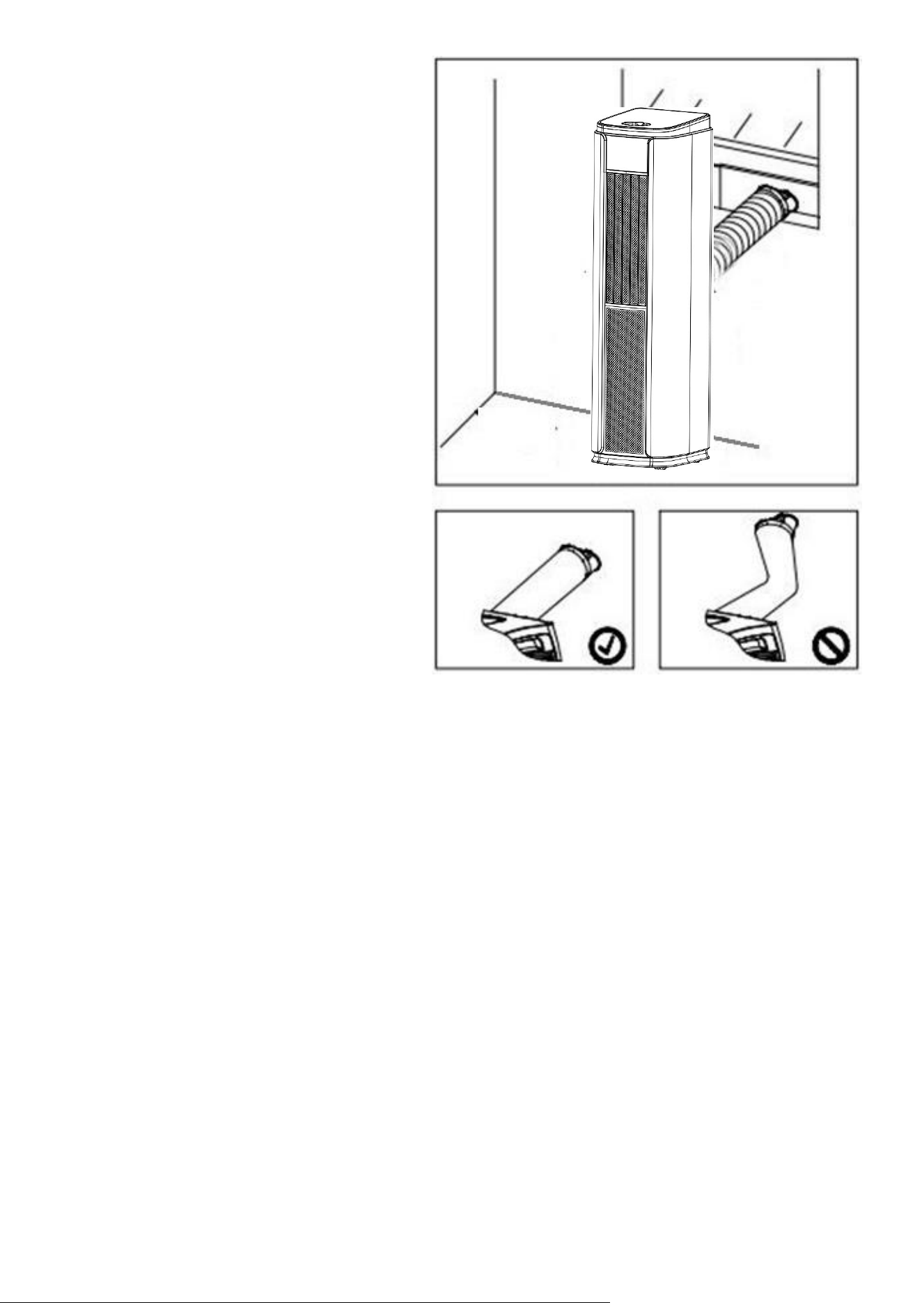
4.
Make sure the unit is upright, and there
are no obstructions to the air inlets and
outlet grills, with at least 50cm of space
to the sides and rear of the unit.
9
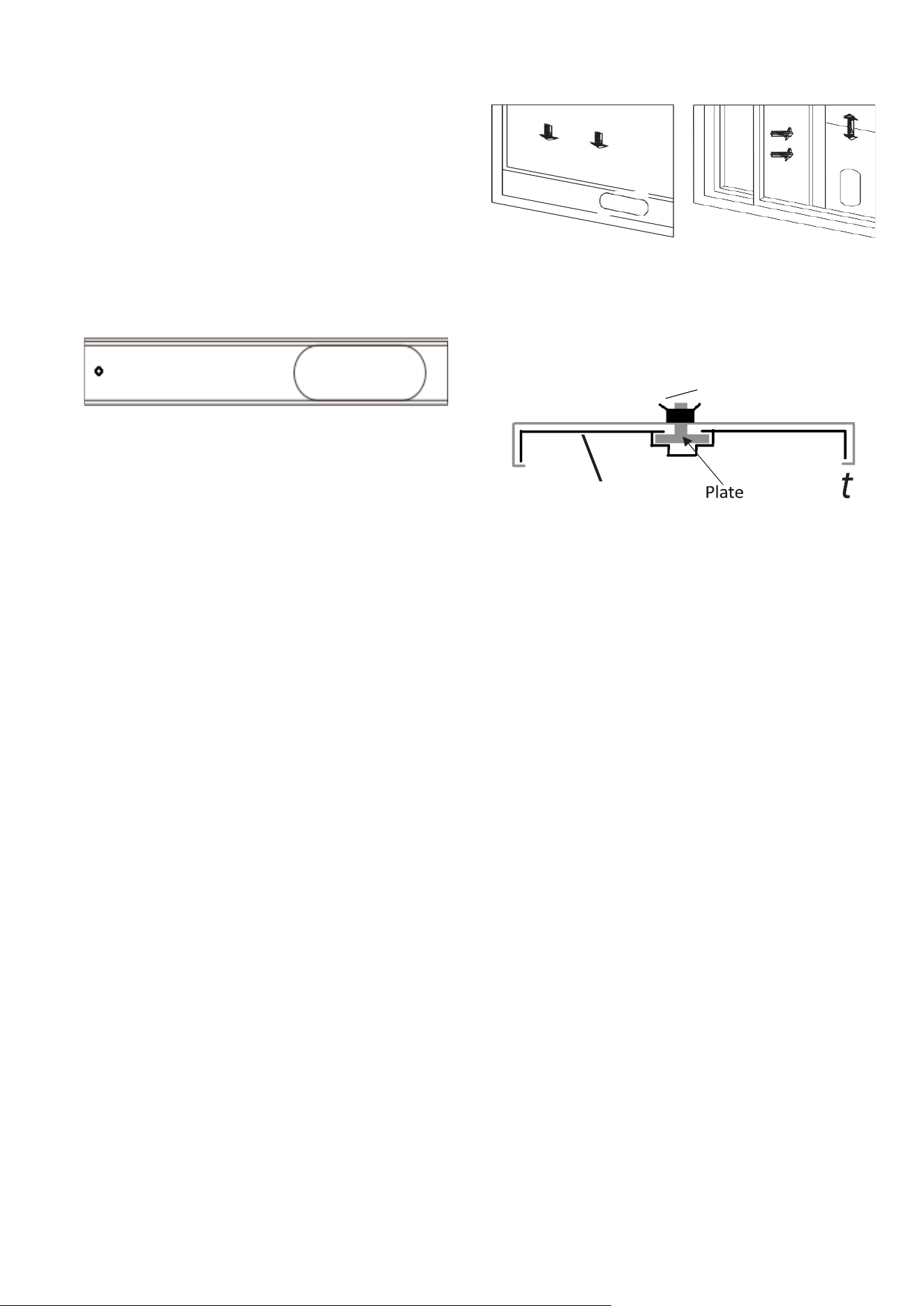
INSTALLATION OF WINDOW KIT
The window kit (slide bar and shtail adaptor) can be
used with sliding windows and doors. For other
types of windows, the shtail adaptor should be
used on its own.
1.
Slide the rear section of the slide bar onto the front section, lining up the plate so it runs
within the groove. Extend the bar to the required length and use the supplied wing nut to
secure it.
2.
Push the screw thread of the plate through the
hole in the rear of the front slide bar section.
3.
Parally open the window and place the
extended slide bar in posion before closing
the window onto it.
4.
Fix the shtail adaptor into the opening on the
slide bar.
NOTES:
•
The window kit is only designed to be installed with sliding or sash windows or
doors. The window kit is not designed to be used with any other style of windows.
•
The shtail adaptor can be used without the slide bar with most windows/doors.
•
When using the air condioner, ensure that the opening around the shtail adaptor
is as small as possible to ensure the unit's eciency is not reduced.
•
The best form of installaon is through a wall duct. By adequately venng, you expel
hot air from your room while eciently cooling it.
•
Your air condioner should be used without the vent pipe in dry mode. When
using dry mode, ensure that an external water tank is used, monitored and
regularly emptied before overflowing.
Permanent plumbing can also be installed, or
an external upli water pump can be set up to allow
uninterrupted use.
Slide Bar
Slide Bar
(Rear Selection)
Wingnut
10
IMPORTANT SAFEGUARDS
The length of the soft hose extends from
approximately 30 cm to 180 cm. If the hose is
extended above this length, the unit may
malfunction, which can invalidate the
warranty. The outlet vent must be well-
ventilated and not obstructed, as this will
cause the unit to overheat. Keep the hose as
straight and short as possible, and avoid
bending the air hose by more than 30
degrees to maintain the unit's performance.
Excessive bends in the hose may prevent the
unit from expelling hot air, leading to internal
damage, and invalidating the warranty.
11
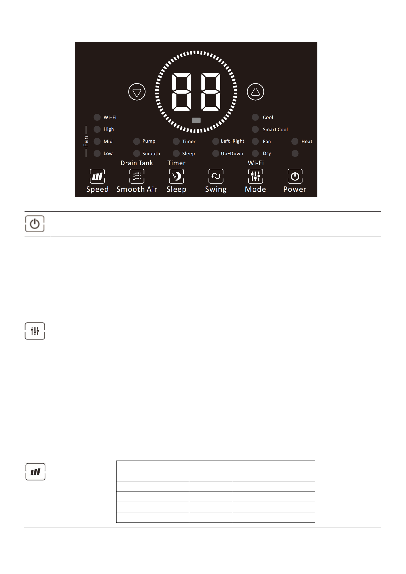
OPERATION
Press the POWER button to turn the unit ON or OFF.
Press the MODE button to cycle between the 4 modes, and the indicator for the selected
mode will be illuminated.
COOL:
The room is cooled with the cold air expelled through the front air outlet while hot
air is expelled through the vent pipe. The desired room temperature can be set between
16 and 32 degrees using the + and - buttons, and the fan speed can be changed using the
SPEED button.
HEAT:
The room is heated with the hot air expelled through the front air outlet while cold
air is expelled through the vent pipe. The desired room temperature can be set between
16 and 32 degrees using the + and - buttons, and the fan speed can be changed using the
SPEED button.
FAN:
The fan speed can be changed by pressing the SPEED button.
DRY:
It should be operated without the vent hose but with continuous drainage to
remove moisture from the air. The unit will run at low fan speed, with dH shown on the
display. Do not use it when the room temperature is below 15 degrees.
SMART COOL:
An intelligent cooling mode where the fan speed is automatically adjusted
based on the amount of cooling required. Attempts to change the fan speed will move the
unit into COOL mode.
WIFI:
Press and hold the MODE button to activate the WiFi connection mode. See the WiFi
section for further information.
Press the SPEED button to change between the five fan speeds. The display and LEDs will
indicate the currently selected fan speed. The fan speed cannot be altered in SMART COOL
and DRY modes.
Fan Speed
Display
LED’s Illuminated
Quiet
F1
Low
Low
F2
Low & Medium
Medium
F3
Medium
High
F4
Medium & High
Turbo
F5
High
12
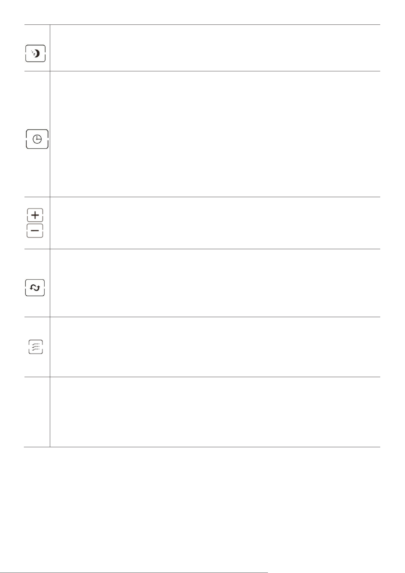
Press to enter sleep mode. The sleep indicator will be illuminated, and all other indicators will
be turned off. In sleep mode, the appliance works at low fan speed. Press SLEEP again to exit
sleep mode.
The timer functions cannot be combined or repeated.
POWER ON TIMER
With the appliance on standby, press the TIMER button to set the power-on timer. Use the +
and - buttons to adjust the timer's duration (1 to 24 hours). The Timer indicator will turn on, and
the unit will start after the selected number of hours.
POWER OFF TIMER
Press the TIMER button to set the power-off timer so the appliance runs with the desired
settings. Use the + and - buttons to adjust the timer's duration (1 to 24 hours). The timer
indicator will illuminate, and the unit will stop after a selected number of hours.
Used the + and – buttons to adjust the temperature in COOL and SMART COOL mode. They are
also used to set the duration of the TIMER. The buttons are not used in FAN or DRY modes.
Press both buttons together to change between displaying the temperature in Celsius and
Fahrenheit.
Use to enable the swing function.
Press SWING to activate and deactivate the up-down swing.
Press and hold SWING for 3 seconds to activate and deactivate the left-right swing.
The SMOOTH AIR function is designed to provide smooth, soft airflow while ensuring quiet
operation with the low fan speed. It provides a gentle refreshing breeze by utilising the small
holes within the louvre to distribute the air.
Press the SMOOTH AIR button to activate and deactivate the function.
When it is activated, both the up-down & left-right louvre will be fully open. The position of the
left-right louvre can be adjusted using the SWING button.
Pump
When the internal water tank is full, the unit will stop working.
Connect the drainage hose and place the other end into a bucket. Press and hold the SMOOTH
AIR button to start the pump function. This function can only be activated when the water tank is
full (E4 will be displayed).
Note: The pump is designed to make emptying the appliance easier, and is intended for purposes
such as draining into a bucket situated next to the unit. For longer distances, or greater heights an
external uplift pump should be used.
SMART COOL
When you turn on the smart, cool function, the unit will select the correct fan speed depending on the
dierence in your desired temperature and the current temperature. If the dierence is more than 2 degrees,
the unit will use the max fan speed; if it is less than this, it will use level F3.
Every 20 minutes, the unit will read the room temperature and adjust the fan accordingly. If the fan is already set to
the max or minimum speed, this may not change.
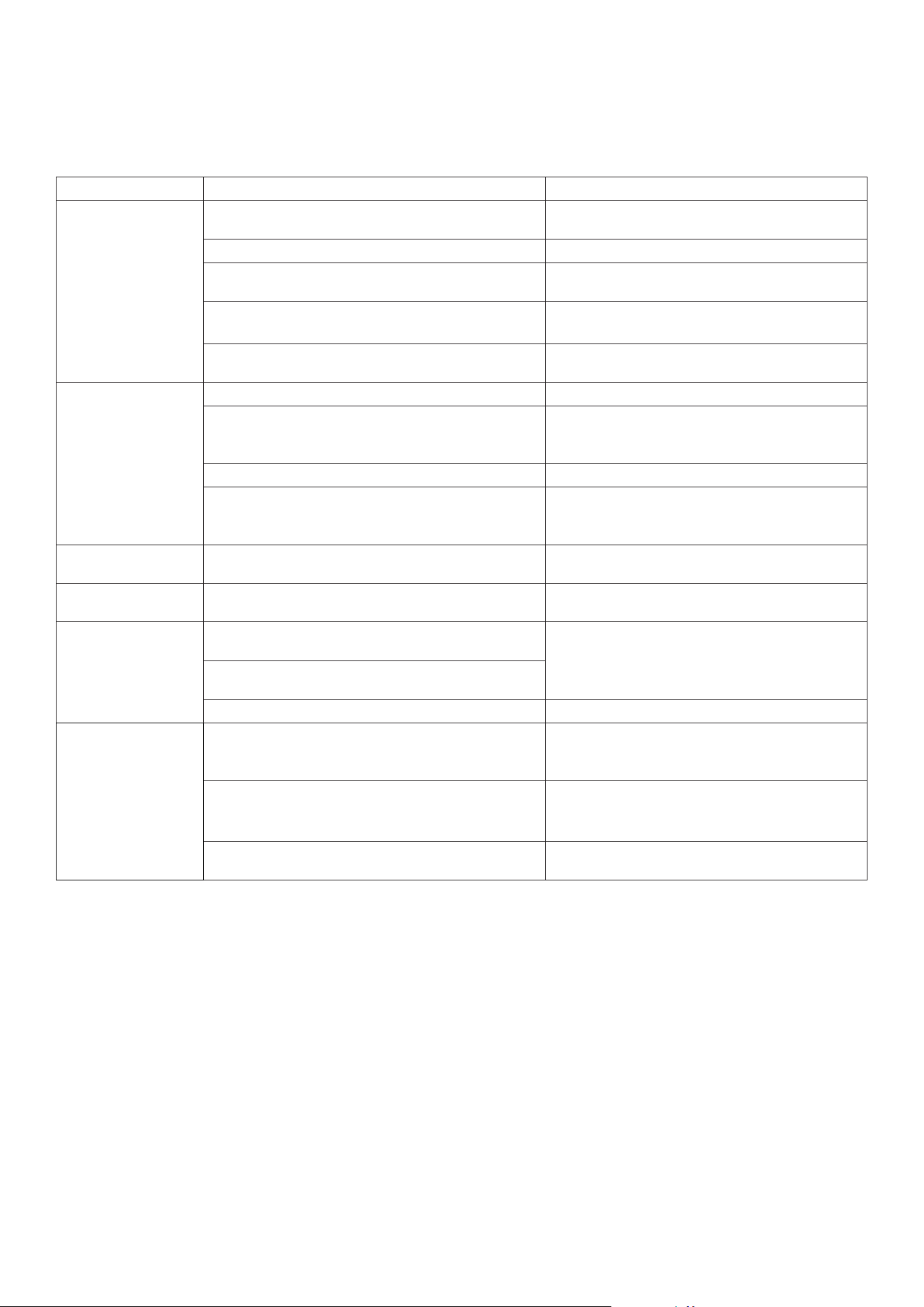
13
Scenario
Adjustment
Example
Desired temperature reached
Fan speed decreases
by one level.
The desired temperature is 22; the Current
room temperature is 22.
The current temperature has risen in the
last 20 minutes.
Fan speed increases by
one level unless it is
already at the max.
The desired temperature is 22; the room
temperature 20 minutes ago was 23 and is now
24. The fan speed increased from F2 to F3.
The current temperature hasn’t dropped
more than a quarter of the dierence
between the current temperature and
the desired temperature 20 minutes ago.
Fan speed increases by
one level unless it is
already at the max.
The desired temperature is 22; the room
temperature 20 minutes ago was 28 and is now
27. The fan speed increased from F2 to F3.
The current temperature has dropped
more than half of the dierence between
the current temperature and the desired
temperature 20 minutes ago.
Fan speed decreases
by one unless it is
already at the
minimum.
The desired temperature is 22; the room
temperature 20 minutes ago was 26 and is now
22. The fan speed decreased from F3 to F2.
Any change in temperature that is not
described.
Connues at the same
speed
The temperature stayed the same.
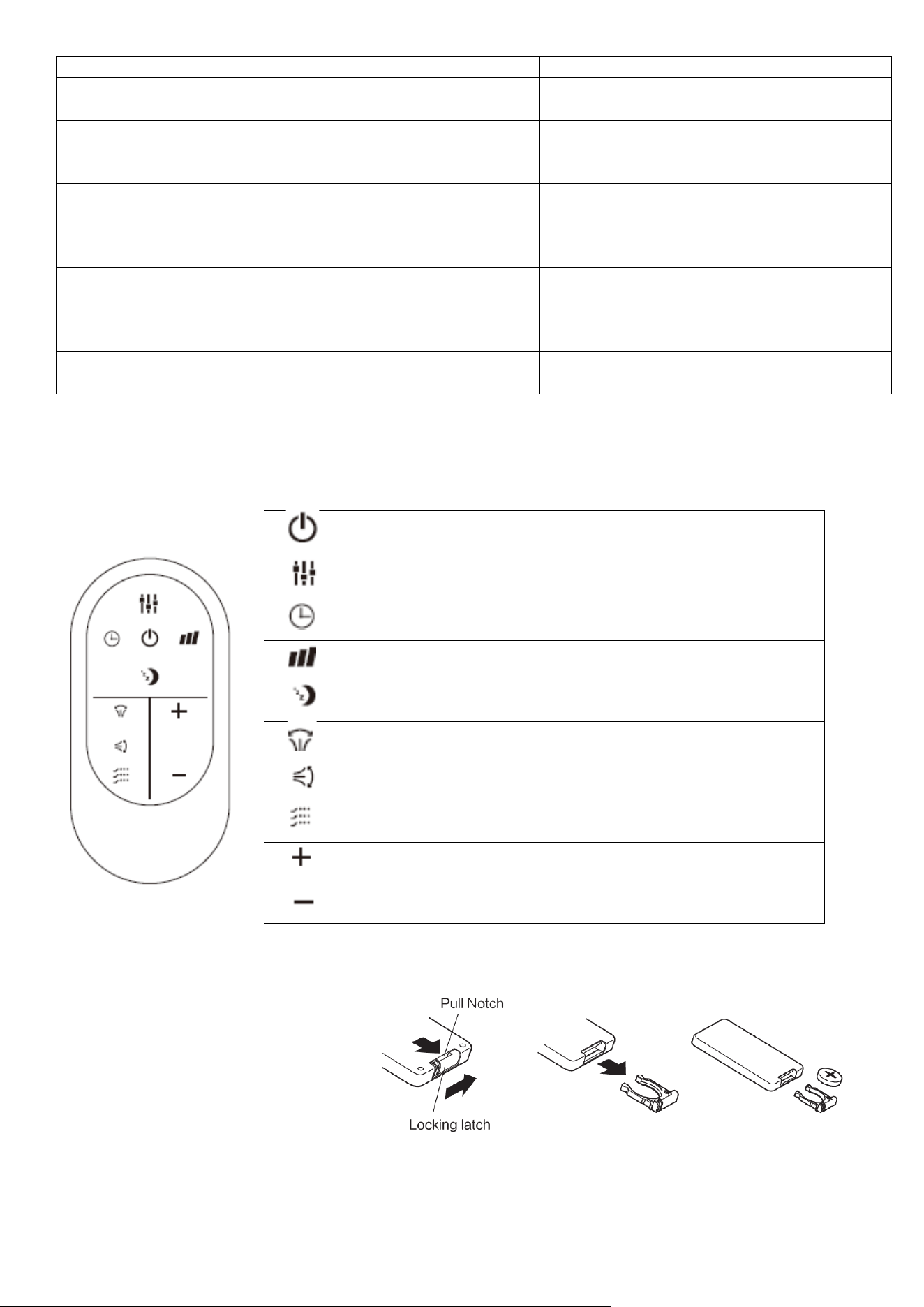
REMOTE CONTROL
REPLACING THE BATTERIES
The remote control takes a CR2025
baery. If the remote becomes
unresponsive, please change the baery
with a new baery, as shown in the
image.
Press to turn the unit on or o.
Press to change between Cooling, Heang, Fan, Dry and
Smart Cool Modes.
Press to turn the mer on or o.
Press to adjust the fan speed.
Press the sleep buon to enter sleep mode.
Press to turn on the le-right swing funcon.
Press to turn on the up-down swing funcon.
Press to turn on the smooth air funcon.
Press to increase the desired temperature.
Press to decrease the desired temperature.

14
MULTI PROTECTIVE FUNCTIONS
FROST PROTECTION
In COOL, DRY or SMART COOL modes, if the temperature of the exhaust is too low, the machine will
automatically stop operating until the temperature has risen.
OVERFLOW PROTECTION
When the water in the internal water tank exceeds the warning level, the machine will stop operating and
sound an alarm with the LCD showing "E4". To resume operation, empty the internal water tank. After
emptying the water, the machine will automatically return to its original state.
AUTO-DEFROST
The machine has an automatic defrosting function. If the internal coils' temperature drops too low during
operation, the unit will enter auto defrost, and the heating symbol will flash on the control panel.
AUTOMATIC THERMAL PROTECTION
To protect the service life of the machine, the machine has automatic thermal protection. If the
temperature within the unit is outside of the specified range, the compressor and the lower motor will
stop operation. After the machine's temperature recovers, the appliance will automatically return to
regular operation.
COMPRESSOR PROTECTION
There is a 3-minute delay in starting the protection function to prevent damage to the compressor.
POWER DOWN MEMORY
If power is cut from the unit, when it is restored, the air conditioner will resume working with the same
settings as before the power interruption (After the compressor protection period). Note: any timer that
was set prior to the power interruption will not be saved.

15
WIFI SMART CONTROL
BEFORE YOU START
• Ensure your router provides a standard 2.4ghz connection.
• If your router is dual band ensure that both networks have dierent network names (SSID). The
provider of your router / Internet service provider will be able to provide advice specic to your
router.
• Place the air conditioner as close as possible to the router during setup.
• Once the app has been installed on your phone, turn o the data connection, and ensure your
phone is connected to your router via WiFi.
DOWNLOAD THE APP TO YOUR PHONE
Download the ”TUYA SMART” app, from your chosen app store, using the QR codes below, or by
searching for the app in your chosen store.
Android
CONNECTION METHODS AVAILABLE FOR SETUP
The air conditioner has two dierent setup modes, EZ (Quick Connection) and AP (Access Point). The
quick connection is a quick and simple way to set the unit up. The AP connection uses a direct local
WiFi connection between your phone and the air conditioner to upload the network details.
Before starting the setup, with the air conditioner plugged in, but turned o, press and hold the MODE
button for 5 seconds (until you hear a bleep) to enter the WIFI connection mode.
Please ensure your device is in the correct WIFI connection mode for the connection type you are
attempting, the ashing of the WIFI light on your air conditioner will indicate this.
Connection Type
Frequency of Flashes
EZ (Quick Connection)
Flashes twice per second
AP (Access Point)
Flashes once per second
CHANGING BETWEEN CONNECTION TYPES
To change the unit between the two WIFI connection modes, hold the MODE button for 5 seconds.
IOS
16
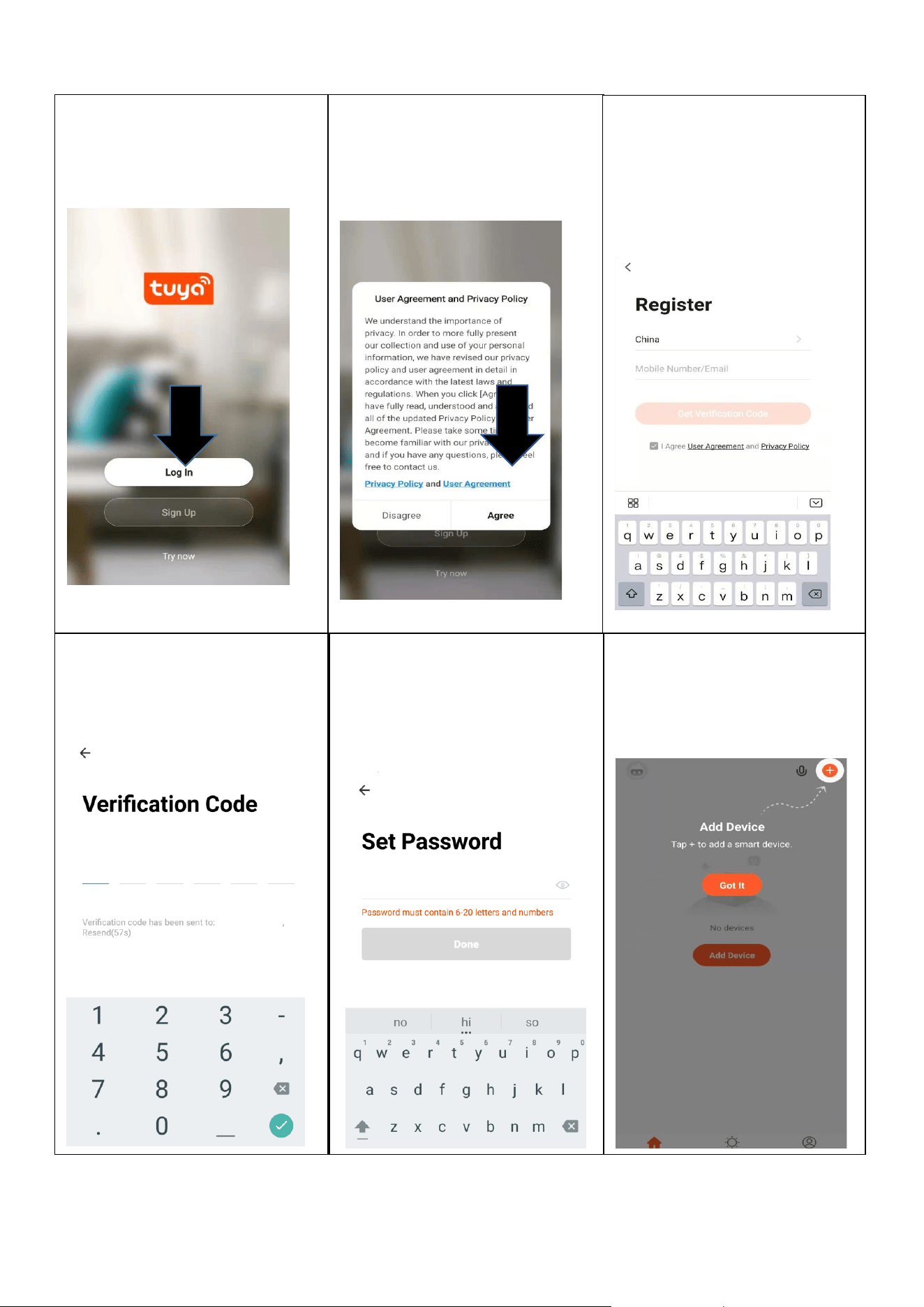
REGISTER THE APP
1. Press on the Sign Up
button at the bottom of the
screen.
2. Read the Privacy policy
and press the Agree
Button.
3. Enter your email address
or phone number and
press continue to register.
4. A verication code will be
sent by the method selected
in step 3. Enter the code
into the app.
6. The app is now registered.
It will automatically log
you in following
registration.
5. Type in the password you
would like to create. This
needs to be 6-20
characters, with letters and
numbers.
17
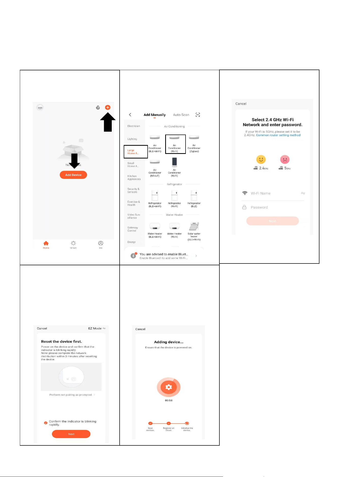
CONNECTING USING EZ (QUICK CONNECTION) MODE
Before initiating the connection, make sure the unit is in standby mode, with the WIFI light ashing
twice per second. If not follow the instructions for changing the connection mode. Also ensure your
phone is connected to the WIFI network. (We advise turning mobile data o during setup)
1. Open the app and press “+”
to add device
2. Select the type of device
as “Air Conditioner (WIFI)”
within the Large Home
Appliance tab.
3. Select your network, enter
your WIFI password and
press Next.
4. Ensure the WIFI light on
the air conditioner is
ashing twice per
second then press on
the orange button at the
bottom of the screen to
conrm
5. This will then transfer the
settings to the air
conditioner. Wait for this to
complete. If this fails, retry. If
still unsuccessful please
review the troubleshooting
section for further help.
18
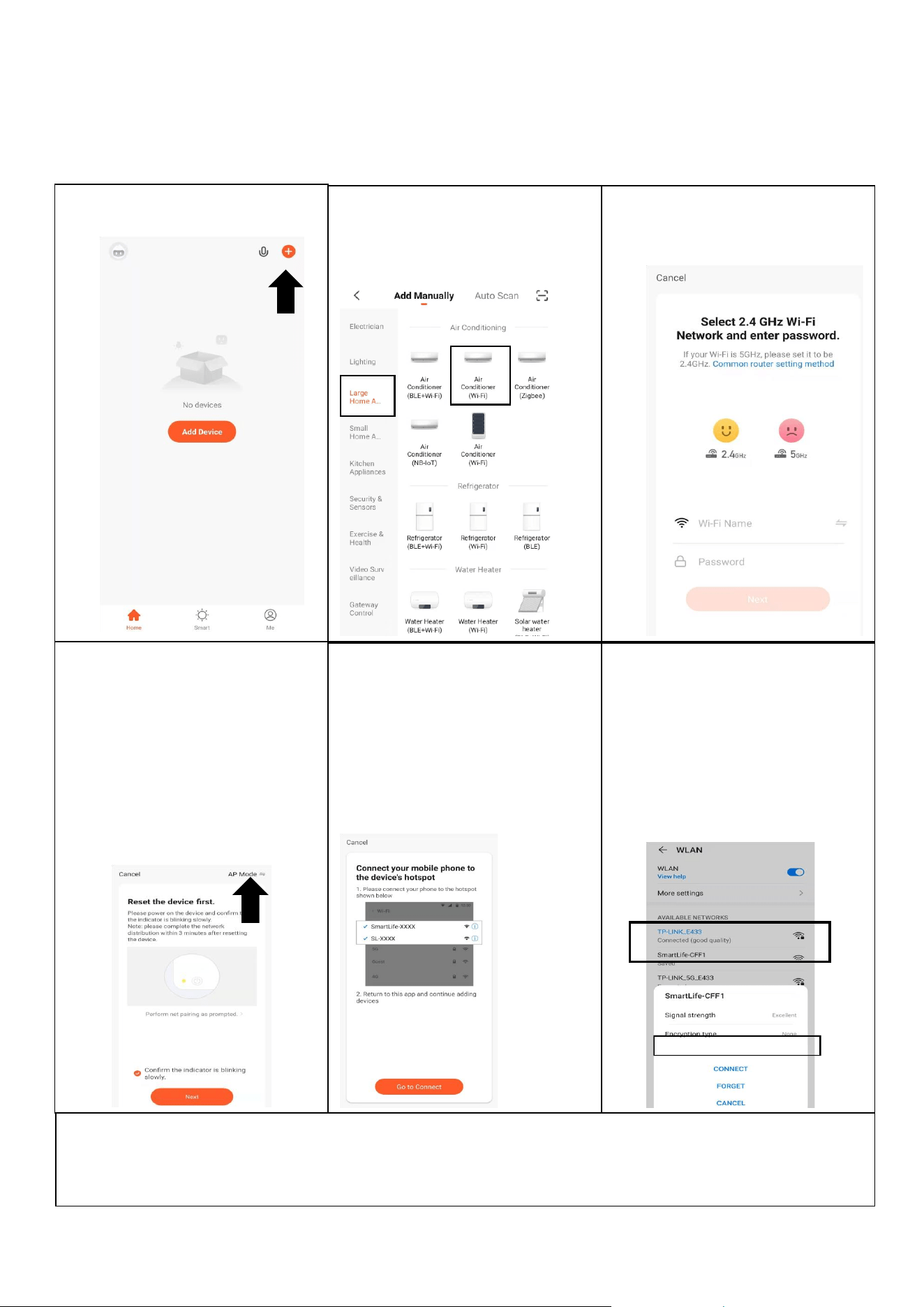
CONNECTING USING AP MODE (ALTERNATIVE METHOD)
Before initiating the connection, make sure the unit is in standby mode, with the WIFI light ashing
once per second. If not follow the instructions for changing the WIFI connection mode. Ensure
your phone is connected to the WIFI network. (We advise turning mobile data o during setup)
1. Open the app and press “+”
to add device
2. Select the type of device
as “Air Conditioner (WIFI)”
within the Large Home
Appliance tab.
3. Select your network, enter
your WIFI password and
press Next.
4. Ensure the WIFI light on the
air conditioner is slowly
ashing (once per three
seconds), then select AP
Mode in the top right corner
before pressing on the
orange button at the bottom
of the screen to conrm
5. Go to network settings in
your phone and connect to
the “SmartLife xxx”
connection. then press on
the orange button at the
bottom of the screen to
conrm
6. Go to network settings in
your phone and connect to
the “SmartLife xxx”
connection. There is no
password to enter. Then
return back to the app to
complete setup.
This will then transfer the settings to the air conditioner.
Once the connection process has completed, go back to the network settings on your phone to
ensure your phone has reconnected to your WIFI router.
19
CONTROLLING YOUR DEVICE THROUGH THE APP
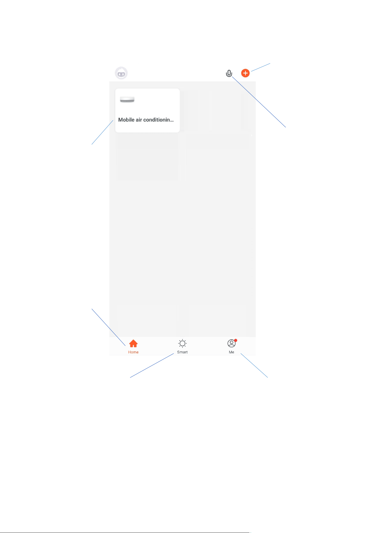
THE HOME SCREEN
Each device has its own entry on the home screen to allow the user to either quickly turn the unit on or
o, or to enter the device screen to make other changes.
Smart Scene: Allows you to
program intelligent behaviour
based on the internal and
external environment
Add Device: Add a device
to the app, and go
through the setup
process.
Prole: Provides the
option for changing
settings, and adding
devices using a QR code
provided by a friend.
Your Device: Press
to enter the device
screen.
Voice Control: Use to
give verbal instructions to
the app.
Home: Return to
this screen when
within the Smart or
prole tabs.
20
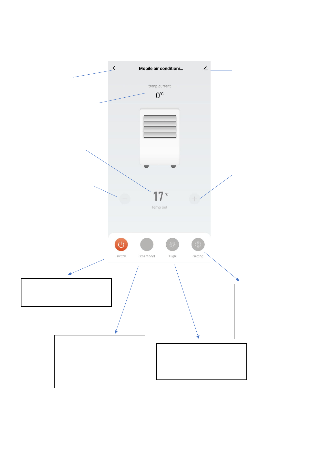
DEVICE SCREEN
The device screen is the main control screen for the air conditioner, providing access to the controls
to amend the functions and settings
Due to continuous development of the app, the layout and available features may be subject to
change.
Edit Name: Use to
change the name of
the air conditioner.
Desired Temperature UP
Button: Use to increase
the desired temperature.
Current Room
Temperature: Displays
the current room
temperature
Back: Returns to the
Home Screen
Desired Temperature:
Shows what
temperature the unit is
currently set to
MODE:
Change the operating mode
of the air conditioner
between Cool, Smart Cool,
Dry, Heat, and Fan
SPEED:
Use to change the Fan
speed between F1(Low)
and F5 (High)
POWER:
Use to turn the air
conditioner on and o.
SETTINGS:
Use to add an o timer
while the unit is running,
or an on timer while the
unit is turned o
Desired Temperature
DOWN Button: Use to
increase the desired
temperature.
21
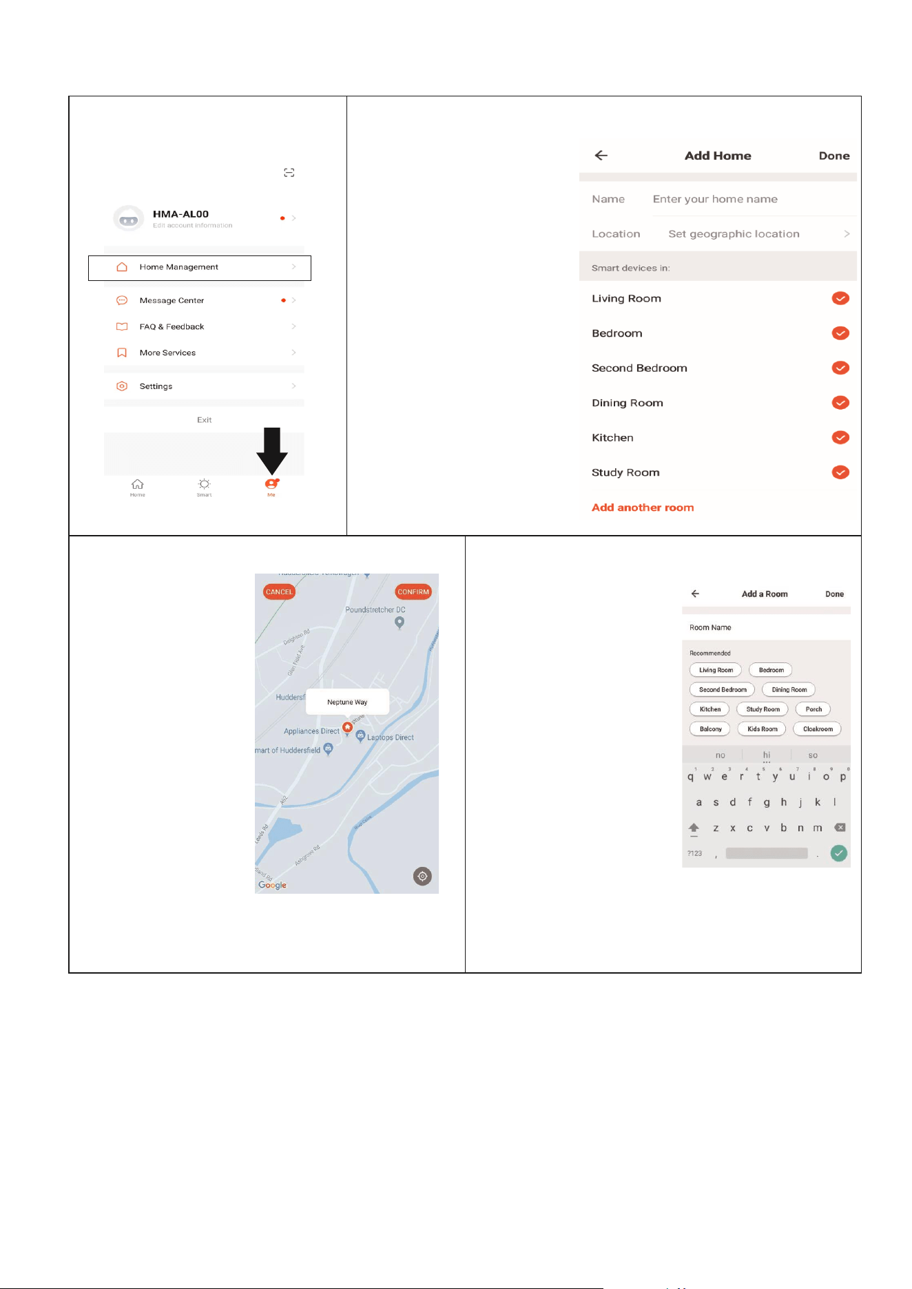
CREATING ROOMS
1. ON THE HOME SCREEN
Press on Home Management
2. Type in a name for your home,
3. Press on the location
button to select the
location of your home.
(See SETTING YOUR
LOCATION below)
4. New rooms can be
added by pressing the
ADD ANOTHER ROOM
option at the bottom.
(See ADD ANOTHER
ROOM below)
5. Untick any rooms that
are not required on the
app.
6. Press DONE in the top
right corner
SETTING YOUR LOCATION
ADD ANOTHER ROOM
Use your finger to
move the orange
HOME symbol.
When the symbol is
in the
approximate
location of your
home, press the
confirm button in
the top right corner.
Type in the name of the
room, and press Done in
the top right corner
button
22
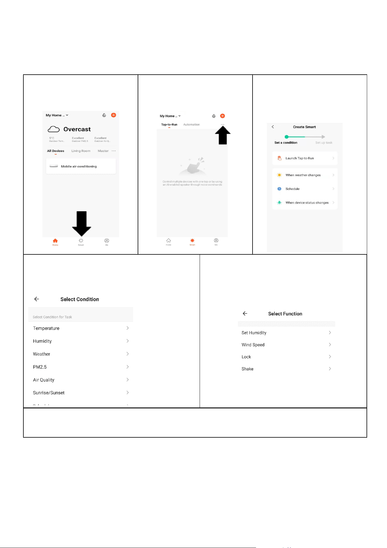
SMART SCENES
Smart Scenes is a powerful tool providing the option to customise the operation of the air
conditioner based both on conditions within the room and outside inuences. This gives the user
the option of specifying much more intelligent actions. These are split into two categories Scene
and Automation.
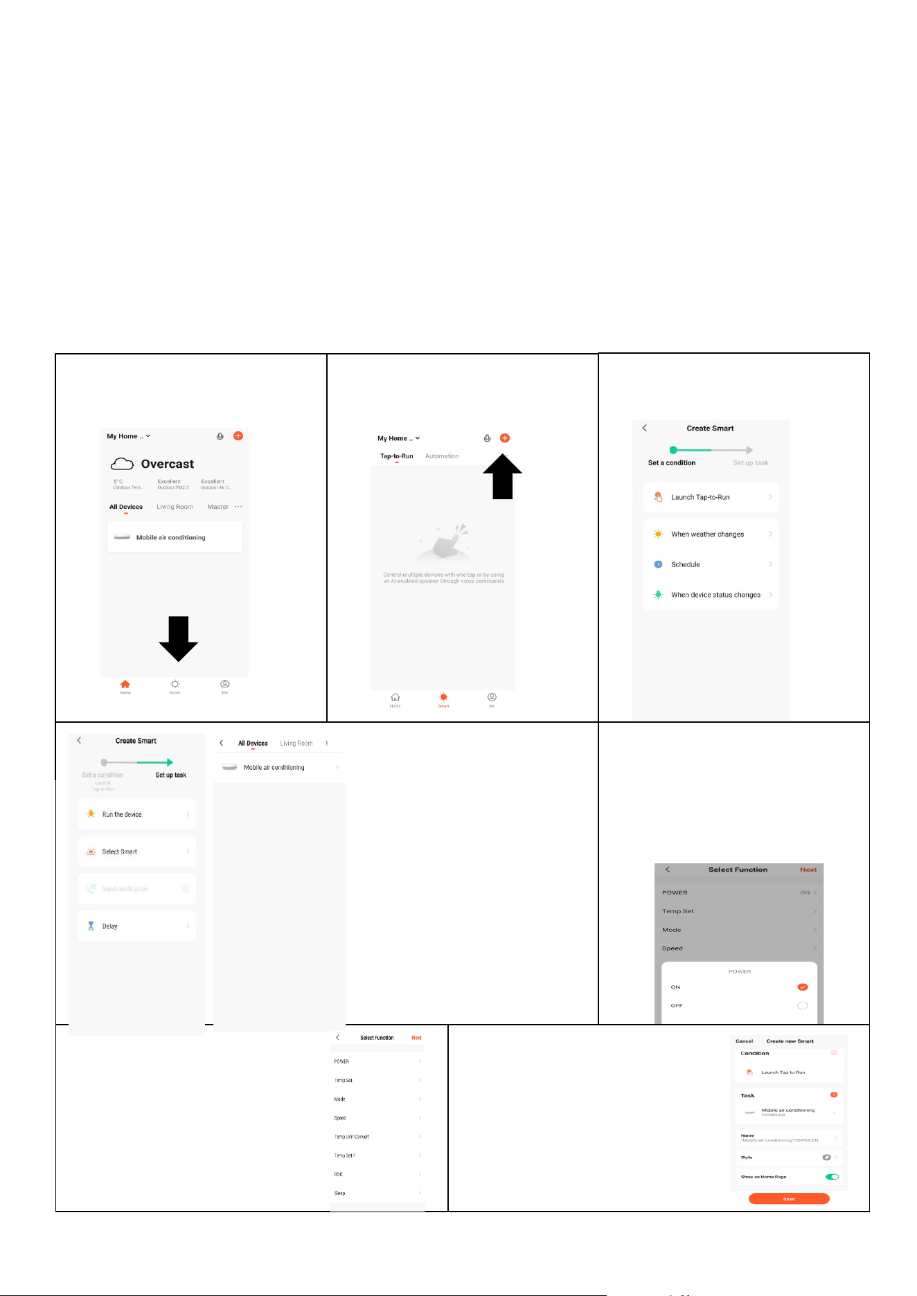
SCENE
Scene allows for a one touch button to be added to the Home screen. The button can be used to
change a number of settings in one go, and can change all the settings within the unit. A number of
scenes can easily be setup, allowing the user to easily change between a number of preset
congurations.
Below is an example of how to set up a scene:
1. Press on the Smart Scene
tab at the bottom of the
Home screen
3. Select the type of Scene to
create.
2. Press on the Plus in the top
right corner to add a smart
scene.
4. Select Tap To Run,
followed by the device
you want to control.
5. Choose the function, set the
value for the function, and
then press the back button
in the top right corner, to
return to the previous
screen.
6. Once all the functions
required have been added,
press the Next button in the
top right corner to nalise
and save your new Scene
7. Once you have named your
scene, save it, and the button
will be available to activate the
scene with one touch within the
app.
23
AUTOMATION
Automation allows an automatic action to be set up for the device. This can be triggered by the Time,
indoor temperature, humidity of the room, weather conditions, and a range of other inuences.
1. Press on the Smart Scene
tab at the bottom of the
Home screen
2. Press on the Plus in the top
right corner to add a smart
scene.
3. Select the type of
automation required, such
as on schedule for setting
up a timed operation.
5. Chose the function, set the value for the
function, and then press the back button in the
top right corner, to return to the previous
screen.
4. Select the condition when the automation
should start. A number of triggers can be
combined.
6. Once all the functions required have been added, press the Save button to nalise and save your
automated action. The automation can be turned on and o as required.
24
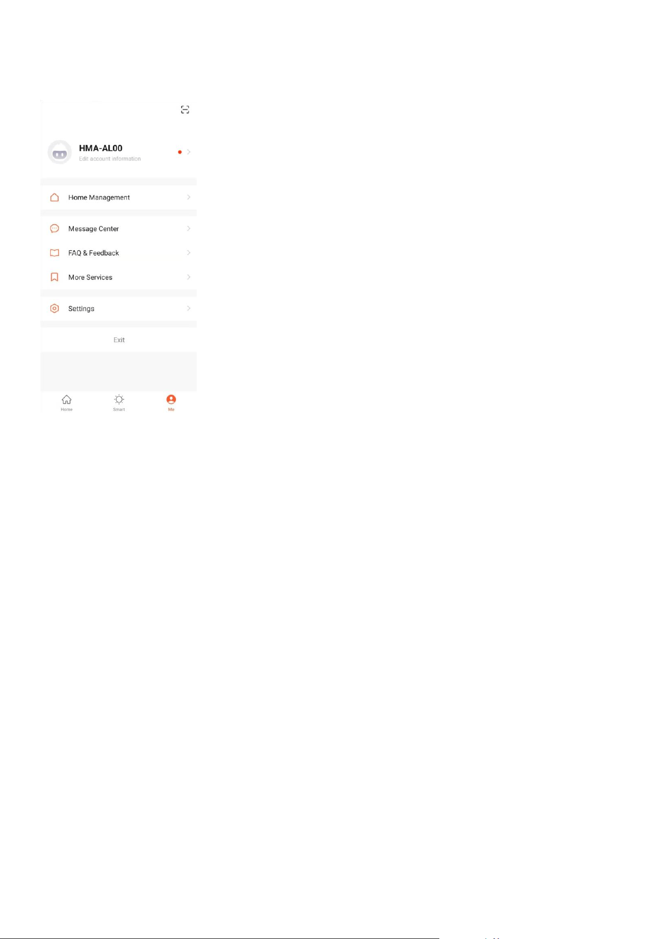
PROFILE TAB
The prole tab gives you the option to edit both your detail, and use the
added features of the unit.
CHANGING THE NAME OF YOUR DEVICE
When in any of the device screens further settings for the device can be
accessed, by pressing on the three dots in the top right hand corner. The
top option within this allows you to change the name of the device to
something relevant to the use of the product, such as “Living Room Air
Conditioner”. Within the menu, you also have the option of setting up a
pattern lock or change your password.
MESSAGE CENTRE
Shows alerts generated by the App.
MORE SERVICES
This allows the unit to be integrated with your favourite home automation
hardware such as Google Home and the Amazon Echo.
CONNECTION TROUBLESHOOTING
1. Check whether the device is powered on and is in the correct WIFI connection mode, if not please
refer to the CHANGING BETWEEN CONNECTION MODES section on page 12.
2. Ensure the WIFI password has been entered into the app correctly (Case sensitive)
3. Check that the phone is connected to the WIFI you are connecting the device to.
4. Ensure the network you are connecting it to is 2.4Ghz (5Ghz WIFI networks are not supported),
and that there is a strong WIFI signal to the item.
5. If your router is dual band, ensure that the 2.4ghz network has a dierent network name (SSID).
Further advice on changing router settings will be available from your Internet service provider /
Router manufacturer.
6. Check the settings on the router. Encryption should be WPA2-PSK and authorisation type should
be set to AES
7. Try using the alternative connection method. i.e. If connection is failing when attempting to
connect through EZ mode, try AP mode.
25
CLEANING AND MAINTENANCE
PLEASE SHUT OFF THE UNIT AND UNPLUG FROM THE MAINS BEFORE CLEANING OR PERFORMING
ANY MAINTENANCE
CLEAN THE SURFACE
Clean the machine's surface with a wet, soft cloth. Do not use chemicals such as benzene, alcohol or
gasoline as acidic, corrosive, and alkaline substances may cause damage to the surface and or the
internal workings of the machine.
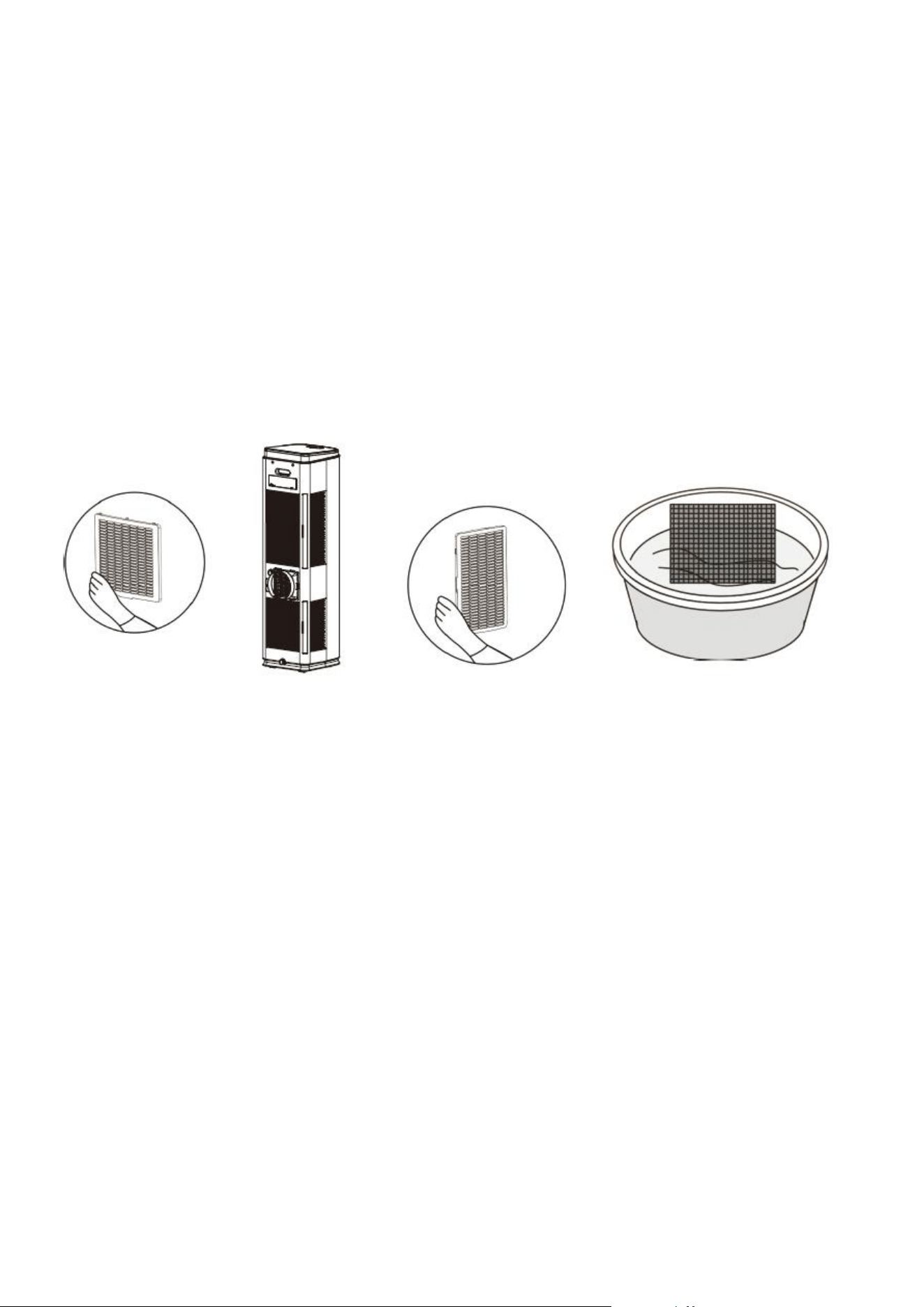
AIR FILTER CLEANING
If the filter screen is clogged with dust, the air conditioner's effectiveness is reduced. The filter screen
should be cleaned once every two weeks or as often as necessary in your environment.
CLEAN THE TWO FILTER SCREEN FRAMES
Remove the filter screens by pulling the base of it gently outwards to unclip it from the appliance. Once
removed, put the evaporator filter screen into warm water with neutral detergent (about 40 °C /104°F)
and dry it in the shade after rinsing it clean.
26
EMPTYING THE INTERNAL WATER TANK
When the internal water tank is full, the unit will stop working and display E4.
There are 3 options of how to drain the internal water tank:
1) PUMP ASSISTED DRAINAGE
Remove the rubber stopper from the upper drain port. Connect a
drainage pipe (12mm internal diameter) to the drain port, and route it
to a suitable drain. Press and hold the SMOOTH AIR button to start the
pump and drain the water tank.
2) MANUAL DRAINAGE:
The unit should be manually drained following END-OF-SEASON
maintenance before any prolonged period of storage.
Turn off the unit and unplug. Avoid moving the model abruptly, as this
may cause the water in the internal tank to spill out.
Place a tray in a drainage area under the lower drain port. Remove the
rubber stopper from the drain port - water will drain from the internal
tank. Once the tank is empty, place the rubber stopper back in position.
3) CONTINUOUS DRAINAGE:
Remove the rubber stopper from the lower drain port. Connect a
drainage pipe (12mm internal diameter) to the drain port. You can
plumb this pipe into your current plumbing system, lead it outside, use
gravity fall, or use an external water pump.
NOTE: This model has a self-evaporative function, which reduces the need to empty the water tank in
cooling mode. If the unit is vented correctly, most of the water is reused to cool the condenser coils, and
any excess is evaporated. Please do not use continuous drainage if you intend to use the self-evaporating
facility.
END-OF-SEASON MAINTENANCE
1.
Remove the rubber stoppers from the drainage holes and empty the internal tank. You
can also drain the water by leaning the unit backwards.
2.
Run the unit in fan mode, with a low fan speed, with the rubber stopper sll removed and
a container under the lower drain port.
3.
Keep the unit in this mode for half a day - unl the conduit is dried. Doing this helps to
keep the inside of the unit dry and prevents mould from developing.
4.
Turn o the unit and disconnect the plug.
5.
Replace the rubber stopper.
6.
Coil the cable, bind it together, and put it into the cable storage compartment.
7.
Separate the vent pipe and store it safely.
8.
Cover the unit and keep it in a dry place.
9.
Take the baeries out of the remote control and store or dispose of them safely.
10.
Keep all accessories with the unit ready for next season.
27
TROUBLESHOOTING
Do not repair or disassemble the air condioning. Unqualied repair will invalidate the
warranty and may lead to failure, causing injuries and property damage. Only use it as directed
in this user manual and only perform operaons advised here.
Problems
Reasons
Solutions
The air conditioner
does not work.
There is no electricity.
Please turn it on after connecting it to a socket
with electricity.
The display shows "E4".
Discharge the water inside.
The ambient temperature is too low or too high.
Only use the machine within a temperature
range of 7-35
0
c (44-95°F).
In cooling mode, the room temperature is lower
than the desired temperature.
Change the desired temperature.
In dry mode, the ambient temperature is low.
The ambient temperature must be above
17 °c. (62 °F).
The cooling effect
is not good.
There is direct sunlight.
Use curtains to reduce the direct sun heat.
Doors or windows are open; there are a lot of
people; or in cooling mode, there are other
sources of heat (e.g. fridges)
Close doors and windows; increase air
conditioning power
The filter screen is dirty.
Clean or replace the filter screen.
The air inlet or outlet is blocked.
Clear obstructions: make sure venting is correct
as described in this user manual and the hose is
not bent
Loud Noise
The air conditioning is not placed on a flat
surface.
Put the air conditioning in a flat, hard place (to
reduce noise).
The compressor does
not work.
Overheat protection starts.
Wait 3 minutes until the temperature is lowered,
then restart the machine.
The remote control
does not work.
The distance between the machine and the
remote control is too far.
Let the remote control get close to the air
conditioner and ensure that the remote control
directly faces the receiver.
The remote control is not aligned with the
receiver.
Batteries are dead.
Replace batteries.
Others
No refrigerant or there is minimal refrigerant.
Refer to Service Centre (check leakage, wielding,
vacuum pump, charge refrigerant according to
nameplate)
Anti-freezing protection
Waiting for defrosting.
The function will recover automatically. No user
input is needed.
High-pressure protection.
After the inside gas pressure comes down, it will
function normally. No user input is needed.
If problems not listed in the table occur or recommended soluons do not work, please get in touch
with the service centre.
1.
Has the unit been standing upright for at least 2 hours?
2.
Is the unit plugged into the mains?
3.
Is the fuse OK?
4.
Switch the unit o and wait three minutes to see if the issue is resolved.
Restart the unit.
5.
Check if the water tank is full.
28
ERROR CODES
CODE
CAUSE
SOLUTION
E2
Room temperature sensor error
Check to ensure filters are clean, vent pipe is not
restricted, and room temperature is within
operational range.
E3
Air Temperature Sensor Error
E4
Water Tank Full
Empty the water tank.
ES
Coil temperature sensor error
Check to ensure filters are clean, vent pipe is not
restricted, and room temperature is within
operational range.
COOL / DRY /
AUTO LIGHT
FLASHING
This is normal – shows which mode is
operating, but that the compressor is
not running.
The unit will start operation when the protection
period has finished (approx. 3 minutes)
Disposal: Do not dispose this product as unsorted municipal waste. Collection of such
waste must be handled separately as special treatment is necessary. Recycling facilities
are now available for all customers at which you can deposit your old electrical
products. Customers will be able to take any old electrical equipment to participating
civic amenity sites run by their local councils. Please remember that this equipment
will be further handled during the recycling process, so please be considerate when
depositing your equipment. Please get in touch with the local council for details of
your local household waste recycling centres.
electriQ UK SUPPORT
www.electriQ.co.uk/support
Please, for your own convenience, make these simple checks before calling the service line. Call the
number below if the unit fails to operate or complete the online form.
0330 390 3061
Office hours: 9 AM - 5 PM, Monday to Friday
www.electriQ.co.uk
Unit 2A, Trident Business Park,
Neptune Way, Leeds Road, Hudderseld, HD2 1UA.
29
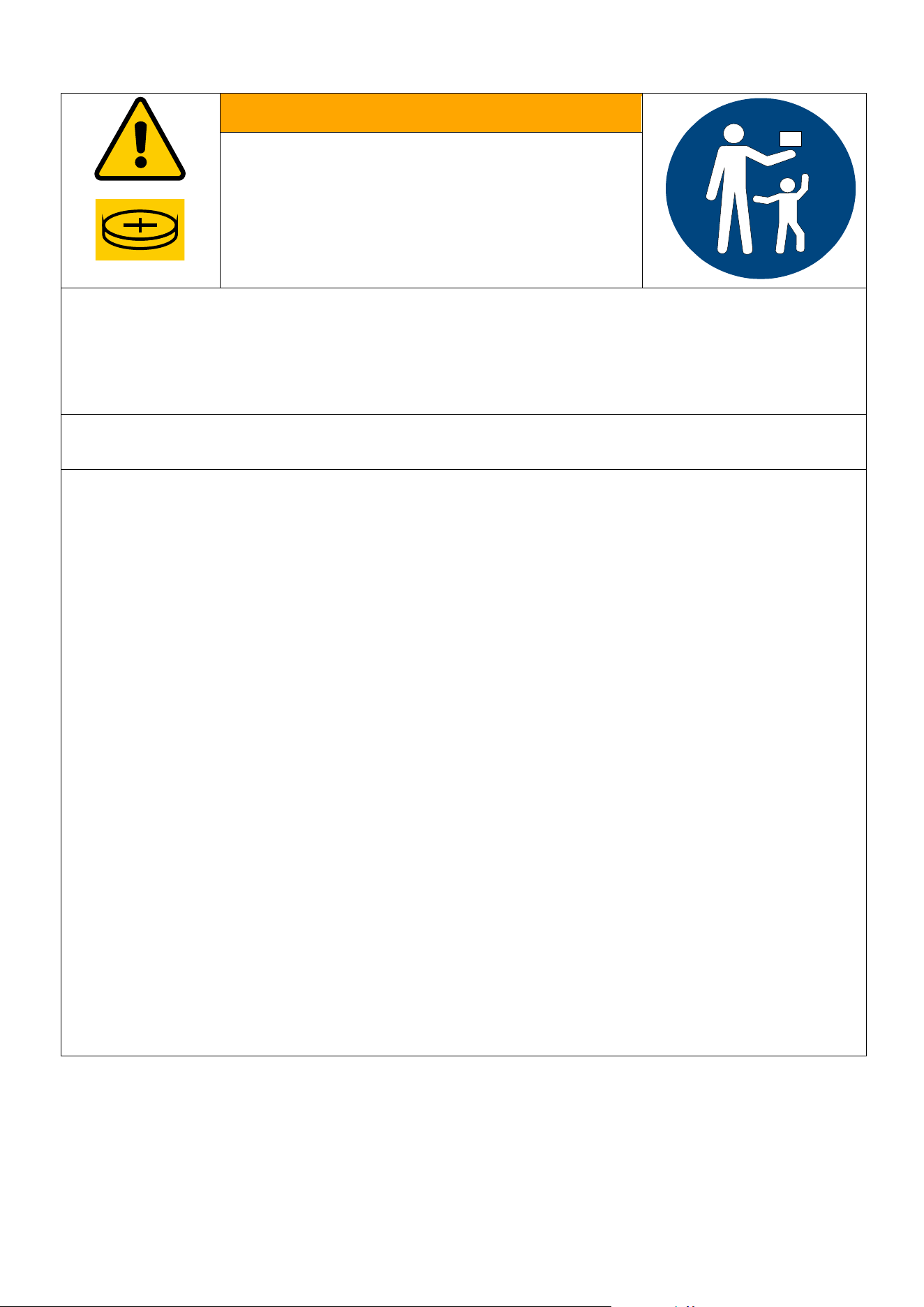
LITHIUM / COIN BATTERIES:
BATTERY WARNING
KEEP OUT OF REACH OF CHILDREN
Swallowing can lead to chemical burns,
perforation of soft tissue, and death. Severe
burns can occur within 2 hours of ingestion.
Seek medical attention immediately.
• If the battery compartment (if applicable) does not close securely, stop using the
product and keep it away from children.
• If you think batteries might have been swallowed, or placed inside any part of the
body, seek immediate medical attention
THERE MAY BE NO OBVIOUS SYMPTOMS OF BATTERY INGESTION
Unfortunately, it is not obvious when a button or coin battery is stuck in a child’s
oesophagus (food pipe). There are no specific symptoms associated with this. The child
might:
• cough, gag or drool a lot;
• appear to have a stomach upset or a virus;
• be sick;
• point to their throat or stomach;
• have a pain in their abdomen, chest or throat;
• be tired or lethargic;
• be quieter or more clingy than usual or otherwise “not themselves”;
• lose their appetite or have a reduced appetite; and
• not want to eat solid food / be unable to eat solid food.
These sorts of symptoms vary or fluctuate, with the pain increasing and then subsiding.
A specific symptom to button and coin battery ingestion is vomiting fresh (bright red)
blood. If the child does this seek immediate medical help.
The lack of clear symptoms is why it is important to be vigilant with “flat” or spare
button or coin batteries in the home and the products that contain them.
30
TECHNICAL
DATA
Model
SC10HPW
SC14HPW
SC16HPW
Cooling capacity:
10,000 BTU
14,000 BTU
16,000 BTU
Heating capacity:
9,000 BTU
12,000 BTU
14,000 BTU
Rated Input:
1050W
1450W
1650W
Running Current:
4.6A
6.5A
7.5A
Fan:
5 speeds
Airflow:
450m
3
/h
EER Rating:
A
Refrigerant:
R290/160g
R290/210g
R290/230g
Sound Power Level:
56dB(A)
56dB(A)
56dB(A)
Thermostat:
16-32˚C
Maximum Allowable Pressure
of suction/ exhaust side:
1.0/3.5Mpa
Maximum Allowable Pressure
3.5MPa
Power Supply:
AC 230V/50 Hz
Net Weight:
29.5 kg
33.5 kg
38.5 kg
Dimension(L*D*H):
320*350*1190 mm
The unit must be vented outside when in air-cooling mode. For the purposes of EU regulation EN12102, this is a
local air conditioner that produces less than 65dB(A) sound energy.
EU DECLARATION OF CONFORMITY
Hereby, electriQ declares that these air condioners are in compliance with Direcve 2014/53/EU. The full
text of the EU declaraon of conformity is available at the following internet addresses:
hps://www.electriq.co.uk/content/DOC/EU/SC10HPW.pdf
hps://www.electriq.co.uk/content/DOC/EU/SC14HPW.pdf
hps://www.electriq.co.uk/content/DOC/EU/SC16HPW.pdf
UK DECLARATION OF CONFORMITY
Hereby, electriQ declares that these air condioners are in compliance with Radio Equipment Regulaons
2017. The full text of the UK declaraon of conformity is available at the following internet addresses:
hps://www.electriq.co.uk/content/DOC/UK/SC10HPW.pdf
hps://www.electriq.co.uk/content/DOC/UK/SC14HPW.pdf
hps://www.electriq.co.uk/content/DOC/UK/SC16HPW.pdf
31
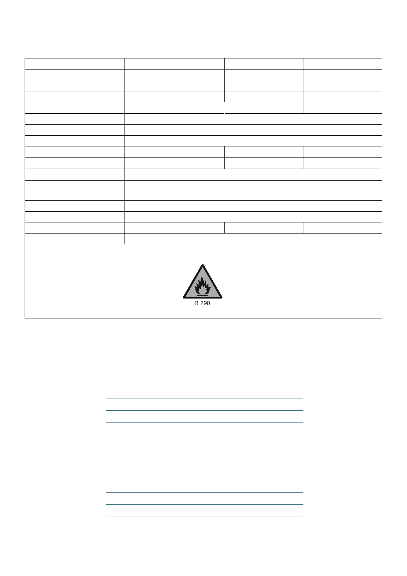
Informaon requirements for single duct and double duct air condioners
Descripon
Symbol
Model
Unit
SC10HPW
SC14HPW
SC16HPW
Capacity for cooling
P
rated
for
cooling
2.90
4.10
4.70
kW
Capacity for heang
P
rated
for
heang
2.65
3.50
4.10
kW
Power input for cooling
P
EER
1.05
1.45
1.65
kW
Power input for heang
P
COP
0.98
1.33
1.45
kW
Energy eciency rao
EER
d
2.76
2.83
2.85
-
Coecient of performance
COP
d
2.70
2.63
2.83
-
Power consumpon in o mode
P
OFF
-
W
Power consumpon in standby mode
P
SB
1.6
W
Electricity consumpon of
single/double duct appliances
DD: Q
DD
SD: Q
SD
1.05 for cooling
0.98 for heang
1.45 for cooling
1.33 for heang
1.65 for cooling
1.45 for heang
DD: kWh/a
SD: kWh/h
Sound power level
L
WA
62
dB(A)
Global warming potenal
GWP
3
kgCO
2
eq
Contact details for obtaining further
informaon
UK
electriQ, Unit 2A, Trident Business Park, Neptune Way, Leeds Road,
Hudderseld, HD2 1UA.
EU
Buy It Direct, The Black Church, St Mary’s Place, Dublin
V20240417