PREINSTALLATION CHECKLIST
1. Inspect your pump. Occasionally, products are damaged during shipment. If the unit or any of the parts are damaged, contact your dealer before using.
2. Carefullyreadtheliteratureprovidedtofamiliarizeyourselfwithspecicdetailsregardinginstallationanduse.Thesematerialsshouldberetainedforfuture
reference.
SEE BELOW FOR
LIST OF WARNINGS
1. Testingforground.Asasafetymeasureeachelectricaloutletshouldbe
checked for ground using an Underwriters Laboratory listed circuit analyzer,
which will indicate if the power, neutral, and ground wires are correctly
connectedtoyouroutlet.Iftheyarenot,callaqualied,licensedelectrician.
2. For your protection, always disconnect the power supply from its power
source before handling the components of your DC backup pump or the
primary pump.
3. Installation and servicing of electrical circuits and hardware should be
performedbyaqualied,licensedelectrician.
4. AllelectricalandsafetycodesmustbefollowedincludingtheNational
Electrical Code and all applicable local codes.
5. It is the owner’s responsibility to check the battery and battery
connection at least once a month. Batteries contain acid, and caution
must be taken when handling.
6. Riskofelectricshock.Thesepumpshavenotbeeninvestigated
for use in swimming pools and marine areas.
7. Prop65 Warning for California residents:
: Cancer and Reproductive Harm-
www.P65Warning.ca.gov.
1. Make sure there is a properly grounded 115 V receptacle available. It is
recommend connecting to a separately protected and properly grounded
circuit.Thelocationmustbewithin6'(1.8m)ofthecontrolboxandbattery.
ThepowersupplyforyourDCcontrolsystemplugsdirectlyintothe115V
outlet. DONOTUSEANEXTENSIONCORD.
2. Make sure the 115 V electrical supply circuit is equipped with fuses or
circuit breakers of proper capacity.
3. DC emergency pumps are designed for handling clear water. Do not use
inseptictankstopumpefuentorinsewagepitstopumpsewage.
4. Repair and service of your DC backup system should be performed by an
authorized service station.
5. TheinstallationofDCautomaticbackuppumpsrequirestheuseofavariable
leveloatswitchforoperation.Itistheresponsibilityoftheinstallingparty
toensurethattheoatswitchwillnothanguponthepumpapparatusor
pit peculiarities and is secured so the pump will turn “on” and “off”.
6. For indoor use only.
CAUTION
SEE BELOW FOR
LIST OF CAUTIONS
REFER TO WARRANTY ON PAGE 2.
CAUTION
Turbulencecausedbyhigh-velocityincomingwatercan
causesumppumpstoairlock.Ifthisconditionexists,theincomingwater
mustbebafedtoavoidexcessiveturbulence.
© Copyright 2025 Zoeller
®
Co. All rights reserved.
NOTICE TO INSTALLER: Instructions must remain with installation.
FM3148
0725
Supersedes
0724
DATE INSTALLED:
MODEL NUMBER:
BATTERY BACKUP SYSTEM WITH PRIMARY SUMP PUMP
MODEL 508 - 12 V DC BATTERY BACKUP SYSTEM
WITH 115 V AC POWERED SUMP PUMP
MODEL M53, M63, OR M98
INSTALLATION INSTRUCTIONS
Product information presented here reflects conditions at time of publication. Consult factory regarding discrepancies or inconsistencies.
MAIL TO: P.O. BOX 16347 • Louisville, KY 40256-0347
SHIP TO: 3649 Cane Run Road • Louisville, KY 40211-1961
Tel: (502) 778-2731 • 1 (800) 928-PUMP
Visit our website:
zoellerpumps.com
Trusted. Tested. Tough.
®
Patent No. D740329
TM
TM
Register your
Zoeller Pump Company
Product on our website:
http://reg.zoellerpumps.com/
AQUANOT FIT 508/53, 508/63, 508/98
P/N155891-D
MEETS UPC
COMPLIES WITH ASME A112.3.4
AND CSA B45.9.
P/N 018535-E
FAMILY OWNED
PROUD
AMERICAN
2
© Copyright 2025 Zoeller
®
Co. All rights reserved.
TheDCcontrollerisequippedwithachargerformaintainingthebatteryinaready
stateandrecharging thebatteryafterusewhen ACpowerisrestored.Time for
recharge depends upon the amount of power consumed by the pumping cycle during
theACpowerinterruption.Thepumpmaygobacktothereadyrunpositionina
veryshortperiodoftime.Acompletelydrainedbatterymayrequireupto24hours
forfullrecharge.Ifbatterydoesnotchargeproperly,thebatteryLEDwillashred.
LIMITED WARRANTY
PERFORMANCE
TheDCpumpperformanceat12.7Vdc
BATTERY SELECTION
Manufacturer warrants, to the purchaser and subsequent owner during the
warranty period, every new product to be free from defects in material and
workmanship under normal use and service, when properly used and maintained,
foraperiodof3years(models508/53and508/98)or5years(508/63)fromdate
of purchase by the end user. Zoeller batteries have a 3 year warranty. Proof of
purchase is required. Parts that fail within the warranty period, that inspections
determine to be defective in material or workmanship, will be repaired, replaced or
remanufacturedatManufacturer'soption,providedhowever,thatbysodoingwe
will not be obligated to replace an entire assembly, the entire mechanism or the
completeunit.Noallowancewillbemadeforshippingcharges,damages,labor
or other charges that may occur due to product failure, repair or replacement.
Thiswarrantydoesnotapplytoandthereshallbenowarrantyforanymaterial
or product that has been disassembled without prior approval of Manufacturer,
subjected to misuse, misapplication, neglect, alteration, accident or uncontrollable
act of nature; that has not been installed, operated or maintained in accordance
withManufacturer'sinstallationinstructions;thathasbeenexposedtooutside
substances including but not limited to the following: sand, gravel, cement, mud,
tar,hydrocarbons,hydrocarbonderivatives(oil,gasoline,solvents,etc.),orother
abrasive or corrosive substances, wash towels or feminine sanitary products,
etc.inallpumpingapplications.Thewarrantysetoutintheparagraphaboveis
inlieuofallotherwarrantiesexpressedorimplied;andwedonotauthorizeany
representative or other person to assume for us any other liability in connection
with our products.
ContactManufacturerat,3649CaneRunRoad,Louisville,Kentucky40211,Attention:
CustomerSupportDepartmenttoobtainanyneededrepairorreplacementof
part(s)oradditionalinformationpertainingtoourwarranty.
MANUFACTURER EXPRESSLY DISCLAIMS LIABILITY FOR SPECIAL, CONSEQUENTIAL
OR INCIDENTAL DAMAGES OR BREACH OF EXPRESSED OR IMPLIED WARRANTY;
AND ANY IMPLIED WARRANTY OF FITNESS FOR A PARTICULAR PURPOSE AND
OF MERCHANTABILITY SHALL BE LIMITED TO THE DURATION OF THE EXPRESSED
WARRANTY.
Somestatesdonotallowlimitationsonthedurationofanimpliedwarranty,so
theabovelimitationmaynotapplytoyou.Somestatesdonotallowtheexclusion
or limitation of incidental or consequential damages, so the above limitation or
exclusionmaynotapplytoyou.
Thiswarrantygivesyouspeciclegalrightsandyoumayalsohaveotherrights
which vary from state to state.
Discharge
Feet of Head
5
(1.5m)
10
(3m)
15
(4.6m)
28
(85m)
Flow
GPM(LPM)12.7volts
43
(163)
35
(132)
27
(102)
Shut-off
Head
Thissystemisacombinationofaprimarysumppumpandabackuppumptoyourprimarysumppump.Itisdesignedtoprotectagainstoodingduringpoweroutagesor
primarypumpfailure.Thissystemisuniqueinthatithasself-testingandcommunicationfeatureswhenconnectedtotheZControlCloud.Thepumpisself-primingand
specicallydesignedandmanufacturedbyZoellerasapurpose-builtDCsumppump,ratherthanarepurposedbilgepump.Thecontrollerhassmartdiagnosticsbuilt
in.IftheDCpumpisunpluggedorjammed,forexample,afaultalarmwillresult.Ifeitheroatswitchismissing/unplugged,itwillcreateanimmediatealarmcondition.
Thecontrollerwillrecognizethedifferencebetweenapumpthatispumpingairvs.apumpthatispumpingwater.Thiswillleadtobehaviorsdesignedtopurgeair
andremedyanairlocksituation.Thecontrolleralsohassmartoatlogicthatisdesignedtopreventacontinuousrunningpump(orrundrypumpcondition).Zoeller
usesanormallyopenoperationaloatswitch,andanormallyclosedhighwateroatswitch.TheadvancedtechnologyhardwareandrmwareintheFitcontrollerwill
recognize,attempttoremedy,andalarmformanyconditionsthathavenotpreviouslybeenpossible.Thecontrollerwillautomaticallychargeandmaintainthebattery
inawaydesignedtoextendbatterylife.
DESCRIPTION
TheDCemergency pumpsystemrequiresagood quality,12voltbattery
toobtainmaximumpumpingtimeduringapoweroutage.Adeep-cycle,12
volt,90amp-hour orlargermarinebatteryis recommended.A100+amp
hourbattery will provide approximately5.5 hours or moreof continuous
pumpingtimeinasumppumpinstallationwith8'(2.4m)ofheadpressure.
In most installations, the pump runs intermittently and the battery life is
extendedaccordingly.Batterieswithtopterminalsarerecommendedfor
ease of installation. "Wet" cell batteries contain acid, and proper precaution
mustbetakenwhenhandling.Batteryboxwillaccommodateamaximum
batterysizeof13-1/2"(34.3cm)Lengthx7"(17.8cm)Widthx9-1/2"(24.1
cm)Height.AGMbatteriesalsorecommended.Donotusegelbatteriesor
automotive batteries.
Primary
Pump
Construction Cast iron & plastic, premium seals
Performance
53:34GPM98:61GPM
63:34GPMmeasured@10'head
DC Pump
Construction Non-corrodibleplastic,premiumseals
Performance 35GPMat10'(113LPMat3m)at12.7volts
ContinuousRunningTime 5.5 hours with recommended battery
DutyCycleof10% 2 days
Connection 9'(2.7m)cordwithconnector
Controller
Construction ABSplastic
Power Requirement 115 V 15 amp circuit
Consumption Up to 3 amps at 115 V
Charger output 7 amp multi-stage
Connections
8'(2.4m)ACpowercord,6'(1.8m)DCchargingcable,connectionsforpump,operationswitch,highwaterswitch
Z Control
WiFi Built in
Bat-
tery
Box
Construction Non-corrodibleplastic
Safety Snaptightlid,keepsbatterysafeandclean
*WhenACpowerisavailable,thecontrollerwillreplacethepowerusedbythepumponcethepumpshutsoff.
Evenduringmoderatepumpcycling,thesystemmaybecapableofrunningindenitely.
In instances where property damages are incurred as a result of an alleged product failure, the property
owner must retain possession of the product for investigation purpose.
TheZoellerLEDPlugmaydimorextinguishafterapproximately5years.Thisdoesnotmeanthepumphasfailed.AlthoughtheLEDlight-upplugisattachedtothe
pump,theLEDlightworksindependentlyfromthepump.Ifthishappens,visuallyinspectthepumptoverifyitisworkingproperly.Thisoccurrencedoesnotmeanpump
replacementunderwarranty.Ifyouhaveanyquestions,pleasecontactZoellerProductSupportat1-800-928-7867or+1-502-978-2731.

3
© Copyright 2025 Zoeller
®
Co. All rights reserved.
1.ElectricalwiringandprotectionmustbeinaccordancewithNational
Electrical Code and any other applicable state and local electrical
requirements.
2. Allinstallationsrequireabasincovertopreventdebrisfromfallinginto
the basin and to prevent accidental injury.
3. Securelytapeorclamppowercordtodischargepipe,clearoftheoat
mechanism(s).
4. Use full-size discharge pipe.
5. Basinmustbeinaccordancewithapplicablecodesandspecications.
6. Pumpmustbelevelandoatmechanism(s)clearofsidesofbasin
before starting pump. Float switch may be repositioned as needed.
7. Basin must be clean and free of debris after installation.
8. Gatevalveorballvalvetobesuppliedbyinstallerandinstalled
according to any and all codes.
9. Gastightsealsrequiredtocontaingasesandodors.
10. Ventgasesandodorstotheatmospherethroughventpipe.
11. InstallZoellerPumpStand(Model10-2421)underpumpto
provide space for settling dirt, sand, or grit".
RECOMMENDED INSTALLATION FOR ALL APPLICATIONS
EASY DO'S & DON'TS FOR INSTALLING A SUMP PUMP
1. DO read thoroughly all installation material provided with the system.
2. DO inspect system for any visible damage caused by shipping. Contact dealer
if system appears to be damaged.
3. DO clean all debris from the sump. Be sure that the pump will have a hard,
atsurfacebeneathit.DONOTinstallonsand,gravelordirt.
4. DO be sure that the sump is large enough to allow proper clearance for the
levelcontrolswitch(es)tooperateproperly.
5. DO always disconnect pump from power source before handling.
6. DO recommend connecting to a separately protected and properly grounded
circuit.
7.DONOTevercut,splice,ordamagepowercord(onlyspliceinawatertight
junctionbox).
8. DONOTcarryorliftpumpbyitspowercord.
9. DONOTuseanextensioncordwithasumppump.
10. DOinstallaunioninthedischargeline.
11. DONOTuseadischargepipesmallerthanthepumpdischarge.
12. DONOTuseasumppumpasatrenchorexcavationpump,orforpumping
sewage, gasoline, or other hazardous liquids.
13. DO test system immediately after installation to be sure that the system is
working properly.
14. DO cover sump with an adequate sump cover.
15. DO review all applicable local and national codes and verify that the installation
conforms to each of them.
16. DOconsultmanufacturerforclaricationsorquestions.
17. DO inspect and test system for proper operations at least every three months.
8. InstalltheFitController(seeFigure3)byusingtheanchorsprovided.For
bestcooling,installwallmountconguration.Thecontrollershouldbe
locatedatleast3'(1m)abovethesump.
9. Connecttheleadsfromthecontrollertothebatteryterminals.Positive
(+)lead topositiveterminaland blackneg.(-) leadtonegativebattery
terminal.
CAUTION
Correct battery hook-up is essential for operation of the
system. Use wing nuts supplied with battery and eyelet connectors on battery
wireleads.Thepositiveterminalisthelargerstud,3/8"(10mm)diameter.
Thesmallerstud,5/16"(8mm)diameteristhenegativeterminal.Thestud
sizesonsomebatteriesmaybeidentical.Applygreasetotheterminals
tohelppreventcorrosion.Tightenslightlypastngertightwithawrench.
Alwaysuseextremecautionaroundbatteries.Becarefulnotto“cross”
or “short across” the battery terminals with your wrench or any other
metal object.
10. ConnecttheDCpump'splugintothecontrollerterminal.
11. Plugthecontrollerintothe115Vwalloutlet.Theprimarysumppumpand
the controller should be on separate circuits.
12. Reconnect power to the primary sump pump.
13. TheAquanot
®
Fit Controller is designed for use with Z Control
®
.
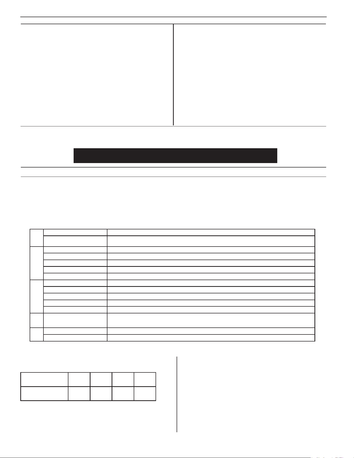
1. ThepreferredmethodofinstallationforbackuppumpsisshowninFigure
1.TheinstallationkitincludesthepartsneededtoinstallasinFigure1.A
check valve is incorporated in the discharge of the backup pump.
NOTE: Do not install in small spaces where the controller will not be
properlycooled.Donotoperatein>80
º
F environment.
2. Remove all parts from the shipping carton, and make sure all parts are
included. Refer to the parts list on page 3.
3. Select alocationforthebattery andthecontroller.The controller must
bewithin8'(2.4m)ofa115Vwalloutletandwithin6'(1.8m)ofpumpand
basin. Connect to a separate electrical circuit from the primary pump.
4. If the primary pump is installed, disconnect power.
NOTE:Dischargepipingmustbe1-1/2"SCH40PVC
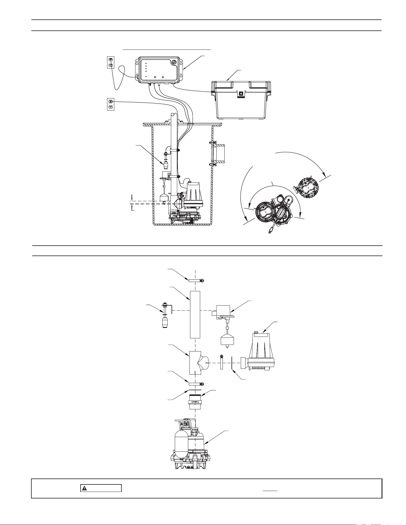
5. Ensure theO-ringis properly located on thepump discharge. Slide the
DC pump into the tting, and tighten the hose clamp. Soapy water is
recommended as a lubricant.
NOTE:Thepumpmustbepushedallthewayintothettingtopreventthe
ttingfromleaking.Placetheclampattheedgeofthettingsothatthe
slottedsectionscansufcientlytightenaroundthepumpdischarge.(see
Figure2)
6. Measure, cut and solvent weld any remaining discharge piping above the
tee.
7. Checkpre-setoatoperationstoensurethehoseclampscrewswillnot
interferewiththeoatoperationoftheprimarypump.Theoatswitchcan
be moved on the discharge pipe, or the rubber stops can be adjusted as
necessary.
INSTALLATION

4
© Copyright 2025 Zoeller
®
Co. All rights reserved.
INITIAL START-UP AND OPERATION
1. Testtheinstallationforleaksbyrunningwaterintothesump,allowing
for normal operation of the primary pump.
2. Checkthecontroller.TheSystemReadylightwillbegreenwhentheunit
ispluggedintothe115Vwalloutlet.Thebatterywillindicateitscondition
whenthecontrollerhasDCpower.Whentheunitisrstpluggedin,all
lightswillashandalarmwillsoundtoverifyalllightsandthealarmwork.
TheFitcontrollerpowersupexpectingbothswitchestobeconnected.
Ifoneorbothoatswitchesarenotconnected,therewillbevarious
alarms depending on what is connected. If this occurs, simply plug in
bothswitchesandthenresetthealarmsbyholdingtheSilencebutton
for3seconds.Notethatthechargermaynotbeginchargingforseveral
minutes.
3. Disconnect the primary pump from its power source before touching
any component in the sump pit.
4. LifttheFit’soperationalfloatswitch.After1second“splashactivation
prevention” delay, the DC backup pump will run, and the alarm will
sound after 1 more second. Lower the operational float switch after the
alarm sounds. TakecarethattheintakeoftheDCpumpissetabovethe
intake of the primary pump. If water was pumped, the Yellow DC Pump
LED and alarm will remain on, indicating that the pump ran and pumped
water.Thealarmcanbesilenced bypressingtheSilencebutton.The
yellowLEDcanbeclearedbyholdingtheSilencebuttonfor3secondsto
reset.Iftheoperationaloatisheldonwhilethereisnowatertopump,
the controller will turn the pump on and off a few times before running the
pumpcontinuous.Thisistopurgeasuspectedairlock.Whentheoatis
lowered, the pump will turn off, but the yellow DC Pump LED will not persist.
TheyellowDCPumpLEDandalarmonlystayonifthepumpactuallypumps
water.Theintentionofthisbehaviorissotheinstallercanturnthepump
on and off for testing during installation without repeatedly having to reset
thecontroller.Iftheoperationaloatisremoved/unplugged,therewillbe
analarmandaredashingFloatStatusLEDuntilsilencedorremedied.If
theoperationaloatwasneverinstalled,thealarmandredashingFloat
StatusLEDwilloccurfor4hoursandthenturnoff.Ifthereisaneedfor
thecontrollertodisregardtheoperationaloat(forexample,serviceor
replacement),aFactoryResetcanbeinitiated.Unplugtheoperational
oatandthenholdtheTestandSilencebuttonstogetherfor6seconds.
ThiswillinstructthecontrollertoNOTalarmforthemissingoperational
oatandresettheunit.
CAUTION
Continuous dry running may cause overheating and damage
the pump seals. Upon release of the float switch, the pump will shut off.
Be certain there are no obstructions around the float or stem that will
prevent the switch from turning off.
5. Check installation of the high water switch taking care that it is installed so
that its “on” point is higher than the “on” point of the operational switch.
Liftthehighwateroat.After1second“splashactivationprevention”delay
the pump will turn on, the alarm will sound, and the light will alert of high
water.Iftheoperationaloatisdown,andtheDCpumpisunderwater,
thepumpwillrununtiltheoatlowersandthepumpisnolongerpumping
water,ortheruntimerexpires.AoatfaultLEDwillbelit.Duringaoat
fault,theoperationaloatisdisregardeduntilthecontrollerisreset.Ifthe
operationaloatisupduringhighwater,unitwillalarmandhighwater
oatlightwillilluminate.Thepumpwillturnoffoncewaterispumped
lowerthantheoperationaloat.
Ifthehighwateroatisheldonwhiletheoperationaloatisdownand
there is no water to pump, the controller will turn the pump on and off
afew timesbeforerunningthepumpcontinuously.This istopurgea
suspected air lock. If the high water oat is removed/unplugged, the
resulting controller and pump behaviors are the same as if it was turned
“on”.ThealarmandredFloatStatusLEDwillbeonuntilsilencedand
reset, respectively. If there is a need for the controller to disregard the
highwateroat(forexample,serviceorreplacement),aFactoryReset
canbeinitiated.UnplugthehighwateroatandthenholdtheTestand
Silencebuttonstogetherfor6seconds.Thiswillinstructthecontroller
toNOTalarmforthemissinghighwateroat.Whenanewhighwater
oatisreceived,simplyplugitinandthecontrollerwillseeitandmonitor
it from that point forward.
6. Completethenaltestingofyour installationbyensuringthe primary
pumpisstilldisconnectedfrompower.Then,unplugtheFitcontroller
from the 115 V wall outlet. Run water into the sump until the DC backup
pumpisactivatedbytheoperationaloatswitch.Checkallconnections
for leaks.
7. Push the Silence button when the pump is running. This will silence
thealarm.Thepump will continue torununtiltheoperationaloat is
deactivated.
8. ReconnectthecontrollerandtheprimarypumptotheACwalloutlets.The
primary pump may come on, lower the water level in the sump back to its
normal operating level, and shut off. Both primary and backup systems
are now ready for use. Hold silence button for 3 seconds to reset the Fit
controller.
9. ThebatteryLEDwillbeyellowduringnormalchargingoperation.See
page 6 and 7 for a description of controller functions.
NOTE:Whenrunningthepumps,itisnormalforastreamofwatertospray
outofthepump's1/8"(3mm)airreliefhole.
It is important to understand that the Fit controller is an advanced technology product that has capabilities beyond those seen in other battery backup products. For
thoseunfamiliarwiththeproduct,behaviorsintheFitmayinitiallyseemunusual.Forexample,thecontrollerisabletorecognizepotentialairlocksituationsandremedy
withanon/off/on/off/onroutineproventopurgetheproblematicairfromthepump.Further,advancedoatlogicenablesthecontrollertosenseotherpumpingissues
suchasastuckoat,allowingthesystemtotakeactionstopreventdamagetoequipment.
TheLEDshavespecicpatternsandbehaviorsthatdifferfromotherproductsonthemarket.Forexample,theDCPumpLEDwillstayYellowafterpumpingwater,
alertingthehomeownerofaDCpump-runevent.IfthepumprunsanddoesNOTpumpwater(forexamplewhenliftingtheoatmanuallyasatestwiththepumpabove
thewaterline),theLEDwillnotstayYellow.Thisismeanttobeanaidtotheinstallerinordertotestthepumpwithouthavingtoresetiteachtime.
Wheneitheroatisdisconnected,thealarmwillsoundandtheRedFloatStatusLEDwillblinkindicatingthattheoatstatehaschanged.Disconnectingthehighwater
oatwillcausethepumptorun.Ifthereisanoperationaloatfaultdiagnosedbythecontroller,youmaynoticethatitnolongerturnsthepumponandoff.Thisis
becausethesequenceofprioreventsindicatedthattheoperationaloatcan’tbetrusted(suchasliftingthehighwateroatwhiletheoperationaloatisdown–this
isillogicaltothecontrollersincewaterwouldalwayslifttheoperationaloatrst),andthecontrollerwillrelyoninputfromthehighwateroat.Sincethehighwater
oatdoesnothaveasufcientpumpingrange,thecontrollerwillturnthepump“off”once30secondshaveelapsedorthepumpbeginsspinninginair.TheFitoffers
true redundancy for pump operation that competitor’s products do not have.
Beforeleavingtheinstallationsite,theinstallermustinitiateaResetbyholdingtheSilencebuttonfor3seconds.Thiswillensurethatallsystemsareinastandby,
ready state.
5
© Copyright 2025 Zoeller
®
Co. All rights reserved.
IMPORTANT
Tominimizeriskofairlock,intakeofDCpumpmustbesetabove intake of primary pump.
SK3182
FIGURE 1
OUTLET
PRIMARY PUMP
1" MIN.
IMPORTANT: OFF LEVEL
OF FLOAT ASSEMBLY
MUST BE HIGHER THAN
DC BACKUP PUMP
FIG. 1
DC PUMP INSTALLED IN LINE WITH SUBMERSIBLE PUMP
BATTERY BOX
AQUANOT CONTROLLER
OUTLET
CONTROLLER
HI-WATER REED
SENSOR
(*OPTIONAL)
FITS 18" BASINS
FITS 16" BASINS
1-1/2 SCH 40 PVC PIPE
X 10" (254 mm) LG.
NOTE: CHECK VALVE SCREWS
INTO PRIMARY PUMP DISCHARGE.
HAND-TIGHTEN ONLY.
WEEP HOLE MUST BE VISIBLE.
OPERATIONAL
FLOAT SWITCH
CLAMP
HIGH WATER
REED SENSOR
(*OPTIONAL)
CHECK VALVE O-RING
PRIMARY PUMP
CLAMP
DC PUMP
1-1/2 SCH 40 PVC
BULLHEAD TEE
DC PUMP O-RING
EXPLODED VIEW - PUMP SYSTEM
FIGURE 2
SK3223
TYPICAL INSTALLATION
6
© Copyright 2025 Zoeller
®
Co. All rights reserved.
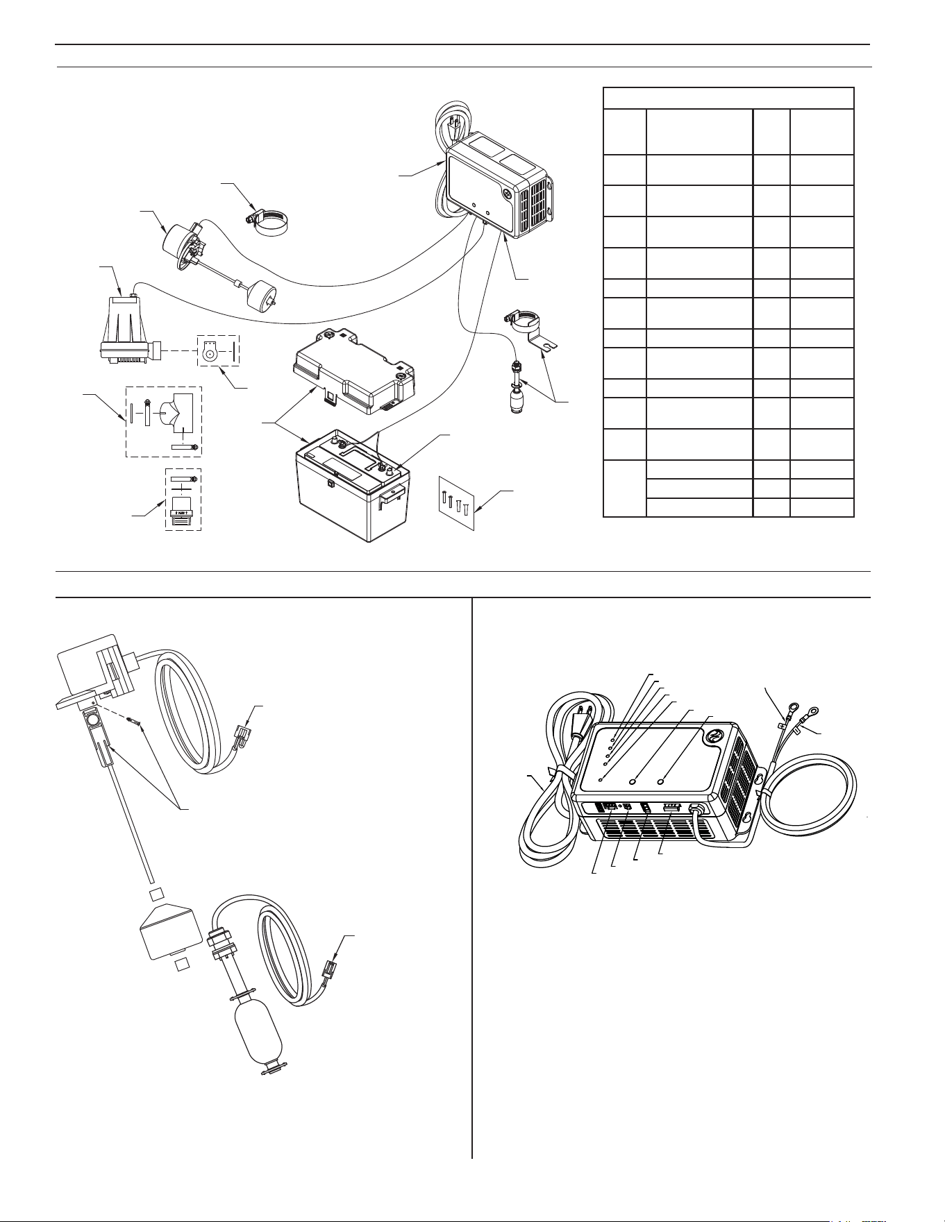
SK3183
2
1
3
4
11
9
10
8
5
6
7
12 VOLT BATTERY
SUPPLIED BY USER
Model 508 Fit Service Parts
Item Description Qty
508-C
8/18
thru Current
1
Pump12VDC/Backup
(servicepart)
1 155652
2
Flapperasm,(service
part)
1 152970
3
Fitting,1.5"X2"Bull-
headteePVC/SCH40
1 153766
4
Valve,check/1.5"
(DN40)Inline/vertical
1 153772
5 Operationaloat,N.O. 1 155654
6
Clamp,#28Worm-SS
(foroatswitch)
2 004287
7 Fit controller 1 155368
8
Fuse,30amp
automotive, blade-type
1 016918
9 Highwateroat,N.C. 1 155653
10
Batteryboxasm(box
andcover)
1 10-0764
11
Hardware pak, charger
/switchmode
2 152864
12
Pump,M53/115V 1 53-0001
Pump,M63/115V 1 63-0001
Pump,M98/115V 1 98-0001
EXPLODED VIEW - DC PUMP SYSTEM SERVICE PARTS
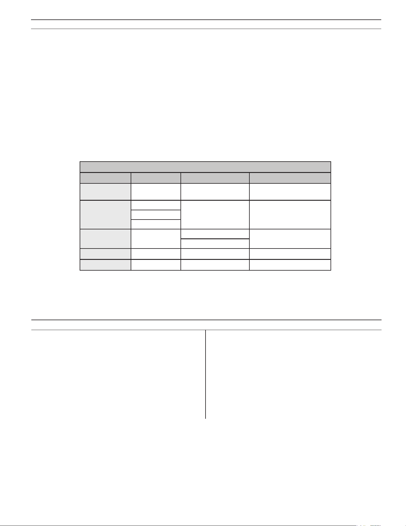
AQUANOT
®
FIT FLOAT SWITCH
FIGURE 3
SK3186
LOCKING PIN MUST BE
INSTALLED UNDER FLOAT
ROD IN THIS LOCATION.
MOLEX 2-PIN CONNECTOR
MOLEX 4-PIN CONNECTOR
FLOAT STATUS LED
DC PUMP LED
BATTERY LED
SYSTEM READY LED
Z CONTROL LED
GROUNDED
POWER CORD
SILENCE BUTTON
TEST BUTTON
WHITE LEAD
(POSITIVE)
BLACK LEAD
(NEGATIVE)
30 AMP FUSE
DC PUMP
HIGH WATER
OPERATIONAL
SK3187
FIGURE 4
Note:Upperrubberstopisusuallynotneeded.
LOCKING PIN MUST BE
INSTALLED UNDER FLOAT
ROD IN THIS LOCATION.
MOLEX 2-PIN CONNECTOR
MOLEX 4-PIN CONNECTOR
7
© Copyright 2025 Zoeller
®
Co. All rights reserved.
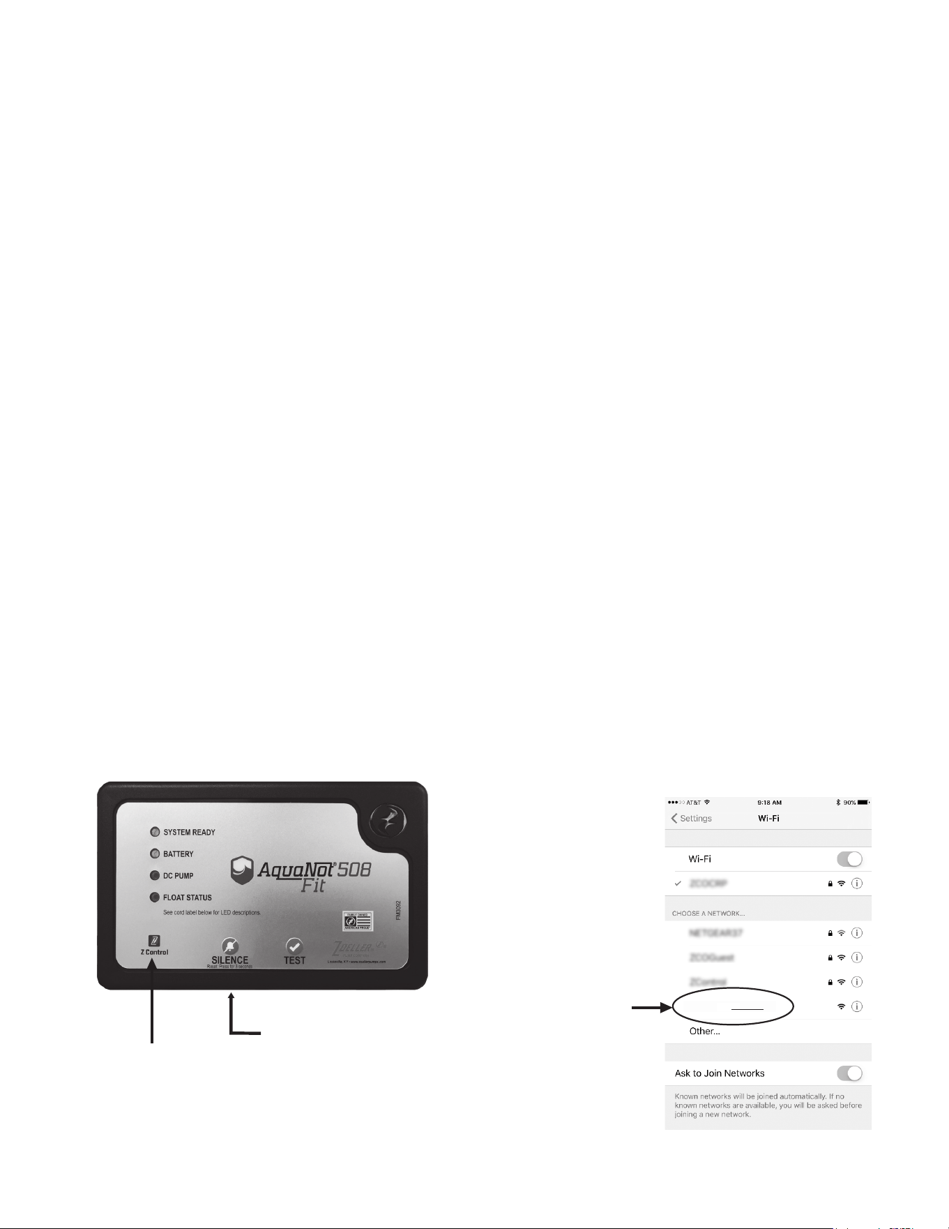
FIT CONTROLLER FUNCTIONS
Therearetwobuttonsonthefrontofthecontroller.
- Silence/Reset
• Can be pressed to silence current alarms for 24 hours.
• Canbeheldfor3+secondstoreset(orclear)alarmsandLEDs.FlashingLEDsforconditionssuchasbad/disconnectedbatteryorpoweroutage,for
example,can’tbeclearedbySilence/Reset.TheseconditionsmustberemediedtoeliminatetheLEDindicator.
- Test
• Will run the pump to determine if amp draw of pump is within range.
• Controllerisfactoryprogrammedtoself-testthepumpforseveralsecondsevery24hours.ThisschedulemaybemodiedoncetheFitisconnected
to the Z Control Cloud.
• Pressing the test button will start the 24-hour timer for self-testing.
- Test and Silence/Reset
• Holdingbothbuttonstogetherforabout6secondswillinitiateaFactoryReset.Thisreturnsthermware’sdevicecongurationtothestateinwhich
itleftthefactory.Anyovertheairrmwareupdatesthathavebeeninstalledwillberetained.
LED INDICATOR SOLID FLASHING OFF
System Ready
NoFaults(Green)
ACoffwithNoFaults
(Green)
--
Battery
Charged(Green)
LowBattery(Red) NoACPowerCharging(Yellow)
BadBattery(Red)
DC pump
Pump Ran
(Yellow)*
PumpRunning(Yellow)
--
PumpFault(Red)
Float Status
HighWater(Red) FloatFault(Red) --
Z Control
Connected Searching BroadcastingSSIDorDormant
*Note:willnotpersistifpumpdidn’tpumpwater.
Seealsothelaminatedlabelafxedtothecontroller’scord.ThiscordlabelalsodescribesLEDand
button functionality.
TheLEDswilldisplayinformationaboutthecontroller.
AQUANOT FIT
MAINTENANCE
1. Inspect and test the system for proper operations at least every 3 months.*
(a) Green "system ready" indicator light should be on, indicating AC
power is on and there are no alarm conditions.
(b) Unplugtheprimarypumpandthecontrollerfromthepowersupply.
(c) Fillthesumpwithwatertothe“on”levelfortheDCpump.Allowthe
pump to run a few minutes.
(d) Thealarmwillsoundapproximately1secondafterthepumpstartsto
run.
(e) PushtheSilence/Resetbutton.Thealarmwillturnoff.
(f) Thepumpwillshutoffafterthewaterlevelisloweredandtheoperational
oatdropstothe"off"position.
(g) HoldSilence/Resetbuttonfor3secondstoresetthecontrollerand
clear any alarms or indicators.
2. Plug the controller and the primary pump into the wall outlet.
(a) The primary pump will come on, lower the water to the normal
operating level and shut off.
(b) Thebatterylightwillbeyellowwhencharging.Thechargerisreplacing
theenergyconsumedduringthetest.Thegreenlightwillcomeonafter
the charger has replaced the energy consumed during the test.
*Electrolytelevelsinwetcellbatteriesshouldbecheckedmonthly.Suchacheck
is not required for "maintenance free" battery types.

8
© Copyright 2025 Zoeller
®
Co. All rights reserved.
CONNECTING THE FIT TO Z CONTROL
®
By connecting the Fit to the Z Control
®
Cloudusingthebuilt-inWiFi,theusercansetupfreealertmessagesviaemail,text,andmobileapp“push”notications.In
addition,theusercanverifytheFit’sreadiness,remotelysilencealarmsandresettheunit,conguresettings,andmodifyhownoticationsaresent.Othervisual
information such as input status and battery level are available through the web and app interfaces.
Thereare2waystoconnecttheAquanotFittotheZControl
®
cloud.
1. ThesimplestmethodistousetheZControl
®
mobileapp.Theseinstructionsarebelowunder“UsetheMobileApp”.
2. ThesecondmethodistouseyourmobiledeviceorcomputertoconnecttotheFitdirectly.Instructionsforconnectingdirectlyareprovidedbelowunder
“UseYourMobileDeviceOrComputerToConnectDirectlyToTheFitController”.
Use the Mobile App (iOS and Android)
Before you begin:
• KnowwhatyourWiFinetworkisnamed(i.e.itsSSID)anditspassword.Doublecheckyouknowthecorrectpasswordandexactlyhowitisspelled,
includingcapitalization.Thiswillpreventthemostcommontroubleshootingissues.
• VerifythatyourmobiledevicehasworkingWi-FianddetectsastrongsignalfromyourWi-FinetworkwhenyouarestandingnexttotheFitcontroller.If
thesignalisweakorvaries,yournetworkmaynotbeabletoprovideastableconnectionfortheFit.Tryrepositioningthecontrollerifpossible,andbe
suretherearenophysicalorinterferencebarriersnearby.Theuseofanoff-the-shelfrangeextendermaybenecessaryinsomeinstallations.
• Verify your WiFi network is connected to the internet and that it is broadcasting a visible, secure, 2.4Ghz network.
• 2.4 Ghz network is required. If you only see 5 Ghz networks, you may need to log into your dual band router to choose to broadcast the networks
separately.
• Band steering may need to be temporarily turned off during setup.
• The2.4GhznetworkmustuseWPAorWPA2security.WEPandOpennetworksarenotcompatiblewiththeFit.
• AnyVPNsorothernetworkcontrolsmayneedtobetemporarilyturnedoffduringsetup.
• LocatetheFit’sDeviceIDanddatamatrixonthetopsticker.
• Likemostinternetconnecteddevices,theFit’sWiFiconnectivityshouldbeusedbehindasecurerewall.Mostroutershavearewallbuiltintothem.
Consultanetworkingprofessionalforspecicquestionsaboutrewalls.
• The above list also helps to troubleshoot connectivity issues.
TROUBLESHOOTING INFORMATION
1. DC Pump won’t run.
(a) Checkforproperconnections.
(b) Checkallwireterminalpoints.Cleanifrequired.
(c) Checkforlowbattery.Servicebatteryifrequired.
(d) Check30ampfuseoncontroller(seeg.3).Iffuseisblown,replace
with30ampautomotivebladefuse.
(e) Removepump.Checkforobstructioninpumppreventingimpellerfrom
rotating.
(f) Floatswitchwasnot“on”formorethan1second.Aquickup/downof
a switch will not turn the pump on because the controller is designed
with “splash activation protection”.
(g) Duringaoatfault,theoperationaloatisdisregardeduntilthecontroller
is reset.
2. Pump runs but moves very little or no water.
(a)Checkforlowbattery. Battery willrechargeifgreenSystemReady
LEDindicatespowerhasbeenrestoredandtheoatswitchisinthe
off position.
(b) Ifimmediateusageisrequired,removeandreplacedeadbatterywith
a fully recharged battery.
(c) Undercertainconditionsthepumpmaycontinuetorunonalowbattery
withoutsufcientpowertoremovewater.Pumpwillstoprunningonce
battery is below minimum voltage threshold.
(d)
CAUTION
Weak batteries can be recharged but may not store
sufcientenergyforfullservice.Aweak,rechargedbatterycanonly
be detected by reduced pumping time or by professional load testing
equipment.Thebatteryshouldbecheckedbyaqualiedbatterydealer.
(e)Verifypumpisconnectedcompletely.
(f) Checktomakesurepumpweepholeisclearandunitisnotairlocked.
(g)Makesuredischargepipingisnotblocked.
3. Pump cycles too frequently.
(a) Checkpositionsofrubberstopsontheoperationaloatrodandadjust
if necessary.
4. Pump runs, but pumps water intermittently.
(a) Pumpmaybeairlocking.Checkowofwaterincomingtosump.Ifwater
is entering the sump at a high velocity creating a turbulent condition, a
mixtureofairandwatermaycauseacompleteorpartialairlockand
reduceorstoptheowofwaterinthedischargepipe.
(b) Bafetheincomingstreamofwater toreduceturbulence.Diverting
water stream against wall of basin usually corrects an air lock problem.
5. Water level stays high. DC Pump continues to run.
(a) Batteryisloworpumpmayhaveblockageinscreen,impeller,orpiping
system.
(b) If power has been restored and water in sump remains highcheck
primarypump.Serviceifrequired.
6. Alarmsoundsduringbatteryrechargecycle.
(a) Tosilencealarmifalarmwillnotreset,unplugthechargerfrom115V
walloutlet,thendisconnecttheblackleadfromchargeronnegative(-)
battery post. Check battery. Replace if necessary. Reconnect and refer
to Installation Instructions.
NOTE:TheZControl
®
Cloud may provide additional information.
ToperformaFactoryReset,holdtheSilenceandTestbuttonstogether.AFactoryResetrestoresallsettingstotheiroriginalsetting.Besureallswitches,pump,
batteryandACconnectionsaregoodbeforetheFactoryReset.
9
© Copyright 2025 Zoeller
®
Co. All rights reserved.
Thesebasicinstructionswillnotdetaileverystep,butprovideanoverviewofwhattheappwilldo.
1. Opentheapp,signintoyouraccount,orcreateanaccountusingthelinkatthebottom.Openyourproletosetupanyadditionalphonenumbersoremail
addresseswhereyouwouldliketoreceivenotications.
2. Onceyou'reloggedintoyouraccount,createlocationsbytouchingthe"+"fromtheLocationsscreen.Whenreadytoaddadevice,choosethedesired
locationnameandthentouchthe"+"tostartaddingadevice.Allowaccesstothecamerasoyoucanscanthedatamatrix.
3. Nowtheappwillprovideseveralinstructionscreensaboutscanningthedatamatrix,joiningtheFit’snetwork,andthenLEAVINGtheappandhowto
come back.
Ratherthanscanthedatamatrix,theusermayinsteadentertheFit’sDeviceIDtogetstarted.Ignorewarningsyourmobiledevicemaygiveyouabout“unsecure
network”or“nointernetconnection”.TheappisconnectingdirectlywiththeZControl
®
equipment, and therefore no security or internet connection is necessary.
4. Whenthecaptivescreenopens(seeFigureCinnextsection),usetheWiScanbuttontondtheWinetworkyouwanttheFittouse,selectitfromthe
listprovidedatthebottomofthescreen(youmayneedtoscroll),andtypethePassphraseintheeld.TheZControl
®
LED should be solid within a minute
indicating successful connection to the router and the Z Control
®
Cloud.Uponrstconnectingtothecloud,theFitcontrollermayimmediatelyupdate
itsrmwareovertheair(OTA),ifanupdateisavailable.Ifanupdateistakingplace,theZControl
®
LEDwillickerforupto1minutewhiletheupdateis
downloaded.TheZControl
®
LEDwillbesolidandallotherLEDswillturnoffwhiletheupdateisbeinginstalled.Afterupto1minute,theFitwillrestartand
returntonormaloperation.TheFit’salerthistoryontheZControl
®
Cloudwillalsobeupdatedwiththermwareupdateinformation,andnoticationto
email accounts will occur.
5. You now should go back to the Z Control
®
apptondyournewdevicesetupinthelocationyoupreviouslyselected.Youcanalwayschangeadevicetoa
different location in your account.
6. OpentheFitandexplorecurrentstatus,congurationsettings,andcommandsavailable,suchasPumpTest,BuzzerTest,Silence,etc.Performthesetest
tobesureeverythingworksasexpected.Resetallalarmswhenyouarenished.
Use your mobile device or computer to connect directly to the Fit controller
Instead of using a mobile device and the Z Control
®
app, you can also use your mobile device or computer to directly connect to the Fit.
Before you begin:
• KnowwhatyourWiFinetworkisnamed(i.e.itsSSID)anditspassword.Doublecheckthatyouknowthecorrectpasswordandexactlyhowitisspelled,
includingcapitalization.Thiswillpreventthemostcommontroubleshootingissues.
• VerifythatyourmobiledevicehasworkingWi-FianddetectsastrongsignalfromyourWi-FinetworkwhenyouarestandingnexttotheFitcontroller.If
thesignalisweakorvaries,yournetworkmaynotbeabletoprovideastableconnectionfortheFit.Tryrepositioningthecontrollerifpossible,andbe
suretherearenophysicalorinterferencebarriersnearby.Theuseofanoff-the-shelfrangeextendermaybenecessaryinsomeinstallations.
• Verify your WiFi router is connected to the internet and that it is broadcasting a visible, secure, 2.4Ghz network.
• 2.4 Ghz network is required. If you only see 5 Ghz networks, you may need to log into your dual band router to choose to broadcast the networks
separately.
• Band steering may need to be temporarily turned off during setup.
• The2.4GhznetworkmustuseWPAorWPA2security.WEPandOpennetworksarenotcompatiblewiththeFit.
• AnyVPNsorothernetworkcontrolsmayneedtobetemporarilyturnedoffduringsetup.
• Create a free account at zcontrolcloud.com.
• Locate the Fit’s Device ID on the top sticker.
• Theabovelistalsohelpstotroubleshootconnectivityissues.
• If the Fit controller still will not connect after trying the above suggestions, follow the same steps to connect the Fit to a mobile phone hotspot instead
Figure A, FIT Controller
ThisLEDshouldbeoffwhen
FitisinAPmode.
When user is connected to
Fit to set up WiFi, LED will
blink.
When Fit is connected to
router and Z Control
®
Cloud,
this LED will be solid.
Z Control button is underneath
thru small hole.
Figure B, Your Mobile Device Wifi Settings
SelecttheFit’sSSID
Thelast4digits
(underlined)willmatch
therst4digitsofyour
Fit controller’s
Device ID.
ZCTL_Fit_MW6M
10
© Copyright 2025 Zoeller
®
Co. All rights reserved.
2. StandingneartheFit,useyourphone,tablet,orcomputertolookfortheFit’sSSIDinyourWiFisettings(seeFigureB).Itwilllooklike“ZCTL_Fit_xxxx”
where“xxxx”istherst4digitsofyourFit’sDeviceID.Selectthis,andbesureyourdevicedisplaysacheckmarkorsimilarindicatorthatyouare
connected to the Fit’s local network. If so, 2 things will happen:
1.TheZControl
®
LEDwillashquickly.
2.AZControl
®
setupscreen(SeeFigureC)willopen.Thismaytakeupto30seconds.
Ifthesetupscreendoesnotappear,openabrowseronthesamedeviceandtype“192.168.125.1”intheaddressbar.Ifthesetupscreenappearsbutis
notused(cancelledorotherwiseclosed),theFitwillreturntoAPmodeandtheZControl
®
LEDwillturnoffuntilthenextWiFisetupattempt.Ifthesetup
screenstilldoesnotappear,verifyyourdeviceisstillconnectedtotheFit’sSSID.Ifitisn’t,repeatStep2andbesureyourdevice’sWistaysconnected
to the Fit. If your device shows a warning message about no internet or no security on the Fit’s network, ignore this and connect to it anyway.
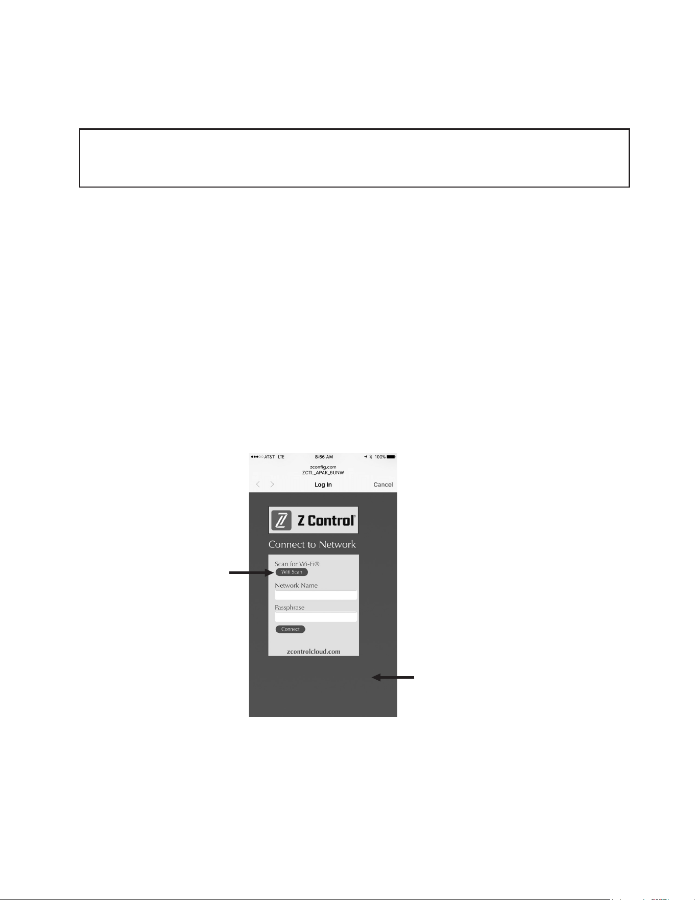
3. Onthesetupscreen(seeFigureC),presstheWiFiScanbutton,scrolldowntoseethelistofWiFisignalsfound,andchoosetheWiFinetworkyouwant
theFittouseforinternetconnectivity.Enterthepassphraseforthenetworkyouchoseintheeldindicated.Ifthepassphraseiscorrect,theFitwill
connect to the network and start sending status updates to zcontrolcloud.com. You will see the Z Control
®
LEDgofromblinkingtosolid.Thiscouldtakeup
to a minute or so.
IftheLEDdoesnotturnsolid,thenthepassphraseenteredisincorrect,therouter’ssecurityisinsufcient(seenotebelow**),orsomeothernetwork
restrictionisinplace(seeyournetworkadministrator).TheFitwillreturntostandbymodeiftheconnectiontorouterisnotsuccessful.Ifyouneedtoforce
the FitintoAPmodeagain,presstheZControl
®
buttonfor12seconds(SeeFigureA).ThiswillcausetheFittore-enterAPmodeandbegintransmittingits
SSIDagain.RepeatSteps2and3.
*AP ModeiswhentheFitisbroadcastingits“name”,orSSID.TheSSIDisintheformatZCTL_Fit_xxxxwhere“xxxx”istherst4digitsofyour
Fit’sDeviceID(SeeFigureB).TheFit’sSSIDwillshowupinyourphone/tablet/computer’slistofavailableWiFinetworks,andselectingitwillgive
youdirectconnectivitytotheFit.ThisisrequiredinordertogiveyourFitthepasswordcredentialsneededtoconnecttotheWiFinetworkofyour
choice.
of thehome'swirouter.IftheFitsuccessfullyconnectstothecloudthroughthehotspot,thentheconictlikelyhassomethingtodowiththerouter
settings.
Connection Steps:
1. ApplyACPowertotheFit.TheZControl
®
LEDwillblinkandthenturnoff,indicatingtheFitisinAPMode*andistransmittinganSSID(seeFigureB).Ifthe
LEDisblinkingandnotinAPmode,presstheZControl
®
buttonfor12secondsandletgo.TheLEDwillnowbeoff,indicatingtheFitisinAPMode.Apen
or toothpick or similar is required to press the Z Contol
®
button(SeeFigureA).
ClickWiFiScanbutton
AvailableWiFinetworkswillbelistedhere.You
mayneedtoscrolldown.Selecttheoneyouwant
FITtousetoconnecttotheinternet.Thenllinthe
Passphrase.
**NotethattheFitwillnotconnecttorouterswith“WEP”or“OPEN”security.SecuritymustbeWPAorWPA2orsimilarvariant.
Figure C
11
© Copyright 2025 Zoeller
®
Co. All rights reserved.
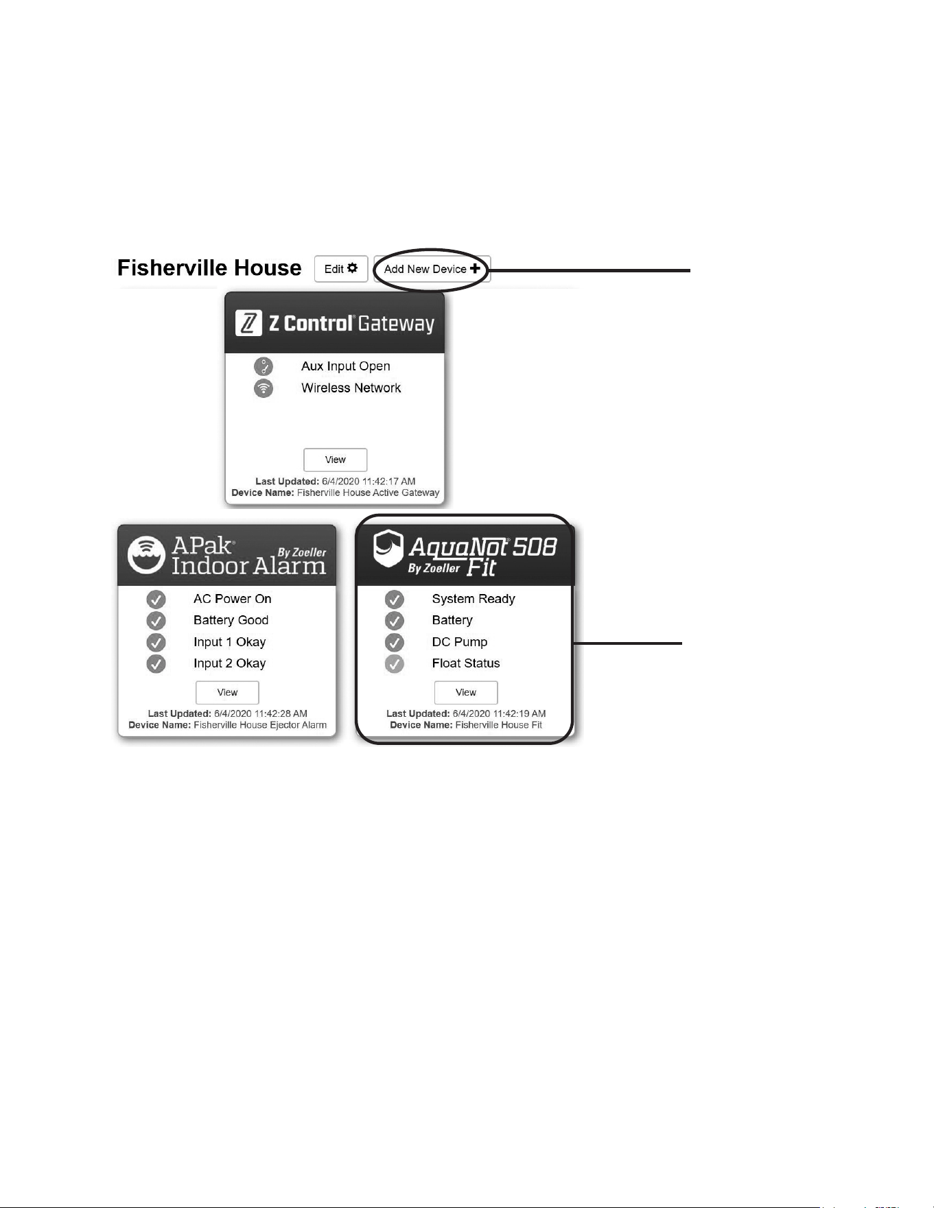
4. Once the Fit’s Z Control
®
LEDissolid,logintoyouraccount(orcreateone)atzcontrolcloud.com.ChoosetheAddNewDevicebuttonnexttothelocation
youwanttousefortheFit(seeFigureD).FollowthedirectionstoaddyourFitbyeitherauto-detectorenteringtheDeviceI.D.Whensuccessful,aFit
product tile will appear in your account.
Firmware Updates:
TheFitiscapableofOTA,or“overtheair”rmwareupdates.It’spossiblethattheFitcouldperformanupdateimmediatelyifoneisavailableattheZControl
®
Cloud.
If an update is taking place, the Z Control
®
LEDwillickerforupto1minutewhiletheupdateisdownloaded.TheZControl
®
LED will be solid and all other LEDs will
turnoffwhiletheupdateisbeinginstalled.Afterupto1minute,theFitwillrestartandreturntonormaloperation.TheFit’salerthistoryontheZControl
®
Cloud will
alsobeupdatedwiththermwareupgradeinformation,andnocationtoemailaccountswilloccur.
When you add the correct
Device ID, a Fit product tile
will appear in your account
SelectAddNewDevice
Figure D
Congratulations! Your Fitisonline.Besureyouhaveaddedthecontactinformationforphonenumbersandemailadressesthatshouldreceivenotications.Thiscan
donebyselecting"ManageContacts"fromthemainmenu(thesquarewith3linesintheupperrightcorner).Youcanalsoedithoweachdevicesendsoutnotica-
tionsfromthedevice's"AlarmSettings"tab.Youcannowopentheproduct’scongurationbyclickingthe“View”buttontomodifytheFit’sdeviceandnotication
settings. You can also install the Z Control
®
mobileapponyourmobiledevice(AndroidandiOSversionsavailable,search“ZControl
®
”intheappstores).

12
© Copyright 2025 Zoeller
®
Co. All rights reserved.
CARBON MONOXIDE DETECTORS
Somebatterytypesusedinbatterybackupsystems,regardlessofbrandormanufacturer,havethepotentialtogiveoffgaseousby-productswhencharging.Someof
theseby-productscanproducearotteneggodor.Also,someoftheseby-productscancauseaCOdetectortofalselyactivate.Inordertohelppreventfalseactivation,
ZoellerPumpCompanyrecommendsmovingthebatteryasfarawayfromtheCOdetectoraspossibleor,ifnecessary,ventingthebatterytotheexterior.ZoellerPump
Company provides the previous statements only as guidelines to help prevent false activation of the CO detector. In no way are these statements intended to supersede
the instructions that accompany the detector, nor do they supersede advice from the CO detector manufacturer.
If the audible alarm associated with your CO detector is activated, we recommend the following actions:
1) TakeimmediateactionforpersonalsafetyasrecommendedintheCOdetectorliterature.
2) ContacttheappropriateagencytodetermineiftheCOisbeingproducedbyyourfurnace,waterheater,oranyotherdevicewhichusesnaturalgas.
3) IfyouarecertainthatnoCOisbeingproduced,achargingbatterymaybeproducinggaseousby-productscapableofcausingtheCOdetectortoactivate.Contact
the manufacturer and ask for recommendations to prevent the alarm activation.
Therearemillionsofbatteriesmanufacturedeachyear,soitisimpossibletoguaranteeconsistentquality.Adefectivebatterywillneverbecomefullycharged
and may damage the charging circuits of the controller. It is for this reason that Zoeller offers its own line of batteries. We offer maintenance-free, deep cycle
batteriescapableofrunningthepumpcontinuoulsyforover5.5hours.Thesetimesarebasedoncontinuouspumpingat10'ofstatichead.Actualtimeswillvary
depending on static head, volume of water entering the pit, and the condition of the battery.
Follow these recommendations:
• Use a B.C.I. size 27 deep-cycle battery, 175 minute reserve capacity, or larger
• Replace your battery every 3 years
• Do not let corrosion build up on the battery terminals
• Tocheckspecificgravity,followtheinstructionsonahydrometer(wetcellbatteriesonly)
• Useoftheincludedplasticbatteryboxisrecommendedtokeepthebatterysafeandclean.
PROTECTYOURWARRANTY:
• Waterlevelinbatteriesmustbecheckedonceamonth(wetcellbatteriesonly)
• Do not use gel batteries
THE AQUANOT
®
BATTERY
MAIL TO: P.O. BOX 16347 • Louisville, KY 40256-0347
SHIP TO: 3649 Cane Run Road • Louisville, KY 40211-1961
Tel: (502) 778-2731
• 1 (800) 928-PUMP
Visit our website:
zoellerpumps.com
These are the original installation instructions.