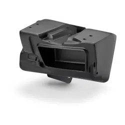

Enclosure Type: Sealed
Driver Type: M3-650X-S-Gm-i
Nominal Impedance: 4 ohms
Continuous Power Handling: 60 watts (RMS method)
Thank you for choosing a JL Audio Stealthbox® for your automotive sound system.
With proper installation, your new vehicle-specific enclosed subwoofer system
will deliver years of listening pleasure.
We strongly recommend that you have your new Stealthbox® installed by your
authorized JL Audio dealer. The installation professionals employed by your
dealer have the necessary tools and experience to disassemble and reassemble
your vehicle properly. If you prefer to perform your own installation, please read
this installation guide completely before beginning the process.
If you choose to perform the installation yourself, it is absolutely
vital that the Stealthbox
®
be properly mounted to the vehicle
according to these instructions. Failure to mount the enclosure
properly presents two problems:
1) The sub-bass performance will suffer due to the movement of the
enclosure caused by the force exerted by the woofer(s).
2) A loose enclosure presents a serious safety hazard in the event of a
collision or sudden deceleration.
INSTALLATION
DIFFICULTY:
ESTIMATED TIME:
1-2 HOURS
Continued on Next Page
2
5
OUT
OF
SB-POL-RZG2SPKR/M3-650i INSTR_SKU# 011545
INSTALLATION GUIDE
for the
SB-POL-RZG2SPKR/M3-650i
SKU# 94679
2014 & Up Polaris RZR 4 900, 900XC, XP 1000, XP4 1000
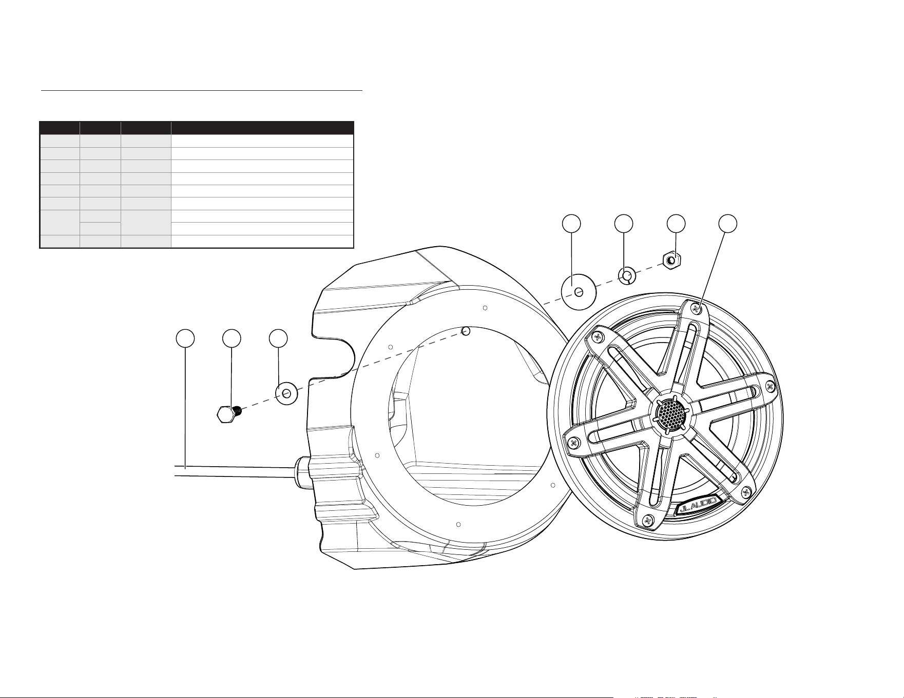
INCLUDED HARDWARE
654
1 3
7
2
Continued on Next Page
Page 2 • JL Audio, Inc., 2019
SB-POL-RZG2SPKR/M3-650i INSTR_SKU# 011545
Note: For optimum performance, JL Audio recommends applying the included Foam Strips (or sound damping material) to surrounding plastic panels to reduce unwanted vibrations.
(hardware pictured for one)
* Pre-installed on enclosure
BOM ID Qty SKU Description
1* 2 152414 Wire Harness (10’)
2 2 153820
1/4 - 20 x 1” Stainless Steel Hex Cap Screw
3 2 153818 1/4” Stainless Steel Flat Washer
4 2 153817 1/4” Stainless Steel x 1” OD Flat Washer
5 2 153819 1/4” Stainless Steel Split Lock Washer
6 2 153816 1/4 - 20 Stainless Steel Hex Nut
7**
12
(1) 193559
#8 x 1-1/8” Stainless Steel Phillips Head Screw
12 #8 Stainless Steel Flat Washer (not shown)
- 1 150249 Foam Tape (not shown)
** Two of each pre-installed on enclosure
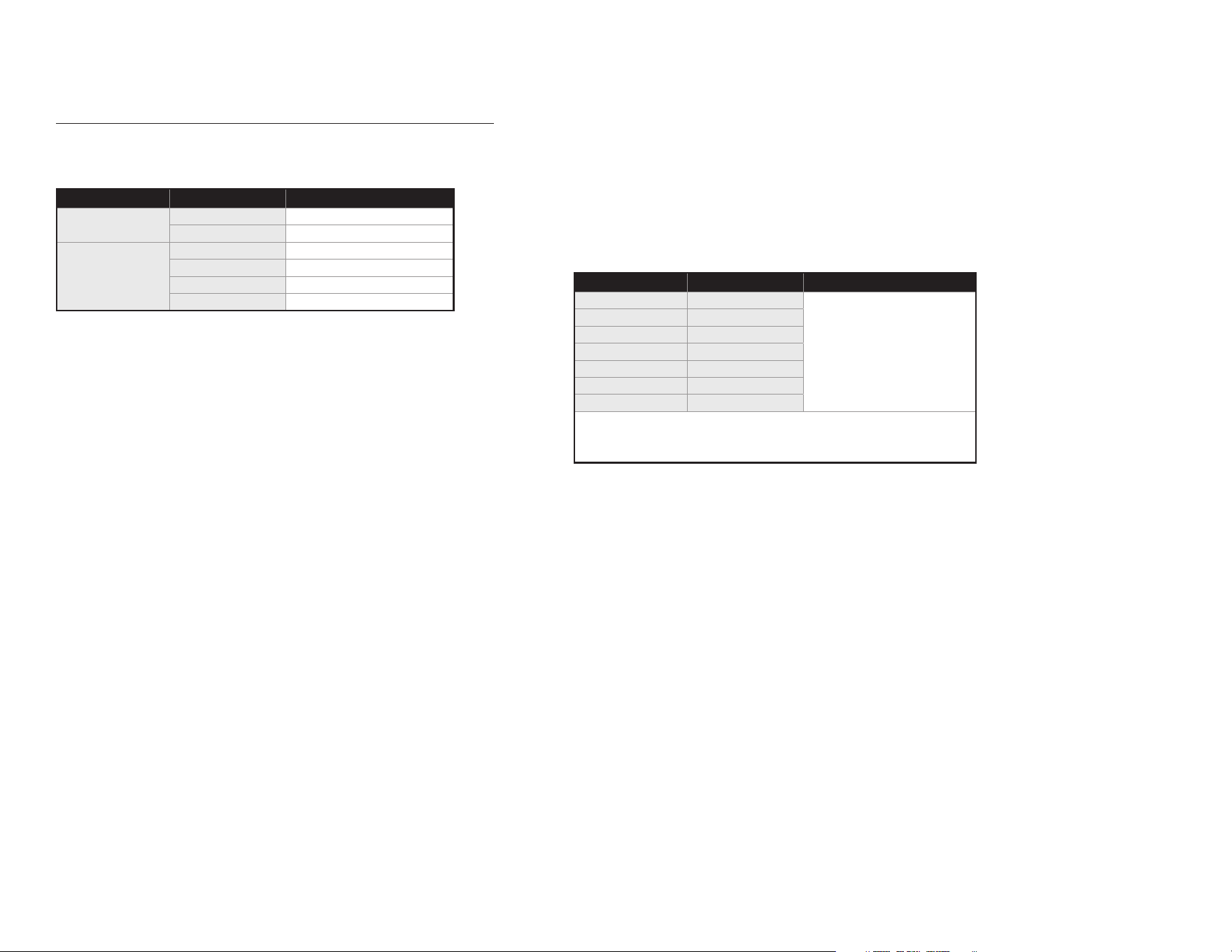
WIRING INFORMATION
Continued on Next Page
Page 3 • JL Audio, Inc., 2019
SB-POL-RZG2SPKR/M3-650i INSTR_SKU# 011545
Direct LED Wiring
Alternatively, you may hard wire individual leads or a combination
of leads to achieve up to seven different LED color assortments.
Refer to the table below for the wire colors used to achieve specific
LED colors.
LED Color Wire Color(s) Connection
Red Red
Combine selected wires from
all speakers and connect to
negative ground or the
negative (–) battery post.
Green Green
Blue Blue
Yellow Red and Green
Pink Red and Blue
Aqua Green and Blue
White Red, Green and Blue
Combine all YELLOW (+12V) leads together (parallel) and connect to a
switched +12V supply.
LED Wiring Considerations
• For short-circuit protection, we recommend installing a fuse
(not included) at EACH speaker’s YELLOW (+12V) LED power
connection lead.
• We recommend activating the speakers’ LEDs thru an interior
lighting circuit that supplies +12V via an existing switch. If an
existing switched circuit is not available, you may install a
dedicated toggle/rocker style switch that will supply positive
(+12V) power. Fuse this main +12V connection according to the
total demands of all LED circuits.
Wiring Harness Info
Wire Size Wire Color Use
16 AWG
Red/Stripe Speaker Positive (+)
Black/Stripe
Speaker Negative (–)
20 AWG
Red Red RGB LED Negative (–)
Green Green RGB LED Negative (–)
Blue Blue RGB LED Negative (–)
Yellow Main RGB LED Positive (+)
Adjustable control of RGB lighting may be achieved with the use of
an RGB lighting controller (sold separately). Note: When selecting
an RGB lighting controller, make sure that the total amperage
demands of all LED circuits does not exceed the output
capacity of the controller. For each M3-650X speaker, a 150 mA
fuse is recommended. For optimal performance, we recommend
using the JL Audio marine lighting controller (MLC-RW).
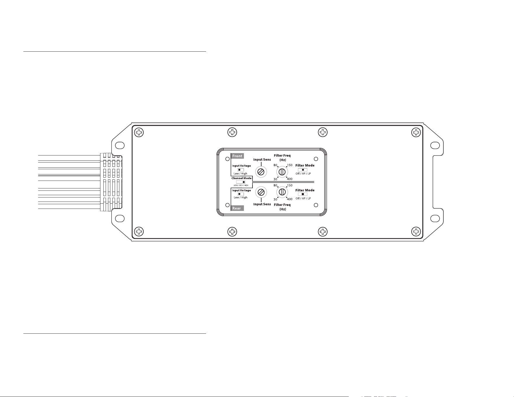
POWER RECOMMENDATION
JL Audio recommends high quality ampliers such as the JL Audio MX280/4. The diagram below shows the recommended crossover settings for the MX280/4. For a detailed description of the ampli-
er settings, consult the owner’s manual for the amplier. If another amplier is being used, please reference this illustration and use similar settings on that amplier.
CONNECTIONS
Using quality power, signal, and speaker wire is essential in ensuring the performance of your Stealthbox®. JL Audio recommends using a 4 AWG power kit such as the XD-PCS4-1B for your
Stealthbox® amplier. Other kits are available should you be using more than one amplier. Signal wire such as the JL Audio Premium Audio Interconnect Cables should be used to provide signal for
both channels of the amplier. JL Audio recommends using 12 AWG speaker wire for subwoofers such as our XC-BCS12-25.
Continued on Next Page
Page 4 • JL Audio, Inc., 2019
SB-POL-RZG2SPKR/M3-650i INSTR_SKU# 011545
Page 5 • JL Audio, Inc., 2019 Continued on Next Page
STEP 8
Using a 1/4” drill bit, carefully drill through the
upper hole in the enclosure, through the
plastic panel, to the exterior wheel well area.
STEP 7
Remove the speaker and batting from the
enclosure. Pass the cable exiting the rear of the
enclosure through the hole in the plastic panel.
Position the speaker enclosure flush against
the kick panel, allowing the grommet to sit in
the drilled hole.
Secure the enclosure using a factory bolt
through the lower hole in the enclosure, as
shown.
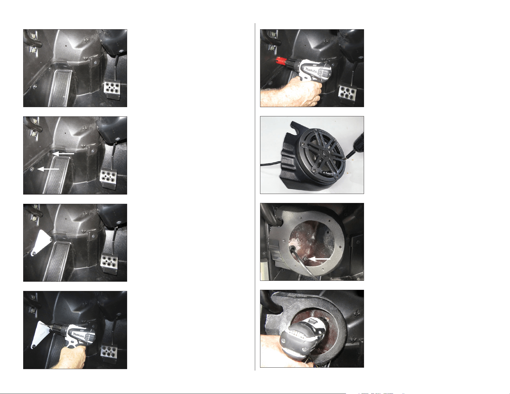
STEP 6
Place the driver’s side enclosure on a flat
surface. Remove the two #8 x 1-1/8” Stainless
Steel Phillips Head Screws and #8 Stainless
Steel Flat Washers.
STEP 5
Using a 1-1/8” hole saw, enlarge the hole drilled
in the previous step.
STEP 4
Using a 1/8” drill bit, carefully drill through the
indicated mark on the Template, through the
plastic panel, to the exterior wheel well area.
Remove the factory bolts, and remove the
Template.
STEP 3
Cut the Template from Page 8 of this manual.
Align the lower holes in the Template to the
factory holes in the vehicle, and secure using
the factory bolts removed in the previous step.
The bottom of the Template should be parallel
with the horizontal edge of the plastic panel,
as shown.
STEP 2
Remove the two indicated factory bolts.
STEP 1
The following steps show the installation
procedure for the driver’s side only, but the
procedure is the same for both sides.
Empty the driver’s side of the vehicle.
SB-POL-RZG2SPKR/M3-650i INSTR_SKU# 011545
Page 6 • JL Audio, Inc., 2019
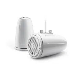
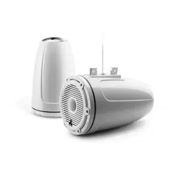
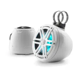
RECOMMENDED SUBWOOFER SOLUTIONS
A Stealthbox® subwoofer system is also available for your vehicle. Each weatherproof enclosure houses a
premium JL Audio subwoofer and is designed for a perfect t.
All specifications are subject to change without notice. “JL Audio®” and the JL Audio logo, “Stealthbox®” and the Stealthbox logo, and “How we play®” are registered trademarks of JL Audio, Inc.
“Ahead of the Curve” and its respective logo are trademarks of JL Audio, Inc.
Printed in USA • ©2017 JL Audio, Inc. • For more detailed information please visit us online at www.jlaudio.com.
(954) 443-1100
www.jlaudio.com
JLA-SKU# 011545 • ver. 11.07.2019 • 10369 NORTH COMMERCE PARKWAY • MIRAMAR, FLORIDA • 33025 • USA
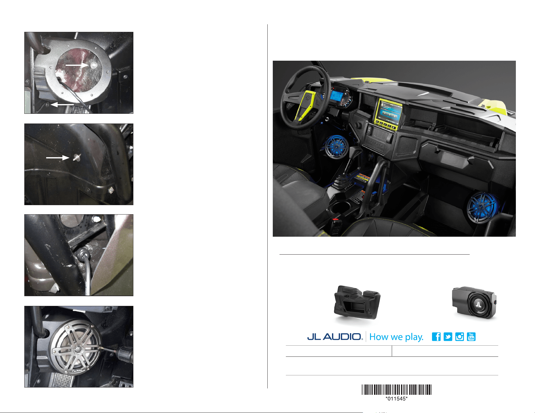
CONGRATULATIONS!
You have completed the installation for this model! Enjoy your new Stealthbox®!
SB-POL-RZG2SPKR/M3-650i INSTR_SKU# 011545
®
STEP 10
From the exterior wheel well area, slide a 1/4” x
1” OD Flat Washer, a 1/4” Split Lock Washer, and
a 1/4 - 20 Hex Nut over the 1/4 - 20 x 1” Hex
Cap Screw, and fully tighten.
STEP 9
Slide a 1/4” Flat Washer over a 1/4 - 20 x 1” Hex
Cap Screw, and pass the assembly through the
hole drilled in the previous step, as shown.
Reinstall the indicated factory bolt.
STEP 12
Reinstall the batting inside the enclosure,
then reinstall the speaker using six #8 x 1-1/8”
Stainless Steel Phillips Head Screws and #8
Stainless Steel Flat Washers.
Repeat the process for the passenger side.
Note: For optimum performance, we
recommend applying the included Foam Strips
(or sound damping material) to surrounding
plastic panels to reduce unwanted vibrations.
STE P 11
Route the cable as necessary. Refer to Page 3
for wiring information.
SB-POL-RZG2/10TW3
SKU # 94620
SB-POL-RZG3/10TW3
SKU # 94675
SB-POL-RZG2R/10TW3
SKU # 94631

Page 7 • JL Audio, Inc., 2019
This page is intentionally left blank.
SB-POL-RZG2SPKR/M3-650i INSTR_SKU# 011545
Page 8 • JL Audio, Inc., 2019
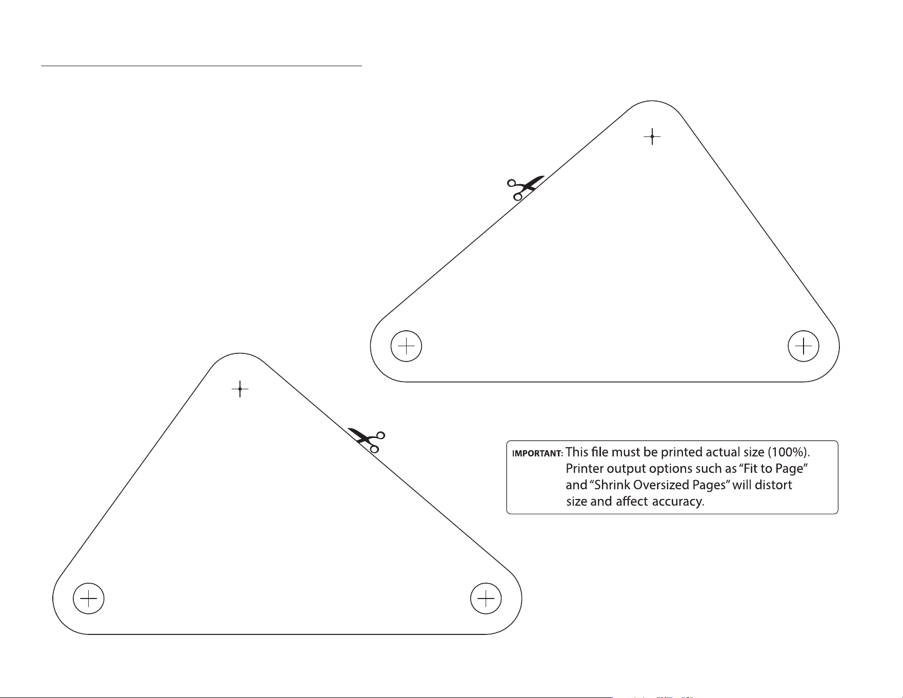
TEMPLATES
Carefully cut out the templates along the indicated lines.
SB-POL-RZG2SPKR/M3-650i INSTR_SKU# 011545
B
o
l
t
A
l
i
g
n
m
e
n
t
H
o
l
e
-
B
o
l
t
A
l
i
g
n
m
e
n
t
H
o
l
e
-
B
o
l
t
A
l
i
g
n
m
e
n
t
H
o
l
e
-
B
o
l
t
A
l
i
g
n
m
e
n
t
H
o
l
e
-
B
o
l
t
A
l
i
g
n
m
e
n
t
H
o
l
e
-
B
o
l
t
A
l
i
g
n
m
e
n
t
H
o
l
e
-
D
r
i
l
l
H
o
l
e
-
D
r
i
l
l
H
o
l
e
-
D
r
i
l
l
H
o
l
e
-
D
r
i
l
l
H
o
l
e
-
B
o
l
t
A
l
i
g
n
m
e
n
t
H
o
l
e
-
B
o
l
t
A
l
i
g
n
m
e
n
t
H
o
l
e
-
DRIVER SIDE TEMPLATE
D
r
i
l
l
H
o
l
e
-
D
r
i
l
l
H
o
l
e
-
D
r
i
l
l
H
o
l
e
-
D
r
i
l
l
H
o
l
e
-
PASSENGER SIDE TEMPLATE