VERSION A0
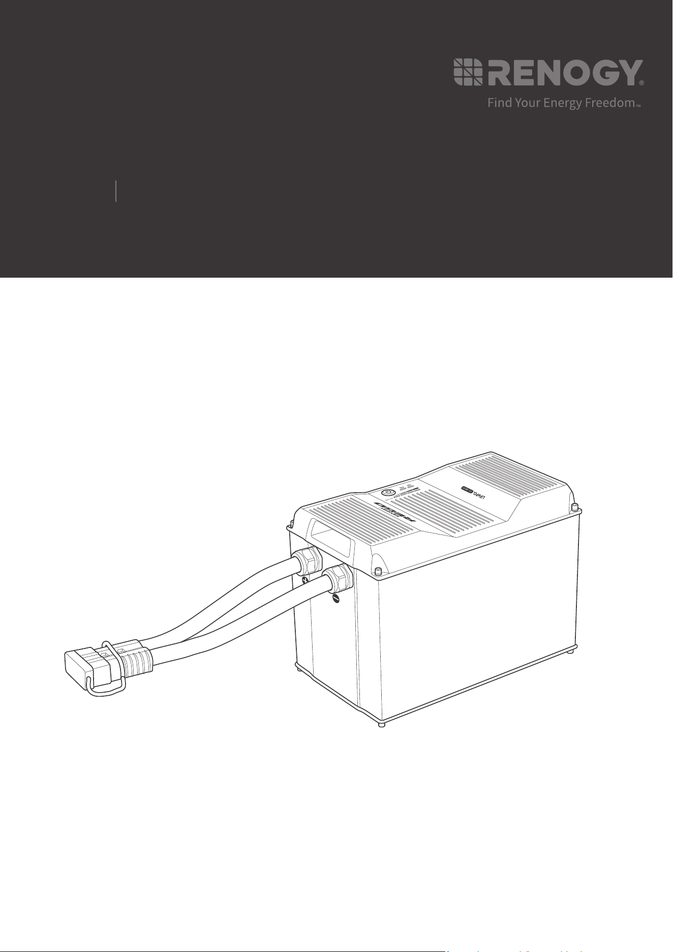
Lithium Iron Phosphate Battery
REGO
12V
400Ah
USER MANUAL
02
Applicability
The user manual applies to the following product:
z
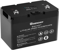
REGO 12V 400Ah Lithium Iron Phosphate Battery (RBT12400LFPL-SHBT)
Disclaimer
z
Renogy makes no warranty as to the accuracy, sufficiency, or suitability of information in the
user manual because continuous product improvements are going to be made.
z
Renogy assumes no responsibility or liability for losses or damages, whether direct, indirect,
consequential, or incidental, which might arise out of the use of information in the user
manual.
z
Renogy is not responsible or liable for the failures, damages, or injuries resulting from repair
attempted by unqualified personnel or improper installation and operation.
z
The illustrations in the user manual are for demonstration purposes only. Details may appear
slightly different depending on product revision and market region.
z
Renogy reserves the right to change the information in the user manual without notice.
Copyright
REGO 12V 400Ah Lithium Iron Phosphate Battery User Manual © 2022 Renogy. All rights
reserved.
All information in the User Manual is subject to copyright and other intellectual property rights
of Renogy and its licensors. The User Manual may not be modified, reproduced, or copied, in
whole or in part, without the prior written permissions of Renogy and its licensors.
Trademarks
The following are trademarks or registered trademarks of Renogy in the United States and other
countries and regions:
RENOGY RENOGY REGO
All other trademarks in the user manual are the property of their respective owners and their
use herein does not imply sponsorship or endorsement of their products or services. The
unauthorized use of any trademark displayed in the user manual or on the product is strictly
prohibited.
Date and Revision
June 2022, Revision A0

03
Table of Contents
Important Safety Information .......................................................................................................05
Symbols Used .........................................................................................................................05
General Safety Information .....................................................................................................05
Introduction ..................................................................................................................................07
Introduction .............................................................................................................................07
Key Features ...........................................................................................................................07
Package Contents .......................................................................................................................09
Product Overview ........................................................................................................................10
Wiring Diagram ............................................................................................................................11
Using Combiner Boxes ...........................................................................................................11
Using Busbars .........................................................................................................................11
Installation ...................................................................................................................................12
Inspection ................................................................................................................................12
Environment ............................................................................................................................12
Placement ...............................................................................................................................12
Mounting .................................................................................................................................13
Power Connection .......................................................................................................................15
Using Combiner Boxes ...........................................................................................................15
Using Busbars .........................................................................................................................18
Communication............................................................................................................................20
Inter-Device Communication ...................................................................................................20
Monitoring Device Communication .........................................................................................23
Commission .................................................................................................................................27
Indicator Pattern ......................................................................................................................27
Turning On ..............................................................................................................................27
Checking Battery Level ...........................................................................................................29

04
Checking Battery Status ..........................................................................................................30
Checking Heater Status ..........................................................................................................31
Changing Heater Settings .......................................................................................................33
Charging ..................................................................................................................................34
Discharging .............................................................................................................................35
Turning Off ..............................................................................................................................35
Maintenance ................................................................................................................................37
Inspection ................................................................................................................................37
Cleaning ..................................................................................................................................37
Storage ....................................................................................................................................37
Battery Management System ......................................................................................................39
Warning/Protection/Permanent Failure ...................................................................................39
Charge Current Request .........................................................................................................42
Cell Voltage Balancing ............................................................................................................42
Troubleshooting ...........................................................................................................................43
Emergency Responses ...............................................................................................................52
Fire ..........................................................................................................................................52
Flooding ..................................................................................................................................52
Smell .......................................................................................................................................52
Technical Support ........................................................................................................................53
Technical Specifications ..............................................................................................................54
Dimensions ..................................................................................................................................56
05
Important Safety Information
The User Manual provides important installation, operation, and maintenance instructions for
REGO 12V 400Ah Lithium Iron Phosphate Battery. Please read the User Manual carefully before
installation and operation and save it for future reference. Failure to observe the instructions
or precautions in the User Manual can result in electrical shock, serious injury, or death, or can
damage the battery, potentially rendering it inoperable.
Symbols Used
The following symbols are used throughout the User Manual to highlight important information:
WARNIN
G
Indicates a potentially dangerous condition which could result in
injury or death.
CAUTIO
N
Indicates a critical procedure for safe and proper installation and
operation.
NOT
E
Indicates an important step or tip for optimal performance.
INFO
Indicates that more information is available in other documents
relating to the subject.
General Safety Information
WARNIN
G
z
DO NOT puncture, drop, crush, penetrate, shake, strike, or step on the battery.
z
DO NOT open, dismantle, repair, tamper with, or modify the battery.
z
DO NOT touch the connector contacts of the battery.
z
Please remove all connections and turn the battery off before maintenance or cleaning.
z
Please install the battery in accordance with the regulations at the site of installation.
z
DO NOT expose the battery to direct flame.
z
Please keep the battery away from flammable or combustible materials.
z
DO NOT expose the battery to harsh chemicals or vapors.
z
Please keep the battery away from heating equipment.
z
DO NOT touch the exposed electrolyte or powder if the battery is damaged.
z
DO NOT use the battery with life support equipment or other medical equipment.
z
Please keep the battery out of the reach of young children and animals.
z
Please use insulated tools when working on or around the battery.
z
DO NOT wear jewelry or other metal objects when working on or around the battery.
z
Please wear proper protective equipment when working on or around the battery.
Important Safety Information
Symbols Used General Safety Information

06
Important Safety Information
CAUTIO
N
z
Ensure adequate and secure mounting of the battery.
z
DO NOT expose the battery to strong electrostatic fields, strong magnetic fields, or radiation.
z
Please use suitable handling equipment for safe transportation of the battery.
z
Ensure that no water sources are above or near the battery, including downspouts,
sprinklers, or faucets.
z
Ensure that snow does not accumulate around the battery.
z
DO NOT lean on, stack anything on top of, or hang anything from the battery or from cables
leading to the battery.
Symbols Used General Safety Information

07
Introduction
Introduction
Introduction
Meet the next era of energy storage system with Renogy 12V 400Ah REGO Lithium Iron
Phosphate Battery. With a large capacity of more than 5KWh, the battery is designed to run
loads for extended periods of time. Manufactured with top grade cells, the battery provides an
exceptional lifespan of more than 3800 cycles (80% DOD), a continuous discharge current up
to 350A for heavy loads, and a continuous charge current up to 300A for 1.5-hour fast charging.
The integrated battery cables and Anderson connector significantly simplify the wiring, reduce
the risk of short circuit, misconnection, and connection failure, and allow for quick connection
and disconnection. The sophisticated battery management system (BMS) offers up to 60 types
of warnings and protections, enables precise cell balancing, and stores up to 150 event records.
The built-in heater operates automatically at low temperatures to keep the battery charging.
The straightforward LED indicators visualize the battery level, battery status, and heater status.
The on-board Bluetooth module ensures real-time monitoring on DC Home app and compatible
monitoring devices. The RV-C protocol compatibility allows for complete system integration,
featuring better charging experience, safer operation, and more customizable settings to
extend the lifespan of the battery. The waterproof die cast aluminum housing and stringent road
load tests ensure that the battery can deliver extreme performance even under the harshest
conditions including wet environments and mechanical vibrations.
Key Features
z
Large Capacity
Runs loads for extended periods of time with a capacity of more than 5KWh.
z
Uncompromising Quality
Provides an exceptional lifespan of more than 3800 cycles (80% DOD), a continuous discharge
current up to 350A, and a continuous charge current up to 300A.
z
Easy Installation
Makes wiring simple and safe with the integrated battery cables and Anderson connector.
z
Advanced BMS
Offers comprehensive protection, precise balancing, and event logging capability with the state-
of-the-art battery management system (BMS).
z
Built-In Heater
Warms the battery up automatically at low temperatures for continuous charging with the built-in
heater.
z
Visualized Status
Visualizes the battery level, battery status, and heater status with the straightforward LED
indicators.
z
Remote Monitoring
Ensures real-time monitoring on DC Home app and compatible monitoring devices with the on-
board Bluetooth module.
Introduction Key Features

08
Introduction
z
RV-C Compatible
Allows for complete system integration for better charging experience, safer operation, and more
customizable settings with the RV-C protocol compatibility.
z
Reliable Design
Delivers extreme performance even under the harshest conditions with the waterproof die cast
aluminum housing.
Introduction Key Features
09
Package Contents
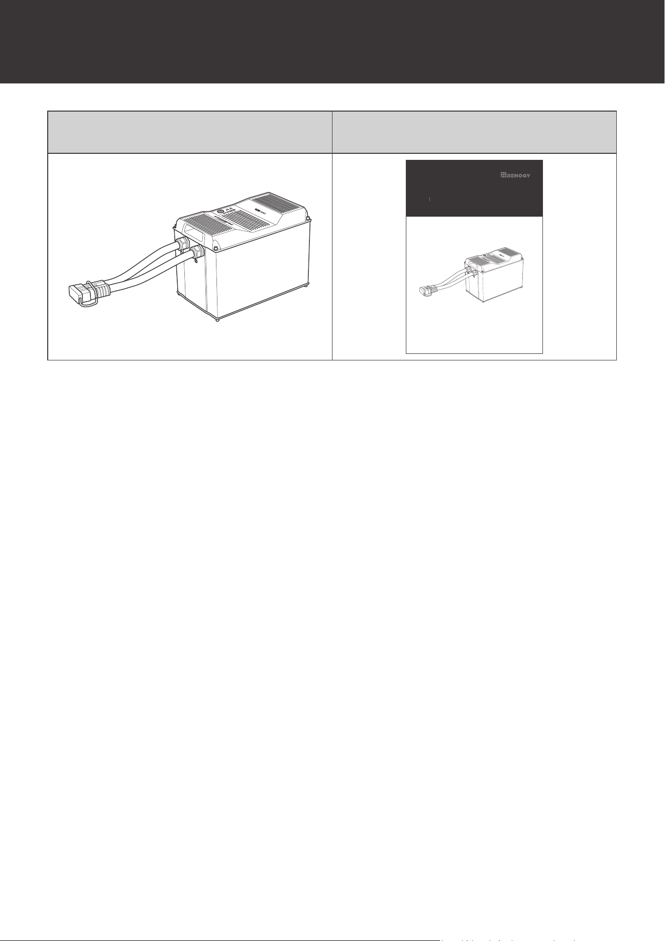
Package Contents
12V 400Ah REGO Lithium Iron Phosphate
Battery × 1
Quick Guide × 1
VERSION A1
Lithium Iron Phosphate Battery
REGO
12V
400Ah
QUICK GUIDE
10
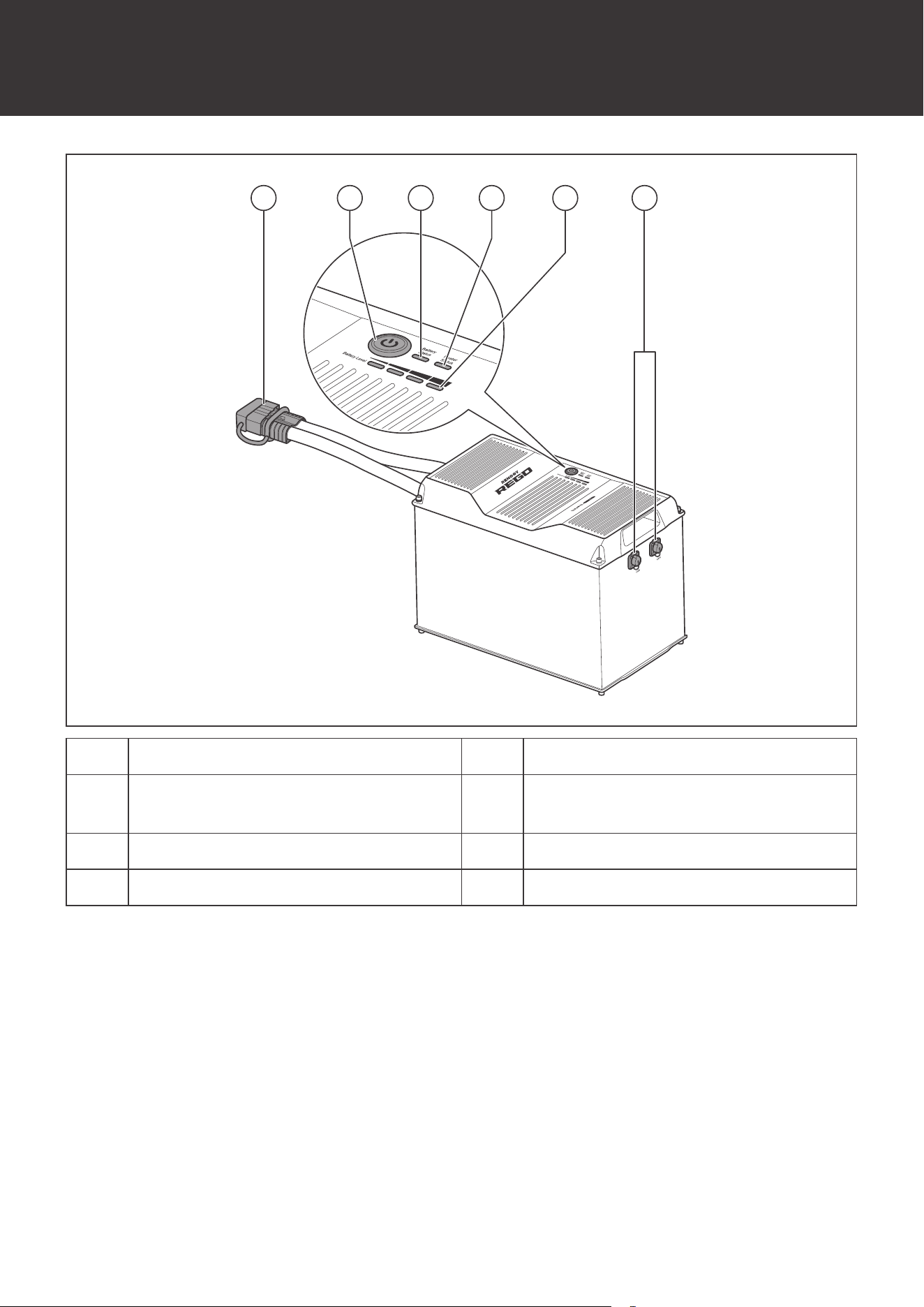
Product Overview
Product Overview
61 532 4
No. Part No. Part
1
Gray Anderson 350 Connector
(with Dust Cover)
4 Heater Status Indicator
2 Power Button 5 Battery Level Indicator
3 Battery Status Indicator 6 CAN Communication Ports
11
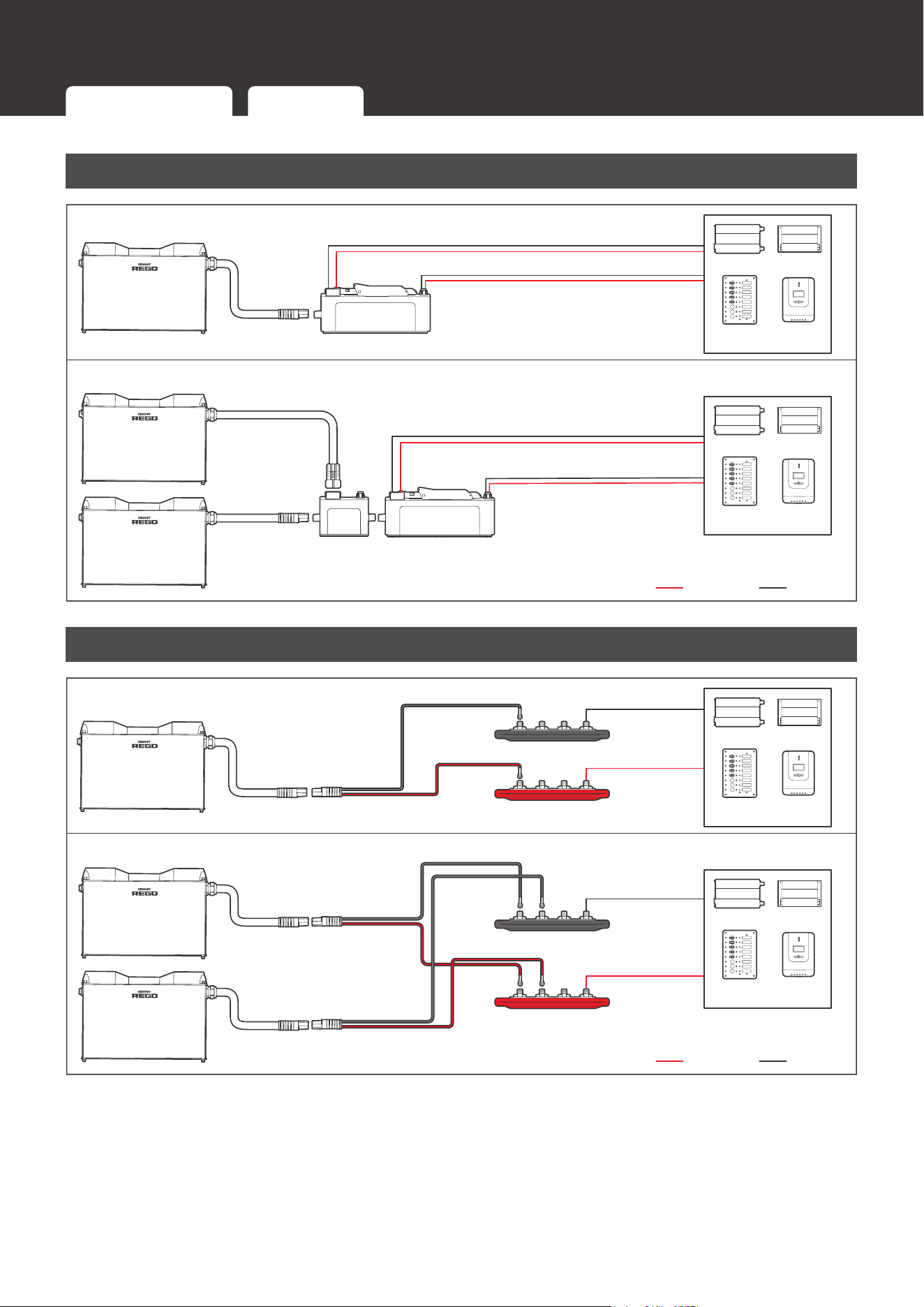
Wiring Diagram
Wiring Diagram
Using Combiner Boxes
Single Battery
System Combiner Box
Battery
Combiner
Box
System
Combiner Box
Positive Negative
Inverter
DC-DC
Charger
DC Distribution
Panel
Charge
Controller
Inverter
DC-DC
Charger
DC Distribution
Panel
Charge
Controller
Multiple Batteries
Using Busbars
Positive Negative
Single Battery
Multiple Batteries
Positive Busbar
Negative Busbar
Positive Busbar
Negative Busbar
Inverter
DC-DC
Charger
DC Distribution
Panel
Charge
Controller
Inverter
DC-DC
Charger
DC Distribution
Panel
Charge
Controller
Using Combiner Boxes Using Busbars
12
Installation
Installation
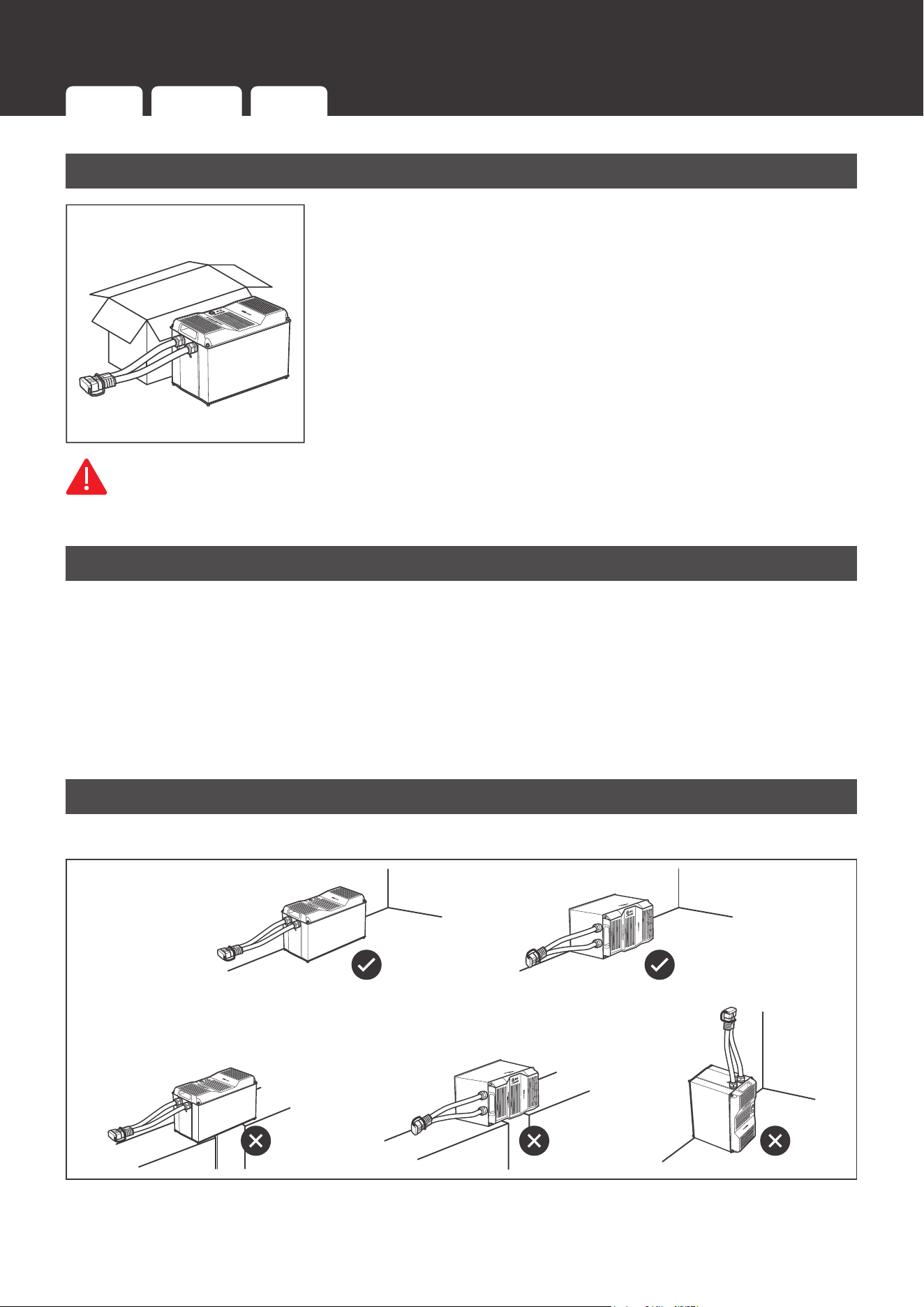
Inspection
Inspect the battery for any visible damages including cracks,
dents, deformation, and other visible abnormalities before
installation. The connector contacts shall be dry, clean, and free
of any dirt and corrosion.
WARNIN
G
z
DO NOT use the battery if it appears damaged.
Environment
Ensure that the installation environment is clean, cool, and well-ventilated. Keep the battery
away from oil and dirt. The accumulation of these substances can cause current leakage,
resulting in self-discharge and a possible short circuit. Avoid restricting airflow by tightly packing
batteries together. Allow at least 0.5 inches (12.7 mm) of space between the batteries for
efficient heat dissipation and minimal battery temperature variations. Safe operation requires
environment temperatures between -4
°F (-20°C) and 122°F (50°C). The recommended
operating environment temperature range is 59°F (15°C) and 86°F (30°C).
Placement
Place the battery upright or horizontally on the long side.
Inspection Environment Placement Mounting
13
Installation
CAUTIO
N
z
DO NOT place the battery upside down or horizontally on the short side.
z
Ensure that the battery is fully supported.
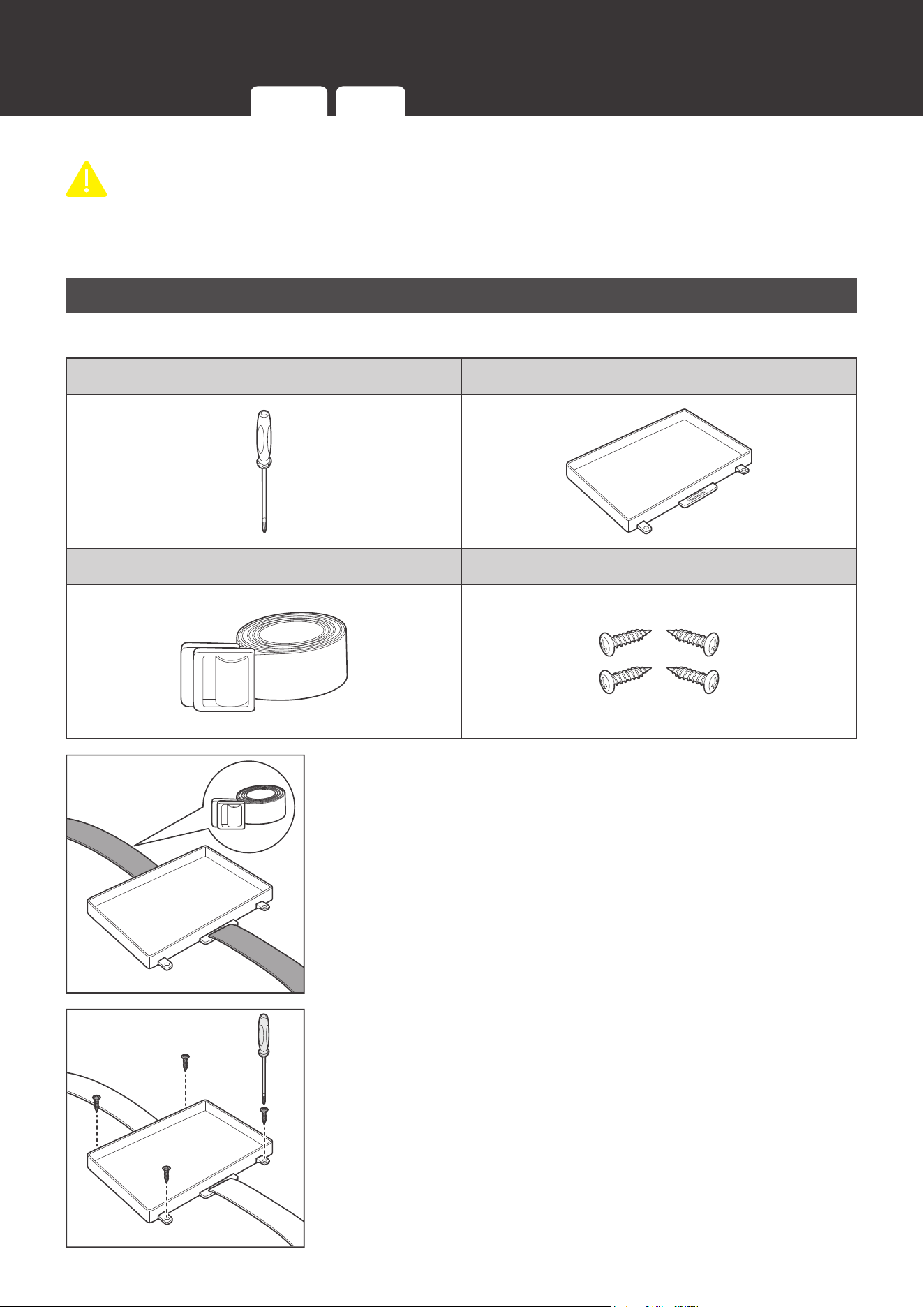
Mounting
Recommended Tool and Accessories
Phillips Screwdriver Battery Tray
Tie Down Strap Mounting Screws
1. Thread the Tie Down Strap through the strap anchors on the
Battery Tray.
2. Secure the Battery Tray on a flat mounting surface with the
Mounting Screws. Tighten the Mounting Screws with the
Philips Screwdriver.
Inspection Environment Placement Mounting
14
Installation
NOT
E
z
It is recommended to pre-drill holes on the mounting surface with a drill and a drill bit before
mounting the Battery Tray.
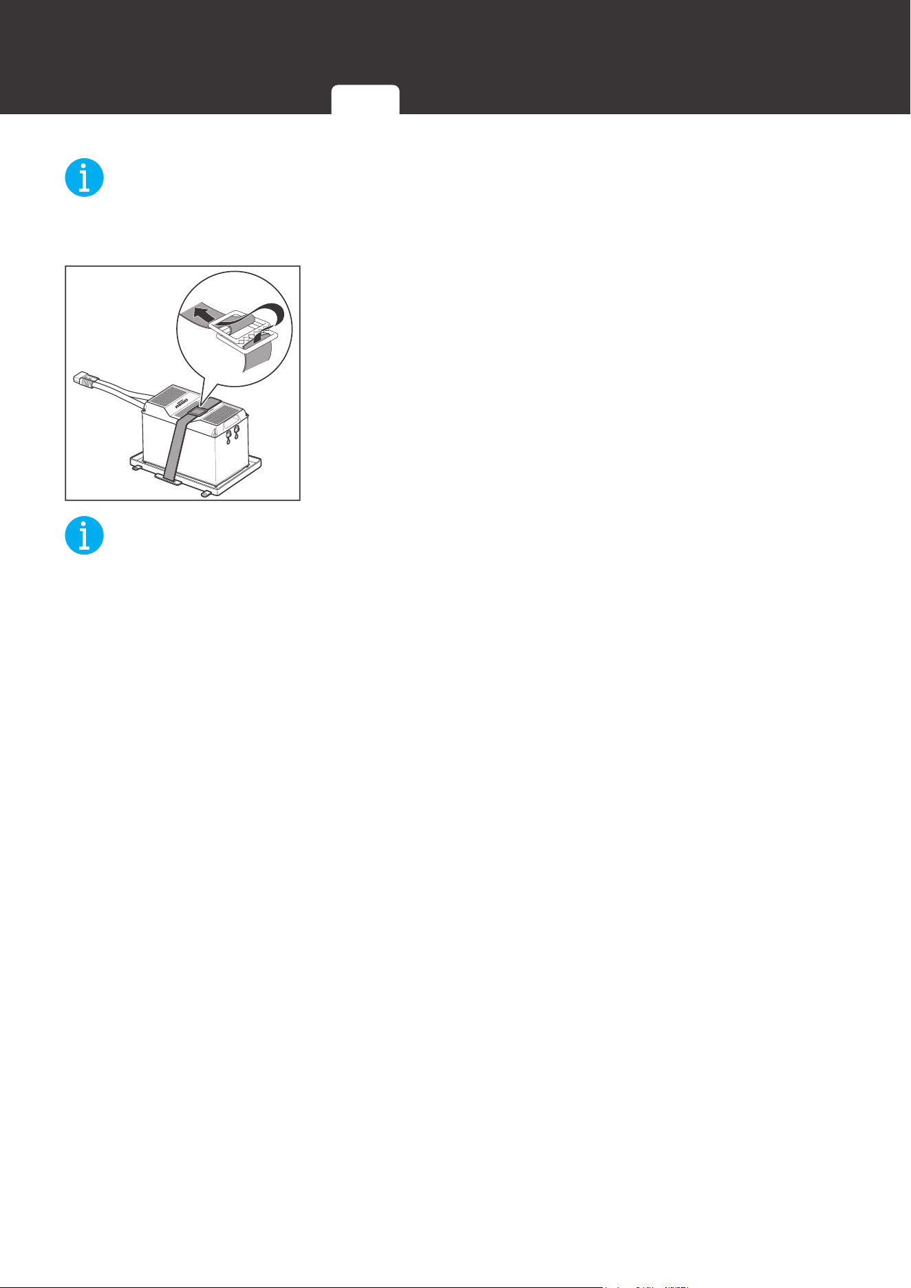
3. Place the battery into the Battery Tray. Buckle the Tie Down
Strap over the battery.
NOT
E
z
Alternative mounting methods are allowed to meet the requirements of specific applications.
Inspection Environment Placement Mounting
15
Power Connection
Power Connection
The batteries can be connected in parallel and to the system with either combiner boxes or
busbars. Parallel connection is intended to increase the battery bank capacity while keeping the
battery bank voltage the same.
WARNIN
G
z
DO NOT short the contacts of the Anderson Connector. Short circuits can damage the
battery.
z
DO NOT connect batteries in series. Series connection can damage the batteries.
z
DO NOT mix battery brands, models, chemistries, nominal voltages, and rated capacities.
CAUTIO
N
z
Please check the polarity before connecting the cables. Reverse polarity can damage the
battery and connected devices.
z
The Anderson Connectors are color coded. DO NOT mate the Anderson Connectors with
different colors together.
z
DO NOT connect more than 8 batteries in parallel.
z
Please avoid large voltage difference between batteries connected in parallel.
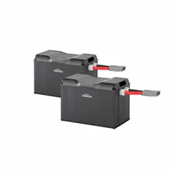
Using Combiner Boxes
Connecting the batteries in parallel and to the system using the Battery Combiner Box and
the System Combiner Box significantly reduces the risk of short circuit, misconnection, or
connection failure and allows for quick connection and disconnection.
Required Accessories
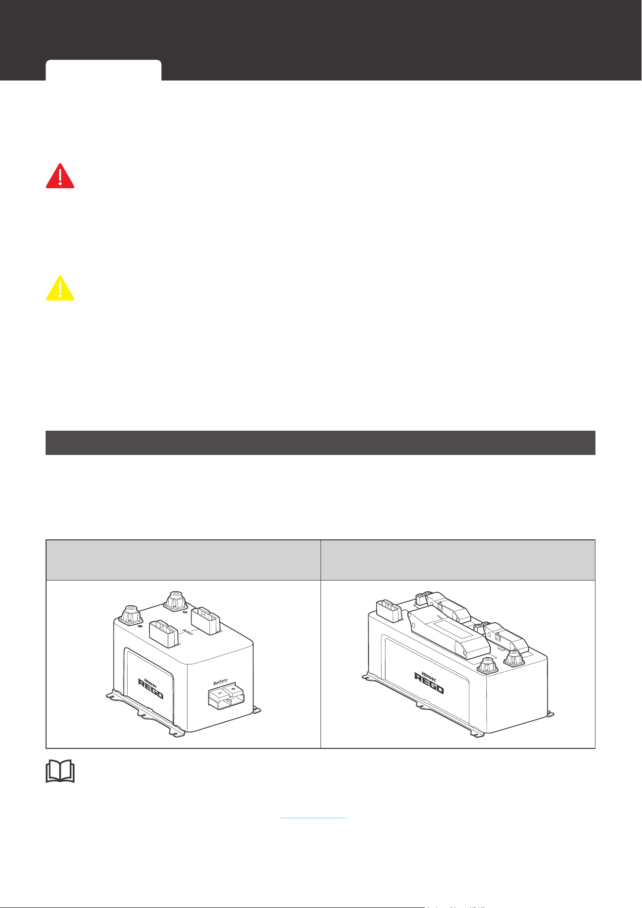
REGO 3 Ports 400A
Battery Combiner Box(es)
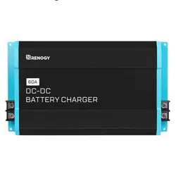
REGO 4 Ports 400A System Combiner Box
DC-DC Charger
Inverter
INF
O
z
Please read the user manual of REGO 3 Ports 400A Battery Combiner Box and REGO 4
Ports 400A System Combiner Box at renogy.com before the connection.
Using Combiner Boxes Using Busbars
16
Power Connection
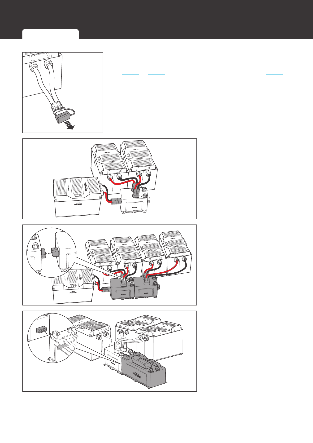
1. Remove the Dust Covers from the Anderson Connectors.
If multiple batteries are to be connected in parallel, refer to
step 2 to step 4. If only one battery is used, refer to step 5.
Battery Combiner Box
2. If multiple batteries are to
be connected in parallel,
plug the Anderson
Connectors of the batteries
to the Battery Combiner
Box (sold separately).
Battery Combiner Box
Battery Combiner Box
3. If necessary, connect
multiple Battery Combiner
Boxes together to accept
more batteries in parallel.
Battery Combiner Box
System Combiner Box
4. Connect the Battery
Combiner Box and the
System Combiner Box
(sold separately) using the
Anderson connectors on
their sides.
Using Combiner Boxes Using Busbars
17
Power Connection
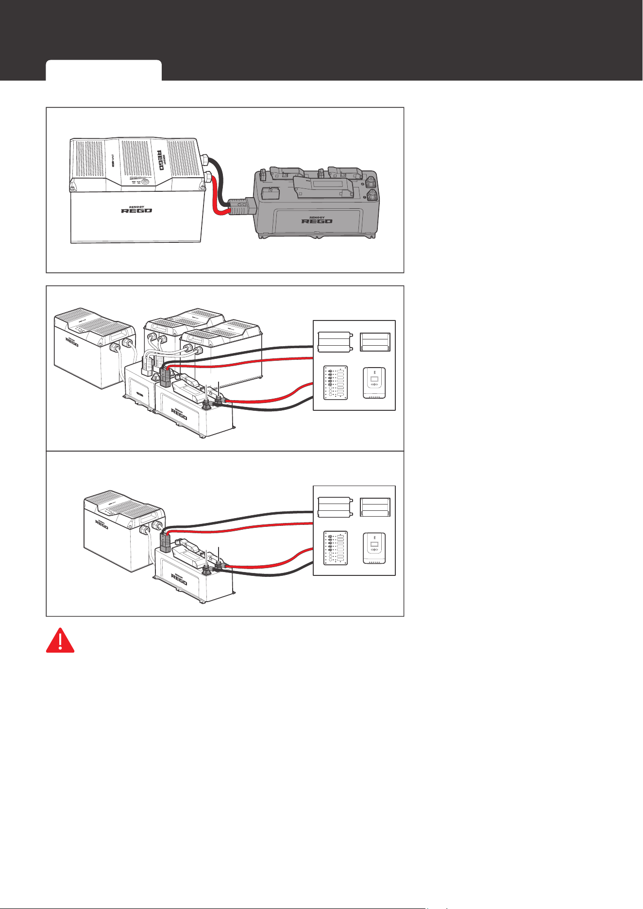
Charger Controller
Inverter
Battery
5. If only one battery is used,
connect the battery directly
to the Anderson connector
on the side of the System
Combiner Box.
-
+
Battery Combiner Box
-
+
6. Connect the devices to the
corresponding Anderson
connectors or insert
terminals on the top of the
System Combiner Box.
WARNIN
G
z
Please size the device cables appropriately to handle the expected current. Refer to the
user manuals of the connected devices for more instructions.
z
If the devices are connected to the Anderson connectors of the System Combiner Box,
please install appropriately sized NH fuses (sold separately) in the System Combiner Box to
protect connected devices and circuit wires. Refer to the user manual of the REGO 4 Ports
400A System Combiner Box for more instructions.
z
If the devices are connected to the insert terminals of the System Combiner Box, please
install appropriately sized fuses or circuit breakers in the branch circuits to protect connected
devices and circuit wires. Refer to the user manuals of the connected devices for more
instructions.
z
Please ensure that the Anderson Connectors are fully seated and/or the ring terminals are
Using Combiner Boxes Using Busbars
18
Power Connection
secured to the proper specification.
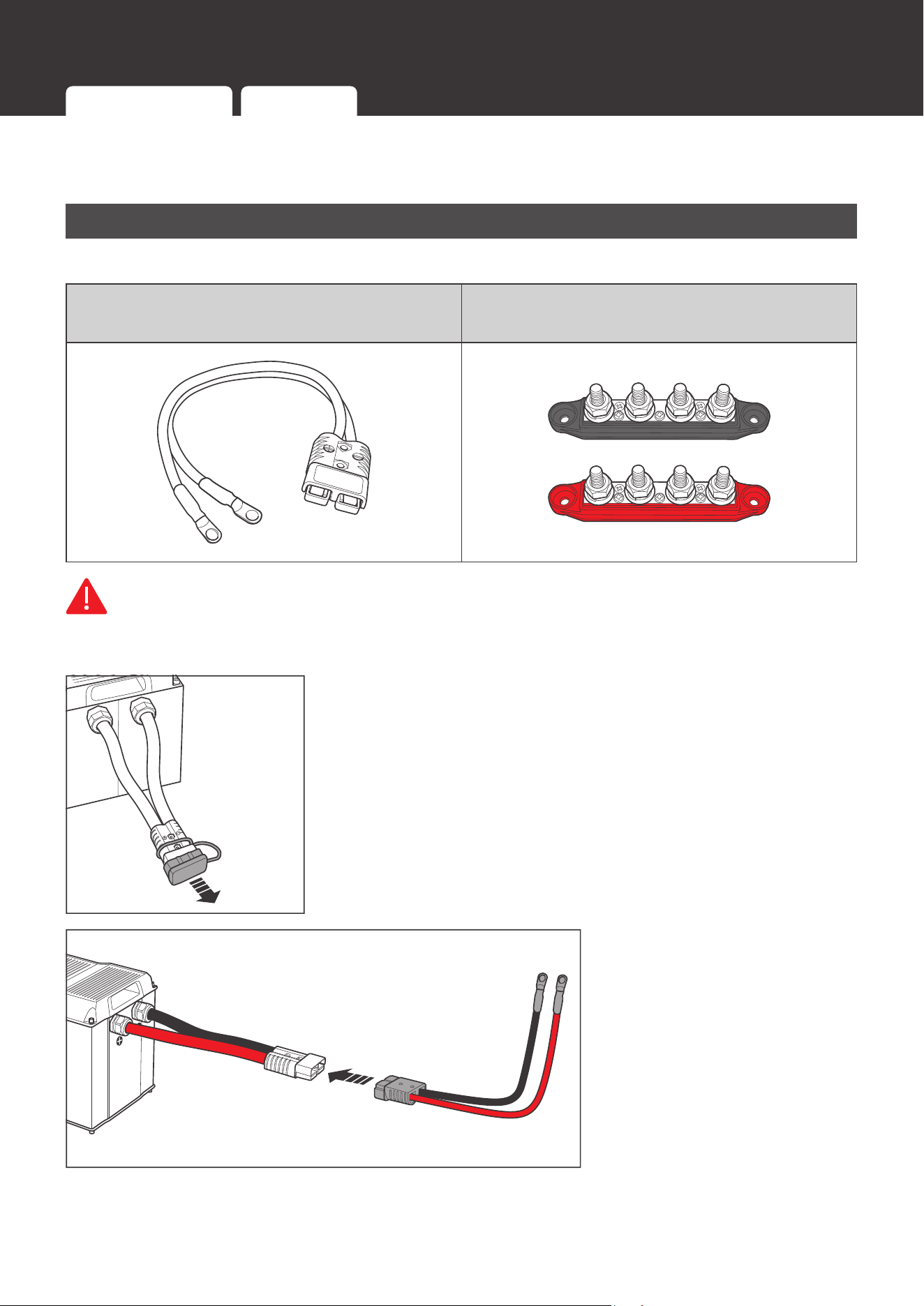
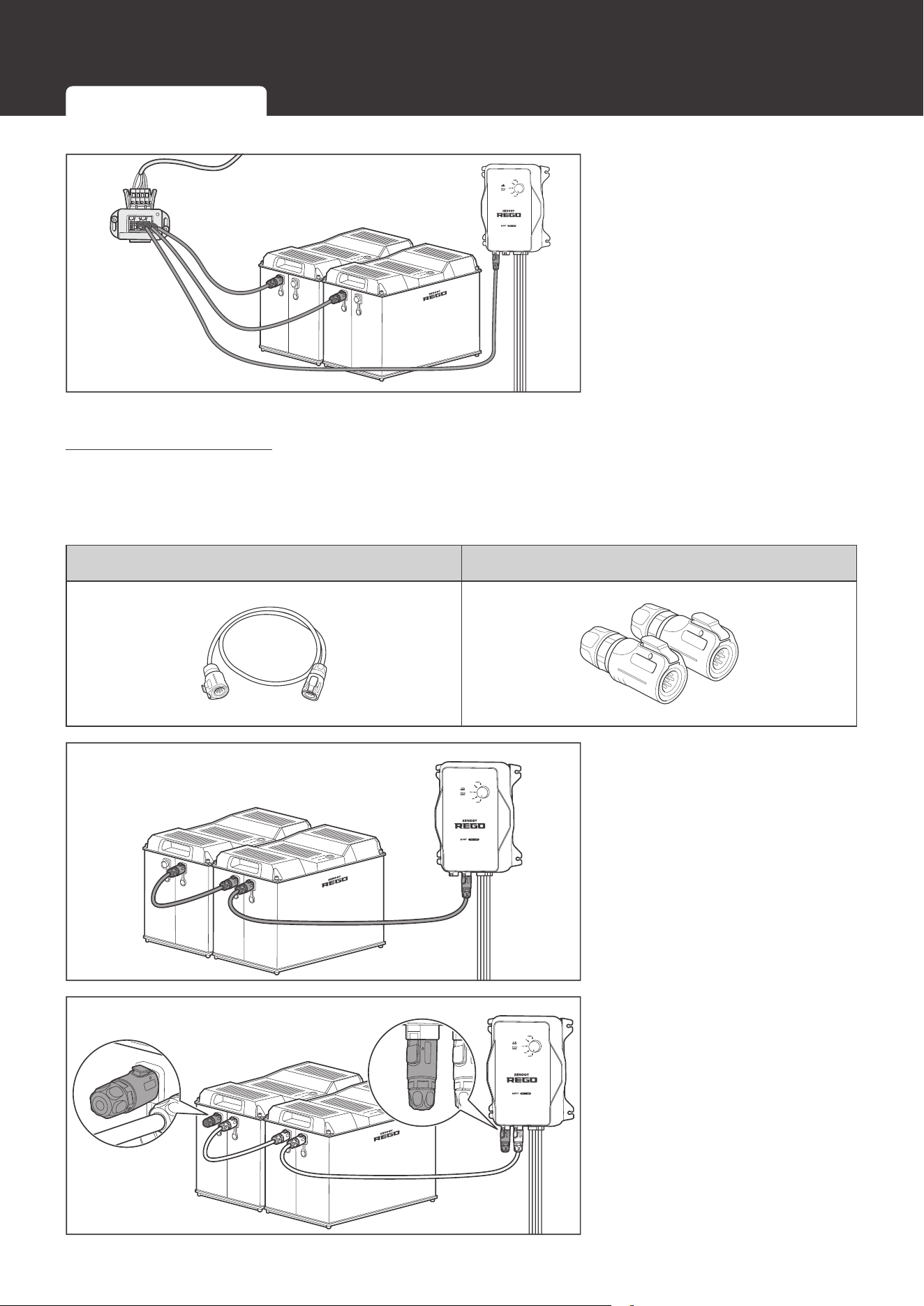
Using Busbars
Required Accessories
Gray Anderson 350 Connector to
Ring Terminal Adapter Cable(s)
Positive/Negative Busbars
WARNIN
G
z
DO NOT short the positive and negative ring terminals of the Adapter Cable(s). Short circuits
can damage the battery.
1. Remove the Dust Cover(s) from the Anderson Connector(s).
2. Connect the Anderson
Connector(s) of the
battery(ies) to the Adapter
Cable(s) (sold separately).
Using Combiner Boxes Using Busbars
19
Power Connection
WARNIN
G
z
Please size the Adapter Cable(s) appropriately to handle the expected current. Refer to
Appendix for more instructions.
CAUTIO
N
z
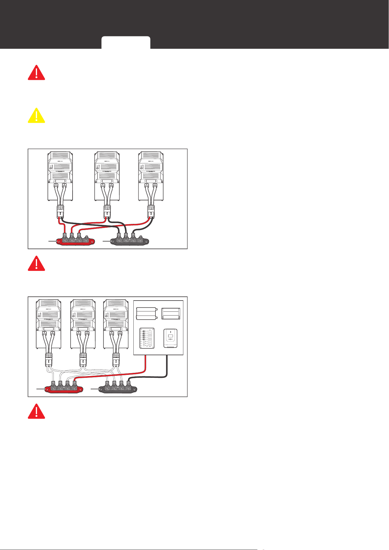
If multiple batteries are to be connected in parallel, please ensure equal length of the
Adapter Cables to make the batteries operate equally together.
+
-
3. Connect the positive and negative ring
terminals of the Adapter Cable(s) to
the Positive and Negative Busbars (not
included) respectively.
WARNIN
G
z
Please size the Busbars appropriately to handle the expected current. Refer to Appendix for
more instructions.
-
+
4. Connect the devices to the Positive and
Negative Busbars.
WARNIN
G
z
Please size the device cables appropriately to handle the expected current. Refer to the
user manuals of the connected devices for more instructions.
z
Please install appropriately sized fuses or circuit breakers in the branch circuits to protect
connected devices and circuit wires. Refer to the user manuals of the connected devices for
more instructions.
z
Please ensure that the Anderson Connector(s) is fully seated and/or the ring terminals are
secured to the proper specification.
Using Combiner Boxes Using Busbars
20
Communication
Communication
The communication connection is optional. It allows the battery to communicate with other
REGO devices and monitoring devices, enabling safe operation, smart control, remote
monitoring, and programmable settings.
Inter-Device Communication
Depending on the installation condition, the communication connections between the battery
and other REGO devices can be established with backbone or daisy chain topology. The inter-
device communication allows the battery to dynamically adjust the charging profile for an optimal
and safe charge.
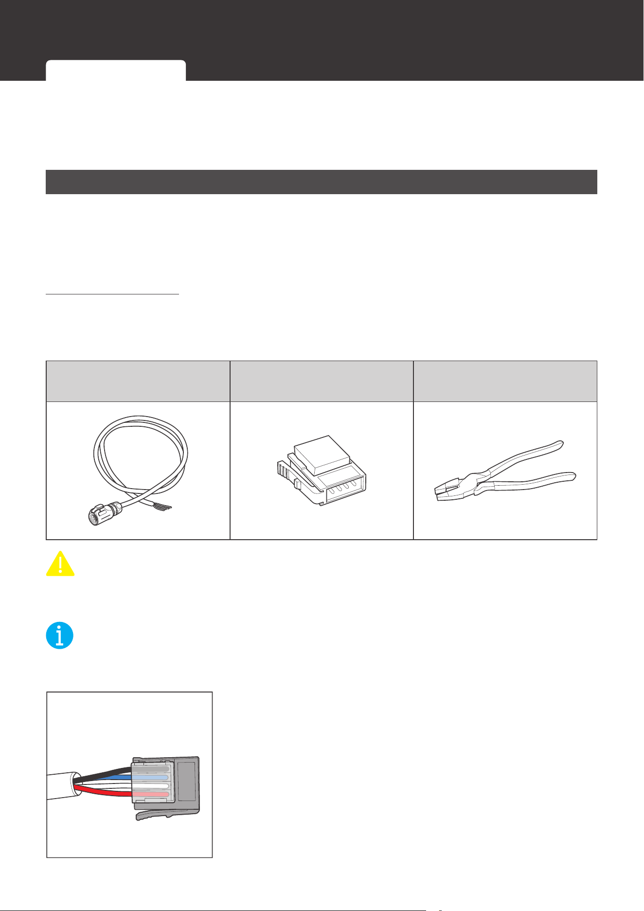
Backbone Topology
If an RV-C bus is pre-installed in the RV, follow the backbone topology for the inter-device
communication connections.
Required Accessories
LP16 Plug (7-Pin) to Bare
Wires Drop Cables
Drop Plugs Split Joint Pliers
CAUTIO
N
z
The lengths of the Drop Cables shall not exceed 19.6 feet (6 m), and the total length shall
not exceed 98.4 feet (30 m).
NOT
E
z
Please check the network wiring diagram provided by the RV manufacturer before
connection.
4 3 2 1
1. Insert the bare wires of the Drop Cables (sold separately) all
the way into the wire ports of the Drop Plugs (not included)
following the Drop Plug pinout. The red PS+ wires go to pin
1, the white CAN_H wires go to pin 2, the blue CAN_L wires
go to pin 3, and the black PS- wires go to pin 4.
Inter-Device Communication Monitoring Device Communication
21
Communication
NOT
E
z
Different drop sockets are used on the RV-C bus by different RV manufacturers. Please
select the Drop Plugs that match the drop sockets for the inter-device communication
connections. If unsure about the Drop Plug selection, please check with the RV
manufacturer. This User Manual takes the Mini-Clamp II plug (4-pin) as an example.
z
Different Drop Plugs follow different pinouts. Please crimp the Drop Plugs on the Drop
Cables following the correct pinout. If unsure about the Drop Plug pinout, please check with
the RV manufacturer. This User Manual takes the pinout of the Mini-Clamp II plug (4-Pin) as
an example.
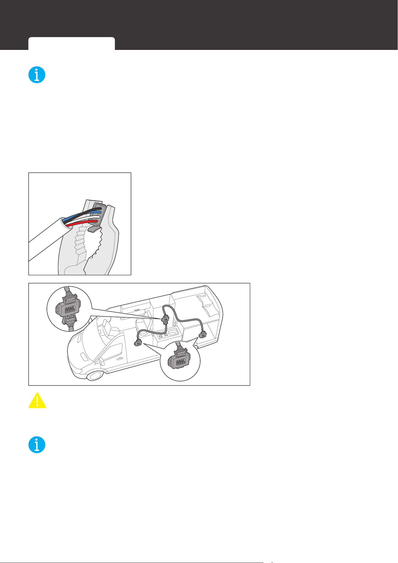
2. Squeeze the crimp areas of the Drop Plugs with the Split
Joint Pliers.
3. Locate the drop tap (not
included) on the RV-C
bus that is the closest to
the battery installation
location. The drop taps
are usually located above
the entry door, in the
bathroom, or under the
bed in the RV.
CAUTIO
N
z
Please ensure that the drop taps at both ends of the RV-C bus are properly terminated with
built-in 120Ω resistors.
NOT
E
z
Different drop taps are used on the RV-C bus by different RV manufacturers. This User
Manual takes the 4-socket drop tap as an example.
z
If unable to locate the drop taps, please contact the RV manufacturer for help.
Inter-Device Communication Monitoring Device Communication
22
Communication
4. Connect either of the CAN
Communication Ports
of the battery and other
REGO devices to the drop
sockets on the drop tap
with the Drop Cables.
Daisy Chain topology
If the RV-C bus is not available, follow the daisy chain topology for the inter-device
communication connections.
Recommended Accessories
LP16 Plug (7-Pin) Communication Cable(s) LP16 Terminator Plugs (7-Pin)
1. Connect REGO devices in
series through either of the
CAN Communication Ports
with the Communication
Cable(s) (sold separately).
2. Plug the Termionator Plugs
(sold separately) into the
free CAN Communication
Ports on the first and last
REGO devices.
Inter-Device Communication Monitoring Device Communication
23
Communication
Monitoring Device Communication
Depending on the application, the short-range or long-range communication connections
can be established between the battery and the monitoring devices. The monitoring device
communication allows for the monitoring and programming of the battery or even the complete
system.
NOT
E
z
Please scan the QR code on the last page of the User Manual to download the DC Home
app.
z
Please make sure that the battery is turned on before the connection. Refer to the Turning
On section for more instructions.
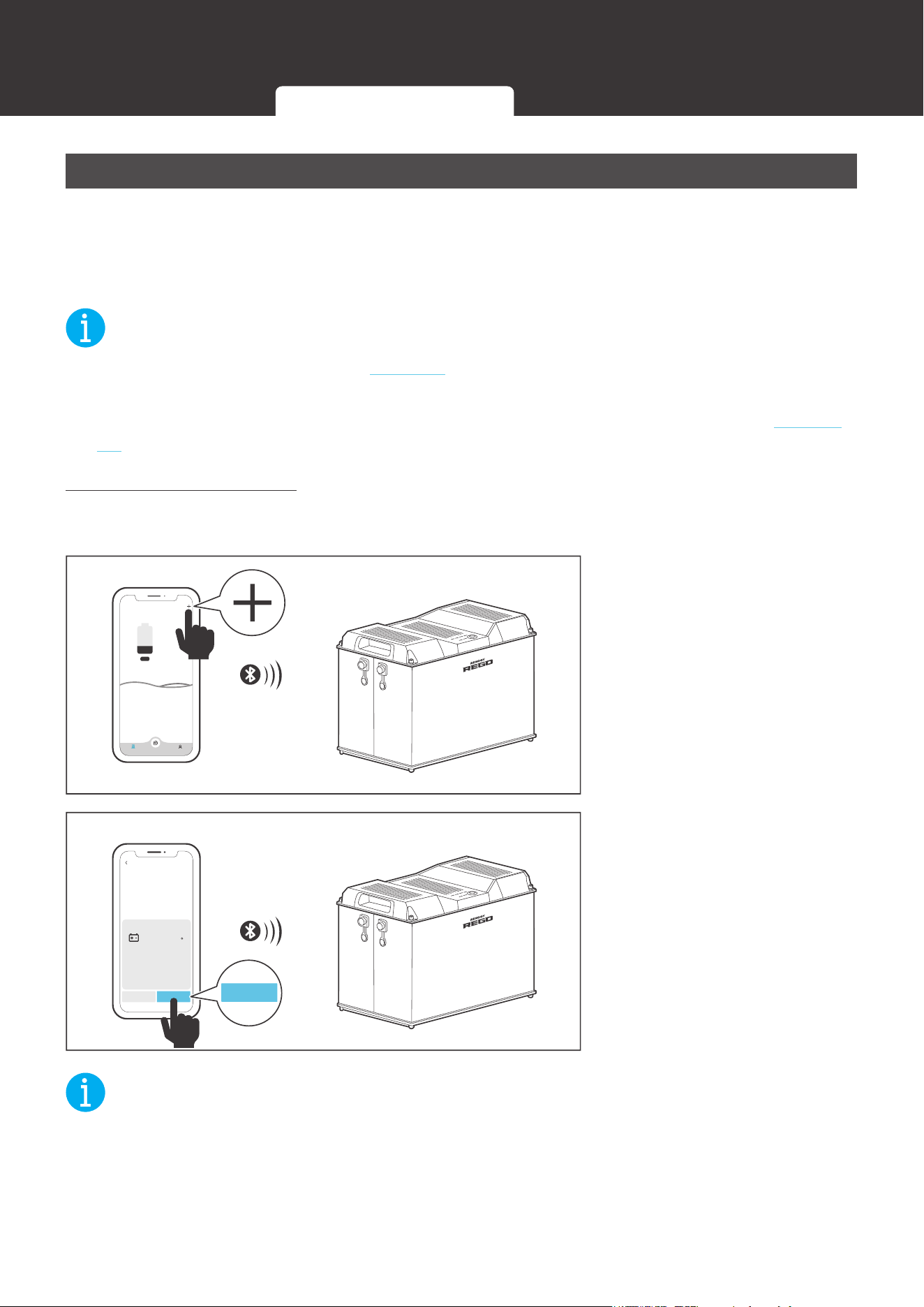
Short-Range Monitoring
If only short-range monitoring is required, connect the battery to the DC Home app directly
through Bluetooth.
My Renogy
25%
Device
No device yet...
Community Personal
1. Open the DC Home app.
Turn on the Bluetooth on
th
e phone or tablet. Tap “+”
on
the top right corner to
search for the battery. Wait
for a few minutes until the
battery is found.
HUB Mode
Add Devices
RBT12400LFPL-...
Cancel Confirm
Confirm
2. Tap
“Conrm” o
n the pop-
up menu to add the battery
to the device list. Monitor
the battery on the device
page.
NOT
E
z
Please keep the phone or tablet within 10 feet (3 m) of the battery.
Inter-Device Communication Monitoring Device Communication
24
Communication
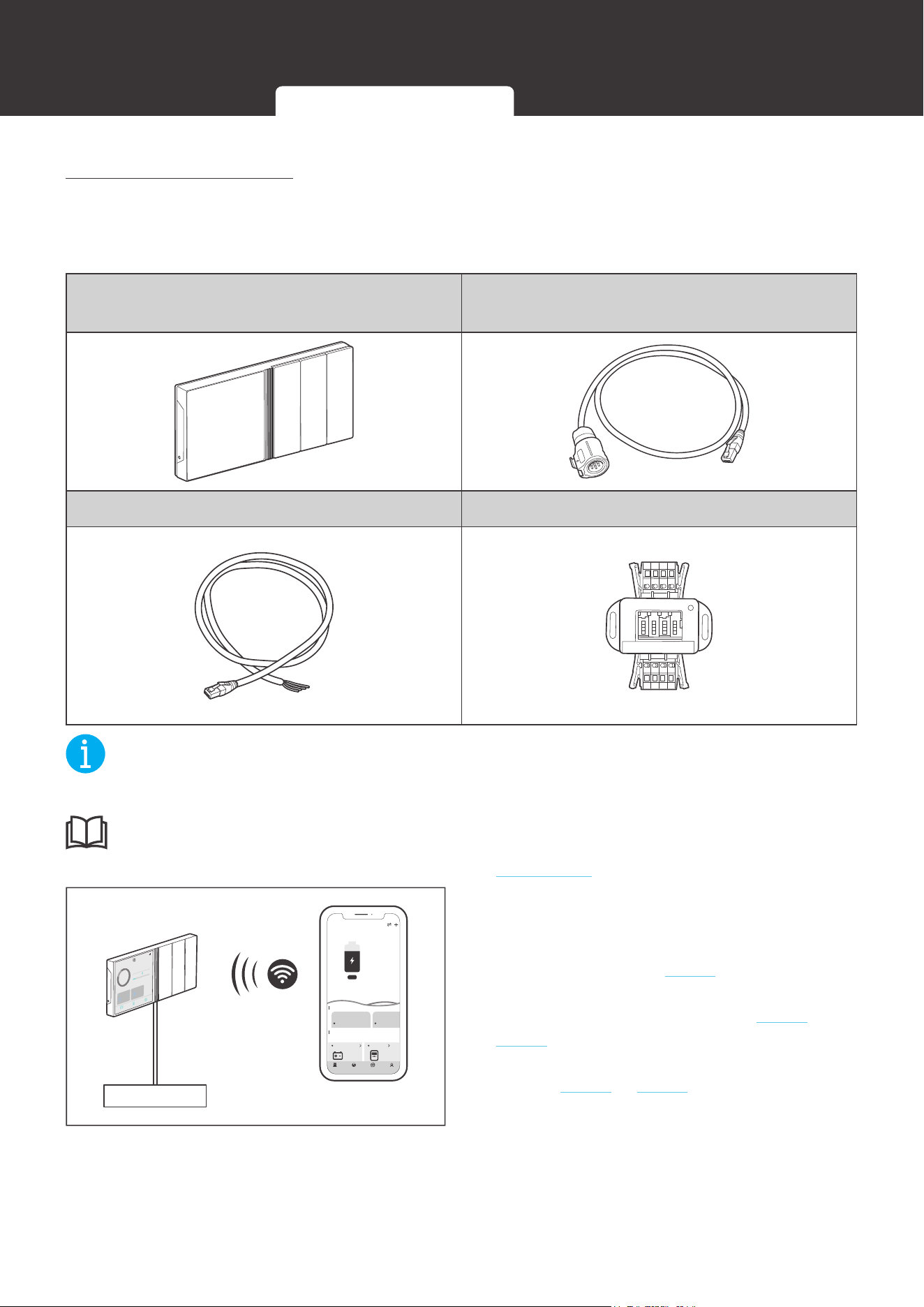
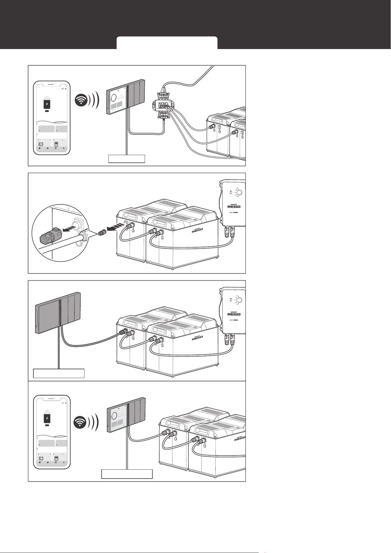
Long-Range Monitoring
If long-range communication and programming are required, connect the battery to Renogy
ONE through Bluetooth or hard wire, and Renogy ONE to the DC Home app through WiFi.
Required Tool and Accessories
Renogy ONE
LP16 Plug (7-Pin) to RJ45 Communication
Adapter Cable
RJ45 Plug to Bare Wires Drop Cable Common Drop Tap
NOT
E
z
Please make sure Renogy ONE is powered on before the connection.
INF
O
z
Please read the user manual of Renogy ONE at renogy.com before the connection.
Power Supply
My Renogy
75%
A
Device
Devices
Battery
RBT12400LFPL-...
Controller
Scene Community Personal
Commonly
RCC60RVRU
%
25
A
0 0
W
0
10
h left
Security Night
12:33
12/23
FULLY
2d13h
2.33A
CHARED IN
80
%
CURRENT
RBT1000HJD
80%
1000
HOME
Device
Setting
Ah
RBT1000HJD
0W
0
1. Pair Renogy ONE (sold separately)
with the DC Home app through WiFi. If
the inter-device communication is not
established, refer to step 2. If the inter-
device communication is established with
the backbone topology, refer to step 3 to
step 4. If the inter-device communication is
established with the daisy chain topology,
refer to step 5 to step 6.
Inter-Device Communication Monitoring Device Communication
25
Communication
Power Supply
My Renogy
75%
A
Device
Devices
Battery
RBT12400LFPL-...
Controller
Scene Community Personal
Commonly
RCC60RVRU
%
25
A
0 0
W
0
10
h left
Security Night
12:33
12/23
FULLY
2d13h
2.33A
CHARED IN
80
%
CURRENT
RBT1000HJD
80%
1000
HOME
Device
Setting
Ah
RBT1000HJD
0W
0
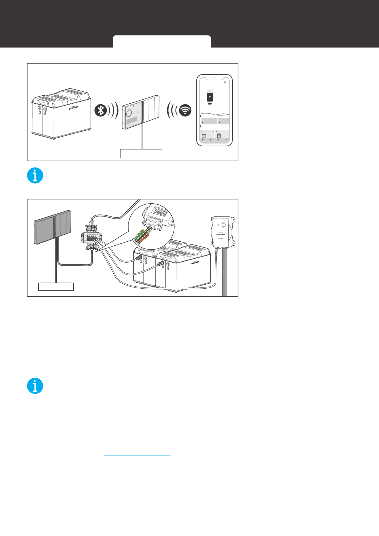
No Inter-Device Communication
2. If the inter-device
communication is not
established, connect the
battery to Renogy ONE
through Bluetooth. Monitor
the battery on Renogy
ONE or the DC Home app.
NOT
E
z
Please keep Renogy ONE within 10 feet (3 m) of the battery.
Power Supply
Backbone Topology
CAN
H
CAN
L
- V
+ V
3. If the inter-device
communication is
established with the
backbone topology,
replace the terminated
drop tap at either end of
the RV-C bus with the
Common Drop Tap (not
included). Secure the
bare wires of the Drop
Cable (not included) onto
the terminal block plug of
the Common Drop Tap
following the terminal
block plug pinout. Plug the
Drop Cable to the RJ45
port of Renogy ONE.
NOT
E
z
Different terminal block plugs are used on different Common Drop Taps and follow different
pinouts. Please connect the Drop Cable to the terminal block plug of the Common Drop Tap
following the correct pinout. If unsure about the terminal block plug pinout, please check with
the RV manufacturer. This User Manual takes the pinout of the MCS MIDI Classic terminal
block plug (4-Pin) as an example.
z
Please refer to the Backbone Topology section for more instructions.
Inter-Device Communication Monitoring Device Communication
26
Communication
Power Supply
12:33
12/23
FULLY
2d13h
2.33A
CHARED IN
80
%
CURRENT
RBT1000HJD
80%
1000
HOME
Device
Setting
Ah
RBT1000HJD
0W
0
My Renogy
75%
A
Device
Devices
Battery
RBT12400LFPL-...
Controller
Scene Community Personal
Commonly
RCC60RVRU
%
25
A
0 0
W
0
10h left
Security Night
4. Monitor and program
the complete system on
Renogy ONE or the DC
Home app.
Daisy Chain Topology
5. If the inter-device
communication is
established with the daisy
chain topology, remove
the Terminator Plug from
the REGO device at either
end of the daisy chain.
Power Supply
Power Supply
12:33
12/23
FULLY
2d13h
2.33A
CHARED IN
80
%
CURRENT
RBT1000HJD
80%
1000
HOME
Device
Setting
Ah
RBT1000HJD
0W
0
My Renogy
75%
A
Device
Devices
Battery
RBT12400LFPL-...
Controller
Scene Community Personal
Commonly
RCC60RVRU
%
25
A
0 0
W
0
10h left
Security Night
6. Connect Renogy
ONE to the free CAN
Communication Port on
the REGO device with the
Communication Adapter
Cable (sold separately).
Monitor and program
the complete system on
Renogy ONE or the DC
Home app.
Inter-Device Communication Monitoring Device Communication
27
Commission
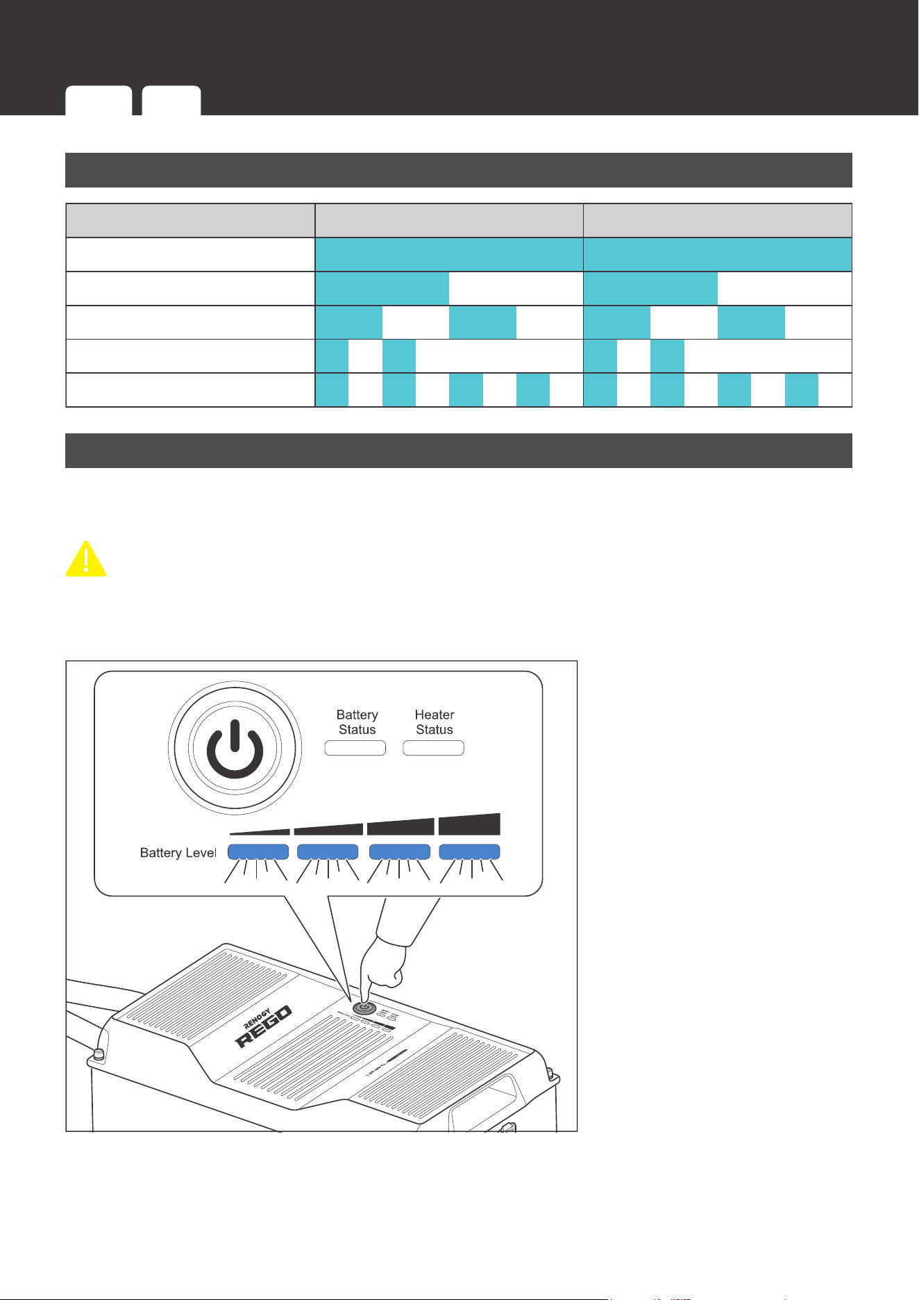
Indicator Pattern
Indicator Pattern
Solid
Slow Flash
Fast Flash
Double Flash
Strobe
1 Second 1 Second
Turning On
The battery is off when it leaves the factory. Please turn the battery on after connecting it to the
system for the first time.
CAUTIO
N
z
DO NOT turn the battery on until completing and securing the power connection. Connecting
a turned on battery to the system can trigger the short circuit or overcurrent protection of the
battery.
1S
1. Long press the Power
Button for 1 second or
charge the battery to turn
the battery on. The Battery
Level Indicators fast flash
blue simultaneously to
indicate that the battery is
turning on.
Commission
Indicator
Pattern
Turning
On
Checking
Battery Level
Checking
Battery Status
Checking
Heater Status
Changing
Heater Settings
Charging Discharging
Turning
Off
28
Commission
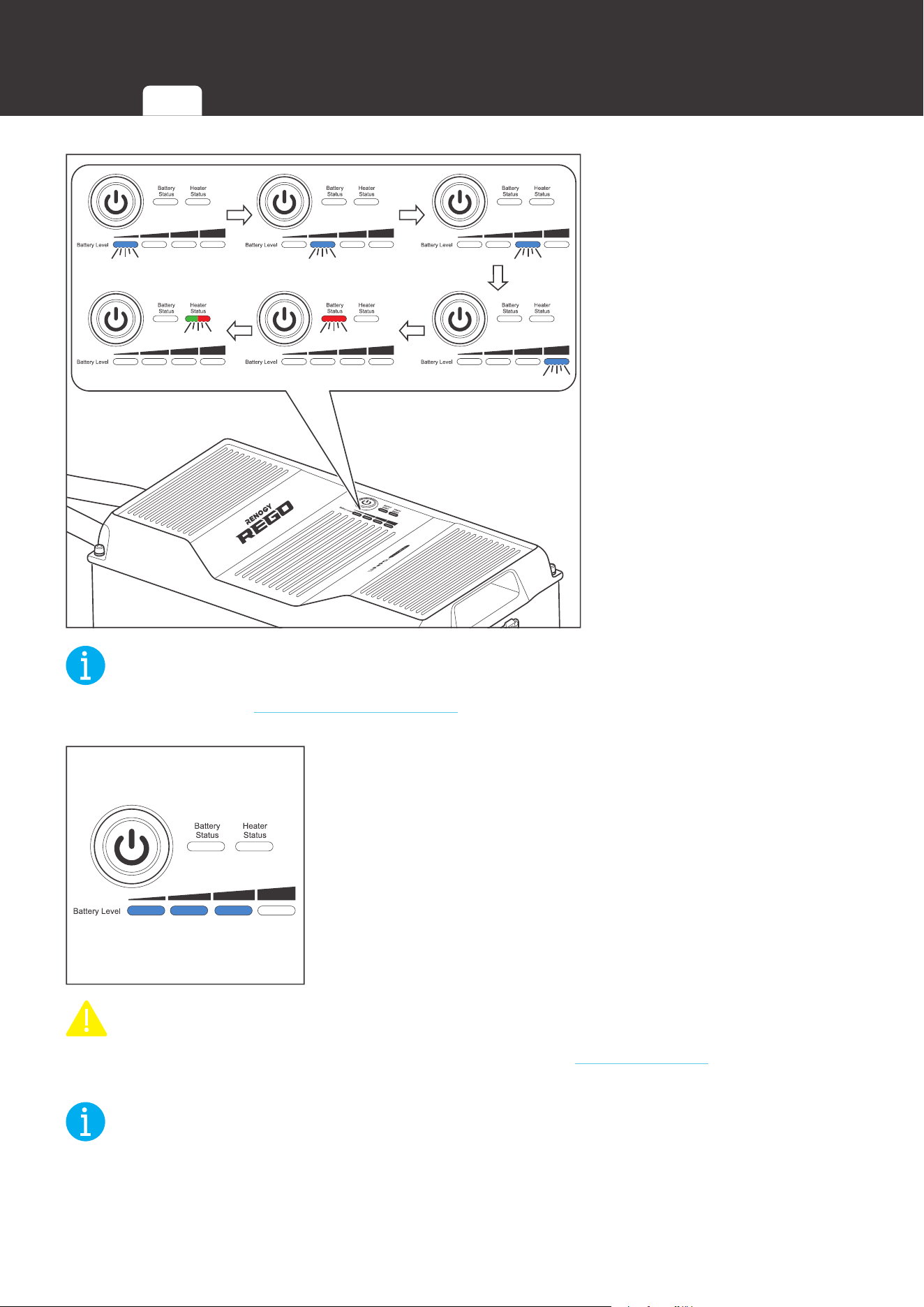
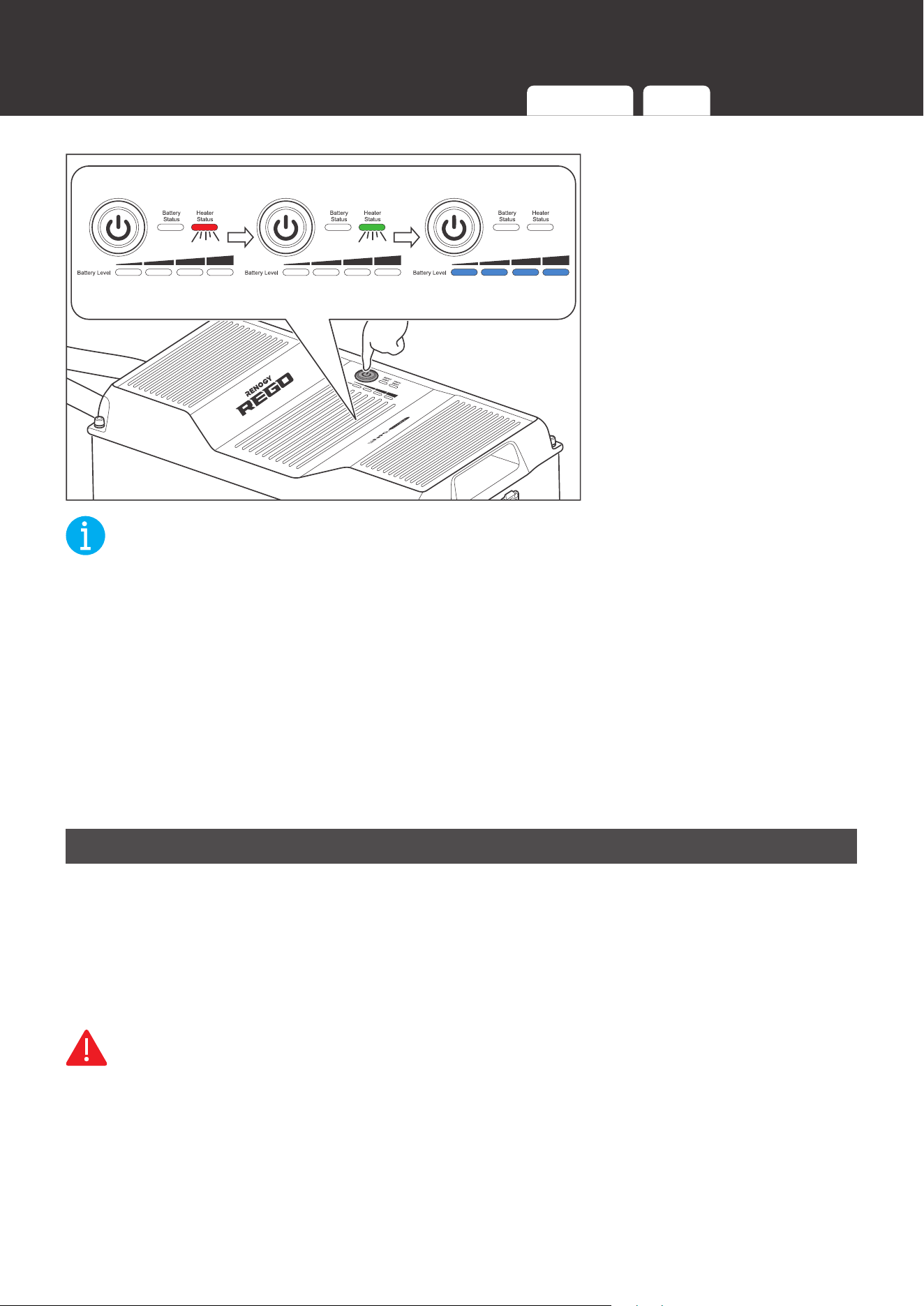
Enabled/Disabled
2. The Battery Level
Indicators, Battery Status
Indicator, and Heater
Status Indicator flash in
sequence once to indicate
that the battery has been
turned on. The color of
the flashing Heater Status
Indicator indicates the
current heater setting.
NOT
E
z
Please refer to the Changing Heater Setting section for more information about the heater
settings.
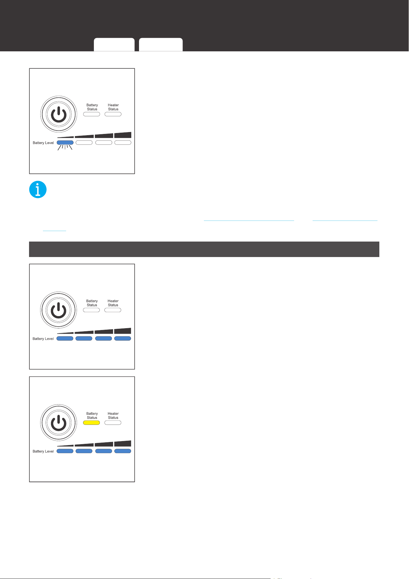
3. The Battery Level Indicators light up blue to indicate the
current battery level.
CAUTIO
N
z
If the battery is unable to be turned on, please refer to the Troubleshooting section for
troubleshooting instructions.
NOT
E
z
To turn on batteries connected in parallel simultaneously, please long press the Power
Button on any battery for 1 second or charge the battery bank.
Indicator
Pattern
Turning
On
Checking
Battery Level
Checking
Battery Status
Checking
Heater Status
Changing
Heater Settings
Charging Discharging
Turning
Off
29
Commission
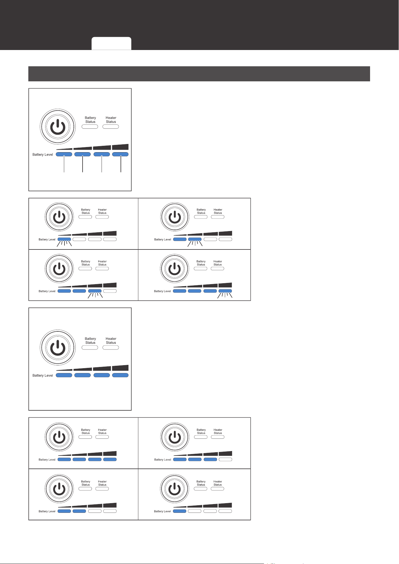
Checking Battery Level
25% 50% 75% 100%
1. The four Battery Level Indicators respectively indicate 25%,
50%, 75%, and 100% battery level.
0%~25% 25.1%~50%
50.1%~75% 75.1%~99.9%
2. As the battery charges, the
Battery Level Indicators
light up blue one by one,
and the rightmost Battery
Level Indicator fast flashes
blue to indicate the current
battery level.
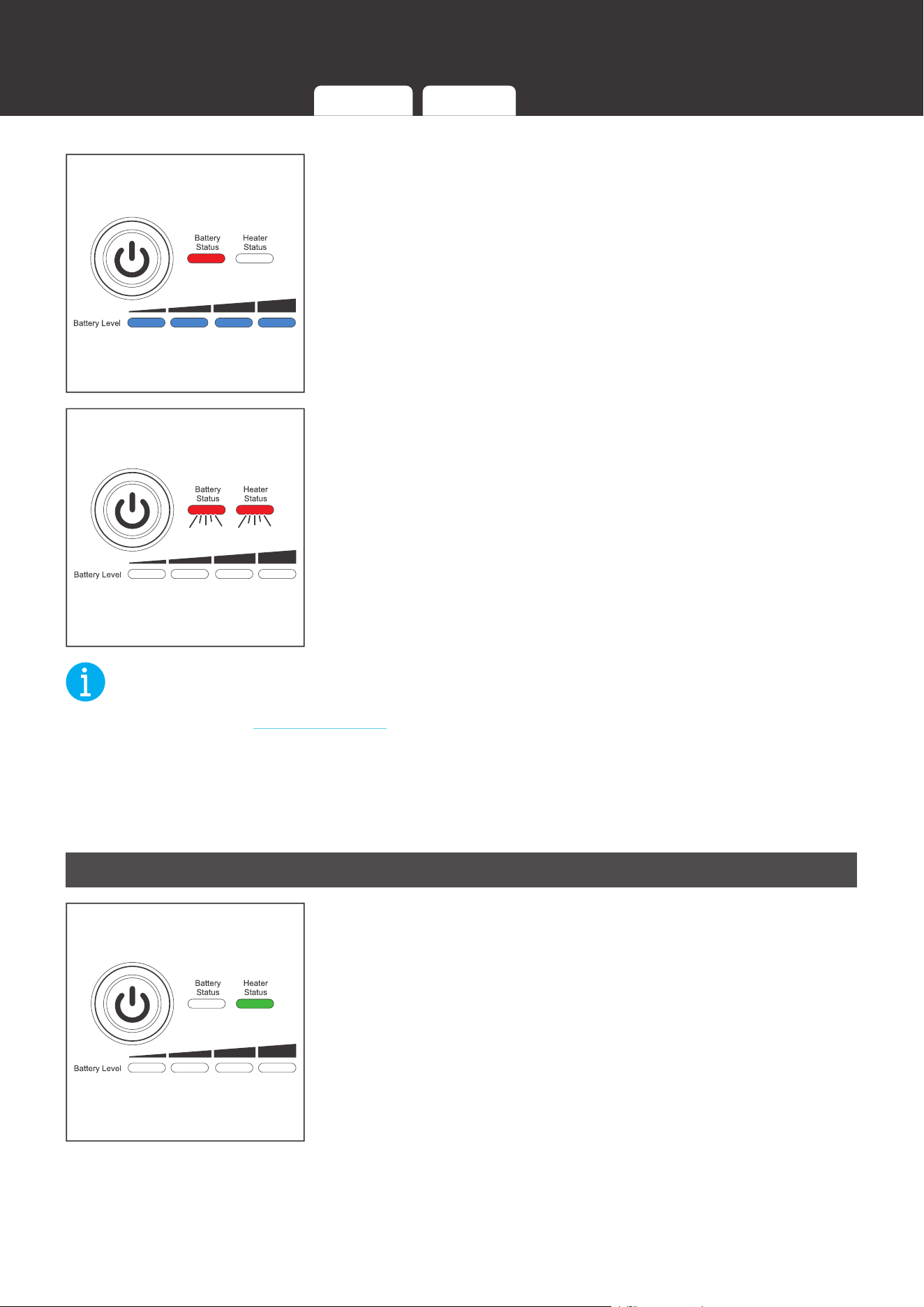
3. Once the battery is fully charged, all the Battery Level
Indicators light up blue and remain solid.
100%~75.1% 75%~50.1%
50%~25.1% 25%~10.1%
4. As the battery discharges,
the Battery Level
Indicators go out one by
one.
Indicator
Pattern
Turning
On
Checking
Battery Level
Checking
Battery Status
Checking
Heater Status
Changing
Heater Settings
Charging Discharging
Turning
Off
30
Commission
5. The last Battery Level Indicator slow flashes blue when the
battery level drops below 10%.
NOT
E
z
The Battery Level Indicators go out when the battery is in the heater setting mode or
permanent failure mode. Please refer to the Changing Heater Setting and Checking Battery
Status sections for more information.
Checking Battery Status
1. The Battery Status Indicator remains off when the battery is
operating properly.
2. The Battery Status Indicator lights up/flashes yellow when
the battery is in the warning mode.
Indicator
Pattern
Turning
On
Checking
Battery Level
Checking
Battery Status
Checking
Heater Status
Changing
Heater Settings
Charging Discharging
Turning
Off
31
Commission
3. The Battery Status Indicator lights up/flashes red when the
battery is in the protection mode.
4. The Battery Status Indicator and Heater Status Indicator
flash red simultaneously when the battery is in the
permanent failure mode.
NOT
E
z
Please refer to the Troubleshooting section for the lighting/flashing pattern of the Battery
Status Indicator and Heater Status Indicator and troubleshooting instructions under different
warnings, protections, and permanent failures.
z
The warnings do not affect the normal operation of the battery, but it is recommended to pay
closer attention to the battery to prevent triggering the protections and/or permanent failures.
Checking Heater Status
1. When the battery temperature drops below 4
1°F (5°C
),
and the charge current is stable and greater than 15A, the
heater starts operating automatically, and the Heater Status
Indicator lights up green.
Turning
Off
Indicator
Pattern
Turning
On
Checking
Battery Level
Checking
Battery Status
Checking
Heater Status
Changing
Heater Settings
Charging Discharging
32
Commission
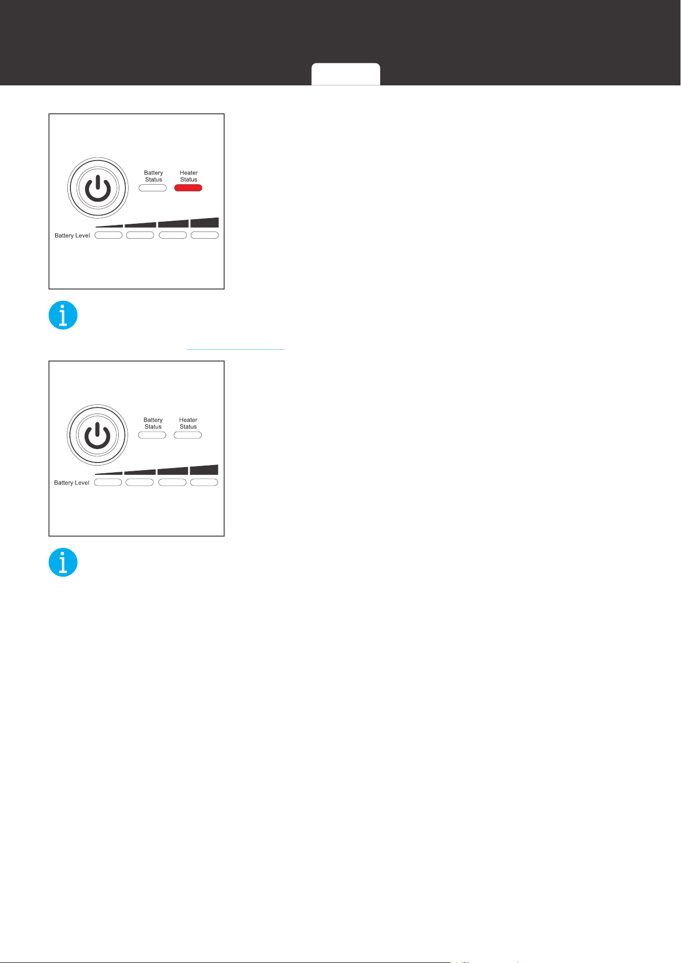
2. When the battery temperature drops below 4
1°F (5°C),
but the charge current is unstable or less than 15A, or
the heater malfunctions, the heater is unable to operate
properly, and the Heater Status Indicator lights up red.
NOT
E
z
Please refer to the Troubleshooting section for troubleshooting instructions.
3. When the battery temperature rises above 50
°F (10°C),
or the charge current ceases, the heater stops operating
automatically and the Heater Status Indicator goes out.
NOT
E
z
The heater does not operate if the battery temperature drops below -4
°
F (-20
°C
).
z
For batteries connected in parallel, each battery requires a stable charge current greater
than 15A for the proper operation of the heater.
Turning
Off
Indicator
Pattern
Turning
On
Checking
Battery Level
Checking
Battery Status
Checking
Heater Status
Changing
Heater Settings
Charging Discharging
33
Commission
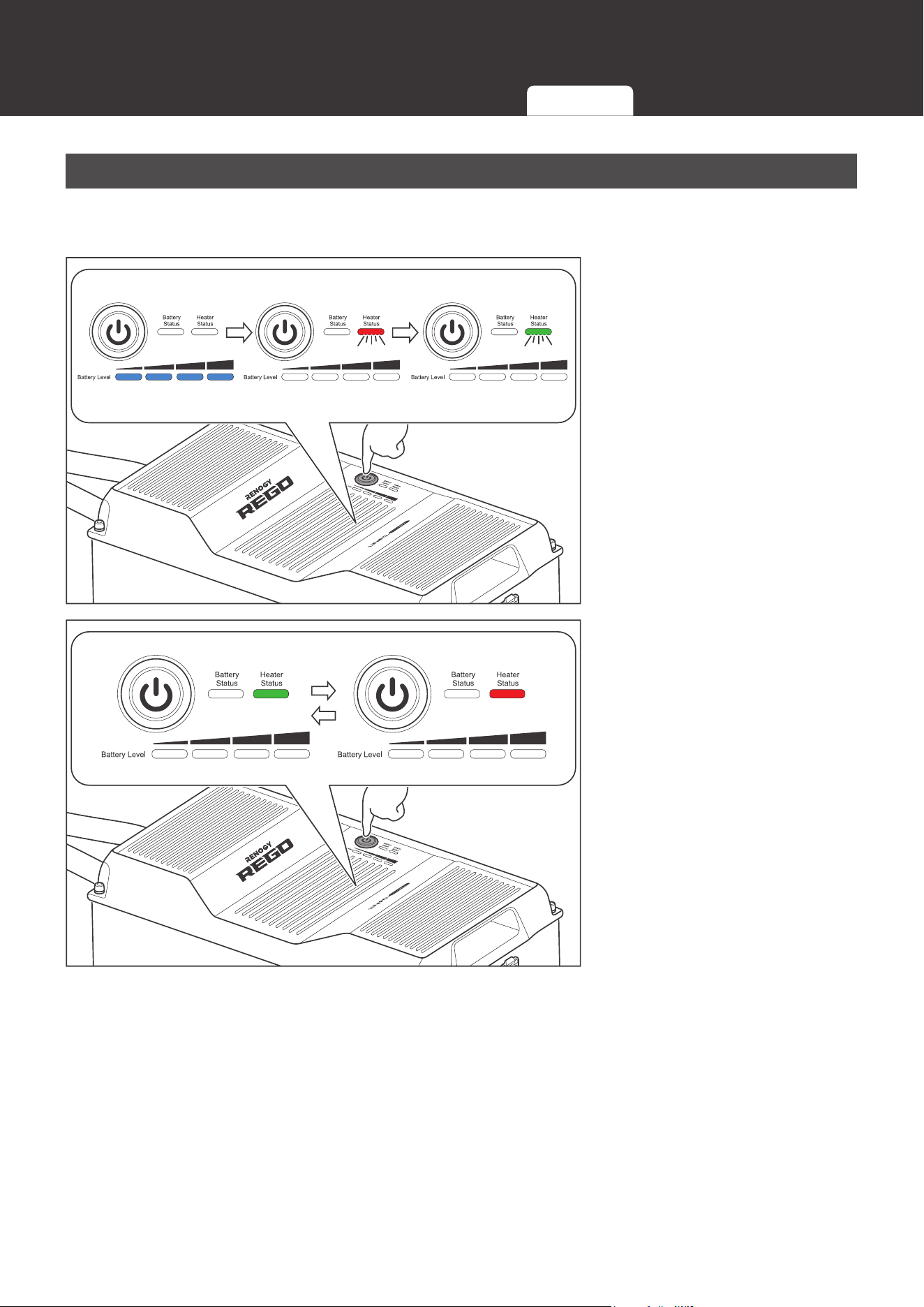
Changing Heater Settings
The battery leaves the factory with the heater enabled. The heater can be enabled or disabled
with the Power Button.
8S
1. Long press the Power
Button for 8 seconds to
enter the heater setting
mode. The Heater Status
Indicator flashes red and
green once.
Short Press
Enable Disable
2. Short press the Power
Button to enable or disable
the heater. The Heater
Status Indicator turns
green to indicate that the
heater is enabled or turns
red to indicate that the
heater is disabled.
Turning
Off
Indicator
Pattern
Turning
On
Checking
Battery Level
Checking
Battery Status
Checking
Heater Status
Changing
Heater Settings
Charging Discharging
34
Commission
8S
3. Long press the Power
Button for 8 seconds to
exit the heater setting
mode and save the current
setting. The Heater Status
Indicator flashes red and
green once.
NOT
E
z
The battery automatically exits the heater setting mode and saves the current setting 10
minutes after entering the heater setting mode if it is not done manually.
z
To enable or disable the heaters of batteries connected in parallel simultaneously, please
establish the inter-battery communication connection and enable or disable the heater of
any battery with the Power Button. If the inter-battery communication connection is not
established, please enable or disable the heater of each battery individually. The heater
setting MUST be uniform across the batteries.
z
The heater is unable to operate properly at low temperatures with PWM charge controllers
or low current chargers. It is recommended to disable the heater to prevent it from turning on
and off repeatedly and draining the battery.
Charging
During the standard charging process, the battery is first charged at a constant current of 80A
until the battery voltage reaches 14.4V. Then, the battery is charged at a constant voltage of
14.4V while tapering the charge current. The standard charging process is considered complete
when the charge current is less than 20A for 10 seconds. However, leaving the battery on float
can help balance the cells and does not damage the battery. The standard charging process
normally takes 5.5 hours.
WARNIN
G
z
DO NOT charge the battery at high temperatures above 13
1°F (55°C) or low temperatures
above -4°F (-20°C). If the heater is disabled or unable to operate properly, charging the
battery at low temperatures below 32°F (0°C) is
NOT recommended.
Turning
Off
Indicator
Pattern
Turning
On
Checking
Battery Level
Checking
Battery Status
Checking
Heater Status
Changing
Heater Settings
Charging Discharging
35
Commission
CAUTIO
N
z
DO NOT overcharge the battery.
z
DO NOT exceed the maximum continuous charge current of the battery.
z
Please charge the battery with the chargers (not included) that are compatible with the
lithium iron phosphate battery and the charge voltage set at 14.4V.
z
DO NOT charge the battery immediately after a long heavy run.
z
Please charge the battery immediately when the battery level drops below 10% to prevent
overdischarge.
NOT
E
z
Please fully charge the battery prior to first use.
Discharging
WARNIN
G
z
DO NOT discharge the battery at high temperatures above 14
0°F (60°C) or low
temperatures above -4°F (-20°C
).
CAUTIO
N
z
DO NOT overdischarge the battery.
z
DO NOT exceed the maximum continuous discharge current of the battery.
z
DO NOT connect high power loads to the battery when it is running low.
During the standard discharging process, the battery is first discharged at a constant current
of 80A until the lowest cell voltage reaches 2.5V. Then, the battery enters protection mode and
cuts off all the loads to prevent the battery from overdischarge.
NOT
E
z
Partial discharges reduce battery stress and prolong battery cycle life. It is recommended to
keep the depth of discharge below 80%.
z
It is recommended to use the battery with loads featuring low voltage disconnect.
Turning Off
Prior to long periods of storage, please disconnect the battery from the system and turn it off.
With the low self-discharge rate when turned off, the battery can hold the charge for a long
period of time.
Turning
Off
Indicator
Pattern
Turning
On
Checking
Battery Level
Checking
Battery Status
Checking
Heater Status
Changing
Heater Settings
Charging Discharging
36
Commission
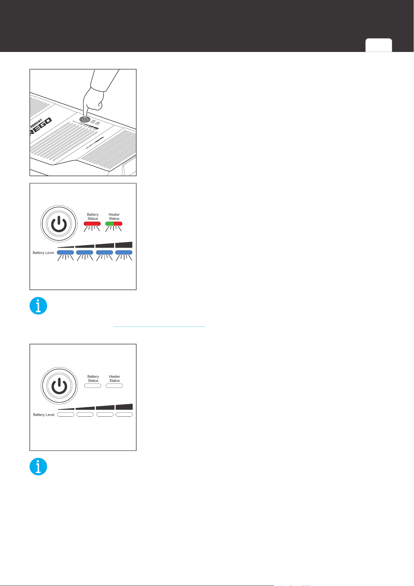
3S
1. Long press the Power Button for 3 seconds.
Enable/Disable
2. The Battery Level Indicators, Battery Status Indicator, and
Heater Status Indicator fast flash simultaneously to indicate
that the battery is turning off. The color of the flashing
Heater Status Indicator indicates the current heater setting.
NOT
E
z
Please refer to the Changing Heater Setting section for more information about the heater
settings.
3. All the indicators go out to indicate that the battery has been
turned off.
NOT
E
z
The battery is unable to be turned off if the Battery Level Indicators, Battery Status Indicator,
and Heater Status Indicator keep fast flashing. Please check if the battery has been
disconnected from the system.
z
To turn off batteries connected in parallel simultaneously, please establish the
communication connection and long press the Power Button on any battery for 3 seconds. If
the communication connection is not established, please disconnect batteries connected in
parallel and turn off each battery individually.
Turning
Off
Indicator
Pattern
Turning
On
Checking
Battery Level
Checking
Battery Status
Checking
Heater Status
Changing
Heater Settings
Charging Discharging

37
Maintenance
Maintenance
Inspection
Please perform regular inspections following the steps below.
z
Examine the external appearance of the battery. The housing and connector contacts of the
battery shall be clean, dry, and free of corrosion.
z
Check the battery cables and connections. Replace any damaged cables and tighten any
loose connections.
NOT
E
z
In some applications, corrosion can form around the contacts internal to the Anderson
Connector. The corrosion can cause loosening of spring retention force and increase of
mated contact resistance, leading to premature failure of the connection. Please apply
dielectric grease onto each connector contact at regular intervals. Dielectric grease can
repel moisture and protect the connector contact against corrosion.
Cleaning
Please clean battery at regular intervals following the steps below.
z
Disconnect the battery from the system.
z
Turn the battery off with the Power Button.
z
Clear the leaves and debris from the battery.
z
Clean the battery with a soft, lint-free cloth. The cloth can be dampened with water or mild
soap and water if the battery is extremely dirty.
z
Dry the battery with a soft, lint-free cloth.
z
Keep the area around the battery clean.
z
Turn the battery back on with the Power Button.
z
Reconnect the battery to the system.
Storage
Please follow the tips below to ensure that the battery emerges from storage in a good condition.
z
Charge the battery to 30%-50%.
z
Disconnect the battery from the system.
z
Turn the battery off with the Power Button.
z
Store the battery in a well-ventilated, dry, clean area with temperatures betwee
n -4°F (-20°C)
and 113°F (45°C
).
z
Handle the battery carefully to avoid sharp impacts or extreme pressure on the battery
housing.
z
Charge the battery at least once every 3 months to prevent it from overdischarge.
z
Fully charge the battery when it is taken out of storage.
Inspection Cleaning Storage

38
Maintenance
CAUTIO
N
z
DO NOT expose the battery to extreme temperatures above 1
40°F (60°C)
.
z
DO NOT expose the battery to heat sources.
z
DO NOT expose the battery to direct sunlight, moisture, or precipitation.
Inspection Cleaning Storage

Battery Management System
Warning/Protection/Permanent Failure
Battery Status
Trigger Release
Comment
Threshold
Sampling
Time
Delay Time
Charge
MOSFET
Discharge
MOSFET
Communication
Power Supply
Bluetooth
Power Supply
BMS Power
Supply
Threshold
Sampling
Time
Cell Overvoltage Warning Highest Cell Voltage > 3.6V 3 Seconds 0 Second Connect Connect On On On
Highest Cell Voltage < 3.45V/
Discharge Current ≥ 3A
1 Second
Cell Overvoltage Protection Highest Cell Voltage > 3.7V 5 Seconds 3 Seconds Disconnect Connect On On On
Highest Cell Voltage < 3.45V/
Discharge Current ≥ 3A
1 Second
Cell Overvoltage
Permanent Failure
Highest Cell Voltage > 4.0V 10 Seconds 3 Seconds Disconnect Disconnect
O (Delay 5
Minutes)
O (Delay 5
Minutes)
O (Delay 5
Minutes)
Unrecoverable /
Cell Undervoltage Warning Lowest Cell Voltage < 3.0V 3 Seconds 0 Second Connect Connect On On On
Lowest Cell Voltage > 3.1V/
Charge Current ≥ 1A
1 Second
Cell Undervoltage
Protection
Lowest Cell Voltage < 2.5V 5 Seconds 3 Seconds Connect Disconnect
O (Delay 5
Minutes)
O (Delay 5
Minutes)
O (Delay 5
Minutes)
Lowest Cell Voltage > 3.1V/
Charge Current ≥ 1A for 4 Minutes
1 Second
Cell Undervoltage
Permanent Failure
Lowest Cell Voltage < 2.0V 10 Seconds 3 Seconds Disconnect Disconnect
O (Delay 5
Minutes)
O (Delay 5
Minutes)
O (Delay 5
Minutes)
Unrecoverable /
Battery Overvoltage
Warning
Battery Voltage > 14.4V 3 Seconds 0 Second Connect Connect On On On
Battery Voltage < 13.8V/
Discharge Current ≥ 3A
1 Second
Battery Overvoltage
Protection
Battery Voltage > 14.8V 5 Seconds 3 Seconds Disconnect Connect On On On
Battery Voltage < 13.8V/
Discharge Current ≥ 3A
1 Second
Battery Undervoltage
Warning
Battery Voltage < 12V 3 Seconds 0 Second Connect Connect On On On
Battery Voltage > 12.4V/
Charge Current ≥ 1A
1 Second
Battery Undervoltage
Protection
Battery Voltage < 10V 5 Seconds 3 Seconds Connect Disconnect
O (Delay 5
Minutes)
O (Delay 5
Minutes)
O (Delay 5
Minutes)
Battery Voltage > 12.4V/
Charge Current ≥ 1A for 4 Minutes
1 Second
Cell Charge High
Temperature Warning
Highest Cell Temperature > 50°C (122°F) 3 Seconds 0 Second Connect Connect On On On Highest Cell Temperature < 45°C (113°F) 1 Second
Cell Charge High
Temperature Protection
Highest Cell Temperature > 55°C (131°F) 5 Seconds 3 Seconds Disconnect Connect On On On Highest Cell Temperature < 50°C (122°F) 1 Second
Cell Discharge/Idle High
Temperature Warning
Highest Cell Temperature > 55°C (131°F) 3 Seconds 0 Second Connect Connect On On On Highest Cell Temperature < 50°C (122°F) 1 Second
Cell Discharge/Idle High
Temperature Protection
Highest Cell Temperature > 60°C (140°F) 5 Seconds 3 Seconds Connect Disconnect On On On Highest Cell Temperature < 55°C (131°F) 1 Second
Cell High Temperature
Permanent Failure
Highest Cell Temperature > 70°C (158°F) 10 Seconds 3 Seconds Disconnect Disconnect
O (Delay 5
Minutes)
O (Delay 5
Minutes)
O (Delay 5
Minutes)
Unrecoverable /
Cell Charge Low
Temperature Warning
Lowest Cell Temperature < 3°C (37.4°F) 3 Seconds 0 Second Connect Connect On On On Lowest Cell Temperature > 6°C (42.8°F) 1 Second
Cell Charge Low
Temperature Protection
Charge Current < 23.6A
Lowest Cell Temperature
< -20°C (-4°F)
5 Seconds 3 Seconds Disconnect Connect On On On
Lowest Cell Temperature > -17°C (1.4°F)
1 Second
Charge Current ≥ 23.6A
Lowest Cell Temperature
< 0°C (32°F)
Lowest Cell Temperature > 3°C (37.4°F)
Cell Discharge/Idle Low
Temperature Warning
Lowest Cell Temperature < -17°C (1.4°F) 3 Seconds 0 Second Connect Connect On On On Lowest Cell Temperature > -14°C (6.8°F) 1 Second
Cell Discharge/Idle Low
Temperature Protection
Lowest Cell Temperature < -20°C (-4°F) 5 Seconds 3 Seconds Connect Disconnect On On On Lowest Cell Temperature > -17°C (1.4°F) 1 Second
Environment High
Temperature Warning
Battery Interior Environment Temperature > 75°C
(167°F)
3 Seconds 0 Second Connect Connect On On On
Battery Interior Environment Temperature
< 65°C (149°F)
1 Second
Environment High
Temperature Protection
Battery Interior Environment Temperature > 80°C
(176°F)
5 Seconds 3 Seconds Disconnect Disconnect
O (Delay 1
Minute)
O (Delay 1
Minute)
O (Delay 1
Minute)
Battery Interior Environment Temperature
< 65°C (149°F)
1 Second
Environment Low
Temperature Warning
Battery Interior Environment Temperature < -30°C
(-22°F)
3 Seconds 0 Second Connect Connect On On On
Battery Interior Environment Temperature
> -25°C (-13°F)
1 Second
Environment Low
Temperature Protection
Battery Interior Environment Temperature < -35°C
(-31°F)
5 Seconds 3 Seconds Disconnect Disconnect
O (Delay 1
Minute)
O (Delay 1
Minute)
O (Delay 1
Minute)
Battery Interior Environment Temperature
> -25°C (-13°F)
1 Second
Cell Imbalance Warning Cell Voltage Dierence > 600mV 3 Seconds 0 Second Connect Connect On On On Cell Voltage Dierence < 200mV 1 Second
Cell Imbalance Protection Cell Voltage Dierence > 1000mV 5 Seconds 3 Seconds Disconnect Disconnect On On On Cell Voltage Dierence < 200mV 1 Second
Battery Management System
Warning/Protection/Permanent Failure Charge Current Request Cell Voltage Balancing

Battery Management System
Battery Status
Trigger Release
Comment
Threshold
Sampling
Time
Delay Time
Charge
MOSFET
Discharge
MOSFET
Communication
Power Supply
Bluetooth
Power Supply
BMS Power
Supply
Threshold
Sampling
Time
Charge Overcurrent
Warning
Cell Temperature ≤ 15°C
(59°F)
Charge Current > 220A
3 Seconds 0 Second Connect Connect On On On
Charge Current < 200A
1 Second
15°C (59°F) < Cell
Temperature <
50°C(131°F)
Charge Current > 330A Charge Current < 300A
Cell Temperature ≥ 55°C
(131°F)
Charge Current > 220A Charge Current < 200A
Charge Overcurrent
Primary Protection
Cell Temperature ≤ 15°C
(59°F)
Charge Current > 230A
15 Seconds 3 Seconds Disconnect Connect On On On
Charge Current < 200A/
Discharge Current ≥ 3A
1 Second
The battery automatically attempts to
recover 1 minute after the protection.
The interval between each attempt
is 1 minute. If the battery fails 3
consecutive attempts, the protection
can only be released with a discharge
current greater than 3A.
15°C (59°F) < Cell
Temperature <
50°C(131°F)
Charge Current > 345A
Charge Current < 300A/
Discharge Current ≥ 3A
Cell Temperature ≥ 55°C
(131°F)
Charge Current > 230A
Charge Current < 200A/
Discharge Current ≥ 3A
Charge Overcurrent
Secondary Protection
Cell Temperature ≤ 15°C
(59°F)
Charge Current > 236A
5 Seconds 3 Seconds Disconnect Connect On On On
Charge Current < 200A/
Discharge Current ≥ 3A
1 Second
15°C (59°F) < Cell
Temperature <
50°C(131°F)
Charge Current > 354A
Charge Current < 300A/
Discharge Current ≥ 3A
Cell Temperature ≥ 55°C
(131°F)
Charge Current > 236A
Charge Current < 200A/
Discharge Current ≥ 3A
Discharge Overcurrent
Warning
Discharge Current > 385A 3 Seconds 0 Second Connect Connect On On On Discharge Current < 350A 1 Second
Discharge Overcurrent
Primary Protection
Discharge Current > 402.5A 15 Seconds 3 Seconds Connect Disconnect On On On
Discharge Current < 350A/
Charge Current ≥ 1A
1 Second
The battery automatically attempts to
recover 1 minute after the protection.
The interval between each attempt
is 1 minute. If the battery fails 3
consecutive attempts, the protection
can only be released with a charge
current greater than 1A.
Discharge Overcurrent
Secondary Protection
Discharge Current > 413A 5 Seconds 3 Seconds Connect Disconnect On On On
Discharge Current < 350A/
Charge Current ≥ 1A
1 Second
Discharge Overcurrent
Hardware Protection
Discharge Current > 700A
100
Microseconds
0 Second Disconnect Disconnect On On On
Discharge Current < 350A/
Charge Current ≥ 1A
100
Microseconds
Low SOH Warning SOH < 55% 3 Seconds 0 Second Connect Connect On On On SOH > 56% 1 Second
Low SOH Permanent
Failure
SOH < 50% 5 Seconds 3 Seconds Disconnect Disconnect
O (Delay 5
Minutes)
O (Delay 5
Minutes)
O (Delay 5
Minutes)
Unrecoverable /
Low SOC Warning SOC ≤ 2% 3 Seconds 0 Second Connect Connect On On On
SOC > 4%/
Charge Current ≥ 1A
1 Second
CAN Communication Error
Warning
Unable to Receive CAN Messages for 1 Minute 1 Minute 0 Second Connect Connect On On On Receives CAN Messages 0 Second
Short Circuit Protection Short Circuit Current > 800A 1 Millisecond 0 Second Connect Disconnect On On On
Remove Short Circuit/
Charge Current ≥ 1A
1 Second
The battery automatically attempts to
recover 1 minute after the protection.
The interval between each attempt
is 1 minute. If the battery fails 3
consecutive attempts, the protection
can only be released with a charge
current greater than 1A.
Reverse Polarity Protection Connection Polarity Reverse 0 Second 0 Second Disconnect Disconnect
O (Delay 5
Minutes)
O (Delay 5
Minutes)
O (Delay 5
Minutes)
Connection Polarity Correct 0 Second
Pre-Charge Failure
Protection
Voltage Dierence Across Pre-Charge MOSFETE >
4V
0 Second 0 Second Disconnect Disconnect On On On
Voltage Dierence Across Pre-Charge
MOSFETE < 1V
0 Second
The battery automatically attempts to
recover 1 minute after the protection.
The interval between each attempt
is 1 minute. If the battery fails 3
consecutive attempts, the protection
can only be released with a restart.
Battery Source Address
Conict Warning
Source Address Conict between Devices 0 Second 0 Second Connect Connect On On On Finds Unclaimed Source Address 0 Second
AFE Communication Error
Protection
Unable to Receive AFE Messages for 10 Seconds 10 Seconds 3 Seconds Disconnect Disconnect
O (Delay 5
Minutes)
O (Delay 5
Minutes)
O (Delay 5
Minutes)
Receives AFE Messages 0 Second
Memory Communication
Error Warning
Communication Between EEPROM and Flash
Memory Fails 3 Times
0 Second 0 Second Connect Connect On On On
Communication Between EEPROM and
Flash Memory Succeeds
0 Second
Warning/Protection/Permanent Failure Charge Current Request Cell Voltage Balancing

Battery Management System
Battery Status
Trigger Release
Comment
Threshold
Sampling
Time
Delay Time
Charge
MOSFET
Discharge
MOSFET
Communication
Power Supply
Bluetooth
Power Supply
BMS Power
Supply
Threshold
Sampling
Time
MOSFET High Temperature
Warning
MOSFET Temperature > 85°C (185°F) 3 Seconds 0 Second Connect Connect On On On MOSFET Temperature < 80°C (176°F) 1 Second
MOSFET High Temperature
Protection
MOSFET Temperature > 105°C (221°F) 5 Seconds 3 Seconds Disconnect Disconnect
O (Delay 5
Minutes)
O (Delay 5
Minutes)
O (Delay 5
Minutes)
MOSFET Temperature < 90°C (194°F) 1 Second
Balancing Circuit High
Temperature Warning
Balancing Circuit > 85°C (185°F) 3 Seconds 0 Second Connect Connect On On On Balancing Circuit < 80°C (176°F) 1 Second
Balancing Circuit High
Temperature Protection
Balancing Circuit > 105°C (221°F) 5 Seconds 3 Seconds Disconnect Disconnect
O (Delay 5
Minutes)
O (Delay 5
Minutes)
O (Delay 5
Minutes)
Balancing Circuit < 85°C (185°F) 1 Second
Temperature Sampling
Error Protection
Unable to Detect Temperature Sampling Signal 3 Seconds 3 Seconds Disconnect Disconnect
O (Delay 5
Minutes)
O (Delay 5
Minutes)
O (Delay 5
Minutes)
Detects Temperature Sampling Signal 0 Second
Charge MOSFET
Permanent Failure
Charge Current ≥ 3A When Disconnecting Charge
MOSFET is Required/
Unable To Connect Charge MOSFET When
Required
0 Second 3 Seconds Disconnect Disconnect
O (Delay 1
Minute)
O (Delay 1
Minute)
O (Delay 1
Minute)
Unrecoverable /
Discharge MOSFET
Permanent Failure
Discharge Current ≥ 3A When Disconnecting
Discharge MOSFET is Required/
Unable To Connect Discharge MOSFET When
Required
0 Second 3 Seconds Disconnect Disconnect
O (Delay 1
Minute)
O (Delay 1
Minute)
O (Delay 1
Minute)
Unrecoverable /
Voltage Sampling Error
Protection
Dierence Between Voltages Sampled by MCU and
AFE > 1V
3 Seconds 3 Seconds Disconnect Disconnect
O (Delay 5
Minutes)
O (Delay 5
Minutes)
O (Delay 5
Minutes)
Dierence Between Voltages Sampled by
MCU and AFE < 0.5V
1 Second
Communication Power
Supply Malfunction Warning
Communication Power Supply Voltage ≤ 10V/
Communication Power Supply Voltage ≥ 14.8V
5 Seconds 0 Second Connect Connect
O (Delay 5
Seconds)
On On
10V < Communication Power Supply
Voltage < 14.8V
1 Second
RTC Error Warning Unable to Receive RTC Messages for 10 Seconds 10 Seconds 0 Second Connect Connect On On On Receives RTC Messages 0 Second
Heater High Temperature
Warning
Heater Temperature > 75°C (167°F) 3 Seconds 0 Second Connect Connect On On On Heater Temperature < 50°C (122°F) 1 Second
Heater High Temperature
Protection
Heater Temperature > 85°C (185°F) 5 Seconds 3 Seconds Disconnect Disconnect On On On Heater Temperature < 70°C (158°F) 1 Second
Heater High Temperature
Hardware Protection
Heater Temperature > 90°C (194°F) 10 Seconds 3 Seconds Disconnect Disconnect
O (Delay 1
Minute)
O (Delay 1
Minute)
O (Delay 1
Minute)
Heater Temperature < 65°C (149°F) Restart
The heater fuse blows when the
protection is triggered. The heater is
unable to operate anymore even the
protection is released.
Heater Malfunction Warning Unable to Heat Battery Up When Heater is On 5 Seconds 0 Second Connect Connect On On On Heats Battery Up When Heater is On 0 Second
Fuse Permanent Failure Voltage Dierence Across > 5V 3 Seconds 3 Seconds Disconnect Disconnect
O (Delay 5
Minutes)
O (Delay 5
Minutes)
O (Delay 5
Minutes)
Unrecoverable /
AFE Overvoltage Protection AFE Sampled Cell Voltage > 3.9V 0 Second 0 Second Disconnect Disconnect On On On AFE Sampled Cell Voltage < 3.9V Restart
AFE Undervoltage
Protection
AFE Sampled Cell Voltage < 2V 0 Second 0 Second Disconnect Disconnect
O (Delay 1
Minute)
O (Delay 1
Minute)
O (Delay 1
Minute)
AFE Sampled Cell Voltage > 2V Restart
BMS Power Supply
Malfunction Protection
BMS Power Supply Voltage ≤ 13.2V/
BMS Power Supply Voltage ≥ 10.8V
5 Seconds
3 Seconds
(BMS Power
Supply
Undamaged)
Disconnect Disconnect
O (Delay 5
Minutes)
O (Delay 5
Minutes)
O (Delay 5
Minutes)
10.8V < BMS Power Supply Voltage <
13.2V
5 Seconds
AFE High Temperature
Protection
AFE Sampled Cell Temperature > 65°C (149°F) 0 Second 3 Seconds Disconnect Disconnect On On On
AFE Sampled Cell Temperature < 60°C
(140°F)
1 Second
AFE Low Temperature
Protection
AFE Sampled Cell Temperature < -25°C (-13°F) 0 Second 3 Seconds Disconnect Disconnect On On On
AFE Sampled Cell Temperature > -20°C
(-4°F)
1 Second
Warning/Protection/Permanent Failure Charge Current Request Cell Voltage Balancing
Battery Management System
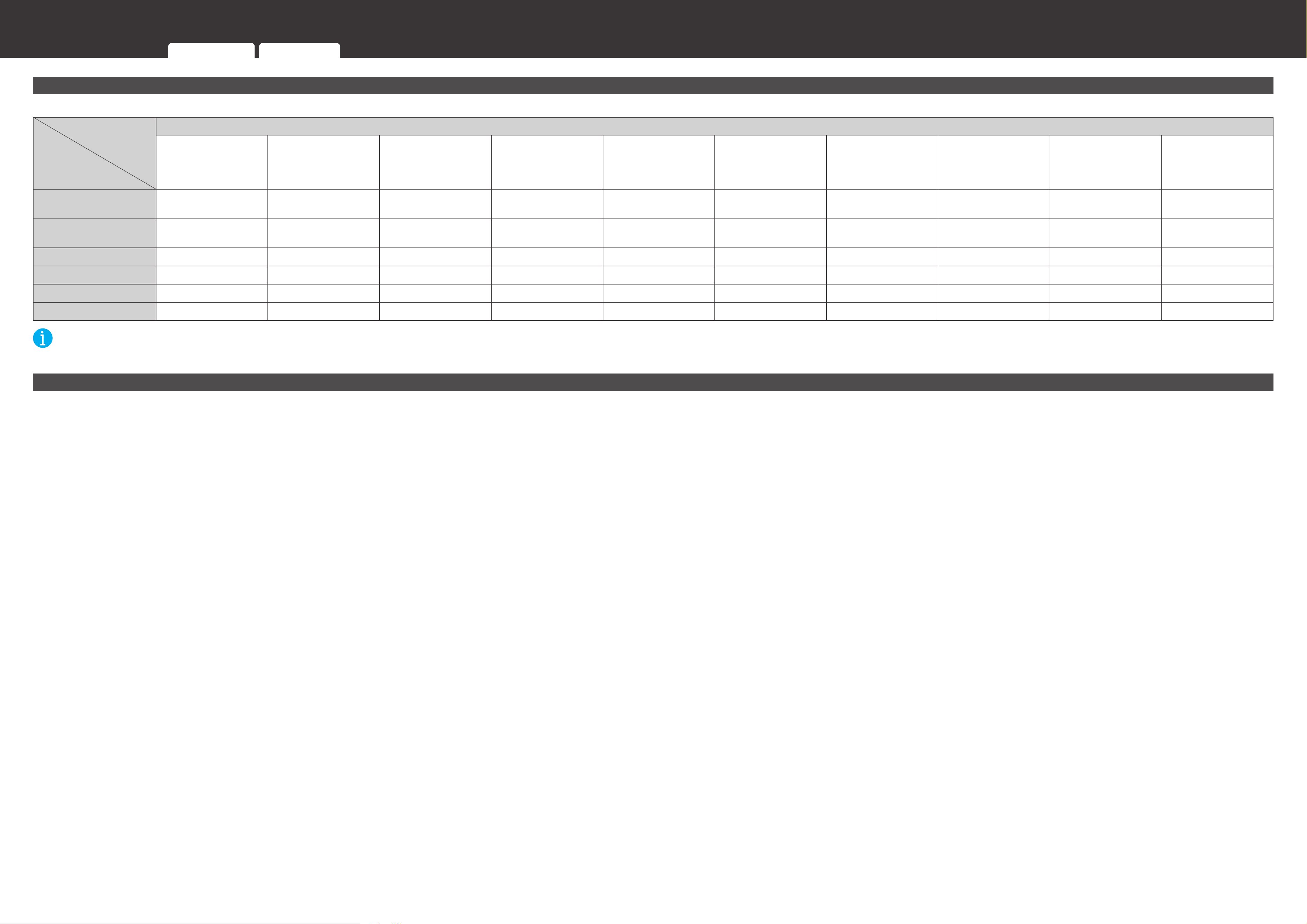
Charge Current Request
With the communication connections established between the battery and chargers, the battery management system can automatically request appropriate charge current from the chargers based on the cell voltage and temperature to prolong battery cycle life.
Cell
Temperature
Highest Cell Voltage
Desired Charge Current
<-19°C
(-2.2°F)
-19°C ~ 0°C
(-2.2°F ~ 32°F)
0°C ~ 1°C
(32°F ~ 33.8°F)
1°C ~ 15°C
(33.8°F ~ 59°F)
15°C ~ 16°C
(59°F ~ 60.8°F)
16°C ~ 49°C
(60.8°F ~ 120.2°F)
49°C ~ 50°C
(120.2°F ~ 122°F)
50°C ~ 53°C
(122°F ~ 127.4°F)
53°C ~ 54°C
(127.4°F ~ 129.2°F)
> 54°C
(129.2°F)
Cell Undervoltage
Permanent Failure
0A 0A 0A 0A 0A 0A 0A 0A 0A 0A
Cell Undervoltage
Permanent Failure~2.5V
0A 5A 5A → 40A 40A 40A 40A 40A 40A 40A → 20A 0A
2.5V~3.5V 0A 5A 5A → 200A 200A 200A → 300A 300A 300A → 100A 100A 100A → 20A 0A
3.5V~3.54V 0A 5A ↓ ↓ ↓ ↓ ↓ ↓ ↓ 0A
3.54V~Full 0A 5A 5A 5A 15A 15 15 15 15 0A
Full 0A 0A 0A 0A 0A 0A 0A 0A 0A 0A
NOT
E
z
After a full charge, the battery stops requesting charge current until the battery level drops below 95%.
Cell Voltage Balancing
The battery management system is equipped with a passive balancing circuit to balance the cell voltages. Each series connected cell is connected to a bypass resistor and a switch. During the charging process, the battery management system turns on the switch for the cell whose voltage is
significantly higher than other cells and shunts the charge current through its bypass resistor until the voltage difference between cells gets small enough. To avoid excessive energy loss, the cell voltage balancing is only performed during the charging process.
Warning/Protection/Permanent Failure Charge Current Request Cell Voltage Balancing

43
Troubleshooting
Troubleshooting
Phenomenon
Possible Causes Solutions
Battery Status
Indicator
Heater Status
Indicator
Solid Yellow
Lights up
/ Flashes
According to
the Heater
Status
Charge
Overcurrent
Warning
• Reduce the charge current immediately.
Discharge
Overcurrent
Warning
• Reduce the discharge current
immediately.
Slow Flash
Yellow
Cell Overvoltage
Warning
• Ensure that the chargers are comptaible
with the lithium iron phosphate battery.
• Ensure that the battery type is set to
lithium iron phosphate and the charge
voltage is set to 14.4V on the chargers.
Slightly reduce the charge voltage or
connect voltage sensors to the chargers
to compensate for the voltage drops
across the charging cables if necessary.
• The charging can be continued if the
chargers are compatible with the lithium
iron phosphat battery and the battery
type and charge voltage are set properly
on the chargers.
Battery
Overvoltage
Warning
• Ensure that the chargers are comptaible
with the lithium iron phosphate battery.
• Ensure that the battery type is set to
lithium iron phosphate and the charge
voltage is set to 14.4V on the chargers.
Slightly reduce the charge voltage or
connect voltage sensors to the chargers
to compensate for the voltage drops
across the charging cables if necessary.
• The charging can be continued if the
chargers are compatible with the lithium
iron phosphat battery and the battery
type and charge voltage are set properly
on the chargers.
Cell Undervoltage
Warning
• Charge the battery immediately.
Battery
Undervoltage
Warning
• Charge the battery immediately.
Low SOC
Warning
• Charge the battery immediately.

44
Troubleshooting
Phenomenon
Possible Causes Solutions
Battery Status
Indicator
Heater Status
Indicator
Slow Flash
Yellow
Lights up
/ Flashes
According to
the Heater
Status
Cell Voltage
Imbalance
Warning
• Disconnect the battery from the system.
• Leave the battery reseting for 24 hours.
• Contact us for help if the warning
persists
Fast Flash
Yellow
CAN
Communication
Error Warning
• Ensure that the inter-device
communication connections are solid.
• Restart the battery if no inter-
device communication connection is
established.
Battery Source
Address Conflict
Warning
• Restart the battery.
• Contact us for help if the warning
persists.
Memory
Communication
Error Warning
• Restart the battery.
• The memory connection might have
been loose if the warning persists.
Contact us for help.
RTC Error
Warning
• Restart the battery.
• The RTC connection might have been
loose if the warning persists. Contact us
for help.
Communication
Power Supply
Malfunction
Warning
• Restart the battery.
• The communication power supply might
have been damaged if the warning
persists. Contact us for help.
Strobe Yellow
Cell Charge High
Temperature
Warning
• Increase the airflow for efficient heat
dessipation.
• Insulate the battery from hot weather if
necessary.
• Reduce the charge current to avoid
internal heat buildup.
Cell Discharge/
Idle High
Temperature
Warning
• Increase the airflow for efficient heat
dessipation.
• Insulate the battery from hot weather if
necessary.
• Reduce the discharge current to avoid
internal heat buildup.

45
Troubleshooting
Phenomenon
Possible Causes Solutions
Battery Status
Indicator
Heater Status
Indicator
Strobe Yellow
Lights up
/ Flashes
According to
the Heater
Status
Cell Charge Low
Temperature
Warning
• Insulate the battery from cold weather.
• Ensure that the heater is enabled and
operating properly.
Cell Discharge/
Idle Low
Temperature
Warning
• Insulate the battery from cold weather.
• Warm up the battery with external heat
sources.
Environment High
Temperature
Warning
• Increase the airflow for efficient heat
dessipation.
• Insulate the battery from hot weather if
necessary.
• Reduce the charge/discharge current to
avoid internal heat buildup if the battery
is charging/discharging.
Environment Low
Temperature
Warning
• Insulate the battery from cold weather.
• Warm up the battery with the heater or
external heat sources.
MOSFET High
Temperature
Warning
• Increase the airflow for efficient heat
dessipation.
• Insulate the battery from hot weather if
necessary.
• Reduce the charge/discharge current to
avoid internal heat buildup.
Balancing Circuit
High Temperature
Warning
• Increase the airflow for efficient heat
dessipation.
• Insulate the battery from hot weather if
necessary.
• Reduce the charge/discharge current to
avoid internal heat buildup.
Heater High
Temperature
Warning
• Restart the battery.
• The heater MOSFET might have been
damaged if the warning persists. Contact
us for help.

46
Troubleshooting
Phenomenon
Possible Causes Solutions
Battery Status
Indicator
Heater Status
Indicator
Double Flash
Yellow
Lights up
/ Flashes
According to
the Heater
Status
Low SOH
Warning
• Restart the battery.
• The battery is near the end of life if the
warning persists. Replace the battery if
necessary.
Battery Voltage
Imbalance
Warning
• Disassemble the battery bank.
• Charge the batteries individually to bring
the voltages to the same level.
• Reconnect the batteries in parallel.
Solid Red
Charge Primary/
Secondary
Overcurrent
Protection
• Reduce the charge current immediately.
• Discharge or restart the battery if the
protection is not released automatically
after 1 minute.
Discharge
Primary/
Secondary
Overcurrent
Protection
• Reduce the discharge current
immediately.
• Charge or restart the battery if the
protection is not released automatically
after 1 minute.
Short Circuit
Protection
• Locate and repair the short circuits
immediately.
• Charge or restart the battery if the
protection is not released automatically
after 1 minute.
Reverse Polarity
Protection
• Check and correct the connection
polarity.
Pre-Charge
Failure Protection
• Reduce initial DC load.
• Restart the battery if the protection is not
released automatically after 1 minute.

47
Troubleshooting
Phenomenon
Possible Causes Solutions
Battery Status
Indicator
Heater Status
Indicator
Slow Flash
Red
Lights up
/ Flashes
According to
the Heater
Status
Cell Overvoltage
Protection
• Ensure that the chargers are comptaible
with the lithium iron phosphate battery.
• Ensure that the battery type is set to
lithium iron phosphate and the charge
voltage is set to 14.4V on the chargers.
Slightly reduce the charge voltage or
connect voltage sensors to the chargers
to compensate for the voltage drops
across the charging cables if necessary.
• The cell overvoltage protection might be
triggered near the end of the charging
process due to cell voltage divergence.
No risk of damage is present if the
chargers are compatible with the lithium
iron phosphat battery and the battery
type and charge voltage are set properly
on the chargers.
Battery
Overvoltage
Protection
• Ensure that the chargers are comptaible
with the lithium iron phosphate battery.
• Ensure that the battery type is set to
lithium iron phosphate and the charge
voltage is set to 14.4V on the chargers.
Slightly reduce the charge voltage or
connect voltage sensors to the chargers
to compensate for the voltage drops
across the charging cables if necessary.
Cell Undervoltage
Protection
• Charge the battery immediately.
Battery
Undervoltage
Protection
• Charge the battery immediately.
Cell Voltage
Imbalance
Protection
• Disconnect the battery from the system.
• Leave the battery resting for 24 hours.
• Contact us for help if the protection
persists

48
Troubleshooting
Phenomenon
Possible Causes Solutions
Battery Status
Indicator
Heater Status
Indicator
Slow Flash
Red
Lights up
/ Flashes
According to
the Heater
Status
AFE Overvoltage
Protection
• Ensure that the chargers are comptaible
with the lithium iron phosphate battery.
• Ensure that the battery type is set to
lithium iron phosphate and the charge
voltage is set to 14.4V on the chargers.
Slightly reduce the charge voltage or
connect voltage sensors to the chargers
to compensate for the voltage drops
across the charging cables if necessary.
AFE Undervoltage
Protection
• Charge the battery immediately.
Voltage Sampling
Error Protection
• Restart the battery.
• The voltage sensor connection might
have been loose if the protection
persists. Contact us for help.
Fast Flash
Red
AFE
Communication
Error Protection
• Restart the battery.
• The AFE connection might have been
loose if the protection persists. Contact
us for help.
BMS Power
Supply
Malfunction
Protection
• Restart the battery.
• The BMS power supply might have been
damaged if the warning persists. Contact
us for help.
Strobe Red
Cell Charge High
Temperature
Protection
• Increase the airflow for efficient heat
dessipation.
• Insulate the battery from hot weather if
necessary.
Cell Discharge/
Idle High
Temperature
Protection
• Increase the airflow for efficient heat
dessipation.
• Insulate the battery from hot weather if
necessary.
Cell Charge Low
Temperature
Protection
• Insulate the battery from cold weather.
• Ensure that the heater is enabled and
operating properly.
Cell Discharge/
Idle Low
Temperature
Protection
• Insulate the battery from cold weather.
• Warm up the battery with external heat
sources.

49
Troubleshooting
Phenomenon
Possible Causes Solutions
Battery Status
Indicator
Heater Status
Indicator
Strobe Red
Lights up
/ Flashes
According to
the Heater
Status
Environment High
Temperature
Protection
• Increase the airflow for efficient heat
dessipation.
• Insulate the battery from hot weather if
necessary.
Environment Low
Temperature
Protection
• Insulate the battery from cold weather.
• Warm up the battery with the heater or
external heat sources.
MOSFET High
Temperature
Protection
• Increase the airflow for efficient heat
dessipation.
• Insulate the battery from hot weather if
necessary.
Balancing Circuit
High Temperature
Protection
• Increase the airflow for efficient heat
dessipation.
• Insulate the battery from hot weather if
necessary.
Heater High
Temperature
Protection
• Restart the battery.
• The heater MOSFET might have been
damaged if the portection persists.
Contact us for help.
Heater High
Temperature
Hardware
Protection
• Restart the battery.
• The heater fuse has blown and the
heater is no longer operable. But the
battery can continue charging and
discharging.
AFE High
Temperature
Protection
• Increase the airflow for efficient heat
dessipation.
• Insulate the battery from hot weather if
necessary.
AFE Low
Temperature
Protection
• Insulate the battery from cold weather.
• Warm up the battery with the heater or
external heat sources.
Temperature
Sampling Error
Protection
• Restart the battery.
• The temperature sensor connection
might have been loose if the protection
persists. Contact us for help.

50
Troubleshooting
Phenomenon
Possible Causes Solutions
Battery Status
Indicator
Heater Status
Indicator
Slow Flash
Red
Slow Flash Red
Fuse Permanent
Failure
• Restart the battery.
• The fuse has blown due to inrush
currents if the permanent failure persists.
Contact us for help.
Fast Flash
Red
Fast Flash Red
Charge MOSFET
Permanent
Failure
• Restart the battery.
• The charge MOSFET has been damaged
due to voltage spikes if the permanent
failure persists. Contact us for help.
Discharge
MOSFET
Permanent
Failure
• Restart the battery.
• The discharge MOSFET has been
damaged due to voltage spikes if the
permanent failure persists. Contact us
for help.
Strobe Red Strobe Red
Cell Overvoltage
Permanent
Failure
• Restart the battery.
• The battery has been severely
overcharged and is no longer usable if
the permanent failure persists. Replace
the battery.
Cell Undervoltage
Permanent
Failure
• Restart the battery.
• The battery has been severely
overdischarged and is no longer usable
if the permanent failure persists. Replace
the battery.
Cell High
Temperature
Permanent
Failure
• Restart the battery.
• The battery has been severely
overheated and is no longer usable if the
permanent failure persists. Replace the
battery.
Double Flash
Red
Double Flash
Red
Low SOH
Permanent
Failure
• Restart the battery.
• The battery reaches the end of life if the
permanent failure persists. Replace the
battery.

51
Troubleshooting
Phenomenon
Possible Causes Solutions
Battery Status
Indicator
Heater Status
Indicator
Lights up/
Flashes
According to
the Battery
Status
Solid Red
Heater
Malfunction
Warning
• Restart the battery.
• The heater might have fell off due to
vibration if the warning persists. Contact
us for help.
Heater Turns
on and off
Repeatedly
• Ensure that the chargers are able to
deliver a charge current greater than 15A
to each battery in the battery bank. The
heater is unable to operate properly with
low current chargers.
• Ensure that the chargers are able to
deliver a stable charge current. The
heater is unable to operate properly with
PWM charge controllers.
Unable to Turn on Battery
Cell Undervoltage
Permanent
Failure
• The battery has been severely
overdischarged and is no longer usable.
Replace the battery.

52
Emergency Responses
In the event of any threat to health or safety, always begin with the steps below before
addressing other suggestions.
z
Immediately contact the fire department or other relevant emergency response team.
z
Notify all people who might be affected and ensure that they can evacuate the area.
WARNIN
G
z
ONLY perform the suggested actions below if it is safe to do so.
Fire
1. Disconnect the battery from the system.
2. Turn the battery off.
3. Put out the fire with a fire extinguisher. Acceptable fire extinguishers include water, CO
2
, and
ABC.
WARNIN
G
z
DO NOT use type D (flammable metal) fire extinguishers.
Flooding
1. Stay out of the water if any part of the battery or cable is submerged.
2. Disconnect the battery from the system.
3. Turn the battery off.
4. Protect the battery by finding and stopping the source of the water and pumping water away
if possible.
Smell
1. Disconnect the battery from the system.
2. Turn the battery off.
3. Ensure that nothing is in contact with the battery.
4. Ventilate the installation space.
Emergency Responses
Fire Flooding Smell

53
Technical Support
For additional support, contact the Renogy technical support team through renogy.com/contact-
us. Have the following information available when contacting Renogy.
z
Owner name
z
Contact information
z
Order number
z
Purchase channel
z
Serial number
z
Brief description of the issue
Visit renogy.com to find relevant documentation or get more support
.
US
www.renogy.com
CN
www.renogy.cn
UK
uk.renogy.com
CA
ca.renogy.com
AU
au.renogy.com
JP
renogy.jp
FR
fr.renogy.com
DE
de.renogy.com
ES
es.renogy.com
KR
kr.renogy.com
Technical Support

54
Technical Specifications
Technical Specifications
General
Dimension
17.99 x 12.95 x 10.52 inch / 457.0 x 329.0 x 267.2 mm
(Exclude Cable Glands and Integrated Cables)
Weight
112.44 lbs. / 51.0 kg
Operating Environment
Temperature
59°F to 86°F / 15°C to 30°C (Recommended)
-4°F to 122°F / -20°C to 50°C (Extreme)
Operating Relative Humidity
5% to 95%
Operating Altitude <9842.5 ft. / <3000 m
Charge Temperature
-4°F to 122°F / -20°C to 50°C
Discharge Temperature
-4°F to 140°F / -20°C to 60°C
Storage Temperature
-4°F to 113°F / -20°C to 45°C
Storage Relative Humidity 5% to 95%
Input/Output Connector Gray Anderson 350 Connector
Integrated Cable Size 4/0 AWG /107 mm
2
Integrated Cable Length
23.62 inch / 600 mm (Include AndersonConnector and Cable
Glands)
Communication Interface LP16 Port (7-Pin), Bluetooth Module
Communication Protocol RV-C (LP16 Port), MODBUS (Bluetooth Module)
Housing Material Aluminum
Protection Rating IP65
Cooling Method Passive Cooling
Electrical
Battery Type Lithium Iron Phosphate
Nominal Voltage 12.8V
Rated Capacity
400Ah (0.2C, 25°C)
Rated Energy
5.12KWh (0.2C, 25°C)
Maximum Continuous Charge
Current
5A (-20°C to 0°C)
200A (0°C to 15°C / 50°C to 55°C)
300A (15°C to 50°C)
Maximum Continuous
DischargeCurrent
350A (-20°C to 60°C)
Cycle Life
3800 Cycles (80% DOD, 80% EOL, 0.2C, 25°C)
Internal Resistance <10mΩ
Connection Method Parallel (Up to 8)

55
Technical Specifications
Self-Discharge Rate
≤18%/Month (Turned On)
≤1.5%/Month (Turned Off)
Charger Setting
Boost Voltage 14.4V
Float Voltage 14.4V/Disable
Equalization Voltage 3500W
Tail Current 20A
Peukert Exponent 1.01
Heater
Heater Operating Temperature
>-20°C / >-4°F
Heater Power Rating
200W
Heater Heating Rate
5°C/h / 9°F/h
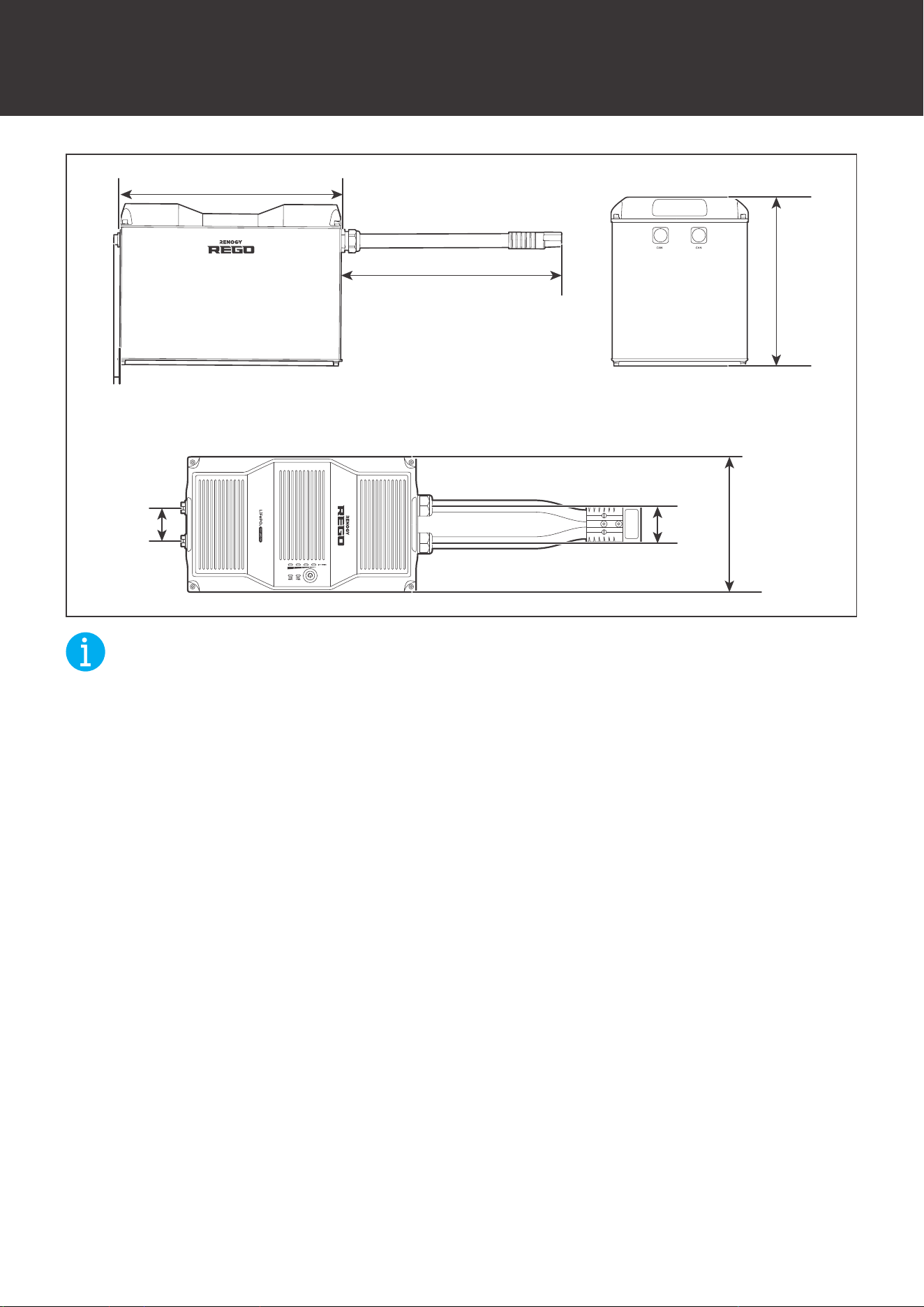
56
Dimensions
Dimensions
12.95in
[329mm]
23.62in [600mm]
17.99in [457mm]
3.89in
[98.7mm]
2.56in
[65mm]
2.87in
[73mm]
10.52in
[267.2mm]
NOT
E
z
The dimension tolerance is ±0.02 inch (±0.5 mm)

57
FCC Statement
This device complies with Part 15 of the FCC Rules. FCC ID:2ANPBRSMLP4-G2. Operation
is subject to the following two conditions:
(1) This device may not cause harmful interference.
(2) This device must accept any interference received, including interference that may cause
undesired operation.
This equipment has been tested and found to comply with the limits for a Class B digital
device, pursuant to Part 15 of the FCC Rules. These limits are designed to provide reasonable
protection against harmful interference in a residential installation. This equipment generates,
uses and can radiate radio frequency energy and, if not installed and used in accordance with
the instructions, may cause harmful interference to radio communications. However, there is no
guarantee that interference will not occur in a particular installation. If this equipment does cause
harmful interference to radio or television reception, which can be determined by turning the
equipment off and on, the user is encouraged to try to correct the interference by one or more of
the following measures:
(1) Orient or relocate the receiving antenna.
(2) Increase the separation between the equipment and receiver.
(3) Connect the equipment into an outlet on a circuit different from that to which the receiver is
connected.
(4) Consult the dealer or an experienced radio/TV technician for help.
FCC Radiation Exposure Statement
This equipment complies with FCC radiation exposure limits set forth for an uncontrolled
environment. This equipment should be installed and operated with minimum distance 20cm
between the radiator & your body.