1
NOVEMBER 2017 HLT-370 V
MODEL: HLT-370 V
SELF-CONTAINED PRESSURE WASHER
MANUAL SERVICE
PARTS LIST
SERVICE

2
NOVEMBER 2017 HLT-370 V
TABLE OF CONTENTS
RECOMMENDATIONS 2
DIRECT CONNECTION TO WATER SUPPLY 3
OPERATION 3
PRESSURE WASHER SET-UP 4
WATER SUPPLY REQUIREMENTS 4
MAINTENANCE 5
TROUBLESHOOTING 6
EXPLODED VIEW HL-370 7
PART LIST HL-370 8
EXPLODED VIEW ENGINE, HEAD AND OIL TANK HLT-370 V 9
PARTS LIST ENGINE, HEAD AND OIL TANK HLT-370 V 9
RECOMMENDATIONS
• Always disconnect electricity and water supplies (if a garden hose is being used) on completion of every job.
• Keep water circulating constantly through appliance. Do not let appliance work without water.
• Do not use or store appliance in a frozen environment. Frozen water will damage it.
• Do not use appliance if any part of is damaged.
• Appliance has been designed to work with water only. Do not use chemicals, gasoline, acids, or any corrosive
substance.
• These are highly flammable and they will also damage appliance.
• Vehicles' tires and valves must be washed from a 3 foot distance to avoid damage to them. If a tire looks
discolored, it could be damage and must be checked.
• Do not use appliance to clean objects containing health -hazardous substances such as asbestos.
• Jets of water must never be pointed at people, animals, electrical equipment or appliances itself. Pressure at
high levels is very dangerous and presents severe health hazard.
• Never use appliance with people in the vicinity unless they are wearing protective clothing.
• Never use close to children or pets.
• Use only hoses, accessories and high pressure couplings recommended by Koblenz.
• Whenever the use of appliance is interrupted, it is important to operate the safety button to prevent accidental
activation of trigger.
• Never store the appliance with water inside container.
• Do not exceed 8 gallon of water inside container.
3
NOVEMBER 2017 HLT-370 V
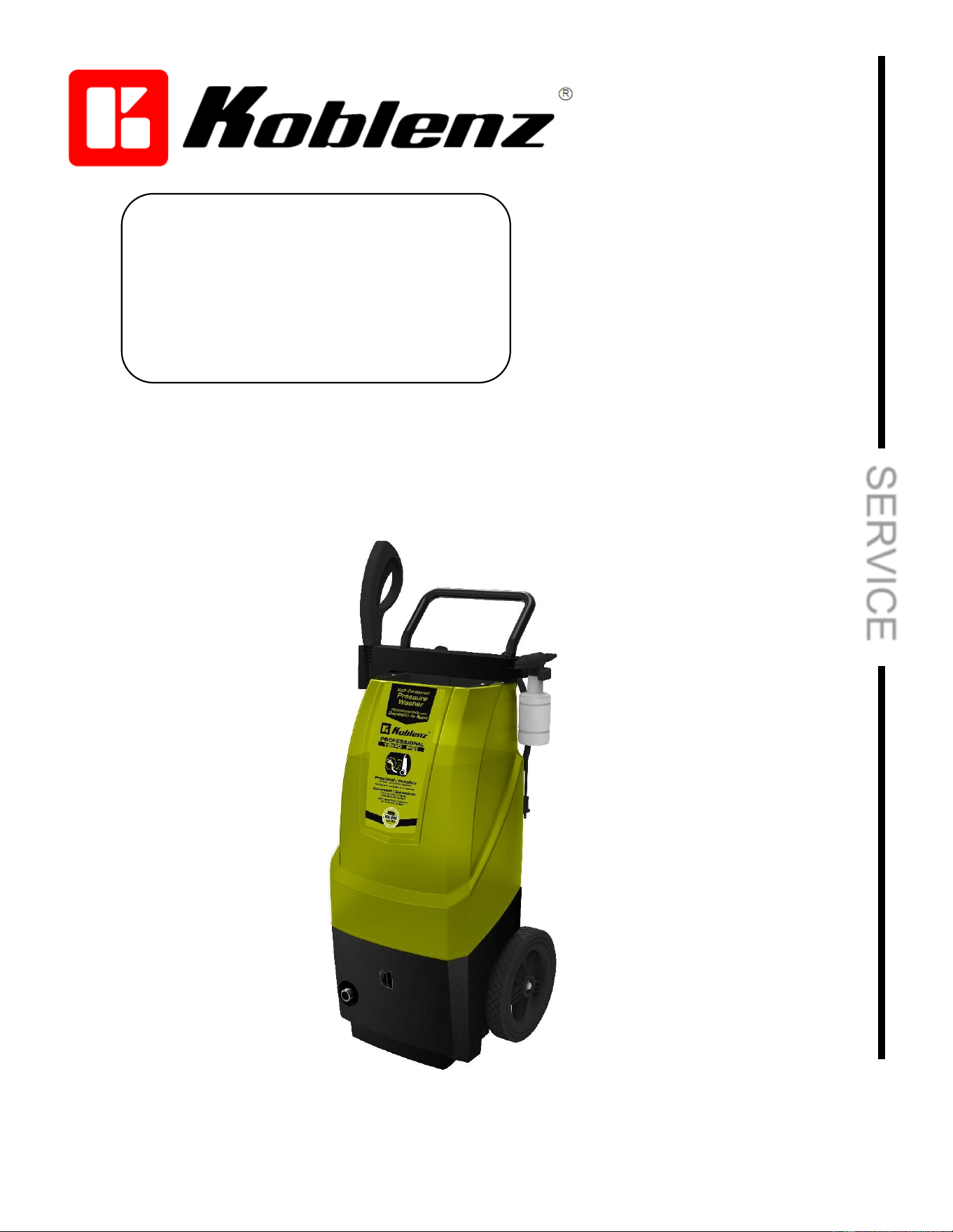
DIRECT CONNECTION TO WATER SUPPLY
OPERATION
4
NOVEMBER 2017 HLT-370 V
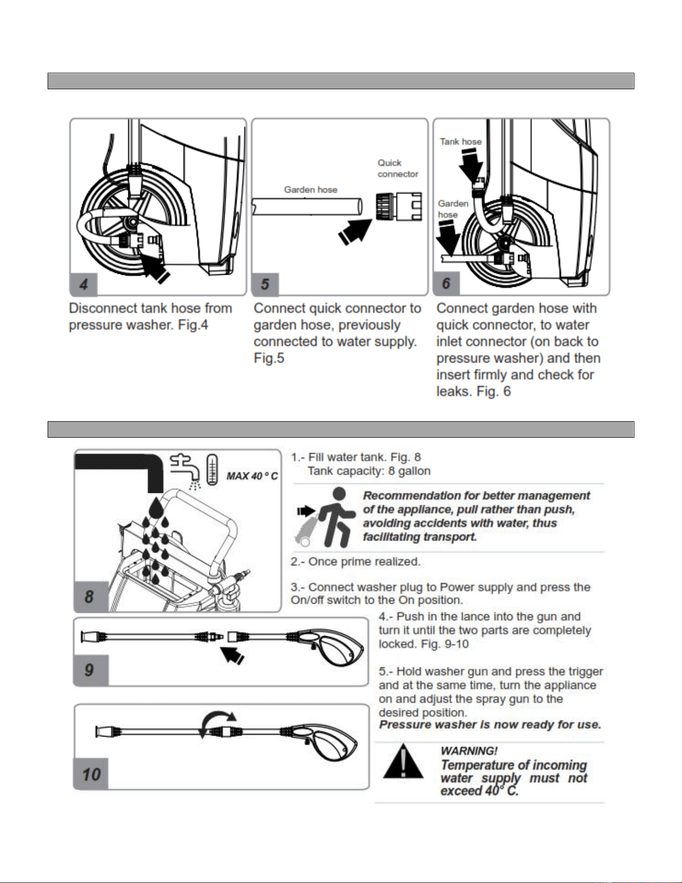
PRESSURE WASHER SET-UP
WATER SUPPLY REQUIREMENTS
• Min water flow: 12 l/min. (When connected directly to a garden hose)
• Water should be free of dirt particles.
• Max water temperature 40 ºC.
• Max water preassure entrance: 7 bar. (700 kPa)
Severe damage can occur to the water pump by not following these instructions, as well as the warranty being
void.
5
NOVEMBER 2017 HLT-370 V
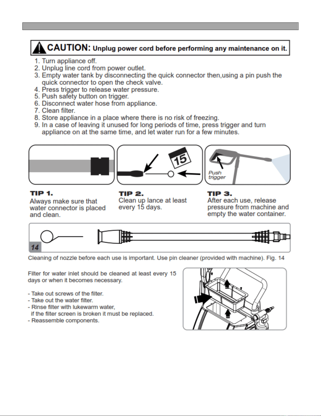
MAINTENANCE
6
NOVEMBER 2017 HLT-370 V
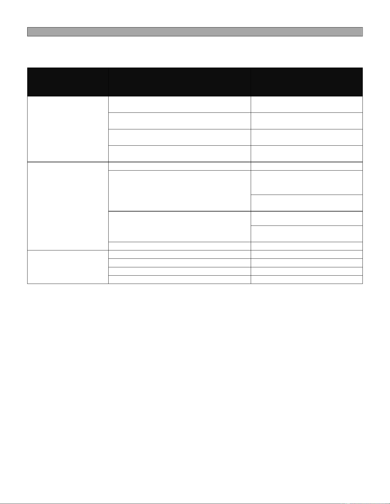
TROUBLESHOOTING
PROBLEM
POSSIBLE CAUSE
SOLUTION
The appliance does not
turn on when the switch
is pressed
The plug is not properly connected to the
socket.
Connect the plug to the
powersocket correctly
There is no voltage or is insufficient.
Check that the power returns to
the normal voltage.
The trigger is not being pressed.
Turn the appliance on while
keeping the trigger pressed.
Pistons stuck.
Disassemble head, clean and
lubricate.
No water comes
out/Uneven pressure
Pressure washer has trapped air inside.
Follow prime instructions
There is not water supply.
Make sure that water hose is
connected to the appliance and
that the water supply is turned on.
Make sure that there is water
inside the tank
The water supply is low or inadecuate.
Clean the water filter.
Make sure the hoses have no
folds or knots.
The high pressure nozzle is dirty.
Remove the nozzle and clean.
Water leaks
Fissured hose.
Replace hoses.
Damaged seals.
Replace seals.
Damaged head.
Replace head.
Fissured gun/lance.
Replace gun/lance.
7
NOVEMBER 2017 HLT-370 V
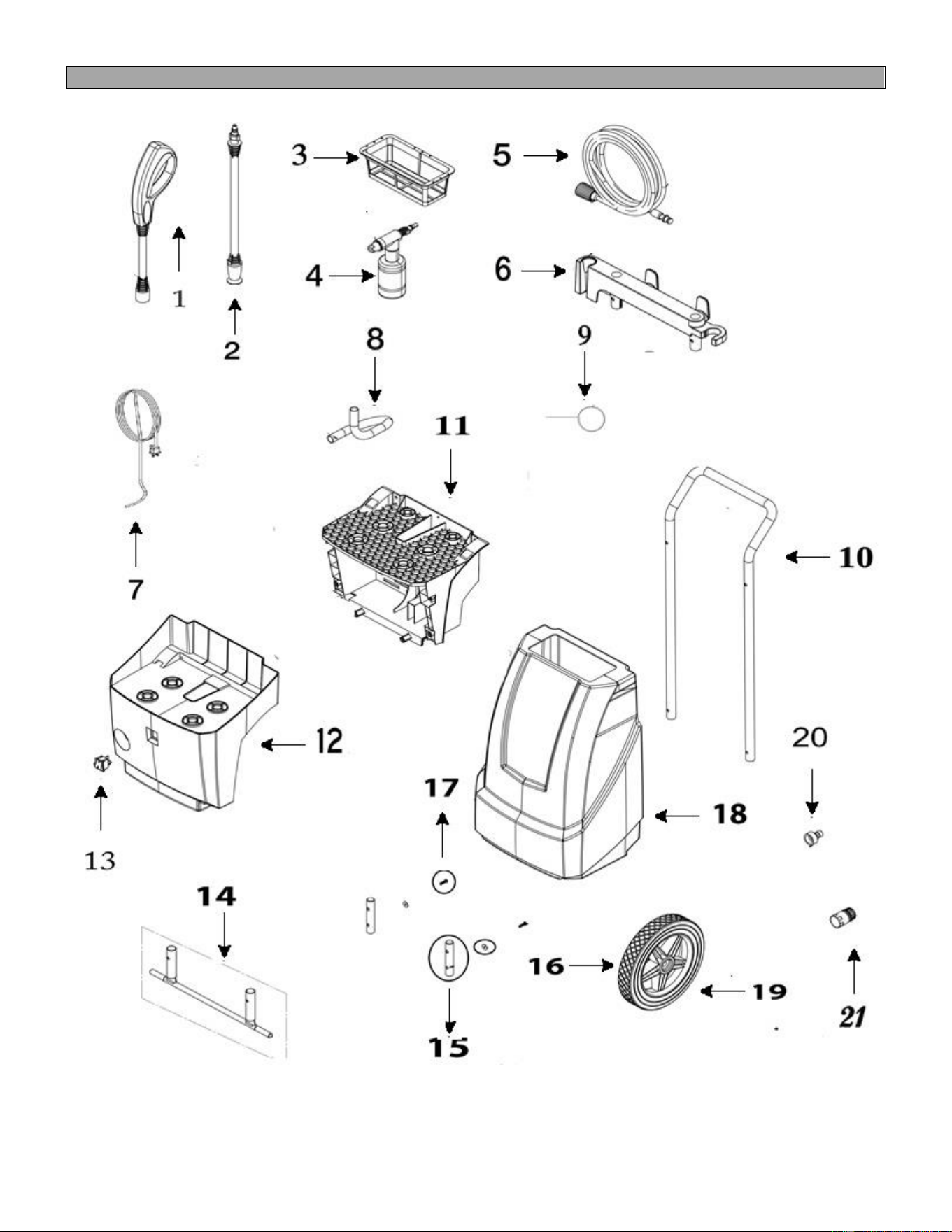
EXPLODED VIEW HLT-370 V
8
NOVEMBER 2017 HLT-370 V
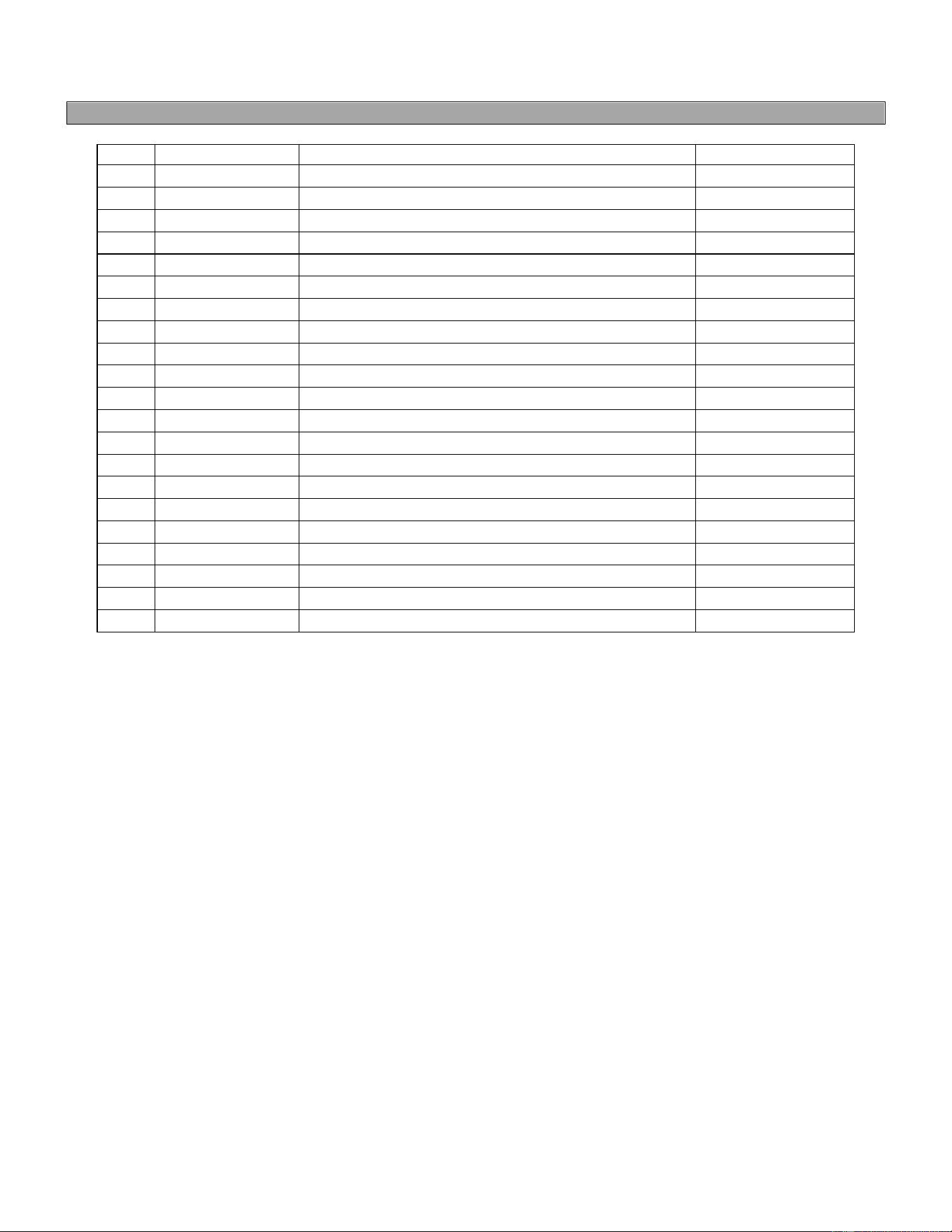
PARTS LIST HLT-370 V
ITEM
No. PART
DESCRIPTION
QUANTITY
1
45-0984-00-0
GUN
1
2
45-0983-00-2
LANCE
1
3
76-0400-2
FILTER
1
4
49-5466-14-6
DETERGENT BOTTLE
1
5
45-0989-00-9
PRESSURE HOSE
1
6
13-4224-00-5
TOOL CADY
1
7
45-0986-00-5
POWER CORD 10 M
1
8
12-1225-00-7
INTERCONNECTION HOSE
1
9
05-5693-00-6
WIRE FOR LANCE
1
10
05-5691-00-0
BLACK HANDLE
1
11
13-4223-00-7
BACK COVER
1
12
13-4222-00-5
FRONT COVER
1
13
49-5995-05-2
SWITCH
1
14
23-1015-01-7
ASSY. CHASSIS
1
15
25-1022-00-6
INSERT FOR HANDLE
2
16
72-0853-1
WASHER FL#10X.518
2
17
01-1818-2
SCREW CAB. GOTA #10-24 X 3/4 INOX
2
18
13-4221-00-1
WATER TANK
1
19
27-0301-01-3
WHEEL
2
20
49-4741-2
MALE CONNECTOR
1
21
49-5451-7
FEMALE CONNECTOR
1
9
NOVEMBER 2017 HLT-370 V
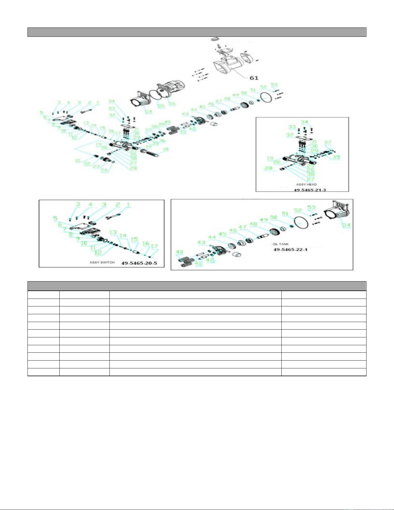
EXPLODED VIEW ENGINE, HEAD AND OIL TANK HLT-370 V
PARTS LIST ENGINE, HEAD AND OIL TANK HLT-370 V
Ítem
No PART
DESCRIPTION
QUANTITY
21
49-5465-8
Filter
1
38
49-5465-01-5
Water trap
3
39
49-5465-02-3
Oil seal
3
44
49-5465-03-1
Bearing kit
1
55
49-5465-04-9
O´ring seal
1
1 al 17
49-5465-20-5
Assy switch
1
40 a 54
49-5465-22-1
Oil tank
1
19 a 35
49-5465-21-3
Assy head
1
56
49-5465-05-6
Motor
1
61
49-5995-04-5
Motor cover
1

10
NOVEMBER 2017 HLT-370 V
WHEN YOU ORDER
DONT´T FORGET SPECIFY
• PART NUMBER
• DESCRIPTION
• MODEL
NOTE:
THE NUMBERS OF THE DRAWINGS ARE ONLY FOR INDETIFICATION PURPOSES
AFTER-SALES SERVICE
Thorne Electric Co.
P. O. Box 18363
San Antonio, TX 78218-0363
Phone: (210) 590-1226
1 (800) 548-5741
THORNE ELECTRIC Co.
E-mail: customerservice@thorne-electric.com
SERVICIO
SERVICE