Before contacting, you must have the following:
Serial no., model no., store no., store address, details (photos, leak locations,
damage, store’s ambient conditions, etc.)
Support: structuralconcepts.com/support
Tech Service/Warranty: 1 (800) 433-9490, EXT. 1
Hours: Monday – Friday, 8am to 8pm EST (Closed holidays)
21-35149 FUSION REFRIGERATED CASES MANUAL-EN REV D DATE: 7/16/25
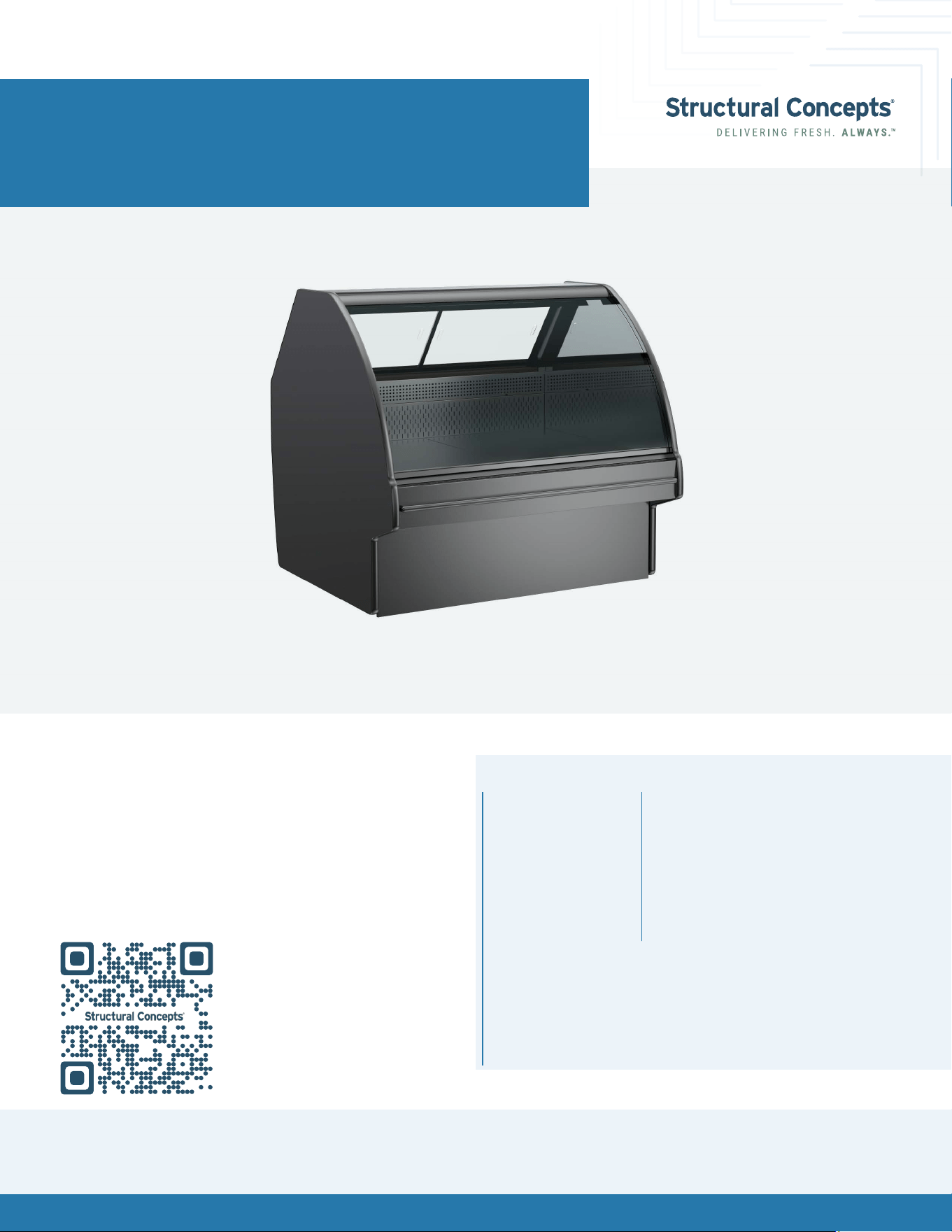
Fusion® User Manual
PART NUMBER: 21-35149
Please Note
Your specic model number is located on the
serial label (usually at the case rear). However,
label locations may vary depending on the
model – see page 30 for more details.
Models shown on this cover sheet do not
represent all models covered by this manual.
Models
GHS456R
GHS556R
GHS656R
GLDS4R
GLDS5R
GLDS6R
GMDS4R
GMDS5R
GMDS6R
GMDSV4R
GMDSV4RA
GMDSVX4RA
GMDSV5R
GMDSV6R
GMDSV6RA
GMDSV8RA
GMDSV12RA
GLDS4R

Fusion® User Manual 2
Overview / Type / Compliance / Warnings / Precautions / Wiring / Plugs .............................................................................. 3-5
Installation: Case Removal From Skid .............................................................................................................................................6-7
Installation: Start Up ..............................................................................................................................................................................8
Placement of Case ................................................................................................................................................................................9
Product Placement ......................................................................................................................................................................... 10-12
Shelf and Deck Load Limits ..................................................................................................................................................................13
Lower Front Panel Removal ................................................................................................................................................................ 14
Rear Panel Removal ............................................................................................................................................................................ 15
Atmosphere System Requirements and Operation .................................................................................................................. 16-17
Atmosphere Cleaning And Maintenance .................................................................................................................................. 18-23
Cleaning Schedule (To Be Performed by Store Personnel) ...........................................................................................................24
Preventative Maintenance .......................................................................................................................................................... 25-29
Serial Label Information & Location ..................................................................................................................................................30
Programmable Controller Information ..............................................................................................................................................31
Technical Service Contact Information / Warranty Information ..................................................................................................32
Table of Contents
Fusion® User Manual 3
Overview
These Structural Concepts cases are designed to
merchandise packaged products at 41 °F (5 °C) or less
product temperatures.
Refrigerated Display cases are classied by “Test Room
Climate Class.” Test Room Climate Class 8 is to be
operated in an environment of 24°C (75.2°F) 55% R.H.
Product must be pre-chilled to 41 °F (5 °C) or less before
being placed in the case.
Component parts shall be replaced with like components.
Cases should be installed and operated according to
this operating manual’s instructions to ensure proper
performance. Improper use will void warranty.
NSF/ANSI Type I vs. II Environmental
Conditions
This case is designed to display products in ambient
indoor store conditions where temperature and humidity
are maintained within a specic range.
NSF/ANSI Type I Conditions: Product is displayed in store
conditions with a maximum ambient temperature of 75 °F
(24 °C) and maximum relative humidity of 55%.
NSF/ANSI Type II Conditions: Product is displayed in store
conditions with a maximum ambient temperature of 80 °F
(27 °C) and maximum relative humidity of 55%.
If you are unsure if your unit is classied as NSF/ANSI Type
I or Type II, see the tag next to the serial label on your
case.
Overview / Type / Compliance / Warnings /
Precautions / Wiring / Plugs
This equipment MUST be installed in compliance
with all applicable NEC, federal, state, and
local electrical and plumbing codes.
Compliance
Performance issues when in violation of applicable
NEC, federal, state and local electrical and plumbing
codes are not covered by warranty.
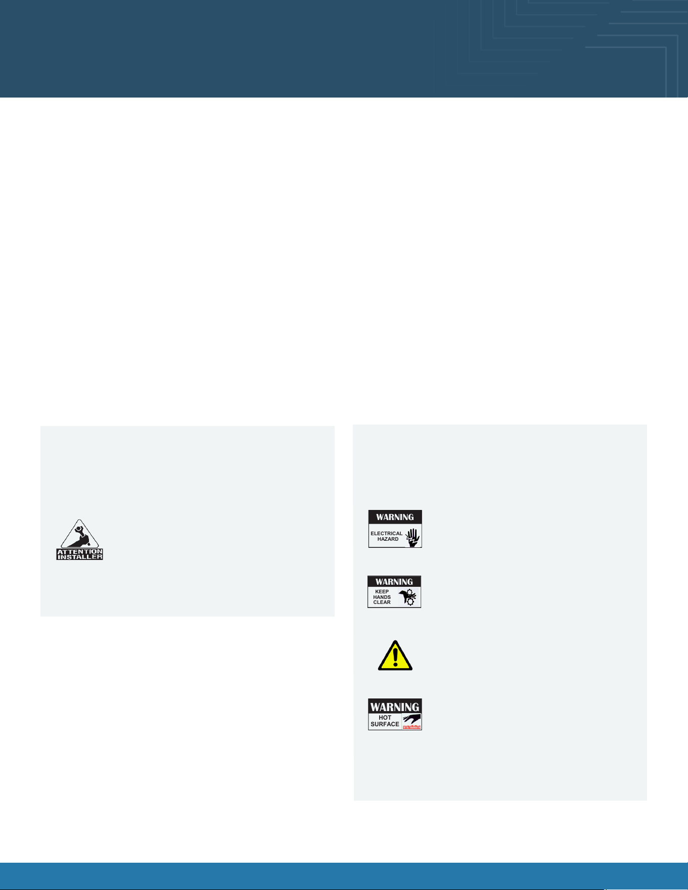
Warnings
This page contains important warnings to prevent
injury or death. Please read carefully!
Risk of electric shock. Disconnect power before
servicing the unit. CAUTION! More than one
source of electrical supply is employed with
units that have separate circuits. Disconnect
ALL ELECTRICAL SOURCES before servicing.
WARNING
ELECTRICAL
HAZARD
WARNING
HOT
SURFACE
Condensate pan and overow condensate
pans are HOT! Disconnect and allow to cool
before cleaning or removing from case.
Hazardous moving parts. Do not operate the
case with the covers removed. Fan blades
may be exposed when deck panel is removed.
Disconnect power before removing deck panel.
WARNING
KEEP
HANDS
CLEAR
This product can expose you to chemicals,
including Urethane (Ethyl Carbonate), which are
known to the state of California to cause cancer
and birth defects or other reproductive harm. For
more information, go to P65Warnings.ca.gov.
Do not place any items on the glass top
surface to prevent scratching or marring.
This equipment MUST be installed in accordance with ANSI/
ASHRAE 15 - Safety Standard for Refrigeration Systems.

Fusion® User Manual 4
CAUTION! Lamp Replacement Guidelines
LED lamps reect specic sizes, shapes, and design. Any replacements must meet factory
specication, resist breakage and reect similar appearance as lamps from the factory.
CAUTION! Check Condensate Pan, Its Position & Plug! Water On Flooring Can Cause Extensive Damage!
Before powering up case, check that condensate pan is positioned directly under case’s condensate drain.
Before powering up case, check that condensate pan’s electrical plug is
SECURELY connected to condensate system’s receptacle.
If wicking material is used in condensate pan, check that it is secure.
Precautions
The following are important precautions to prevent damage to the case or merchandise. Read carefully!
CAUTION! Do Not Rely On Thermometers or Thermostats for Product (Food) Temperatures.
Thermometers & thermostats reect air temperatures ONLY.
Use a calibrated food probe thermometer for actual product (food) temperatures.
For accurate readings, DO NOT use infrared food thermometers. Self-contained
case clearance: 6” min. air intake / 6” min. air discharge.
Wiring Diagram
Each case has its own wiring diagram folded and in its
own packet. It may be placed near ballast box, eld wiring
box, raceway cover, or other related location.
Refrigerant Disclosure Statement
This equipment is prohibited from use in California with
any refrigerants on the “List of Prohibited Substances” for
that specic end-use, in accordance with California Code
of Regulations, title 17, section 95374.
This disclosure statement has been reviewed and
approved by Structural Concepts and Structural Concepts
attests, under penalty of perjury, that these statements
are true and accurate.
CAUTION!
These cases are not to be installed in lobbies or locations of egress, such as hallways or public corridors. If case is
placed in an enclosure or surrounding structure, keep all of the case’s ventilation openings clear of obstructions. The
unit is not intended for use by persons (including children) with reduced physical, sensory, or mental capabilities, or
lack of experience and knowledge, unless they have been give supervision or instruction concerning use of the unit
by a person responsible for their safety. Children should be supervised to ensure that they do not ‘play with unit.
CAUTION! Power Cord and Plug Maintenance
Risk of electric shock if cord or plug becomes damaged, replace only with cord and plug of same type.
Power cord should only be replaced by qualied service personnel.
Fusion® User Manual 5
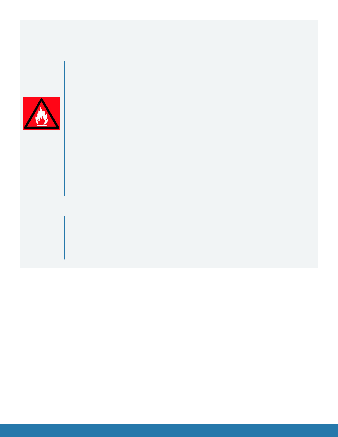
DANGER
Refrigeration unit contains gas under high pressure. Do not tamper with or puncture
the system. Contact qualied service personnel before disposal.
Risk of re or explosion. Flammable refrigerant is used in this case.
Minimum room area (operating or storage): 77.25 ft
2
(7.1 m
2
)
Consult repair manual/owner’s guide before servicing this product.
Do not store explosive substances (such as aerosol cans with a ammable propellant) in this case.
Do not use an electrical appliance INSIDE the food storage compartments unless its type is recommended by manufacturer.
To minimize risk of ignition due to incorrect parts or improper service, this case is
ONLY to be serviced by factory authorized service personnel.
Flammable refrigerant type specied on case nameplate is on the serial label.
APPLIES TO R290 REFRIGERANT MODELS ONLY! Contains a charge of 150g of R290
refrigerant with a lower ammability limit (LFL) of .038kg/m³.
Do not use means to accelerate the defrosting process or to clean, other than those recommended by the manufacturer.
The appliance shall be stored in a room without continuously operating ignition sources (for
example: open ames, an operating gas appliance or an operating electrical heater).
Do not pierce or burn.
Be aware that refrigerant may not contain an odor.
CAUTION: REFRIGERANT RECOVERY/RECYCLING/DISPOSAL
When recycling or discarding case, refrigerants MUST BE handled according to
local, state and federal codes, requirements and regulations.
If disposing of a refrigerated case that uses ozone depleting chemicals in its refrigeration system, make
sure the refrigerant is removed by a qualied service technician and properly disposed of.
If you intentionally release refrigerant into the atmosphere, you may be subject to nes or other
penalties (under regulation mandated by environmental regulators and/or legislative edict.)
Refrigerant Warnings
Following are important information regarding refrigerants. Read carefully!
Fusion® User Manual 6
Oasis® B(L)24 User Manual 6
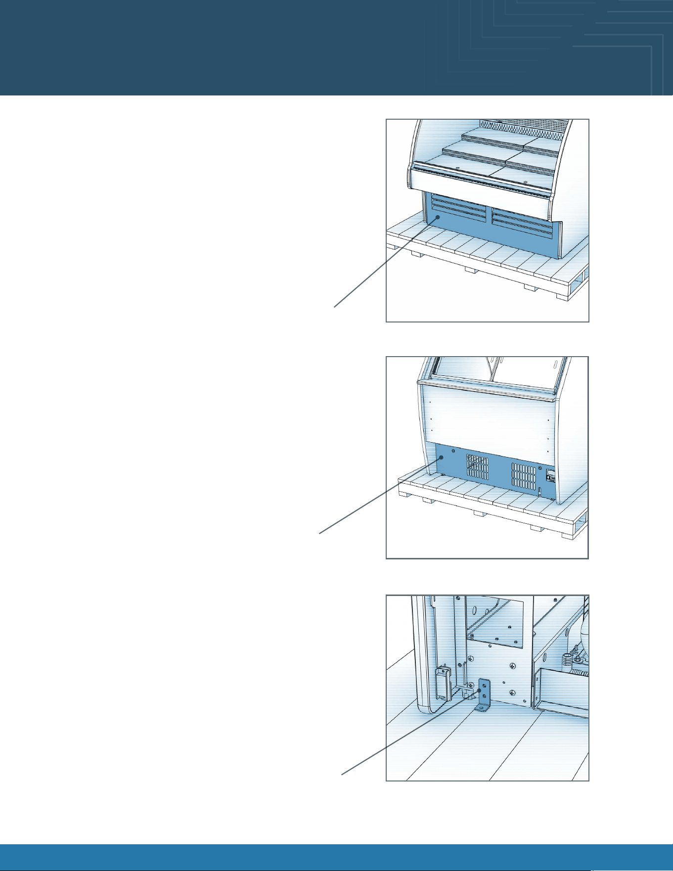
Installation: Case Removal From Skid
Remove Lower Front Panel From Case:
• To prevent damage to the case, remove the lower front
panel from the case before removing it from the pallet.
• The lower front is held in place by magnets only. No
screw removal is required.
• Place the lower front panel in a secure location while
removing the case from the pallet.
Remove Lower Rear Panel From Case:
• Remove the lower rear panel from the case before
removing it from the pallet.
• The lower rear is held in place by magnets only. No screw
removal is required.
• Place the lower rear panel in a secure location while
removing the case from the pallet.
Disconnect Case From Pallet:
• Remove screws from shipping brackets. Remove and
discard shipping brackets from the pallet.
• Raise the leveler all the way up to engage the casters.
Lower Front Panel
Lower Rear Panel
Shipping Bracket
Fusion® User Manual 6
Fusion® User Manual 7Fusion® User Manual 7
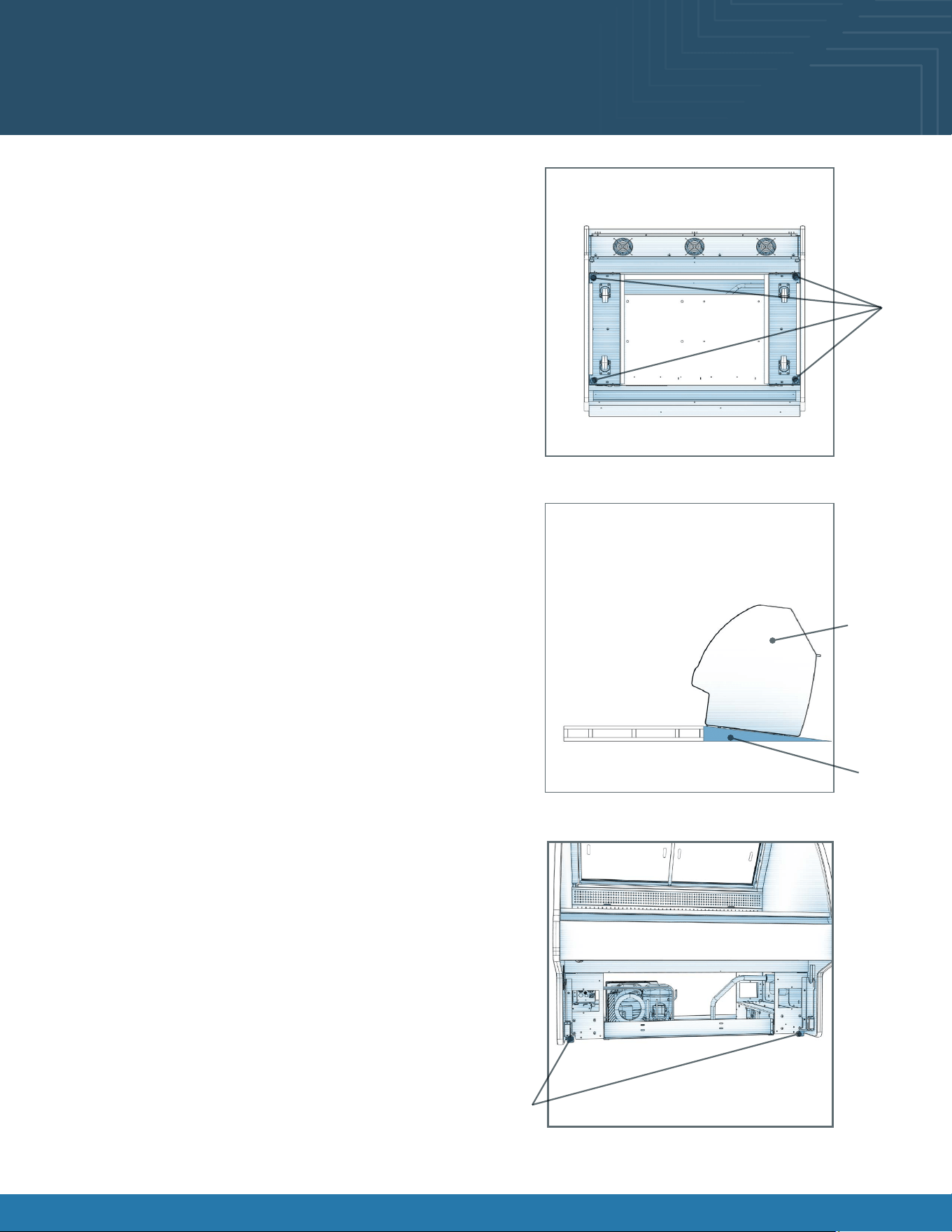
Installation: Case Removal From Skid
Levelers:
• There are levelers on each corner of the case.
• Raise levelers to their highest position to engage the
casters.
Carefully Remove Case From Pallet:
• Check that levelers are fully raised.
• Carefully lower to the oor (using a ramp if available).
• Slide pallet from under case as required.
• Maintain support of the case at all times, or the center of
gravity may cause the case to fall.
• See the illustration at right.
Levelers:
• After the case is at the desired position, lower the levelers
to secure the case in position. Check that the case is
level.
• Adjust height as needed.
Levelers
Ramp
Support
case while
moving
Levelers
Fusion® User Manual 8Fusion® User Manual 8
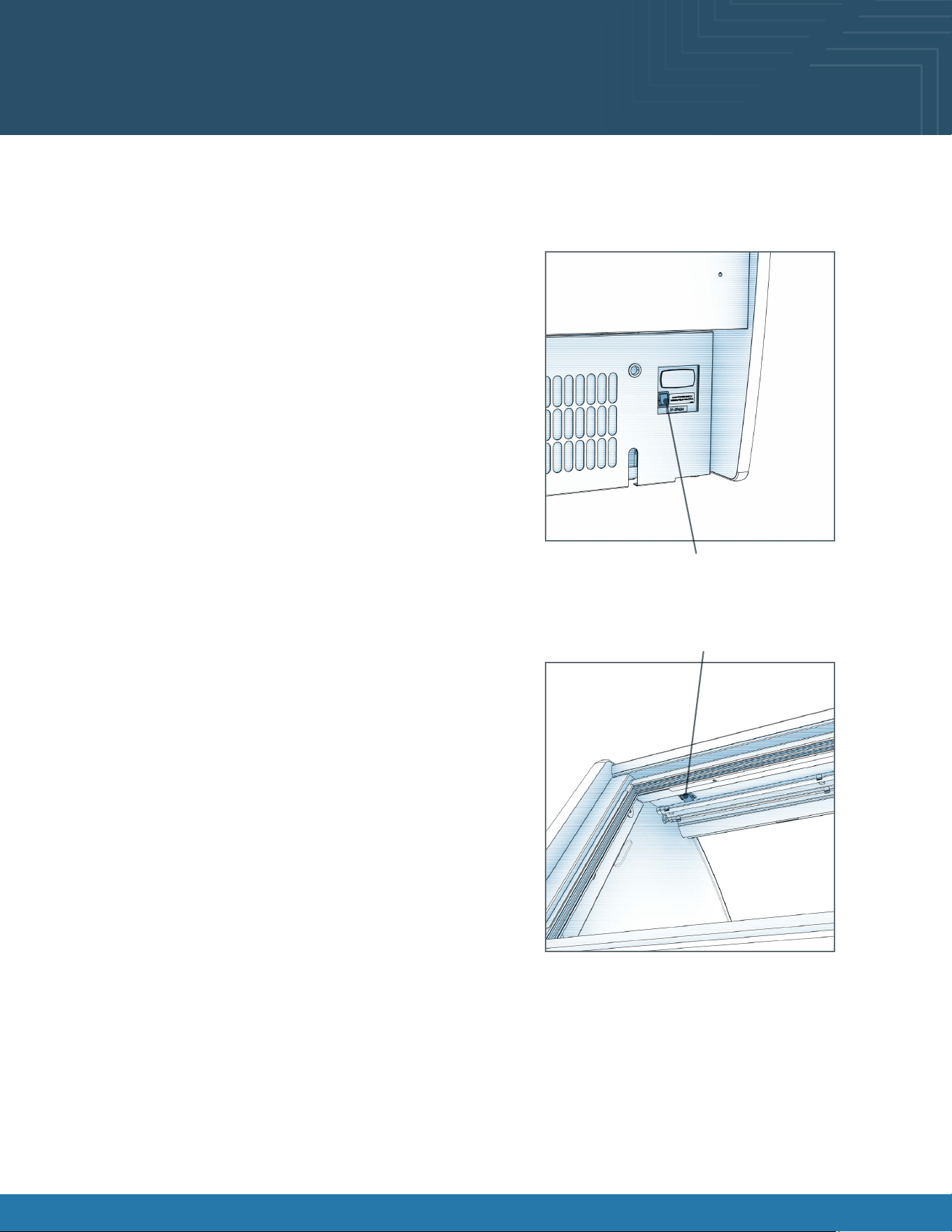
Installation: Start Up
Plug Case In/Turn On Main Power Switch:
• Do not use an extension cord with this case.
• Do not operate this equipment with a damaged cord,
plug, or outlet.
• Ensure that the main power switch is off.
• Route the power cord through the appropriate knockout
in the rear panel. Install the supplied cord bushing in the
knockout hole. Do not install cord without bushing.
• Plug the cord into a certied 120V electrical outlet with
ground.
• Turn the main power switch on.
• Coil fans should turn on.
• From inside of the case, check for discharge air from
front bafe, to conrm that the fans are functioning
properly.
• When the case is in a start-up mode or has been idle for
a long period of time, the case may require 75 minutes
running time to pull down the temperature.
• Turn lights on.
• Light switch is located on the ceiling of merchandising
area.
• The lights should come on at the same time.
• Always maintain front and rear airow clearance of four
inches.
• Obstruction or restriction of air can void warranty.
• Note: Case temperature setting is determined by case
size. Temperature is controlled by a thermostat.
Light Switch
Main Power Switch
Fusion® User Manual 9
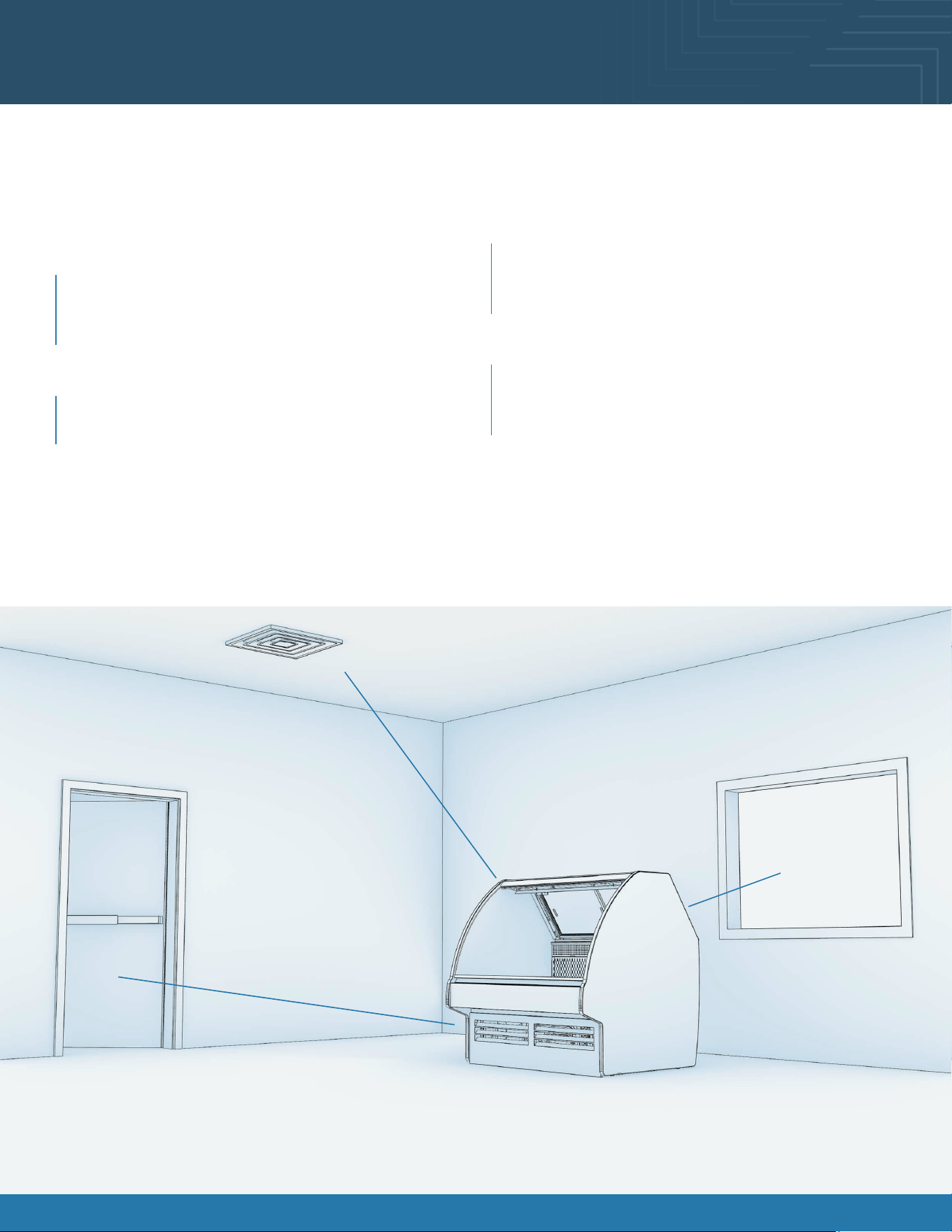
Placement of Case
Consider where the display case will be positioned relative to walls, ceilings, HVAC vents, windows, and other equipment
discharging warm air.
Minimum 4” clearance to walls & ceilings.
Some models can be positioned right to the wall & ceiling.
Refer to spec sheets & design guide for further information.
Stay 5’ away from an exterior window
Direct sunlight increases the heat load on the front of
the display resulting in the refrigeration system having
to work harder and possible condensation on the case.
Remain 10’ away from HVAC ceiling vents
Air blowing on the front of the display interrupts the air
curtain and causes product temperatures to increase.
With service display cases that have a glass front, air
blowing on the front glass causes condensation to
develop.
Position the display 15’ away from exterior doors
Air drafts from the front exterior doors interrupt the air
curtain, allowing warm air to penetrate the inside of the
display, affecting product temperature.
The 5’ - 10’ - 15’ Rule
5’
15’
10’
Fusion® User Manual 10Fusion® User Manual 10
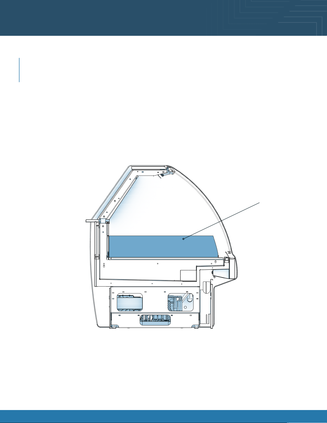
Product Placement
Product Placement
Product can be placed on decking. Proper airow is critical to maintaining proper product temperature. Product should
not be placed on air grills inside of the case and have at least 1 inch of clearance between product and discharge. See
merchandising illustration below.
1” Minimum Load Line
Product Stop
X
1” Minimum Load Line
1” Minimum Load Line
Model GLDS4R Shown Above
Merchandising Area
Fusion® User Manual 11Fusion® User Manual 11
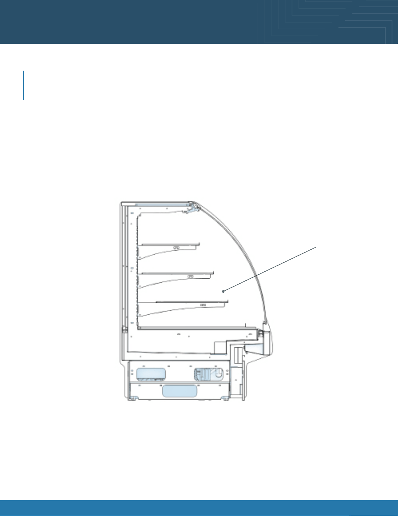
Product Placement
Product Placement
Product can be placed on decking. Proper airow is critical to maintaining proper product temperature. Product should
not be placed on air grills inside of the case and have at least 1 inch of clearance between product and discharge. See
merchandising illustration below.
1” Minimum Load Line
Product Stop
X
1” Minimum Load Line
1” Minimum Load Line
Model GHS456R Shown Above
Merchandising Area
Fusion® User Manual 12Fusion® User Manual 12
Product Placement
Product Placement
Product can be placed on decking. Proper airow is critical to maintaining proper product temperature. Product should
not be placed on air grills inside of the case and have at least 1 inch of clearance between product and discharge. See
merchandising illustration below.
1” Minimum Load Line
Product Stop
X
1” Minimum Load Line
1” Minimum Load Line
Model GMDS4R Shown Above
Merchandising Area

Fusion® User Manual 13
Shelf and Deck Load Limits
The chart below lists the load limits for the shelves and decks. All weights below are for a uniformly distributed load. All
values are in pounds.
MODEL
MAX 12”D
SHELF LOAD
MAX 14”D
SHELF LOAD
MAX 16”D
SHELF LOAD
MAX 20”D
SHELF LOAD
MAX DECK PAN
LOAD
GHS456R (CURVED)
NA 123.2 154 184.8 277.2
GHS556R (CURVED)
NA 158.4 198 237.6 356.4
GHS656R (CURVED)
NA 193.6 242 290.4 415.8
GHS456R (FLAT)
92.4 NA 154 NA 277.2
GHS556R (FLAT)
118.8 NA 198 NA 356.4
GHS656R (FLAT)
145.2 NA 242 NA 415.8
GLDS4R
NA NA NA NA 338.8
GLDS5R
NA NA NA NA 435.6
GLDS6R
NA NA NA NA 508.2
GMDS4R
NA NA 154 NA 277.2
GMDS5R
NA NA 198 NA 356.4
GMDS6R
NA NA 242 NA 145.8
GMDSV4R
NA 123.2 154 184.8 277.2
GMDSV4RA
NA 123.2 154 184.8 277.2
GMDSVX4RA
NA NA NA 90 124
GMDSV5R
NA 158.4 198 237.6 356.4
GMDSV6R
NA 193.6 242 290.4 415.8
GMDSV6RA
NA 193.4 242 290.4 415.8
GMDSV8RA
NA 132/Shelf 165/Shelf 198/Shelf 556
GMDSV12RA
NA 132/Shelf 165/Shelf 198/Shelf 834
Fusion® User Manual 14Fusion® User Manual 14
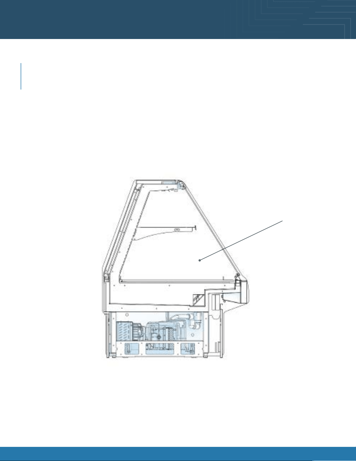
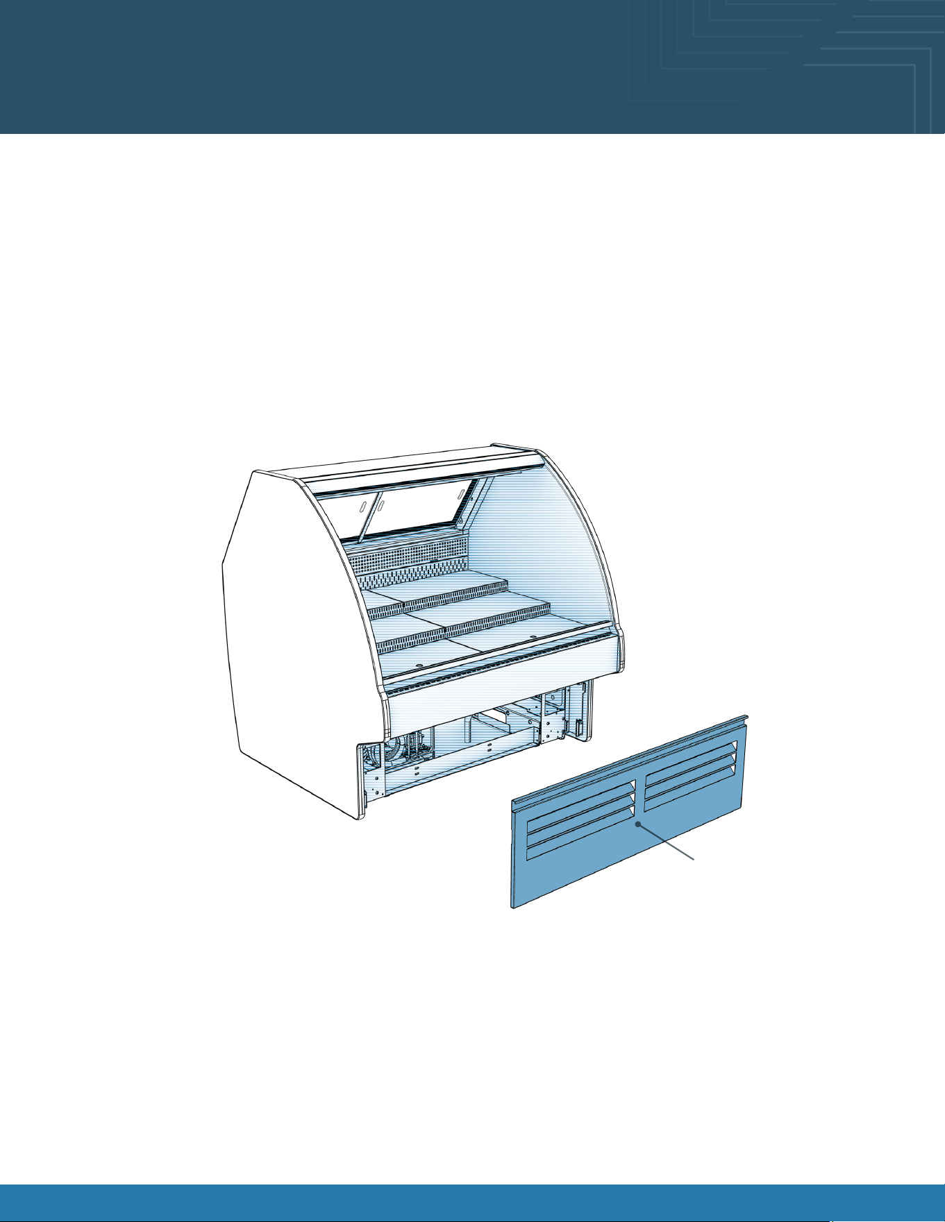
Lower Front Panel Removal
Servicing of refrigeration components is to be done by a licensed refrigeration contractor.
• Remove lower front panel from the magnets to access the compressor package.
• Carefully slide condenser package pan out from under case to access various components.
• For reassembly, reverse the order items were removed.
Lower Front Panel
Fusion® User Manual 15Fusion® User Manual 15
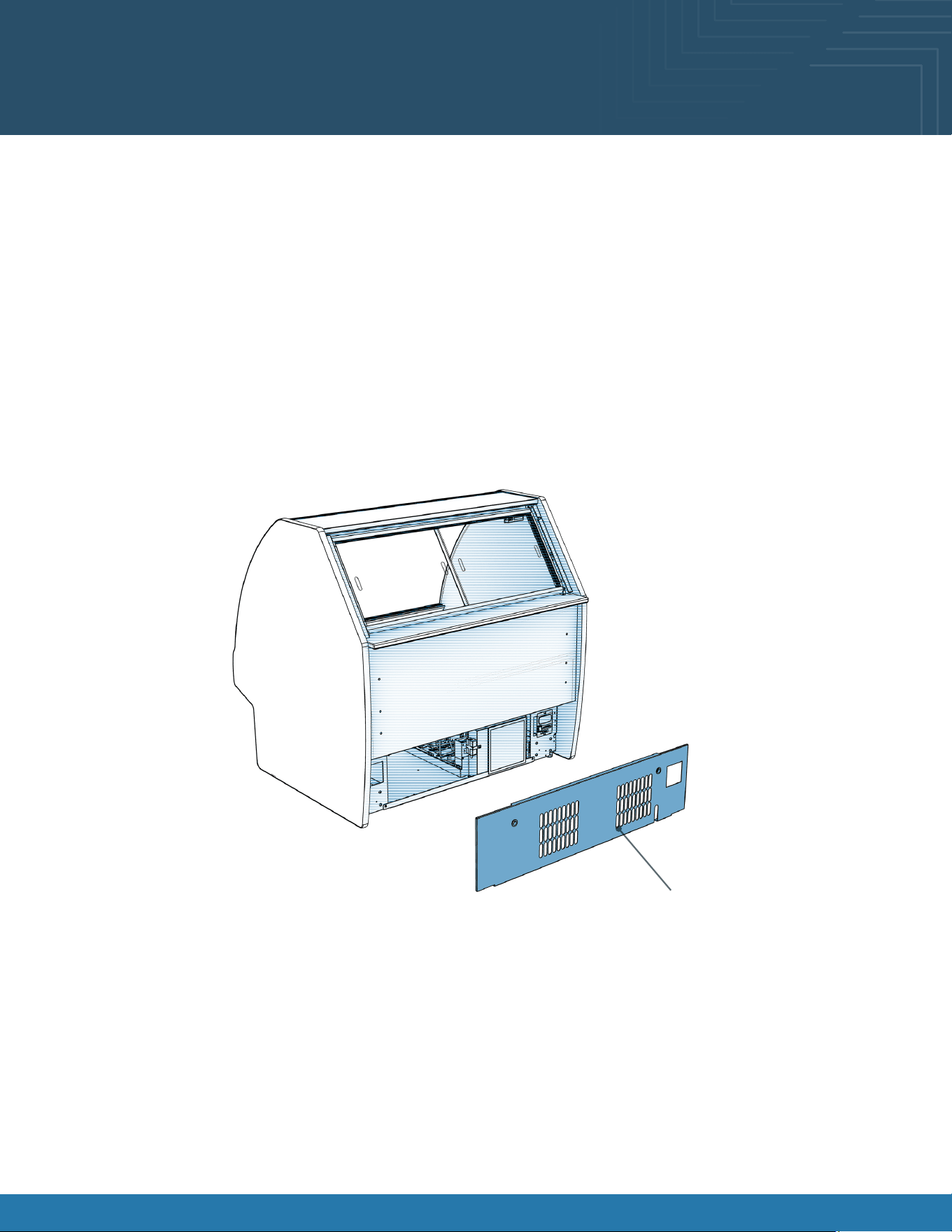
Lower Rear Panel Removal
Servicing of refrigeration components is to be done by a licensed refrigeration contractor.
• Remove lower rear panel by grabbing the bottom of the panel and pull forward to release magnets.
• Carefully slide condenser package pan out from under case to access various components.
• For reassembly, reverse the order items were removed.
Front Panel
Lower Rear Panel

Fusion® User Manual 16
Overview
These instructions apply to models only with the Atmosphere system included. These models are GMDSV4RA, GMDSVX4RA,
GMDSV6RA, GMDSV8A, GMDSV12RA.
System Requirements
System Overview:
The Atmosphere system is designed to maintain a steady relative humidity for a meat/ cheese/ seafood case. This system has
a “closed” design so there are no reservoirs to be cleaned.
Electrical:
Rating: 120VAC 60Hz 25A
Requirements: 120V 60Hz 15A single gang outlet wired onsite.
The outlet must be located within 5 feet of control enclosure should be on the case itself.
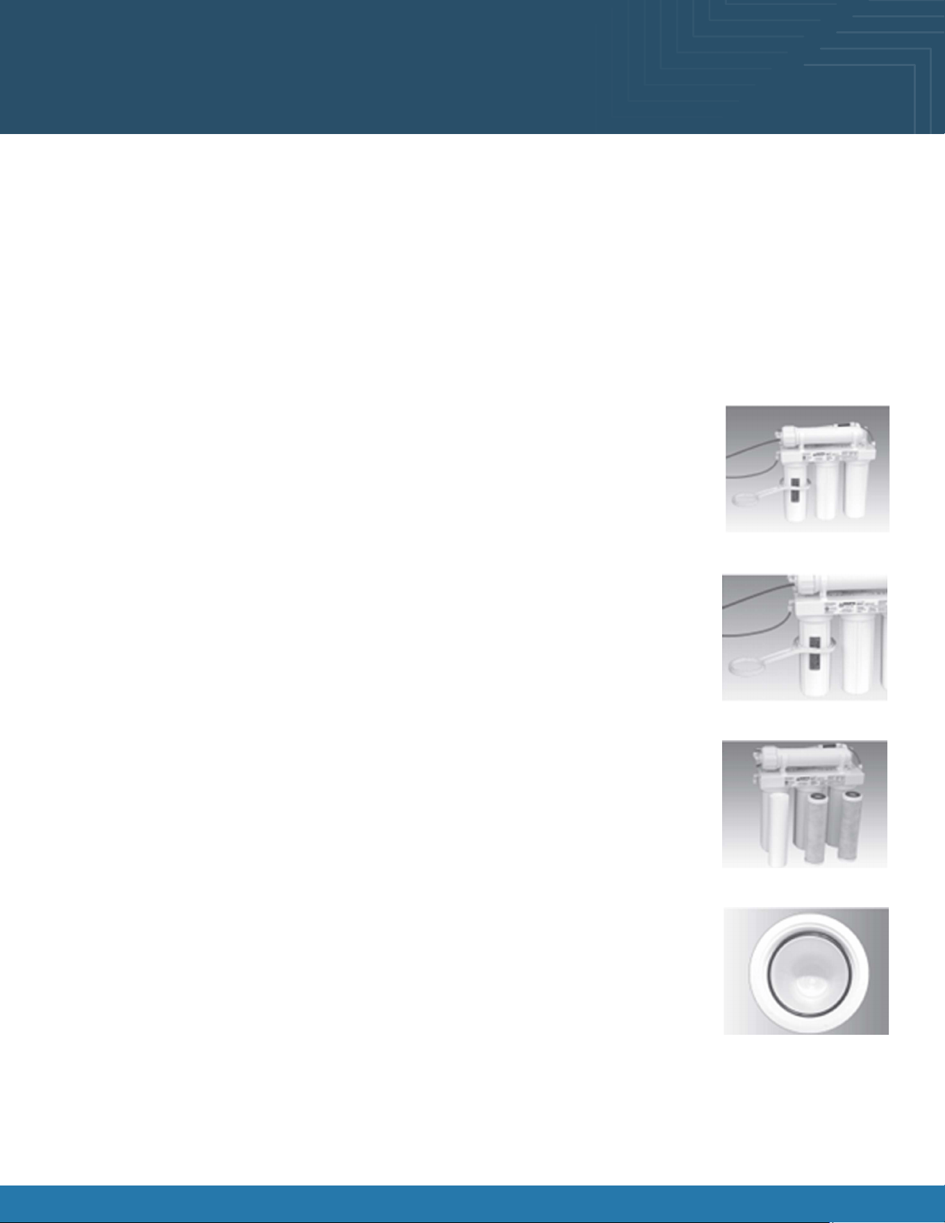
Plumbing:
1/2NPTF potable cold-water supply with ¼ in OD tube connector
Nearby drain or condensate pump required.
Water must be ltered through a reverse osmosis water lter with a TDS range of 7ppm-15ppm. One can be purchased
with the unit or previously installed in the store.
Atmosphere System Requirements and
Operation
Fusion® User Manual 17
Start Up
After the system is plumbed turn on the water to the system. There must be water up to the solenoid before the control
box is powered on. Failure to do this could damage the system causing a need for a full replacement. To turn on the
Atmosphere system you need to switch the ON/OFF toggle located on the bottom of the control box.
Upon initial start-up, it will take 5 to 10 minutes to purge air from the water lines. After the air is purged, the nozzle vapor
will be steady uninterrupted. The regulator has been preset to the intended working pressure of the system.
Atmosphere System Requirements and
Operation
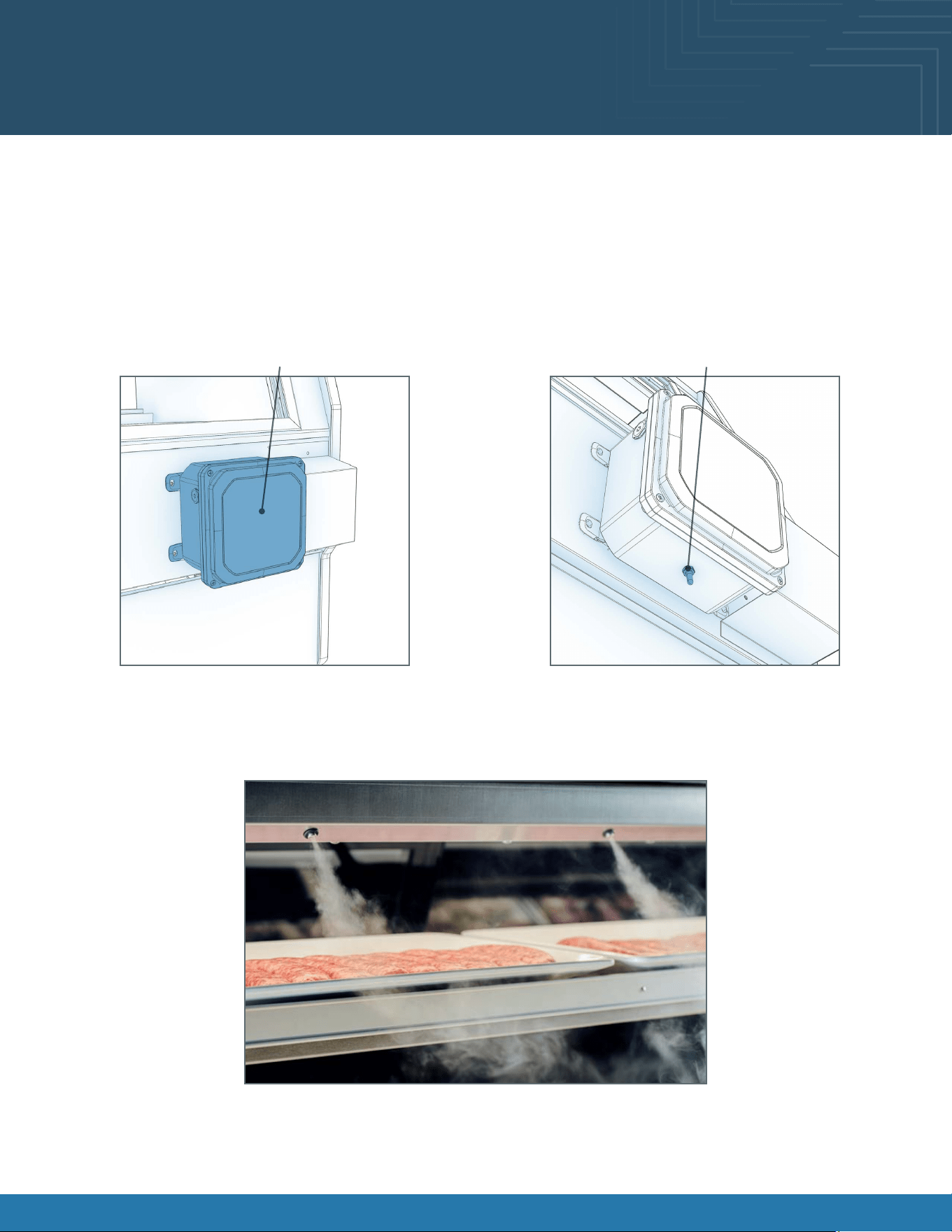
Control Box
Power Switch
Operating
The system just needs to be powered on with water owing. The system has been factory set to the optimal duty cycle.
Below is a photo of the system operating. Visual impact should be similar.
Shutting Down
Turn off the power switch and shut off the water running to the system. Typically, with a shutoff valve upline from the
regulator.

Fusion® User Manual 18
Cleaning
The exterior stainless steel and Controller Boxes can be gently wiped with a moist cloth. Please be careful not to damage
the tip of the nebulizer The nebulizer tip can be cleaned every 6 months with a Q-tip dipped in CLR scale remover.
GENTLY rub the surface of each nebulizer with Q-tip for a few seconds. No further cleaning is required.
Troubleshooting
System won’t run when turned on:
• Make sure the controller is plugged in and turned on.
• Receptacle voltage may be incorrect.
• Water may be turned off. Verify all shutoff valves are open, keep power off while verifying.
• Verify all controller connections are made.
System is running but not humidifying:
• Make sure the water supply is on.
• Check water pressure, increase if water is dripping from nozzle decrease pressure.
• Check for debris in the water line to nozzle.
System is not humidifying well:
• Check water pressure.
• Check water lters.
Atmosphere Cleaning and Maintenance
Fusion® User Manual 19
Atmosphere Cleaning and Maintenance
6-Month System Maintenance
Order lter by calling Watts at 1-800-224-1299
Item Needed: EDP# 7100110
Includes:
• (1) Sediment Filter • (1) Carbon Block Filter
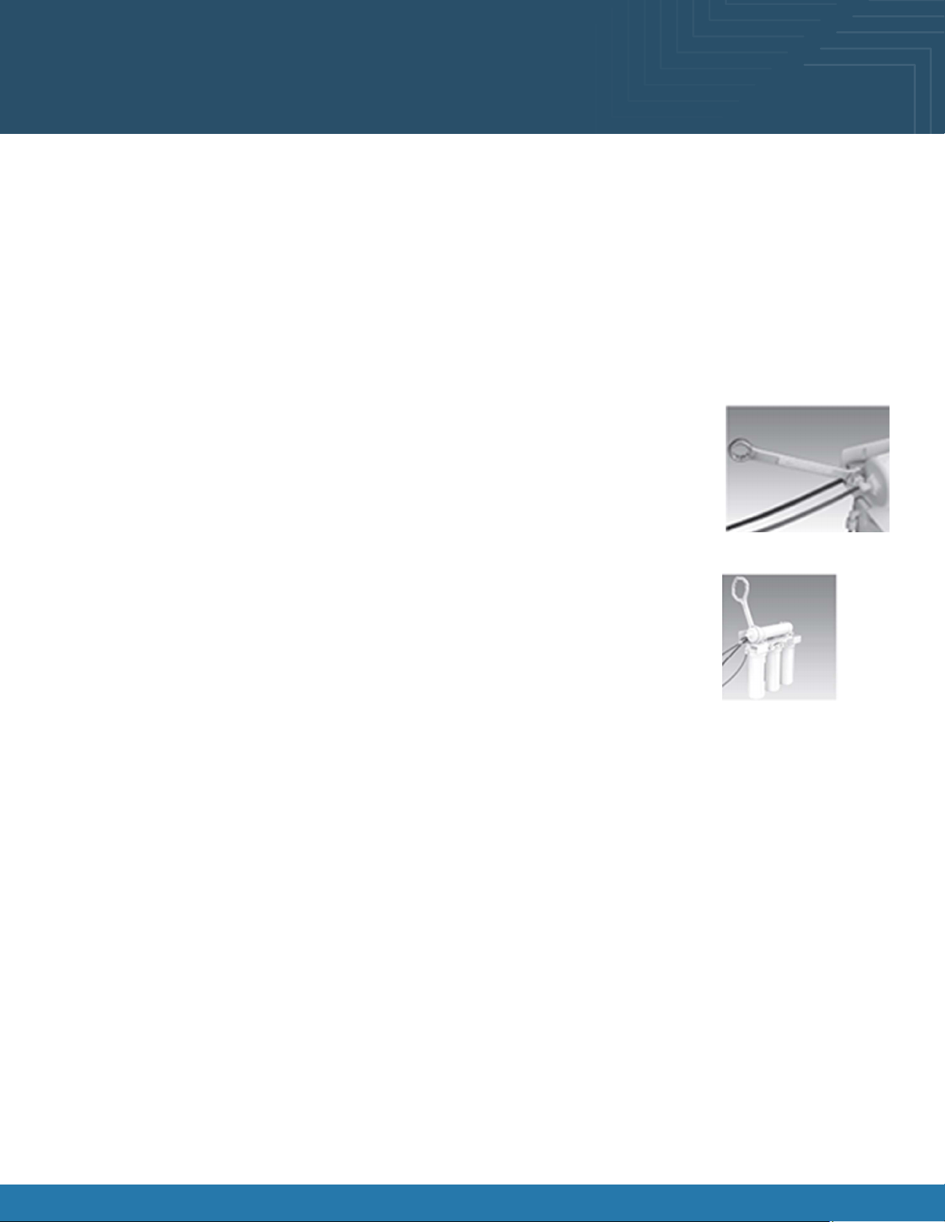
Step A-Turn off the incoming water supply to the RO by turning the knob on the Adapt-A-Valve
TM
clockwise until it stops.
Step B-Open the RO Faucet and allow water to drain from the tank until it is completely empty.
Water may be saved in a container for drinking or to rinse system parts.
Step C-Let system sit for 10 to 15 minutes after the tank is empty to let the system depressurize before
attempting to remove lter housings.
Step D-For more leverage you may leave the RO module attached to wall of cabinet. If you are unable
to access the module while it is mounted, remove it prior to changing lters. Starting with the closet
housing (Stage 1), remove it by turning it clockwise (left), empty water, then discard lter.
Continue on to the 2nd housing (Stage 2) and the 3rd housing (Stage 3).
If you own a 4-stage system it will not have the third stage. A 4-stage system has two vertical
housings instead of three.
Step E-Clean the lter housings (bowls) with a mild soap solution and rinse with water. Check O-rings
and lubricate with water soluble lubricant. Petroleum base lubricants must not be used.
NOTICE: Before re-installing the lter bowls back on the the system, check O-rings to make sure
they are still in place. Do not over-tighten lter housing, over-tightening may damage O-ring(s),
cause water leaks, or affect system performance.
Step F-Insert a new sediment lter (cloth like appearance) into the 1st lter housing which is the one
on the water inlet side (green tubing from the Adapt-A-Valve
TM
) of the RO system, and re-install
housing.
Step G-Insert the new Carbon Block lter (white end caps & plastic netting ) into the second and third
lter bowls and re-install housings.
Step H-Turn water supply on the unit by turning the knob on the Adapt-A-Valve
TM
counterclockwise.
Step I-Open the RO faucet and leave it open until water begins to trickle out. (It will come out slowly).
Step J-Close the RO faucet allowing the storage tank to ll with water. It may take 4 to 6 hours to ll the tank completely
depending on the production capability of the membrane, local water temperature and water pressure.

Fusion® User Manual 20
Atmosphere Cleaning and Maintenance
Annual Maintenance
Order lter by calling Watts at 1-800-224-1299
Item Needed: # 7100110, 7100454
Includes:
• (1) Sediment Filter • (1) Carbon Block Filter
• (1) Final In-Line Filter
Sanitizing of unit is recommended.
Step A-Perform steps A through E in the Six Month System Maintenance.
If not sanitizing the system skip to step H.
Step B-Remove the RO membrane from its housing and rest in a clean sanitary place. (refer to “Membrane Replacement” for
direction on removing the membrane). Replace cap onto empty membrane housing and re-connect green tubing.
Step C-Leaving the lter out, replace Stage 1 and 2 empty lter housings (hand tight) onto unit. Measure & pour either 1/2 cup of
hydrogen peroxide or common household bleach into the 1st lter housing (Stage 1) and hand tighten onto unit.
NOTICE: Over-tightening components can damage the system causing water damage and/or system failure.
Step D-With the RO faucet in the closed position turn on the incoming water supply to the system by turning the Adapt-A-
Valve
TM
counterclockwise. Wait 1 minute for the unit to pressurize. Turn on the RO faucet, and let the water run for 30 seconds.
Turn off the RO faucet, and let the unit rest for 2 minutes. Finally, open the R0 faucet, and let the water run for 5 more minutes.
Step E-Turn of the incoming water supply to the system by turning the Adapt-A-Valve
TM
clockwise until it stops. Keep the RO
faucet open until the storage tank is completely drained.
Step F-Open the membrane housing and re-install the RO membrane while making sure not to kind the O-rings. (Refer to
“Membrane Replacement” section on Page 9 for directions on the installing the membrane). Tighten the cap back on the
housing and reconnect green turning.
Step G-Remove lter housing Stage 1 and 2 and empty of water.
NOTICE: Before re-installing the lter bowls back on to the system, check O-rings to make sure they are still in place and
lubricate with water soluble lubricant. Do not over-tighten lter housing, over-tightening may damage O-ring(s), cause
water leaks, or affect system performance.
Step H-Insert the new Sediment Filter (cloth like appearance) into the 1st lter housing which is the one on the water inlet side
(green tubing from the Adapt-A-Valve
TM
) of the RO system and re-install housing.
Step I-Insert the new Carbon Block lter (white End Caps) into the 2nd housing and re-install housing.

Fusion® User Manual 21
Atmosphere Cleaning and Maintenance
Annual Maintenance
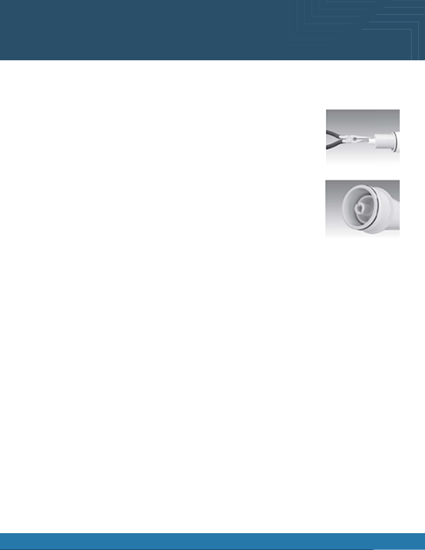
Step J-The nal lter is clipped on the membrane housing. Remove it by rst loosening the compression ttings on both ends of
the lter and disconnecting the blue tubing. Remove lter from holding clips and replace with the new lter. (Discard used nal
lter after sanitizing) Re-attach tubing.
The arrow on the nal lter must be pointing towards the RO faucet/away from the RO storage tank.
This is a good time to check the air pressure in your storage tank.
Step K-Follow Steps H through J in the 6-Month System Maintenance section for start up directions.
Fusion® User Manual 22
Atmosphere Cleaning and Maintenance
Membrane Replacement
Order membrane by calling Watts at 1-800-224-1299
Item Needed: # 7100122
Includes:
• (1) RO membrane
This reverse osmosis system contains a replaceable component (the RO membrane) which is critical to the efciency of the
system. Replacement of this reverse osmosis membrane should be with one of identical specications as dened by Watts to
assure the same efciency and contaminant reduction performance.
Membranes have a life expectancy between 2 and 5 years, depending on the incoming water
conditions and the amount the RO system is used. This reverse osmosis membrane is critical for
effective reduction of total dissolved solids (TDS). The product water should be tested periodically to
verify that the system is performing satisfactorily.
Normally, a membrane would be replaced during the semiannual or annual lter change. However, if
at any time, you notice a reduction in water production or an unpleasant taste in the reverse osmosis
water, it could be time to replace the membrane. Watts recommends replace the membrane when
TDS reduction falls below 75%.
Step A-Turn of the incoming water supply to the RO by turning the knob on the Adapt-A-Valve
TM
clockwise unit it stops.
Step B-Open the RO Faucet and allow water to drain from the tank until it is completely empty.
Removing the Membrane
Step A-Use a 5/8” wrench to remove the Green Tube tting on the left side of the horizontal membrane housing (end with one
elbow).
Step B-Remove the cap from the membrane housing by turning it counterclockwise to loosen.
A double side wrench may be purchased from Watts to aid with loosening the cap/lter housings.
Step C-Remove membrane housing from the holding clips. Using a pair of pliers, grip the PVC tube on the RO membrane and
pull rmly on the membrane to remove from the housing and discard
Fusion® User Manual 23
Atmosphere Cleaning and Maintenance
Installing the Membrane
Step A-Lubricate the O-rings on the new membrane with a water soluble lubricant. Insert the end with the two black O-rings
rst into the housing.
Step B-Once membrane has been inserted into the housing you must take your thumbs and give a
rm push to properly seat the membrane. Replace membrane housing cap and tighten.
Step C-After replacing membrane housing into clips, attach the green tube to the elbow on cap
using 5/8” wrench.
Step D-Follow Start Up.

Fusion® User Manual 24
Cleaning Schedule (To Be Performed by Store Personnel)
FREQUENCY INSTRUCTIONS
Daily Glass Surfaces: Clean glass surfaces and shelves with household or commercial glass cleaner.
Daily Exterior Panels: Wipe off all surfaces with warm water and mild soap solution and non-abrasive
cloth.
Daily Decks: Wipe off decks with a moist cloth dipped in mild soap and water solution..
Daily Acrylic Surfaces:
• Clean: Use a soft, clean cloth dipped in a solution of warm water and a small amount of mild
liquid soap. Apply light pressure while wiping away all smudges and residue.
• Rinse: Use pure water in a spray bottle to rinse.
• Dry: Use non-abrasive clean cloth.
• Polishing: Buff with a light coat of automobile paste wax or plastic cleaner/polish.
• Scratches: Use high-quality bufng compound. Carefully follow instructions.
• Never use window or household cleaning products.
Daily Stainless Steel Surfaces:
• Wash with a solution of hand dish-washing liquid detergent and water or a solution of baking
soda and water. Rinse and polish dry with a soft cloth.
• Never use scouring powders or steel wool as they will scratch stainless steel.
• Brighten by polishing with a cloth dipped in vinegar or in ammonia; sprinkle baking soda on a
sponge and rub gently, rinse. Polish dry with soft cloth.
• Remove streaks or heat stains from stainless steel by rubbing with club soda..
Weekly Magnetic Condensing Coil Filter:
• This lter helps prevent dust particles from entering condenser coil.
• It is accessible at the air intake side of the case.
• Magnetic condenser coil lter is dishwasher safe; remove from case and use a rag or soft-
bristled brush to wipe off excess dust particles from lter. Run in normal dishwasher cycle.
Remove from dishwasher
• Dry with a soft cloth or allow to air dry. Replace in case.
Quarterly Under Case Cleaning:
• Remove lower front and rear panels. Unlock caster and lower to oor.
• Slide the case out of the current position, and slide the condenser package out from under the
case.
• Use a vacuum with brush to remove all dust, dirt, food particles, or residue from underside of
the case.
• Place the case back in position and replace the front and rear panels.
6-Months For Atmosphere equipped cases, reference page 19
Annual For Atmosphere equipped cases, reference pages 20-23

Fusion® User Manual 25
Preventive Maintenance
• All maintenance staff and others working in the local area shall be instructed on the nature of work being carried out. Work
in conned spaces shall be avoided.
• The area shall be checked with an appropriate refrigerant detector prior to and during work, to ensure the technician is
aware of potentially toxic or ammable atmospheres. Ensure that the leak detection equipment being used is suitable for
use with all applicable refrigerants, i.e., non-sparking, adequately sealed, or intrinsically safe.
• If any hot work is to be conducted on the refrigerating equipment or any associated parts, appropriate re extinguishing
equipment shall be available on hand. A dry chemical or CO2 re extinguisher should be adjacent to the charging area.
• No person carrying out work in relation to a refrigerating system which involves exposing any pipe work shall use any
sources of ignition in such a manner that it may lead to the risk of re or explosion. All possible ignition sources, including
cigarette smoking should be kept sufciently far away from the site of installation, repairing, removing and disposal, during
which refrigerant can possibly be released to the surrounding space. Prior to work taking place, the area around the
equipment shall be surveyed to make sure that there are no ammable hazards or ignition risks. “No Smoking” signs shall
be displayed.
• Ensure that the area is in the open or that it is adequately ventilated before breaking into the system or conducting any
hot work. A degree of ventilation shall continue during the period that the work is carried out. The ventilation should safely
disperse any released refrigerant and preferably expel it externally into the atmosphere.
Checks to the refrigerating equipment
• Where electrical components are being changed, they shall be t for the purpose and to the correct specication. At all
times, the manufacturer’s maintenance and service guidelines shall be followed. If in doubt, consult the manufacturer’s
technical department for assistance.
• The following check shall be applied to installation using FLAMMABLE REFRIGERANTS:
a. The actual REFRIGERANT CHARGE is in accordance with the room size within which the refrigerant containing parts
are installed;
b. The ventilation machinery and outlets are operating adequately and are not obstructed;
c. If an indirect refrigeration circuit is being used, the secondary circuit shall be checked for the presence of
refrigerant;
d. Marking to the equipment continues to be visible and legible. Markings and signs that are illegible shall be
corrected;
e. Refrigerating pipe or components are installed in a position where they are unlikely to be exposed to any
substance which may corrode refrigerant containing components, unless the components are constructed of
materials which are inherently resistant to being corroded or are suitably protected against being so corroded.
Checks to electrical devices
• Repair and maintenance to electrical components shall include initial safety checks and component inspection
procedures. If a fault exists that could compromise safety, then no electrical supply shall be connected to the circuit until
it is satisfactorily dealt with. If the fault cannot be corrected immediately but it is necessary to continue operation, an
adequate temporary solution shall be used. This shall be reported to the owner of the equipment, so all parties are advised.
• Initial safety checks shall include:
a. That capacitors are discharged: this shall be done in a safe manner to avoid possibility of sparking;
b. That no live electrical components and wiring are exposed while charging, recovering or purging the system;
c. That there is continuity of earth bonding.
Maintenance and Service Notes
WARNING! TURN OFF CASE BEFORE PERFORMING PREVENTATIVE MAINTENANCE

Fusion® User Manual 26
Preventive Maintenance
Maintenance and Service Notes
WARNING! TURN OFF CASE BEFORE PERFORMING PREVENTATIVE MAINTENANCE
Repairs to sealed components
• During repairs to sealed components, all electrical supplies shall be disconnected from the equipment being worked
upon prior to any removal of sealed covers, etc. If it is absolutely necessary to have an electrical supply to equipment
during servicing, then a permanent opening form of leak detection shall be located at the most critical point to warn of a
potentially hazardous situation.
• Particular attention shall be paid to the following to ensure that by working on electrical components, the casing is not
altered in such a way that the level of protection is affected. This shall include damage to cables, excessive number and
connections, terminals not made to original specication, damage to seals, incorrect tting of glands, etc.
• Ensure that the apparatus is mounted securely.
• Ensure that seals or sealing materials have not degraded to the point that they no longer serve the purpose of preventing
the ingress of ammable atmospheres. Replacement parts shall be in accordance with the manufacturer’s specications.
Repair to intrinsically safe components
• Do not apply any permanent inductive or capacitance loads to the circuit without ensuring that this will not exceed the
permissible voltage and current permitted for the equipment in use.
• Intrinsically safe components are the only types that can be worked on while live in the presence of a ammable
atmosphere. The test apparatus shall be at the correct rating.
• Replace components only with parts specied by the manufacturer. Other parts can result in the ignition of refrigerant in
the atmosphere from a leak.
• NOTE The use of silicon sealant can inhibit the effectiveness of some types of leak detection equipment. Intrinsically safe
components do not have to be isolated prior to working on them.
Cabling
• Check that cabling will not be subject to wear, corrosion, excessive pressure, vibration, sharp edges, or any other adverse
environmental effects. The check shall also take into account the effects of aging or continual vibration from sources such
as compressors or fans.
Detection of ammable refrigerants
• Under no circumstances shall potential sources of ignition be used in the searching for or detection of refrigerant leaks. A
halide torch (or any other detector using a naked ame) shall not be used.
• The following lead detection methods are deemed acceptable for all refrigerant systems.
• Electronic leak detectors may be used to detect refrigerant leaks but, in the case of FLAMMABLE REFRIGERANTS the sensitivity
might not be adequate, or might need recalibration. (Detection equipment shall be calibrated in a refrigerant-free
area.) Ensure that the detector is not a potential source of ignition and is suitable for the refrigerant used. Leak detection
equipment shall be set at a percentage of the LFL of the refrigerant and shall be calibrated to the refrigerant employed,
and the appropriate percentage of gas (25% maximum) is conrmed.
• Leak detection uids are also suitable for use with most refrigerants but the use of detergents containing chlorine shall be
avoided as the chlorine can react with the refrigerant and corrode the copper pipe-work.
• NOTE examples of leak detection uids are
-Bubble method.
-Fluorescent method agents.
• If a leak is suspected, all naked ames shall be removed/extinguished.
• If a leakage of refrigerant is found which requires brazing, all of the refrigerant shall be recovered from the system, or
isolated (by means of shut off valves) in a part of the system remote from the leak. Removal of refrigerant shall be
according to the removal and evacuation procedures below.

Fusion® User Manual 27
Preventive Maintenance
Maintenance and Service Notes
WARNING! TURN OFF CASE BEFORE PERFORMING PREVENTATIVE MAINTENANCE
Removal and evacuation
• When breaking into the refrigerant circuit to make repairs-or for any other purpose-conventional procedures shall
be used. However, for ammable refrigerants it is important that the best practice be followed, since ammability is a
consideration. The following procedure shall be adhered to:
a. Safely remove refrigerant following local and national regulations;
b. Purge the circuit with inert gas;
c. Evacuate (optional for A2L);
d. Purge with inert gas (optional for A2L);
e. Open the circuit by cutting or brazing.
• The refrigerant change shall be recovered into the correct recovery cylinders if venting is not allowed by local and national
codes. For appliances containing ammable refrigerants, the system shall be purged with oxygen-free nitrogen to render
the appliance safe for ammable refrigerants. This process might need to be repeated several times. Compressed air or
oxygen shall not be used for purging refrigerant systems.
• For appliances containing ammable refrigerants, refrigerant purging shall be achieved by breaking the vacuum in the
system with oxygen-free nitrogen and continuing to ll until the working pressure is achieved, then venting to atmosphere,
and nally pulling down to a vacuum (optional for A2L). This process shall be repeated until no refrigerant is within the
system (optional for A2L). When the nal oxygen-free nitrogen change is used, the system shall be vented down to
atmospheric pressure to enable work to take place.
• Ensure that the outlet for the vacuum pump is not close to any potential ignition sources and that ventilation is available.
Charging procedures
• In addition to conventional charging procedures, the following requirements shall be followed.
a. Ensure that contamination of different refrigerants does not occur when using charging equipment. Hoses or lines
shall be as short as possible to minimize the amount of refrigerant contained in them.
b. Cylinders shall be kept in an appropriate position according to the instructions.
c. Ensure that the REFRIGERATING SYSTEM is earthed prior to charging the system with refrigerant.
d. Label the system when charging is complete (if not already).
e. Extreme care shall be taken not to overll the REFRIGERATING SYSTEM.
• Prior to recharging the system. It shall be pressure-tested with the appropriate purging gas. The system shall be lead-
tested on completion of charging but prior to commissioning. A follow up leak test shall be carried out prior to leaving the
site.

Fusion® User Manual 28
Preventive Maintenance
Maintenance and Service Notes
WARNING! TURN OFF CASE BEFORE PERFORMING PREVENTATIVE MAINTENANCE
Decommissioning
• Before carrying out this procedure, it is essential that the technician is completely familiar with the equipment and all its
detail. It is recommended good practice that all refrigerants are recovered safely. Prior to the task being carried out, an
oil and refrigerant sample shall be taken in case analysis is required prior to re-use of recovered refrigerant. It is essential
that electrical power is available before the task is commenced.
a. Become familiar with the equipment and its operation.
b. Isolate the system electrically.
c. Before attempting the procedure, ensure that:
i. Mechanical handling equipment is available, if required, for handling refrigerant cylinders;
ii. All personal protective equipment is available and being used correctly;
iii. The recovery process is supervised at all times by a competent person;
iv. Recovery equipment and cylinders conform to the appropriate standards.
d. Pump down refrigerant system, if possible.
e. If a vacuum is not possible, make a manifold so that refrigerant can be removed from various parts of the system.
f. Make sure that cylinder is situated on the scales before recovery takes place.
g. Start the recovery machine and operate in accordance with instructions.
h. Do not overll cylinders (no more than 80% volume liquid charge).
i. Do not exceed the maximum working pressure of the cylinder, even temporarily.
j. When the cylinders have been lled correctly and the process completed, make sure that the cylinders and the
equipment are removed from the site properly and all isolation valves on the equipment are closed off.
k. Recovered refrigerant shall not be charged into another refrigerating system unless it has been cleaned and
checked.
• Equipment shall be labeled stating that it has been de-commissioned and emptied of refrigerant. The label shall be dated
and signed. For appliances containing ammable refrigerants, ensure that there are labels on the equipment stating the
equipment contains ammable refrigerant.

Fusion® User Manual 29
Preventive Maintenance
Maintenance and Service Notes
WARNING! TURN OFF CASE BEFORE PERFORMING PREVENTATIVE MAINTENANCE
Recovery
• When removing refrigerant from a system, either for servicing or decommissioning, it is recommended good practice that
all refrigerants are removed safely.
• When transferring refrigerant into cylinders, ensure that only appropriate refrigerant recovery cylinders are employed.
Ensure that the correct number of cylinders for holding the total system charge is available. All cylinders to be used
are designated for the recovered refrigerant and labeled for that refrigerant (i.e., special cylinders for the recovery of
refrigerant). Cylinders shall be complete with pressure-relief valve and associated shut-off valve in good working order.
Empty recovery cylinders are evacuated and, if possible, cooled before recovery occurs.
• The recovery equipment shall be in good working order with a set of instructions concerning the equipment that is at hand
and shall be suitable for the recovery of all appropriate refrigerants including, when applicable, FLAMMABLE REFRIGERANTS.
In addition, a set of calibrated weighing scales shall be available and in good working order. Hoses shall be complete with
leak-free disconnect coupling and in good condition. Before using the recovery machine, check that it is in satisfactory
working order, has been properly maintained and that any associated electrical components are sealed to prevent
ignition in the event of refrigerant release. Consult manufacturer if in doubt.
• The recovered refrigerant shall be returned to the refrigerant supplier in the correct recovery cylinder, and the relevant
waste transfer note arranged. Do not mix refrigerants in recovery units and especially not in cylinders.
• If compressors or compressor oils are to be removed, ensure that they have been evacuated to an acceptable level to
make certain that FLAMMABLE REFRIGERANT does not remain within the lubricant. The evacuation process shall be carried
out prior to returning the compressor to the suppliers. Only electric heating to the compressor body shall be employed to
accelerate this process. When oil is drained from a system, it shall be carried out safely.
Fusion® User Manual 30
Serial Label Location & Info Listed / Tech Info &
Service / Refrigerated Cases Only
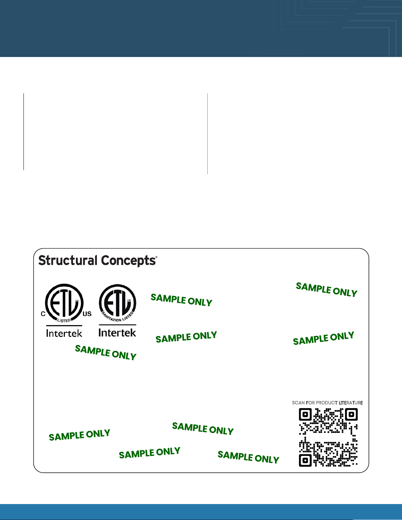
Sample Serial Label For Refrigerated Cases
MODEL NRS3648RXV-SAMPLE
SERIAL NO. 12345X30DZ098765
888 E. Porter Rd - Muskegon, MI 49441
3048256
Conforms to UL Std. 471
Conforms to NSF/ANSI Stds. 2 & 7
CERTIFIED TO CAN/CSA
STD C22.2 NO 120
ELECTRICAL RATING
REFRIGERANT
DESIGN PRESSURE
MINIMUM CIRCUIT AMPACITY
MAXIMUM OVERCURRENT
120/1/60 16 A
R513A AMOUNT 50 OZ
HIGH 186 LOW 88
20A
20A
Super Heat Temp 6-8 °F FOR PARTS AND SERVICE
Defrost 6 defrosts per day, 45 °F CALL 1-800-433-9490
Fusion
Sample QR Code
SCAN FOR PRODUCT LITERATURE
SAMPLE ONLY
Serial labels are afxed at various places (on the
header, near the thermostat, at the case rear, behind
panels/toe-kicks, on electrical boxes, etc.).
Serial labels contain electrical, temperature and
refrigeration information, and regulatory standards to
which the case conforms.
Sample serial label is shown below.
For additional technical information and service, see the
TECHNICAL SERVICE page in this manual for instructions
on contacting Structural Concepts’ Technical Service
Department.
This disclosure statement has been reviewed and
approved by Structural Concepts, and Structural
Concepts attests, under penalty of perjury, that these
statements are true and accurate.
Serial Label Location & Information Listed / Technical Information & Service
Fusion® User Manual 31
Programmable Controller (Select, Click On or
Scan Qr Code for Information)
Carel® PJEZ Platform Carel® ir33 Platform
Carel® iJF Platform Dixell® XM670K-XM679K Platform
Determine which programmable controller is on your case (Controllers that Structural
Concepts commonly use are shown below). Your particular programmable controller
may differ.
To access information about the programmable controller that is used on
your case, follow these instructions:
If viewing this document on a smartphone, a tablet, or computer, select/click on the QR code on the left.
If viewing this document in print (hard copy), scan the QR code on the left with your smartphone or tablet.
Fusion® User Manual 32
Structural Concepts Technical Service Contact
Information & Limited Warranty
Web: structuralconcepts.com/support
Tech Service/Warranty: 1 (800) 433-9490, EXT. 1
Hours Available: Monday – Friday, 8am to 8pm EST
(Closed holidays)
Before contacting, you must have the following: serial
number / model number / store number / store address
/ details (photos, leak locations, damage, store’s
ambient conditions, etc.)
Contact Information
To access the limited warranty to your case, follow these instructions:
If viewing this document on a smartphone, tablet, or computer, select/click on the QR code on the left.
If viewing this document in print (hard copy), scan the QR code on the left with your smartphone or tablet.